17FB-926-AA
FIAT
®
500X
Fifth Edition
User Guide
2017 FIAT
®
500X USER GUIDE
Download a FREE electronic copy
of the Owner’s Manual or Warranty Booklet by visiting:
mopar.com/at or
atusa.com/en/owners/manuals (U.S.);
owners.mopar.ca/en (Canada).
Whether it’s providing information about specic product
features, taking a tour through your vehicle’s heritage,
knowing what steps to take following an accident, or
scheduling your next appointment, we know you’ll nd the
app an important extension of your FIAT
®
vehicle. Simply
download the app, select your make and model and
enjoy the ride.
To get this app, go directly to the App Store or Google Play
and enter the search keyword “MY FIAT” (U.S. market only).
fiatusa.com/en/owners provides special offers
tailored to your needs, customized vehicle galleries,
personalized service records and more. To get this
information, just create an account and check back often.
©2017 FCA US LLC. All Rights Reserved.
FIAT is a registered trademark of FCA Group Marketing
S.p.A., used under license by FCA US LLC.
The driver’s primary responsibility is the safe operation of the
vehicle. Driving while distracted can result in loss of vehicle
control, resulting in a collision and personal injury. FCA US LLC
strongly recommends that the driver use extreme caution when
using any device or feature that may take their attention off
the road. Use of any electrical devices, such as cell phones,
computers, portable radios, vehicle navigation or other devices,
by the driver while the vehicle is moving is dangerous and could
lead to a serious collision. Texting while driving is also dangerous
and should never be done while the vehicle is moving. If you nd
yourself unable to devote your full attention to vehicle operation,
pull off the road to a safe location and stop your vehicle.
Some states or provinces prohibit the use of cell phones
or texting while driving. It is always the driver’s responsibility
to comply with all local laws.
IMPORTANT: This User Guide is intended to familiarize you
with the important features of your vehicle. Your Owner’s
Manual, Navigation/Uconnect Manuals and Warranty Booklets
can be found on your DVD (if applicable) or by visiting the
website on the back cover of your User Guide. We hope you
nd it useful. U.S. residents can purchase replacement kits by
visiting www.techauthority.com and Canadian residents
can purchase replacement kits by calling 1 800 387-1143.
This guide has been prepared to help you get quickly acquainted
with your new FIAT
®
vehicle and to provide a convenient reference
source for common questions. However, it is not a substitute for your
Owner’s Manual.
For complete operational instructions, maintenance procedures and
important safety messages, please consult your Owner’s Manual,
Navigation/Uconnect Manuals and other Warning Labels in your vehicle.
Not all features shown in this guide may apply to your vehicle. For
additional information on accessories to help personalize your vehicle,
visit www.mopar.com (U.S.), www.mopar.ca (Canada) or your
local FIAT
®
dealer.
DRIVING AND ALCOHOL: Drunken driving is one of the most frequent
causes of collisions. Your driving ability can be seriously impaired with
blood alcohol levels far below the legal minimum. If you are drinking,
don’t drive. Ride with a designated non-drinking driver, call a cab, a friend,
or use public transportation.
If you are the rst registered retail owner of your vehicle, you
may obtain a complimentary printed copy of the Owner’s
Manual, Navigation/Uconnect Manuals or Warranty Booklets by
calling 1 888 242-6342 (U.S.) or 1 800 387-1143 (Canada)
or by contacting your dealer.
Driving after drinking can lead to a collision. Your perceptions are less
sharp, your reexes are slower, and your judgment is impaired when you
have been drinking. Never drink and then drive.
WARNING

INTRODUCTION/WELCOME
WELCOME FROM FIAT ...............2
CONTROLS AT A GLANCE
DRIVER COCKPIT ..................4
INSTRUMENT CLUSTER ..............6
GETTING STARTED
KEY FOB .......................8
REMOTE START....................9
VEHICLE SECURITY ALARM ...........10
KEYLESS ENTER-N-GO — PASSIVE ENTRY ...11
KEYLESS ENTER-N-GO — IGNITION ......14
OCCUPANT RESTRAINT SYSTEMS .......15
HEAD RESTRAINTS.................48
SEATS .........................50
STEERING WHEEL .................55
OPERATING YOUR VEHICLE
ENGINE BREAK-IN RECOMMENDATIONS ...57
EXTERIOR LIGHTS .................58
WIPERS AND WASHERS ..............61
SPEED CONTROL..................65
MANUAL CLIMATE CONTROLS .........67
AUTOMATIC TEMPERATURE CONTROLS
(ATC) .........................68
ELECTRIC PARK BRAKE (EPB) ...........70
DYNAMIC SELECTOR — IF EQUIPPED .....72
BLIND SPOT MONITORING (BSM) —
IF EQUIPPED ....................72
BRAKE CONTROL — IF EQUIPPED .......76
LANESENSE — IF EQUIPPED ...........80
PARKSENSE REAR PARK ASSIST —
IF EQUIPPED.....................82
PARKVIEW REAR BACK UP CAMERA —
IF EQUIPPED.....................86
ELECTRONICS
YOUR VEHICLE'S SOUND SYSTEM .......88
CYBERSECURITY ..................90
IDENTIFYING YOUR RADIO............91
RADIO 3.0 ......................92
UCONNECT 5.0 ..................95
UCONNECT 6.5NAV ...............106
UCONNECT PHONE ..............125
STEERING WHEEL AUDIO CONTROLS ....135
INSTRUMENT CLUSTER DISPLAY .......136
PROGRAMMABLE FEATURES ..........137
POWER OUTLET .................138
UTILITY
CARGO AREA FEATURES ............139
TRAILER TOWING ................140
RECREATIONAL TOWING
(BEHIND MOTORHOME, ETC.) .........141
WHAT TO DO IN EMERGENCIES
ROADSIDE ASSISTANCE .............143
WARNING AND INDICATOR LIGHTS .....143
IF YOUR ENGINE OVERHEATS .........152
TIRE SERVICE KIT STORAGE ...........153
JACKING AND TIRE CHANGING ........156
JUMP STARTING ..................164
FREEING A STUCK VEHICLE ...........167
TOW EYE USAGE — IF EQUIPPED .......169
GEAR SELECTOR OVERRIDE ...........171
TOWING A DISABLED VEHICLE .........172
ENHANCED ACCIDENT RESPONSE SYSTEM
(EARS)........................173
EVENT DATA RECORDER (EDR) ........173
MAINTAINING YOUR VEHICLE
HOOD .......................174
ENGINE COMPARTMENT — 1.4L TURBO ...176
ENGINE COMPARTMENT — 2.4L .......178
FLUID CAPACITIES ................180
FLUIDS, LUBRICANTS, AND GENUINE
PARTS .......................180
MAINTENANCE PROCEDURES .........181
MAINTENANCE SCHEDULE ...........181
FUSES ........................187
ADDING FUEL ..................190
TIRE SAFETY INFORMATION ..........192
TIRES — GENERAL INFORMATION ......199
DEPARTMENT OF TRANSPORTATION
UNIFORM TIRE QUALITY GRADES .......207
BULB REPLACEMENT ...............208
CONSUMER ASSISTANCE
FIAT CUSTOMER CENTER ............209
FIAT CANADA CUSTOMER CENTER ......209
ASSISTANCE FOR THE HEARING
IMPAIRED .....................209
PUBLICATIONS ORDERING ...........209
REPORTING SAFETY DEFECTS IN THE
UNITED STATES ..................210
MOPAR® ACCESSORIES
AUTHENTIC ACCESSORIES BY MOPAR ....211
FAQ
FREQUENTLY ASKED QUESTIONS .......212
INDEX
......................213
TABLE OF CONTENTS
1

WELCOME FROM FIAT
Congratulations on selecting your new FIAT vehicle. Be assured that it represents preci-
sion workmanship, distinctive s tyling, and high quality.
Your new FIAT vehicle has characteristics to enhance the driver's control under some
driving conditions. These are to assist the driver and are never a substitute for attentive
driving. They can never take the driver's place. Always drive carefully.
Your new vehicle has many features for the comfort and convenience of you and your
passengers. Some of these should not be used when driving because they take your eyes
from the road or your attention from driving. Never text while driving or take your eyes
more than momentarily off the road.
This guide illustrates and describes the operation of features and equipment that are ei-
ther standard or optional on this vehicle. This guide may also include a description of fea-
tures and equipment that are no longer available or were not ordered on this vehicle.
Please disregard any features and equipment described in this guide that are not available
on this vehicle. FCA US LLC reserves the right to make changes in design and specifica-
tions and/or make additions to or improvements to its products without imposing any
obligation upon itself to install them on products previously manufac tured.
This User Guide has been prepared to help you quickly become acquainted with the im-
portant features of your vehicle. It contains most things you will need to operate and
maintain the vehicle, including emergency information.
The DVD includes a computer application cont aining detailed owner's information which
can be viewed on a personal computer or MAC computer. The multimedia DVD also
includes videos which can be played on any standard DVD player. Additional DVD opera-
tional information is loca ted on the back of the DVD sleeve.
For complete owner information, refer to your Owner's Manual on
www.fiatusa.com/en/owners/manuals.
We are committed to protecting our environment and natural resources. By converting
from paper to electronic delivery for the majority of the user information for your ve-
hicle, together we greatly reduce the demand for tree-based products and lessen the
stress on our environment.
INTRODUCTION/WELCOME
2

VEHICLES SOLD IN CANADA
With respect to any vehicles sold in Canada, the name FCA US LLC shall be deemed to
be deleted and the name FCA Canada Inc. used in substitution (excluding legal lines).
WARNING!
• Pedals that cannot move freely can cause loss of vehicle control and increase the
risk of serious personal injury.
• Always make sure that objects cannot fall into the driver foot well while the ve-
hicle is moving. Objec ts can become trapped under the brake pedal and accelera-
tor pedal causing a loss of vehicle control.
• Failure to properly follow floor mat installation or mounting can cause interference
with the brake pedal and accelerator pedal operation causing loss of control of
the vehicle.
• Never leave children alone in a vehicle, or with access to an unlocked vehicle. Al-
lowing children to be in a vehicle unattended is dangerous for a number of rea-
sons. A child or others could be seriously or fatally injured. Children should be
warned not to touch the parking brake, brake pedal or the transmission gear se-
lector.
• Do not leave the key fob in or near the vehicle, or in a location accessible to chil-
dren. A child could operate power windows, other controls, or move the vehicle.
• Never use the ‘PARK’ position as a substitute for the parking brake. Always apply
the parking brake fully when parked to guard against vehicle movement and pos-
sible injury or damage.
• Refer to your Owner's Manual for further details.
Use Of Af termarket Products (Electronics)
The use of aftermarket devices including cell phones, MP3 players, GPS systems, or char-
gers may affect the performance of on-board wireless features. If you are experiencing
difficulties with any of your wireless features, try disconnecting your aftermarket devices
to see if the situation improves. If your symptoms persist, please see an authorized dealer.
When it comes to service, remember that your authorized dealer knows your vehicle
best, has factory-trained technicians and genuine MOPAR® parts, and cares about your
satisfaction.
INTRODUCTION/WELCOME
3
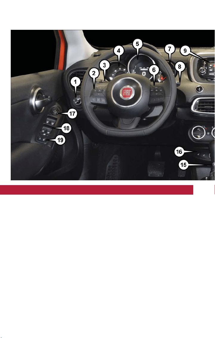
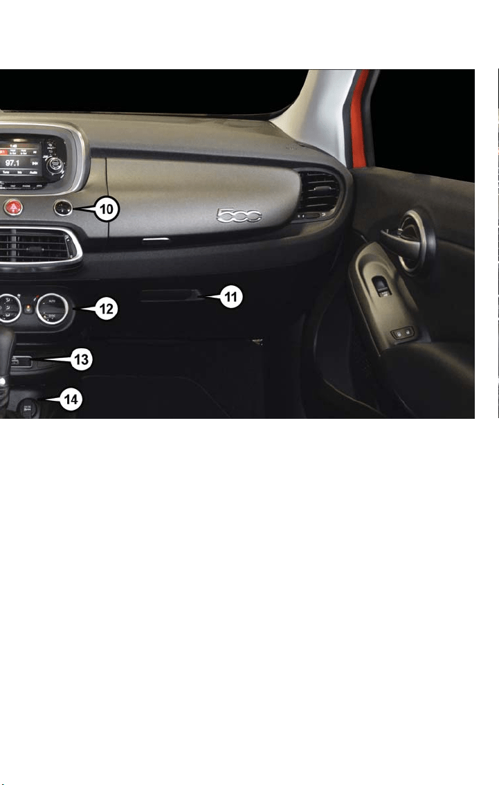
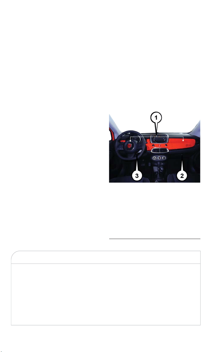
DRIVER COCKPIT
1. Headlight Switch pg. 58
2. Instrument Cluster Display Controls pg. 136
3. Turn Signal/Light Lever pg. 60
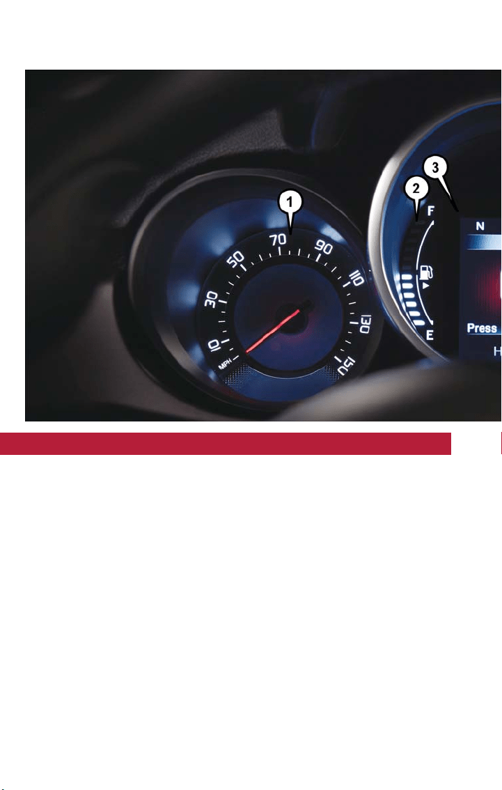
4. Speedometer pg. 6
5. Instrument Cluster Display pg. 136
6. Electronic Speed Control pg. 65
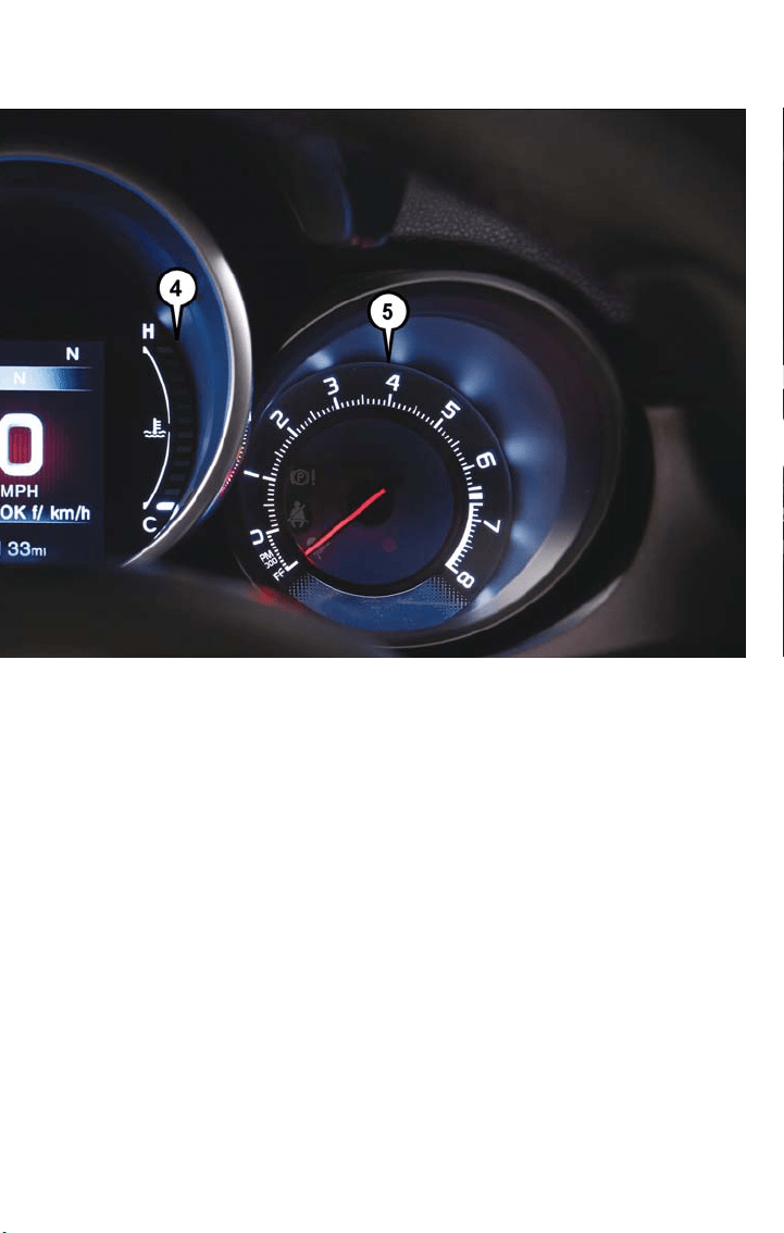
7. Tachometer pg. 6
8. Wiper/Washer Lever pg. 61
9. Audio System pg. 88
10. ParkSense pg. 82
CONTROLS AT A GLANCE
4
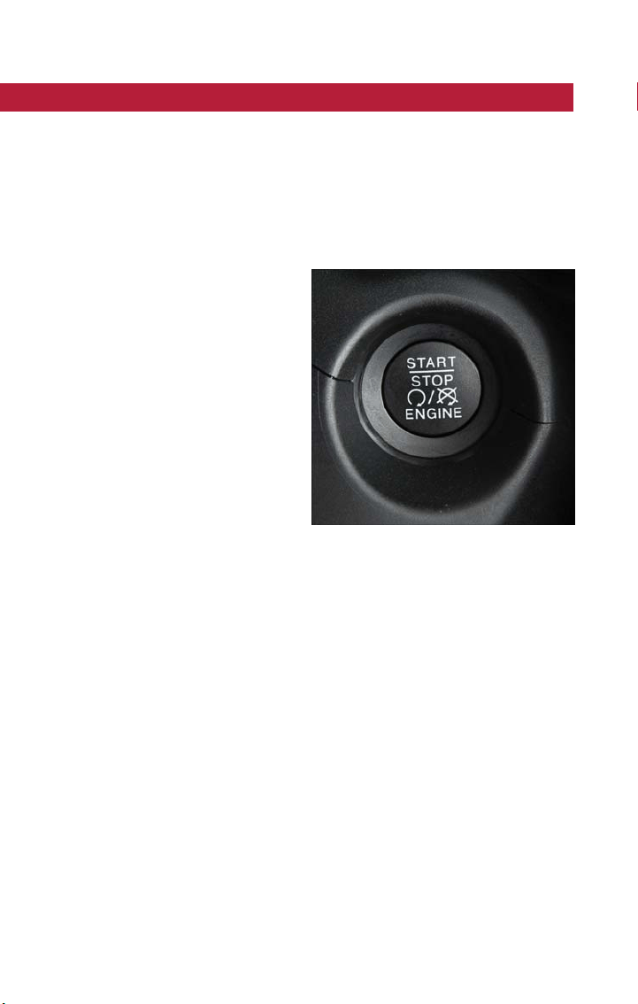
KEY FOB
The Keyless Enter-N-Go feature allows the
driver to operate the ignition switch with
the push of a button as long as the key fob
is in the passenger compartment.
The Keyless Push Button Ignition has three
operating modes. The three modes are
STOP/OFF/LOCK, MAR/ON/RUN and
AVV/START.
NOTE:
In case the ignition button does not change
with the push of a button, the key fob may
have a low or dead battery. In this situation,
a back up method can be used to operate
the ignition switch. Put the nose side (side
opposite of the emergency key) of the key
fob against the ENGINE START/STOP but-
ton and push to operate the ignition.
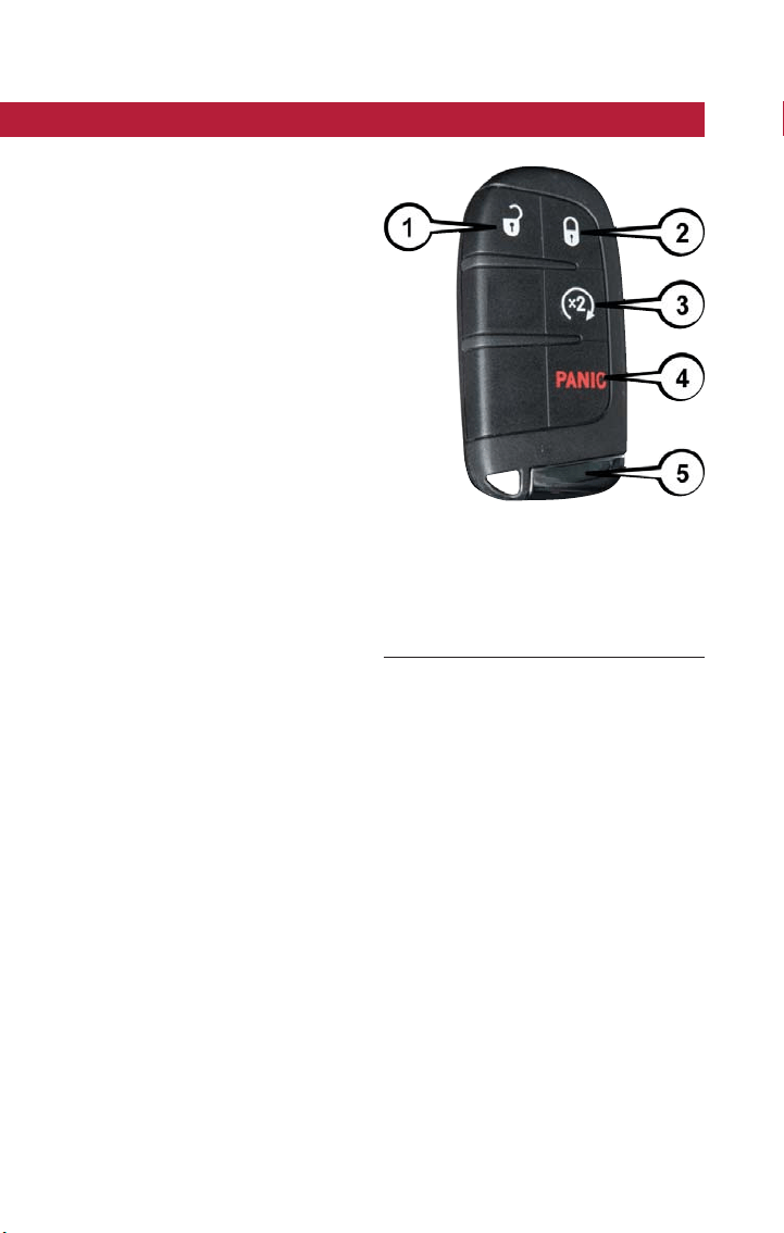
Locking And Unlocking The Doors/Liftgate
Push the lock button once to lock all the doors and the liftgate. Push the unlock button
once to unlock the driver’s door only and twice within five seconds to unlock all the
doors and the liftgate.
All doors can be programmed to unlock on the first push of the unlock button. Refer to
“Uconnect Customer Programmable Features” for further information.
Panic Alarm
Push and hold the PANIC button for one second to turn the panic alarm on.
Wait approximately three seconds and push the button a second time to turn the panic
alarm off.
NOTE:
• Never use the PARK position as a substitute for the parking brake. Always apply the
parking brake fully when parked to guard against vehicle movement and possible injury
or damage.
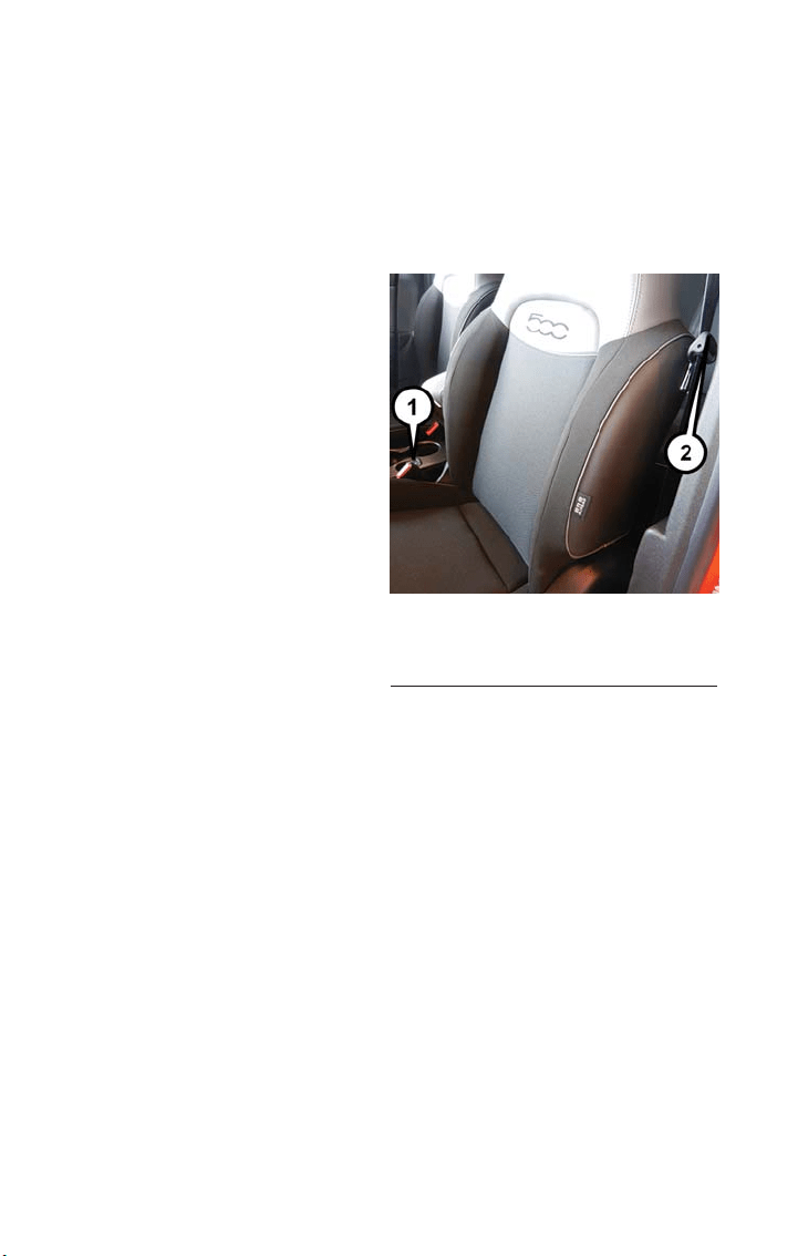
Keyless Enter-N-Go Key Fob
1 — Unlock
2 — Lock
3 — Remote Start
4 — Panic
5 — Emergency Key
GETTING STARTED
8

• When leaving the vehicle, always remove the key fob from the ignition and lock your
vehicle. If equipped with Keyless Enter-N-Go, always make sure the ignition is in OFF
mode, remove the key fob from the vehicle and lock the vehicle.
• Never leave children alone in a vehicle, or with access to an unlocked vehicle. Allowing
children to be in a vehicle unattended is dangerous for a number of reasons. A child
or others could be seriously or fa tally injured. Children should be warned not to touch
the parking brake, brake pedal or the transmission gear selector.
• Do not leave the key fob in or near the vehicle (or in a location accessible to chil-
dren), and do not leave the ignition of a vehicle equipped with Keyless Enter-N-Go in
the ON/RUN mode. A child could operate power windows, other controls, or move
the vehicle.
REMOTE START
This system uses the Remote Keyless Entry key fob to start the engine conveniently from
outside the vehicle while still maintaining security. The system has a range of 246 ft
(75 m).
The Remote Starting System also activates the Climate Control and (if equipped) the
optional heated seats and optional heated steering wheel depending on temperatures
outside and inside the car.
• Push remote start button on the key fob twice within five seconds. Pushing the re-
mote start button a third time shuts the engine off.
• To drive the vehicle, push unlock button and place the ignition in the MAR/ON/RUN
position.
• With Remote Start, the engine will only run for 15 minutes (timeout) unless the igni-
tion is placed in the MAR/ON/RUN position.
• The vehicle must be started with the key fob after two consecutive timeouts.
WARNING!
• Do not start or run an engine in a closed garage or confined area. Exhaust gas
contains Carbon Monoxide (CO) which is odorless and colorless. Carbon Monox-
ide is poisonous and can cause serious injury or death when inhaled.
• Keep key fobs away from children. Operation of the Remote Start System, win-
dows, door locks or other controls could cause serious injury or death.
Remote Start Windshield Wiper De–icer Activation — If Equipped
When Remote Start is active and the outside ambient temperature is less than 40° F
(4.4° C), the wiper De-Icer will be enabled. On exiting Remote Start, the vehicle will
resume the previous operation except if the De-Icer is active; the De-Icer timer and op-
eration will continue.
GETTING STARTED
9

VEHICLE SECURITY ALARM
The vehicle security alarm monitors the vehicle doors for unauthorized entry and the
Keyless Enter-N-Go START/STOP button for unauthorized operation. While the vehicle
security alarm is armed, interior switches for door locks and liftgate release are disabled.
If something triggers t he alarm, the vehicle security alarm will provide the following au-
dible and visible signals: the horn will pulse, the park lamps and/or turn signals will flash,
and the vehicle security light in the instrument cluster will flash.
To Arm
Lock the door using either the power door lock switch (one door must be open) or the
lock button on the key fob doors can be open or closed), and close all doors.
The vehicle security light in the instrument cluster will flash for 16 seconds. This shows
that the vehicle security alarm is arming. During this period, if a door is opened, the igni-
tion is placed in the MAR/ON/RUN mode, or the power door locks are unlocked in any
manner, the vehicle security alarm will automatically disarm.
NOTE:
• The vehicle security alarm will not arm if you lock the doors with the manual door
lock plungers.
• Once armed, the vehicle security alarm disables the unlock switch on the driver door
trim panel and passenger door trim panel.
To Disarm The System
Push the key fob unlock button or place the ignition in the MAR/ON/RUN mode.
The vehicle security alarm is designed to protect your vehicle. However, you can create
conditions where the vehicle security alarm will give you a false alarm. If one of the pre-
viously described arming sequences has occurred, the vehicle security alarm will arm re-
gardless of whether you are in the vehicle or not. If you remain in the vehicle and open
a door, the alarm will sound. If this occurs, disarm the vehicle security alarm.
If the vehicle security alarm is armed and the battery becomes disconnected, the vehicle
security alarm will remain armed when the battery is reconnected. The exterior lights will
flash, and the horn will sound. If this occurs, disarm the vehicle security alarm.
GETTING STARTED
10
KEYLESS ENTER-N-GO — PASSIVE ENTRY
The Keyless Enter-N-Go system is an enhancement to the vehicle’s Remote Keyless Entry
(RKE) feature. This feature allows you to lock and unlock the vehicle's door(s) and liftgate
without having to push the key fob lock or unlock buttons, as well as starting and stop-
ping the vehicle with the push of a button.
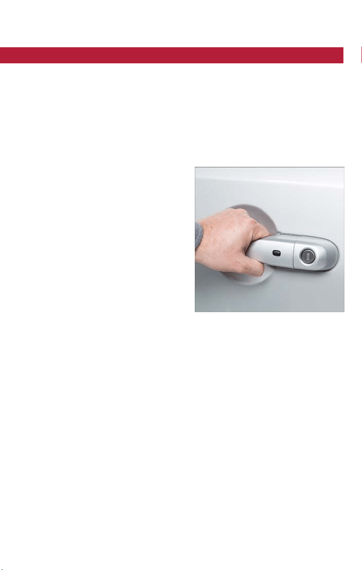
To Unlock From The Driver Or Passenger Side:
With a valid Keyless Enter-N-Go key fob located outside the vehicle and within 5 ft
(1.5 m) of the driver or passenger side door handle, grab either front door handle to
unlock the door automatically.
To Lock The Vehicle
Both front door handles have buttons located on the outside of the handle. With one of
the vehicle’s Keyless Enter-N-Go key fobs located outside the vehicle and within 5 ft
(1.5 m) of the driver's or passenger front door handle, push the door handle button to
lock all four doors and liftgate.
Grab The Door Handle To Unlock
GETTING STARTED
11
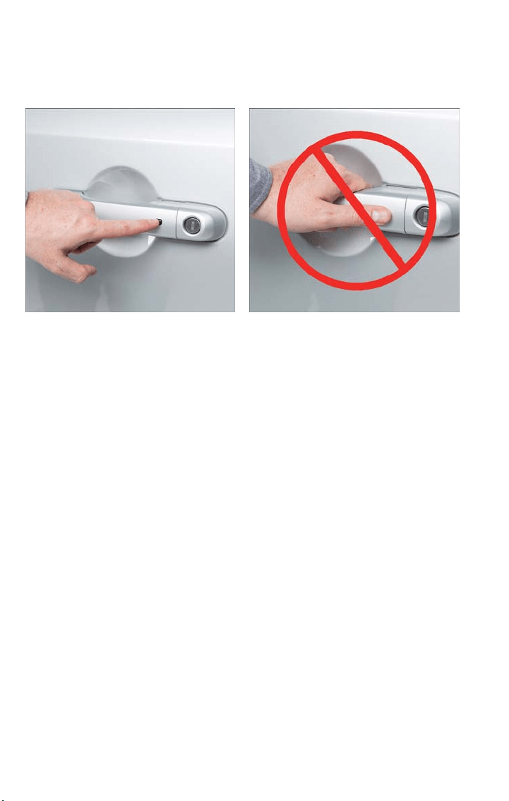
Do NOT grab the door handle when pushing the door handle lock button. This could
unlock the door(s).
NOTE:
• If “Unlock All Doors 1st Press” is programmed, all doors will unlock when you grab
hold of the front driver's door handle. To select between “Unlock Driver Door 1st
Press” and “Unlock All Doors 1st Press,” refer to the “Uconnect Settings” in “Multime-
dia” in your vehicle’s Owner's Manual on www.fiatusa.com/en/owners/manuals for fur-
ther information.
• If “Unlock All Doors 1st Press” is programmed, all doors and liftgate will unlock when
you push the liftgate button. If “Unlock Driver Door 1st Push” is programmed, only
the liftgate will unlock when you push the liftgate button. To select between
“Unlock Driver Door 1st Press” and “Unlock All Doors 1st Press,” refer to the
“Uconnect Settings” in “Multimedia” in your vehicle’s Owner's Manual on
www.fiatusa.com/en/owners/manuals for further information.
• If a key fob is detected in the vehicle when locking the vehicle using the power door
lock switch, t he doors and lif tgate will unlock. On the third attempt of pushing the
door handle lock button, your key fob can be locked inside the vehicle.
• After pushing the Keyless Enter-N-Go lock button, you must wait two seconds before
you can lock or unlock the vehicle using t he door handle. This is done to allow you to
check if the vehicle is locked by pulling the door handle without the vehicle reacting
and unlocking.
Push The Door Handle Button To Lock Do NOT Grab The Handle And Button
When Locking
GETTING STARTED
12
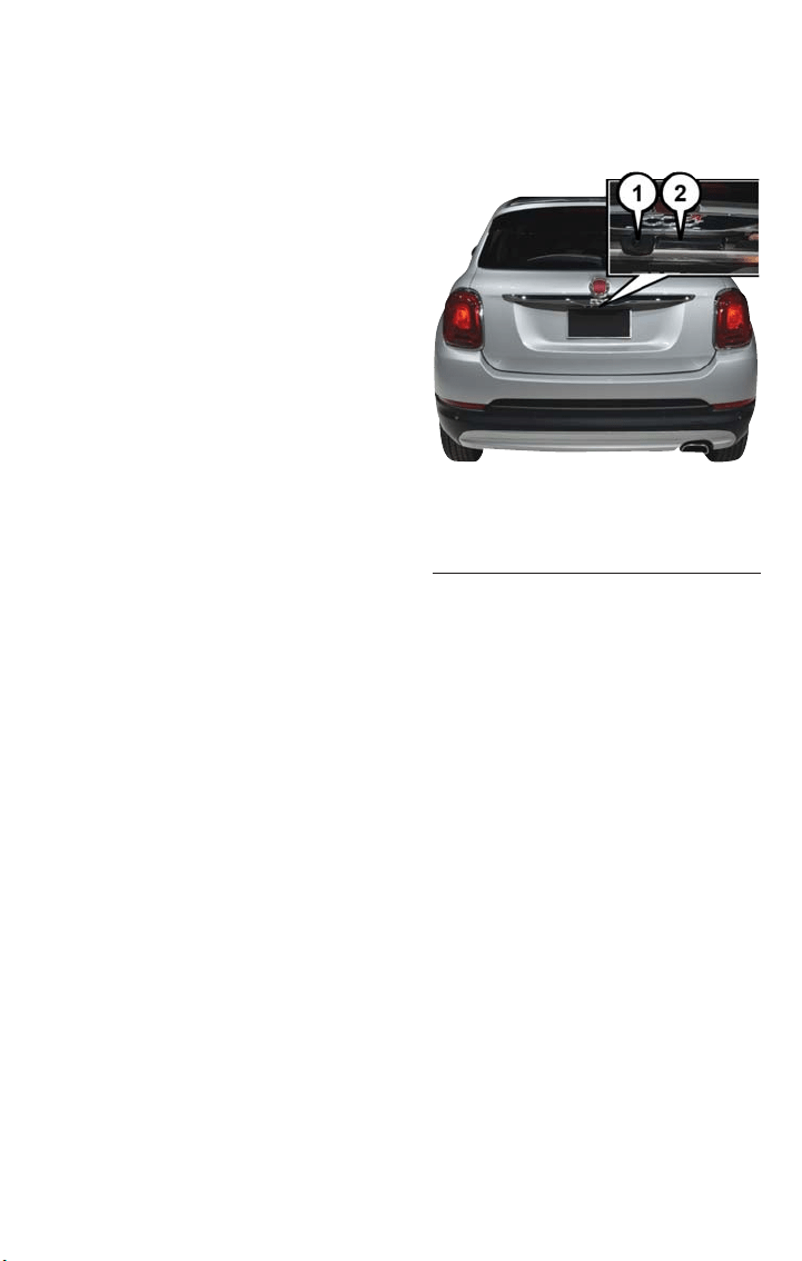
Lock Or Unlock The Liftgate
To Lock The Liftgate
With a valid Passive Entry key fob within
5ft(1.5 m) of the liftgate, push the Passive
Entr y lock button located to the right of
the Passive Entry liftgate unlock/release but-
ton.
To Unlock/Enter The Liftgate
The liftgate passive entry unlock feature is
built into the electronic liftgate handle.
With a valid passive entry key fob within
5ft(1.5 m) of the liftgate, push the Passive
Entr y liftgate unlock/release button and pull
to open the liftgate.
NOTE:
Refer to “Doors” in “Getting To Know Your
Vehicle” in your Owner's Manual on
www.fiatusa.com/en/owners/manuals for
further information.
Passive Entry Liftgate Release Button
1 — Passive Entry Lock Button
2 — Electronic Liftgate Handle
GETTING STARTED
13
KEYLESS ENTER-N-GO — IGNITION
NOTE:
In case the ignition switch does not change with the push of a button, the key fob may
have a low or dead battery. In this situation, a back up method can be used to operate
the ignition switch. Put the nose side of the key fob (side opposite of the Emergency
Key) against the ENGINE START/STOP button and push to operate the ignition switch.
Engine Starting/Stopping
Starting
1. With a valid key fob inside the vehicle.
2. Place the gear selector in PARK or
NEUTRAL.
3. While pushing the brake pedal, push the
ENGINE START/STOP button once. If
the engine fails to start, the starter will
disengage automatically after 10 sec-
onds.
4. To stop the cranking of the engine prior
to the engine starting, push the button
again.
NOTE:
In case the ignition mode does not change
with the push of a button, the key fob may have a low or dead battery. In this situation, a
back up method can be used to operate the ignition. Put the nose side of the key fob
against the ENGINE START/STOP button and push to operate the ignition.
Stopping
1. Place the gear selector in PARK.
2. Push the ENGINE START/STOP button once. The ignition will return to the OFF
mode.
NOTE:
If the gear selector is not in PARK, the ENGINE START/STOP button must be held for
two seconds and vehicle speed must be above 5 MPH (8 km/h) before the engine will
shut off.
Engine Start/Stop Button
GETTING STARTED
14

RUN Position With Engine Off
NOTE:
The following functions are with the driver’s foot OFF the Brake Pedal (Transmission in
PARK or NEUTRAL Position).
Starting With The Ignition In The OFF Mode:
1. Push the ENGINE START/STOP button once to change the ignition to the RUN
mode.
2. Push the ENGINE START/STOP button a second time to return the ignition to the
OFF mode.
NOTE:
If the ignition is left in the RUN (engine not running) mode and the transmission is in
PARK, the system will automatically time out after 30 minutes of inactivity and the ignition
will return to the OFF mode.
In case the ignition does not change with the push of a button, the key fob may have a
low or dead batter y. In this situation, a back up method can be used to operate the igni-
tion. Put the nose side (side opposite of the emergency key) of the key fob against the
ENGINE START/STOP button and push to operate the ignition.
OCCUPANT RESTRAINT SYSTEMS
Some of the most important safety features in your vehicle are the restraint systems:
Occupant Restraint Systems Features
• Seat Belt Systems
• Supplemental Restraint Systems (SRS) Air Bags
• Child Restraints
Some of the safety features described in this section may be standard equipment on
some models, or may be optional equipment on others. If you are not sure, ask your au-
thorized dealer.
Important Safety Precautions
Please pay close attention to the information in this section. It tells you how to use your
restraint system properly, to keep you and your passengers as safe as possible.
Here are some simple steps you can take to minimize the risk of harm from a deploying
air bag:
1. Children 12 years old and under should always ride buckled up in a vehicle with a
rear seat.
2. If a child from 2 to 12 years old (not in a rear-facing child restraint) must ride in the
front passenger seat, move the seat as far back as possible and use the proper child
restraint (refer to “Child Restraints” in this section for further information).
GETTING STARTED
15

3. Children that are not big enough to wear the vehicle seat belt properly (refer to
“Child Restraints” in this section for fur ther information) should be secured in a ve-
hicle with a rear seat in child restraints or belt-positioning booster seats. Older chil-
dren who do not use child restraints or belt-positioning booster seats should ride
properly buckled up in a vehicle with a rear seat.
4. Never allow children to slide the shoulder belt behind them or under their arm.
5. You should read the instructions provided with your child restraint to make sure that
you are using it properly.
6. All occupants should always wear their lap and shoulder belts properly.
7. The driver and front passenger seats should be moved back as far as practical to al-
low the front air bags room to inflate.
8. Do not lean against the door or window. If your vehicle has side air bags, and deploy-
ment occurs, the side air bags will inflate forcefully into the space between occupants
and the door and occupants could be injured.
9. If the air bag system in this vehicle needs to be modified to accommodate a disabled
person, refer to the “Consumer Assistance” section for customer service contact
information.
WARNING!
• Never place a rear-facing child restraint in front of an air bag. A deploying passen-
ger front air bag can cause death or serious injury to a child 12 years or younger,
including a child in a rear-facing child restraint.
• Only use a rear-facing child restraint in a vehicle with a rear seat.
Seat Belt Systems
Buckle up even though you are an excellent driver, even on short trips . Someone on the
road may be a poor driver and could cause a collision that includes you. This can happen
far away from home or on your own street.
Research has shown t hat seat belts save lives, and they can reduce the seriousness of inju-
ries in a collision. Some of the worst injuries happen when people are thrown from the
vehicle. Seat belts reduce the possibility of ejection and the risk of injury caused by strik-
ing the inside of the vehicle. Everyone in a motor vehicle should be belted at all times.
GETTING STARTED
16

Enhanced Seat Belt Use Reminder System (BeltAlert)
Driver And Passenger BeltAlert — If Equipped
BeltAlert is a feature intended to remind the driver and outboard front seat passen-
ger (if equipped with outboard front passenger seat BeltAlert) to buckle their seat belts.
The Belt Alert feature is active whenever the ignition switch is in the START or ON/
RUN position.
Initial Indication
If the driver is unbuckled when the ignition switch is first in the START or ON/RUN po-
sition, a chime will signal for a few seconds. If the driver or outboard front seat passenger
(if equipped with outboard front passenger seat BeltAlert) is unbuckled when the ignition
switch is first in the START or ON/RUN position the Seat Belt Reminder Light will turn
on and remain on until both outboard front seat belts are buckled. The outboard front
passenger seat BeltAlert is not active when an outboard front passenger seat is unoccu-
pied.
BeltAlert Warning Sequence
The BeltAlert warning sequence is activated when the vehicle is moving above a specified
vehicle speed range and the driver or outboard front seat passenger is unbuckled (if
equipped with outboard front passenger seat Bel tAlert) (the outboard front passenger
seat BeltAlert is not active when the outboard front passenger seat is unoccupied). The
BeltAlert warning sequence starts by blinking the Seat Belt Reminder Light and sounding
an intermittent chime. Once the BeltAlert warning sequence has completed, the Seat Bel t
Reminder Light will remain on until the seat belts are buckled. The BeltAlert warning se-
quence may repeat based on vehicle speed until the driver and occupied outboard front
seat passenger seat belts are buckled. The driver should instruct all occupants to buckle
their seat belts.
Change Of Status
If the driver or outboard front seat passenger (if equipped with outboard front passen-
ger seat BeltAlert) unbuckles their seat belt while the vehicle is traveling, the BeltAlert
warning sequence will begin until the seat belts are buckled again.
The outboard front passenger seat BeltAlert is not active when the outboard front pas-
senger seat is unoccupied. BeltAlert may be triggered when an animal or other items are
placed on the outboard front passenger seat or when the seat is folded flat (if
equipped). It is recommended that pets be restrained in the rear seat (if equipped) in
pet harnesses or pet carriers that are secured by seat belts, and cargo is properly
stowed.
GETTING STARTED
17

BeltAlert can be activated or deactivated by your authorized dealer. FCA US LLC does
not recommend deactivating BeltAlert.
NOTE:
If BeltAlert has been deactivated and the driver or outboard front seat passenger (if
equipped with outboard front passenger seat Bel tAlert) is unbuckled the Seat Belt Re-
minder Light will turn on and remain on until the driver and outboard front seat passen-
ger seat belts are buckled.
Lap/Shoulder Belts
All seating positions in your vehicle are equipped with lap/shoulder belts.
The seat belt webbing retractor will lock only during very sudden stops or collisions. This
feature allows the shoulder part of the seat belt to move freely with you under normal
conditions. However, in a collision the seat belt will lock and reduce your risk of striking
the inside of the vehicle or being thrown out of the vehicle.
WARNING!
• Relying on the air bags alone could lead to more severe injuries in a collision. The
air bags work with your seat belt to restrain you properly. In some collisions, the
air bags won’t deploy at all. Always wear your seat belt even though you have air
bags.
• In a collision, you and your passengers can suffer much greater injuries if you are
not properly buckled up. You can strike the interior of your vehicle or other pas-
sengers, or you can be thrown out of the vehicle. Always be sure you and others
in your vehicle are buckled up properly.
• It is dangerous to ride in a cargo area, inside or outside of a vehicle. In a collision,
people riding in these areas are more likely to be seriously injured or killed.
• Do not allow people to ride in any area of your vehicle that is not equipped with
seats and seat belts.
• Be sure everyone in your vehicle is in a seat and using a seat belt properly. Occu-
pants, including the driver, should always wear their seat belts whether or not an
air bag is also provided at their seating position to minimize the risk of severe in-
jur y or death in the event of a crash.
• Wearing your seat belt incorrectly could make your injuries in a collision much
worse. You might suffer internal injuries, or you could even slide out of the seat
belt. Follow these instructions to wear your seat belt safely and to keep your pas-
sengers safe, too.
• Two people should never be belted into a single seat belt. People belted together
can crash into one another in a collision, hurting one another badly. Never use a
lap/shoulder belt or a lap belt for more than one person, no matter what their
size.
GETTING STARTED
18

WARNING!
• A lap belt worn too high can increase the risk of injury in a collision. The seat belt
forces won’t be at the strong hip and pelvic bones, but across your abdomen. Al-
ways wear the lap part of your seat belt as low as possible and keep it snug.
• A twisted seat belt may not protect you properly. In a collision, it could even cut
into you. Be sure the seat belt is flat against your body, without twists. If you can’t
straighten a seat belt in your vehicle, take it to your authorized dealer immediately
and have it fixed.
• A seat belt that is buckled into the wrong buckle will not protect you properly.
The lap portion could ride too high on your body, possibly causing internal injuries.
Always buckle your seat belt into the buckle nearest you.
• A seat belt that is too loose will not protect you properly. In a sudden stop, you
could move too far forward, increasing the possibility of injury. Wear your seat belt
snugly.
• A seat belt that is worn under your arm is dangerous.Your body could strike t he
inside surfaces of the vehicle in a collision, increasing head and neck injury. A seat
belt worn under the arm can cause internal injuries. Ribs aren’t as strong as shoul-
der bones. Wear the seat belt over your shoulder so that your strongest bones
will take the force in a collision.
• A shoulder belt placed behind you will not protect you from injury during a colli-
sion. You are more likely to hit your head in a collision if you do not wear your
shoulder belt. The lap and shoulder belt are meant to be used together.
• A frayed or torn seat belt could rip apart in a collision and leave you with no pro-
tection. Inspect the seat belt system periodically, checking for cuts, frays, or loose
parts. Damaged parts must be replaced immediately. Do not disassemble or
modify the seat belt system. Seat belt assemblies must be replaced after a colli-
sion.
GETTING STARTED
19
Lap/Shoulder Belt Operating Instructions
1. Enter the vehicle and close the door. Sit back and adjust the seat.
2. The seat belt latch plate is above the back of the front seat, and next to your arm in
the rear seat (for vehicles equipped with a rear seat). Grasp the latch pla te and pull
out the seat belt. Slide the latch plate up the webbing as far as necessary to allow the
seat belt to go around your lap.
3. When the seat belt is long enough to
fit, insert the latch plate into the buckle
until you hear a “click.”
4. Position the lap belt so that it is snug
and lies low across your hips, below
your abdomen. To remove slack in the
lap belt portion, pull up on the shoulder
belt. To loosen the lap belt if it is too
tight, tilt the latch plate and pull on the
lap belt. A snug seat belt reduces the
risk of sliding under the seat belt in a
collision.
5. Position the shoulder belt across the
shoulder and chest with minimal, if any
slack so that it is comfortable and not
resting on your neck. The retractor will
withdraw any slack in the shoulder belt.
6. To release the seat belt, push the red
button on the buckle. The seat belt will
automatically retract to its stowed position. If necessary, slide the latch plate down the
webbing to allow the seat belt to retract fully.
Lap/Shoulder Belt Untwisting Procedure
Use the following procedure to untwist a twisted lap/shoulder belt.
1. Position the latch plate as close as possible to the anchor point.
2. At about 6 to 12 inches (15 to 30 cm) above the latch plate, grasp and twist the seat
belt webbing 180 degrees to create a fold that begins immediately above the latch
plate.
3. Slide the latch plate upward over the folded webbing. The folded webbing must enter
the slot at the top of the latch plate.
4. Continue to slide the la tch plate up until it clears the folded webbing and the seat
belt is no longer twisted.
Pulling Out The Latch Plate
1 — Seat Belt Buckle
2 — Seat Belt Latch Plate
GETTING STARTED
20
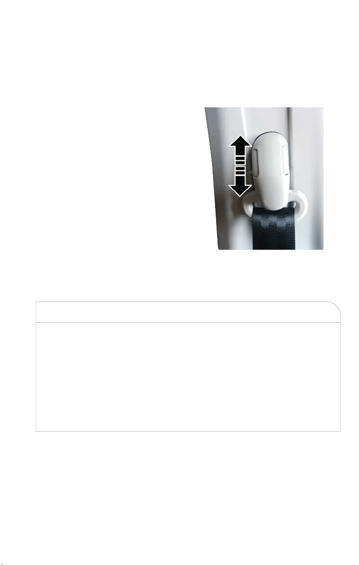
Adjustable Upper Shoulder Belt Anchorage
In the driver and front passenger seats, the top of the shoulder belt can be adjusted up-
ward or downward to position the seat belt away from your neck. Push or squeeze the
anchorage button to release the anchorage, and move it up or down to the position that
serves you best.
As a guide, if you are shorter than average,
you will prefer the shoulder belt anchorage
in a lower position, and if you are taller
than average, you will prefer the shoulder
belt anchorage in a higher position. After
you release the anchorage button, try to
move it up or down to make sure that it is
locked in position.
NOTE:
The adjustable upper shoulder belt anchor-
age is equipped with an Easy Up feature.
This feature allows the shoulder belt an-
chorage to be adjusted in the upward posi-
tion without pushing or squeezing the re-
lease button. To verify the shoulder belt
anchorage is latched, pull downward on the shoulder bel t anchorage until it is locked into
position.
WARNING!
• Wearing your seat belt incorrectly could make your injuries in a collision much
worse. You might suffer internal injuries, or you could even slide out of the seat
belt. Follow these instructions to wear your seat belt safely and to keep your pas-
sengers safe, too.
• Position the shoulder belt across the shoulder and ches t with minimal, if any slack
so that it is comfortable and not resting on your neck. The retractor will withdraw
any slack in the shoulder belt.
• Misadjustment of the seat belt could reduce the effectiveness of the safety belt in
a crash.
Adjustable Anchorage
GETTING STARTED
21

Seat Belts And Pregnant Women
Seat belts must be worn by all occupants
including pregnant women: the risk of injury
in the event of an accident is reduced for
the mother and the unborn child if they
are wearing a seat belt.
Position the lap belt snug and low below
the abdomen and across the strong bones
of the hips. Place the shoulder belt across
the chest and away from the neck. Never
place the shoulder belt behind the back or
under the arm.
Seat Belt Pretensioner
The front seat belt system is equipped wit h pretensioning devices that are designed to
remove slack from the seat belt in the event of a collision. These devices may improve
the performance of the seat belt by removing slack from the seat belt early in a collision.
Pretensioners work for all size occupants, including those in child restraints.
NOTE:
These devices are not a substitute for proper seat belt placement by the occupant. The
seat belt still must be worn snugly and positioned properly.
The pretensioners are triggered by the Occupant Restraint Controller (ORC). Like the
air bags, the pretensioners are single use items. A deployed pretensioner or a deployed
air bag must be replaced immediately.
Energy Management Feature
The front seat belt system is equipped wit h an Energy Management feature that may
help further reduce the risk of injury in the event of a collision. The seat belt system has
a retractor assembly that is designed to release webbing in a controlled manner.
Pregnant Women And Seat Belts
GETTING STARTED
22
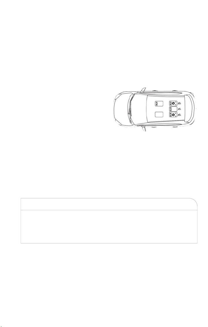
Switchable Automatic Locking Retractors (ALR)
The seat belts in the passenger seating positions are equipped with a Switchable Auto-
matic Locking Retractor (ALR) which is used to secure a child restraint system. For addi-
tional information, refer to “Installing Child Restraints Using The Vehicle Seat Belt” under
the “Child Restraints” section of this manual. The figure below illustrates the locking fea-
ture for each seating position.
If the passenger seating position is
equipped with an ALR and is being used
for normal usage, only pull the seat belt
webbing out far enough to comfortably
wrap around the occupant’s mid-section so
as to not activate the ALR. If the ALR is
activated, you will hear a clicking sound as
the seat belt retracts. Allow the webbing to
retract completely in t his case and then
carefully pull out only the amount of web-
bing necessary to comfortably wrap around
the occupant’s mid-section. Slide the latch
plate into the buckle until you hear a
"click."
In Automatic Locking Mode , the shoulder
belt is automatically pre-locked. The seat
belt will still retract to remove any slack in the shoulder bel t. Use the Automatic Locking
Mode anytime a child restraint is installed in a seating position that has a seat belt with
this feature. Children 12 years old and under should always be properly restrained in a
vehicle with a rear seat.
WARNING!
• Never place a rear-facing child restraint in front of an air bag. A deploying passen-
ger front air bag can cause death or serious injury to a child 12 years or younger,
including a child in a rear-facing child restraint.
• Only use a rear-facing child restraint in a vehicle with a rear seat.
How To Engage The Automatic Locking Mode
1. Buckle the combination lap and shoulder belt.
2. Grasp the shoulder portion and pull downward until the entire seat belt is extracted.
3. Allow the seat belt to retract. As the seat belt retracts, you will hear a clicking sound.
This indicates the seat belt is now in the Automatic Locking Mode.
ALR = Switchable Automatic Locking
Retractor
GETTING STARTED
23

How To Disengage The Automatic Locking Mode
Unbuckle the combination lap/shoulder belt and allow it to retract completely to disen-
gage the Automatic Locking Mode and activate the vehicle sensitive (emergency) locking
mode.
WARNING!
• The seat belt assembly must be replaced if the switchable Automatic Locking Re-
tractor (ALR) feature or any other seat belt function is not working properly
when checked according to the procedures in the Service Manual.
• Failure to replace the seat belt assembly could increase the risk of injury in colli-
sions.
• Do not use the Automatic Locking Mode to restrain occupants who are wearing
the seat belt or children who are using booster seats. The locked mode is only
used to install rear-facing or forward-facing child restraints that have a harness for
restraining the child.
Supplemental Restraint Systems (SRS)
Some of the safety features described in this section may be standard equipment on
some models, or may be optional equipment on others. If you are not sure, ask your au-
thorized dealer.
The air bag system must be ready to protect you in a collision. The Occupant Restraint
Controller (ORC) monitors the internal circuits and interconnecting wiring associated
with the electrical Air Bag System Components. Your vehicle may be equipped with t he
following Air Bag System Components:
Air Bag System Components
• Occupant Restraint Controller (ORC)
• Air Bag Warning Light
• Steering Wheel and Column
• Instrument Panel
• Knee Impact Bolsters
• Driver and Front Passenger Air Bags
• Supplemental Side Air Bags
• Supplemental Knee Air Bags
• Front and Side Impact Sensors
• Seat Belt Pretensioners
• Seat Track Position Sensors
• Seat Belt Buckle Switch
GETTING STARTED
24

Air Bag Warning Light
The ORC monitors the readiness of the electronic parts of the air bag system
whenever the ignition switch is in the START or ACC/ON/RUN position. If the ignition
switch is in the STOP/OFF/LOCK position, the air bag system is not on and the air bags
will not inflate.
The ORC contains a backup power supply system that may deploy the air bag system
even if the battery loses power or it becomes disconnected prior to deployment.
The ORC turns on the Air Bag Warning Light in the instrument panel for approximately
four to eight seconds for a self-check when the ignition switch is in the ACC/ON/RUN
position. Af ter the self-check, the Air Bag Warning Light will turn off. If t he ORC detects
a malfunction in any par t of the system, it turns on the Air Bag Warning Light, either mo-
mentarily or continuously. A single chime will sound to alert you if the light comes on
again after initial startup.
The ORC also includes diagnostics that will illuminate t he instrument panel Air Bag Warn-
ing Light if a malfunction is detected that could affect the air bag system. The diagnostics
also record the nature of the malfunction. While the air bag system is designed to be
maintenance free, if any of the following occurs, have an authorized dealer service the air
bag system immediately.
• The Air Bag Warning Light does not come on during the four to eight seconds when
the ignition switch is first in the ACC/ON/RUN position.
• The Air Bag Warning Light remains on after the four to eight-second interval.
• The Air Bag Warning Light comes on intermittently or remains on while driving.
NOTE:
If the speedometer, tachometer, or any engine related gauges are not working, the Occu-
pant Restraint Controller (ORC) may also be disabled. In this condition the air bags may
not be ready to inflate for your protection. Have an authorized dealer service the air bag
system immediately.
WARNING!
Ignoring the Air Bag Warning Light in your instrument panel could mean you won’t have
the air bag system to protect you in a collision. If the light does not come on as a bulb
check when the ignition is first turned on, stays on after you start the vehicle, or if it
comes on as you drive, have an authorized dealer service the air bag system immediately.
Redundant Air Bag Warning Light
If a fault with the Air Bag Warning Light is detected, which could affect the Supplemental
Restraint System (SRS), the Redundant Air Bag Warning Light will illuminate on the instru-
ment panel. The Redundant Air Bag Warning Light will stay on until the fault is cleared. In
addition, a single chime will sound to alert you that the Redundant Air Bag Warning Light
GETTING STARTED
25
has come on and a fault has been detected. If the Redundant Air Bag Warning Light
comes on intermittently or remains on while driving have an aut horized dealer service
the vehicle immediately. For additional information regarding the Redundant Air Bag
Warning Light, refer to “Warning And Indicator Lights” in “What To Do In Emergencies.”
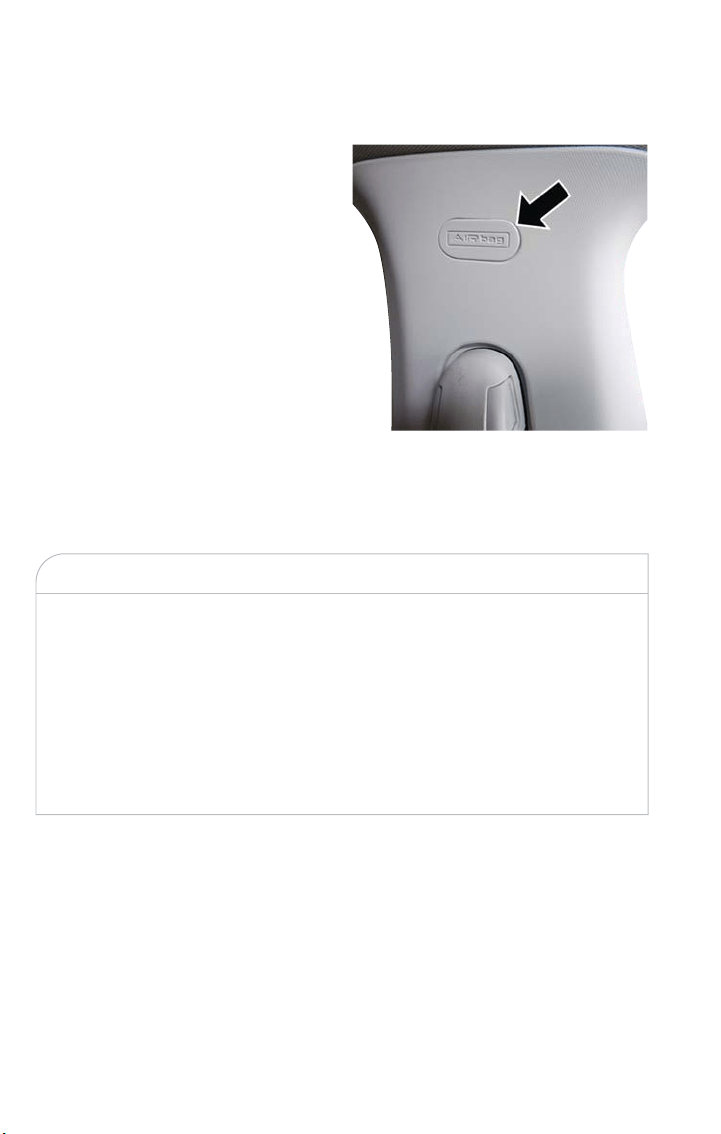
Front Air Bags
This vehicle has front air bags and lap/shoulder belts for both the driver and front pas-
senger. The front air bags are a supplement to the seat belt restraint systems. The driver
front air bag is mounted in the center of the steering wheel. The passenger front air bag
is mounted in the instrument panel, above the glove compartment. The words “SRS AIR-
BAG” or “AIRBAG” are embossed on the air bag covers.
WARNING!
• Being too close to the steering wheel or instrument panel during front air bag
deployment could cause serious injury, including dea th. Air bags need room to in-
flate. Sit back, comfortably extending your arms to reach the steering wheel or
instrument panel.
• Never place a rear-facing child restraint in front of an air bag. A deploying passen-
ger front air bag can cause death or serious injury to a child 12 years or younger,
including a child in a rear-facing child restraint.
• Only use a rear-facing child restraint in a vehicle with a rear seat.
Front Air Bag/Knee Impact Bolster
Locations
1 — Driver And Passenger Front Air Bags
2 — Passenger Knee Impact Bolster
3 — Driver Knee Impact Bolster/
Supplemental Driver Knee Air Bag
GETTING STARTED
26

Driver And Passenger Front Air Bag Features
The Advanced Front Air Bag system has multistage driver and front passenger air bags.
This system provides output appropriate to the severity and type of collision as deter-
mined by the Occupant Restraint Controller (ORC), which may receive information from
the front impact sensors (if equipped) or other system components.
The first stage inflator is triggered immediately during an impact that requires air bag
deployment. A low energy output is used in less severe collisions. A higher energy output
is used for more severe collisions.
This vehicle may be equipped with a driver and/or front passenger seat belt buckle
switch that detec ts whether the driver or front passenger seat belt is buckled. The seat
belt buckle switch may adjust the inflation rate of the Advanced Front Air Bags.
This vehicle may be equipped with driver and/or front passenger seat track position sen-
sors that may adjust the inflation rate of the Advanced Front Air Bags based upon seat
position.
WARNING!
• No objects should be placed over or near the air bag on the instrument panel or
steering wheel because any such objec ts could cause harm if the vehicle is in a
collision severe enough to cause the air bag to inflate.
• Do not put anything on or around the air bag covers or attempt to open them
manually. You may damage the air bags and you could be injured because the air
bags may no longer be functional. The protective covers for the air bag cushions
are designed to open only when the air bags are inflating.
• Relying on the air bags alone could lead to more severe injuries in a collision. The
air bags work with your seat belt to restrain you properly. In some collisions, air
bags won’t deploy at all. Always wear your seat belts even though you have air
bags.
Front Air Bag Operation
Front Air Bags are designed to provide additional protection by supplementing the seat
belts. Front air bags are not expected to reduce the risk of injur y in rear, side, or rollover
collisions. The front air bags will not deploy in all frontal collisions, including some that
may produce substantial vehicle damage — for example, some pole collisions, truck un-
derrides, and angle offset collisions.
On the other hand, depending on the type and location of impact, front air bags may
deploy in crashes with little vehicle front-end damage but that produce a severe initial
deceleration.
Because air bag sensors measure vehicle deceleration over time, vehicle speed and dam-
age by themselves are not good indicators of whether or not an air bag should have de-
ployed.
GETTING STARTED
27

Seat belts are necessary for your protection in all collisions, and also are needed to help
keep you in position, away from an inflating air bag.
When the ORC detects a collision requiring the front air bags, it signals the inflator units.
A large quantity of non-toxic g as is generated to inflate the front air bags.
The steering wheel hub trim cover and the upper right side of the instrument panel
separate and fold out of the way as the air bags inflate to their full size. The front air
bags fully inflate in less time than it takes to blink your eyes. The front air bags then
quickly deflate while helping to restrain the driver and front passenger.
Knee Impact Bolsters
The Knee Impact Bolsters help protect the knees of the driver and front passenger, and
position the front occupants for improved interaction with the front air bags.
WARNING!
• Do not drill, cut, or tamper with the knee impact bolsters in any way.
• Do not mount any accessories to the knee impac t bolsters such as alarm lights,
stereos, citizen band radios, etc.
Supplemental Driver Knee Air Bag
This vehicle is equipped with a Supplemental Driver Knee Air Bag mounted in the instru-
ment panel below the steering column. The Supplemental Driver Knee Air Bag provides
enhanced protection during a frontal impact by working together with the seat belts, pre-
tensioners, and front air bags.
GETTING STARTED
28
Supplemental Side Air Bags
Your vehicle is equipped with two types of side air bags:
1. Supplemental Seat-Mounted Side Air Bags (SABs): Located in the outboard side of the
front seats. The SABs are marked with a “SRS AIRBAG” or “AIRBAG” label sewn into
the outboard side of the seats.
The SABs may help to reduce t he
risk of occupant injury during cer-
tain side impacts and/or vehicle roll-
over events, in addition to the injury
reduction potential provided by the
seat belts and body structure.
When the SAB deploys, it opens the
seam on the outboard side of the
seatback’s trim cover. The inflating
SAB deploys through the seat seam
into the space between the occu-
pant and the door. The SAB moves
at a very high speed and with such
a high force that it could injure oc-
cupants if they are not seated prop-
erly, or if items are positioned in the
area where the SAB inflates. Chil-
dren are at an even greater risk of injury from a deploying air bag.
WARNING!
Do not use accessory seat covers or place objects between you and the Side Air Bags;
the performance could be adversely affected and/or objects could be pushed into you,
causing serious injury.
Front Supplemental Seat-Mounted Side Air
Bag
GETTING STARTED
29
2. Supplemental Side Air Bag Inflatable Curtains (SABICs): Located above the side win-
dows. The trim covering the SABICs is labeled “SRS AIRBAG” or “AIRBAG.”
SABICs may help reduce the risk of
head or other injuries to front and
rear seat outboard occupants in cer-
tain side impacts and/or vehicle roll-
over events, in addition to the injury
reduction potential provided by the
seat belts and body structure.
The SABICs deploy downward, cov-
ering the side windows. An inflating
SABIC pushes the outside edge of
the trim out of the way and covers
the window. The SABICs inflate with
enough force to injure occupants if
they are not belted and sea ted
properly, or if items are positioned
in the area where the SABICs in-
flate. Children are at an even
greater risk of injury from a deploying air bag.
WARNING!
• Do not mount equipment, or stack luggage or other cargo up high enough to
block the deployment of the SABICs. The trim covering above the side windows
where the SABIC and its deployment path are located should remain free from
any obstructions.
• In order for the SABICs to work as intended, do not install any accessory items in
your vehicle which could alter t he roof. Do not add an aftermarket sunroof to
your vehicle. Do not add roof racks that require permanent attachments (bolts or
screws) for installation on the vehicle roof. Do not drill into the roof of the ve-
hicle for any reason.
The SABICs and SABs (Side Air Bags) are designed to activate in certain side impacts and
certain rollover events. The Occupant Restraint Controller (ORC) determines whet her
the deployment of the Side Air Bags in a particular side impact or rollover event is ap-
propriate, based on the severity and type of collision. Vehicle damage by itself is not a
good indicator of whether or not Side Air Bags should have deployed.
Side Air Bags are a supplement to the seat belt restraint system. Side Air Bags deploy in
less time than it takes to blink your eyes.
Supplemental Side Air Bag Inflatable Cur-
tain (SABIC) Label Location
GETTING STARTED
30

WARNING!
• Occupants, including children, who are up against or very close to Side Air Bags
can be seriously injured or killed. Occupants, including children, should never lean
on or sleep against the door, side windows, or area where the side air bags inf late,
even if they are in an infant or child restraint.
• Seat belts (and child restraints where appropriate) are necessary for your protec-
tion in all collisions. They also help keep you in position, away from an inflating Side
Air Bag. To get the best protection from the Side Air Bags, occupants must wear
their seat belts properly and sit upright with their backs against the seats. Children
must be properly restrained in a child restraint or booster seat that is appropriate
for the size of the child.
WARNING!
• Side Air Bags need room to inflate. Do not lean against the door or window. Sit
upright in the center of the seat.
• Being too close to the Side Air Bags during deployment could cause you to be
severely injured or killed.
• Relying on the Side Air Bags alone could lead to more severe injuries in a collision.
The Side Air Bags work with your seat belt to restrain you properly. In some colli-
sions, Side Air Bags won’t deploy at all. Always wear your seat belt even though
you have Side Air Bags.
NOTE:
Air bag covers may not be obvious in the interior trim, but they will open during air bag
deployment.
Side Impacts
In side impacts, the side impact sensors aid the ORC in determining the appropriate re-
sponse to impact events. The system is calibrated to deploy the Side Air Bags on the im-
pact side of the vehicle during impacts that require Side Air Bag occupant protection. In
side impacts, the Side Air Bags deploy independently; a left side impact deploys the lef t
Side Air Bags only and a right side impact deploys the right Side Air Bags only.
The Side Air Bags will not deploy in all side collisions, including some collisions at certain
angles, or some side collisions that do not impact the area of the passenger compart-
ment. The Side Air Bags may deploy during angled or offset frontal collisions where the
front air bags deploy.
GETTING STARTED
31

Rollover Events
Side Air Bags are designed to activate in certain rollover events. The ORC determines
whether the deployment of the Side Air Bags in a particular rollover event is appropriate,
based on the severity and type of collision. Vehicle damage by itself is not a good indica-
tor of whether or not Side Air Bags should have deployed.
The Side Air Bags will not deploy in all rollover events. The rollover sensing system deter-
mines if a rollover event may be in progress and whether deployment is appropriate. In
the event the vehicle experiences a rollover or near rollover event, and deployment of
the Side Air Bags is appropriate, the rollover sensing system will also deploy the seat belt
pretensioners on both sides of the vehicle.
The SABICs may help reduce the risk of partial or complete ejection of vehicle occu-
pants through side windows in certain rollover or side impact events.
The Occupant Restraint Controller (ORC) monitors the internal circuits and intercon-
necting wiring associated with electrical Air Bag System Components listed below:
Air Bag System Components
• Occupant Restraint Controller (ORC)
• Air Bag Warning Light
• Steering Wheel and Column
• Instrument Panel
• Knee Impact Bolsters
• Driver and Front Passenger Air Bags
• Supplemental Side Air Bags
• Supplemental Knee Air Bags
• Front and Side Impact Sensors
• Seat Belt Pretensioners
• Seat Track Position Sensors
• Seat Belt Buckle Switch
If A Deployment Occurs
The front air bags are designed to deflate immediately after deployment.
NOTE:
Front and/or side air bags will not deploy in all collisions. This does not mean something
is wrong with the air bag system.
GETTING STARTED
32

If you do have a collision which deploys the air bags, any or all of the following may occur:
• The air bag material may sometimes cause abrasions and/or skin reddening to the oc-
cupants as the air bags deploy and unfold . The abrasions are similar to friction rope
burns or those you might get sliding along a carpet or gymnasium floor. They are not
caused by contact with chemicals. They are not permanent and normally heal quickly.
However, if you haven’t healed significantly within a few days, or if you have any blister-
ing, see your doctor immediately.
• As the air bags deflate, you may see some smoke-like particles. The particles are a nor-
mal by-product of the process that generates the non-toxic gas used for air bag infla-
tion. These airborne particles may irritate the skin, eyes, nose, or throat. If you have
skin or eye irritation, rinse the area with cool wa ter. For nose or throat irritation, move
to fresh air. If the irritation continues, see your doctor. If these particles settle on your
clothing, follow the garment manufacturer’s instructions for cleaning.
Do not drive your vehicle after the air bags have deployed. If you are involved in another
collision, the air bags will not be in place to protect you.
WARNING!
Deployed air bags and seat belt pretensioners cannot protect you in another collision.
Have the air bags, seat belt pretensioners, and the seat belt retractor assemblies re-
placed by an authorized dealer immediately. Also, have the Occupant Restraint Control-
ler System serviced as well.
NOTE:
• Air bag covers may not be obvious in the interior trim, but they will open during air
bag deployment.
• After any collision, the vehicle should be taken to an authorized dealer immediately.
Enhanced Accident Response System
In the event of an impact, if the communication network remains intact, and the power
remains intact, depending on the nature of the event, the ORC will determine whether
to have the Enhanced Accident Response System perform the following functions:
• Cut off fuel to the engine.
• Flash hazard lights as long as the battery has power or until the hazard light button is
pressed. The hazard lights can be deactivated by pressing the hazard light button.
• Turn on the interior lights, which remain on as long as the battery has power or for
15 minutes from the intervention of the Enhanced Accident Response System.
• Unlock the power door locks.
• Turn off the Fuel Pump Heater (if equipped).
• Turn off the HVAC Blower Motor.
• Close the HVAC Circulation Door.
GETTING STARTED
33

Enhanced Accident Response System Reset Procedure
After the event occurs, when the system is active, a message regarding fuel cutoff is dis-
played. Turn the ignition switch from ignition AVV/START or MAR/ACC/ON/RUN to igni-
tion STOP/OFF/LOCK. Carefully check the vehicle for fuel leaks in the engine compart-
ment and on the ground near the engine compartment and fuel tank before resetting
the system and s tarting the engine.
Depending on the nature of the event the left and right turn signal lights, located in the
instrument panel, may both be blinking and will continue to blink. In order to move your
vehicle to the side of the road, you must follow the system reset procedure.
Customer Action Customer Will See
NOTE:
Each step MUST BE held for at least two seconds
1. Turn ignition STOP/OFF/LOCK. (Turn
Signal Must be placed in Neutral State).
2. Turn ignition MAR/ACC/ON/RUN.
Right turn light BLINKS.
Left turn light is OFF.
3. Turn right turn signal switch ON.
Right turn light is ON SOLID.
Left turn light BLINKS.
4. Place turn signal in neutral state.
Right turn light is OFF.
Left turn light BLINKS.
5. Turn left turn signal switch ON.
Right turn light BLINKS.
Left turn light is ON SOLID.
6. Place turn signal in neutral state.
Right turn light BLINKS.
Left turn light is OFF.
7. Turn right turn signal switch ON.
Right turn light is ON SOLID.
Left turn light BLINKS.
8. Place turn signal in neutral state.
Right turn light is OFF.
Left turn light BLINKS.
9. Turn left turn signal switch ON.
Right turn light is ON SOLID.
Left turn light is ON SOLID.
10. Turn left turn signal switch OFF. (Turn
Signal Switch Must be placed in Neutral
State).
Right turn light is OFF.
Left turn light is OFF.
11. Turn ignition STOP/OFF/LOCK.
12. Turn ignition MAR/ACC/ON/RUN.
(Entire sequence needs to be completed
within one minute or sequence will need
to be repeated).
System is now reset and the engine may
be started.
Turn hazard flashers OFF (Manually).
If a reset procedure step is not completed within 60 seconds, then the turn signal lights
will blink and the reset procedure must be performed again in order to be successful.
GETTING STARTED
34

Maintaining Your Air Bag System
WARNING!
• Modifications to any part of the air bag system could cause it to fail when you
need it. You could be injured if the air bag system is not there to protect you. Do
not modify the components or wiring, including adding any kind of badges or stick-
ers to the steering wheel hub trim cover or the upper right side of the instru-
ment panel. Do not modify the front bumper, vehicle body s tructure, or add after-
market side steps or running boards.
• It is dangerous to try to repair any part of the air bag system yourself. Be sure to
tell anyone who works on your vehicle t hat it has an air bag system.
• Do not attempt to modify any part of your air bag system. The air bag may inflate
accidentally or may not function properly if modifications are made. Take your ve-
hicle to an authorized dealer for any air bag system service. If your seat, including
your trim cover and cushion, needs to be serviced in any way (including removal
or loosening/tightening of seat attachment bolts), take the vehicle to your autho-
rized dealer. Only manufacturer approved seat accessories may be used. If it is
necessar y to modify the air bag system for persons with disabilities, contact your
authorized dealer.
Event Data Recorder (EDR)
This vehicle is equipped with an event data recorder (EDR). The main purpose of an
EDR is to record, in certain crash or near crash-like situations, such as an air bag deploy-
ment or hitting a road obs tacle, data that will assist in understanding how a vehicle’s sys-
tems performed. The EDR is designed to record data related to vehicle dynamics and
safety systems for a short period of time, typically 30 seconds or less. The EDR in this
vehicle is designed to record such data as:
• How various systems in your vehicle were operating;
• Whether or not the driver and passenger safety belts were buckled/fastened;
• How far (if at all) the driver was depressing the accelerator and/or brake pedal; and,
• How fast the vehicle was traveling.
These data can help provide a better understanding of the circumstances in which
crashes and injuries occur.
NOTE:
EDR data are recorded by your vehicle only if a non-trivial crash situation occurs; no data
are recorded by the EDR under normal driving conditions and no personal data (e.g.,
name, gender, age, and crash location) are recorded. However, other parties, such as law
enforcement, could combine the EDR data with the type of personally identifying data
routinely acquired during a crash investigation.
GETTING STARTED
35

To read data recorded by an EDR, special equipment is required, and access to the ve-
hicle or the EDR is needed. In addition to the vehicle manufacturer, other parties, such as
law enforcement, that have the special equipment, can read the information if they have
access to the vehicle or t he EDR.
Child Restraints
Everyone in your vehicle needs to be buckled up at all times, including babies and chil-
dren. Every state in the United States, and every Canadian province, requires that small
children ride in proper restraint systems. This is the law, and you can be prosecuted for
ignoring it.
Children 12 years or younger should ride properly buckled up in a rear seat, if available.
According to crash statistics, children are safer when properly restrained in the rear seats
rather than in the front.
WARNING!
In a collision, an unrestrained child can become a projectile inside the vehicle. The force
required to hold even an infant on your lap could become so great that you could not
hold the child, no matter how strong you are. The child and others could be badly in-
jured or killed. Any child riding in your vehicle should be in a proper restraint for the
child ’s size.
There are different sizes and types of restraints for children from newborn size to the
child almost large enough for an adult safety belt. Always check the child seat Owner’s
Manual to make sure you have the correct seat for your child. Carefully read and follow
all the instructions and warnings in the child restraint Owner’s Manual and on all the la-
bels attached to the child restraint.
Before buying any res traint system, make sure that it has a label certifying that it meets all
applicable Safety Standards. You should also make sure that you can install it in the vehicle
where you will use it.
NOTE:
• For additional information, refer to www.safercar.gov/parents/index.htm or call: 1–888–
327–4236
• Canadian residents should refer to Transport Canada’s website for additional informa-
tion: http://www.tc.gc.ca/eng/motorvehiclesafety/safedrivers-childsafety-index-53.htm
GETTING STARTED
36

Summary Of Recommendations For Restraining Children In Vehicles
Child Size, Height, Weight or Age Recommended Type of Child Restraint
Infants and
Toddlers
Children who are two years old
or younger and who have not
reached the height or weight
limits of their child res traint
Either an Infant Carrier or a Con-
vertible Child Restraint, facing rear-
ward in the rear seat of the vehicle
Small
Children
Children who are at least two
years old or who have out-grown
the height or weight limit of their
rear-facing child restraint
Forward-Facing Child Restraint with a
five-point Harness, facing forward in
the rear seat of the vehicle
Larger
Children
Children who have out-grown
their forward-facing child re-
straint, but are too small to prop-
erly fit the vehicle’s seat belt
Belt Positioning Booster Seat and the
vehicle seat belt, seated in the rear
seat of the vehicle
Children Too
Large for
Child
Restraints
Children 12 years old or
younger, who have out-grown
the height or weight limit of
their booster seat
Vehicle Seat Belt, seated in the rear
seat of the vehicle
Infant And Child Restraints
Safety experts recommend that children ride rear-facing in the vehicle until they are two
years old or until they reach either the height or weight limit of their rear-facing child
restraint. Two types of child restraints can be used rear-facing: infant carriers and convert-
ible child seats.
The infant carrier is only used rear-facing in the vehicle. It is recommended for children
from birth until they reach the weight or height limit of the infant carrier. Convertible
child seats can be used either rear-facing or forward-facing in the vehicle. Convertible
child seats often have a higher weight limit in the rear-facing direction than infant carriers
do, so they can be used rear-facing by children who have outgrown their infant carrier
but are still less than at least two years old. Children should remain rear-facing until they
reach the highest weight or height allowed by their convertible child seat.
WARNING!
• Never place a rear-facing child restraint in front of an air bag. A deploying passen-
ger front air bag can cause death or serious injury to a child 12 years or younger,
including a child in a rear-facing child restraint.
• Only use a rear-facing child restraint in a vehicle with a rear seat.
GETTING STARTED
37

Older Children And Child Restraints
Children who are two years old or who have outgrown their rear-facing convertible child
seat can ride forward-facing in the vehicle. Forward-facing child seats and convertible child
seats used in the forward-facing direction are for children who are over two years old or
who have outgrown the rear-facing weight or height limit of their rear-facing convertible
child seat. Children should remain in a forward-facing child seat with a harness for as long
as possible, up to the highest weight or height allowed by t he child seat.
All children whose weight or height is above the forward-facing limit for the child seat
should use a belt-positioning booster seat until the vehicle’s seat belts fit properly. If the
child cannot sit with knees bent over the vehicle’s seat cushion while the child’s back is
against the seatback, they should use a belt-positioning booster seat. The child and belt-
positioning booster seat are held in the vehicle by the seat belt.
WARNING!
• Improper installation can lead to failure of an infant or child restraint. It could
come loose in a collision. The child could be badly injured or killed. Follow the
child restraint manufacturer’s directions exactly when installing an infant or child
restraint.
• After a child restraint is installed in the vehicle, do not move the vehicle seat for-
ward or rearward because it can loosen t he child restraint attachments. Remove
the child restraint before adjusting the vehicle seat position. When the vehicle seat
has been adjusted, reinstall the child restraint.
• When your child restraint is not in use, secure it in the vehicle with the seat belt
or LATCH anchorages, or remove it from the vehicle. Do not leave it loose in the
vehicle. In a sudden stop or accident, it could strike t he occupants or seatbacks
and cause serious personal injury.
Children Too Large For Booster Seats
Children who are large enough to wear the shoulder belt comfortably, and whose legs
are long enough to bend over the front of the seat when their back is against the seat-
back, should use the seat belt in a rear seat. Use this simple 5-step test to decide
whether the child can use the vehicle’s seat belt alone:
1. Can the child sit all the way back against the back of the vehicle seat?
2. Do the child’s knees bend comfortably over the front of the vehicle seat – while they
are still sitting all the way back?
3. Does the shoulder belt cross the child’s shoulder between their neck and arm?
4. Is the lap part of the belt as low as possible, touching the child’s thighs and not their
stomach?
5. Can the child stay seated like this for the whole trip?
GETTING STARTED
38

If the answer to any of these questions was “no,” then the child still needs to use a
booster seat in this vehicle. If the child is using the lap/shoulder belt, check seat belt fit
periodically and make sure the seat belt buckle is latched. A child’s squirming or slouching
can move the belt out of position. If the shoulder belt contacts the face or neck, move
the child closer to the center of the vehicle, or use a booster seat to position the seat
belt on the child correctly.
WARNING!
Never allow a child to put the shoulder belt under an arm or behind their back. In a
crash, the shoulder belt will not protect a child properly, which may result in serious
injur y or death. A child must always wear both the lap and shoulder portions of the
seat belt correctly.
Recommendations For Attaching Child Restraints
Restraint
Type
Combined
Weight of the
Child + Child
Restraint
Use Any Attachment Method Shown With An “X” Below
LATCH –
Lower An-
chors Only
Seat Belt
Only
LATCH –
Lower An-
chors + Top
Tether An-
chor
Seat Belt +
Top Tether
Anchor
Rear-Facing
Child Re-
straint
Up to 65 lbs
(29.5kg) X X
Rear-Facing
Child Re-
straint
More than
65 lbs
(29.5kg)
X
Forward-
Facing Child
Restraint
Up to 65 lbs
(29.5kg)
XX
Forward-
Facing Child
Restraint
More than
65 lbs
(29.5kg)
X
GETTING STARTED
39
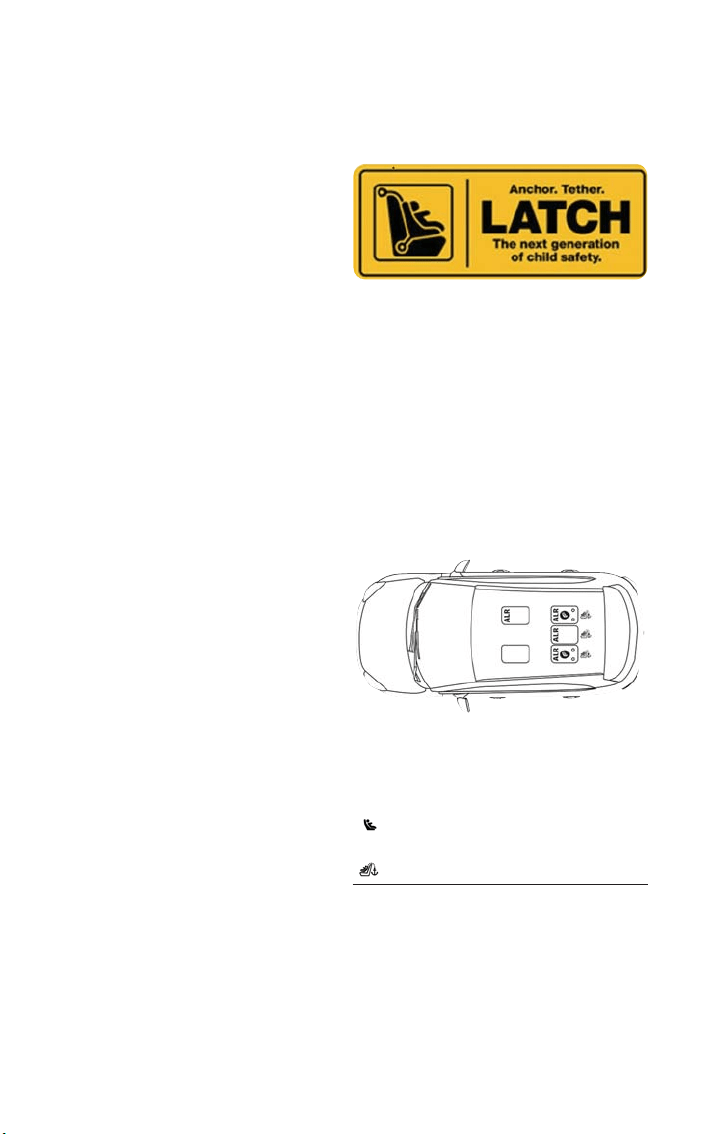
Lower Anchors And Tethers For CHildren (LATCH) Restraint System
Your vehicle is equipped with the child re-
straint anchorage system called LATCH,
which stands for Lower Anchors and Teth-
ers for CHildren. The LATCH system has
three vehicle anchor points for installing
LATCH-equipped child seats. There are two
lower anchorages located at the back of
the seat cushion where it meets the seat-
back and one top tether anchorage located
behind the seating position. These anchor-
ages are used to inst all LATCH-equipped child seats without using the vehicle’s seat belts.
Some seating positions may have a top tether anchorage but no lower anchorages. In
these seating positions, the seat bel t must be used with the top tether anchorage to in-
stall the child restraint. Please see the following table for more information.
LATCH Positions For Installing Child Restraints In This Vehicle
LATCH Label
LATCH Positions
Lower Anchorage Symbol
(2 Anchorages Per Seating Position)
Top Tether Anchorage Symbol
GETTING STARTED
40

Frequently Asked Questions About Installing Child Restraints With LATCH
What is the weight limit (child’s
weight + weight of the child re-
straint) for using the LATCH an-
chorage system to attach the
child restraint?
65 lbs (29.5kg)
Use the LATCH anchorage sys-
tem until the combined weight of
the child and the child restraint is
65 lbs (29.5kg). Use the seat
belt and tether anchor instead of
the LATCH anchorage system
once the combined weight is
more than 65 lbs (29.5kg).
Can the LATCH anchorages and
the seat belt be used together to
attach a rear-facing or forward-
facing child restraint?
No
Do not use the seat belt when
you use the LATCH anchorage
system to attach a rear-facing or
forward-facing child restraint.
Booster seats may be attached to
the LATCH anchorages if allowed
by the booster seat manufacturer.
See your booster seat owner’s
manual for more information.
Can a child seat be installed in
the center position using the in-
ner LATCH lower anchorage?
No
Use the seat belt and tether an-
chor to install a child seat in the
center seating position.
Can two child restraints be at-
tached using a common lower
LATCH anchorage?
No
Never “share” a LATCH anchor-
age with two or more child re-
straints. If the center position
does not have dedicated LATCH
lower anchorages, use the seat
belt to install a child seat in the
center position next to a child
seat using the LATCH anchorages
in an outboard position.
Can the rear-facing child restraint
touch the back of the front pas-
senger seat?
Ye s
The child seat may touch the
back of the front passenger sea t
if the child restraint manufacturer
also allows contact. See your child
restraint owner’s manual for
more information.
Can the head res traints be re-
moved?
Ye s
The head restraints may be re-
moved in every rear seating posi-
tion.
GETTING STARTED
41
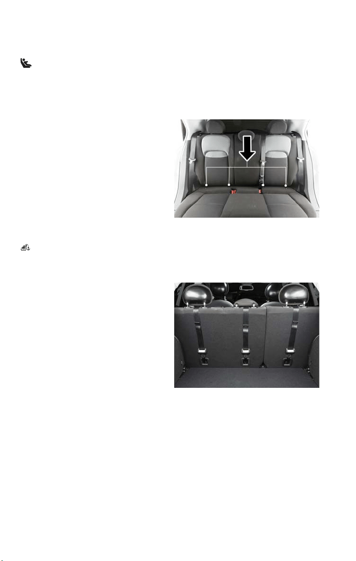
Locating The LATCH Anchorages
The lower anchorages are round bars that are found at the rear of the seat cushion
where it meets the seatback, below the anchorage symbols on the seatback. They are just
visible when you lean into the rear seat to install the child restraint. You will easily feel
them if you run your finger along the gap between the seatback and seat cushion.
Locating The Upper Tether Anchorages
There are tether strap anchorages behind each rear seating position located on the back
of the seat.
LATCH-compatible child restraint systems
will be equipped with a rigid bar or a flex-
ible strap on each side. Each will have a
hook or connector to attach to the lower
anchorage and a way to tighten the con-
nection to the anchorage. Forward-facing
child restraints and some rear-facing child
restraints will also be equipped with a
tether strap. The tether strap will have a
hook at the end to attach to t he top
tether anchorage and a way to tighten the
strap after it is attached to the anchorage.
Lower Anchorage Location
Tether Anchorage Locations
GETTING STARTED
42

Center Seat LATCH :
WARNING!
• Do not install a child restraint in the center position using the LATCH system. This
position is not approved for installing child seats using the LATCH attachments. Yo u
must use the seat belt and tether anchor to install a child seat in the center seat-
ing position.
• Never use the same lower anchorage to attach more than one child restraint.
Please refer to “To Install A LATCH-Compatible Child Restraint” for typical installa-
tion instructions.
Always follow the directions of the child restraint manufacturer when installing your child
restraint. Not all child restraint systems will be installed as described here.
To Install A LATCH-Compatible Child Restraint
If the selected seating position has a Switchable Automatic Locking Retractor (ALR) seat
belt, stow the seat belt, following the instructions below. See the section “Installing Child
Restraints Using The Vehicle Seat Belt” to check what type of seat belt each seating posi-
tion has.
1. Loosen the adjusters on the lower straps and on the tether strap of the child seat so
that you can more easily attach the hooks or connectors to the vehicle anchorages.
2. Place the child seat between the lower anchorages for that seating position. For some
second row sea ts, you may need to recline the seat and/or raise the head restraint to
get a better fit. If the rear seat can be moved forward and rearward in the vehicle,
you may wish to move it to its rear-most position to make room for the child seat.
You may also move the front seat forward to allow more room for the child seat.
3. Attach the lower hooks or connectors of the child restraint to the lower anchorages
in the selected seating position.
4. If the child restraint has a tether strap, connect it to the top tether anchorage. See
the section “Installing Child Restraints Using The Top Tether Anchorage” for directions
to attach a tether anchor.
5. Tighten all of the straps as you push the child restraint rearward and downward into
the seat. Remove slack in the straps according to the child restraint manufacturer’s
instructions.
6. Test that the child restraint is installed tightly by pulling back and forth on the child
seat at the belt path. It should not move more than 1 inch (25.4 mm) in any direc-
tion.
GETTING STARTED
43

How To Stow An Unused Switchable-ALR (ALR) Seat Belt:
When using the LATCH attaching system to install a child restraint, stow all ALR seat
belts that are not being used by other occupants or being used to secure child restraints.
An unused belt could injure a child if they play with it and accidentally lock the seat belt
retractor. Before installing a child restraint using the LATCH system, buckle the seat belt
behind the child restraint and out of the child’s reach. If the buckled seat belt interferes
with the child restraint installation, instead of buckling it behind the child restraint, route
the seat belt through the child restraint belt path and then buckle it. Do not lock the
seat belt. Remind all children in the vehicle that the seat belts are not toys and that they
should not play with them.
WARNING!
• Improper installation of a child restraint to the LATCH anchorages can lead to
failure of the restraint. The child could be badly injured or killed. Follow the child
restraint manufacturer’s directions exactly when installing an infant or child re-
straint.
• Child restraint anchorages are designed to withstand only those loads imposed by
correctly-fitted child restraints. Under no circumstances are they to be used for
adult seat belts, harnesses, or for attaching other items or equipment to the ve-
hicle.
Installing Child Restraints Using The Vehicle Seat Belt
Child res traint systems are designed to be secured in vehicle seats by lap belts or the lap
belt portion of a lap/shoulder belt.
WARNING!
• Improper installation or failure to properly secure a child restraint can lead to fail-
ure of the restraint. The child could be badly injured or killed.
• Follow the child restraint manufacturer’s directions exactly when installing an infant
or child restraint.
The seat belts in the passenger seating positions are equipped with a Switchable Auto-
matic Locking Retractor (ALR) that is designed to keep the lap portion of the seat belt
tight around the child restraint so that it is not necessary to use a locking clip. The ALR
retractor can be “switched” into a locked mode by pulling all of the webbing out of the
retractor and then letting the webbing retract back into the retractor. If it is locked, the
ALR will make a clicking noise while the webbing is pulled back into the retractor. Refer
to the “Automatic Locking Mode” description in “Switchable Automatic Locking Retractors
(ALR)” under “Occupant Restraint Systems” for additional information on ALR.
GETTING STARTED
44
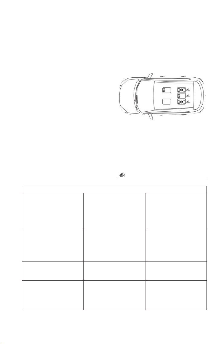
Please see the table below and the following sections for more information.
Lap/Shoulder Belt Systems For Installing Child Restraints In This Vehicle
Frequently Asked Questions About Installing Child Restraints With Seat Belts
What is the weight limit
(child ’s weight + weight of
the child restraint) for using
the Tether Anchor with the
seat belt to attach a for-
ward facing child restraint?
Weight limit of the Child
Restraint
Always use the tether an-
chor when using the seat
belt to install a forward
facing child restraint, up to
the recommended weight
limit of the child restraint.
Can the rear-facing child
restraint touch the back of
the front passenger seat?
Ye s
Contact between the front
passenger seat and the
child restraint is allowed, if
the child restraint manufac-
turer also allows contact.
Can the head res traints be
removed?
Ye s
The head restraints can be
removed in every rear seat-
ing position.
Can the buckle stalk be
twisted to tighten the seat
belt against the belt path of
the child restraint?
No
Do not twist the buckle
stalk in a seating position
with an ALR retractor.
Automatic Locking Retractor (ALR)
Locations
ALR = Switchable Automatic Locking
Retractor
Top Tether Anchorage Symbol
GETTING STARTED
45

Installing A Child Restraint With A Switchable Automatic Locking Retractor (ALR):
Child res traint systems are designed to be secured in vehicle seats by lap belts or the lap
belt portion of a lap/shoulder belt.
WARNING!
• Improper installation or failure to properly secure a child restraint can lead to fail-
ure of the restraint. The child could be badly injured or killed.
• Follow the child restraint manufacturer’s directions exactly when installing an infant
or child restraint.
1. Place the child seat in the center of the seating position. For some second row seats,
you may need to recline the seat and/or raise the head restraint to get a better fit. If
the rear seat can be moved forward and rearward in the vehicle, you may wish to
move it to its rear-most position to make room for the child seat. You may also move
the front seat forward to allow more room for the child sea t .
2. Pull enough of the seat belt webbing from the retractor to pass it through the belt
path of the child restraint. Do not twist the belt webbing in the bel t path.
3. Slide the latch plate into the buckle until you hear a “click.”
4. Pull on the webbing to make the lap portion tight against the child seat.
5. To lock the seat belt, pull down on the shoulder part of the belt until you have pulled
all the seat belt webbing out of the retractor. Then, allow the webbing to retract back
into the retractor. As the webbing retracts, you will hear a clicking sound. This means
the seat belt is now in the Automatic Locking mode.
6. Try to pull the webbing out of the retractor. If it is locked, you should not be able to
pull out any webbing. If the retractor is not locked, repeat step 5.
7. Finally, pull up on any excess webbing to tighten the lap portion around the child re-
straint while you push the child restraint rearward and downward into the vehicle
seat.
8. If the child restraint has a top tether strap and t he seating position has a top tether
anchorage, connect the tether strap to the anchorage and tighten the tether strap.
See the section “Installing Child Restraints Using the Top Tether Anchorage” for direc-
tions to attach a tether anchor.
9. Test that the child restraint is installed tightly by pulling back and forth on the child
seat at the belt path. It should not move more than 1 inch (25.4 mm) in any direc-
tion.
Any seat belt system will loosen with time, so check the belt occasionally, and pull it tight
if necessary.
GETTING STARTED
46
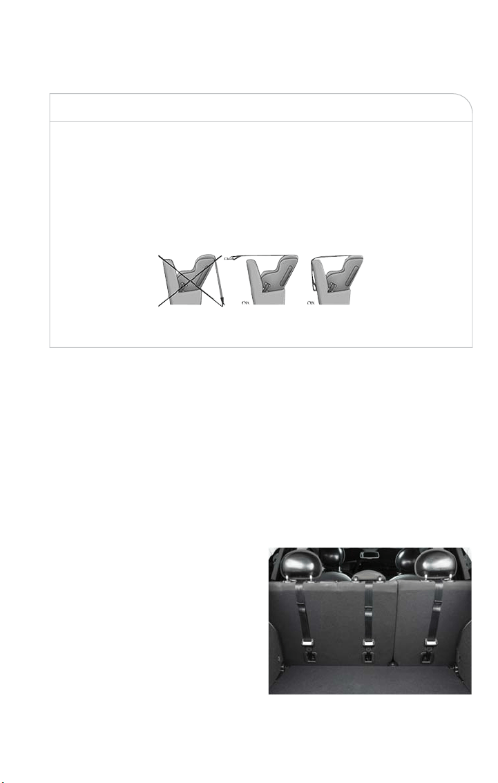
Installing Child Restraints Using The Top Tether Anchorage:
WARNING!
Do not attach a tether strap for a rear-facing car seat to any loca tion in front of the
car seat, including t he seat frame or a tether anchorage. Only attach the tether strap of
a rear-facing car seat to the tether anchorage that is approved for that seating position,
located behind the top of the vehicle seat. See the section “Lower Anchors and Tethers
for CHildren (LATCH) Restraint System” for the location of approved tether anchor-
ages in your vehicle.
1. Look behind the seating position where you plan to install the child restraint to find
the tether anchorage. You may need to move the seat forward to provide better ac-
cess to the tether anchorage. If there is no top tether anchorage for that seating posi-
tion, move the child restraint to another position in the vehicle if one is available.
2. Route the tether strap to provide the most direct path for the strap between the
anchor and the child seat. If your vehicle is equipped with adjustable rear head re-
straints, raise the head restraint, and where possible, route the tether strap under the
head restraint and between the two posts. If not possible, lower the head restraint
and pass the tether strap around the outboard side of the head restraint.
3. Attach the tether strap hook of the child restraint to the top tether anchorage as
shown in the diagram.
4. Remove slack in the tether strap accord-
ing to the child restraint manufacturer’s
instructions.
Tether Anchorage Locations
GETTING STARTED
47

WARNING!
• An incorrectly anchored tether strap could lead to increased head motion and
possible injury to the child. Use only the anchorage position directly behind the
child seat to secure a child restraint top tether strap.
• If your vehicle is equipped with a split rear seat, make sure the tether strap does
not slip into the opening between the seatbacks as you remove slack in the strap.
Transporting Pets
Air Bags deploying in the front seat could harm your pet. An unrestrained pet will be
thrown about and possibly injured, or injure a passenger during panic braking or in a colli-
sion.
Pets should be restrained in the rear seat in pet harnesses or pet carriers that are se-
cured by seat belts.
HEAD RESTRAINTS
Head restraints are designed to reduce the risk of injury by restricting head movement in
the event of a rear impac t. Head restraints should be adjusted so that the top of the
head restraint is located above the top of your ear.
WARNING!
• All occupants, including t he driver, should not operate a vehicle or sit in a vehicle’s
seat until the head restraints are placed in their proper positions in order to mini-
mize the risk of neck injury in the event of a crash.
• Head restraints should never be adjusted while the vehicle is in motion. Driving a
vehicle with the head restraints improperly adjusted or removed could cause seri-
ous injury or death in the event of a collision.
Front Head Restraints
Your vehicle is equipped with driver and passenger head restraints.
To raise the head restraint, pull upward on the head restraint. To lower the head re-
straint, push the adjustment button, located on the base of the head restraint, and push
downward on the head restraint.
To remove the head restraint recline the backres t of the seat to avoid inter ference with
the roof. Raise the head restraint as far as it can go then push the release button and
adjustment button at the base of each post while pulling the head restraint up. To rein-
stall the head restraint, put the head restraint posts into the holes and push downward.
Then adjust it to the appropriate height.
GETTING STARTED
48

NOTE:
Do not reposition the head restraint 180 degrees to the incorrect position in an attempt
to gain additional clearance to the back of the head.
WARNING!
• A loose head restraint thrown forward in a collision or hard stop could cause seri-
ous injury or death to occupants of the vehicle. Always securely stow removed
head restraints in a location outside the occupant compartment.
• ALL the head restraints MUST be reinstalled in the vehicle to properly protect
the occupants. Follow the re-installation instructions above prior to operating the
vehicle or occupying a seat.
Rear Head Restraints
Your vehicle is equipped with two outboard head restraints and one center head re-
straint for its rear passengers. The rear head restraints can be raised or lowered. When
the center seat is being occupied, the head restraint should be in the raised position.
When there are no occupants in the center seat, the head restraint can be lowered for
maximum visibility for the driver.
To raise the head restraint, pull upward on the head restraint. To lower the head re-
straint, push the adjustment button, located at the base of the head restraint, and push
downward on the head restraint.
To remove the head restraint, raise it as far as it can go then push the release button and
adjustment button at the base of each post while pulling the head restraint up. To rein-
stall the head restraint, put the head restraint posts into the holes and push downward.
Then adjust it to the appropriate height.
NOTE:
Do not reposition the head restraint 180 degrees to the incorrect position in an attempt
to gain additional clearance to the back of the head.
WARNING!
• A loose head restraint thrown forward in a collision or hard stop could cause seri-
ous injury or death to occupants of the vehicle. Always securely stow removed
head restraints in a location outside the occupant compartment.
• ALL the head restraints MUST be reinstalled in the vehicle to properly protect
the occupants. Follow the re-installation instructions above prior to operating the
vehicle or occupying a seat.
GETTING STARTED
49
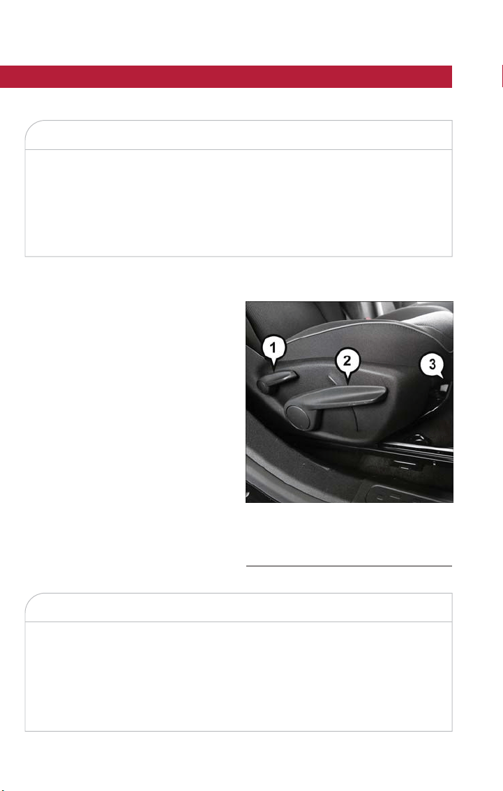
SEATS
Seats are a part of the Occupant Restraint System of the vehicle.
WARNING!
•
It is dangerous to ride in a cargo area, inside or outside of a vehicle. In a collision,
people riding in these areas are more likely to be seriously injured or killed.
• Do not allow people to ride in any area of your vehicle that is not equipped with
seats and seat belts. In a collision, people riding in these areas are more likely to
be seriously injured or killed.
• Be sure everyone in your vehicle is in a seat and using a seat belt properly.
Manual Adjustment Front Seats
Manual Front Seat Forward/Rearward Ad-
justment
On models equipped with manual seats, the
forward/rearward adjusting bar is located at
the front of the seats, near the floor.
While sitting in the seat, lift up on the bar
and move the seat forward or rearward.
Release the bar once you have reached the
desired position. Then, using body pressure,
move forward and rearward on the seat to
be sure that the seat adjusters have
latched.
WARNING!
•
Adjusting a seat while the vehicle is moving is dangerous. The sudden movement of
the seat could cause you to lose control. The seat belt might not be adjusted prop-
erly and you could be injured. Adjust the seat only while the vehicle is parked.
• Do not ride with the seatback reclined so that the shoulder belt is no longer rest-
ing against your chest. In a collision you could slide under the seat belt and be
seriously or even fatally injured. Use the recliner only when the vehicle is parked.
Manual Seat Adjustment Levers
1 — Recline Lever
2 — Seat Height Adjustment Lever
3 — Forward/Rearward Adjustment Bar
GETTING STARTED
50
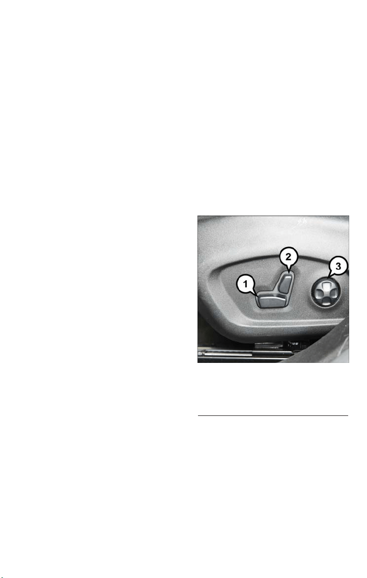
Height Adjustment
The front driver and passenger seats height can be raised or lowered by using a lever,
located on the outboard side of the seat. Pull upward on the lever to raise the seat
height or push downward on the lever to lower the seat height.
Recline Adjustment
To adjust the seatback, lift the lever located on the outboard side of the seat, lean back
to the desired position and release the lever. To return the seatback, lift the lever, lean
forward and release the lever.
Power Adjustment Front Seats — If Equipped
The power seat controls are located on the outboard side of the seat, close to the floor.
Use the switch to move the seat up/down, forward/rearward, tilt if equipped and to set
the angle of the seatback.
Forward Or Rearward Adjustment
The seat can be adjusted both forward and
rearward. Push the seat switch forward or
rearward, the seat will move in the direc-
tion of the switch. Release the switch when
the desired position has been reached.
Height Adjustment
The height of the seats can be adjusted up
or down. Pull upward or push downward
on the seat switch, the seat will move in
the direction of the switch. Release the
switch when the desired position is
reached.
Recline Adjustment
Push the seat recliner switch forward or
rearward, the seatback will move in the
direction of the switch. Release the switch
when the desired position has been
reached.
Tilt Adjustment
The angle of the seat cushion can be adjusted up or down. Pull upward or push down-
ward on the front of the seat switch, the front of the seat cushion will move in the di-
rection of the switch.
Power Lumbar Adjustment
Push the switch forward or rearward to increase or decrease the lumbar support. Push
the switch upward or downward to raise or lower the lumbar support.
Power Seat Switches
1 — Power Seat Switch
2 — Power Recline Switch
3 — Power Lumbar Switch
GETTING STARTED
51

Heated Seats — If Equipped
The heated seat switches are located on the instrument panel.
You can choose between two heating levels:
• Push the heated seat button
once to turn the HI setting on.
• Push the heated seat button
a second time to turn the LO setting on.
• Push the heated seat button
a third time to turn the heating elements off.
If the HI-level setting is selected, the system will automatically switch to LO-level after
approximately 145 minutes of continuous operation. At that time, the display will change
from HI to LO, indicating the change. The LO-level setting will turn off automatically after
approximately 60 minutes.
NOTE:
The engine must be running for the heated seats to operate.
Vehicles Equipped With Remote Start
Vehicles equipped with Remote Start, the heated seats can be programmed to come on
during a Remote Start until the ignition switch is cycled to the RUN position.
Auto On Comfort — If Equipped
If the external temperature is below 40 °F (5 °C) at each start-up of the vehicle the
heated seat functionality of the driver's seat is turned on to HI-level.
WARNING!
• Persons who are unable to feel pain to the skin because of advanced age, chronic
illness, diabetes, spinal cord injury, medication, alcohol use, exhaustion or other
physical condition must exercise care when using the seat heater. It may cause
burns even at low temperatures, especially if used for long periods of time.
• Do not place anything on the sea t or seatback that insulates against heat, such as a
blanket or cushion. This may cause the seat heater to overheat. Sitting in a seat
that has been overheated could cause serious burns due to t he increased surface
temperature of the sea t.
Rear Seats
The split rear seat increases the storage of the rear cargo area.
NOTE:
• Prior to folding the rear seat down, it may be necessary to position the front seat to
its mid-track position. Be sure that the front seats are fully upright and positioned for-
ward, this will allow the rear seat to fold down easily.
GETTING STARTED
52
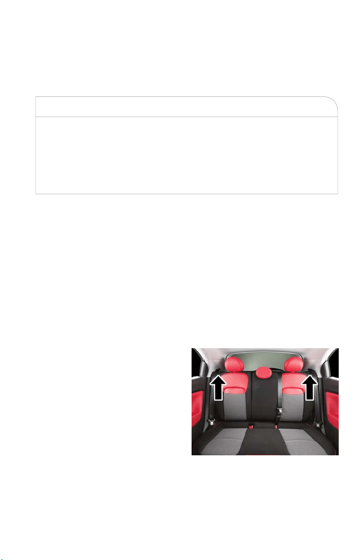
• You may experience deformation in the seat cushion from the seat belt buckles if the
seats are left folded for an extended period of time. This is normal and by simply
opening the seats to the open position, over time the seat cushion will return to its
normal shape.
WARNING!
• It is extremely dangerous to ride in a cargo area, inside or outside of a vehicle. In
a collision, people riding in these areas are more likely to be seriously injured or
killed.
• Do not allow people to ride in any area of your vehicle that is not equipped with
seats and seat belts.
• Be sure everyone in your vehicle is in a seat and using a seat belt properly.
Partial Enlargement Of Cargo Area
Enlargement of the left side of the cargo area allows you to carry a single passenger on
the right side of the rear seat, while the enlargement of the right side allows you to carry
two passengers.
Proceed as follows:
1. Remove the rear shelf (if equipped).
2. Fully lower the rear seat head restraints.
3. Move the safety belts to the outboard side of the seat and rest them on the seat belt
guide.
4. Pull the seatback release lever to fold the left or right rear seatback completely for-
ward.
Rear Seatback Release Levers
GETTING STARTED
53
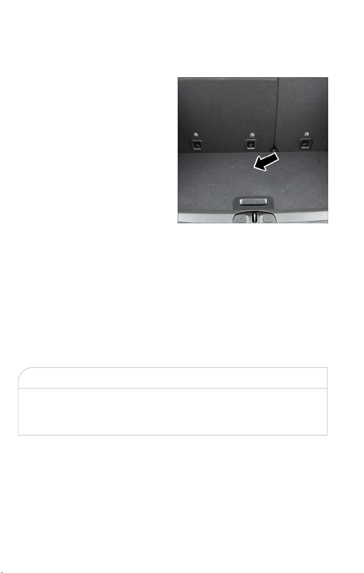
Cargo Area Enlargement
Folding both sides of the rear seat provides additional storage in the rear cargo area.
Proceed as follows:
1. Remove the rear shelf (if equipped).
2. Fully lower the rear seat head restraints.
3. Move the safety belts to the outboard
side of the seat.
4. Pull the seatback release lever to fold
both sides of the rear seatbacks com-
pletely for ward.
Seatback Repositioning
NOTE:
If interference from the cargo area prevents the seatback from fully locking, you will have
difficulty returning the seat to its proper position.
1. Move the safety belts to the seat belt guides on the top edge of the seat to ensure
the seatbacks properly latch.
2. Lift the seatbacks, pushing t hem back until they lock on both the latches. Verify the
red notches are no longer visible on the release lever. If the red notches are visible,
the seatback is not secure.
WARNING!
Be certain that the seatback is securely locked into position. If the seatback is not se-
curely locked into position the seat will not provide the proper stability for child seats
and/or passengers. An improperly latched seat could cause serious injury.
Cargo Area
GETTING STARTED
54
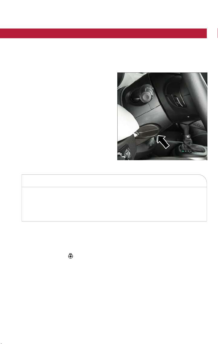
STEERING WHEEL
Tilt/Telescoping Steering Column
This feature allows you to tilt the steering column upward or downward. It also allows
you to lengthen or shorten the steering column. The tilt/telescoping lever is located be-
low the steering wheel at the end of the steering column.
To unlock the steering column, push the
tilt/telescoping lever downward (toward the
floor). To til t the steering column, move the
steering wheel upward or downward as
desired. To lengthen or shorten the steer-
ing column, pull the steering wheel outward
or push it inward as desired.
To lock the steering column in position, pull
the tilt/telescoping lever upward until fully
engaged.
WARNING!
Do not adjust the steering column while driving. Adjusting the steering column while
driving or driving with the steering column unlocked, could cause the driver to lose
control of the vehicle. Failure to follow this warning may result in serious injury or
death.
Heated Steering Wheel — If Equipped
The steering wheel contains a heating element that helps warm your hands in cold
weather. The heated steering wheel has only one temperature setting. Once the heated
steering wheel switch
has been turned on, it will operate for an average of 80 min-
utes or more before automatically shutting off. This time may vary depending on the en-
vironmental temperature. The heated steering wheel can shut off early or may not turn
on when the steering wheel is already warm. The heated steering wheel control button is
located on the center of the instrument panel below the climate controls.
Tilt/Telescoping Steering Wheel Lever
GETTING STARTED
55

Auto On Comfort — If Equipped
If the external temperature is below 40 °F (5 °C) at each start-up of the vehicle the
heated steering wheel functionality is turned on.
WARNING!
• Persons who are unable to feel pain to the skin because of advanced age, chronic
illness, diabetes, spinal cord injury, medication, alcohol use, exhaustion, or other
physical conditions must exercise care when using the steering wheel heater. It
may cause burns even at low temperatures, especially if used for long periods.
• Do not place anything on the steering wheel that insulates against heat, such as a
blanket or steering wheel covers of any type and material. This may cause the
steering wheel heater to overheat.
GETTING STARTED
56

ENGINE BREAK-IN RECOMMENDATIONS
A long break-in period is not required for the engine and drivetrain (transmission and
axle) in your vehicle.
Drive moderately during the first 300 miles (500 km). After the initial 60 miles (100 km),
speeds up to 50 or 55 mph (80 or 90 km/h) are desirable.
While cruising, brief full-throttle acceleration within the limits of local traffic laws contrib-
utes to a good break-in. Wide-open throttle acceleration in low gear can be detrimental
and should be avoided.
The engine oil inst alled in the engine at the factory is a high-quality energy conserving
type lubricant. Oil changes should be consistent with anticipated climate conditions under
which vehicle operations will occur. Refer to “Maintaining Your Vehicle” for the recom-
mended viscosity and quality grades.
NOTE:
A new engine may consume some oil during its first few thousand miles ( kilometers) of
operation. This should be considered a normal part of the break-in and not interpreted
as an indication of an engine problem or malfunction.
CAUTION!
Never use Non-Detergent Oil or Straight Mineral Oil in the engine or damage may
result.
OPERATING YOUR VEHICLE
57
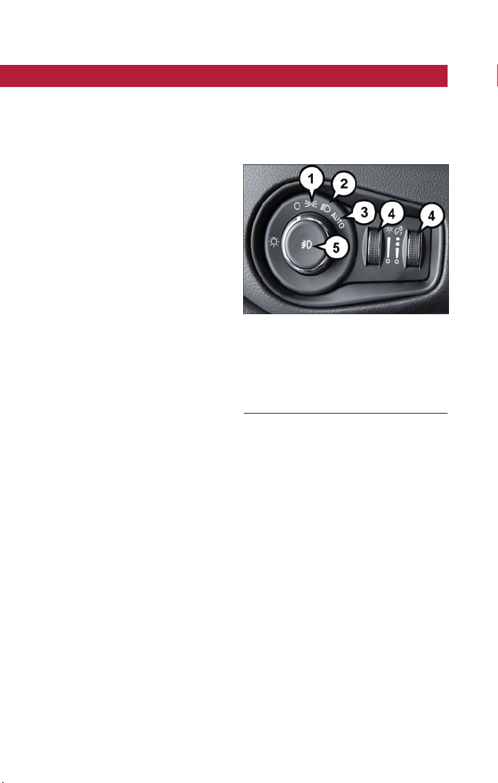
EXTERIOR LIGHTS
Headlights
The headlight switch is located on the left side of the instrument panel. The headlight
switch controls the operation of the headlights, side marker lights, daytime running lights,
fog lights and the dimming of the instrument cluster and interior lighting.
Turning on the headlights will illuminate the
instrument cluster and t he controls located
on the instrument panel.
Automatic Lighting — If Equipped
Light Sensor
The light sensor is equipped with an infrared LED, located on the windshield. It detects
changes in light intensity outside the vehicle, based on the sensitivity of light set by using
the Menu on the display or on the Uconnect system.
The higher the sensitivity, the lesser the amount of external light required for controlling
the lighting.
Automatic Headlights
Turn the headlight switch to the AUTO position.
When the automatic headlights are enabled, the headlight time delay is active. After the
ignition switch is placed in the STOP mode, the headlights will automatically turn off after
approximately 90 seconds depending on the settings of the feature.
The timing of the headlights is adjustable between 0, 30, 60 and 90 seconds.
NOTE:
The engine must be running before the headlights will come on in the automatic mode.
Headlight Switch
1 — Parking Lights
2 — Headlights
3 — Automatic Headlights
4 — Dimmer Controls
5 — Fog Lights
OPERATING YOUR VEHICLE
58

Daytime Running Lights (DRL) — If Equipped
The Daytime Running Lights (DRLs) will turn on when the engine is started and remain
on unless the headlights are turned on or the engine is shut off.
The DRLs will be disabled during turn signal operation and resume operation when the
turn signal operation has ended.
Front Fog Lights — If Equipped
The front fog light switch is built into the headlight switch.
To activate the front fog lights, turn on the parking lights or the low beam headlights and
push the headlight switch. To turn off the front fog lights, push the headlight switch a sec-
ond time or turn off the headlight switch.
An indicator light in the instrument cluster illuminates when the fog lights are turned on.
NOTE:
• The fog lights will operate with the low beam headlights or parking lights on. Selecting
the high beam headlights will turn off the fog lights.
• The fog lights also function as cornering lights. Therefore there will be times when only
one light is on.
Parking Lights
Rotate the headlight switch to the first position to turn on the parking lights. The parking
light indicator in the cluster will illuminate.
Headlight Delay
This feature provides the safety of headlight illumination for up to 90 seconds when leav-
ing your vehicle in an unlit area.
The time delay of the headlights is programmable between 0, 30, 60 and 90 seconds.
Headlight Delay Activation
To activate the delay feature, place the ignition in the STOP position while the headlights
are still on. Then, turn off the headlights within two minutes. The delay interval begins
when the headlight switch is turned off.
Headlight Delay Disable
The feature is disabled by turning on the headlights, the parking lights or by placing the
ignition in RUN mode.
If you shut off the lights before the ignition is turned on, they will turn off in the normal
manner.
NOTE:
The lights must be turned off within two minutes of placing the ignition in STOP mode
to activate this feature.
OPERATING YOUR VEHICLE
59

High Beams
To turn on the high beam headlights, push the turn signal lever forward (toward the front
of the vehicle) and an indicator will illuminate in the cluster. To turn off the high beams,
pull the turn signal lever rearward (toward the rear of the vehicle).
NOTE:
The headlights must be on for the high
beams to activate.
Turn Signals
Move the multifunction lever up or down and the arrows on each side of the instrument
cluster flash to show proper operation of the front and rear turn signal lights.
When the Daytime Running Lights are on and a turn signal is activated, the Daytime Run-
ning Lamp will turn off on the side of the vehicle in which the turn signal is flashing. The
Daytime Running Lamp will turn back on when the turn signal is turned off .
High Beam And Turn Signal Controls
1 — Turn Signals
2 — High Beam Headlights
3 — Flash To Pass
4 — LaneSense On/Off
OPERATING YOUR VEHICLE
60
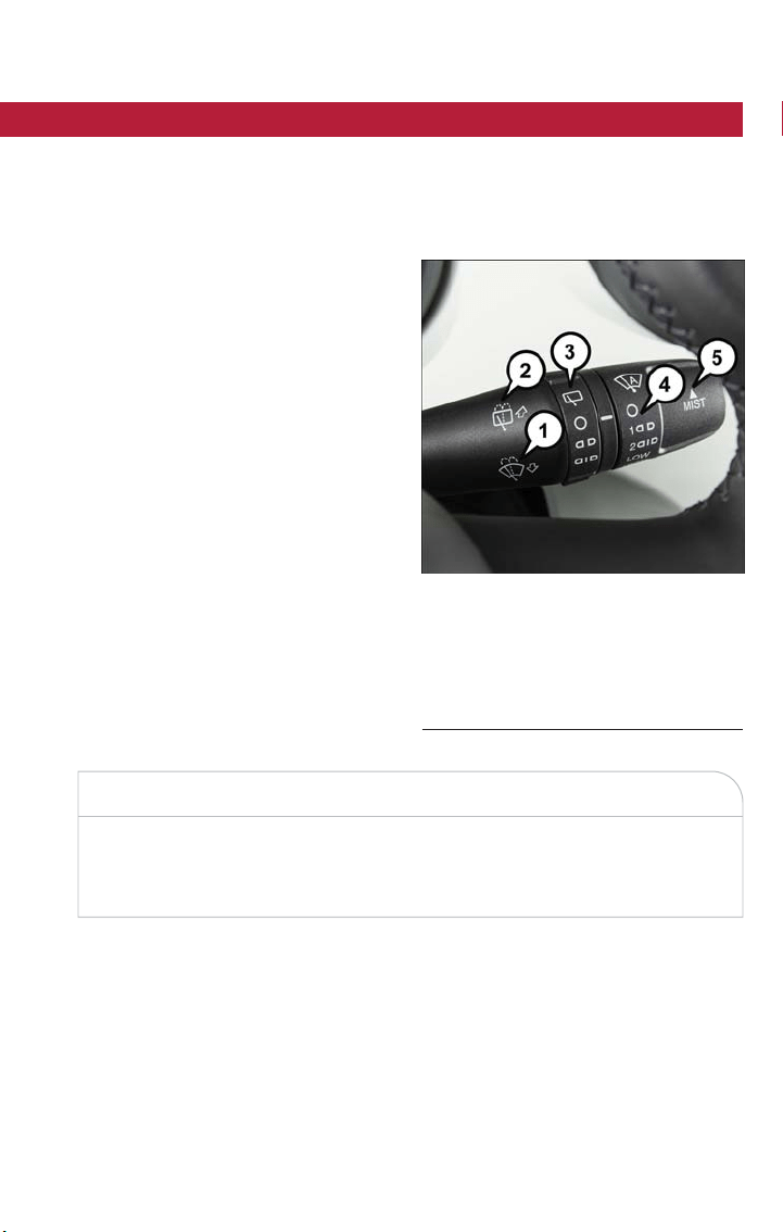
WIPERS AND WASHERS
Front Wiper Operation
The windshield wiper/washer controls are located on the lever on the right side of t he
steering column. The front wipers are operated by rotating a switch, located on the end
of the lever.
CAUTION!
Always remove any buildup of snow that prevents the windshield wiper blades from
returning to the “park” position. If the windshield wiper switch is turned off, and the
blades cannot return to the “park” position, damage to the wiper motor may occur.
Windshield Wiper Operation
Rotate the windshield wiper knob to one of the two detent positions for intermittent
settings, the third detent for low wiper operation and the fourth for high wiper opera-
tion.
Windshield Wiper Stalk
1 — Windshield Washer Operation
2 — Rear Washer Operation
3 — Rear Wiper Operation
4 — Intermittent Wiper Controls
5 — Mist Feature
OPERATING YOUR VEHICLE
61

Windshield Washer Operation
To use the washer, pull the lever toward you and hold while spray is desired. If the lever
is pulled while in the intermittent setting, the wipers will turn on and operate for several
wipe cycles after the lever is released, and then resume the intermittent interval previ-
ously selected.
If the lever is pulled while the wipers are in the off position, the wipers will operate for
several wipe cycles, then turn off.
WARNING!
Sudden loss of visibility through the windshield could lead to a collision. You might not
see other vehicles or other obstacles. To avoid sudden icing of the windshield during
freezing weather, warm the windshield with the defroster before and during windshield
washer use.
Mist
Use this feature when weather conditions make occasional usage of the wipers necessary.
Push the lever upward to the MIST position and release for a single wiping cycle.
NOTE:
The mist feature does not activate the washer pump; therefore, no washer fluid will be
sprayed on the windshield. The wash function must be used in order to spray the wind-
shield with washer fluid.
Rain Sensor — If Equipped
This feature senses moisture on the windshield and automatically activates the wipers for
the driver. The feature is especially useful for road splash or overspray from the wind-
shield washers of the vehicle ahead. Rotate the end of the multifunction lever to one of
two settings to activate this feature.
The sensitivity of the system can be adjusted with the multifunction lever. Wiper delay
position one is the least sensitive, and wiper delay position two is the most sensitive. Set-
ting one should be used for normal rain conditions, and can be used if the driver desires
less wiper sensitivity. Setting two can be used if the driver desires more sensitivity. Place
the wiper switch in the off (O) position when not using the system.
NOTE:
• The Rain Sensing feature will not opera te when the wiper switch is in the low or high-
speed position.
• The Rain Sensing feature may not function properly when ice, or dried salt water is
present on the windshield.
• Use of Rain-X or products containing wax or silicone may reduce Rain Sensing perfor-
mance.
OPERATING YOUR VEHICLE
62

• The Rain Sensing feature can be turned on and off using the Uconnect System,
refer to “Uconnect Settings” in “Multimedia” in the Owner’s Manual on
www.fiatusa.com/en/owners/manuals for further information.
The Rain Sensing system has protection features for the wiper blades and arms, and will
not operate under the following conditions:
• Low Ambient Temperature — When the ignition is first turned to RUN, the Rain
Sensing system will not operate until the wiper switch is moved, vehicle speed is
greater than 0 mph (0 km/h), or the outside temperature is greater than 32°F (0°C).
• Transmission In NEUTRAL Position — When the ignition is in RUN mode, and the
automatic transmission is in the NEUTRAL position, the Rain Sensing system will not
operate until the wiper switch is moved, vehicle speed is greater t han 5 mph (8 km/h),
or the gear selector is moved out of the NEUTRAL position.
Remote Start Mode Inhibit — On vehicles equipped with Remote Starting system, Rain
Sensing wipers are not operational when the vehicle is in the remote start mode. Once
the operator is in the vehicle and has placed the ignition switch in RUN mode, rain sens-
ing wiper operation can resume, if it has been selected, and no other inhibit conditions
(mentioned previously) exist.
Rear Window Wiper/Washer
The rear wiper/washer controls are located on the lever on the right side of the steering
column. The rear wiper/washer is operated by rotating a switch, located at the middle of
the lever.
Rotate the center portion of the lever upward to the first detent for intermittent opera-
tion and to the second detent for continuous rear wiper operation.
To use the washer, push the lever forward and hold while spray is desired. Iftheleveris
pushed while in the intermittent setting, the wiper will turn on and operate for several
wipe cycles after the end of the lever is released, and then resume the intermittent inter-
val previously selected.
NOTE:
• As a protective measure, the pump will stop if the switch is held for more than 30
seconds. Once the lever is released, the pump will resume normal operation.
• When front wipers are continuous and the vehicle is shifted in REVERSE, the rear
wiper will perform one round up to clean the rear window.
If the lever is pushed while the wiper is in the off position, the wiper will operate for
several wipe cycles, then turn off.
If the rear wiper is operating when the ignition is turned to the STOP mode, the wiper
will automatically return to the “park” position.
OPERATING YOUR VEHICLE
63

Rear Window Defroster
The rear window defroster button is located with the Climate Controls on the instru-
ment panel. Push this button to turn on the rear window defroster. An indicator in the
button will illuminate when the rear window defroster is on. The rear window defroster
automatically turns off after approximately 20 minutes. To manually shut the defroster off,
push the button a second time.
CAUTION!
Failure to follow these cautions can cause damage to the heating elements:
• Use care when washing the inside of the rear window. Do not use abrasive win-
dow cleaners on the interior surface of the window. Use a soft cloth and a mild
washing solution, wiping parallel to the heating elements. Labels can be peeled off
after soaking with warm water.
• Do not use scrapers, sharp instruments, or abrasive window cleaners on the inte-
rior surface of the window.
• Keep all objects a safe distance from the window.
Windshield Wiper De-Icer — If Equipped
Your vehicle may be equipped with a Windshield Wiper De-Icer feature that may be acti-
vated under the following conditions:
• Activation By Front Defrost — The Windshield Wiper De-Icer will be activated auto-
matically in the case of a cold weather manual start with full front defrost, and the
ambient temperature is below 40° F (4.4° C).
• Activation By Rear Defrost — The Windshield Wiper De-Icer will be activated auto-
matically when the rear defrost is turned on and the ambient temperature is below
40°F(4.4° C).
• Activation By Remote Start Operation — When Remote Star t is active and the out-
side ambient temperature is less than 40° F (4.4° C), the Windshield Wiper De-Icer
will be enabled. Upon exiting remote start mode the Windshield Wiper De-Icer will
remain on.
OPERATING YOUR VEHICLE
64
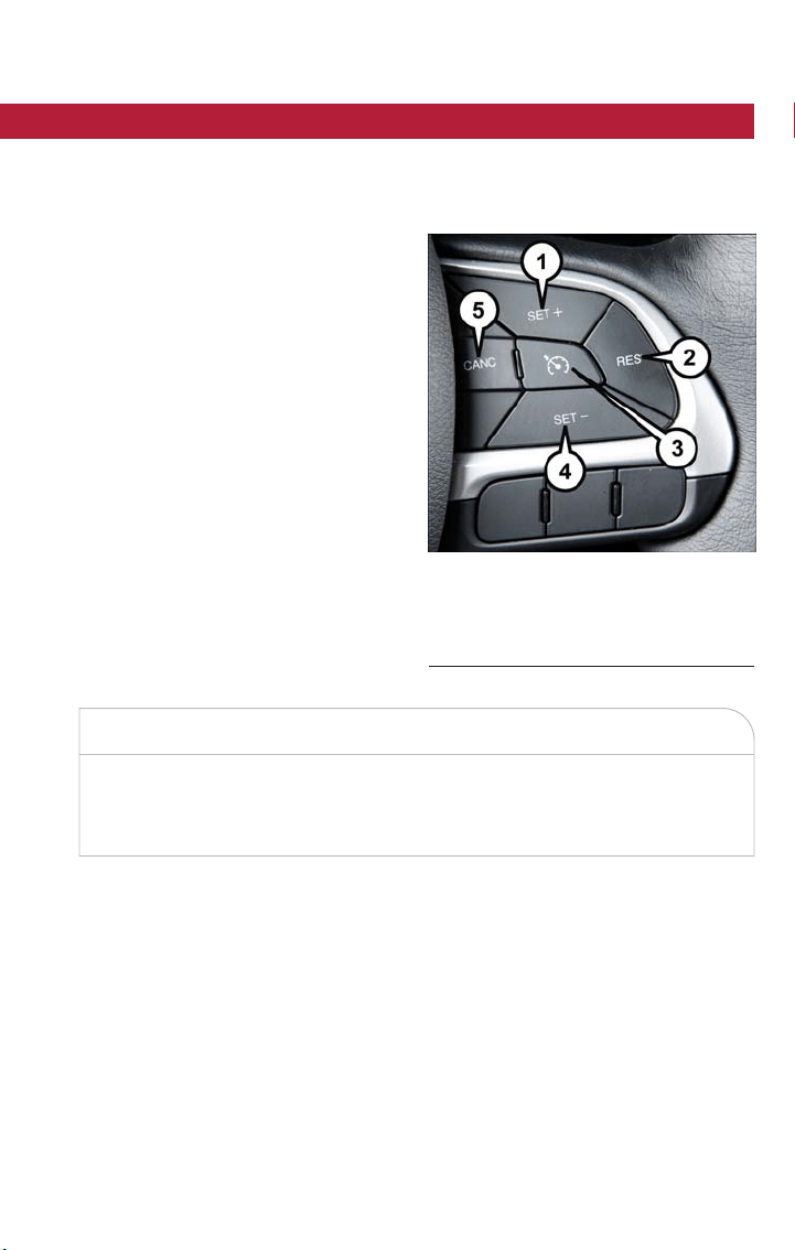
SPEED CONTROL
When engaged, the Speed Control takes over accelerator operations at speeds greater
than 25 mph (40 km/h).
The Speed Control buttons are located on the right side of the steering wheel.
NOTE:
In order to ensure proper operation, the
Speed Control System has been designed
to shut down if multiple Speed Control
functions are operated at the same time. If
this occurs, the Speed Control System can
be reactivated by pushing the Speed Con-
trol on/off button and resetting the desired
vehicle set speed.
Activation
Push the on/off button to activate the
Speed Control. The cruise indicator light in
the instrument cluster display will illumi-
nate. To turn the system off, push the on/
off button a second time. The cruise indica-
tor light will turn off. The system should be
turned off when not in use .
WARNING!
Leaving the Speed Control system on when not in use is dangerous.You could acciden-
tally set the system or cause it to go faster than you want. You could lose control and
have an accident. Always leave the system off when you are not using it.
Setting A Desired Speed
Turn the Speed Control on.
NOTE:
The vehicle should be traveling at a steady speed and on level ground before pushing the
SET (+) or SET (-) button.
When the vehicle has reached the desired speed, push the SET (+) or SET (-) button
and release. Release the accelerator and the vehicle will operate at the selected speed.
Speed Control Buttons
1 — SET+/Accel 4 — SET-/Decel
2 — RES/Resume 5 — CANC/Cancel
3 — On/Off
OPERATING YOUR VEHICLE
65

Deactivation
A soft tap on the brake pedal, pushing the CANC button, ESC inter vention, brake control
mitigation, electronic park brake intervention, or normal brake pressure while slowing the
vehicle will deactivate the Speed Control without erasing the set speed from memory.
Pushing the on/off button or turning the ignition switch to STOP erases the set speed
from memory.
Resume Speed
To resume a previously set speed, push the RES button and release. Resume can be used
at any speed above 20 mph (32 km/h).
Varying The Speed
To Increase Speed
When the Speed Control is set, you can increase speed by pushing the SET (+) button.
The driver’s preferred units can be selected through the Uconnect system if equipped.
The speed increment shown is dependant on the chosen speed unit of U.S. (mph) or
Metric (km/h):
U.S. Speed (mph)
• Pushing the SET (+) button once will result in a 1 mph increase in set speed. Each
subsequent tap of the button results in an increase of 1 mph.
• If the button is continually pushed, the speed will continue to increase until the button
is released, then the new set speed will be established.
Metric Speed (km/h)
• Pushing the SET (+) button once will result in a 1 km/h increase in set speed. Each
subsequent tap of the button results in an increase of 1 km/h.
• If the button is continually pushed, the speed will continue to increase until the button
is released, then the new set speed will be established.
To Decrease Speed
When the Speed Control is set, you can decrease speed by pushing the SET (-) button.
The driver’s preferred units can be selected through the Uconnect system if equipped.
The speed increment shown is dependant on the chosen speed unit of U.S. (mph) or
Metric (km/h):
U.S. Speed (mph)
• Pushing the SET (-) button once will result in a 1 mph decrease in set speed. Each
subsequent tap of the button results in a decrease of 1 mph.
• If the button is continually pushed, the speed will continue to decrease until the button
is released, then the new set speed will be established.
OPERATING YOUR VEHICLE
66
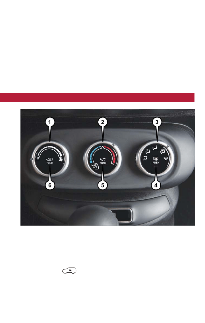
Metric Speed (km/h)
• Pushing the SET (-) button once will result in a 1 km/h decrease in set speed. Each
subsequent tap of the button results in a decrease of 1 km/h.
• If the button is continually pushed, the speed will continue to decrease until the button
is released, then the new set speed will be established.
Accelerating For Passing
Press the accelerator as you would normally. When the pedal is released, the vehicle will
return to the set speed.
MANUAL CLIMATE CONTROLS
Air Recirculation
• Use Air Recirculation for maximum A/C operation.
• For window defogging, turn the recirculation off.
• Air Recirculation is not available as an option when in solo defrost modes.
Manual Climate Controls
1 — Blower Control
2 — Temperature Control
3 — Mode Control
4 — Rear Defroster
5 — A/C Control
6 — Air Recirculation Control
OPERATING YOUR VEHICLE
67
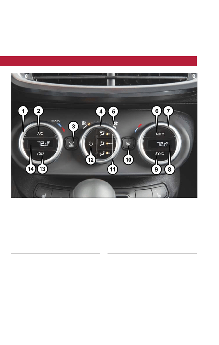
Heated Mirrors
• The mirrors are heated to melt frost or ice. This feature is activated whenever you
turn on the rear window defroster.
AUTOMATIC TEMPERATURE CONTROLS (ATC)
Automatic Operation
• Push the AUTO button.
• Select the desired temperature by rotating temperature control knobs.
• The system will maintain the set temperature automatically.
Automatic Temperature Controls (ATC)
1 — Driver Temperature Control
2 — A/C Control
3 — MAX Front Defrost Control
4 — Blower Control
5 — LED Blower Speed Indicator
6 — AUTO Control
7 — Passenger Temperature Control
8 — Passenger Temperature Display
9 — SYNC Control
10 — Rear Defroster
11 — Mode Control
12 — Climate On/Off Control
13 — Air Recirculation Control
14 — Driver Temperature Display
OPERATING YOUR VEHICLE
68

Air Recirculation
• Use Air Recirculation for maximum A/C operation.
• For window defogging, turn the recirculation off.
• Air Recirculation is not available as an option when in solo defrost modes.
Max Defrost
• Push the MAX Defrost button to change the current airflow setting to Defrost mode.
Performing this function will cause the blower speed to increase to high blower, the
A/C compressor to turn on, the driver and passenger temperatures set to HI, rear
defroster to turn on, and recirculation to turn off.
• If the MAX Defrost button is toggled off, the climate system will return to the previ-
ous setting.
SYNC
• Push the SYNC button to synchronize the passenger temperature setting with the
driver temperature setting.
• Changing the passenger temperature setting while in Sync will automatically exit this
feature.
Mode Buttons
The airflow distribution modes can be adjusted so air comes from the instrument panel,
floor, de-mis t, and defrost outlets. One, two or all modes may be selected at any one
time.
Heated Mirrors
The mirrors are heated to melt frost or ice. This feature is activated whenever you turn
on the rear window defroster.
OPERATING YOUR VEHICLE
69
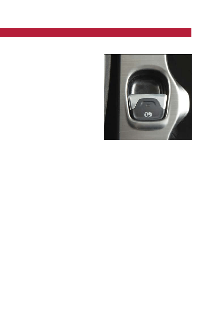
ELECTRIC PARK BRAKE (EPB)
Your vehicle is equipped with a new Electric Park Brake System (EPB) that offers greater
convenience. The EPB switch is located in the center console.
To apply the park brake manually, pull up
on the switch momentarily. Once the park-
ing brake is fully engaged, the BRAKE warn-
ing lamp in the instrument cluster and an
indicator on the switch will illuminate.
To release the park brake manually, the
ignition must be in RUN. Then put your
foot on the brake pedal and push the park
brake switch down momentarily. Once the
park brake is fully disengaged, the BRAKE
warning lamp and the switch indicator will
extinguish.
The park brake can also be automatically
released if the driver’s seat belt is buckled
and driver's intention to start (in forward
or reverse direction) is recognized by the system.
NOTE:
On a manual transmission vehicle, if the clutch pedal is released at the same time the gas
pedal is pressed, the EPB will be automatically released.
NOTE:
• You may hear a slight whirring sound from the back of the vehicle while the parking
brake engages or disengages.
• If your foot is on the brake pedal while you are engaging or disengaging the parking
brake, you may notice a small amount of brake pedal movement.
• The new Auto Park Brake feature can be used to apply the park brake automatically
whenever the vehicle speed is below 1.9 mph (3 km/h) and the automatic transmis-
sion is placed in PARK, or with a manual transmission, whenever the ignition is turned
off. Auto Park Brake can be enabled and disabled in the Settings menu in Uconnect.
• The parking brake can be engaged even when the ignition is OFF, however, it can only
be disengaged when the ignition is in the RUN mode.
• SafeHold is a new feature that will automatically apply the park brake under certain
conditions. The EPB monitors the status of the driver’s seat belt, driver’s door and
pedal positions to determine if the driver may have exited while the vehicle is still ca-
pable of moving and will then automatically apply the park brake to prevent the vehicle
from rolling.
Park Brake Switch
OPERATING YOUR VEHICLE
70

• If vehicle speed is below 1.9 mph (3 km/h), the EPB fault lamp will illuminate if the
EPB switch is held for longer than 10 seconds in either the released or applied posi-
tion. The light will extinguish upon releasing the switch.
• Refer to the “Starting and Operating” section of your vehicle’s Owner’s Manual at
www.fiatusa.com/en/owners/manuals for further details.
WARNING!
• When exiting the vehicle, always remove the key fob from the ignition and lock
your vehicle.
• Never leave children alone in a vehicle, or with access to an unlocked vehicle. Al-
lowing children to be in a vehicle unattended is dangerous for a number of rea-
sons. A child or others could be seriously or fatally injured. Children should be
warned not to touch the parking brake, brake pedal or the transmission gear se-
lector.
• Do not leave the key fob in or near the vehicle (or in a location accessible to chil-
dren), and do not leave the ignition in the ON or RUN mode. A child could oper-
ate power windows, other controls, or move the vehicle.
• Be sure the parking brake is fully disengaged before driving; failure to do so can
lead to brake failure and a collision.
• Always fully apply the parking brake when leaving your vehicle, or it may roll and
cause damage or injury. Also be certain to leave the transmission in PARK. Failure
to do so may allow the vehicle to roll and cause damage or injury.
CAUTION!
If the Brake System Warning Light remains on with the parking brake released, a brake
system malfunction is indicated. Have the brake system serviced by an authorized
dealer immediately.
OPERATING YOUR VEHICLE
71
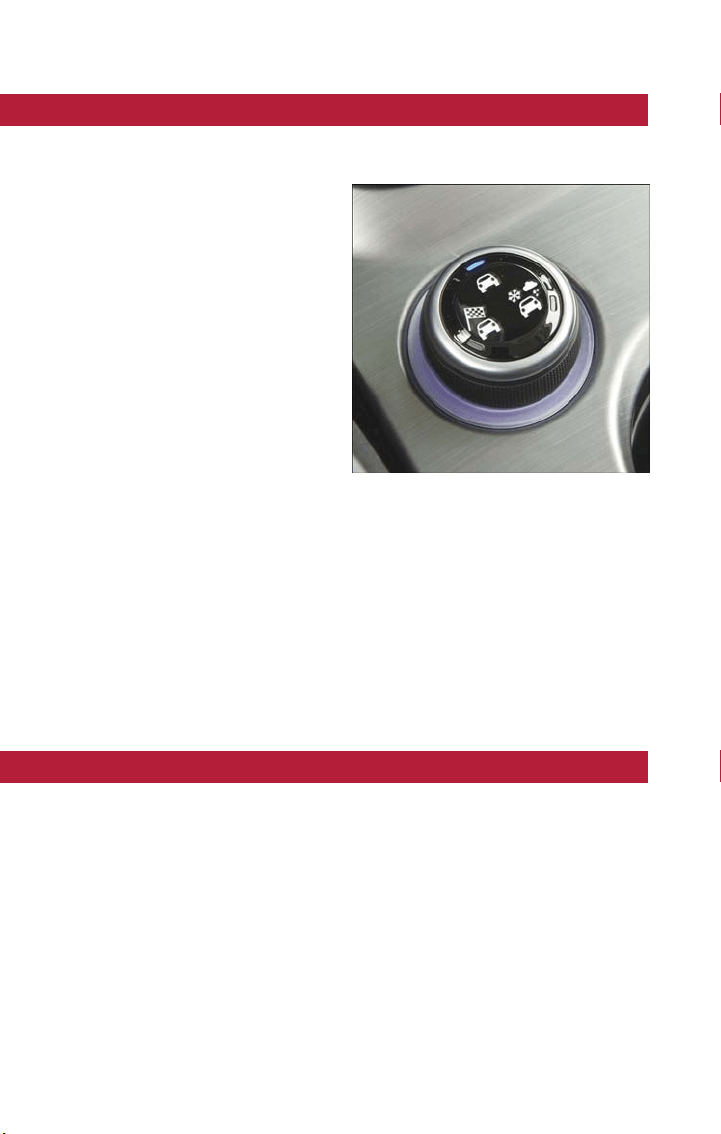
DYNAMIC SELECTOR — IF EQUIPPED
The Dynamic Selector combines the capabilities of the vehicle control systems, along with
driver input, to provide the best performance in all driving conditions.
The Dynamic Selector consists of the fol-
lowing positions:
Auto Mode – This mode is designed for
comfort and safety in normal driving condi-
tions. In versions equipped with all-wheel
drive, this mode also reduces fuel consump-
tion by automatically altering the distribu-
tion of torque between the front and rear
axle.
All Weather Mode – This mode offers in-
creased traction control and stability con-
trol for low traction conditions such as
driving on a dir t road or off road as well as
wet and slippery roads.
Sport Mode – This mode is designed to
increase steering feedback to the driver with a slight increase in effort and changes the
transmission shift schedules for more aggressive shifting. This driving mode is useful while
driving on twisty roads where more steering precision is desired in spirited cornering.
Warning Messages
In the event of a system fault, the system automatically defaults to "Auto" mode and a
message will appear in the instrument cluster display.
Refer to “Instrument Cluster Display” in “Getting To Know Your Instrument Panel” in your
Owner’s Manual at www.fiatusa.com/en/owners/manuals for further information.
BLIND SPOT MONITORING (BSM) — IF EQUIPPED
The Blind Spot Monitoring (BSM) system uses two radar-based sensors, located inside the
rear bumper fascia, to detect highway licensable vehicles (automobiles, trucks, motorcycles,
etc.) that enter the blind spot zones from the rear/front/side of the vehicle .
When the vehicle is started, the BSM warning light will momentarily illuminate in both
outside rear view mirrors to let the driver know that the system is operational. The BSM
system sensors operate when the vehicle is in any forward gear or REVERSE and enters
stand-by mode when the vehicle is in PARK.
The BSM detection zone covers approximately one lane width on both sides of the ve-
hicle, 10 ft (3 m). The zone length start s at the outside mirror and extends approximately
20 ft (6 m) beyond the rear bumper of the vehicle. The BSM system monitors the de-
tection zones on both sides of the vehicle when the vehicle speed reaches approximately
6 mph (10 km/h) or higher and will alert the driver of vehicles in these areas.
Dynamic Selector Switch
OPERATING YOUR VEHICLE
72

NOTE:
• The BSM system does NOT alert the driver about rapidly approaching vehicles that
are outside the detection zones.
• If a trailer is connected to the vehicle, it is necessary to deactivate BSM system manu-
ally by settings menu to avoid a miss-detection. Refer to “Uconnect Settings” in “Multi-
media” in your Owner’s Manual on www.fiatusa.com/en/owners/manuals for further
information.
The area on the rear fascia where the radar sensors are located must remain free of
snow, ice, and dirt/road contamination so that the BSM system can function properly. Do
not block the radar sensors located on the rear fascia with foreign objects (bumper stick-
ers, bicycle racks, etc.).
The BSM sys tem notifies the driver of objects in the detection zones by illuminating the
BSM warning light located in the outside mirrors in addition to sounding an audible
(chime) alert and reducing the radio volume.
The BSM system monitors the detection zone from three different entry points (side,
rear, front) while driving to see if an alert is necessary. The BSM system will issue an alert
during these types of zone entries.
Entering From The Side
Vehicles t hat move into your adjacent lanes from either side of the vehicle.
Entering From The Rear
Vehicles t hat come up from behind your vehicle on either side and enter the rear detec-
tion zone with a relative speed of less than 31 mph (50 km/h).
Overtaking Traffic
If you pass another vehicle slowly with a relative speed less t han 15 mph (25 km/h) and
the vehicle remains in the blind spot for approximately 1.5 seconds, the warning light will
be illuminated. If the difference in speed between the two vehicles is greater than
15 mph (25 km/h), the warning light will not illuminate.
The BSM sys tem is designed not to issue an alert on stationary objects such as guardrails,
posts, walls, foliage, berms, etc. However, occasionally the system may alert on such ob-
jects. This is normal operation and your vehicle does not require service.
OPERATING YOUR VEHICLE
73

The BSM sys tem will not alert you of objects that are traveling in the opposite direction
of the vehicle in adjacent lanes.
WARNING!
The Blind Spot Monitoring system is only an aid to help detect objects in the blind spot
zones. The BSM system is not designed to detect pedestrians, bicyclists, or animals. Even
if your vehicle is equipped with the BSM system, always check your vehicles mirrors,
glance over your shoulder, and use your turn signal before changing lanes. Failure to do
so can result in serious injury or death.
Rear Cross Path (RCP)
The Rear Cross Path (RCP) feature is intended to aid the driver when backing out of
parking spaces where their vision of oncoming vehicles may be blocked. Proceed slowly
and cautiously out of the parking space until the rear end of the vehicle is exposed. The
RCP system will then have a clear view of the cross traffic and if an oncoming vehicle is
detected, alert the driver.
RCP monitors the rear detection zones on both sides of the vehicle, for objects that are
moving toward the side of the vehicle with a minimum speed of approximately 1 mph
(2 km/h), to objects moving a maximum of approximately 22 mph (35 km/h), such as in
parking lot situations.
NOTE:
In a parking lot situation, oncoming vehicles can be obscured by vehicles parked on either
side. If the sensors are blocked by other structures or vehicles, the system will not be
able to alert the driver.
When RCP is on and the vehicle is in REVERSE, the driver is alerted using both the vi-
sual and audible alarms, including reducing the radio volume.
WARNING!
RCPisnotabackupaidsystem. It is intended to be used to help a driver detect an
oncoming vehicle in a parking lot situation . Drivers must be careful when backing up,
even when using RCP. Always check carefully behind your vehicle, look behind you, and
be sure to check for pedestrians, animals, other vehicles, obstructions, and blind spots
before backing up. Failure to do so can result in serious injury or death.
OPERATING YOUR VEHICLE
74

Mode Of Operation
Three selectable modes of operation are available in the Uconnect Sys tem. Refer to
“Uconnect Settings” in “Multimedia” in your Owner’s Manual on
www.fiatusa.com/en/owners/manuals for further information.
Blind Spot Alert Lights Only
When operating in Blind Spot Alert mode, the BSM system will provide a visual alert in
the appropriate side view mirror based on a detected object. However, when the system
is operating in Rear Cross Path (RCP) mode, t he system will respond with both visual
and audible alerts when a detected object is present. Whenever an audible alert is re-
quested, the radio is muted.
Blind Spot Alert Lights/Chime
When operating in Blind Spot Alert Lights/Chime mode, the BSM system will provide a
visual alert in the appropriate side view mirror based on a detected object. If the turn
signal is then activated, and it corresponds to an alert present on that side of the vehicle,
an audible chime will also be sounded. Whenever a turn signal and detected object are
present on the same side at the same time, both the visual and audible alerts will be is-
sued. In addition to the audible alert, the radio (if on) will also be muted.
NOTE:
Whenever an audible alert is requested by the BSM system, the radio is also muted.
When the system is in RCP, the system will respond with both visual and audible alerts
when a detected object is present. Whenever an audible alert is requested, the radio is
also muted. Turn/hazard signal status is ignored; the RCP state always requests the chime.
Blind Spot Alert Off
When the BSM system is turned off, there will be no visual or audible alerts from either
the BSM or RCP systems.
NOTE:
The BSM system will store the current operating mode when the vehicle is shut off. Each
time the vehicle is started the previously stored mode will be recalled and used.
Blind Spot Monitoring Fault Warnings
Sensor Blinded
In the case of a sensor blinded:
• BSM Mirror Warning Lights are turned on continuously.
• An instrument cluster message will display “Blind Spot Monitoring Unavailable - Wipe
Rear Bumper Corners.”
NOTE:
The rear bumper must be clean and free of any obstructing debris.
OPERATING YOUR VEHICLE
75

System Not Available
In the case of the system being temporary unavailable:
• BSM Mirror Warning Lights are turned on continuously.
• An instrument cluster message will display “Blind Spot Monitoring Temporary
Unavailable.”
In the case of the system being completely unavailable:
• A chime will turn on.
• An instrument cluster message will display “Blind Spot Monitoring Unavailable - Service
Required.”
NOTE:
Vehicle mus t be taken to the nearest authorized dealer for service.
BRAKE CONTROL — IF EQUIPPED
Brake Control
The Brake Control system with mitigation provides the driver with audible warnings, vi-
sual warnings (within the instrument cluster display), and may apply a brake jerk to warn
the driver when it detects a potential frontal collision. The warnings and limited braking
are intended to provide the driver with enough time to react, avoid or mitigate the po-
tential collision.
NOTE:
• Brake Control monitors the information from the forward looking sensors as well as
the Electronic Brake Controller (EBC), to calculate the probability of a forward colli-
sion. When the system determines that a forward collision is probable, the driver will
be provided with audible and visual warnings and may provide a brake jerk warning.
• If the driver does not take action based upon these progressive warnings, then the
system will provide a limited level of active braking to help slow the vehicle and miti-
gate the potential forward collision. If the driver reacts to the warnings by braking and
the system determines that the driver intends to avoid the collision by braking but has
not applied sufficient brake force, the system will compensate and provide additional
brake force as required.
Vehicles With A Manual Transmission: After the end of the intervention of automatic
braking, the engine could stall, unless the driver can depress t he clutch pedal.
Vehicles With Automatic Transmission: After the end of the intervention of automatic
braking, the transmission may remain in last gear stored: therefore the car could lurch
forward, once the brakes release a few seconds later. If the Brake Control event stops
the vehicle completely, the system will hold the vehicle at standstill for two seconds and
then release the brakes.
OPERATING YOUR VEHICLE
76
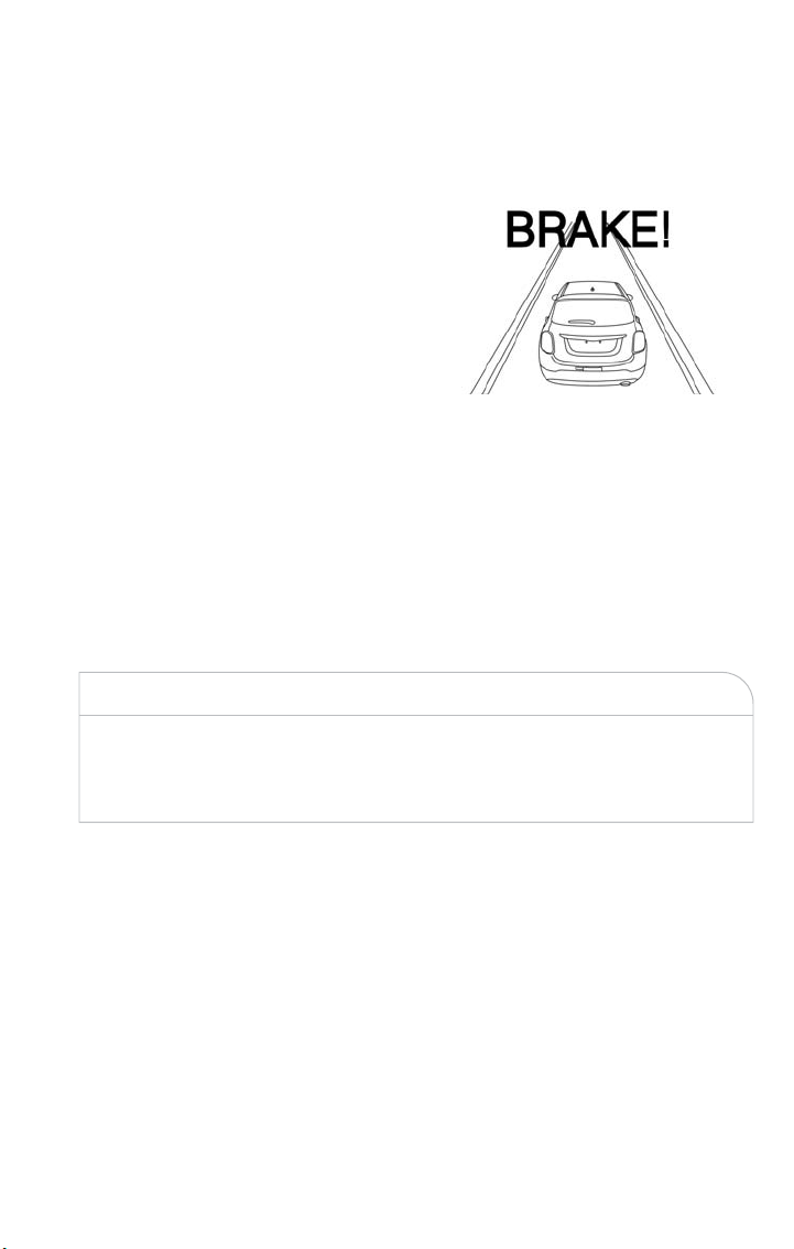
If a Brake Control event begins at a speed below 20 mph (32 km/h), the system may
provide the maximum braking possible to mitigate the potential for ward collision. If the
Brake Control event stops the vehicle completely, the system will hold the vehicle at
standstill for two seconds and then release the brakes.
When the system determines a collision
with the vehicle in front of you is no lon-
ger probable, the warning message will be
deactivated.
NOTE:
• The minimum speed for Brake Control
activation is 4 mph (7 km/h).
• The maximum speed for Brake Control
activation is 124 mph (200 km/h).
• The Brake Control alerts may be triggered on objects ot her than vehicles such as
guard rails or sign posts based on the course prediction. This is expected and is a part
of normal Brake Control activation and functionality.
• The Brake Control system is intended for on-road use only. If the vehicle is taken off-
road, the Brake Control sys tem should be deactiva ted to prevent unnecessary warnings
to the surroundings.
• The active braking is enabled only if the front seat belts are fastened.
WARNING!
Brake Control is not intended to avoid a collision on its own, nor can Brake Control
detect every type of potential collision. The driver has the responsibility to avoid a colli-
sion by controlling the vehicle via braking and steering. Failure to follow this warning
could lead to serious injury or death.
Turning Brake Control On Or Off
The Brake Control menu setting is located in the Uconnect settings.
NOTE:
The default status of Brake Control is “Warning + Active Braking.” This allows the system
to warn you of a possible collision with the vehicle in front of you and enable the active
braking.
• Changing the Brake Control status to “Off” deactivates the system, so no warning or
active braking will be available in case of a possible collision
• Changing the Brake Control status to “Only Warning” prevents the system from pro-
viding limited active braking, or additional brake support if t he driver is not braking
adequately in the event of a potential frontal collision, but maintains the audible and
visual warnings.
Brake Control Message
OPERATING YOUR VEHICLE
77

Changing the status of the system is only possible with the vehicle at a complete stop.
NOTE:
The Brake Control system state is not kept in memory from one key cycle to the next. If
the system is turned off, it will turn on when the vehicle is restarted.
Changing Brake Control Sensitivity
By changing the settings on the menu of the Uconnect system, you can change the sensi-
tivity of the system by choosing one of the following three options: "Near", "Medium" or
"Far". Refer to “Multimedia” in the Owner’s Manual on
www.fiatusa.com/en/owners/manuals for further information.
The default option is "Medium". This setting provides that the system notify the driver of
a possible accident with the vehicle ahead of it when the latter is at a standard distance,
intermediate between the other two possible settings.
By setting the sensitivity of the system to "Far", the system will warn the driver of a pos-
sible accident with the vehicle in front when the latter is at a greater distance, giving you
the chance to act on the brakes in a more limited and gradual. This setting gives the
driver the maximum possible time of reaction to prevent a possible accident.
By changing the option to "Near", the system will warn the driver of a possible accident
with the vehicle ahead of it when the latter is a reduced distance. This setting offers a
reaction time to the driver lower than the settings "Medium" and "Far", in the case of a
potential accident, while a more dynamic driving of the car.
The setting of the sensitivity of the system is maintained in memory when t he engine is
switched off.
Brake Control Limited Warning
If the instrument cluster display will read “Brake Control Limited Functionality” or “Brake
Control Limited Functionality Clean Front Windshield” momentarily, there may be a con-
dition that limits Brake Control functionality. Although the vehicle is still drivable under
normal conditions, the active braking may not be fully available. Once the condition that
limited the sys tem performance is no longer present, t he system will return to its full
performance state. If the problem persists, see your authorized dealer.
Service Brake Control Warning
If the system turns off, and the instrument cluster display displays:
• Brake Control Unavailable Service Required
This indicates there is an internal system fault. Although the vehicle is still drivable under
normal conditions, have the system checked by an authorized dealer.
OPERATING YOUR VEHICLE
78

“Wipe Front Radar Sensor In Front Of Vehicle” Warning
The “Brake Control Front Radar Sensor Temporarily Blocked” warning will display when
conditions temporarily limit system performance. This most often occurs at times of poor
visibility, such as in snow or heavy rain. The system may also become temporarily blinded
due to obstructions, such as mud, dirt or ice. In these cases, the instrument cluster display
will display “Brake Control Front Radar Sensor Temporarily Blocked” and the system will
deactivate.
The “Brake Control Front Radar Sensor Temporarily Blocked” message can sometimes be
displayed while driving in highly reflective areas (i.e. tunnels with reflective tiles, or ice and
snow). The system will recover after the vehicle has left these areas. Under rare condi-
tions, when the radar is not tracking any vehicles or objects in its path this warning may
temporarily occur.
If weather conditions are not a factor, the driver should examine the sensor. It may re-
quire cleaning or removal of an obstruction. The sensor is located behind the lower
grille. In absence of visible obstructions on the bumper, it could be necessary to wipe off
the radar directly on the surface, after having the radar cover removed. It’s recom-
mended that your authorized dealer perform’s this opera tion .
NOTE:
• If the “Brake Control Front Radar Sensor Temporarily Blocked” message occurs fre-
quently (e.g. more than once on every trip) without any snow, rain, mud, or other ob-
struction, have the radar sensor realigned at your authorized dealer.
• Installing a snow plow, front-end protector, an aftermarket grille or modifying the grille
is not recommended. Doing so may block the sensor and inhibit Brake Control
operation.
Precautions While Driving With Brake Control
In certain driving conditions, such as:
• Driving in the vicinity of a curve
• Small vehicles and/or not aligned to the lane
• Lane changing of other vehicles
• Passing of vehicles in an oncoming intersection
The intervention of the system could be unexpected or delayed. The driver must there-
fore always pay particular attention, while maintaining control of the car to drive in com-
plete safety.
Driving In The Vicinity Of A Curve
Entering or exiting a large curve, the system could detect the presence of a vehicle that
is in front of the car, but that does not preside in the same lane. In cases such as this, the
system might respond.
OPERATING YOUR VEHICLE
79

Small Vehicles And/Or Not Aligned To The Lane
The system is not able to detect the presence of vehicles that are in front of the car but
placed outside the field of action of the radar sensor and could therefore not react in
the presence of small vehicles such as bicycles or motorcycles.
Lane Changing Of Other Vehicles
Vehicles t hat suddenly change lane, while standing in the traffic lane of their car and in-
side the field of action of the radar sensor may cause the intervention of the system.
Passing Of Vehicles In An Oncoming Intersection
The system could temporarily react to a vehicle that crossed the range of the radar sen-
sor, in an oncoming intersection.
LANESENSE — IF EQUIPPED
LaneSense Operation
The LaneSense system is operational at speeds above 37 mph (60 km/h) and below
112 mph (180 km/h). The LaneSense system uses a forward looking camera to detect
lane markings and measure vehicle position within the lane boundaries.
When both lane markings are detected and the driver unintentionally drifts out of the
lane (no turn signal applied), the LaneSense system provides a haptic warning in the form
of torque applied to the steering wheel to prompt the driver to remain within the lane
boundaries. If the driver continues to unintentionally drift out of the lane, the LaneSense
system provides a visual warning through the instrument cluster display to prompt the
driver to remain within the lane boundaries.
The driver may manually override the haptic warning by applying torque into the steering
wheel at any time.
When only a single lane marking is detected and the driver unintentionally drifts across
the lane marking (no turn signal applied), the LaneSense system provides a visual warning
through the instrument cluster display to prompt the driver to remain within the lane.
When only a single lane marking is detected, a haptic (torque) warning will not be pro-
vided.
NOTE:
When operating conditions have been met, the LaneSense system will monitor if the
driver’s hands are on the steering wheel and provides an audible warning to the driver
when the driver’s hands are not detected on the steering wheel. The system will cancel if
the driver does not return their hands to the wheel.
OPERATING YOUR VEHICLE
80

Turning LaneSense On Or Off
The default status of LaneSense is “off”.
The LaneSense button is located on t he end of the turn signal stalk, located on the left
side of the steering column.
To turn the LaneSense system on, push the LaneSense button once.
A “Lane Sense On” message is shown in the instrument cluster dis-
play.
To turn the LaneSense system off, push the LaneSense button once.
NOTE:
The LaneSense system will retain the last system state on or off
from the last ignition cycle when the ignition is changed to RUN mode.
LaneSense Warning Message
The LaneSense system will indicate the current lane drift condition through the instru-
ment cluster display.
Base Instrument Cluster Display
When the LaneSense system is on, the lane lines are gray when both of the lane bound-
aries have not been detected and the LaneSense indicator is solid white.
Left Lane Departure — Only Left Lane Detected
• When the LaneSense system is on, the LaneSense indicator is solid white when only
the left lane marking has been detected and the system is ready to provide visual
warnings in the instrument cluster display if an unintentional lane departure occurs.
• When the LaneSense system senses the lane has been approached and is in a lane
departure situation, the left thick lane line flashes yellow (on/off), the left thin line re-
mains solid yellow and the LaneSense indicator changes from solid white to flashing
yellow.
NOTE:
The LaneSense system operates with the similar behavior for a right lane departure
when only the right lane marking has been detected.
Left Lane Departure — Both Lanes Detected
• When the LaneSense system is on, the lane lines turn from gray to white to indicate
that both of the lane markings have been detected. The LaneSense indicator is solid
green when both lane markings have been detected and the system is “armed” to pro-
vide visual warnings in the instrument cluster display and a torque warning in the
steering wheel if an unintentional lane departure occurs.
• When the LaneSense system senses a lane drift situation, the left thick lane line and
left thin line turn solid yellow. The LaneSense indicator changes from solid green to
solid yellow. At this time torque is applied to the steering wheel in the opposite direc-
tion of the lane boundary.
OPERATING YOUR VEHICLE
81

For example: If approaching the left side of the lane the steering wheel will turn to the
right.
• When the LaneSense system senses the lane has been approached and is in a lane
departure situation, the left thick lane line flashes yellow (on/off) and the left thin line
remains solid yellow. The LaneSense indicator changes from solid yellow to flashing yel-
low. At this time torque is applied to the steering wheel in the opposite direction of
the lane boundary.
For example: If approaching the left side of the lane the steering wheel will turn to the
right.
NOTE:
The LaneSense system operates with the similar behavior for a right lane departure.
Changing LaneSense Status
The LaneSense system has settings to adjust the intensity of the torque warning and the
warning zone sensitivity (early/late) that you can configure through the Uconnect system
screen.
NOTE:
• When enabled the system operates above 37 mph (60 km/h) and below 112 mph
(180 km/h).
• Use of the turn signal suppresses the warnings.
• The system will not apply torque to the steering wheel whenever a safety system en-
gages. (anti-lock brakes, traction control system, electronic stability control, forward col-
lision warning, etc.).
PARKSENSE REAR PARK ASSIST — IF EQUIPPED
The ParkSense Rear Park Assist system provides visual and audible indications of the dis-
tance between the rear fascia and a detected obstacle when backing up, e.g. during a
parking maneuver.
ParkSense will retain the last system state (enabled or disabled) from the last ignition
cycle when the ignition is changed to RUN mode.
ParkSense can be active only when the gear selector is in REVERSE.
ParkSense Sensors
The four ParkSense sensors, located in the rear fascia/bumper, monitor the area behind
the vehicle that is within the sensors’ field of view. The sensors can detect obstacles from
approximately 12 inches (30 cm) up to 59 inches (150 cm) from the rear fascia/bumper
in the horizontal direction, depending on the location, type and orientation of the ob-
stacle.
OPERATING YOUR VEHICLE
82

Chime
By shifting the vehicle in REVERSE and in the case of the presence of a rear obstacle, an
acoustic signal that varies with the distance of the obstacle from the bumper is activated.
The frequency of the acoustic signal:
• Increases with the distance between car and object decreases.
• Becomes continuous when the distance that separates the car from the obstacle is less
than approximately 12 inches (30 cm), while terminates immediately if the distance to
the obstacle increases.
• Remains constant if the distance between car and obstacle remains unchanged. If this
situation occurs for the side sensors, the signal is stopped after approximately three
seconds to avoid, for example, it activates in case of maneuver along a wall.
When the system emits a beeping sound, the volume of the Uconnect system, if turned
on, is automatically lowered by ParkSense.
Detection Distances
If the sensors detect more obstacles, it is taken into account only what is the shorter dis-
tance.
Instrument Cluster Display
ParkSense is displayed on the instrument cluster only if you have selected the item
"Sound And Display" inside the "Settings" menu of the Uconnect system.
If an obstacle is detected in the center rear region, the display will show a single solid arc
in the center rear region and will produce a one-half second tone . As the vehicle moves
closer to the obstacle, the display will show the single arc moving closer to the vehicle
and the sound tone will change from slow, to fast, to continuous.
If an obstacle is detected in the left and/or right rear region, the display will show a single
flashing arc in the left and/or right rear region and will produce a fast sound tone. As the
vehicle moves closer to the obstacle, the display will show the single arc moving closer to
the vehicle and the tone will change from fast to continuous.
In general, the car is closest to the obstacle when the display shows only a flashing arc
and the chime becomes continuous.
The color on the display depends on the distance and location of the obstacle.
Enabling And Disabling ParkSense
ParkSense can be enabled and disabled with the ParkSense switch.
When the ParkSense switch is pushed to disable the system, the instrument cluster will
display the “PARKSENSE OFF” message for approximately five seconds. Refer to “Instru-
ment Cluster Display” in “Getting To Know Your Instrument Panel” in your Owner’s
Manual on www.fiatusa.com/en/owners/manuals for further information. When the gear
selector is moved to REVERSE and t he system is disabled, the instrument cluster display
will show the “PARKSENSE OFF” message for as long as the vehicle is in REVERSE.
OPERATING YOUR VEHICLE
83

The ParkSense switch LED will be on when ParkSense is disabled or requires service. The
ParkSense switch LED will be off when the system is enabled. If the ParkSense switch is
pushed, and requires service, the ParkSense switch LED will blink momentarily, and then
the LED will be on.
ParkSense will remember the previous state when the vehicle is switch off.
CAUTION!
After turning the ignition to STOP, the ParkSense remains in this setting until the next
key cycle. This is true even in the case of changing the ignition from RUN to STOP, and
then again to RUN.
Service The Rear Park Assist System
During vehicle start up, when the ParkSense Rear Park Assist System has detected a
faulted condition, the instrument cluster will actuate a single chime, once per ignition
cycle, and it will display a dedicated message such as “PARK ASSIST UNAVAILABLE WIPE
REAR SENSORS” or the “PARK ASSIST UNAVAILABLE SERVICE REQUIRED” message.
Refer to “Instrument Cluster Display” in “Getting To Know Your Instrument Panel” in your
Owner’s Manual on www.fiatusa.com/en/owners/manuals for further information. When
the gear selector is moved to REVERSE and the system has detected a faulted condition,
the instrument cluster display will display a dedicated message such as "PARK ASSIST UN-
AVAILABLE WIPE REAR SENSORS" or "PARK ASSIST UNAVAILABLE SERVICE RE-
QUIRED" message for as long as the vehicle is in REVERSE. Under this condition, Rear
Park Assist will not operate.
If a message such as “PARK ASSIST UNAVAILABLE WIPE REAR SENSORS” appears in
the instrument cluster display, make sure the outer surface and the underside of the rear
fascia/bumper is clean and clear of snow, ice, mud, dirt or other obstructions, and then
cycle the ignition. If the message continues to appear, see an authorized dealer.
If a message such as “PARK ASSIST UNAVAILABLE SERVICE REQUIRED” appears in the
instrument cluster display, see an authorized dealer.
ParkSense System Usage Precautions
NOTE:
• Ensure that the outer surface and the underside of the rear bumper is clean and clear
of snow, ice, mud, dirt or other obstruction to keep the Rear ParkSense system oper-
ating properly.
• Jackhammers, large trucks, and other vibrations could affect the performance of Rear
ParkSense.
OPERATING YOUR VEHICLE
84

• Clean the Rear ParkSense sensors regularly, taking care not to scratch or damage
them. The sensors must not be covered with ice, snow, slush, mud, dirt or debris. Fail-
ure to do so can result in the system not working properly. The Rear ParkSense sys-
tem might not detect an obstacle behind the fascia/bumper, or it could provide a false
indication that an obstacle is behind the fascia/bumper.
• Objects such as bicycle carriers, etc., must not be placed within 12 inches (30 cm)
from the rear fascia/bumper while driving the vehicle. Failure to do so can result in the
system misinterpreting a close object as a sensor problem, causing a failure indication
to be displayed in the instrument cluster.
WARNING!
• Drivers must be careful when backing up even when using ParkSense. Always
check carefully behind your vehicle, look behind you, and be sure to check for pe-
destrians, animals, other vehicles, obstructions, and blind spots before backing up.
You are responsible for safety and must continue to pay attention to your sur-
roundings. Failure to do so can result in serious injury or death.
• Before using ParkSense, it is strongly recommended that the ball mount and hitch
ball assembly is disconnected from the vehicle when the vehicle is not used for
towing. Failure to do so can result in injury or damage to vehicles or obstacles
because the hitch ball will be much closer to the obstacle than the rear fascia
when the loudspeaker sounds the continuous tone. Also, the sensors could detect
the ball mount and hitch ball assembly, depending on its size and shape, giving a
false indication that an obstacle is behind the vehicle.
CAUTION!
• ParkSense is only a parking aid and it is unable to recognize every obstacle, includ-
ing small obstacles. Parking curbs might be temporarily detected or not detected
at all. Obstacles located above or below the sensors will not be detected when
they are in close proximity.
• The vehicle must be driven slowly when using ParkSense in order to be able to
stop in time when an obstacle is detected. It is recommended that the driver
looks over his/her shoulder when using ParkSense.
If it’s necessary to keep the trailer hitch and hitch ball assembly mounted for a long pe-
riod, it is possible to filter out the trailer hitch and hitch ball assembly presence in sensor
field of view. The filtering operation must be performed only by an authorized dealer.
OPERATING YOUR VEHICLE
85
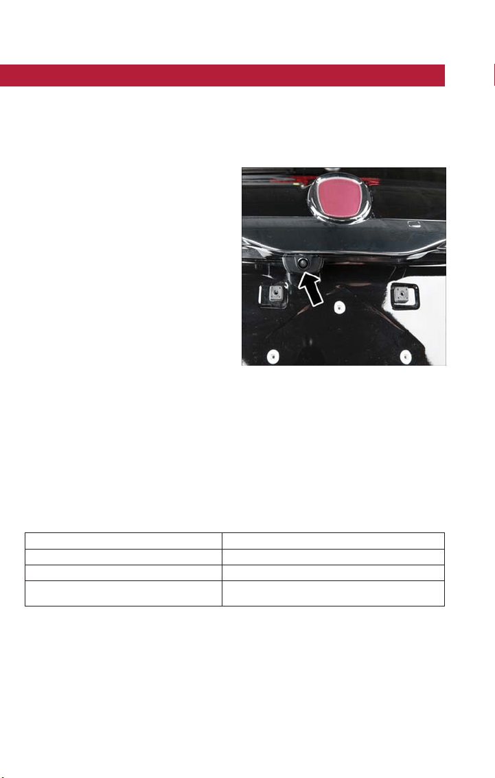
PARKVIEW REAR BACK UP C AMERA — IF EQUIPPED
The ParkView Rear Back Up Camera that allows you to see an on-screen image of your
vehicle's rear surroundings when the gear selector is put into REVERSE. The image will
be displayed on the touchscreen display along with a note to “check entire surroundings”
across the top of the screen. Af ter five seconds this note will disappear. The ParkView
camera is located above the rear license plate.
When the vehicle is shifted out of RE-
VERSE (with camera delay turned off), the
rear camera mode is exited and the naviga-
tion or audio screen appears again.
When the vehicle is shifted out of RE-
VERSE (with camera delay turned on), the
camera image will continue to be displayed
for up to 10 seconds af ter shifting out of
REVERSE unless the vehicle speed exceeds
8 mph (13 km/h), the vehicle is shifted into
PARK or the ignition is switched to STOP
mode.
A touchscreen button to disable the cam-
era is available when the vehicle is not in
REVERSE. Display of the camera image
after shifting out of REVERSE can be disabled via Uconnect Settings.
When enabled, active guide lines are overlaid on the image to illustrate the width of the
vehicle and its projected backup path based on the steering wheel position.
When enabled, fixed guide lines are overlaid on the image to illustrate the width of the
vehicle.
Different colored zones indicate the distance to the rear of the vehicle.
The following table shows the approximate distances for each zone:
Zone Distance To The Rear Of The Vehicle
Red 0-1ft(0-30cm)
Yellow 1 ft-3ft(30cm-1m)
Green 3ftorgreater(1morgreater)
NOTE:
If snow, ice, mud, or any foreign substance builds up on the camera lens, clean the lens,
rinse with water, and dry with a soft cloth. Do not cover the lens.
Parking Camera
OPERATING YOUR VEHICLE
86

WARNING!
Drivers must be careful when backing up even when using the ParkView Rear Back Up
Camera. Always check carefully behind your vehicle, and be sure to check for pedestri-
ans, animals, other vehicles, obstructions, or blind spots before backing up. You are re-
sponsible for the safety of your surroundings and must continue to pay attention while
backing up. Failure to do so can result in serious injury or death.
CAUTION!
• To avoid vehicle damage, ParkView should only be used as a parking aid. The
ParkView camera is unable to view every obstacle or object in your drive path.
• To avoid vehicle damage, the vehicle must be driven slowly when using ParkView
to be able to stop in time when an obstacle is seen. It is recommended that the
driver look frequently over his/her shoulder when using ParkView.
OPERATING YOUR VEHICLE
87
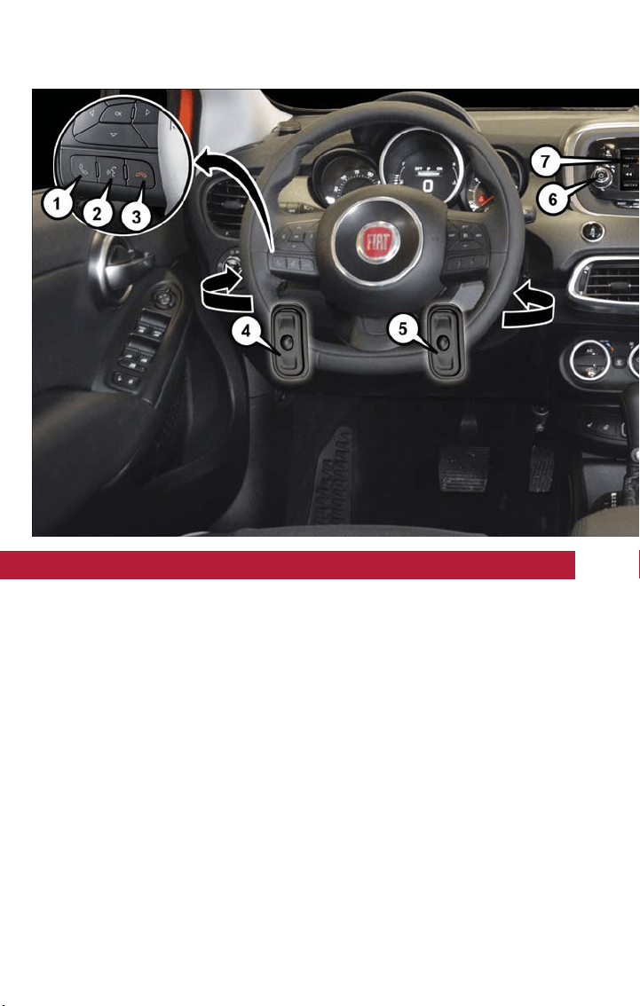
YOUR VEHICLE'S SOUND SYSTEM
1. Uconnect Phone Button pg. 125
2. Uconnect Voice Command Button pg. 131
3. Phone Hang Up Button
4. Left Steering Wheel Audio Controls (Located Behind The Steering Wheel) pg. 135
5. Right Steering Wheel Audio Controls (Located Behind The Steering Wheel) pg. 135
6. Volume Knob — On/Off Button
ELECTRONICS
88
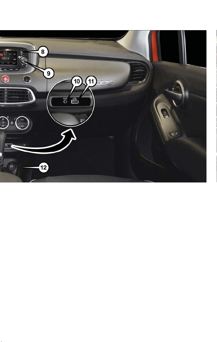

CYBERSECURITY
Your vehicle may be a connected vehicle and may be equipped with both wired and
wireless networks. These networks allow your vehicle to send and receive information.
This information allows systems and fea tures in your vehicle to function properly.
Your vehicle may be equipped with certain security features to reduce the risk of unau-
thorized and unlawful access to vehicle systems and wireless communications. Vehicle soft-
ware technology continues to evolve over time and FCA US LLC, working with its suppli-
ers, evaluates and takes appropriate steps as needed. Similar to a computer or other
devices, your vehicle may require software updates to improve the usability and perfor-
mance of your systems or to reduce the potential risk of unauthorized and unlawful ac-
cess to your vehicle systems.
The risk of unauthorized and unlawful access to your vehicle systems may still exist, even
if the most recent version of vehicle software (such as Uconnect software) is installed.
WARNING!
• It is not possible to know or to predict all of the possible outcomes if your vehi-
cle’s systems are breached. It may be possible that vehicle systems, including safety
related systems, could be impaired or a loss of vehicle control could occur that
may result in an accident involving serious injury or death.
• ONLY insert media (e.g., USB, SD card, or CD) into your vehicle if it came from a
trusted source. Media of unknown origin could possibly contain malicious software,
and if installed in your vehicle, it may increase the possibility for vehicle systems to
be breached.
• As always, if you experience unusual vehicle behavior, take your vehicle to your
nearest authorized dealer immediately.
NOTE:
• FCA or your dealer may contact you directly regarding software updates.
• To help further improve vehicle security and minimize the potential risk of a security
breach, vehicle owners should:
• Routinely check www.driveuconnect.com/software-update to learn about available
Uconnect software updates.
• Only connect and use trusted media devices (e.g. personal mobile phones, USBs,
CDs).
Privacy of any wireless and wired communications cannot be assured. Third parties may
unlawfully intercept information and private communications without your consent. For
further information, refer to “Onboard Diagnostic System (OBD II) Cybersecurity” in
“Getting To Know Your Instrument Panel” in your Owner’s Manual.
ELECTRONICS
90
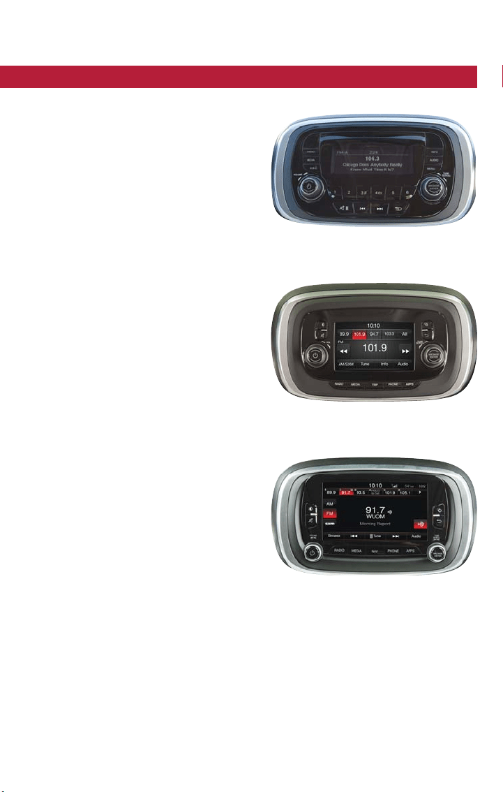
IDENTIFYING YOUR RADIO
Radio 3.0
• 3.0” Display
• Three buttons on t he faceplate on either
side of the display
Uconnect 5.0
• 5.0” Full Color Touchscreen Display
• Bluetooth Connectivity/Bluetooth
Streaming Audio
Uconnect 6.5 NAV
• 6.5” Full Color Touchscreen Display
• HD Radio button visible on right side of
the screen (if equipped)
• Bluetooth Connectivity/Bluetooth
Streaming Audio
Radio 3.0
Uconnect 5.0
Uconnect 6.5 NAV
ELECTRONICS
91
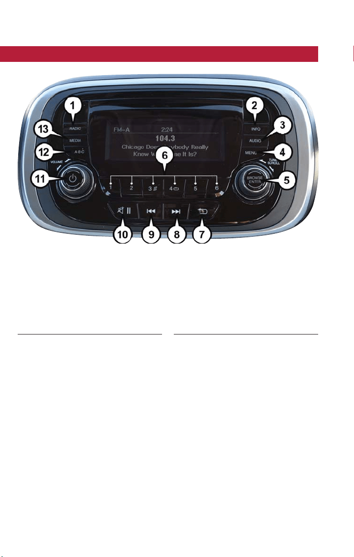
RADIO 3.0
Clock Setting
1. Push the Menu button, then push the Enter/Browse button for System Settings. Next,
select the Time and Format setting and then select Set Time by pushing the Enter/
Browse button.
2. Adjust the hours or minutes by turning the Tune/Scroll knob, then pushing the Enter/
Browse button to move to the next entry. You can also select 12hr or 24hr format by
turning the Tune/Scroll knob, then pushing the Enter/Browse button on the desired
selection.
3. Once the time is set push the “Back” button to exit the time screen.
Radio 3.0 Buttons
1 — RADIO Button
2 — INFO Button
3 — AUDIO Button
4 — MENU Button
5 — BROWSE/ENTER Button — TUNE/
SCROLL Knob
6 — Preset Buttons
7 — BACK Button
8 — SEEK Next Button
9 — SEEK Previous Button
10 — Play/Pause — Mute Button
11 — ON/OFF Button/Volume Knob
12 — A-B-C Button
13 — MEDIA Button
ELECTRONICS
92

Audio
Push the AUDIO button on the radio faceplate.
The Audio Menu shows the following options for you to customize your audio settings.
Treble, Mid, Bass, Fade, Balance, Speed Adjusted Volume, Loudness Select the desired
setting to adjust, then push the ENTER/BROWSE button. Turn the TUNE/SCROLL knob
to adjust the setting plus or minus nine. Push the “Back” button when done.
Radio Operation
Seek Previous/Next Buttons
• Push the up or down buttons to seek through radio stations in AM, FM or SXM
bands.
• Hold either button to bypass stations without stopping.
Store Radio Presets Manually
The Radio stores up to 18 presets in each of the Radio modes. Push the A-B-C button
on the faceplate to select the A, B or C preset list. The Presets are available for all Radio
Modes, and are activated by pushing any of the six Preset buttons.
To store a radio preset manually, follow the steps below:
1. Tune to the desired station.
2. Push and hold the desired numbered button for more than two seconds, or until you
hear a confirmation beep.
USB/Audio Jack (AUX) Manual Operation
To select a specific audio source, push the MEDIA button on the faceplate. To allow mu-
sic to play from your portable device through the vehicle’s speakers, push the MEDIA
button repeatedly to select one of the following modes:
USB/iPod This mode is entered by either inserting a USB Jump Drive or iPod cable into
the USB port or by pushing the MEDIA button located left of the display.
ELECTRONICS
93

Audio Jack (AUX)
• The AUX allows a portable device such as an MP3 player or an iPod to be plugged
into the radio and utilize the vehicle’s audio system, using a 3.5 mm audio cable, to
amplify the source and play through the vehicle’s speakers.
• The functions of the portable device are controlled using the device buttons, not the
buttons on the radio. The volume may be controlled using the radio or portable
device.
Bluetooth Mode
Bluetooth Streaming Audio (BTSA) or Bluetooth Mode is entered by pairing a Bluetooth
device containing music to the Uconnect system.
NOTE:
• Before proceeding, the Bluetooth device must be paired with the Uconnect Phone to
communicate with the Uconnect system. Refer to “Pairing (Wireless Connecting) Your
Mobile Phone To The Uconnect System” within the Electronics chapter of this manual.
• If changing the name of the device within t he Bluetooth settings of your device (where
applicable), and the device is connected to the vehicles Bluetooth, the system may
change the current playing track.
Once the Bluetooth device is paired to the Uconnect system, push the MEDIA button on
the faceplate.
NOTE:
For mobile phone compatibility and pairing instructions, please visit UconnectPhone.com.
Radio 3.0 Available Media Hubs
Radio 3.0 Media Hub (USB,
AUX Ports)
Remote USB Port
(Fully Functional)
Remote USB Port
(Charging Only)
S N/A N/A
S = Standard Equipment
N/A = Not Available
ELECTRONICS
94
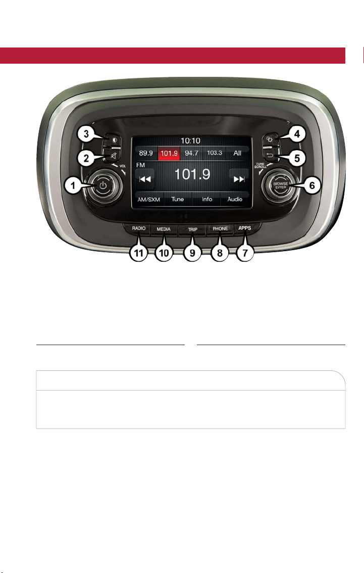
UCONNECT 5.0
CAUTION!
Do NOT attach any object to the touchscreen, doing so can result in damage to the
touchscreen.
Clock Setting
To start the clock setting procedure:
1. Push the Settings button on the faceplate and then press the “Clock and Date” button
on the touchscreen.
2. Press the “Set Time” button on the touchscreen.
Uconnect 5.0 Radio Buttons
1 — On/Off Button
2 — Mute Button
3 — Screen Off Button
4 — Settings Button
5 — Back Button
6 — BROWSE/ENTER Button — TUNE/
SCROLL Knob
7 — APPS Button
8 — PHONE Button
9 — TRIP Button
10 — MEDIA Button
11 — RADIO Button
ELECTRONICS
95

3. Press the “Up” or “Down” arrows to adjust the hours or minutes, then select the
“AM” or “PM” button on the touchscreen. You can also select 12hr or 24hr format by
pressing the desired button on the touchscreen.
4. Once the time is set press the “Done” button on the touchscreen to exit the time
screen.
NOTE:
In the Clock Setting Menu you can also select Display Clock. Display Clock turns the
clock display in the status bar on or off.
Audio Setting
1. Push the Settings button on the faceplate.
2. Scroll down and press the “Audio” button on the touchscreen to open the Audio
menu.
3. The Audio Menu shows the following options for you to customize your audio set-
tings.
Equalizer
Press the “Equalizer” button on the touchscreen to adjust the Bass, Mid and Treble. Use
the “+” or “-” button on the touchscreen to adjust the equalizer to your desired settings.
Balance/Fade
Press the “Balance/Fade” button on the touchscreen to adjust the sound from the speak-
ers. Use the arrow buttons on the touchscreen to adjust the sound level from the front
and rear or right and left side speakers. Press the Center “C” button on the touchscreen
to reset the balance and fade to the factory setting.
Speed Adjusted Volume — If Equipped
Press the “Speed Adjusted Volume” button on the touchscreen to select between OFF, 1,
2or3. This will decrease the radio volume relative to a decrease in vehicle speed.
Loudness — If Equipped
Press the “Loudness” button on the touchscreen to select the Loudness feature. When
this feature is activa ted it improves sound quality at lower volumes.
Surround Sound — If Equipped
Press the “Surround Sound” button on the touchscreen, select On or Off followed by
pressing the back arrow button on the touchscreen. When this feature is activated, it pro-
vides simulated surround sound mode.
ELECTRONICS
96
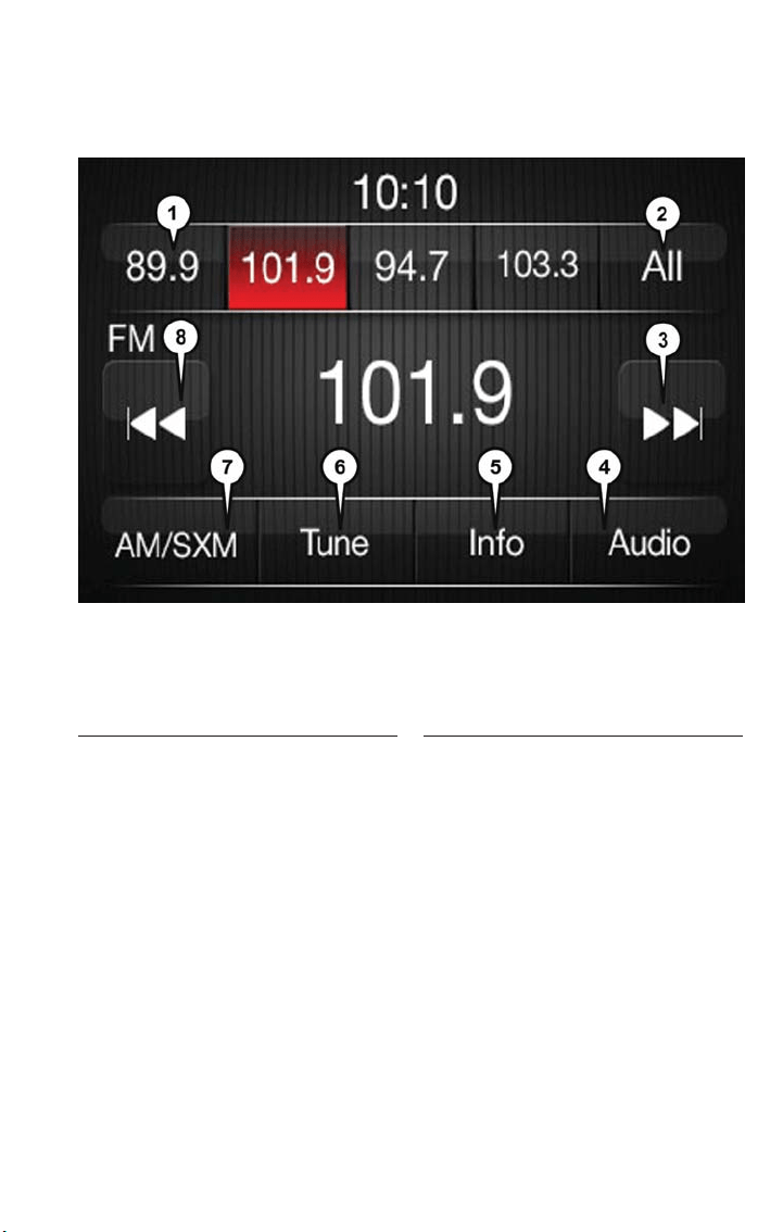
Radio Operation
Store Radio Presets Manually
The Radio stores up to 12 presets in each of the Radio modes. There are four visible
presets at the top of the radio screen. Pressing the “All” button on the touchscreen on
the radio home screen will display all of the preset stations for that mode.
To store a radio preset manually, follow the steps below:
1. Tune to the desired station.
2. Press and hold the desired numbered button on the touchscreen for more than two
seconds, or until you hear a confirmation beep.
Seek Next/Previous Buttons
• Press the up or down button to seek through radio stations in AM, FM or SXM bands.
• Hold either button to bypass stations without stopping.
Radio Operation
1 — Radio Station Preset
2 — All Presets
3 — Seek Next
4 — Audio Settings
5 — Station Information
6 — Direct Tune
7 — Radio Band
8 — Seek Previous
ELECTRONICS
97
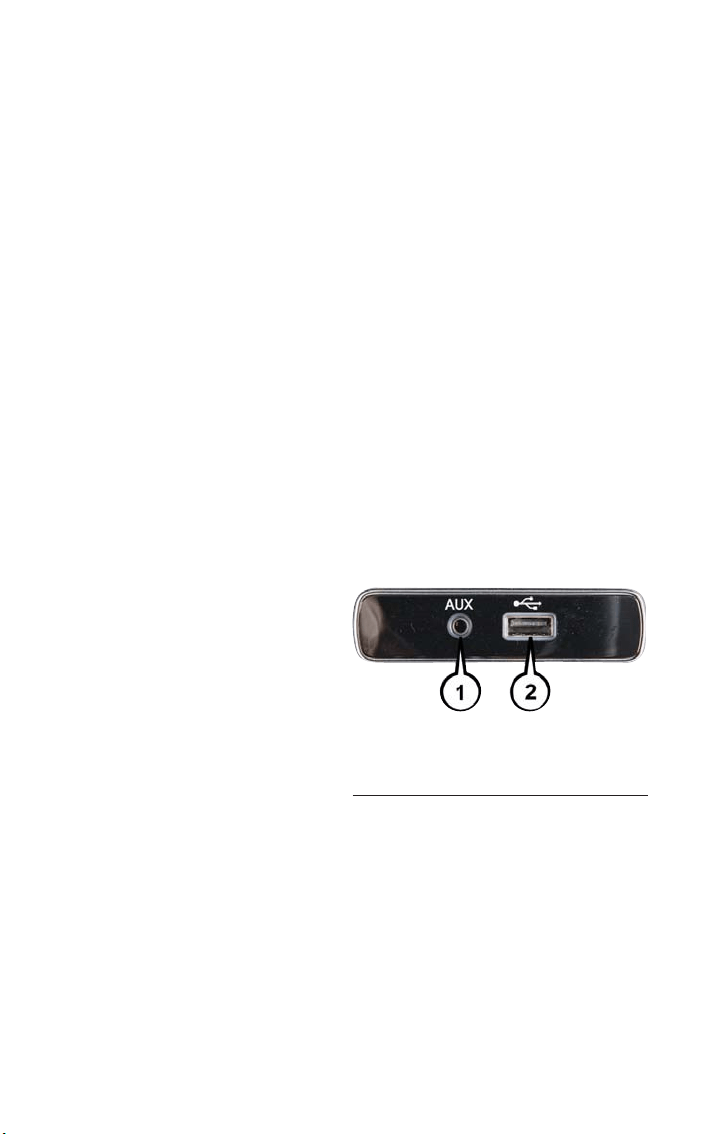
SiriusXM Premier Over 160 Channels
Get every channel available on your satellite radio, and enjoy all you want, all in one place.
Hear commercial-free music plus sports, news, talk and entertainment. Get all the pre-
mium programming, including Howard Stern, every NFL game, Oprah Radio, every MLB
and NHL game, every NASCAR race and more . And get 20+ Xtra channels, including
SiriusXM Latino, a selec tion of channels dedicated to Spanish language programming.
• To access SiriusXM Satellite Radio, push the RADIO Button on the faceplate and then
the “SXM” button on the touchscreen.
SiriusXM services require subscriptions, sold separately after the 12-month trial included
with the new vehicle purchase. If you decide to continue your service at the end of your
trial subscription, the plan you choose will automatically renew and bill at then-current
rates until you call SiriusXM at 1-866-635-2349 for U.S. residents and 1-888-539-7474
for Canadian residents to cancel. See SiriusXM Customer Agreement for complete
terms at www.siriusxm.com and www.siriusxm.ca for Canadian residents. All fees and
programming subject to change. Our satellite service is available only to those at least
18 and older in the 48 contiguous USA and D.C. Our Sirius satellite service is also avail-
able in PR (with coverage limitations). Our Internet radio service is available throughout
our satellite service area and in AK and HI. © 2017 Sirius XM Radio Inc. Sirius, XM and
all related marks and logos are trademarks of Sirius XM Radio Inc.
USB/Audio Jack (AUX)/Bluetooth Operation
USB/AUX
The USB/AUX Jack is located in the center
of the instrument panel, below the HVAC
controls.
• USB/iPod Mode is entered by either in-
serting a USB Jump Drive or an iPod
cable into the USB port or by pushing
the MEDIA button on the faceplate lo-
cated below the display. Once in Media
Mode, press the “Source” button on the
touchscreen and select USB/iPod.
NOTE:
The USB source will say "iPod" only when an apple product is connected to the USB
port.
• Push the MEDIA button on the faceplate, press the “Source” button on the touch-
screen then select USB/iPod to change t he mode to the USB device. If the device is
connected, music from your portable device will play through the vehicle's speakers.
Audio Jack (AUX) And USB Port
1 — AUX/Audio Jack
2 — USB Port
ELECTRONICS
98

Audio Jack (AUX)
The AUX jack allows a portable device, such as an MP3 player or an iPod, to be plugged
into the radio and utilize the vehicle’s audio system, using a 3.5 mm audio cable, to am-
plify the source and play through the vehicle speakers.
• Push the MEDIA button on the faceplate, press the “Source” button on the touch-
screen then select AUX to change the mode to AUX.
• The functions of the portable device are controlled using the device. However, the
volume may be controlled using the radio or portable device.
Bluetooth
If using a Bluetooth - equipped device, you may also be able to stream music to your
vehicle's sound system.
Push the MEDIA button on the faceplate, press the “Source” button on the touchscreen
then select Bluetooth to change the mode to Bluetooth. If the device is paired, music
from your portable device will play through t he vehicle's speakers.
Uconnect 5.0 Available Media Hubs
Uconnect 5.0 Media Hub (USB,
AUX Ports)
Remote USB Port
(Fully Functional)
Remote USB Port
(Charging Only)
S N/A S
S = Standard Equipment
N/A = Not Available
Voice Text Reply (Not Compatible With iPhone)
Once your Uconnect system is paired with a compatible mobile device, the system can
announce a new incoming text message, and read it to your over the vehicle audio sys-
tem. You can reply to the message using Voice Recognition by selecting, or saying, one of
the 18 pre-defined messages.
Here’s how:
1. Push the Uconnect Phone button
and wait for the beep, then say “reply.”
Uconnect will give the following prompt: “Please say the message you would like to
send.”
2. Wait for the beep and say one of the pre-defined messages. (If you are not sure, you
can say “help”). Uconnect will then read the pre-defined messages allowed.
3. As soon as you hear the message you would like to send, you can interrupt the list of
prompts by pushing the Uconnect phone button and saying the phrase. Uconnect will
confirm the message by reading it back to you.
4. Push the Phone button and say “Send.”
ELECTRONICS
99
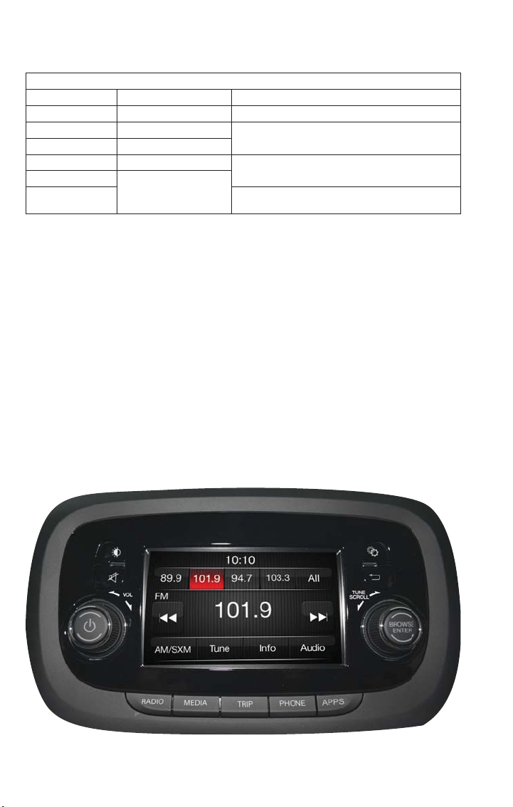
PRE-DEFINED VOICE TEXT REPLY RESPONSES
Ye s . Stuck in traffic. See you later.
No. Start without me. I’ll be late.
Okay. Where are you?
I will be <5, 10, 15, 20, 25, 30, 40, 45, 60>*
minutes late.
Call me. Are you there yet?
I’ll call you later. I need directions.
See you in <5, 10, 15, 20, 25, 30, 40, 45, 60>*
minutes.
I’m on my way.
Can’t talk right now.
I’m los t. Thanks.
*Use only the numbers listed or the system will not transpose the message.
NOTE:
Voice texting reply and voice texting features require a compatible mobile device enabled with
Bluetooth Message Access Profile (MAP). iPhone and some other smartphones do not currently
support Bluetooth MAP. Visit
UconnectPhone.com for system and device compatibility.
Want to dictate a personal message? You must first register with Uconnect Access (U.S.
residents only) to take advantage of a new, cloud-based Voice Texting service, an enhance-
ment to Voice Text Reply.
UCONNECT 5.0 VOICE RECOGNITION QUICK TIPS
Introducing Uconnect
Start using Uconnect Voice Recognition with these helpful quick tips. It provides the key
Voice Commands and tips you need to know to control your Uconnect 5.0 system.
Key Features:
• Five-inch Color Touchscreen Display with AM/FM/USB/Bluetooth
• Bluetooth with integrated voice control
Uconnect 5.0
ELECTRONICS
100
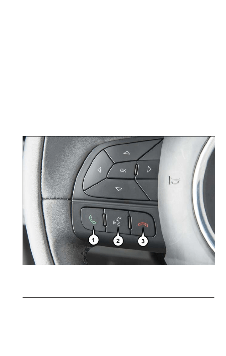
Get Started
1. Visit UconnectPhone.com to check mobile device and feature compatibility and to
find phone pairing instructions.
2. Reduce background noise. Wind and passenger conversations are examples of noise
that may impact recognition.
3. Speak clearly at a normal pace and volume while facing straight ahead. The micro-
phone is positioned on the rearview mirror and aimed at the driver.
4. Each time you give a Voice Command, you must first press either the VR or Phone
button, wait until after the beep, then say your Voice Command.
5. You can interrupt the help message or system prompts by pressing the VR or Phone
button and saying a Voice Command from current category.
All you need to control your Uconnect system with your voice are the buttons on your
steering wheel.
Uconnect VR And Phone Buttons
1 — Push To Initiate Or To Answer A Phone Call, Send Or Receive A Text
2 — Push For Voice Recognition (VR)
3 — Push To End Call
ELECTRONICS
101
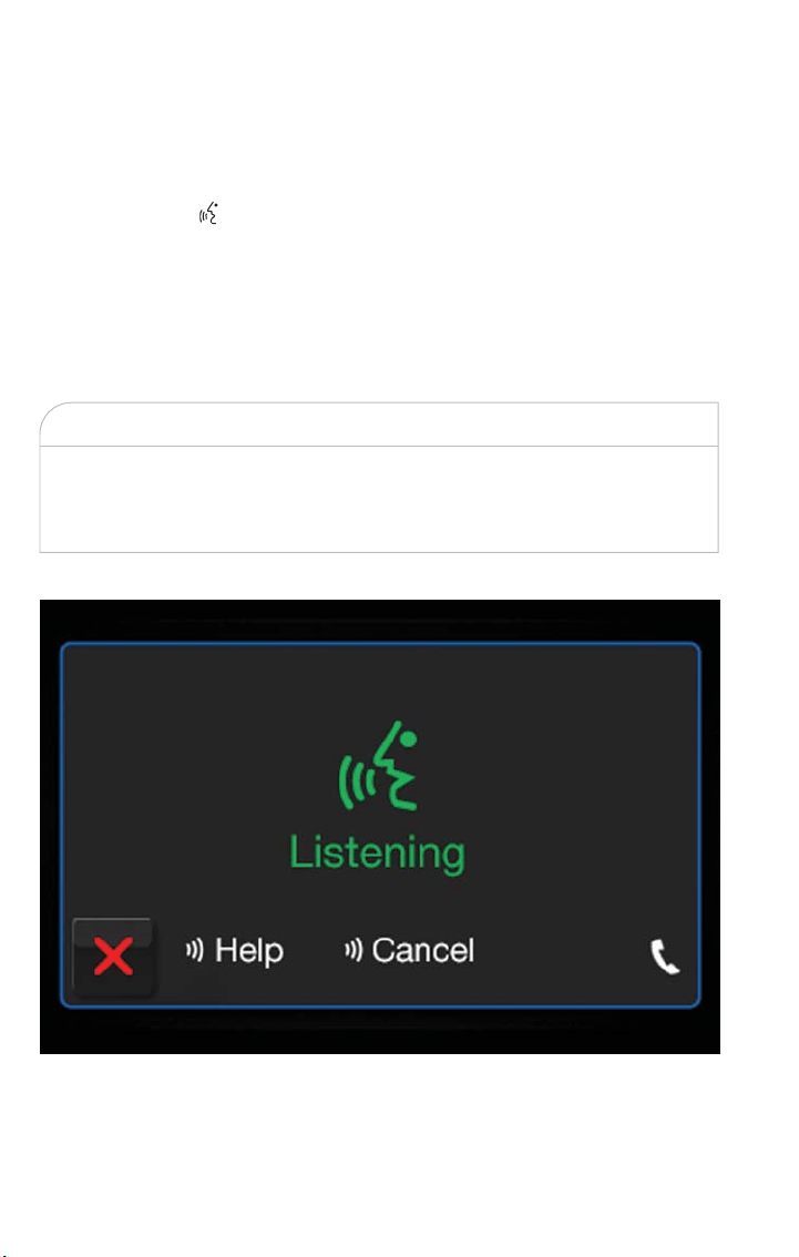
Basic Voice Commands
The basic Voice Commands below can be given at any point while using your Uconnect
system.
Push the VR button
. Af ter the beep, say:
• “Cancel” to stop a current voice session
• “Help” to hear a list of suggested Voice Commands
• “Repeat” to listen to the system prompts again
Notice the visual cues that inform you of your voice recognition system’s status. Cues
appear on the touchscreen.
WARNING!
Any voice commanded system should be used only in safe driving conditions following
all applicable laws.Your attention should be focused on safely operating t he vehicle. Fail-
ure to do so may result in a collision causing serious injury or death.
Uconnect 5.0 Visual Cues
ELECTRONICS
102

Radio
Use your voice to quickly get to the AM, FM or SiriusXM Satellite Radio stations you
would like to hear. (Subscription or included SiriusXM Satellite Radio trial required.)
Push the VR button . Af ter the beep, say:
• “Tune to ninety-five-point-five FM”
• “Tune to Satellite Channel Hits 1”
TIP
At any time, if you are not sure of what to say or want to learn a Voice Command, push
the VR button
and say “Help.” The system provides you with a list of commands.
Uconnect 5.0
ELECTRONICS
103
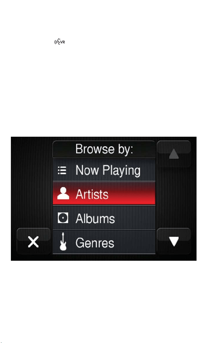
Media
Push the VR button . Af ter the beep, say one of the following commands and fol-
low the prompts to switch your media source or choose an artist.
• “Change source to Bluetooth”
• “Change source to iPod”
• “Change source to USB”
• “Play artist Beethoven”; “Play album Greatest Hits”; “Play song Moonlight Sonata”; “Play
genre Classical”
TIP
Press the Browse button on the touchscreen to see all of the music on your iPod or
USB device. Your Voice Command must match exactly how the artist, album, song and
genre information is displayed.
Uconnect offers connections via USB, Bluetooth and auxiliary ports (If Equipped). Voice
operation is only available for connected USB and iPod devices.
Uconnect 5.0 Media
ELECTRONICS
104
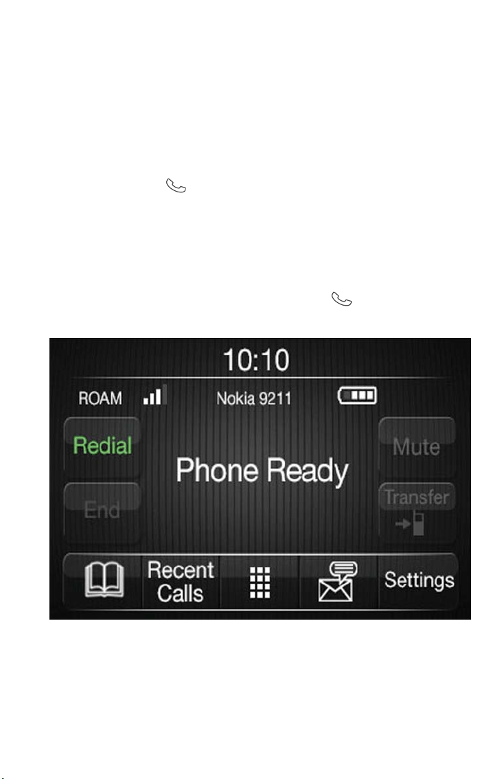
Phone
Making and answering hands-free phone calls is easy with Uconnect. When the Phone-
book button is illuminated on your touchscreen, your system is ready.
U.S./Canadian residents can visit
• UconnectPhone.com to check mobile device and feature compatibility and to find
phone pairing instructions.
Push the Phone button
. Af ter the beep, say one of the following commands…
• “Call John Smith”
• “Dial 123-456-7890 and follow the system prompts”
• “Redial (call previous outgoing phone number)”
• “Call back (call previous incoming phone number)”
TIP
When providing a Voice Command, press the Phone button
and say “Call,” then
pronounce the name exactly as it appears in your phone book. When a contact has mul-
tiple phone numbers, you can say “Call John Smith “work.”
Additional Information
© 2017 FCA US LLC. All rights reserved. Mopar, Mopar Owner Connect and Uconnect
are registered trademarks of FCA US LLC. Android is a trademark of Google Inc.
SiriusXM and all related marks and logos are trademarks of SiriusXM Radio Inc. Yelp, Yelp
logo, Yelp burst and related marks are registered trademarks of Yelp.
Uconnect 5.0 Phone
ELECTRONICS
105
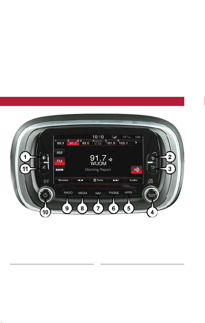
Uconnect System Support:
• U.S. residents visit DriveUconnect.com or call: 1-877-855-8400 (24 hours a day 7 days
a week)
• Canadian residents visit DriveUconnec t.ca or call: 1-800-465-2001 (English) or
1-800-387-9983 (French)
Mon. – Fri., 8:00 am – 8:00 pm, ET
Sat., 9:00 am – 5:00 pm, ET
Sun., Closed
Uconnect Access Services Support 1-855-792-4241. Please have your Uconnect Security
PIN ready when you call.
UCONNECT 6.5NAV
Uconnect 6.5NAV Radio Buttons
1 — Display On/Off Control
2 — Settings Button
3 — Back Button
4 — BROWSE/ENTER Button — TUNE/
SCROLL Knob
5 — Uconnect APPS Button
6 — Uconnect PHONE Button
7 — Uconnect Navigation (NAV) Button
8 — MEDIA Button
9 — RADIO Button
10 — On/Off Button — Volume Knob
11 — Mute Button
ELECTRONICS
106

Clock Setting
Displaying The Time
If the time is not currently displayed on the radio or player main page press the Settings
button. In the Settings list, press the “Clock” button on the touchscreen then press “On”
or “Off” for Show Time in Status Bar.
Setting The Time
Uconnect 6.5NAV synchronizes time automatically via GPS, so should not require any
time adjustment. If you do need to set the time manually, follow the instructions below.
• Turn the unit on, then press the time display at the top of the screen, a pop-up will
ask if you want to set the time. Press “Yes.”
• If the time is not displayed at the top of the screen, push the Settings button. In the
Settings screen, press the “Clock” button on the touchscreen, then select “ON” for
“Show Time Status.”
• Press “+” or “–” next to Set Time Hours and Set Time Minutes to adjust the time.
• If these features are not available, press “Off” for Sync with GPS.
• Press “X” to exit out of the Clock Setting screen.
Audio Setting
• Press the “Audio” button on t he touchscreen to activate the Audio settings screen to
adjust Balance\Fade, Equalizer, and Speed Adjusted Volume.
• You can return to the Radio screen by pressing the “X” or back arrow located at the
top right.
Balance/Fade
• Press the “Balance/Fade” button on the touchscreen to Balance audio between the
front speakers or fade the audio between the rear and front speakers.
• Pressing the “Front,” “Rear,” “Left,” or “Right” buttons on the touchscreen or press and
drag the Speaker Icon to adjust the Balance/Fade.
Equalizer
• Press the “Equalizer” button on the touchscreen to activate the Equalizer screen.
• Press the “+” or “-” buttons on the touchscreen, or press and drag over the level bar
for each of the equalizer bands. The level value, which spans between plus or minus
nine, is displayed at the bottom of each of the Bands.
Speed Adjusted Volume — If Equipped
• Press the “Speed Adjusted Volume” button on the touchscreen to activate the Speed
Adjusted Volume screen. The Speed Adjusted Volume is adjusted by pressing the “+”
and “–” buttons or by pressing and dragging over the level bar. This alters the auto-
matic adjustment of the audio volume with varia tion to vehicle speed.
ELECTRONICS
107
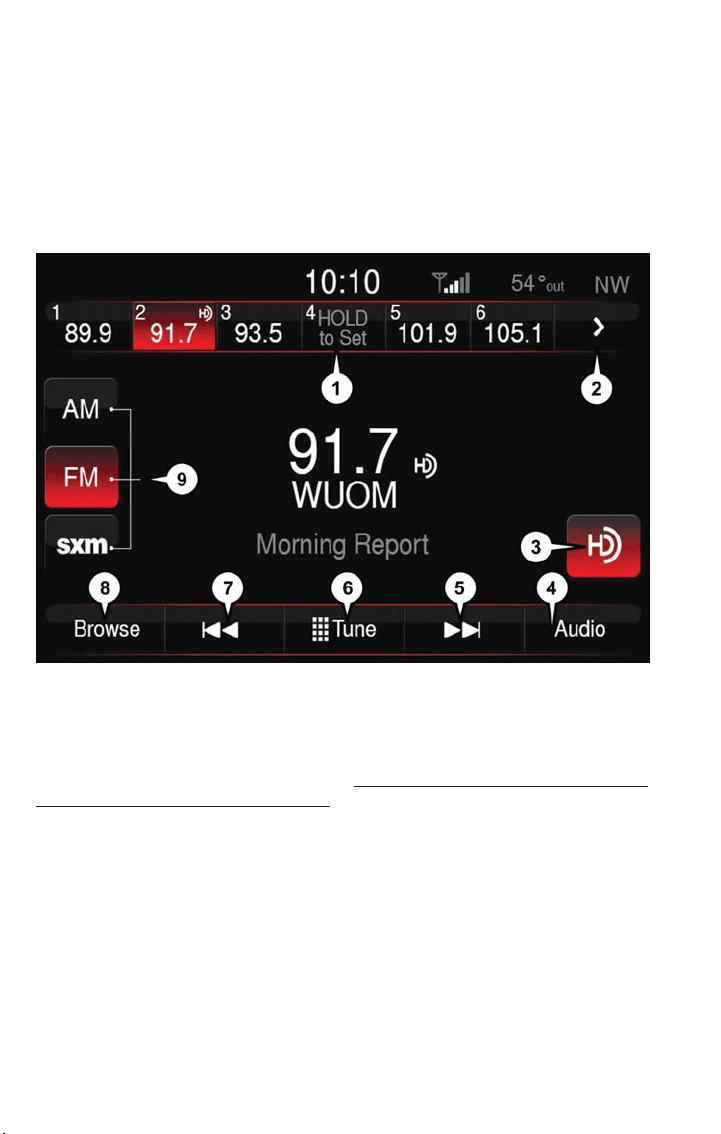
Surround Sound — If Equipped
• Press the “Surround Sound” button on the touchscreen, select “On” or “Off” followed
by pressing the back arrow button on the touchscreen. When this feature is activated,
it provides simulated surround sound mode.
Radio
• To access the Radio mode, press the RADIO button below the screen.
Selecting Radio Stations
• Press the desired radio band (AM, FM or SXM) button.
Seek Next/Seek Previous
• Press the up or down “Seek Arrow” buttons on the touchscreen for less than two
seconds to seek through radio stations.
Uconnect 6.5NAV
1 — Radio Station Presets
2 — Toggle Presets
3 — HD Radio Available
4 — Audio Settings
5 — Seek Next
6 — Direct Tune Radio Stations
7 — Seek Previous
8 — Browse/Manage Presets
9 — Radio Bands
ELECTRONICS
108

• Press and hold either Seek Arrow button on the touchscreen for more than two sec-
onds to bypass stations without stopping. The radio will stop at the next listenable sta-
tion once the Seek Arrow button on the touchscreen is released.
Direct Tune
• Tune directly to a radio station by pressing the “Tune” button on the touchscreen, and
entering the desired station number.
Store Radio Presets Manually
Your radio can store 36 total preset s tations, 12 presets per band (AM, FM and SXM).
They are shown at the top of your radio screen. To see the 12 preset stations per band,
press the “Arrow” button on the touchscreen at the top right of the screen to toggle
between the two sets of six presets.
You can also see all presets for a band by pressing the "Browse" button on the touch-
screen. This browse screen lets you delete a preset and shows the station frequency,
name and genre.
To store a radio preset manually, follow the steps below:
1. Tune to the desired station.
2. Press and hold the desired numbered button on the touchscreen for more than two
seconds or until you hear a confirmation beep.
SiriusXM Premier Over 160 Channels
Get every channel available on your satellite radio, and enjoy all you want, all in one place.
Hear commercial-free music plus sports, news, talk and entertainment. Get all the pre-
mium programming, including Howard Stern, every NFL game, Oprah Radio, every MLB
and NHL game, every NASCAR race and more . And get 20+ Xtra channels, including
SiriusXM Latino, a selec tion of channels dedicated to Spanish language programming.
• To access SiriusXM Satellite Radio, press the “SXM” button on the main Radio screen.
The following describes features that are available when in SiriusXM Satellite Radio mode.
Seek Up/Seek Down
Press the “Seek Arrow” buttons on the touchscreen for less than two seconds to seek
through channels in SXM mode.
Press and hold either arrow button on the touchscreen for more than two seconds to
bypass channels without stopping. The radio will stop at the next listenable channel once
the arrow button on the touchscreen is released.
Direct Tune
Tune directly to a SXM channel by pressing the “Tune” button on the touchscreen, and
entering the desired station number.
ELECTRONICS
109

Traffic & Weather
Automatically tells you when Traffic & Weather for a favorite city is available, and gives
you the option to switch to that channel.
Fav
Activates the favorites menu. You can add up to 50 favorite artists or songs. Just press
Add “Fav Ar tist” or “Add Fav Song” while the song is playing. You will then be alerted any
time one of these songs, or works by these artists, is playing on other SiriusXM channels.
SiriusXM Parental Controls
• You can skip or hide certain channels from view if you do not want access to them.
Push the SETTINGS button on the faceplate, press the “SiriusXM Setup” button on the
touchscreen, then select Channel Skip. Press the box, check-mark, next to the channel
you want skipped. They will not show up in normal usage.
• SiriusXM also offers the option to permanently block selec ted channels. Call
(1-888-601-6297 for U.S. customers, 1-877-438-9677 for Canadian customers) and
request the Family-Friendly Package .
Browse
Lets you browse the SiriusXM channel listing or Genre listing. Favorites, Game Zone,
Weather and Jump settings also provide a way to browse the SiriusXM channel list.
Browse
Sub-Menu
Sub-Menu Description
All Shows the channel listing.
Genre Provides a list of all genres, and lets you jump to a channel within the selected
genre.
Presets Lets you scroll the list of preset satellite channels. Press the channel, or press
enter on the yune knob, to go to that channel. Press the trash can icon to delete
a preset. Your presets are also shown at the top of the main Satellite Radio
screen.
Favorites Lets you manage artists and songs in the favorites list and configureAlert Settings
to let you know when favorite songs or artists are playing on other channels.
Also, view a list of channels airing any of your Favorites.
Game Zone Provides alerts when your favorite sports teams are starting a game which is
being aired on other SiriusXM channels, or when their game score is announced.
You can select and manage your teams list here, and configure alerts.
Jump Lets you select your favorite cities for Traffic & Weather information, which is
used by the jump feature on the main satellite radio screen.
ELECTRONICS
110
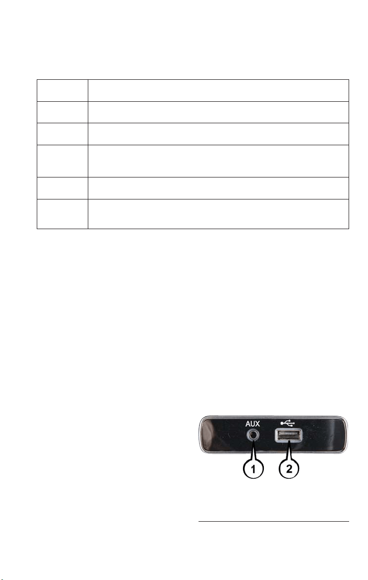
Replay
Lets you replay up to 44 minutes of the content of the current SiriusXM channel.
Replay
Option
Option Description
Play/Pause
Press to pause content playback. Press pause/play again to resume play-
back.
Rewind/RW Rewinds the channel content in s teps of five seconds. Press and hold to
rewind continuously, then release to begin playing content at that point.
Fast
Forward/FW
Forwards the content, and works similarly to Rewind/RW. However, Fast
Forward/FW can only be used when content has been previously re-
wound.
Replay Time Displays the amount of time in the upper center of the screen by which
your content lags the live channel.
Live Resumes playback of Live content at any time while replaying rewound
content.
• SiriusXM services require subscriptions, sold separately after the 12-month trial in-
cluded with the new vehicle purchase. If you decide to continue your service at the
end of your trial subscription, the plan you choose will automatically renew and bill at
then-current rates until you call SiriusXM at 1-866-635-2349 for U.S. residents and
1-888-539-7474 for Canadian residents to cancel. See SiriusXM Customer Agreement
for complete terms at www.siriusxm.com for U.S. residents and www.siriusxm.ca for
Canadian residents. All fees and programming subject to change. Our satellite service
is available only to those at least 18 and older in the 48 contiguous USA and D.C.
Our Sirius satellite service is also available in PR (with coverage limitations). Our Inter-
net radio service is available throughout our satellite service area and in AK and HI .
© 2017 Sirius XM Radio Inc. Sirius, XM and all related marks and logos are trademarks
of Sirius XM Radio Inc.
Media Hub – Playing iPod/USB/MP3 Devices
There are many ways to play music from iPod/MP3 players or USB devices through your
vehicle's sound system.
Audio Jack (AUX)
The AUX allows a portable device, such as
an MP3 player or an iPod, to be plugged
into the radio and utilize the vehicle’s sound
system, using a 3.5 mm audio cable, to am-
plify the source and play through the ve-
hicle speakers.
Audio Jack (AUX) And USB Port
1 — AUX/Audio Jack
2 — USB Port
ELECTRONICS
111

• Press the MEDIA button, press “Select Source” and then choose “AUX” source will
change the mode to auxiliary device if the audio jack is connected, allowing the music
from your portable device to be heard through the vehicle's speakers. To activate the
AUX, plug in the audio jack.
• The functions of the portable device are controlled using the device buttons. The vol-
ume may be controlled using the radio or portable device.
• To route the audio cable out of the center console, use the access cut out in the front
of the console.
USB Port
Connect your iPod or compatible device using a USB cable into the USB Port. USB
Memor y sticks with audio files can also be used. Then, audio from the device can be
played on the vehicle’s sound system while providing metadata (artist, track title, album,
etc.) information on the radio display.
When connected, the iPod/compatible USB device can be controlled using the radio or
Steering Wheel Audio Controls to play, skip to the next or previous track, browse, and list
the contents.
The USB device battery charges when plugged into the USB port (if supported by the
specific device).
• To route the USB/iPod cable out of the center console, use the access cut out.
NOTE:
• When connecting your iPod device for the first time, the system may take several min-
utes to read your music, depending on the number of files. For example, the system
will take approximately five minutes for every 1,000 songs loaded on the device. Also
during the reading process, the Shuffle and Browse functions will be disabled. This pro-
cess ensures the full use of your iPod features and only happens the first time it is
connected. After the first time, the reading process of your iPod will take considerably
less time unless changes are made or new songs are added to the play list.
• The USB port supports certain Mini, Classic, Nano,Touch, and iPhone devices. The USB
port also supports playing music from compatible external USB Mass Storage Class
memor y devices. Some iPod software versions may not fully support the USB port
features. Please visit Apple’s website for iPod software updates.
ELECTRONICS
112
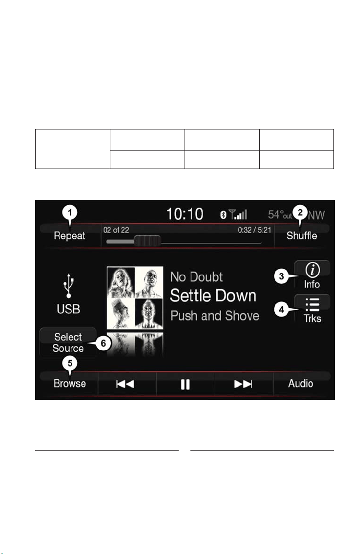
Bluetooth Streaming Audio
If equipped with Uconnect Voice Command, your Bluetooth-equipped iPod devices, cell
phones or other media players, may also be able to stream music to your vehicle's sound
system. Your connected device must be Bluetooth-compatible, and paired with your sys-
tem (see Uconnect Phone for pairing instructions). You can access the music from your
connected Bluetooth device by pressing the “Bluetooth” button on the touchscreen while
in Media mode.
Uconnect 6.5NAV Media Hub (USB,
AUX Ports)
Remote USB Port
(Fully Functional)
Remote USB Port
(Charging Only)
S S N/A
S = Standard Equipment
N/A = Not Available
• The USB/AUX controls are accessed by pressing the desired button on the touch-
screen displayed on the side of the screen and choosing between AUX, USB or
Bluetooth.
iPod/AUX Buttons
1 — Repeat Music Track
2 — Shuffle Music Tracks
3 — Music Track Information
4 — Songs Currently In Queue
5 — Browse Music
6 — Music Source
ELECTRONICS
113
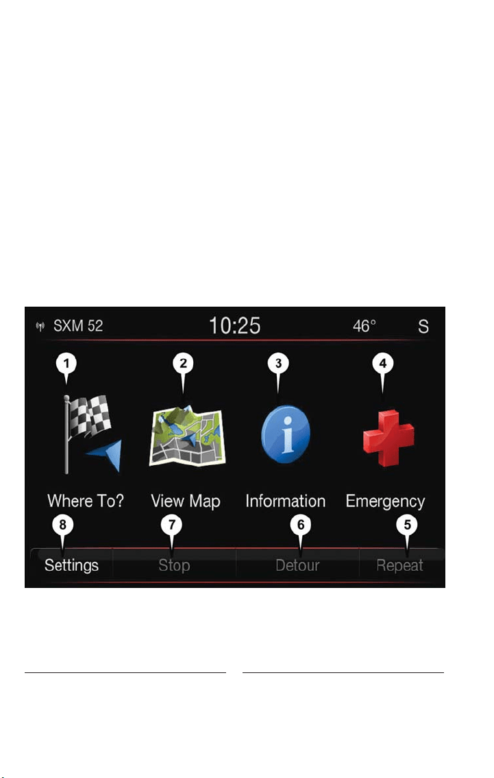
NOTE:
• Uconnect will usually automatically switch to the appropriate mode when something is
first connected or inserted into the system.
• If changing the name of the device within t he Bluetooth settings of your device (where
applicable), and the device is connected to the vehicles Bluetooth, the system may
change the current playing track.
Uconnect 6.5NAV
Press the NAV button to access the Navigation feature.
Changing The Navigation Voice Prompt Volume
1. Press the "Settings" button on the touchscreen from the Nav Main Menu.
2. In the Settings menu, press the “Guidance” button on the touchscreen.
3. In the Guidance menu, adjust the Nav Volume by pressing the “+” or “–” buttons on
the touchscreen.
Uconnect 6.5NAV
1 — Find A Destination
2—ViewMap
3 — View Information
4 — Emergency Assistance
5 — Repeat Route Guidance Prompt
6 — Detour Route
7 — Stop Route
8 — Navigation Settings
ELECTRONICS
114

Finding Points Of Interest
1. From the main Navigation menu, press the “Where To?” button on the touchscreen,
then press the “Point of Interest” button on the touchscreen.
2. Select a Category and then a subcategory, if necessary.
3. Select your destination and press the “Yes” button on the touchscreen.
Finding A Place By Spelling The Name
1. From the Main Navigation Menu, press the “Where to?” button on the touchscreen,
press the “Points of Interest” button on the touchscreen and then press the “Spell
Name” button on the touchscreen.
2. Enter the name of your destination.
3. Press the “List” button on the touchscreen.
4. Select your destination and press the “Yes” button on the touchscreen.
Entering A Destination Address
1. From the main Navigation menu press the “Where To?” button on the touchscreen,
then press the “Address” button on the touchscreen.
2. Follow the on-screen prompts (country, state/province, city, street) to enter the ad-
dress and press the “Yes” button on the touchscreen.
Destination entry is not available while your vehicle is in motion. However, you can also
use Voice Command to enter an address while moving. See Voice Command Tips for
more information.
Setting Your Home Location
1. Press the NAV button to access the Navigation system and the Main Navigation
menu.
2. Press the “Where To?” button on the touchscreen, then press the “Go Home” button
on the touchscreen.
3. You may enter your address directly, use your current location as your home address,
or choose from recently found locations.
To delete your Home location (or other saved locations) so you can save a new Home
location:
1. Press the “Where To?” button on the touchscreen from the Main Navigation menu.
2. Press the “Go Home” button on the touchscreen.
3. In the “Yes” screen, press the “Options” button on the touchscreen.
4. In the Options menu, press Clear Home. Set a new Home location by following the
previous instructions.
ELECTRONICS
115
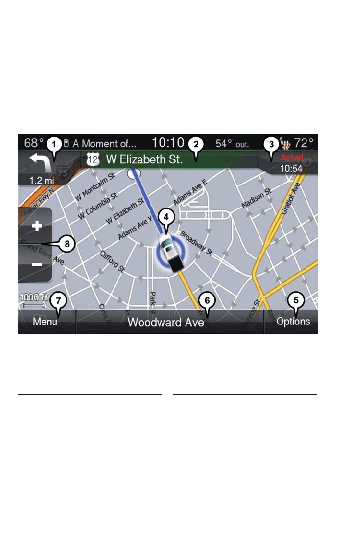
Go Home
A Home location must be saved in the system.
1. From the Main Navigation menu, press the “Where To?” button on the touchscreen,
then press the “Go Home” button on the touchscreen.
2. Your route is marked with a blue line on the map. If you depart from the original
route, your route is recalculated. A speed limit icon could appear as you travel on ma-
jor roadways.
Adding A Stop
To add a stop you must be navigating a route:
1. Press the “Menu” button on t he touchscreen to return to the Main Navigation menu.
2. Press the “Where To?” button on the touchscreen, then search for the extra stop.
When another location has been selected, you can choose to cancel your previous
route, add as the first destination, or add as the last destination.
3. Press the desired selection, and press the “Yes” button on the touchscreen.
Navigation Map
1 — Distance To Next Turn
2 — Next Turn Street
3 — Estimated Time Of Arrival
4 — Your Location
5 — Navigation Routing Options
6 — Current Street Location
7 — Navigation Main Menu
8 — Zoom In/Out
ELECTRONICS
116
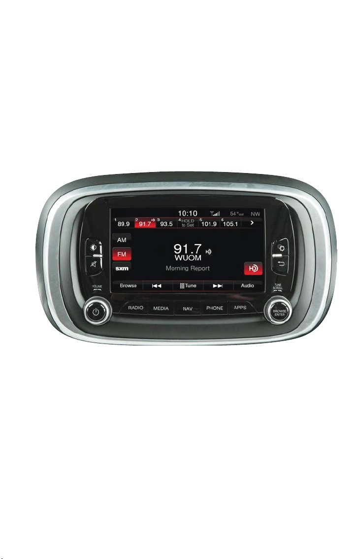
Taking A Detour
To take a detour you must be navigating a route, press the “Detour” button on the
touchscreen. If the route you are currently taking is the only reasonable option, the de-
vice might not calculate a detour.
For more information, see your Uconnect 6.5 NAV Owner’s Manual Supplement.
UCONNECT 6.5 NAV VOICE RECOGNITION QUICK TIPS
Introducing Uconnect
Start using Uconnect Voice Recognition with these helpful quick tips. It provides the key
Voice Commands and tips you need to know to control your Uconnect 6.5NAV system.
Uconnect 6.5NAV
ELECTRONICS
117
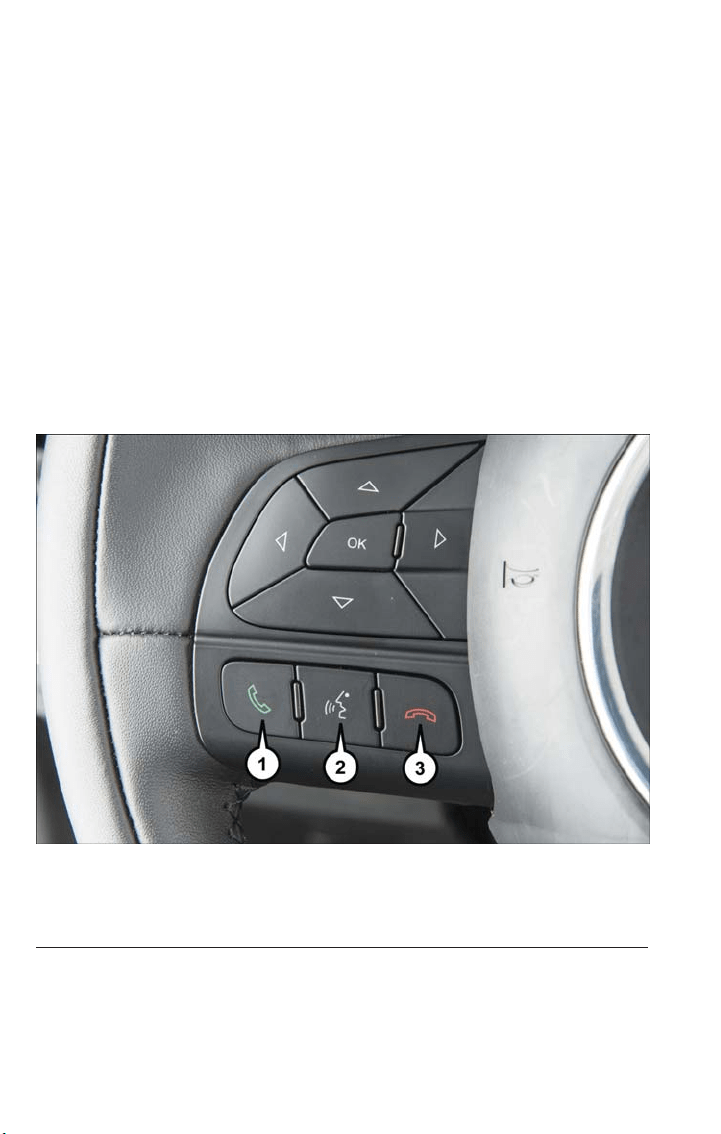
Get Started
1. Visit UconnectPhone.com to check mobile device and feature compatibility and to
find phone pairing instructions.
2. Reduce background noise. Wind and passenger conversations are examples of noise
that may impact recognition.
3. Speak clearly at a normal pace and volume while facing straight ahead. The micro-
phone is positioned on the rearview mirror and aimed at the driver.
4. Each time you give a Voice Command, you must first press either the VR or Phone
button, wait until after the beep, then say your Voice Command.
5. You can interrupt the help message or system prompts by pressing the VR or Phone
button and saying a Voice Command from the current category.
All you need to control your Uconnect system with your voice are the buttons on your
steering wheel.
Uconnect VR And Phone Buttons
1 — Push To Initiate Or To Answer A Phone Call, Send Or Receive A Text
2 — Push For Voice Recognition (VR)
3 — Push To End Call
ELECTRONICS
118
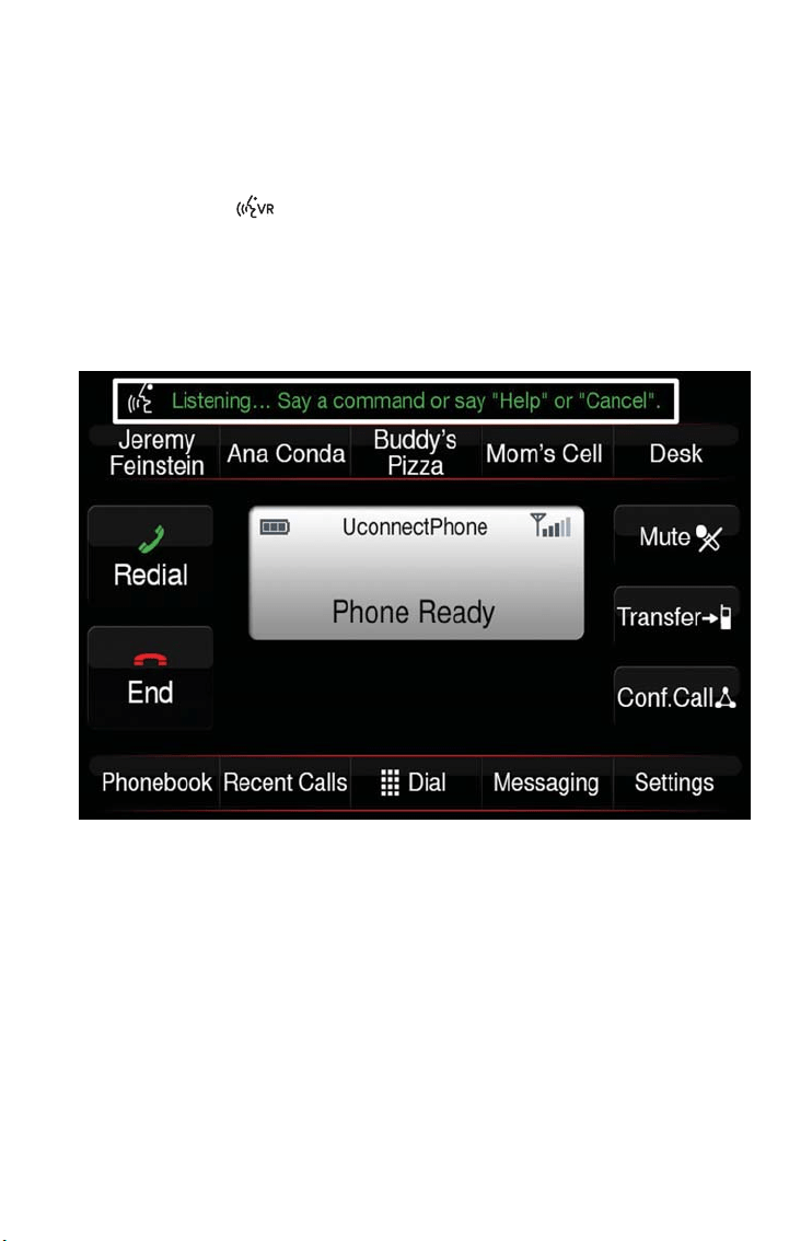
Basic Voice Commands
The basic Voice Commands below can be given at any point while using your Uconnect
system.
Push the VR button . Af ter the beep, say:
• “Cancel” to stop a current voice session
• “Help” to hear a list of suggested Voice Commands
• “Repeat” to listen to the system prompts again
Notice the visual cues that inform you of your voice recognition system’s status. Cues
appear on the touchscreen.
Uconnect 6.5NAV
ELECTRONICS
119
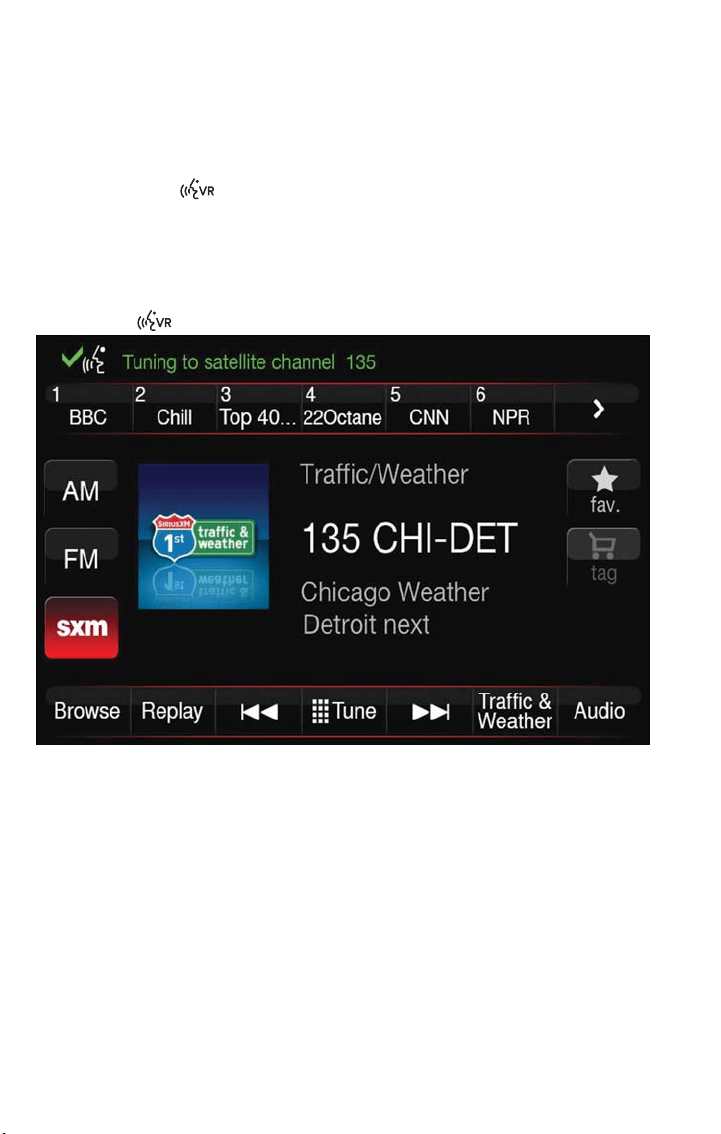
Radio
Use your voice to quickly get to the AM, FM or SiriusXM Satellite Radio stations you
would like to hear. (Subscription or included SiriusXM Satellite Radio trial required.)
Push the VR button . Af ter the beep, say:
• “Tune to ninety-five-point-five FM”
• “Tune to Satellite Channel Hits 1”
TIP
At any time, if you are not sure of what to say or want to learn a Voice Command, push
the VR button
and say “Help.” The system provides you with a list of commands.
Uconnect 6.5 NAV
ELECTRONICS
120
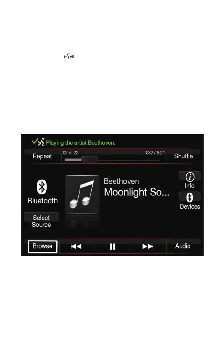
Media
Uconnect offers connections via USB, Bluetooth and auxiliary ports (if equipped). Voice
operation is only available for connected USB and iPod devices.
Push the VR button . Af ter the beep, say one of the following commands and fol-
low the prompts to switch your media source or choose an artist.
• “Change source to Bluetooth”
• “Change source to iPod”
• “Change source to USB”
• “Play artist Beethoven”; “Play album Greatest Hits”; “Play song Moonlight Sonata”; “Play
genre Classical”
TIP
Press the Browse button on the touchscreen to see all of the music on your iPod or
USB device. Your Voice Command must match exactly how the artist, album, song and
genre information is displayed.
Uconnect 6.5NAV Media
ELECTRONICS
121
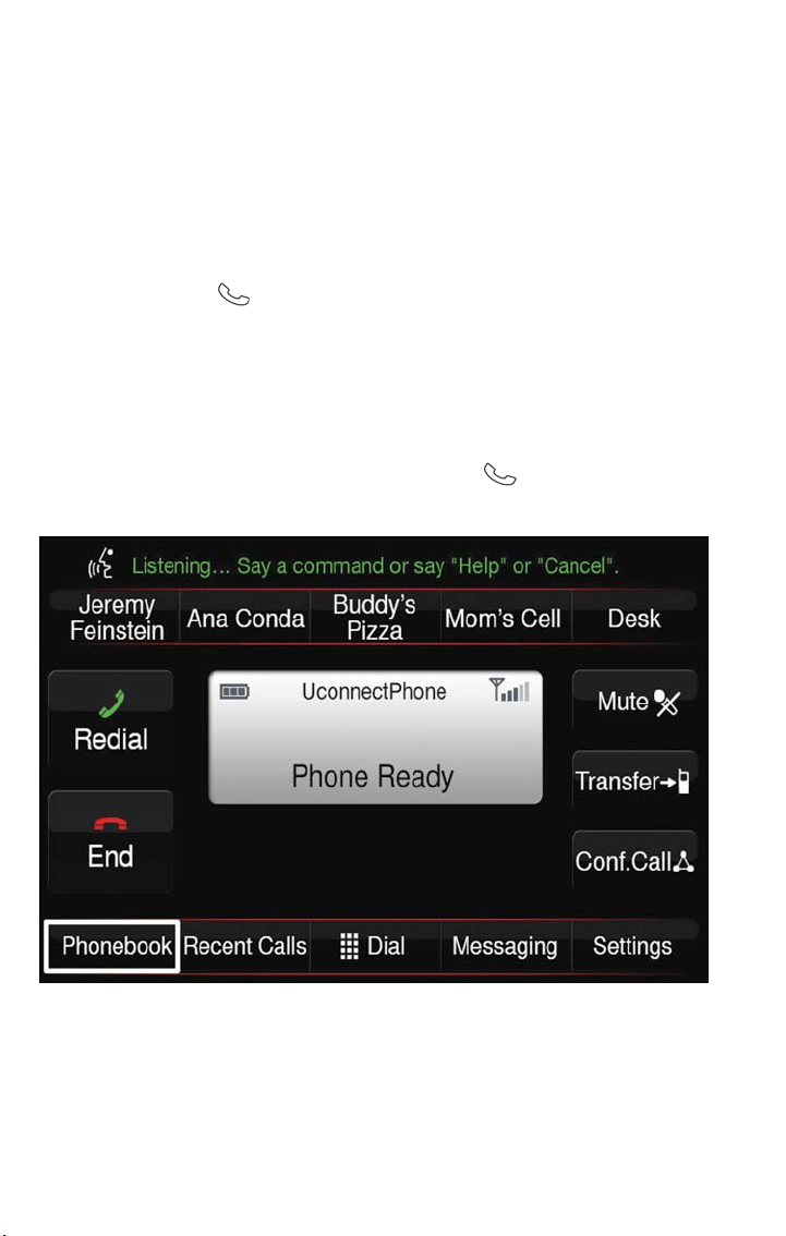
Phone
Making and answering hands-free phone calls is easy with Uconnect. When the Phone-
book button is illuminated on your touchscreen, your system is ready.
U.S./Canadian residents can visit:
• UconnectPhone.com to check mobile device and feature compatibility and to find
phone pairing instructions.
Push the Phone button
. Af ter the beep, say one of the following commands…
• “Call John Smith”
• “Dial 123-456-7890 and follow the system prompts”
• “Redial (call previous outgoing phone number)”
• “Call back (call previous incoming phone number)”
TIP
When providing a Voice Command, push the Phone button
and say “Call,” then pro-
nounce the name exactly as it appears in your phone book. When a contact has multiple
phone numbers, you can say “Call John Smith work.”
Uconnect 6.5NAV Phone
ELECTRONICS
122
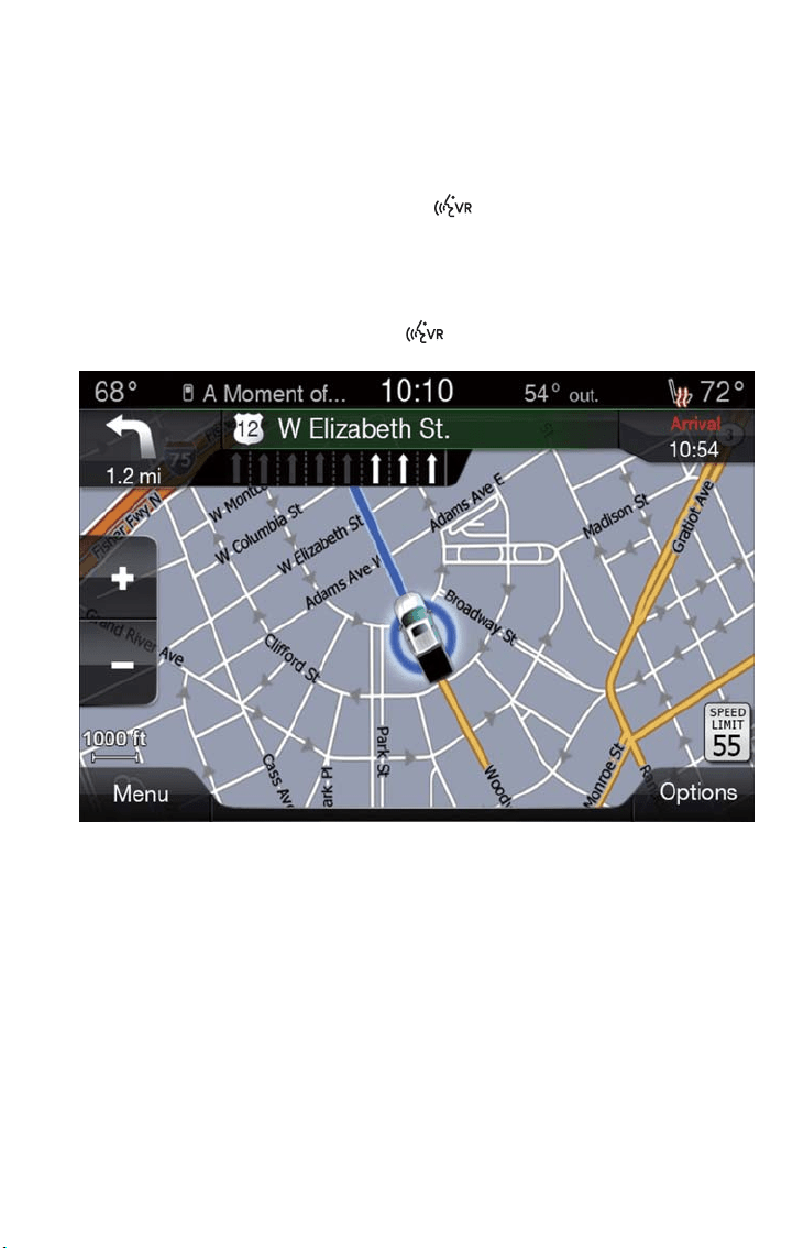
Navigation (Uconnect 6.5NAV)
The Uconnect navigation feature helps you save time and become more productive when
you know exactly how to get to where you want to go.
1. To enter a destination, push the VR button
. Af ter the beep, say:
• “Find Address 800 Chrysler Drive Auburn Hills, Michigan.”
2. Then follow the system prompts.
TIP
To start a POI search, push the VR button
. After the beep, say “Find nearest cof-
fee shop.”
SiriusXM Travel Link (Uconnect 6.5NAV — US Market Only)
Need to find a gas station, view local movie listings, check a sports score or the5-day
weather forecast? SiriusXM Travel Link is a suite of services that brings a wealth of infor-
mation right to your Uconnect 6.5NAV system.
Uconnect 6.5NAV
ELECTRONICS
123
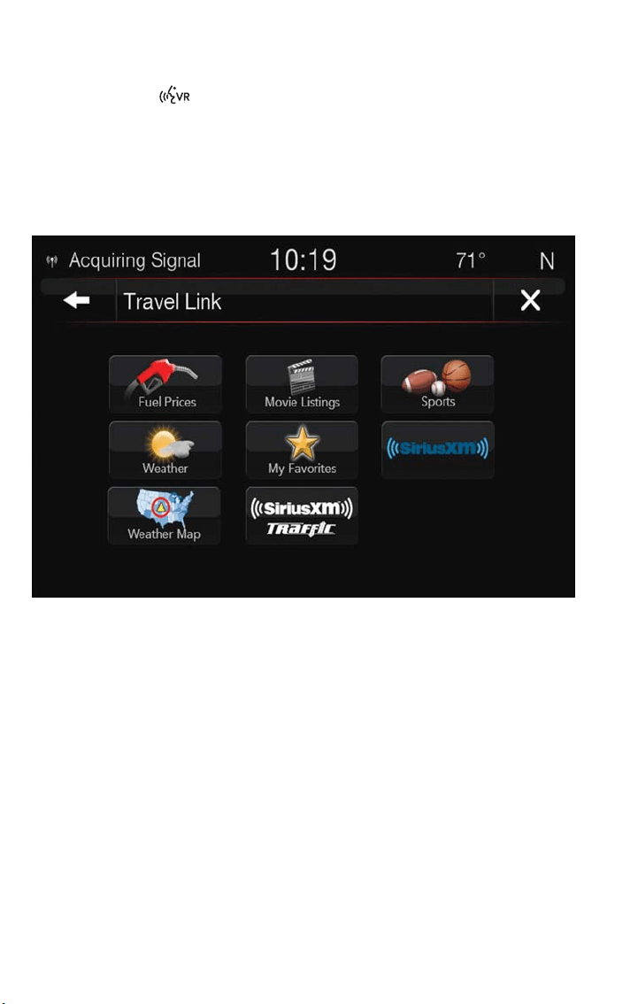
Push the VR button . Af ter the beep, say one of the following commands:
• “Show fuel prices”
• “Show5-dayweather forecast”
• “Show extended weather”
TIP
Traffic alerts are not accessible with Voice Command.
Additional Information
© 2017 FCA US LLC. All rights reserved. Mopar and Uconnect are registered trade-
marks and Mopar Owner Connect is a trademark of FCA US LLC. Android is a trade-
mark of Google Inc. SiriusXM and all related marks and logos are trademarks of SiriusXM
Radio Inc.
Uconnect System Support:
• DriveUconnect.com
• U.S. residents call: 1-877-855-8400 (24 hours a day 7 days a week)
• Canadian residents call: 1-800-465-2001 (English) or 1-800-387-9983 (French)
Mon. – Fri., 8:00 am – 8:00 pm, ET
Sat., 9:00 am – 5:00 pm, ET
Sun., Closed
SiriusXM Travel Link
ELECTRONICS
124
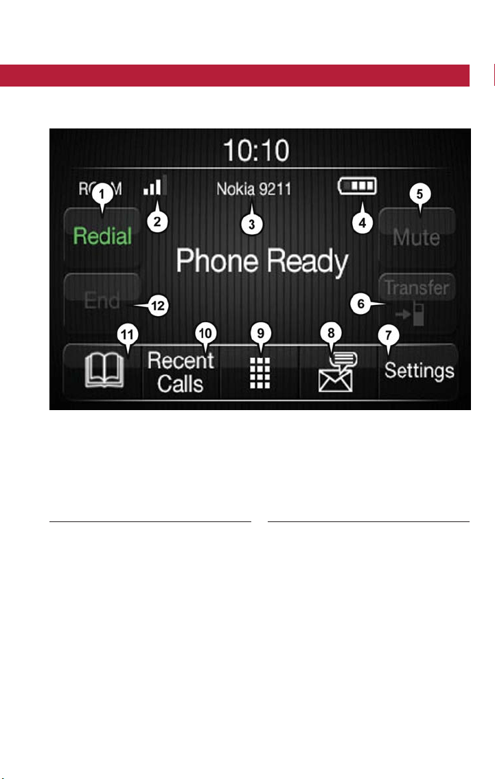
UCONNECT PHONE
Uconnect Phone (Bluetooth Hands Free Calling)
Uconnect 5.0 Phone Menu
1 — Call/Redial/Hold
2 — Mobile Phone Signal Strength
3 — Currently Paired Mobile Phone
4 — Mobile Phone Battery Life
5 — Mute Microphone
6 — Transfer To/From Uconnect System
7 — Uconnect Phone Settings Menu
8 — Text Messaging
9 — Direct Dial Pad
10 — Recent Call Log
11 — Browse Phone Book (Contains 911)
12 — End Call
ELECTRONICS
125
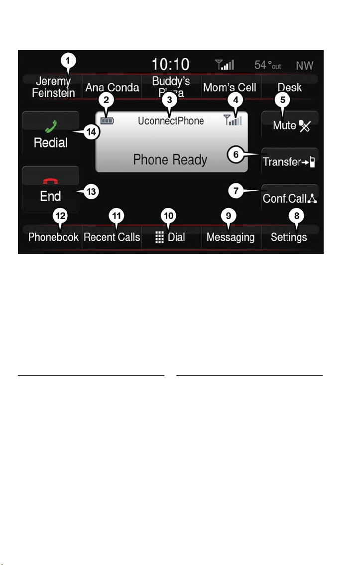
The Uconnect Phone feature enables you to place and receive hands-free mobile phone
calls. Drivers can also place mobile phone calls using their voice or by using the buttons
on the touchscreen (see Voice Command section).
The hands-free calling feature is made possible through Bluetooth technology — the
global standard that enables different electronic devices to connect to each other wire-
lessly.
Uconnect 6.5NAV Phone Menu
1 — Favorite Contacts
2 — Mobile Phone Battery Life
3 — Currently Paired Mobile Phone
4 — Mobile Phone Signal Strength
5 — Mute Microphone
6 — Transfer To/From Uconnect System
7 — Conference Call*
8 — Manage Paired Mobile Phones
9 — Text Messaging**
10 — Direct Dial Pad
11 — Recent Call Log
12 — Browse Phone Book Entries (Con-
tains 911)
13 — End Call
14 — Call/Redial/Hold
* — Conference call fea ture only available
on GSM mobile devices
** — Text messaging feature not available
on all mobile phones (requires Bluetooth
MAP profile and a compatible phone)
ELECTRONICS
126
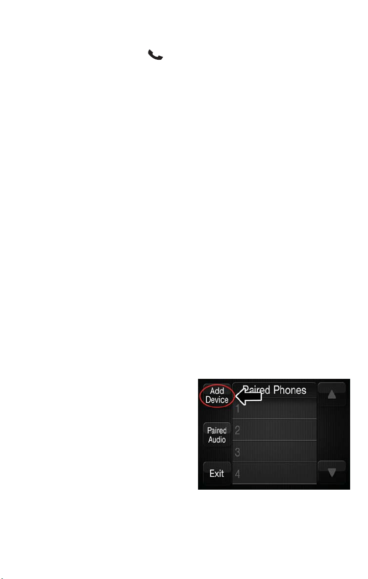
If the Uconnect Phone Button exists on your steering wheel, you then have the
Uconnect Phone features.
NOTE:
• The Uconnect Phone requires a mobile phone equipped with the Bluetooth Hands-
Free Profile,Version 1.0 or higher.
• Most mobile phones/devices are compatible with the Uconnect system, however some
mobile phones/devices may not be equipped with all of the required fea tures to utilize
all of the Uconnect system features.
• For Uconnect Customer Care:
• U.S. residents visit UconnectPhone.com or call 1-877-855-8400.
• Canadian Residents visit UconnectPhone.com or call, 1-800-465-2001 (English) or
1-800-387-9983 (French).
Pairing (Wirelessly Connecting) Your Mobile Phone To The Uconnect
System
Mobile phone pairing is the process of establishing a wireless connection between a cellu-
lar phone and the Uconnect system.
NOTE:
• To use the Uconnect Phone feature, you first must determine if your mobile phone
and software are compatible with the Uconnect system. Please visit
UconnectPhone.com for complete mobile phone compatibility information.
• Mobile phone pairing is not available while the vehicle is in motion.
• A maximum of ten mobile phones can be paired to the Uconnect system.
Start Pairing Procedure On The Radio
Uconnect 5.0:
1. Place the ignition in the ACC or ON
position.
2. Press the “Phone” button.
3. Select “Settings.”
4. Select “Paired Phones.”
5. Select “Add device.”
NOTE:
Uconnect Phone will display an “In prog-
ress” screen while the system is connect-
ing.
Uconnect 5.0
ELECTRONICS
127
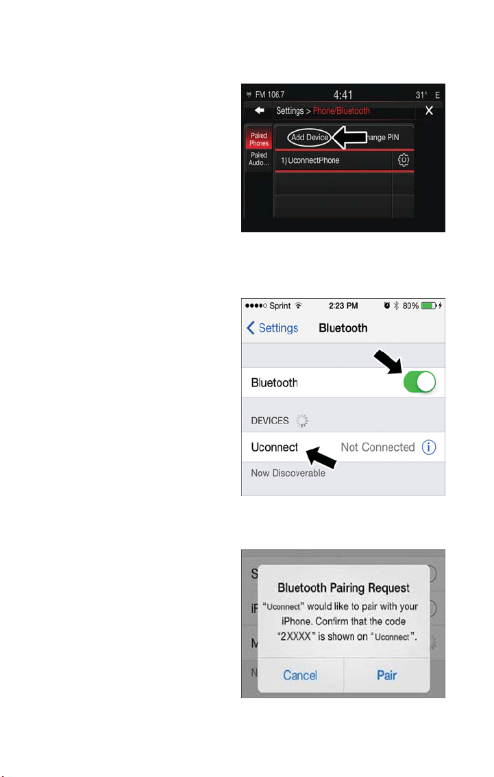
Uconnect 6.5 NAV:
1. Place the ignition in the ACC or ON
position.
2. Press the “Phone” button in the Menu
Bar on the touchscreen.
3. Select “Settings.”
4. Select “Paired Phones.”
5. Select “Add device.”
NOTE:
Uconnect Phone will display an “In prog-
ress” screen while the system is connect-
ing.
Pair Your iPhone:
To search for available devices on your
Bluetooth enabled iPhone:
1. Press the Settings button.
2. Select Bluetooth.
• Ensure the Bluetooth feature is en-
abled. Once enabled, the mobile phone
will begin to search for Bluetooth
connections.
3. When your mobile phone finds the
Uconnect system, select “Uconnect.”
Complete The iPhone Pairing Procedure:
When prompted on the mobile phone,
accept the connection request from
Uconnect Phone.
NOTE:
Some mobile phones will require you to
enter the PIN number.
Uconnect 6.5NAV
Bluetooth On/Uconnect Device
Pairing Request
ELECTRONICS
128
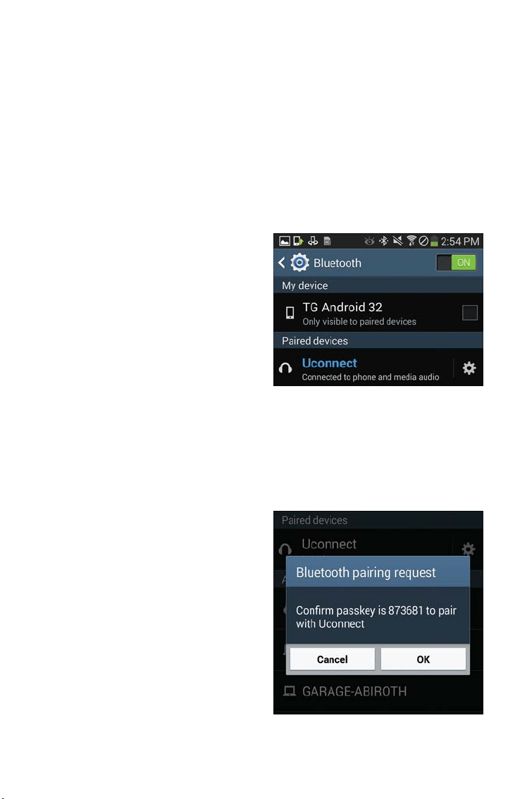
Select The iPhone's Priority Level
When the pairing process has successfully completed, the system will prompt you to
choose whether or not this is your favorite mobile phone. Selecting “Yes” will make this
mobile phone the highest priority. This mobile phone will take precedence over other
paired mobile phones within range and will connect to the Uconnect system automati-
cally when entering the vehicle. Only one mobile phone and/or one Bluetooth audio de-
vice can be connected to the Uconnect system at a time. If “No” is selected, simply se-
lect “Uconnect” from the mobile phone/audio device Bluetooth screen, and the Uconnect
system will reconnect to the Bluetooth device.
Pair Your Android Device:
• To search for available devices on your
Bluetooth enabled Android Device:
1. Push the Menu button.
2. Select Settings.
3. Select Connections.
4. Turn Bluetooth setting to “On.”
• Ensure the Bluetooth feature is en-
abled. Once enabled, the mobile phone
will begin to search for Bluetooth
connections.
5. Once your mobile phone finds the Uconnect system, select “Uconnect.”
• You may be prompted by your mobile phone to download the phonebook, check
“Do Not Ask Again” to automatically download the phonebook. This is so you can
make calls by saying the name of your contact.
Complete The Android Pairing Procedure:
Confirm the passkey shown on the mobile
phone matches the passkey shown on the
Uconnect system then accept the
Bluetooth pairing request.
NOTE:
Some mobile phones require the PIN to be
entered manually, enter the PIN number
shown on the Uconnect screen.
Uconnect Device
Pairing Request
ELECTRONICS
129

Select The Android Mobile Phone's Priority Level
When the pairing process has successfully completed, the system will prompt you to
choose whether or not this is your favorite mobile phone. Selecting “Yes” will make this
mobile phone the highest priority. This mobile phone will take precedence over other
paired mobile phones within range and will connect to the Uconnect system automati-
cally when entering the vehicle. Only one mobile phone and/or one Bluetooth audio de-
vice can be connected to the Uconnect system at a time. If “No” is selected, simply se-
lect “Uconnect” from the mobile phone/audio device Bluetooth screen, and the Uconnect
system will reconnect to the Bluetooth device.
You are now ready to make hands-free calls. Press the Uconnect “Phone” button
on your steering wheel to begin.
NOTE:
Refer to UconnectPhone.com for additional information on mobile phone pairing and for
a list of compatible phones.
Common Phone Commands (Examples)
• “Call John Smith”
• “Call John Smith mobile”
• “Dial 1 248 555 1212”
• “Redial”
Mute (Or Unmute) Microphone During Call
• During a call, press the “Mute” button on the Phone main screen to mute and unmute
the call.
Transfer Ongoing Call Between Handset And Vehicle
• During an on-going call, press the “Transfer” button on the Phone main screen to
transfer an on-going call between handset and vehicle.
Phonebook
The Uconnect system will automatically sync your phonebook from your paired phone, if
this feature is supported by your phone you will be asked if you want to download your
phonebook. Phonebook contacts are updated each time that the phone is connected. If
your phone book entries do not appear, check the settings on your phone. Some phones
require you to enable this feature manually.
• Your phonebook can be browsed on the Uconnect system touchscreen, but editing can
only be done on your phone. To browse, press the “Phone” button on the touch-
screen, then the “Phonebook” button on the touchscreen.
Favorite phonebook entries can be saved as Favorites for quicker access. Favorites are
shown at the top of the main phone screen.
ELECTRONICS
130

Voice Command Tips
• Speaking complete names (i.e; Call John Doe vs. Call John) will result in greater system
accuracy.
• You can “link” commands together for faster results. Say “Call John Doe, mobile,” for
example.
• If you are lis tening to available voice command options, you do not have to listen to
the entire list. When you hear the command that you need, push the
button
on the steering wheel, wait for the beep and say your command.
Changing The Volume
• Start a dialogue by pushing the Phone button , then say a command for example -
"Help."
• Use the radio VOLUME/MUTE rotary knob to adjust the volume to a comfortable
level while the Uconnect system is speaking. Please note the volume setting for
Uconnect is different than the audio system.
NOTE:
To access help, push the Uconnect Phone button
on the steering wheel and say
"help." Press the display or press either the Phone
or VR button and say
"cancel" to cancel the help session.
Incoming Text Messages
After pairing your Uconnect system with a Bluetooth enabled mobile device with the
Message Access Profile (MAP), the Uconnec t system can announce a new incoming text
message and read it to you over the vehicle’s audio system.
NOTE:
Only incoming text messages received during the current ignition cycle can be viewed/read.
To enable incoming text messaging:
iPhone
1. Press the settings button on the mobile phone .
2. Select Bluetooth.
NOTE:
Ensure Bluetooth is enabled, and the mobile phone is paired to the Uconnect system.
3. Select
located under DEVICES next to Uconnect.
ELECTRONICS
131

4. Turn “Show Notifications” to On.
Android Devices
1. Push the Menu button on the mobile phone.
2. Select Settings.
3. Select Connections.
4. Turn “Show Notifications” to On.
NOTE:
• A pop up will appear asking you to accept a request for permission to connect to
your messages. Select “Don’t ask again” and press OK. A pop up will appear asking
you to accept a request for permission to connect to your messages. Select “Don’t
ask again” and press OK.
Enable iPhone Incoming Text Messages
ELECTRONICS
132
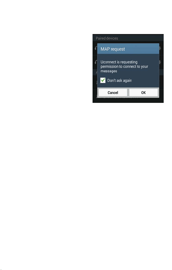
• All incoming text messages received during the current ignition cycle will be deleted
from the Uconnect system when the ignition is turned to the Off position.
Voice Text Reply (Not Compatible With iPhone)
NOTE:
Voice texting reply and voice texting features require a compatible mobile device enabled
with Bluetooth Message Access Profile (MAP). iPhone, and some other smartphones, may
not entirely support Bluetooth MAP. Visit UconnectPhone.com for the latest system and
device compatibility.
• On some mobile phones, to make the SMS voice reading function available, the SMS
notification option on phone must be enabled. This option is usually in the Bluetooth
connections menu for a device registered as “Uconnec t.” After enabling this function
on the device, it must be disconnected and reconnected with the Uconnect system in
order to make it effective
• Due to the extremely large number of mobile phone manufacturers, your mobile de-
vice may not be listed. For further assistance, contact Uconnect Customer Care @
1-877-855-8400 for U.S. residents or, 1-800-465-2001 (English) / 1-800-387-9983
(French) for Canadian residents.
NOTE:
If an SMS is sent through Uconnect, an additional cost may be incurred on the mobile
phone sending the message. For more information, please contact your phone provider.
Once your Uconnect system is paired with a compatible mobile device, the system can
announce a new incoming text message, and read it to your over the vehicle audio sys-
tem. You can reply to the message using Voice Recognition by selecting, or saying, one of
the 18 pre-defined messages.
Enable Android Device Incoming Text
Messages
ELECTRONICS
133

Here’s How:
1. Push the Uconnect Phone button
and wait for the beep, then say “reply.”
Uconnect will give the following prompt: “Please say the message you would like to
send.”
2. Wait for the beep and say one of the pre-defined messages. (If you are not sure, you
can say “help”). Uconnect will then read the pre-defined messages allowed.
3. As soon as you hear the message you would like to send, you can interrupt the list of
prompts by pushing the Uconnect phone button and saying the phrase. Uconnect will
confirm the message by reading it back to you.
4. Push the Phone button and say “Send.”
PRE-DEFINED VOICE TEXT REPLY RESPONSES
Ye s . Stuck in traffic. See you later.
No. Start without me. I’ll be late.
Okay. Where are you?
I will be <5, 10, 15, 20, 25,
30, 45, 60>* minutes late.
Call me. Are you there yet?
I’ll call you later. I need directions.
See you in <5, 10, 15, 20, 25,
30, 45, 60>* minutes.
I’m on my way.
Can’t talk right now.
I’m los t. Thanks.
*Use only the numbers listed (in increments of five up to 60 minutes) or the system will
not transpose the message.
Helpful Tips And Common Questions To Improve Bluetooth Performance
With Your Uconnect System
Mobile Phone won’t reconnect to system after pairing:
• Set mobile phone to auto-connect or trusted device in mobile phone Bluetooth set-
tings (Blackberry devices).
• Perform a factory reset on your mobile phone. Refer to your mobile phone manufac-
turer or cellular provider for instructions.
• Many mobile phones do not automatically reconnect after being restarted (hard re-
boot). Your mobile phone can still be connected manually. Close all applications that
may be operating (refer to mobile phone manufac turer’s instructions), and follow “Pair-
ing (Wirelessly Connecting) Your Mobile Phone To The Uconnect System.”
Mobile Phone won’t pair to system:
• Perform a hard reset in the mobile phone by removing the battery (if removable —
see your mobile phone’s owner manual).
• Delete pairing history in mobile phone and Uconnect system; usually found in phone’s
Bluetooth connection settings.
• Verify you are selecting “Uconnect” in the discovered Bluetooth devices on your mo-
bile phone.
• If your vehicle system generates a pin code the default is 0000.
ELECTRONICS
134
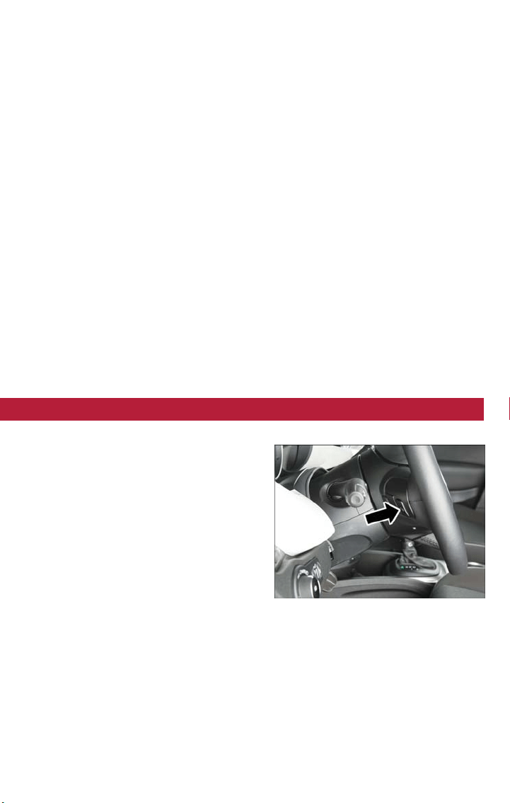
Mobile Phonebook didn’t download:
• Check “Do not ask again,” then accept the “phonebook download” request on your
mobile phone.
• Up to 5,000 contact names with four numbers per contact will transfer to the
Uconnect 6.5NAV system phonebook.
• Up to 2,000 contact names with six numbers per contact will transfer to the
Uconnect 5.0 system phonebook.
Text messaging won’t work:
• Check “Do not ask again,” then accept the “connect to your messages” request on
your mobile phone.
• Verify that your mobile phone has the Bluetooth feature (Message Access Profile).
Can’t make a conference call:
• CDMA (Code-Division Multiple Access) carriers do not support conference calling.
Refer to your mobile phone user’s manual for further information.
Making calls while connected to AUX:
• Plugging in your mobile phone to AUX while connected to Bluetooth will disable
Hands-Free Calling. Do not make calls while your mobile phone is plugged into the
AUX jack.
STEERING WHEEL AUDIO CONTROLS
The steering wheel audio controls are located on the rear surface of the steering wheel.
Left Switch
• Push the switch up or down to search
for the next listenable station.
• Push the button in the center to select
the next preset station (radio).
Right Switch
• Push the switch up or down to increase
or decrease the volume.
• Push the button in the center to change
modes AM/FM/SXM/AUX/USB or BTSA
(Bluetooth Streaming Audio) — If Equipped.
Steering Wheel Audio Controls
ELECTRONICS
135
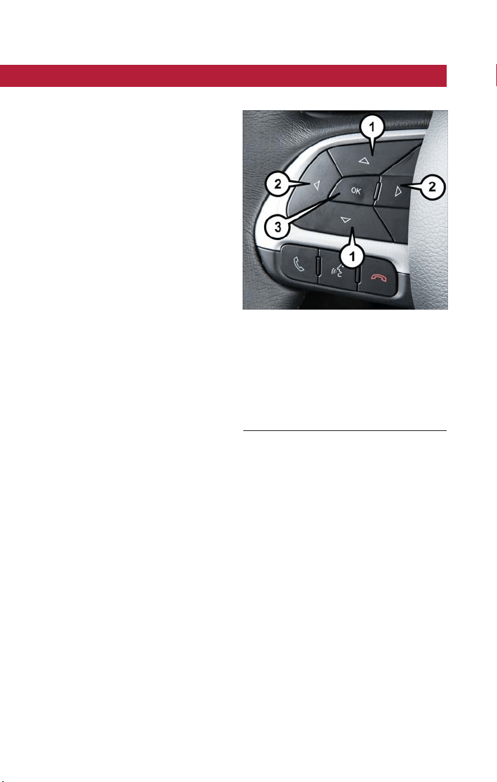
INSTRUMENT CLUSTER DISPLAY
Your vehicle is equipped with an instrument cluster display system.
The instrument cluster display features a
driver interactive display that is located in
the instrument cluster. Pushing the controls
on the left side of the steering wheel al-
lows the driver to select vehicle informa-
tion and Personal Settings. Refer to “Pro-
grammable Features” in this guide for
further information.
• Push the up arrow button to scroll up-
ward through the main menus and sub-
menus (Speedometer,Vehicle Info, Driver
Assist, Fuel Economy, Trip, Audio, Mes-
sages, Screen Set Up).
• Push the down arrow button to scroll
downward through the main menu and
submenus (Speedometer,Vehicle Info,
Driver Assist, Fuel Economy, Trip, Audio,
Messages, Screen Set Up).
• Push the right arrow button to access
the information screens or submenu
screens of a main menu item.
• Push the back/left arrow button to access the information screens or submenu screens
of a main menu item.
• Push the OK button to access/select the information screens or submenu screens of a
main menu item. Push and hold the OK button for two seconds to reset displayed/
selected features that can be reset.
Instrument Cluster Display Main Menu
The Main Menu is composed of several options that can be selected using the control
buttons above.
NOTE:
• The display mode of the menu items varies depending on the type of display.
• For some items, a submenu is provided.
• In the Uconnect system, some items on the menu are not shown on the instrument
panel display.
Instrument Cluster Display Controls
1 — Arrow Up/Down Scroll Through
Menus And Submenus
2 — Arrow Right/Left Access Information/
Submenu Screens
3 — OK Button For Selecting And Reset-
ting Information
ELECTRONICS
136

Menu Items
The Menu has the following options:
• Trip
• Drive Mode Selector
• Vehicle Info
• Driver Assist
• Audio
• Navigation
• Messages
• Vehicle Settings
For further information, please refer to your Owner’s Manual on
www.fiatusa.com/en/owners/manuals.
PROGRAMMABLE FEATURES
Uconnect Customer Programmable Features
The Uconnect system allows you to access Customer Programmable feature settings such
as Display, Units, Voice, Clock & Date, Safety & Driving Assistance, Lights, Doors & Locks,
Engine Off Options, Audio, Phone/Bluetooth, SiriusXM Setup, Restore Default Settings and
Clear Personal Data (Uconnect 6.5NAV) through buttons on the touchscreen.
• For the Uconnect 5.0 and 6.5NAV systems, push the Settings
button located on
the right side of the display. When making a selection, scroll up or down until the pre-
ferred setting is highlighted, then press and release the preferred setting until the selec-
tion is highlighted showing that setting has been selected. Depending on the vehicle’s
options, the following feature settings are available:
• Display • Engine Off Options
• Units • Audio
• Voice • Phone/Bluetooth
• Clock & Date • SiriusXM Setup
• Safety & Driving Assistance • Restore Default Settings
• Lights • Clear Personal Data (Uconnect
6.5NAV)
• Doors & Locks
ELECTRONICS
137
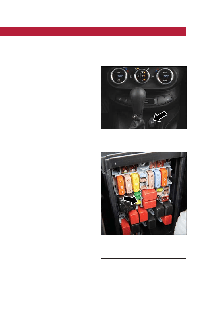
POWER OUTLET
There is one 12 Volt (13 Amp) power outlet in this vehicle, located under the HVAC
controls. This power outlet can power mobile phones, electronics and other low power
devices.
• This power outlet is located in front of the gear selector.
NOTE:
• Do not exceed the maximum power of
160 Watts (13 Amps) at 12 Volt s . If the
160 Wa tt (13 Amp) power rating is ex-
ceeded, the fuse protecting the system
will need to be replaced.
• Power outlets are designed for accessory
plugs only. Do not insert any other ob-
ject in the power outlet as this will dam-
age the outlet and blow the fuse. Im-
proper use of the power outlet can
cause damage not covered by your new
vehicle warranty.
Power Outlet
Engine Compartment Fuses
F84 Fuse 20A Yellow Instrument Panel
Power Outlet.
ELECTRONICS
138

CARGO AREA FEATURES
Cargo Load Floor — If Equipped
The vehicle is equipped with a load floor that can be adjusted as needed.
Position 1 (Floor Flush):
This position allows you to make the load floor flat for ease of loading/unloading objects
from the cargo area. This position also makes it possible to use the space below as an-
other compartment for storing fragile or smaller objects.
Position 2 (Elevated Position):
When the rear seatbacks and front passenger seat is folded flat, it will allow for loading
objects of long dimensions. It is recommended to use this position only during the actual
transporting of the objects, then bring the load floor in position 1.
NOTE:
With a full size spare, the floor will be at the elevated position.
Access To The Loading Floor
To access the double load compartment, proceed as follows:
1. Lift up on the Load Floor Handle.
2. Place the desired objects inside the compartment.
3. Reposition the load f loor.
CAUTION!
The load floor must be arranged in a central position with respect to cargo area.
Displacement Load Floor
To position the load from the lower to the upper position, proceed as follows:
1. Grasp the load floor handle and lift up the load floor.
2. Correctly place the load floor on the side panel guides and on the rear cross mem-
ber.
Access To Tire Service Kit Or Spare Tire
To access the Tire Service Kit or spare tire and container carrier, proceed as follows:
1. Grasp the load floor handle and remove the floor.
2. Pull the tab and lift up on the carpet.
UTILITY
139
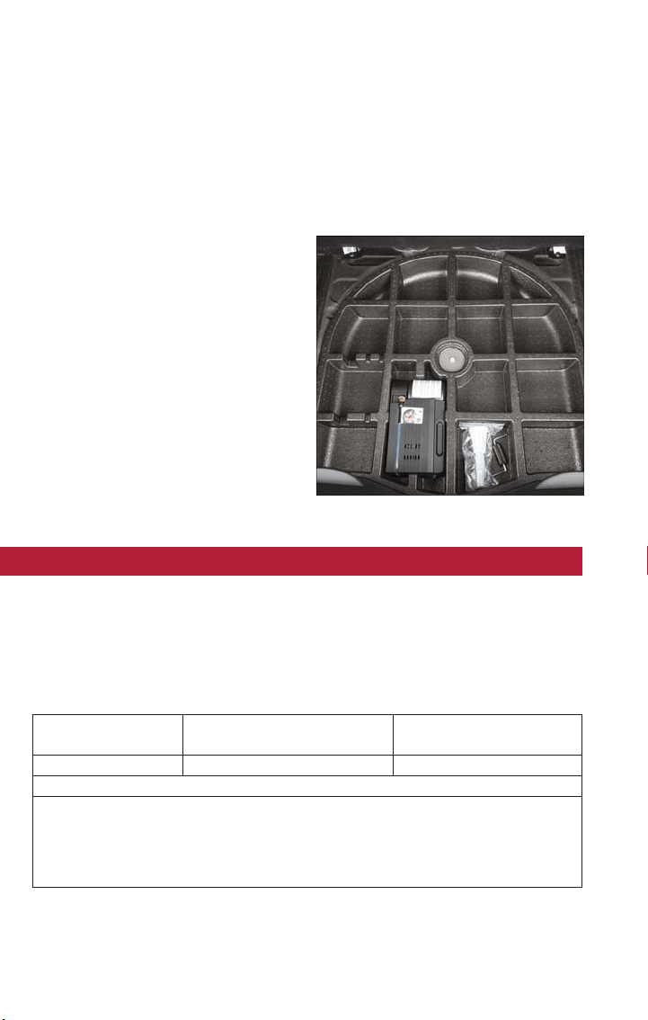
Anchoring Of The Load
The cargo tie-downs, located on the trim panels around the cargo area floor, should be
used to safely secure loads when the vehicle is moving.
Cargo Box — If Equipped
The cargo area contains a preformed cargo box that can be used for the storage of ob-
jects that allows you to obtain a uniform level when loading.
NOTE:
The cargo box is sized for a maximum ca-
pacity of distributed weight equal to
242 lbs (110 kg).
TRAILER TOWING
Trailer Towing Weights (Maximum Trailer Weight Ratings)
The following chart provides the maximum trailer weight ratings towable for your given
drivetrain.
1.4L Turbo Engine & 2.4 FWD
Trailer towing is not recommended.
Engine Max. GTW (Gross Trailer Wt.) Max. Tongue Wt.
(See Note)
2.4L AWD 1,000 lbs (450 kg) 100 lbs (45 kg)
Refer to local laws for maximum trailer towing speeds.
NOTE: The trailer tongue weight must be considered as part of the combined weight
of occupants and cargo and should never exceed the weight referenced on the Tire
and Loading Information placard. Refer to “Tire Safety Information” in “Maintaining
Your Vehicle” for further information.
Cargo Box
UTILITY
140

RECREATIONAL TOWING (BEHIND MOTORHOME, ETC.)
Towing This Vehicle Behind Another Vehicle
TOWING
CONDITION
WHEELS OFF THE
GROUND
FRONT WHEEL
DRIVE (FWD)
ALL-WHEEL DRIVE
(AWD)
Flat Tow NONE NOT ALLOWED NOT ALLOWED
Dolly Tow
REAR NOT ALLOWED NOT ALLOWED
FRONT OK NOT ALLOWED
On Trailer ALL BEST METHOD OK
NOTE:
When towing your vehicle, always follow applicable state and provincial laws. Contact state and
provincial Highway Safety offices for additional details.
NOTE:
You must ensure that the Auto Park Brake feature is disabled before towing this vehicle,
to avoid inadvertent Electric Park Brake engagement. The Auto Park Brake feature is en-
abled or disabled via the Customer Programmable Features in the Uconnect Settings.
Recreational Towing
Front-Wheel Drive (FWD) Models
Recreational towing is allowed ONLY if the front wheels are OFF the ground. This may
be accomplished using a tow dolly (front wheels off the ground) or vehicle trailer (all
four wheels off the ground). If using a tow dolly, follow this procedure:
• Properly secure the dolly to the tow vehicle, following the dolly manufacturer's instruc-
tions.
• Drive the front wheels onto the tow dolly.
• Apply the Electric Park Brake (EPB). Place the transmission in PARK. Turn the engine
OFF.
• Properly secure the front wheels to the dolly, following the dolly manufacturer's in-
structions.
• Cycle the ignition to the RUN mode, but do not start the engine.
• Press and hold the brake pedal.
• Release the Electric Park Brake (EPB).
• Cycle the ignition OFF, remove the key fob, and release the brake pedal.
UTILITY
141

CAUTION!
• DO NOT flat tow this vehicle. Damage to the drivetrain will result. If this vehicle
requires towing, make sure the drive wheels are OFF the ground.
• Ensure that the Electric Park Brake is released, and remains released, while being
towed.
• Towing this vehicle in violation of the above requirements can cause severe trans-
mission damage. Damage from improper towing is not covered under the New
Vehicle Limited Warranty.
All-Wheel Drive (AWD) Models
Recreational towing (with all four wheels on the ground, or using a towing dolly) is NOT
ALLOWED. This vehicle may be towed on a flatbed or vehicle trailer provided all four
wheels are OFF the ground.
CAUTION!
Towing this vehicle with ANY of its wheels on the ground can cause severe transmis-
sion and/or power transfer unit damage. Damage from improper towing is not covered
under the New Vehicle Limited Warranty.
UTILITY
142

ROADSIDE ASSISTANCE
• If your FIAT 500X requires jump start assistance, out of gas/fuel delivery, tire service,
lockout service or towing due to a defect covered under the Basic Limited Warranty,
dial toll-free 1-888-242-6342 or 1-800-363-4869 for Canadian Residents. See your
Warranty booklet for further details.
• Provide your name, vehicle identification number and license plate number.
• Provide your location, including telephone number, from which you are calling.
• Briefly describe the nature of the problem and answer a few simple questions.
• You will be given the name of the service provider and an estimated time of arrival. If
you feel you are in an “unsafe situation,” please let us know. With your consent, we will
contact local police or safety authorities.
WARNING AND INDICATOR LIGHTS
The warning/indicator lights switch on in the instrument panel together with a dedicated
message and/or acoustic signal when applicable. These indications are indicative and pre-
cautionar y and as such must not be considered as exhaustive and/or alternative to the
information contained in the Owner’s Manual, which you are advised to read carefully in
all cases. Always refer to the information in this chapter in the event of a failure indica-
tion.
All active telltales will display first, if applicable. The system check menu may appear differ-
ent based upon equipment options and current vehicle status.
This guide illustrates and describes the operation of warning and indicator telltales that
are either standard or optional based on the vehicle build. FCA reserves the right to
make changes in design and specifications and/or make additions to or improvements to
its products without imposing any obligation upon itself to install them on products previ-
ously manufactured.
Instrument Cluster Warning Lights
— Low Fuel Warning Light
This warning light indicates when the fuel level reaches approximately 2.0 gal (7.8L). This
light will turn on and a single chime will sound.
— Battery Charge Warning Light
This light illuminates when the battery is not charging properly. If the battery charge
warning light remains on, it means that the vehicle is experiencing a problem with the
charging system.
We recommend you do not continue driving if the battery charge warning light is on.
Have the vehicle serviced immediately.
WHAT TO DO IN EMERGENCIES
143

— Oil Pressure Warning Light
This light indicates engine oil pressure sensor failure. If the light turns on while driving,
stop the vehicle and shut off the engine as soon as possible. A chime will sound for four
minutes when this light turns on.
We recommend you do not operate the vehicle or engine damage will occur. Have the
vehicle serviced immediately.
— Anti-Lock Brake (ABS) Light
This light monitors the Anti-Lock Brake System (ABS). The light will turn on when the
ignition switch is turned to the MAR/RUN position and may stay on for as long as four
seconds.
If the ABS light remains on or turns on while driving, it indicates that the Anti-Lock por-
tion of the brake system is not functioning and that service is required. However, the
conventional brake system will continue to operate normally if the BRAKE warning light is
not on.
If the ABS light is on, the brake system should be serviced as soon as possible to restore
the benefits of Anti-Lock brakes. If the ABS light does not turn on when the ignition
switch is turned to the MAR/RUN position, have the light inspected by an authorized
dealer.
— Air Bag Warning Light
This light will turn on for four to eight seconds as a bulb check when the ignition switch
is first turned to t he MAR/RUN position. If the light is either not on during starting, stays
on, or turns on while driving, have the system inspected at an authorized dealer as soon
as possible. Refer to “Occupant Restraint Systems” in “Getting Started” for further infor-
mation.
NOTE:
The Air Bag System is designed to be maintenance free.
— Electronic Throttle Control (ETC) Light
This light informs you of a problem with the Electronic Throttle Control (ETC) system.
If a problem is detected, the light will come on while the engine is running. Cycle the
ignition key when the vehicle has completely stopped and the gear selector is placed in
the PARK position; the light should turn off .
If the light remains lit with the engine running, your vehicle will usually be drivable. How-
ever, see an authorized service center immediately. If the light is flashing when the engine
is running, immediate service is required and you may experience reduced performance,
an elevated/rough idle or engine stall and your vehicle may require towing.
WHAT TO DO IN EMERGENCIES
144

— Tire Pressure Monitoring System (TPMS) Warning Light
The warning light switches on and a message is displayed to indicate that the tire pres-
sure is lower than the recommended value and/or that slow pressure loss is occurring. In
these cases, optimal tire duration and fuel consumption may not be guaranteed.
Should one or more tires be in the condition mentioned above, the display will show the
indications corresponding to each tire in sequence.
CAUTION!
Do not continue driving with one or more flat tires as handling may be compromised.
Stop the vehicle, avoiding sharp braking and steering. If a tire puncture occurs, repair
immediately using the dedicated tire repair kit and contact your authorized dealer as
soon as possible.
Each tire, including the spare (if provided), should be checked monthly when cold and
inflated to the inflation pressure recommended by the vehicle manufacturer on the ve-
hicle placard or tire inflation pressure label. (If your vehicle has tires of a different size
than the size indicated on the vehicle placard or tire inflation pressure label, you should
determine the proper tire inflation pressure for those tires.)
As an added safety feature, your vehicle has been equipped with a tire pressure monitor-
ing system (TPMS) that illuminates a low tire pressure telltale when one or more of your
tires is significantly under-inflated. Accordingly, when the low tire pressure telltale illumi-
nates, you should stop and check your tires as soon as possible, and inflate them to the
proper pressure. Driving on a significantly under-inflated tire causes the tire to overheat
and can lead to tire failure. Under-inflation also reduces fuel efficiency and tire tread life,
and may affect the vehicle’s handling and stopping ability.
Please note that the TPMS is not a substitute for proper tire maintenance, and it is the
driver’s responsibility to maintain correct tire pressure, even if under-inflation has not
reached the level to trigger illumination of the TPMS low tire pressure telltale.
Your vehicle has also been equipped with a TPMS malfunction indicator to indicate when
the system is not operating properly. The TPMS malfunction indicator is combined with
the low tire pressure telltale. When the system detects a malfunction, the telltale will
flash for approximately one minute and then remain continuously illuminated. This se-
quence will continue upon subsequent vehicle start-ups as long as the malfunction exists.
When the malfunction indicator is illuminated, the system may not be able to detect or
signal low tire pressure as intended. TPMS malfunctions may occur for a variety of rea-
sons, including the installation of replacement or alternate tires or wheels on the vehicle
that prevent the TPMS from functioning properly. Always check the TPMS malfunction
telltale after replacing one or more tires or wheels on your vehicle to ensure that the
replacement or alternate tires and wheels allow the TPMS to continue to function
properly.
WHAT TO DO IN EMERGENCIES
145

CAUTION!
The TPMS has been optimized for the original equipment tires and wheels. TPMS pres-
sures and warning have been established for the tire size equipped on your vehicle.
Undesirable system operation or sensor damage may result when using replacement
equipment that is not of the same size, type, and/or style. Aftermarket wheels can cause
sensor damage. Using aftermarket tire sealants may cause the Tire Pressure Monitoring
System (TPMS) sensor to become inoperable. After using an aftermarket tire sealant it
is recommended that you take your vehicle to your authorized dealer to have your
sensor function checked.
— Engine Temperature Warning Light
• This light warns of an overheated engine condition.
• If the light turns on and a warning chime sounds while driving, safely pull over and stop
the vehicle. If the A/C system is on, turn it off. Also, shift the transmission into NEU-
TRAL and idle the vehicle. If the temperature reading does not return to normal, turn
the engine off immediately.
• We recommend that you do not operate the vehicle or engine damage will occur.
Have the vehicle serviced immediately.
WARNING!
A hot engine cooling system is dangerous. You or others could be badly burned by
steam or boiling content.
— Transmission Temperature Warning Light — If Equipped
This light indicates that there is excessive transmission fluid temperature tha t might occur
with severe usage such as trailer towing. If this light turns on, stop the vehicle and run
the engine at idle, with the transmission in NEUTRAL, until the light turns off. Once the
light turns off, you may continue to drive normally.
WARNING!
If you continue operating the vehicle when the Transmission Temperature Warning Light
is illuminated you could cause the fluid to boil over, come in contact with hot engine or
exhaust components and cause a fire.
WHAT TO DO IN EMERGENCIES
146
CAUTION!
Continuous driving with the Transmission Temperature Warning Light illuminated will
eventually cause severe transmission damage or transmission failure.
— Seat Belt Reminder Light
When the ignition switch is first turned to MAR/RUN, this light will turn on if the driver’s
seat belt is unbuckled, and a chime will sound. When driving, if the driver’s seat belt re-
mains unbuckled, the Sea t Belt Reminder Light will illuminate, and the chime will sound.
Please have your vehicle serviced immediately should the Seat Belt Reminder Light remain on.
— Brake Warning Light
This light monitors various brake functions, including brake fluid level and parking brake
application. If the brake light turns on it may indicate that the parking brake is applied,
that the brake fluid level is low, or that there is a problem with the anti-lock brake sys-
tem reservoir.
If the light remains on when the parking brake has been disengaged, and the fluid level is
at the full mark on the master cylinder reservoir, it indicates a possible brake hydraulic
system malfunction or that a problem with the Brake Booster has been detected by the
Anti-Lock Brake System (ABS) / Electronic Stability Control (ESC) system. In this case, the
light will remain on until the condition has been corrected. If the problem is related to
the brake booster, the ABS pump will run when applying t he brake, and a brake pedal
pulsation may be fel t during each stop.
The dual brake system provides a reserve braking capacity in the event of a failure to a
portion of the hydraulic system. A leak in either half of the dual brake system is indicated
by the Brake Warning Light, which will turn on when the brake fluid level in the master
cylinder has dropped below a specified level.
The light will remain on until the cause is corrected.
NOTE:
The light may flash moment arily during sharp cornering maneuvers, which change fluid level
conditions. The vehicle should have service performed, and the brake fluid level checked.
If brake failure is indicated, immediate repair is necessary.
WARNING!
Driving a vehicle with the red brake light on is dangerous. Part of the brake system
may have failed. It will take longer to stop the vehicle. You could have a collision. Have
the vehicle checked immediately.
WHAT TO DO IN EMERGENCIES
147

Vehicles equipped with the Anti-Lock Brake Sys tem (ABS) are also equipped with Elec-
tronic Brake Force Distribution (EBD). In the event of an EBD failure, the Brake Warning
Light will turn on along with the ABS Light. Immediate repair to the ABS system is re-
quired.
Operation of the Brake Warning Light can be checked by turning the ignition switch from
the OFF position to the ON/RUN position. The light should illuminate for approximately
two seconds. The light should then turn off unless the parking brake is applied or a brake
fault is detected. If the light does not illuminate, have the light inspected by an authorized
dealer.
The light also will turn on when the parking brake is applied with the ignition switch in
the ON/RUN position.
NOTE:
This light shows only that the parking brake is applied. It does not show the degree of
brake application.
— Electronic Park Brake Failure Indicator
By placing the ignition in MAR position, the light turns on but should go out after a few
seconds. The light comes on when it detects a failure in electric parking brake. The display
shows the message dedicated. Please contact your authorized dealer as soon as possible.
NOTE:
In this case, with heavy braking the rear wheels may lock early and increase the possibility
of skidding.
— Malfunction Warning Light
The vehicle Check/Malfunction Indicator Light (MIL) is a part of an Onboard Diagnostic
System called OBD II that monitors emissions control systems. The light will illuminate
when the ignition is in the ON position before vehicle start up. If the bulb does not
come on when placing the ignition in the ON/RUN position, have the condition checked
promptly.
Certain conditions, such as a loose or missing gas cap, poor quality fuel, etc., may illumi-
nate the light after vehicle start. The vehicle should be serviced if the light stays on
through several typical driving styles. In most situations, the vehicle will drive normally and
will not require towing.
When the vehicle is running, t he MIL may flash to alert serious conditions that could lead
to immediate loss of power or severe catalytic converter damage. The vehicle should be
serviced as soon as possible if this occurs.
WHAT TO DO IN EMERGENCIES
148
WARNING!
A malfunctioning catalytic converter, as referenced above, can reach higher temperatures
than in normal operating conditions. This can cause a fire if you drive slowly or park
over flammable substances such as dry plants, wood, cardboard, etc. This could result in
death or serious injury to the driver, occupants or others.
CAUTION!
Prolonged driving with the Malfunction Indicator Light (MIL) on could cause damage to
the vehicle control system. It also could affect fuel economy and driveability. If the MIL
is flashing, severe catalytic converter damage and power loss will soon occur. Immediate
service is required.
— SERV (Service) 4WD Indicator Light — If Equipped
If the light stays on or comes on during driving, it means that the 4WD system is not
functioning properly and that service is required. We recommend you drive to the near-
est service center and have the vehicle serviced immediately.
— Electronic Stability Control (ESC) Activation/Malfunction Indicator Light
If this indicator light flashes during acceleration, apply as little throttle as possible. While
driving, ease up on the accelerator. Adapt your speed and driving to the prevailing road
conditions. To improve the vehicle's traction when starting off in deep snow, sand or
gravel, it may be desirable to switch the ESC sys tem off.
— Enhanced Accident Response System Warning Light
The light illuminates when there is a fuel system shut off.
— Enhanced Accident Response System Failure Warning Light
The light illuminates in case of failure of the Enhanced Accident Response System.
Instrument Cluster Indicator Lights
— Turn Signal Indicator
The arrows will flash with the exterior turn signals when the turn signal lever is oper-
ated. A tone will chime, and an instrument cluster display message will appear if either
turn signal is left on for more than 1 mile (1.6 km).
NOTE:
If either indicator flashes at a rapid rate, check for a defective outside light bulb.
WHAT TO DO IN EMERGENCIES
149

— High Beam Indicator
Indicates that headlights are on high beam.
— Glow Plug Indicator Light
This icon blinking indicates that the engine cranking is inhibited in order to prevent pos-
sible engine damage while starting at low temperatures.
— Front Fog Light Indicator
This indicator will illuminate when the front fog lights are on.
— Vehicle Security Light
This light will flash rapidly for approximately 4 seconds when the vehicle security alarm is
arming. The light will flash at a slower speed continuously after the alarm is set. The secu-
rity light will also come on for about t hree seconds when the ignition is first turned on.
— Cruise Control On Indicator Light
This indicator will illuminate when the cruise control has been activated to the “ON”
position.
— Cruise Control Engaged Indicator Light
This indicator will illuminate green when the cruising speed has been set.
— Park/Headlight ON Indicator
This indicator will illuminate when the park lights or headlights are turned on.
— Electronic Stability Control (ESC) OFF Indicator Light
This light indicates the Electronic Stability Control (ESC) is off.
— Door Open Indicator
This indicator will illuminate when a door(s) is left open and not fully closed.
— Hood Open Indicator
This indicator will illuminate when the hood is left open and not fully closed.
— Liftgate Open Indicator — If Equipped
This indicator will illuminate when the liftgate is left open and not fully closed.
— Forward Collision Warning (FCW) OFF Indicator
NOTE:
• The default status of FCW is “On.” This allows the system to warn you of a possible
collision with the vehicle in front of you.
• The forward collision button is located on the switch panel below the Uconnect
display.
WHAT TO DO IN EMERGENCIES
150

To turn the FCW system OFF, push the forward collision button once to turn the system
OFF (led turns on).
Refer to “Electronic Speed Control” in “Operating Your Vehicle” for further informa tion
on Forward Collision Warning (FCW) operation and proper use.
— Oil Change Required
Your vehicle is equipped with an engine oil change indicator system. The Oil Change tell-
tale and message (Oil Change Required) will display in the instrument cluster display for
approximately 5 seconds, after a single chime has sounded, to indicate the next scheduled
oil change interval. The engine oil change indicator system is duty-cycle based, which
means the engine oil change interval may fluctuate dependent upon your personal driving
style.
Unless reset, this message will continue to display each time you turn the ignition switch
to the MAR/RUN position for vehicles not equipped with Keyless Enter-N-Go, or cycle
the ignition to the ON/RUN position for vehicles equipped with Keyless Enter-N-Go. To
turn off the message temporarily, push and release the MENU button. To reset the oil
change indicator system (after performing the scheduled maintenance), refer to the fol-
lowing procedure:
Vehicles Equipped With Keyless Enter-N-Go
1. Without pushing the brake pedal, push the ENGINE START/STOP button and cycle
the ignition to the ON/RUN position (do not start the engine).
2. Fully depress the accelerator pedal, slowly, three times within 10 seconds.
3. Without pushing the brake pedal, push the ENGINE START/STOP button once to
return the ignition to the OFF/LOCK position.
Vehicles Not Equipped With Keyless Enter-N-Go
1. Turn the ignition switch to the MAR/RUN position (do not start the engine).
2. Fully depress the accelerator pedal, slowly, three times within 10 seconds.
3. Turn the ignition switch to the STOP/OFF position.
NOTE:
If the indicator message illuminates when you start the engine, the oil change indicator
system did not reset. If necessary, repeat these steps.
WHAT TO DO IN EMERGENCIES
151

IF YOUR ENGINE OVERHEATS
In any of the following situations, you can reduce the potential for overheating your en-
gine by taking the appropriate action.
• On the highways — slow down.
• In city traffic — while stopped, put transmission in NEUTRAL, but do not increase en-
gine idle speed.
CAUTION!
Driving with a hot cooling system could damage your vehicle. If the temperature gauge
reads “H,” pull over and stop the vehicle. Idle the vehicle with the air conditioner
turned off until the pointer drops back into the normal range. If the pointer remains
on the “H” and you hear continuous chimes, turn the engine off immediately and call
for service.
NOTE:
There are steps that you can take to slow down an impending overheat condition:
• If your air conditioner (A/C) is on, turn it off. The A/C system adds heat to the engine
cooling system and turning the A/C off can help remove this heat.
• You can also turn the temperature control to maximum heat, the mode control to
floor and the blower control to high. This allows the heater core to act as a supple-
ment to the radiator and aids in removing heat from the engine cooling system.
WARNING!
You or others can be badly burned by hot engine coolant (antifreeze) or steam from
your radiator. If you see or hear steam coming from under the hood, do not open the
hood until the radiator has had time to cool. Never try to open a cooling system pres-
sure cap when the radiator or coolant bottle is hot.
WHAT TO DO IN EMERGENCIES
152
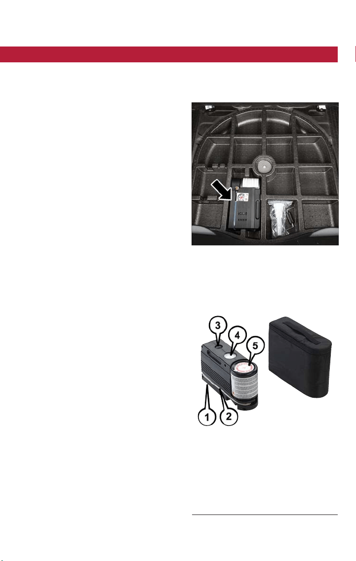
TIRE SERVICE KIT STORAGE
The Tire Service Kit is located in the rear storage compartment inside a storage con-
tainer. Located inside the container are a screwdriver and the emergency fuel funnel. To
access the Tire Service Kit open the liftgate and remove the load floor.
Tire Service Kit — If Equipped
If a tire is punctured, you can make a first
emergency repair using the Tire Ser vice Kit
located in the rear storage compartment
inside the storage container.
Tire punctures of up to 1/4 inch (6 mm)
can be repaired; the kit can be used in all
weather conditions. Do not remove the
foreign object from the punctured tire, i.e.,
screw or nail .
Tire Service Kit Location
Tire Service Kit Components
1 — Power Plug (located on bottom side
of Tire Service Kit)
2 — Sealant Hose (Clear)
3 — Power Button
4 — Pressure Gauge
5 — Sealant Bottle
WHAT TO DO IN EMERGENCIES
153

Remove t he Tire Service Kit from the vehicle, take it out from the bag and place it near
the punctured tire. Screw the clear flexible filling tube to the tire valve.
WARNING!
• Do not attempt to seal a tire on the side of the vehicle closest to traffic. Pull far
enough off the road to avoid the danger of being hit when using the Tire Service
Kit.
• Do not use Tire Service Kit or drive the vehicle under the following circumstances:
• If the puncture in the tire tread is approximately 1/4 inch (6 mm) or larger.
• If the tire has any sidewall damage.
• If the tire has any damage from driving with extremely low tire pressure.
• If the tire has any damage from driving on a flat tire.
• If the wheel has any damage .
• If you are unsure of the condition of the tire or the wheel.
• Keep Tire Service Kit away from open flames or heat sources.
• A loose Tire Service Kit thrown forward in a collision or hard stop could endanger
the occupants of the vehicle. Always stow the Tire Service Kit in the place pro-
vided. Failure to follow these warnings can result in injuries that are serious or
fatal to you, your passengers, and others around you.
• Take care not to allow the contents of Tire Service Kit to come in contact with
hair, eyes, or clothing. Tire Service Kit sealant is harmful if inhaled, swallowed, or
absorbed through the skin. It causes skin, eye, and respirator y irritation. Flush im-
mediately with plenty of water if there is any contact with eyes or skin . Change
clothing as soon as possible, if there is any contact with clothing.
• Tire Service Kit Sealant solution contains latex. In case of an allergic reaction or
rash, consult a physician immediately. Keep Tire Service Kit out of reach of chil-
dren. If swallowed, rinse mouth immediately with plenty of water and drink plenty
of water. Do not induce vomiting! Consult a physician immediately.
Insert t he power plug into the vehicle power outlet socket. Start the vehicle engine.
Push the Tire Service Kit power button to the “I” position. The electric compressor will
be turned on, sealant and air will inflate the tire.
Minimum 26 psi (1.8 bar) of pressure should be reached within 20 minutes. If the pres-
sure has not been reached turn off and remove the Tire Service Kit, drive the vehicle
30 feet (10 meters) back and forth, to better distribute the sealant inside the tire.
Attach the clear flexible filling tube of the compressor directly to the tire valve and re-
peat the inflation process.
When the correct pressure has been reached, start driving the vehicle to uniformly dis-
tribute the sealant inside the tire. After 10 minutes, stop and check the tire pressure. If
the pressure is below 19 psi (1.3 bar), do not drive the vehicle, as the tire is too dam-
aged, contact the nearest authorized dealer.
WHAT TO DO IN EMERGENCIES
154
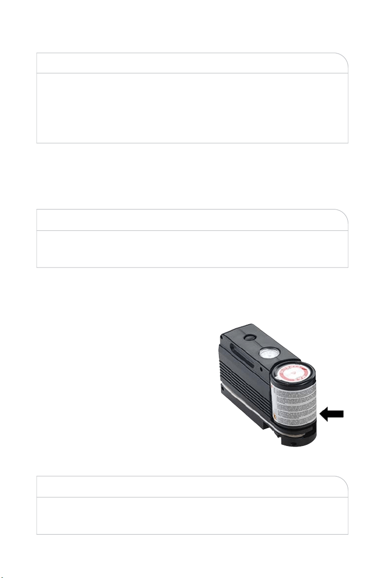
WARNING!
Tire Service Kit is not a permanent flat tire repair. Have the tire inspected and repaired
or replaced after using Tire Service Kit. Do not exceed 65 mph (110 km/h) until the
tire is repaired or replaced. Failure to follow this warning can result in injuries that are
serious or fatal to you, your passengers, and others around you. Have the tire checked
as soon as possible at an authorized dealer.
If the pressure is at 19 psi (1.3 bar) or above repeat the inflation process to reach the
correct tire pressure and continue driving.
Peel off the warning label from the bottle and place it on the dashboard as a reminder
to the driver that the tire has been treated with Tire Service Kit.
WARNING!
The metal end fitting from Power Plug may get hot after use, so it should be handled
carefully.
NOTE:
Replace the sealant canister prior to the expiration date at your authorized dealer.
WARNING!
Store the sealant canister in its special compartment, away from sources of heat. Failure to
follow this WARNING may result in sealant canister rupture and serious injury or death.
Tire Service Kit Expiration Date Location
WHAT TO DO IN EMERGENCIES
155

JACKING AND TIRE CHANGING
WARNING!
• Do not attempt to change a tire on the side of the vehicle close to moving traffic.
Pull far enough off the road to avoid the danger of being hit when operating the
jack or changing the wheel.
• Being under a jacked-up vehicle is dangerous. The vehicle could slip off the jack
and fall on you. You could be crushed. Never put any part of your body under a
vehicle that is on a jack. If you need to get under a raised vehicle, take it to a ser-
vice center where it can be raised on a lift.
• Never start or run the engine while the vehicle is on a jack.
• The jack is designed to be used as a tool for changing tires only. The jack should
not be used to lift the vehicle for service purposes. The vehicle should be jacked
on a firm level surface only. Avoid ice or slippery areas.
Jack Location/Spare Tire Stowage — If Equipped
The jack and tools are located in the rear storage compartment if equipped, inside a spe-
cial container.
1. Open the liftgate.
Jack And Tools Location
WHAT TO DO IN EMERGENCIES
156
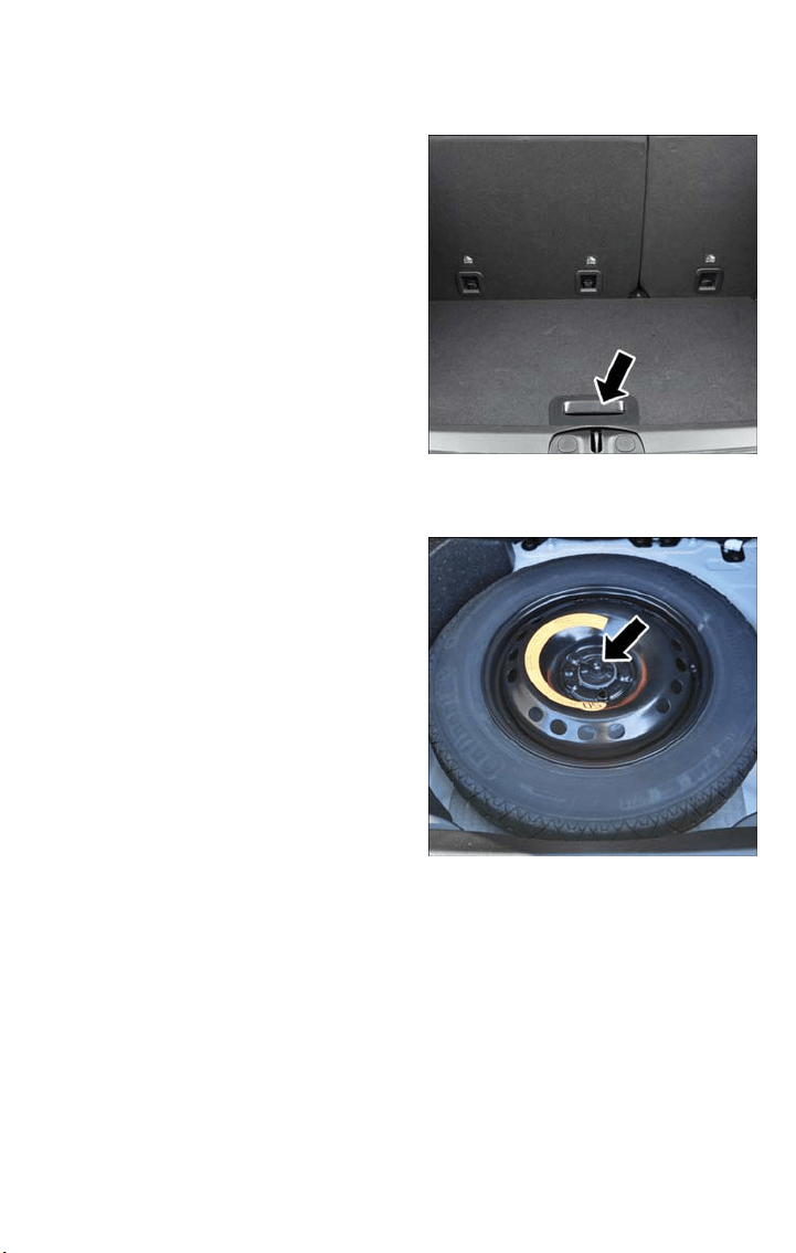
2. Lift the access cover using the load floor handle.
3. Remove the fastener securing the spare tire.
Load Floor Handle
Spare Tire Fastener
WHAT TO DO IN EMERGENCIES
157
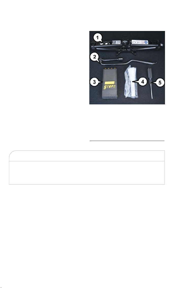
4. Remove the jack, wheel bolt wrench, and wheel chocks.
5. Remove the spare tire.
WARNING!
A loose tire or jack thrown forward in a collision or hard stop could endanger the oc-
cupants of the vehicle. Always stow the jack parts and the spare tire in the places pro-
vided. Have the deflated (flat) tire repaired or replaced immediately.
Jack And Tools
1 — Jack
2 — Wheel Bolt Wrench
3 — Wheel Chock
4 — Emergency Funnel
5 — Screwdriver
WHAT TO DO IN EMERGENCIES
158
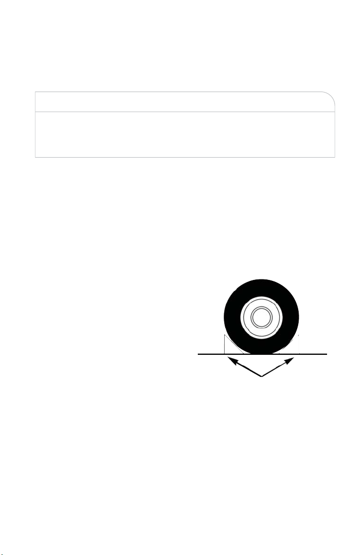
Preparations For Jacking
1. Park the vehicle on a firm level surface as far from the edge of the roadway as pos-
sible. Avoid icy or slippery areas.
WARNING!
Do not attempt to change a tire on the side of the vehicle close to moving traffic, pull
far enough off the road to avoid being hit when operating the jack or changing the
wheel.
2. Turn on the Hazard Warning flasher.
3. Set the Electric Park Brake.
4. Place the gear selector into PARK (automatic transmission) or REVERSE (manual
transmission).
5. Turn the ignition to STOP mode.
6. Chock both the front and rear of the wheel diagonally opposite of the jacking posi-
tion. For example, if changing the right front tire, chock the left rear wheel.
NOTE:
Passengers should not remain in the vehicle
when the vehicle is being jacked.
Wheels Blocked
WHAT TO DO IN EMERGENCIES
159
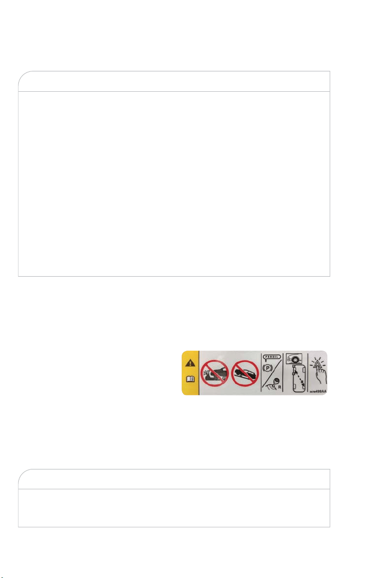
Jacking Instructions
WARNING!
Carefully follow these tire changing warnings to help prevent personal injury or damage
to your vehicle:
• Always park on a firm, level surface as far from the edge of the roadway as pos-
sible before raising the vehicle.
• Turn on the Hazard Warning flasher.
• Chock the wheel diagonally opposite the wheel to be raised.
• Apply the parking brake and place an automatic transmission in PARK.
• Never start or run the engine with the vehicle on a jack.
• Do not let anyone sit in the vehicle when it is on a jack.
• Do not get under the vehicle when it is on a jack. If you need to get under a
raised vehicle, take it to a service center where it can be raised on a lift.
• Only use the jack in the positions indicated and for lifting this vehicle during a tire
change.
• If working on or near a roadway, be extremely careful of motor traffic.
• To assure that spare tires, flat or inflated, are securely stowed, spares must be
stowed with the valve stem facing the ground.
CAUTION!
Do not attempt to raise the vehicle by jacking on locations other than those indicated
in the Jacking Instructions for this vehicle.
Jack Warning Label
WHAT TO DO IN EMERGENCIES
160
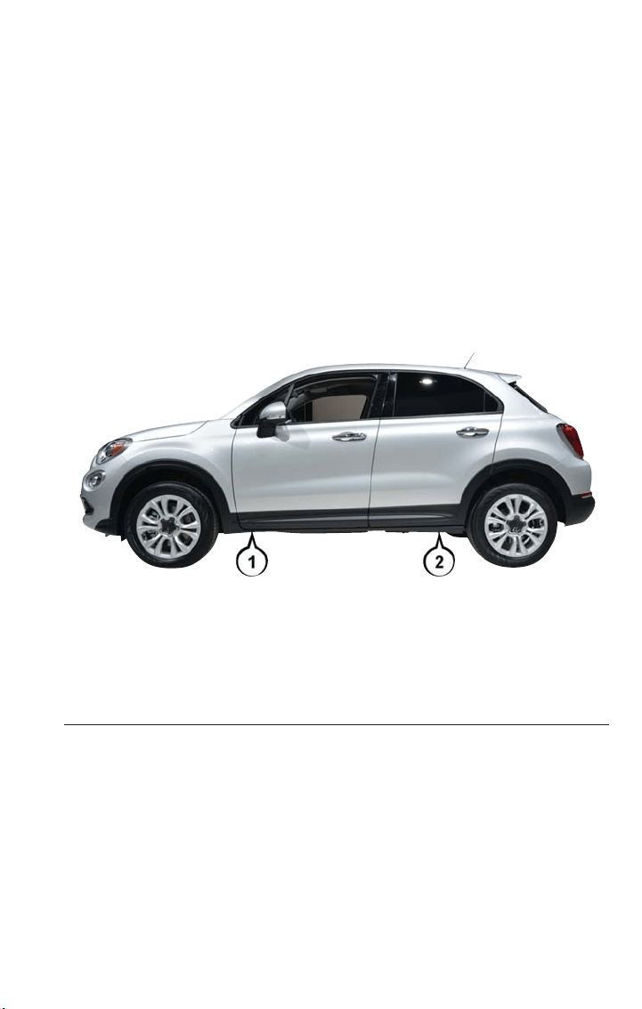
1. Remove the spare tire, jack, and wheel bolt wrench.
2. If equipped with wheels where the center cap covers the wheel bolts, use the wheel
bolt wrench to pry the center cap off carefully before raising the vehicle.
3. Before raising the vehicle, use the wheel bolt wrench to loosen, but not remove the
wheel bolts on the wheel with the flat tire. Turn the wheel bolts counterclockwise
one turn while the wheel is still on the ground.
4. Place the jack underneath the lift area that is closest to the flat tire. Turn t he jack
screw clockwise to firmly engage the jack saddle with the lift area of the sill flange,
centering the jack saddle inside the cutout in the sill cladding.
Jacking Locations
1 — Front Jacking Location
2 — Rear Jacking Location
WHAT TO DO IN EMERGENCIES
161
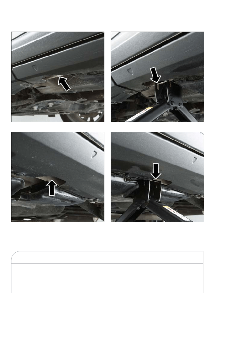
5. Raise the vehicle just enough to remove the flat tire.
WARNING!
Raising the vehicle higher than necessary can make the vehicle less stable. It could slip
off the jack and hurt someone near it. Raise the vehicle only enough to remove the
tire.
6. Remove the wheel bolts and tire.
7. Mount the spare tire.
Front Jacking Location
Rear Jacking Location
Front Jacking Engagement Point
Rear Jacking Engagement Point
WHAT TO DO IN EMERGENCIES
162
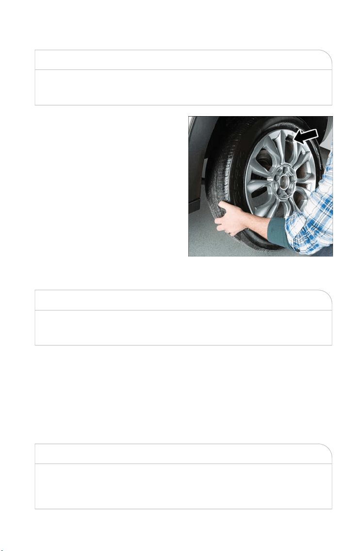
CAUTION!
Be sure to mount the spare tire with the valve stem facing outward. The vehicle could
be damaged if the spare tire is mounted incorrectly.
NOTE:
•
Your vehicle may be equipped with a
compact spare tire or a limited — use
spare tire. For further information re-
fer to “Tires — General Information”
in “Maintaining And Caring For Your
Vehicle” in your Owner’s Manual on
www.fiatusa.com/en/owners/manuals
for further information.
• For vehicles so equipped, do not at-
tempt to install a center cap or wheel
cover on the compact spare.
8. Install the wheel bolts with the threaded
end of the wheel bolt toward the
wheel. Lightly tighten the wheel bolts.
WARNING!
To avoid the risk of forcing the vehicle off the jack, do not fully tighten the wheel bolts until
the vehicle has been lowered. Failure to follow this warning may result in serious injury.
9. Lower the vehicle to the ground by turning the wheel bolt wrench counterclockwise.
10. Finish tightening the wheel bolts. Push down on the wrench while at the end of the
handle for increased leverage. Tighten the wheel bolts in a star pattern until each
wheel bolt has been tightened twice. The correct torque specification for the wheel
bolts is 89 Ft-Lbs (120 Nm). If in doubt about the correct tightness, have them
checked with a torque wrench by your authorized dealer or at a service station.
11. Securely stow the jack, tools, chocks and flat tire.
WARNING!
A loose tire or jack thrown forward in a collision or hard stop could endanger the oc-
cupants of the vehicle. Always stow the jack parts and the spare tire in the places pro-
vided. Have the deflated (flat) tire repaired or replaced immediately.
Mounting Spare Tire
WHAT TO DO IN EMERGENCIES
163

Road Tire Installation
1. Mount the road tire on the axle.
2. Install the remaining wheel bolts with the threaded end of the wheel bolt toward the
wheel. Lightly tighten the wheel bolts.
WARNING!
To avoid the risk of forcing the vehicle off the jack, do not tighten the lug nuts fully
until the vehicle has been lowered. Failure to follow this warning may result in serious
injur y.
3. Lower the vehicle to the ground by turning the jack handle counterclockwise.
4. Finish tightening the wheel bolts. Push down on the wrench while at the end of the
handle for increased leverage. Tighten the wheel bolts in a star pattern until each
wheel bolt has been tightened twice. The correct torque specification for the wheel
bolts is 89 Ft-Lbs (120 Nm). If in doubt about the correct tightness, have them
checked with a torque wrench by your authorized dealer or at a service station.
5. Lower the jack until it is free. Remove the wheel chocks. Stow the jack and tools back
in the proper storage location. Release the Electric Park Brake before driving the ve-
hicle.
6. After 25 miles (40 km) check the wheel bolt torque with a torque wrench to ensure
that all wheel bolts are properly seated against the wheel.
JUMP STARTING
If your vehicle has a discharged batter y it can be jump-started using a set of jumper
cables and a battery in another vehicle or by using a portable ba ttery booster pack. Jump
starting can be dangerous if done improperly so please follow the procedures in this sec-
tion carefully.
NOTE:
When using a por table battery booster pack follow the manufacturer’s operating instruc-
tions and precautions.
WARNING!
Do not attempt jump starting if the battery is frozen. It could rupture or explode and
cause personal injury.
WHAT TO DO IN EMERGENCIES
164
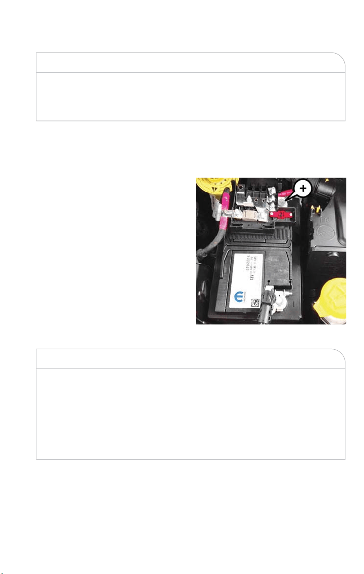
CAUTION!
Do not use a port able battery booster pack or any other booster source with a sys-
tem voltage greater than 12 Volts or damage to the battery, starter motor, alternator or
electrical system may occur.
Preparations For Jump Start
The battery in your vehicle is located in the front of the engine compartment, behind the
left headlight assembly.
NOTE:
The positive battery post is covered with a
protective cap. Liftuponthecaptogain
access to the positive battery post.
WARNING!
• Take care to avoid t he radiator cooling fan whenever the hood is raised. It can
start anytime the ignition switch is ON. You can be injured by moving fan blades.
• Remove any metal jewelry such as rings, watch bands and bracelets that could
make an inadvertent electrical contact. You could be seriously injured.
• Batteries contain sulfuric acid that can burn your skin or eyes and generate hydro-
gen gas which is flammable and explosive. Keep open flames or sparks away from
the battery.
Proceed as follows:
1. Apply the Electric Park Brake, shift the automatic transmission into PARK (manual
transmission in NEUTRAL) and place the ignition OFF.
2. Turn off the heater, radio, and all unnecessary electrical accessories.
Positive Battery Post
WHAT TO DO IN EMERGENCIES
165

3. If using another vehicle to jump start the battery, park the vehicle within the jumper
cables reach, set the parking brake and make sure the ignition is OFF.
WARNING!
Do not allow vehicles to touch each other as this could establish a ground connection
and personal injury could result.
Jump Starting Procedure
WARNING!
Failure to follow this jump starting procedure could result in personal injury or prop-
erty damage due to battery explosion.
CAUTION!
Failure to follow these procedures could result in damage to the charging system of the
booster vehicle or the discharged vehicle.
Connecting The Jumper Cables
1. Connect the positive (+) end of the jumper cable to the positive (+) post of the dis-
charged vehicle.
2. Connect the opposite end of the positive (+) jumper cable to the positive (+) post of
the booster battery.
3. Connect the negative (-) end of the jumper cable to the negative (-) post of the
booster battery.
4. Connect the opposite end of the negative (-) jumper cable to a good engine ground
(exposed metal part of the discharged vehicle’s engine) away from the battery and the
fuel injection system.
WARNING!
Do not connect the jumper cable to the negative (-) post of the discharged battery.
The resulting electrical spark could cause the battery to explode and could result in
personal injury. Only use the specific ground point, do not use any other exposed metal
parts.
WHAT TO DO IN EMERGENCIES
166

5. Start the engine in the vehicle that has the booster battery, let the engine idle a few
minutes, and then start the engine in the vehicle with the discharged battery.
6. Once the engine is started, remove the jumper cables in the reverse sequence:
Disconnecting The Jumper Cables
1. Disconnect the negative (-) end of the jumper cable from the engine ground of the
vehicle with the discharged battery.
2. Disconnect the opposite end of the negative (-) jumper cable from the negative (-)
post of the booster battery.
3. Disconnect the positive (+) end of the jumper cable from the positive (+) post of the
booster battery.
4. Disconnect the opposite end of the positive (+) jumper cable from the positive (+)
post of the vehicle with the discharged battery.
If frequent jump starting is required to start your vehicle you should have the ba ttery
and charging system inspected at your authorized dealer.
CAUTION!
Accessories plugged into the vehicle power outlets draw power from the vehicle’s bat-
tery, even when not in use (i.e., cellular devices, etc.). Eventually, if plugged in long
enough without engine operation, the vehicle’s battery will discharge sufficiently to de-
grade battery life and/or prevent the engine from starting.
FREEING A STUCK VEHICLE
If your vehicle becomes stuck in mud, sand or snow, it can often be moved using a rock-
ing motion. Turn the steering wheel right and left to clear the area around the front
wheels. For vehicles with automatic transmission, push and hold the lock button on the
gear selector. Then shift back and forth between DRIVE and REVERSE (with automatic
transmission) or SECOND GEAR and REVERSE (with manual transmission), while gently
pressing the accelerator.
Use the least amount of accelerator pedal pressure that will maintain the rocking motion
without spinning the wheels or racing the engine.
WHAT TO DO IN EMERGENCIES
167

For Vehicles With Automatic Transmission:
Shifts between DRIVE and REVERSE can only be achieved at wheel speeds of 5 mph
(8 km/h) or less. Whenever the transmission remains in NEUTRAL for more than two
seconds, you must press the brake pedal to engage DRIVE or REVERSE.
NOTE:
Push the "ESC Off" switch (if necessary), to place the Electronic Stability Control (ESC)
system in "Partial Off" mode, before rocking the vehicle. Refer to “Electronic Brake Con-
trol” in “Safety” in your Owner’s Manual at www.fiatusa.com/en/owners/manuals for fur-
ther information. Once the vehicle has been freed, push the "ESC Off" switch again to
restore "ESC On" mode.
WARNING!
Fast spinning tires can be dangerous. Forces generated by excessive wheel speeds may
cause damage, or even failure, of the axle and tires. A tire could explode and injure
someone. Do not spin your vehicle's wheels faster than 30 mph (48 km/h) or for lon-
ger than 30 seconds continuously without stopping when you are stuck and do not let
anyone near a spinning wheel, no matter what the speed.
CAUTION!
• Racing the engine or spinning the wheels may lead to transmission overheating and
failure. Allow the engine to idle with the transmission in NEUTRAL for at least
one minute after every five rocking-motion cycles. This will minimize overheating
and reduce the risk of clutch or transmission failure during prolonged efforts to
free a stuck vehicle.
• When “rocking” a stuck vehicle by shifting between DRIVE/ SECOND gear and
REVERSE, do not spin the wheels faster than 15 mph (24 km/h), or drivetrain
damage may result.
• Revving the engine or spinning the wheels too fast may lead to transmission over-
heating and failure. It can also damage the tires. Do not spin the wheels above
30 mph (48 km/h) while in gear (no transmission shifting occurring).
WHAT TO DO IN EMERGENCIES
168
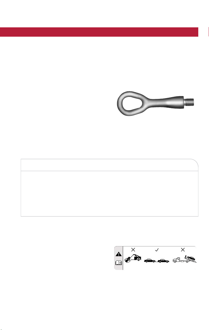
TOW EYE USAGE — IF EQUIPPED
Your vehicle is equipped with a tow eye that can be used to tow a disabled vehicle.
When using a tow eye be sure to follow the “Tow Eye Usage Precautions” and the “Tow-
ing A Disabled Vehicle” instructions in this section.
Tow Eye Usage Precautions
NOTE:
• Ensure that the tow eye is properly
seated and secure in the mounting re-
ceptacle.
• The tow eye is recommended for use
with an approved tow bar and or rope.
• Do not use the tow eye to pull the ve-
hicle onto a flatbed truck.
• Do not use the tow eye to free a s tuck
vehicle. Refer to “Freeing A Stuck Ve-
hicle” in this section for further
information.
WARNING!
Stand clear of vehicles when pulling with tow eyes.
•
Do not use a chain with a tow eye. Chains may break, causing serious injury or death.
• Do not use a tow strap wit h a tow eye. Tow straps may break or become disen-
gaged, causing serious injury or death.
• Failure to follow proper tow eye usage may cause components to break resulting
in serious injury or death.
Tow E ye
Tow Eye Warning Label
WHAT TO DO IN EMERGENCIES
169

CAUTION!
• The tow eye must be used exclusively for roadside assistance operations. Only use
the tow eye with an appropriate device in accordance with the highway code (a
rigid bar or rope) to flat tow the vehicle for a short distance to the nearest ser-
vice location.
• Tow eyes MUST NOT be used to tow vehicles off the road or where there are
obstacles.
• In compliance with the above conditions, towing with a tow eye must take place
with two vehicles (one towing, the other towed) aligned as much as possible along
the same center line. Damage to your vehicle may occur if these guidelines are
not followed.
Front Tow Eye Installation
The front tow eye receptacle is located behind a access door, located on the right front
bumper fascia. To install the tow eye, open the access door using the vehicle key or a
small screwdriver, and thread the tow eye into the receptacle.
Insert t he wheel bolt wrench handle through the eye and tighten, refer to “Jacking And
Tire Changing” for further information. The tow eye must be fully seated to the attaching
bracket through the lower front fascia as shown. If the tow eye is not fully seated to the
attaching bracket, the vehicle should not be towed.
Rear Tow Eye Installation
The rear tow eye receptacle is located behind a access door on the rear bumper fascia.
To install the tow eye, open the access door using the vehicle key or a small screwdriver,
and thread the tow eye into the receptacle.
Insert t he wheel bolt wrench handle through the eye and tighten, refer to “Jacking And
Tire Changing” for further information. The tow eye must be fully seated to the attaching
bracket through the lower rear fascia. If the tow eye is not fully seated to the attaching
bracket, the vehicle should not be towed.
WHAT TO DO IN EMERGENCIES
170
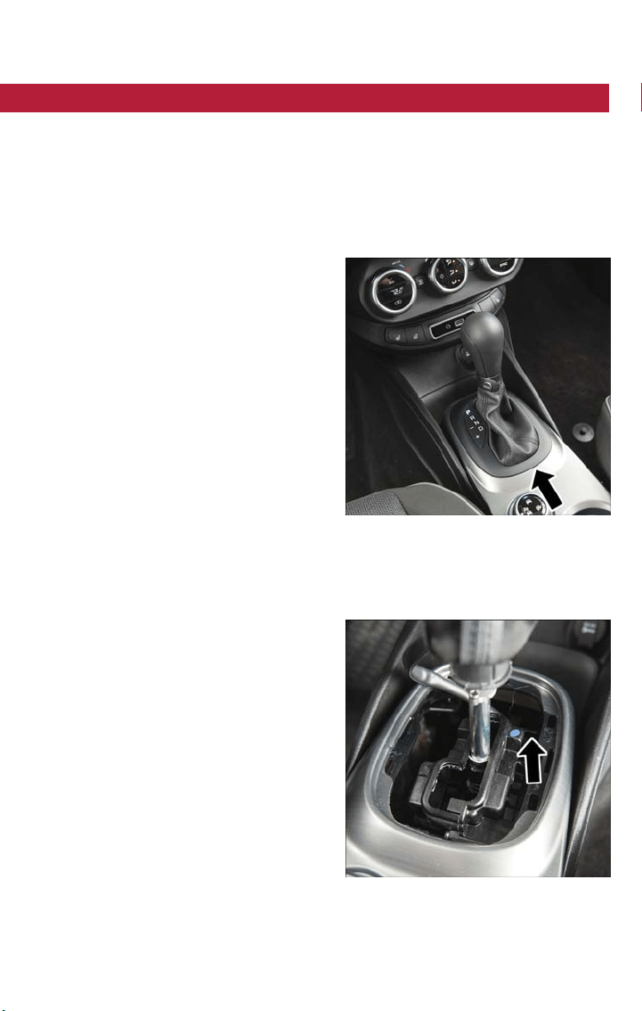
GEAR SELECTOR OVERRIDE
If a malfunction occurs and the gear selector cannot be moved out of the PARK position,
you can use the following procedure to temporarily move the gear selector:
1. Turn the engine OFF.
2. Apply the Electric Park Brake.
3. Carefully separate the gear selector bezel and boot assembly from the center con-
sole.
4. Push and maintain firm pressure on the
brake pedal.
5. Insert a small screwdriver or similar tool down into the gear selec tor override access
hole (at the right front corner of the gear selector assembly), and push and hold the
override release lever down.
6. Move the gear selector to the NEU-
TRAL position.
7. The vehicle may then be started in
NEUTRAL.
8. Reinstall the gear selector bezel.
Gear Selector Bezel Location
Gear Selector Override Location
WHAT TO DO IN EMERGENCIES
171

TOWING A DISABLED VEHICLE
This section describes procedures for towing a disabled vehicle using a commercial towing
service.
Towing Condition
Wheels OFF
The Ground
FWD MODELS
ALL WHEEL DRIVE
Flat Tow
NONE NOT ALLOWED NOT ALLOWED
Wheel Lift Or Dolly Tow
Rear
NOT ALLOWED NOT ALLOWED
Front
OK NOT ALLOWED
Flatbed
ALL BEST METHOD OK
Proper towing or lifting equipment is required to prevent damage to your vehicle. Use
only tow bars and other equipment designed for this purpose, following equipment
manufacturer’s instructions. Use of safety chains is mandatory. Attach a tow bar or other
towing device to main structural members of the vehicle, not to bumpers or associa ted
brackets. State and local laws regarding vehicles under tow must be observed.
NOTE:
•
You must ensure that the Auto Park Brake feature is disabled before towing this vehicle,
to avoid inadvertent Electric Park Brake engagement. The Auto Park Brake feature is en-
abled or disabled via the customer programmable features in the Uconnect Settings.
• Vehicles with a discharged battery or total electrical failure when the Electric Park
Brake (EPB) is engaged, will need a wheel dolly or jack to raise the rear wheels off the
ground when moving the vehicle onto a flatbed.
If you must use the accessories (wipers, defrosters, etc.) while being towed, the ignition
must be in the RUN position.
NOTE:
The Safehold feature will engage the Electric Park Brake whenever the driver's door is
opened (if the ignition is RUN, transmission is not in PARK, and brake pedal is released).
If you are towing this vehicle with the ignition in the RUN position, you must manually
disable the Electric Park Brake each time the driver's door is opened, by pressing the
brake pedal and then releasing the EPB.
If the key fob is unavailable, or the vehicle’s battery is discharged, refer to “Gear Selector
Override” in this section for instructions on shif ting the transmission out of PARK so that
the vehicle can be moved.
CAUTION!
• Do not use sling type equipment when towing. Vehicle damage may occur.
• When securing the vehicle to a flat bed truck, do not attach to front or rear sus-
pension components. Damage to your vehicle may result from improper towing.
WHAT TO DO IN EMERGENCIES
172

Front Wheel Drive (FWD) Models
The manufacturer recommends towing your vehicle with all four wheels OFF the ground
using a flatbed.
If flatbed equipment is not available, this vehicle must towed with the front wheels OFF
the ground (using a towing dolly, or wheel lift equipment with the front wheels raised).
NOTE:
Ensure that the Electric Park Brake is released, and remains released, while being towed.
CAUTION!
Towing this vehicle in violation of the above requirements can cause severe transmission
damage. Damage from improper towing is not covered under the New Vehicle Limited
Warranty.
All Wheel Drive (AWD) Models
The manufacturer requires towing with all four wheels OFF the ground. Acceptable
methods are to tow the vehicle on a flatbed, or with one end of the vehicle raised and
the opposite end on a towing dolly.
CAUTION!
• DO NOT tow this vehicle with ANY of its wheels on the ground. Damage to the
drivetrain will result.
• Front or rear wheel lifts must not be used. Internal damage to the transmission or
power transfer unit will occur if a front or rear wheel lift is used when towing.
• Towing this vehicle in violation of the above requirements can cause severe trans-
mission and/or power transfer unit damage. Damage from improper towing is not
covered under the New Vehicle Limited Warranty.
ENHANCED ACCIDENT RESPONSE SYSTEM (EARS)
This vehicle is equipped with an Enhanced Accident Response System.
Please refer to “Occupant Restraint Systems” in “Getting Started” for further information
on the Enhanced Accident Response System (EARS) function.
EVENT DATA RECORDER (EDR)
This vehicle is equipped with an Event Data Recorder (EDR). The main purpose of an EDR is
to record data that will assist in understanding how a vehicle’s systems performed under cer-
tain crash or near crash-like situations, such as an air bag deployment or hitting a road obstacle.
Please refer to “Occupant Restraint Systems” in “Getting Started” for further information
on the Event Data Recorder (EDR).
WHAT TO DO IN EMERGENCIES
173
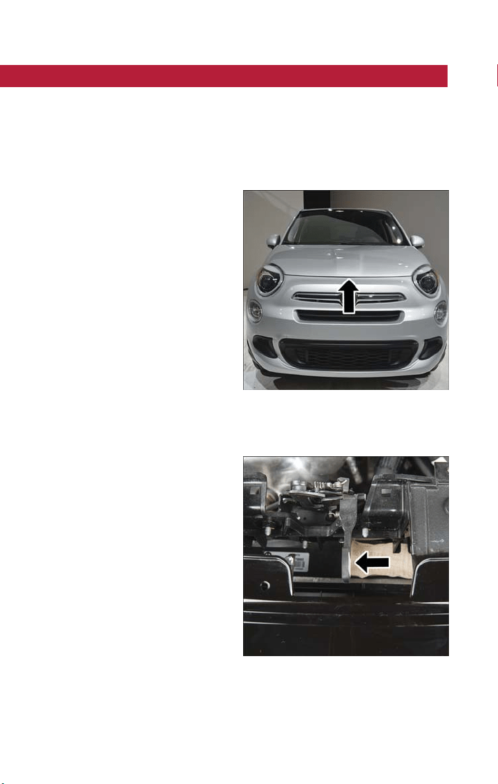
HOOD
Opening
The hood release lever (to open the primary latch) and safety latch (to open the second-
ar y latch) must be released to open the hood.
1. Pull the hood release lever located under the driver’s side of the instrument panel.
2. Move to the outside of the vehicle.
3. Push the safety latch release lever toward the passenger side of the vehicle . The safety
latch is located behind the center front edge of the hood.
4. Remove the support rod from the lock-
ing tab and insert it into the seat lo-
cated on the underside of the hood.
NOTE:
• Before lifting the hood, check that the
wiper arms are not in motion and not in
the lifted position.
• While lifting the hood, use both hands.
• Vehicle must be at a stop and the auto-
matic transmission must be in PARK.
Manual transmission vehicles must have
the electric park brake engaged.
Safety Latch Release Lever Location
Safety Latch Release Lever
MAINTAINING YOUR VEHICLE
174

Closing
1. Hold up the hood with one hand and with the other hand remove the suppor t rod
from its seat and reinsert it into the locking tab.
2. Lower the hood to approximately 12 inches (30 cm) from the engine compartment
and drop it. Make sure that the hood is completely closed.
WARNING!
Be sure the hood is fully latched before driving your vehicle. If the hood is not fully
latched, it could open when the vehicle is in motion and block your vision. Failure to
follow this warning could result in serious injury or death.
CAUTION!
To prevent possible damage, do not slam the hood to close it. Lower hood to approxi-
mately 12 inches (30 cm) and drop the hood to close. Make sure hood is fully closed for
both latches. Never drive vehicle unless hood is fully closed, with both la tches engaged.
MAINTAINING YOUR VEHICLE
175
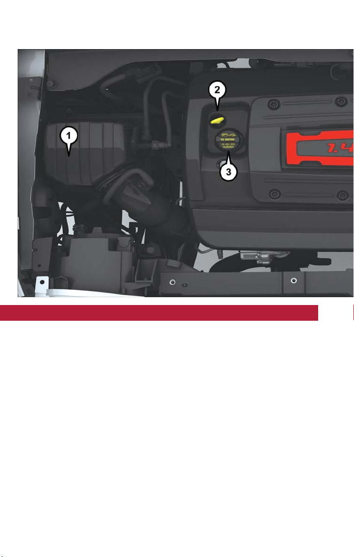
ENGINE COMPARTMENT — 1.4L TURBO
1. Engine Air Filter
2. Engine Oil Dipstick
3. Engine Oil Fill
MAINTAINING YOUR VEHICLE
176
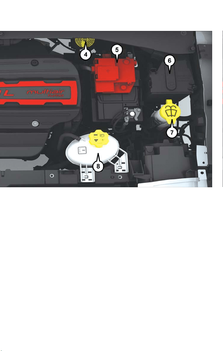
4. Brake Fluid Reservoir
5. Battery
6. Power Distribution Center (Fuses)
7. Washer Fluid Reservoir
8. Engine Coolant Reservoir
MAINTAINING YOUR VEHICLE
177
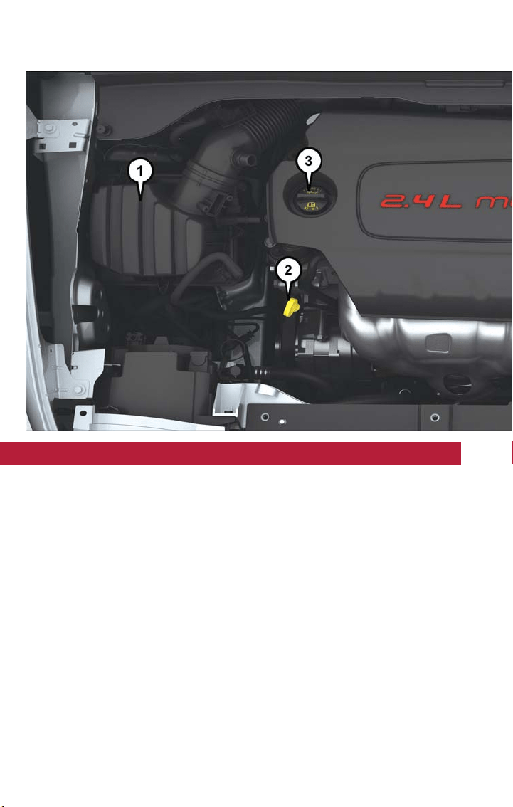
ENGINE COMPARTMENT — 2.4L
1. Engine Air Filter
2. Engine Oil Dipstick
3. Engine Oil Fill
MAINTAINING YOUR VEHICLE
178
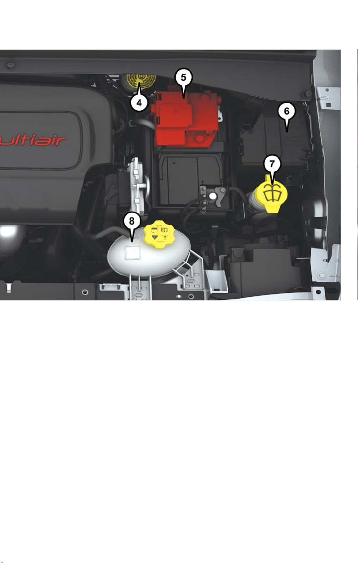
4. Brake Fluid Reservoir
5. Battery
6. Power Distribution Center (Fuses)
7. Washer Fluid Reservoir
8. Engine Coolant Reservoir
MAINTAINING YOUR VEHICLE
179
FLUID CAPACITIES
U.S Metric
Fuel (Approximate)
1.4L Turbo/2.4L Engine 12.7 Gallons 48 Liters
Engine Oil With Filter
1.4L Turbo Engine (SAE 5W-40 Synthetic, API
Certified) 4.0 Quarts 3.8 Liters
2.4L Engine (SAE 0W-20, API Certified) 5.5 Quarts 5.2 Liters
Cooling System *
1.4L Turbo Engine (Mopar Antifreeze/Engine
Coolant 10 Year/150,000 Mile Formula) 5.5 Quarts 5.2 Liters
2.4L Engine (Mopar Antifreeze/Engine Coolant
10 Year/150,000 Mile Formula) 6.8 Quarts 6.5 Liters
* Includes heater and coolant recovery bottle filled to MAX level.
FLUIDS, LUBRICANTS, AND GENUINE PARTS
Engine
Component Fluid, Lubricant, or Genuine Part
Engine Coolant We recommend you use Mopar Antifreeze/
Coolant 10 Year/150,000 Mile Formula OAT
(Organic Additive Technology) or equivalent
meeting the requirements of FCA Material
Standard MS.90032.
Engine Oil – 1.4L Turbo Engine We recommend you use SAE 5W-40 API Cer-
tified Synthetic Engine Oil, meeting the require-
ments of FCA Material Standard MS-12991.
Refer to your engine oil filler cap for correct
SAE grade.
Engine Oil – 2.4L Engine We recommend you use SAE 0W-20 API Cer-
tified Engine Oil, meeting the requirements of
FCA Material Standard MS-6395. Refertoyour
engine oil filler cap for correct SAE grade.
Engine Oil Filter We recommend you use a Mopar Engine Oil
Filter.
Spark Plugs We recommend you use Mopar Spark Plugs.
Fuel Selection – 1.4L Turbo Engine 91 Octane Recommended, 87 Acceptable,
0-15% Ethanol.
Fuel Selection – 2.4L Engine 87 Octane, 0-15% Ethanol.
MAINTAINING YOUR VEHICLE
180

Chassis
Component Fluid, Lubricant, or Genuine Part
Manual Transmission – If Equipped We recommend you use Mopar C Series
Manual & Dual Dry Clutch Transmission
Fluid.
Automatic Transmission – If Equipped Use only Mopar ZF 8&9 Speed ATF Auto-
matic Transmission Fluid, or equivalent.
Failure to use the correct fluid may affect
the function or performance of your
transmission.
Power Transfer Unit (PTU) – If Equipped We recommended you use Mopar Front
Axle/PTU Synthetic Axle Lubricant SAE
75W-90 (API GL-5).
Rear Differential (RDM) – If Equipped We recommended you use Mopar Rear
Axle/RDM Synthetic Axle Lubricant SAE
75W-90 (API GL-5).
Brake Master Cylinder We recommend you use Mopar DOT 4. If
DOT 4 brake fluid is not available, then
DOT 3 is acceptable.
DOT 4 brake fluid must be changed every
2 years regardless of mileage.
MAINTENANCE PROCEDURES
For information on the maintenance procedures for your vehicle, please refer to “Mainte-
nance Procedures” in “Maintaining Your Vehicle” in your Owner’s Manual or an applicable
supplement at www.fiatusa.com/en/owners/manuals for fur ther information.
MAINTENANCE SCHEDULE
Your vehicle is equipped with an automatic oil change indicator system. The oil change
indicator system will remind you that it is time to take your vehicle in for scheduled
maintenance.
Based on engine operation conditions, the oil change indicator message will illuminate in
the instrument cluster. This means that service is required for your vehicle. Operating
conditions such as frequent short-trips, trailer tow and extremely hot or cold ambient
temperatures will influence when the “Change Oil” or “Oil Change Required” message is
displayed. Severe Operating Conditions can cause t he change oil message to illuminate as
early as 3,500 miles (5,600 km) since last reset. Have your vehicle serviced as soon as
possible, within the next 500 miles (805 km).
MAINTAINING YOUR VEHICLE
181

Your authorized dealer will reset the oil change indicator message after completing the
scheduled oil change. If a scheduled oil change is performed by someone other than your
authorized dealer, the message can be reset by referring to the steps described under
“Instrument Cluster Display” in “Getting To Know Your Instrument Panel” in your Owner’s
Manual at www.fiatusa.com/en/owners/manuals for furt her information.
NOTE:
Under no circumstances should oil change intervals exceed 10,000 miles (16,000 km),
twelve months or 350 hours of engine run time, whichever comes first. The 350 hours
of engine run or idle time is generally only a concern for fleet customers.
Severe Duty All Models
Change Engine Oil at 4,000 miles (6,500 km) if the vehicle is operated in a dusty and off
road environment or is operated predominately at idle or only very low engine RPM’s .
This type of vehicle use is considered Severe Duty.
NOTE:
The Oil Change Indicator will not illuminate under these conditions.
Once A Month Or Before A Long Trip:
• Check engine oil level.
• Check windshield washer fluid level.
• Check the tire inflation pressures and look for unusual wear or damage.
• Check the fluid levels of the coolant reservoir, and brake master cylinder reservoir, and
fill as needed.
• Check function of all interior and exterior lights.
Maintenance Chart
Required Maintenance Intervals
At Every Oil Change Interval As Indicated By Oil Change Indicator System:
Change oil and filter.
Inspect battery and clean and tighten terminals as required.
Inspect brake pads, shoes, rotors, drums, and hoses.
Inspect engine cooling system protection and hoses.
Check and adjust hand brake.
Inspect exhaust system.
Inspect engine air filter if using in dusty or off-road conditions.
Refer to the “Maintenance Chart” on the following page for the required maintenance
intervals.
MAINTAINING YOUR VEHICLE
182

Mileage or time passed (whichever comes first)
10,000
20,000
30,000
40,000
50,000
60,000
70,000
80,000
90,000
100,000
110,000
120,000
130,000
140,000
150,000
Or Years: 1 2 3 4 5 6 7 8 9 10 11 12 13 14 15
Or Kilometers:
16,000
32,000
48,000
64,000
80,000
96,000
112,000
128,000
144,000
160,000
176,000
192,000
208,000
224,000
240,000
Check tire condition/wear and adjust pressure, if necessary, check TIREKIT
expiration date (if provided).
••• •••••• • • • • • •
Check operation of lighting system (headlamps, direction indicators, hazard
warning lights, luggage compartment, passenger compartment, glove compart-
ment, instrument panel warning lights, etc.).
••• •••••• • • • • • •
Check and, if necessary, top up fluid levels (brakes/hydraulic clutch, windshield
washer, battery, engine coolant, etc.).
••• •••••• • • • • • •
Check engine control system operation (via diagnostic tool). ••• •••••• • • • • • •
Visually inspect condition of: exterior bodywork, underbody protection, pipes
and hoses (exhaust - fuel system - brakes), rubber elements (boots, sleeves,
bushings, etc.).
••••• • •
Check windshield/rear window wiper blade position/wear. •• ••• • • •
Check operation of windshield washer system and adjust jets if necessary. •• ••• • • •
Check cleanliness of hood and tailgate locks and cleanliness and lubrication of
linkages.
•• ••• • • •
Visually check the condition and wear of the front and rear brakes. ••• •••••• • • • • • •
Check the front suspension, tie rods, CV joints and replace if necessary. ••••• • •
Visual inspec t the condition of the accessory drive belt. •• •
Check the tension of the accessory drive belt. ••••• • •
Inspect and replace, if required, front end accessory drive belt, tensioner, and,
idler pulley.
•
Inspect and replace PCV valve if necessary. •
Change engine oil and replace oil filter. *
In accordance with Oil Change Indicator System OR Severe Duty Mileage, whichever oc-
curs first.
MAINTAINING YOUR VEHICLE
183

Mileage or time passed (whichever comes first)
10,000
20,000
30,000
40,000
50,000
60,000
70,000
80,000
90,000
100,000
110,000
120,000
130,000
140,000
150,000
Or Years: 1 2 3 4 5 6 7 8 9 10 11 12 13 14 15
Or Kilometers:
16,000
32,000
48,000
64,000
80,000
96,000
112,000
128,000
144,000
160,000
176,000
192,000
208,000
224,000
240,000
Inspect the PTU fluid level. •• •
Inspect the rear differential fluid level. •• •
Replace spark plugs (1.4L Turbo engine). ** • • • • •
Replace spark plugs (2.4L engine). ** •
Replace engine air filter. #•••••
Replace brake fluid every two years. ••••• • •
Replace cabin filter. ○ • ○ • ○ • ○ • ○ • ○ • ○ • ○
Change the manual transmission fluid if using your vehicle for any of the fol-
lowing: trailer towing, heavy loading, taxi, police, delivery service (commercial
service), off-road, deser t operation or more than 50% of your driving is at
sustained speeds during hot weather, above 90°F (32°C).
••
Flush and replace the engine coolant at 10 years or 150,000 miles
(240,000 km) whichever comes first.
••
Replace the timing belt (1.4L Turbo Engine). •
○ Recommend replacement
• Mandatory service
# The engine air cleaner should be inspected at every oil change if used in dusty areas.
* The oil and oil filter replacement must be carried out when indicated by a warning light or message on the instrument panel, or in any case should not
exceed 1 year or 10,000 miles (16,000 km).
MAINTAINING YOUR VEHICLE
184

** The spark plug change is distance based only, yearly intervals do not apply.The following are essential to ensure correct operation and prevent serious
damage to the engine:
• Only use spark plugs of the same make and type which are specially certified for such engines (refer to “Fluids, Lubricants, And Genuine
Parts” in “Maintaining Your Vehicle” for further information).
• Strictly comply with the spark plug replacement interval given in the “Maintenance Chart” for spark plug replacement.
• Contact your authorized dealer if you have any questions.
WARNING!
• You can be badly injured working on or around a motor vehicle. Do only service work for which you have the knowledge and the
right equipment. If you have any doubt about your ability to perform a service job, take your vehicle to a competent mechanic.
• Failure to properly inspect and maintain your vehicle could result in a component malfunction and effect vehicle handling and perfor-
mance. This could cause an accident.
MAINTAINING YOUR VEHICLE
185

MAINTENANCE RECORD
Odometer Date Signature, Authorized
Service Center
10,000 Miles
(16,000 km) or
1 Years
20,000 Miles
(32,000 km) or
2 Years
30,000 Miles
(48,000 km) or
3 Years
40,000 Miles
(64,000 km) or
4 Years
50,000 Miles
(80,000 km) or
5 Years
60,000 Miles
(96,000 km) or
6 Years
70,000 Miles
(112,000 km) or
7 Years
80,000 Miles
(128,000 km) or
8 Years
Odometer Date Signature, Authorized
Service Center
90,000 Miles
(144,000 km) or
9 Years
100,000 Miles
(160,000 km) or
10 Years
110,000 Miles
(176,000 km) or
11 Years
120,000 Miles
(192,000 km) or
12 Years
130,000 Miles
(208,000 km) or
13 Years
140,000 Miles
(224,000 km) or
14 Years
150,000 Miles
(240,000 km) or
15 Years
MAINTAINING YOUR VEHICLE
186

FUSES
WARNING!
• When replacing a blown fuse, always use an appropriate replacement fuse with
the same amp rating as the original fuse. Never replace a fuse with another fuse
of higher amp rating. Never replace a blown fuse with metal wires or any other
material. Failure to use proper fuses may result in serious personal injury, fire
and/or property damage.
• Before replacing a fuse, make sure that the ignition is off and that all the other
services are switched off and/or disengaged.
• If the replaced fuse blows again, contact an authorized dealer.
• If a general protection fuse for safety systems (air bag system, braking system),
power unit systems (engine system, gearbox system) or steering system blows,
contact an authorized dealer.
Engine Compartment Fuses/Distribution Unit
The engine compartment fuse panel is located on the left side of the engine compart-
ment.
Refer to your Owner’s Manual at www.fiatusa.com/en/owners/manuals for further fuse
information.
Cavity Maxi Fuse Cartage Fuse Mini Fuse Description
F01 70 Amp Tan – – Module Body Computer
F02 60 Amp Blue – – Module Body Computer,
Rear Distribution Units
Engine Compartment Fuse Location
MAINTAINING YOUR VEHICLE
187

Cavity Maxi Fuse Cartage Fuse Mini Fuse Description
F03 – 20 Amp Blue – Controller Power Supply
Body Computer
F04 – 30 Amp Pink – Brake Control Electronics
Module
F05 70 Amp Tan – – Electric Power-Assisted
Steering
F06 20 Amp Yellow – – Engine Cooling fan
F07 50 Amp Red – – Engine Cooling fan
F08 – 30 Amp Pink –
Automatic Transmission, GSM
F09 – – 5 Amp Tan Control Module Engine
F10 – – 10 Amp Red Horn
F11 – – 10 Amp Red Supply Secondary Loads
F14 – – 5 Amp Tan Pump Power "After run"
F15
40 Amp Orange
– – Brake Control Module
Pump
F16 – – 5 Amp Tan Engine Control Module
Power, Automatic Transmis-
sion
F17 – – 10 Amp Red
15 Amp Blue
Supply Primary Loads
(1.4L)
Supply Primary Loads
(2.4L)
F18 – – 30 Amp Green Power All-Wheel Drive
F19 – – 7.5 Amp
Brown
Air Conditioner Compressor
F20 – – 5 Amp Tan Electronic Power Four-
Wheel Drive
F21 – – 15 Amp Blue Fuel Pump
F22 – – 20 Amp Yelow Power Control Module
Engine
F23 – – 20 Amp Yellow
(Customer
Installed)
Power Outlet (Battery
Powered)
F24 – – 15 Amp Blue Electronic Unit Supply Au-
tomatic Transmission
F30 – – 30 Amp Green Heated Windshield – If
Equipped
F83 – 40 Amp Green – Air Conditioning Fan
F84 – – 20 Amp Yellow Power Outlet (Ignition
Powered)
F87 – – 5 Amp Tan Gear Selector Automatic
Transmission
MAINTAINING YOUR VEHICLE
188

Cavity Maxi Fuse Cartage Fuse Mini Fuse Description
F88 – – 7.5 Amp
Brown
Heated Outside Mirrors
F89 – 30 Amp Pink – Heated Rear Window
F90 – – 5 Amp Tan IBS Sensor (Battery State
of Charge)
Body Computer Fuse Center
The controller is located at the left side of the steering column at the bottom of the
instrument panel.
For the fuse replacement see your authorized dealer.
Cavity Mini Fuse Description
F31 7.5 Amp
Brown
Fan Air Conditioning, Power Socket
F33 20 Amp Yellow Power Window Front (Passenger Side)
F34 20 Amp Yellow Power Window Front (Driver’s Side)
F36 15 Amp Blue Supply Uconnect System, Air Conditioning, USB Port, Rear
lateral ceiling light in case of open roof, EOBD port
F37 10 Amp Red System Power Forward Collision Warning Plus, All Wheel
Drive (AWD), IPC, Central stack switches, Brake Pedal
Switch (NC)
F38 20 Amp Yellow Central Locking
F42 7.5 Amp
Brown
BSM - Brake Control Module, EPS - Electric Power-Assisted
Steering
F43 20 Amp Yellow Bi-directional Pump Washer
F47 20 Amp Yellow Power Rear Window (Driver Side)
F48 20 Amp Yellow Power Rear Window (Passenger Side)
F49 7.5 Amp
Brown
Supply ParkSense, Spot Lights Front Dome, Internal Electo-
cromic Mirror, Heated Front Seats
F50 7.5 Amp
Brown
Supply Air Bag
F51 7.5 Amp
Brown
Air Conditioning Compressor, Plaque Automatic Transmission,
Rear Camera, Air Conditioning, LDW - Lane Departure
Warning, ASS - Auxiliary Stack Switch, DSU - Drive Syle Se-
lector Unit, Reverse gear switch, side mirrors and rear win-
dow defrost
F53 7.5 Amp
Brown
Supply IPC/Star ter Device/System Keyless Enter-N-Go, Brake
Pedal Switch (NA), EPB - Electric Parking Brake
MAINTAINING YOUR VEHICLE
189
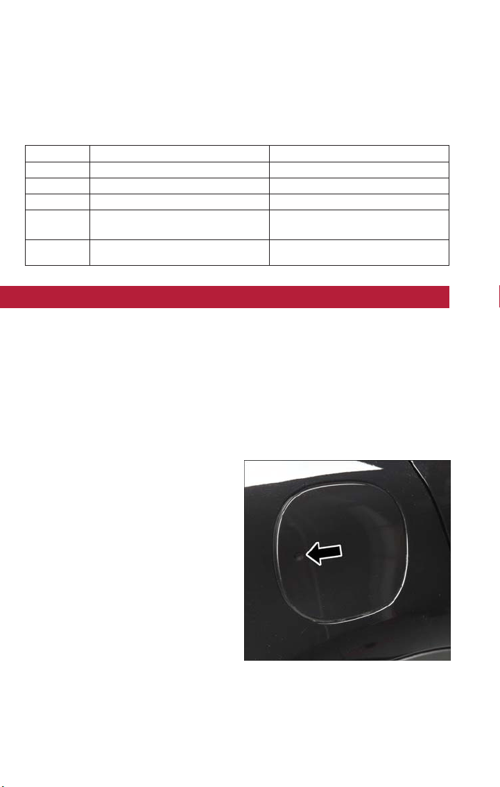
Rear Cargo Fuse/Relay Distribution Unit
To access the fuses, remove the access door from the left rear panel of the rear cargo
area.
Push on the left side of the access door to unhinge and remove.
Cavity Mini Fuse Description
F2 20 Amp Yellow Audio System
F3 20 Amp Yellow Electric Sunroof
F5 30 Amp Green Power Seat (driver side)
F6 7.5 Amp Brown Power Seat (driver side) Lumbar
Adjustment
F8 20 Amp Yellow Heating Front Seats
ADDING FUEL
The Capless Fuel System uses a flapper placed at the filler pipe of the fuel tank; it opens
and closes automatically upon insertion/extraction of the fuel nozzle.
The Capless Fuel System is designed so that it prevents the filling of an incorrect type of
fuel.
Opening The Door
For filling, proceed as follows:
1. Open the door, by pushing and releasing on the indentation point indicated by the
arrow.
2. Insert the fuel nozzle in the filler pipe
and proceed with filling the fuel tank.
3. Before removing the nozzle, wait at least
10 seconds to allow the fuel to flow
inside of the tank .
4. Pull the nozzle from the filler pipe and
then close the door.
Fuel Filler Door
MAINTAINING YOUR VEHICLE
190
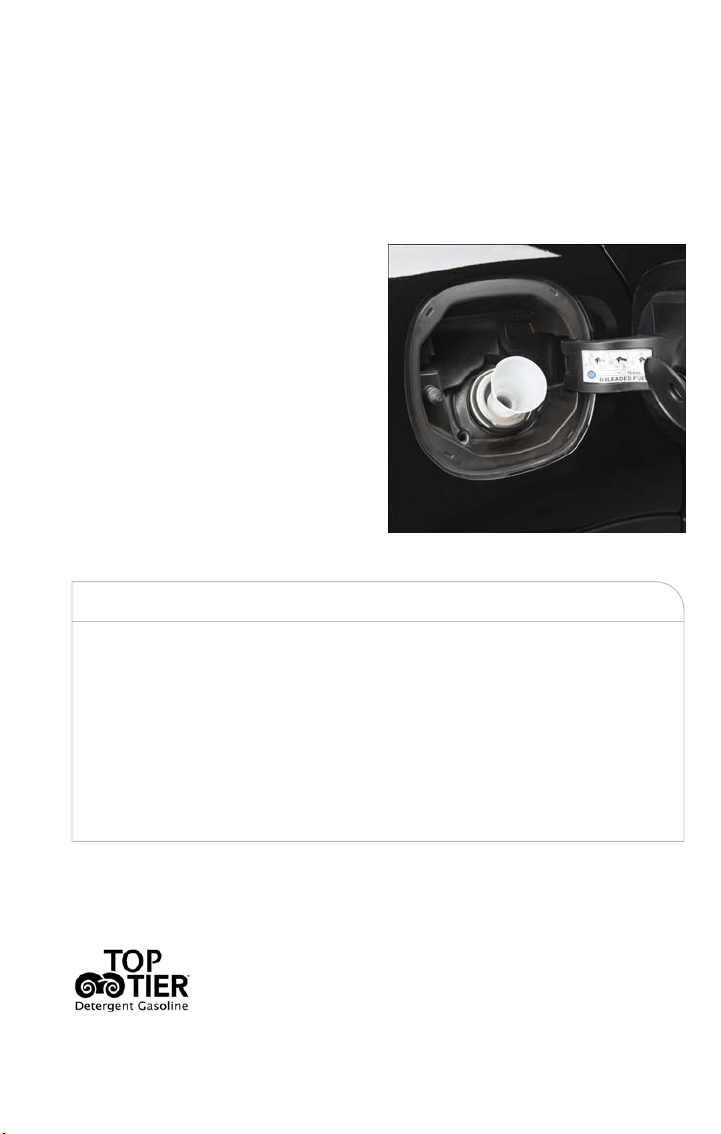
Emergency Refueling Procedure
If the vehicle is out of fuel, proceed as follows:
1. Open the liftgate and remove the emergency fuel fill funnel located in the cargo area.
2. Open the fuel door.
3. Insert the emergency fuel fill funnel in the filler pipe and proceed to fill the fuel tank.
4. Remove the emergency fuel fill funnel,
and close the door.
5. Store the emergency fuel fill funnel in
the cargo area.
WARNING!
• Do not affix objects/plugs to the end of the filler neck other than is provided on
the car.
• The use of objec ts/plugs do not comply with the vehicle and may cause pressure
increases inside the tank, creating dangerous conditions .
• Do not approach the neck of the tank with open flames or lit cigarettes its an
extreme fire hazard. Also, avoid close contact with the filler pipe with your face,
do not inhale harmful vapors.
• Do not use your mobile phone in the vicinity of the pump fuel nozzle, it can be a
possible risk of fire.
Materials Added To Fuel
Designated TOP TIER Detergent Gasoline contains a higher level of
detergents to further aide in minimizing engine and fuel system de-
posits. When available, the usage of Top Tier Detergent gasoline is
recommended.Visit www.toptiergas.com for a list of TOP TIER De-
tergent Gasoline Retailers.
Fueling With Emergency Fuel Fill Funnel
MAINTAINING YOUR VEHICLE
191

Indiscriminate use of fuel system cleaning agents should be avoided. Many of these mate-
rials intended for gum and varnish removal may contain active solvents or similar ingredi-
ents. These can harm fuel system gasket and diaphragm materials.
TIRE SAFETY INFORMATION
Tire Markings
NOTE:
• P (Passenger) — Metric tire sizing is
based on U.S. design standards. P-Metric
tires have the letter “P” molded into the
sidewall preceding the size designation.
Example: P215/65R15 95H.
• European — Metric tire sizing is based
on European design standards. Tires de-
signed to this standard have the tire size
molded into the sidewall beginning with
the section width. The letter "P" is ab-
sent from this tire size designation. Ex-
ample: 215/65R15 96H.
• LT (Light Truck) — Metric tire sizing is
based on U.S. design standards. The size
designation for LT-Metric tires is the
same as for P-Metric tires except for the
letters “LT” that are molded into the
sidewall preceding the size designation.
Example: LT235/85R16.
• Temporary spare tires are designed for temporary emergency use only. Temporary high
pressure compact spare tires have the letter “T” or “S” molded into the sidewall pre-
ceding the size designation. Example:T145/80D18 103M.
• High flot ation tire sizing is based on U.S. design standards and it begins with the tire
diameter molded into the sidewall. Example: 31x10.5 R15 LT.
1—U.S. DOT
Safety Standards
Code (TIN)
4 — Maximum
Load
2 — Size Desig-
nation
5 — Maximum
Pressure
3 — Service De-
scription
6 — Treadwear,
Traction and
Temperature
Grades
MAINTAINING YOUR VEHICLE
192

Tire Sizing Chart
EXAMPLE:
Example Size Designation: P215/65R15XL 95H, 215/65R15 96H, LT235/85R16C, T145/
80D18 103M, 31x10.5 R15 LT
P = Passenger car tire size based on U.S. design standards, or
"....blank...." = Passenger car tire based on European design standards, or
LT = Light truck tire based on U.S. design standards, or
TorS= Temporary spare tire or
31 = Overall diameter in inches (in)
215, 235, 145 = Section widt h in millimeters (mm)
65, 85, 80 = Aspect ratio in percent (%)
• Ratio of section height to section width of tire, or
10.5 = Section width in inches (in)
R = Construction code
• "R" means radial construction, or
• "D" means diagonal or bias construction
15, 16, 18 = Rim diameter in inches (in)
Service Description:
95 = Load Index
• A numerical code associated with the maximum load a tire can carry
H = Speed Symbol
• A symbol indica ting the range of speeds at which a tire can carry a load corre-
sponding to its load index under certain operating conditions
• The maximum speed corresponding to the speed symbol should only be achieved under
specified operating conditions (i.e., tire pressure, vehicle loading, road conditions, and
posted speed limits)
Load Identification:
Absence of the following load identification symbols on the sidewall of the tire indicates
a Standard Load (SL) tire:
• XL = Extra load (or reinforced) tire, or
• LL = Light load tire or
•
C, D, E, F, G = Load range associated with the maximum load a tire can carry at a speci-
fied pressure
Maximum Load – Maximum load indicates the maximum load this tire is designed to
carry
Maximum Pressure – Maximum pressure indicates the maximum permissible cold tire
inflation pressure for this tire
MAINTAINING YOUR VEHICLE
193

Tire Identification Number (TIN)
The TIN may be found on one or both sides of the tire; however, the date code may
only be on one side. Tires with white sidewalls will have the full TIN, including the date
code, located on the white sidewall side of the tire. Look for the TIN on the outboard
side of black sidewall tires as mounted on the vehicle. If the TIN is not found on the out-
board side, then you will find it on the inboard side of the tire.
EXAMPLE:
DOT MA L9 ABCD 0301
DOT = Department of Transportation
• This symbol certifies that the tire is in compliance with the U.S. Department of
Transportation tire safety standards and is approved for highway use
MA = Code representing the tire manufacturing location (two digits)
L9 = Code representing the tire size (two digits)
ABCD = Code used by the tire manufacturer (one to four digits)
03 = Number representing the week in which the tire was manufactured (two digits)
• 03 means the 3rd week
01 = Number representing the year in which the tire was manufactured (two digits)
• 01 means the year 2001
• Prior to July 2000, tire manufacturers were only required to have one number to repre-
sent the year in which the tire was manufactured. Example: 031 could represent the 3rd
week of 1981 or 1991
Tire Terminology And Definitions
Term Definition
B-Pillar
The vehicle B-Pillar is the structural member of the
body located behind the front door.
Cold Tire Inflation Pressure
Cold tire inflation pressure is defined as the tire
pressure after the vehicle has not been driven for
at least three hours, or driven less than 1 mile
(1.6 km) after sitting for a minimum of three
hours. Inflation pressure is measured in units of PSI
( pounds per square inch) or kPa (kilopascals).
Maximum Inflation Pressure
The maximum inflation pressure is the maximum
permissible cold tire inflation pressure for this tire.
The maximum inflation pressure is molded into the
sidewall.
Recommended Cold Tire Infla-
tion Pressure
Vehicle manufacturer's recommended cold tire in-
flation pressure as shown on the tire placard.
Tire Placard
A label permanently attached to the vehicle de-
scribing the vehicle’s loading capacity, the original
equipment tire sizes and the recommended cold
tire inflation pressures.
MAINTAINING YOUR VEHICLE
194
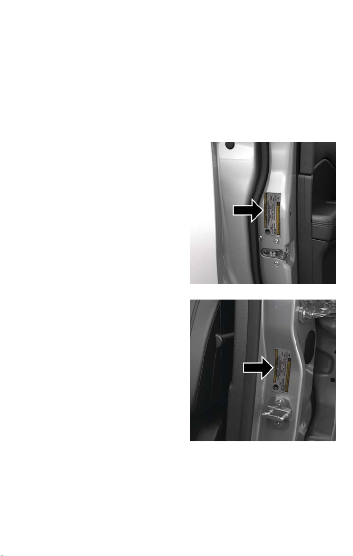
Tire Loading And Tire Pressure
Tire And Loading Information Placard Location
NOTE:
The proper cold tire inflation pressure is listed on the driver’s side B-Pillar or the rear
edge of the driver's side door.
Check the inflation pressure of each tire, including the spare tire (if equipped), at least
monthly and inflate to the recommended pressure for your vehicle.
NOTE:
Refer to the Owner's Manual, or the Tire Information Supplement, located in your Own-
er’s Information kit for more information regarding tire warnings and instructions.
Example Tire Placard Location (Door)
Example Tire Placard Location (B-Pillar)
MAINTAINING YOUR VEHICLE
195
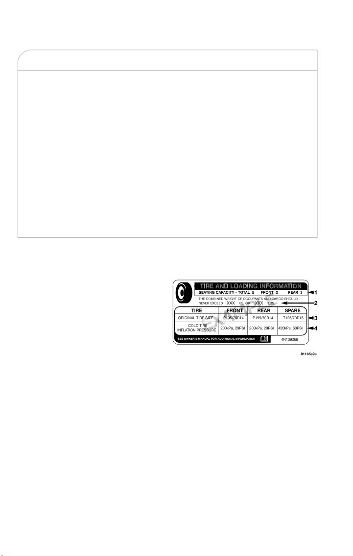
WARNING!
• Overloading of your tires is dangerous. Overloading can cause tire failure, affect
vehicle handling, and increase your stopping distance. Use tires of the recom-
mended load capacity for your vehicle. Never overload them.
• Improperly inflated tires are dangerous and can cause collisions.
• Under-inflation increases tire flexing and can result in over-heating and tire failure.
• Over-inflation reduces a tire’s ability to cushion shock. Objects on the road and
chuck holes can cause damage that results in tire failure.
• Unequal tire pressures can cause steering problems. You could lose control of your
vehicle.
• Unequal tire pressures from one side of the vehicle to the other can cause the
vehicle to drift to the right or left.
• Over-inflated or under-infla ted tires can affect vehicle handling and can fail sud-
denly, resulting in loss of vehicle control.
• Always drive with each tire inflated to the recommended cold tire inflation pres-
sure.
Tire And Loading Information Placard
This placard tells you important information
about the:
1. Number of people that can be carried
in the vehicle.
2. Total weight your vehicle can carry.
3. Tire size designed for your vehicle.
4. Cold tire inflation pressures for the
front, rear, and spare tires.
Loading
The vehicle maximum load on the tire must not exceed the load carrying capacity of the
tire on your vehicle. You will not exceed the tire's load carrying capacity if you adhere to
the loading conditions, tire size, and cold tire inflation pressures specified on the Tire and
Loading Information placard in “Vehicle Loading” in the “Starting And Operating” section
of the Owner’s Manual, or the Tire Information Supplement, located in your Owner’s In-
formation kit.
NOTE:
Under a maximum loaded vehicle condition, gross axle weight ratings (GAWRs) for the front
and rear axles must not be exceeded. Refer to “Vehicle Loading” in “Starting And Operating”
in the Owner’s Manual, or the Tire Information Supplement, located in your Owner’s Infor-
mation kit for further information on GAWRs, vehicle loading, and trailer towing.
Tire And Loading Information Placard
MAINTAINING YOUR VEHICLE
196

To determine the maximum loading conditions of your vehicle, locate the statement “The
combined weight of occupants and cargo should never exceed XXX kg or XXX lbs” on
the Tire and Loading Information placard. The combined weight of occupants, cargo/
luggage and trailer tongue weight (if applicable) should never exceed the weight refer-
enced here.
Steps For Determining Correct Load Limit—
(1) Locate the statement “The combined weight of occupants and cargo
should never exceed XXX kg or XXX lbs.” on your vehicle's placard.
(2) Determine the combined weight of the driver and passengers that will
be riding in your vehicle.
(3) Subtract the combined weight of the driver and passengers from XXX
kg or XXX lbs.
(4) The resulting figure equals the available amount of cargo and luggage
load capacity. For example, if “XXX” amount equals 1400 lbs. and there will
be five 150 lb passengers in your vehicle, the amount of available cargo and
luggage load capacity is 650 lbs. (1400-750 (5x150) = 650 lbs.)
(5) Determine the combined weight of luggage and cargo being loaded on
the vehicle. That weight may not safely exceed the available cargo and lug-
gage load capacity calculated in Step 4.
(6) If your vehicle will be towing a trailer, load from your trailer will be
transferred to your vehicle. Consult this manual to determine how this re-
duces the available cargo and luggage load capacity of your vehicle.
MAINTAINING YOUR VEHICLE
197
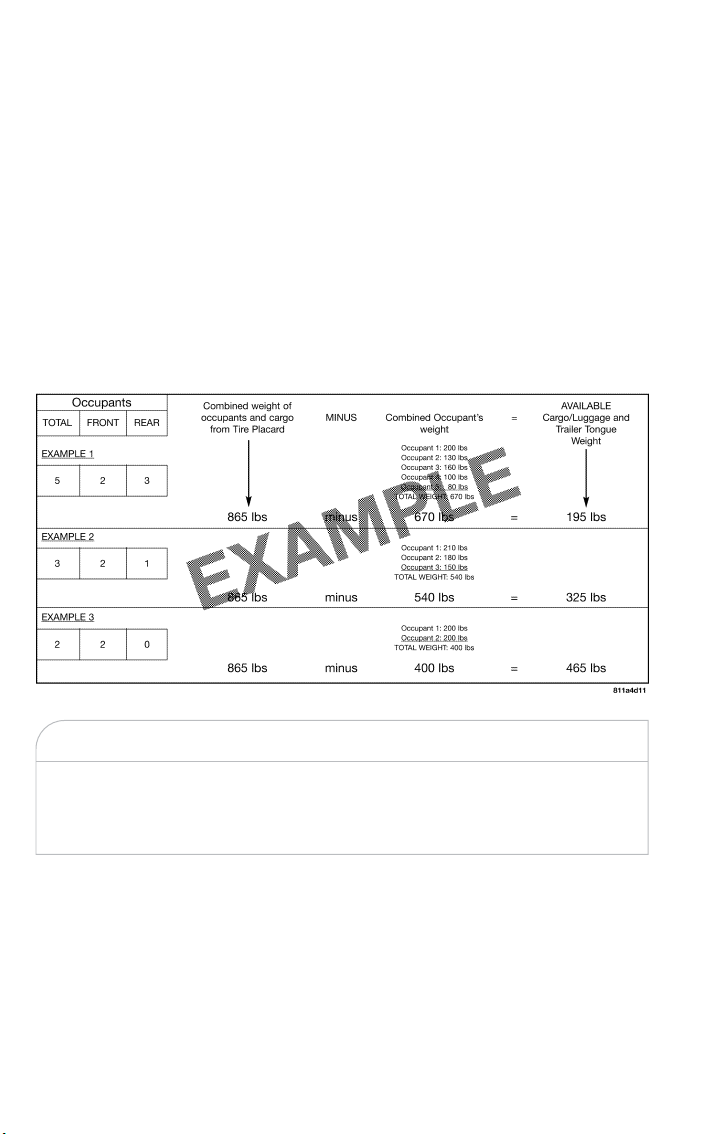
Metric Example For Load Limit
For example, if “XXX” amount equals 635 kg, and there will be five 68 kg passengers in
your vehicle, t he amount of available cargo and luggage load capacity is 295 kg (635-340
(5x68) = 295 kg) as shown in step 4.
NOTE:
• If your vehicle will be towing a trailer, load from your trailer will be transferred to your
vehicle. The following table shows examples on how to calculate total load, cargo/
luggage, and towing capacities of your vehicle with varying seating configurations and
number and size of occupants. This table is for illustration purposes only and may not
be accurate for the seating and load carry capacity of your vehicle.
• For the following example, the combined weight of occupants and cargo should never
exceed 865 lbs (392 kg).
WARNING!
Overloading of your tires is dangerous. Overloading can cause tire failure, affect vehicle
handling, and increase your stopping distance. Use tires of the recommended load ca-
pacity for your vehicle. Never overload them.
MAINTAINING YOUR VEHICLE
198

TIRES — GENERAL INFORMATION
Tire Pressure
Proper tire inflation pressure is essential to the safe and satisfactory operation of your
vehicle. Four primary areas are affected by improper tire pressure:
• Safety and Vehicle Stability
• Economy
• Tread Wear
• Ride Comfort
Safety
WARNING!
• Improperly inflated tires are dangerous and can cause collisions.
• Underinflation increases tire flexing and can result in overheating and tire failure.
• Overinflation reduces a tire's ability to cushion shock. Objects on the road and
chuckholes can cause damage that result in tire failure.
• Overinflated or underinflated tires can affect vehicle handling and can fail suddenly,
resulting in loss of vehicle control.
• Unequal tire pressures can cause steering problems. You could lose control of your
vehicle.
• Unequal tire pressures from one side of the vehicle to the other can cause the
vehicle to drift to the right or left.
• Always drive with each tire inflated to the recommended cold tire inflation pres-
sure.
Both under-inflation and over-inflation affect the stability of the vehicle and can produce
a feeling of sluggish response or over responsiveness in the steering.
NOTE:
• Unequal tire pressures from side to side may cause erratic and unpredictable steering
response.
• Unequal tire pressure from side to side may cause t he vehicle to drift left or right.
Fuel Economy
Underinflated tires will increase tire rolling resistance resulting in higher fuel consumption.
Tread Wear
Improper cold tire inflation pressures can cause abnormal wear patterns and reduced
tread life, resulting in the need for earlier tire replacement.
MAINTAINING YOUR VEHICLE
199

Ride Comfort And Vehicle Stability
Proper tire inflation contributes to a comfortable ride. Over-inflation produces a jarring
and uncomfortable ride.
Tire Inflation Pressures
The proper cold tire inflation pressure is listed on the driver's side B-Pillar or rear edge
of the driver's side door.
At least once a month:
• Check and adjust tire pressure with a good quality pocket-type pressure gauge. Do not
make a visual judgement when determining proper inflation. Tires may look properly
inflated even when they are under-inflated.
• Inspect tires for signs of tire wear or visible damage.
CAUTION!
After inspecting or adjusting the tire pressure, always reinstall the valve stem cap. This
will prevent moisture and dirt from entering the valve stem, which could damage the
valve stem.
Inflation pressures specified on the placard are always “cold tire inflation pressure”. Cold
tire inflation pressure is defined as the tire pressure after the vehicle has not been driven
for at least three hours, or driven less than 1 mile (1.6 km) after sitting for a minimum
of three hours. The cold tire inflation pressure must not exceed the maximum inflation
pressure molded into the tire sidewall.
Check tire pressures more often if subject to a wide range of outdoor temperatures, as
tire pressures vary with temperature changes.
Tire pressures change by approximately 1 psi (7 kPa) per 12°F (7°C) of air temperature
change. Keep this in mind when checking tire pressure inside a garage, especially in the
Winter.
Example: If garage temperature = 68°F (20°C) and the outside temperature = 32°F
(0°C) then the cold tire inflation pressure should be increased by 3 psi (21 kPa), which
equals 1 psi (7 kPa) for every 12°F (7°C) for this outside temperature condition.
Tire pressure may increase from 2 to 6 psi (13 to 40 kPa) during operation. DO NOT
reduce this normal pressure build up or your tire pressure will be too low.
Tire Pressures For High Speed Operation
The manufacturer advocates driving at safe speeds and within posted speed limits. Where
speed limits or conditions are such that the vehicle can be driven at high speeds, main-
taining correct tire inflation pressure is very important. Increased tire pressure and re-
MAINTAINING YOUR VEHICLE
200

duced vehicle loading may be required for high-speed vehicle operation. Refertoyour
authorized tire dealer or original equipment vehicle dealer for recommended safe operat-
ing speeds, loading and cold tire inflation pressures.
WARNING!
High speed driving with your vehicle under maximum load is dangerous. The added
strain on your tires could cause them to fail.You could have a serious collision. Do not
drive a vehicle loaded to the maximum capacity at continuous speeds above 75 mph
(120 km/h).
Radial Ply Tires
WARNING!
Combining radial ply tires with other types of tires on your vehicle will cause your ve-
hicle to handle poorly. The instability could cause a collision. Always use radial ply tires in
sets of four. Never combine them with other types of tires.
Tire Repair
If your tire becomes damaged, it may be repaired if it meets the following criteria:
• The tire has not been driven on when flat.
• The damage is only on the tread section of your tire (sidewall damage is not repair-
able).
• The puncture is no grea ter than a ¼ of an inch (6 mm).
Consult an authorized tire dealer for tire repairs and additional informa tion .
Damaged Run Flat tires, or Run Flat tires that have experienced a loss of pressure should
be replaced immedia tely with another Run Flat tire of identical size and service descrip-
tion (Load Index and Speed Symbol).
Tire Types
All Season Tires — If Equipped
All season tires provide traction for all seasons (Spring, Summer, Fall and Winter). Traction
levels may vary between different all season tires. All season tires can be identified by the
M+S, M&S, M/S or MS designation on the tire sidewall. Use all season tires only in sets of
four; failure to do so may adversely affect the safety and handling of your vehicle.
MAINTAINING YOUR VEHICLE
201
Summer Or Three Season Tires — If Equipped
Summer tires provide traction in both wet and dry conditions, and are not intended to
be driven in snow or on ice. If your vehicle is equipped with Summer tires, be aware
these tires are not designed for Winter or cold driving conditions. Install Winter tires on
your vehicle when ambient temperatures are less than 40°F (5°C) or if roads are cov-
ered with ice or snow. For more information, contact an authorized dealer.
Summer tires do not contain the all season designation or mountain/snowflake symbol on
the tire sidewall. Use Summer tires only in sets of four; failure to do so may adversely
affect the safety and handling of your vehicle.
WARNING!
Do not use Summer tires in snow/ice conditions. You could lose vehicle control, result-
ing in severe injury or death. Driving too fas t for conditions also creates the possibility
of loss of vehicle control.
Snow Tires
Some areas of the country require the use of snow tires during the Winter. Snow tires
can be identified by a “mountain/snowflake” symbol on the tire sidewall.
If you need snow tires, select tires equivalent in size and type to the
original equipment tires. Use snow tires only in sets of four; failure to
do so may adversely affect the safety and handling of your vehicle.
Snow tires generally have lower speed ratings than what was origi-
nally equipped with your vehicle and should not be operated at sus-
tained speeds over 75 mph (120 km/h). For speeds above 75 mph
(120 km/h), refer to original equipment or an authorized tire dealer for recommended
safe operating speeds, loading and cold tire inflation pressures.
While studded tires improve performance on ice, skid and traction capability on wet or
dr y surfaces may be poorer than that of non-studded tires. Some states prohibit studded
tires; therefore, local laws should be checked before using these tire types.
Run Flat Tires — If Equipped
Run Flat tires allow you the capability to drive 50 miles (80 km) at 50 mph (80 km/h)
after a rapid loss of inflation pressure. This rapid loss of inflation is referred to as the Run
Flat mode. A Run Flat mode occurs when the tire inflation pressure is of/or below 14 psi
(96 kPa). Once a Run Flat tire reaches the Run Flat mode, it has limited driving capabili-
ties and needs to be replaced immediately. A Run Flat tire is not repairable.
It is not recommended to drive a vehicle loaded at full capacity, or to tow a trailer while
a tire is in the Run Flat mode.
See the tire pressure monitoring section for more information.
MAINTAINING YOUR VEHICLE
202
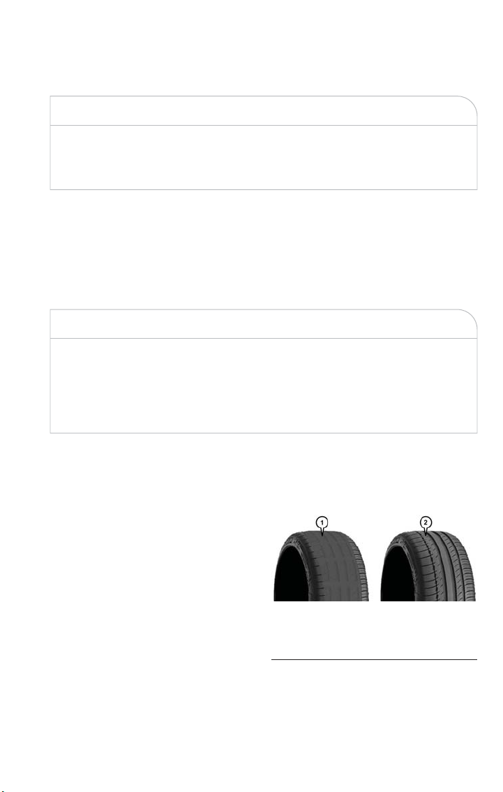
SPARE TIRES — IF EQUIPPED
CAUTION!
Because of the reduced ground clearance, do not take your vehicle through an auto-
matic car wash with a compact or limited use temporary spare installed. Damage to the
vehicle may result.
Tire Spinning
When stuck in mud, sand, snow, or ice conditions, do not spin your vehicle's wheels above
30 mph (48 km/h) or for longer than 30 seconds continuously without stopping.
Refer to “Freeing A Stuck Vehicle” in “In Case Of Emergency” for further information.
WARNING!
Fast spinning tires can be dangerous. Forces generated by excessive wheel speeds may
cause tire damage or failure. A tire could explode and injure someone . Do not spin
your vehicle's wheels faster than 30 mph (48 km/h) for more than 30 seconds continu-
ously when you are stuck, and do not let anyone near a spinning wheel, no matter what
the speed.
Tread Wear Indicators
Tread wear indicators are in the original equipment tires to help you in determining when
your tires should be replaced.
These indicators are molded into the bot-
tom of the tread grooves. They will appear
as bands when the tread depth becomes a
1/16 of an inch (1.6 mm). When the tread
is worn to the tread wear indicators, the
tire should be replaced. Refer to “Replace-
ment Tires” in this section for further
information.
Tire Tread
1 — Worn Tire
2 — New Tire
MAINTAINING YOUR VEHICLE
203

Life Of Tire
The service life of a tire is dependent upon varying factors including, but not limited to:
• Driving style.
• Tire pressure – Improper cold tire inflation pressures can cause uneven wear patterns
to develop across the tire tread. These abnormal wear patterns will reduce tread life,
resulting in the need for earlier tire replacement.
• Distance driven.
• Performance tires, tires with a speed rating of V or higher, and Summer tires typically
have a reduced tread life. Rotation of these tires per the vehicle maintenance schedule
is highly recommended.
WARNING!
Tires and the spare tire should be replaced after six years, regardless of the remaining
tread. Failure to follow this warning can result in sudden tire failure. You could lose con-
trol and have a collision resulting in serious injury or death.
Keep dismounted tires in a cool, dry place with as little exposure to light as possible. Pro-
tect tires from contact with oil, grease, and gasoline.
Replacement Tires
The tires on your new vehicle provide a balance of many characteristics. They should be
inspected regularly for wear and correct cold tire inflation pressures. The manufacturer
strongly recommends that you use tires equivalent to t he originals in size, quality and per-
formance when replacement is needed. Refer to the paragraph on “Tread Wear Indicator”
in this section. Refer to the Tire and Loading Information placard or the Vehicle Certifica-
tion Label for the size designation of your tire. The Load Index and Speed Symbol for
your tire will be found on the original equipment tire sidewall.
See the Tire Sizing Chart example found in the “Tire Safety Information” section of this
manual for more information relating to the Load Index and Speed Symbol of a tire.
It is recommended to replace the two front tires or two rear tires as a pair. Replacing
just one tire can seriously affect your vehicle’s handling. If you ever replace a wheel, make
sure that the wheel’s specifications match those of the original wheels.
It is recommended you contact your authorized tire dealer or original equipment dealer
with any questions you may have on tire specifications or capability. Failure to use equiva-
lent replacement tires may adversely affect the safety, handling, and ride of your vehicle.
MAINTAINING YOUR VEHICLE
204

WARNING!
• Do not use a tire, wheel size or rating other than that specified for your vehicle.
Some combinations of unapproved tires and wheels may change suspension di-
mensions and performance characteristics, resulting in changes to steering, handling,
and braking of your vehicle. This can cause unpredictable handling and stress to
steering and suspension components. You could lose control and have a collision
resulting in serious injury or death. Use only the tire and wheel sizes with load
ratings approved for your vehicle.
• Never use a tire with a smaller load index or capacity, other than what was origi-
nally equipped on your vehicle. Using a tire with a smaller load index could result
in tire overloading and failure. You could lose control and have a collision.
• Failure to equip your vehicle with tires having adequate speed capability can result
in sudden tire failure and loss of vehicle control.
CAUTION!
Replacing original tires with tires of a different size may result in false speedometer
and odometer readings.
Wheel And Wheel Trim Care
All wheels and wheel trim, especially aluminum and chrome plated wheels, should be
cleaned regularly using mild (neutral Ph) soap and water to maintain their luster and to
prevent corrosion. Wash wheels with the same soap solution recommended for the body
of the vehicle.
Your wheels are susceptible to deterioration caused by salt, sodium chloride, magnesium
chloride, calcium chloride, etc., and other road chemicals used to melt ice or control dust
on dirt roads. Use a soft cloth or sponge and mild soap to wipe away promptly. Do not
use harsh chemicals or a stiff brush. They can damage the wheel’s protective coating that
helps keep them from corroding and tarnishing.
NOTE:
Many aftermarket wheel cleaners contain strong acids or strong alkaline additives that can
harm the wheel surface.
MAINTAINING YOUR VEHICLE
205

CAUTION!
Avoid products or automatic car washes that use acidic solutions or strong alkaline addi-
tives or harsh brushes. Many aftermarket wheel cleaners and automatic car washes may
damage the wheel's protective finish. Such damage is not covered by the New Vehicle
Limited Warranty. Only car wash soap, Mopar Wheel Cleaner or equivalent is recom-
mended.
When cleaning extremely dirty wheels including excessive brake dust, care must be taken
in the selection of tire and wheel cleaning chemicals and equipment to prevent damage
to the wheels. Mopar Wheel Treatment, Mopar Chrome Cleaner, or their equivalent is
recommended or select a non-abrasive, non-acidic cleaner for aluminum or chrome
wheels. Do not use any products on Dark Vapor or Black Satin Chrome Wheels. They
will permanently damage this finish and such damage is not covered by the New Vehicle
Limited Warranty.
CAUTION!
Do not use scouring pads, steel wool, a bristle brush, metal polishes or oven cleaner.
These products may damage the wheel's protective finish. Such damage is not covered
by the New Vehicle Limited Warranty. Only car wash soap, Mopar Wheel Cleaner or
equivalent is recommended.
NOTE:
If you intend parking or storing your vehicle for an extended period after cleaning the
wheels with wheel cleaner, drive your vehicle for a few minutes before doing so. Driving
the vehicle and applying the brakes when stopping will reduce the risk of brake rotor
corrosion.
Dark Vapor Or Black Satin Chrome Wheels
CAUTION!
If your vehicle is equipped with these specialty wheels, DO NOT USE wheel cleaners,
abrasives, or polishing compounds. They will permanently damage this finish and such
damage is not covered by the New Vehicle Limited Warranty. HAND WASH ONLY
USING MILD SOAP AND WATER WITH A SOFT CLOTH. Used on a regular basis;
this is all that is required to maintain this finish.
MAINTAINING YOUR VEHICLE
206

DEPARTMENT OF TRANSPORTATION UNIFORM TIRE
QUALITY GRADES
The following tire grading categories were established by the Na tional High-
way Traffic Safety Administration. The specific grade rating assigned by the
tire's manufacturer in each category is shown on the sidewall of the tires on
your vehicle.
All passenger vehicle tires mus t conform to Federal safety requirements in
addition to these grades.
Treadwear
The Treadwear grade is a comparative rating, based on the wear ra te of the
tire when tested under controlled conditions on a specified government test
course. For example, a tire graded 150 would wear one and one-half times
as well on the government course as a tire graded 100. The relative perfor-
mance of tires depends upon the actual conditions of their use, however,
and may depart significantly from the norm due to variations in driving hab-
its, service practices, and differences in road characteristics and climate.
Traction Grades
The Traction grades, from highest to lowest, are AA, A, B, and C. These
grades represent the tire's ability to stop on wet pavement, as measured
under controlled conditions on specified government test surfaces of asphalt
and concrete. A tire marked C may have poor traction performance.
WARNING!
The traction grade assigned to this tire is based on straight-ahead braking
traction tests, and does not include acceleration, cornering, hydroplaning, or
peak traction characteristics.
Temperature Grades
The temperature grades are A (the highest), B, and C, representing the tire's
resistance to the generation of heat and its ability to dissipate heat, when
tested under controlled conditions on a specified indoor laboratory test
wheel. Sustained high temperature can cause the material of the tire to
degenerate and reduce tire life, and excessive temperature can lead to sud-
den tire failure. The grade C corresponds to a level of performance, which
MAINTAINING YOUR VEHICLE
207

all passenger vehicle tires must meet under the Federal Motor Vehicle Safety
Standard No. 109. Grades B and A represent higher levels of performance
on the laboratory test wheel, than the minimum required by law.
WARNING!
The temperature grade for this tire is established for a tire that is properly
infla ted and not overloaded. Excessive speed, under-inflation, or excessive
loading, either separately or in combination, can cause heat buildup and
possible tire failure.
BULB REPLACEMENT
Replacement Bulbs
Interior Bulbs
Lamps Bulb Number
Front Courtesy Light C5W
Front Courtesy Lights (Sun Visors) C5W
Rear Dome Light (Models Without Re-
tractable Roof)
C5W
Rear Interior Lights (Models With Retract-
able Roof)
C5W
Interior Lights W5W
Dome Light (Glove Compartment) W5W
Exterior Bulbs
Lamps Bulb Number
Low Beam/High Beam Headlamps HIR2
Front Position/Daytime Running Lights
(DRL)
P21/5
Front Direction Indicator Lamps PY21W
Front Fog Lamps H8
Side Indicators (Side View Mirror) WY5W
Tail/Brake Lights/Turn Indicators P21W
Center High Mounted Stop Lamp
(CHMSL)
LED (Serviced At An Authorized Dealer)
Reverse P21W
License Plate Lamp W5W
MAINTAINING YOUR VEHICLE
208

FIAT CUSTOMER CENTER
P.O. Box 21–8004 Auburn Hills, MI 48321–8004 Phone: 1-888-242-6342
FIAT CANADA CUSTOMER CENTER
P.O. Box 1621 Windsor, Ontario N9A 4H6 Phone: 1-800-465-2001 (English)
Phone: 1-800-387-9983 (French)
ASSISTANCE FOR THE HEARING IMPAIRED
To assist customers who have hearing difficulties, the manufacturer has installed special TDD
(Telecommunication Devices for the Deaf) equipment at its customer center. Any hearing or
speech impaired customer, who has access to a TDD or a conventional teletypewriter (TTY)
in the United States, can communicate with the manufacturer by dialing 1-800-380-CHRY.
Canadian residents with hearing difficulties that require assistance can use the special needs
relay service offered by Bell Canada. For TTY teletypewriter users, dial 711 and for Voice
callers, dial 1-800-855-0511 to connect with a Bell Relay Service operator.
WARNING!
Engine exhaust, some of its constituents, and certain vehicle components contain, or
emit, chemicals known to the St ate of California to cause cancer and birth defects, or
other reproductive harm. In addition, certain fluids contained in vehicles and certain
products of component wear contain, or emit, chemicals known to the State of
California to cause cancer and birth defects, or other reproductive harm.
PUBLICATIONS ORDERING
• You can purchase a copy of the Owner's Manual, Navigation/Uconnect Manuals or
Warranty Booklet. United States customers may visit the Fiat Contact Us page at
www.fiat.com scroll to the bottom of the page and select the “Contact Us” link, then
select the “Owner’s Manual and Glove Compartment Material” from the left menu.
You can also purchase a copy by calling 1-888-242-6342 (U.S.) or 1-800-387-1143
(Canada).
• Replacement English User Guide kits or DVDs may be purchased by visiting
www.techauthority.com or by calling 1-800-890-4038 (U.S.) or 1-800-387-1143
(Canada). Visa, Master Card, American Express and Discover orders are accepted.
NOTE:
• The Owner's Manual and User Guide electronic files are also available on t he FIAT®
website.
• Click on the “For Owners” tab, select “Owner/Service Manuals”, then select your de-
sired model year and vehicle from the drop down lists.
CONSUMER ASSISTANCE
209

REPORTING SAFETY DEFECTS IN THE UNITED STATES
If you believe that your vehicle has a defect that could cause a crash or
cause injury or death, you should immediately inform t he National Highway
Traffic Safety Administration (NHTSA) in addition to notifying FCA US LLC.
If NHTSA receives similar complaints, it may open an investigation, and if it
finds that a safety defect exists in a group of vehicles, it may order a recall
and remedy campaign. However, NHTSA cannot become involved in indi-
vidual problems between you, your authorized dealer or FCA US LLC.
To contact NHTSA, you may call the Vehicle Safety Hotline toll free at
1-888-327-4236 (TTY: 1-800-424-9153); or go to http://www.safercar.gov;
or write to: Administrator, NHTSA, 1200 New Jersey Avenue, SE., West
Building, Washington, D.C. 20590. You can also obtain other information
about motor vehicle safety from http://www.safercar.gov.
In Canada
If you believe that your vehicle has a safety defect, you should contact the
Customer Service Department immediately. Canadian customers who wish
to report a safety defect to the Canadian government should contact
Transport Canada, Motor Vehicle Defect Investigations and Recalls
at 1-800-333-0510 or go to http://www.tc.gc.ca/roadsafety/.
French Canadian customers who wish to report a safety defect to the
Canadian government should contact Transport Canada, Motor Vehicle
Defect Investigations and Recalls at 1-800-333-0510 or go to
http://www.tc.gc.ca/securiteroutiere/.
CONSUMER ASSISTANCE
210
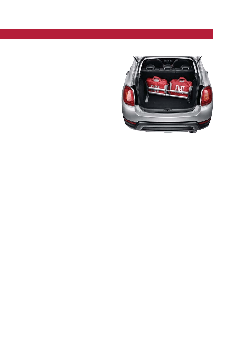
AUTHENTIC ACCESSORIES BY MOPAR
• The following highlights jus t some of the many Authentic FIAT Accessories by Mopar
featuring a fit, finish, and functionality specifically for your FIAT 500X.
• In choosing Authentic Accessories you
gain far more than expressive style, pre-
mium protection, or extreme entertain-
ment, you also benefit from enhancing
your vehicle with accessories that have
been thoroughly tested and factory-
approved.
• For the full line of Authentic FIAT Acces-
sories by Mopar, visit your local dealer-
ship or online at mopar.com for U.S.
residents and mopar.ca for Canadian
residents.
NOTE:
All parts are subject to availability.
EXTERIOR:
• Chrome Hood Spear • 18” Wheels • Front End Cover
• Chrome Mirror Cover • Wheel Locks • Molded Splash Guards
• Painted Mirror Cover • License Plate Frames • Vehicle Cover
• Roof And Body Graphics • Fender Badges • Valve Stem Caps
• Body Side Moldings • Front Air Deflector • Spare Tire Kit
INTERIOR:
• Door Sill Guards • Pedal Kits • Premium Carpet Mats
• Cargo Tray • Key Covers • Slush Mats
• Premium Door Sill • Roadside Safety Kit • Cargo Organizer
• Katzkin Leather Interiors
ELECTRONICS:
• GPS Tracking System(s) • Wi-Fi • Alarm Kits
CARRIERS:
• Bike Carrier • Luggage Carrier • Snowboard/Ski Carrier
• Roof Rack
PERFORMANCE:
• Performance Exhaust
Accessories
MOPAR® ACCESSORIES
211

FREQUENTLY ASKED QUESTIONS
GETTING STARTED
How do I install my LATCH Equipped Child Seat? pg. 43
ELECTRONICS
Which radio is in my vehicle?
• Radio 3.0pg. 92
• Uconnect 5.0pg. 95
• Uconnect 6.5NAV pg. 107
How do I activate the Audio Jack?
• Radio 3.0pg. 93
• Uconnect 5.0pg. 95
• Uconnect 6.5NAV pg. 111
How do I set the clock on my radio?
• Radio 3.0pg. 92
• Uconnect 5.0pg. 95
• Uconnect 6.5NAV pg. 107
How do I use the Naviga tion feature?
• Uconnect 6.5NAV pg. 114
How do I pair my cell phone via Bluetooth with the Uconnect Hands-Free Voice Activa-
tion System? pg. 127
How do I improve the Bluetooth performance of my Uconnect System? pg. 134
UTILITY
How do I know how much I can tow with my FIAT 500X? pg. 140
How do I tow my FIAT 500X behind another vehicle? pg. 141
WHAT TO DO IN EMERGENCIES
What do I do if my TPMS warning light is blinking? pg. 145
How do I change a flat tire? pg. 156
How do I Jump-Start my vehicle? pg. 164
MAINTAINING YOUR VEHICLE
Where is my Fuse Block located? pg. 187
What type of oil do I use? pg. 180
How often should I change my engine’s oil? pg
. 181
What should my tire pressure be set at? pg. 195
FAQ
212

Adding Engine Coolant (Antifreeze) ....181
Adding Fuel.................190
Adding Washer Fluid ............181
Additives, Fuel ...............191
Air Bag....................26
Advance Front Air Bag .........26
Air Bag Operation ............27
Air Bag Warning Light .........144
Enhanced Accident Response ......173
Event Data Recorder (EDR) ......173
Front Air Bag ..............26
If A Deployment Occurs ........32
Knee Impact Bolsters ..........28
Maintaining Your Air Bag System ....35
Redundant Air Bag Warning Light ...25
Side Air Bags ...............29
Transporting Pets ............48
Air Bag Maintenance ............35
Air Cleaner, Engine (Engine Air Cleaner
Filter) ..................181
Air Conditioner Maintenance .......181
Air Conditioning Refrigerant ........181
Air Conditioning System ..........181
Air Pressure,Tires .............200
Alarm
Arm The System .............10
Disarm The System ...........10
Vehicle Security Alarm .........10
Alarm, Panic..................8
Alarm (Security Alarm).........10, 150
Antifreeze (Engine Coolant) .....180, 181
Disposal .................181
Anti-Lock Brake System (ABS).......144
Appearance Care .............181
Audio Systems (Radio) .........88, 97
Automatic Headlights ............58
Automatic Transmission
Adding Fluid ..............181
Fluid Type ...............181
Axle Fluid .................181
Axle Lubrication ..............181
Battery ...................181
Charging System Light .........143
Blind Spot Monitoring ............72
Body Mechanism Lubrication........181
B-Pillar Location ..............195
Brake Fluid .................181
Brakes ...................181
Brake System ................181
Fluid Check ..............181
Master Cylinder ............181
Warning Light .............147
Break-In Recommendations, New Vehicle ..57
Camera, Rear ................86
Canada..................3, 210
Capacities, Fluid...............180
Caps, Filler
Oil (Engine) ..............181
Car Washes ................181
Change Oil Indicator ............151
Changing A Flat Tire ............156
Charging System Light ...........143
Chart,Tire Sizing ..............193
Child Restraint................36
Child Restraints
Booster Seats ..............38
Child Restraints .............36
Child Seat Installation ..........46
How To Stow An Unused ALR Seat
Belt ....................44
Infants And Child Restraints .......37
LATCH Positions ............
40
Locating The LATCH Anchorages ....42
Lower Anchors And Tethers For
Children .................40
Older Children And Child Restraints ..38
Seating Positions .............39
Cleaning
Wheels ..............181, 205
Windshield Wiper Blades .......181
Climate Control
Automatic ................68
Manual ..................67
Clock ....................95
Clock Setting ................95
Cluster Warning/Indicator Lights
Air Bag Warning Light .........144
Electronic Park Brake Failure
Indicator ................148
Electronic Speed Control ON
Indicator ................150
Electronic Speed Control SET
Indicator ................150
Front Fog Light Indicator ........150
INDEX
213

High Beam Indicator ..........150
Instrument Cluster Warning Lights ..143
Park/Headlight ON Indicator ......150
Seat Belt Reminder Light .......147
Turn Signal Indicator ..........149
Vehicle Security Light ..........150
Clutch ...................181
Clutch Fluid ................181
Cooling System...............181
Adding Coolant (Antifreeze) .....181
Coolant Capacity ...........180
Coolant Level .............181
Disposal Of Used Coolant ......181
Drain, Flush, And Refill .........181
Inspection ...............181
Points To Remember .........181
Pressure Cap .............181
Selection Of Coolant
(Antifreeze) ...........180, 181
Corrosion Protection ...........181
Customer Assistance .........209, 210
Customer Programmable Features.....137
Daytime Running Lights ...........59
Defects, Reporting .............210
Defroster, Rear Window...........63
Dimmer Switch, Headlight ..........60
Disabled Vehicle Towing ..........172
Disarming, Security System .........10
Disposal
Antifreeze (Engine Coolant) ......181
Driver Cockpit ................4
Driver's Seat Back Tilt ............50
Electric Park Brake .............70
Electric Parking Brake ............70
Electronics
Your Vehicle's Sound System ......88
Electronic Speed Control
(Cruise Control) .............65
Electronic Throttle Control Warning
Light...................144
Emergency, In Case Of
Brake Warning Light ..........147
Jacking .................156
Jump Starting .............164
Overheating ..............152
Towing .................172
Engine
Air Cleaner ...............181
Break-In Recommendations .......57
Checking Oil Level ...........181
Compartment ...........176, 178
Coolant (Antifreeze) ..........180
Cooling .................181
Jump Starting .............164
Oil ................180, 181
Oil Filler Cap .............181
Oil Selection ...........180, 181
Overheating ..............152
Enhanced Accident Response Feature ...173
Exhaust System...............181
Exterior Lighting ...............58
Exterior Lights ................58
FAQ ....................212
Filters
Air Cleaner ..............181
Engine Oil ............180, 181
Engine Oil Disposal ..........181
Flashers
Turn Signal .............60, 149
Fluid, Brake .................181
Fluid Capacities ...............180
Fluids, Lubricants And Genuine Parts ...180
Fog Lights................59, 150
Forward Collision Warning .........
76
Freeing A Stuck Vehicle...........167
Frequently Asked Questions ........212
Fuel
Adding .................190
Additives ................191
Materials Added ............191
Octane Rating .............180
Specifications .............180
Tank Capacity .............180
Fuses ....................187
Gear Select Lever Override ........171
General Maintenance............181
Glass Cleaning ...............181
Hands-Free Phone (Uconnect) ......125
Headlights
Automatic ................58
Cleaning ................181
INDEX
214

Delay ..................59
High Beam/Low Beam Select Switch ..60
Lights On Reminder ..........59
Switch ..................58
Time Delay ...............59
Head Restraints ...............48
Head Rests .................48
Heated Mirrors .............68, 69
High Beam Indicator ............150
High Beam/Low Beam Select (Dimmer)
Switch ..................60
Hood Prop .................174
Hood Release ...............174
Identifying Your Radio ............91
Instrument Cluster ..............6
Instrument Cluster Display
Information Display ...........136
Instrument Cluster Warning Lights.....149
Instrument Panel Cover ..........181
Instrument Panel Lens Cleaning ......181
Interior And Instrument Lights ........5
Interior Appearance Care .........181
Intermittent Wipers (Delay Wipers).....61
Introduction
Canada ..................3
iPod/USB/MP3 Control
Bluetooth Streaming Audio ......125
Jacking Instructions .............160
Jack Location ................156
Jack Operation ............156, 160
Jump Starting................164
Key Fob ....................8
Arm The Alarm .............10
Disarm The Alarm ............10
Keyless Enter-N-Go .............11
Key Fob .................11
Lock/Unlock
.............11, 13
Passive Entry ...............11
Remote Control .............11
Lane Change And Turn Signals .......60
LaneSense ..................80
Lap/Shoulder Belts..............18
Life Of Tires ................204
Liftgate Window Wiper/Washer.......63
Lights
Automatic Headlights ..........58
Brake Warning .............147
Daytime Running ............59
Dimmer Switch, Headlight .......60
Engine Temperature Warning .....146
Fog .................59, 150
Headlights ................58
Headlights On Reminder ........59
Headlight Switch ............58
High Beam ...............60
High Beam Indicator ..........150
High Beam/Low Beam Select ......60
Instrument Cluster ...........58
Lights On Reminder ...........59
Low Fuel ................143
Malfunction Indicator
(Check Engine) ............148
Security Alarm .............150
Tire Pressure Monitoring (TPMS) ...145
Turn Signal ...............60
Loading Vehicle
Tires ..................195
Lubrication, Body ..............181
Maintenance Free Ba ttery .........181
Maintenance, General ...........181
Maintenance Procedures ..........181
Maintenance Record ............186
Maintenance Schedule
...........181
Malfunction Indicator Light
(Check Engine) .............148
Master Cylinder (Brakes)..........181
Mirrors
Heated ...............68, 69
Navigation .................114
New Vehicle Break-In Period ........57
Occupant Restraints .............15
Octane Rating, Gasoline (Fuel) .......180
Oil Change Indicator ............151
Oil, Engine...............180, 181
Capacity ................180
Change Interval ............181
Checking ................181
Disposal ................181
Filter ...............180, 181
INDEX
215

Filter Disposal .............181
Materials Added To ..........181
Recommenda tion .........180, 181
Viscosity .............180, 181
Oil Filter, Selection .............181
Outlet
Power .................138
Overheating, Engine ............152
Paint Care .................181
Panic Alarm ..................8
Parking Brake ................70
ParkSense System, Rear ...........82
Pets .....................48
Phone, Hands-Free (Uconnect) ......125
Phone (Uconnect) .............125
Placard, Tire And Loading
Information ............195, 196
Power
Outlet (Auxiliary Electrical
Outlet) .................138
Pregnant Women And Seat Belts ......22
Preparation For Jacking...........159
Pretensioners
Seat Belts ................22
Programmable Electronic Features.....137
Radial Ply Tires ...............201
Radio
Presets .............93, 97, 108
Radio Operation...............97
Radio (Sound Systems) ...........97
Rain Sensitive Wiper System ........62
Rear Camera ................86
Rear Cross Path ...............74
Rear ParkSense System ...........82
Rear Window Defroster ..........63
Rear Wiper/Washer .............63
Recreational Towing ............141
Refrigerant .................181
Reminder, Lights On .............59
Reminder, Seat Belt .............17
Remote Keyless Entry
Arm The Alarm .............10
Disarm The Alarm ............10
Remote Starting System ...........9
Replacement Tires .............204
Reporting Safety Defects..........210
Restraint, Head ...............48
Restraints, Child ...............36
Safety Information, Tire...........192
Schedule, Maintenance ...........181
Seat Belt
Adjustable Upper Shoulder Belt
Anchorage ...............21
Automatic Locking Retractor (ALR) ...23
Energy Management Feature ......22
Lap/Shoulder Belt Operation ......20
Lap/Shoulder Belts ............18
Lap/Shoulder Belt Untwisting ......20
Pregnant Women ............22
Seat Belt Pretensioner .........22
Seat Belt Reminder ...........17
Seat Belt Maintenance ...........181
Seat Belt Reminder .............17
Seat Belts ..................16
Adjustable Shoulder Belt ........21
Adjustable Upper Shoulder
Anchorage ...............21
Child Restraint .............36
Front Seat ............16, 18, 20
Operating Instructions .........20
Pregnant Women ............22
Pretensioners ..............22
Rear Seat ................18
Untwisting Procedure ..........20
Seats .....................50
Adjustment ...............50
Head Restraints .............48
Seatback Release ............50
Tilting ..................50
Security Alarm ...............150
Arm The System .............10
Disarm The System ...........10
Security Alarm ..............10
Selection Of Coolant (Antifreeze) .....180
Shift Lever Override ............171
Shoulder Belts ................18
Signals, Turn ...............60, 149
Snow Tires .................202
Spark Plugs .................180
Specifications
Fuel (Gasoline) ............180
Oil ...................180
Speed Control (Cruise Control) ......65
INDEX
216

Starting
Remote ..................9
Steering
Tilt Column ...............55
Wheel, Heated .............55
Wheel, Tilt ...............55
Steering Wheel Audio Controls ......135
Stuck, Freeing................167
Supplemental Restraint System - Air Bag ..26
Telescoping Steering Column ........55
Text Messaging .............99, 133
Tilt Steering Column ............55
Time Delay, Headlight ............59
Tire And Loading Information
Placard ...............195, 196
Tire Markings................192
Tires..................199, 207
Aging (Life Of Tires) ..........204
Air Pressure ...........195, 199
Changing ................156
General Information ..........199
High Speed ..............200
Inflation Pressures ...........200
Jacking .................156
Life Of Tires ..............204
Load Capacity ..........195, 196
Pressure Warning Light ........145
Quality Grading ............207
Radial .................201
Replacement ..............204
Safety ...............192, 199
Sizes ..................193
Snow Tires ...............202
Spinning ................203
Tread Wear Indicators .........203
Tire Safety Information...........
192
Tire Service Kit...............153
Towing ...................140
Disabled Vehicle ............172
Guide .................140
Recreational ..............141
Weight .................140
Towing Eyes ................169
Towing Vehicle Behind A Motorhome ...141
Trailer Towing ...............140
Trailer Towing Guide ............140
Trailer Weight ...............140
Transfer Case
Fluid ..................181
Transmission
Fluid ..................181
Maintenance ..............181
Transporting Pets ..............48
Tread Wear Indicators ...........203
Turn Signals...............60, 149
Uconnect 3.0 ................92
Uconnect 5.0 ..............95, 97
Uconnect (Hands-Free Phone)
Making A Phone Call .........125
Receiving A Call ............125
Uconnect Phone ...........125, 130
Uconnect Voice Command ...100, 117, 130
Uniform Tire Quality Grades........207
Untwisting Procedure, Seat Belt .......20
Vehicle Loading ...............196
Vehicle Security Alarm Disarming ......10
Voice Command .........100, 117, 130
Voice Recognition System
(VR) .............100, 117, 130
Washer
Adding Fluid ..............181
Washing Vehicle
..............181
Wheel And Wheel Trim........181, 205
Wheel And Wheel Trim Care.....181, 205
Windshield Wiper Blades .........181
Wiper Blade Replacement .........181
Wipers, Intermittent .............61
Wipers, Rain Sensitive ............62
Wrecker Towing ..............172
INDEX
217

NOTES
218

NOTES
219

NOTES
220

NOTES
221

NOTES
222

NOTES
223

NOTES
224

The driver’s primary responsibility is the safe operation of the
vehicle. Driving while distracted can result in loss of vehicle
control, resulting in a collision and personal injury. FCA US LLC
strongly recommends that the driver use extreme caution when
using any device or feature that may take their attention off
the road. Use of any electrical devices, such as cell phones,
computers, portable radios, vehicle navigation or other devices,
by the driver while the vehicle is moving is dangerous and could
lead to a serious collision. Texting while driving is also dangerous
and should never be done while the vehicle is moving. If you nd
yourself unable to devote your full attention to vehicle operation,
pull off the road to a safe location and stop your vehicle.
Some states or provinces prohibit the use of cell phones
or texting while driving. It is always the driver’s responsibility
to comply with all local laws.
IMPORTANT: This User Guide is intended to familiarize you
with the important features of your vehicle. Your Owner’s
Manual, Navigation/Uconnect Manuals and Warranty Booklets
can be found on your DVD (if applicable) or by visiting the
website on the back cover of your User Guide. We hope you
nd it useful. U.S. residents can purchase replacement kits by
visiting www.techauthority.com and Canadian residents
can purchase replacement kits by calling 1 800 387-1143.
This guide has been prepared to help you get quickly acquainted
with your new FIAT
®
vehicle and to provide a convenient reference
source for common questions. However, it is not a substitute for your
Owner’s Manual.
For complete operational instructions, maintenance procedures and
important safety messages, please consult your Owner’s Manual,
Navigation/Uconnect Manuals and other Warning Labels in your vehicle.
Not all features shown in this guide may apply to your vehicle. For
additional information on accessories to help personalize your vehicle,
visit www.mopar.com (U.S.), www.mopar.ca (Canada) or your
local FIAT
®
dealer.
DRIVING AND ALCOHOL: Drunken driving is one of the most frequent
causes of collisions. Your driving ability can be seriously impaired with
blood alcohol levels far below the legal minimum. If you are drinking,
don’t drive. Ride with a designated non-drinking driver, call a cab, a friend,
or use public transportation.
If you are the rst registered retail owner of your vehicle, you
may obtain a complimentary printed copy of the Owner’s
Manual, Navigation/Uconnect Manuals or Warranty Booklets by
calling 1 888 242-6342 (U.S.) or 1 800 387-1143 (Canada)
or by contacting your dealer.
Driving after drinking can lead to a collision. Your perceptions are less
sharp, your reexes are slower, and your judgment is impaired when you
have been drinking. Never drink and then drive.
WARNING

17FB-926-AA
FIAT
®
500X
Fifth Edition
User Guide
2017 FIAT
®
500X USER GUIDE
Download a FREE electronic copy
of the Owner’s Manual or Warranty Booklet by visiting:
mopar.com/at or
atusa.com/en/owners/manuals (U.S.);
owners.mopar.ca/en (Canada).
Whether it’s providing information about specic product
features, taking a tour through your vehicle’s heritage,
knowing what steps to take following an accident, or
scheduling your next appointment, we know you’ll nd the
app an important extension of your FIAT
®
vehicle. Simply
download the app, select your make and model and
enjoy the ride.
To get this app, go directly to the App Store or Google Play
and enter the search keyword “MY FIAT” (U.S. market only).
fiatusa.com/en/owners provides special offers
tailored to your needs, customized vehicle galleries,
personalized service records and more. To get this
information, just create an account and check back often.
©2017 FCA US LLC. All Rights Reserved.
FIAT is a registered trademark of FCA Group Marketing
S.p.A., used under license by FCA US LLC.