USING THE ZONELINE
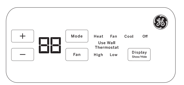
Temp Control
- The temp control is used to maintain the room temperature.
The system will cycle on and off to keep the room at the same level of comfort. - Press the + pad to raise the temperature.
- Press the - pad to lower the temperature.
NOTE: The display shows the set temperature. not the room temperature.
Fan, Mode and Operation Control
- FAN—Sets the fan operation for HIGH or LOW.
- MODE—COOL—For cooling
- FAN—For fan-only operation
- HEAT—For heating
- OFF—Turns the unit off. Power remains connected to the Zoneline. The Freeze/Heat Sentinel features stil function if active. See the Freeze/Heat Sentinel section on page 8.
- USE WALL THERMOSTAT— This LED will light up when the unit is controlled by a wall thermostat. See page 9 for details.
Control Lock Out
- The control panel can be locked out to prevent users from changing the operation mode of the unit.
- While the unit is in the desired operating mode, press and hold the DISPLAY SHOW/HIDE button for 10 seconds to lock the control and the desired setting. Any key press after that will result in the mode LED and temperature that was locked to flash 5 times and then go dormant.
- To unlock the control lock out feature, press the DISPLAY SHOW/HIDE button for 10 seconds to unlock and resume normal operation.
NOTE: The temperature display will flash if the control panel is locked (see Control Lock Out section).
NOTE: When switching between modes, it may take several minutes to completely change operation.
Quick Heat Recovery
- Activates each time the thermostat is switched from OFF or COOL mode to HEAT mode. Electric heaters are energized until the thermostat set point is reached. On heat pump models, the heat pump operation will resume at the next call for heat.
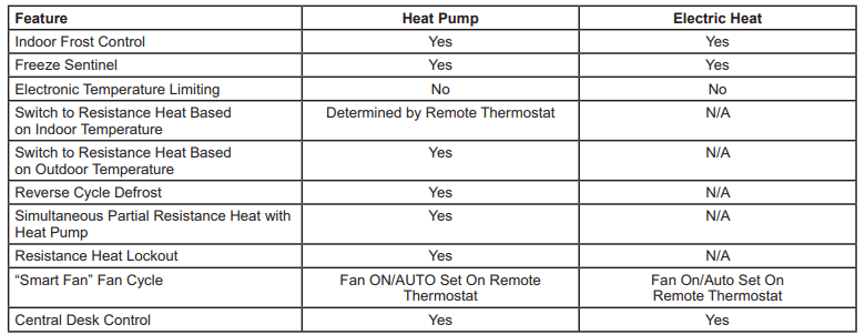
About Your Heat Pump (AZ65 only)
- Heat pumps can save money by removing heat from the outside air—even when the outside temperature is below freezing—and releasing that heat indoors.
- To get the best energy performance from your heat pump, don't change the room thermostat by more than one degree at one time. Raising the heat setting 2-3 degrees will cause the Zoneline to use its electric heating elements in order to teach the new temperature setting quickly.
- The electric heating elements use more electricity than heat pumps and cost more to operate.
- There is a 3-minute minimum compressor run time at any setting to prevent short cycling.
- The fans start before the compressor and stop after the compressor cycles off.
- When the outdoor temperature is lower than 25°F, heat is provided by the electric heater instead of by the heat pump.
- When the outdoor temperature is lower than 35°F, cooling operation is locked out to prevent damage to the compressor. Operation will resume when the outdoor temperature rises above 40°F.
Using the Zoneline
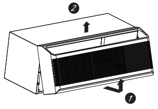
To Remove the Room Front
- Additional controls are located behind the room cover.
- To remove: Pull out at the bottom to release it from the holding tabs on the sides (1). Then lift up (2)
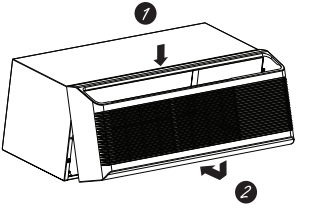
- To replace: Align and place the top rail of the room cover over the chassis (1). Push inward at the bottom until it snaps into place (2)
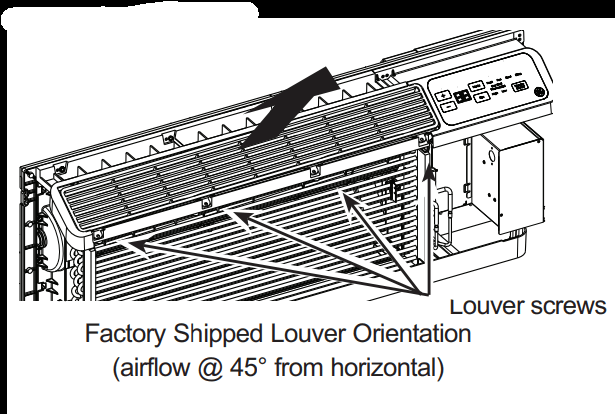
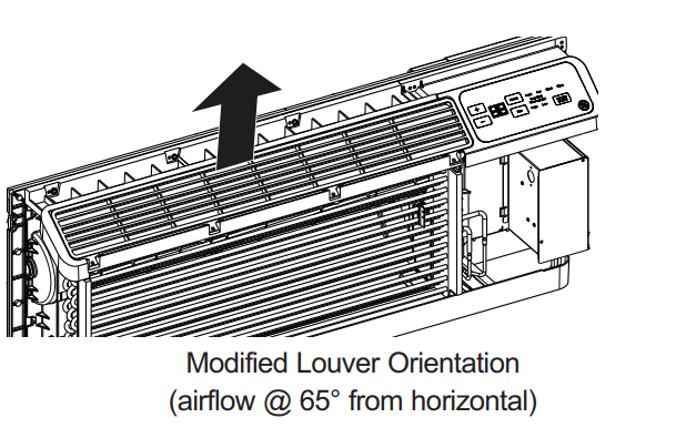
Air Direction
- To change the air direction, remove the room cover. Remove the 4 louver insert inplace. Rotate the louver 180°, reinstall and replace the screws and the room cover.
Ventilation Control*
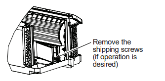
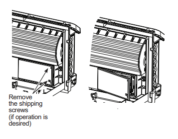
NOTE: Two shipping screws must be removed from the vent door before use. See the Installation Instructions in the back of this manual. If you do not plan to use the ventilation feature, leave the two screws in place
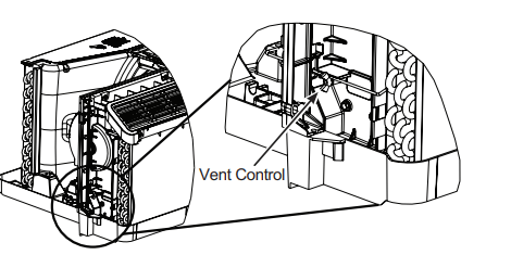
- The ventilation control lever is located at the lower left side of the Zoneline unit, behind the room cover. The position of the lever can be adjusted with the wing nut
- When set at the closed position, only the air inside the room is circulated and filtered.
- When set in an open position, some outdoor air will be drawn into the room. This will reduce the heating or cooling efficiency.
- Energy Tip: Keep the vent control in the closed position to prevent unconditioned air from entering the room.
* Not on Make Up Air Module
Auxiliary controls on your Zoneline
Auxiliary Controls - Aux Set Button
- While the unit is preset to what most customers prefer, the auxiliary controls located behind the room cover, below the control panel.
- Remove the room cover. See the To Remove the Room Cover section.
- If the owner modifies the auxiliary controls itis then the owner is responsible for ensuring the auxiliary controls are set to the desired function. There are 10 different modes that can be set using the auxiliary set button.
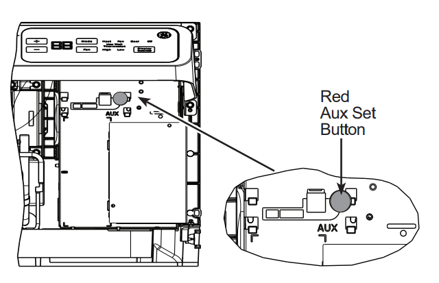
- To change operating or set up parameters, first go to the mode control and tum the unit off, then, press the red AUX SET button ("AU’ appears on the display).
- Press the mode button on the control pad unti the first digit in the display shows the number corresponding to the mode you are choosing and the correct HEAT/COOL LED is lit.
- Press the +1- button to make the mode setting selection where applicable (shown in the second digit of the display).
- Press the red AUX SET button to lock in the selection. and exit AUX SET mode.
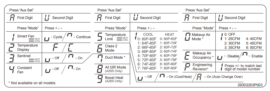
MODE 1: Smart Fan—Cooling/Heating
- Press MODE until a 1 appears in the first digit of the display for Smart Fan cool mode. The COOL LED light on the main control will be on. To change to heat mode, press MODE again. The HEAT LED light on the main control will be lit.
- Press the - pad to set the indoor fan to cycle on/off in the heating or cooling mode selected “
 ”
” - Press the + pad to set the indoor fan to run continuously in the heating or cooling mode selected “
 ”
” - Press AUX SET to confirm your selection and exit AUX SET mode,or press MODE to continue setting other functions.
- The default setting for Mode 1 is as follows:
- Cooling: Continuous (ON)
- Heating: Cycle (OFF)
- The default setting for Mode 1 is as follows:
- Note: In cyclic cooling mode. the indoor fan will activate occasionally to verify air temperature in the room. In cyclic heating mode. the fan will continue to operate for several seconds after the heating function has stopped in order to increase unit efficiency.
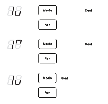
MODE 2: Fahrenheit / Celsius
- This feature allows the individual to switch the temperature units between Fahrenheit and Celsius on the display.
- Press MODE until a 2 appears in the first digit of the displayu for Fahrenheit/Celsius mode
- Press the - pad to select Celsius or the + pad to select Fahrenheit. The individual will see an F for Fahrenheit or a C for Celsius in the second digit of the display based on the selection.
- The default setting for Mode 2 is Fahrenheit
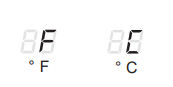
MODE 3: Freeze Sentinel/Heat Sentinel
- With power to the unit and Freeze Sentinel activated. the unit automatically provides heat without user interface. This prevents potential plumbing damage by tuming the heater and indoor fan ON at 41°F and then
OFF once the room temperature reaches 46°F. - When Heat Sentinel is activated, the unit automatically provides cooling without user interface. This prevents an excessively hot room by turing the air conditioner ON at 85°F and then OFF once the room temperature reaches
80°F. - Press MODE until a3 appears in the first digit of the display for Freeze Sentinel mode. The COOL LED light on the main control will be on. Press MODE again to change to the Heat Sentinel. The HEAT LED light on the main control will be on. Press the - pad for OFF “
 “ or the + pad for ON “
 ". This is shown in the second digit of the display. Press AUX SET to lock in your selection. and exit AUX SET mode, or press MODE to continue setting other functions.
 - In the default setting for Mode 3. Heat Senti Freeze Senti on.
NOTE: These functions are active whenever the unit is plugged in. even if the unit is tuned off.
MODE 4: Constant ON Fan
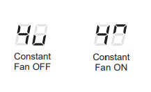
- Press MODE until a 4 appears in the first digit of the display to set the fan to run continuously at high speed - even if the unit is turned off.
- Press the - pad for OFF “
 “ or the + pad for ON “
  ". This is shown in the second digit of the display.
 - Press AUX SET to lock in your selection and exit AUX SET mode, or press MODE to continue setting other functions.
- The default setting for Mode 4 is OFF
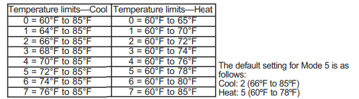
MODE 5: Temperature Limiting
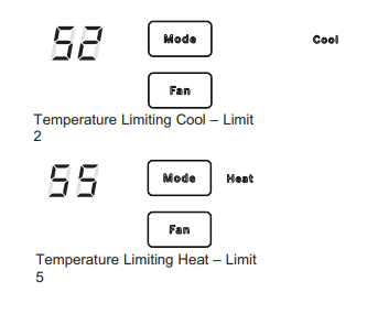
- Temperaure limiting is a feature that reduces energy costs by limiting the lowest temperature that can be obtained in cooling and the highest temperature that can be obtained in heating.
- Press MODE until a 5 appears in the first digit of the display for Temperature Limiting cool mode. The COOL LED light on the main control will be lit. To change to heat mode, press MODE again and the HEAT LED light on the main control will be lit.
- To set the temperature limits. press the + or - pad. The second digit of the display will be between 0 and 7 depending on the limit you want to set. The chart shows the limits available. Press AUX SET to lock in your selection and exit AUX SET mode. or press MODE to continue setting other functions.
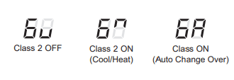
MODE 6: Use Wall Thermostat
- Setting this mode to ON will allow the unit to operate with a Class 2 Remote Control Wall Thermostat. Press MODE until a 6 appears in the first digit of the display for Class 2 mode.
- The default setting for Mode 6 is OFF.
- Press the + pad to turn the option ON “
 " for “standard coo/heat” thermostats. Press the + pad again to turn the option ON “
  “ for “auto change over” thermostat. You may press the - pad to return to the previous setting. Press AUX SET to lock in your selection and exit AUX SET mode. or press MODE to continue setting other functions.
 - When this mode is active, the display will show “Use Wall Thermostat” when any key is pressed.
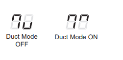
MODE 7: Duct Mode
- This setting is used when the unit is installed with a duct adapter kit. If the unit is ducted, the Duct Mode needs to be set to ON. This increases the fan speed to ensure proper circulation.
- Press MODE until a 7 appears in the first digit of the display. Press the + or - pad to set this switch to OFF "
 " or ON “
 .” This is shown in the second digit of the display. Press AUX SET to lock in your selection and exit AUX SET mode.
 - For Model AZ65. press MODE to continue setting other functions. Pressing MODE on Model AZ45 will return you to AUX SET mode and an “AU” will appear in the display.
- The default setting for Mode 7 is OFF.
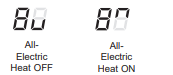
MODE 8 All-Electric Heat (AZ65 only)
- This electric heat option functions only on the AZ65 model. When this option is ON “ ", heat pump operation is locked out, causing the unit to provide only electric resistance heat.
- To set All- Electric Heat option, press MODE until an 8 appears in the first digit of the display. Press the + or - pad to set this switch to OFF “ “ or ON “ ". This is shown in the second digit of the display.
- Press AUX SET to lock in your selection and exit AUX SET mode, or press MODE to continue setting other functions.
- The default setting for Mode 8 is OFF
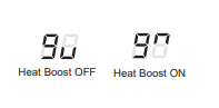
MODE 9 Heat Boost (AZ65 only)
- When Heat Boost is ON and outside temperatures are between 25°F and 46°F, supplementary electric heat to the heat pump operation to help maintain a consistent, comfortable room temperature.
- To set Heat Boost, press MODE until a 9 appears in the first digit of the display. Press the + or - pad to set this switch to OFF “ “ or ON “ ". This is shown in the second digit of the display. Press AUX SET to lock in your selecttion and exit AUX SET mode.
- The default setting for Mode 9 is OFF
MODE 0: Digital Makeup Air Module Fan Speed
- Press MODE until a 0 appears in the first digit of the display for the Digital Makeup Air mode. To tum off the module or change the fan speeds, press the + or - pad. 00 indicates the module is off. 01= module on with fans set at 25cm. (02 = module on with fans set at 30cfm. etc.
- The default setting for Mode 0 is ON with a fan speed of 35 cfm “
 ”
”
MODE E: Digital Makeup Air Module Occupancy
- To enable occupancy detection. press MODE until an E appears in the first digit of the display. Press the + or - pad to set occupancy detection to OFF "
 ” or ON “
 ".
". - The default setting for Mode E is OFF " "
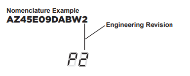
MODE P: Engineering Revision Setup
- This setting is used to configure the unit when the circuit board is replaced.
- The first time the unit is powered after a service board is installed. the unit will automatically enter this mode. The Ul will read “P1.” Press the “+” pad until the number matches the engineering revision as shown. The engineering revision is the last number in the model number. Press “Aux” to save and exit.
- The engineering revision may be adjusted after the frst power cycle using AUX SET. Press MODE until “P” appears in the first digit, and follow the steps described above.
Auxiliary Controls - Terminal Connections
The auxiliary control terminal connects are located behind the room cover beneath the access cover.
- Tum off and unplug the unit.
- Remove the room cover. See the To Remove the Room Cover section.
- To make wiring connections. insert the connectors into the appropriate terminals on the control box.
- After all desired connections have been made. replace the access cover and room cover.
The owner is responsible for making all connections and setting the appropriate AUX SET mode.

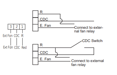
External Fan (Field Installed)
- When connected, an auxiliary or external fan can be controlled with the indoor fan motor on the Zoneline. Connections provide 24 V AC to energize a remote relay.
- To enable this feature, a WP26X22240 control board and a RAKCDC accessory must be installed.
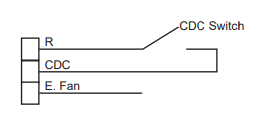
Central Desk Control (Field Supplied)*
- The Central Desk Control is a feature that allows the unit to be made operable/inoperable from a remote location. Operation of the feature requires that an ON-OFF switch at the remote location be wired to the two CDC terminals on the control panel of the Zoneline. When the remote switch is CLOSED, the unit cannot be operated in the Fan, Cool, or Heat modes by the control. The Freeze Sentinel and the Heat Sentinel features remain operable.
When the remote switch is Open, the unit is fully operable by control. - The RAKCDC accessory must be used with a central. desk control system. No “Common Busing’ is permitted
- * It should be noted that CDC cannot be used on DBM and EBM models when occupancy is enabled.
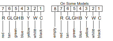
Remote Thermostat
- The Remote Thermostat Connectors are included with each Zonelin.
- When connected to a remote thermostat, the indoor air temperature sensing is shifted from the unit to the remote thermostat. For thi reason, the units will operate slighty differenty when connected to a remote thermostat. The following chart shows the unit operation when connected to a remote thermostat.
- IMPORTANT: The Zoneline thermostat connections provide 24 V AC only
- If using a digtalelectronic wall thermostat, you must set ito the 24 V AC setting. See the installation Instructions for the wall thermostat.
Notice: Damage to a wall themostat or to the Zoneline electronics can result from improper connections. Special care must be used in connecting the wires. No line voltage connections should be mage to any cicult
Isolate all wires in building from line voltage.
Makeup Air Models (not on all units)
The make-up air ventilation system is designed to provide continuous outdoor air through the vent door and into the room. In addition to providing fresh air, it dehumidifies incoming air when itis above 55% relative humidity
*DAM Models
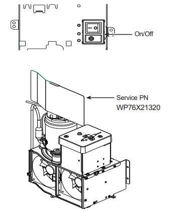
- The make-up air ventilation system is operated by a switch located on the front of the electrical control cover under the Zoneline room front. The system is tured on and of by depressing tne on (I) or off (0) button as shown in the
- Should the Zoneline need to be operated as a PTAC or PTHP only, the following steps should be followed:
- Order service PN# WP76X21320.
- Unplug the Zoneline.
- Remove the room front.
- Turn off the ventilation system by depressing the on/off button so that off (0) is selected (see above ilustration for location).
- Pull the Zoneline from the wall sleeve and install service PN# WP76X21320 as shown in the ilustration.
- Push the Zoneline back into the wall sleeve and restore power to the unit.
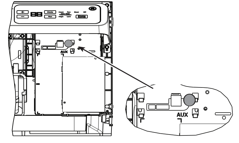
*DBM and *EBM Models
The makeup air ventilation system is operated through the Zoneline’s auxiliary menu (see Auxiliary Controls, section). To tum the system on or off, follow the directions below:
- Remove the room front.
- Press the mode control button and turn off the unit
- Press the red AUX SET button (“AU" appears on the display).
- To turn off the MUAM press the mode control button until “0” appears in the first digit.
- Press the minus on the control panel until "00" is displayed to tur off the makeup air module.
- The system is preset from the factory at 35 cfm. To change that value press the + or - for the fan speed desired: 1=25cfm, 2=30cfm, 3=35cfm, 4=40cfm, 5=45 cfm and 6=50cfm.
- Depress the red Aux button again to return to normal operation.
Should the Zoneline need to be operated as a PTAC or PTHP only, the following steps should be followed:
- Order service PN# WP76X21320.
- Unplug the Zoneline.
- Remove the room front.
- Tum off the makeup air module as instructed above.
- Pull the Zoneline from the wall sleeve and install service PN# WP76X21320 as shown in the illustration.
- Push the Zoneline back into the wall sleeve and restore power to the unit.
NOTE: Digital makeup air units will perform a system check upon power up. power cycle and once every 7 days if the unit is in occupancy mode. The system check lasts approximately 45 seconds. During this time the fans will speed up. slow down. and then go to the set point.
Care and Cleaning
Room Cover and Case
- Turn the Zoneline off and disconnected the power supply.
- To clean, use water and a mild detergent. Do not use bleach or abrasives. Some commercial cleaners may damage the plastic parts.
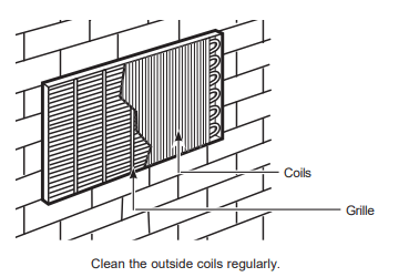
Outdoor Coils
- The coils on the outdoor side of the Zoneline should be checked regularly. If they are clogged with dirt or soot, they should be cleaned by either low or no pressure cleaning methods. Ensure that electrical area/devices are protected during cleaning. You will need to remove the unit from the wall sleeve to inspect the coils. The dirt buildup occurs on the fan side of the outdoor coil
Base Pan
- In some installations, dirt or other debris may be blown into the unit from the outside and settle in the base pan (the bottom of the unit).
- In some areas of the United States, a naturally occurring “gel-like” or “slime-like" substance may be seen in the base pan.
- Check it periodically and clean, if necessary.
- On 4500 Series models, do not remove the rubber drain plug from the base pan. if removed, excess water may drain to the outside.
Ventilation Filter
- If the vent door is open, clean the vent filter twice a year or as required. Access requires the removal of the unit from the wall sleeve.
- Turn the Zoneline off and unplug before removing and cleaning.
To clean the vent filter:
IMPORTANT: This filter is not removable. Trying to remove this filter will damage the unit.
- Use a vaccum to remove debris from the filter
- Use a damp rag to wipe down the filter and surrounding area after vacuuming.
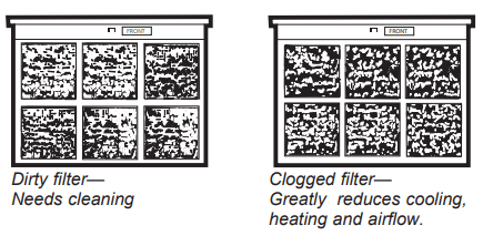
Air Filters
To maintain optimum performance, clean the filters at least every 30 days.
Turn the Zonoline off before cleaning.
The most important thing you can do to maintain the Zoneline isto clean the fit at least every 30 days. Clogged ites reduce cooling. heating and air flow.
Keeping these filters clean will:
- Decrease cost of operation
- Save energy.
- Prevent clogged heat exchanger cols.
- Reduce the risk of premature component faire.
To clean the air fiters
- Vacuum off the heavy soll
- Run water through the fters from the back side.
- Dry thoroughly before replacing.
NOTE: The air ites are interchangeable and will fit in ether the right or left side.
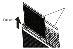
To remove the air filters:
To replace the air filters:
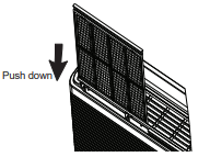
NOTICE: Do not operate the Zoneline without the fiters in place. If a filler Becomes torn or damaged. It should be replaced Immediately.
Operating without the fters in place or with damaged fiers will allow dit and dust to reach the indoor coll and reduce the cooling, heating, alow and efficiency of the unit
Replacement fiters are availabe from your salesperson. GE Appliances dealer, GE Appliances Service and Parts Center of authorized Customer Care servicers
TROUBLESHOOTING TIPS
Save time and money! Review the charts on the following pages first and you may not need to call for service.
Before you call for service
Problem | Possible Cause | What To Do |
| Zoneline does not start. | The unit is unplugged. | Make sure the Zoneline plug is pushed completely into the outlet |
| The power cord is not firmly attached. | Remove the room cover and make sure that the black connector on the end of the ower cord is firmly engaged. | |
| The fuse is blown/circuit breaker is tripped | Check the house fuse/ circuit breker box and replace the fuse or reset the breaker. | |
| The unit is waiting for the compressor overload protector to reset. | This is normal. The Zoneline will start again after it resets. | |
| Power Failure. | If power fadure occurs. set the mode control to OFF. When power is restored, set the mode control to the desired setting. There is protective time dela (up to 3 minutes) to prevent tipping ofthe compressor verioad. For this | |
| The power cord current interrupter devise is tripp | Press the RESET bution located on the powar Gord lg or the box near the plug. If the RESET button wil nt stay engaged. discontinue | |
| Zoneline does not cool or heat as it should. | Indoor airflow is restricted | Make sure there are not curtains, blinds or furniture blocking the front of the Zonelone. |
| Outdoor airflow is restricted or recirculated. | Make sure the rear grille is not restricted. This can cause the unit to cycle off due to the compressor overload protector. Outdoor grille must have a minimum of 65% free area. Non-GE Appliances grills may be too restrictive for proper performance. Consult your salesperson for assistance | |
| The temp control may not be set properly. | Turn the control to the lower or higher setting. Note: The temperature limiter may be limiting the temperature range. | |
| The air filter is dirty. | Change the filter at least every 30 days. See the Care and Cleaning section | |
| The room may have been hot or cold. | When the Zoneline is first turned on you need to allow time for the room to cool down or warm up. | |
| Outdoor air is entering the room | Set the vent control to the closed position. Note: Units equipped with makeup ventilation will continuously allow some outdoor air into the room | |
| Burning odor at the start of heating operation | Dust on the surface of the heating elements. | This can cause a “burning” odor at the beginning of the heating operation. This should quickly fade. |
| The air is not always cool or hot during operation. | The heat pump is not producing hot air. | This is normal. The heat pump will produce warm air but not as hot as air produced when the higher-cost electric heat is used. |
| The Smart Fan Auxiliary control may be set to continuous fan. | This cause the fan to blow room temperature air even when the compressor or heater cycles off. The continuous air movement provides better overall temperature control in the cool mode. See Smart Fan- Cooling/ Hetaing section | |
| The air does not feel warm enough during heating operation | The heat pump alone produces air that feels cooler than desired. | Use the Electric Heat Option. This tums off the heat pump and warms with electric heat only NOTE: Use of this option will result in increased energy consumption. |
| The unit is not blowing out air | The Smart Fan Auxiliary Controls may be set to cycle. | See Smart Fan - Cooling/Heating section on page 9. |
| The electric heating and fan features do not work | The power cord is not firmly attached. | Remove the room cover and make sure that the black connector on the end of the power cord is fimly engaged. |
| Temperature display flashes | The compressor may have failed. | Set the operation control to OFF and then restart the Unit. If the flashing light reappears within 30 minutes, cal for service. |
| The unit does not function after installing Remote Wall Thermostat | Aux Mode 6 not set properly | Verify wiring from Remote Wall Thermostat is correct to tnt thermostat connector. |
| Unit thermostat connections are incorrect. | Check Aux Mode 6 to be sure switch on “or Remote Thermostat. see page 11 | |
| Transformer resets or opens with short. | Wait 5 minutes to see if power resets. | |
| Heat pump operates with electric heat only during heating. | Aux Mode 6 not set properly | Check Aux Mode 6 is set for the appropriate remote wall thermostat, eter “ “ for “ coolIheat” or ” “ for “ coolIheat” or ”  " for “Auto Change Over’, see page 10. " for “Auto Change Over’, see page 10. |
| Aux Mode 8 not set p | Check Aux Mode & to be sure switch is “off for heat pump operation, see page 11 |
Things that are normal
Normal Operating Sounds

- You may hear a pinging noise caused by water being picked up and thrown against the condenser on rainy days or when the humidity is high. This design feature helps remove moisture and improve efficiency
- You may hear relays click when the controls cycle on and off or are adjusted to change the room temperature.

- Water will collect in the base pan during high humidity or on rainy days. The water may overflow and drip from the outdoor side of the unit.

- The indoor fan runs continuously when the unit is operating inthe cooling mode, unless the Smart Fan Ausilay Conta is set to cycle. This will cause the fan to cycle on and of with the compressor. You may also hear a fan noise stop and sta.
There are times when the fan onthe unt wil un even when the units not heating or cooling If the systems. Setup to bein continous fan the indoor an wil run regardless ifthe unit may be cooling or heating. Other times the fan wil run longer than the heating/cooling cyce or kick on occasionally. This is normal and is done to improve room comfort and balance.
- If the unit is equipped with a make-up air ventilation system, fans wil run continuously
- Digital makeup air unit wil perform a system check upon power up, power cyce, and once every 7 days ifthe unis in occupancy mode. The system check lasts approximately 45 seconds. During tis ime the fans will speed up. slow down and then go to the setpoint

- You may notice afew minutes delay in starting if you ty 10 restart the Zoneline too soon after tuning it off or if you adjust the thermostat right after the compressor has shut of. This is due to a built in restart protector for the compressor that causes. a Sminute delay.

- During the deftost cycle, both indoor and outdoor ans stop and the compressor will operate inthe rode to remove fost from the outdoor cool.
After defrost, the unit will restat in electic heat to quickly warm the room to the desired comfort level.
- To protect the compressor and prevent short cycling, the unit is designed to run fora minimum of 3 mutes after the compressor stats at any thermosiat setting.

