Loading ...
Loading ...
Loading ...
Installation en
15
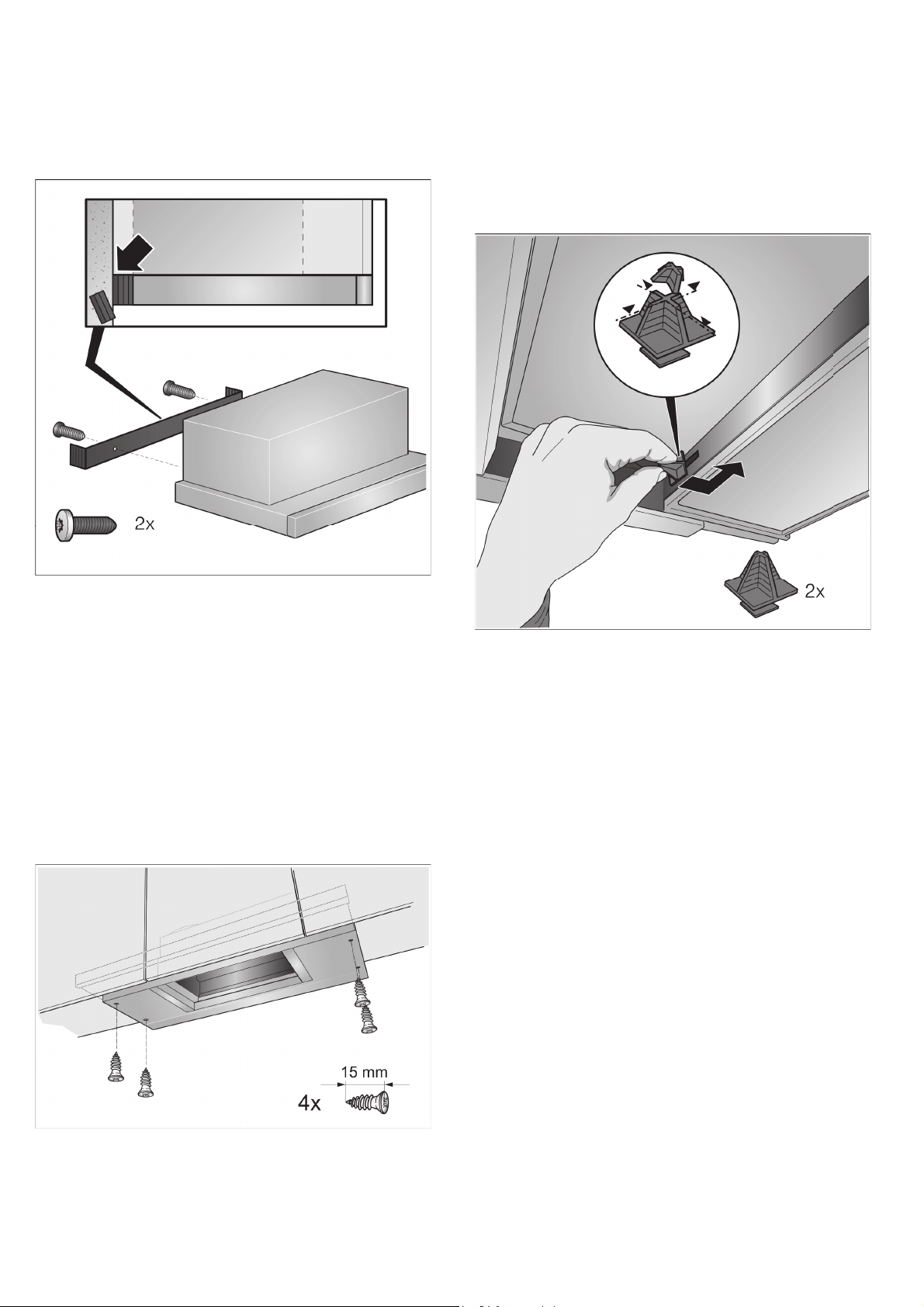
2. Measure the distance from the appliance to the wall
and mark this on the filler strip.
3. If required, shorten the filler strip to the required
dimension.
4. Remove the appliance and screw in the filler strip.
5. Remount the appliance, align it and screw it in place.
Carefully screw in all screws.
6. Establish the electrical connection.
Note: The extractor hood's housing can be concealed
within the upper cabinet. In doing so, you must observe
the following:
■ The intermediate floor must not be placed on the
extractor hood's housing.
■ The front panel must not be secured to the housing.
■ Access must be available in order to change the
filter and for after-sales service.
Appliance width, 90 cm:
You must also screw the appliance onto the side upper
cabinets.
Change the filter pull-out's limit stop
On some versions of the appliance, the limit stop for the
filter pull-out can be changed. Spacers are included
with these appliances in order to set the appliance's
handle strip so that it is flush with the fitted unit.
1. Pull the filter pull-out forwards.
2. Shorten the spacer to the required dimension and
insert it into the specified slot.
Connecting the pipes
Note: If using an aluminium pipe, smooth the
connection area beforehand.
Exhaust-air pipe Ø 150 mm (recommended size)
Attach the exhaust-air pipe directly to the air-pipe
connector and seal.
Exhaust-air pipe Ø 120 mm
1. Attach the reducing connector directly to the air-pipe
connector.
2. Attach the exhaust air pipe to the reducing
connector.
3. Seal both joints appropriately.
Loading ...