OWNER’S
MANUAL
Toledo
6JA012720BE
Inglés
6JA012720BE (11.15)
Toledo Inglés (11.15)
SEAT recommends
SEAT GENUINE OIL
SEAT recommends
Castrol EDGE Professional
SEAT S.A. is permanently concerned about continuous development of its types and models. For this reason we ask you to under-
stand, that at any given time, changes regarding shape, equipment and technique may take place on the car delivered. For this reason
no right at all may derive based on the data, drawings and descriptions in this current handbook.
All texts, illustrations and standards in this handbook are based on the status of information at the time of printing. Except for error
or omission, the information included in the current handbook is valid as of the date of closing print.
Re-printing, copying or translating, whether total or partial is not allowed unless SEAT allows it in written form.
SEAT reserves all rights in accordance with the “Copyright” Act.
All rights on changes are reserved.
❀
This paper has been manufactured using bleached non-chlorine cellulose.
© SEAT S.A. - Reprint: 15.11.15
About this manual
This manual contains a description of the
equipment supplied with the vehicle at the
time this manual was published. Some of the
units described herein will not be available
until a later date or are only available in cer-
tain markets.
Because this is a general manual for the
TOLEDO, some of the equipment and func-
tions that are described in this manual are not
included in all types or variants of the model;
they may vary or be modified depending on
the technical requirements and on the mar-
ket; this is in no way deceptive advertising.
The illustrations are intended as a general
guide and may vary from the equipment fitted
in your vehicle in some details.
The steering indications (left, right, forward,
reverse) appearing in this manual refer to the
normal driving movements of the vehicle ex-
cept when otherwise indicated.
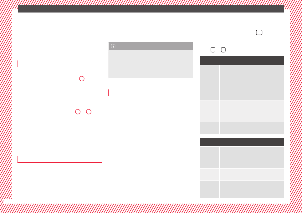
The equipment marked with an aster-
isk* is fitted as standard only in certain
versions, and is only supplied as op-
tional extras for some versions, or are
only offered in certain countries.
® All registered marks are indicated with
®. Although the copyright symbol does
not appear, it is a copyrighted mark.
>> The section is continued on the follow-
ing page.
Important warnings on a given page
Detailed contents on a given page
General information on a given page
Emergency information on a given page
WARNING
Texts preceded by this symbol contain infor-
mation on safety. They warn you about possi-
ble dangers of accident or injury.
CAUTION
Texts with this symbol draw your attention to
potential sources of damage to your vehicle.
For the sake of the environment
Texts preceded by this symbol contain rele-
vant information concerning environmental
protection.
Note
Texts preceded by this symbol contain additio-
nal information.
This manual is divided into six large parts,
which are:
1. The essentials
2. Safety
3. Emergencies
4. Operation
5. Tips
6. Technical data
At the end of this manual, there is a detailed
alphabetical index that will help you quickly
find the information you require.

Foreword
Thi
s
In
struction Manual and its correspond-
ing supplements should be read carefully to
familiarise yourself with your vehicle.
Besides the regular care and maintenance of
the vehicle, its correct handling will help pre-
serve its value.
For safety reasons, always note the informa-
tion concerning accessories, modifications
and part replacements.
If selling the vehicle, give all of the on-board
documentation to the new owner, as it
should be kept with the vehicle.
You can access the information in this man-
ual using:
●
Thematic table of contents that follows the
manual’s general chapter structure.
●
Alphabetical index with many terms and
synonyms to help you find information.
WARNING
Read and always observe safety informa-
tion concernin
g the passenger's front air-
bag ››› page 73, Important information
regarding the front passenger's airbag.


Table of Contents
Table of Contents
The e
s
senti
als . . . . . . . . . . . . . . . . . . . . . . . . 5
Exterior view . . . . . . . . . . . . . . . . . . . . . . . . . . . . 5
Exterior view . . . . . . . . . . . . . . . . . . . . . . . . . . . . 6
Interior view (left guide) . . . . . . . . . . . . . . . . . . 7
Interior view (right-hand drive) . . . . . . . . . . . . . 8
How it works . . . . . . . . . . . . . . . . . . . . . . . . . . . . 9
Unlocking and locking . . . . . . . . . . . . . . . . . . . . 9
Before driving . . . . . . . . . . . . . . . . . . . . . . . . . . . 11
Airbags . . . . . . . . . . . . . . . . . . . . . . . . . . . . . . . . 13
Child seats . . . . . . . . . . . . . . . . . . . . . . . . . . . . . 16
Starting the vehicle . . . . . . . . . . . . . . . . . . . . . . 17
Lights and visibility . . . . . . . . . . . . . . . . . . . . . . 18
Easy Connect . . . . . . . . . . . . . . . . . . . . . . . . . . . 20
Driver information system . . . . . . . . . . . . . . . . . 22
Journey data . . . . . . . . . . . . . . . . . . . . . . . . . . . . 26
Cruise control . . . . . . . . . . . . . . . . . . . . . . . . . . . 31
Warning lamps . . . . . . . . . . . . . . . . . . . . . . . . . . 32
Gearbox lever . . . . . . . . . . . . . . . . . . . . . . . . . . . 34
Air conditioning . . . . . . . . . . . . . . . . . . . . . . . . . 36
Level control . . . . . . . . . . . . . . . . . . . . . . . . . . . . 39
Emergencies . . . . . . . . . . . . . . . . . . . . . . . . . . . . 43
Fuses . . . . . . . . . . . . . . . . . . . . . . . . . . . . . . . . . . 43
Bulbs . . . . . . . . . . . . . . . . . . . . . . . . . . . . . . . . . . 44
Action in the event of a puncture . . . . . . . . . . . 44
Changing a wheel . . . . . . . . . . . . . . . . . . . . . . . 46
Snow chains . . . . . . . . . . . . . . . . . . . . . . . . . . . . 49
Emergency towing of the vehicle . . . . . . . . . . . 50
How to jump start . . . . . . . . . . . . . . . . . . . . . . . . 51
Changing the windscreen wiper blades . . . . . . 53
Safety . . . . . . . . . . . . . . . . . . . . . . . . . . . . . . . . 55
Safe driving . . . . . . . . . . . . . . . . . . . . . . . . . . . . 55
Safety first! . . . . . . . . . . . . . . . . . . . . . . . . . . . . . 55
Advice about driving . . . . . . . . . . . . . . . . . . . . . 55
Correct position for passengers . . . . . . . . . . . . 56
Pedal area . . . . . . . . . . . . . . . . . . . . . . . . . . . . . . 60
Seat belts . . . . . . . . . . . . . . . . . . . . . . . . . . . . . . 61
The whys and wherefores of seat belts . . . . . . . 61
How to properly adjust your seatbelt . . . . . . . . 64
Seat belt tensioners . . . . . . . . . . . . . . . . . . . . . . 65
Airbag system . . . . . . . . . . . . . . . . . . . . . . . . . . 66
Brief introduction . . . . . . . . . . . . . . . . . . . . . . . . 66
Airbag safety instructions . . . . . . . . . . . . . . . . . 69
Deactivating airbags . . . . . . . . . . . . . . . . . . . . . 71
Transporting children safely . . . . . . . . . . . . . . . 72
Safety for children . . . . . . . . . . . . . . . . . . . . . . . 72
Child seats . . . . . . . . . . . . . . . . . . . . . . . . . . . . . 74
Emergencies . . . . . . . . . . . . . . . . . . . . . . . . . . 75
Self-help . . . . . . . . . . . . . . . . . . . . . . . . . . . . . . . 75
Emergency equipment . . . . . . . . . . . . . . . . . . . . 75
Changing a wheel . . . . . . . . . . . . . . . . . . . . . . . 75
Tyre repairs . . . . . . . . . . . . . . . . . . . . . . . . . . . . . 76
Towing the vehicle . . . . . . . . . . . . . . . . . . . . . . . 78
Fuses and bulbs . . . . . . . . . . . . . . . . . . . . . . . . . 80
Fuses . . . . . . . . . . . . . . . . . . . . . . . . . . . . . . . . . . 80
Changing bulbs . . . . . . . . . . . . . . . . . . . . . . . . . 83
Changing the fog light bulbs . . . . . . . . . . . . . . . 86
Changing the rear lights (on the side panel) . . 87
Changing tail lights (on the rear lid) . . . . . . . . . 89
Changing the bulb on the number plate . . . . . . 91
Operation . . . . . . . . . . . . . . . . . . . . . . . . . . . . . 93
Controls and displays . . . . . . . . . . . . . . . . . . . . 93
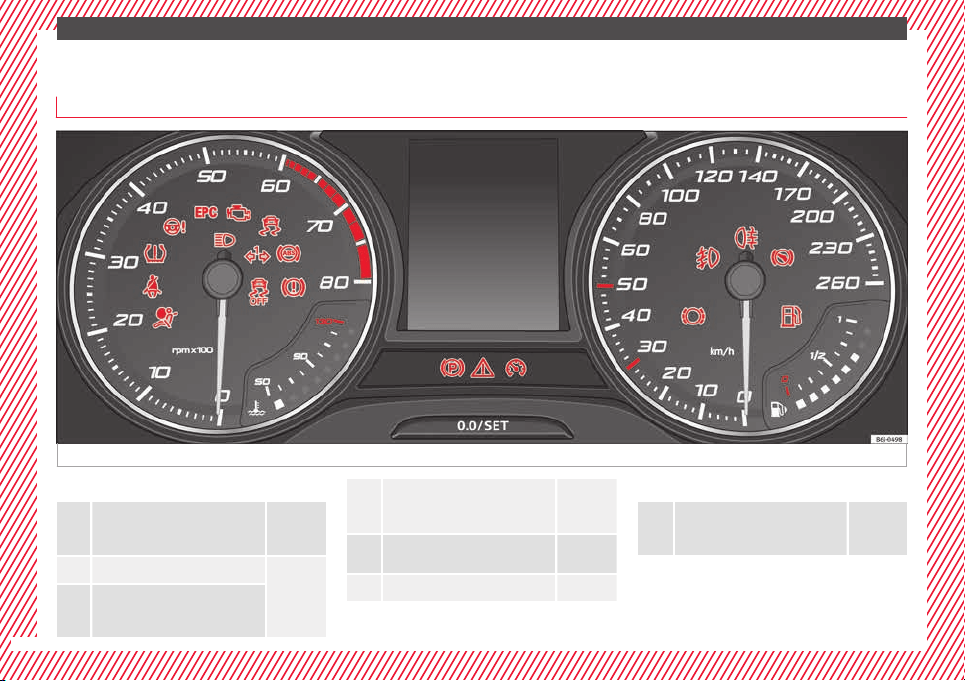
General instrument panel . . . . . . . . . . . . . . . . . 92
Instruments and warning lamps . . . . . . . . . . . . 94
Instruments . . . . . . . . . . . . . . . . . . . . . . . . . . . . 94
Control lamps . . . . . . . . . . . . . . . . . . . . . . . . . . . 98
Introduction to the Easy Connect system* . . . . 104
System settings (CAR)* . . . . . . . . . . . . . . . . . . . 104
Communications and multimedia . . . . . . . . . . . 105
Steering wheel controls* . . . . . . . . . . . . . . . . . . 105
Multimedia . . . . . . . . . . . . . . . . . . . . . . . . . . . . . 109
Opening and closing . . . . . . . . . . . . . . . . . . . . . 109
Remote control . . . . . . . . . . . . . . . . . . . . . . . . . . 109
Keys . . . . . . . . . . . . . . . . . . . . . . . . . . . . . . . . . . . 110
Central locking system . . . . . . . . . . . . . . . . . . . . 112
Anti-theft alarm system* . . . . . . . . . . . . . . . . . . 117
Rear lid . . . . . . . . . . . . . . . . . . . . . . . . . . . . . . . . 118
Opening and closing of electric windows . . . . . 120
Lights and visibility . . . . . . . . . . . . . . . . . . . . . . 121
Lights . . . . . . . . . . . . . . . . . . . . . . . . . . . . . . . . . 121
Interior lights . . . . . . . . . . . . . . . . . . . . . . . . . . . 127
Visibility . . . . . . . . . . . . . . . . . . . . . . . . . . . . . . . 128
Windscreen wipers and windscreen wash-
ers . . . . . . . . . . . . . . . . . . . . . . . . . . . . . . . . . . . . 129
Rear vision mirrors . . . . . . . . . . . . . . . . . . . . . . . 130
Seats and head restraints . . . . . . . . . . . . . . . . . 131
Adjusting seats and head restraints . . . . . . . . . 131
Seat functions . . . . . . . . . . . . . . . . . . . . . . . . . . 133
Transport and practical equipment . . . . . . . . . 135
Practical equipment . . . . . . . . . . . . . . . . . . . . . . 135
Storing objects . . . . . . . . . . . . . . . . . . . . . . . . . . 141
Luggage compartment . . . . . . . . . . . . . . . . . . . . 142
Roof rack* . . . . . . . . . . . . . . . . . . . . . . . . . . . . . . 145
Air conditioning . . . . . . . . . . . . . . . . . . . . . . . . . 146
Heating and air conditioning . . . . . . . . . . . . . . . 146
Heating and fresh air . . . . . . . . . . . . . . . . . . . . . 148
Air conditioning (manual)* . . . . . . . . . . . . . . . . 149
Climatronic* (automatic air conditioning) . . . . 151
Driving . . . . . . . . . . . . . . . . . . . . . . . . . . . . . . . . 153
Starting and stopping the engine . . . . . . . . . . . 153
Brakes and brake servo systems . . . . . . . . . . . . 156
Manual gearbox . . . . . . . . . . . . . . . . . . . . . . . . . 158
Automatic gearbox . . . . . . . . . . . . . . . . . . . . . . . 158
Run-in and economical driving . . . . . . . . . . . . . 163
Wading and driving off-road . . . . . . . . . . . . . . . 166
3

Table of Contents
Driver assistance systems . . . . . . . . . . . . . . . . . 167
Braking and stability systems . . . . . . . . . . . . . . 167
Parking aid . . . . . . . . . . . . . . . . . . . . . . . . . . . . . 168
Rear Assist “Rear View Camera”* . . . . . . . . . . . 173
cruise speed (Cruise control)* . . . . . . . . . . . . . . 176
Monitoring system Front Assist* . . . . . . . . . . . . 177
Start-Stop System* . . . . . . . . . . . . . . . . . . . . . . . 182
Tiredness detection (break recommenda-
tion)*
. . . . . . . . . . . . . . . . . . . . . . . . . . . . . . . . . . 184
T
o
wing bracket device . . . . . . . . . . . . . . . . . . . . 185
Driving with a trailer . . . . . . . . . . . . . . . . . . . . . . 185
Towing bracket device for trailer . . . . . . . . . . . . 187
Advice . . . . . . . . . . . . . . . . . . . . . . . . . . . . . . . . 193
Care and maintenance . . . . . . . . . . . . . . . . . . . . 193
Accessories and modifications to the vehi-
cle . . . . . . . . . . . . . . . . . . . . . . . . . . . . . . . . . . . . 193
Care and cleaning . . . . . . . . . . . . . . . . . . . . . . . 194
Checking and refilling levels . . . . . . . . . . . . . . . 200
Fuel . . . . . . . . . . . . . . . . . . . . . . . . . . . . . . . . . . . 200
Engine compartment . . . . . . . . . . . . . . . . . . . . . 203
Engine oil . . . . . . . . . . . . . . . . . . . . . . . . . . . . . . 206
Coolant . . . . . . . . . . . . . . . . . . . . . . . . . . . . . . . . 208
Brake fluid . . . . . . . . . . . . . . . . . . . . . . . . . . . . . 209
Windscreen washer . . . . . . . . . . . . . . . . . . . . . . 210
Battery . . . . . . . . . . . . . . . . . . . . . . . . . . . . . . . . . 211
Wheels and tyres . . . . . . . . . . . . . . . . . . . . . . . . 215
Wheels . . . . . . . . . . . . . . . . . . . . . . . . . . . . . . . . 215
Spare wheel . . . . . . . . . . . . . . . . . . . . . . . . . . . . 218
Tyre monitoring systems . . . . . . . . . . . . . . . . . . 219
Winter service . . . . . . . . . . . . . . . . . . . . . . . . . . . 219
Technical data . . . . . . . . . . . . . . . . . . . . . . . . 221
Technical specifications . . . . . . . . . . . . . . . . . . 221
Important information . . . . . . . . . . . . . . . . . . . . 221
Information on fuel consumption . . . . . . . . . . . 223
Driving with a trailer . . . . . . . . . . . . . . . . . . . . . . 223
Wheels . . . . . . . . . . . . . . . . . . . . . . . . . . . . . . . . 224
Engine data . . . . . . . . . . . . . . . . . . . . . . . . . . . . . 225
Dimensions . . . . . . . . . . . . . . . . . . . . . . . . . . . . . 231
Index . . . . . . . . . . . . . . . . . . . . . . . . . . . . . . . . . 233
4
The essentials
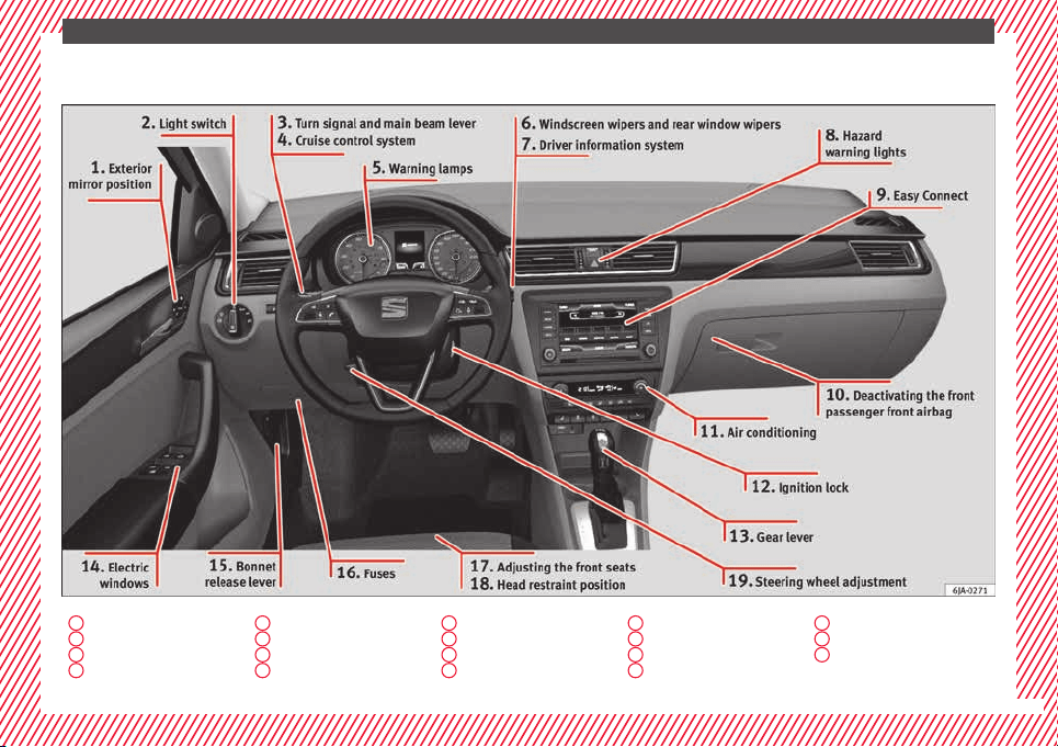
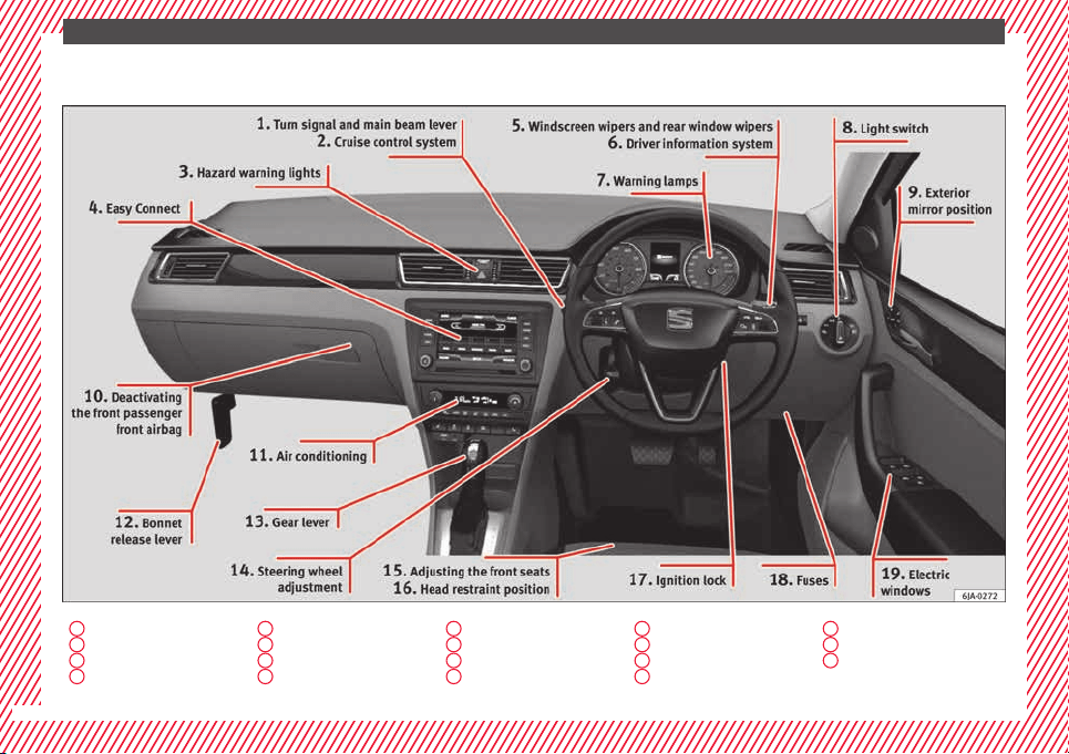
Interior view (right-hand drive)
1
››› page 18
2
››› page 31
3
››› page 19
4
››› page 20
5
››› page 19
6
››› page 22
7
››› page 32
8
››› page 18
9
››› page 13
10
››› page 14
11
››› page 36
12
››› page 11
13
››› page 34
14
››› page 13
15
››› page 11
16
››› page 12
17
››› page 17
18
››› page 43
19
››› page 11
8
The essentials
How it works
Un
loc
k
ing and locking
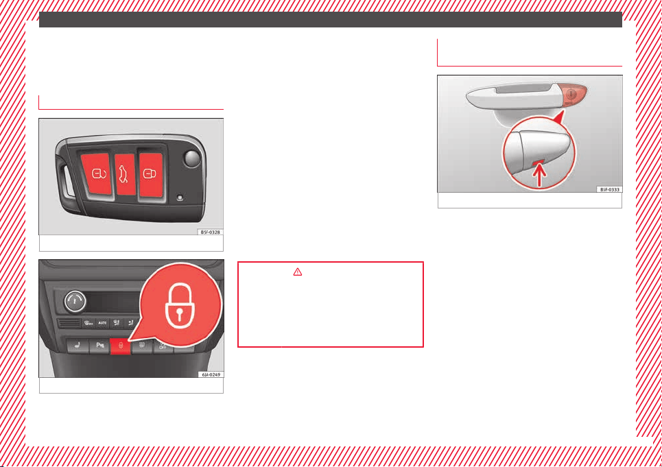
Doors
Fig. 1 Remote control key: buttons.
Fig. 2 See position on page 7-8
Locking and unlocking the vehicle using the
k
ey
●
L
oc
king: press the ››› Fig. 1 button.
●
Unlocking: press the ››› Fig. 1 button.
●
Unlocking the rear lid: press the
››› Fig. 1 button until all the turn signals on
the vehicle briefly light up.
Locking and unlocking with the central lock-
ing switch
●
Locking: press the ››› Fig. 2 button. The
warning lamp on the button will light up.
None of the doors can be opened from the
outside. The doors can be opened from the
inside by pulling the inside door handle.
●
Unlocking: press the ››› Fig. 2 button. The
warning lamp on the button will switch off.
››› in Unlocking and locking the vehicle
on page 110
››› page 109
››› page 9, ››› page 10
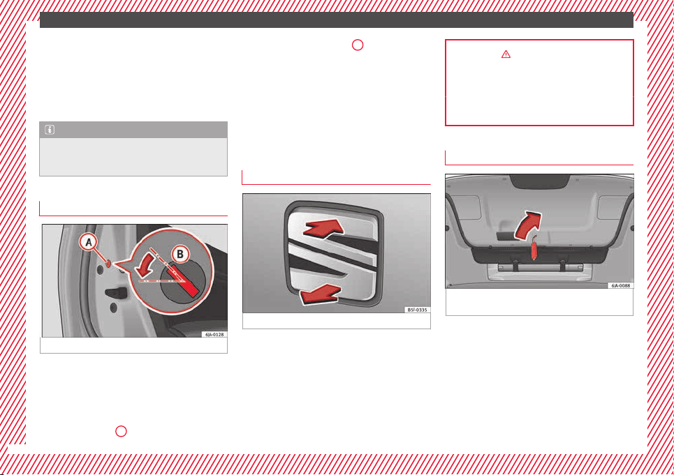
Unlocking and locking the driver's
door
Fig. 3 Driver door lever: hidden lock cylinder.
If the central locking system should fail to op-
er
at
e, the driv
er door can still be locked and
unlocked by turning the key in the lock.
●
Unfold the vehicle key shaft.
●
Insert the key shaft into the lower opening
in the cover on the driver door handle from
below ››› Fig. 3 (arrow) then remove the cover
upwards.
●
Insert the key shaft into the lock cylinder to
unlock or lock the vehicle.
Special Characteristics
●
The anti-theft alarm will remain active when
vehicles are unlocked. However, it is not trig-
gered ›››
page 112.
»
9
The essentials
●
Af
t
er the driv
er door is opened, you have
15 seconds to switch on the ignition. Once
this time has elapsed, the alarm is triggered.
●
Switch the ignition on. The electronic im-
mobilizer recognises a valid vehicle key and
deactivates the anti-theft alarm system.
Note
The anti-theft alarm is not activated when the
vehicl
e is locked manually using the key
shaft ›››
page 112.
Locking manually
Fig. 4 Rear door: manual locking
On the front of a door with no lock cylinder
ther
e i
s
an emergency locking device that is
only visible when the door is open.
Locking
●
Remove the cap
A
›
›
› Fig. 4
.
●
Insert the key in the slot
B
and turn it in
the dir
ection of
the arr
ow until horizontal (on
the other direction on the right-hand door).
●
Replace the cap.
Once the door has been locked, it can no lon-
ger be opened from the outside. The door
can be opened from the inside by pulling the
door handle.
Rear lid
Fig. 5 Rear lid: opening from the outside.
●
Opening the rear lid: Pull on the release
l
ev
er and lif
t it up ››› Fig. 5. The rear lid opens
automatically.
●
Closing the rear lid: Hold it by one of the
handles on the interior lining and close it by
pushing gently.
››› in Rear lid on page 119
››› page 118
››› page 10
Manual release of the rear lid
Fig. 6 Luggage compartment: access to man-
ual
r
el
ease.
The rear lid can be unlocked manually from
in
s
ide in the ev
ent of an emergency.
●
Insert the key in the opening in the lining
of the rear lid and move the key in the direc-
tion of the arrow until the lock is released.
10
The essentials
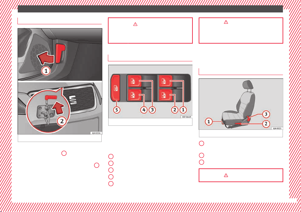
Bonnet
Fig. 7 See position on page 7-8
●
Opening the bonnet: Pull the lever under
the d
a
shbo
ard ››› Fig. 7
1
.
●
Lifting up the bonnet: press the release
c
at
c
h under the bonnet upwards ››› Fig. 7
2
.
The arr
e
s
ter hook under the bonnet is re-
leased.
●
The bonnet can be opened. Release the
bonnet stay and secure it in the fixture de-
signed for this in the bonnet.
››› in Introduction on page 203
››› page 203
Electric windows*
Fig. 8 See position on page 7-8
●
Opening the window: Press the b
utt
on.
●
C
losing the window: Pull the button.
Buttons on the driver door
Window on the front left door
Window on the front right door
Window on the rear left door
Window on the rear right door
Safety switch for deactivating the electric
window buttons in the rear doors.
1
2
3
4
5
››› in Operation of the electric windows
on page 120
››› page 120
Before driving
M
anua
l
ly adjusting the front seats
Fig. 9 Front seats: manual seat adjustment.
Forward/back: pull the lever and move
the se
at
f
orwards or backwards.
Raising/lowering: pull/push the lever.
Tilting the backrest: pull the lever back.
››› in Introduction on page 131
1
2
3
11
The essentials
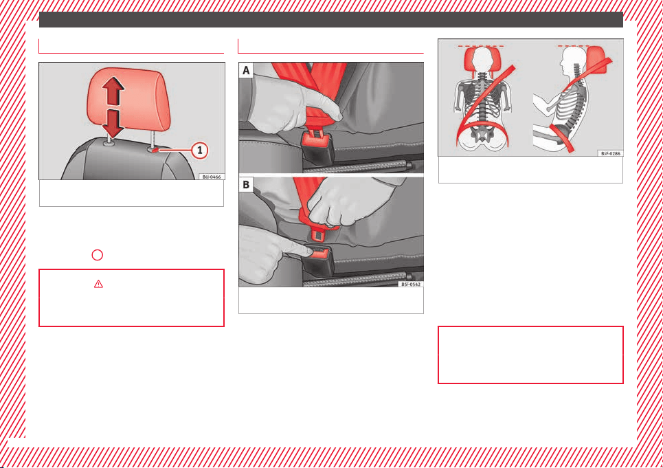
Adjusting the head restraints
Fig. 10 Front seat: adjustment of the head re-
s
tr
aint
.
Grab the sides of the head restraints with
both h
and
s
and push upwards to the desired
position. To lower it, repeat the same action,
pressing the
1
button on the side.
››› in head restraints on page 132
››› page 59, ››› page 132
Adjustment of the seat belt
Fig. 11 Positioning and removing the seat
belt
b
uc
kle.
Fig. 12 Correct seat belt and head restraint
position
s, viewed from front and the side.
To adjust the seat belt around your should-
er
s, a
dju
st the height of the seats.
The shoulder part of the seat belt should be
well centred over it, never over the neck. The
seat belt lies flat and fits comfortably on the
upper part of the body.
The lap part of the seat belt lies across the
pelvis, never across the stomach. The seat
belt lies flat and fits comfortably on the pel-
vis.
››› page 62
››› page 64
12
The essentials
Seat belt tensioners
During a collision, the seat belts on the front
seats ar
e retracted automatically.
The tensioner can be triggered only once.
››› in Service and disposal of belt ten-
sioners on page 66
››› page 65
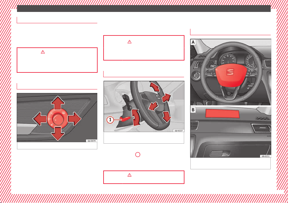
Adjusting the exterior mirrors
Fig. 13 See position on page 7-8
Adjusting the exterior mirrors: Turn the knob
t
o the c
orr
esponding position:
Turning the knob to the desired posi-
tion, adjust the mirrors on the driver
side (L, left) and the passenger side (R,
right) to the direction desired.
L/R
Depending on the equipment fitted on
the vehicle, the mirrors may be heated
according to the outside temperature.
››› in Exterior mirrors on page 130
››› page 130
Adjusting the steering wheel
Fig. 14 Lever in the lower left side of the
s
t
eerin
g column.
Adjusting the position of the steering wheel:
P
u
l
l the ››› Fig. 14
1
lever down, move the
s
t
eerin
g wheel to the desired position and lift
the lever back up until it locks.
››› in Adjusting the steering wheel po-
sition on page 57
Airbags
Fr
ont
airb
ags
Fig. 15 Driver airbag in the steering wheel
and fr
ont
p
assenger airbag in the dash panel
»
13
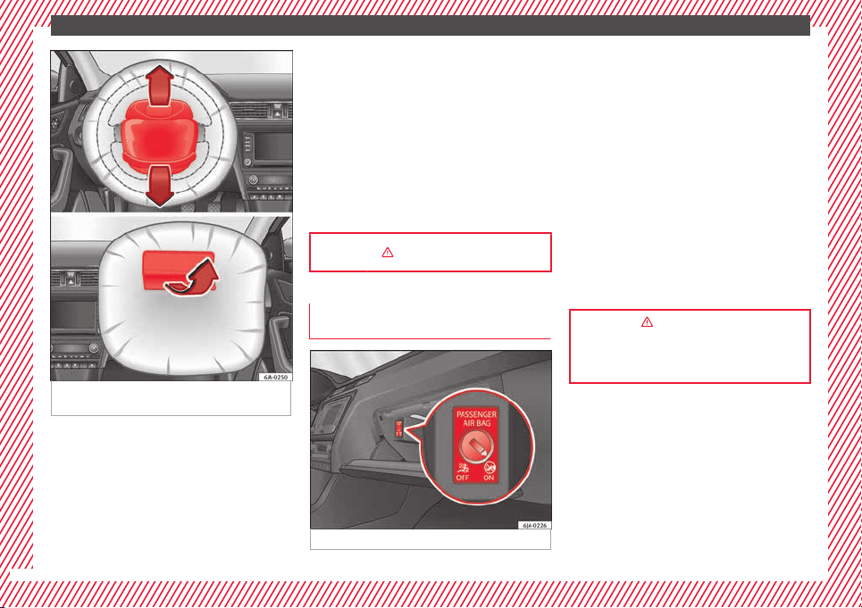
The essentials
Fig. 16 Airbag covers reacting when the front
airb
ag
s
are triggered.
The front airbag for the driver is located in
the s
t
eerin
g wheel
›››
Fig. 15 and the front
passenger airbag is located in the dash pan-
el
›››
Fig. 15 . Airbags are identified by the
word “AIRBAG”.
When the driver and front passenger airbags
are deployed, the covers remain attached to
the steering wheel and dashboard, respec-
tively
›››
Fig. 16.
In conjunction with the seat belts, the front
airbag system gives the driver and the front
passenger additional protection for the head
and chest in the event of a severe frontal col-
lision.
Their special design allows the controlled es-
cape of the propellant gas when an occupant
puts pressure on the bag. Thus, the head and
chest are protected by the airbag. After the
collision, the airbag deflates sufficiently to
allow visibility.
››› in Front airbags on page 69
Deactivating the front passenger front
airb
agde
activ
ating the airbag
Fig. 17 Front passenger front airbag switch.
To deactivate the front passenger front air-
b
ag:
●
Open the glo
v
e compartment on the front
passenger side.
●
Insert the key into the slot provided in the
deactivation switch.
●
Approximately ¾ of the length of the key
remains inserted (the maximum).
●
Turn the key, changing its position to .
Do not force it. If you have difficulty, ensure
that you have inserted the key as far as it will
go.
●
Finally, check the control lamp on the in-
strument panel where it shows
the following should appear .
››› in Front passenger front airbag
switch on page 72
››› page 71
14
The essentials
Side airbags*
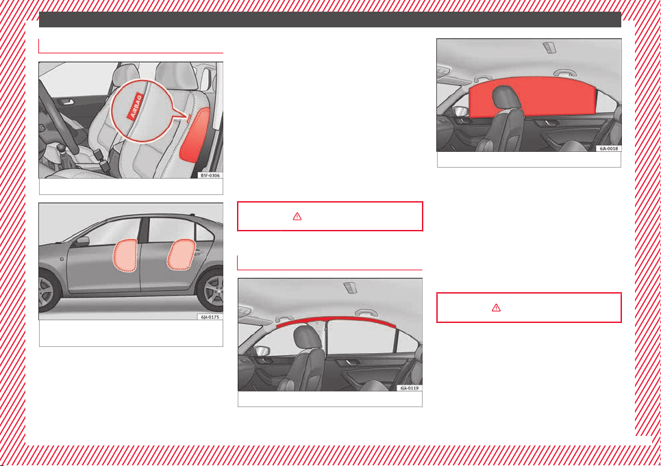
Fig. 18 Side airbag in driver seat.
Fig. 19 Illustration of completely inflated side
airb
ag
s
on the left side of the vehicle.
The side airbags are located in the backrest
c
u
shion
s of the driver seat ››› Fig. 18 and the
front passenger seat as well as in the back-
rest of the side rear seats. The locations are
identified by the text “AIRBAG” in the upper
region of the backrests.
In conjunction with the seat belts, the side
airbag system provides additional protection
for the upper body in the event of a severe
side collision ›››
page 61, The whys
and wherefores of seat belts.
In a side collision, the side airbags reduce
the risk of injury to passengers to the areas
of the body facing the impact. In addition to
their normal function of protecting the occu-
pants in a collision, the front and rear outer
seat belts also hold the passengers in the
event of a side collision; this is how these air-
bags provide maximum protection.
››› in Side airbags* on page 69
Head-protection airbags*
Fig. 20 Location of head-protection airbags.
Fig. 21 Deployed head-protection airbags.
The head-protection airbags are located on
both s
ide
s
in the interior above the doors
››› Fig. 20 and are identified with the text
“AIRBAG”.
In conjunction with the seat belts, the head-
protection airbag system gives the vehicle
occupants additional protection for the head
and upper body in the event of a severe side
collision ››› page 15.
››› in Curtain airbags* on page 70
15
The essentials
Child seats
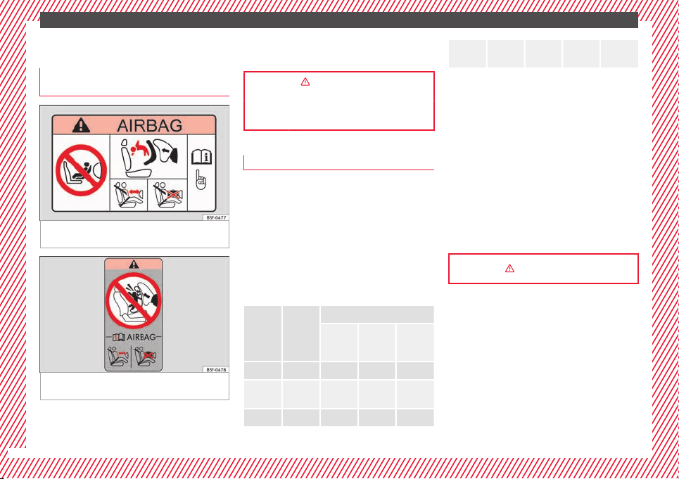
Impor
t
ant
information regarding the
front passenger's airbag
Fig. 22 Passenger's side sun visor: airbag
s
tic
k
er.
Fig. 23 On the rear frame of the passenger
s
ide door: airb
ag s
ticker.
A sticker with important information about
the p
a
s
senger airbag is located on the pas-
senger's sun visor and/or on the passenger
side door frame.
››› in Important information regarding
the front passenger's airbag on page 73
››› page 73
Possible ways to secure child seats
You can secure a child seat to the rear seat or
front p
assenger seat in the following ways:
●
Child seats in groups 0 to 3 c
an be secured
with a seat belt.
●
Child seats for groups 0, 0+ and 1 can be
fastened without seatbelts, using the “ISO-
FIX” and Top Tether* system, using the “ISO-
FIX” and Top Tether* securing rings
››› page 17.
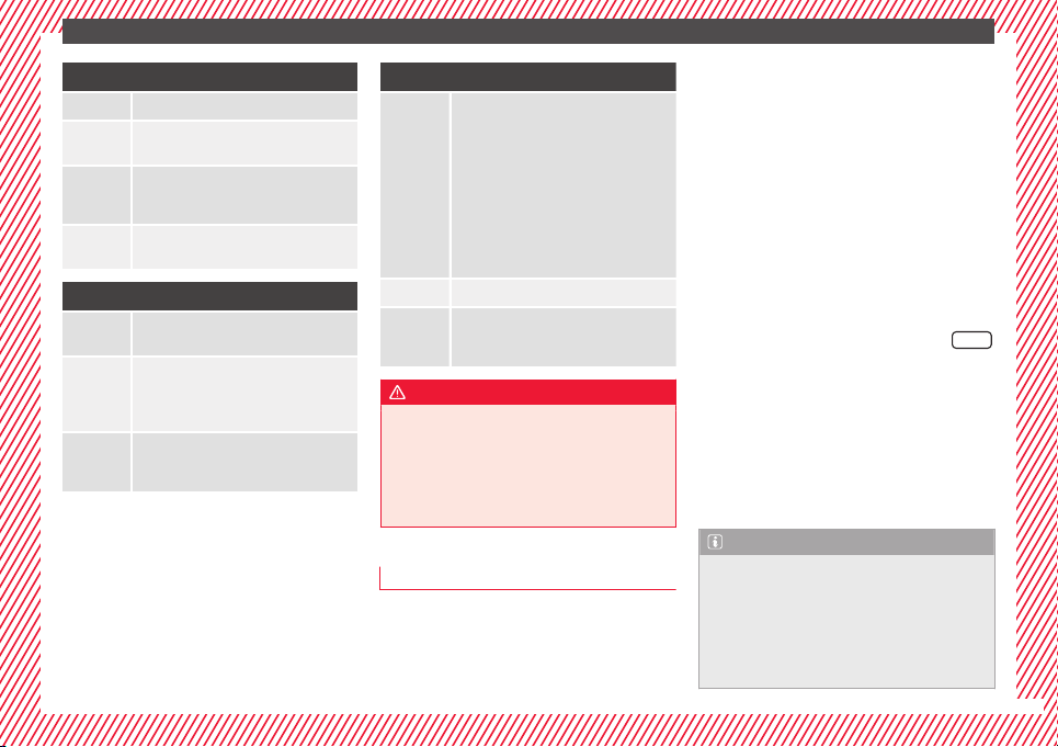
Category Weight
Seat locations
Front
passen-
ger
Rear
outer
Rear
centre
Group 0 <10 kg U* U/L U
Group
0+
<13 kg U* U/L U
Group 1 9-18 kg U* U/L U
Group
2/3
15-36
kg
U* U U
Suitable for universal approved restrain-
ing sys
tems for use in this age category
(universal retention systems are those
fitted using the adult seat belt).
Move the front passenger seat as far
back as possible, as high as possible
and always disable the airbag.
Suitable for retention systems using the
“ISOFIX” and Top Tether* anchors.
The systems include the child restraint sys-
tem mounting with an upper retaining strap
(Top Tether) and lower anchoring points on
the seat.
››› in Safety instructions on page 74
U:
*:
L:
16
The essentials
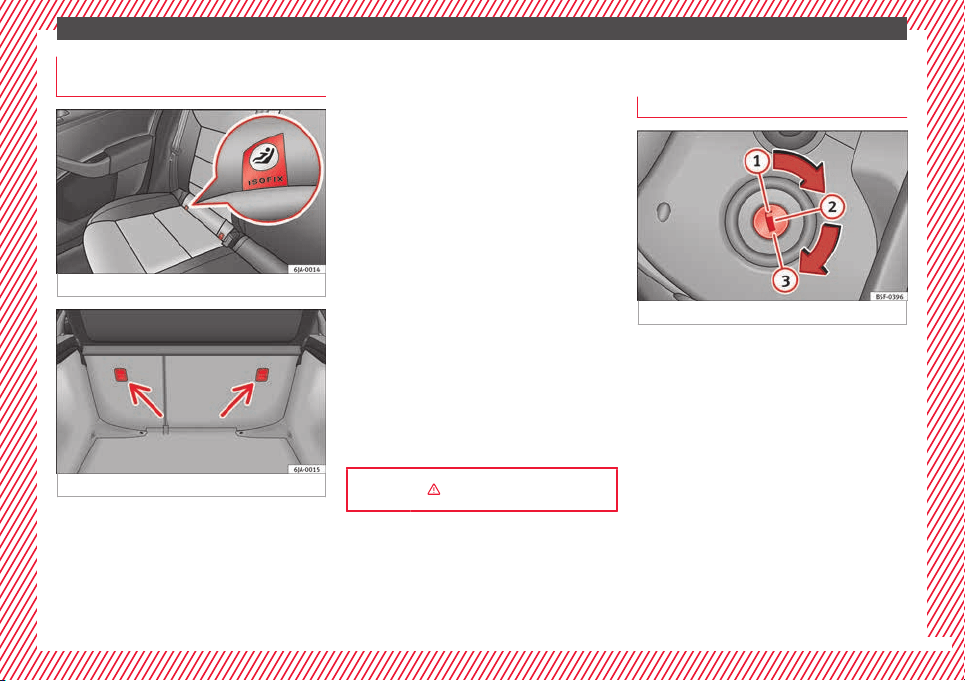
“ISOFIX” and Top Tether child seat
mou
ntin
g sy
stem*
Fig. 24 ISOFIX securing rings.
Fig. 25 Top Tether* securing ring.
Child seats with the “ISOFIX” or Top Tether*
sy
s
t
em can be secured quickly, easily and
safely on the rear outer seats.
When removing or fitting the child seat,
please be sure to follow the manufacturer's
instructions.
●
Move the rear seat as far to the rear as it
will go.
●
Press the child seat onto the “ISOFIX” re-
taining rings until the child seat can be heard
to engage. If the child seat is equipped with
Top Tether* anchor points, secure it to the
correspondent ring. Observe the manufactur-
er's instructions.
●
Pull on both sides of the child seat to en-
sure that it is secure.
Two “ISOFIX” retaining rings are fitted on
each rear seat. In some vehicles, the rings
are secured to the seat frame and, in others,
they are secured to the rear floor. Access to
the “ISOFIX” rings is between the rear seat
backrest and the seat cushioning. The Top
Tether* rings are located at the rear of the
backrests of the rear seats (behind the seat
backrest or in the boot).
Child seats with the “ISOFIX” and Top Tether*
attachment system are available from Techni-
cal Services.
››› in Safety instructions on page 74
Starting the vehicle
Ignition loc
k
Fig. 26 See position on page 7-8
Switch ignition on: Place the key in the igni-
tion and s
t
ar
t the engine.
Locking and unlocking the steering wheel
●
Engaging the steering wheel lock: Remove
the key from the ignition and turn the wheel
until it locks. In vehicles with an automatic
gearbox, the gear lever must be in the P posi-
tion in order to remove the key. If necessary,
press the locking key on the selector lever
and release it again.
●
Unlocking the steering wheel: Put the key
into the ignition and turn it at the same time
as the steering wheel in the direction indica-
ted by the arrow. If it is not possible to turn
the steering wheel, it may be because it is
locked.
»
17
The essentials
Turning on/switching off the ignition, glow
p
lug
s
reheating
●
Switch ignition on: Turn the key to the
2
position.
●
Switch ignition off. Turn the key to the
1
position.
●
Diesel vehicles :
The glo
w p
lugs reheat
when the ignition is switched on
Starting the engine
●
Manual gearbox: press the clutch pedal all
the way down and move the gearbox lever in-
to neutral.
●
Automatic gearbox: Press the brake pedal
and move the selector lever to the P position
or into N.
●
Turn the key to the
3
position. The key au-
t
om
atic
ally returns to the
2
position. Do not
pr
e
s
s the accelerator.
Start-Stop System*
When you stop and release the clutch pedal,
the Start-Stop system* turns off the engine.
The ignition remains switched on.
››› in Introduction on page 153
››› page 153
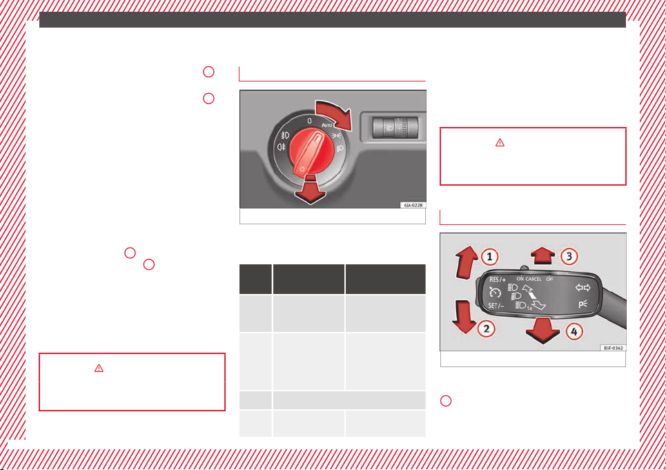
Lights and visibility
Light
sw
it
ch
Fig. 27 See position on page 7-8
Turn the switch to the required position
›
›
›
Fig. 27.
Sym-
bol
Ignition switch-
ed off
Ignition is switch-
ed on
Fog lights, dipped
beam and side
lights off.
Light off or daytime
driving light on.
The “Coming home”
and “Leaving
home” guide lights
may be switched
on.
Automatic control of
dipped beam and day-
time driving light.
Side light on.
Dipped beam head-
light off
Dipped beam switch-
ed on.
Fr
ont fog lights: mo
v
e the switch to the
first position, from positions , or .
Rear fog light: move the switch completely
from positions , or .
Switching off fog lights: Push the switch or
turn it to the position.
››› in Introduction on page 121
››› page 121
Turn signal and main beam lever
Fig. 28 See position on page 7-8
More the lever to the required position:
Right
t
urn s
ignal: Right-hand parking
light (ignition switched off).
1
18
The essentials
Left turn signal: Left-hand parking light
(ignition sw
it
c
hed off).
Main beam switched on: Control lamp
lit up on the instrument panel.
Headlight flasher: lit up when the lever is
pushed. Control lamp lit up.
Lever all the way down to switch it off.
››› page 123
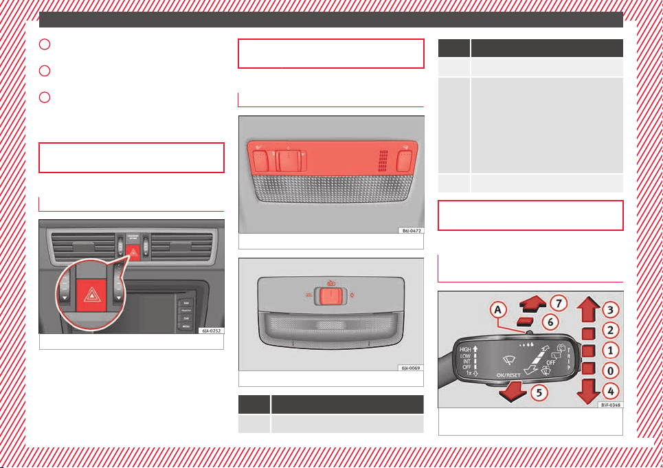
Hazard warning lights
Fig. 29 See position on page 7-8
Switched on, for example:
●
When approaching a traffic jam
●
In an emergency
●
The vehicle has broken down
●
When towing or being towed
2
3
4
››› page 126
Interior lights
Fig. 30 Detail of headliner: version 1
Fig. 31 Detail of headliner: version 2
Knob Function
Switches interior lights off.
Knob Function
Switches interior lights on.
Switches door contact control on (central po-
sition).
The interior lights come on automatically
when the vehicle is unlocked, a door is
opened or the key is removed from the igni-
tion.
The lights go off a few seconds after all the
doors are closed, the vehicle is locked or the
ignition is switched on.
Turning the reading light on and off
››› page 127
Windscreen wipers and window wiper
b
l
a
de
Fig. 32 Operating the windscreen wiper and
r
e
ar w
iper
»
19
The essentials
More the lever to the required position:
0
Windscreen wiper off.
1
Windscreen wipers interval wipe.
Using the control ››› Fig. 32
A
adjust the
interval (vehicles without rain sensor), or
the sensitivity of the rain sensor.
2
Slow wipe.
3
Continuous wipe.
4
Short wipe. Brief press, short clean. Hold
the lever down for more time to increase
the wipe frequency.
More the lever to the required position:
5
Automatic wipe. The windscreen washer
function is activated by pushing the lever
forwards, and simultaneously the wind-
screen wipers start.
6
Interval wipe for rear window. The wiper
will wipe the window approximately every
six seconds.
7
The rear window wash function is activa-
ted by pressing the lever, and the rear wip-
er starts simultaneously.
››› in Introduction on page 129
››› page 129
››› page 53
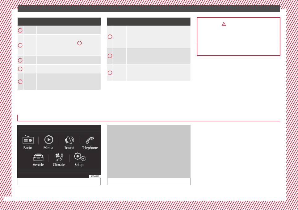
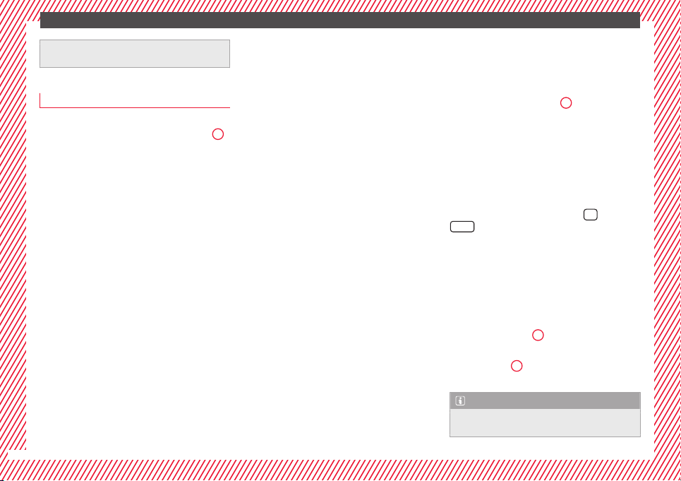
Easy Connect
CAR menu settin
g
s
(Setup)
Fig. 33 See position on page 7-8
Fig. 34 See position on page 7-8
20
The essentials
To select the settings menus, press the Easy
C
onnect
button and the
Set
up
function
b
utt
on.
The act
ual number of menus available and
the name of the various options in these me-
nus will depend on the vehicle’s electronics
and equipment.
●
Switch the ignition on.
●
If the Infotainment System is off, switch it
on.
●
Press the system's
MENU
button and then
the sy
s
t
em's
›
›› Fig. 33
b
utton or
but-
t
on t
o g
o to the CAR menu ››› Fig. 34.
●
Press the function button
Setup
to open the
menu Vehicle settings ›
›
›
Fig. 34.
●
To select a function in the menu, press the
desired button.
When you press the menu button, the last se-
lected menu will always be displayed.
When the function button check box is activa-
ted , the function is active.
Any changes made using the settings menus
are automatically saved on closing the
BACK
menus.
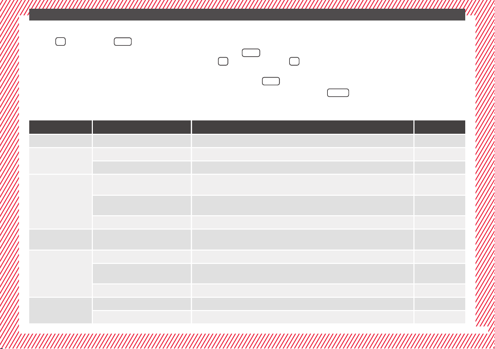
Menu Submenu Possible setting Description
ESC system – Activation of the Electronic Stability Programme (ESC) ››› page 167
Tyres
Tyre pressure monitoring Tyre pressure storing (Calibration) ››› page 219
Winter tyres Activation and deactivation of the speed warning. Setting the speed warning value ››› page 219
Driver assistance
Front Assist (monitoring sys-
tem)
Activation/deactivation: monitoring system, pre-warning, distance warning display ››› page 177
City emergency braking func-
tion
Activation/deactivation of the City emergency braking function. ››› page 181
Tiredness detection Activation/deactivation ››› page 184
Parking and ma-
noeuvring
ParkPilot
Automatically activate, front volume, front sound settings, rear volume, rear sound settings,
adjust volume
››› page 168
Vehicle lights
Vehicle interior lighting Instrument and switch lighting, footrest lighting ››› page 127
Coming home/Leaving home
function
Start time for “Coming home” function, start time for “Leaving home” function ››› page 125
Daytime driving light Activation/deactivation ››› page 122
Mirrors/wind‐
screen wipers
Rear vision mirrors Synchronised regulation, lower the rear-view mirror when reversing, fold in after parking ››› page 130
Windscreen wipers Automatic windscreen wipers, wipe when reversing ››› page 129
»
21

The essentials
Menu Submenu Possible setting Description
Opening and clos-
ing
Radio-operated remote control Convenience open function ››› page 109
Central locking system Unlocking doors, automatic locking/unlocking, audible confirmation ››› page 112
Multifunction
display
–
Current consumption, average consumption, volume to fill up, convenience equipment,
ECOAdvice, journey duration, distance travelled, digital speed display, average speed,
speeding warning, oil temperature, coolant temperature, restore data “from start”, restore
data “total calculation”
››› page 22
Date and time –
Time source, set the time, automatic summer time setting, select time zone, time format, set
the date, date format
–
Measurement units – Distance, speed, temperature, volume, consumption –
Service – Chassis number, date of next SEAT service inspection, date of next oil change service ››› page 30
Factory settings –
All settings can be reset: driver assistance, parking and manoeuvring, lights, rear view mir-
rors and windscreen wipers, opening and closing, multi-function display
–
››› in CAR menu (Setup) on page 104
››› page 104
Driver information system
Intr
oduction
With the ignition switched on, it is possible
to re
ad the different functions of the display
by scrolling through the menus.
In vehicles with multifunction steering wheel,
the multifu
nction display can only be operat-
ed with the steering wheel buttons.
The number of menus displayed on the in-
strument panel will vary according to the ve-
hicle electronics and equipment.
A specialised workshop will be able to pro-
gramme or modify additional functions, ac-
cording to the vehicle equipment. SEAT rec-
ommends visiting a SEAT Official Service.
Some menu options can only be read when
the vehicle is at a standstill.
As long as a priority 1 warning is displayed, it
will not be possible to read the menus. Some
warning messages can be confirmed and
made to disappear with the windscreen wiper
lever button or the multifunction steering
wheel button.
The information system also provides the fol-
lowing information and displays (depending
on the vehicle's equipment):
Driving data ››› page 26
■
Vehicle status
■
MFD from departure
■
MFD from refuelling
■
MFD total calculation
Assist systems ››› table on page 24
■
Reverse (optional)
22
The essentials
Navigation ›
›› Book
l
et Navigation system
Audio ››› Booklet Radio or ››› Booklet Naviga-
tion system
Telephone ››› Booklet Radio or ››› Book-
let Navigation system
Vehicle ››› table on page 24
WARNING
Any distraction may lead to an accident, with
the risk of
injury.
●
Do not operate the instrument panel con-
trols when driving.
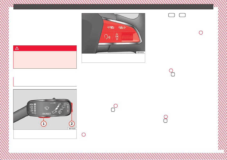
Operating the instrument panel me-
nu
s
Fig. 35 Windscreen wiper lever: control but-
t
on
s.
Fig. 36 Right side of multifunction steering
wheel: contro
l buttons.
The driver information system is controlled
w
ith the mu
ltif
unction steering wheel buttons
››› Fig. 36 or with the windscreen wiper lever
››› Fig. 35 (if the vehicle is not equipped with
multifunction steering wheel).
Enabling the main menu
●
Switch the ignition on.
●
If a message or vehicle pictogram appears,
press button ››› Fig. 35
1
on the windscreen
w
iper l
ev
er or button
on the multifunction
s
t
eerin
g wheel ››› Fig. 36.
●
If managed from the windscreen wiper lev-
er: to display the main screen ››› page 24 or
to return to the main menu from another
menu hold down the rocker button ››› Fig. 35
2
.
●
If managed from the multifunction steering
wheel:
the main menu list is not displayed.
To go from point to point in the main menu,
press button
or
several times
›
›
›
Fig. 36.
Select a submenu
●
Press the rocker switch ››› Fig. 35
2
on the
w
ind
s
creen wiper lever up or down or turn
the thumbwheel of the multifunction steering
wheel ››› Fig. 36 until the desired option ap-
pears marked on the menu.
●
The selected option is displayed between
two horizontal lines. In addition, a triangle is
displayed on the right:
●
To consult the submenu option, press but-
ton ››› Fig. 35
1
on the windscreen wiper
l
ev
er or b
utton
on the multifunction steer-
in
g wheel
›
›› Fig. 36.
Making changes according to the menu
●
With the rocker switch on the windscreen
wiper lever or the thumbwheel of the multi-
function steering wheel, make the desired
changes. To increase or decrease the values
more quickly, turn the thumbwheel faster.
●
Mark or confirm the selection with button
››› Fig. 35
1
on the windscreen wiper lever
or b
utt
on
on the multifunction steering
wheel
›
›
› Fig. 36.
23
The essentials
Menu
Menu Function
Driving
data
Information and possible configurations
of the multifunction display (MFD)
››› page 26, ››› page 104.
Assist
systems
Information and possible configurations
of the driver assistance systems
››› page 104.
Naviga-
tion
Information instructions from the activa-
ted navigation system: when a route guid-
ance is activated, the turning arrows and
proximity bars are displayed. The appear-
ance is similar to the Easy Connect sys-
tem.
If route guidance is not activated, the di-
rection of travel (compass) and the name
of the street along which you are driving
are shown ››› Booklet Navigation system.
Audio
Station display on the radio.
Track name on the CD.
Track name in Media mode ››› Booklet Ra-
dio or ››› Booklet Navigation system.
Tele-
phone
Information and possible configurations
of the mobile phone preinstallation
››› Booklet Radio or ››› Booklet Navigation
system.
Lap tim-
er*
In a racing circuit, measurement and
memorisation of lap times by the vehicle
and comparison with previously measured
best times ››› page 28.
Menu Function
Vehicle
status
Display of the current warning or informa-
tion texts and other system components,
depending on the equipment
››› page 104.
Outside temperature display
When the outside temperature is below +4°C
(+39°F), the symbol
“ice crystal” (warning of
risk of freezing) is also displayed. At first, this
symbol flashes and then it remains lit until
the outside temperature rises above +6°C
(+43°F)
›››
in Indications on the display on
p
ag
e 96
.
When the vehicle is at a standstill or when
travelling at very low speeds, the tempera-
ture displayed may be higher than the true
outside temperature as a result of the heat
produced by the engine.
The temperatures measured range from
-40°C to +50°C (-40°F to +122°F).
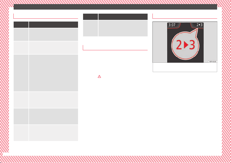
Gear-change indicator
Fig. 37 Instrument panel: gear-change indica-
t
or (m
anual
gearbox).
A gear change will be recommended if the
g
e
ar
you are in is not the most economical
choice. If no gear-change is recommended, it
means that you are already in the most eco-
nomical gear.
Vehicles with a manual gearbox
The following display symbols ››› Fig. 37
mean:
●
Change to a higher gear: the suggested
g
ear appears to the right of the current gear
when a higher gear is recommended.
●
Change to a lower gear: the suggested
gear appears to the left of the current gear
when a lower gear is recommended.
The gear recommendation may occasionally
skip a gear (2nd 4th).
24
The essentials
Vehicles with an automatic gearbox*
The di
s
p
lay is only visible in tiptronic mode
›››
page 161.
The following display symbols mean:
●
Shifting up a gear
●
Shifting down a gear
CAUTION
The gear-change indicator is intended to help
save f
uel, but it is not intended to recom-
mend the right gear for all driving situations.
In certain situations, only the driver can
choose the correct gear (for instance when
overtaking, driving up a steep gradient or
towing a trailer).
Note
The display disappears from the instrument
panel when
you press the clutch pedal.
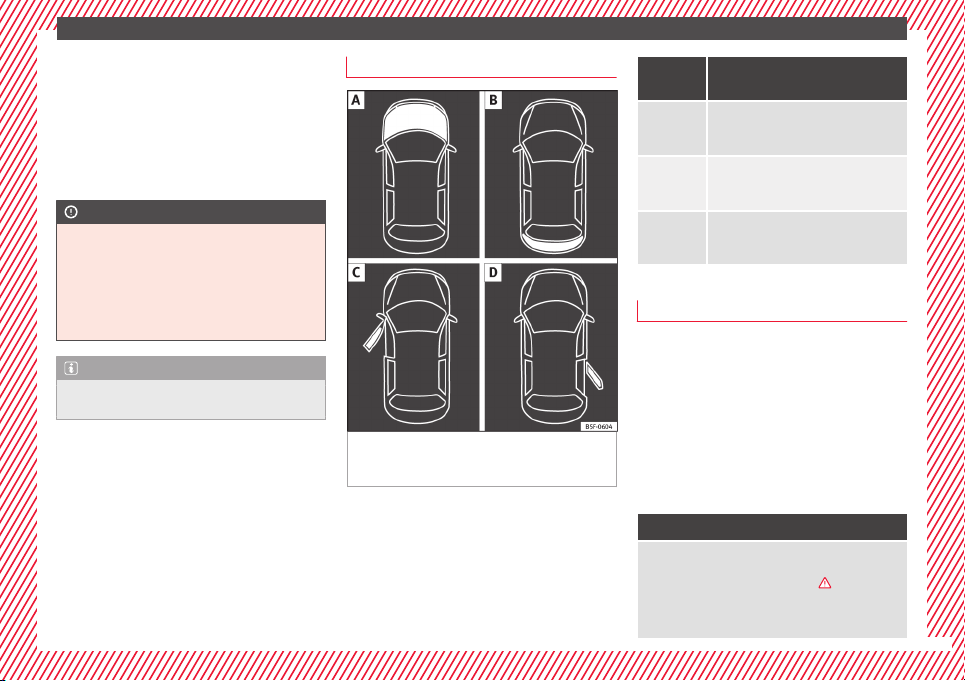
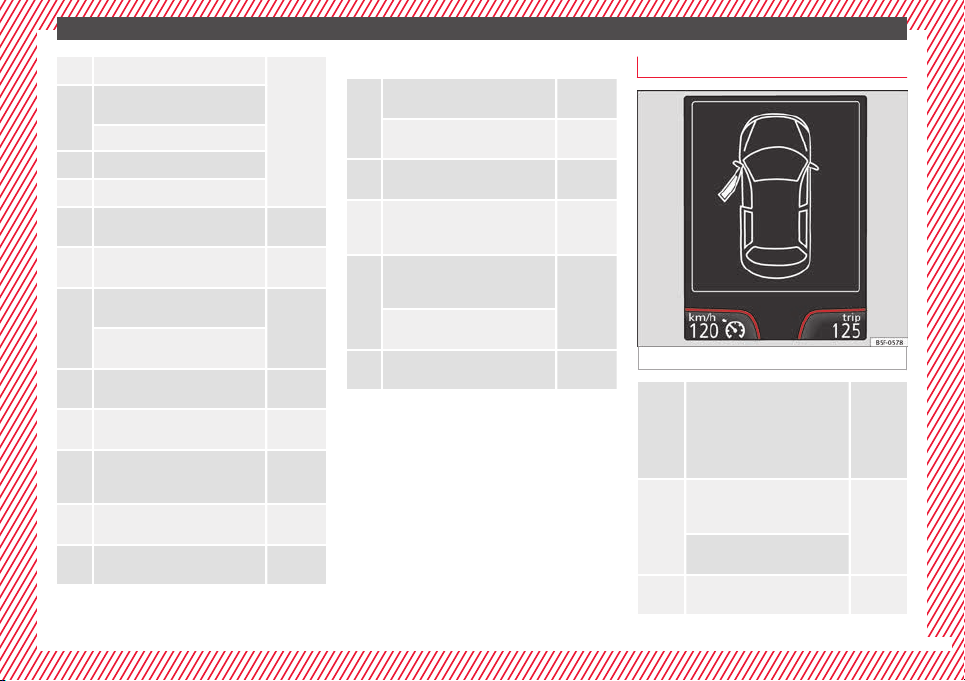
Bonnet, rear lid and doors open
Fig. 38 A: bonnet open; B: rear lid open; C:
fr
ont
l
eft door open; D: rear right door open
(5-door vehicles only).
When the ignition is switched on or when
driv
in
g, the bonnet, r
ear lid or doors that are
open will be indicated on the instrument pan-
el display, and, as applicable, this will be in-
dicated audibly. The display may vary accord-
ing to the type of instrument panel fitted.
Illustra-
tion
Key to ››› Fig. 38
A
Do not continue driving!
The bonnet is open or is not properly
closed ››› page 203.
B
Do not continue driving!
The rear lid is open or is not properly
closed ››› page 10.
C, D
Do not continue driving!
A vehicle door is open or is not properly
closed ››› page 112.
Warning and information messages
The system runs a check on certain compo-
nents
and f
u
nctions when the ignition is
switched on and while the vehicle is moving.
Faults in the operation are displayed on the
screen using red and yellow symbols and
messages on the instrument panel display
(››› page 32, ››› page 32) and, in some ca-
ses, with audible warnings. The display may
vary according to the type of instrument pan-
el fitted.
Priority 1 warning (red symbols)
Symbol flashing or lit; partly combined with audible
warnings.
Stop the vehicle! It is dangerous ››› in Warning
and indication lamps on page 98 !
Check the function that is faulty and repair it. If necessa-
ry, request assistance from specialised personnel.
»
25
The essentials
Priority 2 warning (yellow symbols)
Symbol flashing or lit; partly combined with audible
warnings.
A faulty function, or fluids which are below the correct
levels may cause damage to the vehicle! ›››
in Warn-
ing and indication lamps on page 99
Check the faulty function as soon as possible. If neces-
sary, request assistance from specialised personnel.
Informative text
Information relating to different vehicle processes.
Submenu Assist systems
Assist
systems
menu
Function
Front As-
sist
Switching the monitoring system on
and off ››› page 177.
Tiredness
detection*
Switching the tiredness detection on
or off (pause recommendation)
››› page 184.
Journey data
M
emor
y
The MFD (multifunction display) shows differ-
ent v
alues for the journey and the consump-
tion.
Changing between display modes on the
MFD
●
In vehicles without multifunction steering
wheel: Press the rocker switch
on the
winds
creen wiper lever
›››
Fig. 35.
●
Vehicles with a multifunction steering
wheel:
turn the thumbwheel
›››
Fig. 36.
Multifunction display memory
The multifunction display is equipped with
three memories that work automatically: MFD
from departure, MFD from refuelling and MFD
total calculation. On the screen display, you
can read which memory is currently dis-
played.
●
Toggle between memories with the ignition
on and the memory displayed: Press the
button on the windscreen wiper lever
or the
button of the multifunction steering
wheel
.
Menu Function
MFD from
departure
Display and storage of the values for
the journey and the consumption from
when the ignition is switched on to
when it is switched off.
If the journey is continued in less than
2 hours after the ignition is switched
off, the new data is added to the data
already stored in the memory. The
memory will automatically be deleted if
the journey is interrupted for more than
2 hours.
MFD from
refuelling
Display and storage of the values for
the journey and the consumption. By
refuelling, the memory will be erased
automatically.
MFD total
calcula-
tion
The memory records the values for a
specific number of partial trips, up to a
total of 19 hours and 59 minutes or 99
hours and 59 minutes, or 1999.9 km or
9999 km, depending on the model of
instrument panel. On reaching either of
these limits
a)
, the memory is automati-
cally erased and starts to count from 0
again.
a)
It varies according to the instrument panel version.
Erasing a memory manually
●
Select the memory that you wish to erase.
●
Hold the
button of the multifunction
s
t
eerin
g wheel or the
button of the multi-
f
u
nction wheel
pressed down for about 2 sec-
onds.
26
The essentials
Personalising the displays
In the E
a
sy
Connect system you can adjust
which of the possible displays of the MFD can
be shown on the instrument panel display
with the button
and the function button
Set
up
›
››
p
age 104.
Dat
a summary
Menu Function
Current fuel
consumption
The current fuel consumption dis-
play operates throughout the jour-
ney, in litres/100 km; and with the
engine running and the vehicle
stopped, in litres/hour.
Average fuel
consumption
After turning on the ignition, aver-
age fuel consumption in li-
tres/100 km will be displayed after
travelling about 100 metres. Other-
wise horizontal lines are displayed.
The value shown is updated approxi-
mately every 5 seconds.
ACT
®
*: Depending on the equip-
ment, number of active cylinders.
Operating
range
Approximate distance in km that can
still be travelled with the fuel re-
maining in the tank, assuming the
same style of driving is maintained.
This is calculated using the current
fuel consumption.
Menu Function
Journey du-
ration
This indicates the hours (h) and mi-
nutes (min) since the ignition was
switched on.
Distance
covered
Distance covered in km (m) after
switching on the ignition.
Average
speed
The average speed will be shown af-
ter a distance of about 100 metres
has been travelled. Otherwise hori-
zontal lines are displayed. The value
shown is updated approximately ev-
ery 5 seconds.
Digital dis-
play of
speed
Current speed displayed in digital
format.
Speed warn-
ing at ---
km/h or Speed
warning at
--- mph
If the stored speed is exceeded (be-
tween 30 - 250 km/h, or 19 -
155 mph), an audible warning is
given together with a visual warn-
ing.
Oil tempera-
ture
Updated engine oil temperature dig-
ital display
Coolant tem-
perature
gauge
Digital display of the current temper-
ature of the liquid coolant.
Storing a speed with the speed warning
●
Select the display Speed warning at
---
km/h (---
mph)
●
Press the button
on the windscreen
w
iper l
ev
er or the button
on the multifunc-
tion steering wheel to store the current speed
and activ
at
e the w
arning.
●
To switch system on: adjust to the desired
speed within 5 seconds using the rocker
switch
on the windscreen wiper lever or
b
y
t
urning the thumbwheel on the multifunc-
tion steering wheel. Next, press the button
or
again or wait several seconds.
The s
peed i
s
stored and the warning activa-
ted.
●
To switch system off: press the but-
ton
or
. The stored speed is de-
l
et
ed.
En
gine oil temperature display
Vehicles without multifunction steering
wheel
●
Press the rocker switch ›
›
›
Fig. 35
2
until
the m
ain menu ap
pe
ars. Enter into Journey
data. With the button
2
move to the oil
t
emper
at
ure gauge.
Vehicles with multifunction steering wheel
●
Enter the submenu Journey data and
turn the thumbwheel until the oil tempera-
ture display appears.
The engine reaches its operating temperature
when in normal driving conditions, the oil
temperature is between 80°C (180°F) and
120°C (250°F). If the engine is required to
»
27
The essentials
work hard and the outside temperature is
high, the en
gine oi
l
temperature can in-
crease. This does not present any problem as
long as the warning lamps ››› table on
page 33 or ››› table on page 33 do not
appear on the display.
Additional electrical appliances
●
Operation with the windscreen wiper lever*:
Pres
s the rocker switch ››› Fig. 35
2
until the
main menu appe
ars. Enter into the section
Journey data. With the rocker switch,
move to the display Convenience appli-
ances.
●
Operation with the multi-function steering
wheel*:
Move with the buttons
1
or
2
to
Journey data and ent
er w
ith
OK. Turn the
thumbwheel to the right until the Conven-
ience appliances display appears.
In addition, a scale will inform you of the cur-
rent sum of all the additional appliances.
Saving tips
Tips on how to save fuel will be displayed in
c
ondition
s
that increase fuel consumption.
Follow them to reduce consumption. The indi-
cations appear automatically only with the ef-
ficiency programme. After a time, the tips will
disappear automatically.
If you wish to hide a saving tip immediately
after it appears, press any button on the
windscreen wiper lever*/multifunction steer-
ing wheel*.
Note
●
If y
ou hide a saving tip, it will reappear af-
ter you switch the ignition on again.
●
The saving tips do not appear in all situa-
tions, but rather with a large separation of
time.
Timer*
You can access the timer via the selection
menu
›
›
›
page 24.
It allows you to manually time lap times on a
racing circuit, memorise them and compare
them to the vehicle's previous best times.
The following menus can be displayed:
●
Stop
●
Lap
●
Pause
●
Partial time
●
Statistics
Change from one menu to another
●
Vehicles without multifunction steering
wheel: press the rocker switch
in the
w
ind
s
creen wiper lever.
●
Vehicles with multifunction steering wheel:
press
or
.
Menu “Stop”
Start
The timer starts.
If there are existing laps and they are in-
cluded in the statistics, it will begin with
the number of laps in question.
It is only possible to begin with a new first
lap if the statistics have been reset first in
the Statistics menu.
Since
start
The timer begins when the vehicle sets
off.
If the vehicle is already moving, the timer
begins once the vehicle has stopped.
Statis-
tics
The Statistics menu is displayed on
the screen.
Menu “Lap”
New lap
The timer of the current lap stops and a
new lap starts immediately. The time for
the lap you have just completed is inclu-
ded in the statistics.
Partial
time
For about 5 seconds a partial time is dis-
played. The timer continues in parallel.
Stop
The current lap timer will be interrupted.
The lap does not end. The Pause menu is
displayed.
28
The essentials
Menu “Pause”
Continue The interrupted timer continues.
New lap
A new timer starts. The halted lap ends
and is included in the statistics.
Interr.
lap
The timer of the current lap ends and is
cancelled. It is not included in the statis-
tics.
End
The current timer ends. The lap is inclu-
ded in the statistics.
Menu “Partial time”
Partial
time
For about 5 seconds a partial time is dis-
played. The timer continues in parallel.
New lap
The timer of the current lap stops and a
new lap starts immediately. The time for
the lap you have just completed is inclu-
ded in the statistics.
Stop
The current lap timer will be interrupted.
The lap does not end. The Pause menu is
displayed.
Menu “Statistics”
View of the latest lap times:
– total time
– best lap time
– worst lap time
– average lap duration
A maximum of 10 laps is possible, and a
total duration of 99 hours, 59 minutes
and 59 seconds.
If one of the 2 limits is reached, you will
have to reset the statistics in order to be-
gin a new timer.
Back This returns to the previous menu.
Reset-
ting to
zero
All the memorised statistical data are re-
set.
WARNING
Do your best to avoid handling the timer
while driv
ing.
●
Only set the timer or consult statistics
when the vehicle is stationary.
●
While driving, do not handle the timer in
complicated driving situations.
Speed warning device
The speed warning device warns the driver
when they
h
av
e exceeded the pre-set speed
limit by 3 km/h. An audible warning is given
and the lamp
can be seen simultaneously
on the instrument panel, as well as a mes-
sage for the driver: speed warning ex-
ceeded! The warning lamp switches off
when reducing speed below the stored maxi-
mum limit.
Speed warning programming is recommen-
ded if you wish to be reminded of a maxi-
mum speed, such as when travelling in a
country with different speed limits or for a
maximum speed for winter tyres.
Setting speed limit warning
You can use the radio or the Easy Connect* to
set, alter or cancel the speed limit warning.
●
Vehicles with radio: press the button
SETUP
> control button Driver Assistant >
Speed warning.
●
Vehicles with Easy Connect: pr
e
s
s the but-
ton Systems or else Vehicle systems >
Driver assistant > Speed warning.
The warning limit can be set from 30 to
240 km/h (20 to 150 mph). The adjustment
is done in 10 km/h (mph) intervals.
Note
●
Plea
se bear in mind that, even with the
speed warning function, it is still important
to keep an eye on the vehicle speed with the
speedometer and to observe the legal speed
limits.
●
The speed limit warning function in the ver-
sion for several countries warns you at a
»
29
The essentials
speed of 120 km/h (80 mph). This is a facto-
ry-
set speed limit.
Service intervals
The service interval indication appears on the
instrument
panel display ›››
Fig. 110
4
.
SEAT di
stinguishes between services with en-
gine oil change (e.g. Oil change service) and
services without engine oil change (e.g. In-
spection).
In vehicles with Services established by time
or mileage, the service intervals are already
pre-defined.
In vehicles with LongLife Service, the inter-
vals are determined individually. Thanks to
technological progress, maintenance work
has been greatly reduced. Because of the
technology used by SEAT, with this service
you only need to change the oil when the ve-
hicle so requires. To calculate this change
(max. 2 years), the vehicle's conditions of
use and individual driving styles are consid-
ered. The pre-warning first appears 20 days
before the date established for the corre-
sponding service. The kilometres (miles) re-
maining until the next service are always
rounded up to the nearest 100 km (miles)
and the time is given in complete days. The
current service message cannot be viewed
until 500 km after the last service. Prior to
this, only
lines are visible on the display.
Inspection reminder
When the Service date is approaching, when
the ignition is switched on a Service remind-
er is displayed.
Vehicles without text messages: a span-
ner will be displayed on the instrument
panel plus an indication in km.
The kilometres indicated are the maximum
number of kilometres that can be travelled
until the next service. After a few seconds,
the display mode changes. A clock symbol
appears and the number of days until the
next service is due.
Vehicles with text messages: Service in
--- km or --- days will be shown on the
instrument panel display.
Service due
When the service date is due, an audible
warning is given when the ignition is switch-
ed on and the spanner displayed on the
screen flashes for a few seconds.
Vehicles with text messages: Service now
will be shown on the instrument panel dis-
play.
Reading a service notification
With the ignition switched on, the engine off
and the vehicle at a standstill, the current
service notification can be read:
Press and hold the button
4
for more than 5
sec
ond
s
to consult the service message.
When the service date has passed, a minus
sign is displayed in front of the number of kil-
ometres or days.
Vehicles with text messages: Service
since --- km or --- days ago.will be
shown on the display.
The time can also be set via the
key and
Set
up
function button in the Easy Connect
sy
s
t
em ›››
page 104.
Resetting service interval display
If the service was not carried out by a SEAT
dealership, the display can be reset as fol-
lows:
●
Switch off the ignition, press and hold but-
ton ›››
Fig. 110
4
.
●
Switch ignition back on.
●
Release THE
4
›
›
›
Fig. 110
button and
press it again for the next 20 seconds.
Note
●
The servic
e message disappears after a few
seconds, when the engine is started or when
30
The essentials
OK/RESET
is pressed on the windscreen wiper
lever
, or
OK
on the multifunction steering
wheel.
●
In v
ehicles with the LongLife system in
which the battery has been disconnected for
a long period of time, it is not possible to cal-
culate the date of the next service. Therefore
the service interval display may not be cor-
rect. In this case, bear in mind the maximum
service intervals permitted in the ››› Book-
let Maintenance Programme.
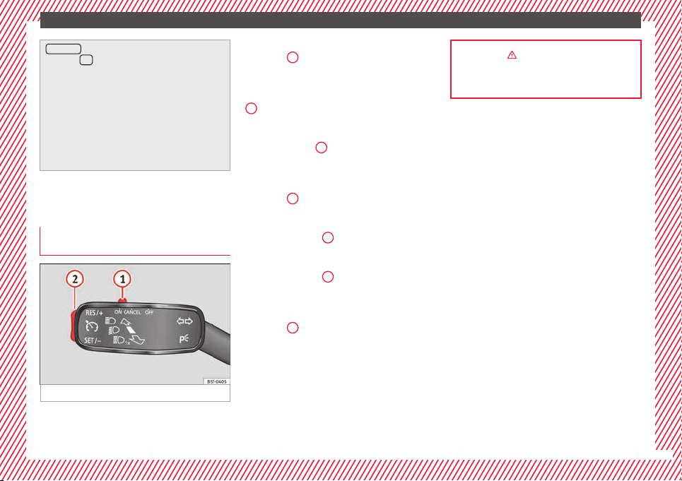
Cruise control
Oper
atin
g the c
ruise control system
(CCS)*
Fig. 39 See position on page 7-8
●
Sw
it
c
hing on the CCS: Move switch
››› Fig. 39
1
to .
The system is on. If no
s
peed h
as been programmed, the system will
not control it.
●
Activating the CCS: Press button ››› Fig. 39
2
in the ar
e
a.
The current speed is
memorised and controlled.
●
Temporarily switching off the CCS: Move
switch ››› Fig. 39
1
to
or push the
br
ak
e. The cruise control system is switched
off temporarily.
●
Reactivating the CCS: Press button
››› Fig. 39
2
in
. The memorised speed
i
s saved and controlled again.
●
Increasing stored speed during CCS regula-
tion: press button
2
in
. The vehicle ac-
c
elerates until the new stored speed.
●
Reducing stored speed during CCS regula-
tion: press button
2
in t
o lower the
s
peed b
y 1 km/h (1 mph). Speed is reduced
until reaching the new stored speed.
●
Switching off the CCS: Move switch
››› Fig. 39
1
to .
The system is disconnec-
t
ed and the memori
sed speed is deleted.
››› in Introduction on page 176
››› page 176
31
The essentials
Warning lamps
On the in
s
trument
panel
Fig. 40 See position on page 7-8
Red warning lamps
Central warning lamp: additional
information on the instrument pan-
el display
–
Parking brake on.
››› page
99
››› page
99
Do not continue driving!
The brake fluid level is too low or
there is a fault in the brake system.
Lit up or flashing:
Do not continue driving!
Fault in the steering.
››› page
100
Driver or passenger has not fas-
tened seat belt.
››› page
99
Use the foot brake!
Yellow warning lamps
Central warning lamp: additional
information on the instrument pan-
el display
–
32
The essentials
Front brake pads worn.
››› page
167
it lights up: Fault in the ESC, or dis-
connection caused by the system.
flashes: ESC or ASR activated.
ASR manually deactivated.
ABS faulty or does not work.
Rear fog light switched on.
››› page
18
lights up or flashes: fault in the
emission control system.
››› page
101
it lights up: pre-ignition of diesel
engine.
››› page
102
flashes: fault in the diesel engine
management.
fault in the petrol engine manage-
ment.
››› page
102
lights up or flashes: fault in the
steering system.
››› page
100
Tyre pressure too low, or fault in
the tyre pressure monitoring sys-
tem.
››› page
103
Fuel tank almost empty.
››› page
102
Fault in airbag system and seat
belt tensioners.
››› page
66
Other warning lamps
Left or right turn signal.
››› page
18
Hazard warning lights on.
››› page
126
Trailer turn signals
››› page
185
it lights up: Press the foot brake!
flashes: the selector lever locking
button has not engaged.
››› page
158
it lights up: cruise control activated
or speed limiter switched on and
active.
››› page
31
flashes: the speed set by the
speed limiter has been exceeded.
Main beam on or flasher on.
››› page
18
On the instrument panel display
Fig. 41 See position on page 7-8
Do not continue driving!
With the corresponding indica-
tion: door(s), rear lid or bonnet
open or not properly closed.
››› page
99
››› page
10
››› page
203
Ignition:
Do not carry on driv-
ing! Engine coolant level too low,
coolant temperature too high
››› page
100
Flashing: Fault in the engine
coolant system.
Do not continue driving!
Engine oil pressure too low.
››› page
206
»
33
The essentials
Fault in the battery.
››› page
99
Driving light totally or partially
faulty.
››› page
83
Fault in the cornering light sys-
tem.
››› page
121
Diesel particulate filter blocked
››› page
102
Level of windscreen washer fluid
too low.
››› page
103
Flashing: Fault in the oil level de-
tection. Control manually.
››› page
206
Ignition: Insufficient engine oil.
Fault in the gearbox.
››› page
162
Immobiliser active.
Service interval display
››› page
30
Mobile telephone is connected
via Bluetooth to the original tele-
phone device.
››› Book-
let Radio
or
››› Book-
let Navi-
gation
system
Mobile telephone battery charge
meter. Available only for devices
pre-installed in factory.
Freezing warning. The outside
temperature is lower than +4°C
(+39°F).
››› page
24
Start-Stop system activated.
››› page
182
Start-Stop system unavailable.
Low consumption driving status
››› page
24
On the instrument panel
Front passenger front airbag is
disabled (
).
››› page
66
››› in Warning and indication lamps on
page 98
››› page 98
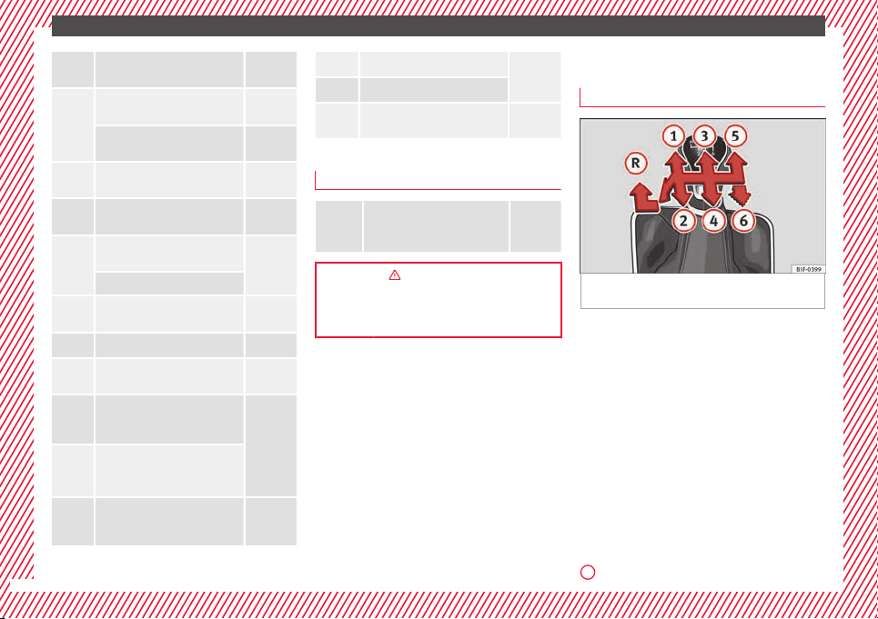
Gearbox lever
M
anua
l
gearbox
Fig. 42 Gear shift pattern of a 5 or 6-speed
m
anual
g
earbox
The position of the gears is indicated on the
g
e
arbo
x lever ››› Fig. 42.
●
Press the clutch pedal and keep your foot
right down.
●
Move the gearbox lever to the required po-
sition.
●
Release the clutch.
Selecting reverse gear
●
Press the clutch pedal and keep your foot
right down.
●
With the gearbox lever in neutral, push it
upwards, move it to the left as far as it will go
and then forwards to select reverse ››› Fig. 42
R
.
34
The essentials
●
R
el
e
ase the clutch.
››› in Changing gears on page 158
››› page 158
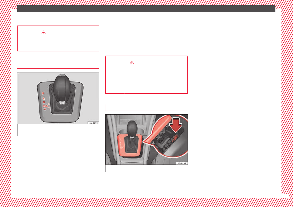
Automatic gearbox*
Fig. 43 Automatic gearbox: selector lever po-
s
ition
s.
Parking lock
R
ev
er
se gear
P
R
Neutral (idling)
Drive (forward)
Sport programme: drive (forward)
Tiptronic mode: pull the lever forwards
(+) to go up a gear or backwards (–) to
go down a gear.
››› in Basic information on page 159
››› page 158
››› page 35
Manual release of selector lever
Fig. 44 Manual release of the selector lever.
N
D
S
+/–
If there is a fault in the power system to the
el
ectr
onic
selector lever lock system (flat bat-
tery, blown fuse) or the system itself is faulty,
the selector lever cannot be moved from po-
sition P in the normal manner, which pre-
vents the vehicle from being moved. The se-
lector lever must be unlocked using the man-
ual release.
●
Apply the handbrake.
●
Pull gently on both sides at the front of the
selector lever cover.
●
Also loosen the cover at the rear.
●
Press the yellow plastic part with your fin-
ger in the direction indicated by the arrow
››› Fig. 44.
●
Press the interlock button on the selector
lever knob at the same time and move the se-
lector lever to position N (if the selector lever
is moved back to position P, it will lock
again).
35
The essentials
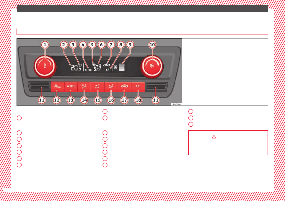
Air conditioning
Ho
w doe
s
Climatronic* work?
Fig. 45 See position on page 7-8
Buttons/controls
Int
erior t
emper
ature setting
Display
Selected interior temperature
Degrees Centigrade or Fahrenheit
Automatic air conditioning mode
Defrost or demist windscreen
Air flow direction
Air recirculation
1
2
3
4
5
6
7
Cooling on/off
Sel
ect
ed b
lower speed
Buttons/controls
Set blower speed
Interior temperature sensor
Defrost or demist windscreen
Automatic mode
Air distribution to windows
Air distribution to upper body
8
9
10
11
12
13
14
15
Air distribution to footwells
Air r
ec
ir
culation
Cooling on/off
››› in General notes on page 146
››› page 151
16
17
18
36
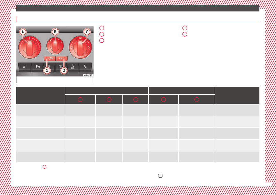
The essentials
How does the manual air conditioning* work?
Fig. 46 See position on page 7-8
Temperature
Blower
Air di
stribution
– Air distribution towards the wind-
screen in order to demist or defrost.
– Air distribution to upper body.
– Air distribution to footwell
– Air distribution to the windscreen
and the footwell.
A
B
C
Air recirculation
A/C: Swit
ching the cooling system on
1
2
Basic positions
Control position Button
Air vents 4
A B C 1 2
Windscreen and side window de-
frost or demist
Full right 3 or 4
Switched off
Switched on automati-
cally
a)
Open and direct towards the
side window
Mild heating
Required tempera-
ture
2 or 3
/
Do not switch on Do not switch on Opening
Cool as quickly as possible
Anti-clockwise as far
as it will go
Briefly 4, then 2
or 3
It is switched on au-
tomatically
b)
Switched on Opening
Optimum cooling
Required tempera-
ture
1 or 2
Do not switch on Switched on
Open and direct towards the
roof
Fresh air mode - blower
Anti-clockwise as far
as it will go
Required position
Do not switch on Switched off Opening
a)
The lamp in button
2
lights up, even if not all of the conditions for cooling system operations are met. Cooling is indicated as available once all of the conditions are met
›››
page 149, General
notes.
b)
In certain conditions, air recirculation mode can switch on automatically
›››
page 150, a lamp illuminates in the
button.
»
37
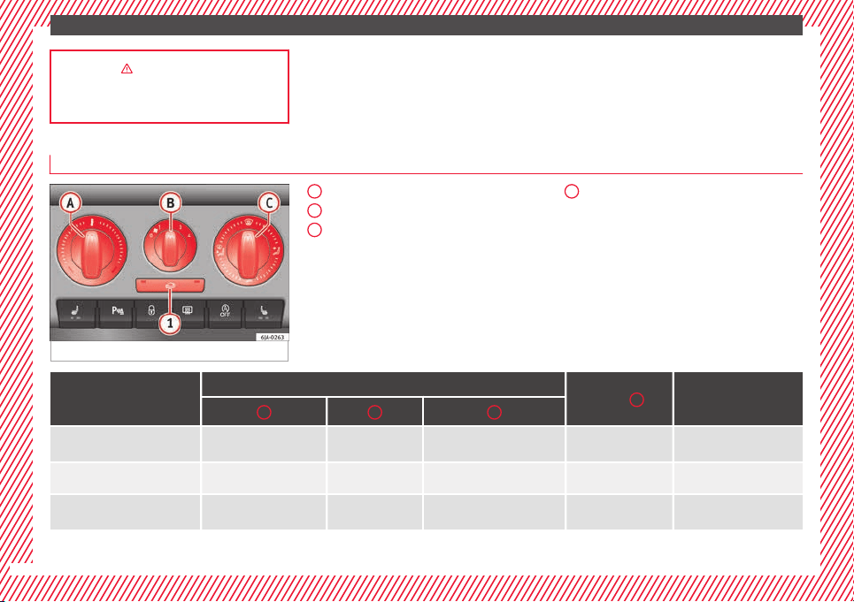
The essentials
››› in General notes on page 146
››› page 149
How does the heating and the fresh air system work?
Fig. 47 See position on page 7-8
Temperature
Blower
Air di
stribution
– Air distribution towards the wind-
screen in order to demist or defrost.
– Air distribution to upper body.
– Air distribution to footwell
– Air distribution to the windscreen
and the footwell.
A
B
C
Air recirculation
1
Basic positions
Control position
Button
1
Air vents 4
A B C
Windscreen and side window de-
frost or demist
Full right 3 or 4
Switched off
Open and direct towards the
side window
Mild heating Required temperature 2 or 3
/
Do not switch on Opening
Fresh air mode - blower
Anti-clockwise as far as it
will go
Required position
Do not switch on Opening
38
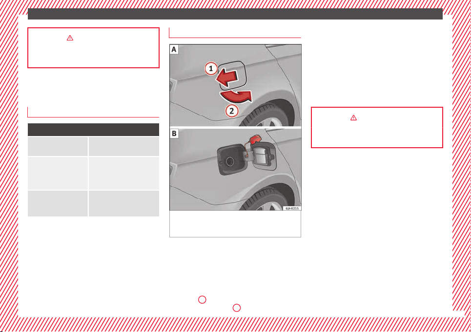
The essentials
››› in General notes on page 146
››› page 148
Level control
Fi
l
lin
g capacities
Capacities
Fuel tank
55 litres, of which 7 litres act
as reserve.
Windscreen washer flu-
id container in version
without headlight wash-
er
3.5 litres
Windscreen washer flu-
id container in versions
with headlight washer
5.4 litres
Fuel
Fig. 48 Vehicle as seen from the rear right:
f
uel
t
ank flap/fuel tank flap with tank un-
screwed cap attached.
The flap that covers the tank cap is unlocked
and loc
k
ed aut
omatically using the central
locking.
Opening the fuel tank cap
●
Press the fuel tank flap in the direction of
the arrow
1
›
›
› Fig. 48
A and open it in the
direction of the arrow
2
.
●
Un
s
c
rew the cap by turning it to the left.
●
Rest it on the upper part of the fuel tank
flap ››› Fig. 48 B.
Closing the fuel tank cap
●
Unscrew the cap by turning it to the right as
far as it will go.
●
Close the lid.
››› in Refuelling on page 201
››› page 200
39
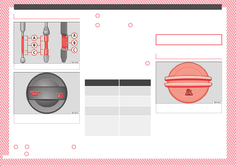
The essentials
Oil
Fig. 49 Engine oil dipstick.
Fig. 50 In the engine compartment: Engine
oi
l
fi
ller cap
The level is measured using the dipstick loca-
t
ed in the en
gine c
ompartment
›››
page 206.
The oil should leave a mark between zones
A
and
C
. It should never exceed zone
A
.
●
Zone
A
: Do not add oil.
●
Z
one
B
: You can add oil but keep the level
in th
at
zone.
●
Zone
C
: Add oil up to zone
B
.
T
op
pin
g up engine oil
●
Unscrew cap from engine oil filler opening
››› Fig. 50.
●
Add oil slowly.
●
At the same time, check the level to ensure
you do not add too much.
●
When the oil level reaches at least zone
B
,
u
n
s
crew the engine oil filler cap carefully.
Oil properties
Engine type Specification
Petrol without flexible serv-
ice interval
VW 502 00/VW 504 00
Petrol with flexible service
interval (LongLife)
VW 504 00
Diesel. Engines without Par-
ticulate filter (DPF)
VW 505 01/VW 506
01/VW 507 00
Diesel. Particulate Filter En-
gines (DPF).
With or without flexible
service interval (with and
without LongLife)
a)
VW 507 00
a)
Only use recommended oils, otherwise you may damage the
engine.
Engine oil additives
No type of additive should be mixed with the
engine oil. The deterioration caused by these
additives is not covered by the warranty.
››› page 206
Coolant
Fig. 51 Engine compartment: coolant expan-
s
ion t
ank
cap.
The coolant tank is located in the engine
c
omp
ar
tment
›››
page 206.
When the engine is cold, replace the coolant
when the level is below .
Coolant specifications
The engine cooling system is supplied from
the factory with a specially treated mixture of
40
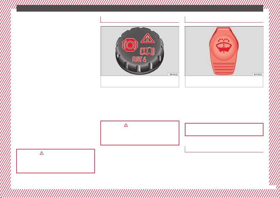
The essentials
water and at least 40 % of the additive G13
(TL
-
VW
774 J), purple. This mixture gives the
necessary frost protection down to -25°C
(-13°F) and protects the light alloy parts of
the engine cooling system against corrosion.
It also prevents scaling and considerably rai-
ses the boiling point of the coolant.
To protect the cooling system, the percentage
of additive must always be at least 40 %,
even in warm climates where anti-freeze pro-
tection is not required.
If for weather reasons further protection is
necessary, the proportion of additive may be
increased, but only up to 60 %; otherwise an-
tifreeze protection will diminish and this will
worsen cooling.
When the coolant is topped up, use a mixture
of distilled water and at least 40% of the G13
or G12 plus-plus (TL-VW 774 G) additive
(both are purple) to obtain an optimum anti-
corrosion protection. The mixture of G13 with
G12 plus (TL-VW 774 F), G12 (red) or G11
(green-blue) engine coolants will reduce anti-
corrosion protection and should therefore be
avoided.
››› in Topping up the coolant level on
page 209
››› page 208
Brake fluid
Fig. 52 Engine compartment: brake fluid res-
er
v
oir c
ap
The brake fluid reservoir is located in the en-
gine c
omp
ar
tment ›››
page 206.
The level should be between the and
marks. If it is below , please visit a Techni-
cal Service.
››› in Checking brake fluid level on
page 210
››› page 209
Windscreen washer
Fig. 53 In the engine compartment: wind-
s
c
r
een washer reservoir top.
The windscreen washer reservoir is located in
the en
gine c
omp
artment ›››
page 206.
To top up, mix water with a product recom-
mended by SEAT.
In cold temperatures, add anti-freeze.
››› page 210
Battery
The battery is located in the engine compart-
ment
›
›
›
page 206. It does not require
maintenance. It is checked as part of the In-
spection Service.
»
41

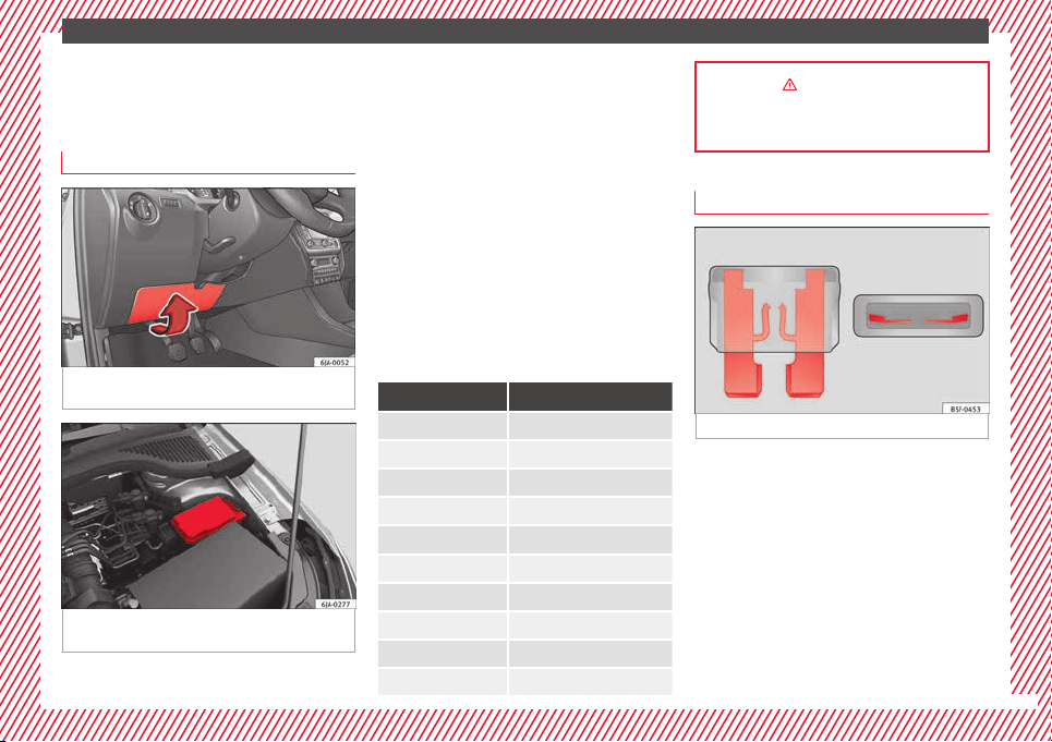
The essentials
Emergencies
F
u
se
s
Fuse location
Fig. 54 On the driver-side dash panel: fuse
bo
x
c
over
Fig. 55 In the engine compartment: fuse box
c
o
v
er
Underneath the instrument panel
●
Carefully tilt the cover in the direction indi-
c
at
ed b
y the arrow and remove it ››› Fig. 54.
●
After changing the fuse, replace the cover
on the dash panel in the direction opposite
that is indicated by the arrow so that the cov-
er tabs fit into the slots on the dash panel.
Subsequently, press down on the cover to
close.
In the engine compartment
Press the locking tabs to release the fuse box
cover ››› Fig. 55.
Identifying fuses situated below the dash
panel by colours
Colour Amp rating
Black 1
Purple 3
Light brown 5
Brown 7.5
Red 10
Blue 15
Yellow 20
White or transparent 25
Green 30
Orange 40
››› in Introduction on page 80
››› page 80
Replacing a blown fuse
Fig. 56 Image of a blown fuse
Preparation
●
Switch off the ignition, lights and all elec-
tric
al
equipment
.
●
Open the corresponding fuse box
›››
page 81.
Identifying a blown fuse
A fuse is blown if its metal strip is ruptured
››› Fig. 56.
Point a lamp at the fuse to see if it has blown.
»
43
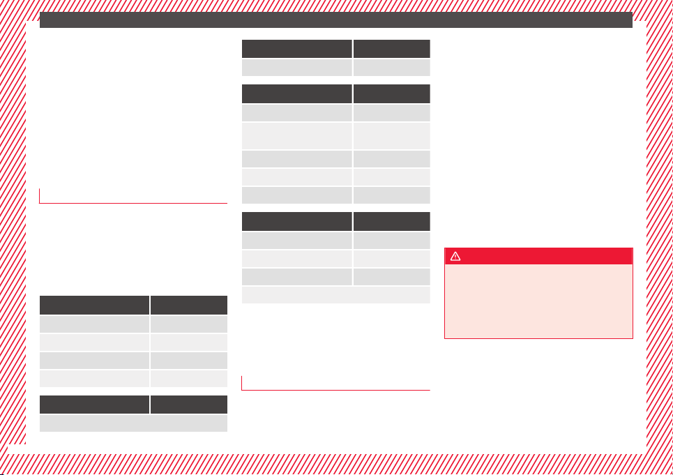
The essentials
To replace a fuse
●
Remove the fuse.
●
Replace the blown fuse by one with an
iden
tic
a
l amperage rating (same colour and
markings) and identical size.
●
Replace the cover again or close the fuse
box lid.
Bulbs
Bulbs (12 V)
Full-LED headlights are designed to last the
lif
etime of
the c
ar and cannot be replaced. If
the headlight becomes damaged, go to a
specialised workshop.
Below, the light source used for all functions
is broken down.
Halogen headlights Type
Daytime driving light/side light P21W SLL
Dipped beam headlights H7 LL
Main beam headlights H7 LL
Turn signal PY21W
Full-LED main headlights Type
No bulbs may be replaced. All functions are with LEDs
Front fog light Type
Fog/cornering lights* H8
Rear bulb light Type
Brake light/tail light P21/5W
Side lights
P21/5W (side panel)
R5W (rear lid)
Turn signal PY21W
Retro fog light P21W
Reverse lights P21W
LED rear lights Type
Turn signal PY21W
Retro fog light P21W
Reverse lights P21W
The remaining functions work with LEDs
Action in the event of a punc-
t
ur
e
Wh
at to do first
●
Park the vehicle on a horizontal surface
and in a s
af
e p
lace as far away from traffic as
possible.
●
Apply the handbrake.
●
Switch on the hazard warning lights.
●
Manual gearbox: select the 1st gear.
●
Automatic gearbox: Move the selector lever
to position P.
●
If you are towing a trailer, unhitch it from
your vehicle.
●
Have the vehicle tool kit* ›››
page 75
and the spare wheel ›››
page 218 ready.
●
Observe the applicable legislation for each
country (reflective vest, warning triangles,
etc.).
●
All occupants should leave the vehicle and
wait in a safe place (for instance behind the
roadside crash barrier).
WARNING
●
Alwa
ys observe the above steps and pro-
tect yourself and other road users.
●
If you change the wheel on a slope, block
the wheel on the opposite side of the car with
a stone or similar to prevent the vehicle from
moving.
44
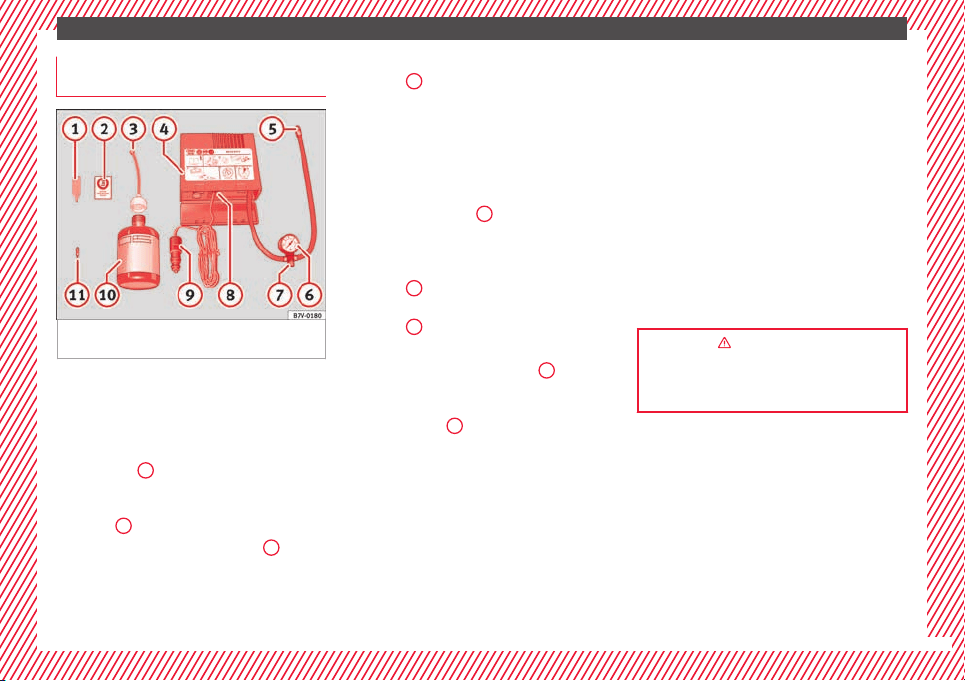
The essentials
Repairing a tyre with the anti-punc-
t
ur
e k
it
Fig. 57 Standard representation: contents of
the anti-p
u
nct
ure kit.
The anti-puncture kit is located under the
floor p
anel
in the lug
gage compartment.
Sealing the tyre
●
Unscrew the tyre valve cap and insert. Use
the ››› Fig. 57
1
tool to remove the insert.
Pl
ac
e it
on a clean surface.
●
Shake the tyre sealant bottle vigorously
››› Fig. 57
10
.
●
Screw the inflator tube ›
›
›
Fig. 57
3
into
the se
al
ant
bottle. The bottle's seal will break
automatically.
●
Remove the lid from the filling tube
››› Fig. 57
3
and screw the open end of the
t
ube int
o the ty
re valve.
●
With the tyre sealant bottle upside down,
fill the tyre with the contents of the sealant
bottle.
●
Remove the bottle from the valve.
●
Place the insert back into the tyre valve us-
ing the tool ››› Fig. 57
1
.
Infl
atin
g the ty
re
●
Screw the compressor tyre inflator tube
››› Fig. 57
5
into the tyre valve.
●
Check that the air bleed screw is closed
›
›
›
Fig. 57
7
.
●
Start the engine and leave it running.
●
Insert the connector ›
›
›
Fig. 57
9
into the
v
ehic
l
e's 12-volt socket ›››
page 138.
●
Turn the air compressor on with the ON/OFF
switch ››› Fig. 57
8
.
●
Keep the air compressor running until it
r
e
ac
hes 2.0 to 2.5 bar
(29-36 psi/200-250 kPa). a maximum of 8
minutes.
●
Disconnect the air compressor.
●
If it does not reach the pressure indicated,
unscrew the tyre inflator tube from the valve.
●
Move the vehicle 10m so that the sealant is
distrib
uted throughout the tyre.
●
Screw the c
ompressor tyre inflator into the
valve.
●
Repeat the inflation process.
●
If the indicated pressure still cannot be
reached, the tyre is too badly damaged. Stop
and request assistance from an authorised
technician.
●
Disconnect the air compressor. Unscrew
the tyre inflator tube from the tyre valve.
●
When the tyre pressure is between 2.5 and
2.0 bars, continue driving without exceeding
80 km/h (50 mph).
●
Check the pressure again after 10 minutes
›››
page 78.
››› in TMS Anti-puncture kit (Tyre Mobi-
lity System)* on page 77
››› page 76
45
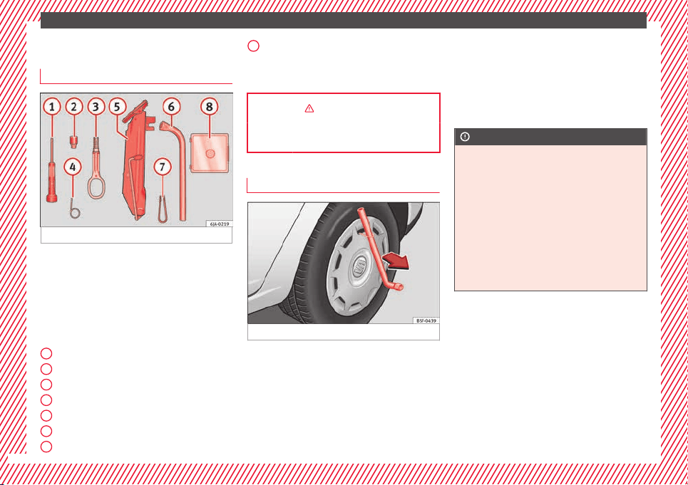
The essentials
Changing a wheel
V
ehic
l
e tool kit*
Fig. 58 Vehicle tool kit.
The vehicle tool kit and the jack are stored in
a bo
x
on the s
pare wheel or in the spare
wheel well. There is also enough space for
the towing bracket ball coupling. The box is
strapped to the spare wheel with tape.
The vehicle tool kit includes the following
parts (depending on equipment):
Screwdriver
Adapter for anti-theft wheel bolts
Towline anchorage
Wire hook for removing hub caps
Jack
Box spanner for wheel bolts
Clip for wheel bolt cover
1
2
3
4
5
6
7
Spare set of bulbs
B
ef
or
e stowing the jack again, screw down
the arm as far as it will go.
››› in What to do first on page 44
››› page 75
Wheel cover
Fig. 59 Remove the wheel cover.
Removing
●
Place the hook from the vehicle tool kit* on
the r
einf
or
ced edge of the wheel trim.
●
Insert the box spanner through the hook,
supporting it on the tyre and remove the
wheel trim.
8
Fitting
●
Press the wheel trim onto the wheel at the
c
ut
out
designed for the valve.
●
Press the wheel trim on both sides in the
direction of the valve so that it fits correctly
in place around all the perimeter.
CAUTION
●
Pres
s down by hand, do not hit the wheel
trim! Knocking it sharply, particularly at
points where the wheel trim has not yet been
inserted, could result in damage to the wheel
trim guiding and centring elements.
●
Before fitting the trim on a steel wheel at-
tached with an anti-theft wheel bolt, make
sure the bolt is in the hole in the valve area
››› page 47, Anti-theft wheel bolts*.
●
Where trim is fitted at a later date, ensure
enough air inflow is guaranteed in order to
cool the brake system.
46
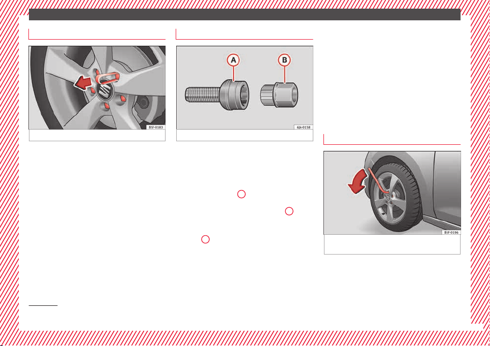
The essentials
Wheel bolt caps
Fig. 60 Pull off the wheel bolt cap.
Removing
●
Fit the plastic clip (vehicle tools) over the
c
ap u
nti
l it clicks into place ››› Fig. 60.
●
Remove the cap with the plastic clip.
Fitting
●
Insert the caps as far as they will go over
the wheel bolts.
The wheel bolt caps are stored in a box on
the spare wheel or in the spare wheel well.
Anti-theft wheel bolts*
Fig. 61 Anti-theft wheel bolt with adapter.
Anti-theft wheel bolts (one bolt per wheel)
c
an on
ly
be loosened or tightened using a
factory-supplied adapter.
●
Pull off the hub cap or bolt cover.
●
Insert the adapter
B
›
›
› Fig. 61
with its
toothed side as far as it will go on the interior
toothing of the anti-theft wheel bolt
A
so
th
at
on
ly the outer hexagonal is protruding.
●
Fit the box spanner as far as it will go over
adapter
B
.
●
Loosen or firmly tighten the wheel bolt
›
›
›
page 47.
●
After removing the adapter, replace the hub
cap or the anti-theft wheel bolt cover.
●
Check the tightening torque as soon as
possible with a torque wrench.
Note down the code number stamped on the
front of the adapter or of the anti-theft wheel
bolt. You will need this number to obtain a
spare adapter from the SEAT original acces-
sories programme.
You should always have a wheel bolt adapter
as part of your vehicle tools.
Loosening and tightening wheel bolts
Fig. 62 Changing a wheel: loosen the wheel
bo
lts.
Loosening wheel bolts
●
Insert the box spanner onto the wheel bolt
a
s
f
ar as it will go
1)
.
»
1)
The corresponding adapter is required to unscrew
or tighten the anti-theft
wheel bolts ››› page 47.
47
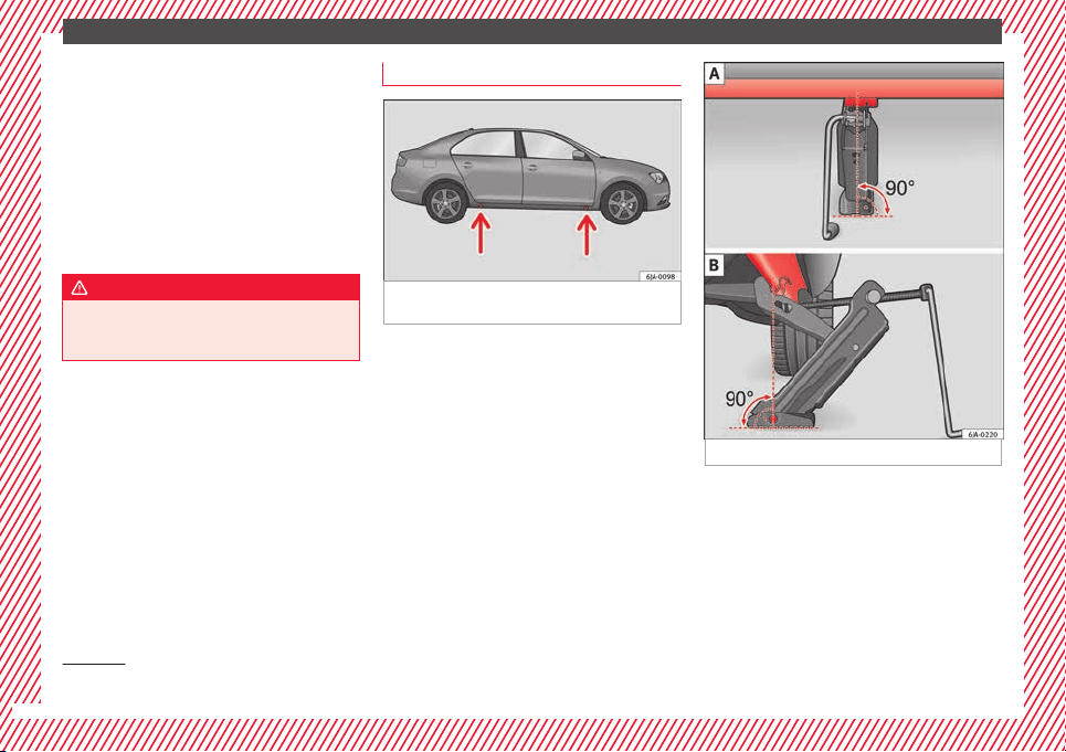
The essentials
●
Grip the end of
the bo
x
spanner and turn
the wheel bolt about one turn anti-clockwise
››› Fig. 62.
Tightening wheel bolts
●
Insert the box spanner onto the wheel bolt
as far as it will go
1)
.
●
Grip the box spanner as close to the end as
possible and tighten the bolt firmly by turn-
ing clockwise.
WARNING
The wheel bolts should only be loosened
slightly (about
one turn) before raising the
vehicle with the jack. Risk of accident!
Lifting the vehicle
Fig. 63 Changing a wheel: jack position
points.
Fig. 64 Fitting the jack.
To place the jack, locate the jacking point un-
der the door s
i
l
l closest to the wheel to be
changed ››› Fig. 63. The jacking point is un-
derneath the stamp on the door sill.
●
Raise the jack, turning the crank handle to
wind it up under the jacking point until its
claw is directly below the jacking point of the
door sill.
1)
The corresponding adapter is required to unscrew
or tighten the anti-theft
wheel bolts ››› page 47.
48

The essentials
●
Adju
s
t
the jack so that its claw surrounds
the jacking point on the door sill ››› Fig. 64 - B
underneath the stamp.
●
Make sure that the base of the jack is en-
tirely supported on a flat surface and that it is
vertical ››› Fig. 64 to the point where the claw
surrounds the jacking point on the door sill.
●
Continue to wind up the jack using the
crank handle until the defective wheel is
clear off the ground.
Removing and fitting a wheel
Change the wheel after loosening the wheel
bo
lts
and r
aising the vehicle with the jack.
Taking off the wheel
●
Unscrew the wheel bolts using the box
spanner and place them on a clean surface.
●
Take off the wheel.
Putting on the spare wheel
When fitting tyres with a compulsory rotation
direction, observe the instructions in
›››
page 49.
●
Mount the wheel.
●
Screw on the wheel bolts in position and
tighten them loosely with a box spanner.
●
Carefully lower the vehicle using the jack*.
●
Tighten the wheel bolts in diagonal pairs
using the wheel brace.
The wheel bolts should be clean and turn
easily. Before fitting the spare wheel, inspect
the wheel condition and hub mounting surfa-
ces. These surfaces must be clean before fit-
ting the wheel.
Tyres with compulsory direction of ro-
tation
A directional tread pattern can be identified
b
y
the arr
ows on the sidewall that point in
the direction of rotation. Always observe the
direction of rotation indicated when fitting
the wheel to guarantee optimum properties
of this type of tyres with regard to grip,
noises, wear and aquaplaning.
If it is absolutely necessary to fit the spare
tyre* against the direction of rotation, drive
with care as this means the tyre does not of-
fer optimum driving properties. This is of par-
ticular importance when the road surface is
wet.
Replace the punctured tyre as soon as possi-
ble and restore the obligatory and correct di-
rection of rotation of all tyres.
Subsequent work
●
Alloy wheels: repl
ace the wheel bolt caps.
●
Plate wheels: replace the wheel hubcap
››› page 46.
●
Return all tools to their proper storing loca-
tion.
●
If the replaced wheel does not fit in the
spare wheel housing, store it safely in the
luggage compartment ›››
page 141.
●
Check the tyre pressure of the newly moun-
ted tyre as soon as possible.
●
In vehicles fitted with a tyre pressure indi-
cator
, adjust the pressure and store it in
memory
›››
page 219.
●
Have the tightening torque of the wheel
bolts checked as soon as possible with a tor-
que wrench (it should be 120 Nm). Mean-
while, drive carefully.
●
Have the flat tyre replaced as quickly as
possible.
Snow chains
Use
Snow chains should only be used on the
fr
on
t
wheels.
»
49
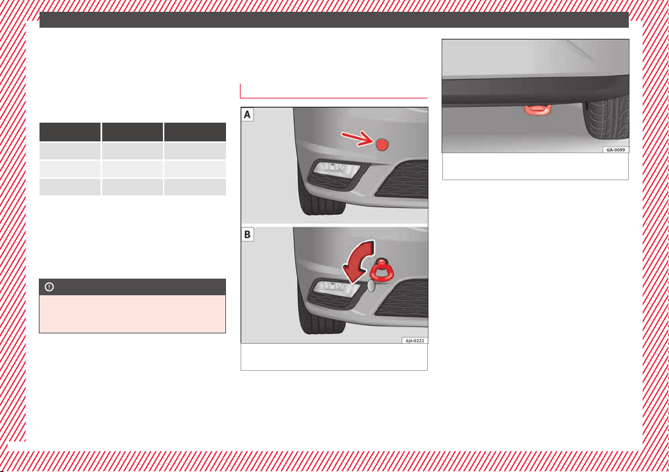
The essentials
In winter road conditions, snow chains not
on
ly
help t
o improve grip but also improve
the braking capacity.
For technical reasons snow chains may only
be used on tyres with the following wheel
rim/tyre combinations.
Rim size Rim offset Tyre size
5J x 14
a)
35 mm 175/70
6J x 15
b)
38 mm 185/60
6J x 15
b)
38 mm 195/55
a)
Only use snow chains with fine-pitch links and lock no greater
than 9 mm.
b)
Only use snow chains with fine-pitch links and lock no greater
than 13 mm.
Remove the wheel trims before fitting snow
chains.
CAUTION
Chains must be removed when roads are free
of sno
w. Otherwise they will impair handling,
damage the tyres and wear out very quickly.
Emergency towing of the vehi-
c
l
e
T
owing
Fig. 65 Right side of the front bumper: tow-
line anc
hor
ag
e screwed in.
Fig. 66 Right side of the rear bumper: Towing
ring.
Towline anchorages
●
Attach the bar or rope to the towline ancho-
r
ag
e
s.
It is located with the vehicle's tools
›››
page 75.
●
Screw the front towline anchorage into the
screw connection ››› Fig. 65 and tighten it
with the wheel brace.
The rear towline anchorage is under the rear
bumper, on the right ››› Fig. 66.
Tow rope or tow bar
The tow bar offers increased safety and a
lower risk of damage.
The tow rope is recommended when there is
no tow bar. It must be elastic so that it does
not damage the vehicle.
50
The essentials
Notes for the driver of the towing vehicle
●
The tow rope must be taut before you drive
off
.
●
R
el
ease the clutch very carefully when start-
ing the vehicle (manual gearbox), or acceler-
ate gently (automatic gearbox).
Driving style
Towing requires some experience, especially
when using a tow rope. Both drivers should
realise how difficult it is to tow a vehicle. In-
experienced drivers should not attempt to
tow.
Do not pull too hard with the towing vehicle
and take care to avoid jerking the tow rope.
When towing on an unpaved road, there is al-
ways a risk of overloading and damaging the
anchorage points.
The towline anchorages are located under
the floor panel in the luggage compartment.
Switch on the ignition so that the turn sig-
nals, windscreen wipers and windscreen
washer can work. Ensure that the steering
wheel is unlocked and moves freely.
Place the gear lever in neutral on vehicles
with a manual gearbox. With an automatic
gearbox, place the lever in N.
To brake, press the brake pedal firmly. The
brake servo does not work when the engine
is switched off.
The power steering only works when the igni-
tion is switched on and the vehicle is moving,
provided that the battery is sufficiently charg-
ed. Otherwise, it will need more force.
Ensure that the tow rope remains taut at all
times.
››› page 78
Tow-starting
If the engine will not start, first try starting it
u
s
in
g the battery of another vehicle
››› page 51. You should only attempt to tow-
start a vehicle if charging the battery does
not work. This is done by leveraging wheel
movement.
When tow-starting a vehicle with a petrol en-
gine, do not tow it more than a short dis-
tance, otherwise unburned fuel can enter the
catalytic converter.
●
Engage 2nd or 3rd gear before moving off.
●
Press the clutch and hold the pedal down.
●
Switch the ignition on.
●
Once both vehicles are moving, release the
clutch.
●
As soon as the engine has started, press
the clutch and move the gear lever to neutral.
How to jump start
Jump leads
The jump lead must have a sufficient wire
cro
ss section.
If the engine fails to start because of a dis-
charged battery, the battery can be connec-
ted to the battery of another vehicle to start
the engine.
Both batteries need to have nominal voltage
of 12 V. The capacity (Ah) of the back-up bat-
tery should not be notably less than the
drained battery.
Jump leads must comply with standard DIN
72553 (see cable manufacturer's instruc-
tions). The wire cross section must be at least
25 mm
2
for petrol engines and at least
35 mm
2
for diesel engines.
Jump leads
Positive cable – usually red
Negative cable – usually black
WARNING
●
A flat b
attery can also freeze at tempera-
tures slightly below to 0°C (32°F). Do not at-
tempt to start the vehicle with a frozen bat-
tery. Risk of explosion!
»
51
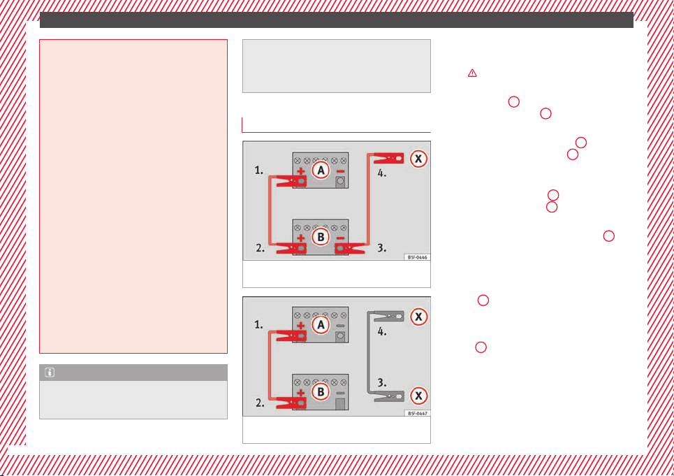
The essentials
●
Plea
se note the safety warnings referring to
working in the engine compartment
›››
page 203.
●
The non-insulated parts of the battery
clamps must not be allowed to touch. Addi-
tionally, the jump lead attached to the posi-
tive battery terminal must not touch metal
parts of the vehicle. Risk of short circuit!
●
Do not connect the negative lead to the
negative terminal of the discharged battery.
In the event of sparks when starting the en-
gine, the explosive gas given off by the bat-
tery could catch fire.
●
Position the jump leads in such a way that
they cannot come into contact with any mov-
ing parts in the engine compartment.
●
Do not bend over the battery. Risk of acid
burns!
●
The screw plugs on the battery cells must
be screwed in firmly.
●
Keep sources of fire (flames, lit cigarettes,
etc.) away from the battery. - Risk of explo-
sion!
●
Never use the jump leads on batteries in
which the electrolyte level is too low. Risk of
explosion and acid burns.
Note
●
The vehic
les must not touch each other, as
electricity could flow as soon as the positive
terminals are connected.
●
The disc
harged battery must be properly
connected to the vehicle electrical system.
●
The jump leads should be checked in a spe-
cialist vehicle battery shop.
How to jump start: description
Fig. 67 Diagram of connections for vehicles
w
ithout
Start Stop system
Fig. 68 Diagram of connections for vehicles
w
ith
St
art Stop system
Jump lead terminal connections
1. Switch off the ignition of both vehicles
›
›
›
.
2. Connect one end of the r
e
d
jump lead to
the positive
+
terminal of the vehicle
w
ith the fl
at
battery
A
›
›› Fig. 67
.
3.
Connect the other end of the red jump
lead to the positive terminal
+
in the ve-
hic
l
e pr
oviding assistance
B
.
4. For vehicles without Start-Stop system:
c
onnect
one end of
the black jump lead to
the negative terminal
–
of the vehicle
pr
o
v
iding the current
B
›
›
› Fig. 67
.
–
For vehicles with Start-Stop system: con-
nect one end of the black jump lead
X
to a
s
uit
ab
le ground terminal, to a solid piece of
metal in the engine block, or to the engine
block itself ››› Fig. 68.
5. Connect the other end of the black jump
lead
X
to a solid metal component bolted
t
o the en
gine b
lock or to the engine block
itself of the vehicle with the flat battery.
Do not connect it to a point near the bat-
tery
A
.
6. Position the leads in such a way that they
c
annot
c
ome into contact with any moving
parts in the engine compartment.
52
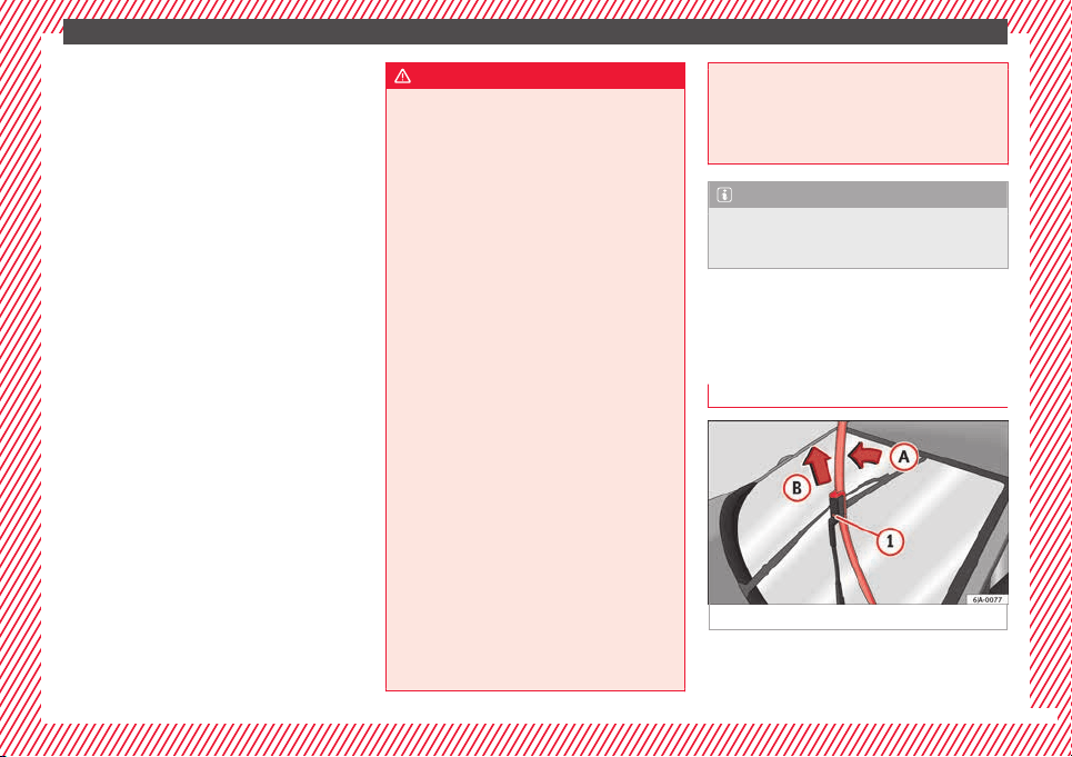
The essentials
Starting
7. Start the engine of the vehicle with the
boo
s
tin
g battery and let it run at idling
speed.
8. Start the engine of the vehicle with the flat
battery and wait for 2 or 3 minutes until
the engine is running.
Removing the jump leads
9. Before you remove the jump leads, switch
off the dipped beam headlights if they are
switched on.
10.Turn on the heater blower and heated rear
window in the vehicle with the flat battery.
This helps minimise voltage peaks which
are generated when the leads are discon-
nected.
11.When the engine is running, disconnect
the leads in reverse order to the details
given above.
Make sure the battery clamps have sufficient
metal-to-metal contact with the battery termi-
nals.
If the engine fails to start, switch off the start-
er after about 10 seconds and try again after
about 1 minute.
WARNING
●
Plea
se note the safety warnings referring to
working in the engine compartment
›››
page 203.
●
The battery providing assistance must have
the same voltage as the flat battery (12V) and
approximately the same capacity (see imprint
on battery). Failure to comply could result in
an explosion.
●
Never use jump leads when one of the bat-
teries is frozen. Danger of explosion! Even af-
ter the battery has thawed, battery acid could
leak and cause chemical burns. If a battery
freezes, it should be replaced.
●
Keep sparks, flames and lighted cigarettes
away from batteries, danger of explosion.
Failure to comply could result in an explo-
sion.
●
Observe the instructions provided by the
manufacturer of the jump leads.
●
Do not connect the negative cable from the
other vehicle directly to the negative terminal
of the flat battery. The gas emitted from the
battery could be ignited by sparks. Danger of
explosion.
●
Do not attach the negative cable from the
other vehicle to parts of the fuel system or to
the brake line.
●
The non-insulated parts of the battery
clamps must not be allowed to touch. The
jump lead attached to the positive battery
terminal must not touch metal parts of the ve-
hicle, this can cause a short circuit.
●
Pos
ition the leads in such a way that they
cannot come into contact with any moving
parts in the engine compartment.
●
Do not lean on the batteries. This could re-
sult in chemical burns.
Note
The vehicles must not touch each other, oth-
er
wi
se electricity could flow as soon as the
positive terminals are connected.
Changing the windscreen wiper
b
l
a
des
Changing the wiper blades
Fig. 69 Windscreen wiper blades.
Set the windscreen wiper arms to the service
po
s
ition bef
ore changing the blades.
»
53
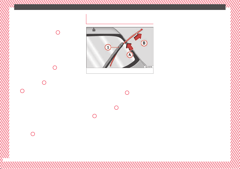
The essentials
Service position
●
Close the bonnet.
●
Switch the ignition on and off.
●
Press the lever to position
4
›››
Fig. 140 ›
›
›
page 129, the wind-
screen wiper arms are set to the service posi-
tion.
Taking off the wiper blade
●
Lift the windscreen wiper arm away from
the glass moving the blade slightly in the di-
rection of the arm – arrow
A
›
›
› Fig. 69
.
●
Hold the top of the windscreen wiper arm
with one hand.
●
Unlock the catch
1
with the other hand
and r
emo
v
e the blade in the direction of ar-
row
B
.
Fittin
g the w
iper b
lade
●
Slide the blade fully until it clicks into posi-
tion.
●
Check that the wiper is correctly secured.
●
Fold the windscreen wiper arm back down
onto the glass.
●
Switch the ignition on and press the lever
to position
4
›
›
›
Fig. 140
›
››
page 129, the windscreen wiper arms
are set to the basic position.
Changing the rear window wiper
blade*
Fig. 70 Rear window wiper blade.
Taking off the wiper blade
●
Lift the rear window wiper arm away from
the gl
a
s
s moving the blade slightly in the di-
rection of the arm – arrow
A
›
›
› Fig. 70
.
●
Hold the top of the rear window wiper arm
with one hand.
●
Unlock the catch
1
with the other hand
and r
emo
v
e the blade in the direction of ar-
row
B
.
Fittin
g the w
iper b
lade
●
Slide the blade fully until it clicks into posi-
tion.
●
Check that the wiper is correctly secured.
●
Fold the rear window wiper arm back down
onto the glass.
54
Safe driving
Safety
Saf
e driv
in
g
Safety first!
This chapter contains important information,
tips, sug
gestions and warnings that you
should read and consider for both your own
safety and for your passengers' safety.
WARNING
●
This m
anual contains important informa-
tion about the operation of the vehicle, both
for the driver and the passengers. The other
sections of the on-board documentation also
contain further information that you should
be aware of for your own safety and for the
safety of your passengers.
●
Ensure that the on-board documentation is
kept in the vehicle at all times. This is espe-
cially important when lending or selling the
vehicle to another person.
Advice about driving
B
ef
or
e starting every trip
For your own safety and the safety of your
p
a
s
sengers, always note the following points
before every trip:
–
Make sure that the vehicle's lights and turn
signals are working properly.
–
Check tyre pressure.
–
Ensure that all windows provide a clear and
good view of the surroundings.
–
Make sure all luggage is secured
››› page 141.
–
Make sure that no objects can interfere
with the pedals.
–
Adjust front seat, head restraint and rear vi-
sion mirrors properly according to your
size.
–
Ensure that the passengers in the rear
seats always have the head restraints in
the in-use position ››› page 59.
–
Instruct passengers to adjust the head re-
straints according to their height.
–
Protect children with appropriate child
seats and properly applied seat belts
››› page 72.
–
Assume the correct sitting position. Instruct
your passengers also to assume a proper
sitting position. ››› page 56.
–
Fasten your seat belt securely. Instruct your
passengers also to fasten their seat belts
properly.
›››
page 61.
Factors influencing safety
As a driver, you are responsible for yourself
and your p
assengers. When your concentra-
tion or driving safety is affected by any cir-
cumstance, you endanger yourself as well as
others on the road ›››
, for this reason:
–
Always pay attention to traffic and do not
get di
stracted by passengers or telephone
calls.
–
Never drive when your driving ability is im-
paired (e.g. by medication, alcohol, drugs).
–
Observe traffic laws and speed limits.
–
Always reduce your speed as appropriate
for ro
ad, traffic and weather conditions.
–
When travelling long distances, take
breaks regularly - at least every two hours.
–
If possible, avoid driving when you are tired
or stressed.
WARNING
When driving safety is impaired during a trip,
the risk of
injury and accidents increases.
Safety equipment
Never put your safety or the safety of your
p
a
s
sengers in danger. In the event of an acci-
dent, the safety equipment may reduce the
»
55
Technical dataAdviceOperationEmergenciesSafety
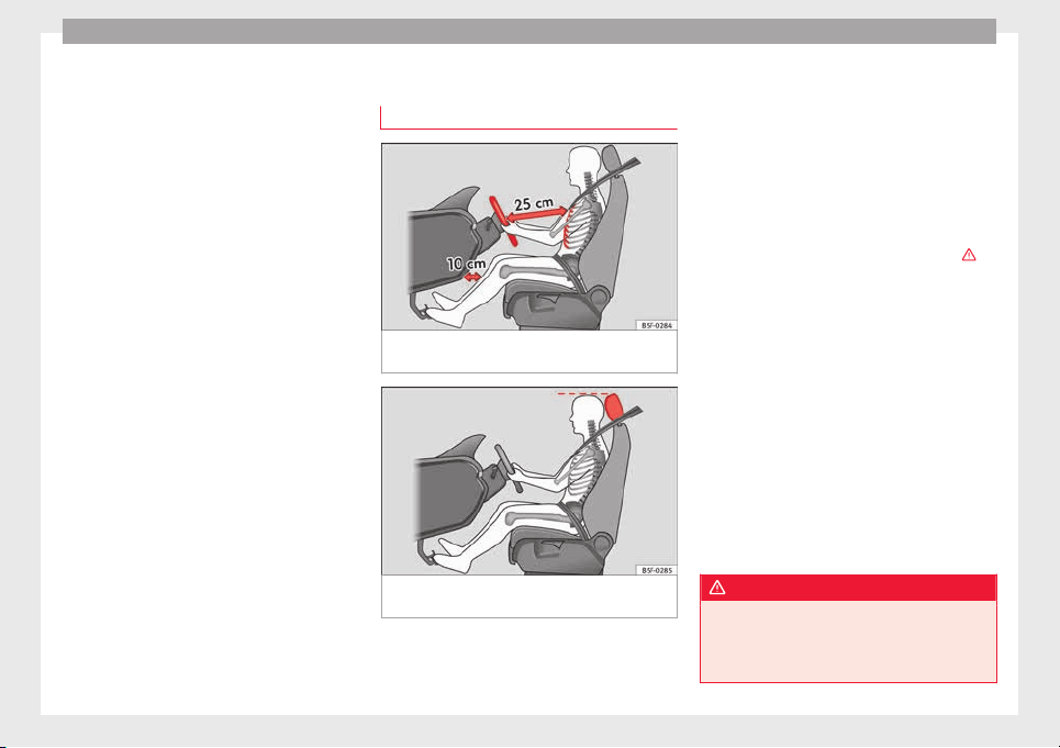
Safety
risk of injury. The following list includes most
of
the s
af
ety equipment in your SEAT:
●
Three-point seat belts
●
belt tension limiters for the front and rear
side seats,
●
Belt tensioners for the front seats
●
Belt height adjustment for the front seats
●
Front airbags
●
Side airbags in the front seat backrests
●
Side airbags in the rear seat backrests*
●
Head-protection airbags
●
Active front head restraints*
●
“ISOFIX” anchor points for child seats in
the rear side seats with the “ISOFIX” system,
●
Height-adjustable front head restraints
●
Rear head restraints with in-use position
and non-use position
●
Adjustable steering column
The safety equipment mentioned above
works together to provide you and your pas-
sengers with the best possible protection in
the event of an accident. However, these
safety systems can only be effective if you
and your passengers are sitting in a correct
position and use this equipment properly.
Safety is everyone's business!
Correct position for passengers
Correct sitting position for driver
Fig. 71 The proper distance between driver
and s
t
eerin
g wheel
Fig. 72 Correct head restraint position for the
driv
er
.
For your own safety and to reduce the risk of
injur
y
in the ev
ent of an accident, we recom-
mend the following adjustments for the driv-
er:
–
Adjust the steering wheel so that there is a
distance of at least 25 cm between the
steering wheel and the centre of your chest
››› Fig. 71.
–
Move the driver seat forwards or backwards
so that you are able to press the accelera-
tor, brake and clutch pedals to the floor
with your knees still slightly angled ›››
.
–
Ensure that you can reach the highest point
of
the s
t
eering wheel.
–
Adjust the head restraint so that its upper
edge is at the same level as the top of your
head, or as close as possible to the same
level as the top of your head ››› Fig. 72.
–
Move the seat backrest to an upright posi-
tion so that your back rests completely
against it.
–
Fasten your seat belt securely ››› page 61.
–
Keep both feet in the footwell so that you
have the vehicle under control at all times.
Adjustment of the driver seat ›››
page 11.
WARNING
●
An incorrect
sitting position of the driver
can lead to severe injuries.
●
Adjust the driver seat so that there is at
least 25 cm distance between the centre of
56
Safe driving
the chest and the centre of the steering
wheel ››
› Fig. 71. If you are sitting closer than
25 cm, the airbag system cannot protect you
properly.
●
If your physical constitution prevents you
from maintaining the minimum distance of 25
cm, contact a specialised workshop. The
workshop will help you decide if special spe-
cific modifications are necessary.
●
When driving, always hold the steering
wheel with both hands on the outside of the
ring at the 9 o'clock and 3 o'clock positions.
This reduces the risk of injury when the driver
airbag is triggered.
●
Never hold the steering wheel at the 12
o'clock position, or in any other manner (e.g.
in the centre of the steering wheel). In such
cases, if the airbag is triggered, you may sus-
tain injuries to the arms, hands and head.
●
To reduce the risk of injury to the driver
during sudden braking manoeuvres or an ac-
cident, never drive with the backrest tilted far
back! The airbag system and seat belts can
only provide optimal protection when the
backrest is in an upright position and the
driver is wearing his or her seat belt correct-
ly.
●
Adjust the head restraint properly to ach-
ieve optimal protection.
Adjusting the steering wheel position
Read the additional information carefully
›››
page 13.
WARNING
●
Never adju
st the position of the steering
wheel when the vehicle is moving, as this
could cause an accident.
●
Move the lever up firmly so the steering
wheel position does not accidentally change
during driving. risk of accident!
●
Make sure you are capable of reaching and
firmly holding the upper part of the steering
wheel: risk of accident!
●
If you adjust the steering wheel so that it
points towards your face, the driver airbag
will not protect you properly in the event of
an accident. Make sure that the steering
wheel points towards your chest.
Correct sitting position for front pas-
sen
g
er
For your own safety and to reduce the risk of
injur
y
in the ev
ent of an accident, we recom-
mend the following adjustments for the front
passenger:
–
Move the front passenger seat back as far
as possible
›››
.
–
Mo
v
e the se
at backrest to an upright posi-
tion so that your back rests completely
against it.
–
Adjust the head restraint so that its upper
edge is at the same level as the top of your
head, or as close as possible to the same
level as the top of your head ››› page 59.
–
Always keep both feet in the footwell in
front of the front passenger seat.
–
Fasten your seat belt securely ››› page 61.
It is possible to deactivate the front passen-
ger airbag in exceptional circumstances
››› page 71.
Adjusting the front passenger seat
›››
page 11.
WARNING
●
An incorrect
sitting position of the front
passenger can lead to severe injuries.
●
Adjust the front passenger seat so that
there is at least 25 cm between your chest
and the dash panel. If you are sitting closer
than 25 cm, the airbag system cannot protect
you properly.
●
If your physical constitution prevents you
from maintaining the minimum distance of 25
cm, contact a specialised workshop. The
workshop will help you decide if special spe-
cific modifications are necessary.
●
Always keep your feet in the footwell when
the vehicle is moving; never rest them on the
»
57
Technical dataAdviceOperationEmergenciesSafety

Safety
dash panel, out the window or on the seat. An
incorrect
sitting position exposes you to an
increased risk of injury in case of a sudden
braking or an accident. If the airbag is trig-
gered, you could sustain severe injuries due
to an incorrect sitting position.
●
To reduce the risk of injury to the front pas-
senger in events such as sudden braking ma-
noeuvres or an accident, never travel with the
backrest tilted far back! The airbag system
and seat belts can only provide optimal pro-
tection when the backrest is in an upright po-
sition and the front passenger is wearing his
or her seat belt properly. The further the seat
backrests are tilted to the rear, the greater
the risk of injury due to incorrect positioning
of the belt web or to the incorrect sitting po-
sition!
●
Adjust the head restraint correctly in order
to achieve maximum protection.
Correct sitting position for rear seat
p
a
s
sengers
To reduce the risk of injury in the event of a
s
ud
den br
aking manoeuvre or an accident,
passengers on the rear seat bench must con-
sider the following:
–
Sit up straight.
–
Adjust the head restraint to the correct po-
sition ››› page 59.
–
Always keep both feet in the footwell in
front of the rear seat.
–
Fasten your seat belt securely ››› page 61.
–
Use an appropriate child restraint system
when you take children in the vehicle
››› page 72.
WARNING
●
If the pa
ssengers in the rear seats are not
sitting properly, they could sustain severe in-
juries.
●
Adjust the head restraint correctly in order
to achieve maximum protection.
●
Seat belts can only provide optimal protec-
tion when seat backrests are in an upright
position and the vehicle occupants are wear-
ing their seat belts correctly. If passengers In
the rear seats are not sitting in an upright po-
sition, the risk of injury due to incorrect posi-
tioning of the seat belt increases.
Examples of incorrect sitting posi-
tion
s
Seat belts can provide optimal protection on-
ly
when the belt
w
ebs are properly posi-
tioned. Incorrect sitting positions substan-
tially reduce the protective function of seat
belts and increase the risk of injury due to in-
correct seat belt position. As the driver, you
are responsible for all passengers, especially
children.
–
Never allow anyone to assume an incorrect
sitting position in the vehicle while travel-
ling ›››
.
The f
o
l
lowing list contains examples of sit-
ting positions that could be dangerous for all
vehicle occupants. The list is not complete,
but we would like to make you aware of this
issue.
Therefore, whenever the vehicle is in motion:
●
Never stand in the vehicle.
●
Never stand on the seats.
●
Never kneel on the seats.
●
Never tilt your seat backrest far to the rear.
●
Never lean against the dash panel.
●
Never lie on the rear bench.
●
Never sit on the front edge of a seat.
●
Never sit sideways.
●
Never lean out of a window.
●
Never put your feet out of a window.
●
Never put your feet on the dash panel.
●
Never put your feet on the surface of a seat.
●
Do not allow anyone to travel in the foot-
well.
●
Never travel without wearing the seat belt.
●
Do not allow anyone to travel in the lug-
gage compartment.
58
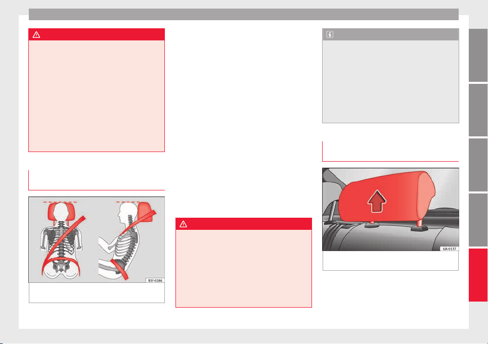
Safe driving
WARNING
●
Any inc
orrect sitting position increases the
risk of severe injuries.
●
Sitting in an incorrect position exposes the
vehicle occupants to severe injuries if airbags
are triggered, by striking a vehicle occupant
who has assumed an incorrect sitting posi-
tion.
●
Before the vehicle moves, assume the prop-
er sitting position and maintain it throughout
the trip. Before every trip, instruct your pas-
sengers to sit properly and to stay in this po-
sition during the trip ››› page 56, Correct posi-
tion for passengers.
Correct adjustment of front head re-
s
tr
aint
s
Fig. 73 Correctly adjusted head restraint as
v
iew
ed fr
om the front and the side.
Properly adjusted head restraints are an im-
por
t
ant
part of passenger protection and can
reduce the risk of injuries in most accident
situations.
–
Adjust the head restraint so that its upper
edge is, as far as possible, at the same lev-
el as the top of your head, or at the very
least, at eye level ››› Fig. 73.
Adjusting the head restraints ››› page 132
Active head restraints*
Vehicle occupants are pressed into their
seats during a rear end collision. The result-
ing body pressure on the seat backrest acti-
vates the active head restraint* on the front
seat, which moves rapidly forwards and up-
wards at the same time. This movement re-
duces the distance between the occupant's
head and the head restraint, thus reducing
the risk of injuries such as whiplash.
WARNING
●
Trav
elling with the head restraints removed
or improperly adjusted increases the risk of
severe injuries. An improper adjustment of
the head restraints may cause death in an ac-
cident and increase the risk of suffering inju-
ries during abrupt braking actions or unex-
pected manoeuvres.
●
The head restraints must always be adjus-
ted according to the height of the passenger.
Note
The active head restraints* could also be trig-
gered if
a vehicle occupant applies a high lev-
el of pressure to the seat backrest (e.g. by
“falling” back into the seat when entering the
vehicle) or if pressure is applied to a front
seat head restraint from the rear. This acci-
dental activation is, however, not dangerous,
as the active head restraints will return to the
original position immediately and are thus
once again ready.
Correct adjustment of rear head re-
s
tr
aint
s
Fig. 74 Head restraints in the correct posi-
tion.
Properly adjusted head restraints are an im-
por
t
ant
part of passenger protection and can
reduce the risk of injuries in most accident
situations.
»
59
Technical dataAdviceOperationEmergenciesSafety
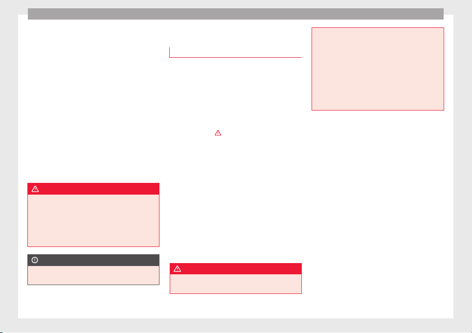
Safety
Rear outer seat head restraints
–
The rear outer seat head restraints have 4
po
s
ition
s.
–
Three positions for use ››› Fig. 74 . In these
positions, the head restraints are used nor-
mally, and along with the rear seat belts,
protect passengers in the rear seats.
–
And one position for non-use.
–
To fit the head restraints in position for use,
pull on the edges with both hands in the
direction of the arrow.
Centre rear head restraint*
–
The centre head restraint only has two posi-
tions, in-use (head restraint up) and non-
use (head restraint down).
WARNING
●
Under no circ
umstances should the rear
passengers travel while the head restraints
are in the non-use position.
●
Do not swap the centre rear head restraint
with either of the outer seat rear head re-
straints. Risk of injury in case of an accident!
CAUTION
Note the instructions on the adjustment of
the head r
estraints ››› page 132.
Pedal area
P
ed
a
ls
–
Ensure that you can always press the accel-
erator
, brake and clutch pedals unimpaired
to the floor.
–
Ensure that the pedals can return unim-
paired to their initial positions.
–
Ensure that the floor mats are securely fas-
tened during the trip and do not obstruct
the pedals
›››
.
On
ly
u
se floor mats which leave the pedals
clear and which are secured to prevent them
from slipping. You can obtain suitable floor
mats from a specialised dealership. Fasten-
ers* for floor mats are fitted in the footwells.
If a brake circuit fails, the brake pedal must
be pressed down thoroughly in order to stop
the vehicle.
Wear suitable footwear
Always wear shoes which support your feet
properly and give you a good feeling for the
pedals.
WARNING
●
If the peda
ls are obstructed, an accident
may occur. Risk of serious injuries.
●
Never la
y or fit floor mats or other floor cov-
erings over the original floor mats. This
would reduce the pedal area and could ob-
struct the pedals. Risk of accident.
●
Never place objects in the driver footwell.
An object could move into the pedal area and
impair pedal operation. In the event of a sud-
den driving or braking manoeuvre, you will
not be able to operate the brake, clutch or ac-
celerator pedal. Risk of accident!
60
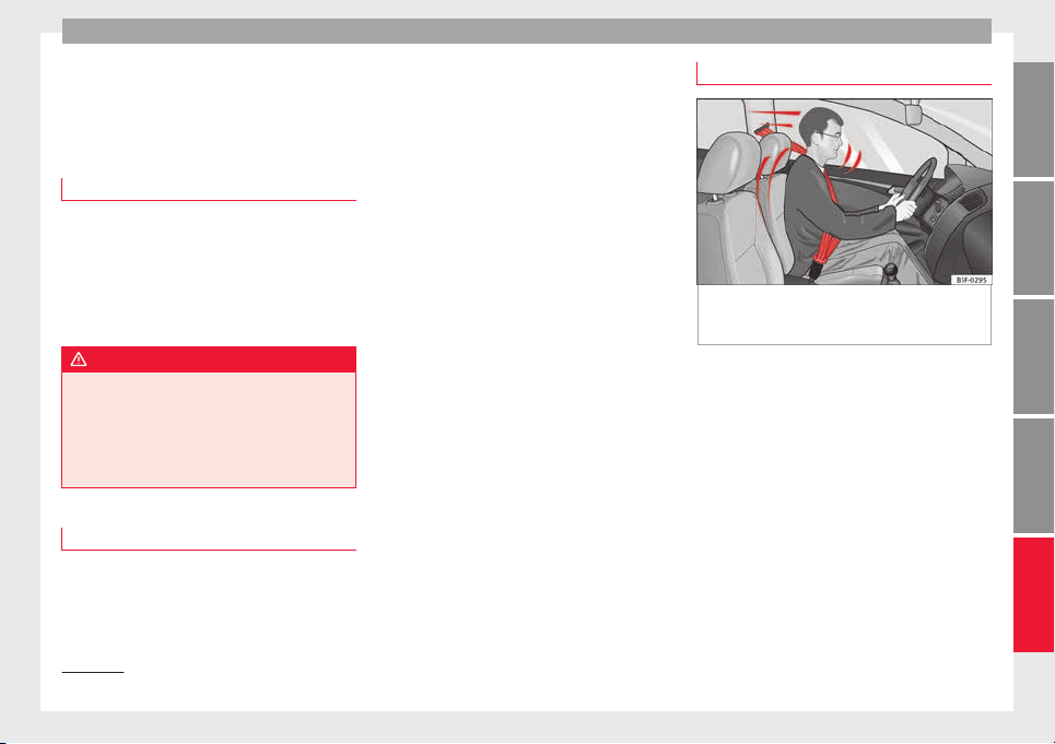
Seat belts
Seat belts
The wh
y
s
and wherefores of
seat belts
Number of seats
Your vehicle has five se
ats, two in the front
and three in the rear. Each seat is equipped
with a three-point seat belt.
In some versions, your vehicle is approved
only for four seats. Two front seats and two
rear seats.
WARNING
●
Never tran
sport more than the permitted
amount of people in your vehicle.
●
Every vehicle occupant must properly fas-
ten and wear the seat belt belonging to his or
her seat. Children must be protected with an
appropriate child restraint system.
Seat belt lamp*
The control lamp illuminates to remind the
driv
er t
o f
asten his seat belt.
Before starting the vehicle:
–
Fasten your seat belt securely.
–
Instruct your passengers to fasten their
seat belts properly before driving off.
–
Protect children by using a child seat ac-
cording to the child's height and weight.
The control lamp on the instrument panel
lights up
1)
if the driver or passenger
1)
has
not fastened their belt when the ignition is
switched on.
If, when starting to drive, speed surpasses
25 km/h (15 mph) approx. and no seat belts
are worn or they are unfastened during the
drive, a warning sound will be heard for a few
seconds. The warning light will also flash .
The lamp goes out when the driver and
passenger seat belts are fastened with the ig-
nition switched on.
The protective function of seat belts
Fig. 75 Drivers with properly worn seat belts
w
i
l
l not be thrown forward in the event of sud-
den braking
Properly worn seat belts hold the occupants
in the pr
oper po
s
ition. They also help prevent
uncontrolled movements that may result in
serious injury and reduce the risk of being
thrown out of the vehicle in case of an acci-
dent.
Vehicle occupants wearing their seat belts
correctly benefit greatly from the ability of the
belts to absorb kinetic energy. In addition,
the front part of your vehicle and other pas-
sive safety features (such as the airbag sys-
tem) are designed to absorb the kinetic ener-
gy released in a collision. Taken together, all
these features reduce the releasing kinetic
energy and consequently, the risk of injury.
»
1)
Depending on the model version
61
Technical dataAdviceOperationEmergenciesSafety
Safety
This is why it is so important to fasten seat
belts
bef
or
e every trip, even when "just driv-
ing around the corner".
Ensure that your passengers wear their seat
belts as well. Accident statistics have shown
that wearing seat belts is an effective means
of substantially reducing the risk of injury
and improving the chances of survival when
involved in a serious accident. Furthermore,
properly worn seat belts improve the protec-
tion provided by airbags in the event of an
accident. For this reason, wearing a seat belt
is required by law in most countries.
Although your vehicle is equipped with air-
bags, the seat belts must be fastened and
worn. The front airbags, for example, are only
triggered in some cases of head-on collision.
The front airbags will not be triggered during
minor frontal or side collisions, rear-end colli-
sions, rollovers or accidents in which the air-
bag trigger threshold value in the control unit
is not exceeded.
Therefore, you should always wear your seat
belt and ensure that all vehicle occupants
have fastened their seat belts properly before
you drive off!
Safety instructions on using seat
belts
–
Always wear the seat belt as described in
thi
s
section.
–
En
sure that the seat belts can be fastened
at all times and are not damaged.
WARNING
●
If seat
belts are worn incorrectly or not at
all, the risk of severe injuries increases. The
optimal protection from seat belts can be
achieved only if you use them properly.
●
Fasten your seat belt before every trip -
even when driving in town. Other vehicle oc-
cupants must also wear the seat belts at all
times, otherwise they run the risk of being in-
jured.
●
The seat belt cannot offer its full protection
if the seat belt is not positioned correctly.
●
Never allow two passengers (even children)
to share the same seat belt.
●
Always keep both feet in the footwell in
front of your seat as long as the vehicle is in
motion.
●
Never unbuckle a seat belt while the vehi-
cle is in motion. Risk of fatal injury.
●
The seat belt must never be twisted while it
is being worn.
●
The seat belt should never lie on hard or
fragile objects (such as glasses or pens, etc.)
because this can cause injuries.
●
Do not allow the seat belt to be damaged or
jammed, or to rub on any sharp edges.
●
Never wear the seat belt under the arm or
in any other incorrect position.
●
Loose, b
ulky clothing (such as an overcoat
over a jacket) impairs the proper fit and func-
tion of the seat belts, reducing their capacity
to protect.
●
The slot in the seat belt buckle must not be
blocked with paper or other objects, as this
can prevent the latch plate from engaging se-
curely.
●
Never use seat belt clips, fastening rings or
similar items to alter the position of the belt
webbing.
●
Frayed or torn seat belts or damage to the
connections, belt retractors or parts of the
buckle could cause severe injuries in the
event of an accident. Therefore, you must
check the condition of all seat belts at regular
intervals.
●
Seat belts which have been worn in an acci-
dent and stretched must be replaced by a
specialised workshop. Renewal may be nec-
essary even if there is no apparent damage.
The belt anchorage should also be checked.
●
Do not attempt to repair a damaged seat
belt yourself. The seat belts must not be re-
moved or modified in any way.
●
The belts must be kept clean, otherwise the
retractors may not work properly
››› page 199.
62
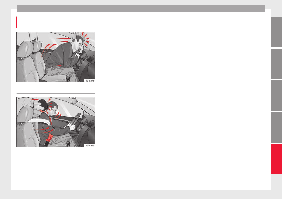
Seat belts
Physical principles of a frontal colli-
s
ion
Fig. 76 A driver not wearing a seat belt is
thr
o
wn f
orward violently
Fig. 77 The unbelted passenger in the rear
se
at
i
s thrown forward violently, hitting the
driver wearing a seat belt
It is easy to explain how the laws of physics
w
ork
in the c
ase of a head-on collision: when
a vehicle starts moving, a type of energy
called “kinetic energy” is created both in the
passengers and inside the vehicle.
The amount of “kinetic energy” depends on
the speed of the vehicle and the weight of
the vehicle and its passengers. The higher
the speed and the greater the weight, the
more energy there is to be “absorbed” in an
accident.
The most significant factor, however, is the
speed of the vehicle. If the speed doubles
from 25 km/h (15 mph) to 50 km/h
(30 mph), for example, the corresponding ki-
netic energy is multiplied by four.
Because the vehicle occupants in our exam-
ple are not restrained by seat belts, in the
event of crashing against a wall, all of the oc-
cupants' kinetic energy will be absorbed
solely by said impact.
Even at speeds of 30 km/h (19 mph) to
50 km/h (30 mph), the forces acting on bod-
ies in a collision can easily exceed one tonne
(1000 kg). At greater speed these forces are
even higher.
Vehicle occupants not wearing seat belts are
not “attached” to the vehicle. In a head-on
collision, they will move forward at the same
speed their vehicle was travelling just before
the impact. This example applies not only to
head-on collisions, but to all accidents and
collisions.
Even at low speeds the forces acting on the
body in a collision are so great that it is not
possible to brace oneself with one's hands.
In a frontal collision, unbelted passengers
are thrown forward and will make violent con-
tact with the steering wheel, dash panel,
windscreen or whatever else is in the way
››› Fig. 76.
It is also important for rear passengers to
wear seat belts properly, as they could other-
wise be thrown forward violently through the
vehicle interior in an accident. Passengers in
the rear seats who do not use seat belts en-
danger not only themselves but also the front
occupants ››› Fig. 77.
63
Technical dataAdviceOperationEmergenciesSafety
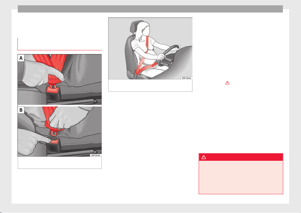
Safety
How to properly adjust your
se
at
belt
F
astening and unfastening the seat
belt
Fig. 78 Positioning and removing the seat
belt
b
uc
kle.
Fig. 79 Placing the seat belt in the shoulder
and pelv
i
s
area for pregnant women.
Fasten your seat belt
The se
at
belt
cannot offer its full protection if
the seat belt is not positioned correctly.
●
Adjust the seat and head restraint correctly.
●
To fasten the belt, take hold of the latch
plate and pull it slowly across your chest and
lap.
●
Insert the latch plate into the buckle for the
appropriate seat and push it down until it is
securely locked with an audible click
›››
Fig. 78 A.
●
Pull the belt to ensure that the latch plate is
securely engaged in the buckle.
The seat belts are equipped with an automat-
ic retractor on the shoulder strap. Full free-
dom of movement is permitted when the
shoulder belt is pulled slowly. However, dur-
ing sudden braking, during travel in steep
areas or bends and during acceleration, the
automatic retractor on the shoulder belt is
locked.
The automatic belt retractors on the front
seats are fitted with seat belt tensioners
››› page 65.
Seat belt release
●
Press the red button on the belt buckle
››› Fig. 78 B. The latch plate is released and
springs out ›››
.
●
Guide the belt back by hand so that it rolls
up e
a
s
ily and the trim is not damaged.
Positioning seat belts
Seat belts offer their maximum protection on-
ly when they are properly positioned.
The following features are available to adjust
the seat belt in the shoulder region:
●
belt height adjustment for the front seats.
●
front seat height adjustment*.
WARNING
●
The seat belt
s offer best protection only
when the backrests are in an upright position
and the seat belts have been fastened prop-
erly.
●
Never put the latch plate in the buckle of
another seat. If you do this, the seat belt will
64
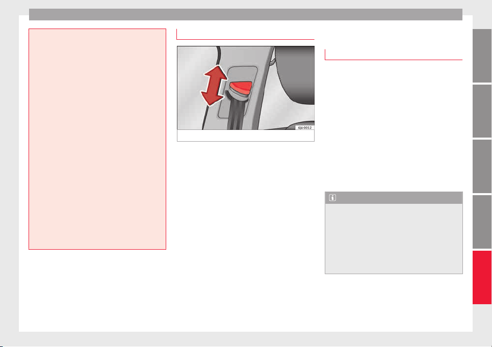
Seat belts
not protect you properly and the risk of injury
is inc
reased.
●
Never unbuckle a seat belt while the vehi-
cle is in motion. If you do, you increase the
risk of sustaining severe or fatal injuries.
●
An incorrectly worn seat belt can cause se-
vere injuries in the event of an accident.
●
The shoulder part of the seat belt must lie
on the centre of the shoulder, never across
the neck. The seat belt must lie flat and fit
comfortably on the torso
●
The lap part of the seat belt must lie across
the pelvis, never across the stomach. The
seat belt must lie flat and fit comfortably on
the pelvis Pull the belt tight if necessary to
take up any slack.
●
For pregnant women, the lap part of the
seat belt must lie as low as possible over the
pelvis, never across the stomach, and always
lie flat so that no pressure is exerted on the
abdomen ››› Fig. 79.
●
Always engage the retractor lock when you
are securing a child seat in group 0, 0+ or 1
››› page 72.
●
Read and observe the warnings ››› page 62.
Belt height adjustment
Fig. 80 Location of the belt height adjuster.
The seat belt adjuster for the front seats can
be u
sed t
o a
djust the proper belt position at
the shoulder.
–
Press the upper part of the shoulder belt
guide and hold it in this position ››› Fig. 80.
–
Move the shoulder belt guide up or down
until you have adjusted the seat belt
››› page 64.
–
After adjusting, pull the shoulder belt
sharply to check that the catch on the
shoulder belt guide is engaged securely.
Seat belt tensioners
How the seat belt tensioner works
Read the additional information carefully
›››
page 13.
The seat belts for the occupants in the front
seats are equipped with belt tensioners. Sen-
sors will trigger the belt tensioners only dur-
ing severe head-on, lateral and rear-end colli-
sions and only if the seat belt is worn. This
retracts and tightens the seat belts, reducing
the forward motion of the occupants.
The belt tensioners will not be triggered in
the event of minor collisions, if the vehicle
overturns, or in accidents where no major
forces act on the vehicle.
Note
●
If the seat
belt tensioners are triggered, a
fine dust is produced. This is normal and it is
not an indication of fire in the vehicle.
●
The relevant safety requirements must be
observed when the vehicle or components of
the system are scrapped. Specialised work-
shops are familiar with these regulations,
which are also available to you.
65
Technical dataAdviceOperationEmergenciesSafety
Safety
Service and disposal of belt tension-
er
s
The belt tensioners are components of the
seat belts
that are installed in the seats of
your vehicle. If you work on the belt tension-
ers or remove and install parts of the system
when performing other repair work, the seat
belt may be damaged. The consequence may
be that, in the event of an accident, the belt
tensioners function incorrectly or may not
function at all.
So that the effectiveness of the seat belt ten-
sioner is not reduced and that removed parts
do not cause any injuries or environmental
pollution, regulations, which are known to
the specialised workshops, must be ob-
served.
WARNING
●
Improper use or r
epairs not carried out by
qualified mechanics increase the risk of se-
vere or fatal injuries. The belt tensioners may
fail to trigger or may trigger in the wrong cir-
cumstances.
●
Never attempt to repair, adjust, remove or
install parts of the belt tensioners or seat
belts.
●
The seat belt tensioner, seat belt and auto-
matic retractor cannot be repaired.
●
Any work on the belt tensioners and seat
belts, including the removal and refitting of
system parts in conjunction with other repair
work, must be performed by a specialised
workshop on
ly.
●
The belt tensioners will only provide pro-
tection for one accident and must be changed
if they have been activated.
Airbag system
Brief
intr
oduction
Wh
y is it so important to wear a seat
belt and to sit correctly?
For the inflating airbags to achieve the best
protection, the se
at belt must always be worn
properly and the correct sitting position must
be assumed.
The airbag system is not a substitute for seat
belts, but it is an integral part of the vehicle's
overall passive safety system. Please bear in
mind that the airbag system can only work ef-
fectively when the vehicle occupants are
wearing their seat belts correctly and have
adjusted the head restraints properly. There-
fore, it is most important to wear the seat
belts at all times, not only because this is re-
quired by law in most countries, but also for
your safety
›››
page 61, The whys and where-
fores of seat belts.
The airbag inflates in a matter of seconds, so
if you are not properly seated when the air-
bag is triggered, you may sustain fatal inju-
ries. Therefore, it is essential that all vehicle
occupants assume a correct sitting position
while travelling.
Sharp braking before an accident may cause
a passenger not wearing a seat belt to be
thrown forward into the area of the deploying
66

Airbag system
airbag. In this case, the inflating airbag may
inflict
c
ritic
al or fatal injuries on the occu-
pant. This also applies to children.
Always maintain the greatest possible dis-
tance between yourself and the front airbag.
This way, the front airbags can completely
deploy when triggered, providing their maxi-
mum protection.
The most important factors that will trigger
an airbag are: the type of accident, the angle
of collision and the speed of the vehicle.
Whether or not the airbags are triggered de-
pends primarily on the vehicle deceleration
rate resulting from the collision and detected
by the control unit. If the vehicle deceleration
occurring during the collision and measured
by the control unit remains below the speci-
fied reference values, the front, side and/or
curtain airbags will not be triggered. Take in-
to account that the visible damage in a vehi-
cle involved in an accident, no matter how
serious, is not a determining factor for the
airbags to have been triggered.
WARNING
●
Wearin
g the seat belt incorrectly or assum-
ing an incorrect sitting position can lead to
critical or fatal injuries.
●
All vehicle occupants, including children,
who are not properly belted can sustain criti-
cal or fatal injuries if the airbag is triggered.
Children up to 12 years old should always
travel on the rear seat. Never transport chil-
dren in the v
ehicle if they are not restrained
or the restraint system is not appropriate for
their age, size or weight.
●
If you are not wearing a seat belt, or if you
lean forward or to the side while travelling or
assume an incorrect sitting position, there is
a substantially increased risk of injury. This
increased risk of injury will be further in-
creased if you are struck by an inflating air-
bag.
●
To reduce the risk of injury from an inflating
airbag, always wear the seat belt properly
››› page 61.
●
Always adjust the front seats properly.
Description of airbag system
The airbag system mainly comprises (as per
v
ehic
l
e equipment):
●
an electronic control and monitoring sys-
tem (control unit)
●
frontal airbags for driver and passenger,
●
side airbags,
●
curtain airbags,
●
a control lamp on the dash panel
››› page 68.
●
key-operated switch for front passenger air-
bag,
●
a control lamp for disabling/enabling the
front passenger airbag.
The airbag system operation is monitored
electronically. The airbag control lamp will il-
luminate for a few seconds every time the ig-
nition is switched on (self-diagnosis).
There is a fault in the system if the control
lamp :
●
does not light up when the ignition is
switched on ››› page 68,
●
turns off after 4 seconds after the ignition
is switched on
●
turns off and then lights up again after the
ignition is switched on
●
illuminates or flashes while the vehicle is
moving.
The airbag system is not triggered if:
●
the ignition is switched off
●
there is a minor frontal collision
●
there is a minor side collision
●
there is a rear-end collision
●
the vehicle turns over.
WARNING
●
The seat belt
s and airbags can only provide
maximum protection if the occupants are
seated correctly ››› page 56, Correct position
for passengers.
●
If a fault has occurred in the airbag system,
have the system checked immediately by a
specialised workshop. Otherwise, during a
»
67
Technical dataAdviceOperationEmergenciesSafety

Safety
frontal collision the system might not trigger
correctly
or may fail to trigger at all.
Airbag activation
The airbags deploy extremely rapidly, within
thousandths
of a second, to provide addi-
tional protection in the event of an accident.
A fine dust may develop when the airbag de-
ploys. This is normal and it is not an indica-
tion of fire in the vehicle.
The airbag system is only ready to function
when the ignition is on.
In special accidents instances, several air-
bags may activate at the same time.
In the event of minor head-on and side colli-
sions, rear-end collisions, overturning or roll-
over of the vehicle, airbags do not activate.
Activation factors
The conditions that lead to the airbag system
activating in each situation cannot be gener-
alised. Some factors play an important role,
such as the properties of the object the vehi-
cle hits (hard/soft), angle of impact, vehicle
speed, etc.
Deceleration trajectory is key for airbag acti-
vation.
The control unit analyses the collision trajec-
tory
and activates the respective restraint
system.
If the deceleration rate is below the prede-
fined reference value in the control unit the
airbags will not be triggered, even though
the accident may cause extensive damage to
the car.
The following airbags are triggered in seri-
ous head-on collisions
●
Driver airbag.
●
Front passenger front airbag
The following airbags are triggered in seri-
ous side-on collisions
●
Front side airbag on the side of the acci-
dent.
●
Rear side airbag on the side of the acci-
dent.
●
Curtain (head) airbag on the side of the ac-
cident.
In an accident with airbag activation:
●
the interior lights switch on (if the interior
light switch is in the courtesy light position);
●
the hazard warning lights switch on;
●
all doors are unlocked;
●
the fuel supply to the engine is cut.
Airbag and seat belt tensioner control
lamp
The control lamp monitors all airbags and
seat belt
tensioners in the vehicle, including
control units and wiring connections.
Monitoring of airbag and belt tensioner sys-
tem
Both the airbag and belt tensioner systems
operation is constantly monitored electroni-
cally. Each time the ignition is switched on,
the control lamp illuminates for several
seconds (self-diagnosis) and the instrument
panel display* shows AIRBAG/TENSIONER.
The system must be checked when the con-
trol lamp :
●
does not light up when the ignition is
switc
hed on,
●
turns off after 4 seconds after the ignition
is switched on
●
turns off and then lights up again after the
ignition is switched on
●
illuminates or flashes while the vehicle is
moving.
In the event of a malfunction, the warning
lamp stays on continuously. In addition, de-
pending on the malfunction, a fault message
appears on the instrument panel display for
approximately 10 seconds and a short audi-
ble warning is given. In this event, you
68

Airbag system
should have a specialised workshop check
the sy
s
t
em immediately.
If any of the airbags are disabled by a Techni-
cal Service, the warning lamp flashes for sev-
eral more seconds after verification and will
turn off if there is no fault.
WARNING
●
If there i
s a malfunction, the airbag and
belt tensioner system cannot properly per-
form its protective function.
●
If a malfunction occurs, have the system
checked immediately by a specialised work-
shop. Otherwise, in the event of an accident,
the airbag system and belt tensioners may
not be triggered, or may not be triggered cor-
rectly.
Airbag safety instructions
Fr
ont
airb
ags
Read the additional information carefully
›
›
›
page 13.
WARNING
●
The deployment
space between the front
passengers and the airbags must not in any
case be occupied by other passenger, pets
and objects.
●
The airbags
provide protection for just one
accident; replace them once they have de-
ployed.
●
It is also important not to attach any ob-
jects such as cup holders or telephone
mountings to the surfaces covering the air-
bag units.
●
Do not attempt to modify components of
the airbag system in any way.
●
When driving, always hold the steering
wheel with both hands on the outside part at
the 9 o'clock and 3 o'clock positions. Never
hold the steering wheel at the 12 o'clock po-
sition, or in any other manner (e.g. in the cen-
tre of the steering wheel). In such cases, if
the airbag is triggered, you may sustain inju-
ries to the arms, hands and head.
Side airbags*
Read the additional information carefully
›
›
›
page 15.
WARNING
●
If y
ou do not wear a seat belt, if you lean
forward, or are not seated correctly while the
vehicle is in motion, you are at a greater risk
of injury if the side airbag system is triggered
in an accident.
●
In order for the side airbags to provide their
maximum protection, the prescribed sitting
position must always be maintained with
seat belt
s fastened while travelling.
●
Occupants of the outer seats must never
carry any objects or pets in the deployment
space between them and the airbags, or al-
low children or other passengers to travel in
this position. It is also important not to at-
tach any accessories (such as cup holders) to
the doors. This would impair the protection
offered by the side airbags.
●
The built-in coat hooks should be used only
for lightweight clothing. Do not leave any
heavy or sharp-edged objects in the pockets.
●
Great forces, such as hard blows or kicks,
must not be exerted upon the backrest bol-
ster because the system may be damaged. In
this case, the side airbags would not be trig-
gered.
●
Under no circumstances should protective
covers be fitted over seats with side airbags
unless the covers have been approved for use
in your vehicle. Because the airbag deploys
from the side of the backrest, the use of con-
ventional seat covers would obstruct the side
airbag, seriously reducing the airbag's effec-
tiveness.
●
Any damage to the original seat upholstery
or around the seams of the side airbag units
must be repaired immediately by a special-
ised workshop.
●
The airbags provide protection for just one
accident; replace them once they have de-
ployed.
»
69
Technical dataAdviceOperationEmergenciesSafety
Safety
●
Any w
ork on the side airbag system or re-
moval and installation of the airbag compo-
nents for other repairs (such as removal of
the front seat) should only be performed by a
specialised workshop. Otherwise, faults may
occur during the airbag system operation.
●
Do not attempt to modify components of
the airbag system in any way.
●
The side and head airbags are managed
through sensors located in the interior of the
front doors. To ensure the correct operation of
the side and curtain (head) airbags neither
the doors nor the door panels should be
modified in any way (e.g. fitting loudspeak-
ers). If the front door is damaged, the airbag
system may not work correctly. All work car-
ried out on the front door must be done in a
specialised workshop.
●
In a side-on collision the side airbags will
not work if the sensors do not correctly meas-
ure the pressure increase on the interior of
the doors, due to air escaping through the
areas with holes or openings in the door pan-
el.
●
Never drive the vehicle if the interior panels
have been removed.
●
Never drive if the interior door panels have
been removed or if the panels have not been
correctly fitted.
●
Never drive the vehicle if the loudspeakers
in the door panels have been removed, un-
less the holes left by the loudspeakers have
been closed properly.
●
Alwa
ys check that the openings are closed
or covered if loudspeakers or other equip-
ment are fitted inside the door panels.
●
Any work carried out to the doors should be
made in an authorised specialised workshop.
Curtain airbags*
Read the additional information carefully
›››
page 15.
WARNING
●
In order for the he
ad-protection airbags to
provide their maximum protection, the pre-
scribed sitting position must always be main-
tained with seat belts fastened while travel-
ling.
●
For safety reasons, the curtain airbag must
be disabled in those vehicles fitted with a
screen dividing the interior of the vehicle.
See your technical service to make this ad-
justment.
●
There must be no other persons, animals or
objects between the occupants of the rear
seats and the deployment space of the head-
protection airbags so that the head-protec-
tion airbag can deploy without restriction and
provide the greatest possible protection.
Therefore, sun blinds which have not been
expressly approved for use in your vehicle
may not be attached to the side windows
●
The built
-in coat hooks should be used only
for lightweight clothing. Do not leave any
heavy or sharp-edged objects in the pockets.
Please, do not hang the clothes on coat hang-
ers.
●
The airbags provide protection for just one
accident; replace them once they have de-
ployed.
●
Any work on the head-protection airbag
system or removal and installation of the air-
bag components for other repairs (such as re-
moval of the roof lining) should only be per-
formed by a specialised workshop. Other-
wise, faults may occur during the airbag sys-
tem operation.
●
Do not attempt to modify components of
the airbag system in any way.
●
The side and head airbags are managed
through sensors located in the interior of the
front doors. To ensure the correct operation of
the side and curtain airbags neither the
doors nor the door panels should be modified
in any way (e.g. fitting loudspeakers). If the
front door is damaged, the airbag system
may not work correctly. All work carried out
on the front door must be done in a special-
ised workshop.
70
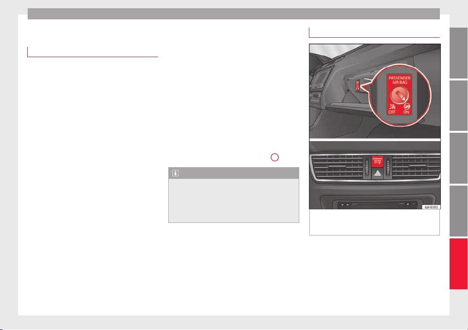
Airbag system
Deactivating airbags
D
e
activ
ation of the front airbag
The disabling of airbags is only carried out in
cert
ain cases, i.e. if:
●
a child seat is required in the front passen-
ger seat with the child facing in the opposite
direction to the direction of travel (in some
countries, due to divergent legal require-
ments, facing in the direction of travel)
››› page 74;
●
despite the driver seat being in the correct
position, a minimum di
stance of 25 cm can-
not be maintained between the centre of the
steering wheel and the driver's torso,
●
installation of special devices is required in
the steering wheel area due to a physical dis-
ability,
●
if you have special seats installed (e.g. an
orthopaedic seat without side airbags).
The front passenger front airbag can be disa-
bled using the switch
›››
page 71.
We recommend that you contact an author-
ised SEAT dealer for the disabling of other air-
bags.
Airbag system control
The airbag system availability is controlled
electronically, regardless of whether an air-
bag is disabled.
If an airbag was disabled using a diagnostics
system:
●
the airbag system warning lamp illumi-
nates after switching on the ignition for
about 4 seconds, and then flashes for about
12 seconds.
If the airbag has been disabled with the air-
bag switch on the side of the dash panel:
●
the airbag control lamp will illuminate
for about 4 seconds after the ignition is
switched on,
●
the airbag is disabled, signalled with the
warning lamp which lights up with the
word placed in the cen-
tre part of the dash panel ››› Fig. 81
3
.
Note
●
Fol
low the current legislation in your coun-
try regarding the disabling of airbags.
●
At your authorised SEAT dealer you can find
information on which vehicle airbags can be
disabled.
Front passenger front airbag switch
Fig. 81 Front passenger front airbag
sw
it
c
h/warning lamp for disabling the front
passenger airbag.
Read the additional information carefully
›
›
›
page 14.
The switch disables only the front passenger
front airbag.
Switching on the airbag
–
Switch the ignition off.
»
71
Technical dataAdviceOperationEmergenciesSafety
Safety
–
Open the p
a
s
senger side storage compart-
ment.
–
Insert the key into the slot of the switch for
deactivating the front passenger airbag
››› Fig. 81. About 3/4 of the key should en-
ter, as far as it will go.
–
Then turn the key gently to the position.
Do not force it if you feel resistance, and
make sure you have inserted the key fully.
–
Close the passenger side storage compart-
ment.
–
Check, with the ignition switched on, that
the control lamp does not illuminate,
with the words in the
centre of the dash panel.
Control lamp with the word
(front passenger airbag disabled)
If the front passenger front airbag is disa-
bled, after switching on the ignition, the con-
trol lamp will illuminate for several seconds,
then it will switch off for about 1 s and then
switch on again.
If the control lamp is flashing, there is a fault
in the disabling of the airbag system ›››
.
Pl
e
a
se go immediately to an Official Service.
WARNING
●
The driver of the
vehicle is responsible for
disabling or switching on the airbag.
●
Alwa
ys switch off the ignition before disa-
bling the front passenger airbag! Failure to do
so could result in a fault in the airbag disa-
bling system.
●
Never leave the key in the airbag disabling
switch as it could get damaged or enable or
disable the airbag during driving.
●
If the (airbag disabled) control lamp
flashes, the front passenger front airbag will
not trigger in the event of an accident! Have
the system immediately checked by an Offi-
cial Service.
Transporting children safely
Saf
ety
f
or children
Introduction
For safety reasons, as we have learned from
accident
statistics, we recommend that chil-
dren under 12 years of age travel in the rear
seats. Depending on their age, height and
weight, children travelling in rear seats must
use a child seat or a seat belt. For safety rea-
sons, the child seat should be installed in the
rear seat, behind the front passenger seat or
in the centre back seat.
The physical laws involved and the forces
acting in a collision apply also to children
›››
page 63. But unlike adults, children do not
have fully developed muscle and bone struc-
tures. This means that children are subject to
a greater risk of injury.
To reduce the risk of injuries, children must
always use special child restraint systems
when travelling in the vehicle.
We recommend the use of child safety prod-
ucts from the SEAT Original Accessories Pro-
gramme, which includes systems for all ages
made by “Peke” (not for all countries).
These systems have been especially de-
signed and approved, complying with the
ECE-R44. regulation.
72
Transporting children safely
Follow the manufacturer's instructions and
o
b
ser
ve any statutory requirements when in-
stalling and using child seats. Always read
and note ››› page 73.
We recommend you always carry the manu-
facturer's Child Seat Instruction Manual to-
gether with the on-board documentation.
Important information regarding the
front passenger's airbag
Read the additional information carefully
›
›
›
page 16.
Read and always observe the safety informa-
tion included in the following chapters:
●
Safety distance with respect to the passen-
ger airbag ››› page 66, Why is it so important
to wear a seat belt and to sit correctly?.
●
Objects between the passenger and the
passenger side airbag ›››
in Front airbags
on p
ag
e 69
.
The passenger side front airbag, when ena-
bled, is a serious risk for a child that is facing
backward since the airbag can strike the seat
with such force that it can cause serious or
fatal injuries. Children up to 12 years old
should always travel on the rear seat.
Therefore we strongly recommend you to
transport children on the rear seats. This is
the safest location in the vehicle. Alternative-
ly, the front passenger airbag can be disa-
bled with a key-operated switch ››› page 71.
When transporting children, use a child seat
suitable for the age and size of each child
››› page 72.
WARNING
●
If a chi
ld seat is secured to the front pas-
senger seat, the risk to the child of sustain-
ing critical or fatal injuries in the event of an
accident increases.
●
An inflating front passenger airbag can
strike the rear-facing child seat and project it
with great force against the door, the roof or
the backrest.
●
Never install a child seat facing backwards
on the front passenger seat unless the front
passenger front airbag has been disabled.
Risk of potentially fatal injuries to the child!
However, if it is necessary, in exceptional ca-
ses, to transport a child in the front passen-
ger seat, the front passenger front airbag
must always be disabled ››› page 71. If the
front passenger seat has a height adjustment
option, move it to the highest position.
●
For those vehicles that do not include a key
lock switch to deactivate the airbag, the vehi-
cle must be taken to a technical service.
●
All vehicle occupants, especially children,
must assume the proper sitting position and
be properly belted in while travelling.
●
Never hold children or babies on your lap,
this can result in potentially fatal injuries to
the child!
●
Never al
low a child to be transported in a
vehicle without being properly secured, or to
stand up or kneel on a seat while travelling.
In an accident, the child could be flung
through the vehicle, causing possibly fatal in-
juries to themselves and to the other vehicle
occupants.
●
If children assume an improper sitting posi-
tion when the vehicle is moving, they expose
themselves to greater risk of injury in the
event of a sudden braking manoeuvre or in an
accident. This is particularly important if the
child is travelling on the front passenger seat
and the airbag system is triggered in an acci-
dent; as this could cause serious injury or
even death.
●
A suitable child seat can protect your child!
●
Never leave a child alone in the child seat
or inside the vehicle because depending on
the season, very high temperatures may be
reached inside a parked vehicle, which could
be fatal.
●
Children who are less than 1.5 metres tall
must not wear a normal seat belt without a
child seat, as this could cause injuries to the
abdominal and neck areas during a sudden
braking manoeuvre or in an accident.
●
Only one child may occupy a child seat
››› page 74, Child seats.
73
Technical dataAdviceOperationEmergenciesSafety
Safety
Child seats
Saf
ety
in
structions
Read the additional information carefully
›››
page 16.
WARNING
●
When travel
ling, children must be secured
in the vehicle with a restraint system suitable
for age, weight and size.
●
Read and always observe information and
warnings concerning the use of child seats
››› page 73.
WARNING
●
The retainin
g rings are designed only for
use with “ISOFIX” and Top Tether* system
child seats.
●
Never secure other child seats that do not
have the “ISOFIX” or Top Tether* system, or
retaining belts or objects to the fastening
rings - this can result in potentially fatal inju-
ries to the child.
●
Ensure that the child seat is secured cor-
rectly using the “ISOFIX” and Top Tether* se-
curing rings.
Categorisation of child seats into
gr
oup
s
Use only child seats that are officially ap-
prov
ed and suitable for the child.
Child seats are subject to the regulation ECE-
R 44. ECE-R stands for: Economic Commis-
sion for Europe Regulation.
The child seats are grouped into 5 catego-
ries:
Group 0: Up to 10 kg (up to around 9
months)
Group 0+: Up to 13 kg (up to around 18
months)
Group 1: from 9 to 18 kg (up to approx. 4
years old)
Group 2: from 15 to 25 kg (up to approx. 7
years old)
Group 3: From 22 to 36 kg (over around 7
years old)
Child seats that have been tested and ap-
proved under the ECE R44 standard bear the
test mark on the seat (the letter E in a circle
with the test number below it).
Follow the manufacturer's instructions and
observe any statutory requirements when in-
stalling and using child seats.
We recommend you to always include the
manufact
urer's Child Seat Instruction Manual
together with the on-board documentation.
SEAT recommends you use child seats from
the Original Accessories Catalogue. These
child seats have been designed and tested
for use in SEAT vehicles. You can find the
right child seat for your model and age group
at SEAT dealers.
WARNING
Read and always observe information and
warning
s concerning the use of child seats
››› page 73.
74
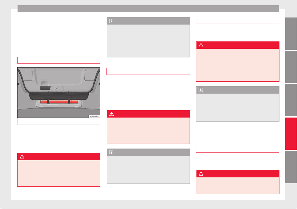
Self-help
Emergencies
Self
-help
Emer
g
ency equipment
First-aid kit and warning triangle*
Fig. 82 Location of the warning triangle.
The warning triangle, measuring max.
436 x 45 x 32 mm, c
an be sec
ur
ed to the lin-
ing on the rear of the luggage compartment
with rubber straps ››› Fig. 82.
WARNING
The first-aid kit and fire extinguisher must be
properly sec
ured so that they are not catapul-
ted through the vehicle during driving and
braking manoeuvres or in the event of an ac-
cident. Risk of injury.
Note
●
Obser
ve the expiry date of the contents of
the first aid kit.
●
We recommend you use the first-aid kit and
the warning triangle from the SEAT Original
Accessories programme available in author-
ised SEAT dealers.
Fire extinguisher*
Read the instructions given on the fire extin-
gui
sher c
ar
efully.
The fire extinguisher must be checked once a
year by an authorised person (take the appli-
cable legal regulations into account).
WARNING
The fire extinguisher must be properly se-
cured so th
at it is not catapulted through the
vehicle, causing injuries, during driving and
braking manoeuvres or in the event of an ac-
cident.
Note
●
The fire extin
guisher must comply with lo-
cal legal requirements.
●
Observe the expiry date of the fire extin-
guisher. The fire extinguisher may not work
properly if used after the expiry date.
Vehicle tool kit*
Read the additional information carefully
›››
page 46
WARNING
●
The factor
y-supplied jack is only designed
for changing wheels on this model of vehicle.
On no account attempt to use it for lighting
heavier vehicles or other loads. Risk of injury!
●
Make sure that the vehicle tools are stored
properly in the luggage compartment.
Note
●
Make s
ure the box always remains strap-
ped to the spare wheel with tape.
●
The jack does not generally require any
maintenance. If required, it should be
greased using universal type grease.
Changing a wheel
Intr
oduction
Read the additional information carefully
›
›
›
page 46
WARNING
●
If y
ou have a puncture in moving traffic,
switch on the hazard warning lights and
place the warning triangle at the obligatory
»
75
Technical dataAdviceOperationEmergenciesSafety
Emergencies
distance. Observe applicable local legal regu-
lations.
This is for your own safety and that of
other drivers.
●
If you have a flat tyre, stop the vehicle as
far away as possible from moving traffic. Stop
on flat, solid ground.
●
If you have to change the tyre on a gradi-
ent, block the wheel opposite the wheel be-
ing changed by placing a stone or similar ob-
ject under it to prevent the vehicle from roll-
ing away unexpectedly.
●
If the vehicle has been fitted with tyres or
alloys that are different to those fitted in
manufacture, the instructions ››› page 217,
New tyres or wheels must be followed.
●
Always raise the vehicle with the doors
closed.
●
Never place parts of your body, e.g. arms
and legs, underneath the vehicle when it is
supported only by the jack.
●
Secure the base of the jack with suitable
supports so that it cannot slip. The jack could
slide if the ground below it is soft and slip-
pery and the vehicle could slip off it. There-
fore, place the jack on a firm surface or use a
large, stable base. On a slippery surface, e.g.
tile, use a non-slip base such as a rubber
mat.
●
Never start the engine when the vehicle is
jacked. Risk of injury.
●
The jack should only be used in the correct
jacking points.
CAUTION
●
The pres
cribed tightening torque for wheel
bolts on steel and alloy wheels is 120 Nm.
●
If the anti-theft wheel bolt is overly tight-
ened, this could damage the bolt and the
adapter.
Note
●
The set of anti-thef
t wheel bolts or the
adapter are available from authorised SEAT
dealers.
●
Please observe the relevant local legal reg-
ulations when changing the wheel.
Wheel bolts
The wheel
bolts ar
e m
atched to the rims.
When installing different wheels, e.g. to fit
light alloy wheels or wheels with winter tyres,
it is important to use the correct wheel bolts
with the right length and correctly shaped
bolt heads. This is essential for a secure fit of
the wheels and for proper operation of the
brake system.
Note
●
Never gre
ase or oil the wheel bolts!
●
If the wheel bolt is very tight, it may be
possible to loosen it by pushing down the
end of the box spanner carefully with your
foot. Hold on to the vehicle for support and
take c
are not to slip.
●
If you notice that the wheel bolts are rusty
and difficult to turn when changing a wheel,
they must be replaced before having the
tightening torque checked.
Tyre repairs
TMS Anti-p
uncture kit (Tyre Mobility
System)*
Read the additional information carefully
›
›
›
page 45
The Tyre Mobility System is stored in a box
under the carpet in the boot.
Using the Tyre Mobility System you can relia-
bly seal tyres damaged by foreign bodies,
provided that cuts or punctures are no larger
than approx. 4 mm in diameter. Do not re-
move the foreign bodies, e.g. bolts or nails,
from the tyre!
The tyre must be repaired immediately.
The repair made using the Tyre Mobility Sys-
tem under no circumstances replaces perma-
nent tyre repair and should only be used to
drive to the nearest official service.
76
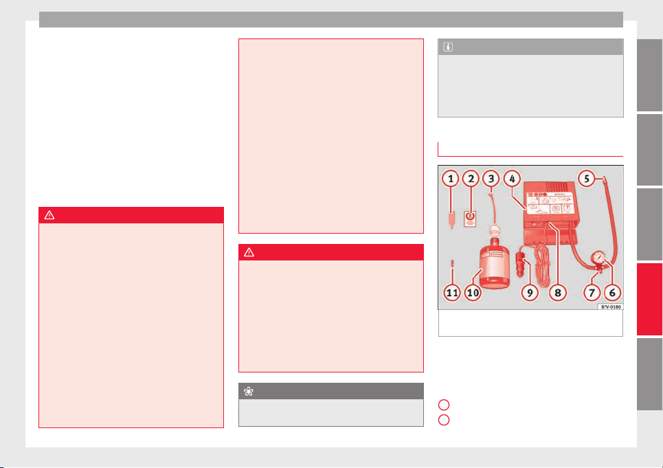
Self-help
The Tyre Mobility System kit shall not be
u
sed:
●
If
the wheel
rim has been damaged,
●
when the outside temperature is below
-20°C (-4°F),
●
on slashes or punctures larger than 4 mm,
●
if the sidewall of the wheel has been dam-
aged,
●
If you have been driving with very low tyre
pressure or a completely flat tyre
●
If the best-before date on the air can has
expired
WARNING
Using the tyre mobility system can be dan-
gerou
s, especially when filling the tyre at the
roadside. Please observe the following rules
to minimise the risk of injury:
●
Stop the vehicle safely as soon as possible.
Park it at a safe distance from surrounding
traffic to fill the tyre.
●
Ensure the ground on which you park is flat
and solid.
●
All passengers and particularly children
must keep a safe distance from the work area.
●
Turn on the hazard warning lights to warn
other road users.
●
Use the tyre mobility system only if you are
familiar with the necessary procedures. Oth-
erwise, you should seek professional assis-
tance.
●
The tyre mo
bility set is intended for tempo-
rary emergency use only until you can reach
the nearest specialised workshop.
●
Replace the repaired tyre with the tyre mo-
bility set as soon as possible.
●
The sealant is a health hazard and must be
cleaned immediately if it comes into contact
with the skin.
●
Always keep the tyre mobility set out of the
reach of small children.
●
Never use an equivalent jack, even if it has
been approved for your vehicle.
●
Always stop the engine, apply the hand-
brake lever firmly and engage gear if using a
manual gearbox, in order to reduce the risk of
vehicle involuntary movement.
WARNING
A tyre filled with sealant does not have the
same perf
ormance properties as a conven-
tional tyre.
●
Never drive faster than 80 km/h (50 mph).
●
Avoid heavy acceleration, hard braking and
fast cornering.
●
Drive for only 10 minutes at a maximum
speed of 80 km/h (50 mph) and then check
the tyre.
For the sake of the environment
Dispose of used or expired sealant observing
any l
egal requirements.
Note
●
A new bottle of se
alant can be purchased at
SEAT dealerships.
●
Take into account the separate instruction
manual of the tyre mobility set* manufactur-
er.
Contents of the tyre mobility set*
Fig. 83 Standard representation: contents of
the anti-p
u
nct
ure kit.
The anti-puncture kit is located underneath
the floor c
o
v
ering in the luggage compart-
ment. It includes the following components
››› Fig. 83:
Tyre valve remover
Sticker indicating maximum speed “max.
80 km/h” or “max. 50 mph”
»
1
2
77
Technical dataAdviceOperationEmergenciesSafety
Emergencies
Filler tube with cap
Air c
ompr
e
ssor
Tube for inflating tyres
Warning provided by tyre pressure moni-
toring system (it can also be integrated in
the compressor).
Air bleed screw (in its place, the compres-
sor may have a button).
ON/OFF switch
12 volt connector
Bottle of sealant
Spare tyre valve
The valve insert remover
1
has a gap at the
lo
w
er end f
or a valve insert. The valve insert
can only be screwed or unscrewed in this
way. This also applies to its replacement part
11
.
WARNING
When inflating the wheel, the air compressor
and the inflator t
ube may become hot.
●
Protect hands and skin from hot parts.
●
Do not place the hot flexible inflator tube or
hot air compressor on flammable material.
●
Allow them to cool before storing the de-
vice.
●
If it is not possible to inflate the tyre to at
least 2.0 bars (29 psi / 200 kPa), the tyre is
too badly damaged. The sealant is not in a
3
4
5
6
7
8
9
10
11
good condition to seal the tyre. Do not con-
tinue driving.
Seek specialist assistance.
CAUTION
Switch off the air compressor after a maxi-
mum of
8 operation
al minutes to avoid over-
heating! Before switching on the air compres-
sor again, let it cool for several minutes.
Check after 10 minutes of driving
Screw the inflator tube ›
›
›
Fig. 83
5
again
and c
hec
k
the pressure on the gauge
6
.
1.3 b
ar (19 p
s
i / 130 kPa) and lower:
●
Stop the vehicle! The tyre cannot be sealed
sufficiently with the tyre mobility set.
●
You should obtain professional assistance
›››
.
1.4 b
ar (20 p
s
i / 140 kPa) and higher:
●
Set the tyre pressure to the correct value
again.
●
Carefully resume your journey until you
reach the nearest specialised workshop with-
out exceeding 80 km/h (50 mph).
●
Have the damaged tyre replaced.
WARNING
Driving with an unsealed tyre is dangerous
and can cau
se accidents and serious injury.
●
Do not continue driving if the tyre pressure
is 1.3 bar (19 psi / 130 kPa) and lower.
●
Seek specialist assistance.
Towing the vehicle
Introduction
Read the additional information carefully
›
›
›
page 50.
Vehicles with manual gearbox can be towed
using a towbar or towrope. They can also be
towed with either the front or rear wheels lif-
ted off the road.
Vehicles with automatic gearbox can be tow-
ed using a towbar or towrope. They can also
be towed with the front wheels lifted off the
road. If the vehicle is towed with the rear
wheels lifted off the road the automatic gear-
box will be damaged!
Maximum towing speed is 50 km/h (31
mph).
78
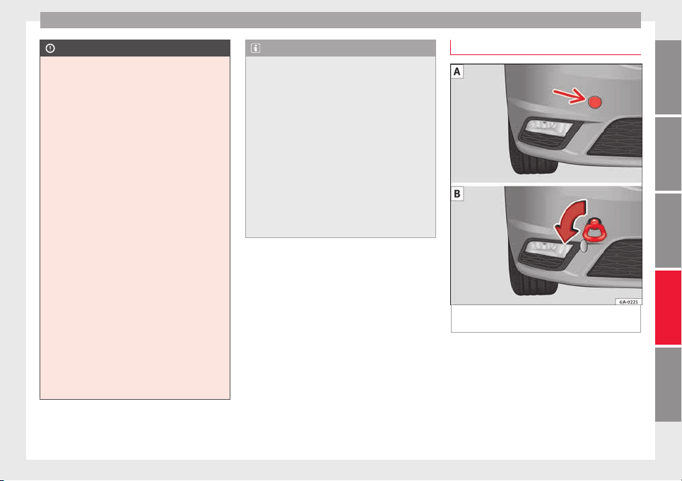
Self-help
CAUTION
●
Do not to
w-start the engine. Risk of engine
damage! In vehicles with a catalytic convert-
er, fuel that has not been burned could reach
the catalytic converter and catch fire in it.
This could damage and destroy the catalytic
converter. You may use the battery from an-
other vehicle to help you start your engine
›››
page 52.
●
If, due to a fault, there is no oil in the gear-
box, the car may only be towed with the driv-
en wheels lifted clear of the road and trans-
ported on a special vehicle transporter or
trailer.
●
If normal towing is not possible or if the ve-
hicle is to be towed for further than 50 km,
the vehicle must be transported on a special
vehicle transporter or trailer.
●
The towrope should be slightly elastic to
reduce the load on both vehicles during tow-
ing. It is advisable to use a towrope made of
synthetic fibre or similar material only.
●
Do not pull too hard with the towing vehicle
and always take care to avoid jerking the tow-
rope. When towing on a loose surface there is
always a risk of overloading and damaging
the anchorage points.
●
Attach the towrope or towbar only to the
towline anchorages or to the removable tow-
ing bracket ››› page 185, or ››› page 79.
Note
●
We rec
ommend you use the towrope or tow-
bar available in the SEAT Original Accessories
programme from authorised SEAT dealers.
●
Towing a vehicle requires a certain degree
of practical skill. Both drivers should be fa-
miliar with the technique required for towing.
Inexperienced drivers should not attempt to
tow away another vehicle or to have their ve-
hicle towed.
●
Note the legal regulations concerning tow-
ing, particularly those regarding the signal-
ling of the towed and towing vehicle.
●
The towrope must not be twisted, as under
certain circumstances this could unscrew the
front towline anchorage.
Front towline anchorage
Fig. 84 Front bumper: towline anchorage cov-
er/fittin
g.
Fitting and detaching the cover
–
Press on the left of the cover as indicated
b
y
the arr
ow ››› Fig. 84 .
–
Pull on the cover to remove it from the front
bumper.
–
To refit the cover after unscrewing the tow-
line anchorage, fit the cover and press
»
79
Technical dataAdviceOperationEmergenciesSafety
Emergencies
down on its right-hand side. The cover
mu
s
t
be securely engaged.
Fitting and detaching the towline anchorage
–
Screw in the towline anchorage anti-clock-
wise by hand as far as it will go ››› Fig. 84
.
To tighten the towline anchorage, we recom-
mend using the box spanner, the towing eye
from another vehicle or a similar object that
can be inserted through the anchorage.
–
Unscrew the towline anchorage by turning
it clockwise.
CAUTION
The towline anchorage must be screwed in as
far as
it will go. Otherwise there is a risk of
the screw connection shearing off during
towing or tow-starting!
Fuses and bulbs
F
u
se
s
Introduction
Due to the constant updating of vehicles,
fuse a
ssignments based on equipment and
the use of the same fuse for various electrical
components, it is not possible to provide an
up-to-date summary of the fuse positions for
the electrical components at the time this
manual was printed. For detailed information
about the fuse positions, please consult a
technical service.
In general, a fuse can be assigned to various
electrical components. Likewise, an electrical
component can be protected by several
fuses.
Only replace fuses when the cause of the
problem has been solved. If a newly inserted
fuse blows after a short time, you must have
the electrical system checked by a special-
ised workshop as soon as possible.
Additional information and warnings:
●
Working in the engine compartment
›››
page 203.
WARNING
The high voltages in the electrical system can
give serious
electrical shocks, causing burns
and even death!
●
Never touch the electrical wiring of the igni-
tion system.
●
Take care not to cause short circuits in the
electrical system.
WARNING
Using unsuitable fuses, repairing fuses or
bridging a curr
ent circuit without fuses can
cause a fire and serious injury.
●
Never use a fuse with a higher value. Only
replace fuses with a fuse of the same amper-
age (same colour and markings) and size.
●
Never repair a fuse.
●
Never replace a fuse by a metal strip, staple
or similar.
CAUTION
●
To prev
ent damage to the vehicle's electric
system, before replacing a fuse always turn
off the ignition, the lights and all electrical
elements and remove the key from the igni-
tion.
●
If you replace a fuse with higher-rating
fuse, you could cause damage to another part
of the electrical system.
80
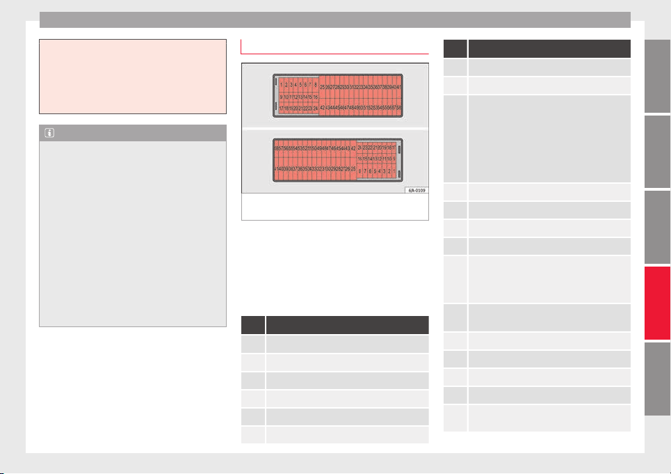
Fuses and bulbs
●
Protect
the fuse boxes when open to pre-
vent the entry of dust or humidity as they can
damage the electrical system.
●
Always carefully remove the fuse box cov-
ers and refit them correctly to avoid problems
with your vehicle.
Note
●
One c
omponent m
ay have more than one
fuse.
●
Several components may run on a single
fuse.
●
In the vehicle, there are more fuses than
those indicated in this chapter. These should
only be changed by a specialised workshop.
●
Positions not containing a fuse do not ap-
pear in the following tables.
●
Some of the equipment listed in the tables
below pertain only to certain versions of the
model or are optional extras.
●
Please note that the above lists, while cor-
rect at the time of printing, are subject to
change.
Fuses in the dash panel
Fig. 85 Diagram of the fuse box to the
l
ef
t/right
of the steering wheel
Read the additional information carefully
›
›
›
page 43
Only replace fuses with a fuse of the same
amperage (same colour and markings) and
size.
Fuse placement
No. Consumer
1 Left light
2 Central locking
3 Ignition system relay
4 Right light
5 Electric windows - Driver
6 Central control unit - Interior lights
No. Consumer
7 Horn
8 Towing bracket - Left light
9
Control lever under steering wheel, motor con-
trol device (without Keyless Access), automatic
transmission (without Keyless Access), automat-
ic transmission selector lever (without Keyless
Access), ESC (without Keyless Access), trailer
sensor control device (without Keyless Access),
steering force assist (without Keyless Access),
Airbag (without Keyless Access)
10 Electric window - rear left
11 Headlight washer unit
12 Radio and navigation display
13 Preparation as taxi
14
Control lever under steering wheel, light switch,
traction locking with ignition key (automatic
transmission), headlight flasher, SmartGate con-
trol device, rain sensor, telephone preparation
15
Air conditioning system control unit, automatic
gearbox selector lever, diagnostics connection
16 Instrument panel
17 Alarm sensor, horn
22 Automatic windscreen and front window washer
23 Heated front seats
24
Air conditioning fan, heating, control unit for air
conditioning, heating
»
81
Technical dataAdviceOperationEmergenciesSafety
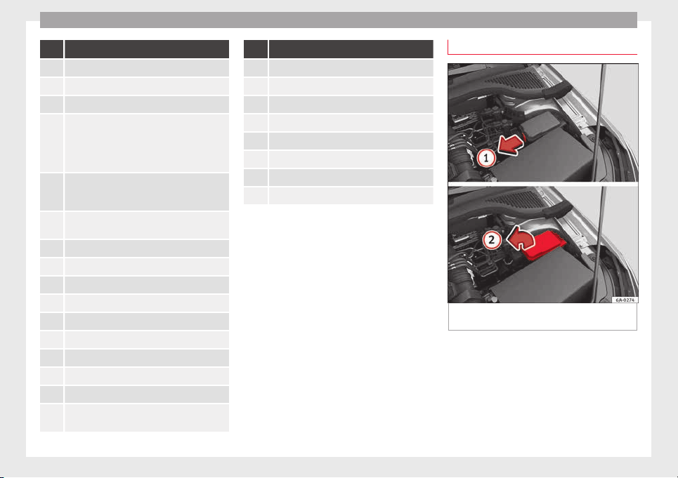
Emergencies
No. Consumer
26 Front seat heating switch.
27 Rear window wiper
29 Airbag (Keyless Access)
30
Electric windows, headlight switch, reversing
light switch, air conditioning control unit, park-
ing aid control unit, exterior mirror, feed for mid-
dle button bar, feed for the side button bar, inte-
rior mirror, telephone preparation
31
Fuel pump, radiator fan control unit, cruise con-
trol, relay coil for the windscreen and rear win-
dow washer system
32
Diagnostics socket, headlight range regulator,
control lever under the steering wheel
33 Ignition relay coil, clutch pedal switch
34 Heated windscreen washer jets
37 Radar
39 Additional electric heating
41 Rear window heater
42 Electric windows - passenger
43 Towing bracket - Connector contact
44 Lighter, 12 volt socket
45 Electric window - rear right
46
Windshield and front window washing system,
control lever under the steering wheel
No. Consumer
47 Towing bracket - Connector contact
48 Towing bracket - Right hand light
49 Fuel pump control unit
50 Radio
51 Heat for exterior mirrors
52 Keyless Access
53 Steering block seized (Keyless Access)
54 ABS/ESC control unit
Fuses in the engine compartment
Fig. 86 In the engine compartment: fuse box
c
o
v
er - 1st variant
82
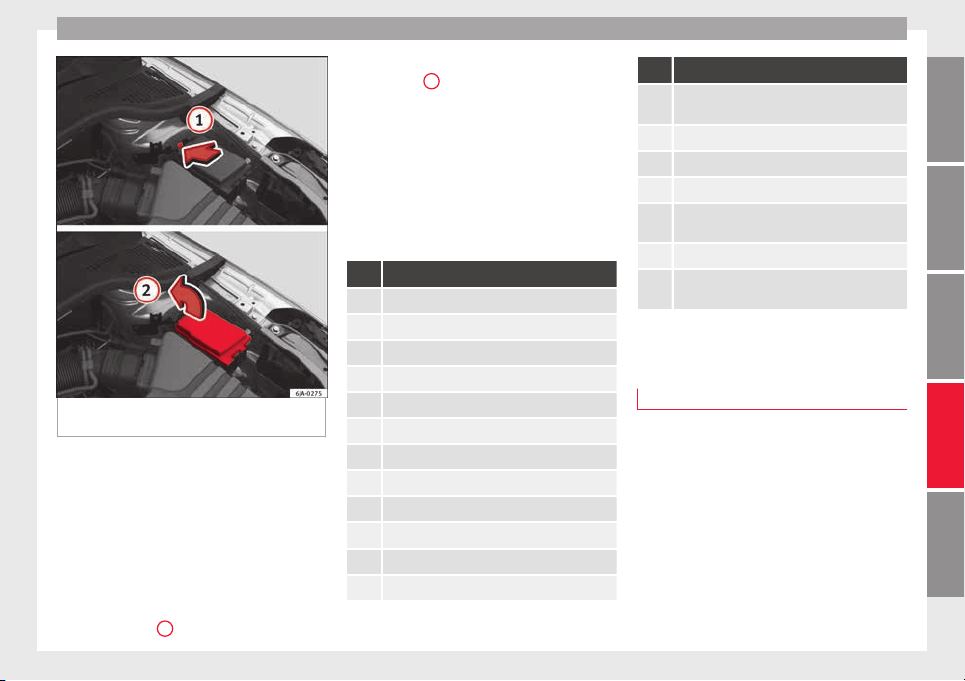
Fuses and bulbs
Fig. 87 In the engine compartment: fuse box
c
o
v
er - 2nd variant
Read the additional information carefully
›
›
›
page 43
Only replace fuses with a fuse of the same
amperage (same colour and markings) and
size.
Opening the fuse box
●
Open the bonnet ››› page 203.
●
Press lid locking clip upwards in the direc-
tion of the arrow
1
›
›
› Fig. 86
o ››› Fig. 87.
●
Open the cover in the direction indicated
by the arrow
2
.
●
Remove the plastic clip from the lid of the
f
u
se bo
x.
●
Replace the appropriate fuse.
●
Place the plastic clip back in its original po-
sition.
●
Place the lid on the fuse box and press un-
til you hear it click into place.
Fuse placement
No. Consumer
1 Radiator fan
2 Control unit for the glow system
3 ABS/ESC control unit
4 Additional electric heat - Circuit 2
5 Additional electric heat - Circuit 3
6 Automatic gearbox
7 Engine control unit
8 Front windscreen wipers
9 Central control unit, battery data module
10 ABS/ESC control unit
12 Engine components
13 Brake pedal switch
No. Consumer
14
Engine components, fuel coil relay, radiator fan,
coolant pump
15 Engine control unit
16 Starter motor
17 Engine control unit
18
Engine components, additional electric heat re-
lay coils
19 Lambda probe
20
Control devices for the glow system, heating of
the sump fan
Changing bulbs
Intr
oduction
Read the additional information carefully
›
›
›
page 44.
Depending on how equipped the vehicle is,
there are different sets of headlights and tail
lights:
●
Halogen main headlights (double head-
light).
●
Full-LED main headlights*.
●
Rear bulb light.
●
LED rear light*.
»
83
Technical dataAdviceOperationEmergenciesSafety
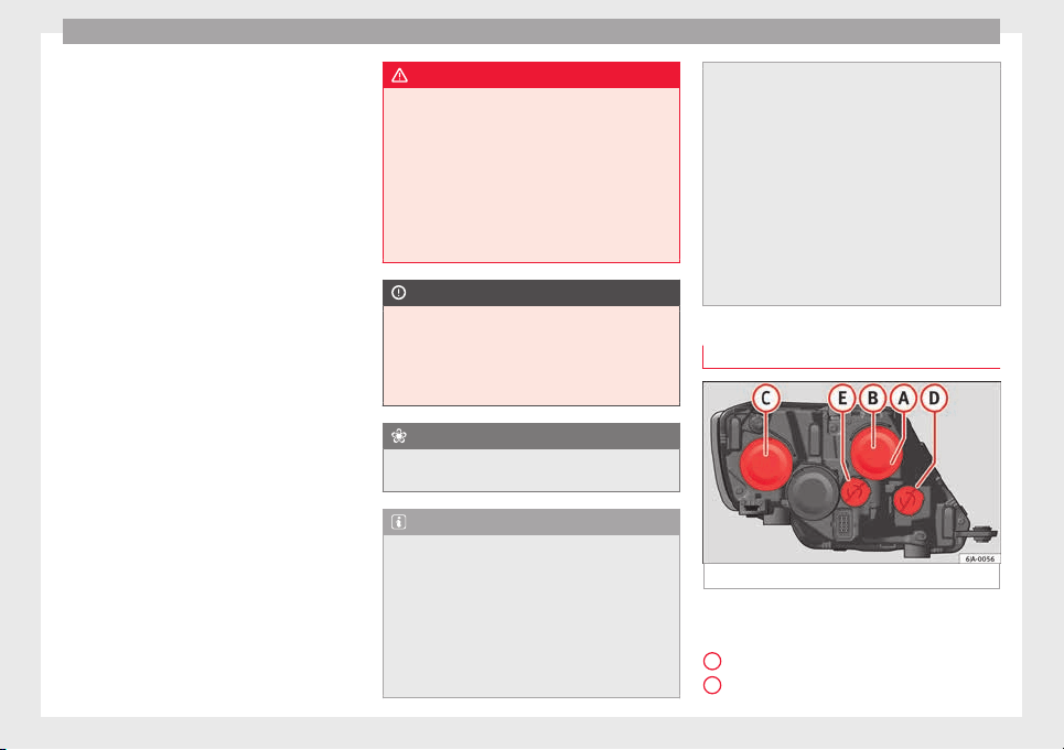
Emergencies
Full-LED headlight system*
F
u
l
l-LED headlights handle all light functions
(daylight, side light, turn signal, dipped
beam and route light) with light emitting di-
odes (LEDs) as a light source.
Full-LED headlights are designed to last the
lifetime of the car and light bulbs cannot be
replaced. In case of headlight failure, go to
an authorised workshop to have it replaced.
Double headlight bulb change
Changing bulbs requires a certain degree of
practical skill. If in doubt, we recommend you
have defective bulbs changed by a special-
ised service or, in case of an emergency,
seek professional assistance.
●
Switch off the ignition and all of the lights
before changing a bulb.
●
Do not touch the glass part of the bulb with
your bare hands. The fingerprints left on the
glass will vaporise as a result of the heat gen-
erated by the bulb, reducing bulb life and
causing condensation on the reflector sur-
face, thus reducing effectiveness.
●
A bulb must only be replaced by one of the
same type. The type is indicated on the bulb,
either on the glass part or on the base.
●
There is a storage area for the bulb box in
the spare wheel well or below the carpet in
the luggage compartment.
WARNING
●
Take p
articular care when working on com-
ponents in the engine compartment if the en-
gine is warm. Risk of burns.
●
Bulbs are highly sensitive to pressure. The
glass can break when you touch the bulb,
causing injury.
●
When changing bulbs, please take care not
to injure yourself on sharp parts in the head-
light housing.
CAUTION
●
Remov
e the ignition key before working on
the electric system. Otherwise, a short circuit
could occur.
●
Switch off the lights and the parking light
before changing a bulb.
For the sake of the environment
Please ask your specialist retailer how to dis-
pose of u
sed bulbs in the proper manner.
Note
●
Depending on w
eather conditions (cold or
wet), the front lights, the fog lights, the rear
lights and the turn signals may be temporari-
ly misted. This has no influence on the useful
life of the lighting system. By switching on
the lights, the area through which the beam
of light is projected will quickly be demisted.
However, the edges may continue to be mis-
ted.
●
Plea
se check at regular intervals that all
lighting (especially the exterior lighting) on
your vehicle is functioning properly. This is
not only in the interest of your own safety,
but also that of all other road users.
●
Before changing a bulb, make sure you
have the correct new bulb.
●
Do not touch the glass part of the bulb with
your bare hands, use a cloth or paper towel
instead. Otherwise, the fingerprints left on
the glass will vaporise as a result of the heat
generated by the bulb, they will be deposited
on the reflector and damage its surface.
Double headlight bulbs
Fig. 88 Main headlight bulbs.
Installation position of double headlight
b
u
l
bs
Side lights
Main beam headlights
A
B
84
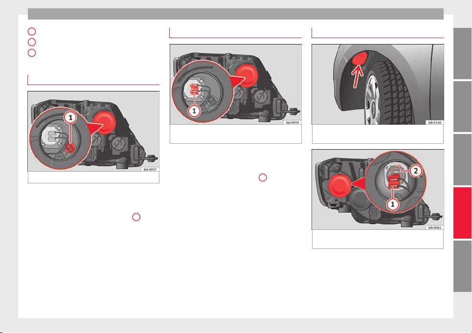
Fuses and bulbs
Dipped beam headlights
T
urn s
ign
al lights
Daylight
Changing side light bulbs
Fig. 89 Changing side light bulbs.
–
Raise the bonnet.
–
Remove the protective cover ›
›
›
Fig. 89.
–
Remove the bulb holder ››› Fig. 89
1
by
p
u
l
ling it outwards.
–
Remove the bulb by pulling it out and fit
the new one.
–
Installation involves all of the above steps
in reverse sequence.
–
Fit the protective cover. Make sure that the
cover fits correctly on the housing during
operation.
–
Check whether the new bulb is working.
C
D
E
Changing main beam headlight bulb
Fig. 90 Changing main beam headlight
b
u
l
bs.
–
Raise the bonnet.
–
Remove the protective cover.
–
Remove connector ›
›
›
Fig. 90
1
by pulling
outw
ar
d.
–
Extr
act the bulb and fit the replacement so
that it fits correctly into the recess on the
reflector.
–
Installation involves all of the above steps
in reverse sequence.
–
Fit the protective cover. Make sure that the
cover fits correctly on the housing during
operation.
–
Check whether the new bulb is working.
Changing dipped beam light bulbs
Fig. 91 Changing dipped beam headlight
b
u
l
bs: wheel housing.
Fig. 92 Changing dipped beam headlight
b
u
l
bs.
–
Turn the wheel for access to the wheel
hou
s
in
g cover and remove the cover
››› Fig. 91.
–
Remove the protective cover from the head-
light ››› Fig. 92.
»
85
Technical dataAdviceOperationEmergenciesSafety
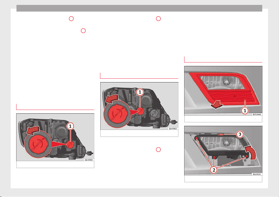
Emergencies
–
R
emo
v
e connector ››› Fig. 92
1
by pulling
outw
ar
d.
–
Unc
lip the retainer spring ››› Fig. 92
2
pressing clockwise and inwards.
–
Extract the bulb and fit the replacement so
th
at
the lug on the b
ase fits into the recess
on the reflector.
–
Fit the connector.
–
Fit the protective cover. Make sure that the
cover fits correctly on the housing during
operation.
–
Replace the wheel housing cover.
–
Check whether the new bulb is working.
Changing turn signal bulbs
Fig. 93 Changing turn signal bulbs.
–
Raise the bonnet.
–
T
urn the b
u
lb holder ››› Fig. 93
1
anti-
c
loc
k
wise and remove it.
–
Remove the bulb by pressing on the bulb
holder and turning it anti-clockwise at the
same time.
–
Fit the replacement bulb in the bulb holder
and turn clockwise as far as it will go.
–
Check whether the new bulb is working.
Changing daytime driving light bulbs
Fig. 94 Changing daytime driving light bulbs.
–
Raise the bonnet.
–
Turn the bulb holder ›
›
›
Fig. 94
1
anti-
c
loc
k
wise and remove it.
–
Remove the bulb by pressing on the bulb
holder and turning it anti-clockwise at the
same time.
–
Fit the replacement bulb in the bulb holder
and turn clockwise as far as it will go.
–
Check whether the new bulb is working.
Changing the fog light bulbs
Front fog light bulb
Fig. 95 Front fog light.
Fig. 96 Front fog light.
86
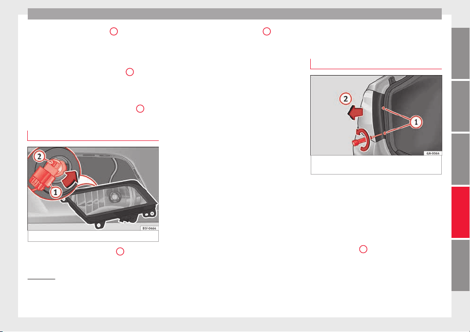
Fuses and bulbs
–
R
emo
v
e the bolt ››› Fig. 95
1
from the fog
light
gri
l
le with a screwdriver.
–
Subsequently, remove the clips located on
the edge of the grille with gentle leverage.
–
Remove the bolts (3x) ››› Fig. 96
2
to re-
mo
v
e the f
og light.
–
Remove the metal clip situated on the up-
per part of the fog light by pulling towards
the exterior of the vehicle ››› Fig. 96
3
.
Removing the bulb holder
Fig. 97 Front fog light.
–
Remove connector ›
›
›
Fig. 97
1
from the
b
u
l
b.
–
Turn the bulb holder ››› Fig. 97
2
anti-
c
loc
k
wise and pull.
–
Remove the bulb by pressing on the bulb
holder and turning it counter-clockwise at
the same time.
–
Installation involves all of the above steps
in reverse sequence.
–
Check that the bulb works properly.
Changing the rear lights (on
the side panel)
Removing the rear light
1)
Fig. 98 Remove the rear light unit from side
p
anel
.
Check which of the bulbs is defective.
–
Open the luggage compartment to access
the r
ainduct
ar
ea.
–
Take the screwdriver or a Torx 20 key (T20)
from the vehicle tool kit and loosen (turn-
ing anti-clockwise) and remove the two re-
taining screws that secure the front of the
light
›››
Fig. 98
1
, taking care not to lose
them.
»
1)
In the case of LED rear lights of the side panel only
the turn sign
al lamp can be changed. The illustra-
tions in the manual correspond to the bulb version
and do not correspond exactly to the LED version.
87
Technical dataAdviceOperationEmergenciesSafety
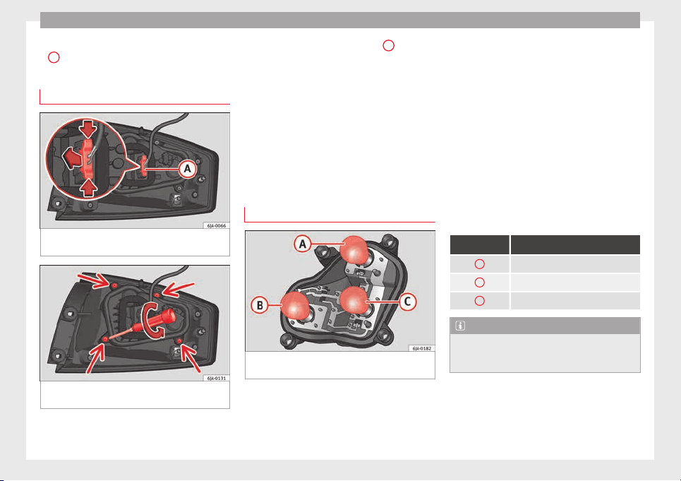
Emergencies
–
P
u
l
l the rear light unit backward (››› Fig. 98
2
) to remove the light from its housing.
Removing the bulb holder
Fig. 99 Light connector at the rear of the rear
light
u
nit
.
Fig. 100 Retaining screws on reverse side of
r
e
ar light
unit.
–
Di
s
c
onnect the light connector
A
››› Fig. 99 b
y moving its side levers (arrows)
and p
u
lling the connector outwards.
–
Place the light on a level, horizontal surface
on top of a soft cloth so as not to scratch
the outer glass.
–
Unscrew the four retaining screws from the
bulb holder anti-clockwise using a screw-
driver or a Torx 20 key (T20) from the vehi-
cle tool kit ››› Fig. 100. Take care not to lose
the bulb holder retaining screws.
Changing bulbs
Fig. 101 Position of the bulbs in the bulb
ho
l
der
The bulbs are secured with a bayonet fasten-
er
.
The t
able below gives an overview of the
bulb positions.
–
Lightly press the defective bulb into the
bulb holder, then turn it anti-clockwise and
remove it.
–
Fit the new bulb, pressing it into the bulb
holder and turn it clockwise as far as it will
go.
–
Use a cloth to remove any fingerprints from
the glass part of the bulb.
–
Check that the new bulb works properly.
–
Replace the bulb holder.
–
Screw in the bulb holder using the four
screws, turning them clockwise.
Position of the bulbs
››› Fig. 101 Bulb function
A
Turn signals: PY21W NA LL
B
Side lights-brake lights: P21/5W
C
Side lights: P21/5W
Note
Check the condition of the seal. If damaged, a
repl
acement can be acquired from an Official
Service.
88
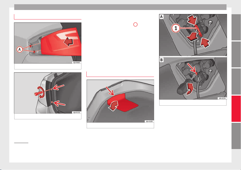
Fuses and bulbs
Fitting the rear light
Fig. 102 Fit the tail light unit.
Fig. 103 Fit the tail light unit.
–
Make sure the connector is correctly in
p
l
ac
e.
–
Press the rear light unit backwards (driving
direction) by fitting the fastenings into the
rubber mountings ››› Fig. 102
A
.
–
Take the screwdriver or a Torx 20 key (T20)
fr
om the
v
ehicle tool kit and tighten (turn-
ing clockwise ››› Fig. 103) the two retaining
screws that secure the front of the light.
Changing tail lights (on the
rear lid)
Removing the bulb holder
1)
Fig. 104 Remove the cover from the boot lid.
Fig. 105 Remove the bulb holder.
The rear lid must be open to change the
b
u
l
bs.
You can access the bulb holder for the inner
tail lights through the inside of the rear lid.
–
Check which of the bulbs is defective.
»
1)
For rear-lid LED rear lights, only the reverse and
retro f
og bulb can be replaced. The illustrations in
the manual correspond to the bulb version and do
not correspond exactly to the LED version.
89
Technical dataAdviceOperationEmergenciesSafety
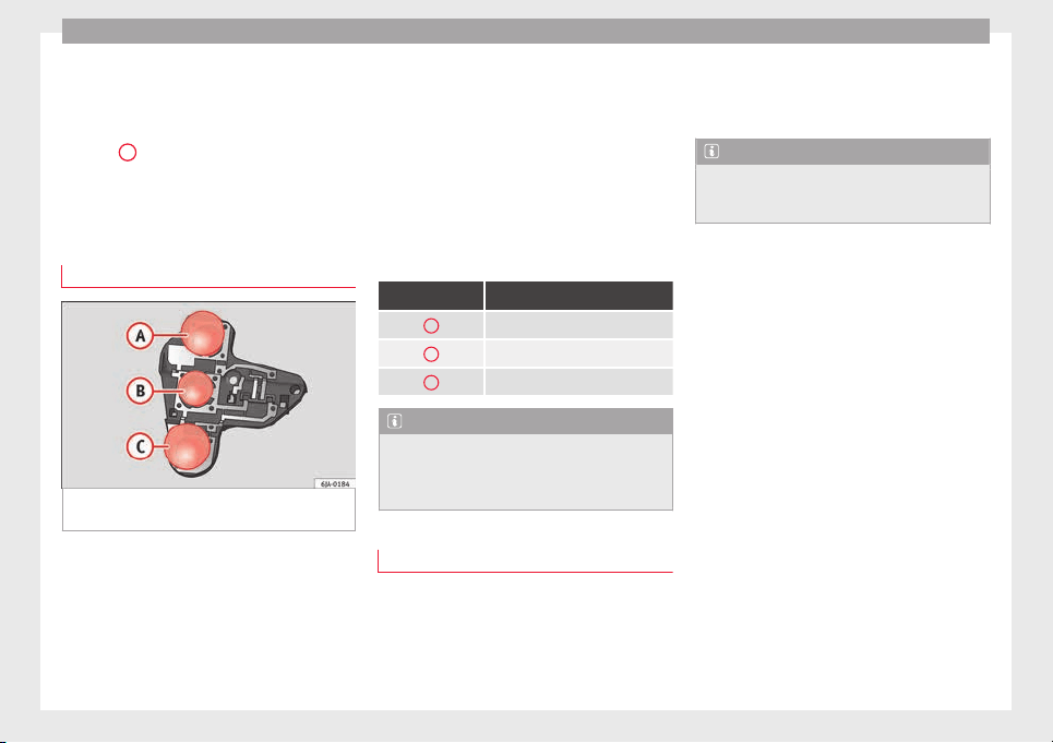
Emergencies
–
Open the c
o
v
er to access the lights, turning
it by hand in the direction indicated by the
arrows.
–
Access the lights by disconnecting the con-
nector
1
›
›› Fig. 105
and unscrewing
the bulb holder ››› Fig. 105 . Take care not
to lose the bulb holder retaining screw.
–
Change the bulbs ››› page 90.
Changing bulbs
Fig. 106 Position of the bulbs in the bulb
ho
l
der
The bulbs are secured with a bayonet fasten-
er
.
The t
able below gives an overview of the
bulbs ››› table on page 90.
–
Lightly press the defective bulb into the
bulb holder, then turn it anti-clockwise and
remove it.
–
Fit the new bulb, pressing it into the bulb
holder and turn it clockwise as far as it will
go.
–
Use a cloth to remove any fingerprints from
the glass part of the bulb.
–
Check that the new bulb works properly.
–
Re-install the bulb holder ››› page 90.
–
Screw in the bulb holder.
Position of the bulbs
››› Fig. 106 Bulb function
A
Reversing lights: P21W
B
Side lights: R5W LL
C
Fog lights: P21W
Note
One of the two sides may not be fitted with a
fog light, depending on the c
ountry and type
of driving. In this case, the hole for the light
is covered.
Fitting the bulb-holder
–
Position the bulb holder on the tail light
and align it
so th
at
it is securely seated.
–
Screw in the bulb holder using the corre-
sponding screw.
–
Make sure the connector is correctly in
place.
–
Close the inner trim cover.
Note
Check the condition of the seal. If damaged, a
repl
acement can be acquired from an Official
Service.
90
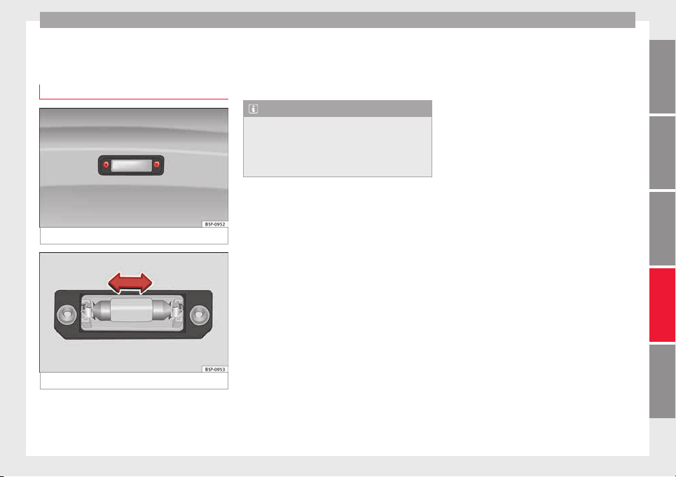
Fuses and bulbs
Changing the bulb on the num-
ber p
l
at
e
Removing the bulb holder
Fig. 107 Removing number plate light
Fig. 108 Changing the bulb.
–
Unscrew the screws to remove the bulb
›
›
›
Fig. 107.
–
Remove the bulb, moving it in the direction
of the arrow and outwards ››› Fig. 108.
–
Installation involves all of the above steps
in reverse sequence.
Note
Depending on how equipped the vehicle is,
the number plat
e lights may be LEDs. LEDs
have an estimated life that exceeds than that
of the car. If a light with LEDs fails, go to an
authorised workshop for replacement.
91
Technical dataAdviceOperationEmergenciesSafety
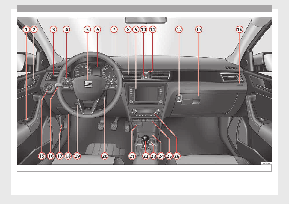
Operation
Fig. 109 Interior.
92
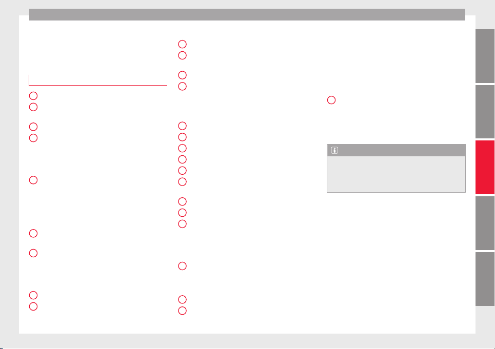
Controls and displays
Operation
C
ontr
o
ls and displays
General instrument panel
Electric window controls . . . . . . . . . . 120
Control for adjusting electric exteri-
or mirrors . . . . . . . . . . . . . . . . . . . . . . . . 130
Air outl
ets . . . . . . . . . . . . . . . . . . . . . . . . 147
Multifunction switch lever:
–
Turn sign
als, headlights, parking
lights, headlight flasher . . . . . . . . 123
–
Cruise c
ontrol system . . . . . . . . . . . 176
Steering wheel:
–
With horn
–
With the driv
er front airbag . . . . . . 13
–
With contr
ols for audio, naviga-
tion system and telephone . . . . . . 105
General instrument panel: instru-
ments and warnin
g lamps . . . . . . . . 93
Multifunction switch lever:
–
Multifunction display . . . . . . . . . . . 22
–
Winds
creen wipers and wind-
screen washers . . . . . . . . . . . . . . . . . 129
Air outlets . . . . . . . . . . . . . . . . . . . . . . . . 147
Depending on the equipment:
–
Audio sy
s
t
em
1
2
3
4
5
6
7
8
9
–
Nav
ig
ation sy
stem
Hazard warning lights switch . . . . . . 126
Control lamp for front passenger
airbag deactivated warning lamp . . 71
Front passenger airbag switch . . . . 71
Depending on the equipment,
glove compartment with: . . . . . . . . . 135
–
CD player* and/or SD card*
››› Booklet Radio
Front passenger airbag . . . . . . . . . . . 13
Light switch . . . . . . . . . . . . . . . . . . . . . . 121
Headlight range control . . . . . . . . . . . 122
Bonnet release lever . . . . . . . . . . . . . . 205
Fuse compartment . . . . . . . . . . . . . . . . 81
Steering column adjustment lev-
er . . . . . . . . . . . . . . . . . . . . . . . . . . . . . . . . 13
Ignition lock . . . . . . . . . . . . . . . . . . . . . . 154
USB/AUX-IN input . . . . . . . . . . . . . . . . 109
Depending on the equipment:
–
Gear lever (manual gearbox) . . . . 158
–
Selector l
ever (automatic gear-
box) . . . . . . . . . . . . . . . . . . . . . . . . . . . . 160
Depending on the equipment:
–
Drink hol
der . . . . . . . . . . . . . . . . . . . . 136
–
Ashtray
holder . . . . . . . . . . . . . . . . . . 138
Rear shelf . . . . . . . . . . . . . . . . . . . . . . . . 135
Depending on the equipment, con-
trol
s for:
10
11
12
13
14
15
16
17
18
19
20
21
22
23
24
25
–
Driv
er he
at
ed seat . . . . . . . . . . . . . . 133
–
Park assist system . . . . . . . . . . . . . . 168
–
Central lock button . . . . . . . . . . . . . 114
–
Heated rear window . . . . . . . . . . . . 128
–
Start-Stop system . . . . . . . . . . . . . . . 182
–
Front passenger heated seat . . . . 133
Depending on the equipment:
–
Heating controls . . . . . . . . . . . . . . . . 148
–
Air conditioning controls . . . . . . . . 149
–
Climatronic controls . . . . . . . . . . . . 151
Note
The location of the controls of right-hand
drive car
s differs slightly from the location
shown here ››› Fig. 109. However, the sym-
bols correspond to the respective controls.
26
93
Technical dataAdviceOperationEmergenciesSafety
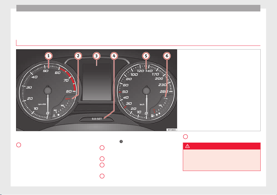
Operation
Instruments and warning lamps
In
s
trument
s
View of instrument panel
Fig. 110 Instrument panel, on dash panel
Details of the instruments ›
›
›
Fig. 110:
Rev counter (with the engine running, in
hundreds of revolutions per minute).
The beginning of the red zone of the rev
counter indicates the maximum speed in
any gear after running-in and with the en-
gine hot. However, it is advisable to
change up a gear or move the selector
lever to D (or lift your foot off the acceler-
1
ator) before the needle reaches the red
z
one ›
›
›
.
En
gine c
oo
lant temperature display
››› page 206.
Displays on the screen.
Adjuster button and display
››› page 97.
Speedometer.
2
3
4
5
Fuel gauge ›
›› p
ag
e 98.
WARNING
Any distraction may lead to an accident, with
the risk of
injury.
●
Do not operate the instrument panel con-
trols when driving.
6
94
Instruments and warning lamps
CAUTION
●
To prev
ent damage to the engine, the rev
counter needle should only remain in the red
zone for a short period of time.
●
When the engine is cold, avoid high revs
and heavy acceleration and do not make the
engine work hard.
For the sake of the environment
Changing up a gear in time reduces fuel con-
sumption and noise.
Rev counter
The rev counter indicates the number of en-
gine r
ev
o
lutions per minute
›››
Fig. 110
1
.
T
og
ether w
ith the gear-change indicator, the
rev counter offers you the possibility of using
the engine of your vehicle at a suitable
speed.
The start of the red zone on the dial indicates
the maximum engine speed which may be
used briefly when the engine is warm and af-
ter it has been run in properly. Before reach-
ing this range, you should change to a higher
gear for vehicles with a manual gearbox or for
automatic gearboxes put the selector lever in
“D” or take your foot off the accelerator ped-
al.
We recommend that you avoid high revs and
that you follow the recommendations on the
gear-change indicator. Consult the additional
information in ›››
page 24.
CAUTION
Never allow the rev counter needle
1
››› Fig. 110 to go int
o the red zone on the
scale for more than a very brief period, other-
wise there is a risk of engine damage.
For the sake of the environment
Changing up a gear early will help you to save
fuel and minimi
se emissions and engine
noise.
Indications on the display
A variety of information can be viewed on the
in
s
trument
panel display
›››
Fig. 110
3
de-
pendin
g on the
v
ehicle equipment:
●
Bonnet, rear lid and doors open
›››
page 25.
●
Information and warning texts.
●
Mileage.
●
Time.
●
Navigation instructions.
●
Outside temperature.
●
Compass.
●
Shift lever position ››› page 160.
●
Recommended gear (manual gearbox)
›››
page 24.
●
Multifunction display (MFD) and menus
with different setting options ›››
page 22.
●
Service interval display ›››
page 30.
●
Second speed display ›››
page 26.
●
Speed warning function ›››
page 29.
●
Start-Stop system status display
››› page 182.
●
Low consumption driving status (ECO)
››› page 96
●
Identifying letters on engine (MKB).
Distance travelled
The odometer registers the total distance
travelled by the car.
The odometer (trip) shows the distance
travelled since the last odometer reset. The
last digit of the trip recorder indicates distan-
ces of 100 metres or one tenths of a mile.
●
Briefly press the button ››› Fig. 110
4
to re-
set
the trip r
ec
order to 0.
●
Keep the button
4
pressed for about 3
sec
ond
s
and the previous value will be dis-
played.
»
95
Technical dataAdviceOperationEmergenciesSafety
Operation
Time
●
To set the time, keep the button ›
›
›
Fig. 110
4
pressed for more than 3 seconds to select
the hour or minut
e di
s
play.
●
To continue setting the time, press the up-
per or lower part of the button
4
. Hold but-
t
on do
wn t
o scroll through the numbers
quickly.
●
Press the button
4
again in order to finish
settin
g the time.
The time c
an al
so be set via the
key and
Set
up
function button in the Easy Connect
sy
s
t
em ››› page 104.
Compass
With the ignition on and the navigation sys-
tem on, the cardinal point corresponding to
the direction of travel of the vehicle is dis-
played on the instrument panel.
Selector lever position
The selected gear is displayed on the side of
the selector lever and on the instrument pan-
el display. In positions D and S, and with the
Tiptronic, the corresponding gear is also dis-
played.
Recommended gear (manual gearbox)
The recommended gear in order to save fuel
is displayed on the instrument panel while
you are driving ›››
page 24.
Second speed display (mph or km/h)
In addition to the speedometer, the speed
can also be displayed in a different unit of
measurement (in miles or in km per hour).
This option cannot be deactivated in models
destined for countries in which the second
speed must always be visible.
The second speed display can be adjusted in
the Easy Connect system via the
key and
the
Set
up
function button ›
›
›
page 104.
Speed warning
When the speed setting is exceeded, this will
be indicated on the instrument panel display.
This is very useful, for example when using
winter tyres that are not designed for driving
at the maximum speed of the vehicle
›››
page 29.
The speed warning settings can be adjusted
in the Easy Connect system via the
key
and the
Set
up
function button ›
›
›
page 104.
Start-Stop operating display
Updated information relating to the status is
displayed on the instrument panel
››› page 182.
Low consumption driving status (ECO)*
Depending on the equipment, when driving,
the “ECO” display appears on the instrument
panel when the vehicle is in low consump-
tion status.
Identifying letters on engine (MKB)
Hold the button ››› Fig. 110
4
down for more
th
an 15 sec
ond
s to display the identifying
letters of the vehicle engine (MKB). To do
this, the ignition must be switched on and
the engine switched off.
WARNING
Observe the safety warnings ›››
in Warning
and indication lamp
s on page 98.
WARNING
Even though outside temperatures are above
freezin
g, some roads and bridges may be icy.
●
At outside temperatures above +4°C
(+39°F), even when the “ice crystal symbol”
is not visible, there may still be patches of ice
on the road.
●
Never rely on the outside temperature indi-
cator!
Note
●
Different
versions of the instrument panel
are available and therefore the versions and
instructions on the display may vary. In the
case of displays without warning or informa-
tion texts, faults are indicated exclusively by
the warning lamps.
96
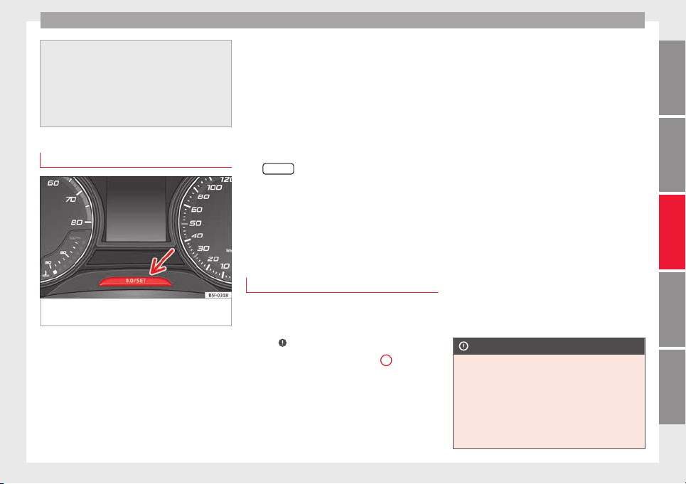
Instruments and warning lamps
●
Depending on the equipment, some set
-
tings and instructions can also be carried out
in the Easy Connect system.
●
When several warnings are active at the
same time, the symbols are shown succes-
sively for a few seconds and will stay on until
the fault is rectified.
Odometer
Fig. 111 Instrument panel: odometer and re-
set
b
utt
on.
The distance covered is displayed in “kilome-
tr
e
s” or mi
les “m”. It is possible to change
the measurement units (kilometres
“km”/miles “m”) in the radio/Easy Connect*.
Please refer to the Easy Connect* Instructions
Manual for more details.
Odometer/trip recorder
The odometer shows the total distance cov-
ered by the vehicle.
The trip recorder shows the distance that has
been travelled since it was last reset. It is
used to measure short trips. The last digit of
the trip recorder indicates distances of 100
metres or tenths of a mile.
The trip recorder can be set to zero by press-
ing
0.0/SET
›
›› Fig. 111
.
F
ault display
If there is a fault in the instrument panel, the
letters DEF will appear in the trip recorder
display. Have the fault repaired immediately,
as far as is possible.
Engine coolant temperature display
For vehicles with no coolant temperature
g
aug
e, a c
ontrol lamp appears for high
coolant temperatures
›››
page 208. Please
note
›››
.
The c
oo
l
ant temperature gauge
2
›››
Fig. 110 only w
orks when the ignition is
switched on. In order to avoid engine dam-
age, please read the following notes for the
different temperature ranges.
Engine cold
If only
the diodes in the lower part of the
scale light up, this indicates that the engine
has not yet reached operating temperature.
Avoid high revs and heavy acceleration and
do not make the engine work hard.
Normal temperature
If in normal operations, the diodes light up
until the central zone, it means that the en-
gine has reached operating temperature. At
high outside temperatures and when making
the engine work hard, the diodes may contin-
ue lighting up and reach the upper zone. This
is no cause for concern, provided the control
lamp does not light up on the instrument
panel digital display.
Heat range
When the diodes light up in the upper area of
the display and the control lamp appears
on the instrument panel display, the coolant
temperature is excessive ››› page 208.
CAUTION
●
To ens
ure a long useful life for the engine,
avoid high revs, driving at high speed and
making the engine work hard for approxi-
mately the first 15 minutes when the engine
is cold. The phase until the engine is warm al-
so depends on the outside temperature. If
necessary, use the engine oil temperature*
››› page 206 as a guide.
»
97
Technical dataAdviceOperationEmergenciesSafety
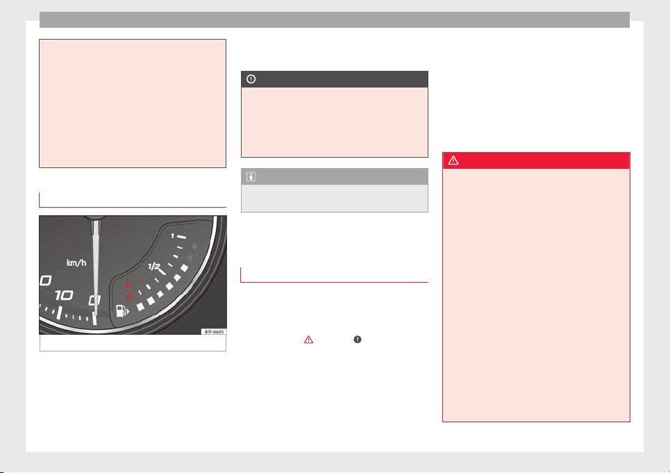
Operation
●
Additiona
l lights and other accessories in
front of the air inlet reduce the cooling effect
of the coolant. At high outside temperatures
and high engine loads, there is a risk of the
engine overheating.
●
The front spoiler also ensures proper distri-
bution of the cooling air when the vehicle is
moving. If the spoiler is damaged this can re-
duce the cooling effect, which could cause
the engine to overheat. Seek specialist assis-
tance.
Fuel level gauge
Fig. 112 Fuel gauge.
The fuel gauge ›
›
›
Fig. 112 operates only
when the ignition is switched on.
The fuel tank has a capacity of approx. 55 li-
tres. When the needle reaches the reserve
area, the ››› page 102 warning symbol illu-
minates on the general instrument panel and
an audible warning can be heard.
CAUTION
Never completely empty the tank! An irregu-
larity in the f
uel supply system can cause ir-
regularities when the engine is running. Un-
burned fuel can reach the exhaust gas sys-
tem, which can cause deterioration of the cat-
alytic converter.
Note
Some vehicles come fitted with the fuel
gauge on the g
eneral instrument panel.
Control lamps
W
arnin
g and indic
ation lamps
Read the additional information carefully
›
›
›
page 32.
The control and warning lamps are indicators
of warnings,
›››
, faults
›
›
›
or certain func-
tion
s.
Some c
ontrol and warning lamps come
on when the ignition is switched on, and
switch off when the engine starts running, or
while driving.
Depending on the model, additional text
messages may be viewed on the instrument
panel display. These may be purely informa-
tive or they may be advising of the need for
action ››› page 94.
Depending upon the equipment fitted in the
vehicle, instead of a warning lamp, some-
times a symbol may be displayed on the in-
strument panel.
When certain control and warning lamps are
lit, an audible warning is also heard.
WARNING
If the warning lamps and messages are ignor-
ed, the vehic
le may stall in traffic, or may
cause accidents and severe injuries.
●
Never ignore the warning lamps or text
messages.
●
Stop the vehicle safely as soon as possible.
●
Park the vehicle away from traffic and en-
sure that there are no highly flammable ma-
terials under the vehicle that could come into
contact with the exhaust system (e.g. dry
grass, fuel).
●
A faulty vehicle represents a risk of acci-
dent for the driver and for other road users. If
necessary, switch on the hazard warning
lamps and put out the warning triangle to ad-
vise other drivers.
●
Before opening the bonnet, switch off the
engine and allow it to cool.
●
In any vehicle, the engine compartment is a
hazardous area and could cause severe inju-
ries ››› page 203.
98
Instruments and warning lamps
CAUTION
Failure to heed the control lamps and text
mess
ages when they appear may result in
faults in the vehicle.
Hand brake
If the warning lamp lights up, the hand-
brak
e is applied. Additionally, driving the ve-
hicle at speeds exceeding 6 km/h (4 mph) for
at least 3 seconds produces an audible warn-
ing.
The informative display indicates:
Release the handbrake!
Brake system
The warning lamp i
l
lumin
ates if the brake
fluid level is too low or if there is a fault in the
ABS system.
The informative display indicates:
Brake fluid Instruction Manual!
Stop the vehicle, switch off the engine and
check the level of the brake fluid
›››
page 209
WARNING
●
The fol
lowing indications must be taken in-
to account when opening the engine com-
partment to check the brake fluid
››› page 203, Engine compartment.
●
If the warning lamp illuminates together
with the warning lamp ››› page 101, Anti-
lock brake system (ABS) , , stop the ve-
hicle! Go to a technical service.
●
A fault in the brake system or in the Anti-
lock brake system (ABS) can lead to longer
braking distances – Risk of accident!
Fastening the seat belt
After switching on the ignition, the warning
l
amp i
l
luminates to instruct the driver or
front passenger to fasten their seat belt. The
warning lamp switches off when the driver or
front passenger fastens their seat belt
›››
page 61.
Alternator
If the c
ontrol lamp is illuminated while the
en
gine i
s running, the battery is not charg-
ing.
Go to a technical service. Have the car's elec-
trical equipment inspected.
CAUTION
Additionally, if the warning lamp lights up
whi
le driving, the warning lamp also lights
up (cooling system fault). Stop the vehicle
and switch off the engine – Risk of engine
damage!
Door open
If the control lamp, lights up, one of
the
doors, the rear lid or the bonnet is open.
Engine oil
The control lamp fl
a
she
s red (oil pressure
low)
The informative display indicates:
Oil pressure. Switch off the en-
gine! Instruction Manual!
Stop the vehicle, switch off the engine and
check the engine oil level
›››
page 207
If the symbol flashes although the oil level is
correct, do not drive on. Do not even run
the engine at idle speed!
Go to a technical service.
The control lamp lights up yellow (insuf-
ficient oil level)
The informative display indicates:
»
99
Technical dataAdviceOperationEmergenciesSafety
Operation
Check the oil level!
St
op the
v
ehicle, switch off the engine and
check the engine oil level ››› page 207
If the bonnet remains open for more than 30
seconds, the warning lamp switches off. If
the engine oil is not refilled, the warning
lamp illuminates again after 100 km (62
miles).
The control lamp flashes yellow (oil level
sensor faulty)
The informative display indicates:
Oil sensor. Workshop!
If the engine oil level sensor is faulty, The
warning lamp flashes various times after
the ignition is switched on and an audible
warning is given.
Go to a technical service.
Coolant level and temperature
If the warning lamp (b
lue) i
s
lit up, the en-
gine has not yet reached its operating tem-
perature
1)
. Avoid high engine speeds, hard
acceleration and subjecting the engine to
high loads.
If the warning lamp (red) is lit up or flash-
ing, the coolant temperature is too high or its
level is too low.
The informative display indicates:
Check coolant! Instruction Man-
ual!
Stop the vehicle, switch off the engine, check
the coolant level ››› page 208 and refill if
necessary ››› page 209.
If the coolant is situated in the prescribed
area, the high temperature may be due to a
fault in the cooling system fan. Check the ra-
diator fan fuse and replace it if necessary
›››
page 43.
If the warning lamp (red) remains lit up,
despite both the coolant level and the radia-
tor fan fuse being in correct condition,
stop the vehicle!
Go to a technical service.
WARNING
●
Take c
are when opening the coolant reser-
voir. When the engine is warm or hot, the
system is pressurised – Danger of burns!
Wait for the engine to cool before opening
the cover.
●
Do not touc
h the fan. The fan can switch on
automatically regardless of whether the igni-
tion is switched on.
Power steering
If the warning lamp is illuminated, there is
a fau
lt in the power steering.
The power steering system functions with re-
duced power steering effect.
Go to a technical service.
Stability system (ESC)
If the control lamp fl
a
she
s, the ESC is
working.
If the warning lamp illuminates on igni-
tion, the ESC system may have switched off
due to technical reasons. Turn off the ignition
and turn it on again. Upon switching on the
ignition again, if the warning lamp has
switched off, this means the ESC is function-
ing correctly again.
If the warning lamp is illuminated there is
a fault in the ESC.
The informative display indicates:
1)
This does not apply to vehicles equipped with an
informativ
e display.
100
Instruments and warning lamps
Report No.: electronic stability
control (ESC)
or
Report No.: Traction control
system (ASR)
Go t
o a t
ec
hnical service.
Further information ››› page 167, Electronic
stability control (ESC).
Note
If the battery is disconnected and connected
again, the y
ellow warning lamp lights up
when the ignition is switched on. This warn-
ing lamp must switch off after covering a
short distance.
Traction control system (ASR)*
If the control lamp fl
a
she
s, the ASR is
working.
If the warning lamp illuminates on igni-
tion, the TCS system may have switched off
due to technical reasons. Turn off the ignition
and turn it on again. Upon switching on the
ignition again, if the warning lamp has
switched off, this means the TCS is function-
ing correctly again.
If the warning lamp remains illuminated,
there is a fault in the TCS.
The informative display indicates:
Report No.: Traction control
system (ASR)
Go to a technical service.
Further information ››› page 168, Traction
control system (ASR).
Anti-lock brake system (ABS)
If the warning lamp is illuminated, there is
a fau
lt in the ABS.
The informative display indicates:
ABS fault
The brake system alone is operational in the
vehicle, without ABS.
Go to a technical service.
WARNING
●
If the w
arning lamp illuminates together
with the ››› page 99 warning lamp, ,
stop the vehicle! Go to a technical service.
●
A fault in the Anti-lock brake system (ABS)
can lead to longer braking distances – Risk of
accident!
Rear fog light
The control lamp lights
up when the r
e
ar
fog light is switched on
›››
page 125.
Bulb fault
The control lamp lights up when there i
s a
fault in a bulb:
●
for several seconds after switching on the
ignition,
●
When connecting a faulty bulb
This is indicated on the informative display,
e.g.:
Check the front right dipped
beam headlight!
Note
The rear side lights and number plate light
contain sev
eral bulbs. The control lamp
lights up only when there is a fault in all the
number plate bulbs or side light bulbs (of a
combined tail light). Therefore it is advisable
to regularly check the bulb operation.
Emission control system
If the warning lamp i
s
lit
up, there is a
fault in the emission system. The engine con-
trol unit allows driving to continue in an
emergency program.
Go to a technical service.
101
Technical dataAdviceOperationEmergenciesSafety
Operation
Preheating (die
sel
en
gines)
When you switch on the ignition, the warning
lamp
lights up. The engine can be started
straight away when the lamp switches off.
If the warning lamp does not illuminate or
if it does not switch off, there is a fault in the
glow plug system.
If the warning lamp starts to flash while
driving, there is a fault in the engine power
control electronic system. The engine control
unit allows driving to continue in an emer-
gency program.
Go to a technical service.
Engine management (petr
ol en-
gines)
If the w
arning lamp is illuminated, there is
a f
au
lt in the engine management system.
The engine control unit allows driving to con-
tinue in an emergency program.
Go to a technical service.
Particulate filter (diesel engines)
The diesel engine particulate filter eliminates
mo
s
t
of the soot from the exhaust gas sys-
tem. Under normal driving conditions, the fil-
ter cleans itself. The diesel particulate filter is
cleaned automatically without need for indi-
cation by the warning lamp . This may be
noticed because the engine idle speed in-
creases and an odour may be detected.
If automatic filter purification cannot be car-
ried out (because only short trips are taken,
for example), soot will accumulate on the fil-
ter and the Diesel particulate filter warning
lamp will switch on.
Facilitate the automatic filter cleaning proc-
ess by driving in the following manner: drive
for approximately 15 minutes at a minimum
speed of 60 km/h in 4th or 5th gear (auto-
matic gearbox: gear S). Maintain the engine
speed at approximately 2,000 rpm. The rise
in temperature causes the soot on the filter
to burn. On completion of the cleaning the
warning lamp will switch off.
If the lamp does not turn off, or the three
lamps turn on (particulate filter , fault in
the emission control system and glow
plugs ), drive the vehicle to a specialised
workshop and have the fault repaired at the
earliest opportunity.
WARNING
●
Alwa
ys drive according to the road weather
conditions, the terrain and traffic.
●
The particulate filter attains very high tem-
peratures. Therefore, do not park the vehicle
in places where the exhaust pipe could come
into contact with dry grass or with highly-
flammab
le materials. Risk of fire!
CAUTION
While the warning lamp i
s lit
up, the fuel
consumption is high, and in certain condi-
tions, the engine power is reduced.
Note
●
In order for the p
articulate filter to burn off
soot in a correct manner, avoid carrying out
frequent short journeys.
●
Using diesel fuel with a high sulphur count
can considerably reduce the useful life of the
particulate filter. The specialised service pro-
vides information about the countries where
fuel with a high sulphur content is used.
Fuel reserve
The w
arning lamp illuminates when ap-
pr
o
ximately only 7 litres of fuel remain in the
tank
The informative display indicates:
Refuel! Fuel range…km...(miles)
Note
The message on the display switches off only
after r
efuelling and carrying out a short jour-
ney.
102
Instruments and warning lamps
Airbag system
If the warning lamp is lit
up, there is a
fault in the airbag system.
The informative display indicates:
Airbag fault!
The airbag system availability is controlled
electronically, regardless of whether an air-
bag is disabled.
If the front airbag, side airbag, head protec-
tion airbag or the belt tensioner are disabled
using the diagnostics system:
●
After switching on the ignition, the warn-
ing l
amp illuminates for about 4 seconds and
flashes for another 12 seconds.
The informative display indicates:
Airbag/belt tensioner disabled!
If the front passenger airbag has been disa-
bled with the airbag switch located in the
storage compartment side:
●
When the ignition is turned on, the
warning lamp illuminates for about 4 sec-
onds.
●
The airbag is disabled, signalled with the
warning lamp which lights up with the
word placed in the cen-
tre part of the dash panel
›››
Fig. 81
›››
page 71.
WARNING
When there is a fault in the airbag system,
have an in
spection carried out by an Author-
ised Service. Otherwise the airbags may fail
to trigger in an accident.
Tyre pressure control*
If the warning lamp illuminates, the pres-
sur
e in one of the tyres has decreased signifi-
cantly. Check and adjust the pressure of all
the tyres
›››
page 215.
If the warning lamp flashes, there is a fault
in the system.
Go to a technical service.
Further information
›››
page 219, Tyre pres-
sure*.
Note
If the battery is disconnected the warning
lamp
lights up when the ignition is switch-
ed on. This warning lamp must switch off af-
ter covering a short distance.
Level of windscreen washer fluid
If the w
arning lamp illuminates, the level
of
w
indscreen washer fluid in the tank is very
low. Fill the windscreen washer fluid
››› page 210, topping up windscreen washer
fluid.
The informative display indicates:
Refill windscreen washer fluid!
Turn signals
Depending on the position of the turn signal
lever the l
eft warning lamp on the left or
right flashes.
If there is a turn signal fault, the warning
lamp flashes at approximately double the
normal speed.
All the turn signals flash in addition to both
warning lamps when the hazard warning
lights are switched on.
Further information
›››
page 123, Turn signal
and main beam lever.
Fog lights
The control lamp lights
up when the f
og
lights
are switched on
›››
page 124.
103
Technical dataAdviceOperationEmergenciesSafety
Operation
Cruise speed
The warning lamp illuminates when the
crui
se control is switched on (cruise speed)
››› page 176.
Selector lever lock
If the control lamp illuminates, press the
brak
e pedal. This is necessary when you re-
quire the automatic gearbox selector lever to
move out of the positions P or N
›››
page 161.
Main beam headlights
The warning lamp lights
up w
ith the m
ain
beam headlights or when the headlights are
flashed
›››
page 123.
Introduction to the Easy
C
onnect
sy
stem*
System settings (CAR)*
CAR menu (Setup)
Read the additional information carefully
›››
page 20
To select the settings menus, press the Easy
Connect
button and the
Set
up
function
b
utt
on.
The act
ual number of menus available and
the name of the various options in these me-
nus will depend on the vehicle’s electronics
and equipment.
Pressing the menu button will always take
you to the last menu used.
When the function button check box is activa-
ted , the function is active.
Pressing the menu button
will always take
y
ou t
o the l
ast menu used.
Any changes made using the settings menus
are automatically saved on closing those me-
nus.
Function buttons in the
vehicle’s settings
menu
Page
ESC system ››› page 167
Tyres ››› page 219
Driver assistance ››› table on page 21
Parking and manoeuvring ››› page 168
Vehicle lights ››› table on page 21
Rear vision mirrors and wind-
screen wipers
››› table on page 21
Opening and closing ››› table on page 21
Multifunction display ››› table on page 21
Date and time ››› table on page 21
Units ››› table on page 21
Service ››› page 30
Factory settings ››› table on page 21
WARNING
Any distraction may lead to an accident, with
the risk of
injury. Operating the Easy Connect
system while driving could distract you from
traffic.
104

Communications and multimedia
Communications and multi-
medi
a
St
eerin
g wheel controls*
General information
The vehicle includes a multifunction module
from where it
is possible to control the audio,
telephone and radio/navigation functions
without needing to distract the driver.
There are two versions of the multifunction
module:
●
Audio version, to control the available au-
dio function
s from the steering wheel (Radio,
audio CD, MP3 CD, iPod
®1)
, USB
1)
).
●
Audio + telephone versions o control the
available audio functions from the steering
wheel (Radio, audio CD, MP3 CD, iPod
®1)
,
USB
1)
, SD
1)
) and the Bluetooth system.
1)
Depending on the vehicle equipment.
105
Technical dataAdviceOperationEmergenciesSafety
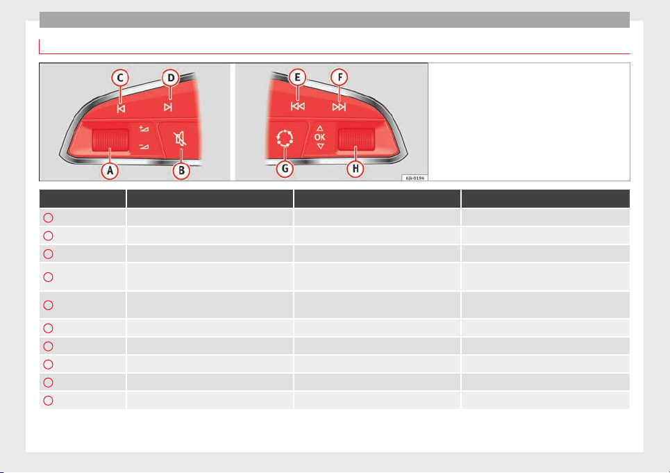
Operation
Operating the audio system
Fig. 113 Controls on the steering wheel.
Button Radio Media (except AUX) AUX
A
Turn Up/down volume Up/down volume Up/down volume
A
Press No function No function No function
B
Mute Pause Mute
C
Search for last station
Short press: switch to the previous song
Hold down: quick rewind
No function
D
Search for the next station
Short press: switch to the next song
Hold down: fast forward
No function
E
Previous preset Previous folder No function
F
Next preset station Next folder No function
G
Change source Change source Change source
H
Turn Switch MFA function Switch MFA function Switch MFA function
H
Press Acts on the MFA Acts on the MFA Acts on the MFA
106
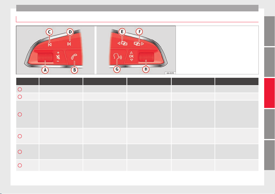
Communications and multimedia
Operating the audio system + telephone
Fig. 114 Controls on the steering wheel.
Button Radio Media (except AUX) AUX Telephone
a)
Navigation
a)
A
Turn Up/down volume Up/down volume Up/down volume Up/down volume Up/down volume
A
Press Mute Pause Mute Mute Mute
B
Short press: access to the tele-
phone menu on the dash pan-
el
a)
.
Hold down: redial
a)
Short press: access to the tele-
phone menu on the dash pan-
el
a)
.
Hold down: redial
a)
Short press: access to the tele-
phone menu on the dash pan-
el
a)
.
Hold down: redial
a)
Short press: answer/hang up
calls, enable/open the tele-
phone menu.
Hold down: reject an incoming
call/switch to private/redial
mode
Short press: access to the tele-
phone menu on the dash pan-
el
a)
.
Hold down: redial
a)
C
Search for last station
Short press: switch to the pre-
vious song
Hold down: quick rewind
No function No function
b)
Radio/media functionality (ex-
cept AUX )
D
Search for the next station
Short press: switch to the next
song
Hold down: fast forward
No function No function
b)
Radio/media functionality (ex-
cept AUX )
E
Change menu on instrument
panel
Change menu on instrument
panel
Change menu on instrument
panel
Change menu on instrument
panel
Change menu on instrument
panel
»
107
Technical dataAdviceOperationEmergenciesSafety

Operation
Button Radio Media (except AUX) AUX Telephone
a)
Navigation
a)
F
Change menu on instrument
panel
Change menu on instrument
panel
Change menu on instrument
panel
Change menu on instrument
panel
Change menu on instrument
panel
G
Enable/disable voice control
a)
Enable/disable voice control
a)
Enable/disable voice control
a)
No function
b)
Enable/disable voice control
H
Turn Next/previous preset station
c)
Next/previous song
c)
Acts upon the dash panel
menu depending on where it is
located
Acts upon the dash panel
menu depending on where it
is located
Acts upon the dash panel
menu depending on where it
is located
H
Press
Acts on the MFA or confirms
the menu option of the dash
panel depending on the menu
option
Acts on the MFA or confirms
the menu option of the dash
panel depending on the menu
option
Acts on the MFA or confirms
the menu option of the dash
panel depending on the menu
option
Acts on the MFA or confirms
the menu option of the dash
panel depending on the menu
option
Acts on the MFA or confirms
the menu option of the dash
panel depending on the menu
option
a)
According to the vehicle's equipment package.
b)
When a call is being made, radio/media functionality (except AUX).
c)
Only if the dash panel is in audio menu.
108
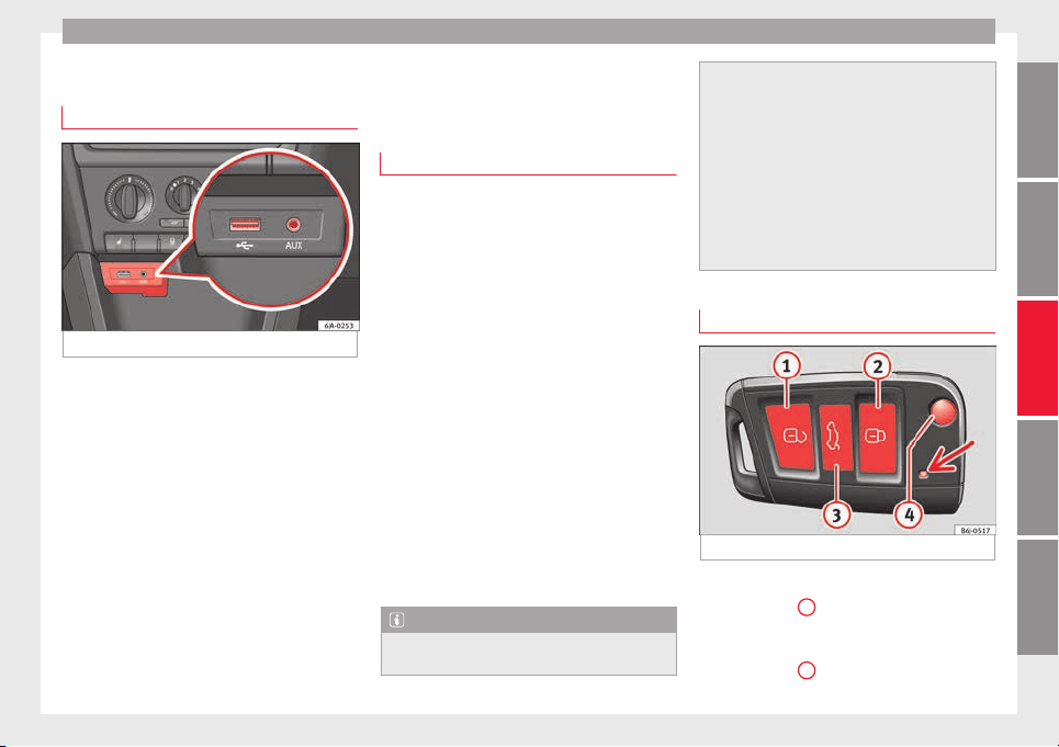
Opening and closing
Multimedia
USB/A
UX
-IN inp
ut
Fig. 115 USB/AUX-IN input.
Depending on the features and the country,
the
v
ehic
le may have a USB/AUX-IN connec-
tion.
The USB/AUX-IN input is located above the
storage compartment in the front centre con-
sole ››› Fig. 115.
The operating description is located in the re-
spective Instruction Manuals of the audio
system or the navigation system.
Opening and closing
R
emot
e c
ontrol
General notes
Read the additional information carefully
›››
page 9
The remote control key can
●
Lock and unlock the vehicle
●
Unlock or open the rear lid
The remote c
ontrol transmitter and the bat-
teries are integrated in the key. The receiver
is inside the vehicle. The remote control key
has a maximum range of 30 metres. The
range is reduced as the batteries start to lose
power.
The key includes a foldaway part that can be
used to manually lock or unlock the vehicle
and to start the engine.
If a lost key is replaced or the receiver is re-
paired or changed, the remote control key
must be adapted by an authorised SEAT deal-
er. Only then can the remote control key be
used again.
Note
●
The remote c
ontrol is automatically deacti-
vated when the ignition is switched on.
●
The remote c
ontrol function may be tempo-
rarily limited by interference from other
transmitters near the vehicle that operate on
the same frequency (e.g. mobile phone, tele-
vision transmitter).
●
If the central locking system or the anti-
theft alarm only responds to the remote con-
trol at a distance of less than 3 metres, then
the battery must be replaced ››› page 111.
●
If the driver door is open, the vehicle can-
not be locked using the remote control.
Unlocking and locking the vehicle
Fig. 116 Remote control key
Unlocking the vehicle
–
Press button
1
.
L
oc
k
ing the vehicle
–
Press button
2
.
»
109
Technical dataAdviceOperationEmergenciesSafety
Operation
Deactivating the Safe lock
–
Press button
2
twice in 2 seconds. Further
inf
orm
ation ›
›› page 112.
Unlocking the rear lid
–
Press button
3
. Further information
›
›
›
page 119.
Unfolding the key shaft
–
Press button
4
.
F
o
l
ding the key shaft
–
Press button
4
and fold the key shaft back
t
o its
origin
al position.
The turn signals will flash twice when the ve-
hicle is unlocked. If the vehicle is unlocked
using button
1
and none of the doors or the
r
e
ar lid i
s opened in the following 30 sec-
onds, the vehicle will automatically relock
and the Safe lock or the anti-theft alarm will
be activated. This function prevents the vehi-
cle from being unlocked by mistake.
Locking indication
The turn signals will flash if the vehicle has
been correctly locked.
Should any of the doors or the rear lid remain
open when the vehicle is locked, the turn sig-
nals will only flash when they are closed.
WARNING
Do not leave people or animals in vehicles
locked fr
om outside with the Safe lock activa-
ted: the doors and windows cannot then be
opened from the inside. Doors locked in this
manner could delay assistance in an emer-
gency. Risk of death!
Note
●
Only u
se the remote control when the
doors and the rear lid are locked and the ve-
hicle is within sight.
●
Do not press the lock button
on the re-
mote contr
ol before inserting the key in the
ignition, otherwise the vehicle could be
locked by mistake. Should this occur, press
the unlock button
on the remote control.
Remote control synchronisation
f the vehicle cannot be locked or unlocked
u
s
in
g the remote control, the key code may
not match that of the control unit. This can
occur when the remote control buttons are
frequently pressed outside the range of the
system or if the remote control battery has
been replaced.
In this case, it must be synchronised as fol-
lows:
●
Press any key on the remote control key.
●
Open the door using the key within the
next minute.
Keys
General notes
Fig. 117 Key with remote control/Key without
r
emot
e c
ontrol.
Two keys are always supplied with the vehi-
c
l
e. D
epending on the model version, your
car may include keys without remote control
››› Fig. 117 or with remote control
››› Fig. 117 .
110
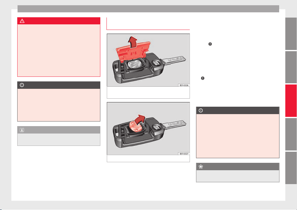
Opening and closing
WARNING
●
Never le
ave the key inside whenever you
leave the vehicle - even if only for a moment.
This is particularly important if children are
to remain in the vehicle. Children might start
the engine or some other electrical compo-
nent, e.g. electric windows. Risk of injury!
●
Wait until the vehicle has completely stop-
ped before taking the key out of the ignition.
Otherwise the steering wheel may lock sud-
denly. Risk of accident!
CAUTION
●
Each k
ey contains electronic components
and must, therefore, be protected from damp-
ness and strong vibrations.
●
Keep the grooves in the key shaft clean.
Any dirt (fibre from clothing, dust, etc.) has a
negative impact on locks, ignition, etc.
Note
Should a key be lost, request a duplicate key
from an Authorised S
EAT dealer.
Replacing the battery in the remote
c
ontr
o
l key
Fig. 118 Vehicle key: opening the battery
c
omp
ar
tment
Fig. 119 Vehicle key: removing the battery
SEAT recommends you ask a specialised
w
ork
shop t
o replace the battery.
The battery is located to the rear of the vehi-
cle key, under a cover.
Changing the battery
●
Unfold the vehicle key shaft.
●
Remove the cover from the back of the ve-
hicle key ››› Fig. 118 in the direction of the ar-
row ›››
.
●
Extract the battery from the compartment
u
s
in
g a suitable thin object ››› Fig. 119.
●
Place the new battery in the compartment
as shown ››› Fig. 119, pressing in the oppo-
site direction to that shown by the arrow
›››
.
●
Fit the cover as shown ›
›
›
Fig. 118, pressing
it onto the vehicle key casing in the opposite
direction to that shown by the arrow until it
clicks into place.
CAUTION
●
If the batt
ery is not changed correctly, the
vehicle key may be damaged.
●
Use of unsuitable batteries may damage
the vehicle key. For this reason, always re-
place the dead battery with another of the
same voltage, size and specifications.
●
When fitting the battery, check that the po-
larity is correct.
For the sake of the environment
Please dispose of your used batteries correct-
ly and with r
espect for the environment.
»
111
Technical dataAdviceOperationEmergenciesSafety
Operation
Note
If it is not possible to unlock or lock the vehi-
cle w
ith the remote control key once the bat-
tery has been replaced, it will need to be re-
synchronised ››› page 110.
Central locking system
General
notes
All of
the doors, the boot lid and the fuel cap
fl
ap w
ill
1)
unlock at the same time when the
central locking system is used.
Warning lamp on the driver door
Once the doors are locked, the warning lamp
will flash quickly for 2 seconds and then at a
slower rate.
If the vehicle is locked with Safe lock engag-
ed
›››
page 113, the warning lamp on the
driver door will flash quickly for 2 seconds
before switching off for 30 seconds and then
flashing at a slower rate.
If the warning lamp flashes quickly for 2 sec-
onds and then remains switched on before
flashing at a slower rate after 30 seconds,
there is a fault in the interior monitor and
tow-away protection system ››› page 118. Go
to a technical service.
Individualised settings
Unlocking single doors
This option
al function unlocks the driver door
only. The other doors remain locked and are
only unlocked when the next command is giv-
en (unlock).
Automatic unlock and lock
The doors and the rear lid are locked auto-
matically when the vehicle reaches a speed
of about 15 km/h (9 mph).
The doors unlock automatically when the key
is removed from the ignition. Additionally,
the driver or front passenger can unlock the
doors by pressing the
›››
page 114 central
lock button or by pulling the front door han-
dle.
WARNING
Locking the doors prevents intruders from
getting int
o the car, e.g. while waiting at in-
tersections. However, it can also delay assis-
tance in the event of an accident. Risk of
death!
Note
●
Activation of
the single door setting can be
requested at your SEAT dealer.
●
In the event of an accident in which the air-
bags deploy, the doors will be automatically
unlocked for easier access and assistance.
●
If the central locking system should fail to
work at any time, only the driver door can be
locked or unlocked using the key
››› page 113. All other doors and the boot
hatch can be operated manually.
–
Manual release ›››
page 10.
–
Manual release of the rear lid
›››
page 10.
1)
Valid for vehicles with a keyless fuel tank cap.
112
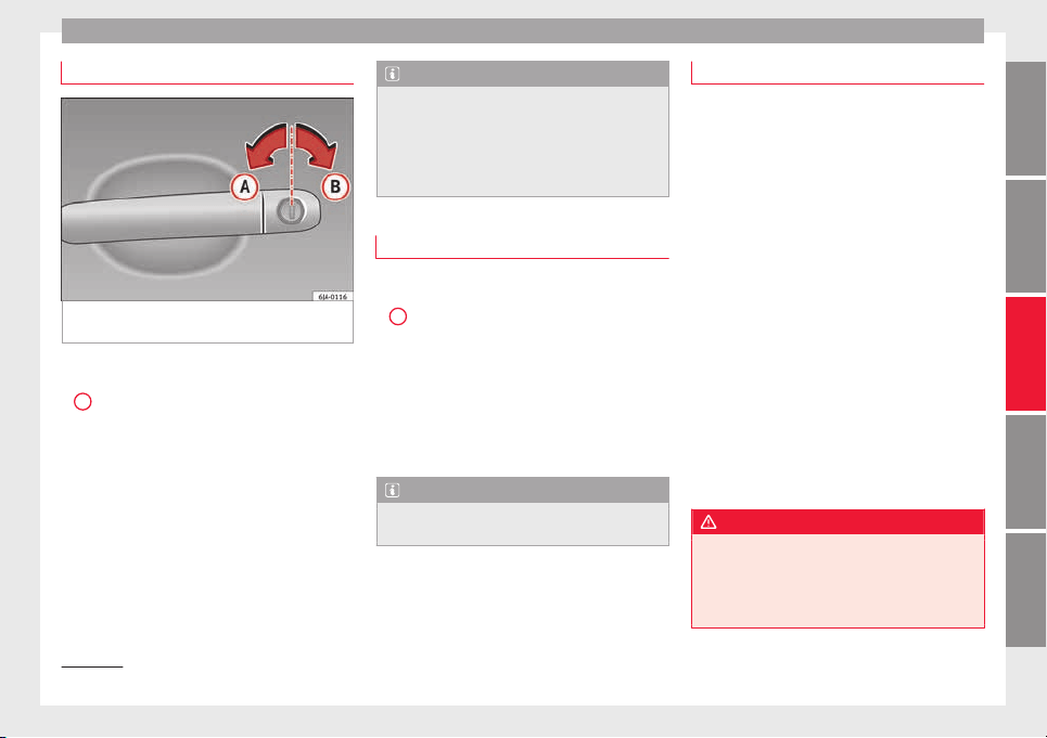
Opening and closing
Unlocking with key
Fig. 120 Key positions during vehicle locking
and u
n
loc
king.
–
Turn the key in the driver door in the for-
w
ar
d driv
ing direction to its unlock position
A
›
›
›
Fig. 120.
–
Pull the handle and open the door.
●
All doors (driver door only on vehicles with
anti-theft alarm) are unlocked.
●
The rear lid is unlocked.
●
The fuel tank flap is unlocked
1)
.
●
The courtesy lights switch on.
●
The Safe lock is deactivated.
●
The driver door warning lamp stops flash-
ing (on vehicles not equipped with an anti-
theft system)
›››
page 117.
Note
If the vehicle is equipped with an anti-theft
alarm sy
stem, you have 15 seconds from the
time the door is opened to insert the key in
the ignition and start the vehicle. If, during
these 15 seconds, the vehicle is not started,
the alarm is triggered.
Locking with key
–
Turn the key in the driver door lock cylinder
in the rever
se direction to its lock position
B
›
›
›
Fig. 120.
●
The doors, the boot lid and the fuel tank
flap
1)
will be locked.
●
The courtesy lights switch off.
●
The Safe lock is immediately activated.
●
Warning lamp on the driver door starts to
flash.
Note
The vehicle doors cannot be locked if the
driver door is
open.
Safe Lock
The central locking system is equipped with a
Safe lock
. If the vehicle is closed from out-
side, the door locks will automatically lock.
The warning lamp on the driver door will
flash quickly for about 2 seconds and then at
a slower rate. It is not possible to open any of
the doors from the inside or outside using
the handle. This limits the possibility of in-
truders getting into the vehicle.
The Safe lock can be deactivated by pressing
the lock button twice in less than 2 seconds.
If Safe lock is out of service, the control lamp
on the driver door will flash quickly for about
2 seconds before switching off for 30 sec-
onds and then flashing at a slower rate.
The Safe lock is re-activated on unlocking
and locking the vehicle again.
If the vehicle is locked and the Safe lock is
deactivated, the vehicle can be opened from
inside by pulling on the door handle.
WARNING
Do not leave people or animals in locked ve-
hicle
s with Safe lock activated: the doors and
windows cannot then be opened from the in-
side. Doors locked in this manner could delay
assistance in an emergency. Risk of death!
»
1)
Valid for vehicles with a keyless fuel tank cap.
113
Technical dataAdviceOperationEmergenciesSafety
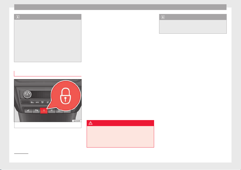
Operation
Note
●
The anti-theft a
larm switches on automati-
cally when the vehicle is locked, even if the
Safe lock is deactivated. The Vehicle interior
monitoring, however, is not activated.
●
Given that the Safe function will be activa-
ted on locking the vehicle, CHECK DEADLOCK
will be shown on the general instrument pan-
el display. On vehicles equipped with an in-
formative display, Caution SAFE! On-
board documentation!
Central locking switch
Fig. 121 Central lock button.
If the vehicle has not been locked from out-
s
ide, it
i
s possible to lock and unlock the
doors from inside by pressing the
›››
Fig. 121
button, even without the key in the ignition.
Locking of all doors, the boot lid and the fuel
tank flap
1)
–
Press the button ››› Fig. 121. The warning
lamp on the button will light up.
Unlocking of all doors, the boot lid and the
fuel tank cap
1)
–
Press the button ››› Fig. 121. The warning
lamp on the button will switch off.
If the vehicle has been locked using the cen-
tral lock button.
●
The rear boot lid cannot be unlocked from
the outside (security measure, e.g. when
stopped at an intersection).
●
The doors can be unlocked individually by
pulling the handle.
●
The vehicle doors cannot be locked if any
of the doors are open.
●
In the event of an accident in which the air-
bags activate, doors locked from the inside
will be automatically unlocked for easier ac-
cess and assistance.
WARNING
The central locking system remains operative
when the ignition is sw
itched off. Never leave
children unattended in the vehicle, as doors
locked from the inside delay assistance in an
emergency. Risk of sustaining fatal injuries!
Note
The handles and the central lock buttons will
not work
if the Safe lock ››› page 113 is acti-
vated.
1)
Valid for vehicles with a keyless fuel tank cap.
114
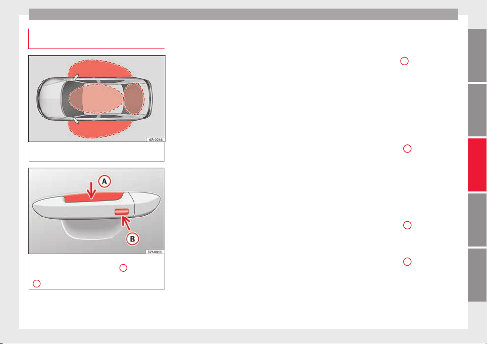
Opening and closing
Unlocking and locking the vehicle
w
ith K
eyl
ess Access
Fig. 122 Lock and ignition system without
K
eyl
e
ss Access: in the proximity of the car.
Fig. 123 Lock and ignition system without
K
eyl
e
ss Access: sensor surface
A
for unlock-
in
g in
s
ide the door handle and sensor surface
B
for locking on the exterior of the handle.
Keyless Access is a key-free lock and ignition
sy
s
t
em to unlock and lock the vehicle without
actively using its key. For this, only a valid ve-
hicle key is required to be in an area near
››› Fig. 122 the vehicle and one of the sensor
surfaces to be touched on the door handles
››› Fig. 123.
General information
If a valid key is located in the proximity of the
car ››› Fig. 122, the Keyless Access lock and
ignition system gives the key entry as soon
as one of the sensor surfaces on the door
handles is touched or the push button on the
boot hatch is operated. The following fea-
tures are then available without having to
use the vehicle key actively:
●
Keyless-Entry: unlocking of the vehicle with
the handles on the four doors or the button
located on the boot hatch.
●
Keyless-Go: engine ignition and driving. For
this to occur, there has to be a valid key in-
side the vehicle and the ››› page 155.
●
Keyless-Exit: unlocking of the vehicle with
one of the four door handle.
The central locking and locking systems oper-
ate in the same way as a normal locking and
unlocking system. Only the controls change.
Unlocking the vehicle is confirmed with a
double flash of the indicator lights; locking
by a single flash.
The vehicle will lock again after a few sec-
onds if you unlock the vehicle but fail to open
any door or boot hatch.
Unlocking and opening the doors (Keyless-
Entry)
●
Grip the door handle. In doing this, the
sensor surface ››› Fig. 123
A
(arrow) is
t
ouc
hed on the h
andle and the vehicle un-
locks.
●
Open the door.
On vehicles without a "safe" system: closing
and locking the doors (Keyless-Exit)
●
Switch the ignition off.
●
Close the driver's door.
●
Touch the surface sensor
B
onc
e (arrow)
on the door h
andl
e. The door being operated
must be closed.
On vehicles with a "safe" security system:
locking and unlocking doors (Keyless-Exit)
●
Switch the ignition off.
●
Close the driver's door.
●
Touch the surface sensor
B
onc
e (arrow)
on the door h
andl
e. The vehicle locks with
the "safe" security system ››› page 113. The
door being operated must be closed.
●
Touch the sensor surface
B
twic
e (arrow)
on the door h
andl
e to lock the vehicle with-
out the "safe" security system ››› page 113.
»
115
Technical dataAdviceOperationEmergenciesSafety
Operation
Unlocking and locking the boot hatch
When the
v
ehic
le is locked, the hatch auto-
matically unlocks on opening if ››› Fig. 122
there is a valid vehicle key in the proximity.
Open or close the hatch normally
››› page 118.
After closing, the hatch locks automatically.
In the following instances, the rear lid does
not lock automatically after closing:
●
If the entire vehicle is unlocked.
●
If the key used last is inside the vehicle. All
vehicle indicator lights flash four times. The
vehicle will lock again after a few seconds if
no door or boot hatch are opened.
Locking the vehicle with a second key
If there is a vehicle key inside the vehicle and
it is locked from the outside with a second
vehicle key, the key inside the vehicle is
blocked for engine ignition ››› page 153. In
order to enable engine ignition, the button
on the key inside the vehicle needs to be
pr
e
s
sed ››› page 109.
Automatically disabling sensors
If the vehicle is not locked or unlocked for a
long period of time, the proximity sensor on
the passenger door is automatically disa-
bled.
If the exterior sensor on the door handle is
often activated unusually with the vehicle
locked (e.g. by the branches of a bush rub-
bing against it), all proximity sensors are dis-
abled for a time. If this only happens with the
exterior sensor on the driver's door, only this
sensor is disabled.
Sensors will again be enabled:
●
After a time.
●
OR: if the vehicle is unlocked with the but-
ton
on the key.
●
OR: if
the boot is opened.
C
on
venience functions
To close all electric windows, the sun roof
and electric tilting panoramic roof with the
convenience feature, keep your finger for a
few seconds on the lock sensor surface
››› Fig. 123
B
located on the exterior part of
the driv
er or p
a
ssenger door handle until the
windows and roof close.
Opening the doors by touching the sensor
surface on the handle takes place in accord-
ance with the settings activated on the menu
Configuration - Convenience.
CAUTION
The sensor surfaces on the door handles
coul
d engage if hit with a water jet or high
pressure steam if there is a valid vehicle key
in the nearby area. If at least one of the win-
dows is open and the sensor surface
B
on
one of the handl
e permanently activates, all
windows will close. If the water jet or steam
is briefly
moved away from the sensor sur-
face
A
on one of the handles and then poin-
ted at it
again, all the windows will probably
open ››› page 116, Convenience functions.
Note
●
If
the v
ehicle battery has little or no charge,
or the vehicle key battery is almost or entire-
ly out of charge, it is likely that the vehicle
will not be able to be lock or unlocked with
the Keyless Access system. The vehicle can
be unlocked or locked manually
›››
page 9.
●
If there is no valid key inside the vehicle or
the system fails to detect one, a warning will
display on the dash panel screen. This could
happen if any other radio frequency signal in-
terferes with the key signal (e.g. from a mo-
bile device accessory) or if the key is covered
by another object (e.g. an aluminium case).
●
If the sensors are very dirty, e.g. have a lay-
er of salt, how the sensors on the door han-
dles operate may be affected. If this is the
case, wash the vehicle ››› page 194.
●
If the vehicle is equipped with an automatic
gearbox, it may only be locked in the gear
stick is in position P.
116
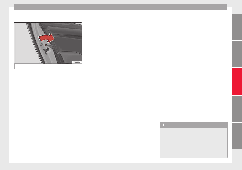
Opening and closing
Child-proof locking
Fig. 124 Activating the childproof lock.
The childproof lock prevents the rear doors
fr
om bein
g opened fr
om the inside. Doors
can only be opened from the outside.
The childproof lock is activated and deactiva-
ted using the ignition key.
Activating the childproof lock
–
Turn the slot in the direction of the arrow
››› Fig. 124 (in the other direction on the
right-hand door).
Deactivating the childproof lock
–
Turn the slot in the opposite direction of
the arrow (in the other direction on the
right-hand door).
Anti-theft alarm system*
General notes
The anti-theft alarm system increases vehicle
protection fr
om intruders. The system will ini-
tiate acoustic and optical warning signals
when your vehicle is tried to be forced.
Activating the alarm system
The anti-theft alarm switches on automatical-
ly when the vehicle is locked using the re-
mote control key or inserting the key in the
driver door. The alarm is activated around 30
seconds after the vehicle is locked.
Deactivating the alarm system
The anti-theft alarm system is deactivated
when the remote control unlock button is
pressed. If the vehicle is not opened within
30 seconds after emitting the radio frequen-
cy signal, the system will be reactivated.
If the vehicle is unlocked using by inserting
the key in the driver door, the ignition must
be switched on within 15 seconds. This deac-
tivates the alarm system. If, during these 15
seconds, the vehicle is not started, the alarm
is triggered.
When does the system trigger an alarm?
The fol
lowing areas of the vehicle are moni-
tored:
●
Bonnet
●
Rear lid
●
Doors
●
Ignition
●
Tilt angle ››› page 118, Vehicle interior
monitoring and anti-tow system
●
The interior ››› page 118, Vehicle interior
monitoring and anti-tow system
●
Drop in voltage in the car systems
●
The factory-fitted towing bracket
The alarm is triggered immediately if one of
the battery cables is disconnected while the
alarm system is active.
How to turn OFF the alarm
To deactivate the alarm, press the unlock but-
ton on the remote control key or switch on
the ignition.
Note
●
The alarm horn po
wer supply has a 5-year
useful life. Contact an Official Service for
more detailed information.
●
To make sure that the anti-theft alarm is
fully operative when leaving the vehicle,
check that all the doors and windows are
closed.
»
117
Technical dataAdviceOperationEmergenciesSafety
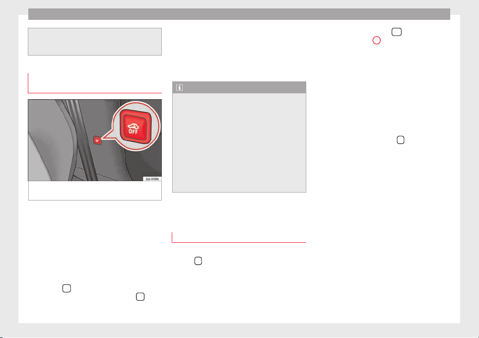
Operation
●
Remote c
ontrol and receiver unit coding
means that the remote control cannot be
used on other vehicles.
Vehicle interior monitoring and anti-
tow sy
stem
Fig. 125 Button for vehicle interior monitor-
in
g and the t
o
w-away protection system.
The Vehicle interior monitoring system is acti-
v
at
ed if
movements are detected in the interi-
or of the vehicle.
Deactivating Vehicle interior monitoring and
the tow-away protection system
–
Switch the ignition off.
–
Open the driver door.
–
Press the
›
›
› Fig. 125
button on the cen-
tre column. The red backlit symbol
on
the b
utt
on t
urns orange.
–
Lock the vehicle within the next 30 sec-
onds.
The Vehicle interior monitoring system and
the tow-away protection system are reactiva-
ted when the vehicle is unlocked again.
Note
●
The vehic
le interior monitoring system and
the tow-away protection system must be de-
activated if there is a danger of the alarm be-
ing triggered due to movements by children
or animals in the interior when being trans-
ported (e.g. by boat or by train) or towed.
●
The effectiveness of the Vehicle interior
monitoring system is reduced if the spectacle
case is left open. Always close the storage
compartment before locking the vehicle to
ensure that this monitoring system operates
correctly.
Rear lid
T
ai
l
gate automatic lock
Where the vehicle has been locked by press-
in
g the
button on the remote control with
the boot
lid open, the boot
lid w
ill lock auto-
matically when closed.
The automatic rear lid locking time extension
function can be activated. When this function
is activated and once the boot lid has been
unlocked by pressing the
button on the
r
emot
e c
ontrol key
2
›
›› p
age 109, the boot
lid c
an be re-opened for a certain length of
time.
Where required, the automatic boot lid lock-
ing time extension function can be activated
or deactivated at a SEAT Authorised Service,
which will provide all of the necessary infor-
mation.
Before the vehicle locks automatically, there
is a risk of intruders getting into the vehicle.
Therefore, we recommend you always lock
the vehicle by pressing the
button on the
r
emot
e c
ontrol or by using the key without re-
mote control ››› page 113
118
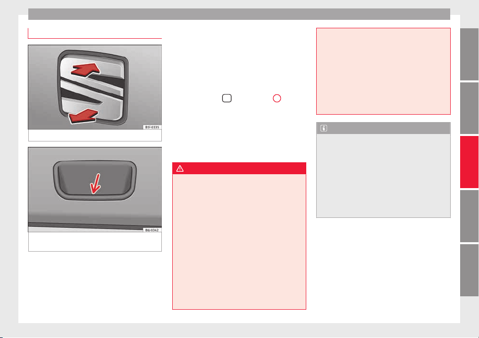
Opening and closing
Rear lid
Fig. 126 Rear lid: opening from the outside.
Fig. 127 Close-up of the inside trim of the
r
e
ar lid: h
and grip
Read the additional information carefully
›
›
›
page 10
The rear lid opening system operates electri-
cally. It is activated by using the handle on
the boot lid.
This system may or may not be operative, de-
pending on the situation of the vehicle.
If the rear lid is locked then it cannot be
opened, however if it is unlocked then the
opening system is operative and the rear lid
may be opened.
To change the locking / unlocking status,
press the button
or the button
1
››› Fig. 116 on the r
emot
e c
ontrol key.
A warning appears on the instrument panel
display if the boot lid is open or not properly
closed.* An audible warning is also given if
the boot lid is opened while the vehicle is
moving faster than 6 km/h (4 mph)*.
WARNING
●
Alwa
ys close the rear lid properly. Risk of
accident or injury.
●
Do not close the rear lid by pushing it down
with your hand on the rear window. The glass
could smash. Risk of injury!
●
Ensure the rear lid is locked after closing it.
If not, it may open unexpectedly while driv-
ing.
●
Never allow children to play in or around
the vehicle. A locked vehicle can be subjected
to extremely high and low temperatures, de-
pending on the time of year, thus causing se-
rious injuries/illness. It could even have fatal
consequences. Close and lock both the rear
lid and all the other doors when you are not
using the vehicle.
●
Clos
ing the rear lid without observing and
ensuring it is clear could cause serious injury
to you and to third parties. Make sure that no
one is in the path of the rear lid.
●
Never drive with the rear lid open or half-
closed, exhaust gases may penetrate into the
interior of the vehicle. Danger of poisoning!
●
If you only open the rear lid, do not leave
the key inside. The vehicle will not be opened
if the key is left inside.
Note
●
Onc
e the re
ar lid is closed, its lock is en-
gaged and the alarm system is activated. On-
ly valid if the vehicle has been locked before
the rear lid is closed.
●
The release catch located at the top of the
registration plate recess is deactivated on ac-
celerating or at speeds of over 5 km/h (3
mph). The catch is reactivated when the vehi-
cle comes to a standstill and a door is
opened.
119
Technical dataAdviceOperationEmergenciesSafety
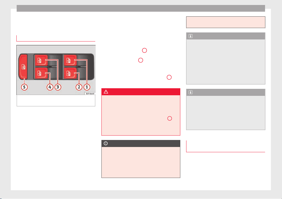
Operation
Opening and closing of electric
w
indo
w
s
Operation of the electric windows
Fig. 128 Detail of the driver door: controls for
the w
indo
w
s.
Read the additional information carefully
›
›
›
page 11
The electric window opening and closing sys-
tem only works when the ignition is switched
on.
Opening
–
Press gently on the respective button on
the door to open the window. The process
will stop when the button is released.
–
The driver door window can also be auto-
matically opened by pressing the button as
far as it will go (fully open). Press the but-
ton again to immediately stop it.
Closing
–
Press the respective button gently to close
the window. The process will stop when the
button is released.
Safety button
Press the safety button
5
›
›› Fig. 128
t
o de-
activate the controls on the rear doors. Press-
ing the safety button
5
again will reactivate
the c
ontr
o
ls on the rear doors.
If the rear door controls are deactivated, the
warning lamp on the safety button
5
will
light
up
.
WARNING
●
When lockin
g the vehicle from the outside,
make sure that nobody is inside the vehicle,
as the windows cannot be opened from the
inside in an emergency.
●
For safety reasons, use safety button
5
››› Fig. 128 that de
activates the window
switches on the rear doors when children are
travelling in the rear seats.
CAUTION
●
Keep the windo
ws clean to ensure the sys-
tem operates correctly.
●
Defrost ››› page 197, Windows and mirrors
any frozen windows before use. Otherwise
you run the risk of damaging the electric win-
dow riser mechanism.
●
Alwa
ys make sure all of the windows are
closed on leaving the locked vehicle.
Note
●
The
vehic
le heating and ventilation system
should be used to ventilate the interior while
driving. Leaving the windows open could al-
low dust and other dirt to enter the vehicle
and cause unpleasant noises at certain
speeds.
●
Do not leave the side windows open at high
speeds, as this will overly increase fuel con-
sumption.
Note
The electric window opening mechanism is
equipped with a thermo
stat switch. This may
overheat if the window is opened and closed
repeatedly. This causes the window to lock
temporarily. Once the thermostat switch has
cooled down, the window can be operated
once again.
Roll-back function on the electric win-
do
w
s
The electric windows are equipped with a
r
o
l
l-back system that reduces risk of injury
when closing windows.
120
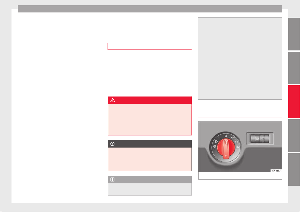
Lights and visibility
If an obstacle is present, the closing mecha-
ni
sm w
i
ll stop and the window will roll back a
few centimetres.
If an obstacle prevents closing for the next
10 seconds, the closing mechanism will once
again stop and the window will roll back an-
other few centimetres.
If in the next 10 seconds you attempt to close
the window after it has rolled back the sec-
ond time, only the closing mechanism will be
stopped even if the obstacle is still present.
The roll-back function is still connected.
The roll-back function will only be disconnec-
ted if you once again attempt to close the
window in the following 10 seconds. In this
case, the window will close at full force.
If you wait for a further 10 seconds, the roll-
back function will be once again connected.
Lights and visibility
Light
s
Intr
oduction
Read the additional information carefully
›››
page 18
The location of the controls of right-hand
drive cars differs slightly from the location
shown here ››› Fig. 129 ››› page 121. Howev-
er, the symbols indicating the respective po-
sitions of the controls remain the same.
WARNING
Never drive with only the side lights on! The
side lights
are not bright enough to illumi-
nate the road ahead and to ensure that other
road users are able to see you. Always use
your dipped beam headlights if it is dark or if
visibility is poor.
CAUTION
●
Use the lights
in line with local law.
●
However, drivers always remain responsi-
ble for correctly adjusting and using the
lights.
Note
●
An audible w
arning will be heard when the
light control is set to and you remove the
ignition key and open the door. Once the
driver door is
closed (ignition off), the audi-
ble warning will stop, whereas the side lights
will remain on to light up the stationary vehi-
cle in case this is necessary.
●
Depending on weather conditions (cold or
wet), the lights may mist up temporarily on
the inside. This is particularly the case in the
event of a difference in temperature between
the inside and in front of the light. By switch-
ing on the lights, the area through which the
beam of light is projected will quickly be
demisted, although the edges may remain
misted. The real lights and turn signals can
mist up. This has no influence on the useful
life of the lighting system.
Side light and dipped beam headlight
Fig. 129 Instrument panel: light control.
»
121
Technical dataAdviceOperationEmergenciesSafety
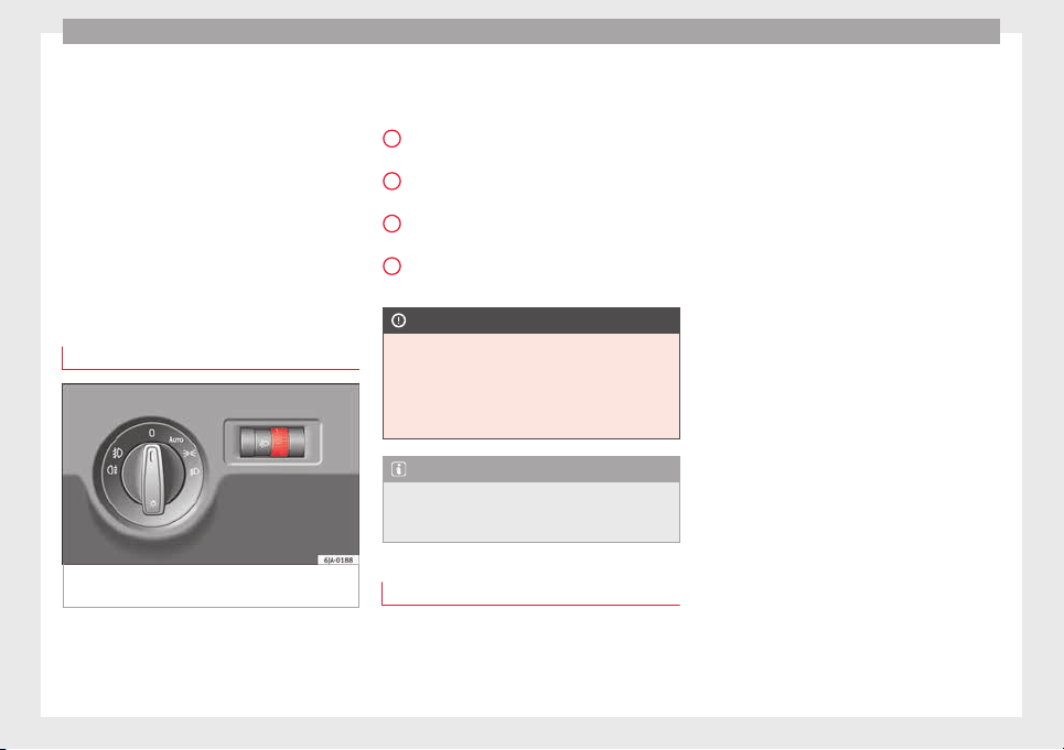
Operation
Switching on side lights
–
Turn the light switch ›
›
›
Fig. 129 to position
.
Switching on dipped beam
–
Turn the light switch ››› Fig. 129 to position
.
Switching off lights (except daytime driving
lights)
–
Turn the light switch ››› Fig. 129 to position
0.
Main light range control
Fig. 130 Instrument panel: light range con-
tr
o
l
.
–
Turn the control ›
›
›
Fig. 130 to set the lights
to the required setting.
Positions
The control positions roughly correspond to
the following vehicle load conditions.
Two front occupants, luggage compart-
ment empty.
All seats occupied, luggage compartment
empty.
All seats occupied, luggage compartment
fully loaded.
Driver only, luggage compartment fully
loaded.
CAUTION
Always adjust the range of the lights so that:
●
Your vehicle does not dazzle others, partic-
ularly
oncoming traffic
●
The range of the headlights is sufficient for
safe driving
Note
Make sure you set the range of the main
lights when the dip
ped beam headlights are
switched on.
Daytime running lights
Daytime running lights are signalling devices
f
or impr
o
ving road safety. The lights are built
into the headlights and come on each time
the ignition is turned on if the light switch is
-
1
2
3
in position 0 or
›
›
› Fig. 129. It is automat-
ically switched off when the side lights are
turned on.
Switching the daytime driving lights on
●
Remove the key from the ignition, move the
turn signal lever upward (right turn signal),
press it back to flash position and hold it
there.
●
Insert the key and switch on the ignition,
holding it in this position for 3 seconds.
Then, switch off the ignition. The daytime
running light is now activated and the corre-
sponding lights can come on.
Switching the daytime running light off
●
Remove the key from the ignition, press the
turn signal lever down (left turn signal), press
it back to flash position and hold it here.
●
Insert the key and switch on the ignition,
holding it in this position for 3 seconds.
Then, switch off the ignition. The daytime
running light is now deactivated and the cor-
responding lights cannot come on.
OR: activate and deactivate the daytime
lights using the Easy Connect system
›››
page 20.
Automatic control of the dipped beam in
combination with the daytime running lights
If the dipped beam control and the daytime
running lights are activated at the same
122
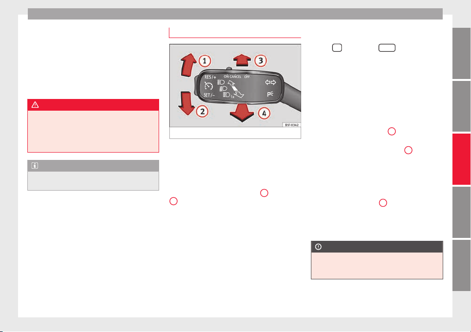
Lights and visibility
time, the dipped beams and the instrument
p
anel
lightin
g will automatically come on as
required (e.g. when entering a tunnel) and
the daytime running lights will switch off.
When the automatic dipped beam control
switches off the dipped beams (e.g. when
coming out of a tunnel), the daytime running
lights come back on.
WARNING
The rear lights do not come on with the day-
time driving light
. A vehicle which does not
have the rear lights on may not be visible to
other drivers in the darkness, if it is raining
or in conditions of poor visibility.
Note
Please observe any relevant legal require-
ments whic
h may apply in your country.
Turn signal and main beam lever
Fig. 131 Turn signal and main beam lever.
The turn signal and main beam lever also op-
er
at
e
s the parking lights and the headlight
flasher.
Right and left-hand turn signal
●
Move the lever ››› Fig. 131 up
1
or down
2
.
●
Keep the lever held down at the point of re-
s
i
s
tance for the turn signals to flash for as
long as you hold the lever, e.g. when chang-
ing lanes.
Convenience turn signals
For the convenience turn signals, move the
lever as far as possible upwards or down-
wards and release the lever. The turn signal
will flash three times.
The convenience turn signals are activated
and deactivated in the Easy Connect system
via the
key and the
Set
up
function button
›
›
›
page 104.
In vehicles that do not have the correspond-
ing menu, this function can be deactivated in
a specialised workshop.
Main beams
●
Switch on the dipped beam ››› page 121.
●
Press the lever ››› Fig. 131 forward in the di-
rection indicated by arrow
3
.
●
Pull the lever back to its original position in
the dir
ection indic
at
ed by arrow
4
to switch
the m
ain be
am off
.
Headlight flasher
●
Pull the lever ››› Fig. 131 towards the steer-
ing wheel (point of resistance) in the direc-
tion indicated by arrow
4
.
P
ark
in
g lights
●
Instructions for use ››› page 126.
CAUTION
Never use the main beam headlights or the
headlight
flasher if they could dazzle other
drivers.
»
123
Technical dataAdviceOperationEmergenciesSafety
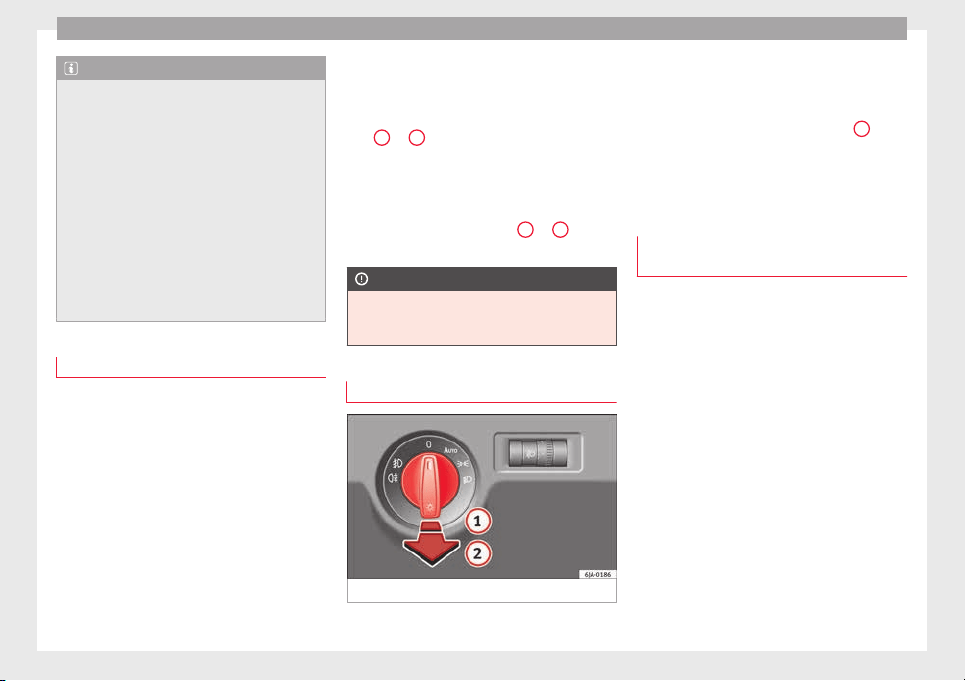
Operation
Note
●
If the con
venience turn signals are operat-
ing (three flashes) and the other convenience
turn signals are switched on, the active part
stops flashing and only flashes once in the
new part selected.
●
The turn signals only work when the igni-
tion is switched on. The corresponding warn-
ing lamp or flashes in the general instru-
ment panel.
●
The turn signals switch off automatically
when the steering wheel is returned to the
straight-ahead position.
●
If a turn signal bulb is defective, the control
lamp flashes at double speed.
Automatic dipped beam control
If the light switch is in this position
›
›
›
Fig. 129, the side lights, headlights and
the number plate lights will turn on or off au-
tomatically.
The light is adjusted according to the data re-
corded by the light sensor that is installed
between the windscreen and the inside rear
view mirror.
If the light switch is in position , the sym-
bol located next to the light switch will il-
luminate. If the light illuminates automatical-
ly, symbol located next to the light switch
will also illuminate.
Automatic headlights in case of rain
If the light switch is in position and is
connected to the automatic wipe in case of
rain for more than 10 seconds or wipe (posi-
tion
2
or
3
) for longer than 15 seconds,
›
›
›
page 129 then the side lights and head-
lights will automatically switch on.
The light automatically switches off if more
than 4 minutes have elapsed and the auto-
matic wipe or wipe (position
2
or
3
) have
not
been sw
it
ched on.
CAUTION
Do not cover the windscreen light sensor with
stick
ers or similar objects; this could impair
operation.
Front fog lights*
Fig. 132 Instrument panel: light switch.
Switching on front fog lights
–
First turn the light switch ›
›
›
Fig. 132 to po-
sition , or .
–
Pull on the light switch to position
1
.
The ›
›
›
page 98 warning lamp lights up on
the general instrument panel if the front fog
lights are switched on.
Front fog lights with cornering func-
tion*
3 Not valid for vehicles fitted with Full-LED lights
Fr
ont fog lights with cornering function pro-
vide better lighting of the area around the car
when driving through a corner or parking,
etc.
Front fog lights with cornering function
switch on depending on how far you turn the
124
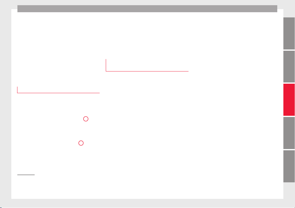
Lights and visibility
steering wheel or whether or not the turn sig-
n
al
s
1)
ar
e switched on, if the following condi-
tions are met:
●
The vehicle is stationary, the ignition is
switched on or you are moving at a speed of
less than 40 km/h (25 mph);
●
The daytime driving light is switched off
●
The dipped beam is switched on
●
The fog lights are switched off
●
Reverse gear is not engaged
Rear fog light
Switching on the rear fog light
–
First turn the light switch ›
›
›
Fig. 132
››› page 124 to position , or .
–
Pull on the light switch to position
2
.
If
the
v
ehicle is not equipped with front fog
lights ››› page 124, the rear fog light is
switched on by turning the switch to position
or and pulling it to position
2
. This
type of
sw
it
ch only has one position.
The
›››
page 98 warning lamp lights up on
the general instrument panel if the rear fog
lights are switched on.
If you are towing a trailer or caravan equip-
ped with a rear fog light on a vehicle with a
factory-fitted towing bracket or one installed
using parts from the original SEAT parts
catalogue, only the rear fog light on the trail-
er or caravan will light up.
Function “Coming Home”/“Leaving
Home”*
This function makes it possible, under poor
v
i
s
ibility conditions, to automatically turn on
the lights for a brief period of time after the
vehicle has been parked or when approach-
ing the vehicle.
The function is automatically turned on if the
following conditions are met:
●
The light switch is in position
››› page 124.
●
The visibility around the vehicle is reduced.
●
The ignition is switched off.
To turn on this function, switch on the head-
light flasher prior to exiting the vehicle.
The light is adjusted according to the data re-
corded by the light sensor that is installed
between the windscreen and the inside rear
view mirror.
The function automatically turns on the side
lights and headlights, the lighting for the en-
try area on the exterior mirrors and the num-
ber plate light.
“Coming Home” function
The light is automatically switched on when
the driver door is opened (for 60 seconds af-
ter the ignition is switched off).
The lights is switched off when all the doors
and the boot lid are closed.
If a door or the boot lid remains open, the
light will switch off after 60 seconds.
“Leaving Home” function
The light is automatically switched on when
the vehicle is unlocked using the remote con-
trol.
The light is switched off after 10 seconds or
when the vehicle is locked.
1)
In the event of a conflict between both functions,
i.e. if
you turn the steering wheel to the left while the
right-hand turn signal is on, the turn signals will take
priority.
125
Technical dataAdviceOperationEmergenciesSafety
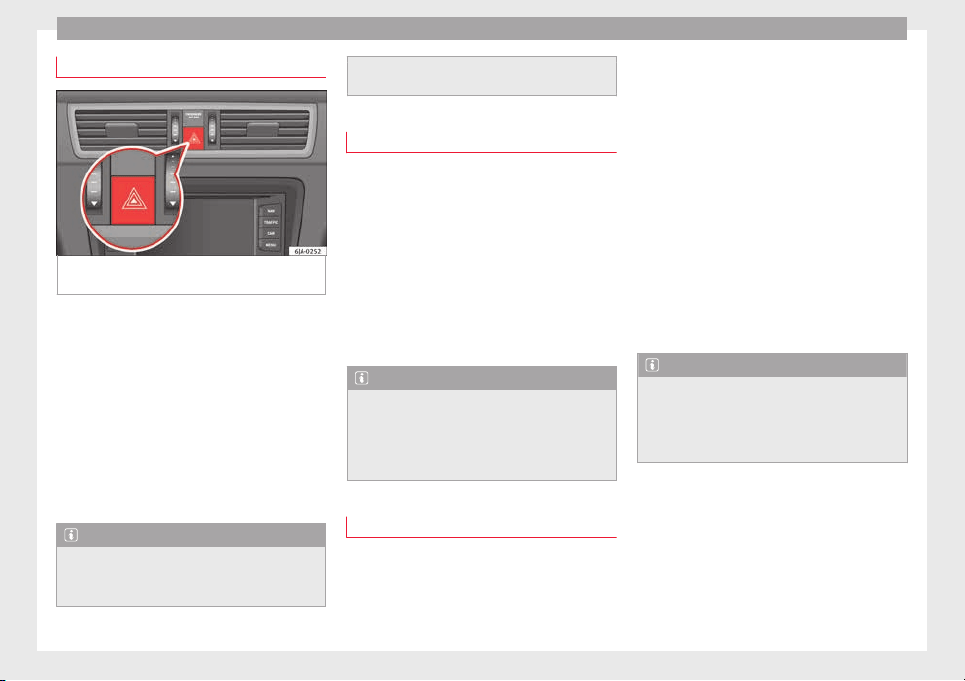
Operation
Hazard warning lights switch
Fig. 133 Instrument panel: switch for hazard
w
arnin
g lights.
–
Press the button
›
›
›
Fig. 133 to switch
the hazard warning lights on or off.
The warning lamps on the instrument panel
and the warning lamp on the switch will flash
at the same time as the turn signals when
the hazard warning lights are switched on.
The hazard warning lights also work when
the ignition is switched off.
The hazard warning lights come on automati-
cally in the event of an accident in which an
airbag is triggered.
Note
Switch on the hazard warning lights to warn
other roa
d users, for example:
●
When reaching the tail end of a traffic jam
●
if the v
ehicle has a technical fault or you
are involved in an emergency situation.
Parking lights*
Parking lights
–
Switch the ignition off.
–
Move the turn signal lever ›››
Fig. 131
››› page 123 up or down to turn on the right
or left-hand parking lights respectively.
Parking light on both sides
–
Turn the light switch ›››
Fig. 129
››› page 121 to position and engage the
steering lock.
Note
●
The parkin
g lights can only be activated
with the ignition disconnected.
●
The parking light will not come on automat-
ically after switching off the ignition if the
left- or right-hand turn signal is left on.
Adjusting the headlights
The light beam of the dipped beam lights is
a
symmetric: the s
ide of
the road on which
you are driving is lit more intensely.
When a car that is manufactured in a country
that drives on the right travels to a country
that drives on the left (or vice versa), it is nor-
mally necessary to cover part of the headlight
bulbs with stickers or to change the adjust-
ment of the headlights to avoid dazzling oth-
er drivers.
In such cases, the regulations specify certain
light values that must be complied with for
designated points of the light distribution.
This is known as “Tourist light”.
The light distribution of the halogen and full-
LED headlights of the SEAT Toledo allows the
specific “tourist light” values to be met with-
out the need for stickers or changes in the
settings.
Note
“Tourist light” is only allowed temporarily. If
you are p
lanning a long stay in a country that
drives on the other side, you should take the
vehicle to an Authorised Technical Service to
change the headlights.
126
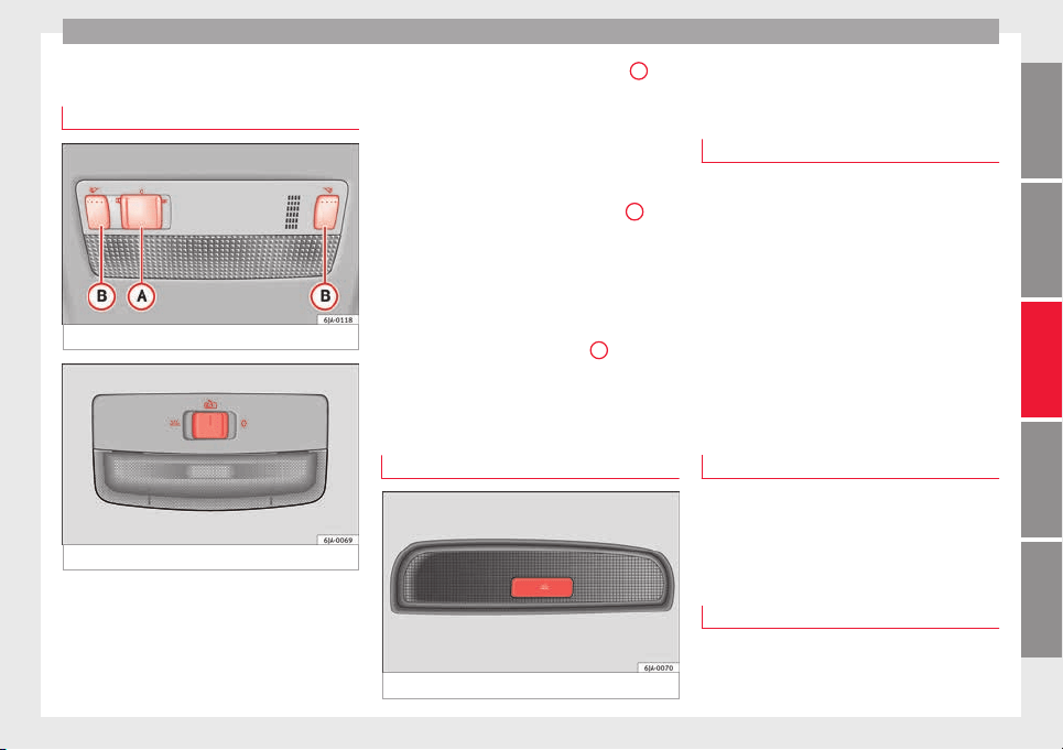
Lights and visibility
Interior lights
Int
erior lightin
g
Fig. 134 Interior lighting – version 1.
Fig. 135 Interior lighting – version 2.
Read the additional information carefully
›
›
›
page 19
Where the courtesy light is on (switch
A
››› Fig. 134 in po
s
ition
), the light will come
on if:
●
the vehicle is unlocked,
●
one of the doors is opened,
●
The key is removed from the ignition
When the courtesy light is on (switch
A
in
po
s
ition
), the light will switch off if:
●
the vehicle is locked,
●
the ignition is switched on,
●
30 seconds after all of the doors have been
closed
If a door is left open or if switch
A
is in the
po
s
ition, the int
erior lighting switches off
after about 10 minutes to prevent the battery
from running flat.
Rear interior light
Fig. 136 Rear interior light.
Press the button ›
›
›
Fig. 136 to switch the
lighting on or off.
Interior lights / ambient light*
The ambient lighting lights up the central
conso
le area, the footwell area and the dash
panel trim when the dipped beam is on.
The lighting of the central console area and
the footwell area will switch on fully when the
doors are opened and will decrease in inten-
sity while driving with the dipped beam
headlights on.
The intensity of the ambient light* can be ad-
justed using the menu Easy Connect >
Lighting settings > Vehicle inte-
rior lighting
›››
page 20.
Glove box light
The light will come on automatically when
the glo
v
e c
ompartment is opened. The light
will go out when the glove compartment is
closed.
Luggage compartment light
The light switches on automatically when the
boot
i
s
open and switches off automatically
»
127
Technical dataAdviceOperationEmergenciesSafety

Operation
10 minutes after the boot lid has been
opened.
Visibility
He
at
ed r
ear window
Fig. 137 Heated rear window switch.
–
Switch the heated rear window on or off by
pr
e
s
sing the button
›
›
› Fig. 137
, the
warning lamp in the button will come on or
go off respectively.
The heated rear window only works when the
engine is running.
After approximately 7 minutes, the heating
device of the rear window switches off auto-
matically.
For the sake of the environment
The heated rear window should be switched
off as
soon as the glass is demisted. By sav-
ing electrical power you can also save fuel
››› page 164.
Note
In the event of a drop in voltage in the on-
board sy
stems, the heated rear window
switches off automatically to ensure enough
power to control the engine ››› page 214, Au-
tomatic disconnection of electrical equip-
ment.
Sun visors
Fig. 138 Driver's sun visor.
Fig. 139 Front passenger's sun visor.
The sun visors for the driver and the front
p
a
s
senger can be pulled out of their central
supports and turned towards the doors in the
direction of arrow
1
›
›
› Fig. 138
and
2
››› Fig. 139 res
pectively.
The strip
A
is to store small objects such as
not
ep
aper
, etc.
The front passenger sun visor includes a van-
ity mirror
B
with a cover. The cover is
opened b
y
s
liding it in the direction indicated
by arrow
3
›
›
› Fig. 139
.
WARNING
Do not turn sun visors with attached objects
such a
s ball-pens, etc. toward the head pro-
tection airbag triggering zone on the side
windows. The head protection airbags could
injure occupants if triggered.
128
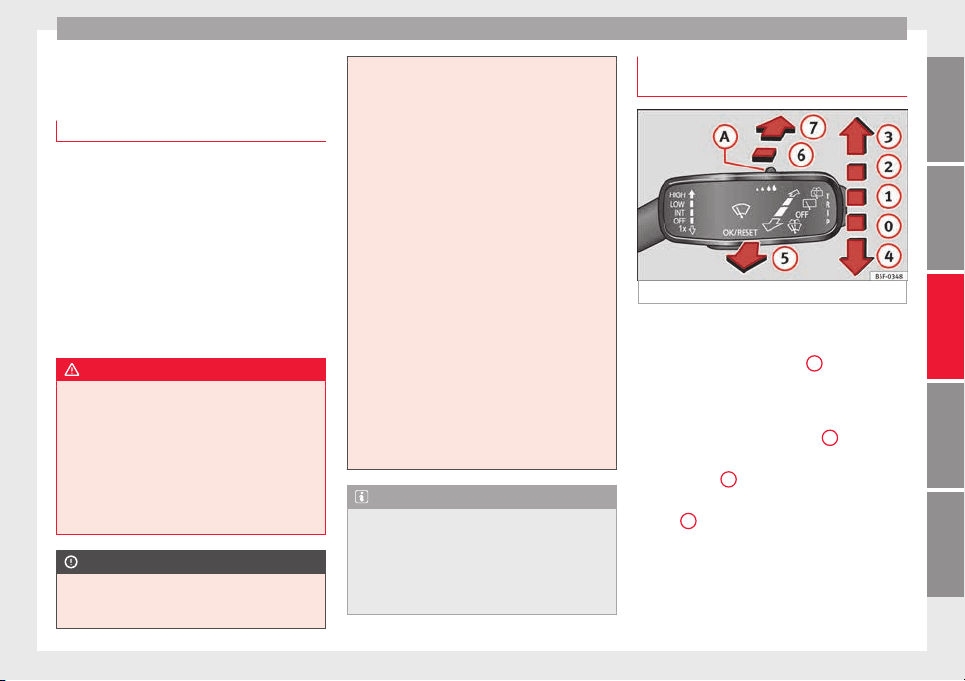
Lights and visibility
Windscreen wipers and wind-
s
c
r
een washers
Introduction
The windscreen wipers and windscreen
washer
s only work when the ignition is
switched on.
The speed of the automatic wipe in case of
rain is automatically adjusted according to
the intensity of the rainfall.
The rear window is wiped once if the wind-
screen wipers are switched on and reverse
gear is engaged.
Fill the windscreen washer fluid
›››
page 210.
WARNING
●
Make s
ure the blades ›››
page 53 are in
perfect condition for good visibility and safe
driving.
●
In cold conditions, you should not use the
wash/wipe system unless you have warmed
the windscreen with the heating and ventila-
tion system. The windscreen washer fluid
could otherwise freeze on the windscreen and
obscure your view of the road.
CAUTION
●
During w
inter, always check that the wind-
screen wiper blades are not frozen to the
glass before each trip or before switching on
the ignition. If you switch on the windscreen
wipers
when the wiper blades are frozen to
the glass, this could damage both the wiper
blades and the wiper motor.
●
If the ignition is switched off when the
windscreen wipers are on, they will start op-
erating in the same mode when the ignition
is switched back on. The wiper blades may be
frozen to the glass at low temperatures when
the ignition is switched off.
●
Carefully separate the frozen wipers from
the windscreen or rear window.
●
Remove snow and ice from the wipers be-
fore starting your journey.
●
Careless handling could lead to the wiper
arms damaging the windscreen.
●
For safety reasons, the wiper blades should
be changed once or twice a year. They can be
purchased at a SEAT Authorised Service.
●
The ignition cannot be switched on while
the windscreen wiper arms are in a raised po-
sition. Otherwise, the windscreen wipers
would return to their original position and
could damage the paintwork on the bonnet.
Note
Keep the wipers clean. The wipers can be
soiled w
ith remains of wax solutions from car
washes ››› page 195.
●
On vehicles equipped with windscreen
washer jets, these are heated once the en-
gine is running.
Operating windscreen wipers and
w
a
sher
s
Fig. 140 Window wiper lever.
Short wipe
–
Give the windscreen a brief w
ipe b
y
moving
the lever down to position
4
›
›
› Fig. 140
.
Wipe intervals/automatic wipe in case of rain
rain sensor*
–
Push the lever up to position
1
››› Fig. 140.
–
With switch
A
, adjust the wipe interval or
r
ain sen
sor sen
sitivity.
Switch
A
has 4 positions.
The r
ain sen
sor* i
s part of the intermittent
wipe function.
The rain sensor* controls the frequency of
the windscreen wiper intervals, depending
on the amount of rain.
»
129
Technical dataAdviceOperationEmergenciesSafety
Operation
Slow wipe
–
Push the lever up to position
2
››› Fig. 140.
C
ontinuou
s
wipe
–
Push the lever up to position
3
››› Fig. 140.
Aut
om
atic
windscreen wash and wipe
–
Pull the lever towards the steering wheel,
position
5
›
›› Fig. 140
, and the w
indscreen
washer and wipers are switched on.
–
Release the lever. The washer will stop and
the windscreen wipers will keep running for
1-3 wipes (depending on the windscreen
washer operating time).
Rear window wiper*
–
Press the lever forward to position
6
››› Fig. 140 and the rear w
indow wiper will
run every 6 seconds.
Automatic rear window wash and wipe*
–
Press the lever fully forward to position
7
››› Fig. 140 and the rear w
indow wiper and
washer switch on at the same time.
–
Release the lever. The rear window washer
wil
l stop and the rear window wipers will
keep running for 1-3 wipes (depending on
the jet operating time). When released, the
lever remains in position
6
.
Switching off the wipers
–
Move the lever to position
0
›
›› Fig. 140
.
WARNING
The rain sensor may not detect enough rain
to swit
ch on the wipers.
●
If necessary, switch on the wipers manually
when water on the windscreen obstructs visi-
bility.
Note
Do not put stickers on the windscreen in front
of the r
ain sensor*. This may cause sensor
disruption or faults.
Headlight washers*
The headlight washers operate briefly if the
dip
ped he
a
dlights or headlights are on and
the lever is moved to position
5
›
›
›
Fig. 140.
The headlight washer system also operates
every 10 windscreen wash cycles.
Clean off stubborn dirt (insects, etc.) from the
headlights at regular intervals, for instance
when filling the fuel tank. Please observe the
following indications
›››
page 197, Head-
lights.
To ensure the system works properly in win-
ter, keep the nozzle holders free of snow and
remove any ice with a de-icer spray.
CAUTION
Never pull on the nozzle holders. Risk of
damag
e to the system!
Rear vision mirrors
Rear
view mirror with manual anti-
dazzle device
Basic settings
–
Push the lever at the bottom of the mirror
f
or
w
ard.
Rear vision mirror anti-dazzle setting
–
Pull the lever at the bottom of the mirror to-
wards you.
Exterior mirrors
Read the additional information carefully
›
›
›
page 13
Before beginning any journey, adjust the rear
view mirrors for a good rear visibility.
WARNING
●
Conv
ex (wide-angle) rear vision mirrors give
a larger field of vision. However, they make
objects appear smaller and further away than
they really are. For this reason, you should
130
Seats and head restraints
not rely on these rear vision mirrors for judg-
ing the dis
tance of vehicle behind.
●
If possible, use the interior rear vision mir-
ror to estimate distances to vehicles behind
you.
Note
●
Ext
erior mirror
s are only heated when the
engine is running.
●
Do not touch the exterior mirrors when the
heating system is running.
●
If the electrical adjustment should ever fail
to operate, the rear vision mirrors can be ad-
justed by hand by pressing the edge of the
mirror glass.
●
Visit the technical service in the event of a
fault in the electrical rear vision mirror ad-
justment system.
Seats and head restraints
Adju
s
tin
g seats and head re-
straints
Introduction
Read the additional information carefully
›››
page 11
Set the driver seat in such a way that the
pedals can be fully depressed with your legs
slightly bent.
Set the driver seat backrest so that you can
reach the upper point of the steering wheel
with your arms slightly bent.
The correct seat position is very important
for:
●
reaching all of the controls safely and
quickly
,
●
a relaxed posture that will not produce fati-
gue,
●
maximum protection from the seat belts
and airbag system
WARNING
●
Adjust
the driver seat only when the vehi-
cle is stationary. Risk of accident!
●
Be careful when adjusting the front seats!
Careless and uncontrolled adjustment can
cause injuries.
●
The back
rests must not be reclined too far
back while driving. This could limit the effect
of the seat belts and the airbag system. Risk
of injury!
●
Never transport more than the permitted
amount of people in your vehicle.
●
Every occupant in the vehicle must properly
fasten and wear the seat belt belonging to
his or her seat. Children must be protected
with an appropriate child restraint system
››› page 72, Transporting children safely.
●
The front seats, head restraints and seat
belts must always be adjusted to the size of
the vehicle occupant to provide you and your
passengers with the greatest possible protec-
tion.
●
Your feet should remain in the footwell
while the vehicle is moving; never rest them
on the dash panel, on the window or on the
seat! This also applies to passengers. An in-
correct sitting position exposes you to an in-
creased risk of injury in case of a sudden
braking or an accident. If the airbag is trig-
gered, you could sustain severe injuries due
to an incorrect sitting position!
●
It is important for the driver and front pas-
senger to keep a distance of at least 25 cm
from the steering wheel and dash panel. Fail-
ure to respect the minimum distance means
that the airbag will not protect you. Risk of
fatal injury if triggered!
●
Objects must not be placed in the footwell,
as they could move to the area of the pedals
in the event of a braking manoeuvre or
change of direction. This would prevent the
»
131
Technical dataAdviceOperationEmergenciesSafety
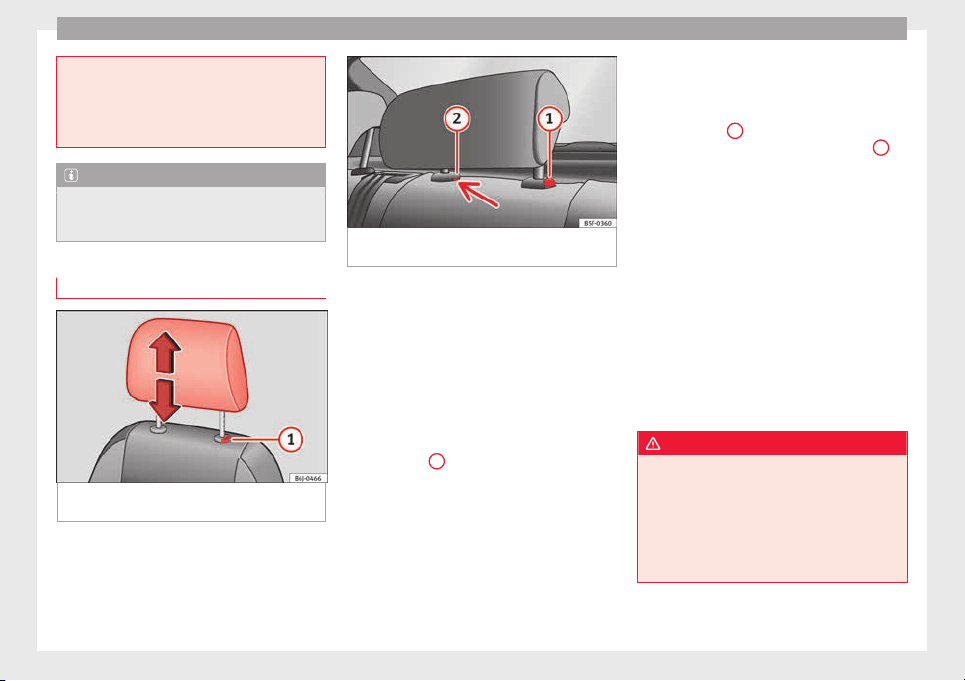
Operation
clutch, brake or accelerator from being press-
ed.
●
Do not place any items on the front passen-
ger seat
other than those allowed (e.g. child
seat). Risk of accident!
Note
After a certain time, the backrest angle ad-
ju
stment
mechanism may gain a certain
amount of play.
head restraints
Fig. 141 Front head restraint: adjust or re-
mo
v
e.
Fig. 142 Rear centre head restraint: release
point.
Read the additional information carefully
›
›
›
page 12
Head restraints cannot be moved up or down
or removed on sports seats.
Fitting and removing head restraints on front
seats
–
Push the head restraint up as far as it will
go.
–
Press catch
1
›
›
› Fig. 141
and remove the
head restraint.
–
To refit, insert the head restraint into the
holes in the backrest, pushing it down until
it engages.
Fitting and removing head restraints on rear
seats
To remove the head restraint, the correspond-
ing backrest must be partially folded forward.
–
Unlock the backrest ››› page 134
–
Move the head restraint upwards until it ar-
rives to the top.
–
Press button
1
›
›› Fig. 142
, whi
le simulta-
neously pressing on the security hole
2
››› Fig. 142 w
ith a fl
at
screwdriver a maxi-
mum of 5 mm wide, and remove the head
restraint.
–
To refit, insert the head restraint into the
holes in the backrest, pushing it down until
it engages.
For maximum head restraint protection, ad-
just the head restraint so that its upper edge
is at the same level as the top of your head.
The head restraint must be adjusted in line
with the height of users. Correct adjustment
of the head restraint, together with the seat
belts, ensure effective passenger protection
››› page 56.
WARNING
●
Badly
adjusted head restraints increase the
risk of injuries in the event of an accident.
●
Never drive with the head restraints re-
moved. Risk of injuries!
●
If the seats are in use, never drive with the
rear head restraints in their out-of-use posi-
tion.
132
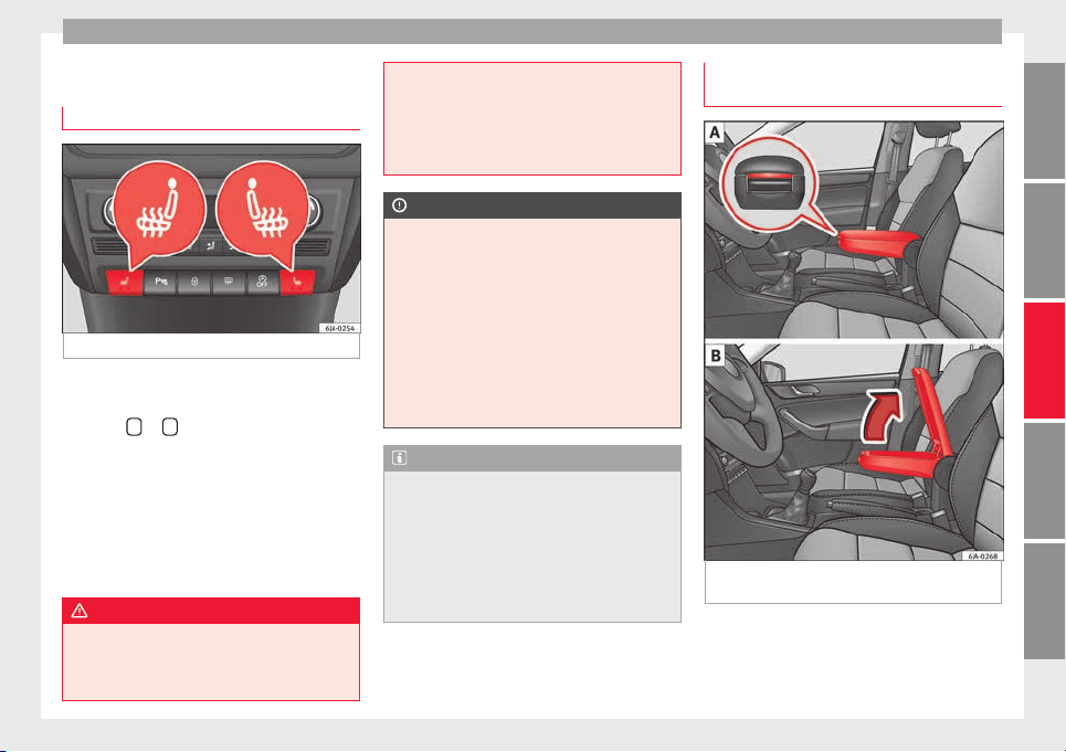
Seats and head restraints
Seat functions
He
at
ed fr
ont seats*
Fig. 143 Heated front seats.
The cushion and backrest of the front seats
c
an be he
at
ed electrically.
Press the
or
›
›
› Fig. 143
button to switch
on and adjust the heated front seats.
Press once to connect the heating at maxi-
mum force.
Press the button again to reduce the force of
the heating and switch it off. The force is indi-
cated by the number of warning lamps lit on
the button.
WARNING
Do not use the heated seat if your perception
of pain and/or t
emperature or that of your
passenger is limited, e.g. due to medication,
paralysis or chronic illness (e.g. diabetes). It
could cause burns on the back, buttocks and
leg
s that are difficult to heal. If you still want
to use the heated seat, take frequent breaks
on long journeys so that the body can recover
from the trip. Ask your doctor about your par-
ticular situation.
CAUTION
●
T
o avoid d
amaging the heating elements,
do not kneel on the seat or apply sharp pres-
sure at a single point to the seat cushion or
backrest.
●
Do not use the heated seats if nobody is
sitting on them or if there are items attached
to or lying on them, such as a child seat or a
bag, etc. This could lead to a fault in the seat
heating elements.
●
Do not clean the seats with anything damp
››› page 198.
Note
●
Only c
onnect the heated seats when the
engine is running. This provides considerable
savings on the battery capacity.
●
In the event of a drop in voltage in the on-
board systems, the heated seats switch off
automatically to ensure enough power to con-
trol the engine ››› page 214, Automatic dis-
connection of electrical equipment.
Armrest on front seats with inner stor-
ag
e*
Fig. 144 Armrest/Opening and closing the
s
t
or
age compartment.
Adjusting armrest height
–
Lift the armrest as far as it will go and then
f
o
l
d it downward.
»
133
Technical dataAdviceOperationEmergenciesSafety
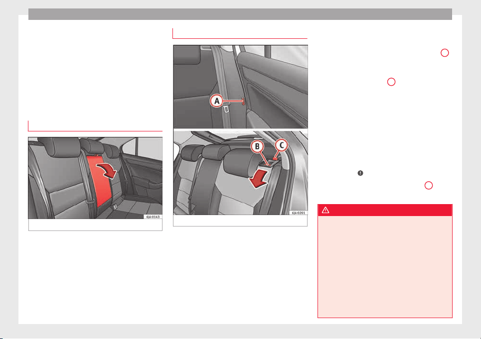
Operation
–
R
ai
se the armr
est until it engages in one of
the 5 positions.
Opening storage compartment
–
Press the button located on the front of the
armrest ››› Fig. 144 - .
–
Lift the storage compartment lid ››› Fig. 144
- .
Armrest on rear seats
Fig. 145 Rear seats: armrest.
The armrest can be folded away for greater
c
omf
or
t using the handle ››› Fig. 145.
Folding down the backrest
Fig. 146 Unlocking the backrest.
Folding
–
Before folding the rear seats, adjust the po-
s
ition of
the fr
ont seats so that the rear
seats are not damaged. When the front
seats are adjusted to the rear position,
their head restraints should be removed
before folding the backrests on the rear
seats. Store the removed head restraints in
such a way that they cannot be soiled or
damaged.
–
Insert the seat belt latch plate into hole
A
››› Fig. 146 loc
at
ed on the c
orresponding
side of the vehicle – safety position.
–
Press the lock button
B
to unlock the
b
ac
k
rest and fold it forward.
Returning to the initial position
–
Where the head restraint has been re-
moved, insert it into the backrest when par-
tially raised.
–
Push the backrest backwards to its original
position until the lock button engages –
check that it is locked by pulling on the
backrest ›››
.
–
Make sure the red protruding part
C
is not
v
i
s
ible.
WARNING
●
Once the bac
krests have been lifted, the
seat belts and their buckles must be in their
initial position – ready for use.
●
The backrests must be safely locked to en-
sure any items in the boot cannot move
around the interior of the vehicle in the event
of a sudden braking manoeuvre. Risk of inju-
ries!
●
Make sure the rear backrests are correctly
locked. Only then will the three-point auto-
matic seat belt on the rear central seat work
correctly.
134
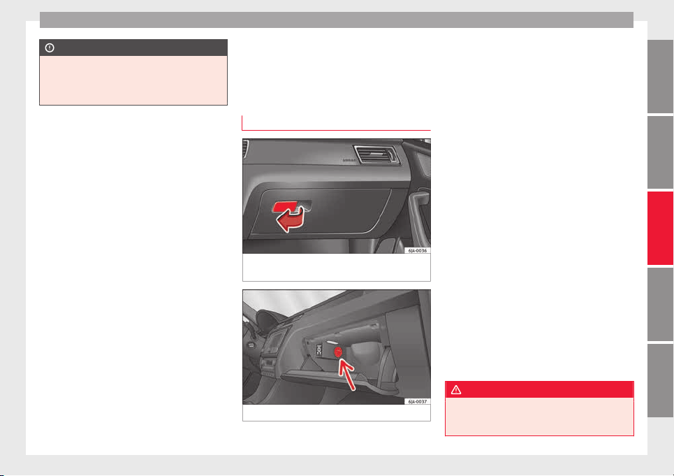
Transport and practical equipment
CAUTION
Take care when handling the rear backrests
so as not
to damage the seat belts. The seat
belt must never be left behind the lifted back-
rest.
Transport and practical
equipment
Pr
actic
a
l equipment
Passenger side storage compartment
Fig. 147 Instrument panel: passenger side
glo
v
e c
ompartment.
Fig. 148 Storage: cooling control.
Opening and closing passenger side glove
c
omp
ar
tment
–
Pull the catch on the lid in the direction in-
dicated by the arrow ››› Fig. 147 and open
the lid.
–
Close the lid and push it until it engages.
Depending on the vehicle equipment, the CD
player is located in the glove compartment.
Separate operating instructions are enclosed
for this equipment in the corresponding In-
struction Manual.
Glove compartment cooling*
Open or close the air outlet by turning the
thumbwheel ››› Fig. 148.
If the air outlet is open and the air condition-
ing is on, the cooled air will be released into
the glove compartment.
If the air outlet is open and the air condition-
ing is off, outdoor air (not conditioned) will
be released into the glove compartment.
The air outlet should be closed if the air con-
ditioning is being used in heating mode or
where glove compartment cooling is not in
use.
WARNING
●
For saf
ety reasons, all storage compart-
ments must be closed while the vehicle is
moving.
»
135
Technical dataAdviceOperationEmergenciesSafety
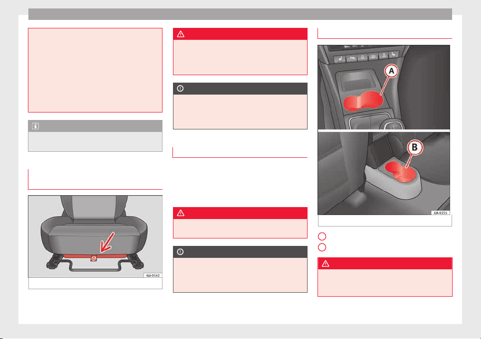
Operation
●
Never pl
ace any objects on the instrument
panel. These objects could be flown around
the interior while the vehicle is moving (on
accelerating or turning) and distract you. Risk
of accident!
●
Make sure objects remain in the centre con-
sole or other compartments while the vehicle
is moving. Otherwise, this could prevent you
from braking, changing gear or accelerating.
Risk of accident!
Note
The glove compartment can hold a bottle no
l
arg
er than 1 litre.
Storage compartment for reflective
v
e
s
t
Fig. 149 Driver seat: storage compartment
There is a compartment below the driver seat
›
›
›
Fig. 149 to store the reflective vests.
WARNING
The compartment is solely designed to store
the reflectiv
e vest and no other objects. Ob-
jects falling out of the storage compartment
could limit or prevent use of the pedals.
CAUTION
The compartment is solely designed to store
the reflectiv
e vest and no other objects, since
there is a risk of damaging the storage com-
partment.
Storage pocket under the front seats
There is a storage pocket on the rear part of
the b
ac
k
rest of the front seats.
These pockets are designed to hold maps,
magazines, etc.
WARNING
Do not place heavy objects in the pockets.
Risk of
injury!
CAUTION
Do not place overly large objects in the pock-
ets (e.
g. bottles) or objects with sharp edges.
Risk of damage to the pockets and the up-
holstery.
Drink holder in the centre console
Fig. 150 Centre console: drink holder
Front drink holder in the centre console
R
e
ar drink
holder in the centre console
WARNING
●
Do not put
hot drinks in the drink holders.
They could spill while the vehicle is moving.
Risk of scalding!
A
B
136
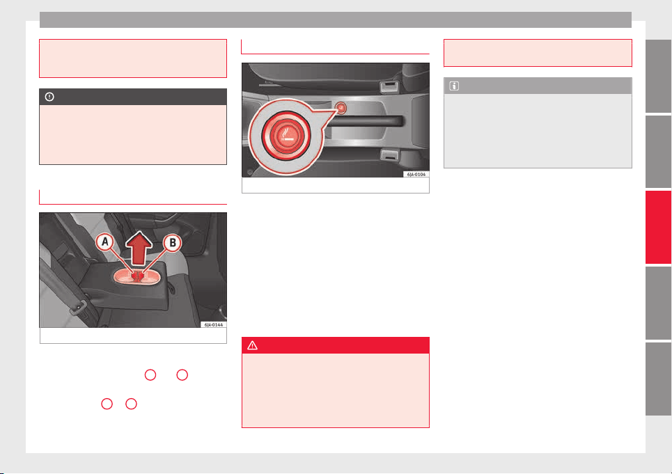
Transport and practical equipment
●
Do not use c
ups or glasses made of fragile
materials (e.g. glass or china). These could
cause injury in the event of an accident.
CAUTION
Avoid putting open drinks containers in the
drink
hol
der while the vehicle is moving.
They could spill (e.g. on braking) and cause
damage to the electrical equipment or the
seat covers.
Drink holder in rear seat armrest
Fig. 151 Rear seats armrest: drink holder
Two drinks can be placed in the drink holder.
U
se the det
ac
hable parts
A
and
B
››› Fig. 151 to ch
ange the size of the holes.
–
Remove part
A
or
B
in the direction indi-
c
at
ed b
y the arrow and replace in the re-
quired position in the drink holder.
Cigarette lighter*
Fig. 152 Centre console: lighter
The cigarette lighter is located at the front of
the c
entr
e c
onsole ››› Fig. 152.
Using the cigarette lighter
–
Press the cigarette lighter knob ››› Fig. 152.
–
Wait for the lighter to spring out.
–
Pull out the cigarette lighter and light the
cigarette on the glowing coil immediately.
–
Put the cigarette lighter back in its socket.
WARNING
●
Take c
are when using the cigarette lighter!
Carelessness or negligence when using the
cigarette lighter can cause burns and serious
injuries.
●
The cigarette lighter also works when the
ignition is off and when the ignition key is re-
moved. Therefore, never leave children unsu-
pervi
sed in the vehicle.
Note
●
The 12
V po
wer socket of the cigarette
lighter can also be used as a power source for
electrical appliances ››› page 138, 12V Power
socket.
●
Additional information ››› page 193, Acces-
sories and modifications to the vehicle.
137
Technical dataAdviceOperationEmergenciesSafety
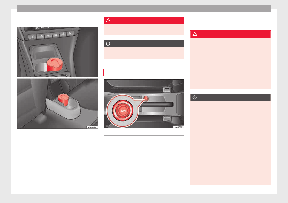
Operation
Ashtrays*
Fig. 153 Centre console: front ashtray/rear
a
shtr
a
y.
Removing the ashtray
–
Pull the ashtray ›
›
›
Fig. 153 upwards to re-
move.
Inserting the ashtray
–
Push the ashtray down.
WARNING
Never put flammable materials in the ashtray.
Risk of
fire!
CAUTION
Never hold onto the ashtray by the lid when
remov
ing it. Risk of breaking the lid.
12V Power socket
Fig. 154 Centre console: 12 V power socket.
The 12 V power socket is located at the front
of
the c
entr
e console
›››
Fig. 154.
Using the power socket
–
Open the cover or remove the cigarette
lighter concealing the socket.
–
Insert the plug of the electrical appliance
into the socket.
Additional information ››› page 193, Acces-
sories and modifications to the vehicle.
WARNING
●
Improper use of
the sockets or electrical
appliances can cause a fire and lead to burns
and other serious injuries.
●
Never leave children unsupervised in the
vehicle. The 12 V power socket is also func-
tional when the ignition is switched off and
the key is removed.
●
Should the connected appliance overheat,
immediately switch it off and disconnect it
from the socket.
CAUTION
●
The 12 V po
wer socket can only be used to
power appliances with a power rating of up to
120 watts.
●
Never exceed the maximum permitted pow-
er, as this could cause damage to the vehicle
electrical installation.
●
With the engine switched off, however, the
vehicle battery will drain. Risk of discharging
the battery!
●
Only use suitable plugs so as not to dam-
age the power socket.
●
Only use appliances that have been tested
for electromagnetic compatibility in compli-
ance with current regulations.
●
Before switching the ignition on or off, un-
plug the appliances from the power socket to
138
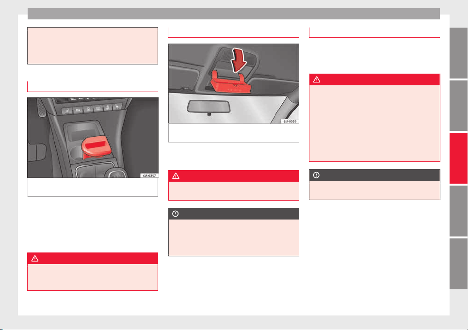
Transport and practical equipment
protect them from any damage caused by
fluctuations
in voltage.
●
Follow the instructions for use of connected
appliances!
Multimedia compartment
Fig. 155 Front centre console: multimedia
c
omp
ar
tment.
The multimedia compartment is in the stor-
ag
e c
omp
artment of the front centre console
››› Fig. 155.
The compartment can be used to hold mobile
phones, mp3 players or similar devices.
WARNING
Never use the multimedia compartment as an
ashtra
y or to store flammable materials. Risk
of fire!
Storage compartment for eyeglasses*
Fig. 156 Close-up of roof panel: storage com-
p
ar
tment
for eyeglasses.
–
Press the compartment lid and it will drop
do
wn ›
›
› Fig. 156.
WARNING
This compartment must only remain open
when remov
ing or replacing glasses.
CAUTION
●
Do not pl
ace heat-sensitive objects in the
compartment as they could be damaged.
●
The side compartment supports a maxi-
mum load of 0.25 kg.
Coat hooks*
The coat hooks are located on the B-pillars
and on the handle
s on the interior lining
above each rear door.
WARNING
●
Make s
ure that any items of clothing hang-
ing from the coat hooks do not obstruct your
view to the rear.
●
Only use the coat hooks for light items of
clothing and make sure that there are no
heavy or sharp objects in the pockets.
●
Do not use clothes hangers to hang up the
clothing, as this could interfere with the func-
tion of the head-protection airbags.
CAUTION
The side hooks support a maximum load of 2
kg.
139
Technical dataAdviceOperationEmergenciesSafety
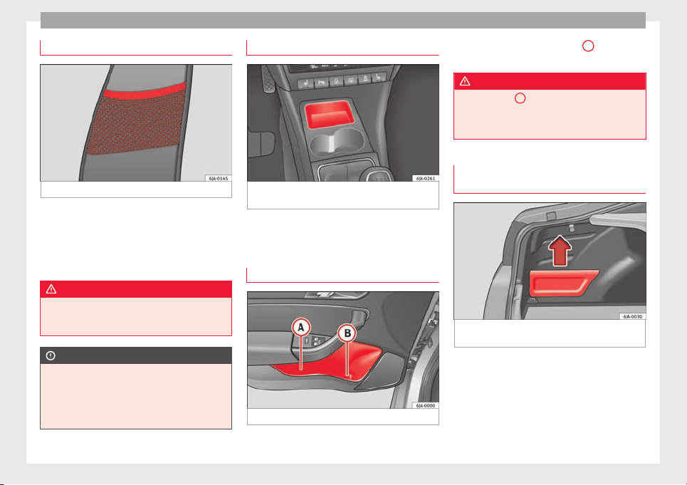
Operation
Front seat backrest net pockets
Fig. 157 Front seats backrests: net pockets.
There are net pockets on the inside part of
the fr
ont
se
ats backrests ››› Fig. 157.
These pockets are designed to hold light-
weight objects such as a mobile phone or an
mp3 player.
WARNING
●
Do not ex
ceed the maximum load that the
net pockets can support. Heavy objects can-
not be safely secured. Risk of injuries!
CAUTION
●
The net pock
ets support a maximum load of
150 g.
●
Do not place overly large objects in the
pockets (e.g. bottles) or objects with sharp
edges. Risk of damage to the pockets.
Compartments in the centre console
Fig. 158 Centre console: storage compart-
ment
Open storage compartment in centre console
›
›
›
Fig. 158.
Storage compartment in front door
Fig. 159 Storage compartment in door trim.
There is a bottle carrier in part
B
›
›› Fig. 159
of
the s
torage compartment in the front door.
WARNING
Only use part
A
››› Fig. 159 of
the compart-
ment in the front door to store objects that do
not protrude from it so as not obstruct the de-
ployment area of the side airbags.
Storage compartment in the luggage
compar
tment*
Fig. 160 Luggage compartment: storage com-
p
ar
tment
The lid from the side storage compartment
c
an be r
emo
ved to increase the size of the
boot.
–
Hold onto the top of the lid and pull it out
in the direction indicated by the arrow
›››
Fig. 160.
140
Transport and practical equipment
CAUTION
●
The compar
tments are designed to hold
small objects with a total weight of 1.5 kg.
●
Make sure you do not damage the storage
compartment or the boot trim when using the
compartment.
Storing objects
Loa
ding the luggage compartment
All luggage and other loose objects must be
s
af
ely
secured in the luggage compartment.
Unsecured objects which shift back and forth
could impair the driving safety or driving
characteristics of the vehicle by shifting the
centre of gravity.
–
Distribute the load evenly in the luggage
compartment.
–
Place heavy objects as far forward as possi-
ble in the luggage compartment.
–
Place the heavy objects first.
–
Secure heavy objects to the fastening rings
›››
page 141.
WARNING
●
Loose lug
gage and other objects in the lug-
gage compartment could cause serious inju-
ries.
●
Alwa
ys stow objects in the luggage com-
partment and secure them on the fastening
rings.
●
Use suitable straps to secure heavy ob-
jects.
●
During sudden manoeuvres or accidents,
loose objects can be thrown forward, injuring
vehicle occupants or passers-by. This in-
creased risk of injury will be further increased
if a loose object is struck by an inflating air-
bag. If this happens, objects may shoot out-
ward like a missile. Risk of fatal injury.
●
Please note that the centre of gravity may
shift when transporting heavy objects; this
may affect vehicle handling and lead to an ac-
cident. Therefore, it is essential to adjust
your speed and driving style accordingly, to
avoid accidents.
●
Never exceed the allowed axle weights or
allowed maximum weight. If said weights are
exceeded, the driving characteristics of the
vehicle may change, leading to accidents, in-
juries and damage to the vehicle.
●
Never leave your vehicle unattended, espe-
cially when the rear lid is open. Children
could climb into the luggage compartment,
closing the door behind them; they will be
trapped and run the risk of death.
●
Never allow children to play in or around
the vehicle. Close and lock all the doors and
rear lid when you leave the vehicle. Before
you lock the vehicle, make sure that there are
no adults or children in the vehicle.
Note
●
Air circ
ulation in the vehicle helps reduce
fogging of the windows. Used air escapes
through ventilation slits in the side trim of
the luggage compartment. Ensure that the
ventilation slots are never covered.
●
Straps for securing the load to the fasten-
ing rings are commercially available.
Fastening rings*
There can be four fastening rings in the lug-
g
ag
e c
ompartment for fastening luggage and
other objects.
–
Always use suitable and undamaged straps
to secure luggage and other objects to the
fastening rings
›››
in Loading the lug-
g
ag
e c
ompartment on page 141.
–
Pull up the fastening rings to attach the
straps.
During a collision or an accident, even small
and light objects can build up so much ener-
gy that they can cause very severe injuries.
The amount of kinetic “energy” depends on
the speed of the vehicle and the weight of
the object. The most significant factor, how-
ever, is the speed of the vehicle.
Example: An object weighing 4.5 kg is lying
unsecured in the vehicle. During a frontal col-
lision at a speed of 50 km/h (31 mph), this
»
141
Technical dataAdviceOperationEmergenciesSafety
Operation
object generates a force corresponding to 20
time
s
its
weight. That means that the effec-
tive weight of the object increases to approxi-
mately 90 kg. You can imagine the severity of
the injuries which might be sustained if this
“object” strikes an occupant as it flies
through the interior of the vehicle. This in-
creased risk of injury will be further increased
if a loose object is struck by an inflating air-
bag.
WARNING
●
If piece
s of baggage or other objects are se-
cured to the fastening rings with inappropri-
ate or damaged retaining cords, injuries
could result in the event of braking manoeu-
vres or accidents.
●
Never secure a child seat on the fastening
rings.
Luggage compartment
Intr
oduction
Please observe the following points to ensure
the
v
ehic
le handles well at all times:
–
Distribute the load as evenly as possible.
–
Place heavy objects as far forward in the
luggage compartment as possible.
–
Secure luggage using the fastening rings or
retaining net
›››
page 143.
During an accident, even small and light ob-
jects can have so much kinetic energy that
they can cause very severe injuries. The
amount of kinetic energy depends on the
speed of the vehicle and the weight of the
object. However, the speed of the vehicle is
the most important factor.
Example: An unsecured object weighing 4.5
kg produces energy corresponding to 20
times its weight in a frontal collision at 50
km/h (31 mph). This means that its weight
reaches around 90 kg. You can imagine the
severity of the injuries that might be sus-
tained if this “projectile” strikes an occupant
as it flies through the vehicle interior.
WARNING
●
Store o
bjects in the luggage compartment
and secure to the fastening points.
●
In an accident or sudden manoeuvre, loose
objects in the interior can be flung forward
and possibly injure vehicle occupants or oth-
ers. This risk is even greater if the flying ob-
jects hit a triggering airbag. In this case, any
rebounding objects could injure vehicle occu-
pants. Risk of fatal injuries!
●
Take into account that transporting heavy
objects changes the centre of gravity that
could also cause changes in vehicle handling.
Risk of accident! Therefore, always adjust
your speed and driving style to suit these cir-
cumstances.
●
Securing the lo
ad to the rings using unsuit-
able or damaged straps could lead to injuries
in the event of an accident or sudden braking
manoeuvre. Secure suitable straps safely to
the rings to ensure this does not happen.
●
Position the load so it cannot move forward
during a sudden braking manoeuvre. Risk of
injuries!
●
If transporting sharp or dangerous objects
in the space provided when the rear seats are
folded, ensure the safety of the occupant of
the remaining rear seat ››› page 58.
●
If the rear seat located alongside a folded
seat is occupied, ensure safety, for example,
by placing the load so that it stops the seat
from folding backward in the event of being
hit from behind.
●
Never drive with the rear lid open or half-
closed, exhaust gases may penetrate into the
interior of the vehicle. Danger of poisoning!
●
Never exceed the allowed axle loads or al-
lowed maximum weight. Risk of accident!
●
Never transport passengers in the luggage
compartment!
CAUTION
Make sure sharp objects stored in the boot
cannot not
damage the rear window heating
filaments.
142
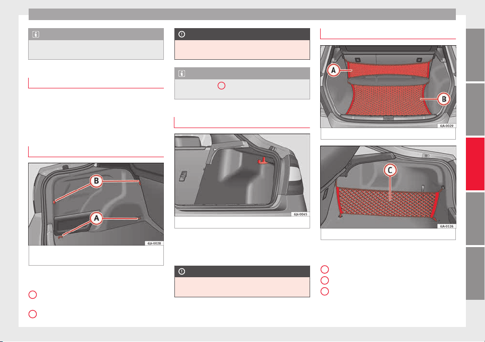
Transport and practical equipment
Note
Tyre pressure must be adapted to suit the
load ›
›› page 216, Useful life of tyres.
Category N1 vehicles
Category N1 vehicles with no protection grille
must
use a retaining set compliant with
Standard EN 12195 (1 – 4) to secure the
load.
Retaining elements*
Fig. 161 Luggage compartment: retaining el-
ements.
The following retaining elements are fitted in
the boot
›
›
›
Fig. 161:
Rings to secure the load and the retain-
ing nets.
Rings used solely for the retaining nets.
A
B
CAUTION
The rings support a maximum load of 3.5 kN
(350 kg).
Note
The front ring
B
is below the folding back-
res
t of the rear seats ››› Fig. 161.
Hook*
Fig. 162 Luggage compartment: hook.
There are hooks on both sides of the boot to
sec
ur
e light
items of luggage such as bags,
etc.
›››
Fig. 162.
CAUTION
The side hooks support a maximum load of
7.5 kg.
Retaining nets*
Fig. 163 Retaining nets.
Fig. 164 Retaining nets.
Example of securing retaining nets
›
›
›
Fig. 163 and ››› Fig. 164.
Sideways bag
Ground net
Lengthways bag
»
A
B
C
143
Technical dataAdviceOperationEmergenciesSafety
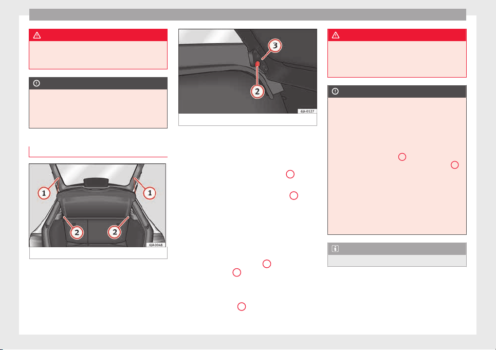
Operation
WARNING
Do not exceed the maximum load that the
nets c
an support. Heavy objects cannot be
safely secured. Risk of injury!
CAUTION
●
The retainin
g nets support a maximum load
of 1.5 kg.
●
Do not place any item with sharp edges in
the net. Risk of damaging the net!
Rear shelf
Fig. 165 Remove the shelf.
Fig. 166 Remove the shelf.
The shelf can be removed if a large load is to
be tr
an
s
ported.
Removing the shelf
–
Remove the straps from the shelf
1
››› Fig. 165.
–
Remove the shelf from its housing
2
by
knoc
k
in
g it gently from underneath be-
tween the supports.
Fitting the shelf
–
Place the shelf on the side supports on the
trim.
–
Adjust the shelf supports
3
›
›
› Fig. 166
to
fit the supports
2
in the trim.
–
Fit into place by knocking the top of the
shelf
g
ently
between the supports.
–
Attach the straps
1
to the tray.
WARNING
Do not place objects on the rear shelf that
coul
d endanger the vehicle occupants in case
of a sudden braking manoeuvre or an acci-
dent.
CAUTION
●
The rear shelf
supports a maximum load of
1 kg.
●
If handled incorrectly, the tray could bend
on closing the rear lid and become damaged
or damage the trim. Follow the instructions
below:
–
The shelf supports
3
››› Fig. 166 mu
st be
securely in place in the trim supports
2
.
–
The size of
the load must not exceed the
height of the shelf.
–
When open, the shelf must not be bent
against the shelf seal.
–
There must be no objects in the space be-
tween the open shelf and the backrest of
the rear seat.
Note
The shelf will lift when the rear lid is opened.
144
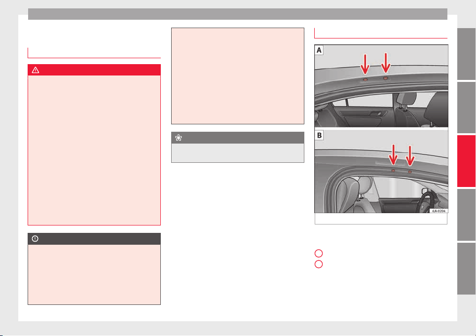
Transport and practical equipment
Roof rack*
Intr
oduction
WARNING
●
The load on the r
oof carrier must be proper-
ly secured. Risk of accident!
●
Always secure the load using retaining
straps that are in good condition.
●
Distribute the load evenly.
●
When transporting heavy or large objects
on the roof, any change in normal vehicle be-
haviour due to a change in the centre of gravi-
ty or increased wind resistance must be taken
into account. Risk of accident! For this rea-
son, speed and driving style must be adjus-
ted for the situation.
●
Avoid sudden manoeuvres and braking.
●
Adjust your driving style to suit visibility,
the weather and road and traffic conditions.
●
Never exceed the allowed axle loads or al-
lowed maximum weight. Risk of accident!
CAUTION
●
Only u
se SEAT-authorised roof carriers.
●
Where roof carriers from other systems are
used or where they are not fitted properly,
any damage caused to the vehicle will not be
covered by the warranty. Therefore, carefully
follow the Instruction Manual for installation
of the roof carrier.
●
Remember that
the rear lid must not hit the
roof load.
●
The total height of the vehicle increases ac-
cording to the roof load. Compare the height
of the vehicle with the heights of bridges or
other underpasses, for example, the height
of the garage door.
●
Do not forget to remove the roof carrier be-
fore entering an automatic carwash.
●
Take into account that the load must not
damage the aerial located on the roof.
For the sake of the environment
If aerodynamic resistance increases, fuel con-
sumption wi
ll also increase.
Attachment points
Fig. 167 Basic roof carrier attachment points.
Location of the basic roof carrier attachment
points
›
›
› Fig. 167:
Rear attachment points
Front attachment points
Install and remove following the instructions
given.
»
A
B
145
Technical dataAdviceOperationEmergenciesSafety
Operation
CAUTION
Follow the instructions given in the manual.
Roof load
The maximum permissible roof load (includ-
ing the sup
port system) of 75 kg and the to-
tal authorised weight of the vehicle must not
be exceeded.
It will not be possible to carry the full maxi-
mum load if the roof carrier you are using is
rated for a load which is less than this figure.
In this case, you can only load the roof carrier
to the maximum load permitted in your in-
stallation manual.
Air conditioning
He
atin
g and air c
onditioning
General notes
The power of the heating depends on the
temperat
ure of the coolant. Therefore, maxi-
mum power is only obtained when the en-
gine has reached operating temperature.
The temperature and humidity of the air in-
side the vehicle decrease when the cooling
system is turned on. This therefore increases
the comfort of all vehicle occupants when
outside temperatures and humidity are high.
It also helps prevent the windows from mist-
ing over during cold periods of the year.
The air recirculation system can be switched
on temporarily to increase the cooling effect.
Keep the air intake slots in front of the wind-
screen clear of ice, snow or leaves to ensure
unimpaired heating and cooling.
When the air conditioning is on, condensa-
tion can drip from the evaporator in the air
cooling system and form a pool underneath
the vehicle. This is normal and does not indi-
cate a leak!
WARNING
●
All
windows must be clear of ice, snow and
condensation for driving safety. Therefore,
make sure you familiarise yourself with the
correct
use of heating and ventilation, win-
dow demisting and defrosting and cooling.
●
Never use the air recirculation system for
too long, as it prevents fresh air from enter-
ing the vehicle and used air can cause tired-
ness, reduce your attention span and cause
the windows to mist over. This increases the
risk of an accident. Switch off the air recircu-
lation system as soon as the windows begin
to mist over.
WARNING
Do not switch off Climatronic for longer than
neces
sary.
●
Switch Climatronic back on as soon as the
windows begin to mist over.
Note
●
Used air es
capes through ventilation slots
in the rear of the luggage compartment.
●
Smoking is not recommended while the air
recirculation system is in use, as the smoke
drawn from the interior of the vehicle settles
in the evaporator of the air conditioning sys-
tem. This causes a persistent, unpleasant
smell while the system is running that is
time-consuming and expensive (evaporator
replacement) to eliminate.
●
To guarantee proper operation, never cover
the air outlets in the luggage compartment.
146
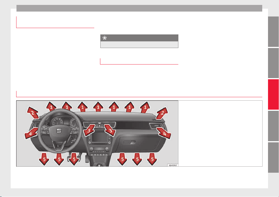
Air conditioning
Economic use of the air-conditioning
sy
s
t
em
When the air conditioning is switched on, the
compre
ssor consumes engine power and has
influence on fuel consumption.
If the vehicle interior has overheated due to
excessive solar radiation, it is best to open
the windows or doors to allow the hot air to
escape.
While in motion, the air conditioning should
not be switched on if the windows are open.
If the interior temperature can be reached
without sw
itching on the air conditioning, the
fresh air mode should be used.
For the sake of the environment
Saving fuel reduces emissions.
Faults
If the air conditioning does not work at out-
side temper
atures above +5°C (+41°F) then
the system is faulty. This may be due to one
of the fo
llowing reasons:
●
One of the fuses has blown. Check the fuse
and replace if necessary ››› page 80.
●
The air conditioning compressor has
switched off temporarily because of in-
creased engine coolant temperature
››› page 97.
If you cannot repair the fault yourself or
where cooling power continues to drop,
switch off the system. Contact a specialised
service.
Air vents
Fig. 168 Air vents
Opening air vents 3 and 4
–
Turn the vertical circular control upwards.
»
147
Technical dataAdviceOperationEmergenciesSafety
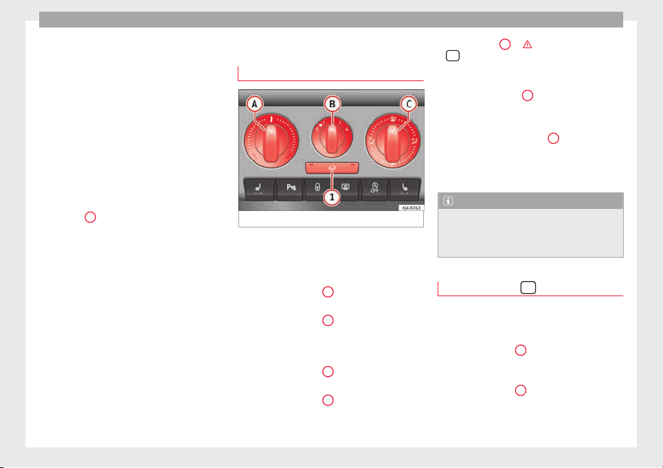
Operation
Closing air vents 3 and 4
–
Turn the vertical circular control down-
w
ar
d
s.
Changing the direction of air delivery from
air vents 3 and 4
–
The air circulation height can be varied by
changing the position of the sliding adjust-
er upwards or downwards ››› Fig. 168.
–
The air circulation direction can be varied
by changing the position of the sliding ad-
juster to the right or to the left.
The flow of air from the vents is controlled us-
ing control
C
›
›
› Fig. 169
. Vents 3 ››› Fig. 168
and 4 can be opened and closed individually.
Depending on the position of the adjusters
and on the weather, open vents can provide
air which is either heated, unheated or
cooled.
Heating and fresh air
Operation
Fig. 169 Heating: controls.
Read the additional information carefully
›
›
›
page 38
Temperature selection
–
Turn rotary control
A
›
›
› Fig. 169
clockwise
to increase the temperature.
–
Turn rotary control
A
anti-clockwise to re-
duc
e the t
emper
ature.
Blower selection
–
Turn rotary control
B
›
›
› Fig. 169
to posi-
tion 1 to 4 to switch the blower on.
–
Turn rotary control
B
to position 0 to
sw
it
c
h the blower off.
–
Press button
1
›
››
in Air recirculation
on page 149 t
o c
lo
se the fresh air vent.
Air distribution selection
–
Turn rotary control
C
›
›› Fig. 169
t
o select
the air vents ››› page 147, Air vents you
wish to activate.
All controls, except control
B
›
›› Fig. 169
,
c
an be set to any intermediate position.
Leave the blower activated at all times to pre-
vent the windows from misting over.
Note
If the system is set so that all of the air is
used to defr
ost the windows, no air is sup-
plied to the footwell area. This could limit
heating comfort.
Air recirculation
Air recirculation prevents unpleasant smells,
e.
g. when p
a
ssing through a tunnel or in
queuing traffic, from entering the interior.
If the rotary switch
C
›
›
›
Fig. 169 is in the
thaw position, the recirculation flap will al-
ways be open (button light off).
If the rotary switch
C
is switched from any
po
s
ition t
o the thaw position, recirculation
will be automatically deactivated.
148
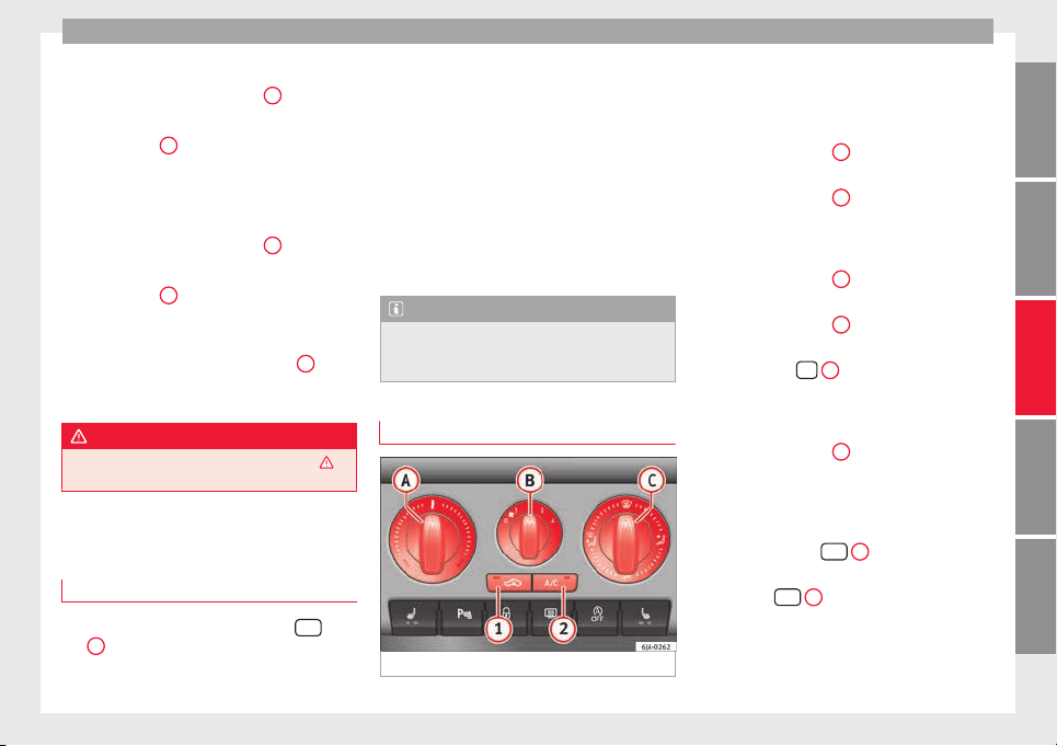
Air conditioning
Connecting the recirculation
In an
y
po
sition of rotary switch
C
except
th
a
w:
●
Pr
ess button
1
›
›› Fig. 169
, the sw
itch's
lamp will light up, indicating that air recircu-
lation inside the vehicle has been activated.
Disconnecting the recirculation
In any position of rotary switch
C
except
th
a
w:
●
Pr
ess button
1
again and the button's
l
amp w
i
ll go off, indicating that air recircula-
tion from the outside has been activated.
In the thaw position of rotary switch
C
, the
entr
y
of
air into the vehicle interior is always
from the outside.
WARNING
Read and observe the safety warnings ›››
in
General
notes on page 146.
Air conditioning (manual)*
Gener
a
l
notes
The air cooling system only works if
A/C
but-
t
on
2
›
›
›
Fig. 170
›››
page 149 is pressed
and under following conditions:
●
The engine is running,
●
The outside temperature is above +2°C
(+36°F),
●
The blower control is in position 1–4.
When the cooling system is on and under cer-
tain conditions, air can be blown from the
vents at a temperature of approximately +5°C
(+41°F). In the event of prolonged, irregular
distribution of the air flow from the outlets
and significant differences in temperature,
e.g. on leaving the vehicle, sensitive people
may catch cold.
Note
A visit to the specialised service once a year
is r
ecommended to clean the air conditioning
system.
Manual operation
Fig. 170 Air conditioning: controls.
Read the additional information carefully
›
›
›
page 37
Temperature selection
–
Turn rotary control
A
›
›› Fig. 170
c
lockwise
to increase the temperature.
–
Turn rotary control
A
anti-clockwise to re-
duc
e the t
emper
ature.
Blower selection
–
Turn rotary control
B
›
›› Fig. 170
t
o posi-
tion 1 to 4 to switch the blower on.
–
Turn rotary control
B
to position 0 to
sw
it
c
h the blower off.
–
Press button
1
›
›
› p
age 150, Air recir-
culation to close the fresh air vent.
Air distribution selection
–
Turn rotary control
C
›
›
› Fig. 170
to select
the air vents ››› page 147 you wish to acti-
vate.
Switching cooling on and off
–
Press the button
A/C
2
›
›
› Fig. 170
and
the lamp in the button will illuminate.
–
Press the
A/C
2
button again and the
light
in the b
utt
on will switch off.
»
149
Technical dataAdviceOperationEmergenciesSafety
Operation
Coldest setting
–
On turning control
A
to the coldest setting
(b
lue indic
at
or), buttons
1
and
2
A/C
, light up
–
The recirculation function is activated auto-
m
atic
al
ly in order to cool faster.
Note
●
If the air dis
tribution is directed towards
the windows, all, of the heating power is
used to defrost the windscreen. No warm air
is directed to the footwell area. This could
limit heating comfort.
●
The
AC
button lamp will illuminate after
the syst
em has been switched on, even if not
all of the conditions for cooling system oper-
ations are met. Cooling is indicated as availa-
ble once all of the conditions are met
›››
page 149, General notes.
Air recirculation
Air recirculation prevents unpleasant smells,
e.g. when pa
ssing through a tunnel or in
queuing traffic, from entering the interior.
If the rotary switch
C
››› Fig. 170 i
s in the
thaw position, the recirculation flap will al-
ways be open (button light off).
If the rotary switch
C
is switched from any
po
s
ition t
o the thaw position, recirculation
will be automatically deactivated.
Connecting the recirculation
In any position of rotary switch
C
except
th
a
w:
●
Pr
ess button
1
›
›› Fig. 170
, the sw
itch's
lamp will light up, indicating that air recircu-
lation inside the vehicle has been activated.
Disconnecting the recirculation
In any position of rotary switch
C
except
th
a
w:
●
Pr
ess button
1
again and the button's
l
amp w
i
ll go off, indicating that air recircula-
tion from the outside has been activated.
In the thaw position of rotary switch
C
, the
entr
y
of
air into the vehicle interior is always
from the outside.
WARNING
Read and observe the safety warnings ›››
in
General
notes on page 146.
150
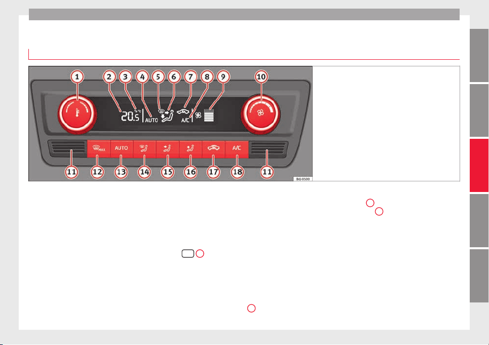
Air conditioning
Climatronic* (automatic air conditioning)
Gener
a
l
notes
Fig. 171 Climatronic: controls.
Read the additional information carefully
›
›
›
page 36
Climatronic automatically maintains a com-
fortable temperature. To do so, it automati-
cally regulates the supplied air temperature
and the blower and air distribution levels.
The system also allows for the effect of sun-
light, so there is no need for manual adjust-
ment. It also has a humidity sensor that
helps to automatically demist the wind-
screen.
Automatic operations ››› page 152 guaran-
tee maximum comfort any time of year.
Climatronic description
Cooling only works if the following conditions
are met:
●
The engine is running
●
the outside temperature is above +2°C
(+36°F);
●
A/C
18
›
›› Fig. 171
sw
itched on.
Starting the Climatronic
The corresponding function will be switched
on when a button is pressed, turning on the
air conditioning if it was switched off, with
the exception of button
17
›
›
› Fig. 171
(recir-
culation).
Switching off the Climatronic
●
Turn control
10
to the left until the seg-
ments
of
c
olumn
9
›
›› Fig. 171
sw
itch off.
●
After 1 second has elapsed, turn the control
again to switch off the display.
In order to ensure engines subject to heavy
loads are cooled, the air conditioning com-
pressor is switched off in the event of high
coolant temperatures.
Recommended setting for all seasons of the
year
●
Set the required temperature. We recom-
mend +22°C (72°F).
»
151
Technical dataAdviceOperationEmergenciesSafety
Operation
●
Pr
e
s
s the
AUTO
button
13
›
›› Fig. 171
.
●
Adju
st vents 3 and 4 ››› page 147 so that
the air flow is directed slightly upwards.
Change between degrees Centigrade and de-
grees Fahrenheit
Keep the
AUTO
and
A/C
›
›› Fig. 171
b
uttons
held down for 2 seconds at the same time.
The data is displayed on the screen in the
units required.
Note
●
A vi
sit to the specialised service once a
year is recommended to clean the Climatronic
system.
●
The interior temperature sensor
11
››› Fig. 171 is at
the bottom. Do not cover it
with stickers or the like, as this could have a
negative effect on Climatronic operations.
Automatic mode
Automatic mode is used to maintain a con-
s
t
ant
temperature and demist the windows
inside the vehicle.
Switching on automatic mode
●
Set the interior temperature between +16°C
(+64°F) and +29°C (+84°F).
●
Adjust vents 3
›››
page 147 and 4 so that
the air flow is directed slightly upwards.
●
Press the
AUTO
button
13
›
›› Fig. 171
and
AUTO di
splayed on the screen.
Automatic mode is switched off by pressing
the air distribution buttons or increasing or
decreasing the blower speed. However, the
temperature remains regulated.
Adjusting the temperature
●
When you switch on the ignition, control
1
››› Fig. 171 can be used t
o set the required in-
terior temperature.
It is possible to select interior temperatures
from +16°C (+64°F) to +29°C (+84°F). In this
range the temperature is regulated automati-
cally. If a temperature below +16°C (+64°F) is
selected, “LO” is displayed on the screen. If a
temperature above +29°C (+84°F) is selected,
“HI” is displayed on the screen. At both ex-
tremes, Climatronic works at maximum cool-
ing or heating power, respectively. The tem-
perature is not regulated.
In the event of prolonged, irregular distribu-
tion of the air flow from the outlets (particu-
larly the footwells) and significant differen-
ces in temperature, e.g. on leaving the vehi-
cle, sensitive people may catch cold.
Air recirculation
Air recirculation prevents unpleasant smells,
e.g. when pa
ssing through a tunnel or in
queuing traffic, from entering the interior.
Switching on air recirculation mode
●
Press button
17
››› Fig. 171 and the
symbol is displayed on the screen.
Switching off air recirculation mode
●
Press button
17
›
›
› Fig. 171
and the
symbol disappears from the screen.
WARNING
Read and observe the safety warnings ›››
in
General
notes on page 146.
Note
If air recirculation mode remains on for 15 mi-
nutes, the
symbol will start to flash on
the screen to indicate prolonged air recircula-
tion. If air recirculation is not switched off,
the symbol will continue to flash for about 5
minutes.
Blower selection
Climatronic automatically regulates blower
s
peed ac
c
ording to the interior temperature.
152
Driving
It is possible, however, to set the blower
s
peed t
o s
uit requirements.
●
Turn control
10
›
›› Fig. 171
c
ounter-clock-
wise (to lower the speed) or clockwise (to in-
crease the speed).
Climatronic will switch off when the blower
switches off.
WARNING
Read and observe the safety warnings ›››
in
General
notes on page 146.
Windscreen defrost
Switching on windscreen defrosting
●
Press the button
12
›
›
›
Fig. 171.
Switching off windscreen defrosting
●
Press button
12
›
›
›
Fig. 171 several
times or press the
AUTO
button.
The t
emper
at
ure is regulated automatically.
The air output is increased from vents 1
›››
page 147 and 2.
Driving
St
ar
tin
g and stopping the en-
gine
Introduction
Read the additional information carefully
›››
page 17
WARNING
●
When movin
g with the engine switched off,
the ignition key must always remain in posi-
tion
2
››› Fig. 172 ›
›› page 154 (ignition on).
The control lamps will light up in this posi-
tion. Otherwise, the steering lock could en-
gage suddenly. Risk of accident!
●
Do not remove the key from the ignition un-
til the vehicle has come to a standstill and is
secure (e.g. the handbrake is engaged). Oth-
erwise, the steering lock could suddenly en-
gage. Risk of accident!
●
Always take the ignition key with you when
you leave the vehicle. This is particularly im-
portant if you leave children in the vehicle.
Children could, for example, start the engine
with the subsequent risk of accident.
●
Never leave the engine running in unventi-
lated or closed rooms. The exhaust gases
contain carbon monoxide, an odourless and
colourless poisonous gas. Risk of fatal acci-
dents! Carbon monoxide can cause people to
lose consciousness and can cause death.
●
Never le
ave the vehicle unattended if the
engine is running.
●
Never switch the engine off until the vehi-
cle has come to a complete stop. Risk of acci-
dent!
CAUTION
●
T
urning the s
teering wheel fully in either
direction when the vehicle is stationary and
the engine is in gear puts the power steering
under great stress. This could lead to noise.
Never leave the steering wheel turned fully in
either direction for more than 15 seconds.
Risk of damage to the power steering system!
●
The starter motor may only be used (key
position
3
››› Fig. 172 ›
›› page 154 in the ig-
nition) if the engine is off. Using the starter
motor when the engine is running could dam-
age it.
●
Immediately release the ignition key when
the engine starts, otherwise damage could be
caused to the starter motor.
●
When the engine is cold, you should avoid
high engine speeds, driving at full throttle
and over-loading the engine before it reaches
operating temperature. Risk of engine dam-
age!
●
Do not tow-start the engine. Risk of engine
damage! In vehicles with a catalytic convert-
er, fuel that has not been burned could reach
the catalytic converter and catch fire in it.
This would lead to a fault in the catalytic con-
verter. You may use the battery from another
»
153
Technical dataAdviceOperationEmergenciesSafety
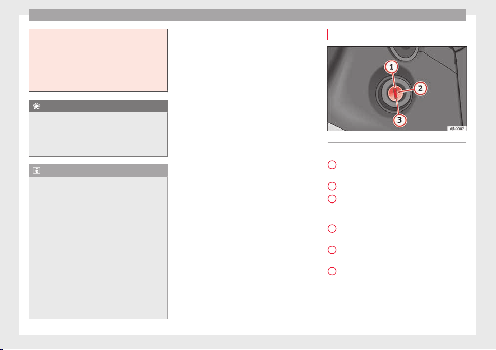
Operation
vehicle to help you start your engine
›››
page 51.
●
After prolonged and demanding operation
of the engine, when the journey has ended,
do not stop the engine immediately. Let the
engine run at idle for about one more minute.
This will stop the engine from overheating.
For the sake of the environment
Do not warm up the engine when the vehicle
i
s s
tationary. If possible, move off immediate-
ly after starting the engine. This will help the
engine reach operating temperature more
quickly, reducing the quantity of emissions.
Note
●
The engine can on
ly be started with the
original SEAT key.
●
Loud running noises may be heard briefly
after cold-starting the engine. This is normal
and is no cause for concern.
●
After the engine has been stopped and the
ignition switched off, the radiator fan may
continue running for around 10 minutes.
●
If the engine still does not start after a sec-
ond attempt, the fuel pump fuse might have
blown. Check it and replace if necessary
››› page 80 or contact your Specialised Serv-
ice.
●
You should always engage the steering lock
when you exit the vehicle. This will hinder
any attempts at theft.
Power steering
The power steering allows you to turn the
steerin
g wheel more easily.
If the power steering fails or the engine is off
(towing), it is still possible to turn the vehi-
cle's steering wheel fully. However, you need
more strength to steer the vehicle.
Start-up lock security system (immo-
biliser)
There is an electronic chip in the key. The
el
ectr
onic
immobiliser is deactivated when
the key is inserted into the ignition. The elec-
tronic immobiliser is automatically activated
when the key is removed from the ignition.
The engine will not start if an unauthorised
key is used.
The informative display indicates:
Immobiliser active!
Ignition lock
Fig. 172 Ignition key positions.
Petrol engines
1
– Ignition switched off, engine stopped,
s
t
eerin
g can be locked
2
– Ignition switched on
3
– Starting
Die
sel
en
gines
1
– Fuel supply stopped, ignition switched
off
, en
gine s
topped, steering can be locked
2
– Engine pre-heating, ignition switched
on
3
– Starting
T
o en
g
age the Steering lock without the key
in the ignition, turn the steering wheel slight-
ly until you hear it engage.
154
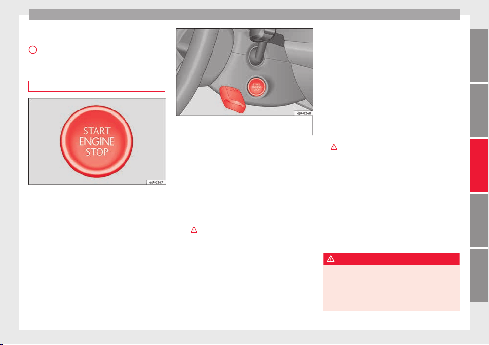
Driving
If the s
teering lock is engaged and it
i
s diffi-
cult or impossible to turn the key to position
2
, release the lock by turning the steering
wheel
s
lightly
in both directions.
Starter button
Fig. 173 In the steering column: start-up
p
u
sh b
utton for the Keyless Access lock and
start-up system. The layout in right-hand
drive vehicles is symmetrical.
Fig. 174 Emergency ignition in vehicles with
Keyle
ss Access.
The start-up button may only be used if there
i
s
a
valid key in the vehicle.
Opening the driver's door when exiting the
vehicle activates the electronic lock on the
steering column if the ignition is disabled.
Switching the ignition on/off
●
Briefly push the start-up button ››› Fig. 173
without touching the brake or clutch ped-
al ›››
.
Emer
g
ency
starting function
If no valid key is detected inside the vehicle,
an emergency start-up will be required. The
relevant message will appear in the dash
panel display. This may happen when, for ex-
ample, the vehicle key battery is very low or
flat:
●
Immediately after pushing the start-up but-
ton, keep the vehicle key next to the steering
column ››› Fig. 174.
●
The ignition connects and the engine starts
automatically.
Emergency disconnection
If the engine does not stop after briefly press-
ing the start-up button, an emergency dis-
connect will be required:
●
Press the starter button twice within 1 sec-
ond or press it once for more than 2 seconds
›››
.
●
The engine turns off automatically.
En
gine r
e
start feature
If no valid key is detected inside the vehicle
after the engine stops, you will only have 5
seconds to restart it. A warning will display
on the dash panel screen.
After this interval, it will not be possible to
start the engine without a valid key inside
the vehicle.
WARNING
Any accidental movement of the vehicle could
res
ult in serious injury.
●
When pressing the start-up button, do not
press the brake or clutch pedal, this way the
engine will start immediately.
»
155
Technical dataAdviceOperationEmergenciesSafety
Operation
WARNING
If vehicle keys are used negligently or with-
out due car
e, this may cause accidents and
serious injury.
●
Never leave any key inside the vehicle
when exiting. Otherwise, a child or unauthor-
ised person could lock the vehicle, start the
engine or connect the ignition and, in this
way, operate electronic equipment (e.g. the
windows).
Note
In diesel vehicles with the Keyless Access
syst
em, there may be a delay in the engine
starting if it requires preheating.
Starting the engine
Vehicles with a die
sel
en
gine are equipped
with a glow plug system. When you switch on
the ignition, the glow plug warning lamp
will light up. The engine can be started
straight away when the lamp switches off.
Do not connect electrical appliances during
preheating so as not the drain the vehicle
battery unnecessarily.
Starting the engine
●
Move the gearbox lever into neutral or
move the selector lever to position P or N and
pull firmly on the handbrake.
●
Press the clutch pedal all the way down
and start the engine
3
›
›› Fig. 172
›
›
› page 154, without pressing the accelera-
tor. Keep the clutch pedal pressed down until
the engine starts.
●
Release the ignition key as soon as the en-
gine starts. The key returns to position
2
.
●
If the engine does not start after 10 sec-
ond
s, t
urn the k
ey back to position
1
. Re-
pe
at
the action af
ter 30 seconds.
●
Release the handbrake before moving off.
Switching off the engine with the key
Stop the engine by turning the ignition key to
po
s
ition
1
›
›
› Fig. 172
››› page 154.
Brakes and brake servo sys-
tems
Introduction
WARNING
●
The brake ser
vo only works when the en-
gine is running. Braking when the engine is
switched off requires applying more strength
to the brake pedal. Risk of accident!
●
Press down on the clutch pedal when stop-
ping and braking with a manual gearbox, pet-
rol engine vehicle at low speed. Otherwise,
the brake ser
vo might not work properly. Risk
of accident!
●
In the event of damage to the standard
front spoiler or where a different front spoil-
er, wheel trims, etc. are subsequently fitted,
make sure the air vent to the brakes on the
front wheels is not blocked. Otherwise, brak-
ing operations may be impaired. Risk of acci-
dent!
●
Always fully release the handbrake. If it is
only partially released, this will cause over-
heating of the rear brakes, which can impair
the function of the brake system. Risk of acci-
dent!
●
Never leave children unsupervised in the
vehicle. They could release the handbrake or
move the gear lever. The vehicle could start
moving. Risk of accident!
●
Insufficient fuel can cause the engine to run
irregularly or to switch off. Brake assist sys-
tems could be impaired. Risk of accident!
●
Always adjust your driving style to suit visi-
bility, the weather and road and traffic condi-
tions. The best vehicle safety offered by
brake assist systems must never encourage
you to run greater risks. Risk of accident!
CAUTION
●
Obser
ve the information concerning new
brake pads ››› page 163.
156
Driving
●
Where brak
ing is not necessary, do not
wear down the brake pads by pressing down
gently on the brake pedal. This causes the
brakes to overheat, increasing their wear and
increasing braking distances.
●
To ensure the brake assist systems work
properly, all wheels must be fitted with tyres
approved by the manufacturer.
Note
●
If
y
ou brake suddenly and the brake system
control unit regards the situation as hazard-
ous for the drivers behind you, the brake
lights will begin to flash automatically. After
reducing speed to approximately 10 km/h (6
mph) or stopping the vehicle, the brake lights
will stop flashing and the hazard warning
lights will switch on. The hazard warning
lights are automatically switched off when
you accelerate or restart the vehicle.
●
On long, steep gradients, reduce your
speed and change to a lower gear (manual
gearbox) or move the selector lever to a lower
gear position (automatic gearbox). This uses
the force of the engine and the brakes do not
suffer as much. If you still have to brake, do
so intermittently, pressing down repeatedly
on the brake pedal.
●
Vehicle modifications (e.g. to the engine,
brakes, frame or a combination of wheels and
tyres) could impair the brake assist systems
››› page 193, Accessories and modifications
to the vehicle.
●
In the event of
a fault in the ABS system,
the ESC, TCS and EDL are switched off auto-
matically. A fault in the ABS is indicated by
the ››› page 101 warning lamp.
Brakes
Wear
The rate of
wear of the brake pads depends
on the driving style and on the way in which
the vehicle is used. The brake pads will wear
more quickly if you use your vehicle frequent-
ly in urban traffic and short trips or drive in a
sporty style. Under these demanding condi-
tions, visit your specialised service, even be-
fore the scheduled service date, so that the
thickness of the brake pads can be meas-
ured.
Wet roads or road salt
If brakes are wet or frozen, or if you are driv-
ing on roads which have been gritted with
salt, braking power may set in later than nor-
mal. Dry the brakes as soon as possible by
braking repeatedly.
Corrosion
Long periods of inactivity and little use can
lead to rust on the brake discs and dirt on the
brake pads. Where the brake system is sub-
jected to light stress or in the case of corro-
sion, clean the brake discs by braking fully
several
times at a high speed.
Brake system fault
If you notice that the braking distance sud-
denly increases and the brake pedal can be
pressed down more fully, there may be a fault
in the brake system. Visit a specialised serv-
ice immediately and adjust your driving style
to the extent of the damage and to limit the
effect of the brakes.
Low brake fluid level
Insufficient brake fluid could cause faults in
the brake system. The brake fluid level is con-
trolled electronically ››› page 99, Brake sys-
tem .
Brake servo
The brake servo supplements the pressure
you exert on the brake pedal. The brake servo
only works when the engine is running.
157
Technical dataAdviceOperationEmergenciesSafety
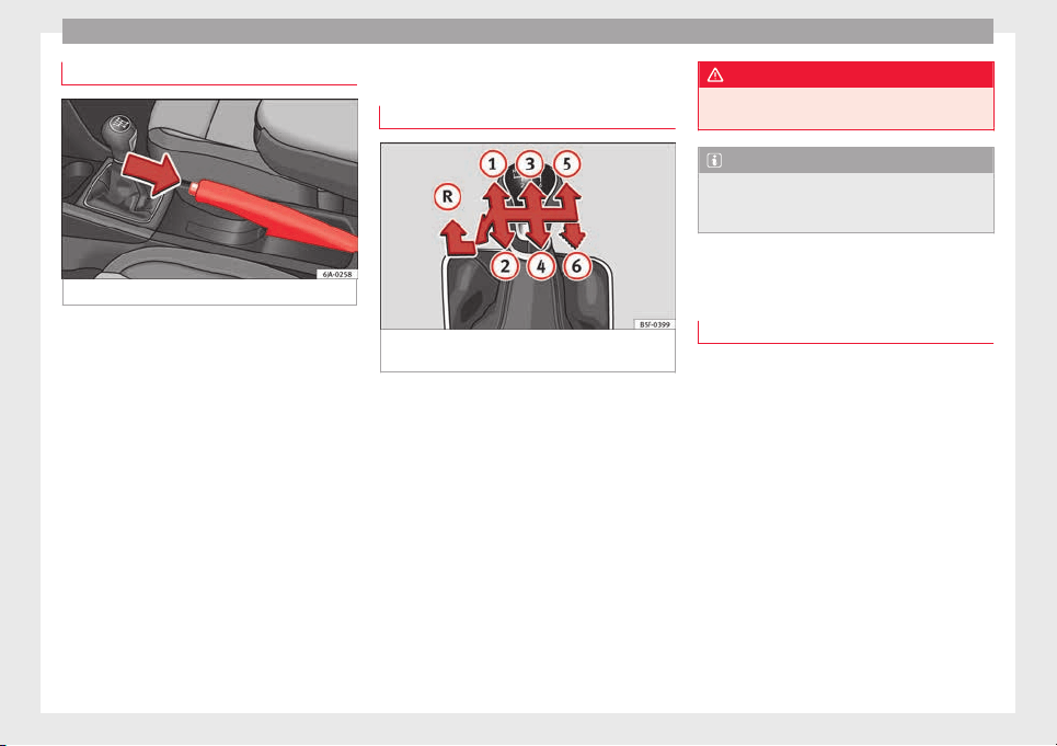
Operation
Handbrake
Fig. 175 Centre console: handbrake.
Applying the handbrake
–
Pull the handbrake lever up all the way.
R
el
e
asing the handbrake
–
Pull the handbrake lever up slightly and
press the unlock button at the same time
››› Fig. 175.
–
Keep the button pressed down and push
the lever all the way down.
The handbrake warning lamp lights up when
the handbrake is applied and the ignition
switched on .
Manual gearbox
Changing gears
Fig. 176 Gear shift diagram of a 5- or 6-speed
m
anual
g
earbox
Read the additional information carefully
›
›
›
page 34
When changing gear, always depress the
clutch pedal fully and keep it pressed down
to avoid excessive clutch wear.
In order to drive at an optimum RPM, follow
the gear change indications ›››
page 24.
Engage reverse gear only when the vehicle is
stopped. On engaging reverse gear while the
engine is running, first wait a moment with
the clutch pedal pressed down fully to limit
gear shift noise.
The reverse lights switch on when the reverse
gear is selected and the ignition is on.
WARNING
Never engage reverse gear when moving for-
ward. Ri
sk of accident!
Note
Do not rest your hand on the gear lever while
driving.
The pressure of your hand could lead
to premature wear of the gear system.
Automatic gearbox
Bas
ic information
The gearbox changes up and down automati-
c
al
ly
. The gearbox can be set to Tiptronic
mode. The gears can be changed manually in
this mode
›››
page 161.
The engine can only be started in positions P
or N. If, on engaging the steering lock,
switching the ignition on/off or starting the
engine, the selector lever is not in these posi-
tions, the informative display will show Move
the selector lever to position
P/N!, or
P/N is shown on the general
dash panel display.
At temperatures below -10°C (14°F), the en-
gine can only be started in position P.
Move the selector lever to position P when
parking the vehicle on a flat surface. On a
158
Driving
slope, the handbrake should be firmly ap-
p
lied bef
or
e moving the selector lever to the
park position. This reduces the load on the
lock mechanism while making it easier to
move the selector lever from position P.
If, while the vehicle is moving, the selector
lever is accidentally moved to position N, re-
lease the accelerator and wait for the engine
to idle before moving it back into position.
WARNING
●
Never pre
ss the accelerator when selecting
the automatic gearbox operating mode when
the vehicle is stationary. Risk of accident!
●
Never move the selector lever to positions
R or P when driving. Risk of accident!
●
If the vehicle is to be stopped with a gear
selected and the engine idling (e.g. waiting
or moving slowly at traffic lights), press down
on the brake pedal because the transmission
is not entirely interrupted when the engine is
idling and the vehicle will tend to start mov-
ing.
●
Apply the handbrake firmly and put the se-
lector lever in position P before opening the
bonnet and working on the vehicle with the
engine running. Risk of accident! Strictly fol-
low the safety instructions ››› page 203, En-
gine compartment.
●
When stopping on a slope (hill), try not to
stop the vehicle from moving by pressing the
“accelerator” with a gear selected. This could
overheat the clutch. If the clutch risks being
burnt due to this force, it would switch off
and the vehic
le could move backwards. Risk
of accident!
●
If you have to stop on a hill, press down on
the brake pedal to stop the vehicle from mov-
ing.
●
The drive wheels could lose traction on a
slippery road surface when the kick-down
function is activated. Risk of sliding!
CAUTION
●
In D
SG autom
atic gearboxes, the double
clutch is protected from overloads. If the hill
hold control is used, the clutches are subjec-
ted to greater force if the vehicle is at a
standstill on a slope or suddenly accelerating
on a slope.
●
Should the clutches overheat, the sym-
bol is shown on the informative display with
a warning message Gear overheated.
Stop! Instruction Manual! An audible
warning is also heard. Stop the vehicle in this
case, stop the engine and wait until the sym-
bol has switched off. Danger of damage to
the gearbox! You can continue driving once
the symbol is switched off.
Starting and driving
Starting
–
Press and hold the brake pedal.
–
Pr
e
s
s and hold the interlock button on the
selector lever knob and move the selector
lever to position ››› page 160 before releas-
ing the interlock button.
–
Release the brake and press the accelera-
tor.
Stopping
–
The selector lever does not have to be
moved to position N if the vehicle is stop-
ped for a short period, e.g. at intersections.
Applying the brake is enough. However, the
engine must remain idling.
Parking
–
Press the brake pedal.
–
Apply the handbrake.
–
Press the interlock button, move the selec-
tor lever to position P and release the but-
ton.
Kick-down feature
The kick-down feature allows maximum ac-
celeration to be reached.
In any gear programme, press down fully on
the accelerator for the automatic gearbox to
activate the kick-down feature. This function
takes priority over the gear programmes with-
out taking into account the position of the se-
lector lever (D, S or Tiptronic) and is used to
reach maximum acceleration, using full
»
159
Technical dataAdviceOperationEmergenciesSafety
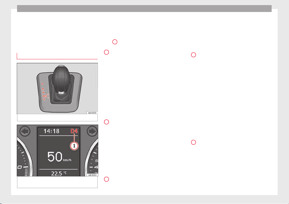
Operation
engine power. Depending on the road speed
and en
gine s
peed, the aut
omatic gearbox
shifts down and the vehicle accelerates. It
only shifts up after the maximum engine
speed has been reached.
Selector lever positions
Fig. 177 Gear selector lever
Fig. 178 Informative display: selector lever
po
s
ition
s.
Read the additional information carefully
›
›
›
page 35
The current position of the selector lever is
shown on the general instrument panel dis-
play
1
›
›› Fig. 178
.
P
– Parking position
In thi
s
po
sition, the driven wheels are me-
chanically locked.
The parking position can only be selected
when the vehicle is stationary.
If you want to move the selector lever from
this position, press the interlock button on
the selector lever knob while pressing down
on the brake pedal.
If the battery is drained, the selector lever
cannot be moved from position P.
R
– Reverse gear
R
ev
er
se gear must be engaged only when the
vehicle is stationary and the engine is idling.
To move the selector lever to position R from
positions P or N, press the interlock button
on the selector lever knob and press down on
the brake pedal.
The reverse lights come on when the selector
lever is in position R and the ignition is on.
N
– Neutral (idling)
Neutr
al
(idlin
g) is engaged in this position.
To move the selector lever from position N (if
the lever has remained in this position for
more than 2 seconds) to position D or R at
speeds of less than 5 km/h (3 mph) and
when the vehicle is stationary, press down on
the brake pedal.
D
– Drive (forwards)
In thi
s
po
sition, the gearbox automatically
changes to a lower or higher gear, depending
on engine requirements, the driving speed
and the gear shift programme.
To move the selector lever to position D from
position N at speeds of less than 5 km/h (3
mph) and when the vehicle is stationary,
press down on the brake pedal.
In some situations (e.g. on mountain roads or
when towing a trailer or caravan), it can be
advantageous to switch temporarily to the
manual shift programme ››› page 161 so that
the gear ratios can be selected manually to
suit driving conditions.
S
– Sports driving position
Shif
tin
g up l
ater than usual makes full use of
the engine power. This shifts down earlier in
relation to position D.
To move the selector lever to position S from
position D, press the interlock button on the
selector lever knob.
160
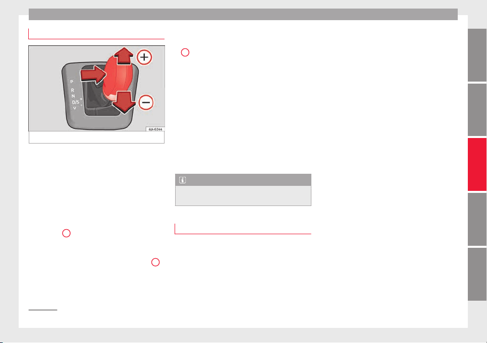
Driving
Tiptronic
Fig. 179 Selector lever: Tiptronic.
The Tiptronic gearbox allows the driver to
c
h
an
ge gears manually using the selector
lever.
Activating the manual gearbox
–
From position D, push the selector lever to
the right. The selected position of the se-
lector lever is shown on the general instru-
ment panel display together with the gear
engaged
1
›
›
› Fig. 178
.
Shifting up
–
Push the selector lever gently forwards
+
››› Fig. 179.
Shifting down
–
Push the selector lever gently backwards
-
›
›› Fig. 179
.
The m
anual gearbox can be activated when
the vehicle is either moving or stationary.
When accelerating, the gearbox automatical-
ly shifts up shortly before the maximum en-
gine speed is reached.
On shifting up, the gear is only engaged
when there is no risk of engine damage.
When the accelerator pedal is pressed down
to the kick-down zone, the gearbox will shift
down in line with the road speed and engine
speed.
Note
The kick-down function is also available in
manual
shift mode.
Selector lever lock
Automatic selector lever lock
The sel
ect
or l
ever is locked in the positions P
and N when the ignition is on. Press down on
the brake to unlock it. Remember, if the se-
lector lever is in positions P and N then the
warning lamp will light up on the general in-
strument panel ››› page 104.
When the selector lever merely moves
through position N (e.g. when moved from R
to D), the lever lock is not applied. This
makes it possible, for example, to rock a
stuck vehicle backwards and forwards. The
lock is only applied if the brake is not press-
ed and the selector lever is moved to position
N for more than 2 seconds.
The selector lever only locks when the is vehi-
cle stationary or driving at a speed lower
than 5 km/h (3 mph). At a higher speed, it
automatically disconnects in the N position.
Interlock button
The interlock button on the selector lever
knob prevents the driver from inadvertently
engaging a gear. Press the button to unlock
the selector lever.
Safety interlock for ignition key
1)
After switching off the ignition, you can only
remove the ignition key if the selector lever is
in position P. When the ignition key is re-
moved, the selector lever is locked in posi-
tion P.
1)
Valid only for certain countries.
161
Technical dataAdviceOperationEmergenciesSafety
Operation
Driving programmes
Your vehicle is equipped with an electronical-
ly-contr
olled automatic gearbox. Shifting up
or down depends on the programme selec-
ted.
For a calm driving style, the gearbox uses the
most economic programme. The gearbox
shifts up as quickly as possible and shifts
down as late as possible, thus increasing
driving economy.
With a sporty driving style, characterised by
sudden acceleration, heavy acceleration,
speeds that often increase and decrease and
maximum speed, the gearbox adapts to this
driving style when the accelerator is pressed
down fully (kick-down) by shifting down as
quickly as possible and can even shift down
by several gears at once.
Selecting the best driving programmes is an
endless job. Regardless of this, the driver can
also make the gearbox switch to a more dy-
namic gear shift programme by pressing the
accelerator quickly. This makes the automatic
gearbox shift down into a lower gear than the
one that would normally apply to the current
speed, allowing for more rapid acceleration
(e.g. to overtake another vehicle) without
having to press the accelerator until the kick-
down position. On shifting up in a corre-
sponding driving style, the gearbox returns to
the original programme.
When driving along mountain roads, the
gearbo
x adapts to the gradients. This avoids
having to frequently change gears when driv-
ing uphill. In Tiptronic mode, it is possible to
shift down manually when driving downhill to
use the braking effect of the engine.
Backup programme
A back-up programme exists in case of faults.
In the event of
a fault in the gearbox electron-
ics, it will continue to work in one of the cor-
responding back-up programmes. All seg-
ments of the screen are lit up or switched off.
The fault can be seen as follows:
●
The gearbox only engages certain gears
●
Reverse gear R cannot be en
gaged
●
The manual gearbox switches off in the
back-up programme
Note
If the gearbox switches to the back-up pro-
gramme, v
isit an Authorised Service as soon
as possible to solve the problem.
Gearbox malfunctions
Gearbox: Fault! Stop the ve-
hicle and place the lever in the
position P.
There is a fault in the gearbox. Stop the vehi-
c
l
e in a s
afe place and do not continue driv-
ing. Seek specialist assistance.
Gearbox: System fault! You
may continue driving.
Have the fault corrected by a specialised
workshop without delay.
Gearbox: System fault! You
can continue driving with re-
strictions. Reverse gear disa‐
bled
Take the vehicle to a specialised workshop
and have the fault repaired without delay.
Gearbox: System fault! You
can continue driving in D until
switching off the engine
Stop the vehicle in a safe place well away
from moving traffic. Seek specialist assis-
tance.
Gearbox: too hot. Adapt your
driving accordingly
Continue driving at moderate speeds. When
the warning lamp switches off, you can con-
tinue driving in a normal manner.
Gearbox: press the brake and
engage a gear again.
If the fault was caused by a gearbox with a
high temperature, this driver message will be
162
Driving
displayed when the gearbox has cooled
ag
ain.
R
u
n-in and economical driving
The first 1,500 km
Over the first 1,500 kilometres the engine
must
be run in.
Up to 1000 kilometres
–
Do not drive at more than 3/4 of the maxi-
mum speed corr
esponding to the engaged
gear, i.e. up to 3/4 of the maximum permit-
ted engine speed.
–
Do not drive at full speed.
–
Avoid high engine speeds.
–
Do not tow a trailer.
From 1000 to 1500 kilometres (600 to 900
miles)
–
Slowly increase the engine speed until
reaching the maximum permitted speed of
the engaged gear, i.e. the maximum per-
mitted engine speed.
During its first few hours of running, the in-
ternal friction in the engine is greater than
later on, when all the moving parts have bed-
ded in. How the vehicle is driven over approx-
imately the first 1,500 kilometres (900
miles), determines the success of the proc-
ess of running in the engine.
Even after running in, the vehicle should not
be unnecessarily driven at high engine
speeds. The maximum permitted engine
speed is marked at the start of the red zone
on the rev counter dial. The gear must be
changed up when the red area is reached in
vehicles with a manual gearbox. Extremely
high engine speeds when accelerating are
automatically limited, however the engine is
not protected against high engine speeds
produced by incorrectly changing to a lower
gear, which could cause the engine to run at
revs above the maximum permitted amount,
and consequently result in damage to the en-
gine.
Additionally, vehicles with a manual gearbox
must also bear the following in mind: do not
drive with the engine speed too low. Change
down to a lower gear when the engine no
longer runs smoothly. Observe the recom-
mendations for changing gear
›››
page 24.
New tyres
New tyres must be submitted to “running in”,
given that initially their grip is not yet at the
maximum level. During the first 500 km (120
miles) drive very carefully.
New brake pads
New brake pads do not yet provide maximum
friction capacity. First they must be “run in”.
During the first 200 km (120 miles) drive very
carefully.
CAUTION
All the information for speed and engine
speed ref
ers to an engine that operates at op-
erating temperature. Do not run the engine at
high engine speeds, neither when stopped or
while driving.
For the sake of the environment
Do not drive at unnecessarily high engine
speeds; c
hanging to a higher gear sooner
contributes to saving fuel, reduces operating
noise and protects the environment.
Environmental compatibility
Environmental protection is a top priority in
the de
s
ign, c
hoice of materials and manufac-
ture of your new SEAT.
Constructive measures to encourage recy-
cling
●
Joints and connections designed for easy
dismantling
●
Modular construction to facilitate disman-
tling
»
163
Technical dataAdviceOperationEmergenciesSafety
Operation
●
Inc
r
e
ased use of single-grade materials.
●
Plastic parts and elastomers are marked in
accordance with ISO 1043, ISO 11469 and
ISO 1629.
Choice of materials
●
Use of recycled materials.
●
Use of compatible plastics in the same part
if its components are not easily separated.
●
Use of recycled materials and/or materials
originating from renewable sources.
●
Reduction of volatile components, includ-
ing odour, in plastic materials.
●
Use of CFC-free coolants.
Ban on heavy metals, with the exceptions
dictated by law (Annex II of ELV Directive
2000/53/EC): cadmium, lead, mercury, hexa-
valent chromium.
Manufacturing methods
●
Reduction of the quantity of thinner in the
protective wax for cavities.
●
Use of plastic film as protection during ve-
hicle transport.
●
Use of solvent-free adhesives.
●
Use of CFC-free coolants in cooling sys-
tems.
●
Recycling and energy recovery from resi-
dues (RDF).
●
Improvement in the quality of waste water.
●
Use of systems for the recovery of residual
heat (thermal recovery, enthalpy wheels,
etc.).
●
The use of water-soluble paints.
Catalytic converter
An exhaust gas emission control system (cat-
alytic con
verter) that functions perfectly is vi-
tally important for vehicle operation that re-
spects the environment.
Please observe the following indications:
●
Refuel only using unleaded petrol in petrol
engine v
ehicles ››› page 201, Unleaded pet-
rol.
●
Do not add too much oil to the engine
›››
page 207, Checking engine oil level.
●
Do not switch off the ignition while driving.
If you are required to drive in a country where
unleaded fuel is not available, when return-
ing to a country where using a catalytic con-
verter is obligatory, the catalytic converter
must be replaced.
WARNING
●
Due to the high t
emperatures that the cata-
lytic converter can reach, the vehicle must be
stopped so that the catalytic converter does
not come into contact with easily flammable
material underneath the vehicle. Risk of fire!
●
Never use s
ubstances for additional under-
body protection or anti-corrosives for the ex-
haust pipes, the catalytic converter or the
heat-resistant screens. Risk of fire!
CAUTION
●
Nev
er comp
letely empty the tank! An irreg-
ular fuel supply can cause ignition faults,
which can result in damage to a substantial
amount of engine parts and the exhaust sys-
tem.
●
Refuelling just once with leaded petrol dis-
ables the exhaust system!
Economical and environmentally-
friendly
driv
in
g
Fuel consumption, environmental pollution
and w
e
ar t
o the engine, brakes and tyres de-
pends in large part on your driving style. By
adopting an economical driving style and an-
ticipating the traffic situation ahead, you can
easily reduce fuel consumption by 10-15%.
Some tips on how to help you reduce pollu-
tion while saving money are listed below.
Drive anticipating the traffic situation
A vehicle uses most fuel when accelerating.
When you anticipate situations, you have to
brake less often and, thus, accelerate less. If
it is possible, let the vehicle roll with a gear
engaged, for example, if you see a red light
164

Driving
ahead. The braking effect achieved in this
w
a
y
helps to reduce the wear of brakes and
tyres; emissions and fuel consumption are
reduced to zero (disconnection due to iner-
tia).
Change gear early to save energy
An effective way of saving fuel is to change
up quickly through the gears. Running the
engine at high rpm in the lower gears uses
an unnecessary amount of fuel.
Manual gearbox: shift up from first to second
gear as soon as possible. We recommend
that, whenever possible, you change to a
higher gear upon reaching 2000 rpm. Follow
the “recommended gear” indication that ap-
pears on the instrument panel
›››
page 24.
Avoid driving at high speed
We advise you not to drive at the top speed
permitted by the vehicle. Fuel consumption,
exhaust emissions and noise levels all in-
crease very rapidly at higher speeds. Driving
at moderate speeds will help to save fuel.
Avoid idling
It is worthwhile switching off the engine
when waiting in a traffic jam, at level cross-
ings or at traffic lights with a long red phase.
The fuel saved after only 30 - 40 seconds is
greater than the amount of fuel needed to re-
start the engine.
The engine takes a long time to warm up
when it is idling. Mechanical wear and pollu-
tant emissions are also especially high dur-
ing this initial warm-up phase. It is therefore
best to drive off immediately after starting
the engine. Avoid running the engine at high
speed.
Periodic maintenance
Periodic maintenance work guarantees that,
before beginning a journey, you will not con-
sume more than the required amount of fuel.
A well-serviced engine gives you the benefit
of improved fuel efficiency as well as maxi-
mum reliability and an enhanced resale val-
ue.
A badly serviced engine can consume up to
10% more fuel than necessary.
Avoid short journeys
To reduce the consumption and emission of
polluting exhaust gases, the engine and the
exhaust gas filtration systems should reach
the optimum operating temperature.
With the engine cold, fuel consumption is
proportionally higher. The engine does not
warm up and fuel consumption does not nor-
malise until having driven approximately four
kilometres (2.5 miles). This is why we recom-
mend avoiding short trips whenever possi-
ble.
Maintain the correct tyre pressures
Bear in mind that keeping the tyres at an ad-
equate pressure saves fuel. If the tyre pres-
sure is just one bar (14.5 psi/100 kPa) too
low, fuel consumption can increase by as
much as 5%. Due to the greater rolling resist-
ance, under-inflation also increases tyre wear
wear and impairs handling.
The tyre pressures should always be checked
when the tyres are cold.
Do not use winter tyres all year round as they
increase fuel consumption by up to 10%.
Avoid unnecessary weight
Given that every kilo of extra weight will in-
crease the fuel consumption, it is advisable
to always check the luggage compartment to
make sure that no unnecessary loads are be-
ing transported.
A roof rack is often left in place for the sake
of convenience, even when it is no longer
needed. At a speed of 100 km/h (62 mph)
and 120 km/h (75 mph) your vehicle will use
about 12% more fuel as a result of the extra
wind resistance caused by the roof rack even
when it is not in use.
»
165
Technical dataAdviceOperationEmergenciesSafety
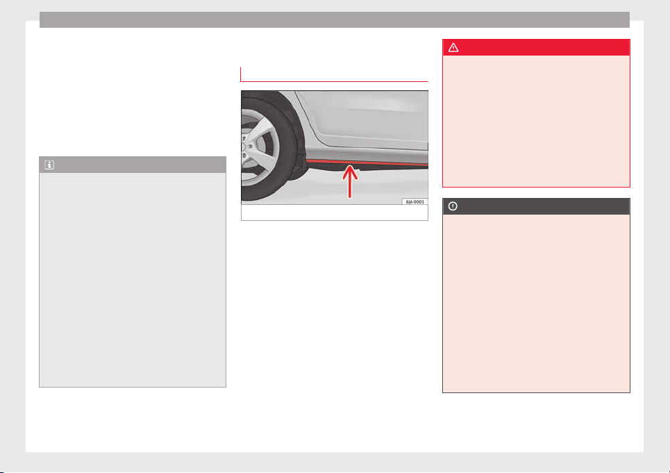
Operation
Save electricity
The en
gine activ
at
es the alternator, which
produces electricity. With the need for elec-
tricity, fuel consumption also increases. Be-
cause of this, always turn off electrical devi-
ces when you do not need them. Examples of
devices that use a lot of electricity are: the
fan at high speeds, the rear window heating
and the seat heaters*.
Note
●
If y
ou vehicle has Start-Stop, it is not rec-
ommended to switch this function off.
●
It is recommended to close the windows
when driving at more than 60 km/h
●
Do not drive with your foot resting on the
clutch pedal,, as the pressure can make the
plate spin, more fuel will be used and it can
burn the clutch plate lining, causing a serious
fault.
●
Do not hold the vehicle on a hill with the
clutch, use the foot brake or hand brake, us-
ing the latter to start. The fuel consumption
will be lower and you will prevent the clutch
plate from being damaged.
●
On descents, use the engine brake, chang-
ing to the gear that is more suitable for the
slope. Fuel consumption will be “zero” and
the brakes will not suffer.
Wading and driving off-road
Driv
in
g thr
ough water on roads
Fig. 180 Driving through water.
To prevent the vehicle from being damaged
when driv
in
g thr
ough water (i.e. flooded
roads), please observe the following:
●
Determine the depth of the water before
entering. Water can reach a maximum height
of below the door sill ››› Fig. 180.
●
Drive at a maximum pace of walking speed.
Driving at a higher speed can cause a wave
in front of the vehicle, which can cause water
to enter the engine air intake system or other
parts of the vehicle.
●
Never stop in the water, never reverse and
never stop the engine.
●
Before driving through water deactivate the
Start-Stop system ››› page 182.
WARNING
●
Driving thr
ough water, dirt and mud can re-
duce braking capability and prolong the brak-
ing distance – Risk of accident!
●
Do not carry out any sudden or strong brak-
ing manoeuvres after driving through water.
●
Clean and dry the brakes as soon as possi-
ble after driving through water by breaking
intermittently. Carry out braking in order to
dry the brakes and clean the brake discs only
if traffic so permits. Do not put other drivers
at risk.
CAUTION
●
In the event of
driving through water, parts
of the vehicle can be seriously damaged,
such as the engine, gearbox, catalytic con-
verter, suspension or the electrical system.
●
Oncoming vehicles that drive through wa-
ter can cause waves that exceed your vehi-
cle's permitted level for driving through wa-
ter.
●
There may be pot-holes mud or rocks under
the water that can hinder or prevent driving
through water.
●
Do not drive through salt water. The salt
can cause rust. All components that are ex-
posed to salt water must be rinsed immedi-
ately with fresh water.
166
Driver assistance systems
Note
After driving through water we recommend
that
you contact a specialised service for an
inspection.
Preventing damage to the vehicle
In order to prevent damage to the vehicle,
take s
pecial care:
●
on roads that are in poor condition,
●
when mounting kerbs,
●
when approaching very steep ramps, etc.,
●
with the parts of the vehicle situated on the
lower p
art of the vehicle, i.e. the spoiler, the
exhaust pipe.
This applies especially to vehicles with a very
low suspension (sport) and when the vehicle
is fully loaded.
Driver assistance systems
Br
ak
in
g and stability systems
Electronic stability control (ESC)
The ESC system increases control of the vehi-
cle in emer
gency situations, e.g. during a
sudden change in direction. Depending on
the driving conditions, it reduces the risk of
skidding and increases driving stability.
The system uses the steering wheel angle
and road speed to calculate the changes of
direction desired by the driver, and constant-
ly compares them with the actual behaviour
of the vehicle. When irregularities occur, for
example, if the vehicle begins to skid, the
ESC brakes the appropriate wheel automati-
cally.
The warning lamp on the general instru-
ment panel starts flashing when the system
is working.
The stability (ESC) system includes the fol-
lowing systems:
●
Anti-lock brake system (ABS),
●
Traction control system (TCS),
●
Electronic differential lock (EDL),
●
Hydraulic brake assist system (HBA),
●
Hill hold control (HHC).
The ASR should be switched on at all times.
Only u
nder certain circumstances should the
system be switched off, e.g.
●
driving with chains,
●
driving in deep snow or on very soft surfa-
ces,
●
During the “swinging movement” required
to remove a stuck vehicle
Switch the ASR back on as soon as possible.
Brake assist system (HBA)*
The HBA system is activated when you press
down on the brake pedal suddenly. It increa-
ses braking power, helping to reduce braking
distances. To reduce braking distance as
much as possible, keep the brake pedal
pressed down firmly until the vehicle comes
to a standstill.
With the help of this system, the ABS is acti-
vated more quickly and more efficiently.
The brake assist function is deactivated auto-
matically when the brake pedal is released.
Hill hold control (HHC)*
The HHC system makes it easier to start the
vehicle on hills. The system maintains the
brake pressure created by pressing down on
the brake pedal for 2 seconds after it has
been released. Your foot can be removed
from the brake pedal and you can use the ac-
celerator pedal and move away on a hill
»
167
Technical dataAdviceOperationEmergenciesSafety
Operation
without having to use the handbrake. The
br
ak
e pr
essure drops as the accelerator ped-
al is pressed. If the vehicle cannot be started,
it will start to move backwards after 2 sec-
onds.
The HHC is activated on gradients of over
5%, if the driver door is closed. It only works
for starting on hills, moving both forward and
in reverse. It is not activated during start-up
down hill.
Anti-lock system (ABS)
The ABS system prevents the wheels locking
durin
g br
ak
ing. This helps the driver keep
control of the vehicle.
The driver is made aware of ABS assistance
by the pulsating of the brake pedal and a
characteristic noise.
Keep the brake pedal pressed down while the
ABS is working. The ABS will switch off when
the brake pedal is released. Never brake in-
termittently while the ABS is working!
Traction control system (ASR)
If the wheels start to slip, the TCS adapts the
en
gine s
peed t
o the driving conditions. Par-
ticularly in unfavourable conditions, the TCS
helps starting, accelerating and hill starts.
The TCS warning lamp on the general dash
panel flashes when the system is working.
Electronic differential lock
If one of the wheels starts to skid, the EDL
brake
s that wheel, transmitting the driving
force to the other wheels. This increases ve-
hicle stability and improves driving stability.
To prevent the disc brake of the braking
wheel from overheating, the EDL cuts out au-
tomatically if subjected to excessive loads.
The vehicle will continue to function normally
without EDL. The EDL will switch on again au-
tomatically when the brake has cooled down.
Parking aid
General
information
Various systems are available to help you
when p
ark
in
g or manoeuvring in tight
spaces, depending on the equipment fitted
on your vehicle.
The rear parking aid is an audible assistant
that warns about obstacles located behind
the vehicle
›››
page 169.
During parking, Parking System Plus assists
the driver by visually and audibly warning
them about obstacles detected in front and
behind the vehicle ››› page 170.
WARNING
●
Alwa
ys pay attention, also when looking
straight ahead, to traffic and the vehicle sur-
roundings. The assistance systems are not a
replacement for driver awareness. When in-
serting or removing the vehicle from a park-
ing space, or when performing similar ma-
noeuvres the driver always assumes the re-
sponsibility.
●
Adapt your speed and driving style at all
times to suit visibility, weather, road and traf-
fic conditions.
●
The ultrasound sensors have blind spots in
which obstacles and people are not regis-
tered. Pay special attention to children and
animals.
●
Always keep visual control of the vehicle
surroundings: use the rear vision mirrors for
additional help.
CAUTION
Parking Aid functions may be negatively af-
fected b
y different factors that may lead to
damage to the vehicle or its immediate sur-
rounds:
●
Under certain circumstances, the system
does not detect or display certain objects:
–
Objects such as chains, trailer draw bars,
fences, posts and thin trees.
168
Driver assistance systems
–
Obj
ects that are located above the sen-
sors, such as protrusions in a wall.
–
Objects with certain surfaces or struc-
tures, such as wire mesh fences or pow-
der snow.
●
Certain surfaces of objects and garments
do not reflect the ultrasound sensors' sig-
nals. The system cannot detect, at least cor-
rectly, these objects or people wearing such
clothes.
●
Ultrasound sensor signals may be affected
by external sound sources. In certain circum-
stances this may prevent them from detect-
ing people or objects.
●
Please note that low obstacles detected by
the system may no longer be registered by
the sensors as the car moves closer, so the
system will not give any further warning. In
certain circumstances, objects such as high
kerbs that could damage the bottom of the
vehicle are not detected either.
●
If the first warning from the Parking Aid is
ignored, the vehicle could suffer considerable
damage.
●
The knocks or damage on the radiator
grille, bumper, wheel arch and vehicle under-
body can adjust the orientation of the sen-
sors. This can affect the parking aid function.
Have the function checked by a specialised
workshop.
Note
●
In cert
ain situations, the system can give a
warning even though there is no obstacle in
the detected area, e.g:
–
with rough or cobbled floors or ground
with long grass;
–
with external ultrasound sources, such as
cleaning vehicles or other vehicles;
–
In downpours, intense snow or dense ex-
haust gases;
–
if the registration plate (front or rear) is
not properly affixed to the bumper sur-
face;
–
or in locations such as the brow of a hill.
●
In order to guarantee good system opera-
tion, keep the ultrasound sensors clean, free
of snow or ice, and do not cover them with
adhesives or other objects.
●
If you use high-pressure or vapour equip-
ment to clean the ultrasound sensors, apply
it directly only very briefly and always from a
distance of more than 10 cm.
●
Retrofitting of accessories to the vehicle,
such as a bicycle carrier, may interfere with
the operation of the Parking Aid.
●
In order to familiarise yourself with the sys-
tem, it is advised that you practice parking in
an area or car park that is free from traffic.
There must be good weather and light condi-
tions.
●
The vo
lume and tone of the warnings can
be modified, in addition to the indications
››› page 172.
●
In vehicles without a driver information
system, these parameters can be modified in
a SEAT Official Service or in a specialised
workshop.
●
Please observe information on towing a
trailer ››› page 173.
●
The display on the Easy Connect screen
shows a slight time delay.
Rear parking aid*
The rear Parking Aid assists the driver in
p
ark
in
g by means of audible warning
sounds.
Description
There are sensors integrated in the rear
bumper. When the sensors detect an obsta-
cle, you are alerted by audible warnings.
Make particularly sure that the sensors are
not covered by adhesives, residues and the
like, as this could affect the system's opera-
tion. Cleaning instructions ››› page 196.
The approximate measurement range of the
rear sensors is:
side area 0,90 m
»
169
Technical dataAdviceOperationEmergenciesSafety
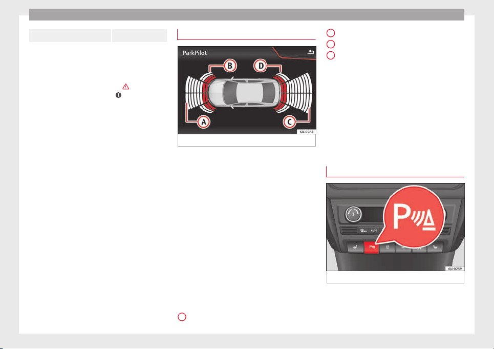
Operation
central area 1.60 m
As you approach the obstacle, the time inter-
val betw
een the audible warnings will be re-
duced. When you reach around 0.30 m the
warning will be constant: Do not continue to
move forward (or backward) ›››
in General
information on p
age 168, ›››
in General in-
formation on p
age 168 !
If you maintain separation from the obstacle,
the volume of the warning begins to reduce
after four seconds (does not affect the tone
of the constant warning).
Activating/Deactivating
When engaging reverse gear, the parking aid
is automatically switched on. This is con-
firmed with a short warning.
On disengaging reverse gear, the Parking Aid
system is disconnected immediately.
Parking system plus*
Fig. 181 Represented area.
Parking system plus assists you audibly and
v
i
s
ually when parking.
There are sensors integrated in the front and
rear bumpers. When they detect an obstacle,
you are alerted by audible warnings and visu-
ally on the Easy Connect system.
In the event of danger of a frontal collision,
the audible warnings come from the front of
the vehicle, and in the event of the danger of
a rear-end collision they come from the rear.
Make particularly sure that the sensors are
not covered by adhesives, residues and the
like, as this could affect the system's opera-
tion. Cleaning instructions ››› page 196.
The approximate measurement range of the
sensors is:
1.20 m
A
0,90 m
1.60 m
0,90 m
As
y
ou approach the obstacle, the time inter-
val between the audible warnings will be re-
duced. When you reach around 0.30 m the
warning will be constant: do not continue to
move forward (or backward)!
If you maintain separation from the obstacle,
the volume of the warning begins to reduce
after four seconds (does not affect the tone
of the constant warning).
Parking Aid Operation
Fig. 182 Centre console: parking aid button.
Manual connection of Parking Aid
●
Press the b
utt
on
once.
B
C
D
170
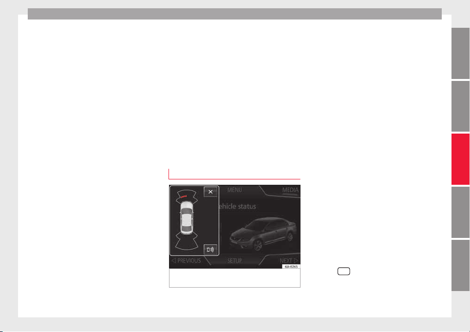
Driver assistance systems
Manual disconnection of Parking Aid
●
Press the b
utt
on
again.
Manual disconnection of Parking Aid display
(the audible sounds remain active)
●
Press a button on the main menu of the fac-
tory-assembled infotainment system.
●
OR: press the BACK function button.
Automatic connection of Parking Aid
●
Engage reverse gear or turn the selector
lever to position R.
●
OR: If the vehicle approaches an obstacle
that is in its forwards path at a speed below
10 km/h (6 mph) ››› page 171, Automatic ac-
tivation. The obstacle is detected as of a dis-
tance of approx. 95 cm if the automatic con-
nection is activated in the infotainment sys-
tem. A reduced display is shown.
Automatic disconnection of Parking Aid
●
Move the selector lever to position P.
●
OR: accelerate to more than approx.
10 km/h (6 mph) forward.
Temporary suppression of sound in Parking
Aid
●
Press the function button.
Change from reduced view to full view
●
Engage reverse gear or turn the selector
lever to position R.
●
OR: press the car icon in reduced view.
If necessary, switch to the rear-assist image
(Rear View Camera “RVC”)
●
Engage reverse gear or turn the selector
lever to position R.
●
OR: Press the RVC function button.
A short confirmation signal will be heard and
the button symbol will light up yellow when
the system is switched on.
Automatic activation
Fig. 183 Miniature indication of automatic ac-
tiv
ation
When the Parking System Plus is switched on
aut
om
atic
ally, a miniature of the vehicle will
be displayed and the segments will be
shown on the left side of the screen
››› Fig. 183.
Automatic activation occurs when slowly ap-
proaching an obstacle located in front of the
vehicle. It only operates every time the speed
is reduced below approximately 10 km/h (6
mph) for the first time.
If the parking aid is switched off using the
button, the following actions must be carried
out in order for it to automatically switch on:
●
Switch off the ignition and switch it on
again.
●
OR: accelerate above 10 km/h (6 mph) be-
fore reducing speed below this number
again.
●
OR: place the selector lever in position P
and then move it from this position.
●
OR: switch on and off the automatic activa-
tion in the Easy Connect system menu.
The automatic activation with parking aid
miniature indication can be switched on and
off from the Easy Connect system menu
›››
page 20:
●
Switch the ignition on.
●
Select:
CAR
button > Settings > Parking
and manoeuvring.
●
Select the Automatic activation op-
tion.
When the f
u
nction button check box is
activated , the function is on.
»
171
Technical dataAdviceOperationEmergenciesSafety
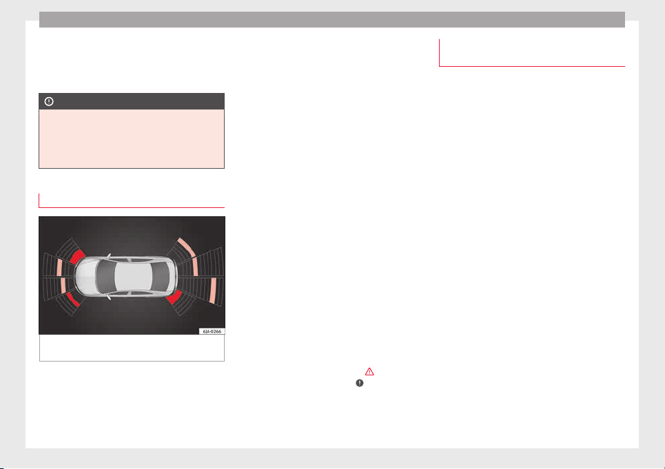
Operation
If the system has been activated automatical-
ly
, an audib
l
e sound warning will only be giv-
en when obstacles in front are at a distance
of less than 50 cm.
CAUTION
The automatic connection of the Parking Aid
only w
orks when you are driving slowly. If
driving style is not adapted to the circum-
stances, an accident and serious injury or
damage may be caused.
Segments of the visual indication
Fig. 184 Parking Aid display on the Easy Con-
nect
sy
s
tem screen.
The distance of separation from the obstacle
c
an be e
s
timated using the segments around
the vehicle.
The optical indication of the segments works
as follows:
a white segment is dis-
played when the obstacle is not within
the vehicle's trajectory or the direction
of travel is in the opposite direction to
its location.
obstacles located in the
vehicle's trajectory and which are more
than 30 cm away from the vehicle are
displayed in yellow.
obstacles that are less than
30 cm away from the vehicle are dis-
played in red.
Moreover, with the SEAT Media System
Plus/Navi System radios, a yellow trail indi-
cates the vehicle's expected journey based
on the steering wheel angle.
Whenever the obstacle is located in the vehi-
cle’s direction of travel, the corresponding
audible warning will sound.
As the vehicle approaches an obstacle, the
segments are displayed closer to the vehicle.
When the penultimate segment is displayed,
this means that the vehicle has reached the
collision zone. In the collision zone, the ob-
stacles are represented in red, including
those out of the path. Do not continue to
move forward (or backward) ›››
in General
inf
orm
ation on p
age 168,
›››
in General in-
f
orm
ation on p
age 168 !
White segments:
Yellow segments:
Red segments:
Adjusting the display and audible
warnings
The settings for the display and audible
warning
s are controlled via the Easy Con-
nect*.
Automatic activation
on – activates the Automatic activa-
tion option ››› page 171.
off – deactivates the Automatic ac-
tivation option ››› page 171.
Front volume*
Volume in the front and rear area.
Front sound settings/sharpness*
Frequency (tone) of the sound in the front
area.
Rear volume*
Volume in the rear area.
Rear sound settings/sharpness*
Frequency (tone) of the sound in the rear
area.
Adjust volume
With the parking aid switched on, the active
audio/video source volume will be reduced
to the intensity of the selected setting.
172
Driver assistance systems
Error messages
When the Parking Aid is activated or when it
is sw
itched on, if a continuous warning can
be heard for several seconds (additionally, in
the case of Parking system Plus, the LED of
the button flashes), there is a fault in the
system.
Parking System Plus*
If there is a fault in a sensor, the symbol is
displayed on the Easy Connect display in
front of/behind the vehicle. If a rear sensor is
faulty, only the obstacles in the areas
A
and
B
are displayed
›
›
›
Fig. 181. If a front sensor
is faulty, only the obstacles in the areas
C
and
D
are displayed.
Hav
e the f
au
lt corrected by a specialised
workshop without delay.
Towing bracket
In vehicles equipped with a towing bracket
dev
ic
e fr
om the factory, when the trailer is
connected electrically, the Parking Aid rear
sensors will not be activated when reverse
gear is engaged, when the selector lever is
turned to position R or when the button is
pressed.
Parking System Plus
The distance to possible obstacles at the rear
of the vehicle will not be displayed on the
screen and nor will it be indicated by means
of audible sound signals.
The Easy Connect system screen will only dis-
play objects detected at the front, and the ve-
hicle's trajectory will be hidden.
Rear Assist “Rear View Cam-
era”*
Operating and safety warnings
WARNING
●
The Rear As
sist does not make it possible
to precisely calculate the distance from ob-
stacles (people, vehicles, etc.) and nor can it
overcome the system's own limits, hence us-
ing it may cause serious accidents and inju-
ries if used negligently or without due care.
The driver should be aware of his/her sur-
roundings at all times to ensure safe driving.
●
The camera lens expands and distorts the
field of vision and displays the objects on the
screen in a different, vague manner. The per-
ception of distances is also distorted by this
effect.
●
Some objects may, due to the resolution of
the display screen - not be displayed in a sat-
isfactory manner or may not be displayed at
all. Take special care with thin posts, fences,
railin
gs or trees that might not be displayed
on screen and could damage the vehicle.
●
The rear assist has blind spots where it is
not possible to represent people or objects
(small children, animals and certain objects
cannot be detected in its field of vision). Mon-
itor the vehicle's surrounding area at all
times.
●
Keep the camera lens clean, free of ice and
snow, and do not cover it.
●
The system is not a replacement for driver
awareness. Supervise the parking operation
at all times, as well as the vehicle's surround-
ing area. Adapt your speed and driving style
at all times to suit visibility, weather, road
and traffic conditions.
●
Do not be distracted from the traffic by
looking at the screen.
●
The images on the rear assist screen are
only two-dimensional. Due to a lack of spatial
depth, protruding parts or holes in the road,
for example, are more difficult to detect or
may not be seen at all.
●
Vehicle load modifies the representation of
the orientation lines displayed. The width
represented by the lines diminishes with ve-
hicle load. Pay special attention to the vehi-
cle's surroundings when the inside of the ve-
hicle of the luggage compartment is carrying
a heavy load.
●
In the following situations, the objects or
other vehicles shown in the navigation sys-
tem display appear to be further away or
»
173
Technical dataAdviceOperationEmergenciesSafety
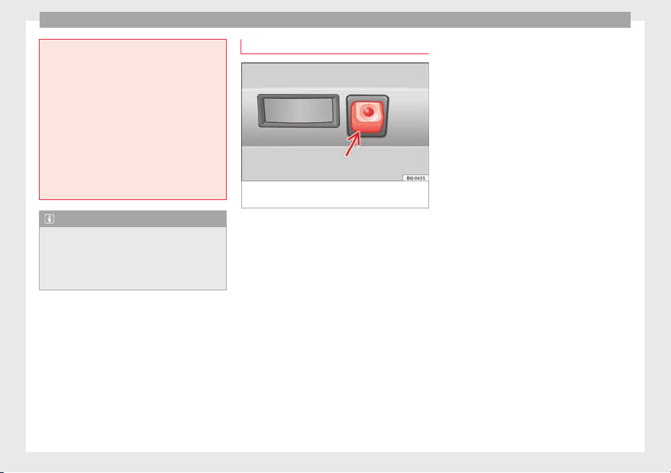
Operation
closer than they really are: Pay special atten-
tion:
–
On movin
g from a horizontal plane to a
slope.
–
On moving from a slope to a horizontal
plane.
–
If the vehicle is heavily loaded at the
rear.
–
When the vehicle approaches objects
that are not on the ground surface or are
jutting out from it. These objects may al-
so be outside the camera's angle of vi-
sion when reversing.
Note
●
It is
important to take great care and pay
special attention if you are not yet familiar
with the system.
●
Rear assist will not be available if the vehi-
cle's rear lid is open.
Instructions for use
Fig. 185 On the rear bumper: location of the
r
e
ar a
ssist camera
A camera on the rear bumper aids the driver
durin
g r
ev
erse parking or manoeuvring
››› Fig. 185. The camera image is viewed to-
gether with orientation lines projected by the
system on the Infotainment system screen.
The bottom of the screen displays part of the
bumper corresponding to the registration
plate area that will be used as reference by
the driver.
Rear assist settings:
Rear assist offers the user the possibility to
change the image's brightness, contrast and
colour settings.
To change these settings:
●
Park the vehicle in a safe place.
●
Apply the parking brake.
●
Switch the ignition on.
●
If necessary, switch on the Infotainment
system.
●
Engage reverse gear or turn the selector
lever to position R.
●
Press the --- function button displayed on
the right of the image.
●
Make the desired adjustments on the menu
by pressing the –/+ function buttons or by
moving the corresponding scroll button.
Necessary conditions for parking and ma-
noeuvring with the
The system should not be used in the follow-
ing cases:
●
If the image displayed is not very reliable or
is distorted, for example low visibility or dirty
lens.
●
If the area behind the vehicle is not dis-
played very clearly or is incomplete.
●
If the vehicle is heavily loaded at the rear.
●
If the position and installation angle of the
camera have been changed, e.g. after a rear-
end collision. Have the system checked by a
specialised workshop.
Familiarising yourself with the system
To familiarise yourself with the system, the
orientation lines and their function, SEAT rec-
ommends practising parking and manoeu-
vring with the rear assist in a place without
174
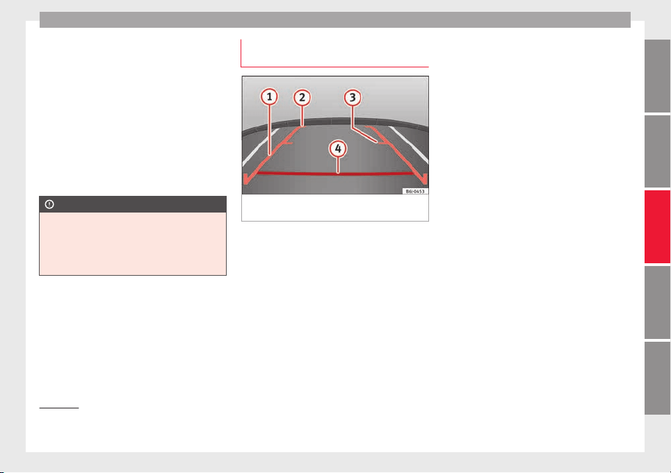
Driver assistance systems
too much traffic or in a car park when there
ar
e g
ood w
eather and visibility conditions.
Cleaning the camera lens
Keep the camera lens clean and clear of snow
and ice:
●
Moisten the lens using a normal alcohol-
based glass cleaning product and clean the
lens with a dry cloth.
●
Remove snow using a small brush.
●
Use de-icing spray to remove any ice.
CAUTION
●
Never use abr
asive cleaning products to
clean the camera lens.
●
Do not use hot or warm water to remove ice
or snow from the camera lens. Doing so could
damage the camera.
Parking and manoeuvring with the
r
e
ar a
ssist
Fig. 186 Display on the Infotainment system
s
c
r
een: orientation lines.
Switching the system on and off
●
The rear assist will switch on when the igni-
tion i
s
on or the en
gine running, on engaging
reverse gear (manual gearbox) or on chang-
ing the selector lever to the R position (auto-
matic gearbox).
●
The system switches off 8 seconds after
disengaging reverse gear (manual gearbox)
or removing the selector lever from the R po-
sition (automatic gearbox). The system will
also disconnect immediately after the igni-
tion is switched off.
In combination with the Parking System Plus
››› page 168, the camera image will cease to
be transmitted immediately when reverse
gear is engaged or when the selector lever is
moved from the R position, and the optical
information provided by the Parking Aid sys-
tem will be displayed.
Also in combination with the system, the rear
assist image can also be concealed:
●
By pressing one of the Infotainment system
buttons on the display.
●
OR: By pressing the miniature vehicle that
appears on the left of the screen (which
switches to the full-screen mode of the Park-
ing System Plus's optical system).
If you wish to display the rear assist image
again:
●
Disengage reverse, or change the selector
lever's position, engage reverse again or
move the selector lever to position R.
●
OR: Press the RVC function button
1)
Meaning of the orientation lines
››› Fig. 186
»
1)
WARNING: the RVC function b
utton will only be ac-
tivated and available when the reverse gear is en-
gaged or the selector lever is set to position R.
175
Technical dataAdviceOperationEmergenciesSafety
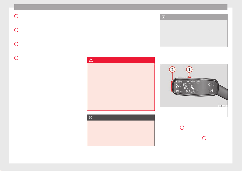
Operation
Side lines: e
xt
en
sion of the vehicle (the
approximate width of the vehicle plus the
rear view mirrors) on the road surface.
End of the side lines: the area marked in
green ends approximately 2 m behind
the vehicle on the road surface.
Intermediate line: indicates a distance of
approximately 1 m behind the vehicle on
the road surface.
Red horizontal line: indicates a safe dis-
tance of approximately 40 cm at the rear
of the vehicle on the road surface.
Parking manoeuvre
●
Place the vehicle in front of the parking
space and engage reverse gear (manual
gearbox) or move the selector to the R posi-
tion (automatic gearbox).
●
Reverse slowly, and turn the steering wheel
so that the side orientation lines lead to-
wards the parking space.
●
Guide the vehicle into the parking space so
that the side orientation lines run parallel to
it.
cruise speed (Cruise control)*
Introduction
Read the additional information carefully
›
›
›
page 31
1
2
3
4
The cruise control system allows you to drive
at
a c
on
stant speed of 30 km/h (19 mph) or
higher without having to press the accelera-
tor. However, the speed is only maintained
within the margin permitted by the engine
power and the braking effect of the engine.
The warning lamp lights up on the general
instrument panel if cruise control is switched
on.
WARNING
●
For saf
ety reasons the cruise control sys-
tem must not be used in dense traffic or
where roads conditions are poor (e.g. due to
ice, aquaplaning, loose grit, snow). – Risk of
accident!
●
The programmed speed can only be re-es-
tablished if it is not too high for current traf-
fic conditions.
●
Always switch the cruise control system off
after using it in order to avoid involuntary
use.
CAUTION
●
The cruise c
ontrol cannot maintain a con-
stant speed when the vehicle is moving
downhill. The vehicle tends to accelerate un-
der its own weight. Therefore, shift down or
use the brake pedal in good time to slow the
vehicle.
Note
●
In vehic
les with an automatic gearbox, the
cruise control system cannot be switched on
if the selector lever is in position P, N or R.
●
In vehicles with a manual gearbox, the
cruise control cannot be switched on if first
gear or reverse gear is engaged.
Setting the speed
Fig. 187 Turn signal and main beam head-
light
l
ev
er: cruise control buttons.
Setting speed
–
Move knob
1
›
›
› Fig. 187
to the ON posi-
tion.
–
Briefly press rocker switch
2
in S
ET posi-
tion when
y
ou have reached the speed you
wish to set.
176
Driver assistance systems
On releasing rocker switch
2
from S
ET, the
c
urr
ent speed is stored and will remain con-
stant without having to press the accelerator
pedal.
Adjusting the programmed speed
Increasing speed by pressing the accelerator
pedal
–
Pr
ess the accelerator to increase the speed
of the vehicle.
–
Release the accelerator and the previously
programmed s
peed will be resumed.
If, when pressing the accelerator, the vehicle
exceeds the programmed speed by more
than 10 km/h (6 mph) for more than 3 mi-
nutes, the set speed will be deleted. The
speed will have to be stored again.
Increasing speed by pressing switch
2
–
Press rocker switch
2
›
›
›
Fig. 187
›››
page 176 in RES.
–
If the button is held down in the RES posi-
tion, the speed increases continuously. Re-
lease the switch when the required speed
is reached. The speed is stored.
Setting a lower speed
–
The set speed can be reduced by pressing
switch
2
›
›
›
Fig. 187
›››
page 176 in SET.
–
If the button is held down in the SET posi-
tion, the speed decreases continuously. Re-
lease the switch when the required speed
is reached. The speed is stored.
–
On releasing the switch at speeds of less
than 30 km/h (19 mph), no speed will be
set and the memory will be deleted. The ve-
hicle must be moving at a speed of over
30 km/h (19 mph) and switch
2
pressed
ag
ain t
o
SET for it to be set.
The speed can be reduced by pressing the
brake pedal, which temporarily switches off
the cruise control.
Temporary deactivation of cruise con-
trol
Cruise control i
s
sw
itched off temporarily by
pressing switch
1
›
›
› Fig. 187
››› page 176 in
CANCEL or by pressing the brake or clutch
pedal.
The set speed is stored.
To recover the set speed, briefly press switch
2
in RE
S once you have released the brake
or c
lut
ch pedal.
Turning off the cruise control system
–
Move knob
1
›
›
›
Fig. 187
›››
page 176 to
OFF.
Monitoring system Front As-
sist*
Introduction
The Front Assist Monitoring system helps to
prevent
rear collisions.
The Front Assist can warn the driver of colli-
sion hazards, prepare the vehicle for emer-
gency braking in case of danger, assist the
driver on braking and cause automatic brak-
ing.
The Front Assist is not a replacement for
driver awareness.
Distance warning
If the system detects that safety is endan-
gered by the proximity of the vehicle in front,
it may warn the driver by means of a message
on the instrument panel when driving at a
speed of between approximately 60 km/h
(37 mph) and 210 km/h (130 mph)
›››
Fig. 188.
The warning moment varies depending on
the traffic situation and driver behaviour.
Pre-warning
If the system detects a possible collision with
the vehicle in front, it may warn the driver by
means of an audible warning and an indica-
tion on the instrument panel when driving at
»
177
Technical dataAdviceOperationEmergenciesSafety
Operation
a speed of between approximately 30 km/h
(18 mph) and 210 km/h (130 mph)
›
›
›
Fig. 188.
The warning moment varies depending on
the traffic situation and driver behaviour. At
the same time, the vehicle will prepare for a
possible emergency braking ›››
.
C
ritic
a
l warning
If the driver fails to react to the pre-warning,
the system may actively intervene in the
brakes when driving at a speed of between
approximately 30 km/h (18 mph) and
210 km/h (130 mph), generating a brief jolt
to warn of the imminent collision.
Automatic braking
If the driver also fails to react to the pre-warn-
ing, the system may brake the vehicle auto-
matically, by progressively increasing braking
effect driving at a speed of between approxi-
mately 5 km/h (3 mph) and 210 km/h
(130 mph). By reducing speed in case of a
possible collision, the system may contribute
to reducing the consequences of an accident.
Front assist
If the Front Assist notices that the driver is
not braking sufficiently in case of a collision
hazard, the system can increase braking ef-
fect and thus avert the collision when driving
at a speed of between approximately 5 km/h
(3 mph) and 210 km/h (130 mph). Front as-
sist only acts while the brake pedal is press-
ed down hard.
WARNING
The intelligent technology in the Front Assist
cannot c
hange the laws of physics. The driver
is always responsible for braking in time. If
the Front Assist issues a warning, then, de-
pending on the traffic circumstances, you
must brake immediately or dodge the obsta-
cle.
●
Adapt your speed and safe distance to the
vehicle in front of you at all times to suit visi-
bility, weather, road and traffic conditions.
●
The Front Assist alone cannot avoid acci-
dents and serious injuries.
●
In complex driving situations, the Front As-
sist may issue unnecessary warnings and in-
tervene unnecessarily in braking, such as in
traffic islands.
●
If the operation of the Front Assist is im-
paired, for example, by dirt or because the ra-
dar sensor has lost its settings, the system
may issue unnecessary warnings and inter-
vene inopportunely in the braking.
●
During driving, the Front Assist does not re-
act to people or animals or vehicles crossing
your path or which approach you head-on in
the same lane.
●
The driver must always be ready to take
over the control of the vehicle.
Note
●
When the Front As
sist causes a braking,
the brake pedal is “harder”.
●
Automatic interventions by the Front Assist
on the brakes may be interrupted by pressing
the clutch, accelerator or moving the wheel.
●
If the Front Assist does not work as descri-
bed in this chapter (e.g. in intervenes several
times unnecessarily), switch it off. Have the
system checked by a specialised workshop.
SEAT recommends visiting a SEAT dealership.
On-screen warning lamps and mes-
s
ag
e
s
Fig. 188 On the instrument panel display:
W
arnin
g indic
ations.
Distance warning
If
the s
af
e distance with regard to the vehicle
in front is exceeded, the relevant warning will
178
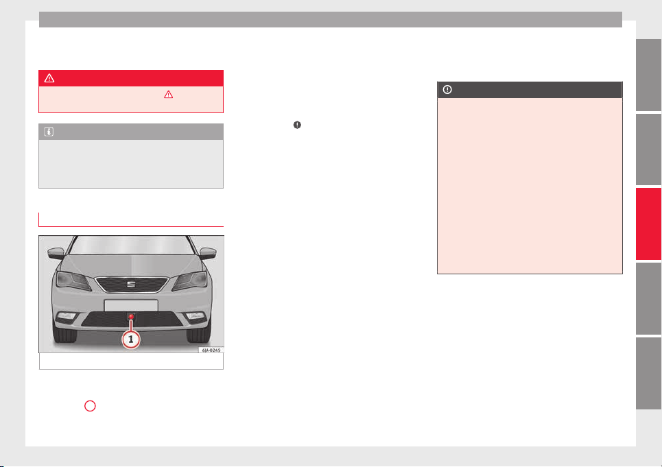
Driver assistance systems
appear on the instrument panel display
.
WARNING
Observe the safety warnings ›››
in Warning
and indication lamp
s on page 98.
Note
When the Front Assist is connected, the indi-
cations
on the instrument panel screen may
be concealed by warnings from other func-
tions, such as an incoming call.
Radar sensor
Fig. 189 On the front bumper: radar sensor.
A radar sensor is installed on the front bump-
er t
o det
ermine the tr
affic situation
›››
Fig. 189
1
. This sensor can detect vehi-
c
l
e
s in front up to a distance of approximately
120 m.
The radar sensor's visibility may be impaired
by dirt, mud or snow, or by environmental in-
fluences such as rain or mist. In this case the
Front Assist monitoring system does not
work. The instrument panel displays the fol-
lowing message: Front Assist: No
sensor vision! If necessary clean the ra-
dar sensor ›››
.
When the r
a
d
ar sensor begins to operate
properly again, the Front Assist will automati-
cally be available again. The message will
disappear from the instrument panel display.
Front Assist operation may be affected by a
strong radar reverse reflection. This may oc-
cur, for example, in a closed car park or due
to the presence of metallic objects (e.g. rails
on the road or sheets used in road works).
The area in front of and around the radar sen-
sor should not be covered with adhesives,
additional or similar headlights, as this may
negatively affect Front Assist operation.
If structural modifications are made to the ve-
hicle, for example, if the suspension is low-
ered or the front spoiler is modified, Front As-
sist operation may be affected. So structural
modifications should only be made by speci-
alised workshops. SEAT recommends visiting
a SEAT dealership for this purpose.
If work is done incorrectly on the front of the
vehicle, the radar sensor could be damaged
or lose its settings, and Front Assist opera-
tion may be affected. So repair work should
only be made by specialised workshops.
SEAT recommends visiting a SEAT dealership
for this purpose.
CAUTION
If you have the sensation that the radar sen-
sor is d
amaged or has lost its settings, dis-
connect the Front Assist. This will avoid pos-
sible damage. If this occurs have it adjusted.
●
The sensor may become damaged or lose
its settings when knocked, for example, dur-
ing a parking manoeuvre. This may compro-
mise the system's efficacy or disconnect it.
●
Repairs to the radar sensor require special-
ist knowledge and special tools. SEAT recom-
mends visiting a SEAT dealership for this pur-
pose.
●
Clean away the snow with a brush and the
ice preferably with a solvent-free de-icer
spray.
179
Technical dataAdviceOperationEmergenciesSafety

Operation
Operating the Front Assist monitoring
sy
s
t
em
Fig. 190 On the instrument panel display:
Fr
ont
As
sist switched off message.
Fig. 191 On the turn signal and main beam
he
a
dlight
lever: button for the driving assis-
tance systems
The Front Assist monitoring system is active
whenev
er the ignition i
s
switched on.
When the Front Assist is switched off, so too
are the pre-warning function (pre warning)
and the distance warning.
SEAT recommends leaving the Front Assist al-
ways switched on. Exceptions ››› page 180,
Switching the Front Assist Monitoring Sys-
tem off in the following situations.
Switching the Front Assist monitoring sys-
tem on and off
With the ignition switched on, the Front As-
sist can be switched on and off as follows:
●
Select the corresponding menu option us-
ing the button for the driver assist systems
››› Fig. 191.
●
OR: switch the system on or off in the Easy
Connect system with the button
and the
f
u
nction b
uttons
and
Driv
er As
s
ist
›››
page 20.
When the Fr
ont Assist monitoring system is
switched off, the instrument panel will inform
that it has been switched off with the follow-
ing indicator ››› Fig. 190.
Switching the pre-warning function on or off
The pre-warning function can be switched on
or off in the Easy Connect system with the
button
and the function buttons
and
Driv
er As
s
ist
›
›
›
p
age 20.
The system will store the setting for the next
time the ignition is switched on.
SEAT recommends keeping the pre-warning
function switched on at all times.
Switching distance warning on and off
If the safe distance with regard to the vehicle
in front is exceeded, the relevant warning will
appear on the instrument panel display
. In this case, increase the safe dis-
tance.
The distance warning function can be activa-
ted or deactivated in the Easy Connect sys-
tem with the button
and the function but-
t
on
s
and
Driv
er As
s
ist
›
›
›
p
age 20.
The system will store the setting for the next
time the ignition is switched on.
SEAT recommends keeping the distance
warning switched on at all times.
Switching the Front Assist Monitoring
System off in the following situations
In the following situations the Front Assist
Monit
orin
g
System should be deactivated
due to the system's limitations
›››
:
●
When the vehicle is to be towed.
●
If the vehicle is on a test bed.
●
When the radar sensor is damaged.
●
If the radar sensor takes a heavy knock, for
e
x
amp
le in a rear collision.
180
Driver assistance systems
●
If
it
int
ervenes several times unnecessarily.
●
If the radar sensor is covered temporarily
with some kind of accessory, such as an ad-
ditional headlight or the like.
●
When the vehicle is to be loaded on a lorry,
ferry or train.
WARNING
If the Front Assist is not switched off in the
situation
s described, serious accidents and
injuries may occur.
●
Switch off the Front Assist in critical situa-
tions.
System limitations
The Front Assist Monitoring System has cer-
t
ain ph
y
sical limitations inherent in the sys-
tem. Thus, in certain circumstances some of
the system's reactions may be inopportune
or be delayed from the driver's standpoint.
So pay attention in order to intervene if nec-
essary.
The following conditions may cause the Front
Assist Monitoring System not to react or do
so too late:
●
On taking tight bends.
●
Pressing the accelerator all the way down.
●
If the Front Assist is switched off or dam-
aged.
●
If the ASR has been manually disconnec-
ted.
●
If the ESC is controlling.
●
If several brake lights of the vehicle or elec-
trically connected trailer are damaged.
●
If the radar sensor is dirty or covered.
●
If there are metal objects, e.g. rails on the
road or sheets used in road works.
●
If the vehicle is reversing.
●
If the vehicle over-accelerates.
●
In case of snow or heavy rain.
●
In case of narrow vehicles, such as motor-
bikes.
●
Misaligned vehicles.
●
Vehicles crossing the other's path.
●
Vehicles approaching in the opposite direc-
tion.
●
Special loads and accessories of other ve-
hicles that jut out over the sides, backwards
or over the top.
City Emergency braking function
Fig. 192 On the instrument panel display:
pr
e-w
arnin
g message
The City Emergency braking function is part
of
the Fr
ont
Assist monitoring and is active
whenever the system is switched on.
Depending on the equipment, the pre-warn-
ing function can be switched on or off in the
Easy Connect system with the button
and
the f
u
nction b
uttons
and
Driv
er As
s
ist
›››
page 20.
The C
ity Emergency braking function picks
up, at speeds between 5 km/h (3 mph) and
30 km/h (19 mph) approximately, the traffic
situation in front of the vehicle up to a dis-
tance of about 10 m.
If the system detects a possible collision with
a vehicle in front of it, the vehicle prepares
for a possible emergency braking ›››
.
»
181
Technical dataAdviceOperationEmergenciesSafety
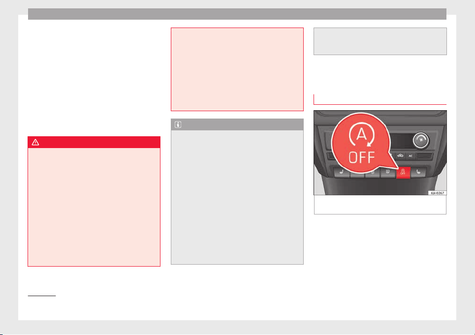
Operation
If the driver fails to react to a possible colli-
s
ion, the sy
s
tem may brake the vehicle auto-
matically, by progressively increasing braking
effect driving to reduce speed in the event of
a collision. The system can thus help to re-
duce the consequences of an accident.
Status display
Automatic deceleration by means of the City
Emergency braking function is displayed on
the instrument panel by means of the pre-
warning ››› Fig. 192
1)
.
WARNING
The smart technology included in the City
Emergency
braking function cannot defy the
laws of physics. The driver is always respon-
sible for braking in time.
●
Adapt your speed and safe distance to the
vehicle in front of you at all times to suit visi-
bility, weather, road and traffic conditions.
●
The City Emergency braking function alone
cannot prevent accidents or serious injury.
●
In complex driving situations, the City
Emergency braking function may issue unnec-
essary warnings and intervene inopportunely
in braking, such as in work areas or if there
are metal rails.
●
If the operation of
the City Emergency brak-
ing function is impaired, for example, by dirt
or because the radar sensor has lost its set-
tings, the system may issue unnecessary
warnings and intervene inopportunely in the
braking.
●
During driving, the City Emergency braking
function does not react to people or animals
or vehicles crossing your path or which ap-
proach you head-on in the same lane.
Note
●
When the C
ity Emer
gency braking function
causes a braking, the brake pedal is “hard-
er”.
●
Automatic interventions on the brakes by
the City Emergency braking function may be
interrupted by pressing the clutch, accelera-
tor or moving the wheel.
●
The City Emergency braking function can
brake the vehicle until it stops completely.
However, the brake system does not halt the
vehicle permanently. Use the foot brake!
●
If several inopportune intervenes occur,
switch off the Front Assist and with it the City
Emergency braking function. Take it to a spe-
cialised workshop, SEAT recommends visiting
a SEAT dealership.
●
If numerou
s unnecessary interventions oc-
cur, the City Emergency braking function may
switch off automatically.
Start-Stop System*
Operating
Fig. 193 Instrument panel: Start-Stop system
b
utt
on
The Start-Stop system helps save fuel and re-
duc
e h
armf
ul and CO
2
emissions.
The system is automatically switched on ev-
ery time the ignition is switched on.
The system automatically switches off the en-
gine when the vehicle is stationary, e.g. wait-
ing at traffic lights.
1)
The symbol on the instrument panels with colour
disp
lay is in colour.
182

Driver assistance systems
The current status of the Start-Stop system is
di
s
p
layed on the general instrument panel
display.
Automatic engine shut down (Stop phase)
–
Stop the vehicle (if necessary using the
handbrake).
–
Shift to neutral.
–
Release the clutch pedal.
Automatic engine start up (Start phase)
–
Press the clutch.
Switching the Start-Stop system on and off
The Start-Stop system can be switched on
and off by pressing the
›
›
› Fig. 193
but-
ton.
The warning lamp in the button will light up
when the system is switched off.
If the vehicle is in Stop phase when the but-
ton is pressed, the engine will start immedi-
ately.
The Start-Stop system works under complex
driving conditions that are difficult to detect
without specialist technology. The set of nec-
essary conditions for the correct operating of
the Start-Stop system are indicated below.
Conditions for automatic engine shut down
(Stop phase)
●
Selector lever in neutral.
●
Clutch pedal not pressed.
●
Driver with seat belt fastened.
●
Driver door closed.
●
The bonnet closed.
●
Vehicle stationary.
●
The factory-fitted towing bracket is not elec-
trically connected to a trailer.
●
Engine at operating temperature.
●
Vehicle's battery sufficiently charged.
●
Vehicle not on a very steep slope
●
Engine speed below 1,200 rpm.
●
Vehicle battery temperature is neither too
high nor too low.
●
Sufficient brake system pressure.
●
Difference between outside temperature
and set interior temperature not too great
●
Vehicle speed since the last time the en-
gine started was above 3 km/h (2 mph).
●
Particulate filter not being cleaned
››› page 102.
●
Front wheels not overly turned (steering
wheel turned less than three quarters of a
turn)
Conditions for engine start up (Start phase)
●
Clutch pedal pressed.
●
Max./min. temperature set.
●
Windscreen defrost function switched on.
●
High blower speed.
●
Start-Stop button pressed.
Conditions for automatic engine start up
without driver involvement
●
Vehicle moving at a speed of over 3 km/h
(2 mph).
●
Difference between outside temperature
and interior temperature is too great
●
Vehicle's battery insufficiently charged.
●
Insufficient brake system pressure.
If the driver seat belt is unfastened for more
than 30 seconds in Stop phase, the engine
must be started using the ignition key.
Please observe the messages on the general
instrument panel display.
Warnings on the instrument panel display
(valid for vehicles not fitted with an informa-
tive display)
FAULT: Start-Stop Fault in the Start-Stop sys-
tem
START-STOP IMPOSSI-
BLE
Engine cannot be auto-
matically shut down
START-STOP ACTIVE Automatic engine shut
down (Stop phase)
SWITCH OFF IGNITION Switch the ignition off
»
183
Technical dataAdviceOperationEmergenciesSafety
Operation
START MANUALLY Start the engine manually
WARNING
●
If the engine i
s switched off, neither the
brake servo nor the power steering will work.
●
Do not move the vehicle when the engine is
switched off.
CAUTION
Switch off the Start-Stop system ›››
page 166
before driving through a pool of water on the
road.
Note
●
The batter
y temperature may reflect
changes in outside temperature after several
hours. If the vehicle has been stopped out-
side at temperatures below zero or in direct
sunlight, for example, the battery tempera-
ture may take several hours to reach the val-
ues required for the correct operating of the
Start-Stop system.
●
If the Climatronic system is operating auto-
matically, this could impair automatic engine
shut down under certain conditions.
Tiredness detection (break rec-
ommend
ation)*
Intr
oduction
The Tiredness detection informs the driver
when their driving beh
aviour shows signs of
fatigue.
WARNING
Do not let the comfort afforded by the Tired-
ness
detection system tempt you into taking
any risks when driving. Take regular breaks,
sufficient in length when making long jour-
neys.
●
The driver always assumes the responsibil-
ity of driving to their full capacity.
●
Never drive if you are tired.
●
The system does not detect the tiredness of
the driver in all circumstances. Consult the in-
formation in the section ››› page 185, System
limitations.
●
In some situations, the system may incor-
rectly interpret an intended driving manoeu-
vre as driver tiredness.
●
No warning is given in the event of the ef-
fect called microsleep!
●
Please observe the indications on the in-
strument panel and act as is necessary.
Note
●
Tirednes
s detection has been developed for
driving on motorways and well paved roads
only.
●
If there is a fault in the system, have it
checked by a specialised workshop.
Function and operation
Fig. 194 On the instrument panel display:
tir
edne
s
s detection symbol.
Tiredness detection determines the driving
beh
av
iour of
the driver when starting a jour-
ney, making a calculation of tiredness. This is
constantly compared with the current driving
behaviour. If the system detects that the driv-
er is tired, an audible warning is given with a
sound and an optic warning is shown with a
symbol and complementary message on the
instrument panel display ››› Fig. 194. The
message on the instrument panel display is
184
Towing bracket device
shown for approximately 5 seconds, and de-
pendin
g on the c
a
se, is repeated. The system
stores the last message displayed.
The message on the instrument panel display
can be switched off by pressing the
button on the windscreen wiper lever or the
b
utt
on
on the multi function steering
wheel
›
›
›
page 22.
The message can be recalled to the instru-
ment panel display using the multifunction
display ›››
page 22.
Conditions of operation
Driving behaviour is only calculated on
speeds above about 65 km/h (40 mph) up to
around 200 km/h (125 mph).
Switching on and off
Tiredness detection can be activated or deac-
tivated in the Easy Connect system with the
button
and the function button
››› page 104. A mark indicates that the ad-
ju
stment has been activated.
System limitations
The Tiredness detection has certain limita-
tions inherent to the system. The following
conditions can limit the Tiredness detection
or prevent it from functioning.
●
At speeds below 65 km/h (40 mph)
●
At speeds above 200 km/h (125 mph)
●
When cornering
●
On r
oads in poor condition
●
In unfavourable weather conditions
●
When a sporty driving style is employed
●
In the event of a serious distraction to the
driver
Tiredness detection will be restored when the
vehicle is stopped for more than 15 minutes,
when the ignition is switched off or when the
driver has unbuckled their seat belt and
opened the door.
In the event of slow driving during a long pe-
riod of time (below 65 km/h (40 mph) the
system automatically re-establishes the tired-
ness calculation. When driving at a faster
speed the driving behaviour will be recalcula-
ted.
Towing bracket device
Driv
in
g w
ith a trailer
Technical requirements
If your vehicle has a factory-fitted towing
brack
et or is equipped with a selection of
SEAT Original Accessories, it meets all the rel-
evant technical and legal requirements.
In vehicles with a towing bracket it is possi-
ble to remove the ball joint, situated (togeth-
er with the special assembly instructions) in
the housing for the spare wheel in the vehi-
cle luggage compartment
›››
page 75, Vehicle
tool kit*.
Your vehicle is fitted with a 13-pole power
socket for the electrical connection between
the trailer and the vehicle. If the trailer you
are going to use has a 7-pin connector, the
corresponding adaptor, acquired from the
SEAT Original Accessories Catalogue, can be
used.
If a towing bracket is to be retro-fitted to the
car, it must be done according to the instruc-
tions of the towing bracket manufacturer.
Note
Any queries that may arise can be directed to
an authorised SEA
T dealer.
185
Technical dataAdviceOperationEmergenciesSafety
Operation
Trailer weight
Trailer weight
The combined
vehicle and trailer must be
balanced. To do so use the maximum permit-
ted towing bracket load. An insufficient
weight exerted by the trailer drawbar on the
ball joint of the towing bracket will have a
negative impact upon the response of the ve-
hicle-trailer assembly on the road.
Weight distribution
Distribute loads in the trailer so that heavy
objects are as near to the axle as possible.
Ensure that the objects do not move.
If the towing vehicle is empty and the trailer
loaded then the load distribution is incorrect.
However, if these conditions cannot be avoi-
ded, drive very slowly.
Tyre pressure values
Correct the tyre pressure in your vehicle to
“total load”
›››
page 216, Useful life of tyres.
Trailer weight
Never exceed the authorised trailer weight
under any circumstances
›››
page 221, Tech-
nical specifications.
The trailer weights listed are only applicable
for altitudes up to 1000 m above sea level.
Due to lower air density, engine power de-
creases depending on the increase in alti-
tude, this also reduces climbing ability,
which requir
es a reduction of the weight of
the vehicle with a trailer by 10% for every
1000 m increase in altitude. The weight of
the assembly is calculated by adding the ve-
hicle weight (loaded) to the trailer weight
(loaded). Always drive with special care when
towing a trailer.
The towed load and support load information
that is displayed on the towing bracket man-
ufacturers label are only values for the verifi-
cation of the device. The correct figures for
your specific vehicle, which are usually lower
than these figures, are given in the documen-
tation of your vehicle.
WARNING
●
Exceedin
g the maximum established load
per axle and the maximum towing bracket
load in addition to the maximum permitted
load or the load of the vehicle + trailer as-
sembly can cause accidents and serious inju-
ries.
●
A sliding load can considerably affect the
stability and safety of the vehicle + trailer as-
sembly, resulting in accidents and serious in-
juries.
Driving with a trailer
Exterior mirrors
Check whether
you can see enough of the
road behind the trailer with the standard rear
vision mirrors. If this is not the case, you
should have additional exterior mirrors fitted.
Observe the relevant statutory requirements
of the country you are in.
Headlights
Before starting a journey, also check the
headlight beam settings with the trailer
hitched up. Adjust the headlight range set-
tings if necessary
›››
page 122, Main light
range control .
Driving speed
For your own safety do not drive faster than
the maximum permitted speed indicated on
the trailer.
At all times, immediately reduce speed if you
detect the slightest swaying movement of the
trailer. Never try to “return the trailer to a
straight position” by accelerating.
Brakes
Brake in due course! If the trailer has an over-
run brake, apply the brakes gently at first and
then, firmly. This will prevent the jerking that
can be caused by locking of trailer wheels.
Change to a lower gear in good time before
186
Towing bracket device
descending a slope in order to take advant-
ag
e of
the en
gine brake.
The trailer is incorporated into the vehicle's
anti-theft alarm system:
●
When the vehicle has a factory-fitted anti-
theft alarm and a towing bracket.
●
When the trailer is electrically connected to
the vehicle via the towing bracket socket.
●
When the vehicle electrical device and the
towing bracket are operational.
●
When the vehicle is locked and the vehi-
cle's anti-theft alarm device is activated.
Once the electrical connection is interrupted
with the vehicle trailer locked, the alarm
sounds.
Always switch off the vehicle anti-theft alarm
device before connecting or disconnecting a
trailer. The vehicle anti-theft alarm device
could cause the alarm to sound ››› page 117,
Anti-theft alarm system*.
Engine overheating
In the event that the coolant temperature
gauge needle moves to the right section of
the scale or to the red area, immediately re-
duce speed. If the control lamp flashes on
the general instrument panel, stop the vehi-
cle and switch off the engine. Wait several
minutes and check the coolant level in the
tank ››› page 208.
Please observe the following indications
››› page 100, Coolant level and temperature
.
The coolant temperature can be reduced by
switching on the heating.
WARNING
●
Adjust
your speed to suit the road and traf-
fic conditions.
●
An electrical installation that is connected
incorrectly or by non-specialised personnel
can prevent the connection of the current to
the trailer and cause faults in the operation of
the electrical system throughout the entire
vehicle, leading to accidents and serious in-
jury.
●
All electrical work must be carried out only
by specialised services.
●
Never directly connect the trailer electrical
device to the electrical sockets of the reverse
driving lights or other sources of electrical
current.
CAUTION
●
Avoid c
orners, and sudden and sharp brak-
ing.
●
Once the trailing arm has been removed,
place the corresponding cover on the hole of
the fastening point. This prevents dirt from
entering the hole – see the trailer system as-
sembly manual.
Note
●
In the event of
frequent journeys with a
trailer, we recommend also having the vehi-
cle inspected in between the service inter-
vals.
●
When connecting and disconnecting the
trailer, the handbrake must be applied.
●
For technical reasons, trailers with LED re-
verse lights cannot be incorporated into the
vehicle anti-theft alarm system.
Towing bracket device for trail-
er
Intr
oduction
If the vehicle is equipped with a towing
br
ac
k
et device from the factory or is a genu-
ine SEAT accessory, it meets all national tech-
nical and legal requirements for towing.
Your vehicle is fitted with a 13-pin power
socket for the electrical connection between
the trailer and the vehicle. If the towing
bracket is equipped with a 7-pin connector,
you can use the corresponding available
adaptor that is a genuine SEAT accessory.
The towing device has a maximum vertical
load of 50 kg.
»
187
Technical dataAdviceOperationEmergenciesSafety
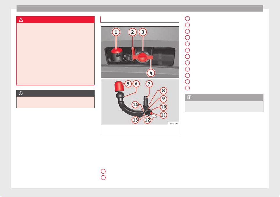
Operation
WARNING
●
Befor
e driving with the ball-headed bar fit-
ted, verify its correct assembly and place-
ment in the clamping bush.
●
Do not use the ball-headed bar if it is not
correctly placed and fixed in the clamping
bush.
●
Do not use the towing device for towing if it
is damaged or has missing parts.
●
Do not modify or adapt the towing device
connection.
●
Never disengage the ball-headed bar with
the trailer still hitched.
CAUTION
Be careful not to damage the paint on the
bumper when handlin
g the ball-headed bar.
Description
Fig. 195 Towing bracket device support for
hit
c
hin
g/ball-headed bar.
The ball-headed bar is detachable. It is loca-
t
ed in the s
p
are wheel compartment or in the
spare wheel compartment in the boot
››› page 75, Vehicle tool kit*.
Key to ››› Fig. 195
13-pin socket
Safety flange
1
2
Clamping bush
C
l
ampin
g bush cap
Ball head cover
Ball-headed bar
Locking balls
Centred
Red marking on the manual regulator
Manual regulator
Key
Key slot cover
Red marking on the manual regulator
White marking on the ball-headed bar
Note
Contact an Authorised Service Partner if you
lose y
our key.
3
4
5
6
7
8
9
10
11
12
13
14
188
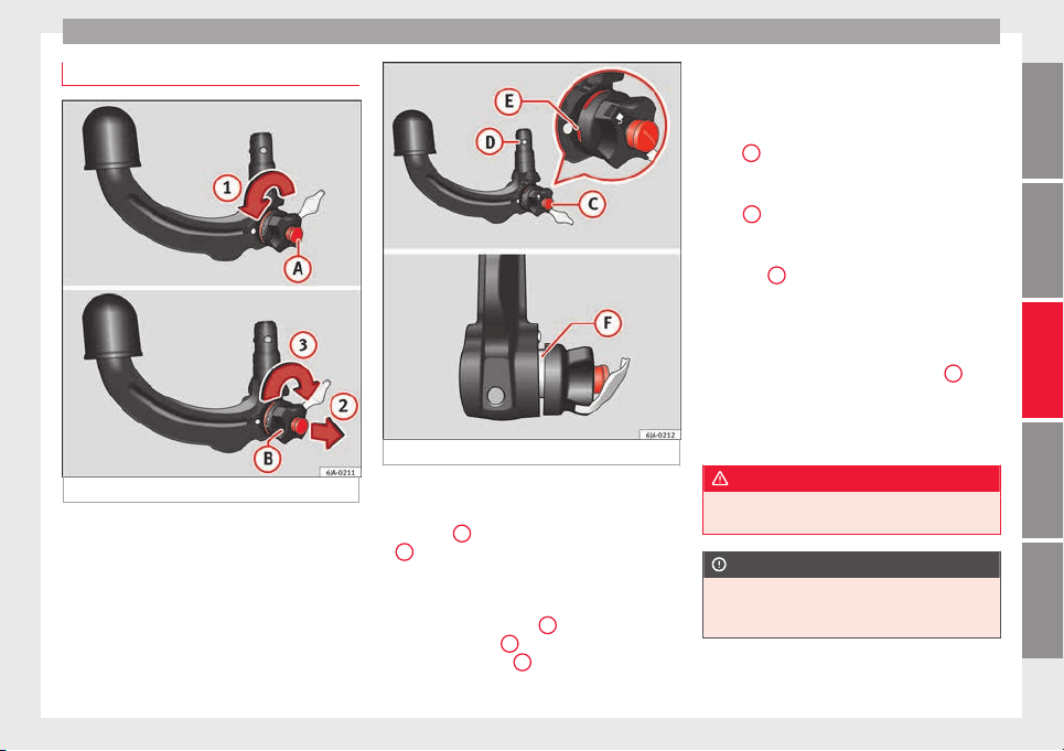
Towing bracket device
Placing in service position
Fig. 196 Placing in service position.
Fig. 197 Service position.
Before assembling, place the ball-headed bar
in ser
v
ic
e position.
–
Turn key
A
fully in the direction of arrow
1
›
›
› Fig. 196
.
–
Hold the ball-headed bar with your left
hand.
–
Pull manual regulator
B
outward in the di-
r
ection of
arr
ow
2
and turn it fully in the
dir
ection of
arr
ow
3
.
The manual regulator will remain in this posi-
tion.
Ser
v
ic
e position ››› Fig. 197
●
Key
C
is in an open position – the key ar-
r
o
w points
to the “unlocked” symbol. The key
cannot be removed from the key slot.
●
The
D
locking balls may be fully inserted
int
o the body
of
the ball-headed bar by ap-
plying some pressure.
●
The red
E
marking on the manual regula-
t
or points
t
owards the white marking on the
ball-headed bar.
●
Between the manual regulator and the
body of the ball-headed bar there is a clearly
visible space of approximately 4 mm
F
.
Onc
e the b
al
l-headed bar has been posi-
tioned like this, it will be ready to be placed
in the clamping bush.
WARNING
Do not use the ball-headed bar if it cannot be
correctly
placed in the service position.
CAUTION
The key cannot be removed from the manual
regu
lator key slot when it is in the service po-
sition.
189
Technical dataAdviceOperationEmergenciesSafety
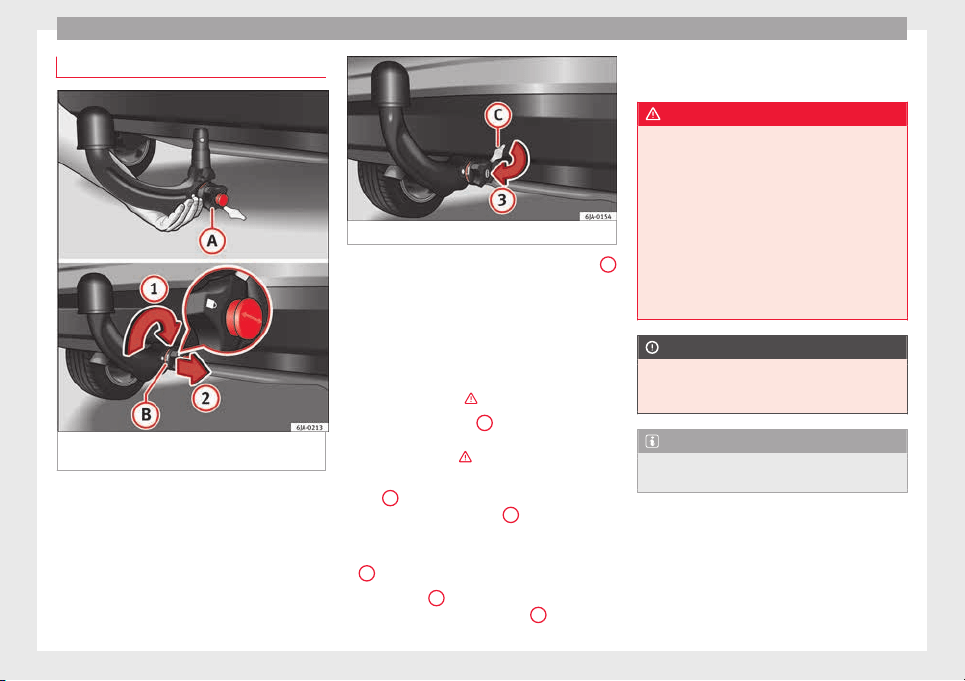
Operation
Assembly of the ball-headed bar
Fig. 198 Placing the ball-headed bar/locking
and r
emo
v
ing the key.
Fig. 199 Placing the key slot cover.
–
Remove the cap from the clamping bush
4
››› Fig. 195 by p
ulling downwards.
–
Place the ball-headed bar in the service po-
sition ››
› page 189.
–
Hold the ball-headed bar from underneath
››› Fig. 198 and push it into the clamping
bush as far as possible until you hear it
click into place ›››
.
The m
anual
r
egulator
A
aut
omatically turns
in the op
po
site direction, adjusting to the
ball-headed bar ›››
.
–
Switch off the manual regulator lock with
k
ey
B
by turning the key fully to the right
in the dir
ection of
arr
ow
1
– the arrow in
the k
ey
di
splays the “locked” symbol.
–
Remove the key in the direction of arrow
2
.
–
Place cover
C
over the manual regulator
loc
k
in the dir
ection of arrow
3
›
›
› Fig. 199
.
–
Verify the correct placement of the ball-
headed bar ››› page 191.
WARNING
●
Do not hol
d the manual regulator with your
hand when fitting the ball-headed bar since
you could sustain injuries to your fingers.
●
When mounting the ball-headed bar, al-
ways lock it with a key and remove the key
from the slot.
●
The ball-headed bar must not be in the
service position with the key in the key slot.
●
If the ball-headed bar is not placed in the
service position you will not be able to place
it in the clamping bush.
CAUTION
When removing the key, always place the
cov
er over the key slot of the manual regula-
tor to prevent dirt from entering.
Note
Once removed, place the clamping bush cap
in an appropri
ate location in the boot.
190
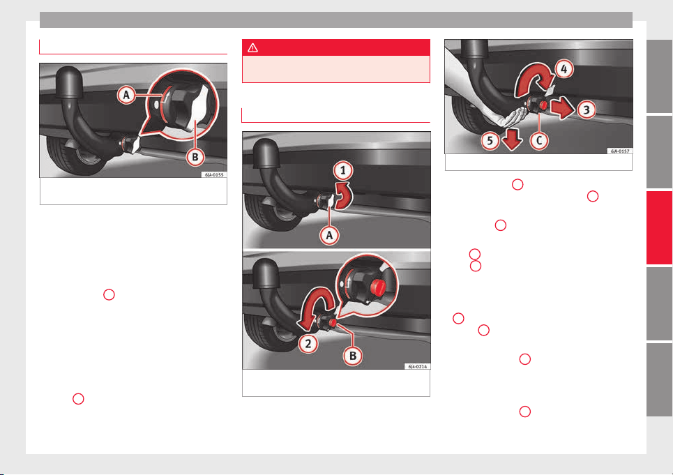
Towing bracket device
Verification of correct placement
Fig. 200 Correct placement of the ball-head-
ed b
ar
.
Before using the ball-headed bar, ensure it is
c
orr
ectly
fitted.
Ensure that:
●
The ball-headed bar does not come out of
the clamping bush in a “jerky” manner.
●
The red mark
A
›
›
› Fig. 200
on the manual
regulator signals toward the white mark on
the ball-headed bar.
●
The manual regulator is adjusted to the
ball-headed bar, leaving no space between
them.
●
The regulator is locked and the key has
been removed.
●
Cover
B
has been placed over the manual
r
e
gu
lator lock.
WARNING
Only use the towing bracket device when the
bal
l-headed bar is properly fitted!
Disassembly of the ball-headed bar
Fig. 201 Remove the key slot cover/unlock
w
ith the k
ey
.
Fig. 202 Unblock the ball-headed bar.
–
Remove cover
A
from over the regulator
k
ey
s
lot in the direction of arrow
1
››› Fig. 201.
–
Insert key
B
in the key slot.
–
Open the manual regulator lock by turning
k
ey
B
fully to the left in the direction of ar-
r
o
w
2
. The arrow on the key points to the
“u
n
loc
ked” symbol.
–
Hold the ball-headed bar from underneath
››› Fig. 202 and remove manual regulator
C
with your other hand in the direction of
arr
o
w
3
.
–
Turn the removed regulator fully in the di-
r
ection of
arr
ow
4
and hold it firmly in this
po
s
ition.
–
R
emove the ball-headed bar from the
clamping bush, pulling downward in the di-
rection of arrow
5
.
»
191
Technical dataAdviceOperationEmergenciesSafety
Operation
The ball-headed bar should be placed in the
ser
v
ic
e position so that it is ready to be inser-
ted into the clamping bush ›››
.
–
Place the cover over the clamping bush
4
››› Fig. 195.
WARNING
●
Never leave the ball-headed bar unsecured
in the boot. It c
ould be damaged in the event
of sudden braking, putting the safety of pas-
sengers at risk!
●
Never disassemble the ball-headed bar
with the trailer still hitched.
CAUTION
●
If y
ou do not turn the manual regulator
fully, it will return to its original position
when the ball-headed bar is removed. The
manual regulator will be stuck to the ball-
headed bar and you will not be able to put it
in the service position. Therefore, before you
assemble it again, you must place the ball-
headed bar in this position.
●
When disassembling, place the cap on the
clamping bush holder’s key slot. This way
you will prevent dirt from entering the clamp-
ing bush.
Note
●
Befor
e disassembling the ball-headed bar,
we recommend placing the cover on the ball
head.
●
Cle
an the ball-headed bar thoroughly be-
fore returning it to the on-board toolbox.
Use and maintenance
Cover the clamping bush with the cap to pre-
vent dir
t from entering.
Before hooking on the trailer, check the ball
head and, if necessary, lubricate it with ade-
quate lubricant.
Place the protective cover over the ball head
when storing the bar. This way, you will avoid
getting the boot dirty.
If it gets dirty, clean and dry the clamping
bush thoroughly with an appropriate prod-
uct.
CAUTION
The top part of the clamping bush opening is
lubricated. B
e careful not to remove this lu-
brication.
192
Care and maintenance
Advice
C
ar
e and m
aintenance
Accessories and modifications
to the vehicle
Accessories, replacement parts and
repair work
If you wish to retrofit accessories in the vehi-
c
l
e, or if
a part of the vehicle has been re-
placed by a new part or technical modifica-
tions are required, the following instructions
must be taken into account:
●
Before purchasing accessories or spare
parts and before making technical modifica-
tions, always request advice from an Author-
ised SEAT dealer
›››
.
●
In the event that technical modifications
ar
e c
arried out
on the vehicle, the instruc-
tions and regulations specified by the com-
pany, SEAT, must be observed.
No damage will be caused to the vehicle if
the established procedures are respected,
which guarantees safe driving and operation.
After the modifications are carried out, the
vehicle will comply with the restrictions and
regulations of the highway code. More infor-
mation can be obtained at an Authorised
SEAT dealer, where all jobs required can be
carried out appropriately.
Vehicle improvements and modifications
The owner must keep the technical documen-
tation regarding the modifications carried out
on the vehicle so it can be handed over to
those responsible for processing end-of-life
vehicles. This ensures end-of-life processing
of the vehicle, while protecting the environ-
ment.
Work done on the electrical components and
software can cause disruption in operations.
Due to the interconnection of electronic com-
ponents, their malfunction can also impair
systems that are not directly affected. This
can adversely affect reliability of the vehicle,
and can produce excessive wear of the parts.
Damage caused by technical modifications
that are not made with the consent of SEAT
will be excluded from the warranty – see war-
ranty certificate.
WARNING
●
Jobs
or modifications unduly carried out on
your vehicle can cause disruption to opera-
tions - Risk of accident!
●
We recommend that you use only expressly
authorised SEAT Accessories and SEAT Origi-
nal Spare Parts for your vehicle. The reliabili-
ty, safety and compatibility with your vehicle
of SEAT original spare parts and accessories
has
been verified.
●
Despite the continuous observation of the
market, we cannot judge nor guarantee the
suitability of other products for your vehicle,
be they authorised products or products ap-
proved by a state testing facility.
Note
SEAT original spare parts and accessories can
be p
urc
hased at authorised SEAT dealers
where the purchased parts can also be fitted.
Modifications and effects of the air-
b
ag sy
s
tem
In the adjustment and modification, respect
the S
EA
T dir
ective.
Modifications and corrections of the front
bumper, doors, front seats, roof or bodywork
must be carried out at authorised SEAT work-
shops. Components of the airbag system can
be found in these parts of the vehicle.
WARNING
●
Airbag modul
es must never be repaired.
They must be replaced.
●
Never fit components of the airbag system
removed from old vehicles or those originat-
ing from a recycling process in the vehicle.
»
193
Technical dataAdviceOperationEmergenciesSafety
Advice
●
The modification of the s
uspension of the
vehicle wheels, including the use of non-per-
mitted combinations of tyres and rims can al-
ter the operation of the airbag system and in-
crease the risk of serious or fatal injuries in
an accident.
●
During all jobs on the airbag system, in ad-
dition to the removal and fitting of parts of
the system in the course of other repair jobs,
parts of the airbag system can be damaged.
Therefore in the event of an accident, this
may cause the airbags to activate incorrectly
or not activate at all.
Radio and aerial reception
In vehicles factory-fitted with an audio or
n
av
ig
ation system, the aerial may be instal-
led in different places:
●
inside the rear window next to the heating
elements,
●
on the roof of the vehicle.
Care and cleaning
Introduction
Regular and suitable care helps to m
aint
ain
the u
seful life of your vehicle. This may also
be one of the requirements for upholding any
warranty claims in the event of corrosion or
paint defects.
We recommend you use cleaning products
from the SEAT Original Accessories pro-
gramme available in SEAT dealers. Please fol-
low the instructions for use on the packag-
ing.
WARNING
●
Cle
aning products and other materials used
for car care can damage the health if mis-
used.
●
Always keep car care materials in a safe
place out of the reach of children. Risk of poi-
soning!
●
When washing the car during the winter
season: Moisture and ice on the brakes may
affect braking efficiency. Risk of accident!
●
The ignition must always be switched off
when the car is washed. Risk of accident!
●
Do not clean the underside of the car or in-
side the wheel arches without protecting your
hands and arms. You may cut yourself on
sharp metal parts!
●
Perfumes and air fresheners inside the ve-
hicle may be harmful to health at high tem-
peratures in the interior.
CAUTION
●
Check the c
olour-fastness of your clothing
to avoid damaging or visibly staining the fab-
ric (leather), upholstery and fabric trim.
●
Cle
aning products containing solvents may
damage the material being cleaned.
●
Do not wash the vehicle in direct sunlight.
Risk of damage to paintwork.
●
If washing the vehicle with a hose in win-
ter, do not direct the jet of water directly at
the locks or at the door seals or bonnet. Risk
of freezing.
●
Do not use sponges for removing insects or
abrasive household sponges, etc. on painted
surfaces. Risk of damage to the painted sur-
face!
●
Do not put stickers on the inner side of the
rear window in areas where heating elements
or the aerial are located. This could cause
damage and, in the case of the aerial, radio
and navigation system reception faults.
●
Do not clean the inside of the window with
sharp objects or corrosive or acidic cleaning
products. Risk of damaging the heating ele-
ments or the aerial.
●
Do not attach any fragrance or air freshener
to the dash panel. Risk of damage to the
dash panel!
●
To avoid damaging the parking aid system
sensors, spray them only briefly at a mini-
mum distance of 10 cm when cleaning the ve-
hicle with a high-pressure or steam cleaner.
●
Do not clean the roof panel with a brush.
Risk of damage to the panel surface!
194
Care and maintenance
For the sake of the environment
●
The pack
aging of the product used to care
for your vehicle is hazardous waste. It must
be disposed of according to current local law.
●
Only wash the car in special wash bays.
Note
●
Remov
e stains from fresh ball-pen and oth-
er inks, lipstick, shoe cream and similar
stains on the fabric (leather), upholstery and
fabric trim as soon as possible.
●
We recommend that you visit an authorised
SEAT dealer to clean and care for the interior
of your vehicle, due to the problems that may
arise when cleaning and caring for the interi-
or of your vehicle and to the utensils and
knowledge required.
Washing the vehicle
The best protection of the vehicle from the
h
armf
u
l influences of the environment in-
volves frequent washing and waxing. The fre-
quency with which the vehicle is washed de-
pends on many different factors, such as:
●
Frequency of use
●
Type of parking (garage, underneath trees,
etc.)
●
Time of year
●
Weather conditions
●
Environmental conditions
The longer substances such as insects, bird
droppings, resinous tree sap, road dirt, in-
dustrial deposits, tar, soot or road salt and
other aggressive materials remain on the
paintwork, the more damage they do. High
temperatures (for instance in strong sunlight)
further intensify the corrosive effect.
After the winter season, it is important to
have the underside of the vehicle washed
thoroughly.
car washes
Your vehicle can be washed in an automatic
c
ar w
a
sh.
Before going through an automatic car wash,
be sure to take the usual precautions such as
closing the windows, etc.
If the vehicle has special accessories such as
spoilers or a roof rack or two-way radio aerial,
etc., it is advisable to consult the car wash
operator beforehand.
The windscreen wiper rubbers must be de-
greased after going after the car wash and
waxing.
Washing by hand
When washing the car by hand, use plenty of
water t
o soften the dirt first and rinse off as
well as possible.
Then clean the vehicle with a sponge, glove
or brush. Start on the roof and work down.
Use only slight pressure when cleaning the
painted surfaces of the vehicle. A car sham-
poo should only be used for very persistent
dirt.
Rinse the sponge or glove thoroughly and of-
ten.
Wheels, sills and underside should be
cleaned last. Use a second sponge for this.
After washing, rinse the vehicle thoroughly
and then dry with a chamois.
Washing with high-pressure cleaners
When cleaning the vehicle with a high-pres-
s
ur
e c
leaner, always follow the operating in-
structions for the equipment. This particular-
ly applies to the operating pressure and the
distance of the spray from the surface of the
vehicle. Do not hold the spray nozzle too
close to the parking aid system sensors and
soft materials, such as rubber hoses or insu-
lating material.
»
195
Technical dataAdviceOperationEmergenciesSafety
Advice
WARNING
Do no use a nozzle that sprays the water out
in a direct s
tream or one that has a “rotating
jet”!
CAUTION
Do not use water hotter than +60°C (140°F).
Risk of
damage to the vehicle!
Sensors and camera lenses
●
Use a small brush to remove snow and a
de-ic
er s
pr
ay to remove ice.
●
Clean the sensors with a solvent-free prod-
uct and a soft, dry cloth.
●
Moisten the camera lens using a standard
alcohol-based glass cleaning agent and
clean the lens with a dry cloth.
CAUTION
●
When you c
lean the vehicle with a pressure
washer:
–
Stay a suitable distance from the sensors
on the front and rear bumpers.
–
Do not clean the camera lenses or sur-
rounding area with the pressure washer.
●
Never use warm or hot water to remove
snow and ice from the reverse camera lens,
as it could crack the lens.
●
Never use abr
asive cleaning agents on the
lens.
Vehicle paint waxing and polishing
Care
To a gre
at extent, good waxing protects the
vehicle surface from the harmful effects of
the environment.
The vehicle must be treated with a high qual-
ity, hard wax when water no longer forms
droplets on clean paintwork.
A new coat of high quality, hard wax can be
applied to the clean, painted surface only
when it has fully dried. Even if a wax solution
is used regularly in the car wash, it is advisa-
ble to protect the paint with a coat of wax at
least twice a year.
Polishing
Polishing is only necessary if the paint has
lost its shine, and the gloss cannot be
brought back by applying wax.
The vehicle must be waxed after polishing if
the polish used does not contain wax com-
pounds to seal the paint.
CAUTION
●
Never wax
the windows.
●
Do not use po
lishes and hard wax on pain-
ted parts with a matt finish or on plastic
parts.
●
Do not polish your vehicle in a sandy or
dusty environment.
Cleaning of chromed parts
Clean the chrome first with a clean cloth and
then buff up w
ith a soft, dry cloth. If this does
not clean the chrome properly, use a special
chrome cleaner.
CAUTION
Do not polish the chrome in a dusty environ-
ment or it c
ould be scratched.
Damage to the paint
Minor damage to the paint, such as scratches
or s
t
one c
hips, should be touched up without
delay using paint.
Suitable touch-up brushes or sprays for the
colour of your vehicle can be purchased from
authorised SEAT dealers.
Note
We recommend you leave paint damage re-
pairs
to a SEAT Authorised Service.
196

Care and maintenance
Plastic parts
Exterior plastic parts will come clean using a
damp cloth. If
this is not sufficient, plastic
parts can also be treated with special sol-
vent-free plastic cleaning detergents.
Do not use paint cleaners, polishes or wax on
plastic parts.
Windows and mirrors
Remove snow and ice from windows and rear
v
i
s
ion mirrors with a plastic scraper only. To
avoid damaging the surface of the glass, the
scraper should only be pushed in one direc-
tion and not moved to and fro.
The windows should also be cleaned on the
inside at regular intervals.
Use a separate cloth or chamois to dry the
windows and rear vision mirrors.
Do not use the chamois used to polish the
bodywork to dry the windows. Waxing and
polishing residues could cause smears on
the glass and hinder visibility.
CAUTION
●
Never use hot
or boiling water to remove
snow and ice from the windows. Risk of crack-
ing glass!
●
Make s
ure you do not damage the paint-
work on the vehicle on removing snow and
ice from the windows and rear vision mirrors.
●
Do not remove the snow or ice dirty with
thick particles, e.g. gravel, sand or road salt,
from windows and mirrors. Risk of damage to
the glass and mirror surfaces.
Headlights
Use soap and clean, hot water to clean the
front he
adlights.
CAUTION
●
Never rub the hea
dlights to dry them and
do not use sharp objects to clean the plastic
glass material. These could damage the pro-
tective paint and cause the headlights to
crack.
●
Do not use aggressive cleaning products or
chemical solvents to clean the glass. This
could damage the headlights.
Care of rubber seals
The weatherstrips on doors and windows will
r
em
ain p
liable and last longer if they are oc-
casionally treated with a suitable rubber care
product. This will prevent premature ageing
and leaks. If they are properly cared for, the
seals will be less likely to freeze up in the
winter.
Door lock cylinder
Special products must be used to defrost
lock cylinder
s.
Note
●
Make s
ure, when washing the vehicle, that
the least amount of water possible enters the
lock cylinders.
●
We recommend the use of products from
the selection of SEAT Original Accessories to
care for the door lock cylinder.
Wheels
Wheel trims
If
y
ou wash the vehicle regularly, you should
also thoroughly wash the wheel trim. Regu-
larly remove any brake dust and road salt
from the wheels, otherwise the wheel materi-
al could be damaged. Repair any damage to
the wheel paintwork immediately.
Alloy wheels
After thorough washing, treat the wheels
with a protective product for alloy wheels. Do
not use abrasive products to care for the
wheels.
»
197
Technical dataAdviceOperationEmergenciesSafety
Advice
WARNING
Moisture, ice and road salt may affect braking
efficiency. Ri
sk of accident!
CAUTION
Heavy dirt on the wheels could lead to their
misa
lignment. This could result in vibrations
being transmitted to the steering wheel that
under certain conditions may cause prema-
ture steering wear. This dirt must be re-
moved.
Note
We recommend you leave paint damage re-
pairs
to a SEAT Authorised Service.
Vehicle underbody protection
The underside of the vehicle is coated to per-
m
anently
pr
otect it from chemical and me-
chanical agents.
Given that damage to the protective coating
during driving cannot be completely ruled
out, we recommend you check the condition
of the protective coating on the underbody
and suspension at regular intervals, prefera-
bly before the start and end of the coldest
season of the year.
Authorised SEAT dealers have suitable spe-
cial products and the necessary facilities and
are aware of the techniques required for their
application. We therefore recommend all
touch-up work or additional anti-corrosion
measures be performed by an authorised
SEAT dealer.
WARNING
Do not apply underseal or anti-corrosion
coatin
gs to the exhaust pipes, catalytic con-
verter, particulate filter or heat shields on the
exhaust system. Once the engine has
reached operating temperature, these sub-
stances could catch fire. Risk of fire!
Cavity waxing
All cavities on the vehicle exposed to corro-
s
ion ar
e perm
anently factory-protected by a
wax solution.
This wax solution does not need to be
checked or touched up. Should wax run out
of the cavities at high ambient temperatures,
remove it using a plastic scraper and clean
away any stains using lighter fluid.
WARNING
Note the regulations concerning safety and
envir
onmental protection if you use lighter
fluid to remove the wax. Risk of fire!
Leatherette and upholstery
Leatherette can be cleaned with a damp
cloth. If thi
s is not sufficient, these parts
should only be cleaned with solvent-free
plastic care and cleaning products.
Textile covers and trim parts on doors, boot
lid, etc. can be cleaned with special deter-
gents, e.g. dry foam. A soft sponge or brush
or a micro-fibre cloth for normal cleaning can
be used. Use special products to clean the
headliner.
The dye used in many garments, for example
dark jeans, is not always sufficiently colour-
fast. Seat upholstery (fabric and leather), es-
pecially when light-coloured, may visibly dis-
colour if the dye comes out of clothing, even
in normal conditions. This is not an uphols-
tery defect but indicates that the dye in the
item of clothing is not solid enough.
Heated seat upholstery
Do not clean the seat upholstery with d
amp
pr
oduct
s, as this could damage the seat
heating system.
Clean the upholstery with special products,
e.g. dry foam, etc.
198
Care and maintenance
Natural leather
Leather should be looked after from time to
time, depending on its u
se.
Normal cleaning
Moisten a cotton or woollen cloth with water
and wipe over the leather surfaces.
More stubborn dirt
Do not let water soak through the leather or
penetrate the seams.
Dry it with a soft, dry cloth.
Removing stains
Remove fresh water-based stains such as cof-
fee, tea, juices, blood, etc. with an absorbent
cloth or kitchen roll. Use the special deter-
gent to clean dried-on stains.
Remove fresh fat-based stains such as but-
ter, mayonnaise, chocolate, etc. with an ab-
sorbent cloth or paper towel or use the spe-
cial detergent if the stain has not yet soaked
through the surface.
Use a grease-dissolving product to treat
dried-in, fat-based stains.
Treat less common stains such as ball-pen
and other inks, felt-tip pens, nail polish,
emulsion paint, shoe cream etc. with a spe-
cial leather stain remover.
Leather care
The leather shou
ld be treated regularly
(about twice a year) with a leather-care prod-
uct.
Apply the protective product very sparingly.
Dry the leather with a soft, dry cloth.
CAUTION
●
Avoid e
xposing leather to direct sunlight
for long periods so that it does not lose its
colour. If the car is left for a prolonged period
outdoors, cover the leather so that it does
not lose its colour.
●
Sharp-edged objects on clothing, such as
zips, rivets or belts can leave permanent
scratches and rough marks on the surface of
the leather.
●
Use of a mechanical steering wheel lock
can damage the leather surface of the steer-
ing wheel.
Note
●
Use a suit
able impregnating cream with ul-
tra-violet protection at regular intervals and
after cleaning. The cream will nourish and
moisturise the leather, keep it supple and
able to breathe. In addition, it will also help
to protect the surface of the leather.
●
Clean the leather every 2 to 3 months and
remove fresh dirt as necessary.
●
Preser
ve the colour of the leather. A special
coloured cream for leather will renew the col-
our of more heavily worn areas as required.
●
Leather is a natural material with specific
properties. During vehicle use, the appear-
ance of parts of the leather covers may
change; folds or wrinkles may appear as a re-
sult of their use.
Seat belts
Keep the seat belts clean!
W
a
sh soi
led seat belts with mild, soapy wa-
ter, removing any heavier dirt with a soft
brush.
Check the condition of all seat belts at regu-
lar intervals.
Very soiled belts may not retract properly.
WARNING
●
The seat belt
s should never be removed
from the vehicle for cleaning.
●
Never clean using chemical products, as
chemical detergents destroy the fabric. En-
sure that the seat belts do not come into con-
tact with corrosive fluids such as acids, etc.
●
If you find any damage to the belt webbing,
belt fittings, the belt retractor or the buckle,
the belt in question must be replaced by an
Official Service.
»
199
Technical dataAdviceOperationEmergenciesSafety
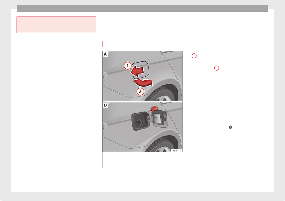
Advice
●
Make s
ure that the inertia reel seat belts
are completely dry before allowing them to
retract.
Checking and refilling levels
F
uel
R
ef
uelling
Fig. 203 Vehicle as seen from the rear right:
f
uel
t
ank flap/fuel tank flap with tank un-
screwed cap attached.
Read the additional information carefully
›
›
›
page 39
The correct type of fuel for your vehicle is in-
dicated on a sticker on the inside of the fuel
tank flap, along with the tyre size and pres-
sure ››› Fig. 203 .
Vehicles with a fuel cap with key
–
Press the flap in the direction of the arrow
1
›
›› Fig. 203
.
–
Open the c
over in the direction indicated
by the arrow
2
.
–
Hold onto the fuel tank cap with one hand
and u
n
loc
k it using the ignition key, turning
it anti-clockwise.
–
Unscrew the tank cap anti-clockwise and
place it on top of the tank flap ››› Fig. 203
.
–
Insert the pump nozzle into the fuel feed
tube as far as it will go.
The fuel tank is full as soon as the automatic
filler nozzle cuts out ›››
.
–
Remove the pump nozzle from the fuel feed
t
ube and p
l
ace it back on the pump.
–
Screw the tank cap clockwise until it clicks
into place.
–
Hold onto the fuel tank cap with one hand
and lock it using the ignition key, turning it
clockwise.
–
Press the tank flap with your hand to close
it.
200
Checking and refilling levels
–
Chec
k
th
at the fuel flap is correctly closed.
Vehicles with a keyless fuel cap (the side
flap will unlock using the central locking sys-
tem)
–
Once the vehicle has been unlocked using
the central locking button, press the fuel
flap in the direction of the arrow
1
››› Fig. 203.
–
Open the cover in the direction indicated
b
y
the arr
ow
2
.
–
Unscrew the tank cap anti-clockwise and
p
l
ac
e it on top of the tank flap ››› Fig. 203
.
–
Insert the pump nozzle into the fuel feed
tube as far as it will go.
The fuel tank is full as soon as the automatic
filler nozzle cuts out ›››
.
–
Remove the pump nozzle from the fuel feed
t
ube and p
l
ace it back on the pump.
–
Screw the tank cap clockwise until it clicks
into place.
–
Close the tank flap. Make sure you hear it
click into place.
–
Check that the fuel flap is properly closed.
WARNING
Observe all relevant statutory regulations on
trans
porting spare fuel canisters. For safety
reasons, we do not recommend carrying a
spar
e canister in the vehicle. The canister
could be damaged in an accident and fuel
may leak. Risk of fire!
CAUTION
●
Sw
itc
h off the auxiliary heater (heater and
independent heater) before filling the tank.
●
The fuel tank is full as soon as the automat-
ic filler nozzle cuts out. Do not continue fill-
ing, as this will fill the expansion chamber.
●
Never completely empty the tank! An irreg-
ular fuel supply can cause ignition faults,
which can result in damage to a substantial
amount of engine parts and the exhaust sys-
tem.
●
If any fuel is spilt onto the paintwork of the
vehicle, it should be removed immediately.
Risk of damage to paintwork!
Note
The fuel tank capacity is around 55 litres, of
which 7 litre
s are the reserve.
Unleaded petrol
Your vehicle must only be run on u
n
l
eaded
petrol that complies with the Standard EN
228 (in Germany, also DIN 51626 – 1, or E10
for unleaded petrol with 95 and 91 octane
rating (RON) or DIN 51626 – 2, or E5 for un-
leaded petrol with 95 and 98 RON).
Prescribed fuel – unleaded petrol (95/91
RON)
Use unleaded petrol with 95 RON. Unleaded
petrol with 91 RON can also be used, al-
though this will result in a slight loss of pow-
er.
If, as an emergency measure, you have to fill
the tank with petrol with a lower RON to that
prescribed, use only moderate engine
speeds and light throttle. High engine speed
and full throttle can seriously damage the en-
gine! Fill up with petrol with the correct RON
as soon as possible.
Prescribed fuel – unleaded petrol (min. 95
RON)
Use unleaded petrol with 95 RON.
If unleaded petrol with 95 RON is not availa-
ble, you can fill up with petrol with 91 RON as
an emergency measure. In this case, use only
moderate engine speeds and a light throttle.
High engine speed and full throttle can seri-
ously damage the engine! Fill up with petrol
with the correct RON as soon as possible.
Petrol with a RON below 91 cannot be used,
even as an emergency measure. Risk of seri-
ously damaging the engine!
Unleaded petrol with higher RON
Unleaded petrol with a higher RON to that
prescribed can be used without limits.
»
201
Technical dataAdviceOperationEmergenciesSafety
Advice
In vehicles running on prescribed unleaded
petr
o
l
with 95/91 RON, there is no notable
increase in power or lower fuel consumption
when petrol with a RON higher than 95 is
used.
In vehicles running on prescribed unleaded
petrol with min. 95 RON, there is an increase
in power and a lower fuel consumption when
petrol with a RON higher than 95 is used.
Prescribed fuel – unleaded petrol (98/(95)
RON)
Use unleaded petrol with 98 RON. Unleaded
petrol with 95 RON can also be used, al-
though this will result in a slight loss of pow-
er.
If unleaded petrol with 98 or 95 RON is not
available, you can fill up with petrol with 91
RON as an emergency measure. In this case,
use only moderate engine speeds and a light
throttle. High engine speed and full throttle
can seriously damage the engine! Fill up with
petrol with the correct RON as soon as possi-
ble.
Petrol with a RON below 91 cannot be used,
even as an emergency measure. Risk of seri-
ously damaging the engine!
Petrol additives
The quality of the fuel influences the behav-
iour, power and service life of the engine.
This is why the petrol you use should carry
suitable additives already included by the
petrol industry, free of metals. These addi-
tives will help to prevent corrosion, keep the
fuel system clean and prevent deposits from
building up in the engine.
If good-quality petrol with metal-free addi-
tives is not available or engine problems
arise, the necessary additives must be added
when refuelling ›››
.
Not
al
l
petrol additives have been shown to
be effective. The use of unsuitable petrol ad-
ditives may cause significant damage to the
engine and the catalytic converter. Metal ad-
ditives should never be used. Metal additives
may also be contained in petrol additives for
improving anti-detonation ratings or octane
ratings ›››
.
S
EA
T r
ecommends “genuine Volkswagen
Group Fuel Additives for petrol engines”.
These additives can be bought at SEAT deal-
ers, where information on how to use them
can also be obtained.
CAUTION
●
Do not ref
uel if the filler indicates that the
fuel contains metal. LRP (lead replacement
petrol) fuels contain high concentrations of
metal additives. Using them may damage the
engine!
●
All SEAT vehicles with petrol engines can
only run on unleaded petrol. Refuelling just
once with leaded petrol disables the exhaust
syst
em!
●
Use of petrol with a lower RON to that pre-
scribed could damage the engine compo-
nents.
●
Fuels marked as containing metal on the
garage fuel pump cannot be used. Risk of
damage to most engine parts or the exhaust
system!
●
The use of unsuitable additives in petrol
can cause damage to most engine parts or
the exhaust system.
Diesel fuel
Please note the information on the inside of
the f
uel
t
ank flap.
Your vehicle can only work using diesel fuel,
which must comply to European standard EN
590. If diesel fuel which meets European
standard EN 590 is not available, the Cetane
number (CZ) must, at minimum, be 51. If the
engine is equipped with a particulate filter,
the sulphur content of the fuel must be below
50 parts per million.
Winter-grade diesel
Summer fuel becomes thicker in winter and it
is more difficult to start the engine. For this
reason, petrol stations in some countries al-
so offer winter diesel with improved fluidity
when cold (winter-grade diesel).
202
Checking and refilling levels
Water in the fuel filter
1)
If
y
our vehicle has a diesel engine and is
equipped with a fuel filter with a water sepa-
rator, the instrument panel may display the
following warning:
Water in the
fuel filter. If this is the case, take the
vehicle to a specialised workshop so that
they can drain the fuel filter.
Preheating the fuel filter
The vehicle is fitted with a glow plug system
for the fuel filter. Therefore, the reliability of
the diesel is ensured at ambient tempera-
tures of down to approximately -25°C (-13°F).
Fuel additives
Fuel additives, known as “thinners” (petrol or
similar substances) should not be mixed with
the diesel fuel.
CAUTION
●
Even one t
ankful of diesel fuel that does
not comply with the standard could damage
engine parts, the fuel system and the ex-
haust system!
●
Your vehicle is not designed to use biodie-
sel fuel. Never, under any circumstances re-
fuel with biodiesel. The use of biodiesel fuel
could damage the engine and the fuel sys-
tem. The addition of biodiesel to diesel fuel
by the diesel manufacturer in accordance
with st
andard EN 590 or DIN 51628 is author-
ised and will not cause damage.
●
The diesel engine has been designed to be
used exclusively with diesel fuel conforming
to standard EN 590. Never refuel or use pet-
rol, kerosene, fuel oil or any other type of
fuel. If you accidentally fill up the vehicle
with the wrong type of fuel, do not start the
engine. Seek assistance from specialised per-
sonnel. The composition of these fuels may
severely damage the fuel system and the en-
gine. Water allowed to collect in the fuel filter
can cause engine faults.
Engine compartment
Intr
oduction
Read the additional information carefully
›
›
›
page 11
Always be aware of the danger of injury and
scalding as well as the risk of accident or fire
when working in the engine compartment,
e.g. when checking and refilling fluids.
Therefore, always observe the warnings and
follow all general safety precautions. The en-
gine compartment is a dangerous area.
WARNING
●
Never open the bonnet if
you see steam,
smoke or coolant escaping from the engine
compartment. Risk of scalding! Wait until no
steam or coolant can be seen before opening
the bonnet.
●
Switch off the engine and remove the key
from the ignition.
●
Engage neutral in vehicles with manual
gearbox and move the selector lever to posi-
tion P in vehicles with automatic gearbox.
●
Apply the handbrake firmly.
●
Wait for the engine to cool down.
●
For safety reasons, the bonnet must always
be closed when the vehicle is moving. There-
fore, after closing the bonnet always check
that it is properly secured.
●
Should you notice that the bonnet is not
safely secured when the vehicle is moving,
stop the vehicle immediately and close the
bonnet properly. Risk of accident!
●
Keep children away from the engine com-
partment.
●
Do not touch hot engine parts. Risk of
burns!
●
Never spill fluids on hot engine compart-
ments. These fluids can cause a fire (e.g. anti-
freeze in coolant)!
»
1)
Valid for the market: Algeria.
203
Technical dataAdviceOperationEmergenciesSafety
Advice
●
Take c
are not to cause short circuits in the
electrical system, especially when working
on the battery.
●
Never touch the radiator fan when the en-
gine is hot. The fan may start running sud-
denly!
●
Never cover the engine with additional in-
sulating materials such as a blanket. Risk of
fire!
●
Do not unscrew the cap on the coolant ex-
pansion tank when the engine is hot. The
cooling system is under pressure!
●
Protect face, hands and arms from any hot
steam or hot coolant released by covering the
cap with a large, thick rag when opening the
expansion tank.
●
Do not leave any objects, such as cloths or
tools, in the engine compartment.
●
When working underneath the vehicle, se-
cure it so that it cannot roll away and support
it safely on suitable supports. The hydraulic
jack is not sufficient for this purpose. Risk of
injuries!
●
If any tests have to be performed with the
engine running, there is an extra safety risk
from rotating parts, such as the drive belt, al-
ternator and radiator fan, etc., and from the
high-voltage ignition system. You should also
note the following:
–
Never touch the electrical wiring of the
ignition system.
–
Keep away from moving engine parts
when wearing jewellery, loose clothing or
long hair. Risk of fatal injuries! All jewel-
lery must be removed, hair tied back and
close-fittin
g clothing worn.
●
Observe the following additional warnings
if work on the fuel system or the electrical
system is necessary.
–
Always disconnect the battery from the
on-board network.
–
Do not smoke.
–
Never work near naked flames.
–
Always keep an approved fire extinguish-
er immediately available.
CAUTION
●
When toppin
g up fluids, make sure the cor-
rect fluid is put into the correct filler opening.
Otherwise this can cause serious malfunc-
tions or engine damage!
●
Never open the bonnet using the release
catch. Risk of damage!
For the sake of the environment
Due to the environmentally-friendly disposal
of fluids, the equipment
necessary and the
knowledge required, let an authorised SEAT
dealer change fluids during service inspec-
tions of the vehicle.
Note
●
Plea
se contact an authorised SEAT dealer
with any doubts regarding fluids.
●
Fluids of
the correct specifications can be
acquired from the selection of SEAT Original
Accessories.
204
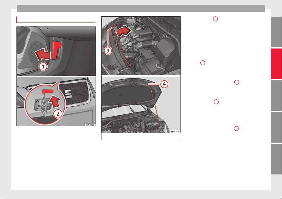
Checking and refilling levels
Opening and closing of the bonnet
Fig. 204 Unlocking the bonnet.
Fig. 205 Locking the bonnet.
Opening the bonnet
–
Open the front left door.
–
P
u
l
l the lever
1
›
›› Fig. 204
u
nder the dash
panel in the direction indicated by the ar-
row.
Before opening the bonnet, make sure that
the windscreen wiper arms are not lifted
away from the glass. Otherwise the paint-
work may be damaged.
–
Pull the release catch in the direction of the
arrow
2
›
›› Fig. 204
and the bonnet
will be
released.
–
Hold and lift the bonnet.
–
Remove the support strut
3
›
›
› Fig. 205
fr
om its fastening in the direction of the ar-
row and secure the raised bonnet so that
the end of the strut hooks onto the opening
in the bonnet
4
.
C
lo
s
ing the bonnet
–
Lift the bonnet slightly and unhook the
support strut keeping the bonnet open and
insert it into its fastening
3
.
–
Let the bonnet drop from a height of
ar
ou
nd 20 c
m into the catch Do not press
down afterwards!
–
Check that the bonnet is correctly closed.
205
Technical dataAdviceOperationEmergenciesSafety
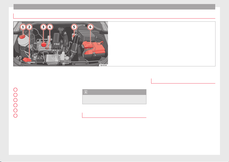
Advice
Checking levels
Fig. 206 Diagram for the location of the various elements.
From time to time, the levels of the different
fluid
s
in the
vehicle must be checked. Never
fill with incorrect fluids, otherwise serious
damage to the engine may be caused.
Coolant expansion tank . . . . . . . . . . . 208
Window washer water tank . . . . . . . . 210
Engine oil filler cap . . . . . . . . . . . . . . . 208
Engine oil level dipstick . . . . . . . . . . . 207
Brake fluid reservoir . . . . . . . . . . . . . . 209
Battery . . . . . . . . . . . . . . . . . . . . . . . . . . . 211
The checking and replenishment of the serv-
ice fluids are carried out on the components
mentioned above. These operations are de-
scribed in the ››› page 203.
1
2
3
4
5
6
Overview
Y
ou w
i
ll find further explanations, instruc-
tions and restrictions on the technical speci-
fications as of ››› page 221.
Note
The layout of the engine compartment is very
simil
ar to all petrol and diesel engines.
Radiator fan
The radiator is driven by an electric motor
and c
ontr
o
lled according to the temperature
of the coolant.
After the engine has been stopped and the
ignition switched off, the radiator fan may
continue running for around 10 minutes.
Engine oil
General notes
The engine comes with a special, multi-grade
oil th
at can be used all year round.
Because the use of high-quality oil is essen-
tial for the correct operation of the engine
and its long useful life, when topping up or
changing oil, use only those oils that comply
with VW standards.
The specifications (VW standards) set out in
the following page should appear on the con-
tainer of the service oil; when the container
displays the specific standards for petrol and
diesel engines together, it means that the oil
can be used for both types of engines.
We recommend that the oil change indicated
in the Maintenance Programme, be
206
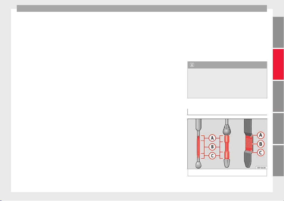
Checking and refilling levels
performed by a technical service or special-
i
sed w
ork
shop.
The correct oil specifications for your engine
are listed in the ›››
page 40.
Service intervals
Service intervals can be flexible (LongLife
service) or fixed (dependent on time/dis-
tance travelled).
If the PR code that appears on the back of the
Maintenance Programme booklet is PR QI6,
this means that your vehicle has the LongLife
service programmed. If it lists the codes QI1,
QI2, QI3, QI4 or QI7, the interval service is
dependent on time/distance travelled.
Flexible service intervals (LongLife service
intervals*)
Special oils and processes have been devel-
oped which, depending on the characteris-
tics and individual driving profiles, enable
the extension of the oil change service (Long-
Life service intervals).
Because this oil is essential for extending the
service intervals, it must only be used ob-
serving the following indications:
●
Avoid mixing it with oil for fixed service in-
tervals.
●
Only in exceptional circumstances, if the
engine oil
level is too low ››› page 207 and
LongLife oil is not available, it is permitted to
top up (once) with oil for fixed ser
vice inter-
vals ›››
page 40 (up to a maximum of 0.5
litres).
Fixed service intervals*
If your vehicle does not have the “LongLife
service interval” or it has been disabled (by
request), you may use oils for fixed service
intervals, which also appear in
›››
page 40. In this case, your vehicle
must be serviced after a fixed interval of 1
year/15,000 km (10,000 miles)(whatever
comes first) ››› Booklet Maintenance Pro-
gramme.
●
In exceptional circumstances, if the engine
oil level is too low ››› page 207 and you can-
not obtain the oil specified for your vehicle,
you can add a small quantity of oil conform-
ing to the specification ACEA A2 or ACEA A3
(petrol engines) or ACEA B3 or ACEA B4 (die-
sel engines) (up to 0.5 l).
Vehicles with diesel particulate filter*
The Maintenance Programme states whether
your vehicle is fitted with a diesel particulate
filter.
Only VW 507 00 engine oil, with reduced ash
formation, may be used in diesel engines
equipped with particulate filter. Using other
types of oil will cause a higher soot concen-
tration and reduce the life of the DPF. There-
fore:
●
Avoid mixing this oil with other engine oils.
●
Only in exceptional circumstances, if the
engine oil level is too low ››› page 207 and
you cannot obtain the oil specified for your
vehicle, you can use a small quantity of oil
(once) conforming to the VW 506 00,
VW 506 01, VW 505 00, VW 505 01 or
ACEA B3/ACEA B4 specification. (up to 0.5 l).
Note
Before a long trip, we recommend finding an
engine oil
that conforms to the correspond-
ing VW specifications and recommend keep-
ing it in the vehicle. This way, the correct en-
gine oil will always be available for a top-up if
needed.
Checking engine oil level
Fig. 207 Engine oil dipsticks.
»
207
Technical dataAdviceOperationEmergenciesSafety
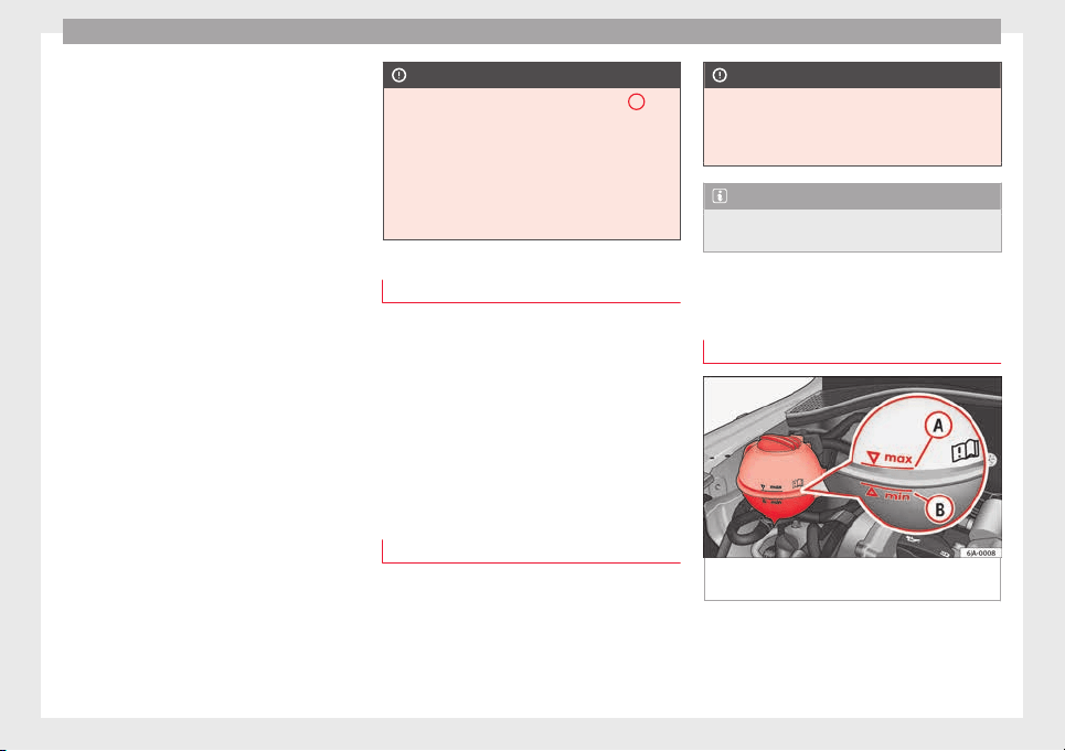
Advice
Read the additional information carefully
›
›
›
page 40
The dipstick shows the engine oil level.
››› Fig. 207.
Checking oil level
–
Park the vehicle on a level surface and en-
sure the engine is at operating tempera-
ture.
–
Switch the ignition off.
–
Open the bonnet.
–
Wait a few minutes for the engine oil to
flow back to the sump and remove the dip-
stick.
–
Wipe the dipstick with a clean cloth and in-
sert it again as far as it will go.
–
Then pull the dipstick out again and check
the oil level.
It is normal for the engine to consume a cer-
tain amount of oil. Depending on how you
drive and the conditions in which the vehicle
is used, oil consumption can be up to 0.5 li-
tres per 1,000 km. Oil consumption can also
be higher for the first 5,000 km (3000 miles).
You should therefore check the oil level at
regular intervals, ideally every time you fill
the tank or before setting off on a long trip.
CAUTION
●
The oil l
evel must never exceed area
A
››› Fig. 207. Risk of
damage to the exhaust
system!
●
If the engine oil cannot be topped up under
the given conditions, do not drive on! Stop
the engine and seek the professional assis-
tance of an Official Service, as this could
cause serious damage to the engine.
Topping up engine oil
–
Check the engine oil level
›
›
›
page 207,
Checking engine oil level.
–
Unscrew the cap from the filler opening.
–
Put in the specified grade of oil 0.5 litres at
a time
›››
page 206.
–
Check the oil level
›››
page 207.
–
Replace the oil filler cap carefully and push
the dipstick all the way in.
Changing engine oil
Engine oil must be changed with the frequen-
cy
indic
at
ed in the Maintenance Programme
or according to the service interval indicator
›››
page 30.
CAUTION
Do not mix engine oil with additives. Risk of
damag
e to the engine! Damage caused by
these products is not covered by the warran-
ty.
Note
Wash your skin thoroughly if it comes into
contact
with engine oil.
Coolant
Chec
k
in
g coolant level
Fig. 208 Engine compartment: coolant fluid
t
ank.
Read the additional information carefully
›
›
›
page 40
The coolant expansion tank is located in the
engine compartment of the vehicle.
208
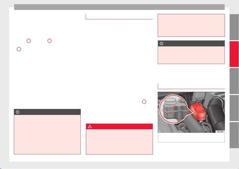
Checking and refilling levels
–
Sw
it
c
h the ignition off.
–
Open the bonnet ››› page 203.
–
Read off the coolant level on coolant ex-
pansion tank ››› Fig. 208. When the engine
is cold, the coolant should be between
marks
B
(min.) and
A
(max.). When the
en
gine i
s
hot, it may be slightly above mark
A
(max.).
If
the c
oo
lant fluid level in the reservoir is too
low, this will be indicated by the red warn-
ing lamp illuminating on the general dash
panel ››› page 100, Coolant level and temper-
ature . However, we recommend checking
the coolant level directly in the tank.
Coolant fluid loss
Any loss of coolant normally indicates a leak.
It is not sufficient merely to top up the cool-
ant. The cooling system should be inspected
by an Official Service without delay.
CAUTION
●
In the event of
a fault that causes the en-
gine to overheat, contact an authorised SEAT
dealer immediately, as this could damage the
engine.
●
Anti-freeze that does not correspond to the
correct specification may particularly affect
corrosion protection considerably.
●
Faults caused by corrosion may lead to
coolant leaks. Risk of serious engine faults!
Topping up the coolant level
–
Switch the ignition off.
–
Wait for the engine to cool down.
–
Cover the cap on the coolant expansion
tank ›
›› Fig. 208 with a cloth and carefully
unscrew the cap.
–
Refill the level of coolant.
–
Screw the cap on again until it clicks into
place.
Do not use a different type of additive if the
prescribed anti-freeze additive is not availa-
ble, in the event of an emergency. In this
case, use only water and bring the coolant
concentration back up to the correct level as
soon as possible at an Official Service.
Always top up with unused coolant.
Never fill the coolant tank above mark
A
(max.)
›
›
›
Fig. 208 Excess coolant is forced
out of the cooling system through the over-
pressure valve in the filler cap of the expan-
sion tank when the engine heats up.
WARNING
●
The anti-freeze a
dditive and, therefore, the
entire coolant, are a health hazard. Avoid
touching the coolant. Coolant fumes are also
a health hazard. For this reason, always store
the coolant additive in a safe place out of the
reach of children. Risk of poisoning!
●
If sp
lashed into eyes, rinse immediately
with clean water and seek immediate medical
attention.
●
Seek immediate medical attention if the
coolant is accidentally ingested.
CAUTION
If the coolant cannot be topped up under the
giv
en condition
s, do not drive on. We rec-
ommend contacting an authorised SEAT deal-
er, as this can damage the engine.
Brake fluid
Chec
k
in
g brake fluid level
Fig. 209 Engine compartment: brake fluid
r
e
ser
voir.
Read the additional information carefully
›
›
›
page 41
»
209
Technical dataAdviceOperationEmergenciesSafety
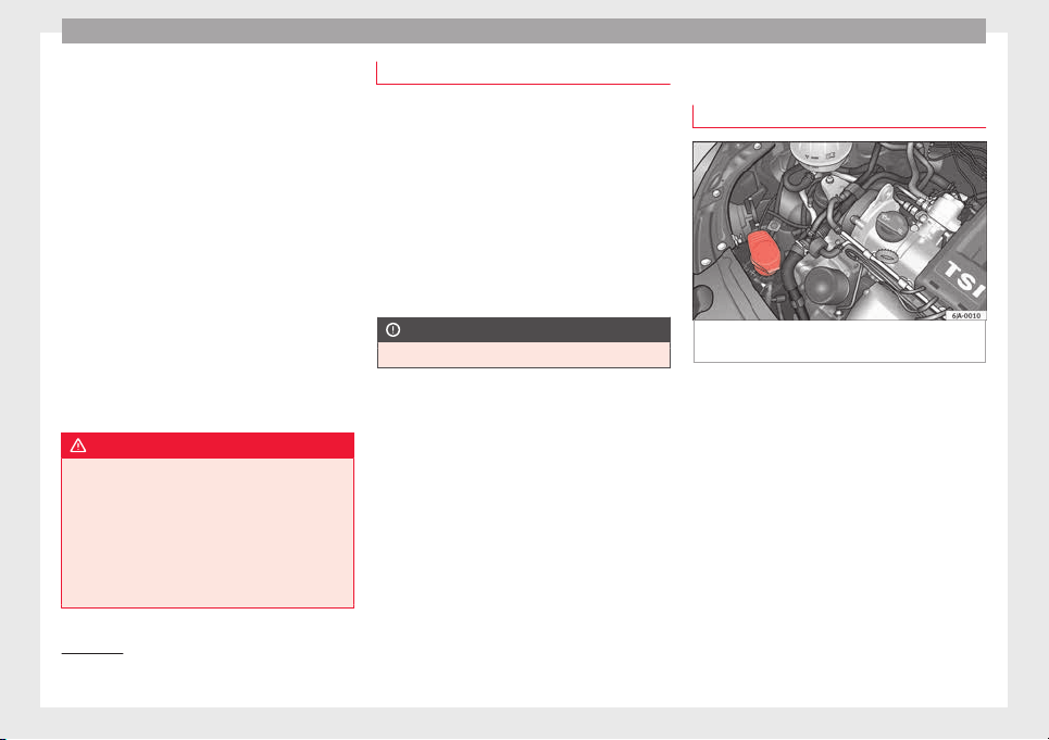
Advice
The brake fluid reservoir is located in the en-
gine c
omp
ar
tment of the vehicle.
–
Switch the ignition off.
–
Open the bonnet ››› page 203.
–
Check the brake fluid level in the reservoir
››› Fig. 209. It should be between the “MIN”
and “MAX” marks.
The fluid level drops slightly after a period of
time due to automatic compensation for
brake pad wear. This is quite normal.
However, if the level goes down noticeably in
a short time, or drops below the “MIN” mark,
there may be a leak in the brake system. If
the brake fluid level in the reservoir is too
low, this will be indicated by the warning
lamp illuminating on the instrument panel
››› page 99, Brake system .
WARNING
●
If the fluid lev
el has dropped below the MIN
mark, do not continue driving. Risk of acci-
dent! Go to a technical service.
●
Heavy use of the brakes may cause a va-
pour lock if the brake fluid is left in the brake
system for too long. This would seriously af-
fect the efficiency of the brakes and the safe-
ty of the vehicle.
Changing the brake fluid
Brake fluid absorbs moisture. Therefore, it
gradual
ly absorbs moisture from the atmos-
phere. If the water content in the brake fluid
is too high, the brake system could corrode.
The water content also reduces the boiling
point of the brake fluid.
The brake fluid must comply with one of the
following standards or specifications:
●
VW 50114
●
FMVSS 116 DOT4
CAUTION
Brake fluid damages the vehicle paintwork.
Windscreen washer
t
op
pin
g up windscreen washer fluid
Fig. 210 Engine compartment: windscreen
w
a
sher r
eservoir.
Read the additional information carefully
›
›
›
page 41
The container for the windscreen washer con-
tains the cleaning fluid for the windscreen or
rear window and the headlight washer sys-
tem. The container is located in the engine
compartment.
The capacity of the reservoir is approximately
3.5 litres; in vehicles with a headlight washer
system, it is approximately 5.4 litres
1)
.
Plain water on its own is not enough to clean
the glass and the headlights properly. We
1)
Valid only for certain countries. 5.4 litres for both
vers
ions.
210
Checking and refilling levels
therefore recommend using clean water with
a gl
a
s
s cleaning product to eliminate any
stubborn dirt (with an anti-freeze additive in
winter).
Although your vehicle has heated windscreen
washer jets, anti-freeze should always be
added to the water in winter.
Ethanol can be used where glass cleaner with
anti-freeze is unavailable. The concentration
of ethanol must be no greater than 15 %.
However, remember that anti-freeze in this
proportion only protects down to -5°C
(+23°F).
CAUTION
●
Never mix
the windscreen washing water
with anti-freeze used for the cooling system
or other additives.
●
If the vehicle is equipped with a headlight
washer system, only mix in with the water a
detergent that does not damage polycarbon-
ates.
Note
When topping up the fluid, do not move the
filter fr
om the container opening, as this
could contaminate the fluid hoses and lead to
a windscreen washer malfunction.
Battery
Intr
oduction
Read the additional information carefully
›››
page 41.
Warning symbols on the battery
Sym
bol
Meaning
Always wear safety glasses!
Battery acid is extremely corrosive. Always wear
gloves and hearing protection!
Keep open flames, sparks, uncovered lights
and lit cigarettes away when working on the
battery!
A highly explosive mixture of gases is released
when the battery is under charge!
Keep children away from the battery!
Incorrect handling of the vehicle battery
c
ou
l
d lead to damage. We therefore recom-
mend all work on the vehicle battery be per-
formed by an authorised SEAT dealer.
Always be aware of the danger of injury and
scalding as well as the risk of accident or fire
when working on the battery and the electri-
cal system. Therefore, always observe the
warnings and follow all general safety pre-
cautions.
WARNING
●
Batter
y acid is very corrosive, therefore, the
battery must be handled with the utmost
care. Wear protective gloves and protect your
eyes and skin when handling batteries. The
corrosive fumes in the air irritate and inflame
the respiratory tract and cause conjunctivitis.
It corrodes tooth enamel. Causes deep and
difficult-to-heal wounds when it comes in
contact with the skin. Repeated contact with
diluted acids causes skin disease (inflamma-
tion, ulcers and fissures). When in contact
with water, acids dilute and develop a great
deal of heat.
●
Do not tilt the battery, as acid could leak
out of the vapour vents. Protect your eyes
with glasses or a protective helmet! Risk of
blindness! If acid should splash into the
eyes, rinse the affected eye immediately for
several minutes using clean water. Then seek
medical care immediately.
●
Neutralize any acid splashes on the skin or
clothing with soap solution as quickly as pos-
sible and rinse off with plenty of water. If acid
is swallowed by mistake, consult a doctor im-
mediately.
●
Keep children away from the battery.
●
Hydrogen is released and a highly explo-
sive mixture of gases is generated when the
battery is under charge. Sparks when discon-
necting or releasing cable terminals with the
ignition switched on could also cause an ex-
plosion.
»
211
Technical dataAdviceOperationEmergenciesSafety
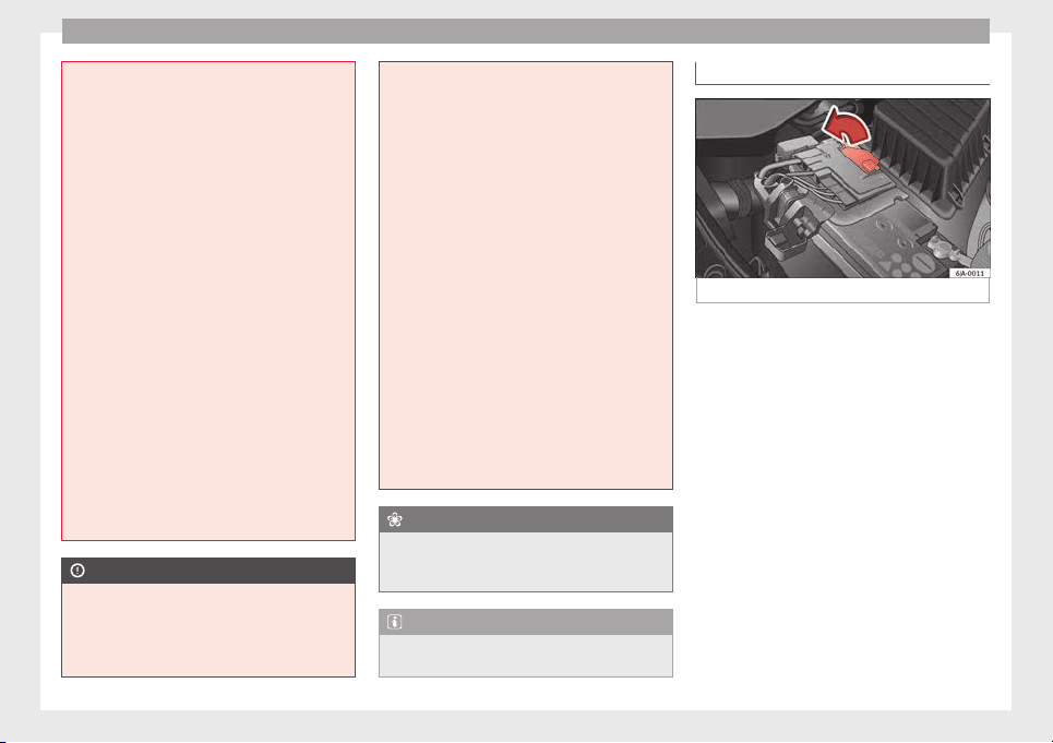
Advice
●
A short c
ircuit is produced if the battery ter-
minals are bridged, e.g. using metal objects,
cables, etc. Possible consequences of a short
circuit: melting of lead plates, battery explo-
sion and fire, splashing acid.
●
The following is forbidden while working on
the battery: fire and open flames, smoking
and activities that could produce sparks.
Avoid causing sparks when handling cables
or electrical apparatus. Risk of injury in the
event of large sparks.
●
Before working on the electrical system,
you must switch off the engine, the ignition
and all electrical components and disconnect
the cable from the negative terminal (-) of the
battery. To change a bulb, simply switch off
the corresponding light.
●
Never charge a frozen or thawed out bat-
tery. Risk of explosion and acid burns! Re-
place a frozen battery.
●
Never use the jump leads on batteries in
which the electrolyte level is too low. Risk of
explosion and acid burns!
●
Never use a damaged battery. Risk of ex-
plosion! Replace a damaged battery immedi-
ately.
CAUTION
●
Never dis
connect the battery when the igni-
tion is switched on, as the electrical system
(electronic components) of the vehicle could
be damaged. When disconnecting the battery
from the vehicle electrical system, disconnect
its negative terminal (-) first. Only then may
the positiv
e terminal (+) be disconnected.
●
When connecting the battery, first connect
the positive terminal (+) and then the nega-
tive terminal (-). The battery cables must nev-
er be connected to the wrong battery termi-
nals. Risk of burning the electrical installa-
tion!
●
Make sure the battery acid does not come
into contact with the bodywork. Risk of paint-
work damage.
●
Do not expose the battery to direct sunlight
to protect it from ultraviolet radiation.
●
If the vehicle is not used for 3 or 4 weeks,
the battery could run flat. This is because
some components use electricity even in
standby mode (e.g. control units). Prevent the
battery from running flat by disconnecting its
negative terminal or leave it charging at a low
current.
●
If you frequently use the vehicle for short
trips, the battery may not fully charge and
could run flat.
For the sake of the environment
A flat battery is particularly harmful waste for
the envir
onment. It must therefore be dis-
posed of according to current local law.
Note
Replace a battery once it is older than 5
year
s.
Lifting the battery cover
Fig. 211 Battery: Opening the cover.
The battery is located beneath a plastic cover
in the en
gine c
omp
artment.
–
Open the battery cover in the direction indi-
cated by the arrow ››› Fig. 211.
–
The positive terminal (+) of the battery is
connected in reverse order.
212
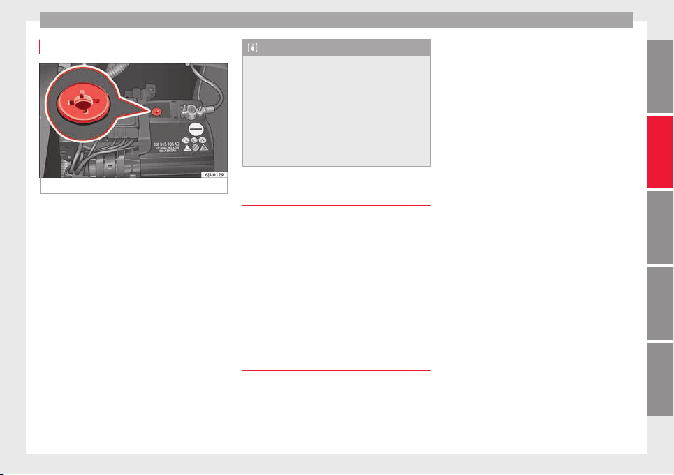
Checking and refilling levels
Checking the battery electrolyte level
Fig. 212 Battery: Electrolyte level indicator.
We recommend you have the acid level regu-
l
arly
c
hecked at an official technical service,
particularly in the following cases.
●
At high outside temperatures.
●
On long daily trips.
●
Whenever the vehicle is loaded
››› page 213, Charging the battery.
In vehicles equipped with a battery with col-
our indicator, the so-called magic eye
››› Fig. 212 changes colour to indicate the
acid level.
Air bubbles can influence the colour of the in-
dicator. Therefore, carefully knock the indica-
tor before checking the acid level.
●
Black – the acid level is correct.
●
Colourless or light yellow – acid level too
low, b
attery must be changed.
Note
●
The batter
y acid level is also regularly
checked during servicing at authorised SEAT
dealers.
●
The electrolyte level on “AGM” batteries
cannot be checked for technical reasons.
●
Vehicles equipped with the “Start-Stop”
system include a battery control unit to con-
trol the battery level for repeated engine
starting.
Winter service
At low temperatures the battery provides only
a fr
action of
the s
tarting power it has at nor-
mal temperatures.
A flat battery can also freeze at temperatures
slightly below to 0°C (32°F).
We therefore recommend you have the bat-
tery checked and, if necessary, charged at an
official SEAT technical service before the start
of winter.
Charging the battery
A fully-charged battery is essential for relia-
b
l
e s
tarting.
–
Switch off the ignition and all electrical
equipment.
–
For “fast-charging” only: disconnect both
battery connection cables (first the “nega-
tive” terminal and then the “positive”).
–
Connect the charger cables to the battery
terminals (red = “positive”, black = “nega-
tive”).
–
Plug in the battery charger and switch on.
–
After charging the battery: Switch off the
battery charger and disconnect the cable.
–
Remove the charger cables.
–
If necessary, reconnect both battery cables
to the battery (first the “positive” cable,
then the “negative” cable).
When charging with a low current (e.g. with a
small battery charger), the battery does not
normally have to be disconnected. The in-
structions of the battery charger manufactur-
er must be followed.
Use a current equivalent to or lower than
10% of the battery capacity to fully charge
the battery.
Before “fast-charging” the battery however,
both battery cables must be disconnected.
“Fast-charging” a battery is dangerous and
requires a battery charger and special knowl-
edge. Fast charges should be performed by
an official technical service.
The battery caps should not be opened while
the battery is being charged.
»
213
Technical dataAdviceOperationEmergenciesSafety
Advice
CAUTION
In vehicles fitted with the “Start-Stop” sys-
tem, the ch
arger cable cannot be directly con-
nected to the negative terminal of the vehicle
battery but must be attached to the engine
ground point ›››
page 52.
Disconnecting and connecting the
batter
y
The following functions will either be inoper-
ative or wi
ll not work properly after discon-
necting and reconnecting the battery:
Function Installation
Setting the clock ››› page 95
The multifunction display data
is deleted
››› page 97
Note
We recommend having the vehicle checked by
an authorised SEA
T dealer to guarantee the
correct working order of all electrical sys-
tems.
Replacing the battery
A replacement battery must have the same
c
ap
ac
ity, voltage, current rating and size as
the original. The appropriate types of battery
can be acquired from authorised SEAT deal-
ers.
We recommend having the battery changed
by an authorised SEAT dealer, where the new
battery will be correctly installed and the
original disposed of in line with regulations.
Automatic disconnection of electrical
equipment
When heavily-charging a battery, the pro-
gr
amme sel
ect
ed by the electrical system
control unit prevents the battery from auto-
matically discharging. This may result in the
following:
●
Increase in idling speed so that the alterna-
tor can supply more current to the electrical
system.
●
The performance of certain electrical com-
ponents could be limited or some may switch
off temporarily, e.g. the heated seats, the
heated rear window, the 12 V power socket.
Note
Despite any measures taken by the control
unit, the batt
ery could drain. e.g. with the en-
gine is switched off, the key is turned in the
ignition for a long period or the side lights or
parking lights are switched on. The switching
off of certain electrical components does not
impair driving comfort and often the driver
wil
l not even notice.
214
Wheels and tyres
Wheels and tyres
Wheel
s
Intr
oduction
WARNING
●
During the fir
st 500 km, new tyres do not
give maximum grip, therefore you should
drive carefully. Risk of accident!
●
Never drive with damaged tyres. Risk of ac-
cident!
●
Only use wheels and tyres that been au-
thorised by SEAT or your vehicle model. Fail-
ure to do so could impair road safety. Risk of
accident!
●
Never exceed the maximum speed permit-
ted for your tyres. Risk of accident due to tyre
damage and loss of vehicle control!
●
Under-inflated tyres are submitted to great-
er rolling resistance. This means that they
can overheat at high speeds. This can cause
tread separation and even tyre blow-out.
●
For driving safety, tyres should be replaced
at least in pairs according to the axle and not
individually. The tyres with the deepest tread
should always be used on the front wheels.
●
Never fit used tyres of an unknown age or
prior use.
●
Tyres must be immediately changed at the
very latest when they have worn down to the
tread wear indicators.
●
Worn tyr
es reduce the necessary grip at
high speeds on damp surfaces. This could
lead to “aquaplaning” (uncontrolled vehicle
movement – “skidding” on damp surfaces).
●
Damaged wheels and tyres must be re-
placed immediately.
●
Do not use summer or winter tyres that are
more than 6 or 4 years old respectively.
●
Wheel bolts should be clean and screw
easily. However, they must never be treated
with grease or oil.
●
If the tightening torque of the wheel bolts
is too low, they could loosen while the vehi-
cle is moving. Risk of accident! If the tighten-
ing torque of the wheel bolts is too high, the
bolts and threads could be damaged, leading
to the permanent deforming of the rim sup-
port surfaces.
●
Incorrectly handled wheel bolts could lead
to a wheel coming loose while the vehicle is
moving. Risk of accident!
●
Observe the national legal requirements re-
garding the use of snow tyres and chains.
CAUTION
●
Where a sp
are wheel that is not compatible
with the wheels fitted is used, follow the in-
structions ››› page 218.
●
The prescribed tightening torque for wheel
bolts on steel and alloy wheels is 120 Nm.
●
Protect your tyres from coming into contact
with oil, grease and fuel.
●
Replace any lost valve caps immediately.
For the sake of the environment
Under-inflated tyres increases fuel consump-
tion.
Note
●
We rec
ommend having all work on tyres
and wheels carried out by an authorised SEAT
dealer.
●
We recommend using wheels, tyres, hub
caps and snow chains from the SEAT Original
Accessories programme.
215
Technical dataAdviceOperationEmergenciesSafety
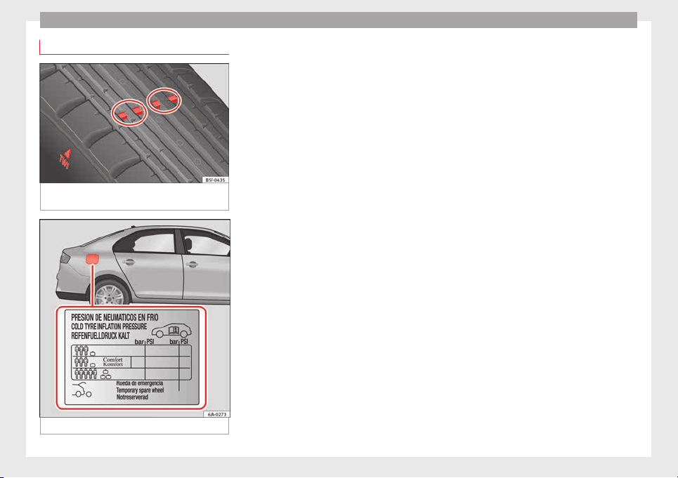
Advice
Useful life of tyres
Fig. 213 Side view of tyres with tread wear in-
dic
at
or
s.
Fig. 214 Location of the tyre pressure sticker.
Tread wear indicator
The b
a
se of
the side of the original tyres on
your vehicle show 1.6 mm high tread wear in-
dicators ››› Fig. 213. The position of these in-
dicators is given on the tyre sidewalls by the
letters “TWI”, triangular symbols or other
symbols.
The useful life of the tyres depends primarily
on the following factors:
Tyre pressure values
Under-inflation or over-inflation will consider-
ably reduce the useful life of the tyres and
impair the vehicle's handling. Therefore,
check the tyre pressure, including the spare
wheel, at least once a month and before any
long journey.
Inflation pressures for summer tyres are lis-
ted on a sticker inside the fuel tank flap
››› Fig. 214. The pressures for winter tyres are
0.2 bar (2.9 psi/20 kPa) above the summer
values.
Always check the pressure when the tyre is
cold. Do not reduce over-pressure in warm
tyres. The tyre pressures must be altered to
suit notable changes in the load being car-
ried.
Depending on the vehicle, tyre pressure can
be adjusted to medium load to improve driv-
ing comfort (“comfort” tyre pressure). When
driving with comfort tyre pressure fuel con-
sumption may increase slightly.
Driving style
Fast cornering, heavy acceleration and hard
braking all increase tyre wear.
Wheel balancing
The wheels on new vehicles are balanced.
Various factors encountered when driving
can cause them to become unbalanced,
which results in vibration of the steering
wheel.
The wheel must be rebalanced if a new tyre is
fitted or if a tyre is repaired.
Incorrect wheel alignment
Incorrect front or rear wheel alignment cau-
ses excessive tyre wear, frequently on one
side, and also impairs vehicle safety. If tyre
wear is very irregular, contact an Official
Service.
Tyre damage
To avoid damage to tyres and wheels, only
drive over kerbs or similar obstacles slowly
and at a right angle if possible.
Check tyres and wheels regularly for damage
(punctures, cracks, blisters, deformities,
etc.). Remove any foreign objects embedded
in outside of the treads.
216
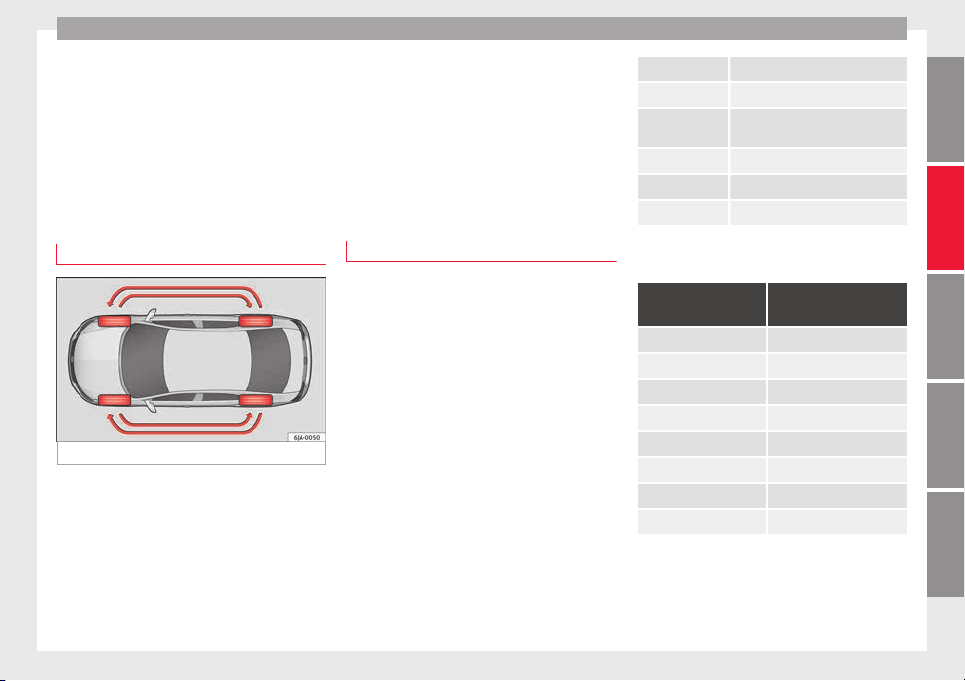
Wheels and tyres
Unusual vibration or the car pulling to one
s
ide m
a
y indicate that one of the tyres is
damaged. Reduce speed immediately and
stop if you suspect that a wheel may have
been damaged! Check the tyres for damage
(blisters, cracks, etc.). If no external damage
is visible, drive slowly and carefully to the
nearest Official Service and have the vehicle
inspected.
Changing wheels
Fig. 215 Interchanging tyres.
Changing wheels around
If
the w
e
ar is visibly greater on the front tyres,
they should be exchanged for the rear tyres
as shown in the diagram ››› Fig. 215. All the
tyres will then last for about the same time.
To ensure that the wear is equal on all tyres
and maintain their optimum useful life, they
should be changed around every 10 000 km.
Storing tyres
When you remove the tyres, mark them in or-
der to maintain the same direction of rotation
when they are installed again.
When removed, the wheels and/or tyres
should be stored in a cool, dry and preferably
dark location. Store tyres in a vertical posi-
tion, if they are not fitted on wheel rims.
New tyres or wheels
All four wheels must be fitted only with tyres
of
the s
ame type, s
ize and the same tread
pattern.
The correct tyre/wheel combinations speci-
fied for your vehicle are listed in its docu-
mentation.
Note for Italy: A SEAT Service Centre should
be consulted whether different sized wheels
or tyres to those originally fitted by SEAT may
be fitted, as well as the combinations al-
lowed between the front axle (axle 1) and
back axle (axle 2).
Understanding the tyre designations makes
it easier to choose the correct tyres. The tyre
designation is marked on the sidewall. For
example.
195/55 R 15 85 H
This contains the following information:
195 Tyre width in mm
55 Height/width ratio in %
R identifying tyre construction letter –
Radial
15 Rim diameter in inches
85 Load rating code
H Speed rating code letter
The tyres are subject to the following maxi-
mum s
peed limits:
Speed rating code
letter
Maximum speed limit
Q 160 km/h (99 mph)
R 170 km/h (106 mph)
S 180 km/h (112 mph)
T 190 km/h (118 mph)
U 200 km/h (124 mph)
H 210 km/h (130 mph)
V 240 km/h (149 mph)
W 270 km/h (168 mph)
The m
anufacturing date is also indicated on
the ty
r
e sidewall (possibly only on the inner
side of the wheel).
DOT … 27 12…
»
217
Technical dataAdviceOperationEmergenciesSafety
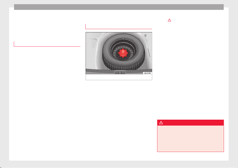
Advice
means, for example, that the tyre was pro-
duc
ed in the 27th w
eek
of 2012.
Follow the instructions ››› page 218 if you
only have a temporary spare wheel.
Tyres with directional tread pattern
The direction of rotation is indicated by the
arrow
s on the tyre sidewall. The direction of
rotation indicated must be respected. This
guarantees optimum grip and helps avoid ex-
cessive noise, wear and aquaplaning.
In the event of a flat tyre, a spare wheel with
an undetermined tread pattern or an oppo-
site tread pattern must be used and you must
drive carefully, as in these cases the tyres no
longer offer maximum performance.
Spare wheel
Spar
e wheel location*
Fig. 216 Luggage compartment: spare wheel.
The spare wheel is housed in a well under
the floor p
anel
in the lug
gage compartment
and is secured by a special bolt ››› Fig. 216.
Take out the tool box before removing the
spare wheel.
The tyre pressure of the spare wheel must be
checked (preferably whenever the tyre pres-
sure is checked – see sticker on fuel tank flap
››› page 216) to ensure the spare wheel re-
mains ready for use.
If the spare wheel is not the same size or de-
sign as the tyres that are mounted on the car
(for example if the car has winter tyres or
tyres with direction tread), only use the spare
tyre for a short period of time in the event of
breakdown and drive with the corresponding
care ›››
.
It
mu
s
t be replaced as soon as possible for a
wheel with a normal size and finish.
Temporary spare wheel
If the vehicle is equipped with a temporary
spare wheel, there will be a warning sign on
the rim of the wheel.
Follow the instructions below when driving
with this wheel fitted.
●
After fitting the wheel, the warning sign
must not be covered.
●
Do not drive faster than 80 km/h (50 mph)
with the spare wheel and take great care
while driving. Avoid heavy acceleration, hard
braking and fast cornering.
●
The tyre pressure is the same as that of the
standard tyres.
●
Only use this spare wheel to reach the
nearest Official Service, as it is not designed
for permanent use.
WARNING
●
Under no circ
umstances must damaged
spare wheels be used.
●
If the spare wheel is different in size or de-
sign to the tyres currently fitted, never drive
faster than 80 km/h (50 mph). Avoid heavy
acceleration, hard braking and fast cornering.
218
Wheels and tyres
CAUTION
Follow the instructions given on the tempora-
ry s
pare wheel label.
Note
The tyre pressure of the spare wheel must al-
way
s correspond to the highest pressure pre-
scribed for the model of vehicle in question.
Tyre monitoring systems
Tyr
e pressure*
The tyre pressure monitoring system uses
ABS
sen
sor
s to compare the revolutions and
the circumference of each wheel. Should the
circumference of any wheel change, the
warning lamp on the general dash panel
›››
page 103 will light up and an audible
warning will be heard.
Tyre circumference may change if:
●
Tyre pressure is too low
●
Tyre structure is damaged
●
Vehicle load not evenly distributed
●
wheels on one axle are subjected to greater
load, (e.g. driving with trailer, uphill, down-
hill);
●
Snow chains are fitted
●
The temporary spare wheel is fitted
●
One wheel on the axle has been changed
Basic system settings
Should the tyre pressure change or if one or
more wheels are changed or the position of
the wheel on the vehicle is changed, e.g.
changing round the front and rear wheels, or
where a warning lamp lights up when driv-
ing, the system must be adjusted as follows:
●
Inflate all tyres to the prescribed pressures
››› page 216.
●
Switch the ignition on.
●
Store the new tyre pressure in the Easy
Connect system with the button
and the
f
u
nction b
utton
Setup
›
›
›
p
age 20.
The warning lamp lights up
If the pressure on at least one tyre is signifi-
cantly lower than the pressure set by the driv-
er, the warning lamp will light up ›››
.
The w
arnin
g l
amp flashes
If the warning lamp flashes, there is a fault in
the system. Contact a specialised service to
have it fixed.
WARNING
●
If the warnin
g lamp lights up, slow down
immediately and avoid any severe braking or
steering manoeuvres. Stop and check the
tyres and their pressure as soon as possible.
●
Under cert
ain conditions (e.g. sporty driv-
ing style, driving on loose surfaces or in win-
ter) the warning lamp may take a while to
light up or may remain switched off.
●
Despite the tyre pressure monitoring sys-
tem, the driver remains responsible for main-
taining the correct tyre pressure. You must
therefore check the tyre pressure often.
Note
●
The ty
re pr
essure monitoring system is not
a replacement for regularly checking the tyre
pressure, as it is unable to recognise an even
drop in pressure.
●
The tyre pressure monitoring system is un-
able to warn of a sudden drop in tyre pres-
sure, e.g. a puncture. In this case, try to stop
the vehicle carefully with no severe braking
or steering manoeuvres.
●
To ensure the tyre pressure monitoring sys-
tem works correctly, the basic setting must
be performed every 10 000 km (6000 miles)
or once a year.
Winter service
W
int
er ty
res
Winter tyres will significantly improve han-
dlin
g of
the
vehicle in winter road conditions.
The design of summer tyres (width, rubber
compound, tread pattern) gives less grip at
»
219
Technical dataAdviceOperationEmergenciesSafety

Advice
temperatures below +7°C (45°F), on ice and
s
no
w
. This applies particularly to vehicles
equipped with wide section tyres or high
speed tyres (code letters H or V on the side-
wall).
In order to preserve the performance of the
vehicle as much as possible, winter tyres
must be fitted on all four wheels, the mini-
mum depth of the tread must be 4 mm and
the maximum age must be 4 years.
You can use winter tyres of a lower speed rat-
ing if the maximum speed limit of these tyres
will not be exceeded, even if the maximum
speed limit for the vehicle is higher.
For the sake of the environment
Summer tyres should be fitted again in time,
as they
give better handling on roads free of
snow and ice and at temperatures over +7°C
(45°F). Summer tyres have a shorter braking
distance, produce less rolling noise and do
not wear as quickly. They also reduce fuel
consumption.
220
Technical specifications
Technical data
T
ec
hnic
al specifications
Important information
Important
The information in the vehicle documentation
alway
s takes precedence over the informa-
tion in this Instruction Manual.
All technical specifications provided in this
documentation are valid for the standard
model in Spain. The vehicle data card inclu-
ded in the Maintenance Programme or the
vehicle registration documents shows which
engine is installed in the vehicle.
The figures may be different depending
whether additional equipment is fitted, for
different models, for special vehicles and for
other countries.
Abbreviations used in the Technical Specifi-
cations
section
kW Kilowatt, engine power measurement.
PS
Pferdestärke (horsepower), formerly
used to denote engine power.
rpm Revolutions per minute - engine speed.
Nm Newton metres, unit of engine torque.
litres per
100 km
Fuel consumption in litres per 100 km
(70 miles).
g/km
Carbon dioxide emissions in grams per
km (mile) travelled.
CO
2
Carbon dioxide
CN
Cetane number, indication of the diesel
combustion power.
RON
Research octane number, indication of
the knock resistance of petrol.
221
Technical dataAdviceOperationEmergenciesSafety
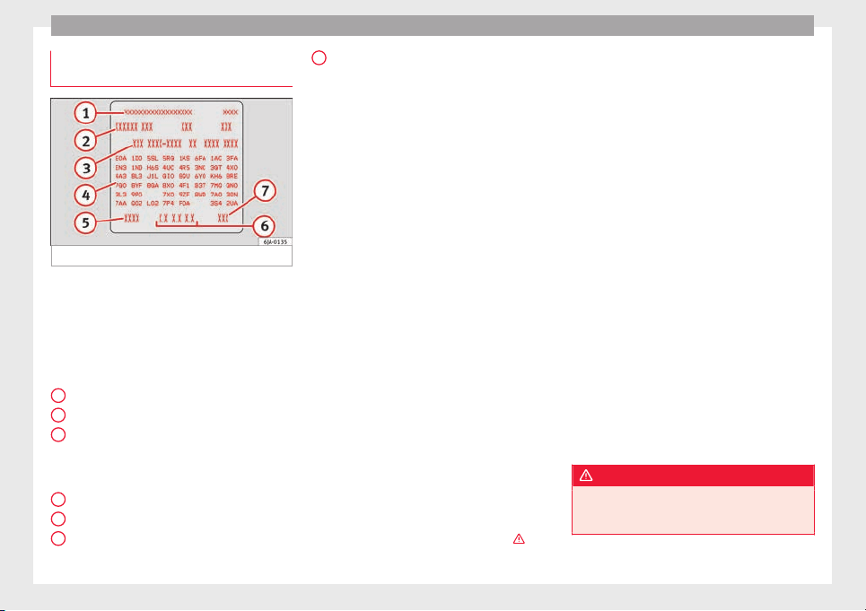
Technical data
Identification data contained on the
d
at
a s
ticker
Fig. 217 Data sticker.
Vehicle data sticker
The
v
ehic
le data sticker ››› Fig. 217 is located
on the boot floor and is also attached to the
Maintenance Programme.
The following information is provided on the
vehicle data sticker:
Vehicle identification number (VIN)
Vehicle model
Identifying letters of the gearbox/number
of the original paint finish/Interior equip-
ment number/engine power/engine
identifying letter
Partial description of the vehicle
Weight in running order
Fuel consumption (in litres per 100 km) –
urban/on the motorway/combined
1
2
3
4
5
6
Combined CO
2
emi
s
s
ions (g/km)
Type plate
The model plate is located at the bottom of
the front driver side door pillar between the
front and rear doors.
The type plate indicates the following
weights:
●
Total permitted weight of the vehicle when
loaded
●
Maximum authorised weight of the vehicle
with a trailer, when the vehicle operates as a
tractor
●
Maximum permitted load of the front axle
●
Maximum permitted load of the rear axle
Weight in running order
The weight in running order only has one ap-
proximate value. This value corresponds to
the minimum operative weight of the vehicle
without additional equipment that increases
its weight, i.e. air conditioning, spare wheel,
towing bracket.
The running order weight also includes 75 kg
of the weight of the driver and service fluids,
in addition to a fuel tank at 90% capacity.
From the difference between the total permit-
ted weight in running order the approximate
carrying capacity can be calculated ›››
.
7
The carrying capacity must include:
●
occupants,
●
all pieces of equipment and other weights,
●
roof loads including the roof rack,
●
equipment that is not included in the run-
nin
g or
der w
eight,
●
when using the towing bracket, the draw-
bar load (max. 50 kg)
Calculating fuel consumption and CO
2
emis-
sions according to the ECE regulations and
the EU specifications
Calculation of fuel consumption for urban
driving begins when cold-starting the engine.
Then, normal city driving is simulated.
In calculating extra-urban driving fuel con-
sumption, braking and acceleration is done
in all gears, as in daily use of the vehicle.
Driving speed varies within a range of 0 and
120 km/h (75 mph).
The consumption value in combined driving
is composed of 37% of the value of urban
driving and 63% of the value of extra-urban
driving.
WARNING
The maximum permitted weight values must
not be ex
ceeded – Risk of an accident and
damage to the vehicle!
222
Technical specifications
Note
●
If y
ou wish to calculate the exact weight of
your vehicle please contact a SEAT dealer.
●
Depending on the volume of equipment,
driving style, road conditions, weather condi-
tions and the condition of the vehicle, con-
sumption values can differ from the theoreti-
cal values stated here.
Information on fuel consump-
tion
Fuel c
onsumption
The consumption and emission details
sho
wn on the
v
ehicle data sticker differ from
one vehicle to another.
Vehicle fuel consumption and CO
2
emissions
appear on the vehicle data sticker in the
spare wheel well, inside the boot and on the
rear cover of the Maintenance Programme.
The fuel consumption and CO
2
emission val-
ues refer to the weight category assigned to
your vehicle according to the engine and
gearbox combination, as well as the specific
equipment fitted, and is only used to com-
pare between the different models.
The fuel consumption and CO
2
emissions do
not depend only on the performance of the
vehicle, they can also differ from the estab-
lished values depending on other factors
such as driving style, road conditions, traffic
conditions, environmental conditions, load
and number of passengers.
Calculation of fuel consumption
The consumption values have been calcula-
ted based on measurements performed or
supervised by certified CE laboratories ac-
cording to the latest version of directives
715/2007/EC and 80/1268/CEE (for more in-
formation consult the European Union Publi-
cations Office at EUR-Lex: © European Union,
http://eur-lex.europa.eu/en/index.htm) and
are valid for the kerb weight indicated for the
vehicle.
Note
In practice, and considering all the factors
mentioned here, con
sumption values can dif-
fer from those calculated in the current Euro-
pean regulations.
Weights
Kerb weight refers to the basic model with a
f
uel
t
ank filled to 90% capacity and without
optional extras. The figure quoted includes
75 kg to allow for the weight of the driver.
Special versions, optional equipment fittings
or retro-fitting accessories will increase the
weight of the vehicle
›››
.
WARNING
●
Plea
se note that the centre of gravity may
shift when transporting heavy objects; this
may affect vehicle handling and lead to an ac-
cident. Always adjust your speed and driving
style to suit road conditions and require-
ments.
●
Never exceed the gross axle weight rating
or the gross vehicle weight rating. If the per-
missible axle load or the permissible total
weight is exceeded, the driving characteris-
tics of the vehicle may change, which could
lead to accidents, injuries and damage to the
vehicle.
Driving with a trailer
T
r
ai
ler weights
Trailer weight
The tr
ai
l
er weights and drawbar loads ap-
proved are selected in intensive trials accord-
ing to precisely defined criteria. The ap-
proved trailer weights are valid for vehicles in
the EU for maximum speeds of 80 km/h (50
mph) (in certain circumstances up to 100
km/h (62 mph)). The figures may be different
in other countries. All data in the official vehi-
cle documentation takes precedence over
these data at all times
›››
.
»
223
Technical dataAdviceOperationEmergenciesSafety
Technical data
Drawbar loads
The maximum permitt
ed dr
a
wbar load on the
ball joint of the towing bracket must not ex-
ceed 50 kg.
In the interest of road safety, we recommend
that you always tow approaching the maxi-
mum drawbar load. The response of the trail-
er on the road will be poor, if the drawbar
load is too small.
If the maximum permissible drawbar load
cannot be met (e.g. with small, empty and
light-weight single axle trailers or tandem
axle trailers with a wheelbase of less than 1
metre), a minimum of 4% of the actual trailer
weight is legally required for the drawbar
load.
WARNING
●
For saf
ety reasons, do not exceed the 80
km/h (50 mph) limit. This is also valid in
countries where higher speeds are permitted.
●
Never exceed the maximum trailer weights
or the drawbar load. If the permissible axle
load or the permissible total weight is excee-
ded, the driving characteristics of the vehicle
may change, leading to accidents, injuries
and damage to the vehicle.
Wheels
T
y
r
e pressure, snow chains, wheel
bolts
Tyre pressures
The stick
er with the tyre pressure values can
be found on the inside of the fuel tank flap.
The tyre pressure values given there are for
cold tyres. Do not reduce the slightly raised
pressures of warm tyres ›››
.
The pres
sure for winter tyres is 0.2 bar
(2.9 psi / 20 kPa) higher than that of summer
tyres.
Snow chains
Snow chains may be fitted only to the front
wheels.
Consult the section “wheels” of this manual.
Wheel bolts
After the wheels have been changed, the
tightening torque of the wheel bolts should
be checked as soon as possible with a torque
wrench
›››
. The tightening torque for steel
and al
lo
y
wheels is 120 Nm.
WARNING
●
Check the ty
re pressure at least once per
month. Checking the tyre pressure is very im-
portant. If the tyre pressure is too high or too
low, there is an increased danger of accidents
- partic
ularly at high speeds.
●
If the tightening torque of the wheel bolts
is too low, they could loosen while the vehi-
cle is in motion. Risk of accident! If the tight-
ening torque is too high, the wheel bolts and
threads can be damaged.
Note
We recommend that you ask your Technical
Ser
vic
e for information about appropriate
wheel, tyre and snow chain size.
224
Technical specifications
Engine data
P
etr
o
l engine 1.2 TSI 66 kW (90 PS)
Power output in kW (PS) at rpm Maximum torque (Nm at rpm) No. of cylinders/displacement (cm
3
) Fuel
66 (90)/4,400-5,400 160/1,400-3,500 4/1,197 Super 95 RON/Normal 91 RON
a)
a)
Slight power loss.
Performance Ecomotive
Top speed (km/h) 186 (5) 186 (5)
Acceleration from 0-80 km/h (seconds) 7.3 7.3
Acceleration from 0-100 km/h (seconds) 11.3 11.3
Weights (in kg)
Gross vehicle weight 1,616 1,625
Weight in running order (with driver) 1,156 1,165
Gross front axle weight 820 820
Gross rear axle weight 830 830
Permitted roof load 75 75
Maximum trailer weights (in kg)
Trailer without brakes 580 580
Trailer with brakes, gradients up to 8% 1,100 1,100
Trailer with brakes, gradients up to 12% 900 900
225
Technical dataAdviceOperationEmergenciesSafety

Technical data
Petrol engine 1.2 TSI 81 kW (110 PS)
Power output in kW (PS) at rpm Maximum torque (Nm at rpm) No. of cylinders/displacement (cm
3
) Fuel
81 (110)/4,600-5,600 175/1,400-4,000 4/1,197 Super 95 RON/Normal 91 RON
a)
a)
Slight power loss.
Performance
manual
manual
Ecomotive
Top speed (km/h) 200 (5) 200 (5)
Acceleration from 0-80 km/h (seconds) 6.5 6.5
Acceleration from 0-100 km/h (seconds) 9.8 8.9
Weights (in kg)
Gross vehicle weight 1,636 1,645
Weight in running order (with driver) 1,176 1,185
Gross front axle weight 840 840
Gross rear axle weight 830 830
Permitted roof load 75 75
Maximum trailer weights (in kg)
Trailer without brakes 590 590
Trailer with brakes, gradients up to 8% 1,200 1,200
Trailer with brakes, gradients up to 12% 1,100 1,100
226

Technical specifications
Petrol engine 1.6 81 kW (110 PS)
Power output in kW (PS) at rpm Maximum torque (Nm at rpm) No. of cylinders/displacement (cm
3
) Fuel
81 (110)/5,800 155/3,800-4,000 4/1,598 Super 95 RON/Normal 91 RON
a)
a)
Slight power loss.
Performance manual automatic
Top speed (km/h) 191 (5) 191 (6)
Acceleration from 0-80 km/h (seconds) 6.7 7.7
Acceleration from 0-100 km/h (seconds) 10.3 11.5
Weights (in kg)
Gross vehicle weight 1,625 1,665
Weight in running order (with driver) 1,165 1,205
Gross front axle weight 820 860
Gross rear axle weight 840 840
Permitted roof load 75 75
Maximum trailer weights (in kg)
Trailer without brakes 580 600
Trailer with brakes, gradients up to 8% 1,200 1,200
Trailer with brakes, gradients up to 12% 1,000 1,000
227
Technical dataAdviceOperationEmergenciesSafety

Technical data
Petrol engine 1.4 TSI 92 kW (125 PS)
Power output in kW (PS) at rpm Maximum torque (Nm at rpm) No. of cylinders/displacement (cm
3
) Fuel
92 (125)/5,000-6,000 200/1,400-4,000 4/1,395 Super 95 RON/Normal 91 RON
a)
a)
Slight power loss.
Performance Ecomotive
Top speed (km/h) 208 (6) 208 (6)
Acceleration from 0-80 km/h (seconds) 6.3 6.4
Acceleration from 0-100 km/h (seconds) 9 9
Weights (in kg)
Gross vehicle weight 1,677 1,686
Weight in running order (with driver) 1,217 1,226
Gross front axle weight 880 880
Gross rear axle weight 830 830
Permitted roof load 75 75
Maximum trailer weights (in kg)
Trailer without brakes 600 600
Trailer with brakes, gradients up to 8% 1,200 1,200
Trailer with brakes, gradients up to 12% 1,200 1,200
228

Technical specifications
Diesel Engine 1.4 CR 66 kW (90 PS)
Power output in kW (PS) at rpm Maximum torque (Nm at rpm) No. of cylinders/displacement (cm
3
) Fuel
66 (90)/3,500 230/1,750-2,500 4/1,422
Diesel according to standard EN 590, min.
51 CZ
Performance manual manual
Ecomotive
automatic
Ecomotive
Top speed (km/h) 185 (5) 185 (5) 185 (7)
Acceleration from 0-80 km/h (seconds) 8 8 8.2
Acceleration from 0-100 km/h (seconds) 11.7 11.7 11.8
Weights (in kg)
Gross vehicle weight 1,689 1,694 1,715
Weight in running order (with driver) 1,229 1,234 1,255
Gross front axle weight 890 890 910
Gross rear axle weight 840 840 840
Permitted roof load 75 75 75
Maximum trailer weights (in kg)
Trailer without brakes 610 610 620
Trailer with brakes, gradients up to 8% 1,200 1,200 1,200
Trailer with brakes, gradients up to 12% 1,200 1,200 1,200
229
Technical dataAdviceOperationEmergenciesSafety

Technical data
Diesel Engine 1.6 CR 85 kW (115 PS)
Power output in kW (PS) at rpm Maximum torque (Nm at rpm) No. of cylinders/displacement (cm
3
) Fuel
85 (115)/3,500-4,000 250/1,500-3,000 4/1,598
Diesel according to standard EN 590, min.
51 CZ
Performance Ecomotive
Top speed (km/h) 201 (5) 201 (5)
Acceleration from 0-80 km/h (seconds) 6.9 6.9
Acceleration from 0-100 km/h (seconds) 10 10
Weights (in kg)
Gross vehicle weight 1,747 1,752
Weight in running order (with driver) 1,287 1,292
Gross front axle weight 910 910
Gross rear axle weight 870 870
Permitted roof load 75 75
Maximum trailer weights (in kg)
Trailer without brakes 640 640
Trailer with brakes, gradients up to 8% 1,200 1,200
Trailer with brakes, gradients up to 12% 1,200 1,200
230
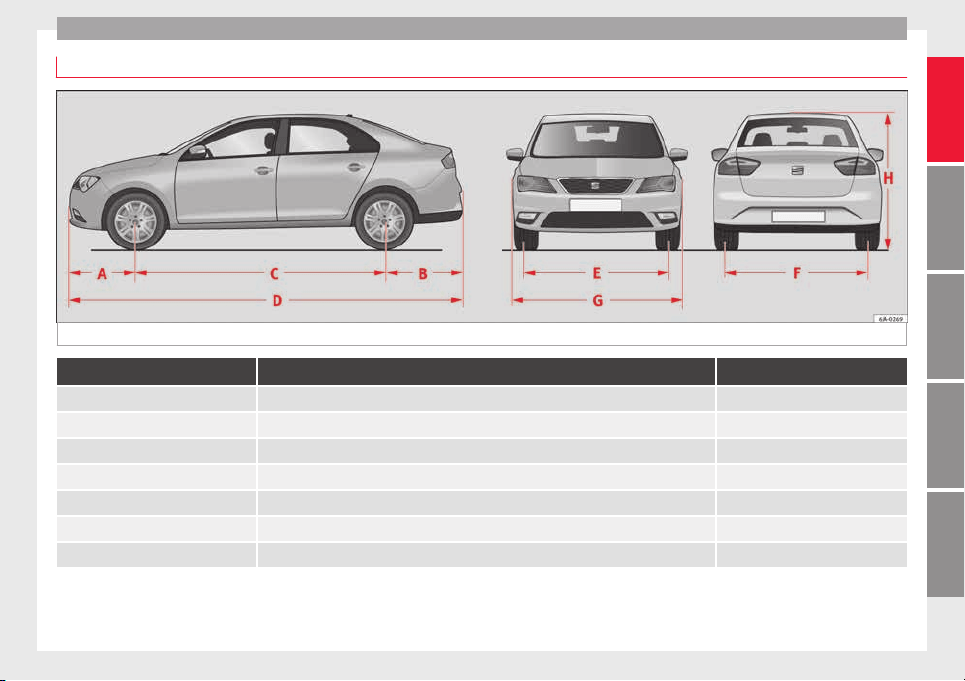
Technical specifications
Dimensions
Fig. 218 Dimensions
TOLEDO
A/B Front and rear projection (mm) 876/1,004
C Wheelbase (mm) 2,602
D Length (mm) 4,482
E/F Front/rear
a)
track width (mm) 1,463/1,500
G Width (mm) 1,715
H Height at kerb weight (mm) 1,466
Turning radius (m) 10.2
a)
This data will change depending on the type of wheel rim.
231
Technical dataAdviceOperationEmergenciesSafety


Index
Index
A
ABS
c
ontr
o
l lamp . . . . . . . . . . . . . . . . . . . . . . . . . . . 101
see also Anti-lock brake system . . 100, 167, 168
Accessories . . . . . . . . . . . . . . . . . . . . . . . . . 138, 193
Additional electrical appliances (efficiency pro-
gramme) . . . . . . . . . . . . . . . . . . . . . . . . . . . . . . . 28
Adjustment
CAR menu . . . . . . . . . . . . . . . . . . . . . . . . . . . . . 104
front head restraints . . . . . . . . . . . . . . . . . 59, 132
lights . . . . . . . . . . . . . . . . . . . . . . . . . . . . . . . . . 122
rear head restraints . . . . . . . . . . . . . . . . . . . . . . 59
seats . . . . . . . . . . . . . . . . . . . . . . . . . . . . . . . . . . 56
Aerial . . . . . . . . . . . . . . . . . . . . . . . . . . . . . . . . . . . 195
Air-conditioning
economic use . . . . . . . . . . . . . . . . . . . . . . . . . . 147
Airbag covers . . . . . . . . . . . . . . . . . . . . . . . . . . . . . 13
Airbag system . . . . . . . . . . . . . . . . . . . . . . . . . . 13, 66
activation . . . . . . . . . . . . . . . . . . . . . . . . . . . . . . 68
control lamp . . . . . . . . . . . . . . . . . . . . . . . . . . . 103
deactivation of front airbag . . . . . . . . . . . . . 68, 71
description . . . . . . . . . . . . . . . . . . . . . . . . . . . . . 67
front airbags . . . . . . . . . . . . . . . . . . . . . . . . . 13, 69
functioning . . . . . . . . . . . . . . . . . . . . . . . . . . . . . 68
head-protection airbags . . . . . . . . . . . . . . . . . . 15
Side airbags . . . . . . . . . . . . . . . . . . . . . . . . . . . . 15
Air conditioning . . . . . . . . . . . . . . . . . . . . . . . . 36, 37
air vents . . . . . . . . . . . . . . . . . . . . . . . . . . . . . . 147
faults . . . . . . . . . . . . . . . . . . . . . . . . . . . . . . . . . 147
introduction . . . . . . . . . . . . . . . . . . . . . . . . . . . 146
operation . . . . . . . . . . . . . . . . . . . . . . . . . . . . . . 149
Alarm system . . . . . . . . . . . . . . . . . . . . . . . . . . . . 117
Alternator
control lamp . . . . . . . . . . . . . . . . . . . . . . . . . . . . 99
Ambient lighting . . . . . . . . . . . . . . . . . . . . . . . . . 127
Anti-freeze . . . . . . . . . . . . . . . . . . . . . . . . . . . . . . . 40
Anti-lock brake system . . . . . . . . . . . . . . . . . . . . . 100
Anti-lock system . . . . . . . . . . . . . . . . . . . . . 167, 168
Anti-puncture kit . . . . . . . . . . . . . . . . . . . . . . . . 45, 76
Check after 10 minutes . . . . . . . . . . . . . . . . . . . 78
Anti-theft alarm . . . . . . . . . . . . . . . . . . . . . . . . . . 117
Anti-theft system . . . . . . . . . . . . . . . . . . . . . . . 9, 113
Armrest
front seats . . . . . . . . . . . . . . . . . . . . . . . . . . . . . 133
rear seats . . . . . . . . . . . . . . . . . . . . . . . . . . . . . 134
Ashtrays . . . . . . . . . . . . . . . . . . . . . . . . . . . . . . . . 138
Aspects to take into account before starting the
vehicle . . . . . . . . . . . . . . . . . . . . . . . . . . . . . . . . . 55
ASR
control lamp . . . . . . . . . . . . . . . . . . . . . . . . . . . 101
see also Traction control system . . 100, 167, 168
Assistance systems
ABS . . . . . . . . . . . . . . . . . . . . . . . . . . . . . 101, 168
ASR . . . . . . . . . . . . . . . . . . . . . . . . . . . . . . . . . . 168
cruise speed . . . . . . . . . . . . . . . . . . . . . . . . . . . 176
EDS . . . . . . . . . . . . . . . . . . . . . . . . . . . . . . . . . . 168
front assist monitoring system . . . . . . . . . . . . 177
parking aid . . . . . . . . . . . . . . . . . . . . . . . 168, 169
Start-Stop . . . . . . . . . . . . . . . . . . . . . . . . . . . . . 182
tiredness detection . . . . . . . . . . . . . . . . . . . . . 184
Tyre monitoring systems . . . . . . . . . . . . . . . . . 219
Assisted starting . . . . . . . . . . . . . . . . . . . . . . . . . . 51
Assist systems
ASR . . . . . . . . . . . . . . . . . . . . . . . . . . . . . . . . . . 101
Audible signal . . . . . . . . . . . . . . . . . . . . . . . . . . . . 61
Audible warning signal
warning and indication lamps . . . . . . . . . . . . . . 98
Automatic air conditioning
climatronic . . . . . . . . . . . . . . . . . . . . . . . . . . . . 151
Automatic car washes
see Washing . . . . . . . . . . . . . . . . . . . . . . . . . . . 195
Automatic gearbox
backup programme . . . . . . . . . . . . . . . . . . . . . 162
driving programmes . . . . . . . . . . . . . . . . . . . . . 162
instructions for use . . . . . . . . . . . . . . . . . . . . . 158
kick-down . . . . . . . . . . . . . . . . . . . . . . . . . . . . . 159
manual release of selector lever . . . . . . . . . . . . 35
parking . . . . . . . . . . . . . . . . . . . . . . . . . . . . . . . 159
selector lever lock . . . . . . . . . . . . . . . . . . . . . . . 161
selector lever positions . . . . . . . . . . . . . . . . . . 160
starting . . . . . . . . . . . . . . . . . . . . . . . . . . . . . . . 159
stopping . . . . . . . . . . . . . . . . . . . . . . . . . . . . . . 159
tiptronic . . . . . . . . . . . . . . . . . . . . . . . . . . 158, 161
AUX-IN . . . . . . . . . . . . . . . . . . . . . . . . . . . . . . . . . . 109
B
Back seat
folding down and raising the back seat back-
rest . . . . . . . . . . . . . . . . . . . . . . . . . . . . . . . . . 134
Ball coupling
disassembly . . . . . . . . . . . . . . . . . . . . . . . . . . . 191
Battery . . . . . . . . . . . . . . . . . . . . . . . . . . . . . . . . . . 111
Before starting the vehicle . . . . . . . . . . . . . . . . . . 55
Belt tightening . . . . . . . . . . . . . . . . . . . . . . . . . . . . 65
Biodiesel . . . . . . . . . . . . . . . . . . . . . . . . . . . . . . . . 202
Blown bulbs
changing a bulb . . . . . . . . . . . . . . . . . . . . . . . . . 83
Bonnet . . . . . . . . . . . . . . . . . . . . . . . . . . . . . 11, 206
opening the bonnet . . . . . . . . . . . . . . . . . . . . . 205
Boot
hook . . . . . . . . . . . . . . . . . . . . . . . . . . . . . . . . . 143
retaining elements . . . . . . . . . . . . . . . . . . . . . . 143
retaining nets . . . . . . . . . . . . . . . . . . . . . . . . . . 143
Brake assist . . . . . . . . . . . . . . . . . . . . . . . . 100, 167
Brake fluid . . . . . . . . . . . . . . . . . . . . . . . . . . . . . . . 41
checking . . . . . . . . . . . . . . . . . . . . . . . . . . . . . . 209
233

Index
Brakes
br
ak
e fluid
. . . . . . . . . . . . . . . . . . . . . . . . . . . . . 209
control lamp . . . . . . . . . . . . . . . . . . . . . . . . . . . . 99
handbrake . . . . . . . . . . . . . . . . . . . . . . . . . . . . . 158
running in . . . . . . . . . . . . . . . . . . . . . . . . . . . . . 163
Brake servo . . . . . . . . . . . . . . . . . . . . . . . . . . . . . . 157
Braking
brake assist . . . . . . . . . . . . . . . . . . . . . . . 100, 167
Bulb fault
control lamp . . . . . . . . . . . . . . . . . . . . . . . . . . . 101
C
Capacities . . . . . . . . . . . . . . . . . . . . . . . . . . . . . . . . 39
Car-care products . . . . . . . . . . . . . . . . . . . . . . . . . 194
Care of vehicle
door lock cylinder . . . . . . . . . . . . . . . . . . . . . . . 197
leatherette . . . . . . . . . . . . . . . . . . . . . . . . . . . . . 198
natural leather . . . . . . . . . . . . . . . . . . . . . . . . . 199
seat belts . . . . . . . . . . . . . . . . . . . . . . . . . . . . . 199
upholstery . . . . . . . . . . . . . . . . . . . . . . . . . . . . . 198
washing by hand . . . . . . . . . . . . . . . . . . . . . . . 195
Carrier system . . . . . . . . . . . . . . . . . . . . . . . . . . . . 145
Catalytic converter . . . . . . . . . . . . . . . . . . . . . . . . 164
CCS . . . . . . . . . . . . . . . . . . . . . . . . . . . . . . . . . . . . . 31
Central locking . . . . . . . . . . . . . . . . . . . . . . 109, 112
anti-theft alarm . . . . . . . . . . . . . . . . . . . . . . . . . 117
central locking switch . . . . . . . . . . . . . . . . . . . . 114
closing . . . . . . . . . . . . . . . . . . . . . . . . . . . . . . . . 113
individualised settings . . . . . . . . . . . . . . . . . . 112
keyless Access . . . . . . . . . . . . . . . . . . . . . . . . . 115
locking . . . . . . . . . . . . . . . . . . . . . . . . . . . . . . . . 113
locking manually . . . . . . . . . . . . . . . . . . . . . . . . 10
opening . . . . . . . . . . . . . . . . . . . . . . . . . . . . . . . 113
unlocking . . . . . . . . . . . . . . . . . . . . . . . . . . . . . 113
Cetane number (Diesel fuel) . . . . . . . . . . . . . . . . 202
Changing a wheel . . . . . . . . . . . . . . . . . . . . . . 46, 75
subsequent work . . . . . . . . . . . . . . . . . . . . . . . . 49
Changing bulbs . . . . . . . . . . . . . . . . . . . . . . . . . . . 83
daytime driving light . . . . . . . . . . . . . . . . . . . . . 86
dipped beam . . . . . . . . . . . . . . . . . . . . . . . . . . . 85
double headlight bulbs . . . . . . . . . . . . . . . . . . . 84
main beam headlight . . . . . . . . . . . . . . . . . . . . . 85
side light . . . . . . . . . . . . . . . . . . . . . . . . . . . . . . . 85
turn signal . . . . . . . . . . . . . . . . . . . . . . . . . . . . . . 86
Changing bulbs on the number plate . . . . . . . . . . 91
removing the bulb holder . . . . . . . . . . . . . . . . . 91
Changing bulbs on the side panel . . . . . . . . . . . . 88
fitting the rear light . . . . . . . . . . . . . . . . . . . . . . 89
removing the bulb holder . . . . . . . . . . . . . . . . . 88
removing the rear light . . . . . . . . . . . . . . . . . . . . 87
Changing lights on the side panel . . . . . . . . . . . . 87
Changing oil . . . . . . . . . . . . . . . . . . . . . . . . . . . . . 208
Changing rear lights on the rear lid
changing bulbs . . . . . . . . . . . . . . . . . . . . . . . . . . 90
fitting the bulb-holder . . . . . . . . . . . . . . . . . . . . 90
removing the bulb holder . . . . . . . . . . . . . . . . . 89
Changing settings
CAR menu . . . . . . . . . . . . . . . . . . . . . . . . . . . . . . 20
Changing tail lights on the rear lid . . . . . . . . . . . . 89
Changing the bulbs
fog light . . . . . . . . . . . . . . . . . . . . . . . . . . . . . . . . 86
Charging the battery . . . . . . . . . . . . . . . . . . . . . . . 51
Checking levels
engine compartment . . . . . . . . . . . . . . . . . . . . 206
Child-proof locking . . . . . . . . . . . . . . . . . . . . . . . . 117
electric windows . . . . . . . . . . . . . . . . . . . . . . . . 120
Child seats . . . . . . . . . . . . . . . . . . . . . . . . . . . . 16, 74
Categorisation in groups . . . . . . . . . . . . . . . . . . 74
ISOFIX system . . . . . . . . . . . . . . . . . . . . . . . . . . . 17
safety instructions . . . . . . . . . . . . . . . . . . . . 16, 73
securing with the seat belt . . . . . . . . . . . . . . . . 16
Top Tether system . . . . . . . . . . . . . . . . . . . . . . . . 17
Cigarette lighter . . . . . . . . . . . . . . . . . . . . . . . . . . 137
City Emergency braking function . . . . . . . . . . . . . 181
Cleaning . . . . . . . . . . . . . . . . . . . . . . . . . . . . . . . . 194
chromed parts . . . . . . . . . . . . . . . . . . . . . . . . . 196
headlights . . . . . . . . . . . . . . . . . . . . . . . . . . . . . 197
leatherette . . . . . . . . . . . . . . . . . . . . . . . . . . . . . 198
natural leather . . . . . . . . . . . . . . . . . . . . . . . . . 199
plastic parts . . . . . . . . . . . . . . . . . . . . . . . . . . . 197
upholstery . . . . . . . . . . . . . . . . . . . . . . . . . . . . . 198
washing the vehicle . . . . . . . . . . . . . . . . . . . . . 195
wheels . . . . . . . . . . . . . . . . . . . . . . . . . . . . . . . . 197
windows . . . . . . . . . . . . . . . . . . . . . . . . . . . . . . 197
Cleaning and thawing windows . . . . . . . . . . . . . 197
Climatronic . . . . . . . . . . . . . . . . . . . . . . . . . . . . . . . 36
adjusting the temperature . . . . . . . . . . . . . . . . 152
air recirculation . . . . . . . . . . . . . . . . . . . . . . . . . 152
automatic mode . . . . . . . . . . . . . . . . . . . . . . . . 152
blower selection . . . . . . . . . . . . . . . . . . . . . . . . 152
windscreen defrost . . . . . . . . . . . . . . . . . . . . . . 153
Closing . . . . . . . . . . . . . . . . . . . . . . . . . . . . . . . . . 109
central locking . . . . . . . . . . . . . . . . . . . . . . . . . 113
vehicle with Keyless Access . . . . . . . . . . . . . . . 115
windows . . . . . . . . . . . . . . . . . . . . . . . . . . . . . . 120
Coat hooks . . . . . . . . . . . . . . . . . . . . . . . . . . . . . . 139
Coming Home and Leaving Home . . . . . . . . . . . . 125
Controls and displays
General instrument panel . . . . . . . . . . . . . . . . . 93
Controls on the steering wheel
Operating the audio system . . . . . . . . . . . . . . 106
operating the audio system and telephone . . 107
Cooling system
Checking coolant . . . . . . . . . . . . . . . . . . . . . . . 208
engine coolant temperature display . . . . . . . . . 97
topping up coolant . . . . . . . . . . . . . . . . . . . . . . 208
Correct position . . . . . . . . . . . . . . . . . . . . . . . . . . . 56
Correct sitting position
front passenger . . . . . . . . . . . . . . . . . . . . . . . . . 57
rear seat passengers . . . . . . . . . . . . . . . . . . . . . 58
234

Index
Cruise control . . . . . . . . . . . . . . . . . . . . . . . . 31, 176
a
dju
s
ting the programmed speed . . . . . . . . . . 177
setting the speed . . . . . . . . . . . . . . . . . . . . . . . 176
temporary deactivation . . . . . . . . . . . . . . . . . . 177
turning off the cruise control system . . . . . . . 177
Cruise speed
control lamp . . . . . . . . . . . . . . . . . . . . . . . . . . . 104
D
Damage to the vehicle . . . . . . . . . . . . . . . . . . . . . 167
Dash panel . . . . . . . . . . . . . . . . . . . . . . . . . . . . . . . 32
Data sticker . . . . . . . . . . . . . . . . . . . . . . . . . . . . . . 221
Deactivating the front passenger front airbag . . . 14
Deactivation of front airbag . . . . . . . . . . . . . . . 68, 71
Defrosting rear window . . . . . . . . . . . . . . . . . . . . 128
Diesel
engine oil . . . . . . . . . . . . . . . . . . . . . . . . . . . . . 206
Preheating . . . . . . . . . . . . . . . . . . . . . . . . . . . . . 153
refuelling . . . . . . . . . . . . . . . . . . . . . . . . . . . . . . 202
Digital clock . . . . . . . . . . . . . . . . . . . . . . . . . . . . . . 94
Dimensions . . . . . . . . . . . . . . . . . . . . . . . . . . . . . . 231
Direction of rotation
tyres . . . . . . . . . . . . . . . . . . . . . . . . . . . . . . . . . . . 49
Display . . . . . . . . . . . . . . . . . . . . . . . . . . . . . . . 94, 95
Disposal
Seat belt tensioners . . . . . . . . . . . . . . . . . . . . . . 66
Door cylinder . . . . . . . . . . . . . . . . . . . . . . . . . . . . . . 9
Door handle . . . . . . . . . . . . . . . . . . . . . . . . . . . . . . . 9
Door lock . . . . . . . . . . . . . . . . . . . . . . . . . . . . . . . . . . 9
Door open
warning lamp . . . . . . . . . . . . . . . . . . . . . . . . . . . 99
Doors
Child-proof locking . . . . . . . . . . . . . . . . . . . . . . 117
opening and closing . . . . . . . . . . . . . . . . . . . . . . 9
Drink holder
centre console . . . . . . . . . . . . . . . . . . . . . . . . . 136
rear seat armrest . . . . . . . . . . . . . . . . . . . . . . . 137
Driver
see Correct sitting position . . . . . . . . . 56, 57, 58
Driver information system
CD/radio indication . . . . . . . . . . . . . . . . . . . . . . 22
engine oil temperature display . . . . . . . . . . . . . 27
operation with the windscreen wiper lever . . . . 22
Driving abroad
headlights . . . . . . . . . . . . . . . . . . . . . . . . . . . . . 126
Driving through water . . . . . . . . . . . . . . . . . . . . . 166
Driving with a trailer . . . . . . . . . . . . . . . . . . 185, 223
Dynamic headlight range control . . . . . . . . . . . . 122
E
E10
see Ethanol (fuel) . . . . . . . . . . . . . . . . . . . . . . . 201
Easy Connect . . . . . . . . . . . . . . . . . . . . . . . . 20, 104
Economical
driving . . . . . . . . . . . . . . . . . . . . . . . . . . . . . . . . 164
EDL
see Electronic differential lock . . . . 100, 167, 168
Efficiency programme
additional electrical appliances . . . . . . . . . . . . 28
saving tips . . . . . . . . . . . . . . . . . . . . . . . . . . . . . . 28
Electric windows . . . . . . . . . . . . . . . . . . . . . . 11, 120
Electronic differential lock . . . . . . . . . . . . . 100, 168
Electronic immobiliser . . . . . . . . . . . . . . . . . . . 9, 154
Electronic Stability Control (ESC) . . . . . . . . . . . . 100
Emergencies . . . . . . . . . . . . . . . . . . . . . . . . . . . . . . 75
automatic gearbox backup programme . . . . . 162
bulbs . . . . . . . . . . . . . . . . . . . . . . . . . . . . . . . . . . 44
changing a wheel . . . . . . . . . . . . . . . . . . . . . 46, 75
emergency towing of the vehicle . . . . . . . . . . . . 50
Front passenger door . . . . . . . . . . . . . . . . . . . . . 10
fuses . . . . . . . . . . . . . . . . . . . . . . . . . . . . . . . . . . 43
hazard warning lights . . . . . . . . . . . . . . . . . . . 126
Jump leads . . . . . . . . . . . . . . . . . . . . . . . . . . . . . 51
puncture . . . . . . . . . . . . . . . . . . . . . . . . . . . . . . . 44
replacing a blown fuse . . . . . . . . . . . . . . . . . . . . 43
selector lever . . . . . . . . . . . . . . . . . . . . . . . . . . . 35
Emission control system
control lamp . . . . . . . . . . . . . . . . . . . . . . . . . . . 101
Emissions data . . . . . . . . . . . . . . . . . . . . . . . . . . . 222
Engine
assisted starting . . . . . . . . . . . . . . . . . . . . . . . . . 51
preheating . . . . . . . . . . . . . . . . . . . . . . . . . . . . 153
run-in . . . . . . . . . . . . . . . . . . . . . . . . . . . . . . . . . 163
Start-Stop system . . . . . . . . . . . . . . . . . . . . . . . 182
starting . . . . . . . . . . . . . . . . . . . . . . . . . . 153, 156
switching off the engine . . . . . . . . . . . . . . . . . 156
Engine and ignition
starting the engine with Keyless Access . . . . . 155
Engine compartment . . . . . . . . . . . . . . 11, 203, 206
battery . . . . . . . . . . . . . . . . . . . . . . . . . . . . . . . . 211
brake fluid . . . . . . . . . . . . . . . . . . . . . . . . . . . . . 209
coolant . . . . . . . . . . . . . . . . . . . . . . . . . . . . . . . 208
engine oil . . . . . . . . . . . . . . . . . . . . . . . . . . . . . 208
opening the bonnet . . . . . . . . . . . . . . . . . . . . . 205
windscreen washer fluid . . . . . . . . . . . . . . . . . 210
Engine coolant . . . . . . . . . . . . . . . . . . . . . . . . . . . . 40
checking level . . . . . . . . . . . . . . . . . . . . . . . . . . 208
control lamp . . . . . . . . . . . . . . . . . . . . . . . . . . . 100
G12 plus-plus . . . . . . . . . . . . . . . . . . . . . . . . . . . 40
G13 . . . . . . . . . . . . . . . . . . . . . . . . . . . . . . . . . . . 40
specifications . . . . . . . . . . . . . . . . . . . . . . . . . . . 40
topping up . . . . . . . . . . . . . . . . . . . . . . . . . . . . 209
Engine data . . . . . . . . . . . . . . . . . . . . . . . . . . . . . . 225
Engine management
control lamp . . . . . . . . . . . . . . . . . . . . . . . . . . . 102
Engine oil . . . . . . . . . . . . . . . . . . . . . . . . . . . 40, 206
changing . . . . . . . . . . . . . . . . . . . . . . . . . 206, 208
Checking oil level . . . . . . . . . . . . . . . . . . . . . . . 207
consumption . . . . . . . . . . . . . . . . . . . . . . . . . . . 207
dipstick . . . . . . . . . . . . . . . . . . . . . . . . . . . . . . . 207
inspection service . . . . . . . . . . . . . . . . . . . . . . 206
235

Index
maintenance intervals . . . . . . . . . . . . . . . . . . . 206
Oi
l
pr
operties . . . . . . . . . . . . . . . . . . . . . . . . . . . 40
Specifications . . . . . . . . . . . . . . . . . . . . . . . . . . 206
temperature display . . . . . . . . . . . . . . . . . . . . . . 27
topping up . . . . . . . . . . . . . . . . . . . . . . . . . . . . 208
warning lamp . . . . . . . . . . . . . . . . . . . . . . . . . . . 99
Environment
ecological driving . . . . . . . . . . . . . . . . . . . . . . . 164
Environmental compatibility . . . . . . . . . . . . . . 163
Environmental tip
refuelling . . . . . . . . . . . . . . . . . . . . . . . . . . . . . . 200
Equipment . . . . . . . . . . . . . . . . . . . . . . . . . 138, 193
ESC
electronic stability control . . . . . . . . . . . 100, 167
Ethanol (fuel) . . . . . . . . . . . . . . . . . . . . . . . . . . . . 201
Extending
the luggage compartment . . . . . . . . . . . . . . . . 134
Exterior lighting
changing a bulb . . . . . . . . . . . . . . . . . . . . . . . . . 83
Exterior mirrors
adjusting . . . . . . . . . . . . . . . . . . . . . . . . . . . . . . . 13
exterior . . . . . . . . . . . . . . . . . . . . . . . . . . . . . . . 130
heated . . . . . . . . . . . . . . . . . . . . . . . . . . . . . . . . 130
Exterior view . . . . . . . . . . . . . . . . . . . . . . . . . . . . . 5, 6
External aerial . . . . . . . . . . . . . . . . . . . . . . . . . . . . 194
F
Fastening rings . . . . . . . . . . . . . . . . . . . . . . . . . . . 141
Filling up the tank . . . . . . . . . . . . . . . . . . . . . . . . 200
Fire extinguisher . . . . . . . . . . . . . . . . . . . . . . . . . . . 75
First-aid kit . . . . . . . . . . . . . . . . . . . . . . . . . . . . . . . 75
Floor mats . . . . . . . . . . . . . . . . . . . . . . . . . . . . . . . . 60
Fog light bulb . . . . . . . . . . . . . . . . . . . . . . . . . . . . . 86
removing the bulb holder . . . . . . . . . . . . . . . . . 87
Fog lights
control lamp . . . . . . . . . . . . . . . . . . . . . . . . . . . 103
Front
headrests . . . . . . . . . . . . . . . . . . . . . . . . . . . . . . 59
Front airbags . . . . . . . . . . . . . . . . . . . . . . . . . . . . . 69
Front Airbags . . . . . . . . . . . . . . . . . . . . . . . . . . . . . 13
Front Assist . . . . . . . . . . . . . . . . . . . . . . . . . . . . . . 177
City Emergency braking function . . . . . . . . . . . 181
malfunction . . . . . . . . . . . . . . . . . . . . . . . . . . . . 178
on-screen messages . . . . . . . . . . . . . . . . . . . . 178
operating . . . . . . . . . . . . . . . . . . . . . . . . . . . . . . 180
radar sensor . . . . . . . . . . . . . . . . . . . . . . . . . . . 179
switching off temporarily . . . . . . . . . . . . . . . . . 180
system limitations . . . . . . . . . . . . . . . . . . . . . . 181
Front passenger front airbag
control lamp . . . . . . . . . . . . . . . . . . . . . . . . . . . . 71
deactivation . . . . . . . . . . . . . . . . . . . . . . . . . 14, 71
Front seat
manual adjustment . . . . . . . . . . . . . . . . . . . . . . 11
Front seats . . . . . . . . . . . . . . . . . . . . . . . . . . . . . . 131
heating . . . . . . . . . . . . . . . . . . . . . . . . . . . . . . . 133
Fuel . . . . . . . . . . . . . . . . . . . . . . . . . . . . . . . . . . . . . 39
consumption . . . . . . . . . . . . . . . . . . . . . . . . . . . 223
diesel . . . . . . . . . . . . . . . . . . . . . . . . . . . . . . . . . 202
fuel level gauge . . . . . . . . . . . . . . . . . . . . . . . . . 98
refuelling . . . . . . . . . . . . . . . . . . . . . . . . . . . . . . 200
saving . . . . . . . . . . . . . . . . . . . . . . . . . . . . . . . . 164
unleaded petrol . . . . . . . . . . . . . . . . . . . . . . . . 201
Fuel consumption
Switching off using inertia . . . . . . . . . . . . . . . . 164
Fuel reserve
control lamp . . . . . . . . . . . . . . . . . . . . . . . . . . . 102
Fuel tank flap
opening and closing . . . . . . . . . . . . . . . . . . . . . 39
Full-LED Headlights . . . . . . . . . . . . . . . . . . . . . . . . 83
Fuses . . . . . . . . . . . . . . . . . . . . . . . . . . . . . . . . . . . . 80
identifying blown fuses . . . . . . . . . . . . . . . . . . . 43
Identifying by colours . . . . . . . . . . . . . . . . . . . . . 43
in the dash panel . . . . . . . . . . . . . . . . . . . . . . . . 81
in the engine compartment . . . . . . . . . . . . . . . . 82
in the instrument panel . . . . . . . . . . . . . . . . . . . 43
Preparation before replacing . . . . . . . . . . . . . . . 43
replacing . . . . . . . . . . . . . . . . . . . . . . . . . . . . . . . 43
G
Gauge
fuel level . . . . . . . . . . . . . . . . . . . . . . . . . . . . . . . 98
Gear-change indicator . . . . . . . . . . . . . . . . . . . . . . 24
Gearbox lever . . . . . . . . . . . . . . . . . . . . . . . . . . . . . 34
Gear change . . . . . . . . . . . . . . . . . . . . . . . . . . . . . . 34
automatic . . . . . . . . . . . . . . . . . . . . . . . . . . . . . . 35
engaging the gears (manual gearbox) . . . . . . 158
manual . . . . . . . . . . . . . . . . . . . . . . . . . . . . . . . . 34
manual gearbox . . . . . . . . . . . . . . . . . . . . . . . . 158
Gear engaged . . . . . . . . . . . . . . . . . . . . . . . . . . . . . 34
Gear recommendation . . . . . . . . . . . . . . . . . . . . . . 24
Gearshift paddles (automatic gearbox) . . . . . . . 161
General instrument panel
Control lamps . . . . . . . . . . . . . . . . . . . . . . . . . . . 32
Controls and displays . . . . . . . . . . . . . . . . . . . . . 93
Warning lamps . . . . . . . . . . . . . . . . . . . . . . . . . . 32
GRA . . . . . . . . . . . . . . . . . . . . . . . . . . . . . . . . . . . . 176
see also Cruise control . . . . . . . . . . . . . . . . . . . 176
H
Handbrake . . . . . . . . . . . . . . . . . . . . . . . . . 156, 158
control lamp . . . . . . . . . . . . . . . . . . . . . . . . . . . 158
indication lamp . . . . . . . . . . . . . . . . . . . . . . . . . . 99
Hazard warning lights . . . . . . . . . . . . . . . . . 19, 126
HBA . . . . . . . . . . . . . . . . . . . . . . . . . . . . . . . . . . . . 167
Head-protection airbags
description . . . . . . . . . . . . . . . . . . . . . . . . . . . . . 15
safety instructions . . . . . . . . . . . . . . . . . . . . . . . 70
Headlight range control . . . . . . . . . . . . . . . . . . . . 122
236

Index
Headlights
c
h
an
ging a bulb . . . . . . . . . . . . . . . . . . . . . . . . . 83
driving abroad . . . . . . . . . . . . . . . . . . . . . . . . . 126
headlight washers . . . . . . . . . . . . . . . . . . . . . . 130
Head restraints . . . . . . . . . . . . . . . . . . . . . . . . . . . . 12
adjustment . . . . . . . . . . . . . . . . . . . . . . . . . . . . 132
Front head restraints . . . . . . . . . . . . . . . . . . . . . 59
Rear head restraints . . . . . . . . . . . . . . . . . . . . . . 59
Headrests . . . . . . . . . . . . . . . . . . . . . . . . . . . . . . . . 12
Heated rear window . . . . . . . . . . . . . . . . . . . . . . . 128
Heating . . . . . . . . . . . . . . . . . . . . . . . . . . . . . . . . . 148
air recirculation . . . . . . . . . . . . . . . . . . . . . . . . . 148
introduction . . . . . . . . . . . . . . . . . . . . . . . . . . . 146
rear window . . . . . . . . . . . . . . . . . . . . . . . . . . . 128
Heating and fresh air . . . . . . . . . . . . . . . . . . . . . . . 38
HHC . . . . . . . . . . . . . . . . . . . . . . . . . . . . . . . . . . . . 167
Hill hold control . . . . . . . . . . . . . . . . . . . . . . . . . . 167
Horn . . . . . . . . . . . . . . . . . . . . . . . . . . . . . . . . . . . . 93
How to jump start . . . . . . . . . . . . . . . . . . . . . . . . . . 51
description . . . . . . . . . . . . . . . . . . . . . . . . . . . . . 52
I
Identification plate . . . . . . . . . . . . . . . . . . . . . . . . 222
Identifying letters on engine . . . . . . . . . . . . . . . . 222
Ignition lock . . . . . . . . . . . . . . . . . . . . . 17, 153, 154
Incorrect sitting position . . . . . . . . . . . . . . . . . . . . 58
Indications on the display . . . . . . . . . . . . . . . . . . . 95
assist systems submenu . . . . . . . . . . . . . . . . . . 26
compass . . . . . . . . . . . . . . . . . . . . . . . . . . . . . . . 96
distance travelled . . . . . . . . . . . . . . . . . . . . . . . . 95
doors, bonnet and rear lid open . . . . . . . . . . . . 25
driver information system . . . . . . . . . . . . . . . . . 22
ECO . . . . . . . . . . . . . . . . . . . . . . . . . . . . . . . . . . . 96
journey data . . . . . . . . . . . . . . . . . . . . . . . . . . . . 26
MKB . . . . . . . . . . . . . . . . . . . . . . . . . . . . . . . . . . . 96
outside temperature . . . . . . . . . . . . . . . . . . . . . . 24
recommended gear . . . . . . . . . . . . . . . . . . . . . . 96
second speed display . . . . . . . . . . . . . . . . . . . . 96
selector lever position . . . . . . . . . . . . . . . 96, 160
service intervals . . . . . . . . . . . . . . . . . . . . . . . . . 30
speed warning . . . . . . . . . . . . . . . . . . . . . . . . . . 96
Start-Stop . . . . . . . . . . . . . . . . . . . . . . . . . . . . . . 96
time . . . . . . . . . . . . . . . . . . . . . . . . . . . . . . . . . . . 96
warning and information messages . . . . . . . . . 25
Infotainment system . . . . . . . . . . . . . . . . . . . . . . . 20
Inspection service . . . . . . . . . . . . . . . . . . . . . . . . 206
Instrument panel . . . . . . . . . . . . . . . . . . . . . . . . . . 94
display . . . . . . . . . . . . . . . . . . . . . . . . . . . . . . 94, 95
Instruments . . . . . . . . . . . . . . . . . . . . . . . . . . . . . 94
odometer . . . . . . . . . . . . . . . . . . . . . . . . . . . . . . . 97
service interval Indication . . . . . . . . . . . . . . . . . 30
warning and indication lamps . . . . . . . . . . . . . . 98
Instrument panel on-screen messages
front assist monitoring system . . . . . . . . . . . . 178
Instruments . . . . . . . . . . . . . . . . . . . . . . . . . . . . . . 94
Interior lights . . . . . . . . . . . . . . . . . . . . . . . . 19, 127
Interior view
left guide . . . . . . . . . . . . . . . . . . . . . . . . . . . . . . . . 7
right-hand drive . . . . . . . . . . . . . . . . . . . . . . . . . . 8
ISOFIX system . . . . . . . . . . . . . . . . . . . . . . . . . . . . . 17
J
Jack . . . . . . . . . . . . . . . . . . . . . . . . . . . . . . . . . . 46, 75
mounting points . . . . . . . . . . . . . . . . . . . . . . . . . 48
Journey data . . . . . . . . . . . . . . . . . . . . . . . . . . . . . . 22
data summary . . . . . . . . . . . . . . . . . . . . . . . . . . . 27
memory . . . . . . . . . . . . . . . . . . . . . . . . . . . . . . . . 26
Jump leads . . . . . . . . . . . . . . . . . . . . . . . . . . . . . . . 51
K
Key-operated switch . . . . . . . . . . . . . . . . . . . . . . . . 68
Keyless Access
go . . . . . . . . . . . . . . . . . . . . . . . . . . . . . . . . . . . 155
keyless-Entry . . . . . . . . . . . . . . . . . . . . . . . . . . . 115
keyless-Exit . . . . . . . . . . . . . . . . . . . . . . . . . . . . 115
Keyless-Go ignition push button needs to be
pressed . . . . . . . . . . . . . . . . . . . . . . . . . . . . . 115
starter button . . . . . . . . . . . . . . . . . . . . . . . . . . 155
things to note . . . . . . . . . . . . . . . . . . . . . . . . . . 116
unlocking and locking the vehicle . . . . . . . . . . 115
Keyless Access lock and ignition system:
see Keyless Access . . . . . . . . . . . . . . . . . . . . . . 115
Keys
remote control . . . . . . . . . . . . . . . . . . . . . . . . . 110
replacing the battery . . . . . . . . . . . . . . . . . . . . 111
unlocking and locking . . . . . . . . . . . . . . . . . . . . . 9
vehicle keys . . . . . . . . . . . . . . . . . . . . . . . . . . . 110
L
Level control . . . . . . . . . . . . . . . . . . . . . . . . . . . . . . 39
Lever
main beam headlights . . . . . . . . . . . . . . . . . . . 123
turn signals . . . . . . . . . . . . . . . . . . . . . . . . . . . . 123
Lifting the vehicle . . . . . . . . . . . . . . . . . . . . . . . . . . 48
Lighting of the instrument panel . . . . . . . . . . . . . 122
Lights . . . . . . . . . . . . . . . . . . . . . . . . . . . . . . 18, 121
automatic dipped beam control . . . . . . . . . . . 124
changing a bulb . . . . . . . . . . . . . . . . . . . . . . . . . 83
coming home and Leaving Home . . . . . . . . . . 125
Daytime running lights . . . . . . . . . . . . . . . . . . . 122
dipped beam . . . . . . . . . . . . . . . . . . . . . . . . . . 122
front fog lights . . . . . . . . . . . . . . . . . . . . . . . . . 124
front fog lights with cornering function . . . . . 124
glove box . . . . . . . . . . . . . . . . . . . . . . . . . . . . . . 127
Hazard warning lights . . . . . . . . . . . . . . . . . . . . 19
headlight flasher . . . . . . . . . . . . . . . . . . . . . . . 123
headlight range control . . . . . . . . . . . . . . . . . . 122
interior lights . . . . . . . . . . . . . . . . . . . . . . . . . . 127
lighting of the controls . . . . . . . . . . . . . . . . . . . 122
Lighting of the instruments . . . . . . . . . . . . . . . 122
light switch . . . . . . . . . . . . . . . . . . . . . . . . . . . . 121
237

Index
luggage compartment . . . . . . . . . . . . . . . . . . . 127
M
ain be
am he
adlights . . . . . . . . . . . . . . . . . . . 123
main beams . . . . . . . . . . . . . . . . . . . . . . . . . . . . 18
parking lights . . . . . . . . . . . . . . . . . . . . . . . . . . 126
parking lights on both sides . . . . . . . . . . . . . . 126
rear fog light . . . . . . . . . . . . . . . . . . . . . . . . . . . 125
rear interior light . . . . . . . . . . . . . . . . . . . . . . . . 127
side lights . . . . . . . . . . . . . . . . . . . . . . . . . . . . . 122
switch . . . . . . . . . . . . . . . . . . . . . . . . . . . . . . . . . 18
turn signals . . . . . . . . . . . . . . . . . . . . . . . . . . . . 123
Loading the vehicle . . . . . . . . . . . . . . . . . . . . . . . 141
luggage compartment . . . . . . . . . . . . . . . . . . . . 10
Locking and unlocking
central locking . . . . . . . . . . . . . . . . . . . . . . . . . 113
in the door cylinder . . . . . . . . . . . . . . . . . . . . . . . 9
remote control . . . . . . . . . . . . . . . . . . . . . . . . . 109
with Keyless Access . . . . . . . . . . . . . . . . . . . . . 115
with the central locking switch . . . . . . . . . . . . 114
Locking the front passenger door manually . . . . . 10
Luggage compartment . . . . . . . . . . . . . . . . . . . . . . 10
automatic lock . . . . . . . . . . . . . . . . . . . . . . . . . 118
Category N1 vehicles . . . . . . . . . . . . . . . . . . . . 143
light . . . . . . . . . . . . . . . . . . . . . . . . . . . . . . . . . . 127
net pocket . . . . . . . . . . . . . . . . . . . . . . . . . . . . . 140
rear shelf . . . . . . . . . . . . . . . . . . . . . . . . . . . . . . 144
Unlocking manually . . . . . . . . . . . . . . . . . . . . . . 10
M
Main beam headlights
control lamp . . . . . . . . . . . . . . . . . . . . . . . . . . . 104
Maintenance intervals . . . . . . . . . . . . . . . . . . . . . 206
Malfunction
front assist . . . . . . . . . . . . . . . . . . . . . . . . . . . . 178
gearbox . . . . . . . . . . . . . . . . . . . . . . . . . . . . . . . 162
Manual air conditioning . . . . . . . . . . . . . . . . . . . 149
air recirculation . . . . . . . . . . . . . . . . . . . . . . . . . 150
Manual gearbox
gear lever . . . . . . . . . . . . . . . . . . . . . . . . . . . . . 158
Mirror
vanity . . . . . . . . . . . . . . . . . . . . . . . . . . . . . . . . . 128
Mobile telephones . . . . . . . . . . . . . . . . . . . . . . . . 194
Multimedia . . . . . . . . . . . . . . . . . . . . . . . . . . . . . . 109
Multimedia compartment . . . . . . . . . . . . . . . . . . 139
N
Net pocket
luggage compartment . . . . . . . . . . . . . . . . . . . 140
Number of seats . . . . . . . . . . . . . . . . . . . . . . . . . . . 61
O
Octane rating (petrol) . . . . . . . . . . . . . . . . . . . . . . 201
Odometer . . . . . . . . . . . . . . . . . . . . . . . . . . . . . 94, 97
Reset button . . . . . . . . . . . . . . . . . . . . . . . . . . . . 97
Oil properties . . . . . . . . . . . . . . . . . . . . . . . . . . . . . 40
Open and close . . . . . . . . . . . . . . . . . . . . . . . . . . 109
Opening and closing . . . . . . . . . . . . . . . . . . . . 9, 109
bonnet . . . . . . . . . . . . . . . . . . . . . . . . . . . . . . . . 205
central locking . . . . . . . . . . . . . . . . . . . . . . . . . 113
in the door cylinder . . . . . . . . . . . . . . . . . . . . . . . 9
rear lid of the luggage compartment . . . . . . . . 10
tank flap . . . . . . . . . . . . . . . . . . . . . . . . . . . . . . 200
vehicle, with Keyless Access . . . . . . . . . . . . . . 115
windows . . . . . . . . . . . . . . . . . . . . . . . . . . . . . . 120
with the central locking switch . . . . . . . . . . . . 114
Opening manually
rear lid . . . . . . . . . . . . . . . . . . . . . . . . . . . . . . . . . 10
Outside temperature . . . . . . . . . . . . . . . . . . . . . . . 24
P
Paint
care . . . . . . . . . . . . . . . . . . . . . . . . . . . . . . . . . . 196
Code . . . . . . . . . . . . . . . . . . . . . . . . . . . . . . . . . 222
damage . . . . . . . . . . . . . . . . . . . . . . . . . . . . . . . 196
Parking aid . . . . . . . . . . . . . . . . . . . . . . . . . . . . . . 168
adjusting the display and audible warnings . 172
automatic activation . . . . . . . . . . . . . . . . . . . . 171
fault . . . . . . . . . . . . . . . . . . . . . . . . . . . . . . . . . . 173
operation . . . . . . . . . . . . . . . . . . . . . . . . . . . . . . 170
parking system plus . . . . . . . . . . . . . . . . . . . . . 170
rear parking aid . . . . . . . . . . . . . . . . . . . . . . . . 169
sensors and camera: cleaning . . . . . . . . . . . . . 196
surroundings warning . . . . . . . . . . . . . . . . . . . 170
towing bracket . . . . . . . . . . . . . . . . . . . . . . . . . 173
visual indication . . . . . . . . . . . . . . . . . . . . . . . . 172
Parking aid system
see Parking aid . . . . . . . . . . . . . . . . . . . . 168, 170
Parking distance warning system
see Parking aid . . . . . . . . . . . . . . . . . . . . 168, 170
ParkPilot
see Parking aid . . . . . . . . . . . . . . . . . . . . 168, 170
Particulate filter
control lamp . . . . . . . . . . . . . . . . . . . . . . . . . . . 102
Parts . . . . . . . . . . . . . . . . . . . . . . . . . . . . . . . . . . . 193
Passenger
see Correct sitting position . . . . . . . . . 56, 57, 58
Pedals . . . . . . . . . . . . . . . . . . . . . . . . . . . . . . . . . . . 60
Petrol
preheating . . . . . . . . . . . . . . . . . . . . . . . . . . . . 153
see also Fuel . . . . . . . . . . . . . . . . . . . . . . . . . . . 201
Physical principles of a frontal collision . . . . . . . . 63
Plastic parts: cleaning . . . . . . . . . . . . . . . . . . . . . 197
Polishing . . . . . . . . . . . . . . . . . . . . . . . . . . . . . . . . 196
Positioning seat belts
during pregnancy . . . . . . . . . . . . . . . . . . . . . . . . 64
seat belts . . . . . . . . . . . . . . . . . . . . . . . . . . . . . . 64
Power socket . . . . . . . . . . . . . . . . . . . . . . . . . . . . 138
Power steering . . . . . . . . . . . . . . . . . . . . . . . . . . . 154
control lamp . . . . . . . . . . . . . . . . . . . . . . . . . . . 100
Preheating . . . . . . . . . . . . . . . . . . . . . . . . . . . . . . 153
control lamp . . . . . . . . . . . . . . . . . . . . . . . . . . . 102
238

Index
Puncture
action
. . . . . . . . . . . . . . . . . . . . . . . . . . . . . . . . . 44
R
R
a
dar sensor . . . . . . . . . . . . . . . . . . . . . . . . . . . . . 179
Radiator fan . . . . . . . . . . . . . . . . . . . . . . . . . . . . . 206
Raising the vehicle . . . . . . . . . . . . . . . . . . . . . . . . . 48
Rear
headrests . . . . . . . . . . . . . . . . . . . . . . . . . . . . . . 59
Rear Assist system . . . . . . . . . . . . . . . . . . . . . . . . 173
instructions for use . . . . . . . . . . . . . . . . . . . . . 174
parking . . . . . . . . . . . . . . . . . . . . . . . . . . . . . . . 175
screen . . . . . . . . . . . . . . . . . . . . . . . . . . . . . . . . 174
special features . . . . . . . . . . . . . . . . . . . . . . . . 174
Rear fog light
control lamp . . . . . . . . . . . . . . . . . . . . . . . . . . . 101
Rear lid . . . . . . . . . . . . . . . . . . . . . . . . . . . . . 10, 119
see also Luggage compartment . . . . . . . . . . . 118
Rear lights
changing a bulb . . . . . . . . . . . . . . . . . . . . . . . . . 83
Rear seat passengers
see Correct sitting position . . . . . . . . . 56, 57, 58
Rear View Camera . . . . . . . . . . . . . . . . . . . . . . . . . 173
Rear view mirror
adjusting the exterior mirrors . . . . . . . . . . . . . 130
anti-dazzle . . . . . . . . . . . . . . . . . . . . . . . . . . . . 130
Rear window wiper blade
changing . . . . . . . . . . . . . . . . . . . . . . . . . . . . . . . 54
cleaning . . . . . . . . . . . . . . . . . . . . . . . . . . . . . . . 54
Refuelling . . . . . . . . . . . . . . . . . . . . . . . . . . . . . . . 200
opening tank flap . . . . . . . . . . . . . . . . . . . . . . . 200
unleaded petrol . . . . . . . . . . . . . . . . . . . . . . . . 201
Remote control . . . . . . . . . . . . . . . . . . . . . . . . . . . 109
synchronisation . . . . . . . . . . . . . . . . . . . . . . . . 110
Repair work . . . . . . . . . . . . . . . . . . . . . . . . . . . . . . 193
Replacement parts . . . . . . . . . . . . . . . . . . . . . . . . 193
Replacing the battery
of the vehicle key . . . . . . . . . . . . . . . . . . . . . . . 111
Reset the trip recorder . . . . . . . . . . . . . . . . . . . . . . 97
Rev counter . . . . . . . . . . . . . . . . . . . . . . . . . . . . 94, 95
Reverse (automatic gearbox) . . . . . . . . . . . . . . . . 160
Rims
Changing a wheel . . . . . . . . . . . . . . . . . . . . . . . . 46
Roll-back function
windows . . . . . . . . . . . . . . . . . . . . . . . . . . . . . . 120
Roof carrier . . . . . . . . . . . . . . . . . . . . . . . . . . . . . . 145
roof load . . . . . . . . . . . . . . . . . . . . . . . . . . . . . . 146
Roof rack . . . . . . . . . . . . . . . . . . . . . . . . . . . . . . . . 145
Attachment points . . . . . . . . . . . . . . . . . . . . . . 145
Rubber seals
care . . . . . . . . . . . . . . . . . . . . . . . . . . . . . . . . . . 197
Run-in
new engine . . . . . . . . . . . . . . . . . . . . . . . . . . . . 163
new tyres . . . . . . . . . . . . . . . . . . . . . . . . . . . . . . 215
the first 1,500 km . . . . . . . . . . . . . . . . . . . . . . . 163
Running in
brake pads . . . . . . . . . . . . . . . . . . . . . . . . . . . . 163
the tyres . . . . . . . . . . . . . . . . . . . . . . . . . . . . . . 163
S
Safe . . . . . . . . . . . . . . . . . . . . . . . . . . . . . . . . . . . . 113
driving safe . . . . . . . . . . . . . . . . . . . . . . . . . . . . . 55
Safety
child safety . . . . . . . . . . . . . . . . . . . . . . . . . . . . . 72
child seats . . . . . . . . . . . . . . . . . . . . . . . . . . . . . . 72
deactivating the front passenger airbag . . . . . . 14
safe driving . . . . . . . . . . . . . . . . . . . . . . . . . . . . . 55
Safety equipment . . . . . . . . . . . . . . . . . . . . . . . . . . 55
Safety instructions
head-protection airbags . . . . . . . . . . . . . . . . . . 70
side airbags . . . . . . . . . . . . . . . . . . . . . . . . . . . . 69
using child seats . . . . . . . . . . . . . . . . . . . . . 16, 73
Safety notes
Seat belt tensioners . . . . . . . . . . . . . . . . . . . . . . 66
Using seat belts . . . . . . . . . . . . . . . . . . . . . . . . . 62
Saving tips (efficiency programme) . . . . . . . . . . . 28
Seat belt position
for pregnant women . . . . . . . . . . . . . . . . . . . 12, 64
seat belts . . . . . . . . . . . . . . . . . . . . . . . . . . . 12, 64
Seat belt release . . . . . . . . . . . . . . . . . . . . . . . . . . 64
Seat belts . . . . . . . . . . . . . . . . . . . . . . . . . . . . . . . . 61
adjustment . . . . . . . . . . . . . . . . . . . . . . . . . . 12, 64
cleaning . . . . . . . . . . . . . . . . . . . . . . . . . . . . . . 199
control lamp . . . . . . . . . . . . . . . . . . . . . . . . . 61, 99
height adjustment . . . . . . . . . . . . . . . . . . . . . . . 65
protective function . . . . . . . . . . . . . . . . . . . . . . . 61
Safety notes . . . . . . . . . . . . . . . . . . . . . . . . . . . . 62
unfastened . . . . . . . . . . . . . . . . . . . . . . . . . . . . . 63
Seat belt tensioners . . . . . . . . . . . . . . . . . . . . . 13, 65
Seat heating . . . . . . . . . . . . . . . . . . . . . . . . . . . . . 133
Selector lever
positions . . . . . . . . . . . . . . . . . . . . . . . . . . . . . . 160
Selector lever lock . . . . . . . . . . . . . . . . . . . . . . . . 161
control lamp . . . . . . . . . . . . . . . . . . . . . . . . . . . 104
Selector lever (automatic gearbox)
malfunction . . . . . . . . . . . . . . . . . . . . . . . . . . . . 161
manual release . . . . . . . . . . . . . . . . . . . . . . . . . . 35
Service interval Indication . . . . . . . . . . . . . . . . . . . 30
Service notification: read . . . . . . . . . . . . . . . . . . . . 30
Side airbags
description . . . . . . . . . . . . . . . . . . . . . . . . . . . . . 15
safety instructions . . . . . . . . . . . . . . . . . . . . . . . 69
see also Airbag system . . . . . . . . . . . . . . . . . . . 15
Signal lever . . . . . . . . . . . . . . . . . . . . . . . . . . . . . . . 18
Sitting position
driver . . . . . . . . . . . . . . . . . . . . . . . . . . . . . . . . . . 56
Snow chains . . . . . . . . . . . . . . . . . . . . . . . . . 49, 224
Spanner symbol . . . . . . . . . . . . . . . . . . . . . . . . . . . 30
Spare wheel . . . . . . . . . . . . . . . . . . . . . . . . . . . . . 218
239

Index
Speed warning device . . . . . . . . . . . . . . . . . . . . . . 29
St
ar
t
-Stop system . . . . . . . . . . . . . . . . . . . . . . . . . 182
operating . . . . . . . . . . . . . . . . . . . . . . . . . . . . . . 182
Starter button . . . . . . . . . . . . . . . . . . . . . . . . . . . . 155
Starting the engine . . . . . . . . . . . . . . . . . . 153, 156
Starting the vehicle . . . . . . . . . . . . . . . . . . . . . . . . 17
Steering
steering lock . . . . . . . . . . . . . . . . . . . . . . . . . . . 153
Steering wheel
adjustment . . . . . . . . . . . . . . . . . . . . . . . . . . . . . 13
Setting . . . . . . . . . . . . . . . . . . . . . . . . . . . . . . . . . 57
Steering wheel controls . . . . . . . . . . . . . . . . . . . . 105
Storage
luggage compartment . . . . . . . . . . . . . . . . . . . 142
Storage compartments . . . . . . . . . . . . . . . . . . . . 135
for eyeglasses . . . . . . . . . . . . . . . . . . . . . . . . . . 139
front seats . . . . . . . . . . . . . . . . . . . . . . . . . . . . . 136
in front door . . . . . . . . . . . . . . . . . . . . . . . . . . . 140
in the centre console . . . . . . . . . . . . . . . . . . . . 140
in the luggage compartment . . . . . . . . . . . . . . 140
passenger side . . . . . . . . . . . . . . . . . . . . . . . . . 135
reflective vest . . . . . . . . . . . . . . . . . . . . . . . . . . 136
Sun visors . . . . . . . . . . . . . . . . . . . . . . . . . . . . . . . 128
Switch
hazard warning lights . . . . . . . . . . . . . . . . . . . 126
Switching off the engine
with the key . . . . . . . . . . . . . . . . . . . . . . . . . . . . 156
Switching off the lights . . . . . . . . . . . . . . . . . . . . 121
Switching on the lights . . . . . . . . . . . . . . . . . . . . 121
Switching the ignition on and off . . . . . . . . . . . . 153
Symbols
see Warning and indication lamps . . . . . . . 98, 99
System Easy Connect . . . . . . . . . . . . . . . . . . . . . . 104
T
Tailgate locking time extension
see Luggage compartment . . . . . . . . . . . . . . . 118
Technical specifications . . . . . . . . . . . . . . . . . . . . 221
Temperature display
engine oil . . . . . . . . . . . . . . . . . . . . . . . . . . . . . . 27
outside temperature . . . . . . . . . . . . . . . . . . . . . . 24
Temperature selection
heating . . . . . . . . . . . . . . . . . . . . . . . . . . . . . . . 148
Tightening torque of wheel bolts . . . . . . . . . . . . 224
Timer . . . . . . . . . . . . . . . . . . . . . . . . . . . . . . . . . . . . 28
lap times . . . . . . . . . . . . . . . . . . . . . . . . . . . . . . . 28
menu . . . . . . . . . . . . . . . . . . . . . . . . . . . . . . . . . . 28
statistics . . . . . . . . . . . . . . . . . . . . . . . . . . . . . . . 28
Tiptronic (automatic gearbox) . . . . . . . . . . 158, 161
Tiredness detection . . . . . . . . . . . . . . . . . . . . . . . 184
Top speed . . . . . . . . . . . . . . . . . . . . . . . . . . . . . . . . 29
Top Tether system . . . . . . . . . . . . . . . . . . . . . . . . . 17
Tow-starting the engine . . . . . . . . . . . . . . . . . . 51, 78
Towing bracket device . . . . . . . . . . . . . . . . . . . . . 185
Towing the vehicle . . . . . . . . . . . . . . . . . . . . . . . . . 50
Towline anchorages . . . . . . . . . . . . . . . . . . . . . . . . 50
front . . . . . . . . . . . . . . . . . . . . . . . . . . . . . . . . . . . 79
Traction Control . . . . . . . . . . . . . . . . . . . . . . . . . . 168
Traction control system . . . . . . . . . . . . . . . 100, 167
Trailer . . . . . . . . . . . . . . . . . . . . . . . . . . . . . . . . . . 185
ball coupling . . . . . . . . . . . . . . . . . . . . . . . . . . . 190
correct placement . . . . . . . . . . . . . . . . . . . . . . . 191
driving with a trailer . . . . . . . . . . . . . . . . . . . . . 186
parking Aid . . . . . . . . . . . . . . . . . . . . . . . . . . . . 173
service position . . . . . . . . . . . . . . . . . . . . . . . . 189
towing bracket device . . . . . . . . . . . . . . . . . . . 187
trailer weights . . . . . . . . . . . . . . . . . . . . . . . . . . 186
use and maintenance . . . . . . . . . . . . . . . . . . . . 192
Trailer weights . . . . . . . . . . . . . . . . . . . . . . . . . . . 223
Transporting children . . . . . . . . . . . . . . . . . . . . . . . 72
Transporting items
carrier system . . . . . . . . . . . . . . . . . . . . . . . . . . 145
Roof carrier . . . . . . . . . . . . . . . . . . . . . . . . . . . . 145
Trip recorder . . . . . . . . . . . . . . . . . . . . . . . . . . . . . . 94
turn signals
control lamp . . . . . . . . . . . . . . . . . . . . . . . . . . . 103
Tyre mobility set . . . . . . . . . . . . . . . . . . . . . . . . . . . 45
components . . . . . . . . . . . . . . . . . . . . . . . . . . . . 77
inflating a tyre . . . . . . . . . . . . . . . . . . . . . . . . . . . 77
sealing a tyre . . . . . . . . . . . . . . . . . . . . . . . . . . . 77
Tyre Mobility System
see Anti-puncture kit . . . . . . . . . . . . . . . . . . . . . 76
Tyre monitoring system . . . . . . . . . . . . . . . . . . . . 219
Tyre pressure control
control lamp . . . . . . . . . . . . . . . . . . . . . . . . . . . 103
Tyre pressures . . . . . . . . . . . . . . . . . . . . . . . . . . . . 224
Tyre Profile . . . . . . . . . . . . . . . . . . . . . . . . . . . . . . 216
Tyre repair kit . . . . . . . . . . . . . . . . . . . . . . . . . . . . . 76
see also Anti-puncture kit . . . . . . . . . . . . . . . . . 76
Tyres . . . . . . . . . . . . . . . . . . . . . . . . . . . . . . . . . . . 215
changing . . . . . . . . . . . . . . . . . . . . . . . . . . . . . . . 46
dimensions . . . . . . . . . . . . . . . . . . . . . . . . . . . . 217
new tyres . . . . . . . . . . . . . . . . . . . . . . . . . . . . . . 217
useful life . . . . . . . . . . . . . . . . . . . . . . . . . . . . . 216
wear indicators . . . . . . . . . . . . . . . . . . . . . . . . . 216
with compulsory direction of rotation . . . . . . . . 49
with directional tread pattern . . . . . . . . . . . . . 218
Tyre tread depth . . . . . . . . . . . . . . . . . . . . . . . . . . 216
Tyre wear . . . . . . . . . . . . . . . . . . . . . . . . . . . . . . . . 216
U
Unfastening the seat belt . . . . . . . . . . . . . . . . . . . 12
Unlocking and locking . . . . . . . . . . . . . . . . . . . . . . . 9
central locking . . . . . . . . . . . . . . . . . . . . . . . . . 113
remote control . . . . . . . . . . . . . . . . . . . . . . . . . 109
with Keyless Access . . . . . . . . . . . . . . . . . . . . . 115
with the central locking switch . . . . . . . . . . . . 114
USB/AUX-IN input . . . . . . . . . . . . . . . . . . . . . . . . 109
240

Index
V
V
ehic
l
e
chassis number . . . . . . . . . . . . . . . . . . . . . . . . 222
data sticker . . . . . . . . . . . . . . . . . . . . . . . . . . . . 222
identification data . . . . . . . . . . . . . . . . . . . . . . 222
identification number . . . . . . . . . . . . . . . . . . . . 222
raising . . . . . . . . . . . . . . . . . . . . . . . . . . . . . . . . . 48
unlocking and locking with Keyless Access . . 115
Vehicle battery . . . . . . . . . . . . . . . . . . . . . . . 41, 211
assisted starting . . . . . . . . . . . . . . . . . . . . . . . . . 51
automatic disconnection of electrical equip-
ment . . . . . . . . . . . . . . . . . . . . . . . . . . . . . . . 214
checking electrolyte level . . . . . . . . . . . . . . . . . 213
connecting and disconnecting . . . . . . . . 31, 211
Lifting the cover . . . . . . . . . . . . . . . . . . . . . . . . 212
replacing . . . . . . . . . . . . . . . . . . . . . . . . . . . . . . 214
winter conditions . . . . . . . . . . . . . . . . . . . . . . . 211
winter service . . . . . . . . . . . . . . . . . . . . . . . . . . 213
Vehicle care
car wash . . . . . . . . . . . . . . . . . . . . . . . . . . . . . . 195
cleaning of chromed parts . . . . . . . . . . . . . . . . 196
headlights . . . . . . . . . . . . . . . . . . . . . . . . . . . . . 197
heated seats . . . . . . . . . . . . . . . . . . . . . . . . . . . 198
high-pressure cleaners . . . . . . . . . . . . . . . . . . 195
paint polishing . . . . . . . . . . . . . . . . . . . . . . . . . 196
rubber seals . . . . . . . . . . . . . . . . . . . . . . . . . . . 197
waxing . . . . . . . . . . . . . . . . . . . . . . . . . . . . . . . . 196
wheel cleaning . . . . . . . . . . . . . . . . . . . . . . . . . 197
windscreen wipers service position . . . . . . . . . 53
Vehicle interior monitoring and anti-tow system
activation . . . . . . . . . . . . . . . . . . . . . . . . . . . . . 118
Vehicle seats . . . . . . . . . . . . . . . . . . . . . . . . . . . . . 61
Vehicle tool kit . . . . . . . . . . . . . . . . . . . . . . . . . 46, 75
Vehicle underbody
protection . . . . . . . . . . . . . . . . . . . . . . . . . . . . . 198
Vehicle washing . . . . . . . . . . . . . . . . . . . . . . . . . . 195
Ventilation slits . . . . . . . . . . . . . . . . . . . . . . . . . . 141
W
Warning and indication lamps . . . . . . . . . . . . 32, 98
ABS . . . . . . . . . . . . . . . . . . . . . . . . . . . . . . . . . . 101
airbags . . . . . . . . . . . . . . . . . . . . . . . . . . . . . . . 103
alternator . . . . . . . . . . . . . . . . . . . . . . . . . . . . . . 99
applying the brake . . . . . . . . . . . . . . . . . 104, 178
ASR . . . . . . . . . . . . . . . . . . . . . . . . . . . . . . . . . . 101
audible warning signal . . . . . . . . . . . . . . . . . . . 98
brakes . . . . . . . . . . . . . . . . . . . . . . . . . . . . . . . . . 99
break recommendation . . . . . . . . . . . . . . . . . . 184
coolant temperature . . . . . . . . . . . . . . . . . 97, 100
Cruise speed GRA . . . . . . . . . . . . . . . . . . . . . . . 104
deactivation of the airbag . . . . . . . . . . . . . . . . . 14
diesel particulate filter . . . . . . . . . . . . . . . . . . . 102
diesel preheating . . . . . . . . . . . . . . . . . . . . . . . 102
disabling airbag . . . . . . . . . . . . . . . . . . . . . . . . . 71
door open . . . . . . . . . . . . . . . . . . . . . . . . . . . . . . 99
emission control system . . . . . . . . . . . . . . . . . 101
engine management . . . . . . . . . . . . . . . . . . . . 102
engine oil . . . . . . . . . . . . . . . . . . . . . . . . . . . . . . 99
ESC . . . . . . . . . . . . . . . . . . . . . . . . . . . . . . . . . . 100
fuel level . . . . . . . . . . . . . . . . . . . . . . . . . . . . . . . 98
fuel reserve . . . . . . . . . . . . . . . . . . . . . . . . . . . . 102
gearbox malfunctions . . . . . . . . . . . . . . . . . . . 162
handbrake . . . . . . . . . . . . . . . . . . . . . . . . . . . . . . 99
instrument panel . . . . . . . . . . . . . . . . . . . . . 32, 34
instrument panel display . . . . . . . . . . . . . . . . . . 33
lights . . . . . . . . . . . . . . . . . . . . . . . . . . . . . . . . . 101
power steering . . . . . . . . . . . . . . . . . . . . . . . . . 100
seat belt . . . . . . . . . . . . . . . . . . . . . . . . . . . . 61, 99
Start-Stop . . . . . . . . . . . . . . . . . . . . . . . . . . . . . 182
turn signals . . . . . . . . . . . . . . . . . . . . . . . . . . . . 103
tyre pressure control . . . . . . . . . . . . . . . . . . . . 103
windscreen washer fluid . . . . . . . . . . . . . . . . . 103
Warning symbols
see Warning and indication lamps . . . . . . . 98, 99
Warning triangle . . . . . . . . . . . . . . . . . . . . . . . . . . . 75
Washing
by hand . . . . . . . . . . . . . . . . . . . . . . . . . . . . . . . 195
care of the vehicle exterior . . . . . . . . . . . . . . . . 195
car wash . . . . . . . . . . . . . . . . . . . . . . . . . . . . . . 195
with high-pressure cleaners . . . . . . . . . . . . . . 195
Washing the vehicle
things to note . . . . . . . . . . . . . . . . . . . . . . . . . . 116
Weights . . . . . . . . . . . . . . . . . . . . . . . . . . . . . . . . . 223
Wheel bolts . . . . . . . . . . . . . . . . . . . . . . . . . . . . . . 224
caps . . . . . . . . . . . . . . . . . . . . . . . . . . . . . . . . . . . 47
loosening and tightening . . . . . . . . . . . . . . . . . 47
Wheel cover . . . . . . . . . . . . . . . . . . . . . . . . . . . . . . 46
Wheels . . . . . . . . . . . . . . . . . . . . . . . . . . . . 215, 224
anti-theft bolts . . . . . . . . . . . . . . . . . . . . . . . . . . 47
chains . . . . . . . . . . . . . . . . . . . . . . . . . . . . . . . . 224
changing . . . . . . . . . . . . . . . . . . . . 46, 49, 75, 217
cleaning . . . . . . . . . . . . . . . . . . . . . . . . . . . . . . 197
new wheels . . . . . . . . . . . . . . . . . . . . . . . . . . . . 217
snow chains . . . . . . . . . . . . . . . . . . . . . . . . . . . . 49
spare wheel . . . . . . . . . . . . . . . . . . . . . . . . . . . 218
wheel bolts . . . . . . . . . . . . . . . . . . . . . . . . . . . . . 76
wheel cover . . . . . . . . . . . . . . . . . . . . . . . . . . . . . 46
Wheel trim
removing . . . . . . . . . . . . . . . . . . . . . . . . . . . . . . . 47
Windows
electric . . . . . . . . . . . . . . . . . . . . . . . . . . . . . . . . . 11
removing ice . . . . . . . . . . . . . . . . . . . . . . . . . . . 197
Window wiper blade . . . . . . . . . . . . . . . . . . . . . . . . 19
Windscreen washer . . . . . . . . . . . . . . . . . . . . . . . . 41
headlight washers . . . . . . . . . . . . . . . . . . . . . . 130
Windscreen washer fluid
checking . . . . . . . . . . . . . . . . . . . . . . . . . . . . . . 210
control lamp . . . . . . . . . . . . . . . . . . . . . . . . . . . 103
winter . . . . . . . . . . . . . . . . . . . . . . . . . . . . . . . . 210
Windscreen washers . . . . . . . . . . . . . . . . . . . . . . 129
241

Index
Windscreen washer water
c
hec
k
ing . . . . . . . . . . . . . . . . . . . . . . . . . . . . . . 210
topping up . . . . . . . . . . . . . . . . . . . . . . . . . . . . 210
Windscreen wipers . . . . . . . . . . . . . . . . . . . . 19, 129
control . . . . . . . . . . . . . . . . . . . . . . . . . . . . . . . . 129
jets . . . . . . . . . . . . . . . . . . . . . . . . . . . . . . . . . . . 129
lifting the wiper blades . . . . . . . . . . . . . . . . . . . 53
replacing the wiper blades . . . . . . . . . . . . . . . . 53
service position . . . . . . . . . . . . . . . . . . . . . . . . . 53
windscreen washer fluid . . . . . . . . . . . . . . . . . 210
Winter conditions
battery . . . . . . . . . . . . . . . . . . . . . . . . . . . . . . . . 211
diesel . . . . . . . . . . . . . . . . . . . . . . . . . . . . . . . . . 202
snow chains . . . . . . . . . . . . . . . . . . . . . . . . . . . . 49
thawing windows . . . . . . . . . . . . . . . . . . . . . . . 197
tyres . . . . . . . . . . . . . . . . . . . . . . . . . . . . . . . . . . 219
Winter service
battery . . . . . . . . . . . . . . . . . . . . . . . . . . . . . . . . 213
disconnecting and connecting . . . . . . . . . . . . 214
Winter tyres . . . . . . . . . . . . . . . . . . . . . . . . . . . . . . 219
Wipe interval . . . . . . . . . . . . . . . . . . . . . . . . . . . . 129
242


SEAT S.A. is permanently concerned about continuous development of its types and models. For this reason we ask you to under-
stand, that at any given time, changes regarding shape, equipment and technique may take place on the car delivered. For this reason
no right at all may derive based on the data, drawings and descriptions in this current handbook.
All texts, illustrations and standards in this handbook are based on the status of information at the time of printing. Except for error
or omission, the information included in the current handbook is valid as of the date of closing print.
Re-printing, copying or translating, whether total or partial is not allowed unless SEAT allows it in written form.
SEAT reserves all rights in accordance with the “Copyright” Act.
All rights on changes are reserved.
❀
This paper has been manufactured using bleached non-chlorine cellulose.
© SEAT S.A. - Reprint: 15.11.15
About this manual
This manual contains a description of the
equipment supplied with the vehicle at the
time this manual was published. Some of the
units described herein will not be available
until a later date or are only available in cer-
tain markets.
Because this is a general manual for the
TOLEDO, some of the equipment and func-
tions that are described in this manual are not
included in all types or variants of the model;
they may vary or be modified depending on
the technical requirements and on the mar-
ket; this is in no way deceptive advertising.
The illustrations are intended as a general
guide and may vary from the equipment fitted
in your vehicle in some details.
The steering indications (left, right, forward,
reverse) appearing in this manual refer to the
normal driving movements of the vehicle ex-
cept when otherwise indicated.
The equipment marked with an aster-
isk* is fitted as standard only in certain
versions, and is only supplied as op-
tional extras for some versions, or are
only offered in certain countries.
® All registered marks are indicated with
®. Although the copyright symbol does
not appear, it is a copyrighted mark.
>> The section is continued on the follow-
ing page.
Important warnings on a given page
Detailed contents on a given page
General information on a given page
Emergency information on a given page
WARNING
Texts preceded by this symbol contain infor-
mation on safety. They warn you about possi-
ble dangers of accident or injury.
CAUTION
Texts with this symbol draw your attention to
potential sources of damage to your vehicle.
For the sake of the environment
Texts preceded by this symbol contain rele-
vant information concerning environmental
protection.
Note
Texts preceded by this symbol contain additio-
nal information.
This manual is divided into six large parts,
which are:
1. The essentials
2. Safety
3. Emergencies
4. Operation
5. Tips
6. Technical data
At the end of this manual, there is a detailed
alphabetical index that will help you quickly
find the information you require.
OWNER’S
MANUAL
Toledo
6JA012720BE
Inglés
6JA012720BE (11.15)
Toledo Inglés (11.15)
SEAT recommends
SEAT GENUINE OIL
SEAT recommends
Castrol EDGE Professional