OWNER’S
MANUAL
Toledo
6JA012720BA
Inglés
6JA012720BA (10.13)
Toledo Inglés (10.13)

SEAT S.A. se preocupa constantemente por mantener todos sus tipos y modelos en un desarrollo continuo. Por ello le rogamos que com-
prenda que, en cualquier momento, puedan producirse modificaciones del vehículo entregado en cuanto a la forma, el equipamiento y
la técnica. Por esta razón, no se puede derivar derecho alguno basándose en los datos, las ilustraciones y descripciones del presente
Manual.
Los textos, las ilustraciones y las normas de este manual se basan en el estado de la información en el momento de la realización de la
impresión. Salvo error u omisión, la información recogida en el presente manual es válida en la fecha de cierre de su edición.
No está permitida la reimpresión, la reproducción o la traducción, total o parcial, sin la autorización escrita de SEAT.
SEAT se reserva expresamente todos los derechos según la ley sobre el “Copyright”. Reservados todos los derechos sobre modificación.
❀
Este papel está fabricado con celulosa blanqueada sin cloro.
© SEAT S.A. - Reimpresión: 15.10.13

Foreword
This Instruction Manual and its corresponding supplements should be read carefully to familiarise yourself
with your vehicle.
Besides the regular care and maintenance of the vehicle, its correct handling will help preserve its value.
For safety reasons, always note the information concerning accessories, modifications and part replace-
ments.
If selling the vehicle, give all of the on-board documentation to the new owner, as it should be kept with the
vehicle.


Table of Contents
About this manual . . . . . . . . . . . . . . . . . . . 5
Content . . . . . . . . . . . . . . . . . . . . . . . . . . . . . . . . 6
Safety First . . . . . . . . . . . . . . . . . . . . . . . . . . . . 7
Safe driving . . . . . . . . . . . . . . . . . . . . . . . . . . . . . . . 7
Brief introduction . . . . . . . . . . . . . . . . . . . . . . . . . 7
Sitting position for vehicle occupants . . . . . . . . . 10
Pedal area . . . . . . . . . . . . . . . . . . . . . . . . . . . . . . . 17
Storing objects . . . . . . . . . . . . . . . . . . . . . . . . . . . 17
Seat belts . . . . . . . . . . . . . . . . . . . . . . . . . . . . . . . . . 20
Brief introduction . . . . . . . . . . . . . . . . . . . . . . . . . 20
Why wear seat belts? . . . . . . . . . . . . . . . . . . . . . . 22
Seat belts . . . . . . . . . . . . . . . . . . . . . . . . . . . . . . . 26
Seat belt tensioners . . . . . . . . . . . . . . . . . . . . . . . 30
Airbag system . . . . . . . . . . . . . . . . . . . . . . . . . . . . . 31
Brief introduction . . . . . . . . . . . . . . . . . . . . . . . . . 31
Front airbags . . . . . . . . . . . . . . . . . . . . . . . . . . . . . 35
Side airbags* . . . . . . . . . . . . . . . . . . . . . . . . . . . . 38
Curtain airbags* . . . . . . . . . . . . . . . . . . . . . . . . . . 41
Deactivating airbags . . . . . . . . . . . . . . . . . . . . . . . 43
Child safety . . . . . . . . . . . . . . . . . . . . . . . . . . . . . . . 46
Brief introduction . . . . . . . . . . . . . . . . . . . . . . . . . 46
Child seats . . . . . . . . . . . . . . . . . . . . . . . . . . . . . . . 48
Securing child seats . . . . . . . . . . . . . . . . . . . . . . . 51
Operating instructions . . . . . . . . . . . . . 55
Controls and displays . . . . . . . . . . . . . . . . . . . . . . 55
Overview . . . . . . . . . . . . . . . . . . . . . . . . . . . . . . . . 54
Instruments and warning lamps . . . . . . . . . . . . . 57
Multi-function display* (on board computer) . . . 61
MAXI DOT* (Informative display) . . . . . . . . . . . . . 66
Control lamps . . . . . . . . . . . . . . . . . . . . . . . . . . . . 69
Communication . . . . . . . . . . . . . . . . . . . . . . . . . . . 78
Steering wheel controls* . . . . . . . . . . . . . . . . . . . 78
Multimedia . . . . . . . . . . . . . . . . . . . . . . . . . . . . . . 81
Voice control . . . . . . . . . . . . . . . . . . . . . . . . . . . . . 82
Opening and closing . . . . . . . . . . . . . . . . . . . . . . 84
Keys . . . . . . . . . . . . . . . . . . . . . . . . . . . . . . . . . . . . 84
Central locking system . . . . . . . . . . . . . . . . . . . . . 86
Remote control . . . . . . . . . . . . . . . . . . . . . . . . . . . 89
Anti-theft alarm system* . . . . . . . . . . . . . . . . . . . 91
Vehicle interior monitoring and tow-away
protection system . . . . . . . . . . . . . . . . . . . . . . . . . 92
Rear lid . . . . . . . . . . . . . . . . . . . . . . . . . . . . . . . . . . 92
Opening and closing electric windows . . . . . . . . 95
Lights and visibility . . . . . . . . . . . . . . . . . . . . . . . . 97
Lights . . . . . . . . . . . . . . . . . . . . . . . . . . . . . . . . . . . 97
Interior lights . . . . . . . . . . . . . . . . . . . . . . . . . . . . . 102
Visibility . . . . . . . . . . . . . . . . . . . . . . . . . . . . . . . . . 104
Windscreen wipers and windscreen washers . . . 106
Rear vision mirrors . . . . . . . . . . . . . . . . . . . . . . . . 109
Seats and storage . . . . . . . . . . . . . . . . . . . . . . . . . 110
Front seats . . . . . . . . . . . . . . . . . . . . . . . . . . . . . . . 110
Head restraints . . . . . . . . . . . . . . . . . . . . . . . . . . . 112
Rear seats . . . . . . . . . . . . . . . . . . . . . . . . . . . . . . . 113
Luggage compartment . . . . . . . . . . . . . . . . . . . . . 115
Roof carrier* . . . . . . . . . . . . . . . . . . . . . . . . . . . . . 119
Drink holder . . . . . . . . . . . . . . . . . . . . . . . . . . . . . . 120
Cigarette lighter, 12V power socket . . . . . . . . . . . 121
Storage compartment . . . . . . . . . . . . . . . . . . . . . . 123
Coat hooks* . . . . . . . . . . . . . . . . . . . . . . . . . . . . . . 127
Heating and air conditioning . . . . . . . . . . . . . . . 128
Heating and air conditioning . . . . . . . . . . . . . . . . 128
Air vents . . . . . . . . . . . . . . . . . . . . . . . . . . . . . . . . . 129
Heating . . . . . . . . . . . . . . . . . . . . . . . . . . . . . . . . . 130
Air conditioning (manual)* . . . . . . . . . . . . . . . . . . 132
Climatronic* (automatic air conditioning) . . . . . . 135
Driving . . . . . . . . . . . . . . . . . . . . . . . . . . . . . . . . . . . . 139
Starting and stopping the engine . . . . . . . . . . . . 139
Brakes and brake servo systems . . . . . . . . . . . . . 142
Manual gearbox . . . . . . . . . . . . . . . . . . . . . . . . . . 145
Automatic gearbox . . . . . . . . . . . . . . . . . . . . . . . . 146
Foot pedals . . . . . . . . . . . . . . . . . . . . . . . . . . . . . . 151
Parking aid* . . . . . . . . . . . . . . . . . . . . . . . . . . . . . . 151
Cruise control (Cruise control system)* . . . . . . . . 152
START-STOP* . . . . . . . . . . . . . . . . . . . . . . . . . . . . . 154
Practical Tips . . . . . . . . . . . . . . . . . . . . . . . . . 156
Driving and the environment . . . . . . . . . . . . . . . 156
The first 1500 km (900 miles) . . . . . . . . . . . . . . . 156
Catalytic converter . . . . . . . . . . . . . . . . . . . . . . . . 157
Economical and ecological driving . . . . . . . . . . . 157
Environmental friendliness . . . . . . . . . . . . . . . . . 161
Driving abroad . . . . . . . . . . . . . . . . . . . . . . . . . . . . 161
Preventing damage to the vehicle . . . . . . . . . . . . 162
Driving through water . . . . . . . . . . . . . . . . . . . . . . 162
Driving the vehicle with a trailer . . . . . . . . . . . . 164
Driving the vehicle with a trailer . . . . . . . . . . . . . 164
Towing bracket device . . . . . . . . . . . . . . . . . . . . . 167
3Table of Contents

Care of the vehicle and cleaning . . . . . . . . . . . . 172
Care of the vehicle . . . . . . . . . . . . . . . . . . . . . . . . 172
Checking and refilling levels . . . . . . . . . . . . . . . 179
Fuel . . . . . . . . . . . . . . . . . . . . . . . . . . . . . . . . . . . . 179
Engine compartment . . . . . . . . . . . . . . . . . . . . . . 182
Engine oil . . . . . . . . . . . . . . . . . . . . . . . . . . . . . . . . 184
Coolant . . . . . . . . . . . . . . . . . . . . . . . . . . . . . . . . . 187
Brake fluid . . . . . . . . . . . . . . . . . . . . . . . . . . . . . . . 189
Windscreen washer . . . . . . . . . . . . . . . . . . . . . . . . 190
Battery . . . . . . . . . . . . . . . . . . . . . . . . . . . . . . . . . . 191
Wheels and tyres . . . . . . . . . . . . . . . . . . . . . . . . . . 196
Wheels . . . . . . . . . . . . . . . . . . . . . . . . . . . . . . . . . . 196
Accessories, modifications and spare parts . 204
General notes . . . . . . . . . . . . . . . . . . . . . . . . . . . . 204
Modifications and effects of the airbag system . 205
Self-help . . . . . . . . . . . . . . . . . . . . . . . . . . . . . . . . . . 206
First-aid kit and warning triangle* . . . . . . . . . . . . 206
Fire extinguisher* . . . . . . . . . . . . . . . . . . . . . . . . . 206
Vehicle tool kit* . . . . . . . . . . . . . . . . . . . . . . . . . . . 207
Changing a wheel . . . . . . . . . . . . . . . . . . . . . . . . . 207
Tyre repair kit* . . . . . . . . . . . . . . . . . . . . . . . . . . . . 211
Jump-starting . . . . . . . . . . . . . . . . . . . . . . . . . . . . . 214
Towing the vehicle . . . . . . . . . . . . . . . . . . . . . . . . 216
Fuses and bulbs . . . . . . . . . . . . . . . . . . . . . . . . . . . 219
Fuses . . . . . . . . . . . . . . . . . . . . . . . . . . . . . . . . . . . 219
Changing bulbs . . . . . . . . . . . . . . . . . . . . . . . . . . . 222
Changing front fog light bulbs . . . . . . . . . . . . . . . 226
Changing bulbs for rear lights (in side panel) . . 227
Changing rear lights (in rear lid) . . . . . . . . . . . . . 230
Changing bulb for the number plate light . . . . . . 232
Technical specifications . . . . . . . . . . . . 233
Description of the data . . . . . . . . . . . . . . . . . . . . 233
Important information . . . . . . . . . . . . . . . . . . . . . 233
Information on fuel consumption . . . . . . . . . . . . 235
Towing a trailer . . . . . . . . . . . . . . . . . . . . . . . . . . . 236
Wheels . . . . . . . . . . . . . . . . . . . . . . . . . . . . . . . . . . 236
Technical Data . . . . . . . . . . . . . . . . . . . . . . . . . . . . 238
Checking fluid levels . . . . . . . . . . . . . . . . . . . . . . . 238
Petrol engine 1.2 55 kW (75 PS) . . . . . . . . . . . . . 239
Petrol engine 1.2 TSI 63 kW (85 PS) . . . . . . . . . . 240
Petrol engine 1.2 TSI 77 kW (105 PS) . . . . . . . . . 241
Petrol engine 1.6 77 kW (105 PS) . . . . . . . . . . . . 242
Petrol engine 1.4 90 kW (122 PS) Automatic . . . 243
Diesel Engine 1.6 CR 66 kW (90 PS) . . . . . . . . . . 244
Diesel Engine 1.6 CR 77 kW (105 PS) . . . . . . . . . 245
Dimensions . . . . . . . . . . . . . . . . . . . . . . . . . . . . . . 246
Capacities . . . . . . . . . . . . . . . . . . . . . . . . . . . . . . . 246
Index . . . . . . . . . . . . . . . . . . . . . . . . . . . . . . . . . . . 247
4 Table of Contents

5About this manual
About this manual
What you should know before reading this manual
This manual contains a description of the equipment supplied with the ve-
hicle at the time of press. Some of the equipment hereunder described will
not be available until a later date, or is only available in certain markets.
Because this is a general manual for the TOLEDO, some of the equipment
and functions that are described in this manual are not included in all
types or variants of the model; they may vary or be modified depending on
the technical requirements and on the market; this is in no way deceptive
advertising.
The illustrations are intended as a general guide and may vary from the
equipment fitted in your vehicle in some details.
The direction indications (left, right, front, rear) appearing in this manual re-
fer to the normal forward working direction of the vehicle except when oth-
erwise indicated.
The equipment marked with an asterisk* is fitted as standard only in
certain versions, and is only supplied as optional extras for some ver-
sions, or are only offered in certain countries.
All registered marks are indicated with ®. Although the copyright sym-
bol does not appear, it is a copyrighted mark.
The section is continued on the following page.
Marks the end of a section.
WARNING
Texts preceded by this symbol contain information on safety. They warn
you about possible dangers of accident or injury.
®
CAUTION
Texts with this symbol draw your attention to potential sources of damage
to your vehicle.
For the sake of the environment
Texts preceded by this symbol contain relevant information concerning envi-
ronmental protection.
Note
Texts preceded by this symbol contain additional information.

6 Content
Content
This manual is structured to provide the information you need in an organ-
ised way. The content of this Manual is divided into sections which belong
to chapters (e.g. “Air conditioning”). The entire manual is divided into five
large parts which are:
1. Safety First
Information about the vehicle equipment relating to passive safety such as
seat belts, airbags, seats, etc.
2. Operating instructions
Information about the distribution of controls in the driver position of your
vehicle, about the seat adjustment possibilities, about how to create a suit-
able climate in the vehicle interior, etc.
3. Practical Tips
Advice relating to the driving, caring and maintenance of your vehicle and
certain problems you can solve yourself.
4. Technical specifications
Figures, values and the dimensions of your vehicle.
5. Alphabetic index
At the end of this manual there is a detailed alphabetical index, this will
help you to quickly find the information you require.

7Safe driving
Safety First
Safe driving
Brief introduction
Dear SEAT Driver
Safety first!
This chapter contains important information, tips, suggestions and
warnings that you should read and consider for both your own
safety and for your passengers' safety.
WARNING
● This manual contains important information about the operation of
the vehicle, both for the driver and the passengers. The other sections of
the on-board documentation also contain further information that you
should be aware of for your own safety and for the safety of your passen-
gers.
● Ensure that the onboard documentation is kept in the vehicle at all
times. This is especially important when lending or selling the vehicle to
another person.
Safety equipment
The safety equipment is a part of the occupant protection
system and can reduce the risk of injury in the event of acci-
dent.
Never put your safety or the safety of your passengers in danger. In the
event of an accident, the safety equipment may reduce the risk of injury.
The following list includes most of the safety equipment in your SEAT:
● Three-point seat belts
● Belt tension limiters for the front and rear side seats
● Belt tensioners for the front seats
● Belt height adjustment for the front seats
● Front airbags
● Side airbags in the front seat backrests
● Side airbags in the rear seat backrests*
● Curtain airbags
● Active front head restraints*
● ISOFIX anchor points for child seats in the rear side seats with the ISOFIX
system,
● Height-adjustable front head restraints
● Head restraints with in-use position and non-use position
● Adjustable steering column
Safety First Operating instructions Practical Tips Technical specifications

8 Safe driving
The safety equipment mentioned above works together to provide you and
your passengers with the best possible protection in the event of an acci-
dent. However, these safety systems can only be effective if you and your
passengers are sitting in a correct position and use this equipment proper-
ly.
Therefore, information is provided about why this equipment is so impor-
tant, how it protects you, what you have to consider when using it and how
you and your passengers can achieve the greatest possible benefit from the
safety equipment fitted. This manual includes important warnings that you
and your passengers should note in order to reduce the risk of injury.
Safety is everyone's business!
Before starting every trip
The driver is always responsible for the safety of the passen-
gers and the safe operation of the vehicle.
For your own safety and the safety of your passengers, always note
the following points before every trip:
– Make sure that the vehicle's lights and turn signals are working
properly.
– Check tyre pressure.
– Ensure that all windows provide a clear and good view of the
surroundings.
– Make sure all luggage is secured ⇒ page 17.
– Make sure that no objects can interfere with the pedals.
– Adjust front seat, head restraint and rear vision mirrors properly
according to your size.
– Ensure that the passengers in the rear seats always have the
head restraints in the in-use position ⇒ page 15
– Instruct passengers to adjust the head restraints according to
their height.
– Protect children with appropriate child seats and properly ap-
plied seat belts ⇒ page 46.
– Assume the correct sitting position. Instruct your passengers al-
so to assume a proper sitting position. ⇒ page 10.
– Fasten your seat belt securely. Instruct your passengers also to
fasten their seat belts properly. ⇒ page 20.
What affects driving safety?
Driving safety is largely determined by your driving style
and the personal behaviour of all vehicle occupants.
As a driver, you are responsible for yourself and your passengers.
When your concentration or driving safety is affected by any cir-
cumstance, you endanger yourself as well as others on the road
⇒
, for this reason:
– Always pay attention to traffic and do not get distracted by pas-
sengers or telephone calls.
– Never drive when your driving ability is impaired (e.g. by medi-
cation, alcohol, drugs).

9Safe driving
– Observe traffic laws and speed limits.
– Always reduce your speed as appropriate for road, traffic and
weather conditions.
– When travelling long distances, take breaks regularly - at least
every two hours.
– If possible, avoid driving when you are tired or stressed.
WARNING
When driving safety is impaired during a trip, the risk of injury and acci-
dents increases.
Safety First Operating instructions Practical Tips Technical specifications

10 Safe driving
Sitting position for vehicle occupants
Introduction
WARNING
● The front seats, head restraints and seat belts must always be adjus-
ted to the size of the vehicle occupant to provide you and your passen-
gers with the greatest possible protection.
● Ensure your correct sitting position before setting off, and do not
change this during the journey. Also advise your passengers to ensure
their correct sitting positions not to be changed.
● A vehicle occupant sitting in an incorrect position is at risk of serious
injury in the event that an airbag is activated.
● If the passengers in the rear seats are not sitting in an upright posi-
tion, they are more likely to be injured due to the incorrect position of the
seat belts.
● It is important that the driver keeps at a minimum of 25 cm from the
steering wheel. It is important that the passenger keeps at a minimum of
25 cm from the dash panel. The airbag system will not be able to give the
required protection if the minimum distance is not observed. This can
cause a risk of fatal injury!
● When driving, always hold the steering wheel with both hands on the
outside part at the 9 o'clock and 3 o'clock positions. Never hold the
steering wheel at the 12 o'clock position, or in any other manner (e.g. in
the centre of the steering wheel or along its interior edge). In such cases,
if the airbag is triggered, you may sustain injuries to the arms, hands
and head.
● The backrests must not be reclined too far back while driving. This
could limit the effect of the seat belts and the airbag system. Risk of in-
jury!
WARNING (Continued)
● Objects must not be placed in the footwell, as they could move to the
area of the pedals in the event of a braking manoeuvre or change of direc-
tion. This would prevent the clutch, brake or accelerator from being
pressed.
● Always keep your feet on the footwell when the vehicle is moving;
never rest them on the dash panel, on the window or on the seat! An in-
correct sitting position exposes you to an increased risk of injury in case
of a sudden braking or an accident. If the airbag is triggered, you could
sustain severe injuries due to an incorrect sitting position!

11Safe driving
Correct sitting position for driver
The correct sitting position for the driver is important for
safe and relaxed driving.
Fig. 1 The correct dis-
tance between driver and
steering wheel
Fig. 2 Correct head re-
straint position for driver
For your own safety and to reduce the risk of injury in the event of
an accident, we recommend the following adjustments for the driv-
er:
– Adjust the steering wheel so that there is a distance of at least
25 cm between the steering wheel and the centre of your chest
⇒ Fig. 1.
– Move the driver seat forwards or backwards so that you are able
to press the accelerator, brake and clutch pedals to the floor
with your knees still slightly angled ⇒
.
– Ensure that you can reach the highest point of the steering
wheel.
– Adjust the head restraint so that its upper edge is at the same
level as the top of your head, or as close as possible to the
same level as the top of your head ⇒ Fig. 2.
– Move the seat backrest to an upright position so that your back
rests completely against it.
– Fasten your seat belt securely ⇒ page 20.
– Keep both feet in the footwell so that you have the vehicle un-
der control at all times.
Adjustment of the driver seat ⇒ page 111.
Safety First Operating instructions Practical Tips Technical specifications

12 Safe driving
WARNING
● An incorrect sitting position of the driver can lead to severe injuries.
● Adjust the driver seat so that there is at least 25 cm distance between
the centre of the chest and the centre of the steering wheel ⇒ Fig. 1. If
you are sitting closer than 25 cm, the airbag system cannot protect you
properly.
● If your physical constitution prevents you from maintaining the mini-
mum distance of 25 cm, contact a specialised workshop. The workshop
will help you decide if special specific modifications are necessary.
● When driving, always hold the steering wheel with both hands on the
outside of the ring at the 9 o'clock and 3 o'clock positions. This reduces
the risk of injury when the driver airbag is triggered.
● Never hold the steering wheel at the 12 o'clock position, or in any
other manner (e.g. in the centre of the steering wheel). In such cases, if
the airbag is triggered, you may sustain injuries to the arms, hands and
head.
● To reduce the risk of injury to the driver during sudden braking ma-
noeuvres or an accident, never drive with the backrest tilted far back! The
airbag system and seat belts can only provide optimal protection when
the backrest is in an upright position and the driver is wearing his or her
seat belt correctly. The further the seat backrests are tilted to the rear,
the greater the risk of injury due to incorrect positioning of the belt web
or to the incorrect sitting position!
● Adjust the head restraint properly to achieve optimal protection.
Correct sitting position for front passenger
The front passenger must sit at least 25 cm away from the
dash panel so that the airbag can provide the greatest pos-
sible protection in the event that it is triggered.
For your own safety and to reduce the risk of injury in the event of
an accident, we recommend the following adjustments for the front
passenger:
– Move the front passenger seat back as far as possible ⇒
.
– Move the seat backrest to an upright position so that your back
rests completely against it.
– Adjust the head restraint so that its upper edge is at the same
level as the top of your head, or as close as possible to the
same level as the top of your head ⇒ page 14.
– Always keep both feet in the footwell in front of the front pas-
senger seat.
– Fasten your seat belt securely ⇒ page 20.
It is possible to deactivate the front passenger airbag in exceptional circum-
stances ⇒ page 27.
Adjusting the front passenger seat ⇒ page 111.

13Safe driving
WARNING
● An incorrect sitting position of the front passenger can lead to severe
injuries.
● Adjust the front passenger seat so that there is at least 25 cm be-
tween your chest and the dash panel. If you are sitting closer than 25 cm,
the airbag system cannot protect you properly.
● If your physical constitution prevents you from maintaining the mini-
mum distance of 25 cm, contact a specialised workshop. The workshop
will help you decide if special specific modifications are necessary.
● Always keep your feet in the footwell when the vehicle is moving;
never rest them on the dash panel, out the window or on the seat. An in-
correct sitting position exposes you to an increased risk of injury in case
of a sudden braking or an accident. If the airbag is triggered, you could
sustain severe injuries due to an incorrect sitting position.
● To reduce the risk of injury to the front passenger in events such as
sudden braking manoeuvres or an accident, never travel with the back-
rest tilted far back! The airbag system and seat belts can only provide op-
timal protection when the backrest is in an upright position and the front
passenger is wearing his or her seat belt properly. The further the seat
backrests are tilted to the rear, the greater the risk of injury due to incor-
rect positioning of the belt web or to the incorrect sitting position!
● Adjust the head restraint correctly in order to achieve maximum pro-
tection.
Correct sitting position for passengers in the rear seats
Passengers in the rear seats must sit up straight, keep their
feet in the footwells, have the head restraints positioned for
use and wear their seat belts properly.
To reduce the risk of injury in the event of a sudden braking ma-
noeuvre or an accident, passengers on the rear seat bench must
consider the following:
– Adjust the head restraint to the correct position. ⇒ page 15
– Always keep both feet in the footwell in front of the rear seat.
– Fasten your seat belt securely ⇒ page 20.
– Use an appropriate child restraint system when you take chil-
dren in the vehicle ⇒ page 46.
WARNING
● If the passengers in the rear seats are not sitting properly, they could
sustain severe injuries.
● Adjust the head restraint correctly in order to achieve maximum pro-
tection.
● Seat belts can only provide optimal protection when seat backrests
are in an upright position and the vehicle occupants are wearing their
seat belts correctly. If passengers In the rear seats are not sitting in an
upright position, the risk of injury due to incorrect positioning of the seat
belt increases.
Safety First Operating instructions Practical Tips Technical specifications

14 Safe driving
Correct adjustment of front seat head restraints
Properly adjusted head restraints are an important part of
passenger protection and can reduce the risk of injuries in
most accident situations.
Fig. 3 Correctly adjusted
head restraint viewed
from the front
Fig. 4 Correctly adjusted
head restraint viewed
from the side
Adjust the head restraint correctly in order to achieve maximum
protection.
– Adjust the head restraint so that its upper edge is at the same
level as the top of your head, or as close as possible to the
same level as the top of your head and, at the very least, at eye
level. ⇒ Fig. 3 and ⇒ Fig. 4.
Adjusting the head restraints ⇒ page 112
WARNING
● Travelling with the head restraints removed or improperly adjusted
increases the risk of severe injuries.
● Incorrectly adjusted head restraints could result in death in the event
of a collision or accident.
● Incorrectly adjusted head restraints also increase the risk of injury
during sudden or unexpected driving or braking manoeuvres.
● The head restraints must always be adjusted according to the height
of the passenger.
Active head restraints*
Vehicle occupants are pressed into their seats during a rear end collision.
The resulting body pressure on the seat backrest activates the active head
restraint* on the front seat, which moves rapidly forwards and upwards at
the same time. This movement reduces the distance between the occu-
pant's head and the head restraint, thus reducing the risk of head injuries
such as brain trauma.

15Safe driving
WARNING
Travelling with the head restraints removed or improperly adjusted in-
creases the risk of severe injuries.
● Incorrectly adjusted head restraints could result in death in the event
of a collision or accident.
● Incorrectly adjusted head restraints also increase the risk of injury
during sudden or unexpected driving or braking manoeuvres.
● The head restraints must always be adjusted according to the height
of the passenger.
Note
The active head restraints* could also be triggered if a vehicle occupant ap-
plies a high level of pressure to the seat backrest (e.g. by “falling” back into
the seat when entering the vehicle) or if pressure is applied to a front seat
head restraint from the rear. This accidental activation is, however, not dan-
gerous, as the active head restraints will return to the original position im-
mediately and are thus once again ready.
Correct adjustment of rear seat head restraints
Properly adjusted head restraints are an important part of
the passenger protection and can reduce the risk of injuries
in most accident situations
Fig. 5 Head restraints in
correct position
Rear outer seat head restraints
– The rear outer seat head restraints have 4 positions.
– Three positions for use ⇒ Fig. 5 . In these positions, the head
restraints are used normally, protecting passengers along with
the rear seat belts.
– And one position for non-use.
– To fit the head restraints in position for use, pull on the edges
with both hands in the direction of the arrow.
Centre rear head restraint*
– The centre head restraint only has two positions, in-use (head
restraint up) and non-use (head restraint down).
Safety First Operating instructions Practical Tips Technical specifications

16 Safe driving
WARNING
● Under no circumstances should the rear passengers travel while the
head restraints are in the non-use position.
● Do not swap the centre rear head restraint with either of the outer
seat rear head restraints.
● Risk of injury in case of an accident!
CAUTION
Note the instructions on the adjustment of the head restraints ⇒ page 112.
Examples of incorrect sitting positions
An incorrect sitting position can lead to severe injuries to ve-
hicle occupants.
Seat belts can provide optimal protection only when the belt webs
are properly positioned. Incorrect sitting positions substantially re-
duce the protective function of seat belts and increase the risk of
injury due to incorrect seat belt position. As the driver, you are re-
sponsible for all passengers, especially children.
– Never allow anyone to assume an incorrect sitting position in
the vehicle while travelling
⇒
.
The following list contains examples of sitting positions that could be dan-
gerous for all vehicle occupants. The list is not complete, but we would like
to make you aware of this issue.
Therefore, whenever the vehicle is in motion:
● Never stand in the vehicle.
● Never stand on the seats.
● Never kneel on the seats.
● Never tilt your seat backrest far to the rear.
● Never lean against the dash panel.
● Never lie on the rear bench.
● Never sit on the front edge of a seat.
● Never sit sideways.
● Never lean out of a window.
● Never put your feet out of a window.
● Never put your feet on the dash panel.
● Never put your feet on the surface of a seat.
● Do not allow anyone to travel in the footwell.
● Never travel without wearing the seat belt.
● Do not allow anyone to travel in the luggage compartment.
WARNING
● Any incorrect sitting position increases the risk of severe injuries.
● Sitting in an incorrect position exposes the vehicle occupants to se-
vere injuries if airbags are triggered, by striking a vehicle occupant who
has assumed an incorrect sitting position.
● Before the vehicle moves, assume the proper sitting position and
maintain it throughout the trip. Before every trip, instruct your passen-
gers to sit properly and to stay in this position during the trip ⇒ page 10,
Sitting position for vehicle occupants.

17Safe driving
Pedal area
Pedals
The operation of all pedals must never be impaired by ob-
jects or floor mats.
– Ensure that you can always press the accelerator, brake and
clutch pedals unimpaired to the floor.
– Ensure that the pedals can return unimpaired to their initial po-
sitions.
Use only floor mats which leave the pedal area free and can be securely fas-
tened on the footwell.
If a brake circuit fails, the brake pedal must be pressed down thoroughly in
order to stop the vehicle.
Wearing suitable shoes
Always wear shoes which support your feet properly and give you a good
feeling for the pedals.
WARNING
● Restricting pedal operation can lead to critical situations while driv-
ing.
● Never place objects on the driver footwell. An object could move into
the pedal area and impair pedal operation. In the event of a sudden driv-
ing or braking manoeuvre, you will not be able to operate the brake,
clutch or accelerator pedal. Risk of accident!
Floor mats on the driver side
Only floor mats may be used which can be securely fastened
in the footwell and do not impair operation of the pedals.
– Ensure that the floor mats are securely fastened during the trip
and do not obstruct the pedals ⇒
.
Only use floor mats which leave the pedals clear and which are secured to
prevent them from slipping. You can obtain suitable floor mats from a speci-
alised dealership. Fasteners* for floor mats are fitted in the footwells.
WARNING
● If the pedals are obstructed, an accident may occur. Risk of serious
injuries.
● Ensure that the floor mats are always securely attached.
● Never lay or fit floor mats or other floor coverings over the original
floor mats. This would reduce the pedal area and could obstruct the ped-
als. Risk of accident.
Storing objects
Loading the luggage compartment
All luggage and other loose objects must be safely secured
in the luggage compartment.
Unsecured objects which shift back and forth could impair the driv-
ing safety or driving characteristics of the vehicle by shifting the
centre of gravity.
Safety First Operating instructions Practical Tips Technical specifications

18 Safe driving
– Distribute the load evenly in the luggage compartment.
– Place heavy objects as far forward as possible in the luggage
compartment.
– Place the heavy objects first.
– Secure heavy objects to the fastening rings ⇒ page 18.
WARNING
● Loose luggage and other objects in the luggage compartment could
cause serious injuries.
● Always stow objects in the luggage compartment and secure them on
the fastening rings.
● Use suitable straps to secure heavy objects.
● During sudden manoeuvres or accidents, loose objects can be thrown
forward, injuring vehicle occupants or passers-by. This increased risk of
injury will be further increased if a loose object is struck by an inflating
airbag. If this happens, objects can be transformed into “missiles”. Risk
of fatal injury.
● Please note that the centre of gravity may shift when transporting
heavy objects; this may affect vehicle handling and lead to an accident.
Therefore, it is essential to adjust your speed and driving style accord-
ingly, to avoid accidents.
● Never exceed the allowed axle weights or allowed maximum weight.
If the allowed axle load or the allowed total weight is exceeded, the driv-
ing characteristics of the vehicle may change, leading to accidents, inju-
ries and damage to the vehicle.
● Never leave your vehicle unattended, especially when the rear lid is
open. Children could climb into the luggage compartment, closing the
door behind them; they will be trapped and run the risk of death.
WARNING (Continued)
● Never allow children to play in or around the vehicle. Close and lock
all the doors and rear lid when you leave the vehicle. Before you lock the
vehicle, make sure that there are no adults or children in the vehicle.
● Never transport passengers in the luggage compartment. All vehicle
occupants must have their seat belt fastened ⇒ page 20.
Note
● Air circulation in the vehicle helps reduce fogging of the windows. Used
air escapes through ventilation slits in the side trim of the luggage compart-
ment. Ensure that the ventilation slits are never covered.
● Straps for securing the load to the fastening rings are commercially
available.
Fastening rings*
There can be four fastening rings in the luggage compart-
ment for fastening luggage and other objects.
– Always use suitable and undamaged straps to secure luggage
and other objects to the fastening rings ⇒
in Loading the lug-
gage compartment on page 18.
– Pull up the fastening rings to attach the straps.
During a collision or an accident, even small and light objects can build up
so much energy that they can cause very severe injuries. The amount of ki-
netic energy depends on the speed of the vehicle and the weight of the ob-
ject. The most significant factor, however, is the speed of the vehicle.
Example: An object weighing 4.5 kg is lying unsecured in the vehicle. Dur-
ing a frontal collision at a speed of 50 km/h (31 mph), this object generates
a force corresponding to 20 times its weight. That means that the effective

19Safe driving
weight of the object increases to about 90 kg. You can imagine the severity
of the injuries which might be sustained if this object strikes an occupant as
it flies through the interior of the vehicle. This increased risk of injury will be
further increased if a loose object is struck by an inflating airbag.
WARNING
● If pieces of luggage or other objects are secured to the fastening
rings with inappropriate or damaged retaining cords, injuries could be
sustained in the event of braking manoeuvres or accidents.
● To prevent pieces of luggage or other objects from flying forward, al-
ways use appropriate retaining cords which are secured to the fastening
rings.
● Never secure a child seat on the fastening rings.
Safety First Operating instructions Practical Tips Technical specifications

20 Seat belts
Seat belts
Brief introduction
Before driving: remember your seat belt!
Wearing a seat belt properly can save your life!
In this section you will learn the importance of wearing seat belts,
how they work and how to properly fasten, adjust and wear them.
– Read and consider all the information as well as the warnings in
this chapter.
WARNING
● If seat belts are worn incorrectly or not at all, the risk of severe inju-
ries increases.
● Properly worn seat belts can reduce severe injuries in case of sudden
braking manoeuvres or accidents. For safety reasons, you and all other
vehicle occupants must always wear the seat belts properly while the ve-
hicle is moving.
● Pregnant women or people with physical disabilities must also use
seat belts. Like all other vehicle occupants, these people can also sustain
severe injuries if they are not wearing their seat belts properly.
Number of seats
Your vehicle has five seats, two in the front and three in the rear. Each seat
is equipped with a three-point seat belt.
In some versions, your vehicle is approved only for four seats. Two front
seats and two rear seats.
WARNING
● Never transport more than the permitted amount of people in your ve-
hicle.
● Every vehicle occupant must properly fasten and wear the seat belt
belonging to his or her seat. Children must be protected with an appro-
priate child restraint system.
Seat belt warning lamp*
The control lamp acts as a reminder to the driver to fasten
the seat belt.
Before starting the vehicle:
– Fasten your seat belt securely.
– Instruct your passengers to fasten their seat belts properly be-
fore driving off.
– Protect children by using a child seat according to the child's
height and weight.

21Seat belts
After the ignition has been switched on, the warning lamp on the instru-
ment panel lights up
1)
if the driver has not fastened his/her seat belt. An
audible warning is heard if the vehicle is driven at more than 30 km/h (19
mph).
The warning lamp* is switched off if the driver seat belt is fastened while
the ignition is switched on.
1)
Depending on the model version
Safety First Operating instructions Practical Tips Technical specifications

22 Seat belts
Why wear seat belts?
Physical principles of frontal collisions
In the event of a frontal collision, a large amount of kinetic
energy must be absorbed.
Fig. 6 Vehicle about to
hit a wall: the occupants
are not wearing seat
belts
Fig. 7 The vehicle hits
the wall: the occupants
are not wearing seat
belts
It is easy to explain how the laws of physics work in the case of a head-on
collision: When a vehicle starts moving
⇒
Fig. 6, a certain amount of energy
known as kinetic energy is produced in the vehicle and its occupants.
The amount of kinetic energy depends on the speed of the vehicle and the
weight of the vehicle and its passengers. The higher the speed and the
greater the weight, the more energy there is to be released in an accident.
The most significant factor, however, is the speed of the vehicle. If the
speed doubles from 25 km/h (15 mph) to 50 km/h (30 mph), for example,
the corresponding kinetic energy is multiplied by four.
Because the vehicle occupants in our example are not restrained by seat
belts, all of the occupants' kinetic energy has to be absorbed at the point of
impact
⇒
Fig. 7.
Even at speeds of 30 km/h (19 mph) to 50 km/h (30 mph), the forces acting
on bodies in a collision can easily exceed one tonne (1000 kg). At greater
speed these forces are even higher.

23Seat belts
Vehicle occupants not wearing seat belts are not “attached” to the vehicle.
In a head-on collision, they will move forward at the same speed their vehi-
cle was travelling just before the impact. This example applies not only to
head-on collisions, but to all accidents and collisions.
The danger of not using the seat belt
The general belief that the passengers can protect them-
selves with their hands in a minor collision is false.
Fig. 8 A driver not wear-
ing a seat belt is thrown
forward violently
Fig. 9 The unbelted pas-
senger in the rear seat is
thrown forward violently,
hitting the driver wearing
a seat belt
Even at low speeds the forces acting on the body in a collision are so great
that it is not possible to brace oneself with one's hands. In a frontal colli-
sion, unbelted vehicle occupants are thrown forward and will make violent
contact with the steering wheel, dash panel, windscreen or whatever else is
in the way ⇒ Fig. 8.
The airbag system is not a substitute for seat belts. When triggered, airbags
provide only additional protection. All occupants (including the driver) must
wear seat belts properly at all times during the trip. This will reduce the risk
of severe injuries in the event of an accident – regardless of whether an air-
bag is fitted for the seat or not.
Note that airbags can be triggered only once. To achieve the best possible
protection, the seat belt must always be worn properly so that you will be
protected in accidents in which no airbag is deployed.
It is also important for the rear passengers to wear seat belts properly, as
they could otherwise be thrown forward violently through the vehicle interi-
or in an accident. Passengers in the rear seats who do not use seat belts
endanger not only themselves but also the front occupants ⇒ Fig. 9.
Safety First Operating instructions Practical Tips Technical specifications

24 Seat belts
Seat belt protection
Passengers not wearing seat belts risk severe injuries in the
event of an accident.
Fig. 10 A driver wearing
the seat belt properly is
secured by the belt in
sharp braking
Properly worn seat belts hold the vehicle occupants in the correct sitting po-
sitions and substantially reduce the kinetic energy in the event of an acci-
dent. Seat belts also help to prevent uncontrolled movements that could
lead to severe injuries. In addition, properly worn seat belts reduce the dan-
ger of being thrown from the vehicle.
Vehicle occupants wearing their seat belts correctly benefit greatly from the
ability of the belts to absorb kinetic energy. The front part of your vehicle
and other passive safety features (such as the airbag system) are also de-
signed to absorb the kinetic energy released in a collision. Taken together,
all these features reduce the releasing kinetic energy and consequently, the
risk of injury.
Our examples describe frontal collisions. Of course, properly worn seat belts
substantially reduce the risk of injury in all other types of accidents. This is
why it is so important to fasten seat belts before every trip, even when "just
driving around the corner".
Ensure that your passengers wear their seat belts as well. Accident statistics
have shown that wearing seat belts is an effective means of substantially
reducing the risk of injury and improving the chances of survival in a seri-
ous accident. Furthermore, properly worn seat belts improve the protection
provided by airbags in the event of an accident. For this reason, wearing a
seat belt is required by law in most countries.
Although your vehicle is equipped with airbags, the seat belts must be fas-
tened and worn. The front airbags, for example, are only triggered in some
frontal accidents. The front airbags will not be triggered during minor frontal
collisions, minor side collisions, rear collisions, overturns or accidents in
which the airbag trigger threshold value in the control unit is not exceeded.
Therefore, you should always wear your seat belt and ensure that all vehicle
occupants have fastened their seat belts properly before you drive off!
Safety instructions on using seat belts
If seat belts are used correctly, they can considerably reduce
the risk of injury in an accident.
– Always wear the seat belt as described in this section.
– Ensure that the seat belts can be fastened at all times and are
not damaged.

25Seat belts
WARNING
● If the seat belts are worn incorrectly or not at all, the risk of severe
injuries increases. The optimal protection from seat belts can be ach-
ieved only if you use them properly.
● Fasten your seat belt before every trip - even when driving in town.
The other vehicle occupants must also wear the seat belts at all times,
otherwise they run the risk of being injured.
● The seat belt cannot offer its full protection if the seat belt is not
positioned correctly.
● Never allow two passengers (even children) to share the same seat
belt.
● Always keep both feet in the footwell in front of your seat as long as
the vehicle is in motion.
● Never unbuckle a seat belt while the vehicle is in motion. Risk of fatal
injury.
● The seat belt must never be twisted while it is being worn.
● The seat belt should never lie on hard or fragile objects (such as
glasses or pens, etc.) because this can cause injuries.
● Do not allow the seat belt to be damaged or jammed, or to rub on any
sharp edges.
● Never wear the seat belt under the arm or in any other incorrect posi-
tion.
● Loose, bulky clothing (such as an overcoat over a jacket) impairs the
proper fit and function of the seat belts, reducing their capacity to pro-
tect.
● The slot in the seat belt buckle must not be blocked with paper or
other objects, as this can prevent the latch plate from engaging securely.
● Never use seat belt clips, fastening rings or similar instruments to al-
ter the position of the belt webbing.
WARNING (Continued)
● Frayed or torn seat belts or damage to the connections, belt retrac-
tors or parts of the buckle could cause severe injuries in the event of an
accident. Therefore, you must check the condition of all seat belts at reg-
ular intervals.
● Seat belts which have been worn in an accident and stretched must
be replaced by a specialised workshop. Renewal may be necessary even
if there is no apparent damage. The belt anchorage should also be
checked.
● Do not attempt to repair a damaged seat belt yourself. The seat belts
must not be removed or modified in any way.
● The belts must be kept clean, otherwise the retractors may not work
properly ⇒ page 178.
Safety First Operating instructions Practical Tips Technical specifications

26 Seat belts
Seat belts
Seat belt adjustment
The seat belts for the front and rear occupants are locked in-
to position by a latch.
Fig. 11 Belt buckle and
latch plate of seat belt
The seat belt cannot offer its full protection if the seat belt is not
positioned correctly.
– Adjust the seat and head restraint correctly.
– To fasten the belt, take hold of the latch plate and pull it slowly
across your chest and lap.
– Insert the latch plate into the buckle for the appropriate seat
and push it down until it is securely locked with an audible click
⇒ Fig. 11.
– Pull the belt to ensure that the latch plate is securely engaged
in the buckle.
The seat belts are equipped with an automatic retractor on the shoulder
strap. Full freedom of movement is permitted when the shoulder belt is
pulled slowly. However, during sudden braking, during travel in steep areas
or bends and during acceleration, the automatic retractor on the shoulder
belt is locked.
The automatic belt retractors on the front seats are fitted with seat belt ten-
sioners ⇒ page 30.
WARNING
● An incorrectly worn seat belt can cause severe injuries in the event of
an accident.
● The seat belts offer best protection only when the backrests are in an
upright position and the seat belts have been fastened properly.
● Never put the latch plate in the buckle of another seat. If you do this,
the seat belt will not protect you properly and the risk of injury is in-
creased.
● If a vehicle occupant is incorrectly belted in, the seat belt cannot pro-
tect him or her properly. An incorrectly positioned seat belt can cause ex-
tremely severe injuries.
● Always engage the retractor lock when you are securing a child seat
in group 0, 0+ or 1 ⇒ page 46.

27Seat belts
Seat belt position
Seat belts offer their maximum protection only when they
are properly positioned.
Fig. 12 Correct seat belt
and head restraint posi-
tions, viewed from front
Fig. 13 Correct seat belt
and head restraint posi-
tions, viewed from side
The following features are available to adjust the seat belt in the shoulder
region:
● belt height adjustment for the front seats.
● front seat height adjustment*.
WARNING
● An incorrectly worn seat belt can cause severe injuries in the event of
an accident.
● The shoulder part of the seat belt must lie on the centre of the shoul-
der, never across the neck. The seat belt must lie flat and snugly on the
torso ⇒ Fig. 12.
● The lap part of the seat belt must lie across the pelvis, never across
the stomach. The seat belt must lie flat and snugly on the pelvis
⇒ Fig. 13. Pull the belt tight if necessary to take up any slack.
● Read and observe the warnings ⇒ page 24.
Safety First Operating instructions Practical Tips Technical specifications

28 Seat belts
Pregnant women must also fasten their seat belts properly
The best protection for the unborn child is for the mother to
wear the seat belt properly at all times during the pregnan-
cy.
Fig. 14 Positioning seat
belts during pregnancy
The seat belt provides maximum protection only when the seat belt
is properly positioned ⇒ page 27.
– Adjust the front seat and head restraint correctly ⇒ page 10.
– Holding the latch plate, pull the belt evenly across your chest
and as low as possible over the pelvis ⇒ Fig. 14.
– Insert the latch plate into the buckle for the corresponding seat
and push it down until it is securely locked with an audible click
⇒
.
– Pull the belt to ensure that the latch plate is securely engaged
in the buckle.
WARNING
● An incorrectly worn seat belt can cause severe injuries in the event of
an accident.
● For pregnant women, the lap part of the seat belt must lie as low as
possible over the pelvis, never across the stomach, and always lie flat so
that no pressure is exerted on the abdomen.
● Read and observe the warnings ⇒ page 24.
Seat belt release
The seat belt must not be unfastened until the vehicle has
come to a standstill.
Fig. 15 Remove latch
plate from buckle
– Press the red button on the belt buckle
⇒
Fig. 15. The latch
plate is released and springs out
⇒
.

29Seat belts
– Guide the belt back by hand so that it rolls up easily and the
trim is not damaged.
WARNING
Never unbuckle a seat belt while the vehicle is in motion. If you do, you
increase the risk of sustaining severe or fatal injuries.
Adjusting the seat belt height
Seat belt height adjusters can be used to adjust the position
of the seat belt at the shoulder.
Fig. 16 Location of the
belt height adjuster
The seat belt adjuster for the front seats can be used to adjust the
proper belt position at the shoulder.
– Press the upper part of the shoulder belt guide and hold it in
this position ⇒ Fig. 16.
– Move the shoulder belt guide up or down until you have adjus-
ted the seat belt
⇒
page 27.
– After adjusting, pull the shoulder belt sharply to check that the
catch on the shoulder belt guide is engaged securely.
Incorrectly fastened seat belts
Incorrectly worn seat belts can cause severe or even mortal
injuries.
Seat belts can provide optimal protection only if the belt web is
properly worn. The seat belts must be fastened exactly in the order
described in this chapter. An incorrect sitting position impairs sub-
stantially the protection a seat belt offers and can lead to severe or
fatal injuries. The risk of severe or fatal injuries is especially in-
creased when a deploying airbag strikes a vehicle occupant who
has assumed an incorrect sitting position. As the driver, you are re-
sponsible for yourself and all passengers, especially children.
Therefore:
– Never allow anyone to wear the seat belt incorrectly while the
vehicle is moving ⇒
.
WARNING
● An incorrectly worn seat belt increases the risk of severe injuries.
● Before every trip, instruct your passengers to adjust their seat belts
properly and to wear them for the whole journey.
● Read and always observe information and warnings concerning the
use of seat belts ⇒ page 24.
Safety First Operating instructions Practical Tips Technical specifications

30 Seat belts
Seat belt tensioners
Function of the seat belt tensioner
During a frontal collision, the seat belts on the front seats
are retracted automatically.
The seat belts for the occupants in the front seats are equipped with belt
tensioners. Sensors will only trigger the belt tensioners during severe head-
on, lateral and rear collisions, and only if the seat belt is actually being
worn. This retracts and tightens the seat belts, reducing the forward motion
of the occupants.
The seat belt tensioner can be triggered only once.
The seat belt tensioners will not be triggered in the event of a light frontal,
side or rear collision, if the vehicle overturns or in situations where no large
forces act on the front, side or rear of the vehicle.
Note
● If the seat belt tensioners are triggered, a fine dust is produced. This is
normal and it is not an indication of fire in the vehicle.
● The relevant safety requirements must be observed when the vehicle or
components of the system are scrapped. Specialised workshops are famili-
ar with these regulations, which are also available to you.
Service and disposal of belt tensioners
The belt tensioners are components of the seat belts that are installed in
the seats of your vehicle. If you work on the belt tensioners or remove and
install parts of the system when performing other repair work, the seat belt
may be damaged. The consequence may be that, in the event of an acci-
dent, the belt tensioners function incorrectly or not at all.
So that the effectiveness of the seat belt tensioner is not reduced and that
removed parts do not cause any injuries or environmental pollution, regula-
tions, which are known to the specialised workshops, must be observed.
WARNING
● Improper use or repairs not carried out by qualified mechanics in-
crease the risk of severe or fatal injuries. The belt tensioners may fail to
trigger or may trigger in the wrong circumstances.
● Never attempt to repair, adjust, remove or install parts of the belt ten-
sioners or seat belts.
● The seat belt tensioner, seat belt and automatic retractor cannot be
repaired.
● Any work on the belt tensioners and seat belts, including the removal
and refitting of system parts in conjunction with other repair work, must
be performed by a specialised workshop only.
● The belt tensioners will only provide protection for one accident and
must be changed if they have been activated.
31Airbag system
Airbag system
Brief introduction
Why wear a seat belt and assume the correct sitting
position?
For the inflating airbags to achieve the best protection, the
seat belt must always be worn properly and the correct sit-
ting position must be assumed.
For your own safety and the safety of the passengers, please en-
sure the following before driving:
– Always wear the seat belt properly ⇒ page 20.
– Adjust the driver seat and the steering wheel correctly
⇒ page 11.
– Adjust the front passenger seat correctly ⇒ page 12.
– Adjust the head restraint correctly ⇒ page 14.
– Use the correct child restraint system to protect children in your
vehicle ⇒ page 46.
The airbag is deployed at high speed in fractions of a second. If you have an
incorrect seating position at the time the airbag is deployed, it could cause
you critical injuries. Therefore, it is essential that all vehicle occupants as-
sume a correct sitting position while travelling.
Sharp braking before an accident may cause a passenger not wearing a seat
belt to be thrown forward into the area of the deploying airbag. In this case,
the inflating airbag may inflict critical or fatal injuries on the occupant. This
also applies to children.
Always maintain the greatest possible distance between yourself and the
front airbag. This way, the front airbags can completely deploy when trig-
gered, providing their maximum protection.
The most important factors that will trigger an airbag are: the type of acci-
dent, the angle of collision and the speed of the vehicle.
Whether the airbags are triggered depends primarily on the vehicle deceler-
ation rate resulting from the collision and detected by the control unit. If the
vehicle deceleration occurring during the collision and measured by the
control unit remains below the specified reference values, the front, side
and/or curtain airbag will not be triggered. Take into account that the visible
damage in a vehicle involved in an accident, no matter how serious, is not a
determining factor for the airbags to have been triggered.
WARNING
● Wearing the seat belt incorrectly or assuming an incorrect sitting po-
sition can lead to critical or fatal injuries.
● All vehicle occupants, including children, who are not properly belted
can sustain critical or fatal injuries if the airbag is triggered. Children up
to 12 years old should always travel on the rear seat. Never transport
children in the vehicle if they are not restrained or the restraint system is
not appropriate for their age, size or weight.
● If you are not wearing a seat belt, if you lean forward or to the side
while travelling or assume an incorrect sitting position, there is a sub-
stantially increased risk of injury. This increased risk of injury will be fur-
ther increased if you are struck by an inflating airbag.
Safety First Operating instructions Practical Tips Technical specifications

32 Airbag system
WARNING (Continued)
● To reduce the risk of injury from an inflating airbag, always wear the
seat belt properly ⇒ page 20.
● Always adjust the front seats properly.
The danger of fitting a child seat on the front passenger
seat
Rear-facing child seats must never be used on the front pas-
senger seat when the front passenger airbag is enabled.
The front passenger front airbag is a serious risk for a child if it is activated.
The front passenger seat is life threatening to a child if he/she is transpor-
ted in a rear-facing child seat. Children up to 12 years old should always
travel on the rear seat.
If a rear-facing child seat is secured to the front passenger seat, an inflating
airbag can strike it with such force that it can cause critical or fatal injuries.
Therefore we strongly recommend you to transport children on the rear
seats. That is the safest place for children in the vehicle. Alternatively, the
front passenger airbag can be disabled with a key-operated switch
⇒ page 43. When transporting children, use a child seat suitable for the
age and size of each child ⇒ page 46.
For those vehicles that do not include a key lock switch to turn the airbag
off, a Technical Service must be consulted.
WARNING
● If a child seat is secured to the front passenger seat, the risk to the
child of sustaining critical or fatal injuries in the event of an accident in-
creases.
● Never secure a rear-facing child seat to the front passenger seat if the
front passenger airbag is enabled. The child can suffer critical or fatal in-
juries if the front passenger airbag is triggered.
● An inflating front passenger airbag can strike the rear-facing child
seat and project it with great force against the door, the roof or the back-
rest.
● For those vehicles that do not include a key lock switch to turn the
airbag off, a Technical Service must be consulted.
● If, under special circumstances, it is necessary to transport a child in
a rear-facing child seat on the front passenger seat, it is absolutely es-
sential that you observe the following safety measures:
– Deactivate the front passenger airbag ⇒ page 43.
– Child seats must be approved by the child seat manufacturer for
use on a front passenger seat with front or side airbag.
– Follow the installation instructions given by the child seat manu-
facturer and observe the safety instructions ⇒ page 46, Child safe-
ty.
– Before properly installing the child seat, push the front passenger
seat completely backwards so that the greatest possible distance to
the front passenger airbag is ensured.
– Ensure that no objects prevent the front passenger seat from being
pushed completely back.
– The backrest of the front passenger seat must be in an upright po-
sition.

33Airbag system
Control lamp for airbag and seat belt tensioner
This control lamp monitors the airbag and seat belt tension-
er system.
The control lamp monitors all airbags and seat belt tensioners in the vehi-
cle, including control units and wiring connections.
Monitoring of airbag and belt tensioner system
Both the airbag and belt tensioner systems operation is constantly moni-
tored electronically. Each time the ignition is switched on, the control lamp
lights for several seconds and the instrument panel display* shows AIR-
BAG/TENSIONER.
The system must be checked when the control lamp :
● does not light up when the ignition is switched on
● turns off after 4 seconds after the ignition is switched on
● turns off and then lights up again after the ignition is switched on
● lights up or flashes while the vehicle is moving
In the event of a malfunction, the warning lamp remains on continuously. In
addition, depending on the malfunction, a fault message appears in the in-
strument panel display for approx. 10 seconds and a short audible warning
is given. In this event, you should have a specialised workshop check the
system immediately.
If any of the airbags are disabled by a Technical Service, the warning lamp
lights for several seconds more after the verification and will turn off if there
is no fault.
WARNING
● If there is a malfunction, the airbag and belt tensioner system cannot
properly perform its protective function.
● If a malfunction occurred, have the system checked immediately by a
specialised workshop. Otherwise, in the event of an accident, the airbag
system and belt tensioners may not be triggered, or may not be triggered
correctly.
Repairs, maintenance and disposal of airbags
The parts of the airbag system are installed in various places in your vehi-
cle. If work is carried out on the airbag system or parts have to be removed
and fitted on the system when performing other repair work, parts of the air-
bag system may be damaged. In the event of an accident this could cause
the airbag to inflate incorrectly or not inflate at all.
The relevant safety requirements must be observed when the vehicle or
components of the airbag are scrapped. Specialised workshops and vehicle
disposal centres are familiar with these requirements.
WARNING
● If repairs are not carried out by a professional, or if the airbags are
used incorrectly, the risk of severe or fatal injuries is increased. The air-
bags may fail to inflate, or could inflate in the wrong circumstances.
● Do not cover or stick anything on the steering wheel hub or the sur-
face of the airbag unit on the passenger side of the dash panel, and do
not obstruct or modify them in any way.
● It is important not to attach any objects such as cup holders or tele-
phone mountings to the surfaces covering the airbag units.
Safety First Operating instructions Practical Tips Technical specifications

34 Airbag system
WARNING (Continued)
● To clean the steering wheel or dash panel, you may use only a dry or a
water-moistened cloth. Never clean the dash panel and the airbag mod-
ule surface with cleaners containing solvents. Solvents cause the surface
to become porous. If the airbag triggered, plastic parts could become de-
tached and cause injuries.
● Never attempt to repair, adjust, remove or install parts of the airbag
system.
● Any work on the airbag system or removal and installation of the air-
bag components for other repairs (such as repairs to the steering wheel)
should be performed only by a specialised workshop. Specialised work-
shops have the necessary tools, repair information and qualified person-
nel.
● We strongly recommend you to go to a specialised workshop for all
work on the airbag system.
● Never attempt to alter the front bumper or the body.
● The airbags provide protection for just one accident; replace them
once they have deployed.
For the sake of the environment
The airbags, which are a special type of waste, must be disposed of through
an authorised service, because they contain pyrotechnic elements.

35Airbag system
Front airbags
Description of front airbags
The airbag system is not a substitute for the seat belts.
Fig. 17 Driver airbag in the steering wheel and front passenger airbag in the dash
panel
The front airbag for the driver is located in the steering wheel ⇒ Fig. 17
and the front passenger airbag is located in the dash panel ⇒ Fig. 17 . Air-
bags are identified by the word “AIRBAG”.
In conjunction with the seat belts, the front airbag system gives the front
occupants additional protection for the head and chest in the event of a se-
vere frontal collision ⇒ page 37, Safety notes on the front airbag system.
In addition to their normal function of restraining the occupants, the seat
belts also hold the driver and front passenger in a position where the air-
bags can provide maximum protection in a frontal collision.
The airbag system is not a substitute for seat belts, but it is an integral part
of the vehicle's overall passive safety system. Please bear in mind that the
airbag system can only work effectively when the vehicle occupants are
wearing their seat belts correctly and have adjusted the head restraints
properly. Therefore, it is most important to wear the seat belts at all times,
not only because this is required by law in most countries, but also for your
safety ⇒ page 20, Brief introduction.
The main parts of the front airbag system are:
● an electronic control and monitoring system (control unit)
● the two front airbags (airbag with gas generator) for the driver and front
passenger
● a control lamp on the dash panel ⇒ page 33
The airbag system operation is monitored electronically. The airbag control
lamp will light up for a few seconds every time the ignition is switched on
(self-diagnosis).
There is a fault in the system if the control lamp :
● does not light up when the ignition is switched on ⇒ page 33
● turns off after 4 seconds after the ignition is switched on
● turns off and then lights up again after the ignition is switched on
● lights up or flashes while the vehicle is moving
The front airbag system will not be triggered if:
● the ignition is switched off
● there is a minor frontal collision
● there is a side collision
● there is a rear-end collision
● the vehicle turns over
Safety First Operating instructions Practical Tips Technical specifications

36 Airbag system
WARNING
● The seat belts and airbags can only provide maximum protection if
the occupants are seated correctly ⇒ page 10, Sitting position for vehicle
occupants.
● If a fault has occurred in the airbag system, have the system checked
immediately by a specialised workshop. Otherwise, during a frontal colli-
sion the system may fail to trigger, or not trigger correctly.
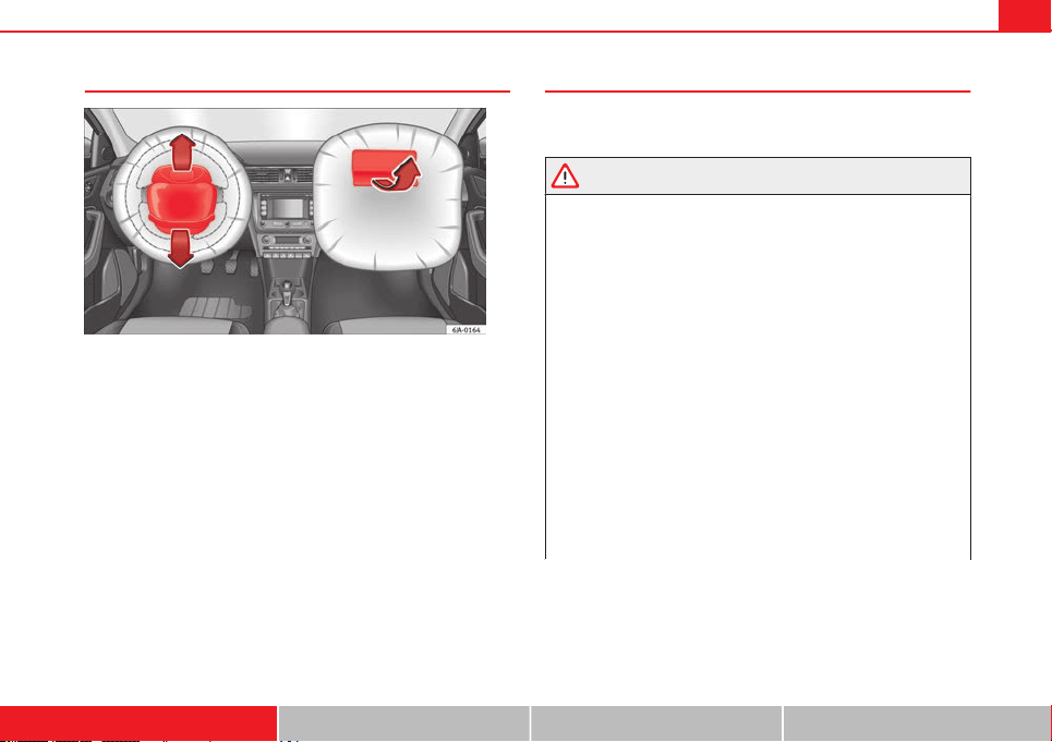
Operation of front airbags
Inflated airbags reduce the risk of injuries to the head or
chest.
Fig. 18 Inflated front air-
bags
The airbag system is designed so that the airbags for the driver and front
passenger are triggered in a severe frontal collision.
In certain types of accident the front, curtain and side airbags may be trig-
gered together.
When the system is triggered, the airbags fill with a propellant gas and de-
ploy in front of the driver and front passenger ⇒ Fig. 18. The fully deployed
airbags cushion the forward movement of the front occupants and help to
reduce the risk of injury to the head and the upper part of the body.
The special design of the airbag allows the controlled escape of the propel-
lant gas when an occupant puts pressure on the bag. Thus, the head and
chest are surrounded and protected by the airbag. After the collision, the
airbag deflates sufficiently to allow visibility.
The airbags deploy extremely rapidly, within thousandths of a second, to
provide additional protection in the event of an accident. A fine dust may
develop when the airbag deploys. This is normal and it is not an indication
of fire in the vehicle.
37Airbag system
Airbag covers when the frontal airbags are triggered
Fig. 19 Airbag covers reacting when the front airbags are triggered
The airbag covers fold out of the steering wheel or dash panel when the
driver and front passenger airbags are triggered ⇒ Fig. 19. The airbag cov-
ers remain connected to the steering wheel or the dash panel.
Safety notes on the front airbag system
If you use airbags correctly, they can considerably reduce
the risk of injury in many kinds of accident.
WARNING
● It is important for the driver and front passenger to keep a distance of
at least 25 cm from the steering wheel and dash panel. If the minimum
distance is not observed then the airbags do not correctly protect the ve-
hicle occupants; risk of fatal injuries! In addition, the front seats and
head restraints must always be positioned correctly for the height of the
occupant.
● If you are not wearing a seat belt, if you lean forward or to the side
while travelling or assume an incorrect sitting position, there is a sub-
stantially increased risk of injury. This increased risk of injury will be fur-
ther increased if you are struck by an inflating airbag.
● Never let a child travel on the front seat without an appropriate re-
straint system. If the airbag is triggered in an accident, children can sus-
tain serious or fatal injuries from the airbag as it inflates ⇒ page 46.
● The deployment space between the front passengers and the airbags
must not in any case be occupied by other passenger, pets and objects.
● The airbags provide protection for just one accident; replace them
once they have deployed.
● It is also important not to attach any objects such as cup holders or
telephone mountings to the surfaces covering the airbag units.
● Do not attempt to modify components of the airbag system in any
way.
Safety First Operating instructions Practical Tips Technical specifications

38 Airbag system
Side airbags*
Description of side airbags
The airbag system is not a substitute for the seat belts.
Fig. 20 Side airbag in
driver seat
The side airbags are located in the backrest cushions of the driver seat
⇒ Fig. 20 and the front passenger seat as well as in the rear seats. The loca-
tions are identified by the text “AIRBAG” in the upper region of the backr-
ests.
Together with the seat belts, the side airbag system gives the front seat oc-
cupants additional protection for the upper body in the event of a severe
side collision ⇒ page 40, Safety notes on the operation of the side airbag
system.
In a side collision, the side airbags reduce the risk of injury to passengers
on the front seats to the areas of the body facing the impact. In addition to
their normal function of protecting the occupants in a collision, the seat
belts also hold the passengers on the front seats and the outer rear seats in
a position where the side airbags can provide maximum protection.
The airbag system is not a substitute for seat belts, but it is an integral part
of the vehicle's overall passive safety system. Please bear in mind that the
airbag system can only work effectively when the occupants are wearing
their seat belts. Therefore, it is most important to wear the seat belts at all
times, not only because this is required by law in most countries, but also
for your safety ⇒ page 20, Brief introduction.
The side airbag system will not be triggered if:
● the ignition is switched off
● there is a minor side collision
● there is a frontal collision
● there is a rear-end collision
● the vehicle turns over
The main parts of the airbag system are:
● an electronic control and monitoring system (control unit)
● the side airbags in the sides of the backrests of the front and rear seats
● a control lamp on the dash panel ⇒ page 33
The airbag system operation is monitored electronically. The airbag control
lamp will light up for approx. 4 seconds every time the ignition is switched
on (self-diagnosis).
WARNING
● In a side-on collision the side airbags will not work if the sensors do
not correctly measure the pressure increase on the interior of the doors,
due to air escaping through the areas with holes or openings in the door
panel.
● Never drive the vehicle if the interior panels have been removed.
● Never drive if the interior door panels have been removed or if the
panels have not been correctly fitted.

39Airbag system
WARNING (Continued)
● Never drive the vehicle if the loudspeakers in the door panels have
been removed, unless the holes left by the loudspeakers have been cor-
rectly closed.
● Always check that the openings are closed or covered if loudspeakers
or other equipment are fitted in the interior door panels.
● Any work carried out to the doors should be made in an authorised
specialised workshop.
● The seat belts and airbags can only provide maximum protection if
the occupants are seated correctly ⇒ page 10, Sitting position for vehicle
occupants.
● If a fault has occurred in the airbag system, have the system checked
immediately by a specialised workshop. Otherwise, during a side colli-
sion, the system may fail to trigger, or not trigger correctly.
Operation of side airbags
Inflated airbags can reduce the risk of head or chest injury
in many side impact collisions.
Fig. 21 Illustration of
completely inflated side
airbags on left side of ve-
hicle
In some side collisions, the side airbag is triggered on the impact side of
the vehicle
⇒
Fig. 21.
In certain types of accident the front, curtain and side airbags may be trig-
gered together.
When the system is triggered, the airbag is filled with propellant gas.
The airbags deploy extremely rapidly, within thousandths of a second, to
provide additional protection in the event of an accident. A fine dust may
develop when the airbag deploys. This is normal and it is not an indication
of fire in the vehicle.
The fully deployed airbags cushion the movement of the occupants of the
front seats and the outer rear seats and help to reduce the risk of injury to
the upper body.
Safety First Operating instructions Practical Tips Technical specifications

40 Airbag system
The special design of the airbag allows the controlled escape of the propel-
lant gas when an occupant puts pressure on the bag. Thus, the head and
chest are surrounded and protected by the airbag.
Safety notes on the operation of the side airbag system
If airbags are used correctly, they can considerably reduce
the risk of injury in side impact collisions.
WARNING
● If you do not wear a seat belt, if you lean forward, or are not seated
correctly while the vehicle is in motion, you are at a greater risk of injury
if the side airbag system is triggered in an accident.
● In order for the side airbags to provide their maximum protection, the
prescribed sitting position must always be maintained with seat belts
fastened while travelling.
● Occupants of the outer seats must never carry any objects or pets in
the deployment space between them and the airbags, or allow children
or other passengers to travel in this position. It is also important not to
attach any accessories (such as cup holders) to the doors. This would im-
pair the protection offered by the side airbags.
● The built-in coat hooks should be used only for lightweight clothing.
Do not leave any heavy or sharp-edged objects in the pockets.
● Great forces, such as hard blows or kicks, must not be exerted upon
the backrest bolster because the system may be damaged. In this case,
the side airbags would not be triggered.
WARNING (Continued)
● Under no circumstances should protective covers be fitted over seats
with side airbags unless the covers have been approved for use in your
vehicle. Because the airbag deploys from the side of the backrest, the
use of conventional seat covers would obstruct the side airbag, seriously
reducing the airbag's effectiveness.
● Any damage to the original seat upholstery or around the seams of
the side airbag units must be repaired immediately by a specialised
workshop.
● The airbags provide protection for just one accident; replace them
once they have deployed.
● When children assume an incorrect sitting position, they expose
themselves to an increased risk of injury in the event of an accident. This
is particularly the case if the child is travelling on the front passenger
seat and the airbag system is triggered in an accident; this could have
critical consequences including serious injury or death ⇒ page 46.
● Any work on the side airbag system or removal and installation of the
airbag components for other repairs (such as removal of the front seat)
should only be performed by a specialised workshop. Otherwise, faults
may occur during the airbag system operation.
● Do not attempt to modify components of the airbag system in any
way.
● The side and head airbags are managed through sensors located in
the interior of the front doors. To ensure the correct operation of the side
and head airbags neither the doors nor the door panels should be modi-
fied in any way (e.g. fitting loudspeakers). If the front door is damaged,
the airbag system may not work correctly. All work carried out on the
front door must be done in a specialised workshop.

41Airbag system
Curtain airbags*
Description of curtain airbags
The airbag system is not a substitute for the seat belts.
Fig. 22 Location of cur-
tain airbags
The curtain airbags are located on both sides in the interior above the doors
⇒ Fig. 22 and are identified with the text “AIRBAG”.
In conjunction with the seat belts, the curtain airbag system gives the vehi-
cle occupants additional protection for the head and upper body in the
event of a severe side collision ⇒ page 42, Safety notes on the operation
of the curtain airbag system.
The airbag system is not a substitute for seat belts, but it is an integral part
of the vehicle's overall passive safety system. Please bear in mind that the
airbag system can only work effectively when the vehicle occupants are
wearing their seat belts correctly and have adjusted the head restraints
properly. Therefore, it is most important to wear the seat belts at all times,
not only because this is required by law in most countries, but also for your
safety ⇒ page 20, Brief introduction.
The main parts of the curtain airbag system are:
● an electronic control and monitoring system (control unit)
● the curtain airbags (airbags with gas generator) for the driver, front pas-
senger and passengers on the rear seats
● a control lamp on the dash panel ⇒ page 33
The airbag system operation is monitored electronically.
The curtain airbag system will not be triggered if:
● the ignition is switched off
● there is a frontal collision
● there is a rear-end collision
● the vehicle turns over
● there is a minor side collision
WARNING
If a fault has occurred in the airbag system, have the system checked im-
mediately by a specialised workshop. Otherwise there is a danger that
during a collision, the system may fail to trigger, or not trigger correctly.
Safety First Operating instructions Practical Tips Technical specifications

42 Airbag system
Operation of curtain airbags
Fully inflated airbags reduce the risk of head or chest injury
in a side collision.
Fig. 23 Deployed cur-
tain airbags
During some side collisions the curtain airbag is triggered on the impact
side of the vehicle ⇒ Fig. 23.
In certain types of accident the front, side and curtain airbags may be trig-
gered together.
When the system is triggered, the airbag is filled with propellant gas. In the
process, the curtain airbag covers the side windows and door pillars.
The airbags deploy extremely rapidly, within thousandths of a second, to
provide additional protection in the event of an accident. A fine dust may
develop when the airbag deploys. This is normal and it is not an indication
of fire in the vehicle.
The fully deployed airbags cushion the movement of the front occupants
and help to reduce the risk of injury to the upper body.
The special design of the airbag allows the controlled escape of the propel-
lant gas when an occupant puts pressure on the bag. Thus, the head and
chest are surrounded and protected by the airbag.
Safety notes on the operation of the curtain airbag system
If you use airbags correctly, they can considerably reduce
the risk of injury in many kinds of accident.
WARNING
● In order for the side airbags to provide their maximum protection, the
prescribed sitting position must always be maintained with seat belts
fastened while travelling.
● For safety reasons, the curtain airbag must be disabled in those vehi-
cles fitted with a screen dividing the interior of the vehicle. See a Techni-
cal Service to make this adjustment.
● There must be no other persons, animals or objects between the oc-
cupants of the outer seats and the deployment space of the curtain air-
bags so that the curtain airbag can deploy without restriction and pro-
vide the greatest possible protection. Therefore, sun blinds which have
not been expressly approved for use in your vehicle may not be attached
to the side windows.
● The built-in coat hooks should be used only for lightweight clothing.
Do not leave any heavy or sharp-edged objects in the pockets. Please, do
not hang the clothes on coat hangers.
● The airbags provide protection for just one accident; replace them
once they have deployed.
● Any work on the curtain airbag system or removal and installation of
the airbag components for other repairs (such as removal of the roof lin-
ing) should only be performed by a specialised workshop. Otherwise,
faults may occur during the airbag system operation.

43Airbag system
WARNING (Continued)
● Do not attempt to modify components of the airbag system in any
way.
● The side and head airbags are managed through sensors located in
the interior of the front doors. To ensure the correct operation of the side
and head airbags neither the doors nor the door panels should be modi-
fied in any way (e.g. fitting loudspeakers). If the front door is damaged,
the airbag system may not work correctly. All work carried out on the
front door must be done in a specialised workshop.
Deactivating airbags
Deactivating airbags
The deactivation of airbags corresponds only to certain cases, i.e. if:
● a child seat is required in the front passenger seat with the child facing
in the opposite direction to the direction of travel (in some countries, due to
divergent legal requirements, facing in the direction of travel) ⇒ page 48;
● despite the driver seat being in the correct position, a minimum dis-
tance of 25 cm cannot be maintained between the centre of the steering
wheel and the driver's torso.
● installation of special devices is required in the steering wheel area due
to a physical disability.
● if you have special seats installed (e.g. an orthopaedic seat without side
airbag).
The front passenger front airbag can be disabled using the switch
⇒ page 44.
We recommend that you contact an authorised SEAT dealer for the disabling
of other airbags.
Airbag system control
The airbag system availability is controlled electronically, regardless of
whether an airbag is disabled.
If an airbag was disabled using a diagnostics system:
● the airbag system warning lamp lights up after switching on the igni-
tion for about 4 seconds, and then flashes for about 12 seconds
If the airbag has been disabled with the airbag switch on the side of the
dash panel:
● the airbag control lamp will light up for about 4 seconds after the ig-
nition is switched on.
● the airbag is disabled, signalled with the warning lamp which
lights up with the word placed in the centre part of the
dash panel ⇒ Fig. 24
3
.
Note
● Respect the current legislation in your country regarding the deactiva-
tion of airbags
● At your authorised SEAT dealer you can find information on which vehi-
cle airbags can be deactivated.
Safety First Operating instructions Practical Tips Technical specifications

44 Airbag system
Front passenger front airbag switch
Fig. 24 Front passenger front airbag switch/warning lamp for the disabling of the
front passenger airbag
The switch disables only the front passenger front airbag.
Disabling the airbag
– Switch the ignition off.
– Open the passenger side storage compartment.
– Insert the key into the slot of the switch for deactivating the
front passenger airbag ⇒ Fig. 24. About 3/4 of the key should
enter, as far as it will go.
– Then turn the key gently to the OFF position. Do not force it if
you feel resistance, and make sure you have inserted the key
fully.
– Check, with the ignition switched on, that the control lamp
lights up with the word in the centre
part of the dash panel.
Switching on the airbag
– Switch the ignition off.
– Insert the key into the slot of the switch for deactivating the
front passenger airbag ⇒ Fig. 24. About 3/4 of the key should
enter, as far as it will go.
– Then turn the key gently to the ON position. Do not force it if you
feel resistance, and make sure you have inserted the key fully.
– Close the passenger side storage compartment.
– Check, with the ignition switched on, that the control lamp does
not light up with the word in the
centre part of the dash panel.
Control lamp with the word (front passenger airbag
disabled)
If the front passenger front airbag is disabled, after switching on the igni-
tion, the control lamp will light up for several seconds, then it will switch off
for about 1 s and then switch on again.
If the control lamp is flashing, there is a fault in the disabling of the airbag
system ⇒
. Please go immediately to an Official Service.
WARNING
● The driver of the vehicle is responsible for disabling or switching on
the airbag.
● Always switch off the ignition before disabling the front passenger
airbag! Failure to do so could result in a fault in the airbag deactivation
system.

45Airbag system
WARNING (Continued)
● Never leave the key in the airbag deactivation switch as it could get
damaged or activate or deactivate the airbag during driving.
● If the control lamp (airbag deactivated) flashes, the front pas-
senger front airbag will not trigger in the event of an accident! Have the
system immediately checked by an Official Service.
Safety First Operating instructions Practical Tips Technical specifications

46 Child safety
Child safety
Brief introduction
Introduction
Statistics show that children are generally safer on the rear
seat than on the front passenger seat.
For safety reasons we recommend that children under 12 years of age travel
on the rear seats. Depending on their age, height and weight, children trav-
elling on the rear seat must use a child seat or a seat belt. For safety rea-
sons, the child seat should be installed in the centre of the rear seat or be-
hind the front passenger seat.
The physical laws involved and the forces acting in a collision apply also to
children ⇒ page 22.
But unlike adults, children do not have fully developed muscle and bone
structures. This means that children are subject to a greater risk of injury.
To reduce this risk, children must always use special child restraint systems
when travelling in the vehicle.
We recommend the use of child safety products from the SEAT Original Ac-
cessories Programme, which includes systems for all ages made by
“Peke”
1)
.
These systems have been especially designed and approved, complying
with the ECE-R44. regulation.
Follow the manufacturer's instructions and observe any statutory require-
ments when installing and using child seats. Always read and note
⇒ page 46.
We recommend you to always include the manufacturer's Child Seat Instruc-
tion Manual together with the on-board documentation.
Safety notes on using child seats
Proper use of child seats substantially reduces the risk of in-
jury in an accident!
As the driver, you are responsible for any children you transport in
your vehicle.
– Protect your children by properly using the appropriate child
seats ⇒ page 48.
– Always ensure that the seat belt is properly positioned accord-
ing to the instructions provided by the manufacturer of the child
seat.
– When travelling, do not allow children to distract you from traf-
fic.
– Take breaks regularly during long trips. Take a break at least ev-
ery two hours.
1)
Not for all countries

47Child safety
WARNING
● Never install a child seat facing backwards on the front passenger
seat unless the front passenger front airbag has been disabled. Risk of
potentially fatal injuries to the child! However, if it is necessary, in excep-
tional cases, to transport a child in the front passenger seat, the front
passenger front airbag must always be disabled ⇒ page 43. If the pas-
senger seat has a height adjustment option, move it to the highest posi-
tion.
● For those vehicles that do not include a key lock switch to deactivate
the airbag, the vehicle must be taken to a Technical Service.
● All vehicle occupants, especially children, must assume the proper
sitting position and be properly belted in while travelling.
● Never hold children or babies on your lap, this can result in potential-
ly fatal injuries to the child!
● Never allow a child to be transported in a vehicle without being prop-
erly secured, or to stand up or kneel on a seat while travelling. In an acci-
dent, the child could be flung through the vehicle, causing possibly fatal
injuries to themselves and to the other vehicle occupants.
● If children assume an improper sitting position when the vehicle is
moving, they expose themselves to greater risk of injury in the event of a
sudden braking manoeuvre or in an accident. This is particularly impor-
tant if the child is travelling on the front passenger seat and the airbag
system is triggered in an accident; as this could cause serious injury or
even death.
● A suitable child seat can protect your child!
● Never leave an unsupervised child alone on a child seat or in the vehi-
cle.
● Depending on weather conditions, it may become extremely hot or
cold inside the vehicle. This can be fatal.
WARNING (Continued)
● Children who are less than 1.5 metres tall must not wear a normal
seat belt without a child seat, as this could cause injuries to the abdomi-
nal and neck areas during a sudden braking manoeuvre or in an accident.
● Do not allow the seat belt to become twisted or jammed, or to rub on
any sharp edges.
● Incorrectly worn seat belts can cause injuries even in a minor colli-
sion or in sudden braking manoeuvres.
● The seat belt provides maximum protection only when the seat belt is
properly positioned ⇒ page 26, Seat belts.
● Only one child may occupy a child seat ⇒ page 48, Child seats.
Safety First Operating instructions Practical Tips Technical specifications

48 Child safety
Child seats
Categorisation of child seats into groups
Use only child seats that are officially approved and suitable
for the child.
Child seats are subject to the regulation ECE-R 44. ECE-R stands for: Eco-
nomic Commission for Europe Regulation
The child seats are grouped into 5 categories:
Group 0: up to 10 kg
Group 0+: up to 13 kg
Group 1: from 9 to 18 kg
Group 2: from 15 to 25 kg
Group 3: from 22 to 36 kg
Child seats that have been tested and approved under the ECE R44 stand-
ard bear the test mark on the seat (the letter E in a circle with the test num-
ber below it).
Group 0 and 0+ child seats
A suitable child seat and a correctly adjusted seat belt can
help you to protect your child.
Fig. 25 A group 0 rear-
facing child seat fitted on
the rear seat
Group 0: For babies up to about 9 months old and 10 kg in weight, the most
suitable seats are those appearing in the illustration
⇒
Fig. 25.
Group 0+: For babies up to about 18 months old and 13 kg in weight the
most suitable seats are those appearing in the illustration.
Follow the manufacturer's instructions and observe any statutory require-
ments when installing and using child seats.
We recommend you to always include the manufacturer's Child Seat Instruc-
tion Manual together with the on-board documentation.
WARNING
Read and always observe information and warnings concerning the use
of child seats ⇒ page 46.

49Child safety
Group 1 child seats
A suitable child seat and a correctly adjusted seat belt can
help you to protect your child.
Fig. 26 A category 1 for-
ward-facing child seat fit-
ted on the rear seat
Child seats using the ISOFIX system or seats in which the child faces the
rear of the vehicle are most appropriate for babies and small children
weighing between 9 and 18 kg.
Follow the manufacturer's instructions and observe any statutory require-
ments when installing and using child seats.
We recommend you to always include the manufacturer's Child Seat Instruc-
tion Manual together with the on-board documentation.
WARNING
Read and always observe information and warnings concerning the use
of child seats ⇒ page 46.
Group 2 and 3 child seats
A suitable child seat and a correctly adjusted seat belt can
help you to protect your child.
Fig. 27 Forward-facing
child seat installed on
rear seat
Follow the manufacturer's instructions and observe any statutory require-
ments when installing and using child seats.
We recommend you to always include the manufacturer's Child Seat Instruc-
tion Manual together with the on-board documentation.
Group 2 child seats
Children under 7 years of age weighing between 15 and 25 kg are best pro-
tected by group 2 child seats together with properly adjusted seat belts.
Group 3 child seats
Children over 7 years of age weighing between 22 and 36 kg but less than
1.5 metres tall are best protected by child seats with head restraints togeth-
er with properly worn seat belts
⇒
Fig. 27.
Safety First Operating instructions Practical Tips Technical specifications

50 Child safety
WARNING
● The shoulder part of the seat belt must lie approximately on the cen-
tre of the shoulder, never across the neck or the arm. The seat belt must
lie close to the upper part of the body. The lap belt part must lie across
the pelvis, not across the stomach, and always fit closely. Pull the belt
tight if necessary to take up any slack ⇒ page 26, Seat belts.
● Read and always observe information and warnings concerning the
use of child seats ⇒ page 46.

51Child safety
Securing child seats
Ways to secure a child seat
A child seat can be secured differently on the rear seat and
on the front passenger seat.
You can secure a child seat to the rear seat or front passenger seat in the
following ways:
● Child seats in groups 0 to 3 can be secured with a seat belt.
● Child seats in groups 0, 0+ and 1 with the ISOFIX and Top Tether* sys-
tems can be secured without using the seatbelt, thanks to the ISOFIX and
Top Tether* securing rings ⇒ page 52.
Category Weight
Seat locations
Front passen-
ger
Rear outer Rear centre
Group 0 <10 kg U* U/L U
Group 0+ <13 kg U* U/L U
Group 1 9-18 kg U* U/L U
Group 2/3 15-36 kg U* U U
Suitable for universal approved restraining systems for use in this age
category (universal retention systems are those fitted using the adult
seat belt).
Move the front passenger seat as far back as possible, as high as pos-
sible and always disable the airbag.
Suitable for retention systems using the ISOFIX and Top Tether* an-
chors.
U:
*:
L:
WARNING
● When travelling, children must be secured in the vehicle with a re-
straint system suitable for age, weight and size.
● Never install a child seat facing backwards on the front passenger
seat unless the front passenger airbag has been disabled. This could
cause fatal injuries to the child! However, if, in exceptional cases, it is
necessary to transport a child in the front passenger seat, the front pas-
senger airbag ⇒ page 43 must always be disabled and the seat adjusted
to its highest position, where possible.
● Read and always observe information and warnings concerning the
use of child seats ⇒ page 46.
Safety First Operating instructions Practical Tips Technical specifications

52 Child safety
Child seats fastened with the “ISOFIX” and Top Tether*
system
Child seats with the ISOFIX or Top Tether* system can be se-
cured quickly, easily and safely on the rear outer seats.
Fig. 28 ISOFIX securing
rings
Fig. 29 Top Tether* se-
curing ring
When removing or fitting the child seat, please be sure to follow
the manufacturer's instructions.
– Move the rear seat as far to the rear as it will go.
– Press the child seat onto the ISOFIX retaining rings until the
child seat can be heard to engage securely. If the child seat is
equipped with Toptether* anchor points, secure it to the corre-
spondent ring. Follow the manufacturer's instructions.
– Pull on both sides of the child seat to ensure that it is secure.
Two ISOFIX retaining rings are fitted on each rear seat. In some vehicles, the
rings are secured to the seat frame and, in others, they are secured to the
rear floor. The access to the ISOFIX rings is between the rear seat backrest
and the seat cushioning. The Top Tether* anchors are located at the rear of
the backrests of the rear seats (behind the seat backrest or in the luggage
compartment).
Child seats with the ISOFIX and Top Tether* attachment system are available
from Technical Services.
WARNING
● The securing rings are designed only for use with ISOFIX and Top
Tether* child seats.
● Never secure child seats that do not have the ISOFIX and Top Tether*
system, retaining belts or other objects to the securing rings – this could
result in potentially fatal injuries to the child!
● Ensure that the child seat is secured correctly using the “ISOFIX” and
Top Tether* securing rings.

53Child safety
Safety First Operating instructions Practical Tips Technical specifications

54 Controls and displays
Fig. 30 Interior

55Controls and displays
Operating instructions
Controls and displays
Overview
Electric window controls . . . . . . . . . . . . . . . . . . . . . . . . . . . . . . . . . . . 95
Control for adjusting electric exterior mirrors . . . . . . . . . . . . . . . . 109
Air outlets . . . . . . . . . . . . . . . . . . . . . . . . . . . . . . . . . . . . . . . . . . . . . . . . 129
Multifunction switch lever:
– turn signals, main beams, parking lights, headlight flash-
er . . . . . . . . . . . . . . . . . . . . . . . . . . . . . . . . . . . . . . . . . . . . . . . . . . . . . . 100
– cruise control . . . . . . . . . . . . . . . . . . . . . . . . . . . . . . . . . . . . . . . . . . 152
Steering wheel:
– with horn
– with the driver front airbag . . . . . . . . . . . . . . . . . . . . . . . . . . . . . . 35
– with controls for audio, navigation system and telephone . 78
General instrument panel: instruments and warning lamps . . 55
Multifunction switch lever:
– multifunction display . . . . . . . . . . . . . . . . . . . . . . . . . . . . . . . . . . . 61
– Windscreen wiper and washer . . . . . . . . . . . . . . . . . . . . . . . . . . . 106
Air outlets . . . . . . . . . . . . . . . . . . . . . . . . . . . . . . . . . . . . . . . . . . . . . . . . 129
Depending on the equipment:
– audio system
– navigation system
Hazard warning lights switch . . . . . . . . . . . . . . . . . . . . . . . . . . . . . . 101
Control lamp for front passenger airbag deactivated warning
lamp . . . . . . . . . . . . . . . . . . . . . . . . . . . . . . . . . . . . . . . . . . . . . . . . . . . . . 44
1
2
3
4
5
6
7
8
9
10
11
Front passenger airbag switch . . . . . . . . . . . . . . . . . . . . . . . . . . . . . 44
Passenger side storage compartment . . . . . . . . . . . . . . . . . . . . . . 123
Front passenger airbag . . . . . . . . . . . . . . . . . . . . . . . . . . . . . . . . . . . . 35
Switch for the lights and the main lights range control . . . . . . 97, 99
Bonnet release lever . . . . . . . . . . . . . . . . . . . . . . . . . . . . . . . . . . . . . . 183
Fuse housing . . . . . . . . . . . . . . . . . . . . . . . . . . . . . . . . . . . . . . . . . . . . . 220
Steering column adjustment lever . . . . . . . . . . . . . . . . . . . . . . . . . . 140
Ignition lock . . . . . . . . . . . . . . . . . . . . . . . . . . . . . . . . . . . . . . . . . . . . . . 141
Driver seat heating control . . . . . . . . . . . . . . . . . . . . . . . . . . . . . . . . . 112
ASR switch . . . . . . . . . . . . . . . . . . . . . . . . . . . . . . . . . . . . . . . . . . . . . . . . 144
Central lock button . . . . . . . . . . . . . . . . . . . . . . . . . . . . . . . . . . . . . . . . 88
Depending on the equipment:
– gear lever (manual gearbox) . . . . . . . . . . . . . . . . . . . . . . . . . . . . 145
– selector lever (automatic gearbox) . . . . . . . . . . . . . . . . . . . . . . . 147
Depending on the equipment:
– drink holder . . . . . . . . . . . . . . . . . . . . . . . . . . . . . . . . . . . . . . . . . . . . 120
– ashtray holder . . . . . . . . . . . . . . . . . . . . . . . . . . . . . . . . . . . . . . . . . . 121
glove compartment/storage compartment . . . . . . . . . . . . . . . . . . 123
Heated rear window control . . . . . . . . . . . . . . . . . . . . . . . . . . . . . . . . 104
Passenger seat heating control . . . . . . . . . . . . . . . . . . . . . . . . . . . . 112
Depending on the equipment:
– heating controls . . . . . . . . . . . . . . . . . . . . . . . . . . . . . . . . . . . . . . . . 130
– air conditioning controls . . . . . . . . . . . . . . . . . . . . . . . . . . . . . . . . 132
– Climatronic controls . . . . . . . . . . . . . . . . . . . . . . . . . . . . . . . . . . . . 135
12
13
14
15
16
17
18
19
20
21
22
23
24
25
26
27
28
Safety First Operating instructions Practical Tips Technical specifications

56 Controls and displays
Note
The location of the controls of right-hand drive cars differs slightly from the
location shown here ⇒ Fig. 30. However, the symbols correspond to the re-
spective controls.

57Controls and displays
Instruments and warning lamps
General instrument panel – summary
Fig. 31 General instrument panel
Rev counter
⇒
page 57
Digital display:
– with trip counter
⇒
page 59
– with service interval display
⇒
page 59
– with digital clock
⇒
page 60
– with multifunction display
⇒
page 61
– with informative digital display
⇒
page 66
– with outside temperature indicator
⇒
page 63
Speedometer
⇒
page 58
Coolant temperature indicator
⇒
page 58
1
2
3
4
Control for selecting the mode:
– adjust hours/minutes
– activate/deactivate according to speed in mph or km/h respectively
– service intervals – show the days and kilometres (miles) remaining
Switch for:
– delete trip counter
– reset the service intervals
– adjust hours/minutes
– activate/deactivate the selected mode
Fuel reserve indicator ⇒ page 58
WARNING
● Always keep your attention on driving! As the driver, you have the full
responsibility for the safety of traffic.
● Never use the instrument panel controls when the vehicle is in mo-
tion. Do so only when the vehicle is stopped!
Rev counter
The red part of the rev counter scale
1
⇒ Fig. 31 ⇒ page 57 marks the zone
where the engine control unit begins to limit the engine speed. The engine
control unit is responsible for reducing the revs to a safe limit.
Before the needle reaches the red zone change up into a higher gear, or
move the selector lever of the automatic gearbox to D.
In order to drive at an optimum RPM, respect the gear change indications
⇒ page 60.
5
6
7
Safety First Operating instructions Practical Tips Technical specifications

58 Controls and displays
For the sake of the environment
Changing to higher gears in advance helps to reduce fuel consumption and
noise levels, helps to protect the environment and benefits both the useful
life and the reliability of the engine.
Speedometer
Speed warning
An audible warning will be heard on exceeding 120 km/h (75 mph). If the
speed falls below this limit, the audible warning switches off.
Note
This function is only valid for certain countries.
Coolant temperature gauge
The coolant temperature gauge
4
⇒
Fig. 31
⇒
page 57 only works when
the ignition is switched on.
Damage to the engine can be avoided by observing the indications regard-
ing the temperature zones.
Engine cold
If the needle is still on the left of the scale, the engine has not yet reached
operating temperature. Avoid high engine speeds, hard acceleration and
submitting the engine to high loads.
Operating temperature zone
When the needle has reached the central part of the scale, this means the
engine has reached operating temperature. Running the engine at full throt-
tle and the high temperatures involved can cause the needle to be posi-
tioned in the zone on the right.
CAUTION
The additional headlights and other parts placed in front of the fresh air in-
lets reduce the effect of engine cooling. With high outside temperatures
and engine speeds a risk becomes present of the engine overheating
⇒ page 72, Coolant level and temperature .
Fuel gauge
The fuel gauge
7
⇒ Fig. 31 ⇒ page 57 operates only when the ignition is
switched on.
The fuel tank has a capacity of approx. 55 litres. When the needle reaches
the reserve area, the warning symbol ⇒ page 75 lights up on the gener-
al instrument panel and an audible warning can be heard.
CAUTION
Never completely empty the tank! An irregularity in the fuel supply system
can cause irregularities when the engine is running. Unburned fuel can
reach the exhaust gas system, which can cause deterioration of the catalytic
converter.
Note
Some vehicles come fitted with the fuel gauge on the general instrument
panel.

59Controls and displays
Trip counter*
Daily trip counter (trip)
The daily trip counter indicates the journey that has been covered since the
last time the function was reset in 100 metre sections.
In order to reset the daily distance covered keep the button
6
⇒ Fig. 31
⇒ page 57 pressed down.
Odometer
The odometer indicates the total number of kilometres (or mileage) that the
vehicle has covered until now.
Fault indication
In the event of a fault in the informative display the word Error will appear
permanently. Please take the vehicle to a specialised Technical Service to
solve this fault.
Note
In vehicles equipped with an informative display, if the indicator of the sec-
ond speed in mph or in kph are activated respectively, this speed will be
displayed in place of the odometer.
Service interval display*
Service interval display
Before reaching the service interval, when the ignition is switched on the
key symbol appears on the screen for several seconds together with the
indication of the number of kilometres (miles) remaining. The number of
days remaining until the service inspection is indicated simultaneously.
The informative display indicates:
Service in … km (miles) or… days.
The indication of kilometres (miles) or time remaining until the inspection
reduces in intervals of 100km (miles) or 1 day.
If the service interval is reached, when the ignition is switched on the key
symbol appears flashing on the screen together with the word Service.
The informative display indicates:
Service now!
Indication of number of kilometres (miles) or time remaining until the
service inspection
The number of kilometres (miles) or time remaining until the service inspec-
tion can always be displayed when the ignition is switched on by pressing
the button
5
⇒ Fig. 31 ⇒ page 57.
The key symbol and indication of the number of kilometres (miles) re-
maining appear on the display for several seconds. The number of days re-
maining until the service inspection is indicated simultaneously.
In vehicles equipped with an informative display this information can be ac-
cessed from the menu, Settings ⇒ page 67.
Resetting service interval display
The service interval display can be reset only after a service message or pre-
warning has been displayed in the general instrument panel display.
It is advisable to visit a Technical Service to reset the display.
The specialised Technical Service:
● resets the display memory after performing the following inspection
● stores the information in the Maintenance Programme
● places a sticker on the side of the instrument panel in the driver area in-
dicating the date of the next inspection
The service intervals display can be reset by pressing the button,
6
⇒ Fig. 31 ⇒ page 57.
Safety First Operating instructions Practical Tips Technical specifications

60 Controls and displays
In vehicles equipped with an informative display the service interval display
can be reset from the menu, Settings ⇒ page 67.
CAUTION
We advise against resetting the service interval display yourself, given that
this action could cause an imbalance in the service intervals, and as a re-
sult, faults in the vehicle.
Note
● Never reset the display between service intervals as this could lead to
erroneous indications.
● After disconnecting the battery of the vehicle, the service interval dis-
play values remain stored.
● If the general instrument panel is changed after a repair, the correct val-
ues must be input in the service interval display. This operation is carried
out by a specialised service.
● After resetting the display with flexible service intervals, the information
will be indicated in the same way as vehicles with fixed service intervals.
Therefore, we recommend that a SEAT Authorised Service resets the service
interval display, who will do so correctly using diagnostics equipment.
● For more detailed information please consult the Maintenance Pro-
gramme.
Digital clock
The clock is set using the buttons
5
to
6
⇒
Fig. 31
⇒
page 57.
Select the indication you want to change with button
5
and make the ad-
justment with button
6
.
In vehicles equipped with an informative display this can be reset from the
menu, Time
⇒
page 67.
Recommended gear display
Fig. 32 Recommended
gear display
The general instrument panel display indicates the engaged gear
A
⇒ Fig. 32.
In order to optimally reduce the fuel consumption, the recommended gear is
displayed on the screen.
If the control unit analysis decides that a gear change is required, an arrow
appears on the display
A
. This arrow can point up or down indicating
whether a lower or higher gear is recommended.
Simultaneously, the gear currently engaged is indicated
B
in the place of
the recommended gear.
CAUTION
However, the driver is always responsible for choosing the appropriate gear
for each situation, (i.e. when overtaking).

61Controls and displays
Multi-function display* (on board computer)
Introduction
The multifunction display can only be operated when the ignition is switch-
ed on. When the ignition is switched on the last function selected before it
was switched off is displayed.
The multifunction display data is shown on the screen ⇒ Fig. 33
⇒ page 61.
In vehicles fitted with an informative display ⇒ page 66 the system can be
adjusted so that certain data is not shown.
WARNING
● Always keep your attention on driving! As the driver, you have the full
responsibility for the safety of traffic.
● Do not rely only on the outside temperature indicator to verify wheth-
er the road surface is frozen. This is because with an outside temperature
of +4 °C (+39 °F) ice can generate on the road - Warning of frozen road
surface!
Note
● Models for certain countries can show the values in imperial units.
● If the second speed in mph (km/h) is displayed, the current speed in
km/h (mph) is not displayed on the screen.
Memory
Fig. 33 Multifunction
display
The multifunction display has two automatic memories. The selected mem-
ory is displayed on the screen ⇒ Fig. 33.
The current journey data (memory 1) is always displayed when the number
1 appears on the display. When number 2 appears on the display, the total
distance travelled is shown (memory 2).
The memory is selected depending on the equipment:
● by pressing the lever's
B
button briefly ⇒ Fig. 34 ⇒ page 62, or else
● briefly pressing the right thumbwheel of the multifunction steering
wheel
1
⇒ Fig. 35.
Current journey memory (memory 1)
The current journey memory collects data from the moment the ignition is
switched on until it is switched off. If the journey is continued within two
hours of switching off the ignition, the new values will be added to the ex-
isting trip recorder memory. The memory will automatically be deleted if the
journey is interrupted for more than two hours.
Total distance travelled memory (memory 2)
The total distance travelled memory collects journey data from any number
of individual journeys up to a maximum of 19 hours and 59 minutes and
Safety First Operating instructions Practical Tips Technical specifications

62 Controls and displays
1999 km (miles) or until 99 hours and 59 minutes and 9999 km (miles) in
cars with an informative display. The memory will automatically be deleted
if one of the named values is reached, resetting the data collected.
Unlike the current journey memory, this memory is not deleted, even when
the ignition is switched off for more than two hours.
Note
After disconnecting the battery, all the values stored in the memories 1 and
2 are deleted.
Operation
Fig. 34 Multifunction
display: controls
Fig. 35 Multifunction
steering wheel: controls
The button to change the functions
A
⇒ Fig. 34 and the button to
delete the memory
B
are located on the window wiper lever.
Selecting a memory
Depending on the equipment:
– Press the lever's
B
⇒ Fig. 34 button briefly.
– Briefly press the right thumbwheel of the multifunction steering
wheel
1
⇒ Fig. 35.
Selecting functions
Depending on the equipment:
– Briefly press the lever's
A
⇒ Fig. 34 rocker switch up or down.
This displays the multifunction display functions in consecutive
order on the screen.

63Controls and displays
– Turn the right thumbwheel of the multifunction steering wheel
1
⇒ Fig. 35. This displays the multifunction display functions
in consecutive order on the screen.
Resetting
– Select the required memory.
Depending on the equipment:
– Press and hold the lever's
B
⇒ Fig. 34 button.
– Press and hold the right thumbwheel of the multifunction steer-
ing wheel
1
⇒ Fig. 35.
This will reset the following values of the selected memory:
● the average fuel consumption
● journey distance covered
● average speed
● duration of the journey
Multifunction display data
Outside temperature
The display indicates the outside temperature.
At temperatures below +4 °C (+39 °F), the snowflake symbol is also dis-
played (frozen road surface warning symbol) and an audible warning is giv-
en. Pressing the lever's rocker switch
A
⇒ Fig. 34 or turning the right
thumbwheel of the steering wheel
1
⇒ Fig. 35 shows the last displayed
function.
Journey duration
The display shows the time you have covered since the memory was last re-
set. If you wish to measure the duration of a journey from a specific mo-
ment, the memory must be deleted ⇒ page 62.
The maximum time indicated by the two memories is 19 hours 59 minutes
or 99 hours and 59 minutes for vehicles fitted with an informative display.
The memory is reset if this value is exceeded.
Current fuel consumption
The current fuel consumption is indicated on the display in litres/100km
(miles)
1)
. You can adapt your driving style to the required consumption with
the assistance of this indicator.
The consumption is displayed in litres per hour while the vehicle is stopped
or at idling speed
2)
.
Average fuel consumption
The display shows the average fuel consumption in litres/100km (miles)
1)
calculated since the memory was last reset ⇒ page 61.
If you wish to measure the average fuel consumption from a specific period,
the memory must first be deleted ⇒ page 62. While driving the first 300 m
after deleting the memory this value is not shown on the display.
The value is updated regularly while the vehicle is in motion.
1)
The indication of consumption is given in kms (miles)/litres in models for certain countries.
2)
The indication of the consumption when the vehicle is stationary is given in - -.- kms/litre
in models for certain countries.
Safety First Operating instructions Practical Tips Technical specifications

64 Controls and displays
Operating range
The approximate operating range is indicated in kilometres (miles) on the
display. It shows how far the vehicle can travel with the available fuel using
the same driving conditions as a reference.
The operating range is calculated in sections of 10 kilometres (miles). When
the fuel gauge enters the reserve zone, the operating range is displayed in
sections of 5 kilometres (miles).
The operating range is calculated based on the fuel consumption during the
last 50 kilometres (miles). The operating range increases when driving in a
more economical manner.
When the memory is reset (after disconnecting the battery), the operating
range is calculated with a 10 litres per 100 km (miles) consumption and ad-
justs to represent the current driving style.
Distance
The display shows the distance you have covered since the memory was last
reset ⇒ page 61. If you wish to measure the duration of a journey from a
specific moment, the memory must be deleted ⇒ page 62.
The maximum value for both memories is 1999 km (miles), or 9999 km
(miles) in vehicles fitted with an informative display. The memory is reset if
this value is exceeded.
Average speed
The display shows the average speed in km/h (mph) calculated from the
last time the memory was reset ⇒ page 61. If you wish to measure the aver-
age speed from a specific period, the memory must first be deleted
⇒ page 62.
While driving the first 300 m after deleting the memory this value is not
shown on the display.
The value is updated regularly while the vehicle is in motion.
Driving speed
The current driving speed, the same as indicated on the speedometer, is
shown on the display
3
⇒ Fig. 31 ⇒ page 57.
Oil temperature
If the oil temperature is lower than +50 °C (+122 °F) or if a fault appears on
the oil temperature control, in place of the temperature indication, the – –.–
sign is shown.
Speed warning
Adjust the speed limit while the vehicle is stopped
Depending on the equipment:
– Press the lever's button
A
⇒ Fig. 34 to select Speed warning.
– Press the lever's button
B
to activate the possibility of adjust-
ing the speed limit.
– Press the lever's button
A
to select the required speed limit,
e.g. 50 km/h. The speed can be adjusted in 5 km/h intervals.
– Press the lever's button
B
to confirm the selected speed limit
or wait several seconds until the adjustment is automatically
stored.
or
– Turn the right thumbwheel of the multifunction steering wheel
1
⇒ Fig. 35 and select Speed warning.
– Press the thumbwheel of the multifunction steering wheel to ac-
tivate the possibility of adjusting the speed limit.

65Controls and displays
– Turn the thumbwheel of the multifunction steering wheel to set
the required speed, for example 50 km/h. The speed can be ad-
justed in 5 km/h intervals.
– Press the thumbwheel of the multifunction steering wheel to
confirm the selected speed limit or wait several seconds until
the adjustment is automatically stored.
Adjust the speed limit while driving
Depending on the equipment:
– Press the lever's button
A
⇒ Fig. 34 to select Speed warning.
– Drive to the required speed, e.g. 50 km/h.
– Press the lever's button
B
to set the current driving speed as
the speed limit. If you want to change the speed limit, this will
be regulated in 5 km/h (mph) intervals (e.g. the speed set at 47
km/h increases to 50 km/h or decreases to 45 km/h).
– Press the lever's button
B
again to confirm the selected speed
limit or wait several seconds until the adjustment is automati-
cally stored.
or
– Turn the right thumbwheel of the multifunction steering wheel
1
⇒ Fig. 35 and select Speed warning.
– Drive to the required speed, e.g. 50 km/h.
– Press the thumbwheel of the multifunction steering wheel to
set the current driving speed as the speed limit. If you want to
change the speed limit, this will be regulated in 5 km/h (mph)
intervals (e.g. the speed set at 47 km/h increases to 50 km/h
or decreases to 45 km/h).
– Press the thumbwheel of the multifunction steering wheel
again to confirm the selected speed limit or wait several sec-
onds until the adjustment is automatically stored.
Changing or resetting the speed limit
Depending on the equipment:
– Press the lever's button
A
⇒ Fig. 34 to select Speed warning.
– Press and hold the button
B
to reset the speed limit.
– Press the button,
B
again to activate the possibility of adjust-
ing the speed limit.
or
– Turn the right thumbwheel of the multifunction steering wheel
1
⇒ Fig. 35 and select Speed warning.
– Press and hold the thumbwheel of the multifunction steering
wheel to reset the speed limit.
– Press the thumbwheel of the multifunction steering wheel
again to activate the possibility of adjusting the speed limit.
If the indicated speed is exceeded at any time, an audible warning is given.
The message Speed warning appears simultaneously on the display with
the imputed speed limit.
The speed limit stays in the memory even after switching the ignition off
and on.
Safety First Operating instructions Practical Tips Technical specifications

66 Controls and displays
MAXI DOT* (Informative display)
Introduction
The informative display informs about the current operational status of your
vehicle. Additionally, the screen also displays the information for the radio,
the multifunction display, the telephone, the navigation system, the devices
connected to the MDI input and the automatic gearbox ⇒ page 146.
WARNING
Always keep your attention on driving! As the driver, you have the full re-
sponsibility for the safety of traffic.
Main menu
Fig. 36 Windscreen wip-
er lever: informative dis-
play controls
Fig. 37 Multifunction
steering wheel: controls
on the steering wheel
Depending on the equipment:
– The Main menu is activated by keeping the multifunction lever's
rocker switch
A
⇒ Fig. 36 held down.
– The menu items can be selected with the button
A
. Briefly
press the button,
B
to display the selected information.
or
– The Main menu is activated by pressing the multifunction's
steering wheel buttons
A
⇒ Fig. 37.
– The menu items can be selected with the thumbwheel
B
of the
multi-function steering wheel. Press the thumbwheel
B
of the
multi-function steering wheel briefly to view the information se-
lected.
The following options are available:
■
MFD
⇒
page 61
■
Audio
⇒
Booklet audio system Instruction Manual

67Controls and displays
■
Navigation ⇒ Booklet Navigation system Instruction Manual
■
Telephone ⇒ Booklet Bluetooth system Instruction Manual
■
Vehicle status ⇒ page 68
■
Settings ⇒ page 67
The Audio and Navigation options are only displayed when these factory-fit-
ted systems are switched on.
Note
● If the multifunction display is not operated during 10 seconds, the menu
automatically returns to one of the superior levels.
Settings
You can make certain adjustments using the informative display. The cur-
rent values are displayed directly in their respective places above or below
the line.
The following items can be selected:
■
Language
■
MFD data
■
Time
■
Winter tyres
■
Units
■
Second speed
■
Inspec. Service
■
Factory settings
■
Back
Select the option Back to return to the superior menu level.
Language
Here the language used to display the warning and information texts can be
selected.
MFD data
Here certain data shown on the multifunction display can be switched on or
off.
Time
In this menu you can set, the time, the display format (24 or 12 hours) and
changes from winter to summer time.
Winter tyres
The speed at which an audible warning is given can be adjusted here. This
function can be used with winter tyres, whose maximum permitted speed is
lower than the maximum speed of the vehicle.
When exceeding the maximum speed the following is shown on the display:
Winter tyres max speed … km/h … (mph)
Units
The units of measure for temperature, consumption and journey distances
can be set here.
Second speed
The second speed can be activated/deactivated in mph or km/h respective-
ly here.
Inspection Service
Here you can choose to display the kilometres (miles) and days remaining
until the next service, and reset the service interval display.
Factory settings
Select Factory setting to reset the values of the informative display to their
factory settings.
Safety First Operating instructions Practical Tips Technical specifications

68 Controls and displays
Door, rear lid or bonnet open indicator
If at least one of the doors, rear lid or bonnet is open, a symbol is shown on
the informative display indicating that the door, rear lid or bonnet con-
cerned is open.
An audible warning is also given simultaneously if the vehicle is being driv-
en at a speed of above 6 km/h (4 mph).
Auto-check system
Vehicle status
When the ignition is switched on, some vehicle functions such as the condi-
tion of its systems are automatically checked.
The warning messages about eventual faults in addition to other informa-
tion is displayed on the informative display. This information is displayed
together with their respective symbols on the informative display or by
warning lamps that light up on the general instrument panel ⇒ page 69.
The option, Vehicle status, appears in the menu when at least one warning
message is present. The first of the warnings given is displayed upon se-
lecting this option. If there is more than one message present, this is dis-
played on the screen, i.e. 1/3. This means that the warning currently dis-
played is the first of a total of three.
Warning symbols
The engine oil pressure is too low ⇒ page 71
Automatic gearbox overheated clutches ⇒ page 68
Engine oil level,
engine oil sensor faulty
⇒ page 71
Engine oil pressure fault ⇒ page 68
Automatic gearbox overheated clutches
If the symbol appears on the informative display, the temperature of the
automatic gearbox clutches has reached an unacceptable level.
The informative display indicates:
Gearbox overheated. Stop! Instruction Manual!
Stop the vehicle in this case, stop the engine and wait until the symbol
has switched off. Danger of damage to the gearbox! You can continue driv-
ing once the symbol is switched off.
Engine oil pressure fault
If the symbol appears on the informative display, the vehicle must be im-
mediately taken to a specialised service. Information regarding the maxi-
mum engine speed is displayed together with this symbol.
WARNING
If the vehicle has to be stopped for technical reasons, park it a safe dis-
tance away from moving traffic, switch off the engine and turn on the
hazard warning lights ⇒ page 101.
Note
● If a warning appears on the informative display it must be confirmed by
pressing the button,
B
⇒ Fig. 36 ⇒ page 66 before proceeding to the main
menu.
● The symbols are displayed again until the fault is corrected. After the
first time a symbol is displayed they reappear, but without a message for
the driver.

69Controls and displays
Control lamps
Summary
The control lamps indicate certain functions or faults accompanied by an
audible warning.
When the ignition is switched on some of the warning lamps light up for
several seconds for the purpose of the control systems of the vehicle. These
warning lamps must switch off several seconds after the ignition is switched
on.
Handbrake ⇒ page 70
Brake system ⇒ page 70
Fasten your seat belt ⇒ page 70
Alternator ⇒ page 71
Door open ⇒ page 71
Engine oil (red or yellow colour) ⇒ page 71
Coolant temperature/level (red or blue colour) ⇒ page 72
Power steering ⇒ page 72
Electronic stability control (ESC) ⇒ page 72
Traction control system (ASR) ⇒ page 73
Anti-lock brake system (ABS) ⇒ page 73
Rear fog light ⇒ page 73
Bulb fault ⇒ page 74
Emission control system ⇒ page 74
Glow plug system (diesel engines) ⇒ page 74
Engine electronics control (petrol engines) ⇒ page 74
Particulate filter (diesel engines) ⇒ page 74
Fuel reserve ⇒ page 75
Airbag system ⇒ page 75
Tyre pressure ⇒ page 76
Liquid level in the window washer system ⇒ page 76
Turn signals (left/right) ⇒ page 76
Fog lights ⇒ page 76
Cruise speed ⇒ page 77
Safety First Operating instructions Practical Tips Technical specifications

70 Controls and displays
Selector lever lock ⇒ page 77
Main beams ⇒ page 77
WARNING
● Failure to observe control lamps and warning messages can result in
serious personal injuries or damage to your vehicle.
● The engine compartment is a dangerous area. Carrying out work in
the engine compartment, i.e. checking and filling service liquids, can
lead to injury, scalding, burns and fires. Therefore the corresponding
warnings must always be observed ⇒ page 182, Engine compartment.
Handbrake
If the warning lamp lights up, the handbrake is applied. Additionally,
driving the vehicle at speeds exceeding 6 km/h (4 mph) for at least 3 sec-
onds produces an audible warning.
The informative display indicates:
Release the handbrake!
Brake system
The warning lamp lights up if the brake fluid level falls too low or if there
is a fault in the ABS system.
The informative display indicates:
Brake fluid Instruction Manual!
Stop the vehicle, switch off the engine and check the level of the brake fluid
⇒ page 189
WARNING
● If the vehicle has to be stopped for technical reasons, park it a safe
distance away from moving traffic, switch off the engine and turn on the
hazard warning lights ⇒ page 101.
● The following indications must be taken into account when opening
the engine compartment to check the brake fluid ⇒ page 182, Engine
compartment.
● If the warning lamp lights up together with the warning lamp
⇒ page 73, Anti-lock system (ABS) , , Stop the vehicle! Seek pro-
fessional help.
● A fault in the brake system or in the Anti-lock brake system (ABS) can
lead to longer braking distances – Risk of accident!
Fastening seat belts
After switching on the ignition, the warning lamp lights up to instruct the
driver or front passenger to fasten their seat belt. The warning lamp switch-
ed off when the driver or front passenger fastens their seat belt.
While driving at a speed in excess of 20 km/h (12 mph), and if the driver or
front passenger does not have their seat belt fastened an audible warning
is given and the control lamp lights up .
If the driver or front passenger does not fasten their seat belt during the fol-
lowing 90 seconds the audible warning switches off while the warning lamp
will remain up.

71Controls and displays
Alternator
If the control lamp is lit up while the engine is running, the battery is not
charging.
Seek professional help. Have the car's electrical equipment inspected.
WARNING
If the vehicle has to be stopped for technical reasons, park it a safe dis-
tance away from moving traffic, switch off the engine and turn on the
hazard warning lights ⇒ page 101, Hazard warning light switch.
CAUTION
Additionally, if the warning lamp lights up while driving, the warning
lamp also lights up (cooling system fault). Stop the vehicle and switch off
the engine – Risk of engine damage!
Door open
If the control lamp, lights up, one of the doors, the rear lid or the bonnet
is open.
WARNING
If the vehicle has to be stopped for technical reasons, park it a safe dis-
tance away from moving traffic, switch off the engine and turn on the
hazard warning lights ⇒ page 101.
Engine oil
The control lamp flashes red (oil pressure low)
The informative display indicates:
Oil pressure. Switch off the engine! Instruction Manual!
Stop the vehicle, switch off the engine and check the engine oil level
⇒ page 186
If the symbol flashes although the oil level is correct, do not drive on. Do
not even run the engine at idle speed!
Seek professional help.
The control lamp lights up yellow (insufficient oil level)
The informative display indicates:
Check the oil level!
Stop the vehicle, switch off the engine and check the engine oil level
⇒ page 186
If the bonnet remains open for more than 30 seconds, the warning lamp
switches off. If the engine oil is not refilled, the warning lamp lights up
again after 100 km (62 miles).
The control lamp flashes yellow (oil level sensor faulty)
The informative display indicates:
Oil sensor. Workshop!
If the engine oil level sensor is faulty, The warning lamp flashes various
times after the ignition is switched on and an audible warning is given.
Seek professional help.
Safety First Operating instructions Practical Tips Technical specifications

72 Controls and displays
WARNING
If the vehicle has to be stopped for technical reasons, park it a safe dis-
tance away from moving traffic, switch off the engine and turn on the
hazard warning lights ⇒ page 101.
Coolant level and temperature
If the warning lamp (blue) is lit up, the engine has not yet reached its op-
erating temperature
1)
. Avoid high engine speeds, hard acceleration and
submitting the engine to high loads.
If the warning lamp (red) is lit up or flashing, the coolant temperature is
too high or its level is too low.
The informative display indicates:
Check coolant! Instruction Manual!
Stop the vehicle, switch off the engine, check the coolant level ⇒ page 188
and refill if necessary ⇒ page 188.
If the coolant is situated in the prescribed area, the high temperature may
be due to a fault in the cooling system fan. Check the radiator fan fuse and
replace it if necessary ⇒ page 221, Changing fuses in the engine compart-
ment.
If the warning lamp (red) remains lit up, despite both the coolant level
and the radiator fan fuse being in correct condition, stop the vehicle!
Seek professional help.
WARNING
● If the vehicle has to be stopped for technical reasons, park it a safe
distance away from moving traffic, switch off the engine and turn on the
hazard warning lights ⇒ page 101.
● Take care when opening the coolant reservoir. When the engine is
warm or hot, the system is pressurised – Danger of burns! Wait for the
engine to cool before opening the cover.
● Do not touch the fan. The fan can switch on automatically regardless
of whether the ignition is switched on.
Power steering
If the warning lamp, is lit up there is a fault in the power steering.
The power steering system functions with reduced power steering effect.
Seek professional help.
Stability Control (ESC)
If the control lamp flashes, the ESC is working.
If the warning lamp lights up on ignition the ESC system may have
switched off due to technical reasons. Turn off the ignition and turn it on
again. Upon switching on the ignition again, if the warning lamp has switch-
ed off, this means the ESC is functioning correctly again.
If the warning lamp, is lit up there is a fault in the ESC.
1)
This does not apply to vehicles equipped with an informative display.

73Controls and displays
The informative display indicates:
Report No.: Stability control (ESC)
or
Report No.: Traction control system (ASR)
Seek professional help.
Further information ⇒ page 144, Stability system (ESC).
Note
If the battery is disconnected and connected again, the yellow warning
lamp lights up when the ignition is switched on. This warning lamp must
switch off after covering a short distance.
Traction control system (ASR)
If the control lamp
flashes, the ASR is working.
If the warning lamp
lights up on ignition the ASR system may have
switched off due to technical reasons. Turn off the ignition and turn it on
again. Upon switching on the ignition again, if the warning lamp has switch-
ed off, this means the ASR is functioning correctly again.
If the warning lamp,
remains lit up there is a fault in the ASR.
The informative display indicates:
Report No.: Traction control system (ASR)
Seek professional help.
Further information ⇒ page 145, Traction control system (ASR).
Anti-lock system (ABS)
If the warning lamp, is lit up there is a fault in the ABS.
The informative display indicates:
ABS fault
The brake system alone is operational in the vehicle, without ABS.
Seek professional help.
WARNING
● If the vehicle has to be stopped for technical reasons, park it a safe
distance away from moving traffic, switch off the engine and turn on the
hazard warning lights ⇒ page 101.
● If the warning lamp ⇒ page 70 lights up together with the warning
lamp , , Stop the vehicle! Seek professional help.
● A fault in the Anti-lock brake system (ABS) can lead to longer braking
distances – Risk of accident!
Rear fog light
The control lamp lights up when the rear fog light is switched on
⇒ page 99.
Safety First Operating instructions Practical Tips Technical specifications

74 Controls and displays
Bulb fault
The control lamp lights up when there is a fault in a bulb:
● For several seconds after switching on the ignition
● When connecting a faulty bulb
This is indicated on the informative display, e.g.:
Check the front right dipped beam headlight!
Note
The rear side lights and number plate light contain several bulbs. The con-
trol lamp lights up only when there is a fault in all the number plate
bulbs or side light bulbs (of a combined tail light). Therefore it is advisable
to regularly check the bulb operation.
Emission control system
If the warning lamp is lit up, there is a fault in the emission system. The
engine control unit allows driving to continue in an emergency program.
Seek professional help.
Preheating (diesel engines)
When you switch on the ignition, the warning lamp lights up. The engine
can be started straight away when the lamp switches off.
If the warning lamp does not light up or if it does not switch off, there is
a fault in the glow plug system.
If the warning lamp starts to flash while driving, there is a fault in the
engine power control electronic system. The engine control unit allows driv-
ing to continue in an emergency program.
Seek professional help.
Engine management system (petrol engines)
If the warning lamp is lit up, there is a fault in the engine management
system. The engine control unit allows driving to continue in an emergency
program.
Seek professional help.
Particulate filter (diesel engines)
The particulate filter eliminates soot from emissions. The particles accumu-
late in the filter where they are normally burned off.
If the warning lamp is lit up, the filter is obstructed by soot.
In order for the filter to clean itself (if the traffic conditions ⇒
so permit) it
is essential to drive for at least 15 minutes (or until the warning lamp
switches off) with 4th or 5th gear engaged (automatic gearbox: position S)
at a minimum speed of 60 km/h (37 mph) with the engine speed between
1800-2500 rpm.
The warning lamp switches off once the filter has been successfully
cleaned.
If the cleaning process is not successful, the warning lamp does not
switch off and the warning lamp starts to flash.
The informative display indicates:

75Controls and displays
Diesel particulate filter. Instruction Manual!
The engine control unit allows driving to continue in an emergency program.
When switching the ignition off and on again, the warning lamp also
lights up.
Seek professional help.
WARNING
● The particulate filter attains very high temperatures. Therefore, do
not park the vehicle in places where the exhaust pipe could come into
contact with dry grass or with highly-flammable materials. Risk of fire!
● Always adjust your speed to suit the weather, road, terrain and traffic
conditions. Never be encouraged, by the recommendations shown in the
warning lamps, to fail to respect traffic legislation.
CAUTION
While the warning lamp is lit up, the fuel consumption is high, and in
certain conditions, the engine power is reduced.
Note
● In order for the particulate filter to burn off soot in a correct manner,
avoid carrying out frequent short journeys.
● Using diesel fuel with a high sulphur count can considerably reduce the
useful life of the particulate filter. The specialised service provides informa-
tion about the countries where fuel with a high sulphur content is used.
Fuel reserve
The warning lamp lights up when approximately only 7 litres of fuel re-
main in the tank.
The informative display indicates:
Refuel! Fuel range…km...(miles)
Note
The message on the display switches off only after refuelling and carrying
out a short journey.
Airbag system
If the warning lamp is lit up, there is a fault in the airbag system.
The informative display indicates:
Airbag fault!
The airbag system availability is controlled electronically, regardless of
whether an airbag is disabled.
If the front airbag, side airbag, head protection airbag or the belt tensioner
are disabled using the diagnostics system:
● After switching on the ignition, the warning lamp lights up for around
4 seconds and flashes for another 12 seconds.
The informative display indicates:
Airbag/belt tensioner disabled!
Safety First Operating instructions Practical Tips Technical specifications

76 Controls and displays
If the front passenger airbag has been disabled with the airbag switch loca-
ted in the storage compartment side:
● When the ignition is turned on, the warning light switches on for
around 4 seconds.
● The airbag is disabled, signalled with the warning lamp which
lights up with the word placed in the centre part of the
dash panel ⇒ Fig. 24 ⇒ page 44.
WARNING
When there is a fault in the airbag system, have an inspection carried out
by an Authorised Service. Otherwise the airbags may fail to trigger in an
accident.
Tyre pressure monitoring*
If the warning lamp lights up, the pressure of a tyre has decreased signif-
icantly. Check and adjust the pressure of all the tyres ⇒ page 196.
If the warning lamp flashes, there is a fault in the system.
Seek professional help.
Further information ⇒ page 201, Tyre pressure *.
Note
If the battery is disconnected the warning lamp lights up when the igni-
tion is switched on. This warning lamp must switch off after covering a short
distance.
Windscreen washer fluid level
If the warning lamp lights up, the level of windscreen washer fluid in the
tank is very low. Fill the windscreen washer fluid ⇒ page 190, Windscreen
washer.
The informative display indicates:
Refill windscreen washer fluid!
Turn signals
Depending on the position of the turn signal lever the left warning lamp on
the left or right flashes.
If there is a turn signal fault the warning lamp flashes at approximately dou-
ble speed.
All the turn signals flash in addition to both warning lamps when the hazard
warning lights are switched on.
Further information ⇒ page 100, Turn signal and main beam lever.
Fog lights
The control lamp lights up when the fog lights are switched on
⇒ page 98.

77Controls and displays
Cruise speed
The warning lamp lights up when the cruise control is switched on
(cruise speed) ⇒ page 152.
Selector lever lock
If the control lamp lights up, press the brake pedal. This is necessary
when you require the automatic gearbox selector lever to move out of the
positions P or N ⇒ page 149.
Mean beams
The warning lamp lights up with the main beam headlights or when the
headlights are flashed ⇒ page 100.
Safety First Operating instructions Practical Tips Technical specifications

78 Communication
Communication
Steering wheel controls*
General information
The vehicle includes a multifunction module from where it is possible to
control the audio, telephone and radio/navigation functions without need-
ing to distract the driver.
There are two versions of the multifunction module:
● Audio version, to control the available audio functions from the steering
wheel (Radio, CD audio, MP3 CD, iPod
®1)
, USB
1)
).
● Audio version + telephone, to control the available audio functions from
the steering wheel (Radio, CD audio, MP3 CD, iPod
®1)
, USB
1)
, SD
1)
) and the
Bluetooth system.
1)
Depending on the vehicle equipment.

79Communication
Audio system adjustment
Fig. 38 Controls on the steering wheel
Button Radio Media (except AUX) AUX
A
Turn Increase/lower volume Increase/lower volume Increase/lower volume
A
Press No function No function No function
B
Mute Pause Mute
C
Search for last station
Short press: Switch to previous song
Long press: Rewind
No function
D
Search for next station
Short press: Change to next song
Long press: Fast forward
No function
E
Previous preset Previous folder No function
F
Next preset Next folder No function
G
Change source Change source Change source
H
Turn Switch MFA function Switch MFA function Switch MFA function
H
Press Operates on MFA Operates on MFA Operates on MFA
Safety First Operating instructions Practical Tips Technical specifications

80 Communication
Audio + Telephone system operation
Fig. 39 Controls on the steering wheel
Button Radio Media (except AUX) AUX Telephone
a)
Navigation
a)
A
Turn Increase/lower volume Increase/lower volume Increase/lower volume Increase/lower volume Increase/lower volume
A
Press Mute Pause Mute Mute Mute
B
Short press: access tele-
phone menu in the instru-
ment panel
a)
.
Long press: redial
a)
Short press: access tele-
phone menu in the instru-
ment panel
a)
.
Long press: redial
a)
Short press: access tele-
phone menu in the instru-
ment panel
a)
.
Long press: redial
a)
Short press: answer / end
active call / open tele-
phone menu.
Long press: reject incom-
ing call / switch to private
mode / redial
Short press: access tele-
phone menu in the instru-
ment panel
a)
.
Long press: redial
a)
C
Search for last station
Short press: Switch to pre-
vious song
Long press: Rewind
No function No function
b)
Radio function / Media
(except AUX )
D
Search for next station
Short press: Change to
next song
Long press: Fast forward
No function No function
b)
Radio function / Media
(except AUX )
E
Change menu instrument
panel
Change menu instrument
panel
Change menu instrument
panel
Change menu instrument
panel
Change menu instrument
panel
F
Change menu instrument
panel
Change menu instrument
panel
Change menu instrument
panel
Change menu instrument
panel
Change menu instrument
panel

81Communication
Button Radio Media (except AUX) AUX Telephone
a)
Navigation
a)
G
Activating/deactivating
voice control
a)
Activating/deactivating
voice control
a)
Activating/deactivating
voice control
a)
No function
b)
Activating/deactivating
voice control
H
Turn Next / previous preset
c)
Next / previous preset
c)
Operates on the instrument
panel menu you are in
Operates on the instru-
ment panel menu you are
in
Operates on the instru-
ment panel menu you are
in
H
Press
Operates on the MFA or
confirms instrument panel
menu option depending on
the menu option
Operates on the MFA or
confirms instrument panel
menu option depending on
the menu option
Operates on the MFA or
confirms instrument panel
menu option depending on
the menu option
Operates on the MFA or
confirms instrument panel
menu option depending
on the menu option
Operates on the MFA or
confirms instrument panel
menu option depending
on the menu option
a)
Depending on the vehicle equipment.
b)
In call-in-progress situation, if not Radio/Media function (except AUX).
c)
Only if the instrument panel is in the Audio menu.
Multimedia
AUX-IN and MDI Inputs
Fig. 40 AUX-IN input/MDI input
The operating description is located in the respective Instruction Manuals of
the audio system or the navigation system.
AUX-IN Input
The AUX-IN input is located in one of the following places:
● in the centre console between the front seats ⇒ Fig. 40 - ;
● above the storage compartment in the front centre console ⇒ Fig. 40 -
;
● in the front panel of the SEAT Media System 2.2 navigation system.
The purpose of the AUX-IN input is to connect external devices in order to
play music (i.e. iPod
®
or an mp3 player) using the factory-fitted audio sys-
tem or the navigation system.
MDI Input
The MDI input is located above the storage compartment in the front centre
console ⇒ Fig. 40 - ;
Safety First Operating instructions Practical Tips Technical specifications

82 Communication
The MDI input is composed of the USB and AUX-IN inputs.
The purpose of the MDI input is to connect external devices (i.e. iPod
®
, mp3
players or USB memories) in order to play music using the audio system or
the navigation system.
In order to connect Apple multimedia devices (such as an iPod
®
/iPhone
®
…)
the corresponding adaptor from the SEAT Original Accessories catalogue is
required.
Voice control
Fig. 41 Multifunction
steering wheel: Voice
control
The time during which the system is ready to receive and execute voice com-
mands is called dialogue. The system gives off acoustic warnings and if
necessary will take you through the respective functions.
The Help menu should be used the first time the voice system is used to be-
come more familiar with the way it works.
For voice commands to work optimally, certain factors must be taken into
account:
● Speak slowly and clearly, as far as possible. The system will not recog-
nise words pronounced unclearly, or words and figures in which syllables
are omitted.
● Speak at a normal volume, without exaggerated intonation or long pau-
ses.
● Close doors, windows and sunroof to dampen and eliminate annoying
noises from outside. Do not turn the air outlets towards the roof.
● When driving at high speed you should speak louder.
● Keep accidental noise in the vehicle during the dialogue to a minimum,
e.g. passengers talking at the same time.
● Do not talk while the system is providing information.
The voice-control microphone is located in the roof trim and faces the driver
and front passenger. This is why the driver and front passenger should use
the device.
Enter the telephone number
The telephone number can be entered as a continuous row of digits memo-
rised in succession (the whole number at once) or as blocks of digits (sepa-
rated by brief pauses). After each series of digits (separated by a brief
pause) the digits recognised until then are repeated.
Digits 0 - 9 and the symbols +, , # are allowed. The system does not rec-
ognise coherent numeric combinations such as twenty-three.
Voice control activation
Press the
1
⇒ Fig. 41 button briefly on the multi-function steering
wheel.
Voice control deactivation
If the system is giving a message it should be stopped by pressing the
1
⇒ Fig. 41 button briefly on the multi-function steering wheel.

83Communication
If the system is waiting for a voice command the dialogue may be ended as
follows:
● with the CANCEL voice command;
● pressing the
1
⇒ Fig. 41 button briefly on the multi-function steer-
ing wheel.
Basic voice commands
Voice command Action
HELP
After this command, the system repeats all the possi-
ble commands.
CALL [XYZ]
This command is used to call a contact in the phone
book.
PHONE BOOK
After this command you can hear the phone book, cor-
rect or delete a name tag for a contact, etc.
CALL LIST Lists of the number selected, missed calls, etc.
DIAL NUMBER
After this command you can enter a phone number to
call the desired person.
REDIAL After this command the system dials the last number.
MUSIC
Music playback from the mobile phone or other paired
telephone.
OTHER OPTIONS
After this command, the system offers other com-
mands depending on the context.
SETTINGS Select the setting for Bluetooth
®
, dialogue, etc.
CANCEL The dialogue ends.
Note
● An incoming call will end the dialogue immediately.
● Voice control is only possible in vehicles equipped with a multi-function
steering wheel with telephone control (High version).
Safety First Operating instructions Practical Tips Technical specifications

84 Opening and closing
Opening and closing
Keys
General notes
Fig. 42 Key with remote control/Key without remote control
Two keys are always supplied with the vehicle. Depending on the model ver-
sion, your car may include keys without remote control ⇒ Fig. 42 or with
remote control ⇒ Fig. 42 .
WARNING
● Never leave the key inside whenever you leave the vehicle - even if
only for a moment. This is particularly important if children are to remain
in the vehicle. They might start the engine or some other electrical com-
ponent, e.g. electric windows. Risk of injury!
● Wait until the vehicle has completely stopped before taking the key
out of the ignition. Otherwise the steering wheel may lock suddenly. Risk
of accident!
CAUTION
● Each key contains electronic components and must, therefore, be pro-
tected from damp and strong vibrations.
● Keep the grooves in the key shaft clean. Any dirt (fibre from clothing,
dust, etc.) has a negative impact on locks, ignition, etc.
Note
Should a key be lost, request a duplicate key from an Authorised SEAT deal-
er.
Replacing the battery in the remote control key
Fig. 43 Remote control key: removing the cover/taking out the battery
Each remote control key contains a battery that is fitted below the
cover
A
⇒ Fig. 43. If the battery is flat, the red control lamp
⇒ Fig. 42 will not light up when one of the buttons is pressed.

85Opening and closing
We recommend replacing the battery at a SEAT dealer. You can
replace the battery yourself as follows.
– Unfold the key shaft.
– Remove the battery cover by pressing down with your thumb or
a flat screwdriver in the location of the arrows
1
⇒ Fig. 43.
– Remove the flat battery from the key by pressing downwards in
the location of the arrows
2
.
– Insert the new battery. Check that the “+” symbol on the battery
is facing upwards. The correct polarity is indicated on the bat-
tery cover.
– Replace the battery cover and press down until it clicks.
CAUTION
● The correct polarity must always be observed when replacing the bat-
tery.
● The new battery must be of the same type as the original.
For the sake of the environment
Dispose of the used battery in line with national legislation.
Note
If it is not possible to unlock or lock the door with the remote control key
once the battery has been replaced, it will need to be re-synchronised
⇒ page 91.
Childproof locks
Fig. 44 Activating the
childproof lock
The childproof lock prevents the rear doors from being opened
from the inside. Doors can only be opened from the outside.
The childproof lock is activated and deactivated using the ignition
key.
Activating the childproof lock
– Turn the slot in the direction of the arrow ⇒ Fig. 44 (in the other
direction on the right-hand door).
Deactivating the childproof lock
– Turn the slot in the opposite direction of the arrow (in the other
direction on the right-hand door).
Safety First Operating instructions Practical Tips Technical specifications

86 Opening and closing
Central locking system
General notes
All of the doors will unlock or lock at the same time when the central locking
system is used. The rear lid is unlocked. It is then possible to open the rear
lid by pressing the release catch located at the top of the registration plate
recess ⇒ page 93.
Warning lamp on the driver door
Once the doors are locked, the warning lamp will flash quickly for 2 seconds
and then at a slower rate.
If the vehicle is locked with the Safe lock engaged ⇒ page 86, the warning
lamp on the driver door will flash quickly for 2 seconds before switching off
for 30 seconds and then flashing at a slower rate.
If the warning lamp flashes quickly for 2 seconds and then remains switch-
ed on before flashing at a slower rate after 30 seconds, there is a fault in
the interior monitor and tow-away protection system ⇒ page 92. Seek pro-
fessional help.
Individual settings
Unlocking single doors
This optional function unlocks the driver door only. The other doors remain
locked and are only unlocked when the next command is given (unlock).
Automatic unlock and lock
The doors and the rear lid are locked automatically when the vehicle rea-
ches a speed of about 15 km/h (9 mph).
The doors unlock automatically when the key is removed from the ignition.
Additionally, the driver or front passenger can unlock the doors by pressing
the ⇒ page 88 central lock button or by pulling the front door handle.
WARNING
Locking the doors prevents intruders from getting into the car, e.g. while
waiting at junctions. However, it can also delay assistance in the event of
an accident. Risk of death!
Note
● Activation of the single door setting can be requested at your SEAT deal-
er.
● In the event of an accident in which the airbags activate, the doors will
be automatically unlocked for easier access and assistance.
● If the central locking system should fail to work at any time, only the
driver door can be locked or unlocked using the key ⇒ page 88. All other
doors and the rear lid can be operated manually.
– Manual release ⇒ page 89.
– Manual release of the rear lid ⇒ page 94.
Safe Lock
The central locking system is equipped with a Safe lock. If the vehicle is
closed from outside, the door locks will automatically lock. The warning
lamp on the driver door will flash quickly for 2 seconds and then at a slower
rate. It is not possible to open any of the doors from the inside or outside
using the handle. This limits the possibility of intruders getting into the ve-
hicle.
The Safe lock can be deactivated by pressing the lock button twice in less
than 2 seconds.

87Opening and closing
If the Safe lock is out of service, the control lamp on the driver door will
flash quickly for 2 seconds before switching off for 30 seconds and then
flashing at a slower rate.
The Safe lock is re-activated on unlocking and locking the vehicle again.
If the vehicle is locked and the Safe lock is deactivated, the vehicle can be
opened from inside by pulling on the door handle.
WARNING
Do not leave people or animals in locked vehicles with the Safe lock acti-
vated: the doors and windows cannot then be opened from the inside.
Doors locked in this manner could delay assistance in an emergency.
Risk of death!
Note
● The anti-theft alarm switches on automatically when the vehicle is
locked, even if the Safe lock is deactivated. The Vehicle interior monitoring,
however, is not activated.
● Given that the Safe function will be activated on locking the vehicle,
CHECK DEADLOCK will be shown on the general instrument panel display. On
vehicles equipped with an informative display, Caution SAFE! On-board docu-
mentation! will be indicated.
Unlocking the vehicle with the key
Fig. 45 Key positions
during vehicle locking
and unlocking
– Turn the key in the driver door in the forward driving direction to
its unlock position
A
⇒ Fig. 45.
– Pull the handle and open the door.
● All doors (driver door only on vehicles with anti-theft alarm) are un-
locked.
● The rear lid is unlocked.
● The courtesy lights switch on.
● The Safe lock is deactivated.
● The driver door warning lamp stops flashing (on vehicles not equipped
with an anti-theft system) ⇒ page 91.
Note
If the vehicle is equipped with an anti-theft alarm system, you have 15 sec-
onds as of opening the door to insert the key in the ignition and start the
vehicle. If, during these 15 seconds, the vehicle is not started, the alarm is
triggered.
Safety First Operating instructions Practical Tips Technical specifications

88 Opening and closing
Locking the vehicle with the key
– Turn the key in the driver door lock cylinder in the reverse direc-
tion to its lock position
B
⇒ Fig. 45.
● The doors and the rear lid are locked.
● The courtesy lights switch off.
● The Safe lock is immediately activated.
● Warning lamp on the driver door starts to flash.
Note
The vehicle doors cannot be locked if the driver door is open.
Central lock button
Fig. 46 Central lock but-
ton
If the vehicle has not been locked from outside, it is possible to
lock and unlock the doors from inside by pressing the ⇒ Fig. 46
button, even without the key in the ignition.
Locking all doors and rear lid
– Press the button ⇒ Fig. 46. The warning lamp on the button
will light up.
Unlocking all doors and rear lid
– Press the button ⇒ Fig. 46. The warning lamp on the button
will switch off.
If the vehicle has been locked using the central lock button.
● The rear lid cannot be unlocked from outside (security measure, e.g.
when stopped at a junction).
● The doors can be unlocked individually by pulling the handle.
● The vehicle doors cannot be locked if any of the doors are open.
● In the event of an accident in which the airbags activate, doors locked
from the inside will be automatically unlocked for easier access and assis-
tance.
WARNING
The central locking system remains operative when the ignition is
switched off. Never leave children unattended in the vehicle, as locked
doors delay assistance in an emergency. Doors locked from the inside de-
lay assistance in an emergency. Risk of death!
Note
The handles and the central lock buttons will not work if the Safe lock
⇒ page 86 is activated.

89Opening and closing
Manual locking
Fig. 47 Rear door: man-
ual locking
On the front of a door with no lock cylinder there is an emergency
locking device that is only visible when the door is open.
Locking
– Remove the cap
A
⇒ Fig. 47.
– Insert the key in the slot
B
and turn it in the direction of the
arrow until horizontal (on the other direction on the right-hand
door).
– Replace the cap.
Once the door has been locked, it can no longer be opened from the out-
side. The door can be opened from the inside by pulling the door handle.
Remote control
General notes
The remote control key can
● Lock and unlock the vehicle
● Unlock or open the rear lid
The remote control transmitter and the batteries are integrated in the key.
The receiver is inside the vehicle. The remote control key has a maximum
range of 30 metres. The range is reduced as the batteries start to lose pow-
er.
The key includes a foldaway part that can be used to manually lock or un-
lock the vehicle and to start the engine.
If a lost key is replaced or the receiver is repaired or changed, the remove
control key must be adapted by an authorised SEAT dealer. Only then can
the remote control key be used again.
Note
● The remote control is automatically deactivated when the ignition is
switched on.
● The remote control function may be temporarily limited by interference
from other transmitters near the vehicle that operate on the same frequency
(e.g. mobile phone, television transmitter).
● If the central locking system or the anti-theft alarm only responds to the
remote control at a distance of less than 3 m, then the battery much be re-
placed ⇒ page 84.
● If the driver door is open, the vehicle can not be locked using the remote
control.
Safety First Operating instructions Practical Tips Technical specifications

90 Opening and closing
Unlocking and locking the vehicle
Fig. 48 Remote control
key
Unlocking the vehicle
– Press button
1
.
Locking the vehicle
– Press button
3
.
Deactivating the Safe lock
– Press button
3
twice in 2 seconds. Further information
⇒ page 86.
Unlocking the rear lid
– Press button
2
. Further information ⇒ page 93.
Unfolding the key shaft
– Press button
4
.
Folding the key shaft
– Press button
4
and fold the key shaft back to its original posi-
tion.
The turn signals will flash twice when the vehicle is unlocked. If the vehicle
is unlocked using button
1
and none of the doors or the rear lid is opened
in the following 30 seconds, the vehicle will automatically relock and the
Safe lock or the anti-theft alarm will be activated. This function prevents the
vehicle from being unlocked by mistake.
Locking indication
The turn signals will flash if the vehicle has been correctly locked.
Should any of the doors or the rear lid remain open when the vehicle is
locked, the turn signals will only flash when it is closed.
WARNING
Do not leave people or animals in vehicles locked from outside with the
Safe lock activated: the doors and windows cannot then be opened from
the inside. Doors locked in this manner could delay assistance in an
emergency. Risk of death!
Note
● Only use the remote control when the doors and the rear lid are locked
and the vehicle is within sight.
● Do not press the lock button
on the remote control before inserting
the key in the ignition, otherwise the vehicle could be locked by mistake.
Should this occur, press the unlock button
on the remote control.

91Opening and closing
Remote control synchronisation
If the vehicle cannot be locked or unlocked using the remote control, the
code of the key might not match that of the control unit. This can occur
when the remote control buttons are frequently pressed outside the range
of the system or if the remote control battery has been replaced.
In this case, it must be synchronised as follows:
● Press any key on the remote control key.
● Open the door using the key within the next minute.
Anti-theft alarm system*
General notes
The anti-theft alarm system increases vehicle protection from intruders. If
the anti-theft alarm system senses interference with the vehicle it triggers
an audible and visible alarm.
Activating the alarm system
The anti-theft alarm switches on automatically when the vehicle is locked
using the remote control key or inserting the key in the driver door. The
alarm is activated around 30 seconds after the vehicle is locked.
Deactivating the alarm system
The anti-theft alarm system is deactivated when the remote control unlock
button is pressed. If the vehicle is not opened within 30 seconds after emit-
ting the radiofrequency signal, the system will be reactivated.
If the vehicle is unlocked using by inserting the key in the driver door, the
ignition must be switched on within 15 seconds. This deactivates the alarm
system. If, during these 15 seconds, the vehicle is not started, the alarm is
triggered.
When does the system trigger an alarm?
The following areas of the vehicle are monitored:
● Bonnet
● Rear lid
● Doors
● Ignition
● Tilt angle ⇒ page 92, Vehicle interior monitoring and tow-away protec-
tion system
● The interior ⇒ page 92, Vehicle interior monitoring and tow-away pro-
tection system
● Drop in voltage in the car systems
● The factory-fitted towing bracket
The alarm is triggered immediately if one of the battery cables is disconnec-
ted while the alarm system is active.
How to turn off the alarm
To deactivate the alarm, press the unlock button on the remote control key
or switch on the ignition.
Note
● The alarm horn power supply has a 5-year useful life. Contact an Official
Service for more detailed information.
● To make sure that the anti-theft alarm is fully operative when leaving the
vehicle, check that all the doors and windows are closed.
● Remote control and receiver unit coding means that the remote control
cannot be used on other vehicles.
Safety First Operating instructions Practical Tips Technical specifications

92 Opening and closing
Vehicle interior monitoring and tow-away
protection system
Fig. 49 Button for Vehi-
cle interior monitoring
and tow-away protection
system
The Vehicle interior monitoring system is activated if movements
are detected in the interior of the vehicle.
Deactivating Vehicle interior monitoring and the tow-away
protection system
– Switch the ignition off.
– Open the driver door.
– Press the
⇒ Fig. 49 button on the centre column. The red
backlit symbol
on the button turns orange.
– Lock the vehicle within the next 30 seconds.
The Vehicle interior monitoring system and the tow-away protection system
are reactivated when the vehicle is unlocked again.
Note
● The Vehicle interior monitoring system and the tow-away protection sys-
tem must be deactivated if there is a danger of the alarm being triggered
due to movements by children or animals in the interior during either trans-
port (e.g. by boat or by train) or towing.
● The effectiveness of the Vehicle interior monitoring system is reduced if
the spectacle case is left open. Always close the case before locking the ve-
hicle to ensure the Vehicle interior monitoring system operates correctly.
Rear lid
Introduction
WARNING
● After closing the lid, check that the catch has engaged properly. The
lid could otherwise open suddenly when the vehicle is moving, even if
the lock is engaged. Risk of accident!
● Never drive with the rear lid open or half-closed, exhaust gases may
penetrate into the interior of the vehicle. Danger of poisoning!
● Do not close the rear lid by pushing down on the rear window, as it
could break. Risk of injury!
Note
● Once the rear lid is closed, its lock is engaged and the alarm system is
activated. Only valid if the vehicle has been locked before the rear lid is
closed.
● The release catch located at the top of the registration plate recess is de-
activated on accelerating or at speeds of over 5 km/h (3 mph). The catch is
reactivated when the vehicle comes to a standstill and a door is opened.

93Opening and closing
Automatic rear lid locking
Where the vehicle has been locked by pressing the
button on the remote
control with the rear lid open, the rear lid will lock automatically when
closed.
The automatic rear lid locking time extension function can be activated.
Where this function is activated and once the rear lid has been unlocked by
pressing the
button on the remote control key
2
⇒ page 90, the rear lid
can be re-opened for a certain length of time.
Where required, the automatic rear lid locking time extension function can
be activated or deactivated at a SEAT Authorised Service, which will provide
all of the necessary information.
Before the vehicle locks automatically, there is a risk of intruders getting in-
to the vehicle. Therefore, we recommend you always lock the vehicle by
pressing the
button on the remote control or by using the key without re-
mote control ⇒ page 88
Rear lid
The rear lid opening system operates electrically. It is activa-
ted by using the handle on the rear lid.
Fig. 50 Rear lid: opening
from the outside
Fig. 51 Close-up of the
inside trim of the rear lid:
hand grip
Safety First Operating instructions Practical Tips Technical specifications

94 Opening and closing
Opening the rear lid
– Pull on the release lever and lift the rear lid ⇒ Fig. 50. The rear
lid will automatically open.
Closing the rear lid
– Hold the rear lid by one of the two handles on the interior lining
and close it, pushing slightly.
This system may or may not be operative, depending on the situation of the
vehicle.
If the rear lid is locked then it cannot be opened, however if it is unlocked
then the opening system is operative and the rear lid may be opened.
To lock/unlock, press the button
or the button
1
on the remote control
key.
A warning appears on the instrument panel display if the rear lid is open or
not properly closed.* An audible warning is also given if the rear lid is
opened while the vehicle is moving faster than 6 km/h (4 mph).*
WARNING
● Always close the rear lid properly. Risk of accident or injury.
● The rear lid must not be opened when the reverse or rear fog lights
are lit. This may damage the tail lights
● Do not close the rear lid by pushing it down with your hand on the
rear window. The glass could smash. Risk of injury!
● Ensure the rear lid is locked after closing it. If not, it may open unex-
pectedly while driving.
WARNING (Continued)
● Never allow children to play in or around the vehicle. A locked vehicle
can be subjected to extremely high and low temperatures, depending on
the time of year, thus causing serious injuries/illness. It could even have
fatal consequences. Close and lock both the rear lid and all the other
doors when you are not using the vehicle.
● Closing the rear lid without observing and ensuring it is clear could
cause serious injury to you and to third parties. Make sure that no one is
in the path of the rear lid.
● Never drive with the rear lid open or half-closed, exhaust gases may
penetrate into the interior of the vehicle. Danger of poisoning!
● If you only open the rear lid, do not leave the key inside. The vehicle
will not be opened if the key is left inside.
Manual release of the rear lid
Fig. 52 Manual release
of the rear lid
In the event of a fault in the central locking system, the rear lid can
be released manually.

95Opening and closing
Release
– Fold down the backrest of the rear seat ⇒ page 113.
– Insert the car key in the opening in the mat.
– Move it towards the arrow to release the rear lid.
– Open the rear lid.
Opening and closing electric windows
Introduction
WARNING
● When locking the vehicle from the outside, make sure that nobody is
inside the vehicle, as the windows cannot be opened from the inside in
an emergency.
● For safety reasons, use the safety button
S
⇒ Fig. 53 that deacti-
vates the window switches in the rear doors when children are travelling
in the rear seats.
CAUTION
● Keep the windows clean to ensure the system operates correctly.
● Defrost ⇒ page 175, Windows and exterior mirrors any frozen windows
before use. Risk of damaging the electric window riser mechanism.
● Always make sure all of the windows are closed on leaving the locked
vehicle.
Note
● The vehicle heating and ventilation system should be used to ventilate
the interior while driving. Leaving the windows open could allow dust and
other dirt to enter the vehicle and cause unpleasant noises at certain
speeds.
● Do not leave the side windows open at high speeds, as this will overly
increase fuel consumption.
Electric window function
Fig. 53 Controls on the driver door/on the rear doors
The electric window opening and closing system only works when
the ignition is switched on.
Opening
– Press gently on the respective button on the door to open the
window. The process will stop when the button is released.
Safety First Operating instructions Practical Tips Technical specifications

96 Opening and closing
– The driver door window can also be automatically opened by
pressing the button as far as it will go (fully open). Press the
button again to immediately stop it.
Closing
– Press the respective button gently to close the window. The
process will stop when the button is released.
Window control buttons
Window button on the driver's door
Window button on the passenger door
Window button on the right rear door
Window button on the left rear door
Safety switch
Safety button
Press the safety button
S
⇒ Fig. 53 to deactivate the controls on the rear
doors. Pressing the safety button
S
again will reactivate the controls on
the rear doors.
If the rear door controls are deactivated, the warning lamp on the safety
button
S
will light up.
Note
The electric window opening mechanism is equipped with a thermostat
switch. This may overheat if the window is opened and closed repeatedly.
This causes the window to lock temporarily. Once the thermostat switch has
cooled down the window can be operated once again.
A
B
C
D
S
Roll-back function on the electric windows
The electric windows are equipped with a roll-back system that reduces risk
of injury when closing windows.
If an obstacle is present, the closing mechanism will stop and the window
will roll back a few centimetres.
If an obstacle prevents closing for the next 10 seconds, the closing mecha-
nism will once again stop and the window will roll back another few centi-
metres.
If in the next 10 seconds you attempt to close the window after it has rolled
back the second time, only the closing mechanism will be stopped even if
the obstacle is still present. The roll-back function is still connected.
The roll-back function will only be disconnected if you once again attempt to
close the window in the following 10 seconds. In this case, the window will
close at full force.
If you wait for a further 10 seconds, the roll-back function will be once again
connected.

97Lights and visibility
Lights and visibility
Lights
Introduction
The location of the controls of right-hand drive cars differs slightly from the
location shown here ⇒ Fig. 54 ⇒ page 97. However, the symbols indicat-
ing the respective positions of the controls remain the same.
WARNING
Never drive with only the side lights on! The side lights are not bright
enough to illuminate the road ahead and to ensure that other road users
are able to see you. Always use your dipped beam headlights if it is dark
or if visibility is poor.
CAUTION
● Use the lights in line with local law.
● However, drivers always remain responsible for correctly adjusting and
using the lights.
Note
● An audible warning will be heard when the light control is set to and
you remove the ignition key and open the door. Once the driver door is
closed (ignition off), the audible warning will stop, whereas the side lights
will remain on to light up the stationary vehicle if necessary.
● Depending on weather conditions (cold or wet), the lights may mist up
temporarily on the inside. This is particularly the case in the event of a dif-
ference in temperature between the inside and in front of the light. By
switching on the lights, the area through which the beam of light is projec-
ted will quickly be demisted, although the edges may remain misted. The
real lights and turn signals can mist up. This has no influence on the useful
life of the lighting system.
Switching lights on and off
Fig. 54 Instrument pan-
el: Light switch
Switching on side lights
– Turn the light switch ⇒ Fig. 54 to position .
Switching on dipped beam
– Turn the light switch ⇒ Fig. 54 to position .
Switching off lights (except daytime driving lights)
– Turn the light switch ⇒ Fig. 54 to position 0.
Safety First Operating instructions Practical Tips Technical specifications

98 Lights and visibility
DAY LIGHT Function*
Switching on daytime driving lights
Turn the light switch ⇒ Fig. 54 ⇒ page 97 to position 0.
Switching off daytime driving lights in vehicles with the START-
STOP system
– Switch the ignition off.
– Move the turn signal lever ⇒ Fig. 57 towards the steering wheel,
pressing it down and keeping it in this position.
– Switch on the ignition – wait for the left turn signal to flash 4
times.
– Switch off the ignition – wait until you hear the audible warning
to confirm that the daytime driving lights have been switched
off.
– Release the turn signal lever.
Switching on daytime driving lights in vehicles with the START-
STOP system
– Switch the ignition off.
– Move the turn signal lever ⇒ Fig. 57 towards the steering wheel,
pressing it up and keeping it in this position.
– Switch on the ignition – wait for the right turn signal to flash 4
times.
– Switch off the ignition – wait until you hear the audible warning
to confirm that the daytime driving lights have been switched
on.
– Release the turn signal lever.
Deactivation of the daytime running light function
1)
● The daytime running light function is deactivated by removing the corre-
sponding fuse ⇒ page 219.
Activation of the daytime running light function
1)
● The daytime running light function is activated by placing the corre-
sponding fuse ⇒ page 219.
Note
The daytime driving lights work when the ignition is switched on.
Front fog lights*
Fig. 55 Instrument pan-
el: light switch
1)
This does not apply to vehicles equipped with the START-STOP system.

99Lights and visibility
Switching on front fog lights
– First turn the light switch ⇒ Fig. 55 to position or .
– Pull on the light switch to position
1
.
The ⇒ page 69 warning lamp lights up on the general instrument panel if
the front fog lights are switched on.
Rear fog light
Switching on the rear fog light
– First turn the light switch ⇒ Fig. 55 ⇒ page 98 to position or
.
– Pull on the light switch to position
2
.
If the vehicle is not equipped with front fog lights ⇒ page 98, the rear fog
light is switched on by turning the switch to position and pulling it to po-
sition
2
. This type of switch only has one position.
The warning lamp lights up on the general instrument panel ⇒ page 69 if
the front fog lights are switched on.
If you are towing a trailer or caravan equipped with a rear fog light on a vehi-
cle with a factory-fitted towing bracket or one installed using parts from the
original SEAT parts catalogue, only the rear fog light on the trailer or cara-
van will light up.
Range control of main lights
Fig. 56 Instrument pan-
el: light range control
– Turn the control ⇒ Fig. 56 to set the lights to the required set-
ting.
Positions
The control positions roughly correspond to the following vehicle load con-
ditions.
Two front occupants, luggage compartment empty.
All seats occupied, luggage compartment empty.
All seats occupied, luggage compartment fully loaded.
Driver only, luggage compartment fully loaded.
CAUTION
Always adjust the range of the lights so that:
● Your vehicle does not dazzle others, particularly oncoming traffic
● The range of the headlights is sufficient for safe driving
-
1
2
3
Safety First Operating instructions Practical Tips Technical specifications

100 Lights and visibility
Note
Make sure you set the range of the main lights when the dipped beam
headlights are switched on.
Turn signal and main beam lever
Fig. 57 Turn signal and
main beam headlight lev-
er
The turn signal and main beam headlight lever also operates the
parking lights and the headlight flasher.
Right and left-hand turn signal
– Move the lever ⇒ Fig. 57 up
A
or down
B
.
– In order for the turn signals to flash three times (turn signal to
change lanes), move the lever briefly up or down just as far as
point of resistance and then release it.
– Keep the lever held down at the point of resistance for the turn
signals to flash for as long as you hold the lever, e.g. when
changing lanes.
Mean beams
– Switch on the dipped beam ⇒ page 97.
– Press the lever ⇒ Fig. 57 forwards in the direction indicated by
arrow
C
.
– Pull the lever back to its original position in the direction indica-
ted by arrow
D
to switch the main beam off.
Headlight flasher
– Pull the lever ⇒ Fig. 57 towards the steering wheel (point of re-
sistance) in the direction indicated by arrow
D
.
Parking lights
Instructions for use ⇒ page 101.
CAUTION
Never use the main beam headlights or the headlight flasher if they could
dazzle other drivers.
Note
● The turn signals only work when the ignition is switched on. The corre-
sponding warning lamp or flashes in the general instrument panel.
● The turn signals switch off automatically when the steering wheel is re-
turned to the straight-ahead position.
● If a turn signal bulb is defective, the control lamp flashes at double
speed.

101Lights and visibility
Parking lights*
Parking lights
– Switch the ignition off.
– Move the turn signal lever ⇒ Fig. 57 ⇒ page 100 up or down to
turn on the right or left-hand parking lights respectively.
Parking light on both sides
– Turn the light switch ⇒ Fig. 54 ⇒ page 97 to position and
engage the steering lock.
Note
● The parking lights only work when the ignition is switched on.
● The parking light will not come on automatically on switching the igni-
tion off if the left or right-hand turn signal is left on.
Front fog lights with CORNER function*
Front fog lights with CORNER function provide better lighting of the area
around the car when driving through a corner or parking, etc.
Front fog lights with CORNER function switch on depending on how far you
turn the steering wheel or whether or not the turn signals
1)
are switched on,
if the following conditions are met:
● the vehicle is stationary, the ignition is switched on or you are moving at
a speed less than 40 km/h (25 mph)
● The daytime driving light is switched off
● The dipped beam is switched on
● The fog lights are switched off
● Reverse gear is not engaged
Hazard warning light switch
Fig. 58 Instrument pan-
el: switch for hazard
warning lights
– Press the button ⇒ Fig. 58 to switch the hazard warning
lights on or off.
The warning lamps on the instrument panel and the warning lamp in the
switch will flash at the same time as the turn signals when the hazard warn-
ing lights are switched on. The hazard warning lights also work when the
ignition is switched off.
The hazard warning lights come on automatically in the event of an accident
in which an airbag is triggered.
1)
In the event of a conflict between both functions, i.e. if you turn the steering wheel to the
left while the right-hand turn signal is on, the turn signals will take priority.
Safety First Operating instructions Practical Tips Technical specifications

102 Lights and visibility
Note
Switch on the hazard warning lights to warn other road users, for example:
● When reaching the tail end of a traffic jam
● If the vehicle has a technical fault or you are involved in an emergency
situation.
Interior lights
Interior lighting – version 1
Fig. 59 Interior lighting
– version 1
Switching on the interior light
– Move the switch
A
⇒ Fig. 59 towards the side of the light. The
symbol will be displayed.
Switching off the interior light
–
Move the switch
A
⇒
Fig. 59 to the centre position
O
.
Operating the courtesy light
– Move the switch
A
⇒ Fig. 59 to the centre of the light. The sym-
bol will be displayed.
Reading lights
– The reading lights are switched on and off by pressing switch
B
⇒ Fig. 59.
Where the courtesy light is on (switch
A
⇒ Fig. 59 in position ), the light
will come on if:
● The vehicle is unlocked
● One of the doors is opened
● The key is removed from the ignition
When the courtesy light is on (switch
A
in position ), the light will switch
off if:
● The vehicle is locked
● The ignition is switched on
● 30 seconds after all of the doors have been closed
If a door is left open or if switch
A
is in position , the interior lighting is
switched off after about 10 minutes to prevent the battery from running flat.

103Lights and visibility
Interior lighting – version 2
Fig. 60 Interior lighting
– version 2
Switching on the interior light
– Turn the light switch to position ⇒ Fig. 60.
Switching off the interior light
– Turn the light switch to position 0.
Operating the courtesy light
– Turn the light switch to position .
The lights in version 2 are operated using the same guidelines as
⇒
page 102, Interior lighting – version 1.
Rear interior light
Fig. 61 Rear interior
light
Press the button ⇒ Fig. 61 to switch the lighting on or off.
Safety First Operating instructions Practical Tips Technical specifications

104 Lights and visibility
Visibility
Heated rear window
Fig. 62 Heated rear win-
dow switch
– Switch the heated rear window on or off by pressing the button
⇒ Fig. 62, the warning lamp in the button will come on or go
off respectively.
The heated rear window only works when the engine is running.
After approx. 7 minutes, the rear window heating device switches off auto-
matically.
For the sake of the environment
The heated rear window should be switched off as soon as the glass is dem-
isted. By saving electrical power you can also save fuel ⇒ page 160, Save
electrical energy.
Note
In the event of a drop in voltage in the onboard systems, the heated rear
window switches off automatically to ensure enough power to control the
engine ⇒ page 194, Automatic disconnection of electrical equipment.
Sun visors
Fig. 63 Driver sun visor
Fig. 64 Front passenger
sun visor
The sun visors for the driver and the front passenger can be pulled out of
their central supports and turned towards the doors in the direction of arrow
1
⇒
Fig. 63 and
2
⇒
Fig. 64 respectively.
The strip
A
is to store small objects such as notepaper, etc.
The front passenger sun visor includes a vanity mirror
B
with a cover. The
cover is opened by sliding it in the direction indicated by arrow
3
⇒
Fig. 64.

105Lights and visibility
WARNING
Do not turn sun visors with attached objects such as ball-pens, etc. to-
wards the head protection airbag triggering zone on the side windows.
The head protection airbags could injure occupants if triggered.
Safety First Operating instructions Practical Tips Technical specifications

106 Lights and visibility
Windscreen wipers and windscreen washers
Introduction
The windscreen wipers and windscreen washers only work when the igni-
tion is switched on.
The rear window is wiped once if the windscreen wipers are switched on and
reverse gear is engaged.
Fill the windscreen washer fluid ⇒ page 190.
WARNING
● Make sure the blades ⇒ page 107 are in perfect condition for good
visibility and safe driving.
● In cold conditions, you should not use the wash/wipe system unless
you have warmed the windscreen with the heating and ventilation sys-
tem. The windscreen washer fluid could otherwise freeze on the wind-
screen and obscure your view of the road.
CAUTION
● During the winter, always check that the windscreen wiper blades are
not frozen to the glass before each trip or before switching on the ignition. If
you switch on the windscreen wipers when the wiper blades are frozen to
the glass, this could damage both the wiper blades and the wiper motor.
● If the ignition is switched off when the windscreen wipers are on, they
will start operating in the same mode when the ignition is switched back
on. The wiper blades could be frozen to the glass at low temperatures when
the ignition is switched off.
● Carefully separate the frozen wipers from the windscreen or rear win-
dow.
● Remove snow and ice from the wipers before starting your journey.
● Careless handling could lead to the wiper arms damaging the wind-
screen.
● For safety reasons, the wiper blades should be changed once or twice a
year. They can be purchased at a SEAT Authorised Service.
● The ignition cannot be switched on while the windscreen wiper arms are
in a raised position. Otherwise, the windscreen wipers would return to their
original position and could damage the paintwork on the bonnet.
Note
Keep the wipers clean. The wipers can be soiled with remains of wax solu-
tions from car washes ⇒ page 173.
● On vehicles equipped with windscreen washer jets, these are heated
once the engine is running.
Handling windscreen wipers and washers
Fig. 65 Window wiper
lever
Short wipe
– Give the windscreen a brief wipe by moving the lever down to
position
4
⇒ Fig. 65.

107Lights and visibility
Interval wipe
– Move the lever up to the stop
1
⇒ Fig. 65.
– Set the required interval wipe using the control
A
.
Slow wipe
– Move the lever up to the stop
2
⇒ Fig. 65.
Continuous wipe
– Move the lever up to the stop
3
⇒ Fig. 65.
Automatic wash and wipe
– Pull the lever towards the steering wheel, position
5
⇒ Fig. 65,
and the windscreen washer and wipers are switched on.
– Release the lever. The washer will stop and the windscreen wip-
ers will keep running for 1–3 wipes (depending on the wind-
screen washer operating time).
Rear window wiper *
– Press the lever forwards to the stop
6
⇒ Fig. 65 and the rear
window wiper will run every 6 seconds.
Automatic rear window wash wipe*
– Press the lever forwards fully to position
7
⇒ Fig. 65 and the
rear window wiper and washer are switched on at the same
time.
– Release the lever. The rear window washer will stop and the rear
window wipers will keep running for 1–3 wipes (depending on
the jet operating time). When released, the lever remains in po-
sition
6
.
Switching off the wipers
– Move the lever to position
0
⇒ Fig. 65.
Headlight washer system*
The headlight washers operate briefly if the dipped or main beam is on and
the lever is raised to position
5
⇒ Fig. 65. The headlight washer system al-
so operates every ten windscreen wash cycles.
Clean off stubborn dirt (insects, etc.) from the headlights at regular inter-
vals, for instance when filling the fuel tank. Please observe the following in-
dications ⇒ page 175, Headlights.
To ensure the system works properly in winter, keep the nozzle holders free
of snow and remove any ice with a de-icer spray.
CAUTION
Never pull on the nozzle holders. Risk of damage to the system!
Changing the windscreen wiper blades
Fig. 66 Windscreen wip-
er blades
Safety First Operating instructions Practical Tips Technical specifications

108 Lights and visibility
Set the windscreen wiper arms to the service position before
changing the blades.
Service position for changing wiper blades
– Close the bonnet.
– Switch the ignition on and off.
– Press the lever to position
4
⇒ Fig. 65 ⇒ page 106, the wind-
screen wiper arms are set to the service position.
Taking off the wiper blade
– Lift the windscreen wiper arm away from the glass moving the
blade slightly in the direction of the arm – arrow
A
⇒ Fig. 66.
– Hold the top of the windscreen wiper arm with one hand.
– Unlock the catch
1
with the other hand and remove the blade
in the direction of arrow
B
.
Fitting the wiper blade
– Slide the blade fully until it clicks into position.
– Check that the wiper is correctly secured.
– Fold the windscreen wiper arm back down onto the glass.
– Switch the ignition on and press the lever to position
4
⇒ Fig. 65 ⇒ page 106, the windscreen wiper arms are set to the
basic position.
Changing the rear window wiper blade*
Fig. 67 Rear window
wiper blade
Taking off the wiper blade
– Lift the rear window wiper arm away from the glass moving the
blade slightly in the direction of the arm – arrow
A
⇒ Fig. 67.
– Hold the top of the rear window wiper arm with one hand.
– Unlock the catch
1
with the other hand and remove the blade
in the direction of arrow
B
.
Fitting the wiper blade
– Slide the blade fully until it clicks into position.
– Check that the wiper is correctly secured.
– Fold the rear window wiper arm back down onto the glass.

109Lights and visibility
Rear vision mirrors
Interior rear vision mirror with manual anti-dazzle
adjustment
Basic settings
– Push the lever at the bottom of the mirror away from you.
Rear vision mirror anti-dazzle setting
– Pull the lever at the bottom of the mirror towards you.
Exterior mirrors
Fig. 68 Door interior: ad-
juster knob
Before beginning any journey, adjust the rear vision mirrors for cor-
rect rear visibility.
Heated rear vision mirrors*
– Turn the knob to position ⇒ Fig. 68.
Electrically adjusting the left-hand exterior mirror*
– Turn the knob to position ⇒ Fig. 68. The mirror movements are
the same as those of the knob.
Electrically adjusting the right-hand exterior mirror*
– Turn the knob to position ⇒ Fig. 68. The mirror movements are
the same as those of the knob.
WARNING
● Convex (wide-angle) rear vision mirrors give a larger field of vision.
However, they make objects appear smaller and further away than they
really are. For this reason, you should not rely on these rear vision mir-
rors for judging the distance of vehicle behind.
● If possible, use the interior rear vision mirror to estimate distances to
vehicles behind you.
Note
● Exterior mirrors are only heated when the engine is running.
● Do not touch the exterior mirrors when the heating system is running.
● If the electrical adjustment should ever fail to operate, the rear vision
mirrors can be adjusted by hand by pressing the edge of the mirror glass.
● Visit the technical service in the event of a fault in the electrical rear vi-
sion mirror adjustment system.
Safety First Operating instructions Practical Tips Technical specifications

110 Seats and storage
Seats and storage
Front seats
Introduction
Set the driver seat in such a way that the pedals can be fully depressed with
your legs slightly bent.
Set the driver seat backrest in such a way that the upper point of the steer-
ing wheel can be reached with your arms slightly bent.
The correct seat position is very important for:
● Reaching all of the controls safely and quickly
● A relaxed low-fatigue posture
● maximum protection from the seat belts and airbag system
WARNING
● Adjust the driver seat only when the vehicle is stationary. Risk of ac-
cident!
● Be careful when adjusting the front seats! Careless and uncontrolled
adjustment can cause injuries.
● The backrests must not be reclined too far back while driving. This
could limit the effect of the seat belts and the airbag system. Risk of in-
jury!
● Never transport more than the permitted amount of people in your ve-
hicle.
WARNING (Continued)
● Every occupant in the vehicle must properly fasten and wear the seat
belt belonging to his or her seat. Children must be protected with an ap-
propriate child restraint system ⇒ page 46, Child safety.
● The front seats, head restraints and seat belts must always be adjus-
ted to the size of the vehicle occupant to provide you and your passen-
gers with the greatest possible protection.
● Your feet should remain in the footwell while the vehicle is moving;
never rest them on the dash panel, on the window or on the seat! This
also applies to passengers. An incorrect sitting position exposes you to
an increased risk of injury in case of a sudden braking or an accident. If
the airbag is triggered, you could sustain severe injuries due to an incor-
rect sitting position!
● It is important for the driver and front passenger to keep a distance of
at least 25 cm from the steering wheel and dash panel. Failure to respect
the minimum distance means that the airbag will not protect you. Risk of
fatal injury if triggered!
● No items must not be kept in the footwell, as they could block the
pedals in the event of a sudden braking manoeuvre or change of direc-
tion. You would no longer be able to brake, change gear or accelerate.
● Do not place any items on the front passenger seat other than those
allowed (e.g. child seat). Risk of accident!
Note
After a certain time, the backrest angle adjustment mechanism may gain a
certain amount of play.

111Seats and storage
Adjusting the front seats
Fig. 69 Seat adjustment
controls/Adjustment con-
trols for a sports seat
Adjusting the seat forwards and backwards
– Lift the lever
1
⇒ Fig. 69 (the central part) and move the seat
forwards or backwards.
– Then release the lever
1
and move the seat further until the
catch engages.
Adjusting seat height
– To raise, pump the lever
2
⇒ Fig. 69 (several times if required)
upwards to the required seat position.
– To lower, pump the lever
2
(several times if required) down-
wards to the required seat position.
Adjusting the backrest angle
– Take your weight off the backrest and pull the lever
3
⇒ Fig. 69
backwards, pressing on the backrest to the required angle.
– When the lever
3
is released, the backrest will remain in the
set position.
Armrest on front seats with inner storage*
Fig. 70 Armrest/Opening and closing the storage compartment
Adjusting armrest height
– Lift the armrest as far as it will go and then fold it downwards.
– Raise the armrest until it engages in one of the 5 positions.
Opening storage compartment
– Press the button located on the front of the armrest ⇒ Fig. 70 -
.
– Lift the storage compartment lid ⇒ Fig. 70 - .
Safety First Operating instructions Practical Tips Technical specifications

112 Seats and storage
Heated front seats*
Fig. 71 Heated front
seats
The cushion and backrest of the front seats can be heated electri-
cally.
Press the
or
⇒ Fig. 71 button to switch on and adjust the
heated front seats.
Press once to connect the heating at maximum force.
Press the button again to reduce the force of the heating and
switch it off. The force is indicated by the number of warning lamps
lit on the button.
WARNING
Do not use the heated seat if your perception of pain and/or temperature
or that of your passenger is limited, e.g. due to medication, paralysis or
chronic illness (e.g. diabetes). It could cause burns on the back, buttocks
and legs that are difficult to heal. If you still want to use the heated seat,
take frequent breaks on long journeys so that the body can recover from
the trip. Ask you doctor about your particular situation.
CAUTION
● To avoid damaging the heating elements, do not kneel on the seat or
apply sharp pressure at a single point to the seat cushion or backrest.
● Do not use the heated seats if nobody is sitting on them or if there are
items attached to or lying on them, such as a child seat or a bag, etc. This
could lead to a fault in the seat heating elements.
● Do not clean the seats with liquid ⇒ page 177.
Note
● Only connect the heated seats when the engine is running. This pro-
vides considerable savings on the battery capacity.
● In the event of a drop in voltage in the onboard systems, the heated
seats switch off automatically to ensure enough power to control the engine
⇒ page 194, Automatic disconnection of electrical equipment.
Head restraints
Fig. 72 Head restraints: adjusting/removing head restraints

113Seats and storage
Head restraints cannot be moved up or down or removed on sports
seats.
Adjusting height
– Take hold of the sides of the head restraint and pull upwards.
– To lower the hear restraint, press button
A
⇒ Fig. 72 while
pushing the head restraint downwards.
Fitting and removing head restraints on front seats
– Push the head restraint up as far as it will go.
– Press catch
A
⇒ Fig. 72 and remove the head restraint.
– To refit, insert the head restraint into the holes in the backrest,
pushing it down until it engages.
Fitting and removing head restraints on rear seats
– Push the head restraint up as far as it will go.
– Press catch
1
⇒ Fig. 72 while pressing on the catch in hole
2
with a max. 5 mm flat-headed screwdriver and remove the head
restraint.
– To refit, insert the head restraint into the holes in the backrest,
pushing it down until it engages.
For maximum head restraint protection, adjust the head restraint so that its
upper edge is at the same level as the top of your head.
The head restraint must be adjusted in line with the height of users. Correct
adjustment of the head restraint, together with the seat belts, ensure effec-
tive passenger protection ⇒ page 10.
WARNING
● Badly adjusted head restraints increase the risk of injuries in the
event of an accident.
● Never drive with the head restraints removed. Risk of injuries!
● If the seats are in use, never drive with the rear head restraints in
their out-of-use position.
Rear seats
Folding the rear backrest
Fig. 73 Unlocking the backrest
Safety First Operating instructions Practical Tips Technical specifications

114 Seats and storage
Folding
– Before folding the rear seats, adjust the position of the front
seats so that they cannot be damaged by the rear seats
1)
.
– Insert the seat belt latch plate into hole
A
⇒ Fig. 73 located on
the corresponding side of the vehicle – safety position.
– Press the lock button
B
to unlock the backrest and fold it for-
wards.
Returning to the initial position
– Where the head restraint has been removed, insert it into the
backrest when partially raised.
– Push the backrest backwards to its original position until the
lock button engages – check that it is locked by pulling on the
backrest ⇒
.
– Make sure the red protruding part
C
is not visible.
WARNING
● Once the backrests have been lifted, the seat belts and their buckles
must be in their initial position – ready for use.
● The backrests must be safely locked to ensure any items in the lug-
gage compartment cannot move around the interior of the vehicle in the
event of a sudden braking manoeuvre. Risk of injuries!
● Make sure the rear backrests are correctly locked. Only then will the
three-point automatic seat belt on the rear central seat work correctly.
CAUTION
Take care when handling the rear backrests so as not to damage the seat
belts. The seat belt must never be left behind the lifted backrest.
Armrest on rear seats
Fig. 74 Rear seats: arm-
rest
The armrest can be folded away for greater comfort using the handle
⇒
Fig. 74.
1)
When the front seats are adjusted to the rear position, their head restraints should be re-
moved before folding the backrests on the rear seats. Store the removed head restraints in
such a way that they cannot be soiled or damaged.

115Seats and storage
Luggage compartment
Introduction
Please observe the following points to ensure the vehicle handles
well at all times:
– Distribute the load as evenly as possible.
– Place heavy objects as far forward in the luggage compartment
as possible.
– Secure luggage using the fastening rings or retaining net
⇒ page 116.
During an accident, even small and light objects can have so much kinetic
energy that they can cause very severe injuries. The amount of kinetic ener-
gy depends on the speed of the vehicle and the weight of the object. How-
ever, the speed of the vehicle is the most important factor.
Example: An unsecured object weighing 4.5 kg produces energy corre-
sponding to 20 times its weight in a frontal collision at 50 km/h (31 mph).
This means that its weight “reaches” around 90 kg. You can imagine the se-
verity of the injuries that might be sustained if this “projectile” strikes an
occupant as it flies through the vehicle interior.
WARNING
● Store objects in the luggage compartment and secure to the fastening
points.
● In an accident or sudden manoeuvre, loose objects in the interior can
be flung forwards and possibly injure vehicle occupants or others. This
risk is increased if the flying objects hit and trigger an airbag. In this
case, any rebounding objects could injure vehicle occupants. Risk of fatal
injuries!
● Take into account that transporting heavy objects changes the centre
of gravity that could also cause changes in vehicle handling. Risk of acci-
dent! Therefore, always adjust your speed and driving style to suit these
circumstances.
● Securing the load to the rings using unsuitable or damage straps
could lead to injuries in the event of an accident or sudden braking ma-
noeuvre. Secure suitable straps safely to the rings to ensure this does
not happen.
● Position the load so that it cannot moved forwards during a sudden
braking manoeuvre. Risk of injuries!
● If transporting sharp or dangerous objects in the space provided
when the rear seats are folded, ensure the safety of the occupant of the
remaining rear seat ⇒ page 13.
● If the rear seat located alongside a folding seat is occupied, ensure
safety by placing the load so that it stops the seat from folding back-
wards in the event of a collision, for example.
● Never drive with the rear lid open or half-closed, exhaust gases may
penetrate into the interior of the vehicle. Danger of poisoning!
● Never exceed the allowed axle loads or allowed maximum weight.
Risk of accident!
● Never transport passengers in the luggage compartment!
Safety First Operating instructions Practical Tips Technical specifications

116 Seats and storage
CAUTION
Make sure sharp objects stored in the luggage compartment cannot not
damage the rear window heating filaments.
Note
Tyre pressure must be adapted to suit the load ⇒ page 197, Tyre useful life.
Luggage compartment light
The light switches on automatically when the rear lid is opened. The light
switches off automatically 10 seconds after the rear lid has been opened.
Category N1 vehicles
Category N1 vehicles with no protection grille must use a retaining set com-
pliant with Standard EN 12195 (1 – 4) to secure the load.
Retaining elements*
Fig. 75 Luggage com-
partment: Retaining ele-
ments
The following retaining elements are fitted in the luggage compartment
⇒ Fig. 75.
Rings to secure the load and the retaining nets.
Rings used solely for the retaining nets.
CAUTION
The rings support a maximum load of 3.5 kN (350 kg).
Note
The front ring
B
is below the folding backrest of the rear seats ⇒ Fig. 75.
A
B

117Seats and storage
Hook*
Fig. 76 Luggage com-
partment: hook
There are hooks on both sides of the luggage compartment to secure light
items of luggage such as bags, etc. ⇒ Fig. 76.
CAUTION
The side hooks support a maximum load of 7.5 kg.
Retaining nets*
Fig. 77 Retaining nets
Fig. 78 Retaining nets
Example of securing retaining nets ⇒ Fig. 77 and ⇒ Fig. 78.
Sideways bag
Ground net
Lengthways bag
WARNING
Do not exceed the maximum load that the nets can support. Heavy ob-
jects cannot be safely secured. Risk of injuries!
CAUTION
● The retaining nets support a maximum load of 1.5 kg.
● Do not place any item with sharp edges in the net. Risk of damaging the
net!
A
B
C
Safety First Operating instructions Practical Tips Technical specifications

118 Seats and storage
Rear shelf
Fig. 79 Removing the
shelf
Fig. 80 Removing the
shelf
The shelf can be removed if a large load is to be transported.
Removing the shelf
– Remove the straps from the shelf
1
⇒ Fig. 79.
– Remove the shelf from its housing
2
by knocking it gently from
underneath between the supports.
Fitting the shelf
– Place the shelf on the side supports on the trim.
– Adjust the shelf supports
3
⇒ Fig. 80 to fit the supports
2
in
the trim.
– Fit into place by knocking the top of the shelf gently between
the supports.
– Attach the straps
1
to the tray.
WARNING
Do not place objects on the rear shelf that could endanger the vehicle oc-
cupants in case of a sudden braking manoeuvre or an accident.
CAUTION
● The rear shelf supports a maximum load of 1 kg.
● If handled incorrectly, the tray could bend on closing the rear lid and be-
come damaged or damage the trim. Follow the instructions below.
– The shelf supports
3
⇒ Fig. 80 must be securely in place in the trim
supports
2
.
– The size of the load must not exceed the height of the shelf.
– When open, the shelf must not be bent against the shelf seal.
– There must be no objects in the space between the open shelf and
the backrest of the rear seat.
Note
The shelf will lift when the rear lid is opened.

119Seats and storage
Roof carrier*
Introduction
WARNING
● The load on the roof carrier must be properly secured. Risk of acci-
dent!
● Always secure the load using retaining straps in good condition.
● Distribute the load evenly.
● When transporting heavy or large objects on the roof, any change in
the normal vehicle behaviour due to a change in the centre of gravity or
an increased wind resistance must be taken into account. Risk of acci-
dent! For this reason, a suitable speed and driving style must be used.
● Avoid sudden manoeuvres and braking.
● Adjust your driving style to suit visibility, the weather and road and
traffic conditions.
● Never exceed the allowed axle loads or allowed maximum weight.
Risk of accident!
CAUTION
● Only use SEAT-authorised roof carriers.
● Where roof carriers from other systems are used or where they are not
fitted properly, any damage caused to the vehicle will not be covered by the
warranty. Therefore, carefully follow the Instruction Manual for installation
of the roof carrier.
● On vehicles fitted with a sliding sunroof, make sure it does not hit the
load on the roof when opened
● Remember that the rear lid must not hit the roof load.
● The total height of the vehicle increases according to the roof load. Com-
pare the height of the vehicle with the heights of bridges or, for example,
the size of the garage door.
● Do not forget to remove the roof carrier before entering an automatic
carwash.
● Take into account that the load must not damage the aerial located on
the roof.
For the sake of the environment
The increased air resistance means that the vehicle uses more fuel.
Attachment points
Fig. 81 Basic roof carrier attachment points
Location of the basic roof carrier attachment points
⇒
Fig. 81.
rear attachment points
front attachment points
Install and remove following the instructions given.
CAUTION
Follow the instructions given in the manual.
A
B
Safety First Operating instructions Practical Tips Technical specifications

120 Seats and storage
Roof load
The maximum permissible roof load (including the support system) of 75 kg
and the total authorised weight of the vehicle must not be exceeded.
It will not be possible to carry the full maximum load if the roof carrier you
are using is rated for a load which is less than this figure. In this case, you
can only load the roof carrier to the maximum load permitted in your instal-
lation manual.
Drink holder
Introduction
WARNING
● Do not put hot drinks in the drink holders. They could spill while the
vehicle is moving. Risk of scalding!
● Do not use cups or glasses made of fragile materials (e.g. glass or chi-
na). These could cause injury in the event of an accident.
CAUTION
Avoid putting open drinks containers in the drink holder while the vehicle is
moving. They could spill (e.g. on braking) and cause damage to the electri-
cal equipment or the seat covers.
Drink holder in centre console
Fig. 82 Centre console: drink holder
Front drink holder in the centre console
Rear drink holder in the centre console
Drink holder in the rear armrest
Fig. 83 Rear seats arm-
rest: drink holder
Two drinks can be placed in the drink holder.
A
B

121Seats and storage
Use the detachable parts
A
and
B
⇒ Fig. 83 to change the size of
the holes.
– Remove part
A
or
B
in the direction indicated by the arrow
and replace in the required position in the drink holder.
Ashtrays*
Fig. 84 Centre console: front ashtray/rear ashtray
Removing the ashtray
– Pull the ashtray ⇒ Fig. 84 upwards to remove.
Inserting the ashtray
– Push the ashtray down.
WARNING
Never put flammable materials in the ashtray. Risk of fire!
CAUTION
Never hold onto the ashtray by the lid when removing it. Risk of breaking
the lid.
Cigarette lighter, 12V power socket
Cigarette lighter*
Fig. 85 Centre console:
cigarette lighter
The cigarette lighter is located at the front of the centre console
⇒ Fig. 85.
Using the cigarette lighter
– Press the cigarette lighter knob ⇒ Fig. 85.
–
Wait for the lighter to spring out.
– Pull out the cigarette lighter and light the cigarette on the glow-
ing coil immediately.
– Put the cigarette lighter back in its socket.
Safety First Operating instructions Practical Tips Technical specifications

122 Seats and storage
WARNING
● Take care when using the cigarette lighter! Carelessness or negli-
gence when using the cigarette lighter can cause burns and serious inju-
ries.
● The cigarette lighter also works when the ignition is off and when the
ignition key is removed. Therefore, never leave children unsupervised in
the vehicle.
Note
● The 12 volt power socket of the cigarette lighter can also be used as a
power source for electrical appliances ⇒ page 122, 12 V power socket.
● Additional information ⇒ page 204, Accessories, modifications and
spare parts.
12 V power socket
Fig. 86 Centre console:
12V power socket
The 12 V power socket is located at the front of the centre console
⇒ Fig. 86.
Using the power socket
– Open the cover or remove the cigarette lighter concealing the
socket.
– Insert the plug of the electrical appliance into the socket.
Additional information ⇒ page 204, Accessories, modifications and spare
parts.
WARNING
● Improper use of the sockets or electrical appliances can cause a fire
and lead to burns and other serious injuries.
● Never leave children unsupervised in the vehicle. The 12 volt power
socket is also operate when the is ignition switched off and the key re-
moved.
● Should the connected appliance overheat, immediately switch it off
and disconnect it from the socket.
CAUTION
● The 12V power socket can only be used to power appliances with a pow-
er rating of up to 120 Watt.
● Never exceed the maximum permitted power, as this could cause dam-
age to the vehicle electrical installation.
● When the engine is switched off, however, the vehicle battery will be
drained. Risk of flat battery!
● Only use suitable plugs so as not to damage the power socket.
● Only use appliances that have been tested for electromagnetic compati-
bility in compliance with current regulations.
● Before switching the ignition on or off, unplug the appliances from the
power socket to protect them from any damage caused by fluctuations in
voltage.
● Follow the instructions for use of connected appliances!

123Seats and storage
Storage compartment
Summary
The following storage areas are available in the vehicle:
Passenger side glove compartment ⇒ page 123
Compartment for reflective vest ⇒ page 124
Storage compartments in front seats ⇒ page 124
Net pockets on back of front backrests ⇒ page 125
Storage compartment for (sun)glasses ⇒ page 125
Storage compartments in centre console ⇒ page 126
Multimedia compartment ⇒ page 126
Storage compartments in doors ⇒ page 126
Storage compartment in luggage compartment ⇒ page 127
WARNING
● Never place any objects on the instrument panel. These objects could
be flown around the interior while the vehicle is moving (on accelerating
or turning) and distract you. Risk of accident!
● Make sure objects remain in the centre console or other compart-
ments while the vehicle is moving. Otherwise, this would prevent you
from braking, changing gear or accelerating. Risk of accident!
Passenger side glove compartment
Fig. 87 Instrument pan-
el: passenger side glove
compartment
Fig. 88 Storage: cooling
control
Opening and closing passenger side glove compartment
–
Pull the catch on the lid in the direction indicated by the arrow
⇒
Fig. 87 and open the lid.
– Close the lid and push it until it engages.
Storage compartment lighting
– The light will come on automatically when the glove compart-
ment is opened.
Safety First Operating instructions Practical Tips Technical specifications

124 Seats and storage
– The light will go out when the glove compartment is closed.
Glove compartment cooling*
Open or close the air outlet by turning the thumbwheel ⇒ Fig. 88.
If the air outlet is open and the air conditioning is on, the cooled air will be
released into the glove compartment.
If the air outlet is open and the air conditioning is off, outdoor air (not con-
ditioned) will be released into the glove compartment.
The air outlet should be closed if the air conditioning is being used in heat-
ing mode or where glove compartment cooling is not in use.
WARNING
For safety reasons, all storage compartments must be closed while the
vehicle is moving.
Note
A maximum 1 litre bottle can be stored in the glove compartment.
Compartment for reflective vest
Fig. 89 Driver seat: stor-
age compartment
There is a compartment below the driver seat ⇒ Fig. 89 to store the reflec-
tive vests.
WARNING
The compartment is solely designed to store the reflective vest and no
other objects. Objects falling out of the storage compartment could limit
or prevent use of the pedals.
CAUTION
The compartment is solely designed to store the reflective vest and no other
objects. Risk of damage to the storage compartment.
Front seat storage pocket
There is a storage pocket on the rear part of the backrest of the front seats.
These pockets are designed to hold maps, magazines, etc.

125Seats and storage
WARNING
Do not place heavy objects in the pockets. Risk of injury!
CAUTION
Do not place overly large objects in the pockets (e.g. bottles) or objects with
sharp edges. Risk of damage to the pockets and the upholstery.
Net pockets on back of front backrests
Fig. 90 Front seats
backrests: net pockets
There are net pockets on the inside part of the front seats backrests
⇒ Fig. 90.
These pockets are designed to hold lightweight objects such as a mobile
phone or an mp3 player.
WARNING
● Do not exceed the maximum load that the net pockets can support.
Heavy objects cannot be safely secured. Risk of injuries!
CAUTION
● The net pockets support a maximum load of 150 g.
● Do not place overly large objects in the pockets (e.g. bottles) or objects
with sharp edges. Risk of damage to the pockets.
Storage compartment for (sun)glasses*
Fig. 91 Close-up of roof
panel: storage compart-
ment for (sun)glasses
– Press the compartment lid and it will drop down ⇒ Fig. 91.
WARNING
This compartment must only remain open when removing or replacing
(sun)glasses.
CAUTION
● Do not place heat-sensitive objects in the compartment as they could be
damaged.
● The side compartment supports a maximum load of 0.25 kg.
Safety First Operating instructions Practical Tips Technical specifications

126 Seats and storage
Storage compartments in centre console
Fig. 92 Centre console:
storage compartment
Open storage compartment in centre console ⇒ Fig. 92.
Multimedia compartment
Fig. 93 Front centre con-
sole: multimedia com-
partment
The multimedia compartment is in the storage compartment of the front
centre console
⇒
Fig. 93.
The compartment can be used to hold mobile phones, mp3 players or simi-
lar devices.
WARNING
Never use the multimedia compartment as an ashtray or to store flamma-
ble materials. Risk of fire!
Storage compartment in front door
Fig. 94 Storage com-
partment in door trim
There is a bottle carrier in part
B
⇒
Fig. 94 of the storage compartment in
the front door.
WARNING
Only use part
A
⇒ Fig. 94 of the compartment in the front door to store
objects that do not protrude from it so as not the limit the deployment
area of the side airbags.

127Seats and storage
Storage compartment in luggage compartment*
Fig. 95 Luggage com-
partment: storage com-
partment
The lid from the side storage compartment can be removed to in-
crease the size of the luggage compartment.
– Hold onto the top of the lid and pull it out in the direction indi-
cated by the arrow ⇒ Fig. 95.
CAUTION
● The compartments are designed to hold small objects with a total
weight of 1.5 kg.
● Make sure you do not damage the storage compartment or the luggage
compartment trim when using the compartment.
Coat hooks*
The coat hooks are located on the B-pillars and on the handles on the interi-
or lining above each rear door.
WARNING
● Make sure that any items of clothing hanging from the coat hooks do
not obstruct your view to the rear.
● Only use the coat hooks for light items of clothing and make sure that
there are no heavy or sharp objects in the pockets.
● Do not use clothes hangers to hang up the clothing, as this could in-
terfere with the function of the head-protection airbags.
CAUTION
The side hooks support a maximum load of 2 kg.
Safety First Operating instructions Practical Tips Technical specifications

128 Heating and air conditioning
Heating and air conditioning
Heating and air conditioning
General notes
The power of the heating depends on the temperature of the coolant. There-
fore, maximum power is only obtained when the engine has reached operat-
ing temperature.
The temperature and the humidity of the air is reduced when the system
cools the interior of the vehicle. This therefore increases the comfort of all
vehicle occupants when outside temperatures and humidity are high. It also
helps prevent the windows from misting over during cold periods of the
year.
The air recirculation system can be switched on temporarily to increase the
cooling effect.
Keep the air intake slots in front of the windscreen clear of ice, snow or
leaves to ensure unimpaired heating and cooling.
When the air conditioning is on, condensation can drip from the evaporator
in the air cooling system and form a pool underneath the vehicle. This is
normal and does not indicate a leak!
WARNING
● All windows must be clear of ice, snow and condensation for driving
safety. Therefore, make sure you familiarise yourself with the correct use
of heating and ventilation, window demisting and defrosting and cooling.
● Never use the air recirculation system for too long, as it prevents
fresh air from entering the vehicle and “used” air can cause tiredness, re-
duce your attention span and cause the windows to mist over. This in-
creases the risk of an accident. Switch off the air recirculation system as
soon as the windows begin to mist over.
Note
● Used air escapes through ventilation slots in the rear of the luggage
compartment.
● Smoking is not recommended while the air recirculation system is in
use, as the smoke drawn from the interior of the vehicle settles in the evap-
orator of the air conditioning system. This causes a persistent, unpleasant
smell while the system is running that is time-consuming and expensive
(evaporator replacement) to eliminate.
● Never cover the air outlets to ensure the system operates correctly.
Economic use of the air conditioning system
When the air conditioning is switched on, the compressor consumes engine
power and has influence on fuel consumption.
If the vehicle interior has overheated due to an excessive solar radiation, it
is best to open the windows or doors to allow the hot air to escape.

129Heating and air conditioning
While in motion, the air conditioning should not be switched on if the win-
dows are open.
If the interior temperature can be reached without switching on the air con-
ditioning, the fresh air mode should be used.
For the sake of the environment
This saves on fuel and reduces emissions.
Faults
If the air conditioning does not work at outside temperatures above +5 °C
(+41 °F) then the system is faulty. This may be due to one of the following
reasons:
● One of the fuses has blown. Check the fuse and replace if necessary
⇒ page 219.
● The air conditioning compressor has switched off temporarily because
of an increased engine coolant temperature ⇒ page 58.
If you cannot repair the fault yourself or where the cooling power continues
to drop, switch the system off. Contact a specialised service.
Air vents
Fig. 96 Air vents
Opening air vents 3 and 4
– Turn the vertical circular control upwards.
Closing air vents 3 and 4
– Turn the vertical circular control downwards.
Changing the direction of air delivery from air vents 3 and 4
– The air circulation height can be varied by changing the posi-
tion of the sliding adjuster upwards or downwards ⇒ Fig. 96.
– The air circulation direction can be varied by changing the posi-
tion of the sliding adjuster to the right or to the left.
The flow of air from the vents is controlled using control
C
⇒ Fig. 97. Vents
3 ⇒ Fig. 96 and 4 can be opened and closed individually.
Depending on the position of the adjusters and on the weather, open vents
can provide air which is either heated, unheated or cooled.
Safety First Operating instructions Practical Tips Technical specifications

130 Heating and air conditioning
Heating
Operation
Fig. 97 Heating: controls
Temperature selection
– Turn rotary control
A
⇒ Fig. 97 clockwise to increase the tem-
perature.
– Turn rotary control
A
anti-clockwise to reduce the temperature.
Blower selection
– Turn rotary control
B
⇒ Fig. 97 to position 1 to 4 to switch the
blower on.
– Turn rotary control
B
to position 0 to switch the blower off.
– Press button
1
⇒ in Air recirculation on page 132 to close
the fresh air vent.
Air distribution selection
– Turn rotary control
C
⇒ Fig. 97 to select the air vents
⇒ page 129, Air vents you wish to activate.
All controls, except control
B
⇒ Fig. 97, can be set to any intermediate po-
sition.
Leave the blower activated at all times to prevent the windows from misting
over.
Note
If the system is set so that all of the air is used to defrost the windows, no
air is supplied to the footwell area. This could limit heating comfort.

131Heating and air conditioning
Heating selection
Recommended settings for the different modes:
Settings
Control position
button
1
Air vents 4
A B C
Windscreen and side window de-
frost
Clockwise as far as it
will go
3
Do not switch on
Open and direct towards the
side window
Windscreen and side window de-
frost
Required tempera-
ture
2 or 3
Do not switch on
Open and direct towards the
side window
Heat as quickly as possible
Clockwise as far as it
will go
3
Switch on briefly Opening
Mild heating
Required tempera-
ture
2 or 3
Do not switch on Opening
Fresh air mode - blower
Anti-clockwise as far
as it will go
Required position
Do not switch on Opening
Note
● Controls
A
⇒ Fig. 97 ⇒ page 130,
B
,
C
and button
1
.
● Air vents 4 ⇒ page 129.
● We recommend you leave the air vents 3 ⇒ page 129 in the open posi-
tion.
Air recirculation
Air recirculation prevents unpleasant smells, e.g. when passing
through a tunnel or in queuing traffic, from entering the interior.
Switching on air recirculation mode
– Press button
1
⇒ Fig. 97 ⇒ page 130 and the lamp in the
button will light up.
Switching off air recirculation mode
– Press button
1
⇒ Fig. 97 ⇒ page 130 again and the lamp
in the button will switch off.
If air vent
C
⇒ Fig. 97 ⇒ page 130 is in position
, air recirculation
mode switches off automatically. Press the
button to switch air recircula-
tion mode back on in this position.
Safety First Operating instructions Practical Tips Technical specifications

132 Heating and air conditioning
WARNING
Never use the air recirculation system for too long, as it prevents fresh air
from entering the vehicle and “used” air can cause tiredness, reduce your
attention span and cause the windows to mist over. This increases the
risk of an accident. Switch off the air recirculation system as soon as the
windows begin to mist over.
Air conditioning (manual)*
General notes
The air cooling system only works if the
AC
button
2
⇒ Fig. 98
⇒ page 132 is pressed and under following conditions:
● The engine is running
● the outside temperature is above +2 °C (+36 °F)
● The blower control is in position 1 – 4
When the cooling system is on and under certain conditions, air can be
blown from the vents at a temperature of approx. +5 °C (+41 °F). In the
event of prolonged, irregular distribution of the air flow from the outlets and
significant differences in temperature, e.g. on leaving the vehicle, sensitive
people may catch a cold.
Note
A visit to the specialised service once a year is recommended to clean the
air conditioning system.
Operation
Fig. 98 Air conditioning: controls
Temperature selection
– Turn rotary control
A
⇒ Fig. 98 clockwise to increase the tem-
perature.
– Turn rotary control
A
anti-clockwise to reduce the temperature.
Blower selection
– Turn rotary control
B
⇒ Fig. 98 to position 1 to 4 to switch the
blower on.
– Turn rotary control
B
to position 0 to switch the blower off.
– Press button
1
⇒ page 134, Air recirculation to close the
fresh air vent.
Air distribution selection
– Turn rotary control
C
⇒ Fig. 98 to select the air vents
⇒ page 129 you wish to activate.

133Heating and air conditioning
Switching cooling on and off
– Press button
A/C
2
⇒ Fig. 98 and the lamp in the button will
light up.
– Press the
A/C
2
button again and the LED in the button will
switch off.
Note
● If the air distribution is directed towards the windows, all, of the heating
power is used to defrost the windscreen. No warm air is directed to the foot-
well area. This could limit heating comfort.
● The
A/C
button lamp lights up after the system has been switched on,
even if not all of the conditions for cooling system operations are met. Cool-
ing is indicated as available once all of the conditions are met ⇒ page 132,
General notes.
Safety First Operating instructions Practical Tips Technical specifications

134 Heating and air conditioning
Air conditioning selection
Basic air conditioning control settings recommended for the corresponding
operating modes:
Settings
Control position Button
Air vents 4
A B C 1 2
Windscreen and side window
defrost
a)
Required temper-
ature
3 or 4
Do not switch on
Switched on automat-
ically
b)
Open and direct towards
the side window
Heat as quickly as possible
Clockwise as far
as it will go
3
Switch on briefly Off Opening
Mild heating
Required temper-
ature
2 or 3
Do not switch on Off Opening
Heat as quickly as possible
Anti-clockwise as
far as it will go
Briefly 4, then 2
or 3
Switch on briefly
c)
Ignition Opening
Optimum cooling
Required temper-
ature
1 or 2, respec-
tively. 3
Do not switch on Ignition
Open and direct towards
the roof
Fresh air mode - blower
Anti-clockwise as
far as it will go
Required posi-
tion
Do not switch on Off Opening
a)
This type of setting is not recommended in countries with high air humidity. The windows could cool too quickly and cause them to mist over on the outside.
b)
The lamp in button
2
lights up, even if not all of the conditions for cooling system operations are met. Cooling is indicated as available once all of the conditions are met ⇒ page 132, General
notes.
c)
In certain conditions, air recirculation mode can switch on automatically ⇒ page 134, a lamp lights up in the
button.
Note
● Controls
A
⇒ Fig. 98 ⇒ page 132,
B
,
C
and buttons
1
and
2
.
● Air vents 4 ⇒ page 129.
● We recommend you leave the air vents 3 ⇒ page 129 in the open posi-
tion.
Air recirculation
Air recirculation prevents unpleasant smells, e.g. when passing
through a tunnel or in queuing traffic, from entering the interior.
Switching on air recirculation mode
– Press button
1
⇒ Fig. 98 ⇒ page 132 and the lamp in the
button will light up.

135Heating and air conditioning
Switching off air recirculation mode
– Press button
1
⇒ Fig. 98 ⇒ page 132 again and the lamp
in the button will switch off.
If air distribution control
C
⇒ Fig. 98 ⇒ page 132 is in position , air recir-
culation mode switches off automatically Press the
button to switch air
recirculation mode back on in this position.
WARNING
Never use the air recirculation system for too long, as it prevents fresh air
from entering the vehicle and “used” air can cause tiredness, reduce your
attention span and cause the windows to mist over. This increases the
risk of an accident. Switch off the air recirculation system as soon as the
windows begin to mist over.
Climatronic* (automatic air conditioning)
General notes
Climatronic automatically maintains a comfortable temperature. To do so, it
automatically regulates the supplied air temperature and the blower and air
distribution levels. The system also allows for the effect of sunlight, so there
is no need for manual adjustment. Automatic operations ⇒ page 136 guar-
antee maximum comfort any time of year.
Climatronic description
Cooling only works if the following conditions are met:
● The engine is running
● the outside temperature is above +2 °C (+36 °F)
●
AC
18
⇒ Fig. 99 ⇒ page 136 on.
In order to ensure engines subject to heavy loads are cooled, the air condi-
tioning compressor is switched off in the event of high coolant tempera-
tures.
Recommended setting for all seasons
● Set the required temperature, we recommend +22 °C (72 °F).
● Press the
AUTO
button
12
⇒ Fig. 99 ⇒ page 136.
● Adjust vents 3 ⇒ page 129 and 4 so that the air flow is directed slightly
upwards.
Change between degrees Centigrade and degrees Fahrenheit
Keep the
AUTO
and
AC
buttons ⇒ Fig. 99 ⇒ page 136 pressed down at the
same time. The data is displayed on the screen in the units required.
Note
A visit to the specialised service once a year is recommended to clean the
Climatronic system.
Safety First Operating instructions Practical Tips Technical specifications

136 Heating and air conditioning
Controls
Fig. 99 Climatronic: controls
Buttons/controls
Interior temperature setting
Display
Selected interior temperature
Degrees Centigrade or Fahrenheit
Automatic air conditioning mode
Defrost or demist windscreen
Air flow direction
Air recirculation
Cooling on/off
Selected blower speed
Buttons/controls
Set blower speed
Interior temperature sensor
1
2
3
4
5
6
7
8
9
10
11
Automatic mode
Defrost or demist windscreen
Air distribution to windows
Air distribution to upper body
Air distribution to footwells
Air recirculation
Cooling on/off
Note
The interior temperature sensor
11
⇒ Fig. 99 ⇒ page 136 is at the bottom.
Do not cover it with stickers or the like, as this could have a negative effect
on Climatronic operations.
Automatic mode
Automatic mode is used to maintain a constant temperature and
demist the windows inside the vehicle.
Switching on automatic mode
– Adjust to temperatures from +18 °C (+64 °F) to +29 °C (+84 °F).
– Adjust vents 3 ⇒ page 129 and 4 so that the air flow is directed
slightly upwards.
– Press the
AUTO
button
12
⇒ Fig. 99 and AUTO displayed on the
screen.
Automatic mode is switched off by pressing the air distribution buttons or
increasing or decreasing the blower speed. However, the temperature re-
mains regulated.
12
13
14
15
16
17
18

137Heating and air conditioning
Temperature selection
– When you switch on the ignition, control
1
⇒ Fig. 99
⇒ page 136 can be used to set the required interior tempera-
ture.
The interior temperature can be adjusted between +18 °C (+64 °F) and
+29 °C (+84 °F). The temperature is regulated automatically within this
range. If a temperature below +18 °C (+64 °F) is selected, “LO” is displayed
on the screen. If a temperature above +29 °C (+84 °F) is selected, “HI” is
displayed on the screen. At both extremes, Climatronic works at maximum
cooling or heating power, respectively. The temperature is not regulated.
In the event of prolonged, irregular distribution of the air flow from the out-
lets (particularly the footwells) and significant differences in temperature,
e.g. on leaving the vehicle, sensitive people may catch a cold.
Air recirculation
Air recirculation prevents unpleasant smells, e.g. when passing
through a tunnel or in queuing traffic, from entering the interior.
Switching on air recirculation mode
– Press button
17
⇒ Fig. 99 ⇒ page 136 and the
symbol
is displayed on the screen.
Switching off air recirculation mode
– Press button
17
⇒ Fig. 99 ⇒ page 136 and the
symbol
disappears from the screen.
WARNING
Never use the air recirculation system for too long, as it prevents fresh air
from entering the vehicle and “used” air can cause tiredness, reduce your
attention span and cause the windows to mist over. This increases the
risk of an accident. Switch off the air recirculation system as soon as the
windows begin to mist over.
Note
If air recirculation mode remains on for 15 minutes, the
symbol will
start to flash on the screen to indicate prolonged air recirculation. If air recir-
culation is not switched off, the symbol will continue to flash for 5 minutes.
Blower selection
Climatronic automatically regulates the blower speed according to
the interior temperature. It is possible, however, to set the blower
speed to suit requirements.
– Turn rotary control
10
⇒ Fig. 99 ⇒ page 136 anti-clockwise (de-
crease speed) or clockwise (increase speed).
Climatronic will switch off when the blower switches off.
WARNING
● “Used air” can cause tiredness, reduce attention spans and cause the
windows to mist over. This increases the risk of an accident.
● Do not switch off Climatronic for longer than necessary.
● Switch Climatronic back on as soon as the windows begin to mist
over.
Safety First Operating instructions Practical Tips Technical specifications

138 Heating and air conditioning
Windscreen defrosting
Switching on windscreen defrosting
– Press button
13
⇒ Fig. 99 ⇒ page 136.
Switching off windscreen defrosting
– Press button
13
⇒ Fig. 99 ⇒ page 136 several times or
press the
AUTO
button.
The temperature is regulated automatically. The air output is increased from
vents 1 ⇒ page 129 and 2.

139Driving
Driving
Starting and stopping the engine
Introduction
WARNING
● Never adjust the steering wheel while the vehicle is moving!
● Maintain at least 25 cm distance between the steering wheel and the
upper part of your body
1
⇒ Fig. 100 ⇒ page 140. The airbag system
will not be able to give the required protection if the minimum distance is
not observed. This can cause a risk of fatal injury!
● For safety reasons, the steering wheel adjustment lever must always
be pushed securely against the steering column to prevent the steering
wheel from accidentally changing position while driving. Risk of acci-
dent!
● If the steering wheel is adjusted closer to your face, the protective ef-
fect of the driver airbag will be decreased in the event of an accident.
Check that the steering wheel is pointing towards the upper part of your
body.
● When driving, always hold the steering wheel with both hands on the
outside part at the 9 o'clock and 3 o'clock positions. Never hold the
steering wheel at the 12 o'clock position, or in any other manner (e.g. in
the centre of the steering wheel). In such cases, if the airbag is triggered,
you may sustain injuries to the arms, hands and head.
● When moving with the engine switched off, the ignition key must al-
ways remain in position
2
⇒ Fig. 101 ⇒ page 141 (ignition on). The
control lamps will light up in this position. Otherwise, the steering lock
could engage suddenly. Risk of accident!
WARNING (Continued)
● Do not remove the key from the ignition until the vehicle has come to
a standstill and is secure (e.g. the handbrake is engaged). Otherwise, the
steering lock could suddenly engage. Risk of accident!
● Always take the ignition key with you when you leave the vehicle.
This is particularly important if you leave children in the vehicle. Children
could start the engine, for example, with the subsequent risk of accident.
● Never leave the engine running in unventilated or closed rooms. The
exhaust gases contain carbon monoxide, an odourless and colourless
poisonous gas. Risk of fatal accidents! Carbon monoxide can cause peo-
ple to lose consciousness and can cause death.
● Never leave the vehicle unattended if the engine is running.
● Never switch the engine off until the vehicle is stationary. Risk of ac-
cident!
CAUTION
● Turning the steering wheel fully in either direction when the vehicle is
stationary and the engine in gear puts the power steering under great
stress. This could lead to noise. Never leave the steering wheel turned fully
in either direction for more than 15 seconds. Risk of damage to the power
steering system!
● The starter motor may only be used (key position
3
⇒ Fig. 101
⇒ page 141 in the ignition) if the engine is off. Using the starter motor
when the engine is running could cause damage.
● Immediately release the ignition key when the engine starts, otherwise
damage could be caused to the starter motor.
● When the engine is cold, you should avoid high engine speeds, driving
at full throttle and over-loading the engine before it reaches operating tem-
perature. Risk of engine damage!
Safety First Operating instructions Practical Tips Technical specifications

140 Driving
● Do not tow-start the engine. Risk of engine damage! In vehicles with a
catalytic converter, unburnt fuel could reach the catalytic converter and
catch fire in it. This would lead to a fault in the catalytic converter. Use the
battery from another vehicle for help in starting the engine ⇒ page 214,
Jump-starting.
● After the engine has been working hard for a long time, leave the engine
idling for about one minute before switching it off at the end of a journey.
This will stop the engine from overheating.
For the sake of the environment
Do not warm up the engine when the vehicle is stationary. If possible, move
off immediately after starting the engine. This will help the engine reach op-
erating temperature more quickly, reducing the quantity of emissions.
Note
● The engine can only be started with the original SEAT key.
● Loud running noises may be heard briefly after cold-starting the engine.
This is normal and is no cause for concern.
● After the engine has been stopped and the ignition switched off, the ra-
diator fan may continue running for around 10 minutes.
● If the engine still does not start after a second attempt, the fuel pump
fuse might have blown. Check the fuse and replace if necessary
⇒ page 219 or contact your Specialised Service.
● You should always engage the steering lock when you leave the vehicle.
This will hinder any attempts at theft.
Adjusting the steering wheel position
Fig. 100 Adjustable steering wheel: lever beneath steering column/safe distance from
steering wheel
The steering wheel can be adjusted vertically and horizontally.
– First adjust the position of the driver seat ⇒ page 110, Front
seats.
– Pull down the leave located below the steering wheel
⇒ Fig. 100 .
– Adjust the steering wheel vertically or horizontally.
– Pull the lever upwards as far as it will go.
Power steering
The power steering allows you to turn the steering wheel more easily.
If the power steering fails or the engine is off (towing), it is still possible to
turn the vehicle's steering wheel fully. However, you need more strength to
steer the vehicle.

141Driving
Start-up lock security system (immobiliser)
There is an electronic chip in the key. The electronic immobiliser is deactiva-
ted when the key is inserted into the ignition. The electronic immobiliser is
automatically activated when the key is removed from the ignition.
The engine will not start if an unauthorised key is used.
The informative display indicates:
Immobiliser active!
Ignition lock
Fig. 101 Ignition key po-
sitions
Petrol engines
1
– Ignition switched off, engine stopped, steering can be locked
2
– Ignition switched on
3
– Starting
Diesel engines
1
– Fuel supply stopped, ignition switched off, engine stopped,
steering can be locked
2
– Engine pre-heating, ignition switched on
3
– Starting
To engage the Steering lock without the key in the ignition, turn the steer-
ing wheel slightly until it engages
If the steering lock is engaged and it is difficult or impossible to turn the key
to position
2
, release the lock by turning the steering wheel slightly in
both directions.
Starting the engine
Vehicles with a diesel engine are equipped with a glow plug system. When
you switch on the ignition, the glow plug warning lamp will light up. The
engine can be started straight away when the lamp switches off.
Do not connect electrical appliances during preheating so as not the drain
the vehicle battery unnecessarily.
Starting the engine
● Move the gearbox lever into neutral or move the selector lever to posi-
tion P or N and pull firmly on the handbrake.
● Press the clutch pedal all the way down
2
⇒ Fig. 101 ⇒ page 141 and
start the engine
3
– without pressing the accelerator. Keep the clutch ped-
al pressed down until the engine starts.
● Release the ignition key as soon as the engine starts. The key returns to
position
2
.
Safety First Operating instructions Practical Tips Technical specifications

142 Driving
● If the engine does not start after 10 seconds, turn the key back to posi-
tion
1
. Repeat the action after 30 seconds.
● Release the handbrake before moving off.
Switching off the engine
Stop the engine by turning the ignition key to position
1
⇒ Fig. 101
⇒ page 141.
Brakes and brake servo systems
Introduction
WARNING
● The brake servo only works when the engine is running. Braking
when the engine is switched off requires more strength on the brake ped-
al. Risk of accident!
● Press down on the clutch pedal when stopping and braking with a
manual gearbox, petrol engine vehicle at low speed. Otherwise, the
brake servo might not work properly. Risk of accident!
● In the event of damage to the standard front spoiler or where a differ-
ent front spoiler, hubcaps, etc. are subsequently fitted, make sure the air
vent to the brakes on the front wheels is not blocked. Otherwise, braking
operations may be impaired. Risk of accident!
● Always fully release the handbrake. If it is only partially released, this
will cause overheating of the rear brakes, which can impair the function
of the brake system. Risk of accident!
WARNING (Continued)
● Never leave children unsupervised in the vehicle. They could release
the handbrake or move the gear lever. The vehicle could start moving.
Risk of accident!
● Insufficient fuel can cause the engine to run irregularly or to switch
off. Brake assist systems could be impaired. Risk of accident!
● Always adjust your driving style to suit visibility, the weather and
road and traffic conditions. The best vehicle safety offered by brake as-
sist systems must never encourage you to run greater risks. Risk of acci-
dent!
CAUTION
● Observe the information concerning new brake pads ⇒ page 157.
● Where braking is not necessary, do not wear down the brake pads by
pressing down gently on the brake pedal. This causes the brakes to over-
heat, increasing their wear and increasing braking distances.
● To ensure the brake assist systems work properly, all wheels must be fit-
ted with tyres approved by the manufacturer.
Note
● If you brake suddenly and the brake system control unit regards the sit-
uation as hazardous for the drivers behind you, the brake lights will begin
to flash automatically. After reducing speed to approx. 10 km/h (6 mph) or
stopping the vehicle, the brake lights will stop flashing and the hazard
warning lights will switch on. The hazard warning lights are automatically
switched off when you accelerate or restart the vehicle.
● On long, steep gradients, reduce your speed and change to a lower gear
(manual gearbox) or move the selector lever to a lower gear position (auto-
matic gearbox). This uses the force of the engine and the brakes do not suf-
fer as much. If you still have to brake, do so intermittently, pressing down
repeatedly on the brake pedal.

143Driving
● Vehicle modifications (e.g. to the engine, brakes, frame or a combina-
tion of wheels and tyres) could impair the brake assist systems
⇒ page 204, Accessories, modifications and spare parts.
● In the event of a fault in the ABS system, the ESC, ASR and EDL are
switched off automatically. A fault in the ABS is indicated by the
⇒ page 73 warning lamp.
Brakes
Wear
The rate of wear of the brake pads depends on the driving style and on the
way in which the vehicle is used. The brake pads will wear more quickly if
you use your vehicle frequently in urban traffic and short trips or drive in a
sporty style. Under these demanding conditions, visit your specialised serv-
ice, even before the scheduled service date, so that the thickness of the
brake pads can be measured.
Wet roads or road salt
If brakes are wet or frozen, or if you are driving on roads which have been
gritted with salt, braking power may set in later than normal. Dry the brakes
as soon as possible by braking repeatedly.
Corrosion
Long periods of inactivity and little use can lead to rust on the brake discs
and dirt on the brake pads. Where the brake system is subjected to light
stress or in the case of corrosion, clean the brake discs by braking fully sev-
eral times at a high speed.
Brake system fault
If you notice that the braking distance suddenly increases and the brake
pedal can be pressed down more fully, there may be a fault in the brake sys-
tem. Visit a specialised service immediately and adjust your driving style to
the extent of the damage and to limit the effect of the brakes.
Low brake fluid level
Insufficient brake fluid could cause faults in the brake system. The brake flu-
id level is controlled electronically ⇒ page 70, Brake system .
Brake servo
The brake servo supplements the pressure you exert on the brake pedal.
The brake servo only works when the engine is running.
Handbrake
Fig. 102 Centre console:
handbrake
Applying the handbrake
– Pull the handbrake lever up all the way.
Releasing the handbrake
– Pull the handbrake lever up slightly and press the unlock button
at the same time ⇒ Fig. 102.
– Keep the button pressed down and push the lever all the way
down.
Safety First Operating instructions Practical Tips Technical specifications

144 Driving
The warning lamp lights up when the handbrake is applied with the ignition
on .
Stability system (ESC)
Fig. 103 ESC system:
ASR switch
The ESC system increases control of the vehicle in emergency situations,
e.g. during a sudden change in direction. Depending on the driving condi-
tions, it reduces the risk of skidding and increases driving stability.
The system uses the steering wheel angle and road speed to calculate the
changes of direction desired by the driver, and constantly compares them
with the actual behaviour of the vehicle. When irregularities occur, for exam-
ple, if the vehicle begins to skid, the ESC brakes the appropriate wheel au-
tomatically.
The warning lamp in the general instrument panel starts flashing when
the system is working.
The stability (ESC) system includes the following systems:
● Anti-lock brake system (ABS)
● Traction control system (ASR)
● Electronic differential lock (EDL)
● Brake assist system (HBA)
● Hill hold control (HHC)
The ESC system cannot be switched on. The
⇒ Fig. 103 button can only
be used to switch off the ASR system. The warning lamp lights up on the
general instrument panel if the ASR system is switched off.
The ASR should be switched on at all times. Only under certain circumstan-
ces should the system be switched off, e.g.
● Driving with chains
● Driving in deep snow or on very soft surfaces
● During the “swinging movement” required to remove a stuck vehicle
Switch the ASR back on as soon as possible.
Brake assist system (HBA)*
The HBA system is activated when you press down on the brake pedal sud-
denly. It increases braking power, helping to reduce braking distances. To
reduce the braking distance as much as possible, keep the brake pedal
pressed down firmly until the vehicle comes to a standstill.
With the help of this system, the ABS is activated more quickly and more
efficiently.
The brake assist function is deactivated automatically when the brake pedal
is released.
Hill hold control (HHC)*
The HHC system makes it easier to start the vehicle on hills. The system
maintains the brake pressure created by pressing down on the brake pedal
for 2 seconds after it has been released. Your foot can be removed from the
brake pedal and you can use the accelerator pedal and move away on a hill
without having to use the handbrake. The brake pressure drops as the ac-
celerator pedal is pressed. If the vehicle is not started then it will start to
move backwards after two seconds.

145Driving
The HHC is activated on gradients of over 5 %, as the driver door is closed.
It only works to start on hills, moving both forwards and in reverse. It is not
activated during start-up down hill.
Anti-lock system (ABS)
The ABS system prevents the wheels locking during braking. This helps the
driver keep control of the vehicle.
The driver is made aware of ABS assistance by the pulsating of the brake
pedal and a characteristic noise.
Keep the brake pedal pressed down while the ABS is working. The ABS will
switch off when the brake pedal is released. Never brake intermittently
while the ABS is working!
Traction control system (ASR)
If the wheels start to slide, the ASR adapts the engine speed to the driving
conditions. Particularly in unfavourable conditions, ASR helps starting, ac-
celerating and hill starts.
The
1)
warning lamp in the general instrument panel flashes when the
system is working.
Electronic differential lock
If one of the wheels starts to skid, the EDL brakes that wheel, transmitting
the driving force to the other wheels. This increases vehicle stability and im-
proves driving stability.
To prevent the disc brake of the braking wheel from overheating, the EDL
cuts out automatically if subjected to excessive loads. The vehicle will con-
tinue to function normally without EDL. The EDL will switch on again auto-
matically when the brake has cooled down.
Manual gearbox
Fig. 104 Gear shift pat-
tern of a 5 or 6-speed
manual gearbox
When changing gear, always depress the clutch pedal fully and keep it
pressed down to avoid excessive clutch wear.
In order to drive at an optimum RPM, respect the gear change indications
⇒ page 60.
1)
Valid for vehicles not fitted with the stability control system (ESC).
Safety First Operating instructions Practical Tips Technical specifications

146 Driving
Engage reverse gear only when the vehicle is stopped. On engaging reverse
gear while the engine is running, first wait a moment with the clutch pedal
pressed down fully to limit gear shift noise.
The reverse lights switch on when the reverse gear is selected and the igni-
tion is on.
WARNING
Never engage reverse gear when moving forwards. Risk of accident!
Note
Do not rest your hand on the gear lever while driving. The pressure of your
hand could lead to premature wear of the gear system.
Automatic gearbox
Introduction
WARNING
● Never press the accelerator when selecting the operating mode of the
automatic gearbox when the vehicle is stationary. Risk of accident!
● Never move the selector lever to positions R or P when driving. Risk of
accident!
● If the vehicle is to be stopped with a gear selected and the engine
idling (e.g. waiting or moving slowly at traffic lights), press down on the
brake pedal because the transmission is not entirely interrupted when
the engine is idling and the vehicle will tend to start moving.
WARNING (Continued)
● Apply the handbrake firmly and put the selector lever in position P
before opening the bonnet and working on the vehicle with the engine
running. Risk of accident! Strictly follow the safety instructions
⇒ page 182, Engine compartment.
● When stopping on a slope (hill), try not to stop the vehicle from mov-
ing by pressing the “accelerator” with a gear selected. This could over-
heat the clutch. If the clutch risks being burnt due to this force, it would
switch off and the vehicle could move backwards. Risk of accident!
● If you have to stop on a hill, press down on the brake pedal to stop
the vehicle from moving.
● The drive wheels could lose traction on a slippery road surface when
the kick-down function is activated. Risk of sliding!
CAUTION
● In DSG automatic gearboxes, the double clutch is protected from over-
loads. If the hill hold control is used, the clutches are subjected to greater
force if the vehicle is at a standstill on a slope or suddenly accelerating on a
slope.
● Should the clutches overheat, the symbol is shown on the informative
display with a warning message Gear overheated. Stop! Instruction Manual!
An audible warning is also heard. Stop the vehicle in this case, stop the en-
gine and wait until the symbol has switched off. Danger of damage to the
gearbox! You can continue driving once the symbol is switched off.
Basic information
The gearbox changes up and down automatically. The gearbox can be set to
Tiptronic mode. The gears can be changed manually in this mode
⇒ page 148.

147Driving
The engine can only be started in positions P or N. If, on engaging the steer-
ing lock, switching the ignition on/off or starting the engine, the selector
lever is not in position P or N, the informative display will show Move the
selector lever to position P/N! or P/N is shown on the general instrument
panel display.
The engine can only be started in position P at temperatures below -10 °C
(14 °F).
Move the selector lever to position P when parking the vehicle on a flat sur-
face. On a slope, the handbrake should be firmly applied before moving the
selector lever to the park position. This reduces the load on the lock mecha-
nism while making it easier to move the selector lever from position P.
If, while the vehicle is moving, the selector lever is accidentally moved to
position N, release the accelerator and wait for the engine to idle before
moving it back into position.
Starting and driving
Starting
– Press and hold the brake pedal.
– Press and hold the interlock button on the selector lever knob
and move the selector lever to position ⇒ page 147 before re-
leasing the interlock button.
– Release the brake and press the accelerator.
Stopping
– The selector lever does not have to be moved to position N if
the vehicle is stopped for a short period, e.g. at junctions. Ap-
plying the brake is enough. However, the engine must remain
idling.
Parking
– Press the brake pedal.
– Apply the handbrake.
– Press the interlock button, move the selector lever to position P
and release the button.
Selector lever positions
Fig. 105 Selector lever/Informative display: selector lever positions
The current position of the selector lever is shown on the general instru-
ment panel display
1
⇒ Fig. 105.
P
– Parking position
In this position, the driven wheels are mechanically locked.
The parking position can only be selected when the vehicle is stationary.
If you want to move the selector lever from this position, press the interlock
button on the selector lever knob while pressing down on the brake pedal.
If the battery is drained, the selector lever cannot be moved from position P.
Safety First Operating instructions Practical Tips Technical specifications

148 Driving
R
– Reverse
Reverse gear must be engaged only when the vehicle is stationary and the
engine is idling.
To move the selector lever to position R from positions P or N, press the in-
terlock button on the selector lever knob and press down on the brake ped-
al.
The reverse lights come on when the selector lever is in position R and the
ignition is on.
N
– Neutral (idling)
Neutral (idling) is engaged in this position.
To move the selector lever from position N (if the lever has remained in this
position for more than 2 seconds) to position D or R, at speeds of less than
5 km/h (3 mph), and when the vehicle is stationary, press down on the
brake pedal.
D
– Drive (forwards)
In this position, the gearbox automatically changes to a lower or higher
gear, depending on engine requirements, the driving speed and the gear
shift programme.
To move the selector lever to position D from position N at speeds of less
than 5 km/h (3 mph) and when the vehicle is stationary, press down on the
brake pedal.
In some situations (e.g. on mountain roads or when towing a trailer or cara-
van), it can be advantageous to switch temporarily to the manual shift pro-
gramme ⇒ page 148 so that the gear ratios can be selected manually to
suit driving conditions.
S
– Sports driving position
Shifting up later than usual makes full use of the engine power. This shifts
down earlier in relation to position D.
To move the selector lever to position S from position D, press the interlock
button on the selector lever knob.
Tiptronic gearbox
Fig. 106 Selector lever:
Tiptronic
The Tiptronic gearbox allows the driver to change gears manually
using the selector lever.
Activating the manual gearbox
– From position D, push the selector lever to the right. The selec-
ted position of the selector lever is shown on the general instru-
ment panel display together with the gear engaged
1
⇒ Fig. 105.
Shifting up
– Push the selector lever gently forwards
+
⇒ Fig. 106.
Shifting down
– Push the selector lever gently backwards
-
⇒ Fig. 106.

149Driving
The manual gearbox can be activated when the vehicle is either moving or
stationary.
When accelerating, the gearbox automatically shifts up shortly before the
maximum engine speed is reached.
On shifting up, the gear is only engaged when there is no risk of engine
damage.
When the accelerator pedal is pressed down to the kick-down zone, the
gearbox will shift down in line with the road speed and engine speed.
Note
The kick-down function is also available in manual shift mode.
Selector lever lock
Automatic selector lever lock
The selector lever is locked in the positions P and N when the ignition is on.
Press down on the brake to unlock it. Remember, if the selector lever is in
positions P and N then the ⇒ page 77 warning lamp will light up on the
general instrument panel.
When the selector lever merely moves through position N (e.g. when moved
from R to D), the lever lock is not applied. This makes it possible, for exam-
ple, to rock a stuck vehicle backwards and forwards. The lock is only applied
if the brake is not pressed and the selector lever is moved to position N for
more than 2 seconds.
The selector lever lock is only activated in vehicles that are stationary and at
speeds below 5 km/h (3 mph). It is automatically switched off in position N
at higher speeds.
Interlock button
The interlock button on the selector lever knob prevents the driver from in-
advertently engaging a gear. Press the button to unlock the selector lever.
Safety interlock for ignition key
1)
After switching off the ignition, you can only remove the ignition key if the
selector lever is in position P. When the ignition key is removed, the selec-
tor lever is locked in position P.
Kick-down feature
The kick-down feature allows maximum acceleration to be reached.
In any gear programme, press down fully on the accelerator for the automat-
ic gearbox to activate the kick-down feature. This function takes priority over
the gear programmes without taking into account the position of the selec-
tor lever (D, S or Tiptronic) and is used to reach maximum acceleration, us-
ing full engine power. Depending on the road speed and engine speed, the
automatic gearbox shifts down and the vehicle accelerates. It only shifts up
after the maximum engine speed has been reached.
Driving programmes
Your vehicle is equipped with an electronically-controlled automatic gear-
box. Shifting up or down depends on the programme selected.
For a calm driving style, the gearbox uses the most economic programme.
The gearbox shifts up as quickly as possible and shifts down as late as pos-
sible, thus increasing driving economy.
1)
Valid only for certain countries.
Safety First Operating instructions Practical Tips Technical specifications

150 Driving
With a sporty driving style, characterised by sudden acceleration, heavy ac-
celeration, speeds that often increase and decrease and maximum speed,
the gearbox adapts to this driving style when the accelerator is pressed fully
down (kick-down) by shifting down as quickly as possible and can even
shift down by several gears at once.
Selecting the best driving programmes is an endless job. Regardless of this,
the driver can also make the gearbox switch to a more dynamic gear shift
programme by pressing the accelerator quickly. This makes the automatic
gearbox shift down into a lower gear that would normally apply to the cur-
rent speed for more rapid acceleration (e.g. to overtake another vehicle)
without having to press the accelerator fully down into the kick-down posi-
tion. On shifting up in a corresponding driving style, the gearbox returns to
the original programme.
When driving along mountain roads, the gearbox adapts to the gradients.
This avoids having to frequently change gears when driving uphill. In Tip-
tronic mode, it is possible to shift down manually when driving downhill to
use the braking effect of the engine.
Back-up programme
A back-up programme exists in case of faults.
In the event of a fault in the gearbox electronics, this will continue to work
in one of the corresponding back-up programmes. All segments of the
screen are lit up or switched off.
The fault can be seen as follows:
● The gearbox only engages certain gears
● Reverse gear R cannot be engaged
● The manual gearbox switches off in the back-up programme
Note
If the gearbox switches to the back-up programme, visit an Authorised Serv-
ice as soon as possible to solve the problem.
Manual release of the selector lever
Fig. 107 Manual release
of the selector lever
If there is a fault in the power system to the electronic selector lev-
er lock system (flat battery, blown fuse) or the system itself is faul-
ty, the selector lever cannot be moved from position P in the nor-
mal manner, which prevents the vehicle from being moved. The se-
lector lever must be unlocked using the manual release.
– Apply the handbrake.
– Pull gently on both sides at the front of the selector lever cover.
– Also loosen the cover at the rear.
– Press the yellow plastic part with your finger in the direction in-
dicated by the arrow
⇒
Fig. 107.

151Driving
– Press the interlock button on the selector lever knob at the
same time and move the selector lever to position N (if the se-
lector lever were to be moved back to position P then it would
lock again).
Foot pedals
Under no circumstances must correct use of the pedals be impaired!
Only a floor mat secured to the two corresponding fastening points may be
used in the driver footwell.
Only use floor mats from the catalogue of SEAT Original Accessories that
fasten at two points.
WARNING
No object must be left in the driver footwell. Risk of preventing or limit-
ing use of the foot pedals!
Parking aid*
Fig. 108 Parking aid:
sensor range
Ultrasound sensors are used so that the parking aid system can calculate
the distance between the rear bumper and an obstacle. The sensors are lo-
cated in the rear bumper.
Sensor range
The warning begins at a distance of 160 cm from the obstacle (zone
A
⇒ Fig. 108). As the obstacle is approached, the audible warning sounds
with increasing frequency.
At a distance of approx. 30 cm (zone
B
), a warning tone will sound contin-
uously. Danger zone. Stop reversing immediately!
In vehicles factory-fitted with certain audio or radio-navigation system mod-
els, the distance from the obstacle is displayed graphically on the screen.
See the audio or navigation system Instruction Manual.
In vehicles factory-fitted with a towing system, the rear area at which the
system starts to indicate the obstacle is extended by around 5 centimetres.
The length of the vehicle can be extended by a detachable towing bracket.
In vehicles factory-fitted with towing equipment, the sensors are deactiva-
ted when towing a trailer or caravan.
Safety First Operating instructions Practical Tips Technical specifications
152 Driving
Switching the parking aid system on and off
Parking aid is switched on when the ignition is on and reverse gear engag-
ed. This is confirmed by a short audible warning.
Parking aid is switched off when reverse gear is released.
WARNING
● Parking aid does not free the driver from responsibility when parking
or performing similar manoeuvres. Pay special attention to small children
or animals, as the parking aid sensors may not always be able to detect
them.
● Before reversing or parking, make sure there are no small obstacles,
e.g. stones, narrow pillars, towing brackets, etc. in front and behind the
vehicle. These obstacles may not always be detected by the parking aid
device.
● The surface of certain objects may not reflect the signals of the park-
ing aid sensors. Therefore, people wearing clothing of this kind may not
be detected by the parking aid system.
● Outside noise may interfere with the parking aid system. Under cer-
tain unfavourable circumstances, certain objects or people may not be
detected.
Note
● If a constant sound at a higher frequency is emitted for 3 seconds when
the system is switched on then there is a fault in the system. Please take the
vehicle to a specialised technical service to solve this fault.
● To ensure that the parking aid system works properly, the sensors must
be kept clean (e.g. free of ice).
● If the parking aid system is switched on when the automatic gearbox se-
lector lever is in position P, the acoustic signal will be interrupted (the car
cannot be moved).
Cruise control (Cruise control system)*
Introduction
The cruise control system allows you to drive at a constant speed of 30 km/
h (19 mph) or higher without having to press the accelerator. However, the
speed is only maintained within the margin permitted by the engine power
and the braking effect of the engine.
The warning lamp lights up on the general instrument panel if cruise con-
trol is switched on.
WARNING
● For safety reasons the cruise control system must not be used in
dense traffic or where roads conditions are poor (e.g. due to ice, aqua-
planing, loose grit, snow). Risk of accident!
● The programmed speed can only be re-established if it is not too high
for current traffic conditions.
● Always switch the cruise control system off after using it in order to
avoid involuntary use.
CAUTION
● The cruise control cannot maintain a constant speed when the vehicle is
moving downhill. The vehicle tends to accelerate under its own weight.
Therefore, shift down or use the brake pedal in good time to slow the vehi-
cle.
Note
● In vehicles with an automatic gearbox, the cruise control system cannot
be switched on if the selector lever is in position P, N or R.
● In vehicles with a manual gearbox, the cruise control cannot be switched
on if first gear or reverse gear is engaged.

153Driving
Setting speed
Fig. 109 Turn signal and
main beam headlight lev-
er: cruise control buttons
Setting speed
– Move knob
A
⇒ Fig. 109 to the ON position.
– Briefly press rocker switch
B
in SET position when you have
reached the speed you wish to set.
On releasing rocker switch
B
in SET, the current speed is stored and will
remain constant without having to press the accelerator pedal.
Adjusting set speed
Increasing speed by pressing the accelerator pedal
– Press the accelerator to increase the speed of the vehicle.
– Release the accelerator and the previously programmed speed
will be resumed.
If, when pressing the accelerator, the vehicle exceeds the program-
med speed by more than 10 km/h (6 mph) for more than 3 mi-
nutes, the set speed will be deleted. The speed will have to be
stored again.
Increasing speed by pressing switch
B
.
– Press rocker switch
B
⇒ Fig. 109 ⇒ page 153 in RES.
– If the button is held down in RES, the speed increases continu-
ously. Release the switch when the required speed is reached.
The speed is stored.
Setting a lower speed
– The set speed can be reduced by pressing switch
B
⇒ Fig. 109
⇒ page 153 in SET.
– If the button is held down in SET, the speed lowers continuous-
ly. Release the switch when the required speed is reached. The
speed is stored.
– On releasing the switch at speeds of less than 30 km/h (19
mph), no speed will be set and the memory will be deleted. The
vehicle must be moving at a speed of over 30 km/h (10 mph)
and press switch
B
again in SET for it to be set.
The speed can be reduced by pressing the brake pedal, which tem-
porarily switches off the cruise control.
Switching off cruise control temporarily
Cruise control is switched off temporarily by pressing switch
A
⇒ Fig. 109
⇒ page 153 in CANCEL or by pressing the brake or clutch pedal.
The set speed is stored.
Safety First Operating instructions Practical Tips Technical specifications

154 Driving
To recover the set speed, briefly press switch
B
in RES once you have re-
leased the brake or clutch pedal.
Switching off cruise control completely
– Move knob
A
⇒ Fig. 109 ⇒ page 153 to OFF.
START-STOP*
Fig. 110 Instrument
panel: Start-Stop system
button
The START-STOP system helps save fuel and reduce harmful emis-
sions and CO
2
.
The system is automatically switched on every time the ignition is
switched on.
The system automatically switches off the engine when the vehicle
is stationary, e.g. waiting at traffic lights.
The current status of the START-STOP system is displayed on the
general instrument panel display.
Automatic engine shut down (Stop phase)
– Stop the vehicle (if necessary using the handbrake).
– Shift to neutral.
– Release the clutch pedal.
Automatic engine start up (Start phase)
– Release the clutch pedal.
Switching the START-STOP system on and off
The START-STOP system can be switched on and off by pressing the
⇒ Fig. 110 button.
The warning lamp in the button will light up when the system is
switched off.
If the vehicle is in Stop phase when the button is pressed, the en-
gine will start immediately.
The START-STOP system works under complex driving conditions that are dif-
ficult to detect without specialist technology. The set of necessary condi-
tions for the correct operating of the START-STOP system are indicated be-
low.
Conditions for automatic engine shut down (Stop phase)
● Selector lever in neutral
● Clutch pedal not pressed
● Driver with seat belt fastened
● Driver door closed
● Bonnet closed
● Vehicle stationary
● The factory-fitted towing bracket is not electrically connected to a trailer

155Driving
● Engine at operating temperature
● Vehicle's battery sufficiently charged
● Vehicle not on a very steep slope
● Engine speed below 1200 rpm
● Vehicle's battery temperature is neither too high nor too low
● Sufficient brake system pressure
● Difference between outside temperature and set interior temperature
not too great
● Vehicle speed since last time the engine started was above 3 km/h (2
mph)
● Particulate filter ⇒ page 74 not being cleaned
● Front wheels not overly turned (steering wheel turned less than three
quarters of a turn)
Conditions for engine start up (Start phase)
● Clutch pedal pressed
● Max./min. temperature set
● Windscreen defrost function switched on
● High blower speed
● START-STOP button pressed
Conditions for automatic engine start up without driver involvement
● Vehicle moving at a speed of over 3 km/h (2 mph)
● Difference between outside temperature and interior temperature is too
great
● Vehicle's battery insufficiently charged
● Insufficient brake system pressure
If the driver seat belt is unfastened for more than 30 seconds in Stop phase,
the engine must be started using the ignition key. Please observe the mes-
sages on the general instrument panel display.
Warnings on the instrument panel display (valid for vehicles not fitted with
an informative display)
FAULT: START-STOP Fault in the START-STOP system
START-STOP IMPOSSIBLE Engine cannot be automatically shut
down
START-STOP ACTIVE Automatic engine shut down (Stop
phase)
SWITCH OFF IGNITION Switch the ignition off
START MANUALLY Start the engine manually
WARNING
● If the engine is switched off, neither the brake servo or the power
steering will work.
● Do not move the vehicle when the engine is switched off.
CAUTION
Switch off the START-STOP system ⇒ page 162 before driving through a
pool of water on the road.
Note
● The battery temperature may reflect the changes in outside temperature
after several hours. If the vehicle has been stopped outside at temperatures
below zero or in direct sunlight, for example, the battery temperature may
take several hours to reach the values required for the correct operating of
the START-STOP system.
● If the Climatronic system is operating automatically, this could impair
automatic engine shut down in certain conditions.
Safety First Operating instructions Practical Tips Technical specifications

156 Driving and the environment
Practical Tips
Driving and the environment
The first 1500 km (900 miles)
New engine
Over the first 1500 kilometres (900 miles) the engine must be run
in.
Up to 1,000 kilometres (600 miles)
– Do not drive at more than 3/4 of the maximum speed corre-
sponding to the engaged gear, i.e. up to 3/4 of the maximum
permitted engine speed.
– Do not drive at full speed.
– Avoid high engine speeds.
– Do not tow a trailer.
From 1,000 to 1,500 kilometres (600 to 900 miles)
– Slowly increase the engine speed until reaching the maximum
permitted speed of the engaged gear, i.e. the maximum permit-
ted engine speed.
During its first few hours of running, the internal friction in the engine is
greater than later on, when all the moving parts have bedded in. How the
vehicle is driven over approximately the first 1500 kilometres (900 miles),
determines the success of the process of running in the engine.
After the running in, the vehicle should not be driven at high engine
speeds. The maximum permitted engine speed is marked at the start of the
red zone on the rev counter dial. The gear must be changed up when the red
area is reached in vehicles with a manual gearbox. Extremely high engine
speeds when accelerating are automatically limited, however the engine is
not protected against high engine speeds produced by incorrectly changing
to a lower gear, which could cause the engine to run at revs above the maxi-
mum permitted amount, and consequently result in damage to the engine.
Additionally, vehicles with a manual gearbox must also bear the following in
mind: do not drive with the engine speed too low. Change down to a lower
gear when the engine no longer runs smoothly. Observe the recommenda-
tions for changing gear ⇒ page 60, Recommended gear display.
CAUTION
All the information for speed and engine speed refers to an engine that op-
erates at operating temperature. Do not run the engine at high engine
speeds, neither when stopped or while driving.
For the sake of the environment
Do not drive at unnecessarily high engine speeds – an anticipated change
to a higher gear contributes to saving fuel, reducing operating noise and
protects the environment.

157Driving and the environment
New tyres
New tyres must be submitted to “running in”, given that initially their grip is
not yet at the maximum level. During approximately the first 500 km (120
miles) drive very carefully.
New brake pads
New brake pads do not yet provide maximum friction capacity. New brake
pads must be “run in” first. During approximately the first 200 km (120
miles) drive very carefully.
Catalytic converter
An exhaust gas emission control system (catalytic converter) that functions
perfectly is vitally important for vehicle operation that respects the environ-
ment.
Please observe the following indications:
● Refuel only using unleaded petrol ⇒ page 180, Unleaded petrol in pet-
rol engine vehicles.
● Do not add too much oil to the engine ⇒ page 186, Checking the en-
gine oil level;.
● Do not switch off the ignition while driving.
If you are required to drive in a country where unleaded fuel is not available
and when returning to a country where using a catalytic converter is obliga-
tory, the catalytic converter must be replaced.
WARNING
● Due to the high temperatures that the catalytic converter can reach,
the vehicle must be stopped so that the catalytic converter does not
come into contact with easily flammable material underneath the vehicle.
Risk of fire!
● Never use substances for additional underbody protection or anti-cor-
rosion for the exhaust pipes, the catalytic converter or the antithermic
screen. Risk of fire!
CAUTION
● Never completely empty the tank! An irregular fuel supply can cause ig-
nition faults, which can result in damage to a substantial amount of engine
parts and the exhaust system.
● Refuelling just once with leaded petrol disables the exhaust system!
Economical and ecological driving
General notes
Fuel consumption, environmental impact and engine, brake and tyre wear
depend largely on three factors:
● personal driving style
● the conditions in which the vehicle is used
● prior technical conditions
By adopting an economical driving style and anticipating the traffic situa-
tion ahead, you can easily reduce fuel consumption by 10-15%.
Safety First Operating instructions Practical Tips Technical specifications

158 Driving and the environment
Fuel consumption also depends on factors that cannot be influenced by the
driver. It is normal for consumption to be greater in winter or in difficult con-
ditions, on roads in poor condition, when towing a trailer, etc.
Fuel consumption can also vary considerably from that stated by the manu-
facturer due to the outside temperature, the weather and driving style.
The vehicle has factory-fitted technical conditions in order to save fuel and
to operate in economic mode. SEAT pays special attention to minimize the
environmental impact. Take the following indications in this chapter into ac-
count in order to conserve and to take advantage of these qualities:
The engine speed must be maintained at the maximum in order to prevent
vehicle resonance and high fuel consumption.
Foresighted driving
The vehicle consumes the majority of fuel when accelerating, therefore
avoid unnecessary acceleration and braking. If you think ahead when driv-
ing, you will need to brake less and thus accelerate less. For example, when
approaching a red traffic light, allow the vehicle to decelerate freely or use
the engine braking effect.
Saving energy when changing gear
Fig. 111 Fuel consump-
tion in litres per 100 km
(miles) relating to the en-
gaged gear
Changing up early to the next higher gear will save fuel.
Manual gearbox
● Drive in first gear only at a length of approximately one length of the ve-
hicle.
● When 2000 revs have been reached, change up to the next gear.
An efficient way of saving fuel is to change up early to a higher gear. Ob-
serve the recommendations for changing gear ⇒ page 60, Recommended
gear display.
An appropriately engaged gear can influence fuel consumption ⇒ Fig. 111.
Automatic gearbox
● Press the accelerator pedal slowly. Avoid pressing the pedal to the kick-
down position.
● If you press the accelerator pedal slowly with an automatic gearbox, and
economical program will automatically be selected.
Note
Observe the recommendations for changing gear ⇒ page 60.

159Driving and the environment
Avoid driving at full speed
Fuel can be saved by driving at a slower speed.
Accelerating slowly not only considerably reduces fuel consumption, but al-
so reduces the environmental impact and vehicle wear.
If possible, you should never take advantage of the maximum speed of your
vehicle. Fuel consumption, exhaust emissions of toxic substances and
noise levels all increase very rapidly at higher speeds.
You can reduce fuel consumption by about one half if you do not drive faster
than three quarters of top speed.
Reduce idling
Idling also consumes fuel.
In a vehicle that does not have the START-STOP function, stop the engine in
traffic jams, level crossings and at traffic lights that remain red for a long
period of time. After 30-40 seconds with the engine switched off, the fuel
savings are greater that the quantity of fuel required to restart the engine
again.
When the engine is idling, a great deal of time is required in order for the
engine to reach operating temperature. When heating the vehicle, however,
engine waste and emissions of toxic substances are elevated. Therefore, im-
mediately begin driving after switching on the engine. Doing so avoids high
engine speeds.
Regular maintenance
A badly tuned engine unnecessarily consumes a large quantity of fuel.
Conditions for economical driving can be created with regular maintenance
at an Official Service. Maintenance of your vehicle has positive repercus-
sions on traffic safety and conserving the value of the vehicle.
A badly tuned engine can result in fuel consumption that is 10% higher
than normal!
Additionally, check the oil level after refuelling. Oil consumption depends
to a great extent on the engine load and engine speed. Depending on your
driving style, oil consumption can reach 0.5 litres per 1000 km (600 miles).
It is normal for the oil consumption of a new engine not to reach its mini-
mum level until after a period of running in time. Therefore, the oil con-
sumption of a new vehicle can only be judged correctly after covering 5000
km (3000 miles).
For the sake of the environment
● An additional reduction in consumption can be achieved using high-per-
formance synthetic oils.
● In order to detect leaks in good time, check the ground underneath the
vehicle regularly. If you notice stains from oils or other operating liquids,
contact an Official Service.
Note
We recommend that you have regular maintenance performed on your vehi-
cle a the SEAT Authorised Service.
Safety First Operating instructions Practical Tips Technical specifications

160 Driving and the environment
Make less short journeys
Fig. 112 Fuel consump-
tion in litres per 100 km
(miles) at different tem-
peratures
In short journeys fuel consumption quantity is incomparably high.
Therefore we recommend avoiding journeys of less than 4 km (2
miles) when the engine is cold.
Immediately after starting, a cold engine consumes the maximum amount
of fuel. After driving approximately one kilometre (0.62 miles), consumption
drops approximately 10 litres per 100 km (62 miles). Consumption returns
to normal only after the engine and the catalytic converter have reached op-
erating temperature.
In this context, this is also determined by the outside temperature. Fuel
consumption is different for the same journey, as shown once at +20 °C
(+68 °F) and again at -10 °C (+14 °F)
⇒
Fig. 112. Your vehicle will consume
more fuel in winter than in summer.
Maintain correct tyre pressure
Maintaining correct tyre pressure saves fuel.
Always maintain correct tyre pressure. Insufficiently tyre pressure increases
rolling resistance. This leads not only to increased fuel consumption, but al-
so tyre wear and deteriorated vehicle behaviour.
Always check the tyre pressure when the tyre is cold.
Do not carry unnecessary loads
Transporting unnecessary loads also consumes fuel.
Every additional kilo of weight increases fuel consumption. Check for un-
necessary objects in the luggage compartment.
The weight of the vehicle considerably influences fuel consumption, espe-
cially in urban traffic where frequent acceleration is required. As a general
rule, every 100 kg of weight increases consumption by approximately 1 litre
per 100 km (62 miles).
Your vehicle consumes almost 10% more fuel than the normal amount at a
speed of 100 – 120 km/h (62 – 75 mph) when a roof carrier without a load
is fitted.
Save electrical energy
An electrical current is generated with help from the alternator when the en-
gine is running. The more electrical devices there are connected to the on-
board network, the larger the quantity of fuel is required for the alternator
service. This is why electrical devices should be disconnected when they
are not required.

161Driving and the environment
Environmental friendliness
Environmental protection is a top priority in the design, choice of materials
and manufacture of your new SEAT.
Constructive measures to encourage recycling
● Joints and connections designed for easy dismantling
● Modular construction to facilitate dismantling
● Increased use of single-grade materials.
● Plastic parts and elastomers are marked in accordance with ISO 1043,
ISO 11469 and ISO 1629.
Choice of materials
● Use of recycled materials.
● Use of compatible plastics in the same part if its components are not
easily separated.
● Use of recycled materials and/or materials originating from renewable
sources.
● Reduction of volatile components, including odour, in plastic materials.
● Use of CFC-free coolants.
Ban on heavy metals, with the exceptions dictated by law (Annex II of ELV
Directive 2000/53/EC): cadmium, lead, mercury, hexavalent chromium.
Manufacturing methods
● Reduction of the quantity of thinner in the protective wax for cavities.
● Use of plastic film as protection during vehicle transport.
● Use of solvent-free adhesives.
● Use of CFC-free coolants in cooling systems.
● Recycling and energy recovery from residues (RDF).
● Improvement in the quality of waste water.
● Use of systems for the recovery of residual heat (thermal recovery, en-
thalpy wheels, etc.).
● The use of water-soluble paints
Driving abroad
General notes
It is possible that in some countries the SEAT dealer network is limited or
inexistent. Therefore it is difficult to acquire certain spare parts and the
workers at the specialised workshops can only carry out limited repair
works. SEAT will inform you about the technical requirements of your vehi-
cle, necessary maintenance work and possibilities for repair.
Unleaded petrol
Refuel only using unleaded petrol ⇒ page 157, Catalytic converter in petrol
engine vehicles. Automobile associations will provide information regarding
the network of petrol stations offering unleaded petrol.
Headlights
Your dipped beam headlights are adjusted in an asymmetrical formation.
The side of the road on which you are driving is illuminated more brightly.
If you are driving in a foreign country where traffic drives on the opposite
side of the road this will dazzle the oncoming traffic. In order to avoid daz-
zling oncoming traffic, it is essential to have the headlights adjusted at an
authorised SEAT dealer.
Safety First Operating instructions Practical Tips Technical specifications

162 Driving and the environment
Note
You will receive information about the modification of the headlights at an
authorised SEAT dealer.
Preventing damage to the vehicle
In order to prevent damage to the vehicle, take special care:
● on roads in poor condition
● when mounting the kerb
● when approaching very steep ramps, etc.
● with the parts of the vehicle situated on the lower part of the vehicle, i.e.
the spoiler, the exhaust pipe,
This applies especially to vehicles with a very low suspension (sport) and
when the vehicle is fully loaded.
Driving through water
Fig. 113 Driving through
water
To prevent the vehicle from being damaged when driving through water (i.e.
flooded roads), please observe the following:
● Determine the depth of the water before entering. The water can reach a
maximum height of below the door sill ⇒ Fig. 113.
● Drive at a maximum pace of walking speed. Driving at a higher speed
can cause a wave in front of the vehicle, which can cause water to enter the
engine air intake system or other parts of the vehicle.
● Never stop in the water, never reverse and never stop the engine.
● Before driving through water deactivate the START-STOP system
⇒ page 154.
WARNING
● Driving through water, dirt and mud can reduce braking capability
and prolong the braking distance – Risk of accident!
● Do not carry out any sudden or strong braking manoeuvres after driv-
ing through water.
● Clean and dry the brakes as soon as possible after driving through
water by breaking intermittently. Carry out braking in order to dry the
brakes and clean the brake discs only if traffic so permits. Do not put oth-
er drivers at risk.
CAUTION
● In the event of driving through water the parts of the vehicle can be seri-
ously damaged, such as the engine, gearbox, catalytic converter, suspen-
sion or the electrical system.
● Oncoming vehicles that drive through water can cause waves that ex-
ceed your vehicle's permitted level for driving through water.
● There may be pot-holes mud or rocks under the water that can hinder or
prevent driving through water.
● Do not drive through salt water. The salt can cause rust. All components
that are exposed to salt water must be rinsed immediately with fresh water.

163Driving and the environment
Note
After driving through water we recommend that you contact a specialised
service for an inspection.
Safety First Operating instructions Practical Tips Technical specifications

164 Driving the vehicle with a trailer
Driving the vehicle with a trailer
Driving the vehicle with a trailer
Technical requirements
If your vehicle has a factory-fitted towing bracket or is equipped with a se-
lection of SEAT Original Accessories, it meets all the relevant technical and
legal requirements.
In vehicles with a towing bracket it is possible to remove the ball joint, situ-
ated (together with the special assembly instructions) in the housing for the
spare wheel in the vehicle luggage compartment ⇒ page 207, Vehicle tool
kit*.
Your vehicle is fitted with a 13-pole power socket for the electrical connec-
tion between the trailer and the vehicle. If the trailer you are going to use
has a 7-pin connector, the corresponding adaptor, acquired from the SEAT
Original Accessories Catalogue, can be used.
If a towing bracket is to be retro-fitted to the car, it must be done according
to the instructions of the towing bracket manufacturer.
Note
Any queries that may arise can be directed to an authorised SEAT dealer.
Trailer weight
Trailer weight
The combined vehicle and trailer must be balanced. To do so use the maxi-
mum permitted towing bracket load. An insufficient weight exerted by the
trailer drawbar on the ball joint of the towing bracket will have a negative
impact upon the response of the vehicle-trailer assembly on the road.
Weight distribution
Distribute loads in the trailer so that heavy objects are as near to the axle as
possible. Ensure that the objects do not move.
If the towing vehicle is empty and the trailer loaded then the load distribu-
tion is incorrect. However, if these conditions cannot be avoided, drive very
slowly.
Tyre pressure values
Correct the tyre pressure in your vehicle to “total load” ⇒ page 197, Tyre
useful life.
Trailer weight
Never exceed the authorised trailer weight under any circumstances
⇒ page 233, Description of the data.
The trailer weights listed are only applicable for altitudes up to 1000 m
above sea level. Due to a lower air density the engine power decreases de-
pending on the increase in altitude, this also causes the climbing ability to
decrease, which requires a reduction of the weight of the vehicle with a
trailer by 10 % for every 1000 m increase in altitude. The weight of the as-
sembly is calculated by adding the vehicle weight (loaded) to the trailer
weight (loaded). Always drive with special care when towing a trailer.
The towed load and support load information that is displayed on the tow-
ing bracket manufacturers label are only values for the verification of the
device. The correct figures for your specific vehicle, which are usually lower
than these figures, are given in the documentation of your vehicle.

165Driving the vehicle with a trailer
WARNING
● Exceeding the maximum established load per axle and the maximum
towing bracket load in addition to the maximum permitted load or the
load of the vehicle + trailer assembly can cause accidents and serious in-
juries.
● A sliding load could considerably affect the stability and safety of the
vehicle + trailer assembly, resulting in accidents and serious injuries.
Towing a trailer
Exterior mirrors
Check whether you can see enough of the road behind the trailer with the
standard rear vision mirrors. If this is not the case, you should have addi-
tional exterior mirrors fitted. Observe the relevant statutory requirements of
the country you are in.
Headlights
Before starting a journey, also check the headlight beam settings with the
trailer hitched up. Adjust the headlight range settings if necessary
⇒ page 99, Range control of main lights .
Driving speed
For your own safety do not drive faster than the maximum permitted speed
indicated on the trailer.
At all times, immediately reduce speed if you detect the slightest swaying
movement of the trailer. Never try to “return the trailer to a straight posi-
tion” by accelerating.
Brakes
Brake in due course! If the trailer has an overrun brake, apply the brakes
gently at first and then, firmly. This will prevent the jerking that can be
caused by locking of trailer wheels. Change to a lower gear in good time be-
fore descending a slope in order to take advantage of the engine brake.
The trailer is incorporated into the vehicle anti-theft alarm system.
● When the vehicle has a factory-fitted anti-theft alarm and a towing
bracket
● When the trailer is electrically connected to the vehicle via the towing
bracket socket
● When the vehicle electrical device and the towing bracket are operation-
al
● When the vehicle is locked and the vehicle anti-theft alarm device is ac-
tivated
Once the electrical connection is interrupted with the vehicle trailer locked,
the alarm sounds.
Always switch off the vehicle anti-theft alarm device before connecting or
disconnecting a trailer. The vehicle anti-theft alarm device could cause the
alarm to sound ⇒ page 91, Anti-theft alarm system*.
Engine overheating
In the event that the coolant temperature gauge needle moves to the right
section of the scale or to the red area, immediately reduce speed. If the con-
trol lamp flashes on the general instrument panel, stop the vehicle and
switch off the engine. Wait several minutes and check the coolant level in
the tank ⇒ page 188.
Please observe the following indications ⇒ page 72, Coolant level and tem-
perature .
The coolant temperature can be reduced by switching on the heating.
Safety First Operating instructions Practical Tips Technical specifications

166 Driving the vehicle with a trailer
WARNING
● Adjust your speed to suit the road and traffic conditions.
● An electrical installation that is connected incorrectly or by non-spe-
cialised personnel can prevent the connection of the current to the trailer
and cause faults in the electrical system operation throughout the entire
vehicle, leading to accidents and serious injury.
● All electrical work must be carried out only by the specialised serv-
ices.
● Never directly connect the trailer electrical device to the electrical
sockets of the reverse driving lights or other sources of electrical current.
CAUTION
● Avoid corners, and sudden and sharp braking.
● Once the trailing arm has been removed, place the corresponding cover
on the hole of the fastening point. This prevents dirt from entering the hole
– see the trailer system assembly manual.
Note
● In the event of frequent journeys with a trailer, we recommend also hav-
ing the vehicle inspected in-between the service intervals.
● When connecting and disconnecting the trailer, the handbrake must be
applied.
● For technical reasons, trailers with LED reverse lights cannot be incorpo-
rated into the vehicle anti-theft alarm system.

167Driving the vehicle with a trailer
Towing bracket device
Introduction
If the vehicle is equipped with a towing bracket device from the factory or
consisting of genuine SEAT accessories, it meets all the national technical
and legal requirements for towing.
Your vehicle is fitted with a 13-pin power socket for the electrical connection
between the trailer and the vehicle. If the towing bracket is equipped with a
7-pin connector, the corresponding available adaptor may be used as a
genuine SEAT accessory.
The towing device has a maximum vertical load of 50 kg.
WARNING
● Before driving with the ball-headed bar fitted, verify its correct as-
sembly and placement in the clamping bush.
● Do not use the ball-headed bar if it is not correctly placed and fixed in
the clamping bush.
● Do not use the towing device for towing if it is damaged or missing
parts.
● Do not modify or adapt the towing device for towing.
● Never disengage the ball-headed bar with the trailer still hitched.
CAUTION
Be careful not to damage the paint on the bumper when handling the ball-
headed bar.
Description
Fig. 114 Towing bracket device support for hitching/ball-headed bar
The ball-headed bar is detachable. It is located in the spare wheel space or
in the spare wheel compartment in the luggage compartment
⇒
page 207,
Vehicle tool kit*.
Key to
⇒
Fig. 114
13-pin socket
Safety flange
Clamping bush
Clamping bush cap
Ball head cover
Ball-headed bar
Locking balls
Centred
Red marking on the manual regulator
Manual regulator
Key
Key slot cover
1
2
3
4
5
6
7
8
9
10
11
12
Safety First Operating instructions Practical Tips Technical specifications

168 Driving the vehicle with a trailer
Red marking on the manual regulator
White marking on the ball-headed bar
Note
Contact an Authorised Service Partner if you lose your key.
Placing in service position
Fig. 115 Placing in service position
Fig. 116 Service position
13
14
Before assembling, place the ball-headed bar in service position.
– Turn key
A
fully in the direction of arrow
1
⇒ Fig. 115.
– Hold the ball-headed bar with your left hand.
– Pull manual regulator
B
outwards in the direction of arrow
2
and turn it fully in the direction of arrow
3
.
The manual regulator will remain in this position.
Service position ⇒ Fig. 116
● Key
C
is in an open position – the key arrow points to the “unlocked”
symbol. The key cannot be removed from the key slot.
● The
D
locking balls may be completely inserted into the body of the
ball-headed bar with some pressure.
● The red
E
marking on the manual regulator points towards the white
marking on the ball-headed bar.
● Between the manual regulator and the body of the ball-headed bar there
is a clearly visible space of approx. 4 mm
F
.
Once the ball-headed bar has been positioned like this, it will be ready to
be placed in the clamping bush.
WARNING
Do not use the ball-headed bar if it cannot be correctly placed in the serv-
ice position.
CAUTION
The key cannot be removed from the manual regulator key slot when it is in
the service position.

169Driving the vehicle with a trailer
Assembling the ball-headed bar
Fig. 117 Placing the ball-headed bar/locking and removing the key
Fig. 118 Placing the key
slot cover
– Remove the cap from the clamp-type bulb holder
4
⇒ Fig. 114
by pulling downwards.
– Place the ball-headed bar in service position ⇒ page 168.
– Hold the ball-headed bar from underneath ⇒ Fig. 117 and place
it in the clamping bush as far as possible until you hear it click
into place ⇒
.
The manual regulator
A
automatically turns in the opposite direc-
tion, adjusting to the ball-headed bar ⇒
.
– Switch off the manual regulator lock with key
B
by turning the
key fully to the right in the direction of arrow
1
– the arrow in
the key represents the “locked” symbol.
– Remove the key in the direction of arrow
2
.
– Place cover
C
over the manual regulator lock in the direction of
arrow
3
⇒ Fig. 118.
– Verify the correct placement of the ball-headed bar
⇒ page 170.
WARNING
● Do not hold the manual regulator with your hand when fitting the
ball-headed bar since you could sustain injuries to your fingers.
● When mounting the ball-headed bar, always lock it with a key and re-
move the key from the slot.
● The ball-headed bar must not be in service position with the key in
the key slot.
● If the ball-headed bar is not placed in service position you will not be
able to place it in the clamping bush.
CAUTION
When removing the key, always place the cover over the key slot of the man-
ual regulator to prevent dirt from entering.
Note
Once removed, place the clamping bush cap in an appropriate location in
the luggage compartment.
Safety First Operating instructions Practical Tips Technical specifications

170 Driving the vehicle with a trailer
Verification of correct placement
Fig. 119 Correct place-
ment of the ball-headed
bar
Before using the ball-headed bar, ensure it is correctly fitted.
Ensure that:
● The ball-headed bar does not come out of the clamping bush with a
strong “shake”.
● The red mark
A
⇒ Fig. 119 on the manual regulator signals towards the
white mark on the ball-headed bar.
● The manual regulator is adjusted to the ball-headed bar, with no space
between them.
● The regulator is locked and the key has been removed.
● Cover
B
has been placed over the manual regulator lock.
WARNING
Only use the towing bracket device when the ball-headed bar is properly
fitted!
Disassembly of the ball-headed bar
Fig. 120 Remove the key slot cover/unlock
Fig. 121 Unblock the
ball-headed bar
– Remove cover
A
from over the regulator key slot in the direc-
tion of arrow
1
⇒ Fig. 120.
– Insert key
B
in the key slot.
– Open the manual regulator lock by turning key
B
fully to the
left in the direction of arrow
2
. The arrow on the key points to
the “unlocked” symbol.

171Driving the vehicle with a trailer
– Hold the ball-headed bar from underneath ⇒ Fig. 121 and re-
move manual regulator
C
with your other hand in the direction
of arrow
3
.
– Turn the removed regulator fully in the direction of arrow
4
and
firmly hold it in this position.
– Remove the ball-headed bar from the clamping bush, pulling
downwards in the direction of arrow
5
.
The ball-headed bar should be placed in service position so that it
is ready to be inserted in the clamping bush ⇒
.
– Place the cover over the clamping bush
4
⇒ Fig. 114.
WARNING
● Never leave the ball-headed bar unsecured in the luggage compart-
ment. It could be damaged in the event of sudden braking, putting the
safety of passengers at risk!
● Never disassemble the ball-headed bar with the trailer still hitched.
CAUTION
● If you do not turn the manual regulator fully, it will return to its original
position when the ball-headed bar is removed. The manual regulator will be
stuck to the ball-headed bar and you will not be able to put it in the service
position. Therefore, before you assemble it again, you must place the ball-
headed bar in this position.
● When disassembling, place the cap on the clamp-type bulb holder’s key
slot. You will thus prevent dirt from entering the key slot.
Note
● Before disassembling the ball-headed bar, we recommend placing the
cover on the ball head.
● Clean the ball-headed bar thoroughly before returning it to the on-board
toolbox.
Use and maintenance
Cover the clamping bush with the cap to prevent dirt from entering.
Before hooking on the trailer, check the ball head and, if necessary, lubri-
cate it with adequate lubricant.
Place the protective cover over the ball head when storing the bar. This way,
you will avoid getting the luggage compartment dirty.
If it gets dirty, clean and dry the clamping bush thoroughly with an appro-
priate product.
CAUTION
The top part of the clamping bush opening is lubricated. Be careful not to
remove this lubrication.
Safety First Operating instructions Practical Tips Technical specifications

172 Care of the vehicle and cleaning
Care of the vehicle and cleaning
Care of the vehicle
Introduction
Regular and suitable care helps to maintain the useful life of your vehicle.
This may also be one of the requirements for upholding any warranty claims
in the event of corrosion or paint defects.
We recommend you use cleaning products from the SEAT Original Accesso-
ries programme available in SEAT dealers. Please follow the instructions for
use on the packaging.
WARNING
● Cleaning products and other materials used for car care can damage
the health if misused.
● Always keep car care materials in a safe place out of the reach of chil-
dren. Risk of poisoning!
● When washing the car during the winter season: Moisture and ice on
the brakes may affect braking efficiency. Risk of accident!
● The ignition must always be switched off when the car is washed.
Risk of accident!
● Do not clean the underside of the car or inside the wheel arches with-
out protecting your hands and arms. You may cut yourself on sharp metal
parts!
● Perfumes and air fresheners inside the vehicle may be harmful to
health at high temperatures in the interior.
CAUTION
● Check the colour stability of your clothing to avoid damaging or visibly
staining the fabric (leather), upholstery and fabric trim.
● Cleaning products containing solvents may damage the material being
cleaned.
● Do not wash the vehicle in direct sunlight. Risk of damage to paintwork.
● If washing the vehicle with a hose in winter, do not direct the jet of water
directly at the locks or at the door seals or bonnet. Risk of freezing.
● Do not use insect sponges or abrasive household sponges, etc. on pain-
ted surfaces. Risk of damage to the painted surface.
● Do not put stickers on the inner side of the window in areas where heat-
ing elements or the aerial is located. This could cause damage and, in the
case of the aerial, radio and navigation system reception faults.
● Do not clean the inner side of the window with sharp objects or corro-
sive or acidic cleaning products. Risk of damaging the heating elements or
the aerial.
● Do not attach any fragrance or air freshener to the dash panel. Risk of
damage to the dash panel.
● To avoid damaging the parking aid system sensors, spray them only
briefly at a minimum distance of 10 cm when cleaning the vehicle with a
high-pressure or steam cleaner.
● Do not clean the roof panel with a brush. Risk of damage to the panel
surface!
For the sake of the environment
● The packaging of the product used to care for your vehicle is hazardous
waste. It must be disposed of according to current local law.
● Only wash the car in special wash bays.

173Care of the vehicle and cleaning
Note
● Remove stains from fresh ball-pen and other inks, lipstick, shoe cream
and similar stains on the fabric (leather), upholstery and fabric trim as soon
as possible.
● We recommend that you visit an authorised SEAT dealer to clean and
care for the interior of your vehicle, due to the problems that may arise
when cleaning and caring for the interior of your vehicle and to the utensils
and knowledge required.
Washing the vehicle
The best protection of the vehicle from the harmful influences of the envi-
ronment involves frequent washing and waxing. The frequency with which
the vehicle is washed depends on many different factors, such as:
● Frequency of use
● Type of parking (garage, underneath trees, etc.)
● Time of year
● Weather conditions
● Environmental conditions
The longer substances such as insects, bird droppings, resinous tree sap,
road dirt, industrial deposits, tar, soot or road salt and other aggressive ma-
terials remain on the paintwork, the more damage they do. High tempera-
tures (for instance in strong sunlight) further intensify the corrosive effect.
After the winter season, it is important to have the underside of the vehicle
washed thoroughly.
Automatic car washes
Your vehicle can be washed in an automatic car wash.
Before going through a car wash, be sure to take the usual precautions such
as closing the windows, etc.
If the vehicle has special accessories such as spoilers or a roof carrier or
two-way radio aerial, etc., it is advisable to consult the car wash operator
beforehand.
The windscreen wiper rubbers must be degreased after going after the car
wash and waxing.
Washing by hand
When washing the car by hand, use plenty of water to soften the dirt first
and rinse off as well as possible.
Then clean the vehicle with a sponge, glove or brush. Start on the roof and
work down. Use only slight pressure when cleaning the painted surfaces of
the vehicle. A car shampoo should only be used for very persistent dirt.
Rinse the sponge or glove thoroughly and often.
Wheels, sills and underside should be cleaned last. Use a second sponge
for this.
After washing, rinse the vehicle thoroughly and then dry with a chamois.
Safety First Operating instructions Practical Tips Technical specifications

174 Care of the vehicle and cleaning
Washing with high-pressure cleaners
When cleaning the vehicle with a high-pressure cleaner, always follow the
operating instructions for the equipment. This particularly applies to the op-
erating pressure and the distance of the spray from the surface of the vehi-
cle. Do not hold the spray nozzle too close to the parking aid system sen-
sors and soft materials, such as rubber hoses or insulating material.
WARNING
Do no use a nozzle that sprays the water out in a direct stream or one
that has a “rotating jet”!
CAUTION
Do not use water hotter than +60 °C (140 °F). Risk of damage to the vehicle.
Waxing and polishing of the vehicle paintwork
Care
To a great extent, good waxing protects the vehicle surface from the harmful
effects of the environment.
The vehicle must be treated with a high quality, hard wax when water no
longer forms droplets on clean paintwork.
The new coat of high quality, hard wax can be applied to the clean, painted
surface only when it has fully dried. Even if a wax solution is used regularly
in the car wash, it is advisable to protect the paint with a coat of wax at least
twice a year.
Polishing
Polishing is only necessary if the paint has lost its shine, and the gloss can-
not be brought back by applying wax.
The vehicle must be waxed after polishing if the polish used does not con-
tain wax compounds to seal the paint.
CAUTION
● Never wax the windows.
● Do not use polishes and hard wax on painted parts with a matt finish or
on plastic parts.
● Do not polish your vehicle in a sandy or dusty environment.
Cleaning chrome
Clean the chrome first with a clean cloth and then buff up with a soft, dry
cloth. If this does not clean the chrome properly, use a special chrome
cleaner.
CAUTION
Do not polish the chrome in a dusty environment or it could be scratched.
Paint damage
Minor damage to the paint, such as scratches or stone chips, should be
touched up without delay using paint.
Suitable touch-up brushes or sprays for the colour of your vehicle can be
purchased from authorised SEAT dealers.
Note
We recommend you leave paint damage repairs to a SEAT Authorised Serv-
ice.

175Care of the vehicle and cleaning
Plastic parts
Exterior plastic parts will come clean using a damp cloth. If this is not suffi-
cient, plastic parts can also be treated with special solvent-free plastic
cleaning detergents.
Do not use paint cleaners, polishes or wax on plastic parts.
Windows and exterior mirrors
Remove snow and ice from windows and rear vision mirrors with a plastic
scraper only. To avoid damaging the surface of the glass, the scraper should
only be pushed in one direction and not moved to and fro.
The windows should also be cleaned on the inside at regular intervals.
Use a separate cloth or chamois to dry the windows and rear vision mirrors.
Do not use the chamois used to polish the bodywork to dry the windows.
Waxing and polishing residues could cause smears on the glass and hinder
visibility.
CAUTION
● Never use warm or hot water to remove snow and ice from the windows
and mirrors. Risk of cracking glass!
● Make sure you do not damage the paintwork on the vehicle on removing
snow and ice from the windows and rear vision mirrors.
● Do not remove the snow or ice from windows and mirrors that are dirty
with thick particles, e.g. gravel, sand or road salt. Risk of damage to surface
of glass and windows.
Radio reception and aerial
In vehicles factory-fitted with an audio and navigation system, the aerial
may be installed in different places:
● Inside the rear window next to the heating elements
● on the roof of the vehicle.
Headlights
Use soap and clean, hot water to clean the front headlights.
CAUTION
● Never rub the headlights dry and do not use sharp objects to clean the
plastic glass material. These could damage the protective paint and cause
the headlights to crack.
● Do not use aggressive cleaning products or chemical solvents to clean
the glass. This could damage the headlights.
Care of rubber seals
The weatherstrips on doors and windows will remain pliable and last longer
if they are occasionally treated with a suitable rubber care product. This will
prevent premature ageing and leaks. If they are correctly cared for, the seals
will be less likely to freeze up in the winter.
Door lock cylinder
Special products must be used to defrost lock cylinders.
Safety First Operating instructions Practical Tips Technical specifications

176 Care of the vehicle and cleaning
Note
● Make sure, when washing the vehicle, that the least amount of water
possible enters the lock cylinders.
● We recommend the use of products from the selection of SEAT Original
Accessories to care for the door lock cylinder.
Wheels
Wheel trims
If you wash the vehicle regularly, you must also thoroughly wash the wheel
trims. Regularly remove any brake abrasion residue and road salt from the
wheels, otherwise the wheel material could be damaged. Repair any dam-
age to the wheel paintwork immediately.
Alloy wheels
After thorough washing, treat the wheels with a protective product for alloy
wheels. Do not use abrasive products to care for the wheels.
WARNING
Moisture, ice and road salt may affect braking efficiency. Risk of acci-
dent!
CAUTION
Heavy dirt on the wheels could lead to their misalignment. This could result
in vibrations being transmitted to the steering wheel that under certain con-
ditions may cause premature steering wear. This dirt must be removed.
Note
We recommend you leave paint damage repairs to a SEAT Authorised Serv-
ice.
Underbody sealant
The underside of the vehicle is coated to permanently protect it from chemi-
cal and mechanical agents.
Given that damage to the protective coating during driving cannot be com-
pletely ruled out, we recommend you check the condition of the protective
coating on the underbody and suspension at regular intervals, preferably
before the start and end of the coldest season of the year.
Authorised SEAT dealers have suitable special products and the necessary
facilities and are aware of the techniques required for their application. We
therefore recommend all touch-up work or additional anti-corrosion meas-
ures be performed by an authorised SEAT dealer.
WARNING
Do not apply underseal or anti-corrosion coatings to the exhaust pipes,
catalytic converter, particulate filter or heat shields on the exhaust sys-
tem. Once the engine has reached operating temperature, these substan-
ces could catch fire. Risk of fire!
Cavity waxing
All cavities on the vehicle exposed to corrosion are permanently factory-pro-
tected by a wax solution.
This wax solution does not need to be checked or touched up. Should wax
run out of the cavities at high ambient temperatures, remove it using a plas-
tic scraper and clean away any stains using lighter fluid.

177Care of the vehicle and cleaning
WARNING
Note the regulations concerning safety and environmental protection if
you use lighter fluid to remove the wax. Risk of fire!
Leatherette and upholstery
Leatherette can be cleaned with a damp cloth. If this is not sufficient, these
parts should only be cleaned with solvent-free plastic care and cleaning
products.
Textile covers and trim parts on doors, rear lid, etc. can be cleaned with spe-
cial detergents, e.g. dry foam. A soft sponge or brush or a micro-fibre cloth
for normal cleaning can be used. Use special products to clean the headlin-
er.
Some upholstery, such as dark jeans fabric, is sometimes not durable
enough. This can cause damage or visible colouring of the seat upholstery
(leather or fabric), even under normal conditions of use. This is particularly
applicable to light-coloured seat upholstery (fabric or leather). This is not an
upholstery defect but indicates that the dye in the item of clothing is not
solid enough.
Heated seat upholstery
Do not clean the seat upholstery with damp products, as this could damage
the seat heating system.
Clean the upholstery with special products, e.g. dry foam, etc.
Natural leather
Leather should be looked after from time to time, depending on its use.
Normal cleaning
Moisten a cotton or woollen cloth with water and wipe over the leather sur-
faces.
More stubborn dirt
Do not let the water soak through the leather or penetrate into the seams.
Dry the leather with a soft, dry cloth.
Removing stains
Remove fresh water-based stains such as coffee, tea, juices, blood, etc.
with an absorbent cloth or kitchen roll. Use the special detergent to clean
dried-on stains.
Remove fresh fat-based stains such as butter, mayonnaise, chocolate, etc.
with an absorbent cloth or kitchen roll or with the special detergent if the
stain has not yet soaked through the surface.
Use a grease-dissolving product to treat dried-in, fat-based stains.
Treat less common stains such as ball-pen and other inks, felt-tip pens, nail
polish, dispersion paint, shoe cream etc. with a special leather stain remov-
er.
Leather care
The leather should be treated twice a year with a special leather-care prod-
uct.
Apply the protective product very sparingly.
Dry the leather with a soft, dry cloth.
Safety First Operating instructions Practical Tips Technical specifications

178 Care of the vehicle and cleaning
CAUTION
● Avoid exposing leather to direct sunlight for long periods so that it does
not lose its colour. If the car is left for a prolonged period outdoors, cover
the leather so that it does not lose its colour.
● Sharp-edged objects on clothing, such as zips, rivets or belts can leave
permanent scratches and rough marks on the surface of the leather.
● Use of the mechanical steering wheel lock can damage the leather sur-
face of the steering wheel.
Note
● Use a suitable impregnating cream with ultra-violet protection at regular
intervals and after cleaning. The cream will nourish and moisturise the
leather, keep it supple and able to breathe. In addition, it will also help to
protect the surface of the leather.
● Clean the leather every 2 to 3 months and remove fresh dirt as necessa-
ry.
● Preserve the colour of the leather. A special coloured cream for leather
will renew the colour of more heavily worn areas as required.
● Leather is a natural material with specific properties. During vehicle use,
parts of the leather covers may change in appearance, such as folds or wrin-
kles, as a result of their use.
Seat belts
Keep the seat belts clean!
Wash soiled seat belts with mild, soapy water, removing any heavier dirt
with a soft brush.
Check the condition of all seat belts at regular intervals.
Very soiled belts may not retract properly.
WARNING
● The seat belts should never be removed from the vehicle for cleaning.
● Never clean using chemical products, as chemical detergents destroy
the fabric. Ensure that the seat belts do not come into contact with corro-
sive fluids such as acids, etc.
● If you find any damage to the belt webbing, belt fittings, the belt re-
tractor or the buckle, the belt in question must be replaced by an Official
Service.
● Make sure that the inertia reel seat belts are completely dry before
allowing them to retract.

179Checking and refilling levels
Checking and refilling levels
Fuel
Introduction
The correct type of fuel for your vehicle is indicated on a sticker on the in-
side of the fuel tank flap, along with the tyre size and pressure ⇒ Fig. 122
.
WARNING
Observe all relevant statutory regulations on transporting spare fuel can-
isters. For safety reasons, we do not recommend carrying a spare canister
in the vehicle. The canister could be damaged in an accident and fuel
may leak. Risk of fire!
CAUTION
● Never completely empty the tank! If there is an irregular fuel supply, mis-
firing can occur that can cause damage to many of the engine parts and the
exhaust system.
● If any fuel is spilt onto the paintwork of the vehicle, it should be re-
moved immediately. Risk of damage to paintwork!
Refuelling
Fig. 122 Vehicle as seen from the rear right: Fuel tank flap/fuel tank flap with tank un-
screwed cap attached
Opening the tank cap
– Press the flap in the direction of the arrow
1
⇒ Fig. 122.
– Open the cover in the direction indicated by the arrow
2
.
– Hold onto the fuel tank cap with one hand and unlock it using
the ignition key, turning it anti-clockwise.
– Unscrew the tank cap anti-clockwise and place it on top of the
tank flap ⇒ Fig. 122 .
Closing the tank cap
– Screw the tank cap clockwise until it clicks into place.
– Hold onto the fuel tank cap with one hand and lock it using the
ignition key, turning it clockwise
Safety First Operating instructions Practical Tips Technical specifications

180 Checking and refilling levels
– Press the tank flap with your hand to close it.
– Check that the fuel flap is correctly closed.
CAUTION
● Switch off the auxiliary heater (heater and independent heater) before
filling the tank.
● The fuel tank is full as soon as the automatic filler nozzle cuts out. Do
not continue filling, as this will fill the expansion chamber.
Note
The fuel tank capacity is around 55 litres, of which 7 litres are the reserve.
Unleaded petrol
Your vehicle must only be run on unleaded petrol that complies with the
Standard EN 228 (in Germany, also DIN 51626 – 1, or E10 for unleaded pet-
rol with 95 and 91 octane rating (RON) or DIN 51626 – 2, or E5 for unleaded
petrol with 95 and 98 RON).
Prescribed fuel – unleaded petrol (95/91 RON)
Use unleaded petrol with 95 RON. Unleaded petrol with 91 RON can also be
used, although this will result in a slight loss of power.
If, as an emergency measure, you have to fill the tank with petrol with a low-
er RON to that prescribed, use only moderate engine speeds and light throt-
tle. High engine speed and full throttle can seriously damage the engine!
Fill up with petrol with the correct RON as soon as possible.
Prescribed fuel – unleaded petrol (min. 95 RON)
Use unleaded petrol with 95 RON.
If unleaded petrol with 95 RON is not available, you can fill up with petrol
with 91 RON as an emergency measure. In this case, use only moderate en-
gine speeds and a light throttle. High engine speed and full throttle can se-
riously damage the engine! Fill up with petrol with the correct RON as soon
as possible.
Petrol with a RON below 91 cannot be used, even as an emergency meas-
ure. Risk of seriously damaging the engine!
Unleaded petrol with higher RON
Unleaded petrol with a higher RON to that prescribed can be used without
limits.
In vehicles running on prescribed unleaded petrol with 95/91 RON, there is
no notable increase in power or lower fuel consumption when petrol with a
RON higher than 95 is used.
In vehicles running on prescribed unleaded petrol with min. 95 RON, there
is an increase in power and a lower fuel consumption when petrol with a
RON higher than 95 is used.
Prescribed fuel – unleaded petrol (98/(95) RON)
Use unleaded petrol with 98 RON. Unleaded petrol with 95 RON can also be
used, although this will result in a slight loss of power.
If unleaded petrol with 98 or 95 RON is not available, you can fill up with
petrol with 91 RON as an emergency measure. In this case, use only moder-
ate engine speeds and a light throttle. High engine speed and full throttle
can seriously damage the engine! Fill up with petrol with the correct RON as
soon as possible.
Petrol with a RON below 91 cannot be used, even as an emergency meas-
ure. Risk of seriously damaging the engine!
Petrol additives
The quality of the fuel influences the behaviour, performance and service
life of the engine. This is why the petrol you use should carry suitable addi-
tives already included by the petrol industry, free of metals. These additives

181Checking and refilling levels
will help to prevent corrosion, keep the fuel system clean and prevent de-
posits from building up in the engine.
If good quality petrol with metal-free additives is not available or engine
problems arise, the necessary additives must be added when refuelling
⇒
.
Not all petrol additives have been shown to be effective. The use of unsuita-
ble petrol additives may cause significant damage to the engine and the
catalytic converter. Metal additives should never be used. Metal additives
may also be contained in petrol additives for improving anti-detonation rat-
ings or octane ratings ⇒
.
SEAT recommends “genuine Volkswagen Group fuel additives for petrol en-
gines”. These additives can be bought at SEAT Authorised Services, where
information on how to use them can also be obtained.
CAUTION
● Do not refuel if the filler indicates that the fuel contains metal. LRP (lead
replacement petrol) fuels contain high concentrations of metal additives.
Using them may damage the engine!
● All SEAT vehicles with petrol engines can only run on unleaded petrol.
Refuelling just once with leaded petrol disables the exhaust system!
● Use of petrol with a lower RON to that prescribed could damage the en-
gine components.
● Fuels marked as containing metal on the garage fuel pump cannot be
used. Risk of damage to most engine parts or the exhaust system!
● The use of unsuitable additives in petrol can cause damage to most en-
gine parts or the exhaust system.
Diesel fuel
Your vehicle can only run on diesel fuel that complies with the Standard EN
590 (in Germany, also DIN 51628, in Austria also ÖNORM C 1590, in Russia
also GOST R 52368-2005/EN 590:2004).
Winter driving – winter-grade diesel
In winter use diesel fuel that complies with the Standard EN 590 (in Germa-
ny, also DIN 51628, in Austria also ÖNORM C 1590, in Russia also GOST R
52368-2005/EN 590:2004). “Winter-grade diesel” still performs well at
-20 °C (-4 °F).
In countries with other weather conditions, diesel is often available that be-
haves differently with regards to the temperature. The authorised SEAT deal-
ers and petrol stations in each country will inform you on the normal diesel
fuel of the country in question.
Preheating the fuel filter
The vehicle is fitted with a glow plug system for the fuel filter. Therefore, the
reliability of the diesel is ensured at ambient temperatures of down to ap-
prox. -25 °C (-13 °F).
Fuel additives
Fuel additives, known as “thinners” (petrol or similar substances) should
not be mixed with the diesel fuel.
CAUTION
● Even one tankful of diesel fuel that does not comply with the standard
could damage engine parts, the fuel system and the exhaust system!
● If fuel different to the prescribed diesel fuel (e.g. petrol) is used by mis-
take, never start the engine or switch on the ignition! Risk of serious dam-
age to the engine! Contact an authorised SEAT dealer to clean the engine
fuel system.
Safety First Operating instructions Practical Tips Technical specifications

182 Checking and refilling levels
● Water allowed to collect in the fuel filter can cause engine faults.
● Your vehicle is not prepared for use of biofuel (RME) and, therefore, this
fuel must not be used for refuelling or driving. The use of biofuel (RME)
could cause serious damage to the engine or the fuel system.
Engine compartment
Introduction
Always be aware of the danger of injury and scalding as well as the risk of
accident or fire when working in the engine compartment, e.g. when check-
ing and refilling fluids. Therefore, always observe the warnings and follow
all general safety precautions. The engine compartment of any motor vehi-
cle is a potentially hazardous area.
WARNING
● Never open the bonnet if you see steam, smoke or coolant escaping
from the engine compartment. Risk of scalding! Wait until no steam or
coolant can be seen before opening the bonnet.
● Switch off the engine and remove the key from the ignition.
● Engage neutral in vehicles with manual gearbox and move the selec-
tor lever to position P in vehicles with automatic gearbox.
● Apply the handbrake firmly.
● Wait for the engine to cool down.
● For safety reasons, the bonnet must always be closed when the vehi-
cle is moving. Therefore, after closing the bonnet always check that it is
properly secured.
WARNING (Continued)
● Should you notice that the bonnet is not safely secured when the ve-
hicle is moving, stop the vehicle immediately and close the bonnet prop-
erly. Risk of accident!
● Keep children away from the engine compartment.
● Do not touch hot engine parts. Risk of burns!
● Never spill fluids on hot engine compartments. These fluids can
cause a fire (e.g. antifreeze in coolant).
● Take care not to cause short circuits in the electrical system, especial-
ly when working on the battery.
● Never touch the radiator fan when the engine is hot. The fan may start
running suddenly!
● Do not unscrew the cap on the coolant expansion tank when the en-
gine is hot. The cooling system is under pressure!
● Protect face, hands and arms from any hot steam or hot coolant re-
leased by covering the cap with a large, thick rag when opening the ex-
pansion tank.
● Do not leave any objects, such as cloths and tools, in the engine com-
partment.
● When working underneath the vehicle, secure it so that it cannot roll
away and support it safely on suitable supports. The hydraulic jack is not
sufficient for this purpose. Risk of injuries!
● If any tests have to be performed with the engine running, there is an
extra safety risk from rotating parts, such as the drive belt, alternator
and radiator fan, etc., and from the high-voltage ignition system. You
should also note the following:
– Never touch the electrical wiring of the ignition system.
– Keep away from moving engine parts when wearing jewellery,
loose clothing or long hair. Risk of fatal injuries! All jewellery must be
removed, hair tied back and close-fitting clothing worn.
● Observe the following additional warnings if work on the fuel system
or the electrical system is necessary.
– Always disconnect the battery from the on-board network.
– Do not smoke.

183Checking and refilling levels
WARNING (Continued)
– Never work near naked flames.
– Always keep an approved fire extinguisher immediately available.
CAUTION
● When topping up fluids, make sure the correct fluid is put into the cor-
rect filler opening. Otherwise this can cause serious malfunctions or engine
damage!
● Never open the bonnet using the release catch. Risk of damage.
For the sake of the environment
Due to the environment-friendly disposal of fluids, the equipment necessary
and the knowledge required, fluids must be changed by an authorised SEAT
dealer during the service inspections of the vehicle.
Note
● Please contact an authorised SEAT dealer with any doubts regarding flu-
ids.
● Fluids of the correct specifications can be acquired from the selection of
SEAT Original Accessories.
Opening and closing the bonnet
Fig. 123 Releasing bonnet
Fig. 124 Securing the bonnet
Opening the bonnet
– Open the front left door.
– Pull the lever
1
⇒ Fig. 123 under the dash panel in the direc-
tion indicated by the arrow.
Safety First Operating instructions Practical Tips Technical specifications

184 Checking and refilling levels
Before opening the bonnet, make sure that the windscreen wiper
arms are not lifted away from the glass. Otherwise the paintwork
may be damaged.
– Pull the release catch in the direction of the arrow
2
⇒ Fig. 123
and the bonnet will be released.
– Hold and lift the bonnet.
– Remove the support strut
3
⇒ Fig. 124 from its fastening in the
direction of the arrow and secure the raised bonnet so that the
end of the strut hooks onto the opening in the bonnet
4
.
Closing the bonnet
– Lift the bonnet slightly and unhook the support strut keeping
the bonnet open and insert it into its fastening
3
.
– Let the bonnet drop from a height of around 20 cm into the
catch Do not press down afterwards!
– Check that the bonnet is correctly closed.
Engine oil
General notes
The engine comes with a special, multi-grade oil that can be used all year
round.
Because the use of high-quality oil is essential for the correct operation of
the engine and its long useful life, when topping up or changing oil, use on-
ly those oils that comply with VW standards.
The specifications (VW standards) set out in the following page should ap-
pear on the container of the service oil; when the container displays the
specific standards for petrol and diesel engines together, it means that the
oil can be used for both types of engines.
We recommend that the oil change, indicated in the Maintenance Pro-
gramme, be performed by a Technical Service or a specialised workshop.
The correct oil specifications for your engine are listed in the ⇒ page 185,
Oil properties.
Service intervals
Service intervals can be flexible (LongLife service) or fixed (dependent on
time/distance travelled).
If the PR code that appears on the back of the “Maintenance Programme”
booklet is QG1, this means that your vehicle has the LongLife service pro-
grammed. If it has the codes QG0 or QG2 the interval service is dependent
on time/distance travelled.
Flexible service intervals (LongLife service intervals*)
Special oils and processes have been developed which, depending on the
characteristics and individual driving profiles, enable the extension of the
oil change service (LongLife service intervals).
Because this oil is essential for extending the service intervals, it must only
be used observing the following indications:
● Avoid mixing it with oil for fixed service intervals.
● Only in exceptional circumstances, if the engine oil level is too low
⇒ page 186 and LongLife oil is not available, it is permitted to top up
(once) with oil for fixed service intervals ⇒ page 185 (up to a maximum of
0.5 litres).
Fixed service intervals*
If your vehicle does not have the “LongLife service interval” or it has been
disabled (by request), you may use oils for fixed service intervals, which al-
so appear in ⇒ page 185, Oil properties. In this case, your vehicle must be

185Checking and refilling levels
serviced after a fixed interval of 1 year/15 000 km (10 000 miles)(whatever
comes first) ⇒ Booklet Maintenance Programme.
● In exceptional circumstances, if the engine oil level is too low
⇒ page 186 and you cannot obtain the oil specified for your vehicle, you
can put in a small quantity of oil conforming to the specification ACEA A2 or
ACEA A3 (petrol engines) or ACEA B3 or ACEA B4 (diesel engines) (up to 0.5
l).
Vehicles with diesel particulate filter*
The “Maintenance Programme” states whether your vehicle is fitted with a
diesel particulate filter.
Only VW 507 00 engine oil, with reduced ash formation, may be used in die-
sel engines equipped with particulate filter. Using other types of oil will
cause a higher soot concentration and reduce the life of the DPF. Therefore:
● Avoid mixing this oil with other engine oils.
● Only in exceptional circumstances, if the engine oil level is too low
⇒ page 186 and you cannot obtain the oil specified for your vehicle, you
can use a small quantity of oil (once) conforming to the VW 506 00,
VW 506 01, VW 505 00, VW 505 01 or ACEA B3/ACEA B4 specification. (up
to 0.5 l).
Oil properties
Engine type
Specification
Petrol without flexible service in-
terval
VW 502 00/VW 504 00
Petrol with flexible service inter-
val (LongLife)
VW 504 00
Engine type Specification
Diesel. Engines without Particu-
late filter (DPF)
VW 505 01/VW 506 01/VW 507 00
Diesel. Particulate Filter Engines
(DPF).
With or without flexible service in-
terval (with and without Long-
life)
a)
VW 507 00
a)
Only use recommended oils, otherwise you may damage the engine.
Engine oil additives
No type of additive should be mixed with the engine oil. The deterioration
caused by these additives is not covered by the warranty.
Note
Before a long trip, we recommend finding an engine oil that conforms to the
corresponding VW specifications and recommend keeping it in the vehicle.
This way, the correct engine oil will always be available for a top-up if nee-
ded.
Safety First Operating instructions Practical Tips Technical specifications

186 Checking and refilling levels
Checking the engine oil level
Fig. 125 Engine oil dip-
sticks
The dipstick shows the engine oil level. ⇒ Fig. 125.
Checking oil level
– Park the vehicle on a level surface and ensure the engine is at
operating temperature.
– Switch the ignition off.
– Open the bonnet.
– Wait a few minutes for the engine oil to flow back to the sump
and remove the dipstick.
– Wipe the dipstick with a clean cloth and insert it again as far as
it will go.
– Then pull the dipstick out again and check the oil level.
Oil level in area
A
– Do not top up oil.
Oil level in area
B
– Oil can be topped up. After topping up the oil level could be in
area
A
.
Oil level in area
C
– Oil must be topped up. After topping up the oil level should be
in area
B
.
It is normal for the engine to consume a certain amount of oil. Depending
on how you drive and the conditions in which the vehicle is used, oil con-
sumption can be up to 0.5 litres per 1000 km (621 miles). Oil consumption
can also be higher for the first 5000 km (3000 miles).
You should therefore check the oil level at regular intervals, ideally every
time you fill the tank or before setting off on a long trip.
When the engine is working hard, for instance during sustained motorway
cruising in summer, when towing a trailer or caravan or climbing on moun-
tain passes, the oil level should preferably be kept within area
A
, but no
higher.
A warning lamp will appear on the instrument panel ⇒ page 71, Engine oil
if the oil level is too low. In this case, check the oil level as soon as pos-
sible. Top up with the required amount of oil.
CAUTION
● The oil level must never exceed area
A
⇒ Fig. 125. Risk of damage to
the exhaust system!
● If the engine oil cannot be topped up under the given conditions, do
not drive on! Stop the engine and seek the professional assistance of an Of-
ficial Service, as this could cause serious damage to the engine.

187Checking and refilling levels
Topping up engine oil
– Check the engine oil level ⇒ page 186, Checking the engine oil
level.
– Unscrew the cap from the filler opening.
– Put in the specified grade of oil 0.5 litres at a time ⇒ page 184.
– Check the oil level ⇒ page 186.
– Replace the oil filler cap carefully and push the dipstick all the
way in.
Changing engine oil
Engine oil must be changed with the frequency indicated in the Mainte-
nance Programme or according to the service interval indicator ⇒ page 59.
CAUTION
Do not mix engine oil with additives. Risk of damage to the engine! Damage
caused by these products is not covered by the warranty.
Note
Wash your skin thoroughly if it comes into contact with engine oil.
Coolant
General notes
The cooling system is factory-filled with an anti-freeze product.
Coolant consists of a mixture of water and 40% anti-freeze additive. This
mixture gives the required anti-freeze protection at temperatures down to
+25 °C (+77 °F) and protects the cooling and heating system against corro-
sion. It also prevents scaling and raises the boiling point of the coolant con-
siderably.
The coolant concentration must not be reduced by adding water, even in
warmer seasons or in warm countries. The concentration of the anti-freeze
additive in the coolant must be at least 40 %.
If greater anti-freeze protection is required in very cold climates, the propor-
tion of the anti-freeze additive can be increased, but only up to 60 % (anti-
freeze protection down to approx. -40 °C (-40 °F). Any excess in this propor-
tion would reduce the anti-freeze protection and affect the cooling effect.
Vehicles for countries with cold climate are are supplied with coolant protec-
tion down to around -35 °C (-31 °F). The proportion of the antifreeze addi-
tive in these countries should always be at least 50 %.
The type of anti-freeze to be used for topping up is indicated on the coolant
tank cover ⇒ Fig. 126.
Amount of coolant
Petrol engines Top-up quantity (in litres)
1.2 l/55 kW MPI 4.2
1.2 l/63 kW TSI 7.0
1.2 l/77 kW TSI 7.0
1.4 l/90 kW TSI 7.0
Safety First Operating instructions Practical Tips Technical specifications

188 Checking and refilling levels
Diesel engines Top-up quantity (in litres)
1.6 l/77 kW TDI CR 6.5
CAUTION
● Anti-freeze that does not correspond to the correct specification may
particularly affect corrosion protection considerably.
● Faults caused by corrosion may lead to coolant leaks. Risk of serious en-
gine faults!
Checking coolant level
Fig. 126 Engine com-
partment: Coolant tank
The coolant expansion tank is located in the engine compartment
of the vehicle.
– Switch the ignition off.
– Open the bonnet ⇒ page 182.
–
Read off the coolant level on coolant expansion tank
⇒
Fig. 126.
When the engine is cold, the coolant should be between marks
B
(min.) and
A
(max.). When the engine is hot, it may be
slightly above mark
A
(max.).
If the brake fluid level in the reservoir is too low, this will be indicated by the
warning lamp (red) in the general instrument panel ⇒ page 72, Coolant
level and temperature . However, we recommend checking the coolant
level directly in the tank.
Coolant fluid loss
Any loss of coolant normally indicates a leak. It is not sufficient merely to
top up the coolant. The cooling system should be inspected by an Official
Service without delay.
CAUTION
In the event of a fault that causes the engine to overheat, contact an author-
ised SEAT dealer immediately, as this could damage the engine.
Topping up coolant
– Switch the ignition off.
– Wait for the engine to cool down.
– Cover the cap on the coolant expansion tank ⇒ Fig. 126 with a
cloth and carefully unscrew the cap.
– Refill the level of coolant.
– Screw the cap on again until it clicks into place.
Do not use a different type of additive if the prescribed anti-freeze additive
is not available, in the event of an emergency. In this case, use only water
and bring the coolant concentration back up to the correct level as soon as
possible at an Official Service.

189Checking and refilling levels
Always top up with unused coolant.
Never fill the coolant tank above mark
A
(max.) ⇒ Fig. 126 Excess coolant
is forced out of the cooling system through the overpressure valve in the fill-
er cap of the expansion tank when the engine heats up.
WARNING
● The anti-freeze additive and, therefore, the entire coolant, are a
health hazard. Avoid touching the coolant. Coolant fumes are also a
health hazard. Store the coolant additive in a safe place out of the reach
of children. Risk of poisoning!
● If splashed into eyes, rinse immediately with clean water and seek
immediate medical advice.
● Seek immediate medical advice if the coolant is accidentally inges-
ted.
CAUTION
If the engine oil cannot be topped up under the given conditions, do not
drive on. We recommend contacting an authorised SEAT dealer, as this can
damage the engine.
Radiator fan
The radiator is driven by an electric motor and controlled according to the
temperature of the coolant.
After the engine has been stopped and the ignition switched off, the radia-
tor fan may continue running for around 10 minutes.
Brake fluid
Checking brake fluid level
Fig. 127 Engine com-
partment: Brake fluid res-
ervoir
The brake fluid reservoir is located in the engine compartment of
the vehicle.
– Switch the ignition off.
– Open the bonnet ⇒ page 182.
– Check the brake fluid level in the reservoir ⇒ Fig. 127. It should
be between the “MIN” and “MAX” marks.
The fluid level drops slightly after a period of time due to automatic com-
pensation for brake pad wear. This is quite normal.
However, if the level goes down noticeably in a short time, or drops below
the “MIN” mark, there may be a leak in the brake system. If the brake fluid
level in the reservoir is too low, this will be indicated by the warning lamp in
the instrument panel
⇒
page 70, Brake system .
Safety First Operating instructions Practical Tips Technical specifications

190 Checking and refilling levels
WARNING
If the fluid level has dropped below the MIN mark, do not drive on.
Risk of accident! Seek professional help.
Changing the brake fluid
Brake fluid absorbs moisture. Therefore, it gradually absorbs moisture from
the atmosphere. If the water content in the brake fluid is too high, the brake
system could corrode. The water content also reduces the boiling point of
the brake fluid.
The brake fluid must comply with one of the following standards or specifi-
cations:
● VW 50114
● FMVSS 116 DOT4
WARNING
Heavy use of the brakes may cause a vapour lock if the brake fluid is left
in the brake system for too long. This would seriously affect the efficien-
cy of the brakes and the safety of the vehicle.
CAUTION
Brake fluid damages the vehicle paintwork.
Windscreen washer
Fig. 128 Engine com-
partment: Windscreen
washer container
The container for the windscreen washer contains the cleaning fluid for the
windscreen or rear window and the headlight washer system. The container
is located in the engine compartment.
The container capacity is approx. 3.5 litres and, in vehicles with windscreen
washer system, approx. 5.4 litres
1)
.
Plain water on its own is not enough to clean the glass and the headlights
properly. We therefore recommend using clean water with a glass cleaning
product to eliminate any stubborn dirt (with an anti-freeze additive in win-
ter).
Although your vehicle has heated windscreen washer jets, anti-freeze
should always be added to the water in winter.
Ethanol can be used where glass cleaner with anti-freeze is unavailable. The
concentration of ethanol must be no greater than 15 %. However, remember
that anti-freeze in this proportion only protects down to -5 °C (23 °F).
1)
Valid only for certain countries. 5.4 litres for both versions.

191Checking and refilling levels
CAUTION
● Never mix the windscreen washing water with anti-freeze used for the
cooling system or other additives.
● If the vehicle is equipped with a headlight washer system, only mix a de-
tergent that does not damage polycarbonates with the water.
Note
On topping up the fluid, do not move the filter on the container opening, as
this could contaminate the fluid pipes and, therefore, lead to a windscreen
washer malfunction.
Battery
Introduction
Warning symbols on the battery
Symbol Meaning
Always wear safety glasses!
Battery acid is extremely corrosive. Always wear gloves and
hearing protection!
Keep open flames, sparks, uncovered lights and lit cigarettes
away when working on the battery!
A highly explosive mixture of gases is released when the bat-
tery is under charge!
Keep children away from the battery!
Incorrect handling of the vehicle battery could lead to damage. We therefore
recommend all work on the vehicle battery be performed by an authorised
SEAT dealer.
Always be aware of the danger of injury and scalding as well as the risk of
accident or fire when working on the battery and the electrical system.
Therefore, always observe the warnings and follow all general safety pre-
cautions.
WARNING
● Battery acid is very corrosive, therefore, the battery must be handled
with the utmost care. Wear protective gloves and protect your eyes and
skin when handling batteries. The corrosive fumes in the air irritate and
inflame the respiratory tract and cause conjunctivitis. It corrodes tooth
enamel and causes deep, difficult-to-heal wounds when in contact with
the skin. Repeated contact with diluted acids causes skin disease (in-
flammation, ulcers and fissures). When in contact with water, acids dilute
and develop a great deal of heat.
● Do not tilt the battery, as acid could leak out of the vapour vents. Pro-
tect your eyes with glasses or a protective helmet! Risk of blindness! If
acid should splash into the eyes, rinse the affected eye immediately for
several minutes using clean water. Then seek medical care immediately.
● Neutralize any acid splashes on the skin or clothing with soap solu-
tion as quickly as possible and rinse off with plenty of water. If acid is
swallowed by mistake, consult a doctor immediately.
● Keep children away from the battery.
● Hydrogen is released and a highly explosive mixture of gases is gen-
erated when the battery is under charge. Sparks when disconnecting or
releasing cable terminals with the ignition switched on could also cause
an explosion.
● A short circuit is produced if the battery terminals are bridged, e.g.
using metal objects, cables, etc. Possible consequences of a short cir-
cuit: melting of lead plates, battery explosion and fire, splashing acid.
Safety First Operating instructions Practical Tips Technical specifications

192 Checking and refilling levels
WARNING (Continued)
● The following is forbidden while working on the battery: fire and open
flames, smoking and activities that could produce sparks. Avoid causing
sparks when handling cables or electrical apparatus. Risk of injury in the
event of large sparks.
● Before working on the electrical system, you must switch off the en-
gine, the ignition and all electrical components and disconnect the cable
from the negative terminal (-) of the battery. To change a bulb, simply
switch off the corresponding light.
● Never charge a frozen or thawed out battery. Risk of explosion and
acid burns! Replace a frozen battery.
● Never use the jump leads on batteries in which the electrolyte level is
too low. Risk of explosion and acid burns.
● Never use a damaged battery. Risk of explosion! Replace a damaged
battery immediately.
CAUTION
● Never disconnect the battery when the ignition is switched on, as the
electrical system (electronic components) of the vehicle could be damaged.
When disconnecting the battery from the vehicle electrical system, discon-
nect its negative terminal (-) first. Only then may the positive terminal (+) be
disconnected.
● When connecting the battery, connect the positive terminal (+) first. On-
ly then may the negative terminal (-) be connected. The battery cables must
never be connected to the wrong battery terminals. Risk of burning the elec-
trical installation.
● Make sure the battery acid does not come into contact with the body-
work. Risk of paintwork damage.
● Do not expose the battery to direct sunlight to protect it from ultraviolet
radiation.
● If the vehicle is not used for 3 or 4 weeks, the battery could run flat. This
is because some components use electricity even in standby mode (e.g.
control units). Prevent the battery from running flat by disconnecting its
negative terminal or leave it charging at a low current.
● If you frequently use the vehicle for short trips, the battery may not fully
charge and could run flat.
For the sake of the environment
A flat battery is particularly harmful waste for the environment. It must
therefore be disposed of according to current local law.
Note
Replace a battery once it is older than 5 years.
Battery cover
Fig. 129 Battery: Open-
ing the cover
The battery is located beneath a plastic cover in the engine com-
partment.
– Open the battery cover in the direction indicated by the arrow
⇒ Fig. 129.

193Checking and refilling levels
– The positive terminal (+) of the battery is connected in reverse
order.
Checking battery acid level
Fig. 130 Battery: Acid
level indicator
We recommend you have the acid level regularly checked at an official tech-
nical service, particularly in the following cases.
● At high outside temperatures.
● On long daily trips.
● Whenever the vehicle is loaded ⇒ page 193, Charging the battery.
In vehicles equipped with a battery with colour indicator, the so-called mag-
ic eye ⇒ Fig. 130 changes colour to indicate the acid level.
Air bubbles can influence the colour of the indicator. Therefore, carefully
knock the indicator before checking the acid level.
● Black – the acid level is correct.
● Colourless or light yellow – acid level too low, battery must be changed.
Note
● The battery acid level is also regularly checked during servicing at au-
thorised SEAT dealers.
● The acid level on “AGM” vehicle batteries cannot be checked for techni-
cal reasons.
● Vehicles equipped with the “START-STOP” system include a battery con-
trol unit to control the battery level for repeat engine starting.
Winter service
At low temperatures the battery provides only a fraction of the starting pow-
er it has at normal temperatures.
A flat battery can also freeze at temperatures slightly below 0 °C (32 °F).
We therefore recommend you have the battery checked and, if necessary,
charged at an official SEAT technical service before the start of winter.
Charging the battery
A fully-charged battery is essential for reliable starting.
– Switch off the ignition and all electrical equipment.
– For “fast-charging” only: disconnect both battery connection ca-
bles (first the “negative” terminal and then the “positive”).
– Connect the charger cables to the battery terminals (red = “pos-
itive”, black = “negative”).
– Plug in the battery charger and switch on.
Safety First Operating instructions Practical Tips Technical specifications

194 Checking and refilling levels
– After charging the battery: Switch off the battery charger and
disconnect the cable.
– Remove the charger cables.
– If necessary, reconnect both battery cables to the battery (first
the “positive” cable, then the “negative” cable).
When charging with a low current (e.g. with a small battery charger), the
battery does not have to be disconnected. The instructions of the battery
charger manufacturer must be followed.
Use a current equivalent to or lower than 10% of the battery capacity to fully
charge the battery.
Before “fast-charging” the battery however, both battery cables must be
disconnected.
“Fast-charging” a battery is dangerous and requires a battery charger and
special knowledge. Fast charges should be performed by an official techni-
cal service.
The battery caps should not be opened while the battery is being charged.
CAUTION
In vehicles fitted with the “START-STOP” system, the charger cable cannot
be directly connected to the negative terminal of the vehicle battery but
must be attached to the engine earthing point ⇒ page 216.
Disconnecting and connecting the battery
The following functions will either be inoperative or will not work properly
after disconnecting and reconnecting the battery:
effect Installation
Setting the clock ⇒ page 60
The multifunction display data is deleted
⇒ page 61
Note
We recommend having the vehicle checked by an authorised SEAT dealer to
guarantee the correct working order of all electrical systems.
Changing the battery
A replacement battery must have the same capacity, voltage, current rating
and size as the original. The appropriate types of battery can be acquired
from authorised SEAT dealers.
We recommend having the battery changed by an authorised SEAT dealer,
where the new battery will be correctly installed and the original disposed
of in line with regulations.
Automatic disconnection of electrical equipment
When heavily-charging a battery, the programme selected by the electrical
system control unit prevents the battery from automatically discharging.
This may result in the following:
● Increase in idling speed so that the alternator can supply more current
to the electrical system.
● The performance of certain electrical components could be limited or
some may switch off temporarily, e.g. the heated seats, the heated rear win-
dow, the 12V power socket.

195Checking and refilling levels
Note
Despite any measures taken by the control unit, the battery could drain. e.g.
with the engine is switched off, the key is turned in the ignition for a long
period or the side lights or parking lights are switched on. The switching off
of certain electrical components does not impair driving comfort and the
driver will often not even realise.
Safety First Operating instructions Practical Tips Technical specifications

196 Wheels and tyres
Wheels and tyres
Wheels
Introduction
WARNING
● During the first 500 km (300 miles), new tyres do not give maximum
grip, therefore you should drive carefully. Risk of accident!
● Never drive with damaged tyres. Risk of accident!
● Only use wheels and tyres that been authorised by SEAT or your vehi-
cle model. Failure to do so could impair road safety. Risk of accident!
● Never exceed the maximum speed permitted for your tyres. Risk of ac-
cident due to tyre damage and loss of vehicle control.
● Under-inflated tyres are submitted to greater rolling resistance. This
means that they can overheat at high speeds. This can cause tread sepa-
ration and even tyre blow-out.
● For driving safety, tyres should be replaced at least in pairs according
to the axle and not individually. The tyres with the deepest tread should
always be used on the front wheels.
● Never fit used tyres of an unknown age or prior use.
● Tyres must be immediately changed at the very latest when they have
worn down to the tread wear indicators.
● Worn tyres reduce the necessary grip at high speeds on damp surfa-
ces. This could lead to “aquaplaning” (uncontrolled vehicle movement –
“skidding” on damp surfaces).
● Damaged wheels and tyres must be replaced immediately.
WARNING (Continued)
● Do not use summer or winter tyres that are more than 6 or 4 years old
respectively.
● Wheel bolts should be clean and screw easily. However, they must
never be treated with grease or oil.
● If the tightening torque of the wheel bolts is too low, they could loos-
en while the vehicle is moving. Risk of accident! If the tightening torque
of the wheel bolts is too high, the bolts and threads could be damaged,
leading to the permanent deforming of the rim support surfaces.
● Incorrectly handled wheel bolts could lead to a wheel coming loose
while the vehicle is moving. Risk of accident!
● The national regulations on the use of snow tyres and chains should
be observed.
CAUTION
● Where a spare wheel that is not compatible with the wheels fitted is
used, follow the instructions ⇒ page 199.
● The prescribed tightening torque for wheel bolts on steel and alloy
wheels is 120 Nm.
● Protect your tyres from coming into contact with oil, grease and fuel.
● Replace any lost valve caps immediately.
For the sake of the environment
Under-inflated tyres increases fuel consumption.

197Wheels and tyres
Note
● We recommend having all work on tyres and wheels carried out by an
authorised SEAT dealer.
● We recommend using wheels, tyres, hub caps and snow chains from the
SEAT Original Accessories programme.
Tyre useful life
Fig. 131 Side view of
tyres with tread wear in-
dicators
Tread wear indicator
The base of the side of the original tyres on your vehicle show 1.6 mm high
tread wear indicators
⇒
Fig. 131. The position of these indicators is given
on the tyre sidewalls by the letters “TWI”, triangular symbols or other sym-
bols.
The useful life of the tyres depends primarily on the following factors:
Tyre pressure values
Under-inflation or over-inflation will considerably reduce the useful life of
the tyres and impair the vehicle's handling. Therefore, check the tyre pres-
sure, including the spare wheel, at least once a month and before any long
journey.
Inflation pressures for summer tyres are listed on a sticker inside the fuel
tank flap. The pressures for winter tyres are 0.2 bar (2.9 psi / 20 kPa) above
the summer values.
Always check the pressure when the tyre is cold. Do not reduce over-pres-
sure in warm tyres. The tyre pressures must be altered to suit notable
changes in the load being carried.
Driving style
Fast cornering, heavy acceleration and hard braking all increase tyre wear.
Wheel balancing
The wheels on new vehicles are balanced. Various factors encountered
when driving can cause them to become unbalanced, which results in vibra-
tion of the steering wheel.
The wheel must be rebalanced if a new tyre is fitted or if a tyre is repaired.
Incorrect wheel alignment
Incorrect front or rear wheel alignment causes excessive tyre wear, frequent-
ly on one side, and also impairs vehicle safety. If tyre wear is very irregular,
contact an Official Service.
Tyre damage
To avoid damage to tyres and wheels, only drive over kerbs or similar obsta-
cles slowly and at a right angle if possible.
Check tyres and wheels regularly for damage (punctures, cracks, blisters,
deformities, etc.). Remove any foreign objects embedded in outside of the
treads.
Safety First Operating instructions Practical Tips Technical specifications

198 Wheels and tyres
Unusual vibration or the car pulling to one side may indicate that one of the
tyres is damaged. Reduce speed immediately and stop if you suspect that
damage may have occurred! Check the tyres for damage (blisters, cracks,
etc.). If no external damage is visible, drive slowly and carefully to the near-
est Official Service and have the vehicle inspected.
Handling wheels and tyres
Fig. 132 Changing
wheels around
Changing wheels around
If the wear is visibly greater on the front tyres, they should be exchanged for
the rear tyres as shown in the diagram ⇒ Fig. 132. All the tyres will then last
for about the same time.
To ensure that the wear is equal on all tyres and maintain their optimum
useful life, they should be changed around every 10 000 km (6000 miles).
Storing tyres
When you remove the tyres, mark them in order to maintain the same direc-
tion of rotation when they are installed again.
When removed, the wheels and/or tyres should be stored in a cool, dry and
preferably dark location. Store tyres in a vertical position if they are not fit-
ted on wheel rims.
Replacing tyres and wheels
All four wheels must be fitted only with tyres of the same type, size and the
same tread pattern.
The correct tyre/wheel combinations specified for your vehicle are listed in
its registration documentation.
Understanding the tyre designations makes it easier to choose the correct
tyres. The tyre designation is marked on the sidewall. For example.
195/55 R 15 85 H
This contains the following information:
195 Tyre width in mm
55 Height/width ratio in %
R Tyre construction – Radial
15 Rim diameter in inches
85 Load rating code
H Speed rating code letter
The tyres are subject to the following maximum speed limits:
Speed rating code letter Maximum speed limit
Q 160 km/h (99 mph)
R 170 km/h (106 mph)
S 180 km/h (112 mph)
T 190 km/h (118 mph)
U 200 km/h (124 mph)
H 210 km/h (130 mph)
V 240 km/h (149 mph)
W 270 km/h (168 mph)

199Wheels and tyres
The manufacturing date is also indicated on the tyre sidewall (possibly only
on the inner side of the wheel).
DOT … 27 12…
means, for example, that the tyre was produced in the 27th week of 2012.
Follow the instructions ⇒ page 199 if you only have a temporary spare
wheel.
Tyres with directional tread pattern
The direction of rotation is indicated by the arrows on the tyre sidewall. The
direction of rotation indicated must be respected. This guarantees optimum
grip and helps avoid excessive noise, wear and aquaplaning.
In the event of a flat tyre, a spare wheel with an undetermined tread pattern
or an opposite tread pattern must be used and you must drive carefully, as
in these cases the tyres no longer offer maximum performance.
Spare wheel*
Fig. 133 Luggage com-
partment: spare wheel
The spare wheel is housed in a well under the floor panel in the luggage
compartment and is secured by a special bolt ⇒ Fig. 133.
Take out the tool box before removing the spare wheel.
The tyre pressure of the spare wheel must be checked (preferably whenever
the tyre pressure is checked – see sticker on fuel tank flap ⇒ page 197) to
ensure the spare wheel remains ready for use.
If the spare wheel is not the same size or design as the tyres that are moun-
ted on the car (for example if the car has winter tyres or tyres with direction
tread), only use the spare tyre for a short period of time in the event of
breakdown and drive with the corresponding care ⇒
.
It must be replaced as soon as possible for a wheel with a normal size and
finish.
Temporary spare wheel
If the vehicle is equipped with a temporary spare wheel, there will be a
warning sign on the rim of the wheel.
Safety First Operating instructions Practical Tips Technical specifications

200 Wheels and tyres
Follow the instructions below when driving with this wheel fitted.
● After fitting the wheel, the warning sign must not be covered.
● Do not drive faster than 80 km/h (50 mph) with this spare wheel and
take great care during the trip. Avoid heavy acceleration, hard braking and
fast cornering.
● The tyre pressure is the same as that of the standard tyres.
● Only use this spare wheel to reach the nearest Official Service, as it is
not designed for permanent use.
WARNING
● Under no circumstances must damaged spare wheels be used.
● If the spare wheel is different in size or design to the tyres currently
fitted, never drive faster than 80 km/h (50 mph). Avoid heavy accelera-
tion, hard braking and fast cornering.
CAUTION
Follow the instructions given on the temporary spare wheel label.
Note
The tyre pressure of the spare wheel must always correspond to the highest
pressure prescribed for the model of vehicle in question.
Wheel trim
Removing
– Place the hook from the vehicle tool kit on the reinforced edge
of the wheel trim.
– Insert the box spanner through the hook, supporting it on the
tyre and remove the wheel trim.
Fitting
– First press the wheel trim onto the wheel at the cut out de-
signed for the valve. Then press the wheel trim on both sides in
the direction of the valve so that it fits correctly in place around
all the perimeter.
CAUTION
● Press down by hand, do not hit the wheel trim! Knocking it sharply, par-
ticularly at points where the wheel trim has not yet been inserted, could re-
sult in damage to the wheel trim guiding and centring elements.
● Before fitting the trim on a steel alloy wheel attached with an anti-theft
wheel bolt, make sure the bolt is in the hole in the valve area ⇒ page 211,
Anti-theft wheel bolts*.
● Where trim is fitted at a later date, ensure enough air inflow is guaran-
teed in order to cool the brake system.
Wheel bolt caps
Fig. 134 Pull off the
wheel bolt cap

201Wheels and tyres
Removing
– Insert the plastic clip into the cap until the inner retaining
notches on the clips touch the collar of the cap and then re-
move ⇒ Fig. 134.
Fitting
– Insert the caps as far as they will go over the wheel bolts.
The wheel bolt caps are stored in a box on the spare wheel or in the spare
wheel well.
Tyre pressure *
Fig. 135 Tyre pressure
setting switch
The tyre pressure monitoring system uses ABS sensors to compare the revo-
lutions and the circumference of each wheel. Should the circumference of
any wheel change, the warning lamp in the general instrument panel
⇒ page 76 will light up and an audible warning will be heard.
Tyre circumference may change if:
● Tyre pressure is too low
● Tyre structure is damaged
● Vehicle load not evenly distributed
● Wheels on one axle are subjected to greater load, (e.g. driving with trail-
er, uphill, downhill)
● Snow chains are fitted
● The temporary spare wheel is fitted
● One wheel on the axle has been changed
Basic system settings
Should the tyre pressure change or if one or more wheels are changed or
the position of the wheel on the vehicle is changed, e.g. changing round the
front and rear wheels, or where a warning lamp lights up when driving, the
system must be adjusted as follows:
● Inflate all tyres to the prescribed pressures ⇒ page 197.
● Switch the ignition on.
● Hold the
⇒ Fig. 135 button down for at least 2 seconds. The warn-
ing lamp will light up when the button is pressed. The system memory is
also deleted and a new calibration system will begin, which is indicated by
an audible warning before the warning lamp switches off .
● If the warning lamp remains lit and does not switch off, not even once
the basic setting process is complete, this indicates a fault in the system.
Contact an Official Service.
The warning lamp lights up
If the pressure on at least one tyre is significantly lower than the pressure
set by the driver, the warning lamp ⇒
will light up.
The warning lamp flashes
If the warning lamp flashes, there is a fault in the system. Contact a special-
ised service to have it fixed.
Safety First Operating instructions Practical Tips Technical specifications

202 Wheels and tyres
WARNING
● If the warning lamp lights up, slow down immediately and avoid
any severe braking or steering manoeuvres. Stop and check the tyres and
their pressure as soon as possible.
● Under certain conditions (e.g. sporty driving style, driving on loose
surfaces or in the winter) the warning lamp may take a while to light
up or may remain switched off.
● Despite the tyre pressure monitoring system, the driver remains re-
sponsible for maintaining the correct tyre pressure. You must therefore
check the tyre pressure often.
Note
● The tyre pressure monitoring system is not a replacement for regularly
checking the tyre pressure, as it is unable to recognise an even drop in pres-
sure.
● The tyre pressure monitoring system is unable to warn of a sudden drop
in tyre pressure, e.g. a puncture. In this case, try to stop the vehicle carefully
with no severe braking or steering manoeuvres.
● To ensure the tyre pressure monitoring system works correctly, the basic
setting must be performed every 10 000 km (6000 miles) or once a year.
Wheel bolts
The wheel bolts are matched to the rims. When installing different wheels,
e.g. to fit light alloy wheels or wheels with winter tyres, it is important to use
the correct wheel bolts with the right length and correctly shaped bolt
heads. The is essential for the secure fit of the wheels and for the proper
function of the brake system.
Winter tyres
Winter tyres will significantly improve handling of the vehicle in winter road
conditions. The design of summer tyres (width, rubber compound, tread
pattern) gives less grip at temperatures below +7 °C (45 °F), on ice and
snow. This applies particularly to vehicles equipped with wide section tyres
or high speed tyres (code letters H or V on the sidewall).
In order to preserve the performance of the vehicle as much as possible,
winter tyres must be fitted on all four wheels, the minimum depth of the
tread must be 4 mm and the maximum age must be 4 years.
You can use winter tyres of a lower speed rating if the maximum speed limit
of these tyres will not be exceeded, even if the maximum speed limit for the
vehicle is higher.
For the sake of the environment
Summer tyres should be fitted again in time, as they give better handling on
roads free of snow and ice and at temperatures over +7 °C (45 °F). Summer
tyres have a shorter braking distance, produce less rolling noise and do not
wear down as quickly. They also reduce fuel consumption.
Snow chains
Snow chains must only be used on the front wheels.
In winter road conditions, snow chains not only help to improve grip but al-
so improve the braking capacity.
For technical reasons snow chains may only be used on tyres with the fol-
lowing wheel rim/tyre combinations.

203Wheels and tyres
Rim size Rim offset Tyre size
5J x 14
a)
35 mm 175/70
6J x 15
b)
38 mm 185/60
6J x 15
b)
38 mm 195/55
a)
Only use snow chains with fine-pitch links and lock no greater than 9 mm.
b)
Only use snow chains with fine-pitch links and lock no greater than 13 mm.
Remove the wheel trims before fitting snow chains.
CAUTION
Chains must be removed when roads are free of snow. Otherwise they will
impair handling, damage the tyres and wear out very quickly.
Safety First Operating instructions Practical Tips Technical specifications

204 Accessories, modifications and spare parts
Accessories, modifications and spare parts
General notes
If you wish to retrofit accessories in the vehicle, or if a part of the vehicle
has been replaced by a new part or technical modifications are required, the
following instructions must be taken into account.
● Before purchasing accessories or spare parts and before making techni-
cal modifications, always request advice from an Authorised SEAT dealer
⇒
.
● In the event that technical modifications are carried out on the vehicle,
the instructions and regulations specified by the company, SEAT, must be
observed.
No damage will be caused to the vehicle if the established procedures are
respected, which guarantees safe driving and operation. After the modifica-
tions are carried out, the vehicle will comply with the restrictions and regu-
lations of the highway code. More information can be obtained at an Au-
thorised SEAT dealer, where all jobs required can be carried out appropriate-
ly.
Vehicle improvements and modifications
The owner must store the technical documents regarding the modifications
carried out on the vehicle to be handed over to those responsible for the
processing of the end-of-life vehicle. This ensures end-of-life processing of
the vehicle, while protecting the environment.
Work done on the electrical components and software can cause disruption
in operations. Due to the interconnection of electronic components, this
disruption can also negatively influence systems that are not directly affec-
ted. This can adversely affect reliability of the vehicle, and can produce ex-
cessive wear of the parts.
Damage caused by technical modifications that are not made with the con-
sent of SEAT will be excluded from the warranty – see warranty certificate.
WARNING
● Jobs or modifications unduly carried out on your vehicle can cause
disruption to operations - Risk of accident!
● We recommend that you use only expressly authorised SEAT Original
Accessories and ® SEAT Original Spare Parts for your vehicle. The relia-
bility, safety and compatibility with your vehicle of SEAT Original Acces-
sories and ® SEAT Original Spare Parts has been checked.
● Despite the continuous observation of the market, we cannot judge
nor guarantee the suitability of other products for your vehicle, be they
authorised products or products approved by a state testing facility.
Note
SEAT Original Accessories and ® SEAT Original Spare Parts can be pur-
chased at authorised SEAT dealers where the purchased parts can also be
fitted.

205Accessories, modifications and spare parts
Modifications and effects of the airbag
system
In the adjustment and modification, respect the SEAT directive.
Modifications and corrections of the front bumper, doors, front seats, roof
or bodywork must be carried out at authorised SEAT workshops. Compo-
nents of the airbag system can be found in these parts of the vehicle.
WARNING
● Airbag modules must never be repaired. They must be replaced.
● Never fit components of the airbag system removed from old vehicles
or those originating from a recycling process in the vehicle.
● The modification of the suspension of the vehicle wheels, including
the use of non-permitted combinations of tyres and rims can alter the op-
eration of the airbag system and increase the risk of serious or fatal inju-
ries in an accident.
● During all jobs on the airbag system, in addition to the removal and
fitting of parts of the system in the course of other repair jobs, parts of
the airbag system can be damaged. Therefore in the event of an accident,
this may cause the airbags to activate incorrectly or not activate al all.
Safety First Operating instructions Practical Tips Technical specifications

206 Self-help
Self-help
First-aid kit and warning triangle*
Fig. 136 Location of
warning triangle
The warning triangle, measuring max. 436 x 45 x 32 mm, can be secured to
the lining on the rear of the luggage compartment with rubber straps
⇒ Fig. 136.
WARNING
The first-aid kit and fire extinguisher must be properly secured so that
they are not catapulted through the vehicle during driving and braking
manoeuvres or in the event of an accident. Risk of injury.
Note
● Observe the expiry date of the contents of the first aid kit.
● We recommend you use the first-aid kit and the warning triangle from
the SEAT Original Accessories programme available in authorised SEAT deal-
ers.
Fire extinguisher*
Read the instructions given on the fire extinguisher carefully.
The fire extinguisher must be checked once a year by an authorised person
(take the applicable legal regulations into account).
WARNING
The fire extinguisher must be properly secured so that it is not catapul-
ted through the vehicle, causing injuries, during driving and braking ma-
noeuvres or in the event of an accident.
Note
● The fire extinguisher must comply with local legal requirements.
● Observe the expiry date of the fire extinguisher. The fire extinguisher
may not work properly if used after the expiry date.

207Self-help
Vehicle tool kit*
Fig. 137 Vehicle tool kit
The vehicle tool kit and the jack are stored in a box on the spare wheel or in
the spare wheel well. There is also enough space for the towing bracket ball
coupling. The box is strapped to the spare wheel with tape.
The vehicle tool kit includes the following parts (depending on equipment):
Screwdriver
Adapter for anti-theft wheel bolts
Towline anchorage
Wire hook for removing hub caps
Jack
Box spanner for wheel bolts
Clip for wheel bolt cover
Spare set of bulbs
Before stowing the jack again, screw down the arm as far as it will go.
1
2
3
4
5
6
7
8
WARNING
● The factory-supplied jack is only designed for changing wheels on
this model of vehicle. On no account attempt to use it for lighting heavier
vehicles or other loads. Risk of injury!
● Make sure that the vehicle tools are stored properly in the luggage
compartment.
Note
Make sure the box always remains strapped to the spare wheel with tape.
Changing a wheel
Introduction
WARNING
● If you have a puncture in moving traffic, switch on the hazard warning
lights and place the warning triangle at the obligatory distance. Observe
the applicable local legal regulations. This is for your own safety and that
of other road users.
● If you have a flat tyre, stop the vehicle well away from moving traffic.
Choose a location that is as level and solid as possible.
● If you have to change the tyre on a gradient, block the wheel opposite
the wheel being changed by placing a stone or similar object under it to
prevent the vehicle from rolling away unexpectedly.
● If the vehicle has been fitted with tyres or alloys that are different to
those fitted in manufacture, the instructions ⇒ page 198, Replacing tyres
and wheels must be followed.
Safety First Operating instructions Practical Tips Technical specifications

208 Self-help
WARNING (Continued)
● Always raise the vehicle with the doors closed.
● Never place parts of your body, e.g. arms and legs, underneath the
vehicle when supported only by the jack.
● Secure the base of the jack with suitable supports so that it cannot
slip. The jack could slide if the ground below it is soft and slippery and
the vehicle could slip off it. Therefore, place the jack on a firm surface or
use a large, stable base. On a slippery surface, e.g. tiles, use a non-slip
base such as a rubber mat.
● Never start the engine when the vehicle is raised. Risk of injury.
● The jack should only be used in the correct jacking points.
CAUTION
● The prescribed tightening torque for wheel bolts on steel and alloy
wheels is 120 Nm.
● If the anti-theft wheel bolt is overly tightened, this could damage the
bolt and the adapter
Note
● The set of anti-theft wheel bolts or the adapter are available from au-
thorised SEAT dealers.
● Please observe the relevant local legal regulations when changing the
wheel.
Preparation work
Some preparation is required before changing a wheel:
– If you have a flat tyre, stop the vehicle as far away as possible
from moving traffic. The surface must be horizontal.
– All vehicle occupants should leave the vehicle. Vehicle occu-
pants should waiting in a safe place, e.g. behind the roadside
crash barrier) while the wheel is being changed.
– Switch off the ignition and engage neutral or move the selector
lever on the automatic gearbox to position P.
– Apply the handbrake firmly.
– If towing a trailer, unhitch it.
– Take the vehicle tool kit ⇒ page 207 and the spare wheel
⇒ page 207 out of the luggage compartment.
Changing a wheel
If possible, change the wheel on a level surface.
– Pull off the hub cap ⇒ page 200 or the wheel bolt covers
⇒ page 200.
– First loosen the anti-theft wheel bolts and then the other wheel
bolts ⇒ page 209.
– Raise the vehicle until the wheel to be changed is no longer
touching the ground ⇒ page 210.
– Remove the wheel bolts and place them on a clean surface
(cloth, paper, etc.).
– Take off the wheel.
– Lift the spare wheel into position and tighten the wheel bolts
lightly.

209Self-help
– Lower the vehicle.
– Tighten the wheel bolts firmly in diagonal sequence with the
box spanner and then the anti-theft wheel bolt ⇒ page 209.
– Replace the hub cap and/or the bolt covers.
Note
● All bolts must be clean and turn easily.
● Never grease or oil the wheel bolts!
● Note the direction of rotation when putting on a tyre with directional
tread pattern ⇒ page 196.
After changing a wheel
Tasks that must be carried out after changing a wheel.
– Place the wheel with the defective tyre in the spare wheel well
and secure it using a special bolt ⇒ page 199.
– Put the vehicle tools back in their storage location.
– Check the tyre pressure of the newly fitted spare wheel as soon
as possible.
– Have the tightening torque of the wheel bolts checked as soon
as possible with a torque wrench.
– Have the flat tyre replaced or ask an Official Service about the
possibility of repair.
Note
● If you notice that the wheel bolts are rusty and difficult to turn when
changing a wheel, they must be replaced before having the tightening tor-
que checked.
● Drive carefully and at moderate speeds until the tightening torque of the
wheel bolts has been checked.
Loosening and tightening wheel bolts
Fig. 138 Changing a
wheel: Loosening wheel
bolts
Loosening wheel bolts
– Fit the box spanner as far as it will go over the wheel bolt
1)
.
– Grip the end of the box spanner and turn the wheel bolt about
one turn anti-clockwise ⇒ Fig. 138.
Tightening wheel bolts
– Fit the box spanner as far as it will go over the wheel bolt
1)
.
1)
The corresponding adapter is required to unscrew or tighten the anti-theft wheel bolts
⇒ page 211.
Safety First Operating instructions Practical Tips Technical specifications

210 Self-help
– Grip the box spanner as close to the end as possible and tight-
en the bolt firmly by turning clockwise.
WARNING
The wheel bolts should only be loosened slightly (about one turn) before
raising the vehicle with the jack. Risk of accident!
Note
If the wheel bolt is very tight, it may be possible to loosen it by pushing
down the end of the box spanner carefully with your foot. Hold on to the ve-
hicle for support and take care not to slip.
Raising the vehicle
Fig. 139 Changing a
wheel: Jacking points
Fig. 140 Fitting the jack
To place the jack, locate the jacking point under the door sill clos-
est to the wheel to be changed ⇒ Fig. 139. The jacking point is di-
rectly underneath the stamp on the door sill.
– Turn the crank handle on the jack to wind it up under the jack-
ing point until its claw is directly below the jacking point of the
door sill.
– Adjust the jack so that its claw surrounds the jacking point on
the door sill ⇒ Fig. 140 - B underneath the stamp on the door
sill.
– Make sure that the base of the jack is entirely supported on a
flat surface and that it is vertical ⇒ Fig. 140 to the point where
the claw surrounds the jacking point on the door sill.
– Continue to wind up the jack using the crank handle until the
defective wheel is clear off the ground.

211Self-help
Anti-theft wheel bolts*
Fig. 141 Anti-theft
wheel bolt with adapter
Vehicles fitted with anti-theft wheel bolts (one bolt per wheel) can
only be loosened or tightened using a factory-supplied adapter.
– Pull off the hub cap or bolt cover.
– Insert the adapter
B
⇒ Fig. 141 with its toothed side as far as
it will go on the interior toothing of the anti-theft wheel bolt
A
so that only the outer hexagonal is protruding.
– Fit the box spanner as far as it will go over adapter
B
.
– Loosen or firmly tighten the wheel bolt ⇒ page 209.
– After removing the adapter, replace the hub cap or the anti-theft
wheel bolt cover.
– Have the tightening torque of the wheel bolts checked as soon
as possible with a torque wrench.
Note down the code number stamped on the front of the adapter or on the
front of the anti-theft wheel bolt. You will need this number to obtain a
spare adapter from the SEAT Original Accessories.
We recommend you always carry the wheel bolt adapter in the vehicle. It
should be stored in the vehicle tool kit.
Tyre repair kit*
Introduction
The tyre repair kit is stored in a box under the carpet in the luggage com-
partment.
The tyre repair kit will reliably seal tyres damaged by foreign bodies, provi-
ded that cuts or punctures are no larger than approx. 4 mm in diameter. Do
not remove the foreign bodies, e.g. bolts or nails, from the tyre!
The tyre must be repaired immediately.
The repair made using the tyre repair kit under no circumstances replaces
permanent tyre repair and should only be used to drive to the nearest Offi-
cial Service.
The tyre repair kit must not be used:
● If the wheel rim has been damaged
● when the outside temperature is below -20 °C (-4 °F)
● On cuts or punctures larger than 4 mm
● If the sidewall of the wheel has been damaged
● If you have been driving with very low tyre pressure or a completely flat
tyre
● If the best-before date on the air can has expired
Safety First Operating instructions Practical Tips Technical specifications

212 Self-help
WARNING
● If you have a puncture in moving traffic, switch on the hazard warning
lights and place the warning triangle at the obligatory distance. Observe
the applicable local legal regulations. This is for your own safety and that
of other road users.
● If you have a flat tyre, stop the vehicle well away from moving traffic.
Choose a location that is as level and solid as possible.
● A tyre filled with sealant does not have the same performance proper-
ties as a conventional tyre.
● Do not drive faster than 80 km/h (50 mph).
● Avoid heavy acceleration, hard braking and fast cornering.
● Check the tyre pressure after 10 minutes of driving!
● The sealant is harmful to health and must be immediately rinsed from
affected skin.
For the sake of the environment
Used or out-of-date sealant must be disposed of in line with environmental
protection regulations.
Note
● Observe the instructions for use provided by the tyre repair kit manufac-
turer.
● A new can of sealant can be acquired from the selection of SEAT Original
Accessories.
● Change the tyre repaired using the tyre repair kit as soon as possible or
ask an Official Service about the possibility of repair.
Tyre repair kit components
Fig. 142 Tyre repair kit
components
The tyre repair kit includes the following parts:
An adapter to fit and remove the valve
Sticker indicating the speed: “max. 80 km/h” or “max. 50 mph”
Flexible filling hose with cap
Compressor
Flexible tyre inflating hose
Tyre pressure gauge
Air release screw
ON/OFF button
12 Volt cable connector
⇒
page 122
Can of sealant
Spare valve
The valve extractor
1
⇒
Fig. 142 has a slot in its lower end that fits onto
the valve insert. This is used to remove the valve insert from the tyre and to
replace it. This is also valid for the spare valve insert
11
.
1
2
3
4
5
6
7
8
9
10
11

213Self-help
Before using the tyre repair kit
The following jobs must be performed before using the tyre repair
kit:
– If you have a flat tyre, stop the vehicle well away from moving
traffic. Stop on flat, solid ground.
– All vehicle occupants should leave the vehicle. Vehicle occu-
pants should waiting in a safe place, e.g. behind the roadside
crash barrier) while the wheel is being changed.
– Switch off the ignition and engage neutral or move the selector
lever on the automatic gearbox to position P.
– Apply the handbrake firmly.
– Check whether the tyre can be repaired using the tyre repair kit
⇒ page 211.
– If towing a trailer, unhitch it.
– Take the tyre repair kit out of the luggage compartment.
– Fix the sticker
2
⇒ Fig. 142 ⇒ page 212 onto the dash panel
where the driver will see it.
– Do not remove the foreign body, e.g. bolts or nails, from the
tyre.
– Unscrew the tyre valve cap.
– Using the valve extractor
1
, unscrew the valve insert and place
it onto a clean surface (cloth, paper, etc.)
Filling and inflating the tyre
Filling the tyre
– Shake the tyre sealant can
10
⇒ Fig. 142 ⇒ page 212 thorough-
ly several times.
– Attach the flexible filling hose
3
onto the can
10
. The foil seal-
ing the can will be automatically pierced.
– Remove the cap from the flexible filling hose
3
and insert the
open end as far as it will go into the tyre valve.
– Hold the can
10
upside down and fill the complete contents of
the can into the tyre.
– Remove the empty can from the tyre.
– Screw the valve insert back into the tyre valve using the valve
extractor
1
.
Inflating the tyre
– Screw the tyre filling hose
5
⇒ Fig. 142 ⇒ page 212 firmly onto
the tyre valve.
– Make sure that the bleed screw
7
is closed.
– Start the vehicle engine and leave it running.
– Plug the connector
9
into the 12-volt power socket.
– Turn the air compressor on with the switch
8
.
– Leave the air compressor running until the tyre pressure has
reached 2.0-2.5 bar (29-36 psi / 200-250 kPa). Max. operating
time for the compressor is 8 minutes ⇒
!
Safety First Operating instructions Practical Tips Technical specifications

214 Self-help
– Switch the compressor off.
– If it is not possible to achieve an air pressure of 2.0-2.5 bar
(29-36 psi / 200-250 kPa), unscrew the tyre inflator tube
5
from the tyre valve.
– Drive the vehicle approx. 10 metres forwards or backwards, so
that the sealant can “spread evenly” in the tyre.
– Screw the flexible hose from the air compressor
5
back onto
the tyre valve and repeat the inflation process.
– If the pressure is still lower than specified, the tyre is too badly
damaged. The tyre cannot be repaired using the tyre sealant kit
⇒
.
– Switch the compressor off.
– Unscrew the flexible hose
5
from the tyre valve.
When a tyre pressure of 2.0-2.5 bar (29-36 psi / 200-250 kPa) is
reached then you can continue driving at a max. speed of 80 km/h
(50 mph)
Check the tyre pressure after 10 minutes of driving ⇒ page 214.
WARNING
● The flexible tyre filling hose and the air compressor may heat up dur-
ing the filling process. Risk of injury!
● Do not place the hot flexible tyre filling hose or hot air compressor on
top of flammable materials. Risk of fire!
● If the tyre cannot be inflated to a minimum pressure of 2.0 bar
(29 psi / 200 kPa) then the tyre is too badly damaged. The sealing prod-
uct is unable to seal the tyre . Do not drive on and obtain professional
assistance.
CAUTION
Do not use the air compressor for longer than 8 minutes at a time. Risk of
overheating! Before using the air compressor again, leave it to cool down
for several minutes.
Check after 10 minutes of driving
Check the tyre pressure after 10 minutes of driving!
If the tyre pressure is less than 1.3 bar (18.8 psi / 130 kPa):
– Do not drive on! The tyre cannot be sufficiently filled using
the tyre repair kit.
– See professional assistance.
If the tyre pressure is greater than 1.3 bar (18.8 psi / 130 kPa):
– Correct the tyre pressure again to the correct value (see inside
of the fuel tank flap).
– Carefully resume your journey to the nearest specialised work-
shop at a maximum speed of 80 km/h (50 mph).
Jump-starting
Introduction
If the engine fails to start because of a discharged battery, the battery can
be connected to the battery of another vehicle to start the engine. Suitable
jump leads are required.

215Self-help
Both batteries must be rated at 12 Volts. The capacity (Ah) of the booster
battery should not be significantly lower than that of the discharged battery.
Jump leads
The jump leads must be heavy enough to carry the starter current and must
be fitted with insulated battery clamps. Refer to the instructions given by
the manufacturer.
Positive cable – usually red
Negative cable – usually black
WARNING
● A flat battery can also freeze at temperatures slightly below 0 °C
(32 °F). Do not attempt a jump start with a frozen battery – Explosion
hazard!
● Please note the safety warnings referring to working in the engine
compartment ⇒ page 182.
● The non-insulated parts of the battery clamps must not be allowed to
touch. Additionally, the jump lead attached to the positive battery termi-
nal must not touch metal parts of the vehicle. Risk of short circuit!
● Do not connect the negative lead to the negative terminal of the dis-
charged battery. In the event of sparks when starting the engine, the ex-
plosive gas given off by the battery could catch fire.
● Position the jump leads in such a way that they cannot come into con-
tact with any moving parts in the engine compartment.
● Do not bend over the battery. Risk of acid burns!
● The screw plugs on the battery cells must be screwed in firmly.
● Keep sources of fire (flames, lit cigarettes, etc.) away from the bat-
tery. Risk of explosion!
● Never use the jump leads on batteries in which the electrolyte level is
too low. Risk of explosion and acid burns.
Note
● The vehicles must not touch each other, as electricity could flow as soon
as the positive terminals are connected.
● The discharged battery must be properly connected to the vehicle elec-
trical system.
● The jump leads should be checked in a specialist vehicle battery shop.
Starting the engine
Fig. 143 Jump-starting
with the battery of anoth-
er vehicle: A – Dis-
charged battery, B –
Boosting battery
The two jump leads must be connected in the correct sequence:
Connecting the positive terminals with the positive lead
– Connect one end
1
⇒ Fig. 143 to the positive terminal of the
flat battery
A
.
– Connect the other end
2
to the positive terminal of the boost-
ing battery
B
.
Safety First Operating instructions Practical Tips Technical specifications

216 Self-help
Connecting negative terminals with the engine block
– Connect one end
3
⇒ Fig. 143 to the negative terminal of the
boosting battery
B
.
– Attach the other end
4
to a solid metal part firmly attached to
the engine block or to the engine block itself.
Starting the engine
– Start the engine of the vehicle and let it run at idling speed.
– Now start the engine of the vehicle with the discharged battery.
– If the engine fails to start, do not operate the start for longer
than 10 seconds. Wait for about 30 seconds and try again.
– Remove the jump leads from the engine in exactly the opposite
sequence to that described above.
Jump-starting vehicles with the START-STOP system
Fig. 144 Jump-starting
vehicles with the START-
STOP system
In vehicles fitted with the START-STOP system, the booster cable cannot be
directly connected to the negative terminal of the vehicle battery but must
be attached to the engine earthing point.
Towing the vehicle
Introduction
Vehicles with manual gearbox can be towed using a towbar or tow-
rope. They can also be towed with either the front or rear wheels
lifted off the road.
Vehicles with automatic gearbox can be towed using a towbar or
towrope. They can also be towed with the front wheels lifted off the

217Self-help
road. If the vehicle is towed with the rear wheels lifted off the road
the automatic gearbox will be damaged!
It is easier and safer to tow a vehicle with a towbar. A towrope
should only be used if you do not have a towbar.
Follow the instructions below when towing a vehicle:
Notes for the driver of the towing vehicle
– Engage the clutch very gently when starting to move or on vehi-
cles with automatic gearbox press the accelerator carefully.
– On vehicles with manual gearbox, the towrope must be taut be-
fore driving off.
The maximum towing speed is 50 km/h (31 mph).
Notes for the driver of the towed vehicle
– The ignition should be switched on so that the steering wheel
lock is not engaged and the turn signals, horn and windscreen
wipers and washers can be used.
– Put the gear lever in neutral or move the selector lever to posi-
tion N (automatic gearbox).
The brake servo and power steering only work when the engine is
running. Considerably more effort is required on the brake pedal
and steering wheel when the engine is switched off.
Ensure the towrope remains taut at all times when towing.
CAUTION
● Do not tow-start the engine. Risk of engine damage! In vehicles with a
catalytic converter, unburnt fuel could reach the catalytic converter and
catch fire in it. This could damage and destroy the catalytic converter. Use
the battery from another vehicle for help in starting the engine ⇒ page 215,
Starting the engine.
● If, due to a fault, there is no oil in the gearbox, the car may only be tow-
ed with the driven wheels lifted clear of the road and transported on a spe-
cial vehicle transporter or trailer.
● If normal towing is not possible or if the vehicle is to be towed for further
than 50 km (31 miles), the vehicle must be transported on a special vehicle
transporter or trailer.
● The towrope should be slightly elastic to reduce the loading on both ve-
hicles during towing. It is advisable to use a towrope made of synthetic fibre
or similar material only.
● Do not pull too hard with the towing vehicle and always take care to
avoid jerking the towrope. When towing on a loose surface there is always a
risk of overloading and damaging the anchorage points.
● Attach the towrope or towbar only to the towline anchorages or to the
removable towing bracket ⇒ page 164, or ⇒ page 218.
Note
● We recommend you use the towrope or towbar available in the SEAT
Original Accessories programme from authorised SEAT dealers.
● Towing a vehicle requires some experience. Both drivers should be fa-
miliar with the technique required for towing. Inexperienced drivers should
not attempt to tow away another vehicle or to have their vehicle towed.
● Note the legal regulations concerning towing, particularly those regard-
ing the signalling of the towed and towing vehicle.
● The towrope must not be twisted, as under certain circumstances this
could unscrew the front towline anchorage.
Safety First Operating instructions Practical Tips Technical specifications

218 Self-help
Front towline anchorage
Fig. 145 Front bumper: towline anchorage cover/fitting
Fitting and detaching the cover
– Press on the left of the cover as indicated by the arrow
⇒ Fig. 145 - .
– Pull on the cover to remove it from the front bumper.
– To refit the cover after unscrewing the towline anchorage, fit the
cover and press down on its right-hand side. The cover must be
securely engaged.
Fitting and detaching the towline anchorage
– Screw in the towline anchorage anti-clockwise by hand as far as
it will go ⇒ Fig. 145 - .
To tighten the towline anchorage, we recommend using the box
spanner, the towing eye from another vehicle or a similar object
that can be inserted through the anchorage.
– Unscrew the towline anchorage by turning it clockwise.
CAUTION
The towline anchorage must be screwed in as far as it will go. Otherwise
there is a risk of the screw connection shearing off during towing or tow-
starting!
Rear towline anchorage
Fig. 146 Rear towline
anchorage
The rear towline anchorage is under the rear bumper, on the right.

219Fuses and bulbs
Fuses and bulbs
Fuses
Introduction
Due to the constant update of vehicles, fuse assignments depending on
equipment and the use of the same fuse for various electrical components,
at the time of printing this manual it is not possible to provide an up-to-date
summary of the electrical components fuse positions. For detailed informa-
tion about the fuse positions, please consult a Technical Service.
In general, a fuse can be assigned to various electrical components. Like-
wise, an electrical component can be protected by several fuses.
Only replace fuses when the cause of the problem has been solved. If a
newly inserted fuse blows after a short time, you must have the electrical
system checked by a specialised workshop as soon as possible.
Additional information and warnings:
● Working in the engine compartment ⇒ page 182
WARNING
The high voltages in the electrical system can give serious electrical
shocks, causing burns and even death!
● Never touch the electrical wiring of the ignition system.
● Take care not to cause short circuits in the electrical system.
WARNING
Using unsuitable fuses, repairing fuses or bridging a current circuit with-
out fuses can cause a fire and serious injury.
● Never use a fuse with a higher value. Only replace fuses with a fuse of
the same amperage (same colour and markings) and size.
● Never repair a fuse.
● Never replace a fuse by a metal strip, staple or similar.
CAUTION
● To avoid damage to the vehicles electric system, before replacing a fuse
turn off the ignition, the lights and all electrical elements and remove the
keys from the ignition.
● If you replace a fuse with higher-rating fuse, you could cause damage to
another part of the electrical system.
● Protect the fuse boxes when open to avoid the entry of dust or humidity.
Dirt and humidity inside fuse boxes can cause damage to the electrical sys-
tem.
Note
● One single consumer could have more than one fuse.
● Several consumers could run over one single fuse.
Safety First Operating instructions Practical Tips Technical specifications

220 Fuses and bulbs
Fuses in the dash panel
Fig. 147 Bottom of the
dash panel. Fuse cover
Fig. 148 Diagram of the
fuse box to the left/right
of the steering wheel
Only replace fuses with a fuse of the same amperage (same colour and
markings) and size.
Identifying fuses situated below the driver-side dash panel by colours
Colour Amp rating
purple 3
Light brown 5
Brown 7.5
Colour Amp rating
Red 10
Blue 15
Yellow 20
White or transparent 25
Green 30
Orange 40
Opening and closing the fuse box
● Carefully tilt the cover in the direction indicated by the arrow and remove
it ⇒ Fig. 147.
● After changing the fuse, replace the cover on the dash panel in the di-
rection opposite that is indicated by the arrow so that the cover tabs fit into
the slots on the dash panel. Subsequently, press down on the cover to
close.
CAUTION
● Always carefully remove the fuse box covers and refit them correctly to
avoid problems with your vehicle.
● Protect the fuse boxes when open to avoid the entry of dust or humidity.
Dirt and humidity inside fuse boxes can cause damage to the electrical sys-
tem.
Note
In the vehicle, there are more fuses than those indicated in this chapter.
These should only be changed by a specialised workshop.

221Fuses and bulbs
Changing fuses in the engine compartment
Fig. 149 Battery: fuse cover (variant 1)
Fig. 150 Battery: fuse cover (variant 2)
● Press the flexible tabs on the fuse box cover in the direction indicated by
the arrows
1
⇒
Fig. 149.
● Remove the cover by sliding it in the direction indicated by arrow
2
.
● Use a flat-headed screwdriver to unlock the holes
3
.
● Open the cover in the direction indicated by the arrow
4
.
Replacing a blown fuse
Fig. 151 Image of a
blown fuse
Preparation
● Switch off the ignition, lights and all electrical equipment.
● Open the corresponding fuse box
⇒
page 220.
Identifying a blown fuse
A fuse is blown if its metal strip is ruptured
⇒
Fig. 151.
Point a lamp at the fuse. This will make it easier to see if the fuse is blown.
To replace a fuse
● Remove the fuse.
● Replace the blown fuse by one with an identical amperage rating (same
colour and markings) and identical size
⇒
.
● Replace the cover again or close the fuse box lid.
CAUTION
If you replace a fuse with higher-rating fuse, you could cause damage to an-
other part of the electrical system.
Safety First Operating instructions Practical Tips Technical specifications

222 Fuses and bulbs
Changing bulbs
Introduction
Changing bulbs requires a certain degree of practical skill. If in doubt, we
recommend you have defective bulbs changed by a specialised service or,
in case of an emergency, seek professional assistance.
● Switch off the ignition and all of the lights before changing a bulb.
● Do not touch the glass part of the bulb with your bare hands. The finger-
prints left on the glass will vaporise as a result of the heat generated by the
bulb, causing a reduction in bulb life and condensation on the mirror sur-
face, thus reducing effectiveness.
● A bulb must only be replaced by one of the same type. The type is indi-
cated on the bulb, either on the glass part or on the base.
● There is a storage area for the bulb box in the spare wheel well or below
the carpet in the luggage compartment.
The light source used for each function is listed below:
Double headlights
H7 Long Life
H7
W5W Long Life
PY21W NA
P21W Super Long Life
Dipped beam:
Main beam:
Side lights:
Turn signals:
Daytime driving lights:
WARNING
● Take particular care when working on components in the engine com-
partment if the engine is warm. Risk of burns.
● Bulbs are highly sensitive to pressure. The glass can break when you
touch the bulb, causing injury.
● The high voltage element of gas discharge bulbs* (xenon light) must
be handled correctly. Otherwise, there is a risk of death.
● When changing bulbs, please take care not to injure yourself on sharp
parts in the headlight housing.
CAUTION
● Remove the ignition key before working on the electric system. Other-
wise, a short circuit could occur.
● Switch off the lights and the parking light before changing a bulb.
For the sake of the environment
Please ask your specialist retailer how to dispose of used bulbs in the prop-
er manner.
Note
● Depending on weather conditions (cold or wet), the front lights, the fog
lights, the rear lights and the turn signals may be temporarily misted. This
has no influence on the useful life of the lighting system. By switching on
the lights, the area through which the beam of light is projected will quickly
be demisted. However, the edges may continue to be misted.
● Please check at regular intervals that all lighting (especially the exterior
lighting) on your vehicle is functioning properly. This is not only in the inter-
est of your own safety, but also in that of all other road users.

223Fuses and bulbs
● Before changing a bulb, make sure you have the correct new bulb.
● Do not touch the glass part of the bulb with your bare hands, use a cloth
or paper towel instead. Otherwise, the fingerprints left on the glass will va-
porise as a result of the heat generated by the bulb, they will be deposited
on the reflector and will impair its surface.
Double headlight bulbs
Fig. 152 Main headlight
bulbs
Installation position of double headlight bulbs
side light
main beam headlight
dipped beam headlight
turn signal light
daytime driving light
A
B
C
D
E
Changing side light bulbs
Fig. 153 Changing side
light bulbs
– Raise the bonnet.
– Remove the protective cover ⇒ Fig. 153.
– Remove the bulb holder ⇒ Fig. 153
1
by pulling it outwards.
– Remove the bulb by pulling it out and fit the new one.
– Installation involves all of the above steps in reverse sequence.
– Fit the protective cover. Make sure that the cover fits correctly
on the housing during the operation.
– Check whether the new bulb is working.
Safety First Operating instructions Practical Tips Technical specifications

224 Fuses and bulbs
Changing main beam headlight bulbs
Fig. 154 Changing main
beam headlight bulbs
– Raise the bonnet.
– Remove the protective cover.
– Remove connector ⇒ Fig. 154
1
by pulling outward.
– Extract the bulb and fit the replacement so that it fits correctly
into the recess on the reflector.
– Installation involves all of the above steps in reverse sequence.
– Fit the protective cover. Make sure that the cover fits correctly
on the housing during the operation.
– Check whether the new bulb is working.
Changing dipped beam headlight bulbs
Fig. 155 Changing dip-
ped beam headlight
bulbs: wheel housing
Fig. 156 Changing dip-
ped beam headlight
bulbs
– Turn the wheel for access to the wheel housing cover and re-
move the cover ⇒ Fig. 155.
– Remove the protective cover from the headlight
⇒
Fig. 156.
– Remove connector
⇒
Fig. 156
1
by pulling outward.
– Unclip the retainer spring
⇒
Fig. 156
2
pressing clockwise and
inwards.

225Fuses and bulbs
– Extract the bulb and fit the replacement so that the lug on the
base fits into the recess on the reflector.
– Fit the connector.
– Fit the protective cover. Make sure that the cover fits correctly
on the housing during the operation.
– Replace the wheel housing cover.
– Check whether the new bulb is working.
Changing turn signal light bulbs
Fig. 157 Changing turn
signal light bulbs
– Raise the bonnet.
– Turn the bulb holder ⇒ Fig. 157
1
anti-clockwise and remove
it.
– Remove the bulb by pressing on the bulb holder and turning it
anti-clockwise at the same time.
– Fit the replacement bulb in the bulb holder and turn clockwise
as far as it will go.
– Check whether the new bulb is working.
Changing daytime driving light bulbs
Fig. 158 Changing day-
time driving light bulbs
– Raise the bonnet.
– Turn the bulb holder ⇒ Fig. 158
1
anti-clockwise and remove
it.
– Remove the bulb by pressing on the bulb holder and turning it
anti-clockwise at the same time.
– Fit the replacement bulb in the bulb holder and turn clockwise
as far as it will go.
– Check whether the new bulb is working.
Safety First Operating instructions Practical Tips Technical specifications

226 Fuses and bulbs
Changing front fog light bulbs
Front fog light bulb
Fig. 159 Front fog light
Fig. 160 Front fog light
– Remove the bolt ⇒ Fig. 159
A
from the fog light grille with a
screwdriver.
– Subsequently, remove the clips located on the edge of the grill
with gentle leverage.
– Remove the bolts (3x) ⇒ Fig. 160
B
to remove the fog light.
– Remove the metal clip situated on the upper part of the fog
light pulling towards the exterior of the vehicle ⇒ Fig. 160
C
.
Remove the bulb holder
Fig. 161 Front fog light
– Remove connector ⇒ Fig. 161
A
from the bulb.
– Turn bulb holder ⇒ Fig. 161
B
to the left and pull.
– Remove the bulb by pressing on the bulb holder and turning it
anticlockwise at the same time.

227Fuses and bulbs
– Installation involves all of the above steps in reverse sequence.
– Check that the bulb works properly.
Changing bulbs for rear lights (in side panel)
Removing tail light
Fig. 162 Remove rear
light unit from side panel
Check which of the bulbs is defective.
– Open the luggage compartment to access the rainduct area.
– Take the screwdriver or a Torx 20 key (T20) from the vehicle tool
kit and loosen (turning anti-clockwise) and remove the two re-
taining screws that secure the front of the light ⇒ Fig. 162
1
,
taking care not to lose them.
– Pull the rear light unit backwards (⇒ Fig. 162
2
) to remove the
light from its housing.
Remove the bulb holder
Fig. 163 Light connector
at the rear of the rear
light unit
Fig. 164 Retaining
screws on reverse side of
rear light unit
– Disconnect the light connector
A
⇒ Fig. 163 by moving its side
levers (arrows) and pulling the connector outwards.
– Place the light on a level, horizontal surface on top of a soft
cloth so as not to scratch the outer glass.
– Unscrew the four retaining screws from the bulb holder anti-
clockwise using a screwdriver or a Torx 20 key (T20) from the ve-
hicle tool kit
⇒
Fig. 164. Take care not to lose the bulb holder
retaining screws.
Safety First Operating instructions Practical Tips Technical specifications

228 Fuses and bulbs
Changing bulbs
All bulbs can be changed easily in the bulb holder.
Fig. 165 Position of the
bulbs in the bulb holder
The bulbs are secured with a bayonet fastener. The table below
gives an overview of the bulb positions.
– Lightly press the defective bulb into the bulb holder, then turn it
anti-clockwise and remove it.
– Fit the new bulb, pressing it into the bulb holder and turn it
clockwise as far as it will go.
– Use a cloth to remove any fingerprints from the glass part of the
bulb.
– Check that the new bulb works properly.
– Replace the bulb holder.
– Screw in the bulb holder using the four screws, turning them
clockwise.
Number of bulbs
Position: ⇒ Fig. 165 Bulb function
A
Turn signals: PY21W NA LL
B
Side lights-brake lights: P21/5W
C
Side lights: P21/5W
Note
Check the condition of the seal. If damaged, a replacement can be acquired
from an Official Service.

229Fuses and bulbs
Fitting rear light
Fig. 166 Fitting tail light
unit
Fig. 167 Fitting tail light
unit
– Make sure the connector is correctly in place.
– Press the rear light unit backwards (driving direction) by fitting
the fastenings into the rubber mountings ⇒ Fig. 166
A
.
– Take the screwdriver or a Torx 20 key (T20) from the vehicle tool
kit and tighten (turning clockwise
⇒
Fig. 167) the two retaining
screws that secure the front of the light.
Safety First Operating instructions Practical Tips Technical specifications

230 Fuses and bulbs
Changing rear lights (in rear lid)
Remove the bulb holder
The rear lid must be open to change the bulbs.
Fig. 168 Remove the
cover from the rear lid
Fig. 169 Remove the bulb holder
You can access the bulb holder for the inner tail lights via the in-
side of the rear lid.
– Check which of the bulbs is defective.
– Open the cover to access the lights, turning it by hand in the di-
rection indicated by the arrows.
– Access the lights by disconnecting the connector
1
⇒ Fig. 169
and unscrewing the bulb holder ⇒ Fig. 169 . Take care not
to lose the bulb holder retaining screw.
– Change the bulbs ⇒ page 230.
Changing bulbs
All bulbs can be changed easily in the bulb holder.
Fig. 170 Position of the
bulbs in the bulb holder
The bulbs are secured with a bayonet fastener. The table below
gives an overview of the bulbs ⇒ table on page 231.

231Fuses and bulbs
– Lightly press the defective bulb into the bulb holder, then turn it
anti-clockwise and remove it.
– Fit the new bulb, pressing it into the bulb holder and turn it
clockwise as far as it will go.
– Use a cloth to remove any fingerprints from the glass part of the
bulb.
– Check that the new bulb works properly.
– Re-install the bulb holder ⇒ page 231.
– Screw in the bulb holder.
Number of bulbs
Pos.
⇒ Fig. 170
Bulb function
A
Reverse light P21W
B
Side lights R5W LL
C
Fog lights P21W
Note
One of the two sides might not be fitted with a fog light, depending on the
country and type of driving. In this case, the hole for the light is covered.
Fitting the bulb holder
The bulb holder is easy to fit.
– Position the bulb holder on the tail light and align it so that it is
securely seated.
– Screw in the bulb holder using the corresponding screw.
– Make sure the connector is correctly in place.
– Close the inner trim cover.
Note
Check the condition of the seal. If damaged, a replacement can be acquired
from an Official Service.
Safety First Operating instructions Practical Tips Technical specifications

232 Fuses and bulbs
Changing bulb for the number plate light
Fig. 171 Removing num-
ber plate light
Fig. 172 Changing bulb
– Unscrew the screws to remove the bulb ⇒ Fig. 171.
– Remove the bulb, moving it in the direction of the arrow and
outwards ⇒ Fig. 172.
– Installation involves all of the above steps in reverse sequence.

233Description of the data
Technical specifications
Description of the data
Important information
Important
The information in the vehicle documentation always takes
precedence over the information in this Instruction Manual.
All technical specifications provided in this documentation are valid for the
standard model in Spain. The vehicle data card included in the Mainte-
nance Programme or the vehicle registration documentation shows which
engine is installed in the vehicle.
The figures may be different depending whether additional equipment is fit-
ted, for different models, for special vehicles and for other countries.
Abbreviations used in the Technical Specifications section
Abbrevia-
tion
Meaning
kW Kilowatt, engine power measurement.
PS
Pferdestärke (horsepower), formerly used to denote engine
power.
rpm Revolutions per minute - engine speed.
Nm Newton metres, unit of engine torque.
litres per
100 km
Fuel consumption in litres per 100 km (70 miles).
g/km Carbon dioxide emissions in grams per km (mile) travelled.
CO
2
Carbon dioxide
Abbrevia-
tion
Meaning
CN Cetane number, indication of the diesel combustion power.
RON
Research octane number, indication of the knock resistance
of petrol.
Safety First Operating instructions Practical Tips Technical specifications

234 Description of the data
Vehicle identification data on the data sticker
Fig. 173 Data sticker
Fig. 174 Type plate
Vehicle data sticker
The vehicle data sticker
⇒
Fig. 173 is located on the luggage compartment
floor and is also attached to the Service Plan.
The following information is provided on the vehicle data sticker:
Vehicle identification number (VIN)
Vehicle model
Identifying letters of the gearbox/number of the original paint finish/In-
terior equipment number/engine power/engine identifying letter
1
2
3
Partial description of the vehicle
Weight in running order
Fuel consumption (in litres per/100 km (miles)) – urban/on the motor-
way/combined
Combined CO
2
emissions (g/km (miles))
Type plate
The type plate ⇒ Fig. 174 is located at the bottom of the front driver side
door pillar between the front and rear door.
The type plate indicates the following weights:
Total permitted weight of the vehicle when loaded
Maximum authorised weight of the vehicle with a trailer, when the vehi-
cle operates as a tractor
Maximum permitted load of the front axle
Maximum permitted load of the rear axle
Weight in running order
The weight in running order only has one approximate value. This value cor-
responds to the minimum operative weight of the vehicle without additional
equipment that increases its weight, i.e. air conditioning, spare wheel, tow-
ing bracket.
The weight in running order also includes 75 kg of the weight of the driver
and the service liquids, in addition to a fuel tank at 90 % capacity.
From the difference between the total permitted weight in running order the
approximate carrying capacity can be calculated ⇒
.
The carrying capacity must include:
● occupants
● all pieces of equipment and other weights
● roof loads incl. roof rack
4
5
6
7
8
9
10
11

235Description of the data
● equipment that is not included in the running order weight
● when using the towing bracket, the drawbar load (max. 50 kg)
Calculating fuel consumption and CO
2
emissions according to the ECE
regulations and the EU specifications
Calculation of fuel consumption for urban driving starts when cold-starting
the engine. Then, normal city driving is simulated.
In extra-urban driving fuel consumption calculation, the vehicle brakes and
accelerated in all gears, as in daily use of the vehicle. The driving speed
moves between a range of 0 and 120 km/h (75 mph).
The consumption value in combined driving is composed of 37 % of the val-
ue of urban driving and 63 % of the value of extra-urban driving.
WARNING
The maximum permitted weight values must not be exceeded – Risk of
an accident and damage to the vehicle!
Note
● If you wish to calculate the exact weight of your vehicle please contact a
SEAT dealer.
● Depending on the volume of equipment, the driving style, road condi-
tions, weather conditions and the condition of the vehicle, the consumption
values can differ from the theoretical values reproduced here.
Information on fuel consumption
Fuel consumption
The consumption and emission details shown on the vehicle
data sticker differ from one vehicle to another.
The vehicle fuel consumption and CO
2
emissions can be consulted on the
vehicle data sticker in the spare wheel well, inside the luggage compart-
ment and on the rear cover of the Maintenance Programme.
The fuel consumption and CO
2
emission values refer to the weight category
assigned to your vehicle according to the engine and gearbox combination,
as well as the specific equipment fitted, and is only used to compare be-
tween the different models.
The fuel consumption and CO
2
emissions do not depend only on the per-
formance of the vehicle, they can also differ from the established values de-
pending on other factors such as driving style, road conditions, traffic con-
ditions, environmental conditions, load and number of passengers.
Calculation of fuel consumption
The consumption values have been calculated based on measurements per-
formed or supervised by certified CE laboratories according to the latest ver-
sion of directives 715/2007/EC and 80/1268/CEE (for more information
consult the European Union Publications Office at EUR-Lex: © European Un-
ion, http://eur-lex.europa.eu/en/index.htm) and are valid for the kerb
weight indicated for the vehicle.
Note
In practice, and considering all the factors mentioned here, consumption
values can differ from those calculated in the current European regulations.
Safety First Operating instructions Practical Tips Technical specifications

236 Description of the data
Weights
Kerb weight refers to the basic model with a fuel tank filled to 90% capacity
and without optional extras. The figure quoted includes 75 kg to allow for
the weight of the driver.
For special versions and optional equipment fittings or for the addition of
accessories, the weight of the vehicle will increase ⇒
.
WARNING
● Please note that the centre of gravity may shift when transporting
heavy objects; this may affect vehicle handling and lead to an accident.
Always adjust your speed and driving style to suit road conditions and re-
quirements.
● Never exceed the gross axle weight rating or the gross vehicle weight
rating. If the allowed axle load or the allowed total weight is exceeded,
the driving characteristics of the vehicle may change, leading to acci-
dents, injuries and damage to the vehicle.
Towing a trailer
Trailer weights
Trailer weight
The trailer weights and drawbar loads approved are selected in intensive tri-
als according to precisely defined criteria. The approved trailer weights are
valid for vehicles in the UE for maximum speeds of 80 km/h (50 mph) (in
certain circumstances up to 100 km/h (62 mph)). The figures may be differ-
ent in other countries. All data in the official vehicle documentation takes
precedence over these data at all times ⇒
.
Drawbar loads
The maximum permitted drawbar load on the ball joint of the towing bracket
must not exceed 75 kg.
In the interest of road safety, we recommend that you always tow approach-
ing the maximum drawbar load. The response of the trailer on the road will
be poor if the drawbar load is too small.
If the maximum permissible drawbar load cannot be met (e.g. with small,
empty and light-weight single axle trailers or tandem axle trailers with a
wheelbase of less than 1 metre), a minimum of 4% of the actual trailer
weight is legally required for the drawbar load.
WARNING
● For safety reasons, you should not drive at speeds above 80 km/h (50
mph) when towing a trailer. This also applies to countries where higher
speeds are permitted.
● Never exceed the maximum trailer weights or the drawbar load. If the
permissible axle load or the permissible total weight is exceeded, the
driving characteristics of the vehicle may change, leading to accidents,
injuries and damage to the vehicle.
Wheels
Tyre pressure, snow chains, wheel bolts
Tyre pressures
The sticker with the tyre pressure values can be found on the inside of the
fuel tank flap. The tyre pressure values given there are for cold tyres. Do not
reduce the slightly raised pressures of warm tyres ⇒
.

237Description of the data
Snow chains
Snow chains may be fitted only to the front wheels.
Consult the section “wheels” of this manual.
Wheel bolts
After the wheels have been changed, the tightening torque of the wheel
bolts should be checked as soon as possible with a torque wrench ⇒
.
The tightening torque for steel and alloy wheels is 120 Nm.
WARNING
● Check the tyre pressure at least once per month. Checking the tyre
pressure is very important. If the tyre pressure is too high or too low,
there is an increased danger of accidents, particularly at high speeds.
● If the tightening torque of the wheel bolts is too low, they could loos-
en while the vehicle is in motion. Risk of accident! If the tightening tor-
que is too high, the wheel bolts and threads can be damaged.
Note
We recommend that you ask your Technical Service for information about
appropriate wheel, tyre and snow chain size.
Safety First Operating instructions Practical Tips Technical specifications

238 Technical Data
Technical Data
Checking fluid levels
From time to time, the levels of the different fluids in the ve-
hicle must be checked. Never fill with incorrect fluids, other-
wise serious damage to the engine may be caused.
Fig. 175 Diagram for the location of the various elements
Coolant expansion tank . . . . . . . . . . . . . . . . . . . . . . . . . . . . . . . . . . . 188
Windscreen washer fluid container . . . . . . . . . . . . . . . . . . . . . . . . . 190
Engine oil filler cap . . . . . . . . . . . . . . . . . . . . . . . . . . . . . . . . . . . . . . . . 187
Engine oil level dipstick . . . . . . . . . . . . . . . . . . . . . . . . . . . . . . . . . . . 186
Brake fluid reservoir . . . . . . . . . . . . . . . . . . . . . . . . . . . . . . . . . . . . . . . 189
Battery . . . . . . . . . . . . . . . . . . . . . . . . . . . . . . . . . . . . . . . . . . . . . . . . . . . 191
The checking and replenishment of the service fluids are carried out on the
components mentioned above. These operations are described in the
⇒ page 182.
1
2
3
4
5
6
Overview
You will find further explanations, instructions and restrictions on the tech-
nical specifications as of ⇒ page 233.
Note
Availability in the engine compartment is very similar to all the petrol and
diesel engines.

239Technical Data
Petrol engine 1.2 55 kW (75 PS)
Engine specifications
Power output in kW (PS) at rpm Maximum torque (Nm at rpm) No. of cylinders/capacity (cm
3
) Fuel
55 (75)/ 5400 112/3750 3/1198 Super 95 RON
a)
/Normal 91 RON
b)
a)
Research Octane Number = Anti-detonation rating of the petrol.
b)
Slight power loss.
Performance
Top speed (km/h) 175 (5)
Acceleration from 0-80 km/h (seconds) 9.3
Acceleration from 0-100 km/h (seconds) 13.9
Consumption (l/100 km) / CO
2
emissions (g/km)
Urban cycle 8.1/187
Extra-urban cycle 4.6/107
Combined 5.9/137
Weights (in kg)
Gross vehicle weight 1595
Weight in running order (with driver) 1135
Gross front axle weight 800
Gross rear axle weight 830
Permitted roof load 75
Maximum trailer weights (in kg)
Trailer without brakes 560
Trailer with brakes, gradients up to 8% 950
Trailer with brakes, gradients up to 12% 750
Safety First Operating instructions Practical Tips Technical specifications

240 Technical Data
Petrol engine 1.2 TSI 63 kW (85 PS)
Engine specifications
Power output in kW (PS) at rpm Maximum torque (Nm at rpm) No. of cylinders/capacity (cm
3
) Fuel
63 (85)/ 4800 160/ 1500-3500 4/1197 Super 95 RON
a)
/Normal 91 RON
b)
a)
Research Octane Number = Anti-detonation rating of the petrol.
b)
Slight power loss.
Performance
Top speed (km/h) 183
Acceleration from 0-80 km/h (seconds) 7.6
Acceleration from 0-100 km/h (seconds) 11.8
Consumption (l/100 km) / CO
2
emissions (g/km)
Urban cycle 6.5/151
Extra-urban cycle 4.4/103
Combined 5.1/119
Weights (in kg)
Gross vehicle weight 1615
Weight in running order (with driver) 1155
Gross front axle weight 820
Gross rear axle weight 830
Permitted roof load 75
Maximum trailer weights (in kg)
Trailer without brakes 570
Trailer with brakes, gradients up to 8% 1100
Trailer with brakes, gradients up to 12% 900

241Technical Data
Petrol engine 1.2 TSI 77 kW (105 PS)
Engine specifications
Power output in kW (PS) at rpm Maximum torque (Nm at rpm) No. of cylinders/capacity (cm
3
) Fuel
77 (105)/ 5000 175/ 1550-4100 4/1197 Super 95 RON
a)
/Normal 91 RON
b)
a)
Research Octane Number = Anti-detonation rating of the petrol.
b)
Slight power loss.
Performance
Top speed (km/h) 195
Acceleration from 0-80 km/h (seconds) 7.1
Acceleration from 0-100 km/h (seconds) 10.3
Consumption (l/100 km) / CO
2
emissions (g/km) without Start-Stop with Start-Stop
with Start-Stop +
185 tyre
Urban cycle 6.9/160 6.4/149 6.3/146
Extra-urban cycle 4.6/107 4.3/100 4.2/98
Combined 5.4/125 5.1/118 5/116
Weights (in kg)
Gross vehicle weight 1635
Weight in running order (with driver) 1175
Gross front axle weight 840
Gross rear axle weight 830
Permitted roof load 75
Maximum trailer weights (in kg)
Trailer without brakes 580
Trailer with brakes, gradients up to 8% 1200
Trailer with brakes, gradients up to 12% 1100
Safety First Operating instructions Practical Tips Technical specifications

242 Technical Data
Petrol engine 1.6 77 kW (105 PS)
Engine specifications
Power output in kW (PS) at rpm Maximum torque (Nm at rpm) No. of cylinders/capacity (cm
3
) Fuel
77 (105)/ 5600 153/3800 4/1598 Super 95 RON
a)
a)
Research Octane Number = Anti-detonation rating of the petrol.
Performance
Top speed (km/h) 193
Acceleration from 0-80 km/h (seconds) 7.2
Acceleration from 0-100 km/h (seconds) 10.6
Consumption (l/100 km) / CO
2
emissions (g/km)
Urban cycle 8.9/212
Extra-urban cycle 4.9/116
Combined 6.4/152
Weights (in kg)
Gross vehicle weight 1615
Weight in running order (with driver) 1155
Gross front axle weight 820
Gross rear axle weight 830
Permitted roof load 75
Maximum trailer weights (in kg)
Trailer without brakes 570
Trailer with brakes, gradients up to 8% 1200
Trailer with brakes, gradients up to 12% 1000

243Technical Data
Petrol engine 1.4 90 kW (122 PS) Automatic
Engine specifications
Power output in kW (PS) at rpm Maximum torque (Nm at rpm) No. of cylinders/capacity (cm
3
) Fuel
90 (122)/ 5000 200/ 1500-4000 4/1390 Super 95 RON
a)
/Normal 91 RON
b)
a)
Research Octane Number = Anti-detonation rating of the petrol.
b)
Slight power loss.
Performance
Top speed (km/h) 206
Acceleration from 0-80 km/h (seconds) 6.4
Acceleration from 0-100 km/h (seconds) 9.5
Consumption (l/100 km) / CO
2
emissions (g/km)
Urban cycle 7.4/172
Extra-urban cycle 4.8/112
Combined 5.8/134
Weights (in kg)
Gross vehicle weight 1690
Weight in running order (with driver) 1230
Gross front axle weight 900
Gross rear axle weight 820
Permitted roof load 75
Maximum trailer weights (in kg)
Trailer without brakes 610
Trailer with brakes, gradients up to 8% 1200
Trailer with brakes, gradients up to 12% 1200
Safety First Operating instructions Practical Tips Technical specifications

244 Technical Data
Diesel Engine 1.6 CR 66 kW (90 PS)
Engine specifications
Power output in kW (PS) at rpm Maximum torque (Nm at rpm) No. of cylinders/capacity (cm
3
) Fuel
66 (90)/ 4200 230/ 1500-2500 4/1598
Diesel according to standard EN 590,
Min. 51 CN
Performance Manual Automatic
Top speed (km/h) 184 (5) 184 (6)
Acceleration from 0-80 km/h (seconds) 7.9 7.9
Acceleration from 0-100 km/h (seconds) 12.0 12.2
Consumption (l/100 km) / CO
2
emissions (g/km)
Urban cycle 5.6/147 5.6/146
Extra-urban cycle 3.7/97 3.9/103
Combined 4.4/114 4.5/118
Weights (in kg)
Gross vehicle weight 1725 1745
Weight in running order (with driver) 1265 1285
Gross front axle weight 930 950
Gross rear axle weight 830 830
Permitted roof load 75 75
Maximum trailer weights (in kg)
Trailer without brakes 630 640
Trailer with brakes, gradients up to 8% 1200 1200
Trailer with brakes, gradients up to 12% 1200 1200

245Technical Data
Diesel Engine 1.6 CR 77 kW (105 PS)
Engine specifications
Power output in kW (PS) at rpm Maximum torque (Nm at rpm) No. of cylinders/capacity (cm
3
) Fuel
77 (105)/ 4400 250/ 1500-2500 4/1598
Diesel according to standard EN 590,
Min. 51 CN
Performance
Top speed (km/h) 190
Acceleration from 0-80 km/h (seconds) 7.1
Acceleration from 0-100 km/h (seconds) 10.4
Consumption (l/100 km) / CO
2
emissions (g/km) without Start-Stop with Start-Stop
with Start-Stop +
185 tyre
Urban cycle 6/158 4.9/129 4.8/126
Extra-urban cycle 3.7/98 3.5/92 3.4/90
Combined 4.6/120
4/106 3.9/104
Weights (in kg)
Gross vehicle weight 1725
Weight in running order (with driver) 1265
Gross front axle weight 930
Gross rear axle weight 830
Permitted roof load 75
Maximum trailer weights (in kg)
Trailer without brakes 630
Trailer with brakes, gradients up to 8% 1200
Trailer with brakes, gradients up to 12% 1200
Safety First Operating instructions Practical Tips Technical specifications

246 Technical Data
Dimensions
Length / Width (mm) 4482/1715
Height at kerb weight (mm) 1466
Front and rear projections (mm) 876/1004
Wheelbase (mm) 2602
Turning circle diameter (m) 10.2
Front/rear
a)
track width (mm) 1463/1500
a)
This data will change depending on the type of wheel rim.
Capacities
Capacities
Fuel tank 55 litres
Windscreen washer fluid container
with headlight washer
3.5 litres/ 4.5 litres
Tyre pressure
Summer tyres:
Correct tyre pressure can be seen on the sticker on the inside of the tank
flap.
Winter tyres:
The pressure of these tyres is 0.2 bar higher than that of summer tyres
(2.9 psi / 20 kPa).

Index
A
ABS . . . . . . . . . . . . . . . . . . . . . . . . . . . . . . . . . . 145
control lamp . . . . . . . . . . . . . . . . . . . . . . . . . 73
Accessories . . . . . . . . . . . . . . . . . . . . . . . . . . . . 204
Adjusting the seat belt height . . . . . . . . . . . . . . 29
Adjustment
seats . . . . . . . . . . . . . . . . . . . . . . . . . . . . . . 111
steering wheel . . . . . . . . . . . . . . . . . . . . . . 140
Aerial . . . . . . . . . . . . . . . . . . . . . . . . . . . . . . . . . 173
see radio reception . . . . . . . . . . . . . . . . . . 175
Airbag . . . . . . . . . . . . . . . . . . . . . . . . . . . . . . . . . 31
Airbag covers . . . . . . . . . . . . . . . . . . . . . . . . . . . 37
Airbag system . . . . . . . . . . . . . . . . . . . . . . . . . . . 31
control lamp . . . . . . . . . . . . . . . . . . . . . . . . . 33
Curtain airbags . . . . . . . . . . . . . . . . . . . . . . . 41
Front airbags . . . . . . . . . . . . . . . . . . . . . . . . 35
Side airbags . . . . . . . . . . . . . . . . . . . . . . . . . 38
air conditioning
air conditioning . . . . . . . . . . . . . . . . . . . . . 129
Air conditioning
air conditioning . . . . . . . . . . . . . . . . . 132, 134
Climatronic . . . . . . . . . . . . . . . . . . . . . . . . . 135
Air recirculation
manual air conditioning . . . . . . . . . . . . . . 134
Alarm . . . . . . . . . . . . . . . . . . . . . . . . . . . . . . . . . . 91
Anti-lock system . . . . . . . . . . . . . . . . . . . . . . . . 145
Anti-theft alarm system . . . . . . . . . . . . . . . . . . . 91
Armrest . . . . . . . . . . . . . . . . . . . . . . . . . . . . . . . 111
rear . . . . . . . . . . . . . . . . . . . . . . . . . . . . . . . 114
Ashtrays . . . . . . . . . . . . . . . . . . . . . . . . . . . . . . 121
Aspects to take into account before starting the
vehicle . . . . . . . . . . . . . . . . . . . . . . . . . . . . . . . . 8
ASR . . . . . . . . . . . . . . . . . . . . . . . . . . . . . . . . . . 145
Assistance systems . . . . . . . . . . . . . . . . . . . 73
control lamp . . . . . . . . . . . . . . . . . . . . . . . . . 73
Assistance system
ABS . . . . . . . . . . . . . . . . . . . . . . . . . . . . . . . 145
ASR . . . . . . . . . . . . . . . . . . . . . . . . . . . . . . . 145
START-STOP . . . . . . . . . . . . . . . . . . . . . . . . . 154
Assistance systems
ABS . . . . . . . . . . . . . . . . . . . . . . . . . . . . . . . . 73
cruise control . . . . . . . . . . . . . . . . . . . . . . . 152
EDL . . . . . . . . . . . . . . . . . . . . . . . . . . . . . . . 145
ESC . . . . . . . . . . . . . . . . . . . . . . . . . . . . 72, 144
parking aid . . . . . . . . . . . . . . . . . . . . . . . . . 151
Audible warning . . . . . . . . . . . . . . . . . . . . . . . . . 21
Auto-check system . . . . . . . . . . . . . . . . . . . . . . . 68
Automatic disconnection of electrical equip-
ment . . . . . . . . . . . . . . . . . . . . . . . . . . . . . . . . 194
Automatic gearbox . . . . . . . . . . . . . . . . . . . . . . 146
back-up programme . . . . . . . . . . . . . . . . . . 150
Driving programmes . . . . . . . . . . . . . . . . . 149
instructions for use . . . . . . . . . . . . . . . . . . 146
kick-down . . . . . . . . . . . . . . . . . . . . . . . . . . 149
manual release of the selector lever . . . . . 150
parking . . . . . . . . . . . . . . . . . . . . . . . . . . . . 147
Selector lever lock . . . . . . . . . . . . . . . . . . . 149
selector lever positions . . . . . . . . . . . . . . . 147
starting . . . . . . . . . . . . . . . . . . . . . . . . . . . . 147
stopping . . . . . . . . . . . . . . . . . . . . . . . . . . . 147
Tiptronic . . . . . . . . . . . . . . . . . . . . . . . . . . . 148
AUX-IN . . . . . . . . . . . . . . . . . . . . . . . . . . . . . . . . . 81
B
Back-up
automatic gearbox . . . . . . . . . . . . . . . . . . . 150
Battery
automatic disconnection of electrical
equipment . . . . . . . . . . . . . . . . . . . . . . . . 194
changing . . . . . . . . . . . . . . . . . . . . . . . . . . . 194
charging . . . . . . . . . . . . . . . . . . . . . . . . . . . 193
checking acid level . . . . . . . . . . . . . . . . . . . 193
safety instructions . . . . . . . . . . . . . . . . . . . 191
winter service . . . . . . . . . . . . . . . . . . . . . . . 193
Before starting the vehicle . . . . . . . . . . . . . . . . . 8
Bonnet
closing . . . . . . . . . . . . . . . . . . . . . . . . . . . . 183
opening . . . . . . . . . . . . . . . . . . . . . . . . . . . . 183
Brake assist . . . . . . . . . . . . . . . . . . . . . . . . . . . 144
Brake fluid
checking . . . . . . . . . . . . . . . . . . . . . . . . . . . 189
brakes
brake fluid . . . . . . . . . . . . . . . . . . . . . . . . . . 189
247Index

Brakes
handbrake . . . . . . . . . . . . . . . . . . . . . . . . . 143
running in . . . . . . . . . . . . . . . . . . . . . . . . . . 157
warning lamps . . . . . . . . . . . . . . . . . . . . . . . 70
Brake servo . . . . . . . . . . . . . . . . . . . . . . . . . . . . 143
Brake servo . . . . . . . . . . . . . . . . . . . . . . . . . 143
bulbs – changing . . . . . . . . . . . . . . . . . . . . . . . 222
Button on driver door
opening and closing electric windows . . . . 95
C
Car computer
see multi-function display . . . . . . . . . . . . . . 61
Care of the vehicle . . . . . . . . . . . . . . . . . . . . . . 172
Care of vehicle
automatic car wash . . . . . . . . . . . . . . . . . . 173
cleaning chrome . . . . . . . . . . . . . . . . . . . . . 174
cleaning wheels . . . . . . . . . . . . . . . . . . . . . 176
door lock cylinder . . . . . . . . . . . . . . . . . . . . 175
headlights . . . . . . . . . . . . . . . . . . . . . . . . . 175
high-pressure cleaners . . . . . . . . . . . . . . . 174
leatherette . . . . . . . . . . . . . . . . . . . . . . . . . 177
natural leather . . . . . . . . . . . . . . . . . . . . . . 177
plastic parts . . . . . . . . . . . . . . . . . . . . . . . . 175
polishing of paintwork . . . . . . . . . . . . . . . . 174
rubber seals . . . . . . . . . . . . . . . . . . . . . . . . 175
seat belts . . . . . . . . . . . . . . . . . . . . . . . . . . 178
upholstery . . . . . . . . . . . . . . . . . . . . . . . . . . 177
washing . . . . . . . . . . . . . . . . . . . . . . . . . . . 173
washing by hand . . . . . . . . . . . . . . . . . . . . 173
waxing . . . . . . . . . . . . . . . . . . . . . . . . . . . . . 174
carrier . . . . . . . . . . . . . . . . . . . . . . . . . . . . . . . . 119
Catalytic converter . . . . . . . . . . . . . . . . . . . . . . 157
Central lock button . . . . . . . . . . . . . . . . . . . . . . . 88
Central locking system . . . . . . . . . . . . . . . . . . . . 86
locking . . . . . . . . . . . . . . . . . . . . . . . . . . . . . 88
unlocking . . . . . . . . . . . . . . . . . . . . . . . . . . . 87
Changing
a wheel . . . . . . . . . . . . . . . . . . . . . . . . . . . . 207
battery . . . . . . . . . . . . . . . . . . . . . . . . . . . . . 194
blades . . . . . . . . . . . . . . . . . . . . . . . . . . . . . 107
bulbs . . . . . . . . . . . . . . . . . . . . . . . . . . . . . . 222
engine oil . . . . . . . . . . . . . . . . . . . . . . . . . . 187
fuses . . . . . . . . . . . . . . . . . . . . . . . . . . . . . . 219
wiper blades . . . . . . . . . . . . . . . . . . . . . . . . 108
Changing bulbs
double headlight bulbs . . . . . . . . . . . . . . . 223
front fog light bulbs . . . . . . . . . . . . . . . . . . 226
Changing gear
economical driving . . . . . . . . . . . . . . . . . . . 158
recommended gear . . . . . . . . . . . . . . . . . . . 60
Charging the battery . . . . . . . . . . . . . . . . . . . . 193
Checking
battery acid level . . . . . . . . . . . . . . . . . . . . 193
brake fluid . . . . . . . . . . . . . . . . . . . . . . . . . . 189
coolant . . . . . . . . . . . . . . . . . . . . . . . . . . . . 188
engine oil . . . . . . . . . . . . . . . . . . . . . . . . . . 186
oil level . . . . . . . . . . . . . . . . . . . . . . . . . . . . 186
windscreen washer . . . . . . . . . . . . . . . . . . 190
Checking fluid levels
engine compartment . . . . . . . . . . . . . . . . . 238
Childproof locks . . . . . . . . . . . . . . . . . . . . . . . . . 85
Child safety . . . . . . . . . . . . . . . . . . . . . . . . . . . . . 46
Child seat
Categorisation in groups . . . . . . . . . . . . . . . 48
Group 1 . . . . . . . . . . . . . . . . . . . . . . . . . . . . . 49
Group 2 . . . . . . . . . . . . . . . . . . . . . . . . . . . . . 49
Group 3 . . . . . . . . . . . . . . . . . . . . . . . . . . . . . 49
Groups 0 and 0+ . . . . . . . . . . . . . . . . . . . . . . 48
Safety notes . . . . . . . . . . . . . . . . . . . . . . . . . 46
Securing . . . . . . . . . . . . . . . . . . . . . . . . . . . . 51
Child seats . . . . . . . . . . . . . . . . . . . . . . . . . . . . . 48
ISOFIX system . . . . . . . . . . . . . . . . . . . . . . . . 52
on the front passenger seat . . . . . . . . . . . . . 32
Top Tether system . . . . . . . . . . . . . . . . . . . . 52
Cigarette lighter . . . . . . . . . . . . . . . . . . . . . . . . 121
Cleaning . . . . . . . . . . . . . . . . . . . . . . . . . . . . . . 172
chrome . . . . . . . . . . . . . . . . . . . . . . . . . . . . 174
headlights . . . . . . . . . . . . . . . . . . . . . . . . . 175
leatherette . . . . . . . . . . . . . . . . . . . . . . . . . 177
natural leather . . . . . . . . . . . . . . . . . . . . . . 177
plastic parts . . . . . . . . . . . . . . . . . . . . . . . . 175
upholstery . . . . . . . . . . . . . . . . . . . . . . . . . . 177
wheels . . . . . . . . . . . . . . . . . . . . . . . . . . . . . 176
Cleaning chrome
see care of vehicle . . . . . . . . . . . . . . . . . . . 174
Climatronic
air recirculation . . . . . . . . . . . . . . . . . . . . . 137
Clock . . . . . . . . . . . . . . . . . . . . . . . . . . . . . . . . . . 60
Coat hooks . . . . . . . . . . . . . . . . . . . . . . . . . . . . 127
Compartments . . . . . . . . . . . . . . . . . . . . . . . . . 123
Computer
see multi-function display . . . . . . . . . . . . . . 61
control lamp . . . . . . . . . . . . . . . . . . . . . . . . . . . . 33
Control lamps . . . . . . . . . . . . . . . . . . . . . . . . . . . 69
248 Index

Controls and displays
summary . . . . . . . . . . . . . . . . . . . . . . . . . . . . 55
coolant
temperature display . . . . . . . . . . . . . . . . . . . 58
Coolant . . . . . . . . . . . . . . . . . . . . . . . . . . . . . . . 187
checking . . . . . . . . . . . . . . . . . . . . . . . . . . . 188
topping up . . . . . . . . . . . . . . . . . . . . . . . . . 188
warning lamp . . . . . . . . . . . . . . . . . . . . . . . . 72
Correct adjustment of front seat head re-
straints . . . . . . . . . . . . . . . . . . . . . . . . . . . . . . . 14
Correct adjustment of rear seat head restraints
In-use and non-use positions . . . . . . . . . . . 15
Correct sitting position
front passenger . . . . . . . . . . . . . . . . . . . . . . 12
Incorrect sitting position . . . . . . . . . . . . . . . 16
passenger . . . . . . . . . . . . . . . . . . . . . . . . . . . 13
Cruise control . . . . . . . . . . . . . . . . . . . . . . . . . . 152
Curtain airbags . . . . . . . . . . . . . . . . . . . . . . . . . . 41
Description . . . . . . . . . . . . . . . . . . . . . . . . . . 41
Operation . . . . . . . . . . . . . . . . . . . . . . . . . . . 42
Safety notes . . . . . . . . . . . . . . . . . . . . . . . . . 42
D
Danger of fitting a child seat on the front pas-
senger seat . . . . . . . . . . . . . . . . . . . . . . . . . . . 32
Data sticker . . . . . . . . . . . . . . . . . . . . . . . . . . . . 234
DAY LIGHT
see daytime driving lights . . . . . . . . . . . . . . 98
Daytime driving lights . . . . . . . . . . . . . . . . . . . . 98
Defrosting rear window . . . . . . . . . . . . . . . . . . 104
Diesel
fuel . . . . . . . . . . . . . . . . . . . . . . . . . . . . . . . 181
see fuel . . . . . . . . . . . . . . . . . . . . . . . . . . . . 181
Diesel fuel
winter driving . . . . . . . . . . . . . . . . . . . . . . . 181
Digital clock . . . . . . . . . . . . . . . . . . . . . . . . . . . . 60
Dimensions . . . . . . . . . . . . . . . . . . . . . . . . . . . . 246
Dipstick . . . . . . . . . . . . . . . . . . . . . . . . . . . . . . . 186
Disabling the airbag . . . . . . . . . . . . . . . . . . . . . . 43
Display
service interval . . . . . . . . . . . . . . . . . . . . . . . 59
Disposal
Airbags . . . . . . . . . . . . . . . . . . . . . . . . . . . . . 33
Seat belt tensioners . . . . . . . . . . . . . . . . . . . 30
Door
childproof locks . . . . . . . . . . . . . . . . . . . . . . 85
manual locking . . . . . . . . . . . . . . . . . . . . . . . 89
Drink holder
Drink holder . . . . . . . . . . . . . . . . . . . . . . . . 120
rear . . . . . . . . . . . . . . . . . . . . . . . . . . . . . . . 120
Driver
see Correct sitting position . . . . . . . 11, 12, 13
Driving
abroad . . . . . . . . . . . . . . . . . . . . . . . . . . . . . 161
driving through water . . . . . . . . . . . . . . . . 162
Emission values . . . . . . . . . . . . . . . . . . . . . 234
fuel consumption . . . . . . . . . . . . . . . . . . . . 234
Driving safety . . . . . . . . . . . . . . . . . . . . . . . . . . . . 8
Driving the vehicle with a trailer . . . . . . . . . . . 164
E
Ecological driving . . . . . . . . . . . . . . . . . . . . . . . 157
Economical and ecological driving . . . . . . . . . 157
EDL . . . . . . . . . . . . . . . . . . . . . . . . . . . . . . . . . . 145
Electric window
operation . . . . . . . . . . . . . . . . . . . . . . . . . . . 95
Electric windows
Roll-back function . . . . . . . . . . . . . . . . . . . . 96
Electronic differential lock . . . . . . . . . . . . . . . . 145
Electronic immobiliser . . . . . . . . . . . . . . . . . . . 141
Emergency
jump-starting . . . . . . . . . . . . . . . . . . . . . . . 214
towing the vehicle . . . . . . . . . . . . . . . . . . . 216
tyre repairs . . . . . . . . . . . . . . . . . . . . . . . . . 211
Emission values . . . . . . . . . . . . . . . . . . . . . . . . 234
Engine
running in . . . . . . . . . . . . . . . . . . . . . . . . . . 156
starting the engine . . . . . . . . . . . . . . . . . . . 141
switching off the engine . . . . . . . . . . . . . . 142
Engine compartment . . . . . . . . . . . . . . . . . . . . 238
battery . . . . . . . . . . . . . . . . . . . . . . . . . . . . . 191
brake fluid . . . . . . . . . . . . . . . . . . . . . . . . . . 189
coolant . . . . . . . . . . . . . . . . . . . . . . . . . . . . 187
Engine coolant . . . . . . . . . . . . . . . . . . . . . . . . . 187
Engine oil . . . . . . . . . . . . . . . . . . . . . . . . . . . . . 184
changing . . . . . . . . . . . . . . . . . . . . . . . . . . . 187
Oil properties . . . . . . . . . . . . . . . . . . . . . . . 185
Specifications . . . . . . . . . . . . . . . . . . . . . . . 184
topping up . . . . . . . . . . . . . . . . . . . . . . . . . 187
warning lamp . . . . . . . . . . . . . . . . . . . . . . . . 71
249Index

Environment . . . . . . . . . . . . . . . . . . . . . . . . . . . 157
Environmental friendliness . . . . . . . . . . . . 161
ESC . . . . . . . . . . . . . . . . . . . . . . . . . . . . . . . . . . 144
control lamp . . . . . . . . . . . . . . . . . . . . . . . . . 72
extending the rear lid locking time
see rear lid . . . . . . . . . . . . . . . . . . . . . . . . . . 93
F
Fastening rings . . . . . . . . . . . . . . . . . . . . . . . . . . 18
Fire extinguisher . . . . . . . . . . . . . . . . . . . . . . . . 206
First-aid kit . . . . . . . . . . . . . . . . . . . . . . . . . . . . 206
Floor mats . . . . . . . . . . . . . . . . . . . . . . . . . . 17, 151
Front airbags . . . . . . . . . . . . . . . . . . . . . . . . . . . 35
Description . . . . . . . . . . . . . . . . . . . . . . . . . . 35
Operation . . . . . . . . . . . . . . . . . . . . . . . . . . . 36
Safety notes . . . . . . . . . . . . . . . . . . . . . . . . . 37
Front fog light bulb . . . . . . . . . . . . . . . . . . . . . . 226
Front seats . . . . . . . . . . . . . . . . . . . . . . . . . . . . 110
Fuel . . . . . . . . . . . . . . . . . . . . . . . . . . . . . . . . . . 179
fuel gauge . . . . . . . . . . . . . . . . . . . . . . . . . . . 58
refuelling . . . . . . . . . . . . . . . . . . . . . . . . . . . 179
see fuel . . . . . . . . . . . . . . . . . . . . . . . . . . . . 179
unleaded petrol . . . . . . . . . . . . . . . . . . . . . 180
Fuel consumption . . . . . . . . . . . . . . . . . . . . . . . 157
Fuses
changing . . . . . . . . . . . . . . . . . . . . . . . . . . . 219
Fuse box . . . . . . . . . . . . . . . . . . . . . . . . . . . 220
Identifying blown fuses . . . . . . . . . . . . . . . 221
Identifying by colours . . . . . . . . . . . . . . . . 220
position . . . . . . . . . . . . . . . . . . . . . . . . . . . . 219
Preparation before replacing . . . . . . . . . . . 221
Replacement . . . . . . . . . . . . . . . . . . . . . . . . 221
G
Gauge
coolant temperature . . . . . . . . . . . . . . . . . . . 58
fuel level . . . . . . . . . . . . . . . . . . . . . . . . . . . . 58
General instrument panel . . . . . . . . . . . . . . . . . 57
H
Handbrake . . . . . . . . . . . . . . . . . . . . . . . . . . . . 143
Hazard
warning lights . . . . . . . . . . . . . . . . . . . . . . . 101
HBA . . . . . . . . . . . . . . . . . . . . . . . . . . . . . . . . . . 144
Headlights
driving abroad . . . . . . . . . . . . . . . . . . . . . . 161
Headlight washer system . . . . . . . . . . . . . 107
Head restraints . . . . . . . . . . . . . . . . . . . . . . . . . 112
Heated rear window . . . . . . . . . . . . . . . . . . . . . 104
Heating . . . . . . . . . . . . . . . . . . . . . . . . . . . . . . . 130
air recirculation . . . . . . . . . . . . . . . . . . . . . 131
defrosting windows . . . . . . . . . . . . . . . . . . 131
exterior mirrors . . . . . . . . . . . . . . . . . . . . . . 109
rear window . . . . . . . . . . . . . . . . . . . . . . . . 104
seats . . . . . . . . . . . . . . . . . . . . . . . . . . . . . . 112
HHC . . . . . . . . . . . . . . . . . . . . . . . . . . . . . . . . . . 144
Hill-hold control . . . . . . . . . . . . . . . . . . . . . . . . 144
Horn . . . . . . . . . . . . . . . . . . . . . . . . . . . . . . . . . . 55
I
Identification plate . . . . . . . . . . . . . . . . . . . . . . 234
Ignition . . . . . . . . . . . . . . . . . . . . . . . . . . . . . . . 141
Ignition lock . . . . . . . . . . . . . . . . . . . . . . . . . . . 141
Immobiliser . . . . . . . . . . . . . . . . . . . . . . . . . . . . 141
Informative display
see MAXI DOT . . . . . . . . . . . . . . . . . . . . . . . . 66
Instrument panel
see general instrument panel . . . . . . . . . . . 57
Interior
ashtray . . . . . . . . . . . . . . . . . . . . . . . . . . . . 121
cigarette lighter . . . . . . . . . . . . . . . . . . . . . 121
lighting . . . . . . . . . . . . . . . . . . . . . . . . . . . . 102
Power socket . . . . . . . . . . . . . . . . . . . . . . . 122
Storage compartment . . . . . . . . . . . . . . . . 123
Interval wipe . . . . . . . . . . . . . . . . . . . . . . . . . . . 107
ISOFIX system . . . . . . . . . . . . . . . . . . . . . . . . . . . 52
J
Jack . . . . . . . . . . . . . . . . . . . . . . . . . . . . . . . . . . 207
securing . . . . . . . . . . . . . . . . . . . . . . . . . . . 210
Jump-starting . . . . . . . . . . . . . . . . . . . . . . . . . . 214
K
Keys . . . . . . . . . . . . . . . . . . . . . . . . . . . . . . . . . . . 84
250 Index

L
Lever
main beam headlights . . . . . . . . . . . . . . . . 100
turn signals . . . . . . . . . . . . . . . . . . . . . . . . . 100
Lights
changing bulbs . . . . . . . . . . . . . . . . . . . . . . 222
control lamps . . . . . . . . . . . . . . . . . . . . . . . . 69
Daytime driving lights . . . . . . . . . . . . . . . . . 98
dipped beam . . . . . . . . . . . . . . . . . . . . . . . . 97
front fog lights . . . . . . . . . . . . . . . . . . . . . . . 98
Front fog lights with CORNER function . . . 101
hazard warning lights . . . . . . . . . . . . . . . . 101
headlight flasher . . . . . . . . . . . . . . . . . . . . 100
Interior . . . . . . . . . . . . . . . . . . . . . . . . . . . . 102
Main beam headlights . . . . . . . . . . . . . . . . 100
parking lights . . . . . . . . . . . . . . . . . . . . . . . 101
parking lights on both sides . . . . . . . . . . . 101
range control of main lights . . . . . . . . . . . . 99
rear fog light . . . . . . . . . . . . . . . . . . . . . . . . . 99
side lights . . . . . . . . . . . . . . . . . . . . . . . . . . . 97
switching lights on and off . . . . . . . . . . . . . 97
turn signals . . . . . . . . . . . . . . . . . . . . . . . . . 100
Load . . . . . . . . . . . . . . . . . . . . . . . . . . . . . . . . . 234
Load compartment in the luggage compart-
ment
see Loading the luggage compartment . . . 17
Loading the luggage compartment . . . . . . . . . . 17
Locking
central locking system . . . . . . . . . . . . . . . . . 88
manual locking . . . . . . . . . . . . . . . . . . . . . . . 89
remote control . . . . . . . . . . . . . . . . . . . . . . . 90
Locking and unlocking from inside . . . . . . . . . . 88
Luggage compartment
Category N1 vehicles . . . . . . . . . . . . . . . . . 116
hook . . . . . . . . . . . . . . . . . . . . . . . . . . . . . . 117
light . . . . . . . . . . . . . . . . . . . . . . . . . . . . . . . 116
manual release . . . . . . . . . . . . . . . . . . . . . . . 94
Manual release of the rear lid . . . . . . . . . . . 94
retaining elements . . . . . . . . . . . . . . . . . . . 116
retaining nets . . . . . . . . . . . . . . . . . . . . . . . 117
see rear lid . . . . . . . . . . . . . . . . . . . . . . . . . . 93
shelf . . . . . . . . . . . . . . . . . . . . . . . . . . . . . . 118
see also Loading the luggage compartment . .17
M
Maintenance
Airbags . . . . . . . . . . . . . . . . . . . . . . . . . . . . . 33
Make-up
mirror . . . . . . . . . . . . . . . . . . . . . . . . . . . . . 104
Manual
door locking . . . . . . . . . . . . . . . . . . . . . . . . . 89
release of the rear lid . . . . . . . . . . . . . . . . . . 94
Release of the selector lever . . . . . . . . . . . 150
Manual gearbox
gear lever . . . . . . . . . . . . . . . . . . . . . . . . . . 145
MAXI DOT . . . . . . . . . . . . . . . . . . . . . . . . . . . . . . 66
main menu . . . . . . . . . . . . . . . . . . . . . . . . . . 66
Settings . . . . . . . . . . . . . . . . . . . . . . . . . . . . . 67
MDI . . . . . . . . . . . . . . . . . . . . . . . . . . . . . . . . . . . 81
Mirror
exterior mirrors . . . . . . . . . . . . . . . . . . . . . . 109
Interior rear vision mirror with manual anti-
dazzle adjustment . . . . . . . . . . . . . . . . . . 109
Modifications . . . . . . . . . . . . . . . . . . . . . . . . . . 204
Multi-function display
function . . . . . . . . . . . . . . . . . . . . . . . . . . . . . 61
Multifunction display
Memory . . . . . . . . . . . . . . . . . . . . . . . . . . . . . 61
operation . . . . . . . . . . . . . . . . . . . . . . . . . . . 62
Multimedia . . . . . . . . . . . . . . . . . . . . . . . . . . . . . 81
N
Number of seats . . . . . . . . . . . . . . . . . . . . . . . . . 20
O
Oil . . . . . . . . . . . . . . . . . . . . . . . . . . . . . . . . . . . 184
see engine oil . . . . . . . . . . . . . . . . . . . . . . . 186
Oil level
checking . . . . . . . . . . . . . . . . . . . . . . . . . . . 186
Oil properties . . . . . . . . . . . . . . . . . . . . . . . . . . 185
On board computer
see multi-function display . . . . . . . . . . . . . . 61
Opening and closing electric windows
button on driver door . . . . . . . . . . . . . . . . . . 95
Opening and closing of the electric windows
control on the driver's door . . . . . . . . . . . . . 95
control on the rear door . . . . . . . . . . . . . . . . 95
Outside temperature . . . . . . . . . . . . . . . . . . . . . 63
Overview . . . . . . . . . . . . . . . . . . . . . . . . . . . . . . . 55
Overview of the engine compartment . . . . . . . 238
251Index

P
Paint
see paint damage . . . . . . . . . . . . . . . . . . . 174
Paint damage . . . . . . . . . . . . . . . . . . . . . . . . . . 174
Parking
parking aid . . . . . . . . . . . . . . . . . . . . . . . . . 151
Particulate filter . . . . . . . . . . . . . . . . . . . . . . . . . 74
Passenger
see Correct sitting position . . . . . . . 11, 12, 13
Pedals . . . . . . . . . . . . . . . . . . . . . . . . . . . . . . . . . 17
Petrol
see fuel . . . . . . . . . . . . . . . . . . . . . . . . . . . . 180
Physical principles of a frontal collision . . . . . . 22
Polishing paintwork
see care of vehicle . . . . . . . . . . . . . . . . . . . 174
Power steering . . . . . . . . . . . . . . . . . . . . . . . . . 140
Preheating – warning lamp . . . . . . . . . . . . . . . . 74
Preventing damage to the vehicle . . . . . . . . . 162
R
Radiator fan . . . . . . . . . . . . . . . . . . . . . . . . . . . 189
Radio reception
aerial . . . . . . . . . . . . . . . . . . . . . . . . . . . . . . 175
Raising the vehicle . . . . . . . . . . . . . . . . . . . . . . 210
Rear lid . . . . . . . . . . . . . . . . . . . . . . . . . . . . . . . . 93
automatic locking . . . . . . . . . . . . . . . . . . . . . 93
rear vision mirror
exterior mirrors . . . . . . . . . . . . . . . . . . . . . . 109
Rear vision mirror
Interior rear vision mirror with manual anti-
dazzle adjustment . . . . . . . . . . . . . . . . . . 109
Recommended gear display . . . . . . . . . . . . . . . 60
Refuelling . . . . . . . . . . . . . . . . . . . . . . . . . . . . . 179
fuel . . . . . . . . . . . . . . . . . . . . . . . . . . . . . . . 179
Remote control . . . . . . . . . . . . . . . . . . . . . . . . . . 89
synchronisation . . . . . . . . . . . . . . . . . . . . . . 91
Remote control key
replacing the battery . . . . . . . . . . . . . . . . . . 84
Repairs
Airbags . . . . . . . . . . . . . . . . . . . . . . . . . . . . . 33
Rev counter . . . . . . . . . . . . . . . . . . . . . . . . . . . . . 57
Rims . . . . . . . . . . . . . . . . . . . . . . . . . . . . . . . . . 196
Roof carrier
attachment points . . . . . . . . . . . . . . . . . . . 119
roof load . . . . . . . . . . . . . . . . . . . . . . . . . . . 120
Running in
brake pads . . . . . . . . . . . . . . . . . . . . . . . . . 157
engine . . . . . . . . . . . . . . . . . . . . . . . . . . . . . 156
the first 1500 km (900 miles) . . . . . . . . . . 156
the tyres . . . . . . . . . . . . . . . . . . . . . . . . . . . 157
S
Safe driving . . . . . . . . . . . . . . . . . . . . . . . . . . . . . 7
Safe Lock . . . . . . . . . . . . . . . . . . . . . . . . . . . . . . 86
Safety . . . . . . . . . . . . . . . . . . . . . . . . . . . . . . . . . . 8
child safety . . . . . . . . . . . . . . . . . . . . . . . . . . 46
child seats . . . . . . . . . . . . . . . . . . . . . . . . . . 46
Head restraints . . . . . . . . . . . . . . . . . . . . . . 112
Safety equipment . . . . . . . . . . . . . . . . . . . . . . . . . 7
Safety first . . . . . . . . . . . . . . . . . . . . . . . . . . . . . . . 7
Safety notes
Airbags . . . . . . . . . . . . . . . . . . . . . . . . . . . . . 33
Curtain airbags . . . . . . . . . . . . . . . . . . . . . . . 42
Front airbags . . . . . . . . . . . . . . . . . . . . . . . . 37
Seat belt tensioners . . . . . . . . . . . . . . . . . . . 30
Side airbags . . . . . . . . . . . . . . . . . . . . . . . . . 40
Using child seats . . . . . . . . . . . . . . . . . . . . . 46
Using seat belts . . . . . . . . . . . . . . . . . . . . . . 24
Saving electrical energy . . . . . . . . . . . . . . . . . . 157
Seat adjuster . . . . . . . . . . . . . . . . . . . . . . . . . . . 10
Seat belt
warning lamp . . . . . . . . . . . . . . . . . . . . . . . . 70
Seat belt control lamp . . . . . . . . . . . . . . . . . . . . 20
Seat belt position
Pregnant women . . . . . . . . . . . . . . . . . . . . . 28
Seat belts . . . . . . . . . . . . . . . . . . . . . . . . . . . 27
Seat belt protection . . . . . . . . . . . . . . . . . . . . . . 24
Seat belt release . . . . . . . . . . . . . . . . . . . . . . . . 28
Seat belts . . . . . . . . . . . . . . . . . . . . . . . . . . . . . . 20
Adjustment . . . . . . . . . . . . . . . . . . . . . . . . . . 26
cleaning . . . . . . . . . . . . . . . . . . . . . . . . . . . 178
control lamp . . . . . . . . . . . . . . . . . . . . . . . . . 20
Incorrectly fastened . . . . . . . . . . . . . . . . . . . 29
Not worn . . . . . . . . . . . . . . . . . . . . . . . . . . . . 23
Safety notes . . . . . . . . . . . . . . . . . . . . . . . . . 24
Seat belt tensioner
control lamp . . . . . . . . . . . . . . . . . . . . . . . . . 33
Seat belt tensioners . . . . . . . . . . . . . . . . . . . . . . 30
Seats
adjustment . . . . . . . . . . . . . . . . . . . . . . . . . 111
angle . . . . . . . . . . . . . . . . . . . . . . . . . . . . . . 113
252 Index

head restraints . . . . . . . . . . . . . . . . . . . . . . 112
heating . . . . . . . . . . . . . . . . . . . . . . . . . . . . 112
Selector lever
see selector lever positions . . . . . . . . . . . . 147
Selector lever positions . . . . . . . . . . . . . . . . . . 147
Service display . . . . . . . . . . . . . . . . . . . . . . . . . . 59
Setting
clock . . . . . . . . . . . . . . . . . . . . . . . . . . . . . . . 60
Settings
exterior mirrors . . . . . . . . . . . . . . . . . . . . . . 109
Interior rear vision mirror with manual anti-
dazzle adjustment . . . . . . . . . . . . . . . . . . 109
light range control . . . . . . . . . . . . . . . . . . . . 99
Side airbags . . . . . . . . . . . . . . . . . . . . . . . . . . . . 38
Description . . . . . . . . . . . . . . . . . . . . . . . . . . 38
Operation . . . . . . . . . . . . . . . . . . . . . . . . . . . 39
Safety notes . . . . . . . . . . . . . . . . . . . . . . . . . 40
Sitting position
driver . . . . . . . . . . . . . . . . . . . . . . . . . . . . . . . 11
Sitting position for vehicle occupants . . . . . . . 10
Snow chains . . . . . . . . . . . . . . . . . . . . . . . 202, 237
Spare
changing a wheel . . . . . . . . . . . . . . . . . . . . 207
Spare parts . . . . . . . . . . . . . . . . . . . . . . . . . . . . 204
Spare wheel . . . . . . . . . . . . . . . . . . . . . . . . . . . 199
Speedometer . . . . . . . . . . . . . . . . . . . . . . . . . . . 58
see speedometer . . . . . . . . . . . . . . . . . . . . . 58
START-STOP
description . . . . . . . . . . . . . . . . . . . . . . . . . 154
jump-starting . . . . . . . . . . . . . . . . . . . . . . . 216
Starting the engine . . . . . . . . . . . . . . . . . . . . . 141
Starting with jump leads
jump-starting . . . . . . . . . . . . . . . . . . . . . . . 214
Steering wheel . . . . . . . . . . . . . . . . . . . . . . . . . 140
Steering wheel controls . . . . . . . . . . . . . . . . . . . 78
Storage
luggage compartment . . . . . . . . . . . . . . . . 115
Storage compartment . . . . . . . . . . . . . . . . . . . 123
Summary
control lamps . . . . . . . . . . . . . . . . . . . . . . . . 69
controls and displays . . . . . . . . . . . . . . . . . . 55
Sun visors . . . . . . . . . . . . . . . . . . . . . . . . . . . . . 104
see sun visors . . . . . . . . . . . . . . . . . . . . . . . 104
Switching off the engine . . . . . . . . . . . . . . . . . 142
T
Technical data . . . . . . . . . . . . . . . . . . . . . . . . . 238
Technical Data . . . . . . . . . . . . . . . . . . . . . . . . . 233
Temperature selection
heating . . . . . . . . . . . . . . . . . . . . . . . . . . . . 130
The danger of not using the seat belt . . . . . . . . 23
Tightening torque of wheel bolts . . . . . . . . . . 237
Tiptronic . . . . . . . . . . . . . . . . . . . . . . . . . . . . . . 146
see automatic gearbox . . . . . . . . . . . . . . . 148
Tool kit . . . . . . . . . . . . . . . . . . . . . . . . . . . . . . . 207
Topping up
coolant . . . . . . . . . . . . . . . . . . . . . . . . . . . . 188
engine oil . . . . . . . . . . . . . . . . . . . . . . . . . . 187
windscreen washer . . . . . . . . . . . . . . . . . . 190
Top Tether system . . . . . . . . . . . . . . . . . . . . . . . 52
Tow-away protection system . . . . . . . . . . . . . . . 92
Towing . . . . . . . . . . . . . . . . . . . . . . . . . . . . . . . . 216
Towing a trailer . . . . . . . . . . . . . . . . . . . . . . . . . 236
Towline anchorage . . . . . . . . . . . . . . . . . . . . . . 218
rear . . . . . . . . . . . . . . . . . . . . . . . . . . . . . . . 218
Traction control . . . . . . . . . . . . . . . . . . . . . . . . . 145
Trailer . . . . . . . . . . . . . . . . . . . . . . . . . . . . . . . . 164
Towing a trailer . . . . . . . . . . . . . . . . . . . . . . 165
Trailer weights . . . . . . . . . . . . . . . . . . . . . . . . . 236
Transport
roof carrier . . . . . . . . . . . . . . . . . . . . . . . . . 119
Transporting children . . . . . . . . . . . . . . . . . . . . . 46
Trip . . . . . . . . . . . . . . . . . . . . . . . . . . . . . . . . . . . 59
Trip counter . . . . . . . . . . . . . . . . . . . . . . . . . . . . . 59
Tyre pressures . . . . . . . . . . . . . . . . . . . . . . . . . . 236
Tyre repair kit . . . . . . . . . . . . . . . . . . . . . . . . . . 211
Tyre repairs . . . . . . . . . . . . . . . . . . . . . . . . . . . . 211
Tyres
see Wheels and tyres . . . . . . . . . . . . . . . . . 198
U
Underbody sealant . . . . . . . . . . . . . . . . . . . . . . 176
Unlocking
central locking system . . . . . . . . . . . . . . . . . 87
remote control . . . . . . . . . . . . . . . . . . . . . . . 90
USB . . . . . . . . . . . . . . . . . . . . . . . . . . . . . . . . . . . 81
V
Vehicle interior monitoring . . . . . . . . . . . . . . . . 92
Vehicle status
see Auto-check system . . . . . . . . . . . . . . . . 68
Vehicle tool kit . . . . . . . . . . . . . . . . . . . . . . . . . 207
253Index

Ventilation slits . . . . . . . . . . . . . . . . . . . . . . . . . 18
Voice control . . . . . . . . . . . . . . . . . . . . . . . . . . . . 82
activation . . . . . . . . . . . . . . . . . . . . . . . . . . . 82
deactivation . . . . . . . . . . . . . . . . . . . . . . . . . 82
Enter number . . . . . . . . . . . . . . . . . . . . . . . . 82
W
Warning symbols
see warning lamps . . . . . . . . . . . . . . . . . . . . 69
Warning triangle . . . . . . . . . . . . . . . . . . . . . . . . 206
Washing . . . . . . . . . . . . . . . . . . . . . . . . . . . . . . 172
automatic car wash . . . . . . . . . . . . . . . . . . 173
by hand . . . . . . . . . . . . . . . . . . . . . . . . . . . . 173
washing with high-pressure cleaners . . . . 174
Waxing
see care of vehicle . . . . . . . . . . . . . . . . . . . 174
Wearing suitable shoes . . . . . . . . . . . . . . . . . . . 17
Weights . . . . . . . . . . . . . . . . . . . . . . . . . . . . . . . 234
Wheel bolts . . . . . . . . . . . . . . . . . . . . . . . . . . . . 237
anti-theft wheel bolts . . . . . . . . . . . . . . . . . 211
caps . . . . . . . . . . . . . . . . . . . . . . . . . . . . . . . 200
loosening and tightening . . . . . . . . . . . . . 209
Wheels . . . . . . . . . . . . . . . . . . . . . . . . . . . . . . . 236
Wheels and tyres
changing a wheel . . . . . . . . . . . . . . . . . . . . 207
general notes . . . . . . . . . . . . . . . . . . . . . . . 196
handling wheels and tyres . . . . . . . . . . . . 198
replacing tyres . . . . . . . . . . . . . . . . . . . . . . 198
snow chains . . . . . . . . . . . . . . . . . . . . . . . . 202
spare wheel . . . . . . . . . . . . . . . . . . . . . . . . 199
tyre useful life . . . . . . . . . . . . . . . . . . . . . . . 197
wheel bolts . . . . . . . . . . . . . . . . . . . . . . . . . 202
wheel trim . . . . . . . . . . . . . . . . . . . . . . . . . . 200
winter tyres . . . . . . . . . . . . . . . . . . . . . . . . . 202
Why assume the correct sitting position? . . . . . 31
Why should head restraints be correctly adjus-
ted? . . . . . . . . . . . . . . . . . . . . . . . . . . . . . . . . . 14
Why wear seat belts? . . . . . . . . . . . . . . . 20, 22, 31
Windows
de-icing . . . . . . . . . . . . . . . . . . . . . . . . . . . . 175
see opening and closing electric windows . 95
Windscreen
see radio reception . . . . . . . . . . . . . . . . . . 175
Windscreen washer
checking . . . . . . . . . . . . . . . . . . . . . . . . . . . 190
headlight washer system . . . . . . . . . . . . . . 107
topping up . . . . . . . . . . . . . . . . . . . . . . . . . 190
winter . . . . . . . . . . . . . . . . . . . . . . . . . . . . . 190
Windscreen washer fluid
warning lamp . . . . . . . . . . . . . . . . . . . . . . . . 76
Windscreen washer system . . . . . . . . . . . . . . . 190
Windscreen wiper
jets . . . . . . . . . . . . . . . . . . . . . . . . . . . . . . . 106
windscreen washer . . . . . . . . . . . . . . . . . . 190
Windscreen wipers
changing the rear window wiper blade . . . 108
changing windscreen wiper blades . . . . . 107
control . . . . . . . . . . . . . . . . . . . . . . . . . . . . . 106
Winter driving
diesel fuel . . . . . . . . . . . . . . . . . . . . . . . . . . 181
Winter service
battery . . . . . . . . . . . . . . . . . . . . . . . . . . . . . 193
Cleaning windows . . . . . . . . . . . . . . . . . . . 175
snow chains . . . . . . . . . . . . . . . . . . . . . . . . 202
Winter tyres
see Wheels and tyres . . . . . . . . . . . . . . . . . 202
254 Index

SEAT S.A. is permanently concerned about continuous development of its types and models. For this reason we ask you to under-
stand, that at any given time, changes regarding shape, equipment and technique may take place on the car delivered. For this reason
no right at all may derive based on the data, drawings and descriptions in this current handbook.
All texts, illustrations and standards in this handbook are based on the status of information at the time of printing. Except for error
or omission, the information included in the current handbook is valid as of the date of closing print.
Re-printing, copying or translating, whether total or partial is not allowed unless SEAT allows it in written form.
SEAT reserves all rights in accordance with the “Copyright” Act.
All rights on changes are reserved.
❀
This paper has been manufactured using bleached non-chlorine cellulose.
© SEAT S.A. - Reprint: 15.10.13
OWNER’S
MANUAL
Toledo
6JA012720BA
Inglés
6JA012720BA (10.13)
Toledo Inglés (10.13)