Loading ...
Loading ...
Loading ...
21
6
8
7
E
D
A
B
A
B
D
6,5 () 6,5 ()
20 ()
20 ()
22 ()
22 ()
22 () 22 ()
6,5 ()6,5 ()
18 ()
44,4 (1 )
18 ()
C
13 ()
Installation Guide
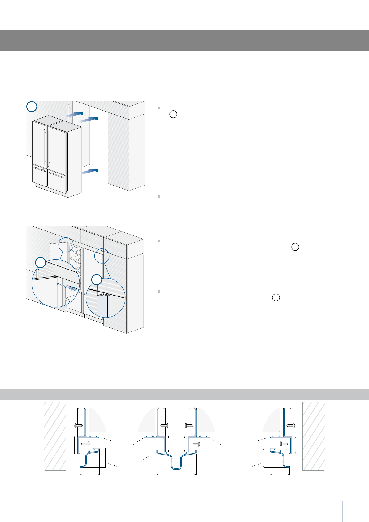
Once completed the previous steps, push the units in their nal posi-
tion
6
.
If the units are to be installed inside a niche or within an enclosed
structure, it is necessary to design a ventilation shaft at the back of
the niche to assure proper ventilation at the back of the unit. A 5 mm
gap is sufcient to prevent overheating. Always mount front panels on
door and drawer before pushing the unit into its nal position inside the
niche or structure.
Check the levelling of the appliance, adjusting its feet and wheels
to correct it.
Secure the appliance to the adjacent cabinets by xing to these the
side proles previously mounted on the appliance
7
.
To make this operation easier keep the door and the drawer open.
Mount the covering frames onto the proles, rst insert them laterally
and then push rmly until a “click” is heard
8
.
Appliance Appliance
Wall
or
furniture
Wall
or
furniture
A Connecting element
B Alluminium frame
D Connecting element
E Aluminium frame
Side and central proles mounting
Series: Integrated
Loading ...
Loading ...
Loading ...