Loading ...
Loading ...
Loading ...
8.4 Injectors replacement
1. Remove the pan supports.
2. Remove the caps and crowns of the
burner.
3. With a socket spanner 7 remove the
injectors and replace them with the
ones which are necessary for the
type of gas you use (see table in
"Technical Information" chapter).
4. Assemble the parts, follow the same
procedure backwards.
5. Replace the rating plate (it is near the
gas supply pipe) with the one for the
new type of gas supply. You can find
this plate in the package supplied
with the appliance.
If the supply gas pressure is changeable
or different from the necessary pressure,
you must fit an applicable pressure
adjuster on the gas supply pipe.
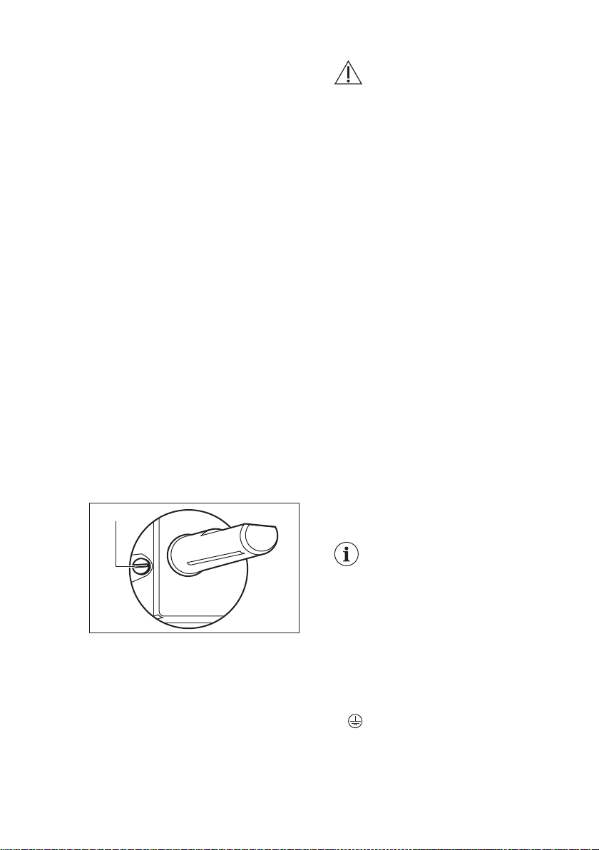
8.5 Adjustment of minimum
level
To adjust the minimum level of the
burners:
1. Light the burner.
2. Turn the knob on the minimum
position.
3. Remove the knob.
4. With a thin screwdriver, adjust the
bypass screw position (A).
A
5. If you change:
• from natural gas G20 20 mbar to
liquid gas, fully tighten the bypass
screw in.
• from liquid gas to natural gas G20
20 mbar, undo the bypass screw
approximately 1/4 of a turn.
WARNING!
Make sure the flame does
not go out when you quickly
turn the knob from the
maximum position to the
minimum position.
8.6 Electrical connection
• Do not pull the mains cable to
disconnect the appliance. Always pull
the mains plug (if applicable).
• The appliance must not be connected
with an extension cable, an adapter or
a multiple socket. There is a risk of
fire.
• Do not let the power cable to heat up
to a temperature of more than 90° C.
The cable should be guided by means
of clamps fixed to the side of the
cabinet, in order to avoid any contact
with the equipment beneath the
cooktop.
• Make sure that there is access to the
mains plug after the installation.
Electrical Requirements
Permanent electrical installation must
agree with the latest I.E.E. Regulations
and local Electricity Board regulations.
For your own safety the installation must
be done by a qualified electrician (e.g.
your local Electricity Board, or a
contractor who is on the roll of the
National Inspection Council for Electrical
Installation Contracting [NICEIC]).
The manufacturer refuses
to be held responsible, if
these safety measures are
not abided by.
Supply connections
This hob has to be connected to 220-240
V (~ 50/60 Hz ) electricity supply.
The hob has a terminal block which is
marked as follows:
• L — Live terminal
• N — Neutral terminal
• or E — Earth terminal
Before carrying out the connection, make
sure:
1. The limiter valve and the electrical
system can take the appliance load
(see the rating plate)
www.electrolux.com14
Loading ...
Loading ...
Loading ...