Loading ...
Loading ...
Loading ...
11
4. Plug into a grounded 3 prong outlet.
Complete Installation
Electronic Ignition System
Initial lighting and gas flame adjustments
Surface burners use electronic igniters in place of standing
pilots. When the cooktop control knob is turned to the “IGNITE”
position, the system creates a spark to light the burner. This
sparking continues, as long as the control knob is turned to
“IGNITE”.
Check Operation of Surface Burners
Push in and turn the surface burners control knobs to light.
The surface burner ame should light within 4 seconds. The rst
time a surface burner is lit, it may take longer that 4 seconds to
light because of air in the gas line.
Check the ame on “HIGH” for a blue color. It should be clean
and soft in character. No yellow tip, blowing or lifting of ame
should occur. Occasional orange ashes are normal and reect
different elements in the air or gas.
After verifying the proper burner operation, turn the control
knobs to “OFF.”
If burners do not light properly:
■ Turn surface burner control knob to the “OFF” position.
■ Check that the power supply cord is plugged in and the
circuit breaker has not tripped or the fuse blown.
■ Check that the gas shutoff valve is set to the “open” position.
■ Check that burner caps are properly positioned on burner
bases.
Recheck operation of surface burners. If a burner does not light
at this point, contact your dealer or authorized service company
for assistance.
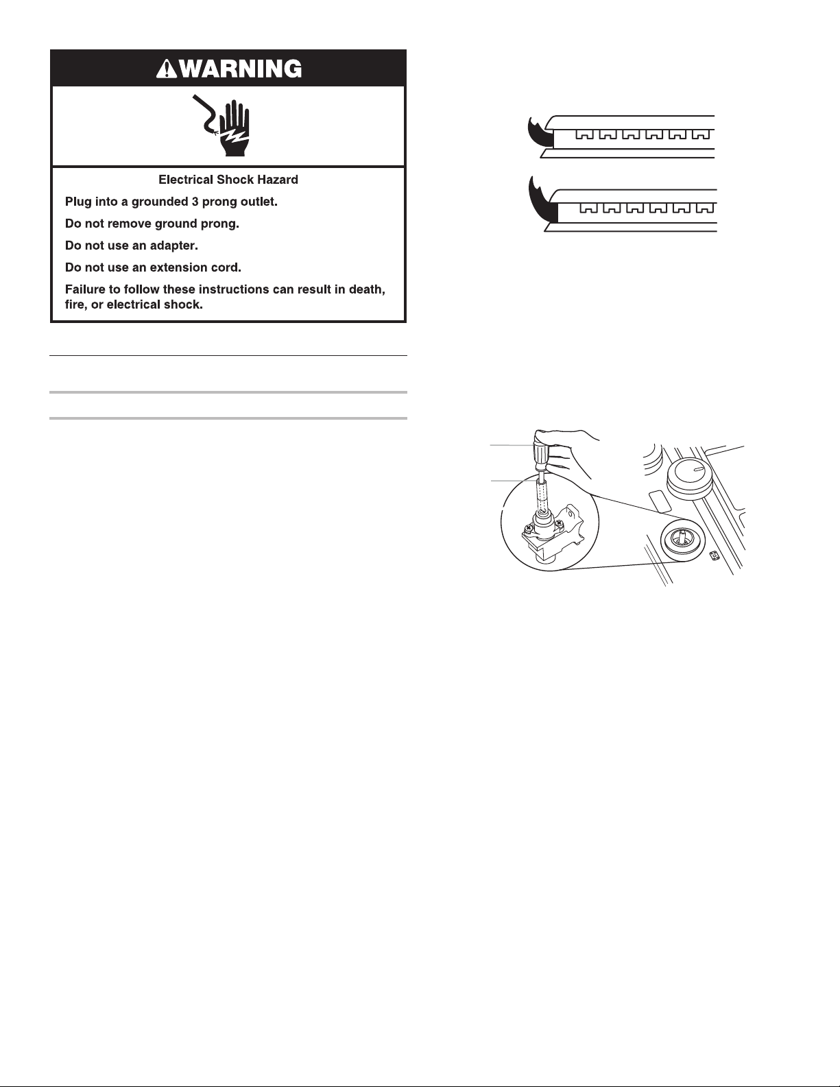
Check Flame Height
Adjust the height of surface burner ames.
The surface burner low ame should be a steady blue ame
approximately 1/4"(6.4mm) high.
Adjustment for Single Valve:
1. Set the burner ame to LO.
2. Remove the control knob.
3. Hold knob stem with a pair of pliers. Use a 3/32" (#0 [2 mm])
at-blade screwdriver to turn the screw located within the
shaft of the control knob stem until the ame is the proper
size.
Turn adjustment screw “C” to the right to reduce ame
height, turn adjustment screw to the left to increase ame
height.
4. Replace the control knob.
5. Test the ame by turning the control from LO to HI, checking
the ame at each setting.
IMPORTANT: Dual valve adjustments must be performed by a
qualied installer or service agency.
A. Low flame
B. High flame
A
B
B
C
A
A. 3/32" (#0 [2.0 mm]) flat-blade screwdriver
(screwdriver shaft must be a minimum of
2" [5.1 cm] long)
B. Control knob stem opening
C. Adjustment screw location
Loading ...
Loading ...
Loading ...