OWNER’S
MANUAL
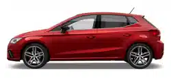
Ibiza
6F0012720BC
Inglés
6F0012720BC (11.17)
Ibiza Inglés (11.17)
SEAT recommends
SEAT GENUINE OIL
SEAT recommends
Castrol EDGE Professional
SEAT S.A. is permanently concerned about continuous development of its types and models. For this reason we ask you to under-
stand, that at any given time, changes regarding shape, equipment and technique may take place on the car delivered. For this reason
no right at all may derive based on the data, drawings and descriptions in this current handbook.
All texts, illustrations and standards in this handbook are based on the status of information at the time of printing. Except for error
or omission, the information included in the current handbook is valid as of the date of closing print.
Re-printing, copying or translating, whether total or partial is not allowed unless SEAT allows it in written form.
SEAT reserves all rights in accordance with the “Copyright” Act.
All rights on changes are reserved.
❀
This paper has been manufactured using bleached non-chlorine cellulose.
© SEAT S.A. - Reprint: 15.11.17
About this manual
This manual contains a description of the
equipment supplied with the vehicle at the
time this manual was published. Some of the
units described herein will not be available
until a later date or are only available in cer-
tain markets.
Because this is a general manual for the
IBIZA, some of the equipment and functions
that are described in this manual are not in-
cluded in all types or variants of the model;
they may vary or be modified depending on
the technical requirements and on the mar-
ket; this is in no way deceptive advertising.
The illustrations are intended as a general
guide and may vary from the equipment fitted
in your vehicle in some details.
The steering indications (left, right, forward,
reverse) appearing in this manual refer to the
normal driving movements of the vehicle ex-
cept when otherwise indicated.
The audiovisual material only is intended to
help users to understand certain car function-
alities better. It does not replace the instruc-
tion manual. Please use the instruction manu-
al to obtain more comprehensive information
and indications.
The equipment marked with an aster-
isk* is fitted as standard only in certain
versions, and is only supplied as op-
tional extras for some versions, or are
only offered in certain countries.
® All registered marks are indicated with
®. Although the copyright symbol does
not appear, it is a copyrighted mark.
>> The section is continued on the follow-
ing page.
Important warnings on a given page
Detailed contents on a given page
General information on a given page
Emergency information on a given page
WARNING
Texts preceded by this symbol contain infor-
mation on safety. They warn you about possi-
ble dangers of accident or injury.
CAUTION
Texts with this symbol draw your attention to
potential sources of damage to your vehicle.
For the sake of the environment
Texts preceded by this symbol contain rele-
vant information concerning environmental
protection.
Note
Texts preceded by this symbol contain additio-
nal information.
This manual is divided into six large parts,
which are:
1. The essentials
2. Safety
3. Emergencies
4. Operation
5. Tips
6. Technical data
At the end of this manual, there is a detailed
alphabetical index that will help you quickly
find the information you require.

Foreword
Thi
s
In
struction Manual and its correspond-
ing supplements should be read carefully to
familiarise yourself with your vehicle.
Besides the regular care and maintenance of
the vehicle, its correct handling will help pre-
serve its value.
For safety reasons, always note the informa-
tion concerning accessories, modifications
and part replacements.
If selling the vehicle, give all of the on-board
documentation to the new owner, as it
should be kept with the vehicle.
You can access the information in this man-
ual using:
●
Thematic table of contents that follows the
manual’s general chapter structure.
●
Visual table of contents that uses graphics
to indicate the pages containing “essential”
information, which is detailed in the corre-
sponding chapters.
●
Alphabetical index with many terms and
synonyms to help you find information.
WARNING
Read and always observe safety informa-
tion concernin
g the passenger's front air-
bag ››› page 92, Important information
regarding the front passenger's airbag.
Thank you for trusting in us.
We wish you safe and enjoya-
ble motoring.
SEAT, S.A.

Related videos
The essentials: Opening and closing ››› page 15
www.seat.com/youtube-af/ibiza/essentials-locking
The essentials: Vehicle interior ››› page 19, ››› page 21,
››› page 23
www.seat.com/youtube-af/ibiza/essentials-insidecar
The essentials: Engine bonnet ››› page 17
www.seat.com/youtube-af/ibiza/essentials-bonnet
The essentials: Wheels ››› page 63, ››› page 65
www.seat.com/youtube-af/ibiza/essentials-wheels
The essentials: Air conditioner ››› page 51
www.seat.com/youtube-af/ibiza/essentials-aircond
The essentials: Dashboard ››› page 31, ››› page 45,
››› page 47
www.seat.com/youtube-af/ibiza/essentials-dashboard

Convenience: Kessy keyless access and starting system, Full LED (+ Vision Pack): Full LED + Welcome light + LED day-
time running lights + Lights sensor + LED interior lighting.
www.seat.com/youtube-af/ibiza/comfort
››› page 135
››› page 148
››› page 150
››› page 204
Technology: SEAT Navi System Plus 8” + Full Link / + Wireless charger in centre console + / Kessy keyless access and
starting system.
www.seat.com/youtube-af/ibiza/technology
››› page 129
››› page 135
››› Booklet Navigation system
Safety: Adaptive cruise control + city safety assist with pedestrian monitoring, drowsiness detection, hill-start assist
system; includes on-board computer and rear view camera.
www.seat.com/youtube-af/safety
››› page 189
››› page 216
››› page 227
››› page 234

Frequently Asked Ques-
tion
s
Before driving
How do you adjust the seat? ››› page 19
How do you adjust the steering wheel? ››› page 20
How do you adjust the exterior mirrors? ››› page 20
How do you turn on the exterior lights? ››› page 31
How does the automatic gearbox selector lever work?
››› page 50
How do you refuel? ››› page 57
How do you activate the windscreen wipers and wind-
screen washer system? ››› page 33
Emergency situations
A warning lamp lights up or flashes. What does this
mean? ››› page 47
Where are the first-aid kit and the warning triangle in
the vehicle? ››› page 97
How do you open the bonnet? ››› page 17
How do you perform a jump start? ››› page 71
Where is the vehicle tool kit located? ››› page 65
How do you repair a tyre with the anti-puncture kit?
››› page 64
How do you change a wheel? ››› page 65
How do you change a fuse? ››› page 62
How do you change a light? ››› page 63
How do you tow a vehicle? ››› page 70
Useful tips
How do you set the time? ››› page 118
When should the vehicle inspection should be per-
formed? ››› page 43
What functions do the buttons/thumbwheels on the
steering wheel perform? ››› page 124
How do you remove the luggage compartment cover?
››› page 163
How do you drive in an economical and environmental-
ly-friendly way? ››› page 200
How do you check and top up the engine oil?
››› page 58
How do you check and top up the engine coolant?
››› page 59
How do you top up the windscreen washer fluid?
››› page 60
How do you check and top up the brake fluid?
››› page 60
How do you check and adjust tyre pressure values?
››› page 275
Vehicle washing tips ››› page 249
Functions of interest
Easy Connect, CAR menu ››› page 34
How does the START-STOP system work? ››› page 204
What parking assistants are available? ››› page 228
How does the rear assist work? ››› page 234
How does the adaptive cruise control work?
››› page 216
How can the SEAT driving mode be adjusted?
››› page 225
How does tyre pressure monitoring work? ››› page 278
How do you open the vehicle without a key (Keyless Ac-
cess)? ››› page 135
Interior lighting and ambient light ››› page 150

Table of Contents
Table of Contents
The e
s
senti
als . . . . . . . . . . . . . . . . . . . . . . . . 7
Exterior view . . . . . . . . . . . . . . . . . . . . . . . . . . . . 7
Exterior view . . . . . . . . . . . . . . . . . . . . . . . . . . . . 8
Driver-side general instrument panel (left-
hand drive) . . . . . . . . . . . . . . . . . . . . . . . . . . . . . 9
Driver-side general instrument panel (right-
hand drive) . . . . . . . . . . . . . . . . . . . . . . . . . . . . . 10
Centre console . . . . . . . . . . . . . . . . . . . . . . . . . . 11
Passenger-side general instrument panel (left-
hand drive) . . . . . . . . . . . . . . . . . . . . . . . . . . . . . 12
Passenger-side general instrument panel
(right-hand drive) . . . . . . . . . . . . . . . . . . . . . . . . 13
Interior view . . . . . . . . . . . . . . . . . . . . . . . . . . . . 14
How it works . . . . . . . . . . . . . . . . . . . . . . . . . . . . 15
Opening and closing . . . . . . . . . . . . . . . . . . . . . 15
Before driving . . . . . . . . . . . . . . . . . . . . . . . . . . . 19
Airbags . . . . . . . . . . . . . . . . . . . . . . . . . . . . . . . . 21
Child seats . . . . . . . . . . . . . . . . . . . . . . . . . . . . . 23
Starting the vehicle . . . . . . . . . . . . . . . . . . . . . . 31
Lights and visibility . . . . . . . . . . . . . . . . . . . . . . 31
Easy Connect . . . . . . . . . . . . . . . . . . . . . . . . . . . 34
Driver information System . . . . . . . . . . . . . . . . . 37
Status display . . . . . . . . . . . . . . . . . . . . . . . . . . . 40
Cruise control . . . . . . . . . . . . . . . . . . . . . . . . . . . 45
Warning lamps . . . . . . . . . . . . . . . . . . . . . . . . . . 47
Gearbox lever . . . . . . . . . . . . . . . . . . . . . . . . . . . 50
Air conditioning . . . . . . . . . . . . . . . . . . . . . . . . . 51
Fluid Level control . . . . . . . . . . . . . . . . . . . . . . . 57
Emergencies . . . . . . . . . . . . . . . . . . . . . . . . . . . . 62
Fuses . . . . . . . . . . . . . . . . . . . . . . . . . . . . . . . . . . 62
Bulbs . . . . . . . . . . . . . . . . . . . . . . . . . . . . . . . . . . 63
Action in the event of a puncture . . . . . . . . . . . 63
Changing a wheel . . . . . . . . . . . . . . . . . . . . . . . 65
Snow chains . . . . . . . . . . . . . . . . . . . . . . . . . . . . 70
Emergency towing of the vehicle . . . . . . . . . . . 70
How to jump start . . . . . . . . . . . . . . . . . . . . . . . . 71
Changing the windscreen wiper blades . . . . . . 73
Safety . . . . . . . . . . . . . . . . . . . . . . . . . . . . . . . . 75
Safe driving . . . . . . . . . . . . . . . . . . . . . . . . . . . . 75
Safety first! . . . . . . . . . . . . . . . . . . . . . . . . . . . . . 75
Advice about driving . . . . . . . . . . . . . . . . . . . . . 75
Correct position of the vehicle occupants . . . . 76
Pedal area . . . . . . . . . . . . . . . . . . . . . . . . . . . . . . 80
Seat belts . . . . . . . . . . . . . . . . . . . . . . . . . . . . . . 81
Why wear a seat belt . . . . . . . . . . . . . . . . . . . . . 81
How to properly adjust your seatbelt . . . . . . . . 84
Seat belt tensioners* . . . . . . . . . . . . . . . . . . . . . 85
Airbag system . . . . . . . . . . . . . . . . . . . . . . . . . . 86
Brief introduction . . . . . . . . . . . . . . . . . . . . . . . . 86
Airbag safety instructions . . . . . . . . . . . . . . . . . 88
Deactivating airbags . . . . . . . . . . . . . . . . . . . . . 90
Transporting children safely . . . . . . . . . . . . . . . 92
Child safety . . . . . . . . . . . . . . . . . . . . . . . . . . . . . 92
Child seats . . . . . . . . . . . . . . . . . . . . . . . . . . . . . 93
Event Data Recorder . . . . . . . . . . . . . . . . . . . . . . 96
Description and operation . . . . . . . . . . . . . . . . . 96
Emergencies . . . . . . . . . . . . . . . . . . . . . . . . . . 97
Self-help . . . . . . . . . . . . . . . . . . . . . . . . . . . . . . . 97
Emergency equipment . . . . . . . . . . . . . . . . . . . . 97
Tyre repair . . . . . . . . . . . . . . . . . . . . . . . . . . . . . . 98
Changing the windscreen wiper blades . . . . . . 100
Towing or tow-starting . . . . . . . . . . . . . . . . . . . . 100
Fuses and bulbs . . . . . . . . . . . . . . . . . . . . . . . . . 104
Fuses . . . . . . . . . . . . . . . . . . . . . . . . . . . . . . . . . . 104
Changing bulbs . . . . . . . . . . . . . . . . . . . . . . . . . 106
Halogen headlights. . . . . . . . . . . . . . . . . . . . . . 107
Changing the fog light bulbs . . . . . . . . . . . . . . . 109
Changing the tail light bulbs . . . . . . . . . . . . . . . 109
Changing the interior bulbs . . . . . . . . . . . . . . . . 111
Operation . . . . . . . . . . . . . . . . . . . . . . . . . . . . . 115
Controls and displays . . . . . . . . . . . . . . . . . . . . 115
General instrument panel . . . . . . . . . . . . . . . . . 114
Instruments and warning/control lamps . . . . . 117
Instruments . . . . . . . . . . . . . . . . . . . . . . . . . . . . 117
Warning and control lamps . . . . . . . . . . . . . . . . 122
Introduction to the Easy Connect system* . . . . 123
System settings (CAR)* . . . . . . . . . . . . . . . . . . . 123
Communications and multimedia . . . . . . . . . . . 124
Steering wheel controls* . . . . . . . . . . . . . . . . . . 124
Multimedia . . . . . . . . . . . . . . . . . . . . . . . . . . . . . 129
Opening and closing . . . . . . . . . . . . . . . . . . . . . 130
Keys . . . . . . . . . . . . . . . . . . . . . . . . . . . . . . . . . . . 130
Central locking system . . . . . . . . . . . . . . . . . . . . 132
Anti-theft alarm* . . . . . . . . . . . . . . . . . . . . . . . . 138
Rear lid . . . . . . . . . . . . . . . . . . . . . . . . . . . . . . . . 141
Controls for the windows . . . . . . . . . . . . . . . . . . 141
Sunroof* . . . . . . . . . . . . . . . . . . . . . . . . . . . . . . . 144
Lights and visibility . . . . . . . . . . . . . . . . . . . . . . 146
Lights . . . . . . . . . . . . . . . . . . . . . . . . . . . . . . . . . 146
Interior lights . . . . . . . . . . . . . . . . . . . . . . . . . . . 150
Visibility . . . . . . . . . . . . . . . . . . . . . . . . . . . . . . . 151
Windscreen wiper and rear window wiper sys-
tems . . . . . . . . . . . . . . . . . . . . . . . . . . . . . . . . . . 152
Rear view mirrors . . . . . . . . . . . . . . . . . . . . . . . . 152
Seats and head restraints . . . . . . . . . . . . . . . . . 154
Adjusting the seat and head restraints . . . . . . 154
Seat functions . . . . . . . . . . . . . . . . . . . . . . . . . . 156
Transport and practical equipment . . . . . . . . . 158
Practical equipment . . . . . . . . . . . . . . . . . . . . . . 158
Luggage compartment . . . . . . . . . . . . . . . . . . . . 160
Roof carrier* . . . . . . . . . . . . . . . . . . . . . . . . . . . . 164
Air conditioning . . . . . . . . . . . . . . . . . . . . . . . . . 166
Heating, ventilation and cooling . . . . . . . . . . . . 166
Heating and fresh air . . . . . . . . . . . . . . . . . . . . . 169
Manual air conditioning* . . . . . . . . . . . . . . . . . . 171
Climatronic* . . . . . . . . . . . . . . . . . . . . . . . . . . . . 173
5

Table of Contents
Driving . . . . . . . . . . . . . . . . . . . . . . . . . . . . . . . . 175
Starting and stopping the engine . . . . . . . . . . . 175
Braking and parking . . . . . . . . . . . . . . . . . . . . . 181
Braking and stability systems . . . . . . . . . . . . . . 183
Manual gearbox . . . . . . . . . . . . . . . . . . . . . . . . . 189
Automatic gearbox/DSG automatic gear-
bo
x*
. . . . . . . . . . . . . . . . . . . . . . . . . . . . . . . . . . . 190
Ge
ar-change indicator . . . . . . . . . . . . . . . . . . . . 197
Steering . . . . . . . . . . . . . . . . . . . . . . . . . . . . . . . 197
Run-in and economical driving . . . . . . . . . . . . . 199
Engine management and emission control sys-
tem . . . . . . . . . . . . . . . . . . . . . . . . . . . . . . . . . . . 202
Driving tips . . . . . . . . . . . . . . . . . . . . . . . . . . . . . 203
Driver assistance systems . . . . . . . . . . . . . . . . . 204
Start-Stop System* . . . . . . . . . . . . . . . . . . . . . . . 204
Cruise control system (CCS)* . . . . . . . . . . . . . . . 207
Speed limiter . . . . . . . . . . . . . . . . . . . . . . . . . . . 209
Emergency brake assist system (Front As-
sist)* . . . . . . . . . . . . . . . . . . . . . . . . . . . . . . . . . . 212
Adaptive Cruise Control (ACC)* . . . . . . . . . . . . . 216
SEAT Drive Profile* . . . . . . . . . . . . . . . . . . . . . . . 225
Fatigue detection (break recommendation)* . . 227
Parking aid (Park Pilot) . . . . . . . . . . . . . . . . . . . 228
Rear Assist “Rear View Camera”* . . . . . . . . . . . 234
Towing bracket device . . . . . . . . . . . . . . . . . . . . 237
Towing bracket device* . . . . . . . . . . . . . . . . . . . 237
Trailer towing . . . . . . . . . . . . . . . . . . . . . . . . . . . 242
Advice . . . . . . . . . . . . . . . . . . . . . . . . . . . . . . . . 247
Care and maintenance . . . . . . . . . . . . . . . . . . . . 247
Accessories and modifications to the vehi-
cle . . . . . . . . . . . . . . . . . . . . . . . . . . . . . . . . . . . . 247
Care and cleaningTaking care of your vehi-
cle . . . . . . . . . . . . . . . . . . . . . . . . . . . . . . . . . . . . 248
Care of the vehicle exterior . . . . . . . . . . . . . . . . 249
Caring for the vehicle interior . . . . . . . . . . . . . . 254
Checking and refilling levels . . . . . . . . . . . . . . . 257
Refuelling . . . . . . . . . . . . . . . . . . . . . . . . . . . . . . 257
Fuel . . . . . . . . . . . . . . . . . . . . . . . . . . . . . . . . . . . 258
AdBlue
®
. . . . . . . . . . . . . . . . . . . . . . . . . . . . . . . 261
Working in the engine compartment . . . . . . . . 263
Engine oil . . . . . . . . . . . . . . . . . . . . . . . . . . . . . . 266
Cooling system . . . . . . . . . . . . . . . . . . . . . . . . . . 269
Brake fluid . . . . . . . . . . . . . . . . . . . . . . . . . . . . . 271
Windscreen washer reservoir . . . . . . . . . . . . . . 272
Vehicle battery . . . . . . . . . . . . . . . . . . . . . . . . . . 272
Wheels . . . . . . . . . . . . . . . . . . . . . . . . . . . . . . . . 274
Wheels and tyres . . . . . . . . . . . . . . . . . . . . . . . . 274
Spare wheel (temporary spare wheel)* . . . . . . 279
Winter service . . . . . . . . . . . . . . . . . . . . . . . . . . . 280
Technical data . . . . . . . . . . . . . . . . . . . . . . . . 281
Technical specifications . . . . . . . . . . . . . . . . . . 281
Important information . . . . . . . . . . . . . . . . . . . . 281
Fuel consumption data . . . . . . . . . . . . . . . . . . . 282
Trailer mode . . . . . . . . . . . . . . . . . . . . . . . . . . . . 282
Wheels . . . . . . . . . . . . . . . . . . . . . . . . . . . . . . . . 283
Engine data . . . . . . . . . . . . . . . . . . . . . . . . . . . . . 284
Dimensions . . . . . . . . . . . . . . . . . . . . . . . . . . . . . 295
Index . . . . . . . . . . . . . . . . . . . . . . . . . . . . . . . . . 297
6
The essentials
How it works
Openin
g and c
lo
sing
Related video
Fig. 1 Opening and clos-
ing
Doors
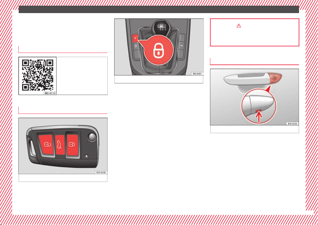
Fig. 2 Remote control key: buttons.
Fig. 3 Centre console: Central lock buttons.
Locking and unlocking the vehicle using the
k
ey
●
L
oc
king: press the ››› Fig. 2 button.
●
Unlocking: press the ››› Fig. 2 button.
●
Unlocking the rear lid: press the button
››› Fig. 2 until all the turn signals on the vehi-
cle briefly light up.
Locking and unlocking with the central lock-
ing switch
●
Locking: press the ››› Fig. 3 button. The
symbol lights up yellow to indicate that it is
activated. None of the doors can be opened
from the outside. The doors can be opened
from the inside by pulling the inside door
handle.
●
Unlocking: Press the button again
››› Fig. 3. The symbol reverts to its initial col-
our.
››› in Description on page 132
››› page 132
Unlocking or locking of driver door
Fig. 4 Driver door lever: hidden lock cylinder.
If the central locking system should fail to op-
er
at
e, the driv
er door can still be locked and
unlocked by turning the key in the lock.
As a general rule, when the driver door is
locked manually all other doors are locked.
When it is unlocked manually, only the driver
door opens. Please observe the instructions
relating to the anti-theft alarm system
›››
page 138.
●
Unfold the vehicle key blade
›››
page 130.
»
15
The essentials
●
In
ser
t
the key shaft into the lower opening
in the cover on the driver door handle
››› Fig. 4 (arrow) then remove the cover up-
wards.
●
Insert the key blade into the lock cylinder
to unlock or lock the vehicle.
Special Characteristics
●
The anti-theft alarm will remain active when
vehicles are unlocked. However, the alarm
will not be triggered ›››
page 138.
●
After the driver door is opened, you have
15 seconds to switch on the ignition. Once
this time has elapsed, the alarm is triggered.
●
Switch the ignition on. The electronic im-
mobilizer recognises a valid vehicle key and
deactivates the anti-theft alarm system.
Note
The anti-theft alarm is not activated when the
vehicl
e is locked manually using the key
shaft ›››
page 138.
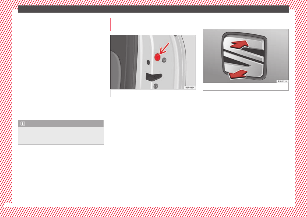
Emergency locking of doors without
door cylinder
Fig. 5 Locking the door manually.
If the central locking system should fail to
w
ork
at
any time, doors with no lock cylinder
will have to be locked separately.
A mechanical locking device (only visible
when the door is open) is provided on the
front passenger door.
●
Pull the cap out of the opening.
●
Insert the key in the inside slot and turn it
to the right as far as it will go (if the door is
on the right side) or to the left (if the door is
on the left side).
Once the door has been closed it can no lon-
ger be opened from the outside. Pull the inte-
rior door handle once to unlock and open the
door.
Rear lid
Fig. 6 Rear lid: opening from the outside.
The rear lid opening system operates electri-
c
al
ly
. It is activated by using the handle on
the boot lid.
This system may or may not be operative, de-
pending on the situation of the vehicle.
If the rear lid is locked then it cannot be
opened, however if it is unlocked then the
opening system is operative and the rear lid
may be opened.
To lock/unlock, press the button or the
button ››› Fig. 2 on the remote control key.
A warning appears on the instrument panel
display if the rear lid is open or not properly
closed.* An audible warning is also given if
the boot lid is opened while the vehicle is
moving faster than 6 km/h (4 mph)*.
16
The essentials
●
Openin
g the r
e
ar lid: pull on the release
lever and lift it up ››› Fig. 6. The rear lid opens
automatically.
●
Closing the rear lid: Hold it by one of the
handles on the interior lining and close it by
pushing gently.
››› in Opening and closing on
page 141
››› page 17
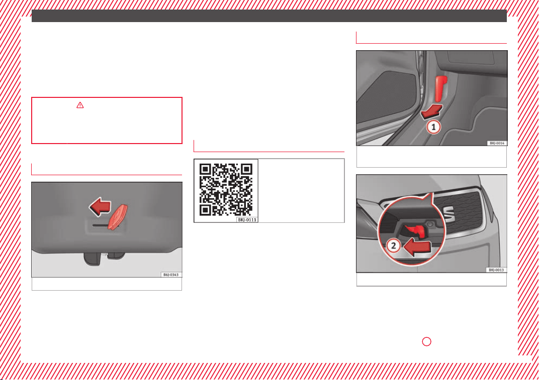
Unlocking the rear lid manually
Fig. 7 Unlocking the rear lid manually.
This allows the vehicle to be opened if the
c
entr
al
locking does not work (for example, if
the battery is flat).
There is a groove in the luggage compart-
ment allowing access to the emergency
opening mechanism.
Opening the rear lid from inside the luggage
compartment
●
Insert the key in the groove and unlock the
locking system, turning the key from right to
left, as shown by the arrow ››› Fig. 7.
Related video
Fig. 8 Bonnet
Bonnet
Fig. 9 Release lever in the driver's footwell
ar
e
a.
Fig. 10 Lever under the bonnet.
Before opening the bonnet, make sure that
the w
ind
s
creen wiper arms are in place
against the windscreen.
●
Open the door and pull the lever under the
dashboard ››› Fig. 9
1
.
»
17
The essentials
●
T
o lif
t
the bonnet, press towards the left on
the lever located under the bonnet, in the
centre ››› Fig. 10
2
. The arrester hooks are
r
el
e
ased.
●
Release the bonnet stay and secure it in
the fixture designed for this in the bonnet.
››› in Safety notes for work in the en-
gine compartment on page 263
››› page 263
Controls for the windows*
Fig. 11 Detail of the driver door: controls for
the w
indo
w
s.
●
Opening the window: Press the b
utt
on.
●
C
losing the window: Pull the button.
Buttons on the driver door
Window on the front left door
Window on the front right door
Window on the rear left door (only vehi-
cles with rear electric windows)
Window on the rear right door (only vehi-
cles with rear electric windows)
Safety switch for deactivating the electric
window buttons on the rear doors (only
vehicles with rear electric windows)
››› in Opening and closing of the elec-
tric windows* on page 142
››› page 141
1
2
3
4
5
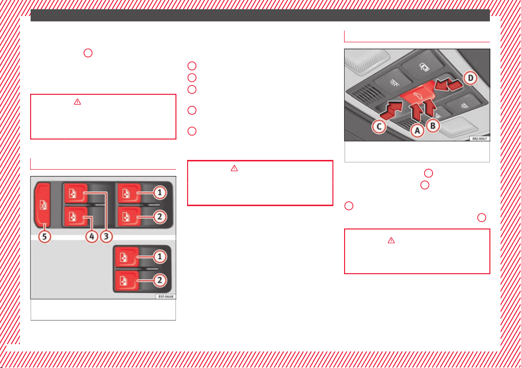
Sliding sunroof*
Fig. 12 On the interior roof lining: sunroof
b
utt
on.
●
Opening: press button
C
backwards.
●
Closing: press button
D
forwards.
●
To tilt open: press the rear part of button
B
.
●
Lowering: press the front part of button
A
.
››› in Introduction on page 144
››› page 144
18
The essentials
Before driving
R
el
at
ed video
Fig. 13 Vehicle interior
Manually adjusting the front seats
Fig. 14 Front seats: manual seat adjustment.
Forward/back: pull the lever and move
the se
at
f
orwards or backwards.
Raising/lowering: pull/push the lever.
Tilting the backrest: turn the hand wheel.
1
2
3
››› in Adjusting the front seats on
page 154
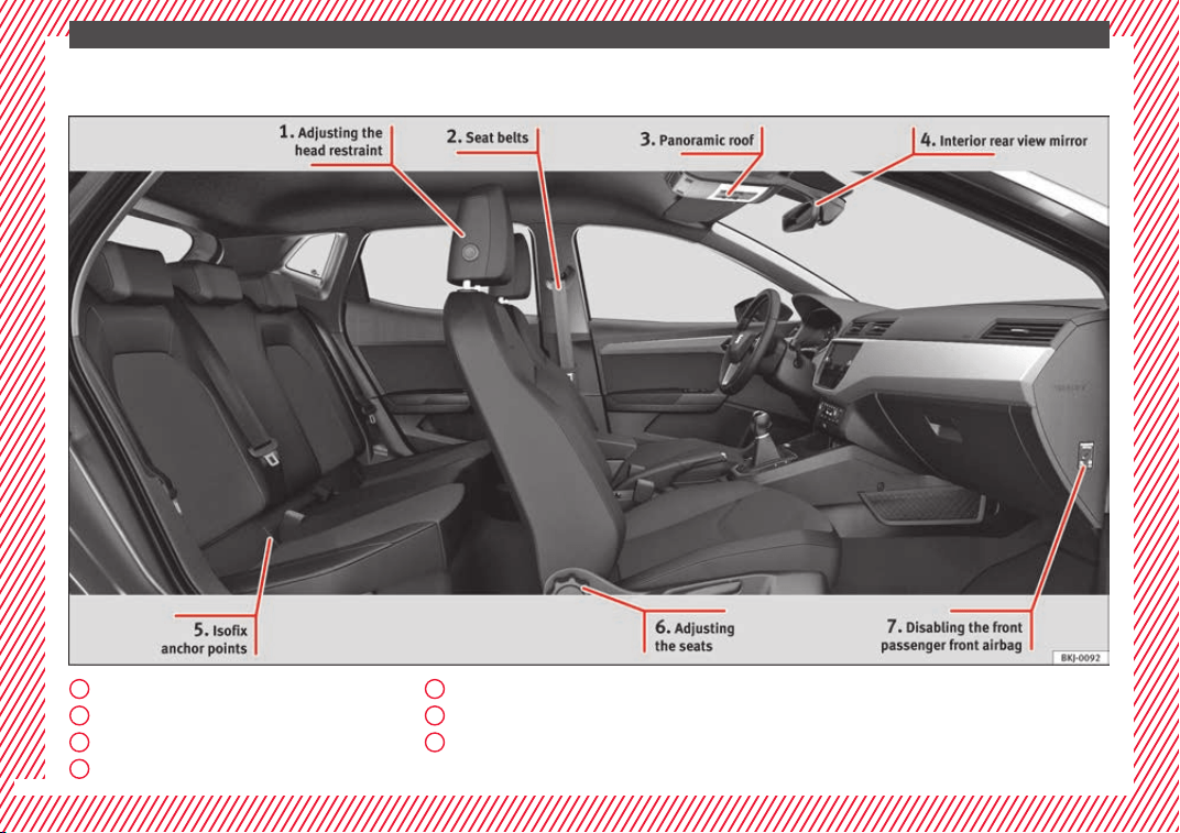
Adjusting the head restraints
Fig. 15 Front seat: adjustment of the head re-
s
tr
aint
.
●
To raise or lower the head restraint, press
the s
ide b
utt
on
1
and move it upwards or
do
wn
w
ards until it engages in the desired
position.
››› in Adjusting the front head re-
straints on page 155
››› page 79, ››› page 155
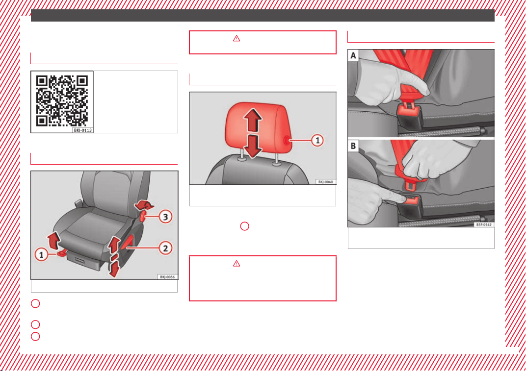
Adjustment of the seat belt
Fig. 16 Positioning and removing the seat
belt
b
uc
kle.
»
19
The essentials
Fig. 17 Correct seat belt and head restraint
position
s, viewed from front and the side.
To adjust the seat belt around your should-
er
s, a
dju
st the height of the seats.
The shoulder part of the seat belt should be
well centred over it, never over the neck. The
seat belt lies flat and fits comfortably on the
upper part of the body.
The lap part of the seat belt lies across the
pelvis, never across the stomach. The seat
belt lies flat and fits comfortably on the pel-
vis.
››› page 82
››› page 84
Seat belt tensioners
During a collision, the seat belts on the front
seats ar
e retracted automatically.
The tensioner can be triggered only once.
››› in Maintenance and disposal of belt
tensioners on page 86
››› page 85
Adjusting the exterior mirrors
Fig. 18 Detail of the driver door: control for
the e
xt
erior mirr
or.
Adjusting the exterior mirrors: Turn the knob
t
o the c
orr
esponding position:
Turning the knob to the desired posi-
tion, adjust the mirrors on the driver
L/R
side (L, left) and the passenger side (R,
right) to the direction desired.
Folding in mirrors.
››› in Electric exterior mirrors* on
page 154
››› page 153
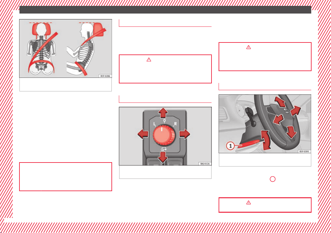
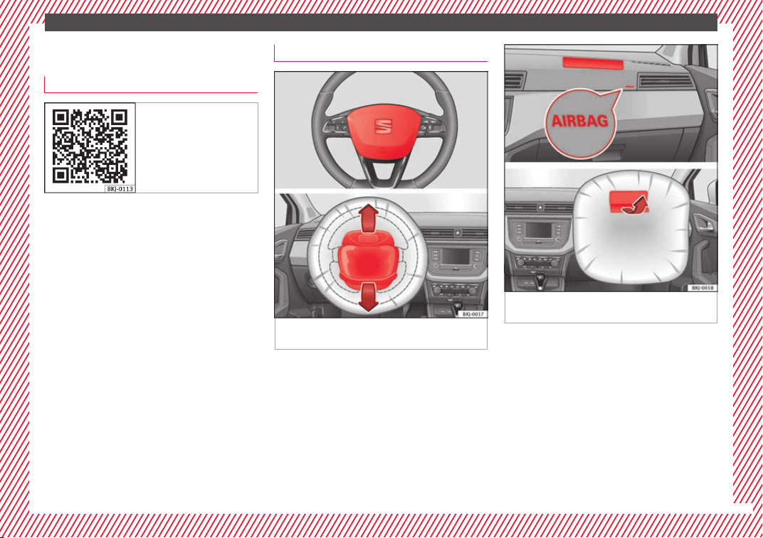
Adjusting the steering wheel
Fig. 19 Lever in the lower left side of the
s
t
eerin
g column.
●
Adjusting the position of the steering
wheel: P
u
l
l the ››› Fig. 19
1
lever down,
mo
v
e the s
teering wheel to the desired posi-
tion and lift the lever back up until it locks.
››› in Adjusting the steering wheel po-
sition on page 77
20
The essentials
Airbags
R
el
at
ed video
Fig. 20 Vehicle interior
Front airbags
Fig. 21 Driver airbag located in steering
wheel
.
Fig. 22 Front passenger airbag located in
d
a
sh p
anel.
The front airbag for the driver is located in
the s
t
eerin
g wheel ››› Fig. 21 and the airbag
for the front passenger is located in the dash
panel ››› Fig. 22. Airbags are identified by the
word “AIRBAG”.
When the driver and front passenger airbags
are deployed, the covers remain attached to
the steering wheel and dashboard, respec-
tively ››› Fig. 21 ››› Fig. 22.
In conjunction with the seat belts, the front
airbag system gives the driver and the front
passenger additional protection for the head
»
21
The essentials
and chest in the event of a severe frontal col-
li
s
ion.
The s
pecial design of the airbag allows the
controlled escape of the propellant gas when
an occupant puts pressure on the bag. Thus,
the head and chest are surrounded and pro-
tected by the airbag. After the collision, the
airbag deflates sufficiently to allow visibility.
››› page 88
Deactivating the front passenger front
airb
ag*
Fig. 23 Front passenger front airbag switch.
Fig. 24 Centre side of dash panel: control
lamp for de
activated front passenger airbag
in centre console.
To deactivate the front passenger front air-
b
ag:
●
Sw
it
ch the ignition off.
●
Switch the ignition off.
●
Open the door on the front passenger side.
●
Insert the key into the slot of the switch for
deactivating the front passenger airbag
››› Fig. 23. About 3/4 of the key should enter;
this is as far as it will go.
●
Turn the key gently to the position. If
you have difficulty, ensure that you have in-
serted the key as far as it will go.
●
Close the front passenger door.
●
Check, with the ignition switched on, that
the control lamp remains lit where it
says in the centre of the
dash panel ››› Fig. 24.
››› in Activation and deactivation of
front passenger airbag* on page 91
››› page 90
Side airbags*
Fig. 25 Side airbag in driver's seat.
Fig. 26 Illustration of completely inflated side
airb
ag on l
ef
t side of vehicle.
22
The essentials
The side airbags are located in the driver's
se
at
and fr
ont passenger seat backrests
››› Fig. 25. The locations are identified by the
text “AIRBAG” in the upper region of the
backrests.
In conjunction with the seat belts, the side
airbag system provides additional protection
for the upper body in the event of a severe
side collision.
In a side collision, the side airbags reduce
the risk of injury to passengers to the areas
of the body facing the impact. In addition to
their normal function of protecting the occu-
pants in a collision, the front and rear outer
seat belts also hold the passengers in the
event of a side collision; this is how these air-
bags provide maximum protection.
››› in Side airbags* on page 88
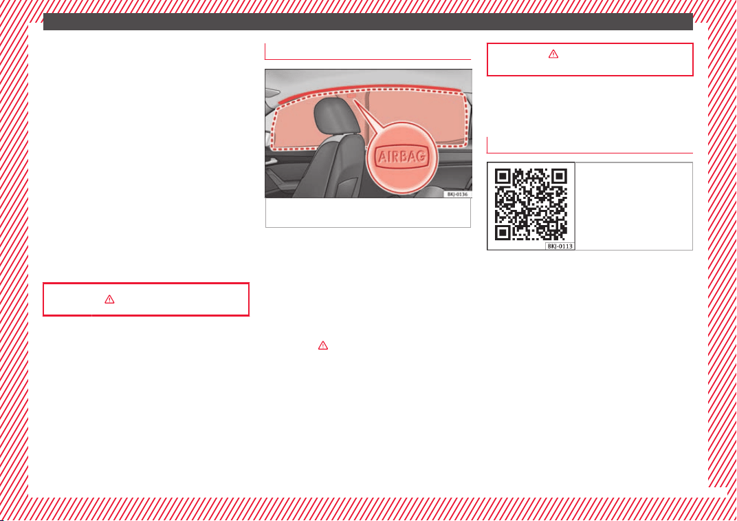
Head-protection airbags*
Fig. 27 Location and deployment area of the
he
a
d-pr
otection airbag.
There is a head airbag on each side of the in-
t
erior abo
v
e the doors ››› Fig. 27. Airbags are
identified by the word “AIRBAG”.
The area framed in red is covered by the
head-protection airbag when it is deployed
››› Fig. 27 (deployment area). Therefore, ob-
jects should never be placed or mounted in
this area ›››
in Head-protection airbags* on
p
ag
e 89
.
In the event of a side collision the curtain air-
bag is triggered on the impact side of the ve-
hicle.
The head-protection airbags reduce the risk
of injury to passengers in the front and rear
side seats facing the impact.
››› in Head-protection airbags* on
page 89
Child seats
Related video
Fig. 28 Vehicle interior
23
The essentials
Important information regarding the
fr
ont
p
assenger's airbag
Fig. 29 Airbag stickers - version 1: on the
p
a
s
senger-side sun blind and on the rear
frame of the front passenger's door .
Fig. 30 Airbag stickers - version 2: on the
p
a
s
senger-side sun blind and on the rear
frame of the front passenger's door .
A sticker with important information about
the p
a
s
senger airbag is located on the pas-
senger's sun visor and/or on the passenger
side door frame.
››› in Important information regarding
the front passenger's airbag on page 92
››› page 92
24
The essentials
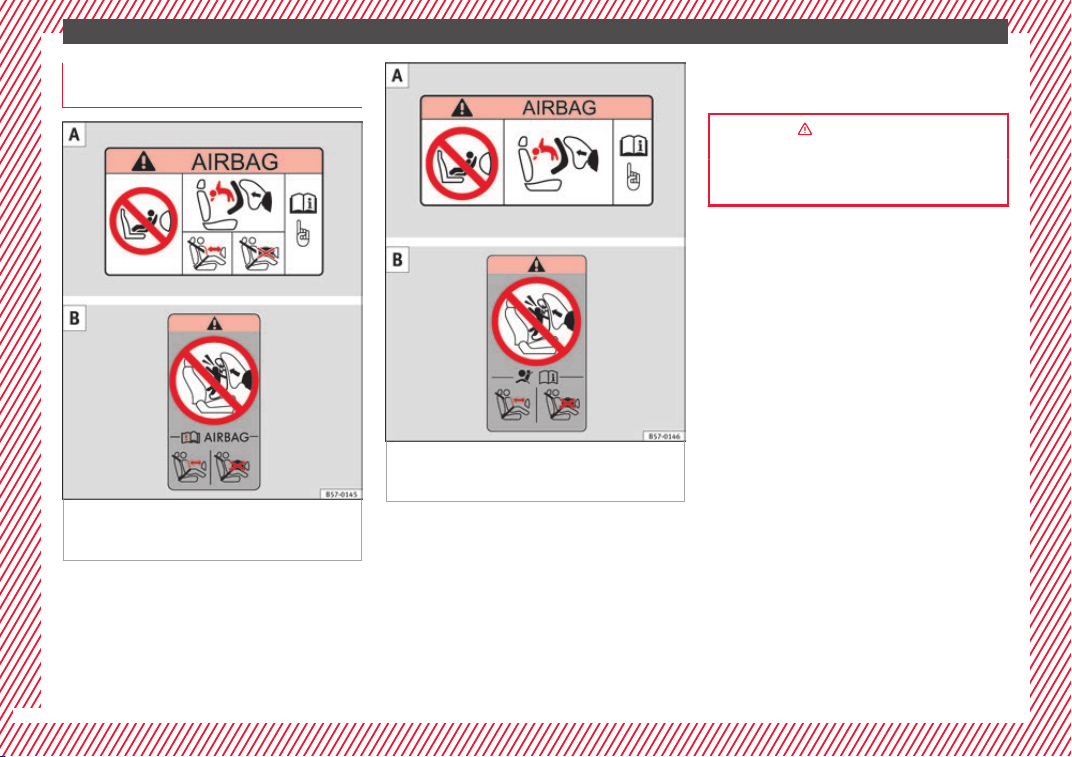
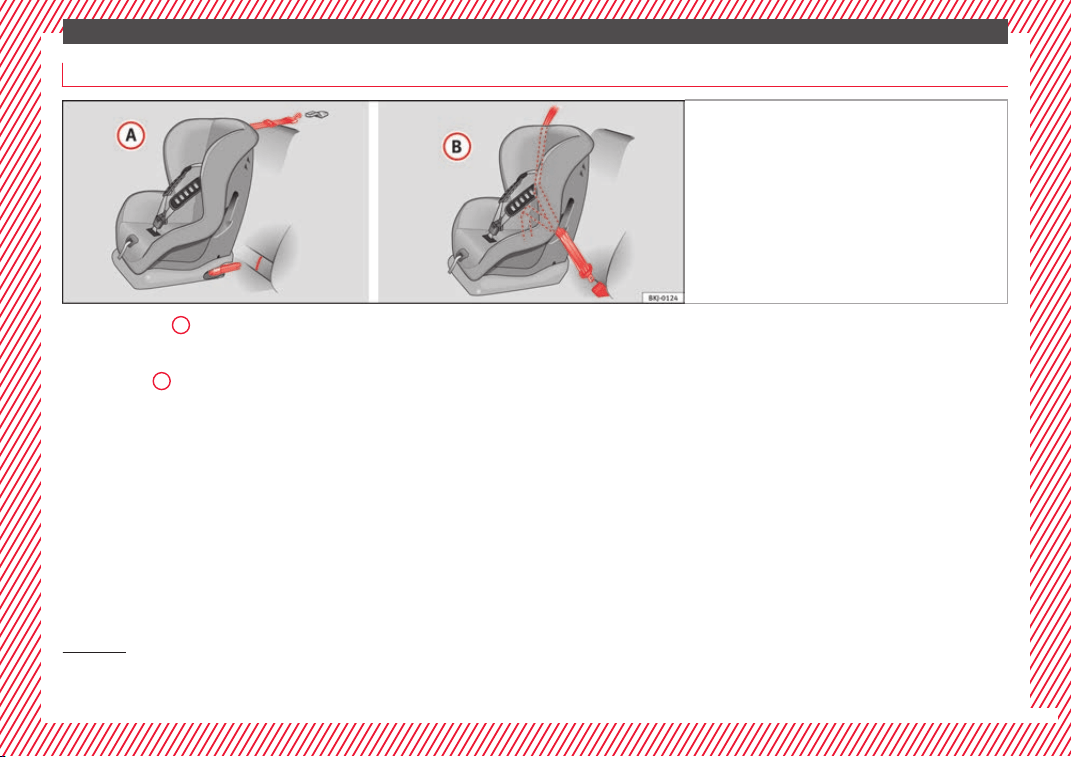
Securing child seats
Fig. 31 On the rear seats: Possible installations
for the chi
ld seat.
Figure ›
›› Fig. 31
A
shows the basic child re-
s
tr
aint
system mounting using lower retain-
ing rings and the upper retaining strap. Fig-
ure ››› Fig. 31
B
shows the child restraint
sy
s
t
em mounting using the vehicle seat belt.
The seat belt may be used to secure univer-
sal type child seats to the vehicle seats
marked with a U in the table below.
●
In a front passenger seat without height ad-
justment: It is necessary to place the front
passenger seat in its rearmost position
1)
.
●
In a front passenger seat with height ad-
justment: it is necessary to place the front
passenger seat in its rearmost and highest
position
1)
.
To correctly use a child seat in the back, the
front backrest must be adjusted so that there
is no contact with the child seat in the back
in the case that it goes opposite to the direc-
tion of the car. In the case of front facing re-
straint systems, the front backrest must be
adjusted so that there is no contact with the
child's feet.
To adjust the passenger seat to accommo-
date a child's seat and get the seat belt in a
perfect position, adjust the passenger back-
rest as far forward as possible
1)
.
If a semi-universal type chair is to be instal-
led, in which the method of attachment to
the car is through the seat belt and support
bracket, it should never be installed in the
central rear seat as the ground clearance is
lower than in other places and the support
bracket will not allow the seat to remain suffi-
ciently stable.
The systems include the child restraint sys-
tem mounting with an upper retaining strap
(Top Tether) and lower anchoring points on
the seat.
»
1)
Compliance with current national legislation and
the manufact
urer's instructions is required when us-
ing or installing child seats.
25
The essentials
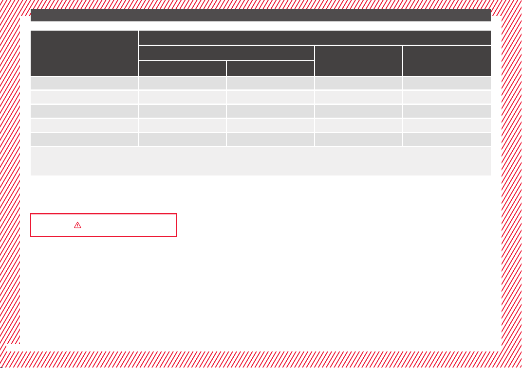
Weight group
Seating position
Front passenger seat
a)
Rear side seat Rear central seat
b)
airbag on airbag off
Group 0 to 10 kg X U
c)
U U
Group 0+ to 13 kg X U
c)
U U
Group I 9 to 18 kg X U
c)
U U
Group II 15 to 25 kg X UF
c)
UF UF
Group III 22 to 36 kg X UF
c)
UF UF
X: It is not compatible to install chairs in this configuration.
U: Suitable for universal restraint systems for use in this weight group.
UF: Acceptable for front-facing universal-category child restraint systems approved for this mass group.
a)
Compliance with current national legislation and the manufacturer's instructions is required when using or installing child seats.
b)
For semi-universal chairs where the securing system is the car safety belt and the support bracket, do not use them in the centre rear seat.
c)
Seats without height adjustment should be placed in their rearmost position. Seats with height adjustment should be placed in their rearmost and highest position.
››› in Safety instructions on page 93
26
The essentials
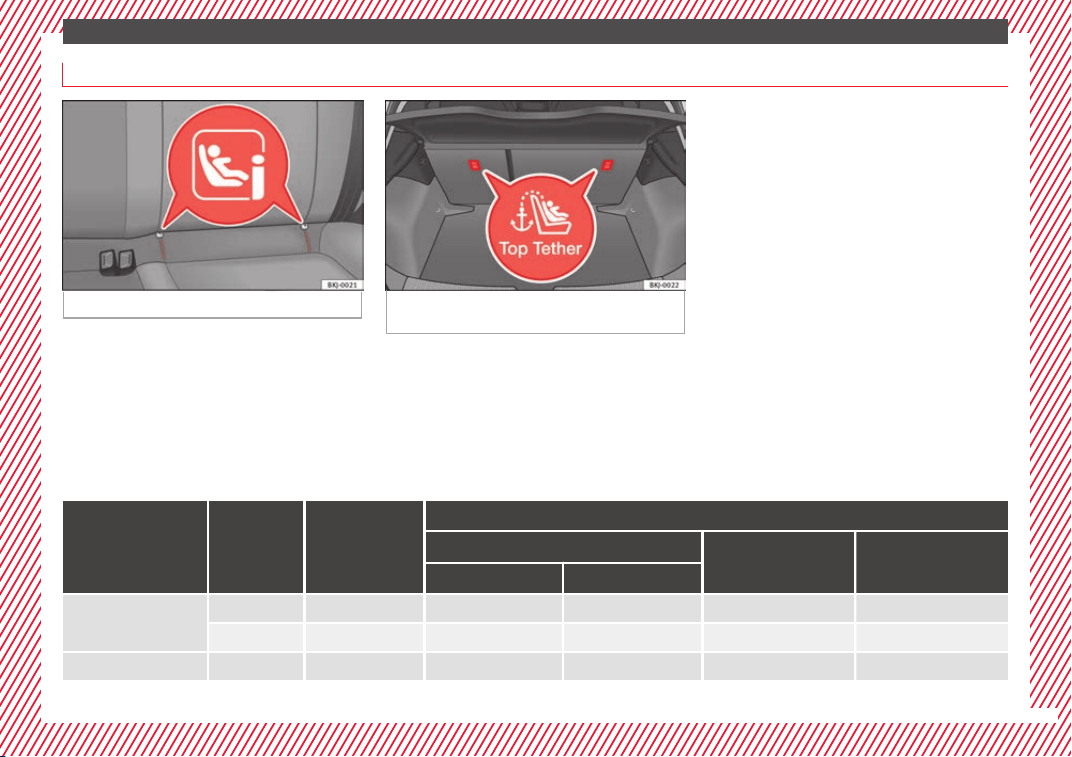
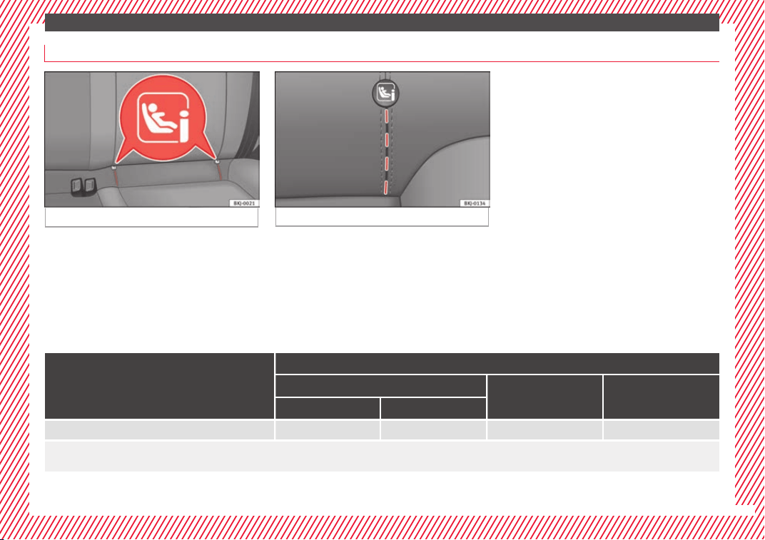
Securing child seats with the ISOFIX/iSize and Top Tether system*
Fig. 32 ISOFIX/iSize securing rings.
Fig. 33 Position of the Top Tether rings on the
back
of the rear seat.
Child seats can be secured quickly, easily
and s
af
ely
on the rear outer seats with the
“ISOFIX” and Top Tether* system.
Two “ISOFIX” retaining rings are fitted on
each rear seat. In some vehicles, the rings
are secured to the seat frame and, in others,
they are secured to the rear floor. The “ISO-
FIX” rings are located between the rear seat
backrest and the seat cushioning ››› Fig. 32.
The Top Tether* rings are located on the rear
part of the backrests of the rear seats (be-
hind the seat backrest or in the boot)
››› Fig. 33.
To understand the compatibility of the "ISO-
FIX" systems in the vehicle, consult the table
below.
The body weight permitted and information
regarding sizes A to F is indicated on the la-
bel on child seats with “universal” or “semi-
universal” certification.
Weight group Size class
Electrical equip-
ment
Vehicle Isofix positions
Front passenger seat
Rear side seat Rear central seat
airbag on airbag off
Baby carrier
F ISO/L1 X X X X
G ISO/L2 X X X X
Group 0 to 10 kg E ISO/R1 X X IL X
»
27
The essentials
Weight group Size class
Electrical equip-
ment
Vehicle Isofix positions
Front passenger seat
Rear side seat Rear central seat
airbag on airbag off
Group 0+ to 13 kg
E ISO/R1 X X IL X
D ISO/R2 X X IL X
C ISO/R3 X X IL X
Group I 9 to 18 kg
D ISO/R2 X X IL X
C ISO/R3 X X IL X
B ISO/F2 X X IUF/IL X
B1 ISO/F2X X X IUF/IL X
A ISO/F3 X X IUF/IL X
Group II 15 to 25 kg --- --- --- ---
Group III 22 to 36 kg --- --- --- ---
IUF: Suitable for forward-facing ISOFIX universal child restraint systems approved for use in this mass group.
IL: It is suitable for certain ISOFIX child restraint systems (CRS) that can be for the specific vehicle, restricted or semi-universal categories. Take the child seat manufacturer's vehicle list
into account.
X: ISOFIX position not suitable for ISOFIX child restraint systems for this weight group or size class.
››› in Safety instructions on page 93
28
The essentials
Securing child seats with the “ISOFIX/i-Size” ISOFIX System
Fig. 34 ISOFIX/iSize securing rings.
Fig. 35 Rear seat: cut-out grooves.
You are obliged to follow the seat manufac-
t
ur
er's
instructions.
●
Open the cut-out section behind the
marked grooves to access the retaining rings
››› Fig. 35.
●
Press the child seat onto the “ISOFIX/iSize”
retaining rings until the child seat is heard to
engage securely. If the child seat is equipped
with Top Tether* anchor points, secure it to
the correspondent ring ››› Fig. 36. Observe
the manufacturer's instructions.
●
Pull on both sides of the child seat to en-
sure that it is properly anchored.
Child seats with the “ISOFIX” and Top Tether*
attachment system are available from Techni-
cal Services.
Vehicle i-Size positions
Front passenger seat
Rear side seat Rear central seat
airbag on airbag off
Child restraint system approved under ECE R129 X X i-U X
i-U Valid position for front-facing and rear-facing child restraint systems approved under ECE R129.
X: Invalid position for child restraint systems approved under ECE R129.
29
The essentials
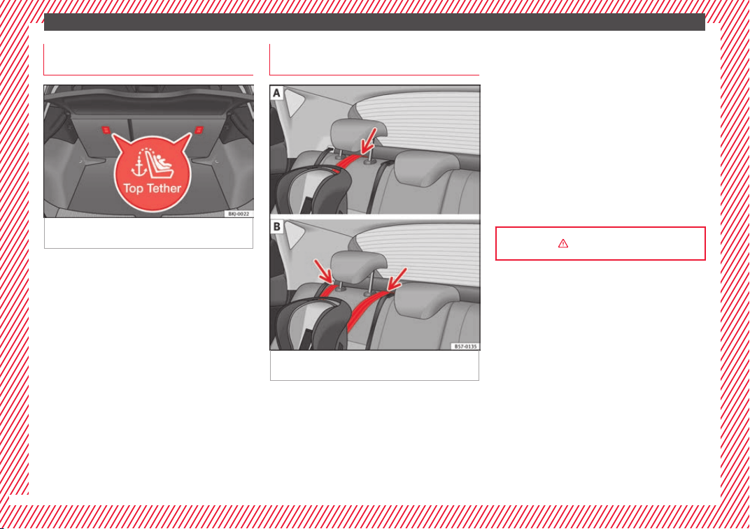
Securing child seats with the Top
T
ether* r
et
aining straps
Fig. 36 Position of the Top Tether rings on the
b
ac
k
of the rear seat.
Child seats with the Top Tether system come
w
ith a s
tr
ap for securing the seat to the vehi-
cle anchor point, located at the back of the
rear seat backrest and provide greater re-
straint.
The objective of this strap is to reduce for-
ward movements of the child seat in a crash,
to reduce the risk of injuries to the head from
hitting the inside of the vehicle.
Using the Top Tether in rear-facing mounted
seats
Currently, there are very few rear-facing child
safety seats that have Top Tether. Please
carefully read and follow the seat manufac-
turer instructions to learn the proper way to
install the Top Tether strap.
Securing the Top Tether* to the an-
chorage point
Fig. 37 Retainer strap: adjustment and as-
semb
ly
ac
cording to the Top Tether belt.
Securing the retainer strap
●
Follow the manufacturer's instructions to
dep
lo
y
the child seat Top Tether retainer
strap.
●
Place the belt under the head restraint of
the back seat ››› Fig. 37 (depending on the in-
structions of the chair itself, lift or remove the
head restraint if necessary).
●
Slide the strap and secure it properly with
the anchorage of the backrest ››› Fig. 36.
●
Firmly tighten the strap following the manu-
facturer's instructions.
Releasing the retaining strap
●
Loosen the strap following the manufactur-
er's instructions.
●
Push the lock and release it from the an-
choring support.
››› in Safety instructions on page 93
30
The essentials
Starting the vehicle
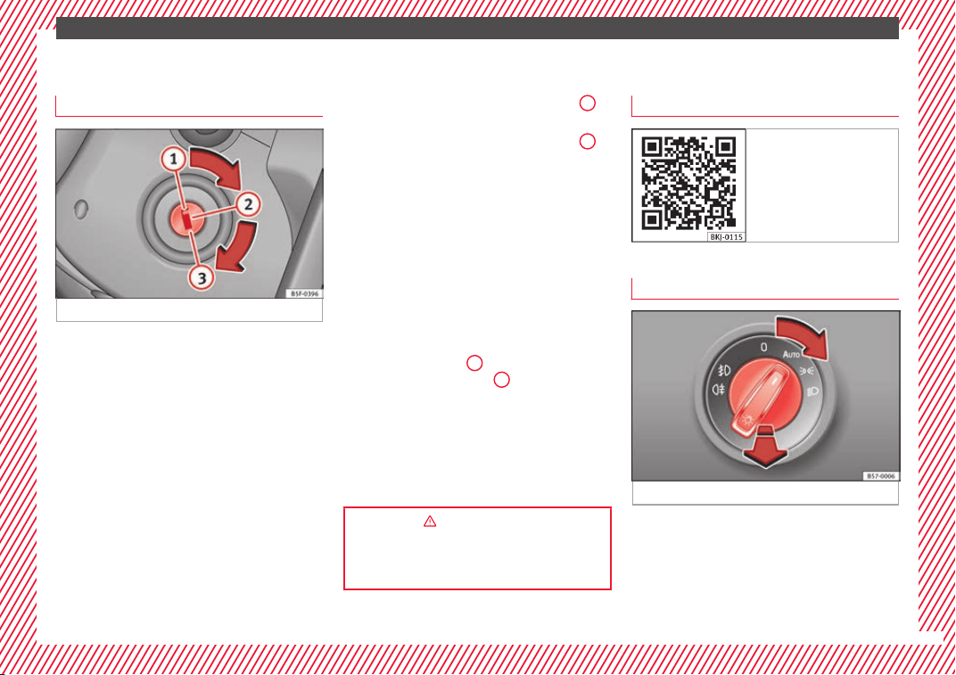
Ignition loc
k
Fig. 38 Ignition key positions.
Switch ignition on: Place the key in the igni-
tion and s
t
ar
t the engine.
Locking and unlocking the steering wheel
●
Engaging the steering wheel lock: Remove
the key from the ignition and turn the wheel
until it locks. In vehicles with an automatic
gearbox, the gear lever must be in the P posi-
tion in order to remove the key. If necessary,
press the locking key on the selector lever
and release it again.
●
Unlocking the steering wheel: Put the key
into the ignition and turn it at the same time
as the steering wheel in the direction indica-
ted by the arrow. If it is not possible to turn
the steering wheel, it may be because it is
locked.
Turning on/switching off the ignition, glow
plugs reheating
●
Switch ignition on: Turn the key to the
2
position.
●
Switch ignition off. Turn the key to the
1
position.
●
Diesel vehicles :
The glo
w p
lugs reheat
when the ignition is switched on.
Starting the engine
●
Manual gearbox: press the clutch pedal all
the way down and move the gearbox lever in-
to neutral.
●
Automatic gearbox: Press the brake pedal
and move the selector lever to the P position
or into N.
●
Turn the key to the
3
position. The key au-
t
om
atic
ally returns to the
2
position. Do not
pr
e
s
s the accelerator.
Start-Stop System*
When you stop and release the clutch pedal,
the Start-Stop system* turns off the engine.
The ignition remains switched on.
››› in Ignition key positions on
page 175
››› page 175
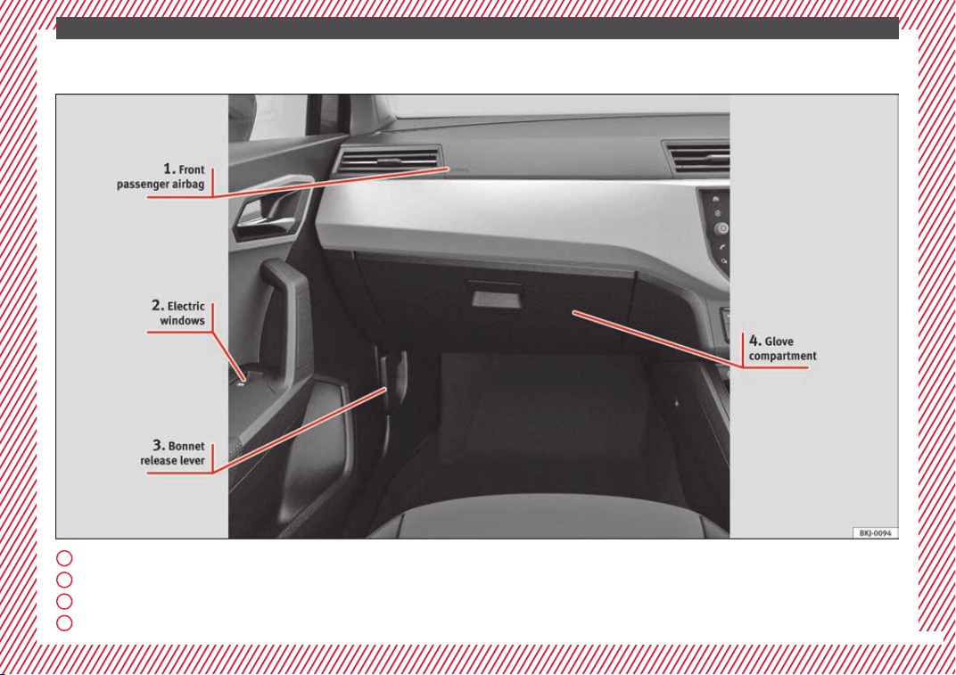
Lights and visibility
R
el
at
ed video
Fig. 39 Dash panel
Light switch
Fig. 40 Dash panel: light control.
●
Turn the switch to the required position
›
›
›
Fig. 40.
»
31
The essentials
Sym-
bol
Ignition switch-
ed off
Ignition is switch-
ed on
Fog lights, dipped
beam and side
lights off.
Light off or daytime
driving light on.
The “Coming home”
and “Leaving
home” guide lights
may be switched
on.
Automatic control of
dipped beam and day-
time running light.
Side light on.
Daylight running
lights switched on.
Dipped beam head-
light off
Dipped beam switch-
ed on.
Front fog lights: mo
ve the switch to the
first position, from positions , or .
Rear fog light: move the switch completely
from positions
,
or
.
Switching off fog lights: Push the switch or
turn it to the
position.
››› page 146
Turn signal and main beam lever
Fig. 41 Turn signal and main beam lever.
More the lever to the required position:
Right
t
urn s
ignal: Right-hand parking
light (ignition switched off).
Left turn signal: Left-hand parking light
(ignition switched off).
Main beam switched on: control lamp
lit up on the instrument panel.
Headlight flasher: lit up when the lever is
pushed. Control lamp lit up.
Lever all the way down to switch it off.
››› in Turn signal and main beam lever
on page 148
››› page 147
1
2
3
4
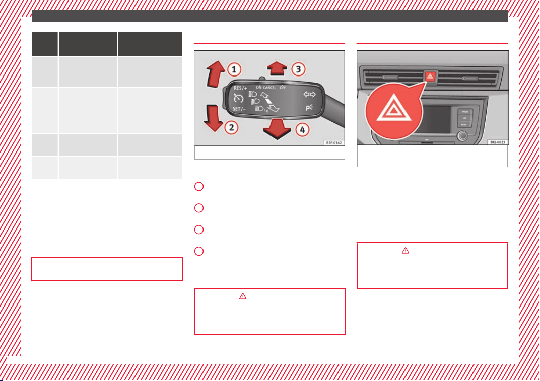
Hazard warning lights
Fig. 42 Dash panel: switch for hazard warn-
in
g lights.
Switched on, for example:
●
When approaching a traffic jam
●
In an emergency
●
The vehicle has broken down
●
When towing or being towed
››› in Hazard warning lights
on
page 150
››› page 150
32
The essentials
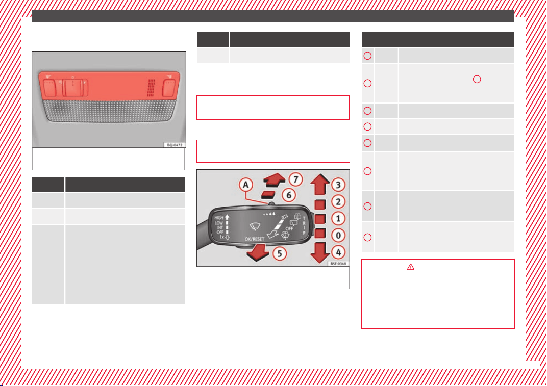
Interior lights
Fig. 43 Detail of headliner: front interior light-
in
g.
Knob Function
Switches interior lights off.
Switches interior lights on.
Switches door contact control on (central
position).
The interior lights come on automatically
when the vehicle is unlocked, a door is
opened or the key is removed from the igni-
tion.
The lights go off a few seconds after all the
doors are closed, the vehicle is locked or
the ignition is switched on.
Knob Function
Turning the reading light on and off
The light controls may vary depending on the
vehicl
e version.
››› page 150
Windscreen wipers and window wiper
bla
de
Fig. 44 Operating the windscreen wiper and
r
e
ar w
iper.
More the lever to the required position:
0
Windscreen wiper off.
1
Windscreen wipers interval wipe.
Using the control ››› Fig. 44
A
adjust the
interval (vehicles without rain sensor), or
the sensitivity of the rain sensor.
2
Slow wipe.
3
Continuous wipe.
4
Short wipe. Brief press, short clean.
5
Automatic wipe. The windscreen washer
function is activated by pushing the lever
forwards, and simultaneously the wind-
screen wipers start.
6
Interval wipe for rear window. The wiper
will wipe the window approximately every
six seconds.
7
The rear window wash function is activa-
ted by pressing the lever, and the rear
wiper starts simultaneously.
››› in Windscreen wiper and window
wiper on page 152
››› page 152
››› page 73
33
The essentials
Easy Connect
CAR menu settin
g
s
Fig. 45 Easy Connect: Main menu. Fig. 46 Easy Connect: CAR menu.
The actual number of menus available and
the n
ame of
the
v
arious options will depend
on the vehicle’s electronics and equipment.
●
Switch the ignition on.
●
If the Infotainment System is off, switch it
on.
●
Press the Infotainment button /
and
then the
V
ehic
l
e
function button ›
›
›
Fig. 45
,
or, press the Infotainment button /
to
g
o t
o the
Vehicle menu ›
›› Fig. 46.
●
Press the
SETTINGS
function button to open
the Vehicle settings menu.
●
To select a function in the menu, press the
de
s
ir
ed b
utton.
When the function button check box is activa-
ted , the function is active.
Pressing the menu button
will always take
y
ou t
o the l
a
st menu used.
Any changes made using the settings menus
are automatically saved on closing those me-
nus.
34

The essentials
Menu Submenu Possible setting Description
ESC system – Activation of the Electronic Stability Programme (ESC) ››› page 183
Tyres
Tyre monitor system Tyre pressure storing (Calibration) ››› page 278
Winter tyres Activation and deactivation of the speed warning. Setting the speed warning value ››› page 280
Lights
Light assist
Motorway function, turning-on time, automatic lights when raining, one-touch sig-
nalling.
››› page 146,
››› page 149
Vehicle interior lighting Brightness of instrument panel and controls ››› page 150
“Coming home/Leaving home” func-
tion
Switch-on time of the “Coming home” and “Leaving home” functions ››› page 148
Driver assistance
Adaptive Cruise Control (ACC) Activation/deactivation: default distance level, driving profiles. ››› page 216
Front Assist (emergency brake as-
sist system)
Activation/deactivation: Front Assist, advance warning, distance warning display ››› page 212
Fatigue detection Activation/deactivation ››› page 227
Parking and manoeu-
vring
Parking and manoeuvring settings
Automatically activate front volume, front sound treble, rear volume, rear sound
treble
››› page 232
Ambient lighting – Background lighting, switch-off, colour ››› page 151
Mirrors and wind-
screen wipers
Rear view mirrors Activate/deactivate folding after parking ››› page 153
Windscreen wipers Activate and deactivate automatic wipe in case of rain, wipe when reversing ››› page 33
Opening and closing
Electric windows control Convenience open function, all, only driver ››› page 143
Central locking system Unlocking doors, automatic lock when driving ››› page 132
Instrument panel
–
Current consumption, average consumption, convenience consumers, ECO Advice,
travelling time, distance travelled, average speed, digital speed display, speed
warning, oil temperature, reset data “when setting off”, reset data for “total calcu-
lation”
››› page 38
Date and time – Time, summer time, time zone, time format, date, date format ››› page 119
»
35
The essentials
Menu Submenu Possible setting Description
Units – Distance, speed, temperature, volume, fuel consumption, pressure –
Service –
Chassis number, date of next SEAT service inspection, date of next oil change serv-
ice
››› page 43
Factory settings
All Restore all settings
–
Individual Restore factory settings for lights, driver assistance, parking and manoeuvring
››› in Car menu on page 123
36
The essentials
Driver information System
Intr
oduction
With the ignition switched on, it is possible
to re
ad the different functions of the display
by scrolling through the menus.
In vehicles with multifunction steering wheel,
the multifunction display can only be operat-
ed with the steering wheel buttons.
The number of menus displayed on the in-
strument panel will vary according to the ve-
hicle electronics and equipment.
A specialised workshop will be able to pro-
gramme or modify additional functions, ac-
cording to the vehicle equipment. SEAT rec-
ommends visiting a SEAT Official Service.
Some menu options can only be read when
the vehicle is at a standstill.
As long as a priority 1 warning is displayed, it
will not be possible to read the menus
›››
page 41. Some warning messages can
be confirmed and made to disappear with the
windscreen wiper lever button or the multi-
function steering wheel button.
The information system also provides the fol-
lowing information and displays (depending
on the vehicle's equipment):
Driving data
›››
page 38
■
MFD from departure
■
MFD from ref
uelling
■
MFD total calculation
Assist systems ››› page 40
Navigation ››› Booklet Navigation system
Audio ››› Booklet Radio or ››› Booklet Naviga-
tion system
Telephone ››› Booklet Radio or ››› Booklet
Navigation system
Vehicle status ››› page 34
WARNING
Any distraction may lead to an accident, with
the risk of
injury.
●
Do not operate the instrument panel con-
trols when driving.
Operating the instrument panel me-
nu
s
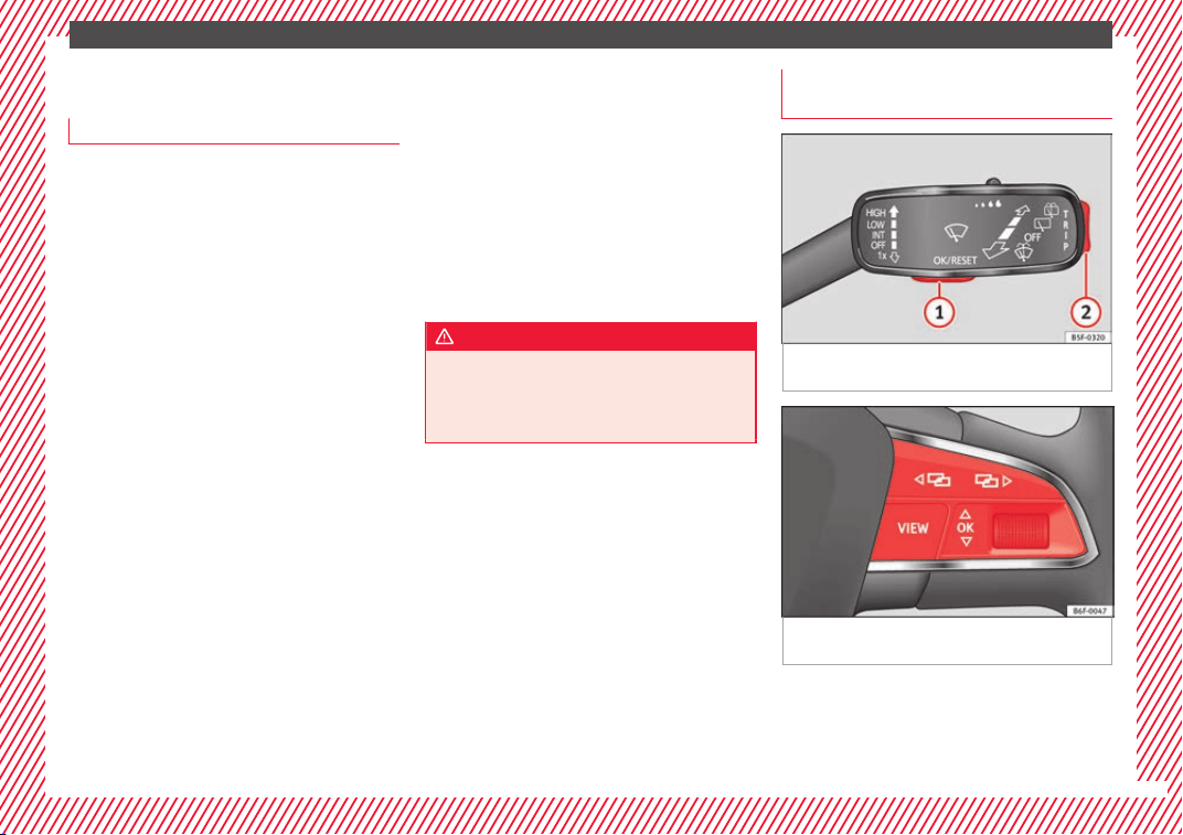
Fig. 47 Windscreen wiper lever: control but-
t
on
s.
Fig. 48 Right side of multifunction steering
wheel: c
ontr
o
l buttons.
The driver information system is controlled
w
ith the mu
ltif
unction steering wheel buttons
››› Fig. 48 or with the windscreen wiper lever
››› Fig. 47 (if the vehicle is not equipped with
multifunction steering wheel).
»
37
The essentials
Enabling the main menu
●
Switch the ignition on.
●
If a message or vehicle pictogram appears,
pr
e
s
s button ››› Fig. 47
1
on the windscreen
w
iper l
ev
er or button
on the multifunction
s
t
eerin
g wheel ››› Fig. 48.
●
If managed from the windscreen wiper lev-
er: to display the main screen or to return to
the main menu from another menu, hold
down the rocker button ››› Fig. 47
2
.
●
If managed from the multifunction steering
whe
e
l:
the main menu list is not displayed.
To go from point to point in the main menu,
press button
or
several times
›
›
›
Fig. 48.
Select a submenu
●
Press the rocker switch ››› Fig. 47
2
on the
w
ind
s
creen wiper lever up or down or turn
the thumbwheel of the multifunction steering
wheel ››› Fig. 48 until the desired option ap-
pears marked on the menu.
●
The selected option will be displayed with a
horizontal line underneath.
●
To consult the submenu option, press but-
ton ››› Fig. 47
1
on the windscreen wiper
l
ev
er or b
utton
on the multifunction steer-
in
g wheel
›
›› Fig. 48.
Making changes according to the menu
●
Make the desired changes with the rocker
switch on the windscreen wiper lever or the
thumbwheel of the multifunction steering
wheel. To increase or decrease the values
more quickly, turn the thumbwheel faster.
●
Mark or confirm the selection with button
››› Fig. 47
1
on the windscreen wiper lever
or b
utt
on
on the multifunction steering
wheel
›
›
› Fig. 48.
Selection menu
Menu Function
Driving
data
Information and possible configura-
tions of the multifunction display
(MFD) ››› page 38, ››› page 123.
Assist
systems
Information and possible configura-
tions of the driver assistance systems
››› page 40.
Navigation*
Information instructions from the acti-
vated navigation system: when a route
guidance is activated, the turning ar-
rows and proximity bars are displayed.
The appearance is similar to the Easy
Connect system.
If route guidance is not activated, the
direction of travel (compass) and the
name of the street along which you are
driving are shown ››› Booklet Naviga-
tion system.
Audio
Station display on the radio.
Track name on the CD.
Track name in Media mode ››› Booklet
Radio or ››› Booklet Navigation sys-
tem.
Menu Function
Telephone
Information and possible configura-
tions of the mobile phone preinstalla-
tion ››› Booklet Radio or ››› Booklet
Navigation system.
Vehicle
status
Display of the current warning or infor-
mation texts and other system compo-
nents, depending on the equipment
››› page 123.
Journey data
The MFD (multifunction display) shows differ-
ent
v
alues for the journey and the consump-
tion.
Changing between display modes on the
MFD
●
In vehicles without multifunction steering
wheel: Press the rocker switch
on the
w
ind
s
creen wiper lever
›››
Fig. 47.
●
Vehicles with a multifunction steering
wheel: turn the thumbwheel
›››
Fig. 48.
Multifunction display memory
The multifunction display is equipped with
three memories that work automatically: MFD
from departure, MFD from refuelling and MFD
total calculation. On the screen display, you
can read which memory is currently dis-
played.
38
The essentials
Toggle between memories with the ignition
on and the memor
y
di
splayed
Press the
button on the windscreen
w
iper l
ev
er or the
button of the multifunc-
tion s
t
eerin
g wheel.
Menu Function
MFD from de-
parture
Display and storage of the values for
the journey and the consumption
from when the ignition is switched
on to when it is switched off.
If the journey is continued in less
than 2 hours after the ignition is
switched off, the new data is added
to the data already stored in the
memory. The memory will automati-
cally be deleted if the journey is in-
terrupted for more than 2 hours.
MFD from re-
fuelling
Display and storage of the values for
the journey and the consumption.
By refuelling, the memory will be
erased automatically.
MFD total
calculation
The memory records the values for a
specific number of partial trips, up
to a total of 19 hours and 59 mi-
nutes or 99 hours and 59 minutes,
or 1999.9 km or 9999 km, depend-
ing on the model of instrument pan-
el. On reaching either of these lim-
its
a)
, the memory is automatically
erased and starts to count from 0
again.
a)
It varies according to the instrument panel version.
Erasing a memory manually
●
Select the memory that you wish to erase.
●
Hold the
button of the multifunction
s
t
eerin
g wheel or the
button of the multi-
f
u
nction wheel
pressed down for about 2 sec-
onds.
Personalising the displays
In the Easy Connect system you can adjust
which of the possible displays of the MFD can
be shown on the instrument panel display
with the
button and the
S
ET
TINGS
function
b
utt
on ›
››
page 123.
Data summary
Menu Function
Current fuel
consumption
The current fuel consumption dis-
play operates throughout the
journey, in litres/100 km; and
with the engine running and the
vehicle stopped, in litres/hour.
Average fuel
consumption
After turning on the ignition, aver-
age fuel consumption in li-
tres/100 km will be displayed af-
ter travelling about 300 metres.
Otherwise horizontal lines are
displayed. The value shown is up-
dated approximately every 5 sec-
onds.
Menu Function
Operating
range
Approximate distance in km that
can still be travelled with the fuel
remaining in the tank, assuming
the same style of driving is main-
tained. This is calculated using
the current fuel consumption.
Travelling
time
This indicates the hours (h) and
minutes (min) since the ignition
was switched on.
Journey
Distance covered in km (m) after
switching on the ignition.
CNG quality
Whenever you refuel the quality
of the natural gas is automatically
verified and is displayed when
the ignition is switched on. The
display is made in a percentage
of between 70% and 100%. The
greater the percentage displayed
the lower the consumption may
be.
Average speed
The average speed will be shown
after a distance of about 100 me-
tres has been travelled. Otherwise
horizontal lines are displayed.
The value shown is updated ap-
proximately every 5 seconds.
Digital dis-
play of speed
Current speed displayed in digital
format.
»
39
The essentials
Menu Function
Speed warning
at --- km/h or
Speed warning
at --- mph
If the stored speed is exceeded
(between 30 - 250 km/h, or 19 -
155 mph), an audible warning is
given together with a visual warn-
ing.
Oil tempera-
ture
Updated engine oil temperature
digital display
Coolant tem-
perature gauge
Digital display of the current tem-
perature of the liquid coolant.
Convenience
consumers
Information about the vehicle’s
main convenience consumers. It
is displayed by means of a con-
sumption indicator bar.
Eco tips Tips on how to save fuel.
Reset data
“when setting
off”
Reset journey data when setting
off.
Reset data for
“total calcu-
lation”
Reset travel journey to zero.
Storing a speed with the speed warning
●
Select the display Speed warning at
---
km/h (---
mph)
●
Press the button
on the windscreen
w
iper l
ev
er or the button
on the multifunc-
tion s
t
eerin
g wheel to store the current speed
and activate the warning.
●
To switch system on: adjust to the desired
speed within 5 seconds using the rocker
switch
on the windscreen wiper lever or
b
y
t
urning the thumbwheel on the multifunc-
tion steering wheel. Next, press the button
or
again or wait several seconds.
The s
peed i
s
stored and the warning activa-
ted.
●
To switch system off: press the but-
ton
or
. The stored speed is de-
l
et
ed.
Assist systems menu
Menu Function
ACC
Display of Adaptive Cruise Control
(ACC) ››› page 216.
Front Assist
Switching the monitoring system
on and off ››› page 212.
Fatigue detec-
tion*
Switching the fatigue detection
on or off (pause recommenda-
tion) ››› page 227.
Status display
Bonnet, r
e
ar lid and door
s open
Fig. 49 A: bonnet open; B: rear lid open; C:
fr
ont
l
eft door open; D: right rear door open.
When the ignition is switched on or when
driv
in
g, the bonnet, r
ear lid or doors that are
open will be indicated on the instrument pan-
el display, and, as applicable, this will be in-
dicated audibly. The display may vary accord-
ing to the type of instrument panel fitted.
40
The essentials
Illustra-
tion
Key to ››› Fig. 49
A
Do not continue driving!
The bonnet is open or is not properly
closed ››› page 263.
B
Do not continue driving!
The rear lid is open or is not properly
closed ››› page 16.
C, D
Do not continue driving!
A vehicle door is open or is not properly
closed ››› page 132.
››› page 118
Warning and information messages
The system runs a check on certain compo-
nents
and f
u
nctions when the ignition is
switched on and while the vehicle is moving.
Faults in the operation are displayed on the
screen using red and yellow symbols and
messages on the instrument panel display
(›››
page 122, ››› page 47) and, in
some cases, with audible warnings. The dis-
play may vary according to the type of instru-
ment panel fitted.
Priority 1 warning (red symbols)
Symbol flashing or lit; partly combined with audible
warnings.
Stop the vehicle! It is dangerous ››› in Warning
symbols on page 122 !
Check the function that is faulty and repair it. If necessa-
ry, request assistance from specialised personnel.
Priority 2 warning (yellow symbols)
Symbol flashing or lit; partly combined with audible
warnings.
A faulty function, or fluids which are below the correct
levels may cause damage to the vehicle! ›››
in Warn-
ing symbols on page 123
Check the faulty function as soon as possible. If neces-
sary, request assistance from specialised personnel.
Informative text
Information relating to different vehicle processes.
››› page 122
Gear-change indicator
Fig. 50 Instrument panel: gear-change indica-
t
or (m
anual
gearbox).
Gear-change recommendation
Whi
l
e driv
ing, the instrument panel of certain
vehicles may indicate a gear recommenda-
tion for saving fuel ›››
page 197.
Outside temperature display
When the outside temperature is below +4°C
(+39°F), the symbo
l
(w
arning of risk of
freezing) is displayed. At first, this symbol
flashes and then it remains lit until the out-
side temperature rises above +6°C (+43°F)
›››
in Indications on the display on
p
ag
e 119
.
When the vehicle is at a standstill or when
travelling at very low speeds, the tempera-
ture displayed may be higher than the true
»
41
The essentials
outside temperature as a result of the heat
pr
oduc
ed b
y the engine.
The temperatures measured range from
-40°C to +50°C (-40°F to +122°F).
Engine oil temperature display
The engine reaches its operating temperature
when in normal driv
ing conditions the oil
temperature is between 80°C (178°F) and
120°C (248°F). If the engine is required to
work hard and the outside temperature is
high, the engine oil temperature can in-
crease. This does not present any problem as
long as the warning lamps ››› table on
page 48 or ››› table on page 48 do not
appear on the display.
Vehicles without multifunction steering
wheel
●
Press the rocker switch
›››
Fig. 47
2
until
the m
ain menu ap
pe
ars. Enter into Driving
data. With the button
2
move to the oil
t
emper
at
ure gauge.
Vehicles with multifunction steering wheel
●
Enter the submenu Driving data and
turn the thumbwheel until the oil tempera-
ture display appears.
Additional consumers
●
Operation with the windscreen wiper lever*:
Pres
s the rocker switch ››› Fig. 47
2
until the
main menu appe
ars. Enter into the section
Driving data. With the rocker switch,
move to the display Convenience con-
sumers.
●
Operation with the multi-function steering
wheel*: move with the buttons
or
to Driving data and enter with
OK. Turn
the right thumbwheel until the Conven-
ience consumers display appears.
In addition, a scale will inform you of the cur-
rent sum of all the additional appliances.
Saving tips
Tips on how to save fuel will be displayed in
c
ondition
s
that increase fuel consumption.
Follow them to reduce consumption. The indi-
cations appear automatically only with the ef-
ficiency programme. After a time, the tips will
disappear automatically.
If you wish to hide a saving tip immediately
after it appears, press any button on the
windscreen wiper lever*/multifunction steer-
ing wheel*.
Note
●
If y
ou hide a saving tip, it will reappear af-
ter you switch the ignition on again.
●
The saving tips do not appear in all situa-
tions, but rather with a large separation of
time.
Speed warning device
The speed warning device warns the driver
when they hav
e exceeded the pre-set speed
limit by 3 km/h (2 mph). An audible warning
signal sounds, and the warning lamp and
the driver message Speed limit excee-
ded! will be displayed simultaneously on the
instrument panel. The warning lamp
switches off when reducing speed below the
stored maximum limit.
Speed warning programming is recommen-
ded if you wish to be reminded of a maxi-
mum speed, such as when travelling in a
country with different speed limits or for a
maximum speed for winter tyres.
Setting speed limit warning
You can use the radio or the Easy Connect* to
set, alter or cancel the speed limit warning.
●
Vehicles with radio: pres
s the
SETUP
button
> c
ontr
o
l button Driver Assistant >
Speed warning.
42
The essentials
●
V
ehicle
s
with Easy Connect: Press the
button and the function button SETTINGS >
Driver assistance > ACC > Dis-
tance.
The w
arnin
g limit
can be set from 30 to
210 km/h (18 to 150 mph) ›››
page 209.
The adjustment is made at 10 km/h (6 mph)
intervals.
Note
●
Plea
se bear in mind that, even with the
speed warning function, it is still important
to keep an eye on the vehicle speed with the
speedometer and to observe the legal speed
limits.
●
The speed limit warning function in the ver-
sion for some countries warns you at a speed
of 120 km/h (75 mph). This is a factory-set
speed limit.
Service intervals
Fig. 51 Instrument panel
The service interval indication appears on the
in
s
trument
panel display ››› Fig. 51
1
.
S
EA
T di
stinguishes between services with en-
gine oil change (e.g. Oil change service) and
services without engine oil change (e.g. In-
spection).
In vehicles with Services established by time
or mileage, the service intervals are already
pre-defined.
In vehicles with LongLife Service, the inter-
vals are determined individually. Thanks to
technological progress, maintenance work
has been greatly reduced. Because of the
technology used by SEAT, with this service
you only need to change the oil when the ve-
hicle so requires. To calculate this change
(max. 2 years), the vehicle's conditions of
use and individual driving styles are consid-
ered. The advance warning first appears 20
days before the date established for the cor-
responding service. The kilometres (miles)
remaining until the next service are always
rounded up to the nearest 100 km (miles)
and the time is given in complete days. The
current service message cannot be viewed
until 500 km after the last service. Prior to
this, only lines are visible on the display.
Inspection reminder
When the Service date is approaching, when
the ignition is switched on a Service remind-
er is displayed.
Vehicles without text messages: a span-
ner will be displayed on the instrument
panel plus an indication in km.
The kilometres indicated are the maximum
number of kilometres that can be travelled
until the next service. After a few seconds,
the display mode changes. A clock symbol
appears and the number of days until the
next service is due.
Vehicles with text messages: Service in
--- km or --- days will be shown on the
instrument panel display.
»
43
The essentials
Service due
When the ser
v
ic
e date is due, an audible
warning is given when the ignition is switch-
ed on and the spanner displayed on the
screen flashes for a few seconds .
Vehicles with text messages: Service now
will be shown on the instrument panel dis-
play.
Reading a service notification
With the ignition switched on, the engine off
and the vehicle at a standstill, the current
service notification can be read:
Press and hold the button
0.0/SET
for more
th
an 5 sec
ond
s to consult the service mes-
sage
2
.
When the ser
v
ic
e date has passed, a minus
sign is displayed in front of the number of kil-
ometres or days.
Vehicles with text messages: the following
message is displayed: Service --- km
(miles) or --- days ago.
Resetting service interval display
If the service was not carried out by a SEAT
dealership, the display can be reset as fol-
lows:
●
Switch off the ignition, press and hold the
button
0.0/SET
2
.
●
Switch ignition back on.
●
Release the button
0.0/S
ET
and press it
ag
ain f
or the ne
xt 20 seconds.
Note
●
The servic
e message disappears after a few
seconds, when the engine is started or when
OK/RESET
is pressed on the windscreen wiper
lever
, or
OK
on the multifunction steering
wheel.
●
In v
ehicles with the LongLife system in
which the battery has been disconnected for
a long period of time, it is not possible to cal-
culate the date of the next service. Therefore
the service interval display may not be cor-
rect. In thi
s case, bear in mind the maximum
service intervals permitted in the ››› Booklet
Maintenance Programme.
●
If you reset the display manually, the next
service interval will be indicated as in vehi-
cles with fixed service intervals. For this rea-
son we recommend that the service interval
display be reset by a SEAT authorised Dealer.
44
The essentials
Cruise control
Oper
atin
g the c
ruise control system (CCS)*
Fig. 52 Related video:
Dash panel
Fig. 53 On the left of the steering column: con-
troller and buttons to operate the cruise control
system; third lever to operate the cruise con-
trol system.
Function
Position of the turn signal lever ››› Fig. 53
or of the third lever ››› Fig. 53
Effect
Switching on the cruise control sys-
tem
Move controller
1
to the
position on the turn signal lever or move the third lever
forward.
The system switches on. The last set speed of the
cruise control is stored. It does not take effect yet.
Switching on the cruise control sys-
tem
Press the button
2
on the turn signal lever or button
3
on the third lever.
The current speed is stored and the cruise control is
activated.
Temporarily switching off the cruise
control
Move controller
1
of the turn signal lever to the
position or move the third
lever into pressure point
.
The limiter is switched off temporarily. The speed will
be stored.
»
45
The essentials
Function
Position of the turn signal lever ››› Fig. 53
or of the third lever ››› Fig. 53
Effect
Switching on the cruise control sys-
tem again
Press the button
2
on the turn signal lever or move the third lever into the pressure
point
.
The set speed control is activated.
Increasing the set speed of the cruise
control
Briefly press the button
2
on the turn signal lever in the area
or press
3
on the third lever to increase the speed in small increments of 1 km/h (1 mph) and
set it.
The speed is changed to the set value.
Press
on the third lever to increase the speed in increments of 10 km/h
(5 mph) and set it.
Hold down the button
2
on the turn signal lever in the
area or hold down
to increase continuously in increments of 10 km/h (5 mph) and set it.
Reducing the set speed of the cruise
control
Briefly press the button
2
on the turn signal lever in the
area or move the third
lever into position
to reduce the speed in small increments of 1 km/h (1 mph)
and set it.
The speed is changed to the set value.
Press
on the third lever to reduce the speed in increments of 10 km/h (5 mph)
and set it.
Hold down the button
2
on the turn signal lever in the
area or hold down
to continuously decrease the speed in increments of 10 km/h (5 mph), then
set it.
Switching off the cruise control sys-
tem
Move controller
1
of the turn signal lever into position
or the third lever into po-
sition
.
The system switches off. The set speed will be stored.
››› in How it works on page 208
››› page 207
46
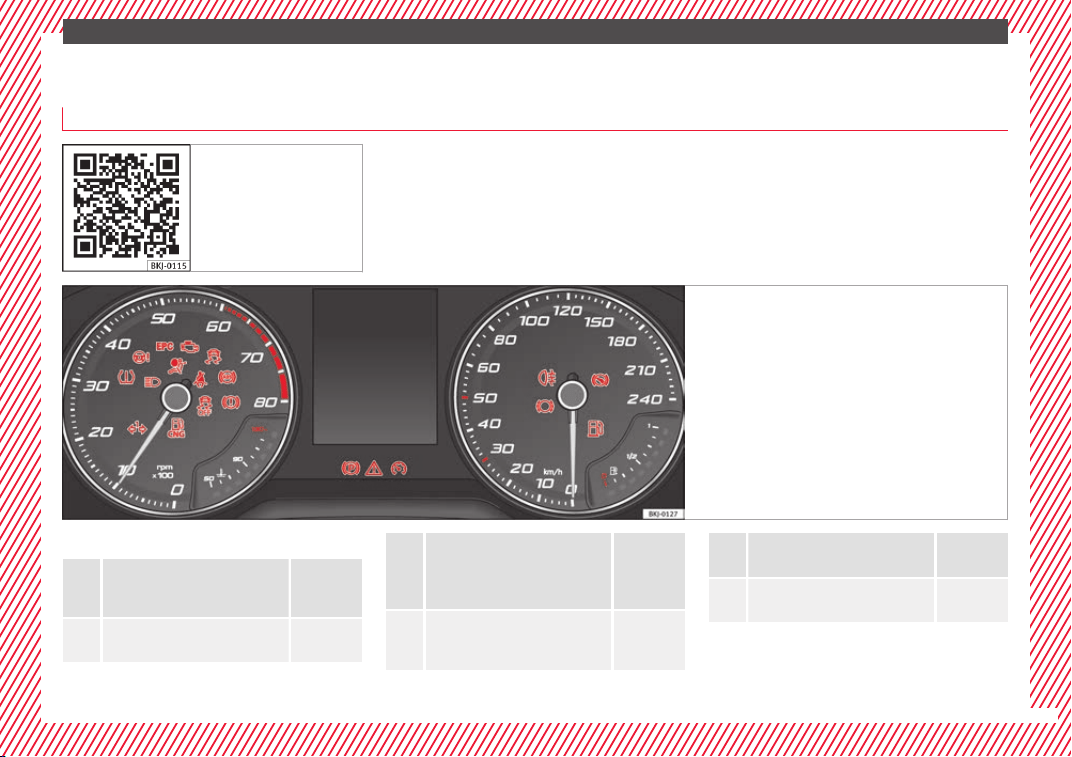
The essentials
Warning lamps
On the in
s
trument
panel
Fig. 54 Related video:
Dash panel
Fig. 55 Instrument panel, on dash panel.
Red warning lamps
Central warning lamp: additional
information on the instrument
panel display
–
Parking brake on.
››› page
182
Do not continue driving!
The brake fluid level is too low or
there is a fault in the brake sys-
tem.
››› page
181
Lit up or flashing:
Do not continue driving!
Fault in the steering.
››› page
198
Driver or passenger has not fas-
tened seat belt.
››› page
81
Use the foot brake!
››› page
218
»
47
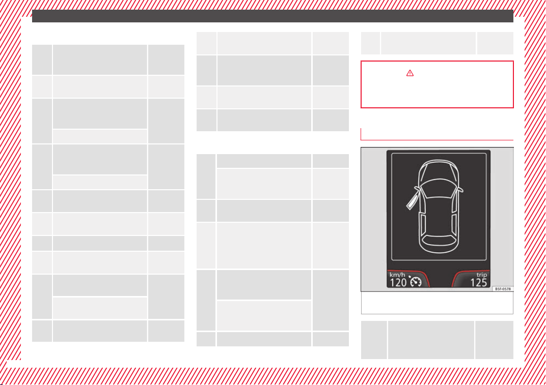
The essentials
Yellow warning lamps
Central warning lamp: additional
information on the instrument
panel display
–
Front brake pads worn.
››› page
181
it lights up: Fault in the ESC, or
disconnection caused by the sys-
tem.
››› page
183
flashes: ESC or ASR activated.
it lights up: fault in the ASR or
disconnection caused by the sys-
tem.
››› page
184
flashes: ASR working.
ASR manually deactivated.
Or else: ESC in Sport mode.
››› page
183
ABS faulty or does not work.
››› page
187
Rear fog light switched on. ››› page 31
lights up or flashes: fault in the
emission control system.
››› page
203
it lights up: pre-heating of diesel
engine.
››› page
203
flashes: fault in the diesel engine
management.
fault in the petrol engine man-
agement.
››› page
203
lights up or flashes: fault in the
steering system.
››› page
198
Tyre pressure too low, or fault in
the tyre pressure monitoring sys-
tem.
››› page
278
Fuel tank almost empty.
››› page
121
Fault in airbag system and seat
belt tensioners.
››› page
91
Other warning lamps
Left or right turn signal. ››› page 32
Hazard warning lights on.
››› page 32
››› page
150
Trailer turn signals
››› page
243
it lights up green: Press the brake
pedal!
It blinks in green: the selector lev-
er locking button has not engag-
ed.
››› page
190
it lights up green: cruise control
activated or speed limiter switch-
ed on and active.
››› page 45
››› page
209
it blinks in green: the speed set
by the speed limiter has been ex-
ceeded.
Main beam on or flasher on. ››› page 32
Natural gas operating mode
››› page
121
››› in Warning symbols on page 122
››› page 122
On the instrument panel display
Fig. 56 On the instrument panel display: door
open.
Do not continue driving!
With the corresponding indica-
tion: door(s), rear lid or bonnet
open or not properly closed.
››› page 40
48
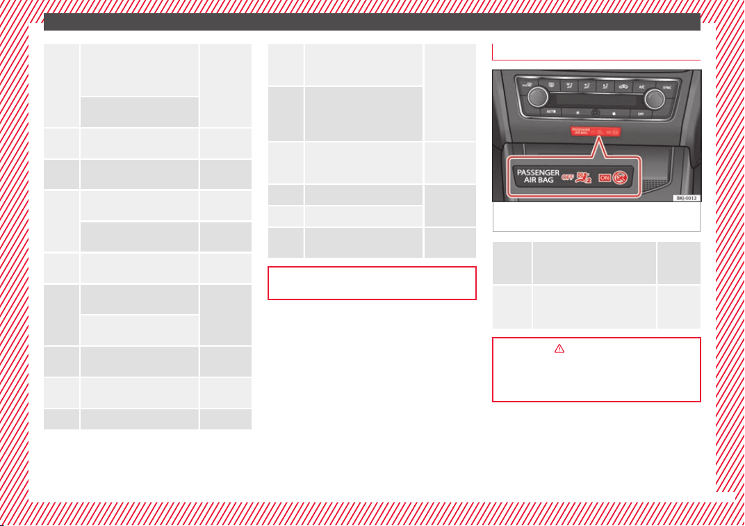
The essentials
Ignition:
Do not carry on
driving! Engine coolant level
too low, coolant temperature
too high
››› page
269
Flashing: Fault in the engine
coolant system.
Do not continue driving!
Engine oil pressure too low.
››› page
267
Fault in the battery.
››› page
272
Driving light totally or partially
faulty.
››› page
106
Fault in the cornering light sys-
tem.
››› page
149
particulate filter blocked.
››› page
202
Flashing: Fault in the oil level
detection. Control manually.
››› page
267
Ignition: Insufficient engine
oil.
Fault in the gearbox.
››› page
196
Immobiliser active.
››› page
177
Service interval display ››› page 43
Mobile telephone is connected
via Bluetooth to the original
telephone device.
››› page
124
››› page
129
››› Booklet
Audio or
navigation
system
Mobile telephone battery
charge meter. Available only
for devices pre-installed in fac-
tory.
Freezing warning. The outside
temperature is lower than
+4°C (+39°F).
››› page 41
Start-Stop system activated.
››› page
204
Start-Stop system unavailable.
Low consumption driving sta-
tus
››› page
225
››› page 118
On the instrument panel
Fig. 57 Warning lamp for disabling the front
p
a
s
senger airbag.
Front passenger front airbag is
disabled (
).
››› page
90
The front passenger front airbag
is activated (
).
››› page
90
››› in Activation and deactivation of
front passenger airbag* on page 91
››› page 90
49
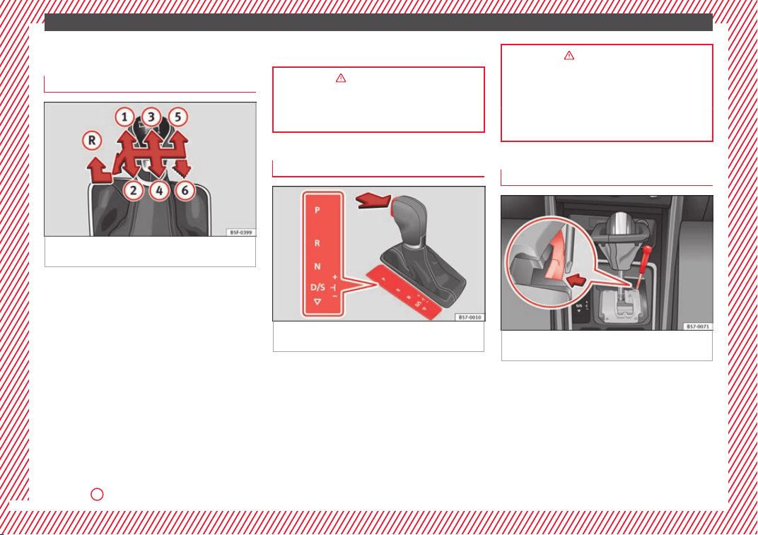
The essentials
Gearbox lever
M
anua
l
gearbox
Fig. 58 Gear shift pattern of a 5 or 6-speed
m
anual
g
earbox.
The position of the gears is indicated on the
g
e
arbo
x lever ››› Fig. 58.
●
Press the clutch pedal and keep your foot
right down.
●
Move the gearbox lever to the required po-
sition.
●
Release the clutch.
Selecting reverse gear
●
Press the clutch pedal and keep your foot
right down.
●
With the gearbox lever in neutral, push it
downwards, move it to the left as far as it will
go and then forwards to select reverse
››› Fig. 58
R
.
●
R
el
e
ase the clutch.
››› in Driving with a manual gearbox on
page 189
››› page 189
Automatic gearbox*
Fig. 59 Automatic gearbox: selector lever po-
s
ition
s.
Parking lock
R
ev
er
se gear
Neutral (idling)
Drive (forward)
Tiptronic mode: pull the lever forwards
(+) to go up a gear or backwards (–) to
go down a gear.
P
R
N
D/S
+/–
››› in Selector lever positions on
page 191
››› page 190
››› page 50
Manual release of the selector lever
Fig. 60 Selector lever: manual release from
po
s
ition P
.
Should the power supply be interrupted,
ther
e i
s
a manual unlocking device located
under the console of the selector lever, on
the right. Releasing the selector lever re-
quires a certain degree of practical skill.
●
Unlocking: use the flat part of a screwdriver
blade.
50
The essentials
Removing the cover from the selector lever
●
Apply the handbrake ›
›
›
to ensure that
the c
ar doe
s
not move.
●
Carefully pull the corners of the selector
lever boot and twist it upwards above the lev-
er handle.
Releasing the selector lever
●
Using a screwdriver, press and hold the yel-
low unlocking tab sideways ››› Fig. 60.
●
Press the interlock button on the selector
lever and move the selector lever to posi-
tion N.
●
After carrying out the manual release, at-
tach the selector lever boot on the gearbox
console again.
If the power supply should ever fail (e.g. dis-
charged battery) and the vehicle has to be
pushed or towed, the selector lever must first
be moved to position N, after operating the
manual release mechanism.
WARNING
The selector lever may be moved out of posi-
tion P only when the h
andbrake is firmly ap-
plied. If this does not work, secure the vehi-
cle with the brake pedal. On a slope the vehi-
cle could otherwise start to move inadver-
tently after shifting the selector lever out of
position P - accident risk!
Air conditioning
R
el
at
ed video
Fig. 61 Air conditioning
51
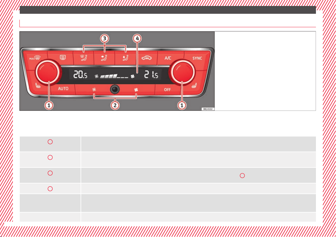
The essentials
How does Climatronic* work?
Fig. 62 In the centre console: Climatronic con-
trol
s
To switch a specific function on, press the ap-
pr
opri
at
e button. Press the button again to
switch off the function.
The LED on each control lights up to indicate
that the respective function of a control has
been switched on.
1
Temperature
The left and right sides can be adjusted separately: turn the control to adjust the temperature.
2
Fan
The power of the fan is automatically adjusted. Press the buttons to manually adjust the fan.
3
Air distribution
The airflow adjusts automatically for comfort. You can also switch it on manually using the buttons
3
.
4
Indications on the display screen of the fan speed and the temperature selected for the right and left sides.
Defrost function
The air drawn in from outside the vehicle is directed at the windscreen and air recirculation is automatically switched off. To defrost the wind-
screen more quickly, the air is dehumidified at temperatures over approximately +3°C (+38°F) and the fan runs at maximum output.
The air is directed at the chest of driver and passengers by the dash panel air vents.
52
The essentials
Air distribution towards the footwell.
Upward air distribution.
Heated rear window: this only works when the engine is running and switches off automatically after a maximum of 10 minutes.
Air recirculation
Seat heating buttons
Press the button to switch on or off the cooling system.
Press the
button to apply the driver-side settings to the passenger side. Use the temperature regulator for the passenger side in order to set
a different temperature.
Automatic adjustment of temperature, fan, and air distribution.
Switching off
Press the
button or manually set the fan to
.
››› in General notes on page 166
››› page 173
53
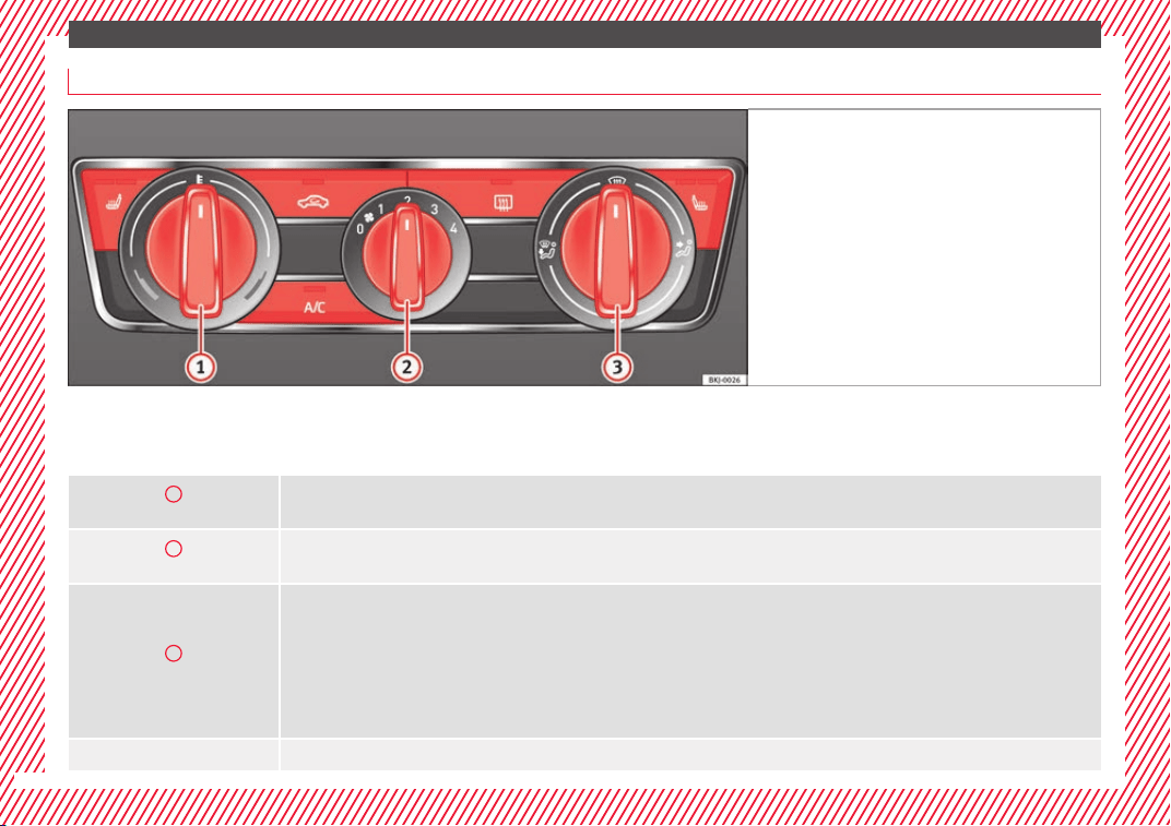
The essentials
How does the manual air conditioning work*?
Fig. 63 In the centre console: Manual air condi-
tioning contr
ols.
To switch a specific function on, press the ap-
pr
opri
at
e button. Press the button again to
switch off the function.
The LED on each control lights up to indicate
that the respective function of a control has
been switched on.
1
Temperature
Turn the control to adjust the temperature.
2
Fan
Setting 0: blower and manual air conditioning switched off
Level 4: maximum fan level.
3
Air distribution
: Defrost function. The airflow is directed at the windscreen. Air recirculation is automatically switched off or is not switched on. Increase the
fan power to clear the windscreen of condensation as soon as possible. To dehumidify the air, the cooling system will automatically switch on.
: The air is directed at the chest of driver and passengers by the dash panel air vents.
: Air distribution to footwells.
: Air distribution towards the windscreen and the footwell.
Heated rear window: this only works when the engine is running and switches off automatically after a maximum of 10 minutes.
54
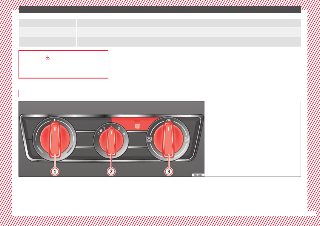
The essentials
Air recirculation
Press the button to switch on or off the cooling system.
Seat heating buttons
››› in General notes on page 166
››› page 171
How does the heating and the fresh air system work?
Fig. 64 In the centre console: heating system and
fresh air controls.
To switch a specific function on, press the ap-
pr
opri
at
e button. Press the button again to
switch off the function.
The LED on each control lights up to indicate
that the respective function of a control has
been switched on.
»
55
The essentials
1
Temperature
Turn the control to adjust the temperature. The temperature cannot be lower than that of the exterior air temperature, as this system cannot cool
or dehumidify the air.
2
Fan
Setting 0: blower and manual air conditioning switched off
Level 4: maximum fan level.
3
Air distribution
: Defrost function. The airflow is directed at the windscreen.
: The air is directed at the chest of driver and passengers by the dash panel air vents.
: Air distribution to footwells.
: Air distribution towards the windscreen and the footwell.
Heated rear window: this only works when the engine is running and switches off automatically after a maximum of 10 minutes.
››› in General notes on page 166
››› page 169
56
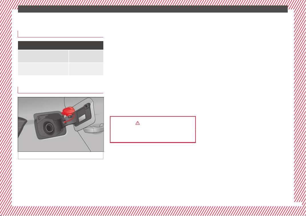
The essentials
Fluid Level control
Fi
l
lin
g capacities
Capacities
Fuel tank 40 litres. 7 litre re-
serve.
Windscreen washer fluid con-
tainer
3 litres
Fuel
Fig. 65 Fuel tank flap with tank cap attached.
The tank flap is released electronically by
me
an
s
of the central locking and is located at
the rear of the vehicle, on the right. The tank
holds approximately 40 litres.
Opening the fuel tank cap
●
Open the fuel tank flap by pressing on the
left side.
●
Unscrew the cap by turning it to the left.
●
Place it in the space on the hinge of the
open flap ››› Fig. 65.
Closing the fuel tank cap
●
Unscrew the cap by turning it to the right as
far as it will go.
●
Close the lid.
››› in Refuelling on page 257
››› page 257
57
The essentials
Oil
Fig. 66 Engine oil dipstick. Fig. 67 In the engine compartment: Engine
oil fi
ller cap.
The level is measured using the dipstick loca-
t
ed in the en
gine c
ompartment
›››
page 266.
The oil should leave a mark between zones
A
and
C
. It should never exceed zone
A
.
●
Zone
A
: Do not add oil.
●
Zone
B
: You can add oil but keep the level
in th
at
zone.
●
Zone
C
: Add oil up to zone
B
.
T
op
pin
g up engine oil
●
Unscrew cap from oil filler opening.
●
Add oil slowly.
●
At the same time, check the level to ensure
you do not add too much.
●
When the oil level reaches at least zone
B
,
u
n
s
crew the engine oil filler cap carefully.
Engine oil additives
No type of additive should be mixed with the
engine oil. The deterioration caused by these
additives is not covered by the warranty.
58
The essentials
Engine oil specifications
Service interval Engine type Specification
Petrol engines with Set Service Intervals (dependent on
time/distance travelled)
1.0l / 1.0l GNC / 1.5l VW 504 00
1.0l / 1.6l VW 502 00
a)
Petrol engines with Flexible Service Intervals (LongLife) 1.0l / 1.5l
VW 508 00
VW 504 00
b)
Diesel engines with Set Service and Flexible Service In-
tervals
c)
With particulate filter (DPF) VW 507 00
a)
If the quality of the fuel available in the country does not fulfil the EN 228 (for petrol) and EN 590 (for diesel) standards.
b)
Use of engine oil compliant with the VW 504 00 specification instead of VW 508 00 may have a slight negative effect on the vehicle’s exhaust gas values.
c)
Only use recommended oils, otherwise you may damage the engine.
››› in Changing engine oil on page 269
››› page 266
Coolant
Fig. 68 Engine compartment: coolant expan-
s
ion t
ank
cap.
The coolant tank is located in the engine
c
omp
ar
tment ›››
page 266.
When the engine is cold, replace the coolant
when the level is below .
Coolant specifications
The engine cooling system is supplied from
the factory with a specially treated mixture of
water and at least 40 % of the additive G13
(TL-VW 774 J), purple. This mixture gives the
necessary frost protection down to -25°C
(-13°F) and protects the light alloy parts of
the engine cooling system against corrosion.
It also prevents scaling and considerably rai-
ses the boiling point of the coolant.
To protect the cooling system, the percentage
of additive must always be at least 40 %,
even in warm climates where anti-freeze pro-
tection is not required.
»
59
The essentials
If for weather reasons further protection is
nec
e
s
sary, the proportion of additive may be
increased, but only up to 60 %; otherwise an-
tifreeze protection will diminish and this will
worsen cooling.
When the coolant is topped up, use a mixture
of distilled water and at least 40 % of the
G13 or G12 plus-plus (TL-VW 774 G) additive
(both are purple) to obtain an optimum anti-
corrosion protection ›››
in Topping up cool-
ant on p
ag
e 271
. The mixture of G13 with
G12 plus (TL-VW 774 F), G12 (red) or G11
(green-blue) engine coolants will significant-
ly reduce anti-corrosion protection and
should therefore be avoided ›››
in Topping
up c
oo
l
ant on page 271.
››› in Topping up coolant on page 270
››› page 269
Brake fluid
Fig. 69 Engine compartment: brake fluid res-
er
v
oir c
ap.
The brake fluid reservoir is located in the en-
gine c
omp
ar
tment ›››
page 266.
The level should be between the and
marks. If it is below , please visit a Techni-
cal Service.
››› in Changing the brake fluid on
page 271
››› page 271
Windscreen washer
Fig. 70 In the engine compartment: wind-
s
c
r
een washer reservoir top.
The windscreen washer reservoir is located in
the en
gine c
omp
artment ›››
page 266.
To top up, mix water with a product recom-
mended by SEAT.
In cold temperatures, add anti-freeze for win-
dows.
››› in Checking and topping up the
windscreen washer reservoir water on
page 272
››› page 272
Battery
The battery is located in the engine compart-
ment
›
›
›
page 266. It does not require
60

The essentials
Emergencies
F
u
se
s
Fuse location
Fig. 71 On the driver-side dash panel: fuse
bo
x
c
over.
Fig. 72 In the engine compartment: fuse box
c
o
v
er.
Opening and closing the fuse box situated
belo
w the d
a
sh panel
●
Opening: remove the fuse box cover in the
direction indicated ››› Fig. 71.
●
Closing: click the cover back into place.
To open the engine compartment fuse box
●
Raise the bonnet.
●
Press the locking tabs to release the fuse
box cover ››› Fig. 72
●
Then lift the cover out.
●
To fit the cover, place it on the fuse box.
Push the locking tabs down until they click
audibly into place.
Identifying fuses situated below the dash
panel by colours
Colour Amp rating
Black 1
Purple 3
Light brown 5
Brown 7.5
Red 10
Blue 15
Yellow 20
White or transparent 25
Colour Amp rating
Green 30
Orange 40
››› in Introduction on page 104
››› page 104
Replacing a blown fuse
Fig. 73 Image of a blown fuse.
Preparation
●
Switch off the ignition, lights and all elec-
tric
al
equipment
.
●
Open the corresponding fuse box
›››
page 104.
62
The essentials
Identifying a blown fuse
A f
u
se i
s blown if its metal strip is ruptured
››› Fig. 73.
●
Point a lamp at the fuse to see if it has
blown.
To replace a fuse
●
Remove the fuse.
●
Replace the blown fuse by one with an
identical amperage rating (same colour and
markings) and identical size.
●
Replace the cover again or close the fuse
box lid.
Bulbs
Bulbs (12 V)
Note: D
epending on the level of equipment
fitt
ed in the
vehicle, LEDs may be used for
part or all of the interior and/or exterior light-
ing. LEDs have an estimated life that exceeds
that of the vehicle. If an LED light fails, go to
an authorised workshop for its replacement.
Light source used for each function
Halogen headlights. Type
Dipped beam headlights H7 Long Life
Main beam headlights H7
Halogen headlights. Type
Side light/DRL (daytime running
light)
W21W
Turn signal PY 21W
Halogen headlight with LED
DRL
Type
Dipped beam headlights H7 Long Life
Main beam headlights H7
Turn signal PY 21W
Side light/DRL (daytime running
light)
LED
a)
a)
In case of a LED failure, go to an authorised workshop to have
it replaced.
Full-LED main headlights Type
No bulbs may be replaced. All functions are with LEDs.
In case of a LED failure, go to an authorised workshop to
have it replaced.
››› page 106
Action in the event of a punc-
t
ur
e
R
elated video
Fig. 74 Wheels
What to do first
●
Park the vehicle on a horizontal surface
and in a s
af
e p
lace as far away from traffic as
possible.
●
Apply the handbrake.
●
Switch on the hazard warning lights.
●
Manual gearbox: select the 1st gear.
●
Automatic gearbox: Move the selector lever
to position P.
●
If you are towing a trailer, unhitch it from
your vehicle.
●
Have the vehicle tool kit*
›››
page 65 and
the spare wheel
›››
page 279 ready.
●
Observe the applicable legislation for each
country (reflective vest, warning triangles,
etc.).
»
63
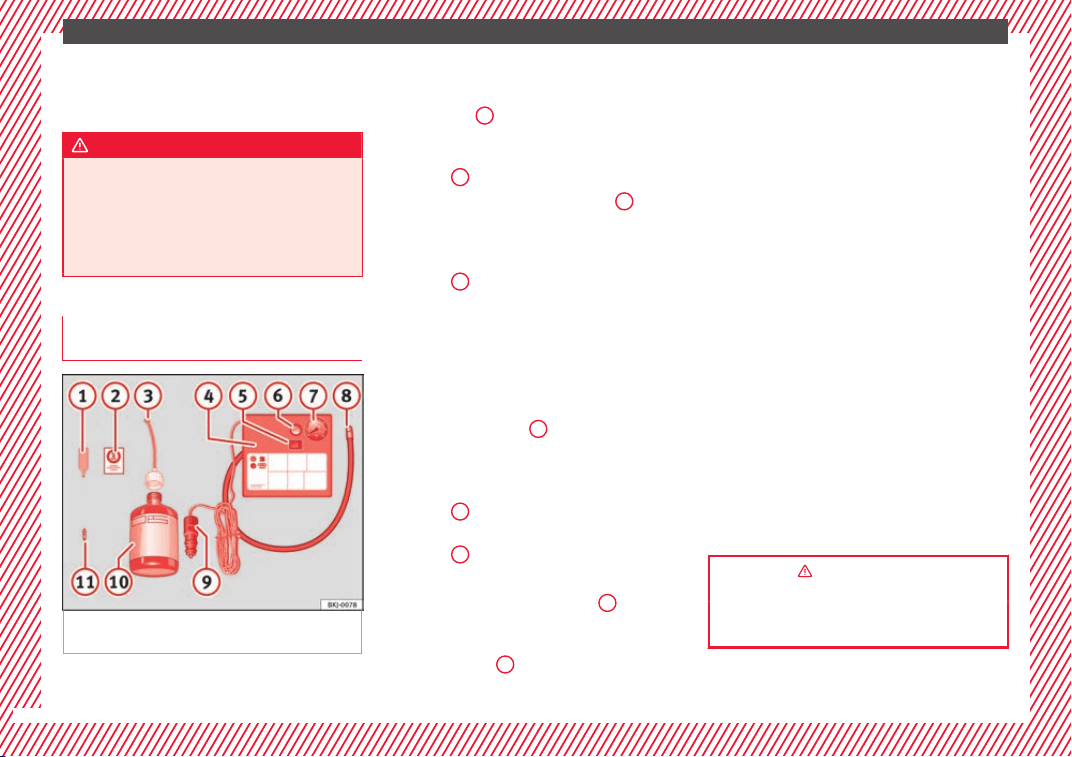
The essentials
●
A
l
l
occupants should leave the vehicle and
wait in a safe place (for instance behind the
roadside crash barrier).
WARNING
●
Alwa
ys observe the above steps and pro-
tect yourself and other road users.
●
If you change the wheel on a slope, block
the wheel on the opposite side of the car with
a stone or similar to prevent the vehicle from
moving.
Repairing a tyre with the anti-punc-
t
ur
e k
it
Fig. 75 Standard representation: contents of
the anti-p
u
nct
ure kit.
The anti-puncture kit is located under the
floor p
anel
in the lug
gage compartment.
Sealing the tyre
●
Unscrew the tyre valve cap and insert. Use
the ››› Fig. 75
1
tool to remove the insert.
Pl
ac
e it
on a clean surface.
●
Shake the tyre sealant bottle vigorously
››› Fig. 75
10
.
●
Screw the inflator tube ›
›
›
Fig. 75
3
into
the se
al
ant
bottle. The bottle's seal will break
automatically.
●
Remove the lid from the filling tube
››› Fig. 75
3
and screw the open end of the
t
ube int
o the ty
re valve.
●
With the tyre sealant bottle upside down,
fill the tyre with the contents of the sealant
bottle.
●
Remove the bottle from the valve.
●
Place the insert back into the tyre valve us-
ing the tool ››› Fig. 75
1
.
Infl
atin
g the ty
re
●
Screw the compressor tyre inflator tube
››› Fig. 75
8
into the tyre valve.
●
Check that the air bleed screw is closed
›
›
›
Fig. 75
6
.
●
Start the engine and leave it running.
●
Insert the connector ›
›
›
Fig. 75
9
into the
v
ehic
l
e's 12-volt socket ›››
page 160.
●
Turn the air compressor on with the ON/OFF
switc
h ››› Fig. 75
5
.
●
K
eep the air c
ompr
essor running until it
reaches 2.0 to 2.5 bar
(29-36 psi/200-250 kPa). A maximum of 8
minutes.
●
Disconnect the air compressor.
●
If it does not reach the pressure indicated,
unscrew the tyre inflator tube from the valve.
●
Move the vehicle 10m so that the sealant is
distributed throughout the tyre.
●
Screw the compressor tyre inflator into the
valve.
●
Repeat the inflation process.
●
If the indicated pressure still cannot be
reached, the tyre is too badly damaged. Stop
and request assistance from an authorised
technician.
●
Disconnect the air compressor. Unscrew
the tyre inflator tube from the tyre valve.
●
When the tyre pressure is between 2.5 and
2.0 bars, continue driving without exceeding
80 km/h (50 mph).
●
Check the pressure again after 10 minutes
›››
page 99.
››› in TMS (Tyre Mobility System)* on
page 98
››› page 98
64

The essentials
Changing a wheel
R
el
at
ed video
Fig. 76 Wheels
Vehicle tool kit
Fig. 77 Underneath the floor panel of the lug-
g
ag
e c
ompartment: vehicle tool kit.
An adapter for the anti-theft wheel bolts*
T
o
wline anc
horage
Box spanner for wheel bolts*
Crank handle for jack
1
2
3
4
Jack*
Hook
f
or e
xtracting the central wheel
trims*
Clip for removing the wheel bolt caps.
››› in Vehicle tools on page 97
››› page 97
Central trim for steel rims*
Fig. 78 Correct positioning of the central
wheel
trim f
or s
teel rims.
The central trims must be removed for access
t
o the wheel
bo
lts.
5
6
7
Removing
●
Attach the wire hook (vehicle tools
›
›
›
Fig. 77
6
) to one of the chambers of the
c
entr
al
wheel trim.
●
Insert the box spanner through the hook,
supporting it on the tyre and remove the
wheel trim.
Fitting
●
Fit the central wheel trim onto the rim. The
bottom of the “S” of the SEAT badge should
align with the inflation valve ››› Fig. 78
1
.
●
Press the central trim firmly until it locks in
w
ith an audib
l
e click.
Note
There is also a valve mark on the back of the
centra
l wheel trim that indicates the correct
alignment.
65
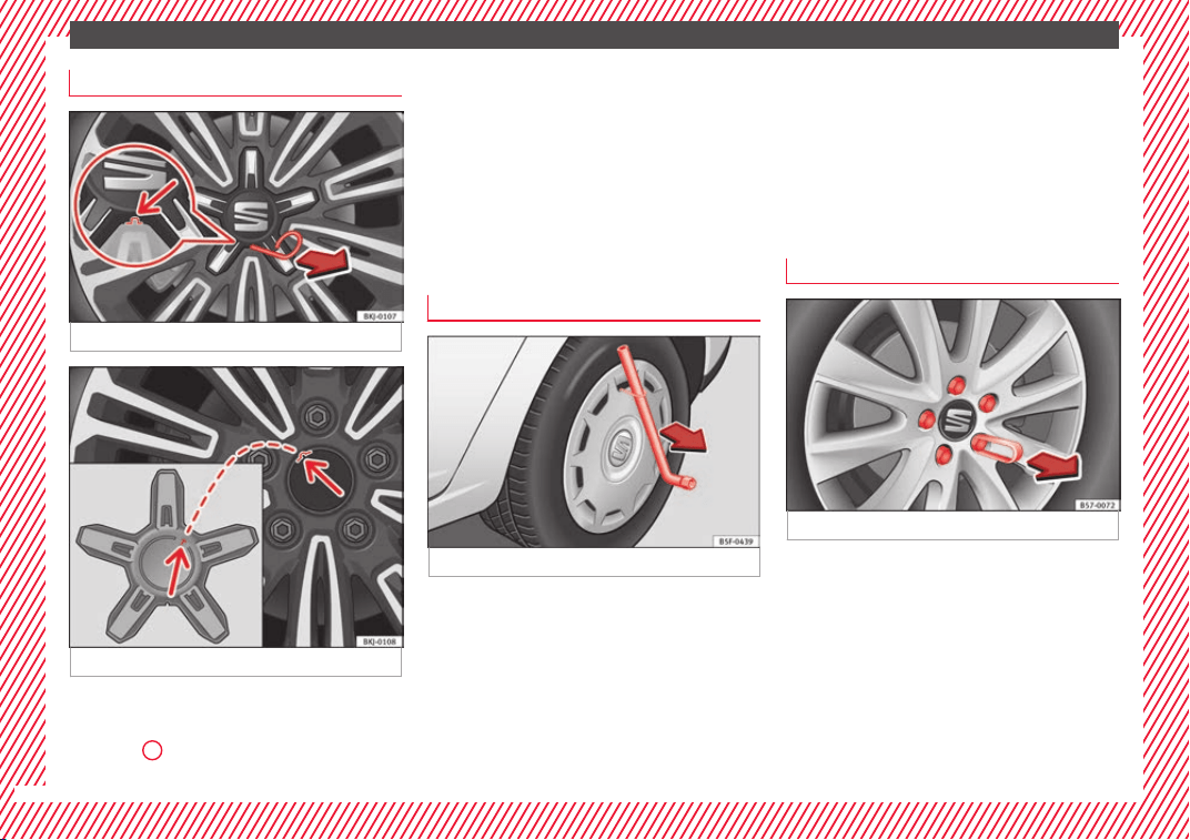
The essentials
Central trim for alloy rims*
Fig. 79 Removing the central wheel trim.
Fig. 80 Fitting the central wheel trim.
Removing
●
Attach the wire hook (vehicle tools
›
››
Fig. 77
6
) to the housing provided for this
›
›
›
Fig. 79.
●
Pull on it to remove the trim ››› Fig. 79.
Fitting
●
Fit the central wheel trim onto the rim, fit-
ting the protrusion on the trim into the recess
in the rim ››› Fig. 80 (arrows).
●
Press the central trim firmly until it locks in
with an audible click.
Wheel covers*
Fig. 81 Remove the wheel cover.
The wheel covers must be removed for access
t
o the wheel
bo
lts.
Removing
●
Remove the wheel cover using the wire
hook ››› Fig. 81.
●
Hook this into one of the cut-outs of the
wheel cover.
Fitting
●
Fit the wheel cover onto the wheel rim by
pressing it firmly.
●
Put pressure on the point of the cut-out for
the valve.
●
Next fit the rest of the wheel cover.
Wheel bolt caps*
Fig. 82 Wheel: wheel bolts with caps.
Removal
●
Fit the plastic clip (vehicle tools) over the
c
ap u
nti
l it clicks into place ››› Fig. 82.
●
Remove the cap with the plastic clip.
66
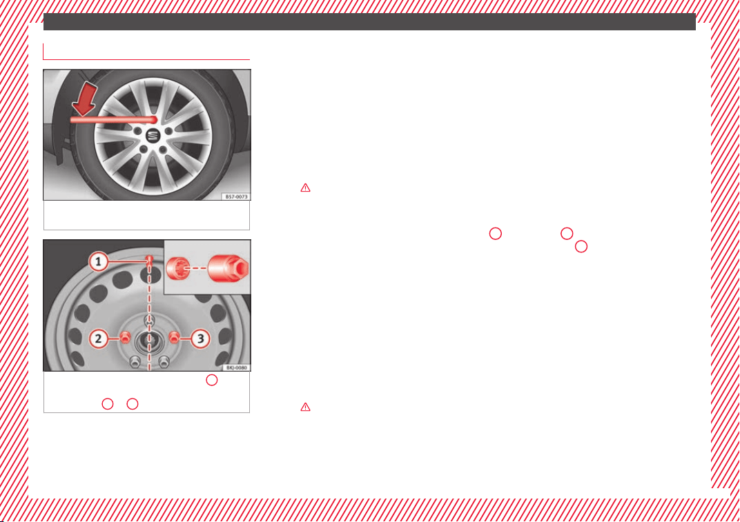
The essentials
Wheel bolts
Fig. 83 Changing a wheel: loosen the wheel
bo
lts.
Fig. 84 Changing a wheel: tyre valve
1
and
the c
orr
ect
position for the anti-theft wheel
locking bolt
2
or
3
.
Use only the wheel wrench belonging to the
c
ar t
o loo
sen the wheel bolts.
Loosen the wheel bolts only about one turn
before raising the vehicle with the jack.
If the wheel bolt is very tight, carefully push
on the end of the wheel wrench with your
foot. Hold on to the vehicle for support and
take care not to slip during this operation.
Loosening wheel bolts
●
Fit the wheel wrench on as far as it will go
››› Fig. 83.
●
Hold the wrench at the end and rotate the
bolt approximately one turn anticlock-
wise ›››
in Removing and fitting the wheel
on p
ag
e 69
.
The caps protect the wheel bolts and should
be pushed fully on again after changing the
tyre.
Loosening the anti-theft wheel bolt
●
Take the adapter for the anti-theft wheel
bolts out of the vehicle tool kit.
●
Insert the adapter fully onto the anti-theft
wheel bolt ››› Fig. 84.
●
Fit the wheel wrench as far as it will go over
the adapter.
●
Hold the wrench at the end and rotate the
bolt approximately one turn anticlock-
wise ›››
in Removing and fitting the wheel
on p
ag
e 69
.
The anti-theft wheel bolt has a different cap.
This cap only fits on anti-theft locking bolts
and is not for use with standard wheel bolts.
Important information about wheel bolts
Factory-fitted rims and wheel bolts are spe-
cially matched during construction. There-
fore, if different rims are fitted, the correct
wheel bolts with the right length and heads
must be used. This ensures that wheels are
fitted securely and that the brake system
functions correctly.
In certain circumstances, you should not
even use wheel bolts from vehicles of the
same model.
In wheels with full hubcaps, the anti-theft
locking bolt must be threaded onto positions
2
›
›
› Fig. 84
or
3
, taking the tyre valve’s po-
s
ition a
s
reference
1
. Otherwise it will not
be po
s
s
ible to mount the hubcap.
67
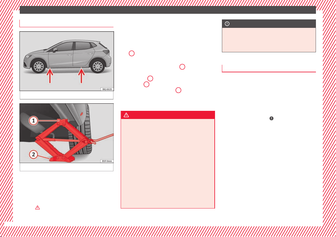
The essentials
Raising the vehicle
Fig. 85 Jack position points.
Fig. 86 Fitting the jack.
●
Place the jack* (vehicle tools) on firm
gr
ou
nd. If
necessary use a large, strong
board or similar support. If the surface is slip-
pery (for example tiles) place the jack on a
rubber mat or similar to prevent it from slip-
ping ›››
.
●
Find the s
up
por
t point on the strut (sunken
area) closest to the wheel to be changed
››› Fig. 85.
●
Turn the jack* crank handle, located below
the strut support point, to raise it until the
tab
1
›
›› Fig. 86
i
s below the housing provi-
ded.
●
Align the jack* so that tab
1
“grips” onto
the hou
s
in
g provided on the strut and the
mobile base
2
is resting on the ground. The
b
a
se p
late
2
should fall vertically with re-
s
pect
t
o the support point
1
.
●
Continue turning the jack* until the wheel
i
s
s
lightly lifted off the ground.
WARNING
●
Make s
ure that the jack* remains stable. If
the surface is slippery or soft, the jack* could
slip or sink, respectively, with the resultant
risk of injury.
●
Only raise the vehicle with the jack* sup-
plied by the manufacturer. Other vehicles
could slip, with the consequent risk of injury.
●
Only mount the jack* on the support points
designed for this purpose on the strut, and
always align the jack correctly. If you do not,
the jack* could slip as it does not have an ad-
equate grip on the vehicle: risk of injury!
●
The height of the parked vehicle can
change as a result of variations in tempera-
ture and loading.
CAUTION
The vehicle must not be raised on the cross-
bar. On
ly place the jack* on the points de-
signed for this purpose on the strut. Other-
wise, the vehicle may be damaged.
Removing and fitting the wheel
Change the wheel after loosening the wheel
bolts and r
aising the vehicle with the jack.
Taking off the wheel
●
Unscrew the wheel bolts using the box
spanner and p
lace them on a clean surface.
●
Take off the wheel
›››
.
P
uttin
g on the s
pare wheel
When fitting tyres with a compulsory rotation
direction, observe the instructions in
›››
page 69.
●
Mount the wheel.
●
Screw on the wheel bolts in position and
tighten them loosely with a box spanner.
●
Carefully lower the vehicle using the jack*.
●
Tighten the wheel bolts in diagonal pairs
using the wheel brace.
The wheel bolts should be clean and turn
easily. Before fitting the spare wheel, inspect
68

The essentials
the wheel condition and hub mounting surfa-
c
e
s.
These surfaces must be clean before fit-
ting the wheel.
Wheel bolt tightening torque
The prescribed tightening torque for wheel
bolts for steel and alloy wheels is 120 Nm.
After changing a wheel, have the tightening
torque checked immediately with a torque
wrench that is working perfectly.
Before checking tightening torque, have any
rusty wheel bolts that are difficult to screw re-
placed and clean the wheel hub threads.
Never apply grease or oil to wheel bolts or to
the wheel hub threads. Even if the bolts have
been tightened to the prescribed torque, they
could come loose while driving.
WARNING
If the wheel bolts are not properly tightened,
they cou
ld come loose while driving and
cause an accident, serious injury and loss of
vehicle control.
●
Use only wheel bolts which correspond to
the rim in question.
●
Never use different wheel bolts.
●
Wheel bolts and threads should be clean,
free of oil and grease, and it should be possi-
ble to screw them easily.
●
To loosen and tighten wheel bolts, only use
the wheel wrench that came with the car from
the factory.
●
Loosen the wheel
bolts only about one turn
before raising the vehicle with the jack.
●
Never apply grease or oil to wheel bolts or
to the wheel hub threads. Even if the bolts
have been tightened to the prescribed tor-
que, they could come loose while driving.
●
Never loosen the screwed joints of wheel
rims with bolted ring trims.
●
If wheel bolts are tightened below the pre-
scribed torque, the bolts and rims could come
loose while driving. If tightening torque is too
high, the wheel bolts or threads can be dam-
aged.
CAUTION
When removing/fitting the wheel, the rim
may
hit and damage the brake disc. For this
reason, please take care and get a second
person to assist you.
Tyres with compulsory direction of ro-
t
ation
A directional tread pattern can be identified
b
y
the arr
ows on the sidewall that point in
the direction of rotation. Always observe the
direction of rotation indicated when fitting
the wheel to guarantee optimum properties
of this type of tyres with regard to grip,
noises, wear and aquaplaning.
If it is absolutely necessary to fit the spare
tyre* against the direction of rotation, drive
with care as this means the tyre does not of-
fer optimum driving properties. This is of par-
ticular importance when the road surface is
wet.
To return to directional tread tires, replace
the punctured tyre as soon as possible and
restore the obligatory direction of rotation of
all tyres.
Subsequent work
●
Alloy wheels: r
ep
l
ace the wheel bolt caps.
●
Plate wheels: replace the wheel hubcap.
●
Return all tools to their proper storing loca-
tion.
●
If the replaced wheel does not fit in the
spare wheel housing, store it safely in the
luggage compartment ›››
page 160.
●
Check the tyre pressure of the newly moun-
ted tyre as soon as possible.
●
In vehicles fitted with a tyre pressure indi-
cator, adjust the pressure and store it in
memory
›››
page 278.
●
Have the tightening torque of the wheel
bolts checked as soon as possible with a tor-
que wrench (it should be 120 Nm). Mean-
while, drive carefully.
●
Have the flat tyre replaced as quickly as
poss
ible.
69
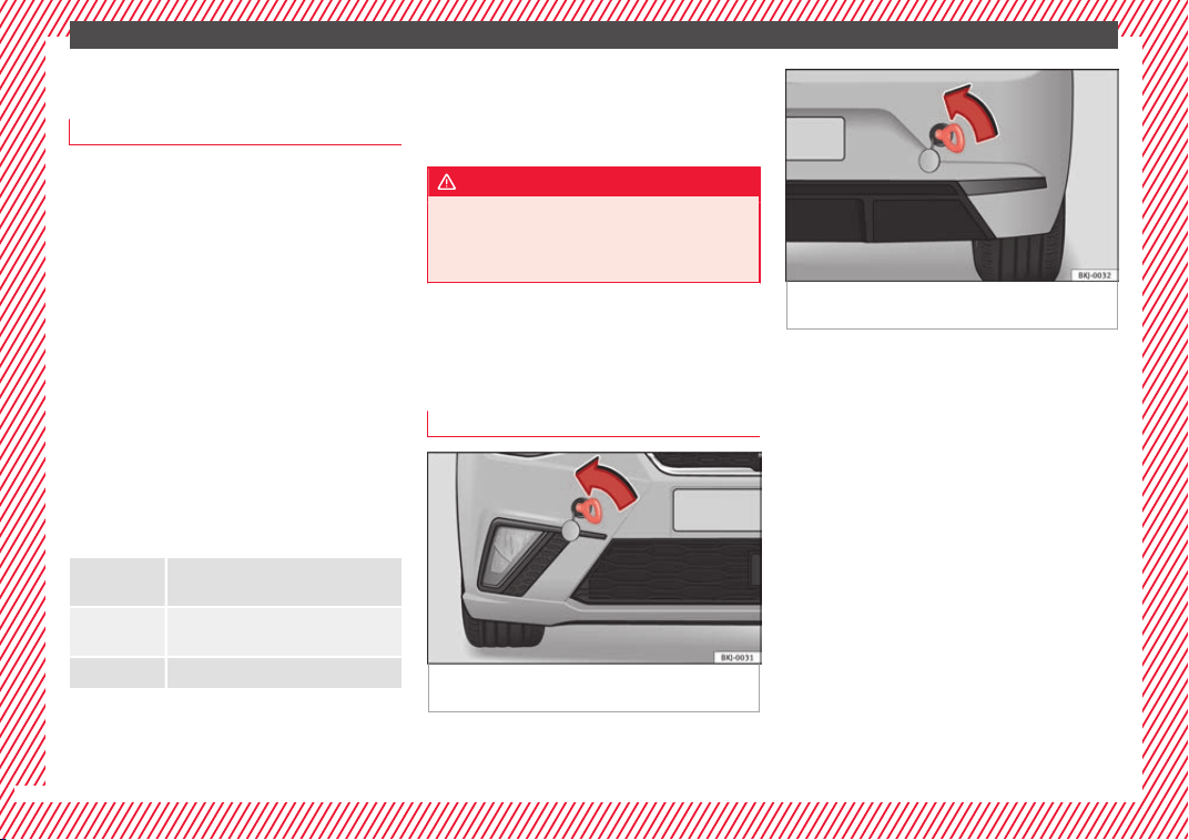
The essentials
Snow chains
U
se
Snow chains should only be used on the
front wheel
s.
●
Check that they are correctly seated after
driving for a few yards; correct the position if
necessary, in accordance with the manufac-
turer's fitting instructions.
●
Keep your speed below 50 km/h (30 mph).
●
If there is a danger of being trapped de-
spite h
aving mounted the chains, it is best to
disable the driving wheels (ASR) in the ESC
›››
page 183.
Snow chains will improve braking ability as
well as traction in winter conditions.
For technical reasons snow chains may only
be used with the following wheel rim/tyre
combination.
185/70 R14 Chains with links of maximum 13.5
mm
185/65 R15 Chains with links of maximum 13.5
mm
195/55 R16 Chains with links of maximum 9 mm
Remove wheel covers and any integral trim
rin
g bef
or
e fitting snow chains.
Remove the chains when roads are free of
snow. Driving characteristics worsen, and the
wheels become damaged quickly and may
even be rendered unusable.
WARNING
Snow chains should be correctly tightened in
accor
dance with the manufacturer's instruc-
tions. This will prevent the chains coming in-
to contact with the wheel housing.
Emergency towing of the vehi-
c
l
e
T
owing
Fig. 87 Right side of the front bumper: Tow-
in
g rin
g.
Fig. 88 Right side of the rear bumper: Towing
ring.
Towline anchorages
Att
ac
h the b
ar or rope to the towline ancho-
rages.
The towline anchorages are located under
the floor panel in the luggage compartment,
next to the vehicle tools ››› page 65.
Screw the towline anchorage into the screw
connection ››› Fig. 87 or ››› Fig. 88 and tighten
it with the wheel brace.
Tow rope or tow bar
It is easier and safer for the vehicle to be tow-
ed using a tow bar. You should only use a
tow-rope if you do not have a tow-bar.
A tow rope should be slightly elastic to re-
duce the loading on both vehicles. It is advis-
able to use a tow rope made of synthetic fi-
bre or similarly elastic material.
70
The essentials
Attach the tow rope or the tow bar only to the
t
o
wline anc
horages provided or a towing
bracket.
Notes for the driver of the towing vehicle
●
The tow rope must be taut before you drive
off.
●
Release the clutch very carefully when start-
ing the vehicle (manual gearbox), or acceler-
ate gently (automatic gearbox).
Driving style
Towing requires some experience, especially
when using a tow rope. Both drivers should
realise how difficult it is to tow a vehicle. In-
experienced drivers should not attempt to
tow.
Do not pull too hard with the towing vehicle
and take care to avoid jerking the tow rope.
When towing on an unpaved road, there is al-
ways a risk of overloading and damaging the
anchorage points.
The ignition of the vehicle being towed must
be switched on to prevent the steering wheel
from locking and also to allow the use of the
turn signals, horn, windscreen wipers and
washers.
Place the gear lever in neutral on vehicles
with a manual gearbox. With an automatic
gearbox, place the lever in N.
The brake servo only works when the engine
is running. When not running, you must ap-
ply considerably more pressure to the brake
pedal.
As the power assisted steering does not work
if the engine is not running, you will need
more strength to steer than you normally
would.
››› in General information on page 100
››› page 100
Tow-starting
If the engine will not start, first try starting it
u
s
in
g the battery of another vehicle
››› page 71. You should only attempt to tow-
start a vehicle if charging the battery does
not work. This is done by leveraging wheel
movement.
When tow-starting a vehicle with a petrol en-
gine, do not tow it more than a short dis-
tance, otherwise unburned fuel can enter the
catalytic converter.
However, if your vehicle has to be tow-star-
ted:
●
Engage 2
nd
or 3
rd
gear.
●
Keep the clutch pressed down.
●
Switch the ignition on.
●
Once both vehicles are moving, release the
clutch.
●
As soon as the engine starts, press the
clutch and move the gear lever into neutral.
This helps to prevent driving into the towing
vehicle.
››› in General information on page 100
››› page 100
How to jump start
Jump l
e
a
ds
The jump lead must have a sufficient wire
c
r
o
ss section.
If the engine fails to start because of a dis-
charged battery, the battery can be connec-
ted to the battery of another vehicle to start
the engine.
Jump leads
Jump leads must comply with standard DIN
72553 (see cable manufacturer's instruc-
tions). The wire cross section must be at least
25 mm
2
for petrol engines and at least
35 mm
2
for diesel engines.
»
71
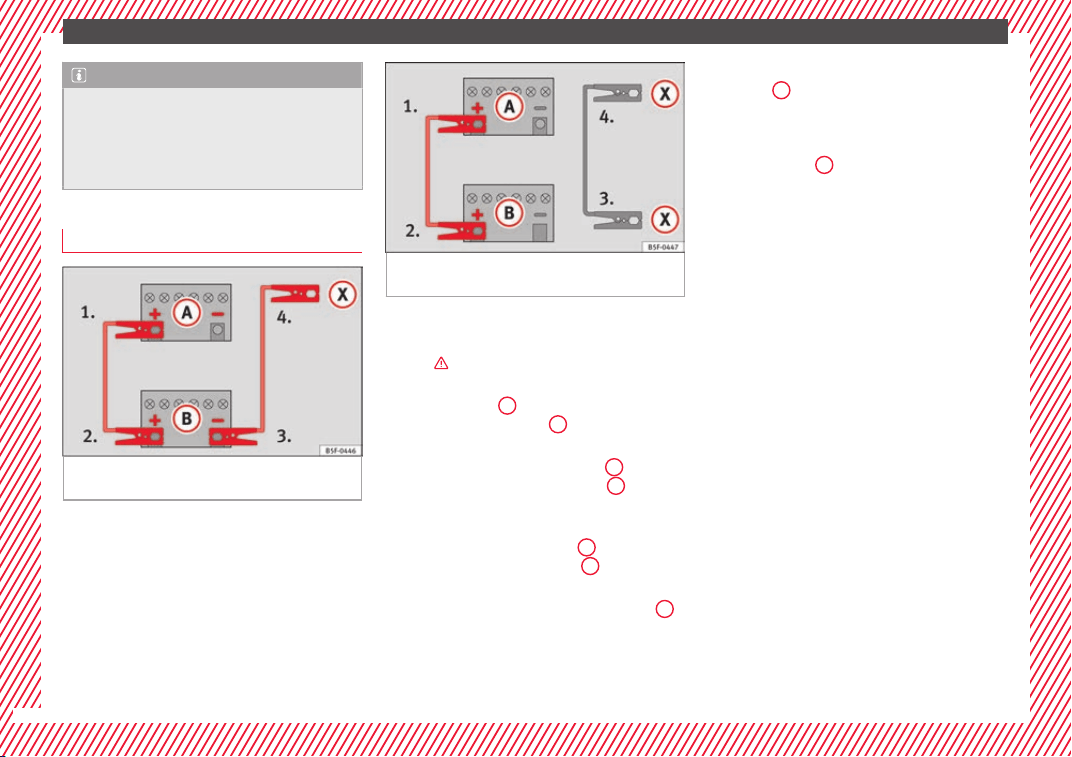
The essentials
Note
●
The vehic
les must not touch each other,
otherwise electricity could flow as soon as
the positive terminals are connected.
●
The discharged battery must be properly
connected to the on-board network.
How to jump start: description
Fig. 89 Diagram of connections for vehicles
w
ithout
Start-Stop system.
Fig. 90 Diagram of connections for vehicles
with St
art-Stop system.
Jump lead terminal connections
Sw
it
c
h off the ignition of both vehicles
›››
.
C
onnect
one end of
the red jump lead to
the positive
+
terminal of the vehicle
w
ith the fl
at
battery
A
›
›
› Fig. 89
.
Connect the other end of the red jump
lead to the positive terminal
+
in the
v
ehic
l
e providing assistance
B
.
F
or
vehicles without Start-Stop system:
connect one end of the black jump lead
to the negative terminal
–
of the vehi-
c
l
e pr
oviding the current
B
›
›
› Fig. 89
.
For vehicles with Start-Stop system: con-
nect one end of the black jump lead
X
to a suitable ground terminal, to a solid
piec
e of
met
al in the engine block, or to
the engine block itself ››› Fig. 90.
1.
2.
3.
4a.
4b.
Connect the other end of the black jump
lead
X
to a solid metal component bol-
t
ed t
o the en
gine block or to the engine
block itself of the vehicle with the flat
battery. Do not connect it to a point near
the battery
A
.
P
o
s
ition the leads in such a way that
they cannot come into contact with any
moving parts in the engine compart-
ment.
Starting
Start the engine of the vehicle with the
boosting battery and let it run at idling
speed.
Start the engine of the vehicle with the
flat battery and wait for 2 or 3 minutes
until the engine is running.
Removing the jump leads
Before you remove the jump leads,
switch off the dipped beam headlights if
they are switched on.
Turn on the heater blower and heated
rear window in the vehicle with the flat
battery. This helps minimise voltage
peaks which are generated when the
leads are disconnected.
When the engine is running, disconnect
the leads in reverse order to the details
given above.
5.
6.
7.
8.
9.
10.
11.
72
The essentials
Make sure the battery clamps have sufficient
met
al-t
o-met
al contact with the battery termi-
nals.
If the engine fails to start after about 10 sec-
onds, switch off the starter and try again after
about 1 minute.
WARNING
●
Plea
se note the safety warnings referring to
working in the engine compartment
›››
page 263, Working in the engine
compartment.
●
The battery providing assistance must have
the same voltage as the flat battery (12 V)
and approximately the same capacity (see
imprint on battery). Failure to comply could
result in an explosion.
●
Never use jump leads when one of the bat-
teries is frozen. Danger of explosion! Even af-
ter the battery has thawed, battery acid could
leak and cause chemical burns. If a battery
freezes, it should be replaced.
●
Keep sparks, flames and lighted cigarettes
away from batteries, danger of explosion.
Failure to comply could result in an explo-
sion.
●
Observe the instructions provided by the
manufacturer of the jump leads.
●
Do not connect the negative cable from the
other vehicle directly to the negative terminal
of the flat battery. The gas emitted from the
battery could be ignited by sparks. Danger of
explosion.
●
Never attac
h the negative cable to fuel sys-
tem components or the brake lines in the oth-
er vehicle.
●
The non-insulated parts of the battery
clamps must not be allowed to touch. The
jump lead attached to the positive battery
terminal must not touch metal parts of the ve-
hicle, this can cause a short circuit.
●
Position the leads in such a way that they
cannot come into contact with any moving
parts in the engine compartment.
●
Do not lean on the batteries. This could re-
sult in chemical burns.
Note
The vehicles must not touch each other, oth-
erwi
se electricity could flow as soon as the
positive terminals are connected.
Changing the windscreen wiper
b
l
a
des
Changing the wiper blades
Fig. 91 Wipers in service position.
Fig. 92 Changing the windscreen wiper
b
l
a
de.
To change the blades it is necessary to move
the w
iper
s
from the rest position into the
service position.
»
73
The essentials
Do not change the windscreen wipers when
out
of
the ser
vice position, as it could cause
paint to flake off the bonnet due to friction
with the windscreen wiper arm.
Service position (for changing wiper blades)
●
Ensure that the wiper blades are not frozen.
●
Turn the ignition on and off and then (with-
in approximately 9 seconds) push the wind-
screen wiper lever down (short wipe). The
windscreen wipers will move to the service
position ››› Fig. 91.
Removing the wiper blade
●
Lift the windscreen wiper arm.
●
Press the securing tab down
1
›
›
› Fig. 92
.
●
Extract the wiper blade from the wiper arm.
Fitting the wiper blade
●
Insert the wiper blade onto the windscreen
wiper arm until it clicks into place.
●
Place the windscreen wiper arms to their in-
itial position.
●
Turn the ignition on, push the windscreen
wiper lever down (touch wipe) and then turn
the ignition off.
››› in Changing the windscreen and
rear window wiper blades on page 100
››› page 100
Changing the rear window wiper blade
Fig. 93 Removing and fitting the rear window
w
iper b
l
ade.
Removing the wiper blade
●
Lift the wiper arm away from the glass
●
Slide the blade adapter in the direction of
the arr
o
w and r
emove the blade ››› Fig. 93 A.
Fitting the wiper blade
●
With one hand, hold the top end of the wip-
er arm.
●
Place the blade as shown in ››› Fig. 93 B
and slide the adapter along until it engages.
››› in Changing the windscreen and
rear window wiper blades on page 100
››› page 100
74
Safe driving
Safety
Saf
e driv
in
g
Safety first!
This chapter contains important information,
tips, sug
gestions and warnings that you
should read and consider for both your own
safety and for your passengers' safety.
WARNING
●
This m
anual contains important informa-
tion about the operation of the vehicle, both
for the driver and the passengers. The other
sections of the on-board documentation also
contain further information that you should
be aware of for your own safety and for the
safety of your passengers.
●
Ensure that the on-board documentation is
kept in the vehicle at all times. This is espe-
cially important when lending or selling the
vehicle to another person.
Advice about driving
B
ef
or
e setting off
For your own safety and the safety of your
p
a
s
sengers, always note the following points
before every trip:
–
Make sure that the vehicle's lights and turn
signals are working properly.
–
Check tyre pressure.
–
Ensure that all windows provide a clear and
good view of the surroundings.
–
Ensure that all luggage is correctly secured
››› page 160.
–
Make sure that no objects can interfere
with the pedals.
–
Adjust front seat, head restraint and mir-
rors properly according to your size.
–
Ensure that the passenger in the central
rear seat always has the head restraint in
the correct position for use.
–
Instruct passengers to adjust the head re-
straints according to their height.
–
Protect children with appropriate child
seats and properly applied seat belts
››› page 92.
–
Assume the correct sitting position. Instruct
your passengers also to assume a proper
sitting position ››› page 76.
–
Fasten your seat belt securely. Instruct your
passengers also to fasten their seat belts
properly ››› page 81.
What affects driving safety?
As a driver, you are responsible for yourself
and your p
assengers. When your concentra-
tion or driving safety is affected by any cir-
cumstance, you endanger yourself as well as
others on the road ›››
, for this reason:
–
Always pay attention to traffic and do not
get di
stracted by passengers or telephone
calls.
–
Never drive when your driving ability is im-
paired (e.g. by medication, alcohol, drugs).
–
Observe traffic laws and speed limits.
–
Always reduce your speed as appropriate
for ro
ad, traffic and weather conditions.
–
When travelling long distances, take
breaks regularly - at least every two hours.
–
If possible, avoid driving when you are tired
or stressed.
WARNING
When driving safety is impaired during a trip,
the risk of
injury and accidents increases.
Safety equipment
Never put your safety or the safety of your
p
a
s
sengers in danger. In the event of an acci-
dent, the safety equipment may reduce the
»
75
Technical dataAdviceOperationEmergenciesSafety
Safety
risk of injury. The following points cover part
of
the s
af
ety equipment in your SEAT
1)
:
●
three-point seat belts,
●
Belt tension limiter for the front and rear
side seats
●
belt tensioners for the front and rear seats,
●
front airbags,
●
side airbags in the front seat backrests,
●
“ISOFIX” anchor points for “ISOFIX” rear
child seat system
●
height-adjustable front head restraints,
●
Rear-centre head restraints with in-use po-
sition and non-use position
●
adjustable steering column.
The safety equipment mentioned above
works together to provide you and your pas-
sengers with the best possible protection in
the event of an accident. However, these
safety systems can only be effective if you
and your passengers are sitting in a correct
position and use this equipment properly.
Safety is everyone's business!
Correct position of the vehicle
occupants
Correct sitting position for the driver
Fig. 94 The proper distance between driver
and s
t
eerin
g wheel.
Fig. 95 Correct head restraint position for the
driv
er
.
For your own safety and to reduce the risk of
injur
y
in the ev
ent of an accident, we recom-
mend the following adjustments for the driv-
er:
–
Adjust the steering wheel so that there is a
distance of at least 25 cm between the
steering wheel and the centre of your chest
››› Fig. 94.
–
Move the driver's seat forwards or back-
wards so that you are able to press the ac-
celerator, brake and clutch pedals to the
floor with your knees still slightly angled
›››
.
–
Ensure that you can reach the highest point
of
the s
t
eering wheel.
–
Adjust the head restraint so that its upper
edge is at the same level as the top of your
head, or as close as possible to the same
level as the top of your head ››› Fig. 95.
–
Move the seat backrest to an upright posi-
tion so that your back rests completely
against it.
–
Fasten your seat belt securely ››› page 81.
–
Keep both feet in the footwell so that you
have the vehicle under control at all times.
Adjustment of the driver's seat ››› page 154.
1)
Depending on the version/market.
76
Safe driving
WARNING
●
An incorrect
sitting position of the driver
can lead to severe injuries.
●
Adjust the driver's seat so that there is at
least 25 cm distance between the centre of
the chest and the centre of the steering
wheel ››› Fig. 94. If distance is less than 25
cm, the airbag system may not protect you
properly.
●
If your physical constitution prevents you
from maintaining the minimum distance of 25
cm, contact a specialised workshop. The
workshop will help you decide if special spe-
cific modifications are necessary.
●
When driving, always hold the steering
wheel with both hands on the outside of the
ring at the 9 o'clock and 3 o'clock positions.
This reduces the risk of injury when the driver
airbag is triggered.
●
Never hold the steering wheel at the 12
o'clock position, or in any other manner (e.g.
in the centre of the steering wheel). In such
cases, if the airbag is triggered, you may sus-
tain injuries to the arms, hands and head.
●
To reduce the risk of injury to the driver
during sudden braking manoeuvres or an ac-
cident, never drive with the backrest tilted far
back! The airbag system and seat belts can
only provide optimal protection when the
backrest is in an upright position and the
driver is wearing his or her seat belt correct-
ly.
●
Adjust the head restraint properly to ach-
ieve optimal protection.
Adjusting the steering wheel position
Read the additional information carefully
›››
page 20
WARNING
●
Never adju
st the position of the steering
wheel when the vehicle is moving, as this
could cause an accident.
●
Move the lever up firmly so the steering
wheel position does not accidentally change
during driving. risk of accident!
●
Make sure you are capable of reaching and
firmly holding the upper part of the steering
wheel: risk of accident!
●
If you adjust the steering wheel so that it
points towards your face, the driver airbag
will not protect you properly in the event of
an accident. Make sure that the steering
wheel points towards your chest.
Correct position for the front passen-
g
er
For your own safety and to reduce the risk of
injur
y
in the ev
ent of an accident, we recom-
mend the following adjustments for the front
passenger:
–
Move the front passenger seat back as far
as possible
›››
.
–
Mo
v
e the se
at backrest to an upright posi-
tion so that your back rests completely
against it.
–
Adjust the head restraint so that its upper
edge is at the same level as the top of your
head, or as close as possible to the same
level as the top of your head ››› page 79.
–
Always keep both feet in the footwell in
front of the front passenger seat.
–
Fasten your seat belt securely ››› page 81.
It is possible to deactivate the front passen-
ger airbag in exceptional circumstances
››› page 90.
Adjusting the front passenger seat
›››
page 19.
WARNING
●
An incorrect
sitting position of the front
passenger can lead to severe injuries.
●
Adjust the front passenger seat so that
there is at least 25 cm between your chest
and the dash panel. If distance is less than
25 cm, the airbag system may not protect you
properly.
●
If your physical constitution prevents you
from maintaining the minimum distance of 25
cm, contact a specialised workshop. The
workshop will help you decide if special spe-
cific modifications are necessary.
»
77
Technical dataAdviceOperationEmergenciesSafety

Safety
●
Alwa
ys keep your feet in the footwell when
the vehicle is moving; never rest them on the
dash panel, out the window or on the seat. An
incorrect sitting position exposes you to an
increased risk of injury in case of a sudden
braking or an accident. If the airbag is trig-
gered, you could sustain severe injuries due
to an incorrect sitting position.
●
To reduce the risk of injury to the front pas-
senger in events such as sudden braking ma-
noeuvres or an accident, never travel with the
backrest tilted far back! The airbag system
and seat belts can only provide optimal pro-
tection when the backrest is in an upright po-
sition and the front passenger is wearing his
or her seat belt properly. The further the seat
backrests are tilted to the rear, the greater
the risk of injury due to incorrect positioning
of the belt web or to the incorrect sitting po-
sition!
●
Adjust the head restraint correctly in order
to achieve maximum protection.
Correct sitting position for rear seat
p
a
s
sengers
To reduce the risk of injury in the event of a
s
ud
den br
aking manoeuvre or an accident,
passengers on the rear seat bench must con-
sider the following:
–
Sit up straight.
–
Adjust the head restraint to the correct po-
sition ››› page 79.
–
Always keep both feet in the footwell in
front of the rear seat.
–
Fasten your seat belt securely ››› page 81.
–
Use an appropriate child restraint system
when you take children in the vehicle
››› page 92.
WARNING
●
If the pa
ssengers in the rear seats are not
sitting properly, they could sustain severe in-
juries.
●
Adjust the head restraint correctly in order
to achieve maximum protection.
●
Seat belts can only provide optimal protec-
tion when seat backrests are in an upright
position and the vehicle occupants are wear-
ing their seat belts correctly. If passengers In
the rear seats are not sitting in an upright po-
sition, the risk of injury due to incorrect posi-
tioning of the seat belt increases.
Examples of incorrect sitting posi-
tion
s
Seat belts can provide optimal protection on-
ly
when the belt
w
ebs are properly posi-
tioned. Incorrect sitting positions substan-
tially reduce the protective function of seat
belts and increase the risk of injury due to in-
correct seat belt position. As the driver, you
are responsible for all passengers, especially
children.
–
Never allow anyone to assume an incorrect
sitting position in the vehicle while travel-
ling ›››
.
The f
o
l
lowing list contains examples of sit-
ting positions that could be dangerous for all
vehicle occupants. The list is not complete,
but we would like to make you aware of this
issue.
Therefore, whenever the vehicle is in motion:
●
Never stand in the vehicle.
●
Never stand on the seats.
●
Never kneel on the seats.
●
Never tilt your seat backrest far to the rear.
●
Never lean against the dash panel.
●
Never lie on the rear bench.
●
Never sit on the front edge of a seat.
●
Never sit sideways.
●
Never lean out of a window.
●
Never put your feet out of a window.
●
Never put your feet on the dash panel.
●
Never put your feet on the surface of a seat.
●
Do not allow anyone to travel in the foot-
well.
●
Never travel without wearing the seat belt.
●
Do not allow anyone to travel in the lug-
gage compartment.
78
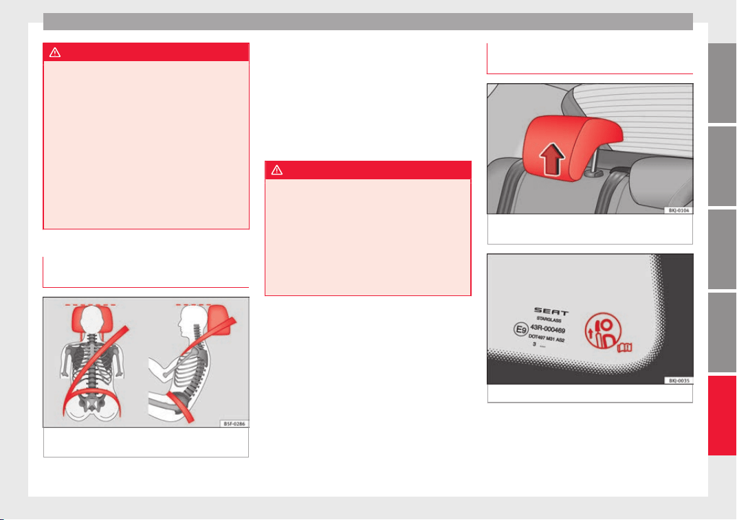
Safe driving
WARNING
●
Any inc
orrect sitting position increases the
risk of severe injuries.
●
Sitting in an incorrect position exposes the
vehicle occupants to severe injuries if airbags
are triggered, by striking a vehicle occupant
who has assumed an incorrect sitting posi-
tion.
●
Before the vehicle moves, assume the prop-
er sitting position and maintain it throughout
the trip. Before every trip, instruct your pas-
sengers to sit properly and to stay in this po-
sition during the trip ››› page 76, Correct posi-
tion of the vehicle occupants.
Correct adjustment of front head re-
s
tr
aint
s
Fig. 96 Correctly adjusted head restraint as
v
iew
ed fr
om the front and the side.
Properly adjusted head restraints are an im-
por
t
ant
part of passenger protection and can
reduce the risk of injuries in most accident
situations.
–
Adjust the head restraint so that its upper
edge is, as far as possible, at the same lev-
el as the top of your head, or at the very
least, at eye level ››› Fig. 96.
WARNING
●
Trav
elling with the head restraints removed
or improperly adjusted increases the risk of
severe injuries. An improper adjustment of
the head restraints may cause death in an ac-
cident and increase the risk of suffering inju-
ries during abrupt braking actions or unex-
pected manoeuvres.
●
The head restraints must always be adjus-
ted according to the height of the passenger.
Correct adjustment of rear head re-
s
tr
aint
s
Fig. 97 Head restraints in the correct posi-
tion.
Fig. 98 Head restraint position warning label.
Properly adjusted head restraints are an im-
por
t
ant
part of the passenger protection and
can reduce the risk of injuries in most acci-
dent situations
»
79
Technical dataAdviceOperationEmergenciesSafety
Safety
Rear head restraints
–
The rear head restraints have 2 positions:
u
se
and
non-use.
–
One position for use (head restraint raised)
››› Fig. 97. In this position, the head re-
straints are used normally, protecting pas-
sengers along with the rear seat belts.
–
And one position for non-use (head re-
straint lowered).
–
To fit the head restraints in position for use,
pull on the edges with both hands in the
direction of the arrow.
WARNING
●
Under no circ
umstances should the rear
passengers travel while the head restraints
are in the non-use position. See the warning
label located on the rear side fixed window
››› Fig. 98.
●
Do not swap the centre rear head restraint
with either of the outer seat rear head re-
straints. Risk of injury in case of an accident!
CAUTION
Note the instructions on the adjustment of
the head r
estraints ››› page 154.
Pedal area
P
ed
a
ls
–
Ensure that you can always press the accel-
erator
, brake and clutch pedals unimpaired
to the floor.
–
Ensure that the pedals can return unim-
paired to their initial positions.
–
Ensure that the floor mats are securely fas-
tened during the trip and do not obstruct
the pedals
›››
.
On
ly
u
se floor mats which leave the pedals
clear and which are secured to prevent them
from slipping. You can obtain suitable floor
mats from a specialised dealership.
If a brake circuit fails, the brake pedal must
be pressed down thoroughly in order to stop
the vehicle.
Wear suitable footwear
Always wear shoes which support your feet
properly and give you a good feeling for the
pedals.
WARNING
●
If the peda
ls are obstructed, an accident
may occur. Risk of serious injuries.
●
Never lay or fit floor mats or other floor cov-
erings over the original floor mats. This
would reduce the pedal area and could ob-
struct the ped
als. Risk of accident.
●
Never place objects in the driver footwell.
An object could move into the pedal area and
impair pedal operation. In the event of a sud-
den driving or braking manoeuvre, you will
not be able to operate the brake, clutch or ac-
celerator pedal. Risk of accident!
80
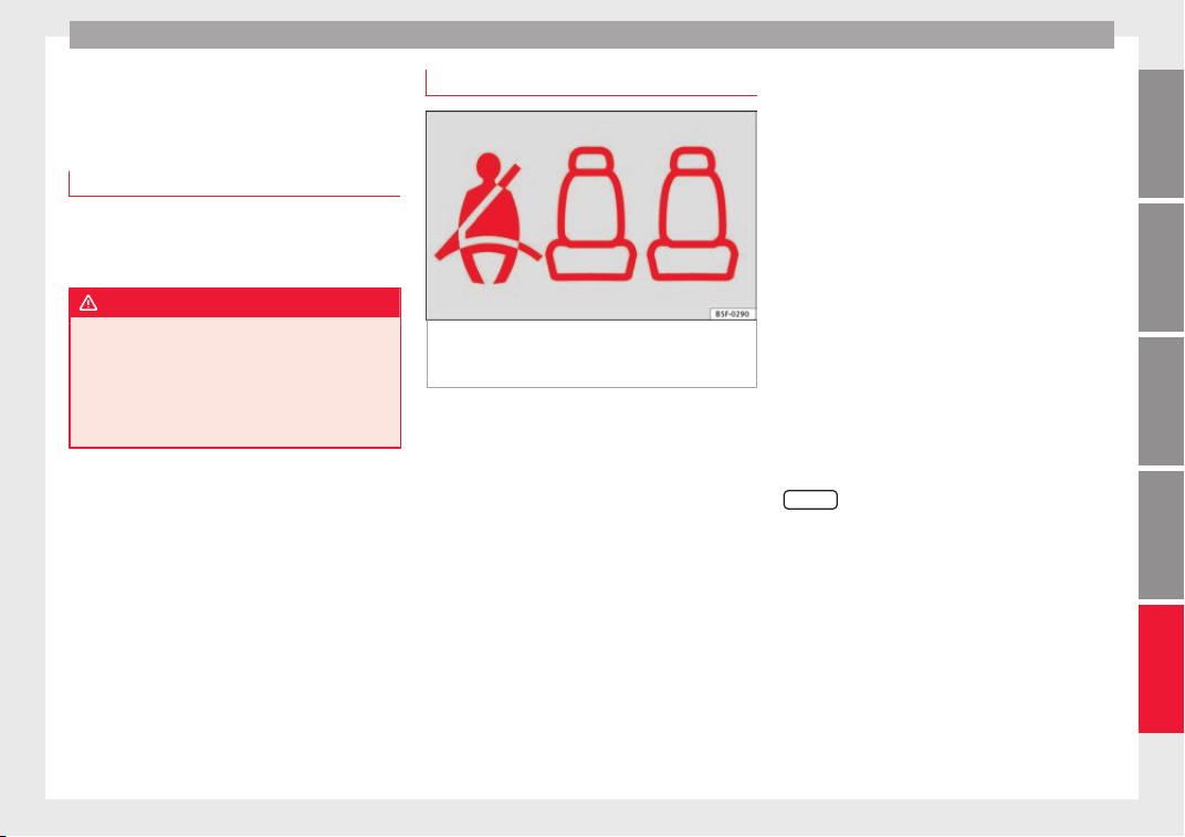
Seat belts
Seat belts
Wh
y
w
ear a seat belt
Number of seats
Your vehicle has five se
ats, two in the front
and three in the rear. Each seat is equipped
with a three-point seat belt.
WARNING
●
Never tran
sport more than the permitted
amount of people in your vehicle.
●
Every vehicle occupant must properly fas-
ten and wear the seat belt belonging to his or
her seat. Children must be protected with an
appropriate child restraint system.
Seat belt control lamp*
Fig. 99 Instrument panel: right rear seat oc-
c
upied and c
orr
esponding seat belt fastened
display.
The control lamp illuminates to remind the
driv
er t
o f
asten his seat belt.
Before starting the vehicle:
–
Fasten your seat belt securely.
–
Instruct your passengers to fasten their
seat belts properly before driving off.
–
Protect children by using a child seat ac-
cording to the child's height and weight.
When the ignition is switched on, the control
lamp in the instrument panel lights up (de-
pending on the model version) if the driver or
passenger have not fastened their seat belts.
When starting to drive, if the vehicle's speed
surpasses approx. 25 km/h (15 mph) and the
seat belts are not fastened or are unfastened
during the drive, a warning sound will be
heard for a few seconds. The warning light
will also flash .
The lamp goes out when the driver and
passenger seat belts are fastened with the ig-
nition switched on.
Rear seat belts fastened display*
Depending on the model version, when the
ignition is switched on, the seat belt status
display ››› Fig. 99 on the instrument panel in-
forms the driver whether the passengers in
the rear seats have fastened their seat belts.
The symbol indicates that the passenger in
this seat has fastened “his or her” seat belt.
When a seat belt in the rear seats is fastened
or unfastened, the seat belt status is dis-
played for approximately 30 seconds. The in-
dication can be hidden by pressing the
0.0/SET
button on the dash panel.
The se
at
belt
status flashes for a maximum of
30 seconds when a seat belt in the rear seats
is unfastened while the vehicle is in motion.
An audible warning will also be heard if the
vehicle is travelling at over 25 km/h
(15 mph).
81
Technical dataAdviceOperationEmergenciesSafety
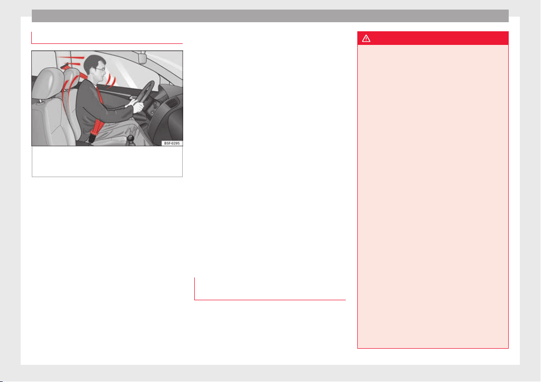
Safety
The protective function of seat belts
Fig. 100 Drivers with properly worn seat belts
w
i
l
l not be thrown forward in the event of sud-
den braking.
Properly worn seat belts hold the occupants
in the pr
oper po
s
ition. These also help pre-
vent uncontrolled movements that may result
in serious injury and reduce the risk of being
thrown out of the vehicle.
Vehicle occupants wearing their seat belts
correctly benefit greatly from the ability of the
belts to absorb kinetic energy. In addition,
the front part of your vehicle and other pas-
sive safety features (such as the airbag sys-
tem) are designed to absorb the kinetic ener-
gy released in a collision. Taken together, all
these features reduce the releasing kinetic
energy and consequently, the risk of injury.
This is why it is so important to fasten seat
belts before every trip, even when "just driv-
ing around the corner".
Ensure that your passengers wear their seat
belts as well. Accident statistics have shown
that wearing seat belts is an effective means
of substantially reducing the risk of injury
and improving the chances of survival when
involved in a serious accident. Furthermore,
properly worn seat belts improve the protec-
tion provided by airbags in the event of an
accident. For this reason, wearing a seat belt
is required by law in most countries.
Although your vehicle is equipped with air-
bags, the seat belts must be fastened and
worn. The front airbags, for example, are only
triggered in some cases of head-on collision.
The front airbags will not be triggered during
minor frontal or side collisions, rear-end colli-
sions, rollovers or accidents in which the air-
bag trigger threshold value in the control unit
is not exceeded.
Therefore, you should always wear your seat
belt and ensure that all vehicle occupants
have fastened their seat belts properly before
you drive off!
Important safety instructions for the
use of seat belts
–
Always wear the seat belt as described in
thi
s
section.
–
En
sure that the seat belts can be fastened
at all times and are not damaged.
WARNING
●
If seat
belts are worn incorrectly or not at
all, the risk of severe injuries increases. The
optimal protection from seat belts can be
achieved only if you use them properly.
●
Fasten your seat belt before every trip -
even when driving in town. Other vehicle oc-
cupants must also wear the seat belts at all
times, otherwise they run the risk of being in-
jured.
●
The seat belt cannot offer its full protection
if the seat belt is not positioned correctly.
●
Never allow two passengers (even children)
to share the same seat belt.
●
Always keep both feet in the footwell in
front of your seat as long as the vehicle is in
motion.
●
Never unbuckle a seat belt while the vehi-
cle is in motion. Risk of fatal injury.
●
The seat belt must never be twisted while it
is being worn.
●
The seat belt should never lie on hard or
fragile objects (such as glasses or pens, etc.)
because this can cause injuries.
●
Do not allow the seat belt to be damaged or
jammed, or to rub on any sharp edges.
●
Never wear the seat belt under the arm or
in any other incorrect position.
●
Bulky and unfastened clothing (such as an
overcoat over a sweater) impairs the proper
fit and function of the seat belts, reducing
their capacity to protect.
82
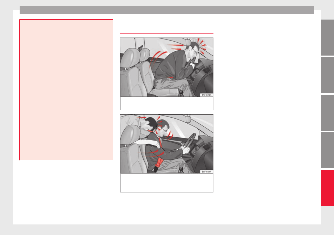
Seat belts
●
The slot in the se
at belt buckle must not be
blocked with paper or other objects, as this
can prevent the latch plate from engaging se-
curely.
●
Never use seat belt clips, fastening rings or
similar items to alter the position of the belt
webbing.
●
Frayed or torn seat belts or damage to the
connections, belt retractors or parts of the
buckle could cause severe injuries in the
event of an accident. Therefore, you must
check the condition of all seat belts at regular
intervals.
●
Seat belts which have been worn in an acci-
dent and have been stretched must be re-
placed by a specialised workshop. Renewal
may be necessary even if there is no apparent
damage. The belt anchorage should also be
checked.
●
Do not attempt to repair a damaged seat
belt yourself. The seat belts must not be re-
moved or modified in any way.
●
The belts must be kept clean, otherwise the
retractors may not work properly.
Head-on collisions and the laws of
ph
y
s
ics
Fig. 101 A driver not wearing a seat belt is
thr
o
wn f
orward violently.
Fig. 102 The unbelted passenger in the rear
se
at
i
s thrown forward violently, hitting the
driver who is wearing a seat belt.
It is easy to explain how the laws of physics
w
ork
in the c
ase of a head-on collision: when
a vehicle starts moving, a type of energy
called “kinetic energy” is created both in the
passengers and inside the vehicle.
The amount of “kinetic energy” depends on
the speed of the vehicle and on the weight of
the vehicle and of its passengers. The higher
the speed and the greater the weight, the
more energy there is to be “absorbed” in an
accident.
The most significant factor, however, is the
speed of the vehicle. If the speed doubles
from 25 km/h (15 mph) to 50 km/h
(30 mph), for example, the corresponding ki-
netic energy is multiplied by four.
Because the vehicle occupants in our exam-
ple are not restrained by seat belts, in the
event of crashing against a wall, all of the oc-
cupants' kinetic energy will be absorbed
solely by said impact.
Even at speeds of 30 km/h (19 mph) to
50 km/h (30 mph), the forces acting on bod-
ies in a collision can easily exceed one tonne
(1000 kg). At greater speed these forces are
even higher.
Vehicle occupants not wearing seat belts are
not “attached” to the vehicle. In a head-on
collision, they will move forward at the same
speed their vehicle was travelling just before
the impact. This example applies not only to
head-on collisions, but to all accidents and
collisions.
»
83
Technical dataAdviceOperationEmergenciesSafety
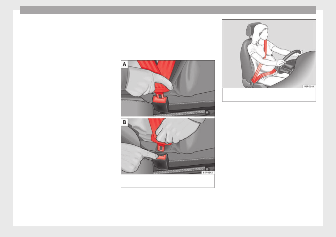
Safety
Even at low speeds the forces acting on the
body
in a c
o
llision are so great that it is not
possible to brace oneself with one's hands.
In a frontal collision, unbelted passengers
are thrown forward and will make violent con-
tact with the steering wheel, dash panel,
windscreen or whatever else is in the way
››› Fig. 101.
It is also important for rear passengers to
wear seat belts properly, as they could other-
wise be thrown forward violently through the
vehicle interior in an accident. Passengers in
the rear seats who do not use seat belts en-
danger not only themselves but also the front
occupants ››› Fig. 102.
How to properly adjust your
seatbelt
Fastening and unfastening your seat
belt
Fig. 103 Positioning and removing the seat
belt
b
uc
kle.
Fig. 104 Position of seat belt during pregnan-
cy
.
Read the additional information carefully
›
›
›
page 19.
Fasten your seat belt
The seat belt cannot offer its full protection if
the seat belt is not positioned correctly.
●
Adjust the seat and head restraint correctly.
●
To fasten the belt, take hold of the latch
plate and pull it slowly across your chest and
lap.
●
Insert the latch plate into the buckle for the
appropriate seat and push it down until it is
securely locked with an audible click
›››
Fig. 103.
●
Pull the belt to ensure that the latch plate is
securely engaged in the buckle.
84
Seat belts
The seat belts are equipped with an automat-
ic
r
etr
actor on the shoulder strap. Full free-
dom of movement is permitted when the
shoulder belt is pulled slowly. However, dur-
ing sudden braking, during travel in steep
areas or bends and during acceleration, the
automatic retractor on the shoulder belt is
locked.
The automatic belt retractors on the front
seats are fitted with seat belt tensioners
››› page 85.
Releasing the seat belt
●
Press the red button on the belt buckle
››› Fig. 103. The latch plate is released and
springs out ›››
.
●
Guide the belt back by hand so that it rolls
up e
a
s
ily and the trim is not damaged.
Positioning seat belts
Seat belts offer their maximum protection on-
ly when they are properly positioned.
WARNING
●
The seat belt
s offer best protection only
when the backrests are in an upright position
and the seat belts have been fastened prop-
erly.
●
Never put the latch plate in the buckle of
another seat. If you do this, the seat belt will
not protect you properly and the risk of injury
is increased.
●
Never unb
uckle a seat belt while the vehi-
cle is in motion. If you do, you increase the
risk of sustaining severe or fatal injuries.
●
An incorrectly worn seat belt can cause se-
vere injuries in the event of an accident.
●
The shoulder part of the seat belt must lie
on the centre of the shoulder, never across
the neck. The seat belt must lie flat and fit
comfortably on the torso
●
The lap part of the seat belt must lie across
the pelvis, never across the stomach. The
seat belt must lie flat and fit comfortably on
the pelvis Pull the belt tight if necessary to
take up any slack.
●
For pregnant women, the lap part of the
seat belt must lie as low as possible over the
pelvis, never across the stomach, and always
lie flat so that no pressure is exerted on the
abdomen ››› Fig. 104.
●
Always engage the retractor lock when you
are securing a child seat in group 0, 0+ or 1
››› page 92.
●
Read and observe the warnings ››› page 82.
Seat belt tensioners*
Se
at
belt
tensioner operation
Read the additional information carefully
›
›
›
page 20
The seat belts for the front and side rear oc-
cupants are equipped with belt tensioners.
The belt tensioners are activated by sensors,
although only in severe head-on and lateral
collisions. This retracts and tightens the seat
belts, reducing the forward motion of the oc-
cupants.
The belt tensioners will not be triggered in
the event of minor collisions, if the vehicle
overturns, or in accidents where no major
forces act on the vehicle.
Note
●
If the seat
belt tensioners are triggered, a
fine dust is produced. This is normal and it is
not an indication of fire in the vehicle.
●
The relevant safety requirements must be
observed when the vehicle or components of
the system are scrapped. Specialised work-
shops are familiar with these regulations,
which are also available to you.
Maintenance and disposal of belt ten-
s
ioner
s
The belt tensioners are components of the
se
at
belts
that are installed in the seats of
your vehicle. If you work on the belt tension-
ers or remove and install parts of the system
when performing other repair work, the seat
belt may be damaged. The consequence may
be that, in the event of an accident, the belt
»
85
Technical dataAdviceOperationEmergenciesSafety
Safety
tensioners function incorrectly or may not
f
u
nction at
all.
So that the effectiveness of the seat belt ten-
sioner is not reduced and that removed parts
do not cause any injuries or environmental
pollution, regulations, which are known to
the specialised workshops, must be ob-
served.
WARNING
●
Improper use or r
epairs not carried out by
qualified mechanics increase the risk of se-
vere or fatal injuries. The belt tensioners may
fail to trigger or may trigger in the wrong cir-
cumstances.
●
Never attempt to repair, adjust, remove or
install parts of the belt tensioners or seat
belts.
●
The seat belt tensioner, seat belt and auto-
matic retractor cannot be repaired.
●
Any work on the belt tensioners and seat
belts, including the removal and refitting of
system parts in conjunction with other repair
work, must be performed by a specialised
workshop only.
●
The belt tensioners will only provide pro-
tection for one accident and must be changed
if they have been activated.
Airbag system
Brief
intr
oduction
Wh
y is it so important to wear a seat
belt and to sit correctly?
For the inflating airbags to achieve the best
protection, the se
at belt must always be worn
properly and the correct sitting position must
be assumed.
The airbag system is not a substitute for seat
belts, but it is an integral part of the vehicle's
overall passive safety system. Please bear in
mind that the airbag system can only work ef-
fectively when the vehicle occupants are
wearing their seat belts correctly and have
adjusted the head restraints properly. There-
fore, it is most important to properly wear the
seat belts at all times, not only because this
is required by law in most countries, but also
for your safety
›››
page 81, Why wear a seat
belt.
The airbag inflates in a matter of seconds, so
if you are not properly seated when the air-
bag is triggered, you may sustain fatal inju-
ries. Therefore, it is essential that all vehicle
occupants assume a correct sitting position
while travelling.
Sharp braking before an accident may cause
a passenger not wearing a seat belt to be
thrown forward into the area of the deploying
airbag. In this case, the inflating airbag may
inflict critic
al or fatal injuries on the occu-
pant. This also applies to children.
Always maintain the greatest possible dis-
tance between yourself and the front airbag.
This way, the front airbags can completely
deploy when triggered, providing their maxi-
mum protection.
The most important factors that will trigger
an airbag are: the type of accident, the angle
of collision and the speed of the vehicle.
Whether or not the airbags are triggered de-
pends primarily on the vehicle deceleration
rate resulting from the collision and detected
by the control unit. If the vehicle deceleration
occurring during the collision and measured
by the control unit remains below the speci-
fied reference values, the front, side and/or
curtain airbags will not be triggered. Take in-
to account that the visible damage in a vehi-
cle involved in an accident, no matter how
serious, is not a determining factor for the
airbags to have been triggered.
WARNING
●
Wearin
g the seat belt incorrectly or assum-
ing an incorrect sitting position can lead to
critical or fatal injuries.
●
All vehicle occupants, including children,
who are not properly belted can sustain criti-
cal or fatal injuries if the airbag is triggered.
Children up to 12 years old should always
86
Airbag system
travel on the rear seat. Never transport
chil
dren in the vehicle if they are not restrain-
ed or the restraint system is not appropriate
for their age, size or weight.
●
If you are not wearing a seat belt, or if you
lean forward or to the side while travelling or
assume an incorrect sitting position, there is
a substantially increased risk of injury. This
increased risk of injury will be further in-
creased if you are struck by an inflating air-
bag.
●
To reduce the risk of injury from an inflating
airbag, always wear the seat belt properly.
●
Always adjust the front seats properly.
Description of airbag system
Read the additional information carefully
›
›
›
page 21.
The airbag system is not a substitute for the
seat belts. The airbag system offers addition-
al protection for the driver and passenger in
combination with the seat belts.
The airbag system mainly comprises (as per
vehicle equipment):
●
an electronic control and monitoring sys-
tem (control unit)
●
frontal airbags for driver and passenger,
●
side airbags,
●
curtain airbags,
●
a control lamp on the dash panel
››› page 91.
●
key-operated switch for front passenger air-
bag,
●
a control lamp for disabling/enabling the
front passenger airbag.
The airbag system operation is monitored
electronically. The airbag control lamp will il-
luminate for a few seconds every time the ig-
nition is switched on (self-diagnosis).
There is a fault in the system if the control
lamp :
●
does not light up when the ignition is
switched on ››› page 91,
●
turns off after 4 seconds after the ignition
is switched on,
●
turns off and then lights up again after the
ignition is switched on,
●
illuminates or flashes while the vehicle is
moving.
The airbag system is not triggered if:
●
the ignition is switched off
●
there is a minor frontal collision
●
there is a minor side collision
●
there is a rear-end collision
●
the vehicle turns over.
WARNING
●
The seat belt
s and airbags can only provide
maximum protection if the occupants are
seated correctly ››› page 76, Correct position
of the vehicle occupants.
●
If a fault has occurred in the airbag system,
have the system checked immediately by a
specialised workshop. Otherwise, during a
frontal collision the system might not trigger
correctly or may fail to trigger at all.
Airbag activation
The airbags deploy extremely rapidly, within
thou
s
andths
of a second, to provide addi-
tional protection in the event of an accident.
A fine dust may develop when the airbag de-
ploys. This is normal and it is not an indica-
tion of fire in the vehicle.
The airbag system is only ready to function
when the ignition is on.
In special accidents instances, several air-
bags may activate at the same time.
In the event of minor head-on and side colli-
sions, rear-end collisions, overturning or roll-
over of the vehicle, airbags do not activate.
Activation factors
The conditions that lead to the airbag system
activating in each situation cannot be gener-
alised. Some factors play an important role,
»
87
Technical dataAdviceOperationEmergenciesSafety
Safety
such as the properties of the object the vehi-
c
l
e hits
(hard/soft), angle of impact, vehicle
speed, etc.
Deceleration trajectory is key for airbag acti-
vation.
The control unit analyses the collision trajec-
tory and activates the respective restraint
system.
If the deceleration rate is below the prede-
fined reference value in the control unit the
airbags will not be triggered, even though
the accident may cause extensive damage to
the car.
The following airbags are triggered in seri-
ous head-on collisions:
●
Driver airbag.
●
Front passenger front airbag
The following airbags are triggered in seri-
ous side-on collisions:
●
Front side airbag on the side of the acci-
dent.
●
Curtain (head) airbag on the side of the ac-
cident.
In an accident with airbag activation:
●
the interior lights switch on (if the interior
light switch is in the courtesy light position);
●
the hazard warning lights switch on;
●
all doors are unlocked;
●
the fuel supply to the engine is cut.
Airbag safety instructions
Front airbags
Read the additional information carefully
›››
page 21.
WARNING
●
The seat belt
s and airbags can only provide
maximum protection if the occupants are
seated correctly ››› page 76, Correct position
of the vehicle occupants.
●
The deployment space between the front
passengers and the airbags must not in any
case be occupied by other passenger, pets
and objects.
●
The airbags provide protection for just one
accident; replace them once they have de-
ployed.
●
It is also important not to attach any ob-
jects such as cup holders or telephone
mountings to the surfaces covering the air-
bag units.
●
Do not attempt to modify components of
the airbag system in any way.
Side airbags*
Read the additional information carefully
›››
page 22.
WARNING
●
If y
ou do not wear a seat belt, if you lean
forward, or are not seated correctly while the
vehicle is in motion, you are at a greater risk
of injury if the side airbag system is triggered
in an accident.
●
In order for the side airbags to provide their
maximum protection, the prescribed sitting
position must always be maintained with
seat belts fastened while travelling.
●
Occupants of the outer seats must never
carry any objects or pets in the deployment
space between them and the airbags, or al-
low children or other passengers to travel in
this position. It is also important not to at-
tach any accessories (such as cup holders) to
the doors. This would impair the protection
offered by the side airbags.
●
The built-in coat hooks should be used only
for lightweight clothing. Do not leave any
heavy or sharp-edged objects in the pockets.
●
Great forces, such as hard blows or kicks,
must not be exerted upon the backrest bol-
ster because the system may be damaged. In
this case, the side airbags would not be trig-
gered.
●
Under no circumstances should protective
covers be fitted over seats with side airbags
88

Airbag system
unless the covers have been approved for use
in your
vehicle. Because the airbag deploys
from the side of the backrest, the use of con-
ventional seat covers would obstruct the side
airbag, seriously reducing the airbag's effec-
tiveness.
●
Any damage to the original seat upholstery
or around the seams of the side airbag units
must be repaired immediately by a special-
ised workshop.
●
The airbags provide protection for just one
accident; replace them once they have de-
ployed.
●
Any work on the side airbag system or re-
moval and installation of the airbag compo-
nents for other repairs (such as removal of
the front seat) should only be performed by a
specialised workshop. Otherwise, faults may
occur during the airbag system operation.
●
Do not attempt to modify components of
the airbag system in any way.
●
The side and head airbags are managed
through sensors located in the interior of the
front doors. To ensure the correct operation of
the side and curtain (head) airbags neither
the doors nor the door panels should be
modified in any way (e.g. fitting loudspeak-
ers). If the front door is damaged, the airbag
system may not work correctly. All work car-
ried out on the front door must be done in a
specialised workshop.
●
In a side-on collision the side airbags will
not work if the sensors do not correctly meas-
ure the pressure increase on the interior of
the doors, due to air escaping through the
areas with holes or openings in the door pan-
el.
●
Never driv
e if the interior door panels have
been removed or if the panels have not been
correctly fitted.
●
Never drive the vehicle if the loudspeakers
in the door panels have been removed, un-
less the holes left by the loudspeakers have
been closed properly.
●
Always check that the openings are closed
or covered if additional loudspeakers or other
equipment are fitted inside the door panels.
●
Any work carried out to the doors should be
made in an authorised specialised workshop.
Head-protection airbags*
Read the additional information carefully
›
›
›
page 23.
WARNING
●
In order for the he
ad-protection airbags to
provide their maximum protection, the pre-
scribed sitting position must always be main-
tained with seat belts fastened while travel-
ling.
●
For safety reasons, the curtain airbag must
be disabled in those vehicles fitted with a
screen dividing the interior of the vehicle.
See your technical service to make this ad-
justment.
●
There mus
t be no other persons, animals or
objects between the occupants of the outer
seats and the deployment space of the head-
protection airbags so that the head-protec-
tion airbag can deploy completely without re-
striction and provide the greatest possible
protection. Therefore, sun blinds which have
not been expressly approved for use in your
vehicle may not be attached to the side win-
dows
●
The built-in coat hooks should be used only
for lightweight clothing. Do not leave any
heavy or sharp-edged objects in the pockets.
Please, do not hang the clothes on coat hang-
ers.
●
The airbags provide protection for just one
accident; replace them once they have de-
ployed.
●
Any work on the head-protection airbag
system or removal and installation of the air-
bag components for other repairs (such as re-
moval of the roof lining) should only be per-
formed by a specialised workshop. Other-
wise, faults may occur during the airbag sys-
tem operation.
●
Do not attempt to modify components of
the airbag system in any way.
●
The side and head airbags are managed
through sensors located in the interior of the
front doors. To ensure the correct operation of
the side and curtain airbags neither the
doors nor the door panels should be modified
in any way (e.g. fitting loudspeakers). If the
front door is damaged, the airbag system
may not work correctly. All work carried out
»
89
Technical dataAdviceOperationEmergenciesSafety
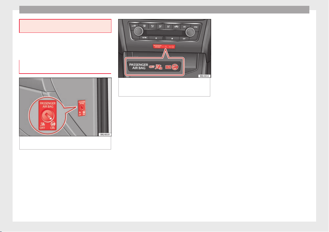
Safety
on the front door must be done in a special-
ised work
shop.
Deactivating airbags
Activation and de
activation of front
passenger airbag*
Fig. 105 Switch for activating and deactivat-
in
g the fr
ont
passenger airbag.
Fig. 106 Centre side of dash panel: control
lamp for de
activated front passenger airbag
in centre console.
Deactivate the front passenger front airbag
on
ly
if
you have to use a rear-facing child
seat in the front passenger seat.
SEAT recommends fitting the child seat in the
rear seat to avoid having to deactivate the
front passenger airbag.
Front passenger front airbag switch
When the front passenger airbag is deactiva-
ted, this means that only the front passenger
front airbag is deactivated. All the other air-
bags in the vehicle remain activated.
Disconnect the front passenger front airbag
●
Switch the ignition off.
●
Open the door on the front passenger side.
●
Insert the key into the slot of the switch for
deactivating the front passenger airbag
››› Fig. 105. About 3/4 of the key should en-
ter; this is as far as it will go.
●
Turn the key gently to the position. If
you have difficulty, ensure that you have in-
serted the key as far as it will go.
●
Close the front passenger door.
●
Check, with the ignition switched on, that
the control lamp remains lit where it
says in the centre of the
dash panel ››› Fig. 106.
Connect the front passenger front airbag
●
Switch the ignition off.
●
Open the front passenger door.
●
Insert the key into the slot of the switch for
deactivating the front passenger airbag
››› Fig. 105. About 3/4 of the key should en-
ter, as far as it will go.
●
Turn the key gently to the position. If you
have difficulty, ensure that you have inserted
the key as far as it will go.
●
Close the front passenger door.
●
Check, with the ignition switched on, that
the control lamp does not remain lit
where it says in the cen-
tre of the dash panel ››› Fig. 106. The
control lamp lights up for 60 seconds and
then goes off.
90
Airbag system
WARNING
●
The driver of the
vehicle is responsible for
disabling or switching on the airbag.
●
Always switch off the ignition before disa-
bling the front passenger airbag! Failure to do
so could result in a fault in the airbag deacti-
vation system.
●
Never leave the key in the airbag disabling
switch as it could get damaged or enable or
disable the airbag during driving.
●
If for any reason an airbag is deactivated,
reactivate it as soon as possible so that it can
fulfil its protective function.
Airbag system control lamps
It lights up on the combi-in-
strument
Fault in airbag
system and seat
belt tensioners.
Have the system checked immedi-
ately by a specialised workshop.
It lights up on the dash panel
Front passenger
front airbag disa-
bled.
Check whether the airbag should
remain disabled
It lights up on the dash panel
Front passenger
front airbag ena-
bled.
The control lamp switches off auto-
matically 60 seconds after the igni-
tion is switched on
Several warning and control lamps light up
for a few sec
onds when the ignition is switch-
ed on, signalling that the function is being
verified. They will switch off after a few sec-
onds.
If the airbag and seat belt tensioner system
control lamp remains on or flashes, it indi-
cates a malfunction in the airbag and seat
belt tensioner system
›››
. Have the system
c
hec
k
ed immediately by a specialised work-
shop.
If the front passenger airbag is deactivated,
the warning lamp re-
mains lit on the dash panel to remind you
that the airbag is deactivated. If, with the
front passenger airbag deactivated, this lamp
does not remain lit or if it is lit together with
the control lamp on the dash panel, there
is a fault in the airbag system
›››
. If the
c
ontr
o
l lamp is flashing, there is a fault in the
disabling of the airbag system
›››
. Have the
sy
s
t
em checked immediately by a specialised
workshop.
WARNING
In the event of a fault in the airbag and seat
belt ten
sioner system, the airbags and seat
belts may not trigger correctly, may fail to
trigger or m
ay even trigger unexpectedly.
●
The vehicle occupants run the risk of sus-
taining severe or fatal injuries. Have the sys-
tem checked immediately by a specialised
workshop.
●
Do not mount a child seat in the front pas-
senger seat or remove the mounted child
seat! The front passenger front airbag may
deploy during an accident in spite of the
fault.
CAUTION
Always pay attention to any lit control lamps
and to the corr
esponding descriptions and in-
structions to avoid damage to the vehicle or
harm to the occupants.
91
Technical dataAdviceOperationEmergenciesSafety
Safety
Transporting children safely
Chi
l
d s
afety
Introduction
For safety reasons, as we have learned from
accident
statistics, we recommend that chil-
dren under 12 years of age travel in the rear
seats. Depending on their age, height and
weight, children travelling in rear seats must
use a child seat or a seat belt. For safety rea-
sons, the child seat should be installed in the
rear seat, behind the front passenger seat or
in the centre back seat.
The physical laws involved and the forces
acting in a collision apply also to children
›››
page 83. But unlike adults, children do not
have fully developed muscle and bone struc-
tures. This means that children are subject to
a greater risk of injury.
To reduce the risk of injuries, children must
always use special child restraint systems
when travelling in the vehicle.
We recommend the use of child safety prod-
ucts from the SEAT Original Accessories Pro-
gramme, which includes systems for all ages
made by “Peke” (not for all countries) (see
www.seat.com).
These systems have been especially de-
signed and appr
oved, complying with the
ECE-R44. regulation.
SEAT recommends securing the child seats
shown on the website as described below:
●
Child seats in the opposite direction of
travel (group 0+): ISOFIX and support bracket
(Peke G0 Plus + ISOFIX Base (RWF)).
●
Child seats in the direction of travel (group
1): ISOFIX and Top Tether (Peke G1 ISOFIX
DUO Plus).
●
Child seats in the direction of travel (group
2): seat belt and ISOFIX (RÖMER KIDFIX XP
©
).
●
Child seats in the direction of travel (group
3): with seat belt (TAKATA MAXI PLUS
©
).
Follow the manufacturer's instructions and
observe any statutory requirements when in-
stalling and using child seats. Always read
and note ››› page 92.
We recommend you always carry the manu-
facturer's Child Seat Instruction Manual to-
gether with the on-board documentation.
Important information regarding the
front passenger's airbag
Read the additional information carefully
›
›
›
page 24.
Read and always observe the safety informa-
tion included in the following chapters:
●
Safety distance with respect to the passen-
ger airbag ››› page 86.
●
Objects between the passenger and the
passenger side airbag ›››
in Front airbags
on p
ag
e 88
.
The passenger side front airbag, when ena-
bled, is a serious risk for a child that is facing
backward since the airbag can strike the seat
with such force that it can cause serious or
fatal injuries. Children up to 12 years old
should always travel on the rear seat.
Therefore we strongly recommend you to
transport children on the rear seats. This is
the safest location in the vehicle. Alternative-
ly, the front passenger airbag can be disa-
bled with a key-operated switch ››› page 90.
When transporting children, use a child seat
suitable for the age and size of each child
››› page 94.
WARNING
●
If a chi
ld seat is secured to the front pas-
senger seat, the risk to the child of sustain-
ing critical or fatal injuries in the event of an
accident increases.
●
An inflating front passenger airbag can
strike the rear-facing child seat and project it
with great force against the door, the roof or
the backrest.
92
Transporting children safely
●
Never ins
tall a child seat facing backwards
on the front passenger seat unless the front
passenger front airbag has been disabled.
Risk of potentially fatal injuries to the child!
However, if it is necessary, in exceptional ca-
ses, to transport a child in the front passen-
ger seat, the front passenger front airbag
must always be disabled ››› page 90, Activa-
tion and deactivation of front passenger air-
bag*. If the passenger seat has a height ad-
justment option, move it to the highest, most
upright position. If it is a fixed seat, it should
be moved to the rearmost position possible.
●
For those vehicles that do not include a key
lock switch to deactivate the airbag, the vehi-
cle must be taken to a technical service. Do
not forget to reconnect the airbag when an
adult wants to sit in the front passenger seat.
●
All vehicle occupants, especially children,
must assume the proper sitting position and
be properly belted in while travelling.
●
Never hold children or babies on your lap,
this can result in potentially fatal injuries to
the child!
●
Never allow a child to be transported in a
vehicle without being properly secured, or to
stand up or kneel on a seat while travelling.
In an accident, the child could be flung
through the vehicle, causing possibly fatal in-
juries to themselves and to the other vehicle
occupants.
●
If children assume an improper sitting posi-
tion when the vehicle is moving, they expose
themselves to greater risk of injury in the
event of a sudden braking manoeuvre or in an
accident. This is particularly important if the
chil
d is travelling on the front passenger seat
and the airbag system is triggered in an acci-
dent; as this could cause serious injury or
even death.
●
A suitable child seat can protect your child!
●
Never leave a child alone in the child seat
or inside the vehicle because depending on
the season, very high temperatures may be
reached inside a parked vehicle, which could
be fatal.
●
Children who are less than 1.5 metres tall
must not wear a normal seat belt without a
child seat, as this could cause injuries to the
abdominal and neck areas during a sudden
braking manoeuvre or in an accident.
●
Do not allow the seat belt to become twis-
ted and the seat belt should be properly in
place ››› page 81.
●
Only one child may occupy a child seat
››› page 93, Child seats.
●
When a child seat is mounted in the rear
seats, the door child-proof lock should be ac-
tivated ››› page 138.
Child seats
Saf
ety
in
structions
Read the additional information carefully
›
›
›
page 23.
WARNING
When travelling, children must be secured in
the vehic
le with a restraint system suitable
for age, weight and size.
●
Read and always observe information and
warnings concerning the use of child seats
››› page 92.
WARNING
The retaining rings are designed only for use
with “ISOFIX” and Top
Tether* system child
seats.
●
Never secure other child seats that do not
have the “ISOFIX” or Top Tether* system, or
retaining belts or objects to the fastening
rings - this can result in potentially fatal inju-
ries to the child.
●
Ensure that the child seat is secured cor-
rectly using the “ISOFIX” and Top Tether* se-
curing rings.
WARNING
An undue installation of the safety seat will
incre
ase the risk of injury in the event of a
crash.
●
Never tie the retainer strap to a hook in the
luggage compartment.
●
Never secure or tie luggage or other items
to the lower anchorages (ISOFIX) or the upper
ones (Top Tether).
93
Technical dataAdviceOperationEmergenciesSafety

Safety
Categorisation of child seats into
gr
oup
s
Use only child seats that are officially ap-
prov
ed and suitable for the child.
These seats are subject to the ECE-R 44 or
ECE-R 129 standard. ECE-R stands for: Eco-
nomic Commission for Europe Regulation.
The child seats are grouped into 5 catego-
ries:
Group 0: Up to 10 kg (up to around 9
months)
Group 0+: Up to 13 kg (up to around 18
months)
Group 1: from 9 to 18 kg (up to approx. 4
years old)
Group 2: from 15 to 25 kg (up to approx. 7
years old)
Group 3: From 22 to 36 kg (over around 7
years old)
Child seats that have been tested and ap-
proved under the ECE-R 44 or ECE-R 129
standard bear the test mark ECE-R 44 or ECE-
R 129 on the seat (the letter E in a circle with
the test number below it).
Follow the manufacturer's instructions and
observe any statutory requirements when in-
stalling and using child seats.
We recommend you to always include the
manufact
urer's Child Seat Instruction Manual
together with the on-board documentation.
SEAT recommends you use child seats from
the Original Accessories Catalogue. These
child seats have been designed and tested
for use in SEAT vehicles. You can find the
right child seat for your model and age group
at SEAT dealers.
Child seats by approval category
Child seats may have the approval category
of universal, semi-universal, vehicle specific
(all according to the ECE-R 44 standard) or i-
Size (according to the ECE-R 129 standard).
●
Universal: Child seats with universal appro-
val can be installed in all vehicles. There is
no need to consult any list of models. In the
case of universal approval for ISOFIX, the
child seat is additionally provided with a Top
Tether belt.
●
Semi-universal: semi-universal approval, in
addition to the standard requirements of uni-
versal approval, requires safety devices to
lock the child seat, which require additional
testing. Child seats with semi-universal ap-
proval include a list of vehicle models for
which they can be installed.
●
Vehicle-specific: vehicle-specific approval
requires a dynamic test of the child seat for
each vehicle model separately. Child seats
with vehicle-specific approval also include a
list of vehicle models for which they can be
installed.
●
i-Size: Child seats with i-Size approval must
meet the requirements prescribed in the ECE-
R 129 standard in relation to installation and
safety. Child seat manufacturers can tell you
which seats have i-Size approval for this vehi-
cle.
Attachment systems
Depending on the country, different attach-
ment
sy
s
tems are used for safely installing
child seats.
Attachment systems overview
●
ISOFIX: ISOFIX is a standardised attach-
ment system allowing quick and safe attach-
ment of child seats in the vehicle. ISOFIX at-
tachment establishes a rigid connection be-
tween the child seat and the car body.
The child seat has two rigid attachment clips,
called connectors. These connectors are fit-
ted into the ISOFIX attachment rings found
between the seat cushion and the backrest of
the vehicle's back seat (on the sides). ISOFIX
attachment systems are used mainly in Eu-
rope
›››
page 27. If necessary, ISOFIX at-
tachment may have to be supplemented with
a Top Tether belt or a support bracket.
94
Transporting children safely
●
Aut
om
atic
three-point seat belt. Whenever
possible, it is preferable to attach the child
seats with the ISOFIX system rather than at-
taching them with an automatic three-point
seat belt ›››
page 25.
Additional attachment:
●
Top Tether: The Top Tether belt is guided
over the back of the rear seat and attached to
an anchor point with a hook. Anchor points
are located at the back of the rear seat back-
rest on the boot side ›››
page 30. The
rings for retaining the Top Tether belt are
marked with an anchor symbol.
●
Support bracket: Some child seats rest on
the floor of the vehicle with a support brack-
et. The support bracket prevents the child
seat from tipping forward in the event of im-
pact. Child seats fitted with a support bracket
should only be used in the passenger seat
and side rear seats ›››
. For the assembly of
thi
s
type of
seat you should also consult the
list of approved vehicles for this assembly,
available in the instructions for child restraint
systems.
Recommended systems for attaching child
seats
SEAT recommends attaching child seats as
follows:
●
Baby carriers or child seats in the opposite
direction of travel: ISOFIX and support brack-
et or iSize.
●
Child seats in the direction of travel: ISO-
FIX and Top Tether.
WARNING
Incorrect use of the support bracket can
cause seriou
s or fatal injury.
●
Make sure the support bracket is correctly
and safely installed.
95
Technical dataAdviceOperationEmergenciesSafety

Safety
Event Data Recorder
D
e
s
cription and operation
Your vehicle has an event data recorder
(EDR).
The EDR’s fu
nction is to record data in the
event of a mild or serious accident. These da-
ta are used to support the analysis of how
different vehicle systems behaved.
The EDR records, over a reduced time range
(normally 10 seconds or less), dynamic driv-
ing data and data from the restraint systems,
such as:
●
How different vehicle systems worked.
●
Whether the driver and the occupants were
wearin
g their seatbelts.
●
How hard the acceleration or brake pedal
was pressed.
●
Vehicle speed.
These data will provide a better understand-
ing of the circumstances of the accident.
Data from the driving assist systems are also
recorded. This includes data such as whether
the systems were inactive or active and if
such action had an impact on the vehicle’s
dynamic behaviour, changing its path in the
aforementioned situations, accelerating or
decelerating the vehicle.
Depending on vehicle equipment, this in-
cludes data from systems such as:
●
Adaptive Cruise Control (ACC)
●
Emergency brake assist system (Front As-
sist).
●
Park Pilot system
The EDR data are only recorded in specific ac-
cident situations. No data are recorded in
normal driving conditions.
No audio or video data inside or around the
vehicle are recorded. Under no circumstances
are personal data such as name, age, or gen-
der recorded. Nevertheless, third parties
(such as criminal proceedings authorities)
may relate the contents of the EDR data to
other data sources and create a personal ref-
erence in the context of an accident investi-
gation.
In order to read the EDR data it is necessary
to access (if legally permitted to do so) the
vehicle's ODB (“On-Board-Diagnose”) inter-
face while the vehicle is switched on.
SEAT will not have access to EDR data unless
the owner (or, in “Leasing” cases, the lessee
or hirer) gives their consent. There may be ex-
ceptions to this, depending on legal or con-
tractual provisions.
Due to legal requirements in safety-related
products, SEAT may use the EDR data for field
research and in order to improve vehicle sys-
tem quality. Any data used for the purposes
of research will be treated anonymously (in
other words, no reference will be made to the
vehicle, their owner or the lessee/hirer).
96
Self-help
Emergencies
Self
-help
Emer
g
ency equipment
Emergency warning triangle*
The use of reflective warning triangles is
oblig
atory in emergencies in some countries.
As are the first aid kit and a set of spare light
bulbs.
The warning triangle is under the storage
compartment which is located under the lug-
gage compartment floor.
Note
●
The warning tri
angle is not part of the vehi-
cle's standard equipment.
●
The warning triangle should meet legal re-
quirements.
First-aid kit and fire extinguisher*
The first-aid kit can go in the storage com-
p
ar
tment
which is located under the luggage
compartment floor.
The fire extinguisher* is attached to the lug-
gage compartment carpet with Velcro.
Note
●
The first
-aid kit and the fire extinguisher
are not part of the vehicle's standard equip-
ment.
●
The first aid kit must comply with legal re-
quirements.
●
Observe the expiry date of the contents of
the first aid kit. After it has expired you
should purchase a new one.
●
The fire extinguisher must comply with le-
gal requirements.
●
Ensure that the fire extinguisher is fully
functional. The fire extinguisher should,
therefore, be checked regularly. The sticker
on the fire extinguisher will inform you of the
next date for checking.
●
Before acquiring accessories and emergen-
cy equipment see the instructions in “Acces-
sories and spares” ››› page 247.
Vehicle tools
Read the additional information carefully
›
›
›
page 65
Depending on the equipment, the tools and
anti-puncture kit* are stored under the floor
panel in the luggage compartment.
The tool kit includes:
●
Adapter for anti-theft wheel bolts*
●
Towline anchorage
●
Box spanner for wheel bolts*
●
Jack*
●
Wire hook for pulling off the wheel cover* /
wheel bolt cap clip.
Some of the items listed are only provided in
certain model versions, or are optional ex-
tras.
WARNING
●
The factor
y-supplied jack is only designed
for changing wheels on this model. On no ac-
count attempt to use it for lifting heavier ve-
hicles or other loads. Risk of injury.
●
Use the jack only on a firm, level ground.
●
Never start the engine when the vehicle is
on the jack. Risk of accident.
●
If work is to be carried out underneath the
vehicle, this must be secured by suitable
means. Otherwise, there is a risk of injury.
Note
The jack does not generally require any main-
tenanc
e. If required, it should be greased us-
ing universal type grease.
97
Technical dataAdviceOperationEmergenciesSafety
Emergencies
Tyre repair
TM
S
(T
yre Mobility System)*
Read the additional information carefully
›››
page 64
The Anti-puncture kit* (Tyre Mobility System)
will reliably seal punctures caused by the
penetration of a foreign body of up to about
4 mm in diameter. Do not remove foreign ob-
jects, e.g. screws or nails, from the tyre.
After inserting the sealant residue in the tyre,
you must again check the tyre pressure about
10 minutes after starting the engine.
You should only use the tyre mobility set if
the vehicle is parked in a safe place, you are
familiar with the procedure and you have the
necessary tyre mobility set! Otherwise, you
should seek professional assistance.
Do not use the tyre sealant in the following
cases:
●
If the wheel rim has been damaged.
●
In outside temperatures below -20°C (-4°F).
●
In the event of cuts or perforations in the
tyre gr
eater than 4 mm.
●
If you have been driving with very low pres-
sure or a completely flat tyre.
●
If the sealant bottle has passed its use by
date.
WARNING
Using the tyre mobility system can be dan-
gerou
s, especially when filling the tyre at the
roadside. Please observe the following rules
to minimise the risk of injury:
●
Stop the vehicle safely as soon as possible.
Park it at a safe distance from surrounding
traffic to fill the tyre.
●
Ensure the ground on which you park is flat
and solid.
●
All passengers and particularly children
must keep a safe distance from the work area.
●
Turn on the hazard warning lights to warn
other road users.
●
Use the tyre mobility system only if you are
familiar with the necessary procedures. Oth-
erwise, you should seek professional assis-
tance.
●
The tyre mobility set is intended for tempo-
rary emergency use only until you can reach
the nearest specialised workshop.
●
Replace the repaired tyre with the tyre mo-
bility set as soon as possible.
●
The sealant is a health hazard and must be
cleaned immediately if it comes into contact
with the skin.
●
Always keep the tyre mobility set out of the
reach of small children.
●
Never use a jack, even if it has been ap-
proved for your vehicle.
●
Always stop the engine, apply the hand-
brake lever firmly and engage gear if using a
manual gearbox, in order to reduce the risk of
vehicl
e involuntary movement.
WARNING
A tyre filled with sealant does not have the
s
ame perf
ormance properties as a conven-
tional tyre.
●
Never drive faster than 80 km/h (50 mph).
●
Avoid heavy acceleration, hard braking and
fast cornering.
●
Drive for only 10 minutes at a maximum
speed of 80 km/h (50 mph) and then check
the tyre.
For the sake of the environment
Dispose of used or expired sealant observing
any l
egal requirements.
Note
●
A new bottle of se
alant can be purchased at
SEAT dealerships.
●
Take into account the separate instruction
manual of the tyre mobility set* manufactur-
er.
98
Self-help
Contents of the tyre mobility system*
Fig. 107 Standard representation: contents of
the anti-p
u
nct
ure kit.
The anti-puncture kit is located underneath
the floor c
o
v
ering in the luggage compart-
ment. It includes the following components
››› Fig. 107:
Valve insert remover
Sticker indicating maximum speed “max.
80 km/h” or “max. 50 mph”
Filler tube with cap
Air compressor
ON/OFF switch
Air bleed screw (it can also be integrated
in the inflator tube).
1
2
3
4
5
6
Warning provided by tyre pressure moni-
t
orin
g sy
stem (it can also be integrated in
the inflator tube).
Tube for inflating tyres
12 volt connector
Bottle of sealant
Spare tyre valve
The valve insert remover
1
has a gap at the
lo
w
er end f
or the valve insert. The valve in-
sert can only be screwed or unscrewed in this
way. This also applies to its replacement part
11
.
WARNING
When inflating the wheel, the air compressor
and the inflator t
ube may become hot.
●
Protect hands and skin from hot parts.
●
Do not place the hot flexible inflator tube or
hot air compressor on flammable material.
●
Allow them to cool before storing the de-
vice.
●
If it is not possible to inflate the tyre to at
least 2.0 bars (29 psi / 200 kPa), the tyre is
too badly damaged. The sealant is not in a
good condition to seal the tyre. Do not con-
tinue driving. Seek specialist assistance.
CAUTION
Switch off the air compressor after a maxi-
mum of 8 operation
al minutes to avoid over-
7
8
9
10
11
heating! Before switching on the air compres-
sor again, let
it cool for several minutes.
Check after 10 minutes of driving
Screw in the inflator tube ›››
Fig. 107
8
again and check the pressure on the gauge
7
.
1.3 bar (19 ps
i / 130 kPa) and lower:
●
Stop the vehicle! The tyre c
annot be sealed
sufficiently with the tyre mobility set.
●
You should obtain professional assistance
›››
.
1.4 b
ar (20 p
s
i / 140 kPa) and higher:
●
Set the tyre pressure to the correct value
again.
●
Carefully resume your journey, without ex-
ceeding 80 km/h (50 mph), until you reach
the nearest specialised workshop and re-
place the tyre.
WARNING
Driving with an unsealed tyre is dangerous
and can cau
se accidents and serious injury.
●
Do not continue driving if the tyre pressure
is 1.3 bar (19 psi / 130 kPa) and lower.
●
Seek specialist assistance.
99
Technical dataAdviceOperationEmergenciesSafety
Emergencies
Changing the windscreen wiper
b
l
a
des
Changing the windscreen and rear
window wiper blades
Read the additional information carefully
›››
page 73.
Perfect windscreen wiper blade condition is
essential for clear vision. Damaged wiper
blades should be replaced immediately.
The windscreen wiper blades are supplied as
standard with a layer of graphite. This layer is
responsible for ensuring that the wipe is si-
lent. If the graphite layer is damaged, the
noise of the water as it is wiped across the
windscreen will be louder.
Check the condition of the wiper blades regu-
larly. If the wipers scrape across the glass,
they should be changed if they are damaged,
or cleaned if they are dirty
›››
.
If
thi
s
does not produce the desired results,
the setting angle of the windscreen wiper
arms might be incorrect. They should be
checked by a specialised workshop and cor-
rected if necessary.
WARNING
Do not drive unless you have good visibility
through al
l windows!
●
Cle
an the windscreen wiper blades and all
windows regularly.
●
The wiper blades should be changed once
or twice a year.
CAUTION
●
Dam
aged or dir
ty windscreen wipers could
scratch the glass.
●
Never use fuel, nail varnish remover, paint
thinner or similar products to clean the win-
dows. This could damage the windscreen
wiper blades.
●
Never move any windscreen wiper by hand.
This could cause damage.
●
To prevent damage to the bonnet and the
windscreen wiper arms, the latter should only
be lifted off the windscreen when in service
position.
Note
●
The winds
creen wiper arms can be moved
to the service position only when the bonnet
is properly closed.
●
You can also use the service position, for
example, if you want to fix a cover over the
windscreen in the winter to keep it clear of
ice.
Towing or tow-starting
Gener
a
l
information
Read the additional information carefully
›››
page 70.
Tow-starting means starting the engine of
the vehicle while another pulls it.
Towing means one vehicle pulling another
that is not roadworthy.
If the vehicle comes with the Keyless Access
system, towing is only allowed with the igni-
tion on!
The vehicle battery drains if the vehicle is
towed with the engine switched off and the
ignition connected. Depending on the battery
charge status, the drop in voltage may be so
large, even after just a few minutes, that no
electrical device in the vehicle may work e.g.
the hazard warning lights. In vehicles with
the Keyless Access system, the steering
wheel could lock up.
WARNING
If the vehicle has no electrical power, the
brake light
s, turn signals and all other lights
will no longer function. Do not have the vehi-
cle towed away. Failure to follow this instruc-
tion could result in an accident.
100
Self-help
WARNING
The risk of accidents is high when tow-start-
ing, for e
xample, the towed vehicle can easily
be driven into the towing vehicle.
CAUTION
If there is no oil in the gearbox or no lubricant
in the automatic
transmission the car may
only be towed with the driven wheels lifted
clear of the road, or transported on a special
car transporter or trailer.
CAUTION
Do not tow a vehicle for more than 50 m in at-
tempt t
o start it. There is risk of damage to
the catalytic converter.
Note
●
Plea
se observe related legal requirements.
●
Switch on the hazard warning lights of both
vehicles. However, observe any regulations
to the contrary.
●
The tow rope must not be twisted. Other-
wise the front tow line anchorage could be
pulled off the vehicle.
Indications for tow-starting
Vehicle's should not generally be tow-star-
t
ed.
The jump s
tart should be used instead
›››
page 71.
For technical reasons, towing the following
vehicles is not allowed:
●
Vehicles with an automatic gearbox.
●
If the vehicle battery is discharged, be-
cause in vehicles with the Keyless Access
locking and ignition system the steering re-
mains locked and the electronic parking
brake cannot be deactivated nor can the elec-
tronic lock of the steering column be re-
leased if they are activated.
●
If the battery is flat, it is possible that the
engine control units may not operate correct-
ly.
However, if the vehicle must absolutely be
tow-started (in the case of manual gearbox-
es):
●
Engage the 2nd or 3rd gear.
●
Keep the clutch pressed down.
●
Switch on the ignition and the hazard warn-
ing lights.
●
Once both vehicles are moving, release the
clutch.
●
Once the engine starts, press the clutch
and disengage the gear to avoid colliding
with the towing vehicle.
Note
The vehicle can only be tow-started if the
electronic
parking brake and, if appropriate,
the electronic lock of the steering column are
deactivated. If the vehicle has no power sup-
ply or ther
e is an electric system fault, the
engine must be tow-started to deactivate the
electronic parking brake and the electronic
lock of the steering column.
101
Technical dataAdviceOperationEmergenciesSafety
Emergencies
Anchoring the front tow line
Fig. 108 Right side of the front bumper: re-
mo
v
e the lid.
Fig. 109 Right side of the front bumper: tow-
line anc
hor
ag
e screwed in.
The front towline anchorage is only mounted
if
the
v
ehicle has to be towed.
There is a cover with an opening into which
the towline anchorage is screwed on the right
part of the front bumper.
–
Take the towline anchorage from the on-
board tool set.
–
Remove the front cover by pressing down
on its left-hand side ››› Fig. 108.
–
Bolt the anchorage to its limit to the left, in
the direction of the arrow ››› Fig. 109.
After use, unscrew the towline anchorage
and fit the cover back on the bumper. Put the
towline anchorage back in the vehicle tool
kit. The towline anchorage should always be
kept in the vehicle.
Rear towline anchorage
Fig. 110 Right side of the rear bumper: cover-
c
ap
.
Fig. 111 Right side of the rear bumper: tow-
line anchorag
e screwed in.
The rear towline anchorage should only be
mou
nt
ed if
you wish to tow another vehicle.
Vehicles with towline anchorage
On the right of the rear bumper there is a cov-
er which covers a threaded hole.
–
Take the towline anchorage out of the vehi-
cle tool set ››› page 97.
–
To open the cover, press the top right side
››› Fig. 110.
–
Screw the towline anchorage into the screw
connection as far as it will go ››› Fig. 111
and tighten with the wheel brace.
After use, unscrew the towline anchorage
and put it back in the vehicle tool kit. Replace
the cover on the bumper. The towline anchor-
age should always be kept in the vehicle.
102
Self-help
WARNING
●
If the to
wline anchorage is not screwed in
as far as the stop, there is a risk of the screw
connection shearing off during towing (acci-
dent risk).
●
If your car has a towing bracket, only use
special towing ropes. Risk of accident!
CAUTION
In vehicles fitted with a towing bracket, only
use spec
ial tow bars to prevent damage to
the ball joint. These tow bars have been spe-
cially approved for use with towing brackets.
Towing vehicles with a manual gear-
bo
x
Towing is relatively straightforward.
Pl
e
a
se observe the relevant instructions
›››
page 100.
The vehicle can be towed using a tow bar or
tow rope in the normal way, with all four
wheels on the road; it can also be towed with
either the front or rear wheels lifted off the
road. The maximum towing speed is 50 km/h
(30 mph).
Towing a vehicle equipped with auto-
matic gearbox
Certain restrictions must be observed when
tow
ing your vehicle.
Please observe the relevant instructions
››› page 100.
The vehicle can be towed with a tow bar or
tow rope in the normal way, with all four
wheels on the ground. When doing so,
please note the following points:
●
Make sure the selector l
ever is in the N po-
sition.
●
The vehicle must not be towed faster than
50 km/h (30 mph).
●
The vehicle must not be towed further than
50 km (30 miles). Reason: when the engine
is not running, the gearbox oil pump does
not work and the gearbox is not adequately
lubricated for higher speeds or longer distan-
ces.
If the vehicle has to be towed with a break-
down truck, it must only be suspended at the
front wheels. Reason: the drive shafts are lo-
cated on the front wheels. If the car is towed
with the rear wheels lifted off the road (I.e.
travelling backwards), the drive shafts also
turn backwards. The planetary gears in the
automatic gearbox then turn at such high
speeds that the gearbox will be severely
damaged in a short time.
Note
●
If it i
s not possible to tow the vehicle in the
normal way, or if it has to be towed further
than 50 km (30 miles), it must be transported
on a special car transporter or trailer.
●
Should the power supply to the selector
lever be interrupted in position P, the selector
lever will be locked. Before the vehicle can be
recovered/manoeuvred you must manually
release the selector lever.
103
Technical dataAdviceOperationEmergenciesSafety
Emergencies
Fuses and bulbs
F
u
se
s
Introduction
In general, a fuse can be assigned to various
electrical
components. Likewise, an electrical
component can be protected by several
fuses.
Only replace fuses when the cause of the
problem has been solved. If a newly inserted
fuse blows after a short time, you must have
the electrical system checked by a special-
ised workshop as soon as possible.
WARNING
The high voltages in the electrical system can
give serious
electrical shocks, causing burns
and even death!
●
Never touch the electrical wiring of the igni-
tion system.
●
Take care not to cause short circuits in the
electrical system.
WARNING
Using unsuitable fuses, repairing fuses or
bridging a curr
ent circuit without fuses can
cause a fire and serious injury.
●
Never use a f
use with a higher value. Only
replace fuses with a fuse of the same amper-
age (same colour and markings) and size.
●
Never repair a fuse.
●
Never replace a fuse by a metal strip, staple
or similar.
CAUTION
●
T
o prev
ent damage to the vehicle's electric
system, before replacing a fuse always turn
off the ignition, the lights and all electrical
elements and remove the key from the igni-
tion.
●
If you replace a fuse with higher-rating
fuse, you could cause damage to another part
of the electrical system.
●
Protect the fuse boxes when open to pre-
vent the entry of dust or humidity as they can
damage the electrical system.
●
Always carefully remove the fuse box cov-
ers and refit them correctly to avoid problems
with your vehicle.
Note
●
One component m
ay have more than one
fuse.
●
Several components may run on a single
fuse.
●
In the vehicle, there are more fuses than
those indicated in this chapter. These should
only be changed by a specialised workshop.
●
Pos
itions not containing a fuse do not ap-
pear in the following tables.
●
Some of the equipment listed in the tables
below pertain only to certain versions of the
model or are optional extras.
●
Please note that the above lists, while cor-
rect at the time of printing, are subject to
change.
Fuses to the left of the instrument
panel
Read the additional information carefully
›
›
›
page 62
Only replace fuses with a fuse of the same
amperage (same colour and markings) and
size.
No. Consumer/Amps
1 Tow Hook 20
2 Cigarette lighter /Power point 20
3 Sound amplifier 30
5 Panoramic Roof 30
6 Central locking 40
8 Heating fan/Climatronic 30
10 Tow Hook 20
11 GNC solenoid valves 7.5
104
Fuses and bulbs
No. Consumer/Amps
13
Lights switch, steering column LSS
and SMLS, diagnostic port, rain/light
sensor
7.5
14 steering column LSS: wiper controls 10
15 Instrument panel 7.5
16 Right Lights Power Supply 40
17 Right Door Window Control 30
18 Windscreen wipers 30
19 Radio, Multimedia System 25
20 Heated Rear Window 30
21 SCR Control Unit 30
23 Rear View Camera 7.5
24
Connectivity Box, external audio
source wiring (Double USB-Aux IN),
telephone amplifier, MIB display
5
25 Steering Column Electronics (MFL) 7.5
26 Gateway 7.5
27 Active Suspension Control Unit 7.5
28 DWA Sensor 7.5
29 DWA Horn 7.5
31
9AA/9AB climate control unit 7.5
9AK Climatronic control unit 15
32 Steering Column LSS, without Kessy 7.5
No. Consumer/Amps
33 Left Door Window Control 30
35 Left Lights Power Supply 40
36 Signal Horn 20
37 Heated seats control unit 30
38 BCM Power C63 30
39 BSD, PDC, MRR 10
40
Lights switch, diagnostic port, head-
light range control, steering column
LSS: lights, halogen headlights, re-
verse light switch, electrochromic mir-
ror, RKA without radio
7.5
41
Regulation of unfolded exterior mir-
rors
7.5
42
Clutch pedal, ignition relays, CNG re-
lay coil, AC sensor pressure
7.5
43 DWP relay coil, rear window wiper mo-
tor, heated nozzles
15
44 Airbag 7.5
45 Leimo Plus left headlight 7.5
46 Leimo Plus right headlight 7.5
48
Steering Column Lock, Kessy Control
Unit
7.5
49 SCR Relay Coil 7.5
53 Automatic gearbox lever, ZSS 7.5
No. Consumer/Amps
58 Double Water Pump 7.5
59 Heated rear view mirrors 10
60 Tow Hook 30
61 Tow Hook 30
Fuse arrangement in engine compart-
ment
Read the additional information carefully
›
›
›
page 62
Only replace fuses with a fuse of the same
amperage (same colour and markings) and
size.
No. Consumer/Amps
1
MPI Engine Injection Module 10
TSI Engine Injection Module 15
Diesel Engine Injection Module 30
2
Fuel metering valve (TJ4/T6P/TJ7), Low
temperature coolant pump
(TJ4/T6P/TJ7); Oil Pressure Regulating
Valve (TJ1), Coolant Valve AGR (TJ1),
High and Low Water Bumps (TJ1), SCR
relay coil
7.5
3 Lambda probes 15
»
105
Technical dataAdviceOperationEmergenciesSafety
Emergencies
No. Consumer/Amps
4
Petrol engine pump relay (MPI), Gauge
control unit (TSI and Diesel)
15
5
Pressure transducer, EPW Solenoid
Valve, TOG Sensor, PWM Electric fan,
Camshaft Control Valve, Active Carbon
Tank Valve and Oil Pressure Regulat-
ing Valve (TSI)
10
6
Ignition coils (MPI and TSI) 20
Glow plug relay, Suction hose resist-
ance (Diesel)
7.5
7 Vacuum pump (TSI) 15
8
Injectors and EKP Relay Coil (MPI and
CNG), Fuel metering valve (diesel)
10
9 Servo sensor 7.5
10 Vref Battery: Gateway, BDM and BCM 7.5
14
Engine Injection Module, Main Engine
Relay, ESC
7.5
15 Automatic Gearbox DQ200 and AQ160 30
17 50 Diag 7.5
18 Starter Motor 30
20
ESC (Pump) 60
ABS (Pump) 40
21 ESC/ABS (Valves) 25
24
TH4 Electric fan without A/C for mod-
erate climate countries
30
No. Consumer/Amps
25
TH4 fan with A/C or T5I for moderate
climate countries
20
PTC1 40
26
TJ1/TJ4/TJ7/T6P or TH4/T5I Electric fan
for warm climate countries
50
27
TH4 fan with A/C or T5I for moderate
climate countries
30
PTC2 40
28 PTC3 40
Changing bulbs
Gener
a
l
notes
Read the additional information carefully
›
›
›
page 63
Changing bulbs requires a certain degree of
practical skill.
If you choose to change the engine compart-
ment lamps yourself, remember that it is a
dangerous area ›››
in Safety notes for work
in the en
gine c
omp
artment on page 263.
Always use identical bulbs with the same
designation. The name can be found on the
base of the bulb holder.
Depending on how equipped the vehicle is,
there are different sets of headlights and tail
lights:
●
Halogen headlights.
●
Full-LED main headlights*
●
Halogen headlights with LED daytime run-
ning lights*
●
Rear bulb light
●
LED rear light*
Full-LED headlight system*
Full-LED headlights handle all light functions
(daylight, side light, turn signal, dipped
beam and route light) with light emitting di-
odes (LEDs) as a light source.
Full-LED headlights are designed to last the
lifetime of the car and light bulbs cannot be
replaced. In case of headlight failure, go to
an authorised workshop to have it replaced.
WARNING
●
Take p
articular care when working on com-
ponents in the engine compartment if the en-
gine is warm, there is a risk of burns.
●
Bulbs are highly sensitive to pressure. The
glass can break when you touch the bulb,
causing injury.
●
When changing bulbs, please take care not
to injure yourself on sharp parts in the head-
light housing.
106
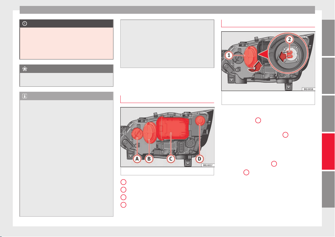
Fuses and bulbs
CAUTION
●
Remov
e the ignition key before working on
the electric system. Otherwise, a short circuit
could occur.
●
Switch off the lights or parking lights be-
fore you change a bulb.
For the sake of the environment
Please ask your specialist retailer how to dis-
pose of u
sed bulbs in the proper manner.
Note
●
Depending on w
eather conditions (cold or
wet), the front lights, the fog lights, the tail
lights and the turn signals may be temporari-
ly misted. This has no influence on the useful
life of the lighting system. By switching on
the lights, the area through which the beam
of light is projected will quickly be demisted.
However, the edges may continue to be mis-
ted.
●
Please check at regular intervals that all
lighting (especially the exterior lighting) on
your vehicle is functioning properly. This is
not only in the interest of your own safety,
but also that of all other road users.
●
Before changing a bulb, make sure you
have the correct new bulb.
●
Do not touch the glass part of the bulb with
your bare hands, use a cloth or paper towel
instead. The residue left by the fingerprints
would vaporise as a result of the heat gener-
ated by the bulb, they will be deposited on
the reflect
or and will impair its surface.
●
Depending on the level of equipment fitted
in the vehicle, LEDs may be used for part or
all of the interior and/or exterior lighting.
LEDs have an estimated life that exceeds than
that of the car. If an LED light fails, go to an
authorised workshop for its replacement.
Halogen headlights.
Pos
ition of the bulbs
Fig. 112 Halogen headlights.
Turn signal
M
ain be
am he
adlights
Dipped beam headlights
DRL (daytime running light)/side light
A
B
C
D
Main beam headlights
Fig. 113 In the engine compartment: main
be
am he
a
dlight bulb.
–
Raise the bonnet.
–
Turn the cover
1
anti-clockwise and take it
out
›
›
› Fig. 113.
–
Remove the bulb connector
2
by pulling it
outw
ar
d
s.
–
Remove the bulb by pulling it out and fit
the new one.
–
Fit the bulb connector
2
.
–
Fit cover
1
, turning it towards the right.
–
Check whether the new bulb is working.
107
Technical dataAdviceOperationEmergenciesSafety
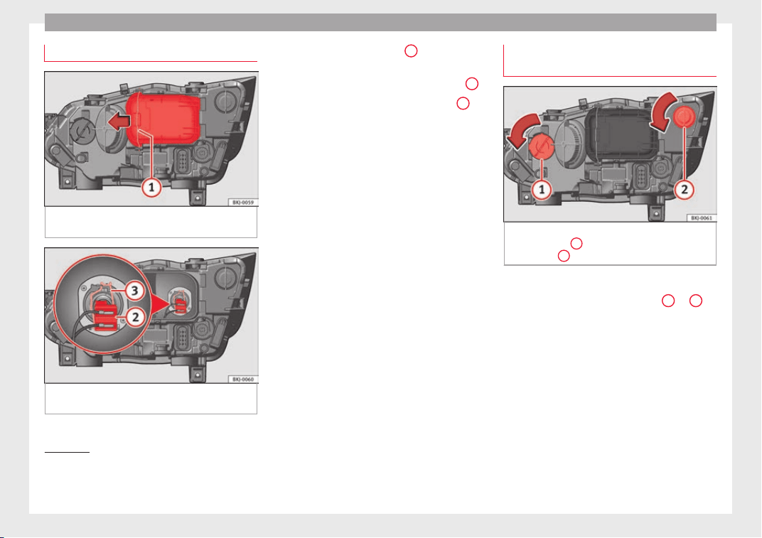
Emergencies
Dipped beam headlight
Fig. 114 In the engine compartment: remove
the lid.
Fig. 115 In the engine compartment: dipped
be
am he
a
dlight.
–
Raise the bonnet.
–
Mo
v
e the loop ›
›› Fig. 114
1
in the direc-
tion of
the arr
o
w and remove the cover.
–
Remove the bulb connector ››› Fig. 115
2
.
–
Unclip the retainer spring ›
›
›
Fig. 115
3
pressing inwards to the right.
–
Extract the bulb and fit the replacement so
th
at
the lug on the b
ase fits into the recess
on the reflector.
–
Fit the connector.
–
Fit the cover and close the strap. Make sure
that the gasket sits well on the casing cover
during the operation.
–
Check whether the new bulb is working.
Turn signal light and DRL(daytime
running light)/sidelight
1)
Fig. 116 In the engine compartment: turn sig-
n
al
light
bulb
1
and DRL (daytime running
light) b
u
l
b
2
.
–
Raise the bonnet.
–
Turn the bulb holder ›
›
›
Fig. 116
1
or
2
to
the l
ef
t
and pull.
–
Remove the bulb by pressing on the bulb
holder and turning it anticlockwise at the
same time.
–
Installation involves all of the above steps
in reverse sequence.
1)
In headlight versions with LED DRL, this light
source c
annot be replaced. It is designed to last the
length of the car’s service life. In case of failure, go
to an authorised workshop to have it replaced.
108
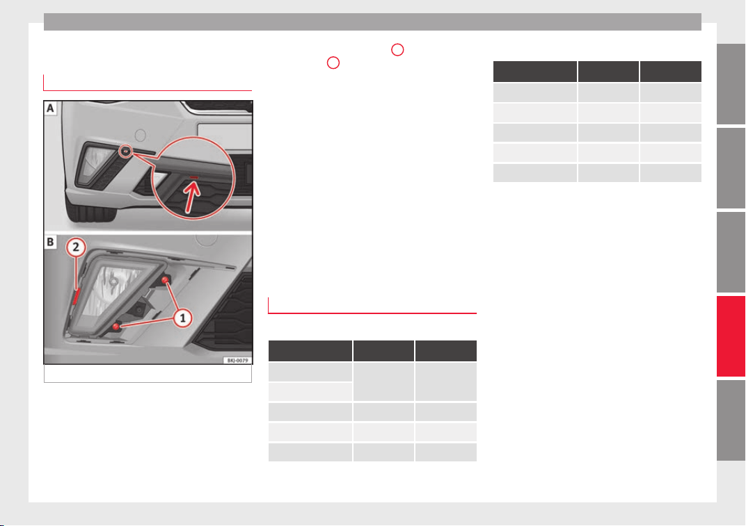
Fuses and bulbs
Changing the fog light bulbs
Fr
ont
f
og light bulb
Fig. 117 Front fog light.
Follow the steps indicated:
L
ev
er the gr
oove with a screwdriver
››› Fig. 117 (arrow). Next, remove the
clips located on the edge of the grill, lev-
ering them gently.
1.
Remove the two bolts
1
and l
ever on
the c
lip
2
to remove the fog light.
R
emo
v
e the bulb connector.
Turn the bulb holder to the left and pull.
Remove the bulb by pressing on it and
turning it anticlockwise at the same
time.
Replace the bulb, making sure that the
fixing guides are in the right position
and then press it and turn it clockwise.
To install the headlight go back through
the above steps in reverse.
Check that the bulb works properly.
Changing the tail light bulbs
Tail light summary
Bulb light
Left Right
Brake lights
2 x P21WLL 2 x P21WLL
Side lights
Retro fog light W21W –
Reverse light – W16W
Turn signal PY 21W NA LL PY 21W NA LL
2.
3.
4.
5.
6.
7
8.
Light with LEDs
Left Right
Brake lights LED LED
Side lights LED LED
Retro fog light LED –
Reverse light – W16W
Turn signal PY 21W NA LL PY 21W NA LL
The tables correspond to a right-hand traffic
vehicl
e. The position of lights may vary ac-
cording to the country.
109
Technical dataAdviceOperationEmergenciesSafety
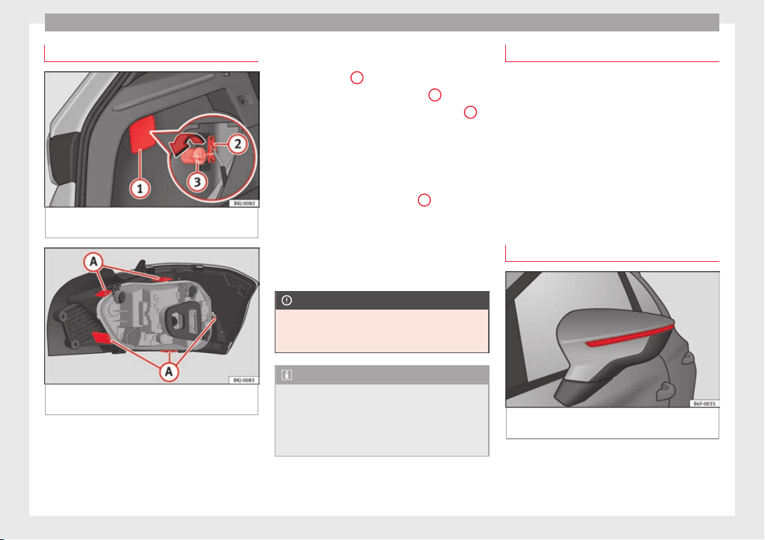
Emergencies
Changing bulbs
Fig. 118 Luggage compartment: access to the
bo
lt
sec
uring the tail light unit.
Fig. 119 Retaining tabs on reverse side of tail
light
.
Follow the steps indicated:
Chec
k
whic
h of the bulbs is defective.
Open the rear lid.
1.
2.
Remove the lid, levering the flat side of
a screwdriver into the recess
››› Fig. 118
1
.
R
emo
v
e the bulb connector
2
.
Un
s
c
rew the bolt securing the light
3
by hand or using a screwdriver.
R
emo
v
e the light from the body, gently
pulling it toward you, and place on a
clean, smooth surface.
Remove the bulb holder unlocking the
retaining tabs ››› Fig. 119
A
.
Ch
an
g
e the damaged bulb.
To refit follow the steps in reverse order,
taking special care when fitting the bulb
holder. The securing tabs must click into
place.
CAUTION
Take care when removing the rear light unit to
make s
ure there is no damage to the paint-
work or any of its components.
Note
●
Make s
ure you have a soft cloth ready to
place under the glass on the rear light unit, to
avoid any scratches.
●
For LED lights, you can only change the turn
signal and reverse light bulbs.
3.
4.
5.
6.
7.
8.
9.
Number plate light
–
Insert the flat part of a screwdriver into the
speci
al slot and remove the bulb.
–
Remove the bulb holder, by turning it until
it is free.
–
Change the bulb.
–
Replace the bulb holder, by turning it until
it fits fully.
–
Fit the light into the space and press until
you hear a “click”.
Side turn signals
Fig. 120 Turn signal integrated in the rear
v
iew mirr
or
The side turn signals are LEDS and are inte-
gr
at
ed in the r
ear view mirrors.
110

Fuses and bulbs
In case of failure, go to an authorised work-
shop t
o h
av
e it replaced.
Additional brake light
Given the difficulty involved in the replace-
ment of thi
s light it should be done by Tech-
nical Services.
Changing the interior bulbs
Interior light and front reading lights
Fig. 121 Front reading light.
To remove the glass
–
Insert a fine screwdriver between the cas-
in
g and the gl
a
ss ››› Fig. 121.
–
Carefully remove the glass, levering it to
avoid possible damage.
To replace the bulbs
–
Pull the bulbs outwards.
–
To remove the central bulb, hold and press
to one side.
Assembly
–
Proceed in the reverse order, pressing gen-
tly on the outer edge of the side light.
–
First fit the glass with the fastening tabs
over the frame of the switch. Next press the
front part until the two long tabs click on
the support.
Note
In LED courtesy lights it is not possible to re-
plac
e the light sources. If the light does not
work, take the vehicle to an official Service.
Luggage compartment light*
Fig. 122 Boot light.
Fig. 123 Boot light.
–
Extract the bulb by pressing on its inside
edg
e u
s
ing the flat side of a screwdriver
››› Fig. 122.
–
Disconnect the cable.
–
Press the bulb sideways and remove it from
its housing ››› Fig. 123.
»
111
Technical dataAdviceOperationEmergenciesSafety

Emergencies
–
Ch
an
g
e the bulb.
–
Connect the cable again.
–
Refit the bulb and press it in until it engag-
es.
112

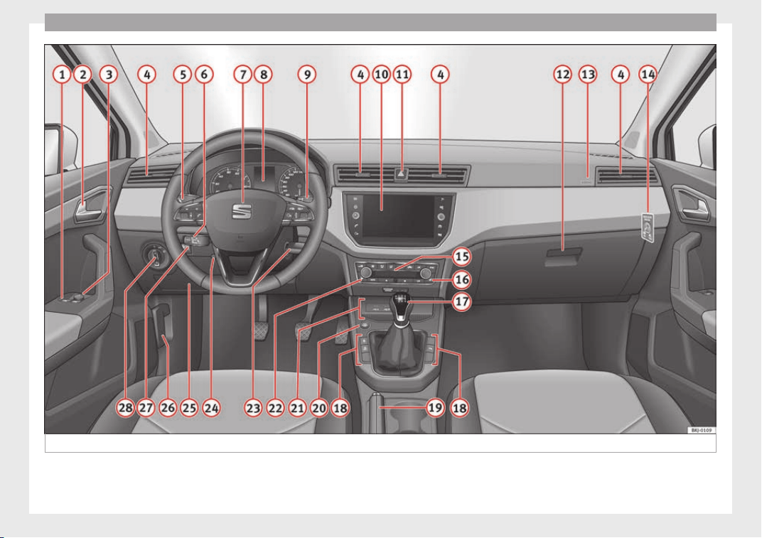
Operation
Fig. 124 Dash panel.
114
Controls and displays
Operation
C
ontr
o
ls and displays
General instrument panel
Electric window controls* . . . . . . . . . 141
Door release lever
Contro
l for adjusting electric exteri-
or mirrors* . . . . . . . . . . . . . . . . . . . . . . . 153
Air vents
Lever f
or:
–
Turn signals/main beam head-
lights . . . . . . . . . . . . . . . . . . . . . . . . . . 147
–
Cruise c
ontrol* . . . . . . . . . . . . . . . . . 207
Depending on equipment fitted:
–
Lever f
or cruise control . . . . . . . . . . 207
Steering wheel with horn and:
–
Driver airbag . . . . . . . . . . . . . . . . . . . 86
–
On-board c
omputer controls . . . . 37
–
Controls for radio, telephone,
navigation and speech dialogue
system
›››
Booklet Radio
–
Paddle levers for tiptronic gear-
shift (automatic gearbox) . . . . . . . 192
Instrument panel and warning
lamps:
–
In
struments . . . . . . . . . . . . . . . . . . . . 117
1
2
3
4
5
6
7
8
–
W
arnin
g and indic
ation lamps . . . 47
Lever for:
–
Windscreen wipers and washer . . 152
–
Rear window washer system* . . . 152
–
Multi-function display control* . . 37
Infotainment system:
Hazard warning lights . . . . . . . . . . . . 150
Depending on the equipment,
glove compartment with: . . . . . . . . . 158
–
CD player* and/or SD card*
››› Booklet Radio
Passenger airbag* . . . . . . . . . . . . . . . . 21
Front passenger airbag disconnec-
tion switch* . . . . . . . . . . . . . . . . . . . . . . 90
Switches for:
–
Heating and ventilation . . . . . . . . . 169
–
Air conditioning* . . . . . . . . . . . . . . . 171
–
C
limatronic* . . . . . . . . . . . . . . . . . . . . 173
Front passenger seat heating con-
trol* . . . . . . . . . . . . . . . . . . . . . . . . . . . . . 156
Ge
ar lever
–
Manual . . . . . . . . . . . . . . . . . . . . . . . . . 189
–
Automatic
gearbox . . . . . . . . . . . . . 190
Depending on the equipment, but-
tons
for:
–
Central locking* . . . . . . . . . . . . . . . . 134
–
Start
-Stop operation button . . . . . 204
–
SEAT Drive Profile . . . . . . . . . . . . . . . 225
9
10
11
12
13
14
15
16
17
18
–
P
ark
a
ssist system . . . . . . . . . . . . . . 228
–
Tyre pressure monitoring* . . . . . . . 278
Handbrake lever . . . . . . . . . . . . . . . . . . 181
Starter button (Keyless Access lock-
ing and ignition system) . . . . . . . . . . 178
Depending on the equipment:
–
USB/AUX-IN input . . . . . . . . . . . . . . 129
–
Connectivity Box/Wireless Charg-
er* . . . . . . . . . . . . . . . . . . . . . . . . . . . . . 129
Driver seat heating control* . . . . . . . 156
Ignition lock (vehicles without Key-
less Access) . . . . . . . . . . . . . . . . . . . . . . 175
Steering column control lever* . . . . 20
Fuse housing . . . . . . . . . . . . . . . . . . . . . 104
Bonnet release lever . . . . . . . . . . . . . . 264
Headlight range control* . . . . . . . . . . 150
Light switch . . . . . . . . . . . . . . . . . . . . . . 146
Note
●
Some of the equipment li
sted in this sec-
tion is only fitted on certain models or are op-
tional extras.
●
A separate Instructions Manual is enclosed
if the vehicle is equipped with a factory-fitted
radio, CD player, AUX IN connection or navi-
gation system.
●
The arrangement of switches and controls
on right-hand drive models* may be slightly
different from the layout shown in
»
19
20
21
22
23
24
25
26
27
28
115
Technical dataAdviceOperationEmergenciesSafety

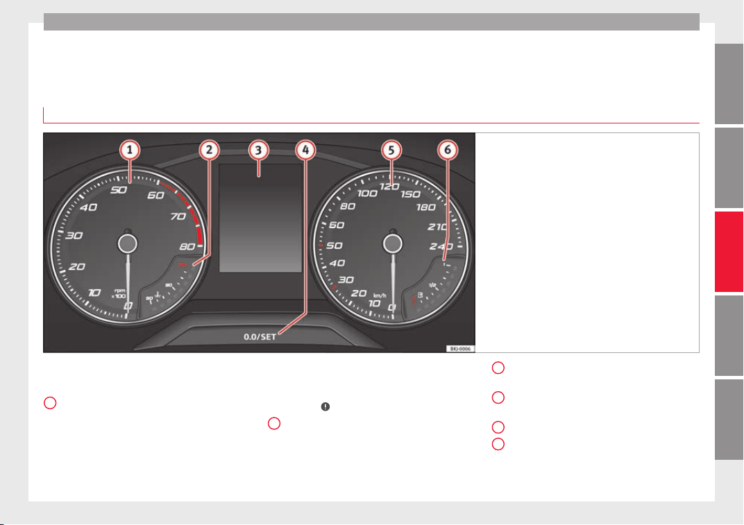
Instruments and warning/control lamps
Instruments and warning/control lamps
In
s
trument
s
General instrument panel
Fig. 125 Instrument panel, on dash panel.
The layout of the instruments depends upon
the model
and the en
gine.
R
ev counter (with the engine running, in
hundreds of revolutions per minute)
››› page 118.
The beginning of the red zone of the rev
counter indicates the maximum speed in
any gear after running-in and with the en-
gine hot. However, it is advisable to
1
change up a gear or move the selector
l
ev
er t
o D (or lift your foot off the acceler-
ator) before the needle reaches the red
zone ›››
.
En
gine c
oo
lant temperature display
››› page 120; OR:
natural gas gauge in vehicles with natural
gas engine (CNG) ››› page 121.
2
Displays on the screen ›
›
›
page 40,
››› page 118.
Adjuster button and display
››› page 120.
Speedometer.
Fuel gauge ››› page 121.
»
3
4
5
6
117
Technical dataAdviceOperationEmergenciesSafety
Operation
WARNING
Any distraction may lead to an accident, with
the risk of
injury.
●
Do not operate the instrument panel con-
trols when driving.
CAUTION
●
When the engine is
cold, avoid high revs
and heavy acceleration and do not make the
engine work hard.
Revolution counter
The rev counter indicates the number of en-
gine r
ev
o
lutions per minute
›››
Fig. 125
1
.
T
og
ether w
ith the gear-change indicator, the
rev counter offers you the possibility of using
the engine of your vehicle at a suitable
speed.
The start of the red zone on the dial indicates
the maximum engine speed which may be
used briefly when the engine is warm and af-
ter it has been run in properly. Before reach-
ing this range, you should change to a higher
gear for vehicles with a manual gearbox or for
automatic gearboxes put the selector lever in
“D” or take your foot off the accelerator ped-
al.
We recommend that you avoid high revs and
that you follow the recommendations on the
gear-change indicator. Consult the additional
information in ›››
page 41, Gear-change
indicator.
CAUTION
Never allow the rev counter needle
1
››› Fig. 125 to go int
o the red zone on the
scale for more than a very brief period, other-
wise there is a risk of engine damage.
For the sake of the environment
Changing up a gear early will help you to save
fuel and minimi
se emissions and engine
noise.
Indications on the display
Read the additional information carefully
›
›
›
page 40
A variety of information can be viewed on the
instrument panel display
›››
Fig. 125
3
de-
pendin
g on the
v
ehicle equipment:
●
Bonnet, rear lid and doors open
›››
page 40.
●
Information and warning texts.
●
Mileage.
●
Time.
●
Navigation instructions.
●
Outside temperature.
●
Compass.
●
Shift lever position ››› page 190.
●
Recommended gear (manual gearbox)
›››
page 41.
●
Multifunction display (MFD) and menus
with different setting options ›››
page 37.
●
Service interval display ›››
page 43.
●
Second speed display ››› page 119.
●
Speed warning function ›››
page 42.
●
Start-Stop system status display
››› page 204.
●
Active cylinder management display
(ACT
®
)* ››› page 200
●
Low consumption driving status ()
››› page 119
●
Engine code (MKB) ››› page 119.
Distance travelled
The odometer registers the total distance
travelled by the car.
The odometer (trip) shows the distance
travelled since the last odometer reset. The
last digit of the trip recorder indicates distan-
ces of 100 metres or one tenths of a mile.
●
Briefly press the button ››› Fig. 125
4
to re-
set
the trip r
ec
order to 0.
●
Keep the button
4
pressed for about 3
sec
ond
s
and the previous value will be dis-
played.
118
Instruments and warning/control lamps
Time
●
To set the time, keep the button ›
›
›
Fig. 125
4
pressed for more than 3 seconds to select
the hour or minut
e di
s
play.
●
To continue setting the time, press button
4
. Hold button down to scroll through the
number
s
quic
kly.
●
Once you have set the time, the second
count will begin from 0 automatically.
●
Press the button
4
again in order to finish
settin
g the time.
●
Onc
e
you have set the time, the time indi-
cator will disappear and the changes will re-
main.
The time can also be set on the Easy Connect
system using the
button and the function
b
utt
on
SETTINGS > Date and time
››› page 123.
Compass
With the ignition on and the navigation sys-
tem on, the cardinal point corresponding to
the direction of travel of the vehicle is dis-
played on the instrument panel.
Selector lever position
The selected gear is displayed on the side of
the selector lever and on the instrument pan-
el display. In positions D and S, and with the
Tiptronic, the corresponding gear is also dis-
played.
Recommended gear (manual gearbox)
The r
ecommended gear in order to save fuel
is displayed on the instrument panel while
you are driving ›››
page 41.
Second speed display (mph or km/h)
In addition to the speedometer, the speed
can also be displayed in a different unit of
measurement (in miles or in km per hour).
This option cannot be deactivated in models
destined for countries in which the second
speed must always be visible.
The second speed display can be adjusted in
the Easy Connect system by means of the
button and the function button SETTINGS >
Units ›
›
›
page 123.
Speed warning
When the speed setting is exceeded, this will
be indicated on the instrument panel display.
This is very useful, for example when using
winter tyres that are not designed for driving
at the maximum speed of the vehicle
›››
page 42.
The speed warning settings can be adjusted
in the Easy Connect system by means of the
button and the function button SET-
TINGS > Driver Assistance
›
›
›
page 123.
Start-Stop operating display
Updated information relating to the status is
displayed on the instrument panel
››› page 204.
Low consumption driving status (ECO)*
Depending on the equipment, when driving,
the “ECO” display appears on the instrument
panel when the vehicle is in low consump-
tion status due to active cylinder manage-
ment (ACT
®
)* ››› page 200.
Identifying letters on engine (MKB)
Hold the button ››› Fig. 125
4
down for more
th
an 15 sec
ond
s to display the identifying
letters of the vehicle engine (MKB). To do
this, the ignition must be switched on and
the engine switched off.
WARNING
Observe the safety warnings ›››
in Warning
symbols on p
age 122.
WARNING
Even though outside temperatures are above
freezin
g, some roads and bridges may be icy.
●
At outside temperatures above +4°C
(+39°F), even when the “ice crystal” symbol
is not visible, there may still be patches of ice
on the road.
●
The outside temperature sensor takes a
guideline measurement.
»
119
Technical dataAdviceOperationEmergenciesSafety
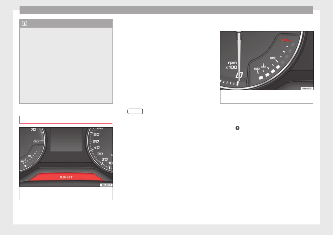
Operation
Note
●
Different
versions of the instrument panel
are available and therefore the versions and
instructions on the display may vary. In the
case of displays without warning or informa-
tion texts, faults are indicated exclusively by
the warning lamps.
●
Depending on the equipment, some set-
tings and instructions can also be carried out
in the Easy Connect system.
●
When several warnings are active at the
same time, the symbols are shown succes-
sively for a few seconds and will stay on until
the fault is rectified.
Odometer
Fig. 126 Instrument panel: odometer and re-
set
b
utt
on.
The distance covered is displayed in “kilome-
tr
e
s” or mi
les “m”. It is possible to change
the measurement units (kilometres
“km”/miles “m”) in the radio/Easy Connect*.
Please refer to the Easy Connect* Instructions
Manual for more details.
Odometer/trip recorder
The odometer shows the total distance cov-
ered by the vehicle.
The trip recorder shows the distance that has
been travelled since it was last reset. It is
used to measure short trips. The last digit of
the trip recorder indicates distances of 100
metres or tenths of a mile.
The trip recorder can be set to zero by press-
ing
0.0/SET
›
›
› Fig. 126
.
Fault display
If there is a fault in the instrument panel, the
letters DEF will appear in the trip recorder
display. Have the fault repaired immediately,
as far as is possible.
Coolant temperature gauge
Fig. 127 Instrument panel: coolant tempera-
t
ur
e g
auge
For vehicles with no coolant temperature
g
aug
e, a c
ontrol lamp appears for high
coolant temperatures ››› page 269. Please
note ›››
.
The c
oo
l
ant temperature gauge only works
when the ignition is switched on ››› Fig. 127.
In order to avoid engine damage, please read
the following notes for the different tempera-
ture ranges.
Engine cold
If only the diodes in the lower part of the
scale light up, this indicates that the engine
has not yet reached operating temperature.
Avoid high revs and heavy acceleration and
do not make the engine work hard.
120
Instruments and warning/control lamps
Normal temperature
If
in norm
al
operations, the diodes light up
until the central zone, it means that the en-
gine has reached operating temperature. At
high outside temperatures and when making
the engine work hard, the diodes may contin-
ue lighting up and reach the upper zone. This
is no cause for concern, provided the control
lamp does not light up on the instrument
panel digital display.
Heat range
When the diodes light up in the upper area of
the display and the control lamp appears
on the instrument panel display, the coolant
temperature is excessive ››› page 269.
CAUTION
●
To ens
ure a long useful life for the engine,
avoid high revs, driving at high speed and
making the engine work hard for approxi-
mately the first 15 minutes when the engine
is cold. The phase until the engine is warm al-
so depends on the outside temperature. If
necessary, use the engine oil temperature*
›››
page 42 as a guide.
●
Additional lights and other accessories in
front of the air inlet reduce the cooling effect
of the coolant. At high outside temperatures
and high engine loads, there is a risk of the
engine overheating.
●
The front spoiler also ensures proper distri-
bution of the cooling air when the vehicle is
moving. If the spoiler is damaged this can re-
duce the coo
ling effect, which could cause
the engine to overheat. Seek specialist assis-
tance.
Fuel level
Fig. 128 Fuel gauge.
The display ›
›
› Fig. 128
only works when the
ignition is switched on. When the display rea-
ches the reserve mark, the lower diode lights
up in red and the control lamp appears
››› page 117. When the fuel level is very low,
the lower diode flashes in red.
The fuel range is displayed on the instrument
panel ››› Fig. 125
3
.
Y
ou c
an c
onsult the tank capacity of your ve-
hicle in the ›››
page 57 section.
CAUTION
Never run the fuel tank completely dry. An ir-
regu
lar fuel supply could cause misfiring. In
this way the unburned fuel can reach the ex-
haust system, which could cause the catalytic
converter to overheat resulting in damage.
Fuel level - Natural Gas (GNC)
3 Valid in vehicles equipped with natural gas engine
(GNC)
Fig. 129 Instrument panel: Natural gas gauge
The gauges
›
›
›
Fig. 129 and
›››
Fig. 128 only
work when the ignition is on. When the dis-
play reaches the reserve mark, the lower LED
lights up in red and the control lamp
ap-
pears. When the fuel level is very low, the
lower diode flashes in red.
●
The green warning lamp
›››
Fig. 129
1
lights up when the vehicle is running in natu-
r
al
g
as operating mode.
»
121
Technical dataAdviceOperationEmergenciesSafety
Operation
●
The gr
een w
arnin
g lamp
1
turns off
when the n
at
ur
al gas is exhausted. The en-
gine changes to operate with petrol.
●
The yellow control lamp lights up when
the reserve level has been reached.
Things to note
If the vehicle is left parked for a long time im-
mediately after refuelling, the natural gas lev-
el indicator may not accurately indicate the
same level shown after refuelling when the
vehicle is started up again. This is not due to
a leak in the system, but to a drop in pres-
sure in the gas tank for technical reasons af-
ter a cooling phase just after refuelling.
Warning and control lamps
Warning symbols
Read the additional information carefully
›
›
›
page 47
There are red warning symbols (priority 1)
and yellow warning symbols (priority 2).
Warning messages, Priority 1 (red)
If one of these faults occurs, the warning
lamp will light up or flash and will be accom-
panied by three audible warnings. This is a
danger warning. Stop the vehicle and switch
off the engine. Check the fault and correct it.
Obtain professional assistance if necessary.
If several priority 1 faults are detected at the
same time, the symbols will be displayed one
after the other for about 2 seconds at a time
and will continue until the fault is corrected.
No menus will be shown in the display for the
duration of a priority 1 warning message.
Examples of priority 1 warning messages
(red)
●
Brake system symbol with the warning
message STOP BRAKE FLUID INSTRUC-
TION MANUAL or STOP BRAKE FAULT IN-
STRUCTION MANUAL.
●
Coolant symbol with the warning mes-
sage STOP SEE COOLANT INSTRUCTION
MANUAL.
●
Engine oil pressure symbol with the
warning message STOP ENGINE OIL
PRESSURE LOW! INSTRUCTION MANUAL.
Warning messages, Priority 2 (yellow)
If one of these faults occurs, the correspond-
ing warning lamp lights up and is accompa-
nied by an audible warning. Check the corre-
sponding function as soon as possible al-
though the vehicle may be used without risk.
If several priority 2 warning messages are de-
tected at the same time, the symbols are dis-
played one after the other for about 2 sec-
onds at a time. After a set time, the informa-
tion text will disappear and the symbol will
be shown as a reminder at the side of the
display.
Priority 2 warning messages will not be
shown until all Priority 1 warning messages
have been dealt with!
Examples of priority 2 warning reports (yel-
low):*
●
Fuel warning light with the information text
PLEASE REFUEL.
WARNING
If the warning lamps and messages are ignor-
ed, the vehic
le may stall in traffic, or may
cause accidents and severe injuries.
●
Never ignore the warning lamps or text
messages.
●
Stop the vehicle safely as soon as possible.
●
Park the vehicle away from traffic and en-
sure that there are no highly flammable ma-
terials under the vehicle that could come into
contact with the exhaust system (e.g. dry
grass, fuel).
●
A faulty vehicle represents a risk of acci-
dent for the driver and for other road users. If
necessary, switch on the hazard warning
lamps and put out the warning triangle to ad-
vise other drivers.
●
Before opening the bonnet, switch off the
engine and allow it to cool.
122
Introduction to the Easy Connect system*
●
In any
vehicle, the engine compartment is a
hazardous area and could cause severe inju-
ries ››› page 263.
CAUTION
Failure to heed the control lamps and text
me
ss
ages when they appear may result in
faults in the vehicle.
Introduction to the Easy
C
onnect
sy
stem*
System settings (CAR)*
Car menu
Read the additional information carefully
›››
page 34
To select the settings menus, depending on
the version, press the Easy Connect button
and the
S
ET
TINGS
function button, OR
pr
e
s
s the button and then
SETTINGS
.
The act
ual
number of
menus available and
the name of the various options in these me-
nus will depend on the vehicle’s electronics
and equipment.
When the function button check box is activa-
ted , the function is active.
Pressing the menu button
will always take
y
ou t
o the l
ast menu used.
Any changes made using the settings menus
are automatically saved on closing those me-
nus.
Menu Vehicle settings Page
ESC system ››› page 183
Tyres ››› page 278
Menu Vehicle settings Page
Lights ››› page 146
Driver assistance
››› page 216
››› page 212
››› page 227
Parking and manoeuvring ››› page 232
Ambient lighting ››› page 151
Mirrors and windscreen wipers
››› page 153
››› page 33
Opening and closing
››› page 143
››› page 132
Instrument panel ››› page 38
Date and time –
Units –
Service ››› page 43
Factory settings –
WARNING
Any distraction may lead to an accident, with
the risk of
injury. Operating the Easy Connect
system while driving could distract you from
traffic.
123
Technical dataAdviceOperationEmergenciesSafety

Operation
Communications and multi-
medi
a
St
eerin
g wheel controls*
General information
The steering wheel includes a multifunction
module fr
om where it is possible to control
the audio, telephone and radio/navigation
functions without needing to distract the
driver.
There are two versions of the multifunction
module:
●
Audio, telephone and navigation with voice
contro
l version: for controlling the audio
functions available (radio, audio CD, MP3,
iPod
®1)
, USB
1)
, SD
1)
) and Bluetooth system
from the steering wheel.
●
Audio, telephone and navigation without
voice control version: for controlling the au-
dio functions available (radio, audio CD,
MP3, iPod
®1)
, USB
1)
, SD
1)
) and Bluetooth sys-
tem from the steering wheel.
1)
Depending on the vehicle equipment.
124
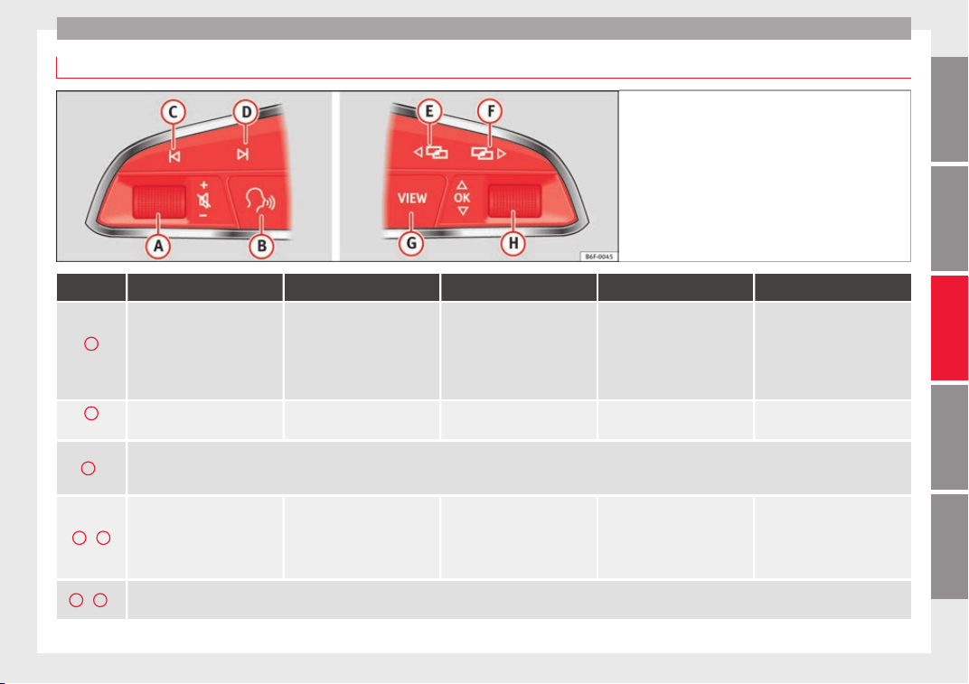
Communications and multimedia
Operating the audio, telephone and navigation system with voice control
Fig. 130 Controls on the steering wheel.
Button Radio Media (except AUX) AUX Telephone
a)
Navigation
a)
A
Turn
Turn volume up/down. You do
not need to be in audio mode
(radio).
Turn volume up/down. You do
not need to be in audio mode
(media).
Turn volume up/down. You do
not need to be in audio mode
(media).
Turn volume up/down. You do
not need to be in telephone
mode.
Turn announcement volume
up/down. You do not need to
be in navigation mode but
there has to be an announce-
ment active when you adjust
the volume.
A
Press
Mute volume. Mute volume. Mute volume. Mute incoming call.
Mute the current navigation an-
nouncement.
B
a)
Activate/deactivate voice control.
This function can be used from any mode (audio, media, navigation, assistants, vehicle status, travel data). When the system is in telephone mode this button’s function
is deactivated during the ongoing call, and without Radio/Media functionality (except AUX).
C
/
D
Search for the previous/next
station
b)
.
Short press: Switch to the pre-
vious/next song.
Hold down: Fast rewind/for-
ward
c)
.
No function
– There is no active call: Ra-
dio/Media functionality (ex-
cept AUX)
– Active call: no function
No function for the other
modes (navigation, assistants,
vehicle status, travel data).
E
/
F
a)
Change instrument panel menu.
This function can be used from any mode (audio, media, navigation, assistants, vehicle status, travel data).
»
125
Technical dataAdviceOperationEmergenciesSafety

Operation
Button Radio Media (except AUX) AUX Telephone
a)
Navigation
a)
G
Coloured instrument panel: switch to the previous menu.
Monochrome instrument panel: switch to the previous function.
H
Turn
Coloured instrument panel: List
of stations available (only if
the instrument panel is in au-
dio menu).
Coloured instrument panel:
next track (only if the instru-
ment panel is in audio menu).
No function
– There is no active call: List of
latest calls.
– Active call: access the call
options list (call on hold, hang
up, mute microphone, private
number, etc.).
– Active route: access the view
to halt guidance to destination.
– No active route: list of recent
destinations.
H
Press
Acts on the instrument panel or confirms the instrument panel menu option depending on the menu option.
a)
According to the vehicle's equipment package.
b)
This action can be performed when you are listening to the radio; there is no need to be in audio-radio mode.
c)
These actions can be performed when you are listening to media; there is no need to be in audio-radio mode.
126

Communications and multimedia
Operating the audio, telephone and navigation system with voice control
Fig. 131 Controls on the steering wheel.
Button Radio Media (except AUX) AUX Telephone
a)
Navigation
a)
A
Turn
Turn volume up/down. You do
not need to be in audio mode
(radio).
Turn volume up/down. You do
not need to be in audio mode
(media).
Turn volume up/down. You do
not need to be in audio mode
(media).
Turn volume up/down. You do
not need to be in telephone
mode.
Turn announcement volume
up/down. You do not need to
be in navigation mode but
there has to be an announce-
ment active when you adjust
the volume.
A
Press
Mute volume. Mute volume. Mute volume. Mute incoming call.
Mute the current navigation an-
nouncement.
B
a)
– Incoming call: pick up (short press), reject (hold down).
– Active call: hang up active call (short press).
– No active/incoming call: open telephone menu (short press), redial the last active call (hold down).
These functions can be used from any mode (audio, media, navigation, assistants, vehicle status, travel data).
C
/
D
Search for the previous/next
station
b)
.
Short press: Switch to the pre-
vious/next song.
Hold down: Fast rewind/for-
ward
c)
.
No function
– There is no active call: Ra-
dio/Media functionality (ex-
cept AUX)
– Active call: no function
No function for the other
modes (navigation, assistants,
vehicle status, travel data).
E
/
F
a)
Change instrument panel menu.
This function can be used from any mode (audio, media, navigation, assistants, vehicle status, travel data).
»
127
Technical dataAdviceOperationEmergenciesSafety

Operation
Button Radio Media (except AUX) AUX Telephone
a)
Navigation
a)
G
Cycles through the audio source: FM/AM – CD – SD - USB - AUX - BT Audio (only those that are available).
This function can be used from any mode (audio, media, navigation, assistants, vehicle status, travel data).
H
Turn
Coloured instrument panel: List
of stations available (only if
the instrument panel is in au-
dio menu).
Coloured instrument panel:
next track (only if the instru-
ment panel is in audio menu).
No function
– There is no active call: List of
latest calls.
– Active call: access the call
options list (call on hold, hang
up, mute microphone, private
number, etc.).
– Active route: access the view
to halt guidance to destination.
– No active route: list of recent
destinations.
H
Press
Acts on the instrument panel or confirms the instrument panel menu option depending on the menu option.
a)
According to the vehicle's equipment package.
b)
This action can be performed when you are listening to the radio; there is no need to be in audio-radio mode.
c)
These actions can be performed when you are listening to media; there is no need to be in audio-radio mode.
128
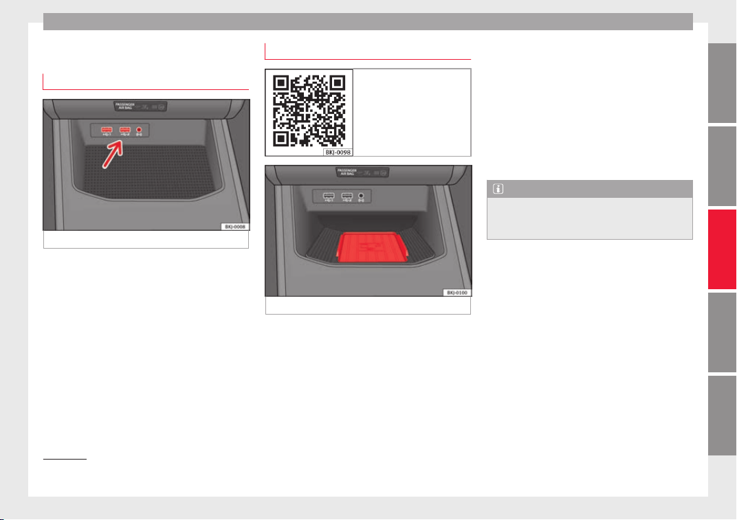
Communications and multimedia
Multimedia
USB/A
UX
-INP
ort
Fig. 132 Centre console: USB/AUX-IN input.
Depending on the special characteristics and
the c
ou
ntr
y, the vehicle may have a
USB/AUX-IN port.
The USB/AUX-IN port can be found in the
storage compartment area of the centre con-
sole ››› Fig. 132.
The operating description is located in the re-
spective Instruction Manuals of the audio
system or the navigation system.
Connectivity Box* / Wireless Charger*
Fig. 133 Related video
Fig. 134 Centre console: Connectivity Box.
Depending on the features and the country,
the
v
ehic
le may have one of these two op-
tions: Connectivity Box or Wireless Charger.
With the Connectivity Box you can charge
your mobile device wirelessly with Qi
1)
tech-
nology as well as reduce the radiation in the
vehicle and have better reception.
With the Wireless Charger you only have the
wireless charging function if your mobile de-
vice has Qi technology.
The Connectivity Box/Wireless Charger is in
the storage compartment area of the centre
console ››› Fig. 134.
The operating description is located in the re-
spective Instruction Manuals of the audio
system or the navigation system.
Note
Your mobile device must support the Qi wire-
les
s inductive charging interface standard for
proper operation.
1)
Qi technology allows you to charge your mobile
phone wirel
essly.
129
Technical dataAdviceOperationEmergenciesSafety
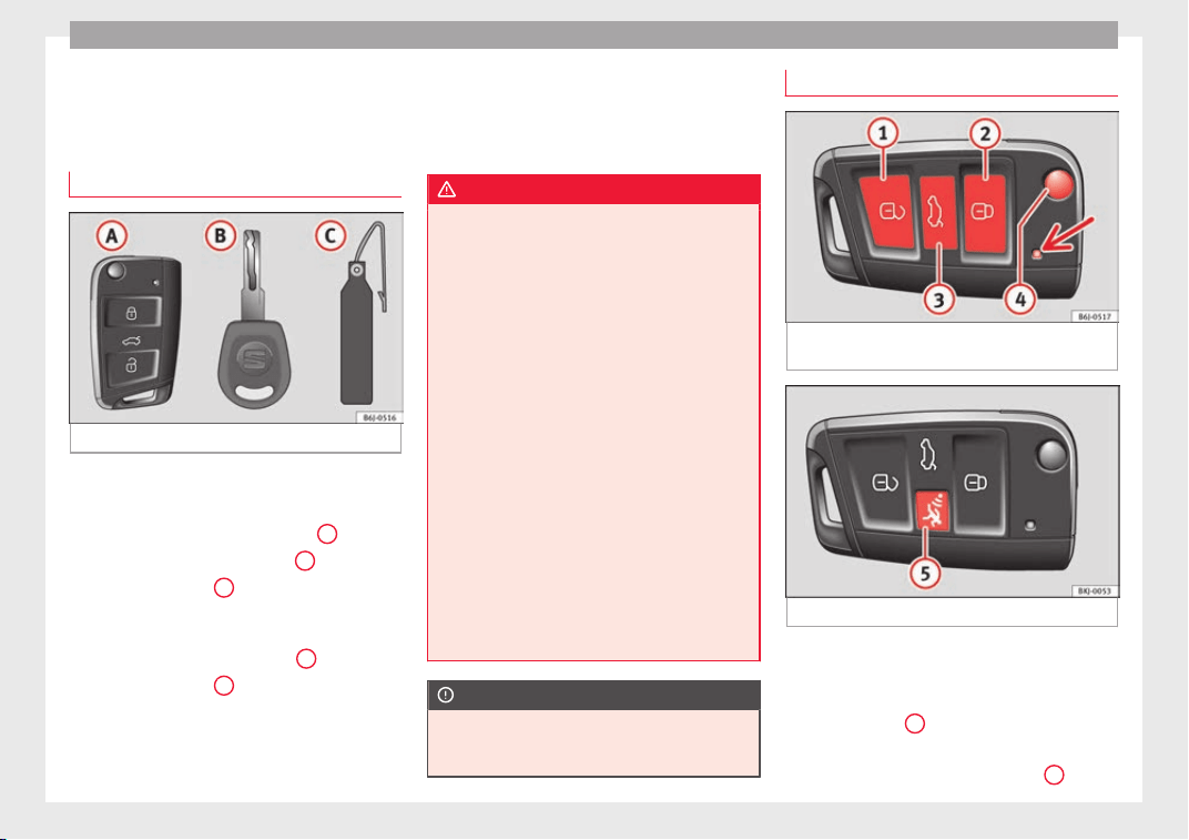
Operation
Opening and closing
K
ey
s
Set
of keys
Fig. 135 Set of keys.
The set of keys may consists of the following,
dependin
g on the
v
ersion of your vehicle:
●
a remote control key ››› Fig. 135
A
●
a key without remote control
B
,
●
a plastic key tab*
C
.
or
●
two keys with remote control
B
●
a plastic key tab*
C
.
Duplicate keys
If
y
ou need a replacement key, go to a Techni-
cal Service with your vehicle identification
number.
WARNING
●
An incorrect
use of the keys can cause seri-
ous injuries.
●
Never leave children or disabled persons in
the vehicle. In case of emergency, they may
not be able to leave the vehicle or manage on
their own.
●
An uncontrolled use of the key could start
the engine or activate any electric equipment
(e.g. electric windows), causing risk of acci-
dent. The doors can be locked using the re-
mote control key. This could become an ob-
stacle for assistance in an emergency situa-
tion.
●
Never forget the keys inside the vehicle. An
unauthorised use of your vehicle could result
in injury, damage or theft. Therefore always
take the key with you when you leave the ve-
hicle.
●
Never remove the key from the ignition if
the vehicle is in motion. Otherwise, the steer-
ing could suddenly block and it would be im-
possible to steer the vehicle.
CAUTION
There are electronic components in the re-
mote contr
ol key. Avoid wetting and hitting
the keys.
Remote control*
Fig. 136 Assignment of buttons on the re-
mot
e c
ontr
ol key.
Fig. 137 Vehicle key with alarm button.
The radio frequency remote control key is
u
sed t
o loc
k and unlock the vehicle from a
distance.
By using button
4
›
›
› Fig. 136
on the control,
the key shaft is released.
Unlocking the vehicle ››› Fig. 136
1
.
130
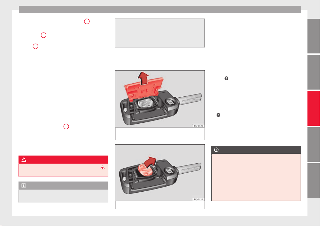
Opening and closing
Locking the vehicle ›
›
›
Fig. 136
2
.
Un
loc
k
ing the rear lid. Press button
››› Fig. 136
3
until all the turn signals on the
v
ehic
l
e flash briefly. When the unlocking but-
ton
3
is pressed, you have 2 minutes to
open the door
. Onc
e thi
s time has passed, it
will lock again.
Moreover, the battery indicator on the key
››› Fig. 136 (arrow), will flash.
The remote control transmitter and the bat-
teries are integrated in the key. The receiver
is inside the vehicle. The maximum range de-
pends on different factors. The range is re-
duced as the batteries start to lose power.
Alarm button*
Only press alarm button in the event of an
emergency ››› Fig. 137
5
! When the al
arm
b
utt
on is pressed, the vehicle horn is heard
and the turn signals are switched on for a
short time. When the alarm button is pressed
again, the alarm is switched off.
WARNING
Read and observe the relevant warnings ›››
in Set of keys on page 130.
Note
●
The remote c
ontrol key works only when
you are in its scope.
●
If the v
ehicle cannot be unlocked or locked
by using the radio frequency remote control,
the remote control key will have to be re-
synchronised. For this, go to your technical
services.
Replacing the battery
Fig. 138 Vehicle key: opening the battery
c
omp
ar
tment.
Fig. 139 Vehicle key: removing the battery.
SEAT recommends you ask a specialised
w
ork
shop t
o replace the battery.
The battery is located to the rear of the vehi-
cle key, under a cover.
Changing the battery
●
Unfold the vehicle key blade ››› page 130.
●
Remove the cover from the back of the ve-
hicle key ››› Fig. 138 in the direction of the ar-
row ›››
.
●
Extract the battery from the compartment
u
s
in
g a suitable thin object ››› Fig. 139.
●
Place the new battery in the compartment
as shown ››› Fig. 139, pressing in the oppo-
site direction to that shown by the arrow
›››
.
●
Fit the cover as shown ›
›
›
Fig. 138, pressing
it onto the vehicle key casing in the opposite
direction to that shown by the arrow until it
clicks into place.
CAUTION
●
If the batt
ery is not changed correctly, the
vehicle key may be damaged.
●
Use of unsuitable batteries may damage
the vehicle key. For this reason, always re-
place the dead battery with another of the
same voltage, size and specifications.
●
When fitting the battery, check that the po-
larity is correct.
»
131
Technical dataAdviceOperationEmergenciesSafety
Operation
For the sake of the environment
Please dispose of your used batteries correct-
ly and with r
espect for the environment.
Synchronising the remote control key
If it is not possible to unlock or lock the door
with the remot
e control, it should be re-
synchronised.
While the vehicle is open:
–
Press the button
2
›
›
›
Fig. 136 on the re-
mote control.
–
Then close the vehicle using the key shaft
within one minute.
While the vehicle is closed:
–
Press the button
1
›
›
›
Fig. 136 on the re-
mote control.
–
Then close the vehicle using the key shaft
within one minute.
It is possible that the vehicle could no longer
be opened and closed with the remote con-
trol if the button is repeatedly pressed out-
side of the effective range of the radio fre-
quency remote control. The remote control
key will have to be resynchronised.
Spare remote control keys are available at
your Technical Service, where they must be
matched to the locking system.
Up to five remote control keys can be used.
Central locking system
Description
Read the additional information carefully
›››
page 15.
The central locking system enables you to
lock and unlock all doors and the rear lid by
just pushing the button.
Central locking can be activated by using any
of the following options:
●
the key, by inserting it into the driver door
cylinder and rot
ating it in the opening direc-
tion. Depending on the vehicle version, ei-
ther all doors will be unlocked or only the
driver door will be unlocked. All doors will be
locked on locking the vehicle using the key.
●
the interior central lock button
›››
page 134.
●
the radio frequency remote control, using
the buttons on the key
›››
page 130.
Various functions are available to improve
the vehicle safety:
Locking system “Safe*”
Selective* unlocking system
Self-locking system to prevent involunta-
ry unlocking
Automatic speed dependent locking and
unlocking system*
Emergency unlocking system
Unlocking the vehicle*
Press the button ››› Fig. 136 on the re-
mote control to unlock all the doors and
the rear lid.
Locking the vehicle*
Press the button ››› Fig. 136 on the re-
mote control to lock all doors and the
rear lid or turn the key in the door to lock
all doors and the rear lid.
WARNING
●
Lock
ing from the outside carelessly or with-
out good visibility may lead to bruising, par-
ticularly in the case of children.
●
When locking a vehicle, never leave chil-
dren unaccompanied inside, as from the out-
side it will be difficult to provide assistance if
required.
●
Having the doors locked prevents intruders
from getting in, for example when stopped at
a traffic light.
–
–
–
–
–
–
–
132
Opening and closing
Note
For anti-theft security, only the driver door is
fitted with a loc
k cylinder.
Safe security system*
1)
This is an anti-theft device which consists of
a double loc
k for the door locks and a deacti-
vation function for the boot in order to pre-
vent forced entry.
Activation
The “safe” system is activated when the vehi-
cle is locked using the key or the remote con-
trol.
To activate it with the key, rotate once it is in-
serted in the door lock cylinder in the locking
direction.
To activate the system using the remote con-
trol, press the lock button once on the re-
mote.
Once this system is activated, opening doors
from the outside and the inside is not possi-
ble. The rear lid can not be opened. The cen-
tral lock button does not work.
When the ignition is switched off, the instru-
ment panel display indicates that the “Safe”
system is on.
Deactivation
Rotat
e the key inserted in the lock cylinder
twice towards the locking direction.
To activate the system using the remote con-
trol, press the lock button on the remote
twice in less than five seconds.
On deactivating the “Safe” system, the alarm
volumetric sensor is also deactivated.
With the “Safe” switched off, doors can be
opened from the interior but not from the ex-
terior.
See “Selective unlocking system*”
“Safe” status
On the driver door, there is warning lamp visi-
ble from outside the vehicle through the win-
dow which shows the “Safe” system status.
We will know that “Safe” system is activated
by the flashing warning lamp. The indicator
will flash on all vehicles, fitted and nor fitted
with an alarm, until they unlock.
Remember:
Safe activated with or without an alarm:
warning lamp flashes continuously.
Safe deactivated without an alarm: the warn-
ing lamp stays off.
Safe deactivated with an alarm: the warning
lamp stays off.
WARNING
No one should remain inside the vehicle if the
“Safe” sys
tem is activated because opening
the doors will not be possible in the event of
an emergency neither from the inside nor the
outside and help from the outside is made
difficult. Danger of death. Passengers could
become trapped inside in case of emergency.
Selective unlocking system*
This system allows to unlock either just the
driv
er door or al
l
the vehicle.
Driver door unlock button
Unlock once. Use either the key or the remote
control.
Once the key is inserted in the lock cylinder,
rotate once in the unlock direction. The driver
door will remain without “Safe” and un-
locked. In vehicles fitted with an alarm, see
the Anti-theft Alarm section
›››
page 138.
Using the remote control, press the unlock
button on the remote once. The “Safe” sys-
tem for all the vehicle is deactivated, only the
»
1)
Available depending on market and version.
133
Technical dataAdviceOperationEmergenciesSafety
Operation
driver door is unlocked and both the alarm
and the w
arnin
g l
amp are also turned off.
Unlocking all doors and the luggage com-
partment
The unlock button on the remote control
must be pressed twice so that all doors
and the luggage compartment can be
opened.
Press twice within 5 seconds to deactivate
the “Safe” system for all vehicle, to unlock all
doors and to use the luggage compartment.
The warning lamp and the alarm (only vehi-
cles fitted with one) are turned off.
Unlocking the luggage compartment
See ›››
page 16.
Self-locking system to prevent invol-
untary unlocking
It is an anti-theft system and prevents the un-
int
ention
al
unlocking of the vehicle.
If the vehicle is unlocked and none of the
doors (including the boot) are opened within
30 seconds, it re-locks automatically.
Automatic speed-dependent locking
and unlocking system*
This is a safety system which prevents access
to the v
ehicle from the outside when it is run-
ning (e.g. when stopped at a traffic light).
Locking
The doors will lock automatically if the speed
of 15 km/h (9 mph) is exceeded. The rear lid
will lock automatically if the speed of 6 km/h
(4 mph) is exceeded.
If the vehicle is stopped and any of its doors
open, when starting again and exceeding the
mentioned speed, all doors will lock again.
Unlocking
On withdrawing the ignition key, the vehicle
will returns to its status prior to self-locking.
Each door can be unlocked and opened inde-
pendently from the inside (for example, when
a passenger gets out). To do it, simply oper-
ate the lever inside the door.
WARNING
The door handles must not be operated when
the vehic
le is running: the door would open.
Note
If the airbags are triggered during an acci-
dent, the vehic
le is unlocked, except for the
luggage compartment. It is possible to lock
the vehic
le from inside with the central lock-
ing, after turning the ignition off and back on
again.
Central lock button*
Fig. 140 Central lock button.
Read the additional information carefully
›
›
›
page 15
The central lock button allows you to lock and
unlock the vehicle from the inside.
The central lock button also works with the
ignition switched off, except when the “safe”
system is activated.
Please note the following if you lock your ve-
hicle with the central lock button:
134
Opening and closing
●
L
oc
k
ing the doors and rear lid prevents ac-
cess from the outside (for safety reasons, e.g.
when stopped at a traffic light).
●
The driver door cannot be locked while it is
open. This avoids the user from forgetting his
key inside the vehicle.
●
All doors can be unlocked separately from
inside the vehicle. To do so, pull the door re-
lease lever once.
WARNING
●
If the v
ehicle is locked, children and disa-
bled people may be trapped inside it.
●
Repeated operation of central locking will
prevent the central lock button from working
for a few seconds. Then, it can only be un-
locked in case it has been previously locked.
After few seconds, the central locking be-
comes operative again.
●
The central lock button is not operative
when the vehicle is locked from the outside
(with the remote control or the key).
Related videos Keyless Access
Fig. 141 Convenience
Fig. 142 Technology
Unlocking and locking the vehicle
with Keyl
ess Access*
Fig. 143 Keyless Access locking and ignition
sy
s
t
em: In the proximity of the car.
Fig. 144 Keyless Access locking and ignition
syst
em: sensor surface
A
for unlocking in-
side the door handl
e and sensor surface
B
for locking on the exterior of the handle.
Depending on the equipment, the vehicle
m
a
y
have the Keyless Access system.
Keyless Access is a key-free locking and igni-
tion system to unlock and lock the vehicle
without actively using its key. To do this, all
that is required is to have a valid vehicle key
in the detection area where you are attempt-
ing to access the vehicle ››› Fig. 143 and to
touch one of the sensor surfaces on the door
handles ››› Fig. 144 ›››
.
The
v
ehic
le can be unlocked and locked via
the driver door only. When doing so, the re-
mote control key must be no further than ap-
prox. 1.5 m from the door handle.
It does not matter where you carry the key, for
instance whether it is in your jacket pocket or
in a briefcase.
»
135
Technical dataAdviceOperationEmergenciesSafety

Operation
Once the doors have been locked, they can-
not
be opened ag
ain immedi
ately. This will
enable you to check that the doors are prop-
erly closed.
If you wish, when unlocking, you can unlock
only the driver’s door, the side being un-
locked, or the entire vehicle. The necessary
adjustments can be performed in vehicles
with a driver information system
›››
page 34.
General information
If a valid key is located in the proximity of the
car ››› Fig. 143, the Keyless Access locking
and starting system gives the key entry as
soon as one of the sensor surfaces on the
driver door handle is touched. The following
features are then available without having to
use the vehicle key actively:
●
Keyless-Entry: unlocking the vehicle using
the handle of the front driver’s door or the
softtouch/handle on the rear lid.
●
Keyless-Exit: locking the vehicle using the
sensor on the driver door handle.
●
Press & Drive: keyless starting of the en-
gine with the starter button ››› page 178.
The central locking and locking systems oper-
ate in the same way as a normal locking and
unlocking system. Only the controls change.
Unlocking the vehicle is confirmed with a
double flash of the indicator lights; locking
by a single flash.
If the vehicle is locked and then all doors and
the rear lid are closed leaving the last key
used inside the vehicle and none outside,
the vehicle will not lock immediately. All the
vehicle's indicator lights will flash four times.
The vehicle will lock after a few seconds if
you do not open any door or the rear lid.
The vehicle will lock again after a few sec-
onds if you unlock the vehicle but fail to open
any door or boot hatch.
Unlocking and opening the doors (Keyless-
Entry)
●
Grip the driver door lever. In doing this, the
sensor surface ››› Fig. 144
A
(arrow) on the
h
andl
e i
s touched and the vehicle unlocks.
●
Open the door.
On vehicles with selective opening or info-
tainment system configuration, pulling the
door handle twice will unlock all doors.
On vehicles without a “Safe” security sys-
tem: shutting and locking doors (Keyless-Ex-
it)
●
Switch the ignition off.
●
Close the driver's door.
●
Touch (once) the locking sensor surface
B
(arrow) on the driver door handle. The door
th
at
i
s used must be closed.
On vehicles with a “Safe” security system:
shutting and locking doors (Keyless-Exit)
●
Switch the ignition off.
●
Close the driver's door.
●
Touch (once) the locking sensor surface
B
(arrow) on the driver door handle. The vehicle
loc
k
s
with the “Safe” ››› page 133 system.
The door that is used must be closed.
●
Touch (twice) the sensor surface
B
(arrow)
of
the driv
er door h
andle to lock the vehicle
without activating the “Safe” security system
››› page 133.
Unlocking and locking the boot hatch
When the vehicle is locked, the rear lid auto-
matically unlocks on opening if there is a val-
id vehicle key in the proximity ››› Fig. 143.
Open or close the rear lid normally.
After closing, the hatch locks automatically. If
the complete vehicle is unlocked, the rear lid
will not lock automatically after closing it.
What happens when locking the vehicle with
a second key
If there is a vehicle key inside the vehicle and
it is locked from the outside with a second
vehicle key, the key inside the vehicle is
136
Opening and closing
blocked for engine ignition ›
›
›
page 175. In
order to enable engine ignition, the button
on the key inside the vehicle needs to be
pressed.
Automatically disabling sensors
If the vehicle is not locked or unlocked for a
long period of time, the proximity sensors on
the passenger doors are automatically disa-
bled.
If one of the sensor surfaces on the door han-
dles is often activated in an unusual manner
with the vehicle locked (e.g. by the branches
of a bush rubbing against it), all proximity
sensors are disabled for a certain period of
time.
Sensors will again be enabled:
●
After a time.
●
OR: If the vehicle is unlocked with the
button on the key.
●
OR: if the boot is opened.
●
OR: if the vehicle is unlocked manually with
the key.
Keyless Access temporary disconnection
function*
You can deactivate the vehicle's Keyless Ac-
cess unlocking for a locking and unlocking
cycle.
●
Move the gear lever to position P (if the ve-
hicle has automatic gearbox), since other-
wise the vehicle cannot be locked.
●
Close the door.
●
Push the central locking button on the
remote control and touch the locking sensor
surface ››› Fig. 144
B
on the driver door han-
dl
e onc
e w
ithin the following 5 seconds. Do
not grip the door handle, otherwise the vehi-
cle will not lock. Deactivation is also possible
if the vehicle is locked through the driver’s
door lock.
●
To check that the function has been deacti-
vated, wait at least 10 seconds, grip and pull
on the door handle. The door should not
open.
The next time the door can only be unlocked
via the remote control or the lock cylinder.
The next time the door is locked/unlocked,
Keyless Access will be active again.
Convenience functions
To close all the electric windows and the sun-
roof using the convenience function, keep a
finger for a few seconds on the locking sen-
sor surface
B
(arrow) of the door handle un-
ti
l
the w
indows and roof have closed.
The doors opened by touching the sensor
surface of the door handle depend on the
settings that have been activated in the Easy
Connect system with the
button and the
SETTINGS
and
Openin
g and c
lo
sing
function but-
t
on
s.
CAUTION
The sensor surfaces on the door handles
coul
d engage if hit with a water jet or high
pressure steam if there is a valid vehicle key
in the proximity. If at least one of the electric
windows is open and the sensor surface
B
(arrow) on the handle is activated continu-
ously
, all windows will close.
Note
●
If the v
ehicle battery has little or no charge,
or the vehicle key battery is almost or entire-
ly out of charge, you will probably not be able
to lock or unlock the vehicle with the Keyless
Access system. The vehicle can be unlocked
or locked manually.
●
To control the proper locking of the vehicle,
the release function is disabled for approx. 2
seconds.
●
If the message Keyless access system
faulty is displayed on the screen of the
dash panel, abnormalities may occur in the
operation of the Keyless Access system. Con-
tact a specialised workshop. SEAT recom-
mends visiting a SEAT dealership for this.
●
Depending on the function set on the info-
tainment system for the mirrors, the exterior
mirrors will unfold and the surround lighting
will come on when unlocking the vehicle us-
ing the sensor surface on the driver door han-
dle.
»
137
Technical dataAdviceOperationEmergenciesSafety
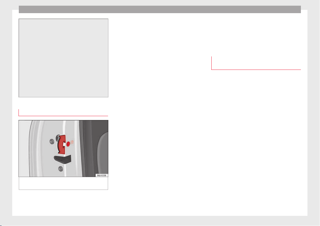
Operation
●
If there i
s no valid key inside the vehicle or
the system fails to detect one, a warning will
display on the dash panel screen. This could
happen if any other radio frequency signal in-
terferes with the key signal (e.g. from a mo-
bile device accessory) or if the key is covered
by another object (e.g. an aluminium case).
●
If the sensors are very dirty, e.g. have a lay-
er of salt, the correct functioning of the sen-
sors on the door handles may be affected. In
this case, clean the vehicle.
●
If the vehicle is equipped with an automatic
gearbox, it may only be locked in the gear
stick is in position P.
Childproof lock
Fig. 145 Childproof lock on the left hand side
door
.
The childproof lock prevents the rear doors
fr
om bein
g opened fr
om the inside. This sys-
tem prevents minors from opening a door ac-
cidentally while the vehicle is running.
This function is independent of the vehicle
electronic opening and locking systems. It
only affects rear doors. It can only be activa-
ted and deactivated manually, as described
below:
Activating the childproof lock
–
Unlock the vehicle and open the door in
which you wish to activate the childproof
lock.
–
With the door open, rotate the groove in
the door using the ignition key, anti-clock-
wise for the left-hand side doors ››› Fig. 145
and clockwise for the right-hand side
doors.
Deactivating the childproof lock
–
Unlock the vehicle and open the door
whose childproof lock you want to deacti-
vate.
–
With the door open, rotate the groove in
the door using the ignition key, anti-clock-
wise for the right-hand side doors, and
clockwise for the left-hand side doors
››› Fig. 145.
Once the childproof lock is activated, the
door can only be opened from the outside.
The childproof lock can be activated or deac-
tivated by inserting the key in the groove
when the door is open, as described above.
Anti-theft alarm*
Description of anti-theft alarm sys-
tem*
The anti-theft alarm makes it more difficult to
break
into the vehicle or steal it. The system
will initiate acoustic and optical warning sig-
nals when your vehicle is tried to be forced.
The anti-theft alarm system is automatically
switched on when locking the vehicle. The
system is immediately activated and the turn
signal light located on the driver door will
flash along with the turn signals, indicating
that the alarm and the locking security sys-
tem (double lock) have been turned on.
If any of the doors or the bonnet are open,
they will not be included in the protection
zones of the vehicle when the alarm is con-
nected. If the door or the bonnet are subse-
quently closed, they will be automatically in-
cluded in the protection areas of the vehicle
and the turn signals will flash accordingly
when the doors close.
●
The turn signal light will flash twice on
opening and deactiv
ating the alarm.
138
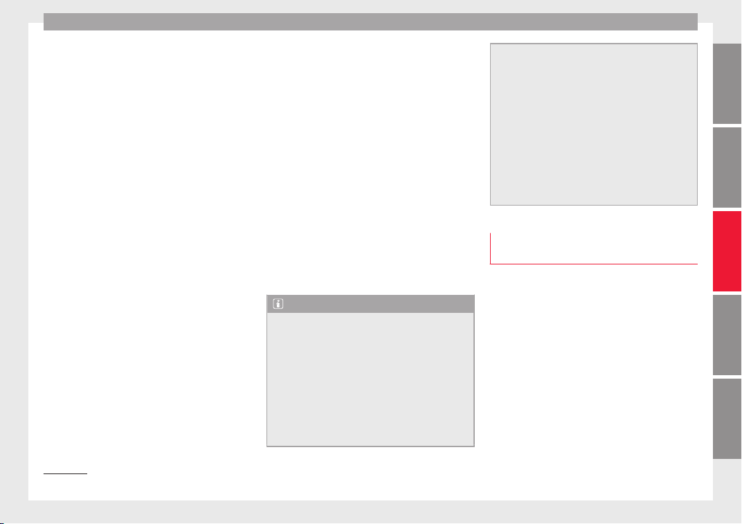
Opening and closing
●
The t
urn s
ign
al light will flash once on clos-
ing and activating the alarm.
When does the system trigger an alarm?
The system triggers an alarm, if the following
unauthorised actions are carried out when
the vehicle is locked:
●
Mechanical opening of the vehicle with the
vehicle key without switching on the ignition
in the next 15 seconds (in certain markets,
such as the Netherlands, the alarm is activa-
ted immediately).
●
A door is opened.
●
Opening the bonnet.
●
The rear lid is opened.
●
Ignition switched on with a non-validated
key.
●
Movements in the driving compartment
(vehicles with a volume sensor).
●
Towing of the vehicle
1)
.
●
Vehicle tilt angle
1)
.
●
Undue manipulation of the alarm.
●
Battery handling.
In this case, the acoustic signals will go off
and the turn signal will flash for approximate-
ly 30 seconds. This cycle may be repeated up
to 10 times depending on the country.
Opening all the doors in manual mode
In vehicles without an alarm, when opening
the driver door manually, all doors are
opened.
How to switch the alarm off
To deactivate the anti-theft alarm, turn the
key in the opening direction, open the door
and switch the ignition on, or press the un-
lock button on the remote control.
In vehicles equipped with an anti-theft alarm
system, you have 15 seconds to insert the
key in the ignition lock and activate the igni-
tion if the vehicle is opened using the driver
door key.
Otherwise, the alarm will trigger for 30 sec.
and the ignition will be blocked.
Note
●
After 28 d
ays, the indicator light will be
switched off to prevent the battery from
draining if the vehicle has been left parked
for a long period of time. The alarm system
remains activated.
●
The alarm will trigger again if attempts are
made to open another protection zone.
●
The alarm system can be activated or deac-
tivated using the radio frequency remote con-
trol ››› page 130.
●
The anti-theft a
larm is not activated when
the vehicle is locked from within using the
central locking button .
●
If the vehicle battery is run down or flat
then the anti-theft alarm will not operate cor-
rectly.
●
Vehicle monitoring remains active even if
the battery is disconnected or not working for
any reason.
●
The alarm is triggered immediately if one of
the battery cables is disconnected while the
alarm system is active.
Vehicle interior monitoring and anti-
t
o
w sy
stem*
Monitoring or control function incorporated
in the anti-thef
t
al
arm* which detects unau-
thorised vehicle entry by means of ultra-
sound.
Activation
–
It is automatically switched on when the
anti-theft alarm is activated.
Deactivation
–
Open the vehicle with the key, either me-
chanically or by pressing the button on
the remote control. If the vehicle is opened
»
1)
With vehicles fitted with a tow-away protection
139
Technical dataAdviceOperationEmergenciesSafety
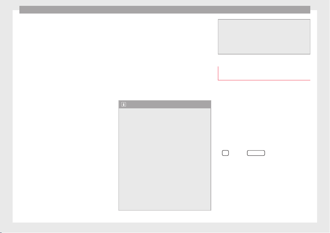
Operation
mechanically, the time period from when
the door i
s
opened u
ntil the key is inserted
into the contact should not exceed 15 sec-
onds, otherwise the alarm will be triggered.
–
Press the button on the remote control
twice. The volumetric sensor and tilt sen-
sors will be deactivated. The alarm system
remains activated.
The vehicle interior monitoring and the anti-
tow system are automatically switched on
again next time the vehicle is locked.
The vehicle interior monitoring and anti-tow
sensor (tilt sensor) are automatically switch-
ed on when the anti-theft alarm is switched
on. In order to activate it, all the doors and
the rear lid must be closed.
If you wish to switch off the vehicle interior
monitoring and the anti-tow system, it must
be done each time that the vehicle is locked;
if not, they will be automatically switched on.
The vehicle interior monitoring and the anti-
tow system should be switched off if animals
are left inside the locked vehicle (otherwise,
their movements will trigger the alarm) or
when, for example, the vehicle is transported
or has to be towed with only one axle on the
ground.
False alarms
Interior monitoring will only operate correctly
if the vehicle is completely closed. Please ob-
serve related legal requirements.
The following cases may cause a false alarm:
●
Open windows (partially or fully),
●
Sliding sunroof open (partially or complete-
ly),
●
Movement of objects inside the vehicle,
such as loose papers, items hanging from
the rear vision mirror (air fresheners), etc.
Note
●
If the v
ehicle is relocked and the alarm is
activated without the volumetric sensor func-
tion, relocking will activate the alarm with all
its functions, except the volumetric sensor.
This function is reactivated when the alarm is
switched on again, unless it is deliberately
switched off.
●
If the alarm has been triggered by the volu-
metric sensor, this will be indicated by a
flashing of the warning lamp on the driver
door when the vehicle is opened. The flash is
different to the flash indicating the alarm is
activated.
●
The vibration of a mobile phone left inside
the vehicle may cause the vehicle interior
monitoring alarm to trigger, as both sensors
react to movements and shakes inside the ve-
hicle.
●
If on activatin
g the alarm, any door or the
rear lid is open, only the alarm will be activa-
ted. The vehicle interior monitoring and the
anti-tow system will only be activated once
all the doors are closed (including the rear
lid).
Deactivating the vehicle interior moni-
toring and anti-t
ow system*
When the vehicle is locked, the alarm will be
trigger
ed if movements are detected in the
interior (e.g. by animals) or if the vehicle's in-
clination is changed (e.g. during transport).
You can prevent the alarm from being trig-
gered accidentally by switching off the vehi-
cle interior monitoring and/or tow-away pro-
tection.
–
To switch off the interior monitoring and
tow-
away protection, switch off the ignition
and, using the Infotainment system, select:
button >
S
ET
TINGS
function button >
Openin
g and c
lo
sing > Central locking >
Switch off alarm.
–
When the vehicle is locked now, the vehicle
interior monitoring and the tow-away pro-
tection are switched off until the next time
the door is opened.
140
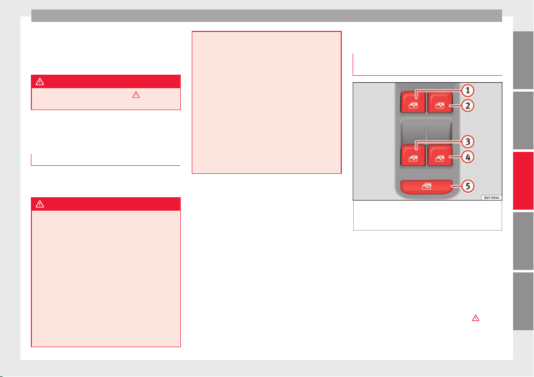
Opening and closing
If the anti-theft security system (Safelock)*
›
›
›
page 133 is switched off, the vehicle interi-
or monitoring and the tow-away protection
are automatically switched off.
WARNING
Observe the safety warnings ›››
in Descrip-
tion on page 132
.
Rear lid
Opening and clo
sing
Read the additional information carefully
›
›
›
page 16
WARNING
●
Alwa
ys close the rear lid properly. Risk of
accident or injury.
●
The rear lid must not be opened when the
reverse or rear fog lights are lit. This may
damage the tail lights.
●
Do not close the rear lid by pushing it down
with your hand on the rear window. The glass
could smash. Risk of injury!
●
Ensure the rear lid is locked after closing it.
If not, it may open unexpectedly while driv-
ing.
●
Never allow children to play in or around
the vehicle. A locked vehicle can be subjected
to extremely high and low temperatures, de-
pending on the time of year, thus causing se-
rious injurie
s/illness. It could even have fatal
consequences. Close and lock both the rear
lid and all the other doors when you are not
using the vehicle.
●
Closing the rear lid without observing and
ensuring it is clear could cause serious injury
to you and to third parties. Make sure that no
one is in the path of the rear lid.
●
Never drive with the rear lid open or half-
closed, exhaust gases may enter into the in-
terior of the vehicle. Danger of poisoning!
●
If you only open the rear lid, do not leave
the key inside. The vehicle cannot be opened
if the key is left inside.
Controls for the windows
Openin
g and c
lo
sing of the electric
windows*
Fig. 146 Detail of the driver door: controls for
the fr
ont
and r
ear windows (vehicles with
front and rear electric windows).
Read the additional information carefully
›
›
›
page 18
The front and rear electric windows can be
operated by using the controls on the driver
door. The other doors each have a switch for
their own window.
Always close the windows fully if you park
the vehicle or leave it unattended ›››
.
Y
ou c
an u
se the electric windows for approx.
10 minutes after switching off the ignition if
»
141
Technical dataAdviceOperationEmergenciesSafety
Operation
neither the driver door nor the front passen-
g
er door h
a
s been opened and the key has
not been removed from the ignition.
Safety switch *
The safety switch ››› Fig. 146
5
on the driver
door c
an be u
sed t
o disable the electric win-
dow buttons on the rear doors.
●
Safety switch not pressed: buttons on rear
doors are activated.
●
Safety switch pressed: buttons on rear
doors are deactivated. The safety control
symbol lights up in yellow if the buttons
on the rear doors are switched off.
WARNING
Observe the safety warnings ›››
in Set of
keys on p
age 130.
●
Incorrect use of the electric windows can
result in injury.
●
Never close the rear lid without observing
and ensuring it is clear, to do otherwise could
cause serious injury to you and third parties.
Make sure that no one is in the path of a win-
dow.
●
If the ignition is switched on, the electric
equipment could be activated with risk of in-
jury, for example, in the electric windows.
●
The doors can be locked using the remote
control key. This could become an obstacle
for assistance in an emergency situation.
●
Therefor
e always take the key with you
when you leave the vehicle.
●
The electric windows will work until the ig-
nition has been switched off and one of the
front doors has been opened.
●
If necessary, use the safety switch to disa-
ble the rear electric windows. Make sure that
they have been disabled.
Note
If the window is not able to close because it
i
s s
tiff or because of an obstruction, the win-
dow will automatically open again
››› page 142. If this happens, check why the
window could not be closed before attempt-
ing to close it again.
Roll-back function
The roll-back function reduces the risk of in-
jur
y
when the el
ectric windows close.
●
If a window is obstructed when closing au-
tomatically, the window stops at this point
and lowers immediately ›››
.
●
Next, check why the window does not close
bef
or
e att
empting it again.
●
If you try within the following 10 seconds
and the window closes again with difficulty
or there is an obstruction, the automatic clos-
ing will stop working for 10 seconds.
●
If the window is still obstructed, the win-
dow will stop at this point.
●
If there is no obvious reason why the win-
dow cannot be closed, try to close it again by
pulling the tab within ten seconds. The win-
dow closes with maximum force. The roll-
back function is now deactivated.
If more than 10 seconds pass, the window
will open fully when you operate one of the
buttons. One-touch closing is reactivated.
WARNING
●
Alwa
ys take the ignition key with you when
leaving the vehicle, even if you only intend to
be gone for a short time. Please ensure that
children are never left alone inside the vehi-
cle.
●
The electric windows will work until the ig-
nition has been switched off and one of the
front doors has been opened.
●
Closing the windows without observing and
ensuring it is clear could cause serious injury
to you and third parties. Make sure that no
one is in the path of a window.
●
Never allow people to remain in the vehicle
when you close the vehicle from the outside.
The windows cannot be opened even in an
emergency.
●
The roll-back function does not prevent fin-
gers or other parts of the body getting
pinched against the window frame. Risk of
accident.
142
Opening and closing
Convenience opening and closing
Use the convenience opening/closing func-
tion to ea
sily open/close all the windows and
the sliding/tilting sunroof* from the outside.
Convenience open function
–
Press and hold the button on the remote
control key until all the windows and the
sliding/tilting sunroof* have reached the
desired position, or
–
First unlock the vehicle using the button
on the r
emote control key and then keep
the key in the driver door lock until all the
windows and the sliding/tilting sunroof*
have reached the required position.
Convenience close function
–
Press and hold button on the remote
control key until all the windows and the
sliding/tilting sunroof* are closed
›››
, or
–
Keep the key in the driver door in the "lock"
po
s
ition u
ntil all the windows and the slid-
ing/tilting sunroof* are closed.
Programming convenience opening in the
Easy Connect*
–
Select:
button > SETTINGS f
u
nction
b
utton > Opening and closing > Elec-
tric windows > Convenience open-
ing, to choose between all the windows
(All), only the driver’s window (Driver)
or none (Deactivated).
WARNING
●
Take c
are when closing the sliding/tilting
sunroof* and windows. There is a risk of suf-
fering injury.
●
For safety reasons, you should only use the
remote control open and close functions with-
in about 2 metres of the vehicle. To avoid in-
juries, always keep an eye on the windows
and the sliding/tilting sunroof* when press-
ing the button to close them. The windows
stop moving as soon as the button is re-
leased.
One-touch opening and closing*
One-touch opening and closing means you
do not
h
av
e to hold down the button.
Buttons
›››
Fig. 146
1
,
2
,
3
and
4
have
tw
o po
s
itions for opening windows and two
for closing them. This makes it easier to open
and close windows to the desired position.
One-touch closing
–
Pull up the window button briefly up to the
second position. The window closes fully.
One-touch opening
–
Push down the window button briefly up to
the second position. The window opens
fully.
Resetting one-touch opening and closing
–
The automatic open and close function will
not work if the battery has been temporari-
ly disconnected. The function can be re-
stored as follows:
–
Close the window as far as it will go by lift-
ing and holding the electric window switch.
–
Release the switch and then lift it again for
1 second. This will re-enable the automatic
function.
If you push (or pull) a button to the first
stage, the window will open (or close) until
you release the button. If you push or lift the
button briefly to the second stage, the win-
dow will open (one-touch opening) or close
(one-touch closing) automatically. If you op-
erate the button while the window is opening
or closing, it stops at this position.
143
Technical dataAdviceOperationEmergenciesSafety
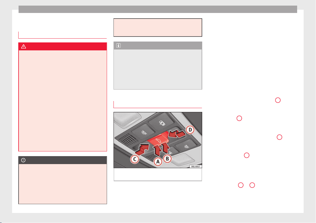
Operation
Sunroof*
Intr
oduction
WARNING
If the sunroof is used negligently or without
pay
ing due attention, it can cause serious in-
jury.
●
Open or close the sunroof and the sun blind
only when no one is in their path of move-
ment.
●
Never leave any key inside the vehicle
when exiting.
●
Never leave a child or any other person who
may need help in the vehicle, especially if
they have access to the vehicle key. If using
they key unattended, they could lock the ve-
hicle, start the engine, switch on the ignition
and activate the sunroof.
●
After switching off, it is still possible to
open or close the sunroof during a short
space of time provided that neither the driver
nor passenger door is opened.
CAUTION
●
To prev
ent damage, during winter tempera-
tures remove any ice or snow that might be
on the car roof before opening the sunroof or
adjusting the tilt position.
●
Before leaving the vehicle or in case of rain-
fall, always close the sunroof. With the sun-
roof open or in a tilted position, water can en-
ter the interior and can cause considerable
damag
e to the electrical system. As a result,
other damage can occur in the vehicle.
Note
●
L
eav
es and other loose objects that accu-
mulate on the sunroof rails should be regular-
ly cleaned away either by hand or with a vac-
uum.
●
If the sunroof does not work correctly, the
anti-trap function will not work either. Con-
tact a specialised workshop.
Opening and closing the sunroof
Fig. 147 On the interior roof lining: sunroof
b
utt
on.
The sunroof only works when the ignition is
sw
it
c
hed on. Once the ignition has been
switched off, you can still open or close the
sunroof for a few minutes provided the driver
door and the front passenger door are not
opened.
The button ››› Fig. 147 has two levels. The
first level switches the sunroof to the tilted
position, opening or closing it fully or partial-
ly.
On the second level, the sunroof automatical-
ly moves to the corresponding final position
after briefly pressing the button. Activating
the button again stops the automatic func-
tion.
Adjusting the tilt position of the sunroof
●
Press the rear part of the button
B
to the
fir
s
t
level.
●
Automatic operation: briefly press the rear
part of button
B
to the second level.
C
lo
s
ing the sunroof from a tilted position
●
Press the front part of the button
A
to the
fir
s
t
level.
●
Automatic operation: briefly press the front
part of the button
A
to the second level.
St
op
pin
g the automatic operation by adjust-
ing the tilted position of the sunroof or by
closing the sunroof
●
Press button
A
or
B
again.
144
Opening and closing
Opening the sunroof
●
Press button
C
backwards to the first lev-
el
.
●
Aut
om
atic operation to comfort position:
briefly press button
C
backwards to the sec-
ond l
ev
el
.
Closing the sunroof
●
Press button
D
forwards to the first level.
●
Automatic operation: briefly press button
D
forwards to the second level.
St
op
pin
g the automatic operation during the
opening or closing
●
Press button
C
or
D
again.
S
u
n b
lind
The sun blind is opened and closed manually
(independently of the sliding sunroof).
Convenience function to open or close the
sunroof*
The sunroof can be opened and closed with
the convenience function, just like the win-
dows:
Using the door lock*
●
Hold the key in the door lock of the driver
door in either the unlocking or locking posi-
tion to open or close the roof in the tilted po-
sition.
●
Release the key to interrupt this function.
Using the remote control
●
Keep the locking/unlocking button pressed
to open/close the roof; if you stop pressing
the button, the opening/closing function is
stopped.
Once all the windows and the sunroof have
closed, all the turn signals flash. During con-
venience closing, the windows and the sun-
roof close at the same time.
Anti-trap function of the panoramic
sliding sunroof
The anti-trap function can reduce the risk of
injur
y
when c
losing the sunroof ›››
. If the
s
u
nr
oof encounters resistance or an obstacle
when closing, it reopens immediately.
●
Check why the sunroof did not close.
●
Try to close the sunroof again.
●
If the sunroof cannot be closed due to an
obstacle or some resistance, it stops at the
corresponding position and then reopens.
For automatic closing, a new closing attempt
might take place.
●
If the sunroof is still unable to close, close
it without the anti-trap function.
Closing the sunroof without the anti-trap
function
●
Before approx. 5 seconds of having activa-
ted the roll-back function, press the but-
ton ››› Fig. 147 to the second level in the di-
rection of arrow ››› Fig. 147
D
until the sun-
r
oof
c
loses completely.
●
The sunroof closes without the anti-trap
function intervening!
●
If the sunroof will still not close, visit a spe-
cialised workshop.
WARNING
Closing the sunroof without the anti-trap
function c
an cause serious injuries.
●
Always be careful when closing the sun-
roof.
●
No person should ever remain in the way of
the sunroof, especially when closing without
the anti-trap function.
●
The anti-trap function does not prevent fin-
gers or other parts of the body from becom-
ing trapped against the roof frame and inju-
ries occurring.
145
Technical dataAdviceOperationEmergenciesSafety
Operation
Lights and visibility
Light
s
C
ontr
ol lamps
It lights up
Rear fog light switched on ››› page 147.
It lights up
Left or right turn signal.
The control lamp flashes twice as fast when a turn signal
is faulty.
It lights up
Main beam on or flasher on ››› page 147.
Several warning and control lamps light up
f
or a f
ew sec
onds when the ignition is switch-
ed on, signalling that the function is being
verified. They will switch off after a few sec-
onds.
WARNING
Observe the safety warnings ›››
in Warning
symbols on p
age 122.
Switching lights on and off
Read the additional information carefully
›››
page 31
The driver is personally responsible for the
correct use and adjustment of the lights in all
situations.
Note
●
The leg
al requirements regarding the use of
vehicle lights in each country must be ob-
served.
●
The dipped beam headlights will only work
with the ignition on. The side lights come on
automatically when the ignition is turned off.
●
If the lights are left on after the key has
been taken out of the ignition lock, an audi-
ble warning sounds while the driver door re-
mains open. This is a reminder to switch the
lights off.
●
The use of the lighting described here is
subject to the relevant statutory require-
ments.
Automatic lighting*
Activation
–
Rotate the switch to the
po
s
ition, this
indication will light up.
Deactivation
–
Turn the light switch to .
Automatic lighting
If automatic headlight control is switched on,
dipped beam headlights are automatically
switched on by a photosensor if you drive in-
to a tunnel, for example.
WARNING
●
Even if
the automatic headlight control is
switched on, the dipped beam headlights will
not be switched on with fog. Therefore, the
dipped beam must be switched on manually.
Note
●
For v
ehicles with the automatic headlight
system, when the key is removed from the ig-
nition, the audible warning will only sound if
the light knob is in position .
●
The use of the lighting described here is
subject to the relevant statutory require-
ments.
●
Do not put stickers on the windscreen in
front of the sensor. This may cause disrup-
tions or faults in the automatic lighting sys-
tem.
●
The rain sensor switches on the dipped
beam headlights when the windscreen wipers
have been operating continuously for a few
seconds and it switches the lights off when
the continuous or interval wipe is switched
off for some minutes.
146
Lights and visibility
Daytime running lights
The daytime running lights consist of individ-
ual lights, inte
grated in the front headlights.
By connecting the daytime running lights,
these lights are switched on
1)
›››
.
The daytime ru
nning lights switch on every
time the ignition is switched on, if the switch
is in positions or , according to the level
of exterior lighting.
When the light switch is in position , a
light sensor automatically switches dipped
beam on and off (including the control and
instrument lighting) or the daytime running
lights depending on the level of exterior
lighting.
WARNING
●
Never drive w
ith daytime lights if the road
is not well lit due to weather or lighting con-
ditions. Daytime lights do not provide
enough light to illuminate the road properly
or be seen by other road users.
●
On vehicles with rear lights with bulbs,
when activating the daytime running light
the rear lights are not switched on. A vehicle
which does not have the rear lights on may
not be visible to other drivers in the dark-
ness, in the case of heavy rain or in condi-
tions of poor visibility.
Fog lights
Fig. 148 Dash panel: light control.
Switching on the front fog lights*
●
Pull the light switch to the first point
›
›
›
Fig. 148
1
, from positions , or
.
The symbo
l
in the light switch lights up.
Switching on the rear fog light (vehicles with
front fog lights)
●
Completely pull the light switch
2
from
po
s
ition
, or . The lamp on the in-
strument panel lights up.
Switching on the rear fog light (vehicles with
no front fog lights)
●
Completely pull the light switch
2
from
po
s
ition
, or . This type of switch
only has one position. The lamp on the in-
strument panel lights up.
Turn signal and main beam lever
Read the additional information carefully
›››
page 32
Parking lights
●
Switch the ignition off and remove the key
from the lock.
●
Move the turn signal lever up or down to
turn the right or l
eft-hand parking lights on,
respectively.
Convenience turn signals
For the one-touch signalling, when the igni-
tion is switched on, move the lever as far as
possible upwards or downwards and release
the lever. The turn signal will flash three
times.
One-touch signalling is activated and deacti-
vated in the Easy Connect system via the
button and the function button SETTINGS >
Lights > One-touch signalling
›
›
›
page 34.
»
1)
On vehicles equipped with rear LED lights, the rear
side light i
s switched on as well.
147
Technical dataAdviceOperationEmergenciesSafety
Operation
In vehicles that do not have the correspond-
in
g menu, thi
s
function can be deactivated in
a specialised workshop.
WARNING
The main beam can dazzle other drivers. Risk
of acc
ident! Never use the main beam head-
lights or the headlight flasher if they could
dazzle other drivers.
Note
●
If the con
venience turn signals are operat-
ing (three flashes) and the other convenience
turn signals are switched on, the active part
stops flashing and only flashes once in the
new part selected.
●
The turn signals only work when the igni-
tion is switched on. The corresponding warn-
ing lamp flashes in the instrument pan-
el. The control lamp flashes when the turn
signals are operated, provided a trailer is cor-
rectly attached and connected to the vehicle.
If a turn signal bulb is defective, the control
lamp flashes at double speed. If the trailer
turn signal bulbs are defective, the control
lamp does not light up. Change the bulb.
●
The main beam headlights can only be
switched on if the dipped beam headlights
are already on. The warning lamp then
comes on in the instrument panel.
●
The headlight flasher comes on for as long
as you pull the lever – even if no other lights
are switched on. The warning lamp then
comes on in the instrument panel.
●
When the parking ligh
ts are switched on,
the headlight and the tail light on the corre-
sponding side of the vehicle light up. The
parking lights will only work with the ignition
off. If said light is on, an audible warning will
be emitted while the driver door is open.
●
If the turn signal lever is left on after the
key has been taken out of the ignition lock,
an acoustic signal sounds when the driver
door is opened. This is intended as a remind-
er to switch off the turn signal, unless you
wish to leave the parking light on.
Coming Home/Leaving Home Func-
tion*
Fig. 149 Related video
The Leaving Home function is controlled with
a phot
o
sen
sor.
If the Coming Home or Leaving Home func-
tion is connected, the front side and dipped
lights, the tail lights and the number plate
light will light up to provide assistance.
Coming home function
The Coming Home function is activated by
switching off the ignition. When the driver
door is opened, the Coming Home lighting
comes on.
The Coming Home lighting switches off in the
following cases:
●
If, 30 seconds after being connected, any
doors or the rear lid remain open.
●
If the light switch is turned to position .
●
If the ignition is switched on.
Automatic Leaving Home function
The Leaving Home function is activated when
the vehicle is unlocked if:
●
the light control is in position and
●
the photosensor detects “darkness”.
The Leaving Home lighting switches off in the
following cases:
●
If the time period for the delay in switching
off the headlights has ended
●
If the vehicle is locked again.
●
If the light switch is turned to position .
●
If the ignition is switched on.
148
Lights and visibility
Note
●
To activat
e the Coming/Leaving home func-
tion, the rotary light switch must be in posi-
tion and the light sensor must detect
darkness.
Fog lights with cornering function*
This is an additional light source to dipped
beam hea
dlights to light up the road as a
bend is taken.
The cornering light operates with the lights
switched on and when driving at less than
40 Km/h (25 mph). Ignition occurs by turning
the steering or connecting the turn signal.
Forward gear
●
If the steering wheel is turned to the right,
or the right-hand t
urn signal operated, the
right-hand fog light turns on.
●
If the steering wheel is turned to the left, or
the left-hand turn signal operated, the left-
hand fog light turns on.
In reverse, both fog lights turn on.
Note
When the fog lamps are on, the cornering
function i
s activated and both headlights are
continuously on.
Motorway light*
The motorway light is available on vehicles
equipped with f
ull-LED lights.
The function is connected/disconnected via
the corresponding Easy Connect system
menu.
●
Activation: when going above 110 km/h
(68 mph) for more than 10 seconds, the dip-
ped beam raises slightly to increase the driv-
er's visibility distance.
●
Deactivation: when reducin
g the speed of
the car below 100 km/h (62 mph), the dip-
ped beam returns to its normal position.
Headlight range control
Fig. 150 Dash panel: headlight range control.
The lights range control adapts according to
the
v
alue of
the headlight beam and the ve-
hicle load status. This offers the driver opti-
mum visibility and the headlights do not daz-
zle oncoming drivers ›››
.
The he
a
dlights
can only be adjusted when
the dipped beam is switched on.
To reset, turn switch ››› Fig. 150:
Value Vehicle load status
a)
Two front occupants, luggage compart-
ment empty
All seats occupied, luggage compartment
empty
All seats occupied, luggage compartment
full. With trailer and minimum drawbar
load.
Driver only, luggage compartment full With
trailer and maximum drawbar load.
a)
If the vehicle load does not correspond to those shown in the
table, it is possible to select intermediary positions.
Dynamic headlight range control
The control is not mounted in vehicles with
dynamic headlight range control. The head-
light range is automatically adjusted accord-
ing to the vehicle load status when they are
switched on.
»
149
Technical dataAdviceOperationEmergenciesSafety
Operation
WARNING
Heavy objects in the vehicle may mean that
the headlight
s dazzle and distract other driv-
ers. This could result in a serious accident.
●
Adjust the light beam to the vehicle load
status so that it does not blind other drivers.
Hazard warning lights
Read the additional information carefully
›››
page 32
The hazard warning lights are used to draw
the attention of other road users to your vehi-
cle in emergencies.
If your vehicle breaks down:
1. Park your vehicle at a safe distance from
movin
g traffic.
2. Press the button to switch on the hazard
warning lights
›››
.
3. Switch the ignition off.
4. Apply the handbrake.
5. For a manual gearbox, engage 1st gear;
f
or an aut
om
atic gearbox, move the gear
lever to P.
6. Use the warning triangle to draw the atten-
tion of other road users to your vehicle.
7. Always take the vehicle key with you when
you leave the vehicle.
All turn signals flash simultaneously when
the hazard warning lights are switched on.
The two turn signal turn signal lamps
and the turn signal lamp in the switch will
flash at the same time. The simultaneous
hazard warning lights also work when the ig-
nition is switched off.
WARNING
●
The risk of
an accident increases if your ve-
hicle breaks down. Always use the hazard
warning lights and a warning triangle to draw
the attention of other road users to your sta-
tionary vehicle.
●
Due to the high temperatures that the cata-
lytic converter can reach, never park in an
area where the catalytic converter could come
into contact with highly inflammable materi-
als, for example dry grass or spilt petrol. This
could start a fire.
Note
●
The batter
y will run down if the hazard
warning lights are left on for a long time,
even if the ignition is switched off.
●
The use of the hazard warning lights de-
scribed here is subject to the relevant statu-
tory requirements.
Interior lights
R
el
at
ed video
Fig. 151 Convenience
Lighting of instruments and controls
The lighting level of instruments, controls
and di
s
p
lays can be adjusted through the
Easy Connect system using the
button
and the
S
ET
TINGS
function button
›
›
›
page 34.
The instrument lighting (some dials and nee-
dles), the centre console lighting and the
lighting of the displays are regulated by a
photodiode incorporated in the instrument
panel.
The instrument lighting (needles) is switched
on when the ignition is on and the light is
off. The instrument lighting is dimmed auto-
matically as the daylight starts to fade. It
goes out completely when ambient light is
very low. This function is intended to remind
the driver to switch on the dipped beam
150
Lights and visibility
headlights in good time when light condi-
tion
s
bec
ome poor.
Interior and reading lights
Read the additional information carefully
›››
page 33
Luggage compartment lighting
The light is activated when the rear lid is
open, even when the ignition and lights are
turned off. For this reason, ensure that the
rear lid is always closed.
Ambient light*
The ambient light lights up the area of the
centre console and the footwell area and, de-
pending on the version, the front door panels
as well.
It will be switched on at full brightness when
the doors are opened and the lights will be
dimmed during driving, when the light selec-
tor is in the , or position.
The brightness of the ambient light* can be
adjusted through the Easy Connect menu, as
can colour, in versions with lighting on the
front door panel (the
button and the func-
tion b
utt
on
SETTINGS > background
lighting
›››
page 34).
Note
If not all the vehicle doors are closed, the in-
terior lights
will be switched off after approx.
10 minutes, providing the ignition key has
been removed and the courtesy light position
selected. This prevents the battery from dis-
charging.
Visibility
Heated r
ear window
Fig. 152 With the air conditioning controls:
he
at
ed r
ear window switch.
The heated rear window only works when the
en
gine i
s
running. When it is switched on, a
lamp lights up on the switch.
After approximately 8 minutes, the heating
device of the rear window switches off auto-
matically.
For the sake of the environment
The heated rear window should be switched
off as
soon as the glass is demisted. By sav-
ing electrical power you can also save fuel.
Note
To avoid possible damage to the battery, an
automatic
temporary disconnection of this
function is possible, coming back on when
normal operating conditions are re-establish-
ed.
Sun visors
Fig. 153 Sun visor on the driver side.
Options for adjusting driver and front pas-
sen
g
er s
un visors:
●
Lower the sun visor towards the wind-
scr
een.
»
151
Technical dataAdviceOperationEmergenciesSafety
Operation
●
The s
u
n
visor can be pulled out of its
mounting and turned towards the door
››› Fig. 153
1
.
●
Swing the sun visor towards the door, lon-
git
udin
al
ly backwards.
Vanity mirror
There is a vanity mirror, with a cover
2
, on
the r
e
ar of
the sun blind.
WARNING
Folded sun blinds can reduce visibility.
●
Always store sun blinds and visors in their
housin
g when not in use.
Windscreen wiper and rear win-
do
w w
iper sy
stems
Windscreen wiper and window wiper
Read the additional information carefully
›
›
›
page 33
WARNING
●
Worn and dirty
wiper blades reduce visibili-
ty and safety levels while driving.
●
In cold conditions you should not use the
wash/wipe system unless you have warmed
the windscreen with the heating and ventila-
tion system. The windscreen washer fluid
could otherwise freeze on the windscreen and
obs
cure your view of the road.
●
Always note the corresponding warnings
›››
page 73.
WARNING
The rain sensor* may not detect enough rain
t
o swit
ch on the wipers.
●
If necessary, switch on the wipers manually
when water on the windscreen obstructs visi-
bility.
CAUTION
In icy conditions, always check that the wind-
scr
een wipers and the window wiper are not
frozen. If you switch on the windscreen wip-
ers when the wiper blades are frozen to the
windscreen, you could damage both the wip-
er blades and the wiper motor.
Note
●
The wipers
and washers will work only
when the ignition is switched on.
●
The heat output of the heated jets* is con-
trolled automatically when the ignition is
switched on, depending upon the outside
temperature.
●
In certain versions of vehicles with alarms,
the windscreen wiper will only work in inter-
val/rain sensor mode when the ignition is on
and the bonnet closed.
●
When the interv
al wipe function is on, the
intervals are directly proportional to the
speed. This way, the higher the vehicle speed
the shorter the intervals.
●
If you stop the vehicle with the windscreen
wiper in position 1 or 2, it will automatically
change to a lower position speed. The set
speed will be resumed when the vehicle pulls
away.
●
The windscreen will be wiped again after
approximately five seconds once the “auto-
matic wash/wipe system” has been activa-
ted, provided the vehicle is moving (drip func-
tion). If you activate the wipers less than 3
seconds after the drip function, a new wash
sequence will begin without performing the
last wipe. For the “drip” function to work
again, you have to turn the ignition off and
then on again.
●
Do not put stickers on the windscreen in
front of the rain sensor*. This may cause sen-
sor disruption or faults.
●
Depending on the version of the model,
when you engage reverse gear and with the
headlight wiper activated, this can start a
wipe.
Rear view mirrors
Int
erior mirr
or
It is dangerous to drive if you cannot see
c
l
e
arly through the rear window.
152
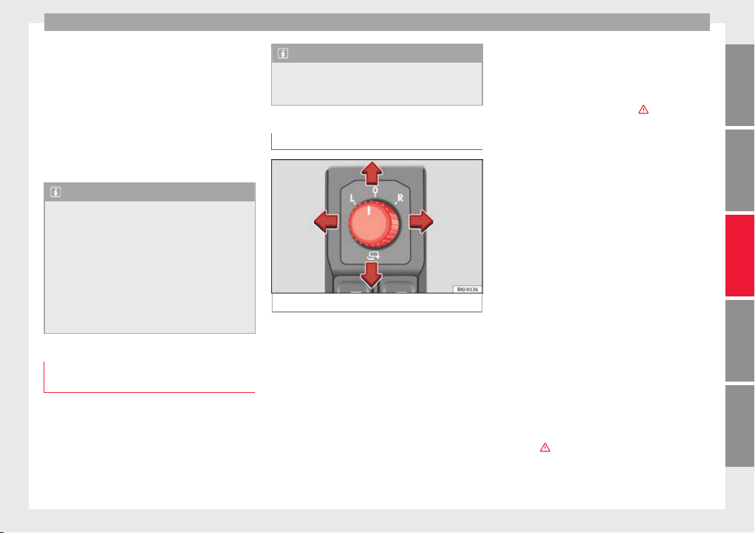
Lights and visibility
Interior mirror with automatic anti-dazzle
f
u
nction*
The anti-d
azzle function is activated every
time the ignition is switched on.
When the anti-dazzle function is enabled, the
interior rear vision mirror will darken auto-
matically according to the amount of light it
receives. The anti-dazzle function is cancel-
led if reverse gear is engaged.
Note
●
The automatic
anti-dazzle function will only
work properly if the sun blind* for the rear
window is retracted and there are no other
objects preventing light from reaching the in-
terior rear vision mirror.
●
If you have to stick any type of sticker on
the windscreen, do not do so in front of the
sensors. Doing so could prevent the anti-daz-
zle function from working well or even from
working at all.
Folding in the exterior mirrors man-
ua
l
ly
The exterior mirrors of the vehicle may be fol-
ded in. F
or thi
s, pr
ess the mirror housing to-
wards the vehicle.
Note
Before washing the vehicle with an automatic
car wa
sh, fold in the exterior mirrors to avoid
damage.
Electric exterior mirrors*
Fig. 154 Exterior mirror controls.
Read the additional information carefully
›
›
›
page 20
The exterior mirrors can be adjusted using
the rotary knob in the driver door.
Basic setting of exterior mirrors
1. Turn knob
›››
Fig. 154 to position L (left ex-
terior mirror).
2. Turn the rotary knob to position the exteri-
or mirror so that you have a good view to
the rear of the vehicle.
3. Turn the knob to position R (right exterior
mirror).
4. Swivel the rotary knob to position the ex-
terior mirror so that you have a good view
to the rear of the vehicle ›››
.
He
at
ed e
xterior mirrors*
–
Press the demisting button ››› Fig. 152
–
The mirrors demist for some minutes to
prevent draining the battery unnecessarily.
–
If necessary, press the button again to re-
peat the function.
–
The exterior mirror heating is not activated
in temperatures above approximately
+20°C (+68°F).
Folding in the exterior mirrors electrically*
–
Turn the control ››› Fig. 154 to position to
fold in the exterior mirrors. You should al-
ways fold in the exterior mirrors if you are
driving through an automatic car wash.
This will help prevent damage.
Folding exterior mirrors back out to the ex-
tended position*
–
Turn the knob to position L or R to return
the exterior mirrors to their original posi-
tion ›››
.
»
153
Technical dataAdviceOperationEmergenciesSafety
Operation
Fold in the exterior mirrors after parking
(c
on
v
enience function)*
The Easy Connect system, the
button and
the f
u
nction b
uttons
SETTINGS
and
Mirr
or
s
and windscreen wipers
can be used to
h
av
e the e
xterior mirrors fold in when the ve-
hicle is parked ››› page 123.
When the vehicle is locked with the remote
control, by pressing for more than approxi-
mately 1 second the exterior mirrors are fol-
ded in automatically. When the vehicle is
opened with the remote control, the exterior
mirrors are deployed automatically.
WARNING
●
Conv
ex or aspheric mirrors increase the
field of vision however the objects appear
smaller and further away in the mirrors. If you
use these mirrors to estimate the distance to
vehicles behind you when changing lane, you
could make a mistake. Risk of accident.
●
If possible, use the rear vision mirror to es-
timate distances to vehicles behind you.
●
Make sure that you do not get your finger
trapped between the mirror and the mirror
base when folding back the mirrors. Risk of
injury!
For the sake of the environment
The exterior mirror heating should be switch-
ed off when it i
s no longer needed. Other-
wise, it is an unnecessary fuel waste.
Note
●
If the electric
al adjustment ever fails to op-
erate, the mirrors can be adjusted by hand by
lightly pressing the edge of the mirror glass.
●
In vehicles with electric exterior mirrors,
the following points should be observed: if,
due to an external force (e.g. being knocked
while manoeuvring), the adjustment of the
mirror housing is altered, the mirror will have
to be fully folded electrically. Do not readjust
the rear vision mirror housing by hand, as
this will interfere with the mirror adjuster
function.
●
The fold-in function on the exterior mirrors
will not activate at speeds over 40 km/h
(25 mph).
Seats and head restraints
Adju
s
tin
g the seat and head re-
straints
Adjusting the front seats
Read the additional information carefully
›››
page 19
WARNING
The safe driving chapter contains important
information, tip
s, suggestions and warnings
that you should read and observe for your
own safety and the safety of your passengers
››› page 75.
WARNING
●
Never adju
st the driver or front passenger
seat while the vehicle is in motion. While ad-
justing your seat, you will assume an incor-
rect sitting position. Risk of accidents. Adjust
the driver or front passenger seat only when
the vehicle is stationary.
●
To reduce the risk of injury to the driver and
front passenger in case of a sudden braking
or an accident, never drive with the backrest
tilted towards the rear. The maximum protec-
tion of the seat belt can be achieved only
when the backrests are in an upright position
and the driver and front passenger have prop-
erly adjusted their seat belts. The further the
154
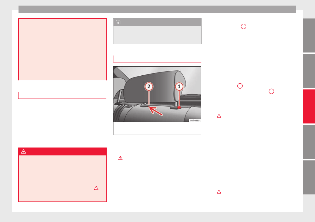
Seats and head restraints
backrests are tilted to the rear, the greater
the risk of
injury due to improper positioning
of the belt web!
●
Exercise caution when securing the seat
height into forwards/backwards position. In-
juries can be caused if the seat height is ad-
justed without due care and attention.
●
To move the seat forwards and backwards,
pull upwards and not sideways on the lever,
as the force exerted on it in that direction
could damage it.
Adjusting the front head restraints
Read the additional information carefully
›
›
›
page 19
Adjust the head restraint ›››
page 19 so
that as far as possible the top of the head re-
straint is level with the top of your head.
When this is not possible, try to get as close
as possible to this position.
WARNING
●
Never drive if
the head restraints have been
removed. Risk of injury.
●
After refitting the head restraint, you must
always adjust it properly for height to achieve
optimal protection.
●
Please observe the safety warnings ›››
in
Correct
adjustment of front head restraints on
page 79.
Note
●
When fitting the hea
d restraints again, in-
sert the tubes as far as possible into the
guides without pressing the button.
Adjustment of the rear head restraints
Fig. 155 Rear centre head restraint: release
point
.
When transporting people in the back seat,
p
l
ac
e the head restraints of the occupied
seats at a minimum of the next socket up
›››
.
Adju
s
tin
g the head restraints
–
To set the head restraint higher, grasp the
sides with both hands and move it up-
wards, until you see it engage.
–
To set the head restraint lower down, press
the ››› Fig. 155
1
button and move it
do
wn
w
ards.
Removing the head restraint
To remove the head restraint, the correspond-
ing backrest must be partially folded forward.
–
Unlock the backrest ››› page 157.
–
Move the head restraint upwards until it ar-
rives to the top.
–
Press button
1
, while simultaneously
pr
e
s
sing on the security hole
2
with a flat
s
c
r
ewdriver a maximum of 5 mm wide, and
remove the head restraint.
–
Move the backrest until it engages properly
›››
.
Fittin
g the he
a
d restraint
To mount the external head restraints, the
corresponding backrest must be partially fol-
ded forward.
–
Unlock the backrest ››› page 157.
–
Insert the head restraint bars into the
guides until they perceptibly engage. It
should not be possible to remove the head
restraint from the backrest.
–
Move the backrest until it engages properly
›››
.
»
155
Technical dataAdviceOperationEmergenciesSafety
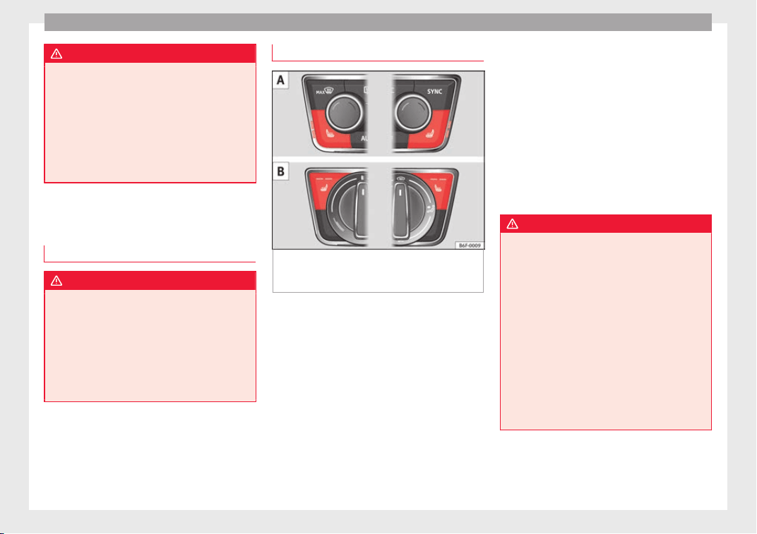
Operation
WARNING
●
Plea
se observe the general notes
››› page 79.
●
Remove the rear head restraints only when
it is necessary for the placement of a child
seat ››› page 92. After removing a child seat,
remount the head restraint immediately.
Travelling with the head restraints removed
or improperly adjusted increases the risk of
severe injuries.
Seat functions
Intr
oduction
WARNING
Inappropriate use of the seat functions can
cause sev
ere injuries.
●
Assume the proper sitting position before
your trip and remain in it throughout. This al-
so applies to the other occupants.
●
Always keep hands, fingers, feet and other
parts of the body away from the operating ra-
dius and the adjustment of seats.
Heated seats*
Fig. 156 In the centre console: front seats
he
atin
g sw
itch : version with Climatronic.
: version with manual air conditioning.
The seat cushions can be heated electrically
when the ignition i
s
sw
itched on. The back-
rest is also heated in some versions.
The seat heating should not be engaged in
any of the following conditions:
●
The seat is unoccupied.
●
The seat has a covering.
●
There is a child seat installed in the seat.
●
The seat cushion is wet or damp.
●
The indoor or outdoor temperature is great-
er than 25°C (77°F).
Activate
Press the button or . Seat heating is
switched on fully.
Adjusting the heating output
Press the button or repeatedly until the
desired temperature is reached.
Deactivating
Press the button or until all the warning
lamps switch off.
WARNING
Children and people who cannot perceive
pain or temper
ature because of medications,
paralysis or chronic diseases (e.g. diabetes)
or have a limited perception of these, may
suffer burns to the back, buttocks or legs
when using seat heating, an occurrence that
may entail a very lengthy recovery period or
from which it may not be possible to recover
fully. Seek medical advice if you have doubts
regarding your health.
●
People with limited pain and temperature
thresholds must never use seat heating.
●
If an abnormality in the device's tempera-
ture control is detected, have it checked by a
specialist workshop.
156
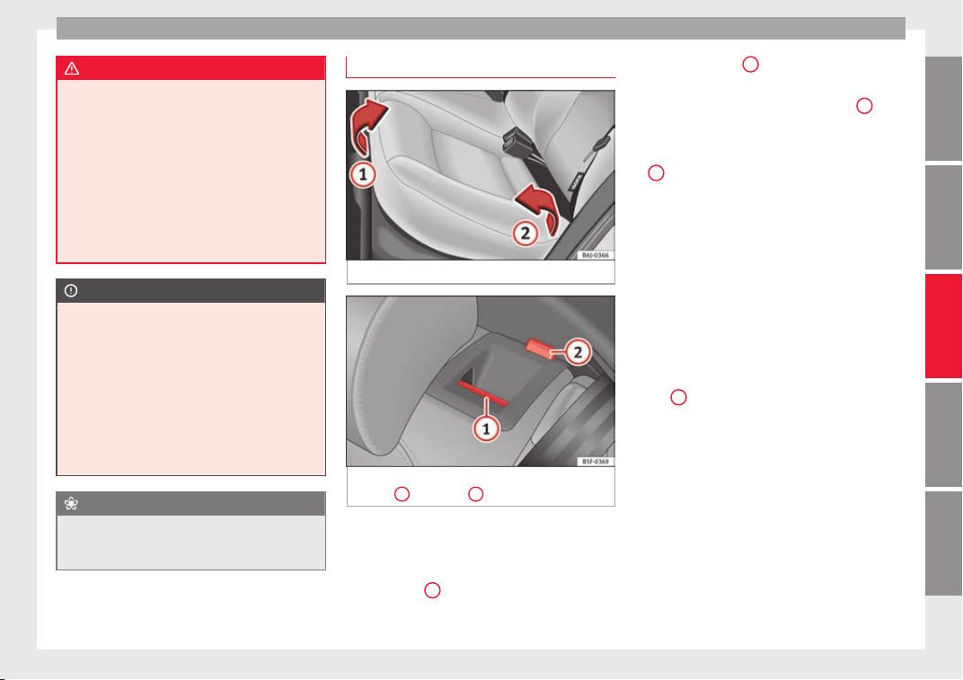
Seats and head restraints
WARNING
If the fabric of the cushion is wet, this can ad-
versely
affect the operation of the seat heat-
ing, increasing the risk of burns.
●
Make sure the seat cushion is dry prior to
using the seat heater.
●
Do not sit on the seat with clothing that is
wet or damp.
●
Do not leave clothing that is wet or damp
on the seat.
●
Do not spill liquid on the seat.
CAUTION
●
To avoid d
amaging the heating elements of
the seat heaters, please do not kneel on the
seat or apply sharp pressure to a single point
on the seat cushion or backrest.
●
Liquids, sharps objects and insulating ma-
terials (e.g. covers or child seats) can damage
the seat heating.
●
In the event of smells, switch off the seat
heating immediately and have it inspected by
a specialised workshop.
For the sake of the environment
The seat heating should remain on only when
needed. Otherwi
se, it is an unnecessary fuel
waste.
Folding down the back seat
Fig. 157 Folding up the rear seat cushion.
Fig. 158 On the rear seat backrest: unlock
b
utt
on
1
; red mark
2
.
Folding seat down
–
Remove the head restraint ›
›
›
page 155.
–
Pull the front edge of the seat cushion
››› Fig. 157
1
upwards in the direction of
the arr
o
w
.
–
Lift the cushion
2
forwards in the direc-
tion of
the arr
o
w.
–
Press the unlock button ››› Fig. 158
1
for-
w
ar
d
s and at the same time fold the back-
rest down. The rear seat backrest is not en-
gaged when the red marking of the button
2
is visible.
–
Insert the head restraints in the spaces on
the r
e
ar of
the seat cushion which are visi-
ble when the seat cushion is lowered.
Folding seat forward
–
Remove the head restraints from the
spaces in the seat cushion.
–
Lift the backrest, and before securing it, re-
place the head restraints in the seat cush-
ion, and then click the seat correctly onto
the locking rails. The red marking on the
tab
2
should no longer be visible when
the b
ac
k
rest is properly secured.
–
Lower the cushion and push it backwards
below the seat belt buckles.
–
Press the front part of the cushion down-
wards.
On split rear seats*, the backrest and cush-
ion can be lowered and raised respectively in
two sections.
»
157
Technical dataAdviceOperationEmergenciesSafety
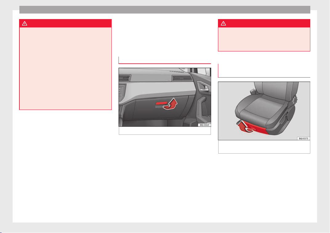
Operation
WARNING
●
Plea
se be careful when folding back the
backrest! Injuries can be caused if the seat
height is adjusted without due care and at-
tention.
●
Do no trap or damage seat belts when rais-
ing the backrest.
●
After raising the backrest, check it has en-
gaged properly in position. Do this by pulling
on the central seat belt or directly on the
backrest and check that the position lever is
in the neutral position.
●
The three point automatic seat belt only
works correctly when the backrest of the cen-
tral seat is correctly engaged.
Transport and practical
equipment
Pr
actic
a
l equipment
Glove compartment
Fig. 159 Passenger side: glove compartment.
The compartment can be opened by pulling
the l
ev
er ›
›› Fig. 159.
This compartment can hold documents in A4
format, a water bottle of 1.5 L, etc.
Depending on the vehicle equipment, the CD
player is located in the glove compartment.
Separate operating instructions are enclosed
for this equipment in the corresponding In-
struction Manual.
WARNING
Always keep the storage compartment cover
closed whi
le the vehicle is in motion in order
to reduce the risk of injury caused by a sud-
den braking or by an accident.
Storage compartment under the front
seats*
Fig. 160 Storage compartment under the
right
fr
ont
passenger seat.
To open
–
The compartment is opened by pulling on
the l
ev
er and guidin
g it with your hand.
To close
–
Press the cover inwards until the closed
drawer “clicks” into position.
158
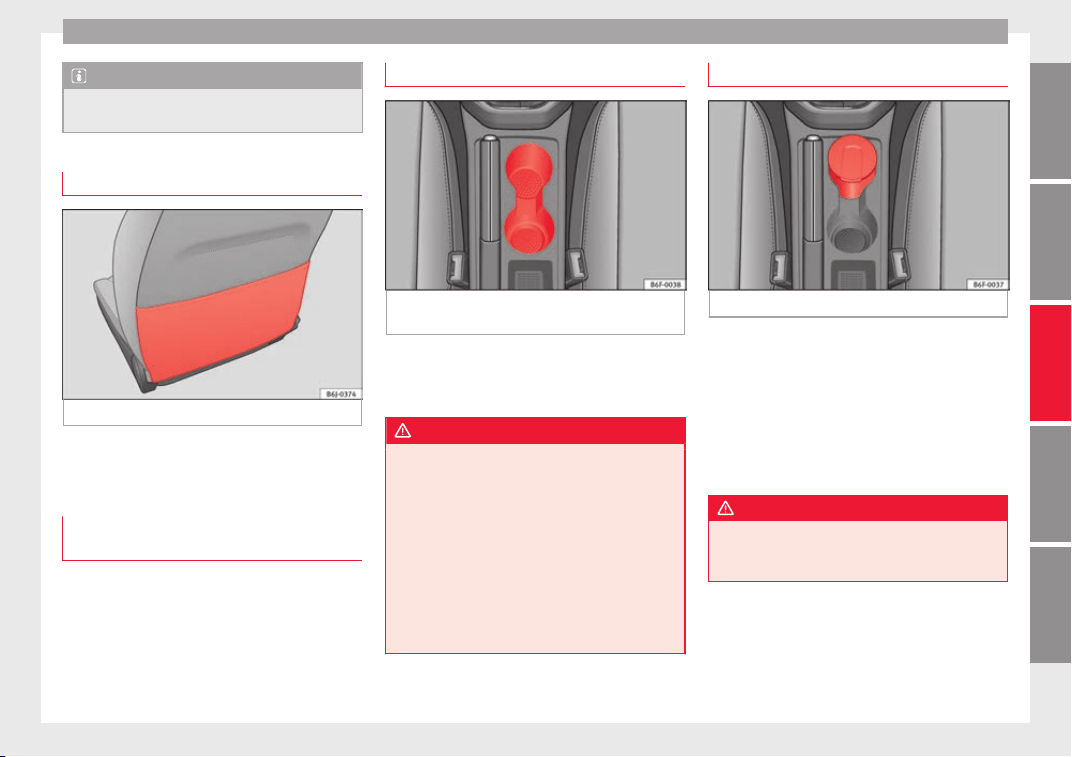
Transport and practical equipment
Note
The storage drawer will hold a maximum
weight of
1.5 kg.
Storage pocket in the seat*
Fig. 161 Storage pocket.
There is a storage pocket on the rear of the
fr
ont
se
ats.
Storage compartment in front door
panel*
In this storage compartment a 1.5l water bot-
tl
e, et
c
. can be stored.
Front drink holder*
Fig. 162 Front drink holders in the centre con-
so
l
e.
In the central console, next to the hand
br
ak
e, ther
e are two drinks holders
››› Fig. 162.
WARNING
●
Do not put
hot drinks in the drink holders.
During sudden or normal driving manoeuvres,
when braking suddenly or in case of an acci-
dent, the hot drink could spill. Risk of scald-
ing.
●
Never use rigid materials (for example,
glass or ceramic), since they could cause in-
jury in the case of an accident.
●
When travelling, the drinks holder should
always be closed to prevent risk in the event
of sudden breaking or accident.
Front ashtray*
Fig. 163 Ashtray in the centre console.
Opening and closing the ashtray
●
To open the ashtray, lift the cover
›
›
›
Fig. 163.
●
To close, push the cover down.
Emptying the ashtray
●
Extract the ashtray and empty it.
WARNING
Never put paper in the ashtray. Hot ash could
ignite the paper in the a
shtray and cause a
fire.
159
Technical dataAdviceOperationEmergenciesSafety
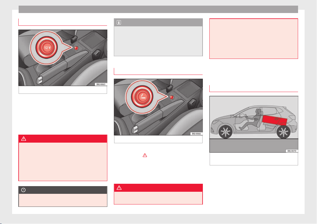
Operation
Electrical power socket
Fig. 164 Front power socket.
The 12 Volt cigarette lighter power socket can
al
so be u
sed f
or other electrical components
with a power rating of up to 120 Watt. When
the engine is switched off, however, the vehi-
cle battery will discharge. For further informa-
tion see ››› page 247.
WARNING
The power sockets and the connected acces-
sories w
ill only operate when the ignition is
on or when the engine is running. Improper
use of the sockets or electrical accessories
can lead to serious injuries or cause a fire. To
avoid the risk of injury, never leave children
alone inside the vehicle.
CAUTION
Always use the correct type of plugs to avoid
damagin
g the sockets.
Note
●
The use of el
ectrical appliances with the
engine switched off will cause a battery dis-
charge.
●
Before using any electrical accessories, see
the instructions in ››› page 247.
Cigarette lighter*
Fig. 165 Lighter.
–
Press on the cigarette lighter
›
›
›
Fig. 165 to
activate it
›››
.
–
Wait for the lighter to spring out.
–
Pull out the cigarette lighter and light the
c
ig
ar
ette on the glowing coil.
WARNING
●
Improper use of
the cigarette lighter can
lead to serious injuries or start a fire.
●
Usin
g the lighter carefully. Carelessness or
negligence when using the cigarette lighter
can cause burns and serious injuries.
●
The lighter only works when the ignition is
turned on or the engine is running. To avoid
the risk of fire, never leave children alone in-
side the vehicle.
Luggage compartment
Loa
ding the luggage compartment
Fig. 166 Position heavy items as far forward
a
s
po
ssible.
All luggage and other loose objects must be
s
af
ely
secured in the luggage compartment.
Unsecured objects which shift back and forth
could affect safety or driving characteristics
of the vehicle by shifting the centre of gravity.
160
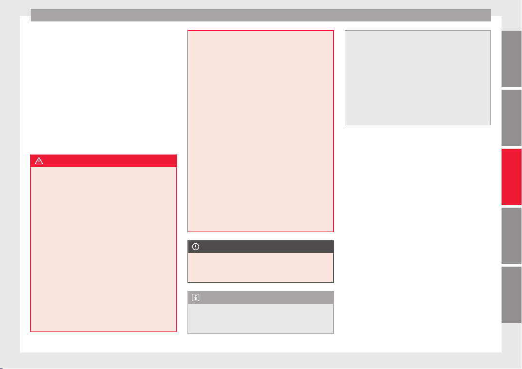
Transport and practical equipment
–
Di
s
trib
ute the load evenly in the luggage
compartment.
–
Place heavy objects as far forward as possi-
ble in the luggage compartment
››› Fig. 166.
–
Place the heavy objects first.
–
Secure heavy objects to the fitted fastening
rings* ››› page 162.
–
Secure loose loads with a luggage net* or
with non-elastic straps secured to the fas-
tening* rings.
WARNING
●
Loose lug
gage and other objects in the lug-
gage compartment could cause serious inju-
ries.
●
Always stow objects in the luggage com-
partment and secure them with the fastening
rings*.
●
During sudden manoeuvres or accidents,
loose objects can be thrown forward, injuring
vehicle occupants or even third parties. This
increased risk of injury will be further in-
creased if a loose object is struck by an inflat-
ing airbag. If this happens, objects may
shoot outward like a missile. Risk of fatal in-
jury.
●
Always keep all objects in the luggage com-
partment and use appropriate grips to secure
them, particularly in the case of heavy ob-
jects.
●
Never ex
ceed the allowed axle weights or
allowed maximum weight. If said weights are
exceeded, the driving characteristics of the
vehicle may change, leading to accidents, in-
juries and damage to the vehicle.
●
Please note that the centre of gravity may
shift when transporting heavy objects; this
may affect vehicle handling and lead to an ac-
cident. Therefore, it is essential to adjust
your speed and driving style accordingly, to
avoid accidents.
●
Never leave your vehicle unattended, espe-
cially when the rear lid is open. Children
could climb into the luggage compartment,
closing the door behind them; they will be
trapped and run the risk of death.
●
Never allow children to play in or around
the vehicle. Close and lock all the doors and
the rear lid when you leave the vehicle. Be-
fore you lock the vehicle, make sure that
there are no adults or children in the vehicle.
●
Please observe the notes on the ››› page 75.
CAUTION
Hard objects on the rear shelf could chafe
agains
t the wires of the heating element in
the heated rear window and cause damage.
Note
●
The tyre pr
essure must be adjusted accord-
ing to the load. When necessary, check the
tyre pressures on the adhesive label stuck to
the back of the front left door frame
›››
page 275.
●
Air circulation in the vehicle helps reduce
fogging of the windows. Used air escapes
through ventilation slits in the side trim of
the luggage compartment. Ensure that the
ventilation slots are never covered.
●
Straps for securing the load to the fasten-
ing rings* are commercially available from ac-
cessory shops.
161
Technical dataAdviceOperationEmergenciesSafety
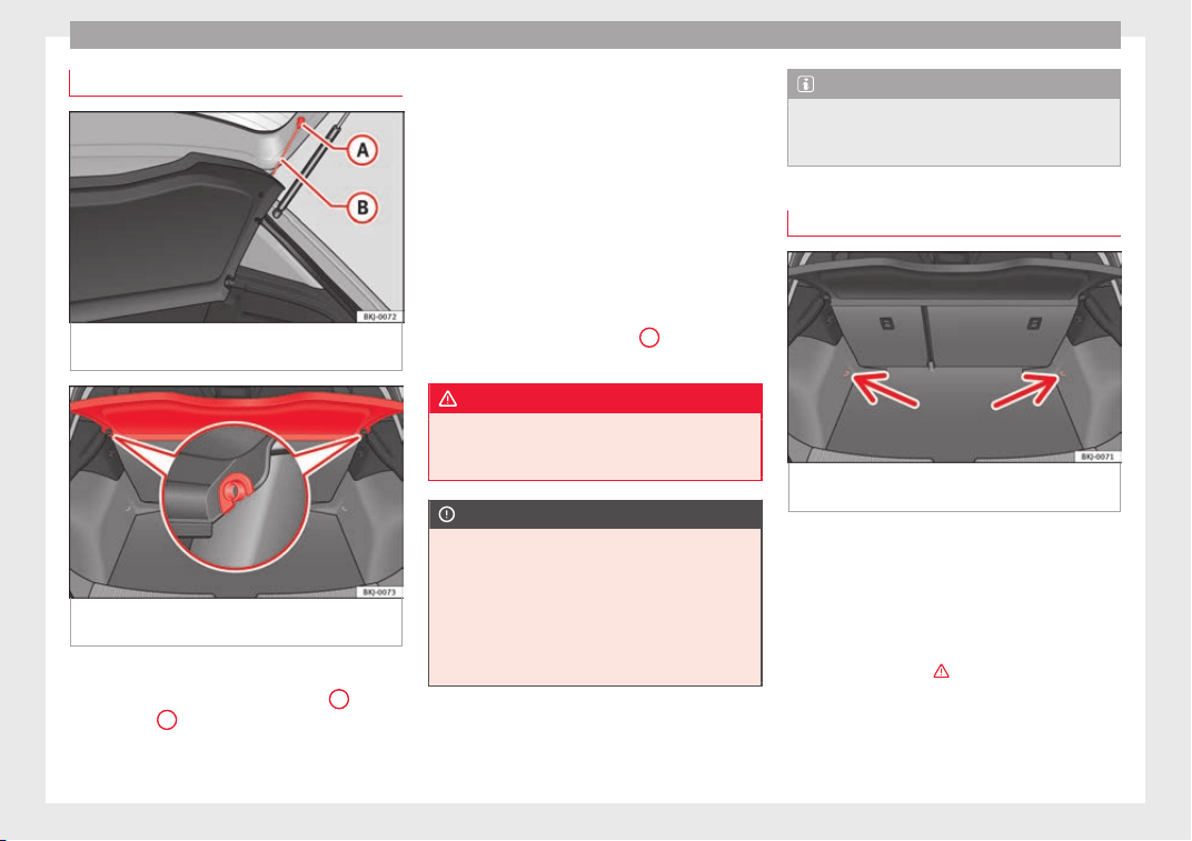
Operation
Rear shelf
Fig. 167 In the luggage compartment: remov-
in
g and in
s
talling the rear shelf.
Fig. 168 In the luggage compartment: remov-
in
g and in
s
talling the rear shelf.
Removing
●
Detach the cord loops ›
›
›
Fig. 167
B
from
their hook
s
A
.
●
R
emo
v
e the rear shelf from the side sup-
ports ››› Fig. 168 by pulling it upwards and
then take it out.
If necessary, the rear shelf can be stored un-
der the luggage compartment double floor
››› page 163.
Fitting
●
Insert the cover horizontally so that the “re-
cess” fits onto the axis of the supports
››› Fig. 168 and press down until it engages.
●
Hook the loops ››› Fig. 167
B
to the rear
lid.
WARNING
Do not place heavy or hard objects on the
rear shelf
, because they will endanger the ve-
hicle occupants in case of sudden braking.
CAUTION
●
Befor
e closing the rear lid, ensure that the
rear shelf is correctly fitted.
●
An overloaded luggage compartment could
mean that the rear shelf is not correctly seat-
ed and it may be bent or damaged.
●
If the luggage compartment is overloaded,
remove the tray.
Note
●
Ensur
e that, when placing items of clothing
on the luggage compartment cover, rear visi-
bility is not reduced.
Fastening rings*
Fig. 169 Location of fastening rings in lug-
g
ag
e c
ompartment.
There may be some fastening rings included
in the lug
g
ag
e compartment for fastening
luggage and other objects
›››
Fig. 169 (ar-
rows).
–
Always use suitable and undamaged straps
to secure luggage and other objects to the
fastening rings
›››
in Loading the lug-
g
ag
e c
ompartment on page 161.
Example: An object weighing 4.5 kg is lying
unsecured in the vehicle. During a frontal col-
lision at a speed of 50 km/h (31 mph), this
162
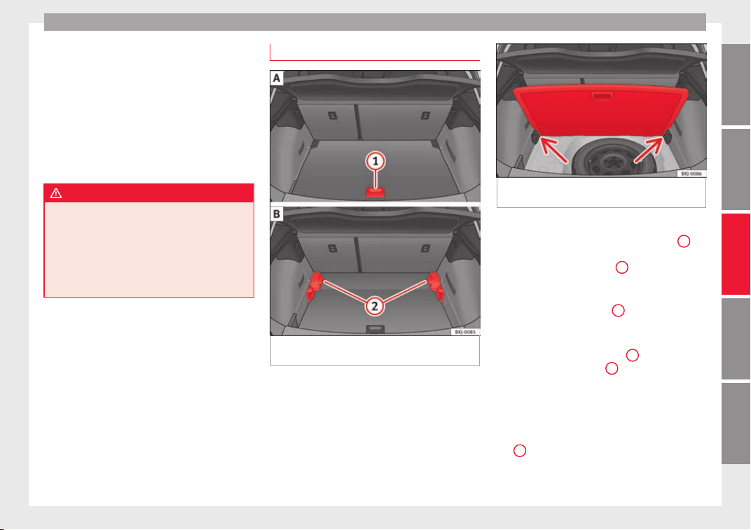
Transport and practical equipment
object generates a force corresponding to 20
time
s
its
weight. That means that the effec-
tive weight of the object increases to approxi-
mately 90 kg. You can imagine the severity of
the injuries which might be sustained if this
“object” strikes an occupant as it flies
through the interior of the vehicle. This in-
creased risk of injury will be further increased
if a loose object is struck by an inflating air-
bag.
WARNING
●
If piece
s of baggage or other objects are se-
cured to the fastening rings with inappropri-
ate or damaged retaining cords, injuries
could result in the event of braking manoeu-
vres or accidents.
●
Never secure a child seat on the fastening
rings.
Luggage compartment variable floor
Fig. 170 Luggage compartment variable
floor: r
ai
sed po
sition; lowered position.
Fig. 171 Luggage compartment variable
floor: sloped pos
ition.
Variable floor in the high position
●
Lift the floor using handle ›
›
›
Fig. 170
1
and pull it back until the front of the floor has
f
u
l
ly passed the supports
2
.
●
Move the floor forward over the supports as
f
ar a
s
the rear seat backrest and then lower
the floor with the handle
1
.
V
ari
ab
le floor in the low position
●
Lift the floor using handle
1
and pull it
b
ac
k
until the supports
2
have fully passed
the fr
ont
p
art of the floor.
●
Now match the front part with the lower
grooves of the supports and slide the floor
forwards as far as the rear seat backrest and
lower the floor at the same time with the han-
dle
1
.
»
163
Technical dataAdviceOperationEmergenciesSafety
Operation
Variable floor in the tilted position
When the
v
ari
able floor is tilted you can ac-
cess the spare wheel/anti-puncture kit area.
●
Lift the variable floor in the high position
using handle
1
, pull it up and push it to-
w
ar
d
s the backrest of the rear seats until the
floor folds along the hinge line and the mov-
able part of the floor is resting on itself.
●
Rest the floor on its housings ››› Fig. 171
(arrows).
WARNING
During a sudden driving or braking manoeu-
vre, or in the event
of an accident, objects
could be flung though the interior and cause
serious or fatal injuries.
●
Always secure objects, even when the lug-
gage compartment floor is properly lifted.
●
Only objects that do not protrude more
than 2/3 the height of the floor may be car-
ried between the rear seat and the raised lug-
gage compartment floor.
●
Only objects that do not weigh than ap-
proximately 7.5 kg may be carried between
the rear seat and the raised luggage compart-
ment floor.
CAUTION
●
The maximum w
eight that can be loaded on
the luggage compartment variable floor in
the top position is 150 kg.
●
Do not let
the luggage compartment floor
fall when closing it. Always carefully guide it
downwards in a controlled manner. Other-
wise, the lining and the floor of the luggage
compartment could be damaged.
Note
SEAT recommends the use of straps to secure
o
bj
ects to retaining rings.
Roof carrier*
Intr
oduction
The vehicle roof has been designed to opti-
mi
se aer
ody
namics. For this reason, cross
bars or conventional roof carrier systems can-
not be secured to the roof water drains.
As the roof water drains are integrated in the
roof to reduce air resistance, only SEAT-ap-
proved cross bars and roof carrier systems
can be used.
Cases in which cross bars and the roof carri-
er system should be disassembled.
●
When they are not used.
●
When the vehicle is washed in a car wash.
●
When the vehicle height exceeds the maxi-
mum height, for ex
ample, in some garages.
WARNING
When heavy or bulky loads are transported
on the roof c
arrier system, car driving per-
formance is affected, as the centre of gravity
shifts and there is greater wind resistance.
●
Always secure the load properly using belts
or retaining straps that are suitable and in a
good condition.
●
Bulky, heavy, long or flat loads have a neg-
ative effect on aerodynamics, the centre of
gravity and driving performance.
●
Avoid sudden braking and manoeuvres.
●
Adapt your speed and driving style at all
times to suit visibility, weather, road and traf-
fic conditions.
CAUTION
●
Remov
e the cross bars and the roof carrier
system before entering a car wash.
●
Vehicle height is increased by the installa-
tion of cross bars or a roof carrier system and
the load secured on them. For this purpose,
check that your vehicle's height does not sur-
pass the headspace limit, for example, for un-
derpasses or for entering garage doors.
●
Cross bars, a roof carrier system and the
load secured on them should not interfere
with the roof aerial or hamper the path of the
panoramic sun roof ››› page 144 and the rear
lid.
●
On opening the rear lid make sure that it
does not knock into the roof load.
164
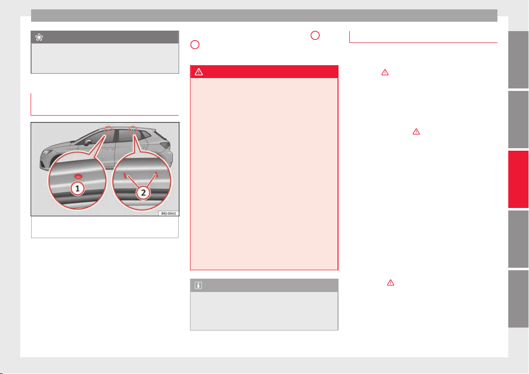
Transport and practical equipment
For the sake of the environment
When cross bars and a roof carrier system are
inst
alled, the increased air resistance means
that the vehicle uses more fuel.
Attach the cross bars and the roof car-
rier syst
em
Fig. 172 Attachment points for the roof rail-
in
g
s
for the roof carrier system.
The crossbars are the basis of a series of spe-
c
i
al
roof carrier systems. For safety reasons,
special fixtures must be used to safely trans-
port luggage, bicycles, skis, surf boards or
boats on the roof. Suitable accessories can
be acquired at SEAT dealerships.
Always secure the crossbars and the roof car-
rier system properly. Always take the assem-
bly instructions that come with the crossbars
and the roof carrier system in question into
account.
The front and rear attachment points
1
and
2
are only visible when the doors are open
›
›
›
Fig. 172.
WARNING
Incorrect attachment and use of the cross-
bars
and the roof carrier system may cause
the whole system to detach from the roof and
cause an accident and injuries.
●
Always take the manufacturer assembly in-
structions into account.
●
Use only crossbars and the roof carrier sys-
tem when they are in perfect condition and
are properly secured.
●
Secure the crossbars and the roof carrier
system properly.
●
Check threaded joints and attachments
travelling and if necessary tighten them after
you have travelled a short distance. When
making long trips, check the threaded joints
whenever you stop for a rest.
●
Always fit the special roof carrier systems
correctly for wheels, skis and surfboards, etc.
●
Do not modify or repair the crossbars or
roof carrier system.
Note
Always read the assembly instructions that
come with the c
rossbars and the roof carrier
system carefully and keep them in the vehi-
cle.
Loading the roof carrier system
The load can only be secured if the crossbars
and the roof c
arrier system are properly in-
stalled ›››
.
Maximum authori
sed roof load
The maximum permissible roof load is 75 kg.
This figure comes from the combined weight
of the roof carrier, the cross bars and the load
itself on the roof ›››
.
Alwa
ys check the weight of the roof carrier
system, the cross bars and the weight of the
load to be transported and weigh them if
necessary. Never exceed the maximum au-
thorised roof load.
If you are using cross bars and a roof carrier
with a lower weight rating, you will not be
able to carry the maximum authorised roof
load. In this case, do not exceed the maxi-
mum weight limit for the roof carrier which is
listed in the fitting instructions.
Distributing a load
Distribute loads uniformly and secure them
correctly
›››
.
»
165
Technical dataAdviceOperationEmergenciesSafety
Operation
Check attachments
Onc
e the c
r
oss bars and roof carrier system
have been installed, check the bolted con-
nections and attachments after a short jour-
ney and subsequently with a certain
frequency.
WARNING
Exceeding the maximum authorised roof load
can re
sult in accidents and considerable vehi-
cle damage.
●
Never exceed the maximum authorised
load on the roof and on the axles or the vehi-
cle's maximum authorised weight.
●
Never exceed the load capacity of the cross
bars and the roof carrier system, even if the
maximum authorised roof load has not been
reached.
●
Secure heavy items as far forward as possi-
ble and distribute the vehicle load uniformly.
WARNING
If the load is loose or not secured, it could fall
from the roof
carrier system or cause acci-
dents and injuries.
●
Always use belts or retaining straps that
are suitable and in a good condition.
●
Secure the load properly.
Air conditioning
He
atin
g,
ventilation and cool-
ing
General notes
Read the additional information carefully
›››
page 51
Pollution filter
The pollution filter (a combined particulate
filter and active carbon filter) serves as a bar-
rier against impurities in the outside air, in-
cluding dust and pollen.
For the climate control system to work with
maximum efficiency, the pollution filter must
be replaced at the specified intervals in the
Maintenance Programme.
If the filter loses efficiency prematurely due
to use in areas reaching very high pollution
levels, the pollen filter must be changed
more frequently than stated in the Service
Schedule.
WARNING
Reduced visibility through the windows in-
cre
ases the risk of serious accidents.
●
Always ensure that all windows are free of
ice and snow, and that they are not fogged,
so as to maintain good visibility of everything
outside.
●
The m
aximum heat output required to de-
frost windows as quickly as possible is only
available when the engine has reached its
normal running temperature. Only drive when
you have good visibility.
●
Always ensure that you use the heating
system, fresh air system, air conditioner and
the heated rear window to maintain good visi-
bility to the outside.
●
Never leave the air recirculation on for a
long period of time. If the cooling system is
switched off and air recirculation mode
switched on, the windows can mist over very
quickly, considerably limiting visibility.
●
Switch air recirculation mode off when it is
not required.
WARNING
Stuffy or used air will increase fatigue and re-
duce driver c
oncentration possibly resulting
in a serious accident.
●
Never leave the fresh air fan turned off or
use the air recirculation for long periods of
time; the air in the vehicle interior will not be
refreshed.
CAUTION
●
If y
ou suspect that the air conditioner is
damaged, switch it off with the
A/C
button to
166
Air conditioning
prevent further damage and have it checked
by a s
pecialised workshop.
●
Repairs to the air conditioner require spe-
cialist knowledge and special tools. There-
fore, we recommend you to take the vehicle
to a specialised workshop.
Note
●
If
the humidity and t
emperature outside the
vehicle are high, condensation can drip off
the evaporator in the cooling system and
form a pool underneath the vehicle. This is
normal and does not indicate a leak.
●
Keep the air intake slots in front of the
windscreen free of snow, ice and leaves to en-
sure heating and cooling are not impaired,
and to prevent the windows from misting
over.
●
The air from the vents flows through the ve-
hicle interior and is extracted by slots in the
luggage compartment designed for this pur-
pose. Therefore, you should avoid obstruct-
ing these s
lots with any kind of object.
●
The air conditioner operates most effective-
ly with the windows and the sliding/tilting
sunroof* closed. However, if the temperature
inside the vehicle is excessive because of the
sun, the air inside can be cooled faster by
opening the windows for a short time.
●
Do not smoke while air recirculation mode
is on, as smoke drawn into the air condition-
ing system leaves residue on the evaporator,
producing a permanent unpleasant odour.
●
At low outside temperatures, the compres-
sor switches off automatically and cannot be
switched on even with the
AUTO
button.
●
It is advisable to turn on the air condition-
ing at l
east once a month, to lubricate the
system gaskets and prevent leaks. If a de-
crease in the cooling capacity is detected, a
Technical Service should be consulted to
check the system.
●
To ens
ure correct operation, the grilles on
both sides of the screen must not be obstruc-
ted.
●
When the engine is under extreme strain,
switch off the compressor for a moment.
Economic use of the air conditioning
When the air conditioning is switched on, the
compre
ssor consumes engine power and has
influence on fuel consumption. Consider the
following points in order to have the system
operating in the minimum possible time.
●
If the vehicle interior has overheated due to
an exc
essive solar radiation, it is best to
open the windows or doors to allow the hot
air to escape.
●
While in motion, the air conditioning
should not be switched on if the windows or
the sunroof* are open.
167
Technical dataAdviceOperationEmergenciesSafety
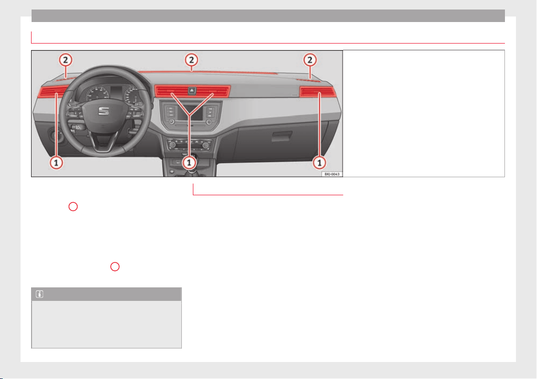
Operation
Air outlets
Fig. 173 Air vents.
To ensure proper heating, cooling and venti-
l
ation in the
v
ehicle interior, air vents
››› Fig. 173
1
should remain open.
●
The outlets can be closed or opened sepa-
r
at
ely
using the slats and the air flow direc-
ted according to need.
There are other additional, non-adjustable air
vents in the dash panel
2
, in the footwell
and in the r
e
ar ar
ea of the interior.
Note
Food, medicine and other heat or cold sensi-
tive ob
jects should never be placed in front of
the air outlets as they may be damaged or
made unsuitable for use by the air coming
from the air vents.
Air recirculation
Air recirculation prevents unpleasant smells,
e.g. when pa
ssing through a tunnel or in
queuing traffic, from entering the interior.
If the air distribution is in the thaw position,
the recirculation flap will always be open (in-
dicator light off).
If the air distribution is switched from any po-
sition to the thaw position, recirculation will
be automatically deactivated.
Connecting the recirculation
In any air distribution position except thaw:
●
Pres
s the button, the button’s lamp will
light up, indicating that air recirculation in-
side the vehicle has been activated.
Disconnecting the recirculation
In any air distribution position except thaw:
●
Press the button again and the button's
lamp will go off, indicating that air entry from
the outside has been activated.
In the thaw position the entry of air into
the vehicle interior is always from the out-
side.
168
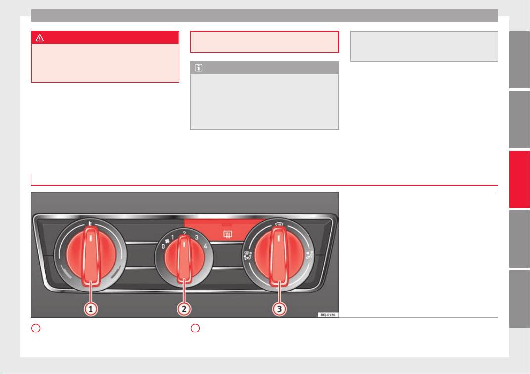
Air conditioning
WARNING
In air recirculation mode, no cold air from the
outside ent
ers the vehicle interior. If the air
conditioner is switched off, the windows can
quickly mist over. Therefore, never leave the
air recirculation mode switched on for a long
time (risk of
accident).
Note
●
A
ctivatin
g air recirculation automatically
activates the button (to prevent the win-
dows from misting up). If the temperature
regulator is turned to the coldest setting
(blue point), the air recirculation function and
the button are automatically activated.
●
If the fu
nction is not deactivated by press-
ing the button, it will deactivate after approx-
imately 20 minutes.
Heating and fresh air
Contro
ls
Fig. 174 Heating controls on the dash panel.
Temperature regulator ›
›
›
page 170.
1
Blower control. There are four speed set-
tin
g
s
for the blower. The blower should
2
always be set at the lowest speed when
driv
in
g s
lowly.
»
169
Technical dataAdviceOperationEmergenciesSafety
Operation
Air distribution regulator.
He
at
ed r
ear window.
Air distribution
Control
3
for setting the flow of air in the re-
quir
ed dir
ection.
– Air distribution towards the windscreen
in order to demist.
– Air distribution to upper body.
– Air distribution to footwell
– Air distribution to the windscreen and
the footwell.
WARNING
●
For y
our safety, the windows should never
be fogged up or covered with snow or ice.
This is essential to ensure good visibility.
Please familiarise yourself with the correct
operation of the heating and ventilation sys-
tem, including the demist/defrost functions
for the windows.
Note
●
Plea
se consider the general notes
››› page 166.
3
Functions
Ventilating the vehicle interior
The desir
ed temperature inside the vehicle
cannot be lower than the ambient tempera-
ture.
●
Turn the temperature selector
››› Fig. 174
1
anti-clockwise.
●
Turn blower switch
2
to any of the levels
1-4.
●
Set the airflow to the desired direction us-
ing air dis
tribution control
3
.
●
Open the relevant air outlets.
Int
erior he
atin
g
Maximum heat output, which is needed to
defrost the windows quickly, is only available
when the engine has reached its operating
temperature.
●
Turn the temperature selector
›››
Fig. 174
1
clockwise to select the re-
quir
ed t
emper
ature.
●
Turn blower switch
2
to any of the levels
1-4.
●
Set the airflow to the desired direction us-
in
g air di
s
tribution control
3
.
●
Open the relevant air outlets.
Defrosting the windscreen
●
Turn the temperature regulator
›
›
›
Fig. 174
1
clockwise to reach the maxi-
mum t
emper
at
ure.
●
Turn the blower switch
2
to level 4.
●
Turn air distribution control to .
●
Close the central outlets.
●
Open and turn the side outlets towards the
w
indo
w
s.
Keeping the windscreen and the side win-
dows demisted
●
Turn the temperature regulator
››› Fig. 174
1
to the heating zone.
●
Turn blower switch
2
to any of the levels
2-3.
●
Turn air distribution control to .
●
Close the central outlets.
●
Open and turn the side outlets towards the
w
indo
w
s.
Once the windows are demisted and as a pre-
ventive measure, the control
3
can be set in
po
s
ition
greater comfort while preventing
the windows from misting again.
Note
Remember that the temperature of the engine
cool
ant should be optimum to ensure that the
heating system functions correctly (except in
vehicles fitted with additional heating*).
170
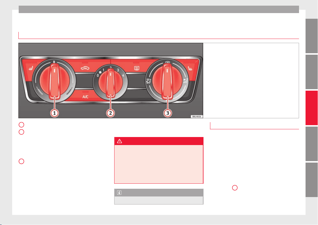
Air conditioning
Manual air conditioning*
C
ontr
o
ls
Fig. 175 Air conditioning controls on the dash
panel.
Temperature selector ›
›
›
page 171
Blower control. There are four speed set-
tings for the blower. At low speed, it is
recommended to set the blower to a mini-
mum of 1 to improve the intake of fresh
air.
Air distribution regulator.
Air recirculation button ››› page 168.
When the function is activated, a warning
light on the button is turned on.
Heated rear window.
Button to switch on air conditioning
››› page 171. The air conditioning system
1
2
3
only works when the engine is running
and the f
an i
s
switched on.
WARNING
For your safety, the windows should never be
fogg
ed up or covered with snow or ice. This is
essential to ensure good visibility. Please fa-
miliarise yourself with the correct operation
of the heating and ventilation system, includ-
ing the demist/defrost functions for the win-
dows.
Note
Please consider the general notes.
Functions
Interior heating
Maximum he
at output, which is needed to
defrost the windows quickly, is only available
when the engine has reached its operating
temperature.
●
Turn off the cooling system using the
button ››› Fig. 175 (the button light turns off).
●
Turn the temperature regulator
››› Fig. 175
1
to set the desired temperature
inside the
vehicle.
●
Turn the blower switch to any of the set-
tings
1-4.
»
171
Technical dataAdviceOperationEmergenciesSafety

Operation
●
Set
the air di
s
tribution regulator
››› Fig. 175
3
to the air flow configuration
de
s
ir
ed: (towards the windscreen), (to-
wards the chest), (towards the footwell)
and (towards the windscreen and foot-
well).
Interior cooling
When the air conditioning is switched on, the
temperature and the air humidity go down.
This way, if the outside humidity is extreme,
the air conditioning prevents the misting of
the windows and therefore, comfort is im-
proved.
●
Turn on the cooling system using the
button (the button light turns on).
●
Turn the temperature control switch until
the desired interior temperature is reached.
●
Turn the blower switch to any of the set-
tings 1-4.
●
Set the air distribution control to the air
flow configuration desired: (towards the
windscreen), (towards the chest), (to-
wards the footwell) and (towards the wind-
screen and footwell).
Demisting the windscreen
●
Turn air distribution to .
●
Turn the fan control to one of the two levels
depending on the speed required.
●
Rotate the temperature control to the de-
sired level of comfort.
●
Close the central outlets.
●
Open and turn the side outlets towards the
windows.
If the air conditioning does not work, this
may be due to the following reasons:
●
The engine is stationary.
●
The fan blower is switched off.
●
The outside temperature is lower than +3°C
(+37°F).
●
The air conditioning system compressor
has been temporarily switched off because of
an increased engine coolant temperature.
●
The air conditioner fuse is faulty.
●
Another fault in the vehicle. Have the air
conditioning checked by a specialised work-
shop.
172
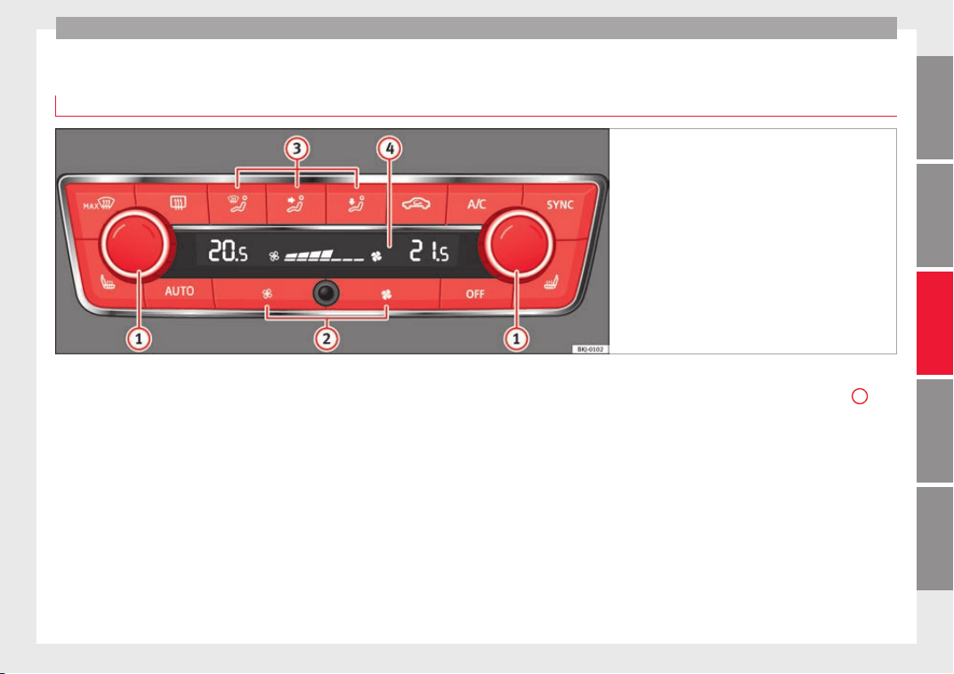
Air conditioning
Climatronic*
Gener
a
l
notes
Fig. 176 Climatronic: controls.
Read the additional information carefully
›
›
›
page 52
Climatronic automatically maintains a com-
fortable temperature. To do so, it automati-
cally regulates the supplied air temperature
and the blower and air distribution levels.
The system also allows for the effect of sun-
light, so there is no need for manual adjust-
ment.
Automatic operation guarantees maximum
comfort any time of year ››› page 174.
Climatronic description
Cooling only works if the following conditions
are met:
●
The engine is running
●
the outside temperature is above +2°C
(+36°F);
●
turned on.
Starting the Climatronic
When a button is pressed, the corresponding
function will be activated (except for the recir-
culation button), switching on the air condi-
tioning if it was switched off.
Switching off the Climatronic
●
Adjust fan power to zero ››› Fig. 176
2
or
pr
e
s
s the button.
In order to ensure engines subject to heavy
loads are cooled, the air conditioning com-
pressor is switched off in the event of high
coolant temperatures.
Recommended setting for all seasons of the
year
●
Set the required temperature. We recom-
mend +22°C (+72°F).
●
Press the button ››› Fig. 176.
»
173
Technical dataAdviceOperationEmergenciesSafety
Operation
●
Adju
s
t
the vents so that the air flow is di-
rected slightly upwards.
Change between degrees Centigrade and de-
grees Fahrenheit
The units of degrees can be changed via the
Easy Connect system using the
button
and the f
u
nction b
utton SETTINGS >
Units > Temperature.
Automatic mode
Automatic mode is used to maintain a con-
stant temperature and demist the windows
inside the vehicle.
●
Set a interior temperature between +16°C
(+64°F) and +29°C (+84°F).
●
Adjust the vents so that the air flow is di-
rected slightly upwards.
●
Press the button, AUTO is displayed on
the screen.
Automatic mode is switched off by pressing
the air distribution buttons or increasing or
decreasing the blower speed. However, the
temperature remains regulated.
Adjusting the temperature
●
When you switch on the ignition, control
1
››› Fig. 176 can be used t
o set the required in-
terior temperature.
It is possible to select interior temperatures
from +16°C (+64°F) t
o +29°C (+84°F). In this
range the temperature is regulated automati-
cally. If a temperature below +16°C (+64°F) is
selected, “LO” is displayed on the screen. If a
temperature above +29°C (+84°F) is selected,
“HI” is displayed on the screen. At both ex-
tremes, Climatronic works at maximum cool-
ing or heating power, respectively. The tem-
perature is not regulated.
In the event of prolonged, irregular distribu-
tion of the air flow from the outlets (particu-
larly the footwells) and significant differen-
ces in temperature, e.g. on leaving the vehi-
cle, sensitive people may catch cold.
Fan regulation
Climatronic automatically regulates blower
speed according to the interior temperature.
It is possible, however, to set the blower
speed to suit requirements.
●
Press the
2
buttons to increase or reduce
f
an s
peed.
C
limatronic will switch off when the blower
switches off.
Turn on windscreen defrost
●
Press the button
›››
Fig. 176.
Switching off windscreen defrosting
●
Press the button several times or
press the button.
The temperature is regulated automatically.
The air output from the vents ››› Fig. 173
2
is increased.
WARNING
Read and observe the safety warnings ›››
in
General
notes on page 166.
Note
●
A vi
sit to the specialised service once a
year is recommended to clean the Climatronic
system.
●
The interior temperature sensor is at the
bottom. Do not cover it with stickers or the
like, as this could have a negative effect on
Climatronic operations.
174
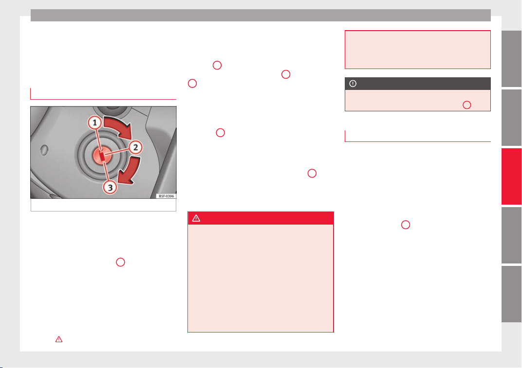
Driving
Driving
St
ar
tin
g and stopping the en-
gine
Ignition key positions
Fig. 177 Ignition key positions.
Read the additional information carefully
›
›
›
page 31
Ignition switched off, steering lock
In this position ››› Fig. 177
1
the ignition
and the en
gine ar
e off
and the steering may
be locked.
For the Steering lock to operate without the
ignition key, turn the steering wheel until it
locks with an audible sound. You should al-
ways lock the steering wheel when you leave
your vehicle. This will help prevent vehicle
theft ›››
.
Switching the ignition or the glow plug sys-
t
em on
T
urn the ignition k
ey to this position and re-
lease it
2
. If the key cannot be turned or it is
diffic
u
lt
to turn from position
1
to position
2
, move the steering wheel from one side to
the other; thi
s
w
ill release it.
Starting
The engine is started when the key is in this
position
3
. Electrical devices with high pow-
er c
on
s
umption are switched off temporarily
at the same time.
Each time that the vehicle is restarted, the ig-
nition key must be turned to position
1
. The
r
epetitiv
e s
tart prevention lock of the igni-
tion prevents possible damage to the starter
motor if the engine is already running.
WARNING
●
The ignition key mu
st NOT be removed from
the lock until the vehicle comes to a stand-
still. Otherwise, the steering could be imme-
diately blocked- Risk of accident!
●
Always remove the key from the ignition
when leaving the vehicle, even if only for a
short period. This is especially important if
children or disabled people are left alone in
the vehicle. They could accidentally start the
engine or work electrical equipment such as
the electric windows, resulting in an acci-
dent.
●
Unsuper
vised use of the key could start the
engine or any electrical system, such as the
electric windows. This could result in serious
injury.
CAUTION
The starter motor will only work when the en-
gine i
s s
topped (ignition key position
3
).
Starting petrol engines
The engine can only be started using a genu-
ine
S
EA
T key with its correct code.
–
Move the gearbox lever to the neutral posi-
tion and depress the clutch pedal thor-
oughly and hold it in this position for the
starter to turn the engine on.
–
Turn the ignition key to the starting posi-
tion ››› Fig. 177
3
.
–
Let go of the ignition key as soon as the en-
gine s
t
ar
ts; the starter motor must not run
on with the engine.
After starting a very hot engine, you may
need to slightly press down the accelerator.
When starting a cold engine, it may be a little
noisy for the first few seconds until oil pres-
sure has built up in the hydraulic valve com-
pensators. This is quite normal, and no cause
for concern.
»
175
Technical dataAdviceOperationEmergenciesSafety
Operation
If the engine does not start immediately,
sw
it
c
h the starter off after 10 seconds and try
again after half a minute. If the engine still
does not start, the fuel pump fuse should be
checked ››› page 104, Fuses.
WARNING
●
Never st
art or run the engine in unventila-
ted or closed rooms. The exhaust gases con-
tain carbon monoxide, an odourless and col-
ourless poisonous gas. Risk of fatal acci-
dents. Carbon monoxide can cause loss of
consciousness and result in death.
●
Never leave the vehicle unattended if the
engine is running.
●
Never use “cold start sprays”, they could
explode or cause the engine to run at high
revs. Risk of injury.
CAUTION
●
When the engine is
cold, you should avoid
high engine speeds, driving at full throttle
and over-loading the engine. Risk of engine
damage.
●
The vehicle should not be pushed or towed
more than 50 metres to start the engine. Un-
burnt fuel could enter the catalytic converter
and damage it.
●
Before attempting to push-start or tow a ve-
hicle in order to start it, you should first try to
start it using the battery of another vehicle.
Please observe and follow the notes on the
›››
page 71, How to jump start.
For the sake of the environment
Do not warm-up the engine by running the
engine with the
vehicle stationary. Start off
immediately, driving gently. This helps the
engine reach operating temperature faster
and reduces emissions.
Starting diesel engines
The engine can only be started using a genu-
ine SEA
T key with its correct code.
–
Move the gearbox lever to the neutral posi-
tion and depres
s the clutch pedal thor-
oughly and hold it in this position for the
starter to turn the engine on.
–
Turn the ignition key to position
›››
Fig. 177
2
. The warning lamp w
i
l
l light for en-
gine pre-heating.
–
When the lamp turns off, turn the ignition
key to position
3
to start the engine. Do
not
pr
e
ss the accelerator.
–
Release the ignition key as soon as the en-
gine starts. The starter motor should not
turn at the same time.
When starting a cold engine, it may be a little
noisy for the first few seconds until oil pres-
sure has built up in the hydraulic valve com-
pensators. This is quite normal, and no cause
for concern.
If there are problems starting the engine, see
the ›››
page 71.
Glow plug system for diesel engines
To avoid unnecessary discharging of the bat-
tery, do not use any other major electrical
equipment while the glow plugs are pre-heat-
ing.
Start the engine as soon as the glow plug
warning lamp goes out.
Starting a diesel engine after the fuel tank
has run dry
If the fuel tank has been completely run dry,
it may take longer than normal (up to one mi-
nute) to start a diesel engine after refuelling.
This is because the fuel system must elimi-
nate air first.
WARNING
Observe the safety warnings ›››
in Starting
petrol
engines on page 176.
CAUTION
●
When the engine is
cold, you should avoid
high engine speeds, driving at full throttle
and over-loading the engine. Risk of engine
damage.
●
The vehicle should not be pushed or towed
more than 50 metres to start the engine. Un-
burnt fuel could enter the particulate filter
and damage it.
176
Driving
●
Befor
e attempting to push-start or tow a ve-
hicle in order to start it, you should first try to
start it using the battery of another vehicle.
Please observe and follow the notes on the
›››
page 71, How to jump start.
For the sake of the environment
Do not warm-up the engine by running the
en
gine with the
vehicle stationary. You
should drive off as soon as you start the en-
gine. This helps the engine reach operating
temperature faster and reduces emissions.
“SAFE” electronic immobiliser
1)
The electronic immobiliser prevents unau-
thori
sed per
son
s from driving the vehicle.
Inside the key there is a chip that deactivates
the electronic immobiliser automatically
when the key is inserted into the ignition.
The electronic immobiliser will be activated
again automatically as soon as you pull the
key out of the ignition lock.
The engine can only be started using a genu-
ine SEAT key with its correct code.
If the following message* is shown on the in-
strument panel display: SAFE, the vehicle
cannot be started.
The engine can, however, be started if the
appropriate coded SEAT genuine key is used.
Note
A perfect operation of the vehicle is ensured
if genuine
SEAT keys are used.
Switching off the engine
–
Stop the vehicle.
–
Turn the ignition key to position
›
›
›
Fig. 177
1
.
Af
t
er sw
itching the engine off, the radiator
fan may run on for up to 10 minutes. It is also
possible that the fan turns itself on once
more if the coolant temperature increases
due to the heat accumulated in the engine
compartment or due to its prolonged expo-
sure to solar radiation.
WARNING
●
Never swit
ch the engine off until the vehi-
cle is completely stationary.
●
The brake servo works only when the en-
gine is running. With the engine switched off,
more strength is needed to brake. As normal
brake operation cannot be performed, risk of
accidents and serious injury may exist.
●
The steerin
g lock can be immediately
blocked once the key is removed from the ig-
nition. The vehicle cannot be steered. Risk of
accident.
●
Power-assisted steering does not work
when the engine is off, and more strength is
needed to turn the wheel.
●
If the key is removed from the ignition lock
the steering lock could be engaged and vehi-
cle steering would not work.
CAUTION
●
When the en
gine ha
s been running under a
heavy load for a long period, heat can accu-
mulate in the engine compartment and cause
engine damage. For this reason, idle the en-
gine for approximately 2 minutes before
switching it off.
●
If the vehicle is stopped and the Start-Stop
system* switches off the engine, the ignition
remains switched on. Make sure that the igni-
tion is switched off before leaving the vehi-
cle, otherwise the battery could discharge.
1)
Available depending on the market
177
Technical dataAdviceOperationEmergenciesSafety
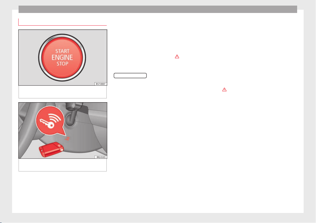
Operation
Starter button*
Fig. 178 In the lower part of the centre con-
so
l
e: s
tarter button.
Fig. 179 On the right of the steering column:
emer
g
ency
start.
The vehicle engine can be started with a
s
t
ar
ter button (Press & Drive). To do so, there
must be a valid key inside the vehicle in the
area of the front or rear seats.
Opening the driver's door when exiting the
vehicle activates the electronic lock on the
steering column if the ignition is disabled.
Switching the ignition on/off manually
Briefly push the starter button without touch-
ing the brake or clutch pedal ›››
.
F
or
v
ehicles with both manual and automatic
transmission, the starter button text
START ENGINE STOP
flashes like a heartbeat
when the sy
s
t
em is preset for switching the
ignition on and off.
Automatic ignition switch-off
If the driver leaves the vehicle, taking the ve-
hicle key with them but leaving the ignition
on, the ignition is not switched off automati-
cally. The ignition is switched off automati-
cally by pressing the lock button on the re-
mote control or manually by pressing the
sensor surface on the door lever ››› Fig. 144
Emergency starting function
If no valid key is detected inside the vehicle,
an emergency start-up will be required. The
relevant message will appear in the dash
panel display. This may happen when, for ex-
ample, the battery of the vehicle key button
is very low or flat:
●
Immediately after pushing the starter but-
ton, keep the
vehicle key next to the right
trim of the steering column ›››
Fig. 179, as
close as possible to the Kessy logo.
●
The ignition connects and the engine starts
automatically.
Emergency disconnection
If the engine does not switch off after briefly
pressing the starter button, an emergency
disconnect will be required:
●
Press the starter button twice within 3 sec-
onds or press it once for more than 1 sec-
ond ›››
.
●
The engine turns off automatically.
En
gine r
e
start feature
If no valid key is detected inside the vehicle
after the engine stops, you will only have 5
seconds to restart it. A warning will display
on the dash panel screen.
After this interval, it will not be possible to
start the engine without a valid key inside
the vehicle.
Automatic deactivation of the ignition on ve-
hicles with the Start-Stop system
The ignition is switched off automatically
when the vehicle is stopped and the auto-
matic engine shutdown is active, if:
●
The driver's seat belt is not fastened,
●
the driver does not step on any pedal,
178
Driving
●
the driv
er door i
s
opened.
After automatically turning off the ignition, if
the dipped beam is on, the side light re-
mains on for approx. 30 minutes (if the bat-
tery is sufficiently charged). If the driver locks
the vehicle or manually turns off the light, the
side light goes out.
WARNING
Any accidental movement of the vehicle could
res
ult in serious injury.
●
When switching on the ignition, do not
press the brake or clutch pedal, otherwise
the engine could start immediately.
WARNING
If vehicle keys are used negligently or with-
out due car
e, this may cause accidents and
serious injury.
●
Never leave any key inside the vehicle
when exiting. Otherwise, a child or unauthor-
ised person could lock the vehicle, start the
engine or connect the ignition and, in this
way, operate electronic equipment (e.g. the
windows).
Note
●
Befor
e leaving the vehicle, always discon-
nect the ignition manually and, if appropri-
ate, take into account the instructions on the
screen of the dash panel.
●
If the v
ehicle is stationary for a long time
with the ignition on, the vehicle battery
might be discharged and it might not be pos-
sible to start the engine.
●
In diesel vehicles, there may be a delay in
the engine starting if it requires preheating.
●
If during the STOP phase you press the
START ENGINE STOP
button, the ignition is
switc
hed off and the button flashes.
●
If the indication “Start-Stop system deacti-
vated: Start the engine manually” is dis-
played on the dash panel display, the
START ENGINE STOP
button will blink.
Starting the engine
3 Valid for vehicles: with starter button
Step
Starting the engine with the starter
button ››› page 178.
1.
Press and hold the brake pedal until step 5
is performed.
1a.
In vehicles with a manual gearbox: press
and hold the clutch down until the engine
starts.
2.
Put the gearbox lever in neutral or the selec-
tor lever in position P or N.
Step
Starting the engine with the starter
button ››› page 178.
3.
Briefly press the starter button ››› Fig. 178
without pressing the accelerator. For the en-
gine to start there must be a valid key in the
vehicle.
After starting the engine, the light of the
START ENGINE STOP
button changes to a fixed
light indicating that the engine has started.
4.
If the engine does not start, stop and wait for
approx. 1 minute before trying again. If nec-
essary, perform an emergency start
››› page 178.
5.
Disconnect the hand brake when you are
about to start driving ››› page 182.
WARNING
Never leave the vehicle with the engine run-
ning, es
pecially if a gear or gear range is en-
gaged. The vehicle could then suddenly move
or something strange could happen that
would cause damage, fire or serious injury.
WARNING
Cold start sprays could explode or cause a
sudden inc
rease in the engine speed.
●
Never use sprays to cold start the engine.
CAUTION
●
The star
ter motor or the engine may be
damaged if you try to start the engine while
»
179
Technical dataAdviceOperationEmergenciesSafety
Operation
driving or if you restart it immediately after
switc
hing it off.
●
If the engine is cold, avoid high engine
speeds, pushing the engine too hard and rap-
id acceleration.
●
Do not start the engine by pushing the ve-
hicle or towing it. Unburnt fuel could enter
the catalytic converter and damage it.
Note
●
Do not
wait
until the engine warms up with
the vehicle stationary; if you have good visi-
bility through the windows, start driving im-
mediately. This helps the engine reach oper-
ating temperature faster and reduces emis-
sions.
●
Electrical components with a high power
consumption are switched off temporarily
when the engine starts.
●
When starting with a cold engine, noise
levels may briefly increase. This is quite nor-
mal, and no cause for concern.
●
When the outside temperature is below
+5°C (+41°F), if the engine is diesel, some
smoke may appear under the vehicle when
the fuel-operated auxiliary heater is on.
Stopping the engine
3 Valid for vehicles: with starter button
Step
Switch off the engine with the starter
button ››› page 178.
1. Stop the vehicle completely ››› .
2.
Press and hold the brake pedal until the step
4 is performed.
3.
If you are driving an automatic vehicle, place
the selector lever in position P.
4. Apply the handbrake ››› page 182.
5.
Briefly press the start-up button ››› Fig. 178.
The
START ENGINE STOP
button blinks again. If
the engine fails to switch off, perform an
emergency disconnect ››› page 178.
6.
If the vehicle is equipped with a manual
gearbox, put it into 1st or reverse.
WARNING
Never switch off the engine while the vehicle
is mo
ving. This could cause loss of control of
the vehicle, accidents and serious injury.
●
The airbags and belt tensioners do not
work when the ignition is switched off.
●
The brake servo does not work with the en-
gine off. Therefore, you need to press the
break pedal harder to brake the vehicle.
●
Power steering does not work when the en-
gine is not running. You need more strength
to steer when the engine is switched off.
●
If the ignition is
switched off, the steering
column could be locked, making it impossible
to control the vehicle.
CAUTION
If the engine is made to work hard for a long
time, it
ma
y overheat after being switched
off. To prevent damage to the engine before
switching it off, leave it idle for approx. 2 mi-
nutes in neutral.
Note
After switching off the engine, the cooling fan
may
continue to operate in the engine com-
partment for a few more minutes, even with
the ignition off. The radiator fan is automati-
cally switched off.
“My Beat” Function
For vehicles with a convenience key there is
the “M
y
B
eat” function. This feature provides
an additional indication of the vehicle igni-
tion system.
When accessing the vehicle, e.g. by opening
the doors with the remote control, the
START ENGINE STOP
button flashes, calling at-
t
ention t
o the r
elevant starter system button.
Upon switching the ignition on/off, the light
of the
START ENGINE STOP
button flashes. With
the en
gine sw
it
ched off, after a few seconds,
180
Driving
the
S
T
OP ENGINE
START
button stops flashing
and g
oe
s
out.
With the engine running, the
START ENGINE STOP
button light stays on, indi-
c
atin
g th
at the engine is running. The time
that lapses between the moment the user
starts the engine with the
START ENGINE STOP
button and the lighting changes from flash-
in
g t
o fi
xed will depend on specific engine
size characteristics. Upon switching the igni-
tion off with the
START ENGINE STOP
button, it
s
t
ar
ts flashing again.
In vehicles with the Start-Stop system, the
“My Beat” function also offers additional in-
formation:
●
When the engine stops during the Stop
phase, the light of the
START ENGINE STOP
but-
t
on s
t
ays on, since, even though the engine
is off, the Start-Stop system is active.
●
When the engine cannot be stated again
with the Start-Stop system, ››› page 204, and
needs to be started manually, the
START ENGINE STOP
button flashes to indicate
thi
s
f
act.
Braking and parking
Braking capacity and braking distance
The efficiency of the brakes depends directly
on the br
ak
e p
ad wear. This wear depends to
a great extent on the conditions under which
the vehicle is operated and the way the vehi-
cle is driven. If you often drive in town, drive
short distances or have a sporty driving style,
we recommend that you have the thickness
of your brake pads checked by technical serv-
ices more frequently than recommended in
the Maintenance Programme.
If you drive with wet brakes, for example, af-
ter crossing areas of water, on days of heavy
rainfall or even after washing the car, the ef-
fect of the brakes is reduced as the brake
discs are wet or even frozen (in winter): in
this case, the brakes should be “dried” by
pressing the brake pedal several times.
WARNING
Longer braking distances and faults in the
brake sy
stem increase the risk of accidents.
●
New brake pads must be run in and do not
have the correct friction during the first
200 km (124 miles). This reduced braking ca-
pacity may be compensated for by pressing
on the brake pedal a little harder, which also
applies when the brake pads have to be
changed further on.
●
If brakes are wet or frozen, or if you are
driving on roads which have been salted,
braking power may be lower than normal.
●
On steep slopes, if brakes are excessively
used, they will overheat. Before driving down
a long steep slope, it is advisable to reduce
speed and change down into a lower gear or
range (depending on the type of transmis-
sion). Thu
s, make use of engine braking and
relieve the brakes.
●
Never let the brakes “drag” by applying
light pressure. Continuous braking will cause
the brakes to overheat and the braking dis-
tance will increase. Apply and then release
the brakes alternately.
●
Never let the vehicle run with the engine
switched off. The braking distance is in-
creased considerably when the brake servo is
not active.
●
If the brake fluid loses its viscosity and is
subjected to heavy use, vapour bubbles can
form in the brake system. This reduces the ef-
ficiency of the brakes.
●
Non-standard or damaged front spoilers
could restrict the airflow to the brakes and
cause them to overheat. Before purchasing
accessories please observe the relevant in-
structions ››› page 247, Technical modifica-
tions.
●
If a brake system circuit fails, the braking
distance will be increased considerably. Con-
tact a specialised workshop immediately and
avoid unnecessary journeys.
Control lamp
Situations in which the warning lamp lights
up *
●
the brake fluid level is too low
›
›
›
page 271.
»
181
Technical dataAdviceOperationEmergenciesSafety
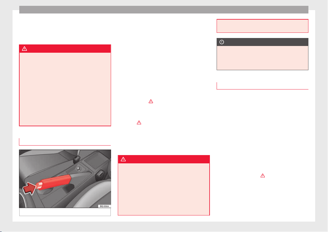
Operation
●
ther
e i
s
a fault in the brake system.
This warning lamp can light up together with
the ABS system warning lamp.
WARNING
●
If the brak
e warning lamp does not go out
or if it lights up when driving, the brake fluid
level in the reservoir is too low so there is a
risk of an accident ››› page 271, Brake fluid.
Stop the vehicle and do not drive on. Obtain
technical assistance.
●
If the brake warning lamp lights up to-
gether with the ABS lamp this could be
due to an ABS fault. This could cause the rear
wheels to lock quickly when you brake. This
could cause the rear to break away. Risk of
skidding. Stop the vehicle and seek technical
assistance.
Handbrake
Fig. 180 Handbrake between the front seats.
The handbrake should be applied firmly to
pr
ev
ent
the vehicle from accidentally rolling
away. Always apply the handbrake when you
leave your vehicle and when you park.
Applying the handbrake
–
Pull the handbrake lever up firmly
››› Fig. 180.
Releasing the handbrake
–
Pull the lever up slightly and press the re-
lease knob in the direction of the arrow
››› Fig. 180 and guide the handbrake lever
down fully ›››
.
A
lw
a
ys pull the handbrake all the way up, so
there is less risk of driving off with it still en-
gaged ›››
.
The h
andbr
ak
e warning lamp lights up
when the handbrake is applied and the igni-
tion switched on. The warning lamp turns off
when the handbrake is released.
WARNING
●
Never use the h
andbrake to stop the vehi-
cle when it is in motion. The braking distance
is considerably longer, because braking is
only applied to the rear wheels. Risk of acci-
dent!
●
If the handbrake is only partially released,
this will cause the rear brakes to overheat,
which can impair the function of the brake
system and could lead to an accident. This al-
so causes premature wear on the rear brake
pad
s.
CAUTION
Always apply the handbrake before you leave
the
vehic
le. Put it in 1st gear as well. In vehi-
cles with an automatic gearbox, place the
gear lever in position P.
Parking
The handbrake should always be firmly ap-
p
lied when the
v
ehicle is parked.
Always note the following points when park-
ing the vehicle:
–
Use the brake pedal to stop the vehicle.
–
Apply the handbrake.
–
Put it in 1st gear.
–
Switch the engine off and remove the key
from the ignition. Turn the steering wheel
slightly to engage the steering lock.
–
Always take you keys with you when you
leave the vehicle ›››
.
Ad
dition
a
l notes on parking the vehicle on
gradients:
Turn the steering wheel so that the vehicle
rolls against the kerb if it started to roll.
182

Driving
●
If
the
v
ehicle is parked facing downhill,
turn the front wheels so that they point to-
wards the kerb.
●
If the vehicle is parked facing uphill, turn
the front wheels so that they point away from
the kerb.
●
Secure the vehicle as usual by applying the
handbrake firmly and putting it in 1st gear.
WARNING
●
Take me
asures to reduce the risk of injury
when you leave your vehicle unattended.
●
Never park where the hot exhaust system
could ignite inflammable materials, such as
dry grass, low bushes, spilt fuel etc.
●
Never allow vehicle occupants to remain in
the vehicle when it is locked. They would be
unable to open the vehicle from the inside,
and could become trapped in the vehicle in
an emergency. In the event of an emergency,
locked doors will delay assistance to vehicle
occupants.
●
Never leave children alone in the vehicle.
They could set the vehicle in motion, for ex-
ample, by releasing the handbrake or the
gearbox lever.
●
Depending on weather conditions, it may
become extremely hot or cold inside the vehi-
cle. This can be fatal.
Braking and stability systems
El
ectr
onic
Stability Control (ESC)*
This Electronic Stability System reduces the
risk of
skidding and improves the vehicle's
stability and ability to hold the road.
The Electronic Stability Control (ESC) contains
the electronic differential lock (EDL) and the
traction control system (ASR). The ESC works
together with the ABS. Both control lamps
will light up if the ESC or ABS systems are
faulty.
The ESC system is started automatically
when the engine is started.
The ESC system is always active and cannot
be switched off. With the Easy Connect sys-
tem it is only possible to deactivate the ASR
or else select Sport mode.
The ASR can be deactivated when wheel spin
is desirable
›››
page 184.
For example:
●
When driving with snow chains.
●
When driving in deep snow or on loose sur-
face
s.
●
When the vehicle is stuck, to rock it back-
wards and forwards.
Press the button to switch the ASR back on
when you no longer need wheel spin.
Electronic Stability Control (ESC)*
The ESC reduces the risk of skidding by brak-
ing the wheels individually.
The system uses the steering wheel angle
and road speed to calculate the changes of
direction desired by the driver, and constant-
ly compares them with the actual behaviour
of the vehicle. When irregularities occur, for
example, if the vehicle begins to skid, the
ESC brakes the appropriate wheel automati-
cally.
The forces acting on the braked wheel bring
the vehicle back to a stable condition. If the
vehicle tends to oversteer (the rear end
slides out), the system will act on the front
wheel on the outside of the turn.
Control lamp
There are two control lamps for the electronic
stability control. The lamp provides infor-
mation concerning function and disconnec-
tion status.
Both control lamps light up together when
the ignition is switched on and should turn
off after approximately 2 seconds. This is the
time taken for the function check.
This programme includes the ABS, EDL and
ASR. It also includes emergency braking as-
sistance (BAS).
»
183
Technical dataAdviceOperationEmergenciesSafety
Operation
The control lamp h
a
s
the following func-
tions:
●
It flashes whilst driving when the ASR/ESC
is activated.
●
It will light up if there is a fault in the ESC.
●
As the ESC operates in conjunction with the
ABS, the ESC light will also come on if a fault
should occur in the ABS.
If the ESC control lamp lights up and stays
on after the engine is started, this may mean
that the control system has temporarily
switched off the ESC. In this case the ESC can
be reactivated by switching the ignition off
and then on again. If the control lamp goes
out, this means the system is fully functional.
The lamp provides information about the
disconnection status of the system:
●
It stays lit when the ASR is disconnected or
if you select ESC Sport mode, only by means
of Easy Connect.
WARNING
●
Do not for
get that the electronic stability
control ESC cannot defy the laws of physics.
Bear this in mind, particularly on slippery
and wet roads and when towing a trailer.
●
Always adapt your driving style to suit the
condition of the roads and the traffic situa-
tion. The greater safety provided by the ESC
should not encourage you to run any risks.
CAUTION
●
To ens
ure that the ESC works correctly, all
four wheels must be fitted with the same
tyres. Any differences in the rolling radius of
the tyres can cause the system to reduce en-
gine power when this is not desired.
●
Any modifications made to the vehicle (for
example, to the engine, brake system, run-
ning gear or to the combination of wheels
and tyres) may affect the operation of the
ABS, EDL, ESC and ASR.
Traction control system (ASR)
The traction control system prevents the driv-
en wheel
s
fr
om spinning when the vehicle is
accelerating.
Description and operation of the traction
control system during acceleration (ASR)
The ASR system intervenes by reducing en-
gine power and preventing the driven wheels
from slipping during acceleration.
TCS helps the car to start moving, accelerate
and climb a gradient in slippery conditions
where this may otherwise be difficult or even
impossible.
The ASR automatically switches on when the
engine is started. If necessary, it could be
switched on or off using the Easy Connect
system*.
When the ASR is off, the warning lamp lights
up . The ASR should normally be left on.
Only in exceptional cases can it be discon-
nected, i.e. when you want the wheels to
slide; this done through the Easy Connect
system, by means of the
button and the
f
u
nction b
utton SETTINGS> ESC system,
for example:
●
With compact temporary spare wheel.
●
When using the snow chains.
●
When driving in deep snow or on soft ter-
rain.
●
When the vehicle is bogged-down, to free it
by “rocking it”.
The ASR should be switched on again as
soon as possible.
Control lamp
There are three control lamps for the traction
control system: (for vehicles equipped
with M-ABS), (for vehicles equipped with
ESC) and . Both control lamps light up to-
gether when the ignition is switched on and
should turn off after approximately 2 sec-
onds, which is the time taken for the function
check.
The or lamp has the following function:
●
It flashes when the ASR is working if the ve-
hicle i
s moving.
184

Driving
If the system is deactivated or if it has any
f
au
lt, the w
arning lamp will remain lit. The
warning lamp will also light up if a fault
should occur in the ABS because the ASR op-
erates in conjunction with the ABS. For fur-
ther information, see ››› page 185.
The lamp provides information about the
disconnection status of the system:*
●
It stays lit when the ASR is disconnected
via Easy Connect.
By means of Easy Connect, the ASR function
is reactivated and the warning lamp switched
off.
WARNING
●
Remember that
not even the ASR can defy
the laws of physics. Bear this in mind, partic-
ularly on slippery and wet roads and when
towing a trailer.
●
Always adapt your driving style to suit the
condition of the roads and the traffic situa-
tion. The greater safety provided by the ASR
should not encourage you to run any risks.
CAUTION
●
To ens
ure that the ASR works correctly,
identical tyres should be fitted on all four
wheels. Any differences in the rolling radius
of the tyres can cause the system to reduce
engine power when this is not desired.
●
Any modific
ations made to the vehicle (for
example, to the engine, brake system, run-
ning gear or to the combination of wheels
and tyres) may affect the operation of the
ABS and ASR.
Connecting/disconnecting ESC and
ASR*
The ESC is switched on automatically when
the engine is
started, and only works when
the engine is running and includes the ABS,
EDS and ASR systems.
The ASR and ESC function should only be
switched off in situations in which traction is
insufficient, among others:
●
When driving in deep snow or on surfaces
that ar
e not very firm.
●
To “free” the vehicle if it gets stuck.
Then switch the ASR and ESC function back
on.
Depending on finishes and versions, it is
possible either to disconnect only the ASR or
else activate ESC Sport mode.
ESC in “Sport” mode
Sport mode can be connected via the Easy
Connect ››› page 123 system menu. The ESC
and the traction control system (ASR) have
only a limited ability to stabilise the vehicle.
The control lamp lights up. For vehicles
with a driver information system*, the driver
will be shown the electronic stability
control (ESC) option: sport.
Warning! Limited stability.
Disable ESC “Sport” mode
Through the Easy Connect system menu
››› page 123. The warning lamp will switch
off. For vehicles with a driver information sys-
tem*, the driver will be shown the elec-
tronic stability control (ESC)
option: on.
Disable ASR
The Easy Connect system menu is used to
switch off the ASR ››› page 123. The traction
control system will be disabled.
The control lamp lights up. For vehicles
with a driver information system* the driver
will be informed that ASR is disabled.
Activate ASR
The Easy Connect system menu ››› page 123
is used to switch on the ASR. The traction
control system will be enabled.
The control lamp switches off. For vehicles
with a driver information system* the driver
will be informed that ASR is enabled.
●
Activate or deactivate the ASR or ESC func-
tion in the Easy
Connect system by means of
»
185
Technical dataAdviceOperationEmergenciesSafety
Operation
the
button and the
S
ET
TINGS
and
E
SC
System
function buttons.
WARNING
You should switch on the ESC Sport mode on-
ly if the tr
affic conditions and your driving
ability allow you to do so safely: risk of skid-
ding!
●
With ESC in Sport mode, the stabilising
function will be limited to allow for a sportier
drive. The driving wheels could spin and the
vehicle could skid.
Note
If the ASR is disconnected or the ESC’s Sport
mode is sel
ected, cruise control* will be
switched off.
Electronic differential lock (EDS)*
The EDL operates along with the ABS in vehi-
c
l
e
s equipped with Electronic Stability Con-
trol (ESC)*.
EDL helps the vehicle to start moving, accel-
erate and climb a gradient in slippery condi-
tions where this may otherwise be difficult or
even impossible.
It uses the ABS sensors to monitor the speed
of the driven wheels.
At speeds of up to approximately 80 km/h
(50 mph), it is able to balance out differences
in the speed of the driven wheels of approxi-
mately 100 rpm/min caused by a partially
slippery road surface. It does this by braking
the wheel which has lost traction and distrib-
uting more driving force to the other driven
wheel via the differential.
To prevent the disc brake of the braking
wheel from overheating, the EDL cuts out au-
tomatically if subjected to excessive loads.
The vehicle will continue to function normally
without EDL. For this reason, the driver is not
informed that the EDL has been switched off.
The EDL will switch on again automatically
when the brake has cooled down.
Control lamp
A malfunction in the EDL is indicated by the
ESC control lamp . Take the vehicle to a
specialised workshop as soon as possible.
WARNING
●
When accel
erating on a slippery surface,
for example on ice and snow, press the accel-
erator carefully. Despite EDL, the driven
wheels may start to spin. This could impair
the vehicle's stability.
●
Always adapt your driving style to suit road
conditions and the traffic situation. Do not let
the extra safety afforded by EDL tempt you in-
to taking any risks when driving, this can
cause accidents.
CAUTION
Modifications to the vehicle (e.g. to the en-
gine, the brake sy
stem, running gear or any
components affecting the wheels and tyres)
could affect the efficiency of the EDL
››› page 247.
Hydraulic Brake Assist (HBA)*
The function (Hydraulic Brake Assist HBA) is
only inc
luded in vehicles with ESC.
In an emergency, most drivers brake in time,
but not with maximum force. This results in
unnecessarily long braking distances.
This is when the brake assist system comes
into action. When pressing the brake pedal
rapidly, the assistant interprets it as an emer-
gency. It very quickly builds up the full brake
pressure so that the ABS can be activated
more quickly and efficiently, thus reducing
braking distance.
Do not reduce the pressure on the brake ped-
al, since the brake assist system switches off
automatically as soon as you release the
brake.
Automatic hazard warning lights activation
The brake lights flash automatically to indi-
cate that the vehicle is braking suddenly or in
an emergency situation. If the emergency
braking continues until the vehicle comes to
186
Driving
a standstill, the hazard warning lights will
then c
ome on and the br
ak
e lights will re-
main on permanently from that moment. The
warning lights will automatically switch off
when the vehicle begins to move again or
when the "warning" light button is pressed.
WARNING
●
The risk of
accident is higher if you drive
too fast, if you do not keep your distance from
the vehicle in front, and when the road sur-
face is slippery or wet. The increased acci-
dent risk cannot be reduced by the brake as-
sist system.
●
The brake assist system cannot defy the
laws of physics. Slippery and wet roads are
dangerous even with the brake assist system!
Therefore, it is essential that you adjust your
speed to suit the road and traffic conditions.
Do not let the extra safety features tempt you
into taking any risks when driving.
Anti-lock brake System (ABS)
The anti-lock brake (ABS) system prevents
the wheel
s
fr
om locking during braking and
is an important part of the vehicle's active
safety system.
How the ABS works
If one of the wheels turns too slowly in rela-
tion to the vehicle's speed, and is close to
locking, the system will reduce the braking
pressure to this wheel. The driver is made
aware of this control process by a pulsating
of the brake pedal and audible noise. This is
a deliberate warning to the driver that one or
more of the wheels is tending to lock and the
ABS control function has intervened. In this
situation it is important to keep the brake
pedal fully depressed so the ABS can regu-
late the brake application. Do not “pump”.
If you brake hard on a slippery road surface,
the best possible control is retained as the
wheels do not lock.
However, ABS will not necessarily guarantee
shorter braking distances in all conditions.
Braking distance could even be further if you
brake on gravel or on fresh snow on a slip-
pery surface.
Control lamp
The control lamp lights up for a few sec-
onds when the ignition is switched on. It
goes out again after the system has run
through an automatic test sequence.
There is a fault in the ABS if:
●
The control lamp does not light up when
the ignition is switched on.
●
The control lamp does not go out again af-
ter a few seconds.
●
The control lamp lights up when the vehicle
is moving.
The vehicle can still be braked in the normal
way, without the ABS function. Take the vehi-
cle to a specialised workshop as soon as
possible.
If there is a fault in the ABS, the ESC* and the
tyre pressure control lamp will also light up.
Brake system fault
If the ABS warning lamp lights up together
with the brake warning lamp , there is a
fault in the ABS function and in the brake
system ›››
.
WARNING
●
The anti-lock br
ake system cannot defy the
laws of physics. Slippery and wet roads are
dangerous even with ABS! If you notice that
the ABS is working (to counteract locked
wheels under braking), you should reduce
speed immediately to suit the road and traffic
conditions. Do not let the extra safety fea-
tures tempt you into taking any risks when
driving.
●
The effectiveness of ABS is also determined
by the tyres fitted ››› page 274.
●
If the running gear or brake system is modi-
fied, the effectiveness of the ABS could be se-
verely limited.
»
187
Technical dataAdviceOperationEmergenciesSafety

Operation
WARNING
●
Befor
e opening the bonnet, read and ob-
serve the warnings ››› page 263, Working in
the engine compartment.
●
If the brake system warning lamp should
light up together with the ABS warning lamp
, stop the vehicle immediately and check
the brake fluid level in the reservoir
››› page 271, Brake fluid. If the brake fluid
level has dropped below the “MIN” mark you
must not drive on. Risk of accident. Obtain
technical assistance.
●
If the brake fluid level is correct, the fault in
the brake system may have been caused by a
failure of the ABS system. This could cause
the rear wheels to lock quickly when you
brake. This could cause the rear to break
away. Risk of skidding. Stop the vehicle and
seek technical assistance.
Electronic differential lock (XDS)*
When taking a curve, the driveshaft differen-
ti
al
mec
hanism allows the outer wheel to turn
at a higher speed than the inner wheel. In
this way, the wheel that is turning faster (out-
er wheel) receives less drive torque than the
inner wheel. This may mean that in certain
situations the torque delivered to the inner
wheel is too high, causing the wheels to
spin. On the other hand, the outer wheel is
receiving a lower drive torque than it could
transmit. This causes an overall loss of lateral
grip on the front axle, resulting in understeer
or “lengthening” of the trajectory.
The XDS system can detect and correct this
effect via the sensors and signals of the ESC.
Via the ESC, the XDS will brake the inside
wheel and counter the excess driving torque
of that wheel. This means that the driver's
desired trajectory is much more precise.
The XDS system works in combination with
the ESC and is always active, even when ASR
traction control is disconnected or the ESC is
in Sport mode.
Multi-collision Brake
In an accident, the multi-collision brake can
help the driv
er b
y
braking to avoid the risk of
skidding during the accident, which could
lead to further collisions.
The multi-collision brake works for front, side
or rear accidents, when the airbag control
unit records its activation level and the acci-
dent takes place at a speed of over 10 km/h
(6 mph). The ESC automatically brakes the
vehicle, as long as the accident has not dam-
aged the ESC, the brake hydraulics or the on-
board network
The following actions control automatic brak-
ing during the accident:
●
When the driver presses the accelerator,
the automatic braking does not take place.
●
When the braking pressure through press-
ing the brake pedal is greater than the sys-
tem’s braking pressure the vehicle will brake
automatically.
●
Multi-collision braking will not be available
if ESC is malfunctioning.
Brake servo
The brake servo increases the pressure you
ap
p
ly
to the brake pedal. It works only when
the engine is running.
If the brake servo is not functioning, e.g. due
to a malfunction, or if the vehicle is being
towed, you will have to press the brake pedal
considerably harder to make up for the lack
of servo assistance.
WARNING
The braking distance can also be affected by
extern
al factors.
●
Never let the vehicle coast with the engine
switched off. Failure to follow this instruction
could result in an accident. The braking dis-
tance is increased considerably when the
brake servo is not active.
●
If the brake servo is not working, for exam-
ple when the vehicle is being towed, you will
have to press the brake pedal considerably
harder than normal.
188
Driving
Hill driving assistant*
Fig. 181 Related video
This function is only included in vehicles with
ESC.
The hil
l driving assistant helps the driver to
move off and upward on a hill when the vehi-
cle is stationary.
The system maintains brake pressure for ap-
proximately two seconds after the driver
takes his foot off the brake pedal to prevent
the vehicle from lurching backward when it is
started. During these 2 seconds, the driver
has enough time to release the clutch pedal
and accelerate without the vehicle moving
and without having to use the handbrake,
making start-up easier, more comfortable
and safer.
These are the basic operation conditions:
●
being on a ramp or hill/slope,
●
driver door closed,
●
vehicle completely stationary,
●
engine running and foot on the brake,
●
beside
s having a gear engaged or being in
neutral for manual gear change and with the
selector lever at position S, D or R for an au-
tomatic gearbox.
This system is also active when reversing up-
hill.
WARNING
●
If y
ou do not start the vehicle immediately
after taking your foot off the brake pedal, the
vehicle may start to roll back under certain
conditions. Depress the brake pedal or use
the hand brake immediately.
●
If the engine stalls, depress the brake ped-
al or use the hand brake immediately.
●
When following a line of traffic uphill, if you
want to prevent the vehicle from rolling back
accidentally when starting off, hold the brake
pedal down for a few seconds before starting
off.
Note
The Official Service or a specialist workshop
can tel
l you if your vehicle is equipped with
this system.
Manual gearbox
Driv
in
g w
ith a manual gearbox
Read the additional information carefully
›››
page 50
Certain versions of the model may include a
6-speed manual gearbox, and its diagram is
shown on the gearbox lever.
The reverse gear can only be engaged when
the car is stationary. When the engine is run-
ning and before engaging this gear, wait
about 6 seconds with the clutch pressed
down thoroughly in order to protect the gear-
box.
The reverse lights switch on when the reverse
gear is selected and the ignition is on.
WARNING
●
When the engine is
running, the vehicle
will start to move as soon as a gear is engag-
ed and the clutch released.
●
Never select the reverse gear when the ve-
hicle is in motion. Risk of accident.
Note
●
Do not re
st your hand on the gear lever
while driving. The pressure of your hand
could cause premature wear on the selector
forks in the gearbox.
»
189
Technical dataAdviceOperationEmergenciesSafety
Operation
●
When chan
ging gear, you should always
depress the clutch fully to avoid unnecessary
wear and damage.
●
Do not “slip” the clutch to hold the vehicle
on a hill. This causes premature wear and
damage to the clutch.
●
Do not leave your foot on the clutch pedal;
although the pressure may seem insignifi-
cant, it can cause the premature wear of the
clutch plate. Use the foot rest when you do
not need to change gear.
Automatic gearbox/DSG auto-
m
atic
g
earbox*
Introduction
Your vehicle is equipped with an electronical-
ly
c
ontr
olled manual gearbox. Torque be-
tween the engine and the gearbox is trans-
mitted via two independent clutches. They re-
place the torque converter found on conven-
tional automatic gearboxes and allow for
smooth, uninterrupted acceleration of the ve-
hicle.
The tiptronic system allows the driver to
change gears manually if desired
››› page 192, Engaging gears with the trip-
tonic mode*.
Selector lever positions
Read the additional information carefully
›››
page 50
The selector lever position engaged is high-
lighted on the display in the instrument clus-
ter. With the selector lever in the manual
gearbox positions G, D, E and S, the engaged
gear is also indicated on the display.
P – Parking lock
When the selector lever is in this position,
the driven wheels are locked mechanically.
The parking lock must be engaged only when
the vehicle is stationary
›››
.
The int
erloc
k
button (the button on the selec-
tor lever handle) must be pressed in and si-
multaneously the brake pedal must be de-
pressed before moving the selector lever ei-
ther in or out of position P.
R – Reverse gear
Reverse gear must be engaged only when the
vehicle is stationary and the engine is idling
›››
.
T
o mo
v
e the selector lever to position R, the
interlock button must be pressed in and at
the same time the brake pedal must be de-
pressed. The reverse lights come on when
the selector lever is in the R position with the
ignition on.
N – Neutral (idling)
With the selector lever in this position, the
gear is in neutral.
D/S – Permanent drive (forward) position
The selector lever in the D/S position enables
the gears to be controlled in normal mode (D)
or Sport (S). To select Sport mode (S), move
the selector lever backwards. Moving the lev-
er again will select normal mode (D). The se-
lected driving mode is shown on the instru-
ment panel display.
In normal mode (D), the gearbox automatical-
ly selects the best gear ratio. This depends
on the engine load, the road speed and the
dynamic gear control programme (DCP).
Sport mode (S) must be selected for a sporty
driving style. This setting makes use of the
engine's maximum power output. When ac-
celerating the gear shifts will be noticeable.
Press the brake pedal to move the selector
lever from N to D/S when the vehicle is sta-
tionary or at speeds below 3 km/h (2 mph)
›››
.
Under c
er
t
ain circumstances (e.g. when driv-
ing in mountains) it can be advantageous to
switch temporarily to tiptronic mode
›››
page 192, in order to manually select gear
ratios to suit the driving conditions.
190
Driving
WARNING
●
Take c
are not to accidentally press the ac-
celerator pedal when the vehicle is stopped.
The vehicle could otherwise start moving im-
mediately (in some cases even if the parking
brake is engaged) resulting in the risk of an
accident.
●
Never move the selector lever to R or P
when driving. Failure to follow this instruc-
tion could result in an accident.
●
With selector lever in any position (except
P) the vehicle must always be held with the
foot brake when the engine is running. This is
because an automatic gearbox still transmits
power even at idling speed, and the vehicle
tends to “creep”. The accelerator pedal must
on no account be pressed inadvertently when
a gear is engaged with the vehicle stationary.
The vehicle could otherwise start moving im-
mediately (in some cases even if the parking
brake is engaged) resulting in the risk of an
accident.
●
While you are selecting a gear and the vehi-
cle is stopped with the engine running, do
not accelerate. Failure to follow this instruc-
tion could result in an accident.
●
As a driver you should never leave your ve-
hicle if the engine is running and a gear is en-
gaged. If you have to leave your vehicle while
the engine is running, you must apply the
handbrake and engage the parking lock (P).
●
To avoid accidents, apply the handbrake
and put the selector lever in position P before
opening the bonnet and working on the vehi-
cle with the engine running. Please always
obser
ve the important safety warnings
››› page 263, Working in the engine compart-
ment.
Note
●
If
the select
or lever is moved accidentally
to N when driving, release the accelerator and
let the engine speed drop to idling before se-
lecting gear range D or S again.
●
Should the power supply to the selector
lever be interrupted in position P, the selector
lever will be locked. If this should happen the
manual release can be used ›››
page 50.
Selector lever lock
Fig. 182 Selector lever lock.
The selector lever lock prevents gears from
bein
g en
g
aged inadvertently, so that the ve-
hicle is not set in motion unintentionally.
The selector lever lock is released as follows:
–
Switch the ignition on.
–
Press the brake pedal and, at the same
time, hold the lock button in the direction
of the arrow ››› Fig. 182.
Automatic selector lever lock
With the ignition switched on, the selector
lever is locked in the positions P and N. The
brake pedal must be pressed to release the
lever while pressing the release button if the
selector lever is in the position P. As a re-
minder for the driver, with the lever in posi-
tions P or N the following message will be
shown on the display:
When stationary, apply footbrake
while selecting a gear.
Level lock only engages with the vehicle sta-
tionary and at speeds of up to 5 km/h
(3 mph). At speeds of over 5 km/h (3 mph)
the lever lock is automatically deactivated in
position N.
The selector lever lock is not engaged if the
selector lever is moved quickly through posi-
tion N (e.g. when shifting from R to D). This
makes it possible, for instance, to rock the
vehicle “backwards and forwards” if it is
stuck. The selector lever lock engages auto-
matically if the brake pedal is not depressed
and the lever is in position N for more than
about two seconds.
»
191
Technical dataAdviceOperationEmergenciesSafety
Operation
Interlock button
The int
erloc
k
button on the selector lever
handle prevents the driver from inadvertently
engaging certain gears. Press the button in
to disengage the selector lever lock.
Safety interlock for ignition key
Once the ignition has been turned off, the
key may be removed only if the gear selector
is in position P. While the key is not in the ig-
nition, the selector lever is locked in position
P.
Note
●
If the select
or lever lock does not engage,
there is a fault. The transmission is interrup-
ted to prevent the vehicle from accidentally
moving. Follow the procedure below in order
for the selector lever lock to engage again:
–
With a 6-speed gearbox: press the brake
pedal and release it again.
–
With a 7-speed gearbox: press the brake
pedal. Move the selector lever to posi-
tion P or N and subsequently engage a
gear.
●
Despite a gear being engaged, the vehicle
does not move forwards or back. Proceed to
the next mode:
–
When the vehicle does not move in the
required direction, the system may not
have the gear range correctly engaged.
Press the brake pedal and engage the
gear range again.
–
If the v
ehicle still does not move in the
required direction, there is a system mal-
function. Seek specialist assistance and
have the system checked.
Engaging gears with the triptonic
mode*
Fig. 183 Centre console: changing gear with
tiptr
onic
Fig. 184 Steering wheel: automatic gearbox
lever
s
The tiptronic gives the driver the option to
c
h
an
ge gears manually.
Changing gear manually with the selector
lever
It is possible to change to tiptronic mode,
both when the vehicle is stopped and while
driving.
–
To switch to tiptronic mode, move the se-
lector lever from position D/S to the right.
As soon as the change is made the selector
level will be shown in the position M on the
instrument panel display (for example M4
means that the fourth gear is engaged).
–
Move the selector lever forwards
+
to se-
l
ect
a higher g
ear ››› Fig. 183.
–
Move the selector lever backwards
–
to
sel
ect
a lo
wer gear.
192
Driving
Changing gear manually with the gearshift
p
a
d
dles*
The gearshift paddles can be used when the
selector lever is in the position D/S or M.
–
Press the gearshift paddle
+
to select a
higher g
e
ar ›
›› Fig. 184.
–
Press the gearshift paddle
–
to select a
lo
w
er g
ear.
–
With the selector lever in position D/S, if no
paddle is operated during a short period of
time, the gearbox control system switches
back to automatic mode. To switch to per-
manent manual gear change using the
gearshift paddles, move the selector lever
from position D/S to the right.
When accelerating, the gearbox automatical-
ly shifts up into the next gear shortly before
the maximum engine speed is reached.
If you select a lower gear, the automatic gear-
box will not shift down until there is no risk of
over-revving the engine.
When the kick-down feature is used, the
gearbox shifts down to a lower gear, depend-
ing on road speed and engine speed.
Driving tips
The gearbox changes gear ratios automatical-
ly
a
s
the vehicle moves.
The engine can only start with the selector
lever in position P or N. At low temperatures,
below -10°C (14°F), the engine can only start
with the selector lever in position P.
Starting the vehicle
–
Press and hold the brake pedal.
–
Press and hold the interlock button (the
button on the selector lever handle), move
the selector lever to the desired position,
for instance D ››› page 190, and release the
interlock button.
–
Wait for the gearbox to engage the gear (a
slight movement can be felt).
–
Release the brake and press the accelerator
›››
.
St
op
pin
g briefly
–
Apply the foot brake to hold the vehicle
briefly when stationary (for instance at traf-
fic lights). Do not press the accelerator.
Stopping/Parking
If the driver door is opened and the selector
lever is not in position P, the vehicle could
move. The driver message will be: Gear
change: selector lever in the
drive position!. Additionally, a buzzer
will sound.
–
Press and hold the brake pedal ›››
.
–
Apply the handbrake.
–
Mo
v
e the sel
ector lever to position P.
Holding the car on a hill
–
Always apply the brake pedal firmly to pre-
vent the vehicle “from moving backwards”;
if necessary, apply the handbrake ›››
. Do
not tr
y
t
o stop the vehicle “rolling back” by
increasing the engine speed (pressing the
accelerator) when a gear is engaged ›››
.
St
ar
tin
g off uphill
–
Apply the handbrake.
–
Once you have engaged a gear press the
accelerator carefully and disengage the
handbrake.
Driving down hills: in some situations (on
mountain roads or when towing a trailer or
caravan) it can be advantageous to switch
temporarily to the manual gearbox pro-
gramme so that the gear ratios can be selec-
ted manually to suit the driving conditions
›››
.
On l
ev
el
ground it is sufficient to move the
selector lever to position P. On slopes, first
engage the parking brake and then put the
selection lever into the P position. This
avoids overloading the locking mechanism
and it will be easier to move the selector lev-
er from position P.
»
193
Technical dataAdviceOperationEmergenciesSafety
Operation
WARNING
Observe the safety warnings ›››
in Selector
lever po
sitions on page 191.
●
Never allow the brake to rub and do not use
the brake pedal too often or for long periods.
Constant braking causes overheating in the
brakes. This could significantly reduce brak-
ing power, increase braking distance or even
result in the total failure of the brake system.
●
To avoid rolling back on gradients always
hold the vehicle with the footbrake or hand-
brake if you have to stop.
CAUTION
●
If y
ou stop the vehicle on a gradient, do not
attempt to stop it from rolling by depressing
the accelerator when a gear has been selec-
ted. This could cause overheating and dam-
age the automatic gearbox. Apply the hand-
brake firmly or press the brake pedal in order
to prevent the vehicle from rolling back.
●
If you allow the car to roll with the selector
lever in position N with the engine switched
off, the automatic gearbox will be damaged
as it will not be lubricated.
●
In certain driving situations or traffic condi-
tions, such as frequently starting, prolonged
“creeping” of the vehicle or traffic jams with
continuous stoppages, the gearbox could
overheat causing damage! If the warning
lamp
lights up, stop the vehicle as soon as
possible and wait for the gearbox to cool
››› page 196.
Kick-down feature
The kick-down feature allows maximum ac-
celer
ation to be reached.
When the accelerator pedal is pressed right
down past the point of resistance at full throt-
tle, the gearbox will shift down to a lower
gear, depending on road speed and engine
speed. The upshift to the next higher gear is
delayed until the engine reaches maximum
rpm.
WARNING
Please note that if the road surface is slip-
pery or w
et, the kick-down feature could
cause the driving wheels to spin, which could
result in skidding.
Launch control program
3 Valid for vehicles: with Launch-Control/6-Speed
DSG w
ith diesel engines superior to 125 kW and pet-
rol engines superior to 140 kW.
The Launch control programme enables maxi-
mum acceleration.
Important: the engine must have reached op-
erating temperature and the steering wheel
must not be turned.
The engine speed for launch-control is differ-
ent on petrol and diesel engines. To use the
launch-control you must disconnect the anti-
slip regulation (ASR) through the Easy Con-
nect system menu
›››
page 123. The warning
lamp will stay switched on or will flash
slowly depending on whether or not the vehi-
cle has a driver information system*.
On vehicles with the driver information sys-
tem, the ESC lamp lights up permanently and
the corresponding text message Stability
control deactivated (temporary) ap-
pears on the instrument panel to indicate the
deactivation status.
–
When the engine is running, switch off the
traction contr
ol (ASR)
1)
.
1)
Vehicles without driver information system: the
warning l
amp flashes slowly/Vehicles with driver in-
formation system: the warning lamp stays on.
194
Driving
–
T
urn the sel
ect
or lever to the position “S”
or tiptronic, or else select the sport driv-
ing mode from the SEAT Drive Profile*
››› page 225.
–
Press the brake pedal firmly with your left
foot and hold it down for at least one sec-
ond.
–
With your right foot, press the accelerator
down to the full throttle or kick-down posi-
tion. The engine speed will stabilise at
about 3,200 rpm (petrol engine) or about
2,000 rpm (diesel engine).
–
Take your left foot off the brake pedal.
WARNING
●
Alwa
ys adapt your driving style to the traf-
fic conditions.
●
Only use the launch control programme
when road and traffic conditions permit, and
make sure your manner of driving and accel-
erating the vehicle does not inconvenience or
endanger other road users.
●
Make sure that the ESC remains switched
on. Please note that when the ASR and ESC
are deactivated, the wheels may start to spin,
causing the vehicle to lose grip. Risk of acci-
dent!
●
After moving off, the ESC “sport” mode
should be deactivated by briefly pressing the
button.
Note
●
After u
sing the Launch control programme,
the temperature in the gearbox may have in-
creased considerably. In this case, the pro-
gramme could be disabled for several mi-
nutes. The programme can be used again af-
ter the cooling phase.
●
Accelerating with the Launch control pro-
gramme places a heavy load on all parts of
the vehicle. This can result in increased wear
and tear.
Downhill speed control*
The downhill speed control function helps
the driv
er when driv
in
g down steep gradi-
ents.
Downhill speed control is activated when the
selector lever is in D/S and the driver applies
the foot brake. The automatic gearbox auto-
matically engages a lower gear that is suita-
ble for the slope. The downhill speed control
function attempts to maintain the speed at
which the vehicle was travelling when the
foot brake was applied (subject to the laws of
physics and technical drive limitations). It
may be necessary to adjust the speed again
using the foot brake in certain situations. Giv-
en that the downhill speed control can only
change down to 3rd gear, on very steep de-
scents the tiptronic mode may be required. In
this case, manually reduce the tiptronic to
2nd or 1st gear to use the engine brake and
reduce the charge on the brakes.
Downhill speed control is deactivated as
soon as the road levels out again or you
press the accelerator pedal.
On vehicles with cruise control system*
››› page 207, downhill speed control is acti-
vated when you set a cruising speed.
WARNING
The downhill speed control cannot defy the
law
s of physics. Therefore, speed cannot be
maintained constant in all situations. Always
be prepared to use the brakes!
Inertia mode
The inertia mode enables the kinetic energy
of
the
v
ehicle to be harnessed enabling cer-
tain stretches to be driven without using the
accelerator. This enables fuel to be saved.
Use the inertia mode to “let the vehicle roll”
before, for example, arriving in a town.
Switching on inertia mode
Important: selector lever must be in position
D, gradients below 12 %.
–
Select, in SEAT Drive Profile*, Eco mode
›››
page 225.
–
Take your foot off the accelerator.
»
195
Technical dataAdviceOperationEmergenciesSafety
Operation
The driver message Inertia w
i
l
l be dis-
played. At speeds higher than 20 km/h (12
mph), the gearbox will automatically disen-
gage and the vehicle will roll freely, without
the effect of the engine brake. While the vehi-
cle rolls, the engine runs at idling speed.
Stopping inertia mode
–
Press the brake or the accelerator pedal.
To make use of the braking force and switch
off the engine again, simply press the brake
pedal briefly.
Applying both the inertia mode (= prolonged
section with less energy) and the switching
off using inertia (= shorter section without
the need for fuel) facilitates improved fuel
consumption and emission balance.
WARNING
●
If the inerti
a mode has been switched on,
take into account, when approaching an ob-
stacle and releasing the accelerator pedal,
that the vehicle will not decelerate in the usu-
al manner: risk of accident!
●
When using inertia mode while travelling
down hills, the vehicle can increase speed:
risk of accident!
●
If other users drive your vehicle, warn them
about inertia mode.
Note
●
Inertia mode i
s only available in eco (SEAT
Drive Profile*) driving mode.
●
The driver message Inertia is only dis-
played with the current consumption. In iner-
tia mode the gear will no longer be displayed
(for example “E” will appear instead of “E7”).
●
On downhill sections with gradients above
15 %, the inertia mode will automatically be
switched off temporarily.
Emergency program
A backup programme is in place if a fault
shou
l
d oc
cur in the control system.
If all the positions of the selector lever are
shown over a light background on the instru-
ment panel display, there is a system fault
and the automatic gearbox will operate in
with the backup programme. When the back-
up programme is activated, it is possible to
drive the vehicle, however, at low speeds and
within a selected range of gears. In some ca-
ses driving in reverse gear may not be possi-
ble.
CAUTION
If the gearbox operates with the backup pro-
gramme, tak
e the vehicle to a specialised
workshop and have the fault repaired without
delay.
Clutch
Clutch overheating! Please
stop!
The c
lut
ch has overheated and could be dam-
aged. Stop the vehicle and wait for the gear-
box to cool with the engine at idling speed
and the selector lever in position P. When the
warning lamp and the driver message switch
off, have the fault corrected by a specialised
workshop without delay. If the warning lamp
and the driver message do not switch off, do
not continue driving. Seek specialist assis-
tance.
Gearbox malfunctions
Gearbox: Fault! Stop the ve-
hicle and place the lever in the
position P.
There is
a fault in the gearbox. Stop the vehi-
cle in a safe place and do not continue driv-
ing. Seek specialist assistance.
Gearbox: System fault! You
may continue driving.
Have the fault corrected by a specialised
workshop without delay.
Gearbox: System fault! You
can continue driving with re-
strictions. Reverse gear disa‐
bled
196
Driving
Take the vehicle to a specialised workshop
and h
av
e the f
ault repaired without delay.
Gearbox: System fault! You
can continue driving in D until
switching off the engine
Stop the vehicle in a safe place well away
from moving traffic. Seek specialist assis-
tance.
Gearbox: too hot. Adapt your
driving accordingly
Continue driving at moderate speeds. When
the warning lamp switches off, you can con-
tinue driving in a normal manner.
Gearbox: press the brake and
engage a gear again.
If the fault was caused by a gearbox with a
high temperature, this driver message will be
displayed when the gearbox has cooled
again.
Gear-change indicator
Selecting the optimal gear
While driving, and depending on vehicle
equipment, the in
s
trument
panel display may
show a recommendation with the gear num-
ber that would be advisable to save fuel.
In vehicles with an automatic gearbox, the
selector lever must be in the tiptronic posi-
tion ››› page 192.
No recommendation will appear if the opti-
mal gear is already engaged. The current
gear will be displayed.
Display Meaning
The optimal gear is selected.
Changing to a higher gear is recom-
mended.
Changing to a lower gear is recom-
mended.
Information regarding the “cleanliness” of
the die
sel
p
articulate filter
The exhaust system manager detects that the
diesel particulate filter is nearly saturated
and contributes to self-cleaning by recom-
mending the optimal gear. For this reason, it
might be necessary to drive for a short time
at a high rpm.
WARNING
The gear change indicator is only an auxiliary
function and in no c
ase should be a substi-
tute for careful driving.
●
The responsibility of choosing the correct
gear depending on the situation (e.g. over-
taking, driving up or down a slope or towing a
trailer) lies with the driver.
For the sake of the environment
Selecting the correct gear can help to save
fuel.
Note
The recommended gear indication turns off
when the clutc
h pedal is pressed in vehicles
with manual gearbox or when the selector
lever is removed from the tiptronic position in
vehicles with an automatic gearbox.
Steering
Intr
oduction
The power steering is not hydraulic but elec-
tr
omec
h
anical. The advantage of this steer-
ing is that it foes not need flexible hydraulic
pipes, hydraulic oil, pump, filter or other
parts. The electromechanical system saves
fuel. Whereas a hydraulic system needs con-
tinuous oil pressure, electromechanical
steering only needs power when it is used.
In vehicles with electromechanical steering,
the assisted steering function automatically
adjusts according to vehicle speed, steering
wheel torque and wheel orientation. The
power steering only works when the engine
is running.
»
197
Technical dataAdviceOperationEmergenciesSafety
Operation
WARNING
If the power steering does not work, you will
need much more s
trength to turn the wheel.
This has a considerable effect on vehicle
safety.
●
The power steering only works when the
engine is running.
●
Never allow the vehicle to move when the
engine is switched off.
●
Never remove the key from the ignition
while the vehicle is moving. The steering lock
could be engaged and vehicle steering would
not work.
Note
The ignition of the vehicle being towed must
be switc
hed on to prevent the steering wheel
from locking and also to allow the use of the
turn signals, horn, windscreen wipers and
washers.
Control lamp
The control lamp should light up for a few
sec
ond
s
when the ignition is switched on. It
should go out once the engine is started.
It lights up red
The electromechani-
cal steering is dam-
aged.
Have the steering checked im-
mediately by a specialised work-
shop.
It lights up yellow
Electromechanical
steering operation
is limited.
See a specialised workshop im-
mediately and have the steering
checked.
If the yellow warning lamp does
not light up again after the en-
gine is restarted and the vehicle
has travelled a short distance,
you do not need to take it to a
specialised workshop.
The 12-volt battery
was disconnected
and has been recon-
nected.
Take the vehicle for a short run
at 15-20 km/h (9-12 mph).
It flashes yellow
The steering column
is tight.
Turn the wheel a little to both
sides.
The steering column
does not unlock or
lock.
Remove the key from the ignition
and switch the ignition back on.
If necessary, check the messag-
es displayed on the instrument
panel display.
Do not drive on if the steering
column remains locked after the
ignition has been switched on.
Seek specialist assistance.
WARNING
If the warning lamps and the corresponding
mess
ages are ignored when they light up, the
vehicle may stall in traffic and cause acci-
dents and severe injuries.
●
Never ignore the w
arning lamps or messag-
es.
●
Stop the vehicle at the next opportunity
and in a safe place.
Note
Failure to heed the control lamps and corre-
s
ponding t
ext messages when they light up
may result in damage to the vehicle.
Information relating to different vehi-
c
l
e pr
ocesses.
In order to make the vehicle more difficult to
s
t
e
al, you should always lock the steering be-
fore leaving the vehicle.
Mechanical steering lock
The steering column is locked when the key
is removed from the ignition lock and the ve-
hicle is stationary.
Activating the steering lock
●
Park the vehicle ››› page 181.
●
Remove the ignition key.
●
Turn the steering wheel slightly until the
steering lock has engaged.
198
Driving
Deactivating the steering lock
●
Turn the steering wheel slightly to release
the loc
k.
●
In
ser
t the key in the ignition lock.
●
Hold the steering wheel in this position
and switch on the ignition.
Electromechanical steering
In vehicles with electromechanical steering,
the assisted steering function automatically
adjusts according to vehicle speed, steering
wheel torque and wheel orientation. The
power steering only works when the engine
is running.
You should take into account that you will
need considerably more power than normal
to steer the vehicle if the power steering is
not working correctly or at all.
Power-assisted steering
Power-assisted steering helps the driver in
critical situations. In counter-steering, it as-
sists by applying additional torque ›››
.
WARNING
Power-assisted steering, together with the
ESC, helps
the driver to control vehicle steer-
ing in critical situations. However, the driver
is ultimately responsible for steering the ve-
hicle at all times. Power-assisted steering
does not remove this responsibility.
Run-in and economical driving
R
u
nnin
g in a new engine
The engine needs to be run-in over the first
1500 km (900 mile
s).
For the first 1,000 kilometres (600 miles)
–
Do not drive at speeds of more than 2/3
the maximum speed.
–
Do not accelerate hard.
–
Avoid high engine revolutions.
–
Do not tow a trailer.
From 1,000 ki
lometres (600 miles) to 1,500
kilometres (900 miles)
–
Speeds can be gradually increased to the
maximum road speed or maximum permis-
sible engine speed (rpm).
During its first few hours of running, the in-
ternal friction in the engine is greater than
later on, when all the moving parts have bed-
ded in.
For the sake of the environment
If the engine is run in gently, its life will be in-
cre
ased and its oil consumption reduced.
Running in tyres and brake pads
New tyres should be run in carefully for the
first
500 km (300 miles) and new brake pads
should be run in carefully for the first 200 km
(125 miles).
During the first 200 km (125 miles) you have
to compensate for the reduced braking effect
by applying more pressure to the brake ped-
al. In case of a sharp braking, the braking
distance will be longer with new brake pads
than with brake pads which have been run-
in.
WARNING
●
At firs
t, new tyres do not give maximum
grip, and require running-in. This may cause
an accident. Drive particularly carefully in the
first 500 km (300 miles).
●
New brake pads must be “run in” and do
not have the correct friction properties during
the first 200 km (125 miles). However, the re-
duced braking capacity may be compensated
by pressing on the brake pedal a little harder.
Environmental compatibility
Environmental protection is a top priority in
the de
s
ign, c
hoice of materials and manufac-
ture of your new SEAT.
»
199
Technical dataAdviceOperationEmergenciesSafety

Operation
Constructive measures to encourage recy-
c
lin
g
●
Joints
and connections designed for easy
dismantling.
●
Modular construction to facilitate disman-
tling.
●
Increased use of single-grade materials.
●
Plastic parts and elastomers are marked in
accordance with ISO 1043, ISO 11469 and
ISO 1629.
Choice of materials
●
Use of recycled materials.
●
Use of compatible plastics in the same part
if its components are not easily separated.
●
Use of recycled materials and/or materials
originating from renewable sources.
●
Reduction of volatile components, includ-
ing odour, in plastic materials.
●
Use of CFC-free coolants.
Ban on heavy metals, with the exceptions
dictated by law (Annex II of ELV Directive
2000/53/EC): cadmium, lead, mercury, hexa-
valent chromium.
Manufacturing methods
●
Reduction of the quantity of thinner in the
protective wax for cavities.
●
Use of plastic film as protection during ve-
hicle transport.
●
Use of solvent-free adhesives.
●
Use of CFC-free coolants in cooling sys-
tems.
●
Recycling and energy recovery from resi-
dues (RDF).
●
Improvement in the quality of waste water.
●
Use of systems for the recovery of residual
heat (thermal recovery, enthalpy wheels,
etc.).
●
The use of water-soluble paints.
Economical and environmentally-
friendly driving
Fuel consumption, environmental pollution
and w
e
ar t
o the engine, brakes and tyres de-
pends in large part on your driving style. By
adopting an economical driving style and an-
ticipating the traffic situation ahead, you can
easily reduce fuel consumption by 10-15%.
Some tips on how to help you reduce pollu-
tion while saving money are listed below.
Active cylinder management (ACT
®
)*
Depending on vehicle equipment, the active
cylinder management (ACT
®
) may automati-
cally deactivate some of the engine cylinders
if the driving situation does not require too
much power. When it is switched off, no fuel
is injected into these cylinders, hence total
fuel consumption may be reduced. The num-
ber of active cylinders can be seen on the in-
strument panel display. ›››
page 38.
Drive anticipating the traffic situation
A vehicle uses most fuel when accelerating.
When you anticipate situations, you have to
brake less often and, thus, accelerate less. If
it is possible, let the vehicle roll with a gear
engaged, for example, if you see a red light
ahead. The braking effect achieved in this
way helps to reduce the wear of brakes and
tyres; emissions and fuel consumption are
reduced to zero (disconnection due to iner-
tia).
Change gear early to save energy
An effective way of saving fuel is to change
up quickly through the gears. Running the
engine at high rpm in the lower gears uses
an unnecessary amount of fuel.
Manual gearbox: shift up from first to second
gear as soon as possible. We recommend
that, whenever possible, you change to a
higher gear upon reaching 2000 rpm. Follow
the “recommended gear” indication that ap-
pears on the instrument panel ››› page 197.
Avoid driving at high speed
We advise you not to drive at the top speed
permitted by the vehicle. Fuel consumption,
200

Driving
exhaust emissions and noise levels all in-
c
r
e
ase very rapidly at higher speeds. Driving
at moderate speeds will help to save fuel.
Avoid idling
It is worthwhile switching off the engine
when waiting in a traffic jam, at level cross-
ings or at traffic lights with a long red phase.
The fuel saved after only 30 - 40 seconds is
greater than the amount of fuel needed to re-
start the engine.
The engine takes a long time to warm up
when it is idling. Mechanical wear and pollu-
tant emissions are also especially high dur-
ing this initial warm-up phase. It is therefore
best to drive off immediately after starting
the engine. Avoid running the engine at high
speed.
Periodic maintenance
Periodic maintenance work guarantees that,
before beginning a journey, you will not con-
sume more than the required amount of fuel.
A well-serviced engine gives you the benefit
of improved fuel efficiency as well as maxi-
mum reliability and an enhanced resale val-
ue.
A badly serviced engine can consume up to
10% more fuel than necessary.
Avoid short journeys
To reduce the consumption and emission of
polluting exhaust gases, the engine and the
exhaust gas filtration systems should reach
the optimum operating temperature.
With the engine cold, fuel consumption is
proportionally higher. The engine does not
warm up and fuel consumption does not nor-
malise until having driven approximately four
kilometres (2.5 miles). This is why we recom-
mend avoiding short trips whenever possi-
ble.
Maintain the correct tyre pressures
Bear in mind that keeping the tyres at an ad-
equate pressure saves fuel. If the tyre pres-
sure is just one bar (14.5 psi/100 kPa) too
low, fuel consumption can increase by as
much as 5%. Due to the greater rolling resist-
ance, under-inflation also increases tyre wear
wear and impairs handling.
The tyre pressures should always be checked
when the tyres are cold.
Do not use winter tyres all year round as they
increase fuel consumption by up to 10%.
Avoid unnecessary weight
Given that every kilo of extra weight will in-
crease the fuel consumption, it is advisable
to always check the luggage compartment to
make sure that no unnecessary loads are be-
ing transported.
A roof rack is often left in place for the sake
of convenience, even when it is no longer
needed. At a speed of 100 km/h (62 mph)
and 120 km/h (75 mph) your vehicle will use
about 12% more fuel as a result of the extra
wind resistance caused by the roof rack even
when it is not in use.
Save electricity
The engine activates the alternator, which
produces electricity. With the need for elec-
tricity, fuel consumption also increases. Be-
cause of this, always turn off electrical devi-
ces when you do not need them. Examples of
devices that use a lot of electricity are: the
blower at high speeds, the rear window heat-
ing or the seat heaters*.
Note
●
If y
our vehicle has Start-Stop, it is not rec-
ommended that you switch this function off.
●
It is recommended that you close the win-
dows when driving at more than 60 km/h
(37 mph).
●
Do not drive with your foot resting on the
clutch pedal,, as the pressure can make the
plate spin, more fuel will be used and it can
burn the clutch plate lining, causing a serious
fault.
●
Do not hold the car on a hill with the clutch,
use the foot brake or hand brake, using the
latter to start. The fuel consumption will be
»
201
Technical dataAdviceOperationEmergenciesSafety
Operation
lower and you will prevent the clutch plate
from being d
amaged.
●
On descents, use the engine brake, chang-
ing to the gear that is more suitable for the
slope. Fuel consumption will be “zero” and
the brakes will not suffer.
Engine management and emis-
sion contr
ol system
Introduction
WARNING
●
Becau
se of the high temperatures which
can occur in the exhaust purification system
(catalytic converter or diesel particulate fil-
ter), do not park the vehicle where the ex-
haust can come into contact with flammable
materials under the car (e.g. on grass or at
the forest edge). Fire hazard!
●
Do not apply wax underneath the vehicle
around the area of the exhaust system: Fire
hazard!
Note
While the control lamps , , or or
remain lit, ther
e may be engine problems,
fuel consumption may increase and the en-
gine may lose power.
Catalytic converter
To maintain the useful life of the catalytic
conv
erter
–
Use only unleaded petrol with petrol en-
gines, as lead damages the catalytic con-
verter.
–
Do not let the fuel get too low in the tank.
–
For engine oil changes, do not replenish
with too much engine oil ››› page 268, Top-
ping up engine oil.
–
Never tow the vehicle to start it, use jump
lea
ds if necessary
›››
page 71.
If you notice misfiring, uneven running or
loss of power when the vehicle is moving, re-
duce speed immediately and have the vehi-
cle inspected at the nearest specialised
workshop. In general, the exhaust warning
lamp will light up when any of the described
symptoms occur
›››
page 122. If this hap-
pens, unburnt fuel can enter the exhaust sys-
tem and escape into the environment. The
catalytic converter can also be damaged by
overheating.
CAUTION
Never run the fuel tank completely dry be-
cause the irr
egularity of the fuel supply may
cause ignition problems. This allows unburnt
fuel to enter the exhaust system, which could
cause overheating and damage the catalytic
converter.
For the sake of the environment
Even when the emission control system is
workin
g perfectly, there may be a smell of
sulphur from the exhaust gas under some
conditions. This depends on the sulphur con-
tent of the fuel used. Quite often the problem
can be solved by changing to another brand
of fuel.
Diesel particulate filter
3 Applies to vehicles with diesel engine
The die
sel engine particulate filter eliminates
most of the soot from the exhaust gas sys-
tem. Under normal driving conditions, the fil-
ter cleans itself. The diesel particulate filter is
cleaned automatically without need for indi-
cation by the warning lamp . This may be
noticed because the engine idle speed in-
creases and an odour may be detected.
If automatic filter purification cannot be car-
ried out (because only short trips are taken,
for example), soot will accumulate on the fil-
ter and the Diesel particulate filter warning
lamp will switch on.
Facilitate the automatic filter cleaning proc-
ess by driving in the following manner: drive
for approximately 15 minutes at a minimum
speed of 60 km/h (37 mph) in 4th or 5th gear
(automatic gearbox: gear S). Maintain the en-
gine speed at approximately 2,000 rpm. The
rise in temperature causes the soot on the
202

Driving
filter to burn. On completion of the cleaning
the w
arnin
g l
amp will switch off. If the warn-
ing lamp does not switch off, go immediately
to a specialised workshop to rectify the prob-
lem.
Engine management*
This warning lamp monitors the engine man-
agement sy
stem for petrol engines.
The warning lamp (Electronic Power Con-
trol) lights up when the ignition is switched
on while system operation is being verified. It
should go out once the engine is started.
If there is a fault in the electronic engine
management system while you are driving,
this warning lamp will light up. Take the vehi-
cle to a specialised workshop as soon as
possible and have the engine checked.
Emission control system*
Control lamp fl
a
she
s:
When there is misfiring that can damage the
catalytic converter. Reduce speed and drive
carefully to the nearest specialised workshop
to have the engine checked.
The control lamp lights up:
If a fault has developed during driving which
has reduced the quality of the exhaust gas
(e.g. lambda probe fault). Reduce speed and
drive carefully to the nearest specialised
workshop to have the engine checked.
Engine pre-heating/fault system*
The warning lamp lights up to show that the
glow plug
s are preheating the diesel engine.
The control lamp lights up
If the control lamp lights up when the en-
gine is started it means that the glow plugs
are preheating. The engine can be started
straight away when the lamp switches off.
Control lamp flashes
If a fault develops in the engine management
system while you are driving, the glow plug
system lamp will flash . Take the vehicle to
a specialised workshop as soon as possible
and have the engine checked.
Driving tips
Driving abr
oad
To drive abroad, the following must be taken
into con
sideration:
●
For vehicles fitted with a catalytic converter
ensure that unleaded petrol is available for
the journey. See chapter ››› page 258, Fuel.
Automobile organisations will have informa-
tion about service station networks selling
unleaded fuel.
●
In some countries, it is possible that your
car model i
s not sold, and therefore some
spare parts are not available or the technical
services may only be able to carry out limited
repairs.
SEAT importers and distributors will gladly
provide information about the technical prep-
aration that your vehicle requires and also
about necessary maintenance and repair
possibilities.
Adhesive strips for headlights
In countries where vehicles drive on the other
side of the road to your home country, the
asymmetric dipped beam may dazzle drivers
of oncoming vehicles.
»
203
Technical dataAdviceOperationEmergenciesSafety
Operation
To prevent dazzling, you must apply stickers
t
o c
er
tain parts of the headlight lenses. Fur-
ther information is available at any Technical
Service.
Driving on flooded roads
To prevent damage to the vehicle when driv-
ing through w
ater, for example, along a floo-
ded road, please observe the following:
●
The water should never come above the
lower edg
e of the bodywork.
●
Drive at pedestrian speed.
WARNING
After driving through water, mud, sludge,
etc., the br
aking effect can be delayed slight-
ly due to moisture build-up on the discs and
brake pads. Applying the brakes carefully
several times will remove the moisture and
restore the full braking effect.
CAUTION
●
Driving thr
ough flooded areas may severely
damage vehicle components such as the en-
gine, transmission, running gear or electrical
system.
●
Whenever driving through water, the Start-
Stop system* must be switched off
››› page 204.
Note
●
Check the depth of
the water before enter-
ing the flooded zone.
●
Do not stop in the water, drive in reverse, or
stop the engine in any situation.
●
Note that vehicles travelling in the opposite
direction may splash water that could exceed
the maximum permitted water height for your
vehicle.
●
Avoid driving through salt water (corro-
sion).
Driver assistance systems
St
ar
t
-Stop System*
Related video
Fig. 185 Convenience
Description and operation
The Start-Stop system helps save fuel and re-
duc
e C
O
2
emi
ssions.
In Start-Stop mode, the engine will automati-
cally switch off when the vehicle stops or is
stopping; for example when stopping at traf-
fic lights. The ignition remains switched on
during the stopping phase. The engine auto-
matically switches back on when required. In
204
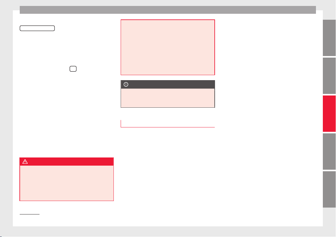
Driver assistance systems
this situation, the light of the
S
T
AR
T ENGINE STOP
button stays on
1)
.
As
soon a
s
the ignition is switched on, the
Start-Stop function is automatically activa-
ted.
Further information about the Start-Stop sys-
tem can be found in the Easy Connect
system: by pressing the
button in the
Vehicle status menu.
B
a
s
ic requirements for the Start-Stop mode
●
The driver door must be closed.
●
The driver must have their seat belt fas-
tened.
●
The bonnet must be closed.
●
The engine must have reached a minimum
service temperature.
●
The reverse gear must not be engaged.
●
The vehicle must not be on a very steep
slope.
WARNING
●
Never swit
ch the engine off until the vehi-
cle is stationary. The brake servo and power
steering functions will not be completely cov-
ered under warranty. More force may also be
needed to turn the steering wheel or to brake.
As you cannot steer and brake in the normal
manner, there is a greater risk of accidents
and serious injur
y.
●
Never remove the key from the ignition if
the vehicle is in motion. Otherwise, the steer-
ing could lock making it impossible to steer
the vehicle.
●
To avoid injury, make sure that the Start-
Stop system is switched off when working in
the engine compartment ››› page 207.
CAUTION
The Start-Stop system must always be
sw
itc
hed off when driving through flooded
areas ››› page 207.
Stopping/Starting the engine
Vehicles with a manual gearbox
–
Before stopping the vehicle or when it is
s
t
op
ped, put it into neutral and release the
clutch pedal. The engine will switch off. The
warning lamp will appear on the instru-
ment panel display. The engine may stop
before the vehicle comes to a halt in the
deceleration phase (at 7 km/h).
–
When the clutch pedal is pressed the en-
gine will start up again. The warning lamp
will switch off.
Vehicles with an automatic gearbox
–
Use the foot brake to bring the vehicle to a
stop and keep the brake pedal pressed
down with your foot. The engine will switch
off. The warning lamp will appear in the
display. The engine may stop before the ve-
hicle comes to a halt in the deceleration
phase (at 7 km/h or 2 km/h, depending on
the vehicle’s gearbox).
–
When you take your foot off the brake pedal
the engine will start up again. The warning
lamp will switch off.
Additional information related to the auto-
matic gearbox
The engine stops when the selector lever is in
the positions P, D, N and S, in addition to
when in manual mode. With the selector lev-
er in position P, the engine will also remain
switched off when you take your foot off the
brake pedal. In order to start the engine up
again the accelerator must be pressed, or an-
other gear engaged or the brake released.
If the selector lever is placed in position R
during the stopping phase, the engine will
start up again.
Change from position D to P to prevent the
engine from accidentally starting when
changing and passing by position R.
»
1)
Only in vehicles with Keyless Access.
205
Technical dataAdviceOperationEmergenciesSafety

Operation
Additional information about vehicles with
Ad
aptiv
e C
ruise Control (ACC)
In vehicles with ACC function, the engine will
start up again in certain operating conditions
if the radar sensor detects that the vehicle
ahead drives off again.
Note
●
In vehic
les with an automatic gearbox, you
can control whether the engine should switch
off or not by reducing or increasing the brake
force applied. While the vehicle remains stop-
ped, the engine will not stop if the brake ped-
al is slightly pressed, in traffic jams with fre-
quent stopping and starting for example. As
soon as strong pressure is applied to the
brake pedal, the engine will stop.
●
In vehicles with manual gearbox, during
the stopping phases the brake pedal must re-
main depressed to prevent the vehicle from
moving.
●
If the engine “stalls” in vehicles with man-
ual gearbox, it can be directly started up
again by immediately pressing the clutch
pedal.
General notes
The system can interrupt the Start-Stop mode
fr
equently
f
or different reasons.
The engine does not switch off
Before the stopping phase, the system veri-
fies whether certain conditions are met. The
engine does not switch off, in the following
situations for example:
●
The engine has not yet reached the mini-
mum required temperature for the Start-Stop
mode.
●
The interior temperature selected for the air
conditioner has not yet been reached.
●
The interior temperature is very high/low.
●
Defrost function button activated
›››
page 51.
●
The parking aid* is switched on.
●
The battery is very low.
●
The steering wheel is overly turned or is be-
ing turned.
●
If there is a danger of misting.
●
After engaging reverse gear.
●
In case of a very steep gradient.
The indication is shown on the instrument
panel display, and in addition, the driver in-
formation system* shows, .
The engine starts by itself
During a stopping phase the normal Start-
Stop mode can be interrupted in the follow-
ing situations: The engine restarts by itself
without involvement from the driver.
●
The interior temperature differs from the
value selected on the air conditioner.
●
Defrost function button activated
›››
page 51.
●
The brake has been pressed several times
consecutively.
●
The battery is too low.
●
High power consumption.
Note
In vehicles with an automatic gearbox, if the
selector l
ever is placed in position D, N or S
after engaging reverse gear, the vehicle must
be driven at a speed faster than 10 km/h (6
mph) for the system to return to conditions in
which the engine can be stopped.
206
Driver assistance systems
Manually switching on/off the Start-
St
op sy
s
tem
Fig. 186 Centre console: Start-Stop system
b
utt
on.
If you do not wish to use the system, you can
sw
it
c
h it off manually.
●
To manually switch on/off the Start-Stop
system, press the button ››› Fig. 186.
The symbol on the button remains lit up
yellow when the system is switched off, and
the following message is displayed on the
dash panel:
Start-Stop system deactivated
Note
The system is automatically switched on each
time the engine is
deliberately stopped dur-
ing a stopping phase. The engine will start
automatically.
Driver messages on the instrument
p
anel
di
splay
Start-Stop system deactivated.
Start the engine manually
This driv
er message is displayed when cer-
tain conditions are not met during the stop-
ping phase and the Start-Stop system cannot
restart the engine. The engine must be star-
ted manually.
Start-Stop system: Fault! Func-
tion not available
There is a fault in the Start-Stop system. Take
the vehicle to a workshop to have the fault
repaired.
Cruise control system (CCS)*
How it w
orks
Fig. 187 Instrument panel display: CCS status
indic
ation
s.
Read the additional information carefully
›
›
›
page 45
The cruise control system (CCS) is able to
maintain the set speed from 20 km/h (15
mph).
The CSS only reduces vehicle speed by ceas-
ing to accelerate, not by actively braking the
vehicle ›››
.
»
207
Technical dataAdviceOperationEmergenciesSafety
Operation
Control lamp
Lights up
The Cruise Control System (GRA) is switched on and ac-
tive.
OR: The Adaptive Cruise Control system (CCS) is switch-
ed on and active.
OR: the speed limiter is switched on and active.
Several warning and control lamps light up
for a few sec
onds when the ignition is switch-
ed on, signalling that the function is being
verified. They will switch off after a few sec-
onds.
Displayed on the CCS screen
Status Fig. 187:
CCS temporarily switched off. The set
speed is displayed in small or darkened
figures.
System error. Contact a specialised work-
shop.
CCS switched on. The speed memory is
empty.
The CCS is switched on. The set speed is
displayed in large figures.
WARNING
Use of the cruise control could cause acci-
dents and sev
ere injuries if it is not possible
A
B
C
D
to drive at a constant speed maintaining the
safety
distance.
●
Do not use the cruise control in heavy traf-
fic, if the distance from the vehicle in front is
insufficient, on steep roads, with several
bends or in slippery circumstances (snow,
ice, rain or loose gravel), or on flooded roads.
●
Never use the CCS when driving off-road or
on unpaved roads.
●
Always adapt your speed and the distance
to the vehicles ahead in line with visibility,
weather conditions, the condition of the road
and the traffic situation.
●
To avoid unexpected operation of the cruise
control system, turn it off every time you fin-
ish using it.
●
It is dangerous to use a set speed which is
too high for the prevailing road, traffic or
weather conditions.
●
When travelling down hills, the CCS cannot
maintain a constant speed. The vehicle tends
to accelerate under its own weight. Select a
lower gear or use the foot brake to slow the
vehicle.
WARNING
Observe the safety warnings ›››
in Warning
symbols on p
age 122.
Operating the cruise control system*
Read the additional information carefully
›››
page 45
The value indicated in the table in brackets
(in mph, miles per hour) only refers to instru-
ment panels with indications in miles.
Changing gear in CCS mode
The CCS decelerates as soon as the clutch
pedal is pressed, intervening again automati-
cally after a gear is engaged.
Travelling down hills with the CCS
When travelling down hills the CCS cannot
maintain a constant speed. Slow the vehicle
down using the brake pedal and reduce
gears if required.
Automatic off
The cruise control system (CCS) is switched
off automatically or temporarily:
●
If the system detects a fault that could af-
fect the w
orking order of the CCS.
●
If you press and maintain the accelerator
pedal for a certain time, driving faster than
the stored speed.
●
If the dynamic driving control systems in-
tervene (e.g. ASR or ESC).
●
If the brake pedal is pressed.
●
If the airbag is triggered.
208
Driver assistance systems
●
If
the g
e
ar lever of the DSG
®
dual clutch
gearbox is removed from the D/S position.
WARNING
After use, always switch off the speed limiter
to prev
ent the speed being regulated against
your wishes.
●
The speed limiter does not relieve the driv-
er of their responsibility to drive at the appro-
priate speed. Do not drive at high speed if not
necessary.
●
Using the speed limiter with adverse
weather conditions is dangerous and can
cause serious accidents, e.g. because of
aquaplaning, snow, ice, leaves, etc. You
should use the speed limiter function only
when traffic, road and weather conditions al-
low it to be used safely.
●
When driving downhill, the speed limiter
cannot limit the vehicle speed. Its speed will
increase due to its own weight. In this case,
select a lower gear or use the foot brake to
slow the vehicle.
Speed limiter
Di
s
p
lay messages and warning and
control lamp
Fig. 188 On the instrument panel display:
me
s
s
ages on the status of the speed limiter.
The speed limiter helps avoid exceeding a
s
peed indiv
idual
ly programmed upwards of
approximately 30 km/h (19 mph) driving in
forwards gears ›››
Display messages on the speed limiter
St
at
u
s ››› Fig. 188:
The speed limiter is active. The last
speed set is displayed in large figures.
The speed limiter is not active. The last
speed set is displayed in small or dark-
ened figures.
The speed limiter is switched off. The to-
tal mileage is displayed.
A
B
C
Warning and control lamp
Lights up green
The speed limiter is switched on and active.
Flashes green
The speed set by the speed limiter has been exceeded.
Lights up
The adaptive cruise control (ACC) and the speed limiter
are active.
Some warning and control lamps will light up
briefly
when the ignition i
s
switched on to
check certain functions. They will switch off
after a few seconds.
WARNING
After use, always switch off the speed limiter
to prev
ent the speed being regulated against
your wishes.
●
The speed limiter does not relieve the driv-
er of their responsibility to drive at the appro-
priate speed. Do not drive at high speed if not
necessary.
●
Using the speed limiter with adverse
weather conditions is dangerous and can
cause serious accidents, e.g. because of
aquaplaning, snow, ice, leaves, etc. You
should use the speed limiter function only
when traffic, road and weather conditions al-
low it to be used safely.
»
209
Technical dataAdviceOperationEmergenciesSafety
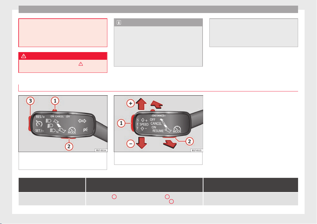
Operation
●
When driving do
wnhill, the speed limiter
cannot limit the vehicle speed. Its speed will
increase due to its own weight. In this case,
select a lower gear or use the foot brake to
slow the vehicle.
WARNING
Observe the safety warnings ›
››
in Warning
symbols on p
age 122.
Note
●
Different
versions of the instrument panel
are available and therefore the versions and
instructions on the display may vary.
●
If when switching the ignition off, the
cruise control system (CCS), the adaptive
cruise control (ACC) or the speed limiter were
switched on, then the cruise control system
or the adaptive cruise control will automati-
cal
ly switch themselves on when the ignition
is back on. However, no speed will be stored.
The last set speed of the speed limiter will be
stored.
Operate the speed limiter
Fig. 189 On the left of the steering column:
contro
l and buttons to operate the speed lim-
iter.
Fig. 190 On the left of the steering column:
third lev
er for operating the speed limiter.
Function
Position of the turn signal lever ››› Fig. 189
or the third lever ››› Fig. 190
Effect
Switching on the speed limiter
Move controller
1
to position
and press button
2
of the turn signal
lever or move the third lever forward and press button
2
.
The system switches on. The last set speed of the speed lim-
iter is stored. It does not take effect yet.
210
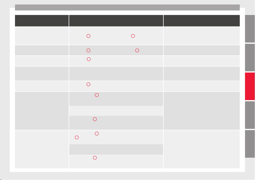
Driver assistance systems
Function
Position of the turn signal lever ››› Fig. 189
or the third lever ››› Fig. 190
Effect
Switching between the speed limiter and
cruise control (CCS) or the adaptive cruise
control (ACC) (with the speed limiter
switched on)
Press button
2
on the turn signal lever or button
2
on the third lever
It switches between the speed limiter and the CCS or the
adaptive cruise control (ACC).
Activating the speed limiter Press button
3
on the turn signal lever or button
1
on the third lever.
The current speed is stored as the maximum speed and the
limiter is switched on.
Temporarily switching off the speed limit-
er limitation
Place control
1
of the turn signal lever in position
or move the third
lever into position
.
The limiter is switched off temporarily. The speed will be
stored.
Temporarily switch off the speed limiter
limitation pressing down the accelerator
(kick-down)
Press down on the accelerator beyond the point of resistance (e.g. to over-
take). Surpassing the set speed switches the speed limiter off temporarily.
The limiter is switched off temporarily. The speed will be
stored. The limiter is reactivated automatically after return-
ing to less than the set speed.
Switching the speed limiter on again
Press button
3
on the turn signal lever or move the third lever into posi-
tion
.
The speed is limited to the set speed as soon as the speed
you are driving at is lower than the speed set as maximum.
Increasing the set speed of the limiter
Briefly press button
3
on the turn signal lever in the
area or move
the third lever into position
to increase the speed in small incre-
ments of 1 km/h (1 mph) and set it.
The speed is limited to the set value
Press
on the third lever to increase the speed in increments of
10 km/h (5 mph) and set it.
Hold down button
3
on the turn signal lever in the area
or hold
down
to increase continuously in increments of 10 km/h (5 mph)
and set it.
Reducing the set speed of the limiter
Briefly press button
3
on the turn signal lever in the
area or press
1
on the third lever to reduce the speed in small increments of 1 km/h
(1 mph) and set it.
The speed is limited to the set value
Press
on the third lever to reduce the speed in increments of
10 km/h (5 mph) and set it.
Hold down button
3
on the turn signal lever in the
area or hold
down
to reduce the speed continuously in increments of 10 km/h
(5 mph) and set it.
»
211
Technical dataAdviceOperationEmergenciesSafety
Operation
Function
Position of the turn signal lever ››› Fig. 189
or the third lever ››› Fig. 190
Effect
Switching off the speed limiter
Move control
1
of the turn signal lever into position
or the third lever
into position
.
The system switches off
The values shown in the table in brackets, in
mph, are dis
played only in instrument panels
with indications in miles.
Going down slopes with the speed limiter
If the set speed of the speed limiter is excee-
ded while driving downhill, soon afterwards
the warning and control lamps
››› page 209 flash and an acoustic warning
may sound. In this case, use the foot brake to
slow the vehicle or, if necessary, select a low-
er gear.
Switching off temporarily
If you wish to temporarily switch off the
speed limiter, e.g. to overtake, move control
››› Fig. 189
1
of the turn signal lever into po-
sition
or the third lever into pressure
point or press button
2
on any lever.
After o
vertaking, the speed limiter can be
switched on with the previously set speed by
pressing button
3
on the turn signal lever in
the area
or by moving the third lever in-
to pressure point.
Switch the speed limiter off temporarily by
pressing down the accelerator (kick-down)
If the accelerator is pressed right down (kick-
down) and the set speed is exceeded be-
cause driver wishes to do so, the limiter is
temporarily disabled.
To confirm it being switched off an acoustic
signal sound once. While the limiter is off,
the warning and control lamp flashes.
When the accelerator is no longer pressed
down and the speed is reduced below the set
value, the limiter switches on again. The con-
trol lamp will light up and remain lit.
Automatic off
The speed limiter is automatically switched
off:
●
If the system detects a fault that could neg-
atively affect the working order of the limiter.
●
If the airbag is triggered.
CAUTION
For automatic switching off due to system
failur
es, for security reasons, the limiter is
only completely switched off when the driver
stops pressing the accelerator at some point
or c
on
s
ciously switches off the system.
Emergency brake assist system
(Fr
ont
As
sist)*
Topic introduction
Fig. 191 On the instrument panel display:
pre-warnin
g messages.
The objective of the emergency brake assist
syst
em is to prevent head-on collisions
against objects that may be in the vehicle’s
path or minimise the consequences of such
impacts.
212

Driver assistance systems
Within the limitations imposed by the envi-
r
onment
al
conditions and by the system it-
self, the function acts in staggered fashion,
depending on how critical the situation is. In-
itially it warns the driver, and if the driver’s
reaction does not occur or is insufficient, it
activates an independent emergency brak-
ing.
The function is intended to prevent collisions
with parked vehicles or vehicles in the same
lane travelling in the same direction, or with
pedestrians crossing the vehicle’s path. It
may fail to activate in other danger situa-
tions.
The Front Assist function is active within a
range of speeds between 4 km/h (2.5 mph)
and 250 km/h (156 mph). Depending on
speed, traffic conditions and driver behav-
iour, some of the sub-functions described be-
low are omitted in order to optimise the sys-
tem’s general behaviour.
The Front Assist is a driving assistance func-
tion that can never replace the driver’s atten-
tion.
Safety distance warning
If the system detects a situation of danger
because the vehicle is too close to the vehi-
cle ahead, it will warn the driver by means of
an indication on the instrument panel display
.
The timing of the warning varies depending
on driver behaviour and the traffic situation.
Advance warning
If the system detects a possible collision with
the vehicle in front, it may alert the driver by
means of an audible warning and an indica-
tion on the instrument panel display
››› Fig. 191.
The warning moment varies depending on
the traffic situation and driver behaviour. At
the same time, the vehicle will prepare for a
possible emergency braking ›››
.
C
ritic
a
l warning
If the driver fails to react to the pre-warning
(advance warning), the system may actively
intervene in the brakes and generate a brief
jolt to warn the driver of the imminent danger
of a collision.
Automatic braking
If the driver also fails to react to the critical
warning, the system may initiate independ-
ent emergency braking by progressively in-
creasing the braking effect in accordance
with how critical the situation is.
Driver emergency brake assist system
Faced with an imminent collision, the system
may detect that the driver is not braking hard
enough to avoid the collision. In this case, it
will automatically increase the braking effect.
Due to certain driving circumstances and the
limitations of its operation, there are some
cases in which the system cannot prevent a
collision, although it can significantly mini-
mise the consequences by reducing the
speed and the force of the impact.
WARNING
Observe the safety warnings ›››
in Warning
symbols on p
age 122.
WARNING
The Front Assist system cannot change the
law
s of physics or replace the driver in terms
of keeping control of the vehicle and reacting
to a possible emergency situation.
WARNING
Following a Front Assist emergency warning,
pay
immediate attention to the situation and
try to avoid the collision by braking or by
dodging the obstacle, as applicable.
●
If the Front Assist does not work as descri-
bed in this chapter (e.g. it repeatedly inter-
venes unnecessarily), switch it off.
●
Adapt your speed and safe distance to the
vehicle in front of you at all times to suit visi-
bility, weather, road and traffic conditions.
●
The Front Assist alone cannot avoid acci-
dents and serious injuries.
»
213
Technical dataAdviceOperationEmergenciesSafety
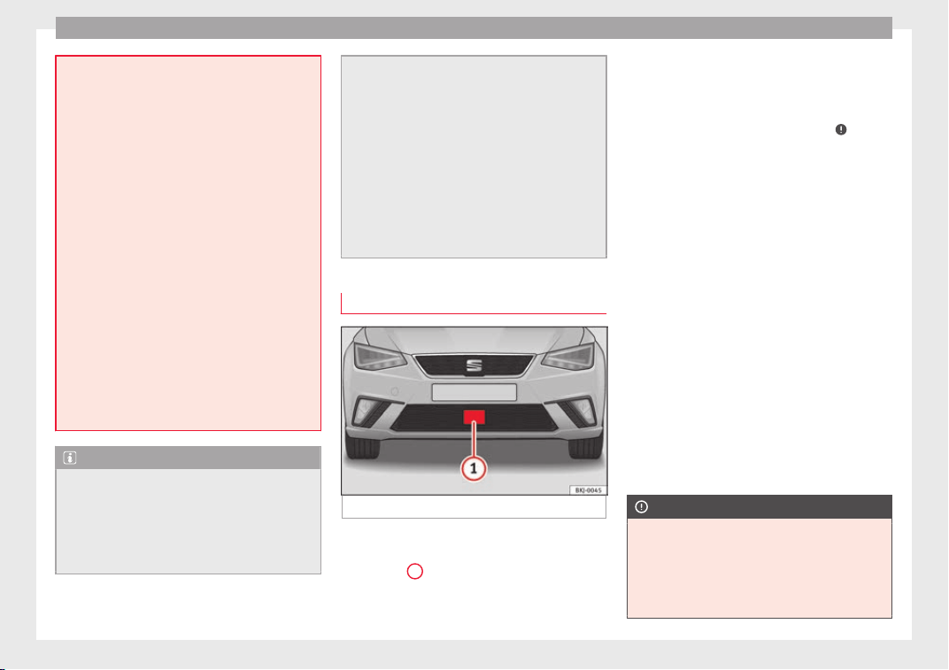
Operation
●
In compl
ex driving situations, occasionally
the Front Assist may issue warnings and in-
tervene in braking unnecessarily, for example
at traffic islands.
●
If the operation of the Front Assist is im-
paired, for example, by dirt or because the ra-
dar sensor has lost its settings, the system
may issue unnecessary warnings and inter-
vene inopportunely in the braking.
●
The Front Assist does not react to animals
or vehicles crossing your path or approaching
head-on down the same lane.
●
The Front Assist does not react to pedes-
trians walking in the same direction or ap-
proaching head-on down the same lane.
●
The driver must always be ready to take
over the control of the vehicle.
●
When the Front Assist causes a braking,
the brake pedal is “harder”.
●
Automatic interventions by the Front Assist
on the brakes may be interrupted by pressing
the clutch, accelerator or moving the wheel.
Note
●
When the Front As
sist is connected, the in-
dications on the instrument panel screen may
be concealed by warnings from other func-
tions, such as an incoming call.
●
When the Front Assist causes a braking,
the brake pedal is “harder”.
●
Automatic
interventions by the Front Assist
on the brakes may be interrupted by pressing
the clutch, accelerator or moving the wheel.
●
The Front Assist may brake the vehicle until
it stops completely. However, the brake sys-
tem does not halt the vehicle permanently.
Use the foot brake!
●
If the Front Assist does not work as descri-
bed in this chapter (e.g. in intervenes several
times unnecessarily), switch it off. Have the
system checked by a specialised workshop.
SEAT recommends visiting a SEAT dealership.
Radar sensor
Fig. 192 On the front bumper: radar sensor.
A radar sensor is installed on the front bump-
er t
o det
ermine the tr
affic situation
››› Fig. 192
1
.
The r
a
d
ar sensor's visibility may be impaired
by dirt, mud or snow, or by environmental in-
fluences such as rain or mist. In this case, the
Front Assist does not work. The instrument
panel displays the following message:
Front Assist: No sensor vision! If
necessary clean the radar sensor ›››
.
When the r
a
d
ar sensor begins to operate
properly again, the Front Assist will automati-
cally be available again. The message will
disappear from the instrument panel display.
Front Assist operation may be affected by a
strong radar reverse reflection. This may oc-
cur, for example, in a closed car park or due
to the presence of metallic objects (e.g. rails
on the road or sheets used in road works).
The area in front of and around the radar sen-
sor should not be covered with adhesives,
additional or similar headlights, as this may
negatively affect Front Assist operation.
If the front of the vehicle is not properly re-
paired or structural modifications are made
to it, for example if the suspension is low-
ered, Front Assist operation may be affected.
SEAT recommends visiting a SEAT dealership
for this purpose.
CAUTION
If you have the sensation that the radar sen-
sor is d
amaged or has lost its settings, dis-
connect the Front Assist. This will avoid pos-
sible dangerous situations caused by a sys-
tem malfunction. If this occurs have it adjus-
ted.
214
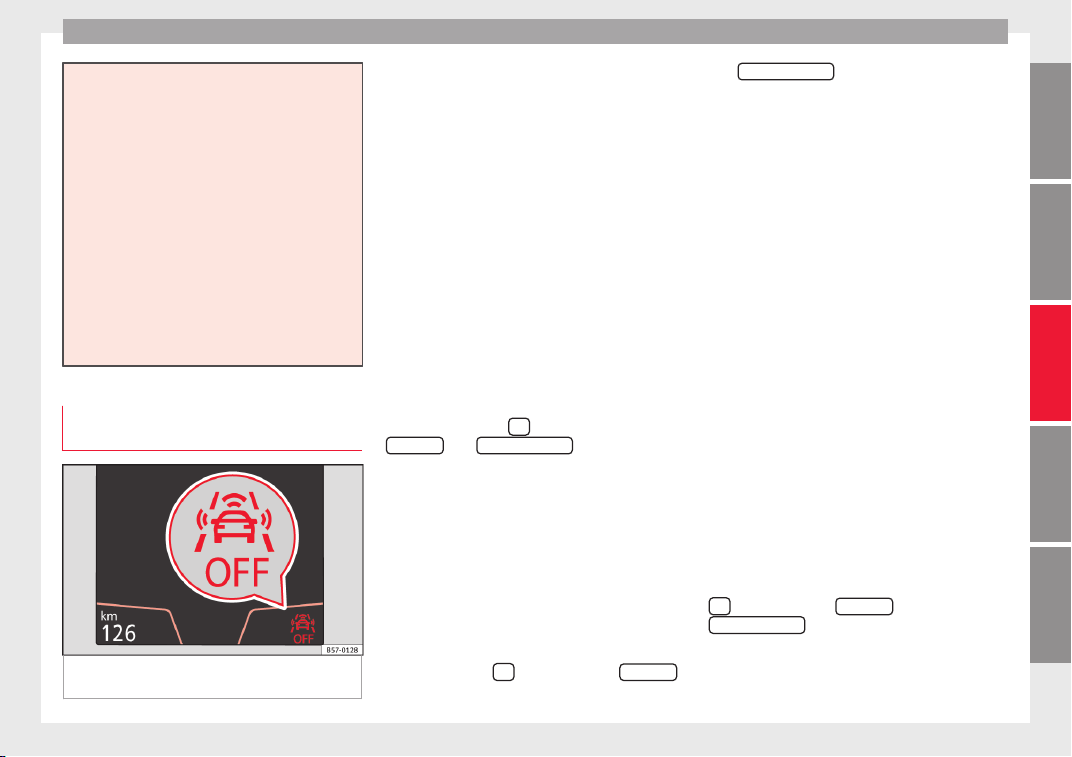
Driver assistance systems
●
The sensor ma
y become damaged or lose
its settings when knocked, for example, dur-
ing a parking manoeuvre. This may compro-
mise the system's efficacy or disconnect it.
●
Repairs to the radar sensor require special-
ist knowledge and special tools. SEAT recom-
mends visiting a SEAT dealership for this pur-
pose.
●
A registration plate or plate holder on the
front that is larger than the space for the reg-
istration plate, or a registration plate that is
curved or warped can cause the radar to mal-
function.
●
Clean away the snow with a brush and the
ice preferably with a solvent-free de-icer
spray.
Operating the Emergency braking as-
s
i
s
tance system (Front Assist)
Fig. 193 On the instrument panel display:
Fr
ont
As
sist switched off message.
The Front Assist is active whenever the igni-
tion i
s
sw
itched on.
When the Front Assist is switched off, so too
are the advance warning function (pre warn-
ing) and the distance warning.
SEAT recommends leaving the Front Assist al-
ways switched on. Exceptions ››› page 216,
Switching the Front Assist off temporarily in
the following situations.
Switching the Front Assist on and off
With the ignition switched on, the Front As-
sist can be switched on and off as follows:
●
Select the corresponding menu option us-
ing the button for the driver assistance sys-
tems ›››
page 37.
●
OR: switch the system on and off in Easy
Connect using the
button and the
S
ET
TINGS
and
Driv
er a
s
sistance
function but-
t
on
s
›››
page 34.
When Front Assist is switched off, the instru-
ment panel will inform that it has been
switched off with the following indicator
››› Fig. 193.
Activating or deactivating the pre-warning
(advance warning)
The pre-warning function (advance warning)
can be switched on or off in the Easy Connect
system with the
button and the
S
ET
TINGS
and
Driv
er a
s
sistance
function buttons
›
›
›
page 34.
The system will store the setting for the next
time the ignition is switched on.
SEAT recommends keeping the pre-warning
function switched on at all times.
Depending on the infotainment system in-
stalled in the vehicle, the advance warning
function may be adjusted as follows:
●
Advance
●
Medium
●
Delayed
●
Deactivated
SEAT recommends driving with the function
in “Medium” mode.
Switching distance warning on and off
If the safe distance with regard to the vehicle
in front is exceeded, the relevant warning will
appear on the instrument panel display
. In this case, increase the safe dis-
tance.
The distance warning can be switched on and
off in the Easy Connect system using the
button and the
S
ET
TINGS
and
Driv
er a
s
sistance
function buttons
›
›
›
page 34.
The system will store the setting for the next
time the ignition is switched on.
»
215
Technical dataAdviceOperationEmergenciesSafety
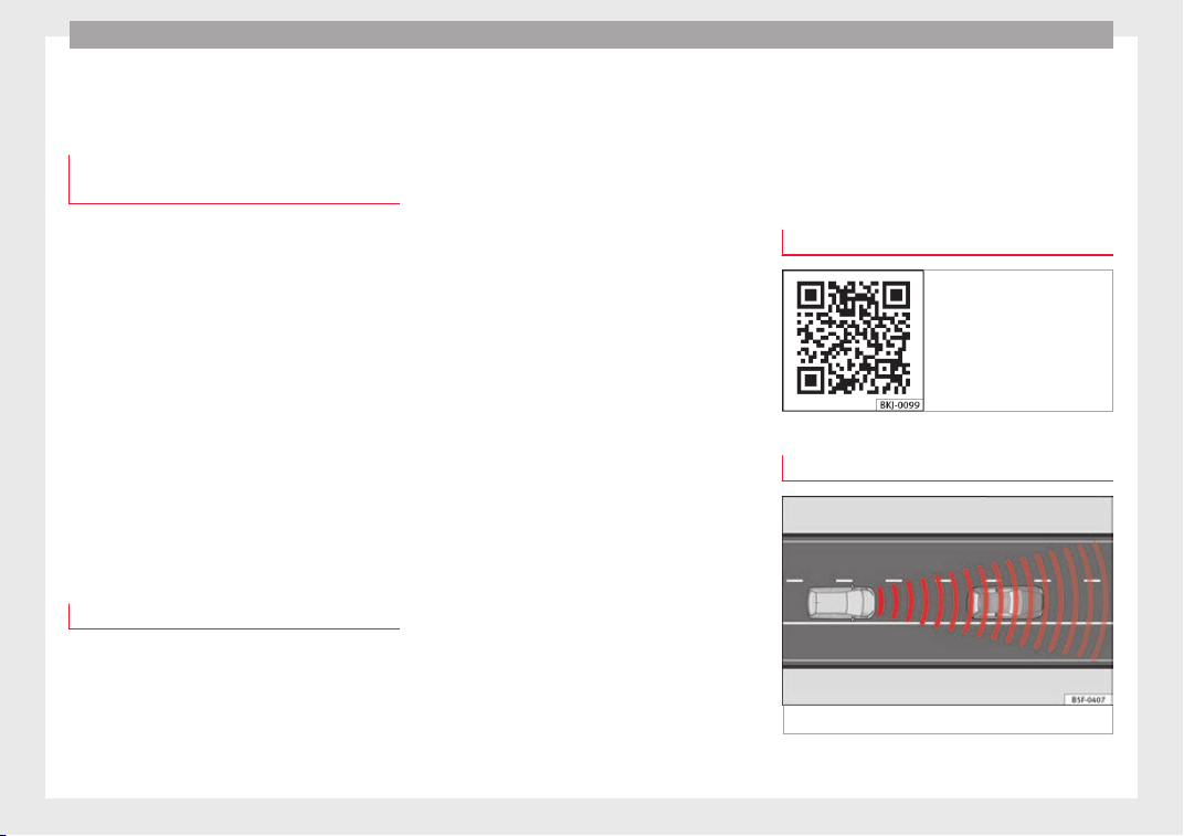
Operation
SEAT recommends keeping the distance
w
arnin
g sw
itched on at all times.
Switching the Front Assist off tempo-
rarily in the following situations
In the following situations the Front Assist
should be de
activated due to the system's
limitations:
●
When the vehicle is to be towed.
●
If the vehicle is on a test bed.
●
When the radar sensor is damaged.
●
If the radar sensor takes a heavy knock, for
examp
le in a rear collision.
●
If it intervenes several times unnecessarily.
●
If the radar sensor is covered temporarily
with some kind of accessory, such as an ad-
ditional headlight or the like.
●
When the vehicle is to be loaded on a lorry,
ferry or train.
System limitations
The Front Assist has certain physical limita-
tion
s
inher
ent to the system. Thus, in certain
circumstances, some of the system's reac-
tions may be inopportune from the driver's
standpoint. So pay attention in order to inter-
vene if necessary.
The following conditions may cause the Front
Assist not to react or to do so too late:
●
In the first few instants of driving after
switching on the ignition, due to the system’s
initial auto-calibration.
●
On taking tight bends or complex paths.
●
Pressing the accelerator all the way down.
●
If the Front Assist is switched off or dam-
aged.
●
If the ASR has been disconnected or the
ESC activated in Sport mode manually
››› page 185.
●
If the ESC is controlling.
●
If several brake lights of the vehicle or elec-
trically connected trailer are damaged.
●
If the radar sensor is dirty or covered.
●
If there are metal objects, e.g. rails on the
road or sheets used in road works.
●
If the vehicle is reversing.
●
If the vehicle over-accelerates.
●
In case of snow or heavy rain.
●
In case of narrow vehicles, such as motor-
bikes.
●
Misaligned vehicles.
●
Vehicles crossing the other's path.
●
Vehicles approaching in the opposite direc-
tion.
●
Special loads and accessories of other ve-
hicles that jut out over the sides, backwards
or over the top.
Adaptive Cruise Control (ACC)*
Related video
Fig. 194 Safety
Topic introduction
Fig. 195 Detection area.
216
Driver assistance systems
The adaptive cruise control (ACC) i
s
an e
xten-
sion of the normal cruise control system
(CCS) ›››
.
The A
C
C
function allows the driver to program
a cruise speed of between 30 and 210 km/h
(18 and 150 mph) and to select the distance
required with regard to the vehicle in front.
The ACC will adapt the vehicle's cruise speed
at all times, maintaining a safe distance with
the vehicle in front based on its speed.
When driving behind another vehicle, the
ACC function reduces speed until it is the
same as that of the vehicle ahead and main-
tains the set distance between the vehicles.
If the vehicle ahead accelerates, the adaptive
cruise control also accelerates, going no
higher than the target speed programmed.
If the vehicle is equipped with automatic
gearbox, the ACC can brake the vehicle until
it stops completely if a vehicle in front of it
stops.
The distance programmed should be in-
creased when the road surface is wet.
Driver intervention prompt
During driving, the ACC is subject to certain
limitations inherent in the system. In other
words, in certain circumstances the driver will
have to adjust speed him or herself, as well
as the distance from other vehicles.
In this case, the instrument panel screen will
warn you to intervene by applying the brake
and a warning tone will be heard
››› page 218.
WARNING
The intelligent technology in the ACC cannot
over
come the system's inherent limitations
or change the laws of physics. If used negli-
gently or involuntarily, it may cause serious
accidents and injuries. The system is not a re-
placement for driver awareness.
●
Adapt your speed and safe distance to the
vehicle in front of you at all times to suit visi-
bility, weather, road and traffic conditions.
●
Do not use the ACC when visibility is bad,
on steep roads, with several bends or in slip-
pery circumstances such as snow, ice, rain or
loose gravel, or on flooded roads.
●
Never use the ACC when driving off-road or
on unpaved roads. The ACC has been de-
signed for use on paved roads only.
●
The ACC does not react on approaching a
fixed obstacle, such as the tail of a traffic
jam, a damaged vehicle or a vehicle stopped
at the traffic lights.
●
The ACC only reacts to people if a pedes-
trian monitoring system is available. In addi-
tion, the system does not react to animals or
vehicles crossing your path or approaching
head-on down the same lane.
●
If the ACC does not reduce speed sufficient-
ly, brake the vehicle immediately by applying
the pedal.
●
If y
ou are driving using the spare wheel,
the ACC function could automatically switch
off during your journey. Switch off the system
when starting off.
●
If the vehicle continues to move involuntar-
ily after a driver intervention prompt, brake
the vehicle by applying the pedal.
●
If the dash panel displays a driver interven-
tion prompt, adjust the distance yourself.
●
The driver should be ready to accelerate or
brake by him/herself at all times.
CAUTION
If you have the sensation that the radar sen-
sor is d
amaged, disconnect the ACC. This will
avoid possible damage. If this occurs have it
adjusted.
●
Repairs to the radar sensor require special-
ist knowledge and special tools. SEAT recom-
mends visiting a SEAT dealership for this pur-
pose.
Note
●
If the AC
C system does not work as descri-
bed in this chapter, do not use it until it has
been checked by a specialised workshop.
SEAT recommends visiting a SEAT dealership
for this purpose.
●
Maximum speed with the ACC activated is
limited to 210 km/h (150 mph).
»
217
Technical dataAdviceOperationEmergenciesSafety
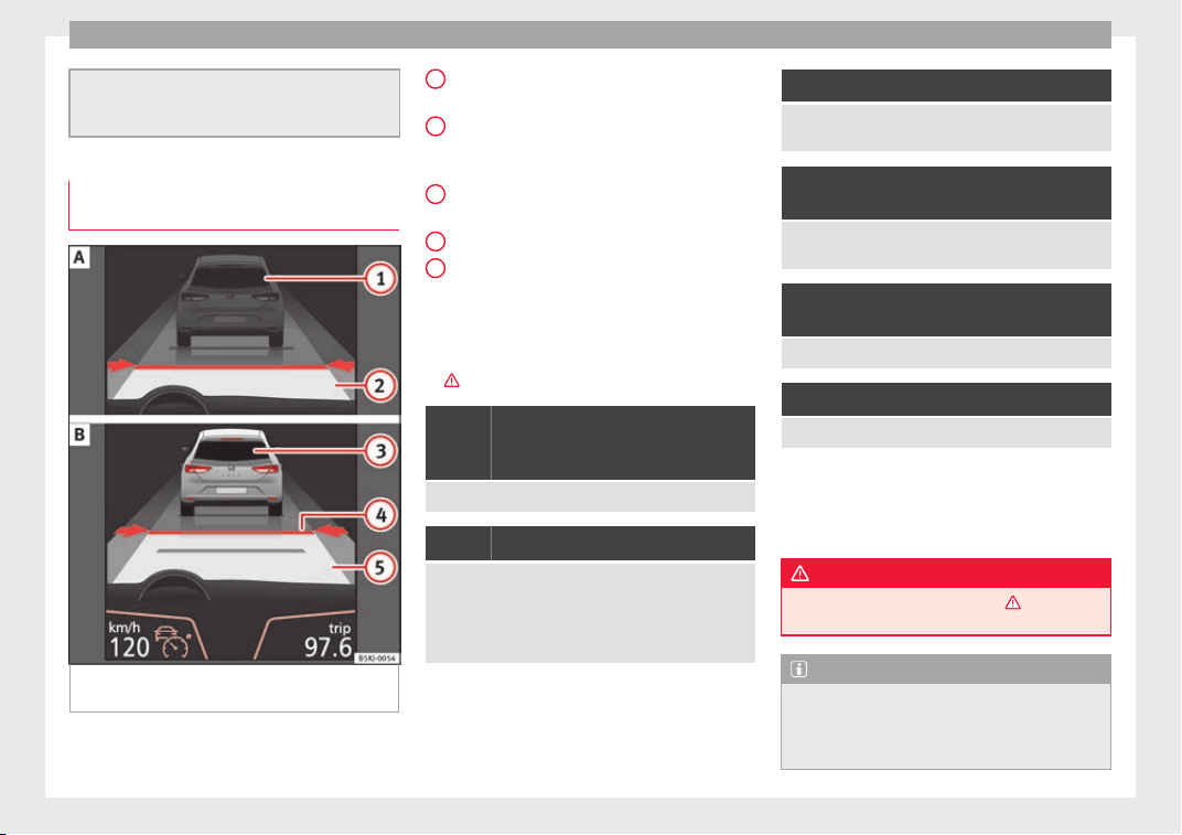
Operation
●
When the ACC
is switched on, strange
noises may be heard during automatic
braking cause by the braking system.
Indications on the display, warning
and contro
l lamps
Fig. 196 On the instrument panel display: (A)
A
C
C
inactive (Standby). (B) ACC active.
Status display
Indic
ation
s
on the display
›››
Fig. 196:
Vehicle ahead detected. ACC is not active
and is not regulating your speed.
Distance from the vehicle ahead. ACC is
not active and is not regulating your dis-
tance.
Vehicle ahead detected. ACC is active and
is regulating your speed.
Distance level 2 set by the driver.
ACC is active and is regulating your dis-
tance based on speed.
Symbols on the instrument panel display
and control lamps.
›››
in Warning symbols on page 122.
The speed reduction by the ACC to
maintain the distance from the vehi-
cle in front is not sufficient.
Brake! apply the foot brake! Driver intervention prompt.
The ACC is not currently available.
a)
With the vehicle stationary, switch off the engine and
start it up again. Check the radar sensor visually
››› Fig. 197 (for dirt, ice or knocks). If it is still unavaila-
ble, refer to a specialised workshop to have the system
inspected.
a)
The symbol on the instrument panels with colour display is in
colour.
1
2
3
4
5
The ACC is active.
No vehicle is detected in front. The programmed speed
remains constant.
If the symbol is white: the ACC is ac-
tive.
A vehicle in front has been detected. The ACC adjusts
speed and distance from the vehicle in front.
If the symbol is grey: ACC is inactive
(Standby)
The system is switched on, but is not adjusting.
It lights up green:
The ACC is active.
Some warning and control lamps will light up
briefly
when the ignition i
s
switched on to
check certain functions. They will switch off
after a few seconds.
WARNING
Observe the safety warnings ›››
in Warning
symbols on p
age 122.
Note
When the ACC is connected, the indications
on the instrument
panel screen may be con-
cealed by warnings from other functions,
such as an incoming call.
218
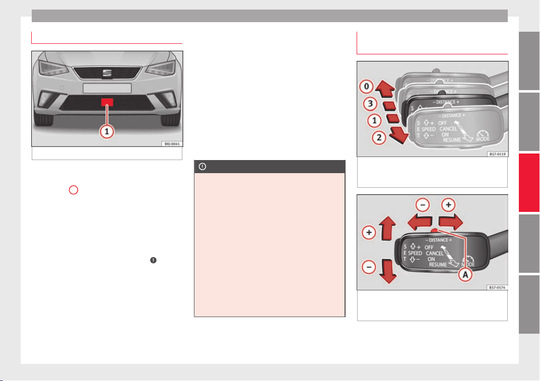
Driver assistance systems
Radar sensor
Fig. 197 On the front bumper: radar sensor.
A radar sensor is installed on the front bump-
er t
o det
ermine the tr
affic situation
›››
Fig. 197
1
.
The r
a
d
ar sensor's visibility may be impaired
by dirt, mud or snow, or by environmental in-
fluences such as rain or mist. In this case the
adaptive cruise control (ACC) does not work.
The instrument panel displays the following
message: ACC: No sensor vision! If
necessary clean the radar sensor
›››
.
When the r
a
d
ar sensor begins to operate
properly again, the ACC will automatically be
available again. The message on the instru-
ment panel screen will switch off and the ACC
will be reactivated again.
ACC operation may be affected by a strong ra-
dar reverse reflection. This may occur, for ex-
ample, in a closed car park or due to the
presence of metallic objects (e.g. rails on the
road or sheets used in road works).
The area in front of and around the radar sen-
sor should not be covered with adhesives,
additional or similar headlights, as this may
negatively affect ACC operation.
If the front of the vehicle is not properly re-
paired or structural modifications are made
to it, for example, if the suspension is low-
ered, ACC operation may be affected. In this
scenario, SEAT recommends visiting a SEAT
dealership.
CAUTION
If you have the sensation that the radar sen-
sor is d
amaged or has lost its settings, dis-
connect the ACC. This will avoid possible
damage. If this occurs have it adjusted.
●
The sensor may become damaged or lose
its settings when knocked, for example, dur-
ing a parking manoeuvre. This may compro-
mise the system's efficacy or disconnect it.
●
Repairs to the radar sensor require special-
ist knowledge and special tools. SEAT recom-
mends visiting a SEAT dealership for this pur-
pose.
●
Clean away the snow with a brush and the
ice preferably with a solvent-free de-icer
spray.
Operating the Adaptive Cruise Control
(A
C
C)
Fig. 198 On the left of the steering column:
thir
d l
ev
er for operating the Adaptive Cruise
Control.
Fig. 199 On the left of the steering column:
thir
d l
ev
er for operating the Adaptive Cruise
Control.
When the Adaptive Cruise Control (ACC) is
c
onnect
ed, the gr
een control lamp will
light up on the instrument panel, and the
»
219
Technical dataAdviceOperationEmergenciesSafety

Operation
programmed speed and ACC status will be
di
s
p
layed ››› Fig. 196.
What ACC settings are possible?
●
Setting your speed ››› page 220.
●
Setting your distance ››› page 220.
●
Connecting and activating the ACC
››› page 220.
●
Disconnecting and deactivating the ACC
››› page 220.
●
Adjusting the default distance level at the
start of your journey ››› page 220.
●
Adjusting the driving profile ››› page 221.
●
Conditions in which the ACC does not react
››› page 221.
Setting speed
To set your speed, move the third lever loca-
ted in position
1
upwards or downwards un-
ti
l
the de
sired speed is shown on the instru-
ment panel display. The speed adjustment is
made at 10 km/h (6 mph) intervals.
Once you are driving, if you wish to set the
current speed as the vehicle’s cruise speed
and activate the ACC, press the button
››› Fig. 199. If you wish to increase or reduce
speed by intervals of 1 km/h (0.6 mph),
move the lever to position
2
›
›
›
Fig. 198 or
press the button, respectively.
The set speed can be changed when the ve-
hicle is stopped or during driving, as you like.
Any modification to the programmed speed
will be shown on the bottom left part of the
instrument panel display ››› Fig. 196.
Setting your distance level
To increase/reduce the distance level, press
the rocker switch towards the left/right
››› Fig. 199
A
.
The in
s
trument
panel display shows the mod-
ification of the distance level. There are 5 dis-
tance levels to choose from. SEAT recom-
mends level 3. The set distance can be
changed when the vehicle is stopped or dur-
ing driving, as you like ›››
.
C
onnectin
g and activ
ating the ACC
To connect and activate the ACC, the position
of the gearbox selector lever, the vehicle
speed and the position of the third level of
the ACC must all be taken into account.
●
With a manual gearbox, the gearbox selec-
tor lever must be in any gear except first, and
speed must be greater than approximately 30
km/h. With an automatic gearbox, the gear-
box selector lever must be in position D or S.
●
To activate the ACC, with the third lever in
position
1
press the b
utt
on or mo
ve the
third lever of the ACC to position
2
›››
Fig. 198. At this
point, the image of the
ACC on the instrument panel display will
switch to Active mode ››› Fig. 196.
When the ACC function is active, the vehicle
travel
s at a set speed and distance from the
vehicle ahead. Both speed and distance can
be changed at any time.
Disconnecting and deactivating the ACC
To disconnect the ACC move the lever to the
0
position ›
›› Fig. 198
(en
gaged). An ACC
deactivated message appears and the
function is totally deactivated.
If you do not wish to disconnect the ACC, just
to switch it temporarily to inactive mode
(Standby), move the third lever to position
3
››› Fig. 198 or pres
s the brake pedal.
It will also switch to inactive mode (Standby)
if the vehicle is stopped and the driver door
is opened.
Adjusting the default distance level at the
start of your journey.
In wet road conditions, you should always set
a larger distance with regard to the vehicle in
front than when driving in dry conditions.
The following distances can be preselected:
●
Very short
●
Short
●
Media
●
Long
●
Very long
220
Driver assistance systems
In the Easy Connect system you can adjust
the di
s
t
ance level that will be applied when
the ACC is connected using the
button
and the
S
ET
TINGS
and
Driv
er a
s
sistance
function
b
utt
on
s ›››
page 34.
Changing the driving profile
In vehicles with SEAT Drive Profile, the driving
profile selected can have an influence on the
ACC’s acceleration and braking behaviour
››› page 225.
In vehicles without SEAT Drive Profile, the be-
haviour of the ACC can also be affected by se-
lecting any of the following drive profiles in
the Easy Connect system:
●
Normal
●
Sport
●
Eco
●
Convenience
In this case, you should access the ACC set-
tings using the
button and the
S
ET
TINGS
>
Driv
er a
s
sistance
>
A
C
C
function buttons
›
›
›
page 34.
The following conditions may lead the ACC
not to react:
●
If the accelerator is pressed.
●
If there is no gear engaged.
●
If the ESC is controlling.
●
If the driver is not wearing his/her seat
belt.
●
If several brake lights of the vehicle or elec-
trically connected trailer are damaged.
●
If the vehicle is reversing.
●
Driving faster than 210 km/h (150 mph).
Driver messages
ACC not available
The system can no longer continue to guar-
antee safe vehicle detection and will be de-
activated. The sensor has lost its setting or is
damaged. Take the vehicle to a specialised
workshop and have the fault repaired.
ACC and Front Assist: cur-
rently not available. No sensor
vision
This message will be displayed to the driver if
the radar sensor's vision is impaired due, for
example, to leaves, snow, heavy fog or dirt.
Clean the sensor ››› Fig. 197.
ACC: currently not available.
Gradient too steep
The maximum road slope has been excee-
ded, hence safe ACC operation cannot be
guaranteed. The ACC cannot be switched on.
ACC: only available in D, S
or M
Select the D/S or M position on the selector
lever.
ACC: parking brake applied
The ACC is deactivated if the parking brake is
applied. The ACC is available once again after
the parking brake is released.
ACC: currently not available.
Intervention of stability con-
trol
The message for the driver is displayed when
the electronic stability control (ESC) inter-
venes. In this case, the ACC is automatically
switched off.
ACC: Take action!
The message for the driver is displayed if,
when the vehicle starts up on a hill with a
mild slope, the vehicle rolls back even al-
though the ACC is activated. Apply the brake
to stop the vehicle from moving/colliding
with another vehicle.
ACC: speed limit
The message for the driver is displayed if, in
vehicles with manual gearbox, the current
speed is too low for the ACC mode.
The speed to be stored must be at least
30 km/h (18 mph). The speed limiter
switches off if the speed falls below 20 km/h
(12 mph).
ACC: available as of the 2nd
gear
»
221
Technical dataAdviceOperationEmergenciesSafety
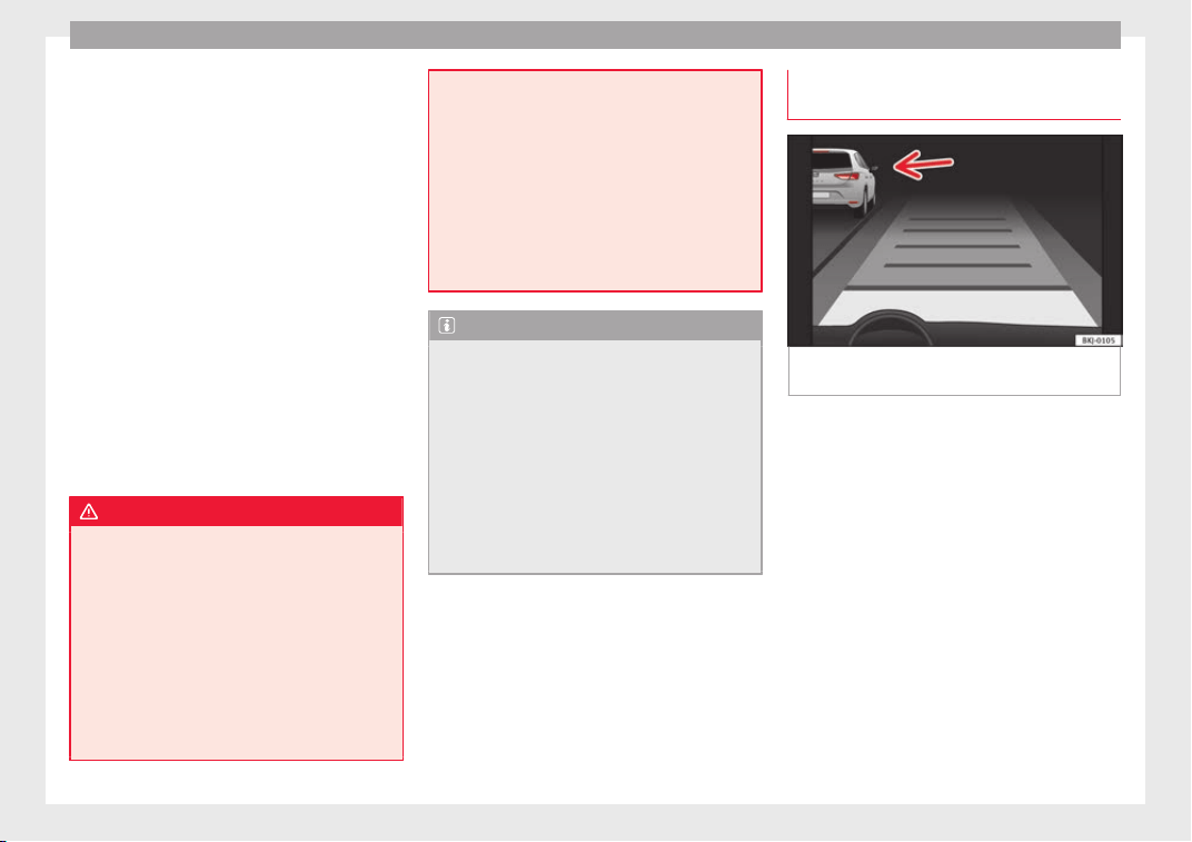
Operation
The ACC is operational as of the 2nd gear
(m
anual
g
earbox).
ACC: engine speed
The message for the driver is displayed if,
when the ACC accelerates or brakes, the driv-
er does not shift up or down a gear in time,
which means exceeding or not reaching the
permissible engine speed. The ACC switches
itself off. A buzzer warning is heard.
ACC: clutch pressed
Vehicles with a manual gearbox: pressing the
clutch pedal for longer abandons control
mode.
Door open
Vehicles with automatic gearbox: the ACC
cannot be activated with the vehicle station-
ary and the door open.
WARNING
There is a danger of rear collision when the
minimum dist
ance to the vehicle in front is
exceeded and the speed difference between
both vehicles is so great that a speed reduc-
tion by the ACC will not suffice. In this case
the brake pedal should be applied immedi-
ately.
●
The ACC may not be able to detect all situa-
tions properly.
●
“Stepping” on the accelerator may cause
the ACC not to intervene in braking. Driver
braking will have priority over intervention by
the speed contr
ol or adaptive cruise control.
●
Always be ready to use the brakes!
●
Observe country-specific provisions gov-
erning obligatory minimum distances be-
tween vehicles.
●
It is dangerous to activate control and re-
sume the programmed speed if the road, traf-
fic or weather conditions do not permit this.
Risk of accident!
Note
●
The pr
ogrammed s
peed is erased once the
ignition or the ACC are switched off.
●
When the traction control system (ASR) is
deactivated during acceleration or else the
ESC is activated in Sport* Mode
(››› page 123), the ACC switches off automati-
cally.
●
In vehicles with the Start-Stop system, the
engine switches off automatically during the
ACC stopping phase and restarts automatical-
ly to begin driving.
Function for preventing overtaking in
an in
s
ide l
ane
Fig. 200 On the instrument panel display:
A
C
C
active, vehicle detected in an outer lane.
The adaptive cruise control (ACC) has a func-
tion th
at
help
s avoid overtaking while driving
in inside lanes at certain speeds.
If another vehicle is detected travelling at a
slower speed in an outer lane, it is displayed
on the multifunction display ››› Fig. 200.
To avoid overtaking while driving in an inside
lane the system will gently brake, and in ac-
cordance with the speed will prevent the car
from overtaking. The driver can override this
function at any time by pressing the accelera-
tor pedal. At low speeds the function is inac-
tive, for greater comfort in a traffic jam or in
city traffic.
222
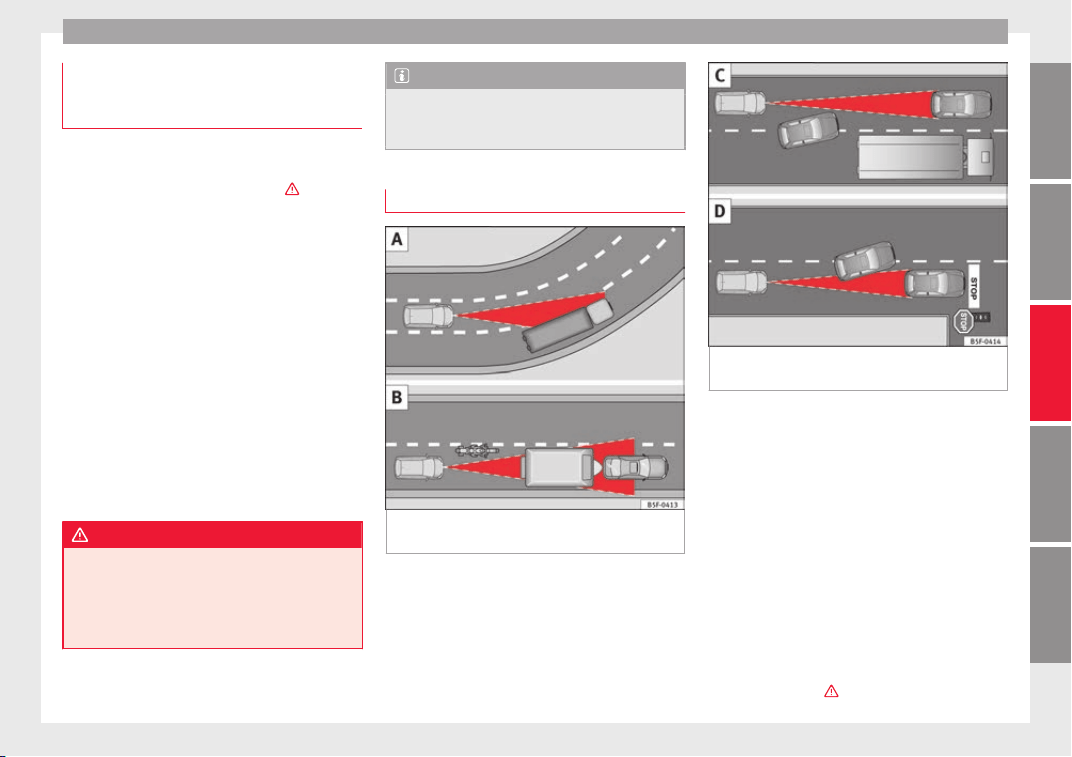
Driver assistance systems
Deactivating the Adaptive Cruise Con-
tr
o
l
ACC temporarily in certain situa-
tions
In the following situations the Adaptive
Cruise C
ontrol (ACC) should be deactivated
due to the system's limitations ›››
:
●
When changing lanes, on tight bends and
round
abouts, in acceleration and decelera-
tion lanes on motorways or in sections with
road works to prevent involuntary accelera-
tion to reach the programmed speed.
●
When going through a tunnel, as operation
coul
d be affected.
●
On roads with several lanes, when other ve-
hicles are driving more slowly in the overtak-
ing lane. In this case, slower vehicles will be
overtaken on the right.
●
In case of heavy rain, snow or spray, as the
vehicle in front might not be detected proper-
ly or, in certain circumstances, might not be
detected at all.
WARNING
If the ACC does not switch off in the situa-
tions de
scribed, serious accidents and inju-
ries may occur.
●
Always switch off the ACC in critical situa-
tions.
Note
If you do not switch off the ACC in the afore-
mentioned situation
s, you may commit a le-
gal offence.
Special driving situations
Fig. 201 (A) Vehicle on a bend. (B) Motorcy-
c
li
s
t ahead out of range of the radar sensor.
Fig. 202 (C) Vehicle changing lanes. (D) One
v
ehic
l
e turning and another stationary.
The adaptive cruise control (ACC) has certain
ph
y
s
ical limitations inherent in the system.
For example, certain reactions of the ACC, in
certain circumstances, may be unexpected or
come late from the driver's point of view. So
pay attention in order to intervene if necessa-
ry.
For example, the following traffic situations
call for the utmost attention:
Starting driving after a stopping phase (only
vehicles with automatic gearbox)
After a stopping phase, the ACC may begin
driving automatically when the vehicle in
front drives off ›››
.
»
223
Technical dataAdviceOperationEmergenciesSafety

Operation
When the ACC halts the vehicle (e.g. traffic
j
am), the in
s
trument panel display shows the
ACC ready to start message. If the ve-
hicle ahead drives off again, the ACC will also
do so automatically.
If the vehicle ahead does not drive off again,
the vehicle can be kept indefinitely in the
ACC ready to start status by operating
the third lever repeatedly towards position
2
›
›› Fig. 198
or b
y pressing the brake pedal.
If the Press the brake message is shown
on the instrument panel, press the brake. If
you do not, an acoustic warning will be heard
and the ACC will switch to inactive mode
(Standby). At this point, the vehicle may be-
gin to move towards the stopped vehicle
ahead ›››
.
Ov
er
t
aking
When the turn signal lights up before the ve-
hicle begins an overtaking manoeuvre, the
ACC accelerates the vehicle automatically
and thus reduces the distance from the vehi-
cle in front.
When the vehicle enters the overtaking lane,
if the ACC does not detect another vehicle in
front, it accelerates until it reaches the pro-
grammed speed and maintains it.
System acceleration can be interrupted at
any time by pressing the brake or moving the
third lever backwards ››› page 219.
Driving through a bend
On entering or exiting bends, the radar sen-
sor may no longer determine the vehicle in
front or react to a vehicle in the adjacent lane
››› Fig. 201 A. In these situations the vehicle
may brake unnecessarily or fail to react to re-
act to the vehicle in front. In this case, the
driver has to intervene by accelerating or in-
terrupting the braking process by applying
the brake or pushing the third lever back-
wards ››› page 219.
Driving in tunnels
When driving through tunnels the radar sen-
sor may be limited. Switch off the ACC in tun-
nels.
Narrow or misaligned vehicles
The radar sensor can only detect narrow or
misaligned vehicles when they are within
range ››› Fig. 201 B. This applies particularly
to narrow vehicles such as motorbikes. In
these cases, you should brake as necessary.
Vehicles with special loads and accessories
Special loads and accessories of other vehi-
cles that jut out over the sides, backwards or
over the top may be out of the ACC's range.
Switch off the ACC when driving behind vehi-
cles with special loads and accessories or
when overtaking them. In these cases, you
should brake as necessary.
Other vehicles changing lanes
Vehicles changing lanes a short distance
away from your own can only be detected
when they are within range of the sensors.
Consequently, the ACC will take longer to re-
act ››› Fig. 202 C. In these cases, you should
brake as necessary.
Stationary vehicles
The ACC does not detect stationary objects
while driving, such as traffic tails or damaged
vehicles.
If a vehicle detected by the ACC turns or
moves over and there is a stationary vehicle
in front of it, the ACC will not react to it
››› Fig. 202 D. In these cases, you should
brake as necessary.
Vehicles driving in the opposite direction
and vehicles crossing your path
The ACC does not react to vehicles approach-
ing from the opposite direction or vehicles
crossing your path.
Metal objects
Metal objects, e.g. rails on the road or sheets
used in road works, can confuse the radar
sensor and cause the ACC to react wrongly.
224

Driver assistance systems
Factors that may affect how the radar sensor
oper
at
e
s
If laser sensor operation is impaired, due to
heavy rain, spray, snow or mud, the ACC is
deactivated temporarily. The relevant text
message will appear in the dash panel dis-
play. If necessary, clean the radar sensor
››› Fig. 197.
When the radar sensor begins to operate
properly again, the ACC will automatically be
available again. The message on the instru-
ment panel screen will switch off and the ACC
will be reactivated again.
ACC operation may be affected by a strong ra-
dar reverse reflection, for example in a closed
car park.
Trailer mode
When driving with trailer the ACC controls
less dynamically.
Overheated brakes
If the brakes overheat, for example after
abrupt braking or in long and steep slopes,
the ACC may be deactivated temporarily. The
relevant text message will appear in the dash
panel display. In this case, adaptive cruise
control cannot be activated.
Adaptive cruise control can be reactivated
once brake temperature has cooled suffi-
ciently. The message will disappear from the
instrument panel display. If the message ACC
not available remains on for quite a long
time it means that there is a fault. Contact a
specialised workshop. SEAT recommends vis-
iting a SEAT dealership.
WARNING
If you do not heed the Press the brake
mess
age, the vehicle may initiate an involun-
tary movement and could crash into the vehi-
cle ahead. In any event, before driving off,
check that the road is clear. The radar sensor
may not detect obstacles on the road. This
could cause an accident and serious injuries.
If necessary, apply the brake.
SEAT Drive Profile*
Intr
oduction
SEAT Drive Profile enables the driver to
c
hoo
se betw
een four profiles or modes, Nor-
mal, Sport, Eco and Individual, that
modify the behaviour of various vehicle func-
tions, providing different driving experiences.
The Individual profile can be configured
according to personal preferences. The other
profiles are fixed.
Description
Depending on the equipment fitted in the ve-
hicle,
SEAT Drive Profile can operate on the
following functions:
Engine
Depending on the profile selected, the en-
gine responds more spontaneously or more
in harmony with the movements of the accel-
erator. Additionally, when Eco mode is selec-
ted, the Start-stop function is automatically
activated.
In vehicles with automatic transmission, the
gear change points are modified to position
them in lower or higher engine speed ranges.
Additionally, the Eco mode activates the In-
ertia function, enabling consumption to be
further reduced.
In manual gearbox vehicles, Eco mode cau-
ses the gear change recommendation indica-
tions that appear on the instrument panel to
vary, facilitating more efficient driving.
“Dual Ride” suspension
The “Dual Ride” suspension features a com-
fortable suspension in the Eco and Normal
profiles, suitable for daily use. Contrasting
with this it features a sporty suspension in
»
225
Technical dataAdviceOperationEmergenciesSafety
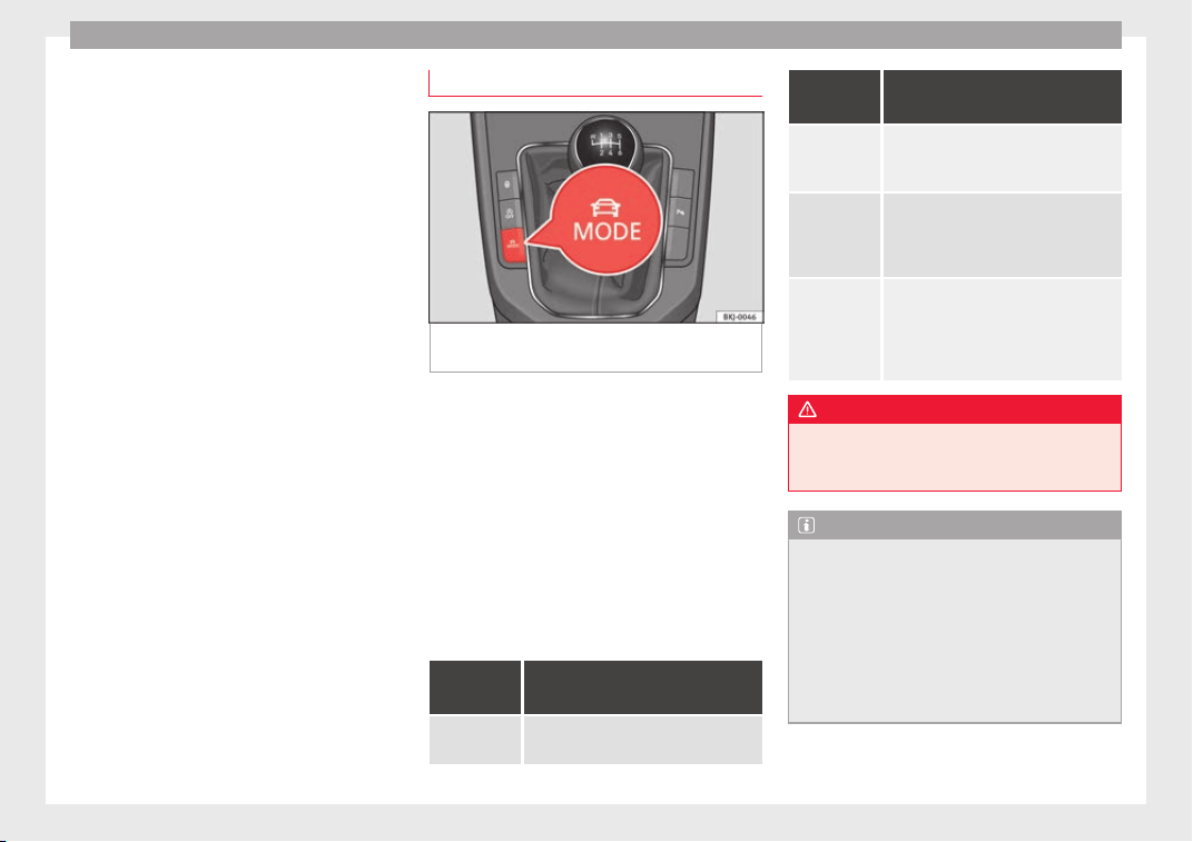
Operation
the Sport pr
ofi
l
e, suitable for a sporty driv-
ing style. In the Individual profile the sus-
pension can be switched between Normal or
Sport, depending on personal preference.
In the event of a fault in the “Dual Ride” sus-
pension, the following message is displayed
on the instrument panel screen Fault:
damping setting.
Address
Power steering becomes more robust in
Sport mode to enable a sportier driving
style.
Air conditioning
In vehicles with Climatronic, this can operate
in eco mode, especially restricting fuel con-
sumption.
Adaptive Cruise Control (ACC)
According to the active driving profile, the ac-
celeration gradient of the adaptive cruise
control varies.
Setting driving mode
Fig. 203 Next to the gearbox lever: MODE but-
t
on.
You can select from Normal, Sport, Eco
and Individual.
Y
ou c
an sel
ect the required mode either by
repeatedly pressing the button MODE
››› Fig. 203, or on the touch screen, in the
menu that opens when the above button is
pressed.
An icon on the Easy Connect system display
informs about the active mode.
The MODE button light remains lit up yellow
when the active mode is different to Normal.
Driving
profile
Characteristics
Normal
Offers a balanced driving experience,
suitable for everyday use.
Driving
profile
Characteristics
Sport
Provides a complete dynamic perform-
ance in the vehicle, enabling the user a
more sporty driving style.
Eco
Places the vehicle in a particularly low
state of consumption, facilitating a
fuel-saving driving style that is respect-
ful to the environment.
Individual
Enables some configurations to be
modified by pressing the Profile
settings button. The functions that
can be adjusted depend on the equip-
ment fitted in the vehicle.
WARNING
When operating SEAT Drive Profile, pay atten-
tion to al
l traffic: doing otherwise could cause
an accident.
Note
●
When the vehic
le is switched off it will al-
ways store the driving profile that was selec-
ted when the ignition key was removed. Nev-
ertheless, when the engine is restarted, the
engine and the gear will not restart in the set-
ting selected. For engine and gear to revert to
the desired position, select the correspond-
ing drive profile again or press the Easy Con-
nect system button repeatedly.
226
Driver assistance systems
●
Your speed and driv
ing style must always
be adjusted to visibility, weather, and traffic
conditions.
●
The Eco profile is not recommended when
towing a vehicle.
Kick-down
The kick-down feature allows maximum ac-
celer
ation to be reached.
If the eco* ››› page 226 mode has been se-
lected in SEAT Drive Profile*, and the acceler-
ator is pressed beyond a hard point, the en-
gine power is automatically controlled to give
your vehicle maximum acceleration.
WARNING
Please note that if the road surface is slip-
pery or w
et, the kick-down feature could
cause the driving wheels to spin, which could
result in skidding.
Fatigue detection (break rec-
ommend
ation)*
R
el
ated video
Fig. 204 Safety
Introduction
The Fatigue detection informs the driver
when their driv
in
g beh
aviour shows signs of
fatigue.
WARNING
Do not let the comfort afforded by the Fatigue
detection sys
tem tempt you into taking any
risks when driving. Take regular breaks, suffi-
cient in length when making long journeys.
●
The driver always assumes the responsibil-
ity of driving to their full capacity.
●
Never drive if you are tired.
●
The system does not detect the tiredness of
the driver in all circumstances. Consult the in-
formation in the section ››› page 228, System
limitations.
●
In some situation
s, the system may incor-
rectly interpret an intended driving manoeu-
vre as driver tiredness.
●
No warning is given in the event of the ef-
fect called microsleep!
●
Please observe the indications on the in-
strument panel and act as is necessary.
Note
●
F
atigue detection h
as been developed for
driving on motorways and well paved roads
only.
●
If there is a fault in the system, have it
checked by a specialised workshop.
Function and operation
Fig. 205 On the instrument panel display: fa-
tigue det
ection symbo
l
.
Fatigue detection determines the driving be-
h
av
iour of
the driver when starting a journey,
»
227
Technical dataAdviceOperationEmergenciesSafety
Operation
making a calculation of tiredness. This is
c
on
s
tantly compared with the current driving
behaviour. If the system detects that the driv-
er is tired, an audible warning is given with a
sound and an optic warning is shown with a
symbol and complementary message on the
instrument panel display ››› Fig. 205. The
message on the instrument panel display is
shown for approximately 5 seconds, and de-
pending on the case, is repeated. The system
stores the last message displayed.
The message on the instrument panel display
can be switched off by pressing the
button on the windscreen wiper lever or the
b
utt
on
on the multi function steering
wheel
›
›
›
page 37.
The message can be recalled to the instru-
ment panel display using the multifunction
display ›››
page 37.
Conditions of operation
Driving behaviour is only calculated on
speeds above about 65 km/h (40 mph) up to
around 200 km/h (125 mph).
Switching on and off
Fatigue detection can be activated or deacti-
vated in the Easy Connect system with the
button and the
S
ET
TINGS
function button
›
›
›
page 34. A mark indicates that the ad-
justment has been activated.
System limitations
The Fatigue detection has certain limitations
inherent to the system. The following condi-
tions can limit the Fatigue detection or pre-
vent it from functioning.
●
At speeds below 65 km/h (40 mph)
●
At speeds above 200 km/h (125 mph)
●
When cornering
●
On roads in poor condition
●
In unfavourable weather conditions
●
When a sporty driving style is employed
●
In the event of a serious distraction to the
driver
Fatigue detection will be restored when the
vehicle is stopped for more than 15 minutes,
when the ignition is switched off or when the
driver has unbuckled their seat belt and
opened the door.
In the event of slow driving during a long pe-
riod of time (below 65 km/h, 40 mph) the
system automatically re-establishes the tired-
ness calculation. When driving at a faster
speed the driving behaviour will be recalcula-
ted.
Parking aid (Park Pilot)
General information
Assorted assistance systems – which vary
depending on the equipment fitt
ed in the car
– will help you when parking or manoeu-
vring.
The rear parking aid is an audible assistant
that warns about obstacles located behind
the vehicle ››› page 229.
During parking, Parking System Plus assists
the driver by visually and audibly warning
them about obstacles detected in front and
behind the vehicle ››› page 230.
WARNING
●
Alwa
ys pay attention, also when looking
straight ahead, to traffic and the vehicle sur-
roundings. The assistance systems are not a
replacement for driver awareness. When in-
serting or removing the vehicle from a park-
ing space, or when performing similar ma-
noeuvres the driver always assumes the re-
sponsibility.
●
Adapt your speed and driving style at all
times to suit visibility, weather, road and traf-
fic conditions.
●
The ultrasound sensors have blind spots in
which obstacles and people are not regis-
tered. Pay special attention to children and
animals.
228
Driver assistance systems
●
Alwa
ys keep visual control of the vehicle
surroundings: use the mirrors for additional
help.
CAUTION
Parking Aid functions may be negatively af-
f
ected b
y different factors that may lead to
damage to the vehicle or its immediate sur-
rounds:
●
Under certain circumstances, the system
does not detect or display certain objects:
–
Objects such as chains, trailer draw bars,
fences, posts and thin trees.
–
Objects that are located above the sen-
sors, such as protrusions in a wall.
–
Objects with certain surfaces or struc-
tures, such as wire mesh fences or pow-
der snow.
●
Certain surfaces of objects and garments
do not reflect the ultrasound sensors' sig-
nals. The system cannot detect, at least cor-
rectly, these objects or people wearing such
clothes.
●
Ultrasound sensor signals may be affected
by external sound sources. In certain circum-
stances this may prevent them from detect-
ing people or objects.
●
Please note that low obstacles detected by
the system may no longer be registered by
the sensors as the car moves closer, so the
system will not give any further warning. In
certain circumstances, objects such as high
kerbs that could damage the bottom of the
vehicl
e are not detected either.
●
If the first warning from the ParkPilot is ig-
nored, the vehicle could suffer considerable
damage.
●
The knocks or damage on the radiator
grille, bumper, wheel arch and vehicle under-
body can adjust the orientation of the sen-
sors. This can affect the parking aid function.
Have the function checked by a specialised
workshop.
Note
●
In cert
ain situations, the system can give a
warning even though there is no obstacle in
the detected area, e.g:
–
with rough or cobbled floors or ground
with long grass;
–
with external ultrasound sources, such as
cleaning vehicles or other vehicles;
–
In downpours, intense snow or dense ex-
haust gases;
–
or in locations such as the brow of a hill.
●
A registration plate or plate holder on the
front with larger than the space for the regis-
tration plate, or a registration plate that is
curved or warped can cause:
–
false detections,
–
loss of sensor visibility,
●
In order to guarantee good system opera-
tion, keep the ultrasound sensors clean, free
of snow or ice, and do not cover them with
adhes
ives or other objects.
●
If you use high-pressure or vapour equip-
ment to clean the ultrasound sensors, apply
it directly only very briefly and always from a
distance of more than 10 cm.
●
Retrofitting of accessories to the vehicle,
such as a bicycle rack, may interfere with the
operation of the Parking Aid.
●
In order to familiarise yourself with the sys-
tem, it is advised that you practice parking in
an area or car park that is free from traffic.
There must be good weather and light condi-
tions.
●
The volume and tone of the warnings can
be modified, in addition to the indications
››› page 232.
●
In vehicles without a driver information
system, these parameters can be modified in
a SEAT Official Service or in a specialised
workshop.
●
Please observe information on towing a
trailer ››› page 233.
●
The display on the Easy Connect screen
shows a slight time delay.
Rear parking aid*
The rear Parking Aid assists the driver in
p
ark
in
g by means of audible warning
sounds.
»
229
Technical dataAdviceOperationEmergenciesSafety
Operation
Description
Ther
e ar
e sen
sors integrated in the rear
bumper. When the sensors detect an obsta-
cle, you are alerted by audible warnings.
Make particularly sure that the sensors are
not covered by adhesives, residues and the
like, as this could affect the system's opera-
tion. Cleaning instructions ››› page 251.
The approximate measurement range of the
rear sensors is:
side area 0.60 m
central area 1.60 m
As you approach the obstacle, the time inter-
v
al
betw
een the audible warnings will be re-
duced. When you reach around 0.30 m the
warning will be constant: Do not continue to
move forward (or backward)
›››
in General
inf
orm
ation on p
age 228,
›››
in General in-
f
orm
ation on p
age 229 !
If you maintain separation from the obstacle,
the volume of the warning begins to reduce
after four seconds (does not affect the tone
of the constant warning).
Activating/Deactivating
When engaging reverse gear, the parking aid
is automatically switched on. This is con-
firmed with a short warning.
On disengaging reverse gear, the Parking Aid
system is disconnected immediately.
Parking Aid Plus*
Fig. 206 Represented area.
During parking, P
ark
in
g System Plus assists
the driver by visually and audibly warning
them about obstacles detected in front of
and behind the vehicle.
There are ultrasound sensors integrated in
the front and rear bumpers. When they detect
an obstacle, you are alerted by audible warn-
ings and visually on the Easy Connect sys-
tem.
In the event of danger of a frontal collision,
the audible warnings come from the front of
the vehicle, and in the event of the danger of
a rear-end collision they come from the rear.
Make particularly sure that the sensors are
not covered by adhesives, residues and the
like, as this could affect the system's opera-
tion. Cleaning instructions ››› page 251.
The approximate measurement range of the
sensors is:
1.20 m
1.60 m
0.90 m
As you approach the obstacle, the time inter-
val between the audible warnings will be re-
duced. When you reach around 0.30 m the
warning will be constant: do not continue to
move forward (or backward)!
If you maintain separation from the obstacle,
the volume of the warning begins to reduce
after four seconds (does not affect the tone
of the constant warning).
In order to view the entire periphery of the ve-
hicle, the vehicle must be moved a few me-
tres forwards and backwards. Thus, the miss-
ing areas are screened and obstacles at the
sides of the vehicle are displayed
››› Fig. 206
C
.
A
B
C
230
Driver assistance systems
Parking Aid operation
Fig. 207 Centre console: parking aid button.
Manual connection of Parking Aid
●
Press the b
utt
on
once. The symbol on
the button will light up yellow.
Manual disconnection of Parking Aid
●
Press the button again.
Manual disconnection of Parking Aid display
(the audible sounds remain active)
●
Press a button on the main menu of the fac-
tory-assembled infotainment system.
●
OR: press the function button in the top
right corner.
Automatic connection of Parking Aid
●
Engage reverse gear or turn the selector
lever to position R.
●
OR: If the vehicle approaches an obstacle
that is in its forwards path at a speed below
10 km/h (6 mph) ››› page 231, Automatic ac-
tivation. The obstacle is detected as of a dis-
tance of approx. 95 cm if the automatic con-
nection is activated in the infotainment sys-
tem. A reduced display is shown.
●
OR: the vehicle moves backwards.
Automatic disconnection of Parking Aid
●
Move the selector lever to position P.
●
OR: accelerate to more than approx.
10 km/h (6 mph) forward.
Temporary suppression of sound in Parking
Aid
●
Press the function button on the info-
tainment system display.
Change from reduced view to full view
●
Engage reverse gear or turn the selector
lever to position R.
●
OR: press the car icon in reduced view.
If necessary, switch to the rear-assist image
(Rear View Camera “RVC”)
●
Engage reverse gear or turn the selector
lever to position R.
●
OR: Press the RVC function button
››› page 236.
A short confirmation signal will be heard and
the button symbol will light up yellow when
the system is switched on.
Automatic activation
Fig. 208 Miniature indication of automatic ac-
tiv
ation.
When the Parking System Plus is switched on
aut
om
atic
ally, a miniature of the vehicle will
be displayed and the segments will be
shown on the left side of the screen
››› Fig. 208.
Automatic activation occurs when slowly ap-
proaching an obstacle located in front of the
vehicle. It only operates every time the speed
is reduced below approximately 10 km/h (6
mph) for the first time.
If the parking aid is switched off using the
button, the following actions must be carried
out in order for it to automatically switch on:
»
231
Technical dataAdviceOperationEmergenciesSafety
Operation
●
Sw
it
c
h off the ignition and switch it on
again.
●
OR: accelerate above 10 km/h (6 mph) be-
fore reducing speed below this number
again.
●
OR: place the selector lever in position P
and then move it from this position.
●
OR: switch on and off the automatic activa-
tion in the Easy Connect system menu.
The automatic activation with parking aid
miniature indication can be switched on and
off from the Easy Connect system menu
›››
page 34:
●
Switch the ignition on.
●
Select:
button > Settings > Parking
and manoeuvring.
●
Select the Automatic activation op-
tion.
When the f
u
nction button check box is
activated , the function is on.
If the system has been activated automatical-
ly, an audible sound warning will only be giv-
en when obstacles in front are at a distance
of less than 50 cm.
CAUTION
The automatic connection of the Parking Aid
only w
orks when you are driving slowly. If
driving style is not adapted to the circum-
stances, an accident and serious injury or
damage may be caused.
Segments of the visual indication
Fig. 209 Parking Aid display on the Easy Con-
nect
sy
s
tem screen.
The distance of separation from the obstacle
c
an be e
s
timated using the segments around
the vehicle.
The optical indication of the segments works
as follows:
a white segment is dis-
played when the obstacle is not within
the vehicle's trajectory or the direction
of travel is in the opposite direction to
its location, and it is more than 30 cm
from the vehicle.
obstacles located in the
vehicle's trajectory and which are more
than 30 cm away from the vehicle are
displayed in yellow.
White segments:
Yellow segments:
obstacles that are less than
30 cm away from the vehicle are dis-
played in red.
Moreover, with the SEAT Media System
Plus/Navi System radios, a yellow trail indi-
cates the vehicle's expected journey based
on the steering wheel angle.
Whenever the obstacle is located in the vehi-
cle’s direction of travel, the corresponding
audible warning will sound.
As the vehicle approaches an obstacle, the
segments are displayed closer to the vehicle.
When the penultimate segment is displayed,
this means that the vehicle has reached the
collision zone. In the collision zone, the ob-
stacles are represented in red, including
those out of the path. Do not continue to
move forward (or backward) ›››
in General
inf
orm
ation on p
age 228, ›››
in General in-
f
orm
ation on p
age 229 !
Adjusting the display and audible
warnings
The settings for the display and audible
w
arnin
g
s are controlled via the Easy Con-
nect*.
Automatic activation
on – activates the Automatic activa-
tion option ››› page 231.
Red segments:
232
Driver assistance systems
off – de
activ
at
es the Automatic ac-
tivation option ››› page 231.
Front volume*
Volume in the front and rear area.
Front sound settings/sharpness*
Frequency (tone) of the sound in the front
area.
Rear volume*
Volume in the rear area.
Rear sound settings/sharpness*
Frequency (tone) of the sound in the rear
area.
Adjust volume
With the parking aid switched on, the active
audio/video source volume will be reduced
to the intensity of the selected setting.
Error messages
When the Parking Aid is activated or when it
i
s
sw
itched on, if a message reporting a Park-
ing aid error is displayed on the instrument
panel, there is a fault in the system.
If the fault does not disappear before discon-
necting the ignition, the next time that the
parking aid is engaged in reverse, no audible
signal of the existence of a fault will be is-
sued.
Parking System Plus*
If there is a fault in the parking aid system a
message will appear on the instrument panel
indicating the error. In addition the key
LED will blink.
If there is a fault in a sensor, the symbol is
displayed on the Easy Connect display in
front of/behind the vehicle. If a rear sensor is
faulty, only the obstacles in area
A
are dis-
p
l
a
yed ››› Fig. 206. If a front sensor is faulty,
only the obstacles in area
B
are displayed.
Hav
e the f
au
lt corrected by a specialised
workshop without delay.
Towing bracket
In vehicles equipped with a towing bracket
dev
ic
e fr
om the factory, when the trailer is
connected electrically, the Parking Aid rear
sensors will not be activated when reverse
gear is engaged, when the selector lever is
turned to position R or when the button is
pressed.
Parking System Plus
The distance to possible obstacles at the rear
of the vehicle will not be displayed on the
screen and nor will it be indicated by means
of audible sound signals.
The Easy Connect system screen will only dis-
play objects detected at the front, and the ve-
hicle's trajectory will be hidden.
Braking while manoeuvring function*
3 Only valid with Parking System Plus
The emerg
ency braking function is used to
minimise damage in the event of a collision.
Depending on the equipment, if the Parking
Aid is active, the braking while manoeuvring
function activates emergency braking when it
detects an obstacle in the vehicle’s path that
could cause a collision, driving forwards or in
reverse.
The function will not brake if the Parking Aid
is activated automatically. For the system to
operate, manoeuvring speed must be be-
tween 2.5 and 10 km/h (between 1.5 and 6
mph) for the front area and between 1.5 and
10 km/h (between 1 and 6 mph) for the rear.
Following an intervention, the braking while
manoeuvring function will be inactive in the
same direction of travel for 5 metres. Once
the gear is changed, or the selector lever’s
position is changed, the function will be ac-
tive again. The Parking Aid’s limitations ap-
ply.
»
233
Technical dataAdviceOperationEmergenciesSafety
Operation
The braking while manoeuvring function is
c
ontr
o
lled in the Easy Connect system with
the
menu and the
S
ET
TINGS
and
P
ark
and m
anoeuvre
function buttons.
●
on – permits the u
se of the braking
while manoeuvring function.
●
off – does not permit the use of the
braking while manoeuvring function.
Temporary suppression of emergency brak-
ing
●
When the function is deactivated with the
Brakin
g while manoeuvring
button that appears
on the P
ark
in
g System screen of the Easy
Connect system.
●
Whenever any of the car doors, rear lid or
bonnet are opened.
Rear Assist “Rear View Cam-
era”*
Related video
Fig. 210 Safety
Operating and safety warnings
WARNING
●
The Rear As
sist does not make it possible
to precisely calculate the distance from ob-
stacles (people, vehicles, etc.) and nor can it
overcome the system's own limits, hence us-
ing it may cause serious accidents and inju-
ries if used negligently or without due care.
The driver should be aware of his/her sur-
roundings at all times to ensure safe driving.
●
The camera lens expands and distorts the
field of vision and displays the objects on the
screen in a different, vague manner. The per-
ception of distances is also distorted by this
effect.
●
Due to the screen resolution or insufficient
light conditions, some items may be dis-
played in an unsatisfactory manner or not at
all. Take special care with thin posts, fences,
railings or trees that might not be displayed
on screen and could damage the vehicle.
●
The rear assist has blind spots where it is
not possible to represent people or objects
(small children, animals and certain objects
cannot be detected in its field of vision). Mon-
itor the vehicle's surrounding area at all
times.
●
Keep the camera lens clean, free of ice and
snow, and do not cover it.
●
The system is not a replacement for driver
awareness. Supervise the parking operation
at all times, as well as the vehicle's surround-
ing area. Adapt your speed and driving style
at all times to suit visibility, weather, road
and traffic c
onditions.
●
Do not be distracted from the traffic by
looking at the screen.
●
The images on the rear assist screen are
only two-dimensional. Due to a lack of spatial
depth, protruding parts or holes in the road,
for example, are more difficult to detect or
may not be seen at all.
●
Vehicle load modifies the representation of
the orientation lines displayed. The width
represented by the lines diminishes with ve-
hicle load. Pay special attention to the vehi-
cle's surroundings when the inside of the ve-
hicle of the luggage compartment is carrying
a heavy load.
●
In the following situations, the objects or
other vehicles shown in the navigation sys-
tem display appear to be further away or
closer than they really are: Pay special atten-
tion:
–
On moving from a horizontal plane to a
slope.
–
On moving from a slope to a horizontal
plane.
–
If the vehicle is heavily loaded at the
rear.
–
When the vehicle approaches objects
that are not on the ground surface or are
jutting out from it. These objects may al-
so be outside the camera's angle of vi-
sion when reversing.
234
Driver assistance systems
Note
●
It is
important to take great care and pay
special attention if you are not yet familiar
with the system.
●
Rear assist will not be available if the vehi-
cle's rear lid is open.
Instructions for use
Fig. 211 On the rear bumper: location of the
r
e
ar a
ssist camera.
A camera on the rear bumper aids the driver
durin
g r
ev
erse parking or manoeuvring
››› Fig. 211. The camera image is viewed to-
gether with orientation lines projected by the
system on the Infotainment system screen.
The bottom of the screen displays part of the
bumper, which can be used by the driver as a
reference point.
Rear assist settings
Rear assist offers the user the possibility to
change the image's brightness, contrast and
colour settings.
To change these settings:
●
Park the vehicle in a safe place.
●
Apply the parking brake.
●
Switch the ignition on.
●
If necessary, switch on the Infotainment
system.
●
Engage reverse gear or turn the selector
lever to position R.
●
Press the function button displayed on
the right of the image.
●
Make the desired adjustments on the menu
by pressing the –/+ function buttons or by
moving the corresponding scroll button.
Necessary conditions for parking and ma-
noeuvring with the rear assist
The system should not be used in the follow-
ing cases:
●
If the image displayed is not very reliable or
is distorted, for example low visibility or dirty
lens.
●
If the area behind the vehicle is not dis-
played very clearly or is incomplete.
●
If the vehicle is heavily loaded at the rear.
●
If the position and installation angle of the
camera have been changed, e.g. after a rear-
end collision. Have the system checked by a
specialised workshop.
Familiarising yourself with the system
To familiarise yourself with the system, the
orientation lines and their function, SEAT rec-
ommends practising parking and manoeu-
vring with the rear assist in a place without
too much traffic or in a car park when there
are good weather and visibility conditions.
Cleaning the camera lens
Keep the camera lens clean and clear of snow
and ice:
●
Moisten the lens using a normal alcohol-
based glass cleaning product and clean the
lens with a dry cloth.
●
Remove snow using a small brush.
●
Use de-icing spray to remove any ice.
CAUTION
●
Never use abr
asive cleaning products to
clean the camera lens.
●
Do not use hot or warm water to remove ice
or snow from the camera lens. Doing so could
damage the camera.
235
Technical dataAdviceOperationEmergenciesSafety
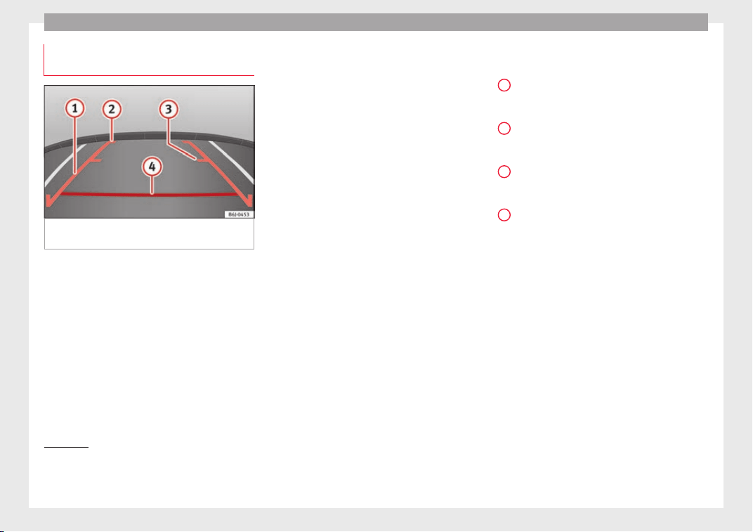
Operation
Parking and manoeuvring with the
r
e
ar a
ssist
Fig. 212 Display on the Infotainment system
s
c
r
een: orientation lines.
Switching the system on and off
●
The rear assist will switch on when the igni-
tion i
s
on or the en
gine running, on engaging
reverse gear (manual gearbox) or on chang-
ing the selector lever to the R position (auto-
matic gearbox).
●
The system switches off 8 seconds after
disengaging reverse gear (manual gearbox)
or removing the selector lever from the R po-
sition (automatic gearbox). The system will
also disconnect immediately after the igni-
tion is switched off.
●
The camera will stop transmitting images
above the speed of 15 km/h (9 mph) with re-
verse engaged.
In combination with the Parking System Plus
››› page 228, the camera image will cease to
be transmitted immediately when reverse
gear is disengaged or when the selector lever
is moved from the R position, and the optical
information provided by the Parking Aid sys-
tem will be displayed.
Also in combination with the system, the rear
assist image can also be concealed:
●
By pressing one of the Infotainment system
buttons on the display.
●
OR: By pressing the miniature vehicle that
appears on the left of the screen (which
switches to the full-screen mode of the Park-
ing System Plus's optical system).
If you wish to display the rear assist image
again:
●
Disengage reverse, or change the selector
lever's position, engage reverse again or
move the selector lever to position R.
●
OR: Press the RVC function button
1)
Meaning of the orientation lines
››› Fig. 212
Side lines: extension of the vehicle (the
approximate width of the vehicle plus the
rear view mirrors) on the road surface.
End of the side lines: the area marked in
green ends approximately 2 m behind
the vehicle on the road surface.
Intermediate line: indicates a distance of
approximately 1 m behind the vehicle on
the road surface.
Red horizontal line: indicates a safe dis-
tance of approximately 40 cm at the rear
of the vehicle on the road surface.
Parking manoeuvre
●
Place the vehicle in front of the parking
space and engage reverse gear (manual
gearbox) or move the selector to the R posi-
tion (automatic gearbox).
●
Reverse slowly, and turn the steering wheel
so that the side orientation lines lead to-
wards the parking space.
●
Guide the vehicle into the parking space so
that the side orientation lines run parallel to
it.
1
2
3
4
1)
WARNING: the RVC (Rear
View Camera) function
button will only be activated and available when the
reverse gear is engaged or the selector lever is set to
position R.
236
Towing bracket device
Towing bracket device
T
o
w
ing bracket device*
Introduction
The towing bracket device fitted to your vehi-
cle, be it
factory-fitted or a genuine SEAT ac-
cessory, meets all the national technical and
legal requirements for towing.
Your vehicle is fitted with a 13-pin connector
for the electrical connection between the
trailer and the vehicle. If the trailer is equip-
ped with a 7-pin connector you can use the
corresponding adaptor, which is available as
a genuine SEAT accessory.
The maximum authorised towing load is 50
kg.
WARNING
●
Befor
e each journey, make sure that the de-
tachable ball joint is properly fitted and se-
cured in its housing.
●
If the detachable ball joint is not properly
fitted and secured, do not use it.
●
Do not use the towing bracket device for
towing if it is damaged or has missing parts.
●
Do not modify or adapt the towing device
connection.
●
Never unhook the detachable ball joint
when the trailer is hitched.
CAUTION
Handle the detachable ball joint with care in
order to av
oid damaging the bumper paint-
work.
Note
Towing the vehicle with the detachable ball
joint ›
›› page 102.
Description
Fig. 213 Towing bracket device support / de-
t
ac
h
able ball joint / key.
Depending on the country or version, the
t
o
w
ing bracket device's detachable ball joint
is located:
●
underneath the floor panel of the luggage
compartment.
The ball joint is fitted and removed by hand.
The towing device bracket is supplied with a
key.
Key to ››› Fig. 213
13-pin connector
Safety lug
Hook housing
Hook housing cap
Ball protective cover
Detachable ball
Locking lever
Lock cover
Release bolt
Lock
Locking balls
Key
Note
Contact an Authorised Service Partner if you
lose y
our key.
1
2
3
4
5
6
7
8
9
10
11
12
237
Technical dataAdviceOperationEmergenciesSafety
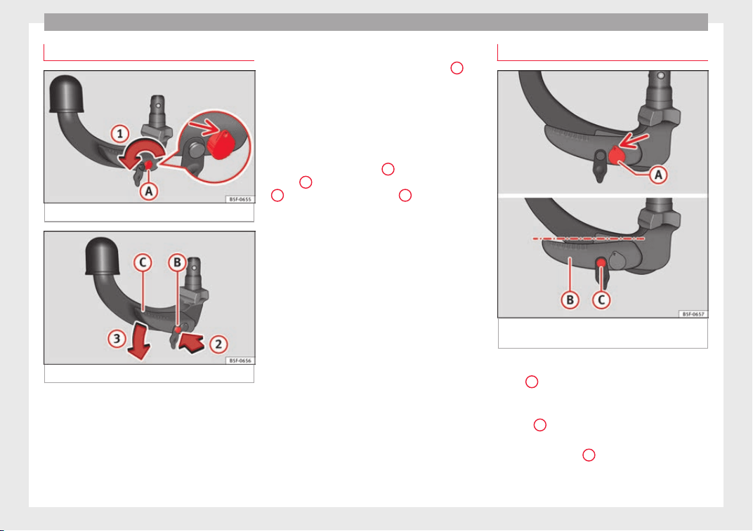
Operation
Placing in standby position
Fig. 214 Step 1.
Fig. 215 Step 2.
Before assembling it, place the detachable
b
al
l
in the standby position with the follow-
ing two steps.
Step 1.
●
Turn the key in the direction of arrow
1
un-
ti
l
the p
art of the key with the holes reaches
the top position ››› Fig. 214 (arrow).
Step 2.
●
Grip the detachable ball below the protec-
tive cover.
●
Press the release bolt
B
in the direction of
arr
o
w
2
, and at the same time press lever
C
in the direction of arrow
3
as far as it will
g
o ›
›
› Fig. 215.
The lever will remain blocked in this position.
Standby position
Fig. 216 Standby position: Position of the lev-
er and the r
el
e
ase bolt.
Standby position adjusted properly
●
Key
A
›
›
› Fig. 216
is in the released posi-
tion (the part of the key with the holes is fac-
ing upwards).
●
Lever
B
›
›
› Fig. 216
is in the bottom posi-
tion.
●
The release bolt
C
›
›
› Fig. 216
can be
moved.
238
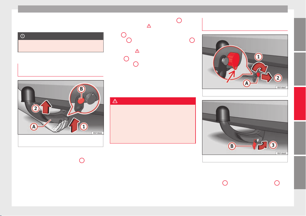
Towing bracket device
Thus adjusted, the detachable ball is ready
f
or in
s
tallation.
CAUTION
The key cannot be removed or turned in the
standb
y position.
Assembling the detachable ball - Step
1
Fig. 217 Fitting the detachable ball / Release
bo
lt
in the dep
loyed position.
Fitting the detachable ball
●
Remove the hook housing cap
4
››› Fig. 213 downw
ards.
●
Set the detachable ball to its standby posi-
tion ›››
page 238.
●
Grip the detachable ball from below
››› Fig. 217 and insert it into the hook hous-
ing following the direction of arrow
1
until it
en
g
ag
es audibly ›››
.
L
ev
er
A
turns aut
omatically in the direction
of
arr
ow
2
upwards, and the release bolt
B
moves outwards (the red and green part will
be
v
i
sible) ›››
.
If
l
ev
er
A
does not turn automatically or the
r
el
e
ase bolt
B
does not come out, the de-
t
ac
h
able ball should be removed by turning
the lever as far as possible downwards from
the housing cavity, and the detachable ball's
support surfaces and the cavity should then
be cleaned.
WARNING
●
When attachin
g the detachable ball, keep
your hands well away from the reach of the
lever's rotation to avoid getting your fingers
caught.
●
Never try to pull the lever upwards by force
to turn the key. The detachable ball would not
be secured properly!
Assembling the detachable ball - Step
2
Fig. 218 Locking the lock.
Fig. 219 Placing the cover over the lock.
Do not omit this first step ›
›
›
page 239, As-
sembling the detachable ball - Step 1 !
●
Turn key
A
in the direction of arrow
1
un-
ti
l
the p
art of the key with the holes reaches
the bottom position ››› Fig. 218.
»
239
Technical dataAdviceOperationEmergenciesSafety
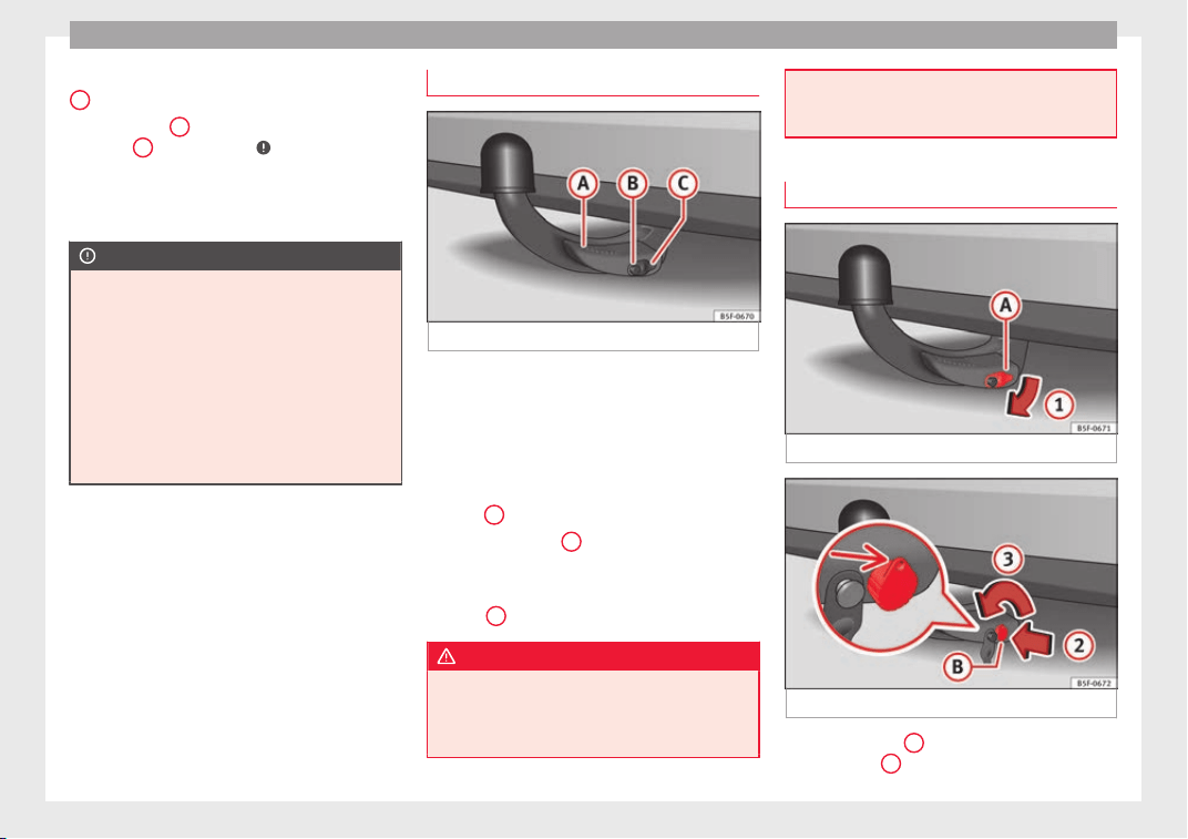
Operation
●
R
emo
v
e the key in the direction of arrow
2
.
●
Place cover
B
in the lock in the direction
of
arr
o
w
3
›
›› Fig. 219
›
››
.
●
Check that the detachable ball is securely
att
ac
hed ›
›› page 240, Checking proper at-
tachment.
CAUTION
●
After r
emoving the key, always place the
cover over the lever's lock. If the lock be-
comes soiled it will be impossible to insert
the key.
●
Keep the towing bracket device's housing
cavity clean at all times. Dirtiness can pre-
vent the detachable ball from being properly
secured!
●
If the detachable ball is removed, always
place the cap on the hook's housing.
Checking proper attachment
Fig. 220 Detachable ball properly attached.
Whenever you go to use the detachable ball,
m
ak
e s
ure that it is properly attached first.
Detachable ball properly attached.
●
The detachable ball will not fall out of the
housing cavity after a major “knock or jerk”.
●
Lever
A
›
›
› Fig. 220
is fully raised.
●
The release bolt
B
›
›
› Fig. 220
is sticking
fully out (the red and green part is visible).
●
The key has been removed.
●
Cover
C
›
›
› Fig. 220
is placed over the lock.
WARNING
●
When remov
ing the detachable ball, keep
your hands well away from the reach of the
lever's rotation to avoid getting your fingers
caught.
●
The tow
ing bracket device should only be
used if the detachable ball has been properly
locked!
Removing the detachable ball - Step 1
Fig. 221 Removing the lock cover.
Fig. 222 Releasing the lock.
●
Remove cover
A
from the lock in the direc-
tion of
arr
o
w
1
›
›
› Fig. 221
.
240
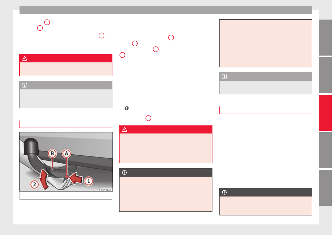
Towing bracket device
●
In
ser
t
key
B
into the lock in the direction
of
arr
o
w
2
›
›› Fig. 222
.
●
T
urn the key in the direction of arrow
3
un-
ti
l
the p
art of the key with the holes is facing
upwards.
WARNING
Never remove the detachable ball joint when
the trail
er is hitched.
Note
Before you remove the detachable ball, you
are adv
ised to place the protective cover on
the ball coupling.
Removing the detachable ball - Step 2
Fig. 223 Releasing the detachable ball.
Do not omit this first step
›
›
›
page 240, Re-
moving the detachable ball - Step 1 !
Releasing the detachable ball
●
Grip the detachable ball from below.
●
Press the release bolt
A
in the direction of
arr
o
w
1
as far as it will go, and at the same
time pr
e
s
s lever
B
in the direction of arrow
2
as far as it will go.
In thi
s
po
sition, the detachable ball is loose
and will fall/drop freely downwards. If this
does not occur when you release it, press it
with the other hand from above.
The detachable ball locks into the standby
position at the same time and is therefore
ready to be reinserted into the hook housing
›››
.
●
Fit the cap
4
›
›
› Fig. 213
onto its housing.
WARNING
Never leave the detachable ball loose in the
luggag
e compartment. It could cause damage
in the luggage compartment in the case of
abrupt braking, and even jeopardise passen-
ger safety!
CAUTION
●
If y
ou hold the lever and do not press down
on it as far as you can, after you remove the
detachable ball, the latter will continue up-
wards and will not lock into the standby posi-
tion. The detachable ball should be placed in
this position before the next assembly.
●
Keep the detac
hable ball in the standby po-
sition, with the key inserted into the box
while you place it facing downwards with the
side opposite to the one where the key is in-
serted. The key could get damaged!
●
When operating the lever, do not apply too
much pressure (for example, do not stand on
it)!
Note
Remove any dirt from the detachable ball be-
f
ore
you put it away with the vehicle tools.
Operation and care
Put the cover on the housing cavity so that
dir
t
c
annot get in.
Before hooking up a trailer, always check the
ball coupling and apply suitable grease if
necessary.
Use the protective cover when putting the de-
tachable ball away to keep the luggage com-
partment clean.
Remove any dirt from the housing cavity sur-
faces and use a suitable cleaning product.
CAUTION
The top part of the hook housing is greased.
Make s
ure that the grease has not been re-
moved.
241
Technical dataAdviceOperationEmergenciesSafety
Operation
Trailer towing
Wh
at
do
you need to bear in mind
when towing a trailer?
Your vehicle may be used to tow a trailer
when fitted with the c
orrect equipment.
If you wish to retrofit a towing bracket, con-
sult ››› page 245.
Connectors
Your vehicle is fitted with a 13-pin connector
for the electrical connection between the
trailer and the vehicle.
If the trailer has a 7-pin plug you will need to
use an adapter cable. It is available at any
Technical Service.
Trailer weight/drawbar load
Never exceed the authorised trailer weight. If
you do not load the trailer up to the maxi-
mum permitted trailer weight, you can then
climb correspondingly steeper slopes.
The maximum trailer weights listed are only
applicable for altitudes up to 1000 m above
sea level. With increasing altitude the engine
power and therefore the vehicle climbing
ability are impaired because of the reduced
air density. The maximum trailer weight has
to be reduced accordingly. The weight of the
vehicle and trailer combination must be re-
duced by 10% for every further 1000 m (or
part
thereof). The gross combination weight
is the actual weight of the laden vehicle plus
the actual weight of the laden trailer. When
possible, operate the trailer with the maxi-
mum permitted drawbar load on the ball joint
of the towing bracket, but do not exceed the
specified limit.
The figures for trailer weights and drawbar
loads that are given on the data plate of the
towing bracket are for certification purposes
only. The correct towing bracket figures for
your specific model, which may be lower than
these figures, are given in the vehicle docu-
mentation or on ››› page 281, Technical
specifications.
Distributing the load
Distribute loads in the trailer so that heavy
objects are as near to the axle as possible.
Loads carried in the trailer must be secured
to prevent them moving.
Tyre pressure
The maximum permissible tyre pressure val-
ues are shown on the sticker on the rear part
of the left front door frame. Set the tyre pres-
sure of the trailer tyres in accordance with the
trailer manufacturer's recommendations.
Exterior mirrors
Check whether you can see enough of the
road behind the trailer with the standard rear
vision mirrors. If this is not the case, you
should have additional exterior mirrors fitted.
Both exterior mirrors should be mounted on
hinged extension brackets. Adjust the mirrors
to give sufficient vision to the rear.
Tow rope
Always use a cable between the vehicle and
the trailer ››› page 243.
Trailer rear lights
The trailer's rear lights should comply with
the statutory safety regulations ››› page 243.
WARNING
Never transport people in a trailer. This could
res
ult in fatal accidents.
Note
●
Tow
ing a trailer places additional demands
on the vehicle. We recommend additional
services between the normal inspection inter-
vals if the vehicle is used frequently for tow-
ing a trailer.
●
Find out whether special regulations apply
to towing a trailer in your country.
242
Towing bracket device
Hitching and connecting the trailer
Fig. 224 Schematic diagram: assignment of
the pins of the trailer's electrical socket.
Key of the Schematic diagram ››› Fig. 224:
Pin Meaning
1 Left turn signal
2 Rear fog light
3 Earth, pins 1, 2, 4 to 8
4 Right turn signal
5 Rear light, right
6 Brake lights
7 Rear light, left
8 Reverse lights
9 Permanent live
10 Cable without positive charge
11 Earth, pin 10
Key of the Schematic diagram ››› Fig. 224:
Pin Meaning
12 Unassigned
13 Earth, pin 9
Electrical socket for trailer
The vehic
le is fitted with a 13-pole power
socket for the electrical connection between
the trailer and the vehicle. If the system de-
tects that a trailer has been connected elec-
trically, the electrical equipment on the trailer
will receive voltage through this connection.
Pin 9 has a permanent live. This powers, for
example, the trailer's interior lighting. Pin 10
is only powered when the engine is running.
The charge wire (pin 10) charges, for exam-
ple, a caravan battery.
Pin 9 and 10 should not be connected to
each other to avoid discharging or damaging
the vehicle's battery.
The earth wires, pin 3, pin 11 and pin 13,
should never be connected to each other to
avoid overloading the electrical system.
If the trailer has a 7-contact connector, you
will need to use an adapter cable. In this case
the function corresponding to pin 10 will not
be available.
Trailer maximum electricity consumption
Brake lights (total) 84 Watts
Turn signal, on each side 42 Watts
Side lights (total) 100 Watts
Rear lights (total) 42 Watts
Rear fog light 42 Watts
Never exceed the values indicated!
Note
●
If the re
ar lights of the trailer are not cor-
rectly connected, the vehicle electronics may
be damaged.
●
If the trailer absorbs excessive electric cur-
rent, the vehicle electronics may be dam-
aged.
●
Never connect the trailer's electric system
directly to the electrical connections of the
tail lights or any other power sources. Only
use the connections intended for providing
electric current to the trailer.
Ball coupling of towing bracket de-
v
ic
e*
The ball coupling is provided with instruc-
tion
s
on fittin
g and removing the ball cou-
pling of the towing bracket.
»
243
Technical dataAdviceOperationEmergenciesSafety
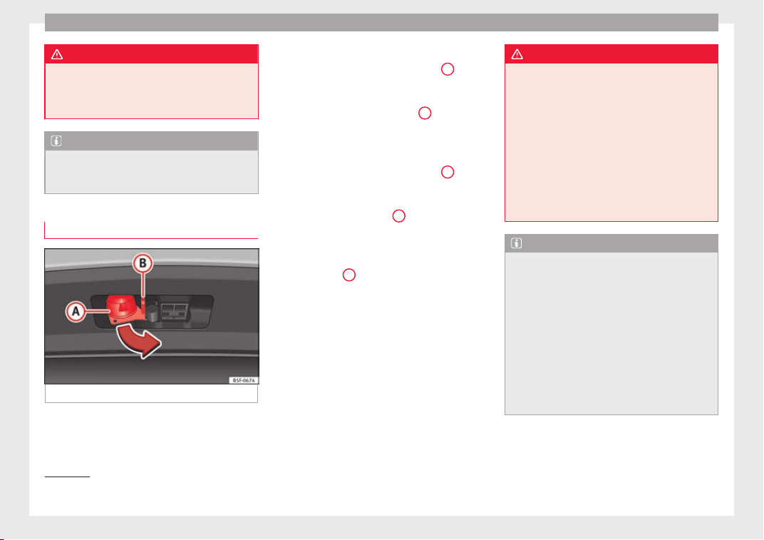
Operation
WARNING
The towing bracket ball coupling must be
stor
ed securely in the luggage compartment
to prevent them being flung through the vehi-
cle and causing injury.
Note
●
By l
aw, the ball coupling must be removed
if a trailer is not being towed if it obscures
the number plate.
Driving with a trailer
Fig. 225 Turn the 13-pin connector.
Before driving
●
Grip the 13-pin connector at area
A
and
r
emo
v
e it in the direction of the arrow
››› Fig. 225.
●
Remove the protective cover
5
›
›› Fig. 213
up
w
ards.
After driving
●
Grip the 13-pin connector at area
A
and
in
ser
t
it in the opposite direction to the arrow
››› Fig. 225.
●
Fit the protective cover
5
›
›
› Fig. 213
on
the ball coupling.
Safety lug
The safety lug
B
›
›
› Fig. 225
is used to hook
up the trailer's retainer cable.
On hooking it up to the safety lug, the retain-
er cable should have slack in all the trailer
positions with respect to the vehicle (sharp
bends, reverse gear, etc.).
Headlights
The front part of the vehicle may be raised
when the trailer is connected and the light
may dazzle the rest of the traffic.
Adapt the height of the headlights using the
headlight range rotary adjuster
1)
.
WARNING
●
Never use the s
afety lug to tow!
●
Adjust your speed to suit the road and traf-
fic conditions.
●
All work on the electrical system must be
carried out only by specialised workshops.
●
Never connect the trailer's electric system
to the electrical connections of the rear lights
or any other power sources.
●
After hooking up the trailer and connecting
the socket, check that all the trailer's rear
lights are working properly.
Note
●
If there i
s any fault in the trailer's lighting,
check the fuses in the instrument panel fuse
box ›››
page 62.
●
The contact between the retainer cable and
the safety lug may give rise to mechanical
wear in the lug's surface protection. This
wear will not prevent the safety lug from op-
erating properly or cause any fault and is ex-
cluded from the warranty.
●
When connecting and disconnecting the
trailer, the towing vehicle's handbrake
should be applied.
1)
This does not apply for vehicles with bi-xenon
headlights.
244
Towing bracket device
Anti-theft alarm
When the vehicle is locked, the alarm is trig-
gered when the el
ectrical connection be-
tween vehicle and trailer is interrupted.
Always turn off the anti-theft alarm system
before connecting or disconnecting a trailer
››› page 138.
Conditions for the integration of a trailer in
the anti-theft alarm system.
●
The vehicle is factory-equipped with an an-
ti-theft al
arm system and a towing bracket
device.
●
The trailer is connected electrically to the
towing vehicle by the trailer connector.
●
The electrical system of the vehicle and the
trailer are prepared for operation.
●
The vehicle is locked with the ignition key
and the anti-theft alarm system is activated.
CAUTION
For technical reasons, trailers fitted with rear
LED lights ar
e not integrated in the anti-theft
alarm system.
Driving tips
Driving with a trailer always requires extra
c
ar
e.
W
eight distribution
The weight distribution of a loaded trailer
with an unladen vehicle is very unfavourable.
However, if this cannot be avoided, drive ex-
tra slowly to allow for the unbalanced weight
distribution.
Speed
The stability of the vehicle and trailer is re-
duced with increasing speed. For this reason,
it is advisable not to drive at the maximum
permissible speed in an unfavourable road,
weather or wind conditions. This applies es-
pecially when driving downhill.
You should always reduce speed immediately
if the trailer shows the slightest sign of snak-
ing. Never try to stop the “snaking” by in-
creasing speed.
Always brake in due course. If the trailer has
an overrun brake, apply the brakes gently at
first and then, firmly. This will prevent the
jerking that can be caused by locking of trail-
er wheels. Select a low gear in due course
before going down a steep downhill. This en-
ables you to use the engine braking to slow
down the vehicle.
Reheating
At very high temperatures and during pro-
longed slopes, driving in a low gear and high
engine speed, always monitor the coolant
temperature gauge ››› page 120.
Electronic Stability Control*
The ESC* system helps to stabilise the trailer
in case of skidding or rocking.
Retrofitting a towing bracket*
Fig. 226 Attachment points for towing brack-
et
.
»
245
Technical dataAdviceOperationEmergenciesSafety
Operation
If a towing bracket is to be fitted after the ve-
hic
l
e i
s purchased, this must be completed
according to the instructions of the towing
bracket manufacturer.
The attachment points for the towing bracket
A
are on the lower part of the vehicle.
The di
s
t
ance between the centre of the ball
coupling and the ground should never be
lower than the indicated value, even with a
fully loaded vehicle and including the maxi-
mum drawbar load.
Elevation values for securing the towing
bracket:
Elevation values for securing the towing bracket:
B
65 mm (minimum)
C
350 mm to 420 mm (fully laden vehicle)
D
1,033 mm
E
322 mm
F
338 mm
Fitting a towing bracket
●
Driving with a trailer involves an extra effort
f
or the
v
ehicle. Therefore, before fitting a
towing bracket, please contact a Technical
Service to check whether your cooling system
needs modification.
●
The legal requirements in your country
must be observed (e.g. the fitting of a sepa-
rate control lamp).
●
Certain vehicle components, e.g. the rear
bumper, must be removed and reinstalled.
The towing bracket securing bolts must be
tightened using a torque wrench, and a pow-
er socket must be connected to the vehicle
electrical system. This requires specialised
knowledge and tools.
●
Figures in the illustration show the eleva-
tion value and the attachment points which
must be considered if you are retrofitting a
towing bracket.
WARNING
The towing brackets should be fitted at a spe-
cia
lised workshop.
●
If the towing bracket is incorrectly instal-
led, there is a serious danger of accident.
●
For your own safety, please observe the tow
bracket manufacturer's instructions.
CAUTION
●
If the pow
er socket is incorrectly installed,
this could cause damage to the vehicle elec-
trical system.
Note
●
SEAT r
ecommends that the towing hooks
be fitted at a specialised workshop. Consult
your SEAT dealer in case additional modifica-
tions to your vehicle are necessary.
●
Due to the specific design of the exhaust,
the fitting of a conventional towing hook is
not recommended for some sportier versions.
Plea
se consult your Technical Service.
246
Care and maintenance
Advice
C
ar
e and m
aintenance
Accessories and modifications
to the vehicle
Accessories, replacement of parts and
modifications
Your vehicle is designed to offer a high
s
t
and
ard of active and passive safety.
Before purchasing accessories and parts,
and before making technical changes to your
vehicle, we recommend that you consult your
Technical Service.
SEAT dealerships will be happy to provide
you with the latest information about the
use, legal requirements and recommenda-
tions from the manufacturer regarding acces-
sories and spare parts.
We recommend you use only SEAT Approved
Accessories
®
and SEAT Approved Spare
Parts
®
. This way, SEAT can guarantee that
the product in question is suitable, reliable
and safe. SEAT Technical Services have the
necessary experience and facilities to ensure
that parts are correctly and professionally in-
stalled.
Despite a continuous observation of the mar-
ket, SEAT is not able to assess the reliability,
safety and suitability of parts that SEAT has
not approved. For this reason, SEAT cannot
assume responsibility for any non-genuine
parts used, even if these parts have been ap-
proved by an official testing agency or are
covered by an official approval certificate.
Any retro-fitted equipment which has a direct
impact on the driver's control of the vehicle,
such as a cruise control system or electroni-
cally-controlled suspension, must be ap-
proved by SEAT for use in your vehicle and
bear the e mark (the European Union's au-
thorisation symbol).
If any additional electrical devices are fitted
which do not serve to control the vehicle it-
self, such as refrigerator boxes, laptops or
ventilator fans, they must bear the CE mark
(European Union manufacturer conformity
declaration).
WARNING
Accessories, for example telephone holders
or cup hol
ders, should never be fitted on the
covers, or within the working range, of the
airbags. Otherwise, there is a danger of in-
jury if the airbag is triggered in an accident.
Technical modifications
Modifications must always be carried out ac-
cordin
g to our specifications. Unauthorised
modifications to the electronic components
or software in the vehicle may cause malfunc-
tions. Due to the way the electronic compo-
nents are linked together in networks, other
indirect systems may be affected by the
faults. This can seriously impair safety, lead
to excessive wear of components, and also
invalidate your vehicle registration docu-
ments.
SEAT Technical Services cannot be held liable
for any damage caused by modifications
and/or work incorrectly performed. For this
reason, we recommend having all work per-
formed by a SEAT Technical Service using
SEAT
®
Original Spare Parts.
WARNING
Any type of work or modification performed
incorrectly
on your vehicle can lead to mal-
functions and can cause accidents.
Radio transmitters and office equip-
ment
Radio transmitters (fixed installation)
An
y
r
etrofit installations of radio transmitters
in the vehicle require prior approval. SEAT
generally authorises in-vehicle installations
»
247
Technical dataAdviceOperationEmergenciesSafety
Advice
of approved types of radio transmitters provi-
ded th
at:
●
The aeri
al
is installed correctly.
●
The aerial is installed on the exterior of the
vehicle (and shielded cables are used togeth-
er with non-reflective aerial trimming).
●
The effective transmitting power does not
exceed 10 Watts at the aerial base.
A SEAT Official Service and specialised work-
shop will be able to inform you about options
for installing and operating radio transmitters
with a higher transmitting power.
Mobile radio transmitters
Commercial mobile telephones or radio
equipment might interfere with the electron-
ics of your vehicle and cause malfunctions.
This may be due to:
●
No external aerial.
●
External aerial incorrectly installed.
●
Transmitting power more than 10 W.
You must, therefore, do not operate portable
mobile telephones or radio equipment inside
the vehicle without a properly installed exter-
nal aerial ›››
.
Pl
e
a
se note also that the maximum range of
the equipment can only be achieved with an
external aerial.
Business equipment
Retrofit installation of business or private
equipment in the vehicle is permitted, provi-
ded the equipment cannot interfere with the
driver's immediate control of the vehicle and
that any such equipment carries the mark.
Any retrofit equipment that could influence
the driver's control of the vehicle must have a
type approval for your vehicle and must carry
the e mark.
WARNING
Mobile telephones or radio equipment which
is oper
ated inside the vehicle without a prop-
erly installed external aerial can create exces-
sive magnetic fields that could cause a health
hazard.
Note
●
The post
erior fitting of electric and elec-
tronic equipment in this vehicle affects its li-
cence and could lead to the withdrawal of the
vehicle registration document under certain
circumstances.
●
Please use the mobile telephone/radio op-
erating instructions.
Care and cleaningTaking care of
y
our
v
ehicle
General notes
Vehicle maintenance
Regu
lar care and washing help to maintain
the value of the vehicle. This may also be one
of the requirements for acknowledging war-
ranty claims in the event of bodywork corro-
sion or paint defects.
The best way to protect your vehicle against
the harmful effects of the environment is
through correct maintenance and frequent
washing. The longer substances such as in-
sect remains, bird droppings, resinous tree
sap, road dirt, industrial deposits, tar, soot or
road salt and other aggressive materials re-
main on the vehicle, the more damage they
do to the paintwork. High temperatures, for
instance in strong sunlight, further intensify
the corrosive effect.
After winter, a period when salt is put on the
roads, it is important to have the underside
of the vehicle washed thoroughly.
Products for vehicle maintenance
Car-care products are available in your Tech-
nical Services. Keep the product instructions
until you have used them up.
248
Care and maintenance
WARNING
●
Car-c
are products can be toxic. Because of
this, they must always be kept closed in their
original container. Keep them out of the reach
of children. Failure to comply could result in
poisoning.
●
Always read and observe the instructions
and warnings on the package before using
car-care products. Improper use could cause
health problems or damage the vehicle. The
use of certain products may produce noxious
vapours; they should be used in well ventila-
ted areas.
●
Never use fuel, turpentine, engine oil, nail
varnish remover or other volatile fluids.
These are toxic and highly flammable. Risk of
fire and explosion.
●
Before washing your vehicle, or carrying
out any maintenance, switch the engine off,
apply the handbrake firmly and remove the
key from the ignition.
CAUTION
Never attempt to remove dirt, mud or dust if
the surf
ace of the vehicle is dry. Never use a
dry cloth or sponge for cleaning purposes.
This could damage the paintwork or the win-
dows of your vehicle. Soak dirt, mud or dust
with plenty of water.
For the sake of the environment
●
When purc
hasing car care products, try to
select ones that are not harmful to the envi-
ronment.
●
The waste from car-care products should
not be disposed of with ordinary household
waste. Observe the disposal information on
the package.
Care of the vehicle exterior
Automatic
car wash tunnel
The vehicle paintwork is so durable that the
v
ehic
l
e can normally be washed without
problems in an automatic car wash tunnel.
However, the paintwork wear depends to a
large extent on the kind of the car wash tun-
nel, the brushes used, its water filtering and
the type of cleaning and preservative prod-
ucts.
Before going through a car wash, be sure to
take the usual precautions (close the win-
dows, the roof and rear-view mirrors). There
is nothing to note apart from that.
If the vehicle has special accessories such as
spoilers or a roof rack or two-way radio aerial,
etc., it is advisable to consult the car wash
tunnel operator first.
After washing, the brakes could take some
time to respond as the brake discs and pads
could be wet, or even frozen in winter. “Dry”
the brakes by braking several times.
WARNING
Water, ice and salt on the brake system can
reduce br
aking effectiveness. Risk of acci-
dent.
Hand-washing
Vehicle washing
–
First soften the dirt and rinse it off with wa-
t
er
.
–
C
lean your vehicle from top to bottom with
a soft sponge, a glove or a brush. Use very
light pressure.
–
Rinse the sponge or glove often with clean
water.
–
Special car shampoo should only be used
for very stubborn dirt.
–
Leave the wheels, sill panels etc. until last,
using a different sponge or glove.
–
Rinse the vehicle thoroughly with water.
–
Dry the vehicle surface gently with a cha-
mois leather.
–
In cold temperature, dry the rubber seals
and their surfaces to prevent them from
»
249
Technical dataAdviceOperationEmergenciesSafety
Advice
freezing. Apply silicone spray to the rubber
se
al
s.
Af
ter washing the vehicle
–
After washing, avoid sudden and sharp
braking. “Dry” the brakes by braking sever-
al times.
WARNING
●
Wash
your vehicle with the ignition switch-
ed off.
●
Protect your hands and arms from cuts on
sharp metal edges when cleaning the under-
body, the inside of the wheel housings etc.
Risk of injury.
●
Water, ice and salt on the brake system can
reduce braking effectiveness. Risk of acci-
dent.
CAUTION
●
Never remo
ve dirt, mud or dust if the vehi-
cle surface is dry. Never use a dry cloth or
sponge for cleaning purposes. This could
scratch the paintwork or glass on your vehi-
cle.
●
Washing the vehicle in low temperatures:
when washing the vehicle with a hose, do not
direct water into the lock cylinders or the
gaps around the doors, rear lid, or sunroof.
Risk of freezing.
For the sake of the environment
To protect the environment, the vehicle
should be w
ashed only in specially provided
wash bays, to prevent toxic, oil-laden waste
water from entering the sewer system. In
some places, washing vehicles outside wash
bays is prohibited.
Note
Do not wash the vehicle in direct sunlight.
Washing the vehicle with a high pres-
s
ur
e c
leaner
Be particularly careful when using a high
pr
e
s
sure cleaner!
–
Always observe the instructions for the
high-pressure cleaner, particularly those
concerning the pressure and the spraying
distance.
–
Increase the spraying distance for soft ma-
terials and painted bumpers.
–
Do not use a high pressure cleaner to re-
move ice or snow from windows
›››
page 251.
–
Never use concentrated jet nozzles (“rotat-
ing jets”)
›››
.
–
Af
t
er w
ashing, avoid sudden and sharp
braking. “Dry” the brakes by braking sever-
al times ››› page 181.
WARNING
●
Never wa
sh tyres with a concentrated jet
(“rotating nozzle”). Even at large spraying
distances and short cleaning times, damage
can occur to the tyres. This may cause an ac-
cident.
●
Water, ice and salt on the brake system can
reduce braking effectiveness. Risk of acci-
dent.
CAUTION
●
Do not use w
ater hotter than +60°C
(+140°F). This could damage the vehicle.
●
To avoid damage to the vehicle, keep a suf-
ficient distance from sensitive materials such
as flexible hoses, plastic, soundproofing ma-
terial, etc. This also applies to bumpers pain-
ted in the colour of the bodywork. The closer
the nozzle is to the surface, the greater the
wear on the material.
Factory-fitted adhesive sheets
The following indications should be taken in-
t
o ac
c
ount to avoid damaging adhesive
sheets:
●
Do not use high pressure cleaners.
250

Care and maintenance
●
Do not
u
se s
crapers to remove ice or snow
from the sheets.
●
Do not polish the adhesive sheets.
●
Do not use dirty cloths or sponges.
●
It is preferable to wash them with a soft
sponge and gentle neutral soap.
Camera sensors and lenses
●
Use a small brush to remove snow and a
de-icer spr
ay to remove ice.
●
Clean the sensors with a solvent-free prod-
uct and a soft, dr
y cloth.
●
Moisten the camera lens using a standard
alcohol-based glass cleaning agent and
clean the lens with a dry cloth.
CAUTION
●
When you c
lean the vehicle with a pressure
washer:
–
Stay a suitable distance from the sensors
on the front and rear bumpers.
–
Do not clean the camera lenses or sur-
rounding area with the pressure washer.
●
Never use warm or hot water to remove
snow and ice from the reverse camera lens,
as it could crack the lens.
●
Never use abrasive cleaning agents on the
lens.
Vehicle paint maintenance
Regular waxing protects the paintwork.
You need to ap
ply wax to your vehicle if water
does not form small drops and run off the
paintwork when it is clean.
Good quality hard wax products are available
at your Technical Service.
Regular wax applications help to protect the
paintwork from environmental contaminants
››› page 248. It is also effective in protecting
against minor scratches.
Even if a wax solution is used regularly in the
vehicle washing tunnel, it is advisable to pro-
tect the paint with a hard wax coating at least
twice a year.
Polishing the paintwork
Polishing is only necessary if the paint has
lo
s
t
its shine, and the gloss cannot be
brought back by applying wax. Polishing
products can be purchased in your Technical
Service.
The vehicle must be waxed after polishing if
the polish used does not contain wax com-
pounds to seal the paint
›››
page 251, Vehicle
paint maintenance.
CAUTION
To prevent damage to the paintwork:
●
Do not use polishes and hard wax on pain-
ted par
ts with a matt finish or on plastic
parts.
●
Do not polish your vehicle in a sandy or
dusty environment.
Caring for plastic parts
If normal washing fails to clean plastic parts,
c
l
e
an them with approved solvent-free plas-
tic cleaning and care products.
CAUTION
●
The use of li
quid air freshener directly over
the air vents of the vehicle may damage the
plastic parts if the liquid is accidentally spil-
led.
●
Cleaning products which contain solvents
will damage the material.
Cleaning of windows and mirrors
Cleaning windows
–
Moisten the windows with commercially
av
ai
l
able, alcohol based glass cleaner.
–
Dry the windows with a clean chamois
leather or a lint-free cloth.
»
251
Technical dataAdviceOperationEmergenciesSafety

Advice
Removing snow
–
Use a small brush to remove snow from the
w
indo
w
s and mirrors.
Removing ice
–
Use a de-icer spray.
Use a clean cloth or chamois leather to dry
the windows. The chamois leathers used on
painted surfaces are not suitable to clean
windows because they are soiled with wax
deposits which could smear the windows.
If possible, use a de-icing spray to remove
ice. If you use an ice scraper, push it in one
direction only without swinging it.
Use window cleaner or a silicone remover to
clean rubber, oil, grease and silicone depos-
its off.
Wax deposits can only be removed with a
special cleaner available at your Technical
Service. Wax deposits on the windscreen
could cause the wiper blades to judder. Add-
ing a window cleaner that dissolves wax to
the windscreen washer fluid reservoir pre-
vents wiper blades from juddering, but the
wax deposits are not removed.
CAUTION
●
Never use w
arm or hot water to remove
snow and ice from windows and mirrors. This
could cause the glass to crack!
●
The heating el
ement for the rear window is
located on the inner side of the window. To
prevent damage, do not put stickers over the
heating elements on the inside of the win-
dow.
Cleaning windscreen wiper blades
Clean wiper blades improve visibility.
1. Use a soft cloth to remove dust and dirt
from the wind
screen wiper blades.
2. Use window cleaner to clean the wind-
scr
een wiper blades. Use a sponge or a
cloth to remove stubborn dirt.
Care of rubber seals
If rubber seals are well looked after, they will
not
fr
eez
e so quickly.
1. Use a soft cloth to remove dust and dirt
from the rubber seals.
2. Apply a specialist care product to the rub-
ber seals.
The rubber strips on the doors, windows, etc.
will remain pliable and last longer if they are
treated with a suitable rubber care product
from time to time (for example silicone
spray).
Caring for rubber seals will also prevent pre-
mature ageing and leaks. The doors will be
easier to open. If rubber seals are well looked
after, they will not freeze so quickly in winter.
Door lock cylinder
The door lock cylinders can freeze up in win-
ter.
T
o de-ice the lock cylinders you should only
use spray with lubricating and anti-corrosive
properties.
Cleaning chrome parts
1. Clean chrome parts with a damp cloth.
2. Polish chrome parts with a soft, dry cloth.
If
thi
s
does not provide satisfying results, use
a specialist chrome cleaning product.
Chrome cleaning products will remove stains
from the surface.
CAUTION
To prevent scratching chrome surfaces:
●
Never use an abrasive cleaning product on
chrome.
●
Do not
clean or polish chrome parts in a
sandy or dusty environment.
252
Care and maintenance
Steel wheel rims
–
Clean steel wheel rims regularly using a
separat
e sponge.
Use an industrial cleaner to remove brake
dust. Any damage to the paint on steel wheel
rims should be repaired before starting to
rust.
WARNING
●
Never wa
sh tyres with a cylindrical jet. Even
at large spraying distances and short clean-
ing times, damage can occur to the tyres.
This may cause an accident.
●
Water, ice and salt on the brake system can
reduce braking effectiveness. Risk of acci-
dent. Directly after washing, avoid sudden
and sharp braking. “Dry” the brakes by brak-
ing several times ››› page 181, Braking ca-
pacity and braking distance.
Alloy wheel rims
Every two weeks
–
Wash salt and brake dust from alloy
wheel
s.
–
U
se an ac
id free detergent to clean the
wheel rims.
Every 3 months
–
Apply a hard wax compound to the wheels.
Alloy wheels require regular attention to pre-
serve their appearance. If road salt and brake
dust are not often removed, the aluminium
finish will be impaired.
Always use an acid-free detergent for alloy
wheel rims.
Car polish or other abrasive agents should
not be used for maintaining the rims. If the
protective coating is damaged, e.g. by flying
stones, the damaged area should be re-
paired immediately.
WARNING
Observe the safety warnings ›››
in Steel
wheel rims on p
age 253.
Vehicle underbody protection
The vehicle underbody is coated to protect it
fr
om c
hemic
al and mechanical damage.
The protective coating can be damaged when
driving. We recommend that you check the
protective coating under the body and on the
running gear, and retouch it if necessary, be-
fore and after the winter season.
We recommend that you go to your Technical
Service to carry out repair work and addition-
al anti-corrosion work.
WARNING
Do not apply underseal or anti-corrosion
coatin
gs to the exhaust pipes, catalytic con-
verter or the heat shields on the exhaust sys-
tem. The heat of the exhaust system or the
engine could cause them to ignite. Risk of
fire.
Cleaning engine compartment
Take special care when cleaning the engine
compar
tment.
Anti-corrosion treatment
The engine compartment and the surface of
the power unit are given anti-corrosion treat-
ment at the factory.
Good corrosion protection is particularly im-
portant in winter when the vehicle is fre-
quently driven on salted roads. To prevent
the salt corroding the vehicle, the entire en-
gine compartment should be thoroughly
cleaned before and after winter.
Technical Services have the proper products
for cleaning and preservation as well as the
necessary workshop equipment. For this rea-
son, we recommend having this work per-
formed by them.
The anti-corrosion protection is usually re-
moved if the engine compartment is cleaned
with grease removing solutions, or if you
»
253
Technical dataAdviceOperationEmergenciesSafety
Advice
have the engine cleaned. On commissioning
thi
s
w
ork, ensure that all surfaces, seams,
joints and components in the engine com-
partment are given anti-corrosion treatment.
WARNING
●
When workin
g in the engine compartment,
always observe the safety warnings
››› page 263.
●
Before opening the bonnet, switch the en-
gine off, apply the handbrake firmly and al-
ways remove the key from the ignition.
●
Allow the engine to cool before you clean
the engine compartment.
●
Do not clean, for example, the vehicle un-
derbody, wheel arches or wheel trims without
protecting your hands and arms. You may cut
yourself on sharp-edged metal parts. Failure
to comply could result in injury.
●
Moisture, ice and salt on the brake system
may affect braking effectiveness. Risk of acci-
dent. Directly after washing, avoid sudden
and sharp braking.
●
Never touch the radiator fan. It is tempera-
ture-controlled and could start automatically,
even when the key is removed from the igni-
tion!
For the sake of the environment
Fuel, grease and oil deposits can be removed
when the engine is
washed. The polluted wa-
ter must be cleaned in an oil separator. For
this reason, engine washing should be car-
ried out only by a specialised workshop or a
petrol
station.
Caring for the vehicle interior
Screen f
or the radio/Easy Connect*
and control panel*
The display can be cleaned with a soft cloth
and a profe
ssionally available “LCD cleaner”.
Moisten the cloth with a small amount of the
cleaning fluid.
The Easy Connect control panel* should first
be cleaned with a brush so that no dirt goes
into the device or between the keys and
housing. Next, we recommend cleaning the
Easy Connect control panel* using a cloth
dampened with water and washing-up liquid.
CAUTION
●
To avoid s
cratching the screen, do not wipe
the display with a dry cloth.
●
To avoid damage, ensure that no liquid
goes into the Easy Connect control panel*.
Cleaning plastic parts and the dash
p
anel
–
Use a clean, damp cloth to clean plastic
p
ar
ts
and the dash panel.
–
If this does not provide satisfactory results,
use a special solvent-free plastic cleaning
product.
WARNING
Never clean the dash panel and the airbag
module s
urface with cleaners containing sol-
vents. Solvents cause the surface to become
porous. If the airbag triggered, plastic parts
could become detached and cause injuries.
CAUTION
Cleaning products which contain solvents will
damag
e the material.
Cleaning wooden trim*
–
Clean the wooden trim with a water-mois-
t
ened c
l
ean cloth.
–
If this does not provide satisfactory results,
use a gentle soap solution.
CAUTION
Cleaning products which contain solvents will
damag
e the material.
Cleaning textile covers and trim parts
Textile covers and trim parts (e.g. seats, door
trim) shou
l
d be c
leaned regularly with a
254
Care and maintenance
vacuum cleaner. This will remove surface dirt
whic
h c
ou
ld otherwise be rubbed into the
textile material during use. Do not use steam
cleaners, as the steam could carry the dirt
deeper into the textile material.
Normal cleaning
We recommend that you use a soft sponge or
a commercially available lint-free, micro-fibre
cloth for normal cleaning. Only use brushes
on floor coverings and mats, as other textile
surfaces could become damaged.
In the case of normal surface dirt you can use
a foam cleaner. Use a sponge to spread the
foam on the textile surface and to work it into
the material lightly. However, make sure that
the textile material does not become soaking
wet. Then dab off the foam with a dry and ab-
sorbent cloth (e.g. a micro-fibre cloth) and
vacuum off any residue once the surface is
completely dry.
Cleaning stains
Treat drink stains (such as coffee or fruit
juice, etc.) with a cleaning solution for deli-
cate fabrics. This solution should be applied
with a sponge. If the stains are difficult to re-
move, a washing paste can be applied direct-
ly onto the stain and worked into the fabric.
The surface will then have to be wiped with
clear water to remove any residue left by the
paste. To do so, use a damp cloth or sponge
and then dab the stain with an absorbent
cloth.
Remove chocolate or make-up stains with a
cleaning paste (for e.g., soft soap). Then re-
move the soap with water (wet sponge).
A spirit-based cleaner can be used to remove
grease, oil, lipstick or ball point pen. Then
dab the dissolved grease or colour particles
off with an absorbent cloth or similar. You
may also have to treat the stain once more
using washing paste and water.
If the covers or textile trim panels are badly
soiled we recommend that you have them
cleaned by a professional cleaning company
with a shampoo and spray.
Note
Open Velcro fasteners on clothes can damage
the seat upho
lstery. Make sure they are
closed.
Cleaning leather*
Normal cleaning
–
Moisten a cotton or woollen cloth with wa-
t
er and w
ipe o
ver the leather surfaces.
Cleaning stubborn stains
–
More stubborn dirt can be removed using a
mild soap solution (pure liquid soap; two
tablespoons diluted in one litre of water)
and a cloth.
–
Do not let the water soak through the leath-
er or soak into the seams.
–
Then wipe off with a soft, dry cloth.
Leather maintenance
–
The leather should be treated twice a year
with a special leather-care product, availa-
ble at Technical Services.
–
Apply these products very sparingly.
–
Then wipe off with a soft cloth.
SEAT does everything possible to preserve
the genuine qualities of this natural product.
Due to the natural properties of the specially
selected hides employed, the finished leath-
er has a certain sensitivity to grease and dirt,
etc. so a degree of care is required in every-
day use and when looking after the leather.
Dust and grit in the pores and seams can
scratch and damage the surface. If the vehi-
cle is under solar radiation for long periods,
the leather should be protected to prevent it
from fading. However, slight colour variations
in high-quality natural leather are normal.
CAUTION
●
Do not use so
lvents, wax polish, shoe
cream, spot removers or similar products on
leather.
»
255
Technical dataAdviceOperationEmergenciesSafety
Advice
●
To avoid d
amage, stubborn stains should
be removed by a specialised workshop.
Cleaning Alcantara upholstery*
Removing dust and dirt
–
Moisten a cloth just a lit
tle and wipe down
the seat covers.
Removing stains
–
Moisten a cloth with lukewarm water or di-
luted whit
e spirits.
–
Dab at the stain. Start at the outside and
work inwards.
–
Dry the clean area with a soft cloth.
Do not use leather cleaning products on Al-
cantara seat covers.
You may use a suitable soap on dust and dirt.
Dust and grit in the pores and seams can
scratch and damage the surface. If the car is
left standing in the sun for long periods, Al-
cantara leather should be protected against
direct sunlight to prevent it from fading. How-
ever, slight colour variations will arise in nor-
mal use.
CAUTION
●
Do not use so
lvents, wax polish, shoe
cream, stain removers, leather cleaning prod-
ucts or any similar products on Alcantara.
●
To avoid damage, stubborn stains should
be removed by a specialised workshop.
●
On no account use brushes, hard sponges
or similar utensils.
Cleaning seat belts
A dirty belt may not work properly. Check all
se
at
belts
regularly and keep them clean.
Seat belts cleaning
–
Pull the dirty seat belt right out and unroll
it.
–
Clean dirty seat belts with a gentle soap
solution.
–
Allow it to dry.
–
Do not roll the seat belt up until it is dry.
If large stains form on the belts, the automat-
ic belt retractor will not work correctly.
WARNING
●
Do not use c
hemical cleaning agents on the
seat belts, as this can impair the strength of
the webbing. Ensure that seat belts do not
come into contact with corrosive fluids.
●
Check the c
ondition of the seat belts at reg-
ular intervals. If you notice that the belt web-
bing, fittings, retractor mechanism or buckle
of any of the belts is damaged, the belt must
be replaced by a specialised workshop.
●
Do not attempt to repair a damaged seat
belt yourself. The seat belts must not be re-
moved or modified in any way.
CAUTION
After cleaning, allow seat belts to dry com-
p
let
ely before rolling them up. Otherwise, the
belt retractors could become damaged.
256
Checking and refilling levels
Checking and refilling levels
R
ef
uel
ling
Refuelling
Read the additional information carefully
›››
page 57
If the automatic filler nozzle is operated cor-
rectly, it will switch itself off as soon as the
tank is “full”. Never attempt to fill beyond
this point, as this will fill the expansion
chamber. Fuel may leak out if ambient condi-
tions are warm.
The correct fuel grade for your vehicle is giv-
en on a sticker on the inside of the fuel tank
flap.
Vehicles with natural gas engines and hy-
brids
Every 6 months it is necessary to run on pet-
rol until the control lamp switches off and
then the tank must be refilled. This is neces-
sary to ensure that the system works proper-
ly, as well as the fuel quality required for driv-
ing with petrol.
WARNING
●
Fuel i
s highly flammable and can cause se-
rious burns and other injuries.
–
Never smoke or c
ome into contact with
sparks when filling the fuel tank of the
vehicle or a spare fuel canister with fuel.
This is an explosion hazard.
–
Follow legal requirements for the use of
spare fuel canisters.
–
For safety reasons we do not recommend
carrying a spare fuel canister in the vehi-
cle. The canister could be damaged in an
accident and leak.
●
If, in exceptional circumstances, you have
to carry a spare fuel canister, please observe
the following:
–
Never fill the spare fuel canister inside
the vehicle or on it. An electrostatic
charge could build up during filling, caus-
ing the fuel fumes to ignite. This could
cause an explosion. Always place the
canister on the ground to fill it.
–
Insert the fuel nozzle into the mouth of
the canister as far as possible.
–
If the spare fuel canister is made of met-
al, the filling nozzle must be in contact
with the canister during filling. This
helps prevent an electrostatic charge
building up.
–
Never spill fuel in the vehicle or in the
luggage compartment. Fuel vapours are
explosive. Danger of death.
CAUTION
●
Fuel s
pills should be removed from the
paintwork immediately.
●
Never run the t
ank completely dry. Irregular
fuel supply can cause misfiring. As a result,
unburnt fuel could enter the catalytic convert-
er and cause damage.
●
When filling the fuel tank after having run it
completely dry on a vehicle with a diesel en-
gine the ignition must be switched on for at
least 30 seconds before starting the engine.
Subsequently, when you start the engine it
may take longer than normal to start firing
(up to one minute). This is due to the fact that
the fuel system has to purge itself of air be-
fore starting.
For the sake of the environment
Do not try to put in more fuel after the auto-
matic fi
ller nozzle has switched off, this may
cause the fuel to overflow if it becomes warm.
Note
There is no emergency mechanism for the
manual
release of the fuel tank flap. If neces-
sary, request assistance from specialised per-
sonnel.
257
Technical dataAdviceOperationEmergenciesSafety
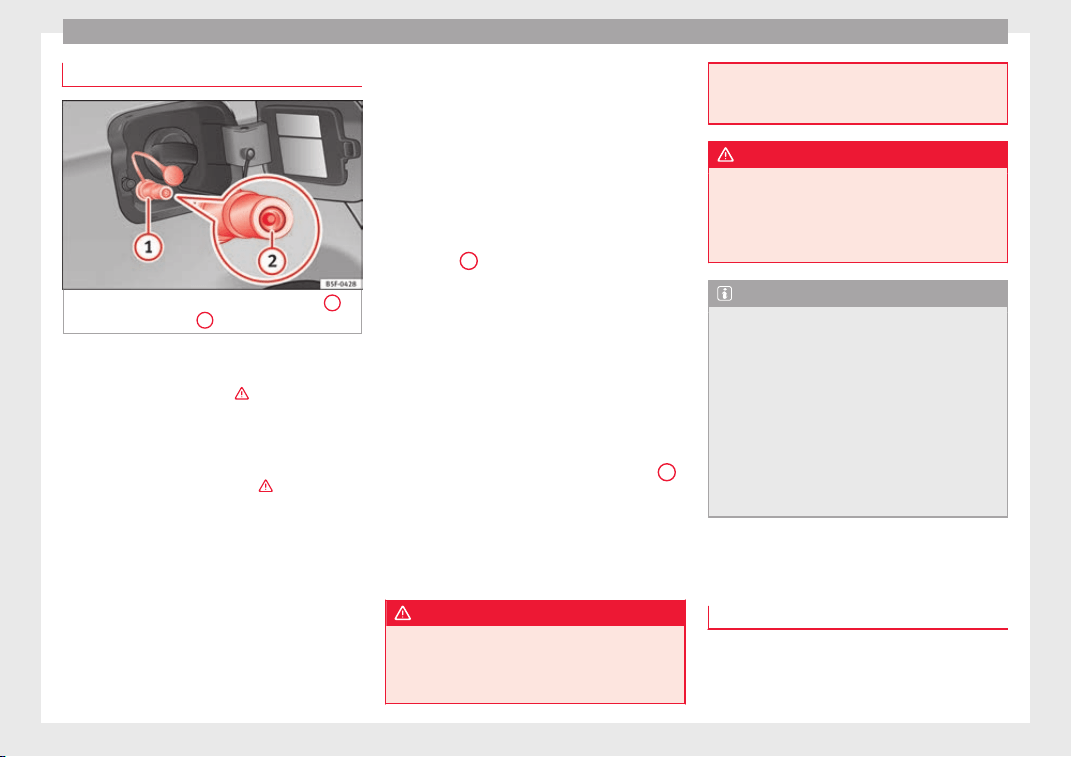
Advice
Refuelling with natural gas
Fig. 227 Tank flap open: gas filler mouth
1
,
fi
l
l
er mouth retainer
2
Before r
efuelling, the engine and the igni-
tion, mo
b
ile telephone and heating must be
switched off separately ›››
.
R
e
a
d the instructions on how to use the natu-
ral gas pump carefully.
The vehicle is not prepared for refuelling with
liquefied natural gas (LNG) ›››
. Before refu-
el
lin
g w
ith natural gas, make sure you add
the appropriate type of fuel ››› page 258.
Opening the fuel tank cap
The natural gas filler mouth is behind the fuel
tank cap, next to the petrol filler mouth.
●
Unlock the vehicle with the key or with the
central locking button situated on the driv-
er door ››› page 134.
●
Press on the rear area of the flap and open
it.
Refuelling
Special feature: if the ambient temperature is
very high, the natural gas pump protection
against overheating disconnects this auto-
matically.
●
Remove the plug from the gas filler mouth
››› Fig. 227
1
.
●
Connect the pump filling nozzle to the gas
fi
l
l
er mouth.
●
The fuel tank will be full when the pump
compressor automatically cuts the supply.
●
If you wish to finish refuelling in advance,
press the button on the pump to stop the
flow.
Closing the fuel tank cap
●
Check that the gas filler mouth retainer
2
is not trapped with the filler nozzle. If neces-
s
ar
y
, place it in the filler mouth again.
●
Insert the plug in the filler mouth.
●
Close the tank flap. Make sure you hear it
click into place.
WARNING
Natural gas is a highly explosive, easily flam-
mabl
e substance. Incorrect handling of the
natural gas can cause accidents serious
burns and other injuries.
●
Befor
e refuelling with natural gas, engage
the filling mouth correctly. If you can smell
gas, stop refuelling immediately.
WARNING
The vehicle is not prepared to use liquefied
n
atur
al gas (LNG), and this fuel must not be
added under any circumstances. Liquefied
natural gas can cause the natural gas tank to
explode, resulting in serious injury.
Note
●
The fillin
g nozzles of natural gas pumps
can differ in the way they are operated. If you
do not know, ask a qualified employee at the
petrol station to do the refuelling.
●
Noises heard when refuelling are normal
and do not indicate the presence of a fault in
the system.
●
The vehicle natural gas system is prepared
both for refuelling with a small compressor
(slow refuel) and a large compressor (fast re-
fuel) in natural gas service stations.
Fuel
T
y
pe
s of petrol
The correct grade of petrol is listed inside the
f
uel
t
ank flap.
258
Checking and refilling levels
The vehicle is equipped with a catalytic con-
v
er
t
er and must only be run on unleaded pet-
rol. The petrol must comply with European
Standard EN 228 or German standard DIN
51626-1 and must be unleaded. You can re-
fuel with a maximum ethanol proportion of
10 % (E10). The types of petrol are differenti-
ated by their octane rating (RON).
The following titles appear on the corre-
sponding adhesive on the fuel tank flap:
Super unleaded 95 octane or normal 91 oc-
tane unleaded petrol
We recommend you use super 95 octane pet-
rol. If this is not available: normal 91 octane
petrol, with a slight decrease in power.
Super unleaded petrol with a minimum of 95
octanes
You should use super petrol with a minimum
of 95 octanes.
If super is not available, in an emergency you
may refuel with normal 91 octane petrol. In
this case only use moderate engine speeds
and a light throttle. Refuel with super as soon
as possible.
Super unleaded 98 octane or super 95 oc-
tane unleaded petrol
We recommend you use super plus 98 octane
petrol. If this is not available: super 95 oc-
tane petrol, with a slight decrease in power.
If super is not available, in an emergency you
may refuel with normal 91 octane petrol. In
this case only use moderate engine speeds
and a light throttle. Refuel with super as soon
as possible.
Petrol additives
The quality of the fuel influences the behav-
iour, power and service life of the engine.
This is why the petrol you use should carry
suitable additives already included by the
petrol industry, free of metals. These addi-
tives will help to prevent corrosion, keep the
fuel system clean and prevent deposits from
building up in the engine.
If good-quality petrol with metal-free addi-
tives is not available or engine problems
arise, the necessary additives must be added
when refuelling ›››
.
Not
al
l
petrol additives have been shown to
be effective. The use of unsuitable petrol ad-
ditives may cause significant damage to the
engine and the catalytic converter. Metal ad-
ditives should never be used. Metal additives
may also be contained in petrol additives for
improving anti-detonation ratings or octane
ratings ›››
.
S
EA
T r
ecommends “genuine Volkswagen
Group Fuel Additives for petrol engines”.
These additives can be bought at SEAT deal-
ers, where information on how to use them
can also be obtained.
CAUTION
●
Do not ref
uel if the filler indicates that the
fuel contains metal. LRP (lead replacement
petrol) fuels contain high concentrations of
metal additives. Using them may damage the
engine!
●
Never refuel with fuels containing a large
proportion of ethanol (for example, E50, E85).
This could damage the fuel system.
●
Just filling one full tank of leaded fuel or
fuel containing other metal additives would
seriously impair the efficiency of the catalytic
converter.
●
Only use fuel additives that have been ap-
proved by SEAT. Octane boosting or anti-
knock additives may contain metal additives
that could seriously damage the engine or
the catalytic converter. These additives must
not be used.
●
High engine speed and full throttle can
damage the engine when using petrol with an
octane rating lower than the correct grade for
the engine.
Note
●
You ma
y use petrol with a high octane num-
ber than the one recommended for your en-
gine.
●
In those countries where unleaded petrol is
not available, you may refuel with a fuel with
a low lead content.
259
Technical dataAdviceOperationEmergenciesSafety
Advice
Diesel fuel
Please note the information on the inside of
the fuel t
ank flap.
We recommend the use of diesel fuel which
complies to European standard EN 590. If
diesel fuel which meets European standard
EN 590 is not available, the Cetane number
(CZ) must, at minimum, be 51. If the engine
is equipped with a particulate filter, the sul-
phur content of the fuel must be below 50
parts per million.
Winter-grade diesel
Summer fuel becomes thicker in winter and it
is more difficult to start the engine. For this
reason, petrol stations in some countries al-
so offer winter diesel with improved fluidity
when cold (winter-grade diesel).
CAUTION
●
The vehic
le is not designed for the use of
FAME fuel (biodiesel). The fuel system would
be damaged if you used biodiesel.
●
Do not mix fuel additives, the so-called
“thinners”, petrol or similar additives with
diesel fuel.
●
If poor-quality diesel fuel is used, it may be
necessary to drain the fuel filter more fre-
quently than is specified in the Maintenance
Programme. We recommend having this done
by a specialised workshop. If water is allowed
to collect in the filter, this can cause engine
perform
ance problems.
Natural gas
Natural gas can be compressed or in liquid
form, ad
dition to others.
Liquefied natural gas (LNG) is the result of
heavy cooling of natural gas. Therefore its
volume is considerably reduced compared
with compressed natural gas (CNG). In vehi-
cles with a natural gas engine, liquefied nat-
ural gas cannot be directly refilled, as the gas
would expand excessively in the vehicle gas
tank.
Therefore, vehicles with a natural gas engine
must only be refuelled using compressed
natural gas ›››
.
Nat
ur
a
l gas quality and consumption
Natural gas is divided into the groups H and
L depending on its quality.
Gas type H has a superior heating power and
inferior nitrogen and carbon dioxide content
than type L. The higher the heating power of
the natural gas, the lower the consumption
will be.
However, the heating power and the propor-
tion of nitrogen and carbon dioxide can fluc-
tuate within the quality groups. Therefore, ve-
hicle consumption can also vary when using
a single type of gas only.
The engine management automatically
adapts to the natural gas used according to
its quality. Therefore, different quality gases
can be mixed in the tank, without the need
for comprehensive draining before applying a
different quality gas.
Updated information relating to natural gas
quality is displayed on the instrument panel
›››
page 37.
Natural gas and safety
If you can smell gas or suspect that there is a
leak ›››
:
●
Stop the vehicle immediately.
●
Switch the ignition off.
●
Open the doors to appropriately ventilate
the
v
ehic
le.
●
Extinguish cigarettes immediately.
●
Move away from the vehicle or switch off
objects that may cause sparks or a fire.
●
If you continue to smell gas, do not contin-
ue driving!
●
Seek specialist assistance. Have the fault
repaired.
Regular checks of the natural gas system
The natural gas tanks may be damaged or
corroded by external factors. The walls of the
260
Checking and refilling levels
gas tanks are weakened by deformations,
d
am
ag
e or corrosion. As a result, the tanks
could burst and result in serious injuries or
even death. For this reason, the vehicle own-
er must have a specialised workshop check
(visual check) the gas system every 4 years
at least. The vehicle owner must have a spe-
cialised workshop replace the natural gas
tanks before they reach the end of their serv-
ice life. For further information about the
service life of gas tanks, go to a SEAT dealer
service or a specialised workshop
WARNING
Failure to act when you can smell gas in the
vehicl
e or when refuelling can cause serious
injuries.
●
Carry out the necessary operations.
●
Leave the danger zone.
●
If necessary, warn the emergency services.
WARNING
The vehicle is not prepared to use liquefied
natur
al gas (LNG) and this fuel must not be
added under any circumstances. Liquefied
natural gas can cause the natural gas tank to
explode, resulting in serious injury.
WARNING
Damaged, corroded or rusted tanks can result
in serious injur
y or even death.
●
Have the nat
ural gas deposits checked at
least every 4 years (visual check).
●
Natural gas tanks have a limited service
life. Have the natural gas tanks replaced
when required. You can obtain further infor-
mation about this at SEAT dealers or special-
ised workshops.
WARNING
If the vehicle underbody touches the ground
or in the ev
ent of
a rear collision, there could
be damage to the natural gas tanks.
●
Check whether there is a smell of gas.
●
If you notice a smell of gas, take the vehicle
to a specialised workshop immediately and
have the natural gas system checked.
Note
Have the natural gas system checked regular-
ly by
a specialised workshop, according to
the Maintenance Programme.
AdBlue
®
Inf
orm
ation on AdBlue
®
The consumption of AdBlue
®
depend
s
on
y
our personal driving style, the temperature
of the system and on the outdoor tempera-
ture when the vehicle is used.
AdBlue
®
freezes at temperatures of -11°C
(+13°F). The system has heating elements
that guarantee its operation even at low tem-
peratures.
The AdBlue
®
tank level capacity is approxi-
mately 10.4 litres.
The AdBlue
®
tank should never be empty.
When the distance to empty drops below
2400 km, a warning to refill the AdBlue
®
tank
will appear on the dash panel display
››› page 262. If this information is ignored,
later on it will not be possible to re-start the
engine. If this warning does not appear, it is
not necessary to refill the AdBlue
®
tank.
AdBlue
®
is a registered brand of the German
Association of the Automotive Industry (VDA)
and is also known as AUS32 or DEF (Diesel
Exhaust Fluid).
CAUTION
Filling the AdBlue
®
tank e
xcessively can
cause damage to the tank.
261
Technical dataAdviceOperationEmergenciesSafety
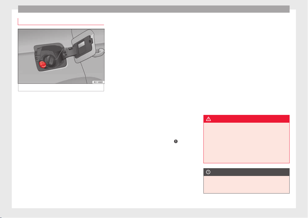
Advice
Refilling AdBlue
®
Fig. 228 AdBlue tank cap.
Operations prior to refilling
P
ark
the
vehicle on a flat surface. If the vehi-
cle is not parked on a flat surface, but, for ex-
ample, on a slope or on the side of a curb,
the level indicator may not detect the load
properly.
If a warning message about AdBlue
®
levels
appears on the dash panel display, fill at
least the minimum amount required (approx.
5 litres). Only after adding this amount will
the system detect that AdBlue
®
has been
added and you will be able to start the en-
gine again. The maximum amount that can
be refilled is 11 litres.
Switch the ignition off. If the ignition is not
switched off during refilling, the warning to
refill may continue to appear on the instru-
ment panel display.
Fill with a refill bottle
Only use AdBlue
®
that complies with ISO
22241-1. Only use original containers.
●
Open the tank cover ››› Fig. 228.
●
Unscrew the tank cap by turning it in an an-
ti-clockwise direction.
●
Please observe the manufacturer's instruc-
tions, indicated on the refill bottle.
●
Check the expiry date.
●
Remove the cap of the refill bottle.
●
Insert the neck of the bottle in the tank fill-
er neck vertically and screw the bottle on by
hand, by turning it in a clockwise direction.
●
Press the refill bottle in the direction of the
filler neck and hold it in this position.
●
Wait until the contents of the refill bottle
have been poured into the AdBlue
®
tank. Do
not compress or break the bottle!
●
Turn the bottle in a counter-clockwise direc-
tion and gently pull it upwards ›››
.
●
The AdBlue
®
t
ank
i
s full when no more liq-
uid comes out of the bottle.
●
Screw on the tank cap in a clockwise direc-
tion until it is tightly closed.
●
Close the fuel tank flap.
Operations before driving
●
After refilling the tank, only switch on the
ignition.
●
Leave the ignition on for at least 30 sec-
onds for the system to detect the fluid load.
●
Make sure you wait for at least 30 seconds
before starting the engine!
Refilling the dispenser with AdBlue
Valid for vehicles with selective catalytic re-
duction.
●
Open the tank cap.
●
Turn the SCR tank cap anti-clockwise
››› Fig. 228.
●
Add AdBlue until the nozzle stops for the
first time.
●
Close the SCR tube by turning it clockwise
until you hear a click.
WARNING
AdBlue
®
should on
ly be stored in the original
container, which should be tightly closed and
kept in a safe place.
●
Never keep AdBlue
®
in empty food contain-
ers, bottles or other similar containers. Other
people may confuse it for other products.
●
Keep AdBlue
®
out of the reach of children.
CAUTION
●
When refil
ling, the nozzle grip should be
aligned downward. Otherwise the nozzle will
not connect automatically.
262
Checking and refilling levels
●
Do not try
to add any more additive after
the nozzle has stopped for the first time. The
AdBlue tank could overflow and AdBlue could
spill out.
●
Only use AdBlue
®
that complies with ISO
22241-1. Only use original containers.
●
Never mix AdBlue
®
with water, fuel or addi-
tives. Any type of damage caused by such a
mixture will not be covered by the warranty.
●
Never pour AdBlue
®
into the fuel tank. This
could result in engine damage.
●
Do not carry the refill bottle inside the vehi-
cle. If there is a leak (due to temperature
changes or damage to the bottle), the
AdBlue
®
may damage the vehicle.
For the sake of the environment
Dispose of the refill bottle in an environment-
friendly manner
.
Note
You can buy refill bottles that are adequate
for AdBlue
®
use at
SEAT dealerships.
Working in the engine compart-
ment
Saf
ety
not
es for work in the engine
compartment
Read the additional information carefully
›››
page 17
Before starting any work on the engine or in
the engine compartment:
1. Switch off the engine and remove the key
from the ignition.
2. Ap
ply the handbrake.
3. Move the gear lever to neutral or the selec-
tor lever to position P.
4. Wait for the engine to cool down.
5. Keep children away from the vehicle.
6. Raise the bonnet
›››
page 264.
You should not do any work in the engine
compartment unless you know exactly how to
carry out the jobs and have the correct tools!
Have the work carried out by a specialised
workshop if you are uncertain.
All service fluids and consumables, e.g. cool-
ant, engine oil, spark plugs and batteries,
are under constant development. SEAT pro-
vides a constant flow of information to Tech-
nical Services concerning modifications. For
this reason, we recommend you have service
fluids and consumables replaced by a Techni-
cal Service. Please observe the relevant in-
structions ››› page 247. The engine compart-
ment of the vehicle is a hazardous area ›››
.
WARNING
All work on the engine or in the engine com-
partment, e.
g. checking and refilling fluids,
involves the danger of injury and burns, acci-
dents and even fire.
●
Never open the bonnet if you see steam,
smoke or coolant escaping from the engine
compartment. Otherwise, there is a risk of
sustaining burns. Wait until no more steam or
coolant is emitted, then allow the engine to
cool before carefully opening the bonnet.
●
Switch off the engine and remove the key
from the ignition.
●
Apply the handbrake and move the gear
lever to neutral or selector lever to position P.
●
Keep children away from the vehicle.
●
Never touch hot engine parts. There is a
risk of burns.
●
Never spill liquids on a hot engine or on a
hot exhaust gas system. This is a fire hazard.
●
Avoid causing short-circuits in the electri-
cal system, particularly at the points where
the jump leads are attached ›››
page 72.
The battery could explode.
●
Never touch the radiator fan. It is tempera-
ture controlled and could start automatically,
even when the engine has been switched off
and the key removed from the ignition!
»
263
Technical dataAdviceOperationEmergenciesSafety
Advice
●
Never co
ver the engine with additional in-
sulating materials such as a blanket. Risk of
fire!
●
Do not unscrew the cap on the coolant ex-
pansion tank when the engine is hot. If the
coolant is hot, the cooling system will be
pressurised!
●
Protect face, hands and arms by covering
the cap with a large, thick cloth to protect
against escaping coolant and steam.
●
Always make sure you have not left any ob-
jects, such as cleaning cloths or tools, in the
engine compartment.
●
If you have to work underneath the vehicle,
you must use suitable stands additionally to
support the vehicle, there is a risk of acci-
dent!. A hydraulic jack is insufficient for se-
curing the vehicle and there is a risk of injury.
●
If any work has to be performed when the
engine is started or with the engine running,
there is an additional, potentially fatal, safety
risk from the rotating parts, such as the drive
belts, alternator, radiator fan, etc., and from
the high-voltage ignition system. You should
also observe the following:
–
Never touch the electrical wiring of the
ignition system.
–
Ensure that jewellery, loose clothing and
long hair do not get trapped in rotating
engine parts. Danger of death. Before
starting any work remove jewellery, tie
back and cover hair, and wear tight-fit-
ting clothes.
–
Never acc
elerate with a gear engaged
without taking the necessary precau-
tions. The vehicle could move, even if the
handbrake is applied. Danger of death.
●
If work has to be carried out on the fuel
system or on electrical components, you
must observe the following safety notes in
addition to the above warnings:
–
Always disconnect the battery from the
on-board network. The vehicle must be
unlocked when this is done, otherwise
the alarm will be triggered.
–
Do not smoke.
–
Never work near naked flames.
–
Always have a fire extinguisher on hand.
WARNING
If the bonnet is not correctly closed, it could
sudden
ly open while driving leaving the driv-
er without visibility. This could result in a se-
rious accident.
●
After closing the bonnet, always check that
it is properly secured by the locking mecha-
nism in the lock carrier piece. The bonnet
must be flush with the surrounding body pan-
els.
●
While driving, if you notice that the bonnet
is not correctly closed then stop immediately
and close it correctly.
●
Only open and close the bonnet when there
is nobody within its range.
CAUTION
When topping up service fluids, make sure
not to mi
stake them. Using the wrong fluids
could cause serious malfunctions and engine
damage!
For the sake of the environment
Service fluids leaks are harmful to the envi-
ronment. F
or this reason you should make
regular checks on the ground underneath
your vehicle. If you find spots of oil or other
fluids, have your vehicle inspected in a speci-
alised workshop.
Opening the bonnet
Read the additional information carefully
›
›
›
page 17
The bonnet is released from inside the vehi-
cle.
Before opening the bonnet ensure that the
windscreen wipers are in rest position.
WARNING
Hot coolant can scald!
●
Never open the bonnet if you see steam,
smoke or coo
lant escaping from the engine
compartment.
264
Checking and refilling levels
●
Wait u
ntil no more steam, smoke or coolant
is emitted from the bonnet, then carefully
open the bonnet.
●
When working in the engine compartment,
always observe the safety warnings
››› page 263.
Closing the bonnet
–
Slightly lift the bonnet.
–
R
el
e
ase the bonnet stay and replace it in its
support.
–
At a height of approximately 30 cm let it fall
so it locks.
If the bonnet does not close, do not press
downwards. Open it again and let it fall as
mentioned above.
WARNING
If the bonnet is not closed properly, it could
open while
you are driving and completely
obscure your view of the road. Risk of acci-
dent.
●
After closing the bonnet, always check that
it is properly secured. The bonnet must be
flush with the surrounding body panels.
●
If y
ou notice that the bonnet latch is not se-
cured when the vehicle is moving, stop the
vehicle immediately and close the bonnet
properly. Risk of accident.
265
Technical dataAdviceOperationEmergenciesSafety
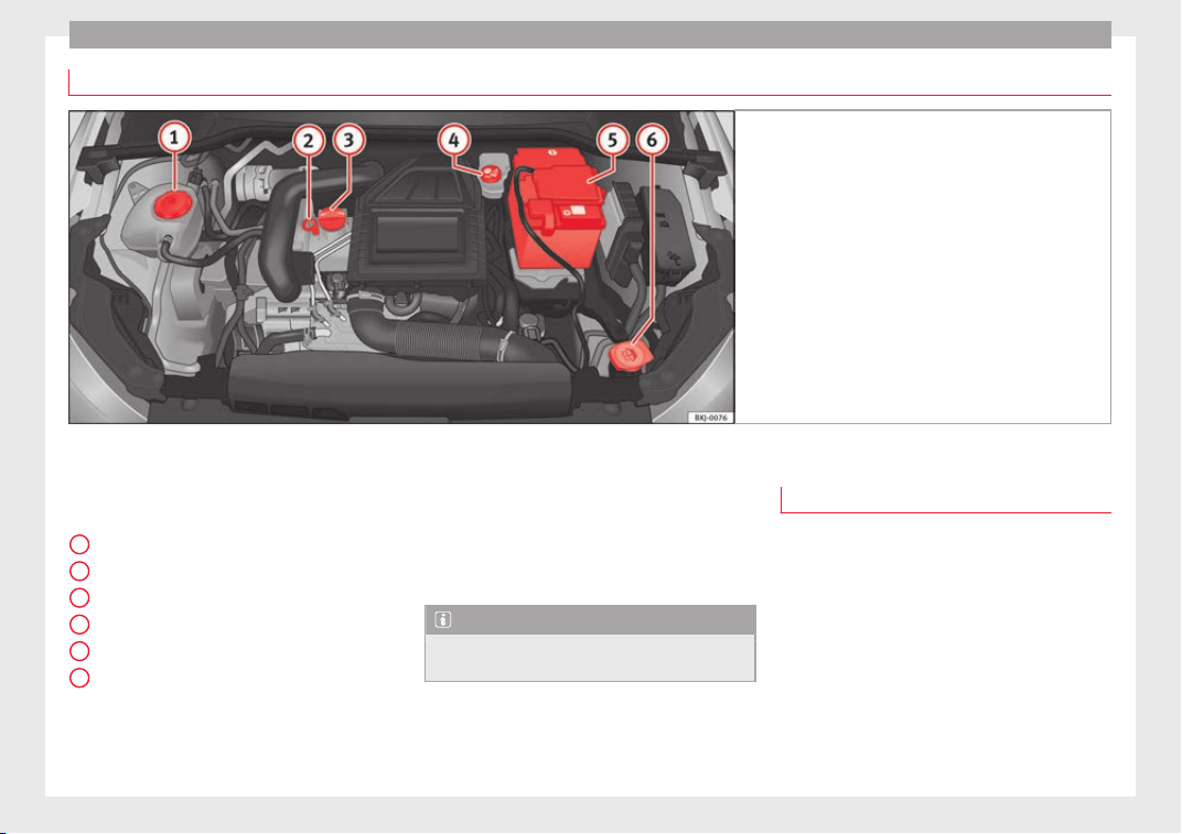
Advice
Checking levels
Fig. 229 Diagram for the location of the various ele-
ments.
From time to time, the levels of the different
fluid
s
in the
vehicle must be checked. Never
fill with incorrect fluids, otherwise serious
damage to the engine may be caused.
Coolant expansion tank
Engine oil level dipstick
Engine oil filler cap
Brake fluid reservoir
Vehicle battery
Windscreen washer reservoir
The checking and refilling of service fluids
are carried out on the components men-
1
2
3
4
5
6
tioned above. These operations are descri-
bed in ›
›
›
page 263.
Overview
You will find further explanations, instruc-
tions and restrictions on the technical speci-
fications as of ››› page 281.
Note
The layout of parts may vary depending on
the engine.
Engine oil
Gener
a
l
notes
The engine comes with a special, multi-grade
oil th
at can be used all year round.
Because the use of high-quality oil is essen-
tial for the correct operation of the engine
and its long useful life, when topping up or
changing oil, use only those oils that comply
with VW standards.
The specifications (VW standards) set out in
the following page should appear on the con-
tainer of the service oil; when the container
displays the specific standards for petrol and
266
Checking and refilling levels
diesel engines together, it means that the oil
c
an be u
sed f
or both types of engines.
We recommend that the oil change indicated
in the Maintenance Programme, be per-
formed by a technical service or specialised
workshop.
The correct oil specifications for your engine
are listed in the ›››
page 59.
Service intervals
Service intervals can be flexible (LongLife
service) or fixed (dependent on time/dis-
tance travelled).
If the PR code that appears on the back of the
Maintenance Programme booklet is PR QI6,
this means that your vehicle has the LongLife
service program. If it lists the codes QI1, QI2,
QI3, QI4 or QI7, the interval service is de-
pendent on the time/distance travelled.
Flexible service intervals (LongLife service
intervals*)
Special oils and processes have been devel-
oped which, depending on the characteris-
tics and individual driving profiles, enable
the extension of the oil change service (Long-
Life service intervals).
Because this oil is essential for extending the
service intervals, it must only be used ob-
serving the following indications:
●
Avoid mixing it with oil for fixed service in-
tervals.
●
Only in exceptional circumstances, if the
engine oil level is too low ››› page 268 and
LongLife oil is not available, it is permitted to
top up (once) with oil for fixed service inter-
vals ›››
page 59 (up to a maximum of 0.5
litres).
Fixed service intervals*
If your vehicle does not have the “LongLife
service interval” or it has been disabled (by
request), you may use oils for fixed service
intervals, which also appear in
›››
page 59. In this case, your vehicle
must be serviced after a fixed interval of 1
year/15,000 km (10,000 miles)(whatever
comes first) ››› Booklet Maintenance Pro-
gramme.
●
In exceptional circumstances, if the engine
oil level is too low ››› page 268 and you can-
not obtain the oil specified for your vehicle,
you can add a small quantity of oil conform-
ing to the specification ACEA A2 or ACEA A3
(petrol engines) or ACEA B3 or ACEA B4 (die-
sel engines) (up to 0.5 l).
Vehicles with diesel particulate filter*
The Maintenance Programme states whether
your vehicle is fitted with a diesel particulate
filter.
Only VW 507 00 engine oil, with reduced ash
formation, may be used in diesel engines
equipped with particulate filter. Using other
types of oil will cause a higher soot concen-
tration and reduce the life of the DPF. There-
fore:
●
Avoid mixing this oil with other engine oils.
●
Only in exceptional circumstances, if the
engine oil level is too low ››› page 268,
Checking engine oil level and you cannot ob-
tain the oil specified for your vehicle, you can
use a small quantity of oil (once) conforming
to the VW 506 00, VW 506 01, VW 505 00,
VW 505 01 or ACEA B3/ACEA B4 specification
(up to 0.5 l).
Note
Before a long trip, we recommend finding an
engine oil
that conforms to the correspond-
ing VW specifications and recommend keep-
ing it in the vehicle. This way, the correct en-
gine oil will always be available for a top-up if
needed.
Warning lamp
If this warning lamp i
s
r
ed it indicates
that the engine oil pressure is too low.
If this warning symbol starts to flash, and is
accompanied by three audible warnings,
switch off the engine and check the oil level.
If necessary, add more oil
›››
page 268.
»
267
Technical dataAdviceOperationEmergenciesSafety
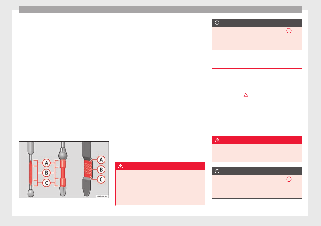
Advice
If the warning lamp flashes although the oil
l
ev
el
is correct, stop driving. Do not even run
the engine at idle speed! Obtain technical as-
sistance.
Checking oil level
If the warning lamp is yellow the engine
oil level should be checked as soon as possi-
ble. Top up the oil at the next opportunity
››› page 268.
Oil level sensor faulty*
If the yellow warning lamp flashes, take
the vehicle to a specialised workshop to have
the oil level sensor checked. Until then it is
advisable to check the oil level every time
you refuel.
Checking engine oil level
Fig. 230 Engine oil dipstick.
Read the additional information carefully
›
›
›
page 58
Checking oil level
–
Park the vehicle in a horizontal position.
–
Briefly run the engine at idle speed until
the operating temperature is reached and
then stop.
–
Wait for about two minutes.
–
Pull out the dipstick. Wipe the dipstick with
a clean cloth and insert it again, pushing it
in as far as it will go.
–
Then pull it out again and check the oil lev-
el. Top up with engine oil if necessary.
Depending on how you drive and the condi-
tions in which the vehicle is used, oil con-
sumption can be up to 0.5 l/1000 km. Oil
consumption is likely to be higher for the first
5,000 km. For this reason the engine oil level
must be checked at regular intervals, prefera-
bly when filling the tank and before a jour-
ney.
WARNING
Any work carried out in the engine compart-
ment or on the engine mu
st be carried out
cautiously.
●
When working in the engine compartment,
always observe the safety warnings
››› page 263.
CAUTION
If the oil level is above area ›››
Fig. 230
A
, do
not st
art the engine. This could result in dam-
age to the engine and catalytic converter.
Contact a Technical Service.
Topping up engine oil
Read the additional information carefully
›››
page 58
Before opening the bonnet, read and observe
the warnings
›››
in Safety notes for work in
the en
gine c
omp
artment on page 263.
The position of the filler neck is shown in the
corresponding engine compartment image
›››
page 266.
Engine oil specification
›››
page 59.
WARNING
Oil is highly inflammable! Ensure that no oil
comes
into contact with hot engine compo-
nents when topping up.
CAUTION
If the oil level is above area ›››
Fig. 230
A
, do
not st
art the engine. This could result in dam-
age to the engine and catalytic converter.
Contact a specialised workshop.
268
Checking and refilling levels
For the sake of the environment
The oil level must never be above area
›››
Fig. 230
A
. Otherwise oil can be drawn in
through the cr
ankcase breather and escape
into the atmosphere via the exhaust system.
Changing engine oil
Read the additional information carefully
›››
page 58
The engine oil must be changed at the inter-
vals given in the service schedule.
We recommend that you have the engine oil
changed by a Technical Service.
The oil change intervals are shown in the
Maintenance Programme.
WARNING
Only change the engine oil yourself if you
have the s
pecialist knowledge required!
●
Before opening the bonnet, read and ob-
serve the warnings ››› page 263, Safety notes
for work in the engine compartment.
●
Wait for the engine to cool down. Hot oil
may cause burn injuries.
●
Wear eye protection to avoid injuries, such
as acid burns, caused by splashes of oil.
●
When removing the oil drain plug with your
fingers, keep your arm horizontal to help pre-
vent oil from running down your arm.
●
Wash
your skin thoroughly if it comes into
contact with engine oil.
●
Engine oil is poisonous! Used engine oil
must be stored in a safe place out of the
reach of children.
CAUTION
No additives should be used with engine oil.
Thi
s c
ould result in engine damage. Any dam-
age caused by the use of such additives
would not be covered by the factory warranty.
For the sake of the environment
●
Becau
se of disposal problems and the spe-
cial tools and specialist knowledge required,
we recommend that you have the engine oil
and filter changed by a Technical Service.
●
Never pour oil down drains or into the
ground.
●
Use a suitable container when draining the
used oil. It must be large enough to hold all
the engine oil.
Cooling system
C
ontr
o
l lamp
There is a fault if:
●
The l
amp does not go out again after a
f
ew sec
onds.
●
The lamp lights up or flashes while the
vehicle is running, and three acoustic warn-
ing signals are emitted ›››
.
Thi
s
me
ans that either the coolant level is too
low or the coolant temperature is too high.
Coolant temperature too high
If the lamp lights up, stop the vehicle,
turn off the engine and wait for it to cool
down. Check the coolant level.
If the coolant level is correct, the overheating
may be caused by a malfunction of the radia-
tor fan. Check the radiator fan fuse and have
it replaced if necessary ››› page 104.
If the control lamp lights up again after driv-
ing on for a short distance, stop the vehicle
and switch the engine off. Contact a Techni-
cal Service or a specialised workshop.
Coolant level too low
If the lamp lights up, stop the vehicle,
turn off the engine and wait for it to cool
down. First check the coolant level. If the lev-
el of the coolant is below the “MIN” mark,
top up with coolant liquid ›››
.
WARNING
●
If y
our vehicle is immobilised for technical
reasons, move it to a safe distance from traf-
fic. Turn the engine off, turn the hazard lights
on and place the warning triangle.
»
269
Technical dataAdviceOperationEmergenciesSafety
Advice
●
Never open the bonnet if
you can see or
hear steam or coolant escaping from the en-
gine compartment. Risk of scalding. Wait un-
til you can no longer see or hear escaping
steam or coolant.
●
The engine compartment is a dangerous
area. Before carrying out any work in the en-
gine compartment, switch off the engine and
allow it to cool down. Always note the corre-
sponding warnings ››› page 263.
Topping up coolant
Read the additional information carefully
›
›
›
page 59
Top up coolant when the level is below the
MIN (minimum) mark.
Checking coolant level
–
Park the vehicle in a horizontal position.
–
Switch the ignition off.
–
Read off the coolant level on coolant ex-
pansion tank. When the engine is cold, the
coolant level should be between the marks.
When the engine is hot, it may be slightly
above the upper mark.
Topping up coolant
–
Wait for the engine to cool down.
–
Cover the coolant expansion tank cap with
a cloth and carefully unscrew it to the left
›››
.
–
Top up the coolant only if there is still cool-
ant
in the e
xp
ansion tank, otherwise you
could damage the engine. If there is no
coolant in the expansion tank, do not con-
tinue driving. You should obtain professio-
nal assistance ›››
.
–
If there is still some coolant in the expan-
s
ion t
ank, t
op up to the upper mark.
–
Top up with coolant until the level becomes
stable.
–
Screw the cap back on correctly.
Any loss of coolant fluid normally indicates a
leak in the cooling system. Take the vehicle
straight to a specialised workshop to have
the cooling system examined. If there are no
leaks in the engine cooling system, a loss of
coolant can only occur if the coolant boils
and is forced out of the system as a result of
overheating.
WARNING
●
The coolin
g system is under pressure. Do
not unscrew the cap on the coolant expan-
sion tank when the engine is hot: risk of
burns!
●
The antifreeze and coolant fluid can be a
health hazard. Therefore, the antifreeze
should be stored in the original container in a
safe place out of reach of children. Failure to
comply
could result in poisoning.
●
If working inside the engine compartment,
remember that, even when the ignition is
switched off, the radiator fan may start up au-
tomatically, and therefore there is a risk of in-
jury.
WARNING
If there is not enough anti-freeze in the cool-
ant
sys
tem, the engine may fail leading to se-
rious damage.
●
Please make sure that the percentage of
additive is correct with respect to the lowest
expected ambient temperature in the zone in
which the vehicle is to be used.
●
When the outside temperature is very low,
the coolant could freeze and the vehicle
would be immobilised. In this case, the heat-
ing would not work either and inadequately
dressed passengers could die of cold.
CAUTION
Do not top up the expansion tank with cool-
ant fluid if it
is empty! Air could enter the
cooling system. In this case, stop driving.
Seek specialist assistance. Otherwise, there
is a risk of engine damage.
270
Checking and refilling levels
CAUTION
The original additives should never be mixed
with coo
lants which are not approved by
SEAT. Otherwise, you run the risk of causing
severe damage to the engine and the engine
cooling system.
●
If the fluid in the expansion tank is not pur-
ple but is, for example, brown, this indicates
that the G13 additive has been mixed with an
inadequate coolant. The coolant must be
changed as soon as possible if this is the
case! This could result in serious faults and
engine damage.
For the sake of the environment
Coolants and additives can contaminate the
envir
onment. If any fluids are spilled, they
should be collected and correctly disposed
of, with respect to the environment.
Brake fluid
Chec
k
in
g the brake fluid level
Read the additional information carefully
›
›
›
page 60
The position of the brake fluid reservoir is
shown in the corresponding engine compart-
ment image
›››
page 266. The brake fluid res-
ervoir has a black and yellow cap.
The brake fluid level drops slightly when the
vehicle is being used as the brake pads are
automatically adjusted as they wear.
However, if the level goes down noticeably in
a short time, or drops below the “MIN” mark,
there may be a leak in the brake system. A
display on the instrument panel will warn you
if the brake fluid level is too low ››› page 122.
WARNING
Before opening the bonnet to check the brake
fluid level, r
ead and observe the warnings
››› page 263.
Changing the brake fluid
The Maintenance Programme indicates brake
fluid c
h
an
ge intervals.
We recommend that you have the brake fluid
changed by a Technical Service.
Before opening the bonnet, please read and
follow the warnings
›››
in Safety notes for
w
ork
in the en
gine compartment on
page 263 in section “Safety notes for work-
ing in the engine compartment”.
In the course of time, brake fluid becomes
hygroscopic and absorbs water from the am-
bient air. If the water content in the brake flu-
id is too high, the brake system could cor-
rode. This also considerably reduces the boil-
ing point of the brake fluid. Heavy use of the
brakes may then cause a vapour lock which
could impair the braking effect.
Be sure to always use the correct brake fluid.
Only use brake fluid that expressly meets the
VW 501 14 standard.
You can buy VW 501 14 standard brake fluid
in a SEAT dealership or a SEAT Official Serv-
ice. If none is available, use only high-quality
brake fluid that meets DIN ISO 4925 CLASS 4
standards, or USA Standards FMVSS 116 DOT
4.
Using any other kind of brake fluid or one
that is not of a high quality may affect opera-
tion of the brake system and reduce its effec-
tiveness. Never use a brake fluid if the con-
tainer does not state that it complies with VW
501 14, DIN ISO 4925 CLASS 4 standards, or
USA standards FMVSS 116 DOT 4.
WARNING
Brake fluid is poisonous. Old brake fluid im-
pairs
the braking effect.
●
Before opening the bonnet to check the
brake fluid level, read and observe the warn-
ings ››› page 263.
●
Brake fluid should be stored in the closed
original container in a safe place out of reach
of children. There is a toxic risk.
●
Perform the brake fluid change according to
the Maintenance Programme. Heavy use of
the brakes may cause a vapour lock if the
brake fluid is left in the brake system for too
»
271
Technical dataAdviceOperationEmergenciesSafety
Advice
long. This would seriously affect the effec-
tivenes
s of the brakes and the safety of the
vehicle. This may cause an accident.
CAUTION
Brake fluid damages the vehicle paintwork.
W
ipe off an
y brake fluid from the paintwork
immediately.
For the sake of the environment
The brake pads and brake fluid must be col-
lected and di
sposed of according the applica-
ble regulations. The SEAT Technical Service
network has the necessary equipment and
qualified personnel for collecting and dispos-
ing of this waste material.
Windscreen washer reservoir
Chec
k
in
g and topping up the wind-
screen washer reservoir water
Read the additional information carefully
›
›
›
page 60
The windscreen washer is supplied with liq-
uid from the windscreen washer reservoir in
the engine compartment. It has a capacity of
approximately 3 litres.
The tank is in the engine compartment.
Plain water is not enough to clean the wind-
screen and headlights. We recommend that
you always add a product to the windscreen
washer fluid. Approved windscreen cleaning
products exist on the market with high deter-
gent and anti-freeze properties, these may be
added all-year-round. Please follow the dilu-
tion instructions on the packaging.
WARNING
Any work carried out in the engine compart-
ment or on the engine mu
st be carried out
cautiously.
●
When working in the engine compartment,
always observe the safety warnings
››› page 263.
CAUTION
●
Never put
radiator anti-freeze or other addi-
tives into the windscreen washer fluid.
●
Always use approved windscreen cleansing
products diluted as per instructions. If you
use other washer fluids or soap solutions,
the tiny holes in the fan-shaped nozzles
could become blocked.
Vehicle battery
S
ymbo
l
s and warnings on handling
the battery
Read the additional information carefully
›››
page 60
Wear eye protection
Battery acid is extremely corrosive. Wear protec-
tive gloves and eye protection!
Fires, sparks, open flames and smoking are pro-
hibited!
A highly explosive mixture of gases is released
when the battery is under charge.
Keep children away from acid and batteries!
WARNING
Always be aware of the danger of injury and
chemica
l burns as well as the risk of accident
or fire when working on the battery and the
electrical system:
●
Wear eye protection. Protect your eyes,
skin and clothing from acid and particles con-
taining lead.
●
Battery acid is extremely corrosive. Wear
protective gloves and eye protection. Do not
tilt the batteries. This could spill acid through
the vents.
●
Rinse battery acid from eyes immediately
for several minutes with clear water. Then
272
Checking and refilling levels
seek medical care immediately. Neutralise
any ac
id splashes on the skin or clothing
with a soapy solution, and rinse off with plen-
ty of water. If acid is swallowed by mistake,
consult a doctor immediately.
●
Fires, sparks, open flames and smoking are
prohibited. When handling cables and electri-
cal equipment, avoid causing sparks and
electrostatic charge. Never short the battery
terminals. High-energy sparks can cause in-
jury.
●
A highly explosive mixture of gases is re-
leased when the battery is under charge. The
batteries should be charged in a well-ventila-
ted room only.
●
Keep children away from acid and batteries.
●
Before working on the electrical system,
you must switch off the engine, the ignition
and all electrical devices. The negative cable
on the battery must be disconnected. When a
light bulb is changed, you need only switch
off the light.
●
Deactivate the anti-theft alarm by unlock-
ing the vehicle before you disconnect the bat-
tery! The alarm will otherwise be triggered.
●
When disconnecting the battery from the
vehicle on-board network, disconnect first
the negative cable and then the positive ca-
ble.
●
Switch off all electrical devices before re-
connecting the battery. Reconnect first the
positive cable and then the negative cable.
Never reverse the polarity of the connections.
This could cause an electrical fire.
●
Never ch
arge a frozen battery, or one which
has thawed. This could result in explosions
and chemical burns. Always replace a battery
which has frozen. A flat battery can also
freeze at temperatures close to 0°C (+32°F).
●
Ensure that the vent hose is always connec-
ted to the battery.
●
Never use a defective battery. This could
cause an explosion. Replace a damaged bat-
tery immediately.
CAUTION
●
Nev
er dis
connect the battery if the ignition
is switched on or if the engine is running.
This could damage the electrical system or
electronic components.
●
Do not expose the battery to direct sunlight
over a long period of time, as the intense ul-
traviolet radiation can damage the battery
housing.
●
If the vehicle is left standing in cold condi-
tions for a long period, protect the battery
from “freezing”. If it freezes it will be dam-
aged.
Warning lamp
It lights up
Alternator fault.
The control lamp lights
up when the igni-
tion i
s
switched on. It should go out when the
engine has started running.
If the control lamp lights up while driving,
the alternator is no longer charging the bat-
tery. You should immediately drive to the
nearest specialised workshop.
You should avoid using electrical equipment
that is not absolutely necessary because this
will drain the battery.
Checking the battery electrolyte level
The electrolyte level should be checked regu-
l
arly
in high-mi
leage vehicles, in hot coun-
tries and in older batteries.
–
Open the bonnet and open the battery cov-
er at the front ›››
in Safety notes for work
in the en
gine c
omp
artment on page 263
›››
in Symbols and warnings on handling
the b
att
er
y on page 272. For vehicles with
the battery under the spare wheel, open
the rear lid and lift the floor covering. The
battery is located next to the spare wheel.
–
Check the colour display in the "magic eye"
on the top of the battery.
–
If there are air bubbles in the window, tap
the window gently until they disperse.
»
273
Technical dataAdviceOperationEmergenciesSafety
Advice
The position of the battery is shown in the
c
orr
e
sponding engine compartment diagram
››› page 266.
The “magic eye” indicator, located on the top
of the battery changes colour, depending on
the charge state and electrolyte level of the
battery.
There are two different colours:
●
Black: correct charge status.
●
Transparent/clear yellow: the battery must
be replaced. Contact a specialised workshop.
Charging or changing the battery
The battery is maintenance-free and is
c
hec
k
ed during the inspection service. All
work on the vehicle battery requires special-
ist knowledge.
If you often drive short distances or if the ve-
hicle is not driven for long periods, the bat-
tery should be checked by a specialised
workshop between the scheduled services.
If the battery has discharged and you have
problems starting the vehicle, the battery
might be damaged. If this happens, we rec-
ommend you have the vehicle battery
checked by a Technical Service where it will
be re-charged or replaced.
Charging the battery
The vehicle battery should be charged by a
specialised workshop only, as batteries us-
ing special technology have been installed
and they must be charged in a controlled en-
vironment.
Replacing a vehicle battery
The battery has been developed to suit the
conditions of its location and has special
safety features.
Genuine SEAT batteries meet the mainte-
nance, performance and safety specifications
of your vehicle.
WARNING
●
We rec
ommend you use only maintenance-
free or cycle free leak-proof batteries which
comply with standards T 825 06 and
VW 7 50 73. This standard applies as of
2001.
●
Before starting any work on the batteries,
you must read and observe the warnings
›››
in Symbols and warnings on handling
the batter
y on page 272.
For the sake of the environment
Batteries contain toxic substances such as
sulphuric
acid and lead. They must be dis-
posed of appropriately and must not be dis-
posed of with ordinary household waste.
Wheels
Wheel
s
and ty
res
General notes
Avoiding damage
–
If you have to drive over a kerb or similar
obs
tacle, drive very slowly and at a right
angle.
–
Keep grease, oil and fuel off the tyres.
–
Inspect the tyres regularly for damage
(cuts, cr
acks or blisters, etc.). Remove any
foreign objects embedded in the treads.
Storing tyres
–
When you remove the tyres, mark them in
order to maintain the same direction of ro-
tation when they are installed again.
–
When removed, the wheels and/or tyres
should be stored in a cool, dry and prefera-
bly dark location.
–
Store tyres in a vertical position, if they are
not fitted on wheel rims.
New tyres
New tyres must be run in
›››
page 199.
The tread depth of new tyres may vary, ac-
cording to the type and make of tyre and the
tread pattern.
274
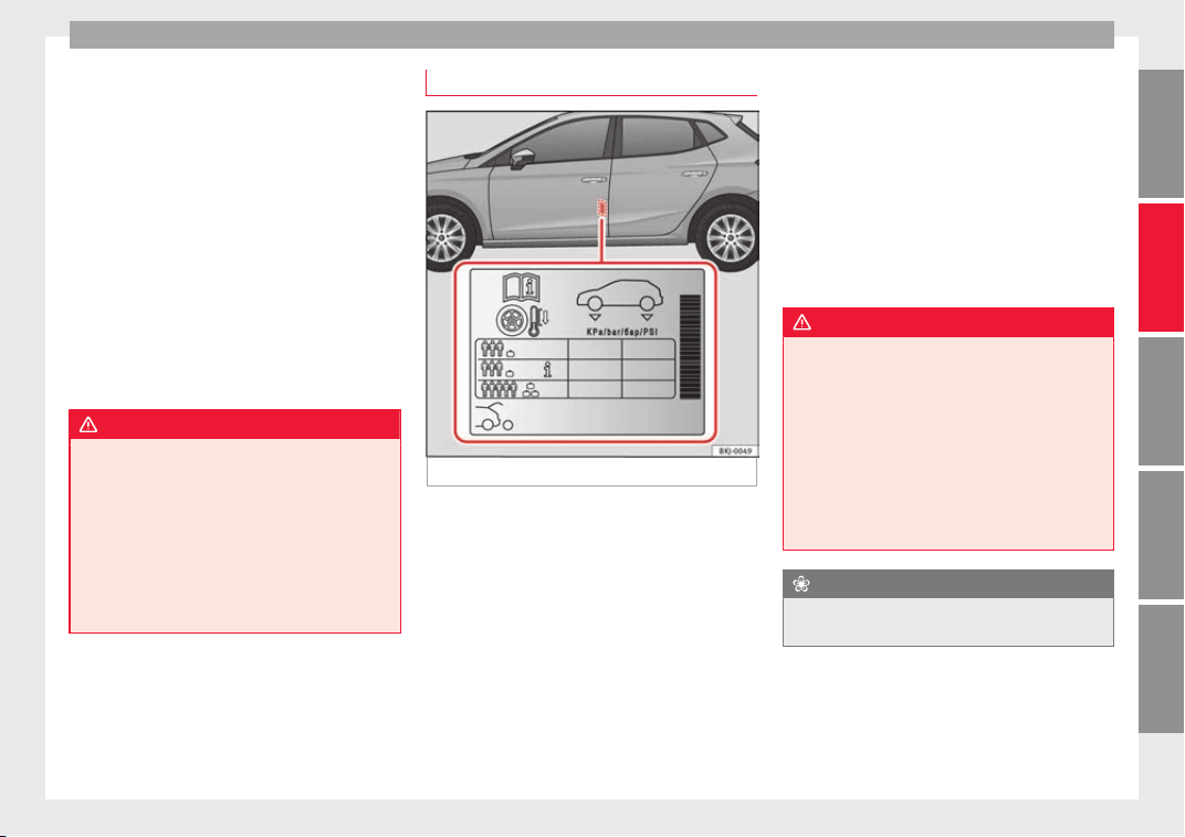
Wheels
Concealed damage
Dam
ag
e t
o tyres and rims is often not readily
visible. If you notice unusual vibrations or the
vehicle pulling to one side, this may indicate
that one of the tyres is damaged. They
should be checked immediately by a Techni-
cal Service.
Tyres with directional tread pattern
An arrow on the tyre sidewall indicates the di-
rection of rotation on tyres with directional
tread. Always observe the direction of rota-
tion indicated when fitting the wheel. This
guarantees optimum grip and helps to avoid
aquaplaning, excessive noise and wear.
WARNING
●
New tyre
s do not have maximum grip dur-
ing the first 500 km. Drive particularly care-
fully to avoid possible accidents.
●
Never drive with damaged tyres. This may
cause an accident.
●
If you notice unusual vibrations or if the ve-
hicle pulls to one side when driving, stop the
vehicle immediately and check the tyres for
damage.
Tyre pressure monitoring system
Fig. 231 Location of the tyre pressure sticker.
The maximum tyre pressure values are shown
on a s
tic
k
er stuck to the back of the left front
door frame
›››
Fig. 231.
1. Read the required tyre inflation pressure
from the sticker. The values refer to Sum-
mer tyres.
2. The tyre pressures should only be checked
when the tyres are cold. The slightly raised
pressures of warm tyres must not be re-
duced.
3. Adjust the tyre pressure to the load you
are carrying.
Tyre pressure
The correct tyre pressure is especially impor-
tant at high speeds. The pressure should
therefore be checked at least once a month
and before starting a journey.
Depending on the vehicle, tyre pressure can
be adjusted to medium load to improve driv-
ing comfort (“comfort” tyre pressure). When
driving with comfort tyre pressure fuel con-
sumption may increase slightly.
WARNING
A tyre can easily burst if the pressure is too
low, c
ausing an accident!
●
At continuously high speeds, a tyre with in-
sufficient pressure flexes more. In this way it
becomes too hot, and this can cause tread
separation and tyre blow-out. Always observe
the recommended tyre pressures.
●
If the tyre pressure is too low or too high,
the tyres will wear prematurely and the vehi-
cle will not handle well. Risk of accident!
For the sake of the environment
Under-inflated tyres will increase fuel con-
sumption.
275
Technical dataAdviceOperationEmergenciesSafety
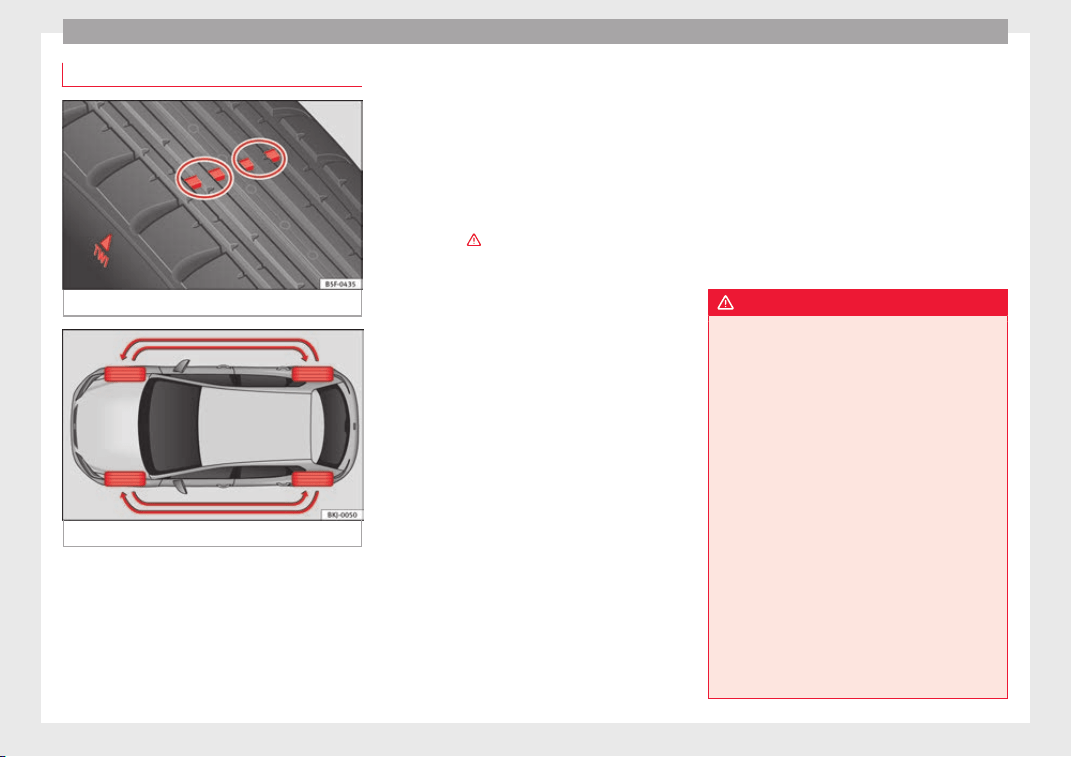
Advice
Service life of tyres
Fig. 232 Tyre tread wear indicators.
Fig. 233 Diagram for changing wheels.
The useful life of tyres is dependent on tyre
pr
e
s
sure, driving style and fitting.
Wear indicators
The original tyres on your vehicle have
1.6 mm high “tread wear indicators”
››› Fig. 232, running across the tread. De-
pending on the make, there will be 6 to 8 of
them evenly spaced around the tyre. Mark-
ings on the tyre sidewall (for instance the let-
ters “TWI” or other symbols) indicate the po-
sitions of the tread wear indicators. The mini-
mum tread depth required by law is 1.6 mm
(measured in the tread grooves next to the
tread wear indicators). Worn tyres must be re-
placed. Different figures may apply in export
countries ›››
.
T
y
r
e pressure
Incorrect tyre pressure causes premature
wear and could cause tyre blow-out. For this
reason, the tyre pressure should be checked
at least once per month ››› page 275.
Driving style
Fast cornering, heavy acceleration and hard
braking all increase tyre wear.
Changing wheels around
If the front tyres are worn considerably more
than the rear ones it is advisable to change
them around as shown ››› Fig. 233. The use-
ful life of all the tyres will then be about the
same time.
Wheel balance
The wheels on new vehicles are balanced.
However, various factors encountered in nor-
mal driving can cause them to become unbal-
anced, which results in steering vibration.
Unbalanced wheels should be rebalanced, as
they otherwise cause excessive wear on
steering, suspension and tyres. A wheel must
also be rebalanced when a new tyre is fitted.
Incorrect wheel alignment
Incorrect running gear alignment causes ex-
cessive tyre wear, impairing the safety of the
vehicle. If tyres show excessive wear, you
should have the wheel alignment checked by
a Technical Service.
WARNING
There is a serious danger of accidents if a tyre
burs
ts during driving!
●
The tyres must be replaced at the latest
when the tread wear indicators are worn
››› page 276. Failure to follow this instruction
could result in an accident. Worn tyres do not
grip well at high speeds on wet roads. There
is also a greater risk of “aquaplaning”.
●
At continuously high speeds, a tyre with in-
sufficient pressure flexes more. This causes it
to overheat. This can cause tread separation
and tyre blow-out. Risk of accident. Always
observe the recommended tyre pressures.
●
If tyres show excessive wear, you should
have the running gear checked by a Technical
Service.
●
Keep chemicals such as oil, fuel and brake
fluid away from tyres.
●
Damaged wheels and tyres must be re-
placed immediately!
276
Wheels
For the sake of the environment
Under-inflated tyres will increase fuel con-
sumption.
New tyres and wheels
New tyres and wheels have to be run in.
The tyre
s and wheel rims are an essential
part of the vehicle's design. Those approved
by SEAT are specially matched to the charac-
teristics of the vehicle and make a major con-
tribution to good road-holding and safe han-
dling
›››
.
T
y
r
es should be replaced at least in pairs and
not individually (i.e. both front tyres or both
rear tyres together). A knowledge of tyre des-
ignations makes it easier to choose the cor-
rect tyres. Radial tyres have the tyre designa-
tions marked on the sidewall, for example:
195/55 R16 91V
This contains the following information:
Tyre width in mm
Height/width ratio in %
Tyre construction: Radial
Rim diameter in inches
Load rating code
Speed rating
195
55
R
16
91
V
The tyres could also have the following infor-
mation:
●
A direction of rotation symbol
●
“Reinforced” denotes heavy-duty tyres.
The manufacturing date is also indicated on
the tyre sidewall (possibly only on the outer
side of the wheel).
“DOT... 1116...” means, for example, that the
tyre was produced in the 11th week of 2016.
We recommend that work on tyres and
wheels be carried out by a Technical Service.
They are familiar with the procedure and
have the necessary special tools and spare
parts as well as the proper facilities for dis-
posing of the old tyres.
Any technical service has full information on
the technical requirements when installing or
changing tyres, wheels or wheel trims.
WARNING
●
We rec
ommend that you use only wheels
and tyres which have been approved by SEAT
for your model. Failure to do so could impair
vehicle handling. Risk of accident.
●
Avoid running the vehicle on tyres that are
more than 6 years old. If you have no alterna-
tive, you should drive slowly and with extra
care at all times.
●
Never use old tyres or those with an un-
known “history of use”.
●
If wheel trims
are retrofitted, you must en-
sure that the flow of air to the brakes is not
restricted. This could cause the brake system
to overheat.
●
All four wheels must be fitted with radial
tyres of the same type, size (rolling circumfer-
ence) and the same tread pattern.
For the sake of the environment
Old tyres must be disposed of according to
the l
aw
s in the country concerned.
Note
●
A SEA
T Service Centre should be consulted
to find out whether wheels or tyres of differ-
ent sizes to those originally fitted by SEAT
can be fitted, and to find out about the com-
binations allowed between the front axle
(axle 1) and the rear axle (axle 2).
●
For technical reasons, it is not generally
possible to use the wheels from other vehi-
cles. This can also apply to wheels of the
same model. The use of wheels or tyres
which have not been approved by SEAT for
use with your model may invalidate the vehi-
cle's type approval for use on public roads.
●
If the spare tyre is not the same as the
tyres that are mounted on the vehicle (e.g.
winter tyres) you should only use the spare
tyre for a short period of time and drive with
extra care. Refit the normal road wheel as
soon as possible.
277
Technical dataAdviceOperationEmergenciesSafety
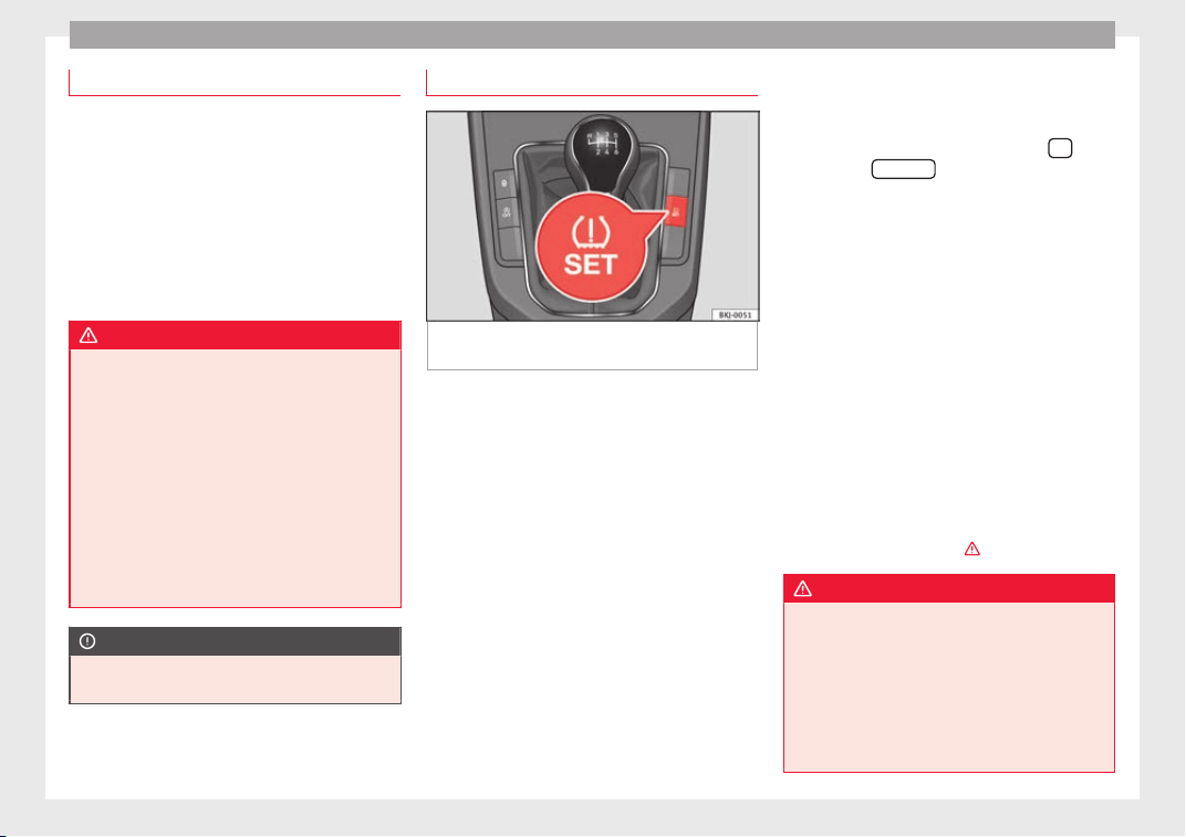
Advice
Wheel bolts
The design of wheel bolts is matched to the
rims. If differ
ent wheel rims are fitted, the
correct wheel bolts with the right length and
correctly shaped bolt heads must be used.
This ensures that wheels are fitted securely
and that the brake system functions correctly.
In certain circumstances, you should not use
wheel bolts from a different vehicle, even if it
is the same model ››› page 247.
WARNING
If the wheel bolts are not tightened correctly,
the wheel cou
ld become loose while driving.
Risk of accident.
●
The wheel bolts must be clean and turn
easily. Never apply grease or oil to them.
●
Use only wheel bolts which belong to the
wheel.
●
If the prescribed torque of the wheel bolts
is too low, they could loosen whilst the vehi-
cle is in motion. Risk of accident! If the tight-
ening torque is too high, the wheel bolts and
threads can be damaged.
CAUTION
The prescribed tightening torque for wheel
bolts
for steel and alloy wheels is 120 Nm.
Tyre monitoring indicator*
Fig. 234 Centre console: tyre monitoring sys-
t
em b
utt
on.
The tyre monitoring system compares wheel
r
ev
o
lutions alongside the wheel diameter of
each wheel, with help from the ESC. If the di-
ameter of a wheel changes, the tyre monitor-
ing indicator lights up . The wheel diame-
ter changes when:
●
Tyre pressure is insufficient.
●
The tyre structure is damaged.
●
The vehicle is unbalanced because of a
load.
●
The wheels of one axle are under more
pressure (for example, driving with a trailer or
on steep slopes).
●
The vehicle is fitted with snow chains.
●
The temporary spare wheel is fitted.
●
The wheel on one axle is changed.
Tyre pressure adjustment
After modifying tyre pressure or changing any
wheels, the new tyre pressure must be stored
in the Easy Connect system with the
but-
t
on and the
S
ET
TINGS
function button
›
›
›
page 34.
In vehicles without a radio, press and hold
down the button ››› Fig. 234, with the
ignition on, until an acoustic signal is heard.
If the wheels are under excessive load (for ex-
ample, driving with a trailer or heavy load),
the tyre pressure must be increased to the
recommended value for a full load (see the
sticker on the back of the left front door
frame). If the tyre monitor system button is
pressed down, the new tyre pressures are
confirmed.
The tyre pressure control lamp lights up
If the tyre pressure of a wheel is much lower
than the value set by the driver, then the tyre
pressure control lamp ›››
will light up.
WARNING
●
When the tyre pr
essure control lamp lights
up, reduce speed immediately and avoid any
sudden turning or braking manoeuvre. Stop
when possible, and check the tyre pressure
and status.
●
The driver is responsible for maintaining
correct tyre pressures. For this reason, tyre
pressure must be regularly checked.
278
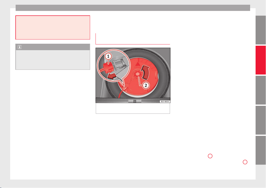
Wheels
●
Under cert
ain circumstances (e.g. when
driving in a sporty manner, in winter condi-
tions or on a dirt track) the tyre control lamp
may light up belatedly or may function incor-
rectly.
Note
If the battery is disconnected, the yellow
w
arning l
amp lights up after turning the
ignition on. This should turn off after a brief
journey.
Spare wheel (temporary spare
wheel)*
L
oc
ation and u
se of the temporary
spare wheel
Fig. 235 In the luggage compartment: re-
mo
v
e the s
ubwoofer.
The temporary spare wheel is stored under
the floor p
anel
in the lug
gage compartment
and is attached by a thumbnut.
How to use the temporary spare wheel
If you ever have a punctured tyre or loss of
pressure, the temporary spare wheel is only
intended for temporary use until you reach a
workshop. Change it for a duty wheel as soon
as possible.
Please note the following restrictions when
using the temporary spare wheel. This tem-
porary spare wheel has been specially de-
signed for your vehicle, thus, it cannot be
changed with the temporary spare wheel
from another vehicle.
No other type of tyre (normal summer or win-
ter tyre) may be fitted on the compact tempo-
rary spare wheel rim.
Snow chains
For technical reasons, snow chains must not
be used on the temporary spare wheel.
If you have a puncture on one of the front
wheels when using snow chains, fit the tem-
porary spare wheel in place of one of the rear
wheels. Fit the snow chains on the rear wheel
that you have removed and replace the punc-
tured front wheel with this wheel.
Getting the spare wheel out of vehicles with
the Beats Audio
®
sound system (6 speakers
with 1 subwoofer)*
Disassemble the subwoofer's floor panel
(carpet) as follows:
●
Pull the carpet upwards to remove it.
●
Disconnect the cable for the subwoofer
speaker
›››
Fig. 235
1
.
●
Turn the securing wheel anti-clockwise
2
.
●
Remove the s
ub
woofer
speaker and the
spare wheel.
»
279
Technical dataAdviceOperationEmergenciesSafety
Advice
●
When r
ep
l
acing the spare wheel, place the
subwoofer speaker in the direction indicated
by the arrow and with the word “FRONT” fac-
ing forward.
●
Reconnect the speaker cable and firmly ro-
tate the securing wheel clockwise so that the
subwoofer system and wheel are firmly in
place.
WARNING
●
After fittin
g the temporary spare wheel,
check the tyre pressures as soon as possible.
Failure to do so may cause an accident. The
tyre pressure is listed on the back of the left
front door frame.
●
Do not drive at over 80 km/h (50 mph)
when the temporary spare wheel is fitted on
the vehicle: risk of accident!
●
Avoid heavy acceleration, hard braking and
fast cornering: risk of accident!
●
Never use more than one temporary spare
wheel at the same time, risk of accident.
●
No other type of tyre (normal summer or
winter tyre) may be fitted on the compact
temporary spare wheel rim.
Winter service
W
int
er ty
res
In winter conditions winter tyres will consid-
er
ab
ly
improve the vehicle's handling. The
design of summer tyres (width, rubber com-
pound, tread pattern) gives less grip on ice
and snow.
Winter tyres must be inflated to a pressure of
0.2 bar (2.9 psi/20 kPa) higher than the pres-
sures specified for summer tyres (see the
sticker on the back of the left front door
frame).
Winter tyres must be fitted on all four wheels.
Information on permitted winter tyre sizes
can be found in the vehicle's registration
documentation. Use only radial winter tyres.
All tyre sizes listed in the vehicle documenta-
tion also apply to winter tyres.
Winter tyres lose their effectiveness when the
tread is worn down to a depth of 4 mm.
The speed rating code ››› page 277, New
tyres and wheels determines the following
speed limits for winter tyres: ›››
max. 160 km/h (99 mph)
m
ax. 180 km/h (112 mph)
m
ax. 190 km/h (118 mph)
m
ax. 210 km/h (130 mph)
In some countries, vehicles which can exceed
the speed rating of the fitted tyre must have
an appropriate sticker in the driver's field of
view. These stickers are available from your
technical service. The legal requirements of
each country must be followed.
Q
S
T
H
Do not have winter tyres fitted for unnecessa-
rily long periods. Vehicles with summer tyres
handle better when the roads are free of
snow and ice.
If you have a flat tyre, please refer to the
notes on the spare wheel ››› page 277, New
tyres and wheels.
WARNING
The maximum speed for the winter tyres must
not be ex
ceeded. Otherwise, this could lead
to damage and risk of accident.
For the sake of the environment
Fit your summer tyres again as soon as possi-
ble.
They are quieter, do not wear so quickly
and reduce fuel consumption.
280
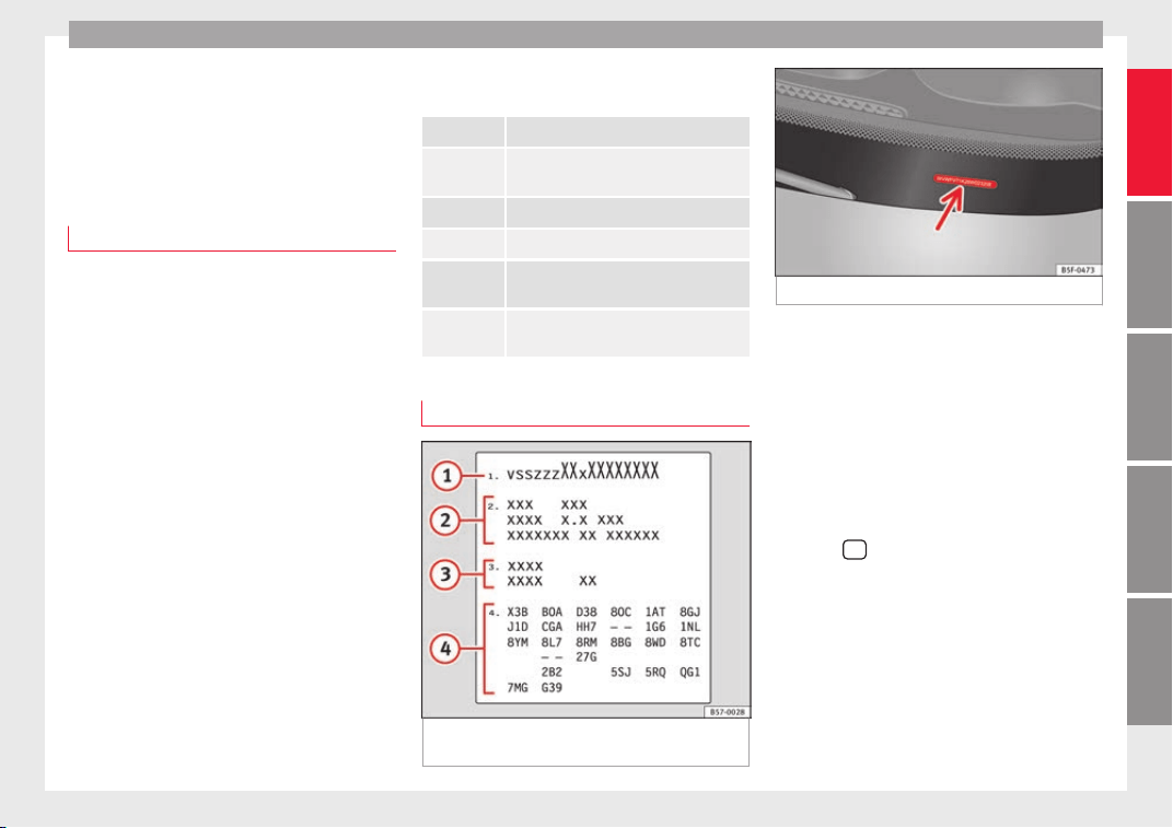
Technical specifications
Technical data
T
ec
hnic
al specifications
Important information
Important
The information in the vehicle documentation
alway
s takes precedence over the informa-
tion in this Instruction Manual.
All technical specifications provided in this
documentation are valid for the standard
model in Spain. The vehicle data card inclu-
ded in the Maintenance Programme or the
vehicle registration documents shows which
engine is installed in the vehicle.
The figures may be different depending
whether additional equipment is fitted, for
different models, for special vehicles and for
other countries.
Abbreviations used in the technical specifi-
cations
section
kW Kilowatt, engine power measurement.
PS
Pferdestärke (horsepower), formerly
used to denote engine power.
rpm Revolutions per minute - engine speed.
Nm Newton metres, unit of engine torque.
CZ
Cetane number, indication of the diesel
combustion power.
RON
Research octane number, indication of
the knock resistance of petrol.
Vehicle identification data
Fig. 236 Vehicle data sticker (luggage com-
p
ar
tment).
Fig. 237 Chassis number.
Chassis number
The
VIN i
s
located in the Easy Connect, on the
vehicle data sticker and under the wind-
screen, on the driver side ››› Fig. 237. Addi-
tionally, the chassis number is located in the
engine compartment, on the right-hand side.
The number is engraved on the top side rail,
and is partially covered.
VIN in the Easy Connect
●
Select:
button > function button SET-
TINGS > Service > Chassis number.
Identific
ation p
l
ate
The identification plate is located on the rear
pillar of the right-hand front door. Vehicles
for certain export countries do not have an
identification plate.
»
281
Technical dataAdviceOperationEmergenciesSafety
Technical data
Vehicle data sticker
The d
at
a s
ticker is placed on the inside of the
spare wheel well, in the boot and on the rear
cover of the Maintenance Programme.
The following information is provided on the
vehicle data sticker: ››› Fig. 236
Vehicle identification number (chassis
number)
Vehicle type, model, capacity, engine
type, finish, engine power and gearbox
type
Engine code, gearbox code, external
paint code and internal equipment code
Optional extras and PR numbers
Identifying letters
The identifying letters of the engine can be
viewed on the instrument panel when the en-
gine is switched off and the ignition is on.
●
Hold down the button
0.0/SET
on the dash
p
anel
f
or more than 15 seconds.
Fuel consumption data
Fuel consumption
Approved consumption values are derived
fr
om me
a
surements performed or supervised
by certified EU laboratories, according to the
1
2
3
4
legislation in force at the time (for more infor-
m
ation, see the P
ub
lications Office of the Eu-
ropean Union on the EUR-Lex website: © Eu-
ropean Union, http://eur-lex.europa.eu/) and
apply to the specified vehicle characteristics.
The values relating to fuel consumption and
CO
2
emissions can be found in the documen-
tation provided to the purchaser of the vehi-
cle at the time of purchase.
Fuel consumption and CO
2
emissions depend
on the equipment/features of each individual
vehicle, as well as on the driving style, road
conditions, traffic conditions, environmental
conditions, load or number of passengers.
Note
In practice, and considering all the factors
mentioned here, con
sumption values can dif-
fer from those calculated in the current Euro-
pean regulations.
Weights
Kerb weight refers to the basic model with a
f
uel
t
ank filled to 90% capacity and without
optional extras. The figure quoted includes
75 kg to allow for the weight of the driver.
Special versions, optional equipment fittings
or retro-fitting accessories will increase the
weight of the vehicle
›››
.
WARNING
●
Plea
se note that the centre of gravity may
shift when transporting heavy objects; this
may affect vehicle handling and lead to an ac-
cident. Always adjust your speed and driving
style to suit road conditions and require-
ments.
●
Never exceed the gross axle weight rating
or the gross vehicle weight rating. If the per-
missible axle load or the permissible total
weight is exceeded, the driving characteris-
tics of the vehicle may change, leading to ac-
cidents, injuries and damage to the vehicle.
Trailer mode
T
r
ai
ler weights
The trailer weights and drawbar loads ap-
pr
o
v
ed are selected in intensive trials accord-
ing to precisely defined criteria. The ap-
proved trailer weights are valid for vehicles in
the EU for maximum speeds of 80 km/h (50
mph) (in certain circumstances up to 100
km/h (62 mph)). The figures may be different
in other countries. All data in the official vehi-
cle documentation takes precedence over
these data at all times
›››
.
282
Technical specifications
Drawbar loads
The maximum permitt
ed dr
a
wbar load on the
ball joint of the towing bracket must not ex-
ceed 50 kg.
In the interest of road safety, we recommend
that you always tow approaching the maxi-
mum drawbar load. The response of the trail-
er on the road will be poor, if the drawbar
load is too small.
If the maximum permissible drawbar load
cannot be met (e.g. with small, empty and
light-weight single axle trailers or tandem
axle trailers with a wheelbase of less than 1
metre), a minimum of 4% of the actual trailer
weight is legally required for the drawbar
load.
WARNING
●
For saf
ety reasons, you should not drive at
speeds above 80 km/h (50 mph) when towing
a trailer. This also applies in countries where
higher speeds are permitted.
●
Never exceed the maximum trailer weights
or the drawbar load. If the permissible axle
load or the permissible total weight is excee-
ded, the driving characteristics of the vehicle
may change, leading to accidents, injuries
and damage to the vehicle.
Wheels
T
y
r
e pressure, snow chains and wheel
bolts
Tyre pressure
The stick
er with the tyre pressure values can
be found on the back of the left front door
frame. The tyre pressure values given there
are for cold tyres. Do not reduce the slightly
raised pressures of warm tyres ›››
.
The pres
sure for winter tyres is 0.2 bar higher
than that of summer tyres (2.9 psi / 20 kPa).
Snow chains
Snow chains may be fitted only to the front
wheels, and only for the following tyres:
185/70 R14 Chains with links of maximum 13.5
mm
185/65 R15 Chains with links of maximum 13.5
mm
195/55 R16 Chains with links of maximum 9 mm
Wheel bolts
Af
t
er the wheel
s have been changed, the
tightening torque of the wheel bolts should
be checked as soon as possible with a torque
wrench
›››
. The tightening torque for steel
and al
lo
y
wheels is 120 Nm.
WARNING
●
Check the ty
re pressure at least once per
month. Checking the tyre pressure is very im-
portant. If the tyre pressure is too high or too
low, there is an increased danger of accidents
- particularly at high speeds.
●
If the tightening torque of the wheel bolts
is too low, they could loosen while the vehi-
cle is in motion. Risk of accident! If the tight-
ening torque is too high, the wheel bolts and
threads can be damaged.
Note
We recommend that you ask your Technical
Servic
e for information about appropriate
wheel, tyre and snow chain size.
283
Technical dataAdviceOperationEmergenciesSafety
Technical data
Engine data
P
etr
o
l engine 1.0 MPI 48 kW (65 PS) Start-Stop
Power output in kW (PS) at rpm Maximum torque (Nm at rpm) No. of cylinders/displacement (cm
3
) Fuel
48 (65)/5,000-6,000 95/3,000-4,300 3/999 Super 95 RON/Normal 91 RON
a)
a)
Slight power loss.
Outputs and weights Manual gearbox
Top speed (km/h) 162 (V)
Acceleration from 0-80 km/h (seconds) 9.9
Acceleration from 0-100 km/h (seconds) 15.2
Maximum authorised weight (kg) 1,510-1,610
a)
Weight in running order (with driver) (kg) 1,091
Maximum authorised weight on front axle (kg) 810
Maximum authorised weight on rear axle (kg) 750-850
b)
Permitted roof load (kg) 75
Maximum trailer weight without brakes (kg) 580
Weight of trailer with brakes, gradients up to 8% (kg) 1,000
Weight of trailer with brakes, gradients up to 12% (kg) 800
a)
Varies depending on the features (Splitting).
b)
Varies depending on the rear spring.
284

Technical specifications
Petrol engine 1.0 MPI 55 kW (75 PS) Start-Stop
Power output in kW (PS) at rpm Maximum torque (Nm at rpm) No. of cylinders/displacement (cm
3
) Fuel
55 (75)/6,200 95/3,000-4,300 3/999 Super 95 RON/Normal 91 RON
a)
a)
Slight power loss.
Outputs and weights Manual gearbox
Top speed (km/h) 167 (IV)
Acceleration from 0-80 km/h (seconds) 9.5
Acceleration from 0-100 km/h (seconds) 14.7
Maximum authorised weight (kg) 1,500-1,600
a)
Weight in running order (with driver) (kg) 1,085
Maximum authorised weight on front axle (kg) 800
Maximum authorised weight on rear axle (kg) 750-850
b)
Permitted roof load (kg) 75
Maximum trailer weight without brakes (kg) 580
Weight of trailer with brakes on gradients up to 8% (kg) 1,000
Weight of trailer with brakes on gradients up to 12% (kg) 800
a)
Varies depending on the features (Splitting).
b)
Varies depending on the rear spring.
285
Technical dataAdviceOperationEmergenciesSafety

Technical data
Petrol engine 1.6 MPI 66 kW (90 PS)
Power output in kW (PS) at rpm Maximum torque (Nm at rpm) No. of cylinders/displacement (cm
3
) Fuel
66 (90)/4,250-6,000 155/3,800-4,000 4/1,598 Super 95 RON/Normal 91 RON
a)
a)
Slight power loss.
Outputs and weights Manual gearbox
Top speed (km/h) 182
Acceleration from 0-80 km/h (seconds) 7.2
Acceleration from 0-100 km/h (seconds) 10.9
Maximum authorised weight (kg) 1,530-1,630
a)
Weight in running order (with driver) (kg) 1,116
Maximum authorised weight on front axle (kg) 830
Maximum authorised weight on rear axle (kg) 750-850
b)
Permitted roof load (kg) 75
Maximum trailer weight without brakes (kg) 560
Weight of trailer with brakes on gradients up to 8% (kg) 1,100
Weight of trailer with brakes on gradients up to 12% (kg) 1,000
a)
Varies depending on the features (Splitting).
b)
Varies depending on the rear spring.
286

Technical specifications
Petrol engine 1.0 EcoTSI 70 kW (95 PS) Start-Stop
Power output in kW (PS) at rpm Maximum torque (Nm at rpm) No. of cylinders/displacement (cm
3
) Fuel
70 (95)/5,000-5,500 175/1,500-3,500 3/999 Super 95 RON/Normal 91 RON
a)
a)
Slight power loss.
Outputs and weights Manual gearbox
Top speed (km/h) 182 (IV)
Acceleration from 0-80 km/h (seconds) 7.2
Acceleration from 0-100 km/h (seconds) 10.9
Maximum authorised weight (kg) 1,540-1,640
a)
Weight in running order (with driver) (kg) 1,122
Maximum authorised weight on front axle (kg) 840
Maximum authorised weight on rear axle (kg) 750-850
b)
Permitted roof load (kg) 75
Maximum trailer weight without brakes (kg) 560
Weight of trailer with brakes on gradients up to 8% (kg) 1,100
Weight of trailer with brakes on gradients up to 12% (kg) 1,000
a)
Varies depending on the features (Splitting).
b)
Varies depending on the rear spring.
287
Technical dataAdviceOperationEmergenciesSafety

Technical data
Petrol engine 1.6 MPI 81 kW (110 PS)
Power output in kW (PS) at rpm Maximum torque (Nm at rpm) No. of cylinders/displacement (cm
3
) Fuel
81 (110)/5,800 155/3,800-4,000 4/1,598 Super 95 RON/Normal 91 RON
a)
a)
Slight power loss.
Outputs and weights Manual gearbox Automatic
Top speed (km/h) 190 192
Acceleration from 0-80 km/h (seconds) 7.0 7.2
Acceleration from 0-100 km/h (seconds) 10.4 10.4
Maximum authorised weight (kg) 1,530-1,630
a)
1,570-1,670
a)
Weight in running order (with driver) (kg) 1,123 1,153
Maximum authorised weight on front axle (kg) 830 870
Maximum authorised weight on rear axle (kg) 750-850
b)
750-850
b)
Permitted roof load (kg) 75 75
Maximum trailer weight without brakes (kg) 560 570
Weight of trailer with brakes on gradients up to 8% (kg) 1,100 1,100
Weight of trailer with brakes on gradients up to 12% (kg) 1,000 1,000
a)
Varies depending on the features (Splitting).
b)
Varies depending on the rear spring.
288

Technical specifications
Petrol engine 1.0 EcoTSI 85 kW (115 PS) Start-Stop
Power output in kW (PS) at rpm Maximum torque (Nm at rpm) No. of cylinders/displacement (cm
3
) Fuel
85 (115)/5,000-5,500 200/2,000-3,500 3/999 Super 95 RON/Normal 91 RON
a)
a)
Slight power loss.
Outputs and weights Manual gearbox Automatic gearbox
Top speed (km/h) 195 (V) 193 (VI)
Acceleration from 0-80 km/h (seconds) 6.4 6.5
Acceleration from 0-100 km/h (seconds) 9.3 9.4
Maximum authorised weight (kg) 1,560-1,660
a)
1,580-1,680
a)
Weight in running order (with driver) (kg) 1,140 1,164
Maximum authorised weight on front axle (kg) 860 880
Maximum authorised weight on rear axle (kg) 750-850
b)
750-850
b)
Permitted roof load (kg) 75 75
Maximum trailer weight without brakes (kg) 570 580
Weight of trailer with brakes, gradients up to 8% (kg) 1,200 1,200
Weight of trailer with brakes, gradients up to 12% (kg) 1,100 1,100
a)
Varies depending on the features (Splitting).
b)
Varies depending on the rear spring.
289
Technical dataAdviceOperationEmergenciesSafety

Technical data
Petrol engine 1.5 TSI Evo 110 kW (150 CV) ACT
®
Power output in kW (PS) at rpm Maximum torque (Nm at rpm) No. of cylinders/displacement (cm
3
) Fuel
110 (150)/5,000-6,000 250/1,500-3,500 4/1,498 Super 95 RON/Normal 91 RON
a)
a)
Slight power loss.
Outputs and weights Manual gearbox
Top speed (km/h) 215 (V)
Acceleration from 0-80 km/h (seconds) 5.5
Acceleration from 0-100 km/h (seconds) 7.7
Maximum authorised weight (kg) 1,600-1,700
a)
Weight in running order (with driver) (kg) 1,184
Maximum authorised weight on front axle (kg) 900
Maximum authorised weight on rear axle (kg) 750-850
b)
Permitted roof load (kg) 75
Maximum trailer weight without brakes (kg) 590
Weight of trailer with brakes on gradients up to 8% (kg) 1,200
Weight of trailer with brakes on gradients up to 12% (kg) 1,200
a)
Varies depending on the features (Splitting).
b)
Varies depending on the rear spring.
290

Technical specifications
Petrol engine/CNG 1.0 MPI 66 kW (90 PS) Start-Stop
Power output in kW (PS) at rpm Maximum torque (Nm at rpm) No. of cylinders/displacement (cm
3
) Fuel
66 (90)/4,500-5,800 160/1,900-3,500 3/999
CNG
Super 95 RON/Normal 91 RON
a)
a)
Slight power loss.
Outputs and weights Manual gearbox
Top speed (km/h) 181
Acceleration from 0-80 km/h (seconds) 7.7
Acceleration from 0-100 km/h (seconds) 11.8
Maximum authorised weight (kg) 1,640
Weight in running order (with driver) (kg) 1,239
Maximum authorised weight on front axle (kg)
a)
Maximum authorised weight on rear axle (kg)
a)
Permitted roof load (kg) 75
Maximum trailer weight without brakes (kg) 610
Weight of trailer with brakes on gradients up to 8% (kg)
a)
Weight of trailer with brakes on gradients up to 12% (kg)
a)
a)
Data not available as this edition goes to print.
291
Technical dataAdviceOperationEmergenciesSafety

Technical data
Diesel engine 1.6 TDI CR 59 kW (80 PS) Start-Stop
Power output in kW (PS) at rpm Maximum torque (Nm at rpm) No. of cylinders/displacement (cm
3
) Fuel
59 (80)/2,700-4,800 230/1,400-2,400 4/1,598
Diesel according to standard EN 590, min.
51 CZ
Outputs and weights Manual gearbox
Top speed (km/h) 172 (IV)
Acceleration from 0-80 km/h (seconds) 8.4
Acceleration from 0-100 km/h (seconds) 13
Maximum authorised weight (kg) 1,670-1,750
a)
Weight in running order (with driver) (kg) 1,247
Maximum authorised weight on front axle (kg)
b)
Maximum authorised weight on rear axle (kg)
b)
Permitted roof load (kg) 75
Maximum trailer weight without brakes (kg) 620
Weight of trailer with brakes on gradients up to 8% (kg) 1,200
Weight of trailer with brakes on gradients up to 12% (kg) 1,000
a)
Varies depending on the features (Splitting).
b)
Data not available as this edition goes to print.
292

Technical specifications
Diesel engine 1.6 TDI CR 70 kW (95 PS) Start-Stop
Power output in kW (PS) at rpm Maximum torque (Nm at rpm) No. of cylinders/displacement (cm
3
) Fuel
70 (95)/2,750-4,600 250/1,500-2,600 4/1,598
Diesel according to standard EN 590, min.
51 CZ
Outputs and weights Manual gearbox
Top speed (km/h) 182 (IV)
Acceleration from 0-80 km/h (seconds) 7.4
Acceleration from 0-100 km/h (seconds) 11.1
Maximum authorised weight (kg) 1,670-1,750
a)
Weight in running order (with driver) (kg) 1,253
Maximum authorised weight on front axle (kg) 950
Maximum authorised weight on rear axle (kg) 770-850
b)
Permitted roof load (kg) 75
Maximum trailer weight without brakes (kg) 620
Weight of trailer with brakes on gradients up to 8% (kg) 1,200
Weight of trailer with brakes on gradients up to 12% (kg) 1,100
a)
Varies depending on the features (Splitting).
b)
Varies depending on the rear spring.
293
Technical dataAdviceOperationEmergenciesSafety

Technical data
Diesel engine 1.6 TDI CR 85 kW (115 PS) Start-Stop
Power output in kW (PS) at rpm Maximum torque (Nm at rpm) No. of cylinders/displacement (cm
3
) Fuel
85 (115)/3,250-4,000 250/1,500-3,200 4/1,598
Diesel according to standard EN 590, min.
51 CZ
Outputs and weights Manual gearbox
Top speed (km/h) 195 (VI)
Acceleration from 0-80 km/h (seconds) 6.4
Acceleration from 0-100 km/h (seconds) 9.6
Maximum authorised weight (kg) 1,680-1,760
a)
Weight in running order (with driver) (kg) 1,258
Maximum authorised weight on front axle (kg)
b)
Maximum authorised weight on rear axle (kg)
b)
Permitted roof load (kg) 75
Maximum trailer weight without brakes (kg) 620
Weight of trailer with brakes on gradients up to 8% (kg) 1,200
Weight of trailer with brakes on gradients up to 12% (kg) 1,200
a)
Varies depending on the features (Splitting).
b)
Data not available as this edition goes to print.
294
Technical specifications
Dimensions
Fig. 238 Dimensions.
Fig. 238 IBIZA
A/B Front and rear projections (mm) 796/699
C Wheelbase (mm) 2,564
D Length (mm) 4,059
E/F Front/rear
a)
track width (mm) 1,525/1,505
G Width (mm) 1,780
H Height at kerb weight (mm) 1,444
a)
This data will change depending on the type of wheel rim. Values for wheel 185/70 R14 ET38.
295
Technical dataAdviceOperationEmergenciesSafety


Index
Index
A
ABS
. . . . . . . . . . . . . . . . . . . . . . . . . . . . . . . . . . . . 187
c
ontr
ol lamp . . . . . . . . . . . . . . . . . . . . . . . . . . . 187
ACC
see Adaptive cruise control . . . . . . . . . . . . . . . 216
Accessories . . . . . . . . . . . . . . . . . . . . . . . . . . . . . . 247
Adaptive cruise control . . . . . . . . . . . . . . . 207, 216
deactivating temporarily . . . . . . . . . . . . . . . . . 223
function for preventing overtaking in an inside
lane . . . . . . . . . . . . . . . . . . . . . . . . . . . . . . . . 222
indications on the display . . . . . . . . . . . . . . . . 218
malfunction . . . . . . . . . . . . . . . . . . . . . . . . . . . . 217
operating . . . . . . . . . . . . . . . . . . . . . . . . . . . . . . 219
radar sensor . . . . . . . . . . . . . . . . . . . . . . . . . . . 219
special driving situations . . . . . . . . . . . . . . . . . 223
warning and control lamp . . . . . . . . . . . . . . . . 218
AdBlue
information . . . . . . . . . . . . . . . . . . . . . . . . . . . . 261
maximum filling capacity . . . . . . . . . . . . . . . . . 261
refilling . . . . . . . . . . . . . . . . . . . . . . . . . . . . . . . 262
specification . . . . . . . . . . . . . . . . . . . . . . . . . . . 262
tank capacity . . . . . . . . . . . . . . . . . . . . . . . . . . . 261
Additional consumers (efficiency program) . . . . . 42
Adjusting
CAR menu . . . . . . . . . . . . . . . . . . . . . . . . . . . . . 123
front head restraints . . . . . . . . . . . . . . . . . . . . . . 79
lights . . . . . . . . . . . . . . . . . . . . . . . . . . . . . . . . . 149
rear head restraints . . . . . . . . . . . . . . . . . 79, 155
seats . . . . . . . . . . . . . . . . . . . . . . . . . . . . . . . . . . 76
Adjusting the front seats
adjusting the lumbar support . . . . . . . . . . . . . 154
Adjusting the head restraints
front head restraints . . . . . . . . . . . . . . . . . . . . . 155
rear head restraints . . . . . . . . . . . . . . . . . . . . . . 79
Adjusting the seat . . . . . . . . . . . . . . . . . . . . . . . . 154
Adjustment
front head restraints . . . . . . . . . . . . . . . . . . . . . 155
Airbag covers . . . . . . . . . . . . . . . . . . . . . . . . . . . . . 21
Airbags . . . . . . . . . . . . . . . . . . . . . . . . . . . . . . . . . . 86
description . . . . . . . . . . . . . . . . . . . . . . . . . . . . . 87
Airbag system . . . . . . . . . . . . . . . . . . . . . . . . . . 21, 86
activation . . . . . . . . . . . . . . . . . . . . . . . . . . . . . . 87
control lamp . . . . . . . . . . . . . . . . . . . . . . . . . . . . 91
deactivation of front airbag . . . . . . . . . . . . . . . . 90
description . . . . . . . . . . . . . . . . . . . . . . . . . . . . . 87
front airbags . . . . . . . . . . . . . . . . . . . . . . . . . 21, 88
functioning . . . . . . . . . . . . . . . . . . . . . . . . . . . . . 87
head-protection airbags . . . . . . . . . . . . . . . 23, 89
side airbags . . . . . . . . . . . . . . . . . . . . . . . . . 22, 88
Air conditioning . . . . . . . . . . . . . . . . . . . . . . . . . . . 51
Climatronic . . . . . . . . . . . . . . . . . . . . . . . . . . . . 173
controls . . . . . . . . . . . . . . . . . . . . . . . . . . . . . . . 171
general notes . . . . . . . . . . . . . . . . . . . . . . . . . . 166
manual air conditioning . . . . . . . . . . . . . . . . . . . 54
Air outlets . . . . . . . . . . . . . . . . . . . . . . . . . . . . . . . 168
Air recirculation
air conditioning . . . . . . . . . . . . . . . . . . . . . . . . 168
Alarm system . . . . . . . . . . . . . . . . . . . . . . . . . . . . 138
switching off . . . . . . . . . . . . . . . . . . . . . . . . . . . 139
Alcantara: cleaning . . . . . . . . . . . . . . . . . . . . . . . 256
Alloy wheel rims . . . . . . . . . . . . . . . . . . . . . . . . . . 253
Alternator
warning lamp . . . . . . . . . . . . . . . . . . . . . . . . . . 273
Ambient lighting . . . . . . . . . . . . . . . . . . . . . . . . . 151
Anchoring
the front tow line. . . . . . . . . . . . . . . . . . . . . . . . 102
Anti-freeze . . . . . . . . . . . . . . . . . . . . . . . . . . . . . . . 59
Anti-lock brake system . . . . . . . . . . . . 183, 185, 187
control lamp . . . . . . . . . . . . . . . . . . . . . . . . . . . 187
Anti-puncture . . . . . . . . . . . . . . . . . . . . . . . . . . 64, 98
Anti-puncture kit . . . . . . . . . . . . . . . . . . . . . . . . 64, 98
check after 10 minutes . . . . . . . . . . . . . . . . . . . . 99
Anti-puncture set . . . . . . . . . . . . . . . . . . . . . . . . . . 98
Anti-theft alarm . . . . . . . . . . . . . . . . . . . . . . . . . . 138
trailer . . . . . . . . . . . . . . . . . . . . . . . . . . . . . . . . . 245
vehicle interior monitoring and anti-tow pro-
tection . . . . . . . . . . . . . . . . . . . . . . . . . . . . . . 140
Anti-theft alarm system . . . . . . . . . . . . . . . . . . . . 138
switching off . . . . . . . . . . . . . . . . . . . . . . . . . . . 139
Anti-theft security system . . . . . . . . . . . . . . . . . . . 15
Anti-tow protection . . . . . . . . . . . . . . . . . . . . . . . 140
Anti-trap function
Sun blind (sunroof) . . . . . . . . . . . . . . . . . . . . . 145
sunroof . . . . . . . . . . . . . . . . . . . . . . . . . . . . . . . 145
Aquaplaning . . . . . . . . . . . . . . . . . . . . . . . . . . . . . 276
Ashtray . . . . . . . . . . . . . . . . . . . . . . . . . . . . . . . . . 159
Aspects to note before setting off . . . . . . . . . . . . . 75
ASR . . . . . . . . . . . . . . . . . . . . . . . . . . . . . . . . . . . . 184
control lamp . . . . . . . . . . . . . . . . . . . . . . . . . . . 184
Assistance systems
adaptive cruise control (ACC) . . . . . . . . . . . . . . 216
Cruise control system . . . . . . . . . . . . . . . . . . . . 207
emergency brake assist (Front Assist) . . . . . . . 212
fatigue detection . . . . . . . . . . . . . . . . . . . . . . . 227
parking aid . . . . . . . . . . . . . . . . . . . . . . . 228, 229
speed limiter . . . . . . . . . . . . . . . . . . . . . . . . . . . 209
Assisted starting . . . . . . . . . . . . . . . . . . . . . . . . . . 71
Audible signal
unfastened safety belt . . . . . . . . . . . . . . . . . . . . 81
Audible warning signal
warning and control lamps . . . . . . . . . . . . . . . 122
Automatic car wash tunnel . . . . . . . . . . . . . . . . . 249
Automatic gearbox . . . . . . . . . . . . . . . . . . . . . . . . 190
downhill speed control . . . . . . . . . . . . . . . . . . 195
driving tips . . . . . . . . . . . . . . . . . . . . . . . . . . . . 193
emergency program . . . . . . . . . . . . . . . . . . . . . 196
kick-down feature . . . . . . . . . . . . . . . . . . . . . . . 194
launch control program . . . . . . . . . . . . . . . . . . 194
297

Index
manual release of the selector lever . . . . . . . . . 50
sel
ect
or l
ever lock . . . . . . . . . . . . . . . . . . . . . . . 191
selector lever positions . . . . . . . . . . . . . . . . . . 190
steering wheel with gear shift paddles . . . . . . 192
tiptronic . . . . . . . . . . . . . . . . . . . . . . . . . . 190, 192
Automatic lighting . . . . . . . . . . . . . . . . . . . . . . . . 146
AUX-IN . . . . . . . . . . . . . . . . . . . . . . . . . . . . . . . . . . 129
B
Back seat
folding down and raising the back seat back-
rest . . . . . . . . . . . . . . . . . . . . . . . . . . . . . . . . . 157
Battery . . . . . . . . . . . . . . . . . . . . . . . . . . . . . . . . . . 131
Before setting off . . . . . . . . . . . . . . . . . . . . . . . . . . 75
Belt tensioners
control lamp . . . . . . . . . . . . . . . . . . . . . . . . . . . . 91
Belt tightening . . . . . . . . . . . . . . . . . . . . . . . . . . . . 85
Biodiesel . . . . . . . . . . . . . . . . . . . . . . . . . . . . . . . . 260
Bonnet . . . . . . . . . . . . . . . . . . . . . . . . . 17, 263, 266
closing . . . . . . . . . . . . . . . . . . . . . . . . . . . . . . . . 265
opening . . . . . . . . . . . . . . . . . . . . . . . . . . . . . . . 264
Brake assist . . . . . . . . . . . . . . . . . . . . . . . . . . . . . 183
Brake fluid . . . . . . . . . . . . . . . . . . . . . . . . . . 60, 271
changing . . . . . . . . . . . . . . . . . . . . . . . . . . . . . . 271
Brake pads . . . . . . . . . . . . . . . . . . . . . . . . . 181, 199
Brakes
brake fluid . . . . . . . . . . . . . . . . . . . . . . . . . . . . . 271
new Brake pads . . . . . . . . . . . . . . . . . . . . . . . . 181
Brake servo . . . . . . . . . . . . . . . . . . . . . . . . . 181, 188
Brake system . . . . . . . . . . . . . . . . . . . . . . . . . . . . 271
Braking
brake assist . . . . . . . . . . . . . . . . . . . . . . . . . . . . 183
Braking distance . . . . . . . . . . . . . . . . . . . . . . . . . 181
Braking system
warning lamp . . . . . . . . . . . . . . . . . . . . . . . . . . 181
Bulbs
changing the bulbs . . . . . . . . . . . . . . . . . . . . . 106
Buzzer . . . . . . . . . . . . . . . . . . . . . . . . . . . . . . . . . . 148
C
Capacities . . . . . . . . . . . . . . . . . . . . . . . . . . . . . . . . 57
AdBlue tank . . . . . . . . . . . . . . . . . . . . . . . . . . . 261
fuel tank . . . . . . . . . . . . . . . . . . . . . . . . . . . . . . 121
Capacity
natural gas tank . . . . . . . . . . . . . . . . . . . . . . . . 258
Car care
exterior . . . . . . . . . . . . . . . . . . . . . . . . . . . . . . . 249
Care and cleaning . . . . . . . . . . . . . . . . . . . . . . . . 248
Catalytic converter . . . . . . . . . . . . . . . . . . . . . . . . 202
malfunction . . . . . . . . . . . . . . . . . . . . . . . . . . . . 202
CCS . . . . . . . . . . . . . . . . . . . . . . . . . . . . . . . . . . . . . 45
Central locking
anti-theft alarm . . . . . . . . . . . . . . . . . . . . . . . . . 138
automatic speed-dependent locking . . . . . . . 134
central locking button . . . . . . . . . . . . . . . . . . . 134
electric windows . . . . . . . . . . . . . . . . . . . . . . . . 143
emergency locking . . . . . . . . . . . . . . . . . . . . . . . 16
key by remote control . . . . . . . . . . . . . . . . . . . . 130
Keyless Access . . . . . . . . . . . . . . . . . . . . . . . . . 135
Panoramic sliding/tilting sunroof . . . . . . . . . . 143
selective unlocking system . . . . . . . . . . . . . . . 133
self-locking system to prevent involuntary un-
locking . . . . . . . . . . . . . . . . . . . . . . . . . . . . . . 134
unlocking system . . . . . . . . . . . . . . . . . . . . . . . 134
Central locking system . . . . . . . . . . . . . . . . . . . . . 132
safe security system . . . . . . . . . . . . . . . . . . . . . 132
Central wheel trim . . . . . . . . . . . . . . . . . . . . . . 65, 66
Centre console . . . . . . . . . . . . . . . . . . . . . . . . . . . . 11
Cetane number (diesel fuel) . . . . . . . . . . . . . . . . 260
Changing a bulb
additional brake light . . . . . . . . . . . . . . . . . . . . 111
fog light bulbs . . . . . . . . . . . . . . . . . . . . . . . . . 109
general notes . . . . . . . . . . . . . . . . . . . . . . . . . . 106
interior light and reading light . . . . . . . . . . . . 111
luggage compartment light . . . . . . . . . . . . . . . 111
number plate light . . . . . . . . . . . . . . . . . . . . . . 110
tail light bulbs . . . . . . . . . . . . . . . . . . . . . . . . . . 109
turn signal light . . . . . . . . . . . . . . . . . . . . . . . . 108
Changing a double headlight bulb
dipped beam headlights . . . . . . . . . . . . . . . . . 108
double headlight bulbs . . . . . . . . . . . . . . . . . . 107
main beam headlights . . . . . . . . . . . . . . . . . . . 107
Changing a wheel . . . . . . . . . . . . . . . . . . . . . . . . . 65
subsequent work . . . . . . . . . . . . . . . . . . . . . . . . 69
wheel bolts . . . . . . . . . . . . . . . . . . . . . . . . . . . . . 67
Changing settings
CAR menu . . . . . . . . . . . . . . . . . . . . . . . . . . . . . . 34
Changing the blades . . . . . . . . . . . . . . . . . . . . . . 100
Charging the battery . . . . . . . . . . . . . . . . . . . . . . . 71
Checking levels
engine compartment . . . . . . . . . . . . . . . . . . . . 266
Childproof locks
electric windows . . . . . . . . . . . . . . . . . . . . . . . . 141
Child seats . . . . . . . . . . . . . . . . . . . . . . . . . . . . 23, 93
categorisation into groups . . . . . . . . . . . . . . . . . 94
ISOFIX system . . . . . . . . . . . . . . . . . . . . . . . . . . . 27
safety instructions . . . . . . . . . . . . . . . . . . . . 24, 92
securing with seat belt . . . . . . . . . . . . . . . . . . . . 25
Top Tether system . . . . . . . . . . . . . . . . . . . . . 27, 30
Chrome parts
cleaning . . . . . . . . . . . . . . . . . . . . . . . . . . . . . . 252
Cigarette lighter . . . . . . . . . . . . . . . . . . . . . . . . . . 160
Cleaning
adhesive sheets . . . . . . . . . . . . . . . . . . . . . . . . 250
alcantara . . . . . . . . . . . . . . . . . . . . . . . . . . . . . . 256
alloy wheel rims . . . . . . . . . . . . . . . . . . . . . . . . 253
chrome parts . . . . . . . . . . . . . . . . . . . . . . . . . . . 252
Easy Connect control panel . . . . . . . . . . . . . . . 254
engine compartment . . . . . . . . . . . . . . . . . . . . 253
fabrics . . . . . . . . . . . . . . . . . . . . . . . . . . . . . . . . 254
high pressure cleaners . . . . . . . . . . . . . . . . . . . 250
298

Index
leather . . . . . . . . . . . . . . . . . . . . . . . . . . . . . . . . 255
p
l
a
stic parts . . . . . . . . . . . . . . . . . . . . . . 251, 254
radio screen . . . . . . . . . . . . . . . . . . . . . . . . . . . 254
rubber seals . . . . . . . . . . . . . . . . . . . . . . . . . . . 252
seat belts . . . . . . . . . . . . . . . . . . . . . . . . . . . . . 256
steel wheel rims . . . . . . . . . . . . . . . . . . . . . . . . 253
washing the vehicle . . . . . . . . . . . . . . . . . . . . . 249
windows and exterior mirrors . . . . . . . . . . . . . 251
windscreen wiper blades . . . . . . . . . . . . . . . . . 252
wooden trim . . . . . . . . . . . . . . . . . . . . . . . . . . . 254
Climatronic . . . . . . . . . . . . . . . . . . . . . . . . . . . . . . . 52
adjusting the temperature . . . . . . . . . . . . . . . . 174
automatic mode . . . . . . . . . . . . . . . . . . . . . . . . 174
controls . . . . . . . . . . . . . . . . . . . . . . . . . . . . . . . 173
fan regulation . . . . . . . . . . . . . . . . . . . . . . . . . . 174
general notes . . . . . . . . . . . . . . . . . . . . . . . . . . 166
windscreen defrost . . . . . . . . . . . . . . . . . . . . . . 174
Close
sunroof . . . . . . . . . . . . . . . . . . . . . . . . . . . . . . . 144
Closing . . . . . . . . . . . . . . . . . . . . . . . . . . . . . . . . . 130
bonnet . . . . . . . . . . . . . . . . . . . . . . . . . . . . . . . . 265
sunroof . . . . . . . . . . . . . . . . . . . . . . . . . . . . . . . 144
windows . . . . . . . . . . . . . . . . . . . . . . . . . . . . . . 141
Clutch (warning lamp) . . . . . . . . . . . . . . . . . . . . . 196
Coming Home . . . . . . . . . . . . . . . . . . . . . . . . . . . . 148
Coming Home Function . . . . . . . . . . . . . . . . . . . . 148
Connectivity Box . . . . . . . . . . . . . . . . . . . . . . . . . . 129
Contact key . . . . . . . . . . . . . . . . . . . . . . . . . . . . . . 175
Control and warning lamps
airbag system . . . . . . . . . . . . . . . . . . . . . . . . . . . 91
alternator . . . . . . . . . . . . . . . . . . . . . . . . . . . . . 273
Anti-lock brake system (ABS) . . . . . . . . . . . . . . 187
ASR . . . . . . . . . . . . . . . . . . . . . . . . . . . . . . . . . . 184
braking system . . . . . . . . . . . . . . . . . . . . . . . . . 181
coolant . . . . . . . . . . . . . . . . . . . . . . . . . . . . . . . 269
cruise control system (CCS) . . . . . . . . . . . . . . . 208
depress the brake . . . . . . . . . . . . . . . . . . . . . . . 212
diesel particulate filter . . . . . . . . . . . . . . . . . . . 202
EDL . . . . . . . . . . . . . . . . . . . . . . . . . . . . . . . . . . 186
emission control . . . . . . . . . . . . . . . . . . . . . . . . 203
engine oil . . . . . . . . . . . . . . . . . . . . . . . . . . . . . 267
ESC . . . . . . . . . . . . . . . . . . . . . . . . . . . . . . . . . . 183
instrument panel . . . . . . . . . . . . . . . . . . . . . 47, 49
lights . . . . . . . . . . . . . . . . . . . . . . . . . . . . . . . . . 146
speed limiter . . . . . . . . . . . . . . . . . . . . . . . . . . . 209
steering column lock . . . . . . . . . . . . . . . . . . . . 198
tyres . . . . . . . . . . . . . . . . . . . . . . . . . . . . . . . . . . 278
Controls and displays
general instrument panel . . . . . . . . . . . . . . . . . 115
Controls for the windows . . . . . . . . . . . . . . . 18, 141
Controls on the steering wheel
without voice control . . . . . . . . . . . . . . . . . . . . 127
with voice control . . . . . . . . . . . . . . . . . . . . . . . 125
Coolant
checking level . . . . . . . . . . . . . . . . . . . . . . . . . . 270
Coolant level
control lamp . . . . . . . . . . . . . . . . . . . . . . . . . . . 269
Coolant temperature
control lamp . . . . . . . . . . . . . . . . . . . . . . . . . . . 269
safety instructions . . . . . . . . . . . . . . . . . . . . . . 270
Cooling
coolant temperature gauge . . . . . . . . . . . . . . . 120
Cooling system
checking coolant . . . . . . . . . . . . . . . . . . 269, 270
topping up coolant . . . . . . . . . . . . . . . . . 269, 270
Correct sitting position . . . . . . . . . . . . . . . . . . . . . 76
driver . . . . . . . . . . . . . . . . . . . . . . . . . . . . . . . . . . 76
front passenger . . . . . . . . . . . . . . . . . . . . . . . . . 77
rear seat passengers . . . . . . . . . . . . . . . . . . . . . 78
Cruise control . . . . . . . . . . . . . . . . . . . . . . . . . . . . . 45
control and warning lamps . . . . . . . . . . . . . . . 208
operation . . . . . . . . . . . . . . . . . . . . . . . . . . . . . . 208
Cruise control system . . . . . . . . . . . . . . . . . . . . . . 207
Current . . . . . . . . . . . . . . . . . . . . . . . . . . . . . . . . . 160
D
Dangers in not using the seat belt . . . . . . . . . . . . 83
Dash panel . . . . . . . . . . . . . . . . . . . . . . . . . . . . . . . 47
Data label . . . . . . . . . . . . . . . . . . . . . . . . . . . . . . . 281
Deactivating the front passenger front airbag . . . 22
Deactivation of front airbag . . . . . . . . . . . . . . . . . . 90
Detachable ball
assembling . . . . . . . . . . . . . . . . . . . . . . . . . . . . 239
checking attachment . . . . . . . . . . . . . . . . . . . . 240
placing in standby position . . . . . . . . . . . . . . . 238
removing . . . . . . . . . . . . . . . . . . . . . . . . . 240, 241
standby position . . . . . . . . . . . . . . . . . . . . . . . . 238
Diesel
diesel particulate filter . . . . . . . . . . . . . . . . . . . 202
refuelling . . . . . . . . . . . . . . . . . . . . . . . . . . . . . . 260
Diesel particulate filter . . . . . . . . . . . . . . . . . . . . 202
malfunction . . . . . . . . . . . . . . . . . . . . . . . . . . . . 202
Digital clock . . . . . . . . . . . . . . . . . . . . . . . . . . . . . 118
Dimensions . . . . . . . . . . . . . . . . . . . . . . . . . . . . . . 295
Direction of rotation
tyres . . . . . . . . . . . . . . . . . . . . . . . . . . . . . . . . . . . 69
Display . . . . . . . . . . . . . . . . . . . . . . . . . . . . 117, 118
Display messages
speed limiter . . . . . . . . . . . . . . . . . . . . . . . . . . . 209
Disposal
belt tensioners . . . . . . . . . . . . . . . . . . . . . . . . . . 85
Distance control
see Adaptive cruise control . . . . . . . . . . . . . . . 216
Door cylinder . . . . . . . . . . . . . . . . . . . . . . . . . . . . . 15
Door handle . . . . . . . . . . . . . . . . . . . . . . . . . . . . . . 15
de-icing . . . . . . . . . . . . . . . . . . . . . . . . . . . . . . . 252
Door lock . . . . . . . . . . . . . . . . . . . . . . . . . . . . . . . . . 15
de-icing . . . . . . . . . . . . . . . . . . . . . . . . . . . . . . . 252
Door lock cylinder
de-icing . . . . . . . . . . . . . . . . . . . . . . . . . . . . . . . 252
Door release lever . . . . . . . . . . . . . . . . . . . . . . . . 115
299

Index
Doors
c
hi
l
dproof locks . . . . . . . . . . . . . . . . . . . . . . . . 138
opening and closing . . . . . . . . . . . . . . . . . . . . . 15
Double headlight bulbs . . . . . . . . . . . . . . . . . . . . 107
Downhill speed control . . . . . . . . . . . . . . . . . . . . 195
Downhill speed control function . . . . . . . . . . . . . 195
Driver
see Correct sitting position . . . . . . . . . 76, 77, 78
Driver-side general instrument panel
left-hand drive . . . . . . . . . . . . . . . . . . . . . . . . . . . 9
right-hand drive . . . . . . . . . . . . . . . . . . . . . . . . . 10
Driver information system
additional consumers . . . . . . . . . . . . . . . . . . . . 42
assist systems . . . . . . . . . . . . . . . . . . . . . . . . . . 40
bonnet, rear lid and doors open . . . . . . . . . . . . 40
engine oil temperature . . . . . . . . . . . . . . . . . . . . 42
gear-change indicator . . . . . . . . . . . . . . . . . . . . 41
journey data . . . . . . . . . . . . . . . . . . . . . . . . . . . . 38
menu . . . . . . . . . . . . . . . . . . . . . . . . . . . . . . . . . . 38
operation . . . . . . . . . . . . . . . . . . . . . . . . . . . . . . . 37
outside temperature . . . . . . . . . . . . . . . . . . . . . . 41
saving tips . . . . . . . . . . . . . . . . . . . . . . . . . . . . . . 42
service intervals . . . . . . . . . . . . . . . . . . . . . . . . . 43
speed warning . . . . . . . . . . . . . . . . . . . . . . . . . . 42
warning and information messages . . . . . . . . . 41
Driving
driving abroad . . . . . . . . . . . . . . . . . . . . . . . . . 203
driving through water . . . . . . . . . . . . . . . . . . . . 204
economic . . . . . . . . . . . . . . . . . . . . . . . . . . . . . 200
safe . . . . . . . . . . . . . . . . . . . . . . . . . . . . . . . . . . . 75
with a trailer . . . . . . . . . . . . . . . . . . 242, 244, 245
with trailer . . . . . . . . . . . . . . . . . . . . . . . . . . . . . 237
Driving abroad
headlights . . . . . . . . . . . . . . . . . . . . . . . . . . . . . 203
petrol . . . . . . . . . . . . . . . . . . . . . . . . . . . . . . . . . 203
Driving data
data summary . . . . . . . . . . . . . . . . . . . . . . . . . . . 39
Driving mode . . . . . . . . . . . . . . . . . . . . . . . . . . . . 226
Driving on flooded roads . . . . . . . . . . . . . . . . . . . 204
Driving profile . . . . . . . . . . . . . . . . . . . . . . . . . . . . 226
DSG . . . . . . . . . . . . . . . . . . . . . . . . . . . . . . . . . . . . 190
Duplicate keys . . . . . . . . . . . . . . . . . . . . . . . . . . . 130
Dust and pollen filter . . . . . . . . . . . . . . . . . . . . . . 166
Dynamic lights range control . . . . . . . . . . . . . . . . 149
E
E10
see Ethanol (fuel) . . . . . . . . . . . . . . . . . . . . . . . 258
Easy Connect . . . . . . . . . . . . . . . . . . . . . . . . 34, 123
Easy Connect System . . . . . . . . . . . . . . . . . . . . . . 123
EDL
see Electronic differential lock . . . . . . . . . . . . . 186
EDS . . . . . . . . . . . . . . . . . . . . . . . . . . . . . . . . . . . . 186
Efficiency program
additional consumers . . . . . . . . . . . . . . . . . . . . 42
saving tips . . . . . . . . . . . . . . . . . . . . . . . . . . . . . . 42
Electrical power socket . . . . . . . . . . . . . . . . . . . . 160
Electrical socket
trailer . . . . . . . . . . . . . . . . . . . . . . . . . . . . . . . . . 243
Electric windows . . . . . . . . . . . . . . . . . . . . . . 18, 141
convenience opening and closing . . . . . . . . . 143
Electrolyte . . . . . . . . . . . . . . . . . . . . . . . . . . . . . . . 273
Electronic differential lock . . . . . . . . . . . . . 183, 186
control lamp . . . . . . . . . . . . . . . . . . . . . . 186, 187
Electronic differential lock control . . . . . . . . . . . 185
Electronic differential lock (XDS) . . . . . . . . . . . . . 188
Electronic immobiliser . . . . . . . . . . . . . . . . . 15, 177
Electronic Stability Control (ESC) . . . . . . . 183, 185
Emergencies . . . . . . . . . . . . . . . . . . . . . . . . . . . . . . 97
automatic gearbox emergency program . . . . . 196
bulbs . . . . . . . . . . . . . . . . . . . . . . . . . . . . . . . . . . 63
changing a wheel . . . . . . . . . . . . . . . . . . . . . . . . 65
changing the battery . . . . . . . . . . . . . . . . . . . . 274
emergency towing of the vehicle . . . . . . . . . . . . 70
emergency warning triangle . . . . . . . . . . . . . . . 97
fire extinguisher . . . . . . . . . . . . . . . . . . . . . . . . . 97
first-aid kit . . . . . . . . . . . . . . . . . . . . . . . . . . . . . . 97
fuses . . . . . . . . . . . . . . . . . . . . . . . . . . . . . . . . . . 62
hazard warning lights . . . . . . . . . . . . . . . . . . . 150
jump leads . . . . . . . . . . . . . . . . . . . . . . . . . . . . . 71
puncture . . . . . . . . . . . . . . . . . . . . . . . . . . . . . . . 63
replacing a blown fuse . . . . . . . . . . . . . . . . . . . . 62
Spare wheel . . . . . . . . . . . . . . . . . . . . . . . . . . . 279
vehicle tools . . . . . . . . . . . . . . . . . . . . . . . . . . . . 97
Emergency braking assistance system
indications on the display . . . . . . . . . . . . . . . . 212
malfunction . . . . . . . . . . . . . . . . . . . . . . . . . . . . 214
operating . . . . . . . . . . . . . . . . . . . . . . . . . . . . . . 215
radar sensor . . . . . . . . . . . . . . . . . . . . . . . . . . . 214
switching off temporarily . . . . . . . . . . . . . . . . . 216
system limitations . . . . . . . . . . . . . . . . . . . . . . 216
Emergency operation
front passenger door . . . . . . . . . . . . . . . . . . . . . 16
selector lever . . . . . . . . . . . . . . . . . . . . . . . . . . . 50
Emergency warning triangle . . . . . . . . . . . . . . . . . 97
Emission control system
catalytic converter . . . . . . . . . . . . . . . . . . . . . . 202
control lamp . . . . . . . . . . . . . . . . . . . . . . . . . . . 203
diesel particulate filter . . . . . . . . . . . . . . . . . . . 202
Emissions data . . . . . . . . . . . . . . . . . . . . . . . . . . . 282
Engine
assisted starting . . . . . . . . . . . . . . . . . . . . . . . . . 71
noises . . . . . . . . . . . . . . . . . . . . . . . . . . . . . . . . 180
running in . . . . . . . . . . . . . . . . . . . . . . . . . . . . . 199
Start-Stop system . . . . . . . . . . . . . . . . . . . . . . . 204
Engine and ignition
automatic ignition switch-off . . . . . . . . . . . . . . 178
My Beat . . . . . . . . . . . . . . . . . . . . . . . . . . . . . . . 180
preheating the engine . . . . . . . . . . . . . . . . . . . 179
starting the engine . . . . . . . . . . . . . . . . . . . . . . 179
300

Index
starting the engine with Press & Drive . . . . . . 179
s
t
op
ping the engine . . . . . . . . . . . . . . . . . . . . . 180
Engine compartment . . . . . . . . . . . . . . 17, 263, 266
battery . . . . . . . . . . . . . . . . . . . . . . . . . . . . . . . . 272
brake fluid . . . . . . . . . . . . . . . . . . . . . . . . . . . . . 271
closing . . . . . . . . . . . . . . . . . . . . . . . . . . . . . . . . 265
coolant . . . . . . . . . . . . . . . . . . . . . . . . . . 269, 270
engine oil . . . . . . . . . . . . . . . . . . . . . . . . 266, 268
opening . . . . . . . . . . . . . . . . . . . . . . . . . . . . . . . 264
safety notes . . . . . . . . . . . . . . . . . . . . . . . . . . . 263
windscreen washer liquid . . . . . . . . . . . . . . . . 272
Engine coolant . . . . . . . . . . . . . . . . . . . . . . . . . . . . 59
checking level . . . . . . . . . . . . . . . . . . . . . . . . . . 269
G12 plus-plus . . . . . . . . . . . . . . . . . . . . . . . . . . . 59
G13 . . . . . . . . . . . . . . . . . . . . . . . . . . . . . . . . . . . 59
specifications . . . . . . . . . . . . . . . . . . . . . . . . . . . 59
Engine data . . . . . . . . . . . . . . . . . . . . . . . . . . . . . . 284
Engine fault
control lamp . . . . . . . . . . . . . . . . . . . . . . . . . . . 203
Engine management . . . . . . . . . . . . . . . . . . . . . . 202
control lamp . . . . . . . . . . . . . . . . . . . . . . . . . . . 203
Engine oil . . . . . . . . . . . . . . . . . . . . . . . . . . . 58, 266
changing . . . . . . . . . . . . . . . . . . . . . . . . . 266, 269
checking engine oil level . . . . . . . . . . . . . . . . . 268
consumption . . . . . . . . . . . . . . . . . . . . . . . . . . . 268
diesel . . . . . . . . . . . . . . . . . . . . . . . . . . . . . . . . . 266
dipstick . . . . . . . . . . . . . . . . . . . . . . . . . . . . . . . 268
inspection service . . . . . . . . . . . . . . . . . . . . . . 266
maintenance intervals . . . . . . . . . . . . . . . . . . . 266
oil properties . . . . . . . . . . . . . . . . . . . . . . . . . . . 58
specifications . . . . . . . . . . . . . . . . . . . . . . 59, 266
temperature display . . . . . . . . . . . . . . . . . . . . . . 42
topping up . . . . . . . . . . . . . . . . . . . . . . . . . . . . 268
Engine oil pressure
control lamp . . . . . . . . . . . . . . . . . . . . . . . . . . . 267
Environment
environmental compatibility . . . . . . . . . . . . . . 199
environmentally-friendly driving . . . . . . . . . . . 200
Environmental tip
refuelling . . . . . . . . . . . . . . . . . . . . . . . . . . . . . . 257
Equipment . . . . . . . . . . . . . . . . . . . . . . . . . . . . . . 247
ESC . . . . . . . . . . . . . . . . . . . . . . . . . . . . . . . . . . . . 183
electronic stability control . . . . . . . . . . . 183, 185
Multi-collision Brake . . . . . . . . . . . . . . . . . . . . 188
Sport Mode . . . . . . . . . . . . . . . . . . . . . . . . . . . . 185
Ethanol (fuel) . . . . . . . . . . . . . . . . . . . . . . . . . . . . 258
Event Data Recorder . . . . . . . . . . . . . . . . . . . . . . . . 96
Exhaust purification system for vehicles with
diesel engines . . . . . . . . . . . . . . . . . . . . . . . . . 261
Extending
the luggage compartment . . . . . . . . . . . . . . . . 157
Exterior lighting
changing the bulbs . . . . . . . . . . . . . . . . . . . . . 106
Exterior mirrors . . . . . . . . . . . . . . . . . . . . . . . . . . . 153
adjusting . . . . . . . . . . . . . . . . . . . . . . . . . . . . . . . 20
control . . . . . . . . . . . . . . . . . . . . . . . . . . . . . . . . 153
folding in electrically . . . . . . . . . . . . . . . . . . . . 153
folding in manually . . . . . . . . . . . . . . . . . . . . . 153
heated . . . . . . . . . . . . . . . . . . . . . . . . . . . . . . . . 153
Exterior view . . . . . . . . . . . . . . . . . . . . . . . . . . . . . 7, 8
External aerial . . . . . . . . . . . . . . . . . . . . . . . . . . . . 247
F
Fastening rings . . . . . . . . . . . . . . . . . . . . . . . . . . . 162
Fatigue detection . . . . . . . . . . . . . . . . . . . . . . . . . 227
Fault in electronic differential lock (EDL)
control lamp . . . . . . . . . . . . . . . . . . . . . . . . . . . 186
Faulty bulbs
changing the bulbs . . . . . . . . . . . . . . . . . . . . . 106
Filling up the tank . . . . . . . . . . . . . . . . . . . . . . . . 257
Fire extinguisher . . . . . . . . . . . . . . . . . . . . . . . . . . . 97
First-aid kit . . . . . . . . . . . . . . . . . . . . . . . . . . . . . . . 97
Floor mats . . . . . . . . . . . . . . . . . . . . . . . . . . . . . . . . 80
Fluid Level control . . . . . . . . . . . . . . . . . . . . . . . . . 57
Fog light bulb . . . . . . . . . . . . . . . . . . . . . . . . . . . . 109
Front airbags . . . . . . . . . . . . . . . . . . . . . . . . . . 21, 88
safety instructions . . . . . . . . . . . . . . . . . . . . . . . 88
Front Assist
indications on the display . . . . . . . . . . . . . . . . 212
Front drink holder . . . . . . . . . . . . . . . . . . . . . . . . . 159
Front passenger front airbag
control lamp . . . . . . . . . . . . . . . . . . . . . . . . . . . . 91
deactivation . . . . . . . . . . . . . . . . . . . . . . . . . . . . 22
Front seat
manual adjustment . . . . . . . . . . . . . . . . . . . . . . 19
Fuel . . . . . . . . . . . . . . . . . . . . . . . . . . . . . . . . 57, 258
consumption . . . . . . . . . . . . . . . . . . . . . . . . . . . 282
diesel . . . . . . . . . . . . . . . . . . . . . . . . . . . . . . . . . 260
ethanol . . . . . . . . . . . . . . . . . . . . . . . . . . . . . . . 258
fuel gauge . . . . . . . . . . . . . . . . . . . . . . . . . . . . . 121
natural gas . . . . . . . . . . . . . . . . . . . . . . . . . . . . 260
refuelling . . . . . . . . . . . . . . . . . . . . . . . . . . . . . . 258
saving . . . . . . . . . . . . . . . . . . . . . . . . . . . . . . . . 200
Fuel consumption . . . . . . . . . . . . . . . . . . . . . . . . . 200
why does fuel consumption increase? . . . . . . 202
Fuel tank cap
opening and closing . . . . . . . . . . . . . . . . . . . . . 57
Fuses . . . . . . . . . . . . . . . . . . . . . . . . . . . . . . . 62, 104
fuse box . . . . . . . . . . . . . . . . . . . . . . . . . . . . . . . 104
identifying blown fuses . . . . . . . . . . . . . . . . . . . 63
identifying by colours . . . . . . . . . . . . . . . . . . . . . 62
preparation before replacing . . . . . . . . . . . . . . . 62
replacing . . . . . . . . . . . . . . . . . . . . . . . . . . . . . . . 62
G
Gear-change indicator . . . . . . . . . . . . . . . . . 41, 197
Gearbox DSG
see Automatic gearbox . . . . . . . . . . . . . . . . . . . 190
Gearbox lever . . . . . . . . . . . . . . . . . . . . . . . . . . . . . 50
301

Index
Gear change . . . . . . . . . . . . . . . . . . . . . . . . . . . . . . 50
aut
om
atic
. . . . . . . . . . . . . . . . . . . . . . . . . . . . . . 50
changing gears (manual gearbox) . . . . . . . . . 189
kick-down . . . . . . . . . . . . . . . . . . . . . . . . . . . . . 227
manual . . . . . . . . . . . . . . . . . . . . . . . . . . . . . . . . 50
manual gearbox . . . . . . . . . . . . . . . . . . . . . . . . 189
Gear engaged . . . . . . . . . . . . . . . . . . . . . . . . . . . . . 50
Gear recommendation . . . . . . . . . . . . . . . . . . . . . . 41
Gear shift paddles (automatic gearbox) . . . . . . . 192
General instrument panel
controls and displays . . . . . . . . . . . . . . . . . . . . 115
turn signal and main beam lever . . . . . . . . . . . 147
warning and indication lamps . . . . . . . . . . . . . . 47
General overview of the engine compartment . . 266
Glove compartment . . . . . . . . . . . . . . . . . . . . . . . 158
Glow plug system . . . . . . . . . . . . . . . . . . . . . . . . . 176
H
Handbrake . . . . . . . . . . . . . . . . . . . . . . . . . . . . . . 182
warning lamp . . . . . . . . . . . . . . . . . . . . . . . . . . 182
Hazard warning lights . . . . . . . . . . . . . . . . . 32, 150
HBA . . . . . . . . . . . . . . . . . . . . . . . . . . . . . . . . . . . . 186
Head-on collisions and their laws of physics . . . . 83
Head-protection airbags
description . . . . . . . . . . . . . . . . . . . . . . . . . . . . . 23
safety instructions . . . . . . . . . . . . . . . . . . . . . . . 23
Headlights
driving abroad . . . . . . . . . . . . . . . . . . . . . . . . . 203
fog lights . . . . . . . . . . . . . . . . . . . . . . . . . . . . . . 147
Head restraints . . . . . . . . . . . . . . . . . . . . . . . . . . . . 19
adjustment . . . . . . . . . . . . . . . . . . . . . . . . . . . . 155
front head restraints . . . . . . . . . . . . . . . . . . . . . . 79
rear head restraints . . . . . . . . . . . . . . . . . . . . . . 79
Headrests . . . . . . . . . . . . . . . . . . . . . . . . . . . . . . . . 19
adjustment . . . . . . . . . . . . . . . . . . . . . . . . . . . . 155
front . . . . . . . . . . . . . . . . . . . . . . . . . . . . . . . . . . . 79
rear . . . . . . . . . . . . . . . . . . . . . . . . . . . . . . . . . . . 79
Heated rear window . . . . . . . . . . . . . . . . . 53, 54, 56
heating element wires . . . . . . . . . . . . . . . . . . . 252
switch . . . . . . . . . . . . . . . . . . . . . . . . . . . . . . . . 151
Heating . . . . . . . . . . . . . . . . . . . . . . . . . . . . . . . . . 170
defrosting the windscreen . . . . . . . . . . . . . . . . 170
demisting the windscreen and side windows 170
Heating and fresh air . . . . . . . . . . . . . . . . . . 55, 169
Heating and fresh air system
controls . . . . . . . . . . . . . . . . . . . . . . . . . . . . . . . 169
Heating or cooling the interior . . . . . . . . . . . . . . 171
Heating system . . . . . . . . . . . . . . . . . . . . . . . . . . . 170
Hill driving assistant . . . . . . . . . . . . . . . . . . . . . . 189
Horn . . . . . . . . . . . . . . . . . . . . . . . . . . . . . . . . . . . 115
How to jump start . . . . . . . . . . . . . . . . . . . . . . . . . . 71
description . . . . . . . . . . . . . . . . . . . . . . . . . . . . . 72
Hydraulic Brake Assist
automatic hazard warning lights activation . . 186
I
Identification plate . . . . . . . . . . . . . . . . . . . . . . . . 281
Identifying letters on engine . . . . . . . . . . . . . . . . 282
Ignition . . . . . . . . . . . . . . . . . . . . . . . . . . . . . 31, 175
Ignition lock . . . . . . . . . . . . . . . . . . . . . . . . . 31, 175
see also Starter button . . . . . . . . . . . . . . . . . . . 178
Incorrect position . . . . . . . . . . . . . . . . . . . . . . . . . . 78
Indications on the display . . . . . . . . . . . . . . . . . . 118
ACT . . . . . . . . . . . . . . . . . . . . . . . . . . . . . . . . . . 200
adaptive cruise control . . . . . . . . . . . . . . . . . . . 218
assist systems submenu . . . . . . . . . . . . . . . . . . 40
compass . . . . . . . . . . . . . . . . . . . . . . . . . . . . . . 119
distance travelled . . . . . . . . . . . . . . . . . . . . . . . 118
doors, bonnet and rear lid open . . . . . . . . . . . . 40
Driver information system . . . . . . . . . . . . . . . . . 37
ECO . . . . . . . . . . . . . . . . . . . . . . . . . . . . . . . . . . 119
Emergency brake assist system (Front Assist) 212
journey data . . . . . . . . . . . . . . . . . . . . . . . . . . . . 38
MKB . . . . . . . . . . . . . . . . . . . . . . . . . . . . . . . . . . 119
outside temperature . . . . . . . . . . . . . . . . . . . . . . 41
recommended gear . . . . . . . . . . . . . . . . . . . . . 119
SEAT Drive Profile . . . . . . . . . . . . . . . . . . . . . . . 225
second speed display . . . . . . . . . . . . . . . . . . . 119
selector lever position . . . . . . . . . . . . . . . . . . . 119
selector lever positions . . . . . . . . . . . . . . . . . . 190
service intervals . . . . . . . . . . . . . . . . . . . . . . . . . 43
speed warning . . . . . . . . . . . . . . . . . . . . . . . . . 119
Start-Stop . . . . . . . . . . . . . . . . . . . . . . . . . . . . . 119
time . . . . . . . . . . . . . . . . . . . . . . . . . . . . . . . . . . 119
warning and control lamps . . . . . . . . . . . . . . . 218
warning and information messages . . . . . . . . . 41
Inertia mode . . . . . . . . . . . . . . . . . . . . . . . . . . . . . 195
Infotainment system . . . . . . . . . . . . . . . . . . . . . . . 34
Inspection . . . . . . . . . . . . . . . . . . . . . . . . . . . . . . . 266
Inspection service . . . . . . . . . . . . . . . . . . . . . . . . 266
Instrument panel . . . . . . . . . . . . . . . . . . . . . . . . . 117
display . . . . . . . . . . . . . . . . . . . . . . . . . . . 117, 118
instruments . . . . . . . . . . . . . . . . . . . . . . . . . . . . 117
odometer . . . . . . . . . . . . . . . . . . . . . . . . . . . . . . 120
service interval indication . . . . . . . . . . . . . . . . . 43
warning and control lamps . . . . . . . . . . . . . . . 122
Instrument panel lighting . . . . . . . . . . . . . . . . . . 150
Instruments . . . . . . . . . . . . . . . . . . . . . . . . . . . . . 117
Interior bulbs . . . . . . . . . . . . . . . . . . . . . . . . . . . . 111
Interior lights . . . . . . . . . . . . . . . . . . . . . . . . . . . . . 33
Interior mirror . . . . . . . . . . . . . . . . . . . . . . . . . . . . 152
anti-dazzle . . . . . . . . . . . . . . . . . . . . . . . . . . . . 153
Interior view . . . . . . . . . . . . . . . . . . . . . . . . . . . . . . 14
ISOFIX . . . . . . . . . . . . . . . . . . . . . . . . . . . . . . . . 27, 29
ISOFIX system . . . . . . . . . . . . . . . . . . . . . . . . . . . . . 27
J
Jack . . . . . . . . . . . . . . . . . . . . . . . . . . . . . . . . . . . . . 65
mounting points . . . . . . . . . . . . . . . . . . . . . . . . . 68
Journey data . . . . . . . . . . . . . . . . . . . . . . . . . . . . . . 37
memory . . . . . . . . . . . . . . . . . . . . . . . . . . . . . . . . 38
302

Index
Jump leads . . . . . . . . . . . . . . . . . . . . . . . . . . . . . . . 71
K
K
ey
-oper
ated switch . . . . . . . . . . . . . . . . . . . . . . . . 90
Key by remote control
unlocking and locking . . . . . . . . . . . . . . . . . . . 130
Keyless Access
Keyless Entry . . . . . . . . . . . . . . . . . . . . . . . . . . . 135
Keyless Exit . . . . . . . . . . . . . . . . . . . . . . . . . . . . 135
Press & Drive . . . . . . . . . . . . . . . . . . . . . . . . . . . 178
special characteristics . . . . . . . . . . . . . . . . . . . 137
starting the engine . . . . . . . . . . . . . . . . . . . . . . 179
unlocking and locking the vehicle . . . . . . . . . . 135
Keyless Access lock and ignition system:
see Keyless Access . . . . . . . . . . . . . . . . . . . . . . 135
Keyless Entry
see Keyless Access . . . . . . . . . . . . . . . . . . . . . . 135
Keyless Exit
see Keyless Access . . . . . . . . . . . . . . . . . . . . . . 135
Keys
replacing the battery . . . . . . . . . . . . . . . . . . . . 131
spare key . . . . . . . . . . . . . . . . . . . . . . . . . . . . . . 130
synchronise . . . . . . . . . . . . . . . . . . . . . . . . . . . . 132
unlocking and locking . . . . . . . . . . . . . . . 15, 130
vehicle key . . . . . . . . . . . . . . . . . . . . . . . . . . . . 130
Kick-down
automatic gearbox . . . . . . . . . . . . . . . . . . . . . . 194
manual gearbox . . . . . . . . . . . . . . . . . . . . . . . . 227
L
Launch control (automatic gearbox) . . . . . . . . . . 194
Leaving Home . . . . . . . . . . . . . . . . . . . . . . . . . . . . 148
Leaving Home Function . . . . . . . . . . . . . . . . . . . . 148
Lifting the vehicle . . . . . . . . . . . . . . . . . . . . . . . . . . 68
Lights . . . . . . . . . . . . . . . . . . . . . . . . . . . . . . 31, 146
additional brake light . . . . . . . . . . . . . . . . . . . . 111
automatic lighting . . . . . . . . . . . . . . . . . . . . . . 146
changing the bulbs . . . . . . . . . . . . . . . . . . . . . 106
coming home . . . . . . . . . . . . . . . . . . . . . . . . . . 148
Control and warning lamps . . . . . . . . . . . . . . . 146
daytime running lights . . . . . . . . . . . . . . . . . . . 147
fog lights . . . . . . . . . . . . . . . . . . . . . . . . . . . . . . 147
fog lights with cornering function . . . . . . . . . . 149
instrument lighting . . . . . . . . . . . . . . . . . . . . . . 150
interior light and front reading lights . . . . . . . 111
interior lights . . . . . . . . . . . . . . . . . . . . . . . . . . 151
leaving home . . . . . . . . . . . . . . . . . . . . . . . . . . 148
lights range control . . . . . . . . . . . . . . . . . . . . . 149
light switch . . . . . . . . . . . . . . . . . . . . . . . . . . . . 146
luggage compartment light . . . . . . . . . . . . . . . 111
main beam lever . . . . . . . . . . . . . . . . . . . . . . . . 147
main beams . . . . . . . . . . . . . . . . . . . . . . . . . . . . 32
motorway light . . . . . . . . . . . . . . . . . . . . . . . . . 149
number plate light . . . . . . . . . . . . . . . . . . . . . . 110
parking lights . . . . . . . . . . . . . . . . . . . . . . . . . . 147
reading lights . . . . . . . . . . . . . . . . . . . . . . . . . . 151
turn signal lever . . . . . . . . . . . . . . . . . . . . . . . . 147
Lights range control . . . . . . . . . . . . . . . . . . . . . . . 149
Light switch . . . . . . . . . . . . . . . . . . . . . . . . . . . . . . 31
Load compartment in the luggage compartment
see Loading the luggage compartment . . . . . 160
Loading the luggage compartment . . . . . . . . . . . 160
Loading the vehicle
fastening rings . . . . . . . . . . . . . . . . . . . . . . . . . 162
luggage compartment . . . . . . . . . . . . . . . . . . . . 16
roof carrier system . . . . . . . . . . . . . . . . . . . . . . 165
Locking and unlocking
in the door cylinder . . . . . . . . . . . . . . . . . . . . . . 15
with Keyless Access . . . . . . . . . . . . . . . . . . . . . 135
with the central lock button . . . . . . . . . . . . . . . 134
Locking the front passenger door manually . . . . . 16
Luggage . . . . . . . . . . . . . . . . . . . . . . . . . . . . . . . . 160
Luggage compartment . . . . . . . . . . . . . . . . . 16, 160
luggage compartment light . . . . . . . . . . . . . . . 151
luggage compartment variable floor . . . . . . . . 163
manual release mechanism . . . . . . . . . . . . . . . . 17
store the rear shelf . . . . . . . . . . . . . . . . . . . . . . 162
see also Loading the luggage compartment . 160
Luggage compartment floor . . . . . . . . . . . . . . . . 163
Luggage compartment variable floor . . . . . . . . . 163
M
Main beam lever . . . . . . . . . . . . . . . . . . . . . . . . . . 147
Maintenance intervals . . . . . . . . . . . . . . . . . . . . . 266
Malfunction
adaptive cruise control . . . . . . . . . . . . . . . . . . . 217
catalytic converter . . . . . . . . . . . . . . . . . . . . . . 202
clutch . . . . . . . . . . . . . . . . . . . . . . . . . . . . . . . . . 196
diesel particulate filter . . . . . . . . . . . . . . . . . . . 202
emergency braking assistance system (Front
Assist) . . . . . . . . . . . . . . . . . . . . . . . . . . . . . . 214
gearbox . . . . . . . . . . . . . . . . . . . . . . . . . . . . . . . 196
Manual air conditioning . . . . . . . . . . . . . . . . . . . 171
Manual gearbox . . . . . . . . . . . . . . . . . . . . . . . . . . 189
MFD
see Driver information system . . . . . . . . . . . . . . 37
Mobile . . . . . . . . . . . . . . . . . . . . . . . . . . . . . . . . . . 247
Mobile telephones . . . . . . . . . . . . . . . . . . . . . . . . 247
Multi-collision Brake . . . . . . . . . . . . . . . . . . . . . . 188
Multi-function display (MFD) . . . . . . . . . . . . . . . . . 37
Multimedia . . . . . . . . . . . . . . . . . . . . . . . . . . . . . . 129
My Beat . . . . . . . . . . . . . . . . . . . . . . . . . . . . . . . . . 180
N
Natural gas . . . . . . . . . . . . . . . . . . . . . . . . . . . . . . 260
fuel gauge . . . . . . . . . . . . . . . . . . . . . . . . . . . . . 121
fuel tank cap . . . . . . . . . . . . . . . . . . . . . . . . . . . 258
LNG . . . . . . . . . . . . . . . . . . . . . . . . . . . . . . . . . . 258
refuelling . . . . . . . . . . . . . . . . . . . . . . . . . 258, 260
303

Index
smell . . . . . . . . . . . . . . . . . . . . . . . . . . . . . . . . . 260
s
pec
i
al features . . . . . . . . . . . . . . . . . . . . . . . . 258
Noises
adaptive cruise control . . . . . . . . . . . . . . . . . . . 218
refuelling natural gas . . . . . . . . . . . . . . . . . . . . 258
tyres . . . . . . . . . . . . . . . . . . . . . . . . . . . . . . . . . . . 69
Number of seats . . . . . . . . . . . . . . . . . . . . . . . . . . . 81
O
Odometer . . . . . . . . . . . . . . . . . . . . . . . . . . . . . . . 120
reset button . . . . . . . . . . . . . . . . . . . . . . . . . . . 120
total . . . . . . . . . . . . . . . . . . . . . . . . . . . . . . . . . . 117
trip recorder . . . . . . . . . . . . . . . . . . . . . . . . . . . 117
Oil change . . . . . . . . . . . . . . . . . . . . . . . . . . . . . . . 269
Oil properties . . . . . . . . . . . . . . . . . . . . . . . . . . . . . 58
On-board computer
see Driver information system . . . . . . . . . . . . . . 37
One-touch opening and closing
electric windows . . . . . . . . . . . . . . . . . . . . . . . . 143
Opening
bonnet . . . . . . . . . . . . . . . . . . . . . . . . . . . . . . . . . 17
fuel tank flap . . . . . . . . . . . . . . . . . . . . . . 257, 258
sunroof . . . . . . . . . . . . . . . . . . . . . . . . . . . . . . . 144
windows . . . . . . . . . . . . . . . . . . . . . . . . . . . . . . 141
Opening and closing . . . . . . . . . . . . . . . . . . . . . . 130
bonnet . . . . . . . . . . . . . . . . . . . . . . . . . . . . . . . . . 17
by remote control . . . . . . . . . . . . . . . . . . . . . . . 130
fuel cap . . . . . . . . . . . . . . . . . . . . . . . . . . . . . . . . 57
fuel tank flap . . . . . . . . . . . . . . . . . . . . . . 257, 258
in the door cylinder . . . . . . . . . . . . . . . . . . . . . . 15
in the lock cylinder . . . . . . . . . . . . . . . . . . . . . . . 15
rear lid . . . . . . . . . . . . . . . . . . . . . . . . . . . . 16, 141
sunroof . . . . . . . . . . . . . . . . . . . . . . . . . . . . . . . 144
windows . . . . . . . . . . . . . . . . . . . . . . . . . . . . . . 141
with the central lock button . . . . . . . . . . . . . . . 134
Operating malfunction
sunroof . . . . . . . . . . . . . . . . . . . . . . . . . . . . . . . 144
Outside temperature . . . . . . . . . . . . . . . . . . . . . . . 41
P
Panoramic sliding sunroof
convenience opening and closing . . . . . . . . . 143
see also Sunroof . . . . . . . . . . . . . . . . . . . . . . . . 144
Parking . . . . . . . . . . . . . . . . . . . . . . . . . . . . 182, 193
Parking aid . . . . . . . . . . . . . . . . . . . . . . . . . . . . . . 228
adjusting the display and audible warnings . 232
parking aid plus . . . . . . . . . . . . . . . . . . . . . . . . 230
sensors and camera: cleaning . . . . . . . . . . . . . 251
towing bracket . . . . . . . . . . . . . . . . . . . . . . . . . 233
Parking Aid
automatic activation . . . . . . . . . . . . . . . . . . . . 231
braking while manoeuvring . . . . . . . . . . . . . . . 233
malfunction . . . . . . . . . . . . . . . . . . . . . . . . . . . . 233
rear parking aid . . . . . . . . . . . . . . . . . . . . . . . . 229
visual indication . . . . . . . . . . . . . . . . . . . . . . . . 232
Parking aid system
see Parking aid . . . . . . . . . . . . . . . . . . . . 228, 230
Parking distance warning system
see Parking aid . . . . . . . . . . . . . . . . . . . . 228, 230
Parking (automatic gearbox) . . . . . . . . . . . . . . . . 193
ParkPilot
see Parking aid . . . . . . . . . . . . . . . . . . . . 228, 230
Parts . . . . . . . . . . . . . . . . . . . . . . . . . . . . . . . . . . . 247
Passenger
see Correct sitting position . . . . . . . . . 76, 77, 78
Passenger-side instrument panel
left-hand drive . . . . . . . . . . . . . . . . . . . . . . . . . . 12
right-hand drive . . . . . . . . . . . . . . . . . . . . . . . . . 13
Pedals . . . . . . . . . . . . . . . . . . . . . . . . . . . . . . . . . . . 80
Petrol
additives . . . . . . . . . . . . . . . . . . . . . . . . . . . . . . 258
refuelling . . . . . . . . . . . . . . . . . . . . . . . . . . . . . . 258
Plastic parts: cleaning . . . . . . . . . . . . . . . . 251, 254
Pollution filter . . . . . . . . . . . . . . . . . . . . . . . . . . . . 166
Positioning seat belts
during pregnancy . . . . . . . . . . . . . . . . . . . . . . . . 85
seat belts . . . . . . . . . . . . . . . . . . . . . . . . . . . . . . 85
Power-assisted steering . . . . . . . . . . . . . . . . . . . . 199
Power steering . . . . . . . . . . . . . . . . . . . . . . . . . . . 197
Pre-heating system
control lamp . . . . . . . . . . . . . . . . . . . . . . . . . . . 203
Preheating the engine . . . . . . . . . . . . . . . . . . . . . 179
Press & Drive
starter button . . . . . . . . . . . . . . . . . . . . . . . . . . 178
starting the engine . . . . . . . . . . . . . . . . . . . . . . 179
Products for vehicle maintenance . . . . . . . . . . . . 248
Puncture
action . . . . . . . . . . . . . . . . . . . . . . . . . . . . . . . . . 63
R
Radar sensor . . . . . . . . . . . . . . . . . . . . . . . . 214, 219
Radio screen: cleaning . . . . . . . . . . . . . . . . . . . . 254
Radio transmitters . . . . . . . . . . . . . . . . . . . . . . . . 247
Raising the vehicle . . . . . . . . . . . . . . . . . . . . . . . . . 68
Rear Assist . . . . . . . . . . . . . . . . . . . . . . . . . . . . . . 234
instructions for use . . . . . . . . . . . . . . . . . . . . . 235
parking . . . . . . . . . . . . . . . . . . . . . . . . . . . . . . . 236
screen . . . . . . . . . . . . . . . . . . . . . . . . . . . . . . . . 235
special characteristics . . . . . . . . . . . . . . . . . . . 235
Rear Assist system . . . . . . . . . . . . . . . . . . . . . . . . 234
Rear fog light
control lamp . . . . . . . . . . . . . . . . . . . . . . . . . . . 146
Rear lid . . . . . . . . . . . . . . . . . . . . . . . . . . 16, 17, 141
Rear lights
access . . . . . . . . . . . . . . . . . . . . . . . . . . . . . . . . 110
replacement . . . . . . . . . . . . . . . . . . . . . . . . . . . 110
Rear seat passengers
see Correct sitting position . . . . . . . . . 76, 77, 78
Rear shelf
store . . . . . . . . . . . . . . . . . . . . . . . . . . . . . . . . . 162
Rear View Camera . . . . . . . . . . . . . . . . . . . . . . . . . 234
304

Index
Rear view mirrors . . . . . . . . . . . . . . . . . . . . . . . . . 152
R
e
ar w
indow wiper blades
changing . . . . . . . . . . . . . . . . . . . . . . . . . . . . . . . 74
cleaning . . . . . . . . . . . . . . . . . . . . . . . . . . . . . . . 74
Refuelling . . . . . . . . . . . . . . . . . . . . . . . . . . . . . . . 257
fuel gauge . . . . . . . . . . . . . . . . . . . . . . . . . . . . . 121
gas gauge . . . . . . . . . . . . . . . . . . . . . . . . . . . . . 121
natural gas . . . . . . . . . . . . . . . . . . . . . . . . . . . . 258
opening the fuel tank flap . . . . . . . . . . . . . . . . 257
Remote control . . . . . . . . . . . . . . . . . . . . . . . . . . . 130
Removing and attaching head restraints . . . . . . 155
Repair work . . . . . . . . . . . . . . . . . . . . . . . . . . . . . . 247
Replacement
parts . . . . . . . . . . . . . . . . . . . . . . . . . . . . . . . . . 247
Replacement keys . . . . . . . . . . . . . . . . . . . . . . . . 130
Replacement parts . . . . . . . . . . . . . . . . . . . . . . . . 247
Replacing the battery
of the vehicle key . . . . . . . . . . . . . . . . . . . . . . . 131
Reset the trip recorder . . . . . . . . . . . . . . . . . . . . . 120
Reverse gear (automatic gearbox) . . . . . . . . . . . 190
Revolution counter . . . . . . . . . . . . . . . . . . . 117, 118
Rims
changing a wheel . . . . . . . . . . . . . . . . . . . . . . . . 65
Roll-back function
windows . . . . . . . . . . . . . . . . . . . . . . . . . . . . . . 142
RON (petrol) . . . . . . . . . . . . . . . . . . . . . . . . . . . . . 258
Roof carrier . . . . . . . . . . . . . . . . . . . . . . . . . . . . . . 164
Roof carrier system . . . . . . . . . . . . . . . . . . . . . . . . 164
Roof load . . . . . . . . . . . . . . . . . . . . . . . . . . . . . . . . 165
technical data . . . . . . . . . . . . . . . . . . . . . . . . . . 165
Roof luggage rack
attach the cross bars . . . . . . . . . . . . . . . . . . . . 165
Roof rack . . . . . . . . . . . . . . . . . . . . . . . . . . . . . . . . 164
Rubber seals
care . . . . . . . . . . . . . . . . . . . . . . . . . . . . . . . . . . 252
Run-in . . . . . . . . . . . . . . . . . . . . . . . . . . . . . . . . . . 274
Running in
brake pads . . . . . . . . . . . . . . . . . . . . . . . . . . . . 199
engine . . . . . . . . . . . . . . . . . . . . . . . . . . . . . . . . 199
tyres . . . . . . . . . . . . . . . . . . . . . . . . . . . . . . . . . . 199
S
Safe . . . . . . . . . . . . . . . . . . . . . . . . . . . . . . . . . . . . 133
SAFE . . . . . . . . . . . . . . . . . . . . . . . . . . . . . . . . . . . 177
Safe driving . . . . . . . . . . . . . . . . . . . . . . . . . . . . . . 75
Safe Security system . . . . . . . . . . . . . . . . . . . . . . 133
Safety
child safety . . . . . . . . . . . . . . . . . . . . . . . . . . . . . 92
child seats . . . . . . . . . . . . . . . . . . . . . . . . . . . . . . 92
deactivating the front passenger airbag . . . . . . 22
safe driving . . . . . . . . . . . . . . . . . . . . . . . . . . . . . 75
Safety equipment . . . . . . . . . . . . . . . . . . . . . . . . . . 75
Safety instructions
belt tensioners . . . . . . . . . . . . . . . . . . . . . . . . . . 85
coolant temperature . . . . . . . . . . . . . . . . . . . . . 270
front airbags . . . . . . . . . . . . . . . . . . . . . . . . . . . . 88
head-protection airbags . . . . . . . . . . . . . . . . . . 23
side airbags . . . . . . . . . . . . . . . . . . . . . . . . . . . . 88
use of seat belts . . . . . . . . . . . . . . . . . . . . . . . . . 82
using child seats . . . . . . . . . . . . . . . . . . . . . 24, 92
Saving fuel
inertia mode . . . . . . . . . . . . . . . . . . . . . . . . . . . 195
Saving tips (efficiency program) . . . . . . . . . . . . . . 42
Seat
heating . . . . . . . . . . . . . . . . . . . . . . . . . . . . . . . 156
Seat belt position
for pregnant women . . . . . . . . . . . . . . . . . . . . . . 19
seat belts . . . . . . . . . . . . . . . . . . . . . . . . . . . . . . 19
Seat belts
adjustment . . . . . . . . . . . . . . . . . . . . . . . . . . 19, 84
control lamp . . . . . . . . . . . . . . . . . . . . . . . . . . . . 81
protective function . . . . . . . . . . . . . . . . . . . . . . . 82
purpose . . . . . . . . . . . . . . . . . . . . . . . . . . . . . 81, 86
safety instructions . . . . . . . . . . . . . . . . . . . . . . . 82
unfastened . . . . . . . . . . . . . . . . . . . . . . . . . . . . . 83
Seat belt tensioners . . . . . . . . . . . . . . . . . . . . . 20, 85
SEAT Drive Profile . . . . . . . . . . . . . . . . . . . . . . . . . 225
Seat heating . . . . . . . . . . . . . . . . . . . . . . . . . . . . . 156
Selective catalytic reduction
see Exhaust purification system (diesel) . . . . 261
Selective opening . . . . . . . . . . . . . . . . . . . . . . . . 133
Selector lever lock . . . . . . . . . . . . . . . . . . . . . . . . 191
Selector lever (automatic gearbox)
malfunction . . . . . . . . . . . . . . . . . . . . . . . . . . . . 191
manual release mechanism . . . . . . . . . . . . . . . . 50
positions . . . . . . . . . . . . . . . . . . . . . . . . . . . . . . 190
Service intervals . . . . . . . . . . . . . . . . . . . . . . . . . . . 43
Service notification: read . . . . . . . . . . . . . . . . . . . . 44
Side airbags
description . . . . . . . . . . . . . . . . . . . . . . . . . . . . . 22
safety instructions . . . . . . . . . . . . . . . . . . . . . . . 88
Signal lever . . . . . . . . . . . . . . . . . . . . . . . . . . . . . . . 32
Sliding sunroof . . . . . . . . . . . . . . . . . . . . . . . . . . . . 18
Smell of gas . . . . . . . . . . . . . . . . . . . . . . . . . . . . . 260
Snow chains . . . . . . . . . . . . . . . . . . . . . . . . . 70, 283
Spanner symbol . . . . . . . . . . . . . . . . . . . . . . . . . . . 43
Spare wheel . . . . . . . . . . . . . . . . . . . . . . . . . . . . . 279
Special characteristics
tow-starting . . . . . . . . . . . . . . . . . . . . . . . . . . . . 101
Speed limiter . . . . . . . . . . . . . . . . . . . . . . . . . . . . 209
control lamp . . . . . . . . . . . . . . . . . . . . . . . . . . . 209
display message . . . . . . . . . . . . . . . . . . . . . . . . 209
operate . . . . . . . . . . . . . . . . . . . . . . . . . . . . . . . 210
warning lamp . . . . . . . . . . . . . . . . . . . . . . . . . . 209
Speed warning . . . . . . . . . . . . . . . . . . . . . . . . . . . . 42
Speed warning device . . . . . . . . . . . . . . . . . . . . . . 42
Sport Mode . . . . . . . . . . . . . . . . . . . . . . . . . . . . . . 185
Start-Stop . . . . . . . . . . . . . . . . . . . . . . . . . . . . . . . 204
305

Index
Start-Stop system
driv
er me
s
sages . . . . . . . . . . . . . . . . . . . . . . . . 207
lamps . . . . . . . . . . . . . . . . . . . . . . . . . . . . . . . . 205
operation . . . . . . . . . . . . . . . . . . . . . . . . . . . . . . 204
starting and stopping the engine . . . . . . . . . . 205
switching off and on . . . . . . . . . . . . . . . . . . . . . 207
Start-Stop System
the engine does not switch off . . . . . . . . . . . . 206
the engine starts by itself . . . . . . . . . . . . . . . . 206
Starter button . . . . . . . . . . . . . . . . . . . . . . . . . . . . 178
Starting the engine . . . . . . . . . . . . . . . . . . 175, 176
after the fuel tank has run dry . . . . . . . . . . . . . 176
diesel . . . . . . . . . . . . . . . . . . . . . . . . . . . . . . . . . 176
petrol . . . . . . . . . . . . . . . . . . . . . . . . . . . . . . . . . 175
Starting the vehicle . . . . . . . . . . . . . . . . . . . . . . . . 31
Steel wheel rims
cleaning . . . . . . . . . . . . . . . . . . . . . . . . . . . . . . 253
Steering . . . . . . . . . . . . . . . . . . . . . . . . . . . . 77, 197
control lamp . . . . . . . . . . . . . . . . . . . . . . . . . . . 198
electromechanical . . . . . . . . . . . . . . . . . . . . . . 199
power . . . . . . . . . . . . . . . . . . . . . . . . . . . . . . . . 199
power-assisted steering . . . . . . . . . . . . . . . . . . 199
steering column lock . . . . . . . . . . . . . . . . . . . . 198
Steering wheel
adjustment . . . . . . . . . . . . . . . . . . . . . . . . . . . . . 20
gear shift paddles (automatic gearbox) . . . . . 192
Steering wheel controls . . . . . . . . . . . . . . . . . . . . 124
Steering wheel height adjustment . . . . . . . . . . . . 77
Storage compartment
of front door panel . . . . . . . . . . . . . . . . . . . . . . 159
on the front passenger side . . . . . . . . . . . . . . . 158
right front seat . . . . . . . . . . . . . . . . . . . . . . . . . 158
storage pocket in the seat . . . . . . . . . . . . . . . . 159
Storage compartments . . . . . . . . . . . . . . . . . . . . 158
Sun blinds
Anti-trap function (sunroof) . . . . . . . . . . . . . . . 145
sliding sunroof . . . . . . . . . . . . . . . . . . . . . . . . . 145
Sunroof . . . . . . . . . . . . . . . . . . . . . . . . . . . . . . . . . 144
anti-trap function . . . . . . . . . . . . . . . . . . . . . . . 145
closing . . . . . . . . . . . . . . . . . . . . . . . . . . . . . . . . 144
opening . . . . . . . . . . . . . . . . . . . . . . . . . . . . . . . 144
operating malfunction . . . . . . . . . . . . . . . . . . . 144
Sun visors . . . . . . . . . . . . . . . . . . . . . . . . . . . . . . . 151
Switch
hazard warning lights . . . . . . . . . . . . . . . . . . . 150
Switching off the engine . . . . . . . . . . . . . . . . . . . 177
Switching off the lights . . . . . . . . . . . . . . . . . . . . 146
Switching on the lights . . . . . . . . . . . . . . . . . . . . 146
Switching the ignition on and off . . . . . . . . 31, 175
T
Tail light bulbs . . . . . . . . . . . . . . . . . . . . . . . . . . . 109
Tail lights
summary . . . . . . . . . . . . . . . . . . . . . . . . . . . . . . 109
Taking care of your vehicle
interior . . . . . . . . . . . . . . . . . . . . . . . . . . . . . . . . 254
Technical data
roof load . . . . . . . . . . . . . . . . . . . . . . . . . . . . . . 165
Technical modifications . . . . . . . . . . . . . . . . . . . . 247
Technical specifications . . . . . . . . . . . . . . . . . . . . 281
Temperature display
engine oil . . . . . . . . . . . . . . . . . . . . . . . . . . . . . . 42
outside temperature . . . . . . . . . . . . . . . . . . . . . . 41
Temporary spare wheel . . . . . . . . . . . . . . . . . . . . 279
Textiles: cleaning . . . . . . . . . . . . . . . . . . . . . . . . . 254
Tightening torque
wheel bolts . . . . . . . . . . . . . . . . . . . . . . . . . . . . . 69
Tightening torque of wheel bolts . . . . . . . . . . . . 283
Tiptronic (automatic gearbox) . . . . . . . . . . 190, 192
Top speed . . . . . . . . . . . . . . . . . . . . . . . . . . . . . . . . 42
Top Tether . . . . . . . . . . . . . . . . . . . . . . . . . . . . . 27, 30
Top Tether system . . . . . . . . . . . . . . . . . . . . . . 27, 30
Tow-starting . . . . . . . . . . . . . . . . . . . . . . . . . 71, 100
Tow-starting the engine . . . . . . . . . . . . . . . . . . . . 101
Towing a trailer . . . . . . . . . . . . . . . . . . . . . . . . . . . 242
Towing bracket
retrofitting . . . . . . . . . . . . . . . . . . . . . . . . . . . . . 245
Towing bracket device . . . . . . . . . . . . . . . . . . . . . 237
ball coupling . . . . . . . . . . . . . . . . . . . . . . . . . . . 243
description . . . . . . . . . . . . . . . . . . . . . . . . . . . . 237
Towing device bracket
operation and care . . . . . . . . . . . . . . . . . . . . . . 241
Towing the vehicle . . . . . . . . . . . . . . . . . . . . 70, 100
Towline anchorages . . . . . . . . . . . . . . . . . . . . . . . . 70
rear . . . . . . . . . . . . . . . . . . . . . . . . . . . . . . . . . . 102
Tow rope . . . . . . . . . . . . . . . . . . . . . . . . . . . . . . . . 242
Traction control system . . . . . . . . . . . 183, 184, 185
control lamp . . . . . . . . . . . . . . . . . . . . . . . . . . . 184
Trailer . . . . . . . . . . . . . . . . . . . . . . . . . . . . . . . . . . 237
connecting . . . . . . . . . . . . . . . . . . . . . . . 243, 244
driving with a trailer . . . . . . . . . . . . . . . . . . . . . 244
electrical socket . . . . . . . . . . . . . . . . . . . . . . . . 243
hitching . . . . . . . . . . . . . . . . . . . . . . . . . . . . . . . 243
mode . . . . . . . . . . . . . . . . . . . . . . . . . . . . . . . . . 282
parking aid . . . . . . . . . . . . . . . . . . . . . . . . . . . . 233
rear lights . . . . . . . . . . . . . . . . . . . . . . . . . . . . . 242
safety lug . . . . . . . . . . . . . . . . . . . . . . . . . . . . . 244
tow rope . . . . . . . . . . . . . . . . . . . . . . . . . . . . . . 242
Trailer turn signals
control lamp . . . . . . . . . . . . . . . . . . . . . . . . . . . 148
Trailer weights . . . . . . . . . . . . . . . . . . . . . . . . . . . 282
Transporting children . . . . . . . . . . . . . . . . . . . . . . . 92
Transporting items
fastening rings . . . . . . . . . . . . . . . . . . . . . . . . . 162
roof carrier . . . . . . . . . . . . . . . . . . . . . . . . . . . . . 164
roof carrier system . . . . . . . . . . . . . . . . . . . . . . 164
Transporting objects
roof carrier system . . . . . . . . . . . . . . . . . . . . . . 165
Turn signal lever . . . . . . . . . . . . . . . . . . . . . . . . . . 147
Turn signals
control lamp . . . . . . . . . . . . . . . . . . . . . . . . . . . 148
306

Index
Tyre Mobility Set . . . . . . . . . . . . . . . . . . . . . . . . . . . 64
c
omponents
. . . . . . . . . . . . . . . . . . . . . . . . . . . .
99
inflating a tyre . . . . . . . . . . . . . . . . . . . . . . . . . . . 99
sealing a tyre . . . . . . . . . . . . . . . . . . . . . . . . . . . 99
Tyre Mobility System
see Anti-puncture kit . . . . . . . . . . . . . . . . . . . . . 98
Tyre pressure . . . . . . . . . . . . . . . . . . . . . . . 276, 283
Tyre profile . . . . . . . . . . . . . . . . . . . . . . . . . . . . . . 276
Tyre repair . . . . . . . . . . . . . . . . . . . . . . . . . . . . . . . . 98
Tyre repair kit
see Anti-puncture kit . . . . . . . . . . . . . . . . . . . . . 98
Tyres . . . . . . . . . . . . . . . . . . . . . . . . . . . . . . . . . . . 274
changing . . . . . . . . . . . . . . . . . . . . . . . . . . . . . . . 65
new tyres . . . . . . . . . . . . . . . . . . . . . . . . . . . . . . 277
pressure . . . . . . . . . . . . . . . . . . . . . 275, 276, 278
service life . . . . . . . . . . . . . . . . . . . . . . . . . . . . . 276
wear indicators . . . . . . . . . . . . . . . . . . . . . . . . . 276
with directional tread . . . . . . . . . . . . . . . . . . . . . 69
with directional tread pattern . . . . . . . . . . . . . 275
Tyre tread depth . . . . . . . . . . . . . . . . . . . . . . . . . . 276
Tyre wear . . . . . . . . . . . . . . . . . . . . . . . . . . . . . . . . 276
U
Unfastening your seat belt . . . . . . . . . . . . . . . . . . 84
Unfasten the seat belt . . . . . . . . . . . . . . . . . . . . . . 19
Unlocking and locking
by remote control . . . . . . . . . . . . . . . . . . . . . . . 130
with Keyless Access . . . . . . . . . . . . . . . . . . . . . 135
with the central lock button . . . . . . . . . . . . . . . 134
Unlocking manually
rear lid . . . . . . . . . . . . . . . . . . . . . . . . . . . . . . . . . 17
Upholstery: cleaning
alcantara . . . . . . . . . . . . . . . . . . . . . . . . . . . . . . 256
upholstery . . . . . . . . . . . . . . . . . . . . . . . . . . . . . 254
USB . . . . . . . . . . . . . . . . . . . . . . . . . . . . . . . . . . . . 129
USB/AUX-IN Port . . . . . . . . . . . . . . . . . . . . . . . . . 129
V
Vanity mirror . . . . . . . . . . . . . . . . . . . . . . . . . . . . . 151
Vehicle
data label . . . . . . . . . . . . . . . . . . . . . . . . . . . . . 281
identification data . . . . . . . . . . . . . . . . . . . . . . 281
identification number . . . . . . . . . . . . . . . . . . . . 281
raising . . . . . . . . . . . . . . . . . . . . . . . . . . . . . . . . . 68
unlocking and locking with Keyless Access . . 135
vehicle identification number . . . . . . . . . . . . . 281
Vehicle battery . . . . . . . . . . . . . . . . . . . . . . . 60, 272
assisted starting . . . . . . . . . . . . . . . . . . . . . . . . . 71
changing . . . . . . . . . . . . . . . . . . . . . . . . . . . . . . 274
charging . . . . . . . . . . . . . . . . . . . . . . . . . . . . . . 274
connecting and disconnecting . . . . . . . . . . . . 272
disconnect and connect . . . . . . . . . . . . . . . . . . . 44
electrolyte level . . . . . . . . . . . . . . . . . . . . . . . . 273
winter conditions . . . . . . . . . . . . . . . . . . . . . . . 272
Vehicle care
windscreen wipers service position . . . . . . . . . 73
Vehicle documentation compartment . . . . . . . . 158
Vehicle interior monitoring and anti-tow system 140
activation . . . . . . . . . . . . . . . . . . . . . . . . . . . . . 139
Vehicle paint
code . . . . . . . . . . . . . . . . . . . . . . . . . . . . . . . . . . 282
Vehicle paintwork
maintenance . . . . . . . . . . . . . . . . . . . . . . . . . . . 251
polishing . . . . . . . . . . . . . . . . . . . . . . . . . . . . . . 251
products for vehicle maintenance . . . . . . . . . . 248
Vehicle seats . . . . . . . . . . . . . . . . . . . . . . . . . . . . . 81
Vehicle tools . . . . . . . . . . . . . . . . . . . . . . . . . . . . . . 65
housing . . . . . . . . . . . . . . . . . . . . . . . . . . . . . . . . 97
Vehicle underbody
protection . . . . . . . . . . . . . . . . . . . . . . . . . . . . . 253
Vehicle washing . . . . . . . . . . . . . . . . . . . . . . . . . . 249
Ventilation . . . . . . . . . . . . . . . . . . . . . . . . . . . . . . 170
Ventilation slits . . . . . . . . . . . . . . . . . . . . . . . . . . 161
W
Warning and control lamps . . . . . . . . . . . . . . . . . 122
adaptive cruise control . . . . . . . . . . . . . . . . . . . 218
airbags . . . . . . . . . . . . . . . . . . . . . . . . . . . . . . . . 90
applying the brake . . . . . . . . . . . . . . . . . . . . . . 218
audible warning signal . . . . . . . . . . . . . . . . . . 122
engine management . . . . . . . . . . . . . . . . . . . . 203
engine pre-heating/fault system . . . . . . . . . . . 203
gear change . . . . . . . . . . . . . . . . . . . . . . . . . . . 196
instrument panel display . . . . . . . . . . . . . . . . . . 48
seat belt . . . . . . . . . . . . . . . . . . . . . . . . . . . . . . . 81
Start-Stop . . . . . . . . . . . . . . . . . . . . . . . . . . . . . 205
Warning messages
red . . . . . . . . . . . . . . . . . . . . . . . . . . . . . . . . . . . 122
yellow . . . . . . . . . . . . . . . . . . . . . . . . . . . . . . . . 122
Warning symbols . . . . . . . . . . . . . . . . . . . . . . . . . 122
see also Control and warning lamps . . . . . . . . 122
Warning triangle . . . . . . . . . . . . . . . . . . . . . . . . . . 150
Washing
care of the vehicle exterior . . . . . . . . . . . . . . . . 249
Washing the vehicle . . . . . . . . . . . . . . . . . . . . . . . 249
adhesive sheets . . . . . . . . . . . . . . . . . . . . . . . . 250
high pressure cleaners . . . . . . . . . . . . . . . . . . . 250
Weights . . . . . . . . . . . . . . . . . . . . . . . . . . . . . . . . . 282
What negatively affects driving safety? . . . . . . . . 75
Wheel balance . . . . . . . . . . . . . . . . . . . . . . . . . . . 276
Wheel bolts . . . . . . . . . . . . . . . . . . . . . . . . . . 67, 283
anti-theft . . . . . . . . . . . . . . . . . . . . . . . . . . . . . . . 67
caps . . . . . . . . . . . . . . . . . . . . . . . . . . . . . . . . . . . 66
tightening torque . . . . . . . . . . . . . . . . . . . 69, 278
Wheel cover . . . . . . . . . . . . . . . . . . . . . . . . . . . . . . 66
Wheels . . . . . . . . . . . . . . . . . . . . . . . . . . . . 274, 283
central wheel trim . . . . . . . . . . . . . . . . . . . . . 65, 66
chains . . . . . . . . . . . . . . . . . . . . . . . . . . . . . . . . 283
changing . . . . . . . . . . . . . . . . . . . . . . . . . . . . . . . 65
new wheels . . . . . . . . . . . . . . . . . . . . . . . . . . . . 277
removing and fitting . . . . . . . . . . . . . . . . . . . . . . 68
307

Index
snow chains . . . . . . . . . . . . . . . . . . . . . . . . . . . . 70
wheel
c
o
ver . . . . . . . . . . . . . . . . . . . . . . . . . . . . . 66
Wheel trim
removing . . . . . . . . . . . . . . . . . . . . . . . . . . . . . . . 66
Windows
electric . . . . . . . . . . . . . . . . . . . . . . . . . . . . 18, 141
removing ice . . . . . . . . . . . . . . . . . . . . . . . . . . . 251
Window wiper . . . . . . . . . . . . . . . . . . . . . . . . . . . . 152
Window wiper blade . . . . . . . . . . . . . . . . . . . . . . . . 33
Windscreen and rear window wiper blades . . . . 100
Windscreen defrosting . . . . . . . . . . . . . . . . . . . . . 170
Windscreen washer . . . . . . . . . . . . . . . . . . . 60, 152
Windscreen washer water
checking . . . . . . . . . . . . . . . . . . . . . . . . . . . . . . 272
filling amounts . . . . . . . . . . . . . . . . . . . . . . . . . 272
topping up . . . . . . . . . . . . . . . . . . . . . . . . . . . . 272
Windscreen wiper blades
cleaning . . . . . . . . . . . . . . . . . . . . . . . . . . . . . . 252
service position . . . . . . . . . . . . . . . . . . . . . . . . . 73
Windscreen wipers . . . . . . . . . . . . . . . . . . . . 33, 152
lifting the wiper blade . . . . . . . . . . . . . . . . . . . . 73
replacing the wiper blade . . . . . . . . . . . . . . . . . 73
service position . . . . . . . . . . . . . . . . . . . . . . . . . 73
Winter conditions
battery . . . . . . . . . . . . . . . . . . . . . . . . . . . . . . . . 272
diesel . . . . . . . . . . . . . . . . . . . . . . . . . . . . . . . . . 260
snow chains . . . . . . . . . . . . . . . . . . . . . . . . . . . . 70
thawing windows . . . . . . . . . . . . . . . . . . . . . . . 251
tyres . . . . . . . . . . . . . . . . . . . . . . . . . . . . . . . . . . 280
Winter driving
sunroof . . . . . . . . . . . . . . . . . . . . . . . . . . . . . . . 144
Winter tyres
sizes . . . . . . . . . . . . . . . . . . . . . . . . . . . . . . . . . 280
Wireless Charger . . . . . . . . . . . . . . . . . . . . . . . . . 129
X
XDS . . . . . . . . . . . . . . . . . . . . . . . . . . . . . . . . . . . . 188
308

SEAT S.A. is permanently concerned about continuous development of its types and models. For this reason we ask you to under-
stand, that at any given time, changes regarding shape, equipment and technique may take place on the car delivered. For this reason
no right at all may derive based on the data, drawings and descriptions in this current handbook.
All texts, illustrations and standards in this handbook are based on the status of information at the time of printing. Except for error
or omission, the information included in the current handbook is valid as of the date of closing print.
Re-printing, copying or translating, whether total or partial is not allowed unless SEAT allows it in written form.
SEAT reserves all rights in accordance with the “Copyright” Act.
All rights on changes are reserved.
❀
This paper has been manufactured using bleached non-chlorine cellulose.
© SEAT S.A. - Reprint: 15.11.17
About this manual
This manual contains a description of the
equipment supplied with the vehicle at the
time this manual was published. Some of the
units described herein will not be available
until a later date or are only available in cer-
tain markets.
Because this is a general manual for the
IBIZA, some of the equipment and functions
that are described in this manual are not in-
cluded in all types or variants of the model;
they may vary or be modified depending on
the technical requirements and on the mar-
ket; this is in no way deceptive advertising.
The illustrations are intended as a general
guide and may vary from the equipment fitted
in your vehicle in some details.
The steering indications (left, right, forward,
reverse) appearing in this manual refer to the
normal driving movements of the vehicle ex-
cept when otherwise indicated.
The audiovisual material only is intended to
help users to understand certain car function-
alities better. It does not replace the instruc-
tion manual. Please use the instruction manu-
al to obtain more comprehensive information
and indications.
The equipment marked with an aster-
isk* is fitted as standard only in certain
versions, and is only supplied as op-
tional extras for some versions, or are
only offered in certain countries.
® All registered marks are indicated with
®. Although the copyright symbol does
not appear, it is a copyrighted mark.
>> The section is continued on the follow-
ing page.
Important warnings on a given page
Detailed contents on a given page
General information on a given page
Emergency information on a given page
WARNING
Texts preceded by this symbol contain infor-
mation on safety. They warn you about possi-
ble dangers of accident or injury.
CAUTION
Texts with this symbol draw your attention to
potential sources of damage to your vehicle.
For the sake of the environment
Texts preceded by this symbol contain rele-
vant information concerning environmental
protection.
Note
Texts preceded by this symbol contain additio-
nal information.
This manual is divided into six large parts,
which are:
1. The essentials
2. Safety
3. Emergencies
4. Operation
5. Tips
6. Technical data
At the end of this manual, there is a detailed
alphabetical index that will help you quickly
find the information you require.
OWNER’S
MANUAL
Ibiza
6F0012720BC
Inglés
6F0012720BC (11.17)
Ibiza Inglés (11.17)
SEAT recommends
SEAT GENUINE OIL
SEAT recommends
Castrol EDGE Professional