Loading ...
Loading ...
Loading ...
WARNING – SERVICING TO BE CARRIED OUT ONLY BY AN AUTHORISED PERSON
Disconnect from electricity before servicing. Check appliance is safe when you have finished.
32
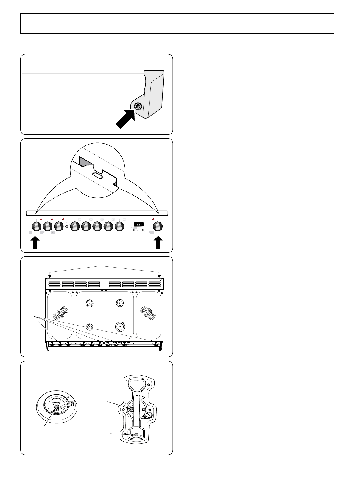
9. Servicing
Disconnect the cooker from the electricity supply
before servicing, particularly before removing any
of the following: control panel, side panels, ceramic
hob, or any of the electrical components or cover
boxes.
Before reconnection, check that the appliance is
electrically safe.
1. To Remove the Handrail
Remove the plastic blanking plugs (Fig.9-1) and remove the
two end bracket fixing screws.
2. To Remove the Control Panel
Disconnect from electricity supply.
Pull off all the control knobs. Remove the handrail (see 1).
Remove the two cross-headed screws that were hidden by the
handrail end brackets.
Open the grill door and right-hand oven door and remove the
two screws underneath the control panel (Fig.9-2).
Pull the control panel forward and support it so that the wires
are not strained.
Reassemble in reverse order. When replacing leads, refer to the
wiring diagram. Check the operation of the timer, ignition, and
oven light switches.
3. To Remove the Hotplate Top
Disconnect from electricity supply.
Remove the pan supports, cooktop burner caps and tops.
Remove the screws holding the cooktop burners to the
cooktop (but not the spark electrode fixing screws).
Remove the two rear cooktop fixing screws ‘B’ on the cooker
back under the flue grille, and the four front cooktop fixing
screws ‘A’, (Fig.9-3).
Remove the screws holding the flue grille stays.
Lift the cooktop clear of the appliance. Replace in reverse
order.
Reassemble in reverse order, ensuring that the leads are
reconnected.
Check for correct burner operation.
4. To Remove a Side Panel
Disconnect from electricity supply.
Remove the control panel (see 2). Pull the cooker forward.
Remove the four retaining screws from each panel (two at the
front and two at the rear). The lower front retaining screws
(one each side) are situated beneath the lower edge at the
front corners of the side panels
Reassemble in reverse order.
ArtNo.210-0009 - Classic
removing the handles
Fig.9-1
Fig.9-3
ArtNo.215-0013 - 90 Elan DF - Removing the control panel
0
0
0
0
Fig.9-2
ArtNo.311-0010 Injectors
Fig.9-4
A - Jet, B - Internal injector, C - External injector
Wok burner (some
models only)
Standard burner
Loading ...
Loading ...
Loading ...