2
SAFETY PRECAUTION
1
1-1. ALWAYS OBSERVE FOR SAFETY
Cautions for units utilising refrigerant R410A
Use new refrigerant pipes.
Make sure that the inside and outside of refrige-
rant piping is clean and it has no contamination
such as sulfur hazardous for use, oxides, dirt,
shaving particles, etc.
In addition, use pipes with specified thickness.
Store the piping to be used indoors during
installation and both ends of the piping sealed
until just before brazing. (Leave elbow joints, etc.
in their packaging.)
Use ester oil, ether oil or alkylbenzene oil (small
amount) as the refrigerant oil applied to flares
and flange connections.
In case of using the existing pipes for R22, be careful with
the followings.
· For RP125 and 140, be sure to perform replacement op-
eration before test run.
· Change flare nut to the one provided with this product.
Use a newly flared pipe.
· Avoid using thin pipes.
Charge refrigerant from liquid phase of gas
cylinder.
If the refrigerant is charged from gas phase, composition
change may occur in refrigerant and the efficiency will be
lowered.
Do not use refrigerant other than R410A.
If other refrigerant (R22 etc.) is used, chlorine in refrige-
rant can cause deterioration of refrigerant oil etc.
Use a vacuum pump with a reverse flow check
valve.
Vacuum pump oil may flow back into refrigerant cycle and
that can cause deterioration of refrigerant oil etc.
Use the following tools specifically designed for
use with R410A refrigerant.
The following tools are necessary to use R410A refrigerant.
Handle tools with care.
If dirt, dust or moisture enters into refrigerant cycle, that can
cause deterioration of refrigerant oil or malfunction of com-
pressor.
Do not use a charging cylinder.
If a charging cylinder is used, the composition of refrigera-
nt will change and the efficiency will be lowered.
Flare tool
Electronic refrigerant
charging scale
Vacuum pump adaptor
Size adjustment gauge
Gauge manifold
Torque wrench
Gas leak detector
Charge hose
Tools for R410A
Contamination inside refrigerant piping can cause deterio-
ration of refrigerant oil etc.
If dirt, dust or moisture enters into refrigerant cycle, that can
cause deterioration of refrigerant oil or malfunction of com-
pressor.
If large amount of mineral oil enters, that can cause deterio-
ration of refrigerant oil etc.
Ventilate the room if refrigerant leaks during
operation. If refrigerant comes into contact with
a flame, poisonous gases will be released.
[1] Cautions for service
(1) Perform service after recovering the refrigerant left in unit completely.
(2) Do not release refrigerant in the air.
(3) After completing service, charge the cycle with specified amount of refrigerant.
(4) When performing service, install a filter drier simultaneously.
Be sure to use a filter drier for new refrigerant.
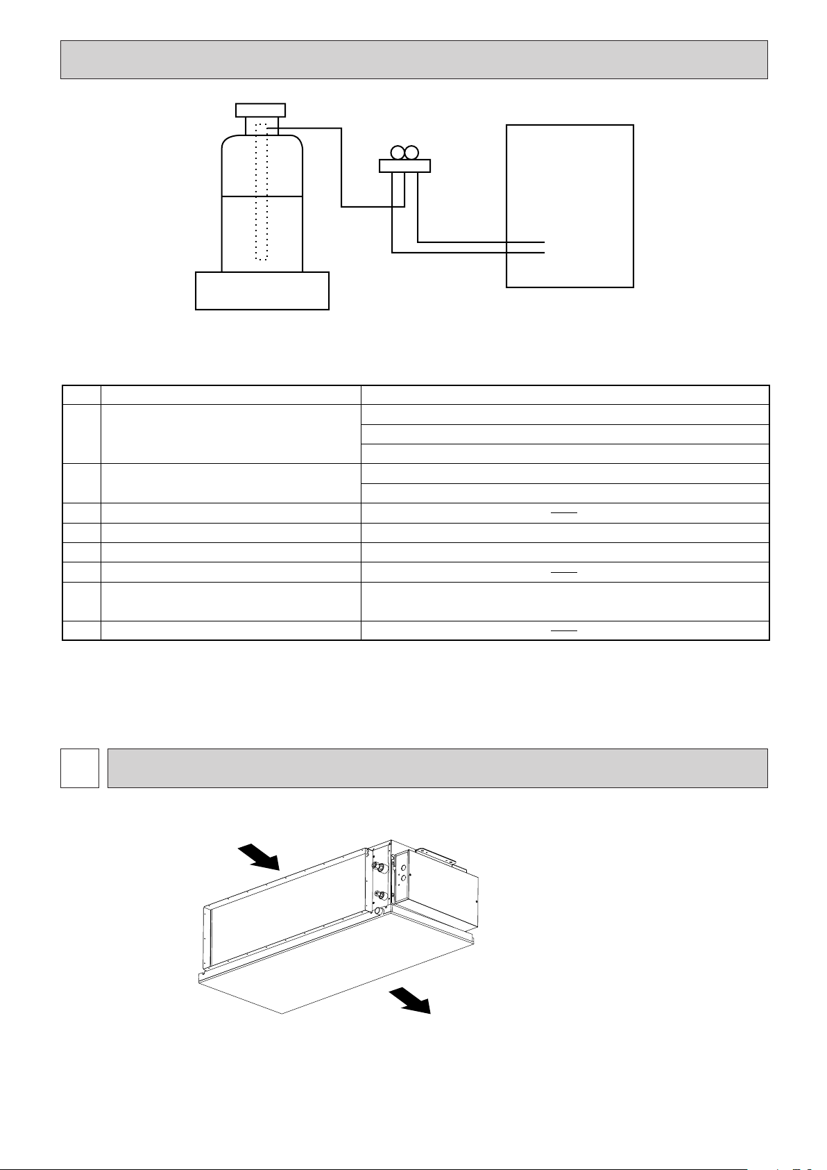
[2] Additional refrigerant charge
When charging directly from cylinder
· Check that cylinder for R410A on the market is syphon type.
· Charging should be performed with the cylinder of syphon stood vertically. (Refrigerant is charged from liquid phase.)
Before obtaining access to terminal, all supply
circuits must be disconnected.
1-2. CAUTIONS RELATED TO NEW REFRIGERANT
HWE1309A.qx 3/18/14 10:10 AM Page 2
3
Gravimeter
Unit
[3] Service tools
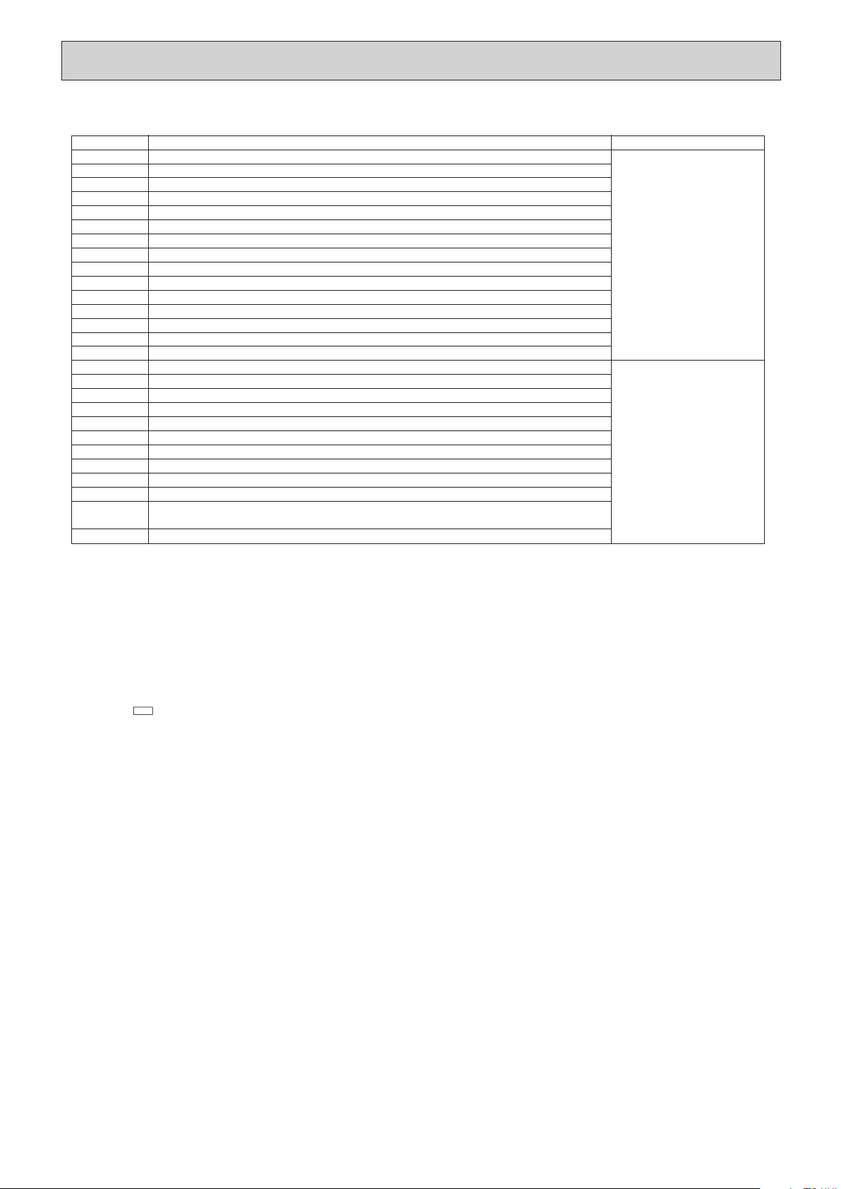
Use the below service tools as exclusive tools for R410A refrigerant.
No. Tool name Specifications
1 Gauge manifold · Only for R410A
· Use the existing fitting specifications. (UNF1/2)
· Use high-tension side pressure of 5.3MPa·G or over.
2 Charge hose · Only for R410A
· Use pressure performance of 5.09MPa·G or over.
3 Electronic scale
4 Gas leak detector · Use the detector for R134a, R407C or R410A.
5 Adaptor for reverse flow check · Attach on vacuum pump.
6 Refrigerant charge base
7 Refrigerant cylinder · Only for R410A · To p of cylinder (Pink)
· Cylinder with syphon
8 Refrigerant recovery equipment
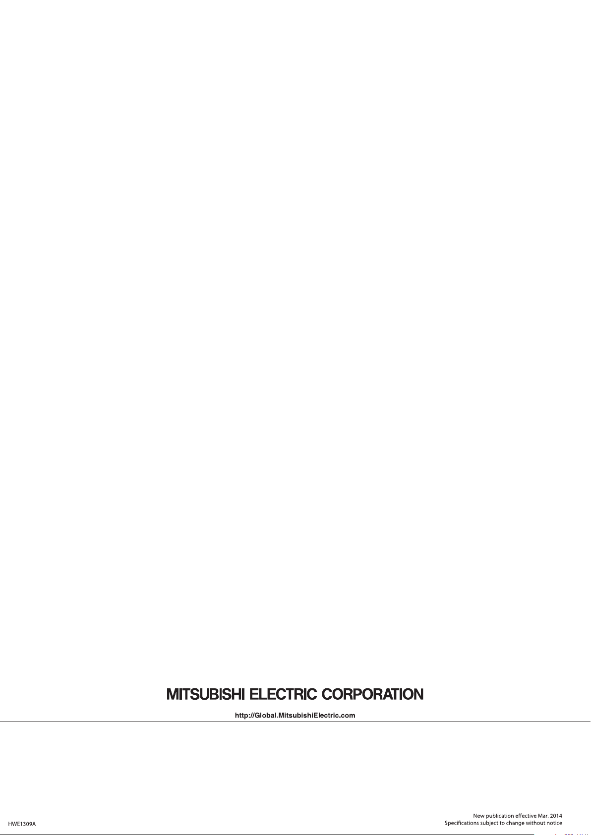
PART NAMES AND FUNCTIONS
2
•
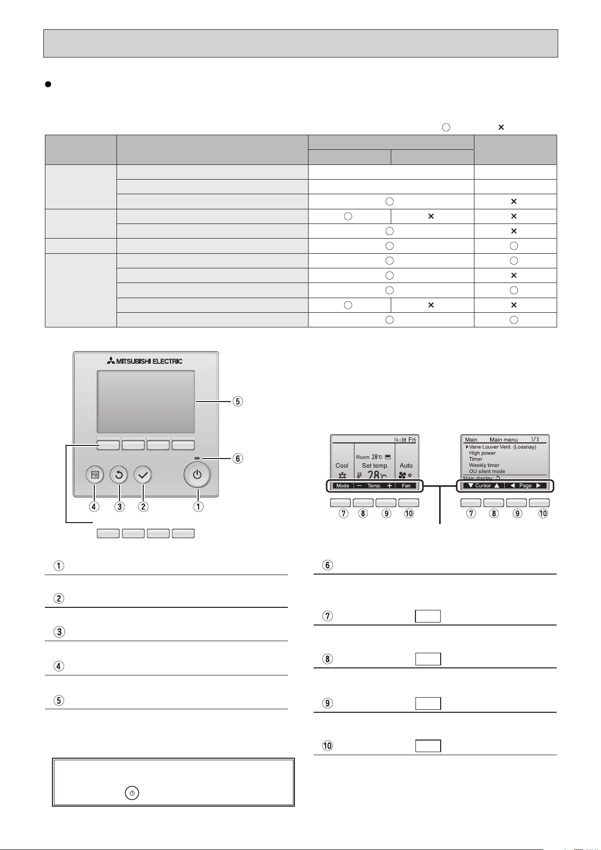
Indoor Unit
Air intake (sucks the air inside
the room into the unit)
In case of rear inlet
Air outlet
HWE1309A.qx 3/18/14 10:10 AM Page 3
4
Function buttons
F1 F2 F3 F4
Press to turn ON/OFF the indoor unit.
ON / OFF button
When the backlight is off, pressing any button turns
the backlight on and does not perform its function.
(except for the
(ON / OFF) button)
The functions of the function buttons change depending on
the screen. Refer to the button function guide that appears
at the bottom of the LCD for the functions they serve on a
given screen.
When the system is centrally controlled, the button function
guide that corresponds to the locked button will not appear.
Press to save the setting.
SELECT button
Press to return to the previous screen.
RETURN button
Press to bring up the Main menu.
MENU button
Operation settings will appear.
When the backlight is off, pressing any button turns the
backlight on and it will stay lit for a certain period of time
depending on the screen.
Backlit LCD
This lamp lights up in green while the unit is in operation.
It blinks while the remote controller is starting up or when
there is an error.
ON / OFF lamp
Main display : Press to change the operation mode.
Main menu : Press to move the cursor down.
Function button
F1
Main display : Press to decrease temperature.
Main menu : Press to move the cursor up.
Function button
F2
Main display : Press to increase temperature.
Main menu : Press to go to the previous page.
Function button
F3
Main display : Press to change the fan speed.
Main menu : Press to go to the next page.
Function button
F4
* The functions which can be used are restricted according to the model.
: Supported : Unsupported
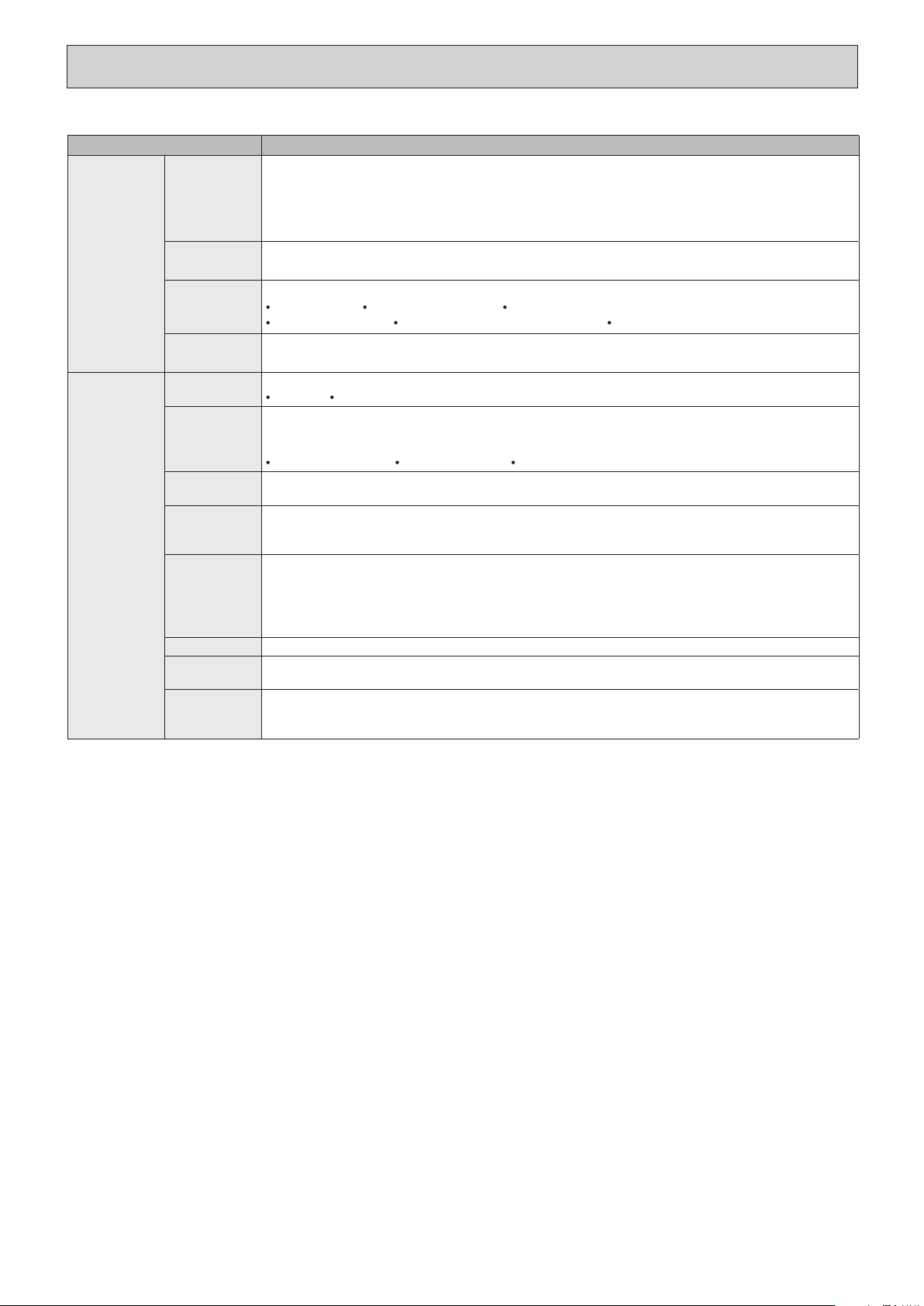
Function
PAR-30MAA/PAR-31MAA
PAR-21MAA
Slim City multi
Body Product size H ✕ W ✕ D (mm) 120 ✕ 120 ✕ 19 120 ✕ 130 ✕ 19
LCD Full Dot LCD Partial Dot LCD
Backlight
Energy-saving Energy-saving operation schedule
Automatic return to the preset temperature
Restriction Setting the temperature range restriction
Function Operation lock function
Weekly timer
On / Off timer
High Power
Manual vane angle
Wired remote controller function
<Main display> <Main menu>
Function guide
Wired remote controller (option)
HWE1309A.qx 3/18/14 12:15 PM Page 4

5
The main display can be displayed in two different modes: "Full" and "Basic".
The initial setting is "Full". To switch to the "Basic" mode, change the setting on the Main display setting.
<Full mode> <Basic mode>
* All icons are displayed for explanation.
Most settings (except ON / OFF, mode, fan speed, temperature) can be made from the Menu screen.
Indoor unit operation mode appears here.
Operation mode
Preset temperature appears here.
Preset temperature
Current time appears here.
Clock (See the Installation Manual.)
Fan speed
Fan speed setting appears here.
Functions of the corresponding buttons appear here.
Button function guide
Appears when the ON/OFF operation is centrally controlled.
Appears when the operation mode is centrally controlled.
Appears when the preset temperature is centrally controlled.
Current room temperature appears here.
Room temperature
(See the Installation Manual.)
Appears when the buttons are locked.
Appears when the On/Off timer or Night setback function is
enabled.
Appears when the Weekly timer is enabled.
Appears while the units are operated in the energy-save
mode.
Indicates the vane setting.
Indicates the louver setting.
Indicates the ventilation setting.
Appears when the preset temperature range is restricted.
HWE1309A.qx 3/24/14 3:21 PM Page 5
6
Not all functions are available on all models of indoor units.
Filter information
Error information
Energy saving
Auto return
Schedule
Night setback
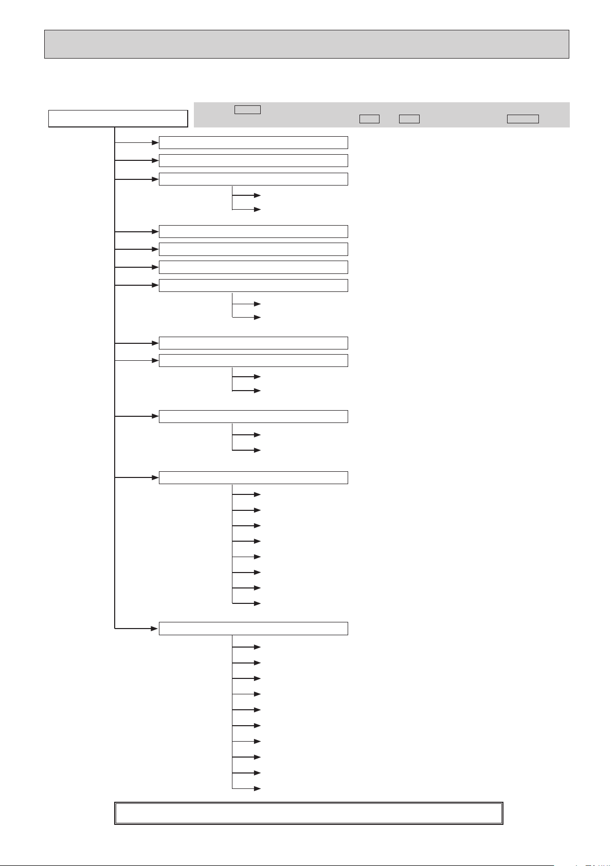
Main menu
Press the
MENU
button.
Move the cursor to the desired item with the
F1
and
F2
buttons, and press the
SELECT
button.
Vane · Louver · Vent. (Lossnay)
High power
Weekly timer
Restriction
Maintenance
Initial setting
On / Off timer
Auto-Off timer
Temp. range
Operation lock
Manual vane angle
Main / Sub
Timer
Main display
Contrast
Display details
Auto mode
Administrator password
Language selection
Service
Service menu
Input maintenance info.
Function setting
Lossnay (City Multi only)
Check
Self check
Maintenance password
Remote controller check
Test run
Clock
Drain pump test run
Auto descending panel
Menu structure
HWE1309A.qx 3/18/14 12:15 PM Page 6
7
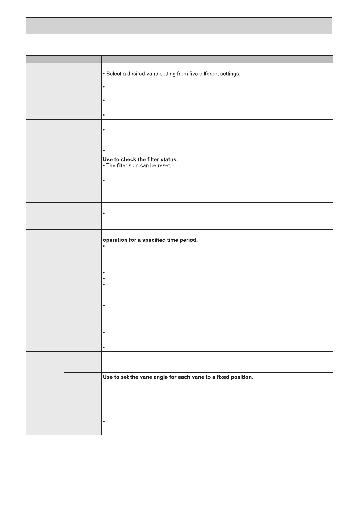
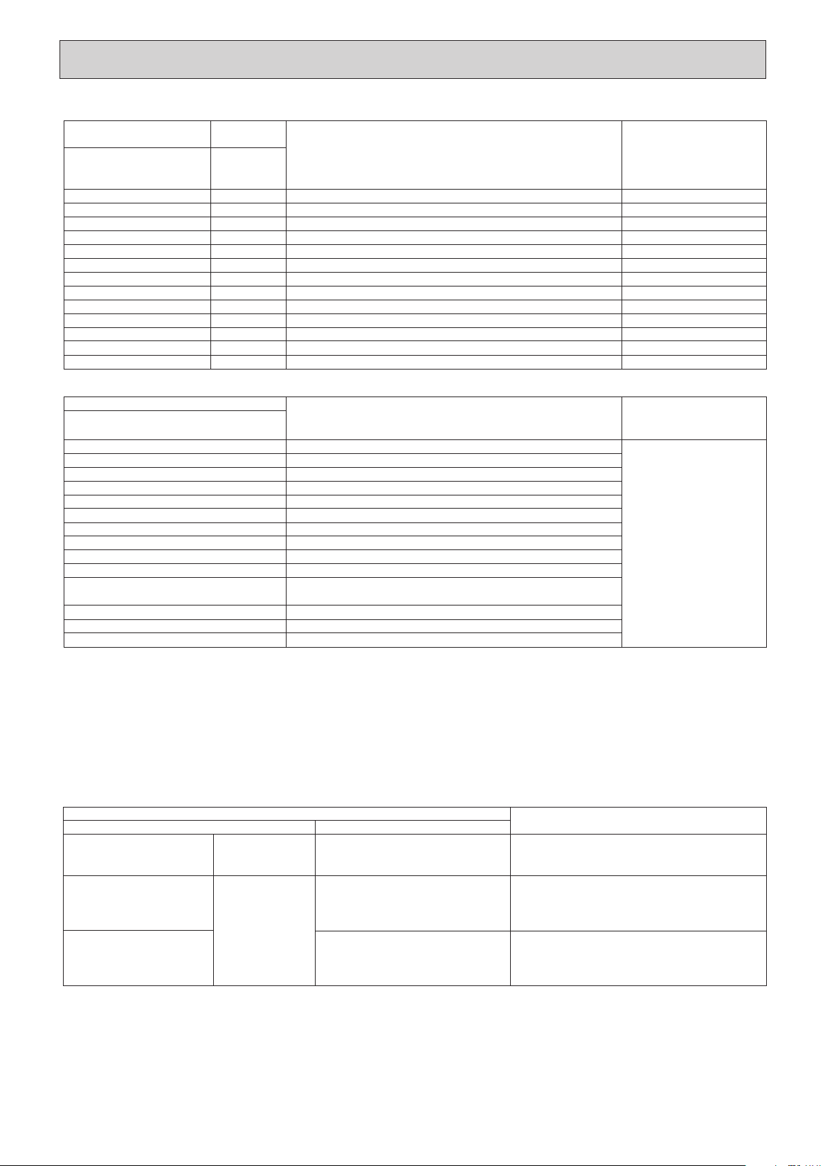
Setting and display items Setting details
Vane · Louver · Vent.
(Lossnay)
Use to set the vane angle.
Use to turn ON / OFF the louver.
Select a desired setting from "ON" and "OFF."
Use to set the amount of ventilation.
Select a desired setting from "Off," "Low," and "High."
High power Use to reach the comfortable room temperature quickly.
Units can be operated in the High-power mode for up to 30 minutes.
Timer On/Off timer Use to set the operation On/Off times.
Time can be set in 5-minute increments.
* Clock setting is required.
Auto-Off
timer
Use to set the Auto-Off time.
Time can be set to a value from 30 to 240 in 10-minute increments.
Filter information
Error information Use to check error information when an error occurs.
Error code, error source, refrigerant address, unit model, manufacturing number, contact
information (dealer's phone number) can be displayed.
* The unit model, manufacturing number, and contact information need to be registered in
advance to be displayed.
Weekly timer Use to set the weekly operation On / Off times.
Up to eight operation patterns can be set for each day.
* Clock setting is required.
* Not valid when the On/Off timer is enabled.
Energy
saving
Auto return Use to get the units to operate at the preset temperature after performing energy-save
Time can be set to a value from 30 and 120 in 10-minute increments.
* This function will not be valid when the preset temperature ranges are restricted.
Schedule Set the start/stop times to operate the units in the energy-save mode for each day of the
week, and set the energy-saving rate.
Up to four energy-save operation patterns can be set for each day.
Time can be set in 5-minute increments.
Energy-saving rate can be set to a value from 0% or 50 to 90% in 10% increments.
* Clock setting is required.
Night setback Use to make Night setback settings.
Select "Yes" to enable the setting, and "No" to disable the setting. The temperature range and
the start/stop times can be set.
* Clock setting is required.
Restriction Temp. range Use to restrict the preset temperature range.
Different temperature ranges can be set for different operation modes.
Operation
lock
Use to lock selected functions.
The locked functions cannot be operated.
Maintenance
Auto
descending
panel
Auto descending panel (Optional parts) Up / Down you can do.
Manual
vane angle
Initial setting
Main/Sub
When connecting two remote controllers, one of them needs to be designated as a sub
controller.
Clock
Use to set the current time.
Main display
Use to switch between "Full" and "Basic" modes for the Main display.
The initial setting is "Full."
Contrast
Use to adjust screen contrast.
Main menu list
HWE1309A.qx 3/18/14 12:15 PM Page 7
8
Setting and display items Setting details
Initial setting Display
details
Make the settings for the remote controller related items as necessary.
Clock: The initial settings are "Yes" and "24h" format.
Temperature: Set either Celsius (˚C) or Fahrenheit (˚F).
Room temp. : Set Show or Hide.
Auto mode: Set the Auto mode display or Only Auto display.
Auto mode Whether or not to use the AUTO mode can be selected by using the button.
This setting is valid only when indoor units with the AUTO mode function are connected.
Administrator
password
The administrator password is required to make the settings for the following items.
Timer setting Energy-save setting Weekly timer setting
Restriction setting Outdoor unit silent mode setting Night set back
Language
selection
Use to select the desired language.
Service
Test run Select "Test run" from the Service menu to bring up the Test run menu.
Test run Drain pump test run
Input
maintenance
Select "Input maintenance Info." from the Service menu to bring up the Maintenance
information screen.
The following settings can be made from the Maintenance Information screen.
Model name input Serial No. input Dealer information input
Function
setting
Make the settings for the indoor unit functions via the remote controller as necessary.
LOSSNAY
setting
(City Multi only)
This setting is required only when the operation of City Multi units is interlocked with
LOSSNAY units.
Check Error history: Display the error history and execute delete error history.
Refrigerant leak check: Refrigerant leaks can be judged.
Smooth maintenance: The indoor and outdoor maintenance data can be displayed.
Request cord: Details of the operation data including each thermistor temperature and error
history can be checked.
Self check Error history of each unit can be checked via the remote controller.
Maintenance
password
Take the following steps to change the maintenance password.
Remote
controller
check
When the remote controller does not work properly, use the remote controller checking
function to troublushoot the problem.
HWE1309A.qx 3/18/14 12:15 PM Page 8
9
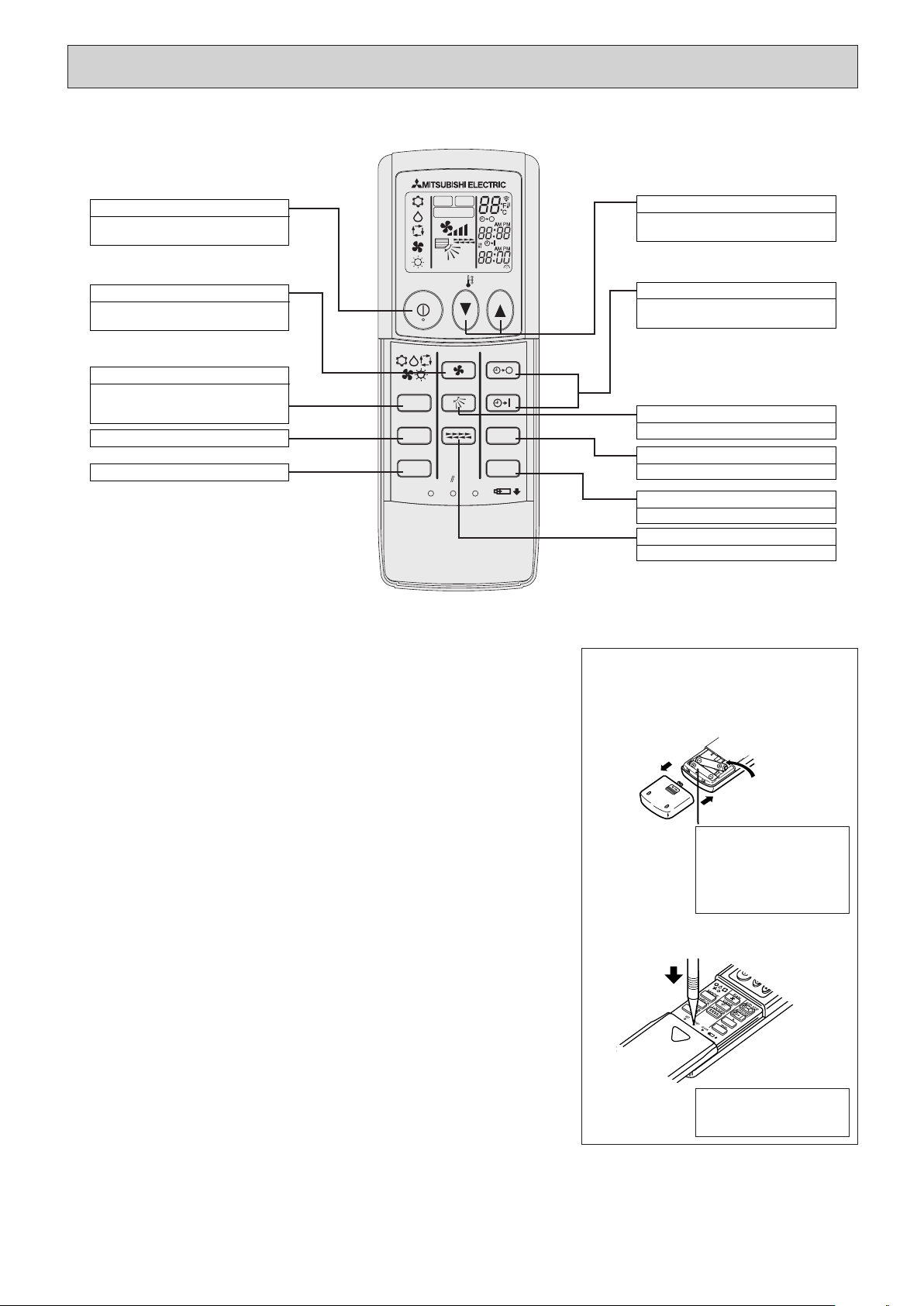
Wireless remote controller (option)
● When using the wireless remote controller, point it towards the receiver on
the indoor unit.
● If the remote controller is operated within approximately two minutes after
power is supplied to the indoor unit, the indoor unit may beep twice as the
unit is performing the initial automatic check.
● The indoor unit beeps to confirm that the signal transmitted from the
remote controller has been received. Signals can be received up to
approximately 7 meters in a direct line from the indoor unit in an area 45°
to the left and right of the unit. However, illumination such as fluorescent
lights and strong light can affect the ability of the indoor unit to receive sig-
nals.
● If the operation lamp near the receiver on the indoor unit is flashing, the
unit needs to be inspected. Consult your dealer for service.
● Handle the remote controller carefully. Do not drop the remote controller or
subject it to strong shocks. In addition, do not get the remote controller
wet or leave it in a location with high humidity.
● To avoid misplacing the remote controller, install the holder included with
the remote controller on a wall and be sure to always place the remote
controller in the holder after use.
CLOCK
CHECK
RESET
SET
TEST RUN
MODE
FAN
VANE
LOUVER
min
h
AUTO START
AUTO STOP
ON/OFF
TEMP
NOT AVAILABLE
MODEL SELECT
TEST RUN
CHECK
SET TEMPERATURE button
SET TEMPERATURE button sets and
any desired room temperature.
AUTO STOP/AUTO START button
Used for selecting timed starting or st-
opping.
VANE CONTROL button
Used to change the airflow direction.
LOUVER button
Used for adjusting the airflow direction.
min button
Used for setting the current time.
h button
Used for setting the current time.
FAN SPEED button
This button is used to set fan speed to
low, medium or high.
MODE SELECT button
This button is used to change between
auto, cooling, heating and drying oper-
ation modes.
TEST RUN button
CHECK button
ON/OFF button
Pushing button starts operation.
Pushing again stops operation.
Battery installation/replacement
1. Remove the top cover, insert two AAA
batteries, and then install the top cover.
Top cover
2. Press the Reset button.
1
2
3
Press the Reset button
with an object that has
a narrow end.
Two AAA batteries
Insert the negative (–)
end of each battery
first. Install the batter-
ies in the correct direc-
tions (+, –).
● Operation buttons
HWE1309A.qx 3/18/14 10:11 AM Page 9
Service Ref.
Mode
Power supply
Input
kW
Running Current
A
External finish
Heat exchanger
Fan
Fan (drive) × No.
Fan motor output
kW
Airflow
(Low-High)
m
3
/min (L/S)
External static pressure
Pa
Booster heater
kW
Operation control & Thermostat
Sound pressure level
(Low-High)
dB (A)
Field drain pipe O.D mm (in.)
Dimensions
W
mm (in.)
D
mm (in.)
H
mm (in.)
kg
lbs
INDOOR UNIT
Weight
50Pa
100Pa
150Pa
50Pa
100Pa
150Pa
PEA-RP125GAA
Cooling, Heating
0.49
3.84
Single phase, 50Hz, 220-240V
Galvanized sheets
Plate fin coil
Sirocco fan
× 2
0.249
48-60 (800-1000)
43-54 (716-900)
41-52 (683-866)
50-100-150
-
Remote controller & built-in
42-45
43-47
45-49
25.4 (1)
1400 (55-1/8)
634 (25)
400 (15-3/4)
63
139
Service Ref.
Mode
Power supply
Input kW
Running Current A
External finish
Heat exchanger
Fan
Fan (drive) × No.
Fan motor output kW
Airflow
(Low-High)
m
3
/min (L/S)
External static pressure Pa
Booster heater kW
Operation control & Thermostat
Sound pressure level
(Low-High)
dB (A)
Field drain pipe O.D mm (in.)
Dimensions W mm (in.)
D mm (in.)
H mm (in.)
kg
lbs
INDOOR UNIT
Weight
50Pa
100Pa
150Pa
50Pa
100Pa
150Pa
PEA-RP140GAA
Cooling, Heating
0.49
3.84
Single phase, 50Hz, 220-240V
Galvanized sheets
Plate fin coil
Sirocco fan
× 2
0.249
48-60 (800-1000)
43-54 (716-900)
41-52 (683-866)
50-100-150
-
Remote controller & built-in
42-45
43-47
45-49
25.4 (1)
1400 (55-1/8)
634 (25)
400 (15-3/4)
63
139
10
Service Ref.
Mode
Power supply
Input
kW
Running Current
A
External finish
Heat exchanger
Fan
Fan (drive) × No.
Fan motor output
kW
Airflow
(Low-High)
m
3
/min (L/S)
External static pressure
Pa
Booster heater
kW
Operation control & Thermostat
Sound pressure level
(Low-High)
dB (A)
Field drain pipe O.D mm (in.)
Dimensions
W
mm (in.)
D
mm (in.)
H
mm (in.)
kg
lbs
INDOOR UNIT
Weight
50Pa
100Pa
150Pa
50Pa
100Pa
150Pa
PEA-RP100GAA
Cooling, Heating
0.21
1.83
Single phase, 50Hz, 220-240V
Galvanized sheets
Plate fin coil
Sirocco fan
× 2
0.249
34-42 (560-700)
50-100-150
-
Remote controller & built-in
39-42
42-45
44-48
25.4 (1)
1400 (55-1/8)
634 (25)
400 (15-3/4)
63
139
SPECIFICATION
3
HWE1309A.qx 3/18/14 10:11 AM Page 10
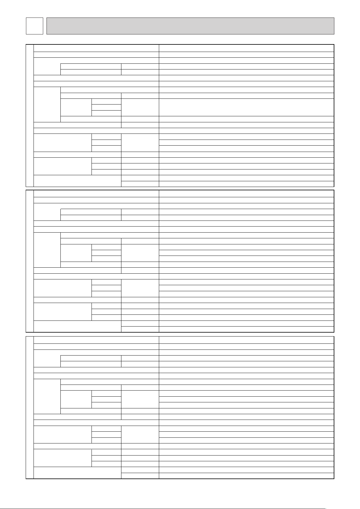
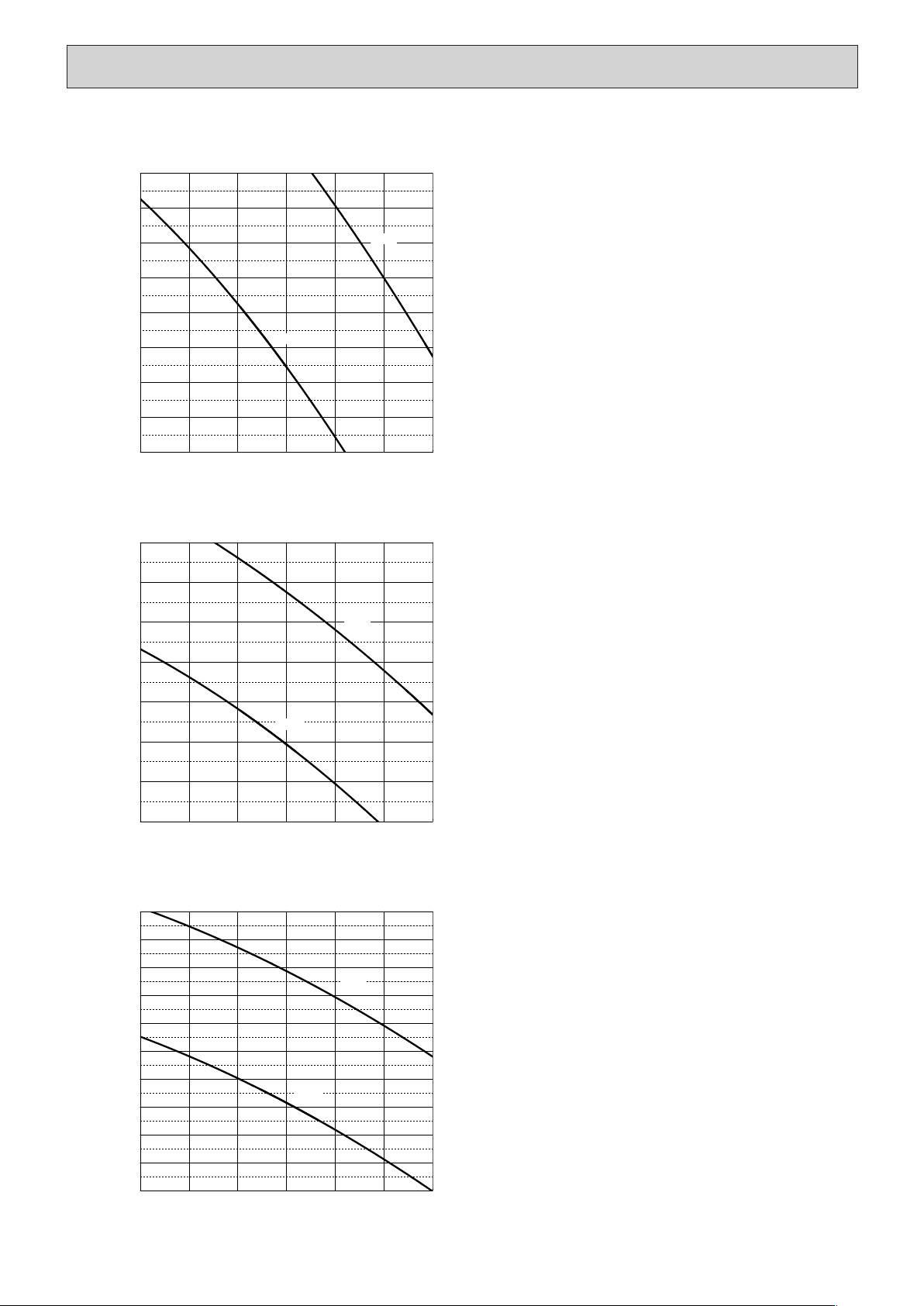
11
Low
High
Low
High
Low
High
PEA-RP100GAA
(External static pressure 50Pa) 220-240V 50Hz
0
10
20
30
40
50
60
70
80
25 30 35 40 45 50
Airflow rate(m
3
/min)
External static pressure (Pa)
25 30 35 40 45 50
Airflow rate(m
3
/min)
External static pressure (Pa)
25 30 35 40 45 50
Airflow rate(m
3
/min)
External static pressure (Pa)
PEA-RP100GAA
(External static pressure 100Pa) 220-240V 50Hz
0
20
40
60
80
100
120
140
PEA-RP100GAA
(External static pressure 150Pa) 220-240V 50Hz
0
20
40
60
80
100
120
140
160
180
200
FAN PERFORMANCE AND CORRECTED AIR FLOW
4
HWE1309A.qx 3/18/14 10:11 AM Page 11
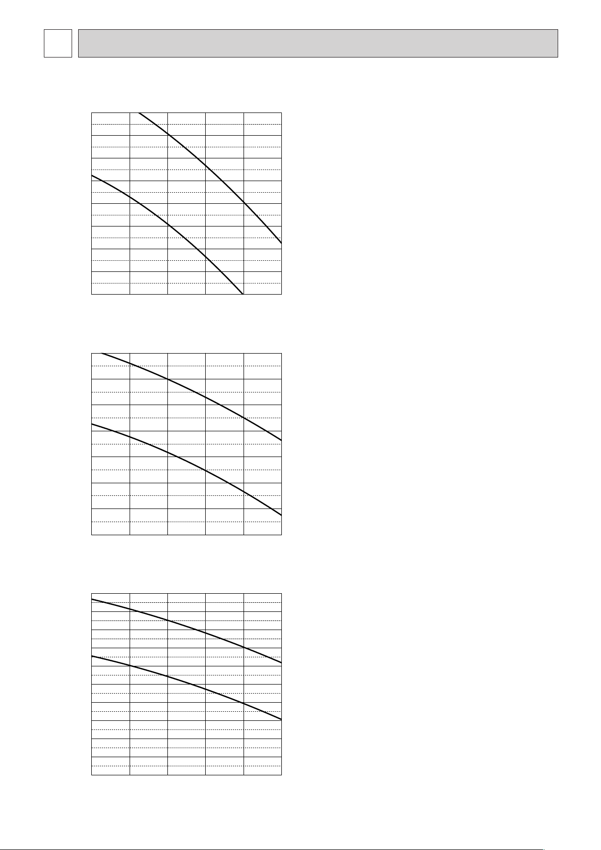
12
Low
High
Low
High
Low
High
PEA-RP125GAA
(External static pressure 50Pa) 220-240V 50Hz
0
10
20
30
40
50
60
70
80
35 40 45 50 55 60 65
Airflow rate(m
3
/min)
External static pressure (Pa)
35 40 45 50 55 60 65
Airflow rate(m
3
/min)
External static pressure (Pa)
35 40 45 50 55 60 65
Airflow rate(m
3
/min)
External static pressure (Pa)
PEA-RP125GAA
(External static pressure 100Pa) 220-240V 50Hz
0
20
40
60
80
100
120
140
PEA-RP125GAA
(External static pressure 150Pa) 220-240V 50Hz
0
20
40
60
80
100
120
140
160
180
200
HWE1309A.qx 3/18/14 10:11 AM Page 12

13
Low
High
Low
High
Low
High
PEA-RP140GAA
(External static pressure 50Pa) 220-240V 50Hz
0
10
20
30
40
50
60
70
80
PEA-RP140GAA
(External static pressure 100Pa) 220-240V 50Hz
0
20
40
60
80
100
120
140
PEA-RP140GAA
(External static pressure 150Pa) 220-240V 50Hz
0
20
40
60
80
100
120
140
160
180
200
35 40 45 50 55 60 65
Airflow rate(m
3
/min)
35 40 45 50 55 60 65
Airflow rate(m
3
/min)
35 40 45 50 55 60 65
Airflow rate(m
3
/min)
External static pressure (Pa)External static pressure (Pa)External static pressure (Pa)
HWE1309A.qx 3/18/14 10:11 AM Page 13
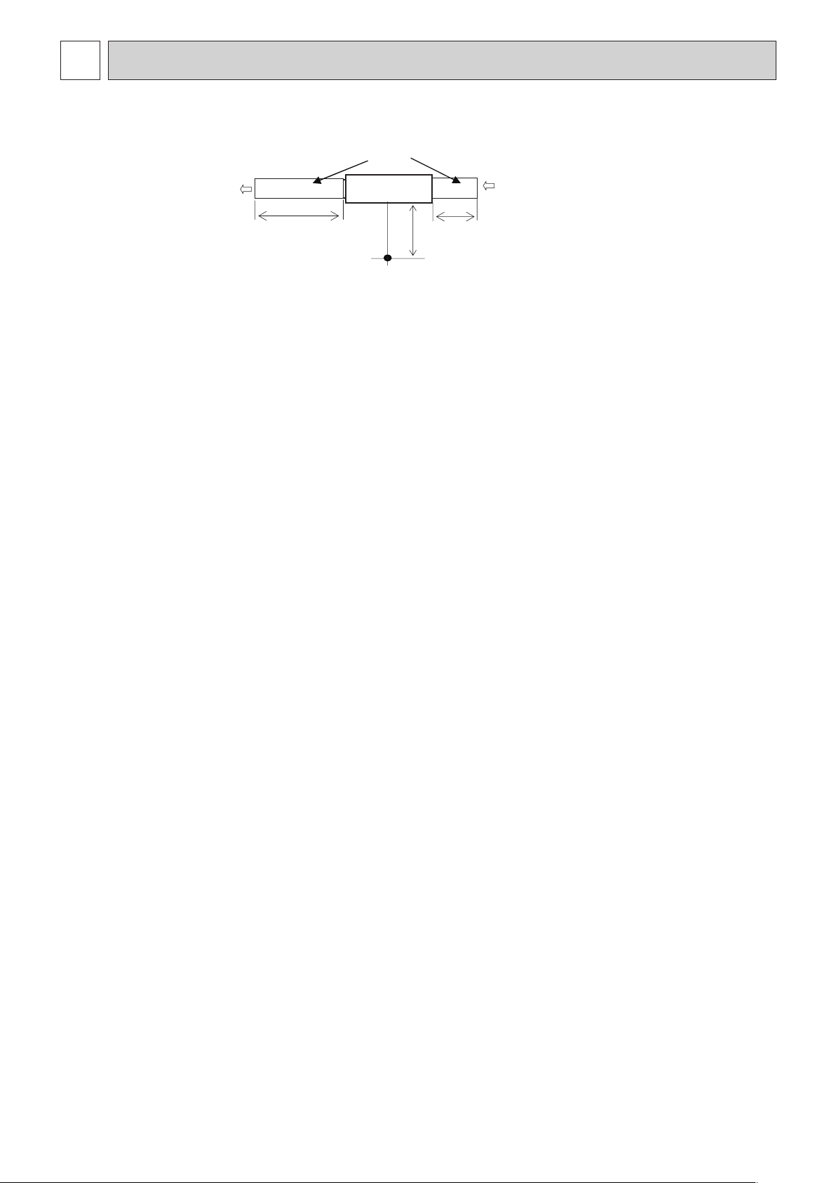
14
SOUND PRESSURE LEVELS
5
5-1. Sound pressure level
Measurement location
2m
1m
Aux. duct
1.5m
test unit
Ceiling concealed
HWE1309A.qx 3/18/14 10:11 AM Page 14
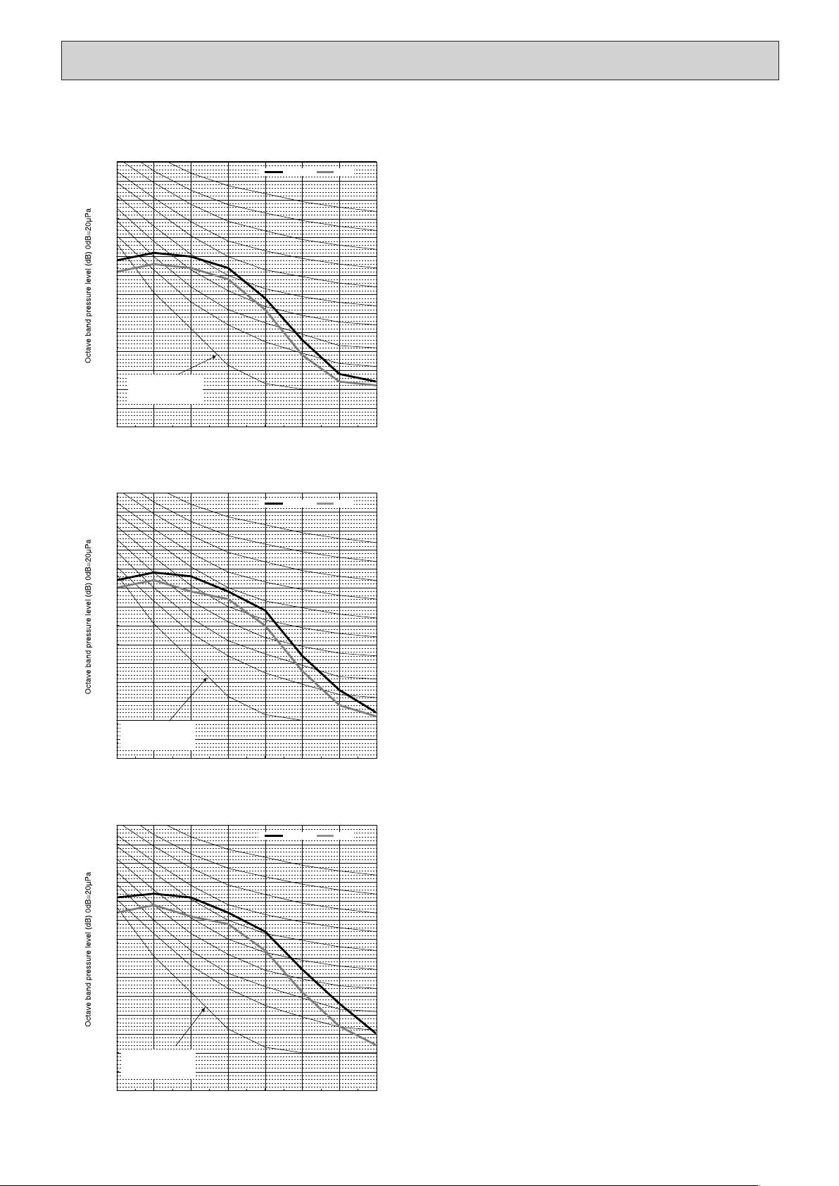
15
PEA-RP100GAA
0.0
5.0
10.0
15.0
20.0
25.0
30.0
35.0
40.0
45.0
50.0
55.0
60.0
65.0
70.0
63 125 250 500 1k 2k 4k 8k
Octave band center frequencies (Hz)
High Low
0.0
5.0
10.0
15.0
20.0
25.0
30.0
35.0
40.0
45.0
50.0
55.0
60.0
65.0
70.0
63 125 250 500 1k 2k 4k 8k
Octave band center frequencies (Hz)
High Low
0.0
5.0
10.0
15.0
20.0
25.0
30.0
35.0
40.0
45.0
50.0
55.0
60.0
65.0
70.0
63 125 250 500 1k 2k 4k 8k
Octave band center frequencies (Hz)
High Low
NC-60
NC-50
NC-40
NC-20
NC-30
NC-60
NC-50
NC-40
NC-20
NC-30
NC-60
NC-50
NC-40
NC-20
NC-30
(External static pressure 50Pa)
(External static pressure 100Pa)
(External static pressure 150Pa)
Approximate minimum
audible limit on
continuous noise
Approximate minimum
audible limit on
continuous noise
Approximate minimum
audible limit on
continuous noise
5-2. NC curves
HWE1309A.qx 3/18/14 10:11 AM Page 15
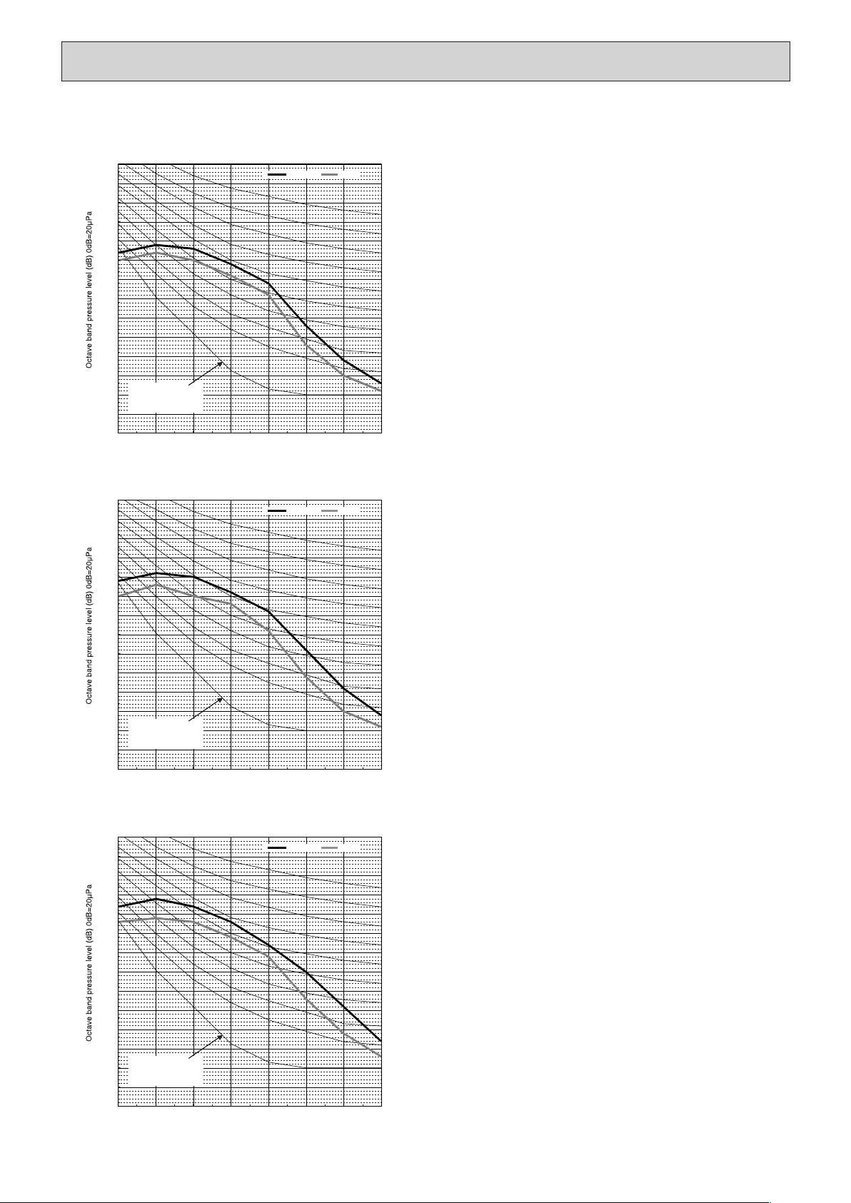
16
PEA-RP125GAA
0.0
5.0
10.0
15.0
20.0
25.0
30.0
35.0
40.0
45.0
50.0
55.0
60.0
65.0
70.0
63 125 250 500 1k 2k 4k 8k
NC-60
NC-50
Approximate minimum
audible limit on
continuous noise
NC-40
Octave band center frequencies (Hz)
NC-20
NC-30
High Low
0.0
5.0
10.0
15.0
20.0
25.0
30.0
35.0
40.0
45.0
50.0
55.0
60.0
65.0
70.0
63 125 250 500 1k 2k 4k 8k
NC-60
NC-50
Approximate minimum
audible limit on
continuous noise
NC-40
Octave band center frequencies (Hz)
NC-20
NC-30
High Low
0.0
5.0
10.0
15.0
20.0
25.0
30.0
35.0
40.0
45.0
50.0
55.0
60.0
65.0
70.0
63 125 250 500 1k 2k 4k 8k
NC-60
NC-50
Approximate minimum
audible limit on
continuous noise
NC-40
Octave band center frequencies (Hz)
NC-20
NC-30
High Low
(External static pressure 50Pa)
(External static pressure 100Pa)
(External static pressure 150Pa)
HWE1309A.qx 3/18/14 10:11 AM Page 16
17
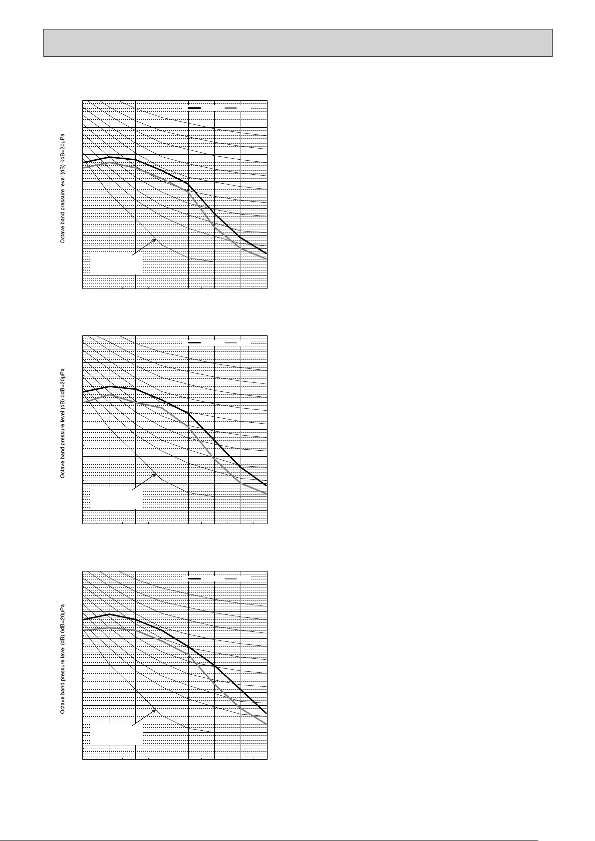
PEA-RP140GAA
0.0
5.0
10.0
15.0
20.0
25.0
30.0
35.0
40.0
45.0
50.0
55.0
60.0
65.0
70.0
63 125 250 500 1k 2k 4k 8k
NC-60
NC-50
Approximate minimum
audible limit on
continuous noise
NC-40
Octave band center frequencies (Hz)
NC-20
NC-30
High Low
0.0
5.0
10.0
15.0
20.0
25.0
30.0
35.0
40.0
45.0
50.0
55.0
60.0
65.0
70.0
63 125 250 500 1k 2k 4k 8k
NC-60
NC-50
Approximate minimum
audible limit on
continuous noise
NC-40
Octave band center frequencies (Hz)
NC-20
NC-30
High Low
0.0
5.0
10.0
15.0
20.0
25.0
30.0
35.0
40.0
45.0
50.0
55.0
60.0
65.0
70.0
63 125 250 500 1k 2k 4k 8k
NC-60
NC-50
Approximate minimum
audible limit on
continuous noise
NC-40
Octave band center frequencies (Hz)
NC-20
NC-30
High Low
(External static pressure 50Pa)
(External static pressure 100Pa)
(External static pressure 150Pa)
HWE1309A.qx 3/18/14 10:11 AM Page 17
18
6
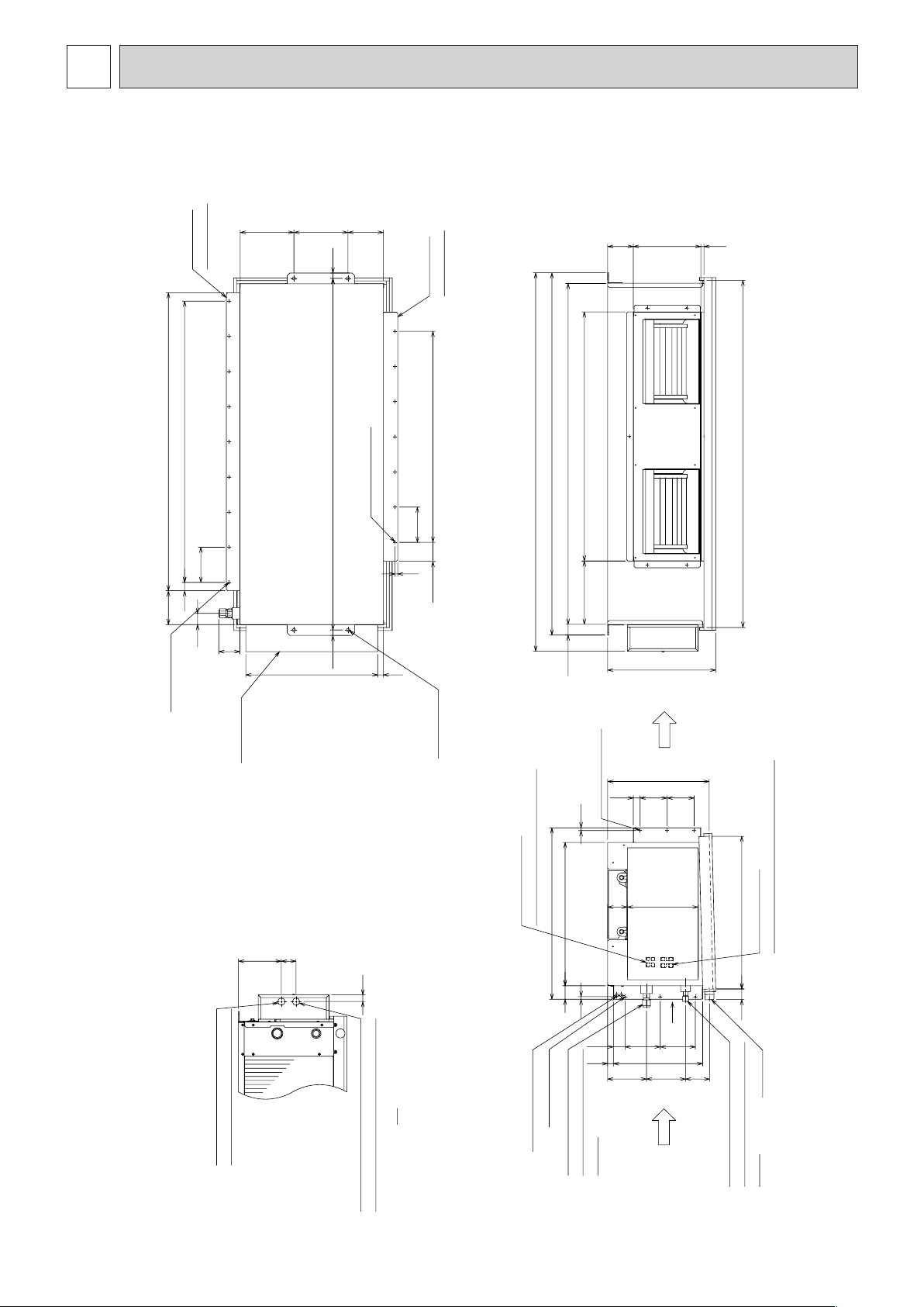
OUTLINES & DIMENSIONS
INDOOR UNIT
PEA-RP100, 125, 140GAA
199
14414589
376
24
54 158
530
125
31
42
10
130x6=780
70.5
130
22330
130 43130
73262
56539
634
50
10 10
25100100
1102
130x8=1040
130
200131
2020 1300
21
78
488
1260
234
40
400
1284
11 250 95
921
1340
1400
Return air sensor
Refrigerant pipe
flare conection (Gas)
ø15.88
2x3-ø3 Holes
2x3-ø3.1 Holes
A
4-ø12 Holes
Drain R1
Refrigerant pipe
flare conection (Liquid)
ø9.52
Top view
2x7-ø3.1 Holes
<For hanging bolt M10>
[Field supply]
Return air
duct flange
Supply air
duct flange
2x9-ø3 Holes
Control box
Left side view
Supply air
Return air
Front view
A
Ter minal block
<Outdoor unit connection wiring>
Knockout hole ø27
<Outdoor unit connection wiring>
Ter minal block
<Remote controller wiring>
Knockout hole ø27
<Remote controller wiring>
<Accessory>
·Pipe cover························2pcs.
(For dew condensation prevention of
local piping and unit connection.)
HWE1309A.qx 3/18/14 10:11 AM Page 18
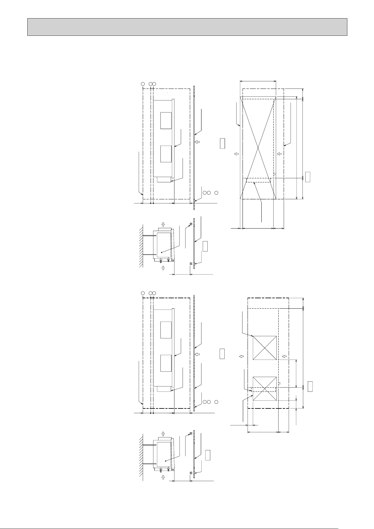
19
Min.300mm
Min.500mm
Min.500mm
Min.300mm
425
685
200 585 50
1754
200 585
0~150
200
200
1304
1304
400
400
0~150
400
400
25
25
75
75
(450x450)
(450x450)
Drain pan Drain pan
Maintenance access space Maintenance access space
Maintenance access space
When connecting inlet duct.
When installing the suspension fixtures prior to
installation of the indoor unit without inlet duct.
When hanging the indoor unit directly without inlet duct.
When connecting inlet duct.
When installing the suspension fixtures prior to
installation of the indoor unit without inlet duct.
When hanging the indoor unit directly without inlet duct.
Ceiling Ceiling
Ceiling Ceiling
Access door 2 Access door 3
Access door 1
Access door 1
Access door 2
Access door 3
Access door 2 Access door 3
Ceiling beam
Ceiling beam
Intake air Intake air
Intake air
Intake air
Supply air Supply air
Supply air
Bottom of indoor unit
Bottom of indoor unit
Supply air
Electric box
Electric box
Electric box Electric box
Electric box
Electric box
B
C
Fig.2
Fig.5
Fig.3
Fig.6
(Viewed from the direction of the arrow B)
(Viewed from the direction of the arrow C)
Fig.1
Fig.4
[Maintenance access space]
Secure enough access space to allow for the maintenance, inspection, and replacement of the motor, fan, drain pan, heat exchanger,
and electric box in one of the following ways.
Select an installation site for the indoor unit so that its maintenance access space will not be obstructed by beams or other objects.
(1) When a space of 500mm or more is available below the unit between the unit and the ceiling. (Fig.1)
· Create access door 1 and 2 (450x450mm each) as shown in Fig.3.
(Access door 2 is not required if enough space is available below the unit for a maintenance worker to work in.)
· An access hole of the same size as the access door 3 as shown in Fig. 6 is required to access drain pan or heat exchanger for replacement.
(Required only when the ceiling material cannot be removed)
(2) When a space of less than 500mm is available below the unit between the unit and the ceiling.
(At least 300mm of space should be left below the unit as shown in Fig.4.)
· Create access door 3 below the electric box and the unit as shown in Fig.6.
1
2
3
1
2
3
1
2
3
1
2
3
HWE1309A.qx 3/18/14 10:11 AM Page 19
20
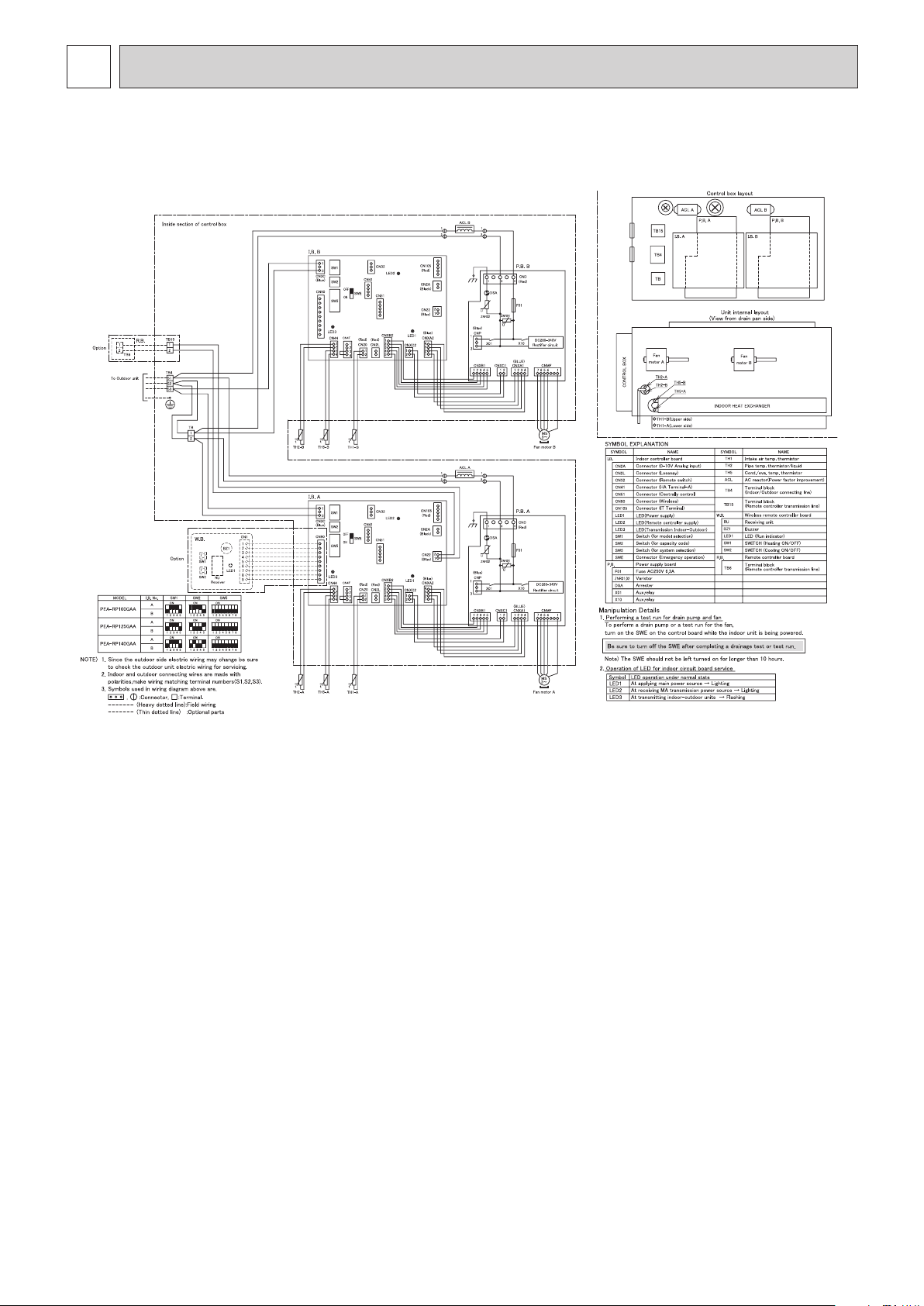
7
WIRING DIAGRAM
PEA-RP100, 125, 140GAA
HWE1309A.qx 3/24/14 3:25 PM Page 20
21
8
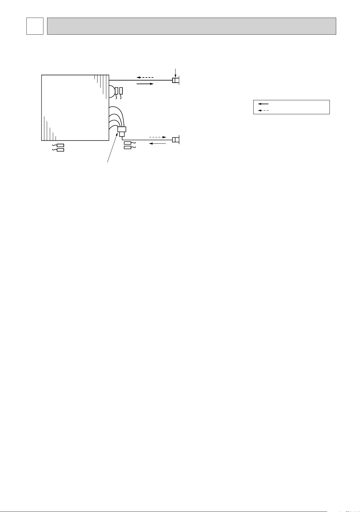
REFRIGERANT SYSTEM DIAGRAM
PEA-RP100, 125, 140GAA
Thermistor TH2-A,B
Pipe temperature(Liquid)
Distributor
with strainer (#100)
Thermistor TH5-A,B
(Cond./ Eva.temperature)
Thermistor TH1-A,B
(Room temperature)
Refrigerant flow in cooling
Refrigerant flow in heating
Strainer (#50)
Heat exchanger
Refrigerant GAS pipe connection
(Flare)
Refrigerant LIQUID pipe connection
(Flare)
HWE1309A.qx 3/18/14 10:11 AM Page 21
22
TROUBLESHOOTING
9-1. CAUTIONS ON TROUBLESHOOTING
(1) Before troubleshooting, check the followings:
1 Check the power supply voltage.
2 Check the indoor/outdoor connecting wire for mis-wiring.
3 PEA-RP·GAA has two control boards. Therefore, “No.1” unit or “No.2” unit is displayed on the remote controller when
an initial setup is performed or an error occurs.
Control Board A is not always No.1 unit and Control Board B is not always No.2 unit. Check the both control boards in
case of a malfunction of the fan motor or the sensor.
4 Connect the connectors of external input/output devices to the circuit board to which the remote controller is
connected.
5 When there is an external output or output connector, check that it is inserted in the board on the side with the remote
controller connected.
(2) Take care the followings during servicing.
1 Before servicing the air conditioner, be sure to turn off the remote controller first to stop the main unit, and then turn
off the breaker.
2 When removing the indoor controller board, hold the edge of the board with care NOT to apply stress on the
components.
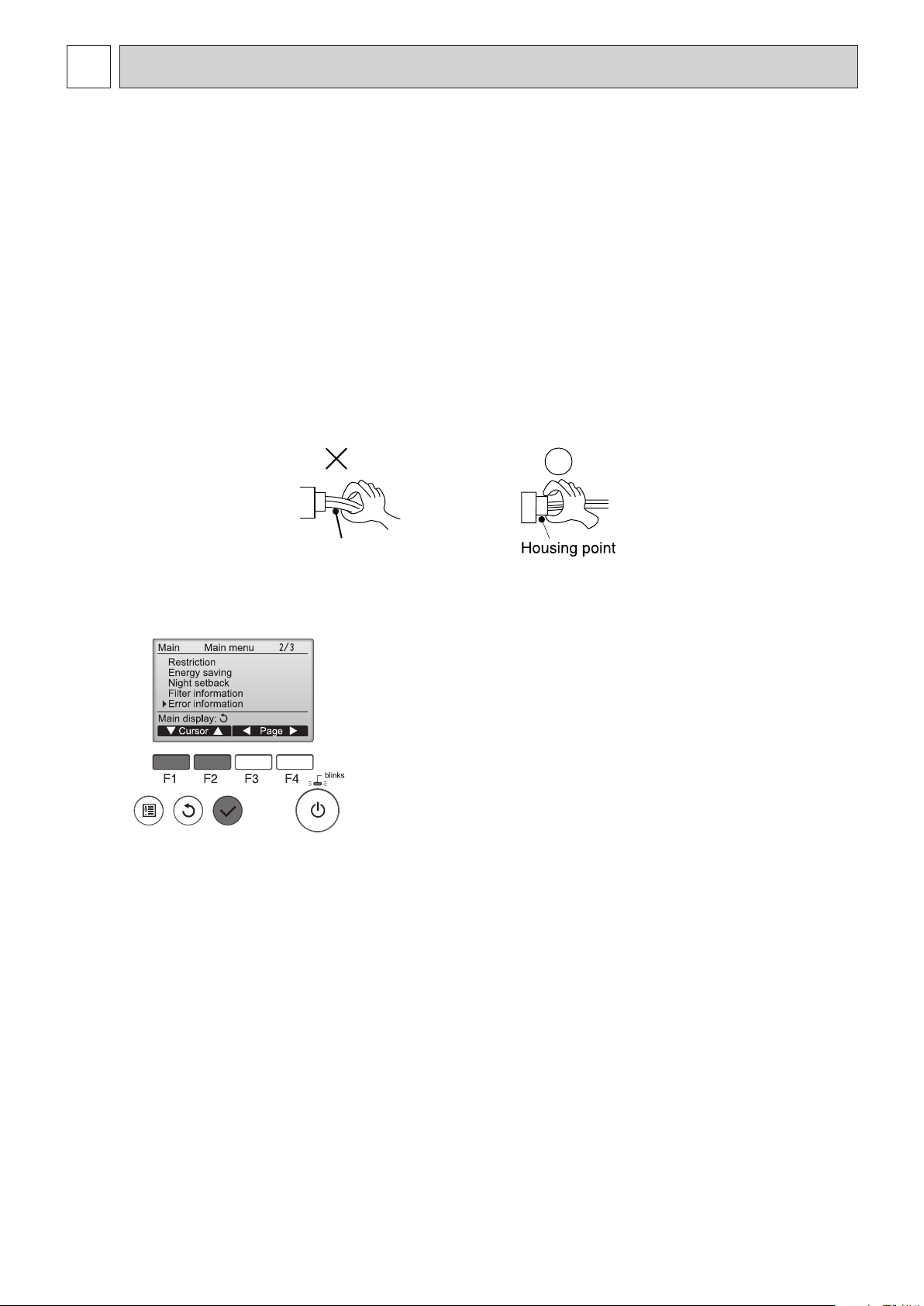
3 When connecting or disconnecting the connectors, hold the housing of the connector. DO NOT pull the lead wires.
Lead wires
9-2. SELF-CHECK FUNCTION
Wired remote controller
9
While no errors are occurring, page 2/2 of the
error information can be viewed by selecting
"Error information" from the Main menu.
Errors cannot be reset from this screen.
HWE1309A.qx 3/18/14 1:05 PM Page 22
23
Wireless remote controller
(1) Turn on the power to the unit at least 12 hours before the test run.
(2) Press the TEST RUN button
AA
twice continuously.
(Start this operation from the status of remote controller display turned off.)
and current operation mode are displayed.
(3) Press the MODE button
BB
to activate COOL mode, then check whether cool air is blown out from the unit.
(4) Press the MODE button
BB
to activate HEAT mode, then check whether warm air is blown out from the unit.
(5) Press the FAN button
CC
and check whether fan speed changes.
(6) Press the VANE button
DD
and check whether the auto vane operates properly.
(7) Press the ON/OFF button to stop the test run.
Note:
• Point the remote controller towards the indoor unit receiver while following steps (2) to (7).
• It is not possible to run the in FAN, DRY or AUTO mode.
TEST RUN
1 Check code Symptom Remark
P1 Intake sensor error
P2 Pipe (TH2) sensor error
P9 Pipe (TH5) sensor error
E6,E7 Indoor/outdoor unit communication error
P4 Drain sensor error
P5
PA
PB
Drain pump error
Forced compressor error
Fan motor error
P6 Freezing/Overheating safeguard operation
EE Communication error between indoor and outdoor units
P8
E4
Fb
Pipe temperature error
Remote controller signal receiving error
E0, E3 Remote controller transmission error
E1, E2 Remote controller control board error
E9
Indoor unit control system error (memory error, etc.)
Indoor/outdoor unit communication error (Transmitting error) (Outdoor unit)
UP Compressor overcurrent interruption
U3,U4 Open/short of outdoor unit thermistors
UF Compressor overcurrent interruption (When compressor locked)
U2 Abnormal high discharging temperature/49C worked/insufficient refrigerant
U1,Ud Abnormal high pressure (63H worked)/Overheating protection operation
U5 Abnormal temperature of heat sink
U8 Outdoor unit fan safeguard stop
U6 Compressor overcurrent interruption/Abnormal of power module
U7 Abnormality of super heat due to low discharge temperature
U9,UH Abnormality such as overvoltage or voltage shortage and abnormal synchronous signal to main circuit/
Current sensor error
Others Other errors (Refer to the technical manual for the outdoor unit.)
For details, check the LED display
of the outdoor controller board.
As for outdoor unit, refer to
service manual.
Each unit has two each of the
following: intake sensors, liquid
pipe sensors, 2-phase pipe
sensors, and fan motors. When
a problem occurs with one of
any of the items above, an error
code (P1, P2, P8, P9, or PB)
will appear. When an error code
appears, check both of the items.
• On wired remote controller.
1 Check code displayed in the LCD.
• For description of each check code, refer to the following table.
HWE1309A.qx 3/18/14 10:11 AM Page 23
24
• If the unit cannot be operated properly after the test run has been performed, refer to the following table to remove the cause.
On the wireless remote controller with conditions above, following phenomena takes place.
• No signals from the remote controller are accepted.
• OPE lamp is blinking.
• The buzzer makes a short ping sound.
Note:
Operation is not possible for about 30 seconds after cancellation of function selection. (Correct operation)
PLEASE WAIT
PLEASE WAIT
→
Error code
Display messages do not appear
even when operation switch is
turned ON (operation lamp does
not light up).
Symptom
After LED 1, 2 are lighted, LED 2 is turned
off, then only LED 1 is lighted. (Correct
operation)
Only LED 1 is lighted.
→
LED 1, 2 blink.
Only LED 1 is lighted.
→
LED 1, 2 blinks
twice, LED 2 blinks once.
• For about 2 minutes after power-on, operation of the
remote controller is not possible due to system start-up.
(Correct operation)
• Connector for the outdoor unit’s protection device is not
connected.
• Reverse or open phase wiring for the outdoor unit’s power
terminal block (L1, L2, L3)
• Incorrect wiring between indoor and outdoor units
(incorrect polarity of S1, S2, S3)
• Remote controller wire short
For about 2 minutes
following power-on
After about 2 min-
utes has expired
following power-on
LED 1, 2 (PCB in outdoor unit)Wired remote controller
Cause
[Output pattern B] Errors detected by unit other than indoor unit (outdoor unit, etc.)
Wireless remote controller
Beeper sounds/OPERATION INDICATOR
lamp flashes (Number of times)
1
2
3
4
5
6
7
8
9
10
11
12
13
14
Symptom
Indoor/outdoor unit communication error (Transmitting error) (Outdoor unit)
Compressor overcurrent interruption
Open/short of outdoor unit thermistors
Compressor overcurrent interruption (When compressor locked)
Abnormal high discharging temperature/49C worked/ insufficient refrigerant
Abnormal high pressure (63H worked)/ Overheating safeguard operation
Abnormal temperature of heat sink
Outdoor unit fan protection stop
Compressor overcurrent interruption/Abnormal of power module
Abnormality of super heat due to low discharge temperature
Abnormality such as overvoltage or voltage shortage and abnormal
synchronous signal to main circuit/Current sensor error
–
–
Other errors (Refer to the technical manual for the outdoor unit.)
Remark
For details, check the LED
display of the outdoor controller
board.
[Output pattern A] Errors detected by indoor unit
Wireless remote controller
Beeper sounds/OPERATION
INDICATOR lamp flashes
(Number of times)
1
2
3
4
5
6
7
8
9
10
11
12
No sound
Wired remote
controller
Check code
P1
P2, P9
E6, E7
P4
P5
P6
EE
P8
E4
–
PB
Fb
– –
Symptom
Intake sensor error
Pipe (Liquid or 2-phase pipe) sensor error
Indoor/outdoor unit communication error
Drain sensor error
Drain pump error
Freezing/Overheating safeguard operation
Communication error between indoor and outdoor units
Pipe temperature error
Remote controller signal receiving error
–
Fan Motor error
Indoor unit control system error (memory error, etc.)
No corresponding
Remark
*1 If the beeper does not sound again after the initial two beeps to confirm the self-check start signal was received and the OPERATION INDICATOR lamp does not
come on, there are no error records.
*2 If the beeper sounds three times continuously “beep, beep, beep (0.4 + 0.4 + 0.4 sec.)” after the initial two beeps to confirm the self-check start signal was
received, the specified refrigerant address is incorrect.
• On wireless remote controller
The continuous buzzer sounds from receiving section of indoor unit.
Blink of operation lamp
•
•
On wired remote controller
Check code displayed on the LCD.
Check that all LEDs on the two control boards on the indoor unit are lit or blinking (3 each, 6 total).
HWE1309A.qx 3/18/14 10:11 AM Page 24
25
Indicates whether control power is supplied. Make sure that this LED is always lit.
Indicates whether power is supplied to the remote controller. This LED lights only in the case of
the indoor unit which is connected to the outdoor unit refrigerant address “0”.
Indicates state of communication between the indoor and outdoor units. Make sure that this LED is
always blinking.
LED 1 (power for microcomputer)
LED 2 (power for remote controller)
LED 3 (communication between indoor and outdoor units)
AUTO RESTART FUNCTION
Indoor controller board
This model is equipped with the AUTO RESTART FUNCTION.
When the indoor unit is controlled with the remote controller, the operation mode, set temperature, and the fan speed are memorized by the indoor controller board.
The auto restart function sets to work the moment the power has restored after power failure, then, the unit will restart automatically.
Set the AUTO RESTART FUNCTION using the wireless remote controller. (Mode no.1).
For description of each LED (LED1, 2, 3) provided on the indoor controller, refer to the following table.
HWE1309A.qx 3/18/14 10:11 AM Page 25
26
9-3. SELF-DIAGNOSIS ACTION TABLE
Note: Refer to the manual of outdoor unit for the details of display
such as F, U, and other E.
Error Code
Abnormal point and detection method
Cause
Countermeasure
P1
Room temperature
thermistor (TH1)
1 The unit is in three-minute resume
prevention mode if short/open of
thermistor is detected. Abnormal if the
unit does not reset normally after three
minutes. (The unit returns to normal
operation, if it has normally reset.)
2 Constantly detected during cooling,
drying and heating operation
Short: 90
: or more
Open: -40
: or less
1 Defective thermistor
characteristics
2 Contact failure of connector
(CN20) on the indoor controller
board (Insert failure)
3 Breaking of wire or contact
failure of thermistor wiring
4 Defective indoor controller
board
1–3 Check resistance value of thermistor.
0
: ······15.0k"
10: ····9.6k"
20: ····6.3k"
30: ····4.3k"
40: ····3.0k"
If you put force on (draw or bend) the lead wire
with measuring resistance value of thermistor
breaking of wire or contact failure can be
detected.
2 Check contact failure of connector (CN20) on
the indoor controller board. Refer to 9-5.
Turn the power on again and check restart
after inserting connector again.
4 Check room temperature display on remote
controller.
Replace indoor controller board if there is
abnormal difference with actual room
temperature.
Turn the power off, and on again to operate
after check.
P2
Pipe temperature
thermistor/Liquid (TH2)
1 The unit is in three-minute resume
prevention mode if short/open of
thermistor is detected. Abnormal if the
unit does not reset normally after three
minutes. (The unit returns to normal
operation, if it has normally reset.)
2 Constantly detected during cooling,
drying, and heating (except defrosting)
operation.
Short: 90
: or more
Open: -40
: or less
1 Defective thermistor
characteristics
2 Contact failure of connector
(CN44) on the indoor controller
board (Insert failure)
3 Breaking of wire or contact
failure of thermistor wiring
4 Defective refrigerant circuit is
causing thermistor temperature
of 90
: or more or -40: or
less.
5 Defective indoor controller board
1–3 Check resistance value of thermistor.
For characteristics, refer to (P1) above.
2 Check contact failure of connector (CN44) on
the indoor controller board. Refer to 9-5. Turn
the power on again and check restart after
inserting connector again.
4 Check pipe <liquid> temperature with remote
controller in test run mode. If pipe <liquid>
temperature is extremely low (in cooling
mode) or high (in heating mode), refrigerant
circuit may have defective.
5 Check pipe <liquid> temperature with remote
controller in test run mode. If there is extreme
difference with actual pipe <liquid> temperature,
replace indoor controller board.
Turn the power off, and on again to operate
after check.
P4
(5701)
Contact failure of drain float switch (CN4F)
1 Extract when the connector of drain float
switch is disconnected.
(
3 and 4 of connector CN4F is not
short-circuited.)
2 Constantly detected during operation.
1 Contact failure of connector
(Insert failure)
2 Defective indoor controller
board
1 Check contact failure of float switch connec-
tor.
Turn the power on again and check after
inserting connector again.
2 Operate with connector (CN4F) short-circuited.
Replace indoor controller board if abnormali-
ty reappears.
P5
Drain overflow protection operation
1 Suspensive abnormality, if drain float
switch is detected to be underwater for 1
minute and 30 seconds continuously
with drain pump on.
Turn off compressor and indoor fan.
2 Drain pump is abnormal if the condition
above is detected during suspensive
abnormality.
3 Constantly detected during drain pump
operation.
1 Malfunction of drain pump
2 Defective drain
Clogged drain pump
Clogged drain pipe
3 Defective drain float switch
Catch of drain float switch or
malfunction of moving parts
cause drain float switch to be
detected under water (Switch
On)
4 Defective indoor-controller
board
1 Check if drain-up machine works.
2 Check drain function.
3 Remove drain float switch connector CN4F
and check if it is short (Switch On) with the
moving part of float switch UP, or OPEN with
the moving part of float switch down.
Replace float switch if it is short with the
moving part of float switch down.
4 Replace indoor controller board if it is short-
circuited between
3-4 of the drain float
switch connector CN4F and abnormality
reappears.
It is not abnormal if there is no problem about
the above-mentioned
1~4
Turn the power off, and on again to operate
after check.
HWE1309A.qx 3/18/14 10:11 AM Page 26
27
Error Code
Abnormal point and detection method
Cause
Countermeasure
P6
Freezing/overheating protection is
working
1 Freezing protection (Cooling mode)
The unit is in six-minute resume prevention
mode if pipe <liquid or condenser/evap-
orator> temperature stays under
-15: for three minutes after the com-
pressor started. Abnormal if it stays
under -15: for three minutes again
within 16 minutes after six-minute
resume prevention mode.
2 Overheating protection (Heating mode)
The units is in six-minute resume
prevention mode if pipe <Liquid or con-
denser/evaporator> temperature is
detected as over 70: after the com-
pressor started. Abnormal if the temper-
ature of over 70: is detected again
within 10 minutes after six-minute
resume prevention mode.
P8
1 Slight temperature difference
between indoor room
temperature and pipe <liquid
or condenser/evaporator>
temperature thermistor
• Shortage of refrigerant
• Disconnected holder of pipe
<liquid or condenser/
evaporator> thermistor
• Defective refrigerant circuit
2 Converse connection of
extension pipe (on plural units
connection)
3 Converse wiring of indoor/
outdoor unit connecting wire
(on plural units connection)
4 Defective detection of indoor
room temperature and pipe
<condenser/evaporator>
temperature thermistor
5 Stop valve is not opened
completely.
(Cooling or drying mode)
1 Clogged filter (reduced airflow)
2 Short cycle of air path
3 Low-load (low temperature)
operation beyond the tolerance
range
4 Defective indoor fan motor
• Fan motor is defective.
• Indoor controller board is
defective.
5 Defective outdoor fan control
6 Overcharge of refrigerant
7 Defective refrigerant circuit
(clogs)
(Heating mode)
1 Clogged filter (reduced airflow)
2 Short cycle of air path
3 Over-load (high temperature)
operation beyond the tolerance
range
4 Defective indoor fan motor
• Fan motor is defective.
• Indoor controller board is
defective.
5 Defective outdoor fan control
6 Overcharge of refrigerant
7 Defective refrigerant circuit
(clogs)
8 Bypass circuit of outdoor unit
is defective.
(Cooling or drying mode)
1 Check clogging of the filter.
2 Remove shields.
4 Refer to 9-8. DC Fan motor (FAN MOTOR/
INDOOR CONTROLLER BOARD)
5 Check outdoor fan motor.
67 Check operating condition of refrigerant
circuit.
(Heating mode)
1 Check clogs of the filter.
2 Remove shields.
4 Refer to 9-8. DC Fan motor (FAN MOTOR/
INDOOR CONTROLLER BOARD)
5 Check outdoor fan motor.
6~8Check operating condition of refrigerant
circuit.
Pipe temperature
<Cooling mode>
Detected as abnormal when the pipe tem-
perature is not in the cooling range 3 min-
utes after compressor start and 6 minutes
after the liquid or condenser/evaporator pipe
is out of cooling range.
Note 1) It takes at least 9 minutes. to
detect.
Note 2) Abnormality P8 is not detected in
drying mode.
Cooling range : -3 deg ] (TH-TH1)
TH: Lower temperature between: liquid
pipe temperature (TH2) and con-
denser/evaporator temperature (TH5)
TH1: Intake temperature
<Heating mode>
When 10 seconds have passed after the
compressor starts operation and the hot
adjustment mode has finished, the unit is
detected as abnormal when
condenser/evaporator pipe temperature is
not in heating range within 20 minutes.
Note 3) It takes at least 27 minutes to
detect abnormality.
Note 4) It excludes the period of defrosting
(Detection restarts when defrost-
ing mode is over)
Heating range : 3 deg [ (TH5-TH1)
1~4 Check pipe <liquid or condenser/
evaporator> temperature with room
temperature display on remote
controller and outdoor controller circuit
board.
Pipe <liquid or condenser/evaporator>
temperature display is indicated by
setting SW2 of outdoor controller circuit
board as follows.
23Check converse connection of extension
pipe or converse wiring of indoor/outdoor
unit connecting wire.
Conduct temperature check with outdoor
controller circuit board after connecting
‘A-Control Service Tool(PAC-SK52ST)’.
(
)
HWE1309A.qx 3/18/14 10:11 AM Page 27
28
Error Code
Abnormal point and detection method
Cause
Countermeasure
P9
Abnormality of pipe temperature ther-
mistor/Condenser-Evaporator (TH5)
1 The unit is in three-minute resume pro-
tection mode if short/open of thermistor
is detected. Abnormal if the unit does
not get back to normal within three min-
utes. (The unit returns to normal opera-
tion, if it has normally reset.)
2 Constantly detected during cooling, dry-
ing, and heating operation (except
defrosting)
Short: 90: or more
Open: -40: or less
1 Defective thermistor
characteristics
2 Contact failure of connector
(CN44) on the indoor controller
board (Insert failure)
3 Breaking of wire or contact
failure of thermistor wiring
4 Temperature of thermistor is
90: or more or -40: or less
caused by defective refrigerant
circuit.
5 Defective indoor controller
board
1–3 Check resistance value of thermistor.
For characteristics, refer to (P1) above.
2 Check contact failure of connector (CN44)
on the indoor controller board.
Refer to 9-5.
Turn the power on and check restart after
inserting connector again.
4 Operate in test run mode and check pipe
<condenser/evaporator> temperature.
If pipe <condenser/evaporator> temperature
is extremely low (in cooling mode) or high (in
heating mode), refrigerant circuit may have
defect.
5 When no problems are found in 1-4 above,
replace the indoor unit control board.
E0
or
E4
Remote controller transmission
error(E0)/signal receiving error(E4)
1 Abnormal if main or sub remote con-
troller can not receive normally any
transmission from indoor unit of refriger-
ant address “0” for three minutes.
(Error code : E0)
2 Abnormal if sub remote controller could
not receive for any signal for two min-
utes. (Error code: E0)
1 Abnormal if indoor controller board can
not receive normally any data from
remote controller board or from other
indoor controller board for three minutes.
(Error code: E4)
2 Indoor controller board cannot receive
any signal from remote controller for two
minutes. (Error code: E4)
1 Check disconnection or looseness of indoor
unit or transmission wire of remote controller.
2 Set one of the remote controllers “main”.
If there is no problem with the action above.
3 Check wiring of remote controller.
•Total wiring length: max.500m
(Do not use cable ✕ 3 or more)
•The number of connecting indoor units:
max.16units
•The number of connecting remote con-
troller: max.2units
When it is not the above-mentioned problem of
1~3
4 Diagnose remote controllers.
a) When “RC OK” is displayed,
Remote controllers have no problem.
Turn the power off, and on again to check.
If abnormality generates again, replace
indoor controller board.
b) When “RC NG” is displayed,
Replace remote controller.
c) When “RC E3” is displayed,
d) When “ERC 00-06” is displayed,
[ c),d)→Noise may be causing abnormality. ]
∗ If the unit is not normal after replacing
indoor controller board in group control,
indoor controller board of address “0”
may be abnormal.
E3
or
E5
Remote controller transmission
error(E3)/signal receiving error(E5)
1 Abnormal if remote controller could not
find blank of transmission path for six
seconds and could not transmit.
(Error code: E3)
2 Remote controller receives transmitted
data at the same time, compares the
data, and when detecting it, judges
different data to be abnormal 30
continuous times. (Error code: E3)
1 Abnormal if indoor controller board could
not find blank of transmission path.
(Error code: E5)
2 Indoor controller board receives trans-
mitted data at the same time, compares
the data,and when detecting it, judges
different data to be abnormal 30
continuous times. (Error code: E5)
1 Set a remote controller to main, and the
other to sub.
2 Remote controller is connected with only one
indoor unit.
3 The address changes to a separate setting.
4~6 Diagnose remote controller.
a) When “RC OK” is displayed, remote con-
trollers have no problem.
Turn the power off, and on again to check.
When becoming abnormal again, replace
indoor controller board.
b)When “RC NG”is displayed, replace
remote controller.
c)When “RC E3” or “ERC 00-66” is dis-
played, noise may be causing abnormali-
ty.
1 Contact failure at transmission
wire of remote controller
2 All remote controllers are set
as “sub” remote controller. In
this case, E0 is displayed on
remote controller, and E4 is
displayed at LED (LED1, LED2)
on the outdoor controller circuit
board.
3 Mis-wiring of remote controller
4 Defective transmitting receiving
circuit of remote controller
5 Defective transmitting receiving
circuit of indoor controller board
of refrigerant address “0”
6 Noise has entered into the
transmission wire of remote
controller.
1 Two remote controller are set
as “main.”
(In case of 2 remote con-
trollers)
2 Remote controller is connected
with two indoor units or more.
3 Repetition of refrigerant
address
4 Defective transmitting receiving
circuit of remote controller
5 Defective transmitting receiving
circuit of indoor controller
board
6 Noise has entered into trans-
mission wire of remote con-
troller.
HWE1309A.qx 3/18/14 10:11 AM Page 28
29
E6
1 Contact failure, short circuit or,
mis-wiring (converse wiring) of
indoor/outdoor unit connecting
wire
2 Defective transmitting receiving
circuit of indoor controller board
3 Defective transmitting receiving
circuit of indoor controller board
4 Noise has entered into indoor/
outdoor unit connecting wire.
∗ Check LED display on the outdoor control cir-
cuit board. (Connect A-control service tool,
PAC-SK52ST.)
Refer to Outdoor manual.
1 Check disconnection or looseness of indoor/
outdoor unit connecting wire of indoor unit or
outdoor unit.
Check all the units in case of twin triple
indoor unit system.
2-4 Turn the power off, and on again to check.
If abnormality generates again, replace
indoor controller board or outdoor
controller circuit board.
∗ Other indoor controller board may have
defect in case of twin triple indoor unit
system.
E7
Indoor/outdoor unit communication
error (Transmitting error)
Abnormal if “1” receiving is detected 30
times continuously though indoor controller
board has transmitted “0”.
1 Defective transmitting receiving
circuit of indoor controller board
2 Noise has entered into power
supply.
3 Noise has entered into outdoor
control wire.
1-3 Turn the power off, and on again to check.
If abnormality generates again, replace
indoor controller board.
Indoor/outdoor unit communication
error (Signal receiving error)
1 Abnormal if indoor controller board
cannot receive any signal normally for
six minutes after turning the power on.
2 Abnormal if indoor controller board
cannot receive any signal normally for
three minutes.
3 Consider the unit as abnormal under the
following condition: When two or more
indoor units are connected to an
outdoor unit, indoor controller board
cannot receive a signal for three minutes
from outdoor controller circuit board, a
signal which allows outdoor controller
circuit board to transmit signals.
Error Code
Abnormal point and detection method
Cause
Countermeasure
Fb
Indoor controller board
Abnormal if data cannot be read normally
from the nonvolatile memory of the indoor
controller board.
1 Defective indoor controller
board
1 Replace indoor controller board.
E1
or
E2
Remote controller control board
1 Abnormal if data cannot be read normal-
ly from the nonvolatile memory of the
remote controller control board.
(Error code: E1)
2 Abnormal if the clock function of remote
controller cannot be operated normally.
(Error code: E2)
1 Defective remote controller 1 Replace remote controller.
PA
(2500)
PB
Water leakage
This detection is performed during the
operation (stop, heating, fan, or error stop
mode etc.) other than cooling and dry.
1 When a) and b) are found, water leakage
occurs.
a) Pipe <liquid> temperature - inlet tem-
perature < -10˚C for 30 minutes
b) When drain float switch is detected to
be soaked in the water for 15 minutes
or more.
* When drain float switch is detected to
be NOT soaked in the water, each
counting of a) and b) is cleared.
*When this error is detected, the error
will not be reset until the main power is
reset.
Fan motor error
Abnormal if a) or b) is detected during fan
motor operation.
a) When the number of rotations is detect-
ed to be below the lower limit for 30 sec-
onds.
b) When the number of rotations is detect-
ed to be above the upper limit for 30
seconds.
1 Mis-piping of extension pipes
(When connected with multiple
units)
2 Mis-wiring of indoor/outdoor
unit connecting wire (When
connected with multiple units)
3 Detection failure of the indoor
unit inlet/pipe <liquid> thermis-
tor
4 Drain pump failure
5 Drainage failure
· Clogged drain pump
· Clogged drain pipe
6 Drain float switch failure
· Drain float switch is detected
to be soaked in the water (ON
status) due to the operation
failure of the moving parts.
· Contact failure of drain float
switch connector
(Loose connector)
1 Motor or fan cannot rotate
because of foreign object, etc.
2 Motor wire disconnection or
connector disconnection or
looseness
3 Motor failure
1 Check the extension pipes for mis-piping.
2 Check the Indoor/outdoor unit connecting
wire for mis-wiring.
3 Check room temperature display on remote
controller and indoor pipe <liquid> tempera-
ture. (Refer to the countermeasure on P2.)
4 Check if drain-up machine works.
5 Check drain function.
6 Check drain float switch. (Refer to the coun-
termeasure on P4 and P5.)
1 Remove the foreign object causing the prob-
lem.
2 Check disconnection of the motor wiring or
connector disconnection.
3 Replace the failed motor.
HWE1309A.qx 3/18/14 10:11 AM Page 29
30
9-4. TROUBLESHOOTING BY INFERIOR PHENOMENA
Note: Refer to the manual of outdoor unit for the detail of remote
controller.
Phenomena
Cause
Countermeasure
(1)LED2 on indoor controller board
is off.
• When LED1 on indoor controller board is also off.
1 Power supply of rated voltage is not supplied to out-
door unit.
2 Defective outdoor controller circuit board
3 Power supply of 220~240V is not supplied to indoor
unit.
4 Defective indoor controller board
1 Check the voltage of outdoor power
supply terminal block (L, N) or (L3, N).
• When AC 220~240V is not detected.
Check the power wiring to outdoor unit
and the breaker.
• When AC 220~240V is detected.
—Check
2 (below).
2 Check the voltage between outdoor
terminal block S1 and S2.
• When AC 220~240V is not detected.
Check the fuse on outdoor controller
circuit board.
Check the wiring connection.
• When AC 220~240V is detected.
—Check
3 (below).
3 Check the voltage between indoor terminal
block S1 and S2.
• When AC 220~240V is not detected.
Check indoor/outdoor unit connecting
wire for mis-wiring.
• When AC 220~240V is detected.
—Check 4 (below).
4 Check the fuse on indoor controller board.
Check the wiring connection.
If no problem are found, indoor controller
board is defective.
(2)LED2 on indoor controller board
is blinking.
• When LED1 on indoor controller board is also blinking.
Connection failure of indoor/outdoor unit connecting
wire
• When LED1 is lit.
1 Mis-wiring of remote controller wires
Under twin triple indoor unit system, 2 or more indoor
units are wired together.
2 Refrigerant address for outdoor unit is wrong or not
set.
Under grouping control system, there are some units
whose refrigerant address is 0.
3 Short-cut of remote controller wires
4 Defective remote controller
Check indoor/outdoor unit connecting wire
for connection failure.
1 Check the connection of remote con-
troller wires in case of twin triple indoor
unit system. When 2 or more indoor units
are wired in one refrigerant system,
connect remote controller wires to one of
those units.
2 Check the setting of refrigerant address
in case of grouping control system.
If there are some units whose refrigerant
addresses are 0 in one group, set one of
the units to 0 using SW1 (3-6) on outdoor
controller circuit board.
34 Remove remote controller wires and
check LED2 on indoor controller board.
• When LED2 is blinking, check the
short-cut of remote controller wires.
• When LED2 is lit, connect remote
controller wires again and:
if LED2 is blinking, remote controller
is defective; if LED2 is lit, connection
failure of remote controller terminal
block etc. has returned to normal.
HWE1309A.qx 3/18/14 10:11 AM Page 30
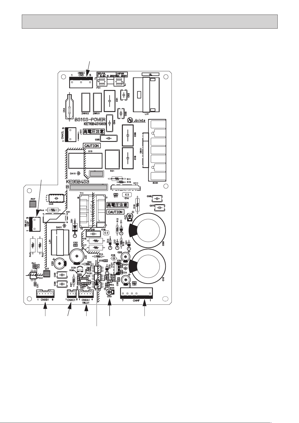
CND
CNXB1 CNXC1
CNXA1 CNMF
PC51
(*1)
C53
(*1)
CNP
CND Power supply voltage (220 - 240VAC)
CNMF Fan motor output
1 - 4: 310 - 340 VDC
5 - 4: 15 VDC
6 - 4: 0 - 6.5 VDC
7 - 4: Stop 0 or 15 VDC
Run 7.5 VDC
(0 - 15 pulse)
CNP Drain-up mechanism output (200VAC)
CNXA1
Connect to the indoor controller board
CNXB1
Connect to the indoor controller board
CNXC1
Connect to the indoor controller board
CNXA2
Connect to the indoor power board
CNXB2
Connect to the indoor power board
CNXC2
Connect to the indoor power board
(*1)
V
FG
Voltage on the (-) side of PC51 and
C25
(Same with the voltage between 7 (+)
and 4 (-) of CNMF)
V
CC
Voltage between the C25 pins 15
VDC
(Same with the voltage between 5 (+)
and 4 (-) of CNMF)
V
sp Voltage between the C53 pins
0VDC (with the fan stopped)
1 - 6.5VDC (with the fan in operation)
(Same with the voltage between 6 (+)
and 4 (-) of CNMF)
31
9-5. TEST POINT DIAGRAM
9-5-1. Power supply board
HWE1309A.qx 3/18/14 10:11 AM Page 31
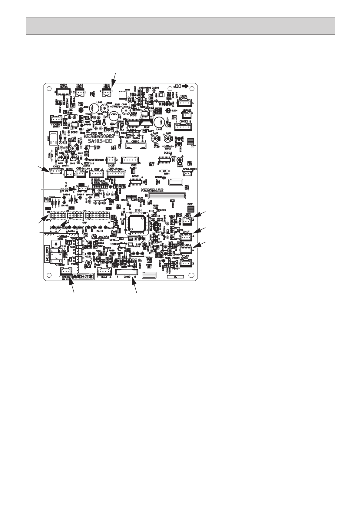
32
9-5-2. Indoor controller board
CN22
CN32
SW1
SW2
SWE
CN3C
CN90
CN44
CN4F
CN20
SWE Emergency operation
SW1 Model selection
SW2 Capacity setting
CN32 Remote start/stop adapter
CN22 For MA remote controller cable con-
nection
(10 - 13 VDC (Between 1 and 3.))
CN51 Centralized control
CN41 JAMA standard HA terminal A
CN44 Thermistor
(liquid/condenser/evaporator
temperature)
CN4F Float thermistor
CN20 Thermistor (Inlet temperature)
CN3C Indoor-outdoor transmission
(0 - 24VDC)
CN90 Wireless remote controller
CNXA2
Connect to the indoor controller board
CNXB2
Connect to the indoor controller board
CNXC2
Connect to the indoor controller board
CNXA1
Connect to the indoor power board
CNXB1
Connect to the indoor power board
CNXC1
Connect to the indoor power board
HWE1309A.qx 3/18/14 10:11 AM Page 32
33
9-6. TROUBLE CRITERION OF MAIN PARTS
Room temperature
thermistor
(TH1)
Condenser/evaporator
temperature thermistor
(TH5)
Measure the resistance with a tester.
(Part temperature 10°C ~ 30°C)
Pipe temperature
thermistor/liquid
(TH2)
Wiring diagram
Check method and criterion
Part name
Normal
4.3kΩ~9.6kΩ
Abnormal
Opened or short-circuited
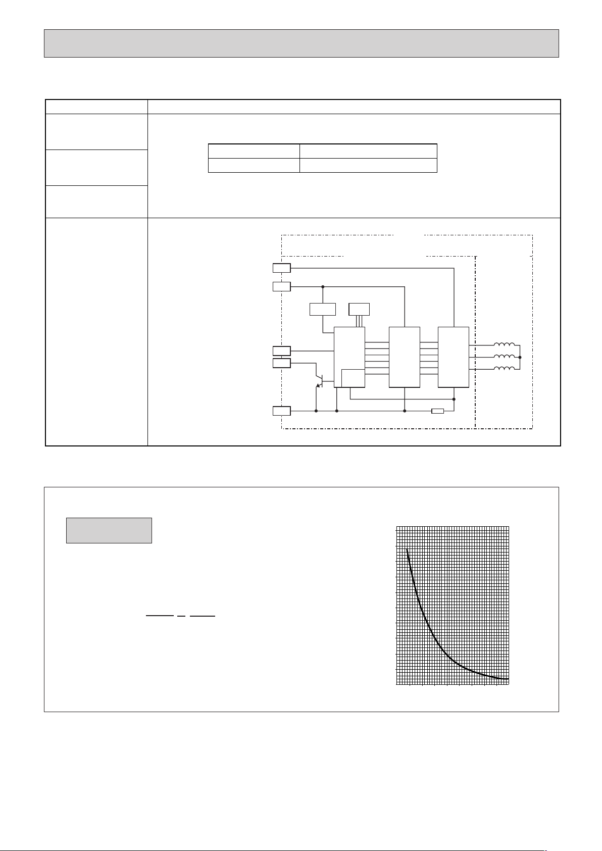
Motor
Board with build-in motor
Current detecting resistor
Regulator Hall IC
Motor winding
Power
device
Pre
driver
Vm (Power supply for motor)
Vcc (Power supply for control)
Vsp (Speed command voltage)
PG (Pulse output for rotation)
GND
9-7. Thermistor
0
10
20
30
40
50
-20 -10 0 10 20 30 40 50
< Thermistor for lower temperature >
Temperature (:)
Resistance (K")
<Thermistor Characteristic graph>
Room temperature thermistor (TH1)
Pipe temperature thermistor (TH2)
Condenser/evaporator temperature
thermistor (TH5)
Thermistor R0=15k" ±3%
Fixed number of B=3480k
" ±2%
Rt=15exp { 3480( ) }
0
: 15k"
10: 9.6k"
20: 6.3k"
25: 5.2k"
30: 4.3k"
40: 3.0k"
Thermistor for
lower temperature
1
273+t
1
273
HWE1309A.qx 3/18/14 10:11 AM Page 33

34
9-8. DC FAN MOTOR (FAN MOTOR/INDOOR CONTROLLER BOARD)
Notes
· High voltage is applied to the connecter (CNMF) for the fan motor. Give attention to the service.
· Do not pull out the connector (CNMF) for the motor with the power supply on.
(It causes trouble of the indoor controller circuit
board and fan motor.)
Self check
Symptom : The indoor fan cannot turn around.
No
NG
NG
Wiring contact check
Contact of fan motor connector (CNMF)
Check the fuse (FUSE) on indoor
controller board.
Power supply check (Remove the connector (CNMF))
Measure the voltage in the indoor controller circuit
board.
TEST POINT
1 :VDC (between 1 (+) and 4 (-) of the fan connector): VDC DC310~340V
TEST POINT 2 :VCC (between 5 (+) and 4 (-) of the fan connector): VCC DC15V
Wiring recovery
Replace drain pump (DP).
Replace indoor controller board.
Replace the fan motor.
Replace indoor controller board (I.B).
Replace fan motor (MF).
Replace indoor
controller board.
Replace the fan motor.
Is the voltage normal?
Is there no contact failure?
Ye s
1
2
Ye s
No
Did the fuse blow?
Check the drain pump (DP)
Is the resistance between
terminals normal?
No
Ye s
Ye s
No
Check the operation of fan. END
Ye s
OK
Check the operation. END
OK
Check method of DC fan motor (fan motor/indoor controller circuit board)
HWE1309A.qx 3/18/14 10:11 AM Page 34
35
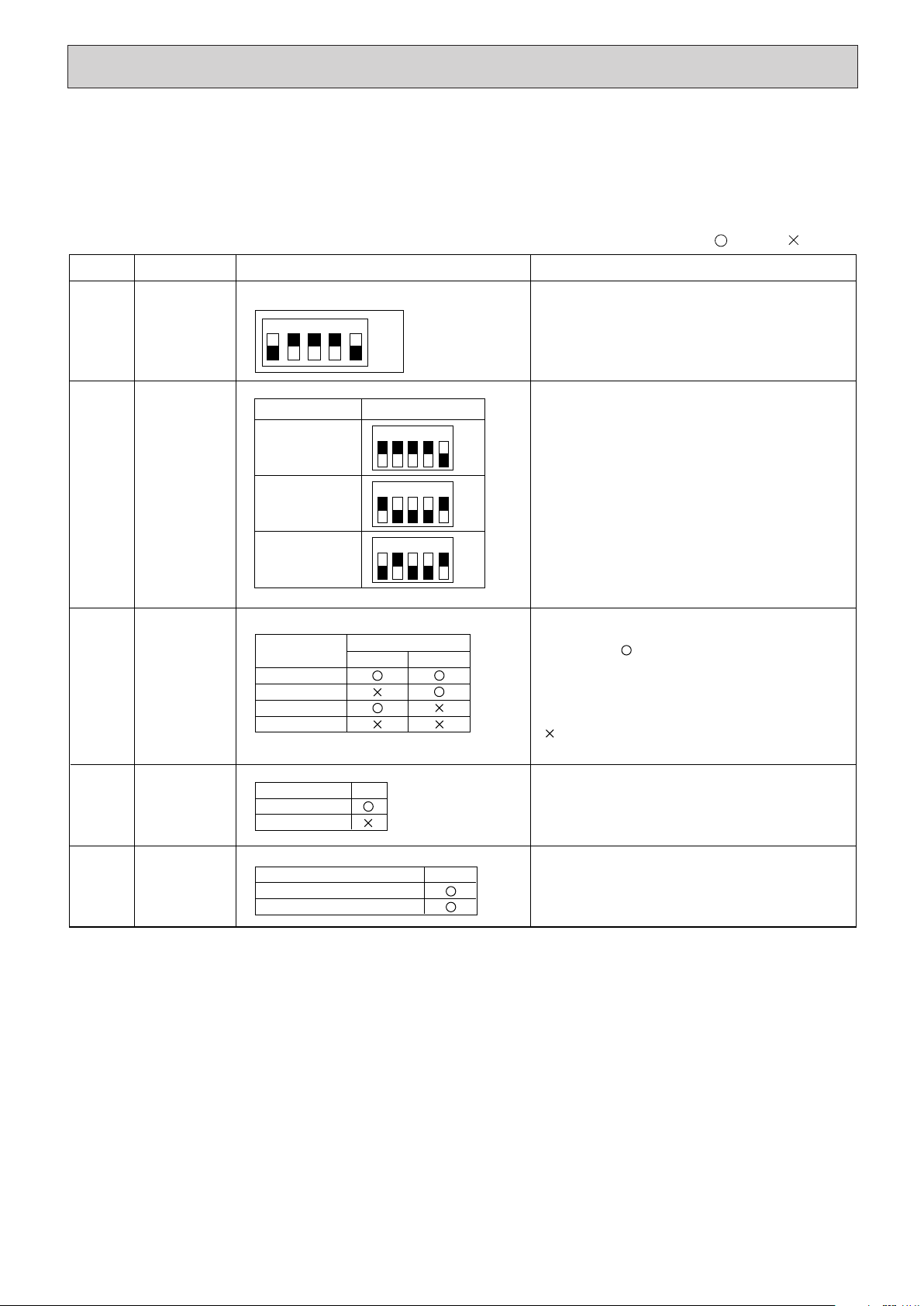
SW1
Setting by the dip switch and jumper wire
Functions
Jumper wire
Model
settings
Capacity
settings
Pair number
setting with
wireless
remote
controller
For service board
Remarks
SW2
J41
J42
Unit type
setting
JP1
Indoor
controller
board type
setting
JP3
* Make sure the above settings are set the same for both boards.
0
1
2
3 ~ 9
Wireless remote
controller setting
Control PCB setting
J41 J42
<Settings at time of factory shipment>
Wireless remote controller: 0
Control PCB: (for both J41 and J42)
Four pair number settings are supported.
The pair number settings of the wireless remote
controller and indoor control PCB (J41/J42) are
given in the table on the left.
(' ' in the table indicates the jumper line is disco-
nnected.)
There is no jumper (JP1) because these models
have the cond./eva. temperature thermistor (TH5).
(Marks in the table below) Jumper wire ( : Short : Open)
Without TH5
With TH5
Model
JP1
Factory shipment
Service parts
Indoor controller board type
JP3
12345
ON
OFF
Service board
MODELS
1 2 3 4 5
PEA-RP125GAA
ON
OFF
1 2 3 4 5
PEA-RP100GAA
ON
OFF
1 2 3 4 5
PEA-RP140GAA
ON
OFF
9-9. FUNCTIONS OF DIP SWITCH AND JUMPER WIRE
Each function is controlled by the dip switch and the jumper wire on control p.c. board.
SW1 and SW2 are equipped only for service parts.
Model setting and capacity setting are memorized in the nonvolatile memory of the control p.c. board of
the unit.
HWE1309A.qx 3/18/14 1:07 PM Page 35
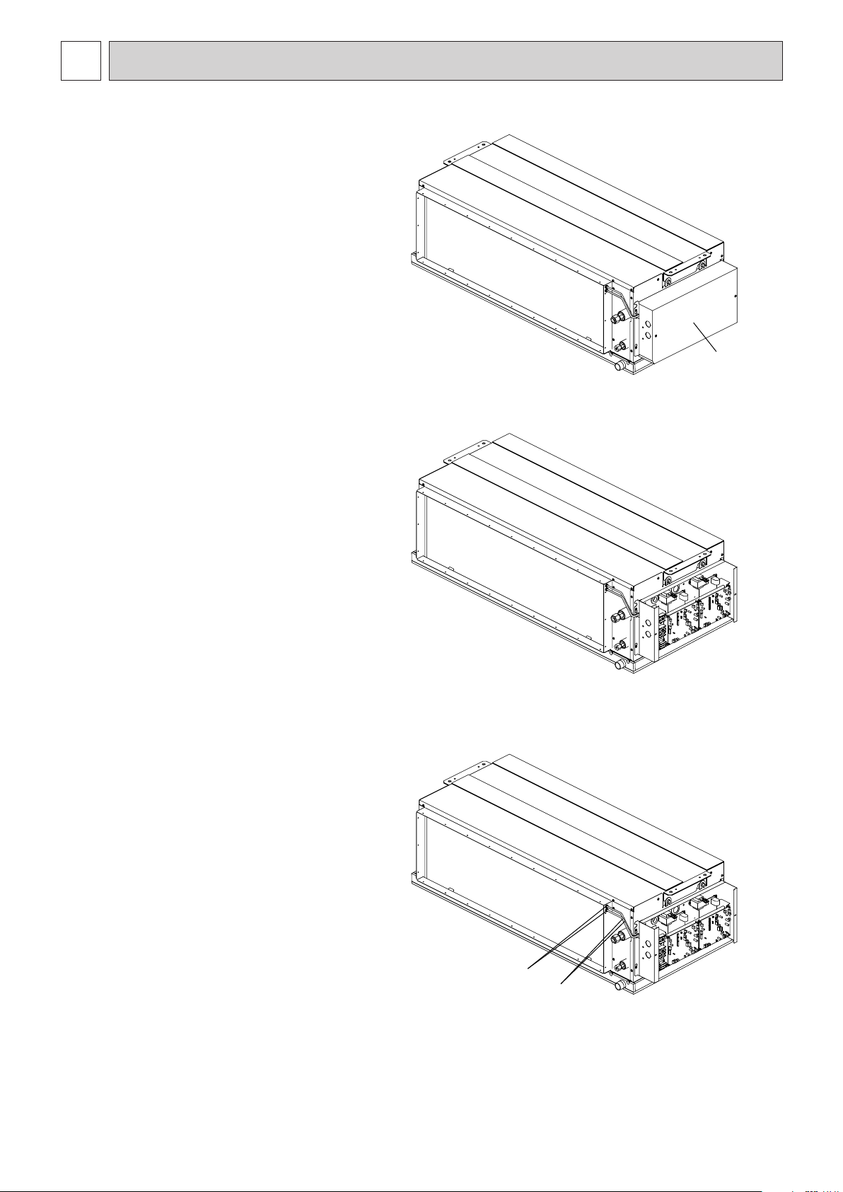
36
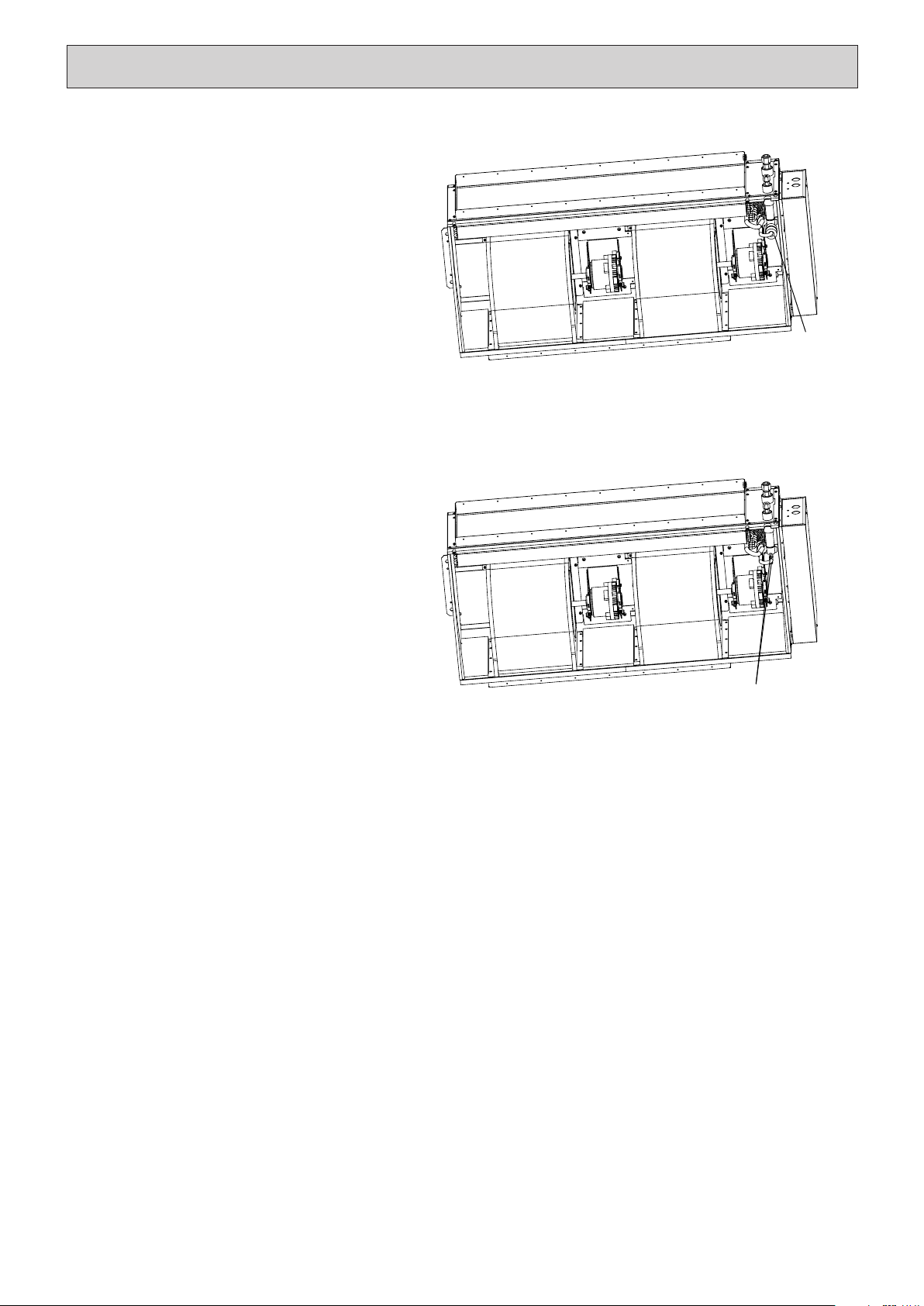
1. Control box
1. Removing the control box cover
(1) Remove the two fixing screws on the cover (A)
to remove it.
2. Thermistor (Intake air)
1. Remove the control box cover according to the
procedure in section [1].
(1) Remove the thermistor holders (D) and (E).
(2) Pull out the thermistor (B), (C) on the control
box.
(A)
Fig. 1-1
Fig. 1-2
(D),(E)
(B),(C)
Fig. 2-1
DISASSEMBLY PROCEDURE
10
Exercise caution when removing heavy parts.
HWE1309A.qx 3/18/14 10:11 AM Page 36
37
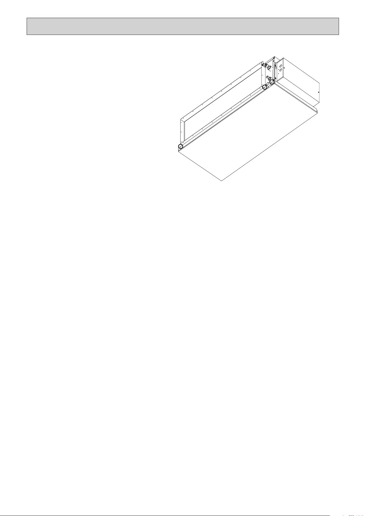
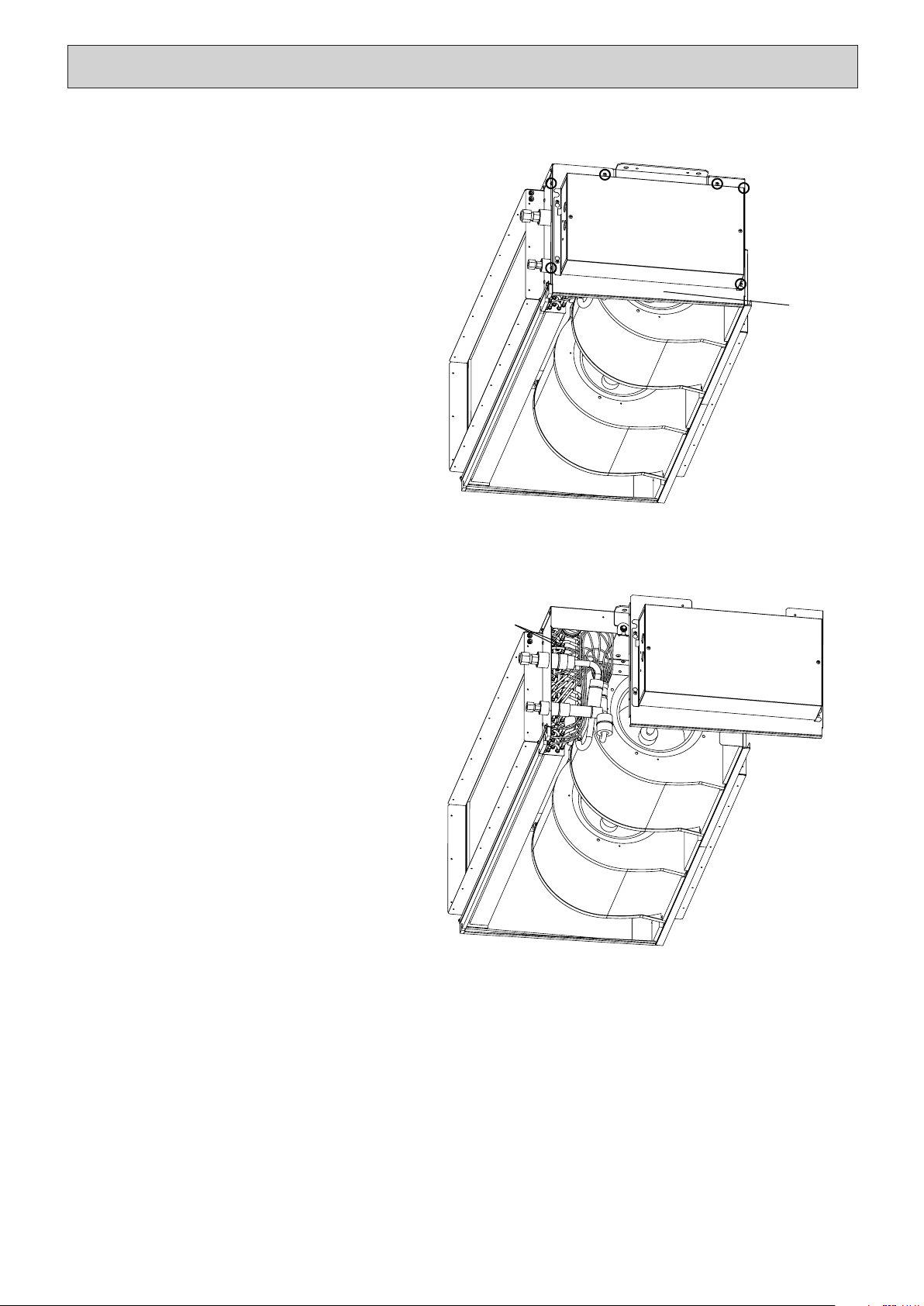
3. Drain pan
Exercise caution when removing heavy parts.
1. Removing the drain pan
(1) Remove the fixing screws on the drain pan to
remove it.
Fig. 3
HWE1309A.qx 3/18/14 10:11 AM Page 37
38
4. Thermistor (Condenser/evaporator)
(Gas pipe)
1. Remove the drain pan according to the proce-
dure in section [3].
2. Removing the heat insulation material.
(1) Cut the cable ties securing the heat insulation
material (F) and remove the heat insulation
material.
3. Removing the thermistor
(1) Remove the thermistor (G), (H) from the ther-
mistor holder (I), (J) on the copper tube.
(F)
Fig. 4-1
(G),(H),(I),(J)
Fig. 4-2
Exercise caution when removing heavy parts.
HWE1309A.qx 3/18/14 10:11 AM Page 38
39
5. Thermistor (Condenser/evaporator)
(Liquid pipe)
1. Remove the drain pan according to the proce-
dure in section [3].
2. Removing the thermistor (Intake air) according
to the procedure in section [2].
3. Removing the side plate.
(1) Remove the screws securing the side plate
(K) and move the side plate sideways.
4. Removing the thermistor
(1) Remove the thermistor (L), (M) from the ther-
mistor holder (N), (O) on the copper tube.
(K)
Fig. 5-1
(L),(M),(N),(O)
Fig. 5-2
Exercise caution when removing heavy parts.
HWE1309A.qx 3/18/14 10:11 AM Page 39
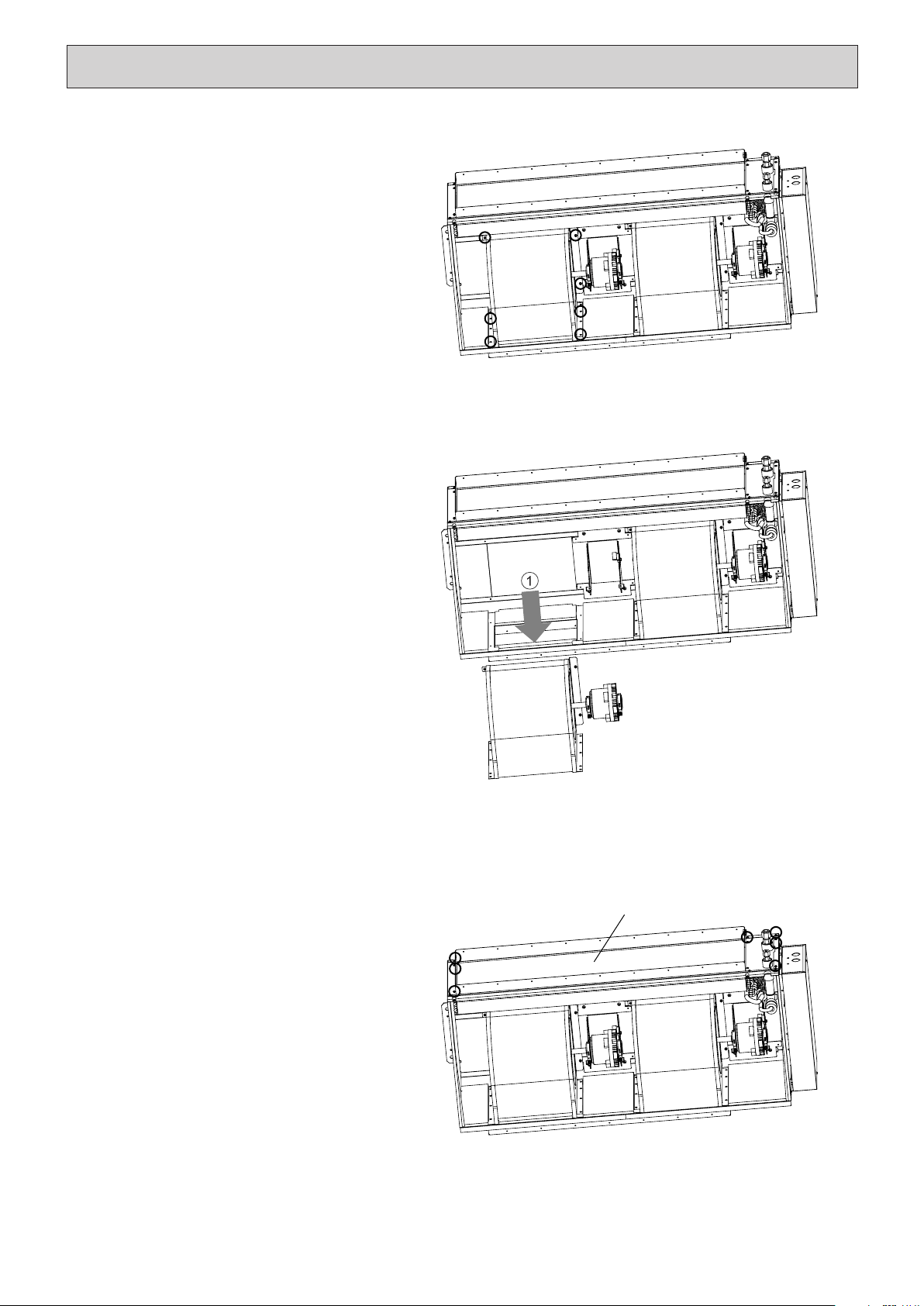
7. Heat exchanger
1. Remove the drain pan according to the proce-
dure in section [3].
2. Removing the Heat exchanger
(1) Remove the fixing screws on the heat
exchanger (P) to remove it.
(P)
Fig. 7
40
Exercise caution when removing heavy parts.
3. Removing the fan casing, fan motor and siroc-
co fan
(1) Remove the fan casing fixing screws and
motor fixing screws and remove the fan and
motor in the direction of the arrow 1.
* Also remove the other fan casing, fan motor,
and Sirocco fan according to the same proce-
dure.
Fig. 6-2
6. Fan and fan motor
1. Remove the drain pan according to the proce-
dure in section [3].
2. Removing the motor cable
(1) Remove the motor cable threw the rubber
bush.
(2) Remove the motor wirings from the cable ties.
Fig. 6-1
HWE1309A.qx 3/18/14 10:11 AM Page 40

HWE1309A.qx 3/18/14 10:11 AM Page 41

HWE1309A.qx 3/18/14 10:11 AM Page 42