Loading ...
Loading ...
Loading ...
10
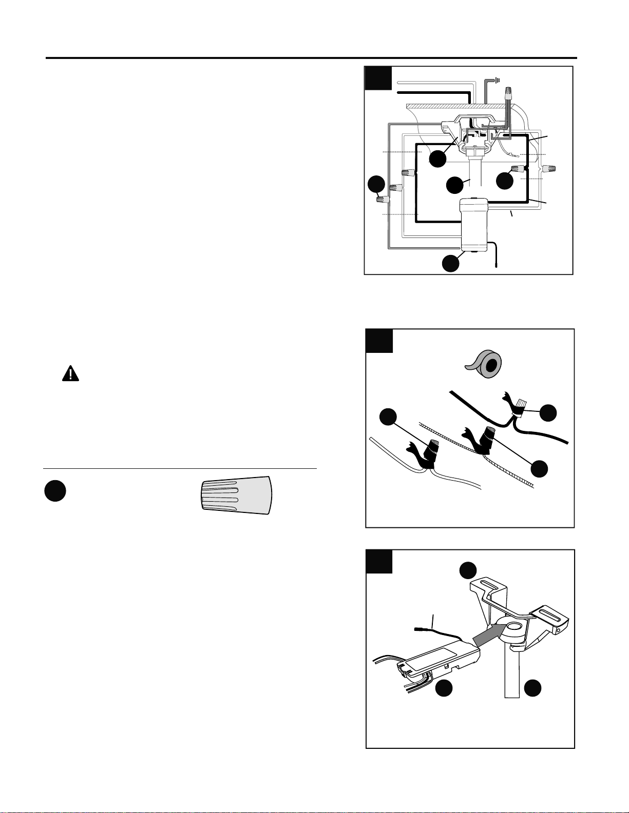
WIRING
Wrap electrical tape (not included) around each
individual wire connector (AA) down to the wire.
WARNING: Make sure no bare wire or wire
strands are visible after making connections. Place
GREEN and WHITE connections on opposite side of
the outlet box from the BLACK and BLUE (if
applicable) connections.
2.
2
Hardware Used
Wire Connector
x 3
AA
AA
AA
AA
3
Gently slide remote control receiver (R) flat-side up
into mounting bracket (C). Turn spliced/taped wires
upward and gently push wires and wire connectors
(CC) into outlet box. Let antenna from remote control
receiver (R) hang to the side.
NOTE: The remote control included with this fan meets
the following requirements:
a. Not for use with solid state fans.
b. Electrical rating: 120V / 60 Hz;
motor amps:1.25 MAX.
Should you choose to use a different remote control
with this fan, it must also meet these same
requirements.
3.
Antenna
A
R
C
(1.)
Connect all GROUND (GREEN) wires from fan (on
downrod (A), if applicable, and mounting bracket (C)) to
BARE/GREEN supply wire from ceiling.
Connect BLACK wire (labeled AC IN L) from remote
control receiver (R) to BLACK supply wire from ceiling.
Connect WHITE wire (labeled AC IN N) from remote
control receiver (R) to WHITE supply wire from ceiling.
Connect WHITE wire (labeled TO MOTOR N) from
remote control receiver (R) to WHITE wire from motor
housing (D).
Connect BLACK wire (labeled TO MOTOR L) from
remote control receiver (R) to BLACK wire from motor
housing (D).
Connect BLUE wire (labeled FOR LIGHT) from remote
control receiver (O) to BLUE wire from motor housing
(D).
R
1
WHITE SUPPLY WIRE
BLACK SUPPLY WIRE
BLACK
BLACK
WHITE
BLUE
BLUE
WHITE
BLACK
AC IN L
WHITE
AC IN N
WHITE
GROUND (GREEN OR BARE)
GROUND
(GREEN OR BARE)
BLACK
FROM
RECEIVER
FROM
FAN
FROM
RECEIVER
FROM
CEILING
AA
AA
A
C
Loading ...
Loading ...
Loading ...