Owner’s manual
SEAT Mii
1SL012720BL
Inglés
1SL012720BL (11.18)
SEAT Mii Inglés (11.18)
SEAT S.A. is permanently concerned about continuous development of its types and models. For this reason we ask you to understand,
that at any given time, changes regarding shape, equipment and technique may take place on the car delivered. For this reason no
right at all may derive based on the data, drawings and descriptions in this current handbook.
All texts, illustrations and standards in this handbook are based on the status of information at the time of printing. Except for error or
omission, the information included in the current handbook is valid as of the date of closing print.
Re-printing, copying or translating, whether total or partial is not allowed unless SEAT allows it in written form.
SEAT reserves all rights in accordance with the “Copyright” Act.
All rights on changes are reserved.
❀
This paper has been manufactured using bleached non-chlorine cellulose.
© SEAT S.A. - Reprint: 15.11.18
Vehicle identification data
Model:
Vehicle Registration:
Vehicle identification
number:
Date of vehicle registration
or vehicle delivery:
SEAT Official Service:
Service advisor:
Telephone:
Confirmation of receipt of documentation
and vehicle keys
The following items were delivered
with the vehicle:
YES NO
On-board documentation
First key
Second key
Correct working order of all keys was
checked
Location:
Date:
Signature of owner:

Introduction
Thank you f
or your trust choosing a SEAT v
e-
hicl
e.
With your new SEAT, you will be able to enjoy
a vehicle with state-of-the-art technology
and top quality features.
We recommend reading this Instruction Man-
ual carefully to learn more about your vehicle
so you can enjoy all its benefits in your daily
driving.
Information about handling is complemented
with instructions regarding the operation and
maintenance of the vehicle in order to ensure
its safety and maintain its value. Moreover, we
want to give you valuable advice and tips to
drive your vehicle efficiently and respecting
the environment.
We wish you safe and enjoyable motoring.
SEAT, S.A.
WARNING
Read and always observe safety infor-
mation concerning the passenger's
front airbag
›
››
page 66, Important in-
formation regarding the front passeng-
er's airbag.
About this manual
This manual describes the f
eat
ur
es of the ve-
hicle at the time of drafting this text. Some of
the features described below will be intro-
duced in the future or will only be available in
certain markets.
Some of the features described here are
not included in all the types or variations
of the model and they can be varied or
modified based on technical or marketing
requirements without it being considered
misleading advertising.
Some details on the drawings may vary from
its vehicle and must be interpreted as a
standard representation.
The direction indicators (left, right, forwards,
backwards) in this manual refer to the travel
direction of the vehicle unless otherwise sta-
ted.
The audiovisual material is only meant to
help the users better understand some fea-
tures of the car. It is not a replacement for the
instruction manual. Access the instruction
manual to see the complete information and
warnings.
The features marked with an asterisk
are included by default only in certain
versions of the model, supplied as op-
tional only for certain versions or only of-
fered in certain countries.
Trademarks are marked with ®. The ab-
sence of this symbol does not guarantee
that the term is not a trademark.
It indicates that the section continues on
the next page.
Important warnings on the page.
More in-depth content on the page.
General information on page indicated.
Emergency information on the page.
You can access the information in this manual
using:
●
Thematic table of contents that follows the
manual’s general chapter structure.
●
Visual table of contents that uses graphics
to indicate the pages containing “essential”
information, which is detailed in the corre-
sponding chapters.
●
Alphabetical index with many terms and
synonyms to help you find information.
WARNING
Texts after this symbol contain informa-
tion about safety and w
arn you about
possible accident or injury risks.
®
CAUTION
Texts after this symbol indicate possible
damage to the vehicl
e.
For the sake of the environment
Texts after this symbol contain informa-
tion about the protection of the envir
on-
ment.
Note
Texts after this symbol contain addition-
al information.
Printed Instruction Manual
The print
ed instruction manual cont
ains r
ele-
vant information about the use of the vehicle
and the Infotainment System.
The digital version of the manuals contains
more in-depth information.
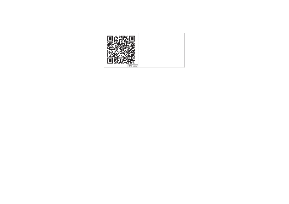
Digital Version of the Infotainment
Syst
em Manual
Fig. 1 SEAT website
The digital version is available on SEAT's offi-
cial website
.
To view the digital version of the manual:
●
scan the QR code
›››
Fig. 1
●
OR enter the following address in the navi-
gator website:
http://www.seat.com/owners/your-
seat/manuals-offline.html
choose your v
ehicle and then “Infotainment”.

Frequently Asked Ques-
tions
Before driving
How do you adjust the seat?
›››
page 14
How do you adjust the steering wheel?
›››
page 15
How do you adjust the exterior mirrors?
›››
page 15
How do you turn on the exterior lights?
›››
page 22
How does the automatic gearbox selector lever
work?
››
›
page 28
How do you refuel?
›
›
›
page 32
How do you activate the windscreen wipers and
windscreen washer system?
›››
page 24
Emergency situations
A warning lamp lights up or flashes. What does
this mean?
›››
page 27
Where are the first-aid kit and the warning trian-
gle in the vehicl
e?
›››
page 70
How do you open the bonnet?
›››
page 12
How do you perform a jump start?
›››
page 44
Where is the vehicle tool kit located?
›››
page 70
How do you repair a tyre with the anti-puncture
kit?
›››
page 36
How do you change a wheel?
›››
page 37
How do you change a fuse?
›››
page 35
How do you change a light?
›››
page 79
How do you tow a vehicle?
›››
page 43
Useful tips
How do you set the time?
›››
page 89
When should the vehicle inspection should be
performed?
››
›
page 90
How do you remove the luggage compartment
cover?
›
››
page 125
How do you drive in an economical and environ-
mentally-friendly way?
›
››
page 166
How do you check and top up the engine oil?
›››
page 32
How do you check and top up the engine cool-
ant?
›››
page 33
How do you top up the windscreen washer fluid?
›››
page 34
How do you check and top up the brake fluid?
›››
page 34
How do you check and adjust tyre pressure val-
ues?
›››
page 209
Vehicle washing tips
›››
page 220
Functions of interest
How does the START-STOP system work?
›››
page 170
What parking assistants are available?
›››
page 172
How does tyre pressure monitoring work?
›››
page 212
Interior lighting
›››
page 24

Table of Contents
Table of Contents
The essential
s
. . . . . . . . . . . . . . . . . . . . . . . . . .
7
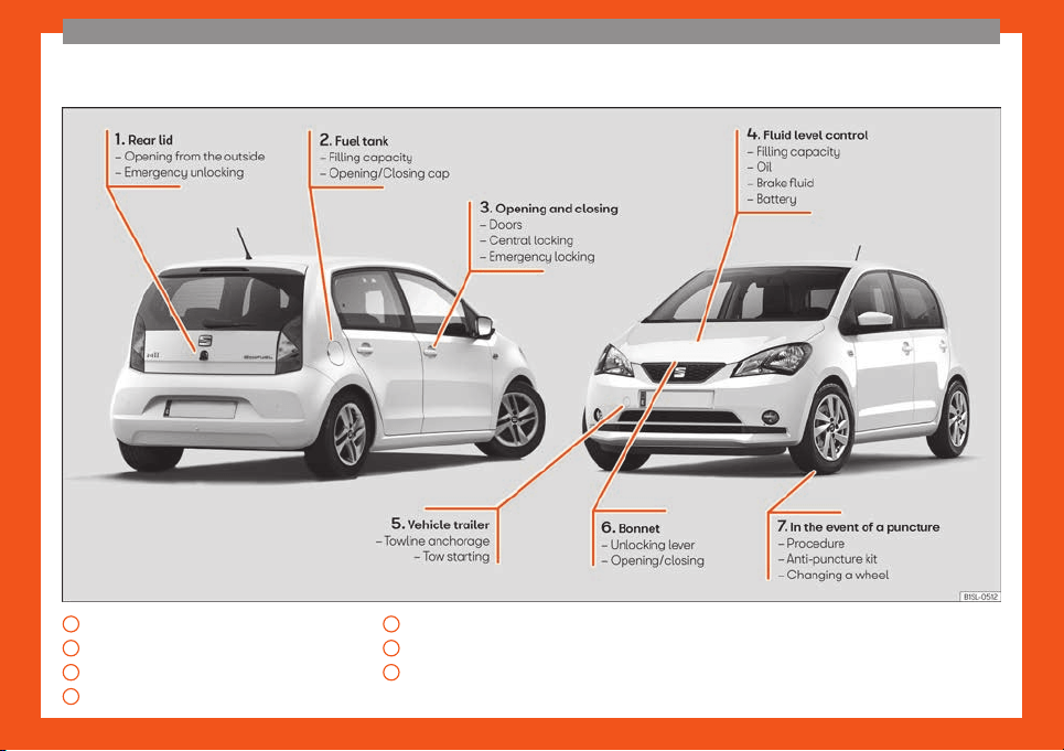
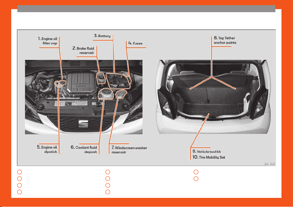
Exterior view . . . . . . . . . . . . . . . . . . . . . . . . . . . . . . . 7
Exterior view . . . . . . . . . . . . . . . . . . . . . . . . . . . . . . . 8
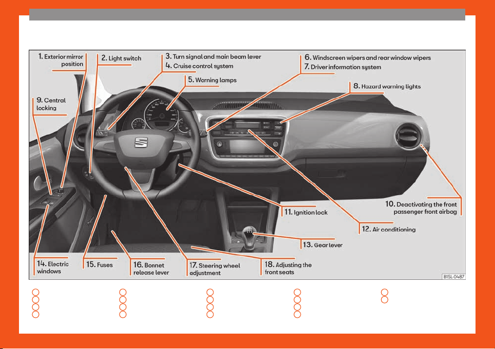
Interior view (left-hand drive) . . . . . . . . . . . . 9
How it works . . . . . . . . . . . . . . . . . . . . . . . . . . . . . . . 10
Unlocking and locking . . . . . . . . . . . . . . . . . . . . . . 10
Before driving . . . . . . . . . . . . . . . . . . . . . . . . . . . . . . 14
Airbags . . . . . . . . . . . . . . . . . . . . . . . . . . . . . . . . . . . . . 16
Child seats . . . . . . . . . . . . . . . . . . . . . . . . . . . . . . . . . 18
Starting the vehicle . . . . . . . . . . . . . . . . . . . . . . . . . 22
Lights and visibility . . . . . . . . . . . . . . . . . . . . . . . . . 22
SEAT information system . . . . . . . . . . . . . . . . . . . 24
Cruise control . . . . . . . . . . . . . . . . . . . . . . . . . . . . . . 26
Warning lamps . . . . . . . . . . . . . . . . . . . . . . . . . . . . . 27
Gearbox lever . . . . . . . . . . . . . . . . . . . . . . . . . . . . . . 28
Air conditioning . . . . . . . . . . . . . . . . . . . . . . . . . . . . . 29
Fluid level control . . . . . . . . . . . . . . . . . . . . . . . . . . . 32
Emergencies . . . . . . . . . . . . . . . . . . . . . . . . . . . . . . 35
Fuses . . . . . . . . . . . . . . . . . . . . . . . . . . . . . . . . . . . . . . . 35
Bulbs . . . . . . . . . . . . . . . . . . . . . . . . . . . . . . . . . . . . . . . 36
Action in the event of a puncture . . . . . . . . . . . 36
Changing a wheel . . . . . . . . . . . . . . . . . . . . . . . . . . 37
Snow chains . . . . . . . . . . . . . . . . . . . . . . . . . . . . . . . . 42
Emergency towing of the vehicle . . . . . . . . . . . 43
How to jump start . . . . . . . . . . . . . . . . . . . . . . . . . . . 44
Changing the wiper blades . . . . . . . . . . . . . . . . 46
Safety . . . . . . . . . . . . . . . . . . . . . . . . . . . . . . . . . . . . 48
Safe driving . . . . . . . . . . . . . . . . . . . . . . . . . . . . . . . 48
Driving advice . . . . . . . . . . . . . . . . . . . . . . . . . . . . . . 48
Correct position of the vehicle occu-
pants . . . . . . . . . . . . . . . . . . . . . . . . . . . . . . . . . . . . . . . 49
Pedal area . . . . . . . . . . . . . . . . . . . . . . . . . . . . . . . . . 53
Seat belts . . . . . . . . . . . . . . . . . . . . . . . . . . . . . . . . . 53
Why wear a set belt . . . . . . . . . . . . . . . . . . . . . . . . 53
How to properly adjust your seat belt . . . . . . 57
Seat belt tensioners . . . . . . . . . . . . . . . . . . . . . . . . 59
Airbag system . . . . . . . . . . . . . . . . . . . . . . . . . . . . . 60
Brief introduction . . . . . . . . . . . . . . . . . . . . . . . . . . . 60
Airbag safety instructions . . . . . . . . . . . . . . . . . . . 63
Deactivating airbags . . . . . . . . . . . . . . . . . . . . . . . 64
Transporting children safely . . . . . . . . . . . . . . 65
Safety for children . . . . . . . . . . . . . . . . . . . . . . . . . . 65
Child seats . . . . . . . . . . . . . . . . . . . . . . . . . . . . . . . . . 67
Emergencies . . . . . . . . . . . . . . . . . . . . . . . . . . . . 70
Self-help . . . . . . . . . . . . . . . . . . . . . . . . . . . . . . . . . . 70
In case of emergency . . . . . . . . . . . . . . . . . . . . . . 70
Vehicle tool kit* . . . . . . . . . . . . . . . . . . . . . . . . . . . . . 70
Changing a wheel . . . . . . . . . . . . . . . . . . . . . . . . . . 72
Tyre repair . . . . . . . . . . . . . . . . . . . . . . . . . . . . . . . . . . 73
Changing the windscreen wiper blades . . . . 75
Tow-starting and towing . . . . . . . . . . . . . . . . . . . . 75
Emergency locking and unlocking . . . . . . . . . . 77
Fuses and bulbs . . . . . . . . . . . . . . . . . . . . . . . . . . . 78
Fuses . . . . . . . . . . . . . . . . . . . . . . . . . . . . . . . . . . . . . . . 78
Changing bulbs . . . . . . . . . . . . . . . . . . . . . . . . . . . . 79
Operation . . . . . . . . . . . . . . . . . . . . . . . . . . . . . . . 87
General instrument panel . . . . . . . . . . . . . . . . 87
Instrument panel . . . . . . . . . . . . . . . . . . . . . . . . . . . 86
Instruments . . . . . . . . . . . . . . . . . . . . . . . . . . . . . . . . . 88
Opening and closing . . . . . . . . . . . . . . . . . . . . . . 92
Vehicle key set . . . . . . . . . . . . . . . . . . . . . . . . . . . . . 92
Central locking* and locking system . . . . . . . 94
Doors . . . . . . . . . . . . . . . . . . . . . . . . . . . . . . . . . . . . . . 98
Rear lid . . . . . . . . . . . . . . . . . . . . . . . . . . . . . . . . . . . . . 99
Controls for the windows . . . . . . . . . . . . . . . . . . . 101
Sliding/tilting electric panoramic sunroof . . . 102
Lights and visibility . . . . . . . . . . . . . . . . . . . . . . . . 103
Lights . . . . . . . . . . . . . . . . . . . . . . . . . . . . . . . . . . . . . . . 103
Visibility . . . . . . . . . . . . . . . . . . . . . . . . . . . . . . . . . . . . 108
Windscreen wiper and window wiper sys-
tems . . . . . . . . . . . . . . . . . . . . . . . . . . . . . . . . . . . . . . . . 108
Mirror . . . . . . . . . . . . . . . . . . . . . . . . . . . . . . . . . . . . . . . 110
Seats and head restraints . . . . . . . . . . . . . . . . 112
Adjusting the seat and head restraints . . . . . . 112
Seat functions . . . . . . . . . . . . . . . . . . . . . . . . . . . . . . 113
Transport and practical equipment . . . . . . 114
Transporting objects . . . . . . . . . . . . . . . . . . . . . . . 114
Practical equipment . . . . . . . . . . . . . . . . . . . . . . . . 115
Luggage compartment . . . . . . . . . . . . . . . . . . . . . 122
Roof carrier . . . . . . . . . . . . . . . . . . . . . . . . . . . . . . . . 127
Air conditioning . . . . . . . . . . . . . . . . . . . . . . . . . . . 129
Heating, ventilation and air conditioning . . . . 129
Infotainment System . . . . . . . . . . . . . . . . . . 133
Introduction . . . . . . . . . . . . . . . . . . . . . . . . . . . . . . . 133
Safety warnings . . . . . . . . . . . . . . . . . . . . . . . . . . . . 133
Overview of the unit . . . . . . . . . . . . . . . . . . . . . . . . 135
General operating information . . . . . . . . . . . . . 137
Audio Mode . . . . . . . . . . . . . . . . . . . . . . . . . . . . . . . . 139
Radio Mode . . . . . . . . . . . . . . . . . . . . . . . . . . . . . . . . 139
Media Mode . . . . . . . . . . . . . . . . . . . . . . . . . . . . . . . . 141
Phone management* . . . . . . . . . . . . . . . . . . . . . . 145
Drive Mii App* . . . . . . . . . . . . . . . . . . . . . . . . . . . . . . 147
Driving . . . . . . . . . . . . . . . . . . . . . . . . . . . . . . . . . . . 149
Start and driving . . . . . . . . . . . . . . . . . . . . . . . . . . 149
Stopping and starting the engine . . . . . . . . . . . 149
Braking and parking . . . . . . . . . . . . . . . . . . . . . . . . 151
Braking and stability systems . . . . . . . . . . . . . . . 156
Changing gear . . . . . . . . . . . . . . . . . . . . . . . . . . . . . 158
Steering . . . . . . . . . . . . . . . . . . . . . . . . . . . . . . . . . . . . 163
Run-in and economical driving . . . . . . . . . . . . . 165
5

Table of Contents
Engine management and exhaust gas puri-
fication syst
em . . . . . . . . . . . . . . . . . . . . . . . . . . . . .
168
Driving tips . . . . . . . . . . . . . . . . . . . . . . . . . . . . . . . . .
169
Driver assistance systems . . . . . . . . . . . . . . . . 170
Start-Stop system . . . . . . . . . . . . . . . . . . . . . . . . . . 170
Cruise control system (CCS)* . . . . . . . . . . . . . . 171
Parking distance warning system* . . . . . . . . . 172
City safety assist (Safety Assist)* . . . . . . . . . . . 174
Hill driving assistant* . . . . . . . . . . . . . . . . . . . . . . . 179
Towing bracket device . . . . . . . . . . . . . . . . . . . . 179
Driving with a trailer . . . . . . . . . . . . . . . . . . . . . . . . 179
Practical tips . . . . . . . . . . . . . . . . . . . . . . . . . . . 180
Care and maintenance . . . . . . . . . . . . . . . . . . . 180
Accessories, replacement of parts and
modifications . . . . . . . . . . . . . . . . . . . . . . . . . . . . . . . 180
Checking and refilling levels . . . . . . . . . . . . . 186
Fuel . . . . . . . . . . . . . . . . . . . . . . . . . . . . . . . . . . . . . . . . 186
Filling the tank . . . . . . . . . . . . . . . . . . . . . . . . . . . . . . 189
Bonnet . . . . . . . . . . . . . . . . . . . . . . . . . . . . . . . . . . . . . 193
Engine oil . . . . . . . . . . . . . . . . . . . . . . . . . . . . . . . . . . . 195
Engine coolant . . . . . . . . . . . . . . . . . . . . . . . . . . . . . 198
Brake fluid . . . . . . . . . . . . . . . . . . . . . . . . . . . . . . . . . . 200
Windscreen washer reservoir . . . . . . . . . . . . . . . 201
Vehicle battery . . . . . . . . . . . . . . . . . . . . . . . . . . . . . 202
Wheels and tyres . . . . . . . . . . . . . . . . . . . . . . . . . 206
Tyres . . . . . . . . . . . . . . . . . . . . . . . . . . . . . . . . . . . . . . . 206
Maintenance . . . . . . . . . . . . . . . . . . . . . . . . . . . . 217
Service . . . . . . . . . . . . . . . . . . . . . . . . . . . . . . . . . . . . 217
Service intervals . . . . . . . . . . . . . . . . . . . . . . . . . . . . 217
Additional service offers . . . . . . . . . . . . . . . . . . . . 219
Warranty . . . . . . . . . . . . . . . . . . . . . . . . . . . . . . . . . . . 220
Vehicle maintenance . . . . . . . . . . . . . . . . . . . . . 220
Maintenance and cleaning . . . . . . . . . . . . . . . . . 220
Information for the user . . . . . . . . . . . . . . 226
Information for the user . . . . . . . . . . . . . . . . . . . 226
Information stored in control units . . . . . . . . . . 226
Other important information . . . . . . . . . . . . . . . . 227
Information about the EU Directive
2014/53/EU . . . . . . . . . . . . . . . . . . . . . . . . . . . . . . . . 229
Technical data . . . . . . . . . . . . . . . . . . . . . . . . . 233
Technical features . . . . . . . . . . . . . . . . . . . . . . . . 233
Important information . . . . . . . . . . . . . . . . . . . . . . 233
Wheels . . . . . . . . . . . . . . . . . . . . . . . . . . . . . . . . . . . . . 234
Engine data . . . . . . . . . . . . . . . . . . . . . . . . . . . . . . . . 235
Vehicle data . . . . . . . . . . . . . . . . . . . . . . . . . . . . . . . . 237
Index . . . . . . . . . . . . . . . . . . . . . . . . . . . . . . . . . . . . . . 239
6
The essentials
How it works
Unl
ocking and l
ocking
Doors
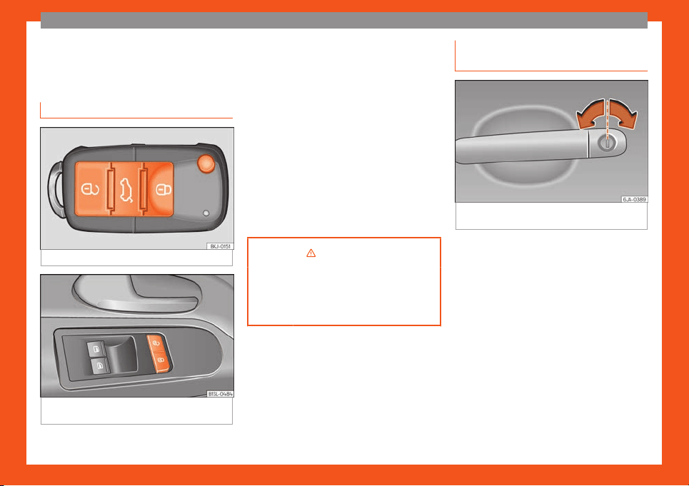
Fig. 2
Remote control key: keys.
Fig. 3 On the driver's door: central locking but-
t
on.
Locking and unlocking the vehicle using
the k
ey
●
L
ocking: pr
ess the button
›››
Fig. 2.
●
Unlocking: press the button
›››
Fig. 2.
●
Unlock the trunk lid: hold down the
›››
Fig. 2 button for at least 1 second.
Locking and unlocking with the central
locking switch
●
Locking: press the button
›››
Fig. 3. None
of the doors can be opened from the outside.
The doors can be opened from the inside by
pulling the inside door handle.
●
Unlocking: press the button
›››
Fig. 3.
›››
in Introduction on page 94
›››
page 94
›››
page 1
1
Locking and unlocking the driver
door manually
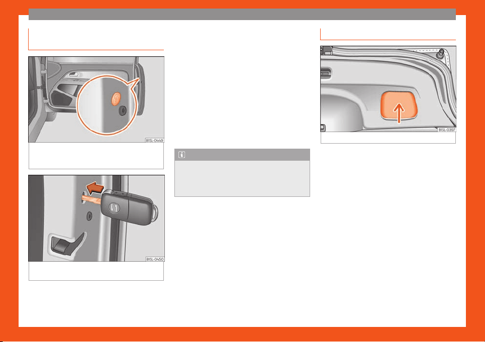
Fig. 4
Driver-side door handle with lock cylin-
der
.
As a general rule, when the driver door is
l
ock
ed all other doors ar
e locked. Unlocking
manually only opens the driver door.
●
Unfold the key shaft if necessary
›››
page 92.
●
Insert the key shaft into the lock cylinder to
unlock or lock the vehicle
›››
Fig. 4.
10
The essentials
Locking the passenger door man-
ually
Fig. 5
On the front part of the passenger door:
emer
gency l
ocking, hidden behind a rubber
gask
et.
Fig. 6
Emergency locking of the vehicle using
the v
ehicl
e k
ey
The passenger door can be manually locked.
●
Open the door.
●
R
emo
v
e the rubber cap to the front of the
door. The rubber cap is marked with a lock
symbol
›››
Fig. 5.
●
Unfold the key shaft if necessary
›››
page 92.
●
Insert the key shaft horizontally into the
opening and moved the coloured lever for-
ward
›››
Fig. 6.
●
Replace the rubber cap and close the door.
●
Check if the door is locked.
●
Have the vehicle checked by a specialised
workshop.
Note
The doors can be opened and unlocked in-
dividually from the inside by pulling the
door handle
. To open, pull the inner door
release lever twice
›››
page 94.
Rear lid
Fig. 7
Rear lid open: space for pulling.
Opening
●
Press the butt
on on the v
ehicl
e key
›››
Fig. 2 for about one second to unlock the
rear lid.
●
Insert the vehicle key into the lock cylinder
of the driver door and turn the key in an anti-
clockwise direction
›››
page 94.
Closing
●
Grab the handgrip inside the rear lid
›››
Fig. 7 (arrow).
●
Push the rear lid downwards until it locks in-
to place in the lock.
●
Ensure that it is correctly closed by pulling
on it firmly.
»
11
The essentials
›››
in Introduction on page 99
›››
page 99
›››
page 12
Manual release mechanism for the
rear lid
Fig. 8
From the trunk: emergency unlocking of
the r
ear lid.
●
If necessary, fold the rear seat bench back-
r
est f
orw
ard
›››
page 14.
●
Remove equipment to access the inside of
the rear lid.
●
Unfold the key shaft
›››
page 92.
●
Insert the key shaft into the rear lid opening
›››
Fig. 8 and press the release lever in the di-
rection of the arrow to unlock the rear lid.
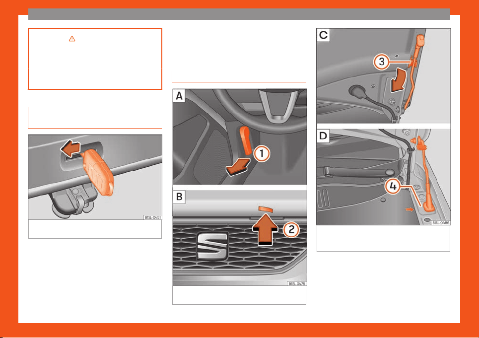
Bonnet
Fig. 9
A: Release lever in the footwell on the
driv
er side B: R
el
ease lever on the bonnet
Fig. 10 C: Bonnet securing rod in the bonnet.
D: Bonnet support
ed by the bonnet securing
r
od
Opening the bonnet
The bonnet is r
el
eased fr
om inside the vehi-
cle.
Before opening the bonnet, make sure that
the windscreen wiper arms are in place
12
The essentials
against the windscreen
›
›
›
in Working in
the engine compar
tment on page 194
.
●
Pull the r
elease lever
›››
Fig. 9
1
in the di-
r
ection of the arr
o
w. The bonnet is released
from the lock carrier by a spring mechanism
›››
in Working in the engine compart-
ment on page 194.
●
Lift the bonnet up slightly while pressing the
r
el
ease l
ever
2
in the direction of the arrow
t
o compl
et
ely open the bonnet.
●
Take out the bonnet support rod from its
clip in the direction of the arrow
3
and place
it in the corr
esponding open position
4
(ar-
r
o
w).
Cl
osing the bonnet
●
Slightly lift the bonnet.
●
Release the bonnet stay and replace it in its
support.
●
At a height of approximately 30 cm let it fall
so it locks.
If the bonnet does not close, do not press
downwards. Open it again and let it fall as
mentioned above.
›››
in Working in the engine com-
partment on page 193
›››
page 193
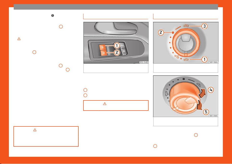
Controls for the windows
Fig. 11
On the driver door: buttons for front
el
ectric windo
ws.
●
Opening the window: press the button .
●
Closing the window: pull the button .
Windo
w on the fr
ont l
eft door
Window on the front right door
›››
in Opening and closing the win-
dows electrically on page 101
1
2
Panoramic sunroof*
Fig. 12
On the internal roof: turn the knob to
open and cl
ose
Fig. 13 On the internal roof: press or pull the
knob t
o r
aise the sunr
oof and close it.
To raise the sliding/tilting sunroof, the knob
must be in the basic position
1
.
●
Open: turn the switch to position
›
›
›
Fig. 12
3
.
»
13
The essentials
●
Comf
ort position: t
urn the s
witch to position
›››
Fig. 12
2
.
●
Close: turn the switch to position
›
›
›
Fig. 12
1
.
●
Lift: Push the switch to position
›
›
›
Fig. 13
4
.
F
or an int
ermediat
e position, hold down the
switch until you reach the desired position.
●
Lower: pull the switch to position
›››
Fig. 13
5
. For an intermediate position, hold down
the s
wit
ch until you r
each the desired posi-
tion.
›››
in Opening and closing the
panoramic sunroof on page 102
›››
page 102
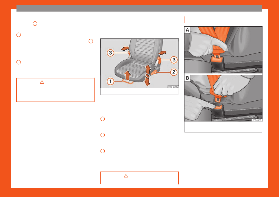
Before driving
Manually adjusting the seats
Fig. 14 Front left seat controls
The front seat head restraints are integrated
in the backr
ests and adjusting them is not
possibl
e
.
Forwards/backwards: pull the lever and
move the seat. The front seat must be en-
gaged when the lever is released!
Raise/lower: pull the lever up or push
down (several times if necessary) from its
home position.
Tilt backrest: pull the lever and adjust
the backrest seat angle until you reach
the desired position. The seat backrest
must be engaged.
›››
in Manual front seat adjust-
ment on page 112
1
2
3
Seat belt adjustment
Fig. 15
Positioning and removing the seat belt
buckl
e
.
14
The essentials
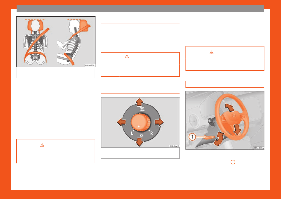
Fig. 16 Correct seat belt and head restraint
positions, viewed fr
om front and the side.
To adjust the seat belt around your shoulders,
adjust the height of the seats.
The shoul
der part of the seat belt shoul
d be
w
ell centred over it, never over the neck. The
seat belt lies flat and fits comfortably on the
upper part of the body.
The lap part of the seat belt lies across the
pelvis, never across the stomach. The seat
belt lies flat and fits comfortably on the pel-
vis.
›››
in Introduction on page 53
›››
page 57
Seat belt tensioners
During a head-on, lateral or rear collision, the
seat belts on the front seats tighten aut
omati-
cally.
The tensioner can be triggered only once.
›››
in Service and disposal of belt
tension devices on page 59
›
››
page 59
Adjusting the exterior mirrors
Fig. 17
On the driver door: rotating control for
el
ectric windo
ws.
Adjusting the exterior mirrors: Turn the knob to
the corr
esponding position:
T
urning the knob t
o the desired position,
adjust the mirrors on the driver side (L,
L/R
left) and the passenger side (R, right) to
the direction desired.
Depending on the equipment fitted on
the vehicle, the mirrors may be heated
according to the outside temperature.
›››
in Exterior mirrors on page 111
›››
page 1
1
1
Adjusting the steering wheel
Fig. 18
Mechanical steering wheel adjustment
●
Push the lever
›
›
›
Fig. 18
1
downwards.
●
Adjust the steering wheel so that you can
hol
d ont
o the st
eering wheel with both hands
on the outside of the ring at the 9 o'clock and
»
15
The essentials
3 o'clock positions and your arms slightly
bent.
●
Firmly push the lever upwards as far as it
will go
›
›
›
in Adjusting the steering wheel
position on page 50.
›››
in Adjusting the steering wheel
position on page 50
›››
page 50
Airbags
Fr
ont airbags
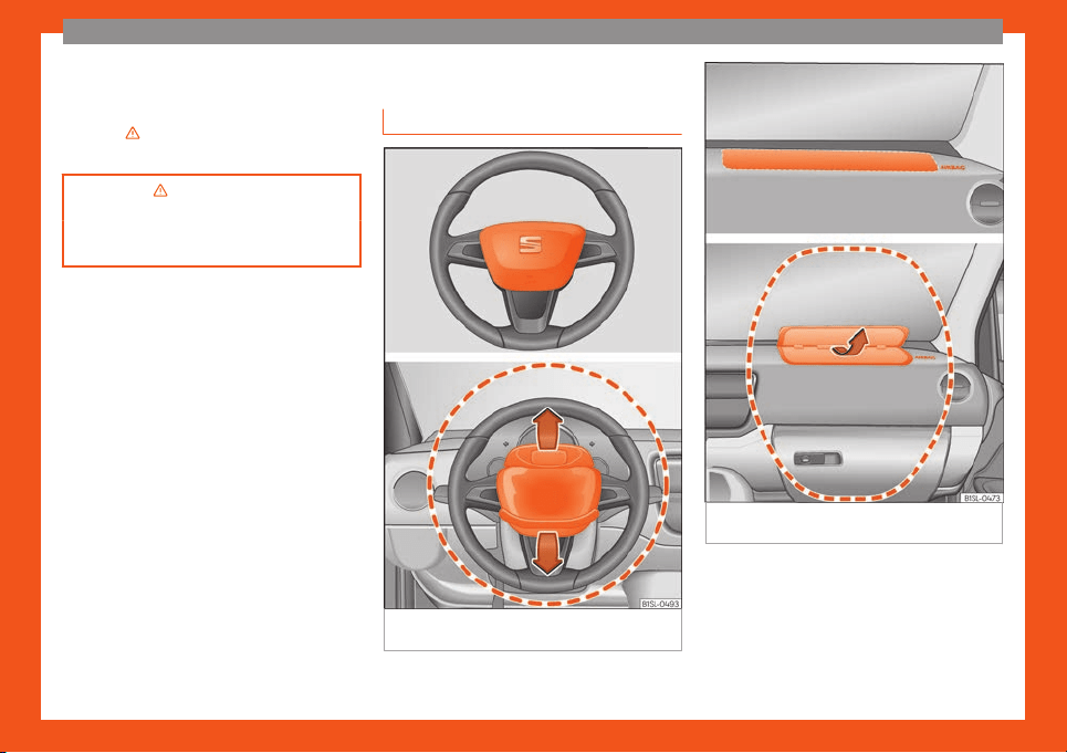
Fig. 19
Location and deployment area of the
fr
ont airbag f
or the driv
er.
Fig. 20 Location and deployment area of the
fr
ont airbag f
or the passenger
.
In conjunction with the seat belts, the front
airbag syst
em giv
es the driv
er and the front
passenger additional protection for the head
and chest in the event of a severe frontal col-
lision. Always remain as far away as possible
from the front airbag
›››
page 49. This
16
The essentials
way, in the event of an accident, the front air-
bags can depl
oy fully when trigger
ed, pr
ovid-
ing maximum protection.
The front airbag for the driver is located in the
steering wheel
›››
Fig. 19 and the airbag for
the front passenger is located in the dash
panel
›››
Fig. 20. Airbags are identified by the
word “AIRBAG”.
When the front airbags are triggered they fill
the zones marked in red
›››
Fig. 19 and
›››
Fig. 20 (radius of action). Therefore, ob-
jects should never be placed or mounted in
these areas
›››
in Front airbags on
page 63, F
act
ory-fitt
ed accessories are out-
side the range of the front airbag for the driv-
er and the front passenger, e.g. the baseplate
for the mobile phone support.
The airbag covers fold out of the steering
wheel
›››
Fig. 19 and the dash panel
›››
Fig. 20 when the driver and front passen-
ger airbags, respectively, are triggered.
›››
in Front airbags on page 63
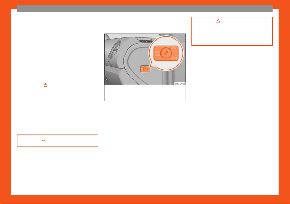
Disabling the front passenger front
airbag
Fig. 21
On the passenger side: switch to acti-
v
at
e and deactiv
ate the front passenger air-
bag.
The front passenger front airbag must be
disabl
ed when a r
ear
-facing child seat is
mounted.
Disabling the front passenger front airbag
●
Switch the ignition off.
●
Open the door on the front passenger side.
●
Unfold the vehicle key blade
›››
page 92.
●
Using the vehicle key, turn the key switch to
OFF
›››
Fig. 21.
●
Close the door on the front passenger side.
●
The control lamp on
the dash panel will remain lit while the ignition
is switched on
›››
page 64.
›››
in Manual disabling and ena-
bling of the front passenger front air
-
bag with the key switch on page 65
›››
page 64
17
The essentials
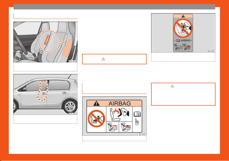
Side airbags
Fig. 22
On the front seat side: location of side
airbag.
Fig. 23
On the left side of the vehicle: side air-
bag depl
oyment z
one
.
The side airbags are located in the outer
cushion of the driv
er and fr
ont passenger
seat backr
ests
›››
Fig. 22. Their position is in-
dicated by the word “AIRBAG”. The area
marked in red
›››
Fig. 23 indicates the side air-
bag deployment zone.
In the event of a side-on collision, the side air-
bag will deploy in the side of the vehicle af-
fected
›››
Fig. 23, thus reducing the risk of in-
juries to passengers on the side of the body
and the head facing the accident side.
›››
in Side airbags* on page 63
Child seats
Impor
t
ant inf
ormation regarding
the front passenger's airbag
Fig. 24 Passenger side sun blind.
Fig. 25 On the rear frame of the passenger
side door: adhesive in rel
ation to the airbag.
A sticker with important information about the
passenger airbag is l
ocat
ed on the passeng-
er
's sun visor and/or on the passenger side
door frame.
›››
in Important information re-
garding the front passenger
's airbag
on page 66
›››
page 65
18
The essentials
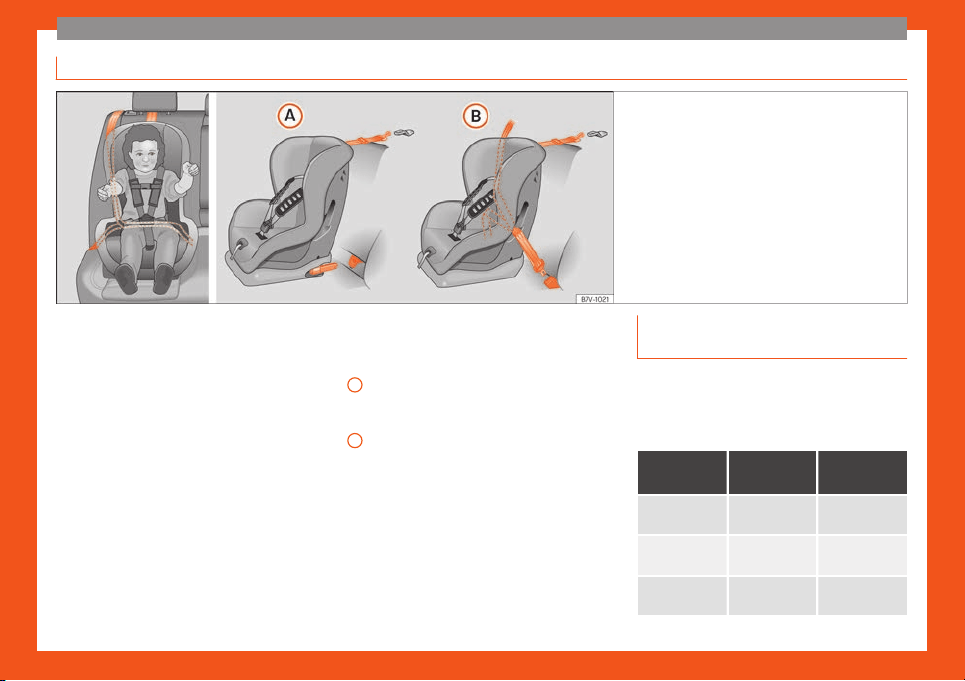
Mounting systems
Fig. 26 On rear seats: possible assemblies of chil-
dren seats.
Always secure child seats properly and safe-
ly in the v
ehicl
e accor
ding to the child seat
manufacturer's installation instructions.
Mounted child seats must rest correctly on
the vehicle's seat and must not move or rock
more than 2.5 cm.
Child seats equipped for a Top Tether strap
must also be secured using the Top Tether re-
taining strap in the vehicle
›››
page 21. At-
tach the retaining strap to the corresponding
retaining rings only. Not all rings can be used
with the Top Tether system. Always tighten
the Top Tether retaining strap so that the child
seat fits snugly against the corresponding
seat in the vehicle.
Specific mounting systems for each coun-
try
Attachment variants
›››
Fig. 26:
Europe: ISOFIX retaining rings and upper
retaining strap
›››
page 20 and
›››
page 21.
Three-point seat belt and upper retaining
strap
›››
page 19.
The systems include the child restraint
system mounting with an upper retaining
strap (Top Tether) and lower anchoring
points on the seat.
A
B
Securing child seats with the seat
belt
The seat belt may be used to secure child
seats with the universal marking (on the or
-
ange label) to the vehicle seats marked with
a u in the table below.
Category
Front pas-
senger
a)
Rear seats
Group 0
Up to 10 kg
u u
Category 0+
Up to 13 kg
u u
Gr
oup 1
9 to 18 kg
u u
»
19
The essentials
Category
Front pas-
senger
a)
Rear seats
Group 2
15 to 25 kg
u u
Gr
oup 3
22 to 36 kg
u u
a)
Compliance with current national legislation and
the manufactur
er's instructions is required when using
or installing child seats.
Securing the child seat using the seat belt
●
Please read and observe the child seat
manufactur
er's handling instructions.
●
Move the front passenger seat, or the rear
seat bench back as far as possible and, in the
case of an adjustable backrest, set it in the
upright position
›››
page 49.
●
Positioning the child seat on the seat ac-
cording to the manufacturer's instructions.
●
Fasten the seat belt or pass it around the
child seat structure in the manner described
in the manufacturer's instructions.
●
Make sure the seat belt is not twisted.
●
Insert the latch plate into the buckle for the
appropriate seat and push it down until it is
securely locked with an audible click.
●
Ensure that the upper belt web lies tightly
on the child seat.
●
Pull the belt (it must be no longer possible
to pull the lower belt webbing out).
Removing the child seat
The seat belt must not be unfastened until the
vehicle has come to a standstill.
●
Press the red button on the buckle. The
latch plate is released from the buckle.
●
Guide the belt back by hand so that it rolls
up easily and the trim will not be damaged.
●
Remove the child seat from the vehicle.
›››
in Safety instructions on
page 67
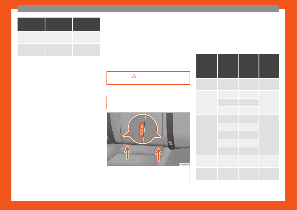
Fixing the child seat with the ISOFIX
syst
em
Fig. 27
On the seat of the vehicle: identifica-
tion v
ariants of the anchor points f
or the chil
d
seats
Both outermost rear seats have tw
o
r
etainers
named lower anchor points.
Summary chart for assembly with the ISO-
FIX system
The following table shows the assembly pos-
sibilities for ISOFIX or i-Size child seats on the
ISOFIX anchorage points of the different vehi-
cle seats.
Age
group
Class
accord-
ing to
siz
e
a)
Front
passen-
ger seat
Rear
seats
Group 0:
up to 10 kg
E X
IL-SU
Group 0+:
up to 13 kg
E X
IL
-SUD X
C X
Group 1:
9 to 18 kg
D X
IL
-SU
IUF
C X
B X
B1 X
A X
Group 2:
15 to 25 kg
– X
IL-SU
Group 3:
22 to 36 kg
– X IL-SU
20
The essentials
Age
group
Class
accord-
ing to
siz
e
a)
Front
passen-
ger seat
Rear
seats
i-Size
child re-
str
aint
system
– X X
X: seat not suitable f
or an ISOFIX or i-Size child seat
of this group.
IL-SU: seat suitable for an ISOFIX child seat with
semi-universal certification. Take into account the list
of vehicles of the manufacturer of the child seat.
IUF: seat suitable for an ISOFIX child seat with univer-
sal certification.
a)
The indication of class according to size corre-
sponds t
o the authorised bodyw
eight f
or the child
seat. In child seats with universal or semi-universal
approval, the class according to size is indicated on
the ECE approval label. The indication of class ac-
cording to size is stated on the corresponding child
seat.
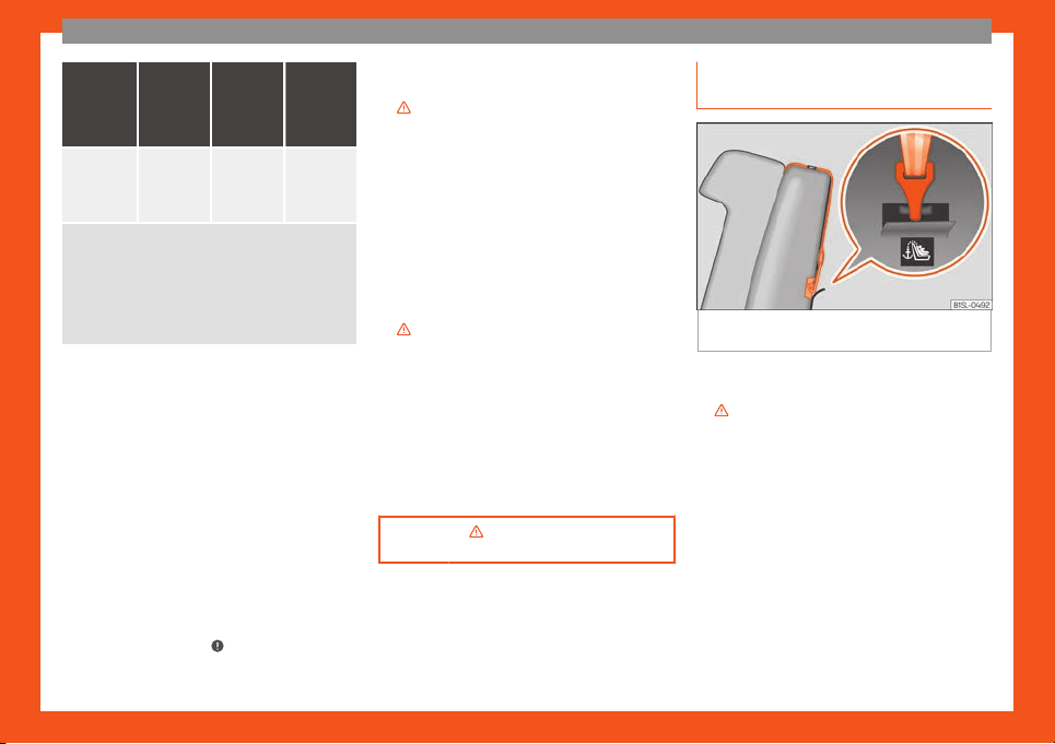
Child seats with rigid mounting
For the installation of a child seat with rigid
mounting auxiliary introduction elements can
be used. These elements facilitate fitting and
protect the upholstery. They form part of the
supply volume of the child seat or can be ac-
quired at a SEAT dealership. If necessary,
these elements are inserted in both anchor
points of the vehicle
›››
in Safety instruc-
tions on page 6
7
.
●
Observ
e the manufacturer's instructions
when installing and removing the child seat
›››
in Safety instructions on page 67.
●
Press the child seat onto the retaining rings
›
›
›
Fig. 27 in the direction of the arrow. The
child seat must be safely engaged and click
audibly into place.
●
Pull on both sides of the child seat to ensure
that it is secure.
Child seat with adjustable retaining straps
●
Observe the manufacturer's instructions
when installing and removing the child seat
›››
in Safety instructions on page 67.
●
Place the child seat on the seat cushion
and att
ach the r
et
aining strap hooks to the
retaining rings
›››
Fig. 27.
●
Tighten the straps evenly using the corre-
sponding adjustment device. The child seat
must sit flush against the vehicle seat.
●
Pull on both sides of the child seat to ensure
that it is secure.
›››
in Safety instructions on
page 67
Securing a child seat with the Top
T
ether r
et
aining strap
Fig. 28
Example of an upper retaining strap
connect
ed.
●
Observe the manufacturer's instructions
when inst
alling and r
emo
ving the child seat
›››
in Safety instructions on page 67.
●
Unlock the seat backrest and fold it gently
f
orw
ar
d
›››
page 14.
●
Remove the head restraints situated behind
the child seat and store them safely in the ve-
hicle
›››
page 49.
●
Guide the upper retaining strap from of the
child seat back to the luggage compartment,
feeding it through the seat backrest and the
rear shelf.
●
Fold back the seat backrest and push it
firmly into the lock.
●
Secure the child seat to the lower anchor
points
›››
page 20
»
21
The essentials
●
Hook the upper r
et
aining str
ap in the lug-
gage compartment, to the corresponding re-
taining ring
›››
Fig. 28.
●
Tighten the strap so that the top of the child
seat rests on the seat backrest.
›››
in Safety instructions on
page 67
Starting the vehicle
Ignition lock
Fig. 29
Ignition key positions.
Turn on the ignition: place the key in the igni-
tion and st
art the engine
.
L
ocking and unlocking the steering wheel
●
Lock the steering wheel: remove the key
from the ignition and turn the wheel until it
locks. In vehicles with automatic transmission,
in order to remove the key, move the gear
shift to the N position. If necessary, press the
gear shift blocking key and release it.
●
Unlock the steering wheel: put the key into
the ignition and turn it at the same time as the
steering wheel in the direction indicated by
the arrow. If it is not possible to turn the steer-
ing wheel, it may be because it is locked.
Turning on/switching off the ignition, glow
plugs reheating
●
Turn on the ignition: turn the key to the
2
position.
●
Turn off the ignition: turn the key to the
1
position.
St
ar
ting the engine
●
Manual tr
ansmission: press the clutch ped-
al all the way down and move the gearbox
lever into neutral.
●
Automatic transmission: press the brake
pedal and move the selector lever to N.
●
Turn the key to the
3
position. The key au-
t
omatically r
et
urns to the
2
position. Do not
pr
ess the accel
er
ator.
Start-Stop system*
When you stop and release the clutch pedal,
the Start-Stop system* turns off the engine.
The ignition remains switched on.
›››
in Switching on the ignition and
starting the engine on page 149
›››
page 149
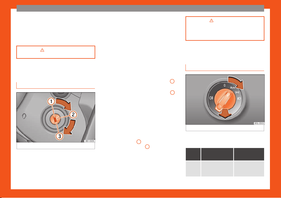
Lights and visibility
Light s
wit
ch
Fig. 30
Instrument console: light panel.
Turn the switch to the required position
›
›
›
Fig. 30.
Sym-
bol
Ignition switch-
ed off
Ignition is
switched on
F
og lights, dipped
beam and side
lights off.
Light off or day-
time driving light
on.
22
The essentials
Sym-
bol
Ignition switch-
ed off
Ignition is
switched on
The “Coming
home” and “Leaving
home” guide lights
may be swit
ched
on.
Automatic control
of dipped beam
and daytime run-
ning light.
Side light on.
Dipped beam head-
light off
Dipped beam
s
witched on.
Rear fog light: mo
v
e the s
witch com-
pletely from positions , or .
Turn on fog lights: push the switch or turn it to
the position.
›››
in Switching lights on and off on
page 104
›››
page 103
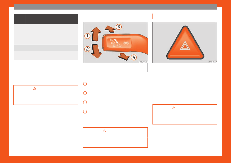
Turn signal and main beam lever
Fig. 31
Turn signal and main beam lever in
their initial position
More the lever to the required position:
Right t
urn light: right
-hand parking light
(ignition s
witched off).
Left turn light: left-hand parking light (ig-
nition switched off).
Main beam on: control lamp lit up on
the instrument panel.
Light flash: on with the lever pushed. Con-
trol lamp lit up.
Lever all the way down to switch it off.
›››
in Turn signal and main beam
lever on page 105
›››
page 105
1
2
3
4
Hazard warning lights
Fig. 32
Dashboard: switch for hazard warning
lights.
Switched on, for example:
●
When approaching a traffic jam
●
In an emergency
●
The vehicle has broken down
●
When towing or being towed
›››
in Hazard warning lights on
page 106
›››
page 106
23
The essentials
Interior lights
Position: Function
Switching off the reading light.
Switching on the reading light.
Switches door contact control on (central
position).
The r
eading light comes on automatically
when the vehicle is unlocked, a door is
opened or the key is removed from the ig-
nition.
The light goes off a few seconds after all
the doors are closed, the vehicle is locked
or the ignition is switched on.
Note
The reading lights go out when the vehicle
is locked, or a f
ew minutes after the key is
removed from the ignition. This prevents
the vehicle's battery from discharging.
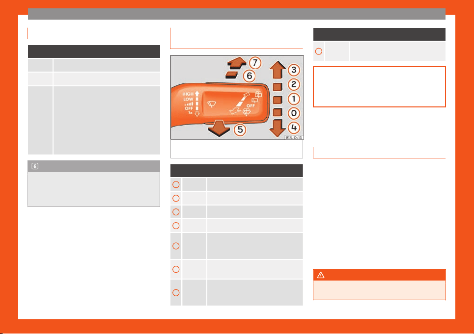
Windscreen wipers and window
wiper bl
ade
Fig. 33
Operating the windscreen wiper and
r
ear wiper
.
More the lever to the required position:
0
Windscreen wipers off.
1
Windscreen interval wipe.
2
Slow wipe.
3
Continuous wipe.
4
Brief wipe - short wipe. Hold the lever
down for mor
e time to increase the
wipe frequency.
5
Automatic wipe for cleaning wind-
screens with the lever up.
6
Interval wipe for rear window. The
wiper will wipe the window appro
xi-
mately every six seconds.
More the lever to the required position:
7
Automatic wipe for cleaning rear win-
dows with the le
ver pressed.
›››
page 108
›››
page 46
SEAT information system
Intr
oduction
With the ignition switched on it is possible to
access diff
er
ent messages via the displ
ay on
the instrument panel display.
The number of messages displayed on the in-
strument panel display will vary according to
the vehicle electronics and equipment.
A specialised workshop will be able to pro-
gramme or modify additional functions, ac-
cording to the vehicle equipment. SEAT rec-
ommends taking your car in for technical
service.
WARNING
Any distraction may lead to an accident,
with the risk of injury.
24
The essentials
●
Do not consult the messages on the in-
strument panel screen when driving.
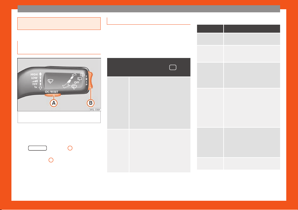
Management of indications on the
display
Fig. 34 Windscreen wipers lever: control but-
t
ons.
Calling up options
●
Switch the ignition on.
●
If a message or vehicle symbol is displayed,
pr
ess OK/RESET (
›
›
›
Fig. 34
A
).
●
Press the top or bottom part of the rocker
s
wit
ch
›
››
Fig. 34
B
until the desired option
appears.
Multifunction display (MFI)
The multifunction display (MFD) has two au-
tomatic memories: 1 - P
artial memory and 2
- Total memory. The selected memory will
be shown in the lower right-hand corner of
the display.
With the ignition switched on, and memo-
ry 1 or 2 displayed, briefly press OK to
change from one memory to another.
Trip memo-
ry (for a sin-
gl
e jour-
ney).
The memory stores the values for the
journey and the consumption from the
moment the ignition is swit
ched on un-
til it is switched off again.
If the journey is broken for more than 2
hours, the memory is automatically
erased. If the journey is continued in
less than 2 hours after the ignition is
switched off, the new data is added to
the data already stored in the memo-
ry.
Total mem-
ory (f
or all
journeys).
The memory stores the values of any
number of journeys, until it counts a
total of 19 hours and 59 minut
es of
driving, or 1999.9 km or miles of driv-
ing, depending on the type of instru-
ment panel fitted. On reaching either
of these limits, the memory is auto-
matically erased and starts to count
from 0 again.
Possible displays
Menu Function
Time
Current time in hours (h) and mi-
nutes (min).
Travelling
time
This indicates the hours (h) and mi-
nutes (min) since the ignition was
switched on.
Current
fuel con-
sumption
The current fuel consumption dis-
play operat
es throughout the jour-
ney, in l/100 km; with the engine
running and the vehicle stopped, in
l/hour.
Average
fuel con-
sumption
After turning on the ignition, aver-
age fuel consumption in li-
tres/100 km will be displayed aft
er
travelling about 100 metres. Oth-
erwise horizontal lines are dis-
played. The value shown is upda-
ted approximately every 5 sec-
onds.
Operating
range
Approximate distance in km that
can still be travell
ed with the fuel
remaining in the tank, assuming
the same style of driving is main-
tained. This is calculated using the
current fuel consumption.
Distance
covered
Distance travelled, after ignition is
switched on, in km.
»
25

The essentials
Menu Function
Average
speed
The average speed will be shown
after a distance of about 100 me-
tr
es has been travelled. Otherwise
horizontal lines are displayed. The
value shown is updated approxi-
mately every 5 seconds.
Digital
display of
speed
Current speed displayed digitally.
Digital
coolant
tempera-
ture gauge
Digital display of the current tem-
peratur
e of the engine liquid cool-
ant.
Warning at
--- km/h
If the stored speed is exceeded
(between 30 - 250 km/h, or 18 -
155 mph), an audible w
arning is
given together with a visual warn-
ing.
Changing between display modes
●
Press the rocker switch in the windscreen
wiper l
e
v
er.
Storing a speed for the speed warning
●
Select the display Speed warning at
--- km/h.
●
Press OK
on the windscreen wiper lever to
st
or
e the curr
ent speed and switch off the
warning.
●
In addition, set the required speed by press-
ing the rocker switch on the windscreen wiper
lever or
or buttons on the multifunction
st
eering wheel f
or 5 seconds. Ne
xt, press OK
again or wait a few seconds. The speed is
st
or
ed and the w
arning activated.
●
To switch off, press OK
. The stored speed is
del
et
ed.
Manually er
asing memory 1 or 2
●
Select the memory to be erased.
●
Press and hold the eject button OK
for ap-
pr
o
ximat
ely 2 seconds.
Cruise control
Operating the cruise control sys-
tem (CCS)*
Fig. 35 Switch and controls for operating the
CCS.
●
S
wit
ching on the CCS: Mo
ve switch
›››
Fig. 35
1
to
. The system is on. If no
speed has been pr
ogr
ammed, the system will
not control it.
●
Activate the CCS: Press button
›››
Fig. 35
2
in the ar
ea. The curr
ent speed is
memorised and contr
olled.
●
Temporarily switching off the CCS: Move
switch
›››
Fig. 35
1
to
or push the
br
ak
e. The cruise control system is switched
off temporarily.
●
Reactivating the CCS: Press button
›››
Fig. 35
2
in . The memorised speed is
sav
ed and contr
oll
ed again.
●
Increasing stored speed during CCS regu-
lation: press button
2
in
. The vehicle
accel
erates until the new stored speed.
●
Reducing stored speed during CCS regula-
tion: press button
2
in t
o lower the
speed by 1 km/h (
1 mph). Speed is r
educed
until reaching the new stored speed.
●
Switching off the CCS: Move switch
›››
Fig. 35
1
to
. The system is disconnec-
t
ed and the memorised speed is deleted.
›››
in Cruise control operation on
page 172
›››
page 1
7
1
26
The essentials
Warning lamps
Contr
ol and w
arning l
amps
The control and warning lamps are indicators
of warnings,
››
›
, faults
›››
or certain func-
tions. Some control and warning l
amps come
on when the ignition is switched on, and
switch off when the engine starts running, or
while driving.
When certain control and warning lamps are
lit, an audible warning is also heard.
Handbrake
›››
page 152.
Fault in the brake system
›
›
›
page 152.
Engine cooling fluid
›
›
›
page 198.
Engine oil pressure
›
›
›
page 195.
Fault in the steering system
›››
page 164.
Driver or passenger has not fastened
seat belt
›››
page 54.
Fault in the generator
›››
page 203;
OR the Start-Stop system cannot start
the engine
›››
page 170.
Fault in ESC or disconnection caused
by the system; OR
ESC or ASR in oper-
ation
›››
page 156.
Fault in Traction Control* or discon-
nection caused by the system; OR
T
raction Control* in operation
›››
page 156.
Fault in the ABS
›››
page 156.
Rear fog light switched on
›››
page 103.
Fault in the emission control system
›››
page 168.
Fault in the petrol engine management
›››
page 168.
Fuel tank almost empty
›››
page 190.
Natural gas tank is almost empty
›››
page 190.
Fault in airbag system and seat belt
tensioners
›››
page 64.
Tyre monitor system
›››
page 212.
Turn lights or emergency lights on
›››
page 103.
Cruise control
›››
page 171.
Main beam on or flasher on
›››
page 103.
A passenger in the rear seats has fas-
tened their seat belt
›››
page 54.
A passenger in the rear seats has not
fastened their seat belt
›››
page 54.
City Safety Assist
›››
page 175.
City Safety Assist switched on manual-
ly
›››
page 175.
City Safety Assist switched off manual-
ly
›››
page 175.
Service interv
al display
›››
page 90.
Start-Stop system activated
›››
page 170.
Start-Stop system unavailable
›››
page 170.
WARNING
If the warning lamps are ignored, the vehi-
cle may stall in tr
affic, or may cause acci-
dents and severe injuries.
●
Never ignore the warning lamps.
●
Stop the vehicle safely as soon as possi-
ble.
●
Park the vehicle away from traffic and
ensure that there are no highly flammable
materials under the vehicle that could
come into contact with the exhaust system
(e.g. dry grass, fuel).
●
A faulty vehicle represents a risk of acci-
dent for the driver and for other road users.
If necessary, switch on the hazard warning
lamps and put out the warning triangle to
advise other drivers.
●
Before opening the bonnet, switch off the
engine and allow it to cool.
»
27
The essentials
●
In any vehicle
, the engine compartment is
a hazardous area and could cause severe
injuries
›››
page 193.
CAUTION
Failure to heed the warning lamps when
they appear may r
esult in faults in the v
ehi-
cle.
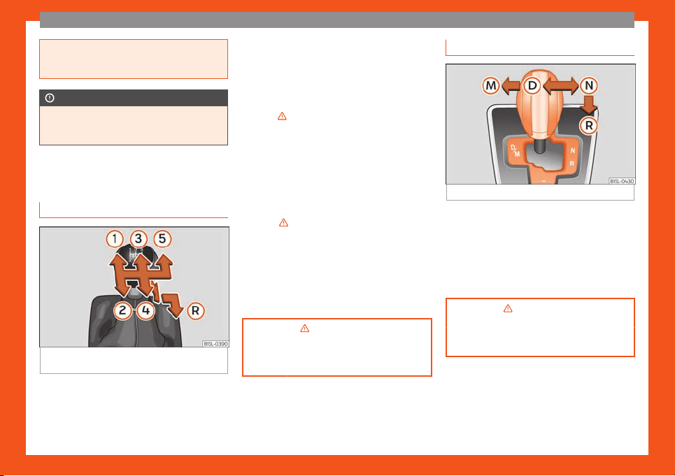
Gearbox lever
Manual gearbo
x
Fig. 36
Gear shift pattern of a 5-speed man-
ual gearbo
x
The position of each of the gears is shown on
the gear stick
›
›
›
Fig. 36.
●
Keep the clutch pedal pushed all the way
down.
●
Move the gearbox lever to the required po-
sition
›››
in Manual gear change on
page 159.
●
Release the clutch pedal to engage clutch.
Sel
ecting r
e
verse gear
●
Engage reverse gear only when the vehicle
is stopped.
●
Keep the clutch pedal pushed all the way
down
›››
in Manual gear change on
page 159.
●
Place the gearbox lever into neutral and
push the l
e
v
er downwards.
●
Slide the gearbox lever to the right, and
then backward as shown on the lever.
●
Release the clutch pedal to engage clutch.
›››
in Manual gear change on
page 159
›››
page 159
Automatic gearbox
Fig. 37
Automatic gearbox diagram of gears
Reverse gear
Neutr
al (idling)
Driv
e (f
orward)
Tiptronic mode: pull the lever forwards
(+) to go up a gear or backwards (–) to
go down a gear.
›››
in Automatic gear change on
page 160
›››
page 160
R
N
D
M
28
The essentials
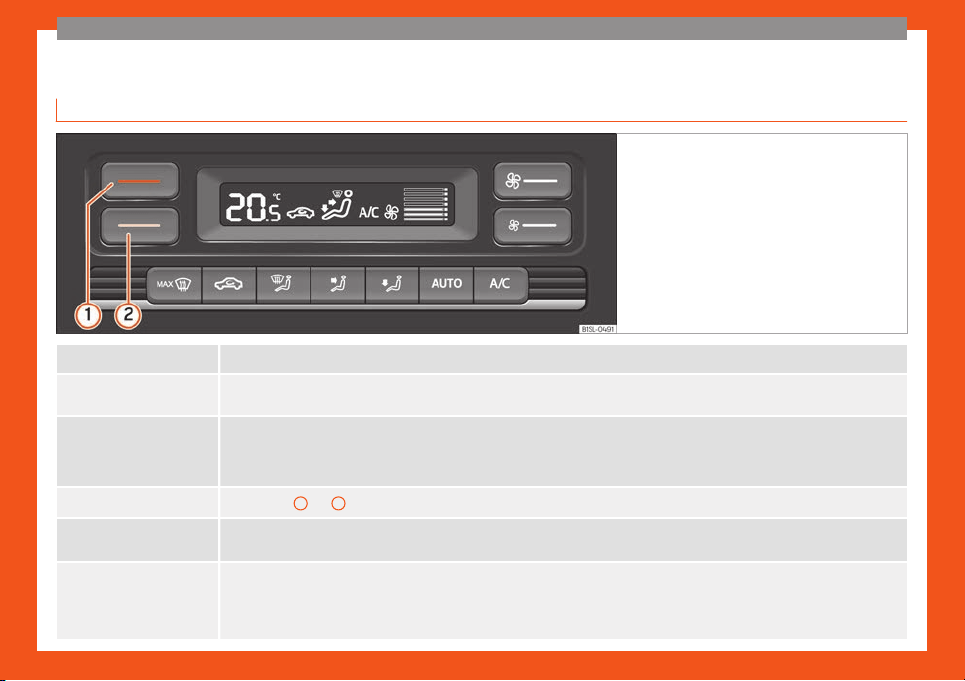
Air conditioning
Ho
w does the Climatr
onic* w
ork?
Fig. 38 In the centre console, top section: Clima-
tronic control panel
.
Switching off
Switch the system off by pressing several times on the lower button
›››
Fig. 38
Cooling mode
The
button s
witches cooling mode on and off.
Automatic mode
The
button s
witches the automatic mode on and off. The automatic mode maintains temperature constant in the vehicle’s interior.
Temperature and the amount and distribution of air are controlled automatically. Modifying ventilation automatically switches off the auto-
matic mode.
Temperature
Press buttons
1
and
2
›››
Fig. 38 to adjust the temperature. The adjusted temperature is displayed on the screen.
Fan
The
›
››
Fig. 38 buttons are used to adjust fan speed.
Air distribution
: The air is distributed to
wards the upper part of the body through the dash panel air vents.
: Air distribution to footwells
: Air distribution to the windscreen
»
29

The essentials
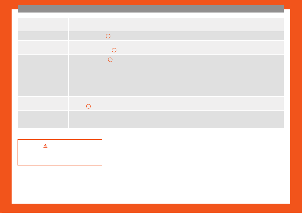
Removing ice from the windscreen
The
›››
Fig. 38 button is used to remove ice from the windscreen as quickly as possible and to demist it (defrost/demist function).
When the temperature is above +3°C (+38°F), the air is dehumidified and fan speed increases.
Air recirculation
The
›
››
Fig. 38 button switches that air recirculation on and off
›››
page 129.
Heated rear window
The butt
on, locat
ed in the upper part of the centre console, switches the heated rear window on and off when the engine is running. The
heated rear window switches off automatically after 10 minutes at most.
›››
in Introduction on page 129
›››
page 129
How does the manual air conditioning and the heating and fresh air system work?
Fig. 39 Centre console, top section: controls for
the manual air conditioning and the heating and
fresh air system.
Switching off
It is switched off by turning the central control
2
to the
›››
Fig. 39 position.
30
The essentials
Cooling mode
a)
The button s
witches cooling mode on and off.
Temperature
The left rotary adjuster
1
›››
Fig. 39 is used to adjust the temperature.
Fan
The central rot
ary adjuster
2
›››
Fig. 39 is used to adjust fan speed.
Air distribution
The right rotary adjuster
3
›››
Fig. 39 is used to adjust air distribution.
: The air is distributed towards the upper part of the body through the dash panel air vents.
: Air distribution to footwells.
: Air distribution towards the windscreen and the footwell.
: Removing ice from the windscreen. Ice is removed from the windscreen as fast as possible and the windscreen is demisted (defrost
function).
Air recirculation
The slider
4
›››
Fig. 39 is used to switch air recirculation on and off
›››
page 129.
Heated rear window
The button, locat
ed in the upper part of the centre console, switches the heated rear window on and off when the engine is running. The
heated rear window switches off automatically after 10 minutes at most.
a)
Valid for vehicles with manual air conditioning.
›››
in Introduction on page 129
›››
page 129
31
The essentials
Fluid level control
Filling the fuel t
ank
Fuel tank capacity
Petrol engines
Around 35.0 l
of which approx. 4.0 l are reserve.
Natural gas
engine
Natural gas: approx. 11.0 kg; of
which max. 1.5 kg are r
eserve
Petrol: approx. 10.0 l; of which ap-
prox. 5.0 l are reserve
Windscreen washer tank capacity
The washer bottle capacity is approximately 3 litres.
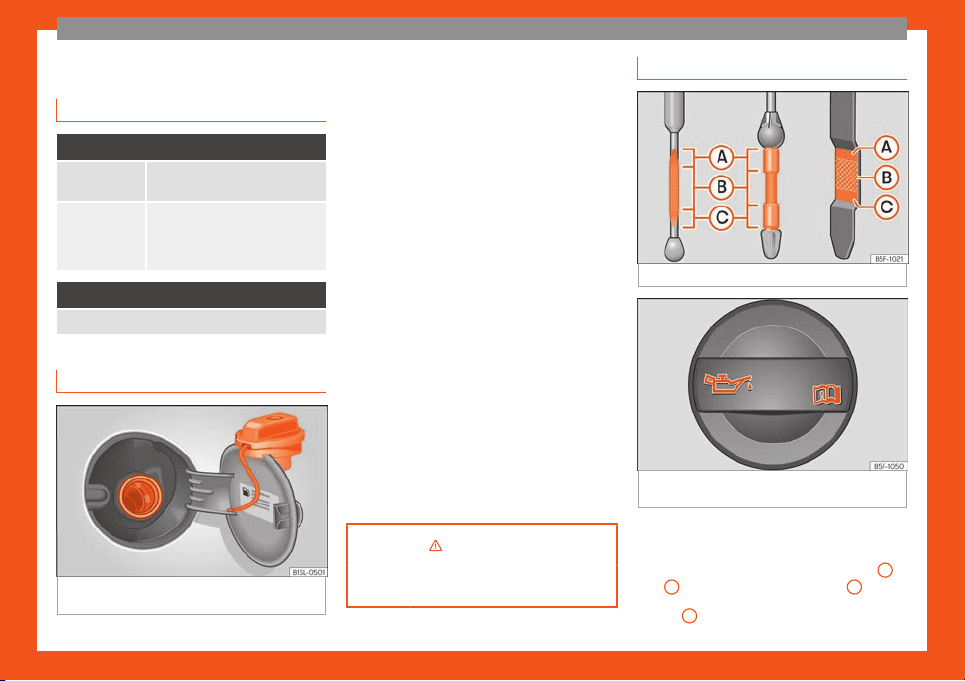
Fuel
Fig. 40
Open fuel tank flap with tank cap in
the hol
der
Opening the fuel tank cap
The t
ank fl
ap is at the r
ear of the vehicle on
the right.
●
Pull the rear zone of the fuel tank flap to
open.
●
Unfold the key shaft if necessary
›››
page 92.
●
Insert the vehicle key into the lock cylinder
of the fuel tank plug and turn the key in an
anticlockwise direction.
●
Take out the fuel tank plug by turning it in an
anticlockwise direction and rest it on the up-
per part of the fuel tank flap
›››
Fig. 40.
Closing the fuel tank cap
●
Screw on the fuel tank filler plug in a clock-
wise direction until it is fully inserted with a
click.
●
Insert the vehicle key into the lock cylinder
of the fuel tank plug, turn the key in a clock-
wise direction and remove the key.
●
Press the tank flap until you hear it click into
place. The tank flap must be flush with the
body contour.
›››
in Introduction on page 189
›››
page 191
Oil
Fig. 41
Engine oil dipstick.
Fig. 42
In the engine compartment: Engine oil
fill
er cap
.
The level is measured using the dipstick loca-
t
ed in the engine compartment.
The oil indicat
or must be betw
een zones
A
and
C
. It can never go above zone
A
.
●
Zone
A
: do not add oil.
32
The essentials
●
Z
one
B
: you can add oil but keep the level
in that z
one
.
●
Z
one
C
: add oil until zone
B
.
T
opping up engine oil
●
Unscr
e
w cap from oil filler opening.
●
Add oil slowly.
●
At the same time, check the level to ensure
you do not add too much.
●
When the oil level reaches at least zone
B
,
unscr
e
w the engine oil fill
er cap carefully.
If the engine oil level is too low
You can get information about the correct en-
gine oil for your vehicle in your specialised
shop. If you have to change your engine oil,
use this oil.
If the recommended engine oil is not availa-
ble, in the event of an emergency you can
change the oil once with a maximum of 0.5 L
of the next oil until the next oil change:
Petrol engines: standard VW 504 00,
VW 502 00, VW 508 00, ACEA C3 or
API SN.
Have the oil changed by a specialised work-
shop.
Using engine oil that is compliant with the VW
504 00 standard instead of VW 508 00
could increase consumption and the vehicle’s
CO
2
emissions.
–
Recommended by SEAT
SEAT recommends using original SEAT oil to
guarantee high SEAT engine performance.
›››
in Topping up engine oil on
page 197
›››
page 195
Coolant
Fig. 43 Engine compartment: coolant expan-
sion t
ank cap
.
The coolant tank is located in the engine
compartment.
When the engine is col
d, r
epl
ace the coolant
when the level is below .
Coolant specifications
The engine cooling system is supplied from
the factory with a specially treated mixture of
water and at least 40 % of the additive G13
(TL-VW 774 J), purple. This mixture gives the
necessary frost protection down to -25°C
(-13°F) and protects the light alloy parts of
the engine cooling system against corrosion.
It also prevents scaling and considerably rai-
ses the boiling point of the coolant.
To protect the cooling system, the percent-
age of additive must always be at least 40 %,
even in warm climates where anti-freeze pro-
tection is not required.
If for weather reasons further protection is
necessary, the proportion of additive may be
increased, but only up to 60 %; otherwise an-
tifreeze protection will diminish and this will
worsen cooling.
When the coolant is topped up, use a mixture
of distilled water and at least 40 % of the
G13 or G12 plus-plus (TL-VW 774 G) additive
(both are purple) to obtain an optimum anti-
corrosion protection
›››
in Checking the
cool
ant l
e
vel and topping up on page 200.
The mixture of G13 with G12 plus (TL-VW 774
F), G12 (red) or G11 (green-blue) engine cool-
ants will significantly reduce anti-corrosion
protection and should therefore be avoided
›››
in Checking the coolant level and
t
opping up on page 200
.
»
33
The essentials
›››
in Checking the coolant level
and topping up on page 199
›››
page 198
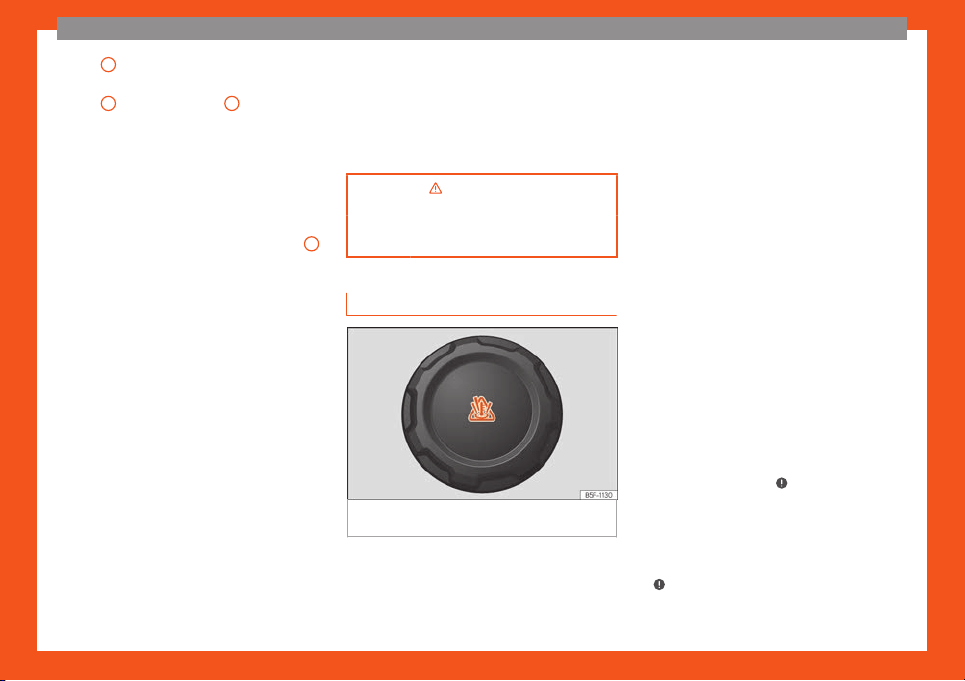
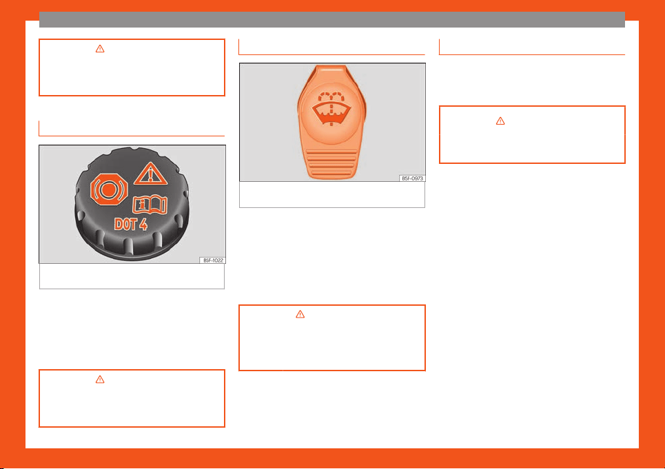
Brake fluid
Fig. 44
Engine compartment: brake fluid res-
erv
oir cap
.
The brake fluid reservoir is located in the en-
gine compartment.
The l
e
v
el should be between the and
marks. If it is below , please visit a Technical
Service.
›››
in Checking the brake fluid lev-
el on page 201
›››
page 200
Windscreen washer
Fig. 45
In the engine compartment: cap of the
windscr
een w
asher t
ank.
The windscreen washer reservoir is located in
the engine compartment.
T
o t
op up
, mix water with a product recom-
mended by SEAT.
In cold temperatures, add anti-freeze for the
windshield cleaner.
›››
in Checking and topping up the
windscreen washer r
eservoir with
water on page 202
›››
page 201
Battery
The battery is located in the engine compart-
ment. It does not require maint
enance. It is
checked as part of the Inspection Service.
›››
in Introduction on page 203
›››
page 202
34
The essentials
Emergencies
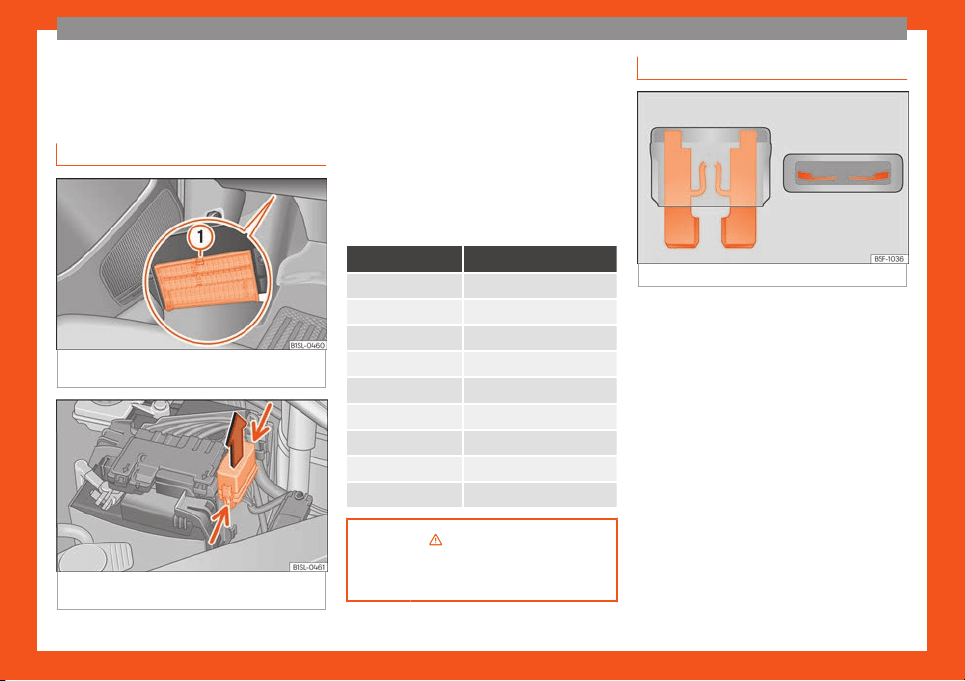
Fuses
Fuse l
ocation
Fig. 46
On the dashboard on the driver side:
lid of the fuse bo
x.
Fig. 47 In the engine compartment: lid of the
fuse bo
x.
Underneath the instrument panel
The fuse bo
x is l
ocat
ed underneath the dash
panel on the driver side
›››
Fig. 46.
In the engine compartment
Press the locking tabs to release the fuse box
cover
›››
Fig. 47.
Identifying fuses situated below the dash
panel by colours
Colour Amp rating
Purple 3
Light brown 5
Brown 7.5
Red 10
Blue 15
Yellow 20
White or transparent 25
Green 30
Orange 40
›››
in Introduction on page 78
›››
page 7
8
Replacing a blown fuse
Fig. 48
Image of a blown fuse.
Preparation
●
Switch off the ignition, lights and all electri-
cal equipment.
●
Open the corresponding fuse box
›
›
›
page 79.
Identifying a blown fuse
A fuse is blown if its metal strip is ruptured
›››
Fig. 48.
Point a lamp at the fuse to see if the fuse has
blown.
To replace a fuse
●
Remove the fuse.
●
Replace the blown fuse by one with an
identical amperage rating (same colour and
markings) and identical size.
»
35
The essentials
●
R
epl
ace the co
ver again or close the fuse
box lid.
Bulbs
Bulbs (12 V)
Light source used for each function
Halogen headlights. Type
Daytime running light/side
light
W21/5W
Dipped beam headlights H4 LL
Main beam headlights H4 LL
Turn signal PY21W NA
Rear bulb light Type
Brake/side lights P21/5W LL
Side lights P21/5W LL
Turn signal PY21W NA LL
Retro fog light P21W
Reverse lights R10W
Action in the event of a punc-
t
ur
e
What t
o do first
●
Park the vehicle on a horizontal surface and
in a safe place as f
ar away from traffic as
possible.
●
Apply the handbrake.
●
Switch on the hazard warning lights.
●
Manual transmission: select the 1st gear.
●
Aut
omatic transmission: Move the selector
lever to position D or R.
●
If you are towing a trailer, unhitch it from
your vehicle.
●
Have the vehicle tool kit
›››
page 71
and the spare wheel* ready
›››
page 213.
●
Observe the applicable legislation for each
country (reflective vest, warning triangles,
etc.).
●
All occupants should leave the vehicle and
wait in a safe place (for instance behind the
roadside crash barrier).
WARNING
●
Always observ
e the above steps and pro-
tect yourself and other road users.
●
If you change the wheel on a slope, block
the wheel on the opposite side of the car
with a stone or similar to prevent the vehi-
cle from mo
ving.
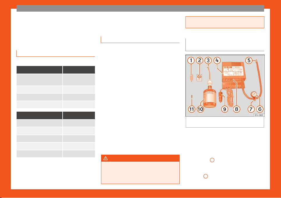
Repairing a tyre with the anti-punc-
ture kit
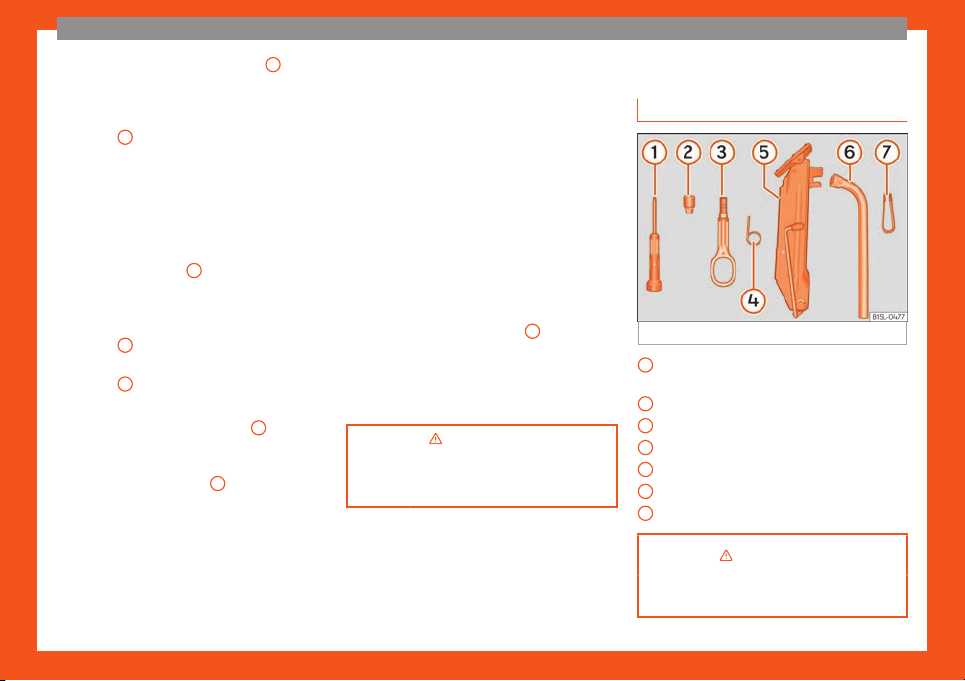
Fig. 49
Standard display: contents of the anti-
punct
ur
e kit.
The anti-puncture kit is located under the
fl
oor panel in the luggage compartment.
Sealing the t
yr
e
●
Unscrew the tyre valve cap and insert. Use
the
›››
Fig. 49
1
tool to remove the insert.
Pl
ace it on a cl
ean surf
ace.
●
Shake the tyre sealant bottle vigorously
›››
Fig. 49
10
.
36
The essentials
●
Scr
e
w the infl
ator tube
›››
Fig. 49
3
into
the seal
ant bottl
e
. The bottle's seal will break
automatically.
●
Remove the lid from the filling tube
›››
Fig. 49
3
and screw the open end of the
t
ube int
o the t
yre valve.
●
With the tyre sealant bottle upside down, fill
the tyre with the contents of the sealant bot-
tle.
●
Remove the bottle from the valve.
●
Place the insert back into the tyre valve us-
ing the tool
›››
Fig. 49
1
.
Infl
ating the t
yr
e
●
Screw the compressor tyre inflator tube
›››
Fig. 49
5
into the tyre valve.
●
Check that the air bleed screw is closed
›
›
›
Fig. 49
7
.
●
Start the engine and leave it running.
●
Insert the connector
›
›
›
Fig. 49
9
into the
v
ehicl
e's 12-v
olt socket
›››
page 120.
●
Turn the air compressor on with the
ON/OFF switch
›››
Fig. 49
8
.
●
Keep the air compressor running until it rea-
ches 2.
0 t
o 2.5 bar (29-36 psi/200-250 kP
a).
A maximum of 8 minutes.
●
Disconnect the air compressor.
●
If it does not reach the pressure indicated,
unscrew the tyre inflator tube from the valve.
●
Move the vehicle 10m so that the sealant is
distributed throughout the tyre.
●
Screw the compressor tyre inflator into the
valve.
●
Repeat the inflation process.
●
If the indicated pressure still cannot be
reached, the tyre is too badly damaged. Stop
and request assistance from an authorised
technician.
●
Disconnect the air compressor. Unscrew
the tyre inflator tube from the tyre valve.
●
When the tyre pressure is between 2.5 and
2.0 bars, continue driving without exceeding
80 km/h (50 mph).
●
Attach the sticker
›››
Fig. 49
2
to the in-
strument clust
er
, within the driv
er's visual
field.
●
Check the pressure again after 10 minutes
›››
page 74.
›››
in TMS (Tyre Mobility System)*
on page 73
›››
page 7
3
Changing a wheel
V
ehicl
e t
ool kit
Fig. 50
Components of the vehicle tool kit
Screwdriver with hexagon socket in the
handl
e
Adapt
er f
or anti-theft bolt.
Towline anchorage, removable.
Wire hook for removing the hub caps.
Jack.
Wheel spanner.
Wheel bolt cap clips.
›››
in What to do first on page 36
›››
page 70
1
2
3
4
5
6
7
37
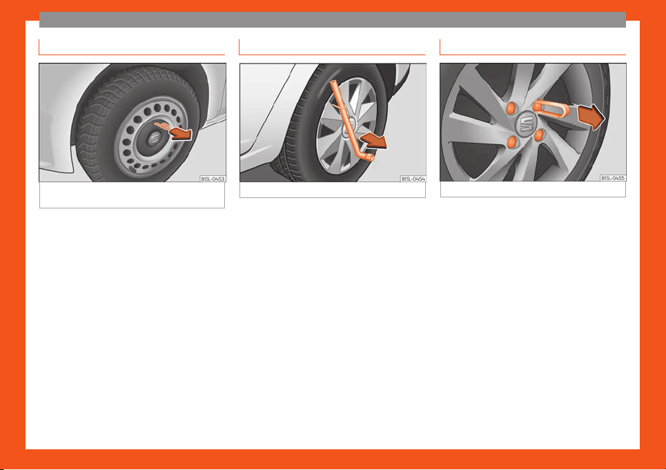
The essentials
Hubcaps
Fig. 51
Remove the hubcap of the steel wheel
trim
In order to access the wheel bolts, first re-
mo
v
e the hubcap
.
Removing and fitting the hubcap
●
To remove, take the vehicle tool kit wire
hook and attach it to the edge of the wheel
trim
›››
Fig. 51.
●
Remove the trim by pulling it in the direction
of the arrow.
●
To replace the hubcap, press the hubcap
against the trim until it clicks into place.
The caps protect the wheel bolts and should
be remounted after changing the tyre.
Full hubcaps
Fig. 52
Removing the full hubcap
Removing the full hubcap
●
Take the wheel brace and the wire hook
fr
om the v
ehicl
e tool kit
›››
page 70.
●
Hook the wire through one of the grooves
on the hubcap.
●
Insert the wheel brace onto the wire hook
›››
Fig. 52 and pull the hub cap in the direc-
tion shown by the arrow.
Fitting hubcaps
●
It is necessary to press the hubcap against
the wheel so that the space for the valve fits
over the tyre valve.
●
Make sure that the hubcap is correctly fit-
ted all the way around the wheel. If you are
using an anti-theft wheel lock, screw it in the
opposite position to the valve.
Wheel bolt caps
Fig. 53
Removing the wheel bolt caps
Removal
●
Fit the plastic clip (vehicle tools
›
›
›
page 70) over the cap until it clicks
into place
›››
Fig. 53.
●
Remove the cap with the plastic clip.
The caps protect the wheel bolts and should
be remounted after changing the tyre.
The anti-theft wheel bolt has a special cap
which is only compatible with anti-theft bolts
and cannot be used for conventional bolts.
38
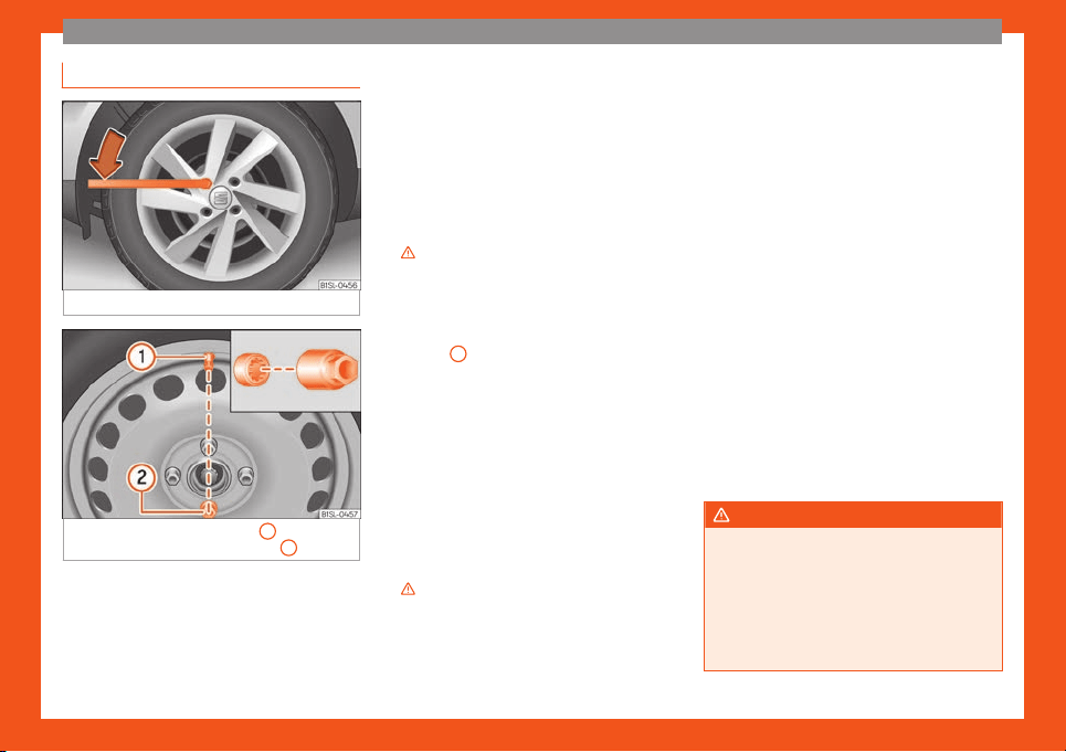
The essentials
Loosening the wheel bolts
Fig. 54
Tyre change: slacken the wheel bolts.
Fig. 55
Tyre change: tyre valve
1
and posi-
tion of anti-theft wheel l
ocking bolt
2
.
●
Only use the tool supplied with the vehicle
t
o l
oosen the wheel bolts.
●
L
oosen the wheel bolts only about one turn
before raising the vehicle with the jack.
●
If the wheel bolt is very tight, you may be
able to loosen it by pushing down on the end
of the wheel brace carefully with your foot.
Hold on to the vehicle for support and take
care not to slip.
Loosening wheel bolts
●
Fit the wheel brace as far as it will go over
the wheel bolt
›››
Fig. 54.
●
Hold the wheel brace at the end and rotate
the bolt approximately one turn anticlockwise
›››
.
L
oosening anti-theft wheel bolts
F
or wheel
s with full hubcap, the anti-theft
wheel lock must be threaded into position
›››
Fig. 55
2
before mounting the hubcap.
Otherwise it will not be possibl
e t
o mount the
entir
e hubcap.
●
Take the adapter for anti-theft wheel bolts
out of the vehicle tool kit.
●
Insert the adapter onto the wheel bolt
›››
Fig. 55. Push it on as far as it will go.
●
Fit the wheel brace onto the adapter as far
as possible.
●
Hold the wheel brace at the end and rotate
the bolt approximately one turn anticlockwise
›››
.
Impor
t
ant inf
ormation about wheel bolts
The wheel rims and bolts have been de-
signed to be fitted to factory options. If differ-
ent rims are fitted, the correct wheel bolts
with the right length and correctly shaped
bolt heads must be used. This ensures that
wheels are fitted securely and that the brake
system functions correctly.
In some circumstances, wheel bolts from the
same model vehicle should not be used.
Wheel bolt tightening torque
The prescribed tightening torque for wheel
bolts for steel and alloy wheels is 110 Nm.
Have the tightening torque of the wheel bolts
checked as soon as possible with a reliable
torque wrench.
If wheel bolts are rusty and it is difficult to
tighten them, the threads should be replaced
and cleaned before checking the tighten-
ing torque.
Never grease or lubricate wheel bolts or the
wheel hub threads. Although they have been
tightened to the prescribed torque, they
could come loose while driving.
WARNING
If the wheel bolts are not fitted correctly
they could be rel
eased while driving lead-
ing to loss of vehicle control and serious
damage.
●
Only use wheel bolts which correspond
to the wheel rims in question.
●
Never use different wheel bolts.
»
39
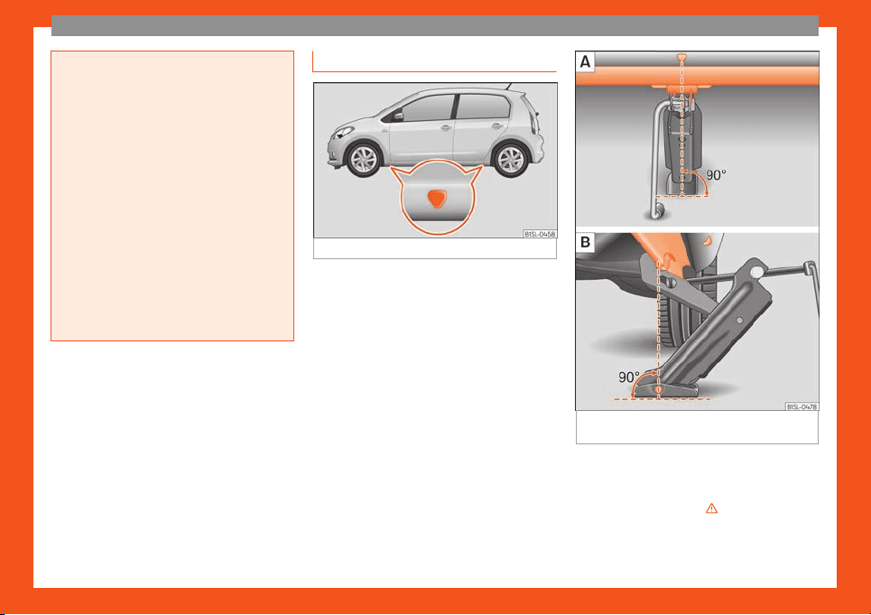
The essentials
●
The bolts and threads should be cl
ean,
free of oil and grease and easy to thread.
●
To loosen and tighten the wheel bolts, al-
ways use the wheel brace supplied with the
vehicle.
●
Loosen the wheel bolts only about one
turn before raising the vehicle with the jack.
●
Never grease or lubricate wheel bolts or
the wheel hub threads. Although they have
been tightened to the prescribed torque,
they could come loose while driving.
●
Never loosen the bolted joints of wheel
rims with bolted ring trims.
●
If the wheel bolts are not tightened to the
correct torque, they may come loose while
driving, and the bolts and rims may come
out. If the tightening torque is too high, the
wheel bolts and threads can be damaged.
Raising the vehicle with the jack
Fig. 56
Jack position points.
Fig. 57 Jack mounted on the left rear part of
the v
ehicl
e
The jack may be applied only at the jacking
points sho
wn (marks on chassis)
›
›
›
Fig. 56.
Always the relevant jacking point for the
wheel to be changed
›››
.
R
aise the v
ehicl
e using only the designated
jacking points.
40
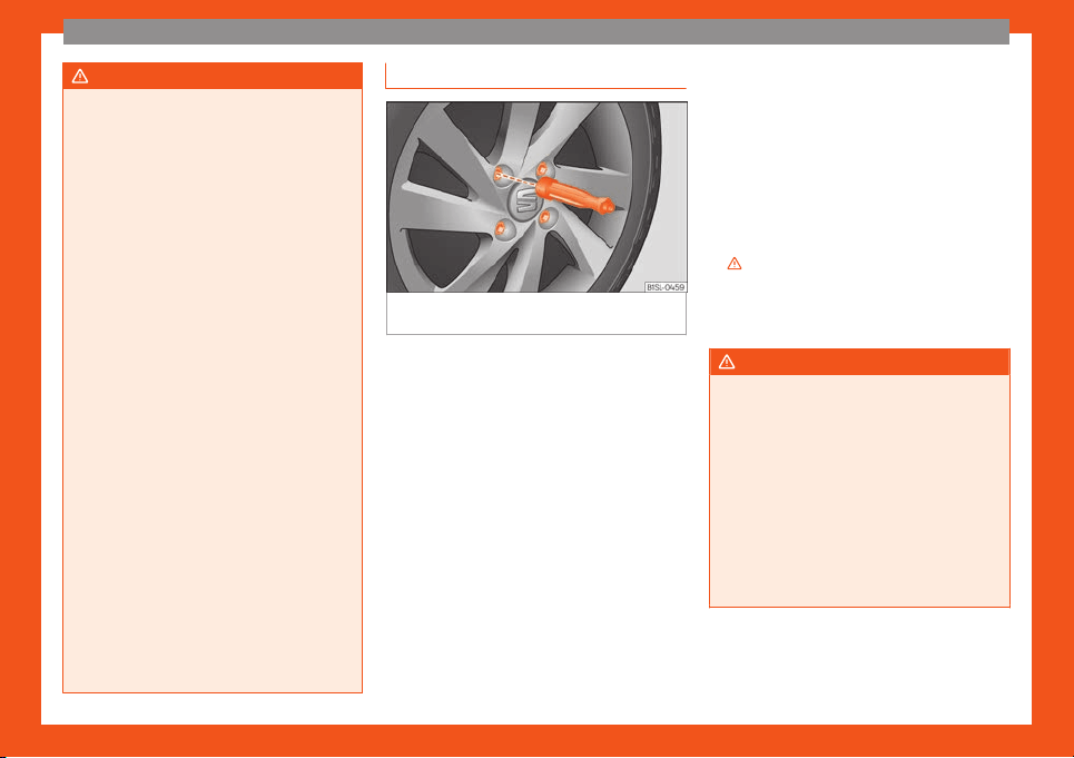
The essentials
WARNING
If the vehicle is not correctly raised, it could
fall off the jack causing serious injury.
Please observ
e the following rules to mini-
mise the risk of injury:
●
You should only use a jack approved by
SEAT for your vehicle. Other jacks, even
those approved for other SEAT models,
might slip out of place.
●
The ground should be firm and flat. If the
ground is sloped or soft then the vehicle
could slip and fall off the jack. If necessary,
support the jack on a wide solid base.
●
If the ground is slippery, such as tiles,
place a non-slip surface (a floor mat, for in-
stance) beneath the jack to avoid slipping.
●
Only fit the jack at the prescribed jacking
points. The claw of the jack should grip the
reinforcement nerve on the underbody
›››
Fig. 57.
●
You should never place a body limb such
as an arm or leg under a raised vehicle that
is solely supported by the jack.
●
If you have to work underneath the vehi-
cle, you must use suitable stands addition-
ally to support the vehicle, there is a risk of
accident!.
●
Never raise the vehicle if it is tilting to one
side or the engine is running.
●
Never start the engine when the vehicle is
raised. The vehicle may come loose from
the jack due to the engine vibrations.
Removing and fitting a wheel
Fig. 58
Changing the tyre: loosen wheel bolts
with the sock
et at the end of the wheel br
ace
Change the wheel after loosening the wheel
bolts and r
aising the v
ehicl
e with the jack.
Removing the wheel
●
Slacken the wheel bolts
›››
page 39.
●
Raise the vehicle
›››
page 40.
●
Using the hexagonal socket in the wheel
brace
›››
Fig. 58, unscrew the slackened
wheel bolts and place them on a clean sur-
face.
●
Take off the wheel.
How to use the spare wheel or temporary
spare wheel
Check the direction of rotation of the tyre
›››
page 214, Tyre code.
●
Place the spare wheel or temporary spare
wheel into position.
●
Replace the wheel bolts and tighten slight-
ly using the hexagonal socket on the end of
the wheel brace.
●
To tighten the anti-theft locking wheel bolts
use the corresponding adaptor.
●
Lower the car with the jack.
●
Tighten all of the wheel bolts clockwise
›››
. Tighten the bolts in diagonal pairs (not
in a cir
cl
e).
●
Put the caps, trim or full hubcap back on
›
››
page 38.
WARNING
If the wheel bolts are not treated suitably
or not tightened to the corr
ect torque then
this could lead to loss of vehicle control
and to a serious accident.
●
All the wheel bolts and hub threads
should be clean and free of oil and grease.
The wheel bolts should be easily tightened
to the correct torque.
●
The hexagonal socket in the wheel brace
should be used for turning wheel bolts only.
Do not use it to loosen or tighten the wheel
bolts.
41

The essentials
Tyres with compulsory direction of
r
ot
ation
A directional tread pattern can be identified
by the arrows on the side
wall that point in the
direction of rotation. Always observe the di-
rection of rotation indicated when fitting the
wheel to guarantee optimum properties of
this type of tyres with regard to grip, noises,
wear and aquaplaning.
If it is absolutely necessary to fit the spare
tyre* against the direction of rotation, drive
with care as this means the tyre does not of-
fer optimum driving properties. This is of par-
ticular importance when the road surface is
wet.
To return to directional tread tires, replace the
punctured tyre as soon as possible and re-
store the obligatory direction of rotation of all
tyres.
After the wheel change
●
Clean the vehicle tools, if necessary and
put them aw
ay in the luggage compartment
f
oam hol
der
›››
page 70.
●
Store the spare wheel, the temporary spare
wheel or the changed wheel securely in the
luggage compartment.
●
Have the tightening torque of the wheel
bolts checked as soon as possible with a tor-
que wrench
›››
page 39.
●
Have the flat tyre replaced as quickly as
possible.
Snow chains
Use
When using snow chains, applicable local
l
egisl
ation and maximum permitt
ed speed
limits must be observed.
In winter weather, snow chains not only help
to improve grip but also improve the braking
capacity.
The fitting of chains is permitted only on
front wheels and with the following combi-
nations of wheel trims and tyres:
Tyre size Wheel rim
165/70 R14
5 J x 14 offset of 35
175/65 R14
SEAT recommends you ask a technical serv-
ice f
or further inf
ormation on wheel, t
yre and
chain sizes.
Wherever possible use fine-link chains meas-
uring less than 15 mm including the lock.
Remove wheel hub covers and trim rings be-
fore fitting snow chains
›››
. The wheel bolts
shoul
d be co
v
ered with caps for safety rea-
sons. These are available from technical
services.
Temporary spare wheel
For technical reasons, snow chains must not
be used on the compact temporary spare
wheel
›››
page 213.
If it is necessary to fit chains with the tempo-
rary spare wheel in use, install the wheel on
the rear axle in the event of a fault in a front
wheel. Then, fit the rear wheel that is free, in-
stead of the damaged front wheel. In this sit-
uation, observe the rotating direction of the
wheels. SEAT recommends attaching the
snow chains before fitting the wheel.
WARNING
The use of unsuitable or incorrectly fitted
chains could lead t
o serious accidents and
damage.
●
Always the appropriate snow chains.
●
Observe the fitting instructions provided
by the snow chain manufacturer.
●
Never exceed the maximum permitted
speeds when driving with snow chains.
CAUTION
●
Remov
e the snow chains to drive on
roads without snow. Otherwise they will
42
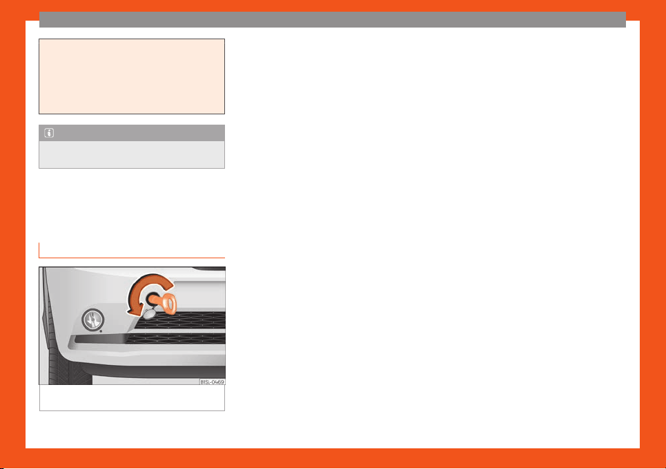
The essentials
impair vehicle handling, damage the tyres
and wear out very quickly.
●
Wheel rims may be damaged or scr
atch-
ed if the chains come into direct contact
with them. SEAT recommends the use of
covered snow chains.
Note
Snow chains are available in different sizes
accor
ding to the v
ehicle type.
Emergency towing of the ve-
hicl
e
T
o
wing
Fig. 59
Right side of the front bumper: towline
anchor
age scr
e
wed in.
Towline anchorages
Att
ach the bar or r
ope t
o the towline ancho-
rages.
It is located with the vehicle's tools
›››
page 70.
Screw the front towline anchorage into the
screw connection
›››
Fig. 59 and tighten it
with the wheel brace.
Tow rope or tow bar
When towing, the tow bar is the safest and
vehicle friendly way. You should only use a
tow rope if you do not have a tow bar.
A tow rope should be slightly elastic to avoid
damage to both vehicles. It is advisable to
use a tow rope made of synthetic fibre or sim-
ilarly elastic material.
●
Only secure the tow rope or tow bar to the
towline anchorage or specially designed fit-
ting.
Notes for the driver of the towed vehicle
●
Keep the ignition running to prevent the
steering wheel from locking and also to allow
the use of the turn signals, horn, windscreen
wipers and washers.
●
As the power assisted steering does not
work if the engine is not running, you will need
more strength to steer than normally.
●
The brake must be depressed much harder
as the brake servo does not operate. Avoid
hitting the towing vehicle.
●
Note the instructions and information con-
tained in the Instruction Manual for the vehi-
cle to be towed.
Notes for the driver of the towing vehicle
●
Accelerate gently and carefully. Avoid sud-
den manoeuvres.
●
Brake well in advance than usual and brake
gently.
●
Note the instructions and information con-
tained in the Instruction Manual for the vehi-
cle to be towed.
Driving style
Towing requires some experience, especially
when using a tow rope. Both drivers should
realise how difficult it is to tow a vehicle. Inex-
perienced drivers should not attempt to tow.
Do not pull too hard with the towing vehicle
and take care to avoid jerking the tow rope.
When towing on an unpaved road, there is al-
ways a risk of overloading and damaging the
anchorage points.
Switch on the ignition so that the turn signals,
windscreen wipers and windscreen washer
can work. Ensure that the steering wheel is
unlocked and moves freely.
»
43
The essentials
Place the gear lever in neutral on vehicles
with a manual gearbo
x. With an aut
omatic
gearbo
x, place the lever in N.
To brake, press the brake pedal firmly. The
brake servo does not work when the engine is
switched off.
The power steering only works when the igni-
tion is switched on, provided that the battery
is sufficiently charged. Otherwise, it will need
more force.
Ensure that the tow rope remains taut at all
times.
›››
in Instructions for tow-starting
on page 76
›››
page 75
Tow-starting
In general, the vehicle should not be star-
t
ed by t
o
wing. Jump-starting is much more
preferable
›››
page 44.
For technical reasons, the following vehicles
can not be tow started:
●
Vehicles with an automatic gearbox.
●
If the vehicle battery is flat, it is possible that
the engine control unit does not operate cor-
rectly.
However, if your vehicle must absolutely
be tow-started (manual gearbox):
●
Put it into second or third gear.
●
Keep the clutch pressed down.
●
Switch on the ignition and the hazard warn-
ing lights.
●
Release the clutch when both vehicles are
moving.
●
As soon as the engine starts, press the
clutch and move the gear lever into neutral.
This helps to prevent a collision with the tow-
ing vehicle.
How to jump start
Jump leads
If the engine fails to start because of a dis-
char
ged batt
ery, the batt
ery of another vehi-
cle can be used to start the engine. Before
starting, check the magic eye on the battery
›››
page 202.
For starting assistance, jump lead cables
conforming to the standard DIN 72553 are re-
quired (see the cable manufacturer instruc-
tions). The cable section in vehicles with pet-
rol engine must be at least 25 mm
2
.
WARNING
Incorrect use of jump leads and incorrectly
jump starting coul
d cause the battery to
explode resulting in serious injury. Please
observe the following rules to minimise the
risk of a battery explosion:
●
The battery providing current must have
the same voltage (12V) and approximately
the same capacity (see markings on bat-
tery) as the flat battery.
●
Never charge a frozen or recently thawed
battery. A flat battery can also freeze at
temperatures close to 0°C (+32°F).
●
If a battery is frozen and/or has been fro-
zen then it must be replaced.
●
A highly explosive mixture of gases is re-
leased when the battery is being charged.
Always keep lit cigarettes, flames, sparks
and fire far from the battery. Never use a
mobile telephone when connecting and re-
moving the jump leads.
●
Charge the battery only in well ventila-
ted areas given that when the battery is
charged by outside assistance, it creates a
mix of highly explosive gases.
●
Jump leads should never enter into con-
tact with moving parts in the engine com-
partment.
●
Never switch the positive and negative
poles or connect the jump leads incorrect-
ly.
●
Note the instruction manual provided by
the manufacturer of the jump leads.
44
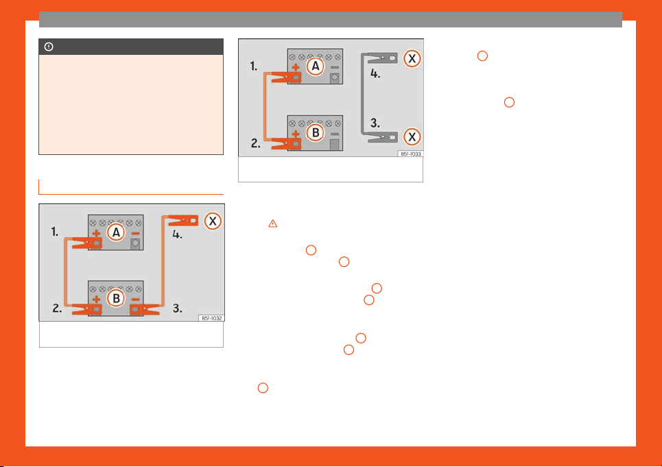
The essentials
CAUTION
To avoid considerable damage to the vehi-
cle electrical syst
em, note the following
carefully:
●
If the jump leads are incorrectly connec-
ted, this could result in a short circuit.
●
The vehicles must not touch each other,
otherwise electricity could flow as soon as
the positive terminals are connected.
How to jump start: description
Fig. 60 Diagram of connections for vehicles
without St
art St
op syst
em
Fig. 61 Diagram of connections for vehicles
with Start Stop syst
em
Jump lead terminal connections
S
wit
ch off the ignition of both v
ehicles
›››
.
Connect one end of the r
ed
jump l
ead to
the positive
+
terminal of the vehicle
with the fl
at batt
ery
A
›
›
›
Fig. 60.
Connect the other end of the red jump
lead to the positive terminal
+
in the ve-
hicl
e pr
o
viding assistance
B
.
In v
ehicl
es without a St
art-Stop system:
connect one end of the black jump lead
to the negative terminal
–
of the vehicle
pr
o
viding the curr
ent
B
›
›
›
Fig. 60.
In vehicles with a Start-stop system:
connect one end of the black jump lead
X
to a suitable ground terminal, to a sol-
id piece of met
al in the engine bl
ock
, or
to the engine block itself
›››
Fig. 61.
1.
2.
3.
4a.
4b.
Connect the other end of the black jump
lead
X
to a solid metal component bol-
t
ed t
o the engine bl
ock or to the engine
block itself of the vehicle with the flat
battery. Do not connect it to a point near
the battery
A
.
P
osition the l
eads in such a w
ay that
they cannot come into contact with any
moving parts in the engine compart-
ment.
Starting
Start the engine of the vehicle with the
boosting battery and let it run at idling
speed.
Start the engine of the vehicle with the
flat battery and wait for 2 or 3 minutes
until the engine is running.
Removing the jump leads
Before you remove the jump leads,
switch off the dipped beam headlights if
they are switched on.
Turn on the heater blower and heated
rear window in the vehicle with the flat
battery. This helps minimise voltage
peaks which are generated when the
leads are disconnected.
When the engine is running, disconnect
the leads in reverse order to the details
given above.
»
5.
6.
7.
8.
9.
10.
11.
45
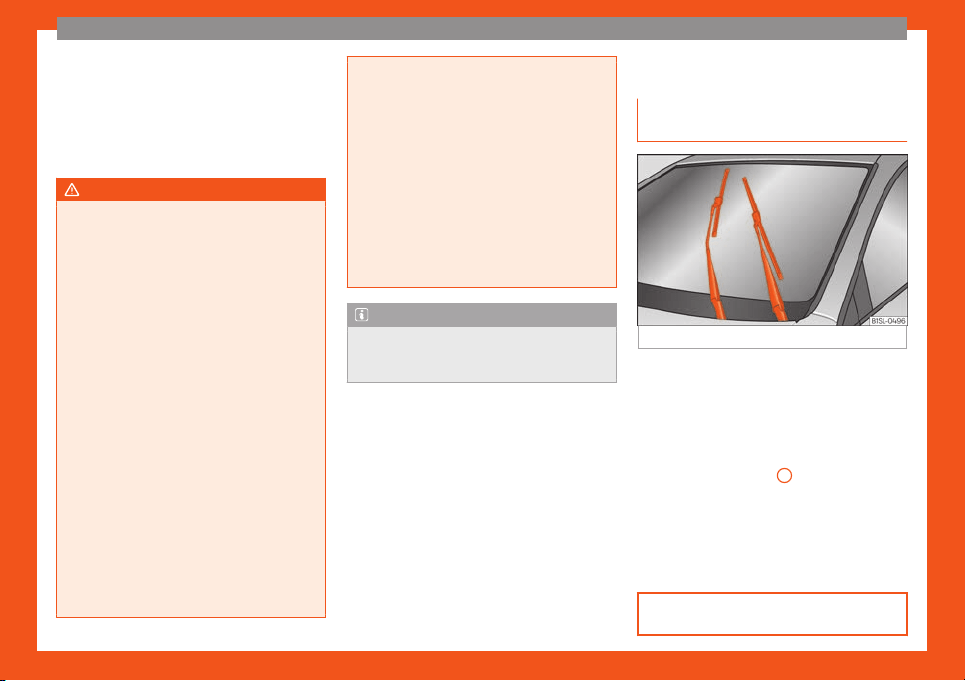
The essentials
Make sure the battery clamps have sufficient
met
al
-t
o-metal contact with the battery ter-
minals.
If the engine fails to start after about 10 sec-
onds, switch off the starter and try again after
about 1 minute.
WARNING
●
Please note the saf
ety warnings referring
to working in the engine compartment
›››
page 193.
●
The battery providing assistance must
have the same voltage as the flat battery
(12V) and approximately the same capaci-
ty (see imprint on battery). Failure to com-
ply could result in an explosion.
●
Never use jump leads when one of the
batteries is frozen. Danger of explosion!
Even after the battery has thawed, battery
acid could leak and cause chemical burns.
If a battery freezes, it should be replaced.
●
Keep sparks, flames and lighted ciga-
rettes away from batteries, danger of ex-
plosion. Failure to comply could result in an
explosion.
●
Observe the instructions provided by the
manufacturer of the jump leads.
●
Do not connect the negative cable from
the other vehicle directly to the negative
terminal of the flat battery. The gas emit-
ted from the battery could be ignited by
sparks. Danger of explosion.
●
Never att
ach the negative cable to fuel
system components or the brake lines in
the other vehicle.
●
The non-insulated parts of the battery
clamps must not be allowed to touch. The
jump lead attached to the positive battery
terminal must not touch metal parts of the
vehicle, this can cause a short circuit.
●
Position the leads in such a way that they
cannot come into contact with any moving
parts in the engine compartment.
●
Do not lean on the batteries. This could
result in chemical burns.
Note
The vehicles must not touch each other,
otherwise electricity coul
d flow as soon as
the positive terminals are connected.
Changing the wiper blades
Windscr
een wipers service posi-
tion
Fig. 62 Wipers in service position.
The wiper arms can be raised when the wip-
ers ar
e in service position
›
›
›
Fig. 62.
●
Close the bonnet
›››
page 193.
●
Switch the ignition on and off.
●
Press the windscreen wiper lever down-
wards briefly
›››
Fig. 33
4
.
Bef
or
e driving, al
ways lower the wiper arms.
When the ignition is switched on, the wind-
screen wiper arms return to their initial posi-
tion upon activating the windscreen wiper
lever.
›››
page 75
46
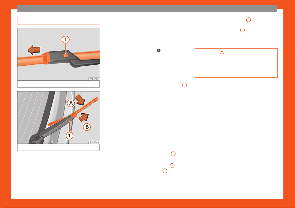
The essentials
Changing the front wiper blades
Fig. 63
Changing the front wiper blades
Fig. 64
Changing the rear wiper blade
Lifting and unfolding the wiper arms
The wiper arm may only be lift
ed at the point
wher
e it is f
astened to the blade.
The wiper should be in service position before
unfolding it
›››
page 108.
Cleaning windscreen wiper blades
●
Lifting and unfolding the wiper arms.
●
Use a soft cloth to remove dust and dirt
from the windscreen wiper blades.
●
If the blades are very dirty, a sponge or
damp cloth may be used
›››
in Changing
the windscr
een and r
ear windo
w wiper
blades on page 75.
Changing the windscreen wiper blades
●
Lifting and unfolding the wiper arms.
●
Hold down the release button
›››
Fig. 63
1
while gently pulling the blade in the direction
of the arr
o
w
.
●
Fit a new wiper blade of the same length
and design on to the wiper arm and hook it
into place.
●
Rest the wiper arms back onto the wind-
screen.
Changing the rear wiper blade
●
Lift the windscreen wiper arm and fold it at
an angle of approximately 60°
›››
Fig. 64.
●
Press and hold the release button
1
.
●
Fold the wiper blade towards the wind-
scr
een wiper arm
›
›
›
Fig. 64 (arrow
A
) while
pulling in the dir
ection of arr
o
w
B
. You might
hav
e t
o apply a l
ot of force.
●
Insert a new blade of the same length and
type in the windscreen wiper arm in the op-
posite direction to the arrow
B
and hook into
pl
ace
. This f
eature is operational when the
knob is in position (arrow
A
).
●
Return the windscreen wiper arm to the
windscr
een. Do not l
et it simply dr
op down!
›››
in Changing the windscreen
and rear window wiper bl
ades on
page 75
›››
page 75
47

Safety
Safety
Saf
e driving
Driving advice
Saf
et
y first!
WARNING
●
This manual contains import
ant informa-
tion about the operation of the vehicle,
both for the driver and the passengers. The
other sections of the on-board documenta-
tion also contain further information that
you should be aware of for your own safety
and for the safety of your passengers.
●
Ensure that the on-board documentation
is kept in the vehicle at all times. This is es-
pecially important when lending or selling
the vehicle to another person.
WARNING
Driving under the influence of alcohol,
drugs, medication or narcotics may result
in se
vere accidents and even loss of life.
●
Alcohol, drugs, medication and narcotics
may significantly alter perception, affect
reaction times and safety while driving,
which could result in the loss of control of
the vehicle.
Before driving
For your own safety and the safety of your
passengers, always not
e the following points
before every trip:
–
Make sure that the vehicle's lights and turn
signals are working properly.
–
Check tyre pressure.
–
Ensure that all windows provide a clear and
good view of the surroundings.
–
Make sure all luggage is secured
›››
page 114.
–
Make sure that no objects can interfere with
the pedals.
–
Adjust front seat, head restraint and mirrors
properly according to your size.
–
Ensure that the passengers in the rear seats
always have the head restraints in the in-
use position
›››
page 52.
–
Instruct passengers to adjust the head re-
straints according to their height.
–
Protect children with appropriate child
seats and properly applied seat belts
›››
page 65.
–
Assume the correct sitting position. Instruct
your passengers also to assume a proper
sitting position
›››
page 49.
–
Fasten your seat belt securely. Instruct your
passengers also to fasten their seat belts
properly
›››
page 53.
What affects driving safety?
As a driver, you are responsible for yourself
and your passengers. When your concentra-
tion or driving safet
y is affected by any cir-
cumstance, you endanger yourself as well as
others on the road
›››
, for this reason:
–
Always pay attention to traffic and do not
get distr
act
ed by passengers or t
elephone
calls.
–
Never drive when your driving ability is im-
paired (e.g. by medication, alcohol, drugs).
–
Observe traffic laws and speed limits.
–
Always reduce your speed as appropriate
for road, traffic and weather conditions.
–
When travelling long distances, take breaks
regularly - at least every two hours.
–
If possible, avoid driving when you are tired
or stressed.
WARNING
When driving safety is impaired during a
trip, the risk of injury and accidents increa-
ses.
48
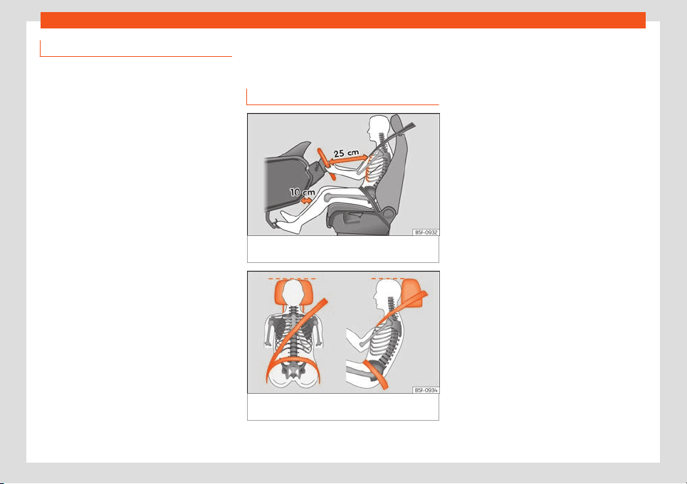
Safe driving
Safety equipment
Never put your safety or the safety of your
passengers in danger. In the ev
ent of an acci-
dent, the safety equipment may reduce the
risk of injury. The following points cover part
of the safety equipment in your SEAT:
●
three-point seat belts,
●
belt tension limiters for the front seats,
●
belt tensioners for the front seats,
●
front airbags,
●
side airbags in the front seat backrests,
●
“ISOFIX” anchor points for child seats in the
rear side seats with the “ISOFIX” system,
●
r
ear head restraints with in-use position and
non-use position,
●
adjustable steering column.
The safety equipment mentioned above
works together to provide you and your pas-
sengers with the best possible protection in
the event of an accident. However, these
safety systems can only be effective if you
and your passengers are sitting in a correct
position and use this equipment properly.
Safety is everyone's business!
Correct position of the vehi-
cle occupants
Correct sitting position
Fig. 65 The proper distance between driver
and st
eering wheel
.
Fig. 66
Correct belt web and head restraint
positions
The correct sitting positions for the driver and
passengers ar
e sho
wn bel
ow.
If your physical constitution prevents you
from maintaining the correct sitting position,
contact a specialised workshop for help with
any special devices. The seat belt and airbag
can only provide optimum protection if a cor-
rect sitting position is adopted. SEAT recom-
mends taking your car in for technical serv-
ice.
For your own safety and to reduce the risk of
injury in the event of an accident or sudden
braking or manoeuvre, SEAT recommend the
following positions:
Valid for the driver:
●
Adjust the seat backrest to an upright posi-
tion so that your back rests completely
against it.
●
Adjust the seat so that there is a distance of
at least 25 cm between the steering wheel
and your chest
›››
Fig. 65 and so that you
can hold the steering wheel with both hands
on the outside of the ring at the 9 o'clock and
3 o'clock positions with your arms slightly
bent.
●
The adjusted steering wheel must face your
chest and not your face.
●
Adjust the driver seat forwards or back-
wards so that you are able to press the ac-
celerator, brake and clutch pedals to the floor
with your knees slightly angled and the dis-
tance between your knees and the dash pan-
el is at least 10 cm
›››
Fig. 65.
»
49

Safety
●
Adjust the height of the driv
er seat so that
you can easily r
each the t
op of the steering
wheel.
●
Keep both feet in the footwell so that you
have the vehicle under control at all times.
●
Adjust and fasten your seat belt correctly
›››
page 53.
Valid for the passenger:
●
Adjust the seat backrest to an upright posi-
tion so that your back rests completely
against it.
●
Move the front passenger seat back as far
as possible for optimum protection should the
airbag deploy.
●
Always keep your feet in the footwell while
the vehicle is in motion.
●
Adjust and fasten your seat belt correctly
›››
page 53.
Valid for the passengers in the rear sec-
tion:
●
Adjust the head restraint so that its upper
edge is at the same level as the top of your
head, or as close as possible to the same lev-
el as the top of your head and under no cir-
cumstances below eye level. Keep the back
of your neck as close as possible to the head
restraint
›››
Fig. 65 and
›››
Fig. 66.
●
Short people must lower the head restraint
to the first anchorage position, even if your
head is below its upper edge.
●
Tall people must raise the head restraint
completely.
●
Always keep your feet in the footwell while
the vehicle is in motion.
●
Adjust and fasten your seat belt correctly
›››
page 53.
Adjusting the steering wheel posi-
tion
Read the additional information carefully
›
›
›
page 15.
Adjust the steering wheel before your trip and
only when the vehicle is stationary.
Adjust the correct distance between the driv-
er and the steering wheel
›››
Fig. 65 using the
controls on the driver seat
›››
page 14.
WARNING
Incorrect use of the steering wheel adjust-
ment function and an incorrect adjustment
of the steering wheel can r
esult in severe or
fatal injury.
●
After adjusting the steering column, push
the lever firmly upwards to ensure the
steering wheel does not accidentally
change position while driving.
●
Never adjust the st
eering wheel while the
vehicle is in motion. If you need to adjust
the steering wheel while the vehicle is in
motion, stop safely and make the proper
adjustment.
●
The adjusted steering wheel should be
facing your chest and not your face so as
not to hinder the driver's front airbag pro-
tection in the event of an accident.
●
When driving, always hold the steering
wheel with both hands on the outside of the
ring at the 9 o'clock and 3 o'clock positions
to reduce injuries when the driver's front
airbag deploys.
●
Never hold the steering wheel at the 12
o'clock position or in any other manner
(e.g. in the centre of the steering wheel). In
such cases, if the driver's airbag deploys,
you may sustain injuries to your arms,
hands and head.
Danger of injuries due to an incor-
r
ect sitting position
Number of seats
The v
ehicl
e has a t
otal of 4 seats: 2 front
seats and 2 rear seats. Each seat is equipped
with a seat belt.
If the seat belts are worn incorrectly or not at
all, the risk of severe injuries increases. Seat
belts can provide optimal protection only if
the belt web is properly worn. Being seated in
50
Safe driving
an incorrect position means the seat belt
cannot off
er its full pr
ot
ection. This could re-
sult in severe and even fatal injuries. The risk
of severe or fatal injuries is especially height-
ened when a deploying airbag strikes a vehi-
cle occupant who has assumed an incorrect
sitting position. The driver is responsible for all
passengers in the vehicle, particularly chil-
dren.
The following list shows just some examples
of incorrect sitting positions which can be
dangerous to all vehicle occupants.
When the vehicle is in motion:
●
Never stand in the vehicle.
●
Never stand on the seats.
●
Never kneel on the seats.
●
Never tilt your seat backrest too far to the
rear.
●
Never lean against the dash panel.
●
Never lie on the rear seats.
●
Never sit on the front edge of a seat.
●
Never sit sideways.
●
Never lean out of a window.
●
Never put your feet out of a window.
●
Never put your feet on the dash panel.
●
Never put your feet on the surface of a seat
or seat backrest.
●
Never travel in a footwell.
●
Never travel on a seat without wearing the
seat belt.
●
Never carry any person in the luggage
compartment.
WARNING
An incorrect sitting position in the vehicle
can lead to se
vere injuries or death in the
event of sudden braking or manoeuvres,
collision or accidents or if the airbag de-
ploys.
●
Before the vehicle moves, assume the
proper sitting position and maintain it
throughout the trip. This also includes fas-
tening the seat belt.
●
Never transport more people than there
are seats with a seat belt available in the
vehicle.
●
Children must always be protected with
an approved child restraint system suited
to their height and weight
›››
page 65,
›››
page 60.
●
Always keep your feet in the footwell
while the vehicle is in motion. Never, for ex-
ample, put your feet on the surface of a
seat or on the dash panel and never put
them out of a window. Otherwise the airbag
and seat belt offer insufficient protection
and the risk of injury in the event of an acci-
dent is increased.
WARNING
Before every trip, adjust the seat, the seat
belt and the head restraints and instruct
your passengers t
o fasten their seat belts
properly.
●
Move the front passenger seat back as
far as possible.
●
Adjust the driver seat so that there is at
least 25 cm distance between your chest
and the hub of the steering wheel. Adjust
the driver seat so that you are able to press
the accelerator, brake and clutch pedals to
the floor with your knees slightly angled
and that the distance between your knees
and the dash panel is at least 10 cm. If your
physical constitution prevents you from
meeting these requirements, contact a
specialised workshop to make any modifi-
cations required.
●
Never drive with the seat backrest tilted
far back. The further the seat backrests are
tilted to the rear, the greater the risk of in-
jury due to incorrect positioning of the belt
web or to the incorrect sitting position!
●
Never drive with the seat backrest tilted
forwards. Should a front airbag deploy, it
could throw the seat backrest backwards
and injure the passengers of the rear seats.
●
Sit as far away as possible from the
steering wheel and the dash panel.
●
Keep your back straight and resting com-
pletely against the seat backrest and the
front seats correctly adjusted. Never place
»
51
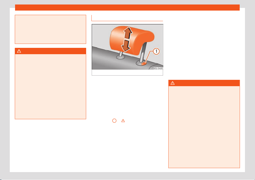
Safety
any part of your body in the area of the air-
bag or very close t
o it.
●
If passengers on the rear seats are not
sitting in an upright position, the risk of se-
vere injury due to incorrect positioning of
the belt web increases.
WARNING
Incorrect seat adjustment may lead to ac-
cidents and se
ver
e injuries.
●
Only adjust the seats when the vehicle is
stationary, as the seats could move unex-
pectedly while the vehicle is in motion and
you could lose control of the vehicle. Fur-
thermore, an incorrect position is adopted
when adjusting the seat.
●
Only adjust the height, seat backrest and
forwards or backwards position of the seat
when there is nobody in the seat adjust-
ment area.
●
There must be no objects blocking the
front seat adjustment area.
Adjusting the rear head restraints
Fig. 67
Adjusting the rear head restraints
All seats are equipped with a head restraint.
The fr
ont seat head r
estr
aints are integrated
in the backrests and adjusting them is not
possible.
Adjusting height
●
Push the head restraint up or down in the
direction of the arrow with the button press-
ed
›››
Fig. 67
1
›
›
›
.
●
The head restraint must engage securely in
position.
Corr
ect adjustment of head r
estr
aints
Adjust the head restraint so that its upper
edge is at the same level as the top of your
head, or as close as possible to the same lev-
el as the top of your head and under no cir-
cumstances below eye level. Keep the back
of your neck as close as possible to the head
restraint.
Adjusting the head restraint for short peo-
ple
Set the head restraint in the first anchorage
position, even if your head is below its upper
edge. When the head restraint is at its lowest,
it is possible that a small gap remains be-
tween it and the seat backrest.
Adjusting the head restraint for tall people
Raise the head restraint completely.
WARNING
Travelling with the head restraints removed
or improperly adjusted incr
eases the risk of
severe or fatal injuries in the event of acci-
dents and sudden braking or manoeuvres.
●
Always fit and adjust the head restraint
properly whenever a person is occupying a
seat.
●
All vehicle occupants must correctly ad-
just the head restraint according to their
height to reduce the risk of back injuries in
the event of an accident. The upper edge
of the head restraint must be as close as
possible to the same level as the top of
your head and under no circumstances be-
low eye level. Keep the back of your neck
as close as possible to the head restraint.
●
Never adjust the head restraint while the
vehicle is in motion.
52
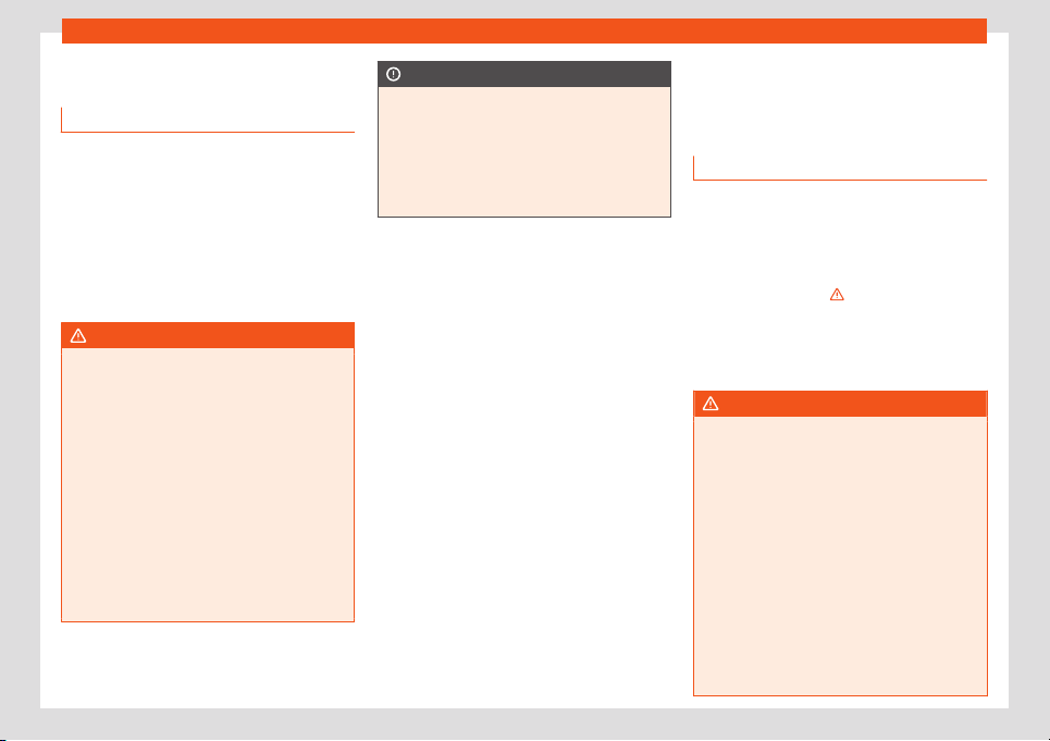
Seat belts
Pedal area
P
edal
s
Do not allow floor mats or other objects to
obstruct the free passage of the pedals.
Fl
oor mats should leave the pedal area free
and unobstructed and be correctly secured
in the footwell zone.
In the event of failure of a brake circuit, the
brake pedal must be pressed harder than
normal to brake the vehicle.
WARNING
Objects falling into the driver's footwell
could pre
vent use of the pedals. This could
lead the driver to lose control of the vehi-
cle, increasing the risk of a serious acci-
dent.
●
Make sure the pedals can be used at all
times, with no objects rolling underneath
them.
●
Always secure the mat in the footwell.
●
Never place other mats or rugs on top of
the original mat supplied by the factory.
●
Ensure that no objects can fall into the
driver's footwell while the vehicle is in mo-
tion.
CAUTION
The pedals must always have free and un-
obstructed passage to the fl
oor. For exam-
ple, in case of a fault in the brake circuit,
the brake pedal will need to be pressed fur-
ther to stop the vehicle. To press the brake
pedal down further will require more force
than usual.
Seat belts
Why w
ear a set belt
Intr
oduction
Check the condition of all the seat belts at
regular int
ervals. If you notice that the belt
webbing, fittings, retractor mechanism or
buckle of any of the belts is damaged, the
belt must be replaced immediately by a spe-
cialised workshop
›››
. The specialised
w
orkshop must use the appr
opriat
e spare
parts corresponding to the vehicle, the equip-
ment and the model year. SEAT recommends
taking your car in for technical service.
WARNING
Unbuckled or badly buckled seat belts in-
crease the risk of sev
ere or even fatal inju-
ries. The seat belt cannot offer its full pro-
tection if it is not fastened and used cor-
rectly.
●
Seat belts are the most effective way of
reducing the risk of sustaining severe or fa-
tal injuries in the event of an accident. Seat
belts must be correctly fastened when the
vehicle is in motion to protect the driver
and all vehicle occupants.
●
Before each trip, every occupant in the
vehicle occupants must sit properly, cor-
rectly fasten the seat belt belonging to his
or her seat and keep it fastened throughout
»
53
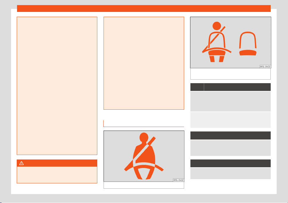
Safety
the trip. This also applies to other vehicle
occupants when driving in town.
●
When tr
avelling, children must be se-
cured in the vehicle with a child restraint
system suitable for their weight and height
and with the seat belts correctly fastened
›››
page 65.
●
Instruct your passengers to fasten their
seat belts properly before driving off.
●
Insert the latch plate into the buckle for
the appropriate seat and ensure it is en-
gaged. Using the latch plate in the buckle
of another seat will not protect you proper-
ly and may cause severe injuries.
●
Do not allow liquids or foreign bodies to
enter the buckle fastenings. This could
damage the buckles and seat belts.
●
Never unbuckle your seat belt when the
vehicle is moving.
●
Never allow more than one passenger to
share the same seat belt.
●
Never hold children or babies on your lap
sharing the same seat belt.
●
Bulky and unbuttoned clothing, such as a
coat worn over a sweatshirt, impairs the
proper fit and function of the seat belt.
WARNING
It is extremely dangerous to drive using
damaged seat belts and could result in se-
rious injury or l
oss of life.
●
Avoid damaging the seat belt by jamming
it in the door or the seat mechanism.
●
If the fabric or other par
ts of the seat belt
are damaged, the seat belts could break in
the event of an accident or sudden braking.
●
Always have damaged seat belts re-
placed immediately by seat belts ap-
proved for the vehicle in question by SEAT.
Seat belts which have been worn in an ac-
cident and stretched must be replaced by
a specialised workshop. Renewal may be
necessary even if there is no apparent
damage. The belt anchorage should also
be checked.
●
Never attempt to repair, modify or re-
move a seat belt yourself. All repairs to
seat belts, retractors and buckles must be
carried out by a specialised workshop.
Warning lamp
Fig. 68 Warning lamp on the instrument panel
Fig. 69 Indication of seat belt status in the rear
seats on the instrument panel display
Lights up or flashes
Driver's seat belt not fastened or front passenger
seat belt not fastened if the fr
ont passenger seat is
occupied.
Fasten your seat belt!
Objects over the passenger seat.
Remov
e any objects from the front passenger seat
and store them safely.
It lights up
A passenger in the rear seats has not fastened their
seat belt, if the seat is occupied.*
Fasten your seat belt
!
It lights up
A passenger in the rear seats has fastened their seat
belt, if the seat is occupied.*
54
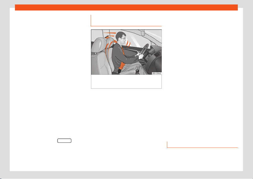
Seat belts
Several warning and control lamps light up
f
or a f
e
w seconds when the ignition is switch-
ed on, signalling that the function is being
verified. They will switch off after a few sec-
onds.
An audible warning will be heard if the seat
belts are not fastened as the vehicle drives
off and reaches a speed of more then
25 km/h (15 mph) or if the seat belts are un-
fastened while the vehicle is in motion. The
seat belt warning lamp will also flash.
The warning lamp does not switch off until
the driver and front passenger fasten their
seat belts while the ignition is switched on.
Seat belt status display for rear seats
The seat belt status display on the instrument
panel informs the driver, when the ignition is
switched on, whether any passengers in the
rear seats have fastened their seat belts. The
symbol indicates that the passenger in this
seat has fastened “his or her” seat belt
›››
Fig. 69.
The seat belt status is displayed for around
30 seconds when a seat belt in the rear seats
is fastened or unfastened. You can switch off
this display by pressing the 0.0 / SET
button.
The seat belt st
at
us fl
ashes for a maximum of
30 seconds when a seat belt in the rear seats
is unfastened while the vehicle is in motion. An
audible warning will also be heard if the vehi-
cle is travelling at over 25 km/h (15 mph).
The protective function of seat
belts
Fig. 70
Drivers with properly worn seat belts
will not be thr
o
wn f
orward in the event of sud-
den braking.
Properly worn seat belts hold the occupants
in the pr
oper position. They al
so help pr
event
uncontrolled movements that may result in
serious injury and reduce the risk of being
thrown out of the vehicle in case of an acci-
dent.
Vehicle occupants wearing their seat belts
correctly benefit greatly from the ability of
the belts to absorb kinetic energy. In addition,
the front part of your vehicle and other pas-
sive safety features (such as the airbag sys-
tem) are designed to absorb the kinetic ener-
gy released in a collision. Taken together, all
these features reduce the releasing kinetic
energy and consequently, the risk of injury.
This is why it is so important to fasten seat
belts before every trip, even when "just driving
around the corner".
Ensure that your passengers wear their seat
belts as well. Accident statistics have shown
that wearing seat belts is an effective means
of substantially reducing the risk of injury and
improving the chances of survival when in-
volved in a serious accident. Furthermore,
properly worn seat belts improve the protec-
tion provided by airbags in the event of an
accident. For this reason, wearing a seat belt
is required by law in most countries.
Although your vehicle is equipped with air-
bags, the seat belts must be fastened and
worn. The front airbags, for example, are only
triggered in some cases of head-on collision.
The front airbags will not be triggered during
minor frontal or side collisions, rear-end colli-
sions, rollovers or accidents in which the air-
bag trigger threshold value in the control unit
is not exceeded.
Therefore, you should always wear your seat
belt and ensure that all vehicle occupants
have fastened their seat belts properly before
you drive off!
Using seat belts
Twisted seat belt
If it is difficult t
o r
emo
ve the seat belt from the
guide, the seat belt may have become
»
55
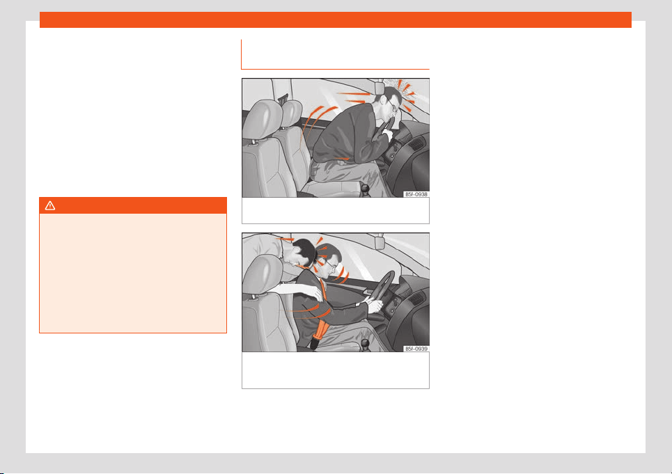
Safety
twisted inside the side trim after being wound
t
oo quickly on unf
ast
ening:
●
Pull out the seat belt completely, carefully
pulling on the latch plate.
●
Untwist the belt and guide it back, assisting
it by hand.
The seat belt must be fastened even if it is im-
possible to untwist it. In this case, the twisted
area must not be in an area in direct contact
with your body. Have the seat belt untwisted
urgently by a specialised workshop.
WARNING
An improperly handled seat belt increases
the risk of sustaining sev
ere or fatal injuries.
●
Regularly check that the seat belts and
their components are in perfect condition.
●
Always keep your seat belt clean.
●
Do not jam or damage the seat belt or
rub it with sharp edges.
●
Make sure there are no liquids or foreign
bodies on the latch plate and in the buckle.
Head-on collisions and the laws of
physics
Fig. 71
A driver not wearing a seat belt is
thr
o
wn f
orward violently.
Fig. 72
The unbelted passenger in the rear
seat is thr
o
wn f
orward violently, hitting the driv-
er who is wearing a seat belt.
The effects of the laws of physics in the case
of a head-on collision ar
e easy t
o e
xplain: the
moment a vehicle starts moving, a type of en-
ergy called “kinetic energy” starts acting on
both the vehicle and its passengers.
The amount of “kinetic energy” depends on
the speed of the vehicle and on the weight of
the vehicle and of its passengers. The higher
the speed and the greater the weight, the
more energy there is to be “absorbed” in an
accident.
The most significant factor, however, is the
speed of the vehicle. If the speed doubles
from 25 km/h (15 mph) to 50 km/h (30 mph),
for example, the corresponding kinetic ener-
gy is multiplied by four.
Because the vehicle occupants in our exam-
ple are not restrained by seat belts, in the
event of crashing against a wall, all of the oc-
cupants' kinetic energy will be absorbed
solely by said impact.
Even at speeds of 30 km/h (19 mph) to
50 km/h (30 mph), the forces acting on bod-
ies in a collision can easily exceed one tonne
(1000 kg). At greater speed these forces are
even higher.
Vehicle occupants not wearing seat belts are
not “attached” to the vehicle. In a head-on
collision, they will move forward at the same
speed their vehicle was travelling just before
the impact. This example applies not only to
head-on collisions, but to all accidents and
collisions.
56
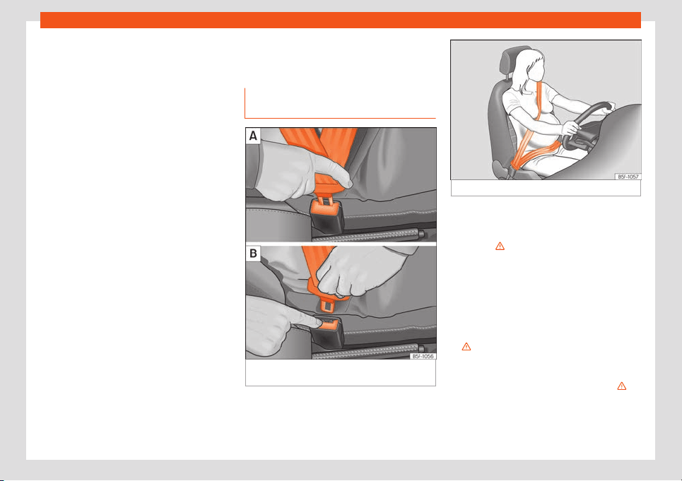
Seat belts
Even at low speeds the forces acting on the
body in a collision ar
e so gr
eat that it is not
possibl
e to brace oneself with one's hands. In
a frontal collision, unbelted passengers are
thrown forward and will make violent contact
with the steering wheel, dash panel, wind-
screen or whatever else is in the way
›››
Fig. 71.
It is also important for rear passengers to
wear seat belts properly, as they could other-
wise be thrown forward violently through the
vehicle interior in an accident. Passengers in
the rear seats who do not use seat belts en-
danger not only themselves but also the front
occupants
›››
Fig. 72.
How to properly adjust your
seat belt
Fastening and unfastening seat
belt
Fig. 73 Positioning and removing the seat belt
buckl
e
.
Fig. 74 Position of seat belt during pregnancy.
Properly worn seat belts hold the vehicle oc-
cupants in the position that most pr
ot
ects
them in the e
vent of an accident or sudden
braking
›››
.
F
ast
ening the seat belt
F
asten your seat belt before each trip.
●
Correctly adjust the front seat
›››
page 49.
●
Engage the seat backrest in the upright po-
sition and correctly adjust the hear restraint
›››
.
●
Pull the latch plate and place the belt web-
bing e
v
enly acr
oss your chest and lap. Do
not twist the seat belt when doing so
›››
.
●
Engage the latch plate in the buckle of the
corr
esponding seat
›
›
›
Fig. 73 A.
●
Pull the belt to ensure that the latch plate is
securely engaged in the buckle.
»
57
Safety
Unfastening the seat belt
The seat belt must not be unf
ast
ened until the
v
ehicle has come to a standstill
›››
.
●
Press the red button on the buckle
›
›
›
Fig. 73 B. The latch plate will come out of
the buckle.
●
Guide the belt back by hand so that it rolls
up easily and the trim will not be damaged.
Correct seat belt position
Seat belts offer their maximum protection in
the event of an accident and reduce the risk
of sustaining severe or fatal injuries only when
they are properly positioned. Furthermore, if
the webbing is correctly positioned, the seat
belt will hold the vehicle occupants in the op-
timum position to ensure the airbag provides
the maximum protection. The seat belt must
therefore always be worn and the webbing
correctly positioned.
Incorrectly worn seat belts can cause severe
or even fatal injuries
›››
page 49, Correct
position of the vehicle occupants.
●
The shoulder part of the seat belt must lie
on the centre of the shoulder, never across
the neck or the arm, under the arm or behind
the shoulder.
●
The lap part of the seat belt must lie across
the pelvis, never across the stomach.
●
The seat belt must lie flat and fit comforta-
bly. Pull the belt tight if necessary to take up
any slack.
In the case of pregnant women, the seat belt
must lie evenly across the chest and as low
as possible over the pelvis, never across the
stomach and must be worn properly at all
times during the pregnancy
›››
Fig. 74.
Adapting the position of the belt webbing
to your size
The seat belt can be adapted using the fol-
lowing equipment:
●
Front seat height adjustment.
WARNING
An incorrectly worn seat belt web can
cause sever
e or fatal injuries in the event of
an accident.
●
The seat belt cannot offer its full protec-
tion unless the seat backrest is in an up-
right position and the seat belt is worn cor-
rectly, according to your size.
●
Unbuckling your seat belt while the vehi-
cle is in motion can cause severe or fatal
injuries in the event of an accident or sud-
den braking.
●
The seat belt itself or a loose seat belt
can cause severe injuries if the belt moves
from hard areas of the body to soft areas
(e.g. the stomach).
●
The shoulder part of the seat belt must lie
on the centr
e of the shoulder, never across
the neck or the arm.
●
The seat belt must lie flat and fit comfort-
ably on the torso
●
The lap part of the seat belt must lie
across the pelvis, never across the stom-
ach. The seat belt must lie flat and fit com-
fortably on the pelvis Pull the belt tight if
necessary to take up any slack.
●
For pregnant women, the lap part of the
seat belt must lie as low as possible over
the pelvis and always lie flat, “surrounding”
the stomach.
●
Do not twist the seat belt while it is fas-
tened.
●
Never pull the seat belt away from your
body using your hand.
●
Do not lie the seat belt across rigid or
fragile objects, e.g. glasses, pens or keys.
●
Never use seat belt clips, retaining rings
or similar instruments to alter the position
of the belt webbing.
Note
If your physical constitution prevents you
from maintaining the corr
ect position of the
belt webbing, contact a specialised work-
shop for help with any special devices to
ensure the optimum protection of the seat
belt and airbag. SEAT recommends taking
your car in for technical service.
58
Seat belts
Seat belt tensioners
Aut
omatic belt r
etr
actor, belt ten-
sioner, belt tension limiter
Seat belts are part of the vehicle safety con-
cept
›››
page 60 and consist of the follow-
ing important functions:
Automatic belt retainer
Every seat belt is equipped with an automatic
belt retainer on the shoulder belt. If the belt is
pulled slowly or during normal driving, the
system allows for total freedom of movement
on the shoulder belt. However, during sudden
braking, during travel in mountains or bends
and during acceleration, the automatic belt
retainer on the seat belt is locked is pulled
quickly.
Belt tensioners
The seat belts for the occupants in the front
seats are equipped with belt tensioners.
Sensors trigger the belt tensioners during se-
vere head-on, lateral and rear collisions and
retract and tighten the seat belts. If the seat
belt is loose, it is retracted to reduce the for-
wards movement of occupants or movement
in the direction of the collision. The belt ten-
sioner works in combination with the airbag
system. The belt tensioner will not be trig-
gered in the event of the vehicle overturning if
the side airbags are not deployed.
If the belt t
ensioner is triggered, a fine dust is
produced. This is normal and it is not an indi-
cation of fire in the vehicle.
Belt tension limiter
The belt tension limiter reduces the force of
the seat belt on the body in the event of an
accident.
Note
The relevant safety requirements must be
observed when the vehicl
e is dismantled or
system components are removed. These
requirements are known to specialised
workshops
›››
page 59.
Service and disposal of belt ten-
sion de
vices
If you work on the belt tensioners or remove
and inst
all other parts of the v
ehicl
e when
performing other repair work, the seat belt
may be damaged. The consequence may be
that, in the event of an accident, the belt ten-
sioners function incorrectly or not at all.
So that the effectiveness of the belt tensioner
is not reduced and that removed parts do not
cause any injuries or environmental pollution,
regulations must be observed. These require-
ments are known to specialised workshops.
WARNING
●
Improper use or repairs not carried out by
qualified mechanics incr
ease the risk of se-
vere or fatal injuries. The belt tensioners
may fail to trigger or may trigger in the
wrong circumstances.
●
Never attempt to repair, adjust, remove or
install parts of the belt tensioners or seat
belts.
●
The seat belt tensioner, seat belt and au-
tomatic retractor cannot be repaired.
●
Any work on the belt tensioners and seat
belts, including the removal and refitting of
system parts in conjunction with other re-
pair work, must be performed by a special-
ised workshop only.
●
The belt tensioners will only provide pro-
tection for one accident and must be
changed if they have been activated.
For the sake of the environment
Airbag modules and belt tensioners may
contain perchl
orate. Observe the legal re-
quirements for their disposal.
59
Safety
Airbag system
Brief intr
oduction
Intr
oduction
Front airbags have been installed for both
driver and passenger. The fr
ont airbags can
also protect the chest and head of driver and
passenger if the seats, seat belts head re-
straints and, for the driver, the steering wheel
are correctly adjusted and used. Airbags are
considered as additional safety equipment.
An airbag cannot replace the seat belt, which
must be worn at all times, even in front seats
where front airbags have been installed.
The airbag can protect vehicle occupants in
the event of an accidents, cushioning the
movement of the occupants in the direction
of the collision in frontal and side accidents.
Deployed airbags fill with a propellant gas.
This causes the airbag covers to break and
the airbags to deploy extremely quickly in
their entire deployment space within frac-
tions of a second. When an occupant with the
seat belt properly fastened puts pressure on
the inflated airbag, the propellant gas es-
capes to absorb the force of the impact and
slow the movement. This reduces the risk of
severe or fatal injuries. Airbag deployment
does not mean that other types of injury such
as swelling, bruising and skin injuries can be
ruled out. Upon deployment of the airbag,
friction can cause the generation of heat.
Airbags do not prot
ect the arms or the lower
part of the body.
The most important factors for triggering the
airbag are the type of accident, the angle of
impact, the vehicle speed and the character-
istics of the object the vehicle hits. Therefore,
airbags are not triggered every time the vehi-
cle is visibly damaged.
The activation of the airbag system depends
on the magnitude of the deceleration of the
vehicle caused by a collision, which registers
through an electronic control unit. If the de-
celeration magnitude value is below the ref-
erence value programmed in the control unit,
the airbags will not deploy even though seri-
ous damage might be caused to the vehicle
as the result of an accident. Damage suf-
fered by the vehicle, reparation costs or ab-
sence of damage suffered from the accident
are not indications of whether an airbag
should have been deployed. Due to the vary-
ing nature of collision situations, it is impossi-
ble to define a speed range of the vehicle
and reference values. For this reason, it is not
possible to cover all types of collisions and
collision angles resulting in the deployment of
the airbag. Factors necessary for the airbag
to be deployed can be, the characteristics of
the object (hard or soft) against which the ve-
hicle collides, the collision angle and the ve-
hicle speed.
Airbags act in conjunction with the three-
point seat belts in certain accident situations,
when the vehicle deceleration rate is severe
enough to trigger the airbags. Airbags only
deploy once and only under certain circum-
stances. Seat belts remain present to offer
protection in situations where airbags are not
triggered or where they have already de-
ployed. For example, when a vehicle hits an-
other after an initial collision or is hit by an-
other vehicle.
The airbag system is an integral part of the
car's passive safety system. The airbag sys-
tem can only work effectively when the vehi-
cle occupants are wearing their seat belts
correctly and have adjusted the head re-
straints properly
›››
page 49.
WARNING
Never exclusively trust the airbag system
as a means of protection.
●
Ev
en when triggered, airbag protection is
only auxiliary.
●
The airbags provide the best protection
when the seat belts are properly fastened,
thus reducing the risk of sustaining injuries
›››
page 53, Why wear a set belt.
●
Before each trip, every occupant must sit
properly, correctly fasten the seat belt be-
longing to his or her seat and keeping it fas-
tened throughout the trip. This rule is valid
for all vehicle occupants.
60
Airbag system
WARNING
Occupants sitting in the front of the vehicle
must never carry any ob
jects in the deploy-
ment space between them and the airbags,
as this increases the risk of sustaining inju-
ries if the airbag is triggered. This modifies
the airbag deployment space or the ob-
jects may fly uncontrollably and hit your
body.
●
Never carry objects in your hand or on
your lap while the vehicle is in motion.
●
Never transport objects on the front pas-
senger seat. In the event of sudden braking
and manoeuvres, the objects may end up in
the airbag deployment space and fly un-
controllably around the interior if the air-
bag is activated.
●
Occupants of the front and rear seats
must never carry any other people, pets or
objects in the deployment space between
them and the airbags. Make sure children
and other passengers also respect this
recommendation.
WARNING
The airbag system provides protection for
one accident only. If they have been de-
ployed, they must be r
eplaced.
●
Ensure deployed airbags and the system
components involved are immediately re-
placed with new, SEAT-approved compo-
nents for the vehicle.
●
Have any repairs or modifications carried
out at a specialised w
orkshop. Specialised
workshops have the necessary tools, diag-
nostics equipment, repair information and
qualified personnel.
●
Never fit recycled or reused airbag com-
ponents in your vehicle.
●
Never modify the airbag system compo-
nents.
WARNING
If the airbags are triggered, a fine dust is
pr
oduced. This is normal and it is not an in-
dication of fire in the v
ehicle.
●
This fine dust may irritate the skin and
eyes and cause breathing difficulties, par-
ticularly in people suffering from or who
have suffered from asthma or other illness-
es of the respiratory tract. To reduce
breathing difficulties, get out of the vehicle
and open and doors and windows to breath
in fresh air.
●
Should you touch the dust, wash your
hands and face using a mild soap and wa-
ter before you eat.
●
Prevent the dust from affecting the eyes
or open wounds.
●
Rinse your eyes with water if you have
dust in them.
WARNING
Solvents cause the surfaces of the airbag
modules to become por
ous. If an airbag is
accidentally triggered, the detachment of
plastic parts could cause serious injury.
●
Never clean the dash panel and the sur-
faces of the airbag modules with cleaners
containing solvents.
Description of airbag system
Vehicle safety components
The f
oll
o
wing safety equipment makes up the
vehicle safety design to reduce the risk of se-
vere and fatal injuries. Depending on the ve-
hicle equipment, some equipment may not
be fitted in the vehicle or may not be availa-
ble in some markets.
●
Optimised seat belts for all seats.
●
Seat belt tension devices for driver and
passenger.
●
Seat belt force limiters for driver and pas-
senger.
●
Seat belt warning lamp
●
Front airbags for driver and passenger.
●
Side airbags for driver and passenger.
●
Airbag control lamp .
●
Control units and sensors.
»
61
Safety
●
Head r
estr
aints optimised f
or rear-end colli-
sion.
●
Adjustable steering column.
●
If necessary, anchor points for child seats
for the rear seats.
●
Where applicable, mountings for the child
seat upper retaining strap.
Situations in which the front and side air-
bags do not deploy:
●
If the ignition is switched off during the colli-
sion.
●
In frontal collisions, when the deceleration
measured by the control unit is too low.
●
In minor side collisions.
●
In rear collisions.
●
In the event of the vehicle overturning.
●
When the impact speed is lower than the
reference value set in the control unit.
There is a fault in the system if the control
lamp :
●
does not light up when the ignition is
switched on,
●
turns off after 4 seconds after the ignition is
switched on,
●
turns off and then lights up again after the
ignition is switched on,
●
illuminates or flashes while the vehicle is
moving.
WARNING
●
The seat belts and airbags can only pro-
vide maximum prot
ection if the occupants
are seated correctly
›››
page 49.
●
If a fault has occurred in the airbag sys-
tem, have the system checked immediately
by a specialised workshop. Otherwise, dur-
ing a frontal collision the system might not
trigger correctly or may fail to trigger at all.
Airbag activation
The airbags deploy extremely rapidly, within
thousandths of a second, t
o pr
o
vide addition-
al protection in the event of an accident. A
fine dust may develop when the airbag de-
ploys. This is normal and it is not an indication
of fire in the vehicle.
The airbag system is only ready to function
when the ignition is on.
In special accidents instances, several air-
bags may activate at the same time.
In the event of minor head-on and side colli-
sions, rear-end collisions, overturning or roll-
over of the vehicle, airbags do not activate.
Activation factors
The conditions that lead to the airbag system
activating in each situation cannot be gener-
alised. Some factors play an important role,
such as the properties of the object the vehi-
cle hits (hard/soft), angle of impact, vehicle
speed, etc.
Deceleration trajectory is key for airbag acti-
vation.
The control unit analyses the collision trajec-
tory and activates the respective restraint
system.
If the deceleration rate is below the prede-
fined reference value in the control unit the
airbags will not be triggered, even though the
accident may cause extensive damage to the
car.
The following airbags are triggered in seri-
ous head-on collisions
●
Driver airbag.
●
Front passenger front airbag
The following airbags are triggered in seri-
ous side-on collisions
●
Front side airbag on the side of the acci-
dent.
●
Rear side airbag on the side of the acci-
dent.
In an accident with airbag activation:
●
the interior lights switch on (if the interior
light switch is in the courtesy light position);
●
the hazard warning lights switch on;
62
Airbag system
●
all doors ar
e unl
ock
ed;
●
the fuel supply to the engine is cut.
Airbag safety instructions
Front airbags
Read the additional information carefully
›››
page 16.
WARNING
The airbag is deployed at high speed in
fractions of a second.
●
Alw
ays keep the deployment areas of the
front airbags vacant.
●
Never secure objects to the covers or in
the deployment area of the airbag mod-
ules, e.g. drink holders or phone supports.
●
The deployment space between the front
passengers and the airbags must not in
any case be occupied by other passenger,
pets and objects.
●
Never fix any object to the windscreen
above the front airbag on the front passen-
ger side.
●
Do not alter, cover or stick anything to
the steering wheel hub or the surface of the
airbag module on the passenger side of the
dash panel.
WARNING
Front airbags are deployed in front of the
steering wheel and the instrument panel.
●
When driving, alw
ays hold the steering
wheel with both hands on the outside part
at the 9 o'clock and 3 o'clock positions.
●
Adjust the driver seat so that there is a
distance of at least 25 cm (10 inches) be-
tween the centre of your chest and the hub
of the steering wheel. If your physical con-
stitution prevents you from meeting these
requirements, make sure you contact a
specialised workshop.
●
Adjust the front passenger seat so there
is as much distance as possible between
the front passenger and the dash panel.
Side airbags*
Read the additional information carefully
›
›
›
page 18.
WARNING
The airbag is deployed at high speed in
fractions of a second.
●
Alw
ays keep the deployment areas of the
side airbags vacant.
●
The deployment space between the front
passengers and the airbags must not in
any case be occupied by other passenger,
pets and objects.
●
Do not mount accessories on the doors.
●
Only used protective covers for the seats
that are appro
ved for the vehicle. Other-
wise, the side airbag would be obstructed
when deployed.
WARNING
Incorrect handling of the driver's and front
passenger seat coul
d pre
vent the side air-
bag from deploying properly and cause se-
vere injuries.
●
Never remove the front seats of the vehi-
cle or modify any of their components.
●
Great forces must not be exerted on the
seat backrest bolsters because the side
airbags might not deploy correctly, might
not deploy at all or might deploy unexpect-
edly.
●
Any damage to the original seat uphols-
tery or around the seams of the side airbag
units must be repaired immediately by a
specialised workshop.
63
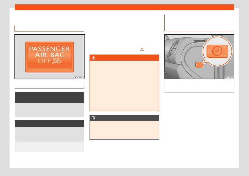
Safety
Deactivating airbags
Contr
ol l
amps
Fig. 75 Control lamp for disabling the front
passenger fr
ont airbag on the dash panel
It lights up on the combi-instru-
ment
Fault in airbag system and seat belt tensioners.
Have the system check
ed immediately by a special-
ised workshop.
It lights up on the dash panel
Fault in airbag system.
Have the system checked immediately by a special-
ised workshop.
Front passenger front airbag disabled.
Check whether the airbag should remain disabl
ed.
Several warning and control lamps light up
f
or a f
e
w seconds when the ignition is switch-
ed on, signalling that the function is being
verified. They will switch off after a few sec-
onds.
If the front passenger airbag is deactivated,
the lamp does not re-
main lit, or if it is lit together with the control
lamp on the instrument panel, there may
be a fault in the airbag system
›››
.
WARNING
In the event of a fault in the airbag system,
the airbag may not trigger correctly, may
fail t
o trigger or may even trigger unex-
pectedly, leading to severe or fatal injuries.
●
Have the airbag system checked immedi-
ately by a specialised workshop.
●
Never mount a child seat in the front pas-
senger seat or remove the mounted child
seat! The front passenger front airbag may
deploy during an accident in spite of the
fault.
CAUTION
Always pay attention to any lit control
lamps and to the corr
esponding descrip-
tions and instructions to avoid damage to
the vehicle.
Manual disabling and enabling of
the fr
ont passenger fr
ont airbag
with the k
ey switch
Fig. 76
On the passenger side: switch to acti-
v
at
e and deactiv
ate the front passenger air-
bag.
Read the additional information carefully
›
›
›
page 17
Activating the front passenger front air-
bag
●
Switch the ignition off.
●
Open the door on the front passenger side.
●
Unfold the vehicle key blade
›››
page 92.
●
Using the vehicle key, turn the key switch to
ON
›››
Fig. 76.
●
Close the door on the front passenger side.
●
Check that, with the ignition switched on,
the control lamp on the
dash panel is not lit up
›››
page 64.
64
Transporting children safely
How to know whether the front passenger
fr
ont airbag is disabl
ed
The
only indication of the front passenger
airbag being disabled is that the
control lamp on the dash panel re-
mains lit ( stays yellow)
›››
page 64.
If the control lamp on the dash panel
does not remain lit or is lit in combination
with the control lamp on the instrument
panel, a child restraint system cannot be
mounted on the front passenger seat for
safety reasons. The front passenger front air-
bag may deploy during an accident.
WARNING
The front passenger front airbag must only
be disabled in special cases.
●
Disable and activ
ate the front passenger
front airbag when the ignition is switched
off to avoid damage to the airbag system.
●
It is the driver's responsibility to ensure
that the key operated switch is set to the
correct position.
●
Only disable the front passenger front
airbag when a child seat is to be mounted
under exceptional circumstances.
●
As soon as the child seat is no longer
needed on the front passenger seat, recon-
nect the front passenger front airbag.
Transporting children
saf
ely
Saf
et
y for children
Introduction
Before transporting babies and children in a
child seat placed in the fr
ont passenger seat,
first completely read the information regard-
ing the airbag system.
This information is extremely important for
driver and passenger safety, particularly that
of babies and children.
SEAT recommends the use of child seats from
the SEAT accessory programme. These child
seats have been designed and tested for use
in SEAT vehicles. You can purchase child
seats with different mountings from a SEAT
dealership.
WARNING
Make sure children are properly belted in
and correctly secured t
o avoid severe or
fatal injuries while the vehicle is in motion.
●
Never use a rear-facing child seat in the
front passenger seat if the front passenger
front airbag is enabled.
●
Children up to 12 years old should always
travel on the rear seat.
●
Children must al
ways be protected with
an approved child restraint system suited
to their height and weight.
●
Children must assume the proper sitting
position and be properly belted in while
travelling.
●
Ensure the seat backrest is upright when
a child seat is being used on it.
●
Do not allow the child's head or other
part of his or her body to enter the deploy-
ment area of the side airbags.
●
Make sure the belt webbing is correctly
positioned.
●
Never hold children or babies on your lap
or in your arms.
●
Only one child may occupy a child seat.
●
Please read and observe the child seat
manufacturer's handling instructions.
WARNING
An empty or loose child seat could fly un-
controllably ar
ound the vehicle interior and
cause injuries in the event of an accident or
sudden braking.
●
When not in use while the vehicle is in
motion, always safely secure the child seat
or store it in the luggage compartment.
Note
Replace the child seat after an accident,
as it may have invisible damage
.
65
Safety
Important information regarding
the fr
ont passenger
's airbag
Read the additional information carefully
›››
page 18.
Read and always observe the safety informa-
tion included in the following chapters:
●
Safety distance with respect to the passen-
ger airbag
›››
in Introduction on page 60.
●
Objects between the passenger and the
passenger side airbag
›››
in Front airbags
on page 63.
The passenger side fr
ont airbag, when ena-
bl
ed, is a serious risk f
or a child that is facing
backward since the airbag can strike the seat
with such force that it can cause serious or
fatal injuries. Children up to 12 years old
should always travel on the rear seat.
Therefore we strongly recommend you to
transport children on the rear seats. This is
the safest location in the vehicle. Alternative-
ly, the front passenger airbag can be disa-
bled with a key-operated switch
›››
page 64.
When transporting children, use a child seat
suitable for the age and size of each child
›››
page 67.
WARNING
●
If a child seat is secured t
o the front pas-
senger seat, the risk to the child of sustain-
ing critical or fatal injuries in the event of an
accident increases.
●
An inflating fr
ont passenger airbag can
strike the rear-facing child seat and project
it with great force against the door, the roof
or the backrest.
●
Never install a child seat facing back-
wards on the front passenger seat unless
the front passenger front airbag has been
disabled. Risk of potentially fatal injuries to
the child! However, if it is necessary, in ex-
ceptional cases, to transport a child in the
front passenger seat, the front passenger
front airbag must always be disabled
›››
page 64. If the passenger seat has a
height adjustment option, move it to the
highest, most upright position. If you have a
fixed seat, do not install any child restraint
system in this location.
●
For those vehicles that do not include a
key lock switch to deactivate the airbag,
the vehicle must be taken to a technical
service.
●
All vehicle occupants, especially chil-
dren, must assume the proper sitting posi-
tion and be properly belted in while travel-
ling.
●
Never hold children or babies on your lap,
this can result in potentially fatal injuries to
the child!
●
Never allow a child to be transported in a
vehicle without being properly secured, or
to stand up or kneel on a seat while travel-
ling. In an accident, the child could be flung
through the vehicle, causing possibly fatal
injuries to themselv
es and to the other vehi-
cle occupants.
●
If children assume an improper sitting po-
sition when the vehicle is moving, they ex-
pose themselves to greater risk of injury in
the event of a sudden braking manoeuvre
or in an accident. This is particularly impor-
tant if the child is travelling on the front
passenger seat and the airbag system is
triggered in an accident; as this could
cause serious injury or even death.
●
A suitable child seat can protect your
child!
●
Never leave a child alone in the child seat
or inside the vehicle because depending on
the season, very high temperatures may be
reached inside a parked vehicle, which
could be fatal.
●
Children who are less than 1.5 metres tall
must not wear a normal seat belt without a
child seat, as this could cause injuries to
the abdominal and neck areas during a
sudden braking manoeuvre or in an acci-
dent.
●
Do not allow the seat belt to become
twisted and the seat belt should be proper-
ly in place
›››
page 53.
●
Only one child may occupy a child seat
›››
page 67.
●
When a child seat is mounted in the rear
seats, the door child-proof lock should be
activated
›››
page 98.
66
Transporting children safely
Child seats
Saf
et
y instructions
Read the additional information carefully
›››
page 18.
WARNING
The lower anchor points for child seats do
not include rings. Only secure booster
seats t
o lower anchor points.
WARNING
Child seats with lower anchor points and
with an upper retaining str
ap must be in-
stalled in line with the manufacturer's in-
structions. Failure to comply could result in
severe injuries.
●
Always secure just one retaining strap to
a child seat with the luggage compartment
retaining ring.
●
Always use the correct retaining rings for
the retaining strap.
●
Never secure the retaining strap to a re-
tainer.
WARNING
In general, the rear seat is always the saf-
est place for chil
dren, who are belted cor-
rectly, in the event of an accident.
●
A suitable chil
d seat that is correctly in-
stalled and used on one of the rear seats
offer the most protection possible for ba-
bies and children up to 12 years in most ac-
cidents.
WARNING
Unbuckling the seat belt while the vehicle
is in motion can cause se
ver
e or fatal inju-
ries in the event of an accident or sudden
braking.
●
The seat belt must not be unfastened un-
til the vehicle has come to a standstill.
CAUTION
●
To avoid making permanent marks in the
padding, r
emove the auxiliary introduction
elements from the anchor points when the
child seat is not installed in the vehicle an-
chor points.
●
To prevent damage being done to the up-
holstery, the padding or the auxiliary intro-
duction elements, always remove the auxil-
iary introduction elements from the anchor
points before folding the rear seat bench.
General information on transport-
ing chil
dr
en in the v
ehicle
Read the additional information carefully
›
›
›
page 19.
Legal regulations and provisions will always
take priority over the descriptions of this in-
struction manual. There are different regula-
tions and provisions for the use of child seats
and their mountings (
›››
table on page 68).
In some countries, for example, the use of
child seats on certain seats in the vehicle
may be forbidden.
The physical principles and the forces acting
on the vehicle in the event of a collision or
other type of accidents also apply to children
›››
page 53. However, unlike adults and
youngsters, children do not have fully devel-
oped muscle and bone structures. In the
event of an accident, children are subject to a
greater risk than adults of sustaining severe
injuries.
Given that children's bodies are not yet fully
developed, child restraint systems must be
used that are especially adapted to their
height, weight and constitution. There are
laws in force in many countries that indicate
the use of approved seat systems for trans-
porting babies and children.
Only used authorised, approved child seats
that are suitable for the vehicle. Always con-
sult with a SEAT dealership or a Specialised
workshop should you have any doubts.
»
67
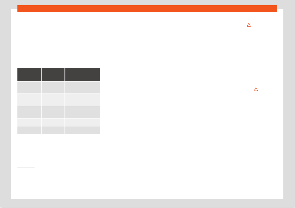
Safety
Specific child seat regulations for each
country (sel
ection)
Chil
d seats must comply with the ECE-R 44
1)
r
egulation. You can get additional information
by consulting your SEAT dealership or at the
internet address www.seat.es.
Categorisation of child seats according to
ECE-R 44
Weight
category
Weight of
the chil
d
Age
Group 0 up to 10 kg
up to approx. 9
months
Group 0+ up to 13 kg
up to approx. 18
months
Group 1 9 to 18 kg
approx. 8 months to
3
1
/
2
years
Group 2 15 to 25 kg 3 to 7 years approx.
Group 3 22 to 36 kg 6 to 12 years approx.
Not all children fit in the seat of their weight
gr
oup
. Nor do all seats adapt t
o the vehicle.
Therefore, always check whether the child fits
properly in the child seat and whether the
seat can be installed safely in the vehicle.
Child seats approved under the ECE-R 44
regulation are fitted with the corresponding
approval symbol. The sign is an upper-case E
in a circle with the identification number be-
low it.
Use of the child seat on the front
passenger seat
2)
Transporting children on the front passenger
seat is not permitt
ed in all countries. Further
-
mor
e, not all child seats are approved for use
on the front passenger seat. Your SEAT deal-
ership has an updated list of all approved
child seats. Only used child seats that are
approved for each vehicle.
The front airbag on the front passenger side
is highly dangerous for a child. The front pas-
senger seat is life-threatening to a child if he
or she is transported in a rear-facing child
seat.
If a rear-facing child seat is secured to the
front passenger seat, an inflating front airbag
can strike it with such great force that severe
or fatal injuries may result
›››
. Therefore,
r
ear
-f
acing child seats must never be placed
on the front passenger seat when the front
passenger front airbag is enabled.
Only use a rear-facing child seat on the front
passenger seat if the front passenger front
airbag is disabled. When it is disabled, the
yellow control lamp on the dash panel
will be lit up
›››
page 60. If you cannot disable the front
passenger front airbag and it remains ac-
tivated, it is forbidden to transport children
on the front passenger seat
›››
.
Things t
o not
e if using a chil
d seat on the
front passenger seat:
●
The front passenger front airbag must be
disabled when using a rear-facing child
seat
›››
page 60.
●
The seat backrest of the front passenger
seat must be upright.
●
The front passenger seat must be moved
as far back as possible.
●
A height-adjustable front passenger seat
must be raised to its highest point.
1)
ECE-R: Economic Comission for E
urope Regu-
lation.
2)
Compliance with current national legislation
and the manufacturer's instructions is required
when using or installing child seats.
68

Transporting children safely
Suitable child seats
The chil
d seat must be authorised by the
manuf
act
urer especially for use on a front
passenger seat with a front or side airbag.
Universal seats for children can be fitted in
the front passenger seat, in groups 0, 0+, 1, 2
or 3 according to the ECE-R 44 regulation.
WARNING
If a child seat is mounted on the front pas-
senger seat, the risk of the child sustaining
se
vere or fatal injuries in the event of an ac-
cident increases. Rear-facing child seats
must never be mounted on the front pas-
senger seat when the front passenger front
airbag is enabled. This is life-threatening to
the child should the front airbag deploy, as
the child seat would be struck by the infla-
ted airbag and thrown against the seat
backrest.
WARNING
If, in exceptional circumstances, a child
must be transport
ed in a rear-facing child
seat on the front passenger seat, strictly
observe the following:
●
Always disable the front passenger front
airbag and leave it disabled.
●
The child seat must be approved by the
manufacturer for use on a front passenger
seat with front and side airbag.
●
Follo
w the installation instructions of the
child seat manufacturer and observe the
warnings.
●
Move the front passenger seat as far
back as possible and adjust it to its highest
position to keep as far away as possible
from the front airbag.
●
Move the seat backrest to the upright po-
sition.
●
Children must always be protected with
an approved child restraint system suited
to their height and weight.
Use of the child seat on the rear
seat
If a child seat is mounted on the rear seat,
adapt the position of the fr
ont passenger
seat so that the chil
d has enough space
.
Therefore, adapt the front passenger seat to
the size of the child seat and the height of the
child. Ensure the passenger is in the correct
position
›››
page 49.
Suitable child seats
The manufacturer must authorise the child
seat for use in the rear seats with side air-
bags.
Universal seats for children can be fitted in
the passenger seat, in groups 0, 0+, 1, 2 or 3
according to the ECE-R 44 regulation.
The rear seats are suitable for child seats with
the ISOFIX system specially designed for this
type of vehicle in accordance with regulation
ECE-R 44.
ISOFIX child seats approved for rear seats
ISOFIX child seats are divided into the follow-
ing certified categories: “universal”, “semi-
universal” or “specific categories for the vehi-
cle”.
●
If the ISOFIX child seat is certified “univer-
sal”, it must be supported by the lower an-
chor points and the Top Tether retaining
strap.
●
If the ISOFIX child seat is certified “semi-uni-
versal” or “specific categories for the vehi-
cle”, check that the child seat is certified for
the vehicle before employing it. The child
seat manufacturer supplies, in addition to the
ISOFIX child seat, a list of vehicles for which
the corresponding ISOFIX child seat has been
certified. If necessary, contact the child seat
manufacturer for an updated list of vehicles.
69
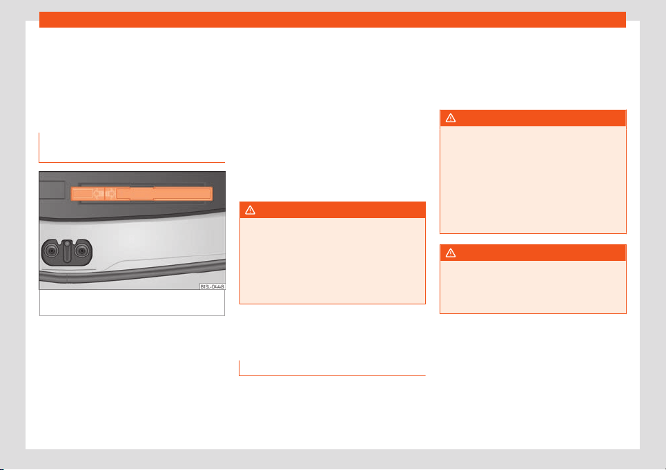
Emergencies
Emergencies
Self
-help
In case of emer
gency
First aid kit, w
arning triangle and
fire extinguishers*
Fig. 77
In the boot: storage compartment for
the w
arning triangl
e
Warning triangle
In some v
ehicl
e equipment it is possibl
e to
store the warning triangle model shown in a
storage compartment of the luggage com-
partment
›››
Fig. 77.
First-aid kit
The first aid kit must comply with legal re-
quirements. Check the expiry date of the
contents of the first aid kit.
Fire extinguisher
A fire extinguisher can be stored in a holder in
the passenger seat footwell.
The fire extinguisher must conform to legal
requirements, be ready for use and be
checked regularly. Check the certification
seal on the extinguisher.
WARNING
Loose objects in the vehicle interior can be
violently thro
wn in case of a sudden ma-
noeuvre or braking and especially in acci-
dents causing serious injury.
●
Secure or store fire extinguishers, first aid
kit, reflective vests and warning triangle
securely in the vehicle.
Vehicle tool kit*
Intr
oduction
When securing the vehicle in case of a break-
do
wn, pl
ease not
e the legal requirements for
each country.
Vehicle tool kit
For vehicles with a factory-fitted spare wheel
or temporary spare wheel, in addition to win-
ter wheels, the luggage compartment may
contain additional vehicle tools
›››
page 71.
WARNING
When the vehicle tool kit, tyre mobility set
and spare wheel are l
oose in the interior
they can be violently thrown in case of a
sudden manoeuvre or braking and espe-
cially in accidents, causing serious injury.
●
Ensure that the vehicle tool kit, the tyre
mobility set and the spare wheel or tempo-
rary spare wheel are safely secured in the
luggage compartment.
WARNING
Unsuitable or damaged vehicle tools can
cause injury or accidents.
●
Never work with inappropriate or dam-
aged tools.
70
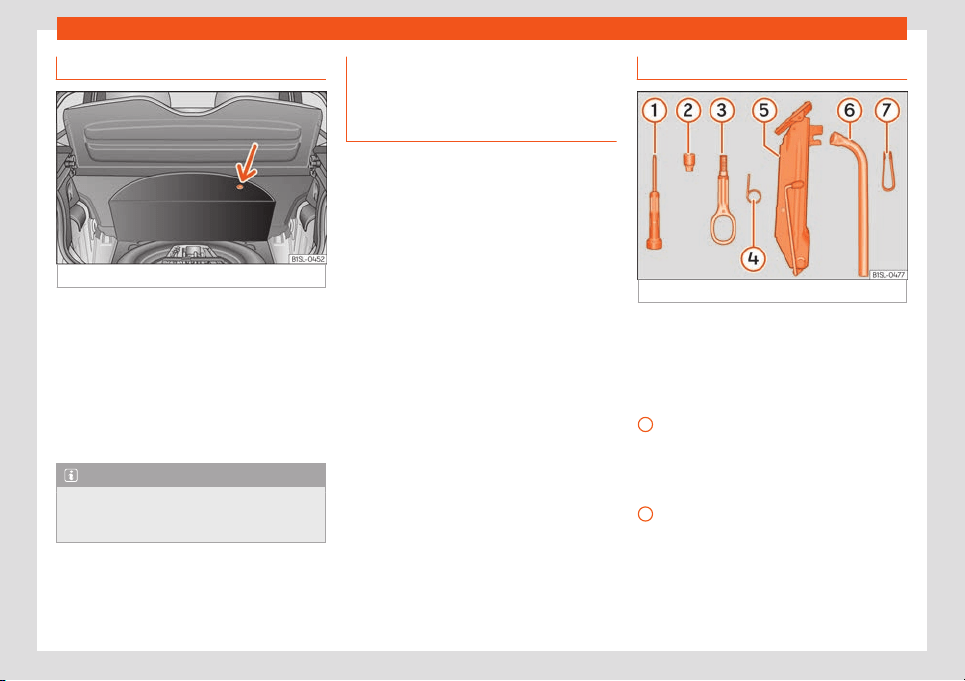
Self-help
Location
Fig. 78
In the boot: carpet raised.
The vehicle tool kit, spare wheel, temporary
spar
e wheel and the t
yr
e mobility set are
stored in the luggage compartment under
the carpeted floor panel
›››
Fig. 78.
●
If necessary, remove the boot variable floor
›››
page 122.
●
Raise the carpet at the recess (arrow)
›››
Fig. 78.
Note
After use, return the jack to its initial posi-
tion using the handle in order t
o securely
store it in the vehicle.
Accessing the vehicle tool kit and
t
yr
e mobilit
y system in vehicles fit-
ted with the SEAT SOUND 7 speaker
system (with subwoofer)*
●
Open the boot hatch and lift the shelf.
●
If necessary, remove the boot variable floor
›››
page 125.
●
Lift up the carpet from the recess and re-
move it from the luggage compartment.
●
Disconnect the subwoofer’s speaker cable.
●
Completely remove the hand-controlled
wheel from the centre of the sub
woofer
speaker by turning it anti-clockwise.
●
Take out the subwoofer, which is on top of
the tools and tyre mobility system.
●
When finished, place the tools and system
back in the same way and place as before to
ensure the speaker sits properly in its housing.
●
Place the subwoofer in the direction of the
arrow and with the word “FRONT” facing for-
ward.
●
Reconnect the speaker cable and firmly ro-
tate the securing wheel clockwise so that the
subwoofer is firmly in place.
Components
Fig. 79
Components of the vehicle tool kit
The vehicle tool kit depends on the vehicle
equipment. The f
oll
o
wing is a description for
a vehicle with all options.
Individual elements of the vehicle tool kit
›››
Fig. 79
Screwdriver with hexagon socket in the
handle for screwing and unscrewing the
wheel bolts. The screwdriver bit is inter-
changeable. The screwdriver may be
found underneath the wheel spanner.
Adapter for anti-theft bolt. SEAT recom-
mend you carry the wheel bolt adapter in
the vehicle tool kit at all times. The code
number of the anti-theft wheel bolt is
stamped on the front of the adapter. In
»
1
2
71
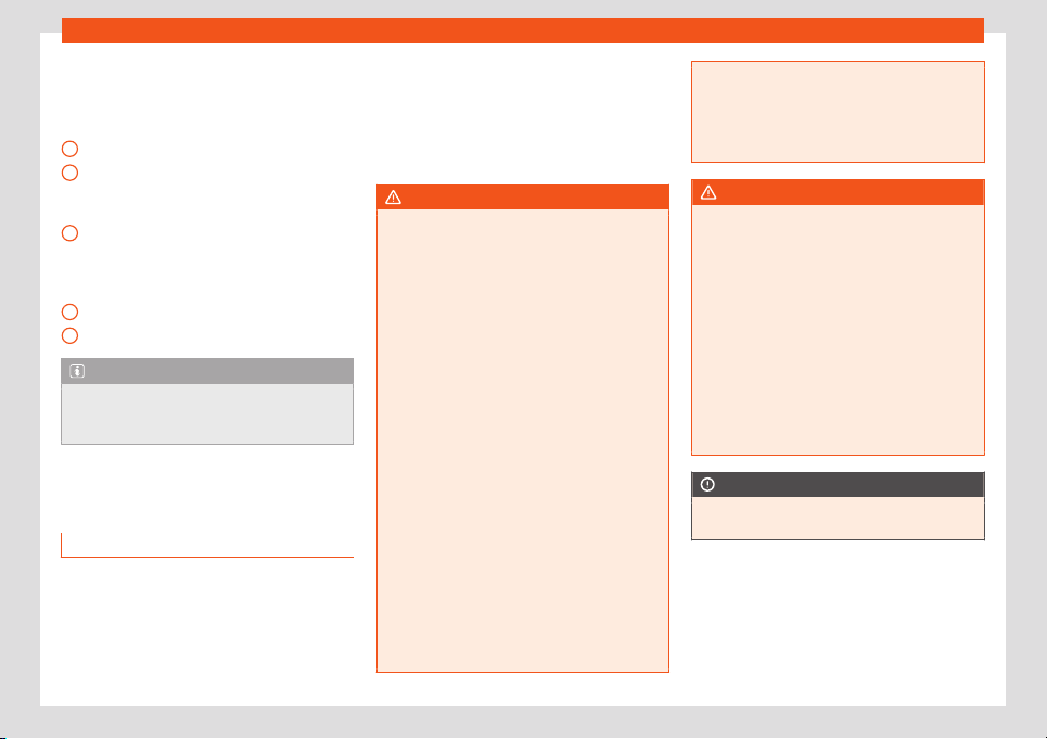
Emergencies
case it is lost, another adapter can be or-
der
ed using this number
. Not
e the anti-
theft bolt code for the wheels and keep it
in a place other than the vehicle.
Towline anchorage, removable.
Wire hook for pulling off the wheel cover,
integral hubcaps and the wheel bolt
caps.
Jack. Before storing the jack in the tool kit,
fold its hook. The crank must then be fol-
ded tight against the side of the jack in
order for it to be safely stored.
Wheel spanner.
Wheel bolt cap clips.
Note
The jack does not generally require any
maintenance. If r
equired, it should be
greased using universal type grease.
Changing a wheel
Intr
oduction
Read the additional information carefully
›
›
›
page 37
Some vehicle versions and models do not
have a factory-fitted jack or box spanner. In
this case, we recommend consulting a Speci-
alised workshop to change the wheel.
3
4
5
6
7
You should only change the wheels yourself if
the v
ehicl
e is park
ed in a safe place, you are
familiar with the procedure and safety stand-
ards and you have all the necessary tools!
Otherwise, you should seek professional as-
sistance.
WARNING
Changing a wheel can be dangerous, es-
pecially on the hard shoulder
. Please ob-
serve the following rules to minimise the
risk of injury:
●
Stop the vehicle safely as soon as possi-
ble. Park at a safe distance from surround-
ing traffic to change a wheel.
●
When changing a wheel, keep all pas-
sengers, and particularly children, a safe
distance away from the work area.
●
Turn on the hazard warning lights to warn
other road users.
●
Ensure the ground on which you park is
flat and solid. If necessary, support the
jack on a wide solid base.
●
If you are changing a wheel yourself, you
should be familiar with the required proce-
dure. Otherwise, you should seek profes-
sional assistance.
●
Only use suitable tools that are not dam-
aged when changing a wheel.
●
Always stop the engine, apply the hand-
brake lever firmly and place the selector
lever in position N, or engage a gear for a
manual gearbox to reduce the risk of the
vehicle mo
ving accidentally.
●
Have the tightening torque of the wheel
bolts checked as soon as possible with a
reliable torque wrench.
WARNING
If the wheel trims are not appropriate or not
fitt
ed correctly, they coul
d cause major
accidents or damage.
●
Incorrectly mounted wheel trims may
come off while driving and endanger other
road users.
●
Damaged trims must never be mounted
on the wheels.
●
Always ensure that the brake ventilation
and cooling is not cut off or blocked. This is
also valid if hubcaps are fitted later. If there
is not enough air, you may require signifi-
cantly longer braking distances.
CAUTION
Remove and remount wheel trims taking
care to av
oid damage to the vehicle.
72
Self-help
Tyre repair
T
MS (T
yr
e Mobility System)*
Read the additional information carefully
›››
page 36
The Anti-puncture kit* (Tyre Mobility System)
will reliably seal punctures caused by the
penetration of a foreign body of up to about
4 mm in diameter. Do not remove foreign
objects, e.g. screws or nails, from the tyre.
After inserting the sealant residue in the tyre,
you must again check the tyre pressure
about 10 minutes after starting the engine.
You should only use the tyre mobility set if the
vehicle is parked in a safe place, you are fa-
miliar with the procedure and you have the
necessary tyre mobility set! Otherwise, you
should seek professional assistance.
Do not use the tyre sealant in the following
cases:
●
If the wheel rim has been damaged.
●
In outside temperatures below -20°C
(-4°F).
●
In the event of cuts or perforations in the
tyre gr
eater than 4 mm.
●
If you have been driving with very low pres-
sure or a completely flat tyre.
●
If the sealant bottle has passed its use by
date.
WARNING
Using the tyre mobility system can be dan-
gerous, especially when filling the tyr
e at
the roadside. Please observe the following
rules to minimise the risk of injury:
●
Stop the vehicle safely as soon as possi-
ble. Park it at a safe distance from sur-
rounding traffic to fill the tyre.
●
Ensure the ground on which you park is
flat and solid.
●
All passengers and particularly children
must keep a safe distance from the work
area.
●
Turn on the hazard warning lights to warn
other road users.
●
Use the tyre mobility system only if you
are familiar with the necessary procedures.
Otherwise, you should seek professional
assistance.
●
The tyre mobility set is intended for tem-
porary emergency use only until you can
reach the nearest specialised workshop.
●
Replace the repaired tyre with the tyre
mobility set as soon as possible.
●
The sealant is a health hazard and must
be cleaned immediately if it comes into
contact with the skin.
●
Always keep the tyre mobility set out of
the reach of small children.
●
Never use an equiv
alent jack, even if it
has been approved for your vehicle.
●
Always stop the engine, apply the hand-
brake lever firmly and engage gear if using
a manual gearbox, in order to reduce the
risk of vehicle involuntary movement.
WARNING
A tyre filled with sealant does not have the
same perf
ormance proper
ties as a conven-
tional tyre.
●
Never drive faster than 80 km/h
(50 mph).
●
Avoid heavy acceleration, hard braking
and fast cornering.
●
Drive for only 10 minutes at a maximum
speed of 80 km/h (50 mph) and then check
the tyre.
For the sake of the environment
Dispose of used or expired sealant observ-
ing any legal requir
ements.
Note
●
A new bottle of seal
ant can be purchased
at SEAT dealerships.
●
Take into account the separate instruc-
tion manual of the tyre mobility set* manu-
facturer.
73
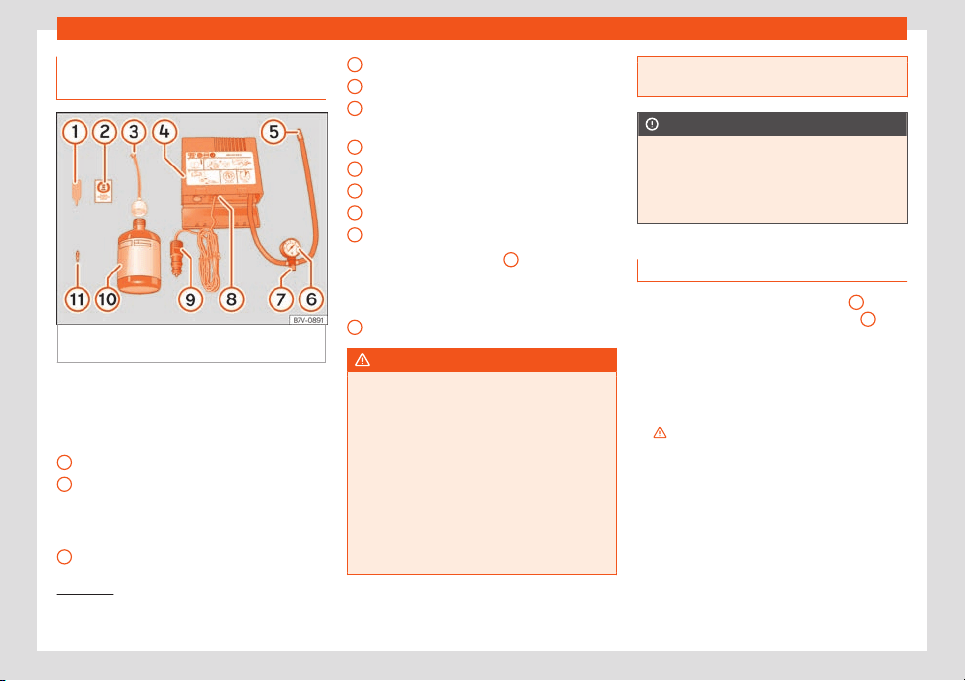
Emergencies
Contents of the tyre mobility sys-
t
em*
Fig. 80
Standard display: contents of the anti-
punct
ur
e kit.
The anti-puncture kit is located underneath
the fl
oor co
v
ering in the luggage compart-
ment. It includes the following components
›››
Fig. 80:
Tyre valve remover
A sticker to be adhered to the instrument
cluster, within the driver's visual field, to
remind that the maximum advisable
speed “max. 80 km/h” or “max. 50 mph”
Filler tube with cap
1
2
3
Air compressor
T
ube f
or infl
ating tyres
Warning provided by tyre pressure moni-
toring system
1)
Air bleed screw
2)
ON/OFF switch
12 volt connector
Bottle of sealant
Spare tyre valve
The valve insert remover
1
has a gap at
the l
o
w
er end for a valve insert. The valve in-
sert can only be screwed or unscrewed in this
way. This also applies to its replacement part
11
.
WARNING
When inflating the wheel, the air compres-
sor and the inflator t
ube may become hot.
●
Protect hands and skin from hot parts.
●
Do not place the hot flexible inflator tube
or hot air compressor on flammable mate-
rial.
●
Allow them to cool before storing the de-
vice.
●
If it is not possible to inflate the tyre to at
least 2.0 bars (29 psi / 200 kPa), the tyre is
too badly damaged. The sealant is not in a
4
5
6
7
8
9
10
11
good condition to seal the tyre. Do not con-
tinue driving. Seek specialist assistance.
CAUTION
Switch off the air compressor after a maxi-
mum of 8 oper
ational minutes t
o avoid
overheating! Before switching on the air
compressor again, let it cool for several mi-
nutes.
Check after 10 minutes of driving
Screw in the inflator tube
›
›
›
Fig. 80
5
again
and check the pr
essur
e on the gauge
6
.
1.3 bar (19 psi / 130 kP
a) and l
o
wer:
●
Stop the vehicle! The tyre cannot be
sealed sufficiently with the tyre mobility set.
●
You should obtain professional assistance
›››
.
1.4 bar (20 psi / 140 kP
a) and higher:
●
Set the t
yr
e pressure to the correct value
again
›››
page 206.
●
Carefully resume your journey until you
reach the nearest specialised workshop with-
out exceeding 80 km/h (50 mph).
1)
It can also be integrated in the compressor.
2)
In its place, the compressor may have a button.
74
Self-help
●
Hav
e the damaged t
yr
e replaced.
WARNING
Driving with an unsealed tyre is dangerous
and can cause accidents and serious in-
jury.
●
Do not continue driving if the tyre pres-
sure is 1.3 bar (19 psi / 130 kPa) and l
ower.
●
Seek specialist assistance.
Changing the windscreen
wiper bl
ades
Changing the windscr
een and r
ear
window wiper blades
Read the additional information carefully
›
›
›
page 47.
The windscreen wiper blades are supplied as
standard with a layer of graphite. This layer is
responsible for ensuring that the wipe is silent.
If the graphite layer is damaged, the noise of
the water as it is wiped across the windscreen
will be louder.
Check the condition of the wiper blades reg-
ularly. If the wipers scrape across the glass
they should be changed if they are dam-
aged, or cleaned if they are dirty
›››
.
Damaged wiper blades should be replaced
immediat
ely. These ar
e av
ailable from quali-
fied workshops.
WARNING
Worn or dirty windscreen wiper blades re-
duce visibility and increase the risk of acci-
dent and serious injury.
●
Al
ways replace damaged or worn wind-
screen wiper blades or blades that no lon-
ger clean the windscreen properly.
CAUTION
●
Damaged or dirty windscr
een wipers
could scratch the glass.
●
If products containing solvents, rough
sponges or sharp objects are used to clean
the blades, the graphite layer will be dam-
aged.
●
Never use fuel, nail varnish remover, paint
thinner or similar products to clean the win-
dows.
CAUTION
●
To pre
vent damage to the bonnet and the
wiper arms, only leave them in the service
position.
●
Before driving, always lower the wiper
arms.
Note
If wax deposits, other cleaning products
from the automatic car w
ash, or other care
products, are left on the windscreen and
the rear window, the blades can scratch
the glass. Remove wax deposits with a spe-
cial product or cleaning cloths.
Tow-starting and towing
Instructions for to
w-starting
Read the additional information carefully
›
›
›
page 43.
When towing or tow starting, respect the le-
gal requirements.
For technical reasons, it is not possible to
tow a vehicle if the battery is flat.
In general, the vehicle should not be star-
ted by towing. Jump-starting is much more
preferable
›››
page 44.
For technical reasons, the following vehicles
can not be tow started:
●
Vehicles with an automatic gearbox.
●
If the vehicle battery is flat, it is possible that
the engine control unit does not operate cor-
rectly.
»
75
Emergencies
However, if your vehicle must absolutely
be t
o
w-st
arted (manual gearbox):
●
Put it into second or third gear.
●
Keep the clutch pressed down.
●
Switch on the ignition and the hazard warn-
ing lights.
●
Release the clutch when both vehicles are
moving.
●
As soon as the engine starts, press the
clutch and move the gear lever into neutral.
This helps to prevent a collision with the tow-
ing vehicle.
WARNING
A vehicle with a flat battery should never
be tow
ed.
●
Never remove the key from the ignition
lock. Otherwise, the steering wheel lock
could suddenly lock. The vehicle would not
be controlled and a serious accident could
ensue.
WARNING
When towing the vehicle, the handling and
braking efficiency change considerably.
Pl
ease observe the following instructions
to minimise the risk of serious accidents
and injury:
●
As the driver of the vehicle being towed:
–
The brake must be depressed must
harder as the brake servo does not op-
erate. Always remain aware to avoid
collision with the towing v
ehicle.
–
More strength is required at the steer-
ing wheel as the power steering does
not operate when the engine is switch-
ed off.
●
As the driver of the towing vehicle:
–
Accelerate gently and carefully.
–
Avoid sudden braking and manoeuvres.
–
Brake well in advance than usual and
brake gently.
CAUTION
●
When tow-st
arting, fuel could enter the
catalytic converter and damage it.
●
Carefully fit and remove the towline an-
chorage and its cover to avoid damage to
the vehicle (e.g. paintwork).
●
When towing, fuel could enter the cata-
lytic converter and cause damage!
Note
Fitting a towline anchorage to the rear
bumper is not possible. The v
ehicle is not
suitable for towing other vehicles.
Advice for towing the vehicle
Towing vehicles with an automatic gear-
box
Note the f
ollowing for a towed vehicle:
●
Make sure the gear selector lever is in the N
position.
●
Do not drive faster than 50 km/h (30 mph)
when towing a vehicle.
●
Do not tow further than 50 km (30 miles).
●
If a breakdown truck is used, the vehicle
must be tow
ed with the front wheels raised.
Situations in which a vehicle should not be
towed
In the following cases, the vehicle should not
be towed but transported on a trailer or spe-
cial vehicle:
●
If the vehicle gearbox does not contain lu-
bricant due to a fault.
●
If the battery is flat and the steering cannot
be unlocked as a result, the electronic steer-
ing lock and electronic parking brake cannot
be disengaged.
●
If the vehicle to be towed has an automatic
gearbox and the distance to be covered is
greater than 50 km (30 miles).
76
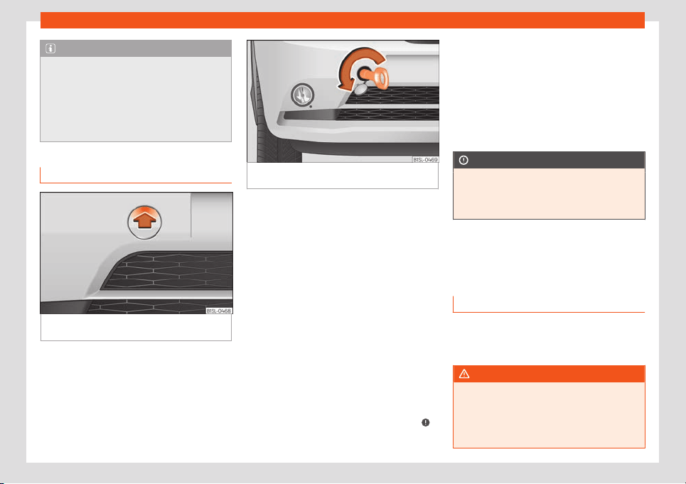
Self-help
Note
The vehicle can only be towed if the steer-
ing lock electr
onic gearbox lock is deacti-
vated. If the vehicle has no power supply or
there is an electric system fault, the engine
must be started using jump leads to deacti-
vate the steering column electronic gear-
box lock.
Fitting the front towline anchorage
Fig. 81
On the right-hand side of the front
bumper: r
emo
v
e the lid.
Fig. 82 On the right-hand side of the front
bumper: screw the anchor
age.
The location for the removable tow ring is on
the right
-hand side of the fr
ont bumper be-
hind a co
ver
›››
Fig. 81.
The towline anchorage should always be
kept in the vehicle.
Note the instructions for towing
›››
page 76.
Fitting the towline anchorage
●
Take the towline anchorage from the vehi-
cle tool kit in the luggage compartment
›››
page 70.
●
Press the upper part of the cover
›››
Fig. 81
(arrow) to disengage and release the cover.
●
Remove the cover and leave it hanging
from the vehicle.
●
Screw in the tow ring into its housing anti-
clockwise as far as it will go
›››
Fig. 82
›››
.
Use a suit
abl
e t
ool to firmly tighten the tow-
line anchorage in its location.
●
After towing, remove the tow ring by turning
it clockwise.
●
Place the cover's upper tab on the opening
of the bumper and carefully guide the lower
tab on the edge of the opening. If necessary,
press the lower tab from below.
●
Press the lower area of the cover until the
lower tab engages in the bumper.
CAUTION
The towline anchorage must always be
completely and firmly tight
ened. Other-
wise, it could be released while towing and
tow-starting.
Emergency locking and un-
l
ocking
Intr
oduction
The doors and rear lid can be locked man-
ually and partially opened, f
or e
x
ample if the
key or the central locking is damaged.
WARNING
Opening and closing doors carelessly can
cause serious injury.
●
If the vehicle is locked from outside, the
doors and windows cannot be opened from
the inside
.
»
77
Emergencies
●
Never l
eave children or disabled people
alone in the car. They could be trapped in
the car in an emergency and will not be
able to get themselves to safety.
●
Depending on the time of the year, tem-
peratures inside a locked and closed vehi-
cle can be extremely high or extremely low
resulting in serious injuries and illness or
even death, particularly for young children.
WARNING
Getting in the way of the doors and the rear
lid is danger
ous and can lead t
o serious in-
jury.
●
Open and close the doors and the rear lid
only when there is nobody in the way.
CAUTION
When opening and closing in an emergen-
cy, carefully disassemble components and
then r
eassemble them carefully to avoid
damage to the vehicle.
Fuses and bulbs
Fuses
Intr
oduction
Due to the constant updating of vehicles, fuse
assignments based on equipment and the
use of the same fuse for various el
ectrical
components, it is not possible to provide an
up-to-date summary of the fuse positions for
the electrical components at the time of
printing this manual. For detailed information
about the fuse positions, please consult a
technical service.
In general, a fuse can be assigned to various
electrical components. Likewise, an electrical
component can be protected by several
fuses.
Only replace fuses when the cause of the
problem has been solved. If a newly inserted
fuse blows after a short time, you must have
the electrical system checked by a special-
ised workshop as soon as possible.
WARNING
The high voltages in the electrical system
can give serious electrical shocks, causing
burns and e
ven death!
●
Never touch the electrical wiring of the
ignition system.
●
Take car
e not to cause short circuits in
the electrical system.
WARNING
Using unsuitable fuses, repairing fuses or
bridging a curr
ent circuit without fuses can
cause a fir
e and serious injury.
●
Never use a fuse with a higher value. Only
replace fuses with a fuse of the same am-
perage (same colour and markings) and
size.
●
Never repair a fuse.
●
Never replace a fuse by a metal strip, sta-
ple or similar.
CAUTION
●
To pre
vent damage to the vehicle's elec-
tric system, before replacing a fuse always
turn off the ignition, the lights and all elec-
trical elements and remove the key from
the ignition.
●
If you replace a fuse with higher-rating
fuse, you could cause damage to another
part of the electrical system.
●
Protect the fuse boxes when open to pre-
vent the entry of dust or humidity as they
can damage the electrical system.
Note
●
One component may have more than one
fuse
.
78
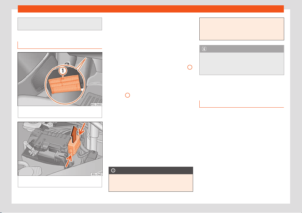
Fuses and bulbs
●
Sever
al components may run on a single
fuse.
Vehicle fuses
Fig. 83
Under the dashboard on the driver
side: lid of the fuse bo
x.
Fig. 84 In the engine compartment: lid of the
fuse bo
x.
Read the additional information carefully
›
›
›
page 35
Only replace fuses with a fuse of the same
amperage (same colour and markings) and
size.
Opening and closing the fuse box situated
below the dash panel
●
Open: Press the unlock button
›››
Fig. 83
1
until it is possible to open the cover. Fold the
co
v
er do
wn.
●
Close: Fold the cover up in the opposite di-
rection to the arrow until it clicks into the lock-
ing lever
1
.
T
o open the engine compar
tment fuse bo
x
●
Open the bonnet
›››
page 193.
●
Press the attachment tabs in the direction
indicated by the arrow (thin arrows) to re-
lease the fuse box cover
›››
Fig. 84.
●
Then lift the cover out.
●
To fit the cover, place it on the fuse box.
Push the attachment tabs down, in the oppo-
site direction indicated by the arrow until they
click audibly into place.
CAUTION
●
Always car
efully remove the fuse box
covers and refit them correctly to avoid
problems with your vehicle.
●
Protect the fuse bo
xes when open to
avoid the entry of dust or humidity. Dirt and
humidity inside fuse boxes can cause dam-
age to the electrical system.
Note
In the vehicle, there are more fuses than
those indicat
ed in this chapter
. These
should only be changed by a specialised
workshop.
Changing bulbs
Intr
oduction
Changing bulbs requires a certain amount of
manual skill. If you ar
e unsur
e
, SEAT recom-
mends that you consult a technical service or
request assistance from a specialist. In gen-
eral a specialist is needed if, in addition to the
bulbs, other vehicle components require re-
moval.
You should store spare light bulbs in the vehi-
cle for safety-relevant lights. Spare bulbs
may be obtained from the technical services.
In some countries, it is a legal requirement to
carry spare bulbs in the vehicle.
Driving with faults and blown bulbs on the ve-
hicle exterior lighting is against the law.
»
79
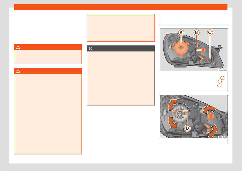
Emergencies
Additional bulb specifications
The specifications of some headl
amp bulbs
and bulbs f
or the r
ear lamps fitted at the fac-
tory may be different to those of conventional
bulbs. Bulb information is displayed on the
bulb socket or on the bulb itself.
WARNING
If the road is not well-lit and the vehicle is
not clearly visible t
o other drivers, there is
a risk of accident.
WARNING
Failure to replace bulbs correctly may
cause serious accidents.
●
Before carrying out any work in the en-
gine compartment please r
ead and ob-
serve the warnings
›››
page 193. In any ve-
hicle, the engine compartment is a hazard-
ous area and could cause severe injury.
●
The bulbs H4, HB4 and H7 are pressurised
and might explode on changing them.
●
Only replace the bulbs concerned when
they have cooled.
●
Never replace bulbs alone if you are not
familiar with the operations necessary. If
you are not sure about procedures then vis-
it a specialised workshop to carry out the
necessary work.
●
Never touch the bulb glass directly. Fin-
gerprints will be evaporated by the heat of
the operating bulb thus “fogging” up the
reflect
or.
●
The headlamp frameworks in the engine
compartment and the rear lamps contain
sharp elements. Always protect your hands
when changing bulbs.
CAUTION
●
Aft
er changing a bulb, if the rubber co
v-
ers are not replaced correctly on the head-
lamp framework, the electrical installation
may be damaged, especially if water is al-
lowed to enter.
●
Remove the ignition key before working
on the electric system. Otherwise, a short
circuit could occur.
●
Switch off the lights and the parking light
before changing a bulb.
●
Take good care to avoid damaging any
components.
Replacing the bulbs in the head-
lights
Fig. 85
In the engine compartment: Rear view
of the fr
ont l
eft headlight with rubber co
ver:
A
dipped beam and main beam headlights,
B
side lights and daytime driving lights and
C
turn signal
Fig. 86
Left headlight
There is no need to remove the headlight to
r
epl
ace bulbs.
80
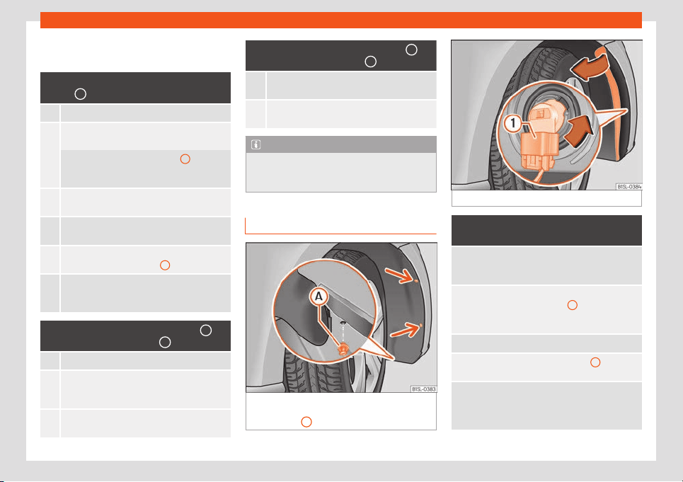
Fuses and bulbs
Complete operations only in the sequence
giv
en:
Dipped beam and main beam headlights
Fig. 85
A
1. Open the bonnet
›››
page 193.
2.
Remove the bulb connector H4. Remove the
rubber cover using the t
abs.
Press the retaining clip
›››
Fig. 86
D
down-
wards in the dir
ection of the arrow, unclip side-
ways, and remove it.
3.
Remove the bulb from the holder. If necessary,
press the lock on the bulb hol
der.
4.
Replace the faulty bulb with a new identical
bulb.
5.
Insert the bulb, r
eturn it to its position and insert
the retaining clip
›››
Fig. 86
D
6.
Place the rubber cover and check that is in the
correct position. Insert the connector t
o the
bulb H4.
Side light and daytime lights Fig. 85
B
/
Front turn indicat
or Fig. 85
C
1. Open the bonnet
›››
page 193.
2.
Turn the bulb holder in an anticlockwise di-
rection
as far as it will go and remove it, along
with the bulb, pulling backwards.
3.
Remove the bulb from the holder. If necessary,
press the lock on the bulb hol
der.
Side light and daytime lights Fig. 85
B
/
Front turn indicat
or Fig. 85
C
4.
Replace the faulty bulb with a new identical
bulb.
5.
Insert the bulb holder in the headlight and t
urn
it clockwise as f
ar as the stop.
Note
The images show the left hand headlight
from behind. The structur
e of the right hand
side headlight is symmetric.
Replacing the front bumper bulbs
Fig. 87 In the front right arch trim: remove the
r
et
aining scr
ews (arrows) and take out the ex-
pansive rivet
A
.
Fig. 88 Changing the bulbs in the headlights
Complete operations only in the se-
quence given:
1.
Unscre
w the 2 retaining screws of the wheel
arch trim
››
›
Fig. 87 (arrows) with the screwdriv-
er from the vehicle took kit
›››
page 70.
2.
Unscrew the expansive rivet in the lower front
part of the wheel arch trim
A
with the screw-
driver from the v
ehicle tool kit and completely
remove it
›››
page 70.
3. Carefully fold the wheel arch trim to the side.
4.
Release the connector
›››
Fig. 88
1
and re-
move it.
5.
T
urn the bulb holder
›››
Fig. 88 in the direction
of the arrow, in an anticlockwise direction as
far as it will go and remove it, along with the
bulb, pulling backwards.
»
81
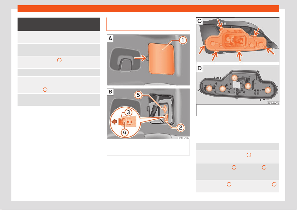
Emergencies
Complete operations only in the se-
quence given:
6.
Repl
ace the faulty bulb with a new identical
bulb.
7.
Insert the bulb holder in the headlight and t
urn
it clockwise as f
ar as the stop.
8.
Plug the connector
1
into the bulb holder. The
connector must audibly click into pl
ace.
9. Replace the wheel arch trim into its position.
10.
Place the expansive rivet in the wheel arch trim
and bumper and press it complet
ely inwards
›››
Fig. 87
A
.
11.
Securely screw the 2 retaining screws
›
››
Fig. 87 (arrows) with a screwdriver.
Changing the bulbs in the rear
lights
Fig. 89
On the side of the luggage compart-
ment: A: r
emo
v
e the cover, B: remove the tail
lights.
Fig. 90 Tail light unit: C: remove the bulb hold-
er
, D: r
emo
ve the bulbs.
Complete operations only in the sequence
giv
en.
R
emo
ving the rear light units
1. Open the rear lid
›››
page 99.
2.
Carefully remove the cover
1
towards the lever
›››
Fig. 89 A.
3.
Pull from the lock
3
in the connector
2
in the
direction of the arro
w
›››
Fig. 89 B. Use the
screwdriver from the on-board tools.
4.
Press position
4
and remove the connector
2
›››
Fig. 89 B.
82
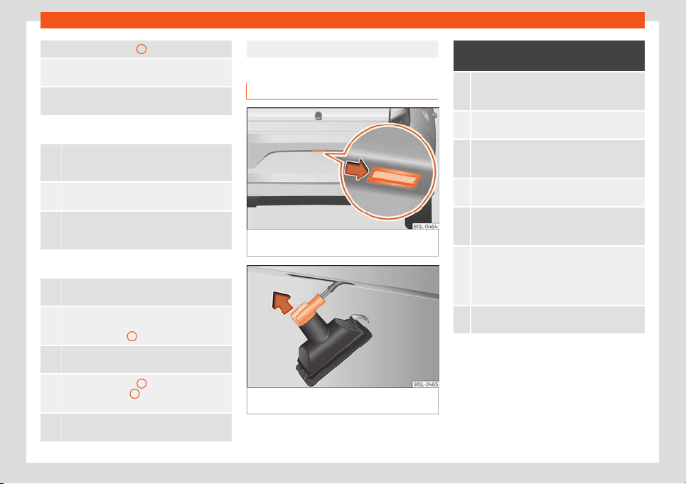
Fuses and bulbs
5. Unscrew the wing nut
5
›››
Fig. 89 B.
6.
Remove the tail light from the bodywork by
carefully pulling backwar
ds.
7.
Disassemble the tail light unit and place it on a
flat, clean surf
ace.
To change the bulb
8.
Unlock the bulb holder locking tab (arrow)
›››
Fig. 90 C and remove the bulb holder from
the tail light.
9.
Replace the faulty bulb by a new identical bulb
›››
Fig. 90 D.
10.
Place the bulb holder in the tail light unit. The
attachment tabs (arr
ow) should audibly click
into place
›››
Fig. 90 C.
Assembling the rear light units
11.
Carefully insert the tail light unit into the open-
ing in the bodywork.
12.
Support the t
ail light with one hand in the as-
sembly position and securely scre
w the wing
nut with the other
5
›››
Fig. 89 B.
13.
Ensure that the tail light unit has been correctly
fitted and is firmly secured.
14.
Insert the connector
2
into the bulb holder
and press the lock
3
on the connector in the
opposite direction t
o the arrow
›››
Fig. 89 B.
15.
Insert the cover. The cover should lock into
place.
16. Close the rear lid
›››
page 99.
Changing the number plate light
Fig. 91
In the rear bumper: remove the plate
light.
Fig. 92
Number plate light: detach the bulb
hol
der
.
Complete operations only in the se-
quence given:
1.
With one hand, press on the number pl
ate light
from left t
o right and remove it from the bumper
›››
Fig. 91.
2.
Detach the number plate light carefully from
the bumper.
3.
Turn the bulb hol
der with the bulb anticlock-
wise
and remove it in the direction of the arrow
›››
Fig. 92.
4.
Replace the faulty bulb with a new identical
bulb.
5.
Place the bulb hol
der in the number plate light
and press in the opposite dir
ection to the arrow
as far as possible
›››
Fig. 92.
6.
Insert the number plate light carefully into the
left edge of the opening on the bumper. During
this process, check that the assembly direction
of the number plate light is correct, i.e. the
spring must be on the right.
7.
Insert the number plate light into the bumper
until it audibly clicks into place.
83
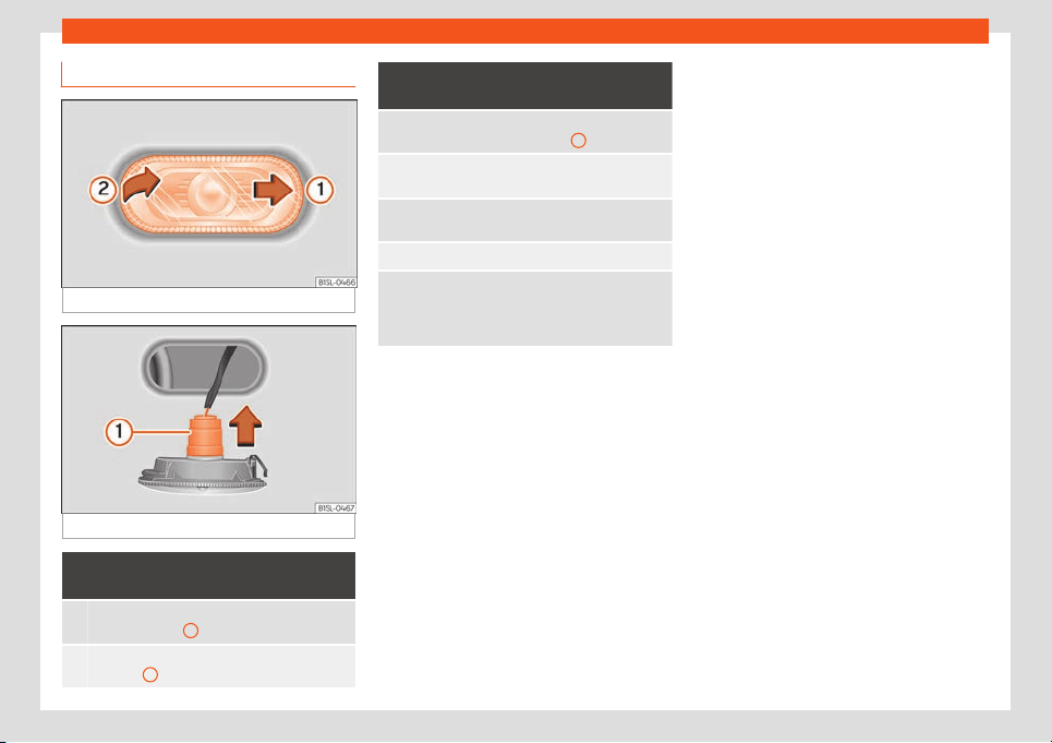
Emergencies
Changing the side turn signal bulb
Fig. 93
Removing the side turn signal
Fig. 94
Side turn light: bulb change.
Complete operations only in the se-
quence given:
1.
With one hand mov
e the side turn signal back-
wards
›
››
Fig. 93
1
.
2.
Remove the side turn signal from the chassis by
leverage
2
.
Complete operations only in the se-
quence given:
3.
Remo
ve the bulb holder with the bulb in the di-
rection of the arro
w
›››
Fig. 94
1
.
4.
Remove the bulb holder bulb in a straight direc-
tion.
5.
Replace the faulty bulb with a new identical
bulb.
6. Inst
all the bulb holder.
7.
Place the side turn signal on the chassis on the
side situated t
owards the rear of the vehicle until
the spring clicks into the other side of the side
turn signal.
84

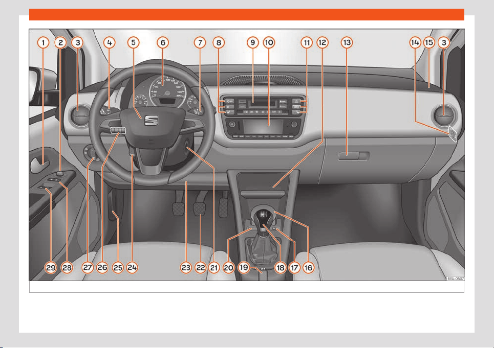
Operation
Fig. 95 Dash panel
86
General instrument panel
Operation
Gener
al instrument panel
Instrument panel
Key to Fig. 95:
Door release l
ever . . . . . . . . . . . . . . . . . . . 98
Turn switch for adjusting the exterior
mirrors . . . . . . . . . . . . . . . . . . . . . . . . . . . . . . . . 110
–
Exterior mirror adjustment
–
Ext
erior mirror heating
Air vents . . . . . . . . . . . . . . . . . . . . . . . . . . . . . . 129
Lever for . . . . . . . . . . . . . . . . . . . . . . . . . . . . . . 103
–
Turn signals and main beam
headlights
–
Cruise control system (CCS) . . . . . 171
Steering wheel with horn and
–
Driver airbag . . . . . . . . . . . . . . . . . . . . . . . 16
Instrument panel. . . . . . . . . . . . . . . . . . . . . 88, 27
Windscreen wiper/ windscreen
wash lever . . . . . . . . . . . . . . . . . . . . . . . . . . . . 108
–
Windscreen wipers
–
Rear window wiper
1
2
3
4
5
6
7
–
L
e
v
er with buttons for controlling
the SEAT information system
- , / . . . . . . . . . . . . . . . . . . . . . . . . . . . . . . . . . . 24
Controls for:
–
Start-Stop system button . . . . . . . . . 170
–
Rear window heating button . . . . . . 129
–
Left seat heating controls . . . . . . . . . 113
Switches for:
–
Heating and fresh air system . . . . . . 129
–
Manual air conditioning . . . . . . . . . . . 129
–
Climatronic . . . . . . . . . . . . . . . . . . . . . . . . 129
Radio (factory fitted) . . . . . . . . . . . . . . . . . 133
Controls for:
–
Hazard warning lights switch . . . . . 70
–
Passenger front airbag off warn-
ing lamp . . . . . . . . . . . . . . . . . . . . . . . . . . . 60
–
Right seat heating controls
or rear window heating button
(alternative position) . . . . . . . . . . . . . . .113, 129
Storage compartment with drink
holder in the centre console . . . . . . . . . 119
Handle of the storage compartment
or storage compartment open
1)
. . . . . 115
In the side of the dash panel: Key
switch for switching off the front
passenger airbag
1)
. . . . . . . . . . . . . . . . . . . 60
8
9
10
11
12
13
14
Position of passenger front airbag
on the dash panel . . . . . . . . . . . . . .
. . . . . . 60
Ashtr
ay*
. . . . . . . . . . . . . . . . . . . . . . . . . . . . . . 119
12 volt socket or cigarette light-
er* . . . . . . . . . . . . . . . . . . . . . . . . . . . . . . . . . . . .120, 120
Lever for:
–
Manual gearbox . . . . . . . . . . . . . . . . . . . 159
–
Automatic gearbox . . . . . . . . . . . . . . . . 160
Handbrake . . . . . . . . . . . . . . . . . . . . . . . . . . . 151
Button for:
–
City Safety Assist function . . . . . . . . . 174
Ignition lock . . . . . . . . . . . . . . . . . . . . . . . . . . 149
Pedals . . . . . . . . . . . . . . . . . . . . . . . . . . . . . . . . 158
Storage compartment . . . . . . . . . . . . . . . 115
Steering column adjustment lev-
er . . . . . . . . . . . . . . . . . . . . . . . . . . . . . . . . . . . . . 49
Open bonnet lever . . . . . . . . . . . . . . . . . . . 193
Headlight range control . . . . . . . . . . . . . 103
Light switch . . . . . . . . . . . . . . . . . . . . . . . . . . 103
Central locking button . . . . . . . . . . . . . . . 94
Buttons for operating the front elec-
tric windows . . . . . . . . . . . . . . . . . . . . . . . . . . 101
15
16
17
18
19
20
21
22
23
24
25
26
27
28
29
1)
According to version
87
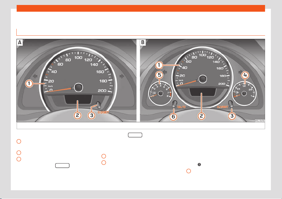
Operation
Instruments
Vie
w of instrument panel
Fig. 96 Instrument panel, on the instrument panel: variant 1 (A) and variant 2 (B).
Details of the instruments
›
›
›
Fig. 96:
Speedometer. Depending on the
vehicle in km/h or in mph.
Displays on the screen. . . . . . . . . . . . . 89
Reset knob for trip recorder (trip).
–
Press the button 0.0/SET
briefly
t
o s
wit
ch the trip odometer and
odometer.
1
2
3
–
Pr
ess the 0.
0/SET f
or 5 seconds
t
o r
eset the odometer to zero and,
where necessary, other indicators
on the multifunction display. . . . . . . 24
Fuel reserve display. . . . . . . . . . . . . . . . 189
Revolution counter (with the en-
gine running, in thousands of revo-
lutions per minute).
The beginning of the red zone of the
rev counter indicates the maximum
4
5
speed in any gear after running-in
and with the engine hot. Ho
w
e
ver, it
is advisable to change up a gear or
move the selector lever to D (or lift
your foot off the accelerator) before
the needle reaches the red zone
›››
.
Cl
ock set butt
on
.
–
If necessary, change the time dis-
play by pressing the top and
6
88
General instrument panel
bottom buttons of the rocker
s
wit
ch
›
››
Fig. 34
B
.
–
Pr
ess the
butt
on to change the
hour, so that it is flashing.
–
To continue setting the time, press
button 0.0/SET
. Hold button down
t
o scr
oll thr
ough the numbers
quickly.
–
Press the button again to
change the minutes, so that it
flashes.
–
To continue setting the time, press
button 0.0/SET
. Hold button down
t
o scr
oll thr
ough the numbers
quickly.
–
Press the button again to end
the clock setting.
CAUTION
●
When the engine is cold, avoid high r
evs
and heavy acceleration and do not make
the engine work hard.
●
To prevent damage to the engine, the rev
counter needle should only remain in the
red zone for a short period of time.
For the sake of the environment
Changing up a gear in time reduces fuel
consumption and noise.
Indications on the display
A variety of information can be viewed on the
instrument panel display
››
›
Fig. 96
2
, de-
pending on the vehicle equipment:
●
W
arning and information messages.
●
Odometer.
●
Time.
●
Outside temperature.
●
Selector lever positions
›››
page 158.
●
Recommended gear (manual gearbox)
›››
page 158.
●
Multifunction display (MFI)
›››
page 24
●
Service interval display
›››
page 90.
●
Start-Stop system status display
›››
page 170.
●
Fuel gauge
›››
page 189.
●
Seat belt status display for rear seats
›››
page 53.
Warning and information messages
The system runs a check on certain compo-
nents and functions when the ignition is
switched on and while the vehicle is moving.
Faults in the operation are displayed on the
screen using red and yellow symbols on the
instrument panel display (
›››
page 27)
and, in some cases, with audible warnings.
The display may vary according to the type
of instrument panel fitted.
Priority 1 warning (red symbols)
Symbol flashing or lit; partly combined with audible
warnings.
Stop the vehicle! It is dangerous
›››
!
Check the function that is faulty and repair it. If nec-
essary, request assistance from specialised person-
nel.
Priority 2 warning (yellow symbols)
Symbol flashing or lit; partly combined with audible
warnings.
A fault
y function, or fluids which are below the cor-
rect levels may cause damage to the vehicle!
›››
Check the faulty function as soon as possible. If nec-
essary, request assistance fr
om specialised person-
nel.
Odometer
The od
omet
er
registers the total distance
travelled by the car.
The odometer (trip) shows the distance
travelled since the last odometer reset. The
last figure indicates 100 m.
Outside temperature indicator!
When the outside temperature is below +4°C
(+39°F), the “ice crystal” symbol (warning of
risk of freezing) is also displayed next to the
temperature. At first this symbol flashes and
then it remains lit until the outside tempera-
ture rises above +6°C (+43°F)
›››
.
»
89
Operation
When the vehicle is stationary or travelling at
v
ery l
o
w speeds, the temperature displayed
may be slightly higher than the actual out-
side temperature as a result of heat coming
from the engine.
The temperatures measured range from
-40°C to +50°C (-40°F to +122°F).
Selector lever position
The range of engaged gears of the selector
lever is shown on the side of the lever, and on
the instrument panel display. In positions D
and M, and with the Tiptronic, the corre-
sponding gear is also indicated on the dis-
play.
Recommended gear* (manual gearbox)
The recommended gear to save fuel can be
displayed on the instrument panel display
while you are driving
›››
page 158.
Seat belt status display for the rear seats*
The seat belt status display on the instrument
panel display informs the driver, when the ig-
nition is switched on, whether any passen-
gers in the rear seats have fastened their seat
belts
›››
page 53.
Start-Stop system status display
The instrument panel display shows informa-
tion on the current status
›››
page 170.
WARNING
If the warning lamps are ignored, the vehi-
cle may stall in tr
affic, or may cause acci-
dents and severe injuries.
●
Never ignore the warning lamps.
●
Stop the vehicle safely as soon as possi-
ble.
●
A faulty vehicle represents a risk of acci-
dent for the driver and for other road users.
If necessary, switch on the hazard warning
lamps and put out the warning triangle to
advise other drivers.
●
Park the vehicle away from traffic and
ensure that no highly flammable materials
are under the vehicle that could come into
contact with the exhaust system (e.g. dry
grass, fuel).
WARNING
Even though outside temperatures are
above fr
eezing, some roads and bridges
may be icy.
●
At outside temperatures above +4°C
(+39°F), even when the “ice crystal sym-
bol” is not visible, there may still be patch-
es of ice on the road.
●
Do not rely on the outside temperature
indicator!
CAUTION
Failure to heed the warning lamps when
they appear may result in faults in the v
ehi-
cle.
Note
●
Different v
ersions of the instrument panel
are available and therefore the versions
and instructions on the display may vary.
●
When several warnings are active at the
same time, the symbols are shown succes-
sively for a few seconds and will stay on
until the fault is rectified.
Service interval display
The inspection message appears on the in-
strument panel displ
ay
›
›
›
Fig. 96
2
.
SEAT distinguishes betw
een services
with
en-
gine oil change (Oil Change Service) and
services without engine oil change (Inspec-
tion Service). The service interval display only
gives information for service dates which in-
volve an engine oil change. The dates of the
remaining services (e.g. the next Inspection
Service or change of brake fluid) are listed on
the label attached to the door strut, or in the
Maintenance Programme.
The set service intervals have been specified
with the service dependent on time/dis-
tance travelled.
90

General instrument panel
Inspection reminder
If the inspection period is due t
o e
xpir
e short-
ly, Inspection reminder appears when start-
ing the ignition abbreviated to and a
warning in km. The number of kilometres
shown is the maximum number that may be
driven until the next service.
Service due
After the service date, an audible warning is
given when the ignition is switched on and the
abbreviation displayed on the screen
flashes for a few seconds.
Inspection of compressed natural gas
tanks (CNG) reminder
When less than 90 days for the review of the
compressed natural gas tanks (CNG), when
the ignition is switched on, the instrument
panel display will a reminder for review of
the gas tanks and an audible warning will be
emitted.
As approaches the service date of inspection
of the gas tanks, the message and the audi-
ble warning will stop modify accordingly.
Note
●
The service message disappears after a
fe
w seconds, when the engine is started or
when OK
is pressed on the windscreen
wiper lev
er.
●
In vehicles whose batt
eries have been
disconnected for a long period of time, it
will not be possible to calculate the next
service date. Therefore the service interval
display may not be correct. In this case,
bear in mind the maximum service intervals
permitted
›››
page 217.
●
If the period of 48 months for an inspec-
tion at a specialised workshop of com-
pressed natural gas tanks (CNG) is excee-
ded, the vehicle may not working in this
mode.
91
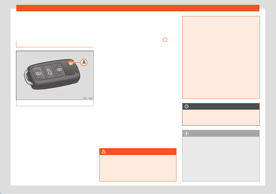
Operation
Opening and closing
V
ehicl
e k
ey set
Remote control vehicle key*
Fig. 97 Remote control key
Remote control key
With the v
ehicl
e k
ey the vehicle may be
locked or unlocked remotely
›››
page 94.
The vehicle key includes an emitter and bat-
tery. The receiver is in the interior of the vehi-
cle. The range of the vehicle key with remote
control and new battery is several metres
around the vehicle.
If it is not possible to open or close the vehicle
using the remote control key, this should be
re-synchronised
›››
page 94 or the battery
changed
›››
page 93.
Different keys belonging to the vehicle may
be used.
Folding the key shaft in and out
When the button is pressed
›››
Fig. 97
A
, the
k
ey shaft is r
el
eased and unfolds.
To fold it press the button and fold the key
shaft in until it locks in place.
Spare key
To obtain a spare key and other vehicle keys,
the vehicle chassis number is required.
Each new key must contain a microchip and
be coded with the data from the vehicle elec-
tronic immobiliser. A vehicle key will not work
if it does not contain a microchip or the mi-
crochip has not been encoded. This is also
true for keys cut for the vehicle.
The vehicle keys or new spare keys can be
obtained from a SEAT dealership, a Special-
ised workshop or approved key service quali-
fied to create this kind of key.
New keys or spare keys must be synchronised
before use
›››
page 94.
WARNING
Careless or incorrect use of vehicle keys
may result in sev
ere injury and accident.
●
Always take all the keys with you when-
ever you leave the vehicle. Children and
unauthorised individuals could lock the
doors or the boot hatch, start the engine or
turn on the ignition, activating el
ectrical
systems, the electric windows, for example.
●
Never leave children or disabled people
alone in the car. They could be trapped in
the car in an emergency and will not be
able to get themselves to safety. For exam-
ple, depending on the time of the year,
temperatures inside a locked and closed
vehicle can be extremely high or extremely
low resulting in serious injuries and illness
or even death, particularly for young chil-
dren.
●
Never remove the key from the ignition if
the vehicle is in motion. The steering may
lock and it will not be possible to turn the
steering wheel.
CAUTION
The remote control key contains electronic
components. Protect them fr
om damage,
impacts and humidity.
Note
●
Only use the key button when you r
equire
the corresponding function. Pushing the
button unnecessarily could accidentally
unlock the vehicle or trigger the alarm. It is
also possible even when you are outside
the radius of action.
●
Remote control key operation can be
greatly influenced by overlapping radio
signals around the vehicle working in the
92
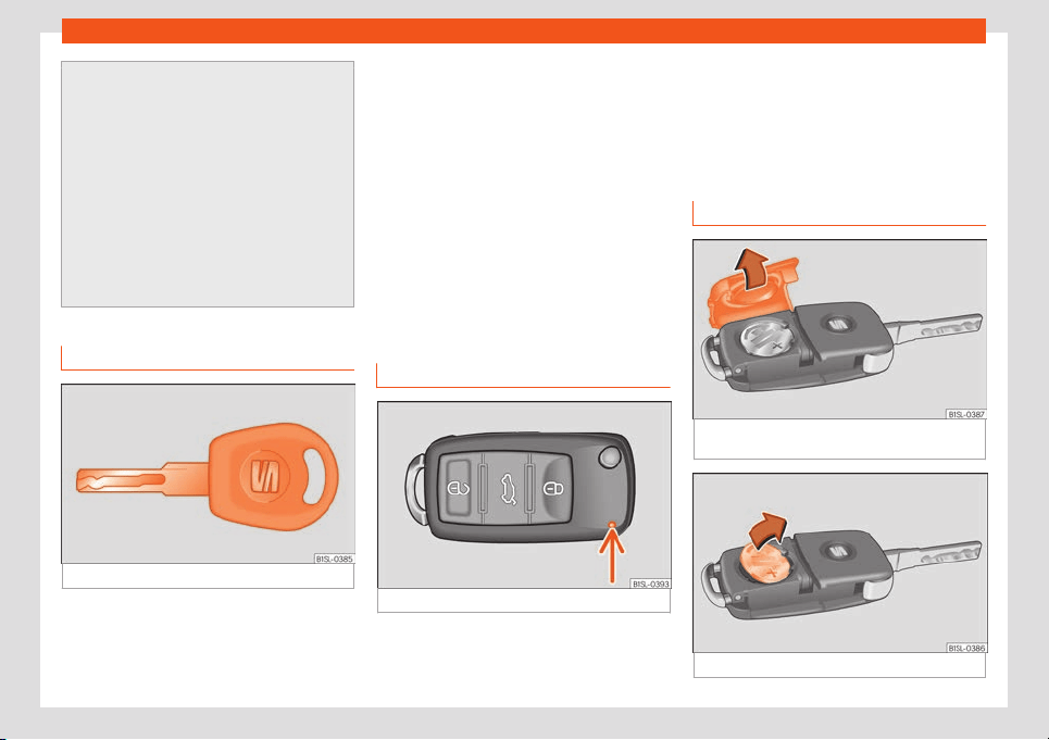
Opening and closing
same range of frequencies (for example,
radio transmitt
ers, mobile telephones).
●
Obstacles between the remote control
and the vehicle, bad weather conditions
and draining batteries can considerably re-
duce the range of the remote control.
●
If the buttons of the vehicle key are
pressed
›››
Fig. 97 or one of the central
locking buttons
›››
page 94 is pressed re-
peatedly in quick succession, the central
locking briefly disconnects as protection
against overloading. The vehicle is then un-
locked. Lock it if necessary.
Mechanical vehicle key
Fig. 98
Vehicle mechanical key
The vehicle key set may include a mechani-
cal k
ey
›
›
›
Fig. 98.
Duplicate keys
To obtain a spare key and other vehicle keys,
the vehicle chassis number is required.
Each new key must contain a microchip and
be coded with the data from the vehicle elec-
tronic immobiliser. A vehicle key will not work
if it does not contain a microchip or the mi-
crochip has not been encoded. This is also
true for keys cut for the vehicle.
The vehicle keys or new spare keys can be
obtained from a SEAT dealership, a special-
ised workshop or an approved locksmith
qualified to create them.
Control lamp on the vehicle key
Fig. 99
Control lamp on the vehicle key
When a button on the vehicle key is pressed,
the contr
ol l
amp fl
ashes
›››
Fig. 99 (arrow)
once briefly. If the button is pressed and held,
the indicator blinks several times, for exam-
ple: for the convenience opening function.
When the control lamp does not light upon
pushing a button, the vehicle key batteries
must be changed
›››
page 93.
Replacing the battery
Fig. 100 Vehicle key: battery compartment
co
v
er
.
Fig. 101 Vehicle key: remove the battery.
»
93
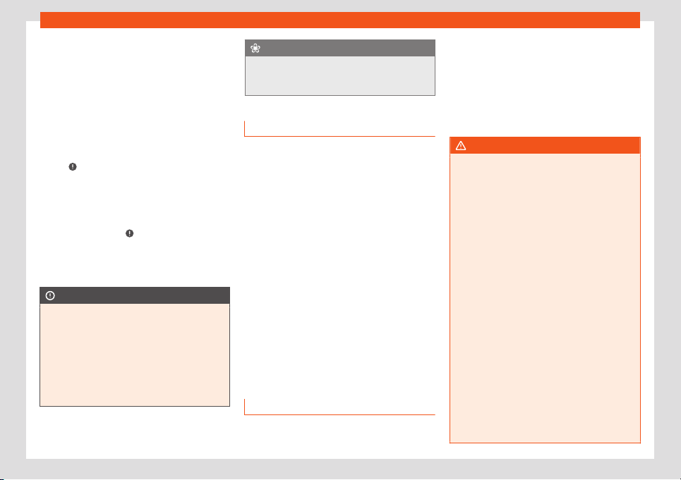
Operation
SEAT recommend having the batteries
changed in a specialised w
orkshop
.
The batt
ery is located to the rear of the vehi-
cle key, under a cover.
Changing the battery
●
Unfold the vehicle key blade
›››
page 92.
●
Remove the cover from the back of the ve-
hicle key
›››
Fig. 100 in the direction of the ar-
row
›››
.
●
Extract the battery from the compartment
using a suit
abl
e thin ob
ject
›››
Fig. 101.
●
Place the new battery in the compartment,
pressing in the direction of the arrow as
shown
›››
Fig. 101
›››
.
●
Fit the battery compartment cover, press-
ing in the dir
ection of the arr
o
w as shown
›››
Fig. 100 until it clicks into place.
CAUTION
●
If the battery is not changed correctly,
the v
ehicle key may be damaged.
●
Use of unsuitable batteries may damage
the vehicle key. For this reason, always re-
place the dead battery with another of the
same voltage, size and specifications.
●
When fitting the battery, check that the
polarity is correct.
For the sake of the environment
Please dispose of your used batteries cor-
rectly and with respect f
or the environ-
ment.
Synchronising the vehicle key
If the button is pressed fr
equently outside
of the vehicle range, it is possible that the ve-
hicle can no longer be locked or unlocked us-
ing the key. In this case, the vehicle key must
be synchronised once more as follows:
●
Unfold the vehicle key blade
›››
page 92.
●
Press the button on the vehicle key. For
this, it must remain with the vehicle.
●
Open the vehicle within one minute using
the key shaft.
●
Turn on the ignition using the vehicle key.
The key has been synchronised.
●
If necessary, fit the cap.
Central locking* and locking
system
Introduction
Read the additional information carefully
›
›
›
page 10
Central locking functions correctly when all
the doors and the rear lid are correctly shut. If
the driver door is open, the vehicle cannot be
locked with the key.
The battery of an unlocked vehicle parked for
a long period (e.g. in a private garage) may
run down and fail to start the motor.
WARNING
The incorrect use of the central locking
system may cause serious injuries.
●
The central l
ocking system will lock all
doors. A vehicle locked from the inside can
prevent any non-authorised individual from
opening the doors and accessing the vehi-
cle. Nevertheless, in case of emergency or
accident, locked doors will complicate ac-
cess to the vehicle interior to help the pas-
sengers.
●
Never leave children or disabled people
alone in the vehicle. The central locking
button can be used to lock all the doors
from within. Therefore, passengers will be
locked inside the vehicle. Individuals locked
in the vehicle can be exposed to very high
or very low temperatures.
●
Depending on the time of the year, tem-
peratures inside a locked and closed vehi-
cle can be extremely high or extremely low
resulting in serious injuries and illness or
even death, particularly for young children.
●
Never leave individuals locked in a closed
and locked vehicle. In case of emergency,
94
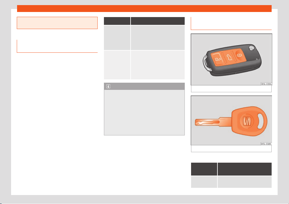
Opening and closing
they may not be able to exit the vehicle by
themselves or get help
.
Description of the central locking
system
The central locking system allows all doors
and the rear lid to be l
ocked and unlocked
centrally.
●
From outside, using the vehicle key.
●
From inside, by pushing the central locking
button
››
›
page 97.
The central locking system can be activated
or deactivated at a specialised workshop.
In case of a vehicle key fault or central lock-
ing system fault, all doors can be locked or
unlocked manually.
Locking the vehicle after the airbags have
been deployed
If the airbags are deployed due to an acci-
dent, the vehicle will be automatically and
completely unlocked. Depending on the
amount of damage, it can be locked follow-
ing an accident in the following ways:
Function Necessary operations
Lock the vehi-
cle,
by push-
ing the central
locking but-
ton:
– Turn off the ignition and turn it on
again.
– Push the central locking button
.
Use the key to
lock the v
ehi-
cle:
– Turn off the ignition and turn it on
again.
OR: Remove the key from the igni-
tion.
– Open any door just once.
– Lock the vehicle with the key.
Note
If the buttons of the vehicle key are pressed
›››
page 92 or one of the central locking
buttons
›››
Fig. 104 is pressed repeatedly in
short succession, the central locking brief-
ly disconnects as protection against over-
loading. In this case, the vehicle remains
unlocked for about 30 seconds. If no door
nor the rear lid is opened during this time,
the vehicle will then automatically lock.
Unlocking and locking the vehicle
fr
om outside
Fig. 102
Buttons on the vehicle key
Fig. 103 Vehicle mechanical key
Central locking
Function Handling the buttons on the
vehicle
›
››
Fig. 102
Unlocking the
vehicle
.
Press button .
»
95

Operation
Function Handling the buttons on the
vehicle
›
››
Fig. 102
Lock the vehi-
cle.
Pr
ess button .
Unlocking the
rear lid.
Press butt
on .
Locking the
rear lid.
Press butt
on .
Function Handling the vehicle key
›››
Fig. 102 in the lock cylin-
der or with the vehicle me-
chanical key
›››
Fig. 103.
Unlocking the
vehicle
.
Insert the vehicle key into the lock
cylinder of the driver door and turn
the key in an anticlockwise di-
rection.
Lock the vehi-
cle.
Insert the v
ehicle key into the lock
cylinder of the driver door and turn
the key in a clockwise direction.
Unlocking the
rear lid.
Insert the vehicl
e key into the lock
cylinder of the driver door and turn
the key in an anticlockwise di-
rection.
Locking the
rear lid.
Insert the vehicle key into the lock
cylinder of the driver door and turn
the key in a clockwise direction.
Warning: in accor
dance with the centr
al
l
ocking function set by a specialised work-
shop, in order to unlock all the doors and the
rear lid, press the button twice.
The vehicle key only locks and unlocks the
vehicle if it is within range of the vehicle and if
the battery has enough power.
●
Upon locking the vehicle, all turn signals will
flash once in confirmation.
●
Upon unlocking the vehicle, all turn signals
will flash twice in confirmation.
If the turn signals do not flash in confirmation,
at least one of the doors or the rear lid has
been left unlocked.
If the driver door is open, the vehicle cannot
be locked with the key. If you unlock the vehi-
cle without opening any doors or the rear lid,
it will lock again automatically after a few
seconds. This function prevents the vehicle
from remaining unlocked if the unlocking but-
ton is pressed by mistake.
Mechanical locking
Function
Using the vehicle's me-
chanical key
››
›
Fig. 103 in
the lock cylinder
Locking the
driver door
manually.
To
unlock, insert the vehicle key
into the l
ock cylinder of the driver
door and turn the key in an anti-
clockwise direction.
To lock, insert the vehicle key into
the lock cylinder of the driv
er
door and turn the key in a clock-
wise direction.
Function
Using the vehicle's me-
chanical key
››
›
Fig. 103 in
the lock cylinder
Locking and un-
locking the rear
lid.
T
o unlock, insert the vehicle key
into the l
ock cylinder of the driver
door and turn the key in an anti-
clockwise direction.
To lock, insert the vehicle key into
the lock cylinder of the driv
er
door and turn the key in a clock-
wise direction.
If the driver's door is open, it cannot be
l
ock
ed with the v
ehicle key.
96
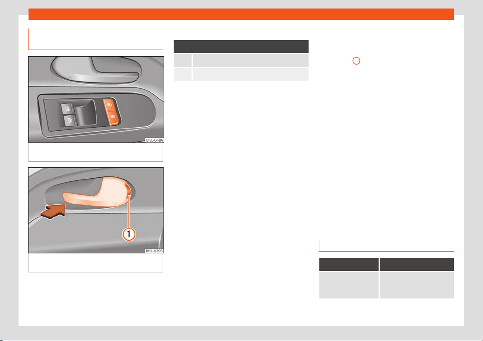
Opening and closing
Locking or unlocking the vehicle
fr
om the inside
Fig. 104
On the driver's door: central locking
butt
on.
Fig. 105
On the passenger door: door handle
f
or mechanical l
ocking.
Central locking
Push the button
›››
Fig. 104:
Unlocking the vehicle.
Locking the vehicle.
The central locking button is still operative
when the ignition is switched off
.
If the vehicle has been locked with the vehicle
key, the central locking button does not oper-
ate.
Please note the following when you use the
central locking button to lock your vehicle:
●
The "Safe" security system will not activate
›
››
page 97.
●
It will not be possible to open the doors or
the rear lid from the outside. This may offer
extra safety, for example when stopped at
traffic lights.
●
The doors can be opened and unlocked in-
dividually from the inside by pulling the door
handle. If necessary, pull the door release
lever twice.
●
The driver door cannot be locked when
open. This avoids locking the vehicle key in-
side the vehicle when there is nobody inside.
Mechanical locking
The doors are locked by pressing the door
lever, so that the red mark becomes visible
›››
Fig. 105
1
.
T
o unl
ock a door
, pull its corresponding door
lever.
If the vehicle becomes locked, take note of
the following:
●
The "Safe" security system will not activate
›››
page 97.
●
It will not be possible to open the doors
from the outside, when stopped at traffic
lights for example.
●
The doors can be opened and unlocked in-
dividually from the inside by pulling the door
handle.
●
The driver door cannot be locked using the
central locking system when it is still open.
This avoids locking the vehicle key inside the
vehicle when there is nobody inside.
Safe security system “Safe”*
Function Necessary operations
Lock the vehicle and
activate the “Saf
e”
security system.
Press the button once on
the vehicle key.
»
97
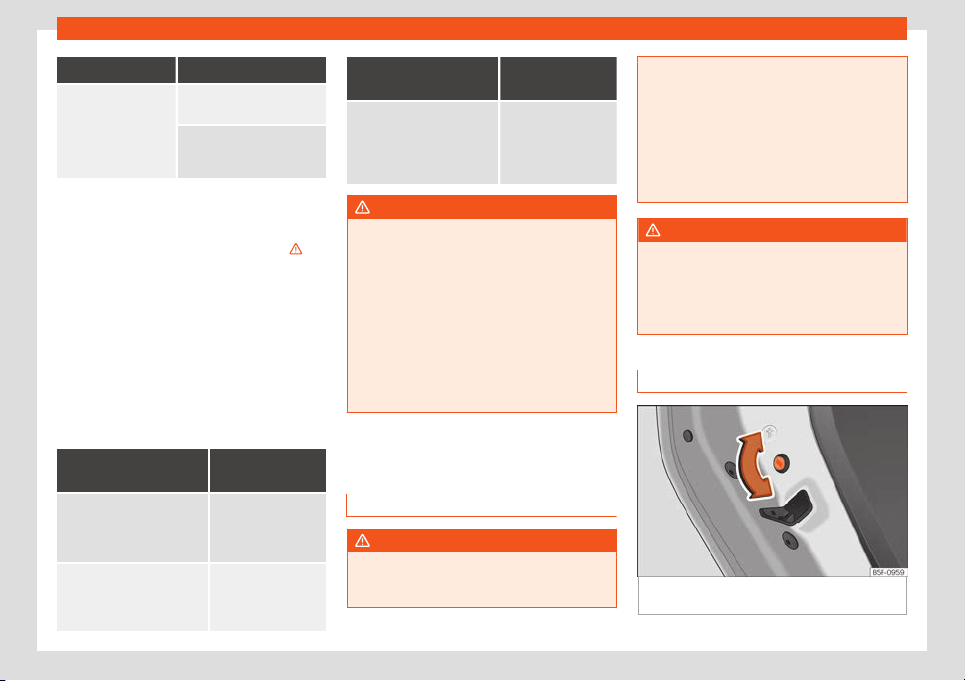
Operation
Function Necessary operations
Lock the vehicle with-
out activ
ating the
“Saf
e” securit
y sys-
tem.
Press the button on the
vehicl
e key twice.
Press the central locking
button on the driv
er door
once.
When the vehicle is locked, the “Safe” securi-
ty system deactiv
ates the door handles, pre-
venting people from opening the vehicle. The
doors cannot be opened from inside
›››
.
Upon switching off the ignition, the instrument
panel displ
ay will show that the “deadlock” is
activated or (SAFELOCK or SAFELOCK).
When the “Safe” security system is deac-
tivated, the following occurs:
●
The vehicle can be opened and unlocked
from the inside using an inside door handle
.
Control lamp on the driver door
When the vehicle is
locked:
Meaning
The r
ed LED flashes for ap-
proximat
ely 2 seconds at
short intervals and then
more slowly.
The "Safe" security
system is switched
on.
The red LED flashes for
about two seconds then
turns off
. After 30 seconds,
the LED flashes again.
The "Safe" security
system is switched
off.
When the vehicle is
locked:
Meaning
The r
ed LED flashes for
about two seconds at short
interv
als. Subsequently, the
light will remain switched on
for about 30 seconds.
There is a fault in the
locking system. Con-
tact a specialised
workshop.
WARNING
Careless use of the "Safe" security system
can cause serious injury.
●
Never leave anybody inside the vehicle if
it has been locked using the k
ey. When the
"Safe" security system is activated, doors
cannot be opened from the inside!
●
When the doors are locked, it is difficult
to get to passengers in the vehicle interior
in case of an emergency. Passengers could
remain trapped inside and unable to unlock
the doors in case of an emergency.
Doors
Intr
oduction
WARNING
If a door is not correctly closed, it could
open unexpectedly when driving and cause
serious injuries.
●
Always st
op immediately and close the
door.
●
When closing, ensure that the door has
closed correctly. A closed door should be
flush with the corresponding parts of the
bodywork.
●
Open and close doors only when nobody
is in the way of the door.
WARNING
A door held open by its retainer could be
bl
own cl
osed by the wind or close if the ve-
hicle is on a hill, causing injury.
●
When opening and closing doors, always
use the door handle.
Childproof lock
Fig. 106 Childproof lock on the left hand side
door
98
Opening and closing
The childproof lock prevents the rear doors
fr
om being opened fr
om the inside
. This sys-
tem prevents minors from opening a door ac-
cidentally while the vehicle is running.
This function is independent of the vehicle
electronic opening and locking systems. It
only affects rear doors. It can only be activa-
ted and deactivated manually, as described
below:
Activating the childproof lock
–
Unlock the vehicle and open the door in
which you wish to activate the childproof
lock.
–
With the door open, rotate the groove in the
door using the ignition key, anti-clockwise
for the left-hand side doors
›››
Fig. 106 and
clockwise for the right-hand side doors.
Deactivating the childproof lock
–
Unlock the vehicle and open the door
whose childproof lock you want to deacti-
vate.
–
With the door open, rotate the groove in the
door using the ignition key, anti-clockwise
for the right-hand side doors, and clock-
wise for the left-hand side doors
›››
Fig. 106.
Once the childproof lock is activated, the
door can only be opened from the outside.
The childproof lock can be activated or de-
activated by inserting the key in the groove
when the door is open, as described above.
Rear lid
Introduction
WARNING
Careless and unsuitable locking, opening
and closing of the rear lid can cause acci-
dents and serious injury.
●
Open and cl
ose the rear lid only when
nobody is in the way.
●
Do not close the rear lid by pushing it
down with your hand on the rear window.
This could break and cause injury.
●
Ensure the rear lid is locked after closing,
otherwise, it may open unexpectedly while
driving. A closed rear lid should be flush
with the corresponding parts of the body-
work.
●
Always keep the rear lid closed while
driving to avoid toxic gases entering the ve-
hicle interior.
●
Do not open the rear lid when there is a
load installed, for example a carrier sys-
tem. Likewise, the boot hatch cannot be
opened when a load is attached to it, for
example bicycles. An open rear lid could
close itself if there is an additional weight
on it. If necessary, press down on the rear
lid and remov
e the load.
●
Close and lock both the rear lid and all
the other doors when you are not using the
vehicle. Ensure that nobody remains inside
the vehicle.
●
Never allow children to play inside or
around the vehicle without supervision, es-
pecially if the rear lid is open. Children
could enter the luggage compartment,
close the rear lid and become trapped. De-
pending on the time of the year, tempera-
tures inside a locked and closed vehicle
can be extremely high or extremely low re-
sulting in serious injuries and illness or even
death, particularly for young children.
●
Never leave children or disabled people
alone in the vehicle. If the vehicle key or the
central locking button is used, they may be
locked in the vehicle.
CAUTION
Before opening the rear lid, ensure that
there is sufficient free space t
o open and
close it, for example if you are in a garage.
99
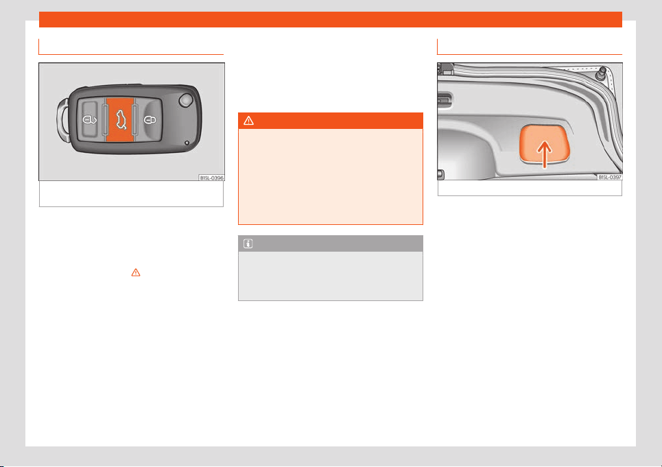
Operation
Opening the rear lid
Fig. 107
On the vehicle key: button to unlock
and open the boot hat
ch.
Read the additional information carefully
›
›
›
page 11
If bicycles are attached to a rack on the boot
hatch, for example, in some cases, it may not
open automatically
›››
. Remove the load
fr
om the carrier and support the open r
ear lid.
Opening with centr
al locking
●
Press the button on the vehicle key
›››
Fig. 107 for about one second to unlock
the rear lid.
●
OR: Press the button on the vehicle key
until the rear lid opens automatically several
centimetres.
●
Opening the rear lid with the button.
Opening with the vehicle mechanical key
●
Insert the vehicle key into the lock cylinder
of the driver door and turn the key in an anti-
clockwise direction
›››
page 94.
●
Opening the rear lid with the button.
WARNING
Unsuitable or careless unlocking and open-
ing of the rear lid could cause serious inju-
ries.
●
If ther
e is a loaded luggage carrier on the
rear lid, it could be unlocked or open but
not recognised as such. An unlocked or
open rear lid could open unexpectedly
while driving.
Note
At outside temperatures of less than 0°C
(+32°F), the pressurised gas struts cannot
alw
ays automatically lift the rear lid. In this
case, open the rear lid manually.
Closing the rear lid
Fig. 108
Rear lid open: space for pulling.
Closing the rear lid
●
Grab the handgrip inside the rear lid
›
›
›
Fig. 108 (arrow).
●
Push the rear lid downwards until it locks in-
to place in the lock.
●
Ensure that it is correctly closed by pulling
on it firmly.
Locking the rear lid with central locking*
If you unlock the vehicle without opening any
doors or the rear lid, it will lock again auto-
matically after about 30 seconds. This func-
tion prevents the vehicle from remaining un-
locked if the unlocking button is pressed by
mistake.
Locking is only possible when the rear lid is
correctly and fully closed.
100
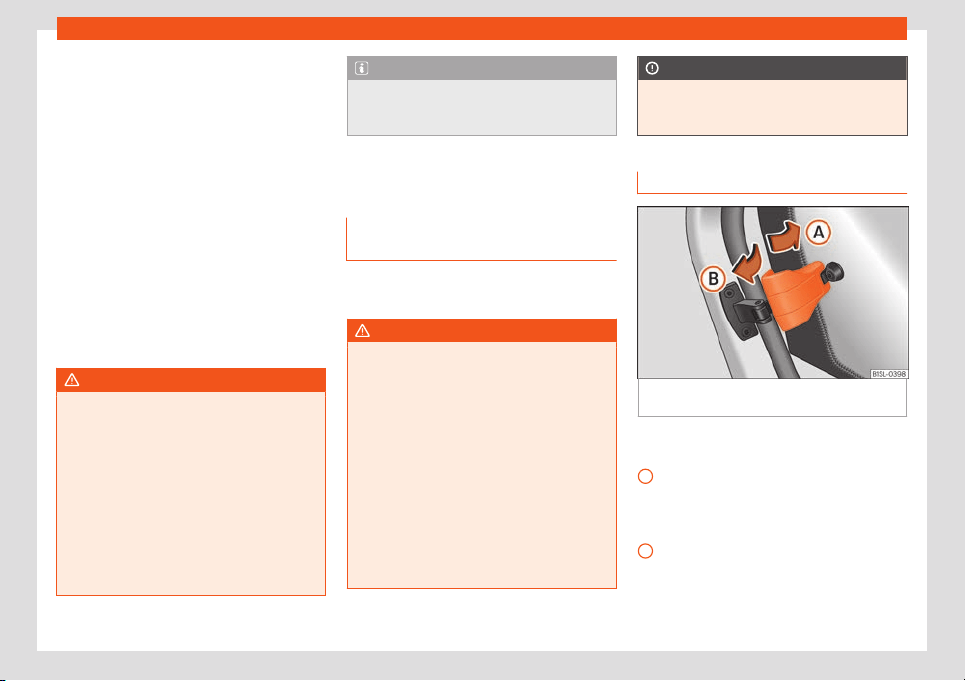
Opening and closing
●
The r
ear lid is al
so l
ocked by a central lock-
ing.
●
If the vehicle rear lid is locked or unlocked
using the button of the vehicle key, when it
is closed again it will lock automatically.
●
A closed but not locked rear lid will lock au-
tomatically at a speed above about 9 km/h
(6 mph).
Locking the rear lid with the vehicle me-
chanical key
Locking is only possible when the rear lid is
correctly and fully closed.
●
Insert the vehicle key into the lock cylinder
of the driver door and turn the key in a clock-
wise direction
›››
page 94.
WARNING
Unsuitable or careless closing and locking
of the rear lid could cause serious injuries.
●
Ne
ver leave the vehicle unattended, or
allow children to play inside or around the
vehicle without supervision, especially if
the rear lid is open. Children could enter
the luggage compartment, close the rear
lid and become trapped. A locked vehicle
can be subjected to extremely high and low
temperatures, depending on the time of
year, thus causing serious injuries/illness
and even death.
Note
Before closing the rear lid, make sure that
the key has not been left inside the luggage
compar
tment.
Controls for the windows
Opening and closing the windows
el
ectrically
Read the additional information carefully
›
›
›
page 13
WARNING
Careless use of the electric windows can
cause serious injury.
●
Only operate the electric windows when
nobody is in the way.
●
Nev
er leave children or disabled people
alone in the vehicle if the doors are to be
locked. The windows cannot be opened in
case of an emergency.
●
Always take all the keys with you when-
ever you leave the vehicle. After turning off
the ignition, the windows can be opened
and closed for a short time using the but-
tons on the door as long as the driver door
or passenger side door is not open.
CAUTION
When the windows are open, rain can enter
the vehicle
, dampening the interior equip-
ment and causing damage to the vehicle.
Side-opening rear windows
Fig. 109 Lever to open and close the rear win-
do
w
Opening
Pull the r
el
ease l
ever in the direction of arrow
A
and press outward until the lever engages.
Cl
osing
Pull the r
el
ease lever in the direction of arrow
B
and then press the lever backward until it
engages.
101
Operation
Sliding/tilting electric pan-
or
amic sunr
oof
Opening and cl
osing the panoram-
ic sunroof
Read the additional information carefully
›››
page 13
The sliding/tilting sunroof only works when
switched on. After switching off, it is still possi-
ble to open or close the sliding/tilting sunroof
during a short space of time provided that
neither the driver nor passenger door is
opened.
All operations are interrupted when the rotary
knob is actuated.
If it were not possible to close the sliding/tilt-
ing sunroof electrically, it would need to be
closed manually. It is not possible to do an
emergency close of the sliding/tilting sunroof
without removing components of the vehicle.
In such a case, obtain professional assis-
tance.
Sliding blind
With the roof grab handle situated in the rear
part of the roof opening, it is possible to move
the sliding blind to the required position.
WARNING
If the sliding/tilting electric panoramic sun-
roof is used negligently or without paying
due attention, it can cause serious injury.
●
The sliding/tilting sunr
oof should only be
opened or closed when no one is blocking
its path.
●
After switching off, it is still possible to
open or close the sliding/tilting sunroof
during a short space of time provided that
neither the driver nor passenger door is
opened.
CAUTION
●
To pre
vent damage, when there are win-
ter temperatures any ice or snow that there
may be on the roof of the vehicle must be
removed before opening or raising the slid-
ing/tilting electric panoramic sunroof.
●
Before leaving the vehicle or in the case
of heavy rain, the sliding/tilting sunroof
must always be closed. With the slid-
ing/tilting sunroof open or raised, water
can enter the passenger compartment and
can cause considerable damage to the
electrical system. As a result, other dam-
age can occur in the vehicle.
●
In the case of heavy rain, if the slid-
ing/tilting sunroof is open, the interior
equipment of the vehicle may get wet, de-
stroying the seat heating and damaging
the electrical system of the vehicle.
Note
●
Leaves and other l
oose objects that land
in the guides of the sliding/tilting sunroof
should be removed periodically by hand or
using a vacuum cleaner.
●
If the sliding/tilting sunroof does not work
correctly, the anti-trap function will not
work either. In this case, you should take
the vehicle to a specialised workshop.
●
The convenience position permits suffi-
cient ventilation with a level of sound pro-
duced by low wind.
Anti-trap function of the slid-
ing/tilting el
ectric panor
amic sun-
r
oof
The anti-trap function can reduce the risk of
injury when cl
osing the sliding/tilting el
ectric
panor
amic sunroof
›››
. If the sliding/tilting
sunr
oof encount
ers r
esistance or an obstacle
when closing, it will immediately reopen.
●
Check why the sliding/tilting sunroof has
not closed.
●
Try to close it again.
●
If it is still not possible to close it due to an
obstacle or resistance, it will remain in the
corresponding position. Close it without the
anti-trap function.
102
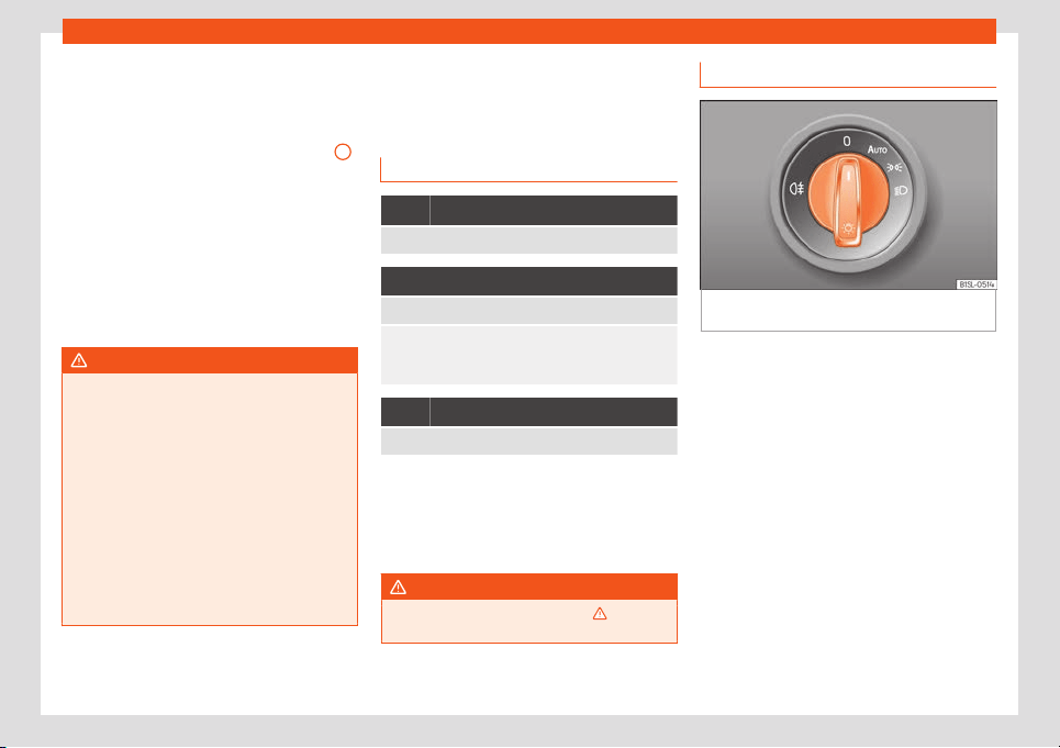
Lights and visibility
Closing the sliding/tilting electric panor-
amic sunr
oof without the anti-tr
ap func-
tion
●
Within about 5 seconds of activ
ating the
anti-trap function, pull knob
›››
Fig. 13
5
until the sliding/tilting sunroof is fully closed.
●
As such, the sliding/tilting sunroof will
cl
ose without the anti-tr
ap function!
●
If the sunr
oof still cannot be closed, visit a
specialised workshop.
If the knob is released during the closing op-
eration, the sliding/tilting electric panoramic
sunroof opens automatically.
WARNING
Closing the sliding/tilting electric panor-
amic sunroof without the anti-trap function
can r
esult in serious injury.
●
The sliding/tilting sunroof should always
be closed carefully.
●
No person should ever remain in the way
of the sliding/tilting sunroof, especially
when closing without the anti-trap func-
tion.
●
The anti-trap function does not prevent
fingers or other parts of the body from be-
coming trapped against the roof frame and
injuries occurring.
Lights and visibility
Lights
Contr
ol l
amps
It lights up
Rear fog light switched on
›››
page 22.
It lights up
Left or right turn signal.
The control lamp flashes twice as fast when a vehicle
turn signal is fault
y. If necessary, check the vehicle's
lights.
It lights up
Main beam on or flasher on
›››
page 105.
Several warning and control lamps light up
f
or a f
e
w seconds when the ignition is switch-
ed on, signalling that the function is being
verified. They will switch off after a few sec-
onds.
WARNING
Observe the safety warnings
›››
in Con-
trol and warning l
amps on page 27.
Switching lights on and off
Fig. 110
On the side of the steering wheel: dia-
gr
am of some of the t
ypes of light s
witch
Read the additional information carefully
›
›
›
page 22
The driver is personally responsible for the
correct use and adjustment of the lights in all
situations.
Audible warnings to advise the driver that
the lights have not been switched off
If the key is not in the ignition and the driver
door is open, an audible warning signal is
heard in the following cases: this will remind
you to turn the light off.
●
When the light switch is in position .
●
When the light switch is in position .
»
103
Operation
WARNING
The side lights or daytime running lights
are not bright enough to illuminat
e the road
ahead and to ensure that other road users
are able to see you.
●
Always use your dipped beam head
lights if it is raining or if visibility is poor.
WARNING
If the headlights are set too high and not
used correctly, there is a risk of dazzling or
distr
acting other road users. This could re-
sult in a serious accident.
●
Always make sure that the headlights are
correctly adjusted.
Note
The legal requirements regarding the use
of vehicle lights in each country must be
observ
ed.
Light and visibility: functions
Parking light remains on both sides
If when s
wit
ching off the ignition, the light
contr
ol remains in the position and the ve-
hicle is closed from outside, both headlights,
in addition to the side lights and the rear
lights will light up.
Daytime running lights
The daytime driving light consists of individu-
al lights in the front headlamps.
When the daytime driving light is switched on,
only the individual lights come on
›››
.
The daytime lights ar
e s
wit
ched on each time
the ignition is turned on if the light setting is in
position or in position .
WARNING
If the road is not well-lit and the vehicle is
not clearly visible t
o other drivers, an acci-
dent may occur.
●
Never use the daytime driving light if the
road is not well-lit as a result of the weath-
er conditions and poor visibility. The day-
time driving lights are not bright enough to
illuminate the road ahead and to ensure
that other road users are able to see you.
●
The rear lights do not come on with the
daytime driving light. A vehicle which does
not have the rear lights on may not be visi-
ble to other drivers in the darkness, if it is
raining or in conditions of poor visibility.
Note
The headlights, rear lights and turn signals
may mist up temporarily on the inside in
cool or damp w
eather. This is normal and in
no way effects the useful life of the vehicle
lighting system.
Automatic dipped beam control
*
The automatic dipped beam control is merely
intended as an aid and is not able t
o recog-
nise all driving situations.
When the light switch is in position , the
vehicle lights and the instrument panel and
switch lighting switch on and off automatical-
ly in the following situations
›››
in Light and
visibility: functions on page 104:
Automatic switch-
ing on
Automatic switch-
ing off
The photo sensor de-
tects darkness
, for exam-
ple, when driving through
a tunnel.
When adequate lighting
is detected.
The rain sensor detects
rain and activat
es the
windscreen wipers.
When the windscreen
wipers have been inac-
tive for a few minutes.
WARNING
If the road is not well lit and other road
users cannot see the vehicle w
ell enough
or at all, accidents may occur.
●
The automatic dipped beam control
() only switches on the dipped beam
when there are no changes in brightness,
and not, for example when it is foggy.
104
Lights and visibility
“Coming home” and “Leaving
home” function (guidance lights)
The “Coming Home” and “Leaving Home”
function lights up the vehicle
’s immediate
proximity when getting into and out of it in the
dark.
The “Coming home” function is switched on
manually. However, the “Leaving home” func-
tion is automatically controlled by a rain and
light sensor.
Activating the “Coming Home” function
●
Switch the ignition off.
●
Activates the headlight flasher for approx. 1
second
›››
page 23.
When the driver door is opened, the “Coming
Home” lighting comes on. The delay in
switching off the headlights is counted from
when the last door or rear lid of the vehicle is
closed.
Deactivating the “Coming Home” function
●
It is automatically deactivated once the
time set for the light switch-off delay has
elapsed.
●
OR: it is automatically deactivated if, 30
seconds after the function has been activa-
ted, any vehicle door or the rear lid is still
open.
●
OR: rotate the light switch to position .
●
OR: switch on the ignition.
Activating the “Leaving Home” function
●
Unlock the vehicle (the light switch must be
at the position and the rain and light sen-
sor must detect darkness).
Deactivating the “Leaving Home” function
●
It is automatically deactivated once the
light switch-off delay time has elapsed.
●
OR: lock the vehicle.
●
OR: rotate the light switch to position .
●
OR: switch on the ignition.
Turn signal and main beam lever
Read the additional information carefully
›
›
›
page 23
Convenience turn signals
For the convenience turn signals, move the
lever as far as possible upwards or down-
wards and release the lever. The turn signal
will flash 3 times.
The convenience indicators can be deactiva-
ted at a Specialised workshop.
WARNING
Improper or lack of use of the turn signals,
or forgetting t
o deactivate them can con-
fuse other road users. This could result in a
serious accident.
●
Always give warning when you are going
to change lane
, overtake or when turning,
activating the turn signal in good time.
●
As soon as you have finished changing
lane, overtaking or turning, switch the turn
signal off.
WARNING
Incorrect use of the headlights may cause
accidents and serious injury, as the main
beam may distr
act or dazzle other driv
ers.
Note
●
If the convenience turn signal
s are oper-
ating (three flashes) and the other conven-
ience turn signals are switched on, the ac-
tive part stops flashing and only flashes
once in the new part selected.
●
The turn signal only works when the igni-
tion is switched on. The hazard warning
lights also work when the ignition is switch-
ed off
›››
page 70.
●
If any of both turn signals fails, the warn-
ing lamp will start flashing twice faster
than normal.
●
The main beam headlights can only be
switched on if the dipped beam headlights
are already on.
105
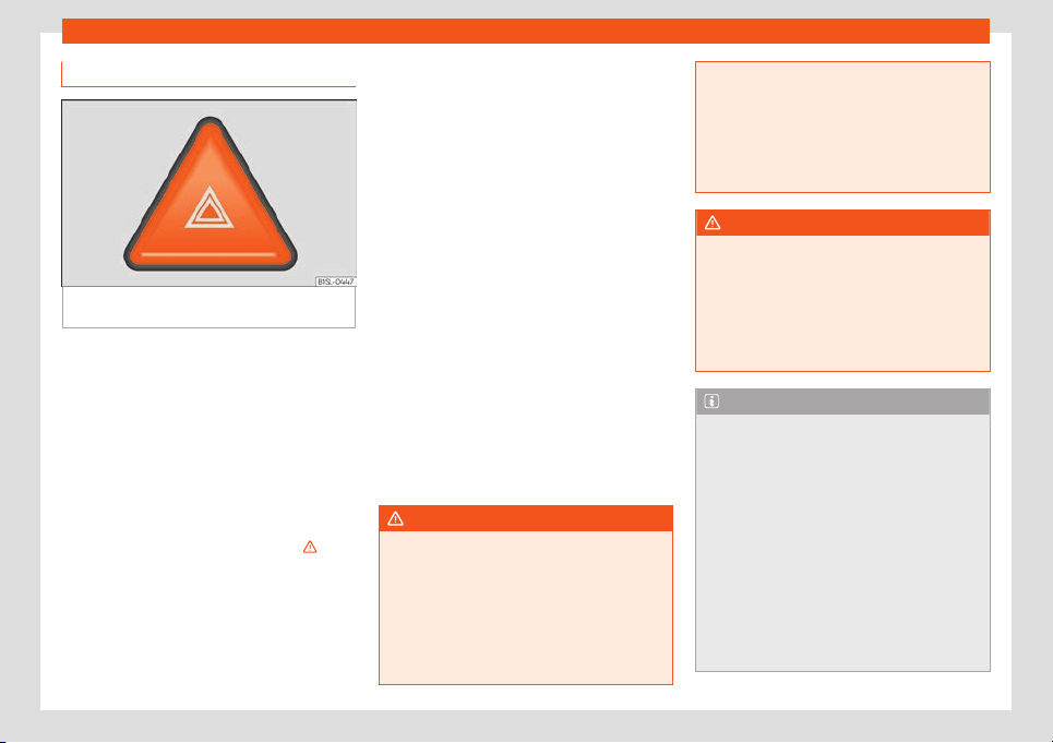
Operation
Hazard warning lights
Fig. 111
Instrument panel: button for switching
the haz
ar
d lights w
arning system on and off.
Read the additional information carefully
›
›
›
page 23
Always fulfil legal requirements for securing a
broken down vehicle. In a number of countries
it is now obligatory, for example, to turn on the
hazard warning lights and use a reflective
safety vest
›››
page 70.
If your vehicle breaks down:
Park the vehicle a safe distance from
traffic and on suitable ground
›››
.
T
urn on the haz
ar
d warning lights with
the button
›››
Fig. 111.
Apply the handbrake firmly
›››
page 151.
Put the gearbox lever in neutral or the
selector lever in position N
›››
page 158.
1.
2.
3.
4.
Switch off the engine and remove the
key from the ignition.
Have all occupants leave the vehicle
and move to safety, for example behind
a guard rail.
When leaving the vehicle, take all keys
with you.
Place an emergency warning triangle to
indicate the position of your vehicle to
other road users.
Allow the engine to cool and check if a
specialist is required.
When being towed with the hazard warning
lights on, a change in direction or traffic lane
can be indicated as usual using the turn sig-
nal lever. The hazard lights will be interrupted
temporarily.
If the hazard warning lights are not working,
you must use an alternative method of draw-
ing attention to your vehicle. This method
must comply with traffic legislation.
WARNING
A faulty vehicle in traffic represents a risk
of accident for the driver and f
or other road
users.
●
Stop the vehicle safely as soon as possi-
ble. Park the vehicle a safe distance from
surrounding traffic to lock all the doors in
case of an emergency. Turn on the hazard
warning lights to warn other road users.
5.
6.
7.
8.
9.
●
Never l
eave children or disabled people
alone in the vehicle if the doors are to be
locked. In case of an emergency, passen-
gers will be trapped inside the vehicle. Indi-
viduals locked in the vehicle can be ex-
posed to very high or very low tempera-
tures.
WARNING
The components of the exhaust system
r
each very high t
emperatures. This could
cause a fire and considerable damage.
●
Always park your vehicle so that no part
of the exhaust system can come in contact
with flammable materials (such as dried
grass or fuel).
Note
●
The vehicle batt
ery will discharge and
run down if the hazard warning lights re-
main on for too long (even with the ignition
turned off).
●
In some vehicles, the brake lights will
flash when braking abruptly at speeds of
approximately 80 km/h (50 mph) to warn
vehicles travelling behind. If braking con-
tinues, the hazard warning lights system
will automatically be turned on at a speed
of less than approximately 10 km/h
(6 mph). The brake lights remain lit. Upon
accelerating, the hazard warning lights will
be automatically turned off.
106
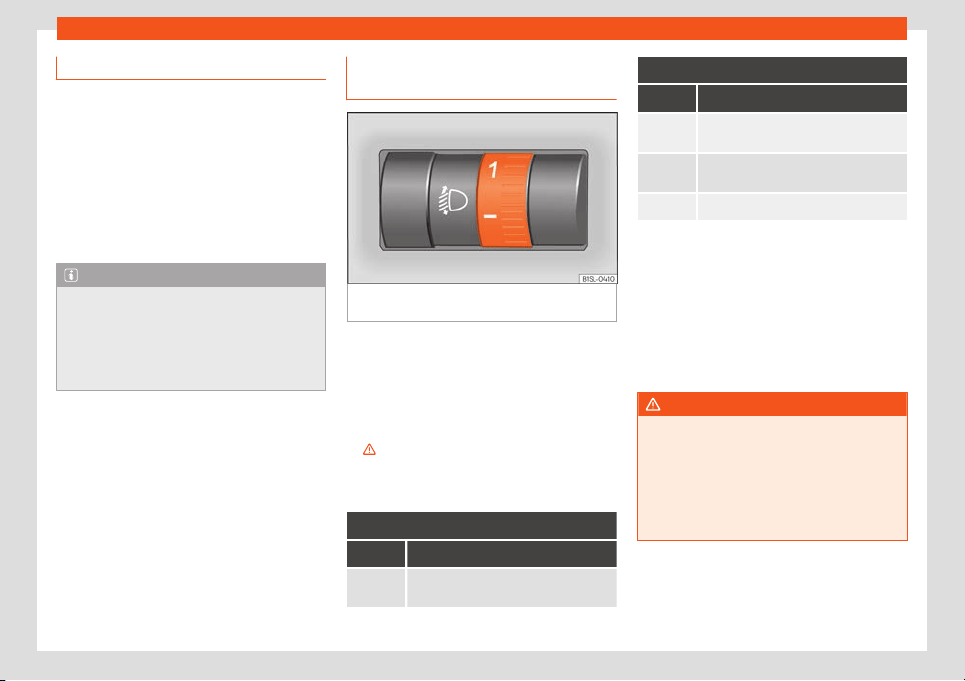
Lights and visibility
Adjusting the headlights
In those countries where vehicles drive on the
other side of the road to the home country,
the asymmetric dipped beam may dazzl
e
drivers of oncoming vehicles.
For this reason, stickers may be needed to
cover the headlights when driving abroad.
For further information, please refer to a spe-
cialised workshop. SEAT recommends visiting
a technical service.
Note
The use of stickers to cover headlights is
only permitted ov
er a short period. To mod-
ify the direction of the headlamps more
permanently, please take the vehicle to a
specialised workshop. SEAT recommends
taking your car in for technical service.
Headlight range control, lighting of
the instrument panel and contr
ol
s
Fig. 112
Next to the steering wheel: Headlight
r
ange contr
ol
Headlamp height adjustment
The headlight r
ange contr
ol
›
››
Fig. 112 is
modified according to the value of the head-
light beam and the vehicle load status. This
offers the driver optimum visibility and the
headlights do not dazzle oncoming drivers
›››
.
The headlights can only be adjust
ed when
the dipped beam is s
wit
ched on.
To reset, turn switch
›››
Fig. 112:
Value Vehicle load status
a)
Two front occupants, luggage compart-
ment empty
To reset, turn switch
›››
Fig. 112:
Value Vehicle load status
a)
All seats occupied, luggage compart-
ment empty
All seats occupied, luggage compart-
ment full.
Driver only, luggage compartment full
a)
If the vehicle load does not correspond to those
sho
wn in the tabl
e, it is possible to select intermediary
positions.
Instrument and switch lighting
When the side lights or dipped beam head-
lights are switched on, the lighting for instru-
ments and controls lights up at a constant
brightness.
WARNING
Heavy objects in the back of vehicle may
cause headlight dazzle and distract other
driv
ers. This could result in a serious acci-
dent.
●
Adjust the light beam to the vehicle load
status so that it does not blind other driv-
ers.
107
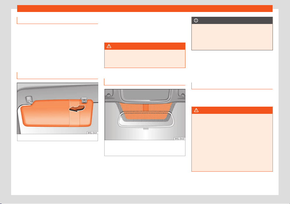
Operation
Luggage compartment light
The light is activated when the rear lid is
open, even when the ignition and lights ar
e
turned off. For this reason, ensure that the
rear lid is always closed.
Visibility
Sun visors
Fig. 113
Sun visor
Options for adjusting driver and front pas-
senger sun visors:
●
Lower the sun visor towards the wind-
scr
een.
●
The sun visor can be pull
ed out of its
mounting and t
urned towards the door.
●
Swing the sun visor towards the door, longi-
tudinally backwards.
Vanity mirror*
There may be a vanity mirror in the folded sun
visor on the passenger side and a cardholder
in the driver sun visor.
WARNING
Folded sun blinds can reduce visibility.
●
Always roll or fold sun blinds and visors
away when not in use.
Heat-insulating glass windscreen
Fig. 114 Windscreen with reflective infrared
and met
al coating and small windo
w (r
ed sur-
face)
The heat-insulating windscreens include a re-
fl
ectiv
e infr
ared coating. The section above
the rear vision mirror has been left uncoated
(communication window) to allow electric
components from the accessories shop to
operate correctly
›››
Fig. 114.
CAUTION
When the uncoated surface is covered or
has a sticker on the interior or e
xterior, mal-
functions in the electronic components
may occur. Never cover the uncoated sur-
face on the interior or exterior.
Windscreen wiper and win-
dow wiper systems
Windo
w wiper lever
Read the additional information carefully
›
›
›
page 24
WARNING
Water from the windscreen washer water
bottle may free
ze on the windscreen if it
does not contain enough anti-freeze, re-
ducing forward visibility.
●
In winter, ensure the windscreen washer
contains enough anti-freeze.
●
In cold conditions, you should not use the
wash/wipe system unless you have
warmed the windscreen with the ventila-
tion system. The antifreeze could freeze on
the windscreen and reduce visibility.
108
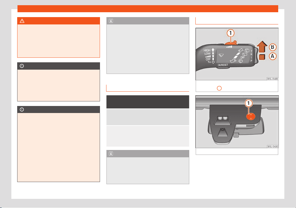
Lights and visibility
WARNING
Worn or dirty wiper blades reduce visibility
and increase the risk of accident and seri-
ous injury.
●
Alw
ays replace damaged or worn blades
or blades which do not clean the wind-
screen correctly.
CAUTION
In icy conditions, always check that the
wiper blades are not fr
ozen to the glass be-
fore using the wipers for the first time. In
cold weather, it may help to leave the vehi-
cle parked with the wipers in service posi-
tion
›››
page 46.
CAUTION
If the ignition is switched off while the wind-
screen wipers are on, the windscr
een wip-
ers carry on wiping at the same level when
the ignition is switched back on. Ice, snow
and other obstacles may damage the
windscreen wiper and the respective mo-
tor.
●
If necessary, remove snow and ice from
the windscreen wipers before starting your
journey.
●
Carefully lift the frozen windscreen wip-
ers from the glass. SEAT recommends a de-
icer spray for this operation.
Note
●
The windscreen wipers will only work
when the ignition is s
witched on.
●
The interval wipe speed varies according
to the vehicle speed. The faster the vehicle
is moving, the more often the windscreen is
cleaned.
●
The rear wiper is automatically switched
on when the windscreen wiper is on and the
car is in reverse gear.
Windscreen wiper functions
Windscreen wipers performance in differ-
ent situations
If the vehicl
e is at a
standstill
The activat
ed position provi-
sionally changes to the previ-
ous position.
For intermittent
wipers
Intervals between wipes de-
pend on the vehicle
's speed.
The higher the vehicle speed
the shorter the intervals.
Note
The wiper will try to wipe away any obsta-
cles that are on the windscr
een. The wiper
will stop moving if the obstacle blocks its
path. Remove the obstacle and switch the
wiper back on again.
Rain and light sensor
Fig. 115
Windscreen wipers lever: adjust the
r
ain sensor
1
.
Fig. 116 Rain sensor reference surface.
When activated, the rain and light sensor au-
t
omatically contr
ol
s the windscreen washer
intervals depending on the intensity of the
rainfall.
»
109
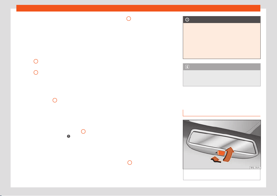
Operation
When the rain and light sensor is deactivated,
the dur
ation of the int
erv
als is adjusted to set
levels.
Activating and deactivating the rain and
light sensor
Move the lever to the required position
›››
Fig. 115:
●
Position
A
- The rain and light sensor is de-
activ
at
ed.
●
P
osition
B
- The rain and light sensor is ac-
tiv
at
ed will wipe aut
omatically as needed.
When the ignition is switched off and then
back on again, the rain sensor stays on and
starts operating again when the windscreen
wipers are in position
B
and the vehicle is
tr
av
elling at mor
e than 4 km/h (2 mph).
Setting the sensitivity level of the rain and
light sensor
The sensitivity of the rain and light sensor can
be adjusted manually with the control
1
on
the windscr
een wiper l
e
ver
›››
.
●
Move the control to the right: high sensitivi-
t
y.
●
Mo
v
e the control to the left: low sensitivity.
Malfunction of the rain and light sensor
Some examples of possible causes of faults
and mistaken readings on the reference sur-
face
›››
Fig. 116
1
of the rain and light sen-
sor:
●
Wiper blades in poor condition: the pr
es-
ence of a film or strips of w
at
er caused by
damaged blades may cause the windscreen
wipers to be slower taking effect, shorten
wiping intervals or cause wiping to be fast
and continuous.
●
Insects: mosquitoes impacting the wind-
screen can activate the windscreen wiper.
●
Traces of salt: in winter, the windscreen
wiper may work for longer than usual due to
the presence of traces of salt on the almost
dry windscreen.
●
Dirt: the presence of dry dust, wax, coating
films (Lotus effect) or traces of detergent (car
wash) etc., on the windscreen may cause the
rain and light sensor to be less sensitive, react
more slowly, later or not at all.
●
Crack on the windscreen: the impact of a
stone will trigger a single wipe cycle if the
rain and light sensor is activated. Subse-
quently, the sensor detects the reduction in
the reference surface area and adapts ac-
cordingly. The behaviour of the sensor will
vary with the size of the damage.
Clean the reference surface area of the rain
and light sensor
1
regularly and check that
the windscr
een wiper bl
ades hav
e not been
damaged.
CAUTION
The rain and light sensor does not always
detect rainf
all with sufficient accuracy so
does not always switch on the windscreen
wiper at the right moment.
●
If necessary, switch on the windscreen
wipers manually when water on the wind-
screen obstructs visibility.
Note
We recommend the use of a glass cleaning
product containing al
cohol to remove
traces of wax or polish.
Mirror
Int
erior r
ear vision mirr
or
Fig. 117 Manual anti-dazzle function for rear
vision mirr
or
110
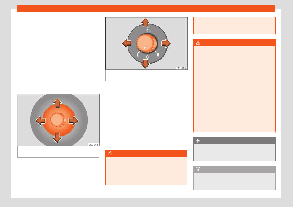
Lights and visibility
The driver should always adjust the rear vi-
sion mirr
or t
o permit adequat
e visibility
through the rear window.
Manual anti-dazzle function for interior
rear vision mirror
●
Basic position: point the lever at the bottom
of the mirror forwards.
●
Pull the lever to the back to select the anti-
dazzle function
›››
Fig. 117.
Exterior mirrors
Fig. 118 On the front doors: button to adjust
the mechanical e
xt
erior r
ear vision mirror
Fig. 119 On the driver door: rotating control for
electric windows.
Read the additional information carefully
›
›
›
page 15
Adjust the exterior mirrors by pressing the ad-
just button
›››
Fig. 118 or the rotary control*
›››
Fig. 119.
Folding in the exterior mirrors and returning
them to their original position is possible
through a mechanical system. Carefully fold
the exterior rear vision mirror casing towards
the side window or pull it away from the win-
dow until it clicks into place.
WARNING
Fold and unfold the exterior mirror, taking
care to av
oid injuries.
●
Only fold or unfold the exterior mirror
when there is no-one in the way of the mir-
ror.
●
When moving the mirror
, take care not to
trap fingers between the mirror and the
mirror bracket.
WARNING
Failure to correctly estimate the distance
of the v
ehicle behind coul
d lead to serious
accident.
●
Rear-view convex or aspheric mirrors in-
crease the field of vision, however objects
appear smaller and further away in the mir-
rors.
●
The use of these mirrors to estimate the
distance to the next vehicle when changing
lane is imprecise and could result in serious
accident.
●
If possible, use the rear vision mirror to
estimate distances to vehicles behind you
or in other circumstances.
●
Make sure that the rear visibility is ade-
quate.
For the sake of the environment
The exterior mirror heating should be
switched off when it is no l
onger needed.
Otherwise, it is an unnecessary fuel waste.
Note
In the event of a fault, the electric exterior
mirrors can be adjusted manually by pr
ess-
ing the edge of the mirror surface.
111
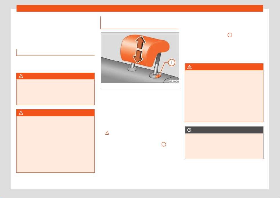
Operation
Seats and head restraints
Adjusting the seat and head
r
estr
aints
Manual fr
ont seat adjustment
Read the additional information carefully
›››
page 14
WARNING
The safe driving chapter contains impor-
tant information, tips, suggestions and
w
arnings that you should read and observe
for your own safety and the safety of your
passengers
›››
page 49.
WARNING
●
Adjust the front seats only when the vehi-
cl
e is stationary. Failure to follow this in-
struction could result in an accident.
●
Be careful when adjusting the seat
height. Careless or uncontrolled adjust-
ment can cause injuries.
●
The front seat backrests must not be re-
clined for driving. Otherwise, seat belts and
the airbag system might not protect as
they should in case of an accident, increas-
ing risk of injury.
Removing and fitting the rear head
r
estr
aints
Fig. 120
Removing the rear head restraint
The rear seats are equipped with a head re-
str
aint.
R
emo
ving the rear head restraint.
●
Unlock the seat backrest and fold it forward
›››
page 122.
●
Push the head restraint up as far as it will go
›››
.
●
Pull the head restraint out of the fitting with-
out r
el
easing the butt
on
›››
Fig. 120
1
.
●
Fold the backrest of the rear seat backward
again until it is engaged.
●
Safely store the removed head restraints.
Fitting the r
ear head r
estr
aint
●
Unlock the seat backrest and fold it forward
›››
page 122.
●
Insert the head restraint into the guides on
the seat backrest.
●
Push the head restraint down as far as it will
go while pressing button
1
.
●
Fold the backrest of the rear seat backward
again until it is engaged.
●
Adjust the head restraint to the correct po-
sition
›
›
›
page 52.
WARNING
Travelling with the head restraints removed
or improperly adjusted incr
eases the risk of
severe or fatal injuries in the event of acci-
dents and sudden braking or manoeuvres.
●
Always fit and adjust the head restraint
properly whenever a person is occupying a
seat.
●
Refit any removed head restraints imme-
diately so that passengers are properly
protected.
CAUTION
When removing and fitting the head re-
straint, make sur
e it does not hit the head-
liner of the vehicle or the front seat back-
rest. Otherwise, the interior roof and other
parts of the vehicle could be damaged.
112
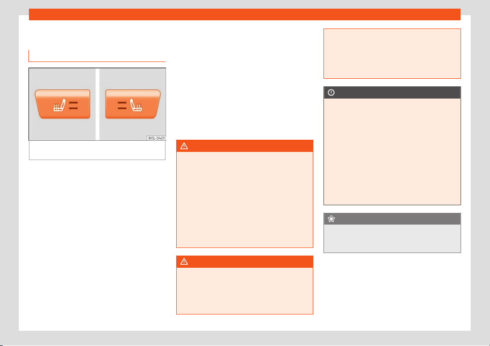
Seats and head restraints
Seat functions
Seat heating*
Fig. 121
In the centre console: Front seats
heating s
wit
ch
With the engine on, the seat cushion and the
seat backr
est can be heat
ed el
ectrically.
●
Enable: Press the or button at the top of
the centre console. Seat heating operates at
full power. All the control lamps light up.
●
Adjust: press the or button repeatedly
to adjust it to the required level.
●
Disable: press the or button as many
times as necessary until no control lamp re-
mains on.
When heat seating is at maximum level, after
approximately 15 minutes it goes back to the
first level automatically.
Cases in which the heat seating should
not be switched on
Do not switch the seat heating on if any of the
following conditions are met:
●
The seat is not occupied.
●
The seat has a cover.
●
A child seat has been installed on the seat.
●
The seat cushion is wet or damp.
●
The outdoor or indoor temperature is great-
er than +25°C (77°F).
WARNING
People whose pain or temperature thresh-
old has been affect
ed by some kind of
medicine, paralysis or chronic illness (e.g.
diabetes) could sustain burns to the back,
buttocks or legs. These burns could take a
long time to heal or never fully heal. Seek
medical advice if you have any doubts re-
garding your health.
●
People with a limited pain or temperature
threshold should never use the seat heat-
ing.
WARNING
If the upholstery gets soaked, the heat
seating could stop w
orking properly and
the risk of burns could increase.
●
Before using the seat heater, make sure
that the seat cushion is dry.
●
Do not sit on the seat if your clothes are
damp or w
et.
●
Do not leave wet or damp objects or
clothing on the seat.
●
Do not spill liquid on the seat.
CAUTION
●
T
o avoid damaging the heating el
ements,
refrain from kneeling on the seat or apply-
ing sharp pressure at a single point to the
seat cushion or backrest.
●
If liquids are spilled on the seats, sharp
objects are left on them or insulating mate-
rials are fitted (such as a cover or a child
seat) on them, the heating could get dam-
aged.
●
If you notice any odour, switch off the
seat heating immediately and have the unit
inspected by a specialised workshop.
For the sake of the environment
The seat heating should be switched off
when it is no longer needed. Otherwise, it is
an unnecessary fuel w
aste.
113
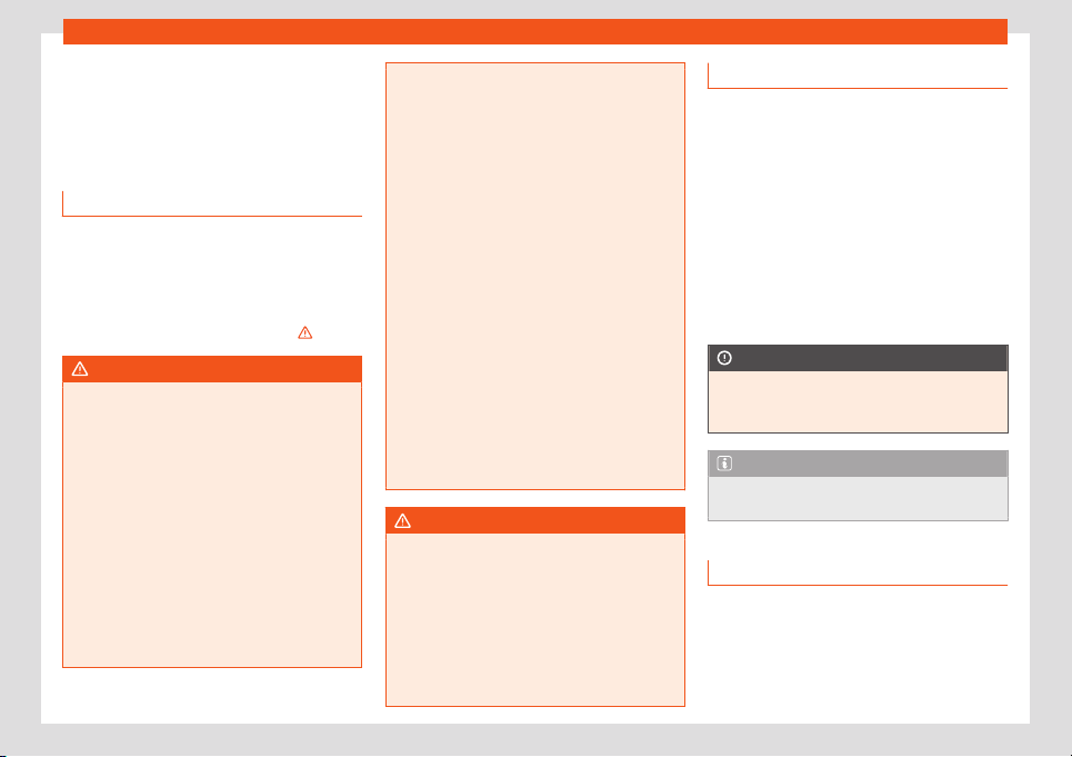
Operation
Transport and practical
equipment
T
r
anspor
ting objects
Introduction
Always transport heavy loads in the luggage
compartment and place the seat backs in a
vertical position. Ne
ver overload the vehicle.
Both the carrying capacity as well as the dis-
tribution of the load in the vehicle affect driv-
ing behaviour and braking ability
›››
.
WARNING
Unsecured or incorrectly secured objects
can cause serious injury in case of a sud-
den manoeuvring or breaking or in case of
an accident. This is especially true when
objects ar
e struck by a detonating airbag
and fired through the vehicle interior. To re-
duce the risks, please note the following:
●
Secure all objects in the vehicle. Always
keep equipment and heavy objects in the
luggage compartment.
●
Always secure objects with suitable rope
or slings so that they cannot enter the de-
ployment areas around the frontal or side
airbags in case of sudden braking or an ac-
cident.
●
Always ensur
e that objects inside the ve-
hicle cannot move into the deployment
area of the bags while driving.
●
While driving, always keep object com-
partments closed.
●
Remove all objects from the front pas-
senger seat when it is folded down. When
the seat backrest is folded down, it presses
on small and light objects and these are
detected by the weight sensor on the seat;
this sends false information to the airbag
control unit.
●
While the backrest of the front passenger
seat is folded, the frontal airbag must re-
main disconnected and the PASSENGER
AIRBAG OFF light on.
●
Objects secured in the vehicle should
never be placed in such a way as to make
passengers sit in an incorrect position.
●
If secured objects occupy a seat, this
seat should not be occupied or used by
anyone.
WARNING
The driving behaviour and braking ability
change when transporting heavy and l
arge
objects.
●
Adjust your speed and driving style to vis-
ibility, road, traffic and weather conditions.
●
Accelerate gently and carefully.
●
Avoid sudden braking and manoeuvres.
●
Brake early.
Transporting the load
Secure all objects in the vehicle
●
Distribute the load throughout the vehicle
and on the roof as uniformly as possibl
e.
●
Transport heavy objects as far forward as
possible in the luggage compartment and
lock the seat backs in the vertical position.
●
Check the headlight adjustment
›››
page 103.
●
Use the suitable tyre pressure according to
the load being transported. Read the tyre in-
flation information label
›››
page 206.
CAUTION
Objects on the shelf could chafe against
the wires of the heating element in the
heat
ed rear window and cause damage.
Note
Please refer to the notes on loading the
roof carrier
››
›
page 127.
Driving with the rear lid open
Driving with the rear lid open creates an addi-
tional risk
. Secur
e all ob
jects and secure the
rear lid correctly and take all measures pos-
sible to reduce toxic gases from entering the
vehicle.
114
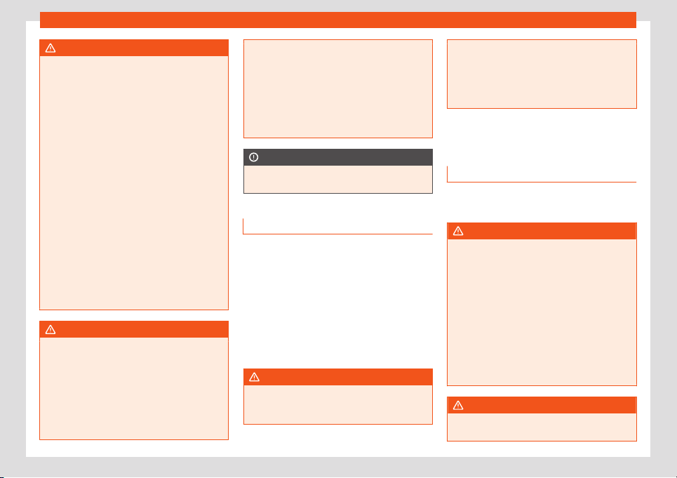
Transport and practical equipment
WARNING
Driving with the rear lid unlocked or open
could cause serious injuries.
●
Alw
ays drive with the rear lid closed.
●
Secure all objects in the vehicle. Loose
items could fall out of the vehicle and injure
other road users or damage other vehicles.
●
Drive particularly carefully and think
ahead.
●
Avoid sudden manoeuvres and braking
given that this could cause an uncontrolled
movement of the open rear lid.
●
When transporting objects that protrude
out of the luggage compartment, indicate
them suitably. Observe legal requirements.
●
If objects must project out of the luggage
compartment, the rear lid must never be
used to “secure” or “attach” objects.
●
If a baggage rack is fitted on the rear lid,
it should be removed before travelling with
the rear lid open.
WARNING
Toxic gases may enter the vehicle interior
when the rear lid is open. This could cause
l
oss of consciousness, carbon monoxide
poisoning, serious injury and accidents.
●
To avoid toxic gases entering the vehicle
always drive with the rear lid closed.
●
In exceptional circumstances, if you must
drive with the rear lid open, observe the fol-
lowing to reduce the entry of toxic gases in-
side the vehicle:
–
Cl
ose all windows.
–
Disable air recirculation mode.
–
Open all of the air outlets on the instru-
ment panel.
–
Switch on the blower to maximum.
CAUTION
An open boot hatch changes the length
and height of the v
ehicle
.
Driving a loaded vehicle
For the best handling when driving a loaded
v
ehicl
e
, note the following:
●
Secure all objects
›››
page 114.
●
Accelerate gently and carefully.
●
Avoid sudden braking and manoeuvres.
●
Brake early.
●
If necessary, read the instructions for driv-
ing with a roof carrier system
›››
page 127.
WARNING
A sliding load could considerably affect the
stability and saf
ety of the vehicle resulting
in an accident with serious consequences.
●
Secure loads corr
ectly so they do not
move.
●
When transporting heavy objects, use
suitable ropes or straps.
●
Lock the seat backs in vertical position.
Practical equipment
Introduction
Storage compartments must only be used to
st
or
e light or small ob
jects.
WARNING
In the event of sudden braking movements
or turns, loose ob
jects may be thrown
around the vehicle interior. This could
cause serious injuries to passengers and
cause the driver to lose control of the vehi-
cle.
●
Do not carry animals or store hard, heavy
or sharp objects in the vehicle in: open stor-
age compartments, instrument panel,
items of clothing or bags.
●
While driving, always keep object com-
partments closed.
WARNING
Objects falling into the driver's footwell
could pre
vent use of the pedals. This could
»
115
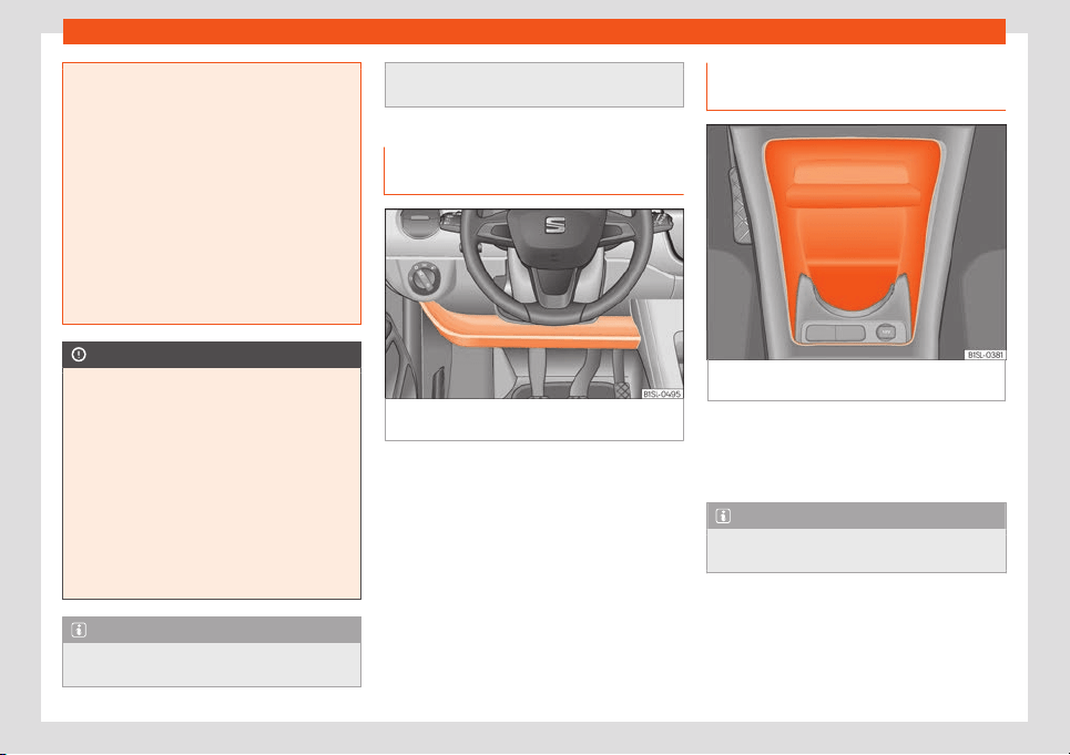
Operation
lead the driver to lose control of the vehi-
cle, incr
easing the risk of a serious acci-
dent.
●
Make sure the pedals can be used at all
times, with no objects rolling underneath
them.
●
The floor mat should always be secured
to the floor.
●
Never place other mats or rugs on top of
the original mat supplied by the factory.
●
Make sure that no objects can fall into
the driver's footwell while the vehicle is in
motion.
CAUTION
●
Objects on the shelf could chaf
e against
the wires of the heating element in the
heated rear window and cause damage.
●
Do not keep temperature-sensitive ob-
jects, food or medicines inside the vehicle.
Heat and cold could damage them or ren-
der them useless.
●
Light-transparent objects placed inside
the vehicle, such as lenses, magnifying
glasses or transparent suction caps on the
windows, may concentrate the sun's rays
and cause damage to the vehicle.
Note
The ventilating slits between the heated
rear window and the r
ear shelf must not be
covered so that used air can escape from
the vehicle
.
Storage compartment on the driver
side
Fig. 122
On the driver side: storage compart-
ment.
There may be a storage compartment on the
driv
er side
.
Compar
tment on the centre con-
sole
Fig. 123
In the front part of the centre console:
st
or
age compartment.
The storage compartment
›
›
›
Fig. 123 may be
used as a drink holder
›››
page 119 or as an
ashtray*
›››
page 119 or to store small ob-
jects.
Note
A 12 volt electrical socket
›››
page 120 can
be found in the storage compartment.
116
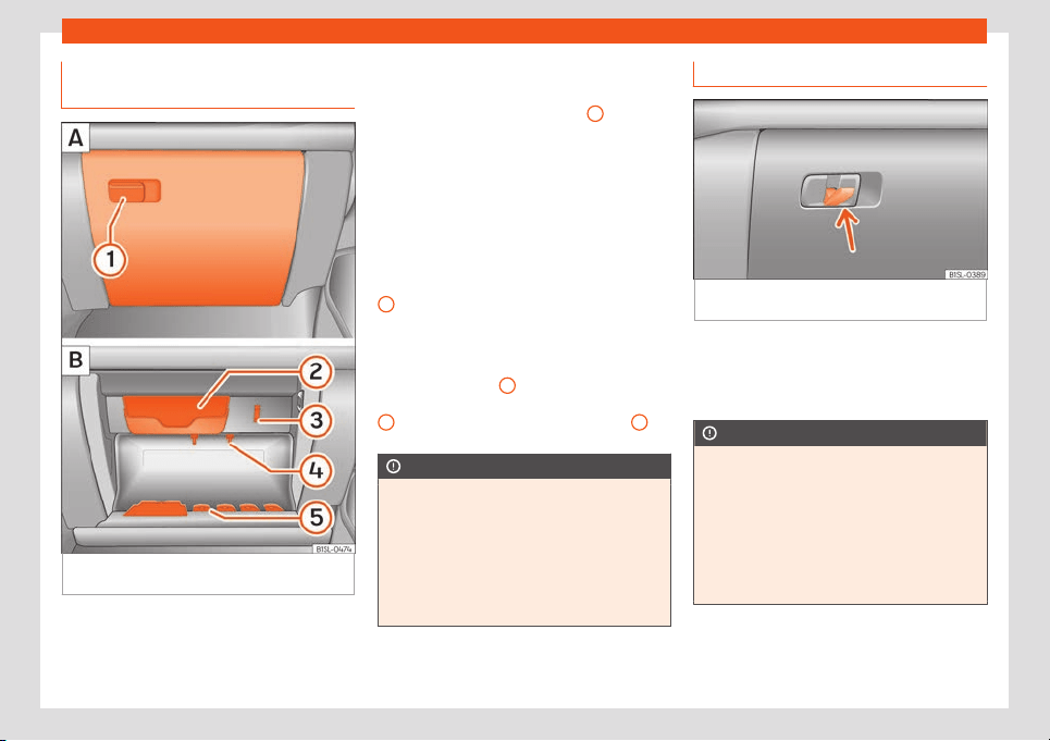
Transport and practical equipment
Storage compartment with cover
on the passenger side*
Fig. 124 Storage compartment with cover on
the passenger side
There may be a storage compartment with
co
v
er on the passenger side
.
Opening and closing the storage com-
partment cover
Pull the lever to open
›››
Fig. 124
1
.
T
o
cl
ose, press the cover upwards until it
clicks into place.
Sunglasses storage compartment.
Sunglasses can be stored in the passenger
side storage compartment.
The sunglasses storage compartment is in
the upper area of the storage compartment
2
.
Suppor
ts
Ne
xt t
o the eyeglass storage compartment is
a notebook holder
3
and in the interior of the
st
or
age compartment ther
e is a pen holder
4
, a map storage area and a coin tray
5
.
CAUTION
For structural reasons, some model ver-
sions will have gaps behind the glo
ve com-
partment into which small objects may fall.
This could lead to strange noises and dam-
age to the vehicle. Therefore, do not store
small objects in the glove compartment,
apart from those stored in the spaces pro-
vided.
Bag support*
Fig. 125
Storage on front passenger side: fold-
ing hook
.
On the opening lever of the glove compart-
ment on the passenger side ther
e is a f
ol
ding
hook
›››
Fig. 125 for hanging small items of
luggage, e.g. bags, etc.
CAUTION
●
The maximum weight for the hook is 1.5
k
g.
●
With the hook folded forward, it automat-
ically draws up when the compartment is
opened.
●
We recommend removing hanging bags
from the hook before opening the glove
compartment.
117
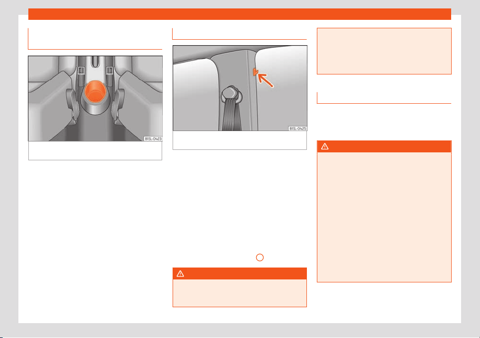
Operation
Storage compartment in the back
of the centr
e consol
e
Fig. 126
In the rear part of the centre console:
st
or
age compartment.
The drink holder at the back of the centre
consol
e can be used as a st
or
age compart-
ment.
Other storage compartments
Fig. 127
The centre pillars contain garment
hooks.
Coat hooks
The centr
e pill
ars cont
ain garment hooks
›››
Fig. 127 (arrow).
Other storage compartments:
●
In the front door trims
›››
page 86.
●
Rear shelf for light items of clothing*.
●
Bag hook in the luggage compartment
›››
page 122.
●
In the upper part of the centre console, in-
stead of the radio
›››
Fig. 95
10
.
WARNING
Clothing hung on the coat hooks could re-
strict the driver's vie
w and lead to serious
accidents.
●
Hang the clothes from the hooks so that
driv
er's view is not restricted.
●
The coat hook is suitable for light items of
clothing. Never place heavy, hard or sharp
objects in the bags.
Drink holders
The drink holders are in the open storage
compartments in the driver and passenger
doors.
WARNING
Improper use of the drink holders can
cause injury.
●
Do not place containers with hot drinks in
a drink holder. During sudden br
aking or
driving manoeuvres, the hot drink could be
spilled and lead to scalding.
●
Ensure that no bottles or other object are
dropped in the driver footwell, as they
could get under the pedals and obstruct
their working.
●
Never place heavy containers, food or
other heavy objects in the drink holder. In
the event of an accident, these heavy ob-
jects could be “thrown around” the vehicle
interior and cause serious injuries.
118
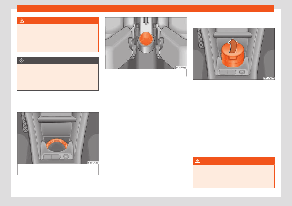
Transport and practical equipment
WARNING
Closed bottles inside the vehicle could ex-
plode or crack due t
o the heat or the cold.
●
Never leave a closed bottle in the vehicle
if the inside temperature is too high or too
low.
CAUTION
Do not leave open drinks containers in the
drink holders when the vehicl
e is in motion.
They could spill during braking, for exam-
ple, and cause damage to the vehicle and
the electrical system.
Centre console drink holders
Fig. 128 In the front part of the centre console:
drink hol
der
.
Fig. 129 In the rear part of the centre console:
There are drink holders in the front and rear
parts of the centr
e consol
e
.
Securing the drink container in the front
drink holder
Fold the drink holder
›››
Fig. 128 forward.
Place the drink container in the drink holder
so that it is securely surrounded.
Ashtray*
Fig. 130
In the front part of the centre console:
open the ashtr
ay.
Opening and closing the ashtray
T
o
open
, lift the lid of the ashtray in the direc-
tion of the arrow
›››
Fig. 130.
To close, push the ashtray lid down.
Emptying the ashtray
●
Remove the ashtray from the storage com-
partment lifting it up.
●
After emptying the ashtray, insert it into the
drink holder from above.
WARNING
Incorrect use of the ashtray may cause a
fire or burns and other serious injuries.
●
Nev
er put paper or other flammable ob-
jects in the ashtray.
119
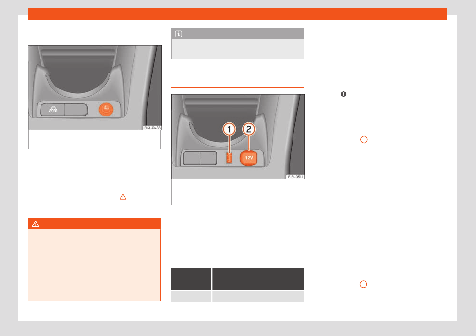
Operation
Cigarette lighter*
Fig. 131
In the front part of the centre console:
light
er
.
●
Push the button on the cigarette lighter in-
w
ar
d with the ignition on
›
››
Fig. 131.
●
Wait for the lighter to pop out slightly.
●
Pull out the cigarette lighter and light the
cigarette on the glowing coil
›››
.
●
Replace the cigarette lighter in its insert.
WARNING
Undue use of the cigarette lighter may
cause a fire or burns and other serious inju-
ries.
●
The cigarett
e lighter must only be used to
light cigarettes or similar.
●
Never leave children unsupervised in the
vehicle. The cigarette lighter can be used
when the ignition is switched on.
Note
The cigarette lighter can also be used with
the 12 Volt socket.
Power outlet and USB socket*
Fig. 132 Front centre console: 12-volt power
outl
et on the st
or
age compartment and USB in-
terface.
Electrical equipment can be connected to
the sock
et in the v
ehicl
e.
All connected appliances should be in per-
fect working order without any faults.
Maximum power consumption
Power
socket
Maximum pow
er consump-
tion
12 Volts 120 Watts
The maximum capacity of the socket must
not be e
x
ceeded. The po
wer consumption is
indicated on the rating plate of each appli-
ance.
Where 2 or more appliances are connected
at the same time, the total rating of all the
connected devices must never exceed 190
Watts
›››
.
12 v
olt po
w
er socket
The 12 volt socket is found in the storage
compartment at the front of the centre con-
sole
›››
Fig. 132
2
and only functions when
the ignition is s
wit
ched on.
Using el
ectrical appliances with the engine
stopped and the ignition switched on will
drain the battery. Therefore, electrical devi-
ces connected to the power socket can only
be used when the engine is running.
To prevent voltage variations from causing
damage, switch off the electrical device con-
nected to the 12 Volt power socket before
switching the ignition on or off and before
starting the engine.
USB Interface
The factory-fitted USB interface is in the stor-
age compartment of the front part of the
centre console
1
.
120
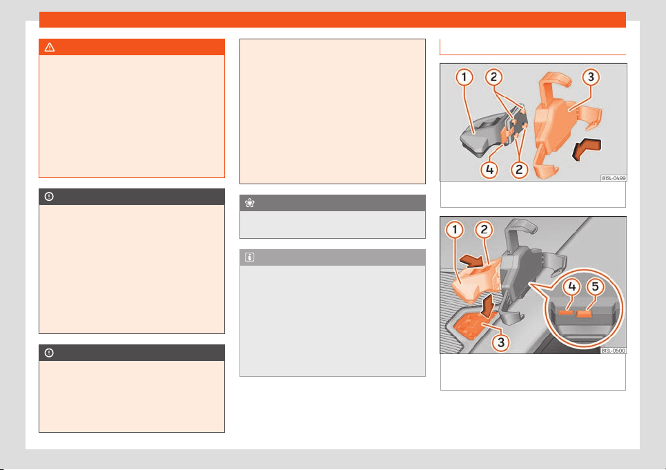
Transport and practical equipment
WARNING
Improper use of the socket or electrical de-
vices could lead t
o a fire and cause serious
injuries.
●
Never leave children unsupervised in the
vehicle. The socket and equipment con-
nected to it can be used when the ignition is
switched on.
●
Should a connected electrical device
overheat, switch it off and unplug it imme-
diately.
CAUTION
●
Always f
ollow the operating instructions
for the appliances to be connected!
●
Never exceed the maximum power rating
as this could damage the vehicle's general
electrical system.
●
12 volt power socket:
–
Only use accessories with approved
electromagnetic compatibility accord-
ing to current regulations.
–
Never power the socket.
CAUTION
●
To avoid damage t
o the vehicle's electri-
cal system, never connect equipment that
generates electrical current, such as solar
panels or battery chargers, to the 12 volt
power sockets in order to charge the vehi-
cle's battery.
●
Only use accessories with approv
ed
electromagnetic compatibility according
to current regulations.
●
To avoid damage due to voltage varia-
tions, switch off all devices connected to
the 12 V socket before switching the ignition
on or off and before starting the engine.
●
Never connect an appliance to the 12 volt
power socket that consumes more than the
power indicated in watts. Exceeding the
maximum power absorption could damage
the vehicle's electrical system.
For the sake of the environment
Do not leave the engine running when the
vehicle is at a st
andstill.
Note
●
Using devices with the engine stopped
and the ignition s
witched on will drain the
battery.
●
Unshielded equipment can cause inter-
ference on the radio equipment and the ve-
hicle's electrical system.
●
Interference can occur on the radio's AM
waveband if electrical appliances are used
near the aerial.
Portable smartphone holder
Fig. 133
Assembling the universal support and
the hol
ding arm.
Fig. 134
On the centre console: close the
compartment wher
e the inf
ot
ainment system is
housed.
Removing the smartphone
●
Grip the smartphone firmly with one hand.
»
121

Operation
●
Pr
ess the r
el
ease button
›››
Fig. 134
5
until
the t
op arm of the univ
ersal hol
der disengag-
es.
●
Remove the smart phone and, as the case
may be, unplug any cables.
Inserting a smart phone
●
If necessary, install the smartphone hous-
ing
›››
.
●
Connect the smartphone.
●
Place the smartphone on the bottom
mountings. T
o adjust the bott
om mountings,
pr
ess button
›››
Fig. 134
4
.
●
Press the top arm of the universal holder
until the smartphone is secur
ely hel
d in pl
ace.
Disassembling the housing
●
If necessary, remove the smartphone.
●
Grip the universal holder
›››
Fig. 133
3
and
pr
ess the r
el
ease button
›››
Fig. 133
4
.
●
Push the universal holder to the right (anti-
cl
ockwise) and r
emo
ve it.
●
Grip the holder arm and
›››
Fig. 134
1
and
pr
ess the r
el
ease button
›››
Fig. 134
4
in the
dir
ection of the arr
o
w.
●
Remove the holder from the dash panel up-
wards.
Install the housing
●
Insert the universal holder
›››
Fig. 133
3
in-
t
o the sl
ots
2
on the holder
1
.
●
Move the universal holder to the side in the
l
ocking dir
ection
4
until it engages audi-
bly
›
›
›
.
●
Place the holder arm
›
›
›
Fig. 134
1
in the
anchoring pl
at
e
›
››
Fig. 134
3
from above
and pr
ess do
wn on it until you hear it en-
gage
›
››
.
WARNING
If a smartphone is not secured or is incor-
rectly secured in the v
ehicle, it could be
flung though the interior during a sudden
driving or braking manoeuvre or in the
event of an accident, and could cause inju-
ries.
●
The infotainment system holder must be
properly secured in the corresponding gap
in the dash panel.
●
The infotainment system must always be
properly secured in its holder or stored
safely in the vehicle.
CAUTION
If tilt and angle of visibility are not properly
adjusted the smart phone coul
d be dam-
aged.
●
When adjusting the smartphone, move it
with care and never beyond its limits.
CAUTION
At very high or very low temperatures the
smartphone might not operat
e properly, or
the actual device could get damaged.
●
Take your smart phone with you when
you get out of the vehicle to protect it from
very high or very low temperatures, and
from intense solar radiation.
CAUTION
Humidity can damage the electrical con-
tacts for the smar
tphone on the instrument
panel.
●
Do not wet the smartphone’s housing
when cleaning it. Use only a dry cloth.
Note
SEAT recommends that you always take
your smart phone with you when you get
out of the vehicl
e to avoid possible thefts.
Luggage compartment
Intr
oduction
Always transport heavy loads in the luggage
compartment and pl
ace the seat backs in a
v
ertical position. Ne
ver overload the vehicle.
Both the carrying capacity as well as the dis-
tribution of the load in the vehicle have
122
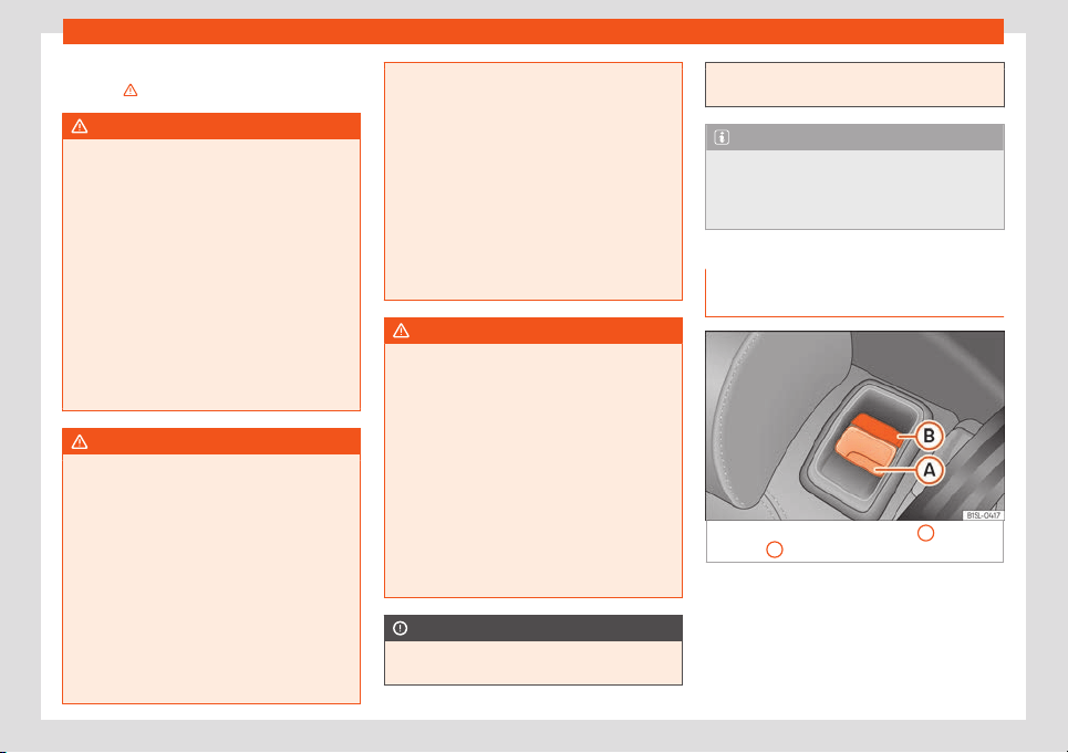
Transport and practical equipment
effects on the driving behaviour and braking
abilit
y
›
›
›
.
WARNING
When the vehicle is not in use or being
watched, al
ways lock the doors and the
rear lid to reduce the risk of serious injury or
death.
●
Do not leave children unwatched, espe-
cially when the boot is open. Children
could climb into the luggage compartment,
close the rear lid from inside and be unable
to escape themselves. This could lead to
serious injury or death.
●
Never allow children to play in or around
the vehicle.
●
Never transport people in the luggage
compartment.
WARNING
Unsecured or incorrectly secured objects
can cause serious injury in case of a sud-
den manoeuvring or breaking or in case of
an accident. This is especially true when
objects ar
e struck by a detonating airbag
and fired through the vehicle interior. To re-
duce the risks, please note the following:
●
Secure all objects in the vehicle. Always
place equipment and heavy objects in the
boot.
●
Always secure objects to the fastening
rings with suitable rope or straps to prevent
them from being thrown around the interior
and moving to the airbag deployment area
in the event of sudden mo
vements or acci-
dents.
●
While driving, always keep object com-
partments closed.
●
Do not place hard, heavy or sharp ob-
jects inside the vehicle interior, in open
storage compartments, the rear shelf of
the boot or on the dash panel.
●
Remove hard, heavy and sharp objects
from clothes and pockets inside the vehicle
and store securely.
WARNING
The transport of heavy object changes ve-
hicle handling and increases br
aking dis-
tance. Heavy loads that have not been
stored or secured correctly could cause
loss of control and result in serious injury.
●
Vehicle handling changes when trans-
porting heavy objects due to a change in
the centre of gravity.
●
Distribute the load as uniformly and as
low down on the vehicle as possible.
●
Store heavy objects in the luggage com-
partment as far from the rear axle as possi-
ble.
CAUTION
Hard objects on the rear shelf could chafe
against the wires of the heating element in
the heated rear window and cause dam-
age.
Note
The ventilating slits between the heated
r
ear window and the r
ear shelf must not be
covered so that used air can escape from
the vehicle.
Folding and lifting up the rear seat
bench backr
est
Fig. 135
Back seat: unlock button
A
; red
marking
B
The rear seat backrest can be folded forward
t
o e
xt
end the luggage compartment.
»
123
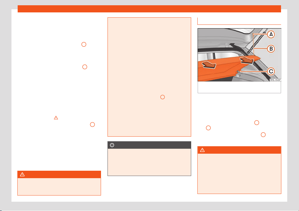
Operation
Folding the rear seat backrest forwards
●
Push the head restraint down as far as it will
go or r
emo
v
e it if necessary
›››
page 49 and
store it in a safe place.
●
Pull the unlock switch
›››
Fig. 135
A
for-
w
ar
ds whil
st simultaneously lifting the rear
seat backrest.
●
The rear seat backrest is not engaged
when the red marking of the button
B
is visi-
bl
e
.
●
If the r
ear seat backrest is folded, people
(including children) are not permitted to trav-
el in the rear folded seats.
Folding up the rear seat backrest
●
Lift back the backrest of the rear seat and
push it firmly into the lock until it clicks se-
curely into place
›››
.
●
The red marking on the unlock button
B
must not be seen.
●
Make sure that the backrest of the rear seat
is secur
ely l
ock
ed in position so that the seat
belts can provide proper protection in the
rear seats.
●
If necessary, reinstall and readjust the head
restraints
›››
page 112.
WARNING
Folding and lifting the backrests of the rear
seats carelessly without paying att
ention
could cause serious injury.
●
Never f
old or lift the seats while driving.
●
Do no trap or damage seat belts when
raising the seat backrest.
●
Keep hands, fingers, feet and other limbs
away from the range of the rear seat
backrests when folding and lifting them.
●
All seat backrests must engage correctly
for the seat belts on the rear seats to work
properly. When the backrest of an occu-
pied seat is not correctly locked in place,
the passenger can be thrust forward with
the rear seat backrest in case of sudden
braking, sudden manoeuvres or an acci-
dent.
●
A red signal on the button
B
warns that
the backrest is not engaged. Alw
ays check
to make sure that the red mark is not visible
when the backrest of the rear seat is in the
upright position.
●
No seat must be occupied if the backrest
of the rear seat is folded or not correctly
engaged.
CAUTION
Before folding the rear seat backrest, ad-
just the front seats so that neither the head
restr
aint or backrest hit them when folded.
If necessary, remove the head restraints
›››
page 112 and store them safely.
Luggage compartment shelf*
Fig. 136
In the boot: removing and installing
the r
ear shelf
.
You may put light items of clothing on the rear
shelf
. Check that the r
ear vie
w is not limited.
Removing the shelf
●
Unhook the loops
›››
Fig. 136
B
from hous-
ings
A
.
●
Extract the shelf from its housing
C
up-
w
ar
ds and then pull it out.
WARNING
Unsecured or incorrectly secured objects
or animals on the rear shelf coul
d cause
serious injuries in case of a sudden ma-
noeuvre, sudden braking or an accident.
●
Do not leave hard, heavy or sharp ob-
jects (loose or in bags) on the rear shelf.
●
Never transport animals on the rear shelf.
124
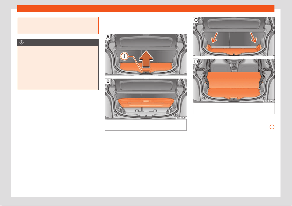
Transport and practical equipment
●
Never driv
e with the rear shelf raised. Al-
ways lower it or remove it before the jour-
ney.
CAUTION
To prevent the rear shelf from being dam-
aged:
●
Always check that the side supports are
firmly engaged.
●
Regulate the height of the load in the lug-
gage compar
tment to ensur
e the rear shelf
does not press down on the load with the
rear lid closed.
Luggage compartment variable
fl
oor
Fig. 137 A: open the boot variable floor. B:
r
aised boot v
ariabl
e floor.
Fig. 138 C: extend the boot downward. D: ex-
t
end the boot f
orw
ard.
Raise and lower the boot floor
●
To r
aise the floor, raise handle
›
›
›
Fig. 137
1
in the direction of the arrow and pull from the
fl
oor all the w
ay up
›
››
Fig. 137 B.
●
To lower it, guide the floor downward.
Extend the boot downward
●
Raise the boot floor and push it downward
in the rail
›››
Fig. 138 C (arrows)
●
Place the variable floor over the floor lining.
●
If necessary, fold the backrest of the rear
seat forward
›››
page 123.
»
125
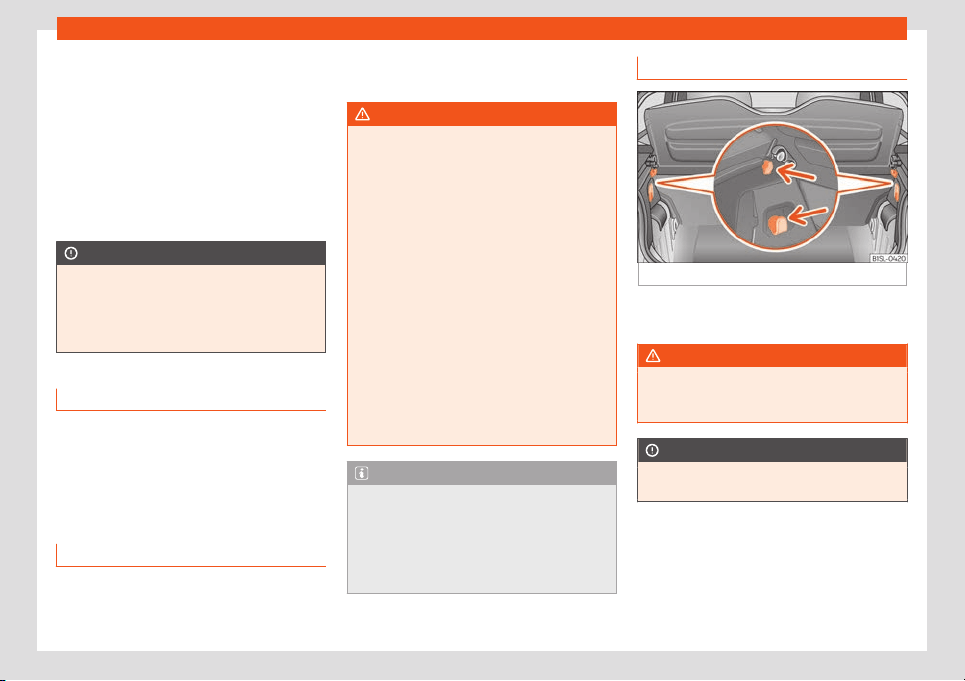
Operation
Extending the luggage compartment for-
w
ar
d
●
Disassembl
e the luggage compartment
tray
›››
page 124.
●
Disassemble the rear headrests
›››
page 49.
●
Fold the backrest of the rear seat forward
›››
page 123.
●
If necessary, expand the boot downward.
CAUTION
Do not let the luggage compartment floor
fall when closing it. Al
ways carefully guide
it downward in a controlled manner. Other-
wise, the lining and the floor of the boot
could be damaged.
Class N1 (commercial) vehicles
For safe vehicle operation, the electrical sys-
t
em must w
ork perf
ectly. Special attention
should be paid so it is not damaged during
adjustment, loading and unloading of trans-
ported objects.
Fastening rings*
In the front part of the luggage compartment,
ther
e may be f
ast
ening rings to secure the
luggage.
In order to use the fastening rings, they must
be lifted beforehand.
WARNING
If unsuitable or damaged belts or retaining
straps are used, they may br
eak in the
event of braking or an accident. Objects
could then be launched across the passen-
ger compartment and cause serious or fa-
tal injuries.
●
It is important to always use belts or re-
taining straps that are suitable and in a
good condition.
●
Belts and retaining straps should be se-
curely fastened to the fastening rings.
●
Objects in the luggage compartment
that are unsecured could move suddenly
and modify the handling of the vehicle.
●
Small light objects should also be fixed in
place.
●
A child seat should never be secured with
the fastening rings.
Note
●
The maximum tensile l
oad that the fas-
tening rings can support is 3.5 kN.
●
Belts and securing systems for the ap-
propriate load can be obtained from speci-
alised dealerships. SEAT recommends visit-
ing a SEAT dealership for this.
Retaining hooks
Fig. 139
In the boot: retaining hooks.
There may be hooks in the upper left and
right part of the luggage compartment.
WARNING
Never use these hooks to secure objects. In
case of sudden braking or an accident,
they could rupt
ure.
CAUTION
The hooks can support a maximum of 2.5 kg
each.
126
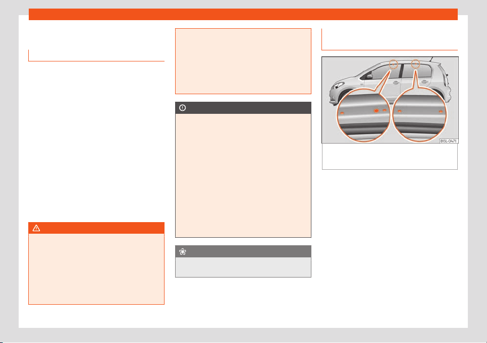
Transport and practical equipment
Roof carrier
Intr
oduction
The vehicle roof has been designed to opti-
mise aerodynamics. For this r
eason, conven-
tional roof carrier systems cannot be secured
to the water drains.
Given that the water drains have been incor-
porated into the roof for aerodynamic rea-
sons, only the SEAT approved basic supports
and roof carrier systems can be used.
When the roof carrier system should be re-
moved:
●
When they are not used.
●
When the vehicle is being washed in a car
wash.
●
When the vehicl
e height exceeds the maxi-
mum height, for example, in some garages.
WARNING
The risk of an accident is increased by
transporting heavy or bulk
y loads on the
roof, which affects the car's handling by
shifting the centre of gravity and increasing
susceptibility to cross winds.
●
Always secure loads correctly with suita-
ble and undamaged attachment rope or
straps.
●
Large
, heavy, wide and flat loads nega-
tively affect the vehicle aerodynamics,
centre of gravity and handling.
●
Avoid brusque manoeuvres and sudden
braking.
●
Adjust your speed and driving style to vis-
ibility, road, traffic and weather conditions.
CAUTION
●
Al
ways r
emove the roof carrier system
from the roof before entering a car wash.
●
The height of your vehicle is changed by
the installation of the roof carrier and the
load secured on it. Compare the vehicle
height with the passage height, for exam-
ple in underground car parks or for garage
doors.
●
The roof antenna and the range of the
rear lid should not be affected by the roof
carrier system or the load being transpor-
ted.
●
Take extra care not to let the hatch strike
the roof load when opening.
For the sake of the environment
The vehicle uses more fuel when the roof
carrier system is fitted.
Fastening the base supports and
the r
oof carrier syst
em
Fig. 140
Attachment points for the basic sup-
ports and the r
oof carrier syst
em in f
our-door
vehicles.
The mounts are the basis of a complete roof
carrier syst
em. Special fixt
ur
es must be add-
ed in order to safely transport luggage, bicy-
cles, skis, surf boards or boats on the roof.
The suitable accessories can be acquired at
SEAT dealerships.
Securing the base supports and roof carri-
er system
The roof carrier system must always be in-
stalled exactly according to the instructions
provided.
The holes or marks indicating the fitting
points for base supports are in the lower half
of the roof struts and can only be seen with
the door open
›››
Fig. 140.
»
127
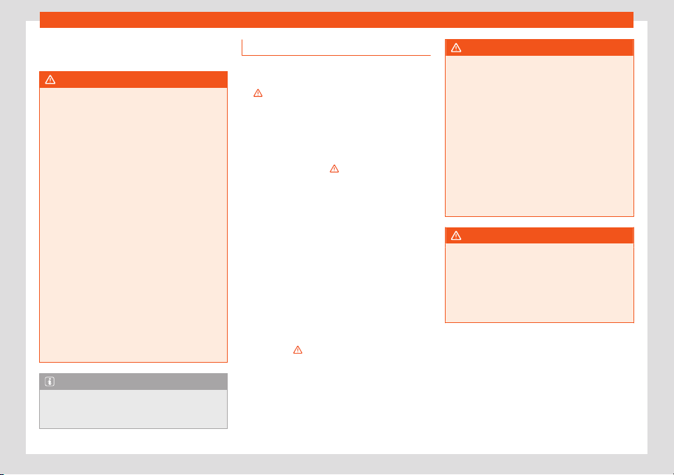
Operation
The base support should only be fitt
ed t
o the
points indicat
ed in the diagram.
WARNING
If the base supports and the roof carrier
system are incorr
ectly fitted or used in an
unsuitable manner, the entire system could
break free causing accident and injury.
●
Always take the manufacturer assembly
instructions into account.
●
Only use base supports and roof carrier
systems that are not damaged and are cor-
rectly fitted.
●
The base support should only be fitted to
the points indicated in the diagram
›››
Fig. 140.
●
Secure the base supports and roof carri-
er system correctly.
●
Check the screws and attachments be-
fore driving and after a short distance. Dur-
ing each long journey, check the attach-
ments during every break.
●
Always fit the roof carrier system correct-
ly for wheels, skis and surfboards, etc.
●
Never modify or repair the basic supports
or roof carrier system.
Note
Read and take into account the instructions
included with the roof carrier system fitt
ed
and keep them in the vehicle.
Loading the roof carrier
Loads can only be correctly secured when
the roof carrier system is corr
ectly fitted
›››
.
Maximum authorised roof load
The maximum authorised r
oof load is 50 kg.
The roof load includes the weight of the base
support, the roof carrier system and the load
being transported
›››
.
Always check the w
eight of the base support,
the roof carrier system and the weight of the
load to be transported and, if necessary,
weigh them. Never exceed the maximum au-
thorised roof load.
If you are using a roof carrier with a lower
weight rating, you cannot transport the maxi-
mum roof load. Do not exceed the maximum
weight limit for the roof carrier given in the fit-
ting instructions.
Distributing a load
Uniformly distribute loads and secure them
correctly
›››
.
Check att
achments
Aft
er fitting the base supports and the r
oof
carrier system, always check the attach-
ments after a short trip and at regular inter-
vals.
WARNING
Exceeding the maximum authorised roof
load can result in accidents and/or v
ehicle
damage.
●
Never surpass the maximum authorised
weight for the roof, the maximum author-
ised weight on the axles and the total maxi-
mum authorised weight of the vehicle.
●
Never exceed the capacity of the roof
carrier system even if this is less than the
maximum authorised roof load.
●
Secure heavy items as far forward as
possible and distribute the vehicle load
uniformly.
WARNING
Loose and incorrectly secured loads can
fall from the r
oof carrier system causing
accidents and injury.
●
Always use suitable ropes and straps in
good condition.
●
Always secure loads correctly.
128
Air conditioning
Air conditioning
Heating, v
entil
ation and air
conditioning
Intr
oduction
Read the additional information carefully
›››
page 29
One of the following systems can be installed
in the vehicle:
●
Heating and fresh air system
●
Manual air conditioning
●
Climatronic
The heating and fresh air system
heats and
ventilates the interior. The heating and fresh
air system cannot cool.
The manual air conditioning and the Cli-
matronic cool and dehumidify the air. They
operate most effectively with the windows
and the sunroof closed. If a great deal of heat
accumulates in the interior, ventilating it can
accelerate the cooling process.
Display of active functions
The LEDs that light up on the rotary controls
on the buttons indicate that the function in
question is activated.
In the case of the Climatronic, the control
panel screen shows the functions that are
currently activated.
WARNING
When visibility through the window display
is poor, the risk of collisions and accidents
which may cause serious injury increases.
●
T
o guarantee good visibility, keep all win-
dows free of ice and snow and properly
demisted.
●
Adjust the heating, air conditioning and
the heated rear window so that the win-
dows do not mist up.
●
Drive off only when you have good visibil-
ity through the windows.
●
Do not use the air recirculation for long
periods of time. When the cooling is switch-
ed off and the air recirculation is on, the
windows can mist over very quickly and se-
riously impair visibility.
●
Switch the air recirculation off when you
do not need it.
WARNING
Used air can quickly cause driver tiredness
and reduce their attention span, which
coul
d lead to collisions, accidents and seri-
ous injury.
●
Never switch off the fan for a long time or
leave the air recirculation on for too long,
since no exterior air enters the interior dur-
ing that time.
CAUTION
If the air conditioning is not working, switch
it off immediat
ely, together with the de-
fr
ost/demist function (in the case of man-
ual air conditioning) and have a special-
ised workshop check it out. This may help
to avoid other possible damage.
CAUTION
To avoid damaging the heated rear win-
do
w
, ne
ver affix adhesives to the electric
filaments on the inside of it.
Air recirculation
In air recirculation mode, no fresh air enters
the v
ehicl
e int
erior.
To switch on the air recirculation, turn the ad-
juster to the right or press the button.
To switch off the air recirculation, turn the ad-
juster to the left or press the button
again
›››
.
WARNING
Used air can quickly cause driver tiredness
and reduce their attention span, which
»
129
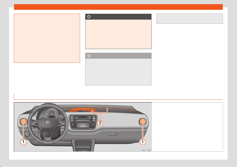
Operation
could lead to collisions, accidents and seri-
ous injury.
●
Never use the air recirculation for too
long, since no ext
erior air enters the interior
during that time.
●
When the cooling is switched off and the
air recirculation is on, the windows can mist
over very quickly and seriously impair visi-
bility.
●
Switch the air recirculation off when you
do not need it.
CAUTION
In vehicles with an air conditioner, do not
smoke when air recir
culation is switched
on. The smoke taken in could impregnate
the cooling vaporiser and the activated
charcoal cartridge of the dust and pollen
filter, leading to permanent unpleasant
odours.
Note
●
Climatronic: When r
everse gear is en-
gaged, the air recirculation switches on
briefly to prevent exhaust gas from enter-
ing the interior.
●
When the outside temperature is very
high, it is recommendable to switch the air
recirculation on briefly to cool down the in-
terior fast
er.
Air vents
Fig. 141 On the dash panel air vents.
130
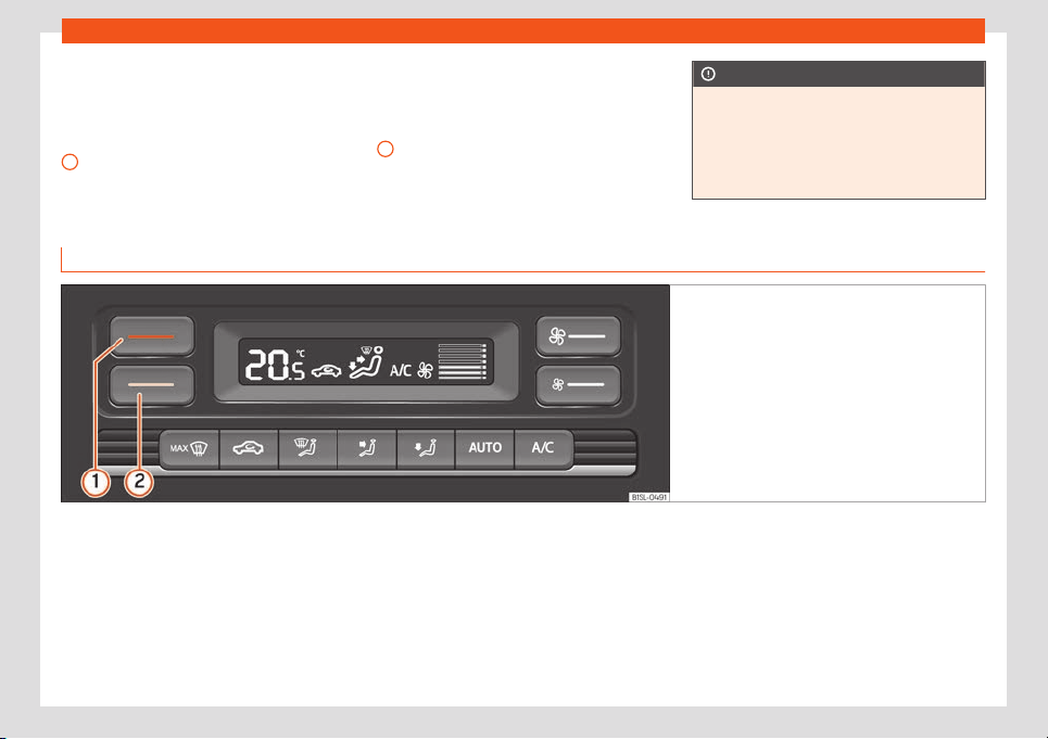
Air conditioning
To achieve sufficient heating power, cooling
and v
entil
ation in the int
erior, the vents should
be left open.
Key to the Fig. 141:
Adjustable air vents: the vent slats can be
used to open and close the vents and to
adjust air direction. For the air to reach
1
the windows as best as possible, open the
corr
esponding v
ent and t
urn it to the de-
frost/demist position, where it will en-
gage.
Non-adjustable air vents
There are more vents in the footwell areas
and at the back of the interior.
2
CAUTION
Never place food, medicines or other tem-
peratur
e-sensitive objects close to the air
vents. Food, medicines and other objects
sensitive to heat or cold may be damaged
or made unsuitable for use by the air com-
ing from the vents.
Tips and instructions for use
Fig. 142 In the centre console, top section: Clima-
tronic control panel
.
The following tips and instructions for use will
help you t
o use the syst
ems pr
operly.
Reasons why the cooling switches off au-
tomatically or will not switch on
●
The engine is not running.
●
The fan is switched off.
●
The air conditioner fuse has blown.
●
The outside temperature is lower than
around +3°C (+38°F).
●
The cooling system compressor has been
temporarily switched off because the engine
coolant temperature is too high.
●
Another fault in the vehicle. Have the air
conditioner checked by a specialised work-
shop.
How to optimise visibility
●
To improve heating or cooling performance
and to prevent the windows from misting over,
keep the air intake slots in front of the wind-
screen free of snow, ice and leaves.
●
To allow the air to move freely through the
interior from the front to the rear, keep the
ventilation slits located at the back of the lug-
gage compartment free.
»
131

Operation
●
The highest possibl
e heating po
w
er will on-
ly be reached and ice removed from the win-
dows as quickly as possible when the coolant
is at its operating temperature.
Recommended settings for the heating
and fresh air system and the manual air
conditioning
●
Switch off the air recirculation.
●
Set fan speed or .
●
Turn the temperature control to the inter-
mediate position.
●
Open and direct all the air outlets in the
dash panel.
●
Turn the air distribution control to the re-
quired position.
●
Manual air conditioning: press the but-
ton in the control panel to switch on the cool-
ing. The air is dehumidified in cooling mode.
Recommended Climatronic settings
●
Press the
button in the control panel.
●
Set the temperature to +22°C (+72°F).
●
Open and direct the air outlets in the dash
panel.
Maximum cooling po
w
er or heating po
wer
in the case of Climatronic
When driving, the maximum cooling power or
heating power can be adjusted by pressing
the
1
or
2
›
›
›
Fig. 142 button repeatedly.
The temperature is not regulated.
●
Maximum cooling potency: set the temper-
ature below +16°C (+60°F). The display then
shows LO.
●
Maximum heating potency: set the temper-
ature above +29°C (+84°F). The display then
shows HI.
Dust and pollen filter
The dust and pollen filter should be changed
regularly in order to maintain air conditioner
performance.
If the vehicle is used frequently in areas
where the outside air is highly polluted, it may
be necessary to change the filter before the
next scheduled service.
Water under the vehicle
If the humidity and temperature outside the
vehicle are high, condensation can drip off
the evaporator in the cooling system and
form a small pool underneath the vehicle.
This is normal and does not indicate a leak!
132
Introduction
Infotainment System
Intr
oduction
Saf
et
y warnings
Safety warnings regarding the Info-
tainment system
WARNING
Distracting the driver in any way can lead
to an accident and cause injuries. Operat
-
ing the radio system while driving can dis-
tract your attention from the traffic.
●
Always drive as carefully and responsibly
as possible.
●
Select volume settings that allow you to
easily hear signals from outside the vehicle
at all times (e.g. emergency services sirens
and horns).
●
Hearing may be impaired if using too high
a volume setting, even if only for short peri-
ods of time.
WARNING
The volume level may suddenly change
when you switch audio sour
ce or connect a
new audio source.
●
Lower the base volume before connect-
ing or switching the audio source.
WARNING
Connecting, inserting or removing a data
medium while driving can distract your at
-
tention from the traffic and cause an acci-
dent.
WARNING
Connecting leads for external devices may
obstruct the driver.
●
Arr
ange the connecting leads so that
they do not obstruct the driver.
WARNING
External devices that are loose or not prop-
erly secured could mo
ve around the pas-
senger compartment during a sudden driv-
ing or braking manoeuvre or an accident
and cause damage or injury.
●
Never place external devices on the
doors, the windscreen, on or close to the
zone marked with the “AIRBAG” word of the
steering wheel, the instrument panel or the
backrests, or between these zones and the
passengers. External devices can cause
serious injury in an accident, especially
when the airbags inflate.
WARNING
Opening a CD player's housing can lead to
injuries from invisible l
aser radiation.
●
Have CD players r
epaired only by quali-
fied workshops.
CAUTION
The system can be damaged by the incor-
r
ect insertion of a dat
a storage device or
the insertion of an incompatible data stor-
age device.
●
When inserting and removing CDs, al-
ways hold them at right angles to the front
of the CD drive without tilting so as not to
scratch them.
●
If a CD or DVD is inserted while another is
already in the unit or being ejected, the
DVD drive may be irreparably damaged.
Always wait until the data medium is com-
pletely ejected.
CAUTION
Any foreign objects stuck to a data storage
device and non-round media may damage
the CD pl
ayer.
●
Only use clean, standard 12-cm CDs.
–
Do not affix stickers or other items to
the data medium. Stickers may peel off
and damage the drive.
–
Do not use printable data media. Prin-
ted labels and coverings may peel off
and damage the CD drive.
–
Do not insert 8-cm single CDs or irreg-
ularly shaped or non-round CDs.
»
133
Infotainment System
–
Do not insert DVD-Plus discs, Dual
Discs or Flip Discs, as these ar
e thicker
than normal CDs.
CAUTION
The vehicle loudspeakers may be dam-
aged if the v
olume is too high or the sound
is dist
orted.
134
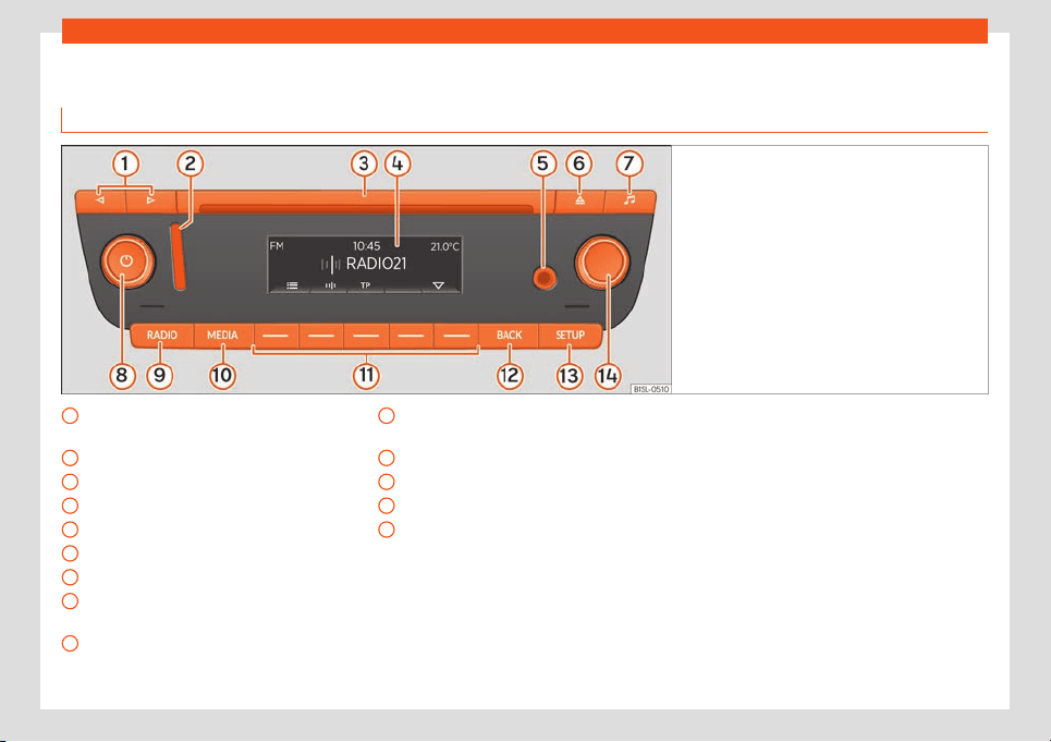
Introduction
Overview of the unit
Y
ou&Mii Music
Fig. 143
Overview of the controls
Arrow buttons (radio/media mode)
›
›
›
page 139,
›››
page 141
Slot for SD cards
›››
page 142
CD slot
Screen
AUX-IN multimedia socket
›››
page 144
Eject the CD
Sound settings
Volume. Off and on
›››
page 137,
›››
page 138
Radio mode (change of band frequency)
›››
page 139
1
2
3
4
5
6
7
8
9
Media mode (audio sources)
›
›
›
page 141
Function buttons
›››
page 137
Go back to the previous menu
Settings menu
Settings button (search and selection)
›››
page 137
10
11
12
13
14
135
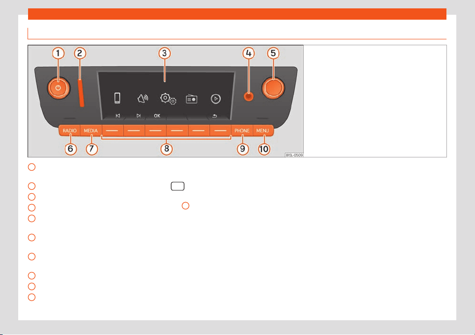
Infotainment System
You&Mii Colour Connection
Fig. 144
Overview of the controls
Volume. Off and on
›
›
›
page 137,
›››
page 137
Slot for SD cards
›››
page 142
Screen
AUX-IN multimedia socket
›››
page 144
Settings button (search and selection)
›››
page 137
Radio mode (change of band frequency)
›››
page 139
Media mode (audio sources)
›››
page 141
Function buttons
›››
page 137
Telephone mode
›››
page 145
Selecting the main menu
›››
page 136
1
2
3
4
5
6
7
8
9
10
Main menus
●
To access the main menu, press button
.
●
To select a function, rotate the setting But-
t
on
5
until it is highlighted and press the but-
t
on.
136
Introduction
General operating informa-
tion
Additional instructions
Depending on the vehicle, notifications of the
factory-fitt
ed driving assistance systems are
shown on the display. The notifications close
automatically when they are no longer use-
ful.
All notifications are only displayed after com-
pletely rebooting the radio system.
Note
●
Pushing the buttons gently is enough to
use the equipment.
●
Due t
o country-specific legislation, cer-
tain functions may not be available when
the vehicle is travelling above a certain
speed.
●
Using a mobile telephone inside the vehi-
cle may provoke noise in the speakers.
●
On some vehicles with ParkPilot, the vol-
ume of the active audio source is automati-
cally lowered when reverse gear is selec-
ted.
Thumbwheels, equipment and
function butt
ons
Overview
●
Rotary/push knobs.
●
Equipment buttons named (physical but-
tons).
●
Function butt
ons (virtual buttons).
Rotary/push knobs
The left-hand rotary knob is known as vol-
ume control or the on/off button.
The right-hand rotary knob is known as the
settings button.
Equipment buttons and function buttons
The named buttons of the equipment are
known as “equipment buttons” and are
shown with a button symbol inside a rectan-
gle, for instance, equipment button
.
Unnamed equipment butt
ons ar
e l
ocated be-
low the screen. These equipment buttons are
known as “function buttons” as their purpose
depends on the active function mode.
The function assigned to a function button is
explained on the bottom of the display,
above the corresponding button.
Switching on and off
●
To manually switch the system on and off,
briefly press the rot
ary knob .
When the unit is switched on the system
starts up. The last active audio source will be
played with the volume set, as long this does
not exceed the maximum, predefined
“switch-on” volume ( Volume
).
Depending on the equipment and country,
when switching off the engine or r
emoving
the key from the ignition, the system switches
off automatically. If the system is switched on
again without switching on the ignition, it will
switch off automatically after approximately
30 minutes (switch-off delay).
Power management
If the charge of the battery goes below the
minimum onboard charge with the ignition
switched off and the system active, an audi-
ble warning will be emitted and the LOW BAT-
TERY message will be displayed. If this hap-
pens, you should turn off the equipment.
Anti-theft password
The anti-theft password of the system is stor-
ed in the system after entering it for the first
time (radio comfort password). If you have to
enter the anti-theft password manually, for
»
137

Infotainment System
instance, because the system has been in-
st
all
ed in a diff
erent vehicle, please go to a
SEAT authorised service.
If only the battery was disconnected, switch
on the ignition before turning the system on
again.
Change base volume
Function Operation
Turn volume
up.
Turn the volume control clock-
wise.
Turn volume
down.
Turn the v
olume control anti-
clockwise.
Changes in base volume are indicated by a
“v
olume bar” on the scr
een, which is dis-
pl
ayed briefly.
It is possible to preset certain volume settings
and adjustments.
Mute system sound
●
Turn the volume control anti-clockwise
until it displays
.
●
OR: press the volume switch briefly to
mute or unmute the system.
While the sound of the system is muted
(MUTE), the playback Media source stops.
Note
If the base volume has been considerably
increased to pl
ay a certain audio source,
lower the volume again before switching to
another audio source.
138
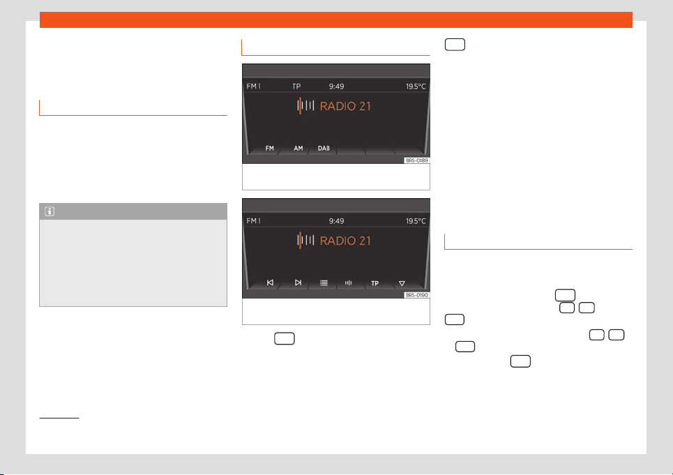
Audio Mode
Audio Mode
R
adio Mode
Intr
oduction
The radio system is supplied in different ver-
sions depending on the country and the fea-
tur
es of the vehicle. Some systems also have
a DAB radio receiver. The general dashboard
contains the possible versions of the system
›››
page 135.
Note
●
Bear in mind that being in underground
parking l
ots, in tunnels, in areas with tall
buildings or mountains can interfere with
radio signals.
●
Foil or metal-coated stickers attached to
the windows may affect reception on vehi-
cles with a window aerial.
RADIO main menu
Fig. 145 RADIO Main Menu: select frequency
band.
Fig. 146 RADIO main menu: Indication of pre-
set butt
ons.
●
Press
so start the Radio mode.
Aft
er s
wit
ching the Radio mode, the available
frequency bands (FM, AM
1)
and DAB
1)
) will be
shown on the bottom of the display. Press the
equipment button gain to display more
functions f
or the r
adio r
eceiver.
The following options are available:
●
Search next station.
●
Access a previously saved station.
●
Switching the TP function on and off
●
Save current station
›››
page 140.
The current station is shown in the middle of
the screen. If the station allows for RDS and
the connection is good, instead of the fre-
quency, the name of the station will be
shown, e.g. RADIO 21.
Change frequency band
The frequency band selected (FM, AM
1)
or
D
AB
1)
) is sho
wn on the t
op left.
●
In Radio mode, press the
equipment
butt
on briefly t
o displ
ay the FM
, AM
1)
and
D
AB
1)
function butt
ons
›
›
›
Fig. 145.
●
Press one of the function buttons FM
, AM
or D
AB
to change the frequency band.
●
OR: Pr
ess the
equipment button a few
times t
o cycl
e thr
ough the different lower
function buttons.
1)
This depends on the country and unit in ques-
tion.
139
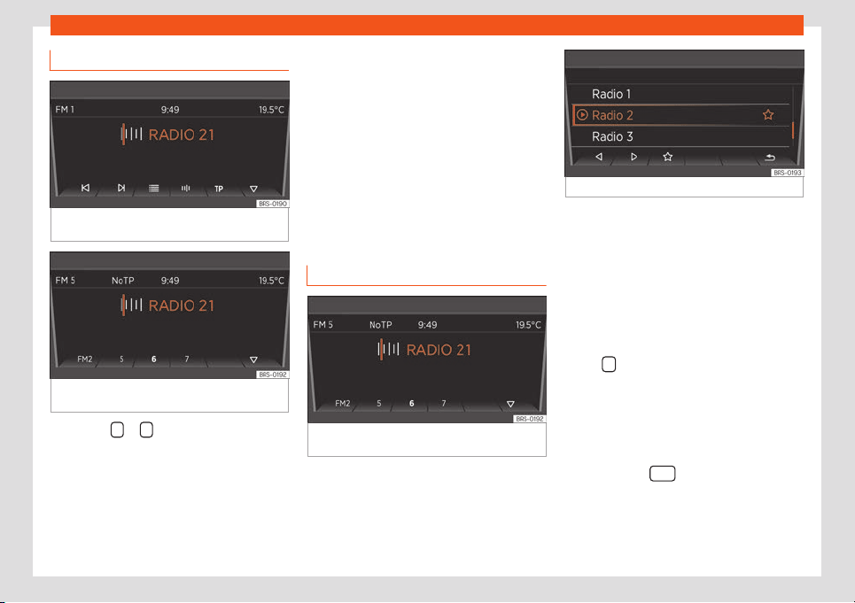
Infotainment System
Changing station
Fig. 147 Go to the next available station with
the arrow butt
ons.
Fig. 148 Changing the stations with the arrow
butt
ons is only possibl
e f
or saved stations.
●
Press the or arrow button on the sys-
t
em or the displ
ay.
Based on the mode sel
ected for the search
engine (Button keys:) you can cycle
through either available or saved stations.
Manually tuning station frequency
●
To select the desired frequency band
›››
page 139.
●
Press the function button of the frequency
band .
●
Rotate the setting switch until the desired
frequency is shown on the display
(e.g. 89.9 MHz).
●
OR: Press one of the double-arrow buttons
›››
Fig. 150 until the frequency is shown on
the screen.
Saving stations in preset buttons
Fig. 149 Station on the FM frequency band
st
or
ed in pr
eset button 6.
Fig. 150 Additional radio functions.
Stations that are already saved are overwrit-
ten if another station is st
ored in the same
preset button.
Assigning different preset buttons manual-
ly
●
Select the frequency band
›››
page 139.
●
Select station
›››
page 140.
●
Change to preset buttons. To do this, press
button
›
›
›
Fig. 151
●
Press and hold the desired preset button
until an audible signal is heard.
●
The current station (RADIO 21) will be saved
in this preset button.
You can update the station list by pressing
and holding the
equipment button or
using the function butt
on
›
›
›
Fig. 150.
140
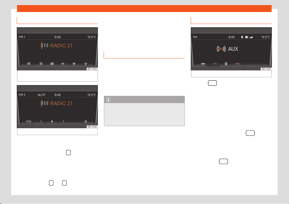
Audio Mode
Choosing stored stations
Fig. 151 Radio mode notification: change of
station using the arro
w buttons.
Fig. 152 Saved stations.
●
Select the frequency band on which the
st
ation is sav
ed.
●
Pr
ess the function button,
.
●
Press the pr
eset butt
on in which the st
ation
is saved briefly.
Depending on the settings, you can cycle
through the stations of a frequency band with
the arrow buttons
and (Arrow but-
tons:).
The stored stations can only be played if they
can be r
eceiv
ed at the curr
ent location.
Media Mode
Introduction
“Media sources” ar
e audio sources contain-
ing audio files on various different data stor-
age devices (e.g. CD, external MP3 players).
These audio files can be played with their
corresponding applications or the radio's au-
dio inputs.
Note
●
Do not use memory card adapters.
●
SEAT assumes no liabilit
y for any deterio-
ration or loss of files on data storage devi-
ces.
Select a Media source
Fig. 153 Select a Media source
Press the
equipment button to switch to
the Media mode
.
When s
wit
ching to the Media mode, the bot-
tom of the screen shows the available Media
sources for a few seconds. The Media source
that is currently playing is highlighted.
Open the Media selection menu manually
and select a Media source
●
In the Media mode, press the
equip-
ment butt
on t
o displ
ay the Media selection
menu again.
●
Enable the Media source you want by
pressing the corresponding function button.
●
OR: Press the
equipment button again
t
o cycl
e thr
ough the available Media sources.
»
141
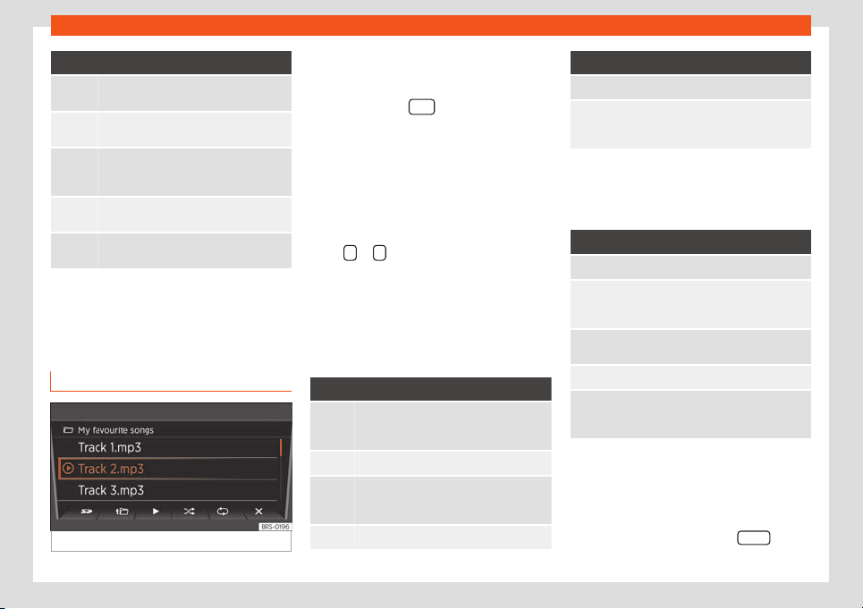
Infotainment System
Function button: Media source
SD card in the slot for SD cards
›››
page 142.
*
Audio or MP3 CD in the internal CD play-
er.
USB data st
orage in the USB socket
›››
page 143. You can see the location of
the connection in
›››
page 120.
*
Smartphone paired through Bluetooth
›››
page 143
External audio source connected to the
AUX-IN multimedia socket
››
›
page 144.
When a Media source that has already been
pl
ayed is sel
ect
ed again, playback is re-
sumed from the point at which it ended (ex-
cept for: AUX
›››
page 144).
SD card playback
Fig. 154 SD card playback: List of tracks.
●
Insert the SD car
d first with the cut corner
f
acing up and the titl
e on the left in the slot for
SD cards.
●
Press the button
.
Pl
ayback continues with the l
ast Media
sour
ce selected. To play the SD card press .
In the folder view, browse with the function
button and the settings button. Press to
access a higher golder level and rotate the
settings switch to select the desired folder.
To switch to the previous or next track, press
either
or .
Hol
d one of the arr
o
w buttons to fast-forward
or rewind the track.
During playback, the following function but-
tons are available on the bottom of the
screen. Active function buttons are highligh-
ted.
Function button: Meaning
a)
Playlist notification. Here you can also se-
lect a track dir
ectly with the settings but-
ton
›››
Fig. 154.
Previous track or rewind.
Play. It can also be pressed to stop the
pl
ayback. In this case
, the symbol
changes to
Next title or fast-forward
Function button: Meaning
a)
Random play.
To repeat a folder or track. The symbol
indicates that the current tr
ack is on re-
peat.
a)
Valid for Media sources: SD card, USB socket and
Bluetooth audio
In the list of playlists (butt
on ) the following
options are available:
Function button: Meaning
To change the main folder of the SD card.
To access a higher folder level. In the folder
list, you can select a differ
ent audio source
with
›››
page 141.
Play. It can also be pressed to stop the
playback.
R
andom play.
To repeat a folder or track. The symbol
indicat
es that the current tr
ack is on re-
peat.
Ejecting the SD card
Connect
ed dat
a st
orage devices must be
prepared before their disconnection in order
to remove them without damaging it.
●
Press the Infotainment button MENU
and
then pr
ess
System settings.
14
2
Audio Mode
●
Sel
ect
Remove source safely and then
SD Card. Aft
er correctly ejecting the data
storage device from the system, the function
button becomes inactive (grey colour).
●
Now you can remove the SD card.
External data storage device in the
USB socket
Depending on the country and device, there
might be one or sever
al USB ports in the
vehicle.
The location of the USB ports depends on
the vehicle in question.
Audio files on an external data storage device
connected to the USB port can be played
and controlled via the Infotainment system.
Where this manual refers to external data
storage devices, this means USB mass stor-
age devices containing supported audio files,
such as MP3 players, iPods™ and USB sticks.
Only compatible audio files are displayed.
Other files are ignored.
The rest of operations to use the external da-
ta device storage (changing tracks, selecting
tracks and enabling playback modes) are
carried out similarly to other audio sources
(e.g. “Playback from SD card”
›››
page 142.
Instructions and restrictions
The number of USB ports and their com-
patibility with Apple™ de
vices as well as with
other media players depends on the features.
The USB port supplies the usual USB volt-
age of 5 volts for a USB connection.
Due to the large number of different data
storage devices and various iPod™ and
iPhone™ generations available, it is not possi-
ble to guarantee fault-free operation of all
functions described here.
Take into account all other instructions and
limitations regarding requirements for media
sources.
Disconnecting
Connected data storage devices must be
prepared before their disconnection in order
to remove them.
●
Press the Infotainment button
and
then pr
ess Syst
em settings .
●
Select R
emove source safely and then
SD Car
d
. After correctly ejecting the data
st
or
age de
vice from the system, the function
button becomes inactive (grey colour).
●
Now the data storage device can be dis-
connected.
Playback over Bluetooth
®
*
Connection of a safe audio source through
Bluetooth
Bluetooth
®
Audio mode all
ows you to listen to
audio files being played on a Bluetooth
®
au-
dio source (e.g., a mobile telephone) connec-
ted via Bluetooth
®
(audio playback by Blue-
tooth
®
) over the vehicle speakers.
Requirements
●
The Bluetooth® audio source must support
the A2DP Bluetooth
®
profil
e.
●
In the Bluetooth Settings menu the
BT Audio (A2DP/AVRCP) function
must be on.
St
ar
ting Bluet
ooth
®
audio transmission
●
Activate Bluetooth
®
visibility on the external
Bluetooth
®
audio source (e.g., mobile tele-
phone).
●
Lower the base volume on the Infotainment
system.
●
Press the button
.
●
Press the function butt
on t
o sel
ect Blue-
tooth
®
as a media source.
●
Start searching for the desired Bluetooth
®
device.
●
Please refer to the instructions on the
screen of the Infotainment system and on the
Bluetooth
®
audio source regarding the rest of
the procedure.
»
143
Infotainment System
You may still need to manually start playback
on the Bluet
ooth
®
sour
ce
. When playback on
the Bluetooth
®
audio source is stopped, the
Infotainment system remains in Bluetooth
®
Audio mode.
Controlling playback
The extent to which the Bluetooth
®
audio
source can be controlled via the Infotainment
system depends on the connected Blue-
tooth
®
audio source.
With media players that support the AVRCP
Bluetooth
®
profile, playback on the Blue-
tooth
®
audio source can be automatically
started or stopped when the unit is switched
to Bluetooth
®
Audio mode or to a different au-
dio source. In addition, it is possible to view or
change the track via the Infotainment system.
WARNING
Do not perform the pairing and connection
process while driving. This may cause an
accident
!
Note
●
Due to the lar
ge number of possible Blue-
tooth
®
audio sources, it is not possible to
guarantee fault-free operation of all de-
scribed functions for all these sources.
●
To operate the media and phone with the
Bluetooth
®
device connected, please read
the electronic Instructions Manual of the
manufactur
er.
●
Only use compatible Bluetooth
®
devices.
You can request information about compat-
ible Bluetooth
®
products at a SEAT Author-
ised Service or online.
External audio source connected to
the AUX-IN multimedia socket
Depending on the version of the vehicle, there
is an AUX-IN connection on the fr
ont of the r
a-
dio
›
››
page 135, in the glove compartment
on the passenger side, on the centre console
or on the armrest between the front seats.
The AUX-IN multimedia connection can only
be used with a 3.5 mm jack.
A connected external audio source is played
over the vehicle speakers and cannot be
controlled via the radio system controls.
The AUX-IN multimedia connection must be
activated in the system settings so it can be
displayed on the Media selection menu
›››
page 141.
Connecting an external audio source to
the AUX-IN multimedia socket
●
Lower the base volume on radio.
●
Connect the external audio source to the
AUX-IN multimedia socket.
●
Start playback on the external audio
source.
●
In the Media mode, press the
equip-
ment butt
on t
o displ
ay the Media source se-
lection menu again
›››
page 141.
●
Press the function button.
The output volume of a connected external
audio source should be adjusted to the vol-
ume of the other audio sources.
Adjusting the playback volume
If you need to increase the playback volume
for the external audio source, first lower the
base volume on the radio system.
If the sound from the external audio source is
too low, increase the output volume on the
external audio source, if possible. If this is not
enough, adjust the input volume in the sys-
tem settings to Level 2 or Level 3.
If the sound from the connected external au-
dio source is too loud or distorted, lower the
output volume on the external audio source,
if possible. If this is not enough, change the
input volume to Level 2 or Level 1.
Note
●
When the playback from the e
xternal au-
dio source ends or the connection to the
AUX-IN socket is interrupted, the radio goes
back to the AUX menu.
144
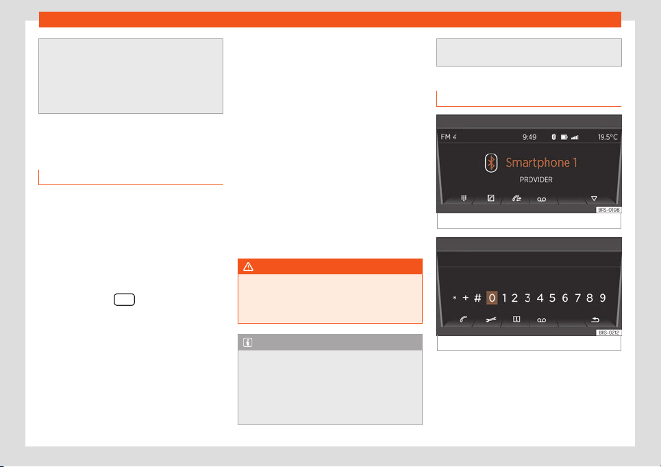
Audio Mode
●
Interfer
ence noise may be heard if the ex-
ternal audio source is powered from the 12-
volt power socket of the vehicle.
●
Please read and observe the manufac-
turer's instruction manual for the external
audio source.
Phone management*
Connection and operation
Requirements for phone management:
Y
our mobil
e phone is connect
ed to the Info-
tainment System through Bluetooth
®
.
Connection between the mobile phone
and the Infotainment System
●
Please observe the information on the
page 143, Playback over Bluetooth
®
*.
●
Press the button
.
●
On the Bluetooth
®
menu of your mobil
e
phone
, sear
ch the name displayed on screen.
●
If necessary, take into account the
›››
page 143 notifications.
●
To complete the pairing process, respond
to the requests of both devices.
Changing the volume
Media and phone call playback from a con-
nected mobile phone will be conducted
through the speaker of the vehicle.
If voice control is enabled on the mobile
phone connected, voice communication will
also take place through the vehicle speaker.
The playback volume can be modified with
the volume control .
Moreover, the volume of navigation an-
nouncements can be adjusted in the Sound
settings menu.
If the volume of the system is muted (notifica-
tion: ), media sources that are playing on
the connected Smartphone are also interrup-
ted.
WARNING
General, mandatory, legal and country-
specific instructions and laws for the use of
mobil
e phones inside the vehicle must al-
ways be considered.
Note
●
To operat
e the media and phone with
your mobile phone plugged in, please read
the electronic Instructions Manual of the
manufacturer.
●
Only use compatible Bluetooth
®
devices.
You can request information about compat-
ible Bluetooth
®
products at a SEAT Author-
ised Service or online
.
Functions of the phone
Fig. 155
Phone disconnected.
Fig. 156 Dial a number with the menu button.
After correctly connecting the phone, you
cam manage the call functions of your
pair
ed mobil
e phone thr
ough the Infotain-
ment System
›››
Fig. 155.
»
145
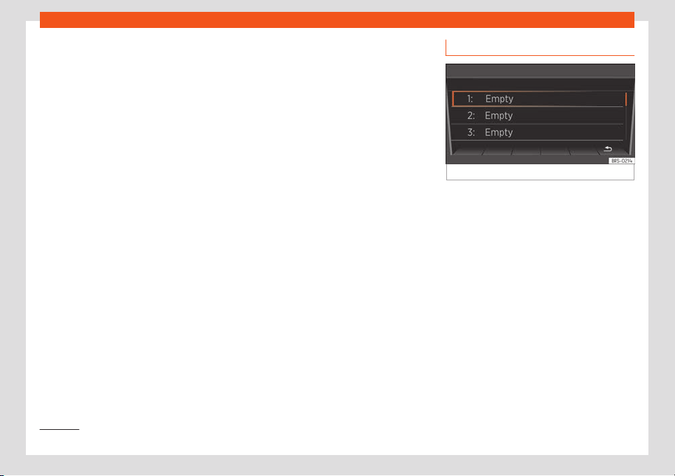
Infotainment System
Dial number:
Pr
ess the
›››
Fig. 155 function button to dis-
play the dial screen
›››
Fig. 156. Here you can
choose a number with the right switch and
confirm it by pressing. If the number is cor-
rect, the call can be started through the
speaker
›››
Fig. 156.
Moreover, the following options are available
here:
●
: calls the emergency number
1)
.
●
: connects to a SEAT fault service
1 )
.
●
: connects to the SEAT information hot
-
line
1 )
.
●
: starts call to your voice mail. For this
purpose, your mailbox number will be reques-
ted the first time you select it.
Phonebook:
Press the
›››
Fig. 155 function button to
display the phonebook. The phonebook con-
tains all the contacts of your mobile phone,
which you can select one by one with the
right switch and establish a connection by
pressing it, or either access a list with availa-
ble numbers first. For this purpose, during the
first connection, you have to confirm the
transfer of your mobile phone contacts. With
the star key you can save a contact as a fast-
dial number.
Call log:
Press the
›››
Fig. 155 function button to dis-
play call log. All the calls from your mobile
phone will be shown here once you have
confirmed the transfer of your contacts from
your phone.
●
All: shows all calls in chronological order.
●
: only shows missed calls.
●
: only shows received calls.
●
: only shows outgoing calls.
The function button bookmarks an entry.
Voice mail:
Press the
›››
Fig. 155 function button to
access your voice mail inbox. For this pur-
pose, your mailbox number will be requested
the first time you select it.
Emergency call:
1 )
Press the
›››
Fig. 155 function button to
make an emergency call.
Favourites
Fig. 157 Fast-dial
Fast-dial:
Pr
ess the
›
›
›
Fig. 155 function button to
open the fast-dial list
›››
Fig. 157. Select an
empty slot of your fast-dial list to access the
phonebook, where you can choose a contact
as a fast-dial number. Select a used slot to di-
al its corresponding phone number.
1)
Not available in all countries.
146
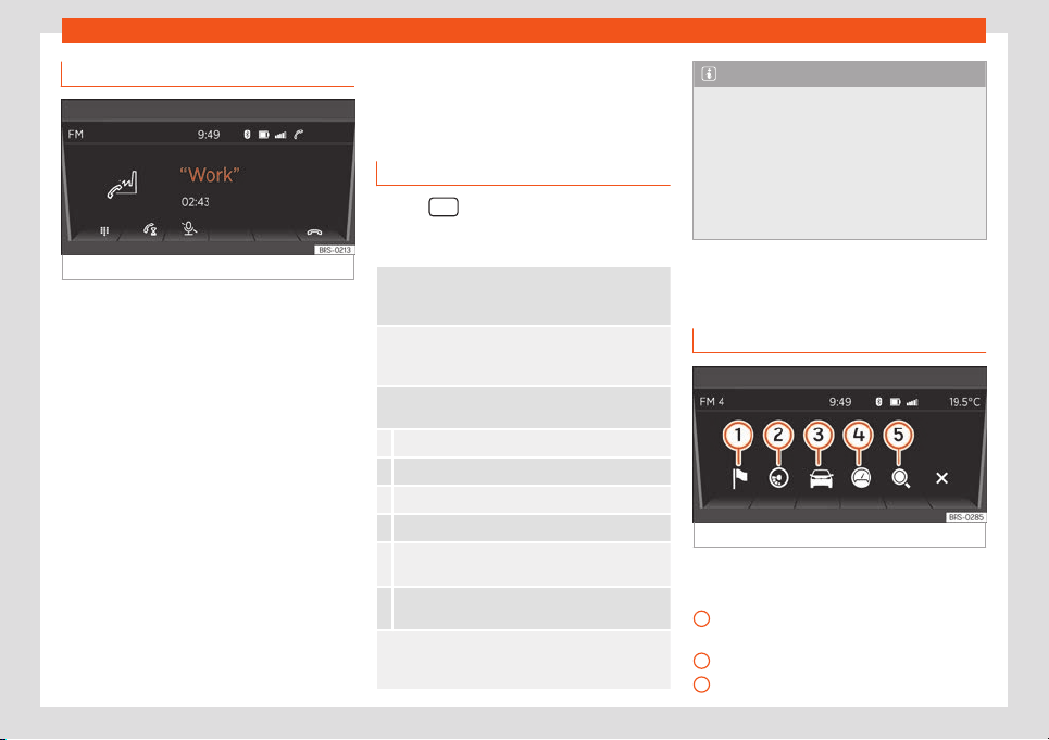
Audio Mode
Phone calls
Fig. 158 Ongoing call.
Incoming call:
If you r
eceiv
e a call, you hav
e three options:
●
accepting the call with the function but-
ton.
●
muting the ringtone with the function
button.
●
rejecting the call with the function but-
ton.
Active call:
If you accept the incoming call, you have the
following options during the call
›››
Fig. 158:
●
Press the function key to emit DTMF
tones (e.g. to operate an answering ma-
chine).
●
Press the function button to pause the
phone call.
●
Press the function button to mute the mi-
crophone.
●
Press to end the call.
Settings of a connected phone
Use the equipment button to access the
phone's settings: The follo
wing options are
available:
Hands-free: If there is an ongoing call, you can
continue the call on the mobil
e phone or transfer it
back to the Infotainment System.
Phone selection: Cycle through the phones r
ec-
ognised by the Infotainment System or search for
new devices.
User profile: Change the settings of the phone
currently connected:
Manage your fast-dial numbers (e.g. delete one).
Set or change voice mail numbers.
Sort your phonebook.
Download your contacts again.
Activate/deactivate mobile phone notifications
when turning off the engine.
Select a ringtone (only if the phone is not emitting
any sounds).
Bluetooth
®
: Here you can change the connection
settings of the telephone. For instance, you can de-
lete known devices.
Note
●
A device connected thr
ough Bluetooth
®
,
if it supports this profile, will always be
used for calls and audio through Blue-
tooth
®
.
●
To operate the media and phone with
your mobile phone plugged in, please read
the electronic Instructions Manual of the
manufacturer.
Drive Mii App*
Intr
oduction
Fig. 159 Application connection main menu.
The connected smartphone offers the follow-
ing options:
Navigation o
v
er the smartphone with
navigation announcements on the r
adio.
ECOTRAINER display.
Driving data notifications.
»
1
2
3
147

Infotainment System
Notifications from the odometer, etc.
Sear
ch in all fiel
ds.
Y
ou can also use the telephone function of
your connected smartphone over the radio
using the right switch.
Note
To operate the telephone and multimedia
aspects and for navigation with the con-
nected smar
tphone, read the instructions
manual of the manufacturer.
Connection and operation
Requirement: Y
our smartphone is connect
ed
t
o the radio through USB
›››
page 143 and the
SEAT application to connect the smartphone
to the radio is installed on your smartphone
1)
.
Place the smartphone in its socket and turn it
on. Removal and installation of the equip-
ment and the socket are described in
›››
page 121.
4
5
Connection between smartphone and ra-
dio
●
Press the button
to open the main
menu.
●
Afterwards, select and enable the Connec-
tion of the application function with
the settings butt
on.
Once the connection is est
ablished, you can
manage r
adio music playback with the
smartphone. You can start the navigation on
the smartphone and listen to the navigation
announcements on the audio system of the
vehicle.
Instructions for navigation
Acoustic navigation announcements will be
played on the speakers of the vehicle. Re-
garding this, take into account the instruc-
tions in Adjusting the volume
›››
page 148.
You can manage this from the connected
smartphone
›››
page 148.
Changing the volume
Multimedia playback, navigation announce-
ments and phone calls emitted by the con-
nected smartphone will be played on the
speakers of the vehicle.
The volume of the traffic announcement can
be modified with the volume control .
You can also adjust the volume of the naviga-
tion announcements on the Sound settings
menu.
When the volume of the system is muted (no-
tification: ), playback of multimedia sour-
ces played on the connected smartphone is
also interrupted.
Note
●
For more inf
ormation about the installa-
tion and use of the application, see the in-
formation provided with the vehicle.
●
To operate the media and phone and to
navigate with your Smartphone plugged in,
please read the electronic Instructions
Manual of the manufacturer.
●
A device connected through Bluetooth
®
,
if it supports this profile, will always be
used for calls and audio through Blue-
tooth
®
. and connection for applications.
●
Only use compatible Bluetooth
®
devices.
You can request information about compat-
ible Bluetooth
®
products at a SEAT Author-
ised Service or online.
1)
For more information about the application re-
garding install
ation and use, take into account
the information provided with the vehicle.
148
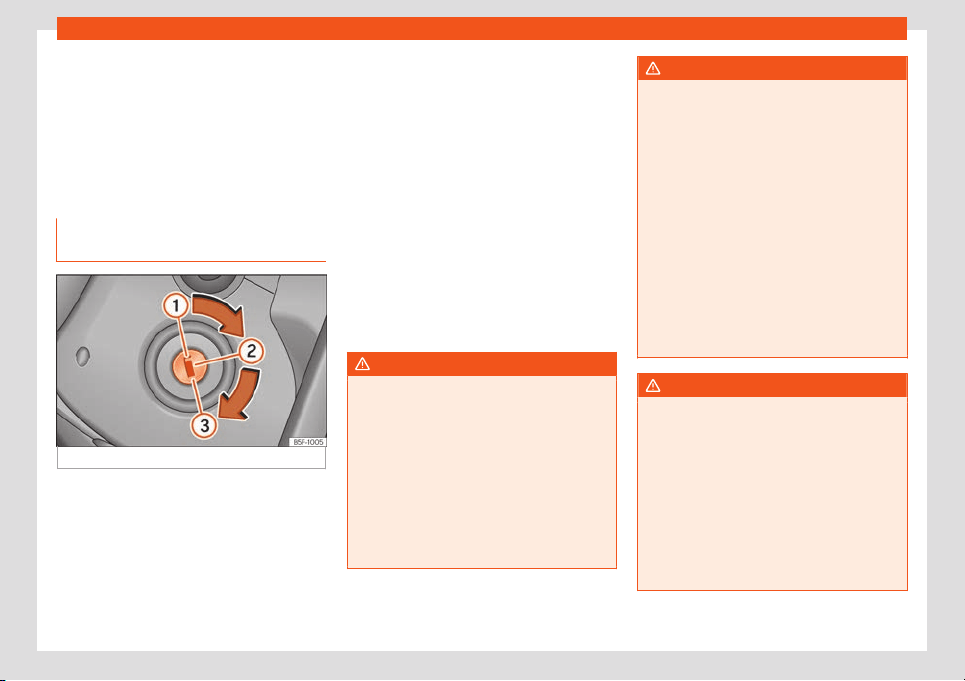
Start and driving
Driving
St
ar
t and driving
St
opping and starting the
engine
Switching on the ignition and start-
ing the engine
Fig. 160 Vehicle key positions
Read the additional information carefully
›
›
›
page 22
Immobiliser display
When an invalid key is used or in the event of
a system fault, is displayed on the instru-
ment panel. The engine cannot be started.
Pushing or towing
For technical reasons, the vehicle must not
be push- or tow-started. Jump starting is
preferable.
Key not authorised for the vehicle
If a key which is not authorised for this vehicle
is inserted in the ignition lock, it can be re-
moved as follows:
●
Automatic transmission: the key cannot be
removed from the ignition lock. Press and re-
lease the selector lever locking button. Key
can be removed from the vehicle.
●
Manual transmission: Remove the key from
the ignition.
WARNING
Switching off the engine while driving
makes stopping the v
ehicle difficult. As a
consequence you may lose control of the
vehicle and there is a risk of serious acci-
dent.
●
The assisted braking and steering sys-
tems, the airbag system, seat belts and
certain safety equipment are only active
while the engine is running.
●
The engine should only be switched off
when the vehicle is at a standstill.
WARNING
While the engine is running or starting it
could help reduce the risk of serious injury.
●
Ne
ver start or leave the engine running in
poorly ventilated or closed spaces. Ex-
haust gas contains carbon monoxide, a
toxic, colourless and odourless gas. Car-
bon monoxide can cause people to lose
consciousness. It can also cause death.
●
Never leave the vehicle unattended if the
engine is running. The vehicle could move
off suddenly or something unexpected
could happen resulting in damage and se-
rious injury.
●
Never use start boosters. Cold start
sprays could explode or increase the en-
gine speed unexpectedly.
WARNING
The components of the exhaust system
reach very high t
emperatures. This could
cause a fire and considerable damage.
●
Always park your vehicle so that no part
of the exhaust system can come in contact
with flammable materials (such as wood,
leaves, spilled fuel, dried grass, etc.).
●
Never apply additional underseal or anti-
corrosion coatings to the exhaust pipes,
catalytic converter or the heat shields on
the exhaust system.
»
149
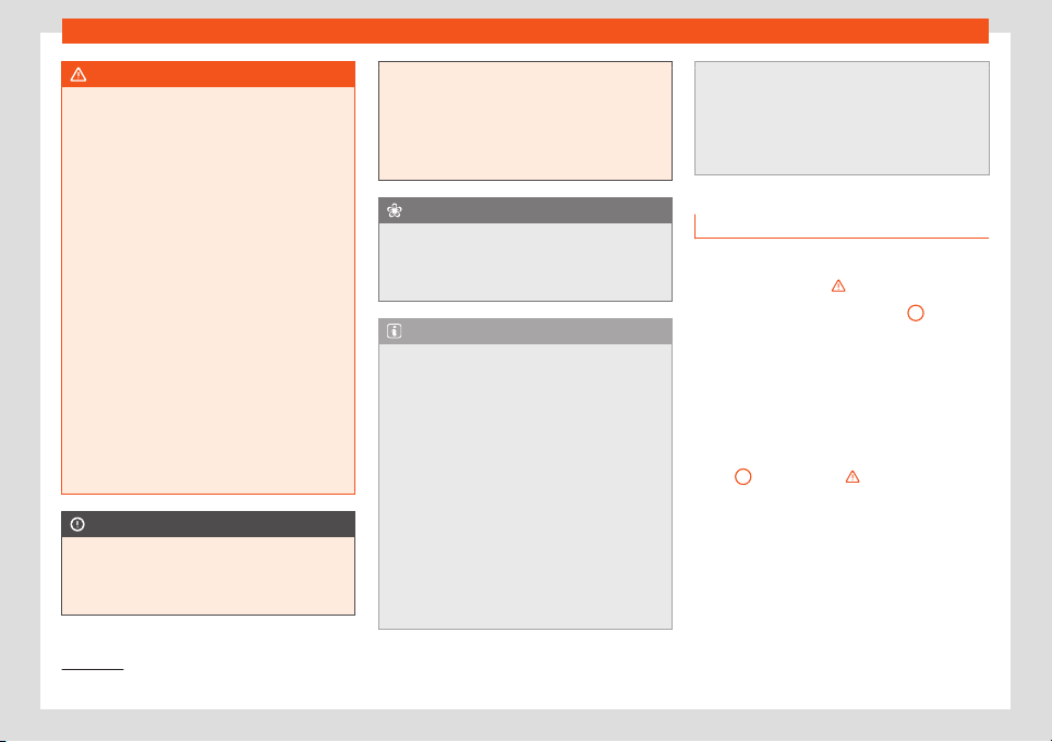
Driving
WARNING
Unsuitable or careless use of the vehicle
key could r
esult in serious injury.
●
Always take all the keys with you when-
ever you leave the vehicle. If not, the en-
gine could accidentally be started and
electrical equipment such as the windows
could accidentally be operated resulting in
serious injury.
●
Never leave children or disabled people
alone in the car. Passengers could be trap-
ped in the car in an emergency and not be
able to get themselves to safety. For exam-
ple, depending on the time of the year,
temperatures inside a locked and closed
vehicle can be extremely high or extremely
low resulting in serious injuries and illness
or even death, particularly for young chil-
dren.
●
Never remove the key from the ignition if
the vehicle is in motion. The steering may
lock and it will not be possible to turn the
steering wheel.
CAUTION
●
An attempt to st
art the engine while driv-
ing or starting the engine immediately after
turning it off can cause damage to the en-
gine or starter motor.
●
When the engine is cold, avoid high r
evs
and heavy acceleration and do not make
the engine work hard.
●
Do not push or tow start the engine. Un-
burnt fuel could damage the catalytic con-
verter.
For the sake of the environment
Do not warm the engine at idle speed; start
driving immediat
ely if the visibility is OK
.
This helps the engine reach operating tem-
perature faster and reduces emissions.
Note
●
If the key is left in the ignition l
ock with
the engine off for long periods, the vehicle
battery will run flat.
●
For automatic gearbox vehicles, the key
can only be removed from the ignition lock
if the gear selector lever is in position P. If
applicable, press and release the locking
button of the selection lever.
●
Electrical devices with a high power con-
sumption are switched off temporarily
when the engine starts.
●
When the engine is started cold, there
may be strong vibrations for a few mo-
ments for technical reasons. This is quite
normal, and no cause for concern.
●
Natural gas engines al
ways start up with
petrol, as a certain operating temperature
is required for running with gas. Once the
required operating temperature is reached,
the engine will change to operate with nat-
ural gas.
Stopping the engine
Switching off the engine
–
Stop the vehicle
›››
.
–
Turn the ignition key to position
1
›››
Fig. 160.
Engaging the st
eering wheel l
ock
In v
ehicles with automatic gearbox, the igni-
tion key can only be removed when the se-
lector lever is in position N
1)
.
–
Remove the key from the ignition in posi-
tion
1
›
›
›
Fig. 160
›››
.
–
Turn the steering wheel until you hear it en-
gage
.
P
ossibl
e vehicle theft is prevented with the
steering lock engaged.
1)
Depending upon country.
150
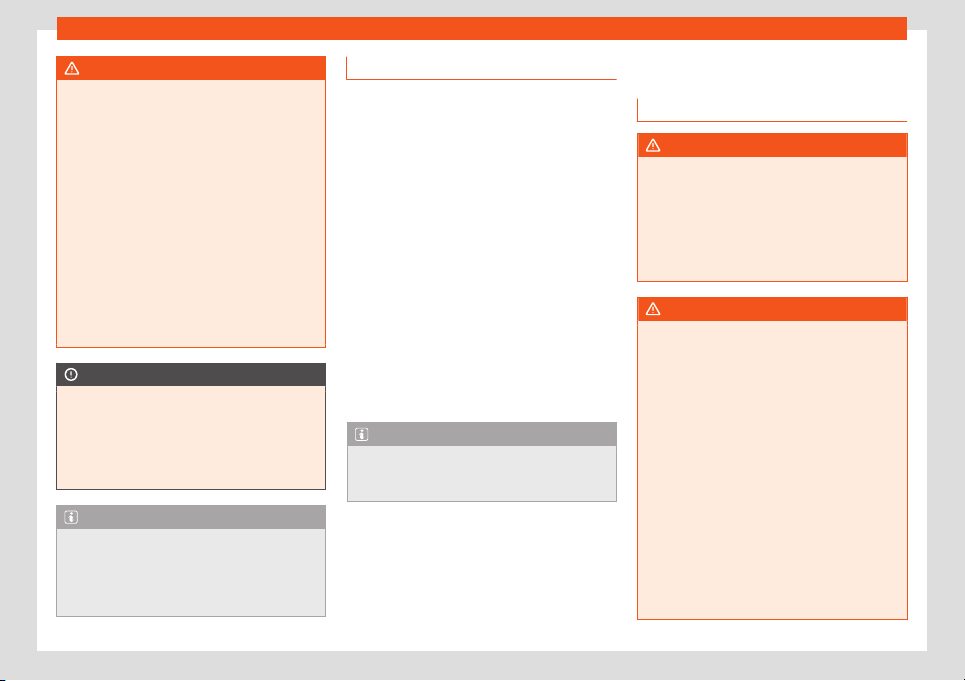
Start and driving
WARNING
Never switch off the engine while the vehi-
cle is moving. Y
ou may lose control of the
vehicle and there is a risk of serious acci-
dent.
●
The airbags and belt tensioners do not
work when the ignition is switched off.
●
The brake servo does not work with the
engine off. To stop, the brake pedal must be
pressed with more force.
●
As the power steering does not work if the
engine is not running, you will need more
strength to steer than normally.
●
If the key is removed from the ignition, the
steering may lock and it will not be possible
to steer the vehicle.
CAUTION
If the engine has been driven at high speed
for a prol
onged period of time, it may over-
heat when turned off. To avoid engine dam-
age, allow the engine to run for approxi-
mately 2 minutes in neutral before switch-
ing it off.
Note
After stopping the engine, the engine com-
partment fan may continue running f
or a
few minutes, even when the ignition has
been switched off or the key removed. The
radiator fan is automatically switched off.
Electronic immobiliser
The gear lock prevents the engine from being
started with an unauthorised k
ey and the ve-
hicle being moved.
The vehicle key has a built-in chip. It automat-
ically deactivates the electronic immobiliser
when the key is inserted into the ignition lock.
The electronic immobilizer will be activated
again automatically as soon as you remove
the key from the ignition lock.
For this reason, the vehicle can only be used
with a genuine SEAT key with the correct
code. Coded keys can be obtained from
SEAT dealerships
›››
page 92.
If an unauthorised key is used, the following
signal appears on the instrument panel dis-
play . The vehicle cannot be started in this
case
Note
The correct operation of the vehicle is only
guaranteed when original SEAT k
eys are
used.
Braking and parking
Intr
oduction
WARNING
Driving with worn brake pads or a faulty
brake syst
em may lead to serious accident.
●
If you believe the brake pads to be worn
or the brake system to be faulty, immedi-
ately refer to a specialised workshop to
check the brake pads and replace the worn
ones.
WARNING
Careless parking can cause serious injury.
●
Never remove the key from the ignition if
the vehicle is in motion. The st
eering lock
may engage and lock the steering wheel
making the vehicle impossible to control.
●
Always park your vehicle so that no part
of the exhaust system can come in contact
with flammable materials (such as wood,
leaves, dried grass, spilled fuel, etc.).
●
Always apply the handbrake when you
leave your vehicle and when you park.
●
Never leave children or disabled people
alone in the vehicle. They could release the
electronic parking brake, activate the se-
lector lever or gear stick and start the vehi-
cle moving. This could result in a serious
accident.
»
151
Driving
●
Always t
ake all the keys with you when-
ever you leave the vehicle. The engine
could accidentally be started and electri-
cal equipment such as the windows could
accidentally be operated resulting in seri-
ous injury.
●
Never leave children or disabled people
alone in the car. They could be trapped in
the car in an emergency and will not be
able to get themselves to safety. For exam-
ple, depending on the time of the year,
temperatures inside a locked and closed
vehicle can be extremely high or extremely
low resulting in serious injuries and illness
or even death, particularly for young chil-
dren.
CAUTION
●
Special care should be t
aken when park-
ing in areas with high kerbs or fixed barri-
ers. Objects protruding from the ground
may damage the bumper or other parts of
the vehicle during manoeuvres. To avoid
damage, stop before the wheels touch the
barrier or kerb.
●
Special attention is required when driving
through entrances, over ramps, kerbs or
other objects. The vehicle underbody,
bumpers, mudguards and running gear,
and the engine and exhaust system could
be damaged as you drive over these ob-
jects.
Control and warning lamps
It lights up
›››
Handbrake applied
›››
page 153.
It lights up
›››
Fault in the brake system
Do not drive on!
Seek prof
essional advice
›››
page 154.
Brake fluid level inadequate.
Do not drive on!
Check brak
e fluid level
›››
page 201.
Together with the ABS control lamp : ABS and EBV
do not function.
Do not drive on!
Seek prof
essional advice
›››
page 154.
Several warning and control lamps light up
f
or a f
e
w seconds when the ignition is switch-
ed on, signalling that the function is being
verified. They will switch off after a few sec-
onds.
WARNING
If the warning lamps are ignored, the vehi-
cle may stall in tr
affic, or may cause acci-
dents and severe injuries.
●
Never ignore the warning lamps.
●
Stop the vehicle safely as soon as possi-
ble.
WARNING
Driving with brakes in bad condition could
result in a serious accident.
●
If the brak
e warning lamp does not
turn off or if it lights up when driving, the
brake fluid level in the reservoir is too low or
there is a fault in the brake system. Obtain
professional assistance immediately
›››
page 200, Checking the brake fluid level.
●
If the brake warning lamp lights up to-
gether with the ABS warning lamp , the
ABS regulation could be malfunctioning. As
a result, the rear wheels can lock relatively
easily when braking. If the rear wheels lock
this could result in loss of vehicle control! If
possible, reduce your speed and drive
carefully to a specialised workshop close
by to check the brake system. During the
following journey, avoid sudden braking
and manoeuvres.
CAUTION
Failure to heed the warning lamps when
they appear may result in faults in the v
ehi-
cle.
152
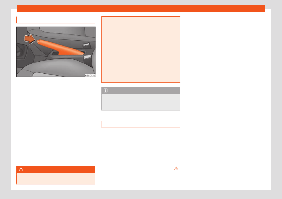
Start and driving
Handbrake
Fig. 161
Between the front seats: parking
br
ak
e
.
Using the handbrake
●
Pull firmly in an upwards direction on the
handbr
ak
e l
ever while pressing the button.
●
The handbrake is applied when the control
lamp lights up on the instrument panel
›››
page 152 when the ignition is switched on.
Releasing the handbrake
●
Pull gently in an upwards direction on the
handbrake lever and press the lock button
›››
Fig. 161 (arrow).
●
Move the handbrake lever downwards
keeping the lock button pressed.
WARNING
The incorrect use of the handbrake may re-
sult in a serious accident.
●
Never use the handbr
ake to brake the ve-
hicle except in an emergency. The braking
distance is considerably longer, because
braking is only applied to the rear wheels.
Always use the foot brake.
●
Never drive with the handbrake gently
applied. This can overheat the brake, af-
fecting the brakes system. This also causes
premature wear on the rear brake pads.
●
Never accelerate from the engine com-
partment with the engine running and a
gear engaged. The vehicle could move,
even if the handbrake is applied.
Note
If the vehicle moves at a speed superior to
6 km/h (4 mph) with the handbrak
e ap-
plied, an audible warning is sounded.
Parking
When parking your vehicle, all legal require-
ments shoul
d be observ
ed.
T
o park the vehicle
Complete operations only in the sequence
given.
●
Park the vehicle on a suitable surface
›››
.
●
Press and hold the brake pedal until the ve-
hicl
e comes t
o a st
andstill.
●
Apply the handbrake firmly
›››
page 153.
●
For an automatic gearbox, move the selec-
tor lever to position N.
●
Switch off the engine and release the brake
pedal.
●
Remove the key from the ignition.
●
If necessary, turn the steering wheel slightly
to lock the steering.
●
With a manual gearbox, engage 1st gear on
flat ground and slopes, or even reverse gear
on hills, and release the clutch pedal.
●
Ensure that all passengers leave the vehi-
cle, especially children.
●
When leaving the vehicle, take all keys with
you.
●
Lock the vehicle.
Additional information for steep slopes
and hills
Before switching off the engine, rotate the
steering wheel so that if the vehicle should
move, it will be held by the kerb.
●
On slopes, turn the front wheels so that
they are against the edge of the kerb.
●
Uphill, turn the wheels towards the centre of
the road.
»
153
Driving
WARNING
The components of the exhaust system
reach very high t
emperatures. This could
cause a fire and considerable damage.
●
Always park your vehicle so that no part
of the exhaust system can come in contact
with flammable materials (such as wood,
leaves,dried grass, or spilled fuel).
CAUTION
●
Special care should be t
aken when park-
ing in areas with high kerbs or fixed barri-
ers. Objects protruding from the ground
may damage the bumper or other parts of
the vehicle during manoeuvres. To avoid
damage, stop before the wheels touch the
barrier or kerb.
●
Special attention is required when driving
through entrances, over ramps, kerbs or
other objects. The vehicle underbody,
bumpers, mudguards and running gear,
and the engine and exhaust system could
be damaged as you drive over these ob-
jects.
Information on the brakes
For the first 200 to 300 km, the ne
w br
ak
e
pads have not yet reached their maximum
braking capacity, and need to be “run in” first
›››
. The slightly reduced braking effect can
be compensat
ed f
or by incr
easing pressure
on the brake pedal. While running in, the full
braking distance or emergency braking
distance is larger then when the brake pads
have been run in. While running in, avoid full
power braking or situations requiring braking
performance. For example, in heavy traffic.
The rate of wear of the brake pads de-
pends to a great extent on the conditions in
which the vehicle is used and the way the ve-
hicle is driven. If the vehicle is used frequently
in city traffic or for short trips or driven sport
style, visit a specialised workshop regularly,
more frequently than advised in the Mainte-
nance Programme, to have the brake pads
checked.
If you drive with wet brakes, for example, af-
ter crossing areas of water, in heavy rainfall
or even after washing the car, the effect of
the brakes is lessened as the brake discs are
wet or even frozen (in winter). At higher speed,
“dry” the brakes as quickly as possible by
braking gently several times. Only do this
without endangering vehicles behind you or
any other road users
›››
.
A l
ayer of salt on the discs and br
ak
e pads
will reduce the effectiveness of the brakes
and increase braking distance. If you drive for
a prolonged period on salted roads without
braking then brake carefully several times to
eliminate the layer of salt on the brakes
›››
.
If the v
ehicl
e r
emains parked for considerable
lengths of time, is used little, or if the brakes
are not used, there may be corrosion on the
brake discs and a build up of dirt on the
brake pads. If the brakes are not used fre-
quently, or if rust has formed on the discs,
SEAT recommends cleaning the pads and
discs by braking firmly a few times at a mod-
erately high speed. Only do this without en-
dangering vehicles behind you or any other
road users
›››
.
F
aults in the br
ak
e system
During braking, if you notice that the vehicle
does not react as usual (that the braking dis-
tance has increased suddenly) it may be
possible that there is a fault in the braking
system. This is indicated by the warning lamp
. Take the vehicle to a specialised work-
shop immediately and have the fault re-
paired. Drive at a moderate speed and be
prepared to use more pressure on the brake
pedal, and allow for longer stopping distan-
ces.
Brake servo
The brake servo only operates when the en-
gine is running and the pressure applied by
the driver on the brake pedal increases.
If the brake servo does not operate or the ve-
hicle must be towed, then the brake pedal will
have to be pressed with more force given that
the braking distance will be increased when
the brake servo does not operate
›››
.
154
Start and driving
WARNING
New brake pads do not brake to full effi-
ciency.
●
For the first 320 km, new brake pads have
not yet reached their maximum braking ca-
pacit
y, and need to be “run in” first. For this,
to compensate for reduced braking effi-
ciency the brake pedal will have to be
pressed with more force.
●
To avoid losing control of the vehicle and
causing serious accidents, always take
great care when driving with new brake
pads.
●
When running in new brake pads, always
respect the safety distances between you
and other vehicles and do not cause situa-
tions requiring extreme braking perform-
ance.
WARNING
When brakes overheat, braking is less effi-
cient and braking distances incr
ease.
●
When driving on slopes, brakes can be
overloaded and overheat quickly.
●
Reduce speed or change down a gear
when faced with steep and long slopes.
This allows you to use the engine braking
effect and to reduce the strain on the brake
system.
●
Non-standard or damaged front spoilers
could restrict the airflow to the brakes and
cause them to overheat.
WARNING
Wet, frozen or salt-covered brakes take
longer to engage and this incr
eases brak-
ing distances.
●
Test the brakes carefully.
●
Dry the brakes, free them of ice and salt
by braking gently several times, when visi-
bility, weather, and road and traffic condi-
tions permit.
WARNING
Driving without the brake servo may signifi-
cantly increase the braking dist
ance and
result in a severe accident.
●
Never allow the vehicle to move forwards
when the engine is switched off.
●
If the brake servo does not operate or the
vehicle must be towed, then the brake ped-
al will have to be pressed with more force
given that the braking distance will be in-
creased when the brake servo does not op-
erate.
CAUTION
●
Never mak
e the brakes “slip” by pressing
the pedal gently, if it is not really necessa-
ry to brake. Continuously pressing on the
brake pedal will heat the brakes. This could
significantly reduce braking power, in-
crease braking distance or even result in
the total failure of the brake system.
●
Reduce speed or change down a gear
when f
aced with steep and long slopes.
This allows you to use the engine braking
effect and to reduce the strain on the brake
system. Otherwise, the brakes may over-
heat and fail. Only use the brakes to reduce
speed or to stop.
Note
Make use, when having the front brake
pads check
ed, and have the r
ear pads
checked also. The thickness of the brake
pads should be checked visually and regu-
larly, by looking through the openings in
the wheel rims or from underneath the ve-
hicle. If necessary, remove the wheels to
check them thoroughly. SEAT recommends
taking your car in for technical service.
155
Driving
Braking and stability sys-
t
ems
W
arning and contr
ol lamps
It lights up
›››
ESC* disconnected by the system.
Turn the ignition on and off. If necessary, drive for a
short distance.
Fault in the ESC*.
Go to a specialised workshop
.
Along with the ABS control lamp : fault in the ABS.
Go to a specialised w
orkshop. The vehicle can be
braked without ABS.
The battery has been reconnected
›››
page 202.
Flashes
ESC* or ASR regulating.
Stop pressing the gas pedal
. Adjust your driving style
to the road conditions.
It lights up
›››
Traction Control* faulty or switched off by the sys-
tem.
Go to a specialised w
orkshop.
Flashes
Traction Control* regulator in operation.
Lift off your fit from the gas pedal. Adjust your driving
st
yle to the road conditions.
It lights up
›››
Along with the ESC* control lamp: f
ault in the ABS.
Go to a specialised workshop. The vehicle can be
braked without ABS.
Together with the warning lamp : ABS and EBV do
not function.
Do not drive on!
Seek prof
essional advice
›››
page 154.
Several warning and control lamps light up
f
or a f
e
w seconds when the ignition is switch-
ed on, signalling that the function is being
verified. They will switch off after a few sec-
onds.
WARNING
If the warning lamps are ignored, the vehi-
cle may stall in tr
affic, or may cause acci-
dents and severe injuries.
●
Never ignore the warning lamps.
●
Stop the vehicle safely as soon as possi-
ble.
WARNING
●
If the ABS warning lamp
does not go
out or if it lights up while driving, the ABS is
not working properly. The vehicle can only
be stopped using normal braking without
ABS. The protection pr
ovided by the ABS is
not available. Visit a specialised workshop
as soon as possible.
CAUTION
Failure to heed the warning lamps when
they appear may r
esult in faults in the v
ehi-
cle.
Brake assist systems
The assist
ed brake systems are the elec-
tr
onic distribution of br
aking force (EBV), the
anti-lock brake system (ABS), the brake assist
system (BAS), the electronic differential lock
(EDL), traction control (TC)*, the traction
control system (ASR) and the electronic sta-
bility control (ESC*).
The brake assistance systems only operate
when the ignition is switched on. They con-
tribute significantly to increasing active safe-
ty.
Electronic Stability Control (ESC)*
ESC* reduces the risk of skidding and increa-
ses the vehicle stability by braking individual
wheels under specific driving conditions.
ESC* detects critical handling situations,
such as understeer, oversteer and wheelspin
on the driven wheels. The system stabilises
156

Start and driving
the vehicle by braking individual wheels or by
r
educing the engine t
or
que.
The ESC* has limits. It is important to realise
that ESC* is also subject to the laws of phys-
ics. ESC* will not be able to deal with all sit-
uations with which drivers may be faced. For
example, if the road surface changes sud-
denly then ESC* will not be useful in all ca-
ses. If the vehicle suddenly enters a section
covered by water, mud or snow then ESC*
will not provide assistance in the same way
as on dry ground. If the vehicle loses its grip
on the ground and moves on a film of water
(“aquaplaning”), the ESC* will not be able to
help the driver control the vehicle due to the
loss of adherence with the road surface pre-
venting braking and steering. If the vehicle is
driven through series of bends at high speed,
the ESC* will not always be as effective: ag-
gressive driving is not the same as slow driv-
ing.
Adjust your speed and driving style to suit vis-
ibility, and weather, road and traffic condi-
tions. ESC* cannot push the limits of the laws
of physics; improve the transmission available
or maintain the vehicle on the road if a lack of
driver attention creates an inevitable situa-
tion. Otherwise, ESC* assists in maintaining
vehicle control in extreme situations and uses
the movements of the steering made by the
driver to maintain the vehicle moving in the
desired direction. If the vehicle is driven at
such a speed that it will leave the road before
ESC* can intervene then the system cannot
provide assistance.
The ABS, BAS, ASR and EDL systems are in-
corporated into the ESC*. The ESC* is al-
ways on
1)
.
Anti-lock system (ABS)
ABS can prevent the wheels from locking dur-
ing braking until just before the vehicle stops
thus helping the driver to steer the vehicle
and maintain control. This means that, even
during full braking, the risk of skidding is re-
duced:
●
Press and hold the brake pedal fully. Do not
remove your foot from the brake pedal or re-
duce braking force!
●
Do not “pump” the brake pedal, or reduce
braking force!
●
Maintain vehicle direction when braking
fully.
●
When the brake pedal is released or when
the brake force is reduced, ABS is turned off.
ABS control can be observed by vibration of
the brake pedal and noise. You should never
expect the ABS to reduce the braking dis-
tance under any circumstances. This dis-
tance will increase when driving on gravel, re-
cent snow or on icy or slippery ground.
Brake assist system (BAS)
The brake assistance system may reduce the
required braking distance. The brake assis-
tance system boosts the braking force if you
press the brake pedal quickly in an emergen-
cy. As a result, the braking pressure increases
rapidly, the braking force is multiplied and the
braking distance is reduced. This enables the
ABS to be activated more quickly and effec-
tively.
Do not lift your foot off the brake pedal!
When the brake pedal is released or when
the brake force is reduced, brake assist auto-
matically turns off the brake servo.
Traction control system (ASR) or Traction
Control (TC)*
In the event of wheelspin, the traction control
system ASR or TC reduces the engine torque
to match the amount of grip available. The
ASR or TC makes some situations easier, for
example, when starting, accelerating or go-
ing uphill, even in unfavourable road condi-
tions.
»
1)
Depending on the version.
157
Driving
Electronic differential lock (EDS)
EDL is av
ail
abl
e when driving in straight lines
under normal conditions. When the EDL de-
tects wheelspin, it brakes the spinning wheel
and directs the power to the other one. To
prevent the disc brake of the braked wheel
from overheating, the EDL cuts out automati-
cally if subjected to excessive loads. The EDL
will switch on again automatically when the
brake has cooled down.
WARNING
Driving at high speed on icy, slippery or wet
ground can result in l
oss of vehicle control
and serious injury to the driver and passen-
gers.
●
Adjust your speed and driving style to vis-
ibility, road, traffic and weather conditions.
Even though the brake assist systems, ABS,
BAS, EDL, ASR and ESC* provide more se-
curity, do not take unnecessary risks while
driving.
●
Brake assistance systems can not over-
come the laws of physics. Even with ESC*
and other systems, slippery and wet roads
will always be dangerous.
●
Driving to quickly on wet ground can re-
sult in the wheels losing contact with the
ground in an effect known as “aquaplan-
ing”. Without adherence, it is impossible to
brake, steer or control the vehicle.
●
Brake assistance systems cannot avoid
accidents if, for example, the driver does
not respect safety distances or drives to
quickly in difficult conditions.
●
Even though brake assistance systems
are extr
emely effective and help control
the vehicle in difficult situations, remember
that the vehicle stability depends on tyre
grip.
●
When accelerating on a slippery surface,
for example on ice or snow, press the ac-
celerator carefully. The wheels can still slip
even with brake assistance systems result-
ing in loss of vehicle control.
WARNING
The effectiveness of the ESC* can be con-
siderably reduced if other components and
syst
ems affecting driving dynamics are not
maintained or are not functioning correct-
ly. This includes, among others, brakes,
tyres and other systems already men-
tioned.
●
Remember that changing and fitting oth-
er components to the vehicle can affect
operation of the ABS, BAS, ASR TC, EDL and
ESC*.
●
Changes to the vehicle suspension or us-
ing unapproved wheel/tyre combinations
can affect operation of the ABS, BAS, ASR,
TC, EDL and ESC* and their effectiveness.
●
Likewise, the effectiveness of ESC* de-
pends on the use of suitable tyres
›››
page 206.
Note
●
To ensure that the ESC*, ASR and T
C
work properly, all four wheels must be fit-
ted with identical tyres. Any differences in
the rolling radius of the tyres can cause the
system to reduce engine power when this is
not desired.
●
If a malfunction should occur in the ABS,
the ESC*, ASR, TC and EDL will also be af-
fected.
●
Noises may be heard while any of the
above systems are operating.
Changing gear
Intr
oduction
When reverse gear is engaged and the ig-
nition is s
wit
ched on the f
ollowing takes
place:
●
Reverse lights light up.
●
The rear wiper blade performs one move-
ment when the windscreen wiper is activated.
●
If necessary, connect the parking distance
warning system.
WARNING
Rapid acceleration can cause loss of trac-
tion and skidding, especially on slippery
ground. This could cause l
oss of control of
158
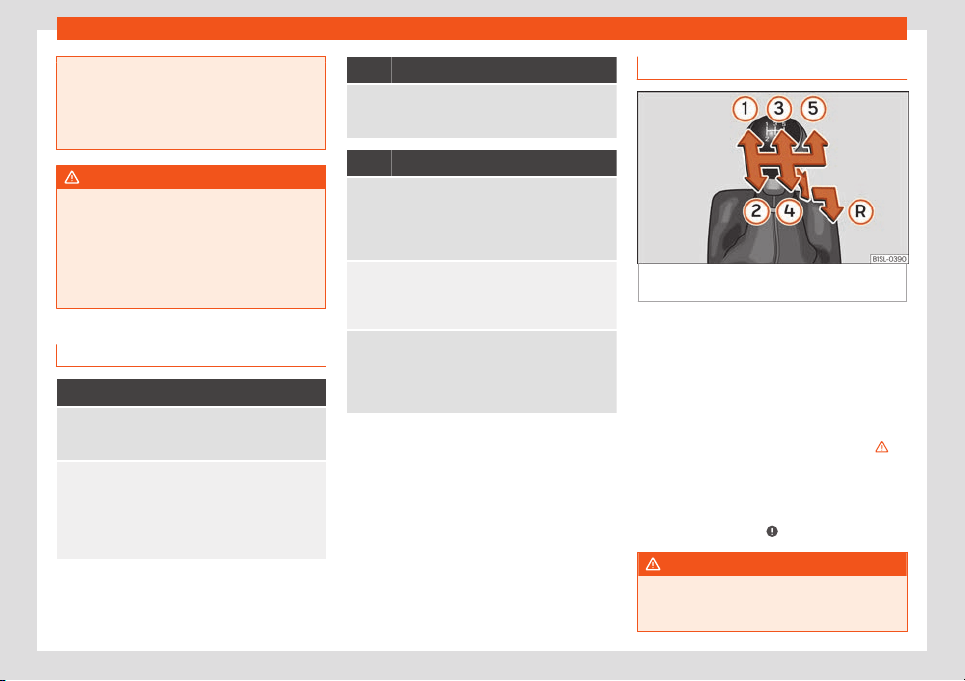
Start and driving
the vehicle resulting in an accident and
considerable damage
.
●
Use rapid acceleration only when visibili-
ty, weather, road conditions and traffic per-
mit.
WARNING
Do not allow the brakes to “rub” for a pro-
l
onged period of time, or br
ake frequently
or for long periods of time. Continuous
braking heats up the brakes. This could sig-
nificantly reduce braking power, increase
braking distance or even result in the total
failure of the brake system.
Control and warning lamps
It lights up
Place the automatic gearbox lever in the position
and do not press the brak
e pedal.
Press the brake pedal to select a list of gears.
Near the blinking display on the instrument panel
display: the gearbox l
evel of automatic transmission
is not in position , which is required to start the en-
gine.
Move the gearbox lever to position and start the en-
gine.
Flashes
An automatic gearbox in the vehicle does not guar-
antee that the vehicl
e will not roll away.
Engage the handbrake.
Flashes
On the instrument panel display, near the required
control lamp
, press the brake pedal : requirement
to start the engine.
Move the gearshift lever to the position and start
the engine.
On the instrument panel display: while driving for-
ward, try t
o move the gearbox level to position .
Stop the vehicle and move the gearbox lever to posi-
tion in order to change the position afterwards .
On the instrument panel display: the gearbox lever of
an automatic transmission mas mo
ved to position
or , but the brake pedal was not operated.
Operate the brake pedal, move the gearbox lever to
position and then to the desired position or .
When switching on the ignition some warning
and indication l
amps light up f
or a short time
t
o check the operations. They will switch off
after a few seconds.
Manual gear change
Fig. 162
Gear shift pattern of a 5-speed man-
ual gearbo
x
Read the additional information carefully
›
›
›
page 28
Shifting down a gear
Shifting down a gear while driving must be
carried out gear by gear, i.e. to the gear im-
mediately preceding the current gear and at
an engine speed that is not excessive
›››
. At
high speeds, or high engine speeds, skipping
one or v
arious gears when shifting do
wn a
gear can cause damage t
o the clutch and
the gearbox, even if the clutch is not engaged
during the process
›››
.
WARNING
When the engine is running, the vehicle will
start t
o move as soon as a gear is engaged
and the clutch released.
»
159
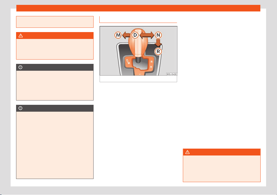
Driving
●
Never engage the r
everse gear when a
vehicle is moving forward.
WARNING
As a consequence of shifting down a gear
incorr
ectly, you may lose contr
ol of the ve-
hicle and cause an accident with serious
consequences.
CAUTION
If, at high speeds or high engine speeds,
the gear lev
er is shifted down to a gear that
is too low, serious damage can be caused
to the clutch and gearbox. This may also
happen if you press the clutch pedal and it
does not engage.
CAUTION
To prevent damage and avoid premature
wear, pl
ease observe the following:
●
While driving, do not leave your hand
resting on the gear stick. The pressure ap-
plied by your hand is transmitted to the
gearbox selector forks.
●
Always ensure that the vehicle is com-
pletely stopped before engaging the re-
verse gear.
●
When changing gear, always make sure
the clutch pedal is pushed right to the floor.
●
Never hold the vehicle “on the clutch” on
hills with the engine on.
Automatic gear change
Fig. 163
Automatic gearbox diagram of gears
Read the additional information carefully
›
›
›
page 28
Move the selector lever to the N position to:
●
Starting up the engine
●
Remove the key from the ignition switch
●
Engage the steering wheel lock
Move the selector lever to the D or R position
to:
●
Park the vehicle
●
Repair a puncture
●
Changing a wheel
To move the gear selector lever from the po-
sition N to D or to R, first press and hold the
brake pedal.
In the instrument panel display, with the igni-
tion switched on, the selected gear range or
the gear engaged in the gearbox is shown.
- Reverse gear
Reverse gear is selected. Engage only when
the vehicle is stopped.
- Neutral
The gearbox is in neutral. No movement is
transmitted to the wheels and the engine
does not act as a brake.
- Standard driving position
The gears are changed (up and down) auto-
matically. The gear shifts are determined by
the engine load, your individual driving style
and the speed of the vehicle.
- Tiptronic driving position (manual shift
programme)
All gears can be changed (up and down)
manually
›››
page 161. This is possible as
long as the system is not changing gear au-
tomatically due to a traffic situation.
WARNING
Placing the selector lever in an incorrect
position may cause loss of control of the
v
ehicle and a serious accident.
●
Do not press the accelerator when en-
gaging a range of gears.
160
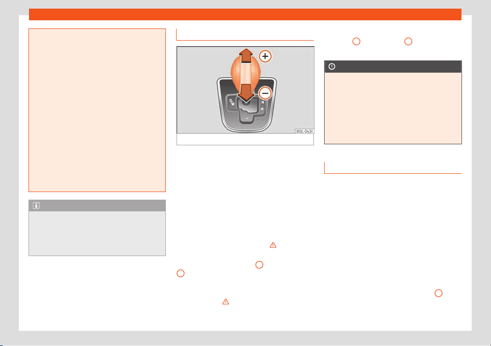
Start and driving
●
With the engine running and a gear range
select
ed, the vehicle will move when the
accelerator is pressed.
●
Never engage reverse gear while driving.
●
Unintentional movements of the vehicle
could cause serious injury.
●
As a driver, you should never leave your
vehicle if the engine is running and a gear
range is engaged. If you have to leave your
vehicle while the engine is running, you
must always apply the handbrake and put
the selector lever in position N.
●
Never engage the R gear range when the
vehicle is moving.
●
Never leave the vehicle without applying
the handbrake. With the engine running the
vehicle moves downhill regardless of the
gear range selected.
Note
If, while driving, the selector lever is acci-
dentally placed in position N, lift your f
oot
off the accelerator. Wait until the engine is
running at idle speed before selecting a
new gear range.
Engaging gear with Tiptronic
Fig. 164
Lever in the Tiptronic position
With Tiptronic, the gears can be changed up
or do
wn manually with the aut
omatic gear
-
box. When you change to the Tiptronic pro-
gramme, the vehicle remains in the currently
selected gear. This is possible as long as the
system is not changing gear automatically
due to a traffic situation.
Using Tiptronic
●
Place the lever in the position D to the left
on the Tiptronic shift gate M
›››
in Auto-
matic gear change on page 160.
●
Press the lever forwards
+
or backwards
–
to move up or down a gear
›
›
›
Fig. 164.
●
Place the lever back to the position M to the
left on the Tiptronic shift gate, to leave Tip-
tronic mode
›››
in Automatic gear change
on page 160.
With the lever in the position D, and pr
essing
f
orw
ards
+
or backwards
–
the Tiptronic
pr
ogr
amme can be sel
ected M.
CAUTION
●
When accelerating, the gearbo
x auto-
matically shifts up into the next gear short-
ly before the maximum engine speed is
reached.
●
When reducing speed manually, the
gearbox only shifts gear when the engine
can no longer exceed the maximum engine
speed.
Driving with automatic gearbox
The gearbox changes gear ratios automati-
cally as the v
ehicl
e mo
ves.
Driving down hills
The steeper the gradient, the lower the gear
you will need to select. The lowest gears in-
crease the engine braking work. Never go
down hills with the selector lever in neutral N.
●
You should reduce speed accordingly.
●
Place the lever in the position D to the left
on the Tiptronic shift gate M
›››
page 161.
●
Gently pull the selector lever back
–
to
change do
wn a gear
.
»
161
Driving
Starting when going up a slope
The st
eeper the gr
adient, the l
ower the gear
you will need.
When stopping on a slope with a gear range
engaged, the vehicle must be prevented from
rolling backwards by always pressing the
brake pedal or pulling the handbrake lever
up. When starting, release the brake pedal or
the handbrake
›››
.
Kick
-do
wn
The kick
down system provides maximum ac-
celeration when the gear selector lever is in
the position D, or in the Tiptronic position M.
When the accelerator pedal is pressed right
down, the automatic gearbox will shift down
to a lower gear, depending on road speed
and engine speed. This takes advantage of
the maximum acceleration of the vehicle
›››
.
When the accel
er
at
or is pressed to the floor,
the automatic gearbox shifts to the next gear
only after the engine reaches the specified
maximum engine speed.
WARNING
Rapid acceleration can cause loss of trac-
tion and skidding, especially on slippery
ground. This could cause l
oss of control of
the vehicle resulting in an accident and se-
rious injury.
●
Always adapt your driving st
yle to suit
the flow of traffic.
●
Only use the kick-down function or rapid
acceleration if visibility, weather, road and
traffic conditions so permit.
●
Never put other road users in danger by
accelerating or with your driving style.
CAUTION
If you stop on a hill with a gear range en-
gaged, do not try t
o pre
vent the vehicle
from rolling back by pressing on the accel-
erator. Otherwise, the automatic gearbox
may overheat causing damage.
Automatic gearbox malfunction
Control lamps
It lights up red
Fault in the automatic gearbox.
Do not drive on!
Seek prof
essional advice. Failure to do so could re-
sult in considerable damage to the transmission.
It lights up yellow
In the automatic gearbox the gears can engage in-
correctly.
Swit
ch the ignition on and off. When the control lamp
does not light up, find the nearest specialised work-
shop and have the automatic gearbox checked.
The automatic gearbox overheats temporarily.
Let the transmission cool with the gearbo
x lever in
the position . When the control lamp does not light
up, find the nearest specialised workshop and have
the automatic gearbox checked.
It lights up
Along with the yellow control lamp for transmission
temperat
ure : the automatic gearbox overheats.
Press the brake pedal and let it cool down. Avoid
pressing the accelerator. When the control lamp
does not light up, find the nearest specialised work-
shop and have the automatic gearbox checked.
Back-up programme
When aut
omatic gearbo
x w
arning and indi-
cation lamps light up on the instrument panel,
there may be a system malfunction
›››
page 158. In the event of some faults the
automatic gearbox functions using a backup
programme. When the programme is activa-
ted, it is possible to drive the vehicle, however,
at low speeds and within a selected range of
gears.
With the manual gearbox, in some cases it is
not possible to drive with all the gears.
162
Start and driving
In all cases the automatic gearbox must be
check
ed at a specialised w
orkshop
.
Automatic gearbox overheating
The automatic gearbox can overheat with a
prolonged start up, or when stopping and
starting continuously. This overheating is dis-
played with a warning lamp in the instru-
ment panel. Additionally, an audible warning
can be heard. Stop and let the gearbox cool
›››
.
The v
ehicl
e mo
ves forward or back de-
spite having selected a gear range
When the vehicle does not move in the re-
quired direction, the system may not have the
gear range correctly engaged. Press the
brake pedal and engage the gear range
again. If the vehicle still does not move in the
required direction, there is a system malfunc-
tion. Seek specialist assistance and have the
system checked.
CAUTION
●
When the gearbox is displayed as o
ver-
heating for the first time, the vehicle must
be parked safely or must be driven at a
speed of more than 20 km/h (12 mph).
●
When the warning lamp lights up and the
audible warning is heard, the vehicle must
be parked safely and the engine switched
off. Let the gearbox cool down.
●
To pre
vent damage to the gearbox, driv-
ing must only be continued when the warn-
ing lamps are no longer lit up. While the
gearbox is overheated, starting up and
driving, even at a slow speed should be
avoided.
Recommended gear display
In some vehicles, the recommended gear for
reducing fuel consumption is displayed on
the instrument panel:
Display Meaning
Optimum gear.
Recommendation to change up a
gear.
Recommendation t
o change down a
gear.
WARNING
The recommended gear display is intended
as a guideline only; it should nev
er replace
the driver's attention to driving carefully.
●
Responsibility for selecting the correct
gear for each situation continues to lie with
the driver, for example when overtaking or
climbing a hill.
For the sake of the environment
Selecting the most appropriate gear for the
situation will help you to sav
e fuel.
Note
The recommended gear display is switched
off when the clutch pedal is pressed.
Steering
Information rel
ating to different ve-
hicle processes.
Electro-mechanical power steering assists
the driv
er when st
eering.
El
ectro-mechanical power steering adapts
electronically to the speed of the car, torque
and turning angle.
If the power steering should fail at any time or
the engine is switched off (for instance when
being towed), the car can still be steered, as
long as the key remains in the ignition. How-
ever, more effort than normal will be required
to turn the steering wheel.
Steering column mechanical lock
To prevent theft, we recommend you lock the
steering before leaving the vehicle.
»
163
Driving
Lock the steering column by removing the key
fr
om the ignition when the v
ehicl
e is stopped.
Please engage steering lock
Park the vehicle
›››
page 151.
Remove the key from the ignition.
Turn the steering wheel slightly until you hear the
steering lock
.
Unlocking the steering
Insert the key in the ignition lock.
Turn the steering wheel slightly to release the steer-
ing lock.
Hol
d the steering wheel in this position and switch on
the ignition.
WARNING
If the power steering is not working then the
steering wheel is much more difficult t
o
turn and the vehicle more difficult to con-
trol.
●
The power steering only works when the
engine is running.
●
Never allow the vehicle to move when the
engine is switched off.
●
Never remove the key from the ignition if
the vehicle is in motion. The steering may
lock and it will not be possible to turn the
steering wheel.
Control and warning lamps
It lights up red
The electromechanical steering is damaged.
Do not continue driving. Stop the vehicle safely and
as soon as possible.
Have the steering checked immediately by a special-
ised workshop.
It lights up yellow
Hindereed operation of the electromechanic steer-
ing.
The steering system shoul
d be checked by a special-
ised workshop as soon as possible.
If, after restarting the engine and driving for a short
distance, the yellow warning lamp no longer comes
on, it will not be necessary to take the vehicle to a
specialised workshop.
Flashes red
Fault in the steering column electronic lock.
Do not continue driving! Seek specialist assis-
tance.
It flashes yellow
Twisted steering column.
Swing the steering wheel a f
ew times.
Not unlocked or blocked steering column.
Remov
e the key from the ignition and then switch the
ignition back on. If necessary, check the messages
displayed on the instrument panel display.
Do not drive on, if the steering column remains
locked after the ignition has been switched on. Seek
specialist assistance.
Several warning and control lamps light up
for a fe
w seconds when the ignition is switch-
ed on, signalling that the function is being
verified. They will switch off after a few sec-
onds.
WARNING
If the warning lamps are ignored, the vehi-
cle may stall in tr
affic, or may cause acci-
dents and severe injuries.
●
Never ignore the warning lamps.
●
Stop the vehicle safely as soon as possi-
ble.
CAUTION
Failure to heed the warning lamps when
they appear may result in faults in the v
ehi-
cle.
164
Start and driving
Run-in and economical driv-
ing
Running in
Please observe the instructions for running-in
new components.
Running-in the engine
The engine needs to be run in o
ver the first
1,500 km. During its first few hours of running,
the internal friction in the engine is greater
than later on when all the moving parts have
bedded down.
How the vehicle is driven for the first 1,500 km
influences the future engine performance.
Throughout the life of the vehicle, it should be
driven at a moderate speed, especially when
the engine is cold, as this will reduce engine
wear and increase its useful life. Never drive
at extremely low engine speeds. Change
down to a lower gear when the engine no
longer runs “smoothly”. Up to 1,000 kilome-
tres the following instructions apply:
●
Do not use full throttle.
●
Do not force the engine above two thirds of
its maximum speed.
Between 1,000 and 1,500 kil
ometres,
gradually increase power until reaching the
maximum speed and high engine speeds.
Running in new tyres and brake pads
●
Replacement of wheel rims and new tyres
›››
page 206
●
Notes on the brakes
›››
page 151
For the sake of the environment
If the engine is run in gently, the life of the
engine will be increased and the engine oil
consumption reduced.
Environmental compatibility
Environmental protection is a top priority in
the design, choice of mat
erial
s and manuf
ac-
ture of your new SEAT.
Constructive measures to encourage re-
cycling
●
Joints and connections designed for easy
dismantling.
●
Modular construction to facilitate disman-
tling.
●
Increased use of single-grade materials.
●
Plastic parts and elastomers are marked in
accordance with ISO 1043, ISO 11469 and
ISO 1629.
Choice of materials
●
Use of recycled materials.
●
Use of compatible plastics in the same part
if its components are not easily separated.
●
Use of recycled materials and/or materials
originating from renewable sources.
●
Reduction of volatile components, including
odour, in plastic materials.
●
Use of CFC-free coolants.
Ban on heavy metals, with the exceptions
dictated by law (Annex II of ELV Directive
2000/53/EC): cadmium, lead, mercury,
hexavalent chromium.
Manufacturing methods
●
Reduction of the quantity of thinner in the
protective wax for cavities.
●
Use of plastic film as protection during vehi-
cle transport.
●
Use of solvent-free adhesives.
●
Use of CFC-free coolants in cooling sys-
tems.
●
Recycling and energy recovery from resi-
dues (RDF).
●
Improvement in the quality of waste water.
●
Use of systems for the recovery of residual
heat (thermal recovery, enthalpy wheels,
etc.).
●
The use of water-soluble paints.
165
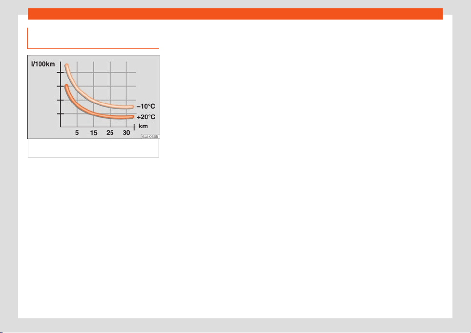
Driving
Economical and environmentally
friendly driving
Fig. 165
Fuel consumption in litres per 100 km
at 2 diff
er
ent outside t
emperatures
Fuel consumption, environmental impact and
engine
, br
ak
e and tyre wear depend largely
on three factors:
●
Personal driving style.
●
Conditions of use (weather, road surface).
●
Technical requirements.
Savings of up to 25% in fuel consumption are
possible with an appropriate driving style and
the adoption of certain simple tips.
Changing gear early
General remarks: the highest gear is always
the most economical. As a guide, for most ve-
hicles at a speed of 30 km/h (19 mph), drive
in third gear, at 40 km/h (25 mph) in fourth
gear and at 50 km/h (31 mph) in fifth gear.
In addition, “skipping” gears when shifting up
helps to save fuel, weather and traffic condi-
tions permitting.
Do not wait until the last moment before
changing gear. Only use first gear when you
move off and change to second gear quickly.
Avoid the kick-down function in vehicles with
automatic gearbox.
Vehicles with a gear display help to achieve
an economical driving style as the display in-
dicates the best moment to change gear.
Let the vehicle roll
If you take your foot off the accelerator, the
fuel supply is stopped and consumption is re-
duced.
Allow the vehicle to roll without accelerating,
for example when approaching a red traffic
light. However, if the vehicle is rolling too
slowly or the distance is too long, the clutch
pedal should be pressed to declutch. The en-
gine will then operate at idle speed.
If the vehicle is going to be at a standstill for a
period of time, switch off the engine; for ex-
ample, while waiting at a level crossing.
Think ahead and “flow” with the traffic
Frequent acceleration and braking consider-
ably increase fuel consumption. If you think
ahead as you drive and keep a safe distance
from the vehicle in front, it is possible to slow
down by simply lifting your foot off the accel-
erator. This eliminates the need for constant
braking and acceleration.
Calm and steady driving
A constant driving style is more important
than speed: a constant driving style will entail
lower fuel consumption.
When driving on the motorway, it is more effi-
cient to drive at a constant and more moder-
ate speed than to be continuously accelerat-
ing and braking. As a general rule, you will
reach your destination just as quickly when
you drive at a constant speed.
The cruise control function helps you to ach-
ieve a constant style of driving.
Moderate use of additional devices
It is important to travel in comfort, but con-
venience systems should be used ecological-
ly.
Some equipment, when connected, increase
fuel consumption considerably, for example:
●
Air conditioning cooling system: If the air
conditioning system is required to cool to sig-
nificantly lower temperatures than the true
outside temperature, it will require a large
amount of energy from the engine. Therefore,
we recommend that the selected
166

Start and driving
temperature for the vehicle is not too different
t
o the outside t
emper
ature. It is a good idea
to air the vehicle before starting your journey
and to drive a short distance with the win-
dows open. Then you can close the windows
and switch on the air conditioning. Keep win-
dows closed when travelling at high speeds.
Driving with the windows open increases fuel
consumption.
●
Switch off the seat heating when the seats
have warmed up.
●
Switch off the heated rear window when it
is not moist or covered in ice.
Avoid short journeys
Fuel consumption is much higher when the
engine is cold, immediately after it has been
started. It takes a few kilometres of driving for
the engine to warm up and to normalise con-
sumption.
The engine and catalytic converter need to
reach their proper working temperature in
order to minimise fuel consumption and emis-
sions. The ambient temperature has a deci-
sive influence.
Fig. 165 shows the difference in consumption
for the same journey at +20°C (+68°F) and at
-10°C (+14°F).
Therefore, unnecessary short journeys should
be avoided. Try to combine trips.
The vehicle uses more fuel in winter than in
summer, even when other conditions are the
same.
The engine takes a long time to warm up
when it is idling. In addition, mechanical wear
and pollutant emissions are also especially
high during this initial warm-up phase. It is
therefore best to drive off immediately after
starting the engine. Doing this avoids running
the engine at a high speed.
Adjusting type pressures.
Having the correct pressure in your tyres
helps to reduce rolling resistance and, as a
result reduces fuel consumption. Increasing
the tyre pressure slightly (+0.2
bar/+3 psi/+200 kPa) can help to save fuel.
When you buy new tyres, make sure they are
optimised for minimum rolling resistance.
Use low friction engine oil
The use of low viscosity totally synthetic oils,
known as low friction engine oil, helps to re-
duce fuel consumption. These oils reduce the
resistance caused by friction in the engine,
they flow around the engine more quickly
and efficiently, particularly in cold starts. The
effect is particularly noticeable in vehicles
frequently used for short journeys.
Always check the engine oil level and ob-
serve service intervals (engine oil change in-
tervals).
When purchasing engine oil, always observe
legal requirements and ensure that the oil is
approved by SEAT.
Avoid carrying unnecessary loads
The lighter the vehicle, the more economical
and ecological the driving style. For example,
an additional weight of 100 kg will increase
fuel consumption up to 0.3 l/100 km.
Remove any unnecessary objects or loads
from the vehicle.
Remove optional equipment and unneces-
sary accessories
The more aerodynamic the vehicle, the lower
the fuel consumption. Optional equipment
and accessories (such as roof racks or bike
carriers) reduce the aerodynamic benefits of
the vehicle.
Therefore, we recommend you remove all op-
tional and unnecessary equipment and
racks, especially if you intend to drive at high
speeds.
Other factors which increase fuel con-
sumption (examples):
●
Fault in engine management.
●
Driving on hills.
»
167
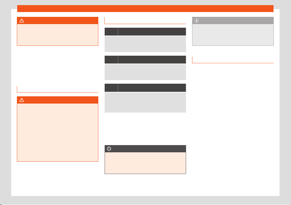
Driving
WARNING
Always adapt your speed and the distance
to the vehicl
es ahead in line with visibility,
weather conditions, the condition of the
road and the traffic situation.
Engine management and ex-
haust gas purification sys-
tem
Introduction
WARNING
The components of the exhaust system
reach very high t
emperatures. This could
cause a fire.
●
Always park your vehicle so that no part
of the exhaust system can come in contact
with flammable materials (such as dried
grass).
●
Never apply additional underseal or anti-
corrosion coatings to the exhaust pipes,
catalytic converter or the heat shields on
the exhaust system.
Control and warning lamps
It lights up
Fault in the management of the petrol engine.
Have the engine checked by a specialised workshop
as soon as possible.
It lights up
Fault in the emission control system.
Reduce speed and drive car
efully to the nearest spe-
cialised workshop to have the engine checked.
Flashes
Combustion fault which could damage the catalytic
converter
.
Reduce speed and drive carefully to the nearest spe-
cialised workshop to have the engine checked.
Several warning and control lamps light up
f
or a f
e
w seconds when the ignition is switch-
ed on, signalling that the function is being
verified. They will switch off after a few sec-
onds.
CAUTION
Always pay attention to any lit control
lamps and to the corr
esponding descrip-
tions and instructions to avoid damage to
the vehicle.
Note
While the or contr
ol lamps remain lit,
the engine may have faults, there will be
higher fuel consumption and a possible
loss of engine power.
Catalytic converter
The catalytic converter permits the subse-
quent treatment of the exhaust gases thus r
e-
ducing contaminating gas emissions. To en-
sure a longer working life for the exhaust sys-
tem and catalytic converter in a petrol en-
gine:
●
Always use unleaded petrol.
●
Never run the fuel tank completely dry.
●
Do not top up with too much engine oil
›››
page 195.
●
Do not tow-start the vehicle; use the starter
cables
›››
page 44.
If you should notice misfiring, uneven running
or loss of power when the car is moving, re-
duce speed immediately. Have the car in-
spected by a specialised workshop. If this
happens, unburnt fuel can enter the exhaust
system and escape into the atmosphere. The
catalytic converter can also be damaged by
overheating.
168
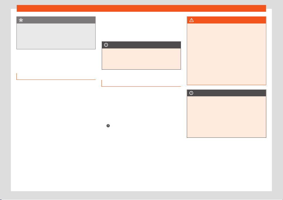
Start and driving
For the sake of the environment
Even when the emission control system is
working perfectly, ther
e may be a smell of
sulphur under certain conditions. This de-
pends on the sulphur content of the fuel
used.
Driving tips
Driving abroad
In some countries, certain safety regulations
and r
equir
ements ar
e in force relating to ex-
haust gas emissions, which differ from the
technical characteristics of the vehicle. Be-
fore travelling abroad, SEAT recommends
you consult a technical service about the le-
gal requirements and the following points:
●
Does the vehicle need technical modifica-
tions for driving abroad, for example, adjust-
ment of the headlamps?
●
Does the vehicle have all the tools, diag-
nostics equipment and spare parts required
for inspections and repairs?
●
Are there any SEAT dealers in the destina-
tion country?
●
For petrol vehicles: Is unleaded petrol avail-
able at the right octane rating?
●
Are a suitable engine oil (
›››
page 195) and
other engine fluids complying with SEAT
specifications available in the destination
country?
●
Are special tyres required in the destination
country?
CAUTION
SEAT does not accept liability for any dam-
age to the vehicl
e due to the use of a lower
quality fuel, an inadequate service or the
non-availability of genuine spare parts.
Driving through flooded roadways
To prevent damage to the vehicle when driv-
ing thr
ough w
at
er, for example, along a floo-
ded road, please observe the following:
●
Check the depth of the water before enter-
ing the flooded zone. The water should never
come above the lower edge of the bodywork
›››
.
●
Do not drive faster than a pedestrian.
●
Do not stop in the water, use reverse gear
or s
wit
ch off the engine
.
●
Oncoming traffic will cause waves which
raise the level of the water, making it difficult
to cross the water.
●
Disconnect the Start-Stop system whenev-
er crossing water.
WARNING
When driving through water, mud, melted
snow, et
c., please remember that due to
damp or frozen brake discs and shoes in
winter, the braking effect may be delayed,
therefore the required braking distance is
greater.
●
“Dry the brakes and remove ice” by brak-
ing carefully. Ensure that you are not en-
dangering other road-users or breaking
traffic regulations in the process.
●
After driving through water, avoid sudden
sharp manoeuvres.
CAUTION
●
Driving through flooded ar
eas may se-
verely damage vehicle components such
as the engine, transmission, drive train or
electrical system.
●
Never drive through salt water as salt
causes corrosion. Always rinse any parts of
the vehicle which have been in contact with
salt water.
169
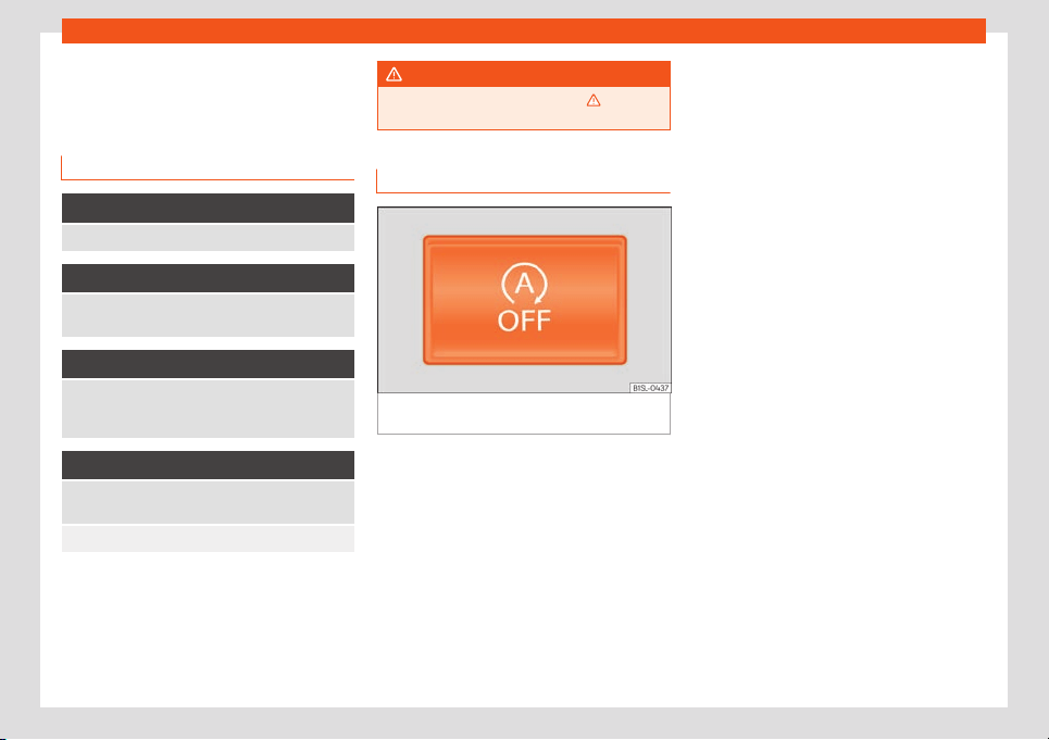
Driving
Driver assistance systems
St
ar
t
-Stop system
Control lamps
It lights up
The Start-Stop system is enabled.
Flashes
The Start-stop system is not available.
Go to a specialised workshop
.
It lights up
The Start-Stop system is enabled but the engine
cannot be automatically stopped.
Go t
o a specialised workshop.
It lights up
The Start-stop system cannot start the engine.
Start the vehicl
e manually with the key
›››
page 149.
There is a fault in the alternator
›››
page 202.
Some control and warning lamps will light up
briefly when the ignition is s
wit
ched on t
o
check certain functions. They will switch off
after a few seconds.
WARNING
Observe the safety warnings
›››
in Con-
trol and warning l
amps on page 27.
Start-Stop system
Fig. 166
In the centre console, top section:
St
art
-st
op system.
With the Start-Stop system enabled, the en-
gine is aut
omatically st
opped when the v
ehi-
cle is at a standstill. It will start again auto-
matically as required.
This function remains enabled while the igni-
tion is switched on. The instrument panel dis-
play shows information on the current status
›››
page 170.
Disconnect the Start-Stop system by hand
whenever crossing water.
Vehicles with a manual gearbox
●
When the vehicle is stopped, put it into neu-
tral and release the clutch pedal. The engine
will stop.
●
To restart, simply engage the clutch.
Vehicles with an automatic gearbox
●
When the vehicle is at a standstill, depress
the brake or keep it pressed down. The en-
gine switches off.
●
The engine will start again as soon as you
release the brake pedal.
●
With the selector lever set to position N, the
engine will not start until a range of gears is
selected or the accelerator pedal is de-
pressed.
Important conditions for the engine to stop
automatically
●
The driver's seat belt must be fastened.
●
The driver door must be closed.
●
The bonnet must be closed.
●
The engine must have reached a minimum
temperature.
●
The vehicle must have moved since the last
time the engine was stopped.
●
The vehicle's battery must be sufficiently
charged.
●
The battery temperature must not be too
low or too high.
170
Driver assistance systems
●
The v
ehicl
e must not be on a v
ery steep
slope.
Conditions for the engine to restart auto-
matically
The engine can be automatically restarted in
the following cases:
●
If the vehicle starts to moves.
●
If the battery voltage drops.
Conditions requiring engine start-up using
the key
The engine has to be manually started in the
following cases:
●
If the driver unbuckles his/her seat belt.
●
If the driver door is opened.
●
If the bonnet is opened.
Switching the Start-Stop system on and
off
●
Press the button situated in the centre
console
›››
Fig. 166.
●
The button will light up when the Start-Stop
system is switched off.
The engine will start immediately if the vehi-
cle is in Stop mode when the system is
switched off by hand.
WARNING
The smart technology included in the hill
hold cannot change the laws of physics. Do
not l
et the extra convenience afforded by
the hill hold tempt you into taking any risks
when driving.
●
Any accidental movement of the vehicle
could result in serious injury.
●
The hill hold is not a replacement for driv-
er awareness.
●
Adjust your speed and driving style to vis-
ibility, weather, road and traffic conditions.
●
The hill hold cannot always keep the ve-
hicle at a standstill on a slope or brake suf-
ficiently when travelling downhill (e.g. on
slippery or frozen surfaces).
WARNING
The brake servo and the electromechani-
cal steering do not work when the engine is
s
witched off.
●
The vehicle must never be allowed to
move with the engine switched off.
●
Disconnect the Start-Stop system before
working in the engine compartment.
CAUTION
The vehicle's battery could be damaged if
the vehicle is used f
or long periods at very
high outside temperatures.
Note
In some cases, it may be necessary to start
the engine by hand using the key. Ref
er to
the corresponding control lamp on the in-
strument panel.
Cruise control system
(CCS)*
Control lamp
It lights up
This cruise control system maintains the set speed of
the vehicle
.
Several warning and control lamps light up
f
or a f
e
w seconds when the ignition is switch-
ed on, signalling that the function is being
verified. They will switch off after a few sec-
onds.
WARNING
If the warning lamps are ignored, the vehi-
cle may stall in tr
affic, or may cause acci-
dents and severe injuries.
●
Never ignore the warning lamps.
»
171
Driving
CAUTION
Failure to heed the warning lamps when
they appear may result in faults in the v
ehi-
cle.
Cruise control operation
Read the additional information carefully
›››
page 26
The cruise control system (CCS) is able to in-
dividually maintain the set speed when driv-
ing forwards from approx. 20 km/h (15 mph).
The CCS only slows down by reducing the
accelerator but not by braking
›››
.
T
r
av
elling down hills with the CCS
When travelling down hills the CCS cannot
maintain a constant speed. Slow the vehicle
down using the brake pedal and reduce
gears if required.
Automatic off
The cruise control system (CCS) is switched
off automatically or temporarily:
●
If the system detects a fault that could af-
fect the working order of the CCS.
●
If you increase the stored speed by press-
ing the accelerator pedal for a certain time.
●
If the brake pedal is pressed.
●
If the gear is changed with the manual
gearbox.
●
If the airbag is triggered.
WARNING
Use of the cruise control could cause acci-
dents and sever
e injuries if it is not possible
to drive at a constant speed maintaining
the safety distance.
●
Do not use the cruise control in heavy
traffic, if the distance from the vehicle in
front is insufficient, on steep roads, with
several bends or in slippery circumstances
(snow, ice, rain or loose gravel), or on floo-
ded roads.
●
Never use the CCS when driving off-road
or on unpaved roads.
●
Always adapt your speed and the dis-
tance to the vehicles ahead in line with visi-
bility, weather conditions, the condition of
the road and the traffic situation.
●
To avoid unexpected operation of the
cruise control system, turn it off every time
you finish using it.
●
It is dangerous to use a set speed which is
too high for the prevailing road, traffic or
weather conditions.
●
When travelling down hills, the CCS can-
not maintain a constant speed. The vehicle
tends to accelerate under its own weight.
Select a lower gear or use the foot brake to
slow the vehicle.
Parking distance warning
syst
em*
Intr
oduction
The parking distance warning system assists
the driver when parking. If the rear of the v
e-
hicle is approaching an obstacle, an intermit-
tent audible warning is emitted. The shorter
the distance, the shorter the intervals be-
tween tones. If the vehicle is too close to the
obstacle, the audible warning becomes con-
stant.
If you continue to approach an obstacle
when the sound is continuous, this means the
system can no longer measure the distance.
Sensors situated on the rear bumper transmit
and receive ultrasound. Using the ultrasound
signal (transmission, reflection from the ob-
stacles and reception), this system continu-
ously calculates the distance between the
bumper and the obstacle.
WARNING
The parking distance warning system can-
not replace the driv
er's assessment of the
situation.
●
The sensors have blind spots in which ob-
stacles and people are not registered.
172
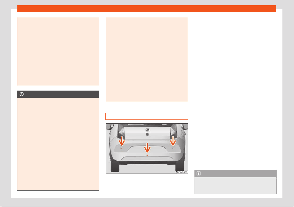
Driver assistance systems
●
Always observ
e the area around the vehi-
cle, as the sensors do not always detect
small children, animals or objects.
●
The surface of certain objects and some
clothing do not reflect the ultrasound sig-
nals from the parking distance system. The
system cannot detect or incorrectly de-
tects these objects and people wearing
these types of clothes.
●
External sound sources can affect the
parking distance aid signals. In this case,
under certain circumstances, people and
objects will not be detected.
CAUTION
●
The sensors may not always be abl
e to
detect objects such as trailer draw bars,
thin rails, fences, posts, trees and open
boots, etc. This could result in damage to
your car.
●
Although the parking distance warning
system detects and warns of the presence
of an obstacle, the obstacle could disap-
pear from the angle of measurement of the
sensors if it is too high or low and the sys-
tem would no longer show it. Therefore, it
will not warn you of these objects. Ignoring
the warnings of the parking sensor system
could cause considerable damage to the
vehicle.
●
The bumper sensors may become dam-
aged or misaligned, for example, when
parking.
●
To ensure that the syst
em works properly,
the bumper sensors must be kept clean,
free of ice and snow and uncovered.
●
When cleaning the sensors with high-
pressure or steam cleaning equipment,
spray the sensors briefly at a distance of
no less than 10 cm.
●
Different sources of noise can produce
errors in the parking distance warning sys-
tem, e.g. parking distance warning systems
from other vehicles, inductive loops or con-
struction works machines.
●
Retrofitting of components to the vehicle,
such as a bicycle carrier, may interfere with
the function of the parking distance warn-
ing system.
Parking distance warning system
Fig. 167 Parking distance warning system sen-
sors on the r
ear bumper
The sensors of the parking distance warning
syst
em ar
e sit
uated on the rear bumper
›››
Fig. 167.
Switching the parking distance warning
system on and off
●
Switch on: With the ignition switched on, se-
lect reverse gear. A short audible warning
confirms that the parking distance warning
system is switched on and functioning.
●
Switch off: Release reverse gear.
Special features of the parking distance
warning system
●
The parking distance warning system
sometimes registers water on the sensors as
an obstacle.
●
If the distance does not change, the warn-
ing signal will sound less loudly after a few
seconds. If the continuous signal sounds, the
volume will remain constant.
●
When the vehicle moves away from the ob-
stacle, the beeping sound automatically
switches off. When getting close again, it re-
connects.
●
Your SEAT dealership can adjust the volume
of the warning signals.
Note
A fault in the parking distance warning sys-
tem is indicated thr
ough a brief audible
warning that is constant for about 3
»
173
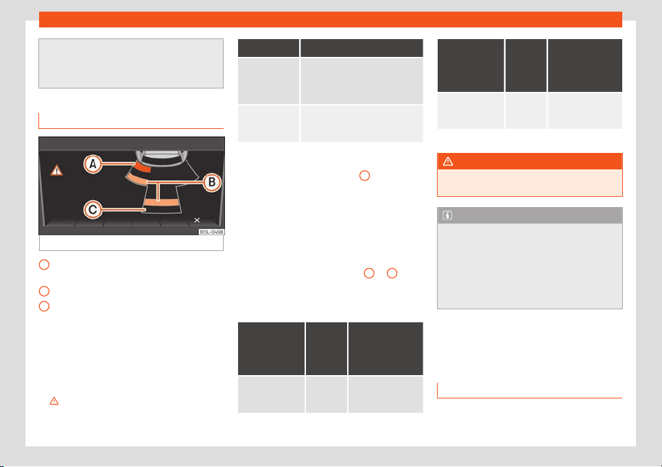
Driving
seconds when switching it on the first time.
Check the parking distance warning sys-
t
em at a Specialised workshop as soon as
possible.
Optical parking system* (OPS)
Fig. 168 On-screen OPS display
An obstacle was detected in the collision
ar
ea
An obst
acl
e was detected in the segment
Zone behind the vehicle registered
The optical parking system is an extension of
the parking distance warning system
›››
page 173.
The radio screen displays the area behind
the vehicle recorded by the sensors. Any ob-
stacles are displayed in relation to the vehicle
›››
.
A
B
C
Function Necessary operations
Switching the
display on:
Switching on the
›››
page 173
parking distance warning system.
The OPS switches on automati-
cally.
Switching the
display off
manually:
Rel
ease reverse gear.
Zones explored
Behind the vehicle
›
››
Fig. 168
C
, the zone
analysed reaches a distance of up t
o 150 cm
and around 60 cm to the sides.
Screen display
The image displayed represents the super-
vised zones in several segments. As the vehi-
cle approaches an obstacle, it approaches
the displayed vehicle segment
A
or
B
. Ulti-
mat
ely, when the second-t
o-l
ast segment is
shown, the collision area has been reached.
Stop the vehicle!
Distance
from the vehi-
cl
e to the ob-
stacle
Audible
warn-
ing
Colour of the
segment if an
obstacle is rec-
ognised
a)
behind:
approx.
31-150
cm
beeping
sound
Yellow
Distance
from the vehi-
cl
e to the ob-
stacle
Audible
warn-
ing
Colour of the
segment if an
obstacle is rec-
ognised
a)
behind:
approx.
0-30 cm
perma-
nent
sound
Red
a)
Displayed in colour on the screen.
WARNING
Do not be distracted from traffic to look at
the screen.
Note
●
SEAT recommends practising using the
parking dist
ance warning system in a traf-
fic-free zone or in a car park to familiarise
yourself with the system and its operation.
●
The display on the radio screen of the
area explored by the sensors may take up
to 5 seconds.
City safety assist (Safety As-
sist)*
Intr
oduction
The City Safety Assist function covers driving
sit
uations at a dist
ance of about 10 metr
es in
174
Driver assistance systems
front of the vehicle, in a speed range of ap-
pr
o
ximat
ely 5-30 km/h (3-19 mph).
When the system detects a possible collision
with a vehicle in front, the vehicle prepares for
a possible emergency braking
›››
.
If the driv
er does not r
eact t
o an imminent
collision, the system can automatically brake
the vehicle in order to reduce speed faced
with a possible collision. The system can help
to reduce the consequences of an accident.
If the City Safety Assist function determines
that the driver has braked insufficiently when
faced with an imminent collision, the system
can increase the brake force in order to re-
duce speed. The system can help to reduce
the consequences of an accident.
WARNING
The smart technology in the City Safety As-
sist system cannot change the limits im-
posed by the laws of physics and by the
syst
em itself. The increased convenience
offered by the City Safety Assist system
should never prompt you to take risks. The
driver always assumes the responsibility of
braking in time.
●
The City Safety Assist function cannot
prevent accidents or serious injury by itself.
●
The City Safety Assist system may carry
out unwanted brake interventions in com-
plex driving situations e.g. when a vehicle
crosses at a short distance.
WARNING
Relying on the City Safety Assist system in
city driving as part of one's driving behav-
iour may cause accidents and serious in-
jury. The syst
em is not a replacement for
driver awareness.
●
Always adapt your speed and the dis-
tance to the vehicles ahead in line with visi-
bility, weather conditions, the condition of
the road and the traffic situation.
●
The City Safety Assist function does not
react to people, animals or vehicles that
cross or move in the opposite direction in
the same lane.
●
If after switching on the City Safety Assist
function the vehicle begins to move, slow
the vehicle with the foot brake.
CAUTION
If you suspect that the City Safety Assist la-
ser sensor is damaged, switch it off
. This
will avoid additional damage.
●
Any reparation of the laser sensor re-
quires specialist knowledge. SEAT recom-
mends taking your car in for technical serv-
ice.
Note
●
If the City Safet
y Assist function activates
a brake, the brake pedal range is reduced.
This makes the brake pedal seem “harder”.
●
Automatic brak
e intervention by the City
Safety Assist function can be cancelled by
pressing the clutch pedal, the accelerator
pedal or by a corrective intervention.
●
During automatic braking by the City
Safety Assist function you may hear unusu-
al noises. This is normal and is produced in
the brake system.
Warning and control lamp
The City Safety Assist function is switched on
e
v
ery time the ignition is s
witched on. No spe-
cial indication is produced.
If the City Safety Assist function is switched
off or on, or if there is an error in the system, it
will be shown by a control lamp on the instru-
ment panel display.
It lights up
The city safety assist function has been switched on
with the button
››
›
Fig. 171.
The control lamp automatically switches off after 5
seconds.
Flashes
Fast: the City Safety Assist system function brakes
automatically or has br
aked automatically.
The control lamp switches off automatically.
»
175
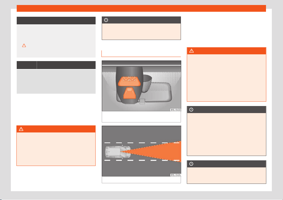
Driving
Flashes
Slow: City Safety Assist function currently not availa-
ble
.
If the vehicle stops, turn the engine off and on again.
If necessary, inspect the laser sensor (dirt, frost)
›››
in Laser sensor on page 176. If it still does not
function, refer to a Specialised workshop to have the
system inspected.
Flashes
Within the 5-30 km/h (3-19 mph) operating range:
the city safet
y assist has been switched off with the
button
›››
Fig. 171.
Switch the city safety assist function on with button
›››
Fig. 171.
Several warning and control lamps should
light up f
or a f
e
w seconds when the ignition is
switched on, signalling that the function is be-
ing verified. They will switch off after a few
seconds.
WARNING
If the warning lamps are ignored, the vehi-
cle may stall in tr
affic, or may cause acci-
dents and severe injuries.
●
Never ignore the warning lamps.
●
Stop the vehicle safely as soon as possi-
ble.
CAUTION
Failure to heed the warning lamps when
they appear may result in faults in the v
ehi-
cle.
Laser sensor
Fig. 169 On the windscreen: laser sensor for
the Cit
y Saf
et
y Assist function.
Fig. 170 Laser sensor detection area.
A laser sensor on the windscreen
›
›
›
Fig. 169
allows the system to detect driving situations
in front of the vehicle.
Vehicles ahead can be detected up to a dis-
tance of about 10 m.
WARNING
The laser beam on the sensor can produce
serious injuries to the eyes.
●
Nev
er focus optical devices, e.g. a cam-
era, a microscope or a magnifying glass
closer than 100 mm from the laser sensor.
●
Note that the laser beam can stay active
when the City Safety Assist system is
switched off or unavailable. The laser
beam is not visible to the human eye.
CAUTION
If the windscreen is dirty or frosted in the
area of the laser sensor
, e.g. due to rain,
mist or snow, the City Safety Assist system
may fail to operate as a result.
●
Always keep the laser sensor area free of
dirt and ice.
●
Use a small brush to remove snow and a
de-icer spray to remove ice.
CAUTION
A damaged windscreen in the laser sensor
area may cause the City Saf
ety Assist
function to stop working.
176
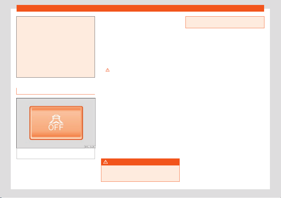
Driver assistance systems
●
Replace the windscr
een if it is scratched,
cracked or chipped by stones in the laser
sensor area. Only use a windscreen author-
ised by SEAT. Carrying out repairs is not
permitted (e.g. in the case of damage suf-
fered in an impact from a stone).
●
When replacing the windscreen wipers,
only use windscreen wipers authorised by
SEAT.
●
Do not paint the laser sensor area on the
windscreen or cover it with adhesives or
other materials.
Function
Fig. 171
In the lower part of the centre console:
butt
on f
or the cit
y safety assist function.
Switching on and off the City Safety Assist
function
●
Press the
›
›
›
Fig. 171 button on the centre
console.
When the City Safety Assist function is
switched on, the control lamp lights up
on the dash panel within the operational
range, i.e. for speeds between 5-30 km/h
(3-19 mph).
Switch off the City Safety Assist function in
the following situations
Switching off the City Safety Assist function is
recommended in the following situations
›››
:
●
While the vehicle is being towed.
●
If the vehicle has been taken to an auto-
matic car w
ash.
●
If the v
ehicl
e is above a test bed.
●
If the laser sensor is faulty.
●
After the laser sensor has been involved in a
collision.
●
When driving off road (overhanging
branches).
●
If objects are protruding above the bonnet,
e.g. a load carried on the roof that significant-
ly protrudes over the front.
●
If the windscreen is damaged in the laser
sensor area.
WARNING
Failure to switch off the City Safety Assist
function in the above sit
uations may result
in accidents and serious injury.
●
Switch off the Cit
y Safety Assist function
in critical situations.
177
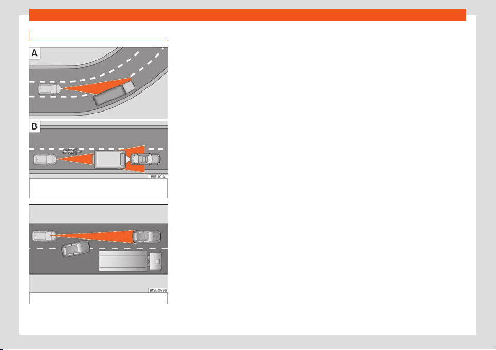
Driving
Special driving situations
Fig. 172
A: Vehicle on a bend. B: Motorcyclist
driving ahead out of r
ange of the l
aser sensor
.
Fig. 173 Other vehicles changing lanes
The City Safety Assist function is limited by
the l
aws of physics and by the nat
ur
e of the
system itself. For this reason, this may pro-
duce reactions from the City Safety Assist
system in certain circumstances that are late
or unexpected by the driver. For this reason,
always pay due attention and if necessary,
intervene.
For example, the following driving situa-
tions require special attention:
Driving through a bend
When entering or leaving a “long” bend, the
vehicle may decelerate when the laser sen-
sor detects a vehicle travelling in the opposite
lane
›››
Fig. 172 A. To interrupt the decelera-
tion, you can step on the gas pedal, turn the
steering wheel or operate the clutch.
Narrow vehicles in front
The laser sensor will only detect narrow vehi-
cles in front if they are in the sensor's detec-
tion zone
›››
Fig. 172 B. This applies particu-
larly to narrow vehicles such as motorcycles.
Other vehicles changing lanes
Vehicles moving into your lane in close prox-
imity can cause unexpected braking from the
City Safety Assist system
›››
Fig. 173. To inter-
rupt deceleration you can accelerate, turn
the steering wheel or press the clutch.
Possible malfunction in the laser sensor
If laser sensor operation is impaired, for ex-
ample due to heavy rain, mist, snow or dirt,
the City Safety Assist system function is tem-
porarily switched off. On the instrument panel
display the control lamp flashes.
When the fault in the laser sensor has been
rectified, the City Safety Assist system func-
tion automatically becomes available again.
The control lamp switches off.
The following conditions could prevent the
City Safety Assist system from functioning:
●
Tight bends.
●
Accelerator pressed all the way down to
the floor.
●
If the City Safety Assist system is switched
off or there is a fault
›››
page 175.
●
If the laser sensor is dirty, covered or over-
heated
›››
page 176.
●
In the event of snow, heavy rain or dense
fog.
●
If there are vehicles in front.
●
Vehicles changing lanes.
●
Vehicles moving in the opposite direction in
the same lane.
●
Very dirty vehicles with a low degree of re-
flection.
●
Presence of thick dust.
178
Towing bracket device
Hill driving assistant*
Oper
ation
This function is only included in vehicles with
ESC.
The hill driving assistant helps the driver t
o
move off and upward on a hill when the vehi-
cle is stationary.
The system maintains brake pressure for ap-
proximately two seconds after the driver
takes his foot off the brake pedal to prevent
the vehicle from lurching backward when it is
started. During these 2 seconds, the driver
has enough time to release the clutch pedal
and accelerate without the vehicle moving
and without having to use the handbrake,
making start-up easier, more comfortable
and safer.
These are the basic operation conditions:
●
being on a ramp or hill/slope,
●
doors closed,
●
vehicle completely stationary,
●
engine running and foot on the brake,
●
besides having a gear engaged or being in
neutral for manual gear change and with the
sel
ector lever at positions S, D or R in vehicles
with an automatic gearbox.
This system is also active when reversing up-
hill.
WARNING
●
If you do not start the v
ehicle immediate-
ly after taking your foot off the brake pedal,
the vehicle may start to roll back under
certain conditions. Depress the brake ped-
al or use the hand brake immediately.
●
If the engine stalls, depress the brake
pedal or use the hand brake immediately.
●
When following a line of traffic uphill, if
you want to prevent the vehicle from rolling
back accidentally when starting off, hold
the brake pedal down for a few seconds
before starting off.
Note
The Official Service or a specialist work-
shop can tell you if your vehicl
e is equip-
ped with this system.
Towing bracket device
Driving with a tr
ail
er
Inf
ormation on driving with a trailer
The vehicle is not certified for trail
er coupling.
The vehicle is not factory-equipped with a
towing bracket, nor is it possible to retrofit it.
WARNING
Installing a towing bracket on the vehicle
may cause accidents and serious injuries
while operating the v
ehicle.
●
Never install a towing bracket on the ve-
hicle.
●
The trailer may be released from the ve-
hicle when the vehicle is moving.
CAUTION
Any type of towing bracket installed on the
vehicle can cause serious and costly dam-
age that ar
e not covered under the SEAT
guarantee.
179
Practical tips
Practical tips
Car
e and maint
enance
Accessories, r
eplacement of
parts and modifications
Introduction
WARNING
The use of spare parts and accessories, or
incorrectly performed modifications or r
e-
pairs may result in damage to the vehicle,
accidents and serious injury.
●
SEAT strongly recommends you to only
use SEAT approved accessories and SEAT
®
original spare parts. These parts and ac-
cessories have been specially tested by
SEAT for suitability, reliability and safety.
●
Have any repairs or modifications carried
out at a specialised workshop. These work-
shops have the necessary tools, diagnos-
tics equipment, repair information and
qualified personnel.
●
Only mount parts with the same specifi-
cations as the parts fitted at factory.
●
Never mount, fasten or fit objects such as
drink holders or telephone cradles over the
covers of the airbag modules or within their
deployment zones.
●
Only use wheels and tyr
e combinations
which have been approved by SEAT for
your vehicle type.
Accessories and spare parts
SEAT recommends you consult an Official
Service before pur
chasing accessories and
spare parts or consumables. For example,
when fitting accessories at a later date, or
when replacing a component. A SEAT Official
Service will advise you as to the legal require-
ments and manufacturer's recommendations
regarding accessories, spare parts and other
components.
SEAT recommend you use only approved
SEAT accessories and genuine SEAT spare
parts
®
. These parts and accessories have
been specially tested by SEAT for suitability,
reliability and safety. In addition, SEAT techni-
cal services will guarantee that assembly is
performed professionally.
Although we continually monitor the market,
SEAT cannot guarantee that products not
approved by SEAT are reliable, safe or suita-
ble for the vehicle. Therefore, SEAT cannot
accept liability, even in those cases author-
ised by an officially recognised technical in-
spection office or other official body.
Any retro-fitted equipment which has a di-
rect effect on vehicle control must be ap-
proved by SEAT for use in your vehicle and
bear the e mark (the European Union's au-
thorisation symbol). This includes cruise con-
trol syst
ems or electronically controlled sus-
pension.
If any additional electrical devices are fit-
ted which do not serve to control the vehicle
itself, these must bear the mark (European
Union manufacturer conformity declaration).
This includes refrigerator boxes, laptops or
ventilator fans.
WARNING
Unprofessional repairs or modifications to
the vehicle may aff
ect the performance of
the airbags, and may cause operating
faults or fatal accidents.
●
Never mount, fasten or fit objects such as
drink holders or telephone cradles over or
next to the covers of the airbag modules or
within their deployment zones.
●
Objects placed over the airbag covers, or
within their deployment zones, could lead
to serious injury or loss of life if the airbags
are triggered.
Service fluids and components
All vehicle fluids and consumables, such as
not
ched belts, t
yr
es, coolant fluids, engine
oils, spark plugs and batteries are continually
being developed. Therefore all fluids and
180
Care and maintenance
consumables should be changed at a speci-
alised w
orkshop
. T
echnical services are per-
manently informed of any modifications.
WARNING
The incorrect use or handling of fluids or
consumables may result in accident, seri-
ous injury, burns or int
oxication.
●
Therefore, fluids must always be stored
closed in their original container.
●
Never store fluids in empty food contain-
ers or bottles as other people may acci-
dentally drink the fluid.
●
Keep all fluids and consumables out of
reach of children.
●
Read and observe the information and
warnings given on the fluid containers.
●
Only work in the open air or in well-venti-
lated zones, when using products which
give off harmful vapours.
●
Never use fuel, turpentine, engine oil,
acetone or any other volatile liquid in the
maintenance of the vehicle. These are toxic
and highly flammable. They could lead to
fire or explosions!
CAUTION
●
Only use appropriate fluids. Do not con-
fuse fluids as this can cause serious mal
-
functions or engine damage.
●
Accessories and other components
mounted in front of the air inlet reduce the
cooling effect of the coolant. If the engine
is running under great strain in high outside
t
emperatures, it could overheat.
For the sake of the environment
Leaking fluids could pollute the environ-
ment. Coll
ect any spilt fluids in suitabl
e
containers and dispose of them in accord-
ance with legislation and with respect for
the environment.
Repairs and technical changes
When performing repairs and technical
modifications, SEAT's dir
ectiv
es must be
observ
ed!
›››
Unauthorised modifications to the electronic
components or softw
ar
e in the v
ehicle may
cause malfunctions. Due to the way the elec-
tronic components are linked together in net-
works, other indirect systems may be affec-
ted by the faults. This may significantly affect
the vehicle's performance, increase compo-
nent wear and could mean that the vehicle
registration documents are no longer valid.
Your SEAT Official Service cannot be held lia-
ble for any damage caused by technical
modifications or repairs performed incorrect-
ly.
The SEAT Official Service does not accept li-
ability for damage resulting from technical
modifications or repairs performed incorrect-
ly; neither is the SEAT warranty valid in these
cases.
SEAT recommends you have any technical
modifications or repairs performed at a SEAT
Official Service and that you use genuine
SEAT spare parts
®
.
Vehicles with special accessories and
equipment
The manufacturers of additional equipment
guarantee that the equipment complies with
applicable laws and regulations with respect
to the environment, in particular Directives
2000/53/CE and 2003/11/CE. The first di-
rective governs the disposal of end-of-life ve-
hicles while the second refers to the restric-
tions on the marketing and use of certain
dangerous substances and preparations.
The vehicle owner should keep the documen-
tation for the additional equipment safely
and hand it over to the scrap yard at the end
of the vehicle's service life. This ensures that
any additional equipment mounted in end-of-
life vehicles is correctly disposed of with re-
spect for the environment.
WARNING
Repairs or modifications which are not per-
formed correctly may r
esult in damage or
errors in the vehicle operation, affecting
the effectiveness of the driver assistance
»
181
Practical tips
systems. This could result in serious acci-
dent.
●
All repairs and modifications to the vehi-
cle should only be perf
ormed by a special-
ised workshop.
Repairs and malfunctions in the
airbag system
When performing repairs and technical
modifications, SEAT's directives must be
observ
ed!
›››
Modifications and repairs to the front bumper,
doors, fr
ont seats, and r
epairs t
o the roof or
chassis should only be carried out in a speci-
alised workshop. These components may
contain parts or sensors belonging to the air-
bag system.
If work is carried out on the airbag system or
parts have to be removed and fitted on the
system when performing other repair work,
parts of the airbag system may be damaged.
The consequence may be that, in the event
of an accident, the airbag inflates incorrectly
or does not inflate at all.
So that the effectiveness of the airbag is not
reduced and that removed parts do not
cause any injuries or environmental pollution,
regulations must be observed. These require-
ments are known to specialised workshops.
Modifications to the vehicle suspension may
affect the operation of the airbag system in
the event of collision. For example, if wheel
and tyre combinations not approved by SEAT
are used, or if the vehicle height is lowered,
the suspension is stiffened or the suspension
springs, telescopic arms, dampers, etc., are
modified, the results received by the airbag
sensors and sent to the control unit may not
be accurate. For example, some modifica-
tions to the suspension could increase the
force measured by the sensors and result in
the triggering of the airbag systems in colli-
sions. Under normal conditions, the measured
values would be lower and the airbag would
not have been triggered. Other modifications
may reduce the forces measured by the sen-
sors and prevent the airbags from being trig-
gered when they should.
WARNING
Repairs or modifications which are not per-
formed correctly may r
esult in damage or
errors in the vehicle operation, affecting
the effectiveness of the airbag systems.
This could result in serious or fatal acci-
dents.
●
All repairs and modifications to the vehi-
cle should only be performed by a special-
ised workshop.
●
Airbag modules must never be repaired:
they have to be replaced.
●
Never fit r
ecycled or reused airbag com-
ponents in your vehicle.
WARNING
Modifications to the vehicle suspension, in-
cluding the use of unauthorised wheel and
t
yre combinations, may aff
ect the perform-
ance of the airbags and increase the risk of
serious or fatal injury in the event of acci-
dent.
●
Never fit suspension components which
are not identical to the original parts in the
vehicle.
●
Never use wheel and tyre combinations
not approved by SEAT.
Retrofitting of mobile phones
An exterior aerial is required for the use of
tw
o-w
ay r
adios in the vehicle.
The retro-fitting of electrical or electronic ap-
pliances in the vehicle is subject to their ap-
proval for use in your vehicle. Under certain
circumstances, this could mean that your ve-
hicle registration documents are no longer
valid.
SEAT has approved your vehicle for use with
two-way radios providing the following con-
ditions are observed:
182

Care and maintenance
●
The e
xt
erior aerial must be mount
ed pro-
fessionally.
●
The maximum transmitting power is 10
watts.
The optimal reach of the equipment is only
achieved with an external aerial.
Check first with a specialised workshop that
understands the technical possibilities of in-
stallation if you wish to use a two-way radio
with a transmitting power of over 10 watts.
SEAT recommends taking your car in for
technical service.
All legal requirements, together with the in-
structions for the use of two-way radios must
be observed.
WARNING
If the two-way radio is not securely fas-
tened in position, it could be sent flying
ar
ound the vehicle in the event of sharp
braking, sudden manoeuvres or accident,
causing injury.
●
While driving, two-way radios must be
securely fastened in position, outside the
airbags deployment zones, or safely stow-
ed away.
WARNING
When using a two-way radio without a con-
nection to an ext
erior aerial, the maximum
permitted levels of electromagnetic radia-
tion may be exceeded. This is also the case
if the aerial has not been correctly instal
-
led.
●
You should only use a two-way radio in-
side the vehicle if it has first been correctly
connected to an exterior aerial.
Using a mobile telephone in a vehi-
cle without connection to an e
xteri-
or aerial
Mobile telephones transmit and receive radio
w
av
es al
so called high-frequency energy,
both when in use and when on stand-by. Sci-
entific studies state that radio waves exceed-
ing certain values may be harmful to the hu-
man body. International committees and au-
thorities have established limits and direc-
tives in order to ensure electromagnetic radi-
ation from mobile phones remains within cer-
tain limits that do not endanger health. Nev-
ertheless, there is no conclusive scientific evi-
dence that wireless telephones are totally
safe.
That is why some experts recommend mod-
erate use of the mobile telephone, and the
appliance of measures to reduce radiation on
the human body.
When a mobile phone not connected to an
exterior aerial is used inside the vehicle, the
electromagnetic radiation may be greater
than if the mobile phone were connected to a
built-in aerial or to another exterior aerial.
If the vehicle is fitted with a suitable hands-
free device that allows the employment of
numerous additional mobile telephone func-
tions with compatible Bluetooth technology
®
,
it will comply with the legislation in many
countries which only permits the use of mo-
bile phones inside vehicles using a hands-
free device.
Mobile telephones must be placed in a suita-
ble telephone support or stored safely in the
vehicle. If a support is used for the telephone,
it must be securely fastened to the base
plate. The mobile will be secure on the instru-
ment panel and always within reach of the
driver only by following these procedures.
Mobile telephone connection with an exter-
nal aerial is carried out subject to the hands-
free device, via the telephone support or by
the Bluetooth
®
connections present in the
mobile telephone and the vehicle.
If the mobile phone is connected to an aerial
incorporated into the vehicle or an exterior
aerial connected to the vehicle, it will help re-
duce the electromagnetic radiation transmit-
ted and the risk to human health. It will also
improve the quality of the connection.
If the phone is used inside the vehicle without
the hands-free system, it will not be securely
fastened and will not be connected to the ex-
terior aerial of the vehicle telephone. Nor will
»
183
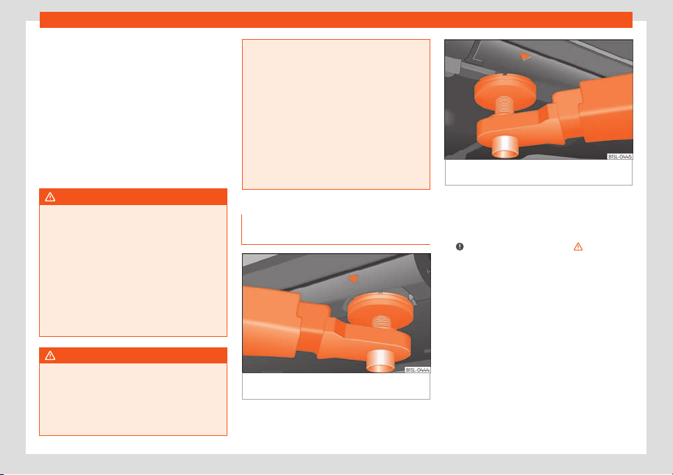
Practical tips
the telephone charge if it is not on the sup-
port. In addition, some call
s may br
eak off
and the qualit
y of the connection will be af-
fected.
Mobile telephones should only be used inside
the vehicle if they are connected to a hands-
free system. SEAT recommends using an ex-
ternal aerial should you wish to use a mobile
telephone inside the vehicle.
Bluetooth
®
is a registered trademark of Blue-
tooth
®
SIG, Inc.
WARNING
If the mobile phone is not securely fastened
in position, it could be sent flying around
the v
ehicle in the event of sharp braking,
sudden manoeuvres or accident, causing
injury.
●
While driving, the mobile telephone, oth-
er equipment including telephone acces-
sories such as telephone supports, note-
pads and navigators must be correctly se-
cured, away from the airbags deployment
zones, or stored in a safe place.
WARNING
When using a mobile telephone or two-way
radio without connecting an ext
ernal aer-
ial, the maximum permitted levels of elec-
tromagnetic radiation in the vehicle may be
exceeded, thus putting the driver and the
rest of the vehicle occupants in danger.
This is also the case if the aerial has not
been correctly install
ed.
●
A minimum of 20 centimetres should be
kept between mobile phone aerials and ar-
tificial pacemakers, as mobile telephones
may affect the working of pacemakers.
●
Do not keep mobile phones in breast
pockets directly above pacemakers.
●
Immediately switch off the mobile tele-
phone if you suspect any interference with
pacemakers or other types of medical
equipment.
Support points for raising the vehi-
cl
e
Fig. 174
Front jacking points for raising vehicle
with lifting pl
atf
orm or jack
Fig. 175 Rear jacking points for raising vehicle
with lifting platform or jack
Always use the jacking points indicated in the
figur
es
›
›
›
Fig. 174 and
›››
Fig. 175 when rais-
ing the vehicle. If the vehicle is not lifted at
these points, it could be seriously damaged
›››
or lead to serious injury
›
›
›
.
The v
ehicl
e shoul
d not be lifted using lifting
platforms with lift pads containing fluid.
When raising a vehicle using a platform or
jack, a series of precautionary measures are
required. Do not raise the vehicle with a lifting
platform or jack unless you have received
training in how to do so and know how to do
so safely.
Notes on raising the vehicle with a jack
›››
page 72.
184
Care and maintenance
WARNING
The improper use of the lifting platform or
the jack when raising the vehicl
e may result
in accidents or serious injury.
●
Before raising the vehicle, please observe
the manufacturer's instructions for the
platform or jack, and the legal require-
ments, where applicable.
●
There should not be anyone inside the
vehicle when it is being raised or once it is
in the air.
●
Only use the jacking points indicated in
the figures
›››
Fig. 174 and
›››
Fig. 175 when
raising the vehicle. If the vehicle is not lifted
at the indicated points, it may fall from the
platform while the engine or gearbox is be-
ing dismounted, for example.
●
The jacking points should be centrally
aligned and firmly positioned on the plat-
form support plates.
●
Never start the engine when the vehicle is
raised! The vehicle may fall from the plat-
form due to the engine vibrations.
●
If it is necessary to work underneath the
vehicle while it is raised, you should check
that the supporting stands have an ade-
quate load capacity.
●
Never climb onto the lifting platform.
●
Always make sure that the weight of the
vehicle does not exceed the lifting platform
load capacity.
CAUTION
●
Never r
aise the vehicle at the engine oil
sump, the gearbox or the rear or front
axles.
●
Always use an intermediate rubber sup-
port to prevent damage to the vehicle un-
derbody. Check that the arms of the lifting
platform are able to move with obstruction.
●
The arms should not come into contact
with the side running boards or other parts
of the vehicle.
185
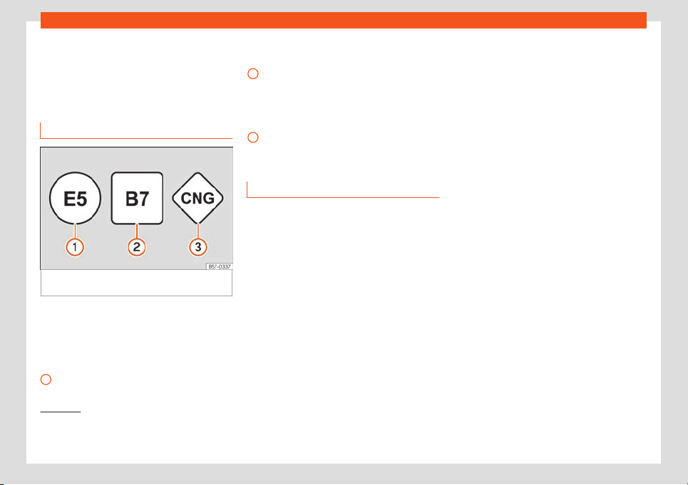
Practical tips
Checking and refilling lev-
el
s
Fuel
Identification of the fuel
1)
Fig. 176 Identification of fuels according to Eu-
r
opean Union (EU) Dir
ectiv
e 2014/94/
Fuels are identified with different symbols.
Depending on the fuel, the diff
er
ent symbol
s
are on the pump and the tank lid of your vehi-
cle. The identification serves to prevent con-
fusion when choosing the fuel.
Petrol with ethanol (“E” stands for Etha-
nol). The number indicates the percent-
1
age of ethanol in the petrol. “E5” means,
f
or e
x
ample, an ethanol ratio of 5% max.
Diesel with biodiesel (“B” stands for Bio-
diesel). The number indicates the per-
centage of biodiesel in the diesel. “B7”
means, for example, a proportion of bio-
diesel of max. 7%.
Natural gas: “CNG” means Compressed
Natural Gas.
Type of petrol
3 Applies to vehicl
es: with petrol engine
The correct grade of petrol is listed inside the
fuel tank flap.
The vehicle is equipped with a catalytic con-
verter and must only be run on unleaded
petrol. The petrol must comply with the
standard EN 228 and be sulphur-free. Fuels
with a 10% ethanol ratio can be refuelled
(E10)
2)
. The types of petrol are differentiated
by using the octane numbers (RON) or via
the anti-knock index (AKI).
The following pieces of text show the infor-
mation included in the corresponding stickers
on the tank lid (examples):
2
3
Super unleaded petrol 95 octane petrol or
normal 91 oct
ane petr
ol at l
east
We recommend refuelling with super 95 oc-
tane petrol (91 AKI). If not available: normal 91
octane petrol (87 AKI) (with a slight power
loss).
Super unleaded petrol, 95 octanes at
least
You should use super 95 octane petrol (91
AKI) at least.
If super is not available, if necessary, use nor-
mal 91 octane petrol (87 AKI). In this case only
use moderate engine speeds and a light
throttle. Refuel with super as soon as possi-
ble.
Unleaded super plus 98 octane petrol or
super 95 octane petrol at least
We recommend refuelling with super plus 98
octane petrol (93 AKI). If not available: super
95 octane petrol (91 AKI) (with a slight power
loss).
If super is not available, if necessary, use nor-
mal 91 octane petrol (87 AKI). In this case only
use moderate engine speeds and a light
1)
Depending on country
2)
Follow the regulations of the country you are
driving in.
186
Checking and refilling levels
throttle. Refuel with super as soon as possi-
bl
e
.
CAUTION
●
Fuels high percent
age of ethanol, e.g.
E30 - E100 button must not be used. The
fuel system would be damaged. Exception:
vehicles with Totalflex engine
›››
page 187,
Ethanol fuel.
●
A single refuelling with leaded fuel or
other metal additives entails a permanent
deterioration of the effectiveness of the
catalytic converter.
●
Only use fuel additives that have been
approved by SEAT. The products that con-
tain substances to increase the octane rat-
ing or decrease knocking may contain met-
al additives that damage the engine and
catalytic converter. This type of products
must not be used.
●
Do not use fuels shown in the pump as
containing metals. LRP (lead replacement
petrol) fuels contain high concentrations of
metal additives. Risk of engine damage!
●
High engine speed and full throttle can
damage the engine when using petrol with
an octane rating lower than the correct
grade for the engine.
Note
●
Fuel with an octane rating higher than the
one r
equired by the engine can be used.
●
In countries in which there is no sulphur-
free fuel, it is also allowed to use low sul-
phur content fuel.
Ethanol fuel
3 Applies to vehicles: with Totalflex engine
You can r
ecognise vehicles with Totalflex en-
gines
1)
by label on the fuel tank lid with with
the marking “Petrol/ethanol”.
Vehicles with Totalflex engine can run with
unleaded petrol (95 octane / 91 AKI) accord-
ing to ANP No. 57 and with fuels with any high
percentage of ethanol. The vehicle is refuel-
led in the same way as petrol refuelling.
Also consider that
›››
page 186, Type of pet-
rol
Note
SEAT recommends filling the tank exclu-
sively with petrol e
very 10,000 km to de-
crease impurities that using E100 ethanol
fuel might have left in the engine.
Natural gas
3 Applies to vehicles: with a natural gas engine
Natur
al gas can be compressed or in liquid
form, addition to others.
Use of compressed natural gas (CNG)
Vehicles with a natural gas engine must only
be working with CNG (Compressed Natural
Gas CNG ), or with a mixture of biomethane
if it complies with Regulation EN 16723-2.
Do not use fuels such as liquefied natural gas
(Liquefied Natural Gas), liquified petroleum
gas (LPG = Liquefied Petroleum G) or hy-
thane (hydrogen mixed with methane)
›››
.
Ther
ef
or
e, vehicles with a natural gas engine
must only be refuelled using compressed
natural gas (CNG).
Natural gas quality and consumption
Natural gas is divided into the groups H and L
depending on its quality.
Gas type H has a superior heating power and
inferior nitrogen and carbon dioxide content
than type L. The higher the heating power of
the natural gas, the lower the consumption
will be.
»
1)
This motor is only available in some markets.
187
Practical tips
However, the heating power and the propor-
tion of nitr
ogen and carbon dio
xide can fluc-
t
uate within the quality groups. Therefore, ve-
hicle consumption can also vary when using
a single type of gas only.
The engine management automatically
adapts to the natural gas used according to
its quality. Therefore, different quality gases
can be mixed in the tank, without the need for
comprehensive draining before applying a
different quality gas.
Natural gas and safety
If you can smell gas or suspect that there is a
leak
›››
:
●
Stop the vehicle immediately.
●
Switch the ignition off.
●
Open the doors to appropriately ventilate
the v
ehicl
e
.
●
Extinguish cigarettes immediately.
●
Move away from the vehicle or switch off
objects that may cause sparks or a fire.
●
If you continue to smell gas, do not contin-
ue driving!
●
Seek specialist assistance. Have the fault
repaired.
Regular checks of the natural gas system
The natural gas tanks may be damaged or
corroded by external factors. The walls of the
gas tanks are weakened by deformations,
damage or corrosion. As a result, the tanks
could burst and result in serious injuries or
even death. For this reason, the vehicle owner
must have a specialised workshop check (vis-
ual check) the gas system every 4 years at
least. The vehicle owner must have a speci-
alised workshop replace the natural gas
tanks before they reach the end of their serv-
ice life. For further information about the serv-
ice life of gas tanks, go to a SEAT dealer serv-
ice or a specialised workshop
WARNING
Failure to act when you can smell gas in the
vehicle or when r
efuelling can cause seri-
ous injuries.
●
Carry out the necessary operations.
●
Leave the danger zone.
●
If necessary, warn the emergency serv-
ices.
WARNING
The vehicle is not suitable for liquefied nat-
ural gas (LNG) or liquefied petrol gas (LPG),
so LNG or LPG shoul
d not be used under
any circumstances. Liquid gas can cause
an explosion of the natural gas tanks and
cause severe injuries!
WARNING
Damaged, corroded or rusted tanks can re-
sult in serious injury or even death.
●
Hav
e the natural gas deposits checked at
least every 4 years (visual check).
●
Natural gas tanks have a limited service
life. Have the natural gas tanks replaced
when required. You can obtain further infor-
mation about this at SEAT dealers or speci-
alised workshops.
WARNING
If the vehicle underbody touches the
ground or in the ev
ent of a rear collision,
there could be damage to the natural gas
tanks.
●
Check whether there is a smell of gas.
●
If you notice a smell of gas, take the vehi-
cle to a specialised workshop immediately
and have the natural gas system checked.
Note
Have the natural gas system checked regu-
larly by a specialised workshop
, according
to the Maintenance Programme.
188
Checking and refilling levels
Filling the tank
Intr
oduction
The fuel tank flap is on the rear right of the
vehicle
.
WARNING
Refuelling or handling fuel carelessly can
cause an explosion or fir
e resulting in seri-
ous burns and injuries.
●
Always make sure that you correctly
close the fuel cap to avoid evaporation and
fuel spillage.
●
Fuels are highly explosive and inflamma-
ble substances that can cause serious
burns and injuries.
●
Fuel could leak out or be spilt if the en-
gine is not switched off or if the filler fuel
nozzle is not fully inserted into the tank fill-
er neck when refuelling. This could lead to
a fire, explosion and severe injuries.
●
When refuelling, turn off the engine and
turn off the ignition for safety reasons.
●
Always turn off mobile telephones, radio
apparatus and other radio wave emitting
equipment before refuelling. Electromag-
netic waves could cause sparks and lead
to a fire.
●
Never enter the vehicle while refuelling. If
it is absolutely necessary to enter, close
the door and touch a metal surface before
touching the filler nozzle again. This will
prevent the generation of static electricity.
Sparks could cause a fire when r
efuelling.
●
Never handle fuel close to flames, sparks
or objects with slow combustion (e.g. ciga-
rettes).
●
Avoid static electricity and electro-mag-
netic radiation when refuelling.
●
Observe the safety regulations of the
service station.
●
Never spill fuel on the vehicle or in the
luggage compartment.
WARNING
For safety reasons, SEAT does not recom-
mend carrying a spare fuel canister in the
v
ehicle. Fuel could be spilled and catch
fire, above all in case of an accident and
this applies to a full container as well as
empty containers. This could lead to explo-
sions, fires and injuries.
●
Observe the following if you exceptional-
ly have to carry fuel in a canister:
–
Never place a fuel container, to fill it, in-
side the vehicle or on the vehicle, for
example, in the luggage compartment.
Filling in these circumstances could
create an electrostatic charge and
spark that could ignite fuel fumes.
–
Always place the canister on the
ground to fill it.
–
Insert the fuel nozzle into the neck of
the canister as far as possible.
–
If you are using a metal fuel canist
er,
the nozzle must always touch the can-
ister while it is being filled to avoid stat-
ic electricity.
–
Follow the legal requirements for the
use, storage and transport of spare fuel
canisters.
–
Insure that the fuel container complies
with manufacturing standards, for ex-
ample, ANSI or ASTM F852-86.
CAUTION
●
Al
ways r
emove any fuel spilled anywhere
on the vehicle to avoid damage to the
wheel housing, the tyre and vehicle paint-
work.
●
Refuelling a petrol engine with diesel can
cause serious engine and fuel system dam-
age; the resulting malfunctions are not
covered by the SEAT warranty. If you refuel
with the wrong type of fuel, never start the
engine. This applies to even the smallest
amount of the wrong fuel. Seek specialist
assistance. With the engine running, the
composition of the wrong fuel could signifi-
cantly damage the fuel system and the en-
gine itself.
For the sake of the environment
Fuels can contaminate the environment.
Collect any spilt service fluids and allo
w a
professional to dispose of them.
189
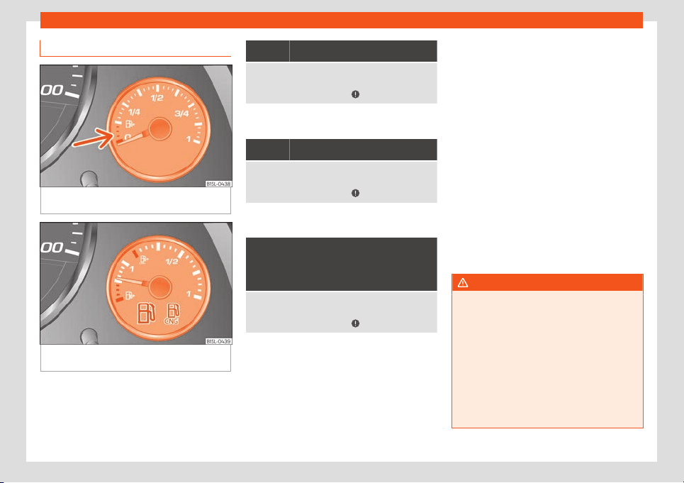
Practical tips
Control lamps and fuel gauge
Fig. 177
On the instrument panel: Fuel gauge
f
or petr
ol
.
Fig. 178 On the instrument panel: Fuel gauge
f
or petr
ol
.
The fuel gauge can vary depending on the
v
ehicl
e equipment
›
››
Fig. 177 or
›››
Fig. 178.
a)
It lights up
The fuel tank is almost empty. The reserve tank is be-
ing used (red mark
››
›
Fig. 177)
›››
page 32.
Refuel as soon as possible
›››
.
a)
This only applies to vehicles with the fuel gauge on
the dash panel
›››
Fig. 177.
a)
It lights up
The natural gas tank is almost empty. The reserve
tank is being used (red mark
›
››
Fig. 178)
›››
page 32.
Refuel as soon as possible
›››
.
a)
This only applies to vehicles with the fuel gauge on
the dash panel
›
›
›
Fig. 177.
and the seg-
ments r
emain-
ing
a)
Fl
ashes f
or about 10 sec-
onds
The fuel tank is almost empty. The reserve tank is be-
ing used
›
››
page 32.
Refuel as soon as possible
›››
.
a)
This only applies to vehicles with the fuel gauge on
the dash panel displ
ay.
Se
v
eral warning and control lamps light up
for a few seconds when the ignition is switch-
ed on, signalling that the function is being
verified. They will switch off after a few sec-
onds.
In natural gas engines
During driving, the fuel gauge needle is in the
fuel area with which the car is currently driv-
ing. Whenever the ignition is switched on, the
needle changes first for a few seconds to the
petrol area in order to display the current lev-
el of fuel. The needle then moves to the natu-
ral gas area. After the engine is started, the
needle changes to the area corresponding to
the current operating mode.
Remark: if the vehicle is left parked for a long
time just after refuelling, the gas level indica-
tor does not accurately indicate the same
level shown after refuelling when the vehicle
is started up again. This is not due to a leak in
the system, but to a drop in pressure in the
gas tank for technical reasons after a cooling
phase immediately after refuelling.
WARNING
Driving with insufficient fuel reserve could
result in the vehicl
e breaking down in traffic
and a serious accident.
●
If the fuel level is too low then the fuel
supply to the engine can become irregular
especially on slopes.
●
If the engine “is choked” or stalls due to
lack of or irregularity of the fuel supply, the
power steering as well as all of the driver
assistance systems including brake assis-
tance will stop working.
190
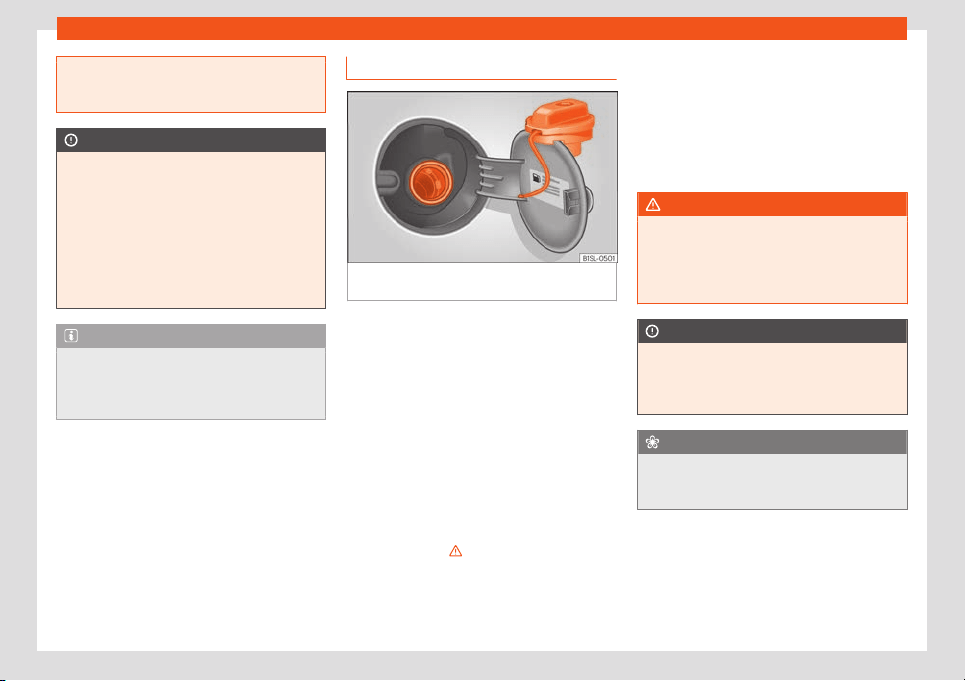
Checking and refilling levels
●
Always r
efuel when there is only one
quarter of the fuel tank left to avoid running
out of fuel.
CAUTION
●
Al
ways pay att
ention to any lit control
lamps and to the corresponding descrip-
tions and instructions to avoid damage to
the vehicle.
●
Never run the fuel tank completely dry.
An irregular fuel supply may lead to ignition
faults and unburnt fuel could enter the ex-
haust system. This could damage the cata-
lytic converter.
Note
The arrow next to the fuel pump symbol on
the instrument panel
›››
Fig. 177 indicates
the side of the vehicle on which the fuel
tank flap is located.
Refuelling with petrol
Fig. 179
Open fuel tank flap with tank cap in
the hol
der
Read the additional information carefully
›
›
›
page 32
Before refuelling, always turn off the engine,
the ignition, mobile telephones, auxiliary
heating and keep them off during refuelling.
Refuelling
The correct petrol type for the vehicle is loca-
ted on a sticker inside the fuel tank flap
›››
page 186.
●
If the automatic filler nozzle is operated
correctly, it will switch itself off as soon as the
fuel tank is full
›››
.
●
Do not continue to refuel if it is turned off!
Otherwise
, this will fill the e
xpansion chamber
and fuel may l
eak out if the ambient condi-
tions are warm.
Vehicles with a natural gas engine
Every 6 months it is necessary to run on pet-
rol until the control lamp switches off and
then the tank must be refilled. This is neces-
sary to ensure the efficient operation of the
system and the fuel quality required for run-
ning on gas.
WARNING
Do not continue refilling once the fuel noz-
zle has swit
ched itself off. The fuel tank
may be filled too much. As a result, fuel
may spurt out and spill. This could lead to a
fire, explosion and severe injuries.
CAUTION
●
Always r
emove any fuel spilled anywhere
on the vehicle to avoid damage to the
wheel housing, the tyre and vehicle paint-
work.
For the sake of the environment
Fuels can contaminate the environment.
Collect any spilt service fluids and allo
w a
professional to dispose of them.
191
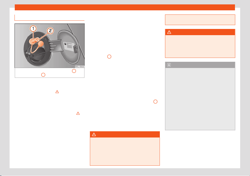
Practical tips
Refuelling with natural gas
Fig. 180
Open tank lid: gas filler mouth
1
, fill-
er mouth r
et
ainer
2
Before r
efuelling, the engine and the ignition,
mobil
e t
elephone and heating must be
switched off separately
›››
.
It is al
so essential t
o car
efully read the in-
structions for the natural gas pump.
The vehicle is equipped for refuelling only
with Compressed Natural Gas (CNG)
›››
.
R
efuelling with another t
ype of nat
ural gas is
not allowed, e.g. Liquefied Natural Gas (LNG)
or hydromethane.
Opening the fuel tank cap
The natural gas filler mouth is behind the fuel
tank cap, next to the petrol filler mouth.
●
Unlock the vehicle with the key or with the
central locking button situated on the driver
door
›››
page 97.
●
Press on the rear area of the flap and open
it.
Refuelling
Remark: If the ambient temperature is very
high, the natural gas pump protection against
overheating disconnects this automatically.
●
Remove the plug from the gas filler mouth
›››
Fig. 180
1
.
●
Connect the pump filling nozzle to the gas
fill
er mouth.
●
The fuel t
ank will be
full when the pump
compressor automatically cuts the supply.
●
If you wish to finish refuelling in advance,
press the button on the pump to stop the flow.
Closing the fuel tank cap
●
Check that the gas filler mouth retainer
2
is not trapped with the filler nozzle. If neces-
sary, pl
ace it in the fill
er mouth again.
●
Insert the plug in the fill
er mouth.
●
Close the tank flap. Make sure you hear it
click into place.
WARNING
Natural gas is a highly explosive, easily
flammable subst
ance. Incorrect handling
of the natural gas can cause accidents se-
rious burns and other injuries.
●
Before refuelling with natural gas, the fill-
ing mouth must be correctly engaged. If
you can smell gas, stop refuelling immedi-
ately.
WARNING
The vehicle is not prepared to use liquefied
nat
ural gas (LNG) and this fuel must not be
added under any cir
cumstances. Liquefied
natural gas can cause the natural gas tank
to explode, resulting in serious injury.
Note
●
The filling nozzles of nat
ural gas pumps
can differ in the way they are operated. If
you are unacquainted with the pump, it is
advisable that a member of staff of the
service station performs the refuelling op-
eration.
●
Noises heard when refuelling are normal
and do not indicate the presence of a fault
in the system.
●
The vehicle natural gas system is pre-
pared both for refuelling with a small com-
pressor (slow refuel) and a large compres-
sor (fast refuel) in natural gas service sta-
tions.
192
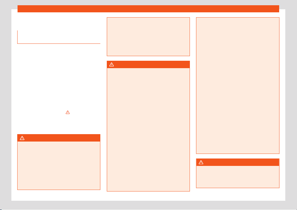
Checking and refilling levels
Bonnet
W
orking in the engine compar
t
-
ment
Read the additional information carefully
›››
page 12
Before working in the engine compartment,
make sure that the vehicle is parked on hori-
zontal and firm ground.
The engine compartment of the vehicle is a
hazardous area. Never work on the engine or
in the engine compartment if you are not fa-
miliar with the operations to be carried out,
the applicable safety standards and espe-
cially if you do not have the necessary instru-
ments, liquids and tools
›››
! If required,
hav
e any w
ork carried out by a specialised
w
orkshop. Negligent work can cause serious
injury.
WARNING
If the vehicle moves unexpectedly, this
could cause serious injury.
●
Nev
er work under the vehicle if it has not
been immobilized. If you must work under-
neath the vehicle with the wheels in con-
tact with the ground then it should be
parked on flat ground, the wheels should
be prevented from moving and the key
should be removed from the ignition.
●
If you have to w
ork underneath the vehi-
cle, you must use suitable stands addition-
ally to support the vehicle, there is a risk of
accident!. The jack is not intended for this
kind of work and its failure could lead to se-
vere injuries.
●
Disconnect the Start-Stop system.
WARNING
The engine compartment is a dangerous
ar
ea capable of causing serious injury.
●
F
or all type of work, always take the ut-
most precautions, work carefully and note
the general safety standards in force. Nev-
er take personal risks.
●
Never work on the engine or in the engine
compartment if you are not familiar with
the necessary operations. If you are not
sure about procedures then visit a special-
ised workshop to carry out the necessary
work. Working incorrectly can cause seri-
ous injuries.
●
Never open the bonnet if you see steam
or coolant escaping from the engine com-
partment. This may cause serious burns. Al-
ways wait until you cannot see or hear the
sound of steam or coolant coming from the
engine compartment.
●
Always allow the engine to cool down be-
fore opening the bonnet.
●
Contact with hot elements of the engine
and the exhaust system can cause burns.
●
Once the engine has cooled, foll
ow the
instructions below before opening the bon-
net:
–
Engage the handbrake and place the
gear selector lever in N or the gear
stick in neutral.
–
Remove the key from the ignition.
–
Keep children away from the engine
compartment and never leave them
unsupervised.
●
When the engine is warm or hot, the cool-
ing system is pressurised. Do not unscrew
the cap on the expansion tank when the en-
gine is hot. Otherwise, coolant may spray
out under pressure causing burns and seri-
ous injury.
–
After cooling, carefully and slowly un-
screw the cap anticlockwise, gently
pressing down on it.
–
Always protect your face, hands and
arms from hot coolant and steam using
a large, thick cloth.
●
When refilling liquids, avoid spilling them
on parts of the engine and the exhaust sys-
tem. Spilled liquids could cause a fire.
WARNING
The high voltages of the electrical system
can give electric shocks as w
ell as causing
burns and serious injury and possibly even
death!
»
193
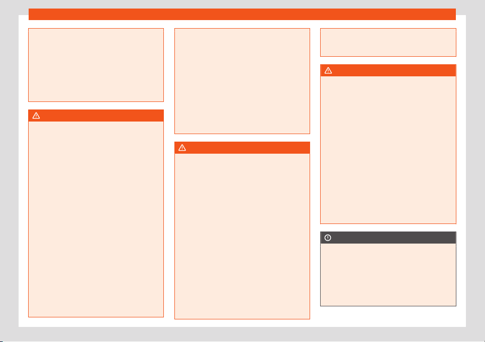
Practical tips
●
Never cause shor
t circuits in the electri-
cal system. The battery could explode.
●
To minimise the risk of electric shock and
serious consequences while the engine is
running or starting the engine, note the fol-
lowing:
–
Never touch the electrical wiring of the
ignition system.
WARNING
In the engine compartment, there are rotat-
ing par
ts that could cause serious injury.
●
Ne
ver place your hands directly on or
near the radiator fan. Touching the rotor
blades could seriously harm you. The venti-
lator works according to the engine tem-
perature and could start suddenly even
when the ignition is turned off and the key is
removed.
●
If any work has to be performed when the
engine is started or with the engine running,
there is an additional, potentially fatal,
safety risk from rotating parts, such as the
drive belts, alternator, radiator fan, etc., as
well as from the high-voltage ignition sys-
tem. Always work with the utmost caution.
–
Always make sure that no parts of your
body, jewellery, ties, loose clothing and
long hair can be trapped by the rotat-
ing parts of the engine. Before any
work, remove ties and jewellery (neck-
laces, etc), tie long hair back and tie all
items of loose clothing to your body to
make sure that they cannot be trapped
by engine components.
–
Take e
xtreme caution when operating
the accelerator and remain attentive.
The vehicle could move, even if the
handbrake is applied.
●
Always make sure you have not left any
objects, such as cleaning cloths and tools,
in the engine compartment. If any object is
left in the engine compartment, this could
cause malfunctions, engine faults and even
a fire.
WARNING
Refill liquids and certain materials can
catch fire easily in the engine compar
t-
ment, causing a fire and serious injury!
●
Never smoke.
●
Never work close to places exposed to
flames or sparks.
●
Never pour service fluids over the engine.
These fluid may ignite hot engine parts and
cause injuries.
●
If it is necessary to work on the fuel sys-
tem or the electrical system, please follow
the instructions below:
–
Always disconnect the vehicle battery.
–
Never work close to heaters, heat sour-
ces or places exposed to flames or
sparks.
●
Always keep a recently serviced and per-
fectly working fire extinguisher close by.
●
Never co
ver the engine with additional in-
sulating materials such as a blanket. Risk of
fire!
WARNING
If the bonnet is not correctly closed, it
coul
d suddenly open while driving l
eaving
the driver without visibility. This could re-
sult in a serious accident.
●
After closing the bonnet, always check
that it is properly secured by the locking
mechanism in the lock carrier piece. The
bonnet must be flush with the surrounding
body panels.
●
While driving, if you notice that the bon-
net is not correctly closed then stop imme-
diately and close it correctly.
●
Make sure the bonnet is opened and
closed safely (when the engine is off, no
smoke is coming from the engine compart-
ment, there is enough space around the
car, no people are near, etc.).
CAUTION
●
When refilling or changing service liq-
uids, ensure that you put the liquids int
o the
right tank. Making a mistake when refilling
could cause serious malfunctions and
damage the engine!
●
To avoid damage to the bonnet and to the
windscreen wiper arms, only open it when
194
Checking and refilling levels
the windscreen wipers are in place against
the windscreen.
●
Befor
e driving, always lower the wiper
arms.
For the sake of the environment
Service fluids leaks are harmful to the envi-
r
onment. For this r
eason you should make
regular checks on the ground underneath
your vehicle. Take the vehicle to a special-
ised workshop to be checked if you see
stains, oil or other fluids on the ground.
Collect any spilt service fluids and allow a
professional to dispose of them.
Engine oil
Intr
oduction
WARNING
Incorrectly handling engine oil can cause
injury and serious burns.
●
Always protect your eyes when handling
engine oil.
●
Oil is toxic and must be kept out of the
reach of childr
en.
●
Engine oil should only be kept in its origi-
nal packaging; the same goes for used oil
until it is disposed of.
●
Never st
ore engine oil in empty food con-
tainers or bottles as other people may ac-
cidentally drink it.
●
Regular contact with engine oil can be
bad for the skin. If you come into contact
with engine oil, wash your skin with soap
and water.
●
With the engine running, the engine oil
gets extremely hot and can cause severe
skin burns. Always wait until the engine has
fully cooled.
For the sake of the environment
Similar to the other service liquids, spilled
engine oil can be bad for the environment.
Coll
ect these liquids in suitable containers
and dispose of them while respecting the
environment.
Control and warning lamps
Flashes
Engine oil pressure too low.
Stop the vehicl
e! Switch off the engine. Check
the engine oil level, and if necessary, refill with en-
gine oil
›››
page 196.
- If the warning indicator flashes although the oil lev-
el is correct, do not continue driving or leave the en-
gine running. Otherwise, the engine could be dam-
aged. Seek specialist assistance.
WARNING
Observe the safety warnings
›››
in Con-
trol and warning l
amps on page 27.
Engine oil specifications
Read the additional information carefully
›››
page 32
Replacement engine oil must strictly comply
with the specifications.
The correct oil must be used to ensure the
correct operation and long service life of the
engine. The engine comes with a high-quality
multigrade oil that can generally be used all
year round.
Only use an engine oil that complies to SEAT
standards whenever possible
›››
. Only refill
engine oil using appr
o
v
ed engine oil in ac-
cordance with the corresponding VW stand-
ard (
›››
page 33). All oils indicated are
synthetic multigrade oils.
Engine oils are being continuously further de-
veloped. Technical services are constantly
updated with any modifications. SEAT there-
fore recommends that you have the engine
oil changed by a technical service.
CAUTION
●
Only use engine oils whose specifica-
tions are e
xpressly approved by SEAT. The
»
195
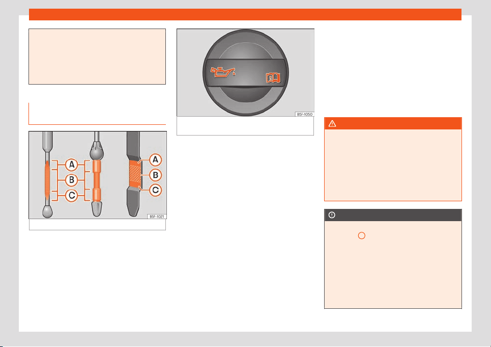
Practical tips
use of any other type of oil could cause en-
gine damage!
●
No additives should be used with engine
oil. Any damage caused by the use of such
additives woul
d not be covered by the fac-
tory warranty.
Checking engine oil level and top-
ping up
Fig. 181
Marked engine oil dipstick
Fig. 182 In the engine compartment: engine oil
filler cap.
Read the additional information carefully
›
›
›
page 32
Preparations
●
Park the vehicle on flat ground so that the
engine oil reading is correct.
●
The engine must be hot to be able to check
the engine oil level. Stop the engine and wait
a few minutes for the oil to drain back into the
sump.
●
Open the bonnet
›››
page 193.
●
The engine oil filler neck can be recognised
by the symbol on the cap
›››
Fig. 182 and
the dipstick by its coloured handle.
Check the engine oil level
●
Pull out the dipstick and wipe it on a clean
cloth.
●
Replace the dipstick, pushing it in as far as
it will go. If the dipstick to measure engine oil
has a mark, when you reintroduce it this mark
should slot into the corresponding groove lo-
cated on the upper end of the tube.
●
Remove the oil dipstick again and check
the engine oil level.
●
After reading the oil level, replace the dip-
stick in the tube completely.
WARNING
Oil could catch fire if it comes into contact
with hot engine components. This could
lead t
o a fire, explosion and severe injuries.
●
Always ensure that after topping of oil,
the engine oil filler cap is correctly tight-
ened. This will avoid engine oil spilling onto
hot engine parts when the engine is run-
ning.
CAUTION
●
If the engine oil lev
el is above the area
›››
Fig. 181
A
do not start the engine. Re-
quest help from specialised staff
. Other-
wise catalytic converter and engine dam-
age may occur.
●
When refilling or changing service liq-
uids, ensure that you put the liquids into the
right tank. Making a mistake when refilling
could cause serious malfunctions and
damage the engine!
196
Checking and refilling levels
For the sake of the environment
The oil level must never be above zone
A
.
Otherwise oil can be drawn in through the
cr
ankcase breather and leak into the at-
mosphere via the exhaust system.
Engine oil consumption
The consumption of engine oil can be differ-
ent from one engine to another and can v
ary
during the useful life of the engine.
Depending on how you drive and the condi-
tions in which the vehicle is used, oil con-
sumption can be up to 1 ltr./2000 km. In the
case of new vehicles, the consumption can
exceed this figure over 5,000 kilometres. For
this reason the engine oil level must be
checked at regular intervals, preferably when
filling the tank and before a journey.
When the engine is working hard, for instance
during sustained high-speed motorway cruis-
ing in summer or when climbing mountain
passes, the oil level should preferably be kept
within area
›››
Fig. 181
A
.
Topping up engine oil
Read the additional information carefully
›
›
›
page 32.
The engine oil must be changed regularly ac-
cording to the specifications of the Mainte-
nance Programme.
Due to the problems linked with disposing of
used oil and the need for suitable tools and
special knowledge, always visit a specialised
workshop to have the engine oil and filter
changed. SEAT recommends taking your car
in for technical service.
Detailed information on the service intervals
is shown in the Maintenance Programme.
Engine oil additives make new oil darker after
the engine has been running for a short peri-
od. This is normal and does not mean more
frequent oil changes are required.
WARNING
Only change the engine oil yourself if you
have the specialist knowl
edge required!
●
Before opening the bonnet, read and ob-
serve the warnings
›››
page 193.
●
Wait for the engine to cool down. Hot oil
may cause burn injuries.
●
Wear eye protection to avoid injuries,
such as acid burns, caused by splashes of
oil.
●
When removing the oil drain plug with
your fingers, keep your arm horizontal to
help prevent oil from running down your
arm.
●
Wash your skin thoroughly if it comes int
o
contact with engine oil.
●
Engine oil is poisonous! Used oil must be
stored in a safe place out of the reach of
children.
CAUTION
No additives should be used with engine oil.
This coul
d result in engine damage
. Any
damage caused by the use of such addi-
tives would not be covered by the factory
warranty.
For the sake of the environment
Before changing the engine oil, find a suita-
ble location or service f
or proper disposal.
For the sake of the environment
Always dispose of engine oil with the ut-
most respect for the envir
onment. Never
dispose of used engine oil in places such as
a garden, woods, drains, roads, paths, riv-
ers and drainage systems.
197
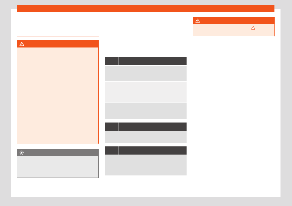
Practical tips
Engine coolant
Intr
oduction
WARNING
Engine coolant is toxic!
●
Only keep engine coolant in its original
container, tightly shut and in a saf
e place.
●
Never store engine coolant in empty food
containers or bottles as other people may
accidentally drink it.
●
Always keep engine coolant out of reach
of children.
●
Ensure that the proportion of engine
coolant additive corresponds to the lowest
outside temperature to which the vehicle
will be exposed.
●
If the outside temperature is extremely
low, the engine coolant could freeze caus-
ing the vehicle to stop. As this would also
cause the heating to stop working, vehicle
occupants without warm clothing could
freeze.
For the sake of the environment
Coolants and additives can contaminate
the environment. If any fluids are spill
ed,
they should be collected and correctly dis-
posed of, with respect to the environment.
Coolant warning lamp
Several warning and control lamps light up
for a fe
w seconds when the ignition is switch-
ed on, signalling that the function is being
verified. They will switch off after a few sec-
onds.
It lights up red
Excessive engine coolant temperature.
Stop the vehicle! Stop the vehicle safely as soon
as possible. Switch off the engine and let it cool.
Insufficient engine coolant level.
Stop the vehicl
e! Check the engine coolant
when the engine has cooled and, if it is low, refill with
engine coolant
›››
page 199.
Engine coolant system faulty.
Do not continue driving. Seek specialist assis-
tance.
Flashes red
Faulty engine coolant system.
Request help from specialised st
aff.
It lights up blue
The natural gas engine coolant temperature is low.
The engine has not reached service temper
ature.
As long as the warning lamp is on, avoid high engine
speeds and pushing the engine too hard.
WARNING
Observe the safety warnings
›››
in Con-
trol and warning l
amps on page 27.
198
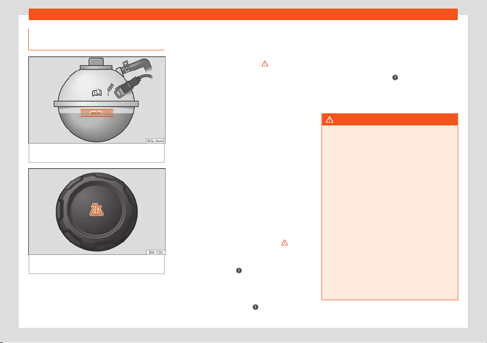
Checking and refilling levels
Checking the coolant level and
t
opping up
Fig. 183
In the engine compartment: Marking
on cool
ant e
xpansion t
ank
Fig. 184
In the engine compartment: Coolant
e
xpansion t
ank cap
Read the additional information carefully
›
›
›
page 33
If the coolant level is low, the coolant warning
indicator will light.
Preparations
●
Park the vehicle on even, flat and firm
ground.
●
Allow the engine to cool
›››
.
●
Open the bonnet
›
›
›
page 193.
●
The coolant expansion tank is easily recog-
nisable because of the symbol on the cap
›››
Fig. 184.
Checking the engine coolant level
●
When the engine is cold, check the coolant
level using the side marking on the expansion
tank
›››
Fig. 183.
●
If the level is below the “MIN” mark, top up
with coolant. When the engine is hot it may
be slightly above the marked area.
Topping up the engine coolant level
●
Always protect your face, hands and arms
from hot coolant and steam using a large,
thick cloth over the coolant expansion tank
cap.
●
Remove the cap very carefully
›››
.
●
Only refill using ne
w
engine cool
ant ac-
cording to SEAT specifications
(
›››
page 33)
›››
.
●
The engine coolant level should be be-
tw
een the marks on the cool
ant e
xpansion
tank
›››
Fig. 183. Do not exceed the top lev-
el of the marked area
›››
.
●
Scr
e
w on the cap tightly.
●
If
, in the event of an emergency, you have
no coolant that is compliant to the required
specifications (
›››
page 33), do not use
another type of additive. Instead, top up with
distilled water only
›››
. Then re-establish
the corr
ect pr
oportion of the mixt
ure with the
correct additive as soon as possible
›››
page 33.
WARNING
Hot vapours and coolant can cause serious
burns.
●
Never open the coolant expansion tank if
steam or coolant is coming fr
om the engine
compartment. Wait until you cannot see or
hear any steam or coolant escaping.
●
Always wait until the engine has com-
pletely cooled before very carefully open-
ing the expansion tank cap. Contact with
hot elements of the engine can cause skin
burns.
●
When the engine is warm or hot, the cool-
ing system is pressurised. Do not unscrew
the cap on the expansion tank when the en-
gine is hot. Otherwise, coolant may spray
out under pressure causing burns and seri-
ous injury.
–
Carefully and slowly unscrew the cap
anti-clockwise, gently pressing down
on it.
»
199
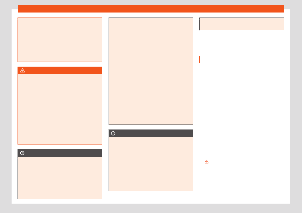
Practical tips
–
Always pr
otect your face, hands and
arms from hot coolant and steam using
a large, thick cloth.
●
When refilling liquids, avoid spilling them
on parts of the engine and the exhaust sys-
tem. Spilled liquids could cause a fire. Un-
der specific circumstances, the ethylene
glycol can catch fire.
WARNING
If there is not enough anti-freeze in the
cool
ant system, the engine may f
ail lead-
ing to serious damage.
●
Please make sure that the percentage of
additive is correct with respect to the low-
est expected ambient temperature in the
zone in which the vehicle is to be used.
●
When the outside temperature is very
low, the coolant could freeze and the vehi-
cle would be immobilised. In this case, the
heating would not work either and inade-
quately dressed passengers could die of
cold.
CAUTION
●
If there is no appropriat
e coolant liquid
available, fill it using distilled water, and
nothing else. Any other type of water may
lead to considerable rusting in the engine
due to its chemical components. This could
consequently damage the engine. If you
have not used distilled water but another
type of water to top up the coolant, a spe-
cialised workshop must immediately re-
place all of the fluid in the engine cooling
system.
●
Only t
op up coolant to the top level of the
marked area
›››
Fig. 183. Otherwise the ex-
cess coolant will be forced out of the cool-
ing system when the engine is hot, causing
damage.
●
If a lot of liquid coolant has been lost,
wait for the engine to cool down complete-
ly before adding coolant. Extensive coolant
loss is an indication of leaks in the engine
cooling system. Have the engine cooling
system inspected immediately by a speci-
alised workshop. Otherwise engine dam-
age may occur.
●
When refilling service liquids, ensure that
you put the liquids into the right tank. Mak-
ing a mistake when refilling could cause se-
rious malfunctions and damage the engine!
CAUTION
The original additives should never be
mixed with coolants which ar
e not ap-
proved by SEAT. Otherwise, you run the risk
of causing severe damage to the engine
and the engine cooling system.
●
If the fluid in the expansion tank is not
purple but is, for example, brown, this indi-
cates that the G13 additive has been mixed
with an inadequate coolant. The coolant
must be changed as soon as possible if this
is the case! This could result in serious
faults and engine damage.
Brake fluid
Checking the brake fluid l
evel
Read the additional information carefully
›››
page 34
In the course of time, the brake fluid absorbs
water from the ambient air. If there is too
much water in the brake fluid, the brake sys-
tem could be damaged. In addition, the boil-
ing point of the brake fluid is significantly low-
ered. When the brake fluid contains too much
water and the brakes are subject to consider-
able forces, bubbles of water vapour can
form in the system. These bubbles can signifi-
cantly reduce braking power, notably in-
creasing braking distance, and could even re-
sult in the total failure of the brake system. En-
suring that the brake system is always func-
tioning correctly is essential for your own
safety and the safety of other road users
›››
.
Br
ak
e fluid specifications
SEAT hav
e developed a special brake fluid
optimised for the brake system of their vehi-
cles. To ensure the optimum working of the
brake system, SEAT recommends the use of
200
Checking and refilling levels
brake fluid in accordance with the VW 501 14
st
andar
d
. If this brake fluid is not available or
another brake fluid is used for different rea-
sons, use a brake fluid that complies with the
United States standard FMVSS 116 DOT 4 or
the German standard DIN ISO 4925 CLASS 4
›››
.
Br
ak
e fluids conf
orming to the standard
VW 501 14, fulfil the American requirements of
the FMVSS 116 DOT 4 standard and the Ger-
man DIN ISO 4925 CLASS 4 standard. How-
ever, fluids that comply with the American
FMVSS 116 DOT 4 standard or the German
DIN ISO 4925 CLASS 4 standard do not nec-
essarily comply with the VW 501 14 standard.
Always check the information on the brake
fluid container and ensure that you are using
suitable brake fluid.
A suitable brake fluid can be obtained from
SEAT dealerships.
Brake fluid level
The level of the brake fluid should always be
between the MIN and MAX marks, or above
the MIN mark
›››
.
It is not al
w
ays possibl
e to check the level of
the brake fluid, as in some models the engine
components make it difficult to see the brake
fluid reservoir. If you cannot read the exact
brake fluid level, consult a specialist.
The brake fluid level drops slightly when the
vehicle is being used due to wear of the brake
pads and the automatic readjustment of the
brake.
Changing the brake fluid
The brake fluid should be changed in accord-
ance with the instructions given in the Mainte-
nance Programme. Have the brake fluid
changed by a specialised workshop. SEAT
recommends taking your car in for technical
service. This means that only brake fluid com-
plying with the required specifications will be
used.
WARNING
If the brake fluid level is low or unsuita-
ble/old br
ake fluid is used, the brake sys-
tem may fail or braking power may be re-
duced.
●
Check the brake system and the brake
fluid level regularly!
●
The brake fluid should be changed regu-
larly in accordance with the instructions
given in the Maintenance Programme.
●
Always ensure that you use suitable
brake fluid. Only use brake fluid that com-
plies with the VW 501 14, FMVSS 116 DOT 4
or DIN ISO 4925 CLASS 4 standards. Other
types of brake fluids can affect the opera-
tion of the brakes and decrease braking
power. Do not use a brake fluid if the con-
tainer does not specify compliance with
the VW 501 14, FMVSS 116 DOT 4 or
DIN ISO 4925 CLASS 4 standards.
●
The replacement br
ake fluid must be
new.
●
Brake fluid should be stored in the closed
original container in a safe place out of
reach of children. Risk of poisoning!
●
If the brake fluid is left in the system for
too long and the brakes are subjected to
heavy use, vapour bubbles may form in the
brake system. This would seriously affect
the efficiency of the brakes and the safety
of the vehicle. This may cause an accident.
CAUTION
Brake fluid damages the vehicle paintwork.
Wipe off any brake fluid fr
om the paintwork
immediately.
For the sake of the environment
Brake fluid is an environmental pollutant.
Collect any spilt service fluids and allo
w a
professional to dispose of them.
Windscreen washer reservoir
Checking and t
opping up the wind-
scr
een w
asher reservoir with water
Read the additional information carefully
›
›
›
page 34
»
201
Practical tips
Check the water level in the windscreen
w
asher r
eserv
oir regularly and top up as re-
quired.
●
Open the bonnet
›››
page 193.
●
The washer reservoir is marked with the
symbol on the lid.
●
Check there is enough water in the reser-
voir.
●
To top up, mix water with a window cleaner
recommended by SEAT
›››
. Please follow
the instructions f
or use f
ound on the pack
ag-
ing.
●
In cold weather, a special antifreeze should
also be added to prevent the water from
freezing.
Reservoir capacity
The washer bottle capacity is approximately
3 litres.
WARNING
If the water from the windscreen washer
does not contain enough anti-free
ze, it may
freeze on the windscreen and rear window,
reducing forward and rear visibility.
●
In winter, ensure the windscreen washer
contains enough anti-freeze.
●
In cold conditions, you should not use the
windscreen wiper system unless you have
warmed the windscreen with the ventila-
tion system. The antifreeze could freeze on
the windscreen and reduce visibilit
y.
WARNING
Never mix an unsuitable antifreeze or other
simil
ar additives with the windscr
een wash-
er water. A greasy layer may be formed on
the windscreen which will impair visibility.
●
Use clean water with a window cleaner
recommended by SEAT.
●
If necessary, add a suitable antifreeze to
the water in the reservoir.
CAUTION
●
Do not mix cleaning products r
ecommen-
ded by SEAT with other products. This
could lead to flocculation and may block
the windscreen washer jets.
●
When topping up service fluids, make ab-
solutely certain that you fill the fluids into
the correct reservoirs. Using the wrong flu-
ids could cause serious malfunctions and
engine damage!
Vehicle battery
Intr
oduction
Read the additional information carefully
›
›
›
page 34.
The battery is a component of the vehicle's
electrical system.
Never work on the electrical system without
fully understanding the operations required,
the applicable safety standards and without
the correct tools
›››
! If required, have any
w
ork carried out by a specialised w
orkshop
.
SEAT recommends taking your car in for
technical service. Negligent work can cause
serious injury.
Location of the vehicle battery
The battery is located in the engine compart-
ment.
Explanation of the warning indications on
the vehicle's battery
Wear eye protection!
Battery acid is very corrosive and
caustic. Always w
ear protective gloves
and eye protection!
Fires, sparks, open flames and smoking
are prohibit
ed.
A highly explosive mixture of gases is
released when the batt
ery is under
charge.
Keep children away from acid and bat-
teries!
202
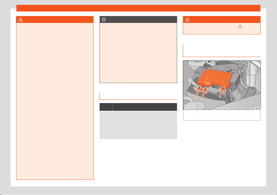
Checking and refilling levels
WARNING
Working on the vehicle battery and the
electrical system can cause corr
osion, fire
and electric shocks. Always read and take
into account the following warnings and
safety standards before carrying out any
work:
●
Before working on the battery, switch off
the engine, the ignition and all electrical
devices then disconnect the negative con-
nection on the battery.
●
Keep children away from acid and the
battery itself!
●
Wear eye protection.
●
Battery acid is very corrosive and caus-
tic. It can burn skin and cause blindness.
When handling the battery, protect your-
self from splashes of acids, above all your
hands, arms and face.
●
Do not smoke and never work close to
places exposed to flames or sparks.
●
Avoid sparks and electrostatic discharg-
es when working with cables and electrical
devices.
●
Never short the battery terminals.
●
Never use a damaged battery. It can ex-
plode. Replace a damaged battery imme-
diately.
●
Replaced damaged or frozen batteries as
soon as possible. A flat battery can also
freeze at temperatures close to 0°C
(+32°F).
CAUTION
●
Never disconnect the batt
ery if the igni-
tion is switched on or if the engine is run-
ning. This could damage the electrical sys-
tem or electronic components.
●
Do not expose the battery to direct sun-
light over a long period of time, as the in-
tense ultraviolet radiation can damage the
battery housing.
●
If the car is left standing for long periods,
protect the battery from extreme cold tem-
perature so that it does not “freeze up” and
become damaged.
Warning lamp
It lights up
Faulty generator.
Contact a specialised workshop
. Have the electrical
system checked.
Disconnect any unnecessary electrical devices. The
generator does not charge the battery while the ve-
hicle is in motion.
Several warning and control lamps light up
f
or a f
e
w seconds when the ignition is switch-
ed on, signalling that the function is being
verified. They will switch off after a few sec-
onds.
WARNING
Observe the safety warnings
›››
in Con-
trol and warning l
amps on page 27.
Checking the electrolyte level of
the vehicle batt
ery
Fig. 185
In the engine compartment: remove
the lid fr
om the v
ehicl
e's battery.
The battery's electrolyte level should be
check
ed r
egul
arly in high-mileage vehicles, in
hot countries and in older batteries. Other
batteries do not require maintenance.
Vehicles fitted with the Start-Stop system are
equipped with special batteries. For technical
reasons, the electrolyte level cannot be
checked in these batteries.
»
203
Practical tips
Preparations
●
Prepare the vehicle for work in the engine
compartment
›
›
›
page 193
●
Open the bonnet
›››
page 193.
●
Press on the tabs
›››
Fig. 185 (arrows) in the
direction of the arrows and lift the battery
cover up.
Checking the battery electrolyte level
●
Make sure there is sufficient lighting to
clearly recognise the colours. Never use
flames or shiny objects as a light source.
●
Depending on the level of acid, the Magic
eye on the top of the battery will change col-
our.
Colour indi-
cator
Necessary operations
Light yell
ow or
colourless
The el
ectrolyte level of the vehi-
cle's batt
ery is too low. Have the
battery checked and, where ap-
plicable, replaced by a special-
ised workshop.
Black
The electrolyte level of the vehi-
cle's batt
ery is correct.
WARNING
Working with the vehicle battery involves a
risk of corrosion, expl
osions and electric
shock.
●
Never tilt the v
ehicle battery. Battery
acid could spill out of the openings for the
release of gases and cause corrosion dam-
age.
●
Never open the vehicle battery.
●
If battery acid splashes on you, immedi-
ately rinse your eyes and skin abundantly
with water for several minutes. Then seek
medical care immediately.
●
If acid is swallowed by mistake, consult a
doctor immediately.
Charging, replacing and connect-
ing or disconnecting the batt
ery
Charging the battery
The v
ehicl
e batt
ery should be charged by a
specialised workshop only, as batteries using
special technology have been installed and
they must be charged in a controlled environ-
ment
›››
. SEAT recommends taking your
car in f
or t
echnical service
.
Replacing a vehicle battery
The battery has been developed to suit the
conditions of its location and has special
safety features. If the battery must be re-
placed, consult a technical service for infor-
mation on electromagnetic compatibility, the
size and maintenance, performance and
safety requirements of the new battery in
your vehicle before you purchase one. SEAT
recommends you have the battery replaced
by a technical service.
Use only maintenance-free genuine batteries
conforming to TL 825 06 and VW 7 50 73
Standards. These standards must be dated
April 2008 or later.
Vehicles fitted with the Start-Stop system are
equipped with a special battery. Therefore,
this battery must only be replaced by anoth-
er with the same specifications.
Disconnecting the vehicle's battery
If you must disconnect the battery from the
electrical system, please note the following:
●
Switch off the ignition and all electrical
equipment.
●
The vehicle must be unlocked before dis-
connecting the battery, otherwise the alarm
will be triggered.
●
First disconnect the negative cable and
then the positive
›››
.
Connecting the v
ehicl
e's batt
ery
●
Before reconnecting the battery, switch off
the engine and all electrical devices.
●
First reconnect the positive cable and then
the negative
›››
.
Diff
er
ent contr
ol lamps may light up after
connecting the battery and switching the
204
Checking and refilling levels
ignition on. They will be turned off after a
short trip at a speed of betw
een 15-20 km/h
(
10-
12 mph). If the warning indicators remain
lit, please visit a specialised workshop to
have the vehicle checked.
If the battery has been disconnected for a
long time, it is possible that the next service
date is not displayed or calculated correctly
›››
page 88. Respect the maximum service
intervals permitted
›››
page 217.
Automatic device disconnection
The intelligent vehicle electrical system auto-
matically implements a range of measures to
prevent the battery from discharging when
high demands are made on it:
●
The idling speed is increased so that the al-
ternator provides more electricity.
●
Where necessary, the power to the most
powerful devices is reduced or even com-
pletely disconnected.
●
On starting the engine, the power supply
from the 12-volt power sockets and the ciga-
rette lighter may be interrupted for a short
time.
The on-board management program cannot
always prevent the battery from running flat.
For example, if the ignition is left on for a long
period with the engine off or if the side lights
or parking lights are left on while the vehicle is
stationary.
Why the battery runs flat:
●
When stationary for a long time without
starting the engine, particularly if the ignition
is switched on.
●
Use of electrical devices with the engine
switched off.
WARNING
Incorrectly securing the battery or using
the wrong battery can cause shor
t-circuits,
fire and serious injuries.
●
Always use only maintenance-free bat-
teries, protected to prevent a leak, and
whose properties, specifications and size
correspond to the standard battery.
WARNING
A highly explosive mixture of gases is re-
leased when the battery is under char
ge.
●
The batteries should be charged in a
well-ventilated room only.
●
Never charge a frozen or recently thawed
battery. A flat battery can also freeze at
temperatures close to 0°C (+32°F).
●
Always replace a battery which has fro-
zen.
●
Battery cables not correctly connected
may cause a short circuit. Reconnect first
the positive cable and then the negative
cable.
CAUTION
●
Never disconnect the batt
ery if the igni-
tion is switched on or if the engine is run-
ning. This could damage the electrical sys-
tem or electronic components.
●
Never plug accessories that supply cur-
rent, such as solar panels or a battery
charger, to the 12-volt power socket or the
cigarette lighter. This could damage the
vehicle's electrical system.
For the sake of the environment
Dispose of the battery in an environment-
friendly manner. Batteries cont
ain toxic
substances such as sulphuric acid and
lead.
For the sake of the environment
Battery acid can contaminate the environ-
ment. Collect any spilt service fluids and
dispose of them correctly.
205
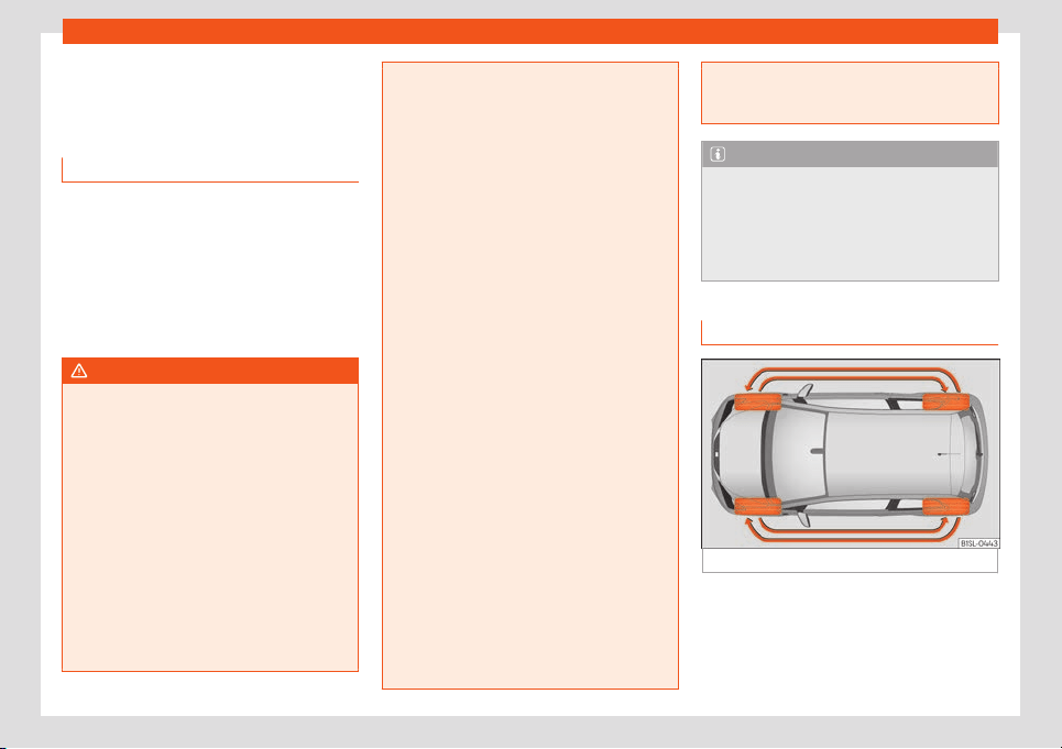
Practical tips
Wheels and tyres
T
yr
es
Intr
oduction
SEAT recommend that all work on tyres and
wheels is carried out by a specialised work
-
shop. These workshops have the necessary
special tools and replacement parts, trained
personnel and facilities for disposing of the
old tyres while respecting the environment.
SEAT recommends taking your car in for
technical service.
WARNING
The vehicle cannot be totally controlled or
braked if the t
yres (new or used) are worn
or damaged.
●
Incorrect use of wheels and tyres could
make driving more dangerous and result in
serious accidents and damage.
●
All four wheels must be fitted with radial
tyres of the same type, size (rolling circum-
ference) and the same tread pattern.
●
New tyres do not give maximum grip and
will not have reached their maximum brak-
ing capacity to start with, and therefore
need running in. To prevent accidents and
major damage, extreme caution should be
taken for the first 600 km.
●
Check tyre pr
essures regularly and en-
sure they are maintained at the pressures
indicated. If the tyre pressure is too low,
they could overheat, resulting in tread de-
tachment or even burst tyres.
●
Never drive on damaged (punctured, cut,
cracked or dented) or worn tyres. Driving
on damaged or worn tyres could result in
burst tyres, serious accidents or damage.
Worn or damaged tyres must be replaced
immediately.
●
Never exceed the maximum permitted
speed or loads specified for the type of
tyre fitted on your vehicle.
●
The effectiveness of driver and brake as-
sistance systems also depends on the grip
of the tyres.
●
If you notice unusual vibration or if the
vehicle pulls to one side when driving, stop
the car immediately and check the tyres
and wheels for damage.
●
To minimise the risk of losing control of
the vehicle or causing a serious accident,
never undo the bolted joints of beadlock
wheels.
●
Never mount used tyres or wheels if you
are not sure of their previous history. They
may be damaged, although the damage is
not immediately visible.
●
Old tyres, even if they have never been
used, may lose air or burst unexpectedly
while driving, especially at high speeds, re-
sulting in serious accident and injury. If
tyres are over six years old, they should on-
ly be used in an emergency and with ex-
tr
eme caution.
Note
For technical reasons, it is not generally
possibl
e to use the wheel
s from other vehi-
cles. In some cases, this may also be true
for the same model of wheel. Please refer
to the vehicle documentation or ask at a
technical service.
Handling tyres and wheels
Fig. 186 Diagram for changing wheels.
The tyres of a vehicle are the components
which ar
e sub
ject
ed to most stress and are
the most underestimated. Tyres are very im-
portant, as the support offered by their nar-
row surface is the only point of contact be-
tween the vehicle and the road.
206

Wheels and tyres
The service life of tyres is dependent on tyre
pr
essur
e
, driving style, the care they receive
and the correct fitting.
The tyres and wheel rims are an essential
part of the vehicle's design. The tyres and
rims approved by SEAT are specially match-
ed to the characteristics of the vehicle and
our critical to good road holding and safe
handling.
Avoiding damage to tyres and wheels
●
If you have to drive over a kerb or similar
obstacle, drive very slowly and as near as
possible at a right angle to the kerb.
●
Inspect the tyres regularly for damage
(punctures, cuts, cracks, dents).
●
Remove any foreign bodies found on the
outside of the tyre tread and ensure that they
have not passed through the wall of the
tyre
›››
page 211.
●
In addition, the instructions for tyre control
systems should always be observed.
●
Replace damaged or worn tyres as soon as
possible
›››
page 211.
●
Regularly check tyres for non-visible dam-
age
›››
page 211.
●
Never exceed the maximum permitted
speed or loads specified for the type of tyre
fitted on your vehicle
›››
page 214.
●
Do not allow tyres (including the spare
wheel) to come into contact with aggressive
substances, grease, oil, fuel or brake fluid
›››
.
●
Lost valve caps should be replaced imme-
diat
ely.
T
yr
es with directional tread pattern
Tyres with directional tread pattern have
been designed to operate best when rotating
in only one direction. An arrow on the tyre
sidewall indicates the direction of rotation on
tyres with directional tread
›››
page 214. Al-
ways observe the direction of rotation indica-
ted when mounting the wheel. This guaran-
tees optimum grip and helps to avoid aqua-
planing, excessive noise and wear.
If the tyre is mounted in the opposite direction
of rotation, drive with extreme caution, as the
tyre is no longer being used correctly. This is
of particular importance when the road sur-
face is wet. Change the tyre as soon as pos-
sible or remount it with the correct direction
of rotation.
Interchanging tyres
To ensure that the wear is equal on all tyres
the wheels should be changed round from
time to time according to the system
›››
Fig. 186. The useful life of all the tyres will
then be about the same time.
SEAT recommends you take the vehicle to a
specialised workshop to have the tyres
changed.
Tyres over 6 years old
Tyres are subject to an ageing process as a
result of physical and chemical processes.
This may affect their performance. Tyres
which are stored for long periods of time
without being used, harden and become
more fragile than tyres which are in constant
use.
SEAT recommends that tyres over six years
old are replaced with new tyres. This also ap-
plies to tyres (including the spare wheel)
which appear to be in perfect condition on
the outside and which have a tread depth
within the values stipulated by the Law
›››
.
The dat
e of manuf
act
ure, part of the tyre
identification number (TIN), indicates the age
of the tyre ()
›››
page 214.
Storing tyres
Mark tyres when you remove them to indicate
the direction of rotation (left, right, forwards,
backwards). This ensures you will be able to
mount them correctly when you replace
them. When removed, the wheels and/or
tyres should be stored in a cool, dry and pref-
erably dark location. Do not place tyres
mounted on the wheel in a vertical position.
Protect tyres not mounted on wheels from dirt
by storing them in suitable bags and standing
them on the ground on their tread.
»
207
Practical tips
WARNING
Aggressive fluids or substances could re-
sult in visible or invisible damage with the
consequent risks.
●
Al
ways ensure that tyres do not come in-
to contact with chemical products, oil,
grease, fuel, brake fluid or other aggressive
substances.
WARNING
Old tyres, even if they have never been
used, may lose air or burst unexpect
edly
while driving, resulting in serious accident
or damage.
●
If tyres are over six years old, they should
only be used in an emergency and with ex-
treme caution.
For the sake of the environment
Old tyres must be disposed of by qualified
personnel according to the l
aws in the
country concerned.
Wheels
The design of wheel bolts is matched to the
rims. If diff
er
ent rims ar
e fitted, the correct
wheel bolts with the right length and correct-
ly shaped bolt heads must be used. This en-
sures that wheels are fitted securely and that
the brake system functions correctly
›››
page 72.
For technical reasons, it is not generally pos-
sible to use the wheels from other vehicles. In
some cases, this may also be true for the
same model of wheel.
The tyres and rims approved by SEAT are
specially matched to the characteristics of
the vehicle and are critical to good road
holding and safe handling.
Wheel bolts
Wheel bolts must be tightened to the correct
torque
›››
page 72.
Beadlock wheel rims
Beadlock wheel rims have various compo-
nents. These are joined together by special
bolts using a special procedure. This ensures
good performance, a better seal, improved
safety and wheel run out. Therefore, worn
rims should always be replaced and must on-
ly be repaired in a specialised workshop.
SEAT recommends visiting a technical service
›››
.
Wheel rims with bolt
ed trims
Wheel rims may be fitt
ed with int
erchangea-
ble trim parts which are attached to the rim
using self-locking bolts. Worn trims should
only be replaced at a specialised workshop.
SEAT recommends visiting a technical service
›››
.
WARNING
The use of worn or damaged wheel rims
could make driving mor
e dangerous and
result in serious accidents and damage.
●
Only wheel rims which have been ap-
proved for use with your vehicle should be
used.
●
Inspect wheel rims regularly for damage
and replace as required.
WARNING
If the bolted joints of wheel rims with bolted
ring trims are not correctly tight
ened or
loosened, this could result in serious acci-
dent.
●
Never loosen the bolted joints of wheel
rims with bolted ring trims.
●
Any work relating to wheel rims with bol-
ted rims should be carried out at special-
ised workshop. SEAT recommends taking
your car in for technical service.
Note
A SEAT Service Centre should be consulted
to find out whether wheels or t
yres of dif-
ferent sizes to those originally fitted by
SEAT can be fitted, and to find out about
the combinations allowed between the
front axle (axle 1) and the rear axle (axle 2).
208
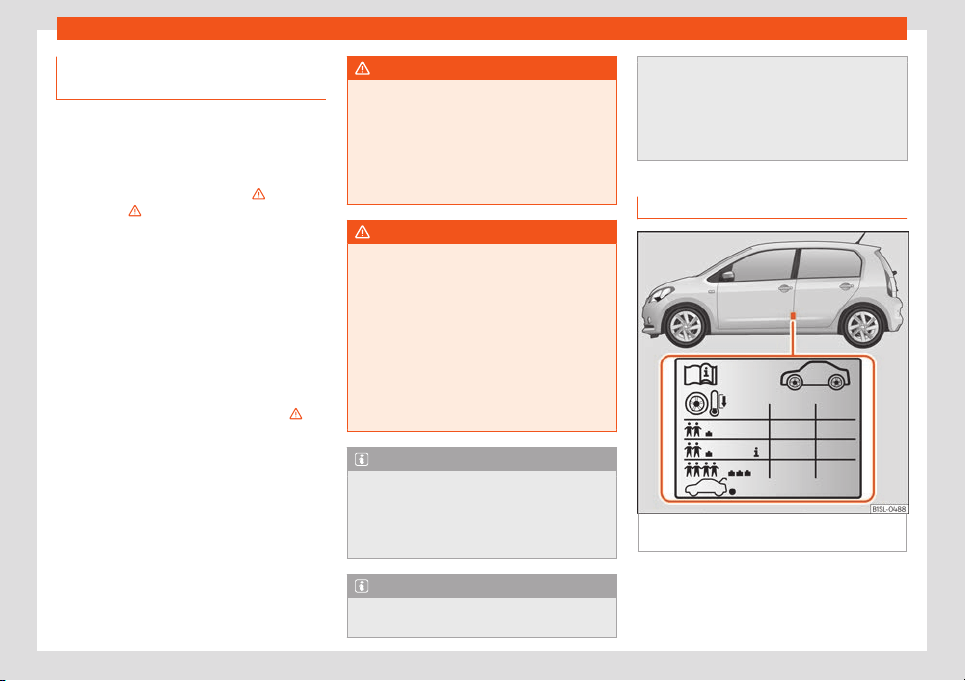
Wheels and tyres
Replacement of wheel rims and
ne
w t
yr
es
New tyres
●
When tyres are new, drive with extreme
caution for the first 600 km, as all tyr
es need
to be run-in. Tyres which have not been run in
do not have such good grip or
›››
braking
capacity
››
›
.
●
All four wheels must be fitted with radial
tyres of the same t
ype, size (rolling circumfer-
ence) and the same tread pattern.
●
The tread depth of new tyres may vary, ac-
cording to the t
ype and make of tyre and the
tread pattern.
Replacing tyres
●
Where possible, always replace both
wheels on an axle (both wheels on the front
axle or both wheels on the rear axle)
›››
.
●
Only replace used tyres with those author-
ised by SEAT f
or the corr
esponding t
ype vehi-
cle. Pay special attention to size, diameter,
and maximum load and speed capacity.
●
Never use tyres which are larger than SEAT
approved tyres. If the tyres are too big, they
may knock or rub against the chassis or other
components, resulting in damage.
WARNING
New tyres do not give maximum grip and
will not have reached their maximum br
ak-
ing capacity to start with, and therefore
need running in.
●
To prevent accidents and major damage,
extreme caution should be taken for the
first 600 km.
WARNING
There should be adequate space between
the tyres and the v
ehicle in accordance
with the vehicle design. If this is not the
case, the tyres may rub against parts of the
running gear, chassis or brake lines, lead-
ing to faults in the brake system or to tread
detachment, and the risk of burst tyres.
●
The true tyre dimension should not be
greater than the dimensions of tyres manu-
factured and approved by SEAT and should
not rub against parts of the vehicle.
Note
Although tyres may be shown as being the
same size, the true dimensions of diff
erent
types of tyre may vary with respect to the
nominal size, or tread patterns may be dif-
ferent.
Note
If you use tyres that are approved by SEAT,
you can be sure that the true tyr
e dimen-
sions will be correct for your vehicle. For
other tyre model
s, the tyre vendor should
provide the manufacturer's certificate with
the tyre, indicating that this type of tyre is
suitable for your vehicle. This certificate
should always be carried with the vehicle.
Tyre pressures
Fig. 187
Position of tyre pressure specification
pl
at
e
The correct tyre pressures for tyres fitted at
the f
act
ory is sho
wn on a label and is valid for
summer and winter tyres. The label
»
209
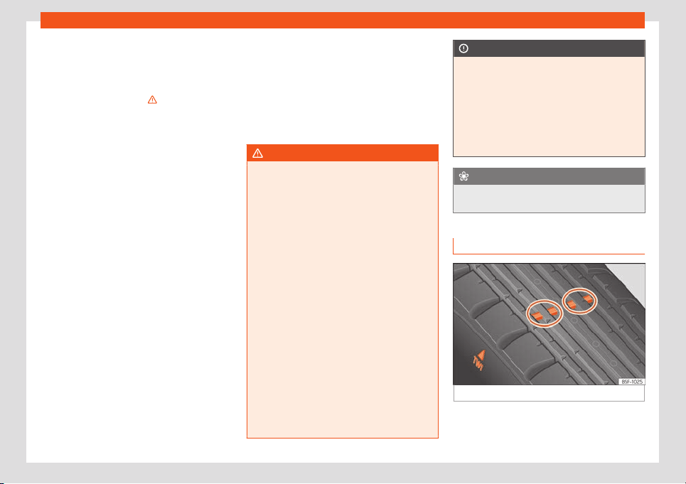
Practical tips
›››
Fig. 187 is l
ocat
ed on the driv
er's door pil-
lar.
Under-inflation or over-inflation will reduce
the life of the tyres considerably and also im-
pair the car's handling
›››
. It is essential to
maint
ain the corr
ect t
yre pressures, especial-
ly if driving at high speeds. Incorrect tyre
pressure causes premature wear and could
cause tyre blow-out.
The pressure should therefore be checked at
least once a month and before starting a
journey.
As a general rule, the pressures given are for
cold tyres. When the tyres are hot, the pres-
sures are greater.
Never deflate a hot tyre in order to obtain the
required pressure. This could result in very low
tyre pressures which may lead to sudden
blow-outs.
Tyre pressure monitoring system
Check tyre pressures only when the vehicle
has not been driven for more than a few kilo-
metres at low speeds in the past three hours.
●
The tyre pressures should be checked reg-
ularly, and only when the tyres are cold. Al-
ways check all tyres, including the spare
wheel. Tyre pressures should be checked
more often in colder regions, and only when
the vehicle has not been driven recently. Al-
ways use a correctly-operating tyre gauge.
●
Adjust tyre pressures to the loads carried in
the vehicle.
●
After adjusting the tyre pressure, check that
the caps are properly screwed on.
The spare wheel or temporary spare wheel
must always be kept at the maximum pres-
sure stipulated.
WARNING
If tyre pressures are too high or too low, the
tyre may defl
ate or burst suddenly while
driving. This could result in a serious acci-
dent.
●
If the tyre pressure is too low, they could
overheat, resulting in tread detachment or
even burst tyres.
●
When driving at high speeds and/or fully
loaded, the tyre could suddenly overheat,
burst or be subject to tread detachment,
with the resultant loss of control of the ve-
hicle.
●
Tyre pressures which are too high or too
low reduce the service life of the tyre, af-
fecting the vehicle's performance.
●
Tyre pressures should be checked regu-
larly, at least once a month and before
long journeys.
●
Adjust the pressures of all the tyres to the
vehicle load.
●
Never deflate excess pressure from hot
tyres.
CAUTION
●
Take car
e not to tilt the manometer when
placing it on the valve. Otherwise, the valve
may be damaged.
●
If tyre valves are not protected by caps,
or if the caps are not screwed on correctly,
they may become damaged. Check that
the caps are identical to the standard caps
and have been correctly tightened.
For the sake of the environment
Under-inflated tyres will increase fuel con-
sumption.
Wear indicator depth profile
Fig. 188 Tyre profile: tread wear indicators.
Tread depth
Cert
ain driving conditions r
equir
e a deeper
tread, as well as needing the tread to be
210
Wheels and tyres
approximately the same on the front and rear
t
yr
es. This is particul
arly important when driv-
ing in winter, in cold temperatures and on wet
roads
›››
.
The minimum tr
ead depth r
equir
ed by law in
the majority of cases is 1.6 mm, measured in
the tread grooves next to the tread wear indi-
cators. Observe legal requirements in each
country.
The performance of winter tyres is much re-
duced when the tread has worn to 4 mm.
The tread depth of new tyres may vary, ac-
cording to the type and make of tyre and the
tread pattern.
Wear indicators on the tyre
The original tyres on your vehicle have
1.6 mm high
›››
Fig. 188 tread wear indicators
running across the tread. A number of these
indicators are equally spaced around the
tyre tread. Certain marks on the tyre walls
(e.g. the letters “TWI” or other symbols) indi-
cate the position of the wear indicators.
Tread wear indicators indicate if a tyre is
worn. They must always be replaced before
the tyre tread has worn to the level of the in-
dicator.
WARNING
Driving with worn tyres is dangerous, and
may lead to l
oss of control of the vehicle
with serious consequences.
●
Tyres must be replaced before the wear
indicators are at the same level as the
tread pattern.
●
Worn tyres have significantly reduced
grip, especially on wet surfaces, increasing
the risk of “aquaplaning”.
●
Worn tyres make control of the vehicle
more difficult in normal or difficult driving
conditions, increasing the braking distance
and the risk of skidding.
Tyre damage
Damage to wheels and tyres is often invisible
t
o the nak
ed eye
. If you notice unusual vibra-
tion or the car pulling to one side, this may
indicate that one of the tyres is damaged
›››
.
●
Slow down immediately if you think you
hav
e a damaged wheel.
●
Check the wheel
s and t
yres for damage.
●
If tyres are worn, stop driving and seek
qualified assistance.
●
If there is no visible exterior damage, drive
slowly and carefully to the nearest special-
ised workshop and have the vehicle checked.
Foreign bodies in the tyre
●
Do not remove foreign bodies if they have
penetrated through the tyre wall!
●
You should obtain professional assistance
immediately.
Tyre wear
The wear of tyres depends on a number of
factors, for example:
●
Driving style.
●
Unbalanced wheels.
●
Running gear settings.
Driving style: driving round bends quickly or
sudden acceleration or braking speed accel-
erates tyre wear. When the driving style is
normal, if the tyres wear too quickly, have the
running gear settings checked at a special-
ised workshop.
Eccentricity of the wheels: the wheels of a
new vehicle are balanced. However, certain
circumstances may lead to imbalance (run-
out), which is detected as vibrations in the
steering wheel. Run-out leads to wear of the
steering and suspension. In the event of run
out, the wheels should be balanced again.
When a new wheel is fitted, it should be bal-
anced again.
Adjustments of the running gear: misaligned
running gear increases the wear of the tyres
and affects safety while driving. If tyres wear
»
211
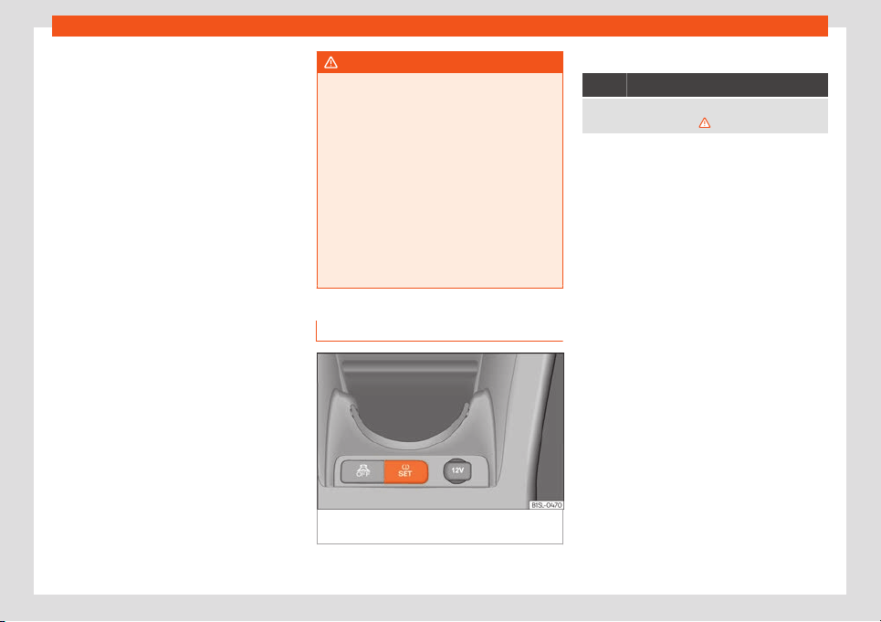
Practical tips
too quickly, have the wheel alignment
check
ed at a specialised w
orkshop
.
Low profile tyres
Low profile tyres, compared to other rim and
tyre combinations, offer a broader tread and
a greater rim diameter along with a lower
height of the tyre sidewall. This results in a
more agile driving behaviour. However, on
roads that are in poor condition, this might af-
fect comfort and cause more noise.
Low profile tyres may deteriorate more quick-
ly than standard tyres, for instance due to
strong knocks, potholes, manhole covers and
kerbs. Therefore, maintaining the correct tyre
pressure is particularly important
›››
page 209.
To avoid damage to tyres and wheels, drive
with special care when driving on roads in
poor condition.
Visually inspect your tyres every 3,000 km re-
garding damage, e.g. flattening/cracks on
the tyre sidewall or deformations/cracks on
the rims.
If the rims and tyres have received a heavy
impact or have been damaged, have them
checked and, if required, replaced at a speci-
alised workshop.
Low profile tyres may deteriorate more quick-
ly than standard tyres.
WARNING
If you notice unusual vibration or the car
pulls to one side whil
e driving, this may in-
dicate that one of the tyres is damaged.
●
Reduce speed immediately and stop,
while observing the highway code.
●
Check the wheels and tyres for damage.
●
Never carry on driving on worn tyres or
wheels. Request qualified assistance im-
mediately.
●
If there is no visible exterior damage,
drive slowly and carefully to the nearest
specialised workshop and have the vehicle
checked.
Tyre monitor system*
Fig. 189
Centre console: tyre monitoring sys-
t
em butt
on.
Control lamp
It lights up
The tyre pressure of a wheel is much lower than the
value set by the driver
›
››
.
The tyre pressure loss indicator compares the
rev
olutions and thus the wheel diameter of
each wheel using the ESC. If the wheel diam-
eter of a wheel changes, the control indicator
of the tyres informs of this fact . The wheel
diameter changes when:
●
Tyre pressure is insufficient.
●
The tyre structure is damaged.
●
The vehicle is unbalanced because of a
load.
●
The wheels of one axl
e are under more
pressure (for example, driving with a trailer or
on steep slopes).
●
The vehicle is fitted with snow chains.
●
The temporary spare wheel is fitted.
●
The wheel on one axle is changed.
Tyre pressure adjustment
On adjusting tyre pressure or changing one
or more wheels, the
›››
Fig. 189 button must
be kept pressed down, with the ignition on,
until an acoustic signal is heard.
If the wheels are under excessive load (for ex-
ample, driving with a trailer or heavy load),
the tyre pressure must be increased to the
212
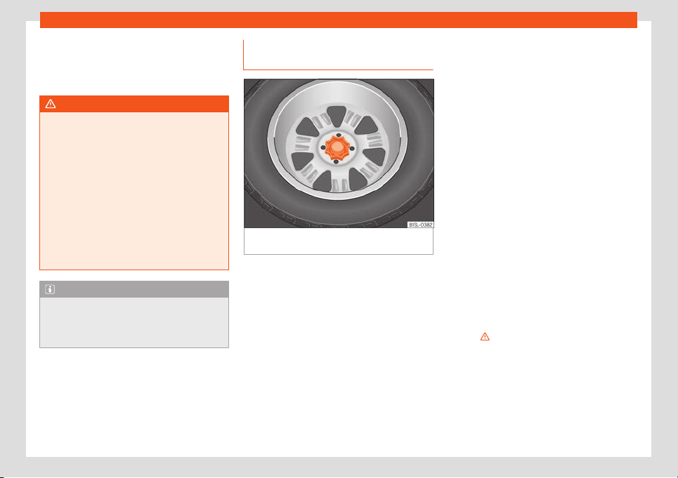
Wheels and tyres
recommended value for a full load (see the
stick
er on the inside of the fuel fl
ap). If the t
yre
monitor system button is pressed down, the
new tyre pressures are confirmed.
WARNING
●
When the tyre pr
essure control lamp
lights up, reduce speed immediately and
avoid any sudden turning or braking ma-
noeuvre. Stop when possible, and check
the tyre pressure and status.
●
The driver is responsible for maintaining
correct tyre pressures. For this reason, tyre
pressure must be regularly checked.
●
Under certain circumstances (e.g. when
driving in a sporty manner, in winter condi-
tions or on a dirt track) the tyre control
lamp may light up belatedly or may func-
tion incorrectly.
Note
If the battery is disconnected, the yellow
warning lamp
lights up after turning the
ignition on. This should turn off after a brief
journey.
Spare wheel or temporary spare
wheel*
Fig. 190
In the boot: hand controlled wheel for
securing the spar
e wheel
Removing the spare wheel
●
Open the rear lid and lift the luggage com-
partment shelf
›
›
›
page 122.
●
If necessary, remove the boot variable floor
›››
page 122.
●
Lift up the carpet from the recess and re-
move it from the luggage compartment.
●
If necessary, take out the vehicle tool kit
with the container.
●
Completely remove the hand controlled
wheel from the centre of the spare wheel
›››
Fig. 190 by turning it in an anticlockwise
direction, and take out the spare wheel.
Storing the replaced wheel
●
Pull back the carpet.
●
With the wheel rim facing downwards, sit-
uate the replaced wheel in the spare wheel
well so that the wheel rim central hole coin-
cides with the opening.
●
Turn the hand controlled wheel with the
shank screwed clockwise until the replaced
wheel is secured.
●
If necessary, store the vehicle tool in the
container, inside the boot.
●
Replace the carpet on the boot floor.
●
Lower the rear shelf.
●
Close the rear lid.
If the spare wheel is different to the rest of
the vehicle tyres
If the spare tyre is not the same as the tyres
that are mounted on the vehicle - for example
with winter tyres or the temporary spare
wheel - you should only use the spare tyre for
a short period of time and drive with extra
care
›››
.
R
efit the normal r
oad wheel as soon as possi-
bl
e.
Please observe driving advice:
●
Do not drive faster than 80 km/h (50 mph).
●
Avoid heavy acceleration, hard braking and
fast cornering.
»
213
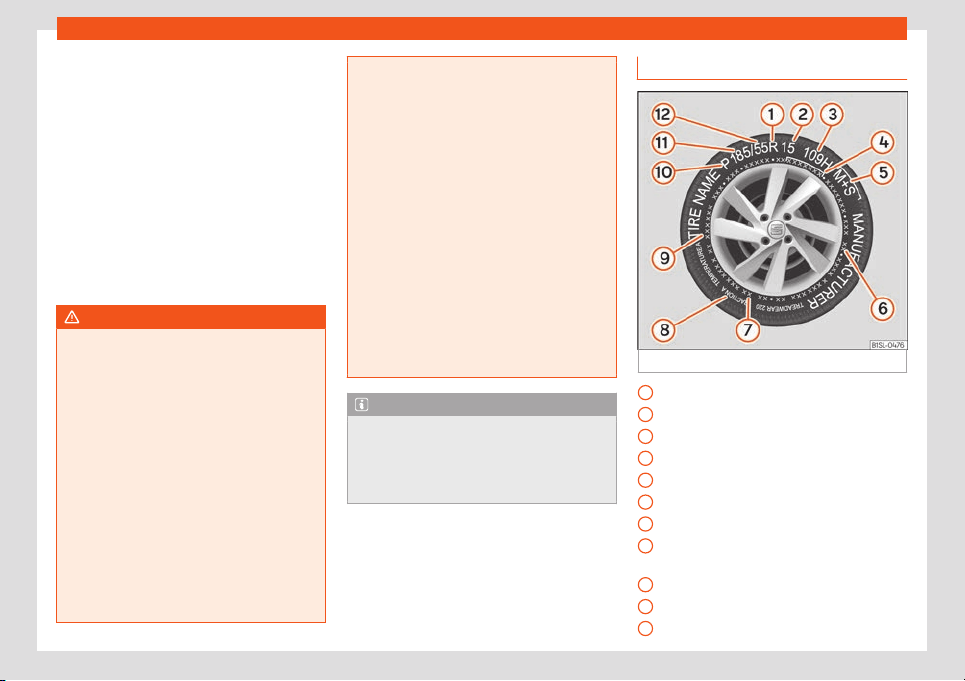
Practical tips
●
Sno
w chains on the t
empor
ary spare wheel
are not permitted
›››
page 42.
●
After mounting the spare wheel or the tem-
porary spare wheel, check the tyre pressure
as soon as possible
›››
page 209.
It is advisable to check the spare wheel or
temporary spare wheel tyre pressure when
checking the rest of the vehicle wheels at
least once a month. The spare wheel should
have the highest pressure allowed for the ve-
hicle
›››
page 209. The sticker situated on
the temporary spare wheel shows the tyre
pressure.
WARNING
Incorrect handling of the spare wheel or
the temporary spar
e wheel can cause loss
of vehicle control, producing collisions or
other serious accidents and injury.
●
Never use the spare wheel or the tempo-
rary spare wheel if it is damaged or worn to
the wear indicator.
●
In some vehicles the spare wheel is
smaller than the original tyres. This can be
seen on a sticker showing the text
“80 km/h” and “50 mph”. This text indi-
cates the maximum velocity permitted for
this type of tyre.
●
Never drive faster than 80 km/h
(50 mph). Avoid powerful acceleration,
hard braking and taking corners at high
speed.
●
Never driv
e more than 200 km with a
temporary spare wheel fitted to the drive
axle.
●
Replace the temporary spare wheel for a
normal wheel as soon as possible. The
compact temporary spare wheel is only in-
tended for temporary use over short dis-
tances.
●
The temporary spare wheel must always
be secured with the factory supplied wheel
bolts.
●
You should never use more than one tem-
porary spare wheel.
●
After mounting the temporary spare
wheel, check the tyre pressure as soon as
possible
›››
page 209.
●
Snow chains on the temporary spare
wheel are not permitted.
Note
Wherever possible, secure the spare wheel,
temporary spar
e wheel or the replaced
wheel safely in the luggage compartment.
In vehicles with anti-puncture kit, it is not
possible to secure the defective wheel.
Tyre code
Fig. 191
Universal code on tyres
Radial
Rim diamet
er code
L
oad inde
x & speed rating
DOT tyre identification number
Severe snow conditions
Tyre ply composition and materials used
Max. load rating
Treadwear, traction and temperature
grades
Max. permissible inflation pressure
Passenger car tyre
Nominal width of tyre in millimetres
1
2
3
4
5
6
7
8
9
10
11
214

Wheels and tyres
Ratio of height to width (aspect ratio)
Tyre code (example): Meaning
P185 / 55 R 15: Size:
P Passenger vehicle code.
185
Nominal width between walls, in
mm.
55 Height/width ratio in %
R Tyre type (R indicates "radial").
15 Rim diameter in inches
109 H Load index
›
›
›
page 216 and
speed rating
›››
page 216.
XL Reinforced tyres (“Reinforced”).
M+S or M/S or
Winter tyres code (mud and snow
tyres).
RADIAL
TUBELESS
R
adial tyre without inner tube.
E4 ... E-mark certifying tyre complies
with international legisl
ation fol-
lowed by a number denoting the
country granting the authorisa-
tion. The authorisation number
( several digits) is shown below.
DOT BT RA TY5 1716: Tyre identification number
(TIN
a)
, maybe only on exterior w
all of the wheel) and
date of manufacture.
12
Tyre code (example): Meaning
DOT The tyre complies with the legal
requirements of the US Depart
-
ment of Transport, responsible for
tyre safety regulations.
BT Place of manufacture code.
RA Information about manufacturer
and tyre siz
e.
TY5 Manufacturer's tyre specifica-
tions.
1716 Manufacturing date: week 17 of
2016.
TWI This identifies the position of the
Tread W
ear Indicator
›››
page 210.
MAX LOAD
615 KG
(1356 LBS)
US load rating, indicating maxi-
mum permitted load per tyre.
MAX INFLATION
350 KPA
(51 PSI)
US limit, indicating maximum per-
mitted tyre pressure.
SIDEWALL 1 PLY
RAYON
Information about tyre wall com-
ponents: 1 layer of rayon (artificial
silk).
TREAD 4 PLIES
1 RAYON +
2 STEEL + 1 NY-
LON
Information about tread compo-
nents: In the example, there are 4
layers below the tread: 1 layer of
rayon (artificial silk), 2 layers of
steel reinforcement and 1 layer of
nylon.
Tyre code (example): Meaning
Information for the end consumer concerning the
comparative v
alues of the established base tyres
(standardised test procedures):
TREAD-
WEAR 280
Relative service life of the tyre,
with respect to specific US st
and-
ard test.
TRACTION A Braking capacity of tyre on wet
surface (AA, A, B or C).
TEMPERA-
TURE A
Tyr
e temperature resistance at
higher test speeds (A, B or C).
If there ar
e different letters, they are specific co-
des of the tyre manuf
acturer or specific national
codes.
a)
The letters TIN refer to the tyre serial number.
T
yr
es with dir
ectional tread pattern
Tyres with directional tread pattern have
been designed to operate best when rotating
in only one direction. An arrow on the tyre
sidewall indicates the direction of rotation on
tyres with directional tread. Always observe
the direction of rotation indicated when
mounting the wheel. This guarantees opti-
mum grip and helps to avoid aquaplaning,
grip, noise and wear.
If the tyre is mounted in the opposite direction
of rotation, drive with extreme caution, as the
tyre is no longer being used correctly. This is
of particular importance when the road sur-
face is wet. Change the tyre as soon as
»
215

Practical tips
possible or remount it with the correct direc-
tion of r
ot
ation.
T
yre load rating
The load rating code indicates the maximum
load in kilogrammes each wheel can carry
(load capacity).
425 kg
462 kg
487 kg
515 kg
545 kg
615 kg
Speed rating
The speed rating indicates the maximum
speed permitted for the tyres.
max. 150 km/h (93 mph)
max. 160 km/h (99 mph)
max. 170 km/h (106 mph)
max. 180 km/h (112 mph)
max. 190 km/h (118 mph)
max. 200 km/h (124 mph)
max. 210 km/h (130 mph)
max. 240 km/h (149 mph)
max. 240 km/h (149 mph)
max. 270 km/h (168 mph)
78
81
83
85
87
91
P
Q
R
S
T
U
H
V
Z
W
max. 300 km/h (186 mph)
Some manufacturers use the letters “ZR” for
tyres with a maximum authorised speed
above 240 km/h.
Y
216
Service
Maintenance
Service
Service int
erv
al
s
Servicing and Digital Maintenance
Plan
Log of services performed (“Digital Main-
tenance Plan”)
The SEAT deal
ership or a specialised work-
shop records Service receipts in a central
system. Thanks to this comprehensive docu-
mentation of the service history, it is possible
to reproduce the services performed any
time. SEAT recommends requesting a Service
receipt after every service carried out con-
taining all the services carried out on the sys-
tem.
Whenever there is a new service the receipt is
replaced with a current one.
The Digital Maintenance Plan is not avail-
able in some markets. In this case, your
SEAT dealer will inform you about the cur-
rent documentation of the work.
Service works
In the Digital Maintenance Pl
an, your SEAT
authorised service or specialised workshop
documents the following information:
●
When each one of the services was carried
out.
●
Whether a specific repair has been sugges-
ted, e.g. changing the brake pads in the near
future.
●
If you have expressed a special request for
the maintenance. Your Service Advisor will
write the work order.
●
The components or fluids that were
changed.
●
The date of the next service.
The Long Life Mobility Warranty is valid until
the next inspection. This information is docu-
mented in all checks performed.
The type and the volume of the service may
vary from one vehicle to another. A special-
ised workshop will be able to provide specific
information on the jobs for your vehicle.
WARNING
If the services are insufficient or not per-
formed and if the service interv
als are not
observed, the vehicle may be immobilised
in traffic cause an accident and severe in-
juries.
●
Make sure that any r
epairs are carried
out by a SEAT authorised service or speci-
alised workshop.
CAUTION
SEAT cannot be held liable for any damage
t
o the vehicl
e due to insufficient work or of
lack of availability of spare parts.
Note
Regular services on the vehicle not only
maintain its value
, but also its correct oper-
ation and road safety. For this reason, con-
duct the services in accordance with SEAT
guidelines.
Fixed Service or Flexible Service
Services are classified as oil change service
and inspection. The service int
erv
al displ
ay
on the instrument panel display serves as a
reminder of the next service.
Depending on the features, the engine and
the conditions of use of the car, either the
Fixed service or the Flexible service will be
applied for an oil change service..
How to know which type of service needs
to his vehicle
●
Check the tables below:
»
217
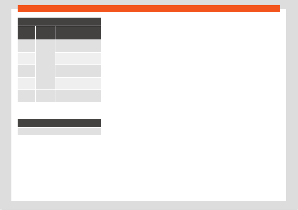
Maintenance
Oil change service
a)
PR No.
Type of
service
Service interval
QI1
Fixed
Every 5000 km or after
1 year
b)
QI2
Every 7500 km or after
1 year
b)
QI3
Every
10000 km or after
1 year
b)
QI4
Every
15000 km or after
1 year
b)
QI6 Fle
xible
According to the service in-
t
erv
al displ
ay
a)
The data are based on normal conditions of use.
b)
Whatever happens first.
Inspection Service
a)
According to the service interval display
a)
The data are based on normal conditions of use.
Bear in mind the inf
ormation about the speci-
fications of the engine oil accor
ding t
o the
VW standard
›››
page 32.
Particular characteristics of the Flexible
Service
Regarding the Flexible Service, the oil
change service only has to be performed
when the vehicle needs it. To calculate when
you have to carry out this service, take into
account the individual conditions of use and
personal driving style. A major component of
the flexible service the use of LongLife oil in-
stead of conventional engine oil.
Bear in mind the information about the speci-
fications of the engine oil according to the
VW standard
›››
page 32.
If you do not want to the flexible service
you can select the fixed service However,
a fixed service may affect service costs
The Service Advisor will gladly advise you.
Service intervals display
At SEAT, the dates of the services are indica-
ted by the service interval display on the in-
strument panel display
›››
page 90. The
service interval display gives information for
service dates that involve an engine oil
change or an inspection. When the time for
the corresponding service comes, additional
work required, such as the change of brake
fluid and the spark plugs, can be carried out.
Information on the conditions of
use
The service intervals and groups are usually
based on normal conditions of use.
If
, on the other hand, the v
ehicl
e is under ad-
verse conditions of use, some of the work
must be carried out before the next service
period or even between service intervals.
Conditions of use adverse include:
●
The use of fuel with a high sulphur content.
●
Frequent short trips.
●
Letting the engine idle for a long period of
time, as in the case of taxis.
●
Using the vehicle in areas with thick dust.
●
Frequent driving with a trailer (depending
on equipment).
●
Using the vehicle mostly in situations with a
lot of traffic and stops (e.g. in a city).
●
Using the vehicle mostly in winter.
This applies especially for the following
parts (depending on equipment):
●
Dust and pollen filter
●
Air Care allergen filter
●
Air filter
●
Toothed chain
●
Particulate filter
●
Engine oil
The Service Advisor of your specialised
workshop will gladly inform you about the
need of performing service work between
normal service intervals, always considering
the conditions of use of your vehicle.
218
Service
WARNING
If the services are insufficient or not per-
formed and if the service interv
als are not
observed, the vehicle may be immobilised
in traffic and cause accidents and severe
injuries.
●
Have the services conducted at author-
ised SEAT services or specialised work-
shops.
CAUTION
SEAT cannot be held liable for any damage
to the vehicl
e due to insufficient work or of
lack of availability of spare parts.
Sets of services
Sets of services include all the maint
enance
w
orks
needed to ensure the safety and the
smooth running of the vehicle (depending on
the conditions of use and the features of
the vehicle, such as the engine, gearbox, or
operating fluids). Maintenance services are
divided into inspection and review services.
Consult the details of the jobs required for
your vehicle at:
●
Your SEAT authorised service
●
Your specialised workshop
Due to technical reasons (continuous devel-
opment of components) the sets of services
may vary. Your SEAT authorised service or
specialised workshop is always receiving up-
dates in time.
Additional service offers
Approved spare parts
Original SEAT Spare Parts have been con-
ceived for their v
ehicles and approved by
SEAT, with a special emphasis on safety.
These parts correspond exactly to the manu-
facturer's requirements in terms of design,
accuracy of the measurements and materi-
als. The original SEAT Spare Parts have been
conceived exclusively for your vehicle. For this
reason, we always recommend the use of
Original SEAT Spare Parts. SEAT cannot be
held liable for the safety and suitability of
parts from other manufacturers.
Approved spare parts
Approved spare parts, following the manu-
f
act
ur
er's requirements, are an additional
service to you, offering the possibility of re-
placing complete sets, such as: light engine,
gearboxes, heads, control units, electrical
components, etc.
These parts are, approved parts, and are the
same as the factory parts, which are also ap-
proved spare parts.
Original accessories
We recommend you only use SEAT Original
Accessories and SEAT approv
ed accessories
for your vehicle. The reliability, safety and
suitability of these accessories have been in-
spected specifically for this type of vehicle.
SEAT cannot be held liable for the safety and
suitability of parts from other manufacturers.
SEAT Service Mobility (SEAT
Service Mobility)
Since the moment you purchase your SEAT
v
ehicl
e you will be abl
e to enjoy the benefits
and coverage of the SEAT Mobility Service.
For the first two years after the purchase,
your new SEAT vehicle is automatically cov-
ered by the SEAT Mobility Service without ad-
ditional costs.
If you wish to enjoy this service after this peri-
od, you can extend SEAT Mobility as long as
you carry out the recommended Inspection
and Maintenance Services at a SEAT Author-
ised Service.
»
219
Maintenance
If your SEAT vehicle is immobilised due to a
f
ault or an accident, our assist
ance services
will help you k
eep moving.
Take into account that the SEAT Mobility
Service differs depending on the country in
which the vehicle was purchased. For further
information ask your SEAT dealership or the
SEAT website in your country.
Warranty
Fault-free operation warranty
SEAT Authorised Services ensure the perfect
condition of ne
w v
ehicl
es. Check the pur-
chase agreement or complementary addi-
tional documentation provided by your Tech-
nical Service to see the conditions and the
terms of the warranty. Consult further infor-
mation in this regard in your SEAT Official
Service.
Vehicle maintenance
Maint
enance and cl
eaning
Basic consider
ations
Regular and careful care helps to maintain
the value of your vehicl
e. In addition, it may
become a prerequisite to demand the war-
ranty in the event of corrosion damage and
deficiencies in the paint coat of the body-
work.
Specialised workshops have the necessary
care products. Please follow the instructions
for application on the packaging.
WARNING
●
Cleaning products and other mat
erials
used for car care can be damaging to your
health if misused.
●
Always keep care products in a safe
place, out of the reach of children. Danger
of poisoning!
For the sake of the environment
●
When purchasing car care pr
oducts,
chose products that are compatible with
the environment.
●
The waste from car-care products should
not be disposed of with ordinary household
waste.
Washing the vehicle
The longer you take to clean the tanks, e.g.
remains of insects, bird e
xcrements, tree resin
or anti frost salt adhered to your vehicle, the
more damage it can cause to the surface.
High temperatures, for instance strong sun-
light, further intensify the damage.
Before washing the car, soften the dirt using
plenty of water.
To remove encrusted dirt such as insects, bird
droppings or tree resin, use a lot of water and
a microfibre cloth.
Have the underside of the vehicle washed af-
ter the end of the anti frost salts in winter.
High pressure cleaners
When washing the vehicle with a high-pres-
sure cleaner, always follow the operating in-
structions for the equipment. This applies
particularly to the operating pressure and the
distance between the spraying water. Do not
aim the jet directly to the side window gas-
kets, doors, covers or the panoramic sun-
roof*; the same applies to tyres, rubber ho-
ses, soundproofing material, sensors* or
camera lenses*. Keep a distance of at least
40 cm.
Do not remove snow and ice with a high-
pressure cleaner.
220
Vehicle maintenance
Do not use a nozzle that sprays the water out
in a dir
ect str
eam or one that has a r
otating
jet for forcing off dirt.
The water temperature must not exceed
60°C.
Automatic car wash tunnels
Spray the vehicle before starting the car
wash.
Make sure that the windows and the panor-
amic sunroof* are closed and the windscreen
wipers are deactivated. Bear in mind the in-
structions of the car wash tunnel operator,
especially if your vehicle has detachable
parts.
Use of car washes without brushes if possible.
Washing by hand
Clean your vehicle from top to bottom with a
soft sponge or with a brush. Only use clean-
ing products that do not contain solvents.
Washing vehicles with a matte paint by
hand
To prevent damage to the vehicle when
washing it, first remove the thicker dust and
dirt. To remove traces of insects, grease and
fingerprints, it is best to use a special cleaner
for matte paint.
Apply the product with a microfibre cloth. To
avoid damaging the surface of the paint, do
not apply too much pressure.
Rinse with plenty of water. Then clean it with
a neutral cleaning product and a soft microfi-
bre cloth.
Rinse the vehicle again with plenty of water
and then leave it to dry. Remove traces of
water with a leather cloth.
WARNING
●
Only wash the vehicl
e with the ignition
switched off or according to the specifica-
tions of the car wash tunnel operator. Risk
of accident!
●
When cleaning the underbody or the in-
side of the wheel arches, protect yourself
from sharp or pointy metal parts. Risk of
cut!
●
After cleaning the brakes could act more
slowly due to moisture or, in winter, the ice
on the brake discs and pads. Risk of acci-
dent! In this case the brakes should be
dried by pressing the brake pedal several
times.
CAUTION
●
Before w
ashing the vehicle in an auto-
matic car wash, please make sure to re-
tract the exterior mirrors to prevent them
from being damaged. Electric exterior rear-
view mirrors must always be folded/de-
ployed electrically!
●
Do not w
ash the vehicle in direct sunlight.
Risk of damaging the paint job!
●
Do not use sponges, abrasive household
sponges or similar to clean insect remains.
Risk of damaging the surface!
●
Vehicle parts with matte paint:
–
Do not use polish or hard wax. Risk of
damaging the surface!
–
Never select washing programs that in-
clude the use of wax. This could dam-
age the appearance of matte paint.
–
Do not put stickers or magnets on parts
with matte paint, as removing them
may damage the paint.
For the sake of the environment
The car should only be washed in special
wash bays. These places ar
e prepared to
prevent oily water from getting into the
public drains.
Cleaning and maintenance instruc-
tions
The cleaning and maintenance of individual
components of the v
ehicl
e can be check
ed in
the following tables. The contents should be
understood merely as a recommendation. Go
to your specialised workshop if you have
»
221
Maintenance
special questions or parts that are not listed.
T
ak
e he gener
al considerations into account
›››
in Take special care with... on
page 225.
Exterior cleaning
Windscreen wipers
Problem Solution
Dirt Soft cloth with wipers
Headlights / Tail lights
Problem Solution
Dirt Soft sponge with neutral soap
solution
a)
a)
Neutral soap solution: two tablespoons maximum in
1 litr
e of w
at
er
Sensors / Camera lenses
Problem Solution
Dirt
Sensors: soft cloth with clean-
ing pr
oduct which does not
contain solvents
Camera lenses - soft cloth with
cleaning product with no alco-
hol content
Snow/ice
Hand brush/Anti frost spray
with no solvents
Wheels
Problem Solution
Anti frost salt Water
Brake abrasion
dust
Acid-free special cleaning
product
End exhausts
Problem Solution
Anti frost salt Water, if a steel cleaning prod-
uct is required
Covers / Trims
Problem Solution
Dirt Neutral soap solution
a)
, if a
steel cleaning pr
oduct is re-
quired
a)
Neutral soap solution: two tablespoons maximum in
1 litr
e of w
at
er
Paint
Problem Solution
Flaws in the paint
Check the paint's colour code
in an authorised service and re-
stor
e with a touch-up pencil
Spilled fuel Immediately rinse with water
Environmental rust
tank
Apply rust remo
ver and then
apply hard wax. Go you your
specialised w
orkshop if you
have any queries
Problem Solution
Corrosion
Have your specialised work-
shop take car
e of this
The water does
not create dr
op-
lets on the clean
paint
Maintain with hard wax (at
least 2 times a year)
No shine de-
spite sober main-
tenance/paint
T
reat with suitable wax and ap-
ply paint preservativ
e after-
wards if the wax used does not
contain preservative ingredi-
ents
Tanks, e.g. insect
remains, bird
dr
oppings, tree
sap, road salt
Immediately soften with water
and remove with a microfibre
cloth
Fat-based dirt,
e.g. cosmetic
products or
sunscreen
Delete immediately with a neu-
tral soap solution
a)
and a soft
cloth
a)
Neutral soap solution: two tablespoons maximum in
1 litr
e of w
at
er
Carbon fibre parts
Problem Solution
Dirt Clean the same way as pain-
ted parts
››
›
page 220
222
Vehicle maintenance
Decoration slides
Problem Solution
Dirt Soft sponge with neutral soap
solution
a)
a)
Neutral soap solution: two tablespoons maximum in
1 litre of wat
er
Interior cleaning
Windows
Problem Solution
Dirt Apply windscreen cleaner and
then dry with a cloth
Covers / Trims
Problem Solution
Dirt Neutral soap solution
a)
a)
Neutral soap solution: two tablespoons maximum in
1 litr
e of w
at
er
Plastic parts
Problem Solution
Dirt Damp cloth
Encrusted dirt Neutral soap solution
a)
, if pos-
sible solvent-free plastic clean-
er
a)
Neutral soap solution: two tablespoons maximum in
1 litr
e of w
at
er
Displays/instrument panel
Problem Solution
Dirt Soft cloth with a liquid crystal
display cleaner
Control panels
Problem Solution
Dirt Soft brush, then soft cloth with
neutral soap solution
a)
a)
Neutral soap solution: two tablespoons maximum in
1 litre of wat
er
Seat belts
Problem Solution
Dirt Neutral soap solution
a)
, al-
lo
wed to dry before retracting
a)
Neutral soap solution: two tablespoons maximum in
1 litr
e of w
at
er
Fabrics, artificial, Alcantara leather
Problem Solution
Dirt particles ad-
hered to the sur
-
face
Vacuum cleaner
Water-based dirt,
e.g. coffee
, tea,
blood etc.
Absorbent cloth and neutral
soap solution
a)
Problem Solution
Grease-based
dirt, e.g. oil, mak
e-
up, etc.
Apply a neutral soap solution
a)
.
Absorb the dissolved grease
and paint particles drying with
an absorbent cloth, in case you
must treat it with water after-
wards
Special dirt, e.g.
pens, nail polish,
dispersion paint,
shoe cream etc.
Special st
ain remove: dry with
an absorbent cloth, if applica-
ble, apply neutral soap solution
afterwards
a)
a)
Neutral soap solution: two tablespoons maximum in
1 litr
e of w
at
er
Natural leather
Problem Solution
Recent dirt Cotton cloth with neutral soap
solution
a)
Water-based dirt,
e.g. coffee, tea,
blood etc.
Recent stains: absorbent cloth
Dry stains: leather cleaner
Grease-based
dirt, e.g. oil, mak
e-
up, etc.
Recent stains: absorbent cloth
and leather cleaner
Dry stains: grease dissolving
spray
Special dirt, e.g.
pens, nail polish,
dispersion paint,
shoe cream etc.
St
ain remover suitable for
leather
»
223

Maintenance
Problem Solution
Care Apply preservative cream regu-
larly to pr
otect from sunlight.
Use a colour preservative if re-
quired
a)
Neutral soap solution: two tablespoons maximum in
1 litre of wat
er
Carbon fibre parts
Problem Solution
Dirt Clean like plastic parts
Take special care with...
Headlights/tail lights
●
Do not clean the headlights/tail lights with
a dry cl
oth or sponge
.
●
Do not use cl
eaning products that contain
alcohol. Risk of cracks!
Wheels
●
Do not use for paint wax or other abrasive
products.
●
If the protective coating on the paint of the
rim has been damaged due to stone impacts,
scratches, etc., the damage should be re-
paired immediately.
Camera lenses
●
Do not use hot or warm water to remove ice
or snow from the camera lenses. Risk of
cracking the lens!
●
To clean the camera lens, never use abra-
sive cleaning products or products with alco-
hol. Risk of scratches and cracks!
Windows
●
Remove snow and ice from windows and
exterior mirrors with a plastic scraper only. To
avoid scratches, the scraper should only be
pushed in one direction and not moved to
and fro.
●
Never remove snow or ice from windows
and rearview mirrors with warm or hot water.
Risk of cracks on the windows!
●
To prevent damage to the heating of the
rear window, do not put stickers over the
heating elements.
Covers/trims
●
Do not use cleaning products or chrome
based cleaning agents.
Paint
●
The vehicle must be free from dirt and dust
before applying wax or care products. Risk of
scratches!
●
Do not apply wax or care products if the
vehicle is exposed to direct sunlight. Risk of
damaging the paint job!
●
The ambient rust deposits must not be re-
moved through friction. Risk of damaging the
paint job!
●
Remove cosmetic products and sunlight
immediately. Risk of damaging the paint job!
Displays/instrument panel
●
The screens, the instrument panel and the
trim around it must not be cleaned dry. Risk of
scratches!
●
Make sure that the instrument panel is
switched off and cooled down before clean-
ing.
●
Make sure that no liquid leaks between the
instrument panel and the trim. Risk of dam-
age!
Control panels
●
Make sure that no liquid leaks into the con-
trol panels. Risk of damage!
Seat belts
●
Do not remove the seat belts to clean them.
●
Seat belts and their components must nev-
er be cleaned with chemical products, nor
should they be allowed to come into contact
with corrosive liquids, solvents or sharp ob-
jects. Risk of damaging the fabric!
●
If you find any damage to the belt webbing,
belt fittings, the belt retractor or the buckle,
ask your specialised workshop to replace the
belt in question.
224
Vehicle maintenance
Fabrics/artificial leather/Alcantara leath-
er
●
Do not treat artificial leather/Alcantara
l
eather with l
eather cl
eaning products, sol-
vents, wax polish, shoe cream, stain removers
or similar products.
●
If the stain is very hard to remove, take the
vehicle to a specialised workshop to have it
removed there. This will prevent damage.
●
Do not use steam cleaners, brushes, hard
sponges, etc. to clean.
●
Do not turn on seat heating* to dry the
seats.
●
Sharp objects on clothing, such as zips, riv-
ets or belts can damage the surface.
●
Open Velcro, e.g. on clothes can damage
the seat upholstery. Make sure that Velcro
fasteners are closed.
Natural leather
●
Never use solvents, wax polish, shoe cream,
spot removers or similar products on leather.
●
Sharp objects on clothing, such as zips, riv-
ets or belts can damage the surface.
●
Do not use steam cleaners, brushes, hard
sponges, etc. to clean.
●
Do not turn on seat heating* to dry the
seats.
●
Avoid exposing leather to direct sunlight for
long periods, otherwise it may tend to lose
some of its colour. If the car is left for a pro-
longed period in the bright sun, it is best to
cover the leather.
WARNING
Do not use water-repellent coatings on the
windscreen. In bad visibility conditions
such as humid w
eather, darkness or when
the sun is in its lowest point, visibility may
be impacted. Risk of accident! Such coat-
ings can also cause the windscreen wiper
blades to make noise.
Note
●
Remains of insects can be remo
ved much
more easily with previously treated paint.
●
Regular car care treatments can prevent
deposits of ambient rust.
Remove the vehicle from traffic
If you want to leave your vehicle stationary
f
or a l
ong period of time
, contact a qualified
workshop. They will gladly inform you about
the necessary measures, such as anti-corro-
sion protection, Service and storage.
Also take into account instructions regarding
the vehicle's battery
›››
page 204.
225

Information for the user
Information for the user
Inf
ormation f
or the user
Inf
ormation stored in control
units
Description and operation
Your vehicle is fitted at the factory with a ser-
ies of electronic contr
ol units responsible for
the engine and gearbox management. In ad-
dition, the control units supervise the per-
formance of the exhaust gas system and the
airbag systems.
Therefore, while the vehicle is being driven,
these electronic control units are continuous-
ly analysing the vehicle data. In the event of
faults or deviations from the theoretical val-
ues, only this data is stored. Normally, the
warning lamps on the instrument panel light
up in the event of faults.
This data can only be read and analysed us-
ing special equipment.
The storing of the data allows specialised
workshops to detect and repair faults. Stored
data may include:
●
Data relating to the engine or the gearbox
●
Speed
●
Direction of trav
el
●
Braking force
●
Detection of seat belt
The vehicle control units never record conver-
sations held by passengers in the vehicle.
In vehicles equipped with an emergency call
function via the mobile phone or other appli-
ances connected in the vehicle, it is possible
to send the vehicle position. If the control unit
records an accident with airbag activation,
the system may automatically send a signal.
This will depend on the network operator.
Normally, transmission is only possible in
areas with good coverage.
Event Data Recorder
The vehicle is not fitted with an event data re-
corder.
An event data recorder temporarily stores the
vehicle information. Therefore, in the event of
an accident, it is possible to obtain detailed
information about how the accident occur-
red. Vehicles with airbag systems can store
data relating to impact speed, seat belt sta-
tus, seat positions and airbag activation times
may be stored, etc. The volume of data de-
pends on the manufacturer.
Event data recorders can only be mounted
with authorisation from the vehicle owner
and, in some countries, they are governed by
local legislation.
Reprogramming control units
On the whole, all the data required for the
component management is stored in the
control units. The programming of certain
convenience functions, such as the turn sig-
nals, individual door opening and instructions
on the display can be modified using special
equipment at the workshop. If the comfort
functions are reprogrammed, the information
and Instruction Manual descriptions will not
coincide with the modified functions. There-
fore, SEAT recommends that any modifica-
tions be recorded in the section “Other work-
shop notes” in the Maintenance Programme.
The SEAT Official Service must have a record
of any modification to the programming.
Reading the vehicle fault memory
There is a diagnostics connector in the vehi-
cle interior for reading the vehicle fault mem-
ory. The fault memory documents errors and
deviations from the theoretical values of the
electronic control units.
The diagnostics connector is in the driver side
footwell area, next to the lever for opening
the bonnet, below a cover.
The fault memory should only be read and
reset by a specialised workshop.
226
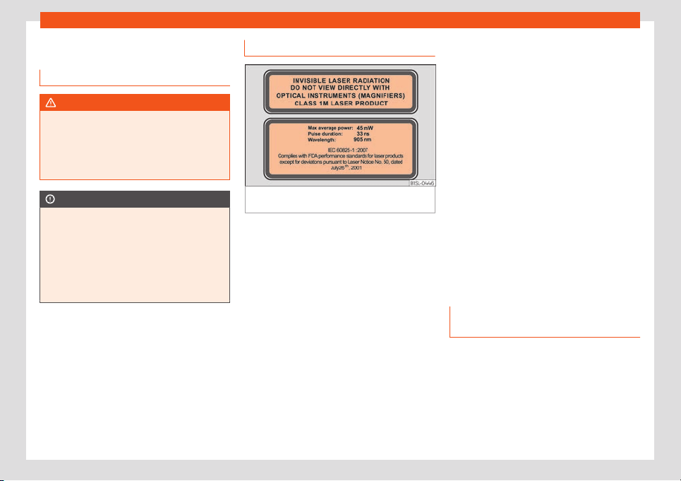
Information for the user
Other important information
Intr
oduction
WARNING
Failure to treat the vehicle with the correct
care increases the risk of accident and in-
jury.
●
Observ
e legal requirements.
●
Observe the Instruction Manual.
CAUTION
If the vehicle is not properly cared for,
damage may occur.
●
Observe l
egal requirements.
●
Carry out regular maintenance of the ve-
hicle, according to specifications in the
Maintenance Programme.
●
Observe the Instruction Manual.
Labels and plates
Fig. 192
Warnings relating to handling of the
Cit
y Saf
et
y Assist system laser sensor function.
Some parts in the engine compartment come
fr
om the f
act
ory with certificates of safety, la-
bels or plates containing important informa-
tion regarding the operation of the vehicle, for
example, on the fuel tank flap, on the pas-
senger's sun visor, on the driver door strut, or
on the floor of the boot.
●
Never remove these certificates of safety,
labels or plates, and ensure they are kept in
good condition and are legible.
●
If a vehicle part, bearing a certificate of
safety, label or plate, is replaced, the special-
ised workshop should attach the information
back in the same place.
Certificate of safety
A certificate of safety on the door strut states
that all the safety standards and regulations
established by the national traffic authorities
responsible for road safety were met at the
time of manufacture. It may also give the
month and year of manufacture, together
with the chassis number.
Warning of high voltage label
There is a label close to the bonnet lock
which warns of high voltage in the vehicle's
electrical system.
Warning relating to the City Safety Assist
system laser sensor
There are some warning and information
signs on the City Safety Assist system laser
sensor
›››
Fig. 192.
Using your vehicle in other coun-
tries and continents
The vehicle is manufactured at the factory for
use in a particul
ar country in accor
dance
with the national l
egislation in force at the
time of manufacture.
If the vehicle is sold in another country or
used in another country for an extended peri-
od of time, the applicable legislation of that
country should be observed.
»
227
Information for the user
It may be necessary to fit or remove certain
pieces of equipment or t
o deactiv
at
e certain
functions. Service work may also be affected.
This is particularly true if the vehicle is used in
a different climate for an extended period of
time.
CAUTION
●
SEAT does not accept liability for any
damage t
o the vehicle due to the use of a
lower quality fuel, an inadequate service or
the non-availability of genuine spare parts.
●
SEAT does not accept liability if the vehi-
cle does not comply in part or in full with
the legal requirements of other countries or
continents.
Radio and antenna reception
For factory-fitted radio equipment, the aerial
f
or r
adio r
eception is fitted to the roof of the
vehicle.
Note
If electrical equipment such as mobile tele-
phones, is used near a roof aerial, you may
observe int
erference in the reception of AM
stations.
Notes on SEAT repairs
WARNING
Repairs or modifications which are not per-
formed correctly may r
esult in damage or
errors in the vehicle operation, affecting
the effectiveness of the driver assist and
airbag systems. This could result in serious
accident.
●
Have any repairs or modifications carried
out at a specialised workshop.
Conformity certification
The respective manufacturer hereby de-
cl
ar
es that the pr
oducts indicated below
comply with basic requirements and the fol-
lowing provisions and important legislation on
the date of manufacture of the vehicle,
among others FCC Part 15.19, FCC Part 15.21
and RSS-Gen Issue 1:
Radio frequency equipment
●
Electronic gearbox lock.
●
Vehicle key
Electrical equipment
●
12 volt power socket
Collection and scrapping of end-
of-life vehicles
Collection of end-of-life vehicles
SEAT is already prepar
ed for the moment
when you wish to scrap your vehicle and of-
fers you an environmentally-friendly solution.
An extensive network of used car reception
centres already exists in much of Europe. Af-
ter the vehicle has been delivered, you will re-
ceive a certificate of destruction describing
the environmentally friendly scrapping of the
vehicle in accordance with applicable legis-
lation.
We will collect the used vehicle free of
charge, provided it complies with all national
legislation.
Please see your technical service for further
information about the collection and scrap-
ping of end-of-life vehicles.
Scrapping
The relevant safety requirements must be ob-
served when the vehicle or components of
the airbag or belt tensioner systems are
scrapped. These requirements are known to
specialised workshops.
228
Information for the user
Recycling of electrical or electron-
ic de
vices
All electrical or electronic devices (EED) that
are not permanently fitted in the v
ehicle must
be marked with the following symbol:
This symbol indicates that EED must not be
discarded as home waste but through selec-
tive waste collection.
Information about the EU Di-
rective 2014/53/EU
Simplified EU compliance decl
ara-
tion
Your vehicle has different radioelectrical devi-
ces. The manuf
act
ur
ers of these devices de-
clare that they comply with Directive
2014/53/EU when legally required.
The full text of the EU compliance declaration
is available online at the following address:
www.seat.com/generalinfo
Table of correspondences
The table of correspondences will help you to
associate the name of the device in the dec-
l
aration of compliance with the features of
the vehicle and the terminology used in the
on-board documentation.
Features of the
vehicle
Name of the de
vice
according to the dec-
laration of compli-
ance
Radiofrequency re-
mote control (v
ehicle)
FS09, FS12A, FS12P, FS1477,
FS94
Radio frequency re-
mote control (auxili-
ary heat
er)
Sender STH SEAT -
50000914
Telestart
Auxiliary heating 50000864 / D208L VW
Telestart
Bluetooth MIB2 Entry
MIB Standard 2
MIB2 Main-Unit
A580 / A270
Wireless hotspot MIB2 Main-Unit
A580 / A270
Keyless Access Sys-
tem
MQB-B B
Features of the
vehicle
Name of the de
vice
according to the dec-
laration of compli-
ance
Radar sensors for as-
sistance systems
ARS4-B
MRR
evo14F
BSD3.0
Central control unit 5WK50254
5WK50474
Infotainment system MIB2 Entry
MIB Standard 2
MIB2 Main-Unit
A580 / A270
Wireless charging WCH-183
WCH-185
5G0.980.611
Connection to the ex-
t
ernal antenna of the
car
UM
TS/GSM-MMC
UMTS/GSM-MMC-AG2
Instrument panel eNSF
Immobilizer integrated in
dashboard module
instrument cluster
»
229
Information for the user
Features of the
vehicle
Name of the de
vice
according to the dec-
laration of compli-
ance
Antenna FM/AM Antenna Base
Antennas MQB27 Small/Big
family
Antennas KSA Small F
am III
5Q0.035.507 Roof Antenna
GNSS Antenna VAG
720166002
8S7.035.503.B
Ant
enna amplifiers 6F0.035.225
6F9.
035.
225
3V5.
035.577.A
7N0.035.552.J
7N0.035.552.K
7N0.035.552.Q
5F4.035.225
5F4.035.225.A
5F4.035.225.B
5F9.035.225
5F9.035.225.A
5F9.035.225.B
575.035.225
575.035.225.A
575.035.225.B
Addresses of the manufacturers
According to the Directive 2014/53/EU, all
rele
vant components must include the ad-
dress of the manufacturer.
The address of the manufacturers of compo-
nents that, due to their size or nature, cannot
include a sticker are listed below, as long as it
is legally required:
Radioelectrical
equipment fitted
in the vehicl
e
Addresses of the
manufacturers
Radiofrequency remote
control key
Hell
a KGaA Hueck & Co.
Rixbecker Straße 75
59552 Lippst
adt,
GERMANY
Radio frequency re-
mote control (auxiliary
heat
er)
Digades gmbH
Äußere Weberstr
aße 20
02763 Zittau, GERMANY
Webasto Thermo &
Comfort SE
Friedrichshafener Str
. 9
82205 Gilching, GERMANY
Radioelectrical
equipment fitted
in the vehicl
e
Addresses of the
manufacturers
Radar sensors for as-
sistance systems
ADC Aut
omotive Distance
Control Systems GmbH
P
eter-Dornier-Straße 10
88131 Lindau, GERMANY
Robert Bosch GmbH
Postfach 16 61
7
1226 Leonberg,
GERMANY
230

Information for the user
Frequency bands, station power
Radioelectrical equipment
a)
Frequency band Max. station power Valid for models
Radiofrequency remote control (vehicle)
433.05-434.78 MHz 10 mW (ERP)
All SEAT models
433.05-434.79 MHz 10 mW
868.0-868.6 MHz 25 mW
434.42 MHz 32 µW
Radio frequency remote control (auxiliary heater)
868.7-869.2 MHz (869.0 MHz) 0.24 mW, / –6.3 dBm e.r.p. Ateca
868.0-868.6 MHz (868.3 MHz) 3.1 mW, / 4.8 dBm e.r.p. Alhambra
Auxiliary heating
868.0-868.6 MHz (868.3 MHz) 23.5 mW, / 13.7 dBm e.r.p. Alhambra
868.7-869.2 MHz (869.0 MHz) 23.5 mW, / 13.7 dBm e.r.p. Ateca
Bluethooth
2402-2480 MHz 6 dBm
All SEAT models
2400-2483.5 MHz 10 dBm
Wireless hotspot 2400-2483.5 MHz 10 dBm Leon and Ateca
Connection to the external antenna of the car
GSM 900: 880-915 MHz 33 dBm
Ibiza, Arona, Leon, Ateca and Alhambra
GSM 1800: 1710-1785 MHz 30 dBm
WCDMA FDD I: 1920-1980 MHz 24 dBm
WCDMA FDD lll: 1710-1785 MHz 24 dBm
Keyless Access 434.42 MHz 32 µW Ibiza, Toledo, Arona, Leon and Ateca
Radar sensors for assistance systems
76 GHz-77 GHz
28.2 dBm Toledo, Leon and Alhambra
35.0 dBm Ibiza, Arona and Ateca
24050-24250 MHz 20 dBm Arona, Ateca and Alhambra
Wireless charging 110-120 kHz 10 W Ibiza, Arona, Leon and Ateca
»
231

Information for the user
Radioelectrical equipment
a)
Frequency band Max. station power Valid for models
Instrument panel 125 kHz 40 dBµA/m All SEAT models
a)
The commissioning or authorisation of radioelectrical technology may be restricted in some European countries, forbidden or only allowed with additional requirements.
232
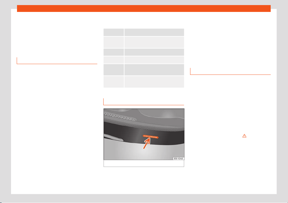
Technical features
Technical data
T
echnical f
eat
ures
Important information
Introduction
The information in the vehicle documentation
always t
akes precedence over the informa-
tion in this Instruction Manual.
All technical specifications provided in this
documentation are valid for the standard
model in Spain.
The figures may be different depending
whether additional equipment is fitted, for dif-
ferent models, for special vehicles and for
other countries.
Abbreviations used in the Technical Speci-
fications section
kW Kilowatt, engine power measurement.
PS
Pferdestärke (horsepower), formerly
used to denote engine po
wer.
rpm, 1/min Revolutions per minute - engine speed.
Nm Newton metres, unit of engine torque.
CZ
Cetane number, indication of the die-
sel combustion power
.
RON
Research octane number, indication of
the knock resistance of petr
ol.
Vehicle identification data
Fig. 193 Vehicle identification number.
Vehicle identification number
The v
ehicl
e identification number (chassis
number) can be r
ead from outside the vehicle
through a viewer in the windscreen
›››
Fig. 193. This viewer is located in the lower
part of the windscreen. The vehicle identifica-
tion number (chassis number) is also stam-
ped on the right water drain channel. The wa-
ter drain channel is located between the sus-
pension tower and the wing. Open the bonnet
to read the vehicle identification number .
Specific vehicle weight information
The instructions in the official vehicle docu-
ments t
ak
e pr
ecedence. All the technical da-
ta provided in this documentation is applica-
ble to the basic model.
The figures may be different depending
whether additional equipment is fitted, for dif-
ferent models and for special vehicles.
Kerb weight values shown in the following ta-
ble apply to a vehicle with driver (75 kg), liq-
uids including a fuel tank 90% full, in addition
to tools and a spare wheel
›››
. The kerb
w
eight indicat
ed incr
eases with optional
equipment and retrofitting of accessories,
while proportionally reducing carrying ca-
pacity.
The load is equivalent to the following
weights:
●
Passengers.
●
Total equipment.
»
233
Technical data
●
R
oof l
oad, included in the carrier
.
WARNING
Exceeding the maximum authorised weight
and the load on the axles coul
d cause
damage to the vehicle, accidents and seri-
ous injuries.
●
The real load on the axles should never
exceed the maximum permitted.
●
The load and its distribution in the vehicle
have effects on the vehicle handling and
the braking ability. Always drive at a suita-
ble speed.
CAUTION
Distribute the load as uniformly and as low
down on the vehicl
e as possible. When
transporting heavy objects in the luggage
compartment, these should be placed as
far forward as possible or over the rear axle
to have as little influence on handling as
possible.
Fuel consumption
Approved consumption values are derived
fr
om measur
ements perf
ormed or supervised
by certified EU laboratories, according to the
legislation in force at the time (for more infor-
mation, see the Publications Office of the Eu-
ropean Union on the EUR-Lex website: © Eu-
ropean Union, http://eur-lex.europa.eu/) and
apply to the specified vehicle characteristics.
The values relating to fuel consumption and
CO
2
emissions can be found in the documen-
tation provided to the purchaser of the vehi-
cle at the time of purchase.
Fuel consumption and CO
2
emissions de-
pend on the equipment/features of each indi-
vidual vehicle, as well as on the driving style,
road conditions, traffic conditions, environ-
mental conditions, load or number of passen-
gers.
Note
In practice, and considering all the factors
mentioned here, consumption v
alues can
differ from those calculated in the current
European regulations.
Wheels
T
yr
e pr
essure, snow chains and
wheel bolts
Tyre pressure
The stick
er with the t
yr
e pressure values can
be found on the back of the left front door
frame
›››
page 209. The tyre pressure values
given there are for cold tyres. Do not reduce
the slightly raised pressures of warm tyres
›››
.
Sno
w chains
Sno
w chains may be fitt
ed only to the front
wheels.
Consult section
›››
page 42, Snow
chains.
Wheel bolts
After the wheels have been changed, the
tightening torque of the wheel bolts should
be checked as soon as possible with a torque
wrench
›››
. The tightening torque for steel
and all
oy wheel
s is
110 Nm.
WARNING
●
Check the tyre pr
essure at least once per
month. Checking the tyre pressure is very
important. If the tyre pressure is too high or
too low, there is an increased danger of ac-
cidents - particularly at high speeds.
●
If the tightening torque of the wheel bolts
is too low, they could loosen while the vehi-
cle is in motion. Risk of accident! If the
tightening torque is too high, the wheel
bolts and threads can be damaged.
Note
We recommend that you ask your Techni-
cal Service for information about appr
opri-
ate wheel, tyre and snow chain size.
234

Technical features
Engine data
P
etr
ol engines
1.0 MPI
1.0 MPI
Ecomotive
1.0 MPI
St
art-Stop
Ecomotive
1.0 MPI
1.0 MPI
Start-Stop
1.0 MPI
Start-Stop
Ecomotive
Power output in kW (PS) at 1/min 44 (60)/5,000-6,000 55 (75)/6,200
Maximum torque (Nm at 1/min) 95/3,000-4,300 95/3,000-4,300
No. of cylinders/displacement (cm
3
) 3/999 3/999
Fuel Super 95 / Normal 91 (with a slight power loss) ROZ
Gearbox manual automatic manual manual manual automatic manual manual
Top speed (km/h) 161 (4) 161 (4) 161 (4) 161 (4) 172 (4) 172 (4) 172 (4) 172 (4)
Acceleration from 0-80 km/h (sec-
onds)
9.1 10.9 9.1 10.9 8.7 10.1 8.7 10.1
Acceleration from 0-100 km/h (sec-
onds)
14.4 16.7 14.4 16.7 13.5 14.9 13.5 14.9
Maximum authorised weight (kg) 1,320 1,330 1,330 1,330 1,330 1,300 1,330 1,330
Weight in running order (with driver)
(k
g)
926 937 934 940 928 931 936 936
Maximum authorised weight on front
axle (kg)
680 680 680 680 680 680 680 680
Maximum authorised weight on rear
axle (kg)
640 640 640 640 640 640 640 640
235

Technical data
Natural gas / petrol engines
1.0 MPI
Power output in kW (PS) at 1/min 50 (68)/6,200
Maximum torque (Nm at 1/min) 90/3,000
No. of cylinders/displacement (cm
3
) 3/999
Fuel
CNG
Super 95 / Normal 91 (with a slight power loss) ROZ
Gearbox manual
Top speed (km/h) 164 (4)
Acceleration from 0-80 km/h (seconds) 10.3
Acceleration from 0-100 km/h (seconds) 16.3
Maximum authorised weight (kg) 1,380
Weight in running order (with driver) (kg) 1,033
Maximum authorised weight on front axle (kg) 680
Maximum authorised weight on rear axle (kg) 640
236
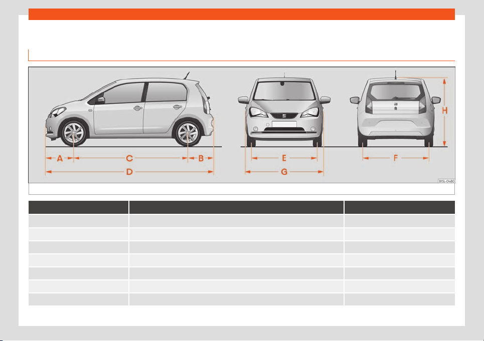
Technical features
Vehicle data
Dimensions
Fig. 194 Dimensions.
Mii
A/B Front and rear projection (mm) 595/542
C Wheelbase (mm) 2,420
D Length (mm) 3,557
E/F Front/rear
a)
track width (mm) 1,428/1,4
24
G Width (mm) 1,645
H Height at kerb weight (mm) 1,478
Turning radius (m) approx. 9.8
a)
This data will change depending on the type of wheel rim.
237


Index
Index
A
Abr
oad
e
xt
ended stay abroad with your vehicle . . . 227
sale of vehicle . . . . . . . . . . . . . . . . . . . . . . . . . . . . . 227
ABS
see Anti-lock brake system . . . . . . . . . . . . . . . . 156
Accessories . . . . . . . . . . . . . . . . . . . . . . . . . . . . . . . . . 180
Acoustic alarm
control and warning lamps . . . . . . . . . . . . . . . . . 27
seat belt unfastened . . . . . . . . . . . . . . . . . . . . . . . 55
Adjust
front seat . . . . . . . . . . . . . . . . . . . . . . . . . . . . . . . . . . 112
Adjusting
lights . . . . . . . . . . . . . . . . . . . . . . . . . . . . . . . . . . . . . . 107
rear head restraints . . . . . . . . . . . . . . . . . . . . 52, 112
seats . . . . . . . . . . . . . . . . . . . . . . . . . . . . . . . . . . . . . . . 49
Adjusting the head restraints
rear head restraints . . . . . . . . . . . . . . . . . . . . . . . . 112
Advice for driving
spare wheel or temporary spare wheel . . . . 213
Airbag covers . . . . . . . . . . . . . . . . . . . . . . . . . . . . . . . . . 16
Airbags . . . . . . . . . . . . . . . . . . . . . . . . . . . . . . . . . . . . . . 60
Airbag system . . . . . . . . . . . . . . . . . . . . . . . . . . . . 16, 60
activation . . . . . . . . . . . . . . . . . . . . . . . . . . . . . . . . . . 62
control lamp . . . . . . . . . . . . . . . . . . . . . . . . . . . . . . . 64
description . . . . . . . . . . . . . . . . . . . . . . . . . . . . . . . . . 61
front airbags . . . . . . . . . . . . . . . . . . . . . . . . . . . . 16, 63
functioning . . . . . . . . . . . . . . . . . . . . . . . . . . . . . . . . . 62
locking the vehicle after deployment . . . . . . . 95
repairs . . . . . . . . . . . . . . . . . . . . . . . . . . . . . . . . . . . . . 182
side airbags . . . . . . . . . . . . . . . . . . . . . . . . . . . . . . . . 18
use of child seats . . . . . . . . . . . . . . . . . . . . . . . . . . . 17
Air conditioning . . . . . . . . . . . . . . . . . . . . . . . . . . . . . . 129
air recirculation . . . . . . . . . . . . . . . . . . . . . . . . . . . . 129
air vents . . . . . . . . . . . . . . . . . . . . . . . . . . . . . . . . . . . 130
climatronic . . . . . . . . . . . . . . . . . . . . . . . . . . . . 29, 129
instructions for use . . . . . . . . . . . . . . . . . . . . . . . . . 131
malfunction . . . . . . . . . . . . . . . . . . . . . . . . . . . . . . . . 131
tips . . . . . . . . . . . . . . . . . . . . . . . . . . . . . . . . . . . . . . . . . 131
water under vehicle . . . . . . . . . . . . . . . . . . . . . . . 132
Air recirculation . . . . . . . . . . . . . . . . . . . . . . . . . . . . . . 129
Climatronic . . . . . . . . . . . . . . . . . . . . . . . . . . . . . . . . 30
how it works . . . . . . . . . . . . . . . . . . . . . . . . . . . . . . . 129
switching off . . . . . . . . . . . . . . . . . . . . . . . . . . . . . . . 129
switching on . . . . . . . . . . . . . . . . . . . . . . . . . . . . . . . 129
Air vents . . . . . . . . . . . . . . . . . . . . . . . . . . . . . . . . . . . . . 130
Alcantara leather: cleaning . . . . . . . . . . . . . . . . . 223
Antenna . . . . . . . . . . . . . . . . . . . . . . . . . . . . . . . . 182, 228
Anti-freeze . . . . . . . . . . . . . . . . . . . . . . . . . . . . . . . . . . . . 33
Anti-lock brake system . . . . . . . . . . . . . . . . . . . . . . 156
Anti-lock system . . . . . . . . . . . . . . . . . . . . . . . . . . . . . 157
Anti-puncture . . . . . . . . . . . . . . . . . . . . . . . . . . . . . 36, 73
Anti-puncture kit . . . . . . . . . . . . . . . . . . . . . . . . . . 36, 73
check after 10 minutes . . . . . . . . . . . . . . . . . . . . . . 74
do not use . . . . . . . . . . . . . . . . . . . . . . . . . . . . . . . . . . 73
Anti-puncture set . . . . . . . . . . . . . . . . . . . . . . . . . . . . . 73
Anti-theft security system . . . . . . . . . . . . . . . . . . . . . 97
Ashtray . . . . . . . . . . . . . . . . . . . . . . . . . . . . . . . . . . . . . . 119
Aspects to take into account before starting
the vehicle . . . . . . . . . . . . . . . . . . . . . . . . . . . . . . . . . 48
ASR
see Traction control system . . . . . . . . . . . . . . . 156
Assistance systems
brake assist system (BAS) . . . . . . . . . . . . . . . . . . 157
cruise control system . . . . . . . . . . . . . . . . . . . . . . 171
electronic differential lock (EDS) . . . . . . . . . . 158
optical parking system (OPS) . . . . . . . . . . . . . . 174
parking aid . . . . . . . . . . . . . . . . . . . . . . . . . . . . . . . . 173
parking distance warning system . . . . . . . . . . 173
safety Assist . . . . . . . . . . . . . . . . . . . . . . . . . . . . . . . 174
traction control (ASR) . . . . . . . . . . . . . . . . . . . . . . 157
Assisted starting . . . . . . . . . . . . . . . . . . . . . . . . . . . . . . 44
Assist systems
traction control (TC) . . . . . . . . . . . . . . . . . . . . . . . 157
Audible warning
lights . . . . . . . . . . . . . . . . . . . . . . . . . . . . . . . . . . . . . . 103
speed . . . . . . . . . . . . . . . . . . . . . . . . . . . . . . . . . . . . . . 26
Automatic belt retractor . . . . . . . . . . . . . . . . . . . . . . 59
Automatic car wash tunnel . . . . . . . . . . . . . . . . . . 221
Automatic device disconnection
battery . . . . . . . . . . . . . . . . . . . . . . . . . . . . . . . . . . . 205
Automatic dipped beam control . . . . . . . . . . . . . 104
Automatic gearbox
driving tips . . . . . . . . . . . . . . . . . . . . . . . . . . . . . . . . . 161
ignition key removal lock . . . . . . . . . . . . . . . . . . 150
kick-down . . . . . . . . . . . . . . . . . . . . . . . . . . . . . . . . . 161
malfunction . . . . . . . . . . . . . . . . . . . . . . . . . . . . . . . 162
starting on a slope . . . . . . . . . . . . . . . . . . . . . . . . . 162
stopping on a slope . . . . . . . . . . . . . . . . . . . . . . . 162
Automatic gear change . . . . . . . . . . . . . . . . . . . . . 160
AUX-IN . . . . . . . . . . . . . . . . . . . . . . . . . . . . . . . . . . . . . . . 144
AUX-IN multimedia source . . . . . . . . . . . . . . . . . . . 144
Axle loads . . . . . . . . . . . . . . . . . . . . . . . . . . . . . . . . . . . 233
B
Bag support . . . . . . . . . . . . . . . . . . . . . . . . . . . . . . . . . . 117
BAS
see Brake assist system . . . . . . . . . . . . . . . . . . . . 157
Battery
changing in the vehicle key . . . . . . . . . . . . . . . . . 93
Battery acid . . . . . . . . . . . . . . . . . . . . . . . . . . . . . . . . . 204
Before starting the vehicle . . . . . . . . . . . . . . . . . . . . 48
239

Index
Belt tension device
service and disposal . . . . . . . . . . . . . . . . . . . . . . .
59
Belt t
ensioner . . . . . . . . . . . . . . . . . . . . . . . . . . . . . . . .
59
Belt tension limiter . . . . . . . . . . . . . . . . . . . . . . . . . . . . 59
Belt tightening . . . . . . . . . . . . . . . . . . . . . . . . . . . . . . . . 59
Bluetooth . . . . . . . . . . . . . . . . . . . . . . . . . . . . . . . . . . . . 143
Bonnet . . . . . . . . . . . . . . . . . . . . . . . . . . . . . . . . . . . 12, 193
Brake assistance system . . . . . . . . . . . . . . . . . . . . . 156
Brake assist system . . . . . . . . . . . . . . . . . . . . . . . . . . 156
Brake fluid . . . . . . . . . . . . . . . . . . . . . . . . . . . . . . . . . . . . 34
specification . . . . . . . . . . . . . . . . . . . . . . . . . . . . . . 200
Brakes . . . . . . . . . . . . . . . . . . . . . . . . . . . . . . . . . . . . . . . 151
brake assist system . . . . . . . . . . . . . . . . . . . . . . . . 156
brake fluid . . . . . . . . . . . . . . . . . . . . . . . . . . . . . . . . 200
brake fluid level . . . . . . . . . . . . . . . . . . . . . . . . . . . . 201
brake pads . . . . . . . . . . . . . . . . . . . . . . . . . . . . . . . . 154
brake servo . . . . . . . . . . . . . . . . . . . . . . . . . . . . . . . . 154
changing the brake fluid . . . . . . . . . . . . . . . . . . . 201
control and warning lamps . . . . . . . . . . . . . . . . 152
running in new brake pads . . . . . . . . . . . . . . . . . 154
warning and control lamps . . . . . . . . . . . . . . . . 156
Brake servo . . . . . . . . . . . . . . . . . . . . . . . . . . . . . 154, 156
Brake system . . . . . . . . . . . . . . . . . . . . . . . . . . . . . . . . 156
fault . . . . . . . . . . . . . . . . . . . . . . . . . . . . . . . . . . . . . . . 154
Braking
brake assistance system . . . . . . . . . . . . . . . . . . 156
Bulb fault
See "Changing bulbs" . . . . . . . . . . . . . . . . . . . . . . 79
C
Capacities . . . . . . . . . . . . . . . . . . . . . . . . . . . . . . . . . . . 32
natural gas tank . . . . . . . . . . . . . . . . . . . . . . . . . . . 192
windscreen washer liquid reservoir . . . . . . . . 202
Catalytic converter . . . . . . . . . . . . . . . . . . . . . . . . . 168
control and warning lamps . . . . . . . . . . . . . . . . 168
malfunction . . . . . . . . . . . . . . . . . . . . . . . . . . . . . . . 168
CCS
see cruise control . . . . . . . . . . . . . . . . . . . . . . . . . . 26
Central locking . . . . . . . . . . . . . . . . . . . . . . . . . . . . . . . 94
emergency locking . . . . . . . . . . . . . . . . . . . . . . . . . . 11
opening doors individually . . . . . . . . . . . . . . . . . 95
Central locking system
after airbag deployment . . . . . . . . . . . . . . . . . . . 95
description . . . . . . . . . . . . . . . . . . . . . . . . . . . . . . . . . 95
remote control key . . . . . . . . . . . . . . . . . . . . . . . . . 95
Changes . . . . . . . . . . . . . . . . . . . . . . . . . . . . . . . . . . . . . 181
Changing a wheel . . . . . . . . . . . . . . . . . . . . . . . . 37, 72
subsequent tasks . . . . . . . . . . . . . . . . . . . . . . . . . . . 42
wheel bolts . . . . . . . . . . . . . . . . . . . . . . . . . . . . . . . . . 39
Changing bulbs . . . . . . . . . . . . . . . . . . . . . . . . . . . . . . 79
front bumper . . . . . . . . . . . . . . . . . . . . . . . . . . . . . . . 81
headlights . . . . . . . . . . . . . . . . . . . . . . . . . . . . . . . . . 80
number plate light . . . . . . . . . . . . . . . . . . . . . . . . . . 83
rear lights . . . . . . . . . . . . . . . . . . . . . . . . . . . . . . . . . . 82
side turn signal . . . . . . . . . . . . . . . . . . . . . . . . . . . . . 84
Changing gear . . . . . . . . . . . . . . . . . . . . . . . . . . . . . . 158
automatic gear change . . . . . . . . . . . . . . . . . . . 160
control and warning lamps . . . . . . . . . . . . . . . . 159
engaging the gears (automatic gearbox) . 160
tiptronic . . . . . . . . . . . . . . . . . . . . . . . . . . . . . . . . . . . . 161
Changing the blades . . . . . . . . . . . . . . . . . . . . . . . . . 75
Changing the wiper blades . . . . . . . . . . . . . . . . . . 46
Charging the battery . . . . . . . . . . . . . . . . . . . . . . . . . 44
Child safety seat
securing with the seat belt . . . . . . . . . . . . . . . . . . 19
Child seat . . . . . . . . . . . . . . . . . . . . . . . . . . . . . . . . . 18, 67
Child seats
disabling the front passenger front airbag . . 17
ISOFIX system . . . . . . . . . . . . . . . . . . . . . . . . . . 20, 69
mounting child seats . . . . . . . . . . . . . . . . . . . . . . . . 19
mounting systems . . . . . . . . . . . . . . . . . . . . . . . . . . 19
on the front passenger seat . . . . . . . . . . . . . . . . 68
on the rear seats . . . . . . . . . . . . . . . . . . . . . . . . . . . 69
regulations . . . . . . . . . . . . . . . . . . . . . . . . . . . . . . . . . 68
safety instructions . . . . . . . . . . . . . . . . . . . . . . 18, 66
Top Tether system . . . . . . . . . . . . . . . . . . . . . . . . . . 21
transporting children in the vehicle . . . . . . . . . 67
weight categories . . . . . . . . . . . . . . . . . . . . . . . . . . 68
Cigarette lighter . . . . . . . . . . . . . . . . . . . . . . . . . . . . . 120
City safety assist . . . . . . . . . . . . . . . . . . . . . . . . . . . . 174
City Safety Assist function
control and warning lamps . . . . . . . . . . . . . . . . 175
function . . . . . . . . . . . . . . . . . . . . . . . . . . . . . . . . . . . . 177
sensor . . . . . . . . . . . . . . . . . . . . . . . . . . . . . . . . . . . . . 176
special driving situations . . . . . . . . . . . . . . . . . . 178
Cleaning
Alcantara leather . . . . . . . . . . . . . . . . . . . . . . . . . 223
carbon fibre . . . . . . . . . . . . . . . . . . . . . . . . . . 222, 224
control panels . . . . . . . . . . . . . . . . . . . . . . . . . . . . 223
decorative sheets . . . . . . . . . . . . . . . . . . . . . . . . . 223
exhaust tail pipes . . . . . . . . . . . . . . . . . . . . . . . . . . 222
exterior . . . . . . . . . . . . . . . . . . . . . . . . . . . . . . . . . . . . 222
fabrics . . . . . . . . . . . . . . . . . . . . . . . . . . . . . . . . . . . . 223
headlights / tail lights . . . . . . . . . . . . . . . . . . . . . 222
high pressure cleaners . . . . . . . . . . . . . . . . . . . . 220
Interior . . . . . . . . . . . . . . . . . . . . . . . . . . . . . . . . . . . . 223
leather . . . . . . . . . . . . . . . . . . . . . . . . . . . . . . . . . . . . 223
paint . . . . . . . . . . . . . . . . . . . . . . . . . . . . . . . . . . . . . . 222
plastic parts . . . . . . . . . . . . . . . . . . . . . . . . . . . . . . . 223
seat belts . . . . . . . . . . . . . . . . . . . . . . . . . . . . . . . . . 223
sensors/camera lenses . . . . . . . . . . . . . . . . . . . 222
240

Index
special care . . . . . . . . . . . . . . . . . . . . . . . . . . . . . . . 224
the r
adio scr
een . . . . . . . . . . . . . . . . . . . . . . . . . . .
223
trims/covers . . . . . . . . . . . . . . . . . . . . . . . . . . 222, 223
washing the vehicle . . . . . . . . . . . . . . . . . . . . . . . 220
wheels . . . . . . . . . . . . . . . . . . . . . . . . . . . . . . . . . . . . 222
windows . . . . . . . . . . . . . . . . . . . . . . . . . . . . . . . . . . 223
windscreen wipers . . . . . . . . . . . . . . . . . . . . . . . . 222
Climatronic
adjusting the temperature . . . . . . . . . . . . . . . . . . 29
air distribution . . . . . . . . . . . . . . . . . . . . . . . . . . . . . . 29
air recirculation . . . . . . . . . . . . . . . . . . . . . . . . . . . . 30
AUTO (automatic mode) . . . . . . . . . . . . . . . . . . . 29
controls . . . . . . . . . . . . . . . . . . . . . . . . . . . . . . . . . . . . 29
cooling mode . . . . . . . . . . . . . . . . . . . . . . . . . . . . . . 29
fan . . . . . . . . . . . . . . . . . . . . . . . . . . . . . . . . . . . . . . . . . 29
removing ice from windows . . . . . . . . . . . . . . . . . 29
switch off . . . . . . . . . . . . . . . . . . . . . . . . . . . . . . . . . . . 29
Close . . . . . . . . . . . . . . . . . . . . . . . . . . . . . . . . . . . . . . . . . 92
bonnet . . . . . . . . . . . . . . . . . . . . . . . . . . . . . . . . . . . . . . 12
Closing . . . . . . . . . . . . . . . . . . . . . . . . . . . . . . . . . . . . . . . 92
bonnet . . . . . . . . . . . . . . . . . . . . . . . . . . . . . . . . . . . . . . 12
electric windows . . . . . . . . . . . . . . . . . . . . . . . . . . . . 13
luggage compartment . . . . . . . . . . . . . . . . . . . . 100
panoramic sunroof . . . . . . . . . . . . . . . . . . . . . . . . . . 13
windows . . . . . . . . . . . . . . . . . . . . . . . . . . . . . . . . . . . 101
Clothes hook . . . . . . . . . . . . . . . . . . . . . . . . . . . . . . . . 118
Code number . . . . . . . . . . . . . . . . . . . . . . . . . . . . . . . . . 71
Coming Home Function . . . . . . . . . . . . . . . . . . . . . 105
Compartments . . . . . . . . . . . . . . . . . . . . . . . . . . . . . . 115
centre console . . . . . . . . . . . . . . . . . . . . . . . . . . . . . 116
glove compartment . . . . . . . . . . . . . . . . . . . . . . . . 117
passenger side . . . . . . . . . . . . . . . . . . . . . . . . . . . . 117
Sunglasses storage compartment . . . . . . . . . 117
Conformity certification . . . . . . . . . . . . . . . . . . . . . 228
Control and warning lamps . . . . . . . . . . . . . . . . . . . 27
airbag system . . . . . . . . . . . . . . . . . . . . . . . . . . . . . . 64
brake system . . . . . . . . . . . . . . . . . . . . . . . . . . . . . . 152
catalytic converter . . . . . . . . . . . . . . . . . . . . . . . . 168
changing gear . . . . . . . . . . . . . . . . . . . . . . . . . . . . 159
City Safety Assist function . . . . . . . . . . . . . . . . . 175
coolant . . . . . . . . . . . . . . . . . . . . . . . . . . . . . . . . . . . . 198
cruise control . . . . . . . . . . . . . . . . . . . . . . . . . . . . . . 171
cruise control system . . . . . . . . . . . . . . . . . . . . . . 171
emission control system . . . . . . . . . . . . . . . . . . . 168
engine management . . . . . . . . . . . . . . . . . . . . . . 168
engine oil sensor . . . . . . . . . . . . . . . . . . . . . . . . . . 195
ESC . . . . . . . . . . . . . . . . . . . . . . . . . . . . . . . . . . . . . . . 152
for the seat belt . . . . . . . . . . . . . . . . . . . . . . . . . . . . 54
fuel level . . . . . . . . . . . . . . . . . . . . . . . . . . . . . . . . . . 190
generator . . . . . . . . . . . . . . . . . . . . . . . . . . . . . . . . . 203
hill hold . . . . . . . . . . . . . . . . . . . . . . . . . . . . . . . . . . . . 170
indication of brake pad wear . . . . . . . . . . . . . . 152
key . . . . . . . . . . . . . . . . . . . . . . . . . . . . . . . . . . . . . . . . . 93
lights . . . . . . . . . . . . . . . . . . . . . . . . . . . . . . . . . . . . . . 103
locking the steering column . . . . . . . . . . . . . . . 164
on the driver door . . . . . . . . . . . . . . . . . . . . . . . . . . 98
overview . . . . . . . . . . . . . . . . . . . . . . . . . . . . . . . . . . . . 27
refuelling . . . . . . . . . . . . . . . . . . . . . . . . . . . . . . 190, 191
tyres . . . . . . . . . . . . . . . . . . . . . . . . . . . . . . . . . . . . . . . 212
vehicle battery . . . . . . . . . . . . . . . . . . . . . . . . . . . . 203
Controls for the windows . . . . . . . . . . . . . . . . . 13, 101
Control units . . . . . . . . . . . . . . . . . . . . . . . . . . . . . . . . 226
reprogramming . . . . . . . . . . . . . . . . . . . . . . . . . . . 226
Coolant
checking the level . . . . . . . . . . . . . . . . . . . . . . . . . 199
control and warning lamps . . . . . . . . . . . . . . . . 198
filler neck . . . . . . . . . . . . . . . . . . . . . . . . . . . . . . . . . . 199
topping up . . . . . . . . . . . . . . . . . . . . . . . . . . . . . . . . 199
Cooling system
checking the coolant . . . . . . . . . . . . . . . . . . . . . . 198
topping up with coolant . . . . . . . . . . . . . . . . . . . 198
Correct position . . . . . . . . . . . . . . . . . . . . . . . . . . . . . . 49
Correct sitting position
driver . . . . . . . . . . . . . . . . . . . . . . . . . . . . . . . . . . . . . . 49
Cruise control . . . . . . . . . . . . . . . . . . . . . . . . . . . . 26, 171
control and warning lamps . . . . . . . . . . . . . . . . . 171
operation . . . . . . . . . . . . . . . . . . . . . . . . . . . . . . . . . . 172
Cruise control system . . . . . . . . . . . . . . . . . . . . . . . . 171
D
Dangers in not using the seat belt . . . . . . . . . . . . 56
Dash panel . . . . . . . . . . . . . . . . . . . . . . . . . . . . . . . . . . . 87
Data registry . . . . . . . . . . . . . . . . . . . . . . . . . . . . . . . . 226
Data storage during the journey . . . . . . . . . . . . 226
Daytime running lights . . . . . . . . . . . . . . . . . . . . . . 104
Diagnostics connector . . . . . . . . . . . . . . . . . . . . . . 226
Digital clock . . . . . . . . . . . . . . . . . . . . . . . . . . . . . . . . . . 88
Dimensions . . . . . . . . . . . . . . . . . . . . . . . . . . . . . . . . . . 237
Direction of rotation
tyres . . . . . . . . . . . . . . . . . . . . . . . . . . . . . . . . . . . . . . . 42
Disabling the front passenger front airbag . . . . 17
Display . . . . . . . . . . . . . . . . . . . . . . . . . . . . . . . . . . . 88, 89
Disposal
belt tension device . . . . . . . . . . . . . . . . . . . . . . . . . 59
Door cylinder . . . . . . . . . . . . . . . . . . . . . . . . . . . . . . . . . 10
Door lock . . . . . . . . . . . . . . . . . . . . . . . . . . . . . . . . . . . . . 10
Door release lever . . . . . . . . . . . . . . . . . . . . . . . . . . . . 10
interior . . . . . . . . . . . . . . . . . . . . . . . . . . . . . . . . . . . . . 87
Doors . . . . . . . . . . . . . . . . . . . . . . . . . . . . . . . . . . . . . . . . 98
childproof locks . . . . . . . . . . . . . . . . . . . . . . . . . . . . 98
Emergency closing or opening . . . . . . . . . . . . . 10
opening and closing . . . . . . . . . . . . . . . . . . . . . . . . 10
241

Index
Drink holders . . . . . . . . . . . . . . . . . . . . . . . . . . . . . . . . . 118
Centr
e consol
e . . . . . . . . . . . . . . . . . . . . . . . . . . . .
119
Driver
see Correct sitting position . . . . . . . . . . . . . . . . . 49
Driving
automatic gearbox . . . . . . . . . . . . . . . . . . . . . . . . 161
data storage . . . . . . . . . . . . . . . . . . . . . . . . . . . . . . 226
driving abroad . . . . . . . . . . . . . . . . . . . . . . . . . . . . 169
driving through water . . . . . . . . . . . . . . . . . . . . . . 169
economical . . . . . . . . . . . . . . . . . . . . . . . . . . . . . . . 166
fuel gauge . . . . . . . . . . . . . . . . . . . . . . . . . . . . . . . . 190
fuel level too low . . . . . . . . . . . . . . . . . . . . . . . . . . 190
parking downhill . . . . . . . . . . . . . . . . . . . . . . . . . . . 153
parking uphill . . . . . . . . . . . . . . . . . . . . . . . . . . . . . . 153
safe . . . . . . . . . . . . . . . . . . . . . . . . . . . . . . . . . . . . . . . . 48
starting on a slope . . . . . . . . . . . . . . . . . . . . . . . . . 162
stopping on a slope . . . . . . . . . . . . . . . . . . . . . . . 162
through salt water . . . . . . . . . . . . . . . . . . . . . . . . . 169
with a trailer . . . . . . . . . . . . . . . . . . . . . . . . . . . . . . . 179
Driving abroad
headlights . . . . . . . . . . . . . . . . . . . . . . . . . . . . . . . . . 107
Driving in winter
fuel consumption . . . . . . . . . . . . . . . . . . . . . . . . . . 167
snow chains . . . . . . . . . . . . . . . . . . . . . . . . . . . . . . . . 42
traces of salt . . . . . . . . . . . . . . . . . . . . . . . . . . . . . . 110
tread depth . . . . . . . . . . . . . . . . . . . . . . . . . . . . . . . . 211
tyre pressure . . . . . . . . . . . . . . . . . . . . . . . . . . . . . . 210
Driving through water . . . . . . . . . . . . . . . . . . . . . . . 169
Driving tips
For a loaded vehicle . . . . . . . . . . . . . . . . . . . . . . . 114
Duplicate keys . . . . . . . . . . . . . . . . . . . . . . . . . . . . . . . 92
Dust filter . . . . . . . . . . . . . . . . . . . . . . . . . . . . . . . . . . . . 132
Dynamic headlight range control . . . . . . . . . . . . 107
E
E10
see Ethanol (fuel) . . . . . . . . . . . . . . . . . . . . . . . . . . 187
EDL
see Electronic differential lock . . . . . . . . . . . . . 156
EDS
see "Brake assist system" . . . . . . . . . . . . . . . . . . 158
Electrical devices . . . . . . . . . . . . . . . . . . . . . . . . 120, 121
Electric windows . . . . . . . . . . . . . . . . . . . . . . . . . . . . . . 13
buttons . . . . . . . . . . . . . . . . . . . . . . . . . . . . . . . . . . . . 101
closing . . . . . . . . . . . . . . . . . . . . . . . . . . . . . . . . . . . . . 101
opening . . . . . . . . . . . . . . . . . . . . . . . . . . . . . . . . . . . 101
see Windows . . . . . . . . . . . . . . . . . . . . . . . . . . . . . . 101
Electronic differential lock . . . . . . . . . . . . . . . . . . . 156
Electronic immobiliser . . . . . . . . . . . . . . . . . . . . . . . . 151
operating fault . . . . . . . . . . . . . . . . . . . . . . . . . . . . 149
Electronic Stability Control (ESC) . . . . . . . . . . . . 156
Emergencies . . . . . . . . . . . . . . . . . . . . . . . . . . . . . . . . . 70
bulbs . . . . . . . . . . . . . . . . . . . . . . . . . . . . . . . . . . . . . . . 36
changing a wheel . . . . . . . . . . . . . . . . . . . . . . . . . . 37
emergency towing of the vehicle . . . . . . . . . . . 43
fire extinguishers . . . . . . . . . . . . . . . . . . . . . . . . . . . 70
first aid kit . . . . . . . . . . . . . . . . . . . . . . . . . . . . . . . . . . 70
fuses . . . . . . . . . . . . . . . . . . . . . . . . . . . . . . . . . . . . . . . 35
hazard warning lights . . . . . . . . . . . . . . . . . . . . . 106
jump leads . . . . . . . . . . . . . . . . . . . . . . . . . . . . . . . . . 44
puncture . . . . . . . . . . . . . . . . . . . . . . . . . . . . . . . . . . . 36
replacing a blown fuse . . . . . . . . . . . . . . . . . . . . . 35
vehicle tool kit . . . . . . . . . . . . . . . . . . . . . . . . . . . . . . 70
warning triangle . . . . . . . . . . . . . . . . . . . . . . . . . . . . 70
Emergency closing or opening
driver door . . . . . . . . . . . . . . . . . . . . . . . . . . . . . . . . . . 10
passenger door . . . . . . . . . . . . . . . . . . . . . . . . . . . . . 11
Emergency locking and unlocking . . . . . . . . . . . . 77
rear lid . . . . . . . . . . . . . . . . . . . . . . . . . . . . . . . . . . . . . . 12
Emergency unlocking
rear lid . . . . . . . . . . . . . . . . . . . . . . . . . . . . . . . . . . . . . . 12
Emission control system
control and warning lamps . . . . . . . . . . . . . . . . 168
Emissions data . . . . . . . . . . . . . . . . . . . . . . . . . . . . . . 234
Engine
assisted starting . . . . . . . . . . . . . . . . . . . . . . . . . . . . 44
noises . . . . . . . . . . . . . . . . . . . . . . . . . . . . . . . . . . . . . 150
running in . . . . . . . . . . . . . . . . . . . . . . . . . . . . . . . . . . 165
Start-Stop system . . . . . . . . . . . . . . . . . . . . . . . . . 170
Engine and ignition . . . . . . . . . . . . . . . . . . . . . . . . . . 149
12 Volt sockets . . . . . . . . . . . . . . . . . . . . . . . . . . . . . 121
ignition lock . . . . . . . . . . . . . . . . . . . . . . . . . . . . . . . 149
Immobiliser . . . . . . . . . . . . . . . . . . . . . . . . . . . . . . . . 151
starting the engine . . . . . . . . . . . . . . . . . . . . . . . . 149
stopping the engine . . . . . . . . . . . . . . . . . . . . . . . 150
unauthorised vehicle key . . . . . . . . . . . . . . . . . . 149
Engine compartment . . . . . . . . . . . . . . . . . . . . . 12, 193
battery . . . . . . . . . . . . . . . . . . . . . . . . . . . . . . . . 34, 202
brake fluid . . . . . . . . . . . . . . . . . . . . . . . . . . . . 34, 200
coolant . . . . . . . . . . . . . . . . . . . . . . . . . . . . . . . . 33, 198
engine oil . . . . . . . . . . . . . . . . . . . . . . . . . . . . . . 32, 197
windscreen washer reservoir . . . . . . . . . . 34, 201
Engine coolant . . . . . . . . . . . . . . . . . . . . . . . . . . . . . . . 33
checking the level . . . . . . . . . . . . . . . . . . . . . . . . . 198
G 12 plus-plus . . . . . . . . . . . . . . . . . . . . . . . . . . . . . . 33
G 13 . . . . . . . . . . . . . . . . . . . . . . . . . . . . . . . . . . . . . . . . 33
specifications . . . . . . . . . . . . . . . . . . . . . . . . . . . . . . 33
temperature display . . . . . . . . . . . . . . . . . . . . . . . 198
Engine data . . . . . . . . . . . . . . . . . . . . . . . . . . . . . . . . . 235
Engine management . . . . . . . . . . . . . . . . . . . . . . . . 168
control lamps . . . . . . . . . . . . . . . . . . . . . . . . . . . . . 168
242

Index
Engine oil . . . . . . . . . . . . . . . . . . . . . . . . . . . . . . . . 32, 195
changing . . . . . . . . . . . . . . . . . . . . . . . . . . . . . . . . . .
195
checking oil l
e
vel . . . . . . . . . . . . . . . . . . . . . . . . . . 196
consumption . . . . . . . . . . . . . . . . . . . . . . . . . . 196, 197
control and warning lamps . . . . . . . . . . . . . . . . 195
dipstick . . . . . . . . . . . . . . . . . . . . . . . . . . . . . . . . . . . . 196
specifications . . . . . . . . . . . . . . . . . . . . . . . . . . . . . 195
topping up . . . . . . . . . . . . . . . . . . . . . . . . . . . . . . . . . 197
Environment
environmental compatibility . . . . . . . . . . . . . . . 165
Environmental
ecological driving . . . . . . . . . . . . . . . . . . . . . . . . . 166
Environmental tips
refuelling . . . . . . . . . . . . . . . . . . . . . . . . . . . . . . . . . . 191
Equipment . . . . . . . . . . . . . . . . . . . . . . . . . . . . . . . . . . . 180
safety . . . . . . . . . . . . . . . . . . . . . . . . . . . . . . . . . . . . . . . 61
ESC
electronic stability control . . . . . . . . . . . . . . . . . 156
Ethanol (fuel) . . . . . . . . . . . . . . . . . . . . . . . . . . . . . . . . 187
Event Data Recorder . . . . . . . . . . . . . . . . . . . . . . . . 226
Exhaust gas purification system . . . . . . . . . . . . . 168
Exterior mirrors
adjustment . . . . . . . . . . . . . . . . . . . . . . . . . . . . . . . . . 15
Exterior rear view mirrors
control of the function . . . . . . . . . . . . . . . . . . . . . . 111
electric exterior mirrors . . . . . . . . . . . . . . . . . . . . . 111
exterior . . . . . . . . . . . . . . . . . . . . . . . . . . . . . . . . . . . . . 111
Exterior view . . . . . . . . . . . . . . . . . . . . . . . . . . . . . . . . . 7, 8
F
Fabrics: cleaning . . . . . . . . . . . . . . . . . . . . . . . . . . . . 223
Fastening rings . . . . . . . . . . . . . . . . . . . . . . . . . . . . . . 126
Fault
parking distance warning system . . . . . . . . . . 174
Fault memory
connector . . . . . . . . . . . . . . . . . . . . . . . . . . . . . . . . . 226
reading . . . . . . . . . . . . . . . . . . . . . . . . . . . . . . . . . . . 226
Filling the tank . . . . . . . . . . . . . . . . . . . . . . . . . . . 189, 191
Fire extinguisher . . . . . . . . . . . . . . . . . . . . . . . . . . . . . . 70
First-aid kit
storage . . . . . . . . . . . . . . . . . . . . . . . . . . . . . . . . . . . . . 70
Floor mats . . . . . . . . . . . . . . . . . . . . . . . . . . . . . . . . . . . . 53
Fluid level control . . . . . . . . . . . . . . . . . . . . . . . . . . . . . 32
Fog light . . . . . . . . . . . . . . . . . . . . . . . . . . . . . . . . . . . . . . 23
Front airbags . . . . . . . . . . . . . . . . . . . . . . . . . . . . . . 16, 63
Front passenger front airbag
control lamp . . . . . . . . . . . . . . . . . . . . . . . . . . . . . . . 64
disabling . . . . . . . . . . . . . . . . . . . . . . . . . . . . . . . . . . . . 17
disconnection . . . . . . . . . . . . . . . . . . . . . . . . . . . . . . 64
Front seats
manual adjustment . . . . . . . . . . . . . . . . . . . . . . . . 112
manually adjusting . . . . . . . . . . . . . . . . . . . . . . . . . 14
Front wiper blades
change . . . . . . . . . . . . . . . . . . . . . . . . . . . . . . . . . . . . . 47
cleaning . . . . . . . . . . . . . . . . . . . . . . . . . . . . . . . . . . . . 47
Fuel . . . . . . . . . . . . . . . . . . . . . . . . . . . . . . . . . . . . . . 32, 186
ethanol . . . . . . . . . . . . . . . . . . . . . . . . . . . . . . . . . . . . 187
identification . . . . . . . . . . . . . . . . . . . . . . . . . . . . . . 186
natural gas . . . . . . . . . . . . . . . . . . . . . . . . . . . . . . . . 187
petrol . . . . . . . . . . . . . . . . . . . . . . . . . . . . . . . . . . . . . 186
savings . . . . . . . . . . . . . . . . . . . . . . . . . . . . . . . . . . . . 166
Fuel gauge
control lamp . . . . . . . . . . . . . . . . . . . . . . . . . . . . . . 190
petrol . . . . . . . . . . . . . . . . . . . . . . . . . . . . . . . . . . . . . 190
Fuel tank cap
opening and closing . . . . . . . . . . . . . . . . . . . . . . . . 32
Fuel tank flap
opening and closing . . . . . . . . . . . . . . . . . . . . . . . . 32
Fuses . . . . . . . . . . . . . . . . . . . . . . . . . . . . . . . . . . . . . 35, 78
fuse box . . . . . . . . . . . . . . . . . . . . . . . . . . . . . . . . . . . . 79
identifying blown fuses . . . . . . . . . . . . . . . . . . . . . 35
identifying by colours . . . . . . . . . . . . . . . . . . . . . . 35
preparation before replacing . . . . . . . . . . . . . . . 35
replacing . . . . . . . . . . . . . . . . . . . . . . . . . . . . . . . . . . . 35
G
Gearbox lever . . . . . . . . . . . . . . . . . . . . . . . . . . . . . . . . 28
Gear change . . . . . . . . . . . . . . . . . . . . . . . . . . . . . . . . . 28
automatic gearbox . . . . . . . . . . . . . . . . . . . . . . . . . 28
changing gears manually . . . . . . . . . . . . . . . . . 159
gear recommendation . . . . . . . . . . . . . . . . . . . . 163
manual gear change . . . . . . . . . . . . . . . . . . . . . . . 28
putting the vehicle in gear (manual gear-
box) . . . . . . . . . . . . . . . . . . . . . . . . . . . . . . . . . . . . . 159
Gear engaged . . . . . . . . . . . . . . . . . . . . . . . . . . . . . . . 28
General instrument panel
instrument panel . . . . . . . . . . . . . . . . . . . . . . . . . . . 87
Generator . . . . . . . . . . . . . . . . . . . . . . . . . . . . . . . . . . . 203
Glove compartment . . . . . . . . . . . . . . . . . . . . . . . . . 117
H
Handbrake . . . . . . . . . . . . . . . . . . . . . . . . . . . . . . . . . . 153
Hazard warning lights . . . . . . . . . . . . . . . . . . . . 23, 106
Head-on collisions and their laws of physics . 56
Headlight range control . . . . . . . . . . . . . . . . . . . . . 107
Headlights
driving abroad . . . . . . . . . . . . . . . . . . . . . . . . . . . . . 107
Head rest
adjustment . . . . . . . . . . . . . . . . . . . . . . . . . . . . . . . . . 112
Head restraints
adjustment . . . . . . . . . . . . . . . . . . . . . . . . . . . . . . . . . 112
rear head restraints . . . . . . . . . . . . . . . . . . . . . . . . 52
243

Index
Heated rear window . . . . . . . . . . . . . . . . . . . . . . 30, 31
Heating and fr
esh air
contr
ol
s . . . . . . . . . . . . . . . . . . . . . . . . . . . . . . . . . . . . 30
Heating and fresh air system . . . . . . . . . . . . . . . . 129
Heating of the rear window . . . . . . . . . . . . . . . . 30, 31
Hill driving assistant . . . . . . . . . . . . . . . . . . . . . . . . . . 179
Hill hold
control and warning lamps . . . . . . . . . . . . . . . . 170
Start-Stop system . . . . . . . . . . . . . . . . . . . . . . . . . 170
Horn . . . . . . . . . . . . . . . . . . . . . . . . . . . . . . . . . . . . . . . . . . 87
How to jump start . . . . . . . . . . . . . . . . . . . . . . . . . . . . . 44
description . . . . . . . . . . . . . . . . . . . . . . . . . . . . . . . . . 45
Hubcaps . . . . . . . . . . . . . . . . . . . . . . . . . . . . . . . . . . . . . 38
I
Ice
removing from the windscreen . . . . . . . . . . 30, 31
Identification of the fuel . . . . . . . . . . . . . . . . . . . . . 186
Identifying letter on engine . . . . . . . . . . . . . . . . . . 233
Ignition . . . . . . . . . . . . . . . . . . . . . . . . . . . . . . . . . . . . . . . 22
see "Engine and ignition" . . . . . . . . . . . . . . . . . . 149
Ignition lock . . . . . . . . . . . . . . . . . . . . . . . . . . . . . . . . . . . 22
removal lock . . . . . . . . . . . . . . . . . . . . . . . . . . . . . . 150
unauthorised vehicle key . . . . . . . . . . . . . . . . . . 149
In case of emergency . . . . . . . . . . . . . . . . . . . . . . . . 70
Indications on the display . . . . . . . . . . . . . . . . . . . . 89
odometer . . . . . . . . . . . . . . . . . . . . . . . . . . . . . . . . . . 89
recommended gear . . . . . . . . . . . . . . . . . . . . . . . 90
reminder . . . . . . . . . . . . . . . . . . . . . . . . . . . . . . . . . . . . 91
seat belt status . . . . . . . . . . . . . . . . . . . . . . . . . . . . 90
selector lever positions . . . . . . . . . . . . . . . . . . . . . 90
Start-Stop . . . . . . . . . . . . . . . . . . . . . . . . . . . . . . . . . 90
temperature . . . . . . . . . . . . . . . . . . . . . . . . . . . . . . . . 89
Information for the user . . . . . . . . . . . . . . . . . . . . . . 226
Infotainment system
introduction . . . . . . . . . . . . . . . . . . . . . . . . . . . . . . . 133
Infotainment System
adjusting the playback volume . . . . . . . . . . . . 144
anti-theft password . . . . . . . . . . . . . . . . . . . . . . . . 137
AUX-IN connection . . . . . . . . . . . . . . . . . . . . . . . . 144
Bluetooth . . . . . . . . . . . . . . . . . . . . . . . . . . . . . . . . . . 143
change the Media source . . . . . . . . . . . . . . . . . . 141
changing station . . . . . . . . . . . . . . . . . . . . . . . . . . 140
Drive Mii App . . . . . . . . . . . . . . . . . . . . . . . . . . . . . . 147
frequency bands . . . . . . . . . . . . . . . . . . . . . . . . . . 139
frequency change . . . . . . . . . . . . . . . . . . . . . . . . . 139
general considerations about operation . . . 137
general equipment panel . . . . . . . . . . . . . 135, 136
Media mode . . . . . . . . . . . . . . . . . . . . . . . . . . . . . . . 141
mobile phone connection . . . . . . . . . . . . . . . . . 145
phone calls . . . . . . . . . . . . . . . . . . . . . . . . . . . . . . . . 147
power management . . . . . . . . . . . . . . . . . . . . . . . 137
preset buttons . . . . . . . . . . . . . . . . . . . . . . . . . . . . . 140
Radio mode . . . . . . . . . . . . . . . . . . . . . . . . . . . . . . . 139
saving stations . . . . . . . . . . . . . . . . . . . . . . . . . . . . 140
SD card . . . . . . . . . . . . . . . . . . . . . . . . . . . . . . . . . . . 142
switching on and off . . . . . . . . . . . . . . . . . . . . . . . 137
tune station frequency . . . . . . . . . . . . . . . . . . . . 140
USB . . . . . . . . . . . . . . . . . . . . . . . . . . . . . . . . . . . . . . . 143
Inspection . . . . . . . . . . . . . . . . . . . . . . . . . . . . . . . . . . . 217
Instrument panel . . . . . . . . . . . . . . . . . . . . . . . . . . . . . 88
control and warning lamps . . . . . . . . . . . . . . . . . 27
display . . . . . . . . . . . . . . . . . . . . . . . . . . . . . . . . . 88, 89
general instrument panel . . . . . . . . . . . . . . . . . . . 87
instruments . . . . . . . . . . . . . . . . . . . . . . . . . . . . . . . . 88
menus . . . . . . . . . . . . . . . . . . . . . . . . . . . . . . . . . . . . . . 25
service intervals . . . . . . . . . . . . . . . . . . . . . . . . . . . . 90
symbols . . . . . . . . . . . . . . . . . . . . . . . . . . . . . . . . . . . . 27
Instrument panel lighting . . . . . . . . . . . . . . . . . . . . 107
Instruments . . . . . . . . . . . . . . . . . . . . . . . . . . . . . . . . . . . 88
Interior lights . . . . . . . . . . . . . . . . . . . . . . . . . . . . . . . . . 24
Interior rear vision mirror
anti-dazzle . . . . . . . . . . . . . . . . . . . . . . . . . . . . . . . . 110
Interior view
left-hand drive . . . . . . . . . . . . . . . . . . . . . . . . . . . . . . . 9
ISOFIX . . . . . . . . . . . . . . . . . . . . . . . . . . . . . . . . . . . . . . . . 20
ISOFIX System . . . . . . . . . . . . . . . . . . . . . . . . . . . . . . . . 20
J
Jack . . . . . . . . . . . . . . . . . . . . . . . . . . . . . . . . . . . 37, 70, 72
mounting points . . . . . . . . . . . . . . . . . . . . . . . . . . . . 40
Jump leads . . . . . . . . . . . . . . . . . . . . . . . . . . . . . . . . . . 44
K
Keys
control lamp . . . . . . . . . . . . . . . . . . . . . . . . . . . . . . . 93
duplicates . . . . . . . . . . . . . . . . . . . . . . . . . . . . . . . . . . 93
mechanical key . . . . . . . . . . . . . . . . . . . . . . . . . . . . 93
remote control . . . . . . . . . . . . . . . . . . . . . . . . . . . . . 92
replacing the battery . . . . . . . . . . . . . . . . . . . . . . . 93
spare key . . . . . . . . . . . . . . . . . . . . . . . . . . . . . . . . . . . 92
synchronising . . . . . . . . . . . . . . . . . . . . . . . . . . . . . . 94
unlocking and locking . . . . . . . . . . . . . . . 10, 95, 97
vehicle key . . . . . . . . . . . . . . . . . . . . . . . . . . . . . . . . . 92
Kick-down . . . . . . . . . . . . . . . . . . . . . . . . . . . . . . . . . . . 162
L
Labels and plates . . . . . . . . . . . . . . . . . . . . . . . . . . . 227
Laser sensor . . . . . . . . . . . . . . . . . . . . . . . . . . . . . . . . . 176
Leaving Home Function . . . . . . . . . . . . . . . . . . . . . . 105
Lift platform . . . . . . . . . . . . . . . . . . . . . . . . . . . . . . . . . 184
244

Index
Lights . . . . . . . . . . . . . . . . . . . . . . . . . . . . . . . . . . . . 22, 103
audibl
e w
arnings . . . . . . . . . . . . . . . . . . . . . . . . . .
103
AUTO . . . . . . . . . . . . . . . . . . . . . . . . . . . . . . . . . . . . . . 104
Coming home . . . . . . . . . . . . . . . . . . . . . . . . . . . . . 105
control and warning lamps . . . . . . . . . . . . . . . . 103
control lighting . . . . . . . . . . . . . . . . . . . . . . . . . . . . 107
daytime running lights . . . . . . . . . . . . . . . . . . . . . 104
dipped beam headlights . . . . . . . . . . . . . . . . . . 103
driving abroad . . . . . . . . . . . . . . . . . . . . . . . . . . . . . 107
fog light . . . . . . . . . . . . . . . . . . . . . . . . . . . . . . . . . . . . 23
functions . . . . . . . . . . . . . . . . . . . . . . . . . . . . . . . . . . 104
hazard warning lights . . . . . . . . . . . . . . . . . . . . . . . 23
headlight range control . . . . . . . . . . . . . . . . . . . 107
instrument panel lighting . . . . . . . . . . . . . . . . . . 107
Leaving home . . . . . . . . . . . . . . . . . . . . . . . . . . . . . 105
light controls . . . . . . . . . . . . . . . . . . . . . . . . . . . . . . 103
luggage compartment . . . . . . . . . . . . . . . . . . . . 108
main beam . . . . . . . . . . . . . . . . . . . . . . . . . . . . . . . . . 23
main beam headlights . . . . . . . . . . . . . . . . . . . . 103
main beam lever . . . . . . . . . . . . . . . . . . . . . . . . . . 105
parking light remains on both sides . . . . . . . . 104
side lights . . . . . . . . . . . . . . . . . . . . . . . . . . . . . . . . . 103
switch . . . . . . . . . . . . . . . . . . . . . . . . . . . . . . . . . . . . . . 22
turn signal lever . . . . . . . . . . . . . . . . . . . . . . . . . . . 105
Load compartment in the luggage compart-
ment
see Loading the luggage compartment . . . 122
Loading
general advice . . . . . . . . . . . . . . . . . . . . . . . . . . . . . 114
loaded vehicle . . . . . . . . . . . . . . . . . . . . . . . . . . . . . 115
transporting the load . . . . . . . . . . . . . . . . . . . . . . 114
Loading the luggage compartment . . . . . . . . . . 122
driving with the rear lid open . . . . . . . . . . . . . . . 114
Loading the vehicle
class N1 . . . . . . . . . . . . . . . . . . . . . . . . . . . . . . . . . . . 126
fastening rings . . . . . . . . . . . . . . . . . . . . . . . . . . . . . 126
luggage compartment . . . . . . . . . . . . . . . . . . . . . . 11
retaining hooks . . . . . . . . . . . . . . . . . . . . . . . . . . . . 126
roof carrier system . . . . . . . . . . . . . . . . . . . . . . . . 128
Locking and unlocking
in the door cylinder . . . . . . . . . . . . . . . . . . . . . . . . . 10
luggage compartment . . . . . . . . . . . . . . . . . . . . 100
panoramic sunroof . . . . . . . . . . . . . . . . . . . . . . . . 102
Luggage . . . . . . . . . . . . . . . . . . . . . . . . . . . . . . . . . . . . . 122
Luggage compartment . . . . . . . . . . . . . . . 11, 99, 122
closing . . . . . . . . . . . . . . . . . . . . . . . . . . . . . . . . . . . . 100
cover . . . . . . . . . . . . . . . . . . . . . . . . . . . . . . . . . . . . . . 124
driving with the rear lid open . . . . . . . . . . . . . . . 114
luggage compartment variable floor . . . . . . 125
manual release mechanism . . . . . . . . . . . . . . . . . 12
opening . . . . . . . . . . . . . . . . . . . . . . . . . . . . . . . . . . . 100
unlocking . . . . . . . . . . . . . . . . . . . . . . . . . . . . . . . . . 100
see also Loading the luggage compart-
ment . . . . . . . . . . . . . . . . . . . . . . . . . . . . . . . . . . . . 122
Luggage compartment floor . . . . . . . . . . . . . . . . . 125
Luggage compartment variable floor . . . . . . . . 125
M
Main beam lever . . . . . . . . . . . . . . . . . . . . . . . . . . . . 105
Main panel
turn signal and main beam lever . . . . . . . . . . 105
Maintenance
see Service . . . . . . . . . . . . . . . . . . . . . . . . . . . . . . . . 217
Malfunction
air conditioning . . . . . . . . . . . . . . . . . . . . . . . . . . . . 131
automatic gearbox . . . . . . . . . . . . . . . . . . . . . . . . 162
catalytic converter . . . . . . . . . . . . . . . . . . . . . . . . 168
rain and light sensor . . . . . . . . . . . . . . . . . . . . . . . 110
Manual air conditioning . . . . . . . . . . . . . . . . . . . . . 129
adjusting the temperature . . . . . . . . . . . . . . . . . . 31
air distribution . . . . . . . . . . . . . . . . . . . . . . . . . . . . . . 31
controls . . . . . . . . . . . . . . . . . . . . . . . . . . . . . . . . . . . . 30
cooling mode . . . . . . . . . . . . . . . . . . . . . . . . . . . . . . . 31
fan . . . . . . . . . . . . . . . . . . . . . . . . . . . . . . . . . . . . . . . . . . 31
switching off . . . . . . . . . . . . . . . . . . . . . . . . . . . . . . . 30
MEDIA . . . . . . . . . . . . . . . . . . . . . . . . . . . . . . . . . . . . . . . . 141
external data storage device connected to
a USB port . . . . . . . . . . . . . . . . . . . . . . . . . . . . . . . 143
smartphone . . . . . . . . . . . . . . . . . . . . . . . . . . . . . . . 147
Mirror . . . . . . . . . . . . . . . . . . . . . . . . . . . . . . . . . . . . . . . . 110
Mobile phone
Bluetooth . . . . . . . . . . . . . . . . . . . . . . . . . . . . . . . . . . 145
Mobile telephone . . . . . . . . . . . . . . . . . . . . . . . . . . . . 182
use without an exterior aerial . . . . . . . . . . . . . . 183
Model plate . . . . . . . . . . . . . . . . . . . . . . . . . . . . . . . . . 233
N
Natural gas . . . . . . . . . . . . . . . . . . . . . . . . . . . . . . . . . . 187
fuel tank cap . . . . . . . . . . . . . . . . . . . . . . . . . . . . . . 192
refuelling . . . . . . . . . . . . . . . . . . . . . . . . . . . . . . 187, 192
smell . . . . . . . . . . . . . . . . . . . . . . . . . . . . . . . . . . . . . . 188
Navigation
smartphone . . . . . . . . . . . . . . . . . . . . . . . . . . . . . . . 147
Noises
brake assist system . . . . . . . . . . . . . . . . . . . . . . . . 158
engine . . . . . . . . . . . . . . . . . . . . . . . . . . . . . . . . . . . . 150
Number of seats . . . . . . . . . . . . . . . . . . . . . . . . . . . . . . 50
O
Octane rating (petrol) . . . . . . . . . . . . . . . . . . . . . . . 186
245

Index
Odometer
partial . . . . . . . . . . . . . . . . . . . . . . . . . . . . . . . . . . . . . .
88
t
ot
al . . . . . . . . . . . . . . . . . . . . . . . . . . . . . . . . . . . . . . . . 88
Open and close
panoramic sunroof . . . . . . . . . . . . . . . . . . . . . . . . 102
Opening . . . . . . . . . . . . . . . . . . . . . . . . . . . . . . . . . . . . . . 92
bonnet . . . . . . . . . . . . . . . . . . . . . . . . . . . . . . . . . . . . . . 12
electric windows . . . . . . . . . . . . . . . . . . . . . . . . . . . . 13
fuel tank flap . . . . . . . . . . . . . . . . . . . . . . . . . . 191, 192
luggage compartment . . . . . . . . . . . . . . . . . . . . 100
panoramic sunroof . . . . . . . . . . . . . . . . . . . . . . . . . . 13
Windows . . . . . . . . . . . . . . . . . . . . . . . . . . . . . . . . . . . 101
Opening and closing . . . . . . . . . . . . . . . . . . . . . . 10, 92
bonnet . . . . . . . . . . . . . . . . . . . . . . . . . . . . . . . . . . . . . . 12
by remote control . . . . . . . . . . . . . . . . . . . . . . . . . . 95
doors . . . . . . . . . . . . . . . . . . . . . . . . . . . . . . . . . . . . . . 98
electric windows . . . . . . . . . . . . . . . . . . . . . . . . . . . . 13
from the inside . . . . . . . . . . . . . . . . . . . . . . . . . . . . . 97
fuel tank flap . . . . . . . . . . . . . . . . . . . . . . . . . . . . . . 192
in the door cylinder . . . . . . . . . . . . . . . . . . . . . . . . . 10
panoramic sunroof . . . . . . . . . . . . . . . . . . . . . 13, 102
rear lid . . . . . . . . . . . . . . . . . . . . . . . . . . . . . . . . . . . . . . 11
tank flap . . . . . . . . . . . . . . . . . . . . . . . . . . . . . . . . . . . 191
Opening doors individually . . . . . . . . . . . . . . . . . . . 95
Optical parking system (OPS) . . . . . . . . . . . . . . . 174
Original SEAT Spare Parts . . . . . . . . . . . . . . . . . . . 219
Overview
Control and warning lamps . . . . . . . . . . . . . . . . . 27
P
Panoramic sunroof . . . . . . . . . . . . . . . . . . . . . . . 13, 102
anti-trap function . . . . . . . . . . . . . . . . . . . . . . . . . . 102
closing . . . . . . . . . . . . . . . . . . . . . . . . . . . . . . . . . . . . 102
opening . . . . . . . . . . . . . . . . . . . . . . . . . . . . . . . . . . . 102
Parking . . . . . . . . . . . . . . . . . . . . . . . . . . . . . . . . . . 151, 153
downhill . . . . . . . . . . . . . . . . . . . . . . . . . . . . . . . . . . . 153
uphill . . . . . . . . . . . . . . . . . . . . . . . . . . . . . . . . . . . . . . 153
Parking aid . . . . . . . . . . . . . . . . . . . . . . . . . . . . . . . . . . 173
optical parking system (OPS) . . . . . . . . . . . . . . 174
sensors and camera: cleaning . . . . . . . . . . . . 222
Parking aid system
see Parking aid . . . . . . . . . . . . . . . . . . . . . . . . . . . . 173
Parking distance warning system . . . . . . . . . . . . 172
fault . . . . . . . . . . . . . . . . . . . . . . . . . . . . . . . . . . . . . . . 174
see also Parking aid . . . . . . . . . . . . . . . . . . . . . . . 173
Parking light remains . . . . . . . . . . . . . . . . . . . . . . . . 104
ParkPilot
see Parking aid . . . . . . . . . . . . . . . . . . . . . . . . . . . . 173
Passenger door emergency locking . . . . . . . . . . . 11
Pedals . . . . . . . . . . . . . . . . . . . . . . . . . . . . . . . . . . . . 49, 53
Petrol
fuel gauge . . . . . . . . . . . . . . . . . . . . . . . . . . . . . . . . 190
Petrol . . . . . . . . . . . . . . . . . . . . . . . . . . . . . . . . . . . . . 186
Phone management
Bluetooth . . . . . . . . . . . . . . . . . . . . . . . . . . . . . . . . . . 145
Pollen filter . . . . . . . . . . . . . . . . . . . . . . . . . . . . . . . . . . 132
Pollution filter . . . . . . . . . . . . . . . . . . . . . . . . . . . . . . . . 132
Positioning the seat belt
for pregnant women . . . . . . . . . . . . . . . . . . . . . . . . 57
seat belts . . . . . . . . . . . . . . . . . . . . . . . . . . . . . . . . . . . 14
Power brake system
anti-lock system . . . . . . . . . . . . . . . . . . . . . . . . . . . 157
Power outlet
12 volts . . . . . . . . . . . . . . . . . . . . . . . . . . . . . . . . . . . . 120
Products for vehicle maintenance . . . . . . . . . . . 220
Puncture
action . . . . . . . . . . . . . . . . . . . . . . . . . . . . . . . . . . . . . . 36
Pushing the vehicle . . . . . . . . . . . . . . . . . . . . . . . . . . 149
R
Radio-operated remote control
see Keys . . . . . . . . . . . . . . . . . . . . . . . . . . . . . . . . . . . 92
Radio DISPLAY: clean . . . . . . . . . . . . . . . . . . . . . . . . 223
Radio Mode . . . . . . . . . . . . . . . . . . . . . . . . . . . . . . . . . 139
Radio reception
antenna . . . . . . . . . . . . . . . . . . . . . . . . . . . . . . . . . . . 228
operating faults . . . . . . . . . . . . . . . . . . . . . . . . . . . 228
Rain and light sensor . . . . . . . . . . . . . . . . . . . . . . . . 109
malfunction . . . . . . . . . . . . . . . . . . . . . . . . . . . . . . . . 110
Raising the vehicle . . . . . . . . . . . . . . . . . . . . . . . . . . . 40
lift platform . . . . . . . . . . . . . . . . . . . . . . . . . . . . . . . . 184
Rear
headrests . . . . . . . . . . . . . . . . . . . . . . . . . . . . . . . . . . 52
Rear backrest
folding . . . . . . . . . . . . . . . . . . . . . . . . . . . . . . . . . . . . . 123
lifting up . . . . . . . . . . . . . . . . . . . . . . . . . . . . . . . . . . . 123
Rear lid . . . . . . . . . . . . . . . . . . . . . . . . . . . . . . . . . . . . . . . . 11
emergency locking and unlocking . . . . . . . . . . 12
see also Luggage compartment . . . . . . . . . . . 99
Rear seat bench . . . . . . . . . . . . . . . . . . . . . . . . . . . . . 123
Rear view mirror
adjusting the exterior mirrors . . . . . . . . . . . . . . . 111
Rear vision mirror
interior anti-dazzle . . . . . . . . . . . . . . . . . . . . . . . . . 110
Rear windows . . . . . . . . . . . . . . . . . . . . . . . . . . . . . . . . 101
Recommended gear . . . . . . . . . . . . . . . . . . . . . . . . 163
Recycled . . . . . . . . . . . . . . . . . . . . . . . . . . . . . . . . . . . . 228
refuelling
Petrol additives . . . . . . . . . . . . . . . . . . . . . . . . . . . . 186
Refuelling . . . . . . . . . . . . . . . . . . . . . . . . . . . . . . . . . . . 186
control and warning lamps . . . . . . . . . . . . . . . . 190
fuel gauge . . . . . . . . . . . . . . . . . . . . . . . . . . . . . . . . 190
mistakes . . . . . . . . . . . . . . . . . . . . . . . . . . . . . . . . . . . 189
246

Index
natural gas . . . . . . . . . . . . . . . . . . . . . . . . . . . . . . . . 192
opening fuel t
ank fl
ap . . . . . . . . . . . . . . . . . . . . . .
191
Remote control key
unlocking and locking . . . . . . . . . . . . . . . . . . . . . . 95
Repairs . . . . . . . . . . . . . . . . . . . . . . . . . . . . . . . . . . 181, 228
airbag system . . . . . . . . . . . . . . . . . . . . . . . . . . . . . 182
Repair work . . . . . . . . . . . . . . . . . . . . . . . . . . . . . . . . . 180
Replacement
parts . . . . . . . . . . . . . . . . . . . . . . . . . . . . . . . . . . . . . . 180
Replacement parts . . . . . . . . . . . . . . . . . . . . . . . . . . 180
Replacing bulbs
See "Changing bulbs" . . . . . . . . . . . . . . . . . . . . . . 79
Reprogramming control units . . . . . . . . . . . . . . . 226
Retaining hooks . . . . . . . . . . . . . . . . . . . . . . . . . . . . . 126
Revolution counter . . . . . . . . . . . . . . . . . . . . . . . . . . . 88
Rims
changing a wheel . . . . . . . . . . . . . . . . . . . . . . . . . . 37
Roof carrier . . . . . . . . . . . . . . . . . . . . . . . . . . . . . . . . . . 127
Roof carrier system . . . . . . . . . . . . . . . . . . . . . . . . . . 127
fastening the supports . . . . . . . . . . . . . . . . . . . . . 127
Roof rack . . . . . . . . . . . . . . . . . . . . . . . . . . . . . . . . . . . . 127
Running in
brake pads . . . . . . . . . . . . . . . . . . . . . . . . . . . . . . . . 154
new engine . . . . . . . . . . . . . . . . . . . . . . . . . . . . . . . . 165
wheels and tyres . . . . . . . . . . . . . . . . . . . . . . . . . 209
S
SAFE . . . . . . . . . . . . . . . . . . . . . . . . . . . . . . . . . . . . . . 97, 151
Safe driving . . . . . . . . . . . . . . . . . . . . . . . . . . . . . . . . . . 48
Safety
child safety . . . . . . . . . . . . . . . . . . . . . . . . . . . . . . . . 65
child seats . . . . . . . . . . . . . . . . . . . . . . . . . . . . . . . . . 65
disabling the front passenger front airbag . . 17
safe driving . . . . . . . . . . . . . . . . . . . . . . . . . . . . . . . . . 48
Safety Assist . . . . . . . . . . . . . . . . . . . . . . . . . . . . . . . . . 174
Safety equipment . . . . . . . . . . . . . . . . . . . . . . . . . . . . 49
Safety instructions
using child seats . . . . . . . . . . . . . . . . . . . . . . . . 18, 66
using seat belts . . . . . . . . . . . . . . . . . . . . . . . . . . . . 55
Sale of vehicle
in other countries / continents . . . . . . . . . . . . . 227
Scrapping . . . . . . . . . . . . . . . . . . . . . . . . . . . . . . . . . . . 228
airbag system . . . . . . . . . . . . . . . . . . . . . . . . . . . . . 228
vend-of-life vehicles . . . . . . . . . . . . . . . . . . . . . . 228
SD card . . . . . . . . . . . . . . . . . . . . . . . . . . . . . . . . . . . . . 142
Seat belts . . . . . . . . . . . . . . . . . . . . . . . . . . . . . . . . . . . . 53
adjustment . . . . . . . . . . . . . . . . . . . . . . . . . . . . . . 14, 57
automatic belt retractor . . . . . . . . . . . . . . . . . . . . 59
belt tensioner . . . . . . . . . . . . . . . . . . . . . . . . . . . . . . 59
belt tension limiter . . . . . . . . . . . . . . . . . . . . . . . . . . 59
protective function . . . . . . . . . . . . . . . . . . . . . . . . . 55
purpose . . . . . . . . . . . . . . . . . . . . . . . . . . . . . . . . . . . . 53
safety instructions . . . . . . . . . . . . . . . . . . . . . . . . . . 55
twisted belt . . . . . . . . . . . . . . . . . . . . . . . . . . . . . . . . 55
unfastened . . . . . . . . . . . . . . . . . . . . . . . . . . . . . . . . . 56
warning lamp . . . . . . . . . . . . . . . . . . . . . . . . . . . . . . 54
Seat belt tensioner . . . . . . . . . . . . . . . . . . . . . . . . . . . . 15
Seat belt tensioners . . . . . . . . . . . . . . . . . . . . . . . . . . 59
Seat heating . . . . . . . . . . . . . . . . . . . . . . . . . . . . . . . . . 113
SEAT information system . . . . . . . . . . . . . . . . . . . . . 24
Seats . . . . . . . . . . . . . . . . . . . . . . . . . . . . . . . . . . . . . . . . . 50
heating . . . . . . . . . . . . . . . . . . . . . . . . . . . . . . . . . . . . 113
incorrect position . . . . . . . . . . . . . . . . . . . . . . . . . . 50
number of seats . . . . . . . . . . . . . . . . . . . . . . . . . . . . 50
rear backrest . . . . . . . . . . . . . . . . . . . . . . . . . . . . . . 123
SEAT Service Mobility . . . . . . . . . . . . . . . . . . . . . . . . 219
Service
conditions of use . . . . . . . . . . . . . . . . . . . . . . . . . . 218
digital maintenance plan . . . . . . . . . . . . . . . . . . 217
fixed service . . . . . . . . . . . . . . . . . . . . . . . . . . . . . . . 217
flexible service . . . . . . . . . . . . . . . . . . . . . . . . . . . . . 217
oil change service . . . . . . . . . . . . . . . . . . . . . . . . . 217
service . . . . . . . . . . . . . . . . . . . . . . . . . . . . . . . . . . . . 217
Service proof . . . . . . . . . . . . . . . . . . . . . . . . . . . . . . 217
services . . . . . . . . . . . . . . . . . . . . . . . . . . . . . . . . . . . 217
servicing . . . . . . . . . . . . . . . . . . . . . . . . . . . . . . . . . . . 217
sets of services . . . . . . . . . . . . . . . . . . . . . . . . . . . . 219
Service fluids . . . . . . . . . . . . . . . . . . . . . . . . . . . . . . . . 180
Service interval display . . . . . . . . . . . . . . . . . . . . . . 90
Service intervals display . . . . . . . . . . . . . . . . . . . . . 218
Side airbags
description . . . . . . . . . . . . . . . . . . . . . . . . . . . . . . . . . 18
Smartphone . . . . . . . . . . . . . . . . . . . . . . . . . . . . . . . . . 147
Smartphone holder
removing and inserting . . . . . . . . . . . . . . . . . . . . . 121
Smell of gas . . . . . . . . . . . . . . . . . . . . . . . . . . . . . . . . . 188
Snow chains . . . . . . . . . . . . . . . . . . . . . . . . . . . . . 42, 234
temporary spare wheel . . . . . . . . . . . . . . . . . . . . 42
Spare fuel canister . . . . . . . . . . . . . . . . . . . . . . . . . . 189
Spare parts . . . . . . . . . . . . . . . . . . . . . . . . . . . . . . . . . 180
Spare wheel
removing . . . . . . . . . . . . . . . . . . . . . . . . . . . . . . . . . . 213
Spare wheel or temporary spare wheel
advice for driving . . . . . . . . . . . . . . . . . . . . . . . . . . 213
Speed limiter . . . . . . . . . . . . . . . . . . . . . . . . . . . . . . . . . 171
Speed rating . . . . . . . . . . . . . . . . . . . . . . . . . . . . . . . . 216
Start-Stop system . . . . . . . . . . . . . . . . . . . . . . . . . . . 170
operation . . . . . . . . . . . . . . . . . . . . . . . . . . . . . . . . . . 170
Starting the vehicle . . . . . . . . . . . . . . . . . . . . . . . . . . . 22
Steering . . . . . . . . . . . . . . . . . . . . . . . . . . . . . . . . . . . . . 163
control and warning lamps . . . . . . . . . . . . . . . . 164
steering column lock . . . . . . . . . . . . . . . . . . . . . . 163
tendency to pull to one side . . . . . . . . . . . . . . . . 211
Steering wheel
adjustment . . . . . . . . . . . . . . . . . . . . . . . . . . . . . 15, 50
247

Index
Storage compartments . . . . . . . . . . . . . . . . . . . . . . 115
centr
e consol
e . . . . . . . . . . . . . . . . . . . . . . . . . . . . .
118
driver side . . . . . . . . . . . . . . . . . . . . . . . . . . . . . . . . . 116
other storage compartments . . . . . . . . . . . . . . 118
Sunglasses storage compartment . . . . . . . . . . . 117
Sun protection . . . . . . . . . . . . . . . . . . . . . . . . . . . . . . 108
Sun visors . . . . . . . . . . . . . . . . . . . . . . . . . . . . . . . . . . . 108
Switch
hazard warning lights . . . . . . . . . . . . . . . . . . . . . 106
Switching lights off . . . . . . . . . . . . . . . . . . . . . . . . . . 103
Switching lights on . . . . . . . . . . . . . . . . . . . . . . . . . . 103
Switching the ignition on and off . . . . . . . . . . . . . . 22
Symbols
see Control and warning lamps . . . . . . . . . . . . 27
T
TC
see Brake assist system . . . . . . . . . . . . . . . . . . . . 157
Technical data
axle loads . . . . . . . . . . . . . . . . . . . . . . . . . . . . . . . . . 233
engine oil specifications . . . . . . . . . . . . . . . . . . . 195
kerb weight . . . . . . . . . . . . . . . . . . . . . . . . . . . . . . . 233
roof load . . . . . . . . . . . . . . . . . . . . . . . . . . . . . . . . . . 128
total weight . . . . . . . . . . . . . . . . . . . . . . . . . . . . . . . 233
tyre pressures . . . . . . . . . . . . . . . . . . . . . . . . . . . . . 209
weights . . . . . . . . . . . . . . . . . . . . . . . . . . . . . . . . . . . 233
windscreen washer reservoir capacity . . . . 202
windshield washer fluid container capacity . 32
Technical features . . . . . . . . . . . . . . . . . . . . . . . . . . . 233
Technical modifications . . . . . . . . . . . . . . . . . . . . . . 181
Technical specifications
dimensions . . . . . . . . . . . . . . . . . . . . . . . . . . . . . . . . 237
Temperature gauge
coolant temperature . . . . . . . . . . . . . . . . . . . . . . . 26
temporary spare wheel
Snow chains . . . . . . . . . . . . . . . . . . . . . . . . . . . . . . . 42
Tightening torque . . . . . . . . . . . . . . . . . . . . . . . . . . . 234
wheel bolts . . . . . . . . . . . . . . . . . . . . . . . . . . . . . . . . . 39
TIN . . . . . . . . . . . . . . . . . . . . . . . . . . . . . . . . . . . . . . . . . . . 215
Tiptronic . . . . . . . . . . . . . . . . . . . . . . . . . . . . . . . . . . . . . 161
Top Tether . . . . . . . . . . . . . . . . . . . . . . . . . . . . . . . . . . . . 21
Top Tether system . . . . . . . . . . . . . . . . . . . . . . . . . . . . . 21
Tow-starting . . . . . . . . . . . . . . . . . . . . . . . . . . . . . . 44, 75
Towing
things to note . . . . . . . . . . . . . . . . . . . . . . . . . . . . . . . 76
Towing bracket . . . . . . . . . . . . . . . . . . . . . . . . . . . . . . 179
description . . . . . . . . . . . . . . . . . . . . . . . . . . . . . . . . 179
Towing the vehicle . . . . . . . . . . . . . . . . . . . 43, 75, 149
front towline anchorage . . . . . . . . . . . . . . . . . . . . 77
tow bar . . . . . . . . . . . . . . . . . . . . . . . . . . . . . . . . . . . . . 76
tow rope . . . . . . . . . . . . . . . . . . . . . . . . . . . . . . . . . . . . 76
Towline anchorages . . . . . . . . . . . . . . . . . . . . . . . . . . 43
Traction . . . . . . . . . . . . . . . . . . . . . . . . . . . . . . . . . . . . . . 215
Traction control . . . . . . . . . . . . . . . . . . . . . . . . . . . . . . 157
Traction control system . . . . . . . . . . . . . . . . . . . . . . 156
Traction Control (TC) . . . . . . . . . . . . . . . . . . . . . . . . 157
Trailer . . . . . . . . . . . . . . . . . . . . . . . . . . . . . . . . . . . . . . . . 179
Transporting
driving with the rear lid open . . . . . . . . . . . . . . . 114
load . . . . . . . . . . . . . . . . . . . . . . . . . . . . . . . . . . . . . . . 114
loaded vehicle . . . . . . . . . . . . . . . . . . . . . . . . . . . . . 115
Transporting children . . . . . . . . . . . . . . . . . . . . . . . . . 65
Transporting items
fastening rings . . . . . . . . . . . . . . . . . . . . . . . . . . . . . 126
roof carrier . . . . . . . . . . . . . . . . . . . . . . . . . . . . . . . . 127
roof carrier system . . . . . . . . . . . . . . . . . . . . . . . . . 127
Transporting objects
roof carrier system . . . . . . . . . . . . . . . . . . . . . . . . 128
Treadwear . . . . . . . . . . . . . . . . . . . . . . . . . . . . . . . . . . . 215
Turn signal convenience function . . . . . . . . . . . . 105
Turn signal lever . . . . . . . . . . . . . . . . . . . . . . . . . 23, 105
Tyre load rating . . . . . . . . . . . . . . . . . . . . . . . . . . . . . . 216
Tyre Mobility Set . . . . . . . . . . . . . . . . . . . . . . . . . . . . . . 36
Tyre Mobility System
components . . . . . . . . . . . . . . . . . . . . . . . . . . . . . . . . 74
inflating a tyre . . . . . . . . . . . . . . . . . . . . . . . . . . . . . . 74
sealing a tyre . . . . . . . . . . . . . . . . . . . . . . . . . . . . . . . 74
see also Anti-puncture kit . . . . . . . . . . . . . . . . . . . 73
Tyre pressure . . . . . . . . . . . . . . . . . . . . . . . . . . . . . . . . 234
spare wheel or temporary spare wheel . . . . 210
Tyre pressures . . . . . . . . . . . . . . . . . . . . . . . . . . . . . . 209
Tyre profile . . . . . . . . . . . . . . . . . . . . . . . . . . . . . . . . . . 210
Tyre repair . . . . . . . . . . . . . . . . . . . . . . . . . . . . . . . . . . . . 73
Tyre repair kit
see Anti-puncture kit . . . . . . . . . . . . . . . . . . . . . . . . 73
Tyres
avoiding damage . . . . . . . . . . . . . . . . . . . . . . . . . 207
changing . . . . . . . . . . . . . . . . . . . . . . . . . . . . . . . . . . . 37
code . . . . . . . . . . . . . . . . . . . . . . . . . . . . . . . . . . . . . . 214
damage . . . . . . . . . . . . . . . . . . . . . . . . . . . . . . . . . . . 211
eccentricity . . . . . . . . . . . . . . . . . . . . . . . . . . . . . . . . 211
foreign bodies in the tyres . . . . . . . . . . . . . . . . . . 211
handling . . . . . . . . . . . . . . . . . . . . . . . . . . . . . . . . . . 206
interchanging tyres . . . . . . . . . . . . . . . . . . . . . . . 207
new . . . . . . . . . . . . . . . . . . . . . . . . . . . . . . . . . . . . . . . 209
old . . . . . . . . . . . . . . . . . . . . . . . . . . . . . . . . . . . . . . . . 207
replacing . . . . . . . . . . . . . . . . . . . . . . . . . . . . . . . . . 209
serial number . . . . . . . . . . . . . . . . . . . . . . . . . . . . . . 215
snow chains . . . . . . . . . . . . . . . . . . . . . . . . . . . . . . . . 42
speed rating . . . . . . . . . . . . . . . . . . . . . . . . . . 215, 216
storing . . . . . . . . . . . . . . . . . . . . . . . . . . . . . . . . . . . . 207
technical details . . . . . . . . . . . . . . . . . . . . . . . . . . . 214
tyre code . . . . . . . . . . . . . . . . . . . . . . . . . . . . . . . . . . 214
tyre identification number (TIN) . . . . . . . . . . . . 215
248

Index
tyre load rating . . . . . . . . . . . . . . . . . . . . . . . . . . . . 216
T
yr
e pr
essures . . . . . . . . . . . . . . . . . . . . . . . . . . . . 209
tyres with directional tread pattern . . . . . . . . 207
valve caps . . . . . . . . . . . . . . . . . . . . . . . . . . . . . . . . 210
wear . . . . . . . . . . . . . . . . . . . . . . . . . . . . . . . . . . . . . . . 211
wear indicators . . . . . . . . . . . . . . . . . . . . . . . . . . . . 211
wheel alignment issues . . . . . . . . . . . . . . . . . . . . 211
Wheel balancing . . . . . . . . . . . . . . . . . . . . . . . . . . . 211
wheels . . . . . . . . . . . . . . . . . . . . . . . . . . . . . . . . . . . . 208
with compulsory direction of rotation . . . . . . . 42
with directional tread pattern . . . . . . . . . . . . . . 215
Tyre tread depth . . . . . . . . . . . . . . . . . . . . . . . . . . . . . 210
Tyre wear . . . . . . . . . . . . . . . . . . . . . . . . . . . . . . . . . . . . 210
U
Unfastening the seat belt . . . . . . . . . . . . . . . . . . 14, 57
Unlocking and locking . . . . . . . . . . . . . . . . . . . . . . . . 10
by remote control . . . . . . . . . . . . . . . . . . . . . . . . . . 95
doors . . . . . . . . . . . . . . . . . . . . . . . . . . . . . . . . . . . . . . 98
from the inside . . . . . . . . . . . . . . . . . . . . . . . . . . . . . 97
USB
connecting an external data storage de-
vice . . . . . . . . . . . . . . . . . . . . . . . . . . . . . . . . . . . . . 143
location . . . . . . . . . . . . . . . . . . . . . . . . . . . . . . . . . . . 120
USB socket . . . . . . . . . . . . . . . . . . . . . . . . . . . . . . . . . . 120
V
Valve caps . . . . . . . . . . . . . . . . . . . . . . . . . . . . . . . . . . 210
Vanity mirror . . . . . . . . . . . . . . . . . . . . . . . . . . . . . . . . . 108
Vehicle
chassis number . . . . . . . . . . . . . . . . . . . . . . . . . . . 233
identification data . . . . . . . . . . . . . . . . . . . . . . . . 233
identification number . . . . . . . . . . . . . . . . . . . . . 233
loading . . . . . . . . . . . . . . . . . . . . . . . . . . . . . . . . . . . . 114
raising . . . . . . . . . . . . . . . . . . . . . . . . . . . . . . . . . . . . . 40
recycling . . . . . . . . . . . . . . . . . . . . . . . . . . . . . . . . . . 228
Vehicle battery . . . . . . . . . . . . . . . . . . . . . . . . . . 34, 202
acid . . . . . . . . . . . . . . . . . . . . . . . . . . . . . . . . . . . . . . 204
assisted starting . . . . . . . . . . . . . . . . . . . . . . . . . . . . 44
automatic device disconnection . . . . . . . . . . 205
charging . . . . . . . . . . . . . . . . . . . . . . . . . . . . . . . . . . 204
checking the battery electrolyte level . . . . . 203
connecting . . . . . . . . . . . . . . . . . . . . . . . . . . . . . . . 204
control and warning lamps . . . . . . . . . . . . . . . 203
discharging . . . . . . . . . . . . . . . . . . . . . . . . . . . . . . . 150
disconnecting . . . . . . . . . . . . . . . . . . . . . . . . . . . . 204
preparations . . . . . . . . . . . . . . . . . . . . . . . . . . . . . . 203
replacing . . . . . . . . . . . . . . . . . . . . . . . . . . . . . . . . . 204
running flat . . . . . . . . . . . . . . . . . . . . . . . . . . . . . . . 205
Vehicle care
antenna incorporated in window . . . . . . . . . . 228
Vehicle data . . . . . . . . . . . . . . . . . . . . . . . . . . . . . . . . . 237
Vehicle key set . . . . . . . . . . . . . . . . . . . . . . . . . . . . . . . 92
Vehicle maintenance . . . . . . . . . . . . . . . . . . . . . . . . 220
Vehicle paint
maintenance . . . . . . . . . . . . . . . . . . . . . . . . . . . . . . 222
Vehicle tool kit . . . . . . . . . . . . . . . . . . . . . . . . . . . . 37, 70
components . . . . . . . . . . . . . . . . . . . . . . . . . . . . . . . . 71
location . . . . . . . . . . . . . . . . . . . . . . . . . . . . . . . . . . . . . 71
Vibrations
steering . . . . . . . . . . . . . . . . . . . . . . . . . . . . . . . . . . . . 211
W
Warning and control lamps
ABS . . . . . . . . . . . . . . . . . . . . . . . . . . . . . . . . . . . . . . . 156
ESC . . . . . . . . . . . . . . . . . . . . . . . . . . . . . . . . . . . . . . . 156
Warning triangle . . . . . . . . . . . . . . . . . . . . . . . . . 70, 106
Warranty . . . . . . . . . . . . . . . . . . . . . . . . . . . . . . . . . . . . 220
Washing the vehicle
external vehicle maintenance . . . . . . . . . . . . . 220
high pressure cleaners . . . . . . . . . . . . . . . . . . . . 220
sensors . . . . . . . . . . . . . . . . . . . . . . . . . . . . . . . . . . . . 173
Wear indicators . . . . . . . . . . . . . . . . . . . . . . . . . . . . . . 211
Weights . . . . . . . . . . . . . . . . . . . . . . . . . . . . . . . . . . . . . 233
What negatively affects driving safety? . . . . . . 48
Wheel bolts . . . . . . . . . . . . . . . . . . . . . . . . . . . . . . 72, 234
anti-theft . . . . . . . . . . . . . . . . . . . . . . . . . . . . . . . . . . . 72
caps . . . . . . . . . . . . . . . . . . . . . . . . . . . . . . . . . . . . . . . 38
loosening . . . . . . . . . . . . . . . . . . . . . . . . . . . . . . . . . . 39
Tightening torque . . . . . . . . . . . . . . . . . . . . . . . . . . 39
Wheel load capacity . . . . . . . . . . . . . . . . . . . . . . . . 215
Wheel rims
beadlock . . . . . . . . . . . . . . . . . . . . . . . . . . . . . . . . . 208
bolted trims . . . . . . . . . . . . . . . . . . . . . . . . . . . . . . . 208
Wheels . . . . . . . . . . . . . . . . . . . . . . . . . . . 206, 208, 234
changing . . . . . . . . . . . . . . . . . . . . . . . . . . . . . . . . 37, 41
changing a wheel . . . . . . . . . . . . . . . . . . . . . . . . . . 72
hubcaps . . . . . . . . . . . . . . . . . . . . . . . . . . . . . . . . . . . 38
spare wheel or temporary spare wheel . . . . 213
storing the replaced wheel . . . . . . . . . . . . . . . . 213
Wheel trim
hubcaps . . . . . . . . . . . . . . . . . . . . . . . . . . . . . . . . . . . 38
remove . . . . . . . . . . . . . . . . . . . . . . . . . . . . . . . . . . . . . 38
Wheel trims
Full hub caps . . . . . . . . . . . . . . . . . . . . . . . . . . . . . . . 38
Windows . . . . . . . . . . . . . . . . . . . . . . . . . . . . . . . . . . . . . 101
electric . . . . . . . . . . . . . . . . . . . . . . . . . . . . . . . . . . . . . 13
Window wiper . . . . . . . . . . . . . . . . . . . . . . . . . . . . . . . 108
Window wiper lever . . . . . . . . . . . . . . . . . . . . . . . 108
Window wiper blade . . . . . . . . . . . . . . . . . . . . . . . . . . 24
249

Index
Windscreen
heat
-insul
ating gl
ass . . . . . . . . . . . . . . . . . . . . . . 108
infrared coating . . . . . . . . . . . . . . . . . . . . . . . . . . . 108
removing ice . . . . . . . . . . . . . . . . . . . . . . . . . . . . 30, 31
Windscreen and rear window wiper blades . . . 75
Windscreen washer . . . . . . . . . . . . . . . . . . . . . 34, 108
rain and light sensor . . . . . . . . . . . . . . . . . . . . . . . 109
Windscreen washer water
checking . . . . . . . . . . . . . . . . . . . . . . . . . . . . . . . . . . 201
topping up . . . . . . . . . . . . . . . . . . . . . . . . . . . . . . . . 201
Windscreen wipers . . . . . . . . . . . . . . . . . . . . . . 24, 108
cleaning . . . . . . . . . . . . . . . . . . . . . . . . . . . . . . . . . . 222
functions . . . . . . . . . . . . . . . . . . . . . . . . . . . . . . . . . . 109
heated windscreen washer jets . . . . . . . . . . . 109
lifting the wiper blade . . . . . . . . . . . . . . . . . . . . . . 46
replacing the wiper blade . . . . . . . . . . . . . . . . . . 46
service position . . . . . . . . . . . . . . . . . . . . . . . . . . . . 46
Windscreen wipers service position . . . . . . . . . . 46
250


SEAT S.A. is permanently concerned about continuous development of its types and models. For this reason we ask you to understand,
that at any given time, changes regarding shape, equipment and technique may take place on the car delivered. For this reason no
right at all may derive based on the data, drawings and descriptions in this current handbook.
All texts, illustrations and standards in this handbook are based on the status of information at the time of printing. Except for error or
omission, the information included in the current handbook is valid as of the date of closing print.
Re-printing, copying or translating, whether total or partial is not allowed unless SEAT allows it in written form.
SEAT reserves all rights in accordance with the “Copyright” Act.
All rights on changes are reserved.
❀
This paper has been manufactured using bleached non-chlorine cellulose.
© SEAT S.A. - Reprint: 15.11.18
Vehicle identification data
Model:
Vehicle Registration:
Vehicle identification
number:
Date of vehicle registration
or vehicle delivery:
SEAT Official Service:
Service advisor:
Telephone:
Confirmation of receipt of documentation
and vehicle keys
The following items were delivered
with the vehicle:
YES NO
On-board documentation
First key
Second key
Correct working order of all keys was
checked
Location:
Date:
Signature of owner:

Owner’s manual
SEAT Mii
1SL012720BL
Inglés
1SL012720BL (11.18)
SEAT Mii Inglés (11.18)