Operating Instructions
The controls on your Zoneline
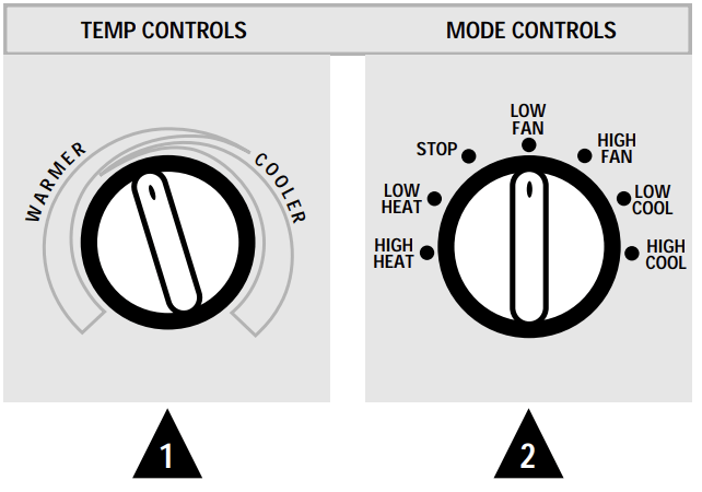
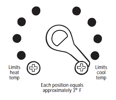
 Temp Control
The temp control is used to maintain the room temperature. The compressor will cycle on and off to keep the room at the same level of comfort. When you turn the knob to COOLER (blue) the indoor air will become cooler. Turn the knob to WARMER (red) and the indoor air will become warmer.
3200 Series only
When the outdoor temperature is lower than 25°F., heat is provided by the electric heater in the air conditioner instead of by the heat pump.
 Mode Control
HIGH COOL and LOW COOL provide cooling with different fan speeds.
HIGH HEAT and LOW HEAT provide heating with different fan speeds.
LOW FAN or HIGH FAN provides air circulation and filtering without cooling or heating.
NOTE: If you move the switch from a cool or heat setting to STOP or to a fan setting, the unit has an automatic 3-minute delay before allowing the compressor to restart in the cool or heat mode.
Energy Tip
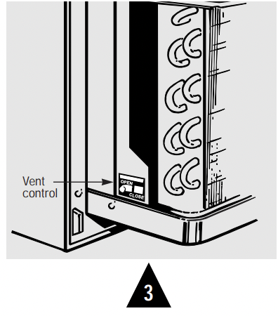
Keep the vent control at CLOSE. The room air will be filtered and circulated.
 Ventilation Control
The ventilation control lever is located at the lower left side of the Zoneline unit, behind the room cabinet.
When set at CLOSE, only the air inside the room is circulated and filtered.
When set at OPEN, some outdoor air will be drawn into the room. This will reduce the heating or cooling efficiency
 Air Direction
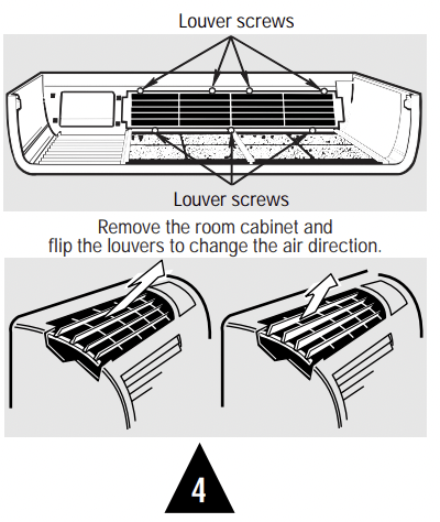
To adjust the air direction, remove the room cabinet. Remove the 7 louver screws that hold the louvers in place. Flip the louver section 180°, replace the screws and the room cabinet.
Other Zoneline features
About Your Heat Pump 3200 Series only
Heat pumps can save money by removing heat from the outside air—even when the outside temperature is below freezing— and releasing that heat indoors.
To get the best performance from your heat pump, don’t change the room thermostat very often. Raising the heat setting 2–3 degrees will cause the Zoneline to use its electric heating elements in order to reach the new temperature setting quickly.
There is a three minute minimum compressor run time at any setting to prevent short cycling. The indoor fan motor starts before the compressor and stops after the compressor cycles off. The electric heating elements use much more electricity than heat pumps and cost more to operate.
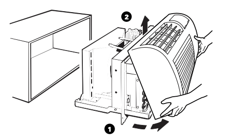
To Remove the Room Cabinet
Additional controls are located behind the room cabinet.
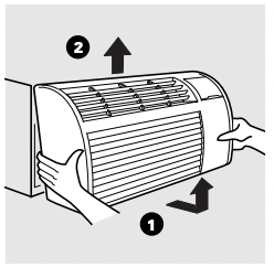
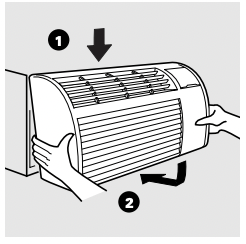
To remove: Pull out at the bottom to release it from the tabs. Then lift up
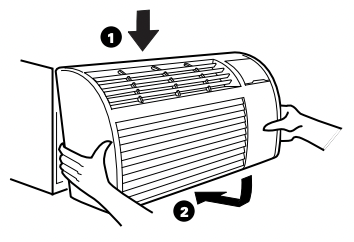
To replace: Place the tabs over the top rail. Push inward at the bottom until it snaps into place.
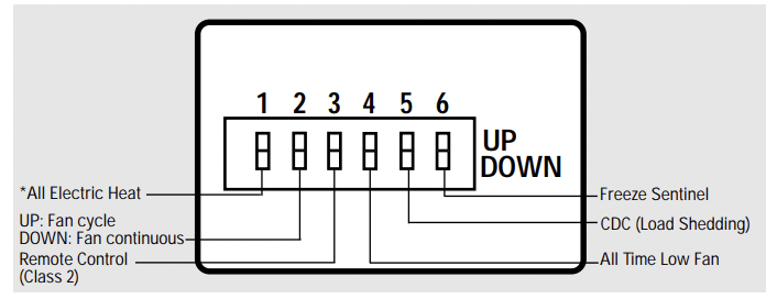
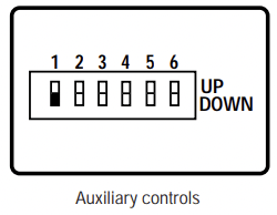
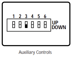
Auxiliary Controls
The auxiliary controls are located behind the room cabinet on the front of the unit control box. The factory settings will be in the DOWN position. The owner is responsible for checking switches and ensuring they are in the desired position.
Fan Switch
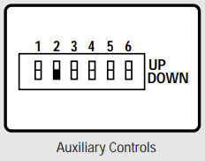
Down—Continuous Fan Up—Cycle Fan
The fan switch #2 is located behind the room cabinet.
This switch is set at continuous fan (DOWN) at the factory to provide continuous fan operation in cool or heat modes. Leaving the switch in the continuous fan setting allows continuous circulation of room air and will result in a more balanced temperature throughout the room.
If you want the fan to cycle on and off with the compressor or with the heater, move the switch to cycle fan (UP).
Freeze Sentinel™
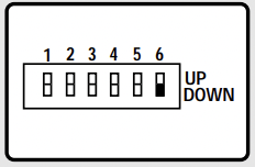
Switch #6 controls the Freeze Sentinel. When the switch is DOWN, the Freeze Sentinel automatically turns on the resistance heater and fan if the room temperature (sensed at the unit) drops to approximately 40° F. It will turn the heater off when the temperature reaches about 45° F
The unit leaves the factory with the Freeze Sentinel in the DOWN (on) position.
The Freeze Sentinel helps prevent plumbing damage in the room due to sub-freezing temperatures. If the Freeze Sentinel is set, it is active as long as power to the unit is on.
NOTE: The owner is responsible for checking the Freeze Sentinel switch and ensuring it is in the desired setting
Care & Cleaning
Room Cabinet and Case
Turn the Zoneline off and disconnect the power supply.
To clean, use water and a mild detergent. Do not use bleach or abrasives. Some commercial cleaners may damage the plastic parts.
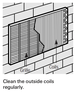
Outdoor Coils
The coils on the outdoor side of the Zoneline should be checked regularly. If they are clogged with dirt or soot they may be professionally steam cleaned, a service available through your GE service outlet. You will need to remove the chassis to inspect the coils because the dirt build-up occurs on the inside.
Base Pan
In some installations, dirt or other debris may be blown into the unit from the outside and settle in the base pan (the bottom of the unit). In some areas of the United States a “jell-like” substance may be seen in the base pan.
Check it periodically and clean it out, if necessary
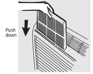
Air Filters
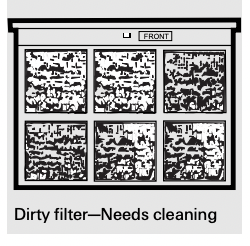
Operating Tip: To maintain optimum performance, clean the filters at least every 30 days.
Turn the Zoneline off before cleaning.
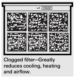
The most important thing you can do to maintain the Zoneline is to clean the filter at least every 30 days. Clogged filters reduce cooling, heating and air flow.
Keeping these filters clean will:
- Decrease cost of operation.
- Save energy.
- Prevent clogged heat exchanger coils.
- Reduce the risk of premature component failure.
To clean the air filters:
- Vacuum off the heavy soil.
- Run water through the filters.
- Dry thoroughly before replacing.
To remove the air filters:
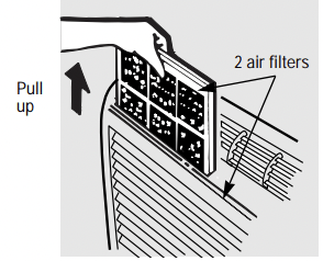
To replace the air filters:
CAUTION: DO NOT operate the Zoneline without the filters in place. If a filter becomes torn or damaged it should be replaced immediately.
Operating without the filters in place or with damaged filters will allow dirt and dust to reach the indoor coil and reduce the cooling, heating, airflow and efficiency of the unit.
Replacement filters are available from your salesperson, GE dealer, GE Service and Parts Center or authorized Customer Care® servicers.
Installation Instructions
Zoneline Components
YOU WILL NEED:
• Phillips screwdriver
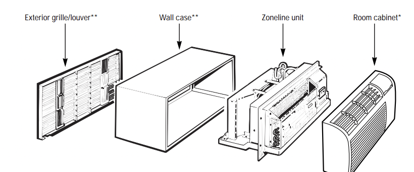
*Shipped with the Zoneline unit
**Check the “Essential Elements” list on the unit
How to Connect
- Remove the room cabinet.
- Connect to electrical power.
- See the special instructions below for applicable supply voltages.
- Reinstall the room cabinet.
1. Install the Wall Case and the Exterior Grille
1 The RAB71 or RAB77 wall case must be properly installed per instructions packed with the case.
2 Remove the corrugated stiffener and the outdoor protective panel. Use the slit in the outdoor panel as a handhold and push out.
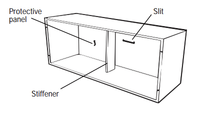
3 Install the exterior grille from the room side following instructions packed with the grille.
Insulated Wall Case
This chassis is designed to be installed in a GE plastic or an insulated steel wall case. This minimizes condensation from forming on the room side of the case.
The RAB71 wall case is insulated. Insulation kit RAK901L is available for use with RAB77 or existing uninsulated wall cases when needed.
NOTE: For installation with a subbase or duct adapter, see the instructions packed with those kits.
2. Remove the Shipping Tape from the Room Cabinet
1 Carefully remove shipping tape, if there is any, from the room cabinet and vent door.
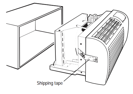
2 Remove the room cabinet by pulling it out at the bottom to release it, then lift it up to clear the rail along the unit top.
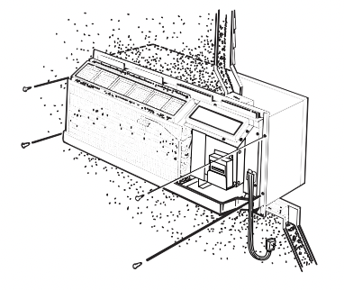
3. Install the Unit into the Wall Case
Slide the unit into the wall case and secure with four screws through the unit flange holes.
If an insulated wall case is needed, see Install the Wall Case and Exterior Grille section on the previous page.
4. Replace the Room Cabinet
Reinstall the room cabinet by hooking the top over the rail along the unit top, then pushing it in at the bottom.
Low Voltage Connectors & Auxiliary Controls
NOTE: The owner is responsible for checking all switches and ensuring they are set in the desired setting.
Electric Heat Option—Model 3200 Series only
The Electric Heat Option switch #1 increases the Zoneline air temperature by using electric heat only. The heat pump is not used to produce any heat.
Using the Electric Heat Option is much more expensive than heating with the heat pump only
To set the Electric Heat Option, move switch to the ON (up) position.
Temperature Limiting
Temperature limiting can reduce energy costs by limiting the lowest temperature that can be set for cooling and the highest temperature that can be set for heating.
Limiting the maximum and minimum settings prevents users from turning the control to the extreme heat or cool positions.
The normal full range of the temp control is approximately 62° F to 85° F. The control range may be narrowed by the use of the temperature limiting screws located behind the control panel.
Remote Control/Wall Thermostat (Class 2)
To operate the Remote Control/Wall Thermostat (Class 2) switch #3, you must use an Optional Interface Module kit. See the Installation Instructions with accessory kit RAK0IM.
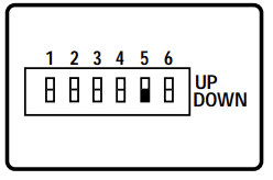
Central Desk Control (Load Shedding)
To operate Central Desk Control (CDC), switch #5, you must have an Optional Interface Module kit. See the Installation Instructions with accessory kit RAK0IM.
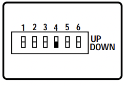
All-Time Low Fan
Switch #4 controls the All-Time Low Fan and is only effective with a Remote Control Thermostat. This function causes the indoor fan to operate at low speed. If the switch is DOWN (off) the fan will run in high speed. If the switch is UP (on) the fan will run in low speed.
Helpful Information
Things That Are Normal
| Noise | Explanation |
 |
You may hear a pinging or popping noise caused by water being picked up and thrown against the condenser on rainy days or when the humidity is high. This design feature helps remove moisture and improve efficiency |
 |
You may hear relays click when the controls cycle on and off or are adjusted to change the room temperature. |
 |
Water will collect in the base pan during high humidity or on rainy days. The water may overflow and drip from the outdoor side of the unit. |
 |
The indoor fan runs continuously when the unit is operating in the cooling mode, unless the fan switch behind the room cabinet is set at fan cycle (up). This will cause the fan to cycle on and off with the compressor. You may also hear a fan noise stop and start. |
 |
You may notice a few minutes delay in starting if you try to restart the Zoneline too soon after turning it off or if you adjust the thermostat right after the compressor has shut off. This is due to a built-in restart protector for the compressor that causes a 3-minute delay. |
 |
The compressor shuts off during the defrost cycle. Full resistance heat comes on during the defrost cycle to maintain room comfort. |
 |
To protect the compressor and prevent short cycling, the unit is designed to run for a minimum of 3 minutes, after the compressor starts at any thermostat setting |
If Something Goes Wrong
Before You Call For Service
| Problem | Possible Causes | What to Do |
| Zoneline Doesn’t Start |
The unit is unplugged | • Make sure the Zoneline plug is pushed completely into the outlet. |
| The fuse is blown/circuit breaker is tripped | • Check the house fuse/circuit breaker box and replace fuse or reset the breaker. | |
|
The unit is waiting for the compressor overload protector to reset Power failure |
• This is normal. The Zoneline will start again after it resets. • If power failure occurs, set the mode control to STOP. When power is restored set the mode control to the desired setting. There is a protective time delay (up to 3 minutes) to prevent tripping of the compressor overload. For this reason, the unit may not start normal heating or cooling for 3 minutes after it is turned back on. |
|
| Zoneline Does Not Cool or Heat as it Should |
Indoor airflow is restricted | • Make sure there are no curtains, blinds or furniture blocking the front of the Zoneline. |
| Outdoor airflow is restricted or recirculated | • Make sure the rear grille is not restricted. This can cause the unit to cycle off due to the compressor overload. | |
| The temp control may not be set high or low enough | • Turn the control to a lower or higher setting. NOTE: The temperature limiter may be limiting the temperature range. | |
| The air filter is dirty | • Clean the filter at least every 30 days. | |
| The room may have been hot or cold | • When the Zoneline is first turned on you need to allow time for the room to cool down or warm up. | |
| Outdoor air is entering the room | • Set the vent control to the CLOSE position. |
If Something Goes Wrong
Before You Call For Service
| Problem | Possible Causes | What to Do |
| Burning Odor at the Start of Heating Operation | Dust is on the surface of the heating element | • This can cause a “burning” odor at the beginning of the heating operation. This odor should quickly fade. |
| The Air is Not Always Cool or Hot During Operation | The heat pump is not producing hot air | • This is normal. The heat pump will produce warm air but not as hot as air produced when the higher-cost electric heat is used. |
| The fan switch may be set at continuous fan (down) | • This causes the fan to blow room temperature air even when the compressor or heater cycles off. The continuous air movement provides better overall temperature control. | |
| The Air Does Not Feel Warm Enough During Heating Operation | The heat pump alone produces air that feels cooler than desired |
• Use the Electric Heat Option. This turns off the heat pump and warms with electric heat only. NOTE: Use of this option will result in increased energy consumption. |

