Loading ...
Loading ...
Loading ...
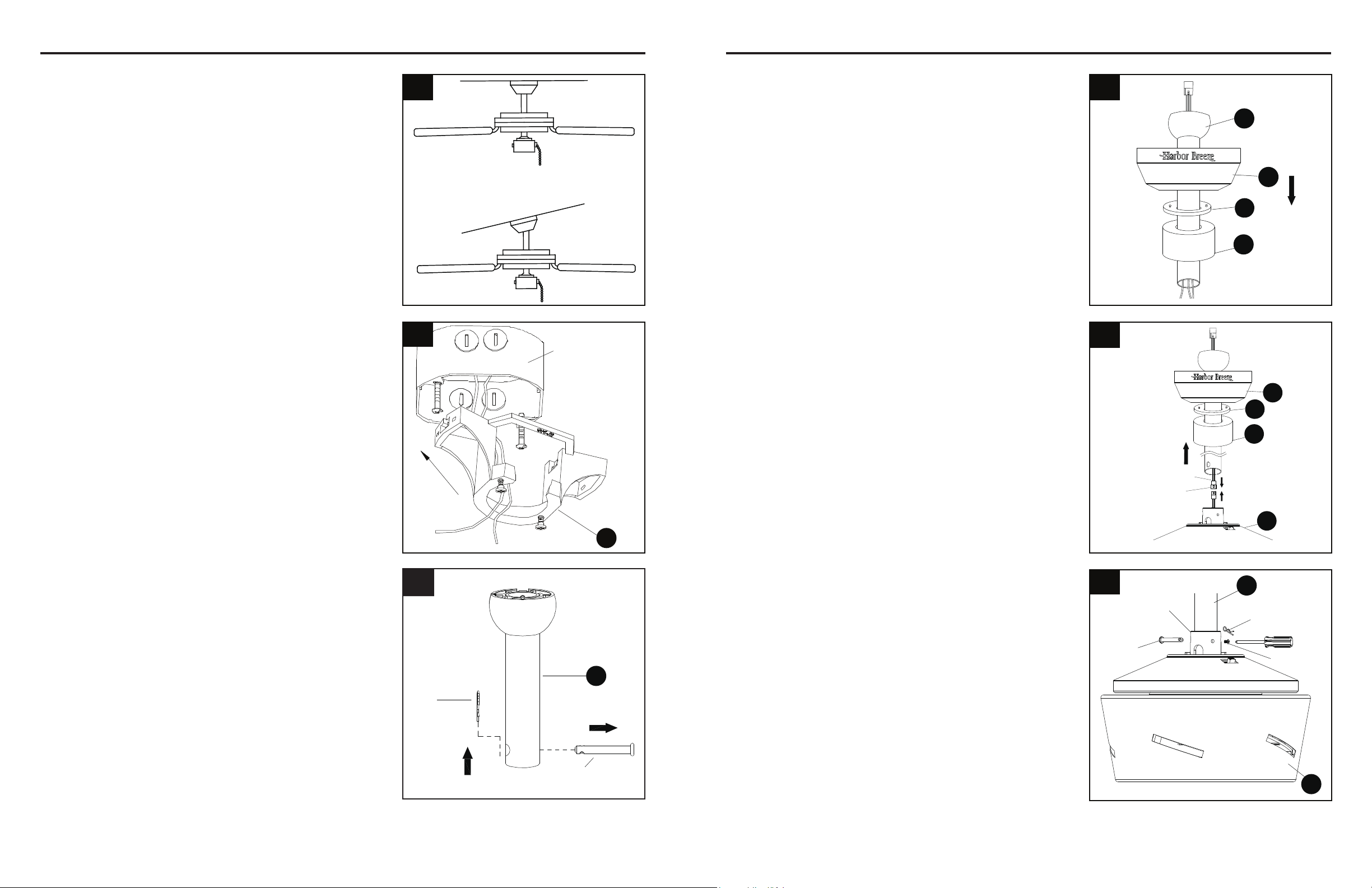
A
Outlet box
6 7
ASSEMBLY INSTRUCTIONS ASSEMBLY INSTRUCTIONS
1. Determine mounting method.
Downrod Mount (standard or angled ceiling)
Important: lf angle mounting, check to make sure the
ceiling angle is not steeper than 20°.
3. Remove preassembled pin and clip from downrod (E).
Save for later use.
5. Loosen preassembled set screws from yoke on fan
motor assembly (H). Slip downrod (E) into housing
yoke, aligning holes on both parts. Insert previously
removed pin through holes on yoke and downrod (E),
then insert previously removed clip into pin until it
snaps into place. Tighten set screws.
E
Pin
Clip
3
2. Install mounting bracket (A) to outlet box (not included
by sliding mounting bracket (A) over the two outlet box
screws (not included). Securely tighten two outlet box
screws.
Important: If angle mounting, make sure open end of
mounting bracket (A) is installed facing the higher part
of the ceiling.
4a. STANDARD DOWNROD INSTALLATION:
Insert downrod (E) through canopy (B), canopy
cover (C), and yoke cover (D). Thread wires from fan
motor assembly through downrod (E).
2
1
E
C
B
D
4a
E
H
Clip
Set screw
Pin
Yoke
5
4b. EXTENDED DOWNROD INSTALLATION:
If you are installing the fan with a longer downrod
(sold separately), insert it through the canopy (B),
canopy cover (C) and yoke cover (D). Then, thread
lead wire (N) through the downrod and connect the
MALE plug from the top of motor assembly (H) to the
FEMALE plug from the lead wire (N).
C
B
D
Female Plug
Male Plug
H
4b
NOTE: The male plug of the lead wire (N) should
extend out of the other end of the downrod.
NOTE: The remainder of the instructions will
reference downrod assembly (D), but note all of
the instructions are applicable even if an accessory
downrod was used.
Loading ...
Loading ...
Loading ...