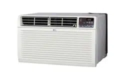
OWNER’S MANUAL
AIR CONDITIONER
Please read this manual carefully before operating
your set and retain it for future reference.
P/NO:MFL38279101
www.lgappliances.com
MODELS:LT1430CR,LT103CER,LT123CNR,LT143CNR
2 RoomAir Conditioner
Window-Type Air Conditioner Owner’s Manual
TABLE OF CONTENTS
FOR YOUR RECORDS
Write themodel and serial numbershere:
Model#
Serial#
Youcan findthem on alabel on theside of eachunit.
Dealer'sName
DatePurchased
■Staple yourreceipt tothis page inthe event youneed it
toprovedate ofpurchase or forwarrantyissues.
READ THIS MANUAL
Inside you will find many helpful hints on how to use and
maintainyour airconditionerproperly. Justalittle preventive
care on your part can save you a great deal of time and
moneyoverthelifeof yourair conditioner.
You'll find many answers to common problems in the chart
oftroubleshooting tips. Ifyoureviewourchart of
TroubleshootingTips first,youmaynotneedtocallfor
service at all.
PRECAUTION
•Contact theauthorizedservicetechnician forrepair
ormaintenance of thisunit.
•Contact theinstaller forinstallation of thisunit.
• The air conditioner is not intended for use by young
childrenor invalidswithout supervision.
• Young children should be supervised to ensure that
theydo notplaywith the airconditioner.
• When the power cord is to be replaced, replacement
workshallbeperformedbyauthorizedpersonnelonly
usingonly genuinereplacement parts.
•Installation work must be performed in accordance
with the National Electric Code by qualified and
authorized personnelonly.
SafetyPrecautions ..........................3
BeforeOperation .............................7
Introduction ....................................8
ElectricalSafety..............................9
Installation ....................................11
OperatingInstructions .................18
Maintenanceand Service ............21
Owner’s Manual 3
ENGLISH
SafetyPrecautions
Safety Precautions
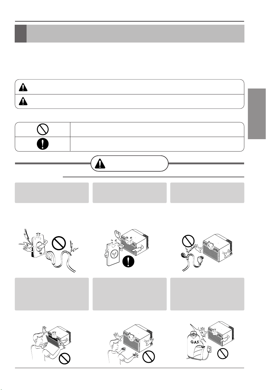
To preventinjuryto theuser orother people andproperty damage,the followinginstructions
mustbe followed.
■Incorrect operationdue to ignoring instruction will cause harm or damage. The seriousness
is classified bythe following indications.
■Meanings ofsymbols usedin thismanual areas shownbelow.
WARNING
CAUTION
This symbol indicates the possibility of death or serious injury.
This symbol indicates the possibility of injury or damage to properties only.
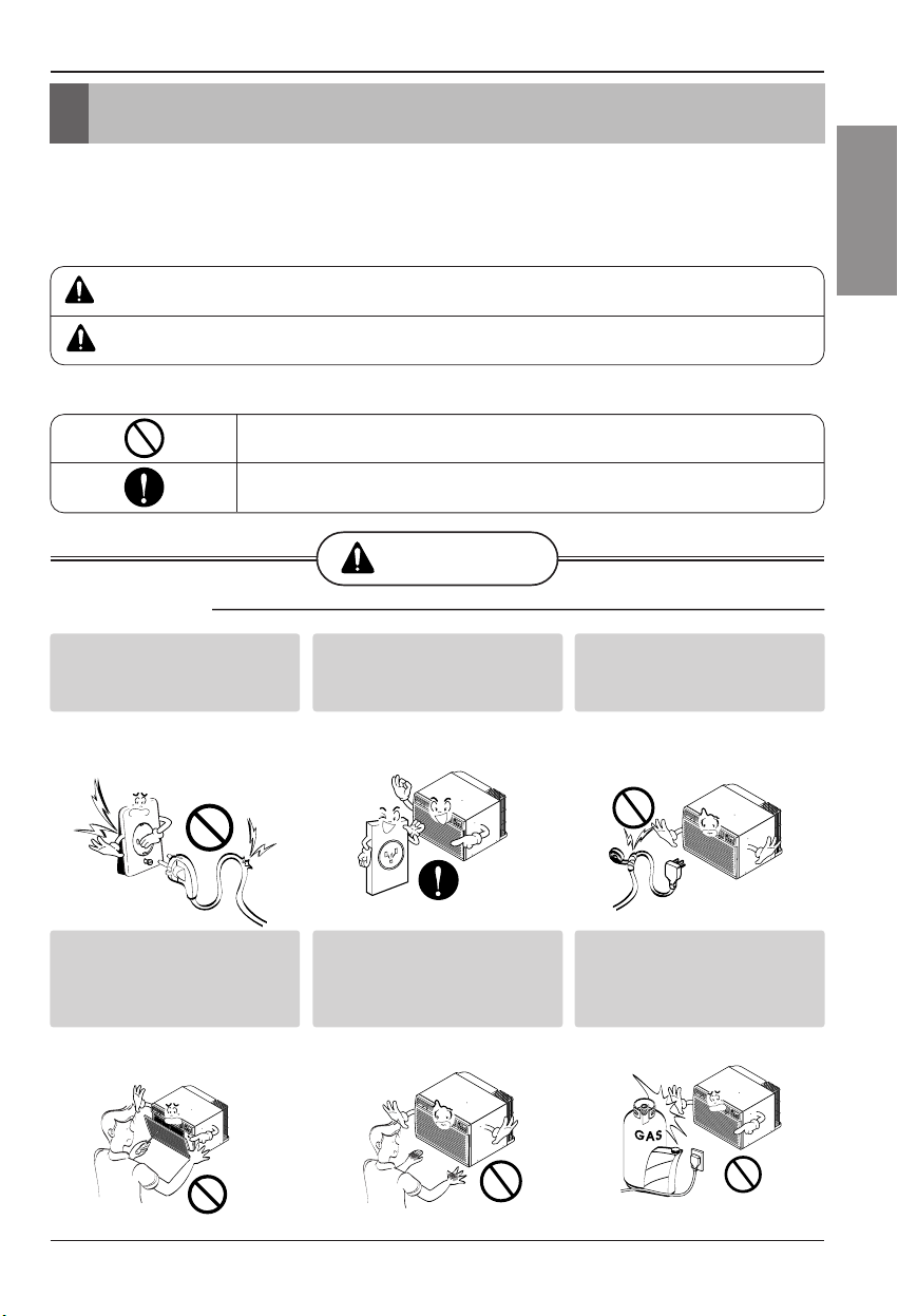
WARNING
■ Installation
Be sure not to do.
Be sure to follow the instruction.
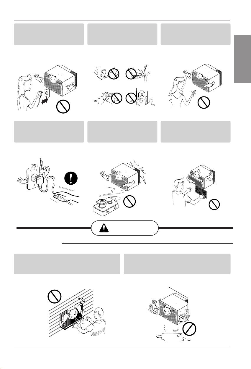
Don’tuse a powercord,a
plugor aloose socketwhich
isdamaged.
•Otherwise,it maycausea fire
orelectrical shock.
Always plug into a grounded
outlet.
•Otherwise,it maycausea fire
orelectrical shock.
Donot modifyor extendthe
powercordlength.
•It willcause electric shockor fire
dueto heatgeneration.
Donot disassembleor
modify products.
•It maycause failureand
electric shock.
Be caution when unpacking
and installing.
•Sharp edgesmaycause
injury.
Donot use thepowercord near
flammablegas orcombustibles
suchas gasoline,benzene,
thinner,etc.
•It maycause explosionorfire.
Gasolin
4 RoomAir Conditioner
SafetyPrecautions
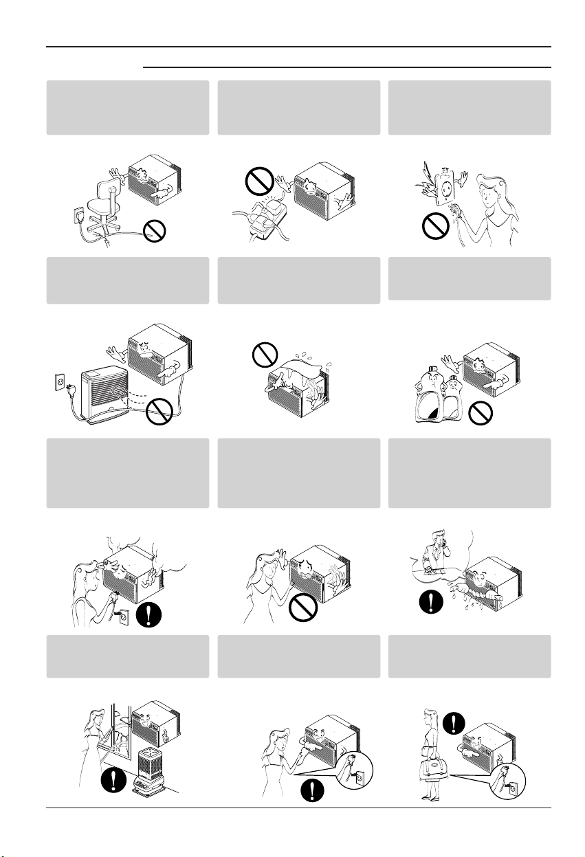
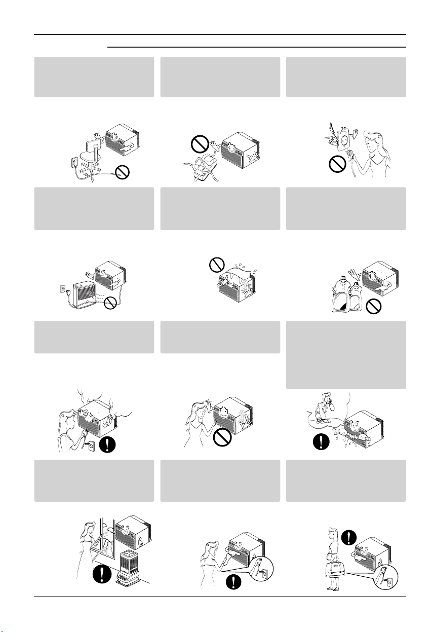
■ Operation
Donot placethe powercord
neara heater.
•It maycause fireand electric
shock.
Donot allowwater to run
intoelectric parts.
•It willcause failureof machineor
electric shock.
Use a soft clothto clean.Do
not use wax,thinner,ora
strongdetergent.
•Theappearanceof theair
conditionermaydeteriorate,
changecolor,or developsurface
flaws.
Wax
Thinner
Ventilate the roomwell when
usingthis appliance
together with a stove,etc.
•An oxygen shortagemayoccur.
Turn off the powerand
breakerfirstlywhen
cleansingthe unit.
•Since thefanrotates athigh
speedduringoperation,itmay
causeinjury.
Turn off the main power
switchwhen not using it for
alongtime.
•Preventaccidentalstartup and
thepossibility ofinjury.
Unplug the unit if strange
sounds,odors, orsmoke
come fromit.
•Otherwise itmaycause fireand
electric shockaccident.
Do not open the suction
inletgrill ofthe product
duringoperation.
•Otherwise,it mayelectrical
shockand failure.
Ifwater entersthe product,turn
off the the powerswitchof the
main bodyof appliance.Contact
service center after taking the
power-plug out fromthe socket.
Donot placeheavy object
onthe powercordand take
care so that the cordshould
notbe pressed.
•Thereisdanger offire orelectric
shock.
Donot share the outlet with
otherappliances.
•It willcause electric shock or fire
dueto heatgeneration.
Take the power plug out if
necessary,holding the head
of the plug and do not touch
itwith wethands.
•Otherwise,it maycausea fire
orelectrical shock.
Owner’s Manual 5
ENGLISH
SafetyPrecautions
CAUTION
■ Installation
Donot operate or stop the
unit byinsertingor pulling
outthe powerplug.
•It willcause electric shock or fire
dueto heatgeneration.
Donot damageor usean
unspecified powercord.
•It willcause electric shockor fire.
Donot operatewith wet
hands or in damp
environment.
•It willcause electric shock.
Holdthe plugby the head
whentaking itout.
•It maycause electric shockand
damage.
Whengas leaks,openthe
windowforventilation
beforeoperating the unit.
•Otherwise,it maycause
explosion,anda fire.
Nevertouch the metal parts
ofthe unitwhen removing
thefilter.
•They aresharp andmaycause
injury.
Install the productso that the noise or hot
wind fromthe outdoor unit may not cause
anydamage to the neighbors.
•Otherwise, it maycause dispute with the
neighbors.
Keeplevelparallel in installingthe product.
•Otherwise,it may cause vibrationor water
leakage.
6 RoomAir Conditioner
SafetyPrecautions
■ Operation
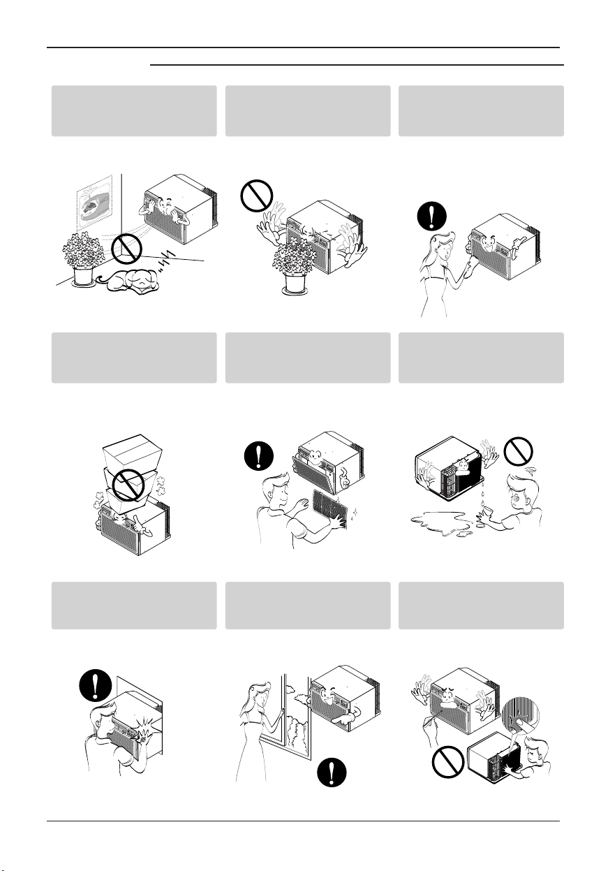
Be cautious not to touch the
sharp edges when
installing.
•It maycause injury.
Avoidexcessive cooling and
performventilation
sometimes.
•Otherwise,it maydoharm to
yourhealth.
Donot insert the hands or
barsthroughthe air inlet or
outletduring operation.
•Otherwise,itmaycause
personalinjury.
Donot puta petor house
plant where it will be
exposedtodirectairflow.
•It maycause injury.
Donot blockthe inletor
outlet of air flow.
•It maycause productfailure.
Useasoftclothtoclean.Do
not use wax,thinner,ora
strongdetergent.
•Theappearanceof theair
conditionermaydeteriorate,
changecolor,or developsurface
flaws.
Donot stepon the
indoor/outdoor unit and do
notputanythingonit.
•It may causean injury through
droppingof theunit orfalling
down.
Always insert the filter
securely.
Clean it every twoweeks.
•Operation withoutfilters will
causefailure.
Donot drinkwater drained
fromair conditioner.
•It containscontainments andwill
make you sick.

BeforeOperation
Owner’s Manual 7
ENGLISH
Before Operation
1. Contactan installation specialist forinstallation.
2. Plug in the power plug properly.
3. Use a dedicated circuit.
4. Do notuse an extensioncord.
5. Do notstart/stop operationby plugging/unplugging the powercord.
6. Ifthe cord/plug is damaged, replace it with only an authorizedreplacement
part.
1. Beingexposedto direct airflow for an extended period of time could be
hazardous to yourhealth. Do not exposeoccupants, pets,or plants to direct
airflowforextendedperiods of time.
2. Dueto the possibility of oxygendeficiency, ventilatethe room when used
together with stoves or other heating devices.
3. Donot use this air conditioner fornon-specified special purposes (e.g.
preserving precision devices, food,pets,plants, and art objects).Suchusage
could damage the items.
1. Donot touch the metal parts of the unit when removingthe filter.Injuries can
occur when handling sharp metal edges.
2. Donot use water to clean inside the air conditioner. Exposure to water can
destroy the insulation, leading to possible electric shock.
3. Whencleaning the unit, first make sure that thepower and breaker are turned
off. Thefanrotates at a very high speed during operation. There is a
possibility of injury if the unit’s poweris accidentally triggered on while
cleaning inner parts of the unit.
For repair and maintenance, contact yourauthorizedservice dealer.
Preparing forOperation
Usage
Cleaning and Maintenance
Service
8 RoomAir Conditioner
Introduction
This symbol alerts youto the risk of electric shock.
This symbol alerts youto hazards that could cause harm to
the air conditioner.
This symbol indicates special notes.
NOTICE
Thisappliance shouldbe installedin accordancewith theNational Electric Code.
Introduction
Symbols Used inthis Manual
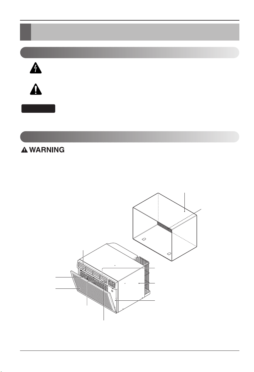
Features
CABINET
FRONT GRILLE
INLET GRILLE
(Air Intake)
AIR FILTER
HORIZONTAL AIR DEFLECTOR
(Vertical Louver)
VENT CONTROL
VERTICAL AIR DEFLECTOR
(Horizontal Louver)
AIR DISCHARGE
SLEEVE ASSEMBLY
(Including Aluminum Rear grille)
THE SLEEVE AND THE REAR GRILLE
(optionally supplied with your unit)
THE UNIT
REAR GRILLE
(Aluminum Rear grille)
Electrical Safety
Owner’s Manual 9
ENGLISH
Electrical Safety
Electrical Data
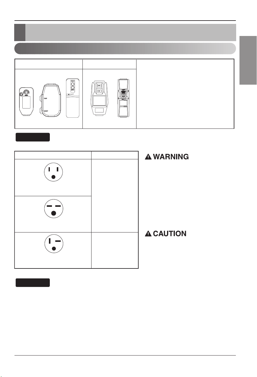
115V~ 230V~
Power cord may include a current
interrupter device. A test and reset button is
provided on the plug case. The device
should be tested on a periodic basis by first
pressing the TEST button and then the
RESET button. If the TEST button does not
trip or if the RESET button will not stay
engaged, discontinue use of the air
conditioner and contact a qualified service
technician.
Use Wall Receptacle Power Supply
Standard 125V, 3-wire grounding
receptacle rated 15A, 125V AC
Standard 250V, 3-wire grounding
receptacle rated 15A, 250V AC
Use 15 AMP. time
delay fuse or 15 AMP.
circuit breaker.
Use 20 AMP. time
delay fuse or 20 AMP.
circuit breaker.
Standard 250V, 3-wire grounding
receptacle rated 20A, 250V AC
Neverpush the test buttonduring
operation
Otherwisethis plug can damaged.
Thisdevicecontains chemical, including
lead,known to theState of California to
causecancer,andbirth defectsor other
reproductiveharm.
Wash hands after handling.
Donot remove,modifyor immerse this plug.
Ifthis devicetrips,the cause itto be
correctedbeforefurther use.
The conductors inside this cord are
surrounded byshields,which monitor
leakage current.
These shields are not grounded.
Periodically examine thecord forany
damage. Donot use this product in the
eventthe shields become exposed.
Avoidshock hazard, this unit can not
be user serviced opening the tamper
resistant. Sealedportion ofthe unit
voidsall warrantiesand performance
claims. This unitnot intendedforuse
asan on-offswitch.
Theshape maybedifferentaccording toits model.
NOTICE
DONOTUSE ANEXTENSION CORDon 230,
208,and 230/208Voltunits.
Allwiring shouldbe madein accordancewith local
electrical codesand regulations.
Aluminumhouse wiring may posespecial
problems. Consulta qualifiedelectrician.
NOTICE
10 RoomAir Conditioner
Electrical Safety
IMPORTANT
(PLEASE READ CAREFULLY)
FOR THE USER'S PERSONAL SAFETY, THIS
APPLIANCEMUST BE PROPERLYGROUNDED
Thepowercord of this appliance is equipped witha
three-prong(grounding) plug.Usethis witha standard
three-slot(grounding) wallpoweroutlet to minimizethe
hazardof electricshock. The customer shouldhave
thewall receptacle andcircuit checkedbya qualified
electrician to makesure the receptacle isproperly
grounded.
DONOTCUT OR REMOVE THE THIRD (GROUND)
PRONGFROM THEPOWERPLUG.
A.SITUATIONSWHEN THEAPPLIANCE WILL BE
DISCONNECTEDOCCASIONALLY:
Becauseof potential safetyhazards,we strongly
discouragethe use of anadapter plug.However, ifyou
wishto use an adapter,aTEMPORARY
CONNECTIONmaybe made.UseUL-listedadapter,
available frommost local hardwarestores.
Thelarge slot in the adapter mustbe aligned with the
largeslot in the receptacle to assure aproper polarity
connection.
:
Attachingthe adapter groundterminal to the wall
receptaclecoverscrewdoes not groundthe
applianceunless the coverscrew is metal,andnot
insulated,andthe wall receptacleis grounded
throughthe housewiring. The customershould
havethe circuitcheckedbya qualified electrician to
makesure the receptacleis properlygrounded.
Disconnectthe powercord from the adapter,using
onehand on each.Otherwise,theadapter ground
terminal might break.DONOTUSEthe appliance with
abroken adapter plug.
B.SITUATIONSWHEN THEAPPLIANCE WILL BE
DISCONNECTEDOFTEN.
Donot use an adapter plug in thesesituations.
Unpluggingthe powercord frequently can lead to an
eventual breakage of theground terminal. The wall
poweroutletshould be replaced bya three-slot
(grounding)outlet instead.
USEOF EXTENSION CORDS
Becauseof potential safetyhazards,we strongly
discouragethe use of anextensioncord.However, if
youwishtouseanextensioncord,useaCSA
certified/UL-listed3-wire (grounding) extensioncord,
rated at 15A, 125V.
Electrical Safety
Owner’s Manual 11
ENGLISH
Installation
Installation
Remove packing materials from the wallsleeveand tape
fromthe air conditioner.
INSTALLATION REQUIREMENTS
Ifyouuse an existing wallsleeve,youshould
measureits dimensions.
Installthe newair conditioner according to these
installationinstructionsto achievethebest
performance. Allwall sleeves used to mount the new
airconditioner must be in goodstructuralcondition
andhavea rear grille tosecurely attach thenew air
conditioner.(FIG. 1)
Withthe LGE sleeve(optionallysupplied with
yourunit),youcanmaintain the best performance of
thenew airconditioner.(FIG. 2)
ELECTRICALSERVICE
Checkyouravailable electricalservice. Thepower
supplyavailablemust be the same asthat shown on
theunit nameplate (foundon left side ofcabinet).
Allmodels are equipped with a 3-prong serviceplug
toprovide proper serviceand safepositive
grounding. Donot change plug in anyway.Donot
usean adapter plug.Ifyourpresent walloutlet does
notmatch yourplug, call a qualified electrician to
makethe necessarycorrections.SAVE CARTON for
storageand this OWNER'SMANUALforfuture
reference. Thecarton is the best way to store unit
during winter or whennot in use.
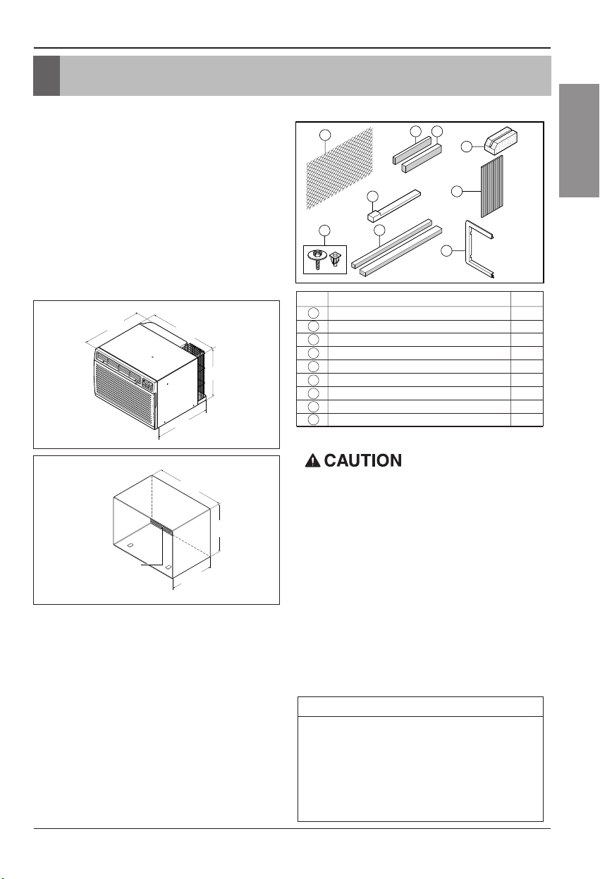
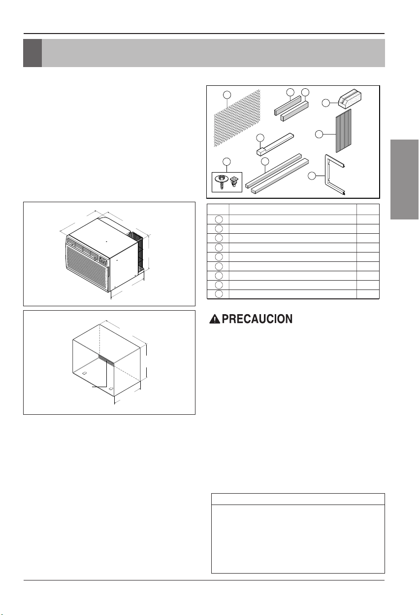
INSTALLATIONHARDWARE
14-
13
/
32
"
(366 mm)
24"(610 mm)
18-
15
/
32
"(468 mm)
20-
3
/
32
"
(511 mm)
1
5
6
7
8
3
2 4
9
2 Size options
2 Size options
To avoid riskof personalinjury,property
damage,orproduct damagedue tothe weightof
thisdevice andsharp edgesthat maybe
exposed:
•Air conditionerscoveredin thismanualpose an
excessive weighthazard. Two ormore peopleare
neededto move andinstall theunit.
Toprevent injury orstrain, useproper liftingand
carrying techniqueswhen movingunit.
•Carefully inspectlocation whereair conditionerwill
beinstalled.Besure itwill supportthe weightof
theunitoveranextendedperiodoftime.
•Handle airconditioner withcare. Wearprotective
gloves wheneverlifting orcarryingthe unit. AVOID
thesharp metalfins offront andrear coils.
•Make sureair conditionerdoes notfallduring
installation.
REQUIRED TOOLS:
•TightFittinggloves
•Standard screwdriver
•Phillips screwdriver
•Pliers
•Sharp knife
•3/8-inch open end
wrenchor adjustable
wrench
•1/4-inch hexsocket
andratchet
•Tapemeasure
•Electricdrill
•1/4-inch drillbit
FIG.1
AirConditioner
ITEM NAMEOF PARTS Q'TY
1 PLASTICGRILLE 1
2 VERTICALINSULATIONSTRIP 1
3 AROUNDINSULATION STRIPS 2
4 HORIZONTALINSULATION STRIP 1
5 SUPPORTBLOCK 2
6 BAFFLE 1
7TRIMFRAME 2
8SHIM 2
9
PLASTICNUTS ANDWASHERSCREWS
4
15-
17
/
32
"
(394 mm)
16-
23
/
32
"
(425 mm)
25-
7
/
8
"
(656 mm)
Aluminum metal grille
FIG.2
LGE Wall Sleeve
12 RoomAir Conditioner
Installation
INSTALLATION
•Picka location which will allowthe conditioned air
toblowinto the area youwant.Goodinstallation
withspecial attention to the proper position ofthe
unitwill lessen the chance that servicewill be
needed.
ITEMSIN INSTALLATIONHARDWARE
Youmaynotneed all parts in the kit.Discardunused
parts
HOW TO INSTALL
Identifythe existingwall sleeve beforeinstalling
theunit from the listed below.
Allwall sleeves used to mount the newAir
Conditionermust be in soundstructuralcondition
andhavea rear grille thatsecurely attaches to
sleeve,or rear flange that servesasa stop forthe
AirConditioner.
Removeold air conditioner from existingwall
sleeve.
Cleanthe interiorof an existingsleeve.
(Donot disturb seals.)
Wall sleevemustbe securely fastenedin wall
beforeinstallingthe air conditioner.Usethe
nailsor screws throughsleeveintowall, if
needed.Repaintsleeveifneeded.
Preparethe wall sleeve forinstallation of the
unit.Ifyouplanto use yourexistingwall sleeve,
andit is not LGE, use procedure Bor C below.
Installnew unit intowall sleeve.
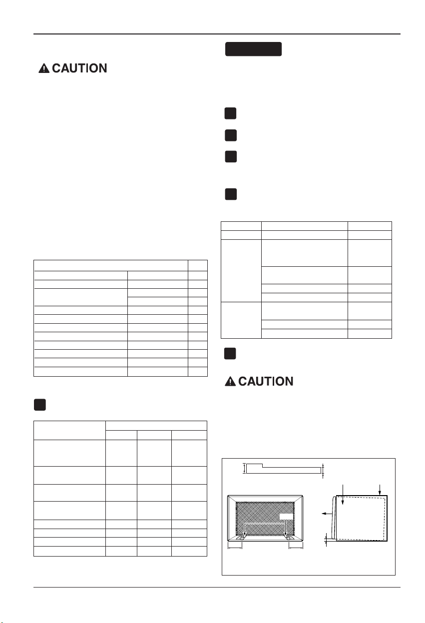
Wheninstallation is completed, replacement unit
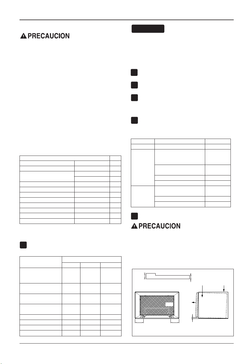
MUSThavea rearwardslope as shown. To
achieve 1/4" slope,removethe backingfrom the
11-13/16"shim stripsand attach them as shown
belowin Fig.3. Place the higher portion of shim to
thefront of the rib on base of wallsleeve.
NOTICE
1
2
3
4
5
6
1/4"
Wall Sleeve
FRONT
UNIT
SHIM PLACEMENT UNIT INSTALLATION
1" high
3
/
4
" High
Shim
6" 6"
FIG.3
Westronglyrecommend theremovalof the
oldwall sleeveand theinstallation ofa new
LGE Wall Sleeve.
Ifyou decideto keep theexistingwall sleeve,
youhave toredirect thelouvers at theback of
thewall sleeve illustration. The useof pliersis
recommended. If youDONOTredirect, you
run therisk ofpoor performance orproduct
failure. This isnot coveredunder thetermsof
theLGE warranty.
ITEM(inches) Qty.
Plasticgrille 26
3
/
4
x16
1
/
2
1
Vertical insulation strip 15
9
/
16
x1
3
/
8
x1
3
/
8
1
AroundInsulation Strips
67
1
/
8
x1
3
/
8
x
25
/
32
1
59
27
/
32
x1
3
/
8
x1
3
/
8
1
HorizontalInsulation Strip 23
7
/32 x1
3
/
8
x1
3
/16 1
SupportBlock 1
3
/
4
x1
3
/
8
x4
5
/
16
2
Baffle
14x
4
1
/
2
x
1
/
8
1
Shim 11
13
/
16
x1x
3
/
4
2
Trim Frame 2
Washer Screw 4
Nuts(Plastic) 4
Grille Rear 1
WallSleeveDimensions(inches)
Brand
Width Height Depth
White-Westinghouse
25-1/2 15-1/4
16,17-1/2
Frigidaire
or22
Carrier (52F series)
GeneralElectric
26 15-5/8 16-7/8
/Hotpoint
Whirlpool 25-7/8 16-1/2
17-1/8
or23
Fedders/Emerson 27 16-3/4
16-3/4
or19-3/4
LGE 25-7/8 15-17/32 16-23/32
Emerson/Fedders 26-3/4 15-3/4 15
Carrier (51S Series) 25-3/4 16-7/8 18-5/8
Friedrich 27 16-3/4 16-3/4
Procedure Brand
Depth(inches)
A LGE 16-23/32
White-Westinghouse
FrigidaireCarrier
16,17-1/2
(52Fseries)
or22
B
GeneralElectric
16-7/8
/Hotpoint
Whirlpool 17-1/8or 23
Carrier (51S series)
18-5/8
Fedders/Emerson
16-3/4
or19-3/4
C
Emerson/Fedders 15
Friedrich 16-3/4
Owner’s Manual 13
ENGLISH
Installation
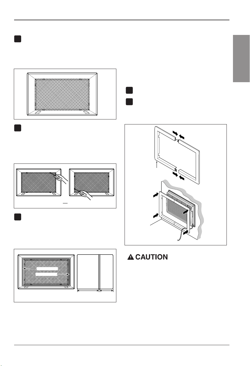
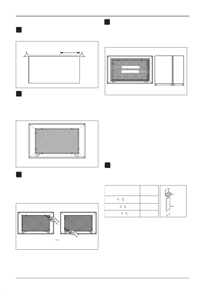
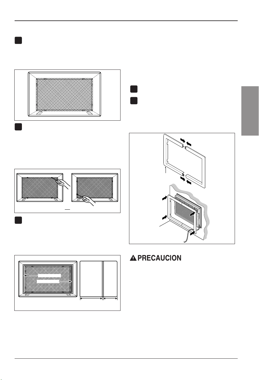
PROCEDUREA
Ifyouareusingthenewsleeve(optionally
suppliedwith yourunit),skip to step 3.
Otherwise,install the plasticgrillefrom the kit.
Cutthe plastic grille to 25-1/2" wide and 15-
1/4"high.Placethe plastic grille to the inside
ofthe wall sleeve at the rear flange.
Fasten the 4 washerscrewsto secure the grille
tothe wall sleeve.Ifyouneed plastic nutsto
mountplastic grille to the inside of the wall
sleeve,there are plastic nuts inthe installation
kit. Thenuts are installed from the insideof the
sleeve and are pressing intothe square holes
ofthe rear flanges.
Remove the backingfrom theVerticalInsulation
strip 15
9
/
16
x1
3
/
8
x1
3
/
8
andattach that to the
insiderightof the sleeveasshown below.
Remove the backingfrom the Around Insulation
strip 67
1
/
8
x1
3
/
8
x
25
/
32
andattach that to the
insidefront of the sleeve as shown below.
Installthe newunit into the wallsleeve.
Toassembletrim,snap the tab of each piece
intothe slot of the other piece asshown below.
Slidetrimoverthe front of theair conditioner
untiltrimis flush with sleeveas shown below.
FIG.4
Around Insulation
Vertical Insulation
9
1
/
2
"6"
Indoor Outdoor
FIG.6
or
FIG.5
1
2
3
4
5
Wall
Trim (2 ea)
FIG. 7
•Air conditionerscoveredin thismanual posean
excessive weighthazard. Twoor more people are
neededto move andinstall theunit.
Toprevent injury orstrain, useproper liftingand
carrying techniques whenmovingunit.
•Whenhandling theair conditioner,be carefulto
avoid cutsfrom sharp metalfins onfront andrear
coils.
•Make sureair conditionerdoes notfallduring
removal.
•If unitdoes notoperate afterinstallation check,to
besure thecircuit interrupter hasnot beentripped.
RefertotheTroubleshootingguide forreset
procedure.
14 RoomAir Conditioner
Installation
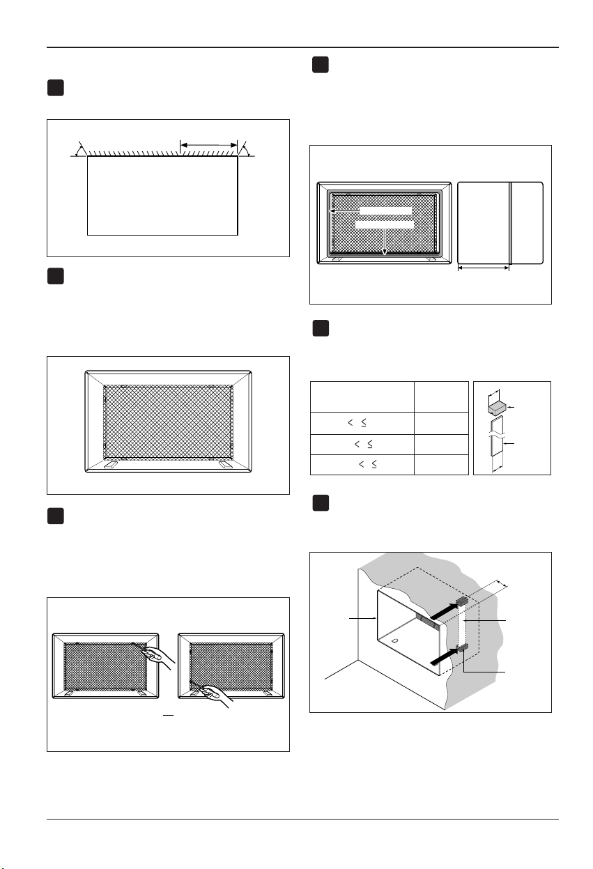
PROCEDUREB
Redirectthe louversat the backof the wall
sleeve to 60° angle as shown in the FIG 8. The
useof pliers is recommended.
Ifthe wall sleeve already has a reargrille,skip
tostep 4.Ifthe wallsleevedoesnot havearear
grilleor louveredpanel, install the plastic grille
fromthe kit.Cutthe plastic grille to 25-1/2" wide
and15-1/4" high.Placethe plastic grille to the
insideof the wallsleeveat therear flange.
Fasten the 4 washerscrews tosecure the grille
tothe wall sleeve.Ifyouneed plasticnuts to
mountplastic grille to the inside of the wall
sleeve,there are plastic nuts inthe installation
kit. The nutsare installed from the insideof the
sleeve and are pressed intothe square holes of
therear flanges.
Removethe backingfrom theVerticalInsulation
strip 15
9
/
16
x1
3
/
8
x1
3
/
8
andattach that to the
insiderightof the sleeveasshown below.
Removethe backingfrom the Around Insulation
strip 67
1
/
8
x1
3
/
8
x
25
/
32
andattach that to the
insidefront of the sleeve as shown below.
Ifthe depth of yourexistingwall sleeve is less
than or equal to 18", skip to step 6. Otherwise,
cutthe baffles and the support blocksaccording
tolength "A" in the tablebelow.
1
4
2
3
FIG. 9
Around Insulation
Vertical Insulation
9
1
/
2
"6"
Indoor Outdoor
FIG. 11
or
FIG. 10
Rear Louvers
(Top View)
60°
60°
7
3
/
32
"
FIG. 8
Depth"D" of the existing
wall sleeve (inches)
Length "A"
(inches)
Support
Block
Baffle
A
A
3
/4
1-
3
/4
4
18 D 18-
5
/
8
18-
5
/
8
D 19-
3
/
4
19-
3
/
4
D 22
5
Placethe plastic grille
Fasten the screws
FIG. 12
Owner’s Manual 15
ENGLISH
Installation
PROCEDUREB
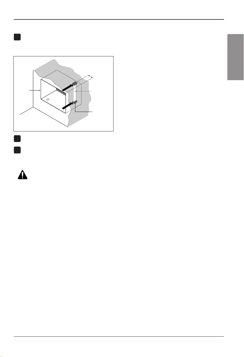
Remove the backingfrom the support blocks
andattach them to the inside of thewall sleeve
as shown FIG 13. Slide the baffle into slots of
thesupport blocks.
Installthe newunit into the wallsleeve.
Assemble trim as described in Step 5,
ProcedureA.
8
Wall
Wall
Sleeve
Baffle
(
7
3
/
32
"
)
Front
Support
Block
FIG. 13
6
7
CAUTION
•Air conditionerscoveredin thismanual pose an
excessive weighthazard. Twoor morepeople are
neededto move andinstall theunit.
Toprevent injury orstrain, useproper liftingand
carrying techniques whenmovingunit.
•Whenhandling theair conditioner,be carefulto
avoid cutsfrom sharp metalfins onfront andrear
coils.
•Make sureair conditionerdoes notfallduring
removal.
•If unitdoes notoperate afterinstallation check,to be
surethe circuitinterrupter hasnot beentripped.
RefertotheTroubleshooting guide forreset
procedure.
16 RoomAir Conditioner
Installation
PROCEDUREC
Redirectthe louversat the backof the wall
sleeve to 60° angle as shown in the FIG 14.
Theuse of pliers is recommended.
Ifthe wall sleeve already has a reargrille,skip
tostep 4.Ifthe wallsleevedoesnot havearear
grilleor louveredpanel, install the plastic grille
fromthe kit.Cutthe plastic grille to 26-1/2" wide
and15-1/2" high.Placethe plastic grille to the
insideof the wallsleeveat therear flange.
Fasten the 4 washerscrews tosecure the grille
tothe wall sleeve.Ifyouneed plasticnuts to
mountplastic grille to the inside of the wall
sleeve,there are plastic nuts inthe installation
kit. The nutsare installed from the insideof the
sleeve and are pressed intothe square holes of
therear flanges.
Removethe backingfrom the Horizontal
Insulationstrip23
7
/
32
x1
3
/
8
x1
3
/
16
andattach
thatto the inside right of the sleeveas shown
below. Removethebacking from theAround
Insulationstrip59
27
/
32
x1
3
/
8
x1
3
/
8
andattach
thattotheinsidefrontofthesleeveasshown
below.
Ifthe depth of yourexistingsleeveisless than
orequal to 18”, skip to step 7.Otherwise, cut
thebaffles and the support blocksaccordingto
Length"A" in the tablebelow.
Removethe backingfrom the support blocks
andattach them to the inside of thewall sleeve
as shown FIG 19. Slide the baffle into slots of
thesupport blocks
Depth"D" of the existing
wall sleeve (inches)
Length "A"
(inches)
Support
Block
Baffle
A
A
3
/4
1-
3
/4
4
18 D 18-
5
/
8
18-
5
/
8
D 19-
3
/
4
19-
3
/
4
D 22
Wall
Wall
Sleeve
Baffle
Front
Support
Block
(7
3
/
32
")
FIG. 19
FIG. 18
1
4
2
3
FIG. 15
8
1
/
2
"
Indoor Outdoor
Around Insulation
Horizontal Insulation
FIG. 17
or
FIG. 16
Rear Louvers
(Top View)
60°
7
3
/
32
"
60°
FIG. 14
5
6
Placethe plastic grille
Fasten the screws
Installation
Owner’s Manual 17
ENGLISH
PROCEDUREC
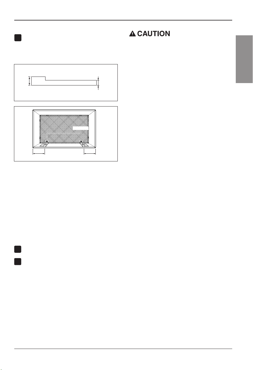
Toachieverearwardslope forunitdraining,
remove the backingfrom the 11
13
/
16
"shim
strips and attach themas shown belowin Fig.
21. The higher portion of shim is to be placed
infront of the rib on the base of wallsleeve.
Installthe newunitinto the wallsleeve
Assembletrim as described in Step 6,
ProcedureA.
8
7
FIG. 20
1" high
3
/
4
" High
Shim (2EA)
6" 6"
FIG. 21
•Air conditionerscoveredin thismanualpose an
excessive weighthazard. Two or morepeople are
neededto move andinstall theunit.
Toprevent injury orstrain, useproper liftingand
carrying techniqueswhen movingunit.
•Whenhandling theair conditioner, be carefulto avoid
cutsfrom sharp metalfins on front and rear coils.
•Make sureair conditionerdoes notfallduring
removal.
•If unitdoes notoperate afterinstallation check,tobe
surethe circuitinterrupter hasnot beentripped.
RefertotheTroubleshooting guide forreset
procedure.
9
18 RoomAir Conditioner
OperatingInstructions
Operating Instructions
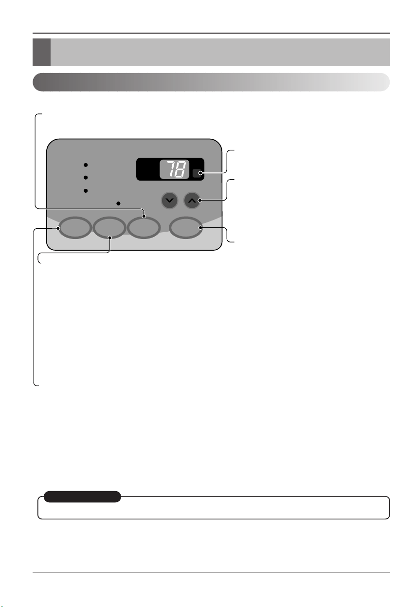
Controls
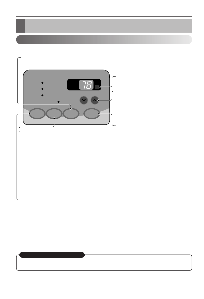
Thecontrols willlook likeone ofthe following.
MODE TIMER POWER
FAN
SPEED
Fan
Energy
Saver
Cool
Timer
TEMP
'
F
F1 LOW
F2 MED
F3 HIGH
REMOTE CONTROL SIGNAL
RECEIVER
POWER
MODE
-
Push this button to shift mode of operation from COOL → ENERGY SAVER → FAN.
- COOL:
• Fan runs continually for normal cooling operation.
- ENERGY SAVER:
• The fan stops when the compressor stops cooling. Approximately every 3 minutes the fan will turn on and the unit will
check the room air temperature to determine if cooling is needed.
- FAN:
• Fan-only operation.
TIMER
- SHUT-OFF TIME
• You will usually use shut-off time while you sleep.
• If unit is running, use Timer to set number of hours until shut-off.
• For your sleeping comfort, once Time is set, the Temperature
setting will raise 2°F after 30 min., and once again after another
30 min.
• Push Timer button to advance setting from 1Hour → 2Hours → ...
→ 12Hours maximum.
- START TIME
• If unit is off, use Timer to set number of hours before unit starts.
• Push Timer button to advance setting from 1Hour → 2Hours → ...
→ 12Hours maximum.
TEMPERATURE SETTING
• Use this button to automatically control the
temperature of the room.
The temperature can be set within a range of
60°F to 86°F by increments of 1°F.
• The setting appears in the display.
• To turn the air conditioner ON, push this button.
To turn the air conditioner OFF, push the button
again.
• This button takes priority over any other button.
• When you first turn it on, the unit is in cool
mode, High fan speed, Temperature setting at
72°F.
FAN SPEED
• Every time you push this button, it advances the setting as follows:
{High → Low → Med → High}
AUTORESTART
Whenpower isrestored after anelectrical powerfailure,theunit willbegin torunat itslast setting.
Owner’s Manual 19
ENGLISH
OperatingInstructions
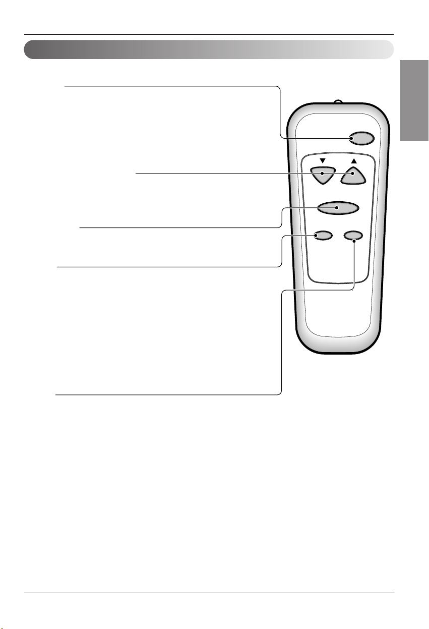
Remote control
Theremote controland control panelwill looklike oneof thefollowingpictures.
Power
Temp
Fan Speed
Timer Mode
POWER
• To turn the air conditioner ON, push this button.
To turn the air conditioner OFF, push the button again.
• This button takes priority over any other button.
• When you first turn it on, the unit is in cool mode, High fan speed,
Temperature setting at 72°F.
• Auto Restart
In the event at a power failure, the unit will run at the previous setting once
power returns.
TEMPERATURE SETTING
• Use this button to automatically control the temperature of the room.
The temperature can be set within a range of 60°F to 86°F by
increments of 1°F.
• The setting appears in the display.
FAN SPEED
• Every time you push this button it advances the setting as follows:
(High → Low → Med → High)
TIMER
- SHUT-OFF TIME
• You will usually use shut-off time while you sleep.
• If unit is running, use Timer to set number of hours until shut-off.
• For your sleeping comfort, once Time is set, the Temperature setting will
raise 2°F after 30 min, and once again after another 30 min.
• Push Timer button to advance setting from 1Hour
→ 2Hours → ... →
12Hours maximum.
- START TIME
• If unit is off, use Timer to set of hours before unit starts.
• Push Timer button to advance setting from 1Hour
→ 2Hours → ... →
12Hours maximum.
MODE
- Push this button to shift mode of operation from COOL
→
ENERGY SAVER
→
FAN.
- COOL:
• Fan runs continually for normal cooling operation.
- ENERGY SAVER:
• The fan stops when the compressor stops cooling. Approximately every 3 minutes the fan will turn on
and the unit will check the room air temperature to determine if cooling is needed.
- FAN:
• Fan-only operation.
20 RoomAir Conditioner
OperatingInstructions
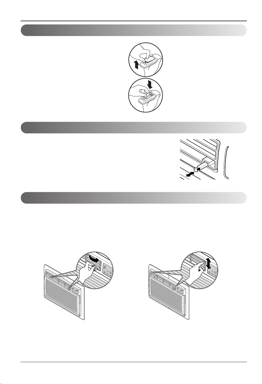
PULL OPEN / PUSH CLOSE
Ventilation
Air Direction
Theventilation leveris locatedinthe right ofthe airdischarge.
Theventilation levermustbe inthe CLOSEposition inorder to
maintainthe bestcooling conditions.
Whenfresh airis necessary inthe room,set theventilationleverto
theOPEN position.
Thedamper isopened androom airis exhausted outside.
Thedirection ofair canbe controlledwhereveryouwantbyadjusting thehorizontallouverand theverticallouver.
•HORIZONTAL AIR-DIRECTION
CONTROL
Thehorizontalair directionis adjustedbymoving
vertical louver.
Theleverofvertical louver islocated inthe right and
leftside ofthe airdischarge.
• VERTICAL AIR-DIRECTION CONTROL
Thevertical airdirection isadjusted by movingthe
horizontallouver.
Howto insert Batteries
1. Removethe cover fromthe backof theremote
controller.
2. Insert twobatteries.
•Be surethat the(+) and(-) directions are
correct.
•Be surethat bothbatteries arenew.
3. Re-attachthe cover.
•Do notuse rechargeablebatteries.
Suchbatteries differ fromstandard
dry cellsin shape,dimensions,and
performance.
•Removethe batteriesfrom the
remotecontroller ifthe air
conditioneris notgoing tobe used
foranextendedlength oftime.
Owner’s Manual 21
ENGLISH
Maintenanceand Service
Maintenance and Service
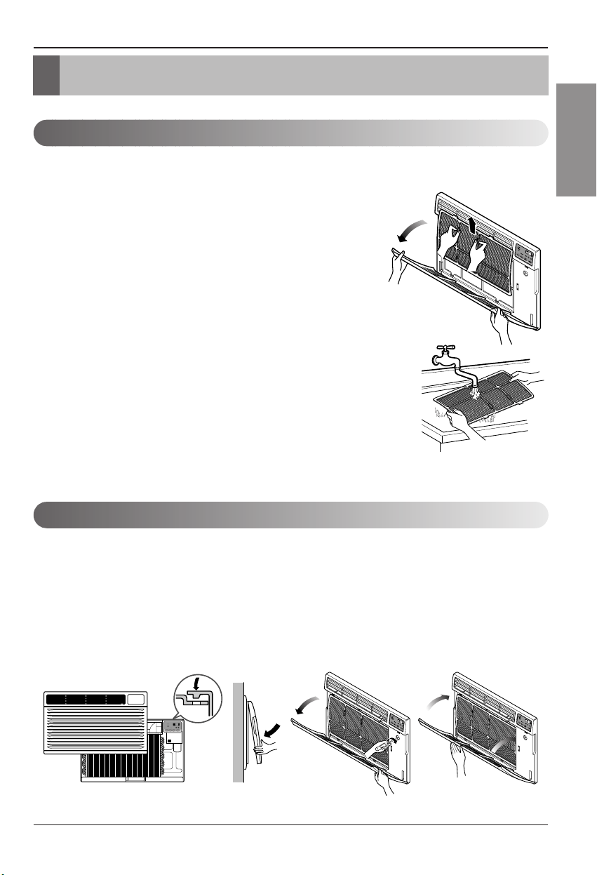
Air Filter Cleaning
Howto Attach Front Grilleto Cabinet
TURNTHEAIR CONDITIONER OFF AND REMOVETHEPLUG FROMTHEPOWER OUTLET.
Theair filtershould becheckedat leasttwice amonth tosee ifcleaning isnecessary.
Trappedparticles inthe filterwill build upand block theairflow. This reducesthe cooling
capacityand alsocauses anaccumulation offrost onthe coolingcoils.
Ifthe filterbecomes turn ordamaged youshould replace
immediately.Replacementfiltersare availablefrom your
salesperson,dealer,and theauthorized customerservice
centers.
1. Openthe inletgrille downwardbypulling outthe topof the
inletgrille.
2. Remove theair filterfrom thefront grilleassembly by
pullingthe airfilter upslightly.
3. Wash thefilter usinglukewarm waterbelow40°C (104°F).
4. Gentlyshake the excesswaterfrom thefilter completely.
Replacethe filter.
Thefront grille canbe removedforcleaning orto checkthe modeland serialnumbers.
Foryoursafety,youshould attachthe frontgrille asthe following procedures.
1. Pulldown frontgrille fromthe cabinettop.
2. Pushfront grille’s tipstowardthe cabinetin
orderto insertfront grille’s tabsinto the
cabinet.
3. Openthe inletgrille.
4. Tighten thescrew throughthe frontgrille into
theplate ofcontrol box.
5. Closeinlet grille.
MODE TIMER POWER
FAN
SPEED
Fan
Energy
Saver
Cool
Timer
TEMP
'
F
F1 LOW
F2 MED
F3 HIGH
22 RoomAir Conditioner
Maintenanceand Service
Common Problemsand Solutions
Troubleshooting
Normal Operation
TroubleshootingTips Savetime andmoney!
Review thechart belowfirstand youmaynot needto callforservice.
• You may hear a pinging noise caused by water being picked up and thrown against the condenser on rainy
daysorwhen thehumidity ishigh. This designfeaturehelps remove moistureand improveefficiency.
• You mayhearthe thermostat clickwhenthe compressorcycles onand off.
•Waterwillcollectinthebasepan duringhighhumidityoronrainydays. Thewatermayoverflowanddripfrom
theoutdoor sideof theunit.
•Thefanmay run evenwhen thecompressor doesnot.
Problem Possible Causes What To Do
■The airconditioner is
unplugged.
■The fuseis blown/circuit
breakeris tripped.
■Power failure.
■The currentinterrupter
deviceis tripped.
■Airflow isrestricted.
■TEMP Controlset too
highernumber.
■The airfilter isdirty.
■The roommayhavebeen
hot.
■Cold airis escaping.
■Cooling coilshaveiced up.
■Ice blocks theair flowand
stopsthe airconditioner
fromcooling theroom.
•Makesure theair conditionerplug ispushed
completelyinto theoutlet.
•Checkthe housefuse/circuit breakerboxand replace
thefuse orreset thebreaker.
•If power failureoccurs,turnthe modecontrol toOFF.
Whenpoweris restored,wait 3minutes torestart the
airconditioner topreventtripping ofthe compressor
overload.
•Press theRESET buttonlocatedon thepowercord
plug. Ifthe RESETbutton willnot stay engaged,
discontinueuse ofthe airconditioner andcontact a
qualifiedservice technician.
•Makesure thereare nocurtains, blinds, orfurniture
blocking thefront ofthe airconditioner.
•Set the TEMPcontrol toa lowernumber.
•Clean thefilter atleast every 2weeks.
Seethe operatinginstructionssection.
•Whentheairconditioner isfirst turned on,
youneed toallowtime for theroom tocool down.
•Checkforopen furnace floorregisters
andcold airreturns.
•Set theair conditioner'svent totheclosed position.
•See AirConditioner Freezing Upbelow.
•Set themode controlat HighFan orHigh Coolwith
thehigh temperature.
Airconditioner
doesnot start
Airconditioner
doesnot cool as it
should
Airconditioner
freezingup

Memo
Owner’s Manual 23
ENGLISH
24 AireAcondicionador
Manualdel usuario del acondicionador de aire tipoVentana
TABLA DE CONTENIDOS
PARA SUS ARCHIVOS
Escriba aquíel modelo ynúmero de serie:
Modelon°:
Serien°:
Puedeencontrar estosdatos en laetiqueta situada enel
lateralde cadaunidad.
Nombredel distribuidor:
Fechade compra:
■ Adjunte surecibo a estapágina con lagrapadorapara
elmomento que lonecesite paraprobar la fechadesu
adquisicióno parala validaciónde lagarantía.
LEAESTEMANUAL
En su interior encontrará muchos consejos útiles sobre la
utilización y mantenimiento de su acondicionador de aire.
Unos pocos cuidados por su parte le pueden ahorrar
mucho tiempo y dinero durante la vida de su
acondicionadorde aire.
Enlatabladeconsejosparalasoluciónrápidade
problemasencontrará muchas respuestas alos problemas
más habituales. Si revisa primero nuestra Tabla de
Consejos para la solución rápida de problemas, tal vez no
necesitellamar nuncaal serviciotécnico.
PRECAUCIÓN
•Póngase encontacto con untécnico del servicio
autorizadopara realizar lareparación y
mantenimientode esta unidad.
•Póngase encontacto con uninstalador para realizar
lainstalacióndeestaunidad.
•Cuando seva a cambiar elcable eléctrico,eltrabajo
dereemplazamiento debe serrealizado únicamente
porpersonal autorizado,utilizandolas piezasde
cambiogenuinasúnicamente.
•El trabajode reemplazamiento debeser realizado de
acuerdoconel Código EléctricoNacional
únicamentepor personalautorizado.
Precaucionesde Seguridad.........25
Antesdeponerelequipoen
funcionamiento..............................29
Introducción...................................30
SeguraidaElectrica.......................31
Instalacion......................................33
Instruccionnesde
Funcionamiento.............................40
Cuidadoy Mantenimiento ............43
Manualdel Propietario 25
ESPAÑOL
Precaucionesde Seguridad
Precauciones de Seguridad
Paraevitarlesionesalusuariooaotraspersonasydañosalapropiedad,estasinstrucciones
estén seguirse.
■
Unaoperación incorrecta por ignorarlas instrucciones provocará lesiones odaños.Laseriedad se clasifica
porlassiguientes indicaciones.
■ Significadosde lossímbolos utilizadosen estemanual.
ADVERTENCIA
PRECAUCION
Este símbolo indica la posibilidad de muerte o de seria lesión.
Este símbolo indica sólo la posibilidad de lesiones o daños ala propiedad
ADVERTENCIA
■ Instalación
No hacer.
Siga estas instrucciones.
No utilice un cable de
alimentación,enchufe o una
tomasuelta queesté dañada.
•De locontrario,podría provocar
unincendio odescarga
eléctrica.
Enchufesiempreaun
tomacorriente que tenga
toma a tierra.
•De locontrario,podría provocar
unincendio odescarga
eléctrica.
Nomodifique nialargue el
cablede alimentación.
•De locontrario,puede provocar
unadescarga eléctrica o
incendiodebido ala
generaciónde calor.
Nodesmonte nimodifique
los productos.
•Puede ocasionarfallosy una
descargaeléctrica.
Tenga cuidado al
desembalar e instalar el
aparato.
•Los bordesafilados pueden
provocar lesiones.
No use el cable de alimentación
cercagas inflamableo
materiales combustiblestales
como la gasolina,benceno,
disolvente,etc.
•Podríaocurrir unaexplosióno
incendio.
Gasolin
26 AireAcondicionador
Precaucionesde Seguridad
■ Operación
Noponga elcable de
alimentacióncerca de un
calentador.
•Puede ocasionarun incendioy
unadescarga eléctrica.
Nopermita queentreagua
enlas piezaseléctricas.
•Puede provocar fallos enel
productoo descargas
eléctricas.
Utilice un paño suavepara
limpiar.Noutilice cera,
disolventes o detergentes
fuertes.
•
Laapariencia del aparatode aire
acondicionadopuede deteriorar,
cambiarel coloro desarrollarflujos
enlas
superficies.
Wax
Thinner
Ventile bien la sala al usar
esteaparato conuna estufa,
etc.
•Puede ocurrir unfaltade
oxígeno.
Apagueel aparato y el
interruptordiferencial
primeroantes de limpiar la
unidad.
•
Debidoa queel ventiladorgiraa
altavelocidad duranteel
funcionamiento, podríaocasionar
lesiones.
Apagueel interruptor de
alimentación principal cuando
no vayaa utilizar el aparato
durante muchotiempo.
•Evitará elarranque accidentaly
laposibilidad delesiones.
Desenchufela unidad si oye
unsonido extraño, olores,o
siobservasalir humo.
•De locontrario,puede ocurrir
unincendio yun accidentepor
descargaeléctrica.
Noabra laparrilla de
entrada al aparato mientras
estáen funcionamiento.
•De locontrario,pueden ocurrir
descargaseléctricas y fallos.
Sientraaguaenelproducto,
apagueel interruptor de la
carcasaprincipal del aparato.
Póngaseen contactocon el
centrode servicio despuésde
haber sacado el enchufedel
tomacorriente.
No use el cablede alimentación
cercagas inflamable o materiales
combustibles tales como la
gasolina,benceno,disolvente,etc.
•Puede ocasionaruna explosión
odescarga eléctrica.
Nocomparta el
tomacorrientecon otros
electrodomésticos.
•
Delo contrario,puede provocar una
descargaeléctrica oincendio debido
ala generaciónde calor.
Saque el enchufeen caso de
necesidad,sosteniendola
cabeza del enchufey no lo
toque con las manos mojadas.
•
Delo contrario,podría provocar un
incendioo descargaeléctrica.
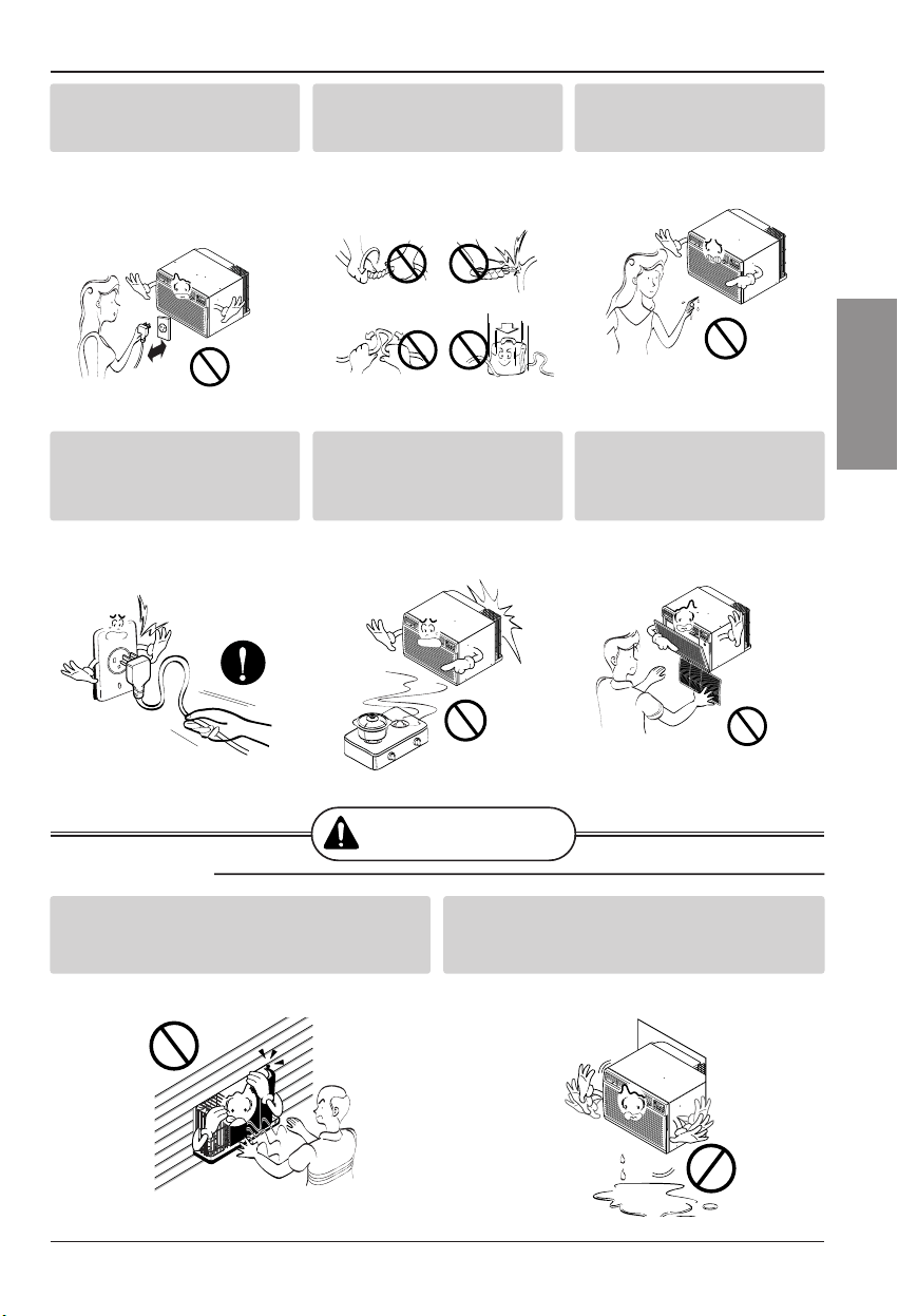
Manualdel Propietario 27
ESPAÑOL
Precaucionesde Seguridad
ADVERTENCIA
■ Instalación
Noopere nidetenga la
unidadinsertando o
estirandode enchufe.
•De locontrario,puede provocar
unadescarga eléctrica o
incendiodebido ala
generaciónde calor.
Nodañeniuseunenchufe
de alimentaciónno
especificado.
•Provocarádescargas eléctricas
oincendios.
Notoque el productocon
lasmanos mojadaso enun
ambiente húmedo.
•Provocarádescargas
eléctricas.
Sostenga el enchufepor su
cabeza al sacarlo.
•Podríaocasionar unadescarga
eléctrica ydaños.
Cuando haya un escape de
gas,abrala ventana para
ventilar antes de poner en
marcha la unidad.
•De locontrario,podría ocurrir
unaexplosióno incendio.
Notoque las partes
metálicas del aparato al
sacar el filtrodel aire.
•Son puntiagudasy pueden
provocar lesiones.
Instale el productode modo que el ruido o
elaire calienteproducido por la unidad
externano moleste a los vecinos.
•De locontrario puededar lugara disputas
vecinales.
Mantenga nivelado el productoal instalarlo.
•De locontrario sepodría causarvibraciones o
escapesde agua.
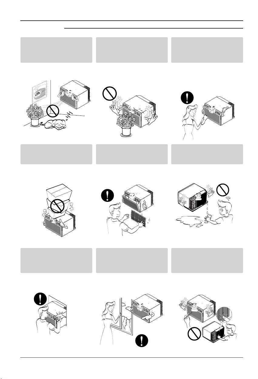
28 AireAcondicionador
Precaucionesde Seguridad
Nosesubaalaunidad
interior/exteriorni coloque
objetos sobre la misma.
•Puede lesionarseal caersedel
aparatoo alcaerse losobjetos
quehayacolocado.
Inserte siempre el filtro
correctamente.
Límpielo cada dos semanas.
•El funcionamientosin filtros
puedeprovocarfallos.
Nobeba elagua que drena
elaparato deaire
acondicionado.
Noponga plantasni
animales en la trayectoria
que recorrerá el aire
caliente.
•Podríaocasionar lesiones.
Nobloquee la entrada ni la
salida del flujo de aire.
•Puede causaruna averíaen el
aparato.
Utilice un paño suavepara
limpiar.Noutilice cera,
disolventes o detergentes
fuertes.
•
Laapariencia delaparatode aire
acondicionadopuede deteriorar,
cambiarel coloro desarrollarflujos
enlas superficies.
Tenga cuidado para no
tocar los bordes
puntiagudosal instalar.
•Podríaocasionar lesiones.
Eviteun enfriamiento
excesivo y ventile en
ocasiones.
•De locontrario,podría dañarsu
salud.
Nointroduzca la mano ni
barras en la entrada o salida
del aire durante el
funcionamientodel aparato.
•De locontrario,podrían ocurrir
lesionespersonales.
■ Operación

Antesde ponerel equipoen funcionamiento
Manualdel Propietario 29
ESPAÑOL
Antes de poner el equipo en funcionamiento
1. Póngase en contacto con un especialista para realizar la instalación.
2. Enchufecorrectamente la toma de alimentación.
3. Utilice un circuito dedicado.
4. No utilice un cablealargador.
5. No inicie/cese el funcionamiento enchufando/desenchufando el cable
eléctrico.
6. Si el cable/enchufe está dañado,sustitúyalosolo por una pieza autorizada.
1. Estando expuestoa la circulación directa de aire duranteun extensoperíodo
de tiempo podría resultar peligrosopara su salud.Noexponga a las personas,
animales domésticos,o a las plantas a la circulación de aire durante largos
períodos de tiempo.
2. Debido a la probabilidad de faltade oxígeno, ventile el cuarto cuando esté
utilizado el aparatojunto con estufasu otros aparatos de calefacción.
3. No utilice este aire acondicionado con propósitos especiales no especificados
(Ej.:conservaciónde dispositivosde precisión, comida, animales domésticos,
plantas y objetos de arte). Tal uso podría dañar los artículos.
1. No toque las piezas metálicas de la unidad al retirar el filtro.Manejararistas
afiladas de metal puede causar lesiones.
2. No utilice el agua paralimpiar el interior del aire acondicionado.Laexposición
al agua puede destruir el aislamiento, conduciendo a posiblesdescargas
eléctricas.
3. Al limpiar la unidad, asegúrese antes de que la electricidad y el interruptor
están apagados. El ventilador rota a muyalta velocidaddurante el
funcionamiento del equipo.Existela posibilidad de lesiones si acciona
accidentalmente la electricidad de la unidad mientras limpia el interior de la
unidad.
Para cuestiones de reparacióny mantenimiento,póngase en contacto con su
distribuidorde servicio autorizado.
Preparación para elfuncionamiento
Uso
Limpieza y mantenimiento
Servicio
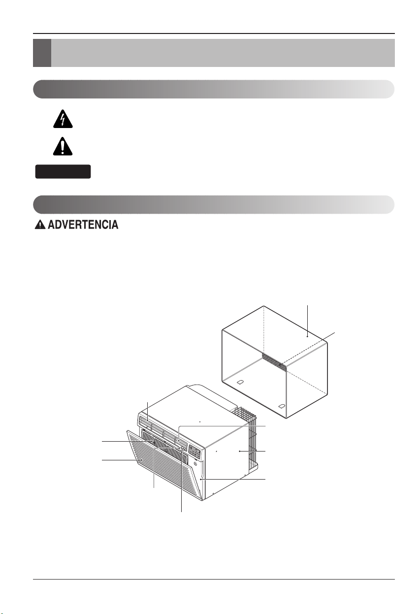
30 AireAcondicionador
Introducción
Este símbolo lo advierte de un peligrode accidente por
corriente eléctrica.
Este símbolo lo adiverte de un peligro que pueda causar un
daño del ventliador.
Este símbolo significa condicciones especiales.
CONSEJO
Introducción
Símbolos Utilizados enEste Manual
Características
Esteaparato deberíainstalarse deacuerdo conlas normas delCódigo EléctricoNacional.
ARMARIO
REJILLA
FRONTAL
REJILLA DE ENTRADA
(Toma de aire)
FILTRO DE AIRE
DEFLECTOR HORIZONTAL DE AIRE
(Rejilla de ventilación vertical)
CONTROL DEL ORIFICIO DE VENTILACIÓN
DEFLECTOR VERTICAL DE AIRE
(Rejilla de ventilación horizontal)
DESCARGA
DE AIRE
MONTAJE DEL SOPORTE DE PARED
(Incluyendo rejilla posterior de aluminio)
EL SOPORTE DE PARED Y
LA REJILLA POSTERIOR
(incluido opcionalmente con su unidad)
EL UNIDAD
REJILLA POSTERIOR
(Rejilla posterior
de aluminio)
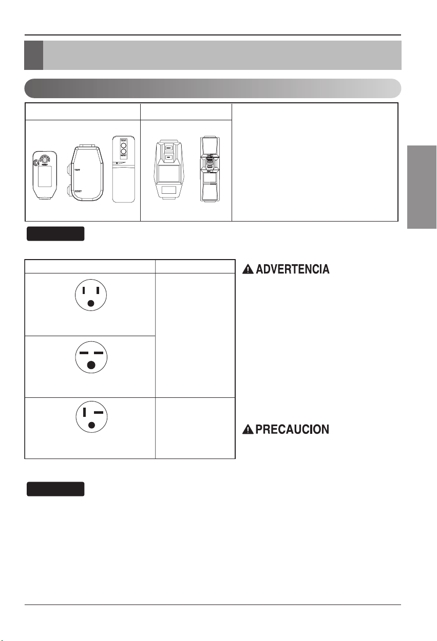
SeguraidaElectrica
Manualdel Propietario 31
ESPAÑOL
Seguraida Electrica
Datos Electricos
115V~ 230V~
El cable de alimentación puede incluir un
dispositivo interruptor de corriente. La
carcasa del enchufe cuenta con un botón de
prueba y otro de reinicio. El dispositivo debe
comprobarse periódicamente presionando
primero el botón TEST y después RESET.
Si el botón TEST no se desconecta o si el
botón RESET no permanece activo,
suspenda el uso del aire acondicionado y
póngase en contacto con un técnico de
servicio cualificado.
Utilice el enchufe de la pared Consumo de Energía
Standard 125V, enchufe de 3
Líneas de 15A, 125V AC
Standard 250V, enchufe de 3
Líneas de 15A, 250V AC
Standard 250V, enchufe de 3
Líneas de 20A, 250V AC
Utilice un fusible de
15AMP. o un
Interruptor de 15AMP.
Utilice un fusible de
20AMP. o un
Interruptor de 20AMP.
Nopresione nuncael botónde pruebadurante el
funcionamiento,delo contrarioel enchufepodría
resultardañado.
Estedispositivo contieneproductos químicos,
incluyendoplomo,conocido enel estadode
Californiacomo productocancerígeno ycausante de
defectosdenacimiento yotros dañosal sistema
reproductor.
Lávesebienlas manos trasmanipular eldispositivo.
Nodesmonte, modifiqueni sumerjaen aguaeste
enchufe.
Siel dispositivose activara, deberácorregir lacausa
antesde volver autilizarlo.
Los hilos conductores dentro del cableestán rodeados
por blindajes,que supervisan lacorriente de fuga.
Estosblindajes no están puestos a tierra.
Examine periódicamente el cable en buscade
cualquier daño.Noutilice este producto si losblindajes
resultaranexpuestos.
Eviteelriesgodedescargaseléctricas;estaunidad no
puede ser reparadapor el usuario por ser resistente y
aprueba de alteraciones. Manipular la porción sellada
dela unidadanulará todas las garantías y quejas de
rendimiento.Estaunidad no está diseñada para su uso
como un interruptor de encendido-apagado.
Laforma puedeser diferente segúnsu modelo.
CONSEJO
NOUSECABLEDEEXTENSIÓNENUNIDADES
DE208, 230,AND 208/230VOLTIOS.
Todoel cableado deberárealizarse deacuerdo
conlos códigosy reglamentoseléctricos
locales.
Elcableado domésticodealuminiopodría
ocasionarproblemas especiales. Consultea un
electricista calificado.
CONSEJO
32 AireAcondicionador
SeguraidaElectrica
IMPORTANTE
(FAVORLEA CON ATENCIÓN)
PORLA SEGURIDAD PERSONALDEL USUARIO,
ESTEAPARATODEBESER DEBÍDAMENTE
NEUTRALIZADO.
Elcordón deenergíadeéste aparatoesta
equipadocon trespatas(cable atierra). Utilice
éstecon unenchufede paredde tressalidas(a
tierra)para minimizarel peligrodechoque
eléctrico. El clientedebe revisar elreceptor de
paredy elcircuito porun electricista calificado
paraasegurarse quela recepciónesta
debidamenteneutralizada.
NOCORTE OREMUEVALA TERCERA
PATA(GROUND)DEL ENCHUFE.
A.SITUACIONES ENLAS CUALES EL
APARATOES DESCONECTADO
OCASIONALMENTE:
Debidoal peligropotencial, nosotrosno
recomendamosel usode adaptadores. Sin
embargo, siusted deseautilizar unadaptador,
unaCONEXIÓNTEMPORAL, puedeser
efectuada. Utilice adaptadoresUL, disponibles
enla mayoríade losestablecimientos de
herramientas. La patamas grandedel
adaptadordebe seralineada conla patamas
grandedel interruptorpara asegurarseuna
polarización adecuada.
Adaptarla terminaldel grounddel
adaptadora lacubierta dela paredcon un
tornillono neutralizael aparatoa menos
quela cubierta deltornillo seade metal,u
nosea insolada,yel receptorde pared
este
neutralizadoa travésdel alambradodel la
casa.Elclientedebe hacerverificar el
circuitopor unelectricista calificadopara
asegurarseque elreceptor esta
debidamenteneutralizado.
Desconecteel cordónde energía del adaptador,
utilizadouna manoen cadauno. De locontrario,
laterminal deladaptador puederomperse.NO
UTILICEel aparatocon unenchuferoto.
B.SITUACIONES ENLAS CUALES EL
APARATOES DESCONECTADOCON
FRECUENCIA.
Noutilice unadaptador enestas
circunstancias. Desconectar elcordónde
energíacon frecuencialo llevará aleventual
rompimientode laterminal deneutralización.
Lasaluda deenergía dela pareddebe ser
reemplazadapor unasalida detres
patas(neutralizada).
USODE EXTENSIONES
Debidoal peligropotencial, norecomendamos
lautilización deextensiones. Sin embargo, si
usteddesea utilizaruna extensión,utiliceuna
certificadapor CSA/ULde tresalambres,
catalogada15A, 125V.
Seguraida Electrica
Manualdel Propietario 33
ESPAÑOL
Instalacion
Instalacion
Retirelos materialesde embalaje del soporte de paredde
paredy la cinta del aire acondicionado.
REQUISITOS DE INSTALACIÓN
Siutiliza un soportede pared de pared yaexistente,
deberámedir sus dimensiones.Instaleelnuevoaire
acondicionadosegún estas instruccionesde instalación
paralograrel mejor funcionamiento. Todoslos soportede
paredde pared utilizados paramontar el nuevoaire
acondicionadodeben estar en buenascondiciones
estructuralesy contar con una rejilla traserapara conectar
elnuevoaire acondicionado de forma segura. (FIG.1)
Conel soportede pared LGE (incluidoopcionalmente
consu unidad), podrá mantener el mejorrendimiento del
nuevoaireacondicionado. (FIG.2)
SERVICIO ELÉCTRICO
Compruebe su servicioeléctrico disponible. La fuente de
alimentacióndisponible debe serigual que la que se
muestraen la placade identificacióndelaunidad
(encontradaen el lado izquierdo de lacarcasa).
Todoslos modelos están equipados con un enchufede
tresdientes para proporcionar elservicio apropiado y
ponera tierra el positivode formasegura.Nocambie el
enchufedeninguna manera.Noutilice un enchufe
adaptador.Sisu enchufede pared actual noadmite su
enchufe,llameaunelectricistacualificadopararealizar
lascorrecciones necesarias. GUARDE LA CAJADE
CARTÓNparael almacenamiento y esteMANUALDEL
PROPIETARIOparafuturas referencias.Elcartónesla
mejormanera de almacenar launidad durante el invierno
ocuando no esté en uso.
HARDWAREDE INSTALACIÓN
14-
13
/
32
"
(366 mm)
24"(610 mm)
18-
15
/
32
"(468 mm)
20-
3
/
32
"
(511 mm)
1
5
6
7
8
3
2 4
9
2 opciones de tamaño
2 opciones de tamaño
•Guantes ceñidos
adecuados
•Destornillador estándar
•Destornillador de estrella
•Alicates
•Cuchillo afilado
•Llaveinglesaabierta o
ajustablede 3/8-pulgadas
•Enchufeycarretedetuerca
hexagonalde1/4- pulgadas
•Cinta métrica
•Taladro eléctrico
•Boca de taladro de1/4-
pulgadas
FIG.1
Aireacondicionado
ARTÍCULO
NOMBREDE LAS PIEZAS Q'TY
1
REJILLADE PLÁSTICO 1
2
TIRAVERTICAL DE AISLAMIENTO 1
3
TIRASENVOLVENTESDE AISLAMIENTO
2
4
TIRAHORIZONTAL DE AISLAMIENTO 1
5
BLOQUEDE APOYO 2
6
COMPUERTA 1
7
MARCODE AJUSTE 2
8
CUÑA2
9
TUERCASDEPLÁSTICOY TORNILLOS DE ARANDELA
4
15-
17
/
32
"
(394 mm)
16-
23
/
32
"
(425 mm)
25-
7
/
8
"
(656 mm)
Rejilla de aluminio
FIG.2
Soporte de pared
LGE
Para evitar riesgos dedaños corporales,materiales, odaños
alproducto debidosal pesode estedispositivo y alos bordes
afiladosque puedenestar expuestos:
•Los airesacondicionados tratadosen estemanual
representanun peligropor pesoexcesivo. Son necesarias
doso máspersonas paradesplazar einstalar launidad.
Para evitar lesioneso grandesesfuerzos,utilicelas técnicas
deelevaciónydesplazamiento paramoverla unidad.
•Examinar cuidadosamentela ubicacióndonde elaire
acondicionadovaya aser instalado.Asegúresede que
aguantaráel peso dela unidada lolargo deun extenso
períododetiempo.
•Manipule concuidado elaire acondicionado.Utilicelos
guantesprotectores siempreque levanteo desplacela
unidad. EVITElas aristas afiladasde metalde lasbobinas
frontaly posterior.
•Asegúrese deque elaire acondicionadono secaiga durante
lainstalación.
HERRAMIENTAS NECESARIAS:
34 AireAcondicionador
Instalacion
INSTALACIÓN
•Escoja una ubicaciónquepermitaalaireacondicionado
soplarhacia el área que desee. Una buenainstalación,
prestandoespecial atenciónalaposicióncorrectadela
unidadreducirá la necesidad de reparaciones.
ARTÍCULOSEN ELHARDWARE DE
INSTALACIÓN
Ustedpuede no necesitar todas las piezas delconjunto.
Descartelas piezas que no utilice
CÓMO INSTALAR
Identifiqueel soporte de pared existenteantes de
instalarla unidad según la lista.
Todoslos soporte de pared utilizados paramontar el
nuevoaireacondicionado deben estar en condiciones
estructuralessanas y tener una rejilla posterior que se
acoplecon seguridadal soporte de pared, o una pestaña
posterior que sirvacomofreno para elaire
acondicionado.
Desmonteel antiguo aire acondicionado del soporte
depared existente.
Limpieel interiordel soporte de pared existente.(No
toqueel sellado.)
Elsoporte de pared se estar firmemente sujeto a la pared
antesde instalar el aire acondicionado. Utilice los clavoso
tornillos a travésdel soporte depared, si fuera necesario.
Vuelvaa pintarel soporte de pared si fueranecesario.
Prepareel soporte de pared parala instalacióndela
unidad.Siustedpiensa utilizar el soporte de pared
existente, y no es LGE, utilice el procedimientoB ó C
acontinuación.
Instalela nueva unidad en el soporte de pared.
Alfinalizar la instalación, la unidad de sustituciónDEBE
teneruna pendiente hacia atrássegúnseilustra.Para
lograruna pendientede 1/4", retire el envoltoriode las
cuñasde 11-13/16" y acóplelas segúnsemuestraa
continuaciónen la FIG.3. Coloque el extremomásalto
dela cuña en la parte frontal de labase del soporte de
pared.
CONSEJO
1
2
3
4
5
6
1/4"
Soporte
de pared
FRENTAL
UNIDAD
COLOCACIÓN DE LA CUÑA INSTALACIÓN DE LA UNIDAD
1"de
alto
3/4"de alto
Cuña
6" 6"
FIG.3
Recomendamosencarecidamente quedesmonte elviejo
soporte depared yla instalaciónde unnuevosoporte
depared LGE.
Sidecide mantenerel soporte de pared existente,tendrá
queredireccionar lasrejillas deventilaciónenlaparte
posterior dela ilustracióndel soporte depared.
Recomendamosel usode alicates. Si NOlas redirecciona,
correelriesgodeunrendimientopobreodeaverías enel
producto.
Estasno estáncubiertasbajo lostérminos degarantíade
LGE.
ARTÍCULO(pulgadas) Cant.
Rejillaplástica 26
3
/
4
x16
1
/
2
1
Tiravertical de aislamiento 15
9
/
16
x1
3
/
8
x1
3
/
8
1
Tirasde aislamiento 67
1
/
8
x1
3
/
8
x
25
/
32
1
envolventes 59
27
/
32
x1
3
/
8
x1
3
/
8
1
Tirahorizontalde aislamiento
23
7
/32 x1
3
/
8
x1
3
/16 1
Bloquede apoyo 1
3
/
4
x1
3
/
8
x4
5
/
16
2
Compuerta 14x 4
1
/
2
x
1
/
8
1
Cuña11
13
/
16
x1x
3
/
4
2
Marcodeajuste 2
Tornillos de arandela 4
Tuercas (Plástico) 4
Rejillaposterior 1
Marca
Dimensionesdel soporte de pared (pulgadas)
Ancho Altura
Profundidad
White-Westinghouse
25-1/2 15-1/4
16,17-1/2
Frigidaire
ó22
Carrier (Serie 52F)
GeneralElectric
26 15-5/8 16-7/8
/Hotpoint
Whirlpool 25-7/8 16-1/2
17-1/8
ó23
Fedders/Emerson 27 16-3/4
16-3/4
ó19-3/4
LGE 25-7/8 15-17/32 16-23/32
Emerson/Fedders 26-3/4 15-3/4 15
Carrier (Serie 51S) 25-3/4 16-7/8 18-5/8
Friedrich 27 16-3/4 16-3/4
Procedimiento Marca
Profundidad(pulgadas)
A LGE 16-23/32
White-Westinghouse
FrigidaireCarrier
16,17-1/2
Carrier (Serie 52F)
ó22
B
GeneralElectric
16-7/8
/Hotpoint
Whirlpool 17-1/8ó 23
Carrier (Serie 51S)
18-5/8
Fedders/Emerson
16-3/4
ó19-3/4
C
Emerson/Fedders 15
Friedrich 16-3/4
Manualdel Propietario 35
ESPAÑOL
Instalacion
PROCEDIMIENTO A
Siestá utilizando un nuevo soporte de pared
(incluidoopcionalmente con su unidad), salte al
paso3.Sino es así, instale la rejillaplástica.Corte
larejilla plástica a 25-1/2" de ancho y 15-1/4”de
alto.Coloquela rejilla plástica en el interior del
soportede pared en la pestaña posterior.
Apriete los 4 tornillos de la arandela paraasegurar la
rejillaal soporte de pared.Sinecesita tuercas
plásticaspara montar la rejillaplásticaenelinterior
delsoporte de pared, encontrarátuercas plásticas
enel equipo de instalación.Lastuercas están
instaladasen el interiordel soporte de pared yestán
presionandolas perforacionesrectangulares de las
pestañasposteriores.
Retireel envoltoriode la tiraverticalde aislamiento
15-9/16x 1-3/8 x 1-3/8 y únala a laparte interior
derechadel soporte de pared segúnsemuestraa
continuación. Retireel envoltoriode la tira de
aislamientoenvolvente de 67-1/8 x 1-3/8 x 25/32 y
únalaa la parte frontal interior del soporte de pared
segúnsemuestraacontinuación.
Instalela nueva unidad en el soporte de pared.
Para el montaje,encaje la lengüetadecadapieza
enla ranurade la otra piezasegúnsemuestraa
continuación.Deslicelapiezasobrelapartefrontal
delaire acondicionado hasta que el ajuste sea
rasantecon el soportede pared segúnsemuestraa
continuación.
FIG.4
Aislamiento envolvente
Aislamiento vertical
9
1
/
2
"6"
Interior Exterior
FIG.6
ó
FIG.5
1
2
3
4
5
Pared
Ajuste (2EA)
FIG. 7
•Los airesacondicionados tratadosen estemanual
representanun peligropor pesoexcesivo.Son
necesarias doso máspersonas paradesplazar e
instalarla unidad. Para evitar lesioneso esfuerzos
excesivos,utilice lastécnicas delevantamiento y
desplazamientoapropiadas almoverla unidad.
•Manipule concuidado elaire acondicionado, tenga
cuidadode evitarcortesde lasaristas afiladasde
metalde lasbobinas frontaly posterior.
•Asegúrese deque elaire acondicionado no se caigaal
desmontarlo.
•Si launidad nofunciona trasla revisióndeinstalación,
asegúreseque elinterruptor delcircuito nose ha
disparado.Consultela guíadesolucióndeaverías
paraconocer elprocedimiento dereinicio.
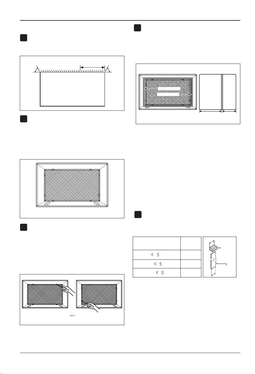
36 AireAcondicionador
Instalacion
PROCEDIMIENTO B
Redireccionelas rejillas de ventilaciónenlaparte
posterior del soportede pared a un ángulo de 60°
según muestra la FIG. 8. Recomendamos el uso de
alicates.
Siel soporte de pared yacuentacon una rejilla
posterior,salte al paso 4.Siel soporte deparedno
tieneuna rejilla posterioro un panel en rejilla,instale
larejilla plástica del conjunto. Cortela rejilla plástica
a25-1/2" de ancho y 15-1/4”dealto. Coloquela
rejillaplástica en la parte interior del soporte de
paredenlapestaña posterior.
Apriete los 4 tornillos de la arandela paraasegurar la
rejillaal soporte de pared.Sinecesita tuercas
plásticaspara montar la rejilla plásticaenelinterior
delsoporte de pared, encontrarátuercas plásticas
enel equipo de instalación.Lastuercas están
instaladasen el interiordel soporte de pared yestán
presionandolas perforacionescuadradasde las
pestañasposteriores.
Retireel envoltoriode la tiraverticalde aislamiento
15-9/16x 1-3/8 x 1-3/8 yúnala a la parteinterior
derechadel soporte de pared segúnsemuestraa
continuación. Retire elenvoltoriode la tira de
aislamientoenvolvente de 67-1/8 x 1-3/8 x 25/32 y
únalaa la parte frontal interior del soporte de pared
segúnsemuestraacontinuación.
Sila profundidad de su soporte de pared esmenor o
igual a 18", salte al paso 6. Si no, corte las
compuertasy los bloquesde soporte segúnla
longitud"A"enlatablaacontinuación.
1
4
2
3
FIG. 9
Aislamiento envolvente
Aislamiento vertical
9
1
/
2
"6"
Interior Exterior
FIG. 11
ó
FIG. 10
Rejillas de ventilación posteriores
(Perspectiva superior)
60°
60°
7
3
/
32
"
FIG. 8
Profundidad "D" del soporte
de pared existente (pulgadas)
Longitud "A"
(pulgadas)
Bloque
de apoyo
Compuerta
A
A
3
/
4
1-
3
/
4
4
18 D 18-
5
/
8
18-
5
/
8
D 19-
3
/
4
19-
3
/
4
D 22
5
Coloquela rejilla plástica
Apriete los tornillos
FIG. 12
Manualdel Propietario 37
ESPAÑOL
Instalacion
PROCEDIMIENTO B
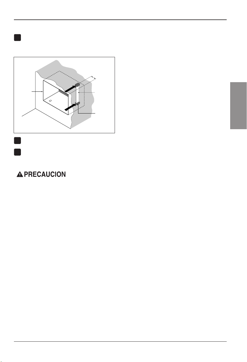
Retireel envoltoriode los bloquesde apoyoy
acóplelosal interiordel soporte de pared como
muestra la FIG. 13. Deslice la compuerta en las
ranurasdelos bloquesde apoyo.
Instalela nueva unidad en el soporte de pared.
Ajuste la posiciónsegúndescribeelpaso5,
procedimientoA.
8
Pared
Soporte
de pared
Compuerta
(
7
3
/
32
"
)
Frontal
Bloque
de apoyo
FIG. 13
6
7
•Los airesacondicionados tratadosen estemanual
representanun peligropor pesoexcesivo.Son
necesarias doso máspersonas paradesplazar e
instalarla unidad.
Para evitar lesioneso esfuerzosexcesivos, utilice
lastécnicas delevantamientoydesplazamiento
apropiadasal mover launidad.
•Manipule concuidado elaire acondicionado, tenga
cuidadode evitarcortesde lasaristas afiladasde
metalde lasbobinas frontaly posterior.
•Asegúrese deque elaire acondicionado no se
caigaal desmontarlo.
•Si launidad nofunciona trasla revisiónde
instalación,asegúrese queel interruptor delcircuito
nose hadisparado. Consulte laguíadesoluciónde
averíaspara conocerel procedimientode reinicio.
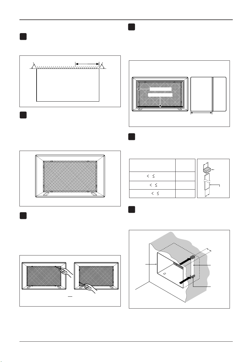
38 AireAcondicionador
Instalacion
PROCEDIMIENTO C
Redireccionelas rejillas de ventilaciónenlaparte
posterior del soportede pared a un ángulo de 60°
según muestra la FIG. 14. Recomendamos el uso de
alicates.
Siel soporte de pared yacuentacon una rejilla
posterior,salte al paso 4.Siel soporte deparedno
tieneuna rejilla posterioro un panel en rejilla,instale
larejilla plástica del conjunto. Cortela rejilla plástica
a26-1/2" de ancho y 15-1/2”dealto. Coloquela
rejillaplástica en la parte interior del soporte de
paredenlapestaña posterior.
Apriete los 4 tornillos de la arandela paraasegurar la
rejillaal soporte de pared.Sinecesita tuercas
plásticaspara montar la rejilla plásticaenelinterior
delsoporte de pared, encontrarátuercas plásticas
enel equipo de instalación.Lastuercas están
instaladasen el interiordel soporte de pared yestán
presionandolas perforacionescuadradasde las
pestañasposteriores.
Retireelenvoltoriodelatirahorizontaldeaislamiento
de23-7/32 x 1-3/8 x 1-3/16 yúnala a laparte interior
derechadelsoportedeparedsegúnsemuestraa
continuación.Retireelenvoltoriodelatirade
aislamientoenvolventede 59-27/32 x 1-3/8 x 1-3/8 y
únalaa la parte frontal interior del soporte de pared
segúnsemuestraacontinuación.
Sila profundidad de su soporte de paredes menor o
iguala 18", salte al paso 7.Sino,cortelas
compuertasy los bloquesde apoyosegúnlalongitud
"A"en la tablaa continuación.
Retireel envoltoriode los bloquesde apoyoyúnalos
alinteriordel soporte de pared como muestrala FIG.
19. Deslice la compuerta dentro de las ranuras en
losbloques deapoyo.
Profundidad "D" del soporte
de pared existente (pulgadas)
Longitud "A"
(pulgadas)
Bloque
de apoyo
Compuerta
A
A
3
/
4
1-
3
/
4
4
18 D 18-
5
/
8
18-
5
/
8
D 19-
3
/
4
19-
3
/
4
D 22
Pared
Soporte
de pared
Compuerta
Frontal
Bloque
de poyo
(7
3
/
32
")
FIG. 19
FIG.18
1
4
2
3
FIG. 15
8
1
/
2
"
Interior Exterior
Aislamiento envolvente
Aislamiento horizontal
FIG. 17
ó
FIG. 16
Rejillas de ventilación posteriores
(Perspectiva superior)
60°
7
3
/
32
"
60°
FIG. 14
5
6
Coloquela rejilla plástica
Apriete los tornillos
Instalacion
Manualdel Propietario 39
ESPAÑOL
PROCEDIMIENTO C
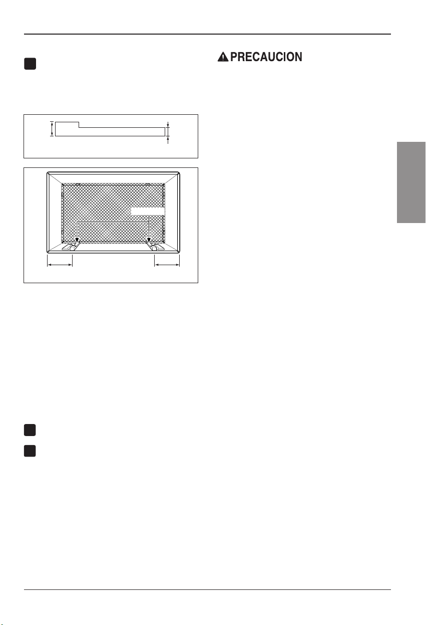
Paralograruna pendiente de posterior para el
drenajede la unidad, retire el envoltorio de las
cuñasde 11-13/16" y acóplelas segúnsemuestra
a continuación en la FIG. 21. Coloque el extremo
másaltodelacuñaen la parte frontal de la base
delsoporte de pared.
Instalela nueva unidad en el soporte de pared.
Monteel ajuste segúnlodescritoenelpaso6,
procedimientoA.
8
7
FIG. 20
1" de
alto
3/4"
de alto
Cuña (2EA)
6" 6"
FIG. 21
•Los airesacondicionados tratadosen estemanual
representanun peligropor pesoexcesivo. Son
necesarias doso máspersonas paradesplazar e
instalarla unidad.
Para evitar lesioneso esfuerzosexcesivos, utilice
lastécnicas delevantamientoy desplazamiento
apropiadasal mover launidad.
•Manipule concuidado elaire acondicionado, tenga
cuidadode evitarcortesde lasaristas afiladasde
metalde lasbobinas frontaly posterior.
•Asegúrese deque elaire acondicionadono se
caigaal desmontarlo.
•Si launidad nofunciona trasla revisiónde
instalación,asegúrese queel interruptor delcircuito
nose hadisparado. Consulte laguíadesolución
deaveríaspara conocerel procedimientode
reinicio.
9
40 AireAcondicionador
Instruccionnes deFuncionamiento
Instruccionnes de Funcionamiento
Controles
Laapariencia delos controlesserá comouno delos siguientes.
MODE TIMER POWER
FAN
SPEED
Fan
Energy
Saver
Cool
Timer
TEMP
'
F
F1 LOW
F2 MED
F3 HIGH
RECEPTOR DE SEÑAL DEL MANDO
A DISTANCIA
ENERGÍA
MODO
- Presione este botón para cambiar el modo de funcionamiento de COOL → ENERGY SAVER → FAN.
- COOL (frío):
• El ventilador funciona continuamente en enfriamiento normal.
- ENERGY SABER (ahorro de energía):
• El ventilador para su funcionamiento cuando el compresor cesa de enfriar. El ventilador se encenderá y la unidad
comprobará la temperatura del aire de la habitación aproximadamente cada 3 minutos para determinar si es
necesario seguir enfriando.
- FAN (ventilador):
• Sólo está en funcionamiento el ventilador.
TEMPORIZADOR
- HORA DE APAGADO
• Normalmente utilizará el tiempo de apagado mientras usted
duerme.
• Si la unidad está funcionando, utilice el temporizador para
fijar el número de horas hasta que se apague.
• Para su tranquilidad al dormir, una vez que el temporizador
esté configurado, el control de temperatura se elevará hasta
los 2° F tras 30 minutos y de nuevo tras otros 30 minutos.
• Presione el botón del temporizador para avanzar el ajuste de
1 hora → 2 horas → … → 12 horas máximo.
- HORA DE INICIO
• Si la unidad está apagada, utilice el temporizador para establecer el número de horas antes de iniciar la unidad.
• Presione el botón del temporizador para adelantar el ajuste de 1 hora → 2 horas → … → 12 horas máximo.
AJUSTE DE TEMPERATURA
• Utilice este botón para controlar
automáticamente la temperatura del
cuarto. La temperatura puede establecerse
dentro de una gama de 60° F a 86° F
mediante incrementos de 1° F.
• El ajuste se muestra en pantalla.
• Para ENCENDER el aire acondicionado,
presione este botón. Para APAGAR el aire
acondicionado, presione de nuevo el
botón.
• Este botón tiene prioridad sobre cualquier
otro botón.
• Cuando la encienda por primera vez, la
unidad estará en modo frío, alta velocidad
del ventilador, control de temperatura en
72° F.
VELOCIDAD DEL VENTILADOR
• Cada vez que presione este botón, el ajuste cambiará como sigue a continuación: {Alto → Bajo → Medio → Alto}
REINICIOAUTOMÁTICO
Cuandose restablezcalaalimentación despuésde uncorteen elsuministro,launidad empezaráa
funcionarcon suúltimo ajuste.
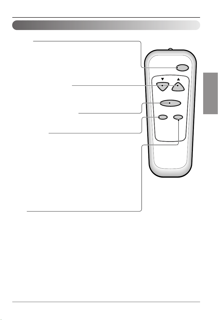
Manualdel Propietario 41
ESPAÑOL
Instruccionnes deFuncionamiento
Control remoto
Elmando adistancia yel panelde controlse parecerána losde lassiguientes imágenes.
Power
Temp
Fan Speed
Timer Mode
ENERGÍA
• Presione este botón para ENCENDER el aire acondicionado.
Para APAGAR el aire acondicionado vuelva a presionar el botón.
• Este botón tiene prioridad sobre cualquier otro botón.
• Al encenderla por primera vez, la unidad se encuentra en modo frío, alta
velocidad del ventilador, ajuste de temperatura a 72° F.
• Reinicio automático
En el caso de una caída de tensión, la unidad funcionará bajo la configuración
anterior una vez que la tensión vuelva a ser la normal.
AJUSTE DE TEMPERATURA
• Utilice este botón para controlar automáticamente la temperatura del cuarto.
La temperatura puede establecerse dentro de una gama de 60° F a 86° F por
incrementos de 1° F.
• El ajuste aparece en pantalla.
VELOCIDAD DEL VENTILADOR
• Cada vez que presione este botón, el ajuste cambiará como sigue a
continuación: {Alto → Bajo → Medio → Alto}
MODO
- Presione este botón para cambiar el modo de funcionamiento de COOL
→
ENERGY SAVER
→
FAN.
- COOL (frío):
• El ventilador funciona continuamente en enfriamiento normal.
- ENERGY SABER (ahorro de energía):
• El ventilador para su funcionamiento cuando el compresor cesa de enfriar. El ventilador se encenderá y la
unidad comprobará la temperatura del aire de la habitación aproximadamente cada 3 minutos para determinar si
es necesario seguir enfriando.
- FAN (ventilador):
• Sólo está en funcionamiento el ventilador.
TEMPORIZADOR
- HORA DE APAGADO
• Normalmente utilizará el tiempo de apagado mientras usted duerme.
• Si la unidad está funcionando, utilice el temporizador para fijar el número de
horas hasta que se apague.
• Para su tranquilidad al dormir, una vez que el temporizador esté
configurado, el control de temperatura se elevará hasta los 2° F tras 30
minutos y de nuevo tras otros 30 minutos.
• Presione el botón del temporizador para avanzar el ajuste de 1 hora → 2
horas → … → 12 horas máximo.
- HORA DE INICIO
• Si la unidad está apagada, utilice el temporizador para establecer el número
de horas antes de iniciar la unidad.
• Presione el botón del temporizador para adelantar el ajuste de 1 hora → 2
horas → … → 12 horas máximo.
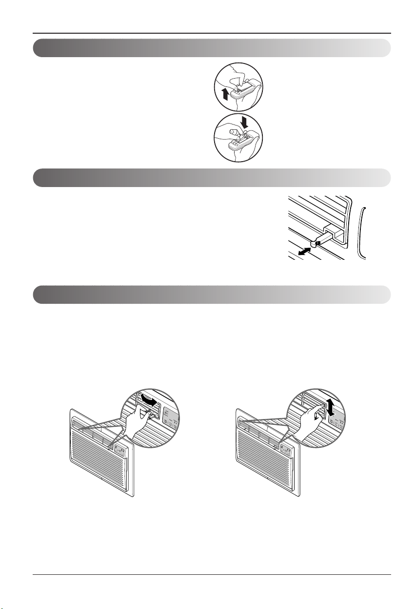
42 AireAcondicionador
Instruccionnes deFuncionamiento
Cómo Poner LasBaterias
1. Quitela tapade laparte posterior del
telemando.Para ellohaga deslizarla tapa
segúnla direccióndel laflecha.
2. Introduzcalas dosbaterías, asegurándosede
quelas direcciones(+) y(-) estén colocadas
correctament. Usebaterías nuevas.
3. Volvera cerrar, resbalandola tapahasta la
posicióninicial.
•No utilicebaterís recargables,
éstasson diferentesdeforma,
dedimensiónyusorespectoa
lasbaterías secasusuales.
•Seque lasbaterías del
telemandocuando el
acondicionadorno vayaa ser
usadodurante unlargo
período.
PULL OPEN / PUSH CLOSE
Ventilación
Direccióndelaire
Lapalanca deventilaciónestá colocadaen elextremoderecho de
ladescarga deaire.
Estapalanca debeestar enla posiciónCLOSE (Cerrada)a finde
mantenerlas mejorescondiciones deenfriamiento.
Cuandose necesitaaire frescoen lahabitación, coloquela palanca
deventilaciónenlaposiciónOPEN (abierta).
Elregulador detiro estáabierto yel airede lahabitaciónes
expulsadohaciael exterior.
Elaire puededirigirse haciadonde usteddesee ajustandolas rejillashorizontalesy verticales.
•
CONTROLHORIZONTAL DE LA
DIRECCIÓN DEL AIRE
Ladirección horizontaldel airese ajustamoviendo la
rejillavertical.
Lapalanca dela rejillaverticalestá situadaa los
costadosderecho eizquierdo dela descargade aire.
•
CONTROL VERTICALDE LA DIRECCIÓN
DEL AIRE
Ladirección vertical delaire seajusta moviendola
rejillahorizontal.
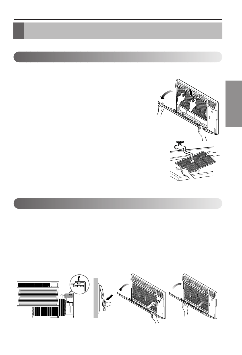
Manualdel Propietario 43
ESPAÑOL
Cuidadoy Mantenimiento
Cuidado y Mantenimiento
MODE TIMER POWER
FAN
SPEED
Fan
Energy
Saver
Cool
Timer
TEMP
'
F
F1 LOW
F2 MED
F3 HIGH
Limpieza del filtro de aire
Como agregar la rejillafrontal al gabinete
APAGUEEL ACONDICIONADORDE AIRE Y DESENCHÚFELO DE LA FUENTE DE PODER.
Elfiltro deaire debeser controladoal menosdos vecesal mesparaversi esnecesariasu
limpieza.
Laspartículas atrapadasen elfiltro puedenacumularse y
bloquearel flujodel aire. Esto reducela capacidadde
refrigeraciónytambién causauna acumulacióndehielo
enlos sepentinesde enfriamiento.
Siel filtrose inutilizao sedaña, debeser reemplazado
inmediatamente. Filtros derepuesto estándisponiblesen la
tiendadonde locompró, elrepresentante yen loscentros de
servicios autorizados.
1. Abrala rejillade entradahaciaabajo tirandode laparte
superior dela rejillade entrada.
2. Quiteel filtrode airede larejilla frontaltirando ligeramente
delfiltro deaire.
3. Lave elfiltro usandoagua tibiapor debajode 40°C
(104°F).
4. Sacudasuavementeel exceso deagua delfiltro.
Reemplaceel filtro.
Larejilla frontalpuede quitarsepara sulimpieza opara comprobarel modeloy elnúmero de
serie.
Para suseguridad,debe seguirel siguienteprocedimiento paracolocarla.
1. Quitela parte superior de larejilla frontalde
lapartesuperiordel gabinete.
2. Empujelos extremosfrontalesde larejilla
haciael gabinetea finde insertarlas
pestañasde larejilla frontal en elgabinete.
3. Abrala rejillade entrada.
4. Ajustelos tornillos atravésde larejilla frontal
enla placade lacaja decontrol.
5. Cierrela rejillade entrada.
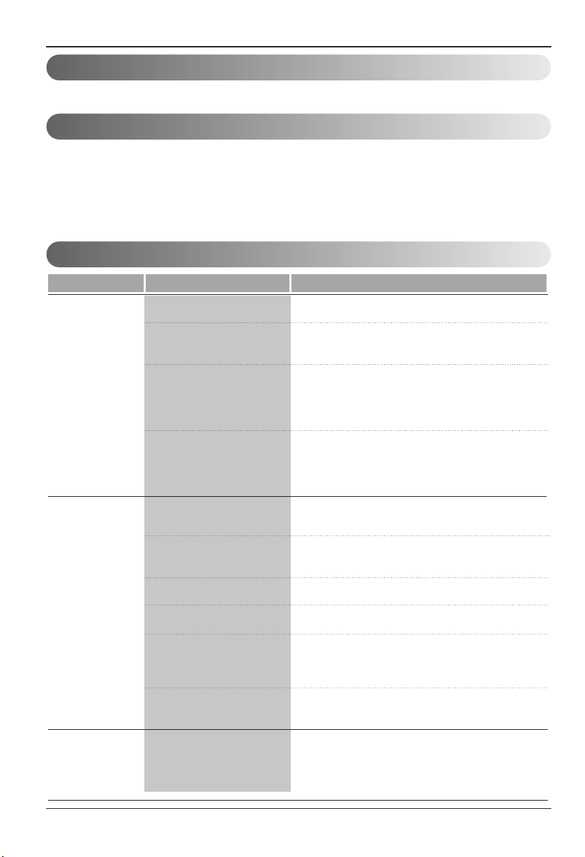
44 AireAcondicionador
Cuidadoy Mantenimiento
Problemasy solucioneshabituales
Operaciónnormal
Operación anormal
Lassugerencias parasolucionar problemasahorrantiempo ydinero !
Reviselacartilla demás abajoantes dellamar alservice, tal vezno tengaque hacerlo.
•Se puedeoír unruidoagudo causadopor elagua cuandoestá siendorecogida yarrojada contrael
condensadoren díaslluviosos ocuando lahumedad es alta.Estacaracterística dediseñoayudaaquitarla
humedady mejorarla eficiencia.
•Se puedenoír clicksen eltermostato cuando elcompresor girahacia dentroy haciaafuera.
•El agua sedepositará enla bandejade basedurante losdías lluviososo dehumedad alta.
Elagua puederebalsar ygotear desde el lado exterior dela unidad.
•El ventiladorpuedefuncionar aúncuando elcompresor nolo hace.
Probama Causas posibles Quehacer
■ El acondicionadorde aire
estádesenchufado.
■ El fusibleestáquemado/el
interruptor decircuito está
abierto.
■ Interrupciónde laprovisión
deenergía eléctrica.
■ El dispositivointerruptor de
corriente está
desconectado.
■ Elflujodeaireestá
restringido
■ Coloque elcontrol de
TEMPERATURAen un
númeromás alto.
■ El filtrode aireestá sucio.
■ La habitaciónpuede haber
estadocaliente.
■ El airefrío seescapa.
■ Los serpentines de
enfriamiento sehan
congelado.
■ El hielo bloqueael flujode
airey nopermite queel
acondicionadorde aire
enfríela habitación.
•Asegúrese deque elenchufedel acondicionadorde aire
seatotalmente ajustadodentro dela salida.
•Compruebeel fusiblede lacasa /lacaja delinterruptor
decircuito yreemplace elfusible ovuelvaa colocarel
interruptor.
•Si seproduce unainterrupcióndelaprovisiónde
energíaeléctrica, gireel controla OFF(apagado).
Cuandola energíase restituye,espere 3 minutospara
reiniciarel acondicionadorde airepara prevenirque el
compresorse dispare.
•Presione elbotón RESETsituado enel enchufe del
cablede alimentación. Si elbotón RESETno
permanece activo,suspenda eluso delaire
acondicionadoy póngaseen contactocon untécnicode
servicio cualificado.
•Asegúresedequenohayacortinas,persianas,o
muebles que bloqueenla parte frontaldel
acondicionadorde aire.
•Gire elcontrol deTEMPERATURA aun númeromás
bajo.
•Limpie elfiltro porlo menoscada 2semanas. Veala
secciónde instrucciones parael funcionamiento.
•
Cuandoel acondicionadorde airese haencendido porprimera
vez,se necesitatiempo para quela habitaciónseenfríe.
•Compruebesi lasrejillas del respiradero delpiso están
abiertasy queel airefrío regrese.
•Coloque elrespiradero delacondicionador deaire en
posicióncerrada.
•Vea más abajo"Congelamiento delacondicionador
deaire".
•Ajustar elcontrol demode en'VentilaciónAlta'o
'ErfriamientoAlto'conlatemperaturaalta.
Elacondicionador
deaire no arranca.
Elacondicionador
deaire noenfría
comodebería.
Congelamiento del
acondicionadorde
aire

Manualdel Propietario 45
ESPAÑOL
Nota
Garantía
GARANTÍA LIMITADA DEL AIRE ACONDICIONADO LG - EE.UU.
COBERTURA DE LA GARANTÍA:
LG Electronics Inc. (“LG”) garantiza que reparará o sustituirá, gratuitamente, su producto si resulta defectuoso en materiales o
mano de obra bajo condiciones normales de uso durante el periodo de garantía mencionado más abajo, efectivo a partir de
la fecha de compra del producto original por parte del consumidor. Esta garantía limitada sólo es válida para el comprador
original del producto y no es asignable ni transferible a ningún otro comprador o usuario final subsecuentes, y efectiva
únicamente cuando el producto se compra a través de un distribuidor autorizado de LG y se util
iza en los Estados Unidos ("EE
UU") o en cualquiera de sus territorios.
Nota: Los recambios y piezas de repuesto pueden ser nuevos o estar reconstruidos de fábrica y están garantizados durante el
tiempo restante del periodo de garantía de la unidad original o noventa días (90), el periodo de los dos que sea más largo. Por
favor, guarde el recibo de compra o la nota de entrega como prueba de la fecha de compra como comprobante de garantía (se le
puede pedir que presente una copia a LG o a su representante autorizado).
PERIODO DE GARANTÍA:
Periodo
Un (1) año desde la fecha a partir de la fecha
del
producto con una prueba de compra válida
Cinco (5) años desde la fecha a partir de la
fecha del producto con una prueba de compra
válida
Cobertura de
la garantía
Cualquier repuesto interno/funcional y mano
de obra
Compresor
Observación Repuestos y mano de obra
Sólo repuestos. El cliente se hará cargo de los costes
de cualquier servicio de mano de obra en nuestras
instalaciones o en su hogar para reemplazar las
piezas defectuosas.
PROCESO DE SERVICIO: Servicio a domicilio
Los servicios a domicilio se prestarán durante el periodo de garantía sujeto a disponibilidad en los Estados Unidos. El servicio a
domicilio puede no estar disponible en todas las áreas. Para recibir asistencia técnica a domicilio, el producto debe estar en un
entorno despejado y accesible al personal técnico. Si durante el servicio a domicilio la reparación no se puede llevar a cabo, es
posible que sea necesario desplazarlo a nuestras instalaciones, repararlo y devolverlo a su hogar. Si este fuera el caso, LG puede
optar, a petición nuestra, a utilizar el transporte de nuestra elección para desplazar la unidad al y del centro de servicio
autorizado de LG.
ESTA GARANTÍA LIMITADA NO SE APLICA A:
1. Las visitas de Asistencia a domicilio para entregar, recoger
y/o instalar el producto, instruir o sustituir fusibles.
2. Sustitución de fusibles de la casa o reajuste de
interruptores de circuito, la corrección del cableado de la casa
o de la tubería, o la corrección de la instalación del producto.
3. Los daños o averías causados por fugas / roturas/
congelación de tuberías de agua, líneas de
drenaje restringido,
suministro insuficiente de agua o interrumpido, o suministro
insuficiente de aire.
4. Los daños o averías causados por accidentes, plagas e
insectos, rayos, viento, fuego, inundaciones o actos de Dios.
5. Los daños o fallos ocasionados por el mal uso, abuso,
instalación inadecuada, reparación o mantenimiento. Se
considera reparación inadecuada aquella en que se hayan
utilizado piezas no aprobadas o especificadas por LG.
6. Los daños o averías causados por modificaciones no
autorizadas o alteraciones del producto.
7. Los daños o averías causados por la utilización de una
corriente eléctrica, tensión o código de pl
omería incorrectos.
8. Daños estéticos, incluyendo arañazos, abolladuras,
desportilladuras u otros daños en el acabado del producto, a
menos que dichos daños sean el resultado de defectos en los
materiales o mano de obra y se informe a LG en el plazo de
siete días naturales (7) a partir de la fecha de entrega.
9. Los daños o la pérdida de componentes de cualquier
producto cuya caja haya sido abierta, haya sido objeto de un
descuento o se haya restaurado.
10. Los productos cuyos números de serie de fábrica
originales hayan sido quitados, borrados o cambiados de
ninguna manera.
11. Las reparaciones cuando el producto se utiliza para
cua
lquier cosa fuera de lo normal y del uso doméstico
habitual (por ejemplo su alquiler, uso comercial, en oficinas o
en instalaciones de ocio) o en contra de la instrucciones que
se indican en el manual del propietario.
12. La extracción y reinstalación del producto si está instalado
en un lugar inaccesible.
ESTA GARANTÍA SE OTORGA EN SUSTITUCIÓN O EXCLUSIÓN DE TODA OTRA GARANTÍA, EXPRESA O IMPLÍCITA, INCLUYENDO SIN
LIMITAR CUALQUIER GARANTÍA DE CALIDAD O IDONEIDAD CON UN PROPÓSITO CONCRETO. EN LA MEDIDA EN QUE CUALQUIER
GARANTÍA IMPLÍCITA ES OBLIGADA POR LA LEY, ESTÁ LIMITADA EN DURACIÓN AL PERIODO DE GARANTÍA YA MENCIONA
DO. LA
REPARACIÓN O REEMPLAZO DE PIEZAS, SEGÚN LO ESTABLECIDO EN ESTA GARANTÍA, ES EL ÚNICO QUE PUEDE RECLAMAR EL
CLIENTE. NI EL FABRICANTE NI SU DISTRIBUIDOR EN LOS EE.UU. SE HACE RESPONSABLE DE CUALQUIER DAÑO (DERIVADO,
INDIRECTO, ESPECIAL O PENAL) DE CUALQUIER NATURALEZA, INCLUYENDO, SIN LIMITACION, LA PÉRDIDA DE INGRESOS O
BENEFICIOS O CUALQUIER OTRO TIPO DE DAÑO, AÚN BASADO EN UN CONTRATO, SEA UN AGRAVIO O DE CUALQUIER OTRA
MANERA.
ALGUNOS ESTADOS NO PERMITEN LA EXCLUSIÓN O LIMITACIÓN DE DAÑOS IMPREVISTOS O RESULTANTES, O LIMITACIONES A LA
DURACIÓN DE LAS GARANTÍAS IMPLÍCITAS, POR LO QUE LA EXCLUSIÓN O LIMITACIÓN MENCIONADA ANTERIORMENTE NO SERÁ
APLICABLE AL USUARIO. ESTA GARANTÍA LE OTORGA DERECHOS LEGALES ESPECÍFICOS Y TAMBIÉN PUEDE TEN
ER OTROS QUE
VARIARÁN DE UN ESTADO A OTRO.
COMO OBTENER EL SERVICIO DE ESTA GARANTÍA E INFORMACIÓN ADICIONAL:
Llame al 1-800-243-0000 o visite nuestra página web: www.lg.com
.
Dirección de correo ordinario: LG Customer Information Center (ATTN: CIC)
201 James Record Road, Huntsville, AL 35824
WARRANTY
LG ROOM AIR CONDITIONER LIMITED WARRANTY
-
USA
WH
AT T
HIS WARRANTY COVERS:
LG Electronics U.S.A., Inc. (“LG”) warrants your LG Room Air Conditioner ("product") against defect in materials or workmanship
under normal household use, during the warranty period set forth below, LG will, at its option, repair or replace the product. This
limited warranty is valid only to the original retail purchaser of the product, is not assignable or transferrable to any subsequent
purchaser or user, and applies only when the product is purchased through an LG authorized dealer or distributor and used within
the United States (“U.S.”) including U.S. Territories.
Note: Replacement products and repair parts may be new or factory-remanufactured and are warranted for the remaining portion
of the original unit’s warranty period or ninety (90) days, whichever is longer. Please retain dated receipt or delivery ticket as
evidence of the Date of Purchase for proof of warranty (you may be required to submit a copy to LG or authorized representative).
WARRANTY PERIOD:
Period
One (1) year from date of original retail
purchase:
Five (5) years from date of original retail
purchase:
Scope of
Warranty
Any internal / functional Parts and Labor Compressor
Remark Parts & labor
Parts Only. Customer will be responsible for any
labor or in-home service to replace defective parts.
HOW SERVICE IS HANDLED: In-Home Service
In-home service will be provided during the warranty period subject to availability within the United States. In-home service may
not be available in all areas. To receive in-home service, the product must be unobstructed and accessible to service personnel. If
during in-home service repair cannot be completed, it may be necessary to remove, repair and return the product. If in-home
service is unavailable, LG may elect, at our option, to provide for transportation of our choice to and from a LG authorized service
center.
THIS LIMITED WARRANTY DOES NOT COVER:
1. Serv
ice trips to deliver, pick up, or install the product or
for instruction on product use.
2. Replacing house fuses or resetting of circuit breakers,
correction of house wiring or plumbing, or correction of
product installation.
3. Damage or failure caused by leaky/ broken/ frozen water
pipes, restricted drain lines, inadequate or interrupted
water supply or inadequate supply of air.
4. Damage or failure caused by accidents, pests and vermin,
lightning, wind, fire, floods or acts of God.
5. Damage or failure resulting from misuse, abuse, improper
installation, repair or maintenance. Improper repair
includes use of parts not approved or specified by LG.
6. Damage or failure caused by unauthorized modification or
alteration to the product.
7. Damage or failure caused by incorrect electrical current,
voltage, or plumbing codes.
8. Cosmetic damage, including scratches, dents, chips or
other damage to the finish of the product, unless such
damage results from defects in materials or
workmanship and is reported to LG within seven (7)
calendar days from the date of delivery.
9. Damage or missing items to any display, open box,
discounted, or refurbished product.
10. Product where the original factory serial numbers have
been removed, defaced or changed in any way.
11. Repairs when product is used in other than normal and
usual household use (e.g. rental, commercial use,
offices, or recreational facilities) or contrary to the
instructions outlined in the owner’s manual.
12. The removal and reinstallation of the Product if it is
installed in an inaccessible location.
THIS
WARR
ANTY IS IN LIEU OF ANY OTHER WARRANTY, EXPRESS OR IMPLIED, INCLUDING AND WITHOUT LIMITATION TO, ANY
WARRANTY OF MERCHANTABILITY OR FITNESS FOR A PARTICULAR PURPOSE. TO THE EXTENT ANY IMPLIED WARRANTY IS
REQUIRED BY LAW, THIS WARRANTY IS LIMITED IN DURATION TO THE TERM PERIOD EXPRESSED ABOVE. REPAIR OR
REPLACEMENT AS PROVIDED UNDER THIS WARRANTY IS THE EXCLUSIVE REMEDY FOR THE CUSTOMER. NEITHER THE
MANUFACTURER NOR ITS U.S. DISTRIBUTOR SHALL BE LIABLE FOR ANY INCIDENTAL, CONSEQUENTIAL, INDIRECT, SPECIAL, OR
PUNITIVE DAMAGES OF ANY NATURE, INCLUDING AND WITHOUT LIMITATION TO, LOST REVENUES OR PROFITS, OR ANY OTHER
DAMAGE, WHETHER BASED IN CONTRACT, TORT, OR OTHERWISE.
SOME STATES DO NOT ALLOW THE EXCLUSION OR LIMITATION OF INCIDENTAL OR CONSEQUENTIAL DAMAGES OR LIMITATIONS
ON HOW LONG AN IMPLIED WARRANTY LASTS, SO THE ABOVE EXCLUSION OR LIMITATION MAY NOT APPLY TO YOU. THIS
WARRANTY GIVES YOU SPECIFIC LEGAL RIGHTS AND YOU MAY ALSO HAVE OTHER RIGHTS THAT VARY FROM STATE TO STATE.
HOW TO OBTAIN WARRANTY SERVICE & ADDITIONAL INFORMATION:
Call 1-800-243-0000 or visit our website at www.lg.com
.
Mail to: LG Customer Information Center (ATTN: CIC)
201 James Record Road, Huntsville, AL 35824

1-800-243-0000
LG Customer Information Center
Register your product Online!
www.lgappliances.com
LG ELECTRONICS,INC.
1000 Sylvan Ave.,Englewood Cliffs,NJ 07632
(LT103CER)