Loading ...
Loading ...
Loading ...
4
3. Connect the POWER+DATA OUT port of the TL-POE150S to
a PD or a PoE Receiver Adapter with CAT 5 UTP cable.
Now, the device can work normally with data and power.
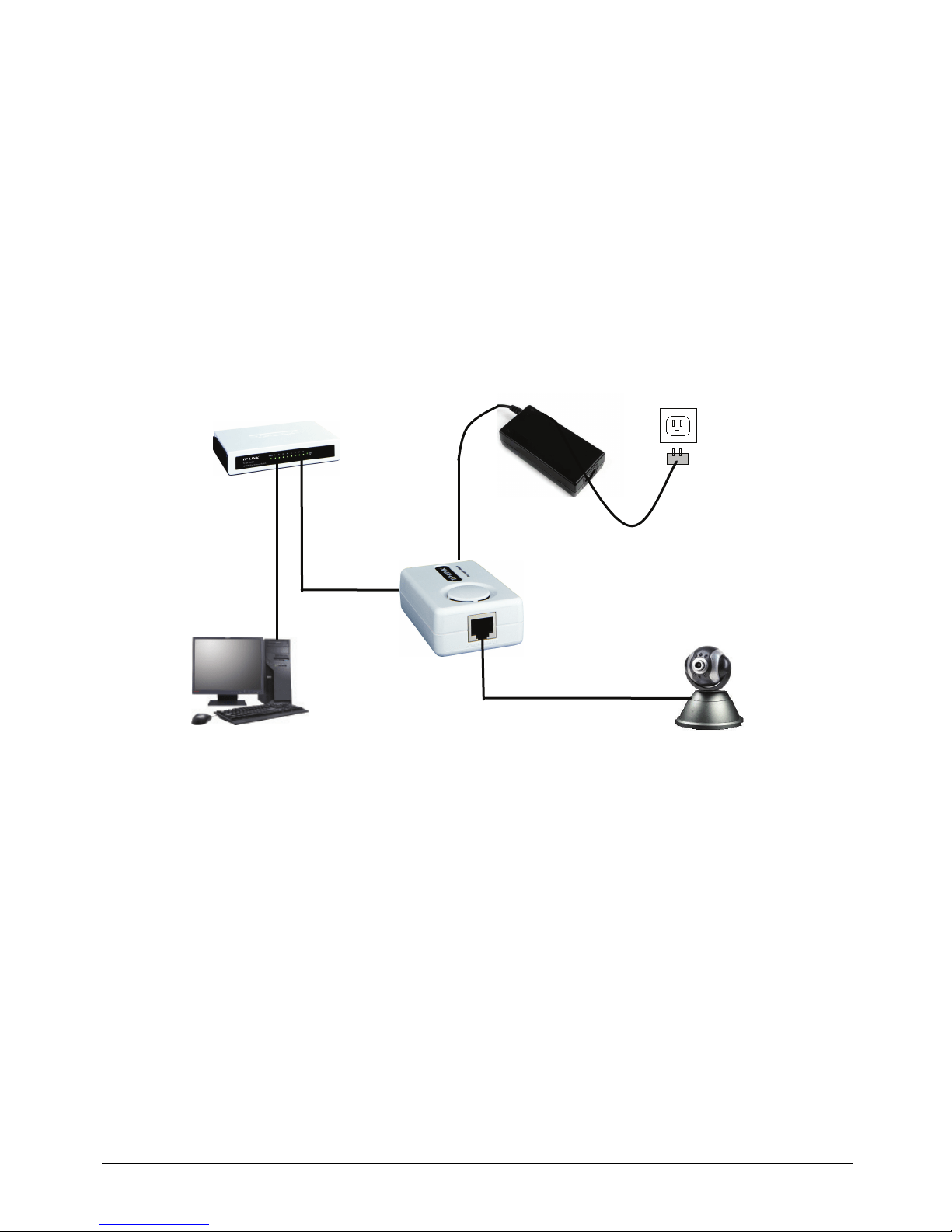
There are two schemes to realize the PoE.
1. If the device supports PoE (take an IP camera with PoE for
example), following topology will work:
`
2. If the device does not support PoE, it is necessary to have a
PoE Receiver Adapter to separate the power and data,
transmitting them detached in one UTP cable and one power
cable. Here we take TP-LINK TL-POE10R Receiver Adapter
for example. You can use following topology:
IP camera with PoE
PC
Switch
TL-SF1008D
Power Adapter
TL-POE150S
CAT5 UTP Cable
(Data)
Power Cable
(Power)
CAT5 UTP Cable
(Power & Data)
Downloaded from www.ManualsFile.com manuals search engine
Loading ...
Loading ...
Loading ...