Loading ...
Loading ...
Loading ...
10 installation instructions Kelvinator Air Conditioning
Note: unit may be supported by a
solid frame from below or
by a hanger from a solid
overhead support.
Preferred method of installation into a timber
framed wall, partition or window.
Flash or seal around external
Wall frame or architrave
Flash or seal around external
Wall frame or architrave
Ensure louvres
are entirely
outside the wall
Drain pan
Steadying bracket
(one per side)
Solid timber support
Study timber
frame
Timber frame
wall or partition
Sturdy timber
frame all
round unit
Timber framed
Wall or partition
Drain pan
External support
frame at balance
point of A/C
Alternately, brackets
as illustrated below
may be used.
Alternative method of installation if external
45° brick cut away
to clear louvres
45° brick cut away
to clear louvres
Front
Louvre
support cannot be provided.
AIR IN
AIR OUT
100mm minimum
AIR IN
OPTION A
OPTION B
BRICK
WALL
AIR OUT
A
100mm
100mm
IR INAIR IN
TOP
VIEW
BRICK
WALL
AIR IN
flash or seal around external
wall frame of architrave
sturdy timber
frame all
around unit
timber framed
wall or partition
external support frame
at balance point of A/C
alternately, brackets as
illustrated below may
be used
preferred method of installation into a timber
framed wall, partition or window
drain
Installation of the unit into the housing
1 Slide the unit into the housing until it is firmly against the
rear of the housing. Care is required to ensure the foam
sealing strips on the housing remain in position.
2 Connect the air conditioner to the power and position
excess cord length beneath the air conditioner base.
3 Engage the chassis fixing brackets into the bottom
housing rail and secure to the base with the
screws provided.
4 Remove the front panel from it's carton and plastic bag
and fit as per the Installation lnstruction.
5 Switch unit on. Check for operation of the unit and check
for vibration in the installation.
6 Fit the drain pan to the housing and run a drain line to a
suitable location if required.
Installing the unit into the wall
Note: unit may be supported by a
solid frame from below or
by a hanger from a solid
overhead support.
Preferred method of installation into a timber
framed wall, partition or window.
Flash or seal around external
Wall frame or architrave
Flash or seal around external
Wall frame or architrave
Ensure louvres
are entirely
outside the wall
Drain pan
Steadying bracket
(one per side)
Solid timber support
Study timber
frame
Timber frame
wall or partition
Sturdy timber
frame all
round unit
Timber framed
Wall or partition
Drain pan
External support
frame at balance
point of A/C
Alternately, brackets
as illustrated below
may be used.
Alternative method of installation if external
45° brick cut away
to clear louvres
45° brick cut away
to clear louvres
Front
Louvre
support cannot be provided.
AIR IN
AIR OUT
100mm minimum
AIR IN
OPTION A
OPTION B
BRICK
WALL
AIR OUT
A
100mm
100mm
IR INAIR IN
TOP
VIEW
BRICK
WALL
AIR IN
air in
air in
air out
100mm minimum
option A
air in
Note: unit may be supported by a
solid frame from below or
by a hanger from a solid
overhead support.
Preferred method of installation into a timber
framed wall, partition or window.
Flash or seal around external
Wall frame or architrave
Flash or seal around external
Wall frame or architrave
Ensure louvres
are entirely
outside the wall
Drain pan
Steadying bracket
(one per side)
Solid timber support
Study timber
frame
Timber frame
wall or partition
Sturdy timber
frame all
round unit
Timber framed
Wall or partition
Drain pan
External support
frame at balance
point of A/C
Alternately, brackets
as illustrated below
may be used.
Alternative method of installation if external
45° brick cut away
to clear louvres
45° brick cut away
to clear louvres
Front
Louvre
support cannot be provided.
AIR IN
AIR OUT
100mm minimum
AIR IN
OPTION A
OPTION B
BRICK
WALL
AIR OUT
A
100mm
100mm
IR INAIR IN
TOP
VIEW
BRICK
WALL
AIR IN
air out
air in
air in
louvre
100mm
100mm
front
45° brick cut away
to clear louvres
45° brick cut away
to clear louvres
option B
Select the best location
1 To avoid vibration and noise, make sure the unit is
installed securely and firmly.
2 Install the unit where the sunlight does not shine directly
on the unit.
If the unit receives direct sunlight, build an awning to
shade the cabinet.
3 There should be no obstacle, such as a fence or wall,
within 50cm from the back of the cabinet because it will
prevent heat radiation of the condensor.
Restriction of outside air will greatly reduce the cooling
and heating efficiency of the air conditioner.
4 Install the unit a little obliquely outward not to leak the
condensed water into the room (about 10mm or 1/4
bubble with level).
5 Install the unit with its bottom portion 75~150cm above
the floor level.
6 The power cord must be connected to an independent
circuit. The yellow/green wire must be grounded.
7 Based on calculations in compliance with AS60335.2.40
there is no minimum safe floor area for the installation of
the air conditioners described in this manual.
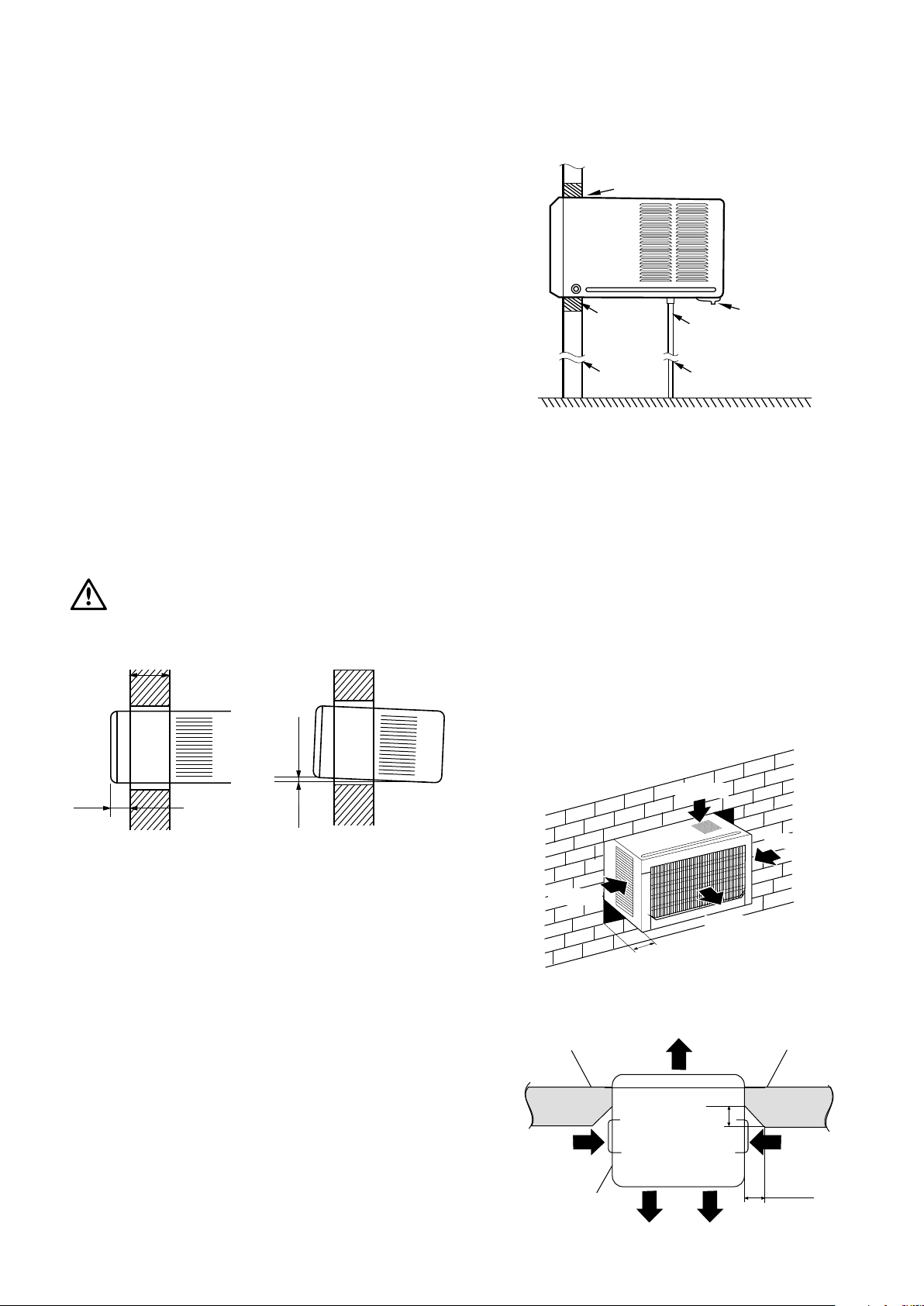
caution
All side louvers of the cabinet must remain exposed to the
outside of the structure.
less than 220mm
more than 160mm
wall thickness is less than 220mm
make rear of the airconditioner (outside)
lower than the front of the airconditioner
(inside) to allow water to drain
5-10mm
Installation of the Housing
1 Remove the air conditioner from its packaging, remove
fixing screws and slide the air conditioner out of its
housing (Refer to Installation Steps).
2 Prepare the hole in the wall so that the bottom of
the housing is well supported, the top has minimum
clearance and the air inlet louvers have clearance as
shown below in options A and B. Holes from the outside
through to the cavity should be sealed. The housing
should slope down towards the rear by about 5mm to
allow water formed during operation to drain.
3 Install the housing into the wall and secure. Ensure the
foam seals are not damaged. Flash, seal or fill gaps
around the inside and outside to provide satisfactory
appearance and protection against the weather, insects
and rodents.
Note: Unit may be supported by a solid frame from below or
by a hanger from a solid overhead support.
Installation instructions
Loading ...
Loading ...
Loading ...