Check the data specification plate and ensure the proper voltage and current rating is available for the type power plug on the unit. DO NOT REMOVE THE GROUNDING PRONG FROM THE POWER CORD. Note the types of acceptable plugs on the following figure. Refer to the data serial plate for electrical requirements.
UNIT FEATURES
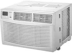
This unit has many features which are different than those found on conventional units. The servicer must be familiar with these features in order to properly service the unit.
Check the data specification plate and ensure the proper voltage and current rating is available for the type power plug on the unit. DO NOT REMOVE THE GROUNDING PRONG FROM THE POWER CORD. Note the types of acceptable plugs in Figure 1.
Refer to the data serial plate for electrical requirements.
LCDI or AFCI Power Cords - Underwriters Laboratories and the National Electric Code (NEC) now require power cords that sense current leakage and can open the electrical circuit to the unit on units rated at 250 volts or less. In the event that unit does not operate, check the reset button located on or near the head of the power cord as part of the normal troubleshooting procedure.
VOLTAGE MEASUREMENTS
Before connecting the unit, measure the supply voltage. Voltage must fall within the voltage utilization range given in the following table.
INSTALLATION INSTRUCTIONS
To ensure that the unit operates safely and efficiently, it must be installed, operated, and maintained according to these installation and operating instructions and all local codes and ordinances, or, in their absence, with the latest edition of the National Electrical Code. The proper installation of this unit is described in the following sections. Following the steps in the order presented should ensure proper installation.
SLEEVE INSTALLATION
In order for condensate water to drain properly inside the unit, the sleeve must be installed properly:
Level from right to left.
A slight downward pitch from the indoor side to the outdoor side as shown in Figure 3.
Refer to the Installation Instructions supplied with the wall sleeve for a complete description of the installation procedure.
NOTE: Wall sleeve (PBWS01A ) is not shipped with chassis and must be purchased separately
REAR LOUVER PANEL
A TWKG rear louver panel kit is required for unit installation into an existing Amana® brand 26” wall sleeve. A TWEAK or TWFAK adapter kit is required for unit installation into an existing 27” wall sleeve. The rear louver panel directs air flow for proper unit operation and protects the outdoor coil. The panel must be installed before installing the chassis. These kits are not supplied with the unit. Refer to the Installation Instructions supplied with the rear louver panel kit for a complete description of the installation procedure.
CHASSIS INSTALLATION
1. Remove front grille. See Figure A.
The front grille can be removed for more thorough cleaning or to make the model and serial numbers accessible. To remove, pull the filter out and remove the two grille screws.
Pull the grille out from the bottom and lift up from the tabs on the top of the case.
2. Remove the grounding screw and wire next to the grounding symbol on right side of chassis control panel (Figure 3). Attach other end of ground wire to the hole in the bottom right side of the sleeve with #8 x 3/8” blunt point sheet metal screw. The hole on the sleeve is indicated by grounding symbol on the sleeve. Slide chassis part of the way into the sleeve and reattach the ground wire back to the hole on the right side on the control panel area next to the grounding symbol.
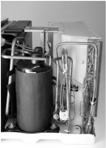
3. Remove shipping pads inside air conditioner next to compressor. (See Figure B.)
4. Carefully slide the chassis into the sleeve. Ensure that the ground wire is not pinched or in the path of the condenser fan.
5. Loosen locking plate screw and rotate tab with tab behind wall case flange (See Figure C) then tighten locking plate screw.
6. If outlet is on the left side of the unit, route power cord as shown in Figure D.
To replace front grille
Hook the tabs on the front grille even with the tabs on the case and snap into place. Replace the screws and filter. Refer to Page 3, Figure A.
VENT CONTROL AND AIR DIRECTION (See Figure E)
The vent control is located behind the front grille on the right side of the air discharge area. When set at CLOSE only the air inside the room will be circulated and conditioned. When set at OPEN, some inside air is exhausted outside.
To open or close the vent:
Remove the front grille.
Remove the vent card screw.
Remove the vent card, turn it over and replace it by locating rear hole in card over locating pin inside air discharge and reattaching screw at front.
AIR DIRECTION:
Horizontal louvers on the front grille let you control the air direction up and down.
Remove the front grille to adjust the vertical louvers side-to-side to direct the air left or right.
IMPORTANT NOTES:
The unit is equipped with a rubber-grommet-mounted compressor. These grommets are factory set and require no adjustment.
Obstruction to air flow must be checked and removed. Check the indoor and outdoor grilles for obstructions. The unit must be located where curtains, furniture, trees, or other objects do not block air flow to and from the unit. If air is obstructed and/or deflected back into the unit, the air conditioner’s compressor may cycle on and off rapidly. This could cause damage to the compressor
WIRING Before wiring the unit, please review the following warnings and cautions.
AIR CONDITIONER FEATURES ELECTRONIC
CONTROL OPERATING INSTRUCTIONS
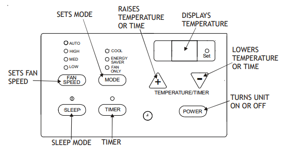
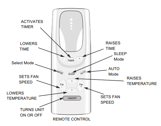
Before you begin, thoroughly familiarize yourself with all of the functions of the control panel and remote as shown below and follow the instructions. The unit can be controlled by the touchpad alone or with the remote control.
COOLING ONLY UNIT
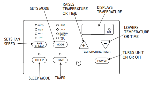
HEAT/COOL UNIT
NOTE: The remote control will work normally after a 5 second reset.
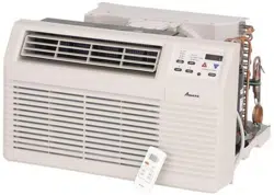
AIR CONDITIONER FEATURES
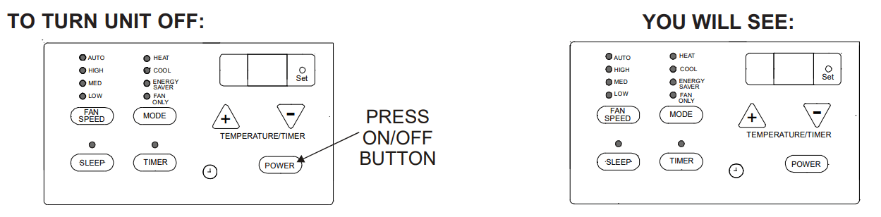
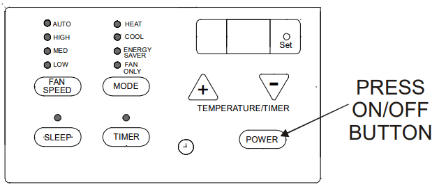
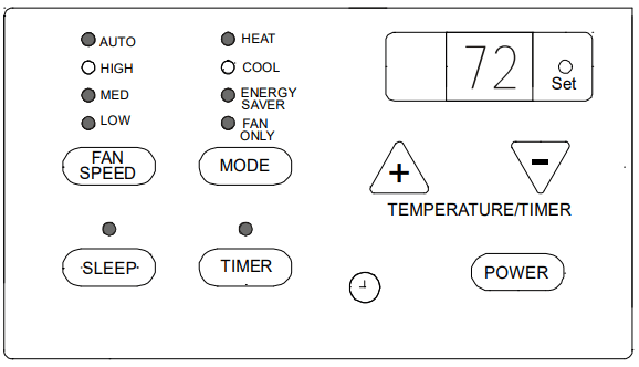
TO TURN UNIT ON:
YOU WILL SEE:
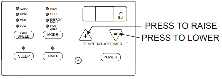
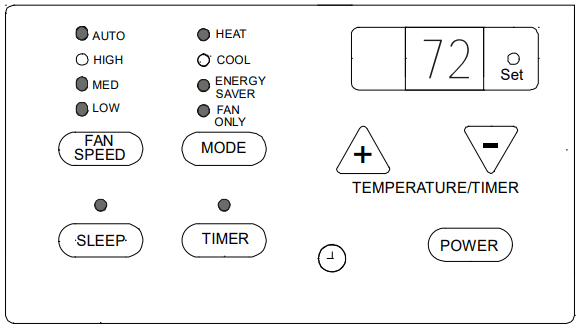
TO CHANGE TEMPERATURE SETTING:
YOU WILL SEE:
NOTE: Tap or hold either up ( ) or down ( ) button until the desired temperature is seen on the display. This temperature will be automatically maintained anywhere between 60°F (16°C) and 86°F (30°C) for both cooling and heating modes. If you want the display to read the actual room temperature, select the FAN ONLY MODE.
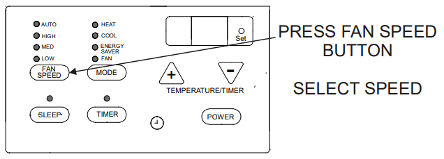
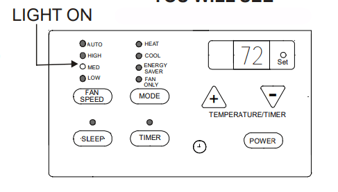
TO CHANGE FAN SPEEDS:
YOU WILL SEE THE SPEED CHOSEN:
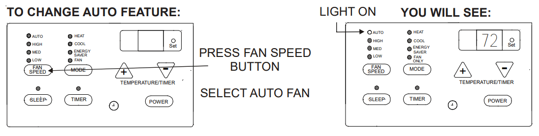
NOTE: The fan speed will automatically set to the speed needed to provide optimum comfort setting with the set temperature. If the room needs more cooling, the fan speed will automatically increase. If the room needs less cooling, the fan speed will automatically decrease. Auto fan speed cannot be used when in the FAN ONLY mode.
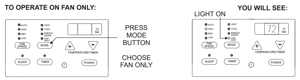
Note: Use this function only when cooling is not desired, such as for room air circulation. You can choose any fan speed you prefer, except AUTO FAN. During this function, the display will show the actual current temperature, not the set temperature as in the cooling mode.
Note: In this mode, the fan will continue to run for 1 (one) minute after the compressor or electric heat strip shuts off. This results in wider variations of room temperature and is normally used when the room is unoccupied.
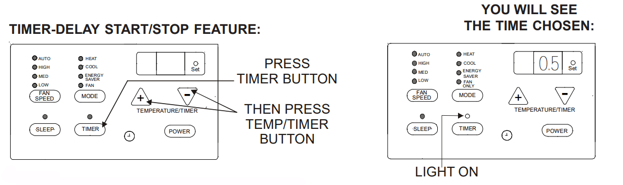
To adjust the timer setting, tap or hold the UP ( ) arrow or DOWN ( ) arrow to change the delay time by 1/2 hour (0.5) increments up to 10 hours; then 1 hour increments up to 24 hours. The control will count down the time remaining until start or stop (8, 7.5, 7, etc.).
After setting the Timer, the unit will enter into Timer mode within 5 seconds. The Timer light will then be on and the Set light will be off.
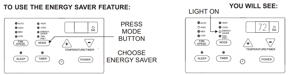
While in Timer mode, the Set temperature and fan speed will maintain previously set temperature and fan speed and the Temperature display will show the set temperature. (There will be no display if the power is turned off.) By pressing the Timer once, TO USE THE ENERGY SAVER FEATURE: TIMER-DELAY START/STOP FEATURE: YOU WILL SEE: YOU WILL SEE THE TIME CHOSEN: the LED displays the remaining portion of the set time. (The LED will return to set temperature within 5 seconds.) When in Fan Only mode, the LED will only display the room temperature; it will not display set temperature.
Turning the unit “ON” or “OFF” at any time will cancel the DELAY START/STOP function. The DELAY START/STOP feature will work until the unit starts or stops. Once this has happened, the above steps must be repeated again.
NOTE: Factory default setting is for °F. To convert to °C, press the INCREASE / DECREASE buttons simultaneously for approximately 5 seconds. To return to °F, repeat the procedure.
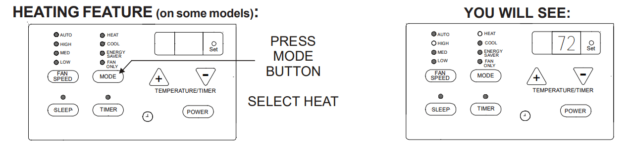
Note: This feature can be used with any combination of FAN Speeds, Timer or Sleep Modes. When in the “heat” Mode, the fan will run continuously while heat is needed. The temperature will automatically be maintained anywhere between 61°F (16°C) and 86°F (30°C).
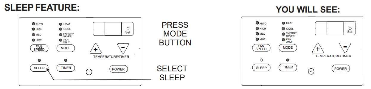
Note: After pressing this button, SLEEP ON and SLEEP OFF can be selected. After powered on, SLEEP OFF is defaulted. After the unit is turned off, the SLEEP function is cancelled. If SLEEP mode is set while the unit is in COOL or ENERGY SAVER modes, the SET TEMP. would increase 1.8°F (1°C) in 1 hour and 3.6°F (2°C) in 2 hours. If SLEEP mode is set while unit is in HEAT mode, the SET TEMP. would decrease 1.8°F (1°C) in 1 hour and 3.6°F (2°C) in 2 hours. When unit is in FAN ONLY and AUTO modes, this function is not available.
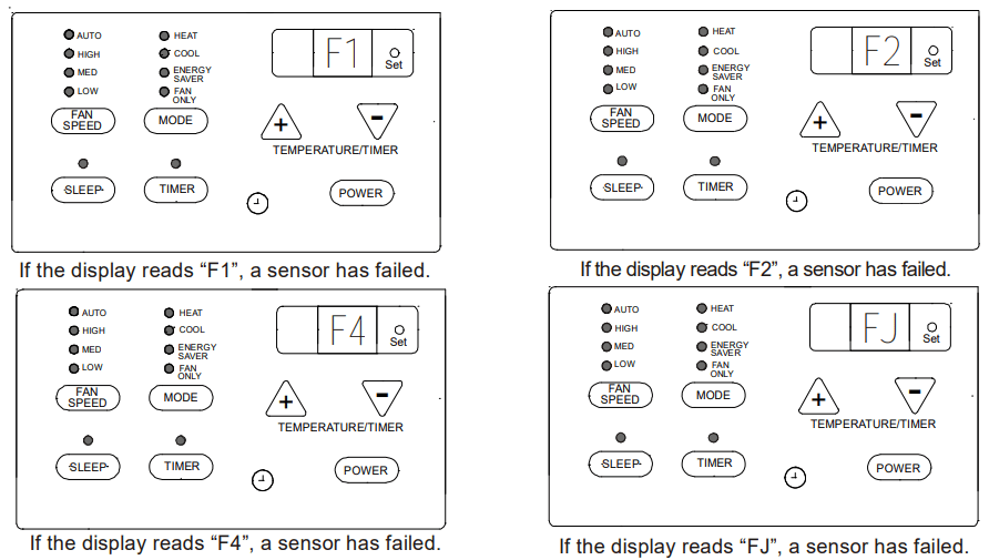
FAULT CODES
ADDITIONAL INFORMATION
The remote control will operate all the control panel features. Instructions will be the same.
The “COOL” circuit has an automatic 3 minute time delayed start if the unit is turned off and on quickly. This prevents overheating of the compressor and possible circuit breaker tripping. NOTE: The fan will continue to run during this time.
The control will maintain any set temperature between 60°F and 90°F (cooling), 55°F and 80°F (heating).
The control is capable of displaying temperature in degrees (Fahrenheit) or degrees (Celsius). To convert from one to the other, press and hold the UP and DOWN Temperature Selection Pads at the same time for 3 seconds.
COMPRESSOR
The compressor is hermetically sealed, permanently lubricated and requires no additional oiling.
FRONT PANEL AND GRILLE
The front panel and grille can be cleaned with a mild soap or detergent. Do not use hydrocarbon-based cleaners (e.g. acetone, benzene, naphtha, gasoline, etc.) to clean the front panel or grille. Use care when cleaning the control area. Do not use an excessively wet cleaning cloth.
SCHEDULED MAINTENANCE
To achieve continuing top performance and high efficiency, a regular cleaning/inspection schedule must be established. Maintaining this schedule can be accomplished by either a local maintenance staff or an authorized servicer and must follow the instructions described in this manual.
If the unit is operated in a dusty climate, dust may collect in the basepan and clog the condenser coil. It is advisable to remove the unit from the sleeve and thoroughly clean the basepan and condenser coil on a periodic basis.
If the unit is installed ocean side or in a corrosive atmosphere, its life may be greatly reduced by the corrosive environment. Under these conditions, the unit should be removed from the sleeve and completely cleaned once a year. At that time any scratches or blisters on the painted surfaces should be sanded and repainted.
NORMAL OPERATING SOUNDS AND CONDITIONS
POPPING OR GURGLING SOUNDS
This sound is the refrigerant traveling through the lines. This is a normal sound which may be heard for a few seconds after the unit shuts off.
WATER TRICKLING SOUNDS
This sound is produced by the water as it is picked up and run over the coils. This procedure improves the efficiency of the unit and helps with water removal.
WATER DRIPPING
Water will collect in the basepan during high humidity days.
STARTING DELAY
You may notice a short delay in the startup if you try to restart the unit too soon after turning it off or if you adjust the thermostat right after the compressor has shut off. This delay protects the compressor.
Obtaining Service
In the unlikely event this unit requires repair or servicing beyond what is covered in this manual, contact an authorized service organization.
To obtain an authorized servicer, contact your sales representative or agency.
-921860.png)
-994499.png)
-837509.png)
-58005.png)
-825867.png)
-483767.png)
-319945.png)
-235035.png)
-481082.png)
-410809.png)
-542896.png)
-377055.png)
-954684.png)
-877908.png)
-830061.png)
-598863.png)
 ) or down (
  ) button until the desired temperature is seen on the display. This temperature will be automatically maintained anywhere between 60°F (16°C) and 86°F (30°C) for both cooling and heating modes. If you want the display to read the actual room temperature, select the FAN ONLY MODE.