

A Word to Mazda Owners
Thank you for choosing a Mazda. We at Mazda design and build vehicles with complete
customer satisfaction in mind.
To help ensure enjoyable and trouble-free operation of your Mazda, read this manual
carefully and follow its recommendations.
Regular servicing of your vehicle by an expert repairer helps maintain both its
roadworthiness and its resale value. A world-wide network of Authorised Mazda Repairers
can help you with their professional servicing expertise.
Their specially trained personnel are best quali¿ ed to service your Mazda vehicle properly
and exactly. Also, they are supported by a wide range of highly specialized tools and
equipment specially developed for servicing Mazda vehicles. When maintenance or service
is necessary we recommend an Authorised Mazda Repairer.
We assure you that all of us at Mazda have an ongoing interest in your motoring pleasure
and in your full satisfaction with your Mazda product.
Mazda Motor Corporation
HIROSHIMA, JAPAN
Important Notes About This Manual
Keep this manual in the glove box as a handy reference for the safe and enjoyable use of your Mazda. Should you
resell the vehicle, leave this manual with it for the next owner.
All speci¿ cations and descriptions are accurate at the time of printing. Because improvement is a constant goal at
Mazda, we reserve the right to make changes in speci¿ cations at any time without notice and without obligation.
Please be aware that this manual applies to all models, equipment and options. As a result, you may ¿ nd
some explanations for equipment not installed on your vehicle.
©2016 Mazda Motor Corporation
Oct. 2016 (Print2)
How to Use This Manual
We want to help you get the most driving
pleasure from your vehicle. Your owner's
manual, when read from cover to cover,
can do that in many ways.
Illustrations complement the words of
the manual to best explain how to enjoy
your Mazda. By reading your manual, you
can ¿ nd out about the features, important
safety information, and driving under
various road conditions.
The symbol below in this manual means
"Do not do this" or "Do not let this
happen".
References to left hand and right hand are
made as if facing in the same direction
the vehicle faces. Although this manual
explains a left-hand-drive model, it also
applies to right-hand-drive models.
Index: A good place to start is the Index,
an alphabetical listing of all information in
your manual.
You'll ¿ nd several WARNINGs,
CAUTIONs, and NOTEs in the manual.
WARNING
A WARNING indicates a situation in
which serious injury or death could
result if the warning is ignored.
CAUTION
A CAUTION indicates a situation in
which bodily injury or damage to your
vehicle, or both, could result if the
caution is ignored.
NOTE
A NOTE provides information and
sometimes suggests how to make better
use of your vehicle.
The following symbol, located on some
parts of the vehicle, indicates that this
manual contains information related to the
part.
Please refer to the manual for a detailed
explanation.

Table of Contents
Pictorial Index
Interior, exterior views and part identification of your Mazda.
1
Essential Safety Equipment
Important information about safety equipment, including seats, seat belt
system, child-restraint systems and SRS air bags.
2
Before Driving
Use of various features, including keys, doors, mirrors and windows.
3
When Driving
Information concerning safe driving and stopping.
4
Interior Features
Use of various features for ride comfort, including air-conditioning and audio
system.
5
Maintenance and Care
How to keep your Mazda in top condition.
6
If Trouble Arises
Helpful information on what to do if a problem arises with the vehicle.
7
Customer Information
Important consumer information including warranties and add-on equipment.
8
Specifications
Technical information about your Mazda.
9
Index
10


1
–
11
–
1
1
Pictorial Index
Interior, exterior views and part identi¿ cation of your Mazda.
Interior Overview (Left-Hand Drive Model)................................... 1-2
Interior Equipment (View A) ........................................................ 1-2
Interior Equipment (View B) ........................................................ 1-4
Interior Equipment (View C) ........................................................ 1-5
Interior Overview (Right-Hand Drive Model) ................................ 1-6
Interior Equipment (View A) ........................................................ 1-6
Interior Equipment (View B) ........................................................ 1-8
Interior Equipment (View C) ........................................................ 1-9
Exterior Overview ............................................................................ 1-10
Saloon ......................................................................................... 1-10
Hatchback ................................................................................... 1-11
1
–
2
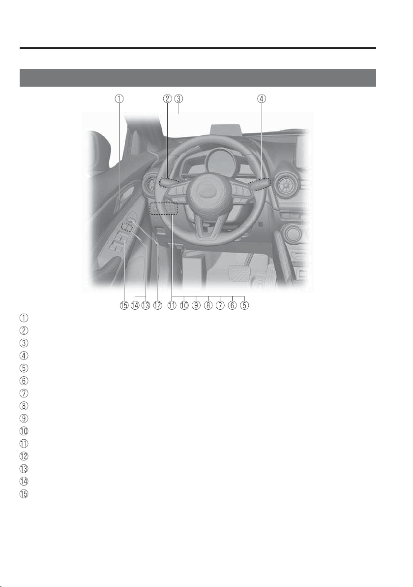
Pictorial Index
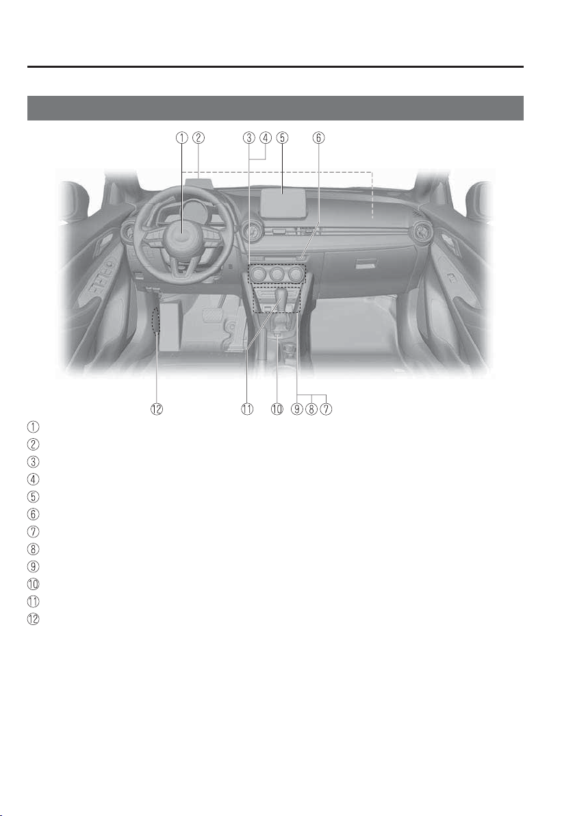
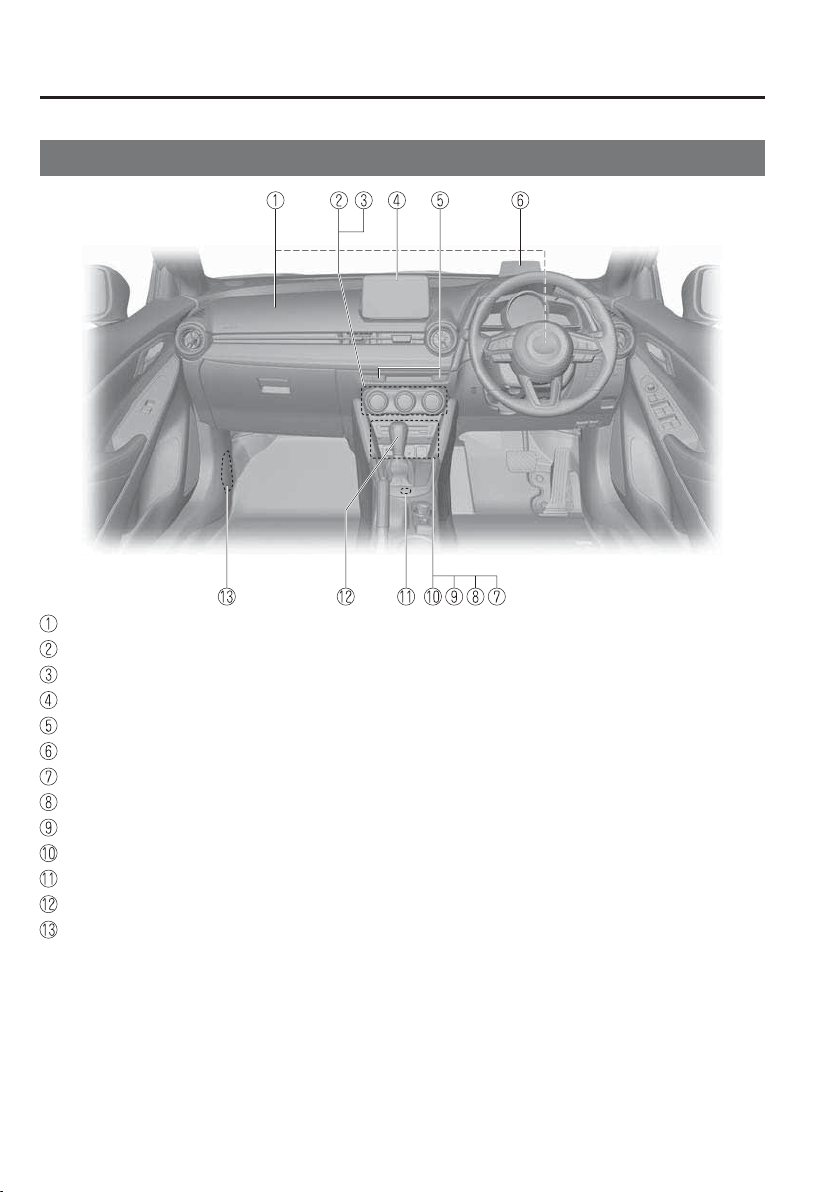
Interior Overview (Left-Hand Drive Model)
Interior Equipment (View A)
Door-lock knob .....................................................................................................page 3-19
Turn and lane-change signal .................................................................................page 4-71
Lighting control.....................................................................................................page 4-61
Wiper and washer lever .........................................................................................page 4-72
Blind Spot Monitoring (BSM) OFF switch ........................................................page 4-123
DSC OFF switch ...................................................................................................page 4-89
Tyre pressure monitoring system set switch .......................................................page 4-192
i-stop OFF switch ..................................................................................................page 4-21
Headlight Levelling switch ...................................................................................page 4-68
LDWS OFF switch..............................................................................................page 4-114
SCBS OFF switch ...............................................................................................page 4-160
Outside mirror switch............................................................................................page 3-34
Power window lock switch ...................................................................................page 3-41
Power folding mirror switch .................................................................................page 3-34
Power window switches ........................................................................................page 3-38
The equipment and installation position varies by vehicle
1
–
3
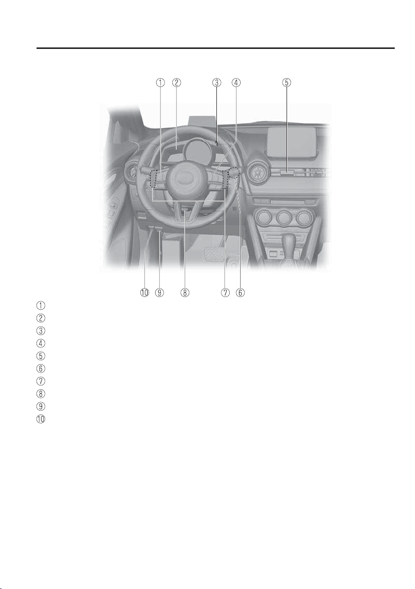
Pictorial Index
Interior Overview (Left-Hand Drive Model)
Audio control switches..........................................................................................page 5-18
Instrument cluster ..................................................................................................page 4-24
Instrument panel illumination knob ......................................................................page 4-30
Cruise control switches ............................................................................page 4-139 , 4-185
Hazard warning À asher switch ..............................................................................page 4-80
Push button start ......................................................................................................page 4-4
Steering shift switches ..........................................................................................page 4-55
Lock release lever .................................................................................................page 3-33
Bonnet release handle ...........................................................................................page 6-19
Remote fuel-¿ ller À ap release ...............................................................................page 3-31
The equipment and installation position varies by vehicle
1
–
4
Pictorial Index
Interior Overview (Left-Hand Drive Model)
Interior Equipment (View B)
SRS air bags ..........................................................................................................page 2-41
Active driving display ...........................................................................................page 4-35
Air-conditioning system ..........................................................................................page 5-4
Rear window defogger switch...............................................................................page 4-78
Audio system................................................................................................page 5-26 , 5-80
Seat warmer switches ..............................................................................................page 2-6
CD player .....................................................................................................page 5-34 , 5-94
Accessory sockets ...............................................................................................page 5-159
External input terminal..........................................................................................page 5-20
Drive selection switch .........................................................................................page 4-100
Shift lever/Selector lever ..............................................................................page 4-46 , 4-49
Fuse block (Left side) ...........................................................................................page 6-61
The equipment and installation position varies by vehicle
1
–
5
Pictorial Index
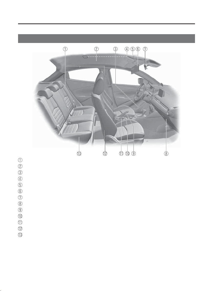
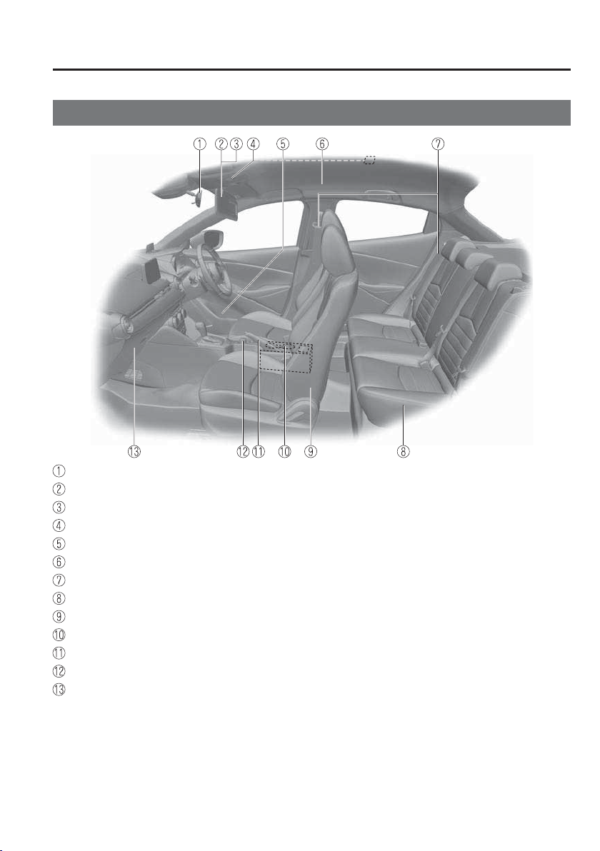
Interior Overview (Left-Hand Drive Model)
Interior Equipment (View C)
Seat belts ...............................................................................................................page 2-14
SRS air bag............................................................................................................page 2-41
Bottle holder ........................................................................................................page 5-160
Overhead lights ...................................................................................................page 5-156
Sunvisor ..............................................................................................................page 5-156
Vanity mirror .......................................................................................................page 5-156
Rearview mirror ....................................................................................................page 3-37
Glove compartment .............................................................................................page 5-161
Parking brake ........................................................................................................page 4-82
Commander switch ...............................................................................................page 5-80
Cup holders .........................................................................................................page 5-160
Front seat .................................................................................................................page 2-5
Rear seat ..................................................................................................................page 2-7
The equipment and installation position varies by vehicle
1
–
6
Pictorial Index
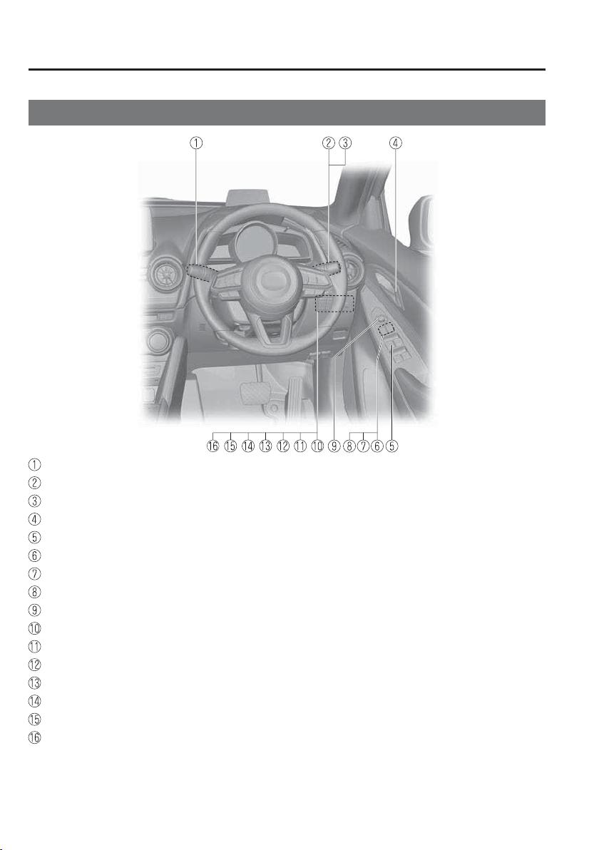
Interior Overview (Right-Hand Drive Model)
Interior Equipment (View A)
Wiper and washer lever .........................................................................................page 4-72
Turn and lane-change signal .................................................................................page 4-71
Lighting control.....................................................................................................page 4-61
Door-lock knob .....................................................................................................page 3-19
Power window switches ........................................................................................page 3-38
Power window lock switch ...................................................................................page 3-41
Door-lock switch ...................................................................................................page 3-17
Power folding mirror switch .................................................................................page 3-34
Outside mirror switch............................................................................................page 3-34
DSC OFF switch ...................................................................................................page 4-89
Tyre pressure monitoring system set switch .......................................................page 4-192
i-stop OFF switch ..................................................................................................page 4-21
Headlight Levelling switch ...................................................................................page 4-68
LDWS OFF switch..............................................................................................page 4-114
SCBS OFF switch ...............................................................................................page 4-160
Blind Spot Monitoring (BSM) OFF switch ........................................................page 4-123
The equipment and installation position varies by vehicle
1
–
7
Pictorial Index
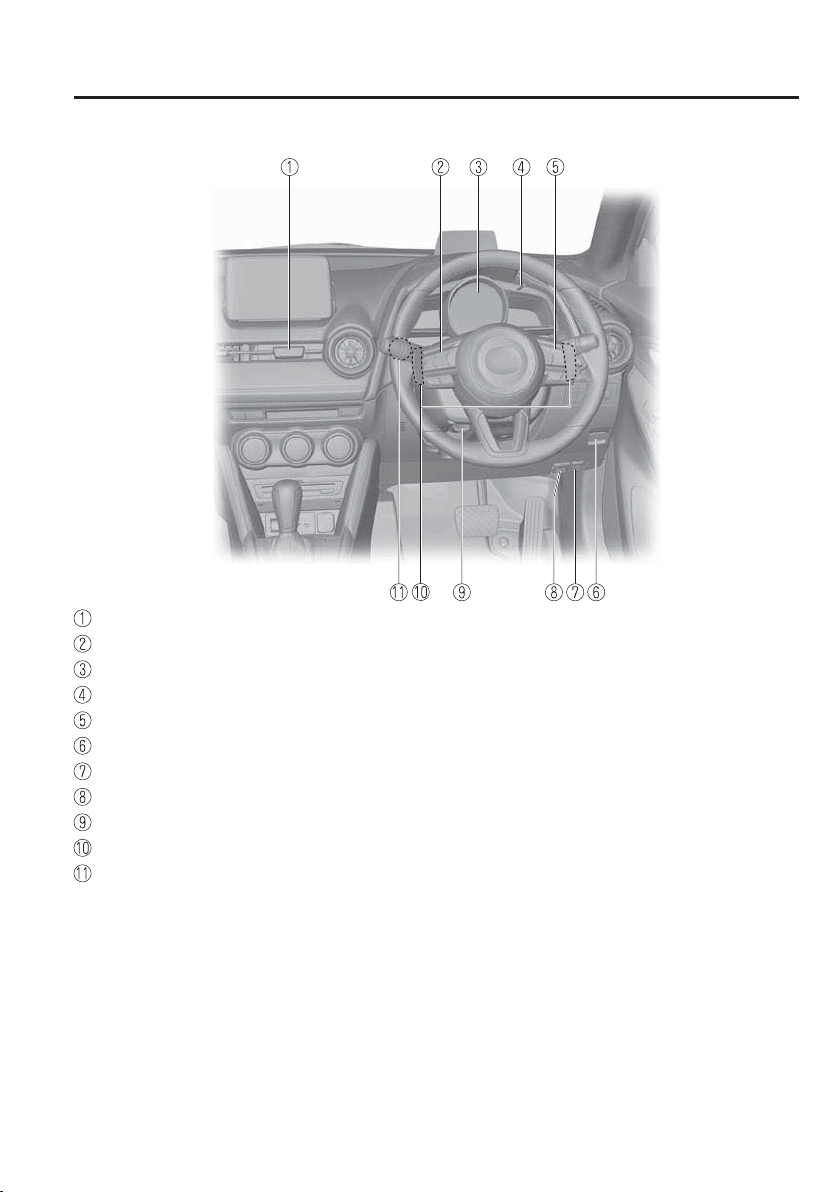
Interior Overview (Right-Hand Drive Model)
Hazard warning À asher switch ..............................................................................page 4-80
Audio control switches..........................................................................................page 5-18
Instrument cluster ..................................................................................................page 4-24
Instrument panel illumination knob ......................................................................page 4-30
Cruise control switches ............................................................................page 4-139 , 4-185
Boot release button................................................................................................page 3-22
Remote fuel-¿ ller À ap release ...............................................................................page 3-31
Bonnet release handle ...........................................................................................page 6-19
Lock release lever .................................................................................................page 3-33
Steering shift switches ..........................................................................................page 4-55
Push button start ......................................................................................................page 4-4
The equipment and installation position varies by vehicle
1
–
8
Pictorial Index
Interior Overview (Right-Hand Drive Model)
Interior Equipment (View B)
SRS air bags ..........................................................................................................page 2-41
Air-conditioning system ..........................................................................................page 5-4
Rear window defogger switch...............................................................................page 4-78
Audio system................................................................................................page 5-26 , 5-80
Seat warmer switches ..............................................................................................page 2-6
Active driving display ...........................................................................................page 4-35
CD player .....................................................................................................page 5-34 , 5-94
DVD player ...........................................................................................................page 5-97
Accessory sockets ...............................................................................................page 5-159
External input terminal..........................................................................................page 5-20
Drive selection switch .........................................................................................page 4-100
Shift lever/Selector lever ..............................................................................page 4-46 , 4-49
Fuse block (Left side) ...........................................................................................page 6-61
The equipment and installation position varies by vehicle
1
–
9
Pictorial Index
Interior Overview (Right-Hand Drive Model)
Interior Equipment (View C)
Rearview mirror ....................................................................................................page 3-37
Sunvisor ..............................................................................................................page 5-156
Vanity mirror .......................................................................................................page 5-156
Overhead lights ...................................................................................................page 5-156
Bottle holder ........................................................................................................page 5-160
SRS air bag............................................................................................................page 2-41
Seat belts ...............................................................................................................page 2-14
Rear seat ..................................................................................................................page 2-7
Front seat .................................................................................................................page 2-5
Cup holders .........................................................................................................page 5-160
Parking brake ........................................................................................................page 4-82
Commander switch ...............................................................................................page 5-80
Glove compartment .............................................................................................page 5-161
The equipment and installation position varies by vehicle
1
–
10
Pictorial Index
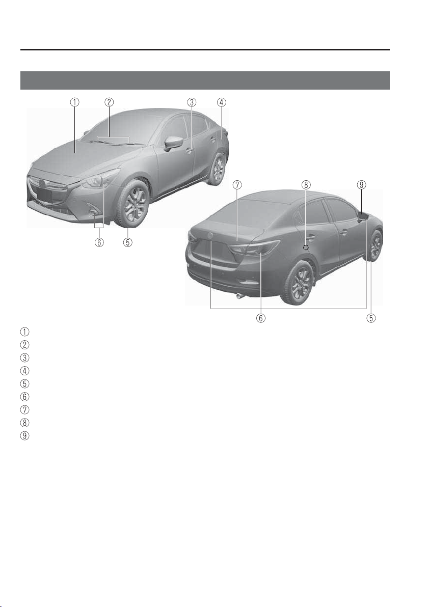
Exterior Overview
S a l o o n
Bonnet ...................................................................................................................page 6-19
Windscreen wiper blades ......................................................................................page 6-33
Doors and keys ......................................................................................................page 3-13
Fuel-¿ ller À ap ........................................................................................................page 3-31
Wheels and Tyres ..................................................................................................page 6-44
Exterior lights ........................................................................................................page 6-48
Boot lid ..................................................................................................................page 3-22
Child safety locks ..................................................................................................page 3-20
Outside mirror .......................................................................................................page 3-34
The equipment and installation position varies by vehicle
1
–
11
Pictorial Index
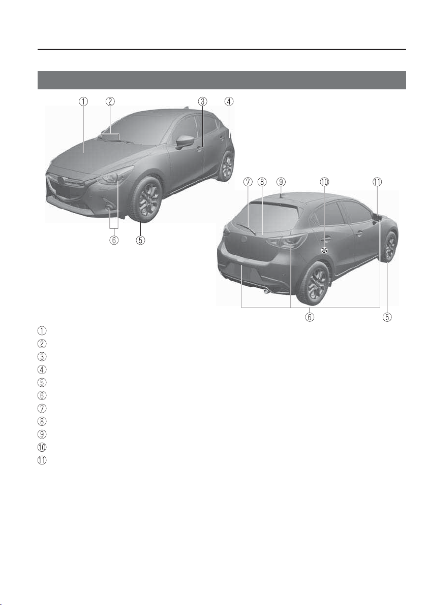
Exterior Overview
Hatchback
Bonnet ...................................................................................................................page 6-19
Windscreen wiper blades ......................................................................................page 6-33
Doors and keys ......................................................................................................page 3-13
Fuel-¿ ller À ap ........................................................................................................page 3-31
Wheels and Tyres ..................................................................................................page 6-44
Exterior lights ........................................................................................................page 6-48
Rear window wiper blade .....................................................................................page 6-36
Liftgate ..................................................................................................................page 3-22
Aerial .....................................................................................................................page 5-23
Child safety locks ..................................................................................................page 3-20
Outside mirror .......................................................................................................page 3-34
The equipment and installation position varies by vehicle

MEMO
1
–
12

2
–
1
*Some models.
2
–
1
2
Essential Safety Equipment
Important information about safety equipment, including seats, seat belt
system, child-restraint systems and SRS air bags.
Seats ..................................................................................................... 2-2
Seat Precautions ............................................................................ 2-2
Front Seat ...................................................................................... 2-5
Rear Seat ....................................................................................... 2-7
Head Restraints ........................................................................... 2-11
Seat Belt Systems .............................................................................. 2-14
Seat Belt Precautions .................................................................. 2-14
Seat Belt ...................................................................................... 2-17
Seat Belt Warning Systems ......................................................... 2-18
Seat Belt Pretensioner and Load Limiting Systems .................... 2-18
Child Restraint ................................................................................. 2-21
Child-Restraint Precautions ........................................................ 2-21
Child-Restraint System Installation ............................................ 2-26
Child-Restraint System Suitability for Various Seat Positions
Table ............................................................................................ 2-32
Installing Child-Restraint Systems ............................................. 2-36
SRS Air Bags .................................................................................... 2-41
Supplementary Restraint System (SRS) Precautions .................. 2-41
Front Passenger Air Bag Deactivation Switch
*
........................... 2-47
Supplementary Restraint System Components ........................... 2-51
How the SRS Air Bags Work ...................................................... 2-52
SRS Air Bag Deployment Criteria .............................................. 2-56
Limitations to SRS Air Bag ........................................................ 2-58
2
–
2
Essential Safety Equipment
Seats
Seat Precautions
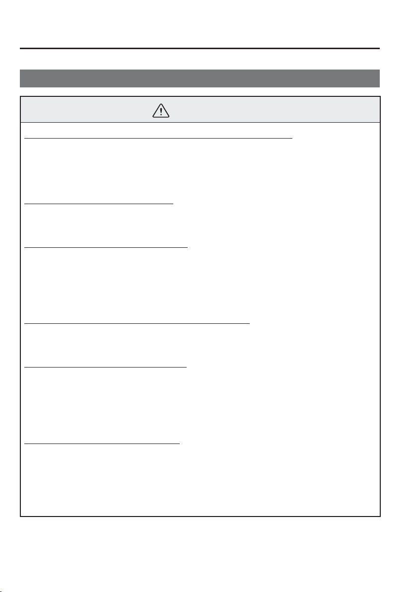
WARNING
Make sure the adjustable components of a seat are locked in place:
Adjustable seats and seatbacks that are not securely locked are dangerous. In a sudden
stop or collision, the seat or seatback could move, causing injury. Make sure the
adjustable components of the seat are locked in place by attempting to slide the seat
forward and backward and rocking the seatback.
Never allow children to adjust a seat:
Allowing children to adjust a seat is dangerous as it could result in serious injury if a
child's hands or feet become caught in the seat.
Do not drive with the seatback unlocked:
All of the seatbacks play an important role in your protection in a vehicle. Leaving
the seatback unlocked is dangerous as it can allow passengers to be ejected or thrown
around and baggage to strike occupants in a sudden stop or collision, resulting in
severe injury. After adjusting the seatback at any time, even when there are no other
passengers, rock the seatback to make sure it is locked in place.
Adjust the driver's seat only when the vehicle is stopped:
Adjusting the driver's seat while the vehicle is moving is dangerous. The driver could
lose control of the vehicle and have an accident.
Do not modify or replace the front seats:
Modifying or replacing the front seats such as replacing the upholstery or loosening
any bolts is dangerous. The front seats contain air bag components essential to the
supplementary restraint system. Such modi¿ cations could damage the supplementary
restraint system and result in serious injury. Consult an Authorised Mazda Repairer if
there is any need to remove or reinstall the front seats.
Do not drive with damaged front seats:
Driving with damaged front seats, such as seat cushions torn or damaged down to the
urethane, is dangerous. A collision, even one not strong enough to inÀ ate the air bags,
could damage the front seats which contain essential air bag components. If there was
a subsequent collision, an air bag may not deploy which could lead to injuries. Always
have an Authorised Mazda Repairer inspect the front seats, front seat belt pretensioners
and air bags after a collision.
2
–
3
Essential Safety Equipment
Seats
WARNING
Do not drive with either front seats reclined:
Sitting in a reclined position while the vehicle is moving is dangerous because you do
not get the full protection from seat belts. During sudden braking or a collision, you can
slide under the lap belt and suffer serious internal injuries. For maximum protection,
sit well back and upright.
Do not place an object such as a cushion between the seatback and your back:
Putting an object such as a cushion between the seatback and your back is dangerous
because you will be unable to maintain a safe driving posture and the seat belt cannot
function at its full capacity in a collision, which could result in a serious accident,
injury or death.
Do not place objects under the seat:
The object could get stuck and cause the seat to not be ¿ xed securely, and result in an
accident.
Do not stack cargo higher than the seatbacks:
Stacking luggage or other cargo higher than the seatbacks is dangerous. During
sudden braking or a collision, objects can À y around and become projectiles that may
hit and injure passengers.
Make sure luggage and cargo is secured before driving:
Not securing cargo while driving is dangerous as it could move or be crushed during
sudden braking or a collision and cause injury.
Never allow a passenger to sit or stand on the folded seatback while the vehicle is
moving:
Driving with a passenger on the folded seatback is dangerous. Allowing a child to sit
up on the folded seatback while the vehicle is moving is particularly dangerous. In a
sudden stop or even a minor collision, a child not in a proper seat or child-restraint
system and seat belt could be thrown forward, back or even out of the vehicle resulting
in serious injuries or death. The child in the baggage area could be thrown into other
occupants and cause serious injury.
Never give the car keys to children and do not allow them to play in the vehicle
(Saloon):
Playing with the folding rear seats is dangerous. Once the seatbacks are back up, a
child in the boot would not be able to get out the way they had entered. If you have
small children, keep the seatbacks locked.
2
–
4
Essential Safety Equipment
Seats
WARNING
Always leave your car locked and keep the car keys safely away from children (Saloon):
Leaving your car unlocked or the keys in reach of children is dangerous. Children
who ¿ nd their way into the boot through an unlocked rear seatback or an open boot
can become accidentally locked in the boot. This could result in death or brain damage
from heat prostration, particularly in the summer. Always lock the doors and the boot,
and as an added measure, keep the rear seatbacks locked, whether you have children in
your home or not.
CAUTION
When operating a seat, be careful not to put your hands or ¿ ngers near the moving
parts of the seat or on the side trim to prevent injury.
When moving the seats, make sure there is no cargo in the surrounding area. If the
cargo gets caught it could damage the cargo.
When moving the seats forward and rearward or returning a rear-reclined seatback
to its upright position, make sure you hold onto the seatback with your hand while
operating. If the seatback is not held, the seat will move suddenly and could cause
injury.
NOTE
When returning a rear seat to its original position, place the seat belt in its normal
position. Verify that the seat belt pulls out and retracts.
2
–
5
Essential Safety Equipment
Seats
*Some models.
Front Seat
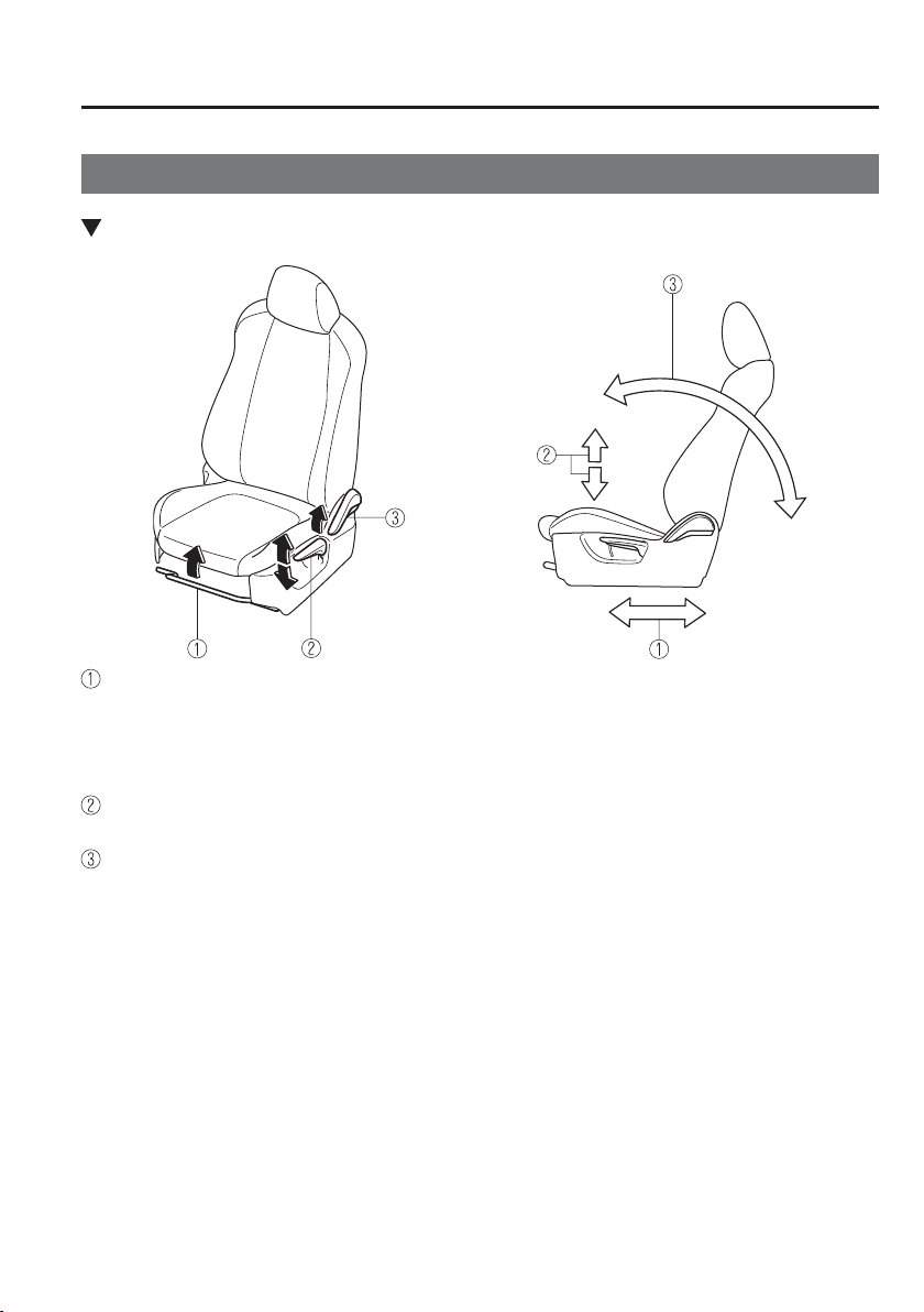
Seat Operation
Seat Slide
To move a seat forward or backward, raise the lever and slide the seat to the desired position
and release the lever.
Make sure the lever returns to its original position and the seat is locked in place by
attempting to push it forward and backward.
Height Adjustment
*
To adjust the seat height, move the lever up or down.
Seat Recline
To change the seatback angle, lean forward slightly while raising the lever. Then lean back
to the desired position and release the lever.
Make sure the lever returns to its original position and the seatback is locked in place by
attempting to push it forward and backward.
2
–
6
Essential Safety Equipment
Seats
*Some models.
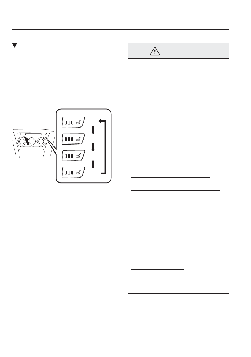
Seat Warmer
*
The front seats are electrically heated. The
ignition must be switched ON.
Press the seat warmer switch while the
ignition is switched ON to operate the seat
warmer. The indicator lights turn on to
indicate that the seat warmer is operating.
The mode changes as follows each time
the seat warmer switch is pressed.
OFF
High
Mid
Low
WARNING
Be careful when using the seat
warmer:
The heat from the seat warmer may be
too hot for some people, as indicated
as follows, and could cause a low-
temperature burn.
Infants, small children, elderly
people, and physically challenged
people
People with delicate skin
People who are excessively fatigued
People who are intoxicated
People who have taken sleep-
inducing medicine such as sleeping
pills or cold medicine
Do not use the seat warmer with
anything having high moisture-
retention ability such as a blanket or
cushion on the seat:
The seat may be heated excessively and
cause a low-temperature burn.
Do not use the seat warmer even when
taking a short nap in the vehicle:
The seat may be heated excessively and
cause a low-temperature burn.
Do not place heavy objects with sharp
projections on the seat, or insert
needles or pins into it:
This could cause the seat to become
excessively heated and result in injury
from a minor burn.
2
–
7
Essential Safety Equipment
Seats
CAUTION
Do not use organic solvents to clean the
seat. It may damage the seat surface and
the heater.
NOTE
If the ignition is switched off while
the seat warmer is operating (High,
Mid or Low) and then switched
ON again, the seat warmer will
automatically operate at the
temperature set before switching off
the ignition.
Use the seat warmer when the engine
is running. Leaving the seat warmer
on for long periods with the engine
not running could cause the battery
power to be depleted.
The temperature of the seat warmer
cannot be adjusted beyond High, Mid
and Low because the seat warmer is
controlled by a thermostat.
Rear Seat
Split/One-piece Folding the
Seatback
By lowering the rear seatback(s) the
luggage compartment space can be
expanded.
2
–
8
Essential Safety Equipment
Seats
WARNING
Do not drive the vehicle with occupants
on folded down seatback(s) or in the
luggage compartment.
Putting occupants in the luggage
compartment is dangerous because seat
belts cannot be fastened which could
lead to serious injury or death during
sudden braking or a collision.
Do not allow children to play inside the
vehicle with the seatback(s) lowered.
Allowing children to play in the vehicle
with the seatback(s) folded down is
dangerous. If a child enters the luggage
compartment and the seatback(s) were
raised back up, the child may become
trapped in the luggage compartment
which could lead to an accident.
Tightly secure cargo in the luggage
compartment when it is transported
with the seatback(s) folded down.
Driving without tightly securing cargo
and luggage is dangerous as it could
move and become an obstruction to
driving during emergency braking or
a collision resulting in an unexpected
accident.
When transporting cargo, do not allow
the cargo to exceed the height of the
seatback(s).
Transporting cargo stacked higher
than the seatback(s) is dangerous
as visibility to the rear and sides of
the vehicle is reduced which could
interfere with driving operations and
lead to an accident.
Lowering the seatback(s)
CAUTION
(Hatchback)
When folding the seatback forward,
always support the seatback with
your hand. If it is not supported by a
hand, ¿ ngers or the hand pressing the
push knob could be injured.
Check the position of a front seat
before folding a rear seatback.
Depending on the position of a front
seat, it may not be possible to fold
a rear seatback all the way down
because it may hit the seatback of
the front seat which could scratch or
damage the front seat or its pocket.
Remove the head restraint on the rear
outboard seat if necessary.
2
–
9
Essential Safety Equipment
Seats
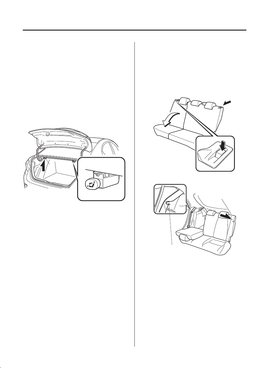
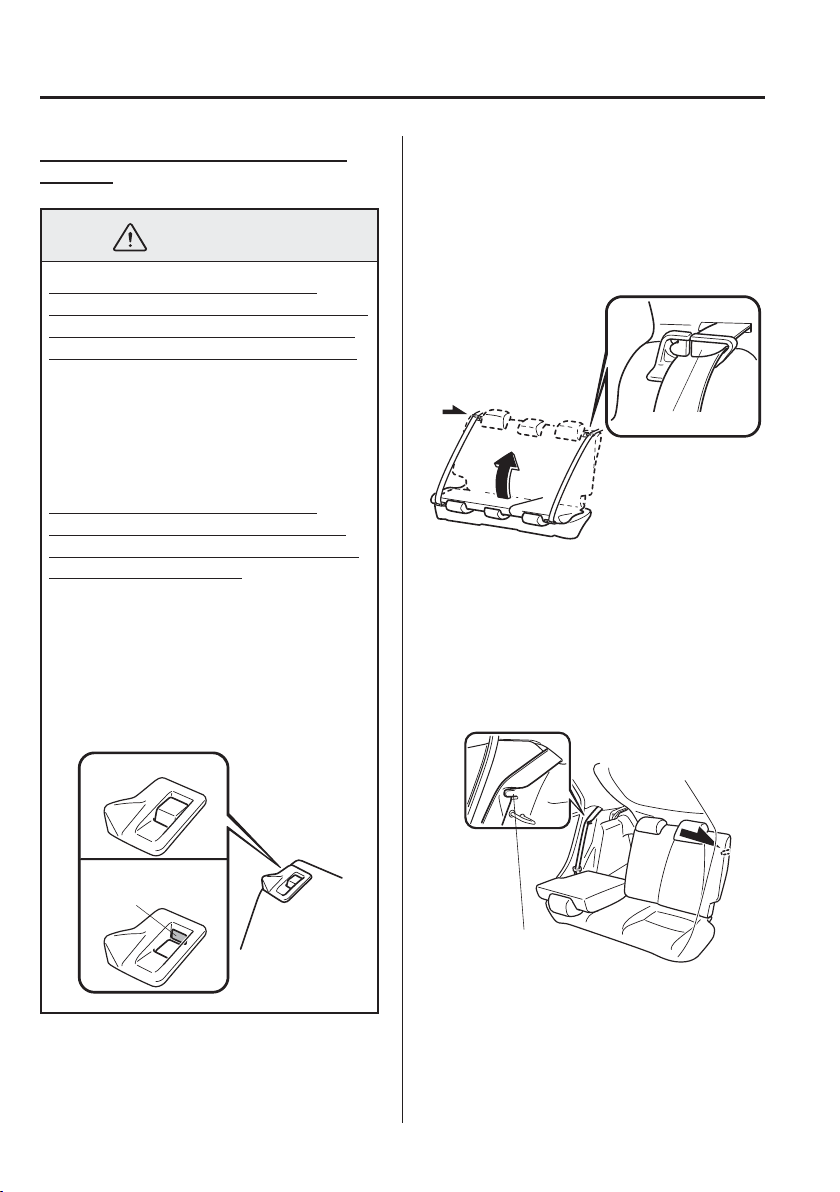
(Saloon)
1. If your vehicle is equipped with the
head restraint, lower it all the way
down.
Refer to Head Restraints on page
2-11 .
2. (Split-folding type seat)
Open the boot lid and pull the lever of
the seatback you want to fold down.
(One-piece folding type seat)
Open the boot lid and pull the lever of
the seatback.
*1: With split-folding
type seat only
*1
3. Open a rear door and fold the rear seat
forward.
(Hatchback)
1. Lower the head restraint all the way
down.
Refer to Head Restraints on page
2-11 .
2. Press the push knob to fold down the
seatback.
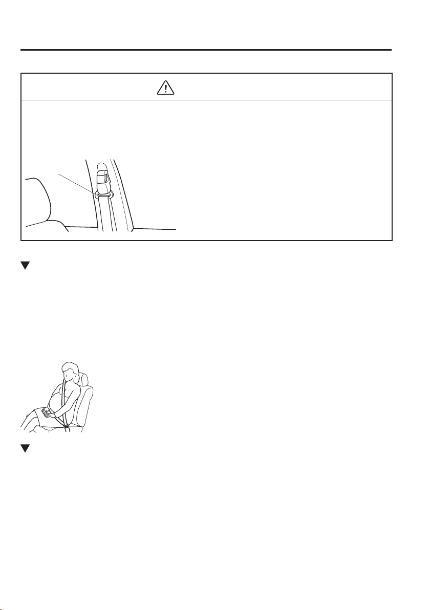
3. Secure the rear seat belt in the belt clip.
Belt clip
2
–
10
Essential Safety Equipment
Seats
To return the seatback to its upright
position:
WARNING
When returning a seatback to its
upright position, make sure the 3-point
seat belt is not caught in the seatback
and the 3-point seat belt is not twisted.
If the seat belt is used while it is twisted
and caught in the seatback, the seat
belt cannot function at its full capacity,
which could cause serious injury or
death.
When returning a seatback to its
upright position, make sure that it is
¿ rmly locked and the red indication is
not visible (Hatchback).
If the red indication is visible behind
the push knob, it means the seatback
is not locked. If the vehicle is driven
without the seatback locked, it could
fold down suddenly and cause an
accident.
Locked position
Unlocked position
Red indication
(Saloon)
1. Make sure that the seat belt passes
through the seat belt guide correctly
and it is not twisted, then raise the
seatback while preventing the seat belt
from being caught in the seatback.
Seat belt guide
2. Press the seatback rearward and lock it
in place. After returning the seatback
to its upright position, make sure it is
securely locked.
(Hatchback)
1. Verify that the seat belt is secured in
the belt clip.
Belt clip
2. Lift the seatback upright.
3. Press the seatback rearward and lock it
in place. After returning the seatback
to its upright position, make sure it is
securely locked.
2
–
11
Essential Safety Equipment
Seats
4. Make sure that the seat belt is neither
stuck in the rear seat nor twisted, then
remove the seat belt from the belt clip.
Head Restraints
Your vehicle is equipped with head
restraints on all outboard seats and the
rear centre seat. The head restraints are
intended to help protect you and the
passengers from neck injury.
WARNING
Always drive with the head restraints
installed when seats are being used and
make sure they are properly adjusted.
In addition, always raise the head
restraints on all rear seat when they are
being used:
Driving with the head restraints
adjusted too low or removed is
dangerous. With no support behind
your head, your neck could be seriously
injured in a collision.
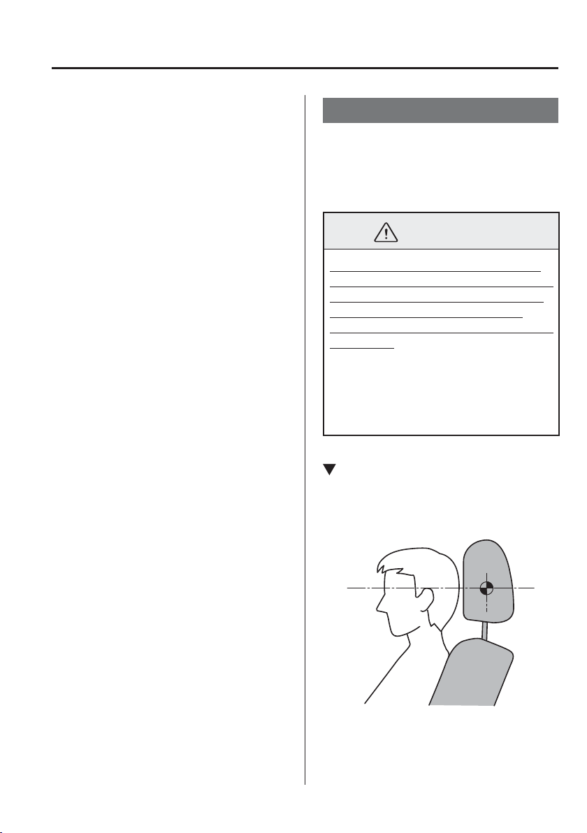
Height Adjustment
Adjust the head restraint so that the centre
is even with the top of the passenger's ears.
To raise a head restraint, pull it up to the
desired position.
To lower the head restraint, press the stop-
catch release, then push the head restraint
down.
2
–
12
Essential Safety Equipment
Seats
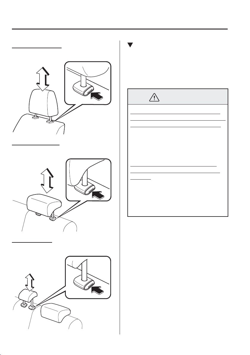
Front outboard seat
Rear outboard seat
Rear centre seat
Removal/Installation
To remove the head restraint, pull it up
while pressing the stop-catch.
To install the head restraint, insert the legs
into the holes while pressing the stop-
catch.
WARNING
Always drive with the head restraints
installed when seats are being used and
make sure they are properly installed:
Driving with the head restraints not
installed is dangerous. With no support
behind your head, your neck could be
seriously injured in a collision.
After installing a head restraint, try
lifting it to make sure that it does not
pull out:
Driving with an unsecured head
restraint is dangerous as the
effectiveness of the head restraint will
be compromised which could cause it to
unexpectedly detach from the seat.
2
–
13
Essential Safety Equipment
Seats
CAUTION
When installing a head restraint,
make sure that it is installed
correctly with the front of the head
restraint facing forward. If the head
restraint is installed incorrectly, it
could detach from the seat during a
collision and result in injury.
The head restraints on each of the
front and rear seats are specialized
to each seat. Do not switch around
the head restraint positions. If a head
restraint is not installed to its correct
seat position, the effectiveness of the
head restraint during a collision will
be compromised which could cause
injury.
2
–
14
Essential Safety Equipment
Seat Belt Systems
Seat Belt Precautions
Seat belts help to decrease the possibility of severe injury during accidents and sudden
stops. Mazda recommends that the driver and all passengers always wear seat belts.
All the seats have lap/shoulder belts. These belts also have retractors with inertia locks that
keep them out of the way when not in use. The locks allow the belts to remain comfortable
on users, but they will lock in position during a collision.
WARNING
Always wear your seat belt and make sure all occupants are properly restrained:
Not wearing a seat belt is extremely dangerous. During a collision, occupants not
wearing seat belts could hit someone or things inside the vehicle or even be thrown out
of the vehicle. They could be seriously injured or even killed. In the same collision,
occupants wearing seat belts would be much safer.
Do not wear twisted seat belts:
Twisted seat belts are dangerous. In a collision, the full width of the belt is not available
to absorb the impact. This puts more force on the bones beneath the belt, which could
cause serious injury or death. So, if your seat belt is twisted, you must straighten the
seat belt to remove any twists and to allow the full width of the belt to be used.
Never use one seat belt on more than one person at a time:
Using one seat belt for more than one person at a time is dangerous. A seat belt used
in this way cannot spread the impact forces properly and the two passengers could
be crushed together and seriously injured or even killed. Never use one belt for more
than one person at a time and always operate the vehicle with each occupant properly
restrained.
Do not operate a vehicle with a damaged seat belt:
Using a damaged seat belt is dangerous. An accident could damage the belt webbing
of the seat belt in use. A damaged seat belt cannot provide adequate protection in a
collision. Have an expert repairer, we recommend an Authorised Mazda Repairer
inspect all seat belt systems in use during an accident before they are used again.
Have your seat belts changed immediately if the pretensioner or load limiter has been
expended:
Always have an expert repairer, we recommend an Authorised Mazda Repairer
immediately inspect the seat belt pretensioners and air bags after any collision. Like the
air bags, the seat belt pretensioners and load limiters will only function once and must
be replaced after any collision that caused them to deploy. If the seat belt pretensioners
and load limiters are not replaced, the risk of injury in a collision will increase.
2
–
15
Essential Safety Equipment
Seat Belt Systems
WARNING
Positioning the Shoulder Portion of the Seat Belt:
Improper positioning of the shoulder portion of the seat belt is dangerous. Always make
sure the shoulder portion of the seat belt is positioned across your shoulder and near
your neck, but never under your arm, on your neck, or on your upper arm.
Positioning the Lap Portion of the Seat Belt:
The lap portion of the seat belt worn too high is dangerous. In a collision, this would
concentrate the impact force directly on the abdominal area, causing serious injury.
Wear the lap portion of the belt snugly and as low as possible.
Instructions for Use of Seat Belt Assemblies:
Seatbelts are designed to bear upon the bony structure of the body, and should be worn
low across the front of the pelvis or the pelvis, chest and shoulders, as applicable;
wearing the lap section of the belt across the abdominal area must be avoided.
Seatbelts should be adjusted as ¿ rmly as possible, consistent with comfort, to provide
the protection for which they have been designed. A slack belt will greatly reduce the
protection afforded to the wearer.
Care should be taken to avoid contamination of the webbing with polishes, oils and
chemicals, and particularly battery acid. Cleaning may safely be carried out using mild
soap and water. The belt should be replaced if webbing becomes frayed, contaminated
or damaged.
It is essential to replace the entire assembly after it has been worn in a severe impact
even if damage to the assembly is not obvious.
Belts should not be worn with straps twisted.
Each belt assembly must only be used by one occupant; it is dangerous to put a belt
around a child being carried on the occupant's lap.
No modi¿ cations or additions should be made by the user which will either prevent
the seat belt adjusting devices from operating to remove slack, or prevent the seat belt
assembly from being adjusted to remove slack.
2
–
16
Essential Safety Equipment
Seat Belt Systems
CAUTION
Belt retraction may become dif¿ cult if the belts and rings are soiled, so try to keep them
clean. For more details about cleaning the seat belts, refer to "Seat Belt Maintenance"
(page 6-73 ).
Ring
Pregnant Women and Persons with Serious Medical Conditions
Pregnant women should always wear seat belts. Ask your doctor for speci¿ c
recommendations.
The lap belt should be worn SNUGLY AND AS LOW AS POSSIBLE OVER THE HIPS.
The shoulder belt should be worn across your shoulder properly, but never across the
stomach area.
Persons with serious medical conditions also should wear seat belts. Check with your doctor
for any special instructions regarding speci¿ c medical conditions.
Emergency Locking Mode
When the seat belt is fastened, it will always be in the emergency locking mode.
In the emergency locking mode, the belt remains comfortable on the occupant and the
retractor will lock in position during a collision.
If the belt is locked and cannot be pulled out, retract the belt once, and then try pulling it out
slowly. If this fails, pull the belt strongly one time and loosen, then pull it out again slowly.
2
–
17
Essential Safety Equipment
Seat Belt Systems
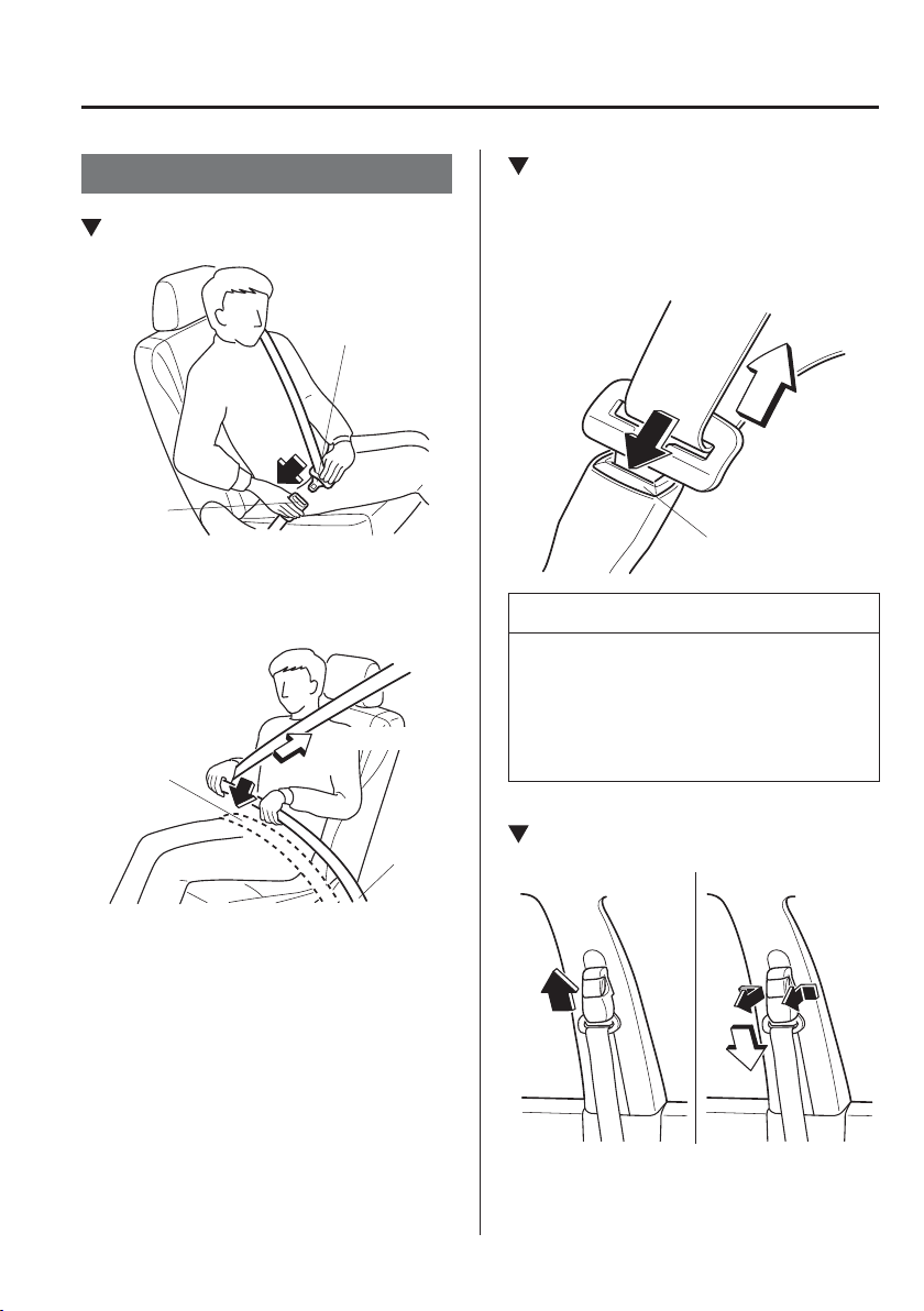
Seat Belt
Fastening the Seat Belt
Seat belt
buckle
Seat belt tongue
Position the lap belt as low as possible,
not on the abdominal area, then adjust the
shoulder belt so that it ¿ ts snugly against
your body.
Keep low on
hip bone
Too high
Take up slack
Unfastening the Seat Belt
Depress the button on the seat belt buckle.
If the belt does not fully retract, pull it out
and check for kinks or twists. Then make
sure it remains untwisted as it retracts.
Button
NOTE
If a belt does not fully retract, inspect
it for kinks and twists. If it is still not
retracting properly, have it inspected at
an expert repairer, we recommend an
Authorised Mazda Repairer.
Front Shoulder Belt Adjuster
To raise To lower
Make sure the adjuster is locked.
2
–
18
Essential Safety Equipment
Seat Belt Systems
*Some models.
Seat Belt Warning
Systems
If it detects that the occupant seat belt
is unfastened, the warning light or beep
alerts the occupant.
Refer to Taking Action on page 7-43 .
Refer to Seat Belt Warning Beep on page
7-50 .
Seat belt indicator light (rear seat)
(green)
*
The light turns on when the ignition
is switched ON and a rear seat belt is
fastened, and then it turns off after about
30 seconds.
Seat Belt Pretensioner
and Load Limiting
Systems
For optimum protection, the front seat
belts and rear outboard seat belts
*
are
equipped with pretensioner and load
limiting systems. For both these systems to
work properly you must wear the seat belt
properly.
Pretensioners:
When a collision is detected, the
pretensioners deploy simultaneously with
the air bags.
For deployment details, refer to the SRS
Air Bag Deployment Criteria (page
2-56 ).
The seat belt retractors remove slack
quickly as the air bags are expanding.
Any time the air bags and seat belt
pretensioners have ¿ red they must be
replaced.
A system malfunction or operation
conditions are indicated by a warning.
Refer to Warning/Indicator Lights on page
4-38 .
Refer to Air Bag/Seat Belt Pretensioner
System Warning Beep on page 7-50 .
(With front passenger air bag
deactivation switch)
In addition, the pretensioner system for
the front passenger, like the front and side
passenger air bag, is designed to only
deploy when the front passenger air bag
deactivation switch is turned to the ON
position.
For details, refer to front passenger air bag
deactivation switch (page 2-47 ).
2
–
19
Essential Safety Equipment
Seat Belt Systems
Load limiter:
The load limiting system releases belt
webbing in a controlled manner to reduce
belt force on the occupant's chest. While
the most severe load on a seat belt occurs
in frontal collisions, the load limiter has
an automatic mechanical function and
can activate in any accident mode with
suf¿ cient occupant movement.
Even if the pretensioners have not ¿ red,
the load limiting function must be checked
by an expert repairer, we recommend an
Authorised Mazda Repairer.
WARNING
Wear seat belts only as recommended
in this owner's manual:
Incorrect positioning of the seat belts is
dangerous. Without proper positioning,
the pretensioner and load limiting
systems cannot provide adequate
protection in an accident and this
could result in serious injury. For more
details about wearing seat belts, refer
to "Fastening the seat belts" (page
2-17 ).
Have your seat belts changed
immediately if the pretensioner or load
limiter has been expended:
Always have an expert repairer, we
recommend an Authorised Mazda
Repairer immediately inspect the
seat belt pretensioners and air bags
after any collision. Like the air bags,
the seat belt pretensioners and load
limiters will only function once and
must be replaced after any collision
that caused them to deploy. If the seat
belt pretensioners and load limiters
are not replaced, the risk of injury in a
collision will increase.
WARNING
Do not modify the components or
wiring, or use electronic testing devices
on the pretensioner system:
Modifying the components or wiring
of the pretensioner system, including
the use of electronic testing devices
is dangerous. You could accidentally
activate it or make it inoperable which
would prevent it from activating in an
accident. The occupants or repairers
could be seriously injured.
Properly dispose of the pretensioner
system:
Improper disposal of the pretensioner
system or a vehicle with non-
deactivated pretensioners is dangerous.
Unless all safety procedures are
followed, injury could result. Have
an expert repairer, we recommend an
Authorised Mazda Repairer safely
dispose of the pretensioner system or
scrap a pretensioner system equipped
vehicle.

2
–
20
Essential Safety Equipment
Seat Belt Systems
NOTE
The pretensioner system may not
operate depending on the type of
the collision. For details, refer to the
SRS Air Bag Deployment Criteria
(page 2-56 ).
Some smoke (non-toxic gas) will
be released when the air bags and
pretensioners deploy. This does not
indicate a ¿ re. This gas normally has
no effect on occupants, however,
those with sensitive skin may
experience light skin irritation. If
residue from the deployment of the
air bags or the pretensioner system
gets on the skin or in the eyes, wash
it off as soon as possible.

2
–
21
Essential Safety Equipment
Child Restraint
Child-Restraint Precautions
Mazda strongly urges the use of child-restraint systems for children small enough to use
them.
Mazda recommends use of a Mazda genuine child-restraint system or one that complies with
the UNECE
*1
44 regulation. If you would like to purchase a Mazda genuine child-restraint
system, please contact an Authorised Mazda Dealer.
Check your local and state or provincial laws for speci¿ c requirements regarding the safety
of children riding in your vehicle.
*1 UNECE stands for United Nations Economic Commission for Europe.
Whatever child-restraint system you consider, please pick the appropriate one for the age
and size of the child, obey the law and follow the instructions that come with the individual
child-restraint system.
A child who has outgrown child-restraint systems should sit in the rear and use seat belts.
The child-restraint system should be installed on the rear seat.
Statistics con¿ rm that the rear seat is the best place for all children up to 12 years of age-the
more so with a supplementary restraint system (air bags).
A rear-facing child-restraint system should NEVER be used in the front passenger seat with
the air bag system activated. The front passenger's seat is also the least preferred seat for
other child-restraint systems.
For some models, we have provided a deactivation switch that will disable front passenger
air bag inÀ ation. Do not switch off the front passenger air bag without reading the “Front
Passenger Air Bag Deactivation Switch” (page 2-47 ).
2
–
22
Essential Safety Equipment
Child Restraint
WARNING
Use the correct size child-restraint system:
For effective protection in vehicle accidents and sudden stops, a child must be properly
restrained using a seat belt or child-restraint system depending on age and size. If not,
the child could be seriously injured or even killed in an accident.
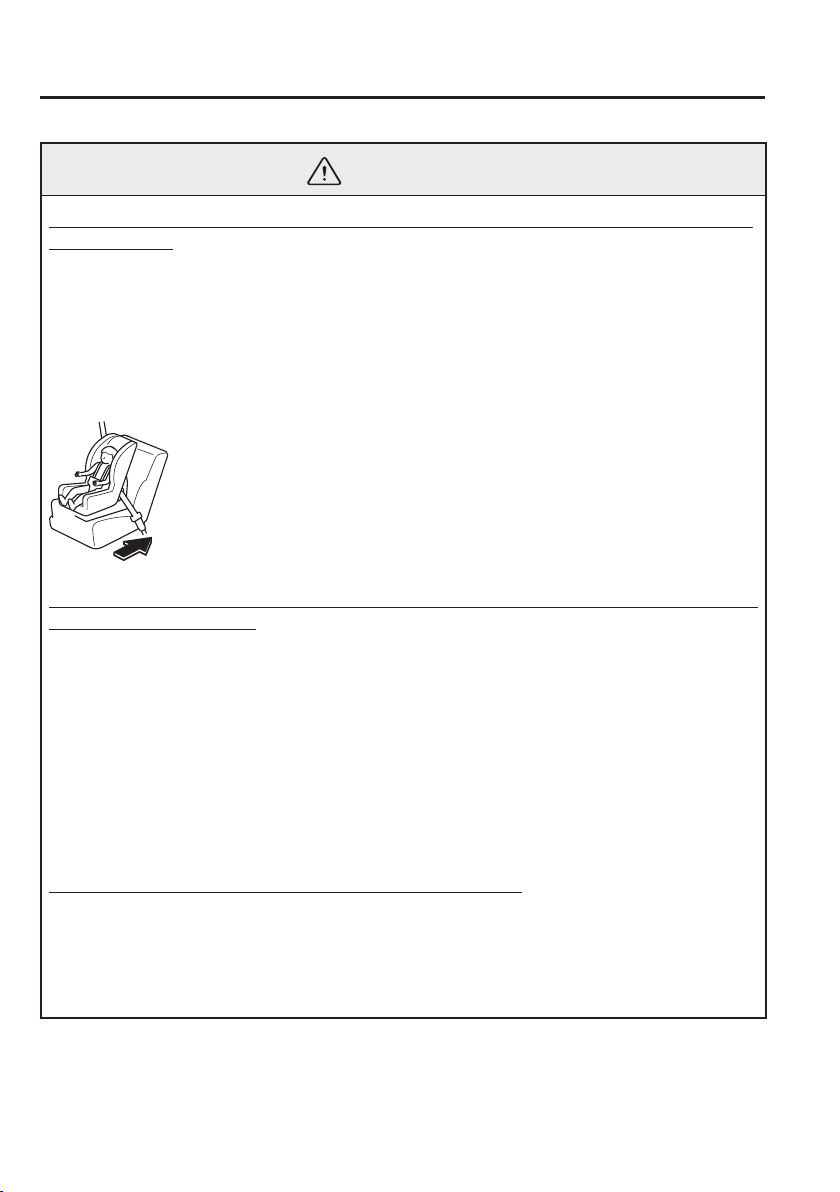
Follow the manufacturer's instructions and always keep the child-restraint system
buckled down:
An unsecured child-restraint system is dangerous. In a sudden stop or a collision it
could move causing serious injury or death to the child or other occupants. Make sure
any child-restraint system is properly secured in place according to the child-restraint
system manufacturer's instructions. When not in use, remove it from the vehicle or
fasten it with a seat belt, or latch it down to BOTH ISOFIX anchors, and attach the
corresponding tether anchor.
Always secure a child in a proper child-restraint system:
Holding a child in your arms while the vehicle is moving is extremely dangerous. No
matter how strong the person may be, he or she cannot hold onto a child in a sudden
stop or collision and it could result in serious injury or death to the child or other
occupants. Even in a moderate accident, the child may be exposed to air bag forces that
could result in serious injury or death to the child, or the child may be slammed into an
adult, causing injury to both child and adult.
2
–
23
Essential Safety Equipment
Child Restraint
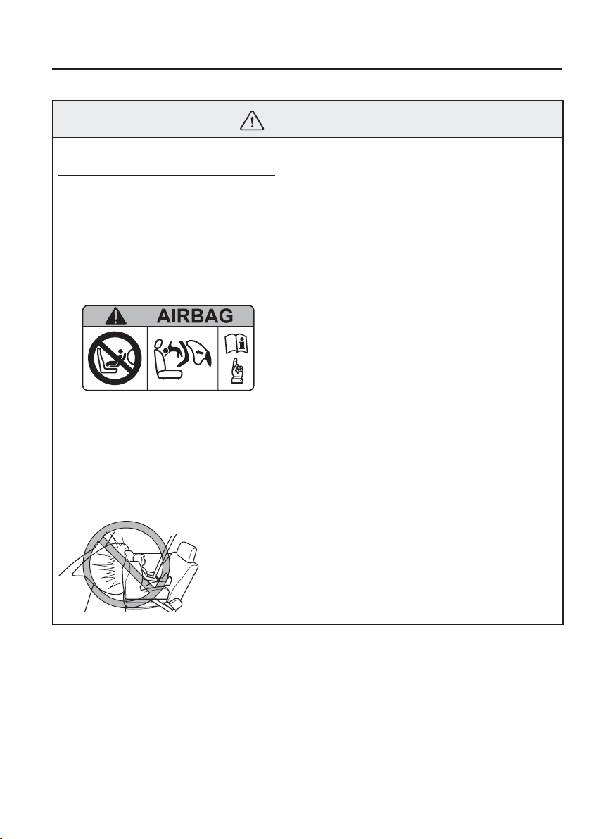
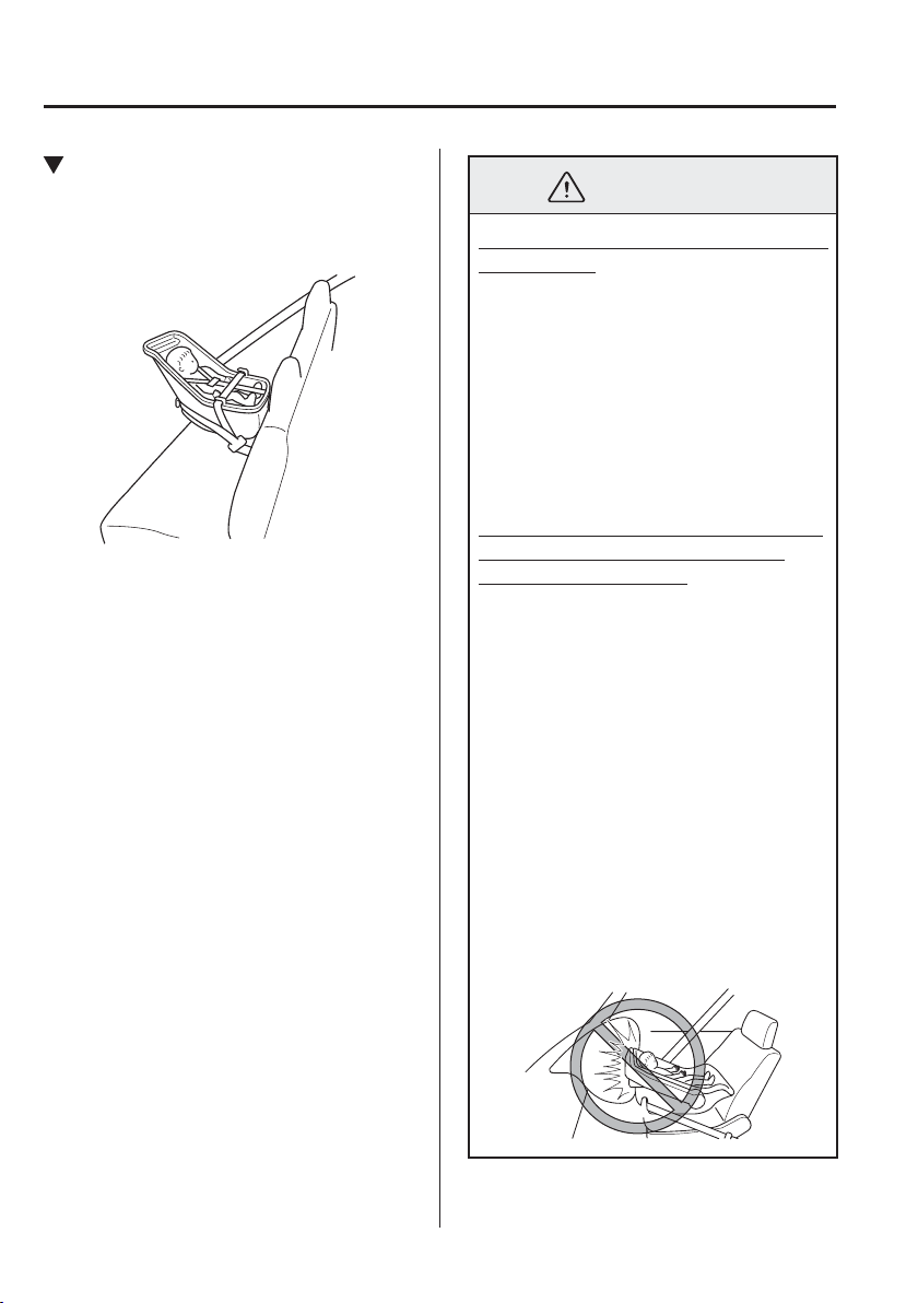
WARNING
Extreme Hazard! Never use a rear-facing child-restraint system on the front passenger
seat with an air bag that could deploy:
NEVER use a rearward facing child restraint on a seat protected by an ACTIVE
AIRBAG in front of it, DEATH or SERIOUS INJURY to the CHILD can occur.
Vehicles with a front passenger air bag have a warning label attached as shown below.
The warning label reminds you not to put a rear-facing child-restraint system on the
front passenger seat at any time.
Even in a moderate collision, the child-restraint system can be hit by a deploying air
bag and moved violently backward resulting in serious injury or death to the child. If
your vehicle is equipped with a front passenger air bag deactivation switch, always set
the switch to the OFF position when installing a rear-facing child-restraint system on
the front passenger seat.
2
–
24
Essential Safety Equipment
Child Restraint
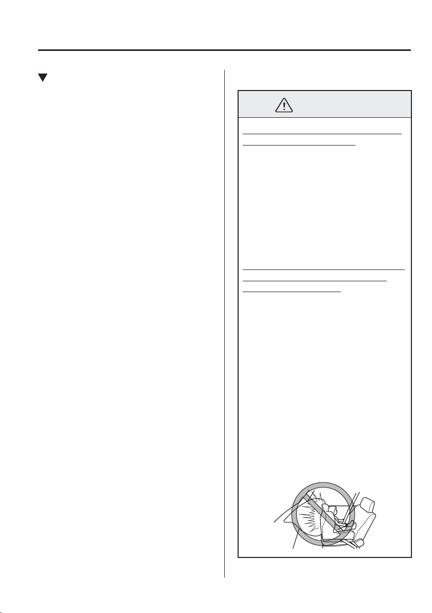
WARNING
Do not install a front-facing child-restraint system on the front passenger seat unless it
is unavoidable:
In a collision, the force of a deploying air bag could cause serious injury or death to
the child. If installing a front-facing child-restraint system on the front passenger seat
is unavoidable, move the front passenger seat as far back as possible and adjust the
seat bottom (height adjustable seat bottom) to the highest position at which the seat belt
fastening the child-restraint system is securely tightened.
Make sure that the front passenger air bag deactivation switch is in the OFF position.
Refer to Front Passenger Air Bag Deactivation Switch (page 2-47 ).
Do not allow a child or anyone to lean over or against the side window of a vehicle with
side and curtain air bags:
It is dangerous to allow anyone to lean over or against the side window, the area of the
front passenger seat, the front and rear window pillars and the roof edge along both
sides from which the side and curtain air bags deploy, even if a child-restraint system
is used. The impact of inÀ ation from a side or curtain air bag could cause serious
injury or death to an out of position child. Furthermore, leaning over or against the
front door could block the side and curtain air bags and eliminate the advantages of
supplementary protection. With the front air bag and the additional side air bag that
comes out of the front seat, the rear seat is always a better location for children. Take
special care not to allow a child to lean over or against the side window, even if the
child is seated in a child-restraint system.
Never use one seat belt on more than one person at a time:
Using one seat belt for more than one person at a time is dangerous. A seat belt used
in this way cannot spread the impact forces properly and the two passengers could
be crushed together and seriously injured or even killed. Never use one belt for more
than one person at a time and always operate the vehicle with each occupant properly
restrained.
2
–
25
Essential Safety Equipment
Child Restraint
WARNING
Use the tether and tether anchor only for a child-restraint system:
Child-restraint system anchorages are designed to withstand only those loads imposed
by correctly installed child-restraint systems. Under no circumstances are they to be
used for adult seat belts, harnesses, or for attaching other items or equipment to the
vehicle.
Always remove the head restraint and install child-restraint system (except when
installing a booster seat):
Installing a child-restraint system without removing the head restraint is dangerous.
The child-restraint system cannot be installed correctly which may result in death or
injury to the child in a collision.
CAUTION
A seat belt or child-restraint system can become very hot in a closed vehicle during
warm weather. To avoid burning yourself or a child, check them before you or your child
touches them.
NOTE
Your Mazda is equipped with ISOFIX anchors for attachment of ISOFIX child-restraint
systems in the rear seats. When using these anchors to secure a child-restraint system,
refer to “ISOFIX Anchor-Secured Child-Restraint Systems” (page 2-38 ).
2
–
26
Essential Safety Equipment
Child Restraint
Child-Restraint System Installation
Categories of Child-Restraint Systems
NOTE
When purchasing, ask the manufacturer of the child-restraint system which type of child-
restraint system is appropriate for your child and vehicle.
(Europe and countries conforming to the UNECE 44 regulation)
Child-restraint systems are classi¿ ed into the following 5 groups according to the UNECE
44 regulation.
Group Age Weight
0 Up to 9 months old Less than 10 kg (less than 22 lb)
0
Up to 2 years old Less than 13 kg (less than 29 lb)
1 8 months to 4 years old 9 kg — 18 kg (20 lb — 40 lb)
2 3 to 7 years old 15 kg — 25 kg (33 lb — 55 lb)
3 6 to 12 years old 22 kg — 36 kg (48 lb — 79 lb)
(Other countries)
Please comply with the legal regulations concerning the use of child-restraint systems in
your country.
2
–
27
Essential Safety Equipment
Child Restraint
Child-Restraint System Types
(Europe and countries conforming to
the UNECE 44 regulation)
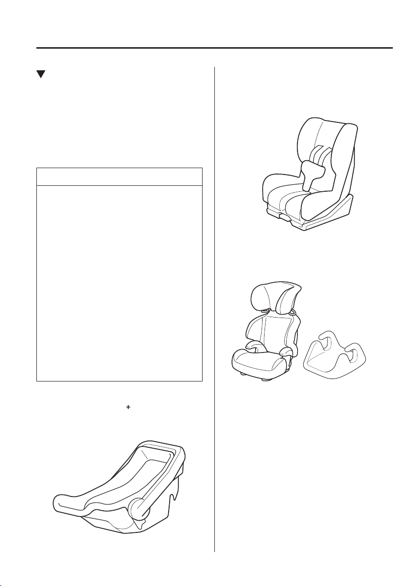
In this owner's manual, explanation of
child-restraint systems secured with seat
belts is provided for the following three
types of popular child-restraint systems:
baby seat, child seat, junior seat.
NOTE
Installation position is determined
by the type of child-restraint system.
Always read the manufacturer's
instructions and this owner's manual
carefully.
Due to variations in the design of
child-restraint systems, vehicle seats
and seat belts, all child-restraint
systems may not ¿ t all seating
positions. Before purchasing a child-
restraint system, it should be tested in
the speci¿ c vehicle seating position
(or positions) where it is intended to
be used. If a previously purchased
child-restraint system does not ¿ t,
you may need to purchase a different
one that will.
Baby seat
Equal to Group 0 and 0
of the UNECE 44
regulation.
Child seat
Equal to Group 1 of the UNECE 44
regulation.
Junior seat
Equal to Group 2 and 3 of the UNECE 44
regulation.
When using a booster seat, always install the
vehicle head restraint to the seat where the
booster seat is installed.
Booster seat
*
1
*
1
(Other countries)
Please comply with the legal regulations
concerning the use of child-restraint
systems in your country.
2
–
28
Essential Safety Equipment
Child Restraint
Baby Seat Installation Position
A baby seat is used in the rear-facing
position only.
Refer to the table, “Child-Restraint System
Suitability for Various Seat Positions”
for baby seat installation position (page
2-32 ).
WARNING
Always install a baby seat in the correct
seat position:
Installing a baby seat without ¿ rst
consulting the table “Child-Restraint
System Suitability for Various Seat
Positions” is dangerous. A baby seat
installed on the wrong seat position
cannot be properly secured. In a
collision, the child could hit something
or someone in the vehicle and be
seriously injured or even killed.
Never use a rear-facing child-restraint
system on the front passenger seat
protected by an air bag:
NEVER use a rearward facing child
restraint on a seat protected by an
ACTIVE AIRBAG in front of it,
DEATH or SERIOUS INJURY to the
CHILD can occur.
The child-restraint system can be hit
by the deploying air bag and knocked
out of position. A child in the child-
restraint system could be seriously
injured or killed. If your vehicle is
equipped with a front passenger air
bag deactivation switch, always set the
switch to the OFF position if installing
a rear-facing child-restraint system on
the front passenger seat is unavoidable.
2
–
29
Essential Safety Equipment
Child Restraint
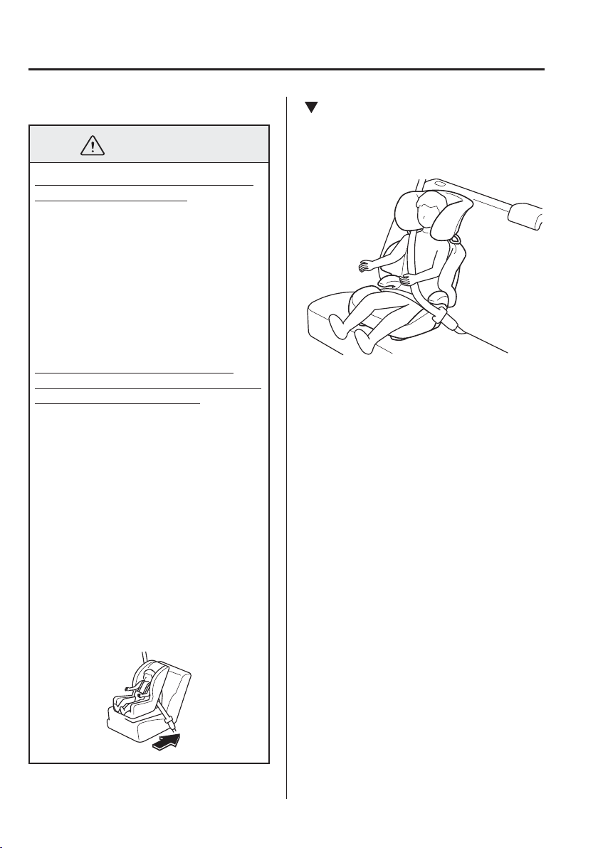
Child Seat Installation Position
A child seat is used in front-facing and
rear-facing positions depending on the
age and size of the child. When installing,
follow the manufacturer's instructions in
accordance with the appropriate age and
size of the child as well as the directions
for installing the child-restraint system.
Refer to the table, “Child-Restraint System
Suitability for Various Seat Positions”
for child seat installation position (page
2-32 ).
Rear-facing type
WARNING
Always install a rear-facing child seat
in the correct seat position:
Installing a rear-facing child seat
without ¿ rst consulting the table
“Child-Restraint System Suitability for
Various Seat Positions” is dangerous.
A rear-facing child seat installed on the
wrong seat position cannot be properly
secured. In a collision, the child could
hit something or someone in the vehicle
and be seriously injured or even killed.
Never use a rear-facing child-restraint
system on the front passenger seat
protected by an air bag:
NEVER use a rearward facing child
restraint on a seat protected by an
ACTIVE AIRBAG in front of it,
DEATH or SERIOUS INJURY to the
CHILD can occur.
The child-restraint system can be hit
by the deploying air bag and knocked
out of position. A child in the child-
restraint system could be seriously
injured or killed. If your vehicle is
equipped with a front passenger air
bag deactivation switch, always set the
switch to the OFF position if installing
a rear-facing child-restraint system on
the front passenger seat is unavoidable.
2
–
30
Essential Safety Equipment
Child Restraint
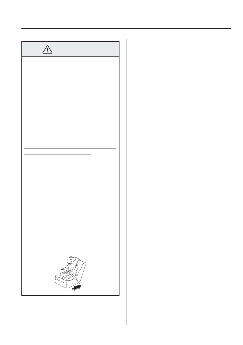
Front-facing type
WARNING
Never install a front-facing child seat
in the wrong seat position:
Installing a front-facing child seat
without ¿ rst consulting the table
“Child-Restraint System Suitability for
Various Seat Positions” is dangerous. A
front-facing child seat installed in the
wrong seat position cannot be properly
secured. In a collision, the child could
hit something or someone in the vehicle
and be seriously injured or even killed.
Do not install a front-facing child-
restraint system on the front passenger
seat unless it is unavoidable:
In a collision, the force of a deploying
air bag could cause serious injury or
death to the child. If installing a front-
facing child-restraint system on the
front passenger seat is unavoidable,
move the front passenger seat as far
back as possible and adjust the seat
bottom (height adjustable seat bottom)
to the highest position at which the seat
belt fastening the child-restraint system
is securely tightened.
Make sure that the front passenger air
bag deactivation switch is in the OFF
position. Refer to Front Passenger Air
Bag Deactivation Switch (page 2-47 ).
Junior Seat Installation Position
A junior seat is used in the front-facing
position only.
Refer to the table, “Child-Restraint System
Suitability for Various Seat Positions”
for junior seat installation position (page
2-32 ).
2
–
31
Essential Safety Equipment
Child Restraint
WARNING
Always install a junior seat in the
correct seat position:
Installing a junior seat without ¿ rst
consulting the table “Child-Restraint
System Suitability for Various Seat
Positions” is dangerous. A junior seat
installed on the wrong seat position
cannot be properly secured. In a
collision, the child could hit something
or someone in the vehicle and be
seriously injured or even killed.
Do not install a front-facing child-
restraint system on the front passenger
seat unless it is unavoidable:
In a collision, the force of a deploying
air bag could cause serious injury or
death to the child. If installing a front-
facing child-restraint system on the
front passenger seat is unavoidable,
move the front passenger seat as far
back as possible and adjust the seat
bottom (height adjustable seat bottom)
to the highest position at which the seat
belt fastening the child-restraint system
is securely tightened.
Make sure that the front passenger air
bag deactivation switch is in the OFF
position. Refer to Front Passenger Air
Bag Deactivation Switch (page 2-47 ).

2
–
32
Essential Safety Equipment
Child Restraint
Child-Restraint System Suitability for Various Seat
Positions Table
(Europe and countries conforming to the UNECE 16 regulation)
Provided information in the table shows your child-restraint system suitability for various
seating position. For installation suitability of other manufacturer child-restraint system,
carefully consult the manufacturer's instructions which accompany the child-restraint
system.
When installing a child-restraint system, the following points must be observed:
If the child-restraint system does not ¿ t into the seatback because of the head restraint,
adjust the head restraint or remove the head restraint so that the child-restraint system ¿ ts
into the seatback. However, when installing a booster seat, always install the vehicle head
restraint to the seat where the booster seat is installed.
Refer to Head Restraints on page 2-11 .
When installing a child-restraint system to the rear seat, adjust the front seat position so
that the front seat does not contact the child-restraint system.
Refer to Seat Operation on page 2-5 .
When installing a child-restraint system came equipped with a tether, remove the head
restraint.
Refer to Head Restraints on page 2-11 .
2
–
33
Essential Safety Equipment
Child Restraint
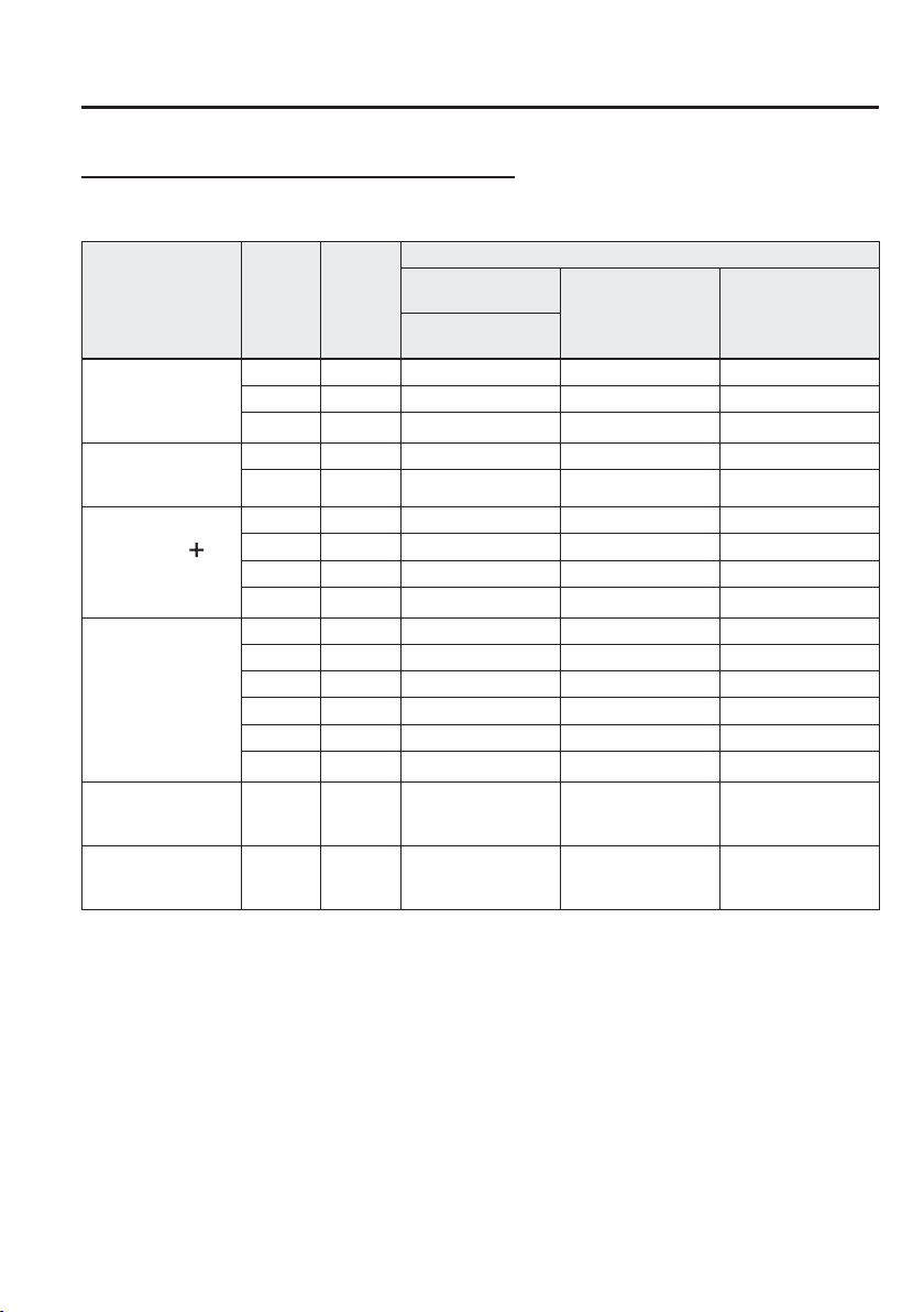
ISOFIX anchor-secured child-restraint systems
When installing a child-restraint system to the rear seat, refer to the child-restraint system
manufacturer's instructions and the Using ISOFIX Anchor on page 2-38 .
Mass group
Size
Class
Fixture
Seat Positions
Vehicle ISOFIX
positions
Rear seat (centre)
Front passenger
seat (outboard)
Rear seat
(outboard)
Carrycot
F ISO/L1 X X X
G ISO/L2 X X X
(1) X X X
GROUP 0
Up to 10 kg
(less than 22 lb)
E ISO/R1 IL X X
(1) X X X
GROUP 0
Up to 13 kg
(less than 29 lb)
E ISO/R1 IL X X
D ISO/R2 IL X X
C ISO/R3 IL X X
(1) X X X
GROUP 1
9 kg — 18 kg
(20 lb — 40 lb)
D ISO/R2 IL X X
C ISO/R3 IL X X
B ISO/F2 IUF X X
B1 ISO/F2X IUF X X
A ISO/F3 IUF X X
(1) X X X
GROUP 2
15 kg — 25 kg
(33 lb — 55 lb)
(1) X X X
GROUP 3
22 kg — 36 kg
(48 lb — 79 lb)
(1) X X X
(1) For the CRS which do not carry the ISO/XX size class identi¿ cation (A to G), for the applicable mass group,
the car manufacturer shall indicate the vehicle speci¿ c ISOFIX child-restraint system(s) recommended for each
position.
Key of letters to be inserted in the above table:
IUF = suitable for ISOFIX forward child-restraints systems of universal category approved for use in this mass
group.
IL = suitable for particular ISOFIX child-restraint systems (CRS).
These ISOFIX CRS are those of the “speci¿ c vehicle”, “restricted” or “semi-universal” categories.
A Mazda genuine child-restraint system can be installed. Regarding child-restraint systems which can be installed,
refer to the accessories catalog.
(Except Europe)
Regarding child-restraint systems which can be installed to your Mazda, consult an expert repairer, we recommend
an Authorised Mazda Repairer.
X = ISOFIX position not suitable for ISOFIX child-restraint systems in this mass group and/or this size class.
2
–
34
Essential Safety Equipment
Child Restraint
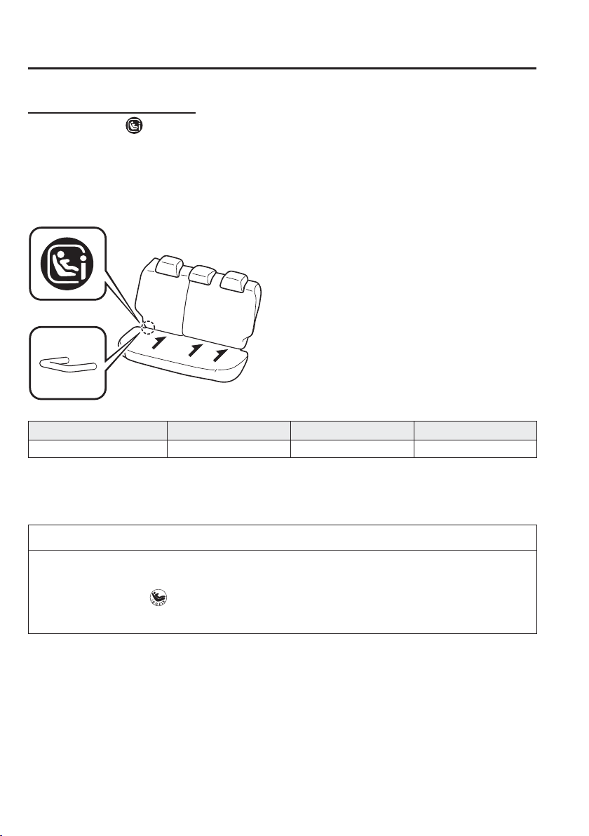
i-Size child-restraint systems
Vehicles with the
mark indicated on the front surface of a rear seatback are i-Size child-
restraint certi¿ ed.
When installing a child-restraint system to the rear seat, refer to the child-restraint system
manufacturer's instructions and the Using ISOFIX Anchor on page 2-38 .
Marking location
An i-Size child-restraint system can be installed to the speci¿ ed seat as follows:
Front passenger seat Rear seat (outboard) Rear seat (centre)
i-Size child-restraint systems X i-U X
Key of letters to be inserted in the above table:
i-U = Suitable for i-Size “universal” child-restraint systems forward and rearward facing.
X = Seating position not suitable for i-Size “universal” child-restraint systems.
NOTE
An i-Size child-restraint system refers to a child-restraint system which has acquired
i-Size category certi¿ cation for the UNECE 129 regulation.
Vehicles with the mark indicated on the front surface of a rear seatback are not
i-Size child-restraint certi¿ ed.
2
–
35
Essential Safety Equipment
Child Restraint
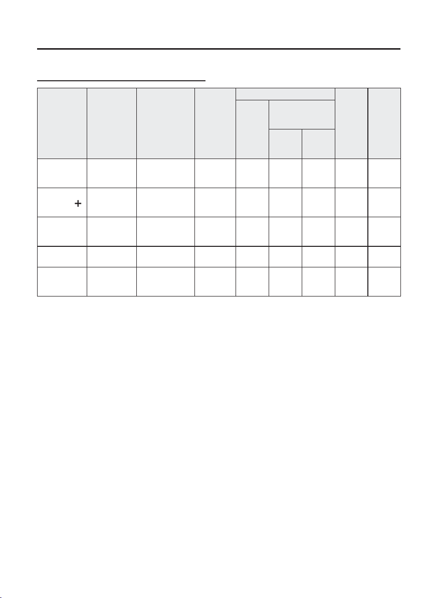
Seat belt-secured child-restraint systems
System
group
Age group Weight group
Child-
restraint
system
type
Front passenger seat
Rear seat
(outboard)
Rear
seat
(centre)
Without
air bag
deactivation
switch
With air bag
deactivation
switch
O N
(Air bag
enabled)
OFF
(Air bag
disabled)
GROUP 0
Up to
approximately
9 months old
Less than 10 kg
(less than 22 lb)
Baby seat X X U U X
GROUP 0
Up to
approximately
2 years old
Less than 13 kg
(less than 29 lb)
Baby seat X X U U X
GROUP 1
Approximately
8 months to 4
years old
9 kg — 18 kg
(20 lb — 40 lb)
Child seat UF UF U U X
GROUP 2
Approximately
3 to 7 years old
15 kg — 25 kg
(33 lb — 55 lb)
Junior seat UF UF U U X
GROUP 3
Approximately
6 to 12 years
old
22 kg — 36 kg
(48 lb — 79 lb)
Junior seat UF UF U U X
Key of letters to be inserted in the above table:
U = Suitable for “universal” category restraints approved for use in this mass group.
UF = Suitable for forward-facing “universal” category restraints approved for use in this mass group.
X = Seat position not suitable for children in this mass group.
(Other countries)
Please comply with the legal regulations concerning the use of child-restraint systems in
your country.
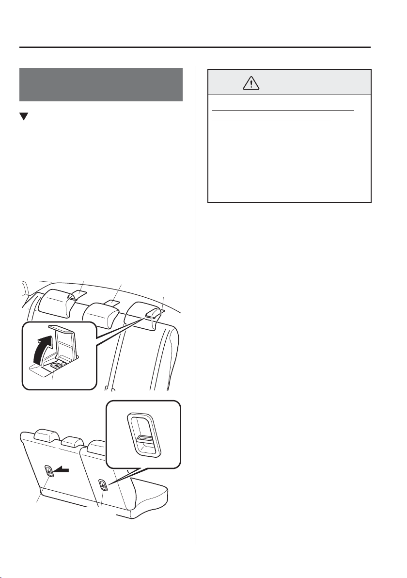
2
–
36
Essential Safety Equipment
Child Restraint
Installing Child-Restraint
Systems
Anchor Bracket
Anchor brackets for securing child-
restraint systems are equipped in the
vehicle. Locate each anchor position using
the illustration.
To install a child-restraint system, remove
the head restraint. Always follow the
instruction manual accompanying the
child-restraint system.
Anchor bracket location
Use the indicated anchor bracket locations
when installing a child-restraint system
equipped with a tether.
Anchor bracket
For right
For left
For centre
(Saloon)
(Hatchback)
For left
For right
WARNING
Always attach the tether strap to the
correct tether anchor position:
Attaching the tether strap to the
incorrect tether anchor position is
dangerous. In a collision, the tether
strap could come off and loosen the
child-restraint system. If the child-
restraint system moves it could result in
death or injury to the child.
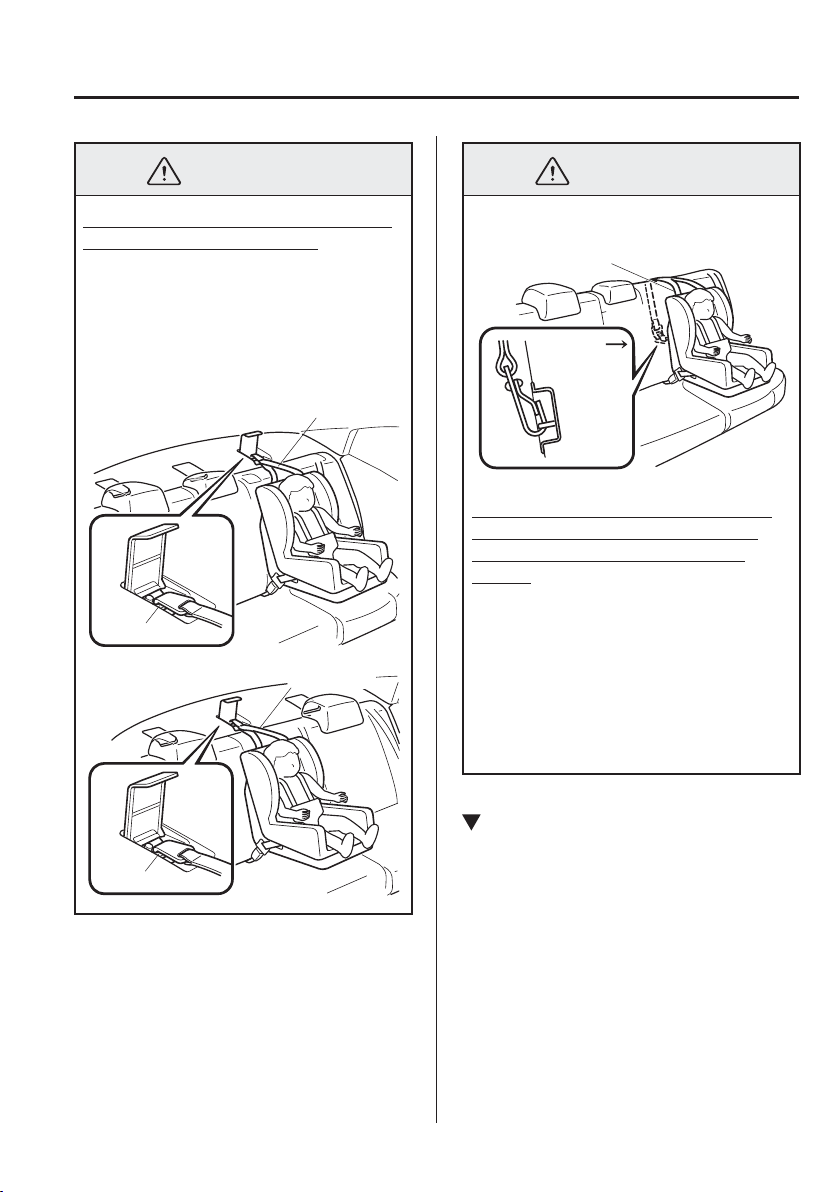
2
–
37
Essential Safety Equipment
Child Restraint
WARNING
Always remove the head restraint and
install child-restraint system:
Installing a child-restraint system
without removing the head restraint is
dangerous. The child-restraint system
cannot be installed correctly which may
result in death or injury to the child in
a collision.
Anchor bracket
Tether strap
(Saloon)
Anchor bracket
Tether strap
WARNING
Tether strap
Forward
(Hatchback)
Always install the head restraint and
adjust it to the appropriate position
after removing the child-restraint
system:
Driving with the head restraint
removed is dangerous as impact to the
occupant's head cannot be prevented
during emergency braking or in a
collision, which could result in a
serious accident, injury or death.
Refer to Head Restraints on page
2-11 .
Using the Seat Belt
When installing a child-restraint system,
follow the installation instructions
included with the product.
In addition, remove the head restraint.
However, when installing a booster seat,
always install the vehicle head restraint to
the seat where the booster seat is installed.
2
–
38
Essential Safety Equipment
Child Restraint
Using ISOFIX Anchor
WARNING
Follow the manufacturer's instructions
for the use of the child-restraint
system:
An unsecured child-restraint system
is dangerous. In a sudden stop or a
collision it could move causing serious
injury or death to the child or other
occupants. Make sure any child-
restraint system is properly secured in
place according to the manufacturer's
instructions.
Make sure the child-restraint system is
properly secured:
A child-restraint system that is not
secured is dangerous. In a sudden stop
or collision, it can become a projectile
and hit someone, causing serious
injury. When not in use, remove it
from the vehicle, put it in the luggage
compartment or at least make sure
it is securely fastened to the ISOFIX
anchors.
WARNING
Make sure there are no seat belts or
foreign objects near or around the
ISOFIX anchor-secured child-restraint
system:
Not following the child-restraint system
manufacturer's instructions when
installing the child-restraint system is
dangerous. If seat belts or a foreign
object prevent the child-restraint
system from being securely attached
to the ISOFIX anchors and the child-
restraint system is installed improperly,
the child-restraint system could move
in a sudden stop or collision causing
serious injury or death to the child or
other occupants. When installing the
child-restraint system, make sure there
are no seat belts or foreign objects
near or around the ISOFIX anchors.
Always follow the child-restraint system
manufacturer's instructions.
1. First, adjust the front seat to allow
clearance between the child-restraint
system and the front seat (page
2-5 ).
2. Make sure the seatback is securely
latched by pushing it back until it is
fully locked.
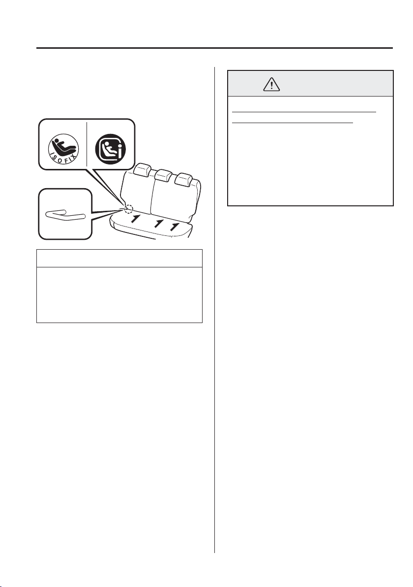
2
–
39
Essential Safety Equipment
Child Restraint
3. Expand the seams on the rear of the
seat bottom slightly to verify the
locations of the ISOFIX anchor.
Type A Type B
NOTE
The markings above the ISOFIX
anchors indicate the locations of the
ISOFIX anchors for the attachment of a
child-restraint system.
4. Remove the head restraint.
Refer to Head Restraints on page
2-11 .
5. Secure the child-restraint system using
the ISOFIX anchor, following the
child-restraint system manufacturer's
instruction.
6. If your child-restraint system came
equipped with a tether, that probably
means it is very important to properly
secure the tether for child safety. Please
carefully follow the child-restraint
system manufacturer's instructions
when installing tethers (page 2-36 ).
WARNING
Always attach the tether strap to the
correct tether anchor position:
Attaching the tether strap to the
incorrect tether anchor position is
dangerous. In a collision, the tether
strap could come off and loosen the
child-restraint system. If the child-
restraint system moves it could result in
death or injury to the child.
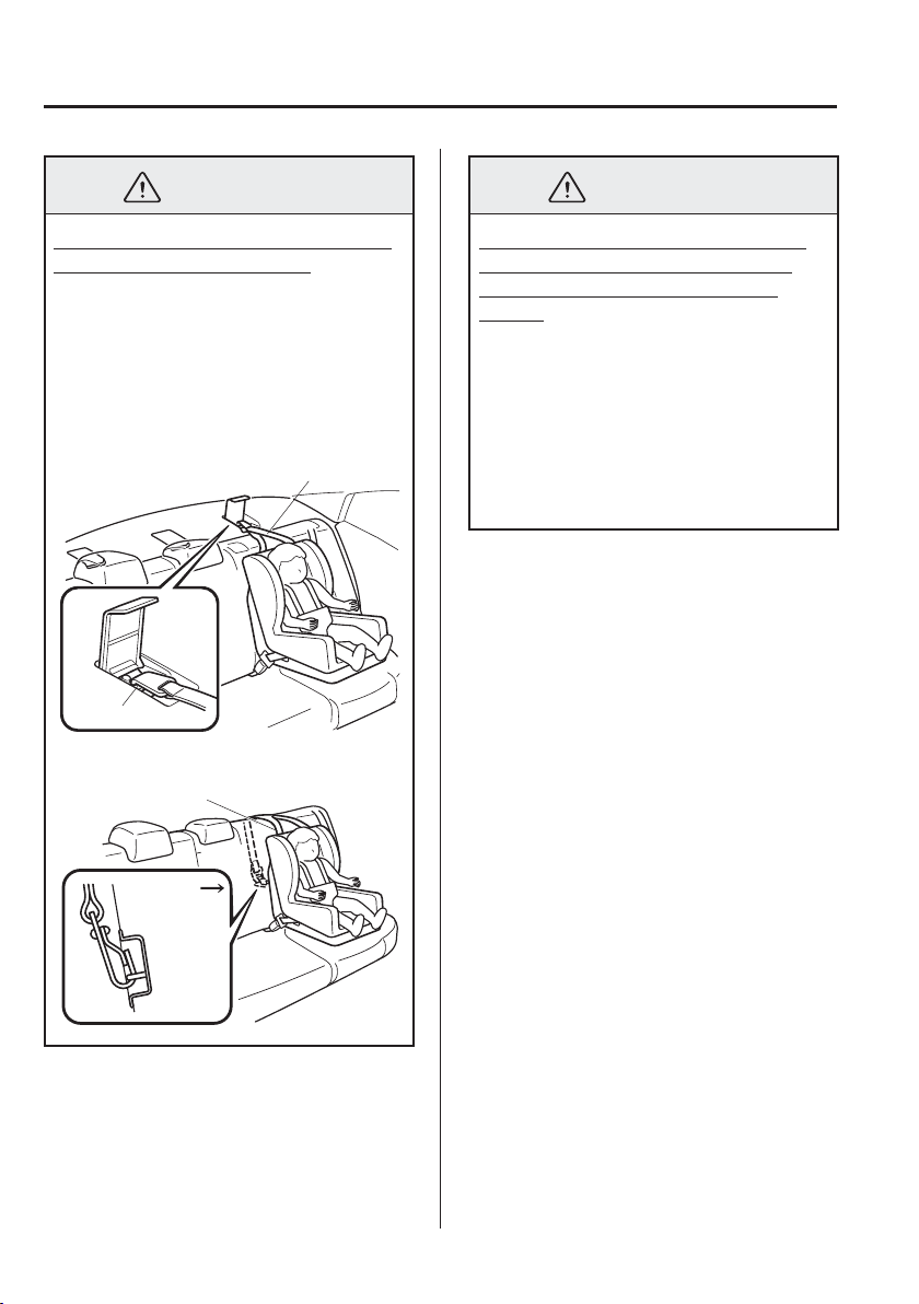
2
–
40
Essential Safety Equipment
Child Restraint
WARNING
Always remove the head restraint and
install child-restraint system:
Installing a child-restraint system
without removing the head restraint is
dangerous. The child-restraint system
cannot be installed correctly which may
result in death or injury to the child in
a collision.
Anchor bracket
Tether strap
(Saloon)
Tether strap
Forward
(Hatchback)
WARNING
Always install the head restraint and
adjust it to the appropriate position
after removing the child-restraint
system:
Driving with the head restraint
removed is dangerous as impact to the
occupant's head cannot be prevented
during emergency braking or in a
collision, which could result in a
serious accident, injury or death.
Refer to Head Restraints on page
2-11 .

2
–
41
Essential Safety Equipment
SRS Air Bags
*Some models.
Supplementary Restraint System (SRS) Precautions
The front and side supplementary restraint systems (SRS) include different types of air bags.
Please verify the different types of air bags which are equipped on your vehicle by
locating the “SRS AIRBAG” location indicators. These indicators are visible in the area
where the air bags are installed.
The air bags are installed in the following locations:
The steering wheel hub (driver air bag)
The front passenger instrument panel (front passenger air bag)
The outboard sides of the front seatbacks (side air bags)
*
The front and rear window pillars, and the roof edge along both sides (curtain air bags)
*
The air bag supplementary restraint systems are designed to provide supplementary
protection in certain situations so seat belts are always important in the following ways:
Without seat belt usage, the air bags cannot provide adequate protection during an accident.
Seat belt usage is necessary to:
Keep the occupant from being thrown into an inÀ ating air bag.
Reduce the possibility of injuries during an accident that is not designed for air bag
inÀ ation, such as roll-over or rear impact.
Reduce the possibility of injuries in frontal, near frontal or side collisions that are not
severe enough to activate the air bags.
Reduce the possibility of being thrown from your vehicle.
Reduce the possibility of injuries to lower body and legs during an accident because the
air bags provide no protection to these parts of the body.
Hold the driver in a position which allows better control of the vehicle.
A child who is too small to use a seat belt must be properly secured using a child-restraint
system (page 2-21 ).
Carefully consider which child-restraint system is necessary for your child and follow
the installation directions in this Owner's Manual as well as the child-restraint system
manufacturer's instructions.
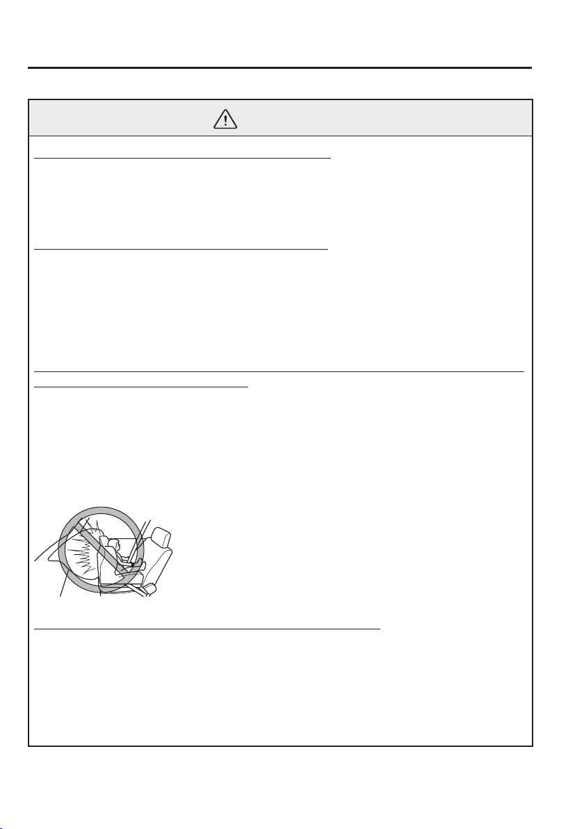
2
–
42
Essential Safety Equipment
SRS Air Bags
WARNING
Seat belts must be worn in air bag equipped vehicles:
Depending only on the air bags for protection during an accident is dangerous. Alone,
air bags may not prevent serious injuries. The appropriate air bags can be expected to
inÀ ate only in the ¿ rst accident, such as frontal, near frontal or side collisions that are
at least moderate. Vehicle occupants should always wear seat belts.
Children should not ride in the front passenger seat:
Placing a child, 12 years or under, in the front seat is dangerous. The child could be hit
by a deploying air bag and be seriously injured or even killed. A sleeping child is more
likely to lean against the door and be hit by the side air bag in moderate collision to the
front-passenger side of the vehicle. Whenever possible, always secure a child 12 years
and under on the rear seats with an appropriate child-restraint system for the child's
age and size.
Extreme Hazard! Never use a rear-facing child-restraint system on the front passenger
seat with an air bag that could deploy:
NEVER use a rearward facing child restraint on a seat protected by an ACTIVE
AIRBAG in front of it, DEATH or SERIOUS INJURY to the CHILD can occur.
Even in a moderate collision, the child-restraint system can be hit by a deploying air
bag and moved violently backward resulting in serious injury or death to the child. If
your vehicle is equipped with a front passenger air bag deactivation switch, always set
the switch to the OFF position when installing a rear-facing child-restraint system on
the front passenger seat.
Do not sit too close to the driver and front passenger air bags:
Sitting too close to the driver and front passenger air bag modules or placing hands or
feet on them is extremely dangerous. The driver and front passenger air bags inÀ ate
with great force and speed. Serious injuries could occur if someone is too close. The
driver should always hold onto only the rim of the steering wheel. The front seat
passenger should keep both feet on the À oor. Front seat occupants should adjust their
seats as far back as possible and always sit upright against the seatbacks with seat belts
worn properly.
2
–
43
Essential Safety Equipment
SRS Air Bags
WARNING
Sit in the centre of the seat and wear seat belts properly:
Sitting too close to the side air bag modules or placing hands on them, or sleeping up
against the door or hanging out the windows is extremely dangerous. The side and
curtain air bags inÀ ate with great force and speed directly expanding along the door on
the side the car is hit. Serious injury could occur if someone is sitting too close to the
door or leaning against a window, or if rear seat occupants grab the sides of the front
seatbacks. Give the side and curtain air bags room to work by sitting in the centre of the
seat while the vehicle is moving with seat belts worn properly.
Do not attach objects on or around the area where driver and front passenger air bags
deploy:
Attaching an object to the driver and front passenger air bag modules or placing
something in front of them is dangerous. In an accident, an object could interfere with
air bag inÀ ation and injure the occupants.
Do not attach objects on or around the area where a side air bag deploys:
Attaching objects to the front seat in such a way as to cover the outboard side of the seat
in any way is dangerous. In an accident the object could interfere with the side air bag,
which inÀ ates from the outboard side of the front seats, impeding the added protection
of the side air bag system or redirecting the air bag in a way that is dangerous.
Furthermore, the bag could be cut open releasing the gas.
Do not hang net bags, map pouches or backpacks with side straps on the front seats.
Never use seat covers on the front seats. Always keep the side air bag modules in your
front seats free to deploy in the event of a side collision.
Do not attach objects on or around the area where a curtain air bag deploys:
Attaching objects to the areas where the curtain air bag activates such as on the
windscreen glass, side door glass, front and rear window pillars and along the roof edge
and assist grips is dangerous. In an accident the object could interfere with the curtain
air bag, which inÀ ates from the front and rear window pillars and along the roof edge,
impeding the added protection of the curtain air bag system or redirecting the air bag in
a way that is dangerous. Furthermore, the bag could be cut open releasing the gas.
Do not place hangers or any other objects on the assist grips. When hanging clothes,
hang them on the coat hook directly. Always keep the curtain air bag modules free to
deploy in the event of a side collision.
Do not touch the components of the supplementary restraint system after the air bags
have inÀ ated:
Touching the components of the supplementary restraint system after the air bags have
inÀ ated is dangerous. Immediately after inÀ ation, they are very hot. You could get
burned.
2
–
44
Essential Safety Equipment
SRS Air Bags
WARNING
Never install any front-end equipment to your vehicle:
Installation of front-end equipment, such as frontal protection bar (kangaroo bar,
bull bar, push bar, or other similar devices), snowplow, or winches, is dangerous. The
air bag crash sensor system could be affected. This could cause air bags to inÀ ate
unexpectedly, or it could prevent the air bags from inÀ ating during an accident. Front
occupants could be seriously injured.
Do not modify the suspension:
Modifying the vehicle suspension is dangerous. If the vehicle's height or the suspension
is modi¿ ed, the vehicle will be unable to accurately detect a collision resulting in
incorrect or unexpected air bag deployment and the possibility of serious injuries.
Do not modify a front door or leave any damage unrepaired. Always have an expert
repairer, we recommend an Authorised Mazda Repairer inspect a damaged front door:
Modifying a front door or leaving any damage unrepaired is dangerous. Each front
door has a side crash sensor as a component of the supplementary restraint system.
If holes are drilled in a front door, a door speaker is left removed, or a damaged door
is left unrepaired, the sensor could be adversely affected causing it to not detect the
pressure of an impact correctly during a side collision. If a sensor does not detect a side
impact correctly, the side and curtain air bags and the front seat belt pretensioner may
not operate normally which could result in serious injury to occupants.
Do not modify the supplementary restraint system:
Modifying the components or wiring of the supplementary restraint system is
dangerous. You could accidentally activate it or make it inoperable. Do not make any
modi¿ cations to the supplementary restraint system. This includes installing trim,
badges, or anything else over the air bag modules. It also includes installing extra
electrical equipment on or near system components or wiring. An expert repairer, we
recommend an Authorised Mazda Repairer can provide the special care needed in the
removal and installation of front seats. It is important to protect the air bag wiring
and connections to assure that the bags do not accidentally deploy, and that the driver
seat slide position sensor is not damaged and the seats retain an undamaged air bag
connection.
Do not place luggage or other objects under the front seats:
Placing luggage or other objects under the front seats is dangerous. The components
essential to the supplementary restraint system could be damaged, and in the event of
a side collision, the appropriate air bags may not deploy, which could result in death
or serious injury. To prevent damage to the components essential to the supplementary
restraint system, do not place luggage or other objects under the front seats.
2
–
45
Essential Safety Equipment
SRS Air Bags
WARNING
Do not operate a vehicle with damaged air bag/seat belt pretensioner system
components:
Expended or damaged air bag/seat belt pretensioner system components must be
replaced after any collision which caused them to deploy or damage them. Only a
trained expert repairer, we recommend an Authorised Mazda Repairer can fully
evaluate these systems to see that they will work in any subsequent accident. Driving
with an expended or damaged air bag or pretensioner unit will not afford you the
necessary protection in the event of any subsequent accident which could result in
serious injury or death.
Do not remove interior air bag parts:
Removing any components such as the front seats, front instrument panel, the steering
wheel or parts on the front and rear window pillars and along the roof edge, containing
air bag parts or sensors is dangerous. These parts contain essential air bag components.
The air bag could accidentally activate and cause serious injuries. Always have an
Authorised Mazda Repairer remove these parts.
Properly dispose of the air bag system:
Improper disposal of an air bag or a vehicle with live air bags in it can be extremely
dangerous. Unless all safety procedures are followed, injury could result. Have an
expert repairer, we recommend an Authorised Mazda Repairer safely dispose of the air
bag system or scrap an air bag equipped vehicle.
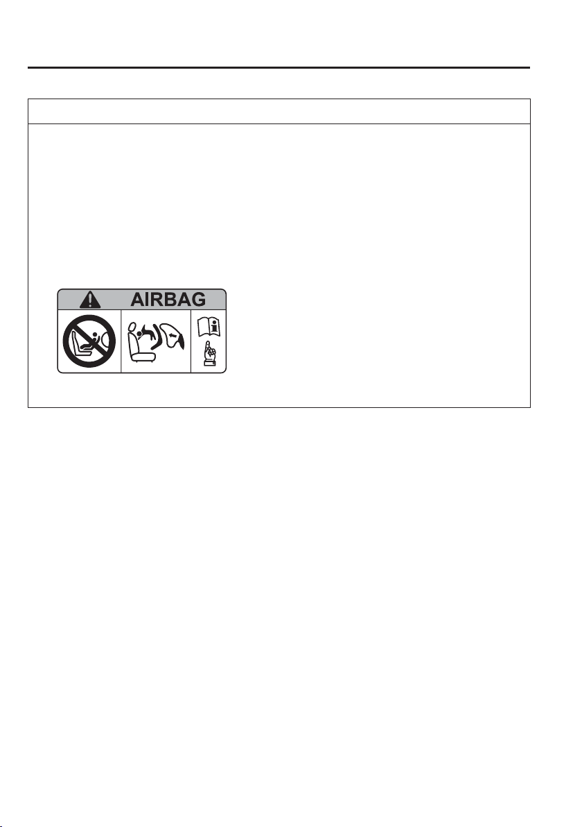
2
–
46
Essential Safety Equipment
SRS Air Bags
NOTE
When an air bag deploys, a loud inÀ ation noise can be heard and some smoke will
be released. Neither is likely to cause injury, however, the texture of the air bags may
cause light skin injuries on body parts not covered with clothing through friction.
Should you sell your Mazda, we urge you to tell the new owner of its air bag systems
and that familiarization with all instructions about them, from the Owner's Manual, is
important.
This highly-visible label warns against the use of a rear-facing child-restraint system
on the front passenger seat.
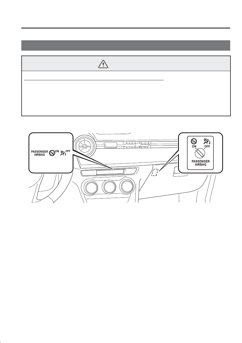
2
–
47
Essential Safety Equipment
SRS Air Bags
*Some models.
Front Passenger Air Bag Deactivation Switch
*
WARNING
Do not deactivate the front passenger air bag unnecessarily:
Unnecessary deactivation of the front passenger air bag is dangerous. If turned off
unnecessarily, the front passenger will not receive the added protection of the air bag.
Serious injuries or even death could occur. With the exception of installing a child-
restraint system on the front passenger seat, do not turn the air bag deactivation switch
to the OFF position.
The front passenger air bag deactivation switch should be used to deactivate the front
passenger front and side air bags and also the front passenger seat belt pretensioner system
if installing a child-restraint system on the front passenger seat.
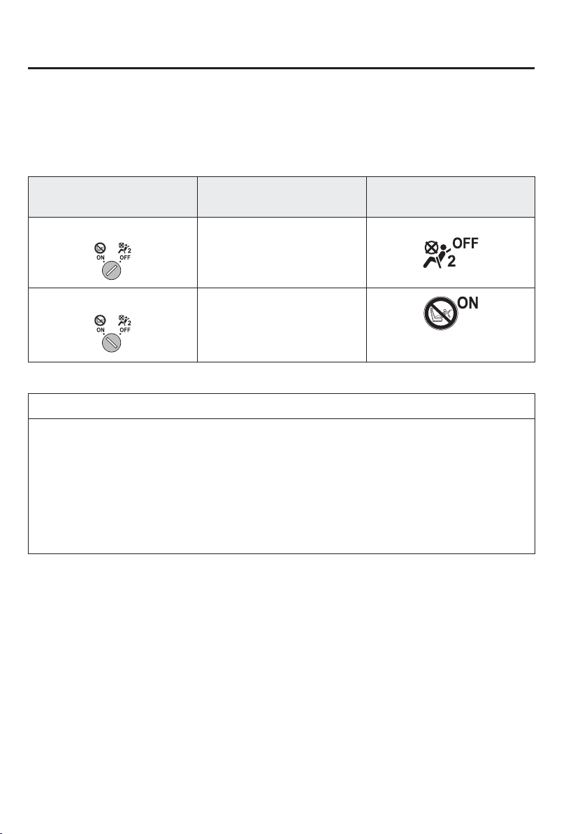
2
–
48
Essential Safety Equipment
SRS Air Bags
When the ignition is switched ON, both front passenger air bag deactivation indicator
lights illuminate regardless of the front passenger air bag deactivation switch position. The
indicator light turns off after a speci¿ ed period of time, then turns on/off depending on the
conditions as indicated in the following table.
Front Passenger Air Bag
Deactivation Switch
Front Passenger Seat/Side Air
Bag, Front Passenger Seat Belt
Pretensioner Operation Condition
Front Passenger Air Bag
Deactivation Indicator Light
OFF position
Deactivate
ON position
Ready
Turns off after a short period of
time.
NOTE
Have the front passenger air bag deactivation switch inspected by an expert repairer, we
recommend an Authorised Mazda Repairer if any of these conditions occur:
The front passenger air bag deactivation indicator light does not illuminate for a
speci¿ ed period of time when the ignition is switched ON.
The front passenger air bag deactivation indicator light does not turn off after a short
period of time when the ignition is switched ON (front passenger air bag deactivation
switch is in ON position).
2
–
49
Essential Safety Equipment
SRS Air Bags
Switch Positions
Before driving, always con¿ rm that the front passenger air bag deactivation switch is in the
appropriate position using the auxiliary key according to your requirements.
WARNING
Do not leave the key in the front passenger air bag deactivation switch:
Unintentional deactivation of the front passenger air bag is dangerous. In an accident,
the front passenger will not be properly protected. Serious injuries or even death
could occur. To avoid unintentional deactivation, always use the auxiliary key stored
in the transmitter body currently being used to operate the front passenger air bag
deactivation switch. After deactivating the air bag, put the auxiliary key back into the
transmitter body. That way you will not leave the key in the front passenger air bag
deactivation switch.
NOTE
After operating the front passenger air bag deactivation switch, put the auxiliary key back
into the transmitter body.
OFF
Front passenger front air bag, side air bag, and front passenger seat belt pretensioner do not
operate.
Switching to OFF position
1. Insert the key into the front passenger air bag deactivation switch and turn the key
clockwise until the key points to OFF.
2. Remove the key.
3. Make sure the air bag deactivation indicator light remains illuminated when the ignition
is switched ON.
The front passenger front and side air bags and also the seat belt pretensioner system will
remain deactivated until the front passenger air bag deactivation switch is turned to the ON
position.

2
–
50
Essential Safety Equipment
SRS Air Bags
O N
Front passenger front air bag, side air bag, and front passenger seat belt pretensioner
operate. Activate the system only when a child-restraint system is not installed on the front
passenger seat.
Switching to ON position
1. Insert the key into the front passenger air bag deactivation switch and turn the key
anticlockwise until the key points to ON.
2. Remove the key.
3. Make sure the air bag deactivation indicator light remains illuminated when the ignition
is switched ON. The air bag deactivation indicator light turns off after a short period of
time.
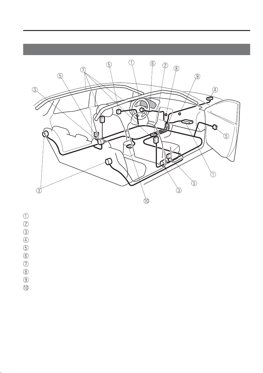
2
–
51
Essential Safety Equipment
SRS Air Bags
*Some models.
Supplementary Restraint System Components
*
*
Some models
Driver/Front passenger inÀ ators and air bags
Crash sensors, and diagnostic module (SAS unit)
Seat belt pretensioners (page 2-18 )
Front air bag sensor
Side crash sensors
*
Air bag/seat belt pretensioner system warning light (page 4-38 )
Side and curtain inÀ ators and air bags
*
Front passenger air bag deactivation indicator light
*
(page 2-47 )
Front passenger air bag deactivation switch
*
(page 2-47 )
Driver seat slide position sensor
*
(page 2-52 )

2
–
52
Essential Safety Equipment
SRS Air Bags
*Some models.
How the SRS Air Bags Work
Your Mazda is equipped with the following types of SRS air bags. SRS air bags are
designed to work together with the seat belts to help to reduce injuries during an accident.
The SRS air bags are designed to provide further protection for passengers in addition to the
seat belt functions. Be sure to wear seat belts properly.
Seat Belt Pretensioners
The pretensioners operate differently depending on what types of air bags are equipped. For
more details about seat belt pretensioner operation, refer to the SRS Air Bag Deployment
Criteria (page 2-56 ).
Front
The front seat belt pretensioners are designed to deploy in moderate or severe frontal, near
frontal collisions. In addition, during a side collision, the pretensioner operates on the side in
which the collision occurs.
Rear Outboard
*
The rear outboard seat belt pretensioners are designed to deploy in moderate or severe
frontal, near frontal collisions.
Driver Air Bag
The driver's air bag is mounted in the steering wheel.
When air bag crash sensors detect a frontal impact of greater than moderate force, the
driver's air bag inÀ ates quickly helping to reduce injury mainly to the driver's head or chest
caused by directly hitting the steering wheel.
For more details about air bag deployment, refer to "SRS Air Bag Deployment Criteria"
(page 2-56 ).
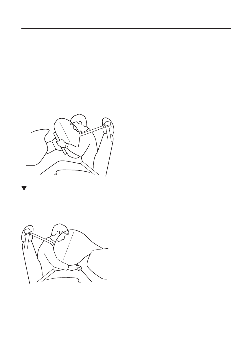
2
–
53
Essential Safety Equipment
SRS Air Bags
(With Front Passenger Air Bag Deactivation Switch)
The inÀ ation of the driver's dual-stage air bag is controlled in two energy stages depending
on the driver's seat position. The driver's seat slide position sensor is located under the
driver's seat. The sensor determines whether the driver's seat is forward of or behind a
reference position and sends the seat position to the diagnostic module (SAS unit). The SAS
unit is designed to control the deployment of the driver's air bag depending on how close the
driver's seat is to the steering wheel.
During an impact of moderate severity, the driver's air bag deploys with lesser energy,
whereas during more severe impacts and when the driver's seat is behind the reference
position, it deploys with more energy.
Front Passenger Air Bag
The front passenger air bag is mounted in the front passenger instrument panel.
The inÀ ation mechanism for the front passenger air bag is the same as the driver's air bag.
For more details about air bag deployment, refer to "SRS Air Bag Deployment Criteria"
(page 2-56 ).
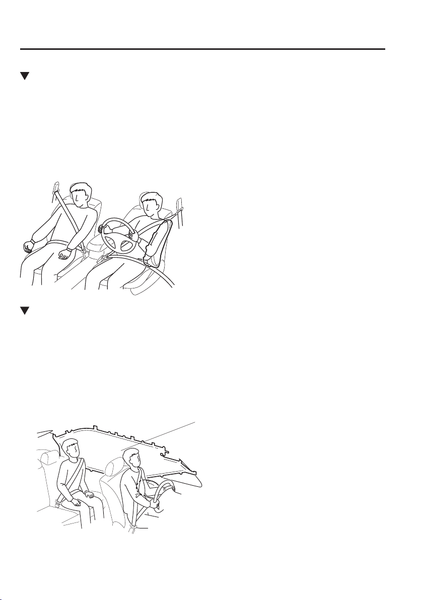
2
–
54
Essential Safety Equipment
SRS Air Bags
*Some models.
Side Air Bags
*
The side air bags are mounted in the outboard sides of the front seatbacks.
When the air bag crash sensors detect a side impact of greater than moderate force, the
system inÀ ates the side air bag only on the side in which the vehicle was hit. The side
air bag inÀ ates quickly to reduce injury to the driver or front passenger's chest caused by
directly hitting interior parts such as a door or window.
For more details about air bag deployment, refer to "SRS Air Bag Deployment Criteria"
(page 2-56 ).
Curtain Air Bags
*
The curtain air bags are mounted in the front and rear window pillars, and the roof edge
along both sides.
When the air bag crash sensors detect a side impact of greater than moderate force, the
curtain air bag inÀ ates quickly and helps to reduce injury mainly to the rear outboard
passenger's head caused by directly hitting interior parts such as a door or window.
For more details about air bag deployment, refer to "SRS Air Bag Deployment Criteria"
(page 2-56 ).
Only one side curtain air bag will deploy on the
side of the vehicle that receives the force of an
impact.

2
–
55
Essential Safety Equipment
SRS Air Bags
Warning Light/Beep
A system malfunction or operation conditions are indicated by a warning.
Refer to Warning/Indicator Lights on page 4-38 .
Refer to Warning Sound is Activated on page 7-50 .
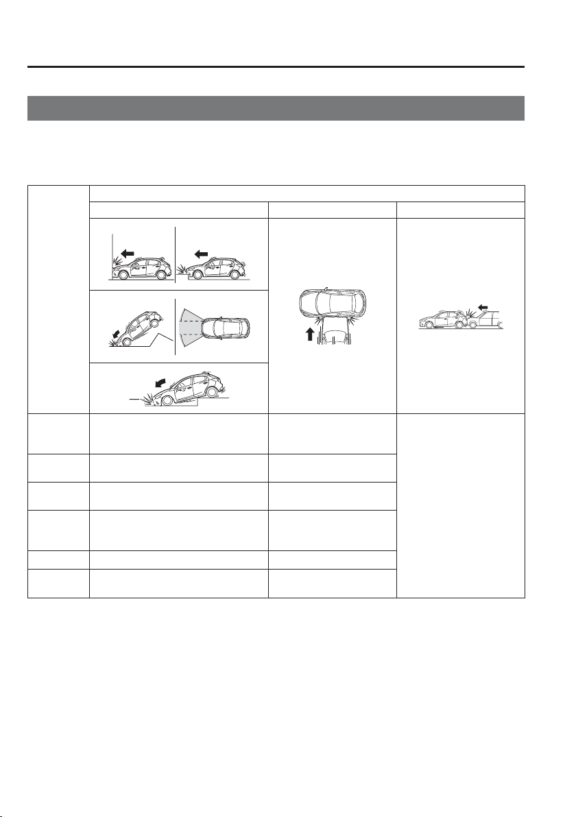
2
–
56
Essential Safety Equipment
SRS Air Bags
*Some models.
SRS Air Bag Deployment Criteria
This chart indicates the applicable SRS equipment that will deploy depending on the type of
collision.
(The illustrations are the representative cases of collisions.)
SRS
equipment
Types of collision
A severe frontal/near frontal collision A severe side collision
*2
A rear collision
Front
seat belt
pretensioner
X
*1
(both sides) X
*1
(impact side only)
No air bag and seat belt
pretensioner will be
activated in a rear collision.
Rear seat belt
pretensioner
*
X (both sides)
Driver air
bag
X
Front
passenger
air bag
X
*1
Side air bag
*
X
*1
(impact side only)
Curtain air
bag
*
X (impact side only)
X : The SRS air bag equipment is designed to deploy in a collision.
*1 (With Front Passenger Air Bag Deactivation Switch)
The front passenger front and side air bags and the front seat belt pretensioner are designed to deploy depending
on the status of the front passenger air bag deactivation switch.
*2 (With Side/Curtain Air Bags)
In a side collision, the front seat belt pretensioners and the side/curtain air bags deploy (only on the side in
which the collision occurs).

2
–
57
Essential Safety Equipment
SRS Air Bags
NOTE
In a frontal offset collision, the equipped air bags and pretensioners may all deploy
depending on the direction, angle, and rate of impact.
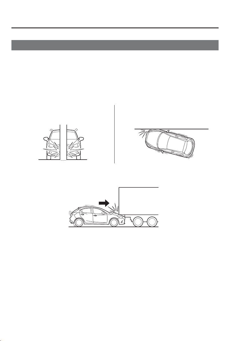
2
–
58
Essential Safety Equipment
SRS Air Bags
Limitations to SRS Air Bag
In severe collisions such as those described previously in "SRS Air Bag Deployment
Criteria", the applicable SRS air bag equipment will deploy. However, in some accidents,
the equipment may not deploy depending on the type of collision and its severity.
Limitations to front/near front collision detection:
The following illustrations are examples of front/near front collisions that may not be
detected as severe enough to deploy the SRS air bag equipment.
Impacts involving trees or poles
Frontal offset impact to the vehicle
Rear-ending or running under a truck's tail gate
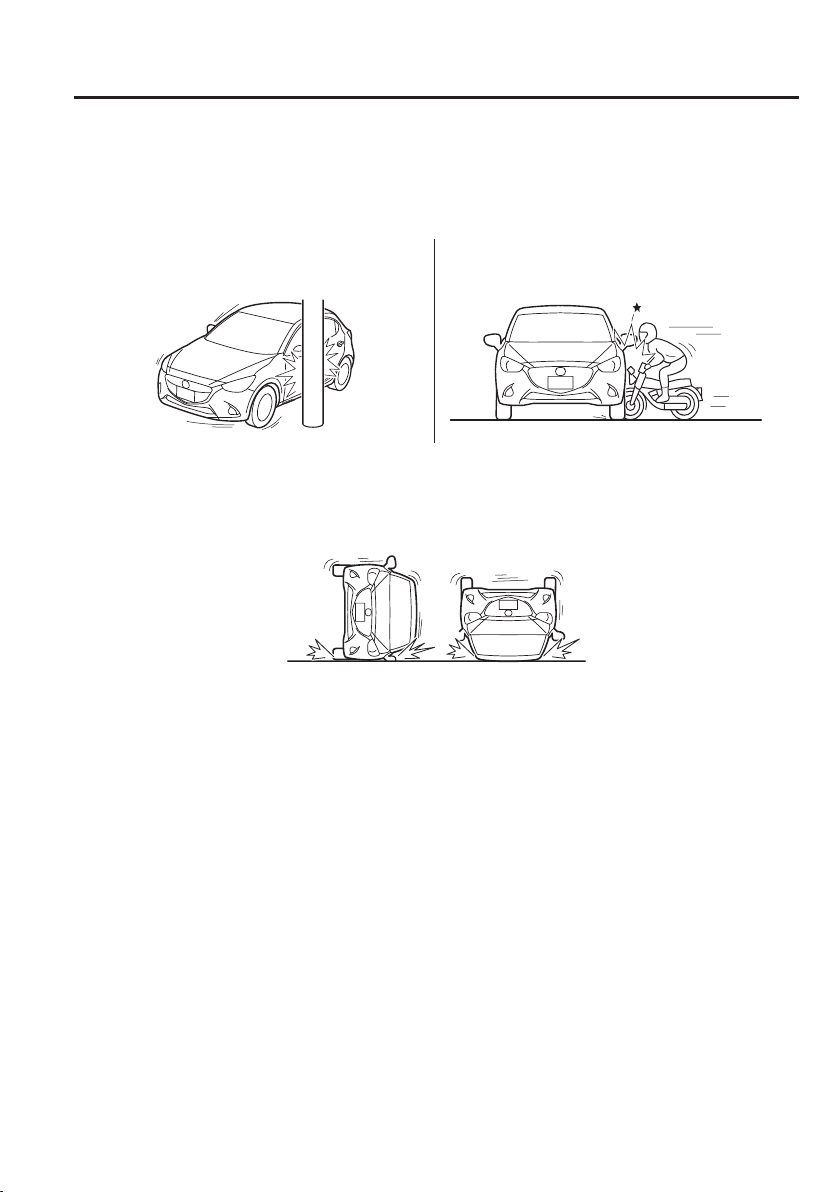
2
–
59
Essential Safety Equipment
SRS Air Bags
Limitations to side collision detection:
The following illustrations are examples of side collisions that may not be detected as severe
enough to deploy the SRS air bag equipment.
Side impacts involving trees or poles
Side impacts with two-wheeled vehicles
Roll-over

MEMO
2
–
60

3
–
1
*Some models.
3
–
1
3
Before Driving
Use of various features, including keys, doors, mirrors and windows.
Keys ...................................................... 3-2
Keys ............................................... 3-2
Keyless Entry System .................... 3-3
Advanced Keyless Entry System ....... 3-9
Advanced Keyless Entry
System
*
........................................... 3-9
Operational Range ....................... 3-10
Doors and Locks ................................ 3-11
Door Locks ................................... 3-11
Liftgate/Boot Lid ......................... 3-21
Fuel and Emission ............................. 3-26
Fuel and Engine Exhaust
Precautions ................................... 3-26
Fuel-Filler Flap and Cap .............. 3-31
Steering Wheel................................... 3-33
Steering Wheel ............................. 3-33
Mirrors ............................................... 3-34
Mirrors ......................................... 3-34
Windows ............................................. 3-38
Power Windows ........................... 3-38
Manual Windows
*
........................ 3-41
Security System ................................. 3-42
Modi¿ cation and Add-On
Equipment .................................... 3-42
Immobilizer System ..................... 3-42
Theft-Deterrent System
*
............... 3-44
Driving Tips ....................................... 3-48
Running-In ................................... 3-48
Saving Fuel and Protection of the
Environment ................................. 3-48
Hazardous Driving ....................... 3-49
Floor Mat ..................................... 3-50
Rocking the Vehicle ..................... 3-51
Winter Driving ............................. 3-51
Driving In Flooded Area .............. 3-54
Turbocharger Information
(SKYACTIV-D 1.5) ..................... 3-55
Towing ................................................ 3-56
Towing Caravans and Trailers
(Europe/Turkey/South Africa) ..... 3-56
3
–
2
Before Driving
Keys
K e y s
WARNING
Do not leave the key in your vehicle
with children and keep them in a place
where your children will not ¿ nd or
play with them:
Leaving children in a vehicle with the
key is dangerous. This could result in
someone being badly injured or even
killed. Children may ¿ nd these keys
to be an interesting toy to play with
and could cause the power windows or
other controls to operate, or even make
the vehicle move.
CAUTION
Because the key (transmitter) uses
low-intensity radio waves, it may
not function correctly under the
following conditions:
The key is carried with
communication devices such as
cellular phones.
The key contacts or is covered by a
metal object.
The key is near electronic devices
such as personal computers.
Non-Mazda genuine electronic
equipment is installed in the
vehicle.
There is equipment which
discharges radio waves near the
vehicle.
The key (transmitter) may consume
battery power excessively if it
receives high-intensity radio waves.
Do not place the key near electronic
devices such as televisions or
personal computers.
To avoid damage to the key
(transmitter), DO NOT:
Drop the key.
Get the key wet.
Disassemble the key.
Expose the key to high
temperatures on places such as the
instrument panel or bonnet, under
direct sunlight.
Expose the key to any kind of
magnetic ¿ eld.
Place heavy objects on the key.
Put the key in an ultrasonic
cleaner.
Put any magnetized objects close
to the key.
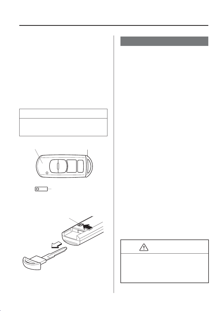
3
–
3
Before Driving
Keys
A code number is stamped on the plate
attached to the key set; detach this plate
and store it in a safe place (not in the
vehicle) for use if you need to make a
replacement key (auxiliary key).
Also write down the code number and
keep it in a separate safe and convenient
place, but not in the vehicle.
If your key (auxiliary key) is lost, consult
your Authorised Mazda Repairer and have
your code number ready.
NOTE
The driver must carry the key to ensure
the system functions properly.
Auxiliary keyTransmitter
Key code number plate
To use the auxiliary key, pull out the
auxiliary key from the transmitter while
pressing the knob.
Knob
Keyless Entry System
This system uses the key buttons to
remotely lock and unlock the doors and
the liftgate/boot lid, and opens the boot lid.
The system can start the engine without
having to take the key out of your purse or
pocket.
Operating the theft-deterrent system is
also possible on theft-deterrent system-
equipped vehicles.
System malfunctions or warnings are
indicated by the following warning lights
or beeps.
KEY Warning Light (Red)
Refer to Warning/Indicator Lights on
page 4-38 .
Ignition Not Switched Off (STOP)
Warning Beep
Refer to Ignition Not Switched Off
(STOP) Warning Beep on page 7-51 .
Key Removed from Vehicle Warning
Beep
Refer to Key Removed from Vehicle
Warning Beep on page 7-51 .
If you have a problem with the key,
consult an expert repairer, we recommend
an Authorised Mazda Repairer.
If your key is lost or stolen, consult an
Authorised Mazda Repairer as soon as
possible for a replacement and to make the
lost or stolen key inoperative.
CAUTION
Changes or modi¿ cations not expressly
approved by the party responsible
for compliance could void the user's
authority to operate the equipment.
3
–
4
Before Driving
Keys
NOTE
The keyless entry system operation
may vary due to local conditions.
The keyless entry system is fully
operational (door/liftgate/boot lid
lock/unlock) when the ignition is
switched off. The system does not
operate if the ignition is switched to
any position other than off.
If the key does not operate when
pressing a button or the operational
range becomes too small, the
battery may be weak. To install a
new battery, refer to Key Battery
Replacement (page 6-41 ).
Battery life is about one year.
Replace the battery with a new one
if the KEY indicator light (green)
À ashes in the instrument cluster.
Replacing the battery about once
a year is recommended because
the KEY warning light/indicator
light may not illuminate or À ash
depending on the rate of battery
depletion.
Additional keys can be obtained at
an Authorised Mazda Repairer. Up to
6 keys can be used with the keyless
functions per vehicle. Bring all keys
to an Authorised Mazda Repairer
when additional keys are required.
Transmitter
Operation buttons
Operation indicator light
NOTE
(European models)
The headlights turn on/off by
operating the transmitter. Refer
to Leaving Home Light on page
4-67 .
(With theft-deterrent system)
The hazard warning lights À ash when
the theft-deterrent system is armed or
turned off.
Refer to Theft-Deterrent System on
page 3-44 .
(With the advanced keyless
function (European models))
The setting can be changed so that a
beep sound is heard for con¿ rmation
when the doors and the liftgate/boot
lid are locked/unlocked using the
key.
(With the advanced keyless
function (Except European
models))
A beep sound can be heard for
con¿ rmation when the doors and the
liftgate/boot lid are locked/unlocked
using the key. If you prefer, the beep
sound can be turned off.
The volume of the beep sound can
also be changed.
Refer to Personalisation Features on
page 9-13 .
3
–
5
Before Driving
Keys
NOTE
Use the following procedure to
change the setting.
1. Switch the ignition off and close
all of the doors and the liftgate/
boot lid.
2. Open the driver's door.
3. Within 30 seconds of opening the
driver's door, press and hold the
LOCK button on the key for 5
seconds or longer.
All of the doors and the liftgate/
boot lid lock and the beep sound
activates at the currently set
volume. The setting changes each
time the LOCK button on the key
is pressed and the beep sound
activates at the set volume. (If the
beep sound has been set to not
activate, it will not activate.)
4. The setting change is completed
by doing any one of the following:
Switching the ignition to ACC
or ON.
Closing the driver's door.
Opening the liftgate/boot lid.
Not operating the key for 10
seconds.
Pressing any button except the
LOCK button on the key.
Pressing a request switch.
The operation indicator light À ashes when
the buttons are pressed.
Lock button
To lock the doors and the liftgate/boot
lid, press the lock button and the hazard
warning lights will À ash once.
(With the advanced keyless function
(Except European models))
A beep sound will be heard once.
3
–
6
Before Driving
Keys
NOTE
(European models)
The doors and the liftgate/boot lid
cannot be locked by pressing the lock
button while any other door is open.
The hazard warning lights will also
not À ash.
(Except European models)
The doors and the liftgate/boot lid
cannot be locked by pressing the lock
button while any other door or the
liftgate is open. The hazard warning
lights will also not À ash.
(With the i-stop function
(European models))
Removing the key from the vehicle,
closing all the doors and pressing the
LOCK button on the key while the
i-stop function is operating (engine
is stopped) will switch the ignition
OFF and lock all the doors (Steering
wheel also locks).
Refer to i-stop on page 4-13 .
Make sure all doors and the liftgate/
boot lid are locked after pressing the
button.
(With double locking system)
Pressing the lock button twice within
3 seconds will activate the double
locking system.
Refer to Double Locking System on
page 3-13 .
(With theft-deterrent system)
When the doors are locked by
pressing the lock button on the key
while the theft-deterrent system is
armed, the hazard warning lights will
À ash once to indicate that the system
is armed.
Unlock button
To unlock the doors and the liftgate/boot
lid, press the unlock button and the hazard
warning lights will À ash twice.
(With the advanced keyless function
(Except European models))
A beep sound will be heard twice.
NOTE
(Auto re-lock function)
After unlocking with the key, all
doors and the liftgate/boot lid
will automatically lock if any of
the following operations are not
performed within about 30 seconds.
If your vehicle has a theft-deterrent
system, the hazard warning lights
will À ash for con¿ rmation.
The time required for the doors to
lock automatically can be changed.
Refer to Personalisation Features on
page 9-13 .
A door or the liftgate/boot lid is
opened.
The ignition is switched to any
position other than off.
(With theft-deterrent system)
When the doors are unlocked by
pressing the unlock button on the key
while the theft-deterrent system is
turned off, the hazard warning lights
will À ash twice to indicate that the
system is turned off.
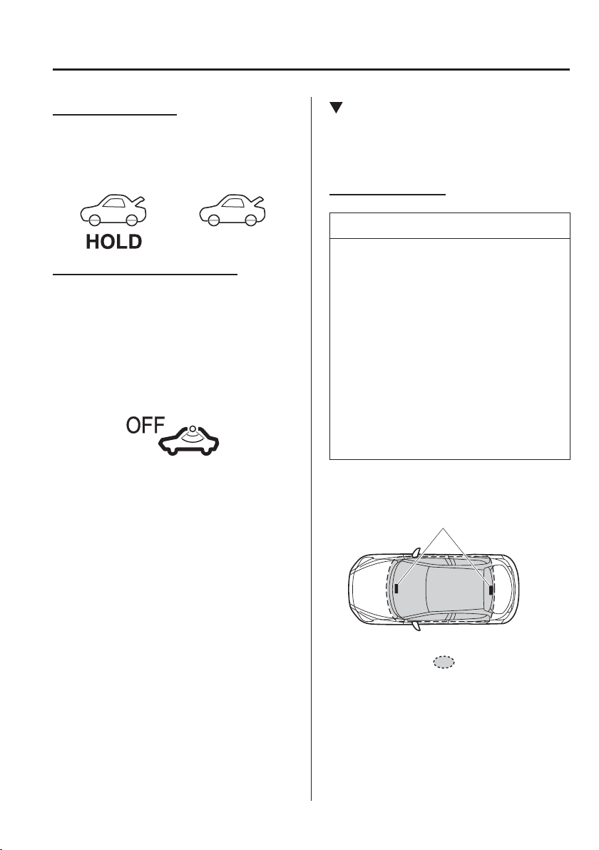
3
–
7
Before Driving
Keys
*Some models.
Boot button (Saloon)
To open the boot lid, press and hold the
boot button until the boot lid opens.
Type A Type B
Intrusion sensor cancel button
*
To cancel the intrusion sensor (part of
the theft-deterrent system), press the
intrusion sensor cancel button within 20
seconds after pressing the lock button and
the hazard warning lights will À ash three
times.
Refer to Theft-Deterrent System on page
3-44 .
Operational Range
The system operates only when the driver
is in the vehicle or within operational
range while the key is being carried.
Starting the Engine
NOTE
Starting the engine may be possible
even if the key is outside of the
vehicle and extremely close to a door
and window, however, always start
the engine from the driver's seat.
If the vehicle is started and the key
is not in the vehicle, the vehicle will
not restart after it is shut off and the
ignition is switched to off.
The luggage compartment/boot is
out of the assured operational range,
however, if the key (transmitter) is
operable the engine will start.
With the advanced keyless function
Interior aerial
Operational range
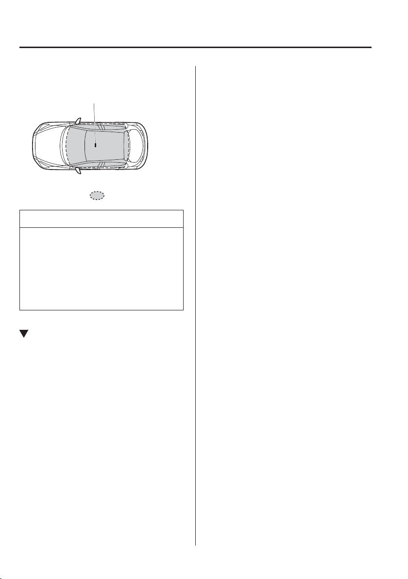
3
–
8
Before Driving
Keys
Without the advanced keyless function
Interior aerial
Operational range
NOTE
The engine may not start if the key is
placed in the following areas:
Around the instrument panel
In the storage compartments or the
centre console
On the rear parcel shelf (saloon)
Key Suspend Function
If a key is left in the vehicle, the
functions of the key left in the vehicle are
temporarily suspended to prevent theft of
the vehicle.
To restore the functions, press the unlock
button on the functions-suspended key in
the vehicle.

3
–
9
Before Driving
Advanced Keyless Entry System
*Some models.
Advanced Keyless Entry
System
*
WARNING
Radio waves from the key may affect
medical devices such as pacemakers:
Before using the key near people who
use medical devices, ask the medical
device manufacturer or your physician
if radio waves from the key will affect
the device.
The advanced keyless function allows you
to lock/unlock the door and the liftgate/
boot lid, or open the liftgate/boot lid while
carrying the key.
System malfunctions or warnings are
indicated by the following warning lights
or beeps.
Request switch Inoperable Warning
Beep
Refer to Request Switch Inoperable
Warning Beep (With the advanced
keyless function) on page 7-51 .
Key Left-in-luggage Compartment/Boot
Warning Beep
Refer to Key Left-in-luggage
Compartment Warning Beep (With the
advanced keyless function) on page
7-52 .
Key Left-in-vehicle Warning Beep
Refer to Key Left-in-vehicle Warning
Beep (With the advanced keyless
function) on page 7-52 .
NOTE
The advanced keyless entry system
functions can be deactivated to prevent
any possible adverse effect on a user
wearing a pacemaker or other medical
device. If the system is deactivated,
you will be unable to start the engine
by carrying the key. Consult an expert
repairer, we recommend an Authorised
Mazda Repairer for details. If the
advanced keyless entry system has been
deactivated, you can start the engine by
following the procedure indicated when
the key battery goes dead.
Refer to Engine Start Function When
Key Battery is Dead on page 4-10 .
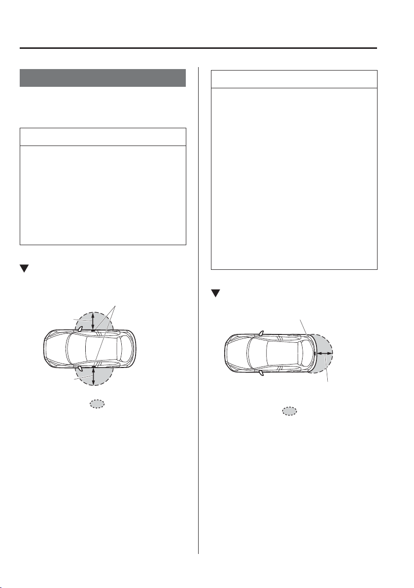
3
–
10
Before Driving
Advanced Keyless Entry System
Operational Range
The system operates only when the driver
is in the vehicle or within operational
range while the key is being carried.
NOTE
When the battery power is low, or in
places where there are high-intensity
radio waves or noise, the operational
range may become narrower or
the system may not operate. For
determining battery replacement, Refer
to Keyless Entry System on page
3-3 .
Locking, Unlocking the Doors and
the Liftgate/Boot Lid
Exterior aerial
80 cm(31in)
80 cm(31in)
Operational range
NOTE
The system may not operate if you
are too close to the windows or door
handles, or liftgate/boot lid.
If the key is left in the following
areas and you leave the vehicle, the
doors may be locked depending on
the radio wave conditions even if the
key is left in the vehicle.
Around the instrument panel
In the storage compartments such
as the glove compartment or the
centre console
On the rear parcel shelf (saloon)
Next to a communication device
such as a mobile phone
Opening the Liftgate/Boot Lid
Exterior aerial
80 cm(31in)
Operational range
3
–
11
Before Driving
Doors and Locks
Door Locks
WARNING
Always take all children and pets with
you or leave a responsible person with
them:
Leaving a child or a pet unattended in
a parked vehicle is dangerous. In hot
weather, temperatures inside a vehicle
can become high enough to cause
brain damage or even death.
Do not leave the key in your vehicle
with children and keep them in a place
where your children will not ¿ nd or
play with them:
Leaving children in a vehicle with the
key is dangerous. This could result in
someone being badly injured or even
killed.
Always close all the windows, lock the
doors and the liftgate/boot lid and take
the key with you when leaving your
vehicle unattended:
Leaving your vehicle unlocked is
dangerous as children could lock
themselves in a hot vehicle, which
could result in death. Also, a vehicle
left unlocked becomes an easy target
for thieves and intruders.
WARNING
After closing the doors and the liftgate/
boot lid, always verify that they are
securely closed:
Doors and the liftgate/boot lid not
securely closed are dangerous, if the
vehicle is driven with a door and the
liftgate/boot lid not securely closed,
the door and the liftgate/boot lid could
open unexpectedly resulting in an
accident.
Always con¿ rm the safety around the
vehicle before opening a door and the
liftgate/boot lid:
Suddenly opening a door and the
liftgate/boot lid is dangerous. A passing
vehicle or a pedestrian could be hit and
cause an accident.
CAUTION
Always con¿ rm the conditions around
the vehicle before opening/closing the
doors and the liftgate/boot lid and use
caution during strong winds or when
parked on an incline. Not being aware
of the conditions around the vehicle is
dangerous because ¿ ngers could get
caught in the door and the liftgate/boot
lid or a passing pedestrian could be hit,
resulting in an unexpected accident or
injury.

3
–
12
Before Driving
Doors and Locks
*Some models.
NOTE
Always stop the engine and lock the
doors. In addition, to prevent theft of
valuables, do not leave them inside
the cabin.
If the key is left in the following
areas and you leave the vehicle, the
doors may be locked depending on
the radio wave conditions even if the
key is left in the vehicle.
Around the instrument panel
In the storage compartments such
as the glove compartment or the
centre console
On the rear parcel shelf (saloon)
Next to a communication device
such as a mobile phone
The vehicle lock-out prevention
feature prevents you from locking
yourself out of the vehicle.
(European models)
All doors and the liftgate/boot lid
will automatically unlock if they are
locked using the power door locks
with any door open.
If all the doors are closed even
though the liftgate/boot lid is open,
all the doors will lock.
(Except European models)
All doors and the liftgate/boot lid
will automatically unlock if they are
locked using the power door locks
with any door or the liftgate open.
NOTE
(Door unlock (control) system with
collision detection)
*
This system automatically unlocks
the doors and the liftgate/boot lid in
the event the vehicle is involved in
an accident to allow passengers to
get out of the vehicle immediately
and prevent being trapped inside.
While the ignition is switched ON
and in the event the vehicle receives
an impact strong enough to inÀ ate
the air bags, all the doors and the
liftgate/boot lid are automatically
unlocked after about 6 seconds have
elapsed from the time of the accident.
The doors and the liftgate/boot lid
may not unlock depending on how
an impact is applied, the force of the
impact, and other conditions of the
accident.
If door-related systems or the battery
is malfunctioning, the doors and the
liftgate/boot lid will not unlock.
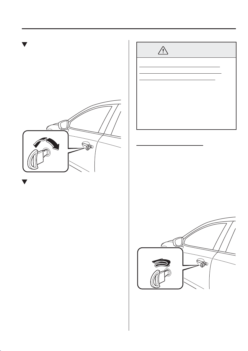
3
–
13
Before Driving
Doors and Locks
*Some models.
Locking, Unlocking with Key
All doors and the liftgate/boot lid lock
automatically when the driver's door is
locked using the auxiliary key. They all
unlock when the driver's door is unlocked
using the auxiliary key.
Turn the auxiliary key toward the front to
lock, toward the back to unlock.
Lock
Unlock
Double Locking System
*
The double locking system is designed
to prevent someone who has broken into
your vehicle from opening the door from
the inside.
If you have any problems with the double
locking system, consult an expert repairer,
we recommend an Authorised Mazda
Repairer.
WARNING
Never activate the double locking
system with passengers, especially
children, still inside the vehicle:
Activating the system with passengers,
especially children, still inside the
vehicle is dangerous. The passengers
cannot open the doors from inside.
They would be trapped and subjected to
extreme temperatures. This could result
in serious injuries or even death.
How to Activate the system
1. Close all the windows.
2. Switch the ignition off and take the key
with you.
3. Close all doors and the liftgate/boot lid.
4. Insert the auxiliary key in the driver's
door, turn the auxiliary key to the lock
position, and return it to the centre
position. Then turn it to the lock
position again within 3 seconds.
Centre
position
Lock
position
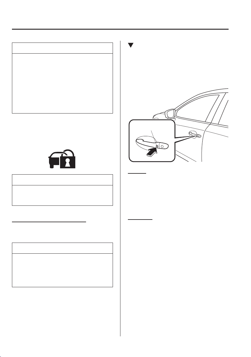
3
–
14
Before Driving
Doors and Locks
NOTE
You can also activate the system
by pressing the lock button on the
transmitter twice within 3 seconds.
(With the advanced keyless
function)
You can also activate the system by
pressing the request switch twice
within 3 seconds.
5. The indicator light illuminates for
about 3 seconds to indicate that the
system has been activated.
NOTE
The system cannot be activated when
any door or the liftgate is open.
How to Deactivate the System
Unlock the driver's door or switch the
ignition ON.
NOTE
If the power supply is interrupted (fuse
blows or the battery is disconnected),
the system can only be deactivated by
unlocking a door with the auxiliary key.
Locking, Unlocking with Request
Switch (With the advanced keyless
function)
All doors and the liftgate/boot lid can be
locked/unlocked by pressing the request
switch while the key is being carried.
Request switch
To lock
To lock the doors and the liftgate/boot lid,
press the request switch and the hazard
warning lights will À ash once.
(Except European models)
A beep sound will be heard once.
To unlock
To unlock the doors and the liftgate/boot
lid, press the request switch and the hazard
warning lights will À ash twice.
(Except European models)
A beep sound will be heard twice.

3
–
15
Before Driving
Doors and Locks
NOTE
Con¿ rm that all doors and the
liftgate/boot lid are securely locked.
For the liftgate/boot lid, move it
without pressing the electric liftgate/
boot lid opener to verify that the
liftgate/boot lid has not been left ajar.
(European models)
All doors and the liftgate/boot lid
cannot be locked when any door is
open.
(Except European models)
All doors and the liftgate/boot lid
cannot be locked when any door or
the liftgate is open.
It may require a few seconds for
the doors to unlock after the request
switch is pressed.
(European models)
The setting can be changed so that a
beep sound is heard for con¿ rmation
when the doors and the liftgate/
boot lid are locked/unlocked using a
request switch.
(Except European models)
A beep sound is heard for
con¿ rmation when the doors and the
liftgate/boot lid are locked/unlocked
using the request switch. If you
prefer, the beep sound can be turned
off.
The volume of the beep sound
can also be changed. Refer to
Personalisation Features on page
9-13 .
NOTE
Use the following procedure to
change the setting.
1. Switch the ignition off and close
all of the doors and the liftgate/
boot lid.
2. Open the driver's door.
3. Within 30 seconds of opening the
driver's door, press and hold the
LOCK button on the key for 5
seconds or longer.
All of the doors and the liftgate/
boot lid lock and the beep sound
activates at the currently set
volume. The setting changes each
time the LOCK button on the key
is pressed and the beep sound
activates at the set volume. (If the
beep sound has been set to not
activate, it will not activate.)
4. The setting change is completed
by doing any one of the following:
Switching the ignition to ACC
or ON.
Closing the driver's door.
Opening the liftgate/boot lid.
Not operating the key for 10
seconds.
Pressing any button except the
LOCK button on the key.
Pressing a request switch.
(With theft-deterrent system)
The hazard warning lights À ash when
the theft-deterrent system is armed or
turned off.
Refer to Theft-Deterrent System on
page 3-44 .
3
–
16
Before Driving
Doors and Locks
NOTE
(With double locking system)
The double locking system can
be activated/deactivated using the
request switch.
Refer to Double Locking System on
page 3-13 .
The setting can be changed so that
the doors and the liftgate/boot lid
are locked automatically without
pressing the request switch.
Refer to Personalisation Features on
page 9-13 .
(Auto-lock function)
A beep sound is heard when all
doors and the liftgate are closed
while the advanced key is being
carried. All doors and the liftgate/
boot lid are locked automatically
after about three seconds when
the advanced key is out of the
operational range. Also, the hazard
warning lights À ash once. (Even
if the driver is in the operational
range, all doors and the liftgate/boot
lid are locked automatically after
about 30 seconds.) If you are out
of the operational range before the
doors and the liftgate/boot lid are
completely closed or another key
is left in the vehicle, the auto-lock
function will not work. Always make
sure that all doors and the liftgate/
boot lid are closed and locked before
leaving the vehicle. The auto-lock
function does not close the power
windows.
NOTE
Auto re-lock function
After unlocking with the request
switch, all doors and the liftgate/boot
lid will automatically lock if any
of the following operations are not
performed within about 30 seconds.
If your vehicle has a theft-deterrent
system, the hazard warning lights
will À ash for con¿ rmation.
The time required for the doors to
lock automatically can be changed.
Refer to Personalisation Features on
page 9-13 .
Opening a door or the liftgate/boot
lid.
Switching the ignition to any
position other than off.
Locking, Unlocking with
Transmitter
All doors and the liftgate/boot lid can be
locked/unlocked by operating the keyless
entry system transmitter, refer to Keyless
Entry System (page 3-3 ).
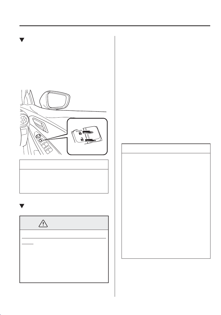
3
–
17
Before Driving
Doors and Locks
*Some models.
Locking, Unlocking with Door-
Lock Switch
*
All doors and the liftgate/boot lid lock
automatically when the lock side is
pressed with all doors and the liftgate
closed.
They all unlock when the unlock side is
pressed.
Unlock
Lock
NOTE
The doors and the liftgate/boot lid
cannot be locked while any other door
or the liftgate is open.
Auto Lock/Unlock Function
*
WARNING
Do not pull the inner handle on a front
door:
Pulling the inner handle on a front
door while the vehicle is moving
is dangerous. Passengers can fall
out of the vehicle if the door opens
accidentally , which could result in
death or serious injury.
When the vehicle speed exceeds
20 km/h (12 mph), all doors and the
liftgate/boot lid lock automatically.
When the ignition is switched off, all
doors and the liftgate/boot lid unlock
automatically.
These functions can also be disabled so
that they do not operate.
Auto lock/unlock function setting
change using door-lock switch (With
door-lock switch)
The doors and the liftgate/boot lid can
be set to lock or unlock automatically by
selecting any one of the functions from the
following table and using the door-lock
switch on the interior door panel.
NOTE
Function number 3 in the following
table is the factory setting for your
vehicle.
There are only a total of six auto
lock/unlock settings available for
automatic transaxle vehicles, and
three for manual transaxle vehicles.
Be sure to press the unlock side of
the door-lock switch the correct
number of times according to the
selected function number. If the
switch is mistakenly pressed seven
times on an automatic transaxle
vehicle or four times on a manual
transaxle, the procedure will be
cancelled. If this occurs, start the
procedure from the beginning.
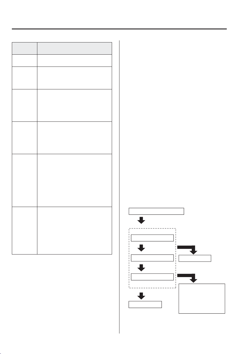
3
–
18
Before Driving
Doors and Locks
Function
number
Function
*1
1
The auto door-lock function is
disabled.
2
All the doors and the liftgate/boot lid
lock automatically when the vehicle
speed is about 20 km/h (12 mph) or
more.
3 (Factory
Setting)
All the doors and the liftgate/boot lid
lock automatically when the vehicle
speed is about 20 km/h (12 mph) or
more. All the doors and the liftgate/
boot lid unlock when the ignition is
switched from ON to Off.
4
(Automatic transaxle vehicles only)
When the ignition is switched ON and
the selector lever is shifted from park
(P) to any other gear position, all the
doors and the liftgate/boot lid lock
automatically.
5
(Automatic transaxle vehicles only)
When the ignition is switched ON and
the selector lever is shifted from park
(P) to any other gear position, all the
doors and the liftgate/boot lid lock
automatically.
When the selector lever is shifted to
park (P) while the ignition is switched
ON, all the doors and the liftgate/boot
lid unlock automatically.
6
(Automatic transaxle vehicles only)
All the doors and the liftgate/boot lid
lock automatically when the vehicle
speed is about 20 km/h (12 mph) or
more.
When the selector lever is shifted to
park (P) while the ignition is switched
ON, all the doors and the liftgate/boot
lid unlock automatically.
*1 Other settings for the auto door lock function are
available at an expert repairer, we recommend an
Authorised Mazda Repairer. For details consult
an expert repairer, we recommend an Authorised
Mazda Repairer. Refer to Personalisation Features
on page 9-13 .
Settings can be changed using the
following procedure.
1. Safely park the vehicle. All doors must
remain closed.
2. Switch the ignition ON.
3. Press and hold the lock side of the
door-lock switch within 20 seconds of
switching the ignition ON, and make
sure a beep sound is heard about eight
seconds afterwards.
4. Refer to the auto lock/unlock function
setting table, determine the function
number for the desired setting. Press
the unlock side of the door-lock switch
the same number of times as the
selected function number (Ex. If you
select function 2, press the unlock side
of the switch only 2 times).
5. Three seconds after the function setting
has been changed, a beep sound will
beep in the amount of the selected
function number. (Ex. Function number
3 = 3 beep sounds)
(Manual transaxle vehicles)
Press 2 times
Press 3 times
Current Function Number
Function Number 1
Function Number 2
Function Number 3
Press 4 times
Press unlock side of
lock switch once
Cancel setting
Cancel setting
Function set (The
number of beeps
heard is the same as
the selected function
number)
Press lock side of
lock switch
Wait for 3 second
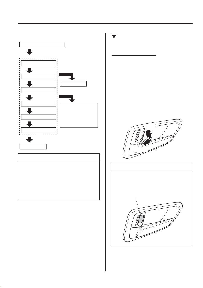
3
–
19
Before Driving
Doors and Locks
(Automatic transaxle vehicles)
Press unlock side of
lock switch once
Press 2 times
Press 3 times
Current Function Number
Function Number 1
Function Number 2
Press 4 times
Function Number 3
Press 5 times
Function Number 4
Press 7 times
Function Number 5
Press 6 times
Function Number 6
Cancel setting
Cancel setting
Function set (The
number of beeps
heard is the same as
the selected function
number)
Press lock side of
lock switch
Wait for 3 second
NOTE
The doors cannot be locked or
unlocked while the setting function is
being performed.
The procedure can be cancelled by
pressing the lock side of the door-
lock switch.
Locking, Unlocking with Door-
Lock Knob
Operation from inside
(With door-lock switch)
To lock any door from the inside, press the
door-lock knob.
To unlock, pull it outward.
This does not operate the other door locks.
(Without door-lock switch)
All doors and the liftgate/boot lid lock
automatically when the driver's door-lock
knob is pressed. They all unlock when the
driver's door-lock knob is pulled out.
Lock
Unlock
NOTE
The red indication can be seen when the
door-lock knob is unlocked.
Red indication
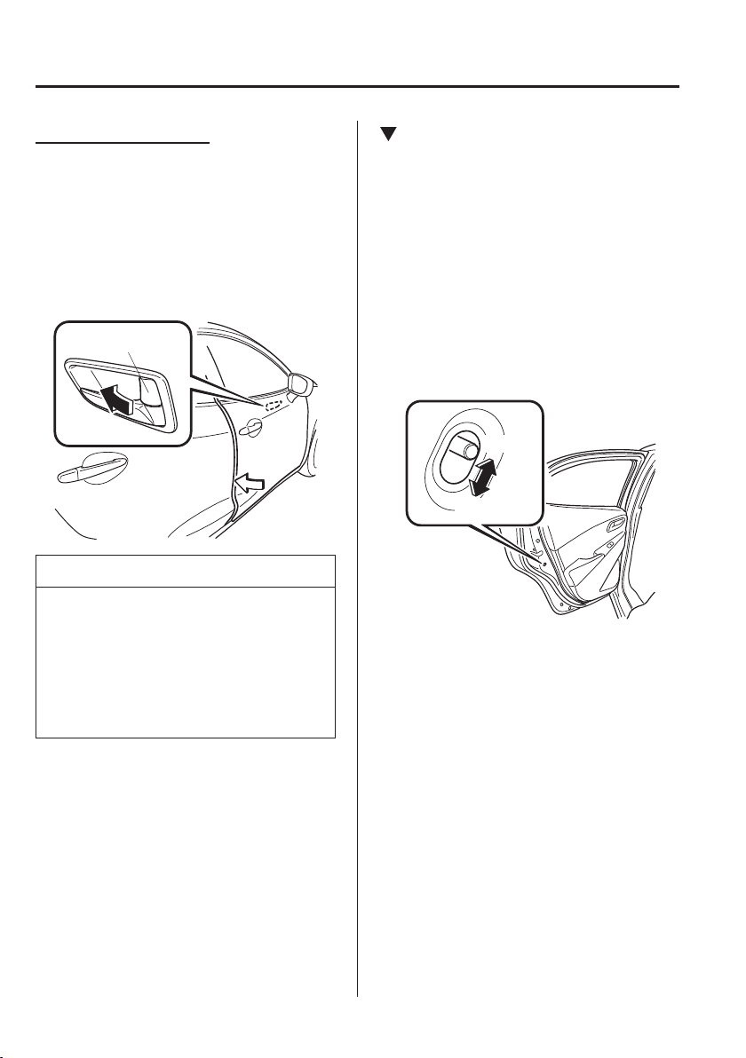
3
–
20
Before Driving
Doors and Locks
Operation from outside
To lock the rear and front passenger
doors with the door-lock knob from the
outside, press the door-lock knob to the
lock position and close the door (holding
the door handle in the open position is not
required).
This does not operate the other door locks.
Door-lock knob
NOTE
When locking the door this way:
Be careful not to leave the key inside
the vehicle.
The driver's door lock knob cannot
be used while the driver's door is
open.
Rear Door Child Safety Locks
These locks are intended to help prevent
children from accidentally opening the
rear doors. Use them on both rear doors
whenever a child rides in the rear seat of
the vehicle.
If you slide the child safety lock to the
lock position before closing that door, the
door cannot be opened from the inside.
The door can only be opened by pulling
the outside handle.
Unlock
Lock
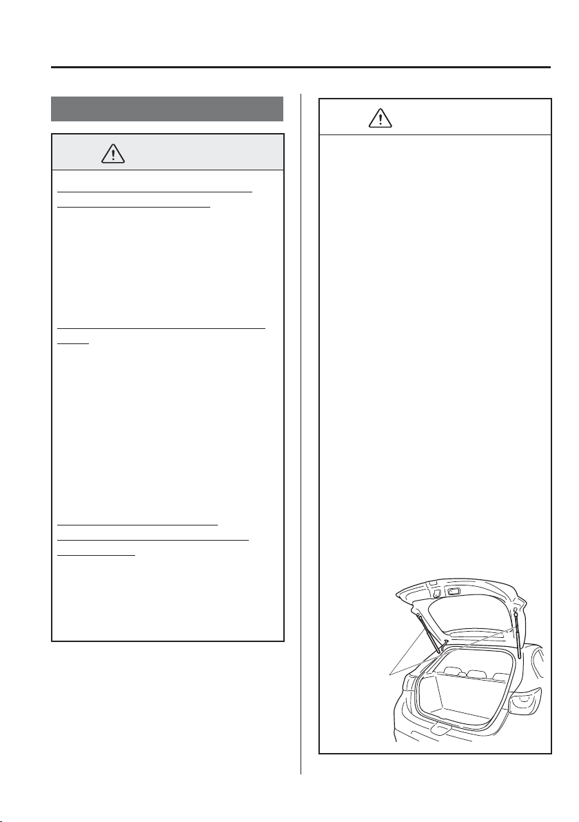
3
–
21
Before Driving
Doors and Locks
Liftgate/Boot Lid
WARNING
Never allow a person to ride in the
luggage compartment/boot:
Allowing a person to ride in the
luggage compartment/boot is
dangerous. The person in the luggage
compartment/boot could be seriously
injured or killed during sudden braking
or a collision.
Do not drive with the liftgate/boot lid
open:
Exhaust gas in the cabin of a vehicle
is dangerous. An open liftgate/boot lid
in a moving vehicle will cause exhaust
gas to be drawn into the cabin. This
gas contains CO (carbon monoxide),
which is colourless, odourless, and
highly poisonous, and it can cause loss
of consciousness and death. Moreover,
an open liftgate/boot lid could cause
occupants to fall out in an accident.
Do not stack or leave loaded
luggage unsecured in the luggage
compartment:
Otherwise, the luggage may move
or collapse, resulting in injury or an
accident. In addition, do not load
luggage higher than the seatbacks. It
may affect the side or rear ¿ eld of view.
CAUTION
Before opening the liftgate/boot
lid, remove any snow and ice
accumulation on it. Otherwise, the
liftgate/boot lid could close under the
weight of the snow and ice resulting
in injury.
Be careful when opening/closing
the liftgate/boot lid during strong
winds. If a strong gust blows against
the liftgate/boot lid, it could close
suddenly resulting in injury.
Fully open the liftgate/boot lid and
make sure that it stays open. If the
liftgate/boot lid is only opened
partially, it could slam shut by
vibration or wind gusts resulting in
injury.
When loading or unloading luggage
in the luggage compartment/boot,
turn off the engine. Otherwise, you
could get burned by the heat of the
exhaust gas.
Be careful not to apply excessive
force to the damper stay on the
liftgate such as by putting your hand
on the stay. Otherwise, the damper
stay may bend and affect the liftgate
operation.
Damper stay
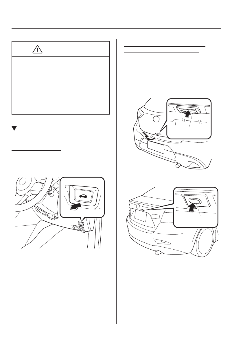
3
–
22
Before Driving
Doors and Locks
*Some models.
CAUTION
Do not modify or replace the
liftgate damper stay. Consult an
expert repairer, we recommend an
Authorised Mazda Repairer if a
liftgate damper stay is deformed
or damaged for reasons such as a
collision or if there is some other
problem.
Opening and Closing the Liftgate/
Boot Lid
Opening the boot lid
Using the remote release button
*
Push the remote release button.
Opening the liftgate/boot lid with
Electric liftgate/boot lid opener
Unlock the doors and liftgate/boot lid,
then press the electric liftgate/boot lid
opener on the liftgate/boot lid and raise the
liftgate/boot lid when the latch releases.
(Hatchback)
Electric liftgate
opener
(Saloon)
*
Electric boot lid
opener
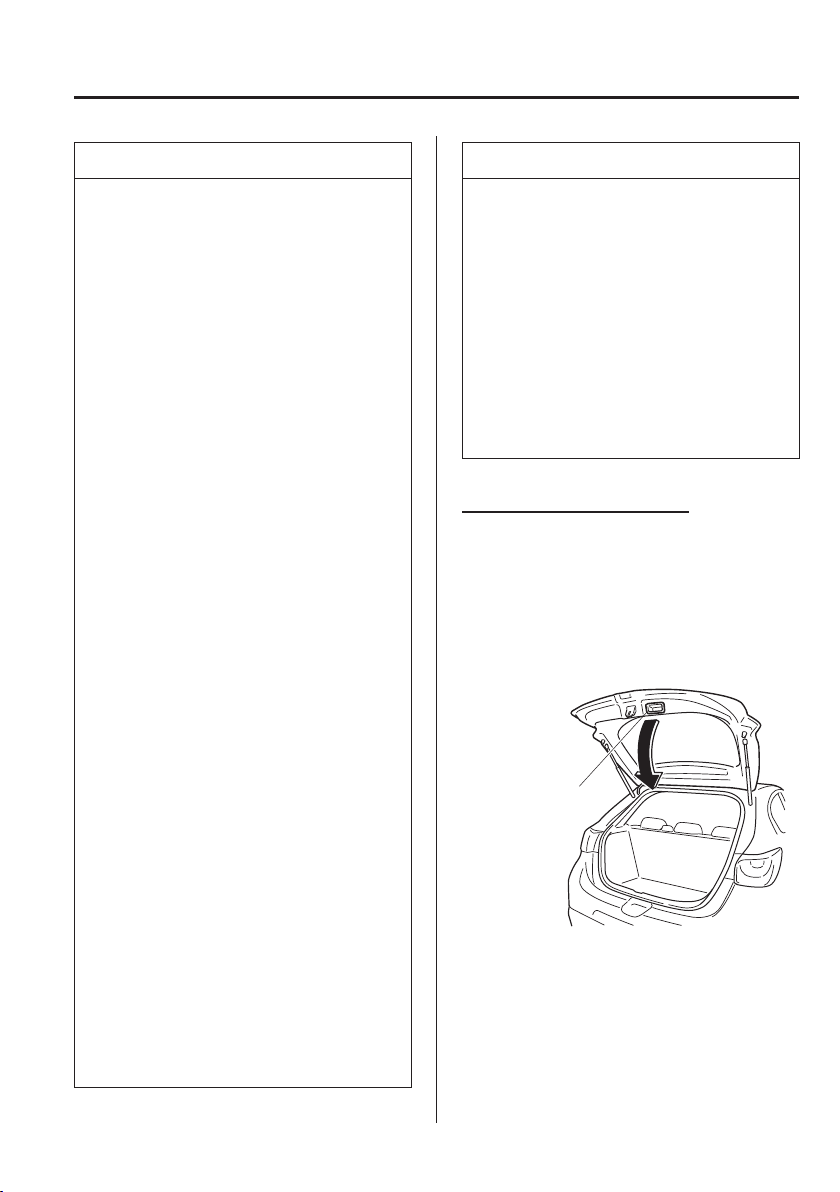
3
–
23
Before Driving
Doors and Locks
NOTE
(With the advanced keyless function)
A locked liftgate/boot lid can also
be opened while the key is being
carried.
When opening the liftgate/boot lid
with the doors and the liftgate/boot
lid locked, it may require a few
seconds for the liftgate/boot lid latch
to release after the electric liftgate/
boot lid opener is pressed.
The liftgate/boot lid can be closed
when the doors are locked with the
key left in the vehicle. However,
to prevent locking the key in the
vehicle, the liftgate/boot lid can
be opened by pressing the electric
liftgate/boot lid opener. If the liftgate/
boot lid cannot be opened despite
doing this procedure, ¿ rst push the
liftgate/boot lid completely closed,
then press the electric liftgate/boot
lid opener to fully open the liftgate/
boot lid .
(Hatchback)
When the latch is released by
pressing the electric liftgate opener,
the liftgate raises slightly. If the
liftgate is not operated for a certain
period of time, the liftgate cannot be
raised.
To open
Press the electric liftgate opener
again.
To close
To close the liftgate from its slightly
raised position, open it ¿ rst by
pressing the electric liftgate opener,
then close it after waiting at least 1
second.
NOTE
If the liftgate is not fully closed,
the driver is noti¿ ed by a warning
indicated in the instrument cluster.
If the vehicle battery is dead or there
is a malfunction in the electrical
system and the liftgate/boot lid
cannot be unlocked, the liftgate/boot
lid can be opened by performing the
emergency procedure.
Refer to When Liftgate/Boot Lid
Cannot be Opened on page 7-55 .
Closing the liftgate/boot lid
(Hatchback)
Lower the liftgate slowly using the liftgate
grip recess, then push the liftgate closed
using both hands.
Do not slam it. Pull up on the liftgate to
make sure it is secure.
Liftgate grip recess
(Saloon)
Use both hands to push the boot lid down
until the lock snaps shut. Do not slam it.
Pull up on the boot lid to make sure it is
secure.
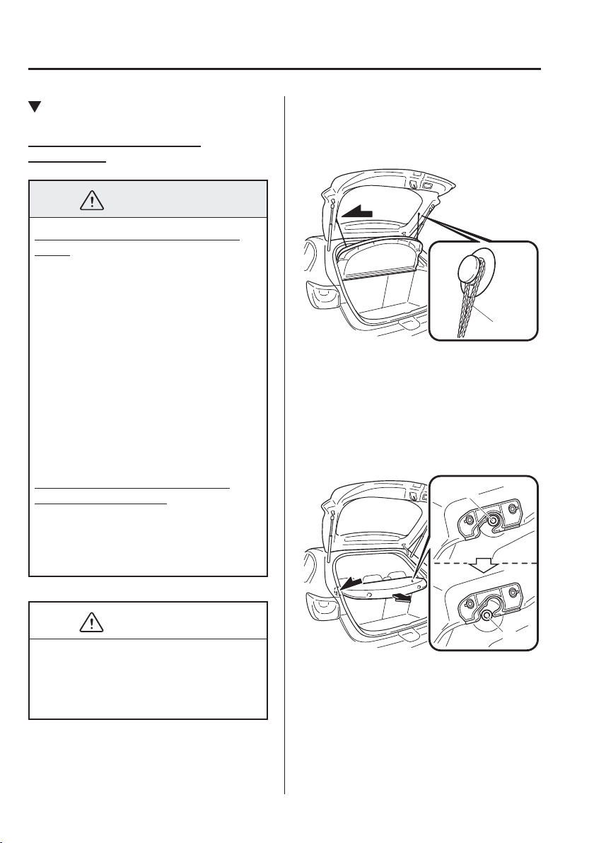
3
–
24
Before Driving
Doors and Locks
*Some models.
Luggage Compartment
Luggage compartment cover
(Hatchback)
*
WARNING
Do not place anything on top of the
cover:
Placing luggage or other cargo on top
of the luggage compartment cover is
dangerous. During sudden braking
or a collision, the cargo could become
a projectile that could hit and injure
someone. The vehicle has a light
weight luggage compartment cover to
keep the contents of your luggage area
out of sight; it will not retain heavy
objects that are not tied down in an
accident such as a rollover. Tie down
all heavy objects, whether luggage or
cargo, using the tie down hooks.
Make sure luggage and cargo are
secured before driving:
Not securing cargo while driving
is dangerous as it could move or be
crushed during sudden braking or a
collision and cause injury.
CAUTION
Make sure the luggage compartment
cover is ¿ rmly secured. If it is not
¿ rmly secured, it could unexpectedly
disengage resulting in injury.
The luggage compartment can be accessed
by opening the liftgate when the straps are
attached to the sides of the liftgate.
Strap
Removing the cover
This cover can be removed for more room.
1. Remove the straps from the hooks.
2. Lift the end of the luggage
compartment cover a little, pull it
outward, and remove it from the pins.
Pin
Pin
3. Lift the front end of the luggage
compartment cover and remove it.
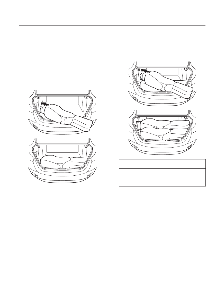
3
–
25
Before Driving
Doors and Locks
Loading golf bags (only Saloon)
Up to two golf bags can be carried in the
boot.
1. Place the bottom of the ¿ rst golf bag in
the boot with its bottom pointed to the
left and ¿ t it into the front of the boot.
2. Place the second golf bag in the boot
with its bottom pointed to the left and
¿ t it into the back of the boot.
NOTE
Some golf bags cannot ¿ t depending on
their size.
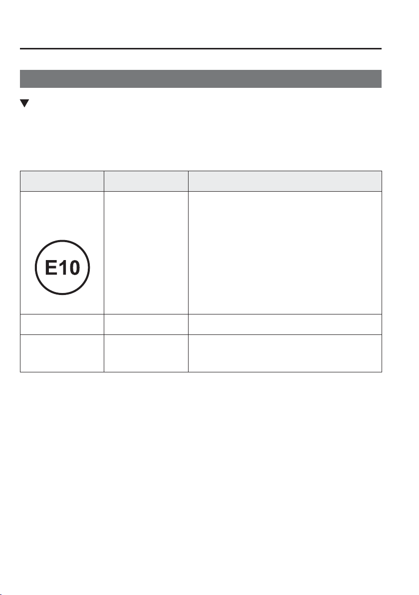
3
–
26
Before Driving
Fuel and Emission
Fuel and Engine Exhaust Precautions
Fuel Requirements (SKYACTIV-G 1.3, SKYACTIV-G 1.5)
Vehicles with catalytic converters or oxygen sensors must use ONLY UNLEADED FUEL,
which will reduce exhaust emissions and keep spark plug fouling to a minimum.
The vehicle will perform best with fuel listed in the table.
Fuel
Research Octane
Number
Country
Premium unleaded fuel
(Conforming to EN 228
and within E10)
*1
95 or above
New Caledonia, Turkey, Azerbaijan, Armenia, Georgia,
Canary Islands, Reunion, Morocco, Austria, Greece,
Italy, Switzerland, Belgium, Denmark, Finland, Norway,
Portugal, Spain, Sweden, Hungary, Germany, Poland,
Bulgaria, Croatia, Slovenia, Luxembourg, Slovakia,
Latvia, Lithuania, France, Ukraine, Czech, Estonia, Faeroe,
Iceland, Romania, The Netherlands, Macedonia, Bosnia
and Herzegovina, Serbia, Montenegro, Albania, Moldova,
Martinique, F.Guiana, Guadeloupe, Singapore, Hong Kong,
Macau, Malaysia, Brunei, Mauritius, Seychelles, South
Africa, Namibia, Botswana, Swaziland, Lesoto, Bermuda,
Jamaica, Barbados, Antigua, Guatemala, Bolivia, Uruguay,
Honduras, Nicaragua, Aruba, St. Martin, Cyprus, Malta,
Ireland, UK
Premium unleaded fuel
(within E20)
95 Thailand
Regular unleaded fuel 90 or above
Indonesia, Nepal, Sri Lanka, Fiji, Kenya, Tanzania,
Mozambique, Trinidad and Tobago, Chile, El Salvador,
Costa Rica, Ecuador, Haiti, Colombia, Dominican Republic
(LHD), Panama, Peru, B. Virgin, Curacao
*1 Europe
Fuel with a lower rating will negatively affect the emission control system performance and
could also cause engine knocking and serious engine damage.
3
–
27
Before Driving
Fuel and Emission
CAUTION
USE ONLY UNLEADED FUEL.
Leaded fuel is harmful to the catalytic converter and oxygen sensors and will lead to
deterioration of the emission control system and or failures.
The use of E10 fuel with 10 % ethanol in Europe is safe for your vehicle. Damage to
your vehicle may occur when ethanol exceeds this recommendation.
Never add fuel system additives, otherwise the emission control system could be
damaged. Consult an expert repairer, we recommend an Authorised Mazda Repairer
for details.
Fuel Requirements (SKYACTIV-D 1.5)
The vehicle will operate ef¿ ciently on diesel fuel with speci¿ cation EN590 or the
equivalent.
CAUTION
Never use fuel other than speci¿ cation EN590 or the equivalent for your vehicle. Use
of petrol or paraf¿ n in diesel engines will result in engine damage.
Never add fuel system additives. Otherwise, the emission control system could be
damaged. Consult an expert repairer, we recommend an Authorised Mazda Repairer
for details.
NOTE
When refuelling, always add at least 10 L (2.6 US gal, 2.2 Imp gal) of fuel.
3
–
28
Before Driving
Fuel and Emission
Emission Control System (SKYACTIV-G 1.3, SKYACTIV-G 1.5)
This vehicle is equipped with an emission control system (the catalytic converter is
part of this system) that enables the vehicle to comply with existing exhaust emissions
requirements.
WARNING
Never park over or near anything À ammable:
Parking over or near anything À ammable, such as dry grass, is dangerous. Even with
the engine turned off, the exhaust system remains very hot after normal use and could
ignite anything À ammable. A resulting ¿ re could cause serious injury or death.
CAUTION
Ignoring the following precautions could cause lead to accumulate on the catalyst inside
the converter or cause the converter to get very hot. Either condition will damage the
converter and cause poor performance.
USE ONLY UNLEADED FUEL.
Do not drive your Mazda with any sign of engine malfunction.
Do not coast with the ignition switched off.
Do not descend steep grades in gear with the ignition switched off.
Do not operate the engine at high idle for more than 2 minutes.
Do not tamper with the emission control system. All inspections and adjustments must
be made by a quali¿ ed technician.
Do not push-start or pull-start your vehicle.
3
–
29
Before Driving
Fuel and Emission
Emission Control System (SKYACTIV-D 1.5)
Your vehicle is equipped with an emission control system (the catalytic converter is
part of this system) that enables your vehicle to comply with existing exhaust emissions
requirements.
WARNING
Never park over or near anything À ammable:
Parking over or near anything À ammable, such as dry grass, is dangerous. Even with
the engine turned off, the exhaust system remains very hot after normal use and could
ignite anything À ammable. A resulting ¿ re could cause serious injury or death.
CAUTION
Ignoring the following precautions could cause lead to accumulate on the catalyst inside
the converter or cause the converter to get very hot. Either condition will damage the
converter and cause poor performance.
Do not drive your Mazda with any sign of engine malfunction.
Do not coast with the ignition switched off.
Do not descend steep grades in gear with the ignition switched off.
Do not operate the engine at high idle for more than 2 minutes.
Do not tamper with the emission control system. All inspections and adjustments must
be made by a quali¿ ed technician.
Do not push-start or pull-start your vehicle.
3
–
30
Before Driving
Fuel and Emission
Engine Exhaust (Carbon monoxide)
WARNING
Do not drive your vehicle if you smell exhaust gas inside the vehicle:
Engine exhaust gas is dangerous. This gas contains carbon monoxide (CO), which is
colourless, odourless, and poisonous. When inhaled, it can cause loss of consciousness
and death. If you smell exhaust gas inside the vehicle, keep all windows fully open and
contact an expert repairer, we recommend an Authorised Mazda Repairer immediately.
Do not run the engine when inside an enclosed area:
Running the engine inside an enclosed area, such as a garage, is dangerous. Exhaust
gas, which contains poisonous carbon monoxide, could easily enter the cabin. Loss of
consciousness or even death could occur.
Open the windows or adjust the heating or cooling system to draw fresh air when idling
the engine:
Exhaust gas is dangerous. When the vehicle is stopped with the windows closed and
the engine running for a long time even in an open area, exhaust gas, which contains
poisonous carbon monoxide, could enter the cabin. Loss of consciousness or even death
could occur.
Clear snow from underneath and around your vehicle, particularly the tail pipe, before
starting the engine:
Running the engine when a vehicle is stopped in deep snow is dangerous. The exhaust
pipe could be blocked by the snow, allowing exhaust gas to enter the cabin. Because
exhaust gas contains poisonous carbon monoxide, it could cause loss of consciousness
or even death to occupants in the cabin.
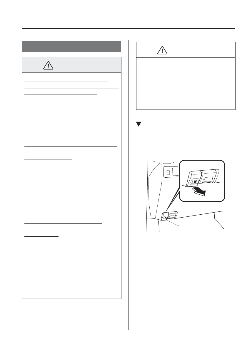
3
–
31
Before Driving
Fuel and Emission
Fuel-Filler Flap and Cap
WARNING
When removing the fuel-¿ ller cap,
loosen the cap slightly and wait for any
hissing to stop, then remove it:
Fuel spray is dangerous. Fuel can
burn skin and eyes and cause illness
if ingested. Fuel spray is released
when there is pressure in the fuel tank
and the fuel-¿ ller cap is removed too
quickly.
Before refuelling, stop the engine, and
always keep sparks and À ames away
from the ¿ ller neck:
Fuel vapour is dangerous. It could be
ignited by sparks or À ames causing
serious burns and injuries.
Additionally, use of the incorrect fuel-
¿ ller cap or not using a fuel-¿ ller cap
may result in a fuel leak, which could
result in serious burns or death in an
accident.
Do not continue refuelling after
the fuel pump nozzle shuts off
automatically:
Continuing to add fuel after the fuel
pump nozzle has shut off automatically
is dangerous because over¿ lling the
fuel tank may cause fuel overÀ ow or
leakage. Fuel overÀ ow and leakage
could damage the vehicle and if the
fuel ignites it could cause a ¿ re and
explosion resulting in serious injury or
death.
CAUTION
Always use only a designated Mazda
fuel-¿ ller cap or an approved equivalent,
available at an expert repairer, we
recommend an Authorised Mazda
Repairer. The wrong cap can result in
a serious malfunction of the fuel and
emission control systems.
Fuel-Filler Flap
To open, pull the remote fuel-¿ ller À ap
release.
To close, press the fuel-¿ ller À ap until it
locks securely.
Remote fuel-filler flap release
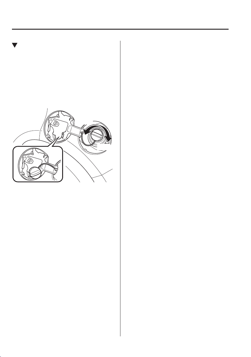
3
–
32
Before Driving
Fuel and Emission
Fuel-Filler Cap
To remove the fuel-¿ ller cap, turn it
anticlockwise.
Attach the removed cap to the inner side
of the fuel À ap.
To close the fuel-¿ ller cap, turn it
clockwise until a click is heard.
Open
Close
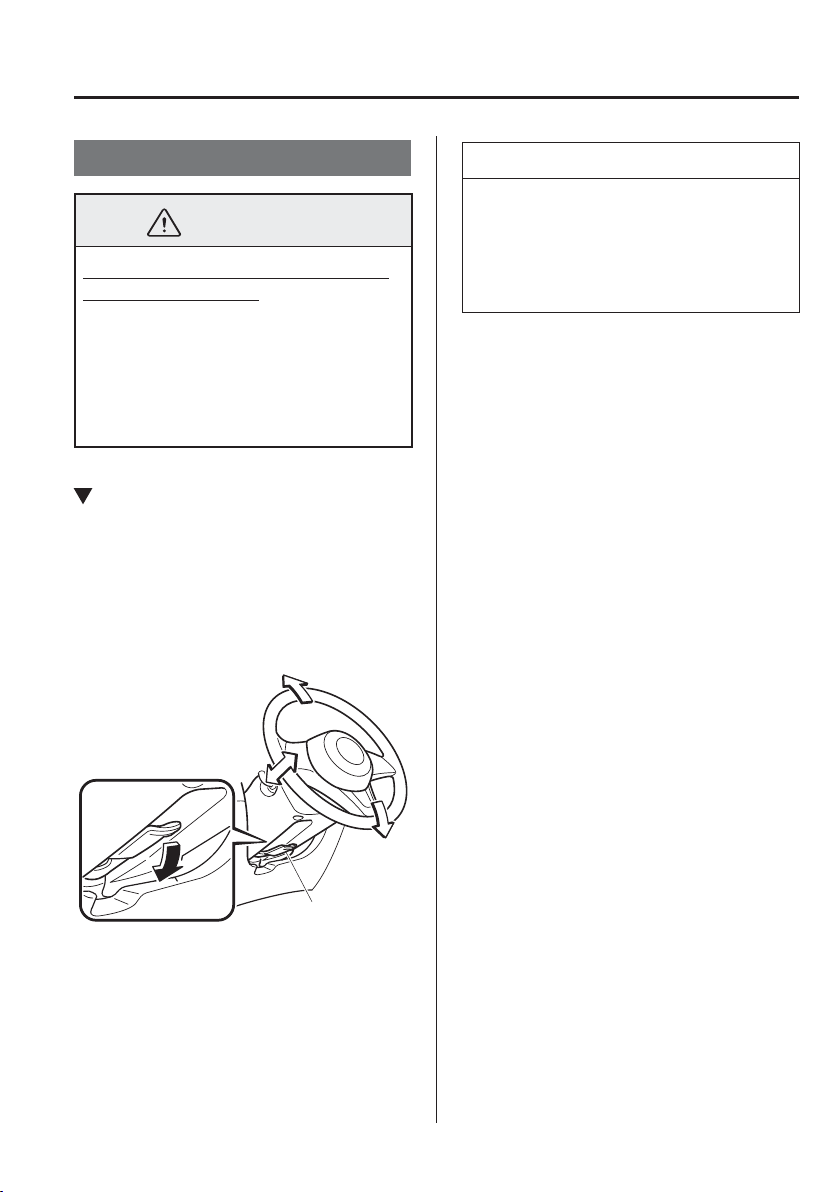
3
–
33
Before Driving
Steering Wheel
Steering Wheel
WARNING
Never adjust the steering wheel while
the vehicle is moving:
Adjusting the steering wheel while the
vehicle is moving is dangerous. Moving
it can very easily cause the driver
to abruptly turn to the left or right.
This can lead to loss of control or an
accident.
Steering Wheel Adjustment
To change the angle or length of the
steering wheel:
1. Stop the vehicle, and then pull down
the lock release lever under the steering
column.
Lock release lever
2. Tilt the steering wheel and/or adjust the
steering column length to the desired
positions, then push the lever up to lock
the column.
3. Attempt to push the steering wheel
up and down to make sure it's locked
before driving.
NOTE
Make sure that the steering wheel is
locked ¿ rmly in place. If it is dif¿ cult to
raise the lever, lightly move the steering
wheel forward and back to pull up the
lever.
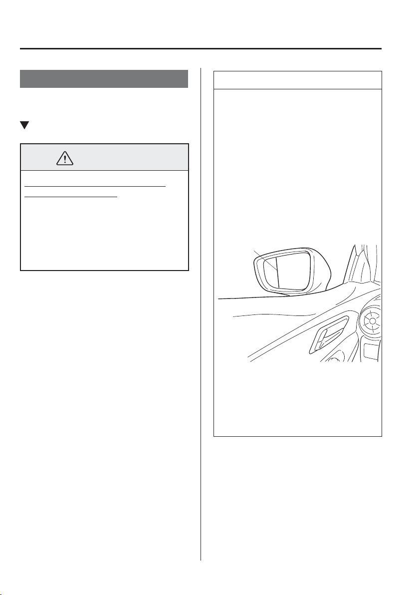
3
–
34
Before Driving
Mirrors
*Some models.
Mirrors
Before driving, adjust the inside and
outside mirrors.
Outside Mirrors
WARNING
Be sure to look over your shoulder
before changing lanes:
Changing lanes without taking
into account the actual distance of
the vehicle in the convex mirror is
dangerous. You could have a serious
accident. What you see in the convex
mirror is closer than it appears.
NOTE
(Driver's Side Wide Angle Mirror
*
)
The wide angle mirror has two
curvatures on its surface separated
by a region line into outer and
inner regions. The inner region is
a standard convex mirror whereas
the outer region allows for a wider
range of visibility within the same
sweep. This combination allows for
better assurance when making lane
changes.
Region line
The perceived distance of objects
in the outer and inner regions of
the wide angle mirror is different.
Objects appearing in the outer region
are actually further away than they
are in the inner region.
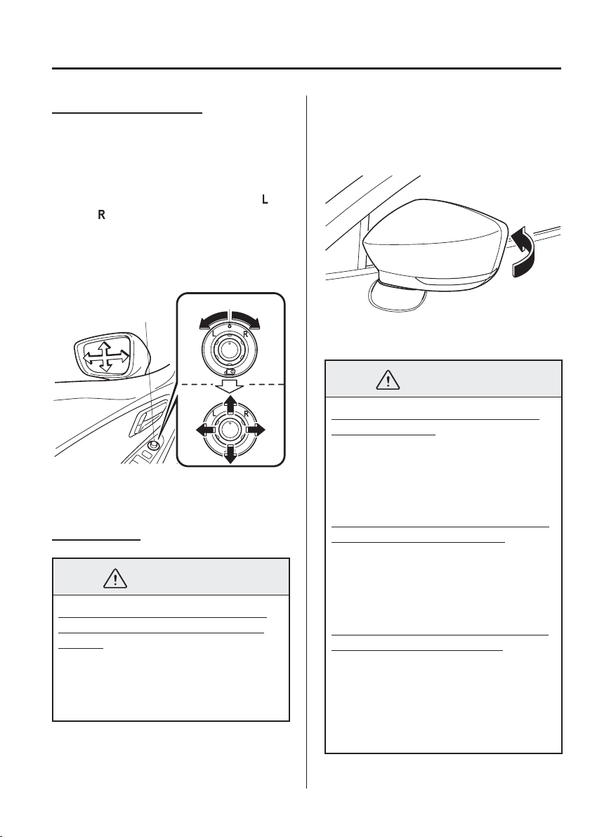
3
–
35
Before Driving
Mirrors
Power mirror adjustment
The ignition must be switched to ACC or
ON position.
To adjust:
1. Rotate the mirror switch to the left or
right
to choose the left or right side
mirror.
2. Press the mirror switch in the
appropriate direction.
Centre position
Mirror switch
After adjusting the mirror, lock the
control by rotating the switch to the centre
position.
Folding mirror
WARNING
Always return the outside mirrors to
the driving position before you start
driving:
Driving with the outside mirrors folded
in is dangerous. Your rear view will
be restricted, and you could have an
accident.
Manual folding mirror
Fold the outside mirror rearward until it is
À ush with the vehicle.
Power folding mirror
WARNING
Do not touch a power fold-in mirror
while it is moving:
Touching the power fold-in mirror
when it is moving is dangerous. Your
hand could be pinched and injured or
the mirror could be damaged.
Use the power fold-in switch to set the
mirror to the on-road position:
Setting the power fold-in mirror to the
on-road position by hand is dangerous.
The mirror will not lock in position and
will prevent effective rearview visibility.
Only operate the power fold-in mirror
with the vehicle safely parked:
Operating the power fold-in mirror
while the vehicle is moving is
dangerous. Wind blast on the mirror
will cause them to collapse and you will
be unable to return it to the on-road
position, preventing rearview visibility.
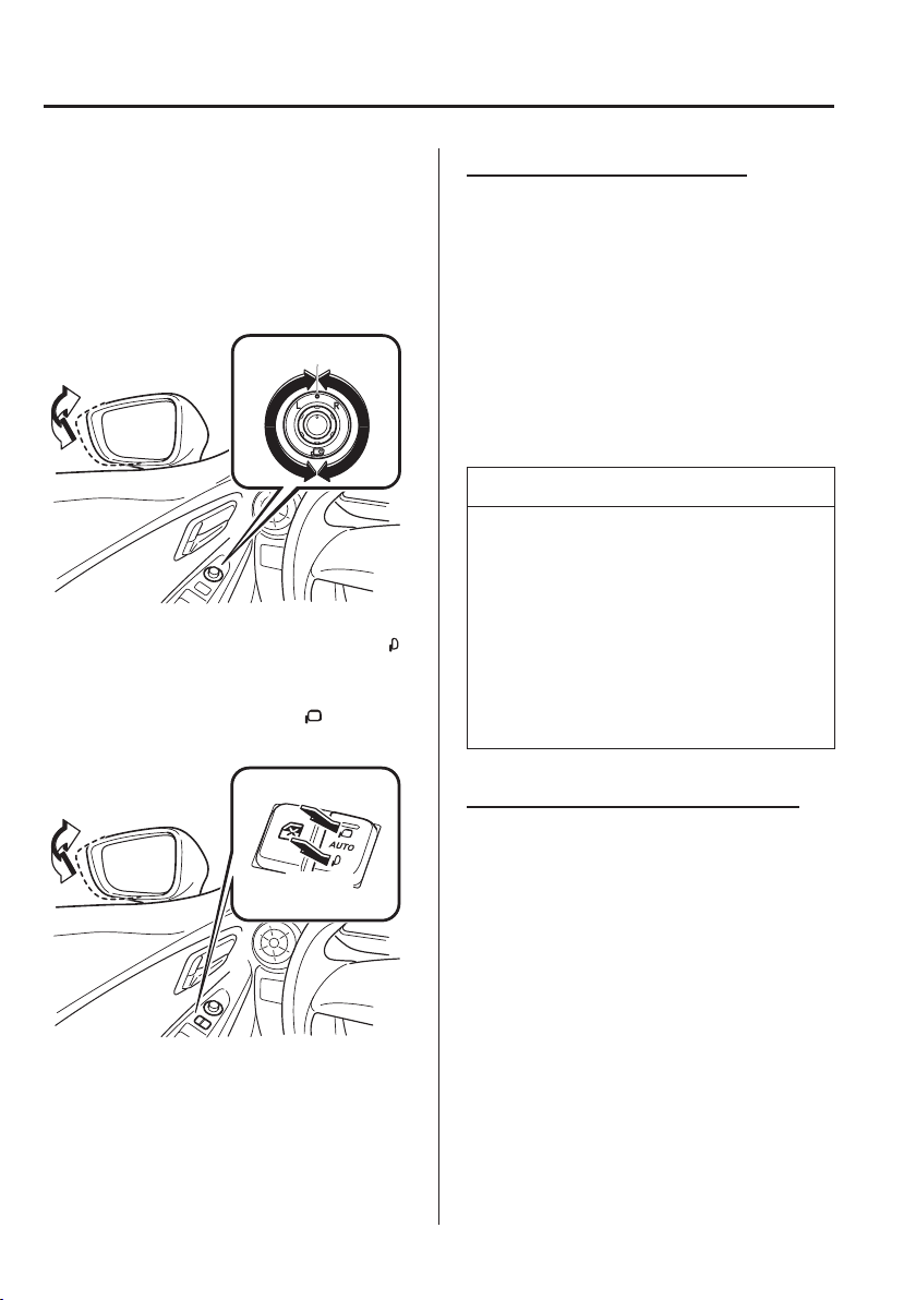
3
–
36
Before Driving
Mirrors
*Some models.
The ignition must be switched to ACC or
ON position.
Type A
To fold, rotate the switch.
To return the mirror to the driving
position, rotate the switch to the centre
position.
Centre position
Type B
To fold the mirrors, press the lower side
of the switch.
To return the mirrors to their on-road
positions, press the upper side
of the
switch.
Fold in
Fold out
Automatic folding mechanism
*
The automatic folding mechanism operates
when the ignition is switched to ACC or
OFF.
When the outer mirror automatic folding
switch is pressed to the AUTO position
(neutral position), the outside mirrors
automatically fold in and out when the
doors are locked and unlocked.
Also, when the ignition is switched ON or
the engine is started, the outside mirrors
fold out automatically.
NOTE
The outside mirrors may not fold in and
out automatically under cold weather
conditions.
If the outside mirrors do not fold in
and out automatically, remove any ice
or snow, and then press the upper or
lower side of the outer mirror automatic
folding switch to fold the outside
mirrors in or out.
Engine-off outside mirror operation
*
The outside mirrors can be operated for
about 40 seconds after the ignition is
switched from ON to off.
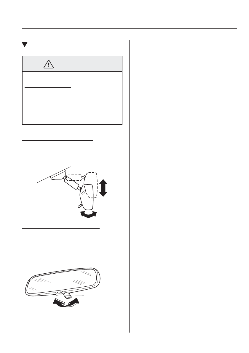
3
–
37
Before Driving
Mirrors
Rearview Mirror
WARNING
Do not stack cargo or objects higher
than the seatbacks:
Cargo stacked higher than the
seatbacks is dangerous. It can block
your view in the rearview mirror, which
might cause you to hit another car
when changing lanes.
Rearview mirror adjustment
Before driving, adjust the rearview mirror
to centre on the scene through the rear
window.
Reducing glare from headlights
Adjust the mirror with the antidazzle lever
in the day position.
Push the antidazzle lever forward for day
driving. Pull it back to reduce glare of
headlights from vehicles at the rear.
Antidazzle lever
DayNight
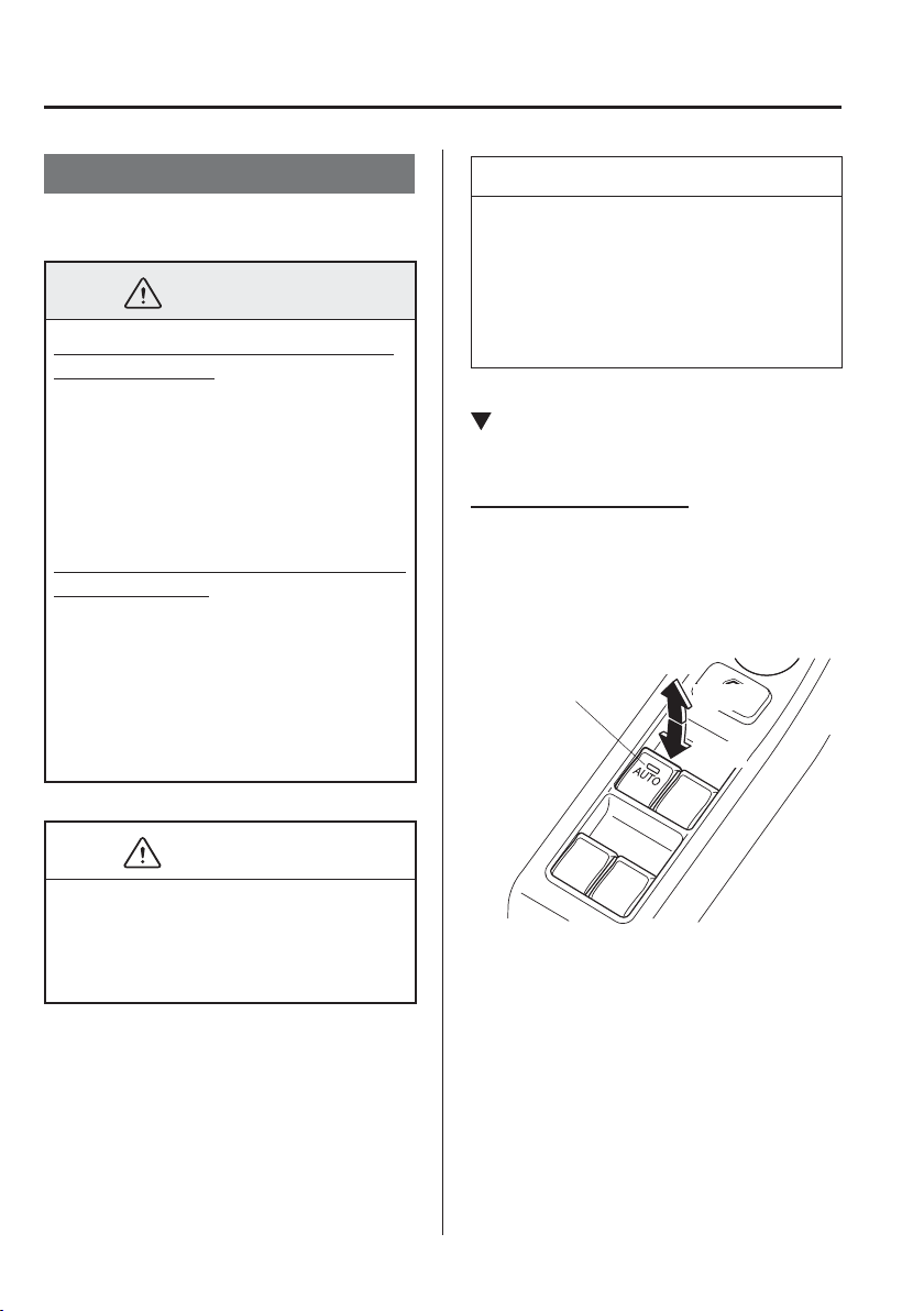
3
–
38
Before Driving
Windows
Power Windows
The ignition must be switched ON for the
power windows to operate.
WARNING
Make sure the opening is clear before
closing a window:
Closing a power window is dangerous.
A person's hands, head, or even neck
could be caught by the window and
result in serious injury or even death.
This warning applies especially to
children.
Never allow children to play with power
window switches:
Power window switches that are not
locked with the power window lock
switch would allow children to operate
power windows unintentionally, which
could result in serious injury if a
child's hands, head or neck becomes
caught by the window.
CAUTION
To prevent burning out the fuse and
damaging the power window system,
do not open or close more than three
windows at once.
NOTE
A power window may no longer open/
close if you continue to press the switch
after fully opening/closing the power
window. If the power window does not
open/close, wait a moment and then
operate the switch again.
Operating the Driver's Side Power
Window
Normal opening/closing
To open the window to the desired
position, lightly hold down the switch.
To close the window to the desired
position, lightly pull up the switch.
Driver's window
Open
Close
Master control switches
3
–
39
Before Driving
Windows
Auto-opening/closing
To fully open the window automatically,
press the switch completely down, then
release. The window will fully open
automatically.
To fully close the window automatically,
pull the switch completely up, then
release. The window will fully close
automatically.
To stop the window partway, pull or press
the switch in the opposite direction and
then release it.
Power window system initialization
procedure
If the battery was disconnected during
vehicle maintenance, or for other reasons
(such as a switch continues to be operated
after the window is fully open/closed),
the window will not fully open and close
automatically.
The power window auto function will only
resume on a power window that has been
reset.
1. Switch the ignition ON.
2. Make sure that the power window lock
switch located on the driver's door is
not depressed.
3. Press the switch and fully open the
window.
4. Pull up the switch to fully close the
window and continue holding the
switch for about 2 seconds after the
window fully closed.
Jam-safe window
If a person's hands, head or an object
blocks the window during the auto-closing
operation, the window will stop and open
halfway.
WARNING
Make sure nothing blocks the window
just before it reaches the fully closed
position or while holding up the power
window switch:
Blocking the power window just before
it reaches the fully closed position or
while holding up the power window
switch is dangerous.
In this case, the jam-safe function
cannot prevent the window from
closing all the way. If ¿ ngers are
caught, serious injuries could occur.
NOTE
Depending on driving conditions, a
closing power window could stop
and start opening when the window
feels a shock that is similar to
something blocking it.
In the event the jam-safe function
activates and the power window
cannot be closed automatically, pull
and hold the switch and the window
will close.
The jam-safe window function does
not operate until the system has been
reset.
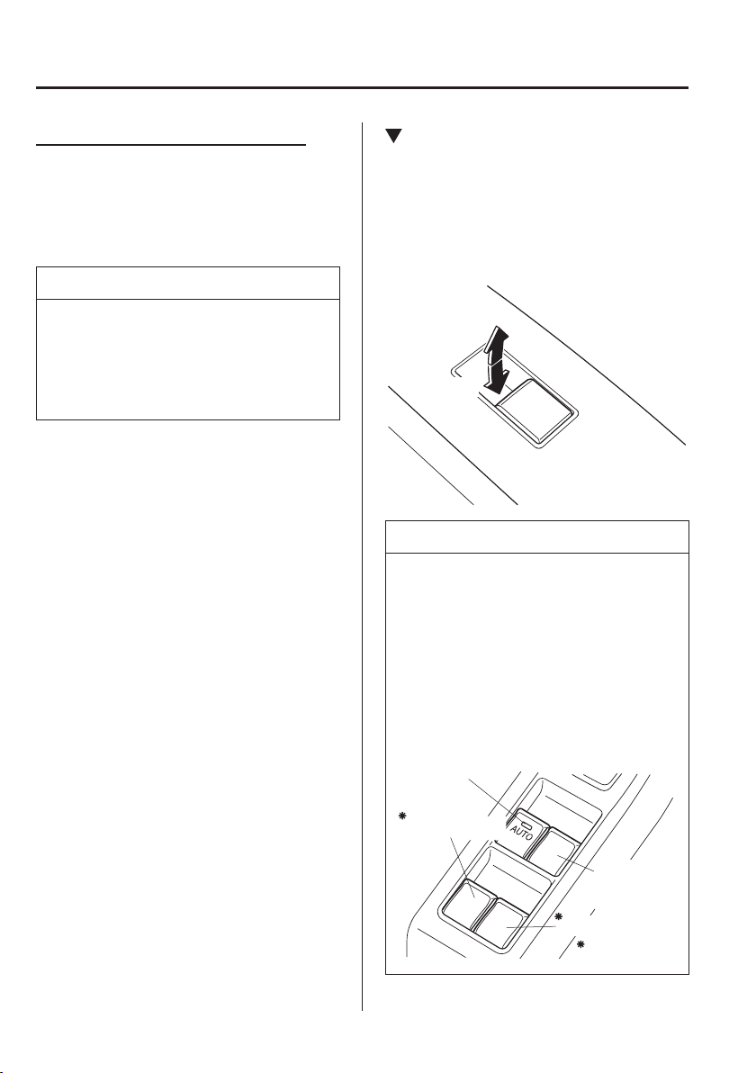
3
–
40
Before Driving
Windows
Engine-off power window operation
The power window can be operated for
about 40 seconds after the ignition is
switched from ON to off with all doors
closed. If any door is opened, the power
window will stop operating.
NOTE
For engine-off operation of the power
window, the switch must be held up
¿ rmly throughout window closure
because the auto-closing function will
be inoperable.
Operating the Passenger Power
Windows
To open the window to the desired
position, hold down the switch.
To close the window to the desired
position, pull up the switch.
Close
Open
NOTE
The power windows may be operated
when the power window lock switch
on the driver's door is in the unlocked
position.
The passenger windows may be
opened or closed using the master
control switches on the driver's door.
Left rear window
Right rear window
Front
passenger's
window
Driver's window
Master control switches
Some models.
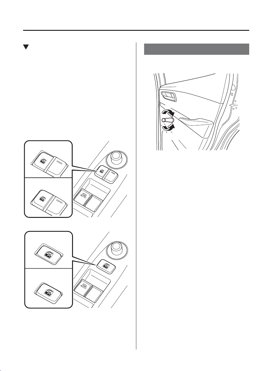
3
–
41
Before Driving
Windows
*Some models.
Power Window Lock Switch
This feature prevents all power windows
from operating, except the driver's power
window. Keep this switch in the locked
position while children are in the vehicle.
Locked position (button depressed):
Only the driver's power window can be
operated.
Unlocked position (button not
depressed):
All power windows on each door can be
operated.
(Type A)
Locked position
Unlocked position
(Type B)
Locked position
Unlocked position
Manual Windows
*
To open and close the window turn the
handle on the door.
Close
Open
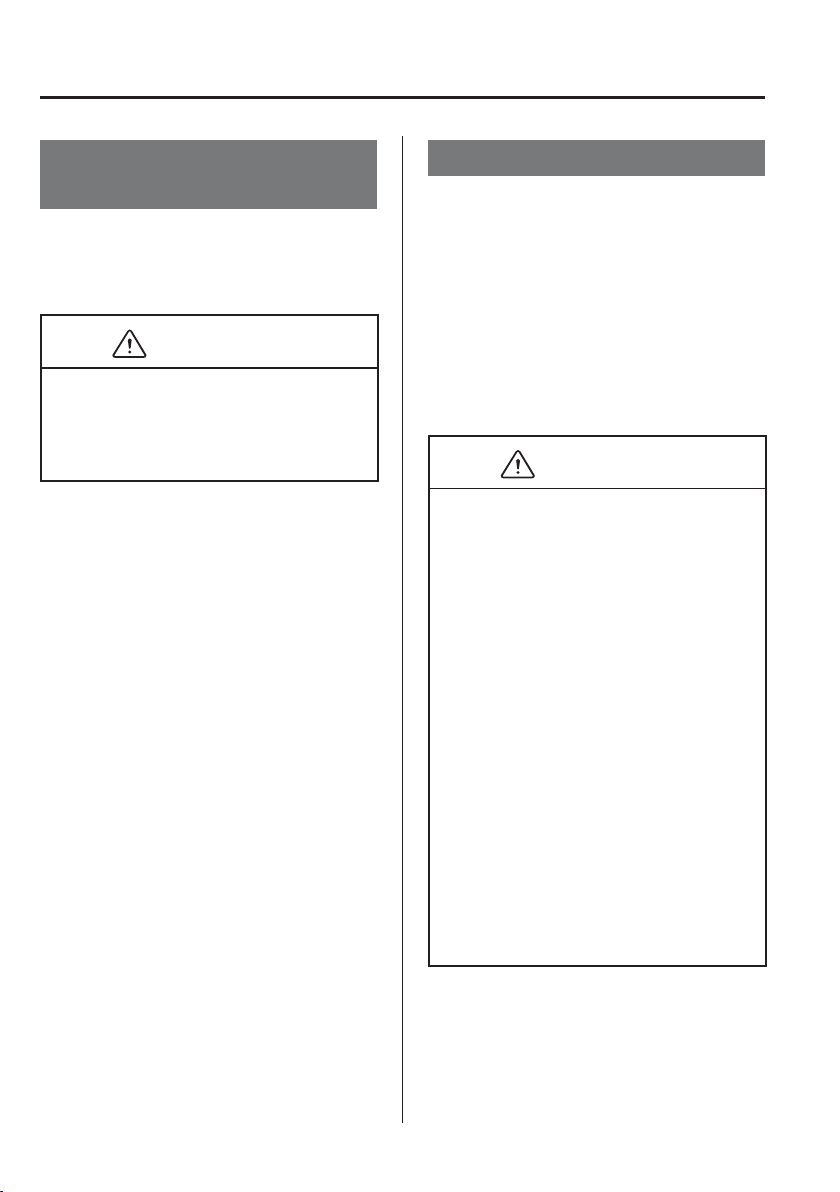
3
–
42
Before Driving
Security System
M o d i ¿ cation and Add-On
Equipment
Mazda cannot guarantee the immobilizer
and the theft-deterrent systems' operation
if the system has been modi¿ ed or if any
add-on equipment has been installed.
CAUTION
To avoid damage to the vehicle, do not
modify the system or install any add-on
equipment to the immobilizer and the
theft-deterrent systems or the vehicle.
Immobilizer System
The immobilizer system allows the
engine to start only with a key the system
recognises.
If someone attempts to start the engine
with an unrecognised key, the engine
will not start, thereby helping to prevent
vehicle theft.
If you have a problem with the
immobilizer system or the key, consult an
Authorised Mazda Repairer.
CAUTION
Changes or modi¿ cations not
expressly approved by the party
responsible for compliance could
void the user's authority to operate
the equipment.
To avoid damage to the key, do not:
Drop the key.
Get the key wet.
Expose the key to any kind of
magnetic ¿ eld.
Expose the key to high
temperatures on places such as the
instrument panel or bonnet, under
direct sunlight.
If the engine does not start with the
correct key, and the security indicator
light keeps illuminating or À ashing,
the system may have a malfunction.
Consult an Authorised Mazda
Repairer.
3
–
43
Before Driving
Security System
NOTE
The keys carry a unique electronic
code. For this reason, and to assure
your safety, obtaining a replacement
key requires some waiting time.
They are only available through an
Authorised Mazda Repairer.
Always keep a spare key in case one
is lost. If a key is lost, consult an
Authorised Mazda Repairer as soon
as possible.
If you lose a key, an Authorised
Mazda Repairer will reset the
electronic codes of your remaining
keys and immobilizer system.
Bring all the remaining keys to an
Authorised Mazda Repairer to reset.
Starting the vehicle with a key that
has not been reset is not possible.
Operation
NOTE
The engine may not start and security
indicator light may illuminate or
À ash if the key is placed in an area
where it is dif¿ cult for the system
to detect the signal, such as on the
instrument panel or in the glove
compartment. Move the key to a
location within the signal range,
switch the ignition off, and then
restart the engine.
Signals from a TV or radio station,
or from a transceiver or mobile
telephone could interfere with your
immobilizer system. If you are using
the proper key and the engine fails
to start, check the security indicator
light.
A r m i n g
The system is armed when the ignition is
switched from ON to off.
The security indicator light in the
instrument cluster À ashes every 2 seconds
until the system is disarmed.
Disarming
The system is disarmed when the
ignition is switched ON with the correct
programmed key. The security indicator
light illuminates for about 3 seconds and
then turns off. If the engine does not start
with the correct key, and the security
indicator light remains illuminated or
À ashing, try the following:
Make sure the key is within the
operational range for signal transmission.
Switch the ignition off, and then restart
the engine. If the engine does not start
after 3 or more tries, contact an Authorised
Mazda Repairer.
NOTE
If the security indicator light À ashes
continuously while you are driving,
do not shut off the engine. Go to an
Authorised Mazda Repairer and have
it checked. If the engine is shut off
while the indicator light is À ashing,
you will not be able to restart it.
Because the electronic codes are
reset when the immobilizer system
is repaired, the keys are needed.
Make sure to bring all the keys to an
Authorised Mazda Repairer so that
they can be programmed.
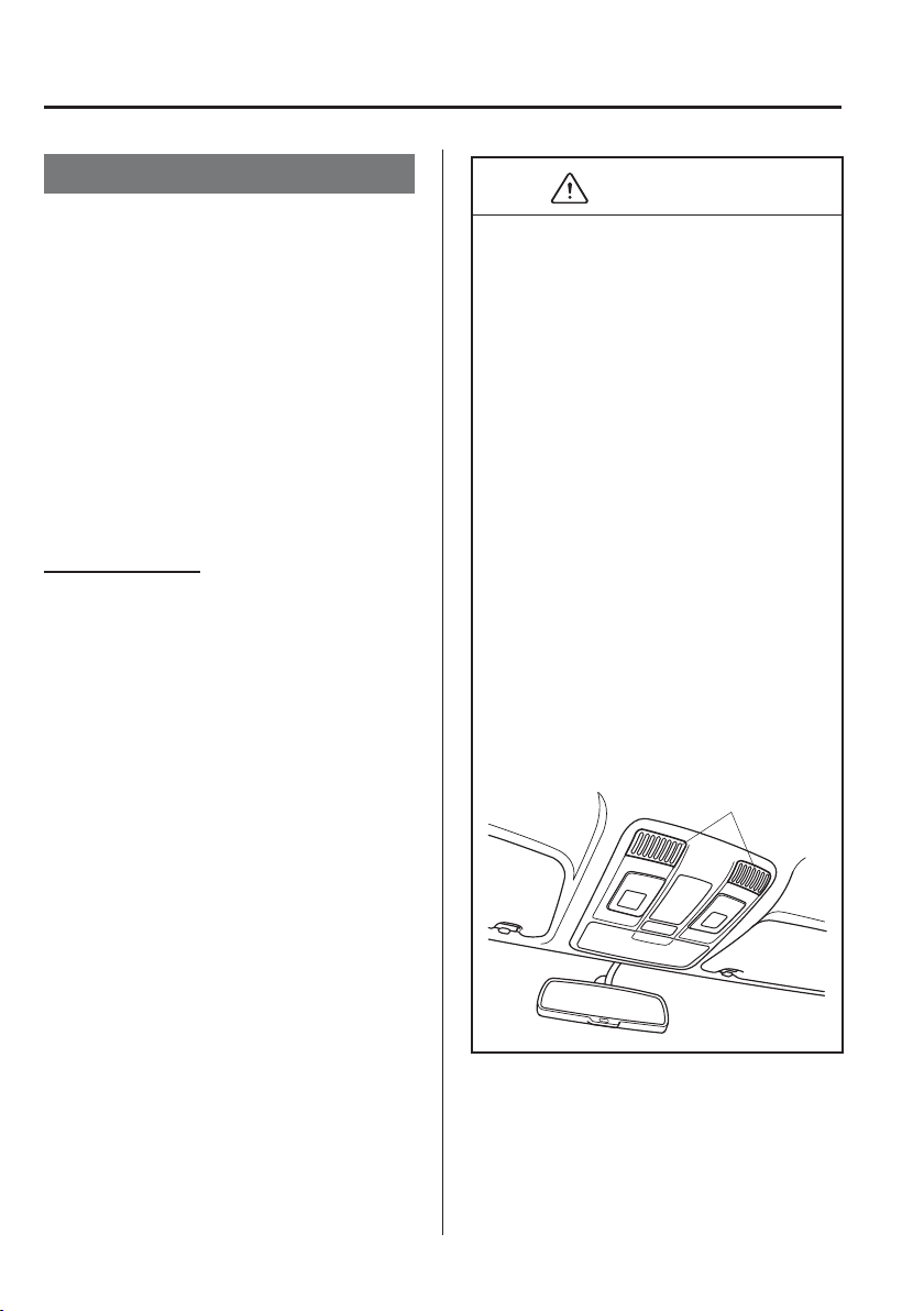
3
–
44
Before Driving
Security System
*Some models.
Theft-Deterrent System
*
If the theft-deterrent system detects an
inappropriate entry into the vehicle or
the intrusion sensor detects movement
in the vehicle which could result in the
vehicle (with the intrusion sensor) or its
contents being stolen, the alarm alerts the
surrounding area of an abnormality by
sounding the siren/horn and À ashing the
hazard warning lights.
The system will not function unless it's
properly armed. So when you leave the
vehicle, follow the arming procedure
correctly.
Intrusion sensor
*
The intrusion sensor uses ultrasonic waves
to detect movement inside the vehicle and
to raise an alert of an intrusion into the
vehicle.
The intrusion sensor detects certain kinds
of movement inside the vehicle, however,
it may also respond to phenomenon
outside the vehicle such as vibrations, loud
noise, wind, and air currents.
CAUTION
In order for the intrusion sensor to
operate appropriately, be aware of the
following:
Do not hang clothing or objects from
a head restraint or a coat hook.
Return the extension sunvisors to
their original positions.
Do not blind the intrusion sensor by
covering it or placing objects over it.
Do not allow the intrusion sensor to
get soiled or wipe it with a liquid.
Do not shock or cause an impact to
the intrusion sensor or the intrusion
sensor bezel.
Do not install seats that are not
Mazda genuine products.
To prevent obstruction of intrusion
sensor, do not place objects or cargo
near the intrusion sensor that are
higher than the head restraints.
Intrusion sensor and
intrusion sensor bezel
3
–
45
Before Driving
Security System
Operation
Siren/Horn triggering conditions
The siren/horn sounds intermittently and
the hazard warning lights À ash for about
30 seconds when the system is triggered
by any one of the following:
Unlocking a door with an inside door-
lock knob.
Forcing open a door, the bonnet or the
liftgate/boot lid.
Opening the bonnet by operating the
bonnet release handle.
Switching the ignition ON without using
the push button start.
(With the intrusion sensor)
The intrusion sensor detects a movement
in the vehicle.
The system will be triggered again (up to
10 times) if one of the above conditions
remains.
(With the intrusion sensor)
Disconnecting the battery terminal (the
hazard warning lights do not À ash).
The system will be triggered about 10
times.
NOTE
The liftgate/boot lid does not open
while the theft-deterrent system is
operating.
If the battery goes dead while the
theft-deterrent system is armed,
the siren/horn will activate and the
hazard warning lights will À ash when
the battery is charged or replaced.
How to Arm the System
1. Close the windows securely.
NOTE
(With the intrusion sensor)
Even with a window open, the system
can be armed, however, leaving the
windows even partially open can invite
theft, and wind blowing into the vehicle
could trigger the alarm.
The intrusion sensor function can also
be cancelled.
Refer to Cancelling the Intrusion Sensor
(With Intrusion Sensor) on page 3-46 .
2. Switch the ignition OFF.
3. Make sure the bonnet, the doors, and
the liftgate/boot lid are closed.
4. Press the lock button on the transmitter
or lock the driver's door from the
outside with the auxiliary key.
The hazard warning lights will À ash
once.
(With the advanced keyless function)
Press a request switch.
The security indicator light in the
instrument cluster À ashes twice per
second for 20 seconds.
5. After 20 seconds, the system is fully
armed.

3
–
46
Before Driving
Security System
NOTE
The theft-deterrent system can also
be armed by activating the auto
relock function with all the doors,
the liftgate/boot lid and the bonnet
closed.
Refer to Transmitter on page 3-4 .
The system will disarm if one of
the following operations takes place
within 20 seconds after pressing the
lock button:
Unlocking any door.
Opening any door.
Opening the bonnet.
Switching the ignition ON.
To rearm the system, do the arming
procedure again.
When the doors are locked by
pressing the lock button on the
transmitter or using the auxiliary key
while the theft-deterrent system is
armed, the hazard warning lights will
À ash once to indicate that the system
is armed.
Cancelling the Intrusion Sensor
(With Intrusion Sensor)
If the theft deterrent system has been
armed while any of the following
conditions are present, cancel the intrusion
sensor to prevent the alarm from triggering
unnecessarily.
Leaving the vehicle with a movable
object, passengers or pets remaining
inside.
Leaving an object inside the vehicle
that can roll around, such as when the
vehicle is placed on a tilting, unstable
surface when being shipped.
Hanging small objects/accessories in
the vehicle, hanging clothing on a coat
hook, or placing other items which can
move easily inside the vehicle.
Parking in an area where there is strong
vibration or loud noise.
When using a high pressure or automatic
car wash.
Continuous shock and vibration
from hail or thunder and lightning is
transmitted to the vehicle.
Doors are locked with a window left
open.
An accessory heater or device that
produces moving air and vibration
operates while the theft deterrent system
is armed.
NOTE
If any door or the liftgate/boot lid
remains closed for 30 seconds, all
the doors and the liftgate/boot lid
automatically re-lock and the theft
deterrent system arms even if a window
is left open.
3
–
47
Before Driving
Security System
To cancel the intrusion sensor, press
the intrusion sensor cancel button on
the transmitter within 20 seconds after
pressing the lock button.
The hazard warning lights will À ash three
times.
NOTE
To reactivate the intrusion sensor,
turn off the armed theft-deterrent
system and then rearm it.
The intrusion sensor is operational
when the theft-deterrent system
is armed. To cancel the intrusion
sensor, press the intrusion sensor
cancel button each time the theft-
deterrent system is armed.
To Turn Off an Armed System
An armed system can be turned off using
any one of the following methods:
Pressing the unlock button on the
transmitter.
Starting the engine with the push button
start.
(With the advanced keyless function)
Pressing a request switch on the doors.
The hazard warning lights will À ash twice.
NOTE
When the doors are unlocked by
pressing the unlock button on the
transmitter while the theft-deterrent
system is turned off, the hazard warning
lights will À ash twice to indicate that the
system is turned off.
To Stop the Alarm
A triggered alarm can be turned off using
any one of the following methods:
Pressing the unlock button or the boot
button (saloon) on the transmitter.
Starting the engine with the push button
start.
(With the advanced keyless function)
Pressing a request switch on the doors.
Pressing the electric liftgate/boot lid
opener while the key is being carried.
The hazard warning lights will À ash twice.

3
–
48
Before Driving
Driving Tips
Running-In
No special running-in is necessary, but
a few precautions in the ¿ rst 1,000 km
(600 miles) may add to the performance,
economy, and life of the vehicle.
Do not race the engine.
Do not maintain one constant speed,
either slow or fast, for a long period of
time.
Do not drive constantly at full-throttle or
high engine rpm for extended periods of
time.
Avoid unnecessary hard stops.
Avoid full-throttle starts.
Do not tow a trailer.
Saving Fuel and
Protection of the
Environment
How you operate your Mazda determines
how far it will travel on a tank of fuel. Use
these suggestions to help save fuel and
reduce CO2.
Avoid long warm-ups. Once the engine
runs smoothly, begin driving.
Avoid fast starts.
Drive at lower speeds.
Anticipate when to apply the brakes
(avoid sudden braking).
Follow the maintenance schedule (page
6-3 ) and have an expert repairer,
we recommend an Authorised Mazda
Repairer perform inspections and
servicing.
Use the air conditioner only when
necessary.
Slow down on rough roads.
Keep the tyres properly inÀ ated.
Do not carry unnecessary weight.
Do not rest your foot on the brake pedal
while driving.
Keep the wheels in correct alignment.
Keep windows closed at high speeds.
Slow down when driving in crosswinds
and headwinds.
3
–
49
Before Driving
Driving Tips
WARNING
Never stop the engine when going
down a hill:
Stopping the engine when going
down a hill is dangerous. This causes
the loss of power steering and power
brake control, and may cause damage
to the drivetrain. Any loss of steering
or braking control could cause an
accident.
Hazardous Driving
WARNING
Be extremely careful if it is necessary
to downshift on slippery surfaces:
Downshifting into lower gear while
driving on slippery surfaces is
dangerous. The sudden change in tyre
speed could cause the tyres to skid. This
could lead to loss of vehicle control and
an accident.
When driving on ice or in water, snow,
mud, sand, or similar hazards:
Be cautious and allow extra distance for
braking.
Avoid sudden braking and sudden
manoeuvring.
Do not pump the brakes. Continue to
press down on the brake pedal.
Refer to Antilock Brake System (ABS)
on page 4-86 .
If you get stuck, select a lower gear and
accelerate slowly. Do not spin the front
wheels.
For more traction in starting on slippery
surfaces such as ice or packed snow,
use sand, rock salt, chains, carpeting, or
other nonslip material under the front
wheels.
NOTE
Use snow chains only on the front
wheels.
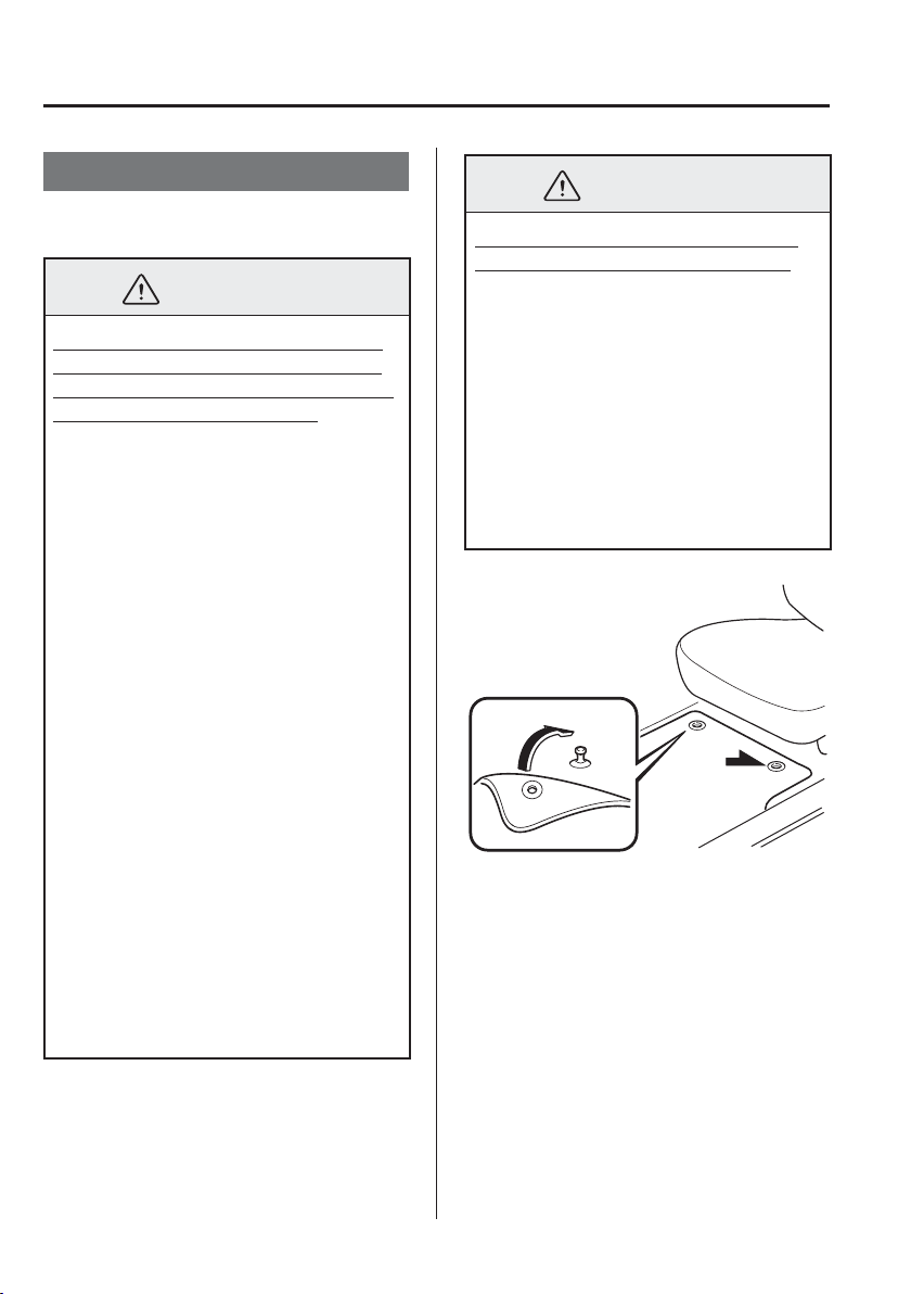
3
–
50
Before Driving
Driving Tips
Floor Mat
We recommend the use of Genuine
Mazda À oor mats.
WARNING
Make sure the À oor mats are secured
with the grommets or the retainers to
prevent them from bunching up under
the foot pedals (Driver's side):
Using a À oor mat that is not secured is
dangerous as it will interfere with the
accelerator and brake pedal operation
(driver's side), which could result in an
accident.
Only use a À oor mat which conforms
to the shape of the À oor on the driver's
side and make sure it is oriented
correctly.
Secure the À oor mat using the
grommets or retainers.
There are various ways to secure À oor
mats depending on the type used,
therefore secure the mat according to
the type.
After installing the À oor mat, make
sure that it does not slide from side
to side or back and forth, and that
there is suf¿ cient clearance with the
accelerator and brake pedals on the
driver's side.
After removing the À oor mat for
cleaning or some other reason, always
securely reinstall it while paying
attention to the precautions just
mentioned.
WARNING
Do not install two À oor mats, one on
top of the other, on the driver's side:
Installing two À oor mats, one on top
of the other, on the driver's side is
dangerous as the retention pins can
only keep one À oor mat from sliding
forward.
Loose À oor mat(s) will interfere with
the foot pedals and could result in an
accident.
If using an all weather mat for winter
use always remove the original À oor
mat.
When setting a À oor mat, position the
À oor mat so that its grommets or retainers
are inserted over the pointed end of the
retention posts.
3
–
51
Before Driving
Driving Tips
Rocking the Vehicle
WARNING
Do not spin the wheels at high speed,
and do not allow anyone to stand
behind a wheel when pushing the
vehicle:
When the vehicle is stuck, spinning
the wheels at high speed is dangerous.
The spinning tyre could overheat and
explode. This could cause serious
injuries.
CAUTION
Too much rocking may cause engine
overheating, transaxle failure, and tyre
damage.
If you must rock the vehicle to free it from
snow, sand or mud, depress the accelerator
slightly and slowly move the shift lever
from 1 (D) to R.
Winter Driving
Carry emergency gear, including tyre
chains, window scraper, À ares, a small
shovel, jumper leads, and a small bag of
sand or salt.
Ask an expert repairer, we recommend an
Authorised Mazda Repairer to check the
following:
Have the proper ratio of antifreeze in the
radiator.
Refer to Engine Coolant on page
6-29 .
Inspect the battery and its leads. Cold
reduces battery capacity.
Use an engine oil appropriate for the
lowest ambient temperatures that the
vehicle will be driven in (page 6-23 ).
Inspect the ignition system for damage
and loose connections.
Use washer À uid made with antifreeze—
but do not use engine coolant antifreeze
for washer À uid (page 6-32 ).
3
–
52
Before Driving
Driving Tips
NOTE
Do not use the parking brake in
freezing weather as it may freeze.
Instead, shift to P with an automatic
transaxle and to 1 or R with a manual
transaxle. Block the rear wheels.
Remove snow before driving. Snow
left on the windscreen is dangerous
as it could obstruct vision.
Do not apply excessive force to a
window scraper when removing ice
or frozen snow on the mirror glass
and windscreen.
Never use warm or hot water for
removing snow or ice from windows
and mirrors as it could result in the
glass cracking.
Drive slowly. Braking performance
can be adversely affected if
snow or ice adheres to the brake
components. If this situation occurs,
drive the vehicle slowly, releasing
the accelerator pedal and lightly
applying the brakes several times
until the brake performance returns
to normal.
Snow Tyres
WARNING
Use only the same size and type tyres
(snow, radial, or non-radial) on all four
wheels:
Using tyres different in size or type is
dangerous. Your vehicle's handling
could be greatly affected and result in
an accident.
CAUTION
Check local regulations before using
studded tyres.
Use snow tyres on all four wheels
Do not exceed the maximum permissible
speed for your snow tyres or legal speed
limits.
E u r o p e
When snow tyres are used, select the
speci¿ ed size and pressure (page 9-10 ).
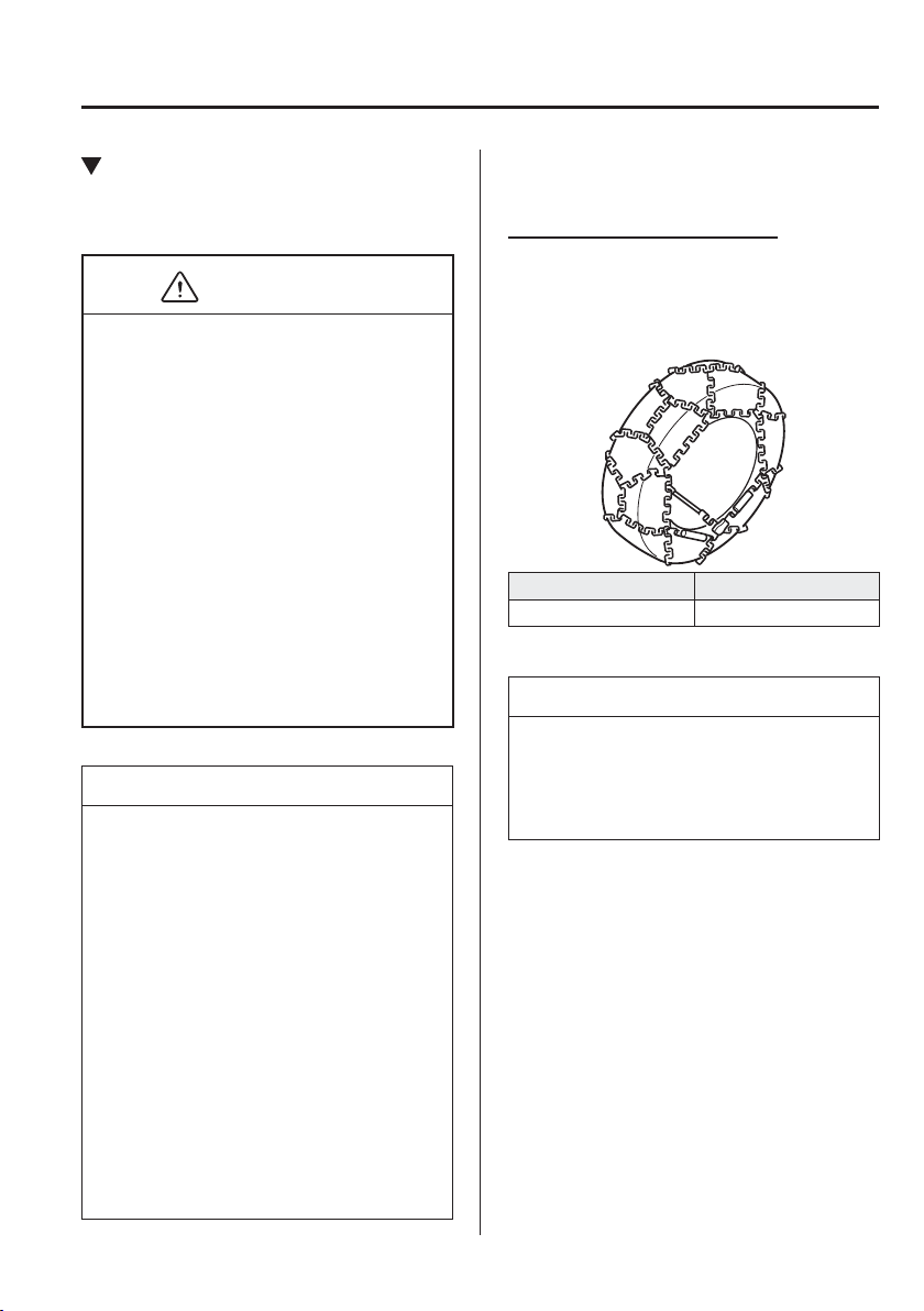
3
–
53
Before Driving
Driving Tips
Tyre Chains
Check local regulations before using tyre
chains.
CAUTION
Chains may affect handling.
Do not go faster than 50 km/h (30
mph) or the chain manufacturer's
recommended limit, whichever is
lower.
Drive carefully and avoid bumps,
holes, and sharp turns.
Avoid locked-wheel braking.
Do not use chains on a temporary
spare tyre; it may result in damage to
the vehicle and to the tyre.
Do not use chains on roads that are
free of snow or ice. The tyres and
chains could be damaged.
Chains may scratch or chip
aluminium wheels.
NOTE
If your vehicle is equipped with the
tyre pressure monitoring system, the
system may not function correctly
when using tyre chains.
Use of tyre chains on a vehicle
equipped with 185/60R16 tyres could
cause interference with the vehicle
body and scratching. If tyre chains
are to be used, replace both the front
and rear tyres with 185/65R15 tyres
and replace both the front and rear
wheels with genuine Mazda 15-inch
wheels of the same size, and use
genuine Mazda tyre chains. Consult
an expert repairer, we recommend an
Authorised Mazda Repairer.
Install the chains on the front tyres only.
Do not use chains on the rear tyres.
Tyre chain selection (Europe)
Mazda recommends hexagon type
steel ring chains. Select the proper type
according to your tyre size.
Tyre size Tyre chain
185/65R15 Hexagon type
NOTE
Although Mazda recommends hexagon
type steel ring chains, all chains within
the installation speci¿ cations may be
used.
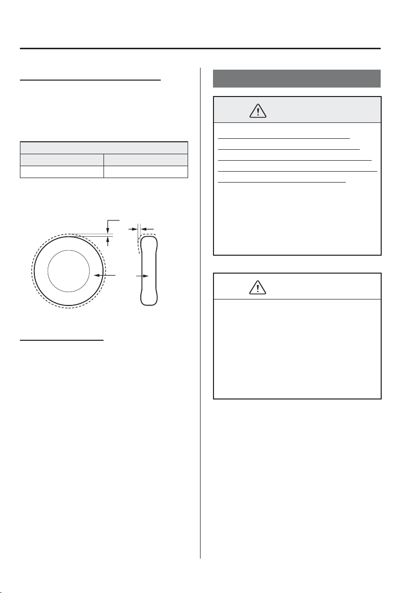
3
–
54
Before Driving
Driving Tips
Installation speci¿ cation (Europe)
When installing tyre chains, the distance
between the tyre tread and the chain must
be within the prescribed limits in the
following table.
Distance [Unit: mm (in)]
A B
MAX 11 (0.43) MAX 11 (0.43)
Side view
Cross section view
Tyre
A
B
Installing the chains
1. If your vehicle is equipped with wheel
covers remove them, otherwise the
chain bands will scratch them.
2. Secure the chains on the front tyres as
tightly as possible. Always follow the
chain manufacturer's instructions.
3. Retighten the chains after driving
1/2—1 km (1/4—1/2 mile).
Driving In Flooded Area
WARNING
Dry off brakes that have become
wet by driving slowly, releasing the
accelerator pedal and lightly applying
the brakes several times until the brake
performance returns to normal:
Driving with wet brakes is dangerous.
Increased stopping distance or the
vehicle pulling to one side when
braking could result in a serious
accident. Light braking will indicate
whether the brakes have been affected.
CAUTION
Do not drive the vehicle on À ooded
roads as it could cause short circuiting
of electrical/electronic parts, or
engine damage or stalling from water
absorption. If the vehicle has been
immersed in water, consult an expert
repairer, we recommend an Authorised
Mazda Repairer.
3
–
55
Before Driving
Driving Tips
Turbocharger Information (SKYACTIV-D 1.5)
CAUTION
After driving at freeway speeds or up a long hill, idle the engine at least 30 seconds
before stopping it. Otherwise, the turbocharger could be damaged. However, when
i-stop operates, idling is unnecessary.
Racing or over-revving the engine, particularly after it's just been started, can damage
the turbocharger.
To protect the engine from damage, the engine is designed so that it cannot be raced
just after starting it in extremely cold weather.
The turbocharger greatly enhances engine power. Its advanced design provides improved
operation and requires minimum maintenance.
To get the most from it, observe the following.
1. Change engine oil and ¿ lter according to Scheduled Maintenance (page 6-3 ).
2. Use only recommended engine oil (page 6-23 ). Extra additives are NOT
recommended.
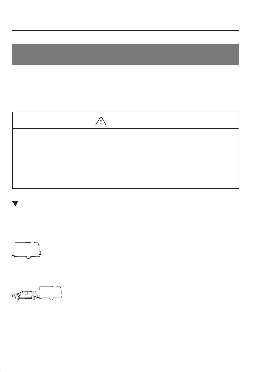
3
–
56
Before Driving
Towing
Towing Caravans and Trailers (Europe/Turkey/South
Africa)
Your Mazda was designed and built primarily to carry passengers and cargo.
If you tow a trailer, follow these instructions because driver and passenger safety depends
on proper equipment and safe driving habits. Towing a trailer will affect handling, braking,
durability, performance, and economy.
Never overload vehicle or trailer. Consult an Authorised Mazda Dealer if you need further
details.
CAUTION
Do not tow a trailer during the ¿ rst 1,000 km (600 miles) of your new Mazda. If you
do, you may damage the engine, transaxle, differential, wheel bearings, and other
power train components.
Damage caused by towing a trailer/caravan is not covered by the vehicle's warranty for
the following models and countries:
All models in Turkey
Saloon models
Weight Limits
The total trailer weight, gross combination weight and trailer nose weight must be
within the prescribed limits in the Trailer Towing-Load Table.
TOTAL TRAILER WEIGHT:
Sum of weights of the trailer and its load.
GROSS COMBINATION WEIGHT:
Sum of total trailer weight and towing vehicle weight; including trailer hitch, vehicle
passengers, and vehicle load.
3
–
57
Before Driving
Towing
TRAILER NOSE WEIGHT:
The weight exerted on the trailer tongue. It is varied by changing the weight distribution
when loading the trailer.
CAUTION
Be aware of the towing load weight differences when towing at high altitudes. For
altitudes exceeding 1,000 meter (3,280 ft 10 in), always reduce the towing load by 10%
for every 1,000 meter (3,280 ft 10 in) increase in altitude from the load indicated under
the gross combination weight heading in the maximum trailer towing-load table. If the
determined maximum total towing load weight is exceeded, the engine and other power
train parts may be damaged.

3
–
58
Before Driving
Towing
Maximum trailer towing-load table
Europe/Gradient up to 12%
MODEL
TOTAL TRAILER
WEIGHT
GROSS
COMBINATION
WEIGHT
Engine
*1
Transaxle
Emission
level
i-stop
system
i-ELOOP
system
Trailer
without
brake
Trailer with
brake
Trailer with brake
SKYACTIV-G
1.5 LP
Manual
transaxle
EURO6 × —
515 kg
(1,135.3 lb)
900 kg
(1,984.1 lb)
2,400 kg (5,291.0 lb)
SKYACTIV-G
1.5 MP
Manual
transaxle
EURO6 × —
520 kg
(1,146.3 lb)
900 kg
(1,984.1 lb)
2,405 kg (5,302.0 lb)
SKYACTIV-G
1.5 MP
Automatic
transaxle
EURO6 × —
530 kg
(1,168.4 lb)
900 kg
(1,984.1 lb)
2,435 kg (5,368.2 lb)
SKYACTIV-G
1.5 HP
Manual
transaxle
EURO6 × —
520 kg
(1,146.3 lb)
900 kg
(1,984.1 lb)
2,405 kg (5,302.0 lb)
SKYACTIV-G
1.5 HP
Manual
transaxle
EURO6 × ×
520 kg
(1,146.3 lb)
900 kg
(1,984.1 lb)
2,410 kg (5,313.0 lb)
SKYACTIV-D
1.5
Manual
transaxle
EURO6 × —
550 kg
(1,212.5 lb)
900 kg
(1,984.1 lb)
2,475 kg (5,456.3 lb)
×: Available
—: Not available
TRAILER NOSE WEIGHT: 50 kg (110.2 lb)
*1 The alphabetical letters at the end of the engine types are short for the following:
LP: Low-Power
MP: Medium-Power
HP: High-Power
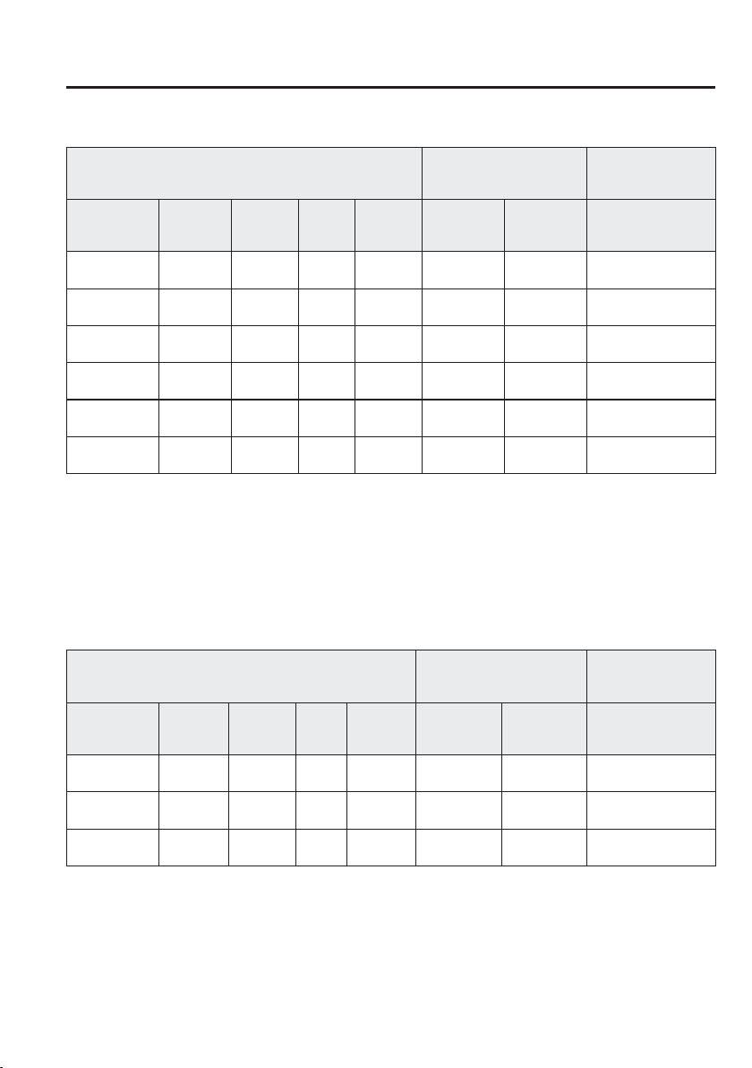
3
–
59
Before Driving
Towing
Germany and Austria/Gradient up to 8%
MODEL
TOTAL TRAILER
WEIGHT
GROSS
COMBINATION
WEIGHT
Engine
*1
Transaxle
Emission
level
i-stop
system
i-ELOOP
system
Trailer
without
brake
Trailer with
brake
Trailer with brake
SKYACTIV-G
1.5 LP
Manual
transaxle
EURO6 × —
515 kg
(1,135.3 lb)
1,100 kg
(2,425.0 lb)
2,600 kg (5,731.9 lb)
SKYACTIV-G
1.5 MP
Manual
transaxle
EURO6 × —
520 kg
(1,146.3 lb)
1,100 kg
(2,425.0 lb)
2,605 kg (5,742.9 lb)
SKYACTIV-G
1.5 MP
Automatic
transaxle
EURO6 × —
530 kg
(1,168.4 lb)
1,000 kg
(2,204.6 lb)
2,535 kg (5,588.6 lb)
SKYACTIV-G
1.5 HP
Manual
transaxle
EURO6 × —
520 kg
(1,146.3 lb)
1,100 kg
(2,425.0 lb)
2,605 kg (5,742.9 lb)
SKYACTIV-G
1.5 HP
Manual
transaxle
EURO6 × ×
520 kg
(1,146.3 lb)
1,100 kg
(2,425.0 lb)
2,610 kg (5,754.0 lb)
SKYACTIV-D
1.5
Manual
transaxle
EURO6 × —
550 kg
(1,212.5 lb)
1,100 kg
(2,425.0 lb)
2,675 kg (5,897.3 lb)
×: Available
—: Not available
TRAILER NOSE WEIGHT: 50 kg (110.2 lb)
*1 The alphabetical letters at the end of the engine types are short for the following:
LP: Low-Power
MP: Medium-Power
HP: High-Power
South Africa/Gradient up to 12% (Hatchback only)
MODEL
TOTAL TRAILER
WEIGHT
GROSS
COMBINATION
WEIGHT
Engine Transaxle
Emission
level
i-stop
system
i-ELOOP
system
Trailer
without
brake
Trailer with
brake
Trailer with brake
SKYACTIV-G
1.5
Manual
transaxle
EURO4 — —
450 kg
(992.0 lb)
750 kg
(1,653.4 lb)
2,246 kg (4,951.5 lb)
SKYACTIV-G
1.5
Automatic
transaxle
EURO4 — —
250 kg
(551.1 lb)
250 kg
(551.1 lb)
1,765 kg (3,891.1 lb)
SKYACTIV-D
1.5
Automatic
transaxle
EURO4 × —
130 kg
(286.5 lb)
130 kg
(286.5 lb)
1,735 kg (3,824.9 lb)
×: Available
—: Not available
TRAILER NOSE WEIGHT: 50 kg (110.2 lb)
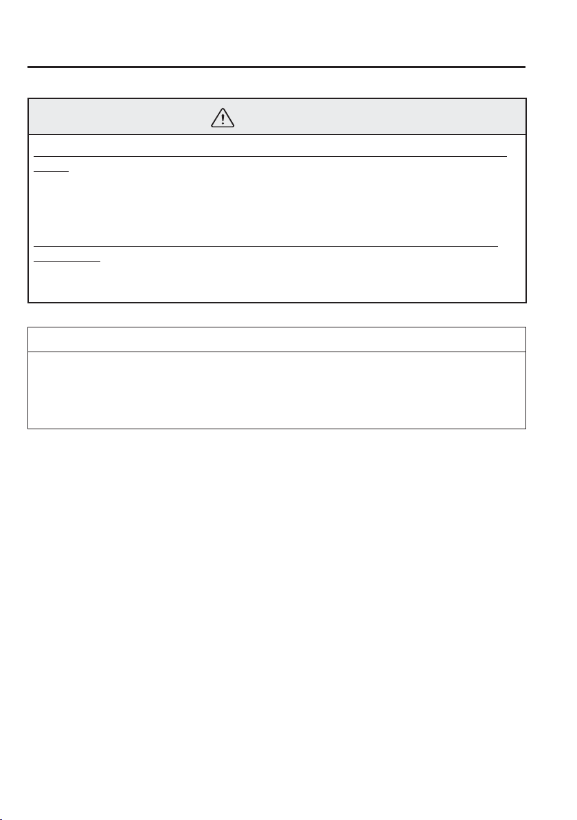
3
–
60
Before Driving
Towing
WARNING
Always keep tow loads within speci¿ ed limits as indicated in the Trailer Towing-Load
Table:
Attempting to tow loads greater than those speci¿ ed is dangerous as it may cause
serious handling and performance problems that could result in personal injury or
vehicle damage, or both.
Always keep the trailer nose weight within the speci¿ ed limits in the Trailer Towing-
Load Table:
Loading the trailer with more weight in the rear than in the front is dangerous. This
could cause loss of vehicle control and an accident.
NOTE
The total trailer weight and nose weight can be determined by weighing the trailer on
platform scales at a highway weighing station or a trucking company.
Appropriate total trailer weight and nose weight may prevent the danger of trailer sway
from crosswinds, rough roads, or other causes.
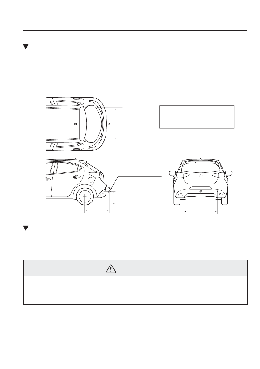
3
–
61
Before Driving
Towing
Trailer Hitch
When towing a trailer, use an appropriate trailer hitch. We recommend using a genuine
Mazda trailer hitch. Use the original holes drilled by the vehicle manufacture for securing
the trailer hitch. Contact your Authorised Mazda Dealer for more information.
Trailer hitch installation area
Unit: mm (in)
MAX. 50 Kg (110 lb)
Hitch coupling point
A
B
A:350—420 (13.8—16.5)
B:746.3 (29.382)
C:1017.9 (40.075)
C
C
Tyres
When towing a trailer, make sure all tyres are inÀ ated to the recommended cold-tyre
pressure, as indicated on the tyre pressure chart on the driver's door frame. Trailer tyre size,
load rating, and inÀ ation pressures should conform to tyre manufacturer speci¿ cations.
WARNING
Never use the temporary spare tyre when towing:
Using the temporary spare tyre on your vehicle when towing a trailer is dangerous as it
could result in tyre failure, loss of control, and injury to vehicle occupants.
3
–
62
Before Driving
Towing
Safety Chains
Safety chains must be used as a precautionary measure should the trailer become
unintentionally unhitched. They should cross under the trailer tongue and attach to the hitch.
Leave enough slack to allow full turns. Consult literature published by your trailer or hitch
manufacturer for more details.
WARNING
Make sure the safety chain is securely attached to both the trailer and the vehicle prior
to departure:
Towing a trailer without using a safety chain securely attached to both the trailer and
the vehicle is dangerous. If damage occurs to the coupling unit or hitch ball, the trailer
could wander into another lane and cause a collision.
Trailer Lights
CAUTION
Do not connect a trailer lighting system directly to the lighting system of your Mazda.
This may damage your vehicle's electrical system and lighting systems. To connect the
lighting system, consult an Authorised Mazda Dealer.
Trailer Brakes
Check the Maximum trailer towing-load table in Weight Limits (page 3-56 ), and if your
trailer weight exceeds the value in the TOTAL TRAILER WEIGHT (Trailer without brake),
trailer brakes are required.
If your trailer has brakes, make sure they meet regulations.
WARNING
Do not connect a hydraulic trailer-brake system to your vehicle's brake system:
Connecting a hydraulic trailer-brake system directly to the vehicle brake system is
dangerous and will result in inadequate braking and possible injury.
3
–
63
Before Driving
Towing
Trailer Towing Tips
Before driving
Verify that your Mazda maintains a near-normal attitude when a loaded or unloaded trailer
is connected. Do not drive if it has an abnormal front-up or front-down position. Inspect
for incorrect nose weight, worn suspension parts, and trailer overloading. Have the vehicle
inspected by an expert repairer, we recommend an Authorised Mazda Repairer.
Make sure the trailer cargo is secure to prevent it from shifting.
Make sure the mirrors meet all government regulations. Inspect them.
Before starting out, inspect the operation of all vehicle and trailer lights and all vehicle-
to-trailer connections. Stop and re-inspect all lights and connections after driving a short
distance.
Driving
Your Mazda will handle differently with a trailer in tow, so practice turning, backing, and
stopping in a traf¿ c-free area.
Take time to get accustomed to the extra weight and length.
Do not exceed 100 km/h (62 mph) with a trailer in tow. If the local legal maximum speed
with a trailer in tow is less than 100 km/h (62 mph), do not exceed the legal speed.
CAUTION
If the vehicle exceeds 100 km/h (62 mph) with a trailer in tow, the vehicle could be
damaged.
When ascending a hill, shift into a lower gear to reduce the possibility of overloading or
overheating the engine, or both.
When descending a hill, shift into a lower gear and use engine compression as a braking
effect. Pay constant attention to speed and use the brakes only as needed. Holding the
brake pedal down for a prolonged period may cause the brakes to overheat and lose
power.

3
–
64
Before Driving
Towing
Parking
Avoid parking on an incline with a trailer. If this must be done, follow these instructions.
Parking on an Incline
1. Set the parking brake and the brakes.
2. Have someone block the wheels of the vehicle and trailer while you apply the brakes.
3. After the wheels are blocked, release the parking brake and the brakes slowly, allowing
the blocks to bear the load.
4. Set the parking brake ¿ rmly.
5. If the vehicle has an automatic transaxle, put the selector lever in P. If it has a manual
transaxle, place the gear shift in 1 or R.
Starting on an Incline
1. Start the engine (page 4-5 ).
2. Release the parking brake and slowly pull away a short distance from the wheel blocks.
3. Stop on the nearest level ground, set the parking brake, and pick up the wheel blocks.

4
–
1
*Some models.
4
–
1
4
When Driving
Information concerning safe driving and stopping.
Start/Stop Engine ................................ 4-4
Ignition Switch ............................... 4-4
Starting the Engine ......................... 4-5
Turning the Engine Off ................ 4-12
i-stop
*
........................................... 4-13
Instrument Cluster and Display ...... 4-24
Meters and Gauges ....................... 4-24
Active Driving Display
*
............... 4-35
Warning/Indicator Lights ............. 4-38
Manual Transaxle Operation ........... 4-46
Manual Transaxle Shift Pattern .... 4-46
Automatic Transaxle ......................... 4-49
Automatic Transaxle Controls ..... 4-49
Shift-Lock System ....................... 4-50
Transaxle Ranges ......................... 4-51
Manual Shift Mode ...................... 4-53
Direct Mode
*
................................ 4-59
Driving Tips ................................. 4-60
Switches and Controls ...................... 4-61
Lighting Control ........................... 4-61
Front Fog Lights
*
......................... 4-69
Rear Fog Light
*
............................ 4-70
Turn and Lane-Change Signals .... 4-71
Windscreen Wipers and
Washer .......................................... 4-72
Rear Window Wiper and
Washer
*
......................................... 4-77
Headlight Washer
*
........................ 4-77
Rear Window Defogger ............... 4-78
Horn ............................................. 4-79
Hazard Warning Flasher ............... 4-80
Brake .................................................. 4-81
Brake System ............................... 4-81
Emergency Stop Signal System ... 4-84
Hill Launch Assist (HLA)
*
........... 4-84
ABS/TCS/DSC ................................... 4-86
Antilock Brake System (ABS) ..... 4-86
Traction Control System (TCS)
*
...
4-87
Dynamic Stability Control
(DSC)
*
.......................................... 4-88
i-ELOOP ............................................ 4-90
i-ELOOP
*
..................................... 4-90
Fuel Economy Monitor ..................... 4-93
Fuel Economy Monitor
*
............... 4-93

4
–
2
*Some models.
Drive Selection ................................... 4-99
Drive Selection
*
........................... 4-99
Power Steering................................. 4-101
Power Steering ........................... 4-101
i-ACTIVSENSE............................... 4-102
i-ACTIVSENSE
*
........................ 4-102
High Beam Control System
(HBC)
*
........................................ 4-105
Adaptive LED Headlights
(ALH)
*
........................................ 4-108
Lane Departure Warning System
(LDWS)
*
.................................... 4-111
Blind Spot Monitoring (BSM)
System
*
....................................... 4-117
Distance Recognition Support System
(DRSS)
*
...................................... 4-124
Driver Attention Alert (DAA)
*
... 4-127
Rear Cross Traf¿ c Alert
(RCTA)
*
..................................... 4-130
Mazda Radar Cruise Control
(MRCC)
*
.................................... 4-135
Adjustable Speed Limiter
*
......... 4-148
Smart City Brake Support [Forward]
(SCBS F)
*
................................... 4-155
Smart City Brake Support [Reverse]
(SCBS R)
*
.................................. 4-161
Smart Brake Support (SBS)
*
...... 4-167
Forward Sensing Camera
(FSC)
*
......................................... 4-170
Radar Sensor (Front)
*
................. 4-176
Laser Sensor
*
.............................. 4-179
Radar Sensors (Rear)
*
................ 4-181
Ultrasonic Sensor (Rear)
*
........... 4-183
Cruise Control ................................. 4-184
Cruise Control
*
........................... 4-184
Tyre Pressure Monitoring System
... 4-190
Tyre Pressure Monitoring
System
*
....................................... 4-190
Diesel Particulate Filter
(SKYACTIV-D 1.5) ......................... 4-194
Diesel Particulate Filter
(SKYACTIV-D 1.5) ................... 4-194
Rear View Monitor .......................... 4-195
Rear View Monitor
*
................... 4-195
Parking Sensor System ................... 4-204
Parking Sensor System
*
............. 4-204

MEMO
4
–
3
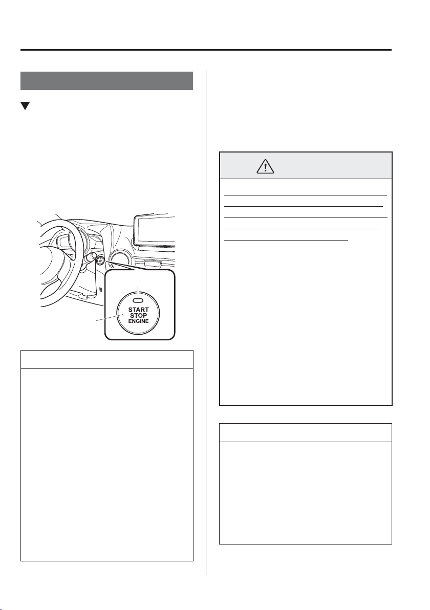
4
–
4
When Driving
Start/Stop Engine
Ignition Switch
Push Button Start Positions
The system operates only when the driver
is in the vehicle or within operational
range while the key is being carried.
Each time the push button start is pressed,
the ignition switches in the order of off,
ACC, and ON. Pressing the push button
start again from ON switches the ignition
off.
Push button start
Indicator light
NOTE
The engine starts by pressing the
push button start while depressing
the clutch pedal (manual transaxle)
or the brake pedal (automatic
transaxle). To switch the ignition
position, press the push button start
without depressing the pedal.
Do not leave the ignition switched
ON while the engine is not running.
Doing so could result in the battery
going dead. If the ignition is left in
ACC (For automatic transaxle, the
selector lever is in the P position, and
the ignition is in ACC), the ignition
switches off automatically after about
25 minutes.
O f f
The power supply to electrical devices
turns off and the push button start indicator
light (amber) also turns off.
In this position the steering wheel is
locked.
WARNING
Before leaving the driver's seat, always
switch the ignition off, set the parking
brake, and make sure the selector lever
is in P (automatic transaxle) or in 1st
gear or R (manual transaxle):
Leaving the driver's seat without
switching the ignition off, setting the
parking brake, and shifting the selector
lever to P (automatic transaxle) or
to 1st gear or R (manual transaxle)
is dangerous. Unexpected vehicle
movement could occur which could
result in an accident.
In addition, if your intention is to leave
the vehicle for even a short period, it
is important to switch the ignition off,
as leaving it in another position will
disable some of the vehicle's security
systems and run the battery down.
NOTE
(Locked steering wheel)
If the push button start indicator light
(green) is À ashing and the beep sound
is heard, this indicates that the steering
wheel is not unlocked. To unlock the
steering wheel, press the push button
start while moving the steering wheel
left and right.
4
–
5
When Driving
Start/Stop Engine
ACC (Accessory)
Some electrical accessories will operate
and the indicator light (amber) illuminates.
In this position the steering wheel is
unlocked.
NOTE
The keyless entry system does not
function while the push button start has
been pressed to ACC, and the doors will
not lock/unlock even if they have been
locked manually.
O N
This is the normal running position after
the engine is started. The indicator light
(amber) turns off. (The indicator light
(amber) illuminates when the ignition
is switched ON and the engine is not
running.)
Some indicator lights/warning lights
should be inspected before the engine is
started (page 4-38 ).
NOTE
(SKYACTIV-G 1.3, SKYACTIV-G
1.5)
When the push button start is pressed
to ON, the sound of the fuel pump
motor operating near the fuel tank can
be heard. This does not indicate an
abnormality.
Starting the Engine
WARNING
Radio waves from the key may affect
medical devices such as pacemakers:
Before using the key near people who
use medical devices, ask the medical
device manufacturer or your physician
if radio waves from the key will affect
the device.

4
–
6
When Driving
Start/Stop Engine
NOTE
The key must be carried because the
key carries an immobilizer chip that
must communicate with the engine
controls at short range.
The engine can be started when the
push button start is pressed from off,
ACC, or ON.
The push button start system
functions (function which can start
the engine by only carrying the
key) can be deactivated to prevent
any possible adverse effect on a
user wearing a pacemaker or other
medical device. If the system is
deactivated, you will be unable
to start the engine by carrying the
key. Consult an expert repairer, we
recommend an Authorised Mazda
Repairer for details. If the push
button start system functions have
been deactivated, you can start the
engine by following the procedure
indicated when the key battery goes
dead.
Refer to Engine Start Function When
Key Battery is Dead on page 4-10 .
After starting a cold engine, the
engine speed increases and a whining
sound from the engine compartment
can be heard.
This is for improved exhaust gas
puri¿ cation and does not indicate any
parts defect.
1. Make sure you are carrying the key.
2. Occupants should fasten their seat
belts.
3. Make sure the parking brake is on.
4. Continue to press the brake pedal
¿ rmly until the engine has completely
started.
5. (Manual transaxle)
Continue to press the clutch pedal
¿ rmly until the engine has completely
started.
(Automatic transaxle)
Put the vehicle in park (P). If you must
restart the engine while the vehicle is
moving, shift into neutral (N).
NOTE
(Manual transaxle)
The starter will not operate if the clutch
pedal is not depressed suf¿ ciently.
(Automatic transaxle)
The starter will not operate if the
selector lever is not in P or N and the
brake pedal is not depressed suf¿ ciently.
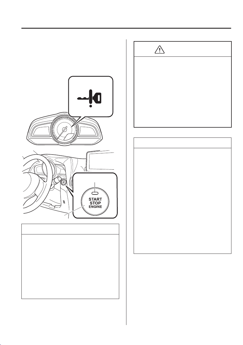
4
–
7
When Driving
Start/Stop Engine
6. Verify that the KEY indicator light
(green) in the instrument cluster and the
push button start indicator light (green)
illuminate.
Indicator light
Push button start
NOTE
If the push button start indicator light
(green) À ashes, make sure that the
key is being carried.
If the push button start indicator light
(green) À ashes with the key being
carried, touch the key to the push
button start and start the engine.
Refer to Engine Start Function When
Key Battery is Dead on page 4-10 .
CAUTION
If the KEY warning light (red)
illuminates, or the push button start
indicator light (amber) À ashes, this
could indicate a problem with the engine
starting system. This may prevent the
engine from starting or from switching
the ignition to ACC or ON. Have your
vehicle inspected at an expert repairer,
we recommend an Authorised Mazda
Repairer as soon as possible.
NOTE
Under the following conditions, the
KEY warning light (red) À ashes
after the push button start is pressed.
This informs the driver that the push
button start will not switch to ACC
even if it is pressed from off.
The key battery is dead.
The key is out of operational
range.
The key is placed in areas where it
is dif¿ cult for the system to detect
the signal (page 3-7 ).
A key from another manufacturer
similar to the key is in the
operational range.
4
–
8
When Driving
Start/Stop Engine
NOTE
(Forced engine starting method)
If the KEY warning light (red)
illuminates, or the push button start
indicator light (amber) À ashes, this
could indicate that the engine may
not start using the usual starting
method. Have your vehicle inspected
at an expert repairer, we recommend
an Authorised Mazda Repairer as
soon as possible. If this occurs, the
engine can be force-started. Press
and hold the push button start until
the engine starts. Other procedures
necessary for starting the engine,
such as having the key in the cabin,
and depressing the clutch pedal
(manual transaxle) or the brake pedal
(automatic transaxle) are required.
When the engine is force-started,
the KEY warning light (red) remains
illuminated and the push button
start indicator light (amber) remains
À ashing.
(Automatic transaxle)
When the selector lever is in the
neutral (N) position, the KEY
indicator light (green) and the push
button start indicator light (green) do
not illuminate.
7. Press the push button start after both
the KEY indicator light (green) in the
instrument cluster and the push button
start indicator light (green) illuminate.
NOTE
After starting the engine, the push
button start indicator light (amber)
turns off and the ignition switches to
the ON position.
(SKYACTIV-G 1.3, SKYACTIV-G
1.5)
After pressing the push button start
and before the engine starts, the
operation sound of the fuel pump
motor from near the fuel tank can be
heard, however, this does not indicate
a malfunction.
(SKYACTIV-D 1.5)
When starting the engine, do
not release the brake pedal until
the glow indicator light in the
instrument cluster turns off and
the engine starts, after pressing the
push button start.
If the brake pedal is released
before the engine starts, depress
the brake pedal again and press
the push button start to start the
engine.
If the ignition is left switched ON
for a long period of time without
the engine running after the glow
plugs are warmed up, the glow
plugs may warm up again which
will illuminate the glow indicator
light.
The starter does not rotate until the
glow indicator light turns off.

4
–
9
When Driving
Start/Stop Engine
8. After starting the engine, let it idle
for about ten seconds (Prohibited in
Germany).
NOTE
(Germany)
Drive immediately after starting the
engine. However do not use high
engine speeds until reaching the
operating temperature.
(SKYACTIV-G 1.3, SKYACTIV-G
1.5)
Whether the engine is cold or
warm, it should be started without
the use of the accelerator.
If the engine does not start the ¿ rst
time, refer to Starting a Flooded
Engine under Emergency Starting.
If the engine still does not start,
have your vehicle inspected by an
Authorised Mazda Repairer (page
7-27 ).
(SKYACTIV-D 1.5)
If the ambient temperature is lower
than about - 10 °C (14 °F), the
maximum engine speed may not
be attained for about three minutes
after the engine starts to protect the
engine.
NOTE
(Manual transaxle vehicle with
i-stop function)
If the engine has stopped due to
stalling, it can be restarted by
depressing the clutch pedal within
3 seconds of the engine stopping.
The engine cannot be restarted even
if the clutch pedal is depressed under
the following conditions:
The driver's door is open.
The driver's seat belt is unfastened.
The clutch pedal is not released
completely after the engine stalled.
The clutch pedal is depressed with
the engine not stopped completely.
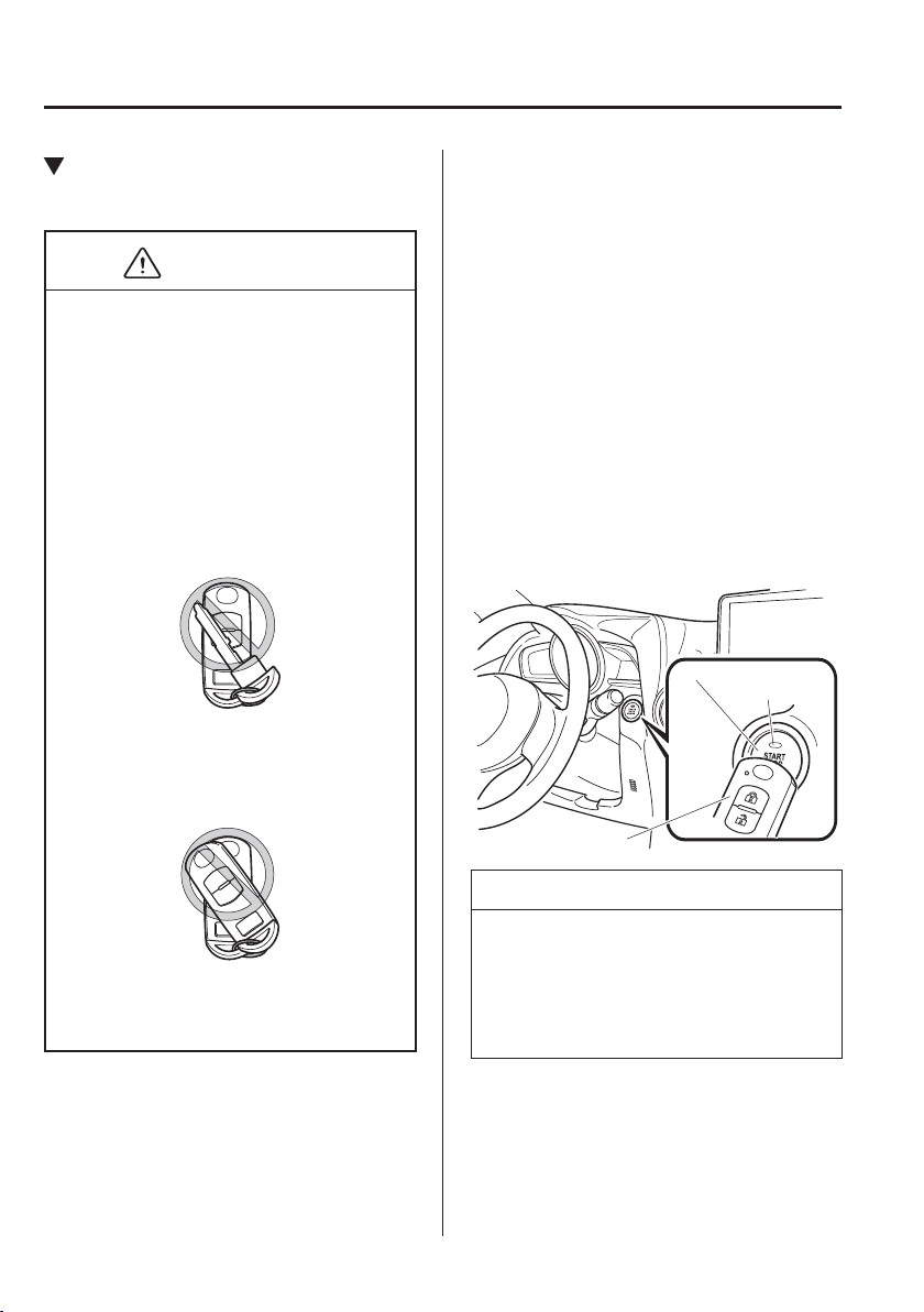
4
–
10
When Driving
Start/Stop Engine
Engine Start Function When Key
Battery is Dead
CAUTION
When starting the engine by holding
the transmitter over the push button
start due to a dead key battery or a
malfunctioning key, be careful not
to allow the following, otherwise the
signal from the key will not be received
correctly and the engine may not start.
Metal parts of other keys or metal
objects touch the key.
Spare keys or keys for other vehicles
equipped with an immobilizer system
touch or come near the key.
Devices for electronic purchases, or
security passage touch or come near
the key.
If the engine cannot be started due to a
dead key battery, the engine can be started
using the following procedure:
1. Continue to depress the brake pedal
¿ rmly until the engine has completely
started.
2. (Manual transaxle)
Continue to depress the clutch pedal
¿ rmly until the engine has completely
started.
3. Verify that the push button start
indication light (green) À ashes.
4. Touch the push button start using the
backside of the key (as shown) while
the push button start indicator light
(green) À ashes.
Push button start
Transmitter
Indicator light
NOTE
When touching the push button start
using the backside of the key as shown
in the illustration, touch the push button
start with the lock switch side of the key
facing up.
5. Verify that the push button start
indicator light (green) turns on.

4
–
11
When Driving
Start/Stop Engine
6. Press the push button start to start the
engine.
NOTE
The engine cannot be started unless
the clutch pedal is fully depressed
(manual transaxle) or the brake
pedal is fully depressed (automatic
transaxle).
If there is a malfunction with the
push button start function, the push
button start indicator light (amber)
À ashes. In this case, the engine may
start, however, have the vehicle
checked at an expert repairer, we
recommend an Authorised Mazda
Repairer as soon as possible.
If the push button start indicator light
(green) does not illuminate, perform
the operation from the beginning
again. If it does not illuminate,
have the vehicle checked at an
expert repairer, we recommend an
Authorised Mazda Repairer.
To switch the ignition position
without starting the engine, perform
the following operations after the
push button start indicator light
(green) turns on.
1. Release the clutch pedal (manual
transaxle) or brake pedal
(automatic transaxle).
2. Press the push button start to
switch the ignition position. The
ignition switches in the order of
ACC, ON, and off each time the
push button start is pressed. To
switch the ignition position again,
perform the operation from the
beginning.
Emergency Operation for Starting
the Engine
If the KEY warning light (red) illuminates,
or the push button start indicator light
(amber) À ashes, this could indicate that
the engine may not start using the usual
starting method. Have your vehicle
inspected at an expert repairer, we
recommend an Authorised Mazda Repairer
as soon as possible. If this occurs, the
engine can be force-started. Press and hold
the push button start until the engine starts.
Other procedures necessary for starting the
engine such as having the key in the cabin,
and depressing the clutch pedal (manual
transaxle) or the brake pedal (automatic
transaxle) are required.
4
–
12
When Driving
Start/Stop Engine
Turning the Engine Off
WARNING
Do not stop the engine while the
vehicle is moving:
Stopping the engine while the vehicle is
moving for any reason other than in an
emergency is dangerous. Stopping the
engine while the vehicle is moving will
result in reduced braking ability due to
the loss of power braking, which could
cause an accident and serious injury.
1. Stop the vehicle completely.
2. (Manual transaxle)
Shift into neutral and set the parking
brake.
(Automatic transaxle)
Shift the selector lever to the P position
and set the parking brake.
3. Press the push button start to turn off
the engine. The ignition position is off.
CAUTION
When leaving the vehicle, make sure the
push button start is off.
NOTE
The cooling fan in the engine
compartment could turn on for a few
minutes after the ignition is switched
from ON to OFF, whether or not the
A/C is on or off, to cool the engine
compartment quickly.
When the push button start is pressed
from ON to ACC or OFF, the KEY
indicator light (green) may À ash for
approximately 30 seconds indicating
that the remaining battery power of
the key is low.
Replace with a new battery before
the key becomes unusable.
Refer to Key Battery Replacement on
page 6-41 .
(Automatic transaxle)
If the engine is turned off while the
selector lever is in a position other
than P, the ignition switches to ACC.
Emergency Engine Stop
Continuously pressing the push button
start or quickly pressing it any number of
times while the engine is running or the
vehicle is being driven will turn the engine
off immediately. The ignition switches to
ACC.
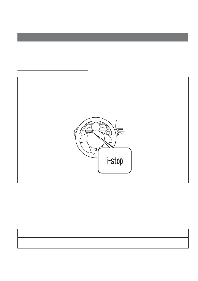
4
–
13
When Driving
Start/Stop Engine
*Some models.
i-stop
*
The i-stop function automatically stops the engine when the vehicle is stopped at a traf¿ c
light or stuck in traf¿ c, and then restarts the engine automatically to resume driving. The
system provides improved fuel economy, reduced exhaust gas emissions, and eliminates
idling noise while the engine is stopped.
Engine idle stopping and restarting
NOTE
The i-stop indicator light (green) turns on under the following conditions:
When engine idling is stopped.
(Except European model)
Engine idling stop conditions are met while the vehicle is being driven.
The i-stop indicator light (green) turns off when the engine is restarted.
Manual transaxle
1. Stop the vehicle by depressing the brake pedal and then the clutch pedal.
2. While depressing the clutch pedal, shift the shift lever to the neutral position. Engine
idling stops after the clutch pedal is released.
3. (SKYACTIV-G 1.3, SKYACTIV-G 1.5)
The engine restarts automatically when you depress the clutch pedal or start to release it.
NOTE
The engine restart timing varies depending on the brake pedal depression force.
(SKYACTIV-D 1.5)
The engine restarts automatically when the clutch pedal is depressed.

4
–
14
When Driving
Start/Stop Engine
Automatic transaxle
1. Engine idling stops when the brake pedal is depressed while the vehicle is driven (except
for driving in the R or M position second gear ¿ xed mode) and the vehicle is stopped.
2. The engine restarts automatically when the brake pedal is released with the selector lever
in the D or M position (not in second gear ¿ xed mode).
3. If the selector lever is in the N or P position, the engine does not restart when the brake
pedal is released. The engine restarts when the brake pedal is depressed again or the
selector lever is shifted to the D, M (not in second gear ¿ xed mode) or the R position.
(For the purposes of safety, always keep the brake pedal depressed when shifting the
selector lever while engine idling is stopped.)
Operation conditions
When the system is operable
Under the following conditions, engine idling stops and the i-stop indicator light (green)
turns on.
(SKYACTIV-G 1.3, SKYACTIV-G 1.5)
The engine is warmed up.
(SKYACTIV-D 1.5)
The engine is not cold.
The fuel injection amount learning, which is performed periodically and automatically,
is not being performed.
The engine has been started and the vehicle is driven for a certain period.
The engine is started with the bonnet closed.
The battery is in good condition.
All doors, liftgate/boot lid, and bonnet are closed.
The driver's seat belt is fastened.
The air conditioner is not operating with the airÀ ow mode dial in the position.
(Automatic air-conditioning)
The temperature setting dial for the air-conditioning is set to a position other than
maximum heating/maximum cooling (A/C ON).
The vehicle's interior temperature and the set temperature for the air conditioner are
nearly the same.
The i-stop warning light (amber) is not turned on/À ashing.
The keyless entry & push button start system functions are normal.
The brake vacuum is suf¿ ciently high.
The steering wheel is not being operated.

4
–
15
When Driving
Start/Stop Engine
(Manual transaxle)
The vehicle speed is 3 km/h (1.8 mph) or less.
The shift lever is in the neutral position.
The clutch pedal is not depressed.
(Automatic transaxle)
The vehicle is stopped.
The selector lever is in the D or M position (not in second gear ¿ xed mode).
The automatic transaxle À uid has warmed up suf¿ ciently.
The automatic transaxle À uid temperature is not abnormally high.
The steering wheel is almost in the straight-ahead position (idling may not stop even
with the steering wheel in the straight-ahead position if force is applied to the steering
wheel. Release the force applied to the steering wheel to stop engine idling).
The vehicle is stopped by depressing the brake pedal.
Emergency braking is not applied.
When the system is not operable
Engine idling does not stop in the following conditions:
The vehicle is stopped but the engine is kept idling.
The air conditioner is operating with the airÀ ow mode dial in the position.
(Automatic air-conditioning)
The temperature setting dial for the air-conditioning is set to the maximum heating/
maximum cooling (A/C ON) position.
There is a large difference between the cabin temperature and the set temperature of the
air conditioner.
The ambient temperature is extremely high or low.
The atmospheric pressure is low (when driving at high altitudes).
(Automatic transaxle)
The vehicle is stopped on a steep incline.
The steering wheel is not in the straight-ahead position while the vehicle is stopped.
(SKYACTIV-D 1.5)
The particulate matter (PM) is being removed by the diesel particulate ¿ lter (DPF).
The fuel injection amount learning is being performed. (The i-stop indicator light (green)
turns off when the vehicle speed before stopping is approx. 10 km/h (6.2 mph) or less
and fuel injection amount learning is performed while the vehicle is stopped.)

4
–
16
When Driving
Start/Stop Engine
NOTE
Under the following conditions, a period of time is required to stop engine idling
The battery power is depleted for some reasons such as the vehicle has not been driven
for a long period.
The ambient temperature is high or low.
After the battery terminals are disconnected for some reasons such as for battery
replacement.
(SKYACTIV-D 1.5)
After PM removal is performed by the diesel particulate ¿ lter (DPF).
Engine does not restart
If the following operations are performed while the idling is stopped, the engine will not
restart for safety reasons. In such cases, start the engine using the normal method.
The bonnet is opened.
(European model)
The driver's seat belt is unfastened and the driver's door is opened.
(Except European model)
(Manual transaxle)
With the shift lever in a position other than neutral, the driver's seat belt is
unfastened and the driver's door is opened.
(Automatic transaxle)
With the selector lever in the D or M (not in second gear ¿ xed mode), the driver's
seat belt is unfastened and the driver's door is opened.
Engine-stop period is short or time until next engine idle stop is long
The ambient temperature is high or low.
The battery power is depleted.
Power consumption by the vehicle's electrical parts is high.

4
–
17
When Driving
Start/Stop Engine
NOTE
Engine restarts automatically while engine idling is stopped
Under the following conditions, the engine restarts automatically.
The i-stop OFF switch is pressed until the beep sounds.
The air conditioner is operated with the airÀ ow mode dial in the position.
(Automatic air-conditioning)
The temperature setting dial of the air conditioner is set to the maximum heating/
maximum cooling (A/C ON).
The cabin temperature is largely different from the set temperature of the air
conditioner.
The brakes are released slightly on a slope and the vehicle begins to move.
Two minutes have elapsed since the idling was stopped.
The battery power is depleted.
(Automatic transaxle)
The accelerator pedal is depressed with the selector lever in the D or M (not in
second gear ¿ xed mode) position.
The selector lever is shifted to the R position.
The selector lever is shifted from N or P position to D or M (not in second gear ¿ xed
mode) position.
The steering wheel is operated with the selector lever in the D or M (not in second
gear ¿ xed mode) position.
The selector lever is in the M position and the second gear ¿ xed mode is selected.
(Except European model)
(Manual transaxle)
With the shift lever in the neutral position, the driver's seat belt is unfastened and the
driver's door is opened.
(Automatic transaxle)
With the selector lever in the N or P position, the driver's seat belt is unfastened and
the driver's door is opened.
4
–
18
When Driving
Start/Stop Engine
NOTE
Selector lever is operated while engine idling is stopped (automatic transaxle)
If the selector lever is shifted from D or M (not in second gear ¿ xed mode) position to
N or P position while engine idling is stopped, the engine does not restart even when the
brake pedal is released. The engine will restart if the brake pedal is depressed again or the
selector lever is shifted to the D, M (not in second gear ¿ xed mode), or R position. (For
the purposes of safety, always keep the brake pedal depressed when shifting the selector
lever while engine idling is stopped.)
(European model)
If the selector lever is shifted from the D or M (not in second gear ¿ xed mode) position
to the N or P position, and the driver's seat belt is unfastened and the driver's door is
opened, the engine does not restart. Start the engine using the normal method.
(Except European model)
If the selector lever is shifted from the D or M (not in second gear ¿ xed mode) to the
N or P position, and the driver's seat belt is unfastened and the driver's door is opened,
the engine restarts.
Battery terminals are disconnected
Engine idling may not stop right after the battery terminals are disconnected. In addition,
if the battery is replaced, the i-stop functions must be veri¿ ed. Consult an expert repairer,
we recommend an Authorised Mazda Repairer.
i-stop Warning Light (Amber)/i-stop Indicator Light (Green)
To ensure safe and comfortable use of the vehicle, the i-stop system constantly monitors the
driver's operations, the vehicle's interior and exterior environment, and the operational status
of the vehicle, and uses the i-stop warning light (amber) and i-stop indicator light (green) to
inform the driver of various cautions and warnings.
NOTE
On vehicles equipped with the centre display, the i-stop operation status is displayed in the
fuel monitor control status display.
Refer to Control Status Display on page 4-95 .

4
–
19
When Driving
Start/Stop Engine
i-stop warning light (amber)
When the light is turned on
The light turns on when the ignition is switched ON and turns off when the engine is
started.
The light turns on when the i-stop OFF switch is pressed and the system is turned off.
The light turns on if the following operations are performed while engine idling is
stopped. In such cases, the engine does not restart automatically to ensure safety. Start the
engine using the normal method.
The bonnet is opened.
(European model)
The driver's seat belt is unfastened and the driver's door is opened.
(Except European model)
(Manual transaxle)
With the shift lever in a position other than neutral, the driver's seat belt is unfastened
and the driver's door is opened.
(Automatic transaxle)
With the selector lever in the D or M (not in second gear ¿ xed mode) position, the
driver's seat belt is unfastened and the driver's door is opened.
NOTE
A problem in the system may be indicated under the following conditions. Have your
vehicle inspected at an expert repairer, we recommend an Authorised Mazda Repairer.
The light does not turn on when the ignition is switched ON.
The light continues to remain on even though the i-stop OFF switch has been pressed
while the engine is running.
When the light is À ashing
The light continues to À ash if the system has a malfunction. Have your vehicle inspected at
an expert repairer, we recommend an Authorised Mazda Repairer.

4
–
20
When Driving
Start/Stop Engine
i-stop indicator light (green)
When the light is turned on
The light turns on while engine idling is stopped and turns off when the engine is
restarted.
(Except European model)
The light turns on when the engine idling stop conditions are met while the vehicle is
driven.
When the light is À ashing
(Manual transaxle)
The light À ashes when the shift lever is shifted to a position other than the neutral while
engine idling is stopped to notify the driver that engine idling is stopped.
(SKYACTIV-G 1.3, SKYACTIV-G 1.5)
By depressing the clutch pedal or starting to release it, the engine restarts automatically
and the light turns off.
(SKYACTIV-D 1.5)
By depressing the clutch pedal, the engine restarts automatically and the light turns off.
(European model)
The light À ashes when the driver's door is opened while engine idling is stopped to
notify the driver that engine idling is stopped. It turns off when the driver's door is
closed.
If the engine is restarted due to low battery voltage while the engine idling is stopped,
the i-stop indicator light (green) in the instrument cluster À ashes for about 3 seconds.
(Except European model)
(Automatic transaxle)
The light À ashes if the vehicle is stopped but the brake pedal is not depressed with
suf¿ cient force. Depress the brake pedal a little more strongly because the pedal force
may be insuf¿ cient.
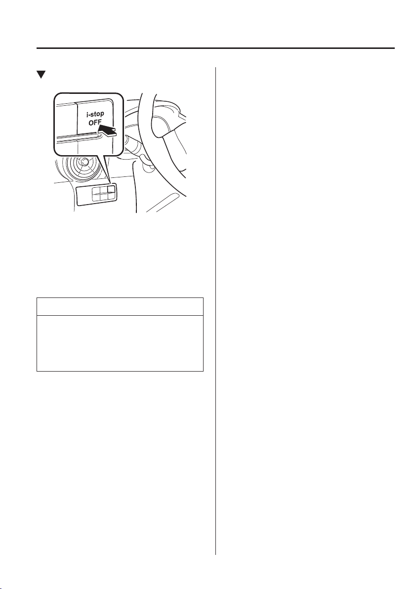
4
–
21
When Driving
Start/Stop Engine
i-stop OFF Switch
By pressing the switch until a beep
sounds, the i-stop function is turned off
and the i-stop warning light (amber) in the
instrument cluster turns on. By pressing
the switch again until the beep sounds, the
i-stop function becomes operational and
the i-stop warning light (amber) turns off.
NOTE
If the engine is stopped with the i-stop
function cancelled, the i-stop function
becomes operational when the engine is
started the next time.
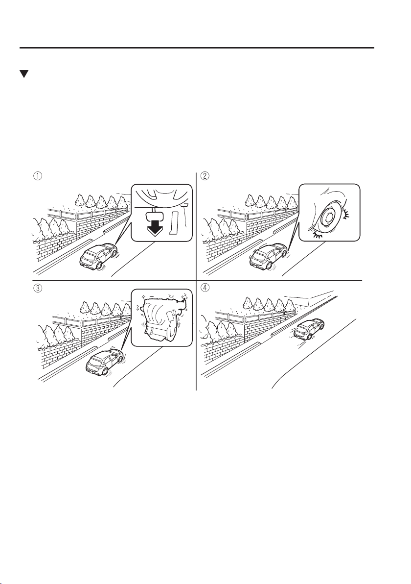
4
–
22
When Driving
Start/Stop Engine
Vehicle Roll Prevention Function (Automatic transaxle)
Vehicles with the i-stop function are equipped with a vehicle roll prevention function. This
function prevents the vehicle from rolling, such as when releasing the brake pedal while on
a slope under the following conditions:
While engine idling is stopped (prevents the vehicle from rolling back)
When starting from a stop (prevents the vehicle's sudden movement due to vehicle creep)
When the brake pedal is released, the braking force is maintained automatically depending
on the grade of the road.
Release foot from brake pedal Vehicle brake force maintained
Engine restarted Acceleration
4
–
23
When Driving
Start/Stop Engine
WARNING
Do not rely completely on the vehicle roll prevention function.
The vehicle roll prevention function is a supplementary function which operates
for a maximum of four seconds after releasing the brake pedal and accelerating the
vehicle from an engine idling stop condition. Over reliance on the system may result
in an unexpected accident if the vehicle were to suddenly accelerate. Before starting
to drive the vehicle, always con¿ rm the safety of the surroundings and operate the
selector lever, brake pedal, and accelerator pedal appropriately. Note that the vehicle
may move suddenly depending on the grade of the road, the vehicle's load, or if it is
towing something.
Note that the vehicle may move suddenly after the vehicle roll prevention function is
released while the vehicle is under the following conditions:
The selector lever is in the N position.
If the selector lever is shifted to the N position and the brake pedal is released
while the i-stop function is operating, the brake force is gradually released. To
accelerate the vehicle, release the brake pedal after the engine restarts and shift
the selector lever to a position other than the N position.
NOTE
When the vehicle is stopped on a steep grade, the vehicle roll prevention function does
not operate because engine idling is not stopped.
The brake pedal response may change, sound may occur from the brakes, or the
brake pedal could vibrate from the operation of the vehicle roll prevention function.
However, this does not indicate a malfunction.
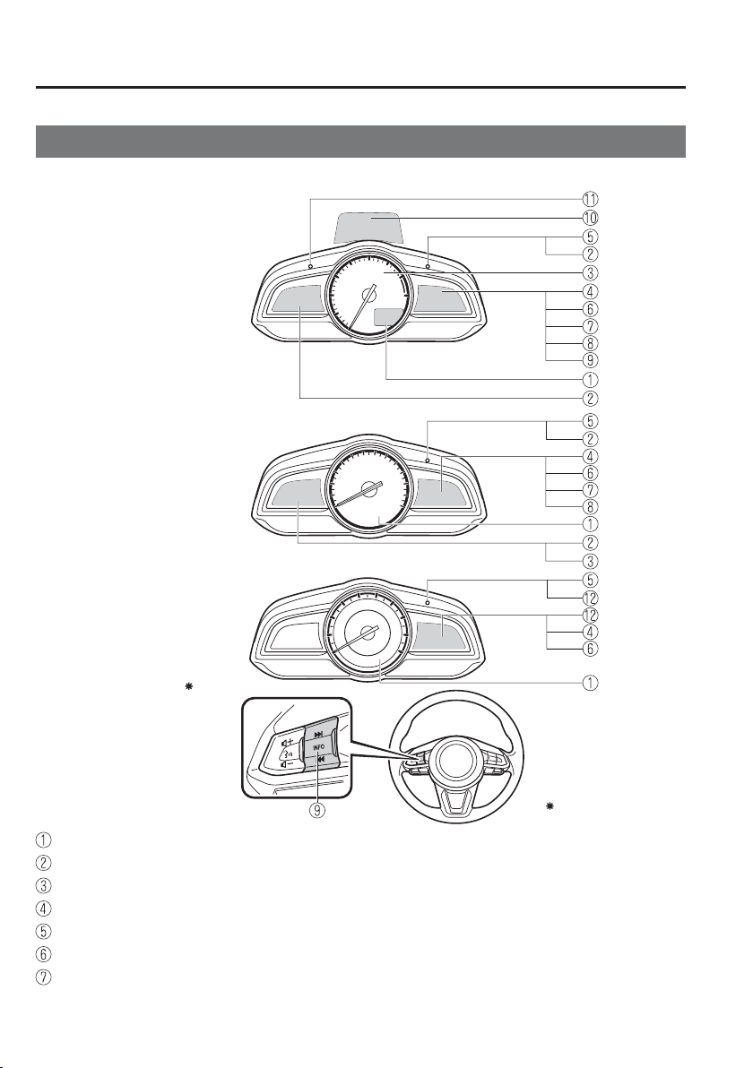
4
–
24
When Driving
Instrument Cluster and Display
M e t e r s a n d G a u g e s
Some models.
Type A
Type B
Type C
Steering Switch
(Digital Speed Meter Type)
(Analog Speed Meter Type (With Tachometer))
(Analog Speed Meter Type (Without Tachometer))
Instrument Cluster
Speedometer ..........................................................................................................page 4-25
Odometer, Trip Meter and Trip Meter Selector ....................................................page 4-25
Tachometer ............................................................................................................page 4-29
Fuel Gauge ............................................................................................................page 4-30
Instrument Panel Illumination ...............................................................................page 4-30
Outside Temperature Display ................................................................................page 4-31
Cruise Control Set Vehicle Speed Display ............................................................page 4-32
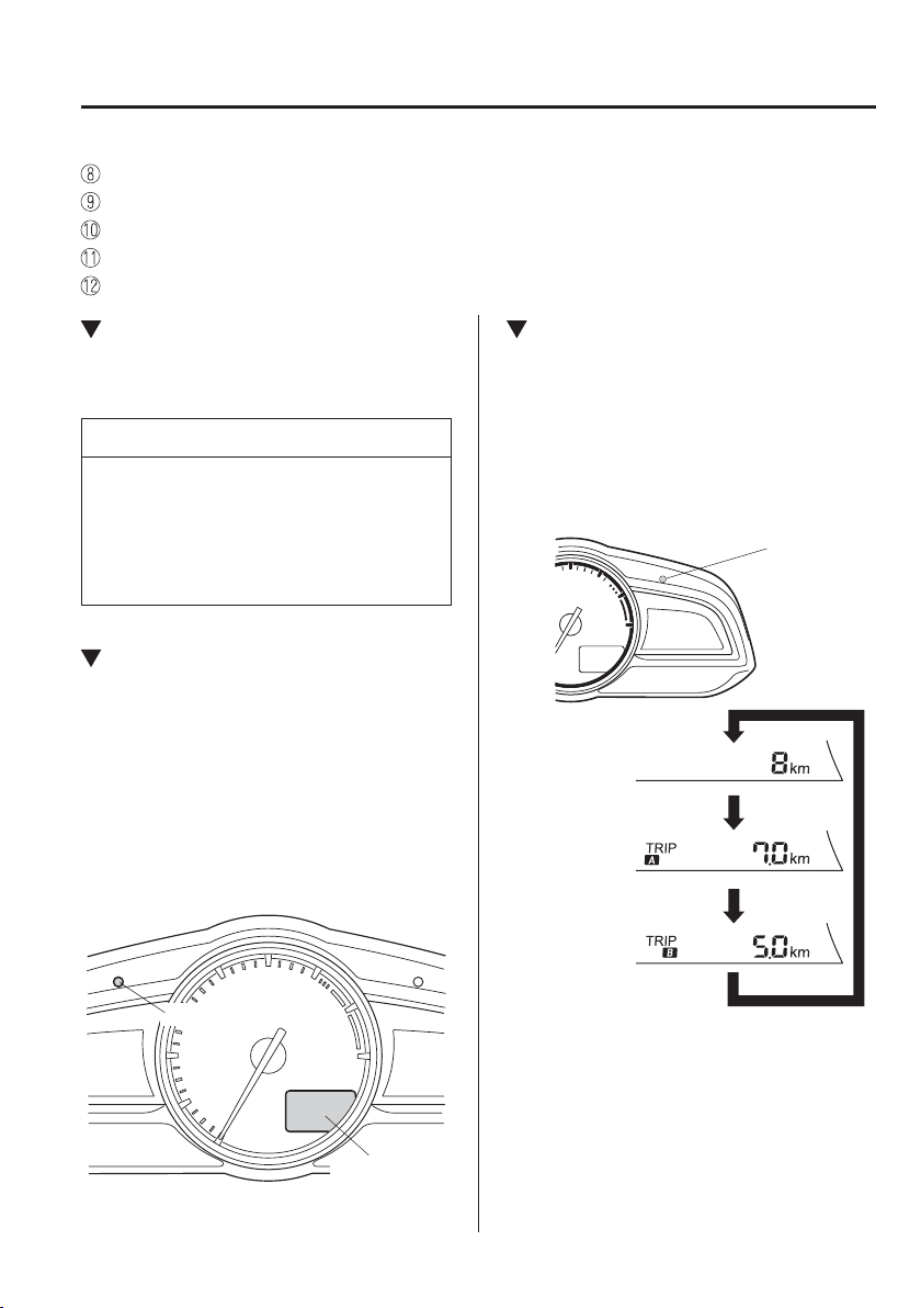
4
–
25
When Driving
Instrument Cluster and Display
*Some models.
Adjustable Speed Limiter Display ........................................................................page 4-32
Trip Computer and INFO Switch ..........................................................................page 4-32
Active Driving Display .........................................................................................page 4-35
Speed Unit Selector ...............................................................................................page 4-25
Odometer, Trip Meter, Trip Computer and Trip Meter Selector ...........................page 4-27
Speedometer
The speedometer indicates the speed of the
vehicle.
NOTE
(Analog speedometer type)
If a few seconds have elapsed after
switching the ignition off, the needle
may deviate. However, this does not
indicate a problem.
Speed Unit Selector (Digital
Speedometer Type)
*
In some countries, you may have to
change the speed units between km/h and
mph.
Press the speed unit selector for 1.5
seconds or more.
The speed units for the speedometer will
change between km/h and mph.
Speedometer
Speed unit selector
Odometer, Trip Meter and Trip
Meter Selector
*
The display mode can be changed from
odometer to trip meter A to trip meter B
and then back to odometer by pressing the
selector while one of them is displayed.
The selected mode will be displayed.
Press the selector
Press the selector
Press the selector
Odometer
Trip meter A
Trip meter B
Selector
4
–
26
When Driving
Instrument Cluster and Display
NOTE
When the ignition is switched to ACC
or off, the odometer or trip meters
cannot be displayed, however, pressing
the selector can inadvertently switch
the trip meters or reset them during an
approximate ten-minute period in the
following cases:
After the ignition is switched to off
from ON.
After the driver's door is opened.
Odometer
The odometer records the total distance
the vehicle has been driven.
Trip meter
The trip meter can record the total distance
of two trips. One is recorded in trip meter
A, and the other is recorded in trip meter
B.
For instance, trip meter A can record the
distance from the point of origin, and
trip meter B can record the distance from
where the fuel tank is ¿ lled.
When trip meter A is selected, pressing
the selector again within one second will
change to trip meter B mode.
When trip meter A is selected, TRIP A
will be displayed. When trip meter B is
selected, TRIP B will be displayed.
The trip meter records the total distance
the vehicle is driven until the meter
is again reset. Return it to “0.0” by
depressing and holding the selector for
one second or more. Use this meter to
measure trip distances and to compute fuel
consumption.
NOTE
(Vehicles with type B audio)
If the fuel economy data is reset
using the fuel economy monitor,
or trip A is reset using the trip
meter when the function which
synchronizes the fuel economy
monitor and the trip meter is on, the
fuel economy data and trip A are
reset simultaneously.
Refer to Fuel Economy Monitor on
page 4-93 .
Only the trip meters record tenths of
kilometres (miles).
The trip record will be erased when:
The power supply is interrupted
(blown fuse or the battery is
disconnected).
The vehicle is driven over
9999.9 km (mile).
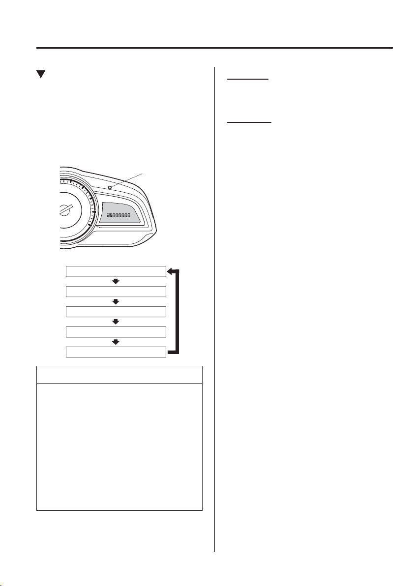
4
–
27
When Driving
Instrument Cluster and Display
*Some models.
Odometer, Trip Meter, Trip
Computer and Trip Meter
Selector
*
The display mode can be changed
between trip meter A and trip meter B by
pressing the selector while one of them
is displayed. The selected mode will be
displayed.
Selector
Current fuel economy mode
Distance-to-empty mode
Trip meter B
Trip meter A
Odometer
NOTE
When the ignition is switched to ACC
or off, the odometer or trip meters
cannot be displayed, however, pressing
the selector can inadvertently switch
the trip meters or reset them during an
approximate ten-minute period in the
following cases:
After the ignition is switched to off
from ON.
After the driver's door is opened.
Odometer
The odometer records the total distance
the vehicle has been driven.
Trip meter
The trip meter can record the total distance
of two trips. One is recorded in trip meter
A, and the other is recorded in trip meter
B.
For instance, trip meter A can record the
distance from the point of origin, and
trip meter B can record the distance from
where the fuel tank is ¿ lled.
When trip meter A is selected, pressing
the selector again within one second will
change to trip meter B mode.
When trip meter A is selected, TRIP A
will be displayed. When trip meter B is
selected, TRIP B will be displayed.
The trip meter records the total distance
the vehicle is driven until the meter is
again reset. Return it to “0.0” by holding
the selector depressed for 1 second
or more. Use this meter to measure
trip distances and to compute fuel
consumption.
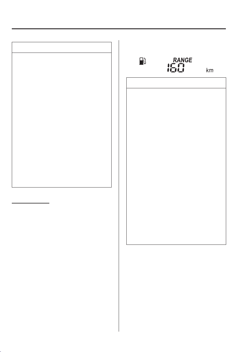
4
–
28
When Driving
Instrument Cluster and Display
NOTE
(Vehicles with type B audio)
If the fuel economy data is reset
using the fuel economy monitor,
or trip A is reset using the trip
meter when the function which
synchronizes the fuel economy
monitor and the trip meter is on, the
fuel economy data and trip A are
reset simultaneously.
Refer to Fuel Economy Monitor on
page 4-93 .
Only the trip meters record tenths of
kilometres (miles).
The trip record will be erased when:
The power supply is interrupted
(blown fuse or the battery is
disconnected).
The vehicle is driven over
9999.9 km (mile).
Trip Computer
The following information can be selected
by pressing the selector with the ignition
switched ON.
Approximate distance you can travel on
the available fuel
Current fuel economy
If you have any problems with your trip
computer, consult an expert repairer,
we recommend an Authorised Mazda
Repairer.
Distance-to-empty mode
This mode displays the approximate
distance you can travel on the remaining
fuel based on the fuel economy.
The distance-to-empty will be calculated
and displayed every second.
NOTE
Even though the distance-to-empty
display may indicate a suf¿ cient
amount of remaining driving distance
before refuelling is required, refuel
as soon as possible if the fuel level
is very low or the low fuel warning
light illuminates.
The display may not change unless
you add more than approximately
9 L (2.3 US gal, 1.9 Imp gal) of fuel.
The distance-to-empty is the
approximate remaining distance the
vehicle can be driven until all the
graduation marks in the fuel gauge
indicating the remaining fuel supply
disappear.
If there is no past fuel economy
information such as after ¿ rst
purchasing your vehicle or the
information is deleted when the
battery leads are disconnected, the
actual distance-to empty/range may
differ from the amount indicated.
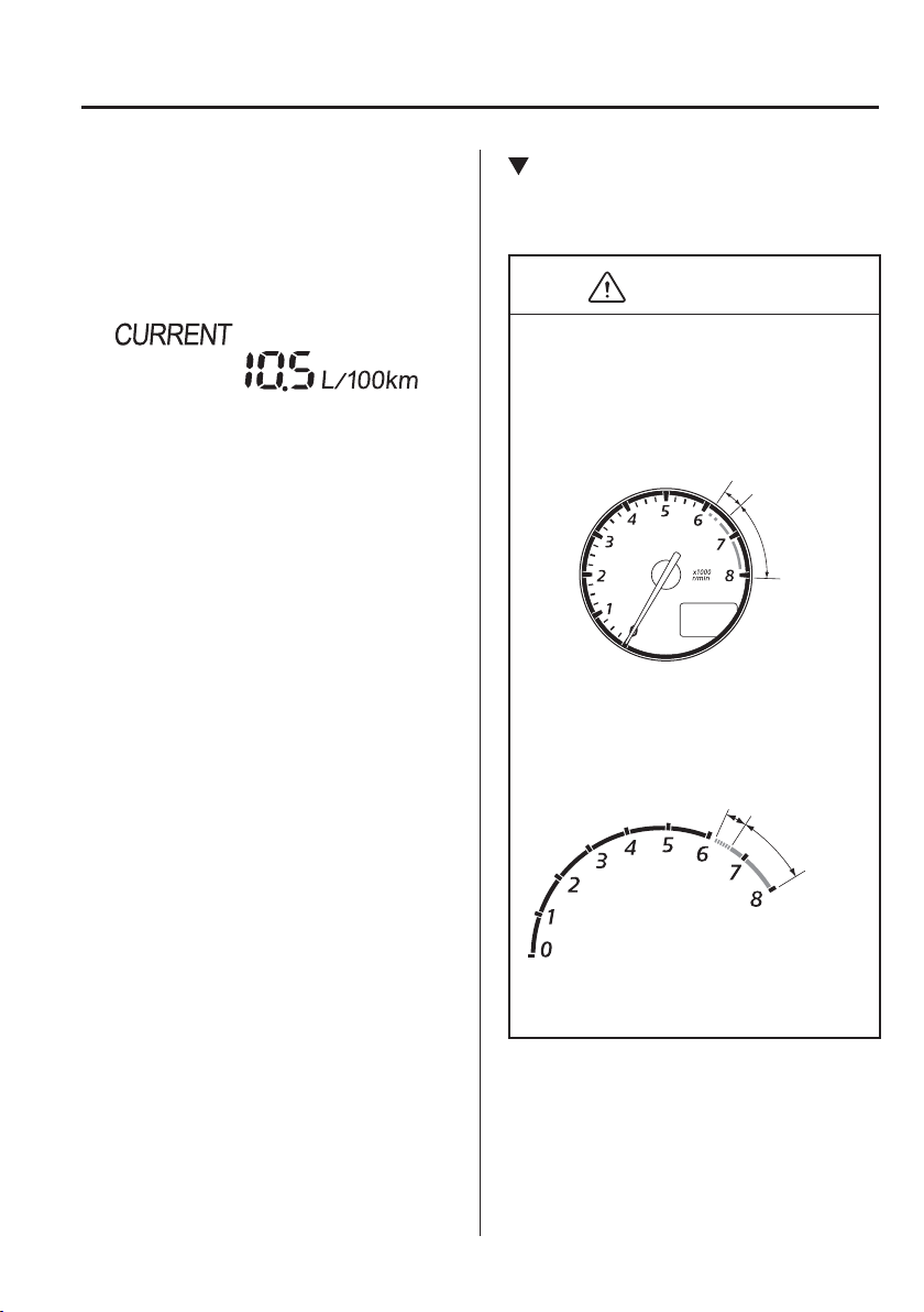
4
–
29
When Driving
Instrument Cluster and Display
*Some models.
Current fuel economy mode
This mode displays the current fuel
economy by calculating the amount of fuel
consumption and the distance travelled.
Current fuel economy will be calculated
and displayed every 2 seconds.
When you've slowed to about 5 km/h
(3 mph), - - - L/100 km (- - - mpg) will be
displayed.
Tachometer
*
The tachometer shows engine speed in
thousands of revolutions per minute (rpm).
CAUTION
Do not run the engine with the
tachometer needle in the RED ZONE.
This may cause severe engine damage.
Type A
*
1
The range varies depending on the type
of gauge.
*
1
Striped zone
*
1
Red zone
Type B
*
1
The range varies depending on the type
of gauge.
*
1
Striped zone
*
1
Red zone
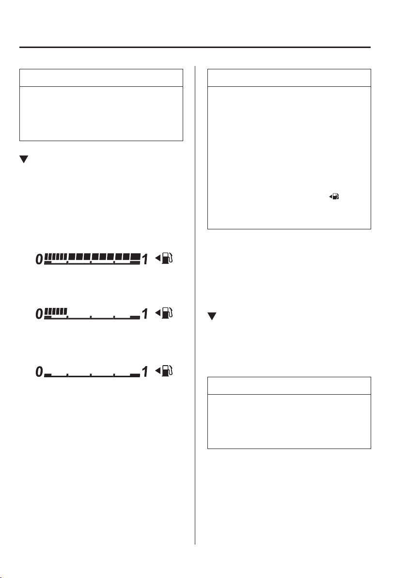
4
–
30
When Driving
Instrument Cluster and Display
NOTE
When the tachometer needle enters the
STRIPED ZONE, this indicates to the
driver that the gears should be shifted
before entering the RED ZONE.
Fuel Gauge
The fuel gauge shows approximately
how much fuel is remaining in the tank
when the ignition is switched ON. We
recommend keeping the tank over 1/4 full.
Full
1/4 Full
Empty
If the low fuel warning light illuminates or
the fuel level is very low, refuel as soon as
possible.
Refer to Warning Lights on page 4-38 .
NOTE
After refuelling, it may require some
time for the indicator to stabilize. In
addition, the indicator may deviate
while driving on a slope or curve
since the fuel moves in the tank.
The display indicating a quarter
or less remaining fuel has more
segments to show the remaining fuel
level in greater detail.
The direction of the arrow ( )
indicates that the fuel-¿ ller À ap is on
the left side of the vehicle.
(SKYACTIV-D 1.5)
If inconsistency in engine performance
or stalling occurs due to low fuel level
conditions, refuel the vehicle as soon as
possible and add at least 10 L (2.7 US gal,
2.2 Imp gal) of fuel.
Instrument Panel Illumination
When the position lights are turned
on with the ignition switched ON,
the brightness of the instrument panel
illumination is dimmed.
NOTE
When the position lights are turned on,
the position lights indicator light in the
instrument cluster turns on.
Refer to Headlights on page 4-61 .
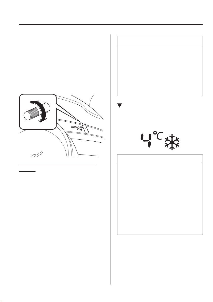
4
–
31
When Driving
Instrument Cluster and Display
*Some models.
The brightness of the instrument cluster
and instrument panel illuminations can be
adjusted by rotating the knob.
The brightness decreases by rotating the
knob to the left. A beep sound will be
heard when the knob has been rotated to
the maximum dim position.
The brightness increases by rotating the
knob to the right.
Dim
Bright
Function for cancelling illumination
dimmer
The illumination dimmer can be
cancelled by rotating the instrument panel
illumination knob to the right until a beep
sound is heard while the instrument cluster
is dimmed with the ignition switched
ON. If the instrument cluster's visibility
is reduced due to glare from surrounding
brightness, cancel the illumination
dimmer.
NOTE
When the illumination dimmer is
cancelled, the instrument cluster
cannot be dimmed even if the
position lights are turned on.
When the illumination dimmer is
cancelled, the screen in the centre
display switches to constant display
of the daytime screen.
Outside Temperature Display
*
When the ignition is switched ON, the
outside temperature is displayed.
NOTE
Under the following conditions, the
outside temperature display may differ
from the actual outside temperature
depending on the surroundings and
vehicle conditions:
Signi¿ cantly cold or hot
temperatures.
Sudden changes in outside
temperature.
The vehicle is parked.
The vehicle is driven at low speeds.
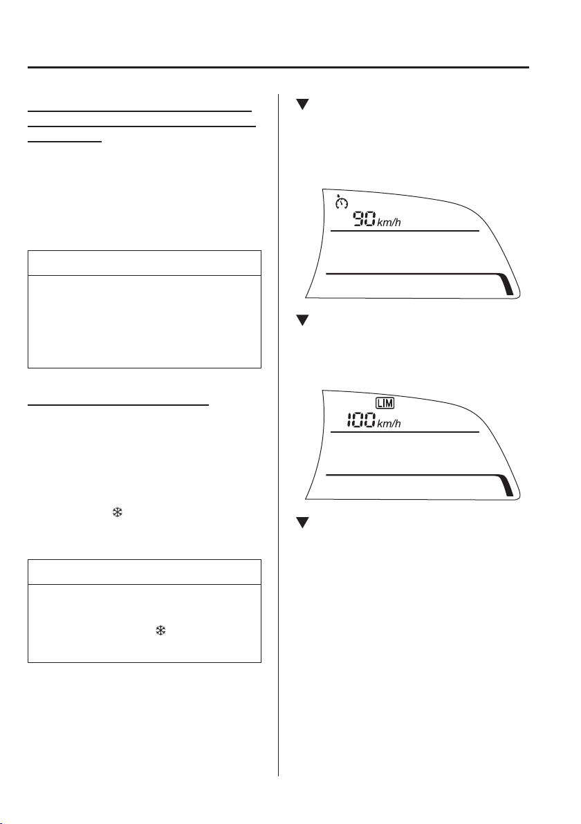
4
–
32
When Driving
Instrument Cluster and Display
*Some models.
Changing the Temperature Unit of the
Outside Temperature Display (Vehicles
with Type B)
The outside temperature unit can be
switched between Celsius and Fahrenheit.
Settings can be changed by operating the
centre display screen.
Refer to Personalisation Features on page
9-13 .
NOTE
When the temperature unit indicated
in the outside temperature display is
changed, the temperature unit indicated
in the engine coolant gauge display
changes in conjunction with it.
Outside Temperature Warning
*
When the outside temperature is low, the
indication À ashes and a beep sound is
heard to warn the driver of the possibility
of icy roads.
If the outside temperature is lower than
about 4 °C (39 °F), the outside temperature
display and the
mark À ashes for about
ten seconds and a beep sound is heard
once.
NOTE
If the outside temperature is lower than
-20 °C (-4 °F), the beep sound does not
operate. However, the
mark
illuminates.
Cruise Control Set Vehicle Speed
Display
*
The vehicle speed preset using the cruise
control is displayed.
Adjustable Speed Limiter Display
*
The setting status of the adjustable speed
limiter is displayed.
Trip Computer and INFO Switch
*
The following information can be selected
by pressing the INFO switch with the
ignition switched ON.
Distance-to-empty mode
Average fuel economy mode
Current fuel economy mode
Average vehicle speed mode
Vehicle speed alarm mode
*
If you have any problems with your trip
computer, consult an expert repairer,
we recommend an Authorised Mazda
Repairer.
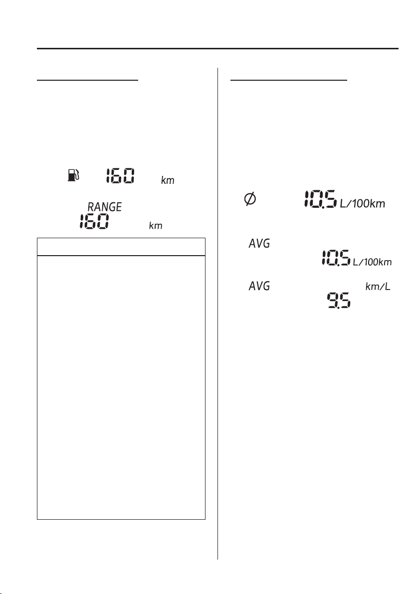
4
–
33
When Driving
Instrument Cluster and Display
Distance-to-empty mode
This mode displays the approximate
distance you can travel on the remaining
fuel based on the fuel economy.
The distance-to-empty will be calculated
and displayed every second.
(European model)
(Except European model)
NOTE
Even though the distance-to-empty
display may indicate a suf¿ cient
amount of remaining driving distance
before refuelling is required, refuel
as soon as possible if the fuel level
is very low or the low fuel warning
light illuminates.
The display may not change unless
you add more than approximately 9 L
(2.3 US gal, 1.9 Imp gal) of fuel.
The distance-to-empty is the
approximate remaining distance
the vehicle can be driven until all
the graduation marks in the fuel
gauge (indicating the remaining fuel
supply) disappear.
If there is no past fuel economy
information such as after ¿ rst
purchasing your vehicle or the
information is deleted when the
battery leads are disconnected, the
actual distance-to empty/range may
differ from the amount indicated.
Average fuel economy mode
This mode displays the average fuel
economy by calculating the total fuel
consumption and the total travelled
distance since purchasing the vehicle, re-
connecting the battery after disconnection,
or resetting the data. The average fuel
economy is calculated and displayed every
minute.
(European model)
(Except European model)
Type A
Type B
To clear the data being displayed, press the
INFO switch for more than 1.5 seconds.
After pressing the INFO switch, - - -
L/100 km (- - - mpg) or - - - km/L will
be displayed for about 1 minute before
the fuel economy is recalculated and
displayed.
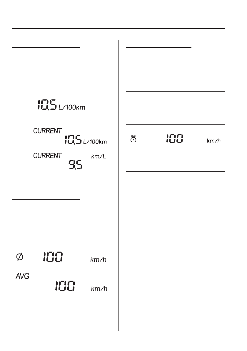
4
–
34
When Driving
Instrument Cluster and Display
*Some models.
Current fuel economy mode
This mode displays the current fuel
economy by calculating the amount of fuel
consumption and the distance travelled.
Current fuel economy will be calculated
and displayed every 2 seconds.
(European model)
(Except European model)
Type A
Type B
When you have slowed the vehicle to
about 5 km/h (3 mph), - - - L/100 km
(- - - mpg) or - - - km/L will be displayed.
Average vehicle speed mode
This mode displays the average vehicle
speed by calculating the distance and the
time travelled since connecting the battery
or resetting the data.
Average vehicle speed will be calculated
and displayed every 10 seconds.
(European model)
(Except European model)
To clear the data being displayed, press the
INFO switch for more than 1.5 seconds.
After pressing the INFO switch, - - - km/h
(- - - mph) will be displayed for about
1 minute before the vehicle speed is
recalculated and displayed.
Vehicle speed alarm mode
*
In this mode, the current setting for the
vehicle speed alarm is displayed. You can
change the vehicle speed setting at which
the warning is triggered.
NOTE
The vehicle speed alarm display is
activated at the same time the beep
sound is heard. The set vehicle speed
À ashes several times.
The vehicle speed alarm can be set using
the centre display.
NOTE
Always set the vehicle speed
according to the laws and regulations
of the country/city in which the
vehicle is driven. In addition, always
verify the speed of the vehicle using
the speedometer.
The vehicle speed alarm function can
be set between 30 and 250 km/h
(20 and 150 mph).
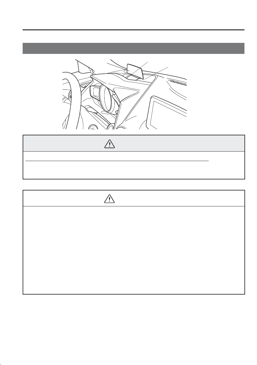
4
–
35
When Driving
Instrument Cluster and Display
*Some models.
Active Driving Display
*
Optical receiver
Mirror
Combiner
WARNING
Always adjust the display brightness and position with the vehicle stopped:
Adjusting the display brightness and position while driving the vehicle is dangerous as
doing so could distract your attention from the road ahead and lead to an accident.
CAUTION
Do not try to adjust the angle or open/close the active driving display manually.
Fingerprints on the display will make it dif¿ cult to view and using excessive force
when operating it could cause damage.
Do not place objects in the vicinity of the active driving display. The active driving
display may not operate or any interference with its operation could cause damage.
Do not place beverages near the active driving display. If water or other liquids are
splashed on the active driving display, it could cause damage.
Do not place objects above the active driving display or apply stickers to the dust-
proof sheet/optical receiver as they will cause interference.
A sensor is integrated to control the display's luminosity. If the optical receiver is
covered, the display's luminosity will lower making the display dif¿ cult to view.
Do not allow intense light to hit the optical receiver. Otherwise, it could cause damage.

4
–
36
When Driving
Instrument Cluster and Display
NOTE
It may be dif¿ cult to view the display when wearing polarized sunglasses. Take off
your polarized sunglasses or adjust the luminosity.
If the battery has been removed and re-installed or the battery voltage is low, the
adjusted position may deviate.
The display may be dif¿ cult to view or temporarily affected by weather conditions
such as rain, snow, light, and temperature.
If the audio system is removed, the active driving display cannot be operated.
The active driving display indicates the following information:
Blind Spot Monitoring (BSM) Operation Conditions and Warnings
Refer to Blind Spot Monitoring (BSM) on page 4-117 .
Distance Recognition Support System (DRSS) Warnings
Refer to Distance Recognition Support System (DRSS) on page 4-124 .
Mazda Radar Cruise Control (MRCC) Operation Conditions and Warnings
Refer to Mazda Radar Cruise Control (MRCC) on page 4-135 .
Lane Departure Warning System (LDWS) Operation Conditions and Warnings
Refer to Lane Departure Warning System (LDWS) on page 4-111 .
Smart City Brake Support [Forward] (SCBS F) Warnings
Refer to Smart City Brake Support [Forward] (SCBS F) on page 4-155 .
Smart City Brake Support [Reverse] (SCBS R) Operation Conditions
Refer to Smart City Brake Support [Reverse] (SCBS R) on page 4-161 .
Smart Brake Support (SBS) Warnings
Refer to Smart Brake Support (SBS) on page 4-167 .
Adjustable Speed Limiter Operation Conditions and Warnings
Refer to Adjustable Speed Limiter on page 4-148 .
Driver Attention Alert (DAA) Warnings
Refer to Driver Attention Alert (DAA) on page 4-127 .
Cruise Control Operation Conditions
Refer to Cruise Control on page 4-184 .
Navigation Guidance (vehicles with navigation system)
Speed limit indicator (vehicles with navigation system)
Vehicle Speed
4
–
37
When Driving
Instrument Cluster and Display
Each setting/adjustment for the active driving display can be performed on the centre
display.
1. Select the icon on the home screen and display the Settings screen.
2. Select the AD-Disp tab.
3. Select the desired item and perform the setting/adjustment.
Method for adjusting screen brightness (automatically/manually)
Screen brightness initial settings (automatic adjustment is selected)
Screen brightness adjustment (manual adjustment is selected)
Display position of active driving display (display height)
Active driving display angle adjustment (display angle correction)
Turn by turn (TBT) display/non-display (navigation guidance)
Street name display timing can be changed (navigation guidance)
Active driving display ON/OFF (indication)
Reset settings (reset)
NOTE
The street name may not be displayed depending on the market and region.
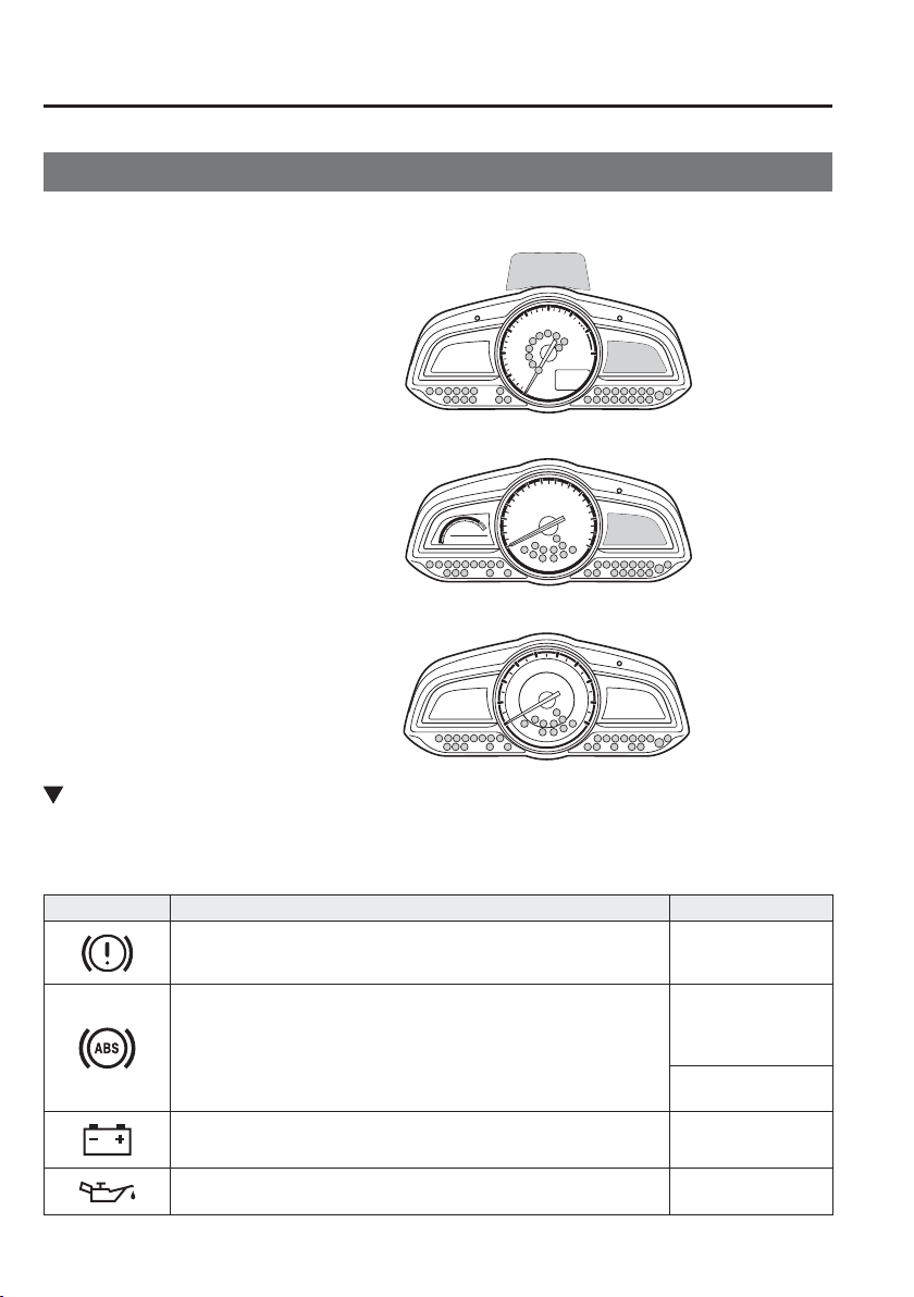
4
–
38
When Driving
Instrument Cluster and Display
Warning/Indicator Lights
Instrument Cluster varies depending on model and speci¿ cations.
Type A
Type B
Type C
(Digital Speed Meter Type)
(Analog Speed Meter Type (With Tachometer))
(Analog Speed Meter Type (Without Tachometer))
Instrument Cluster
Warning Lights
These lights turn on or À ash to notify the user of the system operation status or a system
malfunction.
Signal Warning Page
Brake System Warning Light
*1*2
7-35
ABS Warning Light
*1
Electronic Brake
Force Distribution
System Warning
7-35
ABS warning
7-38
Charging System Warning Light
*1
7-35
Engine Oil Warning Light
*1
7-35
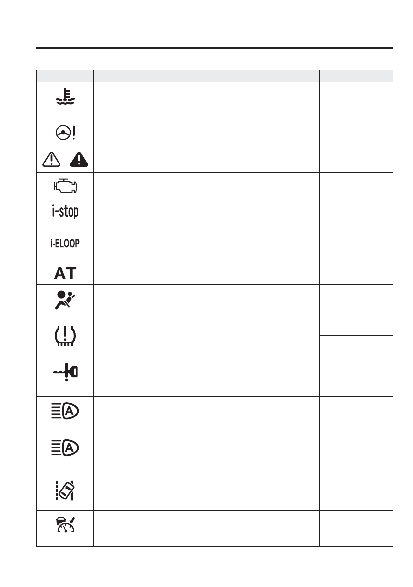
4
–
39
When Driving
Instrument Cluster and Display
*Some models.
Signal Warning Page
(Red)
High Engine Coolant Temperature Warning Light
*1
7-35
Power Steering Malfunction Warning Light
*1
7-35
Master Warning Light
*1
7-38
Check Engine Light
*1
7-38
(Amber)
*
i-stop Warning Light
*1
7-38
(Amber)
*
i-ELOOP Warning Light 7-38
*
Automatic Transaxle Warning Light
*1
7-38
Air Bag/Seat Belt Pretensioner System Warning Light
*1
7-38
*
Tyre Pressure Monitoring System Warning Light
*1
Flashing
7-38
Turns on
7-43
(Red)
KEY Warning Light
*1
Malfunction
7-38
Except malfunction
7-43
(Amber)
*
High Beam Control System (HBC) Warning Light
*1
7-38
(Amber)
*
Adaptive LED Headlights (ALH) Warning Light
*1
7-38
*
Lane Departure Warning System (LDWS) Warning Light
*1
Flashing
4-115
Turns on
7-38
(Amber)
*
Mazda Radar Cruise Control (MRCC) Warning Light 7-38
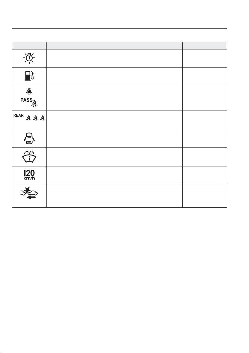
4
–
40
When Driving
Instrument Cluster and Display
*Some models.
Signal Warning Page
*
LED Headlight Warning Light
*1
7-38
Low Fuel Warning Light 7-43
Seat Belt Warning Light (Front seat) 7-43
(Red)
*
Seat Belt Warning Light (Rear seat) 7-43
*
Door-Ajar Warning Light 7-43
*
Low Washer Fluid Level Warning Light 7-43
*
120 km/h Warning Light
*1
7-43
(Amber)
*
Smart Brake Support/Smart City Brake Support (SBS/SCBS) Warning
Light
*1
7-43
*1 The light turns on when the ignition is switched on for an operation check, and turns off a few seconds later or
when the engine is started. If the light does not turn on or remains turned on, have the vehicle inspected at an
expert repairer, we recommend an Authorised Mazda Repairer.
*2 The light turns on continuously when the parking brake is applied.
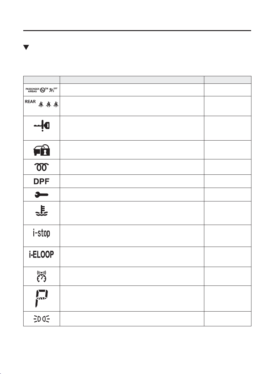
4
–
41
When Driving
Instrument Cluster and Display
*Some models.
Indicator Lights
These lights turn on or À ash to notify the user of the system operation status or a system
malfunction.
Signal Indicator Lights Page
*
Passenger Air Bag Deactivation Indicator Light
*1
2-47
(Green)
*
Seat Belt Indicator Light (Rear seat) 2-18
(Green)
KEY Indicator Light 4-5
Security Indicator Light
*1
3-43
*
Glow Indicator Light
*1
4-45
*
Diesel Particulate Filter Indicator Light
*1
4-194
Wrench Indicator Light
*1
4-44
(Blue)
Low Engine Coolant Temperature Indicator Light 4-44
(Green)
*
i-stop Indicator Light 4-18
(Green)
*
i-ELOOP Indicator Light 4-92
*
Vehicle Speed Alarm Indication 4-32
Shift Position Indication 4-52
Lights-On Indicator Light 4-61
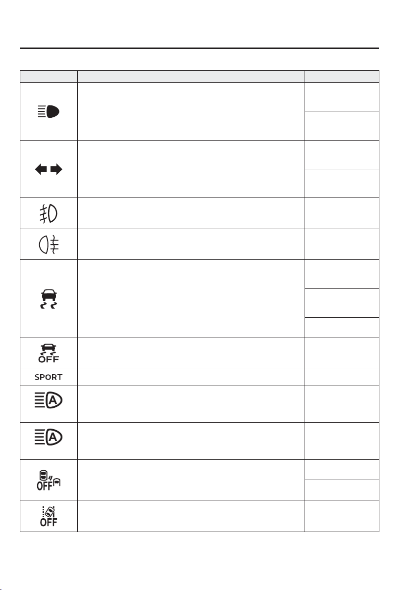
4
–
42
When Driving
Instrument Cluster and Display
*Some models.
Signal Indicator Lights Page
Headlight High-Beam Indicator Light
Headlight High-Low
Beam
4-66
Flashing the
Headlights
4-66
Direction Indicator/Hazard Warning Indicator Lights
Turn and Lane-
Change Signals
4-71
Hazard Warning
Flasher
4-80
*
Front Fog Light Indicator Light 4-69
*
Rear Fog Light Indicator Light 4-70
*
TCS/DSC Indicator Light
*1
Traction Control
System (TCS)
4-87
Dynamic Stability
Control (DSC)
4-88
Turns on
7-38
*
DSC OFF Indicator Light
*1
4-89
*
Select Mode Indicator Light 4-100
(Green)
*
High Beam Control System (HBC) Indicator Light 4-106
(Green)
*
Adaptive LED Headlights (ALH) Indicator Light 4-110
*
Blind Spot Monitoring (BSM) OFF Indicator Light
*1
Malfunction
7-38
Except malfunction
4-123
*
Lane Departure Warning System (LDWS) OFF Indicator Light
*1
4-115
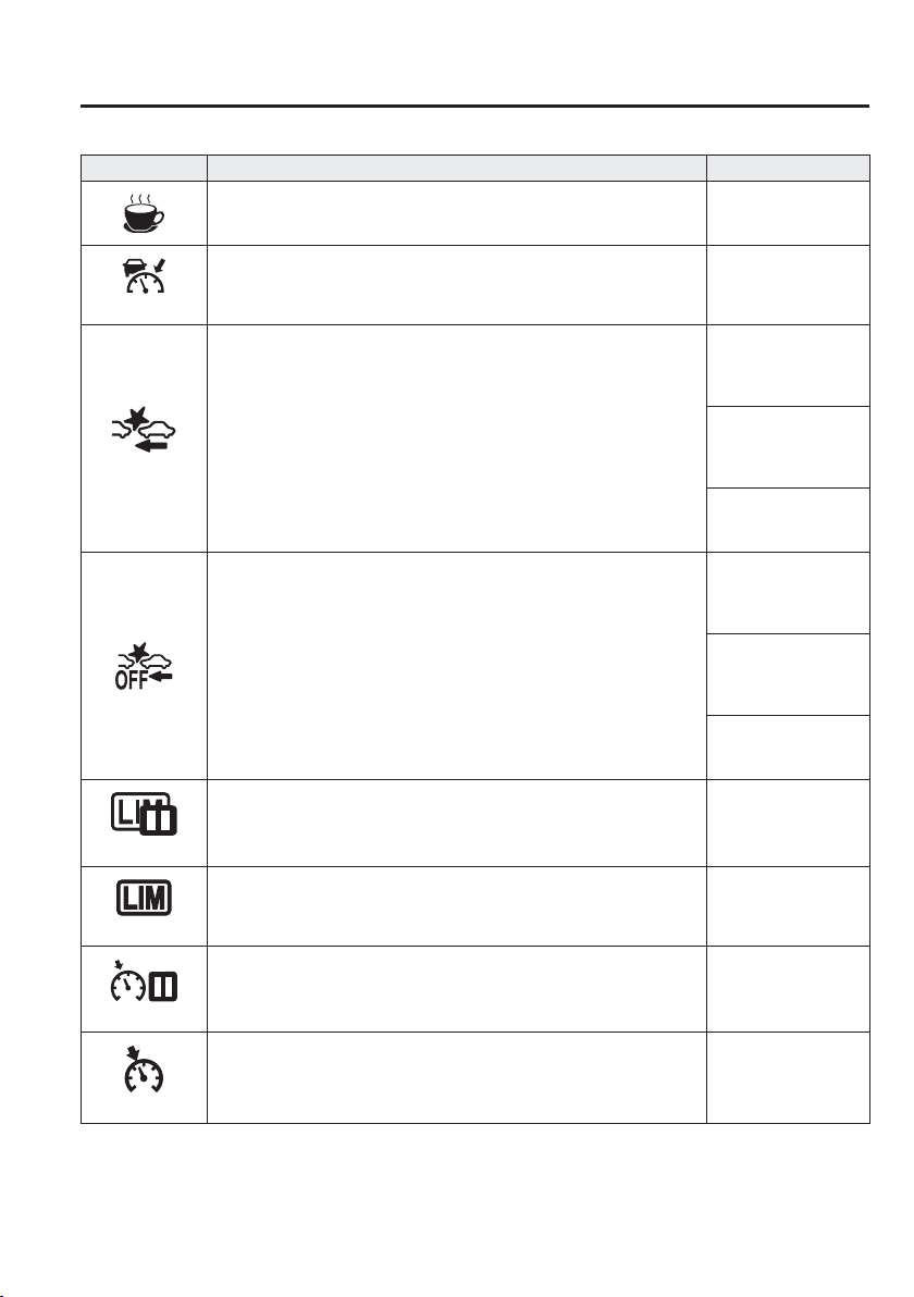
4
–
43
When Driving
Instrument Cluster and Display
*Some models.
Signal Indicator Lights Page
*
Driver Attention Alert (DAA) Indication 4-129
(Green)
*
Mazda Radar Cruise Control (MRCC) Indicator Light 4-139
(Red)
*
Smart Brake Support/Smart City Brake Support (SBS/SCBS) Indicator
Light
Smart City Brake
Support [Forward]
(SCBS F)
4-160
Smart City Brake
Support Reverse
(SCBS R)
4-165
Smart Brake Support
(SBS)
4-169
*
Smart Brake Support/Smart City Brake Support (SBS/SCBS) OFF
Indicator Light
Smart City Brake
Support [Forward]
(SCBS F)
4-160
Smart City Brake
Support Reverse
(SCBS R)
4-166
Smart Brake Support
(SBS)
4-169
(White)
*
Adjustable Speed Limiter Main Indication 4-150
(White/Green)
*
Adjustable Speed Limiter Set Indication/Indicator Light 4-150
(White)
*
Cruise Main Indication 4-186
(White/Green)
*
Cruise Set Indication/Indicator Light 4-186
*1 The light turns on when the ignition is switched on for an operation check, and turns off a few seconds later or
when the engine is started. If the light does not turn on or remains turned on, have the vehicle inspected at an
expert repairer, we recommend an Authorised Mazda Repairer.
4
–
44
When Driving
Instrument Cluster and Display
*Some models.
Wrench Indicator Light
When the ignition is switched ON, the
wrench indicator light turns on and then
turns off after a few seconds.
The wrench indicator light turns on
when the preset maintenance period
arrives. Verify the content and perform
maintenance.
Refer to Maintenance Monitor on page
6-15 .
SKYACTIV-D 1.5
The wrench indicator light turns on under
the following conditions:
The engine oil has deteriorated.
The engine oil level is around the MIN
mark on the dipstick or it is less than the
MIN mark.
*
The engine oil level is around the X
mark on the dipstick or it exceeds the X
mark.
*
Check the engine oil. Refer to Inspecting
Engine Oil Level on page 6-28 .
Replace the engine oil if the wrench
indicator light does not turn off even
though the engine oil level is in the normal
range.
NOTE
Depending on the vehicle use
conditions, the wrench indicator light
may turn on for reasons other than
the preset maintenance period.
Whenever the engine oil is replaced,
a reset of the vehicle engine control
unit is necessary.
Your Authorised Mazda Repairer
will be able to reset the engine
control unit or see page 6-27 for
the Vehicle engine control unit reset
procedure.
Low Engine Coolant Temperature
Indicator Light (Blue)
The light illuminates continuously when
the engine coolant temperature is low and
turns off after the engine is warm.
If the low engine coolant temperature
indicator light remains illuminated after
the engine has been suf¿ ciently warmed
up, the temperature sensor could have a
malfunction. Consult an expert repairer,
we recommend an Authorised Mazda
Repairer.

4
–
45
When Driving
Instrument Cluster and Display
Glow Indicator Light
(SKYACTIV-D 1.5)
This light may illuminate when the
ignition is switched ON.
It turns off when the glow plugs are warm.
If the ignition is left switched ON for a
long period of time without the engine
running after the glow plugs are warmed
up, the glow plugs may warm up again
which will illuminate the glow indicator
light.
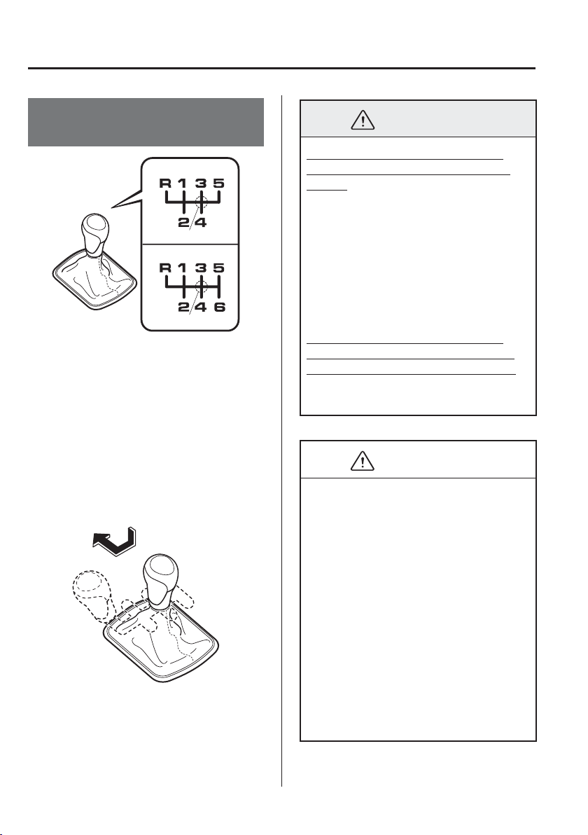
4
–
46
When Driving
Manual Transaxle Operation
Manual Transaxle Shift
Pattern
5-speed transaxle
6-speed transaxle
Neutral position
Neutral position
The vehicle is equipped with either a
5-speed or 6-speed transaxle. The shift
pattern for each is shown above.
Depress the clutch pedal all the way down
while shifting; then release it slowly.
Your vehicle is equipped with a device to
prevent shifting to R (reverse) by mistake.
Push the shift lever downward and shift
to R.
WARNING
Do not use sudden engine braking
on slippery road surfaces or at high
speeds:
Shifting down while driving on wet,
snowy, or frozen roads, or while driving
at high speeds causes sudden engine
braking, which is dangerous. The
sudden change in tyre speed could
cause the tyres to skid. This could
lead to loss of vehicle control and an
accident.
Always leave the shift lever in 1 or
R position and set the parking brake
when leaving the vehicle unattended:
Otherwise the vehicle could move and
cause an accident.
CAUTION
Keep your foot off the clutch pedal
except when shifting gears. Also, do
not use the clutch to hold the vehicle
on an upgrade. Riding the clutch
will cause needless clutch wear and
damage.
Do not apply any excessive lateral
force to the shift lever when
changing from 5th to 4th gear. This
could lead to the accidental selection
of 2nd gear, which could result in
damage to the transaxle.
Make sure the vehicle comes to a
complete stop before shifting to R.
Shifting to R while the vehicle is still
moving may damage the transaxle.

4
–
47
When Driving
Manual Transaxle Operation
NOTE
If shifting to R is dif¿ cult, shift back
into neutral, release the clutch pedal,
and try again.
(With i-stop function)
If the engine has stopped due to
stalling, it can be restarted by
depressing the clutch pedal within 3
seconds of the engine stopping.
The engine cannot be restarted even
if the clutch pedal is depressed under
the following conditions:
The driver's door is open.
The driver's seat belt is unfastened.
The clutch pedal is not released
completely after the engine stalled.
The clutch pedal is depressed with
the engine not stopped completely.
(With parking sensor system)
When the shift lever is shifted to the
R position with the ignition switched
ON, the parking sensor system is
activated and a beep sound is heard.
Refer to Parking Sensor System on
page 4-204 .
Gear Shift Indicator (GSI)
The Gear Shift Indicator (GSI) supports
you to obtain optimum fuel economy and
smooth driving. It displays the selected
gear position in the instrument cluster as
well as noti¿ es the driver to change to the
most suitable gear position corresponding
to the actual driving condition.
Selected gear position Suitable gear position
Indication Condition
Numeral
The selected gear position is
displayed.
and numeral
Shift up or down to the indicated
gear position is recommended.
CAUTION
Do not rely solely on the shift-up/
shift-down recommendations by
indications. The actual driving situation
might require shift operations different
from indication. To avoid the risk of
accidents, the road and traf¿ c conditions
have to be judged correctly by the driver
before shifting.

4
–
48
When Driving
Manual Transaxle Operation
NOTE
The Gear Shift Indicator (GSI) turns
off when the following operations are
performed.
The vehicle is stopped.
The vehicle is put in neutral.
The vehicle is driven in reverse.
The clutch is not fully engaged when
accelerating from a stop.
The clutch pedal remains depressed
for 2 seconds or longer while driving.
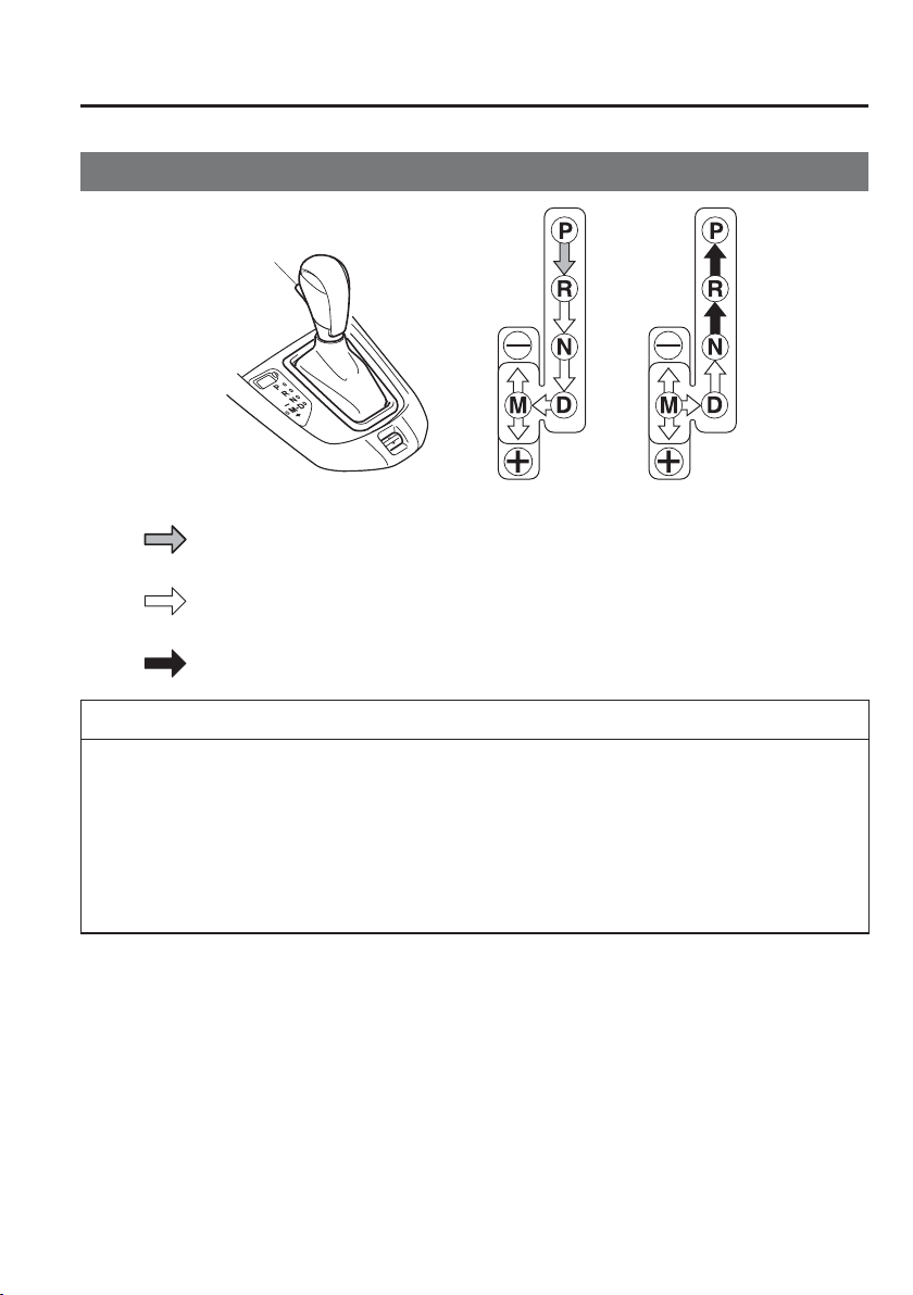
4
–
49
When Driving
Automatic Transaxle
Automatic Transaxle Controls
Lock-release button
Indicates the selector lever can be shifted freely into any position.
Indicates that you must hold in the lock-release button to shift.
Indicates that you must depress the brake pedal and hold in the lock-release
button to shift (The ignition must be switched ON).
Various Lockouts:
NOTE
The Sport AT has an option that is not included in the traditional automatic transaxle that
gives the driver the option of selecting each gear instead of leaving it to the transaxle to
shift gears. Even if you intend to use the automatic transaxle functions as a traditional
automatic, you should also be aware that you can inadvertently shift into manual shift
mode and an inappropriate gear may be retained as the vehicle speed increases. If you
notice the engine speed going higher or hear the engine racing, con¿ rm you have not
accidentally slipped into manual shift mode (page 4-53 ).
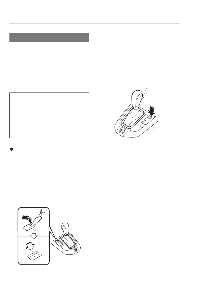
4
–
50
When Driving
Automatic Transaxle
Shift-Lock System
The shift-lock system prevents shifting out
of P unless the brake pedal is depressed.
To shift from P:
1. Depress and hold the brake pedal.
2. Start the engine.
3. Press and hold the lock-release button.
4. Move the selector lever.
NOTE
When the ignition is switched to
ACC or the ignition is switched off,
the selector lever cannot be shifted
from P.
The ignition cannot be switched to
OFF if the selector lever is not in P.
Shift-Lock Override
If the selector lever will not move from P
using the proper shift procedure, continue
to hold down the brake pedal.
Type A
1. Remove the shift-lock override cover
using a cloth-wrapped À at head
screwdriver.
2. Insert a screwdriver and push it down.
Cover
3. Press and hold the lock-release button.
4. Move the selector lever.
Take the vehicle to an expert repairer, we
recommend an Authorised Mazda Repairer
to have the system checked.
Type B
1. Press the lock-release button with the
button pressed.
Lock-release button
button
2. Move the selector lever.
Take the vehicle to an expert repairer, we
recommend an Authorised Mazda Repairer
to have the system checked.
4
–
51
When Driving
Automatic Transaxle
Transaxle Ranges
The shift position indicator light in the
instrument cluster illuminates. Refer
to Warning/Indicator Lights on page
4-38 .
The selector lever must be in P or N to
operate the starter.
P (Park)
P locks the transaxle and prevents the front
wheels from rotating.
WARNING
Always set the selector lever to P and
set the parking brake:
Only setting the selector lever to the
P position without using the parking
brake to hold the vehicle is dangerous.
If P fails to hold, the vehicle could
move and cause an accident.
CAUTION
Shifting into P, N or R while the
vehicle is moving can damage your
transaxle.
Shifting into a driving gear or reverse
when the engine is running faster
than idle can damage the transaxle.
R (Reverse)
In position R, the vehicle moves only
backward. You must be at a complete
stop before shifting to or from R, except
under rare circumstances as explained in
Rocking the Vehicle (page 3-51 ).
NOTE
(With parking sensor system)
When the selector lever is shifted to the
R position with the ignition switched
ON, the parking sensor system is
activated and a beep sound is heard.
Refer to Parking Sensor System on page
4-204 .
N (Neutral)
In N, the wheels and transaxle are not
locked. The vehicle will roll freely even
on the slightest incline unless the parking
brake or brakes are on.
WARNING
If the engine is running faster than
idle, do not shift from N or P into a
driving gear:
It's dangerous to shift from N or P
into a driving gear when the engine
is running faster than idle. If this is
done, the vehicle could move suddenly,
causing an accident or serious injury.
Do not shift into N when driving the
vehicle:
Shifting into N while driving is
dangerous. Engine braking cannot be
applied when decelerating which could
lead to an accident or serious injury.
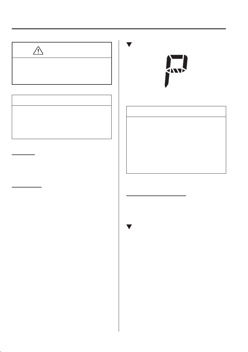
4
–
52
When Driving
Automatic Transaxle
CAUTION
Do not shift into N when driving the
vehicle. Doing so can cause transaxle
damage.
NOTE
Apply the parking brake or depress the
brake pedal before moving the selector
lever from N to prevent the vehicle from
moving unexpectedly.
D (Drive)
D is the normal driving position. From a
stop, the transaxle will automatically shift
through a 6-gear sequence.
M (Manual)
M is the manual shift mode position. Gears
can be shifted up or down by operating the
selector lever. Refer to Manual Shift Mode
on page 4-53 .
Shift Position Indication
The selector position is indicated when the
ignition is switched ON.
NOTE
If one of the following actions is
performed, the selector position is
displayed for 5 minutes even if the
ignition switch is in a position other than
ON.
The ignition is switched OFF.
The driver's door is opened.
Gear position indication
In manual shift mode, the “M” of the shift
position indication illuminates and the
numeral for the selected gear is displayed.
Active Adaptive Shift (AAS)
Active Adaptive Shift (AAS)
automatically controls the transaxle shift
points to best suit the road conditions
and driver input. This improves driving
feel. The transaxle may switch to AAS
mode when driving up and down slopes,
cornering, driving at high elevations,
or depressing the accelerator pedal
quickly while the selector lever is in the
D position. Depending on the road and
driving conditions/vehicle operations, gear
shifting could be delayed or not occur,
however, this does not indicate a problem
because the AAS mode will maintain the
optimum gear position.
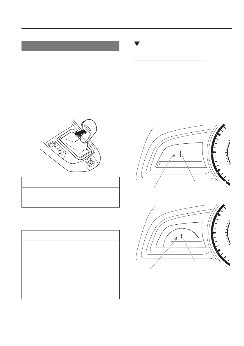
4
–
53
When Driving
Automatic Transaxle
Manual Shift Mode
The manual shift mode gives you the feel
of driving a manual transaxle vehicle by
allowing you to operate the selector lever
manually. This allows you to control
engine rpm and torque to the drive wheels
much like a manual transaxle when more
control is desired.
To change to manual shift mode, shift the
lever from D to M.
NOTE
Changing to manual shift mode while
driving will not damage the transaxle.
To return to automatic shift mode, shift the
lever from M to D.
NOTE
If you change to manual shift mode
when the vehicle is stopped, the gear
will shift to M1.
If you change to manual shift mode
without depressing the accelerator
pedal when driving in D range, 5th
gear/6th gear, the gear will shift to
M4/M5.
Indicators
Manual shift mode indication
In manual shift mode, the “M” of the shift
position indication in the instrument panel
illuminates.
Gear position indication
The numeral for the selected gear
illuminates.
Type A
Manual shift mode indication
Gear position indication
Type B
Gear position indication
Manual shift mode indication
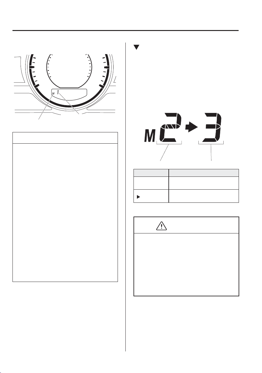
4
–
54
When Driving
Automatic Transaxle
Type C
Manual shift mode indication
Gear position indication
NOTE
If the gears cannot be shifted down
when driving at higher speeds, the
gear position indication will À ash
twice to signal that the gears cannot
be shifted down (to protect the
transaxle).
If the automatic transaxle À uid
(ATF) temperature becomes too
high, there is the possibility that the
transaxle will switch to automatic
shift mode, cancelling manual
shift mode and turning off the gear
position indication illumination.
This is a normal function to protect
the AT. After the ATF temperature
has decreased, the gear position
indication illumination turns back on
and driving in manual shift mode is
restored.
Gear Shift Indicator
The gear shift indicator supports you to
obtain optimum fuel economy and smooth
driving. It displays the selected gear
position in the instrument cluster as well
as noti¿ es the driver to change to the most
suitable gear position corresponding to the
actual driving condition.
Selected gear position Suitable gear position
Indication Condition
Numeral
The selected gear position is
displayed.
and numeral
Shift up or down to the indicated
gear position is recommended.
CAUTION
Do not rely solely on the shift-up/
shift-down recommendations by
indications. The actual driving situation
might require shift operations different
from indication. To avoid the risk of
accidents, the road and traf¿ c conditions
have to be judged correctly by the driver
before shifting.
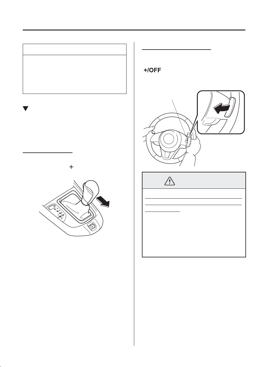
4
–
55
When Driving
Automatic Transaxle
*Some models.
NOTE
The gear shift indicator turns off when
the following operations are performed.
The vehicle is stopped.
Manual shift mode is cancelled.
Manually Shifting Up
You can shift gears up by operating
the selector lever or the steering shift
switches
*
.
M 1 ĺ M2 ĺ M3 ĺ M4 ĺ M5 ĺ M6
Using selector lever
To shift up to a higher gear, tap the
selector lever back
once.
Using steering shift switch
*
To shift up to a higher gear with the
steering shift switches, pull the UP switch
(
) toward you once with your
¿ ngers.
UP switch (+/OFF)
WARNING
Keep your hands on the steering wheel
rim when using ¿ ngers on the steering
shift switches:
Putting your hands inside the rim of
the steering wheel when using the
steering shift switches is dangerous. If
the driver's air bag were to deploy in a
collision, your hands could be impacted
causing injury.
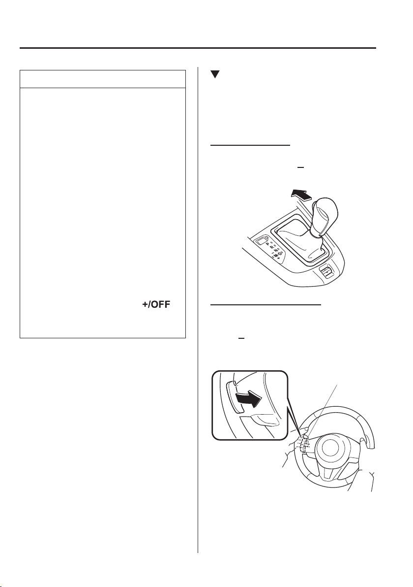
4
–
56
When Driving
Automatic Transaxle
*Some models.
NOTE
When driving slowly, the gears may
not shift up.
Do not drive the vehicle with the
tachometer needle in the RED ZONE
while in manual shift mode. In
addition, manual shift mode switches
to automatic shift mode while the
accelerator pedal is completely
depressed.
This function is cancelled while
the DSC is turned off. However,
if the vehicle is continuously
driven at a high rpm, the gears may
automatically shift up to protect the
engine.
The steering shift switch can be used
temporarily even if the selector lever
is in the D position while driving. In
addition, it returns to automatic shift
mode when the UP switch (
)
is pulled rearward for a suf¿ cient
amount of time.
Manually Shifting Down
You can shift gears down by operating
the selector lever or the steering shift
switches
*
.
M 6 ĺ M5 ĺ M4 ĺ M3 ĺ M2ĺ M1
Using selector lever
To shift down to a lower gear, tap the
selector lever forward
once.
Using steering shift switch
*
To shift down to a lower gear with the
steering shift switches, pull the DOWN
switch
toward you once with your
¿ ngers.
DOWN switch (-)
4
–
57
When Driving
Automatic Transaxle
WARNING
Do not use engine braking on slippery
road surfaces or at high speeds:
Shifting down while driving on wet,
snowy, or frozen roads, or while driving
at high speeds causes sudden engine
braking, which is dangerous. The
sudden change in tyre speed could
cause the tyres to skid. This could
lead to loss of vehicle control and an
accident.
Keep your hands on the steering wheel
rim when using ¿ ngers on the steering
shift switches:
Putting your hands inside the rim of
the steering wheel when using the
steering shift switches is dangerous. If
the driver's air bag were to deploy in a
collision, your hands could be impacted
causing injury.
NOTE
When driving at high speeds, the
gear may not shift down.
During deceleration, the gear may
automatically shift down depending
on vehicle speed.
When depressing the accelerator
fully, the transaxle will shift to a
lower gear, depending on vehicle
speed. However, the gears do not
kickdown while the DSC is turned
off.
Second Gear Fixed Mode
When the selector lever is moved back
while the vehicle speed is about 10 km/h
(6.2 mph) or less, the transaxle is set in the
second gear ¿ xed mode. The gear is ¿ xed
in second while in this mode for easier
acceleration from a stop and driving on
slippery roads such as snow-covered
roads.
If the selector lever is moved back
or
forward
while in the second gear ¿ xed
mode, the mode will be cancelled.
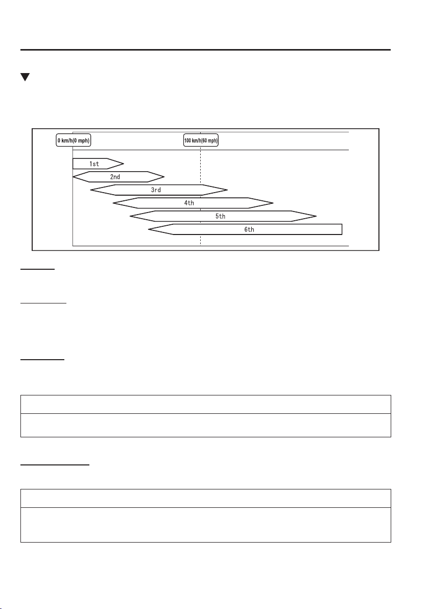
4
–
58
When Driving
Automatic Transaxle
Shift Gear (Shifting) Speed Limit
For each gear position while in the manual mode, the speed limit is set as follows: When the
selector lever is operated within the range of the speed limit, the gear is shifted.
Shift up
The gear does not shift up while the vehicle speed is lower than the speed limit.
Shift down
The gear does not shift down while the vehicle speed exceeds the speed limit.
If the vehicle speed exceeds the speed limit and the gear does not shift down, the gear
position indication À ashes 2 times to notify the driver that the gear cannot be shifted.
Kickdown
When the accelerator pedal is depressed fully while driving, the gear shifts down.
However, the gears do not kickdown while the DSC is turned off.
NOTE
The gear also shifts down using kickdown while in the second gear ¿ xed mode.
Auto-shift down
The gear shifts down automatically depending on the vehicle speed during deceleration.
NOTE
If the vehicle comes to a stop while in the second gear ¿ xed mode, the gear remains in
second.
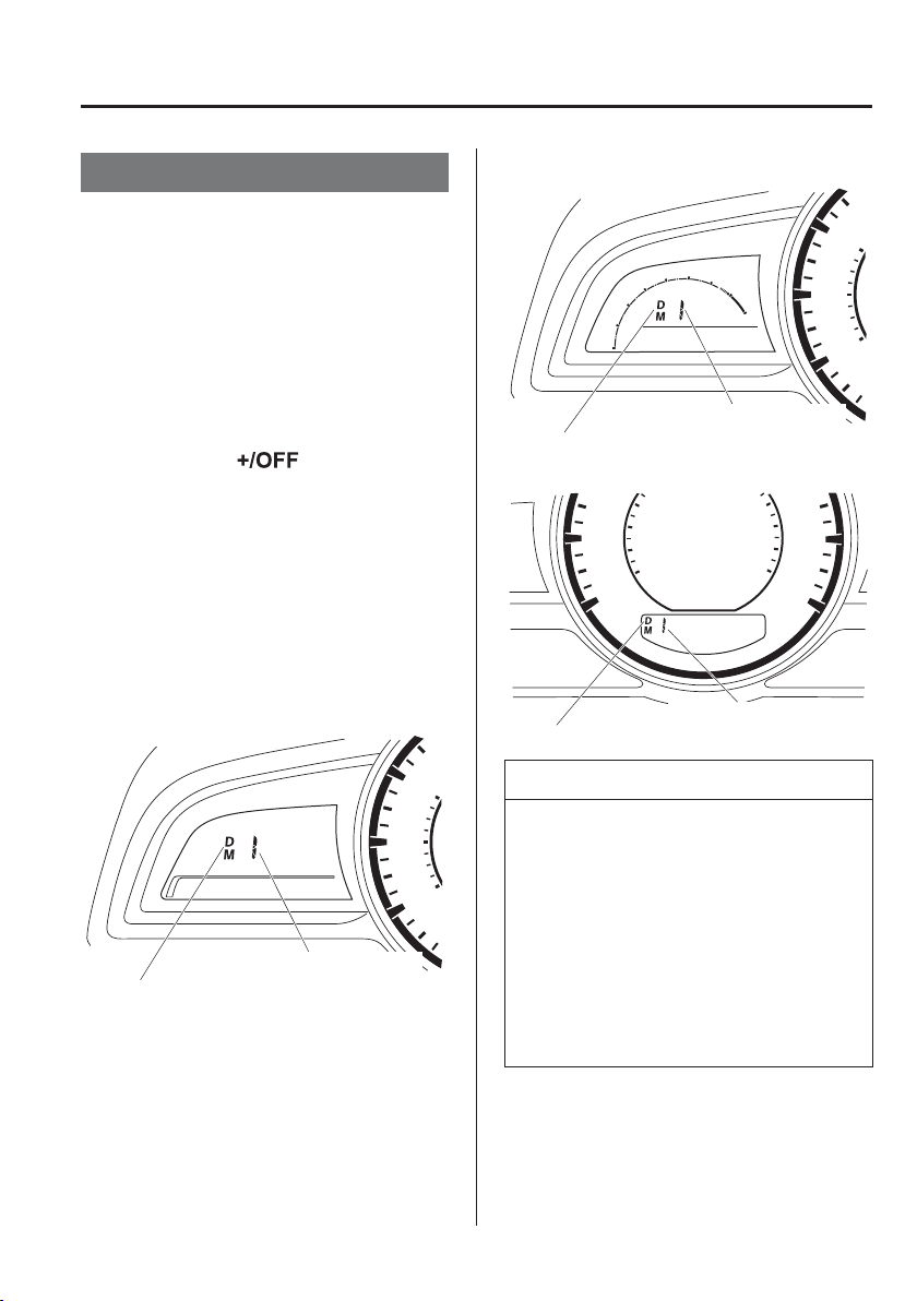
4
–
59
When Driving
Automatic Transaxle
*Some models.
Direct Mode
*
Direct mode can be used for temporarily
switching gears by operating the steering
shift switch while the vehicle is being
driven with the selector lever in the D
range.
While in direct mode, the D and M
indication illuminate and the gear position
in use is illuminated.
Direct mode is cancelled (released) under
the following conditions.
The UP switch ( ) is pulled
rearward for a certain amount of time or
longer.
The vehicle is driven for a certain
amount of time or longer (time differs
depending on the driving conditions
while operating).
The vehicle is stopped or moving at a
slow speed.
Type A
Gear position indication
Direct mode indication
Type B
Gear position indication
Direct mode indication
Type C
Gear position indication
Direct mode indication
NOTE
Shifting up and down while in direct
mode may not be possible depending on
the vehicle speed. In addition, because
direct mode is cancelled (released)
depending on the rate of acceleration
or if the accelerator is fully depressed,
use of the manual shift mode is
recommended if you need to drive the
vehicle in a particular gear for long
periods.
4
–
60
When Driving
Automatic Transaxle
Driving Tips
WARNING
Do not let the vehicle move in a
direction opposite to the direction
selected by the selector lever:
Do not let the vehicle move backward
with the selector lever in a forward
position, or do not let the vehicle move
forward with the selector lever in the
reverse position. Otherwise, the engine
may stop, causing the loss of the power
brake and power steering functions,
and make it dif¿ cult to control the
vehicle which could result in an
accident.
Passing
For extra power when passing another
vehicle or climbing steep grades, depress
the accelerator fully. The transaxle will
shift to a lower gear, depending on vehicle
speed.
NOTE
The accelerator pedal may initially
feel heavy as it is being depressed,
then feel lighter as it is depressed
further. This change in pedal force
aids the engine control system
in determining how much the
accelerator pedal has been depressed
for performing kickdown, and
functions to control whether or not
kickdown should be performed.
While the selector lever is in the M
position and the DSC is turned off,
manual shift mode does not switch
to automatic shift mode even if
the accelerator pedal is completely
depressed. Operate the selector lever.
Climbing steep grades from a stop
To climb a steep grade from a stopped
position:
1. Depress the brake pedal.
2. Shift to D or M1, depending on the
load weight and grade steepness.
3. Release the brake pedal while gradually
accelerating.
Descending steep grades
When descending a steep grade, shift to
lower gears, depending on load weight and
grade steepness. Descend slowly, using the
brakes only occasionally to prevent them
from overheating.
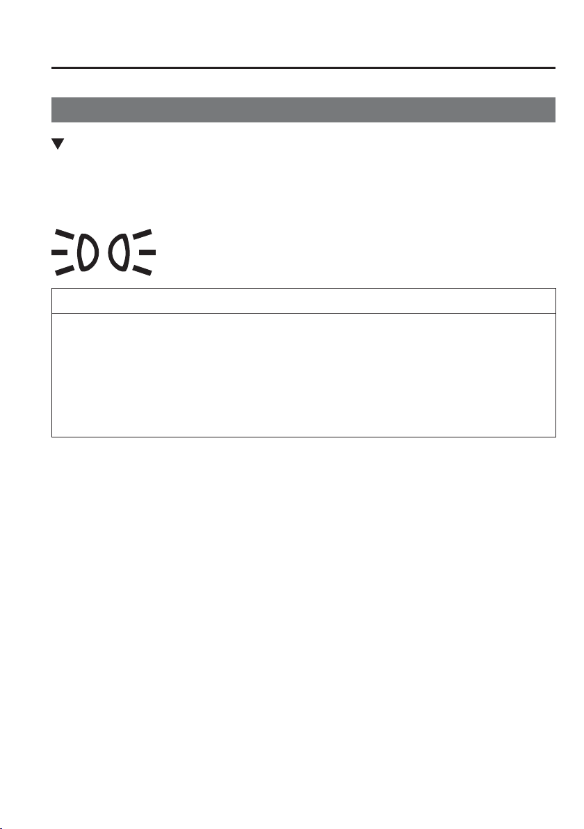
4
–
61
When Driving
Switches and Controls
Lighting Control
Headlights
Turn the headlight switch to turn the headlights, other exterior lights and instrument panel
illumination on or off.
When the lights are turned on, the lights-on indicator light in the instrument cluster turns on.
NOTE
To prevent discharging the battery, do not leave the lights on while the engine is off
unless safety requires them.
Headlights do not blind drivers approaching in the opposite direction no matter
what side of the road you must drive your vehicle (left-hand or right-hand traf¿ c).
Therefore, it is not necessary to adjust the optical axis of the headlights when
switching temporarily to driving on the opposite side of the road (left-hand or right-
hand traf¿ c).
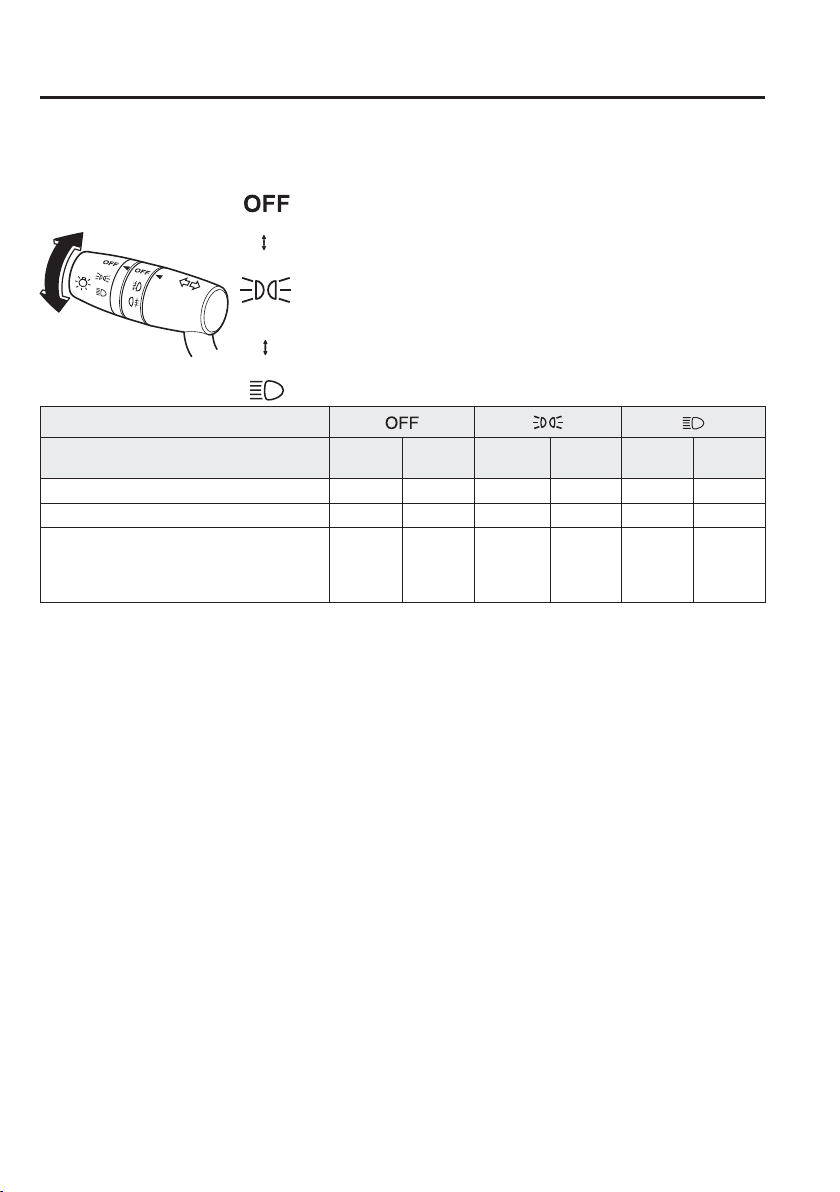
4
–
62
When Driving
Switches and Controls
*Some models.
Without auto-light control
Switch Position
Ignition Position ON
ACC or
OFF
O N
ACC or
OFF
O N
ACC or
OFF
Headlights Off Off Off Off On Off
Running lights
*
On Off Off Off Off Off
Tail lights
Position lights
Number plate lights
Instrument panel illumination
Off Off On On On On
*1
*1 If the driver's door is opened or 30 s have elapsed with the lights turned on, the lights turn off.
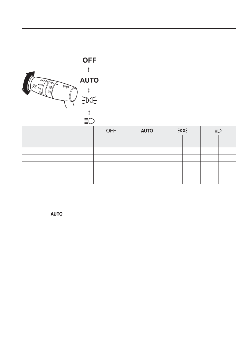
4
–
63
When Driving
Switches and Controls
*Some models.
With auto-light control
Switch Position
Ignition Position ON
ACC
or OFF
O N
ACC
or OFF
O N
ACC
or OFF
O N
ACC
or OFF
Headlights Off Off Auto
*1
Off Off Off On Off
Running lights
*
On Off Auto
*1
Off Off Off Off Off
Tail lights
Position lights
Number plate lights
Instrument panel illumination
Off Off Auto
*1
On
*2
/
Off
*3
On On On On
*4
*1 The headlight and other light settings switch automatically depending on the surrounding brightness detected by
the sensor.
*2 While the lights are turned on, they will remain on even if the ignition is switched to a position other than ON .
If the driver’s door is opened or 30 s have elapsed with the lights turned on, the lights turn off.
*3 When the ignition is switched to a position other than ON , the lights will not turn on even if the light switch is
switched to
.
*4 If the driver’s door is opened or 30 s have elapsed with the lights turned on, the lights turn off.
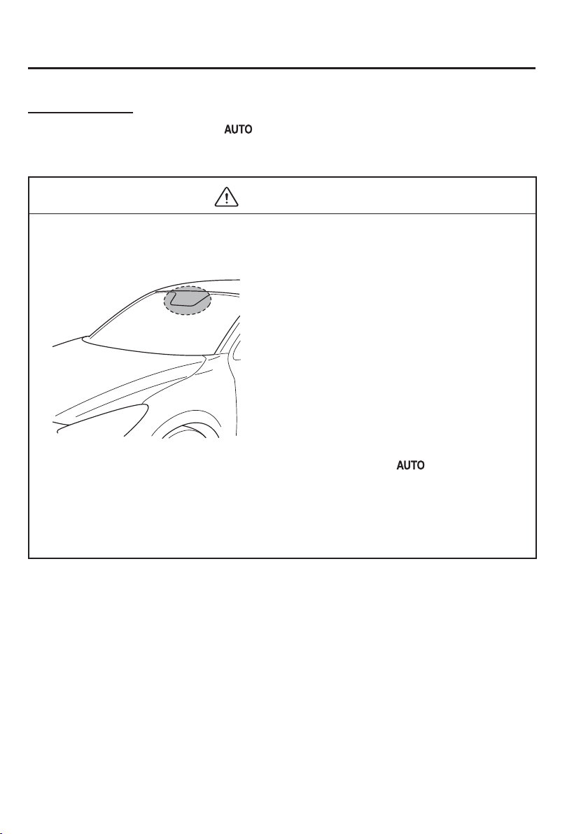
4
–
64
When Driving
Switches and Controls
Auto-light control
When the headlight switch is in the
position and the ignition is switched ON, the light
sensor senses the surrounding lightness or darkness and automatically turns the headlights,
other exterior lights and instrument panel illumination on or off (see chart above).
CAUTION
Do not shade the light sensor by adhering a sticker or a label on the windscreen.
Otherwise the light sensor will not operate correctly.
The light sensor also works as a rain sensor for the auto-wiper control. Keep hands and
scrapers clear of the windscreen when the wiper lever is in the
position and the
ignition is switched ON as ¿ ngers could be pinched or the wipers and wiper blades
damaged when the wipers activate automatically. If you are going to clean the
windscreen, be sure the wipers are turned off completely — this is particularly
important when clearing ice and snow — when it is particularly tempting to leave the
engine running.
4
–
65
When Driving
Switches and Controls
NOTE
The headlights, other exterior lights and instrument panel illumination may not turn
off immediately even if the surrounding area becomes well-lit because the light sensor
determines that it is night time if the surrounding area is continuously dark for several
minutes such as inside long tunnels, traf¿ c jams inside tunnels, or in indoor parking
lots.
In this case, the lights turn off if the light switch is turned to the position.
When the headlight switch is in the position and the ignition is switched to ACC
or the ignition is switched off, the headlights, other exterior lights and instrument panel
illumination will turn off.
The instrument panel illumination can be adjusted by rotating the knob in the
instrument cluster. Also, the antidazzle mode can be changed by rotating the knob until
a beep sound is heard. To adjust the brightness of the instrument panel illumination:
Refer to Instrument Panel Illumination on page 4-30 .
The sensitivity of the AUTO lights may be changed by an Authorised Mazda Repairer.
Refer to Personalisation Features on page 9-13 .
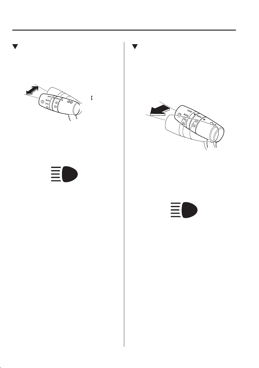
4
–
66
When Driving
Switches and Controls
Headlight High-Low Beam
The headlights switch between high and
low beams by moving the lever forward or
backward.
High beam
Low beam
When the headlight high-beams are on,
the headlight high-beam indicator light is
turned on.
Flashing the Headlights
Can be used when the ignition is switched
ON.
To À ash the headlights, pull the lever fully
towards you (the headlight switch does not
need to be on).
OFF
Headlight
flashing
The headlight high-beam indicator light
in the instrument cluster illuminates
simultaneously. The lever will return to the
normal position when released.
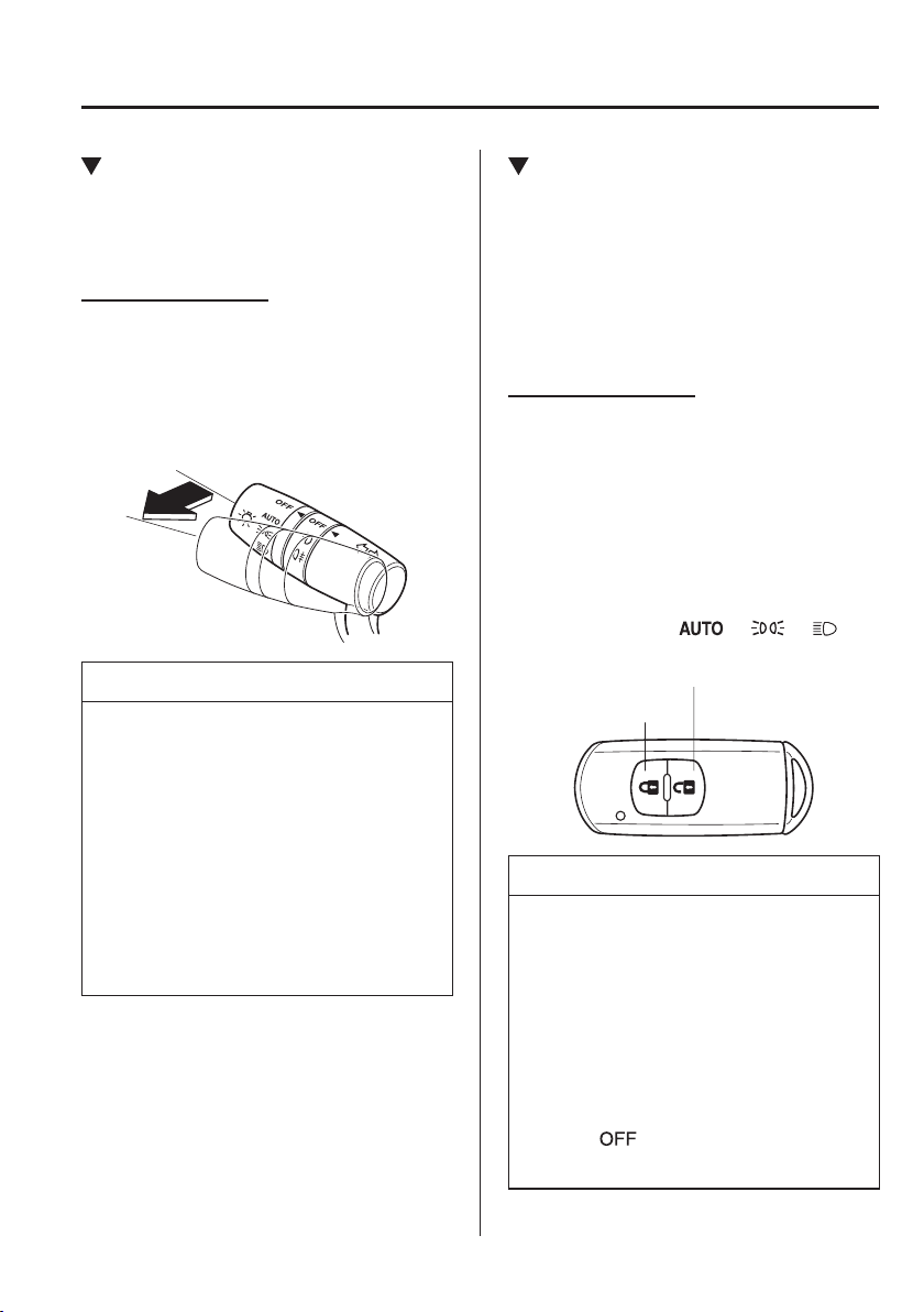
4
–
67
When Driving
Switches and Controls
Coming Home Light
The coming home light turns on the
headlights (low beams) when the lever is
operated.
To turn on the lights
When the lever is pulled with the ignition
switched to ACC or OFF, the low beam
headlights turn on.
The headlights turn off after a certain
period of time has elapsed after the doors
are closed.
NOTE
The time until the headlights turn off
after all of the doors are closed can
be changed.
Refer to Personalisation Features on
page 9-13 .
If no operations are done for 3
minutes after the lever is pulled, the
headlights turn off.
The headlights turn off if the lever is
pulled again while the headlights are
illuminated.
Leaving Home Light
The leaving home light turns on the lights
when the transmitter unlock button is
pressed while away from the vehicle.
The following lights turn on when the
leaving home light is operated.
Low beams, Position lights, Tail lights,
Number plate lights.
To turn on the lights
When the ignition switch and the headlight
switch are in the following conditions,
the headlights will illuminate when the
transmitter unlock button is pressed and
the vehicle receives the transmitter signal.
The headlights turn off after a certain
period of time has elapsed (30 seconds).
Ignition switch: off
Headlight switch: or or
Unlock button
Lock button
NOTE
Operation of the leaving home light
can be turned on or off.
Refer to Personalisation Features on
page 9-13 .
When the transmitter lock button is
pressed and the vehicle receives the
transmitter signal, the headlights turn
off.
When the headlight switch is turned
to the
position, the headlights
turn off.

4
–
68
When Driving
Switches and Controls
*Some models.
Headlight Levelling
*
The number of passengers and weight of
cargo in the luggage compartment change
the angle of the headlights.
Auto type
The angle of the headlights will be
automatically adjusted when turning on
the headlights.
Manual type
The headlight levelling switch is used
to adjust the angle of the headlights
manually.
Select the proper headlight angle from the
following chart.
Front seat
Rear
seat
Load
Switch
Position
Driver Passenger
× — — — 0
× × — — 0.5
× × × — 1.5
× × × × 2.5
× — — × 3.5
× : Ye s
—: No
Running Lights
*
Some countries require moving vehicles to
have their lights on (running lights) during
the daytime.
The running lights turn on automatically
when the vehicle starts moving.
They turn off when the parking brake is
operated or the selector lever is shifted
to the P position (automatic transaxle
vehicle).
NOTE
(Except countries prohibited by law)
The running lights can be deactivated.
Refer to Personalisation Features on
page 9-13 .
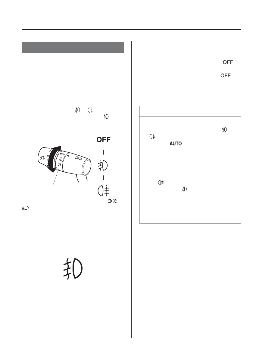
4
–
69
When Driving
Switches and Controls
*Some models.
Front Fog Lights
*
The front fog lights can be used when the
ignition is switched ON.
Use this switch to turn on the front fog
lights. The front fog lights will improve
visibility at night and during foggy
conditions.
To turn the front fog lights on, rotate the
fog light switch to the
or position
(the fog light switch returns to the
position automatically).
Fog light switch
The headlight switch must be in the
or
position before turning on the front fog
lights.
The front fog light indicator light in the
instrument cluster illuminates while the
front fog light are on.
To turn the front fog lights off, do any of
the following:
Rotate the fog light switch to the
position.
Turn the headlight switch to the
position.
Switch the ignition to a position other
than ON.
NOTE
(With auto-light control)
If the fog light switch is in the or
position and the headlight switch
is in the
position, the front fog
lights will turn on when the
headlights, the exterior lights and
instrument panel illumination turn
on.
If the fog light switch is rotated to
the
position (the fog light switch
returns to the
position
automatically), the rear fog light will
also illuminate, and the rear fog light
indicator light in the instrument
cluster will also illuminate.
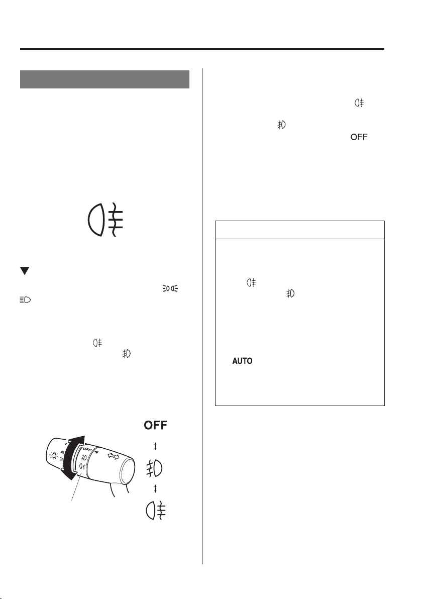
4
–
70
When Driving
Switches and Controls
*Some models.
Rear Fog Light
*
The rear fog light can be used when the
ignition is switched ON.
The rear fog light helps your vehicle to be
seen.
When the lights are turned on, the rear
fog lights indicator light in the instrument
cluster turns on.
Type A (With Front Fog Light)
The headlight switch must be in the or
position before turning on the rear fog
light.
To turn the rear fog light on, rotate the fog
light switch to the
position (the fog
light switch returns to the
position
automatically).
The rear fog light indicator light in the
instrument cluster illuminates while the
rear fog light is on.
Fog light switch
To turn the rear fog light off, do any of the
following:
Rotate the fog light switch to the
position again (the fog light switch
returns to the
position automatically).
Turn the headlight switch to the
position.
Switch the ignition to a position other
than ON.
The rear fog light indicator light in the
instrument cluster goes off when the rear
fog light is turned off.
NOTE
The front fog lights turns on when
the rear fog light is turned on.
If the fog light switch is rotated to
the
position (the fog light switch
returns to the
position
automatically), the front fog light
indicator light in the instrument
cluster will also illuminate.
(With auto-light control)
When the headlight switch is in the
position, the rear fog light turns
on when the headlights, the exterior
lights and instrument panel
illumination are on.
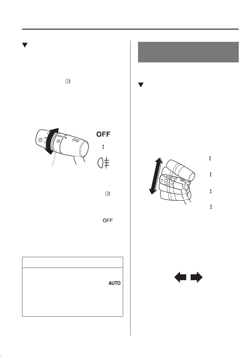
4
–
71
When Driving
Switches and Controls
Type B (Without Front Fog Light)
The headlights must be turned on to turn
on the rear fog light.
To turn the rear fog light on, rotate the fog
light switch to the
position (the fog
light switch returns to its original position
automatically).
The rear fog light indicator light in the
instrument cluster illuminates while the
rear fog light is on.
Fog light switch
To turn the rear fog light off, do any of the
following:
Rotate the fog light switch to the
position again (the fog light switch
returns to its original position
automatically).
Turn the headlight switch to the
position.
The rear fog light indicator light in the
instrument cluster goes off when the rear
fog light is turned off.
NOTE
(With auto-light control)
When the headlight switch is in the
position and the headlights, exterior
lights and instrument panel illuminated,
the rear fog light turns on when the rear
fog light switch is turned on.
Turn and Lane-Change
Signals
The ignition must be switched ON to use
the turn and lane-change signals.
Direction Indicators
Move the signal lever down (for a left
turn) or up (for a right turn) to the stop
position. The signal will self-cancel after
the turn is completed.
If the indicator light continues to À ash
after a turn, manually return the lever to its
original position.
Right turn
Left turn
Right lane change
Left lane change
OFF
The direction indicators in the instrument
cluster À ash according to the operation of
the direction indicator lever to show which
signal is working.
4
–
72
When Driving
Switches and Controls
NOTE
If an indicator light stays on without
À ashing or if it À ashes abnormally,
one of the direction indicator bulbs
may be burned out.
A personalised function is available
to change the turn indicator sound
volume. (page 9-13 )
Lane-Change Signals
Move the lever halfway toward the
direction of the lane change—until the
indicator À ashes— and hold it there. It will
return to the off position when released.
Three-Flash Turn Signal
After releasing the direction indicator
lever, the direction indicator À ashes three
times. The operation can be cancelled by
moving the lever in the direction opposite
to which it was operated.
NOTE
The three-À ash turn signal function can
be switched to operable/inoperable using
the personalisation function.
Refer to Personalisation Features on
page 9-13 .
Windscreen Wipers and
Washer
The ignition must be switched ON to use
the wipers.
WARNING
Use only windscreen washer À uid or
plain water in the reservoir:
Using radiator antifreeze as washer
À uid is dangerous. If sprayed on the
windscreen, it will dirty the windscreen,
affect your visibility, and could result in
an accident.
Only use windscreen washer À uid
mixed with anti-freeze protection in
freezing weather conditions:
Using windscreen washer À uid without
anti-freeze protection in freezing
weather conditions is dangerous as it
could freeze on the windscreen and
block your vision which could cause
an accident. In addition, make sure
the windscreen is suf¿ ciently warmed
using the defroster before spraying the
washer À uid.
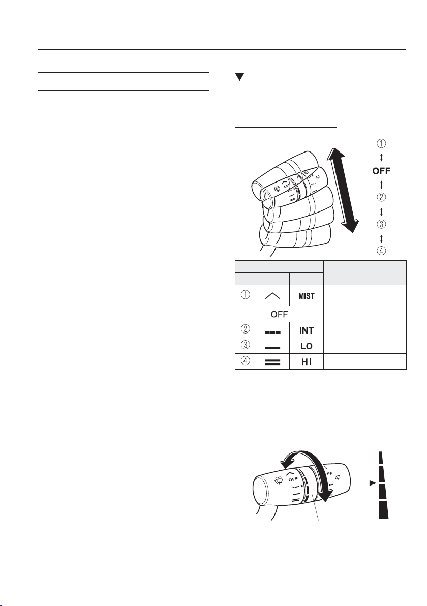
4
–
73
When Driving
Switches and Controls
NOTE
If the windscreen wipers are operated
under cold weather conditions or
during snowfall, they could stop due to
accumulated snow on the windscreen.
If the windscreen wipers stop due to
accumulated snow on the windscreen,
park the vehicle in a safe place, turn the
wiper switch off, and then remove the
accumulated snow. If the wiper switch
is turned to another position other than
OFF, the wipers will operate. If the
wipers do not operate even though the
wiper switch is turned to a position other
than OFF, consult an expert repairer,
we recommend an Authorised Mazda
Repairer as soon as possible.
Windscreen Wipers
Turn the wipers on by pressing the lever
up or down.
With intermittent wiper
Switch Position
Wiper operation
No. Type A Type B
Operation while pulling
up lever
Stop
Intermittent
Low speed
High speed
Variable-speed intermittent wipers
Set the lever to the intermittent position
and choose the interval timing by rotating
the ring.
INT ring
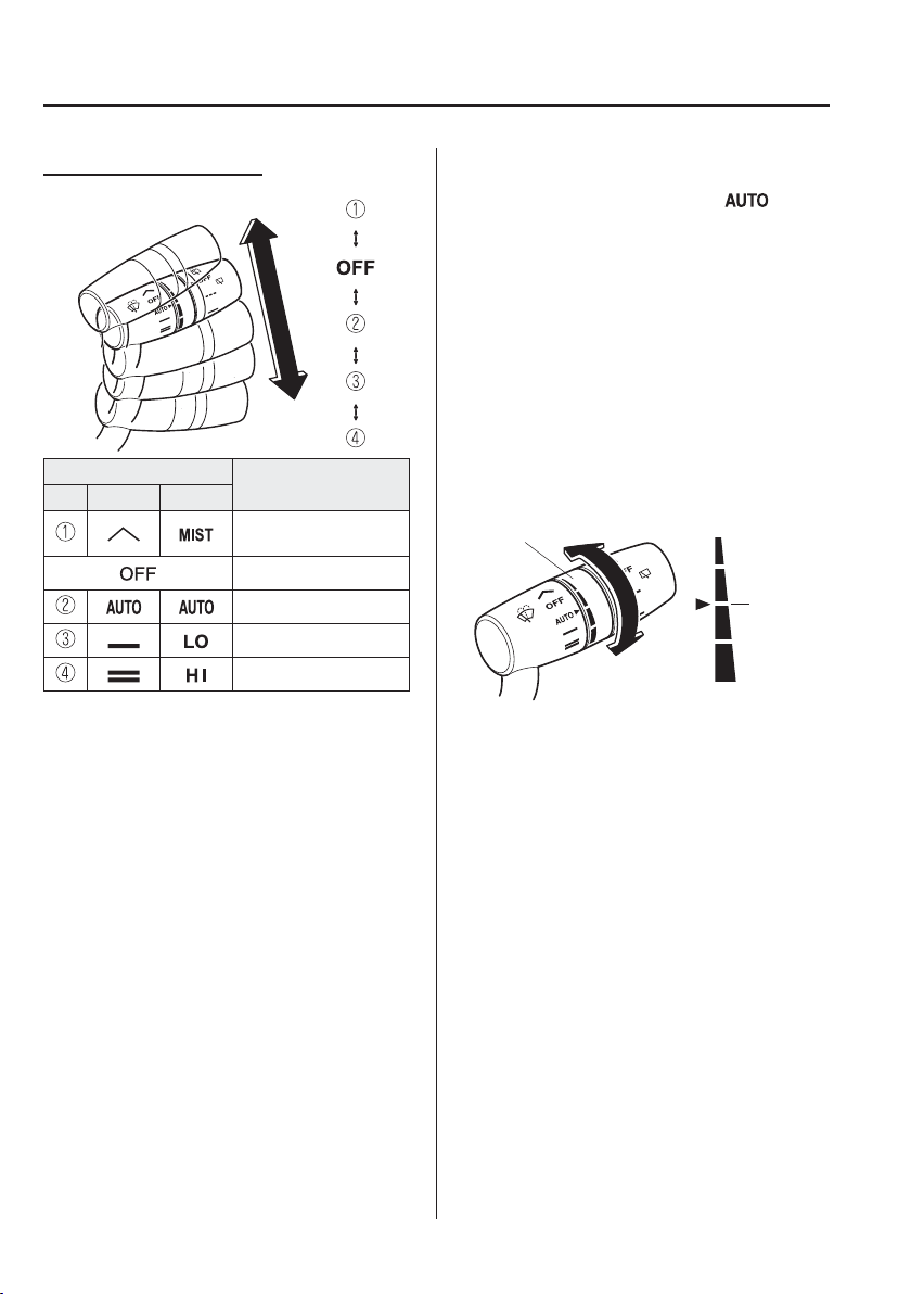
4
–
74
When Driving
Switches and Controls
With auto-wiper control
Switch Position
Wiper operation
No. Type A Type B
Operation while pulling
up lever
Stop
Auto control
Low speed
High speed
Auto-wiper control
When the wiper lever is in the
position, the rain sensor senses the amount
of rainfall on the windscreen and turns the
wipers on or off automatically (off—
intermittent—low speed—high speed).
The sensitivity of the rain sensor can be
adjusted by turning the switch on the
wiper lever.
From the centre position (normal), rotate
the switch upward for higher sensitivity
(faster response) or rotate it downward for
less sensitivity (slower response).
Higher sensitivity
Less sensitivity
Switch
Centre
position
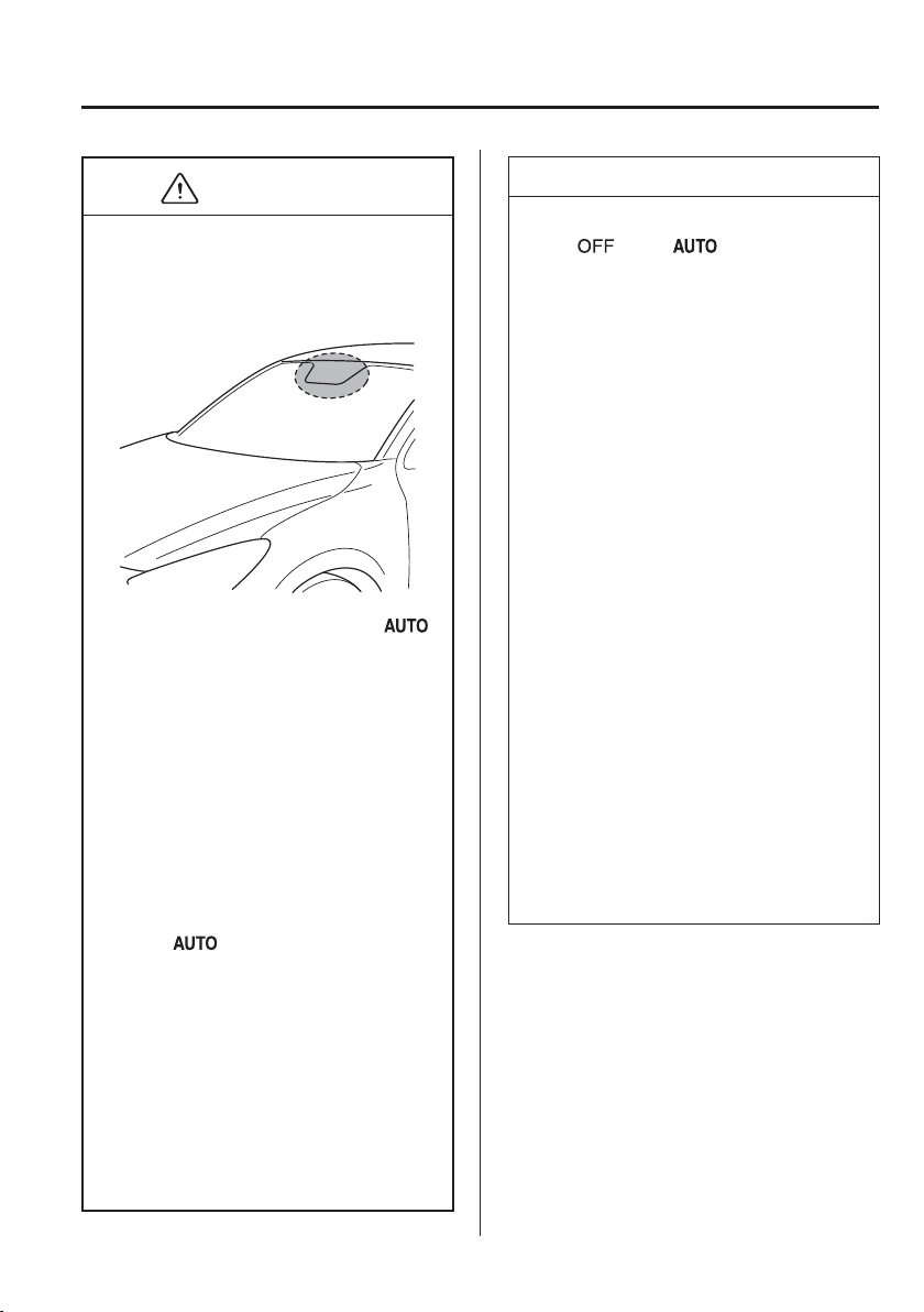
4
–
75
When Driving
Switches and Controls
CAUTION
Do not shade the rain sensor by
adhering a sticker or a label on the
windscreen. Otherwise the rain
sensor will not operate correctly.
When the wiper lever is in the
position and the ignition is switched
ON, the wipers may move
automatically in the following cases:
If the windscreen above the rain
sensor is touched or wiped with a
cloth.
If the windscreen is struck with a
hand or other object from either
outside or inside the vehicle.
Keep hands and scrapers clear of the
windscreen when the wiper lever is
in the
position and the ignition
is switched ON as ¿ ngers could be
pinched or the wipers and wiper
blades damaged when the wipers
activate automatically.
If you are going to clean the
windscreen, be sure the wipers are
turned off completely (when it is
most likely that the engine is left
running) this is particularly important
when clearing ice and snow.
NOTE
Switching the auto-wiper lever from
the
to the position while
driving activates the windscreen
wipers once, after which they operate
according to the rainfall amount.
The auto-wiper control may not
operate when the rain sensor
temperature is about –10 °C (14 °F)
or lower, or about 85 °C (185 °F) or
higher.
If the windscreen is coated with
water repellent, the rain sensor may
not be able to sense the amount of
rainfall correctly and auto-wiper
control may not operate properly.
If dirt or foreign matter (Such as
ice or matter containing salt water)
adheres to the windscreen above
the rain sensor or if the windscreen
is iced, it could cause the wipers to
move automatically. However, if the
wipers cannot remove this ice, dirt
or foreign matter, the auto-wiper
control will stop operation. In this
case, set the wiper lever to the low
speed position or high speed position
for manual operation, or remove the
ice, dirt or foreign matter by hand to
restore the auto-wiper operation.
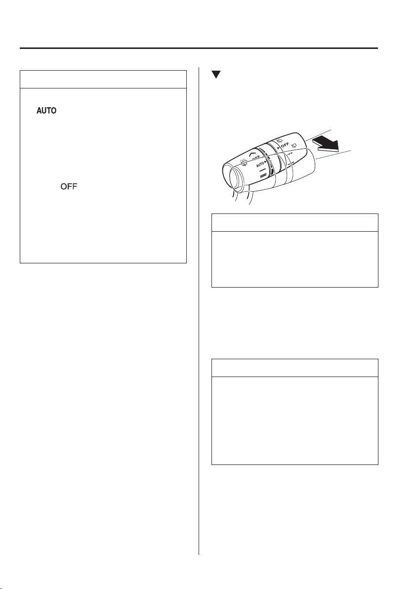
4
–
76
When Driving
Switches and Controls
NOTE
If the auto-wiper lever is left in the
position, the wipers could
operate automatically from the effect
of strong light sources,
electromagnetic waves, or infrared
light because the rain sensor uses an
optical sensor. It is recommended
that the auto-wiper lever be switched
to the
position other than when
driving the vehicle under rainy
conditions.
The auto-wiper control functions can
be turned off.
Refer to Personalisation Features on
page 9-13 .
Windscreen Washer
Pull the lever toward you and hold it to
spray washer À uid.
Washer
OFF
NOTE
If the windscreen washer is turned
on when the windscreen wipers are
not operating, the windscreen wipers
operate a few times.
If the washer does not work, inspect the
À uid level (page 6-32 ). If the À uid level
is normal, consult an expert repairer,
we recommend an Authorised Mazda
Repairer.
NOTE
(With headlight washers)
When the headlights are on, the
headlight washers operate automatically
once every ¿ fth time the windscreen
washer operates.
Refer to Headlight Washer on page
4-77 .
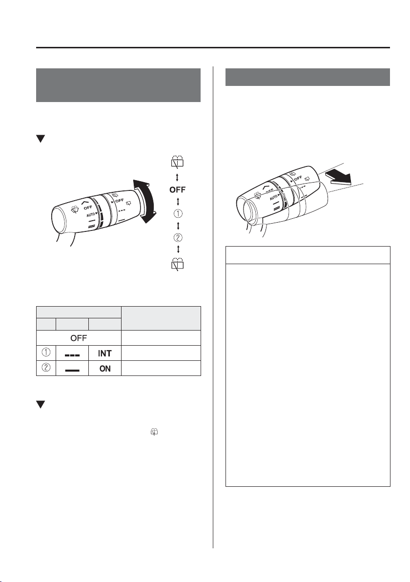
4
–
77
When Driving
Switches and Controls
*Some models.
Rear Window Wiper and
Washer
*
The ignition must be switched ON to use
the wiper.
Rear Window Wiper
Turn the wiper on by turning the rear
wiper/washer switch.
Switch Position
Wiper operation
No. Type A Type B
Stop
Intermittent
Normal
Rear Window Washer
To s p r a y w a s h e r À uid, turn the rear wiper/
washer switch to either of the
position.
After the switch is released, the washer
will stop.
If the washer does not work, inspect the
À uid level (page 6-32 ). If the À uid
level is normal and the washer still does
not work, consult an expert repairer,
we recommend an Authorised Mazda
Repairer.
Headlight Washer
*
The engine must be started and the
headlights must be turned on.
If you want to operate headlight washers,
double À ick the wiper lever.
Washer
OFF
NOTE
When the windscreen washer
is operated for the ¿ rst time
after turning on the headlights,
the headlight washers operate
automatically.
If air enters the headlight washer
À uid pipe under conditions such
as when the vehicle is brand-new
or after an empty washer tank is
replenished with washer À uid,
washer À uid will not spray even
when the wiper lever is operated. If
this occurs, perform the following
procedure:
1. Start the engine.
2. Turn on the headlights.
3. Double À ick the wiper lever
several times until the washer
À uid sprays.
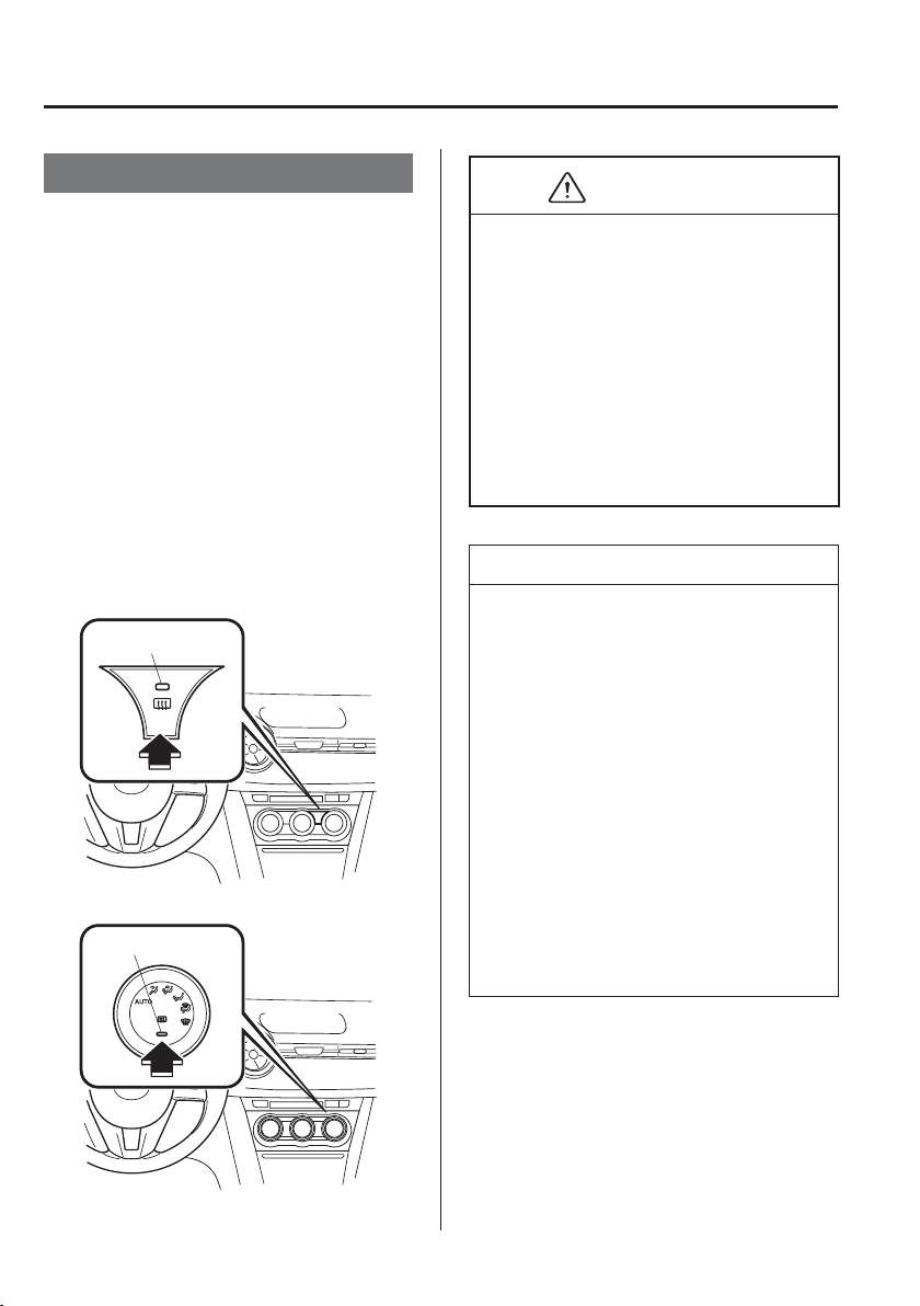
4
–
78
When Driving
Switches and Controls
Rear Window Defogger
The rear window defogger clears fog from
the rear window.
The ignition must be switched ON to use
the defogger.
Press the switch to turn on the rear
window defogger. The rear window
defogger operates for about 15 minutes
and then turns off automatically.
The indicator light illuminates when the
defogger is operating.
To turn off the rear window defogger
before the 15 minutes has elapsed, press
the switch again.
Manual Air-Conditioning
Indicator light
Fully Automatic Air-Conditioning
Indicator light
CAUTION
Do not use sharp instruments or
window cleaners with abrasives to
clean the inside of the rear window
surface. They may damage the
defogger grid inside the window.
Before opening the convertible top,
make sure the rear window defogger
switch is turned off. Otherwise the
heat generated from the defogger
could damage the convertible top and
the internal material.
NOTE
This defogger is not designed
for melting snow. If there is an
accumulation of snow on the rear
window, remove it before using the
defogger.
The rear window defogger setting
can be changed. After changing the
setting, the rear window defogger
stops automatically after 15 minutes
have elapsed and when the ambient
temperature is high. When the
ambient temperature is low, it
continues to operate until the switch
is pressed again.
Refer to Personalisation Features on
page 9-13 .
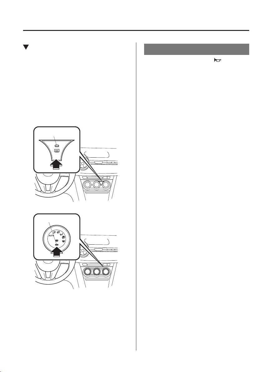
4
–
79
When Driving
Switches and Controls
*Some models.
Mirror Defogger
*
The mirror defoggers defrost the outside
mirrors.
The mirror defoggers operate in
conjunction with the rear window
defogger.
To turn on the mirror defoggers, switch
the ignition ON and press the rear window
defogger switch (page 4-78 ).
Manual Air-Conditioning
Indicator light
Fully Automatic Air-Conditioning
Indicator light
Horn
To sound the horn, press the mark on
the steering wheel.
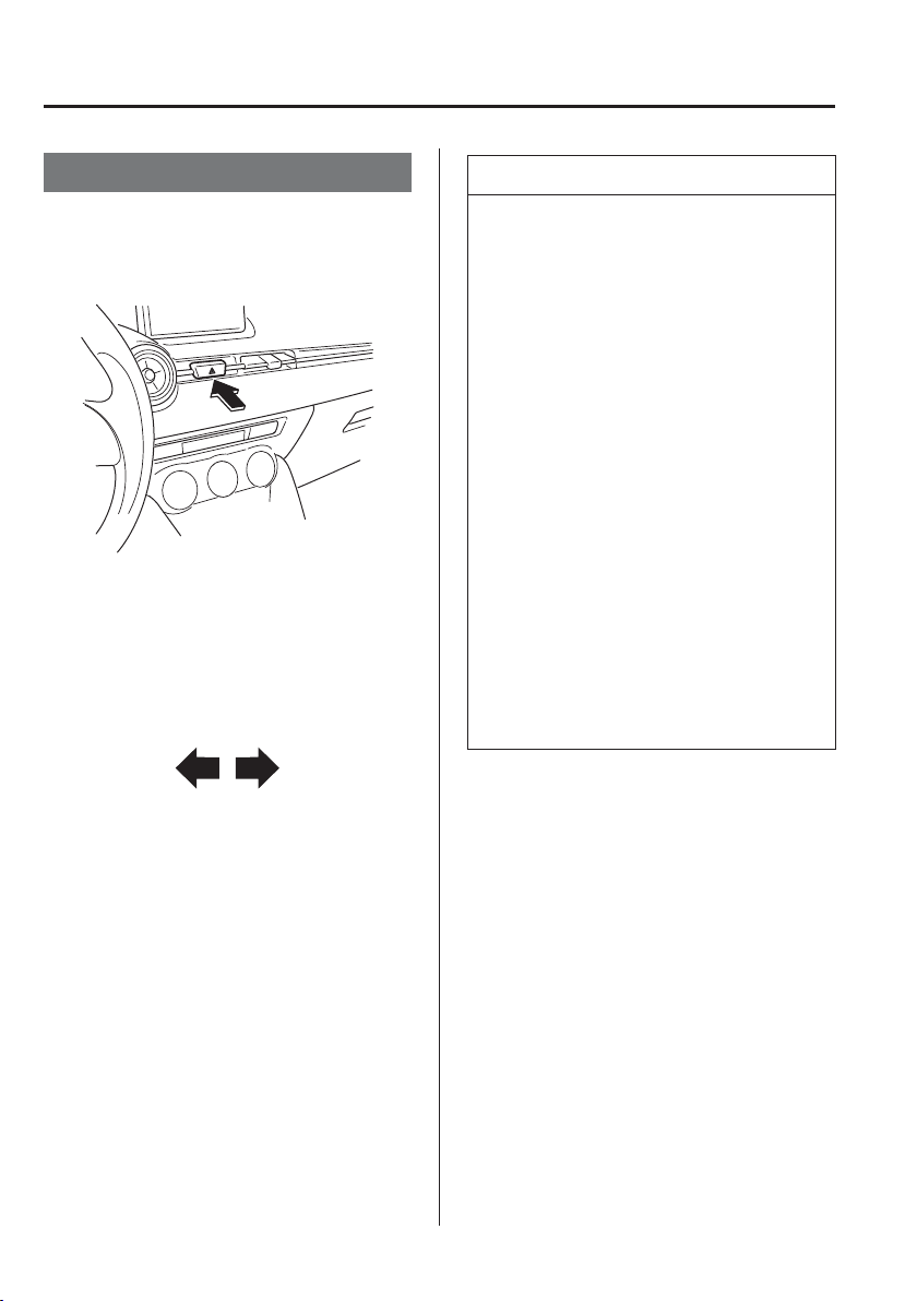
4
–
80
When Driving
Switches and Controls
Hazard Warning Flasher
The hazard warning lights should always
be used when you stop on or near a
roadway in an emergency.
The hazard warning lights warn other
drivers that your vehicle is a traf¿ c hazard
and that they must take extreme caution
when near it.
Depress the hazard warning À asher and
all the direction indicators will À ash. The
hazard warning indicator lights in the
instrument cluster À ash simultaneously.
NOTE
The direction indicators do not work
when the hazard warning lights are
on.
Check local regulations about the use
of hazard warning lights while the
vehicle is being towed to verify that
it is not in violation of the law.
If the brake pedal is depressed
while driving on slippery roads, the
emergency stop signal system could
operate causing all the turn and lane
change signals to À ash. Refer to
Emergency Stop Signal System on
page 4-84 .
While the emergency stop signal
system is operating, all the direction
indicators automatically À ash rapidly
to caution the driver of a vehicle
following behind your vehicle of a
sudden braking situation. Refer to
Emergency Stop Signal System on
page 4-84 .
4
–
81
When Driving
Brake
B r a k e S y s t e m
Foot Brake
This vehicle has power-assisted brakes
that adjust automatically through normal
use.
Should power-assist fail, you can stop by
applying greater force than normal to the
brake pedal. But the distance required to
stop will be greater than usual.
WARNING
Do not coast with the engine stalled or
turned off, ¿ nd a safe place to stop:
Coasting with the engine stalled or
turned off is dangerous. Braking will
require more effort, and the brake's
power-assist could be depleted if you
pump the brake. This will cause longer
stopping distances or even an accident.
Shift to a lower gear when going down
steep hills:
Driving with your foot continuously on
the brake pedal or steadily applying the
brakes for long distances is dangerous.
This causes overheated brakes,
resulting in longer stopping distances
or even total brake failure. This could
cause loss of vehicle control and a
serious accident. Avoid continuous
application of the brakes.
Dry off brakes that have become
wet by driving slowly, releasing the
accelerator pedal and lightly applying
the brakes several times until the brake
performance returns to normal:
Driving with wet brakes is dangerous.
Increased stopping distance or the
vehicle pulling to one side when
braking could result in a serious
accident. Light braking will indicate
whether the brakes have been affected.
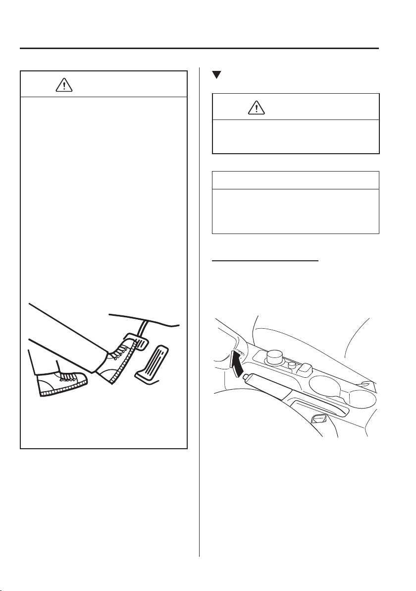
4
–
82
When Driving
Brake
CAUTION
Do not drive with your foot held
on the clutch pedal or brake pedal,
or hold the clutch pedal depressed
halfway unnecessarily. Doing so
could result in the following:
The clutch and brake parts will
wear out more quickly.
The brakes can overheat
and adversely affect brake
performance.
Always depress the brake pedal with
the right foot. Applying the brakes
with the unaccustomed left foot
could slow your reaction time to
an emergency situation resulting in
insuf¿ cient braking operation.
Wear shoes appropriate for driving in
order to avoid your shoe contacting
the brake pedal when depressing the
accelerator pedal.
Parking Brake
CAUTION
Driving with the parking brake on will
cause excessive wear of the brake parts.
NOTE
For parking in snow, refer to Winter
Driving (page 3-51 ) regarding parking
brake use.
Setting the parking brake
Depress the brake pedal and then ¿ rmly
pull the parking brake lever fully upwards
with suf¿ cient force to hold the vehicle in
a stationary position.
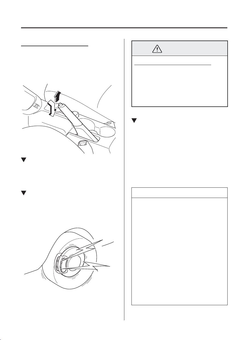
4
–
83
When Driving
Brake
Releasing the parking brake
Depress the brake pedal and pull the
parking brake lever upwards, then press
the release button. While holding the
button, lower the parking brake lever all
the way down to the released position.
Warning Light
The warning light turns on when the
system has a malfunction.
Refer to Warning Lights on page 4-38 .
Brake Pad Wear Indicator
When the disc brake pads become worn,
the built-in wear indicators contact the
disc plates. This causes a screeching noise
to warn that the pads should be replaced.
When you hear this noise, consult an
expert repairer, we recommend an
Authorised Mazda Repairer as soon as
possible.
WARNING
Do not drive with worn disc pads:
Driving with worn disc pads is
dangerous. The brakes could fail and
cause a serious accident. As soon as
you hear a screeching noise consult
an expert repairer, we recommend an
Authorised Mazda Repairer.
Brake Assist
During emergency braking situations
when it is necessary to depress the brake
pedal with greater force, the brake assist
system provides braking assistance, thus
enhancing braking performance.
When the brake pedal is depressed hard or
depressed more quickly, the brakes apply
more ¿ rmly.
NOTE
When the brake pedal is depressed
hard or depressed more quickly,
the pedal will feel softer but the
brakes will apply more ¿ rmly. This
is a normal effect of the brake assist
operation and does not indicate a
malfunction.
When the brake pedal is depressed
hard or depressed more quickly, a
motor/pump operation noise may be
heard. This is a normal effect of the
brake assist and does not indicate a
malfunction.
The brake assist equipment does not
supersede the functionality of the
vehicle's main braking system.

4
–
84
When Driving
Brake
*Some models.
Emergency Stop Signal
System
Your Mazda is equipped with an
emergency stop signal system that is
designed to determine whether you are
depressing the brake pedal with greater
force than during normal braking such
as in a situation requiring emergency
braking. If the system determines that such
a situation is occurring, it À ashes all the
direction indicators rapidly to caution the
driver of the vehicle following behind your
vehicle of the sudden braking situation.
The system turns off when it determines
that the brake pedal is released or that an
emergency braking situation no longer
exists based on the reduced vehicle speed.
NOTE
If you bring your vehicle to a
complete stop while all the direction
indicators are À ashing rapidly, the
rapid À ashing of all the direction
indicators changes back to the
normal À ashing pattern.
The emergency stop signal system
does not operate at vehicle speeds
under about 60 km/h (37 mph).
If the brake pedal is depressed
while driving on slippery roads, the
emergency stop signal system could
operate causing all the turn and lane
change signals to À ash.
Hill Launch Assist (HLA)
*
Hill Launch Assist (HLA) is a function
which assists the driver in accelerating
from a stop while on a slope. When
the driver releases the brake pedal and
depresses the accelerator pedal while
on a slope, the function prevents the
vehicle from rolling. The braking force is
maintained automatically after the brake
pedal is released on a steep grade.
For vehicles with a manual transaxle,
Hill Launch Assist (HLA) operates on a
downward slope when the shift lever is in
the reverse (R) position, and on an upward
slope when the shift lever is in a position
other than the reverse (R) position.
For vehicles with an automatic transaxle,
Hill Launch Assist (HLA) operates on a
downward slope when the selector lever
is in the reverse (R) position, and on an
upward slope when the selector lever is in
a forward gear.
4
–
85
When Driving
Brake
WARNING
Do not rely completely on Hill Launch
Assist (HLA):
Hill Launch Assist (HLA) is an
auxiliary device for accelerating from
a stop on a slope. The system only
operates for about two seconds and
therefore, relying only on the system,
when accelerating from a stop is
dangerous because the vehicle may
move (roll) unexpectedly and cause an
accident.
The vehicle could roll depending on
the vehicle's load or if it is towing
something. In addition, for vehicles
with a manual transaxle, the vehicle
could still roll depending on how the
clutch pedal or the accelerator pedal is
operated.
Always con¿ rm the safety around the
vehicle before starting to drive the
vehicle.
NOTE
Hill Launch Assist (HLA) does not
operate on a gentle slope. In addition,
the gradient of the slope on which
the system will operate changes
depending on the vehicle's load.
Hill Launch Assist (HLA) does
not operate if the parking brake is
applied, the vehicle has not stopped
completely, or the clutch pedal is
released.
While Hill Launch Assist (HLA) is
operating, the brake pedal may feel
stiff and vibrate, however, this does
not indicate a malfunction.
Hill Launch Assist (HLA) does not
operate while the TCS/DSC indicator
light is illuminated.
Refer to Warning/Indicator Lights on
page 4-38 .
Hill Launch Assist (HLA) does not
turn off even if the DSC OFF switch
is pressed to turn off the TCS/DSC.
(Automatic Transaxle)
Although the Hill Launch Assist
(HLA) does not operate during idling
stop, the vehicle roll prevention
function operates to prevent vehicle
roll.
4
–
86
When Driving
ABS/TCS/DSC
Antilock Brake System
(ABS)
The ABS control unit continuously
monitors the speed of each wheel. If
one wheel is about to lock up, the ABS
responds by automatically releasing and
reapplying that wheel's brake.
The driver will feel a slight vibration in
the brake pedal and may hear a chattering
noise from the brake system. This is
normal ABS system operation. Continue to
depress the brake pedal without pumping
the brakes.
The warning light turns on when the
system has a malfunction.
Refer to Warning Lights on page 4-38 .
WARNING
Do not rely on ABS as a substitute for
safe driving:
The ABS cannot compensate for unsafe
and reckless driving, excessive speed,
tailgating (following another vehicle
too closely), driving on ice and snow,
and hydroplaning (reduced tyre friction
and road contact because of water on
the road surface). You can still have an
accident.
NOTE
Braking distances may be longer
on loose surfaces (snow or gravel,
for example) which usually have a
hard foundation. A vehicle with a
normal braking system may require
less distance to stop under these
conditions because the tyres will
build up a wedge of surface layer
when the wheels skid.
The sound of the ABS operating may
be heard when starting the engine
or immediately after starting the
vehicle, however, it does not indicate
a malfunction.
4
–
87
When Driving
ABS/TCS/DSC
*Some models.
Traction Control System
(TCS)
*
The Traction Control System (TCS)
enhances traction and safety by controlling
engine torque and braking. When the TCS
detects driving wheel slippage, it lowers
engine torque and operates the brakes to
prevent loss of traction.
This means that on a slick surface, the
engine adjusts automatically to provide
optimum power to the drive wheels,
limiting wheel spin and loss of traction.
The warning light turns on when the
system has a malfunction.
Refer to Warning Lights on page 4-38 .
WARNING
Do not rely on the Traction Control
System (TCS) as a substitute for safe
driving:
The Traction Control System (TCS)
cannot compensate for unsafe and
reckless driving, excessive speed,
tailgating (following another vehicle
too closely), and hydroplaning (reduced
tyre friction and road contact because
of water on the road surface). You can
still have an accident.
Use snow tyres or tyre chains and
drive at reduced speeds when roads are
covered with ice and/or snow:
Driving without proper traction devices
on snow and/or ice-covered roads
is dangerous. The Traction Control
System (TCS) alone cannot provide
adequate traction and you could still
have an accident.
NOTE
To turn off the TCS, press the DSC OFF
switch (page 4-89 ).
TCS/DSC Indicator Light
This indicator light stays on for a few
seconds when the ignition is switched
ON. If the TCS or DSC is operating, the
indicator light À ashes.
If the light stays on, the TCS, DSC
or the brake assist system may have a
malfunction and they may not operate
correctly. Take your vehicle to an expert
repairer, we recommend an Authorised
Mazda Repairer.
NOTE
In addition to the indicator light
À ashing, a slight labouring sound
will come from the engine. This
indicates that the TCS/DSC is
operating properly.
On slippery surfaces, such as fresh
snow, it will be impossible to achieve
high rpm when the TCS is on.
4
–
88
When Driving
ABS/TCS/DSC
*Some models.
Dynamic Stability
Control (DSC)
*
The Dynamic Stability Control (DSC)
automatically controls braking and engine
torque in conjunction with systems such
as ABS and TCS to help control side slip
when driving on slippery surfaces, or
during sudden or evasive manoeuvring,
enhancing vehicle safety.
Refer to ABS (page 4-86 ) and TCS
(page 4-87 ).
DSC operation is possible at speeds
greater than 20 km/h (12 mph).
The warning light turns on when the
system has a malfunction.
Refer to Warning Lights on page 4-38 .
WARNING
Do not rely on the Dynamic Stability
Control as a substitute for safe driving:
The Dynamic Stability Control (DSC)
cannot compensate for unsafe and
reckless driving, excessive speed,
tailgating (following another vehicle
too closely), and hydroplaning (reduced
tyre friction and road contact because
of water on the road surface). You can
still have an accident.
CAUTION
The DSC may not operate correctly
unless the following are observed:
Use tyres of the correct size
speci¿ ed for your Mazda on all
four wheels.
Use tyres of the same
manufacturer, brand and tread
pattern on all four wheels.
Do not mix worn tyres.
The DSC may not operate correctly
when tyre chains are used or a
temporary spare tyre is installed
because the tyre diameter changes.
TCS/DSC Indicator Light
This indicator light stays on for a few
seconds when the ignition is switched
ON. If the TCS or DSC is operating, the
indicator light À ashes.
If the light stays on, the TCS, DSC
or the brake assist system may have a
malfunction and they may not operate
correctly. Take your vehicle to an expert
repairer, we recommend an Authorised
Mazda Repairer.
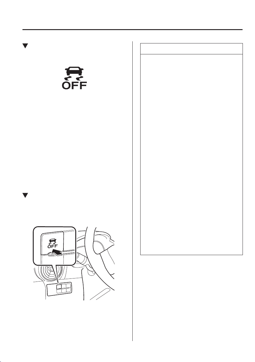
4
–
89
When Driving
ABS/TCS/DSC
DSC OFF Indicator Light
This indicator light stays on for a few
seconds when the ignition is switched ON.
It also illuminates when the DSC OFF
switch is pressed and TCS/DSC is
switched off.
Refer to DSC OFF Switch on page 4-89 .
If the light remains illuminated and
the TCS/DSC is not switched off, take
your vehicle to an expert repairer, we
recommend an Authorised Mazda
Repairer. The DSC may have a
malfunction.
DSC OFF Switch
Press the DSC OFF switch to turn off the
TCS/DSC. The DSC OFF indicator light
in the instrument cluster will illuminate.
Press the switch again to turn the TCS/
DSC back on. The DSC OFF indicator
light will turn off.
NOTE
When DSC is on and you attempt to
free the vehicle when it is stuck, or
drive it out of freshly fallen snow, the
TCS (part of the DSC system) will
activate. Depressing the accelerator
will not increase engine power and
freeing the vehicle may be dif¿ cult.
When this happens, turn off the TCS/
DSC.
If the TCS/DSC is off when the
engine is turned off, it automatically
activates when the ignition is
switched ON.
Leaving the TCS/DSC on will
provide the best traction.
If the DSC OFF switch is pressed
and held for 10 seconds or more,
the DSC OFF switch malfunction
detection function operates and the
DSC system activates automatically.
The DSC OFF indicator light
turns off while the DSC system is
operative.
(Vehicles with Smart City Brake
Support (SCBS))
If the Smart City Brake Support
(SCBS) operates with the TCS/DSC
turned off, the TCS/DSC becomes
operational automatically.
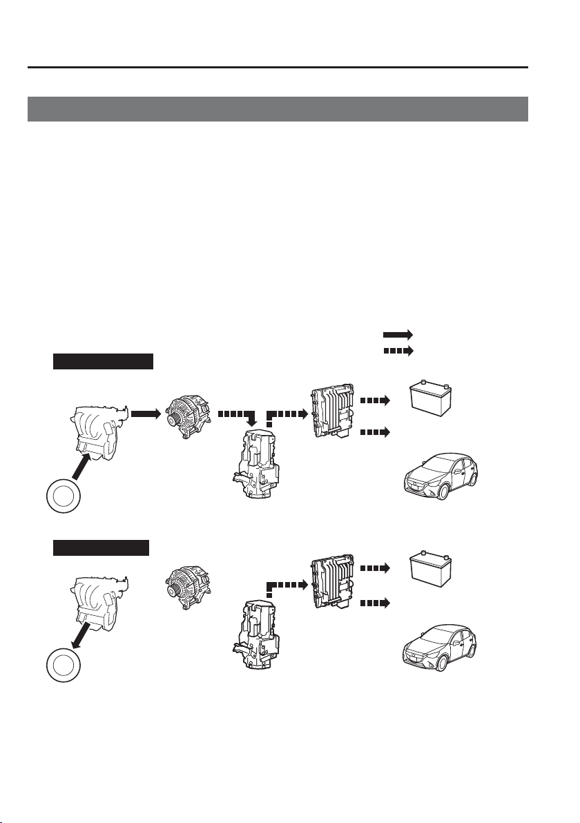
4
–
90
When Driving
i-ELOOP
*Some models.
i-ELOOP
*
i-ELOOP is a regenerative braking system. When you depress the brake pedal or use
engine braking, the kinetic energy that occurs is converted to electrical energy by the power
generator and the converted electrical energy is stored in the rechargeable battery (capacitor
and battery). The stored electricity is used as power to charge the battery and the vehicle's
electrical devices.
A variable voltage alternator is incorporated in the power generator which converts
the kinetic energy to electricity and can generate electricity ef¿ ciently according to the
vehicle conditions.
A capacitor is used to store large amounts of electricity instantly which can be utilized
quickly.
A DC-DC converter is incorporated which steps down the stored electricity to voltage
useable by the vehicle's electrical devices.
Vehicle electric
devices
Vehicle electric
devices
Accelerator OFF
Accelerator ON
Energy
regeneration
Charge
Battery
Battery
Power
Power
Engine
Variable
voltage
alternator
Variable
voltage
alternator
Engine
Tyre
Tyre
Capacitor
Capacitor
DC-DC converter
DC-DC converter
Kinetic energy
Electrical power
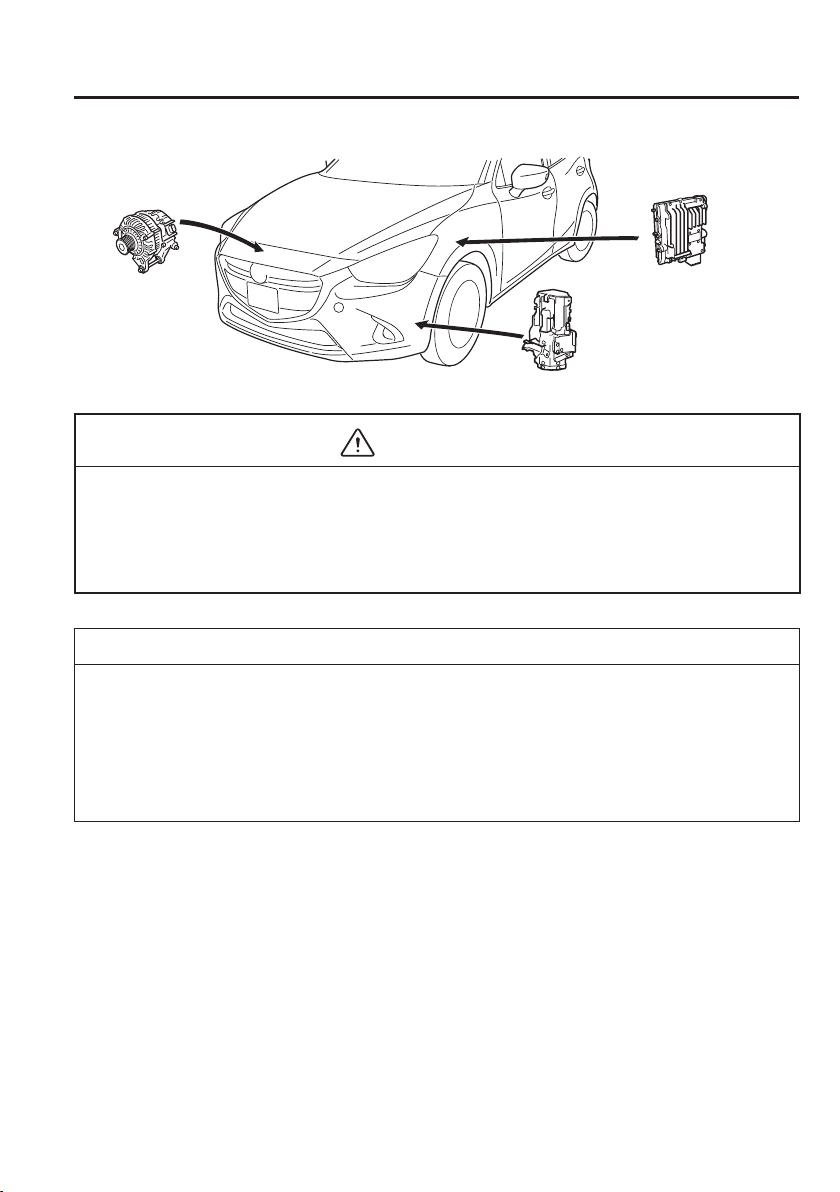
4
–
91
When Driving
i-ELOOP
Variable
voltage
alternator
Capacitor
DC-DC converter
CAUTION
High-current electricity À ows through the following parts, therefore do not touch them.
Variable voltage alternator
DC-DC converter
Capacitor
NOTE
A difference in the fuel economy may occur depending on how the vehicle's electrical
devices are used.
If the capacitor is to be disposed of, always consult an expert repairer, we recommend
an Authorised Mazda Repairer.
For details, go to the following URL.
http://www.mazda.com/csr/environment/recycling

4
–
92
When Driving
i-ELOOP
i-ELOOP Indicator Light/Control
Status Display
T h e d r i v e r i s n o t i ¿ ed of the i-ELOOP
power generating status and the vehicle
conditions by the i-ELOOP indicator light
(green) and the control status display.
i-ELOOP indicator light (green) (vehicle
without type B audio)
The light turns on during power
generation.
Control status display (vehicles with
type B audio)
The i-ELOOP power generating status is
displayed in the centre display.
Refer to Control Status Display on page
4-95 .
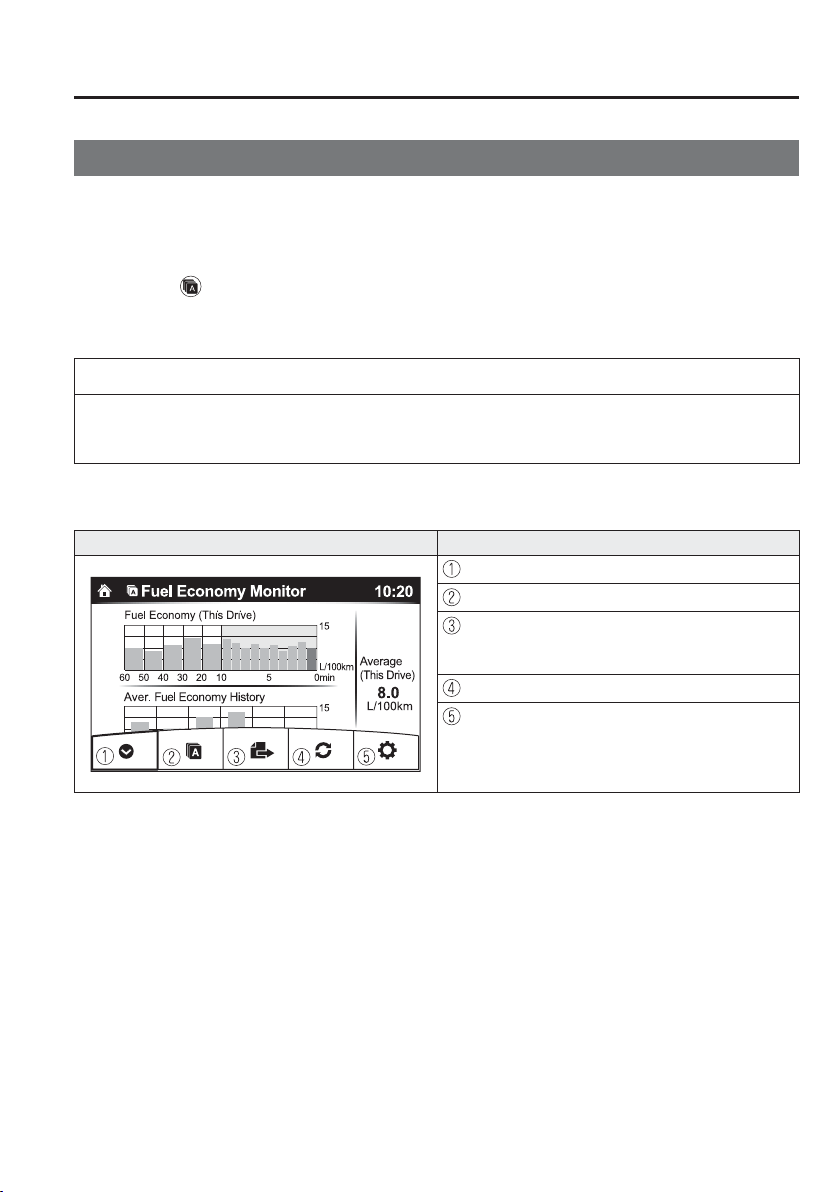
4
–
93
When Driving
Fuel Economy Monitor
*Some models.
Fuel Economy Monitor
*
For vehicles with type B audio, the Control Status, Fuel Consumption, and Effectiveness
*1
are switched and displayed by operating each icon in the display.
In addition, after completing a trip, the total energy ef¿ ciency to date is displayed in the
ending display when the ending display is turned on.
1. Select the icon on the home screen to display the applications screen.
2. Select the “Fuel Economy Monitor”.
3. Operate the commander switch or touch the screen and display the menu.
NOTE
When the menu is displayed by touching the screen, the display is hidden automatically
after 6 seconds.
4. Select the icon in the menu and perform the operation. Each icon operates as follows:
Indication on display Control status
Hides the menu display.
Displays the application screen.
Switches the Fuel Economy Monitor in the order of
Control Status, Fuel Consumption, and
Effectiveness
*1
.
Resets the fuel economy data.
Displays the following setting screen.
Ending display on/off switching
On/off switching for function which synchronizes
reset fuel economy data to trip meter (Trip A)
*1 With i-stop function.
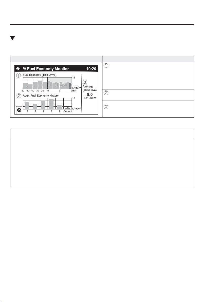
4
–
94
When Driving
Fuel Economy Monitor
Fuel Consumption Display
Information regarding the fuel economy is displayed.
Indication on display Control status
Displays the fuel economy for the past 60 minutes.
Displays the fuel economy every minute for the
past 1 to 10 minutes.
Displays the fuel economy every 10 minutes for
the past 10 to 60 minutes.
Displays the average fuel economy over the past 5
resets and after the current reset.
Calculates the average fuel economy every minute
after vehicle travel begins, and displays it.
NOTE
The fuel economy data can be reset by doing the following operation:
Press the reset switch from the menu screen.
When the function which synchronizes the fuel economy monitor and the trip meter
is on, reset trip A of the trip meter.
Delete the average fuel economy information displayed in the trip computer.
After resetting the fuel economy data, “-- -” is displayed while the average fuel
economy is calculated.
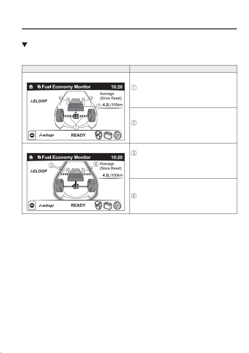
4
–
95
When Driving
Fuel Economy Monitor
Control Status Display
The i-stop operation status and the i-ELOOP power generating status are displayed.
Indication on display Control status
With i-ELOOP system
Displays the level of electricity generated by
regenerative braking.
Displays the amount of the electricity stored in the
rechargeable battery.
With i-ELOOP system
Displays the status of the electricity stored in the
rechargeable battery and being supplied to the
electrical devices (whole vehicle in display is
illuminated simultaneously).
Displays the accumulated fuel economy.
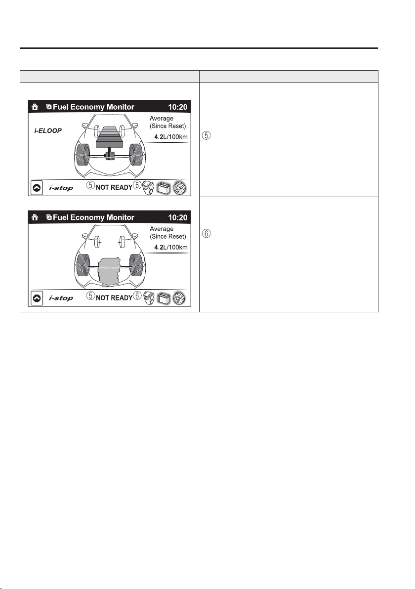
4
–
96
When Driving
Fuel Economy Monitor
Indication on display Control status
With i-ELOOP system
Without i-ELOOP system
Displays the readiness status as to whether operation
of the i-stop function is available.
Displays the operation readiness status of the i-stop
function on the vehicle side (engine, battery, and
A/C) using icon colouring. The blue colour indicates
that the i-stop function is ready to operate, and the
grey colour indicates that it is not ready for
operation.
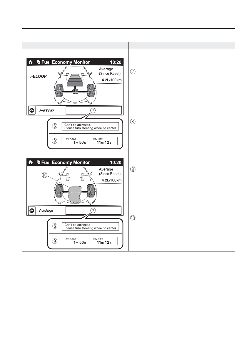
4
–
97
When Driving
Fuel Economy Monitor
Indication on display Control status
With i-ELOOP system
Without i-ELOOP system
Displays the i-stop function status while the vehicle
is stopped.
Indicates the operations required by the driver to
operate the i-stop function while it is not operating.
Displays the current amount of time that the i-stop
function has been operating and the accumulated
amount of time that it has been operating.
The i-stop function operation status is indicated by
the colour of the engine area. The colour is blue
during i-stop function operation, and grey when it is
not operating.
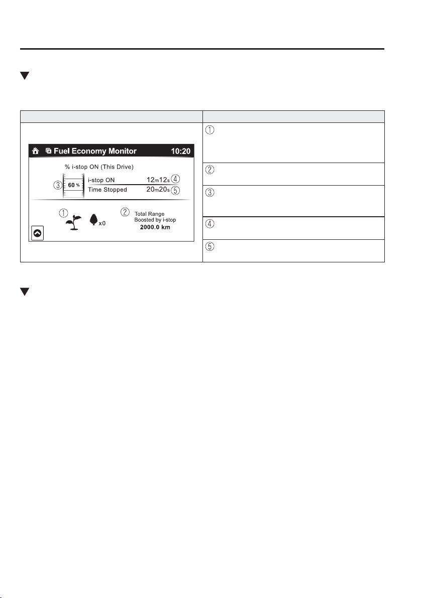
4
–
98
When Driving
Fuel Economy Monitor
Effectiveness Display
The actual performance of the energy ef¿ ciency is displayed.
Indication on display Control status
The leaf graphic grows according to the amount of
CO 2 emissions reduced by the system effects. The
cumulative total amount of leaf growth is indicated
in terms of the number of tree graphics.
Displays the total driving distance which could be
extended by the operation of the i-stop function.
Displays the percentage of time that the vehicle was
stopped by the i-stop function operation out of the
total amount of time that the vehicle was stopped.
Displays the amount of time that the i-stop function
has operated.
Displays the total amount of time that the vehicle
was stopped.
Ending Screen Display
If the ending display on the fuel economy monitor is on when the ignition is switched from
ON to OFF, the actual energy ef¿ ciency (with i-stop function) or the information regarding
the fuel economy (without i-stop function) is displayed.
4
–
99
When Driving
Drive Selection
*Some models.
Drive Selection
*
Drive selection is a system to switch the vehicle's drive mode. When the sport mode is
selected, vehicle's response against accelerator operation is enhanced. Use the sport mode
when higher vehicle response is required such as merging onto expressway or accelerating
to overtake.
CAUTION
Do not use the sport mode when driving on slippery roads such as wet or snow-covered
roads. It may cause tyre slipping.
NOTE
When the sport mode is selected, driving at higher engine speeds increases and it may
increase fuel consumption. Mazda recommends to cancel the sport mode on normal
driving.
Drive mode cannot be switched in the following conditions:
ABS/TCS/DSC is operating
Steering wheel is being operated abruptly
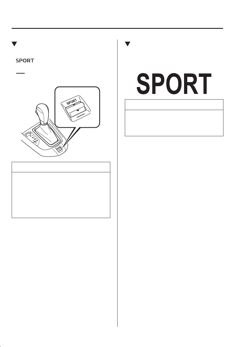
4
–
100
When Driving
Drive Selection
Drive Selection Switch
Press the drive selection switch forward
(“
”) to select the sport mode.
Pull the drive selection switch back
(“
”) to cancel the sport mode.
NOTE
When the ignition is switched off, the
sport mode is cancelled.
Depending on the driving conditions
when sport mode is selected, the
vehicle may perform shift-down or
slightly accelerate.
Select Mode Indicator Light
When the sport mode is selected, the
select mode indicator light turns on in the
instrument cluster.
NOTE
If the drive selection cannot be switched
to sport mode, the select mode indicator
light À ashes to notify the driver.
4
–
101
When Driving
Power Steering
Power Steering
Power steering is only operable when
the engine is running. If the engine is
off or if the power steering system is
inoperable, you can still steer, but it
requires more physical effort.
If the steering feels stiffer than usual
during normal driving or the steering
vibrates, consult an expert repairer,
we recommend an Authorised Mazda
Repairer.
The warning light noti¿ es the driver
of system abnormalities and operation
conditions.
In addition, the buzzer may also activate
depending on the system abnormality or
operation condition.
Refer to Warning Lights on page
4-38 .
Refer to Power Steering Warning Buzzer
on page 7-53 .
CAUTION
Never hold the steering wheel to the
extreme left or right for more than
5 seconds with the engine running.
This could damage the power steering
system.

4
–
102
When Driving
i-ACTIVSENSE
*Some models.
i-ACTIVSENSE
*
i-ACTIVSENSE is a collective term covering a series of advanced safety and driver support
systems which make use of a Forward Sensing Camera (FSC) and radar sensors. These
systems consist of active safety and pre-crash safety systems.
These systems are designed to assist the driver in safer driving by reducing the load on the
driver and helping to avert collisions or reduce their severity. However, because each system
has its limitations, always drive carefully and do not rely solely on the systems.
Active Safety Technology
Active Safety Technology supports safer driving by helping the driver to recognise potential
hazards and avert accidents.
Driver awareness support systems
Nighttime visibility
Adaptive LED Headlights (ALH) ..................................................................................... 4-108
High Beam Control System (HBC) .................................................................................. 4-105
Left/right side and rear side detection
Lane Departure Warning System (LDWS) ....................................................................... 4-111
Blind Spot Monitoring (BSM) .......................................................................................... 4-117
Inter-vehicle distance recognition
Distance Recognition Support System (DRSS) ................................................................ 4-124
Driver fatigue detection
Driver Attention Alert (DAA) ........................................................................................... 4-127
Rear obstruction detection when leaving a parking space
Rear Cross Traf¿ c Alert (RCTA) ...................................................................................... 4-130
Driver support systems
Inter-vehicle distance
Mazda Radar Cruise Control (MRCC) ............................................................................. 4-135
Speed control
Adjustable Speed Limiter ................................................................................................. 4-148

4
–
103
When Driving
i-ACTIVSENSE
Pre-Crash Safety Technology
Pre-crash safety technology is designed to assist the driver in averting collisions or reduce
their severity in situations where they cannot be avoided.
Collision damage reduction in low vehicle speed range
Forward driving
Smart City Brake Support [Forward] (SCBS F) ............................................................... 4-155
Reverse driving
Smart City Brake Support [Reverse] (SCBS R) ............................................................... 4-161
Collision damage reduction in medium/high speed range
Smart Brake Support (SBS) .............................................................................................. 4-167
Camera and Sensors
Forward Sensing Camera (FSC)
The Forward Sensing Camera (FSC) detects lane indications and recognises headlights, tail
lights and city lights during nighttime driving. The following systems also use the Forward
Sensing Camera (FSC).
High Beam Control System (HBC)
Adaptive LED Headlights (ALH)
Driver Attention Alert (DAA)
Lane Departure Warning System (LDWS)
Smart Brake Support (SBS)
The Forward Sensing Camera (FSC) is installed at the top of the windscreen near the
rearview mirror.
Refer to Forward Sensing Camera (FSC) on page 4-170 .
Radar sensor (front)
The radar sensor (front) functions by detecting the radio waves reÀ ected off a vehicle ahead
sent from the radar sensor. The following systems also use the radar sensor (front).
Distance Recognition Support System (DRSS)
Mazda Radar Cruise Control (MRCC)
Smart Brake Support (SBS)
The radar sensor (front) is mounted behind the radiator grille.
Refer to Radar Sensor (Front) on page 4-176 .

4
–
104
When Driving
i-ACTIVSENSE
Laser sensor (front)
The laser sensor (front) emits a near-infrared laser beam and receives the beam reÀ ected
off the reÀ ective surface of a vehicle in front, and the detected beam is then used for
measurement. The following systems also use the laser sensor (front).
Smart City Brake Support [Forward] (SCBS F)
Smart Brake Support (SBS)
The laser sensor (front) is installed at the top of the windscreen near the rearview mirror.
Refer to Laser Sensor (Front) on page 4-179 .
Radar sensors (rear)
The radar sensors (rear) function by detecting the radio waves reÀ ected off a vehicle
approaching from the rear or an obstruction sent from the radar sensors. The following
systems also use the radar sensors (rear).
Blind Spot Monitoring (BSM)
Rear Cross Traf¿ c Alert (RCTA)
The radar sensors (rear) are installed inside the rear bumper, one each on the left and right
sides.
Refer to Radar Sensors (Rear) on page 4-181 .
Ultrasonic sensors (rear)
The ultrasonic sensors (rear) function by detecting the ultrasonic waves reÀ ected off
obstructions at the rear sent from the ultrasonic sensors. The following systems also use the
ultrasonic sensors (rear).
Smart City Brake Support [Reverse] (SCBS R)
The ultrasonic sensors (rear) are mounted in the rear bumper.
Refer to Ultrasonic Sensors (Rear) on page 4-183 .
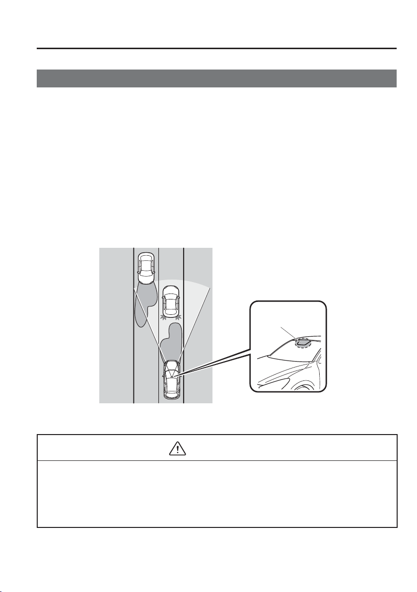
4
–
105
When Driving
i-ACTIVSENSE
*Some models.
High Beam Control System (HBC)
*
The High Beam Control System (HBC) determines the conditions in front of the vehicle
using the Forward Sensing Camera (FSC) while driving in darkness to automatically switch
the headlights between high and low beams.
Refer to Warning/Indicator Lights on page 4-38 .
While driving the vehicle at a speed of about 30 km/h (19 mph) or more, the headlights are
switched to high beams when there are no vehicles ahead or approaching in the opposite
direction.
The system switches the headlights to low beams when one of the following occurs:
The system detects a vehicle or the headlights/lights of a vehicle approaching in the
opposite direction.
The vehicle is driven on roads lined with streetlamps or on roads in well-lit cities and
towns.
The vehicle is driven at less than about 20 km/h (12 mph).
Forward Sensing
Camera (FSC)
The recognition distance of the
Forward Sensing Camera (FSC)
varies according to the
surrounding conditions.
The warning light À ashes when the system has a malfunction.
Refer to Warning Lights on page 4-38 .
CAUTION
Do not adjust the vehicle height, modify the headlight units, or remove the camera,
otherwise the system will not operate normally.
Do not rely excessively on the High Beam Control System (HBC) and drive the
vehicle while paying suf¿ cient attention to safety. Switch the headlights between the
high beams and low beams manually if necessary.
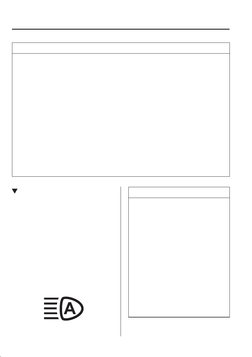
4
–
106
When Driving
i-ACTIVSENSE
NOTE
The timing in which the system switches the headlights changes under the following
conditions. If the system does not switch the headlights appropriately, manually switch
between high and low beams according to the visibility as well as road and traf¿ c
conditions.
When there are sources of light in the area such as street lamps, illuminated
signboards, and traf¿ c signals.
When there are reÀ ective objects in the surrounding area such as reÀ ective plates and
signs.
When visibility is reduced under rain, snow and foggy conditions.
When driving on roads with sharp turn or hilly terrain.
When the headlights/rear lamps of vehicles in front of you or in the opposite lane are
dim or not illuminated.
When there is suf¿ cient darkness such as at dawn or dusk.
When the luggage compartment is loaded with heavy objects or the rear passenger
seats are occupied.
When visibility is reduced due to a vehicle in front of you spraying water from its tyres
onto your windscreen.
To Operate the System
The High Beam Control System (HBC)
operates to switch the headlights
automatically between high and low
beams after the ignition is switched ON
and the headlight switch is in the AUTO
and high beam position.
The High Beam Control System (HBC)
determines that it is dark based on the
brightness of the surrounding area. At the
same time, the High Beam Control System
(HBC) indicator light (green) in the
instrument cluster illuminates.
NOTE
When the vehicle speed is about
30 km/h (19 mph) or more, the
headlights automatically switch
to high beams when there are no
vehicles ahead or approaching in the
opposite direction.
When the vehicle speed is less
than about 20 km/h (12 mph), the
High Beam Control System (HBC)
switches the headlights to low
beams.
The low beams may not switch to
high beams when cornering.
Operation of the High Beam Control
System (HBC) function can be
disabled. Refer to Personalisation
Features on page 9-13 .

4
–
107
When Driving
i-ACTIVSENSE
Manual Switching
Switching to low beams
Shift the lever to the low beam position.
The High Beam Control System (HBC)
indicator light (green) turns off.
Switching to high beams
Turn the headlight switch to the
position.
The High Beam Control System (HBC)
indicator light (green) turns off and the
is illuminated.
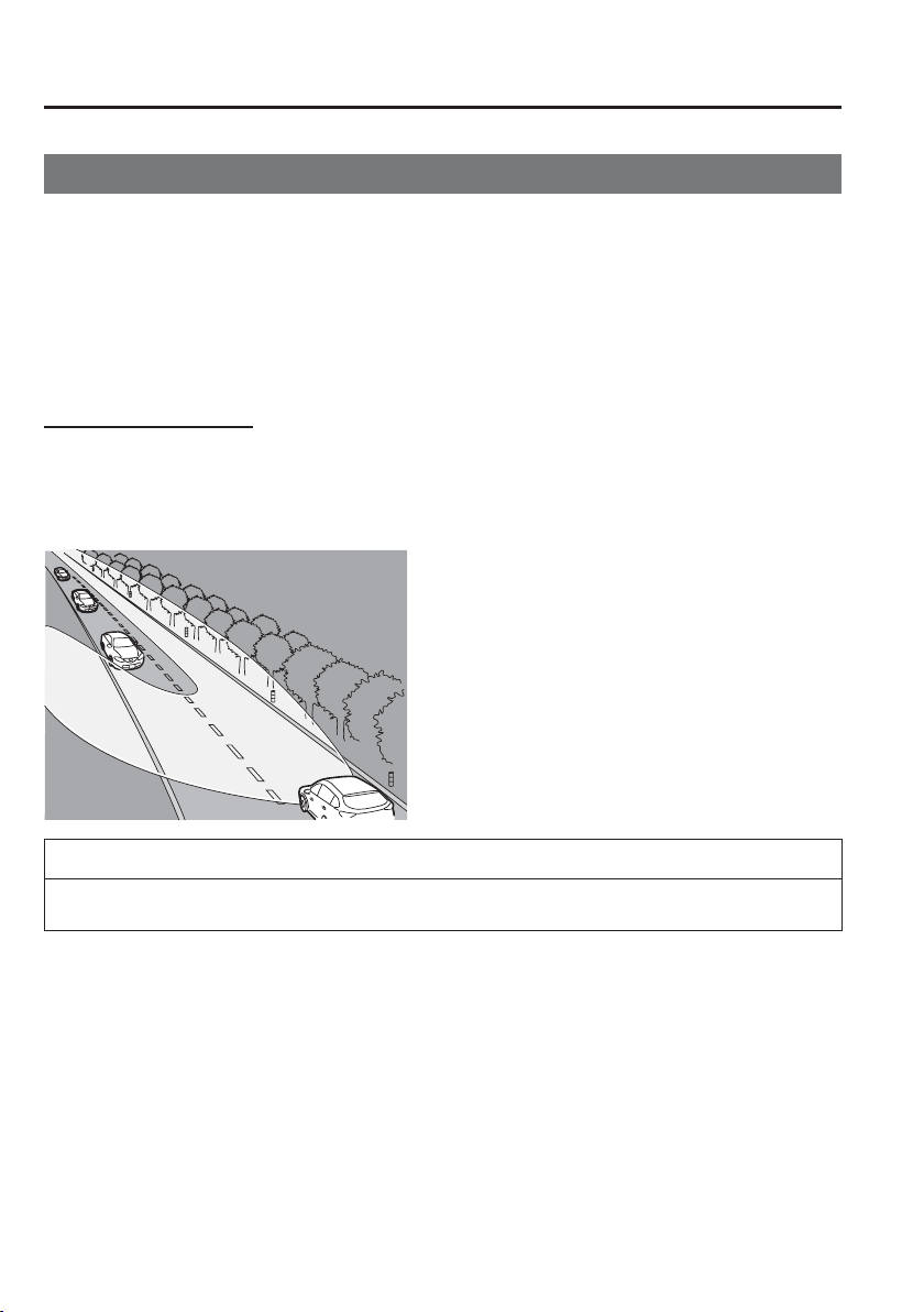
4
–
108
When Driving
i-ACTIVSENSE
*Some models.
Adaptive LED Headlights (ALH)
*
The Adaptive LED Headlights (ALH) are a system which uses the Forward Sensing Camera
(FSC) to determine the situation of a vehicle ahead or a vehicle approaching in the opposite
direction while driving at night to automatically switch the illumination range of the
headlights, the illuminated area, or the illumination brightness.
Refer to Forward Sensing Camera (FSC) on page 4-170 .
The Adaptive LED Headlights (ALH) are controlled between high and low beams as follows
to assure the driver’s visibility without dazzling a vehicle ahead or a vehicle approaching in
the opposite direction.
Glare-Free High Beam
This feature dims only the high-beam light shone on the vehicle ahead.
The high beams will dim while driving at a speed of about 40 km/h (25 mph) or faster.
When the vehicle speed is less than about 30 km/h (18 mph), the beams switch to the low
beams.
NOTE
The headlight high-beam indicator light turns on while the high beams are on.
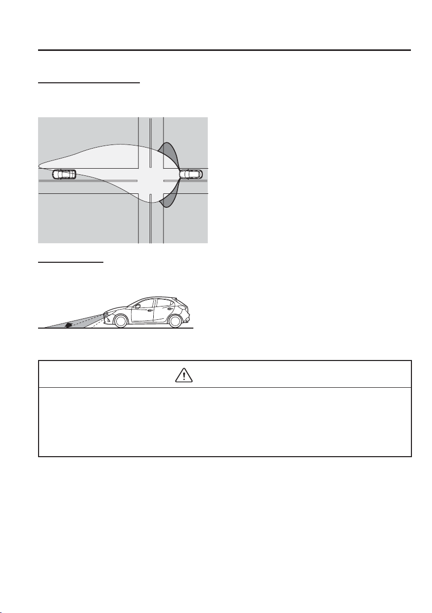
4
–
109
When Driving
i-ACTIVSENSE
Wide-Range Low Beam
This feature extends the illumination range of the light cast by the low beams while driving
at a speed less than about 40 km/h (25 mph).
Highway Mode
This feature shifts the illumination angle of the light cast by the headlights upward while
driving on highways.
The distance in which the Adaptive LED Headlights (ALH) can detect objects varies
depending on the surrounding conditions.
CAUTION
Do not modify the suspensions or headlight units, or remove the camera. Otherwise,
the Adaptive LED Headlights (ALH) may not operate normally.
Do not rely excessively on the Adaptive LED Headlights (ALH) and drive the vehicle
while paying suf¿ cient attention to safety. Switch the headlights between the high
beams and low beams manually if necessary.
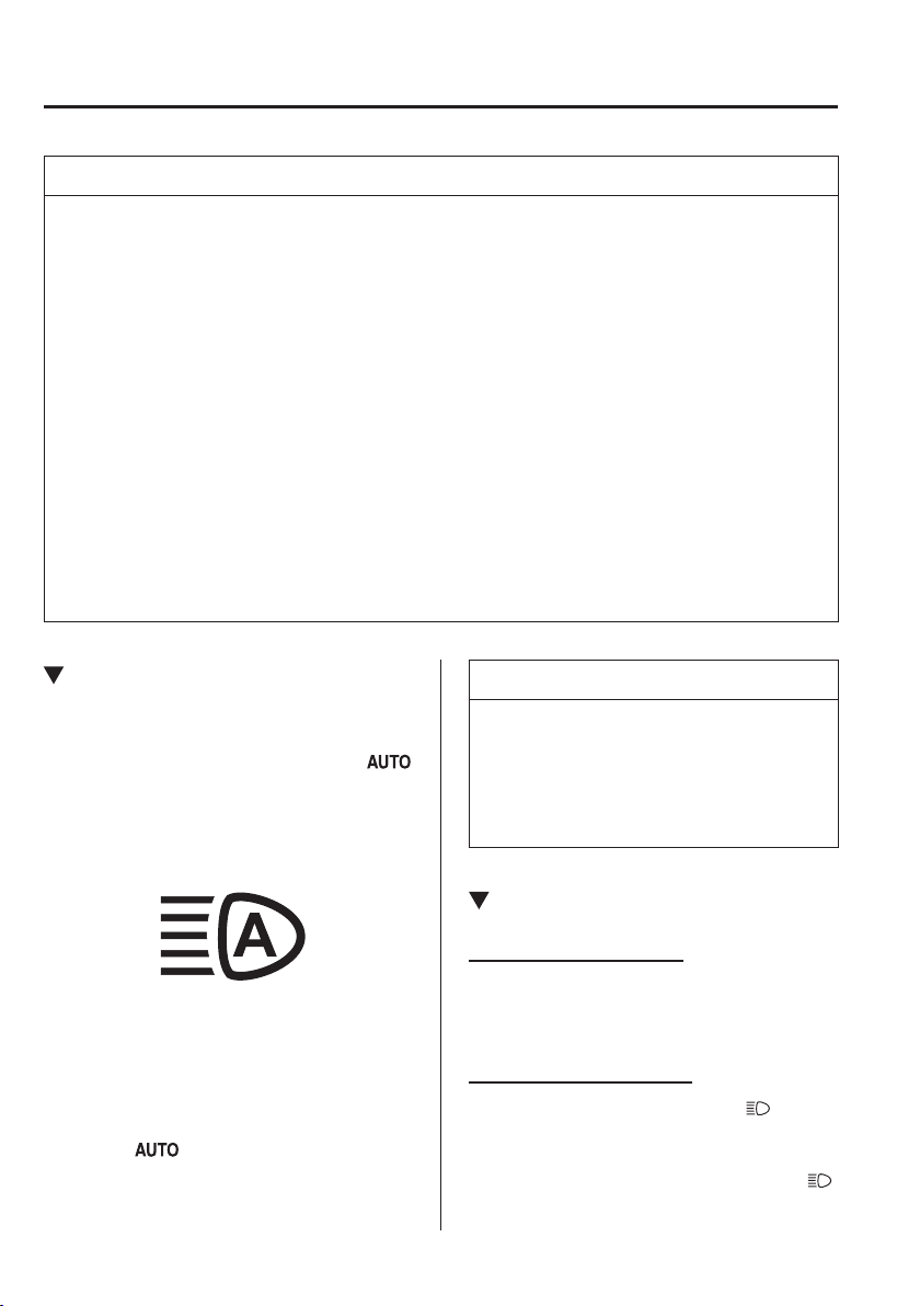
4
–
110
When Driving
i-ACTIVSENSE
NOTE
Under the following conditions, the Adaptive LED Headlights (ALH) may not operate
normally. Manually switch between the high and low beams according to the visibility,
and the road and traf¿ c conditions.
When there are other sources of light in the area such as street lamps, illuminated
signboards, and traf¿ c signals.
When there are reÀ ective objects in the surrounding area such as reÀ ective plates and
signs.
When visibility is reduced under rain, snow and foggy conditions.
When driving on roads with sharp curves or undulations.
When the headlights/rear lamps of vehicles ahead or in the opposite lane are dim or not
illuminated.
When there is insuf¿ cient darkness such as at dawn or dusk.
When the luggage compartment is loaded with heavy objects or the rear passenger
seats are occupied.
When visibility is reduced due to a vehicle ahead spraying water from its tyres onto
your windscreen.
To Operate the System
The system switches the headlights to the
high beams after the ignition is switched
ON and the headlight switch is in the
position. The Adaptive LED Headlights
(ALH) indicator light (green) in the
instrument cluster turns on simultaneously.
The Adaptive LED Headlights (ALH)
determine that it is nighttime based on the
brightness of the surrounding area.
The system cancels operation when the
headlight switch is turned to a position
other than
, the headlights are
manually switched to low beams, or the
high beams are À ashed on and off.
NOTE
The system can be changed so that the
Adaptive LED Headlights (ALH) do not
operate.
Refer to Personalisation Features on
page 9-13 .
Manual Switching
Switching to low beams
Shift the lever to the low beam position.
The Adaptive LED Headlights (ALH)
indicator light (green) turns off.
Switching to high beams
Turn the headlight switch to the
position.
The Adaptive LED Headlights (ALH)
indicator light (green) turns off and the
is illuminated.
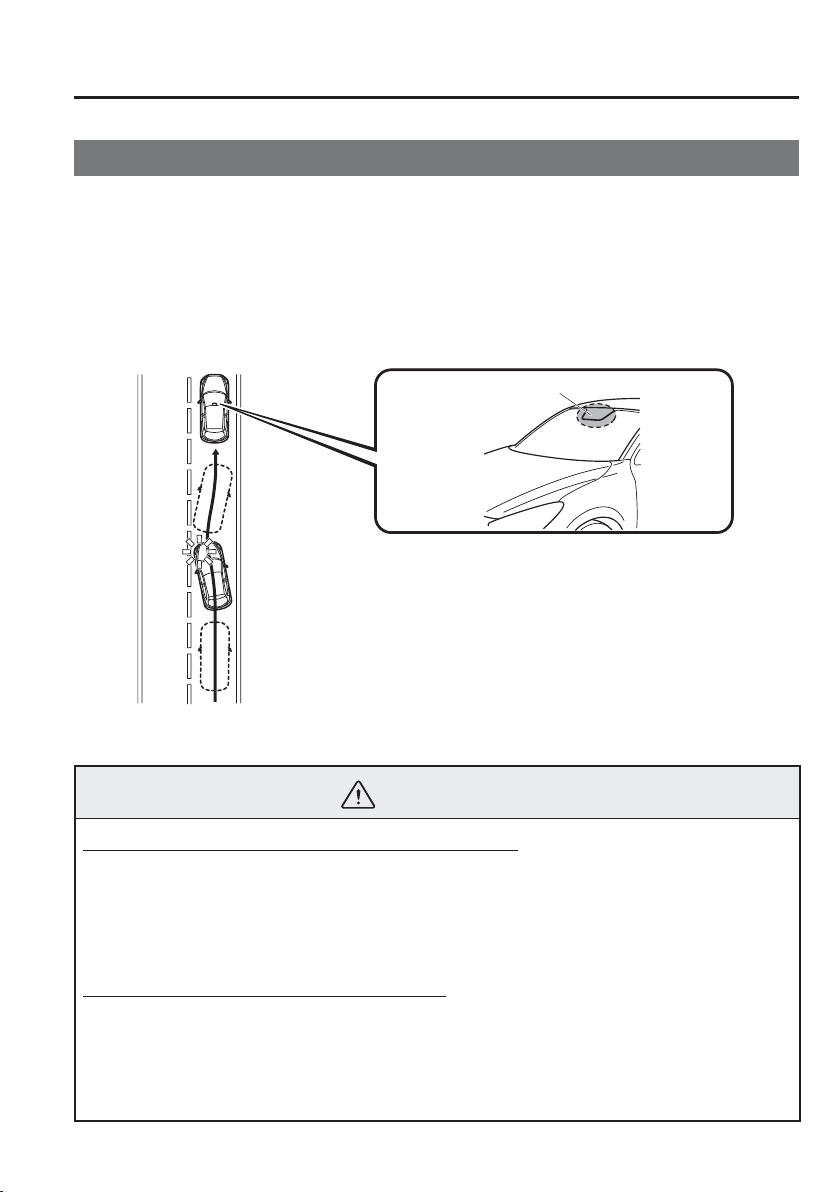
4
–
111
When Driving
i-ACTIVSENSE
*Some models.
Lane Departure Warning System (LDWS)
*
The LDWS system noti¿ es the driver that the vehicle may be deviating from its lane.
The system detects the white or yellow lines on the traf¿ c lane using the Forward Sensing
Camera (FSC) and if it determines that the vehicle may be deviating from its lane, it noti¿ es
the driver using the active driving display (vehicles with active driving display), and by
À ashing the LDWS warning light and activating the LDWS warning beep.
Use the LDWS when you drive the vehicle on roads with white or yellow lines.
Refer to Forward Sensing Camera on page 4-170 .
Forward Sensing Camera (FSC)
The warning light illuminates when the system has a malfunction.
Refer to Warning Lights on page 4-38 .
WARNING
Do not use the LDWS under the following conditions:
The system may not operate adequately according to the actual driving conditions,
resulting in an accident.
Driving on roads with tight curves.
Driving under bad weather conditions (rain, fog, and snow).
The functions of the LDWS have limitations:
Always stay on course using the steering wheel and drive with care. The system is not
designed to compensate for a driver’s lack of caution and if you rely too much on the
LDWS it could lead to an accident. The driver is responsible for assuring lane changes
and other manoeuvres. Always pay attention to the direction in which the vehicle is
travelling and the vehicle’s surroundings.
4
–
112
When Driving
i-ACTIVSENSE
CAUTION
Do not modify the suspension. If the vehicle height or the damping force of the
suspensions is changed, the LDWS may not operate correctly.
NOTE
If your vehicle deviates from its traf¿ c lane, the LDWS operates (warning sound and
indicator light). Steer the vehicle adequately to drive the vehicle to the centre of the
lane.
When the direction indicator lever is operated for a lane change, the LDWS warning
is automatically cancelled. The LDWS warning becomes operable when the direction
indicator lever is returned and the system detects the white or yellow lines.
If the steering wheel, accelerator pedal, or brake pedal is operated abruptly and the
vehicle moves close to a white or yellow line, the system determines that the driver is
making a lane change and the LDWS warning is automatically cancelled.
The LDWS may not operate during the period immediately after the vehicle has
deviated from its lane and the LDWS has operated, or the vehicle deviates from its
lane repeatedly within a short period of time.
The LDWS does not operate if it does not detect the white or yellow lines of the traf¿ c
lane.

4
–
113
When Driving
i-ACTIVSENSE
NOTE
Under the following conditions, the LDWS may not be able to detect white or yellow
lines correctly and the LDWS may not operate correctly.
If an object placed on the instrument panel is reÀ ected in the windscreen and picked
up by the camera.
Heavy luggage is loaded in the luggage compartment or on the rear seat and the
vehicle is inclined.
The tyre pressures are not adjusted to the speci¿ ed pressure.
When the vehicle is driven on the entry and exit to or from the rest area or tollgate of
a highway.
The white or yellow lines are less visible because of dirt or paint À aking.
The vehicle ahead is running near a white or yellow line and the line is less visible.
A white or yellow line is less visible because of bad weather (rain, fog, or snow).
The vehicle is driven on a temporary lane or section with a closed lane due to
construction.
A misleading line is picked up on the road such as a temporary line for construction,
or because of shade, lingering snow, or grooves ¿ lled with water.
The surrounding brightness suddenly changes such as when entering or exiting a
tunnel.
The illumination of the headlights is weakened because of dirt or the optical axis is
deviated.
The windscreen is dirty or foggy.
Back-light is reÀ ecting from the road surface.
The road surface is wet and shiny after rain, or there are puddles on the road.
The shade of a guardrail parallel to a white or yellow line is on the road.
The width of a lane is excessively narrow or wide.
The road is excessively uneven.
The vehicle is shaken after hitting a road bump.
There are two or more adjacent white or yellow lines.
There are various road markings or lane markings of various shapes near an
intersection.
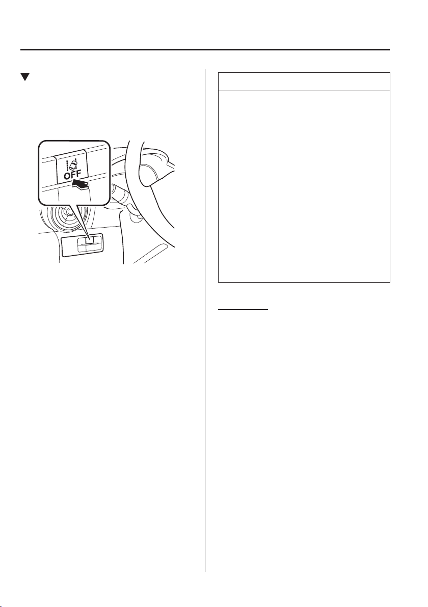
4
–
114
When Driving
i-ACTIVSENSE
When The System Operates
1. The system goes on operation standby
when the LDWS OFF switch is pressed
and the LDWS OFF indicator light in
the instrument cluster turns off.
2. Drive the vehicle in the centre of the
driving lane while the LDWS OFF
indicator light is turned off. The system
becomes operational when all of the
following conditions are met.
The vehicle is driven in the centre
of the driving lane with the white
or yellow lines on the left and right
sides, or on either side.
The vehicle speed is 70 km/h
(44 mph) or faster.
The vehicle is driven on a straight
road or road with gentle curves.
The LDWS does not operate in the
following cases:
The system cannot detect white or
yellow lines.
The vehicle speed is less than
65 km/h (40 mph).
The vehicle is making a sharp turn.
The vehicle is making a curve at an
inadequate speed.
NOTE
The LDWS does not operate until the
system detects a white or yellow line
on either the left or right.
When the system detects a white
or yellow line on one side only, the
system will activate the warning only
when the vehicle deviates on the side
where the white or yellow line is
being detected.
The distance and warning sensitivity
(likelihood of a warning) which
the system uses to determine the
possibility of a lane departure can be
changed.
Refer to Personalisation Features on
page 9-13 .
Auto cancel
In the following cases, the LDWS cancels
automatically and the LDWS warning
light in the instrument cluster turns on.
The temperature inside the camera is
high or low.
The windscreen around the camera is
foggy.
The windscreen around the camera is
blocked by an obstruction, causing poor
forward visibility.
The LDWS is enabled automatically when
the operation conditions are met, and the
LDWS warning light turns off.
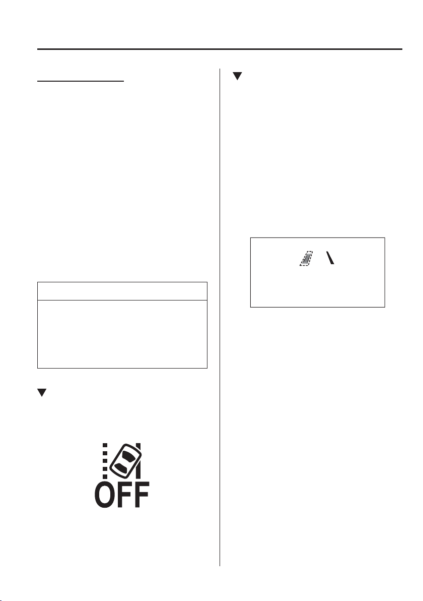
4
–
115
When Driving
i-ACTIVSENSE
Auto cancel warning
When the following operations are
performed, the LDWS determines that
the driver intends to make a lane change
and the LDWS warning is cancelled
automatically. The LDWS is enabled
automatically after the driver performs the
operation.
The steering wheel is operated abruptly.
The brake pedal is depressed abruptly.
The accelerator pedal is depressed
abruptly.
The direction indicator lever is operated
(after the direction indicator lever is
returned, the LDWS may not operate for
about 3 seconds which is the period of
time required to make a lane correction).
NOTE
After about 60 seconds have elapsed
with the direction indicator lever left
operating, the LDWS warning may
operate if the vehicle is close to a white
or yellow line.
Cancelling The System
Press the LDWS OFF switch to cancel the
LDWS. The LDWS OFF indicator light
turns on.
LDWS Warning
If the system determines that there is the
possibility of a lane departure, the LDWS
warning beep activates and the LDWS
warning light À ashes. Operate the steering
wheel appropriately and steer the vehicle
to the centre of the lane.
For vehicles equipped with the active
driving display, if there is the possibility of
a lane departure, the system indicates the
direction it determines that the vehicle is
deviating in the active driving display.
Indication on display
4
–
116
When Driving
i-ACTIVSENSE
NOTE
If the LDWS warning sound is set
to rumble
*1
, the sound will be heard
from the vehicle speaker on the side
which the system determined the
vehicle may be deviating from its
lane.
It may be dif¿ cult to hear the LDWS
warning beep depending on the
surrounding conditions such as
outside noise.
The volume of the LDWS warning
sound can be changed.
Refer to Personalisation Features on
page 9-13 .
The type of warning sound (rumble
*1
/
beep) on the LDWS can be changed.
Refer to Personalisation Features on
page 9-13 .
*1 A rumble strip is a series of grooves
in the road pavement surface
positioned at speci¿ c intervals,
and when the vehicle passes over
it a vibration and rumble sound is
produced which alerts the driver that
the vehicle is departing from the lane.
The rumble sound is a reproduction
of the sound which occurs when a
vehicle passes over a rumble strip.
Rumble
Groove
4
–
117
When Driving
i-ACTIVSENSE
*Some models.
Blind Spot Monitoring (BSM) System
*
The Blind Spot Monitoring (BSM) is designed to assist the driver in checking the area to the
rear of the vehicle on both sides during lane changes by notifying the driver of the presence
of vehicles approaching from the rear in an adjacent lane.
The Blind Spot Monitoring (BSM) detects vehicles approaching from the rear while
travelling in the forward direction at a speed of 30 km/h (19 mph) or faster and noti¿ es
the driver by turning on the Blind Spot Monitoring (BSM) warning indicator light and
displaying the vehicle detection screen (vehicles with active driving display).
If the direction indicator lever is operated to signal a turn in the direction in which the
Blind Spot Monitoring (BSM) warning indicator light is illuminated while the approaching
vehicle is detected, the Blind Spot Monitoring (BSM) noti¿ es the driver of possible danger
by turning on the Blind Spot Monitoring (BSM) warning indicator light, and by activating
the warning sound and the warning screen indicator display (vehicles with active driving
display).
The detection area on this system covers the driving lanes on both sides of the vehicle and
from the rear part of the front doors to about 50 m (164 ft) behind the vehicle.
Detection areas
Your vehicle
4
–
118
When Driving
i-ACTIVSENSE
WARNING
Always check the surrounding area visually before making an actual lane change:
The system is only designed to assist you in checking for vehicles at your rear when
making a lane change. Due to certain limitations with the operation of this system,
the Blind Spot Monitoring (BSM) warning indicator light, the warning sound and the
warning screen indicator display may not activate or they might be delayed even though
a vehicle is in an adjacent driving lane. Always make it your responsibility as a driver to
check the rear.
NOTE
The Blind Spot Monitoring (BSM) will operate when all of the following conditions
are met:
The ignition is switched ON.
The Blind Spot Monitoring (BSM) OFF switch is pressed and the BSM OFF switch
indicator light is turned off.
The vehicle speed is about 30 km/h (19 mph) or faster.
The Blind Spot Monitoring (BSM) will not operate under the following circumstances.
The vehicle speed falls below about 25 km/h (15 mph) even though the Blind Spot
Monitoring (BSM) OFF switch indicator light is turned off.
The shift lever (manual transaxle)/selector lever (automatic transaxle) is shifted to
reverse (R) and the vehicle is reversing.
In the following cases, the Blind Spot Monitoring (BSM) OFF indicator light turns
on and operation of the system is stopped. If the Blind Spot Monitoring (BSM) OFF
indicator light remains illuminated, have the vehicle inspected at an Authorised Mazda
Repairer as soon as possible.
Some problem with the system including the Blind Spot Monitoring (BSM) warning
indicator lights is detected.
A large deviation in the installation position of a radar sensor (rear) on the vehicle
has occurred.
There is a large accumulation of snow or ice on the rear bumper near a radar sensor
(rear). Remove any snow, ice or mud on the rear bumper.
Driving on snow-covered roads for long periods.
The temperature near the radar sensors (rear) becomes extremely hot due to driving
for long periods on slopes during the summer.
The battery voltage has decreased.

4
–
119
When Driving
i-ACTIVSENSE
NOTE
Under the following conditions, the radar sensors (rear) cannot detect target objects or
it may be dif¿ cult to detect them.
A vehicle is in the detection area at the rear in an adjacent driving lane but it does
not approach. The Blind Spot Monitoring (BSM) determines the condition based on
radar detection data.
A vehicle is travelling alongside your vehicle at nearly the same speed for an
extended period of time.
Vehicles approaching in the opposite direction.
A vehicle in an adjacent driving lane is attempting to pass your vehicle.
A vehicle is in an adjacent lane on a road with extremely wide driving lanes. The
detection area of the radar sensors (rear) is set at the road width of expressways.
In the following case, the À ashing of the Blind Spot Monitoring (BSM) warning
indicator light, and the activation of the warning sound and the warning screen
indicator display may not occur or they may be delayed.
A vehicle makes a lane change from a driving lane two lanes over to an adjacent
lane.
Driving on steep slopes.
Crossing the summit of a hill or mountain pass.
The turning radius is small (making a sharp turn, turning at intersections).
When there is a difference in the height between your driving lane and the adjacent
lane.
Directly after the Blind Spot Monitoring (BSM) system becomes operable by
changing the setting.
If the road width is extremely narrow, vehicles two lanes over may be detected.
The detection area of the radar sensors (rear) is set according to the road width of
expressways.
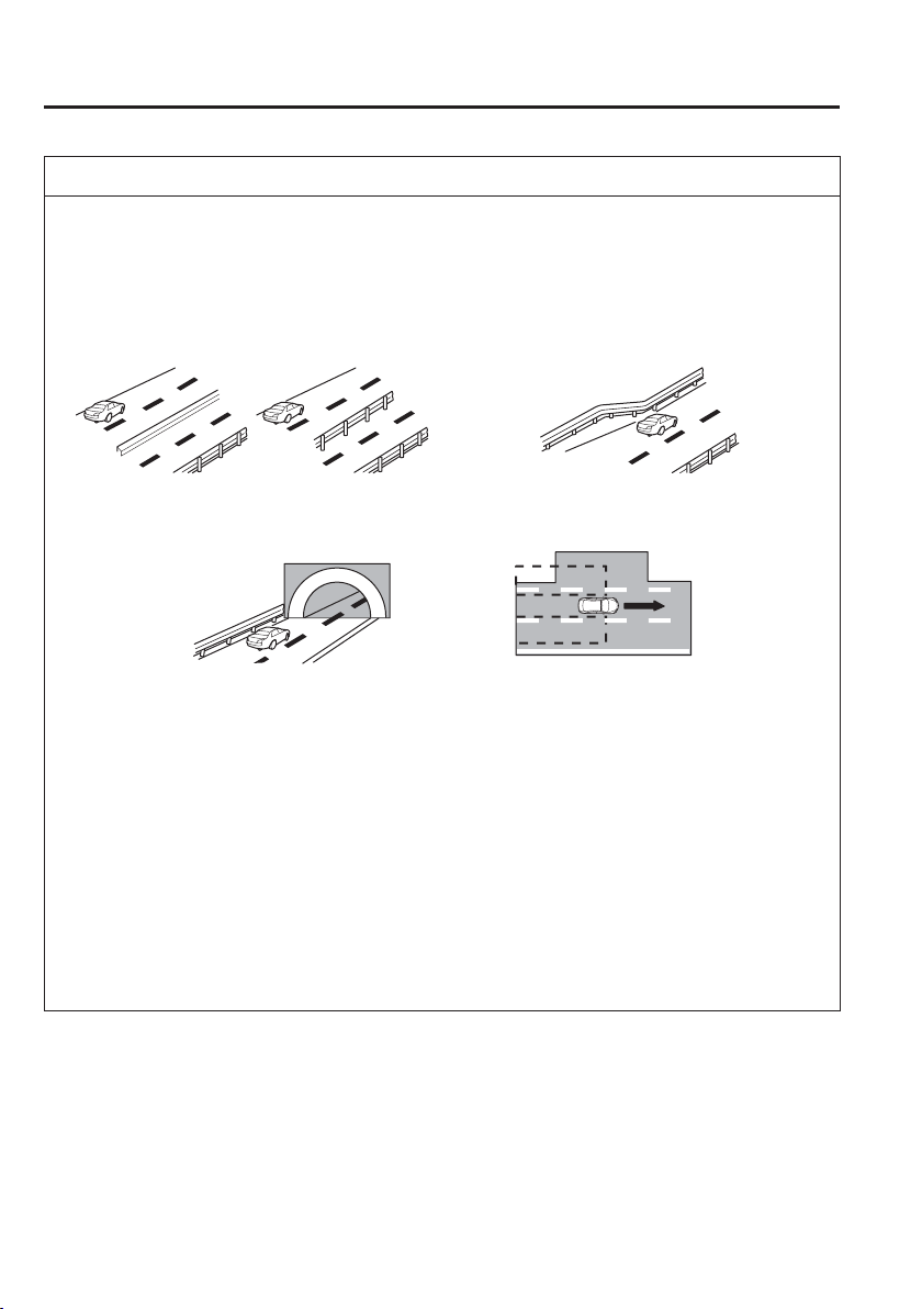
4
–
120
When Driving
i-ACTIVSENSE
NOTE
The Blind Spot Monitoring (BSM) warning indicator light may turn on and the vehicle
detection screen may be displayed in the display in reaction to stationary objects
(guardrails, tunnels, sidewalls, and parked vehicles) on the road or the roadside.
Objects such as guardrails and concrete walls
running alongside the vehicle.
Places where the width between guardrails or
walls on each side of the vehicle narrows.
The walls at the entrance and exits of tunnels,
turnouts.
A Blind Spot Monitoring (BSM) warning indicator light may À ash or the warning beep
may be activated several times when making a turn at a city intersection.
Turn off the Blind Spot Monitoring (BSM) while pulling a trailer or while an accessory
such as a bicycle carrier is installed to the rear of the vehicle. Otherwise, the radar’s
radio waves will be blocked causing the system to not operate normally.
In the following cases, it may be dif¿ cult to view the illumination/À ashing of the Blind
Spot Monitoring (BSM) warning indicator lights equipped on the door mirrors.
Snow or ice is adhering to the door mirrors.
The front door glass is fogged or covered in snow, frost or dirt.
The system switches to the Rear Cross Traf¿ c Alert function when the shift lever
(manual transaxle) or the selector lever (automatic transaxle) is shifted to the reverse
(R) position.
Refer to Rear Cross Traf¿ c Alert (RCTA) on page 4-130 .
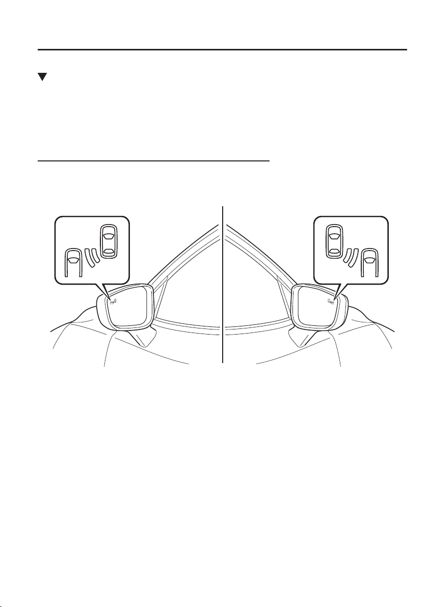
4
–
121
When Driving
i-ACTIVSENSE
Blind Spot Monitoring (BSM) Warning Indicator Lights/Blind Spot
Monitoring (BSM) Warning Beep
The Blind Spot Monitoring (BSM) or Rear Cross Traf¿ c Alert (RCTA) system noti¿ es the
driver of the presence of vehicles in adjacent lanes or at the rear of the vehicle using the
Blind Spot Monitoring (BSM) warning indicator light, the warning sound and the display
indicator (vehicles with active driving display) while the systems are operational.
Blind Spot Monitoring (BSM) warning indicator lights
The Blind Spot Monitoring (BSM) warning indicator lights are equipped on the left and
right door mirrors. The warning indicator lights turn on when a vehicle approaching from
the rear in an adjacent lane is detected.
When the ignition is switched ON, the warning indicator light turns on momentarily and
then turns off after a few seconds.
Forward driving (Blind Spot Monitoring (BSM) operation)
The Blind Spot Monitoring (BSM) detects vehicles approaching from the rear and turns on
the Blind Spot Monitoring (BSM) warning indicator lights equipped on the door mirrors
according to the conditions. Additionally, while a Blind Spot Monitoring (BSM) warning
indicator light is illuminated, if the direction indicator lever is operated to signal a turn in the
direction in which the Blind Spot Monitoring (BSM) warning indicator light is illuminated,
the Blind Spot Monitoring (BSM) warning indicator light À ashes.
Reverse driving (Rear Cross Traf¿ c Alert (RCTA) system operation)
The Rear Cross Traf¿ c Alert (RCTA) system detects vehicles approaching from the left and
right of your vehicle and À ashes the Blind Spot Monitoring (BSM) warning indicator lights.

4
–
122
When Driving
i-ACTIVSENSE
Function for cancelling illumination dimmer
If the Blind Spot Monitoring (BSM) warning indicator lights turn on when the position
lights are turned on, the brightness of the Blind Spot Monitoring (BSM) warning indicator
lights is dimmed.
If the Blind Spot Monitoring (BSM) warning indicator lights are dif¿ cult to see due to
glare from surrounding brightness when travelling on snow-covered roads or under foggy
conditions, press the dimmer cancellation button to cancel the dimmer and increase the
brightness of Blind Spot Monitoring (BSM) warning indicator lights when they turn on.
Refer to Instrument Panel Illumination on page 4-30 .
Display indicator (Vehicles with active driving display)
The detected approaching vehicle and warning are displayed in the active driving display
when the vehicle is moving forward (Blind Spot Monitoring (BSM) operational).
The detected direction is displayed with a detection indicator (white) when an approaching
vehicle is detected. In addition, if the direction indicator lever is operated to signal a lane
change while the vehicle is detected, the display changes the colour (amber) of the warning
indicator.
Blind Spot Monitoring (BSM) warning beep
The Blind Spot Monitoring (BSM) warning beep is activated simultaneously with the
À ashing of a Blind Spot Monitoring (BSM) warning indicator light.
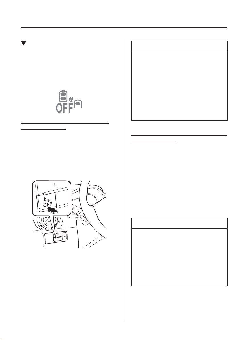
4
–
123
When Driving
i-ACTIVSENSE
Cancelling Operation of Blind Spot
Monitoring (BSM)
The Blind Spot Monitoring (BSM)
and Rear Cross Traf¿ c Alert (RCTA)
systems are turned off and the Blind Spot
Monitoring (BSM) OFF indicator light in
the instrument cluster turns on.
Vehicles with Blind Spot Monitoring
(BSM) OFF switch
When the Blind Spot Monitoring (BSM)
OFF switch is pressed, the Blind Spot
Monitoring (BSM) and Rear Cross Traf¿ c
Alert (RCTA) systems are turned off and
the Blind Spot Monitoring (BSM) OFF
indicator light in the instrument cluster
turns on.
If the switch is pressed again, the Blind
Spot Monitoring (BSM) and Rear Cross
Traf¿ c Alert (RCTA) systems become
operable and the Blind Spot Monitoring
(BSM) OFF indicator light turns off.
NOTE
When the ignition is switched OFF,
the system status before it was turned
off is maintained. For example, if the
ignition is switched OFF while the
Blind Spot Monitoring (BSM) and Rear
Cross Traf¿ c Alert (RCTA) systems are
operable, the Blind Spot Monitoring
(BSM) and Rear Cross Traf¿ c Alert
(RCTA) systems remain operable the
next time the ignition is switched ON.
Vehicles without Blind Spot Monitoring
(BSM) OFF switch
The Blind Spot Monitoring (BSM) system
can be set to inoperable.
Refer to Personalisation Features on page
9-13 .
When the Blind Spot Monitoring (BSM)
is set to inoperable, the Blind Spot
Monitoring (BSM) and Rear Cross Traf¿ c
Alert (RCTA) systems are turned off and
the Blind Spot Monitoring (BSM) OFF
indicator light in the instrument cluster
turns on.
NOTE
When the ignition is switched OFF, the
system status before it was turned off is
maintained. For example, if the ignition
is switched OFF while the BSM and
RCTA systems are operational, the BSM
and RCTA systems remain operational
the next time the ignition is switched
ON.
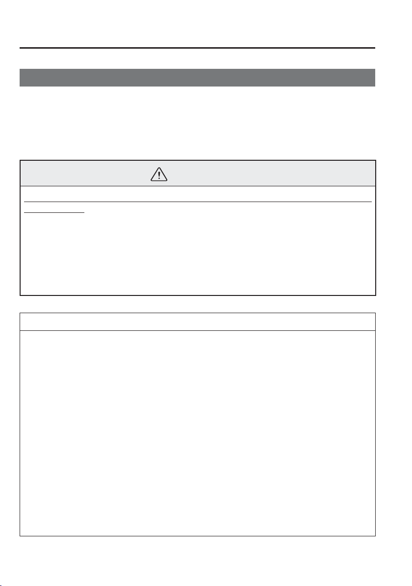
4
–
124
When Driving
i-ACTIVSENSE
*Some models.
Distance Recognition Support System (DRSS)
*
The Distance Recognition Support System (DRSS) measures the distance between your
vehicle and a vehicle ahead using a radar sensor (front) while the vehicle speed is about
30 km/h (19 mph) or faster, and if your vehicle approaches a vehicle ahead more closely
than what is appropriate for maintaining distance between the vehicles according to the
vehicle speed, a noti¿ cation in the active driving display is indicated to advise you to keep a
safe distance from the vehicle ahead.
WARNING
Do not rely completely on the Distance Recognition Support System (DRSS) and always
drive carefully:
The Distance Recognition Support System (DRSS) provides advice for safer driving and
noti¿ es the driver of a recommended, safer distance to maintain with a vehicle ahead.
The ability to detect a vehicle ahead is limited depending on the type of vehicle ahead,
the weather conditions, and the traf¿ c conditions. Therefore, if the accelerator and
brake pedals are not operated correctly it could lead to an accident. Always verify the
safety of the surrounding area and depress the brake pedal or accelerator pedal while
keeping a safer distance from vehicles ahead or on-coming vehicles.
NOTE
The Distance Recognition Support System (DRSS) operates when all of the following
conditions are met:
The ignition is switched ON.
The Distance Recognition Support System (DRSS) is on.
The selector lever is in a position other than reverse (R).
The vehicle speed is 30 km/h or faster (19 mph or faster).
The objects which activate the system are 4-wheeled vehicles.
The Distance Recognition Support System (DRSS) may also operate in the presence of
motorcycles and bicycles.
The Distance Recognition Support System (DRSS) system may not operate normally
under the following conditions:
The Dynamic Stability Control (DSC) has a malfunction.
The vehicle ahead is travelling at an extremely slow speed.
The system does not operate with the following objects:
Vehicles approaching in the opposite direction.
Stationary objects (stopped vehicles, obstructions)
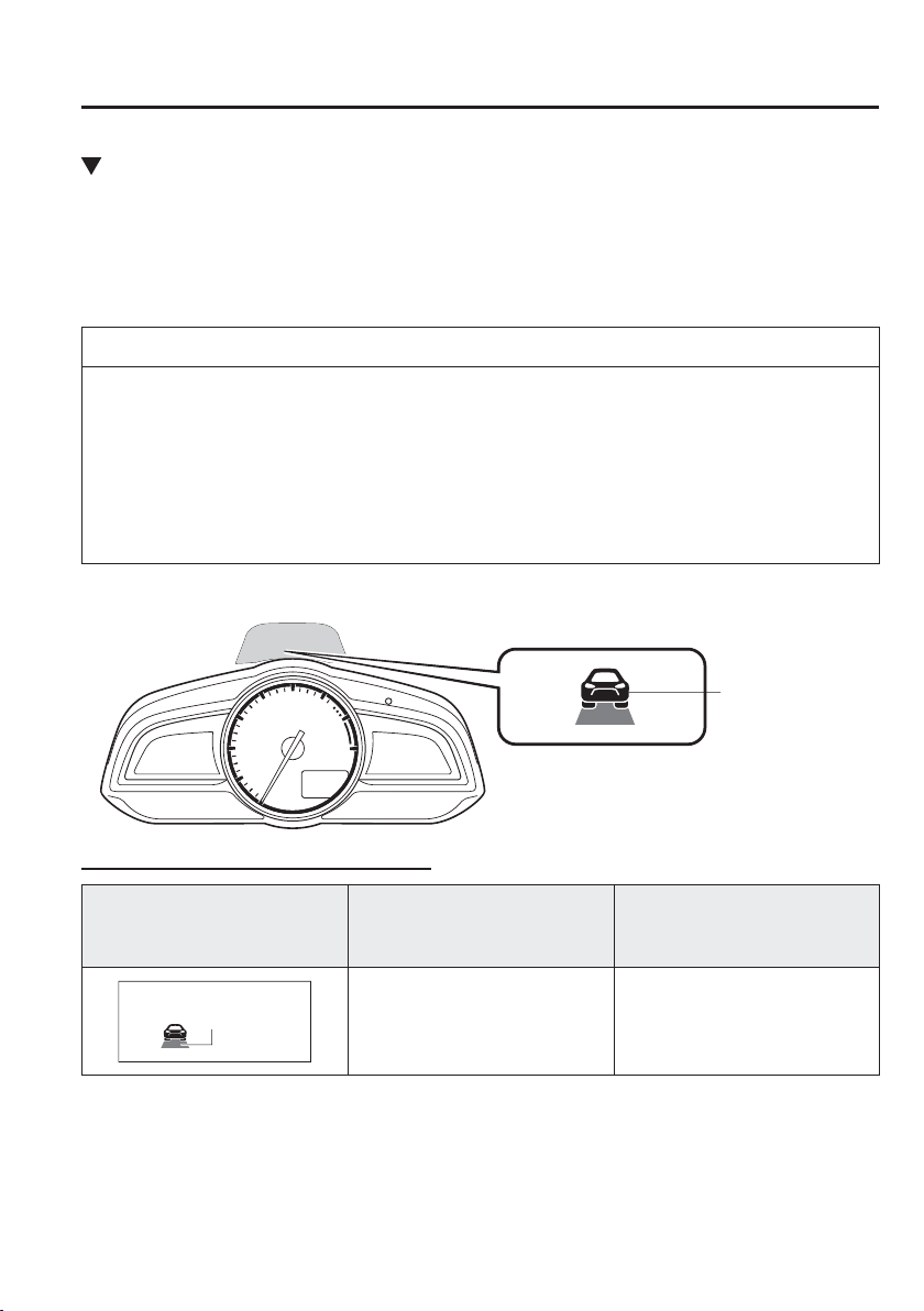
4
–
125
When Driving
i-ACTIVSENSE
Indication on Display
The Distance Recognition Support System (DRSS) operation status is indicated in the active
driving display. Regarding malfunctions, check the vehicle conditions or have it inspected
by an expert repairer, we recommend an Authorised Mazda Repairer according to the
content of the displayed message.
Refer to Warning/Indicator Lights on page 4-38 .
NOTE
When the ignition is switched off, the operation status before the system was turned
off is maintained. For example, if the ignition is switched off with the Distance
Recognition Support System (DRSS) operable, the system will be operable when the
ignition is switched ON the next time.
The Distance Recognition Support System (DRSS) can be turned on/off and the
system's sensitivity can be changed.
Refer to Personalisation Features on page 9-13 .
Vehicle ahead
display
Distance-between-vehicles guidelines
*1
Display
Distance between vehicles
guidelines
(During travel at about 40 km/h
(25 mph)
Distance between vehicles
guidelines
(During travel at about 80 km/h
(50 mph)
Illuminated in
amber
About 10 m (32 ft) or less About 20 m (65 ft) or less
*1 The distance between vehicles differs depending on vehicle speed.

4
–
126
When Driving
i-ACTIVSENSE
NOTE
The distance at which the distance-between-vehicles indication in the display À ashes can
be changed.
Refer to Personalisation Features on page 9-13 .
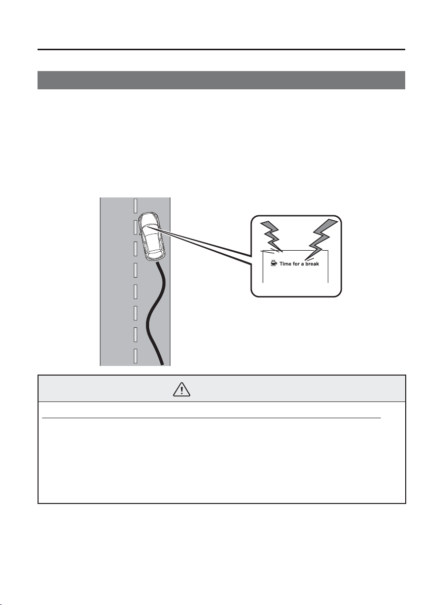
4
–
127
When Driving
i-ACTIVSENSE
*Some models.
Driver Attention Alert (DAA)
*
The Driver Attention Alert (DAA) is a system which detects driver fatigue and decreased
attentiveness, and encourages the driver to take a rest.
When the vehicle is driven inside traf¿ c lane lines at about 65 to 140 km/h (41 to 86 mph),
the Driver Attention Alert (DAA) estimates the amount of accumulated fatigue and
decreased attentiveness of the driver based on the information from the Forward Sensing
Camera (FSC) and other vehicle information, and encourages the driver to take a rest using
an indication on the active driving display and a warning sound.
Use the Driver Attention Alert (DAA) on expressways or highways.
Refer to Forward Sensing Camera (FSC) on page 4-170 .
WARNING
Do not rely completely on Driver Attention Alert (DAA) and always drive carefully:
The Driver Attention Alert (DAA) detects driver fatigue and decreased attentiveness and
encourages the driver to take a rest, however, it is not designed to prevent the vehicle
from straying. If you rely too much on the Driver Attention Alert (DAA) it could lead to
an accident. Drive carefully and operate the steering wheel appropriately.
In addition, the system may not be able to detect driver fatigue and decreased
attentiveness correctly depending on the traf¿ c and driving conditions. The driver must
take suf¿ cient rest in consideration of safer driving.

4
–
128
When Driving
i-ACTIVSENSE
NOTE
The Driver Attention Alert (DAA) operates when all of the following conditions are
met.
The vehicle speed is about 65 to 140 km/h (41 to 86 mph).
The system detects white (yellow) lane lines.
The system has completed learning of the driver’s driving data.
The Driver Attention Alert (DAA) does not operate under the following conditions.
The vehicle speed is less than about 65 km/h (41 mph).
The vehicle speed exceeds about 140 km/h (86 mph)
The vehicle is making a sharp turn.
The vehicle is changing lanes.
The Driver Attention Alert (DAA) may not operate normally under the following
conditions.
White (yellow) lane lines are less visible because of dirt or fading/patchiness.
The vehicle is jolted or swayed continuously by strong winds or rough roads.
The vehicle is driven aggressively.
When making frequent lane changes.
The Driver Attention Alert (DAA) detects driver fatigue and decreased attentiveness
based on the driving data when the vehicle is driven at about 65 to 140 km/h
(41 to 86 mph) for about 20 minutes. The driving data will be reset under the following
conditions.
The vehicle is stopped for 15 minutes or longer.
The vehicle is driven at less than about 65 km/h (41 mph) for about 30 minutes.
The ignition is switched off.
After the Driver Attention Alert (DAA) has displayed the ¿ rst message encouraging
rest, it does not display the next one until 45 minutes have passed.
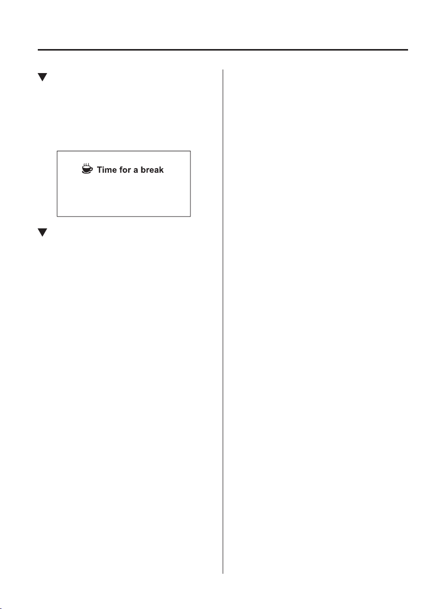
4
–
129
When Driving
i-ACTIVSENSE
Driver Attention Alert (DAA)
Display
When the system detects driver fatigue or
decreased attentiveness, it activates the
warning sound and displays an alert in the
active driving display.
Cancelling Driver Attention Alert
(DAA)
The Driver Attention Alert (DAA) can be
set to not activate.
Refer to Personalisation Features on page
9-13 .
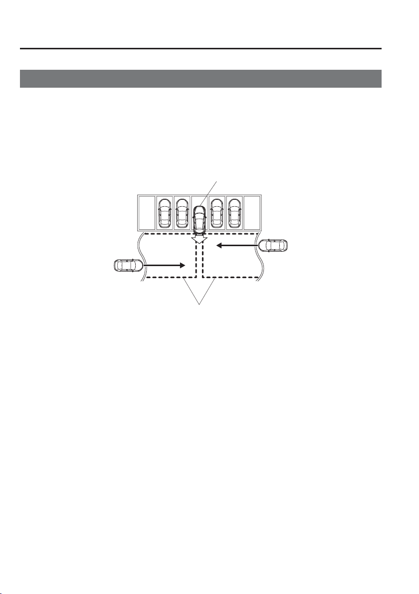
4
–
130
When Driving
i-ACTIVSENSE
*Some models.
Rear Cross Traf¿ c Alert (RCTA)
*
T h e R e a r C r o s s T r a f ¿ c Alert (RCTA) system is designed to assist the driver in checking the
area to the rear of the vehicle on both sides while the vehicle is reversing by alerting the
driver to the presence of vehicles approaching the rear of the vehicle.
The Rear Cross Traf¿ c Alert (RCTA) system detects vehicles approaching from the left
and right sides of the vehicle while the vehicle is being reversed out of a parking space,
and noti¿ es the driver of possible danger using the Blind Spot Monitoring (BSM) warning
indicator lights and the warning buzzer.
Detection areas
Your vehicle
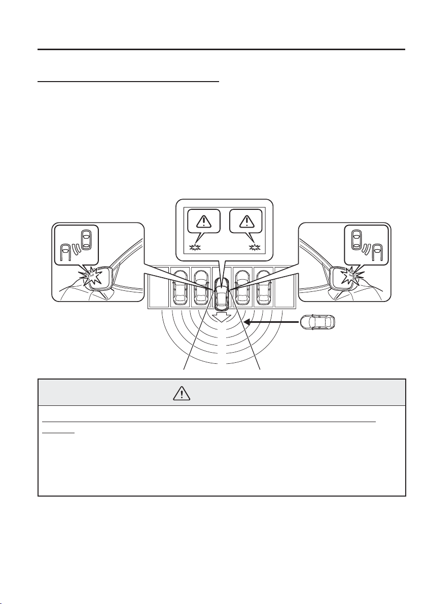
4
–
131
When Driving
i-ACTIVSENSE
Rear Cross Traf¿ c Alert (RCTA) operation
1. The Rear Cross Traf¿ c Alert (RCTA) system operates when the shift lever (manual
transaxle) or the selector lever (automatic transaxle) is shifted to the reverse (R) position.
2. If there is the possibility of a collision with an approaching vehicle, the Blind Spot
Monitoring (BSM) warning indicator lights À ashes and the warning beep is activated
simultaneously.
(With rear view monitor)
The Rear Cross Traf¿ c Alert (RCTA) warning indication in the rearview monitor also
synchronizes with the Blind Spot Monitoring (BSM) warning indicator light on the door
mirrors.
WARNING
Always check the surrounding area visually before actually putting the vehicle in
reverse:
The system is only designed to assist you in checking for vehicles at the rear when
putting the vehicle in reverse. Due to certain limitations with the operation of this
system, the Blind Spot Monitoring (BSM) warning indicator lights may not À ash or it
might be delayed even though a vehicle is behind your vehicle. Always make it your
responsibility as a driver to check the rear.

4
–
132
When Driving
i-ACTIVSENSE
NOTE
In the following cases, the Blind Spot Monitoring (BSM) warning indication/warning
light turns on and operation of the system is stopped. If the Blind Spot Monitoring
(BSM) warning indication/warning light remains illuminated, have the vehicle
inspected at an Authorised Mazda Dealer as soon as possible.
Some problem with the system including the Blind Spot Monitoring (BSM) warning
indicator lights has occurred.
A large deviation in the installation position of a radar sensor (rear) on the vehicle
has occurred.
There is a large accumulation of snow or ice on the rear bumper near a radar sensor
(rear).
Driving on snow-covered roads for long periods.
The temperature near the radar sensors becomes extremely hot due to driving for
long periods on slopes during the summer.
The battery voltage has decreased.
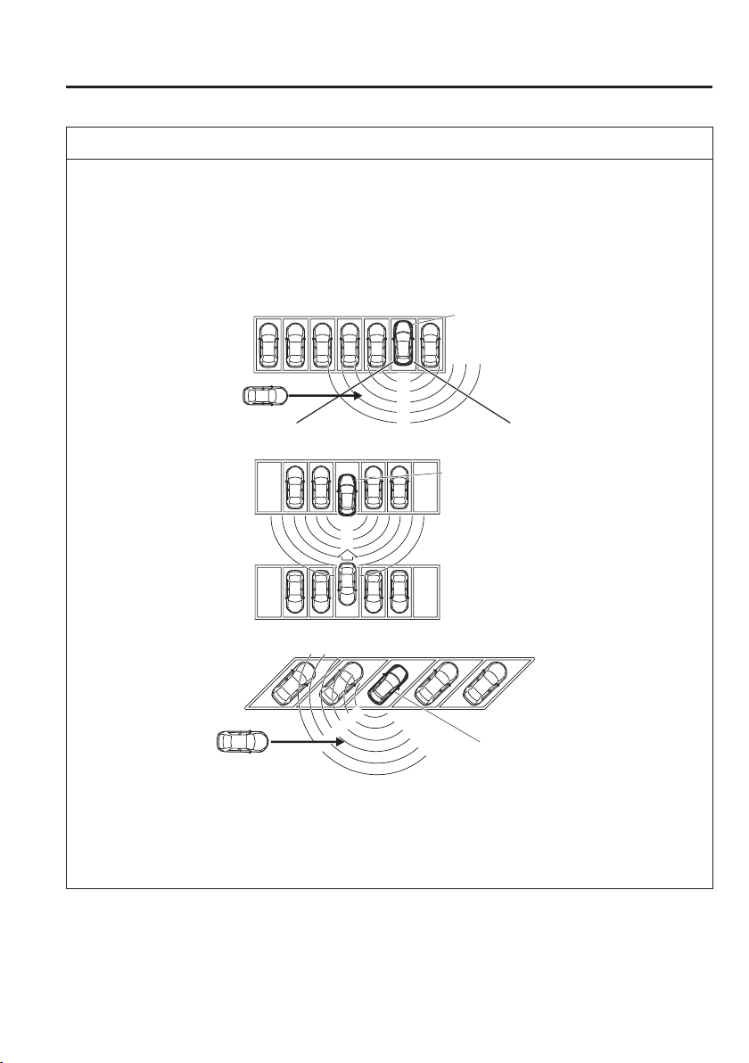
4
–
133
When Driving
i-ACTIVSENSE
NOTE
Under the following conditions, the radar sensors (rear) cannot detect target objects or
it may be dif¿ cult to detect them.
The vehicle speed when reversing is about 10 km/h (6 mph) or faster.
The radar sensor (rear) detection area is obstructed by a nearby wall or parked
vehicle. (Reverse the vehicle to a position where the radar sensor detection area is no
longer obstructed.)
Your vehicle
A vehicle is approaching directly from the rear of your vehicle.
Your vehicle
The vehicle is parked on a slant.
Your vehicle
(With Blind Spot Monitoring (BSM) OFF switch)
Directly after pressing the Blind Spot Monitoring (BSM) OFF switch and the system
becomes operable.
(Without Blind Spot Monitoring (BSM) OFF switch)
Directly after the Blind Spot Monitoring (BSM) system becomes operable.

4
–
134
When Driving
i-ACTIVSENSE
NOTE
In the following cases, it may be dif¿ cult to view the illumination/À ashing of the Blind
Spot Monitoring (BSM) warning indicator lights equipped on the door mirrors.
Snow or ice adheres to the door mirrors.
The front door glass is fogged or covered in snow, frost or dirt.
Turn off the Rear Cross Traf¿ c Alert (RCTA) system while pulling a trailer or while
an accessory such as a bicycle carrier is installed to the rear of the vehicle. Otherwise,
the radio waves emitted by the radar will be blocked causing the system to not operate
normally.

4
–
135
When Driving
i-ACTIVSENSE
*Some models.
Mazda Radar Cruise Control (MRCC)
*
The Mazda Radar Cruise Control (MRCC) system is designed to maintain headway control
*1
according to the vehicle speed using a radar sensor (front) to detect the distance to a vehicle
ahead, which frees the driver from having to constantly use the accelerator or brake pedals.
*1 Headway Control: Control of the distance between your vehicle and the vehicle ahead
detected by the Mazda Radar Cruise Control (MRCC) system.
Additionally, if your vehicle starts closing in on the vehicle ahead because, for example, the
vehicle ahead brakes suddenly, a warning sound and a warning indication in the display are
activated simultaneously to alert you to maintain a suf¿ cient distance between the vehicles.
The possible vehicle speed setting ranges are as follows:
(European models)
About 30 km/h (19 mph) to 200 km/h (124 mph)
(Except European models)
About 30 km/h (19 mph) to 145 km/h (90 mph)
Use the Mazda Radar Cruise Control (MRCC) system on expressways and other highways
which do not require a lot of repeated acceleration and deceleration.
4
–
136
When Driving
i-ACTIVSENSE
WARNING
Do not rely completely on the Mazda Radar Cruise Control (MRCC) system and always
drive carefully:
The Mazda Radar Cruise Control (MRCC) system is designed to reduce load on the
driver, and although it maintains a constant vehicle speed, or speci¿ cally, it maintains
a constant distance between your vehicle and the detected vehicle ahead according to
the vehicle speed, the system has detection limitations depending on the type of vehicle
ahead and its conditions, the weather conditions, and the road conditions. Additionally,
the system may be unable to decelerate suf¿ ciently to avoid hitting the vehicle ahead if
the vehicle ahead applies the brakes suddenly or another vehicle cuts into the driving
lane, which could result in an accident. Always verify the safety of the surrounding area
and depress the brake pedal or accelerator pedal while keeping a safer distance from
vehicles ahead or on-coming vehicles.
Do not use the Mazda Radar Cruise Control (MRCC) system in the following locations.
Otherwise, it could lead to an accident:
Roads with sharp curves and where vehicle traf¿ c is heavy and there is insuf¿ cient
space between vehicles. Roads where frequent and repetitive acceleration and
deceleration occur (Driving under these conditions using the Mazda Radar Cruise
Control (MRCC) system is not possible).
When entering and exiting interchanges, service areas, and parking areas of
highways (If you exit a highway while headway control is in use, the vehicle ahead
will no longer be tracked and your vehicle may accelerate to the set speed).
Slippery roads such as ice or snow-bound roads (The tyres could spin causing you to
lose vehicle control).
Long descending slopes (to maintain distance between vehicles, the system
automatically and continuously applies the brakes which could result in the loss of
brake power).
For the purposes of safety, switch the Mazda Radar Cruise Control (MRCC) system off
when it is not being used.
CAUTION
If the vehicle is towed or you are towing something, switch the Mazda Radar Cruise
Control (MRCC) system off to prevent an incorrect operation.

4
–
137
When Driving
i-ACTIVSENSE
NOTE
The Mazda Radar Cruise Control (MRCC) system operates when all of the following
conditions are met.
The vehicle speed is as follows:
(European models)
About 30 km/h (19 mph) to 200 km/h (124 mph)
(Except European models)
About 30 km/h (19 mph) to 145 km/h (90 mph)
The Mazda Radar Cruise Control (MRCC) system is turned on.
The parking brake is not applied.
The Smart Brake Support (SBS) is not malfunctioning.
The Dynamic Stability Control (DSC) is operating normally.
All doors are closed.
The driver's seat belt is fastened.
(Manual transaxle)
The shift lever is in a position other than reverse (R) or neutral (N).
The clutch pedal is not depressed.
(Automatic transaxle)
The selector lever is in the drive (D) position or manual (M) position (manual
mode).
In the following cases, the warnings may not activate even if your vehicle starts
closing in on the vehicle ahead.
You are driving at the same speed as the vehicle ahead.
Directly after the Mazda Radar Cruise Control (MRCC) system has been set.
When the accelerator pedal is depressed or directly after the accelerator pedal is
released.
Another vehicle cuts into the driving lane.
The following are not detected as physical objects.
Vehicles approaching in the opposite direction
Pedestrians
Stationary objects (stopped vehicles, obstructions)
If a vehicle ahead is travelling at an extremely low speed, the system may not detect it
correctly.
During headway control travel, do not set the system on two-wheeled vehicles such as
motorcycles and bicycles.
Do not use the Mazda Radar Cruise Control (MRCC) system under conditions in
which the close proximity warnings are frequently activated.
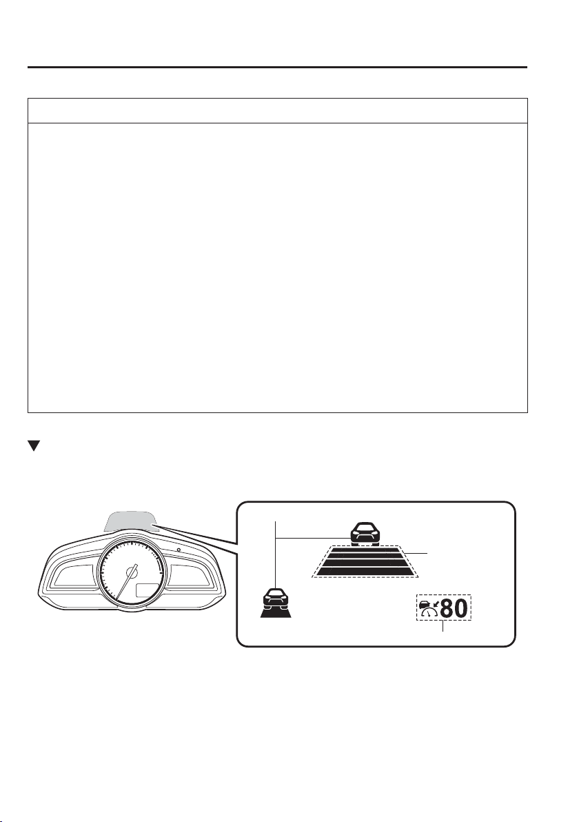
4
–
138
When Driving
i-ACTIVSENSE
NOTE
During headway control travel, the system accelerates and decelerates your vehicle
in conjunction with the speed of the vehicle ahead. However, if it is necessary to
accelerate for a lane change or if the vehicle ahead brakes suddenly causing you to
close in on the vehicle rapidly, accelerate using the accelerator pedal or decelerate
using the brake pedal depending on the conditions.
While the Mazda Radar Cruise Control (MRCC) system is in use, it does not cancel
even if the selector lever (automatic transaxle)/shift lever (manual transaxle) is
operated and any intended engine braking will not occur. If deceleration is required,
lower the vehicle speed setting or depress the brake pedal.
The brake lights are illuminated while the Mazda Radar Cruise Control (MRCC)
automatic braking is operating, however, they may not be illuminated while the
vehicle is on a down slope at the set vehicle speed or travelling at a constant speed and
following a vehicle ahead.
The Mazda Radar Cruise Control (MRCC) warning light (amber) illuminates when the
system has a malfunction.
Refer to Warning Lights on page 4-38 .
The headway control operation can be cancelled and the system can be switched to
only cruise control. Refer to Cruise Control Function on page 4-145 .
Mazda Radar Cruise Control (MRCC) Display Indication
The setting status and operation conditions of the Mazda Radar Cruise Control (MRCC)
system are indicated in the active driving display.
Vehicle ahead display
MRCC Distance
between vehicle
display
MRCC Set vehicle speed
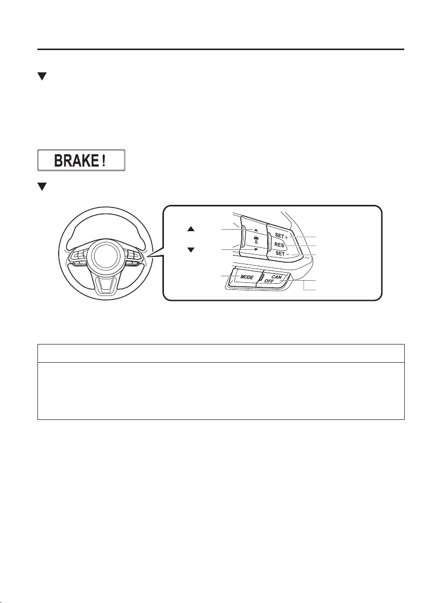
4
–
139
When Driving
i-ACTIVSENSE
Close Proximity Warning
If your vehicle rapidly closes in on the vehicle ahead because the vehicle applies the brakes
suddenly while you are travelling in headway control, the warning sound activates and
the brake warning is indicated in the display. Always verify the safety of the surrounding
area and depress the brake pedal while keeping a safer distance from the vehicle ahead.
Additionally, always keep a safer distance from the vehicles behind you.
Setting the System
CANCEL switch
RES switch
OFF switch
switch
switch
MODE switch
SET- switch
SET+ switch
When the MODE switch is pressed, the Mazda Radar Cruise Control (MRCC) main
indication (white) turns on and the vehicle speed and the distance between vehicles while in
headway control can be set.
NOTE
When the ignition is switched to ACC or OFF while the Mazda Radar Cruise Control
(MRCC) is ON, the Mazda Radar Cruise Control (MRCC) remains ON automatically.
When the MODE switch is pressed while the Mazda Radar Cruise Control (MRCC)
system is turned on, the system switches to the cruise control function.
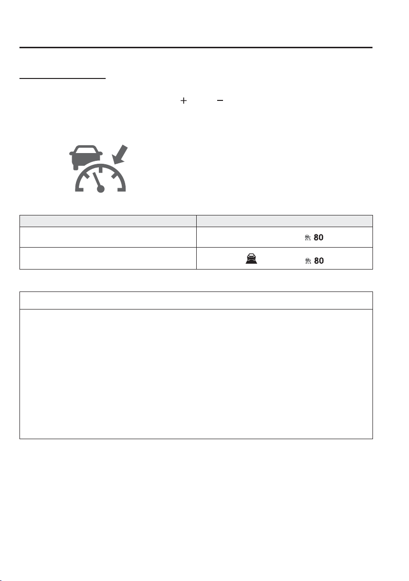
4
–
140
When Driving
i-ACTIVSENSE
How to Set the Speed
1. Adjust the vehicle speed to the desired setting using the accelerator pedal.
2. Headway control begins when the SET
or SET switch is pressed. The set speed and
the inter-vehicle distance display ¿ lled with white lines are displayed. The Mazda Radar
Cruise Control (MRCC) set indication (green) is indicated simultaneously.
Travel status Display
During travel at constant speed
During travel under headway control
NOTE
If a vehicle ahead is detected while travelling at a constant speed, the vehicle-ahead
indication is displayed and headway control is performed. Additionally, when a vehicle
ahead is no longer detected, the vehicle-ahead indication turns off and the system
switches back to travel at constant speed.
Headway control is not possible if the vehicle ahead is driving faster than the set
speed. Adjust the system to the desired vehicle speed using the accelerator pedal.
(European models)
When switching to a passing lane and operating the direction indicator, the system
provides more acceleration automatically if it determines that more acceleration is
required. Drive while being careful of the road ahead because you could approach the
vehicle ahead too closely.
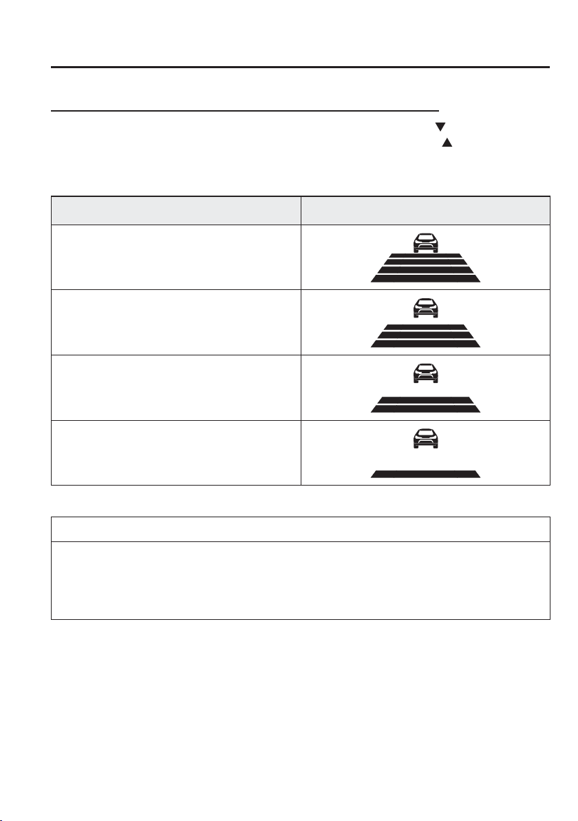
4
–
141
When Driving
i-ACTIVSENSE
How to Set the Distance Between Vehicles During Headway Control
The distance between vehicles is set to a shorter distance each time the
switch is pressed.
The distance between vehicles is set to a longer distance by pressing the
switch. The
distance-between-vehicles can be set to 4 levels; Long, medium, short, and extremely short
distance.
Distance-between-vehicles guideline
(at 80 km/h (50 mph) vehicle speed)
Display
Long (about 50 m (164 ft))
Medium (about 40 m (131 ft))
Short (about 30 m (98 ft))
Extremely short (about 25 m (82 ft))
NOTE
The distance between vehicles differs depending on the vehicle speed, and the slower
the vehicle speed, the shorter the distance.
When the ignition is switched to ACC or OFF and then the engine is started again, the
system automatically sets the distance between vehicles to the previous setting.
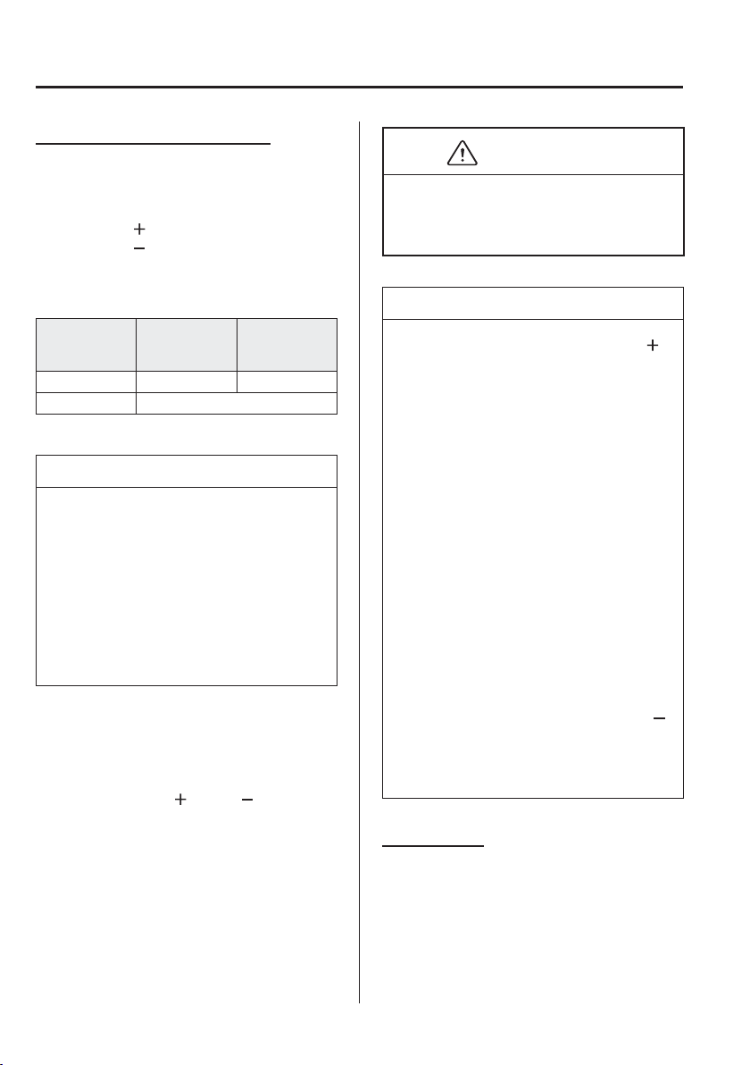
4
–
142
When Driving
i-ACTIVSENSE
Changing the Set Vehicle Speed
Changing the set vehicle speed using the
SET switch
Press the SET
switch to accelerate.
Press the SET
switch to decelerate.
The set vehicle speed changes as follows
each time the SET switch is pressed.
European
models
Except
European
models
Short press 1 km/h (1 mph) 5 km/h (5 mph)
Long press 10 km/h (5 mph)
NOTE
For example, the set vehicle speed is
changed by pressing the SET switch
four times as follows:
(European models)
The vehicle speed accelerates or
decelerates by 4 km/h (4 mph).
(Except European models)
The vehicle speed accelerates or
decelerates by 20 km/h (20 mph).
To accelerate using the accelerator
pedal
Depress the accelerator pedal and press
and release the SET
or SET switch at
the desired speed. If a switch cannot be
operated, the system returns to the set
speed when you release your foot from the
accelerator pedal.
CAUTION
The warnings and brake control do not
operate while the accelerator pedal is
depressed.
NOTE
When accelerating using the SET
switch while in headway control, the
set vehicle speed can be adjusted but
acceleration is not possible. If there
is no longer a vehicle ahead,
acceleration continues until reaching
the set vehicle speed. Check the set
vehicle speed by viewing the set
vehicle speed display in the active
driving display.
When depressing the accelerator
pedal, the inter-vehicle distance
display in the active driving display
changes to the white-line display.
The minimum settable speed is
30 km/h (19 mph). If the set vehicle
speed reaches 30 km/h (19 mph)
using the switch operation, constant
speed travel is maintained at about
30 km/h (19 mph) even if the SET
switch is pressed. The Mazda Radar
Cruise Control (MRCC) system is
not cancelled.
To Deactivate
The Mazda Radar Cruise Control (MRCC)
is deactivated when the OFF/CAN switch
is pressed twice.

4
–
143
When Driving
i-ACTIVSENSE
When the system is temporarily
cancelled
In the following cases, the Mazda Radar
Cruise Control (MRCC) is temporarily
cancelled, the Mazda Radar Cruise Control
(MRCC) set indication (green) is turned
off, and the Mazda Radar Cruise Control
(MRCC) main indication (white) is turned
on.
The OFF/CAN switch is pressed once.
The brake pedal is depressed.
The parking brake is applied.
(Automatic transaxle)
The selector lever is shifted to park (P),
neutral (N) or reverse (R).
(Manual transaxle)
The shift lever is in the reverse (R)
position .
In the following cases, the “MRCC
cancelled” indication is displayed and
the beep sounds one time.
The vehicle speed decreases to less
than 25 km (16 mph).
The DSC has operated.
The TCS has operated for a certain
period of time.
The Smart City Brake Support
[Forward] (SCBS F) has operated.
The Smart Brake Support (SBS) has
operated.
When travelling on a down slope for a
long period of time.
There is a problem with the system.
Any door is opened.
The driver's seat belt is unfastened.
(Manual transaxle)
The shift lever is shifted to neutral
(N) for a certain period of time.
The clutch is depressed for a certain
period of time.
The engine stalls.
NOTE
The Mazda Radar Cruise Control
(MRCC) system may be cancelled
during rain, fog, snow or other
inclement weather conditions, or the
front surface of the radiator grille is
dirty.
If you have temporarily cancelled
the Mazda Radar Cruise Control
(MRCC), you can return to your
previously set speed by pressing
the RES switch and after all of the
operation conditions have been met.
If the Mazda Radar Cruise Control
(MRCC) system is deactivated,
the system does not return to the
previously set speed even if the RES
switch is pressed.
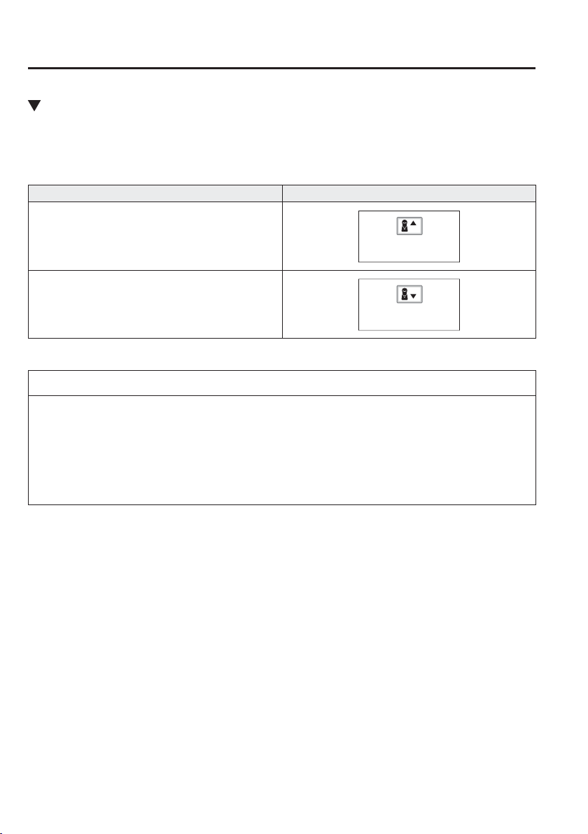
4
–
144
When Driving
i-ACTIVSENSE
Shift-up/Shift-down Request Display (Manual Transaxle)
The shift-up or shift-down request display in the active driving display may be indicated
while the Mazda Radar Cruise Control (MRCC) is operating. When this occurs, shift gears
because the gear position is not appropriate.
Request Display
Shift up
Shift down
NOTE
If the gears are not shifted up even though the shift-up request indication is displayed,
load will be applied to the engine and the Mazda Radar Cruise Control (MRCC)
system may be automatically cancelled or engine damage could occur.
If the gears are not shifted down even though the shift-down request indication is
displayed, the Mazda Radar Cruise Control (MRCC) system may be automatically
cancelled or engine stalling could occur.
4
–
145
When Driving
i-ACTIVSENSE
Cruise Control Function
While this function is operating, the
headway control operation is cancelled
and only the cruise control function
operates.
The vehicle speed can be set more than
about 25 km/h (16 mph).
Use the cruise control function on
expressways and other highways which do
not require a lot of repeated acceleration
and deceleration.
WARNING
Do not use the cruise control function
in the following locations:
Otherwise, it could lead to an accident.
Roads with sharp curves and where
vehicle traf¿ c is heavy and there is
insuf¿ cient space between vehicles.
(Driving under these conditions
using the cruise control function is
not possible)
Steep down slopes (Set speed may be
exceeded because suf¿ cient engine
braking cannot be applied)
Slippery roads such as ice or snow-
bound roads (Tyres could spin
causing you to lose vehicle control)
Always drive carefully:
The warnings and brake control
will not operate after the headway
control function is cancelled and the
system is switched to only the cruise
control function. Depress the brake
pedal to decelerate according to the
surrounding conditions while keeping
a safer distance from the vehicle ahead
and always driving carefully.
Switching to cruise control function
When the MODE switch is pressed while
the Mazda Radar Cruise Control (MRCC)
system is turned on, the system switches to
the cruise control function.
When the system switches to the cruise
control function, the cruise main indication
(white) is displayed in the instrument
cluster and the active driving display to
notify the driver as follows:
The Mazda Radar Cruise Control
(MRCC) set indication (green) or the
Mazda Radar Cruise Control (MRCC)
main indication (white) is turned off,
and the cruise main indication (white) is
turned on.
WARNING
Always turn off the cruise control
function when it is not in use:
Leaving the cruise control function
turned on when it is not in use
is dangerous as it could operate
unexpectedly, resulting in an accident.
How to set the speed
Adjust the system to the desired vehicle
speed using the accelerator pedal.
When the SET
or SET switch is
pressed, the cruise set indication (green) is
turned on and headway control begins.
4
–
146
When Driving
i-ACTIVSENSE
NOTE
The system may not be able to
maintain the set speed constantly
depending on driving conditions such
as steep up or down slopes.
The speed will continue increasing
while the SET
switch is pressed
and held. The speed will continue
decreasing while the SET
switch is
pressed and held.
How to increase the set speed
The set speed can be increased using the
following operations:
To increase speed using the SET
switch
Press and hold the SET
switch and
release the switch at the desired speed.
The set speed can be adjusted
incrementally (1 km/h (1 mph)
increments) by pressing the switch and
releasing it immediately. For example, if
the switch is pressed 4 times, the set speed
increases by about 4 km/h (4 mph).
To increase speed using accelerator
pedal
Depress the accelerator pedal and press the
SET
or SET switch at the desired
speed.
If the switch is not operated, the system
returns to the set speed after you release
your foot from the accelerator pedal.
How to Decrease the Set Speed
Press the SET
switch continuously and
release the switch at the desired speed.
The set speed can be adjusted
incrementally (1 km/h (1 mph) increments)
by pressing the switch and releasing it
immediately. For example, if the switch
is pressed 4 times, the set vehicle speed
decreases by about 4 km/h (4 mph).
Cancelling the function
Cancelling using OFF/CAN switch
When the OFF/CAN switch is pressed
once, the cruise control function is
cancelled.
Cancelling using MODE switch
When the MODE switch is pressed, the
cruise control function is cancelled and
the headway control function is made
available for operation.
The cruise control function is cancelled
automatically in the following cases. If the
RES switch is pressed while the vehicle
speed is 25 km/h (16 mph) or higher, the
speed returns to the original set speed.
The OFF/CAN switch is pressed once.
The brake pedal is depressed.
The parking brake is applied.
(Manual transaxle)
The clutch pedal is depressed.
The shift lever is shifted to neutral
position.
(Automatic transaxle)
The selector lever is shifted to P or N
position.

4
–
147
When Driving
i-ACTIVSENSE
NOTE
If the vehicle speed decreases by
about 15 km/h (9.4 mph) or more
than the set speed, the cruise control
function may be cancelled.
When the vehicle speed is less than
21 km/h (13 mph), the cruise control
function is cancelled. In this case, the
vehicle speed will not return to the
original set speed even if the vehicle
is accelerated to 25 km/h (16 mph) or
higher and the RES switch is pressed.
Reset the cruise control function.
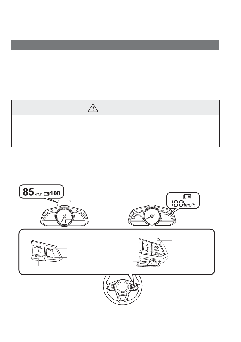
4
–
148
When Driving
i-ACTIVSENSE
*Some models.
Adjustable Speed Limiter
*
The adjustable speed limiter is a function to prevent the vehicle from being driven at a
vehicle speed faster than a set speed. The vehicle speed is controlled to kept it below the set
speed even if the accelerator pedal is depressed.
The adjustable speed limiter can be set between 30 km/h (20 mph) and 200 km/h (125 mph).
The vehicle speed may exceed the set speed when the vehicle is driven on a down slope,
however, the system noti¿ es the driver by À ashing the display and operating a warning
sound.
WARNING
Always turn off the system when changing drivers:
If the driver is changed and the new driver is unaware of the adjustable speed limiter
function, the vehicle may not accelerate when the driver depresses the accelerator
pedal, leading to an accident.
The system consists of the adjustable speed limiter display and the speed limiter switch on
the steering wheel.
Cruise control system
Mazda Radar Cruise Control (MRCC)
Active Driving Display Display in the instrument cluster
MODE switch
RES/+ switch
SET- switch
OFF/CAN switch
CANCEL switch
RES switch
OFF switch
MODE
switch
SET- switch
SET+ switch
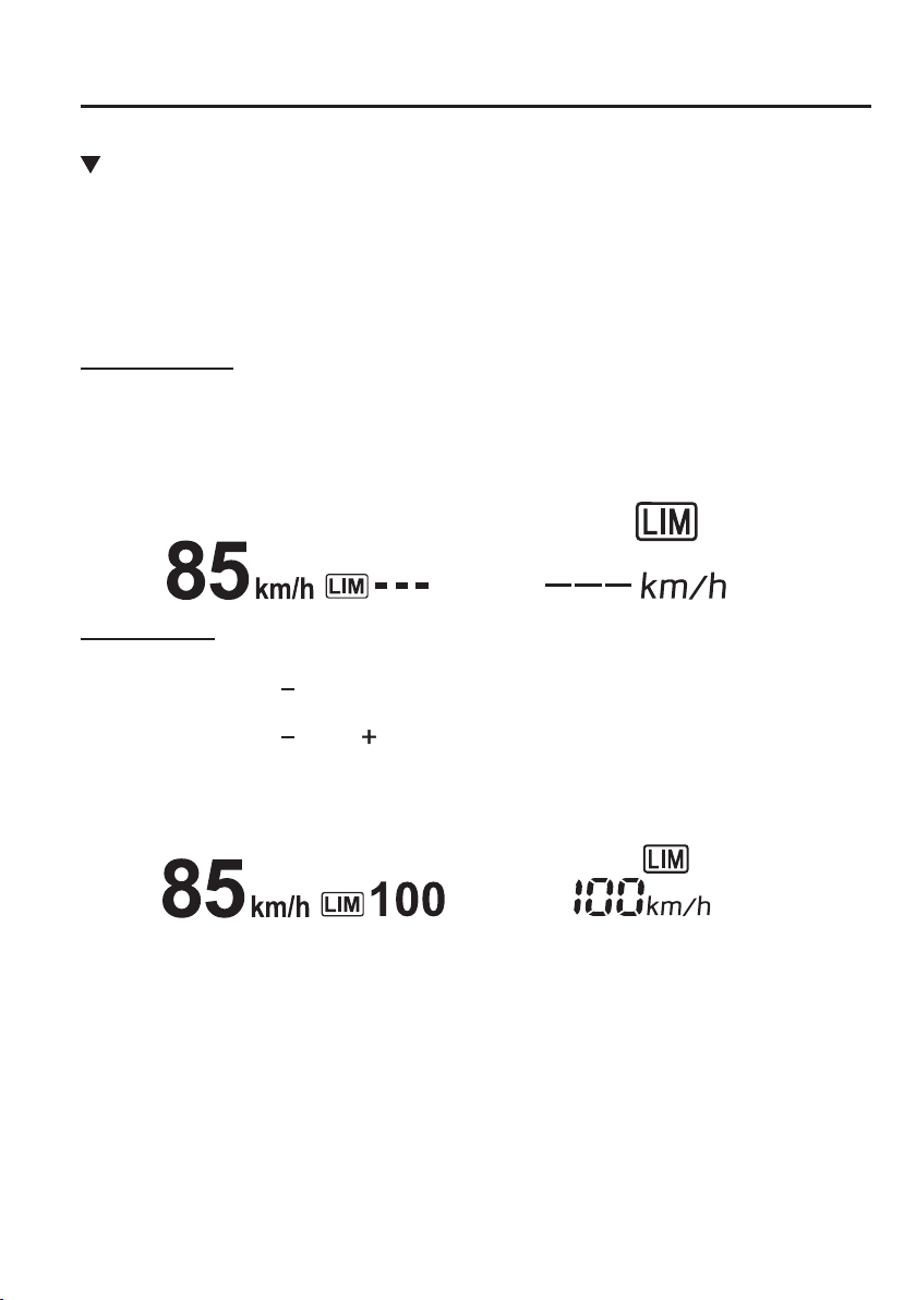
4
–
149
When Driving
i-ACTIVSENSE
Adjustable Speed Limiter Display
The setting status of the adjustable speed limiter is displayed in the active driving display
(Type A instrument cluster
*1
) or the display in the instrument cluster (Type B instrument
cluster
*1
).
*1 To determine which instrument cluster is equipped on your Mazda, Refer to Meters and
Gauges on page 4-24 .
Stand-by display
Displays when the speed limiter switch is operated and the system is turned on.
Turns off when the system is turned off.
Active Driving Display Display in the instrument cluster
Setting display
With cruise control
Displays when the SET
switch is operated and the speed is set.
With Mazda Rader Cruise Control (MRCC)
Displays when the SET
or SET switch is operated and the speed is set.
Active Driving Display Display in the instrument cluster
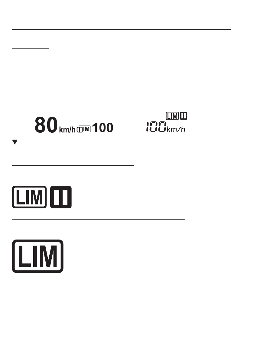
4
–
150
When Driving
i-ACTIVSENSE
Cancel display
Displays when any of the following operations is done and the system is temporarily
cancelled.
OFF/CAN switch is operated
Accelerator pedal is strongly depressed
Active Driving Display Display in the instrument cluster
Adjustable Speed Limiter Main Indication (White), Adjustable Speed Limiter
Set Indication (White)/Indicator Light (Green)
Adjustable speed limiter main indication (white)
The adjustable speed limiter main indication (white) is displayed in the instrument cluster
when the adjustable speed limiter is activated.
Adjustable speed limiter set indication (white)/indicator light (green)
The adjustable speed limiter set indication (white) is displayed in the instrument cluster and
the adjustable speed limiter set indicator light (green) turns on when a speed has been set.
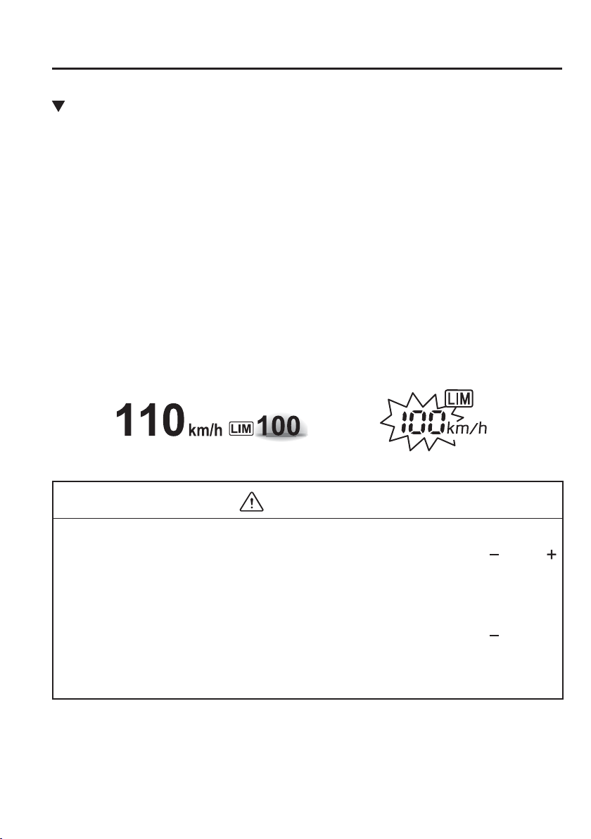
4
–
151
When Driving
i-ACTIVSENSE
Speed Limiter Warning Beep
Indicated in instrument cluster
If the vehicle speed exceeds the set speed by about 3 km/h (2 mph) or more, a warning
sound operates continuously and the adjustable speed limiter display À ashes at the same
time. The warning sound operates and the display À ashes until the vehicle speed decreases
to the set speed or less.
Indicated in active driving display
If the vehicle speed exceeds the set speed by about 3 km/h (2 mph) or more, a warning
sound is activated continuously and the adjustable speed limiter display À ashes at the same
time. The indication stops À ashing and remains on if the vehicle speed continues to exceed
the set speed by about 3 km/h (2 mph) or more, and the indication and warning sound
remain on until the vehicle is driven at the set speed or less.
Verify the safety of the surrounding area and adjust the vehicle speed by applying the
brakes. Additionally, keep a safer distance from the vehicles behind you.
Active Driving Display Display in the instrument cluster
CAUTION
(With cruise control)
If the set speed is set lower than the current vehicle speed by pressing the SET
or RES /
switch, the warning beep is not activated for about 30 seconds even if the vehicle speed is
faster than the newly set speed by 3 km/h (2 mph). Be careful not to drive over the set
speed.
(With Mazda Radar Cruise Control (MRCC))
If the set speed is set lower than the current vehicle speed by pressing the SET
or RES
switch, the warning beep is not activated for about 30 seconds even if the vehicle speed is
faster than the newly set speed by 3 km/h (2 mph). Be careful not to drive over the set
speed.
4
–
152
When Driving
i-ACTIVSENSE
NOTE
When the system is temporarily cancelled by depressing the accelerator pedal fully, the
adjustable speed limiter display shows the cancel display. If the vehicle speed exceeds the
set speed by about 3 km/h (2 mph) or more while the cancel display is displayed, the set
speed display À ashes but the warning sound is not operated.
Activation/Deactivation
NOTE
When the ignition is switched off, the system status before it was turned off is maintained.
For example, if the ignition is switched off while the adjustable speed limiter is operating,
the system will be operable when the ignition is switched ON the next time.
Activation
Press the MODE switch to operate the system. The adjustable speed limiter screen is
displayed, and the adjustable speed limiter main indication (white) turns on.
NOTE
When the cruise control or Mazda Radar Cruise Control (MRCC) system becomes
operable after pressing the MODE switch, press the mode switch again to switch to the
adjustable speed limiter.
Deactivation
To deactivate the system, do the following operations:
When a cruising speed has been set (adjustable speed limiter set indication (white)/
indicator light (green) turns on)
Long-press the OFF/CAN switch or press the OFF/CAN switch 2 times. The adjustable
speed limiter screen is no longer displayed and the adjustable speed limiter set indication
(white)/indicator light (green) turns off.
When a cruising speed has not been set (adjustable speed limiter main indication
(white) turns on)
Press the OFF/CAN switch. The adjustable speed limiter screen is no longer displayed and
the adjustable speed limiter main indication (white) turns off.
4
–
153
When Driving
i-ACTIVSENSE
NOTE
When the MODE switch is pressed while the adjustable speed limiter is operating, the
system switches to the cruise control or Mazda Radar Cruise Control (MRCC) system.
Setting the System
WARNING
Always verify the safety of the surrounding area when setting the adjustable speed
limiter:
If the speed is set lower than the current vehicle speed, the vehicle speed is decreased
to the set speed. Verify the safety of the surrounding area and keep a safer distance
between vehicles ahead and behind you.
1. Press the MODE switch to turn the system on.
2. (With cruise control)
Press the SET
to set the speed. When the current vehicle speed is 30 km/h (20 mph) or
more, the speed is set to the current vehicle speed. When the current vehicle speed is less
than 30 km/h (20 mph), the speed is set to 30 km/h (20 mph).
(With Mazda Radar Cruise Control (MRCC))
Press the SET
or SET to set the speed. When the current vehicle speed is 30 km/h
(20 mph) or more, the speed is set to the current vehicle speed. When the current vehicle
speed is less than 30 km/h (20 mph), the speed is set to 30 km/h (20 mph).
3. (With cruise control)
To increase the set speed, press the RES
switch continuously. The set speed can be
adjusted in 10 km/h (5 mph) increments. The set speed can also be adjusted in about
1 km/h (1 mph) increments by pressing the RES
switch momentary. For example, the
set speed increases about 4 km/h (4 mph) by pressing the RES
switch 4 times.
(With Mazda Radar Cruise Control (MRCC))
To increase the set speed, press the SET
switch continuously. The set speed can be
adjusted in 10 km/h (5 mph) increments. The set speed can also be adjusted in about
1 km/h (1 mph) increments by pressing the SET
switch momentary. For example, the
set speed increases about 4 km/h (4 mph) by pressing the SET
switch 4 times.
4. To decrease the set speed, press the SET
switch continuously. The set speed can be
adjusted in 10 km/h (5 mph) decrements. The set speed can also be adjusted in about
1 km/h (1 mph) increments by pressing the SET
switch momentary. For example, the
set speed decreases about 4 km/h (4 mph) by pressing the SET
switch 4 times.
4
–
154
When Driving
i-ACTIVSENSE
NOTE
(With cruise control)
When the vehicle set speed is displayed in the instrument cluster, press the RES /
switch to set the displayed vehicle speed.
(With Mazda Radar Cruise Control (MRCC))
When the vehicle set speed is displayed in the instrument cluster, press the RES switch
to set the displayed vehicle speed.
The system is temporarily cancelled when the vehicle is accelerated by depressing the
accelerator pedal strongly, however, it resumes when the vehicle speed decreases to the
set speed or less.
The vehicle speed may exceed the set speed on a down slope.
Temporarily Cancelling the System
The system is temporarily cancelled (stand-by status) when any of the following operations
is done while the adjustable speed limiter is displayed.
OFF/CAN switch is pressed
Accelerator pedal is strongly depressed
With cruise control
Press the RES /
switch to resume the operation at the previous set speed. The adjustable
speed limiter display remains displayed.
With Mazda Radar Cruise Control (MRCC)
Press the RES switch to resume the operation at the previous set speed. The adjustable speed
limiter display remains displayed.
NOTE
(With cruise control)
The set speed can be set by pressing the SET switch while the system is in stand-by
status.
(With Mazda Radar Cruise Control (MRCC))
The set speed can be set by pressing the SET or SET switch while the system is in
stand-by status.
The adjustable speed limiter is not cancelled by depressing the brake pedal.
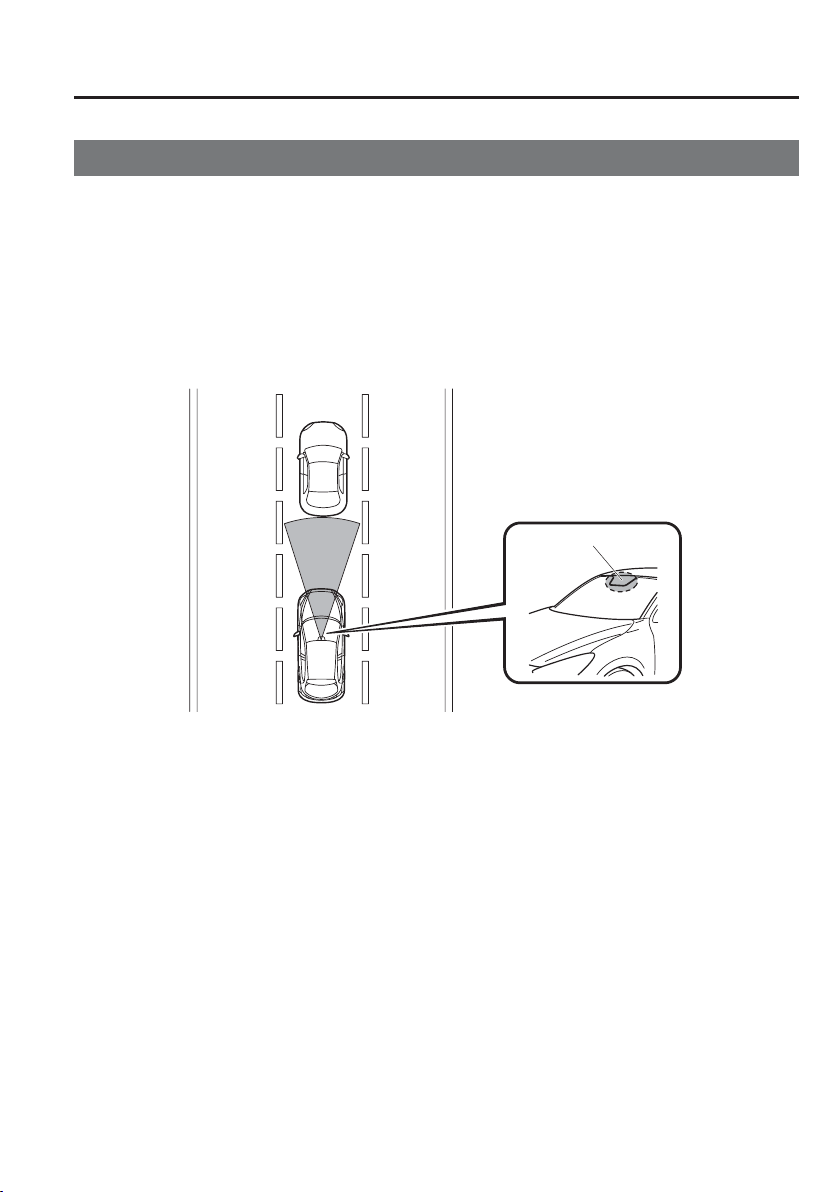
4
–
155
When Driving
i-ACTIVSENSE
*Some models.
Smart City Brake Support [Forward] (SCBS F)
*
The Smart City Brake Support (SCBS) system is designed to reduce damage in the event
of a collision by operating the brake control (SCBS brake) when the system's laser sensor
detects a vehicle ahead and determines that a collision with a vehicle ahead is unavoidable.
It may also be possible to avoid a collision if the relative speed between your vehicle and a
vehicle ahead is less than about 20 km/h (12 mph).
In addition, when the driver depresses the brake pedal while the system is in the operation
range at about 4 to 30 km/h (2 to 18 mph), the brakes are applied ¿ rmly and quickly to
assist. (Brake Assist (SCBS brake assist))
Laser sensor
4
–
156
When Driving
i-ACTIVSENSE
WARNING
Do not rely on the Smart City Brake Support System (SCBS) as a substitute for safer
driving:
The Smart City Brake Support (SCBS) system cannot compensate for unsafe and
reckless driving, excessive speed, tailgating (following another vehicle too closely), and
driving on slippery roads such as wet, snowy, and icy roads (reduced tyre friction and
road contact because of water on the road surface). You can still have an accident.
Do not rely completely on the Smart City Brake Support (SCBS) system:
The Smart City Brake Support (SCBS) system is only designed to reduce damage in
the event of a collision. Over reliance on the system leading to the accelerator pedal
or brake pedal being mistakenly operated could result in an accident.
The Smart City Brake Support (SCBS) is a system which operates in response to a
vehicle ahead. The system may not be able to detect or react to two-wheeled vehicles
or pedestrians.
The laser sensor for the Smart City Brake Support (SCBS) system is installed near
the rearview mirror. To assure the correct operation of the Smart City Brake Support
(SCBS), heed the following cautions.
Do not apply stickers to the surface of the windscreen near the laser sensor
(including transparent stickers). Otherwise, the laser sensor may not be able to
detect vehicles ahead which could result in an accident.
Do not apply coating agent to the windscreen. Otherwise, the laser sensor may
not be able to detect vehicles or obstructions in front which could result in an
accident.
Do not disassemble the laser sensor.
If cracks or damage caused by À ying gravel or debris is visible near the laser
sensor, stop using the Smart City Brake Support (SCBS) system immediately and
have your vehicle inspected by an expert repairer, we recommend an Authorised
Mazda Repairer. If the vehicle continues to be driven with cracks or scratch marks
left on the windscreen near the laser sensor, the system may operate unnecessarily
and cause an unexpected accident.
Refer to Stopping The Smart City Brake Support (SCBS) System Operation on
page 4-160 .
When replacing the windscreen wipers or windscreen, consult an expert repairer,
we recommend an Authorised Mazda Repairer.
Do not modify the suspension:
If the vehicle height or inclination is changed, the system will not be able to correctly
detect vehicles ahead. This will result in the Smart City Brake Support (SCBS) system
not operating normally or mistakenly operating, which could cause a serious accident.
4
–
157
When Driving
i-ACTIVSENSE
WARNING
Turn off the Smart City Brake Support (SCBS) when the vehicle is running on a chassis
roller or being towed:
Turn off the Smart City Brake Support (SCBS) system to prevent mistaken operation
when the vehicle is running on a chassis roller or being towed.
Refer to the Stopping the Smart City Brake Support (SCBS) System Operation on page
4-160 on how to turn off the Smart City Brake Support (SCBS) system.
CAUTION
When driving off-road in areas where there is grass or forage, it is recommended that
the Smart City Brake Support (SCBS) system be turned off.
Always use tyres for all wheels that are of the speci¿ ed size, and the same
manufacturer, brand, and tread pattern. In addition, do not use tyres with signi¿ cantly
different wear patterns on the same vehicle as the Smart City Brake Support (SCBS)
system may not operate normally.
The laser sensor includes a function for detecting a soiled windscreen and informing
the driver, however, depending on the conditions, it may not detect plastic shopping
bags, ice or snow on the windscreen. In such cases, the system cannot accurately
determine a vehicle ahead and may not be able to operate normally. Always drive
carefully and pay attention to the road ahead.

4
–
158
When Driving
i-ACTIVSENSE
NOTE
The Smart City Brake Support (SCBS) system will not operate if the driver is
deliberately performing driving operations (accelerator pedal and steering wheel).
The Smart City Brake Support (SCBS) system will operate under the following
conditions.
The engine is running.
The Smart City Brake Support (SCBS) warning light (amber) does not illuminate.
The vehicle speed is between about 4 to 30 km/h (2 to 18 mph).
The Smart City Brake Support (SCBS) system is not turned off.
The DSC is not malfunctioning.
The Smart City Brake Support (SCBS) detects a vehicle ahead by emitting a near-
infrared laser beam and receiving the beam reÀ ected off the reÀ ector of the vehicle
ahead, and then using it for the measurement. Consequently, the Smart City Brake
Support (SCBS) may not operate under the following conditions:
ReÀ ection of the laser is poor due to the shape of the vehicle ahead.
The vehicle ahead is signi¿ cantly dirty.
Under bad weather condition, such as rain, fog and snow.
The window washer is being used or the windscreen wipers are not used when it's
raining.
The windscreen is dirty.
The steering wheel is turned completely left or right, or the vehicle is accelerated
rapidly and comes close to the vehicle ahead.
Trucks with low loading platforms and vehicles with an extremely low or high
pro¿ le.
Vehicles with certain shapes such as a vehicle carrier.
Under the following conditions, the Smart City Brake Support (SCBS) system may not
operate normally.
Heavy luggage is loaded in the luggage compartment or on the rear seat.
If there is the possibility of partial contact with a vehicle ahead.
When driving on continuously curving roads, and entering and exiting exits.
Elongated luggage or cargo is loaded onto installed roof rails and covers the laser
sensor.
Exhaust gas from the vehicle in front, sand, snow, and water vapour rising from
manholes and grating, and water splashed into the air.
When towing a malfunctioning vehicle.
When driving with tyres having signi¿ cantly different wear.

4
–
159
When Driving
i-ACTIVSENSE
*Some models.
NOTE
In the following cases, the laser sensor may inadvertently determine that there is a
vehicle ahead and the Smart City Brake Support (SCBS) system may operate.
Objects on the road at the entrance to a curve.
Vehicles passing in the opposite lane while making a curve.
Metal objects, bumps, or protruding objects on the road.
When passing through a toll gate equipped with a bar.
When passing under a vinyl curtain or À ag.
Plastic objects such as pylons.
Two-wheeled vehicles, pedestrians, animals or standing trees.
(Manual transaxle)
If the vehicle is stopped by the SCBS operation and the clutch pedal is not depressed,
the engine stops.
When the system operates, the user is noti¿ ed by the À ashing Smart City Brake
Support (SCBS) indicator light (red) and the active driving display
*
.
The Smart City Brake Support (SCBS) warning light (amber) turns on when the
system has a malfunction.
Refer to Warning Lights on page 4-38 .
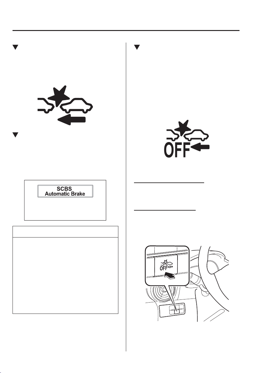
4
–
160
When Driving
i-ACTIVSENSE
Smart City Brake Support (SCBS)
Indicator Light (Red)
If the Smart City Brake Support (SCBS) is
operating, the indicator light (red) À ashes.
Automatic Brake Operation
Display
“SCBS Automatic Brake” is displayed in
the active driving display while the SCBS
brakes or the brake assist (SCBS brake
assist) is operating.
NOTE
The collision warning beep sounds
intermittently while the SCBS brake
or brake assist (SCBS brake assist) is
operating.
If the vehicle is stopped by the SCBS
operation and the brake pedal is not
depressed, the warning beep sounds
one time after about 2 seconds and
the SCBS brake is automatically
released.
Stopping The Smart City Brake
Support [Forward] (SCBS F)
System Operation
The Smart City Brake Support (SCBS)
system can be temporarily deactivated.
When the Smart City Brake Support
(SCBS) system is turned off, the Smart
City Brake Support (SCBS) OFF indicator
light turns on.
When the engine is restarted, the system
becomes operational.
Without SCBS OFF switch
Refer to Personalisation Features on page
9-13 .
With SCBS OFF switch
Press the SCBS OFF switch to turn
off the system. The Smart City Brake
Support (SCBS) OFF indicator light in the
instrument cluster will illuminate.
Press the switch again to turn the system
back on. The Smart City Brake Support
(SCBS) OFF indicator light will turn off.
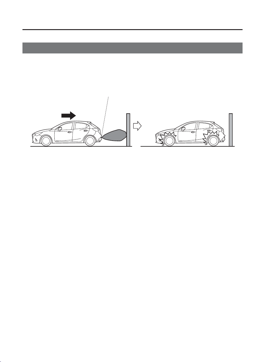
4
–
161
When Driving
i-ACTIVSENSE
*Some models.
Smart City Brake Support [Reverse] (SCBS R)
*
The Smart City Brake Support [Reverse] (SCBS R) is a system which is designed to reduce
damage in the event of a collision by operating the brake control (SCBS brake) when the
system’s ultrasonic sensors detect an obstruction at the rear of the vehicle while driving
at a speed of about 2 to 8 km/h (2 to 4 mph) and the system determines that a collision is
unavoidable.
Reverse
Ultrasonic sensor (rear)
4
–
162
When Driving
i-ACTIVSENSE
WARNING
Do not rely completely on the Smart City Brake Support [Reverse] (SCBS R) system:
The Smart City Brake Support [Reverse] (SCBS R) system is only designed to
reduce damage in the event of a collision. Over reliance on the system leading to
the accelerator pedal or brake pedal being mistakenly operated could result in an
accident.
To assure the correct operation of the Smart City Brake Support [Reverse] (SCBS
R), heed the following cautions.
Do not apply a sticker to an ultrasonic sensor (rear) (including transparent
stickers). Otherwise, the ultrasonic sensor (rear) may not be able to detect vehicles
or obstructions which could result in an accident.
Do not disassemble an ultrasonic sensor (rear).
If cracks or damage caused by À ying gravel or debris is visible around an
ultrasonic sensor (rear), stop using the Smart City Brake Support [Reverse] (SCBS
R) system immediately and have your vehicle inspected by an expert repairer, we
recommend an Authorised Mazda Repairer. If the vehicle continues to be driven
with cracks or scratch marks left around an ultrasonic sensor, the system may
operate unnecessarily and cause an unexpected accident.
Refer to Stopping the Smart City Brake Support [Reverse] (SCBS R) System
Operation on page 4-166 .
Consult an expert repairer, we recommend an Authorised Mazda Repairer for rear
bumper replacement.
Do not modify the suspension:
If the vehicle height or inclination is changed, the Smart City Brake Support [Reverse]
(SCBS R) system may not operate correctly because it cannot detect obstructions
correctly.
Do not apply a strong force to an ultrasonic sensor (rear):
When washing the vehicle, do not spray highly pressurised water against an ultrasonic
sensor (rear), or rub it strongly. In addition, do not hit the rear bumper forcefully
when loading and unloading cargo Otherwise, the sensors may not detect obstructions
correctly which could cause the Smart City Brake Support [Reverse] (SCBS R) system
to not operate normally, or it could operate unnecessarily.
4
–
163
When Driving
i-ACTIVSENSE
CAUTION
When driving off-road in areas where there is grass or foliage, it is recommended that
the Smart City Brake Support [Reverse] (SCBS R) system be turned off.
Always use tyres of the speci¿ ed size and the same manufacturer, brand, and tread
pattern on all 4 wheels. In addition, do not use tyres with signi¿ cantly different wear
patterns on the same vehicle. Do not use tyres with signi¿ cantly different wear patterns
on the same vehicle. Otherwise, the Smart City Brake Support [Reverse] (SCBS R)
system may not operate normally.
If ice or snow is stuck on the ultrasonic sensors (rear) they may not be able to detect
obstructions correctly depending on the conditions. In such cases, the system may not
be able to perform controls correctly. Always drive carefully and pay attention to the
rear of the vehicle.
NOTE
The vehicle posture changes depending on the accelerator pedal, brake pedal and
steering wheel operations, which could make it dif¿ cult for the system to recognise an
obstruction, or it could facilitate unnecessary detection. In such cases, the Smart City
Brake Support [Reverse] (SCBS R) may or may not operate.
The Smart City Brake Support [Reverse] (SCBS R) system will operate under the
following conditions.
The engine is running.
The change lever (manual transaxle vehicle) or the selector lever (automatic
transaxle vehicle) is in the R (reverse) position.
The vehicle speed is between about 2 to 8 km/h (2 to 4 mph).
The Smart City Brake Support [Reverse] (SCBS R) is not turned off.
The DSC is not malfunctioning.
The Smart City Brake Support [Reverse] (SCBS R) operates using ultrasonic sensors
(rear) which detect obstructions at the rear by emitting ultrasonic waves and then
receiving the returning waves reÀ ected off the obstructions.

4
–
164
When Driving
i-ACTIVSENSE
NOTE
In the following cases, the ultrasonic sensors (rear) cannot detect obstructions and the
Smart City Brake Support [Reverse] (SCBS R) may not operate.
The height of the obstruction is low such as low walls or trucks with low loading
platforms.
The height of the obstruction is high such as trucks with high loading platforms.
The obstruction is small.
The obstruction is thin such as a signpost.
The obstruction is positioned away from the centre of the vehicle.
The surface of the obstruction is not pointed vertically relative to the vehicle.
The obstruction is soft such as a hanging curtain or snow stuck to a vehicle.
The obstruction is shaped irregularly.
The obstruction is extremely close.
In the following cases, the ultrasonic sensors (rear) cannot detect obstructions correctly
and the Smart City Brake Support [Reverse] (SCBS R) may not operate.
Something is stuck on the bumper near an ultrasonic sensor (rear).
The steering wheel is turned sharply, or the brake or accelerator pedal is operated.
There is another obstruction near one obstruction.
During inclement weather such as rain, fog and snow.
High or low humidity.
High or low temperatures
Strong winds.
The path of travel is not À at.
Heavy luggage is loaded in the luggage compartment or on the rear seat.
Objects such as a wireless aerial, fog light, or illuminated number plate is installed
near an ultrasonic sensor (rear).
The orientation of an ultrasonic sensor (rear) has deviated for reasons such as a
collision.
The vehicle is affected by other sound waves such as the horn, engine noise,
ultrasonic sensor of another vehicle.
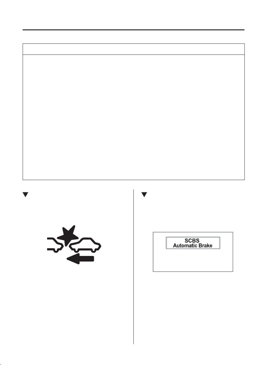
4
–
165
When Driving
i-ACTIVSENSE
NOTE
In the following cases, an ultrasonic sensor (rear) may detect something as a target
obstruction which could cause the Smart City Brake Support [Reverse] (SCBS R)
system to operate.
Driving on a steep slope.
Wheel blocks.
Hanging curtains, gate poles such as at toll gates and railroad crossing.
When travelling near objects such as foliage, barriers, vehicles, walls, and fences
along a road.
When driving off-road in areas where there is grass and forage.
When passing through low gates, narrow gates, car washing machines, and tunnels.
A towing bar is installed or a trailer is connected.
(Manual transaxle)
If the vehicle is stopped by the SCBS operation and the clutch pedal is not depressed,
the engine stops.
The Smart City Brake Support (SCBS) warning indication (amber) turns on when the
system has a malfunction.
Refer to Warning Lights on page 4-38 .
Smart City Brake Support (SCBS)
Indicator Light (Red)
If the Smart City Brake Support (SCBS) is
operating, the indicator light (red) À ashes.
Automatic Brake Operation
Display
“SCBS Automatic Brake” is indicated in
the active driving display after the SCBS
brakes is operated.
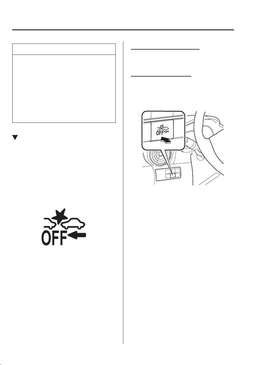
4
–
166
When Driving
i-ACTIVSENSE
NOTE
The collision warning beep sounds
intermittently while the SCBS brake
is operating.
If the vehicle is stopped by the SCBS
operation and the brake pedal is not
depressed, the warning beep sounds
one time after about 2 seconds and
the SCBS brake is automatically
released.
Stopping the Smart City Brake
Support [Reverse] (SCBS R)
System Operation
The Smart City Brake Support [Reverse]
(SCBS R) system can be temporarily
deactivated.
When the Smart City Brake Support
[Reverse] (SCBS R) system is turned off,
the Smart City Brake Support (SCBS)
OFF indicator light turns on.
When the engine is restarted, the system
becomes operational.
When the DSC OFF switch is pressed to
stop the DSC operation, the Smart City
Brake Support [Reverse] (SCBS R) system
operation also stops and the Smart City
Brake Support (SCBS) OFF indicator light
turns on.
Without SCBS OFF switch
Refer to Personalisation Features on page
9-13 .
With SCBS OFF switch
Press the SCBS OFF switch to turn
off the system. The Smart City Brake
Support (SCBS) OFF indicator light in the
instrument cluster will illuminate.
Press the switch again to turn the system
back on. The Smart City Brake Support
(SCBS) OFF indicator light will turn off.
4
–
167
When Driving
i-ACTIVSENSE
*Some models.
Smart Brake Support (SBS)
*
The Smart Brake Support (SBS) system alerts the driver of a possible collision using a
display and warning sound if the radar sensor (front) and the Forward Sensing Camera
(FSC) determine that there is the possibility of a collision with a vehicle ahead while the
vehicle is being driven at about 15 km/h or faster (10 mph or faster). Furthermore, if the
radar sensor (front) and the Forward Sensing Camera (FSC) determines that a collision is
unavoidable, the automatic brake control is performed to reduce damage in the event of a
collision.
In addition, when the driver depresses the brake pedal, the brakes are applied ¿ rmly and
quickly to assist. (Brake Assist (SBS brake assist))
WARNING
Do not rely completely on the Smart Brake Support (SBS) system and always drive
carefully:
The Smart Brake Support (SBS) is designed to reduce damage in the event of
a collision, not avoid an accident. The ability to detect an obstruction is limited
depending on the obstruction, weather conditions, or traf¿ c conditions. Therefore,
if the accelerator pedal or brake pedal is mistakenly operated it could result in an
accident. Always verify the safety of the surrounding area and depress the brake pedal
or accelerator pedal while keeping a safer distance from vehicles ahead or on-coming
vehicles.
CAUTION
In the following cases, turn the system off to prevent a mis-operation:
The vehicle is being towed or when towing another vehicle.
The vehicle is on a chassis roller.
When driving on rough roads such as in areas of dense grass or off-road.

4
–
168
When Driving
i-ACTIVSENSE
NOTE
The Smart Brake Support (SBS) system operates when all of the following conditions
are met:
The ignition is switched ON.
The Smart Brake Support (SBS) system is on.
The vehicle speed is about 15 km/h or faster (10 mph or faster).
The relative speed between your vehicle and the vehicle ahead is about 15 km/h or
faster (10 mph or faster).
The Dynamic Stability Control (DSC) is not operating.
The Smart Brake Support (SBS) system may not operate under the following
conditions:
If the vehicle is accelerated rapidly and it comes close to a vehicle ahead.
The vehicle is driven at the same speed as the vehicle ahead.
The accelerator pedal is depressed.
The brake pedal is depressed.
The steering wheel is being operated.
The selector lever is being operated.
The direction indicator is being used.
When the vehicle ahead is not equipped with tail lights or the tail lights are turned
off.
When warnings and messages, such as a dirty windscreen, related to the Forward
Sensing Camera (FSC) are being displayed in the centre display.
Although the objects which activate the system are four-wheeled vehicles, the radar
sensor (front) could detect the following objects, determine them to be an obstruction,
and operate the Smart Brake Support (SBS) system.
Objects on the road at the entrance to a curve (including guardrails and snow banks).
A vehicle appears in the opposite lane while cornering or rounding a curve.
When crossing a narrow bridge.
When passing under a low gate or through a tunnel or narrow gate.
When entering an underground parking area.
Metal objects, bumps, or protruding objects on the road.
If you suddenly come close to a vehicle ahead.
When driving in areas where there is high grass or forage.
Two-wheeled vehicles such as motorbikes or bicycles.
Pedestrians or non-metallic objects such as standing trees.
When the system operates, the user is noti¿ ed by the active driving display.
The Smart Brake Support (SBS) warning indication (amber) turns on when the system
has a malfunction.
Refer to Warning Lights on page 4-38 .
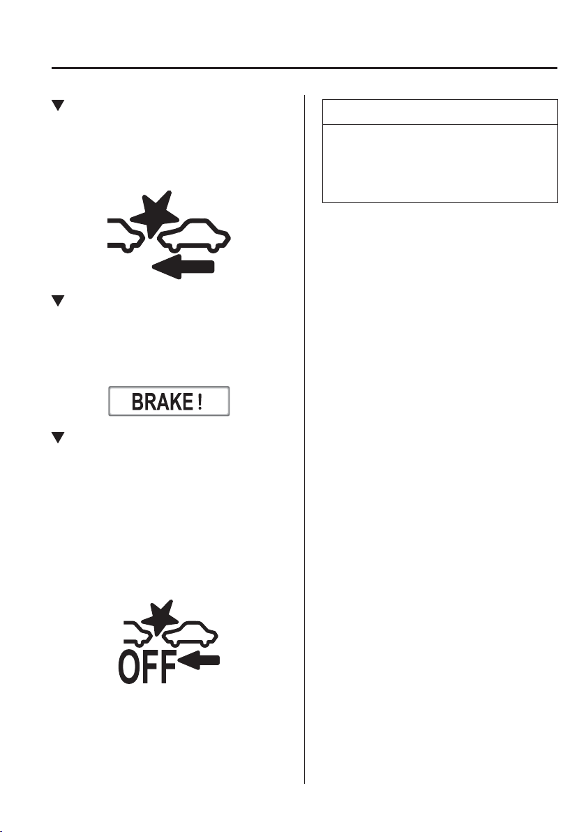
4
–
169
When Driving
i-ACTIVSENSE
Smart Brake Support (SBS)
Indicator Light (Red)
If the Smart Brake Support (SBS) is
operating, the indicator light (red) À ashes.
Collision Warning
If there is the possibility of a collision
with a vehicle ahead, the beep sounds
continuously and a warning is indicated in
the active driving display.
Stopping The Smart Brake
Support (SBS) System Operation
The Smart Brake Support (SBS) system
can be temporarily deactivated.
Refer to Personalisation Features on page
9-13 .
When the Smart Brake Support (SBS)
system is turned off, the Smart Brake
Support (SBS) OFF indicator light turns
on.
When the engine is restarted, the system
becomes operational.
NOTE
If the Smart Brake Support (SBS)
system operation is turned off, the Smart
City Brake Support (SCBS) system
operation is turned off simultaneously.
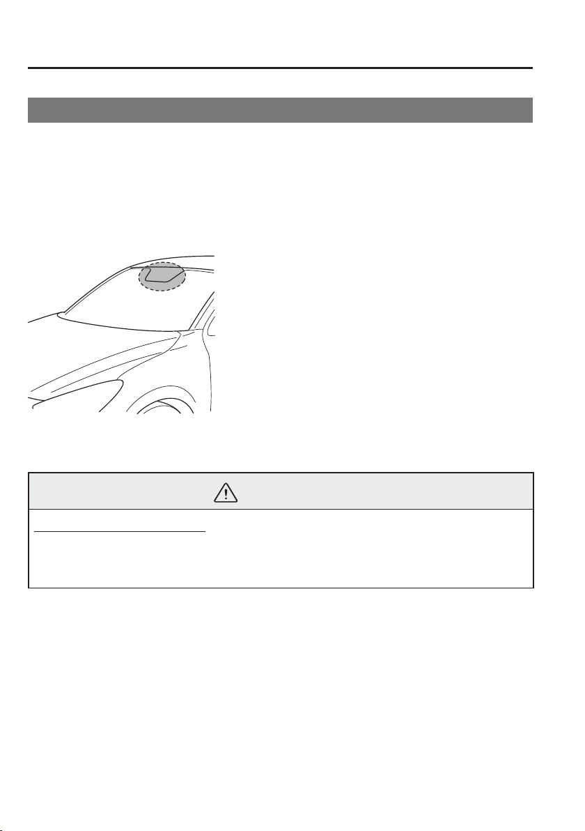
4
–
170
When Driving
i-ACTIVSENSE
*Some models.
Forward Sensing Camera (FSC)
*
Your vehicle is equipped with a Forward Sensing Camera (FSC). The Forward Sensing
Camera (FSC) is positioned near the rearview mirror and used by the following systems.
High Beam Control System (HBC)
Adaptive LED Headlights (ALH)
Driver Attention Alert (DAA)
Lane Departure Warning System (LDWS)
Smart Brake Support (SBS)
The Forward Sensing Camera (FSC) determines the conditions ahead of the vehicle while
travelling at night and detects traf¿ c lanes. The distance in which the Forward Sensing
Camera (FSC) can detect objects varies depending on the surrounding conditions.
WARNING
Do not modify the suspension:
If the vehicle height or inclination is changed, the system will not be able to correctly
detect vehicles ahead. This will result in the system not operating normally or
mistakenly operating, which could cause a serious accident.
4
–
171
When Driving
i-ACTIVSENSE
CAUTION
Do not apply accessories, stickers or ¿ lm to the windscreen near the Forward Sensing
Camera (FSC).
If the area in front of the Forward Sensing Camera (FSC) lens is obstructed, it will
cause the system to not operate correctly. Consequently, each system may not operate
normally which could lead to an unexpected accident.
Do not disassemble or modify the Forward Sensing Camera (FSC).
Disassembly or modi¿ cation of the Forward Sensing Camera (FSC) will cause a
malfunction or mistaken operation. Consequently, each system may not operate
normally which could lead to an unexpected accident.

4
–
172
When Driving
i-ACTIVSENSE
CAUTION
Heed the following cautions to assure the correct operation of the Forward Sensing
Camera (FSC).
Be careful not to scratch the Forward Sensing Camera (FSC) lens or allow it to get
dirty.
Do not remove the Forward Sensing Camera (FSC) cover.
Do not place objects on the instrument panel which reÀ ect light.
Always keep the windscreen glass around the camera clean by removing dirt or
fogging. Use the windscreen defroster to remove fogging on the windscreen.
Consult an expert repairer, we recommend an Authorised Mazda Repairer regarding
cleaning the interior side of the windscreen around the Forward Sensing Camera
(FSC).
Consult an expert repairer, we recommend an Authorised Mazda Repairer before
performing repairs around the Forward Sensing Camera (FSC).
The Forward Sensing Camera (FSC) is installed to the windscreen. Consult an expert
repairer, we recommend an Authorised Mazda Repairer for windscreen repair and
replacement.
When cleaning the windscreen, do not allow glass cleaners or similar cleaning À uids
to get on the Forward Sensing Camera (FSC) lens. In addition, do not touch the
Forward Sensing Camera (FSC) lens.
When performing repairs around the rearview mirror, consult an expert repairer, we
recommend an Authorised Mazda Repairer.
Consult an expert repairer, we recommend an Authorised Mazda Repairer regarding
cleaning of the camera lens.
Do not hit or apply strong force to the Forward Sensing Camera (FSC) or the area
around it. If the Forward Sensing Camera (FSC) is severely hit or if there are cracks
or damage caused by À ying gravel or debris in the area around it, stop using the
following systems and consult an expert repairer, we recommend an Authorised
Mazda Repairer.
High Beam Control System (HBC)
Adaptive LED Headlights (ALH)
Lane Departure Warning System (LDWS)
Driver Attention Alert (DAA)
Smart Brake Support (SBS)
The direction in which the Forward Sensing Camera (FSC) is pointed has been ¿ nely
adjusted. Do not change the installation position of the Forward Sensing Camera
(FSC) or remove it. Otherwise, it could result in damage or malfunction.
Always use tyres for all wheels that are of the speci¿ ed size, and the same
manufacturer, brand, and tread pattern. In addition, do not use tyres with signi¿ cantly
different wear patterns on the same vehicle as the system may not operate normally.
4
–
173
When Driving
i-ACTIVSENSE
CAUTION
The Forward Sensing Camera (FSC) includes a function for detecting a soiled
windscreen and informing the driver, however, depending on the conditions, it may not
detect plastic shopping bags, ice or snow on the windscreen. In such cases, the system
cannot accurately determine a vehicle ahead and may not be able to operate normally.
Always drive carefully and pay attention to the road ahead.
NOTE
In the following cases, the Forward Sensing Camera (FSC) cannot detect target objects
correctly, and each system may be unable to operate normally.
The height of the vehicle ahead is low.
You drive your vehicle at the same speed as the vehicle ahead.
Headlights are not turned on during the night or when going through a tunnel.

4
–
174
When Driving
i-ACTIVSENSE
NOTE
In the following cases, the Forward Sensing Camera (FSC) may not be able to detect
target objects correctly.
Under bad weather condition, such as rain, fog and snow.
The window washer is being used or the windscreen wipers are not used when it's
raining.
Ice, fog, snow, frost, rainfall, dirt, or foreign matter such as a plastic bag is stuck on
the windscreen.
Trucks with low loading platforms and vehicles with an extremely low or high
pro¿ le.
When driving next to walls with no patterning (including fences and longitudinally
striped walls).
The tail lights of the vehicle ahead are turned off.
A vehicle is outside the illumination range of the headlights.
The vehicle is making a sharp turn, or ascending or descending a steep slope.
Entering or exiting a tunnel.
Heavy luggage is loaded causing the vehicle to tilt.
Strong light is shone at the front of the vehicle (back light or high-beam light from
on-coming vehicles).
There are many light emitters on the vehicle ahead.
When the vehicle ahead is not equipped with tail lights or the tail lights are turned
off at nighttime.
Elongated luggage or cargo is loaded onto installed roof rails and covers the Forward
Sensing Camera (FSC).
Exhaust gas from the vehicle in front, sand, snow, and water vapour rising from
manholes and grating, and water splashed into the air.
When towing a malfunctioning vehicle.
The vehicle is driven with tyres having signi¿ cantly different wear.
The vehicle is driven on down slopes or bumpy roads.
There are water puddles on the road.
The surroundings are dark such as during the night, early evening, or early morning,
or in a tunnel or indoor parking lot.
The illumination brightness of the headlights is reduced or the headlight illumination
is weakened due to dirt or a deviated optical axis.
The target object enters the blind spot of the Forward Sensing Camera (FSC).
A person or object bursts onto the road from the shoulder or cuts right in front of
you.
You change lanes and approach a vehicle ahead.
When driving extremely close to the target object.
Tyre chains or a temporary spare tyre is installed.
The vehicle ahead has a special shape. For example, a vehicle towing a trailer house
or a boat, or a vehicle carrier carrying a vehicle with its front pointed rearward.

4
–
175
When Driving
i-ACTIVSENSE
NOTE
If the Forward Sensing Camera (FSC) cannot operate normally due to backlight or fog,
the system functions related to the Forward Sensing Camera (FSC) are temporarily
stopped and the following warning lights turn on. However, this does not indicate a
malfunction.
High Beam Control System (HBC) warning light (amber)
Adaptive LED Headlights (ALH) warning light (amber)
Lane Departure Warning System (LDWS) warning light
Smart Brake Support/Smart City Brake Support (SBS/SCBS) warning light (amber)
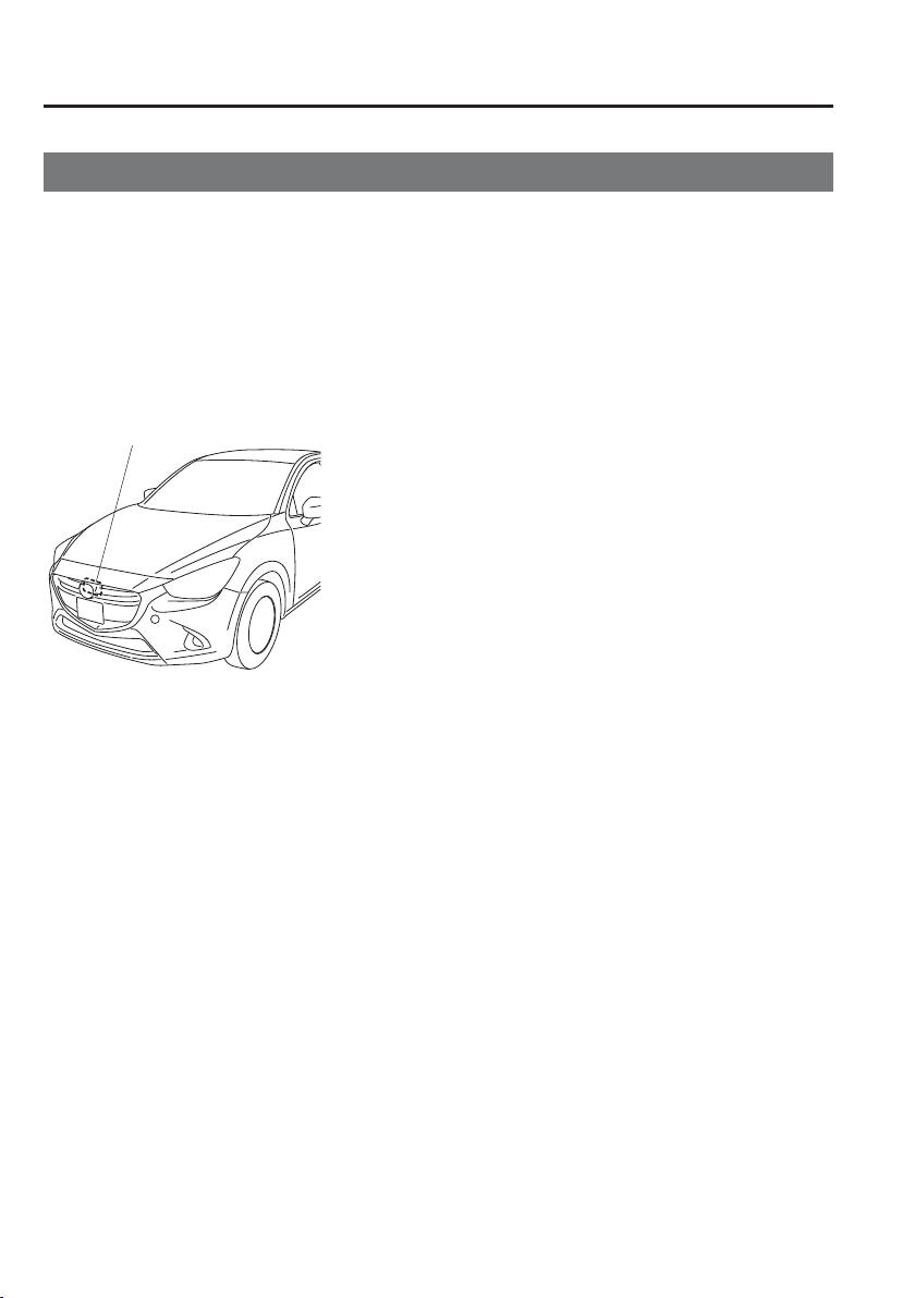
4
–
176
When Driving
i-ACTIVSENSE
*Some models.
Radar Sensor (Front)
*
Your vehicle is equipped with a radar sensor (front).
The following systems also use the radar sensor (front).
Mazda Radar Cruise Control (MRCC)
Distance Recognition Support System (DRSS)
Smart Brake Support (SBS)
The radar sensor (front) functions by detecting the radio waves reÀ ected off a vehicle ahead
or an obstruction sent from the radar sensor.
The radar sensor (front) is mounted behind the front emblem.
Radar sensor (front)
If the Smart Brake Support/Smart City Brake Support (SBS/SCBS) Warning Light (amber)
is illuminated, the area around the radar sensor may be dirty. Refer to “Warning Guidance”
in the centre display (Type B audio).
Refer to If a Warning Light Turns On or Flashes on page 7-35 .

4
–
177
When Driving
i-ACTIVSENSE
CAUTION
Heed the following precautions to assure correct operation of each system.
Do not adhere stickers (including transparent stickers) to the surface of the radiator
grille and front emblem in and around the radar sensor (front), and do not replace
the radiator grille and front emblem with any product that is not a genuine product
designed for use with the radar sensor (front).
The radar sensor (front) includes a function for detecting soiling of the radar sensor's
front surface and informing the driver, however, depending on the conditions, it may
require time to detect or it may not detect plastic shopping bags, ice or snow. If this
occurs, the system may not operate correctly, therefore always keep the radar sensor
(front) clean.
Do not install a grille guard.
If the front part of the vehicle has been damaged in a vehicle accident, the position of
the radar sensor (front) may have moved. Stop the system immediately and always
have the vehicle inspected at an Authorised Mazda Repairer.
Do not use the front bumper to push other vehicles or obstructions such as when
pulling out of a parking space. Otherwise, the radar sensor (front) could be hit and its
position deviated.
Do not remove, disassemble, or modify the radar sensor (front).
For repairs, replacement or paint work around the radar sensor (front), consult an
Authorised Mazda Repairer.
Do not modify the suspension. If the suspension are modi¿ ed, the vehicle's posture
could change and the radar sensor (front) may not be able to correctly detect a vehicle
ahead or an obstruction.

4
–
178
When Driving
i-ACTIVSENSE
NOTE
Under the following conditions, the radar sensor (front) may not be able to detect
vehicles ahead or obstructions correctly and each system may not operate normally.
The rear surface of a vehicle ahead does not reÀ ect radio waves effectively, such as
an unloaded trailer or an automobile with a loading platform covered by a soft top,
vehicles with a hard plastic tailgate, and round-shaped vehicles.
Vehicles ahead with low vehicle height and thus less area for reÀ ecting radio waves.
Visibility is reduced due to a vehicle ahead casting off water, snow, or sand from its
tyres and onto your windscreen.
The boot/luggage compartment is loaded with heavy objects or the rear passenger
seats are occupied.
Ice, snow, or soiling is on the front surface of the front emblem.
During inclement weather such as rain, snow, or sand storms.
When driving near facilities or objects emitting strong radio waves.
Under the following conditions, the radar sensor (front) may not be able to detect
vehicles ahead or obstructions.
The beginning and end of a curve.
Roads with continuous curves.
Narrow lane roads due to road construction or lane closures.
The vehicle ahead enters the radar sensor's blind spot.
The vehicle ahead is running abnormally due to accident or vehicle damage.
Roads with repeated up and down slopes
Driving on poor roads or unpaved roads.
The distance between your vehicle and the vehicle ahead is extremely short.
A vehicle suddenly comes close such as by cutting into the lane.
To prevent incorrect operation of the system, use tyres of the same speci¿ ed size,
manufacturer, brand, and tread pattern on all four wheels. In addition, do not use
tyres with signi¿ cantly different wear patterns or tyre pressures on the same vehicle
(Including the temporary spare tyre).
If the battery power is weak, the system may not operate correctly.
If the vehicle is driven on a road with little traf¿ c and few vehicles ahead or
obstructions for the radar sensor (front) to detect, the sensor detects that the radar
sensor (front) is dirty and the Smart Brake Support/Smart City Brake Support (SBS/
SCBS) Warning Light (amber) may be temporarily turned on. However, it does not
indicate a malfunction.
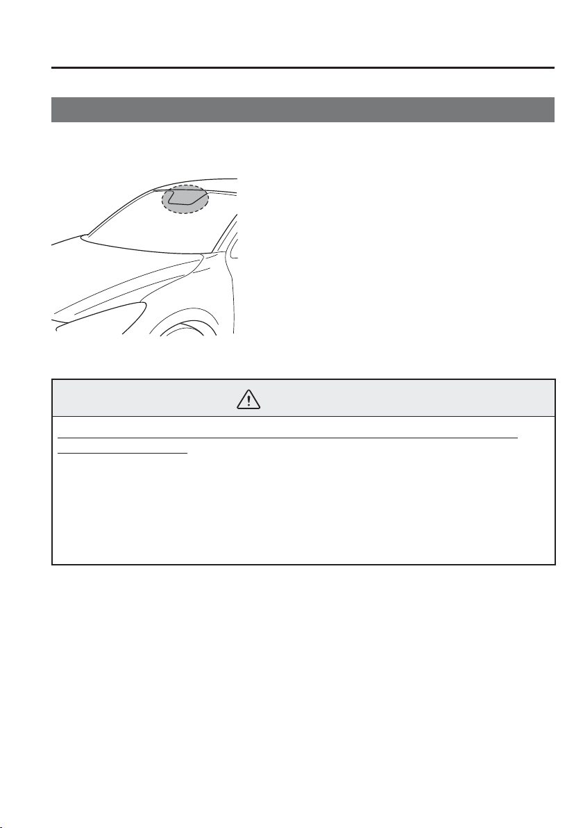
4
–
179
When Driving
i-ACTIVSENSE
*Some models.
Laser Sensor
*
The Smart City Brake Support (SCBS) laser sensor is installed at the top of the windscreen
near the rearview mirror.
Always keep the surface of the windscreen around the laser sensor clean to assure proper
operation of the Smart City Brake Support (SCBS) system.
WARNING
As there is the possibility of eye damage occurring from the laser, always heed the
following precautions:
Never remove the sensor.
A removed sensor will not meet the conditions for a class 1M laser under the IEC
60825-1 speci¿ cation and therefore eye safety cannot be assured.
Do not peer into the sensor using optical instruments with a magni¿ cation function
such as magnifying glasses, and microscopic and objective lenses within a distance
of 100 mm (3.94 in) from the sensor.
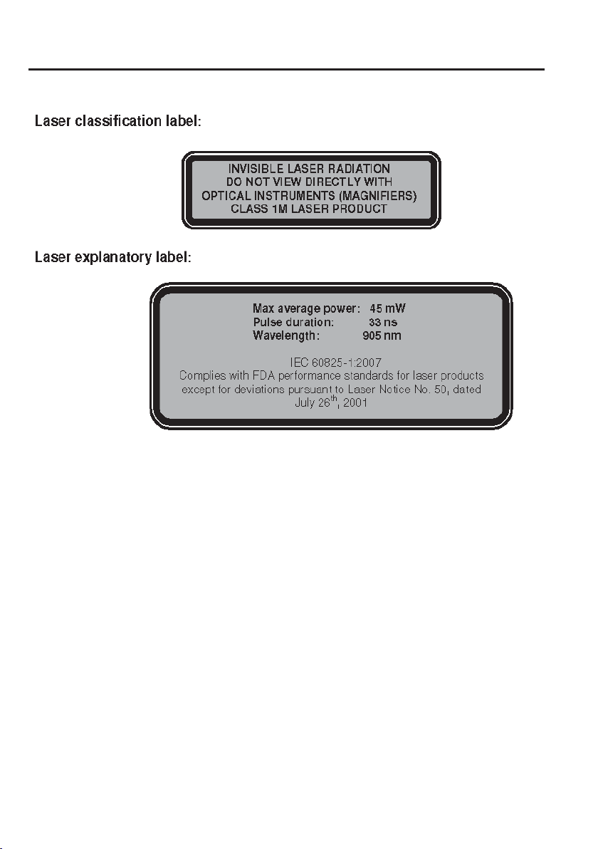
4
–
180
When Driving
i-ACTIVSENSE
Laser sensor radiation data
Maximum average power: 45 mW
Pulse duration: 33 ns
Wavelength: 905 nm
Divergence angle (horizontal×vertical): 28 degrees×12 degrees
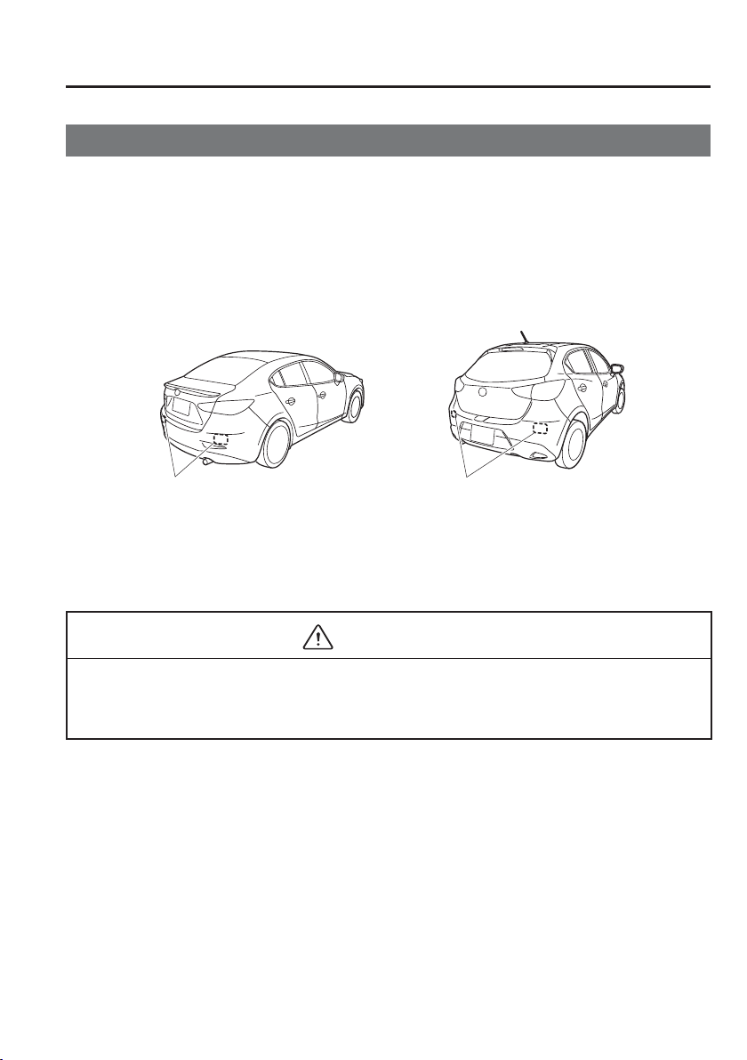
4
–
181
When Driving
i-ACTIVSENSE
*Some models.
Radar Sensors (Rear)
*
Your vehicle is equipped with radar sensors (rear). The following systems also use the radar
sensors (rear).
Blind Spot Monitoring system (BSM)
Rear Cross Traf¿ c Alert (RCTA)
The radar sensors (rear) function by detecting the radio waves reÀ ected off a vehicle
approaching from the rear or an obstruction sent from the radar sensor.
Saloon Hatchback
Radar sensors (rear) Radar sensors (rear)
The radar sensors (rear) are installed inside the rear bumper, one each on the left and right
sides.
Always keep the surface of the rear bumper near the radar sensors (rear) clean so that the
radar sensors (rear) operate normally. Also, do not apply items such as stickers.
Refer to Exterior Care on page 6-66 .
CAUTION
If the rear bumper receives a severe impact, the system may no longer operate normally.
Stop the system immediately and have the vehicle inspected at an Authorised Mazda
Dealer.

4
–
182
When Driving
i-ACTIVSENSE
NOTE
The detection ability of the radar sensors (rear) has limitations. In the following cases,
the detection ability may lower and the system may not operate normally.
The rear bumper near the radar sensors (rear) has become deformed.
Snow, ice or mud adheres to the radar sensors (rear) on the rear bumper.
Under bad weather conditions such as rain, snow and fog.
Under the following conditions, the radar sensors (rear) cannot detect target objects or
it may be dif¿ cult to detect them.
Stationary objects on a road or a road side such as small, two-wheeled vehicles,
bicycles, pedestrians, animals, and shopping carts.
Vehicle shapes which do not reÀ ect radar waves well such as empty trailers with a
low vehicle height and sports cars.
Vehicles are shipped with the direction of the radar sensors (rear) adjusted for each
vehicle to a loaded vehicle condition so that the radar sensors (rear) detect approaching
vehicles correctly. If the direction of the radar sensors (rear) has deviated for some
reason, have the vehicle inspected at an Authorised Mazda Dealer.
For repairs or replacement of the radar sensors (rear), or bumper repairs, paintwork,
and replacement near the radar sensors, consult an Authorised Mazda Dealer.
Turn off the system while pulling a trailer or while an accessory such as a bicycle
carrier is installed to the rear of the vehicle. Otherwise, the radio waves emitted by the
radar will be blocked causing the system to not operate normally.
The radar sensors are regulated by the relevant radio wave laws of the country in
which the vehicle is driven. If the vehicle is driven abroad, authorization from the
country in which the vehicle is driven may be required.
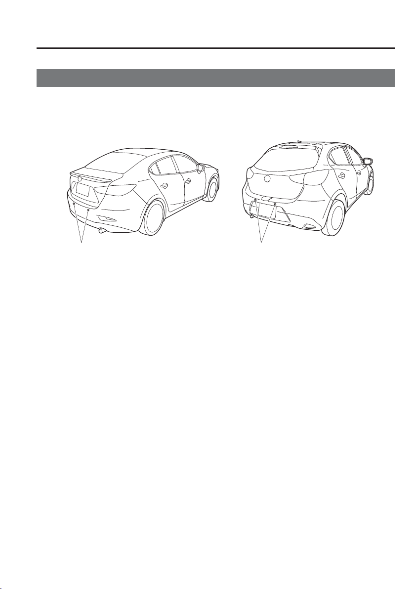
4
–
183
When Driving
i-ACTIVSENSE
*Some models.
Ultrasonic Sensor (Rear)
*
The ultrasonic sensors (rear) function by emitting ultrasonic waves which are reÀ ected off
obstructions at the rear and the returning ultrasonic waves are picked up by the ultrasonic
sensors (rear).
Saloon Hatchback
Ultrasonic sensor (rear)
Ultrasonic sensor (rear)
The ultrasonic sensors (rear) are mounted in the rear bumper.
4
–
184
When Driving
Cruise Control
*Some models.
Cruise Control
*
With cruise control, you can set and automatically maintain any speed of more than about
25 km/h (16 mph).
WARNING
Do not use the cruise control under the following conditions:
Using the cruise control under the following conditions is dangerous and could result
in loss of vehicle control.
Hilly terrain
Steep inclines
Heavy or unsteady traf¿ c
Slippery or winding roads
Similar restrictions that require inconsistent speed
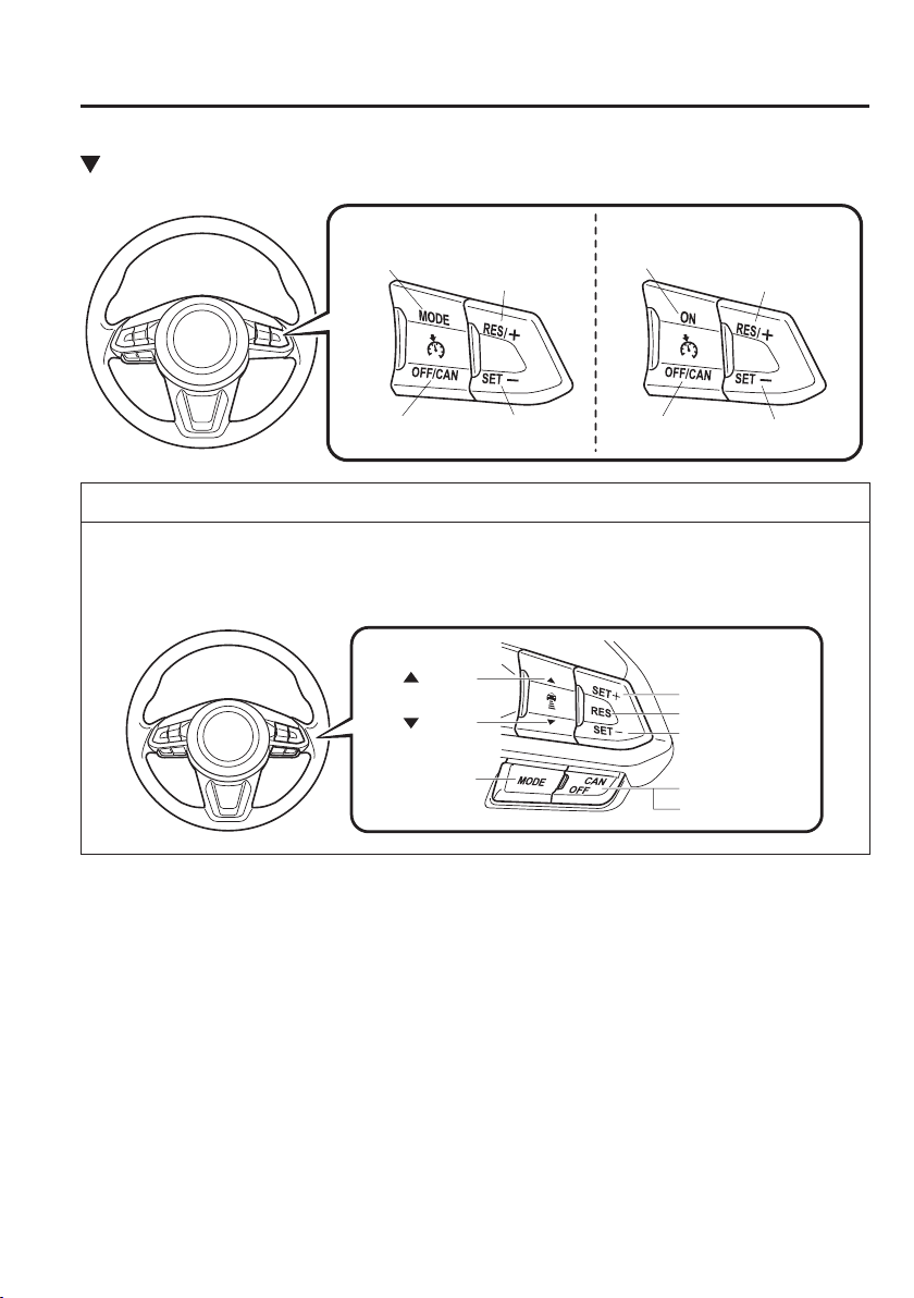
4
–
185
When Driving
Cruise Control
Cruise Control Switch
ON switch
RES/+ switch
Without Adjustable Speed
Limiter
SET- switch
OFF/CAN
switch
MODE switch
RES/+ switch
With Adjustable Speed
Limiter
SET- switch
OFF/CAN
switch
NOTE
If your Mazda has the following steering switch, your Mazda is equipped with the Mazda
Radar Cruise Control (MRCC) system.
Refer to Mazda Radar Cruise Control (MRCC) on page 4-135 .
CANCEL switch
RES switch
OFF switch
switch
switch
MODE switch
SET- switch
SET+ switch
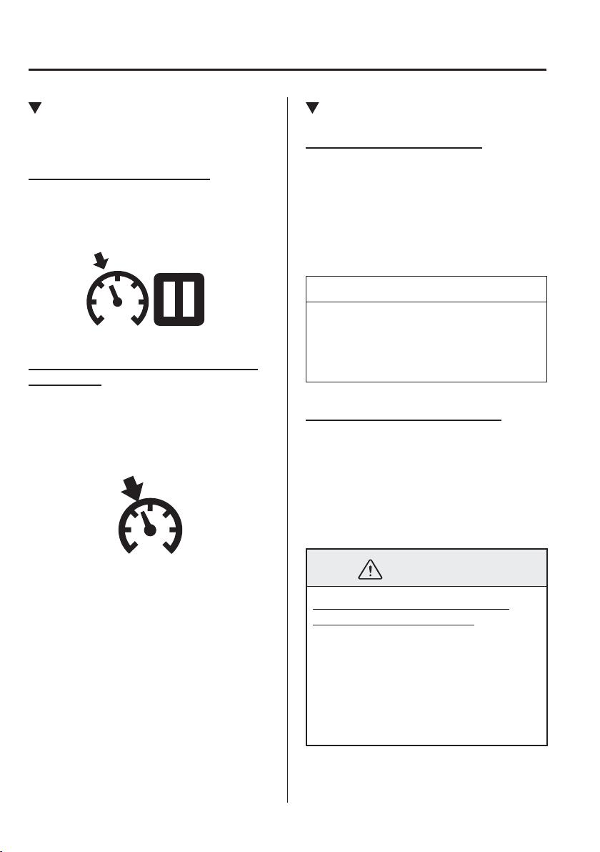
4
–
186
When Driving
Cruise Control
Cruise Main Indication (White),
Cruise Set Indication (White)/
Indicator Light (Green)
Cruise main indication (white)
The cruise main indication (white) is
displayed in the instrument cluster when
the cruise control system is activated.
Cruise set indication (white)/indicator
light (green)
The cruise set indication (white) is
displayed in the instrument cluster and the
cruise set indicator light (green) turns on
when a cruising speed has been set.
Activation/Deactivation
With adjustable speed limiter
To activate the system, press the MODE
switch. The cruise main indication (white)
is displayed.
To deactivate the system, press the OFF/
CAN switch.
The cruise main indication (white) turns
off.
NOTE
When the MODE switch is pressed
while the cruise control system is
operating, the cruise control system
switches to the adjustable speed limiter.
Without adjustable speed limiter
To activate the system, press the ON
switch. The cruise main indication (white)
is displayed.
To deactivate the system, press the OFF/
CAN switch.
The cruise main indication (white) turns
off.
WARNING
Always turn off the cruise control
system when it is not in use:
Leaving the cruise control system in an
activation-ready state while the cruise
control is not in use is dangerous as
the cruise control could unexpectedly
activate if the activation button is
accidentally pressed, and result in loss
of vehicle control and an accident.
4
–
187
When Driving
Cruise Control
NOTE
When the ignition is switched OFF, the
system status before it was turned off is
maintained. For example, if the ignition
is switched OFF with the cruise control
system operable, the system will be
operable when the ignition is switched
ON the next time.
To Set Speed
1 . (With adjustable speed limiter)
Activate the cruise control system by
pressing the MODE switch. The cruise
main indication (white) is displayed.
(Without adjustable speed limiter)
Activate the cruise control system by
pressing the ON switch. The cruise
main indication (white) is displayed.
2. Accelerate to the desired speed, which
must be more than 25 km/h (16 mph).
3. Set the cruise control by pressing the
SET
switch at the desired speed. The
cruise control is set at the moment the
SET
switch is pressed. Release the
accelerator pedal simultaneously. The
cruise set indication (white) is
displayed and the cruise set indicator
light (green) turns on.
NOTE
The cruise control speed setting
cannot be performed under the
following conditions:
(Automatic transaxle)
The selector lever is in the P or N
position.
(Manual transaxle)
The shift lever is in the neutral
position.
The parking brake is applied.
(Vehicles with adjustable speed
limiter)
The MODE switch for the
adjustable speed limiter is pressed.
Release the SET or RES / switch
at the desired speed, otherwise the
speed will continue increasing while
the RES /
switch is pressed and
held, and continue decreasing while
the SET
switch is pressed and held
(except when the accelerator pedal is
depressed).
On a steep grade, the vehicle may
momentarily slow down while
ascending, or speed up while
descending.
The cruise control will cancel if the
vehicle speed decreases below
21 km/h (13 mph) when climbing a
steep grade.
The cruise control may cancel at
about 15 km/h (9 mph) below the
preset speed such as when climbing a
long, steep grade.
4
–
188
When Driving
Cruise Control
To Increase Cruising Speed
Follow either of these procedures.
To increase speed using cruise control
switch
Press the RES /
switch and hold it. Your
vehicle will accelerate. Release the switch
at the desired speed.
Press the RES /
switch and release it
immediately to adjust the preset speed.
Multiple operations will increase the
preset speed according to the number of
times it is operated.
Increasing speed with a single RES /
switch operation
Instrument cluster display for vehicle
speed indicated in km/h: 1 km/h (0.6 mph)
Instrument cluster display for vehicle
speed indicated in mph: 1 mph (1.6 km/h)
To increase speed using accelerator
pedal
Depress the accelerator pedal to accelerate
to the desired speed. Press the SET
switch and release it immediately.
NOTE
Accelerate if you want to speed up
temporarily when the cruise control is
on. Greater speed will not interfere with
or change the set speed. Take your foot
off the accelerator to return to the set
speed.
To Decrease Cruising Speed
Press the SET switch and hold it. The
vehicle will gradually slow.
Release the switch at the desired speed.
Press the SET
switch and release it
immediately to adjust the preset speed.
Multiple operations will decrease the
preset speed according to the number of
times it is operated.
Decreasing speed with a single SET
switch operation
Instrument cluster display for vehicle
speed indicated in km/h: 1 km/h (0.6 mph)
Instrument cluster display for vehicle
speed indicated in mph: 1 mph (1.6 km/h)
To Resume Cruising Speed at
More Than 25 km/h (16 mph)
If some other method besides the OFF/
CAN switch was used to cancel cruising
speed (such as applying the brake pedal)
and the system is still activated, the most
recent set speed will automatically resume
when the RES /
switch is pressed.
If vehicle speed is below 25 km/h
(16 mph), increase the vehicle speed up to
25 km/h (16 mph) or more and press the
RES /
switch.
4
–
189
When Driving
Cruise Control
To Temporarily Cancel
To temporarily cancel the system, use one
of these methods:
Slightly depress the brake pedal.
(Manual transaxle)
Depress the clutch pedal.
Press the OFF/CAN switch.
If the RES / switch is pressed when the
vehicle speed is 25 km/h (16 mph) or
higher, the system reverts to the previously
set speed.
NOTE
If any of the following conditions
occur, the cruise control system is
temporarily cancelled.
The parking brake is applied.
(Vehicles with adjustable speed
limiter)
The MODE switch for the
adjustable speed limiter is pressed.
(Automatic transaxle)
The selector lever is in the P or N
position.
(Manual transaxle)
The shift lever is in the neutral
position.
When the cruise control system is
temporarily cancelled by even one of
the applicable cancel conditions, the
speed cannot be re-set.
(Automatic transaxle)
The cruise control cannot be
cancelled while driving in manual
mode (selector lever shifted from
D to M position). Therefore, engine
braking will not be applied even
if the transaxle is shifted down
to a lower gear. If deceleration is
required, lower the set speed or
depress the brake pedal.
To Deactivate
When a cruising speed has been
set (cruise set indication (white) is
displayed/cruise set indicator light
(green) turns on)
Long-press the OFF/CAN switch or press
the OFF/CAN switch 2 times.
When a cruising speed has not been
set (cruise main indication (white) is
displayed)
Press the OFF/CAN switch.
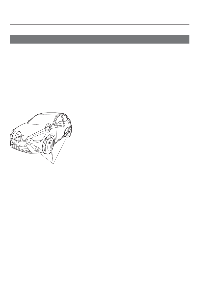
4
–
190
When Driving
Tyre Pressure Monitoring System
*Some models.
Tyre Pressure Monitoring System
*
The Tyre Pressure Monitoring System (TPMS) monitors the air pressure of all four tyres. If
the air pressure of one or more tyres is too low, the system warns the driver by indicating the
tyre pressure monitoring system warning light in the instrument cluster and operating a beep
sound. The system monitors the tyre pressures indirectly using the data sent from the ABS
wheel speed sensors.
To allow the system to operate correctly, the system needs to be initialized with the speci¿ ed
tyre pressure (value on the tyre pressure label). Follow the procedure and perform the
initialization.
Refer to Tyre Pressure Monitoring System Initialization on page 4-192 .
The warning light À ashes when the system has a malfunction.
Refer to Warning Lights on page 4-38 .
ABS wheel speed sensor

4
–
191
When Driving
Tyre Pressure Monitoring System
CAUTION
Each tyre, including the spare (if provided), should be checked monthly when cold
and inÀ ated to the inÀ ation pressure recommended by the vehicle manufacturer on the
vehicle placard or tyre inÀ ation pressure label. (If your vehicle has tyres of a different
size than the size indicated on the vehicle placard or tyre inÀ ation pressure label, you
should determine the proper tyre inÀ ation pressure for those tyres.)
As an added safety feature, your vehicle has been equipped with a tyre pressure
monitoring system (TPMS) that illuminates a low tyre pressure telltale when one or
more of your tyres is signi¿ cantly under-inÀ ated. Accordingly, when the low tyre
pressure telltale illuminates, you should stop and check your tyres as soon as possible,
and inÀ ate them to the proper pressure. Driving on a signi¿ cantly under-inÀ ated tyre
causes the tyre to overheat and can lead to tyre failure. Under-inÀ ation also reduces
fuel ef¿ ciency and tyre tread life, and may affect the vehicle's handling and stopping
ability.
Please note that the TPMS is not a substitute for proper tyre maintenance, and it is the
driver's responsibility to maintain correct tyre pressure, even if under-inÀ ation has not
reached the level to trigger illumination of the TPMS low tyre pressure telltale.
Your vehicle has also been equipped with a TPMS malfunction indicator to indicate
when the system is not operating properly.
The TPMS malfunction indicator is combined with the low tyre pressure telltale.
When the system detects a malfunction, the telltale will À ash for approximately
one minute and then remain continuously illuminated. This sequence will continue
upon subsequent vehicle start-ups as long as the malfunction exists. When the
malfunction indicator is illuminated, the system may not be able to detect or signal
low tyre pressure as intended. TPMS malfunctions may occur for a variety of reasons,
including the installation of replacement or alternate tyres or wheels on the vehicle that
prevent the TPMS from functioning properly. Always check the TPMS malfunction
telltale after replacing one or more tyres or wheels on your vehicle to ensure that the
replacement or alternate tyres and wheels allow the TPMS to continue to function
properly.
To avoid false readings, the system samples for a little while before indicating a
problem. As a result it will not instantaneously register a rapid tyre deÀ ation or blow
out.

4
–
192
When Driving
Tyre Pressure Monitoring System
NOTE
Because this system detects slight changes in tyre conditions, the timing of the warning
may be faster or slower in the following cases:
The size, manufacturer, or the type of tyres is different from the speci¿ cation.
The size, manufacturer, or the type of a tyre is different from the others, or the level of
tyre wear is excessively different between them.
A run-À at tyre, studless tyre, snow tyre, or tyre chains are used.
An emergency tyre is used (The tyre pressure monitoring system warning light may
À ash and then continue illuminating).
A tyre is repaired using the emergency À at tyre repair kit.
The tyre pressure is excessively higher than the speci¿ ed pressure, or the tyre pressure
is suddenly lowered for some reason such as a tyre burst during driving.
The vehicle speed is lower than about 15 km/h (9.3 mph) (including when the vehicle
is stopped), or the drive period is shorter than 5 minutes.
The vehicle is driven on an extremely rough road or a slippery, icy road.
Hard steering and rapid acceleration/deceleration are repeated such as during
aggressive driving on a winding road.
Load on the vehicle is applied to a tyre such as by loading heavy luggage to one side of
the vehicle.
System initialization has not been implemented with the speci¿ ed tyre pressure.
Tyre Pressure Monitoring System
Initialization
In the following cases, system
initialization must be performed so that the
system operates normally.
A tyre pressure is adjusted.
Tyre rotation is performed.
A tyre or wheel is replaced.
The battery is replaced or completely
drained.
The tyre pressure monitoring system
warning light is illuminated.
Initialization method
1. Park the car in a safe place and ¿ rmly
apply the parking brake.
2. Let the tyres cool, then adjust the tyre
pressure of all four (4) tyres to the
speci¿ ed pressure indicated on the tyre
pressure label located on the driver's
door frame (door open).
Refer to Tyres on page 9-10 .
3. Switch the ignition ON.
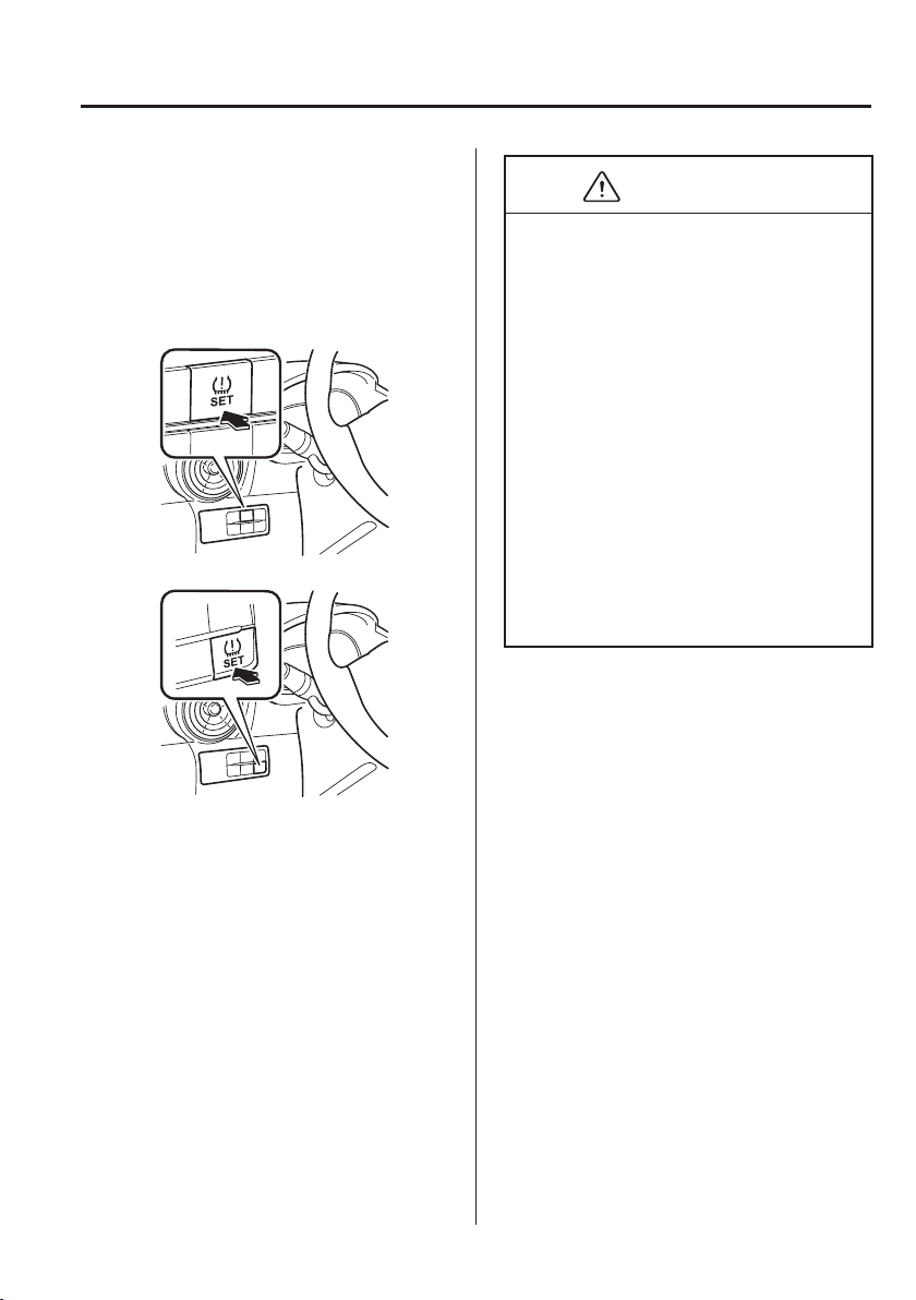
4
–
193
When Driving
Tyre Pressure Monitoring System
4. Press and hold the tyre pressure
monitoring system set switch and
verify that the tyre pressure monitoring
system warning light in the instrument
cluster À ashes twice and a beep sound
is heard once.
Type A
Type B
CAUTION
If the system initialization is performed
without adjusting the tyre pressure, the
system cannot detect the normal tyre
pressure and it may not illuminate the
tyre pressure monitoring system warning
light even if a tyre pressure is low, or
it may illuminate the light even if the
pressures are normal.
Adjust the tyre pressure on all four
tyres and initialize the system when
the warning light is turned on. If the
warning light turns on for a reason other
than a À at tyre, the tyre pressure of all
four tyres may have decreased naturally.
The system initialization will not be
performed if the switch is pressed while
the vehicle is being driven.
4
–
194
When Driving
Diesel Particulate Filter (SKYACTIV-D 1.5)
Diesel Particulate Filter
(SKYACTIV-D 1.5)
The diesel particulate ¿ lter collects and
removes most of the particulate matter
(PM) in the exhaust gas of a diesel engine.
PM collected by the diesel particulate
¿ lter is cleared during normal driving,
however, PM may not be removed and the
diesel particulate ¿ lter indicator light may
illuminate under the following conditions:
If the vehicle is driven at 15 km/h (9
mph) or less continuously.
If the vehicle is repeatedly driven for a
short period of time (10 minute or less)
or driven while the engine is cold.
If the vehicle is idled for a long time.
NOTE
The engine sound and exhaust gas smell
may change when PM is being removed
while driving.
Diesel Particulate Filter Indicator Light
When illuminated
The particulate matter (PM) cannot be
removed automatically and the amount of
collected PM reaches a speci¿ ed amount.
After the engine has suf¿ ciently warmed
up (engine coolant temperature of 80 °C
or more), depress the accelerator pedal and
drive the vehicle at a speed of 20 km/h
or more for about 15 to 20 minutes to
eliminate the PM.
When À ashing
Contact an expert repairer, we recommend
an Authorised Mazda Repairer.
CAUTION
If the vehicle is continually driven as
usual with the diesel particulate ¿ lter
indicator light illuminated, PM increases
and the indicator light may start À ashing.
If the diesel particulate ¿ lter indicator
light starts À ashing, have the vehicle
inspected immediately at an expert
repairer, we recommend an Authorised
Mazda Repairer. If the vehicle is not
inspected and continues to be driven, the
engine may malfunction.
NOTE
When the diesel particulate ¿ lter
indicator light À ashes, the engine
output is restricted to protect the diesel
particulate ¿ lter.
4
–
195
When Driving
Rear View Monitor
*Some models.
Rear View Monitor
*
The rear view monitor provides visual images of the rear of the vehicle when reversing.
WARNING
Always drive carefully con¿ rming the safety of the rear and the surrounding conditions
by looking directly with your eyes:
Reversing the vehicle by only looking at the screen is dangerous as it may cause an
accident or a collision with an object. The rear view monitor is only a visual assist
device when reversing the vehicle. The images on the screen may be different from the
actual conditions.
CAUTION
Do not use the rear view monitor under the following conditions: Using the rear view
monitor under the following conditions is dangerous and could result in injury or
vehicle damage or both.
Icy or snow-covered roads.
Tyre chains or a temporary spare tyre is installed.
The liftgate/boot lid is not fully closed.
The vehicle is on a road incline.
When the display is cold, images may course across the monitor or the screen and
may be dimmer than usual, which could cause dif¿ culty in con¿ rming the surrounding
conditions of the vehicle. Always drive carefully con¿ rming the safety of the rear and
the surrounding conditions by looking directly with your eyes.
Do not apply excessive force to the camera. The camera position and angle may
deviate.
Do not disassemble, modify, or remove it as it may no longer be waterproof.
The camera cover is made of plastic. Do not apply degreasing agents, organic solvents,
wax, or glass coating agents to the camera cover. If any are spilled on the cover, wipe
off with a soft cloth immediately.
Do not rub the camera cover forcefully with an abrasive or hard brush. The camera
cover or lens may be scratched which might affect the images.
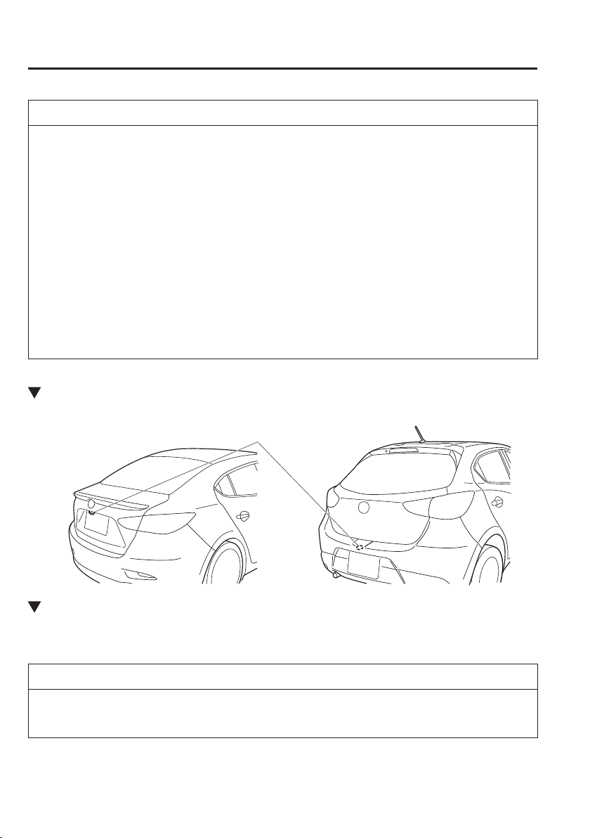
4
–
196
When Driving
Rear View Monitor
NOTE
If water, snow, or mud is stuck on the camera lens, wipe it off using a soft cloth. If it
cannot be wiped off, use a mild detergent.
If the camera temperature changes rapidly (Hot to cold, cold to hot), the rear view
monitor may not operate correctly.
When replacing the tyres, consult an expert repairer, we recommend an Authorised
Mazda Repairer. Replacing the tyres could result in deviation of the guide lines which
appear on the display.
If the vehicle's front, side, or rear has been involved in a collision, the alignment of
the rear view parking camera (location, installation angle) may have deviated. Always
consult an expert repairer, we recommend an Authorised Mazda Repairer to have the
vehicle inspected.
If “No Video Signal Available” is indicated in the display, there could be a problem
with the camera. Have your vehicle inspected at an expert repairer, we recommend an
Authorised Mazda Repairer.
Rear View Parking Camera Location
Rear View Parking Camera
Saloon Hatchback
Switching to the Rear View Monitor Display
Shift the shift lever to R with the ignition switched ON to switch the display to the rear view
monitor display.
NOTE
When the shift lever is shifted from R to another shift lever position, the screen returns to
the previous display.
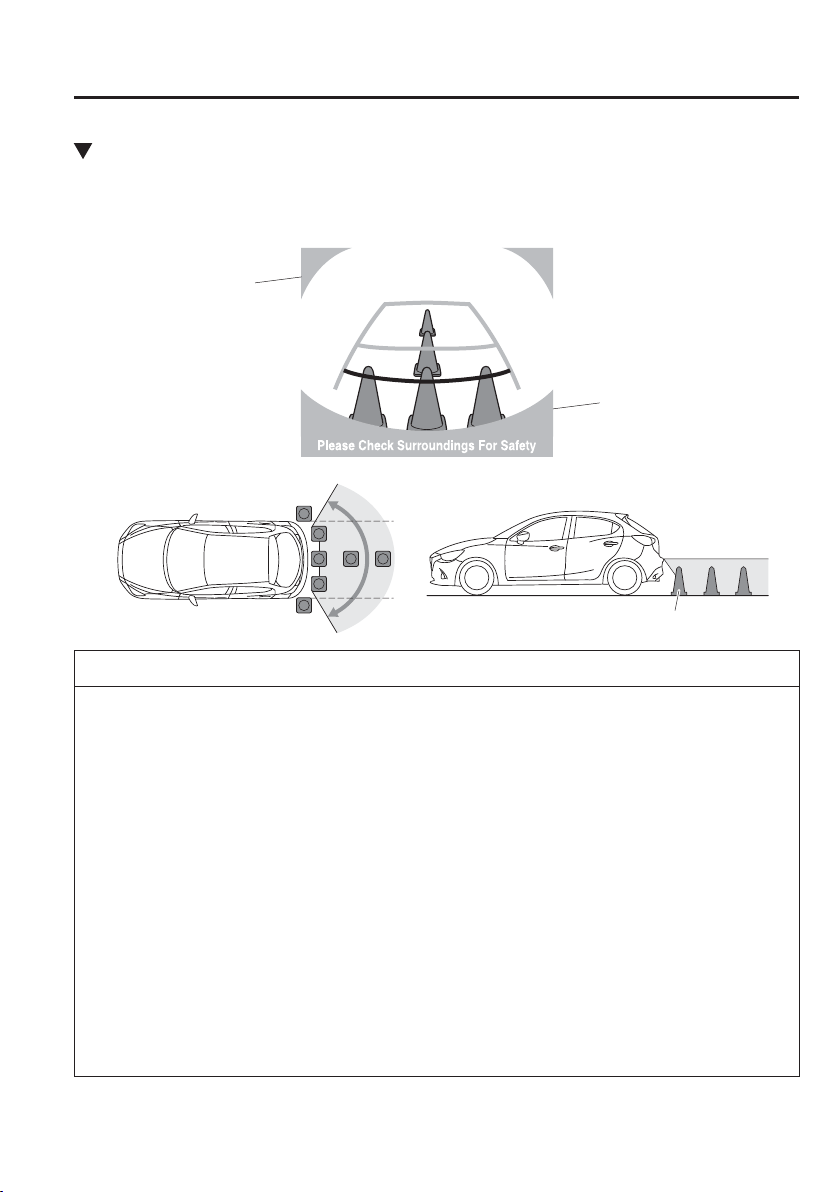
4
–
197
When Driving
Rear View Monitor
Displayable Range on the Screen
The images on the screen may be different from the actual conditions.
(Screen display)
Bumper
Object
(Actual view)
Boot lid (saloon)/
Bumper (hatchback)
NOTE
The displayable range varies depending on the vehicle and road conditions.
The displayable range is limited. Objects under the bumper or around the bumper ends
cannot be displayed.
The distance appearing in the displayed image is different from the actual distance
because the rear view parking camera is equipped with a speci¿ c lens.
Some optionally installed vehicle accessories may be picked up by the camera. Do not
install any optional parts that can interfere with the camera view, such as illuminating
parts or parts made of reÀ ective material.
It may be dif¿ cult to see the display under the following conditions, however, it does
not indicate a malfunction.
In darkened areas.
When the temperature around the lens is high/low.
When the camera is wet such as on a rainy day or during periods of high humidity.
When foreign material such as mud is stuck around the camera.
When the camera lens reÀ ects sunlight or headlight beams.
Image display may be delayed if the temperature around the camera is low.
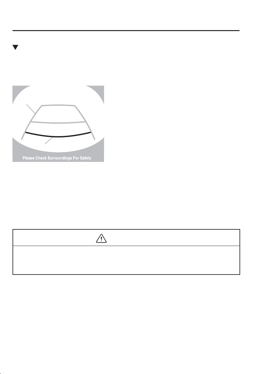
4
–
198
When Driving
Rear View Monitor
Viewing the Display
Guide lines which indicate the width of the vehicle (yellow) are displayed on the screen as a
reference to the approximate width of the vehicle in comparison to the width of the parking
space you are about to back into.
Use this display view for parking your vehicle in a parking space or garage.
b
a
a) Vehicle width guide lines (yellow)
These guide lines serve as a reference to the approximate width of the vehicle.
b) Distance guide lines.
These guide lines indicate the approximate distance to a point measured from the
vehicle's rear (from the end of the bumper).
The red and yellow lines indicate the points about 50 cm (19 in) for the red line and
100 cm (39.3 in) for the yellow lines from the rear bumper (at the centre point of each
of the lines).
CAUTION
The guide lines on the screen are ¿ xed lines. They are not synced to the driver's turning
of the steering wheel. Always be careful and check the area to the vehicle's rear and the
surrounding area directly with your eyes while backing up.
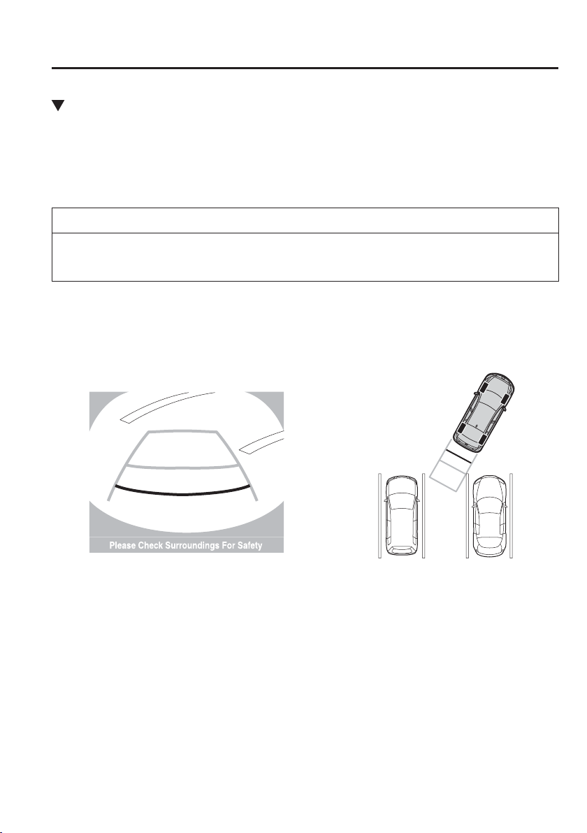
4
–
199
When Driving
Rear View Monitor
Rear View Monitor Operation
The operation of the rear view monitor when reversing the vehicle varies depending on
the traf¿ c, road, and vehicle conditions. The amount of steering and the timing also varies
depending on conditions, so con¿ rm the surrounding conditions directly with your eyes and
steer the vehicle in accordance with the conditions.
Be well aware of the above cautions prior to using the rear view monitor.
NOTE
Images displayed on the monitor from the rear view parking camera are reversed images
(mirror images).
1. Shift the shift lever to R to switch the display to the rear view monitor display.
2. Con¿ rming the surrounding conditions, reverse the vehicle.
(Display condition) (Vehicle condition)
3. After your vehicle begins entering the parking space, continue backing up slowly so that
the distance between the vehicle width lines and the sides of the parking space on the left
and right are roughly equal.
4. Continue to adjust the steering wheel until the vehicle width guide lines are parallel to
the left and right sides of the parking space.
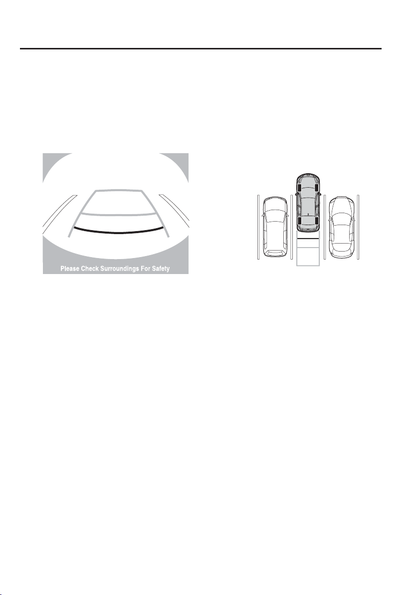
4
–
200
When Driving
Rear View Monitor
5. Once they are parallel, straighten the wheels and back your vehicle slowly into the
parking space. Continue checking the vehicle's surroundings and then stop the vehicle
in the best possible position. (If the parking space has division lines, check whether the
vehicle width guide lines are parallel to them.)
(Display condition) (Vehicle condition)
6. When the shift lever is shifted from R to another shift lever position, the screen returns to
the previous display.
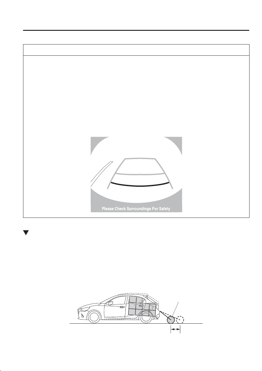
4
–
201
When Driving
Rear View Monitor
NOTE
Because there may be a difference between the displayed image, such as indicated below,
and the actual conditions when parking, always verify the safety at the rear of the vehicle
and the surrounding area directly with your eyes.
In the image of the parking space (or garage) displayed on the screen, the back end and
distance guide lines may appear aligned in the monitor, but they may not actually be
aligned on the ground.
When parking in a space with a division line on only one side of the parking space, the
division line and the vehicle width guide line appear aligned in the monitor, but they
may not actually be aligned on the ground.
Variance Between Actual Road Conditions and Displayed Image
Some variance occurs between the actual road and the displayed road. Such variance in
distance perspective could lead to an accident. Note the following conditions that may cause
a variance in distance perspective.
When the vehicle is tilted due to the weight of passengers and load
When the vehicle rear is lowered, the object displayed on the screen appears farther than the
actual distance.
Variance
Object
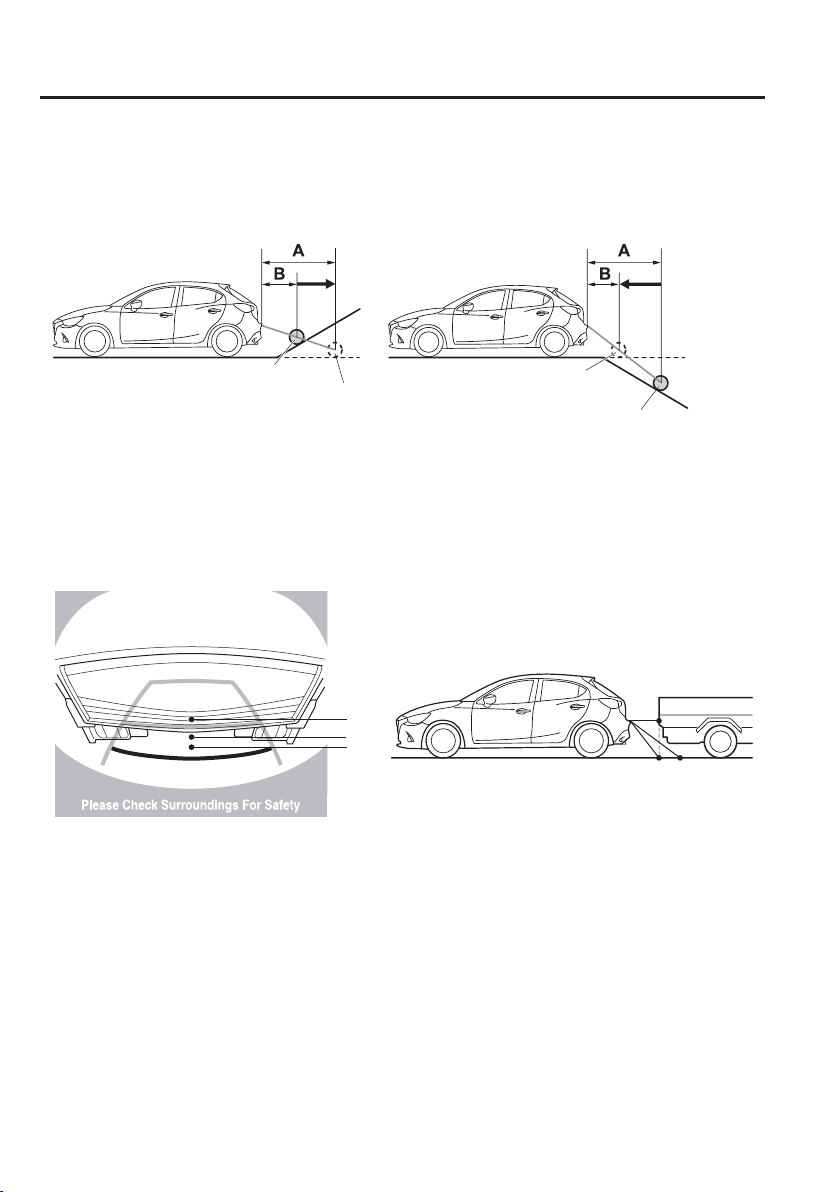
4
–
202
When Driving
Rear View Monitor
When there is a steep grade behind the vehicle
When there is a steep upgrade (downgrade) behind the vehicle, the object displayed on the
screen appears farther (downgrade: closer) than the actual distance.
Appears
farther than
actual
distance
Appears
closer than
actual
distance
Object at actual
position
Object at actual position
Object on screen
A: Distance between the vehicle and object displayed on the screen.
B: Actual distance between the vehicle and object.
Object on screen
Three-dimensional object on vehicle rear
Because the distance guide lines are displayed based on a À at surface, the distance to the
three-dimensional object displayed on the screen is different from the actual distance.
A
A
C
B
CB
(Actual distance) B>C=A
Sensed distance on screen A>B>C
(Screen display)
(Actual condition)
4
–
203
When Driving
Rear View Monitor
Picture Quality Adjustment
WARNING
Always adjust the picture quality of the rear view monitor while the vehicle is stopped:
Do not adjust the picture quality of the rear view monitor while driving the vehicle.
Adjusting the picture quality of the rear view monitor such as brightness, contrast,
colour, and tint while driving the vehicle is dangerous as it could distract your attention
from the vehicle operation which could lead to an accident.
Picture quality adjustment can be done while the shift lever is in reverse (R).
There are four settings which can be adjusted including, brightness, contrast, tint, and
colour. When adjusting, pay suf¿ cient attention to the vehicle surroundings.
1. Select the icon on the screen to display the tabs.
2. Select the desired tab item.
3. Adjust the brightness, contrast, tint, and colour using the slider.
If you need to reset, press the reset button.
4. Select the
icon on the screen to close the tab.
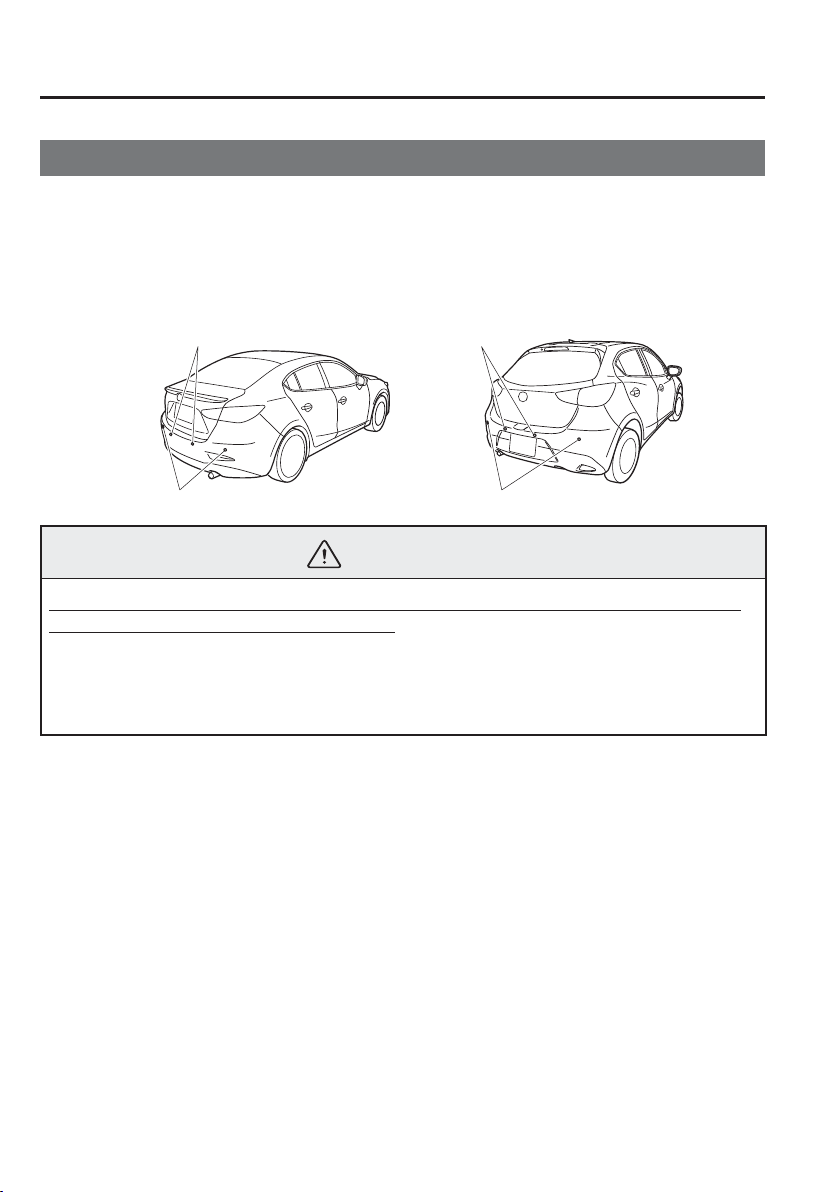
4
–
204
When Driving
Parking Sensor System
*Some models.
Parking Sensor System
*
The parking sensors use ultrasonic sensors which detect obstructions around the vehicle
when the vehicle is driven at low speeds, such as during garage or parallel parking, and a
buzzer sound and detection indicator notify the driver of the approximate distance from the
vehicle to the surrounding obstruction.
Rear sensor Rear sensor
Saloon Hatchback
Rear corner sensor
Rear corner sensor
WARNING
Do not rely completely on the parking sensor system and be sure to con¿ rm the safety
around your vehicle visually when driving:
This system can assist the driver in operating the vehicle in the backward directions
while parking. The detection ranges of the sensors are limited, therefore, driving the
vehicle while relying only on the system may cause an accident. Always con¿ rm the
safety around your vehicle visually when driving.

4
–
205
When Driving
Parking Sensor System
NOTE
Do not install any accessories within the detection ranges of the sensors. It may affect
the system operation.
Depending on the type of obstruction and the surrounding conditions, the detection
range of a sensor may narrow, or the sensors may not be able to detect obstructions.
The system may not operate normally under the following conditions:
Mud, ice, or snow is adhering to the sensor area (Returns to normal operation when
removed).
The sensor area is frozen (Returns to normal operation when the ice is thawed).
The sensor is covered by a hand.
The sensor is excessively shocked.
The vehicle is excessively tilted.
Under extremely hot or cold weather conditions.
The vehicle is driven on bumps, inclines, gravel, or grass covered roads.
Anything which generates ultrasound is near the vehicle, such as another vehicle's
horn, the engine sound of a motorcycle, the air brake sound of a large-sized vehicle,
or another vehicle's sensors.
The vehicle is driven in heavy rain or in road conditions causing water-splash.
A commercially-available wing pole or an aerial for a radio transmitter is installed to
the vehicle.
The vehicle is moving towards a tall or square curbstone.
An obstruction is too close to the sensor.
Obstructions under the bumper may not be detected. Obstructions that are lower than
the bumper or thin which may have been initially detected but are no longer detected
as the vehicle approaches more closely.
The following types of obstructions may not be detected:
Thin objects such as wire or rope
Things which absorb sonic waves easily such as cotton or snow
Angular shaped objects
Very tall objects, and those which are wide at the top
Small, short objects
Always have the system inspected at an expert repairer, we recommend an Authorised
Mazda Repairer if any shock is applied to the bumpers, even in a minor accident. If the
sensors are deviated, they cannot detect obstructions.
The beeper which indicates a system malfunction may not be heard if the ambient
temperature is extremely cold, or mud, ice, or snow adheres to the sensor area.
Remove any foreign material from the sensor area.
When installing a trailer hitch, consult an expert repairer, we recommend an
Authorised Mazda Repairer.
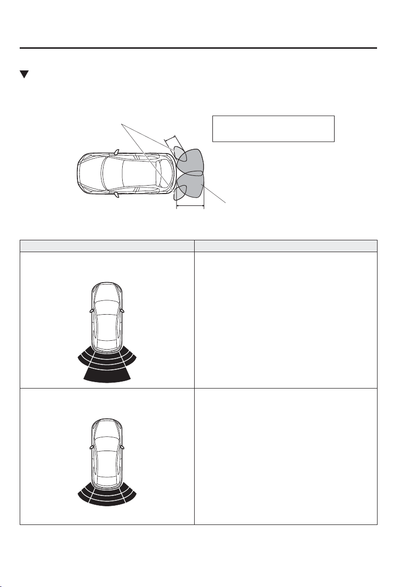
4
–
206
When Driving
Parking Sensor System
Sensor Detection Range
The sensors detect obstructions within the following range.
Rear sensor detection range
Rear corner sensor detection range
B
A
A: About 50 cm (About 19 in)
B: About 150 cm (About 59.0 in)
Viewing distance display
Display Distance between vehicle and obstruction
Rear sensor:
Approx. 150—60 cm (59.0—23.6 in)
Rear sensor:
Approx. 60—45 cm (23.6—17.7 in)
Rear corner sensor:
Approx. 50—37 cm (19.6—14.6 in)
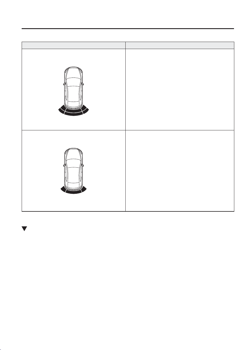
4
–
207
When Driving
Parking Sensor System
Display Distance between vehicle and obstruction
Rear sensor:
Approx. 45—35 cm (17.7—13.7 in)
Rear corner sensor:
Approx. 37—25 cm (14.6—9.8 in)
Rear sensor:
Within approx. 35 cm (13.7 in)
Rear corner sensor:
Within approx. 25 cm (9.8 in)
Park Assist Sensor System Operation
When the ignition is switched ON and the shift lever (manual transaxle)/selector lever
(automatic transaxle) is shifted to the reverse (R), the beep sound activates and the system is
enabled for use.
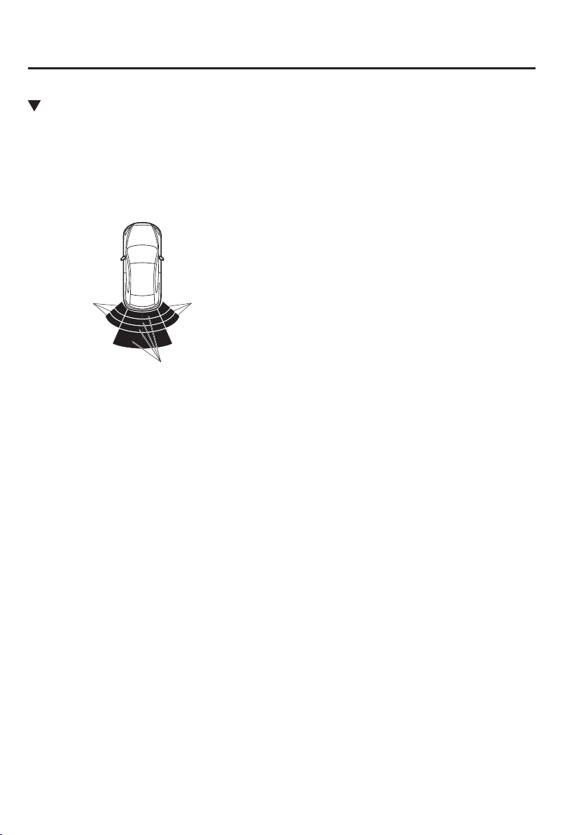
4
–
208
When Driving
Parking Sensor System
Obstruction Detection Indication
The position of a sensor which has detected an obstruction is indicated. The gauge
illuminates in different areas depending on the distance to an obstruction detected by the
sensor.
As the vehicle approaches closer to an obstruction, the zone in the gauge closer to the
vehicle illuminates.
Right corner
sensor gauge
Left corner
sensor gauge
Rear sensor gauge
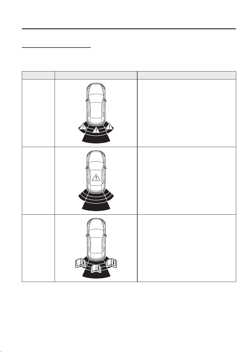
4
–
209
When Driving
Parking Sensor System
System problem noti¿ cation
If any of the problems indicated in the table occurs, the driver is noti¿ ed of the problem
depending on the type of system as shown.
Disconnection Solution
Disconnection
The system may have a malfunction. Have
the vehicle inspected at an expert repairer, we
recommend an Authorised Mazda Repairer as soon
as possible.
System
malfunction
The system may have a malfunction. Have
the vehicle inspected at an expert repairer, we
recommend an Authorised Mazda Repairer as soon
as possible.
Frost/soiling
Foreign matter may be on the sensor area
corresponding to the obstruction detection
indication shown. If the system does not recover,
have the vehicle inspected at an expert repairer, we
recommend an Authorised Mazda Repairer.
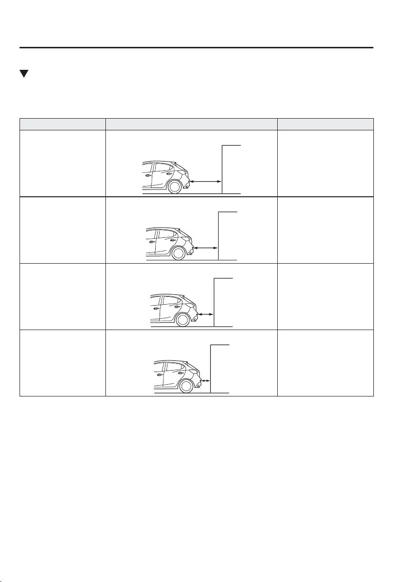
4
–
210
When Driving
Parking Sensor System
Parking Sensor Warning Beep
The beeper sounds as follows while the system is operating.
Rear Sensor
Distance detection area Distance between vehicle and obstruction Beeper sound
*1
Farthest distance
Approx. 150—60 cm (59.0—23.6 in)
Slow intermittent sound
Far distance
Approx. 60—45 cm (23.6—17.7 in)
Medium intermittent sound
Middle distance
Approx. 45—35 cm (17.7—13.7 in)
Fast intermittent sound
Close distance
Within approx. 35 cm (13.7 in)
Continuous sound
*1 The rate at which the intermittent sound beeps increases as the vehicle approaches the obstruction.
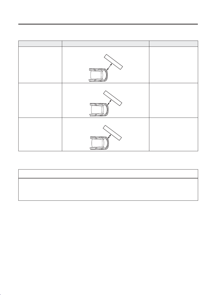
4
–
211
When Driving
Parking Sensor System
Rear Corner Sensor
Distance detection area Distance between vehicle and obstruction Beeper sound
*1
Far distance
Approx. 50—37 cm (19.0—15.0 in)
Medium intermittent sound
Middle distance
Approx. 37—25 cm (14.0—9.8 in)
Fast intermittent sound
Close distance
Within approx. 25 cm (9.8 in)
Continuous sound
*1 The rate at which the intermittent sound beeps increases as the vehicle approaches the obstruction.
NOTE
If an obstruction is detected in a zone for 6 seconds or more, the beep sound is stopped
(except for the close-distance zone). If the same obstruction is detected in another zone,
the corresponding beep sound is heard.
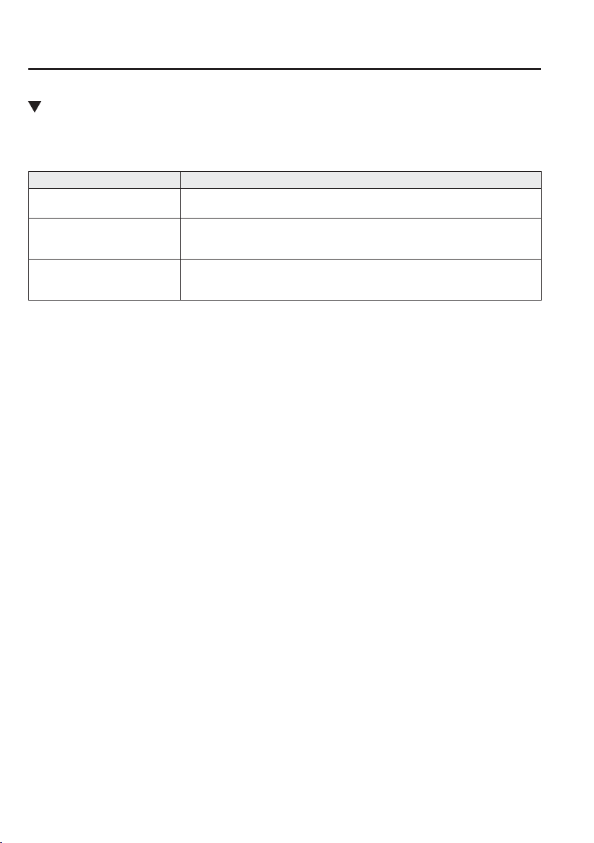
4
–
212
When Driving
Parking Sensor System
When Warning Beep is Activated
The system noti¿ es the driver of an abnormality by activating the beep sound and the
indicator light.
Indicator/Beep How to check
The beep sound is not heard.
The system may have a malfunction. Have the vehicle inspected at an expert
repairer, we recommend an Authorised Mazda Repairer as soon as possible.
The intermittent sound of the
buzzer is heard ¿ ve times.
Remove any foreign material from the sensor area. If the system does not
recover, have the vehicle inspected at an expert repairer, we recommend an
Authorised Mazda Repairer.
A certain obstruction detection
indicator is continuously
displayed.
Refer to Obstruction Detection Indication on page 4-208 .

5
–
1
*Some models.
5
–
1
5
Interior Features
Use of various features for ride comfort, including air-conditioning and
audio system.
Air-Conditioning System .................... 5-4
Operating Tips ................................ 5-4
Vent Operation ............................... 5-5
Manual Type .................................. 5-7
Fully Automatic Type ................... 5-14
Before Using the Audio System ........ 5-18
Audio Control Switch
*
................. 5-18
AUX/USB mode .......................... 5-20
Aerial ............................................ 5-23
Audio Set
[Type A (non-touchscreen)] .............. 5-26
Power/Volume/Sound Controls .... 5-26
Clock ............................................ 5-28
Operating the Radio ..................... 5-30
Operating the Compact Disc (CD)
Player
*
.......................................... 5-34
How to use AUX mode ................ 5-37
How to use USB mode ................. 5-38
How to use iPod mode ................. 5-42
Error Indications .......................... 5-45
Bluetooth
®
*
................................... 5-46
Bluetooth
®
Preparation
*
............... 5-49
Available Language
*
.................... 5-60
Security Setting
*
........................... 5-61
Bluetooth
®
Audio
*
........................ 5-62
Bluetooth
®
Hands-Free
*
............... 5-65
Voice Recognition
*
....................... 5-72
Voice Recognition Learning Function
(Speaker Enrolment)
*
................... 5-73
Troubleshooting
*
.......................... 5-76
Audio Set [Type B (touchscreen)] .... 5-80
Basic Operation Method .............. 5-80
Home screen ................................. 5-85
Volume/Display/Sound
Controls ........................................ 5-86
Operating the Radio ..................... 5-88
Operating the Digital Audio
Broadcasting (DAB) Radio
*
......... 5-91
Operating the Compact Disc
(CD) Player .................................. 5-94
Operating the Digital Versatile Disc
(DVD) Player
*
.............................. 5-97
How to use AUX mode .............. 5-100
How to use USB mode ............... 5-101
Bluetooth
®
.................................. 5-107
Bluetooth
®
Preparation ............... 5-111
Available Language
*
.................. 5-113
Bluetooth
®
Audio ....................... 5-114
How to Use Aha
™
....................... 5-118
How to Use Stitcher
™
Radio ...... 5-122
Bluetooth
®
Hands-Free .............. 5-124
Voice Recognition ...................... 5-134
Settings ....................................... 5-137
Applications ............................... 5-139
Troubleshooting ......................... 5-140
Appendix .......................................... 5-144
Things You Need to Know ......... 5-144

5
–
2
Interior Equipment ......................... 5-156
Sunvisors .................................... 5-156
Interior Lights ............................ 5-156
Accessory Sockets ..................... 5-159
Cup Holder ................................. 5-160
Bottle Holder .............................. 5-160
Storage Compartments ............... 5-161

MEMO
5
–
3
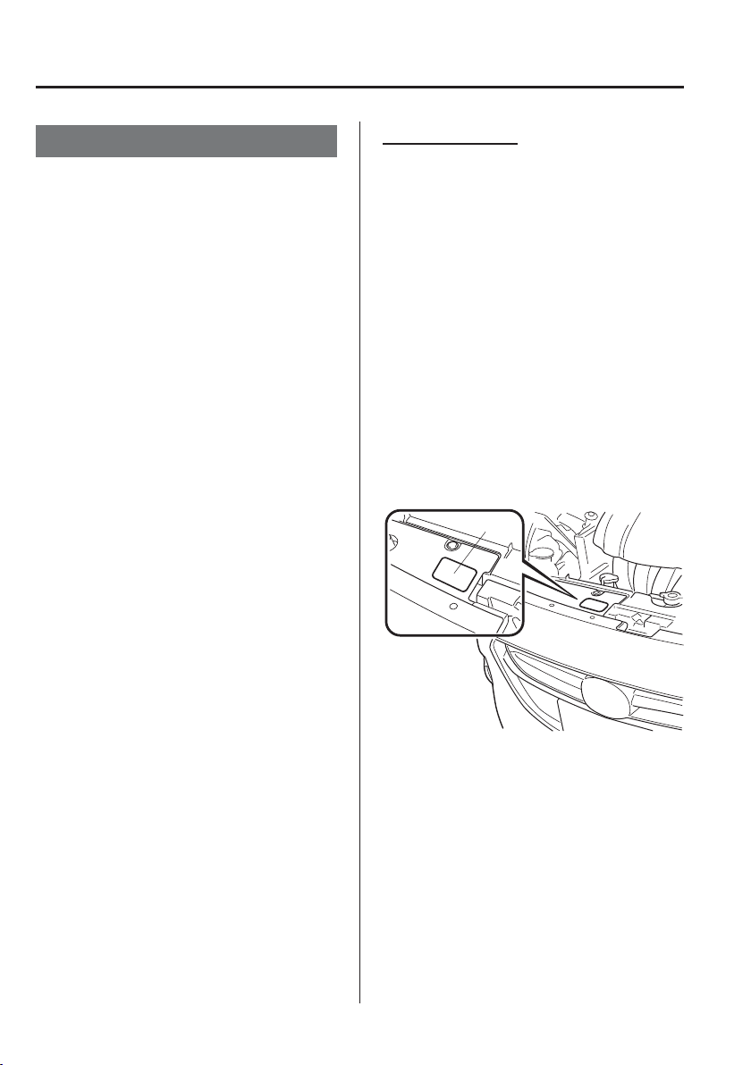
5
–
4
Interior Features
Air-Conditioning System
O p e r a t i n g T i p s
Operate the air-conditioning system with
the engine running.
To prevent the battery from being
discharged, do not leave the fan control
dial on for a long period of time with the
ignition switched ON when the engine is
not running.
(With i-stop)
The airÀ ow amount may decrease
slightly while the i-stop function is
operating.
Clear all obstructions such as leaves,
snow and ice from the bonnet and the
air inlet in the cowl grille to improve the
system ef¿ ciency.
Use the air-conditioning system to defog
the windows and dehumidify the air.
The recirculate mode should be used
when driving through tunnels or while in
a traf¿ c jam, or when you would like to
shut off outside air for quick cooling of
the interior.
Use the outside air position for
ventilation or windscreen defrosting.
If the vehicle has been parked in direct
sunlight during hot weather, open the
windows to let warm air escape, then
run the air-conditioning system.
(With A/C switch)
Run the air conditioner about 10 minutes
at least once a month to keep internal
parts lubricated.
Have the air conditioner checked before
the weather gets hot. Lack of refrigerant
may make the air conditioner less
ef¿ cient.
The refrigerant speci¿ cations are
indicated on a label attached to the
inside of the engine compartment. Check
the label before re¿ lling the refrigerant.
If the wrong type of refrigerant is used,
it could result in a serious malfunction
of the air conditioner.
For details, consult an expert repairer,
we recommend an Authorised Mazda
Repairer.
Label
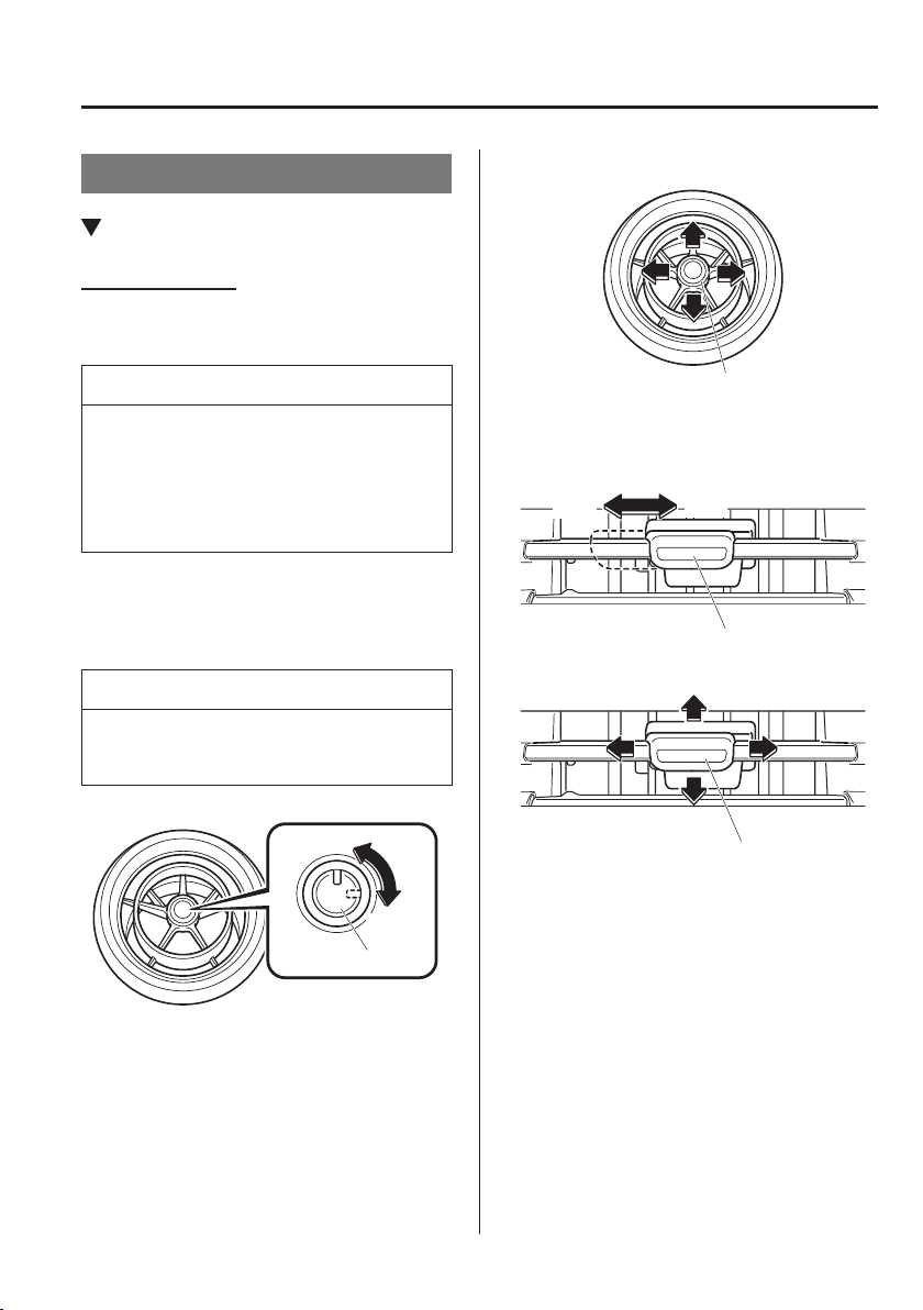
5
–
5
Interior Features
Air-Conditioning System
Vent Operation
Adjusting the Vents
Directing airÀ ow
To adjust the direction of airÀ ow, move the
adjustment knob.
NOTE
When using the air conditioner under
humid ambient temperature conditions,
the system may blow fog from the vents.
This is not a sign of trouble but a result
of humid air being suddenly cooled.
Centre vents (driver) and Side vents
Air vent open/close
NOTE
The air vents can be fully opened and
closed by operating the knob.
Open
Close
Knob
AirÀ ow direction adjustment
Knob
Centre vents (front passenger)
Air vent open/close
OpenClose
Knob
AirÀ ow direction adjustment
Knob
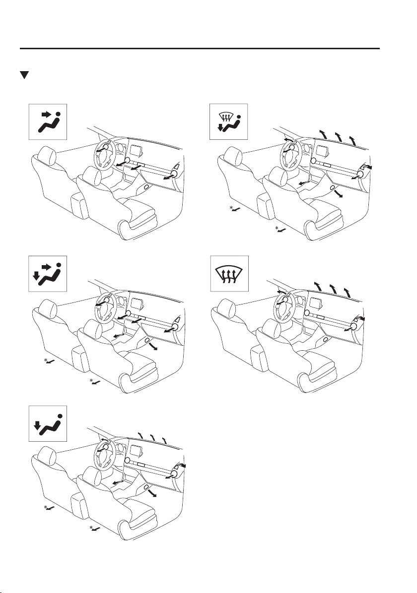
5
–
6
Interior Features
Air-Conditioning System
Selecting the AirÀ ow Mode
Instrument panel Vents
Instrument panel and Floor Vents
Floor Vents
Defroster and Floor Vents
Defroster Vents
* With rear vents
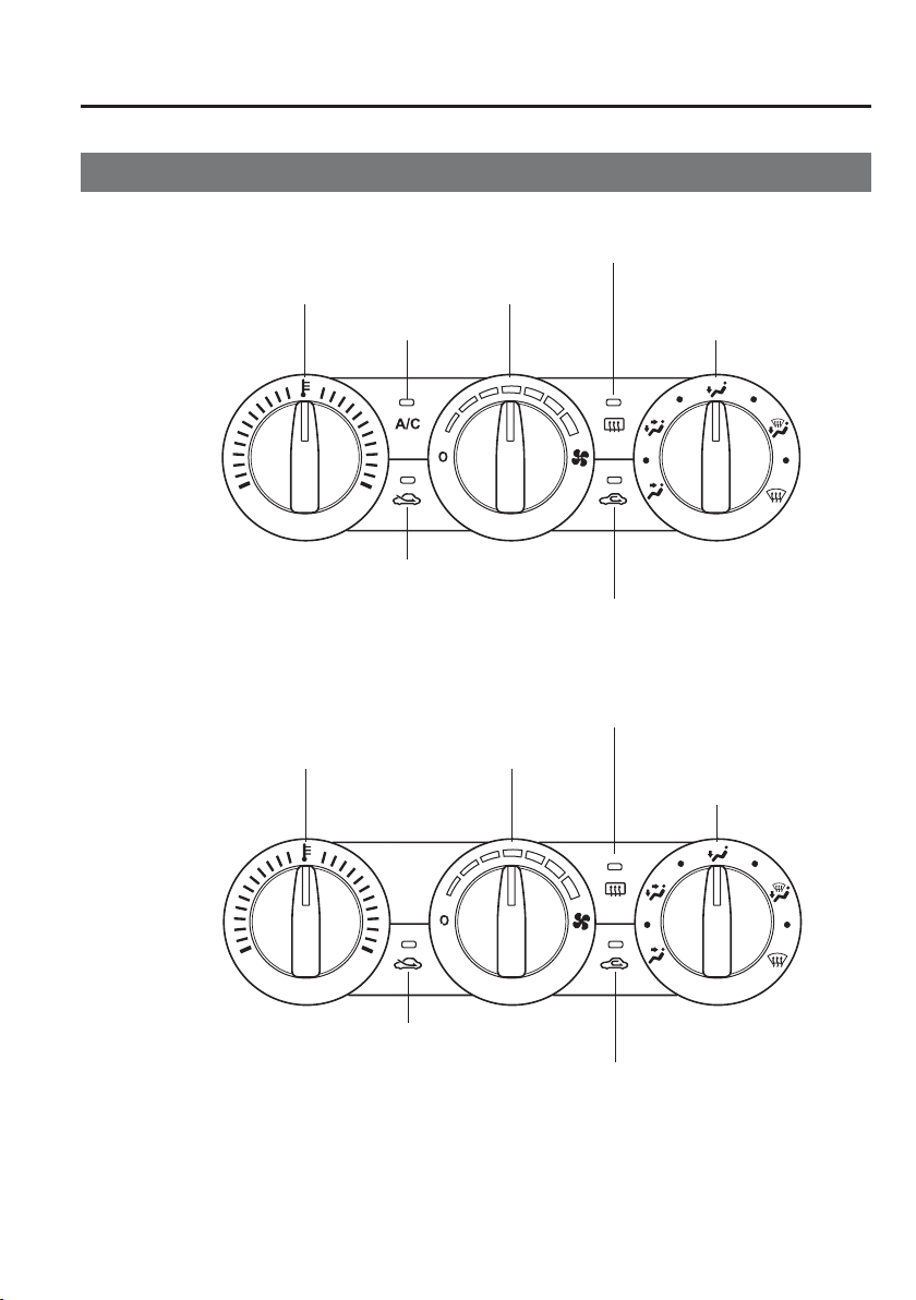
5
–
7
Interior Features
Air-Conditioning System
Manual Type
Temperature control dial Fan control dial
Rear window defogger switch
A/C switch
Air intake selector (outside air position)
Air intake selector (recirculated air position)
Mode selector dial
Type A
Temperature control dial Fan control dial
Rear window defogger switch
Air intake selector (outside air position)
Air intake selector (recirculated air position)
Mode selector dial
Type B
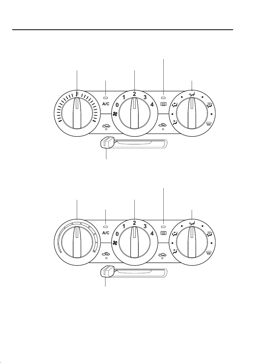
5
–
8
Interior Features
Air-Conditioning System
Temperature control dial Fan control dial
Rear window defogger switch
A/C switch
A/C switch
Air intake selector
Mode selector dial
Temperature control dial Fan control dial
Rear window defogger switch
Air intake selector
Mode selector dial
Type C
Type D
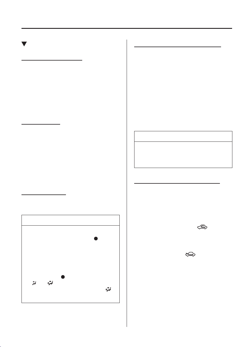
5
–
9
Interior Features
Air-Conditioning System
Control Switches
Temperature control dial
(Type A/Type B/Type C)
This dial controls temperature. Turn it
clockwise for hot and anticlockwise for
cold.
(Type D)
This dial controls the air temperature when
using the air conditioner. Turn it clockwise
for cold.
Fan control dial
This dial allows variable fan speeds.
(Type A/Type B)
This fan has seven speeds.
(Type C/Type D)
0—Fan off
1—Low speed
2—Medium low speed
3—Medium high speed
4—High speed
Mode selector dial
Turn the mode selector dial to select
airÀ ow mode (page 5-6 ).
NOTE
The mode selector dial can be set at
the intermediate positions (
)
between each mode. Set the dial to
an intermediate position if you want
to split the airÀ ow between the two
modes.
For example, when the mode selector
dial is at the
position between the
and positions, airÀ ow from the
À oor vent is less than that of the
position.
A/C switch (Type A/Type C/Type D)
(Type A)
Press the A/C switch to turn the air
conditioner on. The indicator light on the
switch will illuminate when the fan control
dial is in any position except OFF.
(Type C/Type D)
Press the A/C switch to turn the air
conditioner on. The indicator light on the
switch will illuminate when the fan control
dial is set at position 1, 2, 3, or 4.
Press the switch once again to turn the air
conditioner off.
NOTE
The air conditioner may not function
when the outside temperature
approaches 0 °C (32 °F).
Air intake selector (Type A/Type B)
This switch controls the source of air
entering the vehicle.
Press the air intake selector switch to
alternate between the outside air and
recirculated air positions.
Recirculated air position (
)
Outside air is shut off. Air within the
vehicle is recirculated.
Outside air position (
)
Outside air is allowed to enter the
cabin. Use this mode for ventilation or
windscreen defrosting.
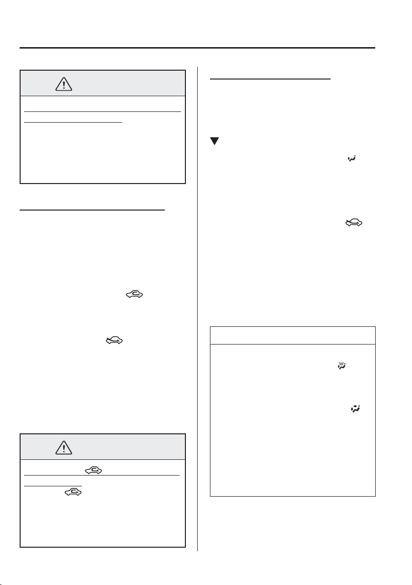
5
–
10
Interior Features
Air-Conditioning System
*Some models.
WARNING
Do not use the recirculated air position
in cold or rainy weather:
Using the recirculated air position in
cold or rainy weather is dangerous as it
will cause the windows to fog up. Your
vision will be hampered, which could
lead to a serious accident.
Air intake selector (Type C/Type D)
This lever controls the source of air
entering the vehicle.
It is recommended that under normal
conditions the switch be kept in the
outside air position.
Recirculated air position (
)
Outside air is shut off. Air within the
vehicle is recirculated.
Outside air position (
)
(Type C)
Outside air is taken into the vehicle. Use
this position for normal ventilation and
heating.
(Type D)
Outside air is taken into the vehicle. Use
this position for normal ventilation.
WARNING
Do not use the position in cold or
rainy weather:
Using the
position in cold or rainy
weather is dangerous as it will cause
the windows to fog up. Your vision will
be hampered, which could lead to a
serious accident.
Rear window defogger switch
Press the rear window defogger switch to
defrost the rear window.
Refer to Rear Window Defogger on page
4-78 .
Heating
*
1. Set the mode selector dial to the
position.
2. (Type A/Type B)
Set the air intake selector to the outside
air position.
(Type C)
Set the air intake selector to the
position.
3. Set the temperature control dial to the
hot position.
4. Set the fan control dial to the desired
speed.
5. (Type A/Type C)
If dehumidi¿ ed heating is desired, turn
on the air conditioner.
NOTE
If the windscreen fogs up easily, set
the mode selector dial to the
position.
(Type A/Type C)
If cooler air is desired at face level,
set the mode selector dial to the
position and adjust the temperature
control dial to maintain maximum
comfort.
The air to the À oor is warmer than
air to the face (except when the
temperature control dial is set at the
extreme hot or cold position).
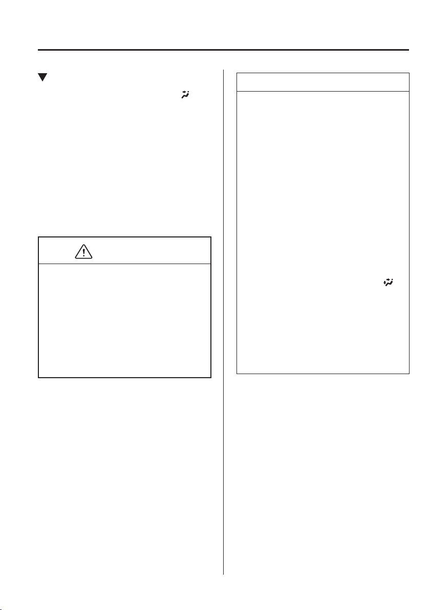
5
–
11
Interior Features
Air-Conditioning System
Cooling (With air conditioner)
1. Set the mode selector dial to the
position.
2. Set the temperature control dial to the
cold position.
3. Set the fan control dial to the desired
speed.
4. Turn on the air conditioner by pressing
the A/C switch.
5. After cooling begins, adjust the fan
control dial and temperature control
dial as needed to maintain maximum
comfort.
CAUTION
If the air conditioner is used while
driving up long hills or in heavy traf¿ c,
monitor the engine coolant temperature
warning light to see if it is illuminated or
À ashing (page 4-38 ).
The air conditioner may cause engine
overheating. If the warning light is
illuminated or À ashing, turn the air-
conditioning off (page 7-29 ).
NOTE
(Type A/Type B)
When maximum cooling is desired,
set the temperature control dial to
the extreme cold position and set the
air intake selector to the recirculated
air position, then turn the fan control
dial fully clockwise.
(Type C/Type D)
When maximum cooling is desired,
set the temperature control dial to the
extreme cold position and set the air
intake selector to the recirculated air
position, then set the fan control dial
to position 4.
(Type A/Type C)
If warmer air is desired at À oor level,
set the mode selector dial to the
position and adjust the temperature
control dial to maintain maximum
comfort.
The air to the À oor is warmer than
air to the face (except when the
temperature control dial is set at the
extreme hot or cold position).
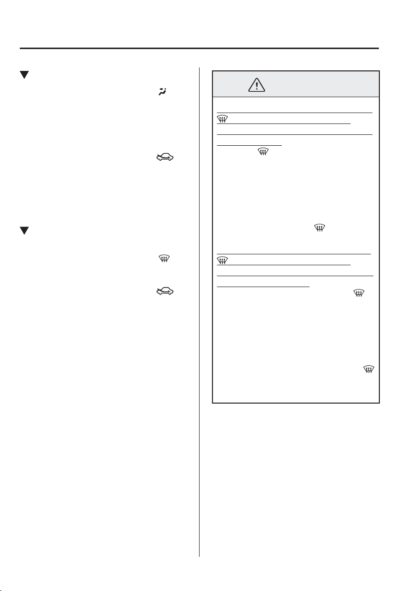
5
–
12
Interior Features
Air-Conditioning System
Ventilation
1. Set the mode selector dial to the
position.
2. (Type A/Type B)
Set the air intake selector to the outside
air position.
(Type C/Type D)
Set the air intake selector to the
position.
3. Set the temperature control dial to the
desired position.
4. Set the fan control dial to the desired
speed.
Windscreen Defrosting and
Defogging
1. Set the mode selector dial to the
position.
2. (Type C/Type D)
Set the air intake selector to the
position.
3. Set the temperature control dial to the
desired position.
4. Set the fan control dial to the desired
speed.
5. (Type A/Type C)
If dehumidi¿ ed heating is desired, turn
on the air conditioner.
(Type D)
Press the A/C switch to turn on the air
conditioner.
WARNING
Do not defog the windscreen using the
position with the temperature
control set to the cold position (Type A/
Type B/Type C):
Using the
position with the
temperature control set to the cold
position is dangerous as it will cause
the outside of the windscreen to fog up.
Your vision will be hampered, which
could lead to a serious accident. Set the
temperature control to the hot or warm
position when using the
position.
Do not leave the air conditioner in the
position with the temperature
control set to cold after the windscreen
has defogged (Type D):
Leaving the air conditioner in the
position with the temperature control
set to cold after the windscreen has
defogged is dangerous as the outside of
the windscreen will fog up. Your vision
will be hampered, which could lead to a
serious accident.
Set the mode selector dial except the
position and turn on the windscreen
wipers to clear the window.
5
–
13
Interior Features
Air-Conditioning System
NOTE
(Type A)
For maximum defrosting, turn on the
air conditioner, set the temperature
control dial to the extreme hot
position, and turn the fan control dial
fully clockwise.
(Type C)
For maximum defrosting, turn on the
air conditioner, set the temperature
control dial to the extreme hot
position, and the fan control dial to
position 4.
(Type A/Type C)
If warm air is desired at the À oor, set
the mode selector dial to the
position.
(Type A/Type B)
In the position, the outside air
position is automatically selected.
The air intake selector cannot be
changed to the recirculated air
position.
Dehumidifying (With air
conditioner)
Operate the air conditioner in cool or cold
weather to help defog the windscreen and
side windows.
1. Set the mode selector dial to the desired
position.
2. (Type A)
Set the air intake selector to the outside
air position.
(Type C/Type D)
Set the air intake selector to the
position.
3. Set the temperature control dial to the
desired position.
4. Set the fan control dial to the desired
speed.
5. Turn on the air conditioner by pressing
the A/C switch.
NOTE
(Type A/Type C)
One of the functions of the air
conditioner is dehumidifying the air
and, to use this function, the temperature
does not have to be set to cold.
Therefore, set the temperature control
dial to the desired position (hot or cold)
and turn on the air conditioner when you
want to dehumidify the cabin air.
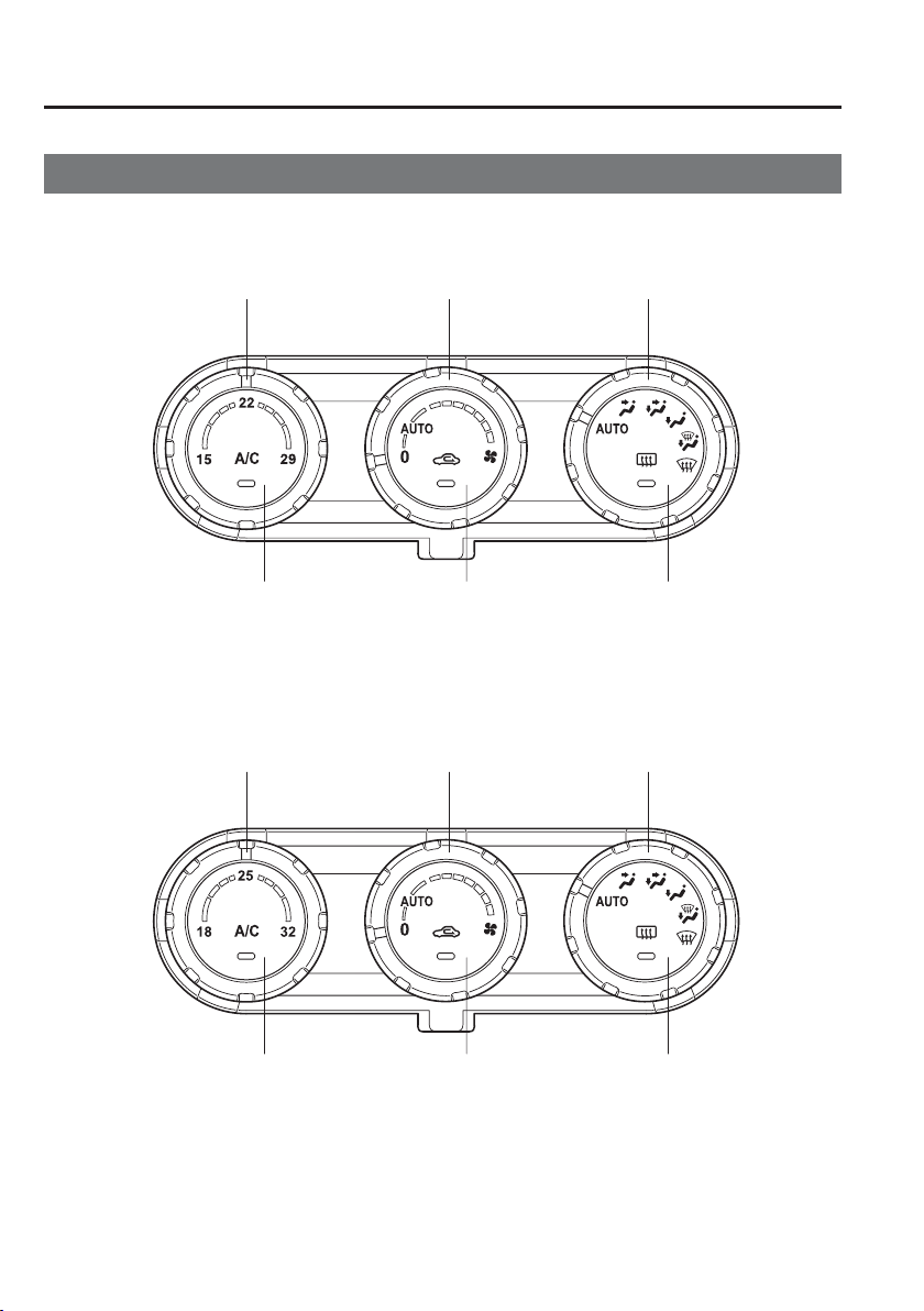
5
–
14
Interior Features
Air-Conditioning System
Fully Automatic Type
Temperature control dial Fan control dial Mode selector dial
A/C switch Air intake selector switch Rear window defogger switch
European model
Except European model
Temperature control dial Fan control dial Mode selector dial
A/C switch Air intake selector switch Rear window defogger switch
5
–
15
Interior Features
Air-Conditioning System
Control Switches
Temperature control dial
This dial controls temperature. Turn it
clockwise for hot and anticlockwise for
cold.
Fan control dial
The fan has seven speeds.
AUTO position
The amount of airÀ ow will be
automatically controlled in accordance
with the set temperature.
Except AUTO position
The airÀ ow amount can be adjusted to the
desired level by turning the dial.
0 position
To turn off the system, set the dial to 0
position.
Mode selector dial
Turn the mode selector dial to select
airÀ ow mode (page 5-6 ).
AUTO position
The airÀ ow mode automatically adjusts to
the selected temperature.
Except AUTO position
The desired airÀ ow position can be
selected by turning the dial.
NOTE
With the airÀ ow mode set to the
position and the temperature control
dial set at a medium temperature,
heated air is directed to the feet and
air at a comparably lower
temperature will À ow through the
central, left and right vents.
When the fan control dial is ON, and
the mode selector dial is in the
position, the air conditioner is
automatically turned on and the
outside air position is automatically
selected to defrost the windscreen.
A/C switch
The air-conditioning (cooling/
dehumidifying functions) can be turned on
or off by pressing the switch while the fan
control dial is at a position other than 0.
The indicator light turns on while the air-
conditioning is operating.
NOTE
The air conditioner may not function
when the outside temperature
approaches 0 °C (32 °F).
5
–
16
Interior Features
Air-Conditioning System
Air intake selector
Outside or recirculated air positions can be
selected. Press the switch to select outside/
recirculated air positions.
Recirculated air position (indicator light
illuminated)
Outside air is shut off. Use this position
when going through tunnels, driving in
congested traf¿ c (high engine exhaust
areas) or when quick cooling is desired.
Outside air position (indicator light
turned off)
Outside air is allowed to enter the
cabin. Use this mode for ventilation or
windscreen defrosting.
WARNING
Do not use the position in cold or
rainy weather:
Using the
position in cold or rainy
weather is dangerous as it will cause
the windows to fog up. Your vision will
be hampered, which could lead to a
serious accident.
Rear window defogger switch
Press the rear window defogger switch to
defrost the rear window.
Refer to Rear Window Defogger on page
4-78 .
Operation of Automatic Air-
conditioning
1. Set the mode selector dial to the AUTO
position.
2. Set the air intake selector to the outside
air position (indicator light turned off).
NOTE
If the recirculated air position is used
for long periods in cold weather or high
humidity, the windscreen may fog up
more easily.
3. Set the fan control dial to the AUTO
position.
4. Press the A/C switch to operate the air-
conditioning (turn indicator light on).
5. Set the temperature control dial to the
desired position.
6. To turn off the system, set the fan
control dial to the 0 position.
NOTE
Setting the temperature to maximum
hot or cold will not provide the
desired temperature at a faster rate.
When selecting heat, the system will
restrict airÀ ow until it has warmed to
prevent cold air from blowing out of
the vents.
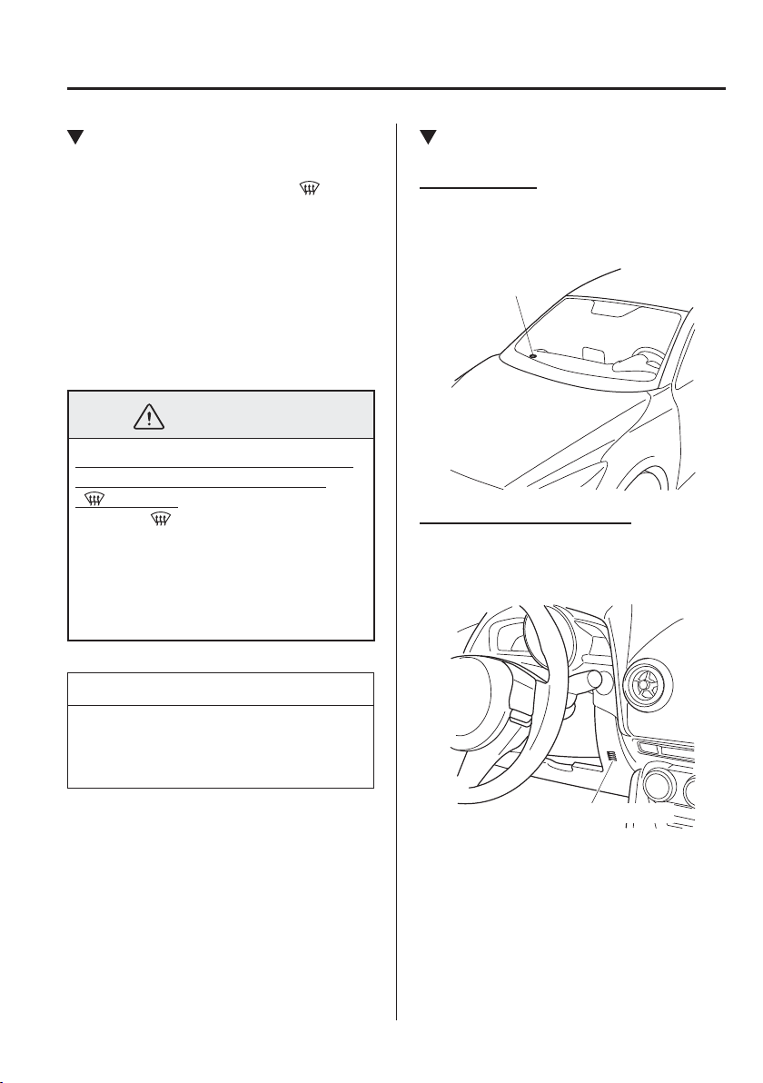
5
–
17
Interior Features
Air-Conditioning System
Windscreen Defrosting and
Defogging
Set the mode selector dial to the
position and turn the fan control dial to the
desired speed.
In this position, the outside air position
is automatically selected, and when the
fan control dial is ON, the air conditioner
automatically turns on. The air conditioner
will directly dehumidify the air to the
front windscreen and side windows (page
5-6 ). AirÀ ow amount will be increased.
WARNING
Set the temperature control to the hot
or warm position when defogging
( position):
Using the
position with the
temperature control set to the cold
position is dangerous as it will cause
the outside of the windscreen to fog up.
Your vision will be hampered, which
could lead to a serious accident.
NOTE
Use the temperature control dial to
increase the air À ow temperature and
defog the windscreen more quickly.
Sunlight/Temperature Sensor
Sunlight sensor
Do not place objects on the sunlight
sensor. Otherwise, the interior temperature
may not adjust correctly.
Sunlight sensor
Interior temperature sensor
Do not cover the interior temperature
sensor. Otherwise, the interior temperature
may not adjust correctly.
Interior temperature sensor
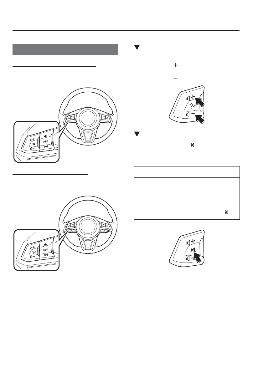
5
–
18
Interior Features
Before Using the Audio System
*Some models.
Audio Control Switch
*
Without Bluetooth
®
Hands-Free
With Bluetooth
®
Hands-Free
Adjusting the Volume
To increase the volume, press up the
volume switch (
).
To decrease the volume, press down the
volume switch (
).
Mute Switch
*
Press the mute switch ( ) once to mute
audio, press it again to resume audio
output.
NOTE
If the ignition is switched off with the
audio muted, the mute will be cancelled.
Therefore, when the engine is restarted,
the audio is not muted. To mute the
audio again, press the mute switch (
).
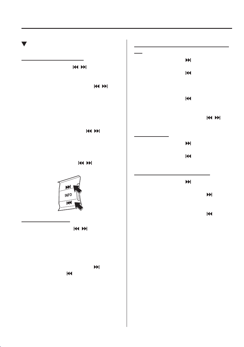
5
–
19
Interior Features
Before Using the Audio System
*Some models.
Seek Switch
A M
*
/MW
*
/LW
*
/FM radio
Press the seek switch (
, ). The radio
switches to the next/previous stored station
in the order that it was stored.
Press and hold the seek switch (
, ) to
seek all usable stations at a higher or lower
frequency whether programmed or not.
Radio stations which have been previously
stored in the auto memory tuning (Type A)/
favourite radio (Type B) can be called up
by pressing the seek switch (
, ) while
any radio station stored in the auto memory
tuning (Type A)/favourite radio (Type B) is
being received. Radio stations can be
called up in the order they were stored with
each press of the switch (
, ).
DAB radio (Type B)
Press the Seek switch (
, ) while
listening to DAB radio to call up a station
previously stored to the favourites list.
With each operation of the switch, radio
stations can be called up in the order they
were stored.
Press and hold the seek switch (
) to go
to the next station, (
) to return to the
previous station.
USB Audio/Bluetooth
®
Audio (Type B)/
CD
Press the seek switch (
) to skip forward
to the beginning of the next track.
Press the seek switch (
) within a few
seconds after playback begins to track
down to the beginning of the previous
track.
Press the seek switch (
) after a few
seconds have elapsed to start playback
from the beginning of the current track.
Press and hold the seek switch (
, ) to
continuously switch the tracks up or down.
DVD (Type B)
Press the seek switch (
) to skip forward
to the beginning of the next chapter.
Press the seek switch (
) to return to the
beginning of the previous chapter.
Aha
™
/Stitcher
™
Radio (Type B)
Press the seek switch (
) to skip forward
to the beginning of the next track.
Press and hold the seek switch (
) to
evaluate the playback of the current song
as “Like”.
Press and hold the seek switch (
) to
evaluate the playback of the current song
as “Dislike”.
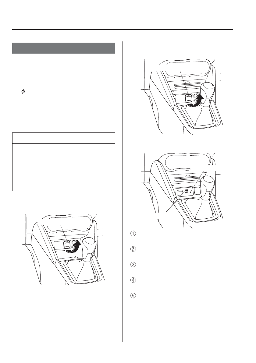
5
–
20
Interior Features
Before Using the Audio System
AUX/USB mode
Audio can be heard from the vehicle's
speakers by connecting a commercially-
available portable audio unit to the
auxiliary jack.
A commercially-available, non-impedance
(3.5
) stereo mini plug lead is required.
Contact an expert repairer, we recommend
an Authorised Mazda Repairer for details.
In addition, audio can be played from the
vehicle audio device by connecting a USB
device to the USB port.
NOTE
(Type B)
The SD card slot is for the navigation
system. For vehicles with the navigation
system, the SD card (Mazda genuine)
with stored map data is inserted into the
SD card slot and used.
Type A (Without CD player)
Auxiliary jack/USB port
Type A (With CD player)
Auxiliary jack/USB port
Type B
USB port
Auxiliary jack
How to use AUX mode
(Type A) .................................page 5-37
How to use USB mode
(Type A) .................................page 5-38
How to use iPod mode
(Type A) .................................page 5-42
How to use AUX mode
(Type B) ...............................page 5-100
How to use USB mode
(Type B) ...............................page 5-101
5
–
21
Interior Features
Before Using the Audio System
WARNING
Do not adjust the portable audio unit
or a similar product while driving the
vehicle:
Adjusting the portable audio unit
or a similar product while driving
the vehicle is dangerous as it could
distract your attention from the vehicle
operation which could lead to a serious
accident. Always adjust the portable
audio unit or a similar product while
the vehicle is stopped.
CAUTION
Depending on the portable audio device,
noise may occur when the device is
connected to the vehicle accessory
socket. (If noise occurs, do not use the
accessory socket.)
NOTE
This mode may not be usable
depending on the portable audio
device to be connected.
Before using the auxiliary jack/USB
port, refer to the instruction manual
for the portable audio device.
Use a commercially-available,
non-impedance (3.5
) stereo mini
plug for connecting the portable
audio unit to the auxiliary jack.
Before using the auxiliary jack, read
the manufacturer's instructions for
connecting a portable audio unit to
the auxiliary jack.
To prevent discharging of the battery,
do not use the auxiliary input for
long periods with the engine off or
idling.
When connecting a device to the
auxiliary jack or USB port, noise
may occur depending on the
connected device. If the device is
connected to the vehicle's accessory
socket, the noise can be reduced by
unplugging it from the accessory
socket.
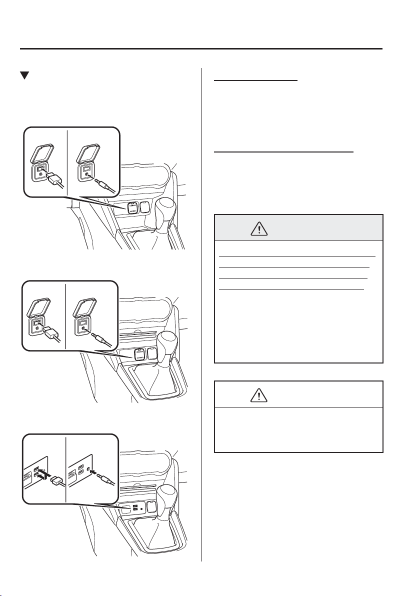
5
–
22
Interior Features
Before Using the Audio System
How to connect USB port/
Auxiliary jack
Type A (Without CD player)
USB port Auxiliary jack
Type A (With CD player)
USB port Auxiliary jack
Type B
USB port Auxiliary jack
Connecting a device
1. If there is a cover on the AUX jack or
USB port, remove the cover.
2. Connect the connector on the device to
the USB port.
Connecting with a connector lead
1. If there is a cover on the AUX jack or
USB port, remove the cover.
2. Connect the device plug/connector lead
to the auxiliary jack/USB port.
WARNING
Do not allow the connection plug cord
to get tangled with the parking brake
or the shift lever (manual transaxle)/
selector lever (automatic transaxle):
Allowing the plug cord to become
tangled with the parking brake or
the shift lever (manual transaxle)/
selector lever (automatic transaxle) is
dangerous as it could interfere with
driving, resulting in an accident.
CAUTION
Do not place objects or apply force to
the auxiliary jack/USB port with the
plug connected.
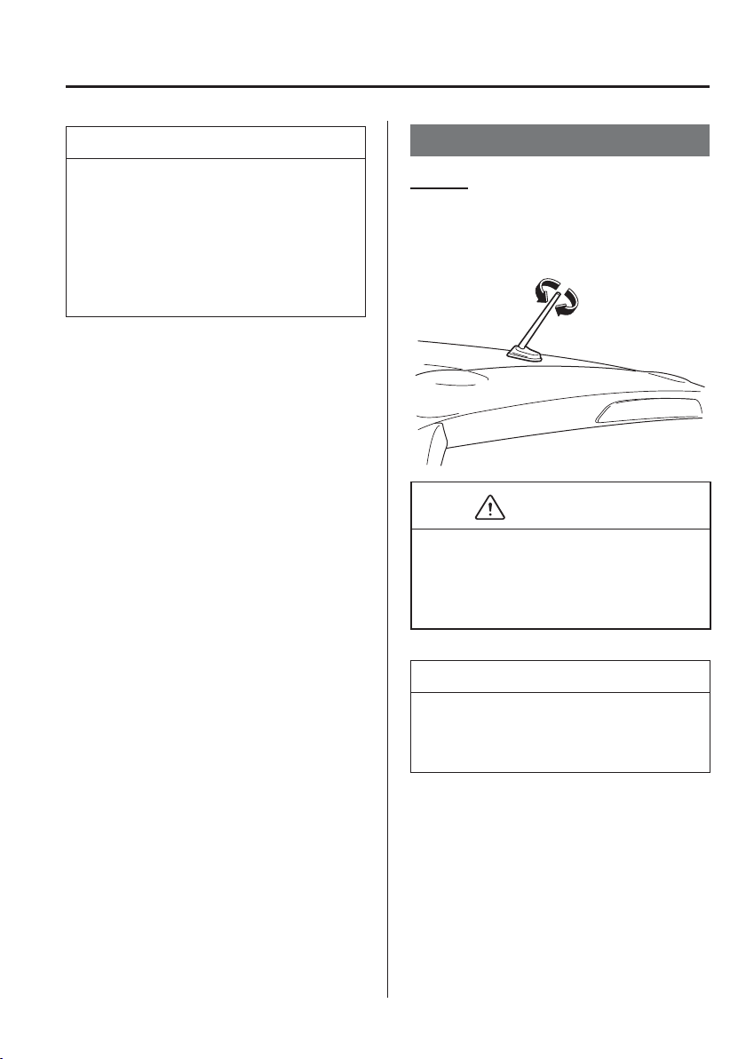
5
–
23
Interior Features
Before Using the Audio System
*Some models.
NOTE
Insert the plug into the auxiliary jack/
USB port securely.
Insert or pull out the plug with the
plug perpendicular to the auxiliary
jack/USB port hole.
Insert or remove the plug by holding
its base.
Aerial
Ty p e A
*
To remove the aerial, turn it anticlockwise.
To install the aerial, turn it clockwise.
Make sure the aerial is securely installed.
Install
Remove
CAUTION
To prevent damage to the aerial, remove
it before entering a car wash facility
or passing beneath a low overhead
clearance.
NOTE
When leaving your vehicle unattended,
we recommend that you remove the
aerial and store it inside the vehicle.
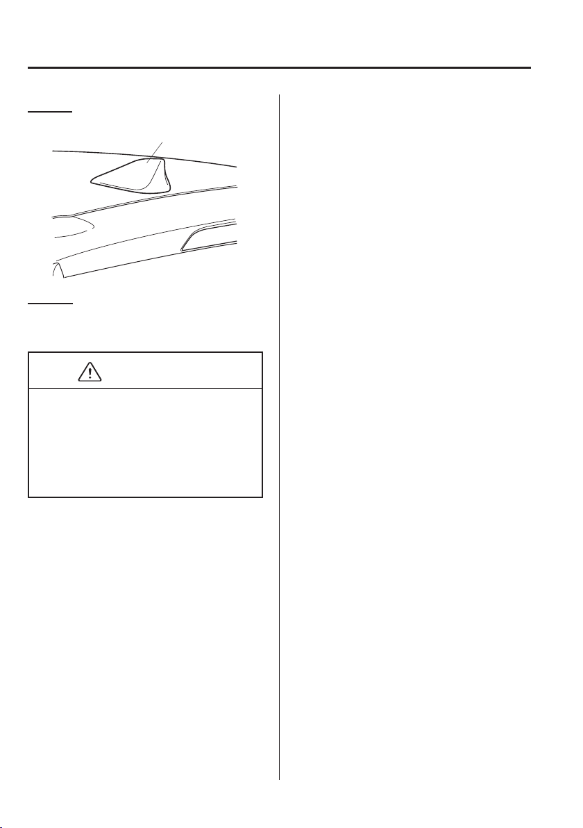
5
–
24
Interior Features
Before Using the Audio System
*Some models.
Type B
*
Aerial
Type C
*
The aerial is embedded into the window
glass.
CAUTION
When washing the inside of the window
which has an aerial, use a soft cloth
dampened in lukewarm water, gently
wiping the aerial lines.
Use of glass cleaning products could
damage the aerial.

MEMO
5
–
25
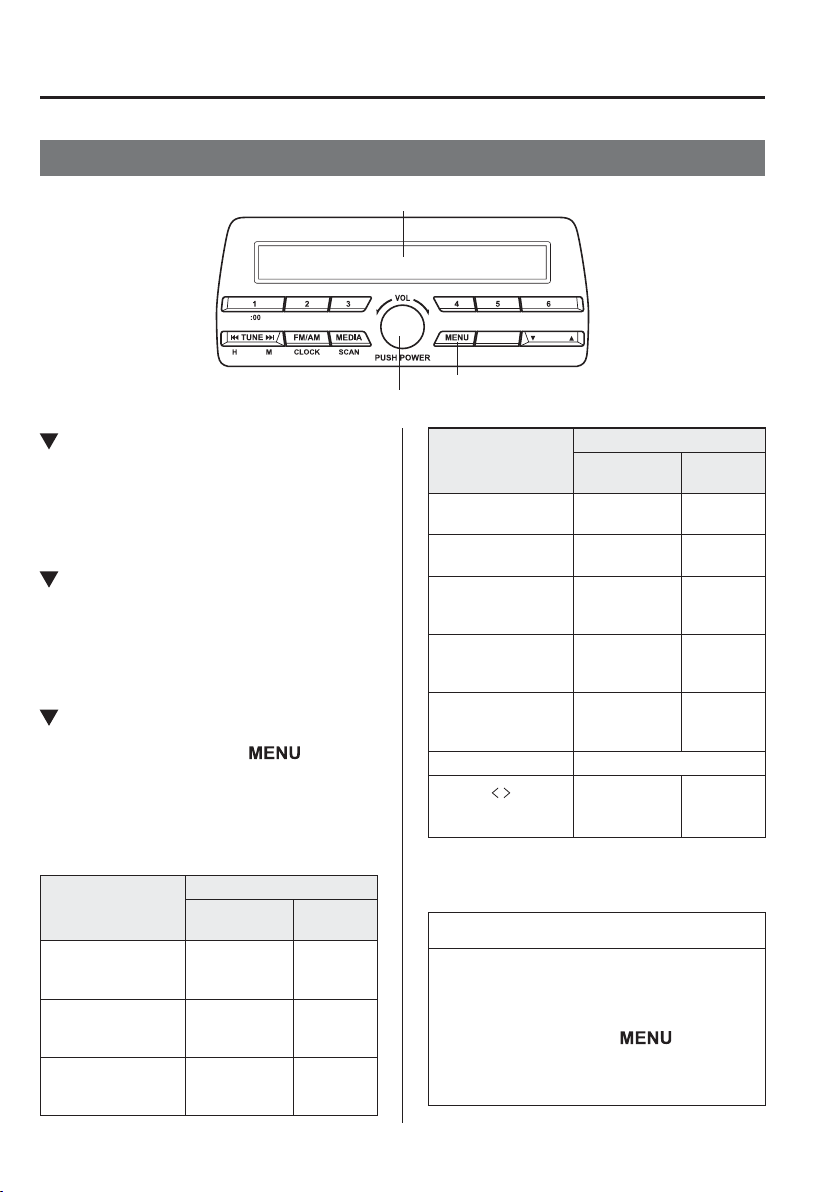
5
–
26
Interior Features
Audio Set [Type A (non-touchscreen)]
Power/Volume/Sound Controls
Power/Volume/Audio control dial
Menu button
Audio display
Power ON/OFF
Switch the ignition to ACC or ON. Press
the power/volume dial to turn the audio
system on. Press the power/volume dial
again to turn the audio system off.
Volume adjustment
To adjust the volume, turn the power/
volume dial. Turn the power/volume
dial clockwise to increase volume,
anticlockwise to decrease it.
Audio sound adjustment
1. Press the menu button ( ) to select
the function. The selected function will
be indicated.
2. Turn the audio control dial to adjust the
selected functions as follows:
Indication
Setting value
Turn
Anticlockwise
Turn
Clockwise
AF
*1
(Setting Alternative
Frequency (AF))
Off On
R E G
*1
(Setting Regional
Programme (REG))
Off On
A L C
(Automatic volume
adjustment)
Level decrease
Level
increase
Indication
Setting value
Turn
Anticlockwise
Turn
Clockwise
BASS
(Low pitch sound)
Decrease bass
Increase
bass
T R E B
(Treble sound)
Decrease treble
Increase
treble
FADE
(Front/back volume
balance)
Shift the sound
to the front
Shift the
sound to
the rear
B A L
(Left/right volume
balance)
Shift the sound
to the left
Shift the
sound to
the right
BEEP
(Audio operation
sound)
OFF ON
BT SETUP
*2
Select mode
12HR
24HR
(12 HR/24 HR time
adjustment)
12HR
(Flashing)
24HR
(Flashing)
*1 With Radio Data System (RDS)
*2 Depending on the model, this function may not be
available.
NOTE
If not operated for several seconds, the
display returns to the previous display.
To reset bass, treble, fade, and balance,
press the menu button (
) for
2 seconds. The unit will beep and
“ CLEAR ” will be displayed.

5
–
27
Interior Features
Audio Set [Type A (non-touchscreen)]
*Some models.
AF (Setting Alternative Frequency
(AF))
*
The AF function of the Radio Data System
(RDS) can be set on or off.
Refer to Radio Data System (RDS) on
page 5-32 .
REG (Setting Regional Programme
(REG))
*
The REG function of the Radio Data
System (RDS) can be set on or off.
Refer to Radio Data System (RDS) on
page 5-32 .
ALC (Automatic volume adjustment)
The automatic level control (ALC)
changes the audio volume automatically
according to the vehicle speed. The faster
the vehicle speed, the higher the volume
increases. ALC has ALC OFF and ALC
LEVEL 1 to 7 modes. At ALC LEVEL 7,
the amount that the volume can increase
is at the maximum. Select the mode
according to the driving conditions.
BEEP (Audio operation sound)
The setting for the operation sound when
pressing and holding a button can be
changed. The initial setting is ON. Set to
OFF to mute the operation sound.
BT SETUP mode
*
Music and other audio such as voice data
recorded on portable audio devices and
mobile phones available on the market
which are equipped with the Bluetooth
®
transmission function can be listened to
via wireless transmission over the vehicle's
speakers. Using the BT SETUP mode,
these devices can be programmed to the
Bluetooth
®
unit or changed (page 5-49 ).
1 2 H R
24HR (12 HR/24 HR time
adjustment)
Rotating the audio control dial switches
the display between 12 and 24-hour clock
time (page 5-28 ).
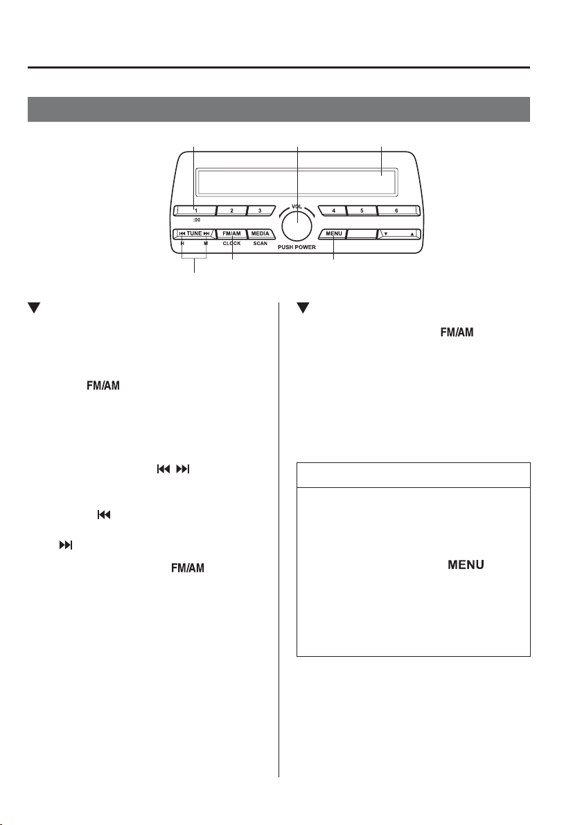
5
–
28
Interior Features
Audio Set [Type A (non-touchscreen)]
Clock
Audio displayAudio control dial
Hour/Minute set switch
:00 button
Menu buttonClock button
Setting the time
The clock can be set at any time when the
ignition is switched to ACC or ON.
1. To adjust the time, press the clock
button (
) for about 2 seconds until
a beep is heard.
2. The clock's current time will À ash.
Time adjustment
To adjust the time, press the hour/
minute set button (
, ) while the
clock's current time is À ashing.
The hours advance while the hour set
button (
) is pressed. The minutes
advance while the minute set button
(
) is pressed.
3. Press the clock button ( ) again to
start the clock.
Time resetting
1. Press the clock button ( ) for about
2 seconds until a beep is heard.
2. Press the :00 button ( 1 ).
3. When the button is pressed, the time
will be reset as follows:
(Example)
12:01—12:29ĺ12:00
12:30—12:59ĺ1:00
NOTE
When the :00 button ( 1 ) is pressed,
the seconds will start at “ 00 ”.
Switching between 12 and 24-hour
clock time:
Press the menu button ( )
several times until 12 and 24-hour
clock time are displayed. Turn the
audio control dial in either direction,
select the desired clock setting while
the preferred clock time is À ashing.

MEMO
5
–
29
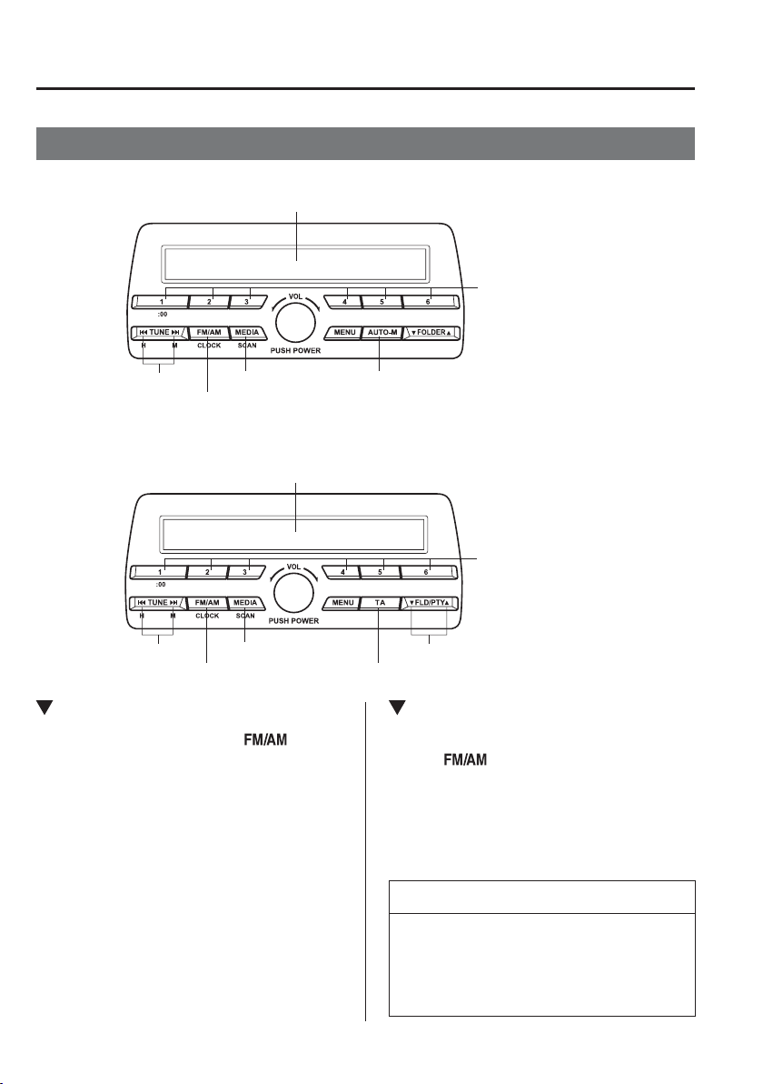
5
–
30
Interior Features
Audio Set [Type A (non-touchscreen)]
Operating the Radio
Without Radio Data System (RDS)
With Radio Data System (RDS)
Band selector button Traffic announcement button
Channel preset buttons
Scan button
Tuning button Programme-type information button
Audio display
Band selector button
Channel preset buttons
Scan button
Auto memory button
Tuning button
Audio display
Radio ON
Press a band selector button ( ) to
turn the radio on.
Band selection
Successively pressing the band selector
button (
) switches the bands as
follows: FM1ĺFM2ĺAM (Without
Radio Data System (RDS)), MW/LW
(With Radio Data System (RDS)).
The selected mode will be indicated.
NOTE
If the FM broadcast signal becomes
weak, reception automatically changes
from STEREO to MONO for reduced
noise.
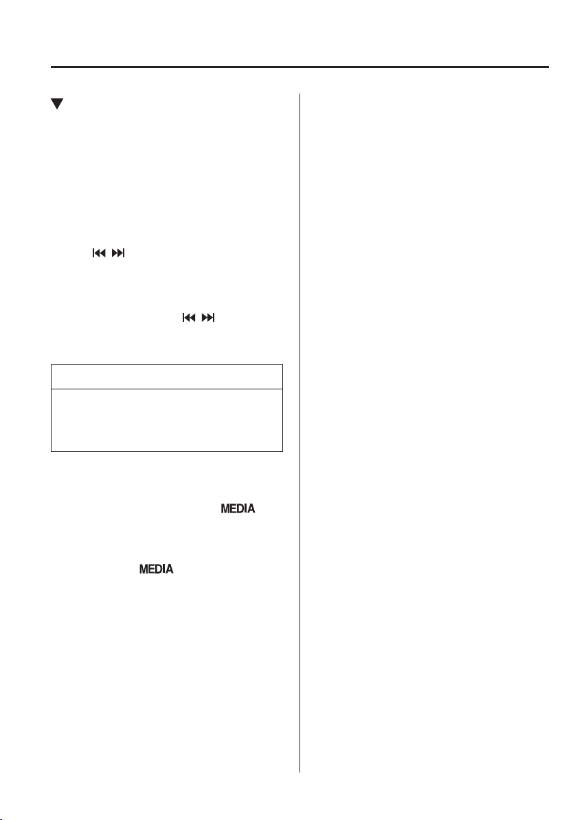
5
–
31
Interior Features
Audio Set [Type A (non-touchscreen)]
Tuning
The radio has the following tuning
methods: Manual, Seek, Scan, Preset
channel, and Auto memory tuning. The
easiest way to tune stations is to set them
on preset channels.
Manual tuning
Select the station by pressing the tuning
button (
, ) lightly.
Seek tuning
Automatic search for radio stations starts
when the tuning button (
, ) is pressed
until a beep sound is heard. The search
stops when a station is found.
NOTE
If you continue to press and hold the
button, the frequency will continue
changing without stopping.
Scan tuning
Press and hold the scan button (
) to
automatically sample strong stations.
Scanning stops at each station for about 5
seconds. To hold a station, press and hold
the scan button (
) again during this
interval.
Preset channel tuning
The 6 preset channels can be used to
store 6 AM (Without Radio Data System
(RDS)), MW/LW (With Radio Data
System (RDS)) and 12 FM stations.
1. To set a channel ¿ rst select AM
(Without Radio Data System (RDS)),
MW/LW (With Radio Data System
(RDS)), FM1, or FM2. Tune to the
desired station.
2. Press a channel preset button for
about 2 seconds until a beep is heard.
The preset channel number or station
frequency will be displayed. The
station is now held in the memory.
3. Repeat this operation for the other
stations and bands you want to store.
To tune one in the memory, select AM
(Without Radio Data System (RDS)),
MW/LW (With Radio Data System
(RDS)), FM1, or FM2 and then press
its channel preset button. The station
frequency or the channel number will
be displayed.
5
–
32
Interior Features
Audio Set [Type A (non-touchscreen)]
*Some models.
Auto memory tuning (Without Radio
Data System (RDS))
This is especially useful when driving in
an area where the local stations are not
known.
Press and hold the auto memory button
(
) for about 2 seconds until a beep
is heard; the system will automatically
scan and temporarily store up to 6 stations
with the strongest frequencies in each
selected band in that area.
After scanning is completed, the station
with the strongest frequency will be tuned
and its frequency displayed. Press and
release the auto memory button (
)
to recall stations from the auto-stored
stations. One stored station will be
selected each time and its frequency and
channel number will be displayed.
NOTE
If no stations can be tuned after scanning
operations, “ A ” will be displayed.
Radio Data System (RDS)
*
NOTE
The radio data system (RDS) does
not function if it is out of the system's
service coverage area.
Alternative frequency (AF)
AF functions on FM stations. Press the
menu button (
) and select the AF
mode to turn it on and “ AF ” will be
displayed. If the radio reception of the
current station weakens, the system
switches to an alternative station
automatically.
If you wish to continue a regional
programme, press the menu button
(
) and select the REG mode to turn
it on. “ REG ON ” is displayed. To cancel
it, press the audio control dial and select
the REG mode to turn it off. “ REG OFF ”
is displayed.
Tr a f ¿ c announcement (TA)
If the traf¿ c announcement button (
) is
pressed, the unit switches to TA mode and
“ TA ” is displayed.
If a TA broadcast is received while in the
TA mode, the TA broadcast intercedes
even while using other functions (FM,
CD, USB device, AUX, or BT audio), and
“ Traf¿ c Info ” is displayed.
During a TA broadcast, press the traf¿ c
announcement button (
) to end the
broadcast and return to the previous mode.

5
–
33
Interior Features
Audio Set [Type A (non-touchscreen)]
Programme-type information (PTY)
Some FM stations transmit programme-
type codes. This code enables alternative
stations transmitting the same programme-
type code to be found quickly.
Press the programme-type information
button (
, ) while in FM mode. The
programme-type code and “ PTY ” will be
displayed during reception. If there is no
programme-type code, “ None ” will be
displayed.
(To choose a programme-type:)
1. Press the Programme-type information
button (
, ) when the programme-
type code is displayed.
2. Operate any one of the following:
Press the pre-programmed channel
preset button ( 1 to 6 ).
Press the Programme-type
information button (
, ).
(To scan for programme-type
information:)
1. Press the Programme-type information
button (
, ) when the programme-
type code is displayed.
2. Press the Programme-type information
button (
, ) until the beep sounds.
The unit will scan for broadcasts, if
none are found, “ Nothing ” will be
displayed and the unit will return to the
previously tuned band.
(To store programme types in the
channel preset buttons:)
1. Press the Programme-type information
button (
, ) when the programme-
type code is displayed.
2. Press the Programme-type information
button (
, ) and select the programme
type.
3. While the programme type is displayed,
press a channel preset button for about
2 seconds.
Emergency broadcast
If an emergency broadcast is received,
the emergency broadcast intercedes even
while using other functions (FM, CD,
USB device, AUX, or BT audio), and
“ Alarm! ” is displayed.
When the emergency broadcast ends, the
system will return to the previous mode.
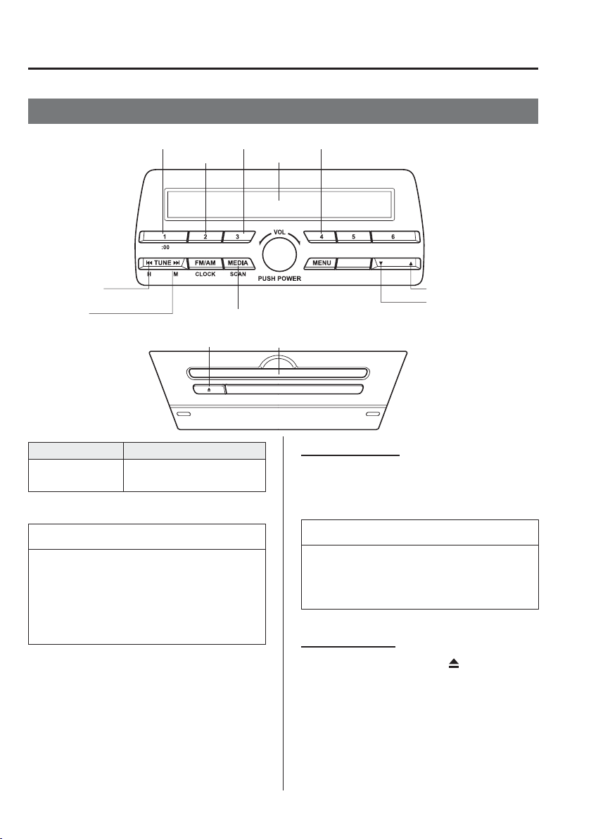
5
–
34
Interior Features
Audio Set [Type A (non-touchscreen)]
*Some models.
Operating the Compact Disc (CD) Player
*
CD eject button CD slot
Media/Scan button
Folder down button
Folder up button
Play/Pause button
Random button
Repeat button
Audio display
Text button
Track down/
Reverse button
Track up/
Fast-forward button
Type Playable data
Music/MP3/WMA/
AAC CD player
Music data (CD-DA)
MP3/WMA/AAC ¿ le
NOTE
If a disc has both music data (CD-
DA) and MP3/WMA/AAC ¿ les,
playback of the two or three ¿ le types
differs depending on how the disc was
recorded.
Inserting the CD
Insert the CD into the slot, label-side up.
The auto-loading mechanism will set the
CD and begin play.
NOTE
There will be a short lapse before play
begins while the player reads the digital
signals on the CD.
Ejecting the CD
Press the CD eject button (
) to eject the
CD.
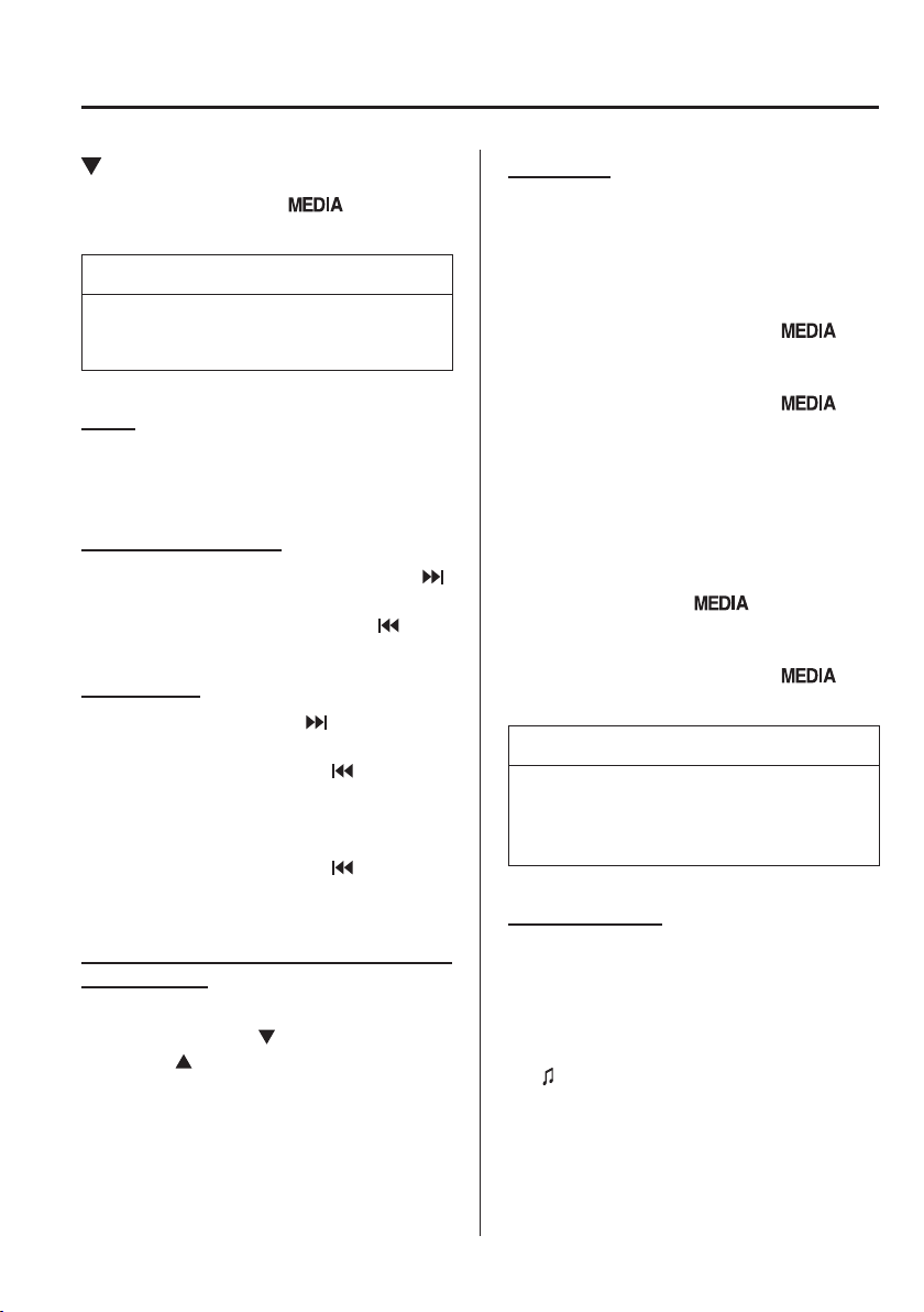
5
–
35
Interior Features
Audio Set [Type A (non-touchscreen)]
Playback
Press the media button (
) to switch
to CD mode and start playback.
NOTE
The CD mode cannot be selected if a
CD has not been inserted.
Pause
To stop playback, press the Play/Pause
button ( 4 ).
Press the button again to resume playback.
Fast-forward/Reverse
Press and hold the fast-forward button (
)
to advance through a track at high speed.
Press and hold the reverse button (
) to
reverse through a track at high speed.
Track search
Press the track up button (
) once to skip
forward to the beginning of the next track.
Press the track down button (
) within a
few seconds after playback begins to track
down to the beginning of the previous
track.
Press the track down button (
) after a
few seconds have elapsed to start playback
from the beginning of the current track.
Folder search (during MP3/WMA/AAC
CD playback)
To change to the previous folder, press the
folder down button (
), or press the folder
up button (
) to advance to the next
folder.
Music scan
During music CD playback
This function scans the titles on a CD and
plays 10 seconds of each song to aid you
in ¿ nding a song you want to listen to.
Press and hold the scan button (
)
during playback to start the scan play
operation (the track number will À ash).
Press and hold the scan button (
)
again to cancel scan playback.
During MP3/WMA/AAC CD playback
This function scans the titles in a folder
currently being played and plays 10
seconds of each song to aid you in ¿ nding
a song you want to listen to. Press and
hold the scan button (
) during
playback to start the scan play operation
(the track number will À ash).
Press and hold the scan button (
)
again to cancel scan playback.
NOTE
If the unit is left in scan, normal
playback will resume where scan was
selected.
Repeat playback
During music CD playback
1. Press the repeat button ( 1 ) during
playback to play the current track
repeatedly. “ TRACK RPT ” is displayed
(
is displayed next to RPT at the
bottom of the display area).
2. Press the button again to cancel the
repeat playback.
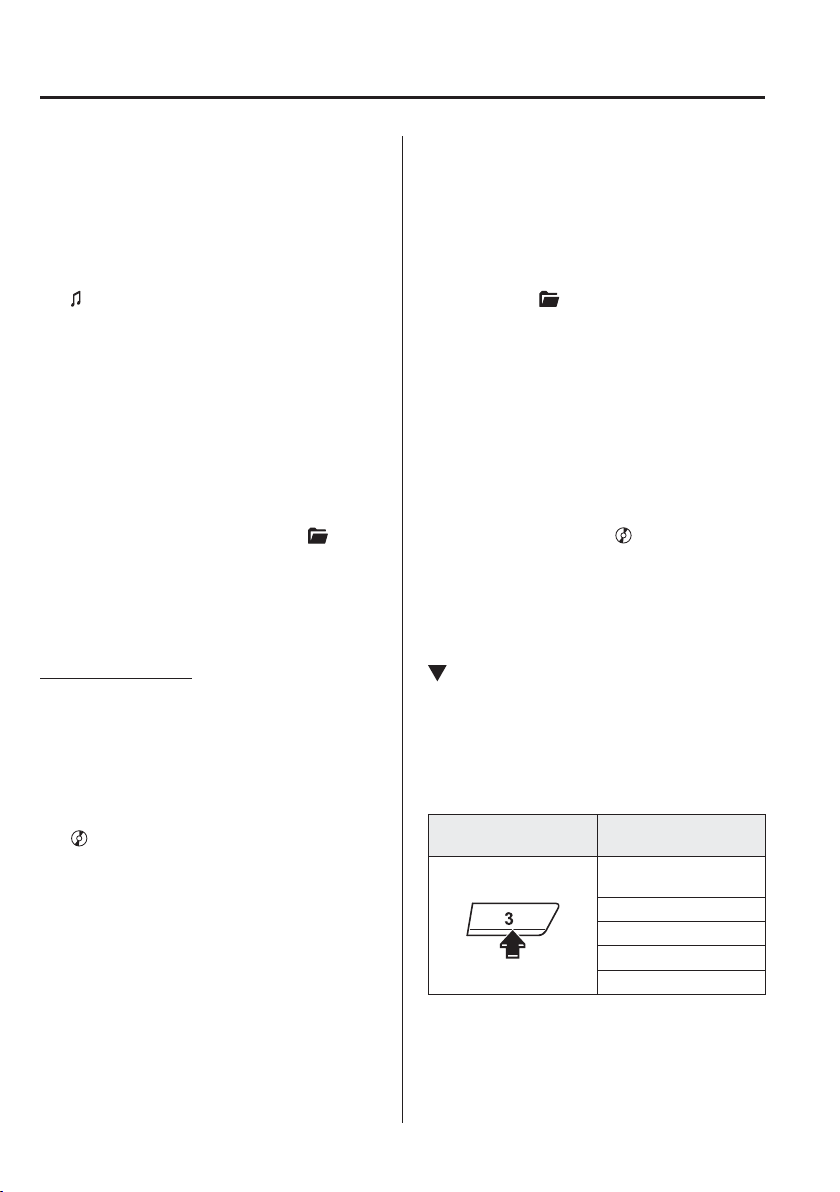
5
–
36
Interior Features
Audio Set [Type A (non-touchscreen)]
During MP3/WMA/AAC CD playback
(Track repeat)
1. Press the repeat button ( 1 ) during
playback to play the current track
repeatedly. “ TRACK RPT ” is displayed
(
is displayed next to RPT at the
bottom of the display area).
2. To cancel the repeat playback, press the
button again after 3 seconds.
(Folder repeat)
1. Press the repeat button ( 1 ) during
playback, and then press the button
again within 3 seconds to play the
tracks in the current folder repeatedly.
“ FOLDER RPT ” is displayed (
is
displayed next to RPT at the bottom of
the display area).
2. Press the button again to cancel the
repeat playback.
Random playback
Tracks are randomly selected and played.
During music CD playback
1. Press the random button ( 2 ) during
playback to play the tracks on the CD
randomly. “ DISC RDM ” is displayed
(
is displayed next to RDM at the
bottom of the display area).
2. Press the button again to cancel the
random playback.
During MP3/WMA/AAC CD playback
(Folder random)
1. Press the random button ( 2 ) during
playback to play the tracks in the folder
randomly. “ FOLDER RDM ” is
displayed (
is displayed next to RDM
at the bottom of the display area).
2. To cancel the random playback, press
the button again after 3 seconds.
(CD random)
1. Press the random button ( 2 ) during
playback, and then press the button
again within 3 seconds to play the
tracks on the CD randomly. “ DISC
RDM ” is displayed (
is displayed
next to RDM at the bottom of the
display area).
2. Press the button again to cancel the
random playback.
Switching the display
The information displayed on the audio
display changes as follows each time the
text button ( 3 ) is pressed during playback.
Music CD
Button
Information displayed
on audio display
Track number/Elapsed
time
Track number
Track name
Album name
Artist name
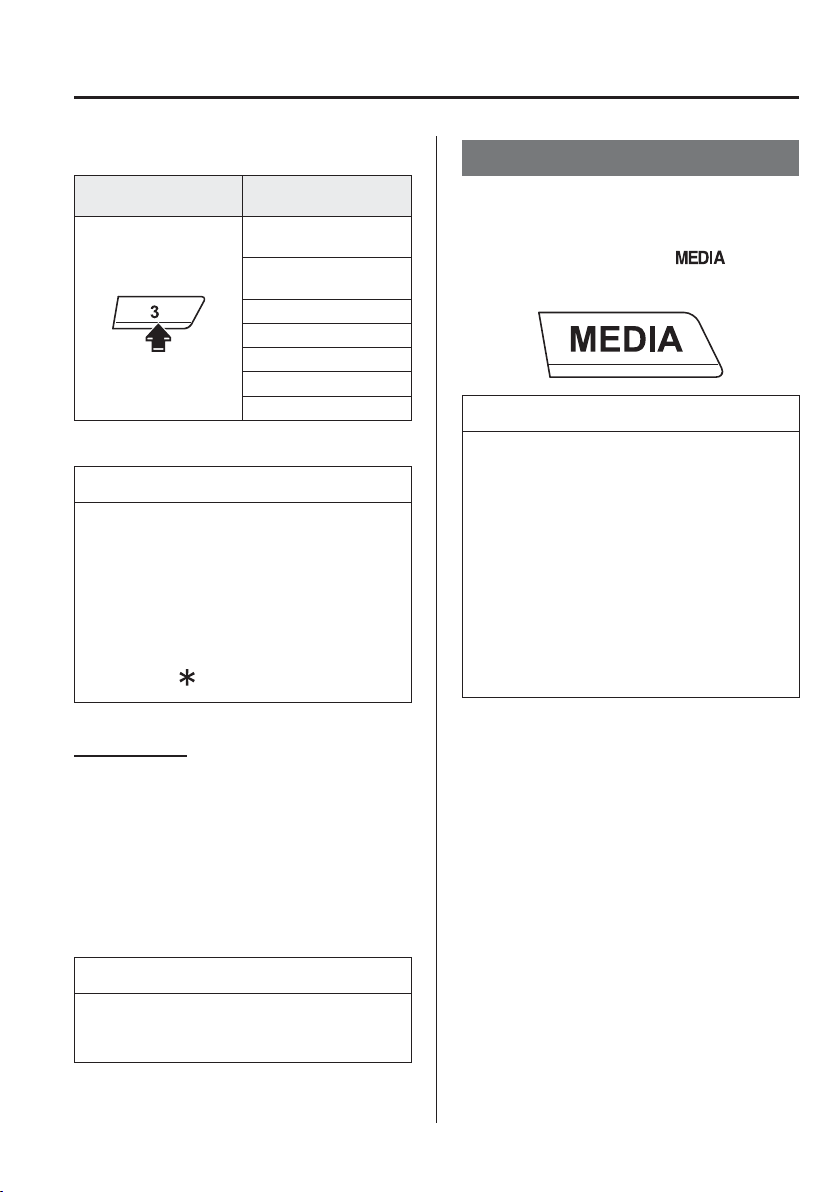
5
–
37
Interior Features
Audio Set [Type A (non-touchscreen)]
MP3/WMA/AAC CD
Button
Information displayed
on audio display
File number/Elapsed
time
Folder number/File
number
File name
Folder name
Album name
Song name
Artist name
NOTE
The information viewable in the
display is only CD information (such
as artist name, song title) which has
been recorded to the CD.
This unit cannot display some
characters. Characters which cannot
be displayed are indicated by an
asterisk (
).
Display scroll
Only 13 characters can be displayed at one
time. To display the rest of the characters
of a long title, press and hold the text
button ( 3 ). The display scrolls the next 13
characters. Press and hold the text button
( 3 ) again after the last 13 characters have
been displayed to return to the beginning
of the title.
NOTE
The number of characters which can be
displayed is restricted.
How to use AUX mode
1. Switch the ignition to ACC or ON.
2. Press the power/volume dial to turn the
audio system on.
3. Press the media button (
) of the
audio unit to change to the AUX mode.
NOTE
When the device is not connected to
the auxiliary jack, the mode does not
switch to the AUX mode.
Adjust the audio volume using the
portable audio device or audio unit.
Audio adjustments other than audio
volume can only be done using the
portable audio device.
If the connection plug is pulled out
from the auxiliary jack while in AUX
mode, noise may occur.
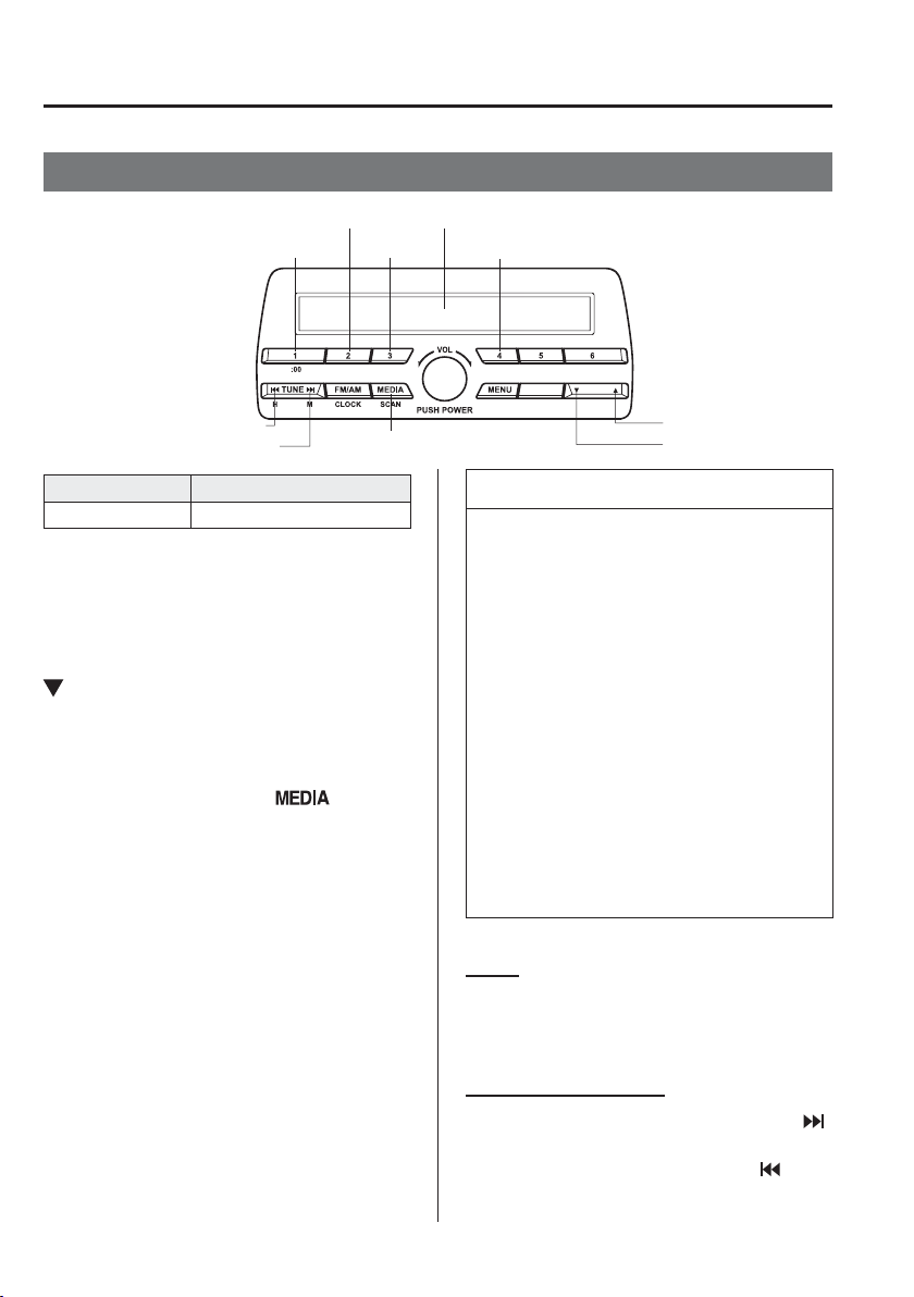
5
–
38
Interior Features
Audio Set [Type A (non-touchscreen)]
How to use USB mode
Media/Scan button
Folder down button
Folder up button
Play/Pause button
Random button
Repeat button
Audio display
Text button
Track down/Reverse button
Track up/Fast-forward button
Type Playable data
USB mode MP3/WMA/AAC ¿ le
This unit does not support a USB 3.0
device. In addition, other devices may not
be supported depending on the model or
OS version.
Playback
1. Switch the ignition to ACC or ON.
2. Press the power/volume dial to turn the
audio system on.
3. Press the media button (
) to
switch to the USB mode and start
playback.
NOTE
Some devices such as smart phones
may require a setting change to allow
operation using a USB connection.
When the USB device is not
connected, the mode does not switch
to USB mode.
When there is no playable data in the
USB device, “ NO CONTENTS ” is
À ashed.
Playback of the USB device is in the
order of the folder numbers. Folders
which have no MP3/WMA/AAC
¿ les are skipped.
Do not remove the USB device while
in the USB mode. The data may be
damaged.
Pause
To stop playback, press the play/pause
button ( 4 ).
Press the button again to resume playback.
Fast-forward/Reverse
Press and hold the fast-forward button (
)
to advance through a track at high speed.
Press and hold the reverse button (
) to
reverse through a track at high speed.
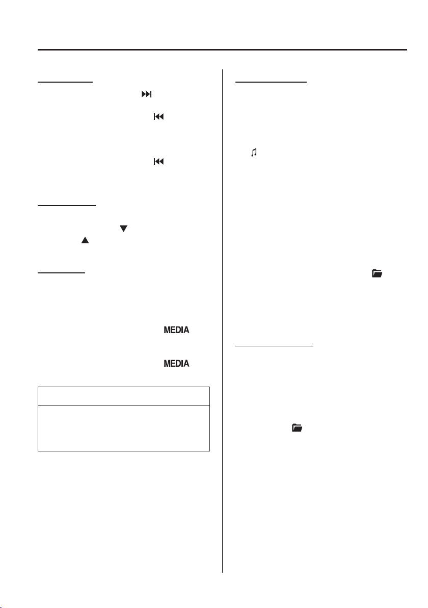
5
–
39
Interior Features
Audio Set [Type A (non-touchscreen)]
Track search
Press the track up button (
) once to skip
forward to the beginning of the next track.
Press the track down button (
) within a
few seconds after playback begins to track
down to the beginning of the previous
track.
Press the track down button (
) after a
few seconds have elapsed to start playback
from the beginning of the current track.
Folder search
To change to the previous folder, press the
folder down button (
), or press the folder
up button (
) to advance to the next
folder.
Music scan
This function scans the titles in a folder
currently being played and plays ten
seconds of each song to aid you in ¿ nding
a song you want to listen to.
Press and hold the scan button (
)
during playback to start the scan play
operation (the track number will À ash).
Press and hold the scan button (
)
again to cancel scan playback.
NOTE
If the unit is left in scan, normal
playback will resume where scan was
selected.
Repeat playback
Tr a c k r e p e a t
1. Press the repeat button ( 1 ) during
playback to play the current track
repeatedly. “ TRACK RPT ” is displayed
(
is displayed next to RPT at the
bottom of the display area).
2. To cancel the repeat playback, press the
button again after 3 seconds.
Folder repeat
1. Press the repeat button ( 1 ) during
playback, and then press the button
again within 3 seconds to play the
tracks in the current folder repeatedly.
“ FOLDER RPT ” is displayed (
is
displayed next to RPT at the bottom of
the display area).
2. Press the button again to cancel the
repeat playback.
Random playback
Tracks are randomly selected and played.
Folder random
1. Press the random button ( 2 ) during
playback to play the tracks in the folder
randomly. “ FOLDER RDM ” is
displayed (
is displayed next to RDM
at the bottom of the display area).
2. To cancel the random playback, press
the button again after 3 seconds.
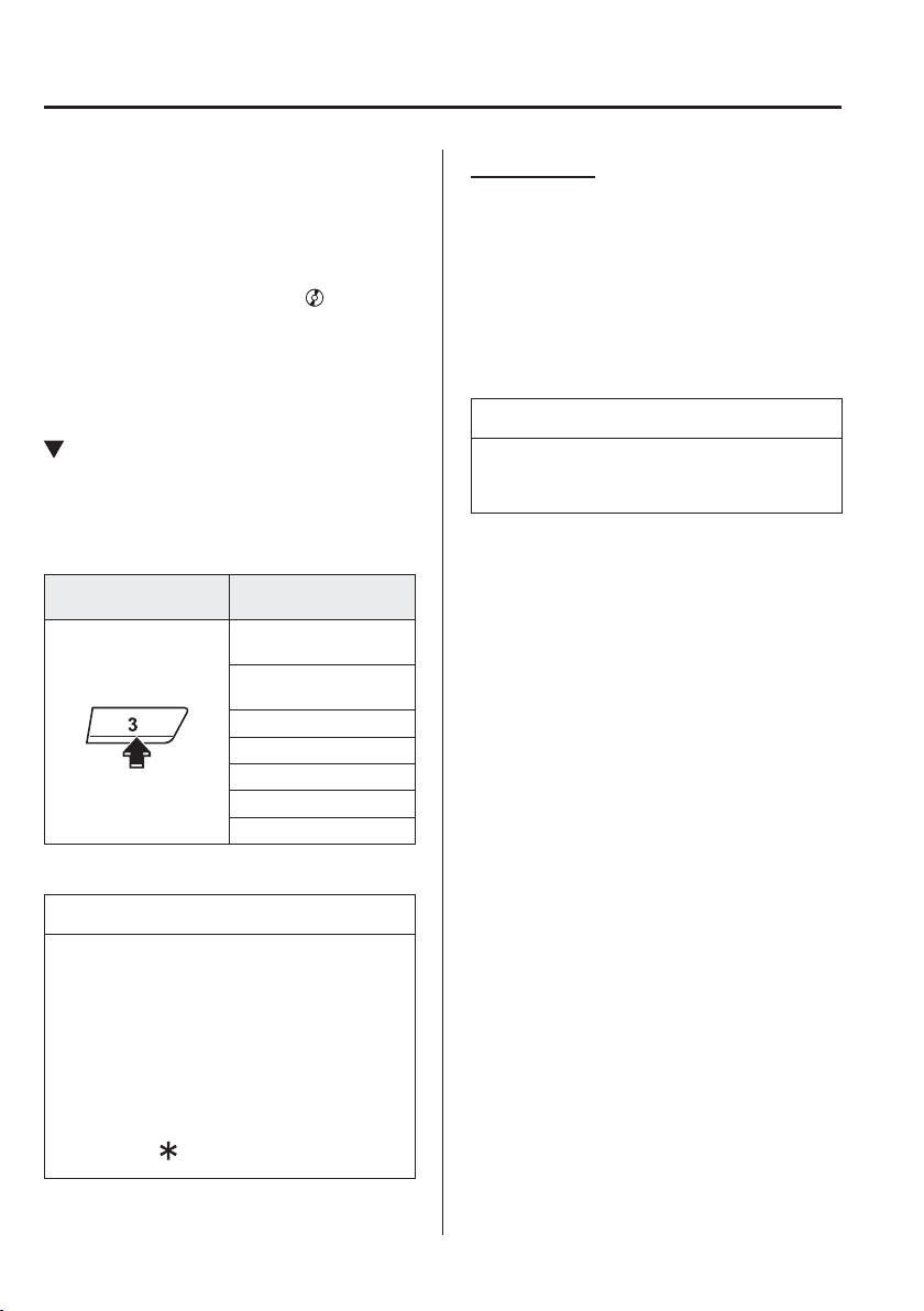
5
–
40
Interior Features
Audio Set [Type A (non-touchscreen)]
All random
1. Press the random button ( 2 ) during
playback, and then press the button
again within 3 seconds to play the
tracks in the USB device randomly.
“ ALL RDM ” is displayed (
is
displayed next to RDM at the bottom of
the display area).
2. Press the button again to cancel the
random playback.
Switching the display
The information displayed on the audio
display changes as follows each time the
text button ( 3 ) is pressed during playback.
Button
Information displayed
on audio display
File number/Elapsed
time
Folder number/File
number
File name
Folder name
Album name
Song name
Artist name
NOTE
The information (artist name, music
name) is displayed only when the
USB device information in the USB
device has information which can be
displayed on the screen.
This unit cannot display some
characters. Characters which cannot
be displayed are indicated by an
asterisk (
).
Display scroll
Only 13 characters can be displayed at one
time. To display the rest of the characters
of a long title, press and hold the text
button ( 3 ). The display scrolls the next 13
characters. Press and hold the text button
( 3 ) again after the last 13 characters have
been displayed to return to the beginning
of the title.
NOTE
The number of characters which can be
displayed is restricted.

MEMO
5
–
41
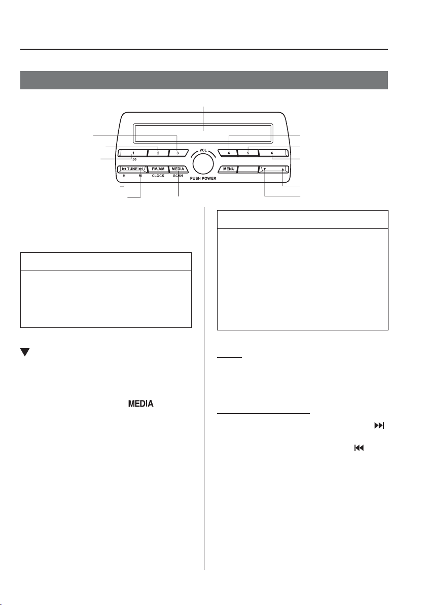
5
–
42
Interior Features
Audio Set [Type A (non-touchscreen)]
How to use iPod mode
Media/Scan button
List down button
List up button
Play/Pause button
Random button
Repeat button
Audio display
Text button
Track down/Reverse button
Track up/Fast-forward button
Category down button
Category up button
An iPod may not be compatible depending
on the model or OS version. In this case,
an error message is displayed.
NOTE
The iPod functions on the iPod cannot
be operated while it is connected to the
unit because the unit controls the iPod
functions.
Playback
1. Switch the ignition to ACC or ON.
2. Press the power/volume dial to turn the
audio system on.
3. Press the media button (
) to
switch to the iPod mode and start
playback.
NOTE
When an iPod is not connected, the
mode does not switch to the iPod
mode.
When there is no playable data in the
iPod, “ NO CONTENTS ” is À ashed.
Do not remove the iPod while in the
iPod mode. Otherwise, the data could
be damaged.
Pause
To stop playback, press the play/pause
button ( 4 ).
Press the button again to resume playback.
Fast-forward/Reverse
Press and hold the fast-forward button (
)
to advance through a track at high speed.
Press and hold the reverse button (
) to
reverse through a track at high speed.
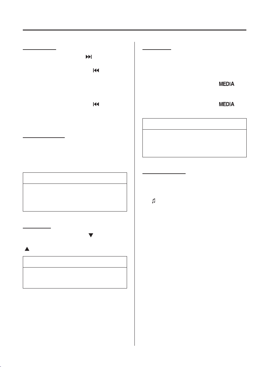
5
–
43
Interior Features
Audio Set [Type A (non-touchscreen)]
Track search
Press the track up button (
) once to skip
forward to the beginning of the next track.
Press the track down button (
) within a
few seconds (depends on iPod software
version) after playback begins to track
down to the beginning of the previous
track.
Press the track down button (
) after a
few seconds (depends on iPod software
version) have elapsed to start playback
from the beginning of the current track.
Category search
Press the category down button ( 5 ) to
select the previous category and press the
category up button ( 6 ) to select the next
category.
NOTE
The types of categories include Playlist,
Artist, Album, Song, Podcast, Genre,
Composer, and Audio book.
List search
Press the list down button (
) to select the
previous list and press the list up button
(
) to select the next list.
NOTE
When the selected category is Song or
Audio book, there is no list.
Music scan
This function scans the titles in a list
currently being played and plays 10
seconds of each song to aid you in ¿ nding
a song you want to listen to.
Press and hold the scan button (
)
during playback to start the scan play
operation (the track number will À ash).
Press and hold the scan button (
)
again to cancel scan playback.
NOTE
If the unit is left in scan, normal
playback will resume where scan was
selected.
Repeat playback
1. Press the repeat button ( 1 ) during
playback to play the current track
repeatedly. “ TRACK RPT ” is displayed
(
is displayed next to RPT at the
bottom of the display area).
2. Press the button again to cancel the
repeat playback.
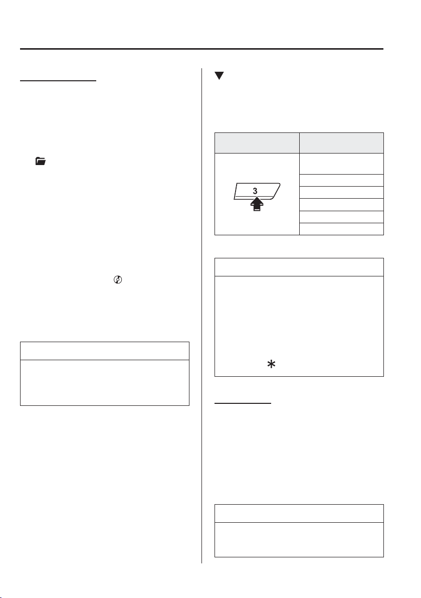
5
–
44
Interior Features
Audio Set [Type A (non-touchscreen)]
Random playback
Tracks are randomly selected and played.
Song random
1. Press the random button ( 2 ) during
playback to play the tracks in the list
randomly. “ SONG RDM ” is displayed
(
is displayed next to RDM at the
bottom of the display area).
2. To cancel the random playback, press
the button again after 3 seconds.
Album random
1. Press the random button ( 2 ) during
playback, and then press the button
again within 3 seconds to play the
tracks in the iPod randomly. “ ALBUM
RDM ” is displayed (
is displayed
next to RDM at the bottom of the
display area).
2. Press the button again to cancel the
random playback.
NOTE
The track number being played
randomly is in the order of the iPod
shufÀ e table.
Switching the display
The information displayed on the audio
display changes as follows each time the
text button ( 3 ) is pressed during playback.
Button
Information displayed
on audio display
File number/Elapsed
time
File number
Category name
Artist name
Album name
Song name
NOTE
The information (artist name, music
name) is displayed only when the
iPod has information which can be
displayed.
This unit cannot display some
characters. Characters which cannot
be displayed are indicated by an
asterisk (
).
Display scroll
13 characters can be displayed at one
time. To display the rest of the characters
of a long title, press and hold the text
button ( 3 ). The display scrolls the next 13
characters. Press and hold the text button
( 3 ) again after the last 13 characters have
been displayed to return to the beginning
of the title.
NOTE
The number of characters which can be
displayed is restricted.

5
–
45
Interior Features
Audio Set [Type A (non-touchscreen)]
Error Indications
If you see an error indication on the
display, take appropriate action according
to the following methods. If you cannot
clear the error indication, take the vehicle
to an expert repairer, we recommend an
Authorised Mazda Repairer.
CHECK CD
If “ CHECK CD ” is displayed, it means
that there is some CD malfunction. Check
the CD for damage, dirt, or smudges, and
then properly reinsert it. If the message
appears again, insert another known good
CD.
CHECK USB
When the message “ CHECK USB ” is
displayed, it indicates that there is some
error in the USB device. Verify that the
content recorded in the USB device has
MP3/WMA/AAC ¿ les and re-connect
correctly.
CHECK iPod
If the message “ CHECK iPod ” is
displayed, it indicates that there is a
malfunction in the iPod. Verify that the
content recorded in the iPod has playable
¿ les and connect correctly.

5
–
46
Interior Features
Audio Set [Type A (non-touchscreen)]
*Some models.
Bluetooth
®
*
Introduction
Bluetooth
®
Hands-Free outline
When a Bluetooth
®
device (mobile phone) is connected to the vehicle's Bluetooth
®
unit via
radio wave transmission, a call can be made or received by pressing the talk button, pick-
up button, or hang-up button on the audio remote control switch, or by operating the centre
display. For example, even if a device (mobile phone) is in your coat pocket, a call can be
made without taking the device (mobile phone) out and operating it directly.
Bluetooth
®
audio outline
When a portable audio unit equipped with the Bluetooth
®
communication function is paired
to the vehicle, you can listen to music stored on the paired portable audio device from the
vehicle's speakers. It is not necessary to connect the portable audio device to the vehicle's
external input terminal. After programming, operate the vehicle audio control panel to play/
stop the audio.
NOTE
For your safety, a device can be paired only when the vehicle is parked. If the vehicle
starts to move, the pairing procedure will end. Park the vehicle in a safe place before
pairing.
The communication range of a Bluetooth
®
equipped device is about 10 meters (32 ft)
or less.
Basic audio operation is available using voice commands even if Bluetooth
®
is not
connected.
For safety reasons, operation of the centre display is disabled while the vehicle is being
driven. However, items not displayed in grey can be operated using the commander
switch while the vehicle is being driven.
5
–
47
Interior Features
Audio Set [Type A (non-touchscreen)]
CAUTION
Some Bluetooth
®
mobile devices are not compatible with the vehicle. Consult an
Authorised Mazda Repairer, Mazda's call centre or Web support centre for information
regarding Bluetooth
®
mobile device compatibility:
Phone:
(Germany)
0800 4263 738 (8:00—18:00 Central European Time)
(Except Germany)
00800 4263 7383 (8:00—18:00 Central European Time)
(Worldwide)
49 (0) 6838 907 287 (8:00—18:00 Central European Time)
Web:
http://www.mazdahandsfree.com
Applicable Bluetooth
®
speci¿ cation (Recommended)
Ver. 2.0
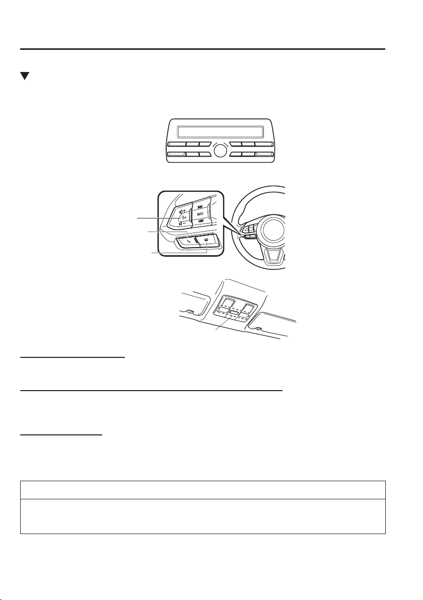
5
–
48
Interior Features
Audio Set [Type A (non-touchscreen)]
Component Parts
Microphone
Talk button, Pick-up button and Hang-up button
Microphone
Audio unit
Talk button
Hang-up button
Pick-up button
Microphone (hands-free)
The microphone is used for speaking voice commands or when making a Hands-free call.
Talk button, Pick-Up button and Hang-Up button (hands-free)
The basic functions of Bluetooth
®
Hands-Free can be used for such things as making calls or
hanging up using the talk, pick-up and hang-up buttons on the steering wheel.
Volume adjustment
The power/volume dial of the audio unit is used to adjust the volume. Turn the dial to the
right to increase volume, to the left to decrease it.
The volume can also be adjusted using the volume button on the steering wheel.
NOTE
If the volume is lower compared to other audio modes, increase the volume from the
device side.
5
–
49
Interior Features
Audio Set [Type A (non-touchscreen)]
*Some models.
Bluetooth
®
Preparation
*
Bluetooth
®
Hands-Free
Preparation
Pairing code setting
The 4-digit pairing code setting for
registration of your cell phone (pairing)
can be set beforehand.
NOTE
The initial setting value is “0000”.
1. Press the pick-up button or talk button
with a short press.
2. Say: [Beep] “Setup”
3. Prompt: “Select one of the following:
Pairing options, con¿ rmation prompts,
language, password, select phone or
select music player.”
4. Say: [Beep] “Pairing options”
5. Prompt: “Select one of the following:
Pair, Edit, Delete, List, or Set pin
Code.”
6. Say: [Beep] “Set pin code”
7. Prompt: “Your current pin code is
XXXX. Do you want to change it to a
different pairing pin code?”
8. Say: [Beep] “Yes”
9. Prompt: “Please say a 4-digit pairing
code.”
10. Say: [Beep] “YYYY”
11. Prompt: “YYYY is this correct?”
12. Say: [Beep] “Yes” or “No”
13. If “Yes”, go to Step 14. If “No”, the
procedure returns to Step 9.
14. Prompt: “Your new pairing pin code is
YYYY. Use this pin code when pairing
devices to the Hands free system. Do
you want to pair a device now?”
15. Say: [Beep] “Yes” or “No”
16. If “Yes”, the system switches to the
device registration mode. If “No”, the
system returns to standby status.
Device pairing (Bluetooth
®
Hands-
Free)
To use Bluetooth
®
Hands-Free, the device
equipped with Bluetooth
®
has to be paired
to the Bluetooth
®
unit using the following
procedure.
A maximum of seven devices including
hands-free mobile phones and Bluetooth
®
audio devices can be paired to one vehicle.
NOTE
A device can be paired only when
the vehicle is parked. If the vehicle
starts to move, the pairing procedure
will end. Pairing is dangerous while
driving - pair up your device before
you start driving. Park the car in a
safe place before paired.
If a Bluetooth
®
device has already
been paired to the vehicle as a
Bluetooth
®
audio device, it does not
need to be paired again when using
the device as a hands-free mobile
phone. Conversely, it does not need
to be paired again as a Bluetooth
®
audio device if it has already been
paired as a hands-free mobile phone.
Since the communication range of
a Bluetooth
®
equipped device is
about 10 meters (32 ft), if a device is
placed within a 10-meter
(32 ft) radius of the vehicle, it may
be detected/paired unintentionally
while another device is being paired.
5
–
50
Interior Features
Audio Set [Type A (non-touchscreen)]
1. Activate the Bluetooth
®
application of
the device.
NOTE
For the operation of the device, refer to
its instruction manual.
2. Press the pick-up button or talk button
with a short press.
3. Say: [Beep] “Setup”
4. Prompt: “Select one of the following:
Pairing options, con¿ rmation prompts,
language, password, select phone or
select music player.”
5. Say: [Beep] “Pairing options”
6. Prompt: “Select one of the following:
Pair, edit, delete, list, or set pin code.”
7. Say: [Beep] “Pair”
8. Prompt: “Start the pairing process on
your Bluetooth
®
device. Your pin code
is 0000 (XXXX). Input this on your
Bluetooth
®
device. See device manual
for instructions.”
9. Using the device, perform a search
for the Bluetooth
®
device (Peripheral
device).
NOTE
For the operation of the device, refer to
its instruction manual.
10. Select “Mazda” from the device list
searched by the device.
11. Input the 4-digit pairing code to the
device.
12. Prompt: “Please say the name of the
device after the beep.”
13. Say: [Beep] “XXXX - - -” (Speak a
“device tag”, an arbitrary name for the
device.)
Example: “Stan's device.”
NOTE
Say a paired “device tag” within
10 seconds.
If more than two devices are to be
paired, they cannot be paired with the
same or similar “device tag”.
14. Prompt: “Adding XXXXXX - - - (Ex.
“Stan's device”) (Device tag). Is this
correct?”
15. Say: [Beep] “Yes”
16. Prompt: “Pairing complete”
After a device is registered, the system
automatically identi¿ es the device. By
activating Bluetooth
®
Hands-Free again,
or by activating Bluetooth
®
Hands-Free
¿ rst after switching the ignition from
OFF to ACC, the system reads out a voice
guidance, “XXXXXX - - - (Ex. “Stan's
device”) (Device tag) is connected”.
NOTE
When the pairing is completed, the
symbol is displayed.
Some Bluetooth
®
audio devices need
a certain amount of time before the
symbol is displayed.
Device registration can also be done
by operating the audio unit.
Depending on the device, the
registration status may be lost after a
certain period of time. If this occurs,
repeat the entire process from Step 1.

5
–
51
Interior Features
Audio Set [Type A (non-touchscreen)]
Registered device read-out
Bluetooth
®
Hands-Free can read-out the
devices registered to its system.
NOTE
Do this function only when parked. It is
too distracting to attempt while driving
and you may make too many errors to
be effective.
1. Press the pick-up button or talk button
with a short press.
2. Say: [Beep] “Setup”
3. Prompt: “Select one of the following:
Pairing options, con¿ rmation prompts,
language, password, select phone or
select music player.”
4. Say: [Beep] “Pairing options”
5. Prompt: “Select one of the following:
Pair, edit, delete, list, or set pin code.”
6. Say: [Beep] “List”
7. Prompt: “XXXXX..., XXXXX...,
XXXXX... (Ex. Device A, device B,
device C)” (The voice guidance reads
out the device tags registered to the
hands-free system.)
Press the talk button with a short press
during the read-out at the desired
device, and then say one of the
following voice commands to execute
it.
“Select phone”: Selects device
(Mobile phone) when the talk button
is short-pressed.
“Select music player”: Selects device
(Music player) when the talk button is
short-pressed.
“Edit”: Edits device when the talk
button is short-pressed.
“Continue”: Continues the list read-
out.
“Delete”: Deletes the registered
device when the talk button is short-
pressed.
“Previous”: Returns to the previous
device in read-out when the talk
button is short-pressed.
8. Prompt: “End of list, would you like to
start from the beginning?”
9. Say: [Beep] “No”
10. Prompt: “Returning to main menu.”
5
–
52
Interior Features
Audio Set [Type A (non-touchscreen)]
Device selection (Bluetooth
®
Hands-Free)
If several devices have been paired, the
Bluetooth
®
unit links the device last
paired. If you would like to link a different
paired device, it is necessary to change the
link. The order of device priority after the
link has been changed is maintained even
when the ignition is switched off.
(Hands-free phone)
1. Press the pick-up button or talk button
with a short press.
2. Say: [Beep] “Setup”
3. Prompt: “Select one of the following:
Pairing options, con¿ rmation prompts,
language, password, select phone or
select music player.”
4. Say: [Beep] “Select phone”
5. Prompt: “Please say the name of
the device you would like to select.
Available devices are XXXXX... (Ex.
device A), XXXXX... (Ex. device B),
XXXXX... (Ex. device C). Which
device please?”
6. Say: [Beep] “X” (Say the number for
the mobile phone to be connected.)
7. Prompt: “XXXXX... (Ex. device B...)
(Registered device tag) is this correct?”
8. Say: [Beep] “Yes”
9. Prompt: “XXXXX... (Ex. device B...)
(Device tag) selected.”
(Music player)
1. Press the pick-up button or talk button
with a short press.
2. Say: [Beep] “Setup”
3. Prompt: “Select one of the following:
Pairing options, con¿ rmation prompts,
language, password, select phone or
select music player.”
4. Say: [Beep] “Select music player”
5. Prompt: “Please say the name of
the device you would like to select.
Available devices are XXXXX... (Ex.
device A), XXXXX... (Ex. device B),
XXXXX... (Ex. device C). Which
device please?”
6. Say: [Beep] “X” (Say the number for
the music player to be connected.)
7. Prompt: “XXXXX... (Ex. device B...)
(Registered device tag) is this correct?”
8. Say: [Beep] “Yes”
9. Prompt: “XXXXX... (Ex. device B...)
(Device tag) selected.”
NOTE
When the selected device connection
is completed, the
or symbol is
displayed.
Some Bluetooth
®
audio devices need
a certain amount of time before the
or
symbol is displayed.
Device (Music player) selection can
also be done by operating the panel
button.
5
–
53
Interior Features
Audio Set [Type A (non-touchscreen)]
Deleting a device (Bluetooth
®
Hands-Free)
Registered devices (Mobile phone) can be
deleted individually or collectively.
NOTE
Do this function only when parked. It is
too distracting to attempt while driving
and you may make too many errors to
be effective.
1. Press the pick-up button or talk button
with a short press.
2. Say: [Beep] “Setup”
3. Prompt: “Select one of the following:
Pairing options, con¿ rmation prompts,
language, password, select phone or
select music player.”
4. Say: [Beep] “Pairing options”
5. Prompt: “Select one of the following:
Pair, edit, delete, list, or set pin code.”
NOTE
A registered device (Mobile phone) can
be deleted using the registration list.
6. Say: [Beep] “Delete”
7. Prompt: “Please say the name of
the device you would like to delete.
Available devices are XXXXX... (Ex.
device A), XXXXX... (Ex. device
B), XXXXX... (Ex. device C), or all.
Which device please?”
8. Say: [Beep] “X” (Say the number of
the device to be deleted.)
NOTE
Say “All” to delete all devices (Mobile
phone).
9. Prompt: “Deleting XXXXX... (Ex.
device B...) (Registered device tag). Is
this correct?”
10. Say: [Beep] “Yes”
11. Prompt: “Deleted”
Registered device editing
(Bluetooth
®
Hands-Free)
1. Press the pick-up button or talk button
with a short press.
2. Say: [Beep] “Setup”
3. Prompt: “Select one of the following:
Pairing options, con¿ rmation prompts,
language, password, select phone or
select music player.”
4. Say: [Beep] “Pairing options”
5. Prompt: “Select one of the following:
Pair, edit, delete, list, or set pin code.”
6. Say: [Beep] “Edit”
7. Prompt: “Please say the name of the
device you would like to edit. Available
devices are XXXXX... (Ex. device A),
XXXXX... (Ex. device B), XXXXX...
(Ex. device C). Which device please?”
8. Say: [Beep] “X” (Say the number of
the device to be edited.)
9. Prompt: “New name please?”
10. Say: [Beep] “XXXXX... (Ex. device
C)” (Speak a “device tag”, an arbitrary
name for the device.)
11. Prompt: “XXXXX... (Ex. device C)
(Device tag), is this correct?”
12. Say: [Beep] “Yes”
13. Prompt: “New name saved.”
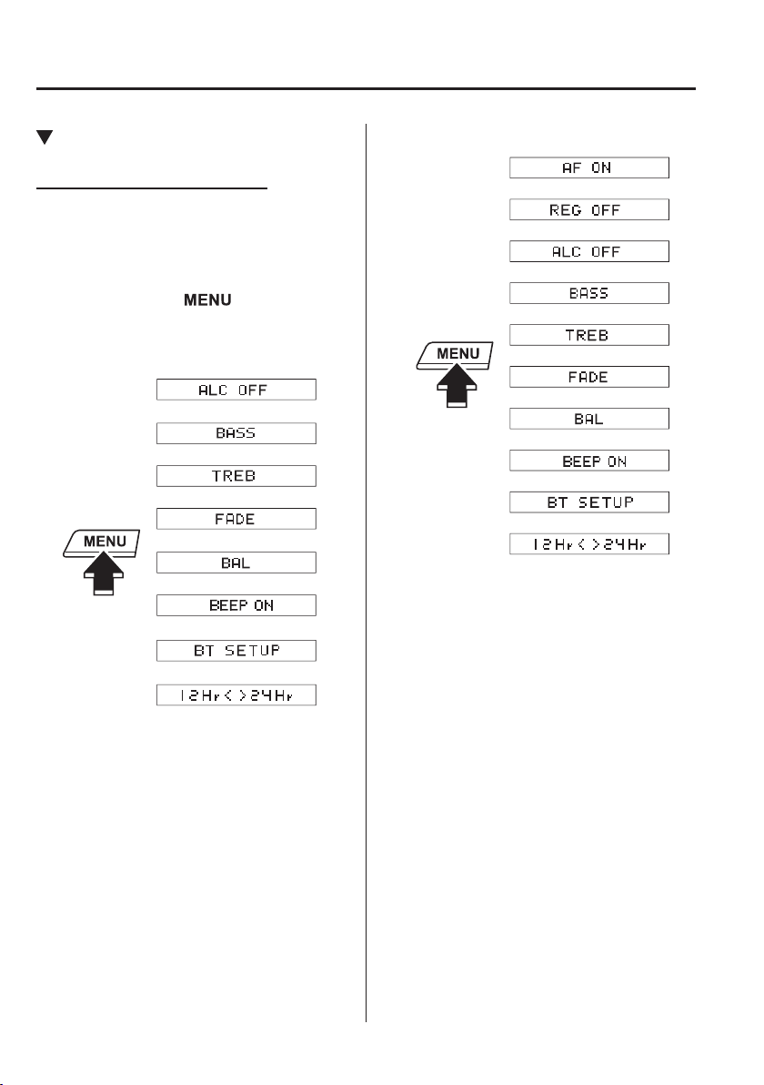
5
–
54
Interior Features
Audio Set [Type A (non-touchscreen)]
Bluetooth
®
Audio Preparation
Bluetooth
®
audio device set-up
Bluetooth
®
audio pairing, changes,
deletions, and display of paired device
information can be performed.
1. The mode changes as follows each time
the menu button (
) is pressed.
Select “ BT SETUP ”.
Without Radio Data System (RDS)
*
*
With Radio Data System (RDS)
*
*
*
*
* Depending on the mode selected, the
indication changes.
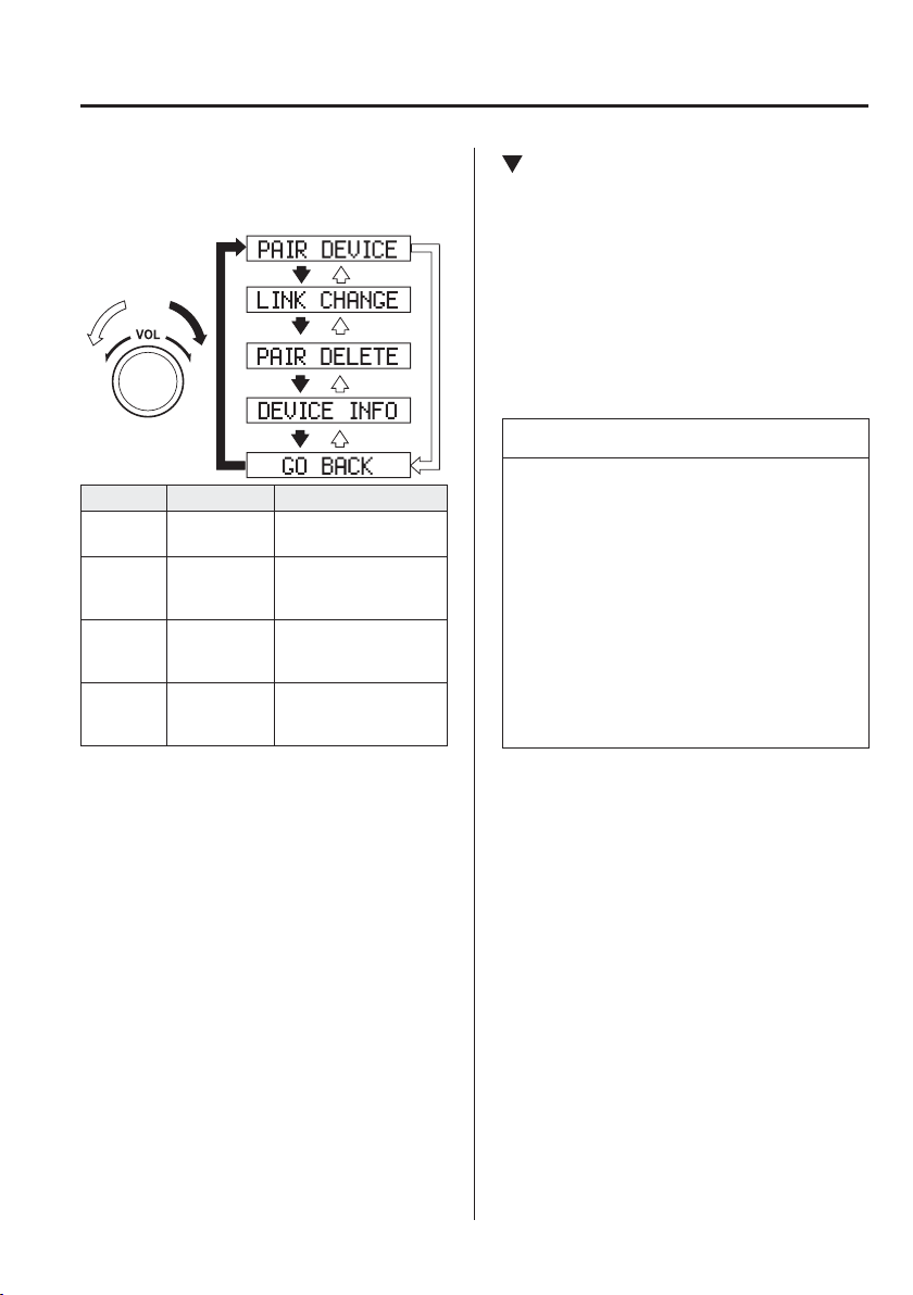
5
–
55
Interior Features
Audio Set [Type A (non-touchscreen)]
2. Turn the audio control dial and select a
desired mode.
Display Mode Function
PAIR
DEVICE
Pairing mode
Bluetooth
®
audio
device pairing
LINK
CHANGE
Link change
mode
Changing link to
Bluetooth
®
audio
device
PAIR
DELETE
Pairing
deletion
mode
Deleting link to
Bluetooth
®
audio
device
DEVICE
INFO
Device
information
display mode
Displaying vehicle's
Bluetooth
®
unit
information
3. Press the audio control dial to
determine the mode.
Bluetooth
®
audio device pairing
(Bluetooth
®
Audio)
Any Bluetooth
®
audio device must be
paired to the vehicle's Bluetooth
®
unit
before it can be listened to over the
vehicle's speakers.
A maximum of seven devices including
Bluetooth
®
audio devices and hands-
free mobile phones can be paired to one
vehicle.
NOTE
If a Bluetooth
®
device has already
been paired to the vehicle as a hands-
free mobile phone, it does not need
to be paired again when using the
device as a Bluetooth
®
audio device.
Conversely, it does not need to be
paired again as a hands-free mobile
phone if it has already been paired as
a Bluetooth
®
audio device.
Device registration can also be done
using voice recognition.
Concerning the operation of a Bluetooth
®
audio device itself, refer to its instruction
manual.
Some Bluetooth
®
audio devices have PIN
codes (four digits). Refer to the audio
device's instruction manual because the
pairing procedure differs depending on
whether it has a PIN code or not.
5
–
56
Interior Features
Audio Set [Type A (non-touchscreen)]
Pairing a Bluetooth
®
audio device which
has a four-digit PIN code
1. Using the audio control dial, select
the pairing mode “ PAIR DEVICE ”
in the “ BT SETUP ” mode. (Refer to
“Bluetooth
®
audio device set-up” for
details.)
2. Press the audio control dial to
determine the mode.
After “ ENTER PIN ” is displayed on
the audio display for three seconds,
“ PIN 0000 ” is displayed and the PIN
code can be input.
3. Input the PIN code of your Bluetooth
®
audio device by pressing channel preset
buttons 1 to 4 while “ PIN 0000 ” is
displayed.
Press channel preset button 1 to input
the ¿ rst digit, 2 for the second, 3 for the
third, and 4 for the forth. For example,
if the PIN code were “4213”, press
channel preset button 1 four times
(1, 2, 3, 4), button 2 twice (1, 2), button
3 once (1), and button 4 three times
(1, 2, 3). If the “ PIN 0000 ” display
disappears before ¿ nishing the PIN
code input, repeat the procedure from
Step 1.
NOTE
Some devices accept only a particular
pairing code (Usually, “0000” or
“1234”).
If pairing cannot be completed, refer
to the owner's manual of your mobile
device, and try those numbers if
necessary.
4. Press the audio control dial while the
input PIN code is displayed.
“ PAIRING ” À ashes on the display.
5. Operate the Bluetooth
®
audio device
and set it to the pairing mode while
“ PAIRING ” is À ashing.
6. When the pairing is completed, “
” and
“ PAIR SUCCESS ” are displayed after
about 10-30 seconds, after which
“ PAIR SUCCESS ” continues to be
displayed for three seconds, and then
the unit returns to the normal display.
NOTE
Some Bluetooth
®
audio devices need
a certain amount of time before the
“
” symbol is displayed.
If the pairing failed, “ Err ” À ashes for
three seconds.
Pairing cannot be performed while
the vehicle is moving. If you attempt
to perform pairing while the vehicle
is moving, “ PAIR DISABLE ” is
displayed.
If seven Bluetooth
®
audio devices
have already been paired to the
vehicle, pairing cannot be performed
and “ MEMORY FULL ” is displayed.
Delete one paired device to pair
another one.
Pairing a Bluetooth
®
audio device which
does not have a four-digit PIN code
1. Using the audio control dial, select
the pairing mode “ PAIR DEVICE ”
in the “ BT SETUP ” mode. (Refer to
“Bluetooth
®
audio set up” for details.)
2. Press the audio control dial to
determine the mode. After “ ENTER
PIN ” is displayed on the audio display
for three seconds, “ PIN 0000 ” is
displayed and the PIN code can be
input.
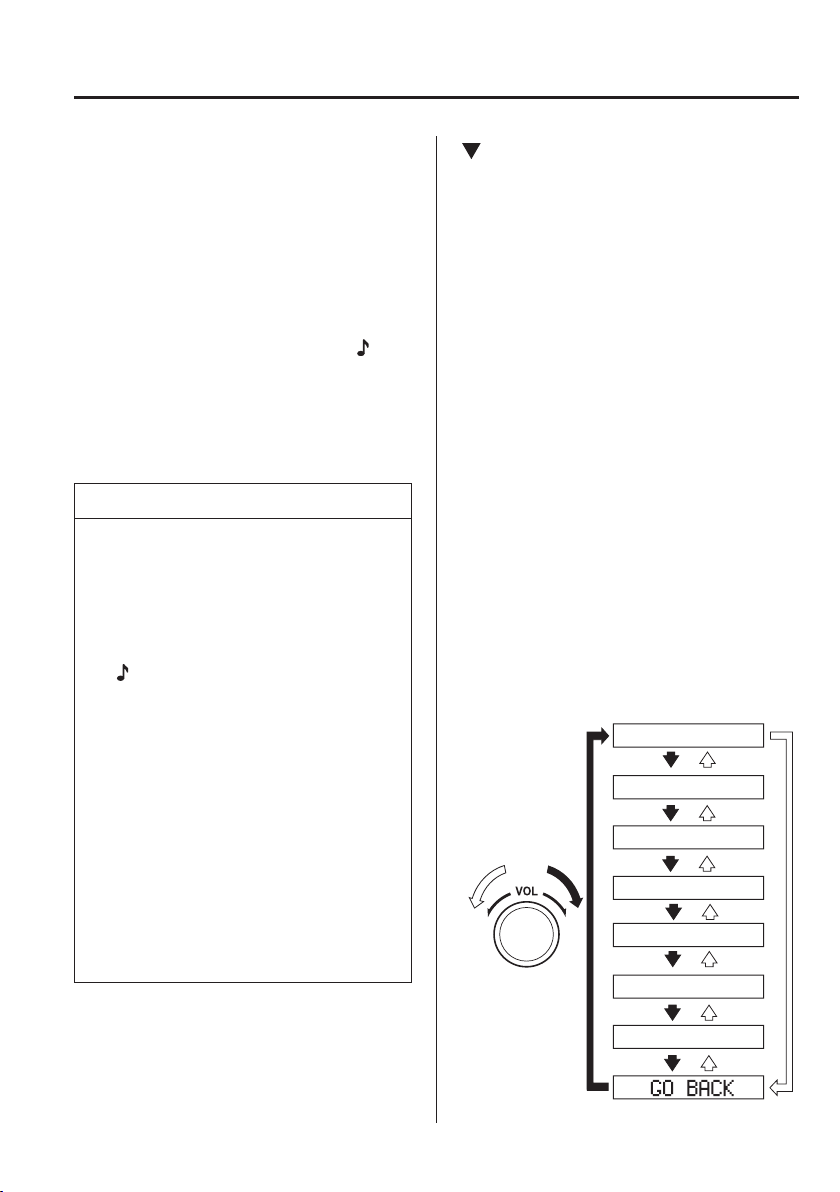
5
–
57
Interior Features
Audio Set [Type A (non-touchscreen)]
3. Press the audio control dial while “ PIN
0000 ” is displayed.
“ PAIRING ” À ashes on the audio
display.
4. Operate the Bluetooth
®
audio device
and set it to the pairing mode while
“ PAIRING ” is À ashing.
5. As the Bluetooth
®
audio device
requires a PIN code, input “0000”.
6. When the pairing is completed, “
” and
“ PAIR SUCCESS ” are displayed after
about 10-30 seconds, after which
“ PAIR SUCCESS ” continues to be
displayed for three seconds, and then
the unit returns to the normal display.
NOTE
If pairing cannot be completed, try
“1234” instead. Refer to the owner's
manual of your mobile device for the
right PIN code.
Some Bluetooth
®
audio devices need
a certain amount of time before the
“
” symbol is displayed.
If the pairing failed, “ Err ” À ashes for
three seconds.
Pairing cannot be performed while
the vehicle is moving. If you attempt
to perform pairing while the vehicle
is moving, “ PAIR DISABLE ” is
displayed.
If seven Bluetooth
®
audio devices
have already been paired to the
vehicle, pairing cannot be performed
and “ MEMORY FULL ” is displayed.
Delete one paired device to pair
another one.
Device selection (Bluetooth
®
Audio)
If several devices have been paired, the
Bluetooth
®
unit links the device last
paired. If you would like to link a different
paired device, it is necessary to change the
link. The order of device priority after the
link has been changed is maintained even
when the ignition is switched off.
1. Using the audio control dial, select the
link change mode “ LINK CHANGE ”
in the “ BT SETUP ” mode. (Refer to
“Bluetooth
®
audio device set-up” for
details.)
2. Press the audio control dial to
determine the mode.
3. The name of the currently linked
Bluetooth
®
audio device is displayed.
If no Bluetooth
®
audio device is
currently linked, the name of the ¿ rst
device among the paired devices is
displayed.
4. Turn the audio control dial to select the
name of the device you would like to
link.
Device name 1
Device name 2
Device name 3
Device name 4
Device name 5
Device name 6
Device name 7
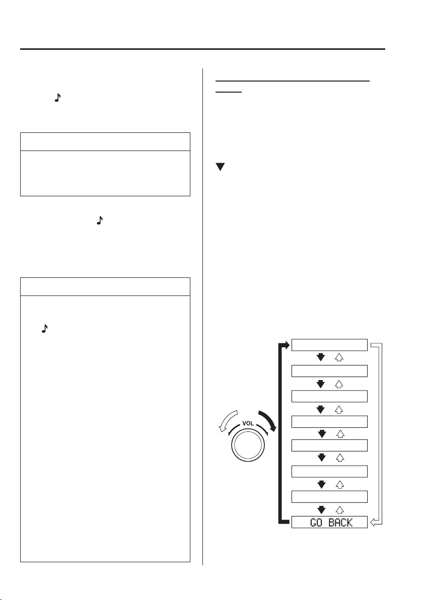
5
–
58
Interior Features
Audio Set [Type A (non-touchscreen)]
5. Press the audio control dial to select the
device you would like to link.
The “
” symbol disappears, and
“ PAIRING ” À ashes in the audio
display.
NOTE
When “ GO BACK ” is selected and the
audio control dial is pressed, the display
returns to “ LINK CHANGE ”.
6. If the link to the desired device is
successful, the “
” symbol is displayed
again, together with “ LINK
CHANGED ”. “ LINK CHANGED ” is
displayed for three seconds, then it
returns to the normal display.
NOTE
Some Bluetooth
®
audio devices need
a certain amount of time before the
“
” symbol is displayed.
If a hands-free type mobile phone has
been the most recently paired device,
the Bluetooth
®
unit links this device.
If you would like to use a Bluetooth
®
audio type device which has been
previously paired to the Bluetooth
®
unit, the link must be changed to this
device.
If an error occurs while trying to link
a device, “ Err ” À ashes in the display
for three seconds, and the display
returns to “ LINK CHANGE ”. If this
occurs, check the pairing status of
the Bluetooth
®
audio device and the
location of the device in the vehicle
(not in the luggage compartment/
boot or a metal-type box), and then
try the link operation again.
Device selection can also be done
using voice recognition.
H o w t o c o n ¿ rm the device currently
linked
Switch to the link-change mode. (Refer to
“Changing the link to a Bluetooth
®
audio
device”)
The device name displayed ¿ rst is the
device which is currently linked.
Deleting a device (Bluetooth
®
Audio)
1. Using the audio control dial, select the
pairing delete mode “ PAIR DELETE ”
in the “ BT SETUP ” mode. (Refer to
“Bluetooth
®
audio device set-up” for
details.)
2. Press the audio control dial to
determine the mode.
3. The name of the ¿ rst device among the
paired devices is displayed.
4. Rotate the audio control dial and select
the name of the paired device you
would like to delete.
Device name 1
Device name 2
Device name 3
Device name 4
Device name 5
Device name 6
Device name 7
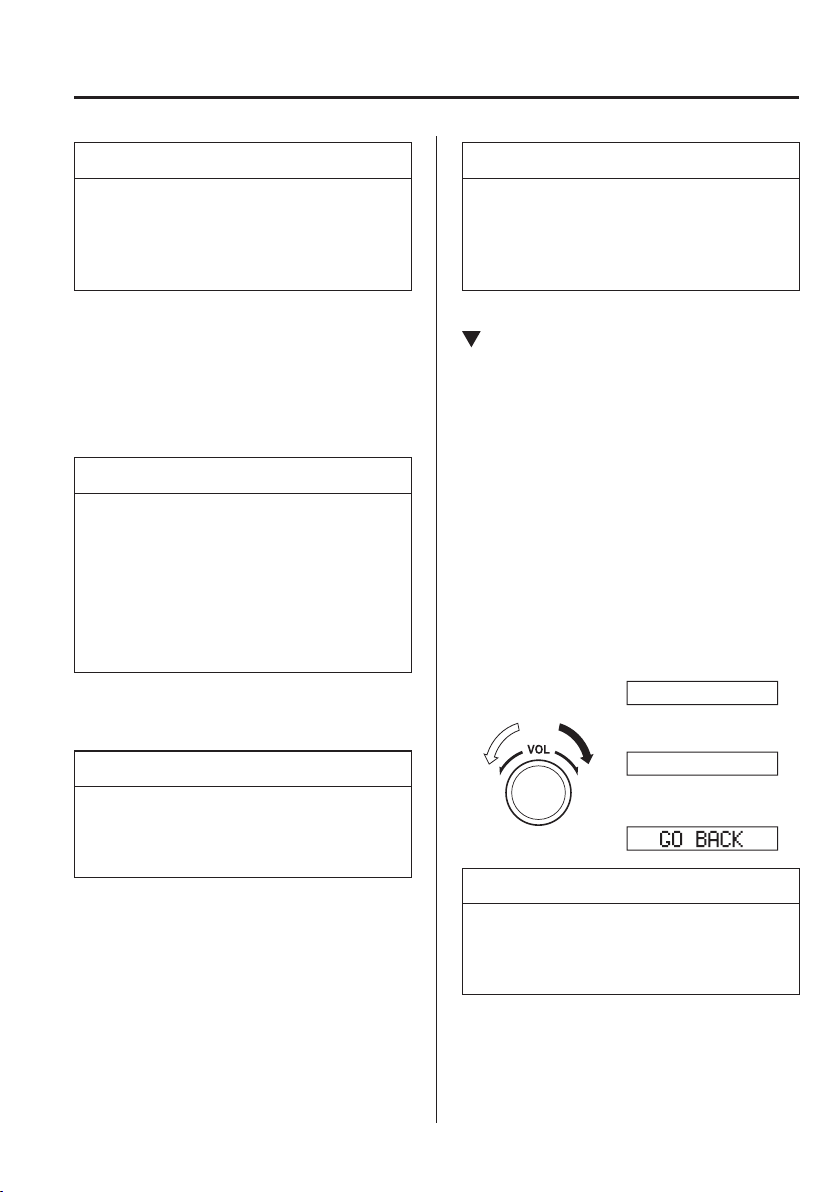
5
–
59
Interior Features
Audio Set [Type A (non-touchscreen)]
NOTE
Only the names of paired devices can
be displayed. If only one device is
paired, only the name for this device is
displayed.
5. If a selection other than “ GO BACK ”
is made and the audio control dial is
pressed, “ SURE ? NO ” is displayed.
6. Rotate the audio control dial clockwise
and switch the display to “ SURE ?
YES ”.
NOTE
The display changes as follows
depending on whether the audio
control dial is rotated clockwise or
anticlockwise.
-Clockwise: “ SURE ? YES ” displayed
-Anticlockwise: “ SURE ? NO ”
displayed
7. Press the audio control dial to delete
the selected device.
NOTE
Select “ GO BACK ” and press the audio
control dial to return to the “ PAIR
DELETE ” display.
8. “ PAIR DELETED ” is displayed for
three seconds after the deletion is
completed, and then it returns to the
normal display.
NOTE
If an error occurs while trying to delete
the paired device, “ Err ” À ashes in the
display for three seconds and the display
returns to “ LINK DELETE ”.
Bluetooth
®
audio device
information display
1. Using the audio control dial, select the
pair device information display mode
“ DEVICE INFO ” in the “ BT SETUP ”
mode. (Refer to “Bluetooth
®
audio
device set-up” for details.)
2. Press the audio control dial to
determine the mode.
3. The name of the Bluetooth
®
unit device
is displayed.
4. Rotate the audio control dial to select
the information for the Bluetooth
®
unit
which you would like to view.
Device name
BT address
NOTE
When “ GO BACK ” is selected and the
audio control dial is pressed, the display
returns to “ DEVICE INFO ”.
5
–
60
Interior Features
Audio Set [Type A (non-touchscreen)]
*Some models.
Available Language
*
The available languages are English,
French, Spanish, Italian, German, Dutch,
and Portuguese. If the language setting
is changed, all of the voice guidance and
voice input commands are done in the
selected language.
NOTE
If the language setting is changed,
device registration is maintained.
Phonebook records are not cleared,
but each language has a separate
phonebook. Therefore, entries
created in one language will need to
be re-entered in the phonebook of the
new language.
Do these steps before you start
driving. These less used functions
are too distracting to undertake while
driving until you are fully familiar
with the system.
(Method 1)
1. Press the pick-up button or talk button
with a short press.
2. Say: [Beep] “Setup”
3. Prompt: “Select one of the following:
Pairing options, con¿ rmation prompts,
language, password, select phone or
select music player.”
4. Say: [Beep] “Language”
5. Prompt: “Select a language: English,
French, Spanish, Italian, German,
Dutch, or Portuguese.”
6. Say: [Beep] “French” (Speak the
desired language: “English”, “French”,
“Spanish”, “Italian”, “German”,
“Dutch”, or “Portuguese”)
NOTE
Other language settings can also be
made while in the current setting by
saying the name of the language in the
native pronunciation.
7. Prompt: “French (Desired language)
selected. Is this correct?”
8. Say: [Beep] “Yes”
9. Prompt: “Please wait. Switching to
French phonebook. French selected.”
(Spoken in the newly selected
language).
(Method 2)
1. Press the pick-up button or talk button
with a short press.
2. Say: [Beep] “French” (Say the desired
language: “English”, “French”,
“Spanish”, “Italian”, “German”,
“Dutch”, or “Portuguese”). (Change
the desired language by saying the
language name.)
NOTE
Other language settings can also be
made while in the current setting by
saying the name of the language in the
native pronunciation.
3. Prompt: “Would you like to change
the language to French (Desired
language)?”
4. Say: [Beep] “Yes”
5. Prompt: “Please wait. Switching to
French phonebook. French selected.”
(Spoken in the newly selected
language).
5
–
61
Interior Features
Audio Set [Type A (non-touchscreen)]
*Some models.
Security Setting
*
If a password is set, the system cannot be
activated unless the password is input.
NOTE
Do this function only when parked. It is
too distracting to attempt while driving
and you may make too many errors to
be effective.
Password setting
1. Press the pick-up button or talk button
with a short press.
2. Say: [Beep] “Setup”
3. Prompt: “Select one of the following:
Pairing options, con¿ rmation prompts,
language, password, select phone or
select music player.”
4. Say: [Beep] “Password”
5. Prompt: “Password is disabled. Would
you like to enable it?”
6. Say: [Beep] “Yes”
7. Prompt: “Please say a 4-digit
password. Remember this password. It
will be required to use this system.”
8. Say: [Beep] “XXXX” (Say a desired
4-digit password, “PCode”.)
9. Prompt: “Password XXXX (Password,
PCode). Is this correct?”
10. Say: [Beep] “Yes”
11. Prompt: “Password is enabled.”
Using Bluetooth
®
Hands-Free with a
password
1. Press the pick-up button or talk button
with a short press.
2. Prompt: “Hands-Free system
is locked. State the password to
continue.”
3. Say: [Beep] “XXXX” (Say the set
password “PCode”.)
4. If the correct password is input, voice
guidance “XXXXXX... (Ex. “Mary's
device”) (Device tag) is connected” is
announced.
If the password is incorrect, voice
guidance “XXXX (4-digit password,
Pcode) incorrect password, please try
again” is announced.
Cancelling the password
NOTE
Do this function only when parked. It is
too distracting to attempt while driving
and you may make too many errors to
be effective.
1. Press the pick-up button or talk button
with a short press.
2. Say: [Beep] “Setup”
3. Prompt: “Select one of the following:
Pairing options, con¿ rmation prompts,
language, password, select phone or
select music player.”
4. Say: [Beep] “Password”
5. Prompt: “Password is enabled. Would
you like to disable it?”
6. Say: [Beep] “Yes”
7. Prompt: “Password is disabled.”
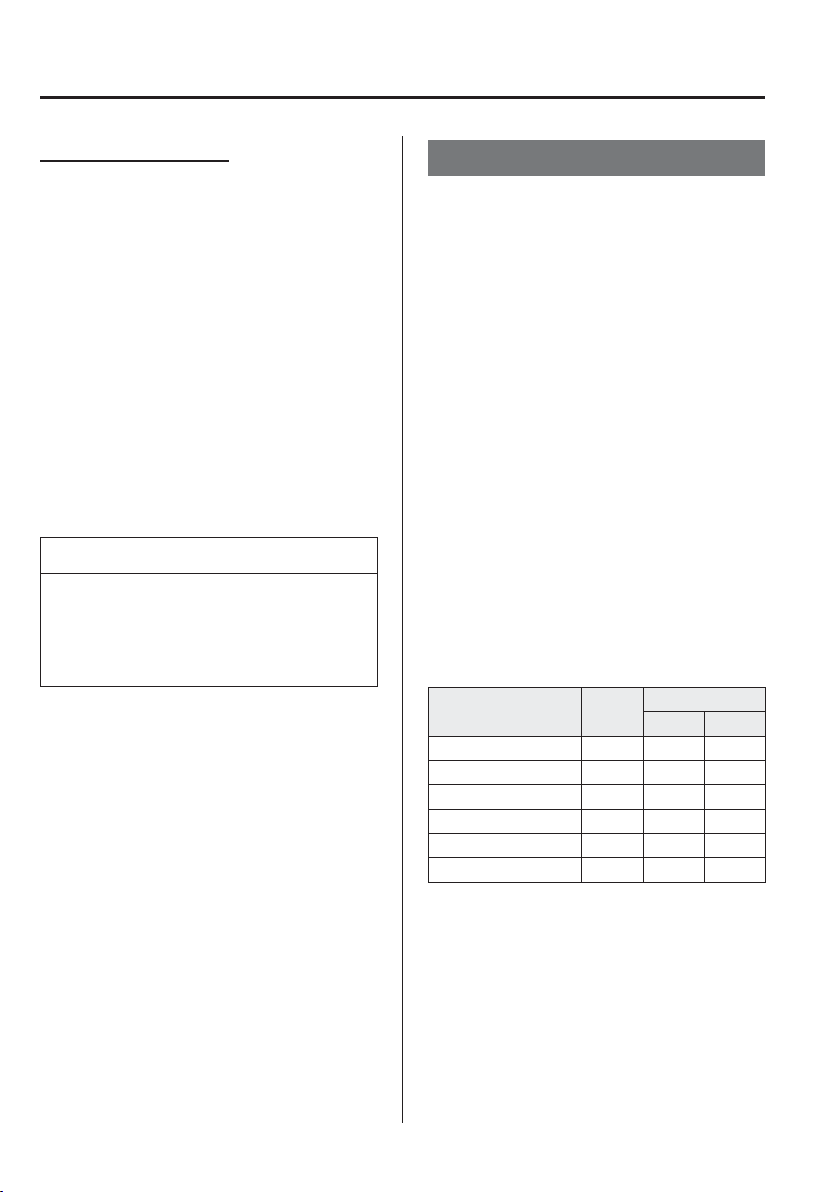
5
–
62
Interior Features
Audio Set [Type A (non-touchscreen)]
*Some models.
C o n ¿ rmation Prompts
The con¿ rmation prompt con¿ rms the
command content to the user before
advancing to the operation requested by
the user. When this function is turned
on, the system reads out the voice
input command previously received
and con¿ rms whether the command is
correct before advancing to the command
execution.
When the con¿ rmation prompt function is
turned on:
(Ex. “Calling John's device. Is this
correct?”)
When the con¿ rmation prompt function is
turned off:
(Ex. “Calling John's device.”)
NOTE
If the con¿ rmation prompt function is
turned off when making an emergency
call, the system reads out and con¿ rms
the command before executing it.
1. Press the pick-up button or talk button
with a short press.
2. Say: [Beep] “Setup”
3. Prompt: “Select one of the following:
Pairing options, con¿ rmation prompts,
language, password, select phone or
select music player.”
4. Say: [Beep] “Con¿ rmation prompts”
5. Prompt: “Con¿ rmation prompts
are on/off. Would you like to turn
con¿ rmation prompts off/on?”
6. Say: [Beep] “Yes”
7. Prompt: “Con¿ rmation prompts are
off/on.”
Bluetooth
®
Audio
*
Applicable Bluetooth
®
speci¿ cation
(Recommended)
Ver. 2.0
Response pro¿ le
A2DP (Advanced Audio Distribution
Pro¿ le) Ver. 1.0/1.2
AVRCP (Audio/Video Remote Control
Pro¿ le) Ver. 1.0/1.3
A2DP is a pro¿ le which transmits only
audio to the Bluetooth
®
unit. If your
Bluetooth
®
audio device corresponds
only to A2DP, but not AVRCP, you
cannot operate it using the control panel
of the vehicle's audio system. In this
case, only the operations on the mobile
device are available the same as when a
portable audio device for a non-compliant
Bluetooth
®
device is connected to the
AUX terminal.
Function A2DP
AVRCP
Ver. 1.0 Ver. 1.3
Playback — X X
Pause — X X
File (Track) up/down — X X
Reverse — — X
Fast-forward — — X
Text display — — X
X: Available
—: Not available
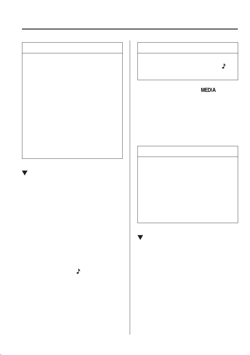
5
–
63
Interior Features
Audio Set [Type A (non-touchscreen)]
NOTE
The battery consumption of
Bluetooth
®
audio devices increases
while Bluetooth
®
is connected.
If a general mobile phone device
is USB connected during music
playback over the Bluetooth
®
connection, the Bluetooth
®
connection is disconnected. For
this reason, you cannot have
music playback over a Bluetooth
®
connection and music playback using
a USB connection at the same time.
The system may not operate
normally depending on the
Bluetooth
®
audio device.
Switching to Bluetooth
®
audio
mode
To listen to music or voice audio recorded
to a Bluetooth
®
audio device, switch to
the Bluetooth
®
audio mode to operate
the audio device using the audio system
control panel. Any Bluetooth
®
audio
device must be paired to the vehicle's
Bluetooth
®
unit before it can be used.
Refer to Bluetooth
®
Preparation (Type A)
on page 5-49 .
1. Turn on the Bluetooth
®
audio device's
power.
2. Switch the ignition to ACC or ON.
Make sure that the “
” symbol is
displayed in the audio display. The
symbol is not displayed if an un-paired
Bluetooth
®
audio device is being used
or the vehicle's Bluetooth
®
unit has a
malfunction.
NOTE
Some Bluetooth
®
audio devices need a
certain amount of time before the “
”
symbol is displayed.
3. Press the media button (
) to
switch to the Bluetooth
®
audio mode
and start playback.
If the current device version is lower
than AVRCP Ver. 1.3: “ BT Audio ” is
displayed.
If the current device is AVRCP Ver. 1.3:
The playback time is displayed.
NOTE
If the Bluetooth
®
audio device does
not begin playback, press the Play/
Pause button (4).
If a call is received on a hands-free
mobile phone during playback from
the Bluetooth
®
audio device, the
playback is stopped. Playback from
the Bluetooth
®
audio device resumes
after the call ends.
Playback
1. To listen to a Bluetooth
®
audio device
over the vehicle's speaker system,
switch the mode to Bluetooth
®
audio mode. (Refer to “Switching to
Bluetooth
®
audio mode”)
2. To stop playback, press the Play/Pause
button (4).
3. Press the button again to resume
playback.
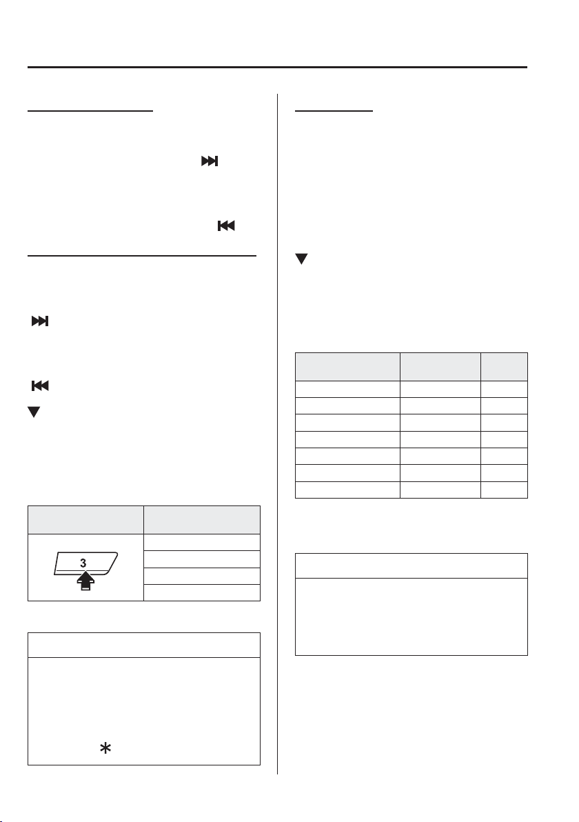
5
–
64
Interior Features
Audio Set [Type A (non-touchscreen)]
Selecting a ¿ le (track)
Selects the next ¿ le (track)
Short-press the track up button (
).
Selects the beginning of the current ¿ le
(track)
Short-press the track down button (
).
Fast-forward/Reverse (AVRCP Ver. 1.3)
Fast-forward
Press and hold the fast-forward button
(
).
Reverse
Press and hold the reverse down button
(
).
Switching the display (only AVRCP
Ver. 1.3)
The information displayed on the audio
display changes as follows each time the
text button ( 3 ) is pressed during playback.
Button
Information displayed
on audio display
Elapsed time
Album name
Song name
Artist name
NOTE
If title information is not available,
“ NO TITLE ” is displayed.
This unit cannot display some
characters. Characters which cannot
be displayed are indicated by an
asterisk (
).
Display scroll
Only 13 characters can be displayed at one
time. To display the rest of the characters
of a long title, press and hold the text
button (3). The display scrolls the next
13 characters. Press and hold the text
button (3) again after the last 13 characters
have been displayed to return to the
beginning of the title.
Bluetooth
®
audio device
information display
If a Bluetooth
®
audio device is connected,
the following information is displayed in
the audio display.
AVRCP Ver.
lower than 1.3
AVRCP
Ver. 1.3
Device name X X
Title — X
Artist name — X
Album name — X
File number — X
Playback time — X
Folder number — —
X: Available
—: Not available
NOTE
Some information may not display
depending on the device, and if the
information cannot be displayed, “ NO
TITLE ” is indicated.
5
–
65
Interior Features
Audio Set [Type A (non-touchscreen)]
*Some models.
Bluetooth
®
Hands-Free
*
Making a Call
Phonebook Usage
Telephone calls can be made by saying
the name of a person (voice tag) whose
phone number has been registered in
Bluetooth
®
Hands-Free in advance. Refer
to Phonebook registration.
1. Press the pick-up button or talk button
with a short press.
2. Say: [Beep] “Call”
3. Prompt: “Name please.”
4. Say: [Beep] “XXXXX... (Ex. “John's
phone”)” (Say a voice tag registered in
the phonebook.)
5. Prompt: “Calling XXXXX... (Ex.
“John's phone”) XXXX (Ex. “at
home”). Is this correct?” (Voice tag and
phone number location registered in
phonebook).
6. Say: [Beep] “Yes”
7. Prompt: “Dialing”
NOTE
The “Call” command and the voice tag
can be combined.
Ex. In Step 2, say, “Call John's phone”,
then, Steps 3 and 4 can be skipped.
Phonebook registration
Phone numbers can be registered to the
Bluetooth
®
Hands-Free phonebook.
NOTE
Do this function only when parked. It is
too distracting to attempt while driving
and you may make too many errors to
be effective.
1. Press the pick-up button or talk button
with a short press.
2. Say: [Beep] “Phonebook”
3. Prompt: “Select one of the following:
New entry, edit, list names, delete,
erase all or import contact.”
4. Say: [Beep] “New entry”
5. Prompt: “Name please.”
6. Say: [Beep] “XXXXX... (Ex. “Mary's
phone”)” (Say a voice tag for the name
registered.)
7. Prompt: “Adding XXXXX... (Ex.
“Mary's phone”) (Registered voice tag).
Is this correct?”
8. Say: [Beep] “Yes”
9. Prompt: “Home, Work, Mobile, or
Other?”
10. Say: [Beep] “Mobile” (Say “Home” ,
“Work”, “Mobile”, or “Other”, for the
desired location to be registered.)
11. Prompt: “Mobile (Location to be
registered). Is this correct?”
12. Say: [Beep] “Yes”
13. Prompt: “Number, please.”
14. Say: [Beep] “XXXXXXXXXXX”
(Say the phone number to be
registered.)
15. Prompt: “XXXXXXXXXXX (Phone
number registration). After the beep,
continue to add numbers, or say
Go-Back to re-enter the last entered
numbers, or press the Pick-Up button to
save the number.”

5
–
66
Interior Features
Audio Set [Type A (non-touchscreen)]
16. (Registration)
Press the pick-up button or say “Enter”,
then go to Step 17.
(Adding/inputting telephone
number)
Say, “XXXX” (desired telephone
number), then go to Step 15.
(Telephone number correction)
Say, “Go Back”. The prompt replies,
“Go Back. The last entered numbers
have been removed.”. Then go back to
Step 13.
17. Prompt: “Number saved. Would you
like to add another number for this
entry?”
18. Say: [Beep] “Yes” or “No”.
19. If “Yes”, an additional phone number
registration can be made for the same
entry.
If “No”, the system returns to standby
status.
(Import contact)
Phonebook data from your device (Mobile
phone) can be sent and registered to your
Bluetooth
®
Hands-Free phonebook using
Bluetooth
®
.
1. Press the pick-up button or talk button
with a short press.
2. Say: [Beep] “Phonebook”
3. Prompt: “Select one of the following:
New entry, edit, list names, delete,
erase all or import contact.”
4. Say: [Beep] “Import contact”
5. Prompt: “The hands free system is
ready to receive a contact from the
phone; only a home, work, mobile
number can be imported into the
hands free system. The import contact
process requires the user to operate the
phone. Refer to the phone's manual
for information on how to operate
the phone to perform the import
operation.”
6. Prompt: “X (Number of locations
which include data) numbers have been
imported. What name would you like to
use for these numbers?”
7. Say: [Beep] “XXXXX... (Ex. “Mary's
phone”)” (Say a voice tag for the name
registered.)
8. Prompt: “Adding XXXXX... (Ex.
“Mary's phone”) (Voice tag). Is this
correct?”
9. Say: [Beep] “Yes”
10. Prompt: “Number saved. Would you
like to import another contact?”
11. Say: [Beep] “Yes” or “No”
12. If “Yes”, the procedure proceeds to
Step 5.
If “No”, the system returns to standby
status.
Editing phonebook
The data registered to the Bluetooth
®
Hands-Free phonebook can be edited.
NOTE
Do this function only when parked. It is
too distracting to attempt while driving
and you may make too many errors to
be effective.
1. Press the pick-up button or talk button
with a short press.
2. Say: [Beep] “Phonebook”

5
–
67
Interior Features
Audio Set [Type A (non-touchscreen)]
3. Prompt: “Select one of the following:
New entry, edit, list names, delete,
erase all or import contact.”
4. Say: [Beep] “Edit”
5. Prompt: “Please say the name of the
entry you would like to edit or say,
“List names”.”
6. Say: [Beep] “XXXXX... (Ex. “Mary's
phone”)” (Say the voice tag for the
registered name to be edited in the
phonebook.)
7. Prompt: “Home, Work, Mobile, or
Other?”
8. Say: [Beep] “Home” (Say the
registered location to be edited:
“Home”, “Work”, “Mobile”, or
“Other”.)
9. Prompt: “XXXXX... (Ex. “Mary's
phone”) (Registered voice tag) XXXX
(Ex. “Home”) (Registered location). Is
this correct?”
10. Say: [Beep] “Yes”
11. Prompt: “The current number is
XXXXXXXXXXX (Ex. “555-1234”)
(Currently registered number). New
number, please.”
NOTE
If there was no previous phone number
registered to a location (Ex. “Work”),
the prompt will only read out “Number,
please”
12. Say: [Beep] “XXXXXXXXXXX (Ex.
“555-5678”)” (Say the new phone
number to be registered.)
13. Prompt: “XXXXXXXX (Telephone
number) After the beep, continue to add
numbers, or say Go-Back to re-enter
the last entered numbers, or press the
Pick-Up button to save the number.”
14. (Number Change)
Press the pick-up button, then go to
Step 15.
(Adding/inputting telephone
number)
Say, “XXXX” (desired telephone
number), then go to Step 13.
(Telephone number correction)
Say, “Go Back”. The prompt replies,
“Go Back. The last entered numbers
have been removed. Number, please.”.
Then go back to Step 12.
15. Prompt: “Number changed.”
Phonebook data deletion
(Erasing individual phonebook data)
Individual data registered to the
Bluetooth
®
Hands-Free phonebook can be
cleared.
NOTE
Do this function only when parked. It is
too distracting to attempt while driving
and you may make too many errors to
be effective.
1. Press the pick-up button or talk button
with a short press.
2. Say: [Beep] “Phonebook”
3. Prompt: “Select one of the following:
New entry, edit, list names, delete,
erase all or import contact.”
4. Say: [Beep] “Delete”
5. Prompt: “Please say the name of the
entry you would like to delete or say,
“List names”. ”
6. Say: [Beep] “XXXXX... (Ex. “John's
phone”) ” (Say the registered voice tag
to be deleted from the phonebook.)

5
–
68
Interior Features
Audio Set [Type A (non-touchscreen)]
7. Prompt: “Deleting XXXXX... (Ex.
“John's phone”) (Registered voice tag)
Home (Registered location). Is this
correct?”
8. Say: [Beep] “Yes”
9. Prompt: “XXXXX... (Ex. “John's
phone”) (Registered voice tag) Home
(Registered location) deleted.”
(Complete deletion of the phonebook
data)
All data registered to the Bluetooth
®
Hands-Free phonebook can be erased.
NOTE
Do this function only when parked. It is
too distracting to attempt while driving
and you may make too many errors to
be effective.
1. Press the pick-up button or talk button
with a short press.
2. Say: [Beep] “Phonebook”
3. Prompt: “Select one of the following:
New entry, edit, list names, delete,
erase all or import contact.”
4. Say: [Beep] “Erase all”
5. Prompt: “Are you sure you want to
delete everything from your Hands
Free system phonebook?”
6. Say: [Beep] “Yes”
7. Prompt: “You are about to delete
everything from your Hands Free
system phonebook. Do you want to
continue?”
8. Say: [Beep] “Yes”
9. Prompt: “Please wait, deleting the
Hands Free system phonebook.”
10. Prompt: “Hands-Free system
phonebook deleted.”
Read-out of names registered to the
Bluetooth
®
Hands-Free phonebook
Bluetooth
®
Hands-Free can read out the
list of names registered to its phonebook.
1. Press the pick-up button or talk button
with a short press.
2. Say: [Beep] “Phonebook”
3. Prompt: “Select one of the following:
New entry, edit, list names, delete,
erase all or import contact.”
4. Say: [Beep] “List names”
5. Prompt: “XXXXX..., XXXXX...,
XXXXX... (Ex. “John's phone”, Mary's
phone, Bill's phone)” (Voice guidance
reads out the voice tags registered to
the phonebook.)
Press the talk button with a short press
during the read-out at the desired name,
and then say one of the following voice
commands to execute it.
“Continue”: Continues the list
readout.
“Call”: Calls the registered
phonebook data when the talk button
is short-pressed.
“Edit”: Edits the registered
phonebook data when the talk button
is short-pressed.
“Delete”: Deletes the registered
phonebook data when the talk button
is short-pressed.
“Previous”: Returns to the previous
phonebook data in read-out when the
talk button is short-pressed.
6. Prompt: “End of list, would you like to
start from the beginning?”
7. Say: [Beep] “No”
5
–
69
Interior Features
Audio Set [Type A (non-touchscreen)]
Redial Function
Redialing the number of the person
previously dialed using the phone is
possible.
1. Press the pick-up button or talk button
with a short press.
2. Say: [Beep] “Redial”
3. Prompt: “Dialing”
Telephone Number Input
NOTE
Practice this while parked until you are
con¿ dent you can do it while driving in
a non-taxing road situation. If you are
not completely comfortable, make all
calls from a safe parking position, and
only start driving when you can devote
your full attention to driving.
1. Press the pick-up button or talk button
with a short press.
2. Say: [Beep] “Dial”
3. Prompt: “Number, please”
4. Say: [Beep] “XXXXXXXXXXX
(Telephone number)”
5. Prompt: “XXXXXXXXXXX.
(Telephone number) After the beep,
continue to add numbers, or say
Go-Back to re-enter the last entered
numbers, or press the Pick-Up button to
execute dialing.”
6. (Dialing)
Press the pick-up button or say “Dial”,
then go to Step 7.
(Adding/inputting telephone
number)
Say, “XXXX” (desired telephone
number), then go to Step 5.
(Telephone number correction)
Say, “Go Back”. The prompt replies,
“Go Back. The last entered numbers
have been removed.”. Then go back to
Step 3.
7. Prompt: “Dialing”
NOTE
The “Dial” command and a telephone
number can be combined.
Ex. In Step 2, say, “Dial 123-4567”
then, Steps 3 and 4 can be skipped.
Emergency calls
A call can be made to the emergency
phone number (112) using the voice input
command.
1. Press the pick-up button or talk button
with a short press.
2. Say: [Beep] “Emergency”
3. Prompt: “Dialing “112”, is this
correct?”
4. Say: [Beep] “Yes”
5. Prompt: “Dialing”
Receiving an Incoming Call
1 . Prompt: “Incoming call, press the
pick-up button to answer”
2. To accept the call, press the pick-up
button.
To reject the call, press the hang-up
button.
5
–
70
Interior Features
Audio Set [Type A (non-touchscreen)]
Hanging Up a Call
Press the hang-up button during the call. A
beep sound will con¿ rm that call is ended.
Mute
The microphone can be muted during a
call.
1. Press the talk button with a short press.
2. Say: [Beep] “Mute”
3. Prompt: “Microphone muted”
Cancelling mute
1. Press the talk button with a short press.
2. Say: [Beep] “Mute off”
3. Prompt: “Microphone unmuted”
Transferring a Call from Hands-
Free to a Device (Mobile Phone)
Communication between the hands-free
unit and a device (Mobile phone) is
cancelled, and the line can be switched
to a standard call using a device (Mobile
phone).
1. Press the talk button with a short press.
2. Say: [Beep] “Transfer call”
3. Prompt: “Transferred call to phone”
Transferring a Call from a Device
(Mobile Phone) to Hands-Free
Communication between devices (Mobile
phone) can be switched to Bluetooth
®
Hands-Free.
1. Press the talk button with a short press.
2. Say: [Beep] “Transfer call”
3. Prompt: “Transferred call to Hands
Free system”
Call interrupt
A call can be interrupted to receive an
incoming call from a third party.
Switch to a new incoming call using the
following methods.
(Method 1)
1. Press the pick-up button.
2. Prompt: “Swapping calls.”
(Method 2)
1. Press the talk button with a short press.
2. Say: [Beep] “Swap calls”
3. Prompt: “Swapping calls.”
NOTE
To refuse an incoming call, press the
hang-up button.
After receiving a new incoming call,
the previous call is placed on hold.
Switching calls
Switching back to the previous call can
also be done.
Method 1
1. Press the pick-up button.
2. Prompt: “Swapping calls.”
Method 2
1. Press the talk button with a short press.
2. Say: [Beep] “Swap calls”
3. Prompt: “Swapping calls.”
Three-way call function
1. Press the talk button with a short press.
2. Say: [Beep] “Join calls”
3. Prompt: “Joining calls”

5
–
71
Interior Features
Audio Set [Type A (non-touchscreen)]
Making a call using a telephone number
1. Press the talk button with a short press.
2. Say: [Beep] “Dial”
3. Prompt: “Number, please”
4. Say: [Beep] “XXXXXXXXXXX
(Telephone number)”
5. Prompt: “XXXXXXXXXXX.
(Telephone number) After the beep,
continue to add numbers, or say
Go-Back to re-enter the last entered
numbers, or press the Pick-Up button to
execute dialing.”
6. (Dialing)
Press the pick-up button or say “Dial”,
then go to Step 7.
(Adding/inputting telephone
number)
Say, “XXXX” (desired telephone
number), then go to Step 5.
(Telephone number correction)
Say, “Go Back”. The prompt replies,
“Go Back. The last entered numbers
have been removed.”. Then go back to
Step 3.
7. Prompt: “Dialing”
Making calls using the phonebook
1. Press the talk button with a short press.
2. Say: [Beep] “Call”
3. Prompt: “Name please.”
4. Say: [Beep] “XXXXX... (Ex. “John's
phone”)” (Say a voice tag registered in
the phonebook.)
5. Prompt: “Calling XXXXX... (Ex.
“John's phone”) XXXX (Ex. “at
home”). Is this correct?” (Voice tag and
phone number location registered in
phonebook).
6. Say: [Beep] “Yes”
7. Prompt: “Dialing”
Redialing function
1. Press the talk button with a short press.
2. Say: [Beep] “Redial”
3. Prompt: “Dialing”
Ending the current call
Press the hang-up button during the call.
DTMF (Dual Tone Multi-
Frequency Signal) Transmission
This function is used when transmitting
DTMF via the user's voice. The receiver
of a DTMF transmission is generally a
home telephone answering machine or
a company's automated guidance call
centre (When you send tone signals
back according to the voice guidance
recording).
1. Press the talk button with a short press.
2. Say: [Beep] “XXXX... send” (Say
DTMF code)
3. Prompt: “Sending XXXX... (DTMF
code)”
5
–
72
Interior Features
Audio Set [Type A (non-touchscreen)]
*Some models.
Voice Recognition
*
In this section, the basic operation of the
voice recognition is explained.
Activating Voice Recognition
To Activate the Main Menu: Press the
pick-up button or talk button with a short
press.
Ending Voice Recognition
Use one of the following methods:
Press and hold the talk-button.
Press the hang-up button.
Skipping Voice Guidance (for faster
operation)
Press and release the talk-button.
NOTE
The Bluetooth
®
Hands-Free system
is operable several seconds after the
ignition is switched to ACC or ON
(requires less than 15 seconds).
When operating the audio unit or
the A/C while using Bluetooth
®
Hands-Free, the beep sounds or voice
guidance (audio unit)/cannot be
heard.
Tutorial
The tutorial explains how to use
Bluetooth
®
Hands-Free.
To activate the tutorial, do the following:
1. Press the pick-up button or talk button
with a short press.
2. Say: [Beep] “Tutorial”
3. Follow the prompts to receive the
appropriate voice guidance instructions.
Commands useable anytime during
voice recognition
“Help” or “Go Back” are commands
which can be used at anytime during voice
recognition.
Help function use
The help function informs the user of all
the available voice commands under the
current conditions.
1. Say: [Beep] “Help”
2. Follow the prompts to receive the
appropriate voice guidance instructions.
Returning to previous operation
This command is for returning to the
previous operation while in the voice
recognition mode.
Say: [Beep] “Go Back”
5
–
73
Interior Features
Audio Set [Type A (non-touchscreen)]
*Some models.
To prevent a deterioration in the voice
recognition rate and voice quality, the
following points should be observed:
The voice recognition cannot be
performed while voice guidance or
the beep sound is operating. Wait
until the voice guidance or the beep
sound is ¿ nished before saying your
commands.
Dialects or different wording other
than hands-free prompts cannot be
recognised by voice recognition. Speak
in the wording speci¿ ed by the voice
commands.
It is not necessary to face the
microphone or approach it. Speak the
voice commands while maintaining a
safe driving position.
Do not speak too slow or too loud.
Speak clearly, without pausing between
words or numbers.
Close the windows to reduce loud
noises from outside the vehicle, or turn
down the airÀ ow of the air-conditioning
system while Bluetooth
®
Hands-Free is
being used.
Make sure the vents are not directing air
up towards the microphone.
NOTE
If the voice recognition performance is
not satisfactory.
Refer to Voice Recognition Learning
Function (Speaker Enrolment) (Type A)
on page 5-73 .
Refer to Troubleshooting on page
5-76 .
Voice Recognition
Learning Function
(Speaker Enrolment)
*
The voice recognition learning function
enables voice recognition appropriate to
the characteristics of the user's voice. If the
recognition of the voice input commands
to the system is not adequate, this function
can largely improve the system's voice
recognition of the user. If your voice can
be recognised suf¿ ciently without using
this function, you may not realize the
added bene¿ t of the function. To register
your voice, the voice input command
list must be read out. Read out the list
when the vehicle is parked. Perform the
registration in as quiet a place as possible
(page 5-72 ). The registration must be
performed completely. The required time
is a few minutes. The user needs to be
seated in the driver's seat with the voice
input command list for voice recognition
learning visible.
When voice recognition learning is
done for the ¿ rst time
1. Press the pick-up button or talk button
with a short press.
2. Say: [Beep] “Voice training”
3. Prompt: “This operation must be
performed in a quiet environment while
the vehicle is stopped. See the owner's
manual for the list of required training
phrases. Press and release the talk
button when you are ready to begin.
Press the hang-up button to cancel at
any time.”
4. Press the talk button with a short press.
5
–
74
Interior Features
Audio Set [Type A (non-touchscreen)]
5. The voice guidance reads out the voice
input command number (refer to the
voice input command list for voice
recognition learning). (Ex. “Please read
phrase 1”)
6. Say: [Beep] “0123456789” (Say
the voice input command for voice
recognition learning (1 to 8) according
to the voice guidance.)
7. Prompt: “Speaker enrolment is
complete.”
NOTE
If an error occurred in the voice
recognition learning, re-learning can be
done by pressing the talk button with a
short press.
Voice recognition re-learning
If voice recognition learning has already
been done.
1. Press the pick-up button or talk button
with a short press.
2. Say: [Beep] “Voice training”
3. Prompt: “Enrolment is enabled/
disabled. Would you like to disable/
enable or retrain?”
4. Say: [Beep] “Retrain”
5. Prompt: “This operation must be
performed in a quiet environment while
the vehicle is stopped. See the owner's
manual for the list of required training
phrases. Press and release the talk
button when you are ready to begin.
Press the hang-up button to cancel at
any time.”
6. Press the talk button with a short press.
7. The voice guidance reads out the voice
input command number (refer to the
voice input command list for voice
recognition learning). (Ex. “Please read
phrase 1”)
8. Say: [Beep] “0123456789” (Say
the voice input command for voice
recognition learning (1 to 8) according
to the voice guidance.)
9. Prompt: “Speaker enrolment is
complete.”
NOTE
If an error occurred in the voice
recognition learning, re-learning can be
done by pressing the talk button with a
short press.
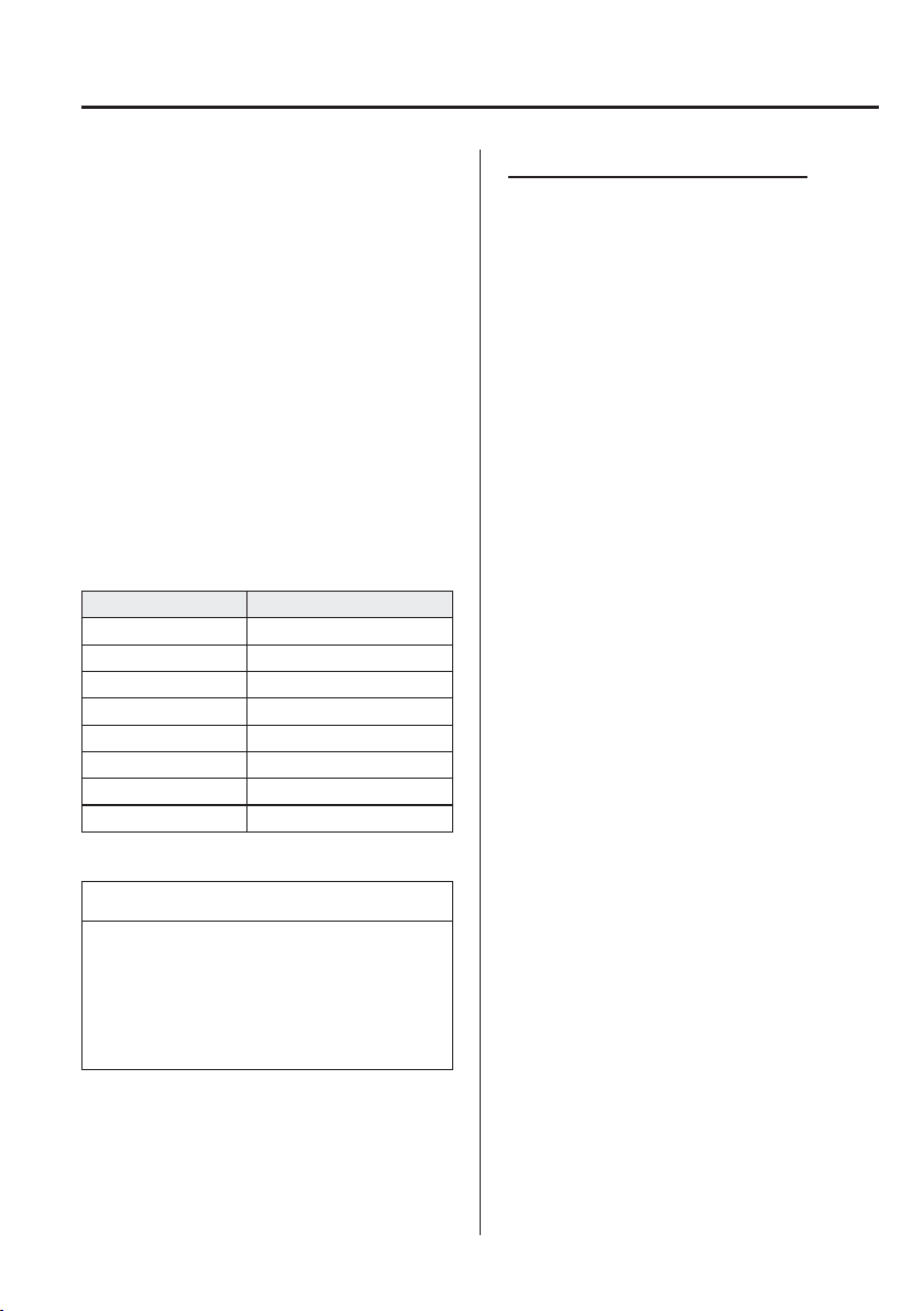
5
–
75
Interior Features
Audio Set [Type A (non-touchscreen)]
Voice input command list for voice
recognition learning
When reading out, the following points
must be observed:
Read out the numbers one at a time
correctly and naturally.
(For example, “1234” must be read out
“one, two, three, four” not “twelve,
thirty four”.)
Do not read out parentheses. “(” and
hyphens “-” are used for separating
numbers in a phone number.
E x .
“(888) 555-1212” must be spoken “Eight,
eight, eight, ¿ ve, ¿ ve, ¿ ve, one, two, one,
two.”
Phrase Command
1 0123456789
2 (888) 555-1212
3 Call
4 Dial
5 Setup
6 Cancel
7 Continue
8 Help
NOTE
The applicable phrase appears in the
audio display.
After user voice registration is
completed, voice guidance “Speaker
enrolment is complete” is announced.
Voice recognition learning on/off
1. Press the pick-up button or talk button
with a short press.
2. Say: [Beep] “Voice training”
3. Prompt: “Enrolment is enabled/
disabled. Would you like to disable/
enable or retrain?”
4. Say: [Beep] “Disable” or “Enable”
5. When “Disable” is spoken, the voice
recognition learning is turned off.
When “Enable” is spoken, the voice
recognition learning is turned on.
6. Prompt: “Speaker Enrolment is
disabled/enabled.”

5
–
76
Interior Features
Audio Set [Type A (non-touchscreen)]
*Some models.
Troubleshooting
*
Mazda Bluetooth
®
Hands-Free Customer Service
If you have any problems with Bluetooth
®
, contact our toll-free customer service centre.
Phone:
(Germany)
0800 4263 738 (8:00—18:00 Central European Time)
(Except Germany)
00800 4263 7383 (8:00—18:00 Central European Time)
(Worldwide)
49 (0) 6838 907 287 (8:00—18:00 Central European Time)
We b :
http://www.mazdahandsfree.com
Bluetooth
®
Device pairing, connection problems
Symptom Cause Solution method
Unable to perform pairing —
First make sure the device is
compatible with the Bluetooth
®
unit, and then check whether the
Bluetooth
®
function and the Find
Mode/Visible setting
*1
on the
device are turned on. If pairing is
still not possible after this, contact
an expert repairer, we recommend
an Authorised Mazda Repairer or
Mazda Bluetooth
®
Hands-Free
Customer Service.
Pairing cannot be performed again
The pairing information paired to
the Bluetooth
®
unit or device is not
recognised correctly.
Perform pairing using the following
procedure.
Clear “Mazda” stored in the device.
Perform pairing again.
Unable to perform pairing
The Bluetooth
®
function and the
Find Mode/Visible setting
*1
on the
device may turn off automatically
after a period of time has elapsed
depending on the device.
Check whether the Bluetooth
®
function and the Find Mode/Visible
setting
*1
on the device are turned on
and pairing or reconnect.
Does not connect automatically
when starting the engine
Automatically connects, but then
disconnects suddenly
Disconnects intermittently
The device is in a location in which
radio wave interference can occur
easily, such as inside a bag in a rear
seat, in a rear pocket of a pair of
pants.
Move the device to a location in
which radio wave interference is less
likely to occur.
Does not connect automatically
when starting the engine
The pairing information is updated
when the device OS is updated.
Perform pairing again.
*1 Setting which detects the existence of a device external to the Bluetooth
®
unit

5
–
77
Interior Features
Audio Set [Type A (non-touchscreen)]
NOTE
When the OS of the device is updated, the pairing information may be deleted. If this
happens, reprogramme the pairing information to the Bluetooth
®
unit.
If you pair your phone which has already been paired to your vehicle more than once
in the past, you need to delete “Mazda” on your mobile device. Then, execute the
Bluetooth
®
search on your mobile device once again, and pair to a newly detected
“Mazda”.
Before you pair your device, make sure that Bluetooth
®
is “ON”, both on your phone
and on the vehicle.
If Bluetooth
®
-enabled devices are used in the following locations or conditions,
connection via Bluetooth
®
may not be possible.
The device is in a location hidden from the centre display such as behind or under a
seat, or inside the glove compartment.
The device contacts or is covered by a metal object or body.
The device is set to power-saving mode.
Different Bluetooth
®
-enabled devices can be used for Bluetooth
®
Hands-Free and
Bluetooth
®
audio. For example, device A can be connected as a Bluetooth
®
Hands-Free
device and device B can be connected as a Bluetooth
®
audio device. However, the
following may occur when they are used at the same time.
The Bluetooth
®
connection of the device is disconnected.
Noise occurs in the Hands-Free audio.
Hands-Free operates slowly.

5
–
78
Interior Features
Audio Set [Type A (non-touchscreen)]
Voice recognition related problems
Symptom Cause Solution method
Poor voice recognition
Excessive, slow speech.
Excessive, forceful speech
(shouting).
Speaking before the beep sound
has ended.
Loud noise (speaking or noise from
outside/inside vehicle).
A i r À ow from A/C is blowing
against the microphone.
Speaking in off-standard
expressions (dialect).
Regarding the causes indicated
on the left, be careful with how
you speak. In addition, when
numbers are spoken in a sequence,
recognition ability will improve
if no stop is placed between the
numbers.
False recognition of numbers
Poor voice recognition
There is a malfunction in the
microphone.
A poor connection or malfunction
with the microphone may have
occurred. Consult an expert repairer,
we recommend an Authorised
Mazda Repairer.
Phone-related voice recognition is
disabled
There is a problem with the
connection between the Bluetooth
®
unit and the device.
If there is any malfunction after
checking the pairing situation, check
for device pairing or connection
problems.
Names in the phonebook are not
easily recognised
The Bluetooth
®
system is under a
condition in which recognition is
dif¿ cult.
By carrying out the following
measures, the rate of recognition
will improve.
Clear memory from the phonebook
which is not used very often.
Avoid shortened names, use full
names. (Recognition improves the
longer the name is. By not using
names such as “Mum”, “Dad”,
recognition will improve.)
When operating the audio, a song
name is not recognised
Song names cannot be recognised
by voice.
—
You want to skip guidance —
Guidance can be skipped by quickly
pressing and releasing the Talk
button.
Regarding problems with calls
Symptom Cause Solution method
When starting a call, vehicle noise
from the other party can be heard
For about three seconds after
starting a call, the Bluetooth
®
unit's Noise Suppression function
requires time to adapt to the call
environment.
This does not indicate a problem
with the device.
The other party cannot be heard or
the speaker's voice is quiet
The volume is set at zero or low. Increase the volume.

5
–
79
Interior Features
Audio Set [Type A (non-touchscreen)]
Other problems
Symptom Cause Solution method
The indication for the remaining
battery is different between the
vehicle and the device
The indication method is different
between the vehicle and the device.
—
When a call is made from the
vehicle, the telephone number is
updated in the incoming/outgoing
call record but the name does not
appear
The number has not been registered
into the phonebook.
If the number has been registered
into the phonebook, the incoming/
outgoing call record is updated by
the name in the phonebook when the
engine is restarted.
The cell phone does not synchronize
with the vehicle regarding the
incoming/outgoing call record
Some types of cell phones do not
synchronize automatically.
Operate the cell phone for
synchronization.
It takes a long time to complete the
function for changing the language
A maximum of 60 seconds is
required.
—
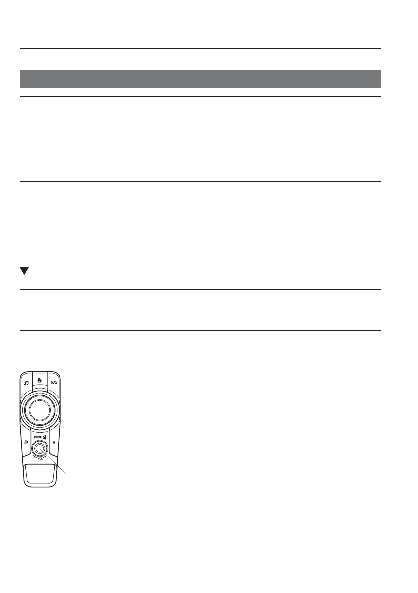
5
–
80
Interior Features
Audio Set [Type B (touchscreen)]
B a s i c O p e r a t i o n M e t h o d
NOTE
The explanation of functions described in this manual may differ from the actual
operation, and the shapes of screens and buttons and the letters and characters
displayed may also differ from the actual appearance.
Additionally, depending on future software updates, the content may successively
change without notice.
Audio Set Type B has three different human interfaces.
Commander switch
Touch panel
Voice recognition with steering switch and microphone
Refer to Voice Recognition on page 5-134 .
Commander switch operation
NOTE
For safety reasons, some operations are disabled while the vehicle is being driven.
Volume dial operation
Volume dial
Press the volume dial to switch the audio MUTE on and off.
Turn the volume dial to adjust the volume. The volume increases by turning the dial
clockwise, and decreases by turning it anticlockwise.
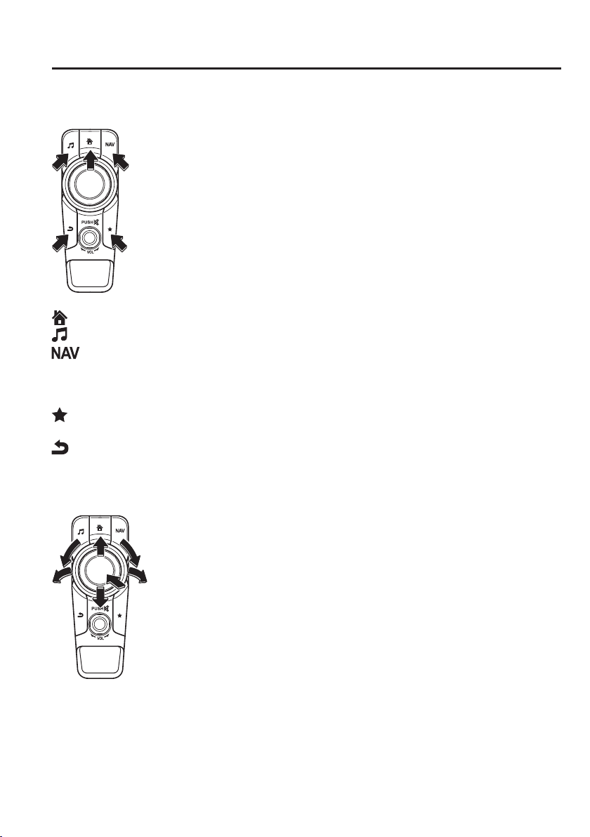
5
–
81
Interior Features
Audio Set [Type B (touchscreen)]
Switches around commander knob
The following operations can be done by pressing the switches around the commander knob.
: Displays the home screen.
: Displays the Entertainment screen.
: Displays the Navigation screen (Only navigation-equipped vehicles). For operation
of the Navigation screen, refer to the navigation system manual. If the SD card for
the navigation system is not inserted, the compass indicating the direction in which
the vehicle is moving is displayed.
: Displays the Favourites screen. Long-press to store particular items in Favourites.
(Radio, phonebook and destination of the navigation system can be programmed.)
: Returns to previous screen.
Commander knob operation
(Selection of icons on screen)
1. Tilt or turn the commander knob and move the cursor to the desired icon.
2. Press the commander knob and select the icon.
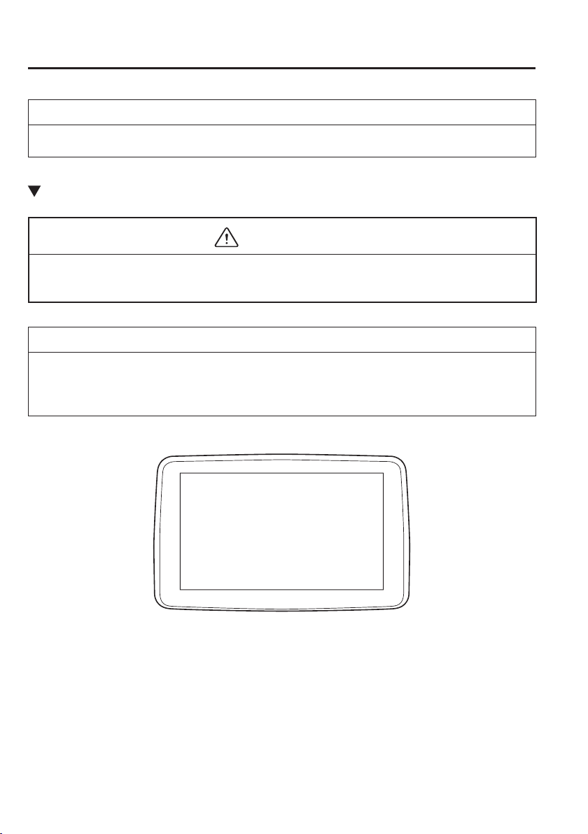
5
–
82
Interior Features
Audio Set [Type B (touchscreen)]
NOTE
Long-press operation of the commander knob is also possible for some functions.
Touch panel operation
CAUTION
Do not press the screen strongly or press it with a sharp-pointed object. Otherwise, the
screen could be damaged.
NOTE
For safety reasons, operation of the centre display is disabled while the vehicle is being
driven. However, items not displayed in grey can be operated using the commander switch
while the vehicle is being driven.
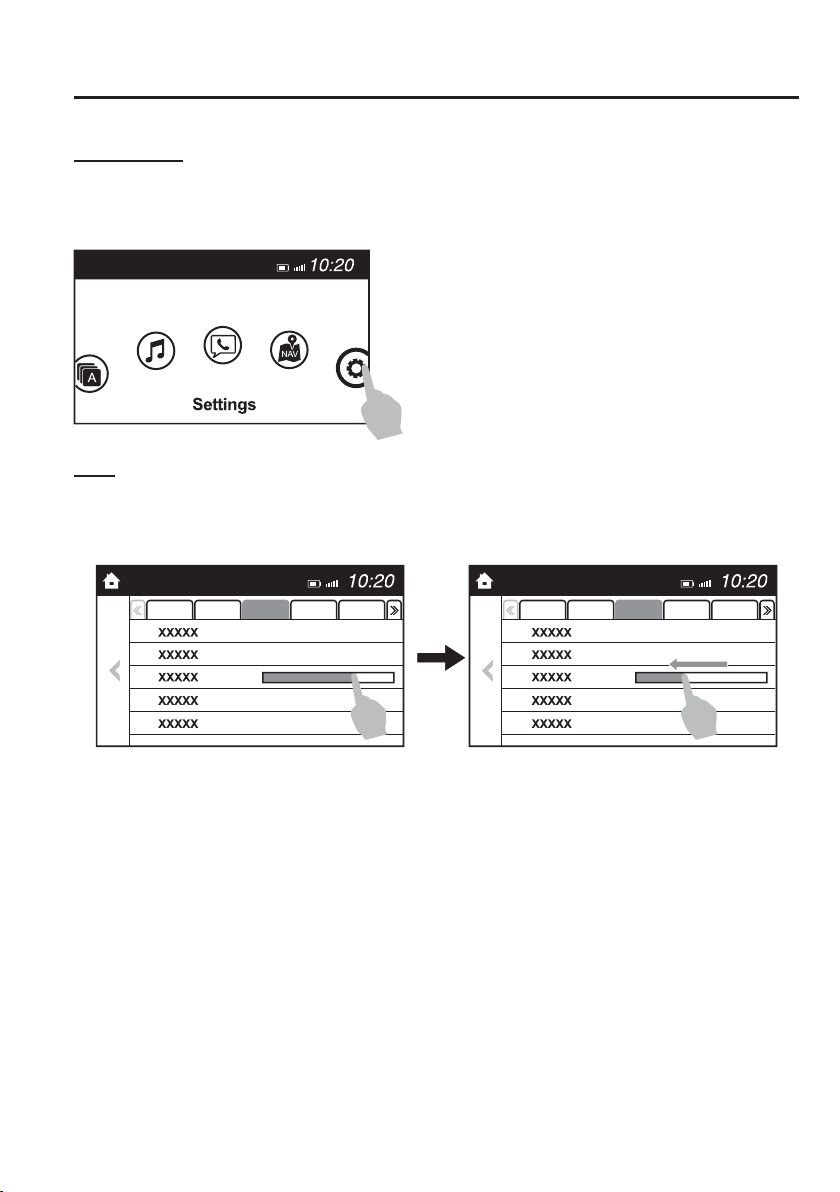
5
–
83
Interior Features
Audio Set [Type B (touchscreen)]
Touch & Tap
1. Touch or tap on the item indicated on the screen.
2. The operation is launched and the next item is displayed.
S l i d e
1. Touch the setting item displaying a slider bar.
2. Touch the slider with your ¿ nger and move to the desired level.
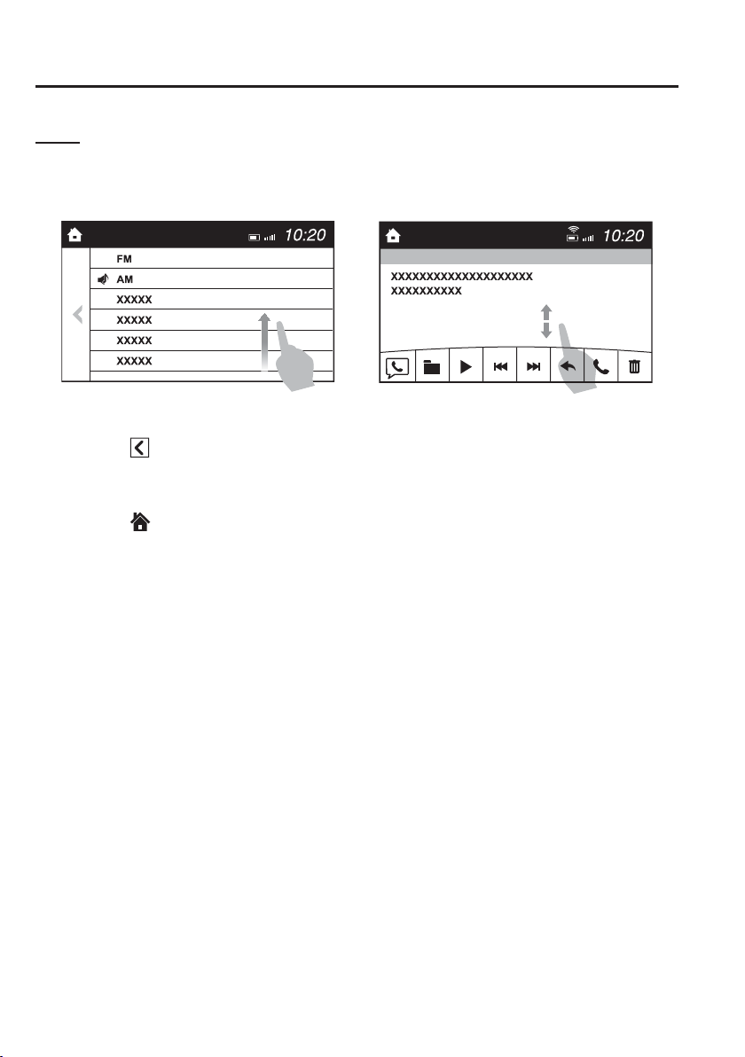
5
–
84
Interior Features
Audio Set [Type B (touchscreen)]
Swipe
1. Touch the screen with your ¿ nger and move up or down.
2. Items which were not displayed can be displayed.
Return to previous screen
1. Touch the
.
Displaying the home screen
1. Touch the
.
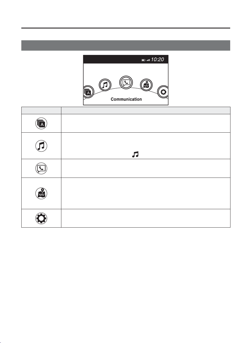
5
–
85
Interior Features
Audio Set [Type B (touchscreen)]
Home screen
Icon Function
Applications
Information such as average fuel economy, maintenance, and warnings can be veri¿ ed.
Depending on the grade and speci¿ cation, the screen display may differ.
Entertainment
Operates audio such as the radio and CDs. The audio source most recently used is
displayed. An audio source which cannot be used at that time is skipped and the previous
audio source is displayed.
To change the audio source, select the
icon displayed at the bottom of the screen.
Communication
Bluetooth
®
related functions are available.
Navigation
Navigation screen is displayed (vehicles with navigation system).
If the SD card for the navigation system is not inserted, the compass indicating the direction
in which the vehicle is moving is displayed.
The compass may not indicate the correct bearing when the vehicle is stopped or travelling
at a slow speed.
Settings
Overall setting menu (Such as display, sound, Bluetooth
®
and Language).
Depending on the grade and speci¿ cation, the screen display may differ.
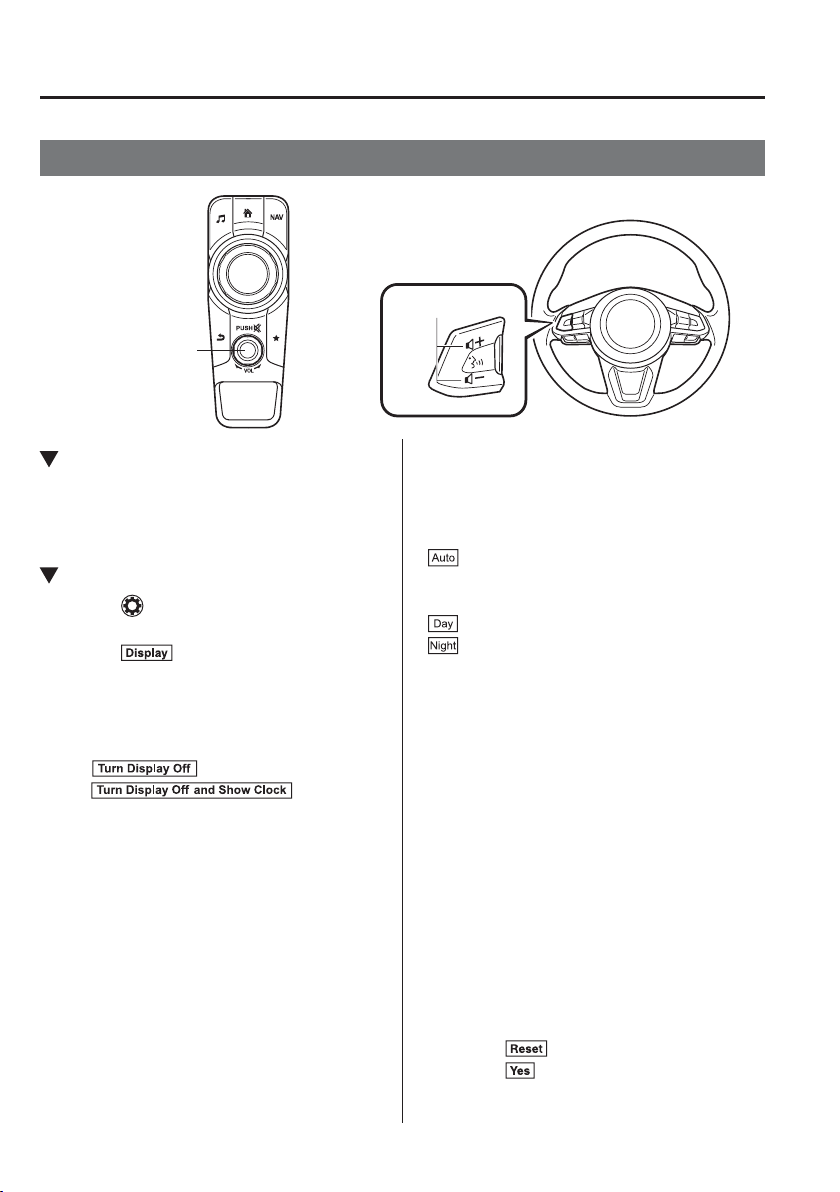
5
–
86
Interior Features
Audio Set [Type B (touchscreen)]
Volume/Display/Sound Controls
Volume dial
Commander switch
Audio control switch
Volume switch
Volume adjustment
Turn the commander switch volume dial.
The volume switch on the steering switch
can also be pressed.
Display setting
Select the icon on the home screen to
display the Settings screen.
Select the
tab to select the item you
would like to change.
Display OFF/Clock
The centre display can be turned off.
Select
to turn the display off.
When
is
selected the centre display turns off and
the clock is displayed.
The centre display can be turned back on
as follows:
Touch the centre display.
Operate the commander switch.
Daytime/nighttime (Mode) screen
setting
The daytime or nighttime screen can be
selected.
: Switches screen automatically
according to headlight illumination
condition
*1
: Daytime screen setting
: Nighttime screen setting
*1 The display is constantly on daytime
screen when the illumination dimmer is
cancelled.
Brightness adjustment
Adjust the centre display brightness using
the slider.
Contrast adjustment
Adjust the centre display contrast using
the slider.
Display setting reset
All of the screen setting values can be
reset to their initial settings.
1. Select .
2. Select
.
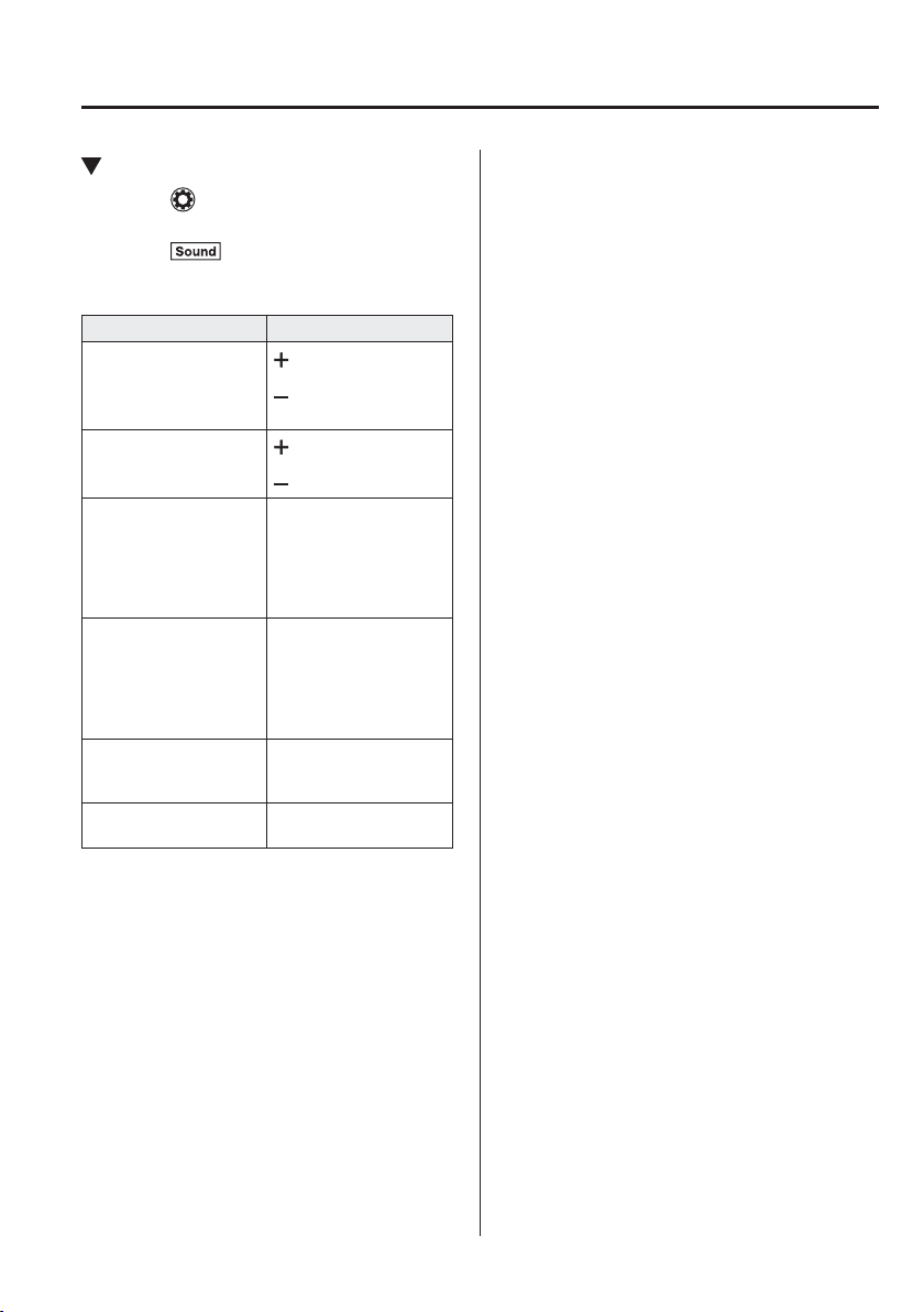
5
–
87
Interior Features
Audio Set [Type B (touchscreen)]
Audio sound adjustment
Select the icon on the home screen to
display the Settings screen.
Select the
tab to select the item you
would like to change.
Indication Setting value
Bass
(Low pitch sound)
Side: Low pitch
enhancement
Side: Low pitch
reduction
Treble
(Treble sound)
Side: Treble
enhancement
Side: Treble reduction
Fade
(Front/Rear volume
balance)
Front: Front speaker
volume
enhancement
Rear: Rear speaker
volume
enhancement
Balance
(Left/right volume
balance)
Right: Right speaker
volume
enhancement
Left: Left speaker
volume
enhancement
ALC
(Automatic volume
adjustment)
Off—Adjustment at
seven levels
Beep
(Audio operation sound)
On/Off
ALC (Automatic volume adjustment)
The automatic level control (ALC) is a
feature that automatically adjusts audio
volume and sound quality according to
the vehicle speed. The volume increases
in accordance with the increase in vehicle
speed, and decreases as vehicle speed
decreases.
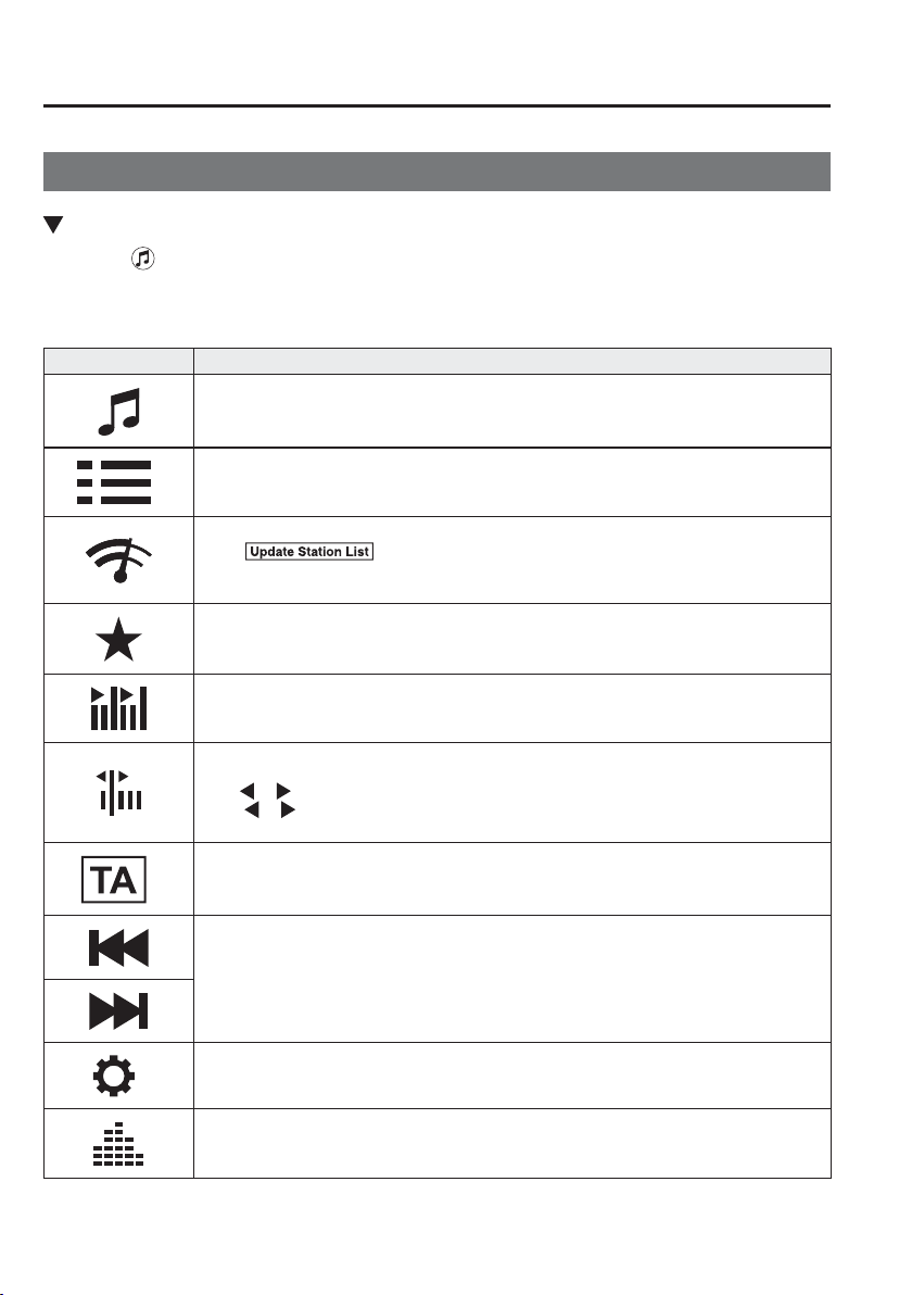
5
–
88
Interior Features
Audio Set [Type B (touchscreen)]
Operating the Radio
Radio ON
Select the icon on the home screen to display the Entertainment screen. When selecting
the desired radio, the following icons are indicated in the lower part of the centre display.
AM/FM Radio
Icon Function
Displays the Entertainment menu. Use to switch to a different audio source.
*1
Displays the list of receivable RDS radio stations (FM only).
Displays the station list (AM only).
*1
Select
to display the frequencies of up to ten radio stations on the auto
memory preset list.
Select the desired frequency.
Displays the Favourites list. Long-press to store radio station currently being aired.
You can search for receivable radio stations.
Scanning stops at each station for about ¿ ve seconds.
Select again to continue receiving the radio station.
You can change the radio frequency manually.
Rotate the commander knob, slide the screen, or touch the radio frequency.
Press
or to change the radio frequency one step at a time.
When
or is long-pressed, the radio frequency changes continually. It stops when you
remove your hand from the icon or the commander knob.
*1
Switches the TA mode on and off.
Automatic radio station selection.
When long-pressed, the radio frequency changes continually. It stops when you remove
your hand from the icon or the commander knob.
*1
Displays the FM settings screen (FM only).
On/Off of Alternative frequency and Region lock can be set.
Displays sound settings to adjust audio quality level.
Refer to Volume/Display/Sound Controls on page 5-86 .
*1 With Radio Data System (RDS)
5
–
89
Interior Features
Audio Set [Type B (touchscreen)]
*Some models.
NOTE
(With Radio Data System (RDS))
When the
or icon is selected while
FM is selected, each programme is
selected.
Favourites Radio
Selected stations can be registered for
convenient operation. Up to 50 stations
can be registered. The Favourites list is
common to AM, FM and DAB radio
*
.
Registering to Favourites
Long-press the
icon to register the
current radio station. The registration can
also be performed using the following
procedure.
1. Select the icon to display the
Favourites list.
2. Select
.
3. Select
.
4. The station is added to the bottom of
the Favourites list.
NOTE
If the battery is disconnected, your
Favourites list will be not deleted.
Selecting radio station from Favourites
1. Select the
icon to display the
Favourites list.
2. Select the radio frequency to tune in the
radio station.
Deleting from Favourites
1. Select the
icon to display the
Favourites list.
2. Select
.
3. Select
.
4. Select the radio frequency you want to
delete.
5. Select
.
Changing Favourites list order
1. Select the
icon to display the
Favourites list.
2. Select
.
3. Select
.
4. Select a radio frequency. The selected
radio station can be moved.
5. Slide the radio station or move it using
the commander switch, then select
.
Radio Data System (RDS)
*
Alternative frequency (AF)
AF functions on FM stations. Turn on
the AF mode. If the radio reception
of the current station weakens, the
system switches to an alternative station
automatically.
If you wish to continue a regional
programme, turn on the Region lock
(REG) mode.
AF/REG on or off switching
Select the
icon while in FM mode to
switch to the FM settings screen. AF/REG
on or off switching can be performed as
follows:
(AF mode on/off)
Select On/Off on the FM settings screen.
(REG mode on/off)
While the AF mode is on, select On/Off.
5
–
90
Interior Features
Audio Set [Type B (touchscreen)]
Tr a f ¿ c announcement (TA)
Select
during FM/AM reception to
switch to the TA mode.
If a TA broadcast is received while in the
TA mode, the TA broadcast intercedes
even while using other functions (FM,
CD, USB device, AUX, BT audio, Aha
™
radio, or Stitcher
™
radio), and “Traf¿ c
Announcement” is displayed.
If a TA is received on the Entertainment
screen,
is displayed on the screen.
Select
to cancel the received TA and
return to TA reception stand-by. If a TA is
received on a screen other than the
Entertainment screen, the selection screens
for
, , and are displayed
on the screen. If
is selected, the
selection screen turns off when a TA is
received while continuing to receive TAs.
Selection from Station List
List of receivable RDS radio stations is
displayed. You can easily select the station
you want to listen to from the list. If a
radio station name is not available, the
frequency is displayed. In addition, radio
stations which have been programmed to a
Genre code (Programme types like Rock,
News, and so on) can also be displayed
separately by category.
NOTE
It may take longer to display the
station list depending on the reception
conditions.
1. Select the
icon to display the radio
station list.
2. Select the radio frequency to tune in the
radio station.
(Selecting Genre)
1. Select the
on the station list
screen to display the genre list screen.
2. Select the genre to display the radio
station list in the genre.
NOTE
Only one Genre can be selected.

5
–
91
Interior Features
Audio Set [Type B (touchscreen)]
*Some models.
Operating the Digital Audio Broadcasting (DAB) Radio
*
What is DAB radio?
DAB radio is a digital broadcasting system for radio.
DAB radio provides a high-quality radio sound source using an auto frequency switching
function in boundary areas.
By displaying the radio text, information such as the song name and artist name can be
displayed.
NOTE
This unit is also compatible with DAB radio.
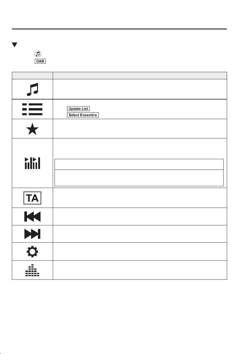
5
–
92
Interior Features
Audio Set [Type B (touchscreen)]
Radio ON
1. Select on the home screen to display the Entertainment screen.
2. Select
, the following icons are displayed at the bottom of the screen.
Icon Function
Displays the Entertainment menu. Use to switch to a different audio source.
Displays the station list (ensemble and station).
Select
to update the station list.
Select
to select the ensemble you want to display.
Displays the favourites list. Press and hold to store the currently tuned station to the
favourites list.
Refer to Operating the Radio (Type B) on page 5-88 .
Searches your desired station from the station list.
Tunes to each station in the station list for 10 seconds.
Select again when your desired station is tuned.
NOTE
If the station list is not available, it switches to the station list update screen. Perform
the station list updating.
Switches the TA mode on and off.
Refer to Operating the Radio (Type B) on page 5-88 .
Returns to the previous station.
Touch and hold to return to the top station in the previous ensemble.
Goes to the next station.
Touch and hold to go to the top station in the next ensemble.
Displays the DAB radio setting screen.
Displays sound settings to adjust audio quality level.
Refer to Volume/Display/Sound Controls on page 5-86 .
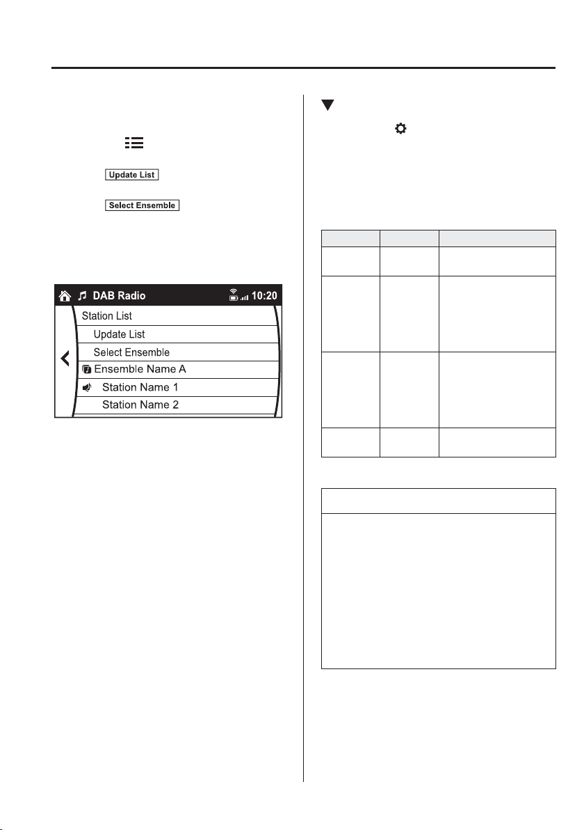
5
–
93
Interior Features
Audio Set [Type B (touchscreen)]
Example of use (Update station list and
listen to DAB radio)
1. Select the
icon and display the
following screen.
2. Select
to update the station
list.
3. Select
to select the
ensemble you want to display.
4. Select a desired station to start radio
reception.
DAB radio setting
1. Select the icon while using DAB
radio.
2. Select the desired item and perform the
setting.
The items which can be set are as
follows:
Item Setting Function
BAND
Settings
Band III/L
Band/Both
Frequency band can be
changed.
DAB-FM
Link
On/Off
On: If the reception
condition is bad, an
FM station which is
providing the same
broadcast is searched
and switched to.
DAB-DAB
Link
On/Off
On: If the reception
condition is bad, a
DAB station which
is providing the same
broadcast is searched
and switched to.
Radio Text On/Off
On: Radio text is
displayed.
NOTE
The radio text may not be displayed
depending on the radio station.
The radio text cannot be displayed in
DAB-FM mode.
If there is no DAB radio signal,
“Signal Lost” is displayed on the
screen. Change the ensemble or
radio station, or perform station list
updating.
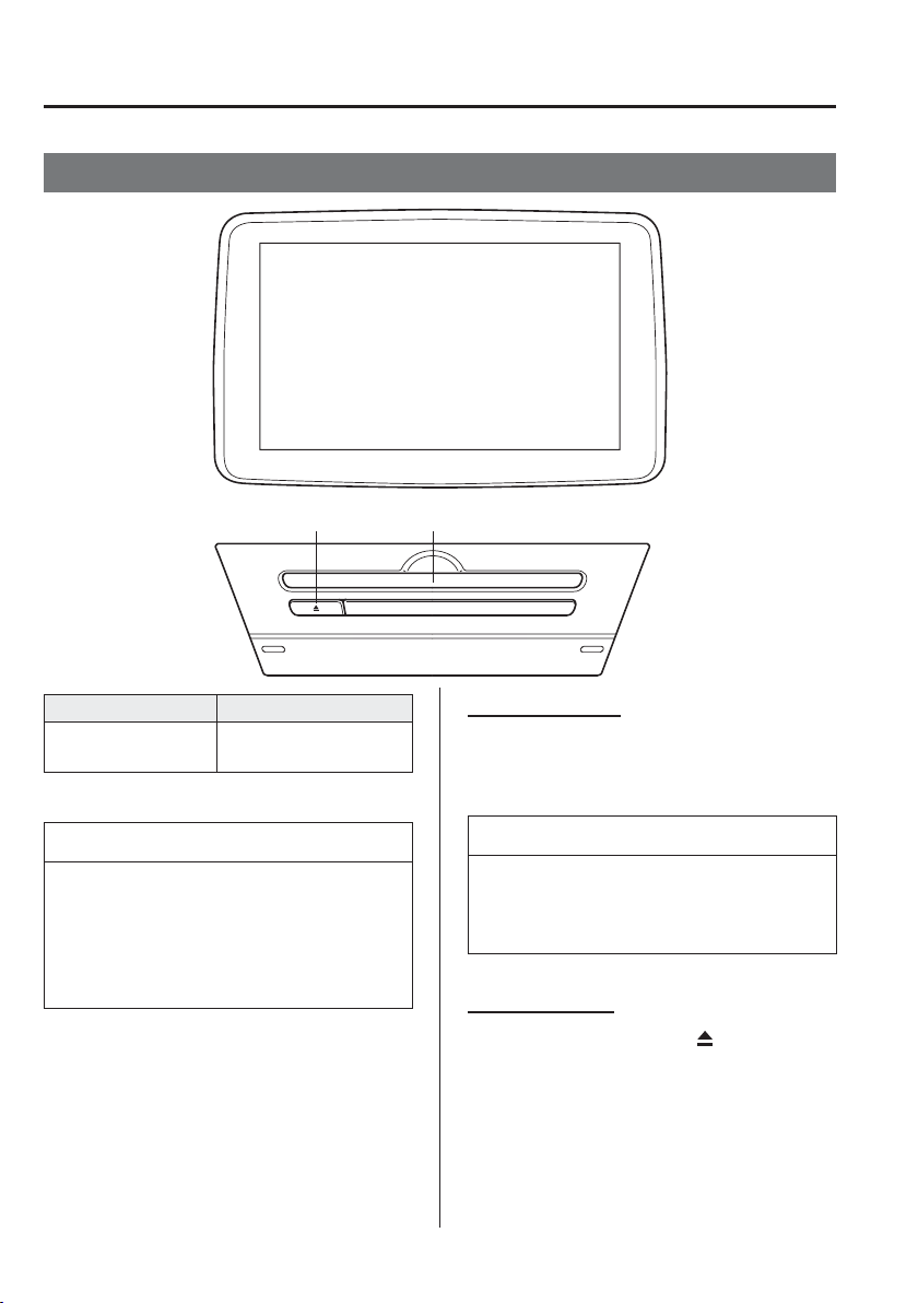
5
–
94
Interior Features
Audio Set [Type B (touchscreen)]
Operating the Compact Disc (CD) Player
CD slotCD eject button
Type Playable data
Music/MP3/WMA/
AAC CD player
Music data (CD-DA)
MP3/WMA/AAC ¿ le
NOTE
If a disc has both music data (CD-
DA) and MP3/WMA/AAC ¿ les,
playback of the two or three ¿ le types
differs depending on how the disc was
recorded.
Inserting the CD
Insert the CD into the slot, label-side up.
The auto-loading mechanism will set the
CD and begin play.
NOTE
There will be a short lapse before play
begins while the player reads the digital
signals on the CD.
Ejecting the CD
Press the CD eject button (
) to eject the
CD.
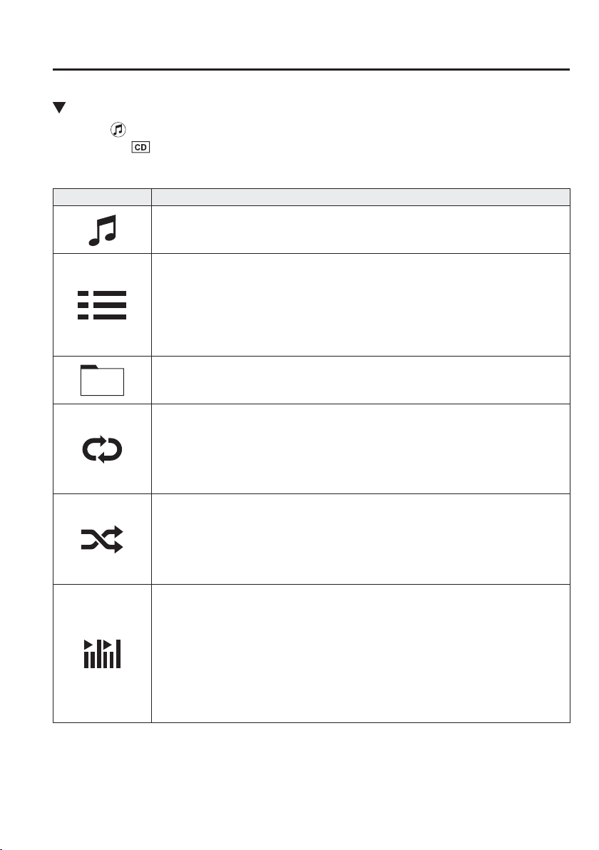
5
–
95
Interior Features
Audio Set [Type B (touchscreen)]
Playback
Select the icon on the home screen with a CD inserted and display the Entertainment
screen. When
is selected, the following icons are indicated in the lower part of the centre
display.
Icon Function
Displays the Entertainment menu. Use to switch to a different audio source.
(Music CD)
Displays the track list of the CD.
Select the track you want to play.
(MP3/WMA/AAC CD)
Displays the top level folder/¿ le list.
Select the folder you want to select.
The ¿ les in the selected folder are displayed.
Select the ¿ le you want to play.
(MP3/WMA/AAC CDs only)
Displays the ¿ le list of the folder currently being played.
Select the song you want to listen to.
(Music CD)
Replays the song currently being played repeatedly.
Select it again to cancel.
(MP3/WMA/AAC CD)
Replays the song currently being played repeatedly.
When selected again, the songs in the folder are played repeatedly.
Select it again to cancel.
(Music CD)
Plays songs on the CD in random order.
Select it again to cancel.
(MP3/WMA/AAC CD)
Plays songs in the folder in random order.
When selected again, the songs on the CD are played in random order.
Select it again to cancel.
(Music CD)
The beginning of each track on a CD is played to aid in searching for a desired track.
When selected again, the operation is cancelled and the song currently being played
continues.
(MP3/WMA/AAC CD)
The beginning of each track in a folder is played to aid in searching for a desired track.
When selected again, the operation is cancelled and the song currently being played
continues.
If the audio is operated during scan-play, the track being scan-played is played normally.
Then, the audio operation is performed.
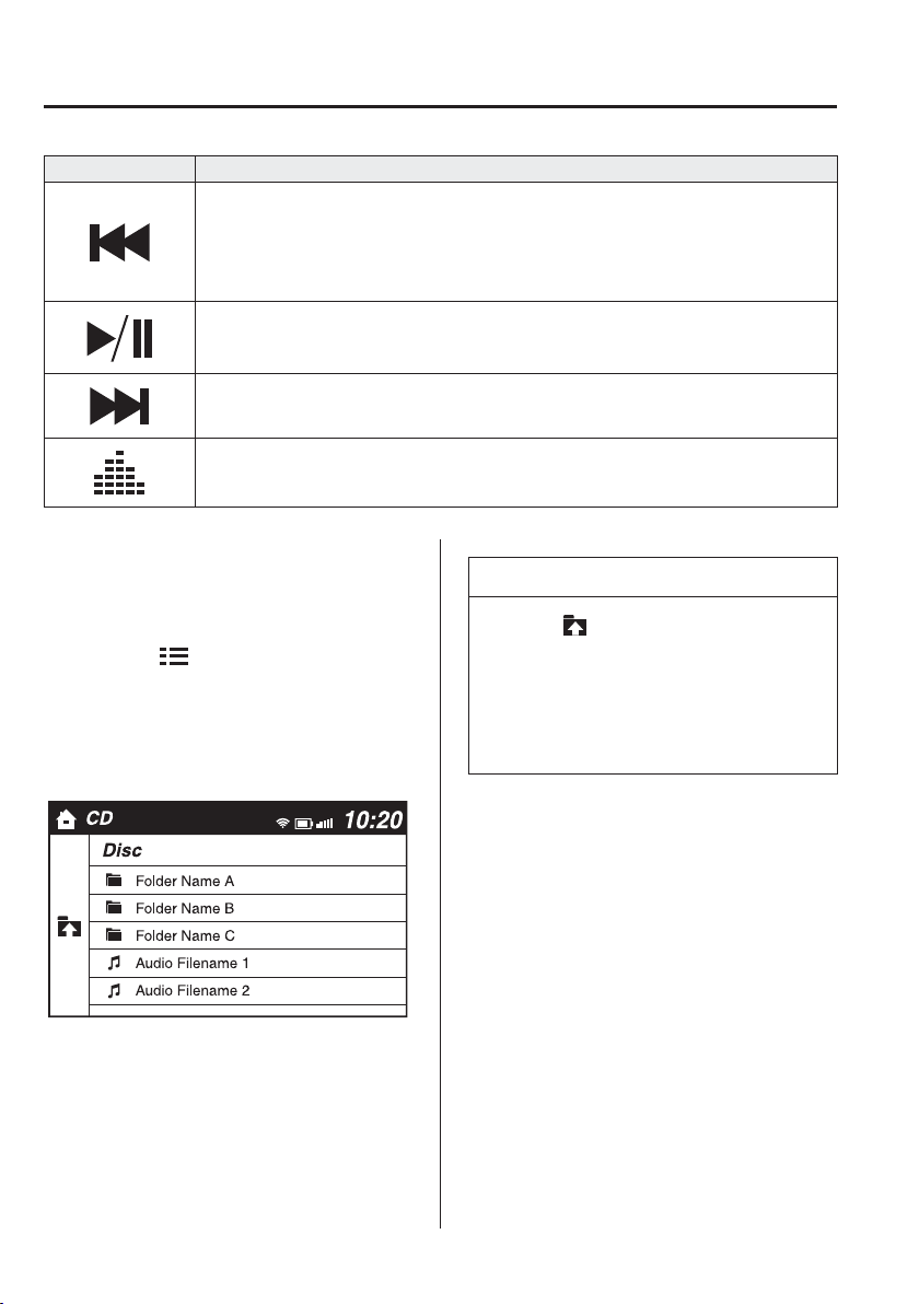
5
–
96
Interior Features
Audio Set [Type B (touchscreen)]
Icon Function
If selected within a few seconds of a song which has started to play, the previous song is
selected.
If more than a few seconds have elapsed after a song has begun to play, the song currently
being played is replayed from the beginning.
Long-press to fast reverse. It stops when you remove your hand from the icon or the
commander knob.
Plays a CD. When selected again, playback is temporarily stopped.
Advances to the beginning of the next song.
Long-press to fast forward. It stops when you remove your hand from the icon or the
commander knob.
Displays sound settings to adjust audio quality level.
Refer to Volume/Display/Sound Controls on page 5-86 .
Example of use (When searching for
a song from the top level of an MP3/
WMA/AAC CD)
1. Select the
icon to display the
folder/¿ le list at the top level.
2. When the folder is selected, folders/¿ le
lists in the folder are displayed.
3. Select the desired song.
NOTE
Select to move to a folder one
level higher.
The appearance of the repeat and
shufÀ e icons changes depending on
the type of operation in which the
function is used.
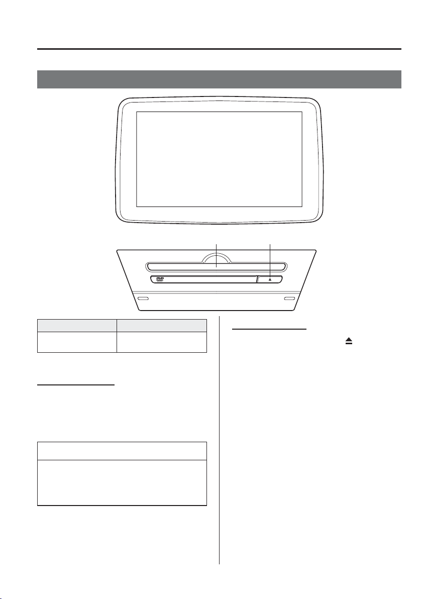
5
–
97
Interior Features
Audio Set [Type B (touchscreen)]
*Some models.
Operating the Digital Versatile Disc (DVD) Player
*
DVD slot DVD eject button
Type Playable data
DVD VIDEO/DVD-
VR player
DVD VIDEO/DVD-VR
¿ le
Inserting the DVD
Insert the DVD into the slot, label-side up.
The DVD is inserted automatically and
the top menu screen of the DVD disc and
controller are displayed.
NOTE
There will be a short lapse before play
begins while the player reads the digital
signals on the DVD.
Ejecting the DVD
Press the DVD eject button (
) to eject the
DVD.
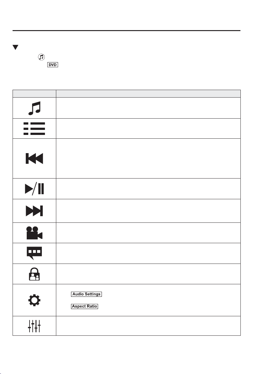
5
–
98
Interior Features
Audio Set [Type B (touchscreen)]
Playback
Select the icon on the home screen with a DVD inserted and display the Entertainment
screen. When
is selected, the DVD top menu screen and the controller are displayed.
When starting the playback by operating the controller, the following icons are displayed at
the bottom of the screen.
Icon Function
Displays the Entertainment menu. Use to switch to a different audio source.
Returns to the DVD menu screen.
Returns to the beginning of the previous chapter if the icon is selected within a few seconds
after the playback of the current chapter has started.
Returns to the beginning of the current chapter if the icon is selected a few seconds after the
playback of the current chapter has started.
Long-press during playback to fast reverse.
Long-press during pause to play in reverse in slow motion. It stops when you remove your
hand from the icon or the commander knob.
Plays the DVD. Select again to pause the playback.
Advances to the beginning of the next chapter.
Long-press during playback to fast forward.
Long-press during pause to play in slow motion. It stops when you remove your hand from
the icon or the commander knob.
Changes camera angle each time the icon is selected (usable DVDs only).
Changes display/non-display of the sub titles (usable DVDs only).
Changes the parental lock setting.
Parental lock level and PIN code setting changes are possible.
Pauses the playback and displays the DVD setting screen.
Select
to adjust the sound quality.
Refer to Volume/Display/Sound Controls on page 5-86 .
Select
to change the aspect ratio (horizontal to vertical ratio of the screen).
16:9 Widescreen, 4:3 Letterbox, and 4:3 Pan-scan are available.
Adjusts the screen.
Displays the video setting screen at the bottom of the screen.
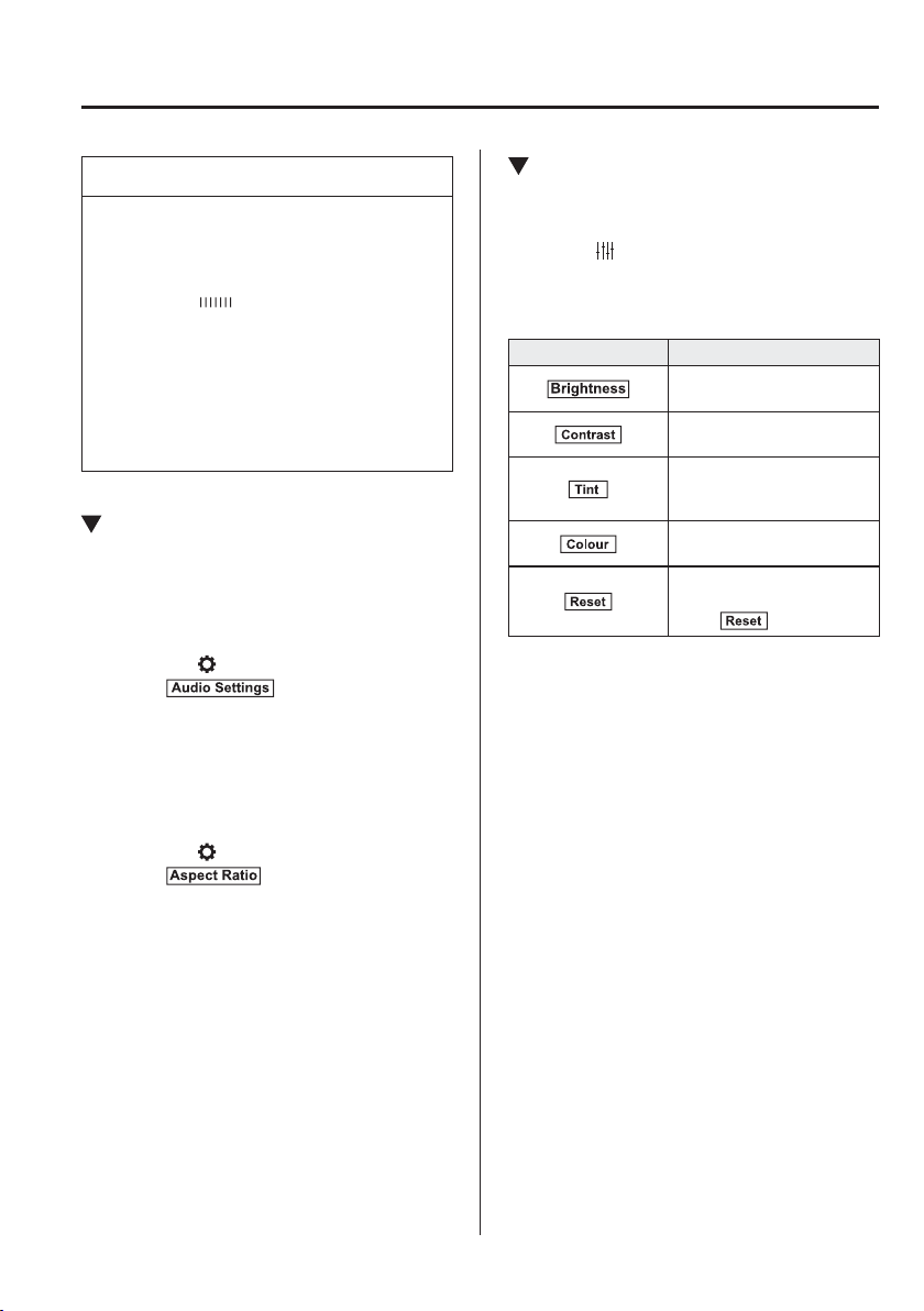
5
–
99
Interior Features
Audio Set [Type B (touchscreen)]
NOTE
For safety reasons, images are not
displayed while the vehicle is being
driven.
Slide the of the controller to
move the controller.
If the mode is switched to DVD
mode once the DVD playback
has stopped, the playback restarts
without displaying the DVD menu
screen.
Setting DVD functions
Sound quality and aspect ratio settings can
be performed.
Setting sound quality
1. Select the
icon.
2. Select
to adjust the sound
quality.
Refer to Volume/Display/Sound
Controls on page 5-86 .
Setting aspect ratio
1. Select the
icon.
2. Select
.
3. Select a desired aspect ratio.
Setting image quality
Brightness, contrast, tint, colour density
can be adjusted.
When the
icon is selected, the following
tabs are displayed at the bottom of the
screen.
Tab Function
Screen brightness can be
adjusted using the slider.
Screen contrast can be
adjusted using the slider.
Colour tone of the screen
can be adjusted using the
slider.
Screen colour can be
adjusted using the slider.
Screen settings can be reset
to initial values.
Select
.
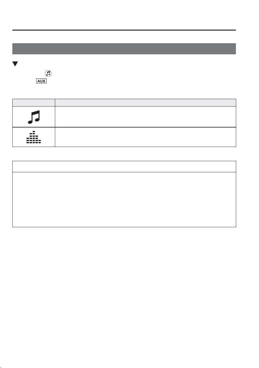
5
–
100
Interior Features
Audio Set [Type B (touchscreen)]
How to use AUX mode
Playback
1. Select the icon on the home screen to display the Entertainment screen.
2. Select
to switch to the AUX mode. The following icons are displayed in the lower
part of the centre display.
Icon Function
Displays the Entertainment menu. Use to switch to a different audio source.
Displays sound settings to adjust audio quality level.
Refer to Volume/Display/Sound Controls on page 5-86 .
NOTE
If a device is not connected to the auxiliary jack, the mode does not switch to the AUX
mode.
Adjust the audio volume using the portable audio device, commander switch, or audio
control switch.
Audio adjustments can also be made using the portable audio device's volume setting.
If the connection plug is pulled out from the auxiliary jack while in AUX mode, noise
may occur.
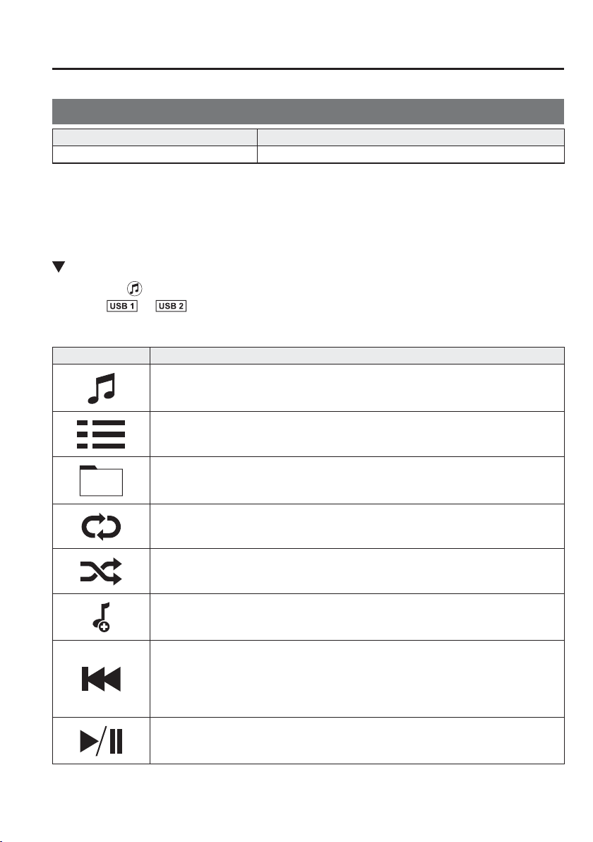
5
–
101
Interior Features
Audio Set [Type B (touchscreen)]
How to use USB mode
Type Playable data
USB mode MP3/WMA/AAC/OGG ¿ le
This unit does not support a USB 3.0 device. In addition, other devices may not be
supported depending on the model or OS version.
USB devices formatted to FAT32 are supported (USB devices formatted to other formats
such as NTFS are not supported).
Playback
1. Select the icon on the home screen to display the Entertainment screen.
2. Select
or to switch the USB mode. The following icons are displayed in the
lower part of the centre display.
Icon Function
Displays the Entertainment menu. Use to switch to a different audio source.
Category list is displayed.
Current track list is displayed.
Select a desired track to play it.
Plays the current track repeatedly.
Select it again to play the tracks in the current track list repeatedly.
When selected again, the function is cancelled.
Tracks in the current track list are played randomly.
Select it again to cancel.
Starts playing a track similar to the current track using Gracenote's More Like This
™
.
Select the desired song from the category list to cancel More Like This
™
.
If selected within a few seconds from the beginning of a song which has started to play, the
previous song is selected.
If more than a few seconds have elapsed, the song currently being played is replayed from
the beginning.
Long-press to fast reverse. It stops when you remove your hand from the icon or the
commander knob.
Track is played. When selected again, playback is temporarily stopped.
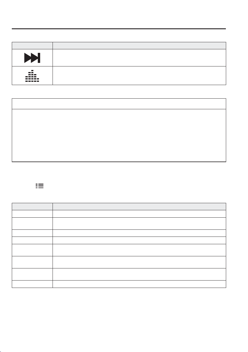
5
–
102
Interior Features
Audio Set [Type B (touchscreen)]
Icon Function
Advances to the beginning of the next song.
Long-press to fast forward.
Displays sound settings to adjust audio quality level.
Refer to Volume/Display/Sound Controls on page 5-86 .
NOTE
If a ¿ le name in the USB memory is too long, it could cause operation problems such
as not being able to playback the song.
(Recommended: Within 80 characters)
To move to the desired location on the track, move the slider indicating the playback
time.
The appearance of the repeat and shufÀ e icons changes depending on the type of
operation in which the function is used.
Category list
Select the
icon to display the following category list.
Select a desired category and item.
Category Function
Playlist
*1
Displays playlists on the device.
Artist
Displays the artist name list.
All the tracks or tracks for each album of the selected artist can be played.
Album Displays the album name list.
Song All the tracks in the device are displayed.
Genre
Displays the genre list.
All the tracks or tracks per album or artist in the selected genre can be played.
Audiobook
*2
Displays the audiobook list.
Chapters can be selected and played.
Podcast
*2
Displays the podcast list.
Episode can be selected and played.
Folder
*3
Displays the folder/¿ le list.
*1 Playlist folders of Apple devices are not supported.
*2 Apple device only
*3 USB-Sticks and USB-Android
™
device only
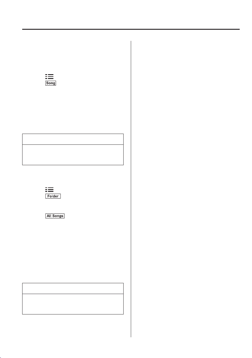
5
–
103
Interior Features
Audio Set [Type B (touchscreen)]
Example of use (to play all tracks in
USB device)
( M e t h o d 1 )
1. Select
to display the category list.
2. Select
.
All the tracks in the USB device are
displayed.
3. Select a desired track.
The selected track is played. All the
tracks in the USB device can be played
by continuing playback.
NOTE
Only the tracks in the desired category
selected in Step 2 are played.
(Method 2)
*1
1. Select
to display the category list.
2. Select
.
All the folders in the USB device are
displayed.
3. Select
.
All the tracks in the USB device are
displayed.
4. Select a desired track.
The selected track is played. All the
tracks in the USB device can be played
by continuing playback.
*1 Can be operated using an Android
™
device or USB À ash memory.
NOTE
Only the tracks in the desired folder
selected in Step 3 are played.
5
–
104
Interior Features
Audio Set [Type B (touchscreen)]
Gracenote Database
When a USB device is connected to this unit and the audio is played, the album name,
artist name, genre and title information are automatically displayed if there is a match in
the vehicle's database compilation to the music being played. The information stored in this
device uses database information in the Gracenote music recognition service.
CAUTION
For information related to the most recent Gracenote database which can be used and how
to install it, go to the Mazda Hands Free Website:
http://www.mazdahandsfree.com
Introduction
Music recognition technology and related data are provided by Gracenote
®
. Gracenote is the
industry standard in music recognition technology and related content delivery. For more
information visit www.gracenote.com.
CD and music-related data from Gracenote, Inc., copyright © 2000 to present Gracenote.
Gracenote Software, copyright © 2000 to present Gracenote. One or more patents owned
by Gracenote apply to this product and service. See the Gracenote website for a non-
exhaustive list of applicable Gracenote patents. Gracenote, CDDB, MusicID, MediaVOCS,
the Gracenote logo and logotype, and the “Powered by Gracenote” logo are either registered
trademarks or trademarks of Gracenote in the United States and/or other countries.
Gracenote
®
End User License Agreement
This application or device contains software from Gracenote, Inc. of Emeryville, California
(“Gracenote”). The software from Gracenote (the “Gracenote Software”) enables this
application to perform disc and/or ¿ le identi¿ cation and obtain music-related information,
including name, artist, track, and title information (“Gracenote Data”) from online servers
or embedded databases (collectively, “Gracenote Servers”) and to perform other functions.
You may use Gracenote Data only by means of the intended End-User functions of this
application or device.

5
–
105
Interior Features
Audio Set [Type B (touchscreen)]
You agree that you will use Gracenote Data, the Gracenote Software, and Gracenote Servers
for your own personal non-commercial use only. You agree not to assign, copy, transfer or
transmit the Gracenote Software or any Gracenote Data to any third party. YOU AGREE
NOT TO USE OR EXPLOIT GRACENOTE DATA, THE GRACENOTE SOFTWARE, OR
GRACENOTE SERVERS, EXCEPT AS EXPRESSLY PERMITTED HEREIN.
You agree that your non-exclusive license to use the Gracenote Data, the Gracenote
Software, and Gracenote Servers will terminate if you violate these restrictions. If your
license terminates, you agree to cease any and all use of the Gracenote Data, the Gracenote
Software, and Gracenote Servers. Gracenote reserves all rights in Gracenote Data, the
Gracenote Software, and the Gracenote Servers, including all ownership rights. Under no
circumstances will Gracenote become liable for any payment to you for any information
that you provide. You agree that Gracenote, Inc. may enforce its rights under this Agreement
against you directly in its own name.
The Gracenote service uses a unique identi¿ er to track queries for statistical purposes. The
purpose of a randomly assigned numeric identi¿ er is to allow the Gracenote service to count
queries without knowing anything about who you are. For more information, see the web
page for the Gracenote Privacy Policy for the Gracenote service.
The Gracenote Software and each item of Gracenote Data are licensed to you “AS IS.”
Gracenote makes no representations or warranties, express or implied, regarding the
accuracy of any Gracenote Data from in the Gracenote Servers. Gracenote reserves the right
to delete data from the Gracenote Servers or to change data categories for any cause that
Gracenote deems suf¿ cient. No warranty is made that the Gracenote Software or Gracenote
Servers are error-free or that functioning of Gracenote Software or Gracenote Servers will
be uninterrupted. Gracenote is not obligated to provide you with new enhanced or additional
data types or categories that Gracenote may provide in the future and is free to discontinue
its services at any time.
GRACENOTE DISCLAIMS ALL WARRANTIES EXPRESS OR IMPLIED,
INCLUDING, BUT NOT LIMITED TO, IMPLIED WARRANTIES OF
MERCHANTABILITY, FITNESS FOR A PARTICULAR PURPOSE, TITLE, AND
NON-INFRINGEMENT. GRACENOTE DOES NOT WARRANT THE RESULTS THAT
WILL BE OBTAINED BY YOUR USE OF THE GRACENOTE SOFTWARE OR ANY
GRACENOTE SERVER. IN NO CASE WILL GRACENOTE BE LIABLE FOR ANY
CONSEQUENTIAL OR INCIDENTAL DAMAGES OR FOR ANY LOST PROFITS OR
LOST REVENUES.
© 2000 to present. Gracenote, Inc.
5
–
106
Interior Features
Audio Set [Type B (touchscreen)]
Updating the database
The Gracenote media database can be updated using USB device.
1. Connect a USB device containing the software for updating Gracenote.
2. Select the
icon on the home screen to display the Settings screen.
3. Select the
tab and select .
4. Select
. The list of the update package stored in the USB device and the version are
displayed.
5. Select the package to use the update.
6. Select
.
NOTE
Gracenote can be downloaded from the Mazda Hands-free Website.
5
–
107
Interior Features
Audio Set [Type B (touchscreen)]
Bluetooth
®
Introduction
Bluetooth
®
Hands-Free outline
When a Bluetooth
®
device (mobile phone) is connected to the vehicle's Bluetooth
®
unit via
radio wave transmission, a call can be made or received by pressing the talk button, pick-
up button, or hang-up button on the audio remote control switch, or by operating the centre
display. For example, even if a device (mobile phone) is in your coat pocket, a call can be
made without taking the device (mobile phone) out and operating it directly.
Bluetooth
®
audio outline
When a portable audio unit equipped with the Bluetooth
®
communication function is paired
to the vehicle, you can listen to music stored on the paired portable audio device from the
vehicle's speakers. It is not necessary to connect the portable audio device to the vehicle's
external input terminal. After programming, operate the vehicle audio control panel to play/
stop the audio.
NOTE
For your safety, a device can be paired only when the vehicle is parked. If the vehicle
starts to move, the pairing procedure will end. Park the vehicle in a safe place before
pairing.
The communication range of a Bluetooth
®
equipped device is about 10 meters (32 ft)
or less.
Basic audio operation is available using voice commands even if Bluetooth
®
is not
connected.
For safety reasons, operation of the centre display is disabled while the vehicle is being
driven. However, items not displayed in grey can be operated using the commander
switch while the vehicle is being driven.
5
–
108
Interior Features
Audio Set [Type B (touchscreen)]
CAUTION
Some Bluetooth
®
mobile devices are not compatible with the vehicle. Consult an
Authorised Mazda Repairer, Mazda's call centre or Web support centre for information
regarding Bluetooth
®
mobile device compatibility:
Phone:
(Germany)
0800 4263 738 (8:00—18:00 Central European Time)
(Except Germany)
00800 4263 7383 (8:00—18:00 Central European Time)
(Worldwide)
49 (0) 6838 907 287 (8:00—18:00 Central European Time)
Web:
http://www.mazdahandsfree.com
Applicable Bluetooth
®
speci¿ cation (Recommended)
Ver. 1.1/1.2/2.0
EDR/2.1 EDR/3.0 (conformity)
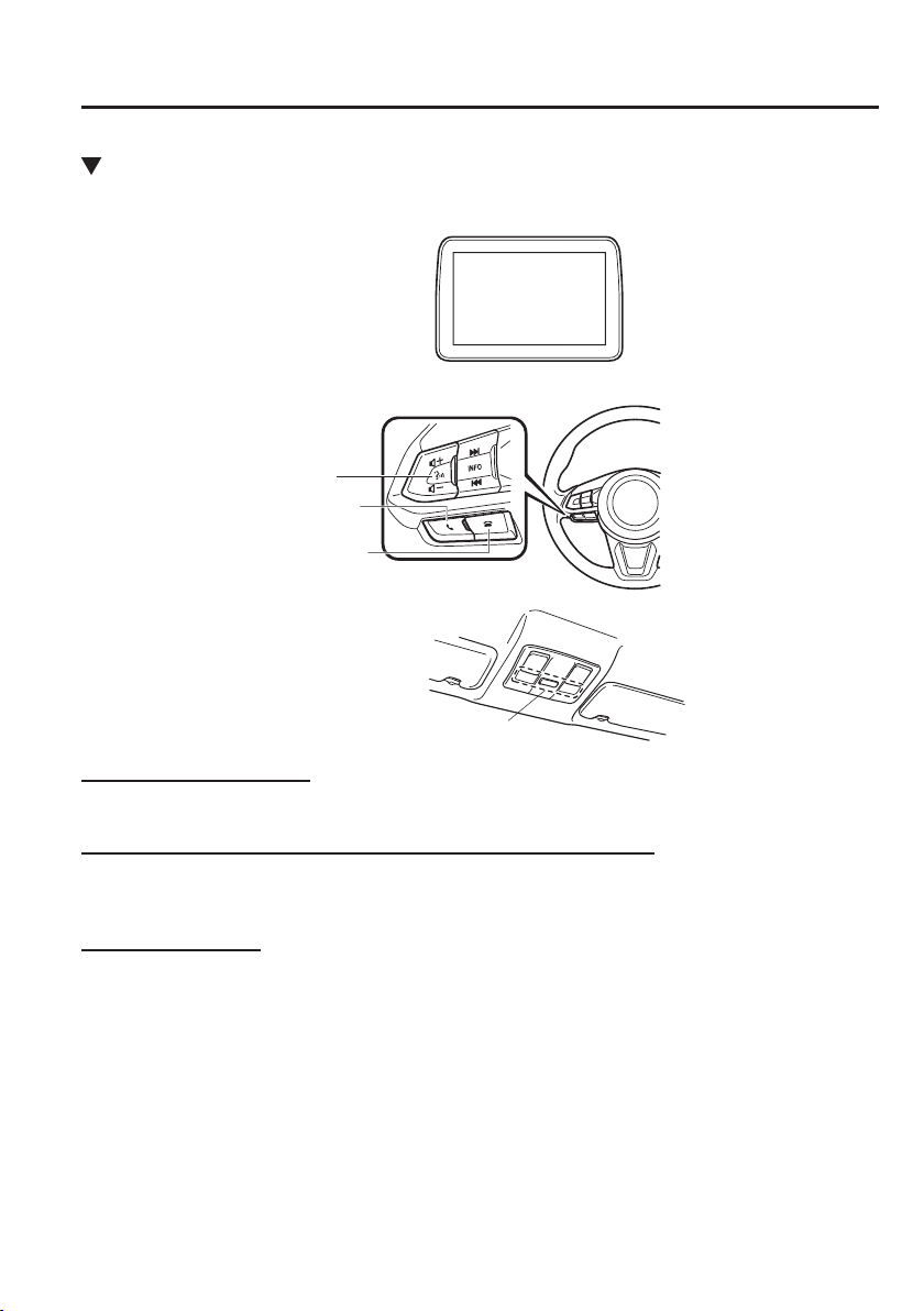
5
–
109
Interior Features
Audio Set [Type B (touchscreen)]
Component Parts
Microphone
Talk button, Pick-up button and Hang-up button
Microphone
Audio unit
Talk button
Hang-up button
Pick-up button
Microphone (hands-free)
The microphone is used for speaking voice commands or when making a Hands-free call.
Talk button, Pick-Up button and Hang-Up button (hands-free)
The basic functions of Bluetooth
®
Hands-Free can be used for such things as making calls or
hanging up using the talk, pick-up and hang-up buttons on the steering wheel.
Commander switch
The commander switch is used for volume adjustment and display operation. Tilt or turn the
commander knob to move the cursor. Press the commander knob to select the icon.
5
–
110
Interior Features
Audio Set [Type B (touchscreen)]
Volume adjustment
The volume dial of the commander switch is used to adjust the volume. Turn the dial to the
right to increase volume, to the left to decrease it.
The volume can also be adjusted using the volume button on the steering wheel.
NOTE
If the volume is lower compared to other audio modes, increase the volume from the
device side.
Conversation volume and the volume of the voice guidance and ringtone can each be set in
advance.
1. Select the icon on the home screen to display the Communication screen.
2. Select
.
3. Adjust the
and the using the slider.
5
–
111
Interior Features
Audio Set [Type B (touchscreen)]
Bluetooth
®
Preparation
Device pairing
To use Bluetooth
®
audio and Hands-Free,
the device equipped with Bluetooth
®
has
to be paired to the unit using the following
procedure. A maximum of seven devices
including Bluetooth
®
audio devices and
hands-free mobile phones can be paired.
NOTE
The Bluetooth
®
system may not
operate for 1 or 2 minutes after the
ignition is switched to ACC or ON.
However, this does not indicate a
problem. If the Bluetooth
®
system
does not connect automatically after
1 or 2 minutes have elapsed, make
sure that the Bluetooth
®
setting on
the device is normal and attempt to
reconnect the Bluetooth
®
device from
the vehicle side.
If Bluetooth
®
-enabled devices are
used in the following locations
or conditions, connection via
Bluetooth
®
may not be possible.
The device is in a location hidden
from the centre display such as
behind or under a seat, or inside
the glove compartment.
The device contacts or is covered
by a metal object or body.
The device is set to power-saving
mode.
Pairing Procedure
1. Select the
icon on the home screen
to display the Settings screen.
2. Select the
tab.
3. Select
.
4. Turn the Bluetooth
®
setting on.
5. Select
to display the
message and switch to the device
operation.
6. Using your device, perform a search
for the Bluetooth
®
device (Peripheral
device).
7. Select “Mazda” from the device list
searched by the device.
8. (Device with Bluetooth
®
version 2.0)
Input the displayed 4-digit pairing code
into the device.
(Device with Bluetooth
®
version 2.1
or higher)
Make sure the displayed 6-digit code
on the audio is also displayed on the
device, and touch the
.
Connection permission and phonebook
access permission for your mobile
device may be required depending on
the mobile device.
9. If pairing is successful, the functions of
the device connected to Bluetooth
®
are
displayed.
10. (Devices compatible with Mazda
E-mail / SMS function)
SMS (Short Message Service)
messages, and E-mail for the device are
downloaded automatically. A download
permission operation for your device
may be required depending on the
device.
5
–
112
Interior Features
Audio Set [Type B (touchscreen)]
NOTE
When Call history and messages
are downloaded automatically, each
automatic download setting must be on.
Refer to Communication Settings on
page 5-133 .
After a device is registered, the system
automatically identi¿ es the device. By
activating Bluetooth
®
Hands-Free again, or
by activating Bluetooth
®
Hands-Free ¿ rst
after switching the ignition from OFF to
ACC, the device connection condition is
indicated in the centre display.
IMPORTANT note about pairing and
automatic reconnection:
If pairing is redone on the same
mobile phone device, ¿ rst clear
“Mazda” displayed on the Bluetooth
®
setting screen of the mobile device.
When the OS of the device is updated,
the pairing information may be deleted.
If this happens, reprogramme the pairing
information to the Bluetooth
®
unit.
Before you pair your device, make sure
that Bluetooth
®
is “ON”, both on your
phone and on the vehicle.
Device selection
If several devices have been paired, the
Bluetooth
®
unit links the device last
paired. If you would like to link a different
paired device, it is necessary to change the
link. The order of device priority after the
link has been changed is maintained even
when the ignition is switched off.
Connecting other devices
1. Select the
icon on the home screen
to display the Settings screen.
2. Select the
tab.
3. Select
.
4. Turn the Bluetooth
®
setting on.
5. Select the name of the device you
would like to connect.
6.
selection
Connects both devices as hands-free
and Bluetooth
®
audio.
selection
Connects as a hands-free device.
selection
Connects as Bluetooth
®
audio.
NOTE
The following functions can be used for
the Hands-free or audio.
Hands-free: Phone calls and E-mail/
SMS
Audio: Bluetooth
®
audio, Aha
™
,
Stitcher
™
radio
Disconnecting a device
1. Select the
icon on the home screen
to display the Settings screen.
2. Select the
tab.
3. Select
.
4. Turn the Bluetooth
®
setting on.
5. Select the device name which is
currently connected.
6. Select
.
5
–
113
Interior Features
Audio Set [Type B (touchscreen)]
*Some models.
Deleting a device
Selecting and deleting devices
1. Select the
icon on the home screen
to display the Settings screen.
2. Select the
tab.
3. Select
.
4. Turn the Bluetooth
®
setting on.
5. Select the device name which you
would like to delete.
6. Select
.
7. Select
.
Deleting all devices
1. Select the
icon on the home screen
to display the Settings screen.
2. Select the
tab.
3. Select
.
4. Select
.
5. Select
.
6. Select
.
Changing PIN code
PIN code (4 digits) can be changed.
1. Select the icon on the home screen
to display the Settings screen.
2. Select the
tab.
3. Select
.
4. Select
.
5. Select
.
6. Input the new PIN code to be set.
7. Select
.
Available Language
*
The language can be changed.
Refer to Settings on page 5-137 .
NOTE
Depending on the language, it may only
be available for the screen display, but
not for the voice recognition.
5
–
114
Interior Features
Audio Set [Type B (touchscreen)]
Bluetooth
®
Audio
Applicable Bluetooth
®
speci¿ cation
(Recommended)
Ver. 1.1/1.2/2.0
EDR/2.1 EDR/3.0
(conformity)
Response pro¿ le
A2DP (Advanced Audio Distribution
Pro¿ le) Ver. 1.0/1.2
AVRCP (Audio/Video Remote Control
Pro¿ le) Ver. 1.0/1.3/1.4
A2DP is a pro¿ le which transmits only
audio to the Bluetooth
®
unit. If your
Bluetooth
®
audio device corresponds
only to A2DP, but not AVRCP, you
cannot operate it using the control panel
of the vehicle's audio system. In this
case, only the operations on the mobile
device are available the same as when a
portable audio device for a non-compliant
Bluetooth
®
device is connected to the
AUX terminal.
Function A2DP
AVRCP
Ver.
1.0
Ver. 1.3 Ver. 1.4
Playback X X X X
Pause X X X X
File (Track)
up/down
— X X X
Reverse — — X X
Fast-forward — — X X
Text display — — X X
Repeat — —
Depends
on device
Depends
on device
ShufÀ e — —
Depends
on device
Depends
on device
Scan — —
Depends
on device
Depends
on device
Folder up/
down
— — —
Depends
on device
X: Available
—: Not available
NOTE
The battery consumption of
Bluetooth
®
audio devices increases
while Bluetooth
®
is connected.
If a general mobile phone device
is USB connected during music
playback over the Bluetooth
®
connection, the Bluetooth
®
connection is disconnected. For
this reason, you cannot have
music playback over a Bluetooth
®
connection and music playback using
a USB connection at the same time.
The system may not operate
normally depending on the
Bluetooth
®
audio device.
5
–
115
Interior Features
Audio Set [Type B (touchscreen)]
Switching to Bluetooth
®
audio mode
To listen to music or voice audio recorded to a Bluetooth
®
audio device, switch to the
Bluetooth
®
audio mode to operate the audio device using the audio system control panel.
Any Bluetooth
®
audio device must be paired to the vehicle's Bluetooth
®
unit before it can be
used.
Refer to Bluetooth
®
Preparation on page 5-111 .
1. Turn on the Bluetooth
®
audio device's power.
2. Switch the ignition to ACC or ON.
3. Select the
icon on the home screen to display the Entertainment screen.
4. When
is selected, switches to the Bluetooth
®
audio mode to begin playback.
NOTE
If Bluetooth
®
audio is used after using Aha
™
or Stitcher
™
radio, the application on the
mobile device has to be closed ¿ rst.
If the Bluetooth
®
audio device does not begin playback, select the icon.
If the mode is switched from Bluetooth
®
audio mode to another mode (radio mode),
audio playback from the Bluetooth
®
audio device stops.
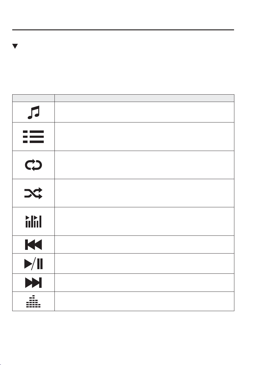
5
–
116
Interior Features
Audio Set [Type B (touchscreen)]
Playback
To listen to a Bluetooth
®
audio device over the vehicle's speaker system, switch the mode to
Bluetooth
®
audio mode. (Refer to “Switching to Bluetooth
®
audio mode”)
After switching to the Bluetooth
®
audio mode, the following icons are displayed in the
lower part of the display. Icons which can be used differ depending on the version of the
Bluetooth
®
audio device which you are currently using.
Icon Function
Displays the Entertainment menu. Use to switch to a different audio source.
(AVRCP Ver. 1.4 only)
Displays the top level folder/¿ le list.
Select the folder which you want to select.
The ¿ les in the selected folder are displayed.
Select the ¿ le you want to play.
(AVRCP Ver. 1.3 or higher)
Replays the song currently being played repeatedly.
When selected again, the songs in the folder are played repeatedly.
Select it again to cancel.
Icons change when the song is repeated or the folder is repeated.
(AVRCP Ver. 1.3 or higher)
Plays songs in the folder in random order.
When selected again, the songs on the device are played in random order.
Select it again to cancel.
Icons change during folder shufÀ e or device shufÀ e.
Scans the titles in a folder and plays the beginning of each song to aid in ¿ nding a desired
song.
When selected again, the beginning of each song on the device is played.
When selected again, the operation is cancelled and the song currently being played
continues.
Returns to the beginning of the previous song.
Long-press to fast reverse. It stops when you remove your hand from the icon or the
commander knob.
Plays the Bluetooth
®
audio. When selected again, playback is temporarily stopped.
Advances to the beginning of the next song.
Long-press to fast forward. It stops when you remove your hand from the icon or the
commander knob.
Displays sound settings to adjust audio quality level.
Refer to Volume/Display/Sound Controls on page 5-86 .
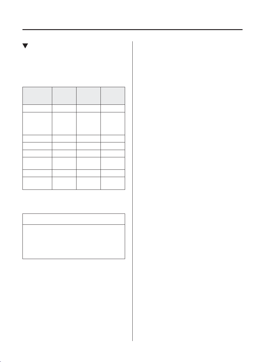
5
–
117
Interior Features
Audio Set [Type B (touchscreen)]
Bluetooth
®
Audio Device
Information Display
If a Bluetooth
®
audio device is connected,
the following information is displayed in
the centre display.
AVRCP
Ver. lower
than 1.3
AVRCP
Ver. 1.3
AVRCP
Ver. 1.4 or
higher
Device name X X X
Remaining
battery
charge of
device
X X X
Song name — X X
Artist name — X X
Album name — X X
Playback
time
— X X
Genre name — X X
Album art
image
— — —
X: Available
—: Not available
NOTE
Some information may not display
depending on the device, and if the
information cannot be displayed,
“Unknown - - -” is indicated.

5
–
118
Interior Features
Audio Set [Type B (touchscreen)]
How to Use Aha
™
What is Aha
™
?
A h a
*1
is an application which can be used to enjoy various Internet content such as Internet
radio and podcasts.
Stay connected to your friends activities by getting updates from Facebook and Twitter.
Using the location-based service, nearby services and destinations can be searched or real-
time local information can be obtained.
For details on Aha, refer to “http://www.aharadio.com/”.
*1 Aha, the Aha logo, and the Aha trade dress are trademarks or registered trademarks of
Harman International Industries, Inc., used with permission.
NOTE
The service content provided by Aha varies depending on the country in which the user
resides. In addition, the service is not available in some countries.
To operate Aha from your Bluetooth
®
device, perform the following in advance:
Install the Aha application to your device.
Create an Aha account for your device.
Log onto Aha using your device.
Select the preset station on your device.
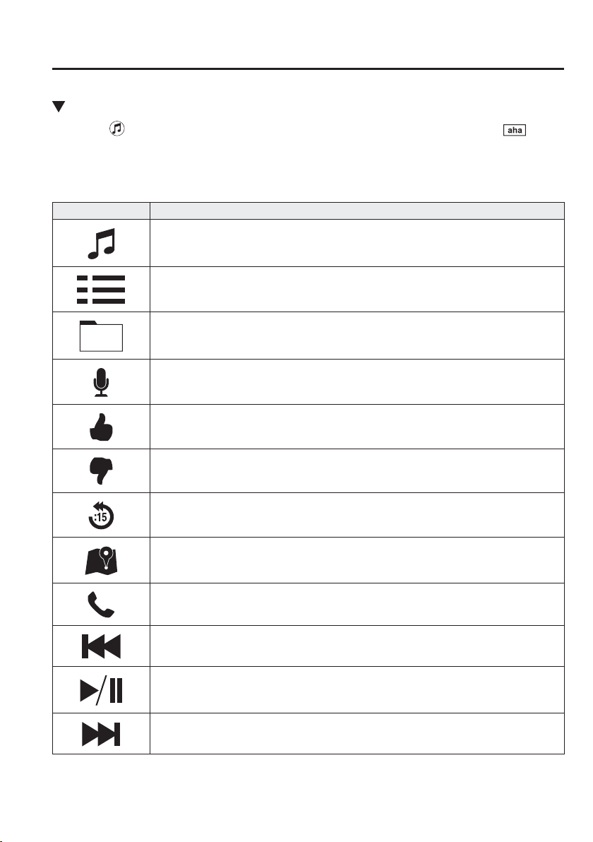
5
–
119
Interior Features
Audio Set [Type B (touchscreen)]
Playback
Select the icon on the home screen to display the Entertainment screen. When is
selected, the following icons are displayed at the bottom of the centre display. The displayed
icon differs depending on the selected station.
In addition, icons other than the following icons may be displayed.
Icon Function
Displays the Entertainment menu. Use to switch to a different audio source.
Displays the main menu.
Use to switch to other stations.
Displays the content list.
Use to switch to other desired content on the station.
Shout
Records voice.
Records voice and posts it as playable audio to Facebook and other social stations.
Like
*1
Evaluates the current content as “Like”.
Dislike
*1
Evaluates the current content as “Dislike”.
Reverses for 15 seconds.
Map (vehicles with navigation system)
Displays the destination searched by the location based services on the navigation system.
Call
A call can be made to the telephone number of a shop searched using the Location Based
Services. Available when a device is connected as a Hands-Free.
Returns to the previous content.
Pauses playback of the content. When selected again, playback resumes.
Goes to the next content.
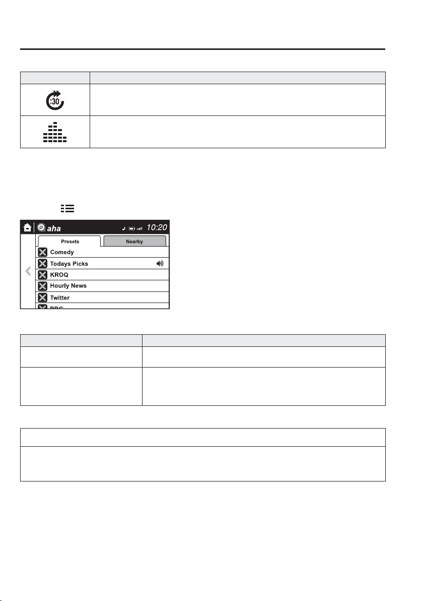
5
–
120
Interior Features
Audio Set [Type B (touchscreen)]
Icon Function
Fast-forwards for 30 seconds.
Displays sound settings to adjust audio quality level.
Refer to Volume/Display/Sound Controls on page 5-86 .
*1 Some stations may use alternate variations of Like and Dislike, based on station type or provider.
Main menu
Select the
icon.
Switch the tab and select the station category.
Tab Function
Presets
Displays the preset station list set on the device.
Select the preset station name to play the station content.
Nearby
Select the desired station.
Guidance is provided to the searched destination near the vehicle's position.
You can designate desired categories previously set using the ¿ lter setting
on your device.
NOTE
The available Location Based Services may differ because the services depend on the
content provided by Aha
™
.
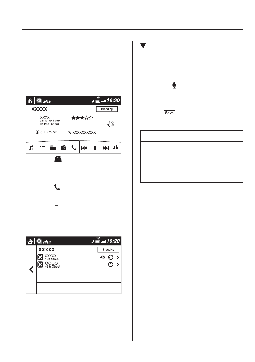
5
–
121
Interior Features
Audio Set [Type B (touchscreen)]
Example of use (Location Based
Services)
1. Select the desired station from the
“Nearby” tab on the main menu.
The destination name or address
playback starts in the order of the
destination name list.
2. When the
icon is selected, the
currently displayed destination is
displayed on the navigation system
(vehicles with navigation system).
3. When the
icon is selected, a phone
call is placed to the currently displayed
destination.
4. Select the
icon to display the
content list.
Selection of other destinations from the
list can be made.
Shout
Some social stations, such as Facebook or
Caraoke, support the ability to record and
share voice messages using the “Shout”
function.
1. Select the icon and start the
countdown (3, 2, 1, 0). Recording starts
when the countdown reaches zero.
2. Records voice.
3. Select
and store/post the
recording.
NOTE
Recordable time varies depending on
the station (Max. 30 seconds).
Recording stops automatically when
the recordable time has elapsed. You
can then post or delete the recording.
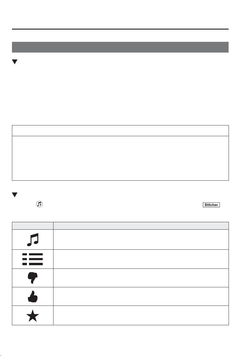
5
–
122
Interior Features
Audio Set [Type B (touchscreen)]
How to Use Stitcher
™
Radio
What is Stitcher
™
Radio?
Stitcher
™
*1
radio is an application which can be used to listen to Internet radio or stream
podcasts.
Recommended content is automatically selected by registering content which you put into
your favourites, or by pressing the Like or Dislike button.
For details on Stitcher
™
Radio, refer to “http://stitcher.com/”.
*1 Stitcher
™
, the Stitcher
™
logo, and the Stitcher
™
trade dress are trademarks or registered
trademarks of Stitcher, Inc., used with permission.
NOTE
To operate Stitcher
™
Radio from your Bluetooth
®
device, perform the following in
advance:
Install the Stitcher
™
Radio application to your device.
Create a Stitcher
™
Radio account for your device.
Log onto Stitcher
™
Radio using your device.
Playback
Select the icon on the home screen to display the Entertainment screen. When is
selected, the following icons are indicated in the bottom part of the centre display.
Icon Function
Displays the Entertainment menu. Use to switch to a different audio source.
Displays the station list.
Use to switch to other stations.
Dislike
Evaluates the current programme as “Dislike”.
Like
Evaluates the current programme as “Like”.
Adds the current station to your favourites or deletes the current station from your
favourites.
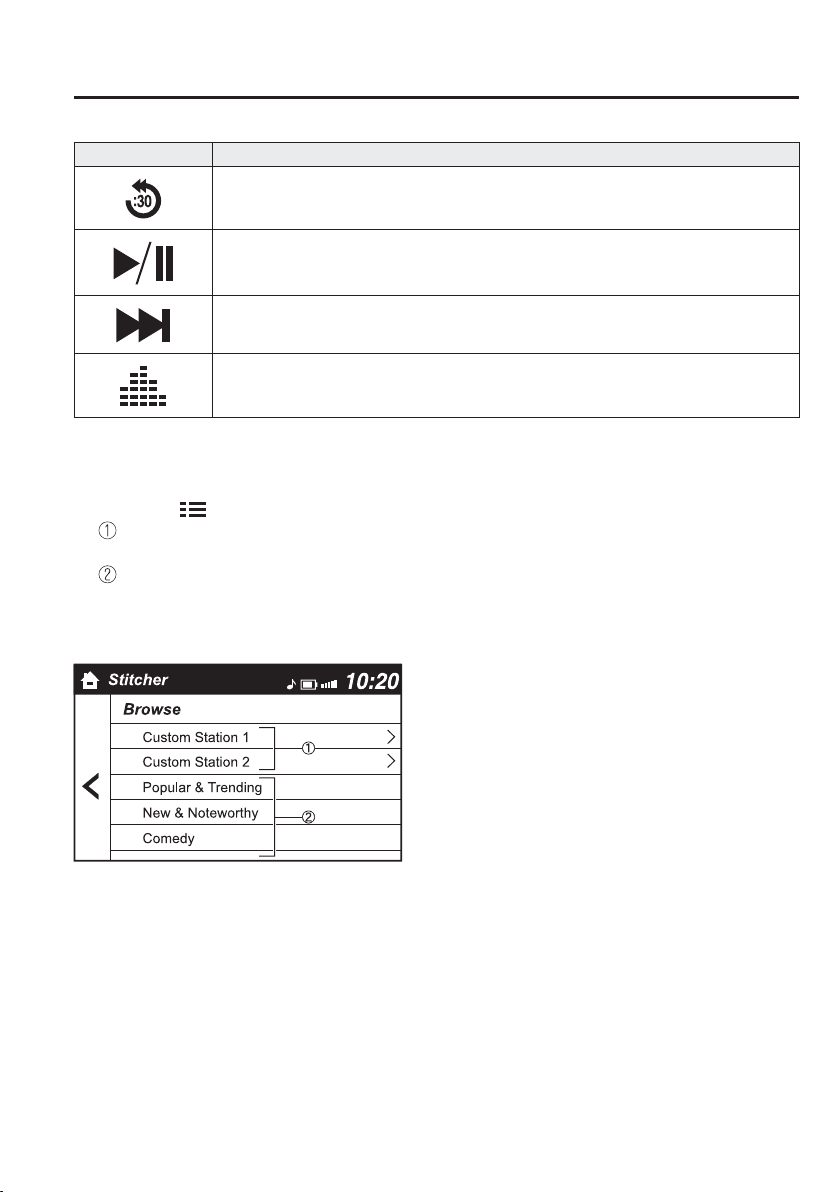
5
–
123
Interior Features
Audio Set [Type B (touchscreen)]
Icon Function
Reverses for 30 seconds.
Plays the station. Select it again to pause playback.
Goes to the next station.
Displays sound settings to adjust audio quality level.
Refer to Volume/Display/Sound Controls on page 5-86 .
Station list
1. Select the
icon to display the station list.
Favourites station name: Select to display the programme registered to your
favourites.
Category name: A recommended category selected from your favourites by Stitcher
™
is displayed.
Select it to display the category programme.
2. Select the programme name to play it.
5
–
124
Interior Features
Audio Set [Type B (touchscreen)]
Add to your favourites
If the current programme has not been
registered to your favourites, it can be
registered to your favourites.
1. Select the icon to display the
favourites station which the registration
can be added.
2. Select the station name which you want
to register.
3. Select
to add the programme to the
selected favourites station.
NOTE
Multiple favourites stations can be
selected and registered.
Favourites stations registered by
oneself as well those set by default
are displayed.
Delete from your favourites
If the current programme has already
been registered to your favourites, the
programme can be deleted from your
favourites.
1. Select the icon.
2. The programme is automatically
deleted from the favourites station.
Bluetooth
®
Hands-Free
Making a Call
Phonebook Usage
Telephone calls can be made by saying
the contact name in the downloaded
phonebook or the name of a person whose
phone number has been registered in the
Bluetooth
®
Hands-Free. Refer to Import
contact (Download Phonebook).
1. Press the talk button.
2. Wait for the beep sound.
3. Say: “Call XXXXX... (Ex. “John”)
Mobile”.
4. Follow the voice guidance to place the
call.
Screen operation
1. Select the
icon on the home screen
to display the Communication screen.
2. Select
to display the contact
list.
3. Select the contact you would like
to call to display the details for the
contact.
4. Select the desired phone number to
make the call.
Import contact (Download Phonebook)
Phonebook data from your device (Mobile
phone) can be sent and registered to your
Bluetooth
®
Hands-Free phonebook using
Bluetooth
®
.
5
–
125
Interior Features
Audio Set [Type B (touchscreen)]
(Automatic downloading)
The “Auto Download Contacts”
setting must be on. When hands-free is
connected to the device, the phonebook is
downloaded automatically.
Refer to Communication Settings on page
5-133 .
(Manually downloading)
If the “Auto Download Contacts” setting
is off, download the phonebook using the
following procedure.
1. Select the icon on the home screen
to display the Communication screen.
2. Select
to display the contact
list.
3. Select
.
4. Select
or
to switch to the
device operation.
5. If
is selected, select
.
6. Download will be started from the
mobile phone.
NOTE
If “Import All Contacts” is performed
after saving the phonebook to the
Bluetooth
®
unit, the phonebook will
be overwritten.
A maximum of 1,000 contacts can be
registered to the phonebook.
Phonebook, incoming/outgoing call
record, and favourite memories are
exclusive to each mobile phone to
protect privacy.
Favourites Contacts
A maximum of 50 contacts can be
registered. It will take less time to make a
call after registering the telephone number.
In addition, you do not have to look for the
person you want to call in the phonebook.
Registering to your favourites
1. Select the
icon on the home screen
to display the Communication screen.
2. Select
to display the
favourites list.
3. Select
.
4. Select
or
.
5. Select from the displayed list.
NOTE
When “Add New Contact” is selected,
information such as the selected person’s
name is also registered. In addition,
when “Add New Contact Details” is
selected, only the telephone number of
the selected person is registered.
5
–
126
Interior Features
Audio Set [Type B (touchscreen)]
Calling a favourites
1. Select the
icon on the home screen
to display the Communication screen.
2. Select
to display the
favourites list.
3. (If only one phone number is
registered to contact)
Select the contact information you
would like to call. Go to Step 5.
(If multiple phone numbers are
registered to contact)
Select the contact you would like to
call to display the screen indicating the
details for the contact. Go to Step 4.
4. Select the phone number you would
like to call.
5. Select
.
Deleting from your favourites
1. Select the
icon on the home screen
to display the Communication screen.
2. Select
to display the
favourites list.
3. Select
.
4. Select
.
5. Select the contact information which
you would like to delete.
6. Select
.
Changing the display order of your
favourites list
1. Select the
icon on the home screen
to display the Communication screen.
2. Select
to display the
favourites list.
3. Select
.
4. Select
.
5. The contact can be moved after it is
selected.
6. Slide the contact or move it using the
commander switch, then select
.
Changing contact name of your
favourites
1. Select the
icon on the home screen
to display the Communication screen.
2. Select
to display the
favourites list.
3. Select
.
4. Select
.
5. Select the contact to display the
keyboard screen.
6. If a new name is input and
is
selected, the contact name is stored.
NOTE
If the contact is long-pressed when the
favourites list is displayed, the contact
information can be edited (deleted,
moved).
Telephone Number Input
NOTE
Practice this while parked until you are
con¿ dent you can do it while driving in
a non-taxing road situation. If you are
not completely comfortable, make all
calls from a safe parking position, and
only start driving when you can devote
your full attention to driving.
1. Select the
icon on the home screen
to display the Communication screen.
2. When
is pressed, the dial pad
is displayed.
3. Input the telephone number using the
dial pad.
4. Select
to make the call.

5
–
127
Interior Features
Audio Set [Type B (touchscreen)]
Numeral or symbol entry
Use the dial pad.
Long-press the
to input +.
Select
to delete the currently input
value.
Long-press
to delete all input values.
Redial Function
Makes a call to the last person called
(latest person on outgoing call record)
from the mobile phone/vehicle.
1. Press the talk button.
2. Wait for the beep sound.
3. Say: “Redial”
Call back Function
Makes a call to the last person who called
your (latest person on incoming call
record) mobile phone/vehicle.
1. Press the talk button.
2. Wait for the beep sound.
3. Say: “Call back”
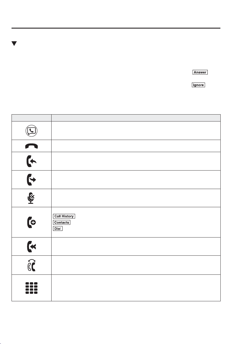
5
–
128
Interior Features
Audio Set [Type B (touchscreen)]
Receiving an Incoming Call
When an incoming call is received, the incoming call noti¿ cation screen is displayed. The
“Incoming Call Noti¿ cations” setting must be on.
Refer to Communication Settings on page 5-133 .
To accept the call, press the pick-up button on the audio control switch or select
on
the screen.
To reject the call, press the hang-up button on the audio control switch or select
on the
screen.
The following icons are displayed on the screen during a call. Icons which can be used differ
depending on use conditions.
Icon Function
Displays the Communication menu.
Ends the call.
Transferring a call from hands-free to a mobile phone
Communication between the Bluetooth
®
unit and a device (mobile phone) is cancelled, and
an incoming call will be received by the device (mobile phone) like a standard call.
Transferring a call from a device (mobile phone) to hands-free
Communication between devices (mobile phone) can be switched to Bluetooth
®
Hands-
Free.
Mute
The microphone can be muted during a call.
When selected again, the mute is cancelled.
To make a 3-way call, select the contacts from the following:
: Call History is displayed.
: The phonebook is displayed.
: The dial pad is displayed. Input the phone number.
The device may be unusable depending on the contractual content.
The call on hold is made to make a 3-way call.
The device may be unusable depending on the contractual content.
Switches the call on hold.
DTMF (Dual Tone Multi-Frequency Signal) Transmission
This function is used when transmitting DTMF via the dial pad. The receiver of a DTMF
transmission is generally a home telephone answering machine or a company's automated
guidance call centre.
Input the number using a dial pad.
5
–
129
Interior Features
Audio Set [Type B (touchscreen)]
NOTE
If the ignition is switched off
during a hands-free call, the line is
transferred to the device (Mobile
phone) automatically.
If the DTMF code has two or more
digits or symbols, each one must be
transmitted individually.
Call Interrupt
A call can be interrupted to receive an
incoming call from a third party.
When
is selected or the pick-
up button on the steering wheel is pressed,
the current call is held and the system
switches to the new incoming call.
When
is selected, the current
call is ended and the system switches to
the new incoming call (GSM network
only).
When
is selected or the hang-up
button on the steering wheel is pressed, an
incoming call is refused.
NOTE
The function may not be available
depending on the contractual content
of the mobile device.
The function may not be operable
depending on the type of the
telephone network and the mobile
device.
Receiving and Replying to
Messages (available only with
E-mail/SMS compatible phones)
SMS (Short Message Service) messages,
and E-mail received by connected devices
can be downloaded, displayed, and played
(read by the system).
Additionally, replies can also be made
to calls and messages in the received
messages.
Downloading messages
Up to 20 new messages can be
downloaded and displayed from a
connected device.
NOTE
For E-mail, 20 messages for each
account can be downloaded.
(Automatic downloading)
The “Auto Download Email” (E-mail) or
“Auto Download SMS” (SMS) setting
must be on. A message is downloaded
automatically when the Bluetooth
®
unit is
connected to the device.
Refer to Communication Settings on page
5-133 .
5
–
130
Interior Features
Audio Set [Type B (touchscreen)]
(Manually downloading)
When the “Auto Download Email”
(E-mail) or “Auto Download SMS” (SMS)
setting is off, the message is downloaded
using the following procedure.
1. Select the icon on the home screen
to display the Communication screen.
2. Select
or to display the
Inbox.
3. Select
.
4. Download will be started from the
mobile phone.
NOTE
Attached data is not downloaded.
Messages up to 1 kilobyte
(E-mail)/140-bytes (SMS) can be
downloaded.
A message list is created for each
device.
If the connected device does not
correspond to MAP 1.0, the AT
command is used to download. The
downloaded message indicates that it
is already read.
Downloading using the AT command
may not function depending on the
connected device.
Receiving messages
( M e t h o d 1 )
When a device receives a message, a
message received noti¿ cation is displayed.
The “Email Noti¿ cations” (E-mail) or
“SMS Noti¿ cations” (SMS) setting must
be on.
Refer to Communication Settings on page
5-133 .
Select
and display the message.
(Method 2)
1. Select the
icon on the home screen
to display the Communication screen.
2. Select
and display the new
message list for E-mail and SMS.
3. Select the message you would like to
display.
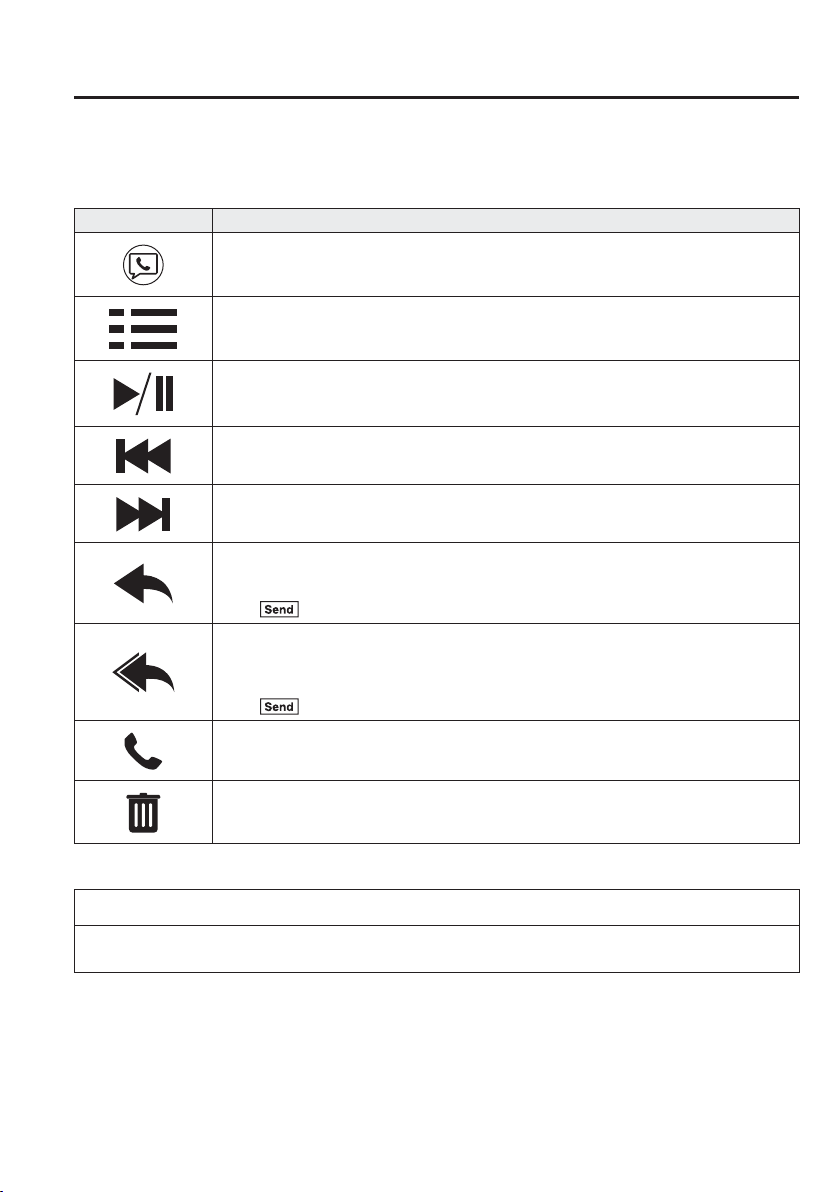
5
–
131
Interior Features
Audio Set [Type B (touchscreen)]
The following icons are displayed in the lower part of the details on the message. Icons
which can be used differ depending on use conditions.
Icon Function
Displays the Communication menu.
Displays the inbox.
Plays back a message.
When selected again, playback is temporarily stopped.
Displays the previous message.
Displays the next message.
Only replies to the sender of the currently displayed message.
Select the sentence on the displayed reply screen and select the sentence for sending from
the preset message.
Select
.
(Only E-mail)
Replies to all members including CC.
Select the sentence on the displayed reply screen and select the sentence for sending from
the preset message.
Select
.
Makes a call to a person who sent a message.
For E-mail, this function may not work depending on the device.
Deletes a message.
The messages stored in a device is also deleted.
NOTE
Up to three preset messages can be selected.
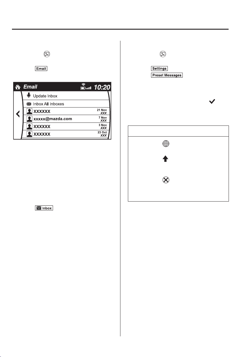
5
–
132
Interior Features
Audio Set [Type B (touchscreen)]
Example of use (verify unread E-mail)
1. Select the
icon on the home screen
to display the Communication screen.
2. Select
to display the inbox.
3. Select the unread message displayed in
bold.
4. The details of the message are
displayed and replying to the message,
making a call, or playback can be
performed.
Changing account for displaying
(E-mail only)
1. Select
.
2. Select the account which you would
like to display. Only the messages for
the selected account are displayed in
the inbox.
Editing preset messages
1. Select the
icon on the home screen
to display the Communication screen.
2. Select
.
3. Select
.
4. Select the preset message which you
would like to edit. The keyboard screen
is displayed.
5. When the message is input and
is
selected, the message is stored as a
preset message.
NOTE
Select the icon to change the
language.
Select the icon to switch between
capitalized and lower-case
characters.
Select the icon to return to the
previous screen without storing the
edit.
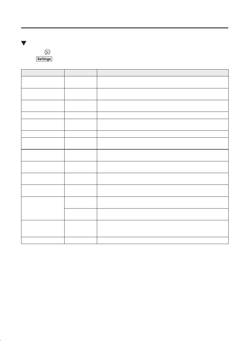
5
–
133
Interior Features
Audio Set [Type B (touchscreen)]
Communication Settings
Select the icon on the home screen to display the Communication screen.
Select
to change the setting.
Item Setting Function
Bluetooth
®
—
Go to Bluetooth
®
setting menu.
Refer to Bluetooth
®
Preparation on page 5-111 .
Incoming Call
Noti¿ cations
On/Off Noti¿ es when an incoming call is received.
Auto Download SMS On/Off
Downloads SMS automatically when the Bluetooth
®
unit is connected
to the device.
SMS Noti¿ cations On/Off Noti¿ es when a new SMS is received.
Auto Download
Email
*1
On/Off
Downloads E-mail automatically when the Bluetooth
®
unit is connected
to the device.
Email Noti¿ cations On/Off Noti¿ es when a new E-mail is received.
Auto Download Call
History
On/Off
Downloads Call History automatically when the Bluetooth
®
unit is
connected to the device.
Auto Download
Contacts
*1
On/Off
Downloads the phonebook automatically when the Bluetooth
®
unit is
connected to the device.
Ringtone
Fixed/In-band/
Off
Changes the ringtone setting.
Phone Volume
Adjusts using
the slider.
Adjusts the conversation volume.
VR and Ringtone
Adjusts using
the slider.
Adjusts the voice guidance and ringtone volume.
Contacts Sort Order
First Name,
Last Name
Displays the contact information in alphabetical order of the ¿ rst name.
Last Name,
First Name
Displays the contact information in alphabetical order of the last name.
Preset Messages —
Edits the preset message.
Refer to Receiving and Replying to Messages (available only with
E-mail/SMS compatible phones) on page 5-129 .
Reset — Initializes all Communication Settings.
*1 Depending on the device, it may be necessary to acquire download permission on the device side.
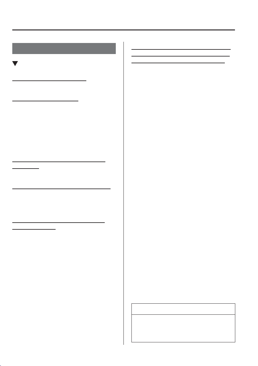
5
–
134
Interior Features
Audio Set [Type B (touchscreen)]
Voice Recognition
Basic Operation Method
Activating Voice Recognition
Press the talk button.
Ending Voice Recognition
Use one of the following methods:
Press the hang-up button.
Say, “Cancel”.
Operate the commander switch or the
centre display (only when vehicle is
stopped).
Skipping Voice Guidance (for faster
operation)
Press and release the talk button.
Troubleshooting for Voice Recognition
If you do not understand an operation
method while in the voice recognition
mode, say “Tutorial” or “Help”.
Commands useable anytime during
voice recognition
“Go Back” and “Cancel” are commands
which can be used at anytime during voice
recognition.
Returning to previous operation
To return to the previous operation, say,
“Go Back” while in voice recognition
mode.
Cancel
To put the Bluetooth
®
Hands-Free system
in standby mode, say, “Cancel” while in
voice recognition mode.
To prevent a deterioration in the voice
recognition rate and voice quality, the
following points should be observed:
The voice recognition cannot be
performed while voice guidance or
the beep sound is operating. Wait
until the voice guidance or the beep
sound is ¿ nished before saying your
commands.
Phone related commands are available
only when your phone is connected via
Bluetooth
®
. Make sure your phone is
connected via Bluetooth
®
before you
operate phone related voice commands.
Music play commands, such as Play
Artist and Play Album can be used only
in USB audio mode.
Do not speak too slowly or loudly (no
loud voice).
Speak clearly, without pausing between
words or numbers.
Dialects or different wording other
than hands-free prompts cannot be
recognised by voice recognition. Speak
in the wording speci¿ ed by the voice
commands.
It is not necessary to face the
microphone or approach it. Speak the
voice commands while maintaining a
safe driving position.
Close the windows to reduce loud
noises from outside the vehicle, or turn
down the airÀ ow of the air-conditioning
system while Bluetooth
®
Hands-Free is
being used.
Make sure the vents are not directing air
up towards the microphone.
NOTE
If the voice recognition performance is
not satisfactory.
Refer to Troubleshooting on page 5-140 .
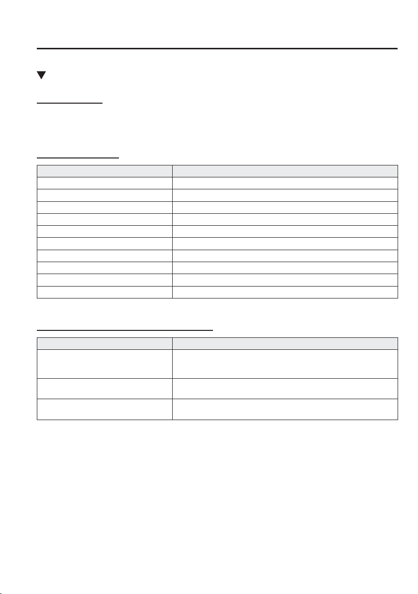
5
–
135
Interior Features
Audio Set [Type B (touchscreen)]
Voice Command List
Voice command
When the talk button is pressed and the following command is spoken, the audio or
navigation can be operated. The commands in the () can be omitted. The speci¿ ed name and
number are put into the {}.
Standard command
Voice command Function
cancel Ends the voice recognition mode.
(go) back Returns to the previous operation.
help Usable commands can be veri¿ ed.
tutorial Basic voice commands and methods of use can be veri¿ ed.
(go to) home (screen)/main menu Moves to the home screen.
(go to) communication Moves to the communication screen.
(go to) navigation Moves to the navigation screen.
(go to) entertainment (menu) Moves to the entertainment screen.
(go to) settings Moves to the setting screen.
(go to) favourites Moves to the favourites screen.
Communication (phone) related command
Voice command Function
Call {name in phonebook} (mobile/
home/work/other)
Example: “Call John Mobile”
Call to the contact in the downloaded phonebook.
Refer to Making a Call on page 5-124 .
Redial
Call to the last contact you called.
Refer to Making a Call on page 5-124 .
Callback
Call to the last contact who called you.
Refer to Making a Call on page 5-124 .
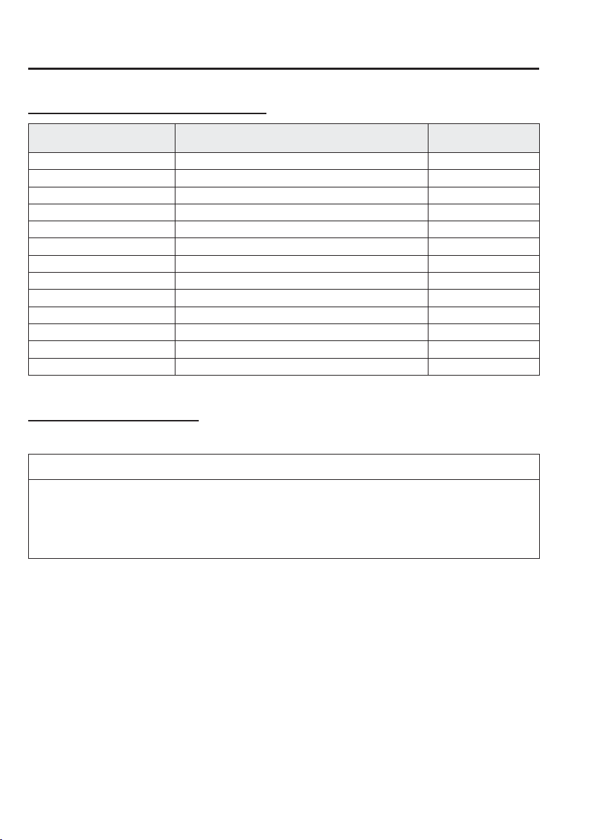
5
–
136
Interior Features
Audio Set [Type B (touchscreen)]
Entertainment (audio) related command
Voice command Function
Corresponding audio
source
(Go to/Play) AM (Radio) Switches the audio source to AM radio. All
(Go to/Play) FM (Radio) Switches the audio source to FM radio. All
(Go to/Play) DAB (Radio) Switches the audio source to DAB radio. All
(Go to/Play) Bluetooth (Audio) Switches the audio source to BT audio. All
(Go to/Play) Aha (Radio) Switches the audio source to Aha
™
Radio. All
(Go to/Play) Stitcher Switches the audio source to Stitcher
™
Radio. All
(Go to/Play) USB 1 Switches the audio source to USB 1. All
(Go to/Play) USB 2 Switches the audio source to USB 2. All
Play Playlist {Playlist name} Plays the selected playlist. USB
Play Artist {Artist name} Plays the selected artist. USB
Play Album {Album name} Plays the selected album. USB
Play Genre {Genre name} Plays the selected genre. USB
Play Folder {Folder name} Plays the selected folder. USB
Navigation related command
For the navigation screen voice commands, refer to the separate navigation system manual.
NOTE
Some commands cannot be used depending on the grade and speci¿ cation.
Some commands cannot be used depending on the device connection conditions and
the use conditions.
The commands are examples of the available commands.
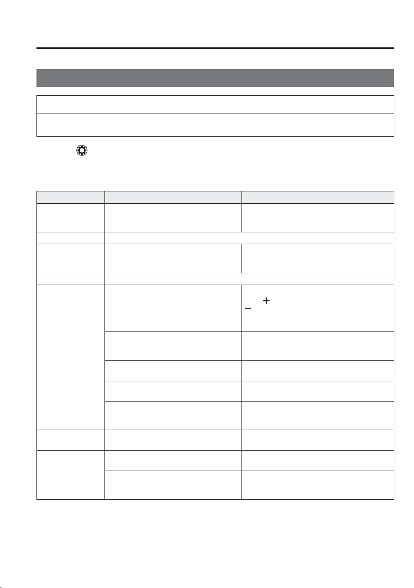
5
–
137
Interior Features
Audio Set [Type B (touchscreen)]
Settings
NOTE
Depending on the grade and speci¿ cation, the screen display may differ.
Select the
icon on the home screen and display the Settings screen.
Switch the tab and select the setting item you want to change.
You can customize settings in the setup display as follows:
Tab Item Function
AD-Disp
Height
Brightness Control
Other
Refer to Active Driving Display on page
4-35 .
Display Refer to Volume/Display/Sound Controls on page 5-86 .
Safety
Distance Recognition Support System
SBS/SCBS
Other
Refer to Personalisation Features on page
9-13 .
Sound Refer to Volume/Display/Sound Controls on page 5-86 .
Clock
Adjust Time
Displays the currently set time is displayed.
Press
to advance the hour/minute, and select
to move the hour/minute back.
AM/PM can only be selected with the 12-hour
clock display.
GPS Sync
Synchronizes with GPS when turned on.
When turned off, the time can be changed from
“Adjust Time”.
Time Format
Changes the display between 12 and 24-hour
clock time.
Time Zone Select
When it's not synchronized with GPS, select
the region you want to specify.
Daylight Savings Time
Turns the daylight saving time setting on/off.
When ON, the time advances 1 hour. When
OFF, it returns to normal time.
Vehicle
Rain Sensing Wiper
Other
Refer to Personalisation Features on page
9-13 .
Devices
Bluetooth
Refer to Bluetooth
®
Preparation on page
5-111 .
Network Management
Wi-Fi
™
is used to obtain Navi POI/Real Time
Traf¿ c function (Such as gas prices, weather,
nearest restaurant)
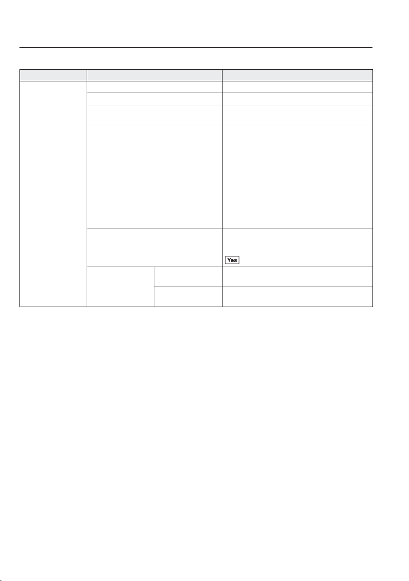
5
–
138
Interior Features
Audio Set [Type B (touchscreen)]
Tab Item Function
System
Tool Tips Turns button explanations ON/OFF.
Language Changes the language.
Temperature
Changes the setting between Fahrenheit and
Celsius.
Distance
Changes the setting between miles and
kilometres.
Music Database Update
Used to update Gracenote
®
. Gracenote is used
with USB Audio, and provides:
1. Supplementary music information (Such as
song name, artist name)
2. Voice recognition assistance for Play Artist
and Play Album
Gracenote can be downloaded from the Mazda
Handsfree Website.
Refer to Gracenote Database on page 5-104 .
Factory Reset
Memory and settings are initialized to the
factory settings.
The initialization launches by selecting the
button.
About
Agreements and
Disclaimers
Verify the disclaimer and agree.
Version Information
Can verify the current audio unit OS version
and Gracenote Database version.
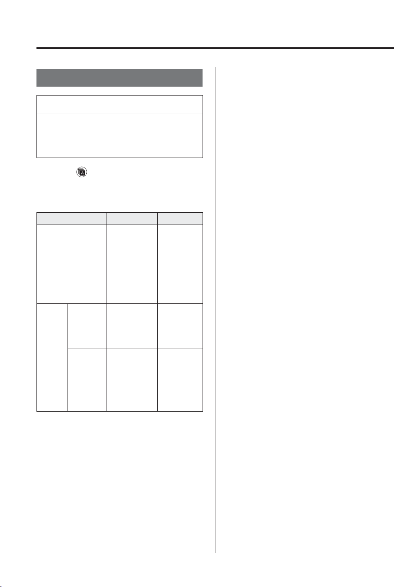
5
–
139
Interior Features
Audio Set [Type B (touchscreen)]
Applications
NOTE
Depending on the grade and
speci¿ cation, the screen display may
differ.
Select the
icon on the home screen to
display the Applications screen. The
following information can be veri¿ ed.
Top screen Item Function
Fuel Economy
Monitor
Fuel
Consumption
Display
Control Status
Display
Effectiveness
Display
Ending Screen
Display
Refer
to Fuel
Economy
Monitor
on page
4-93 .
Vehicle
Status
Monitor
Maintenance
Scheduled
Maintenance
Tyre Rotation
Oil Change
Refer to
Maintenance
Monitor
on page
6-15 .
Warning
Guidance
Warnings
currently
active can be
veri¿ ed.
Refer to If
a Warning
Light
Turns On
or Flashes
on page
7-35 .
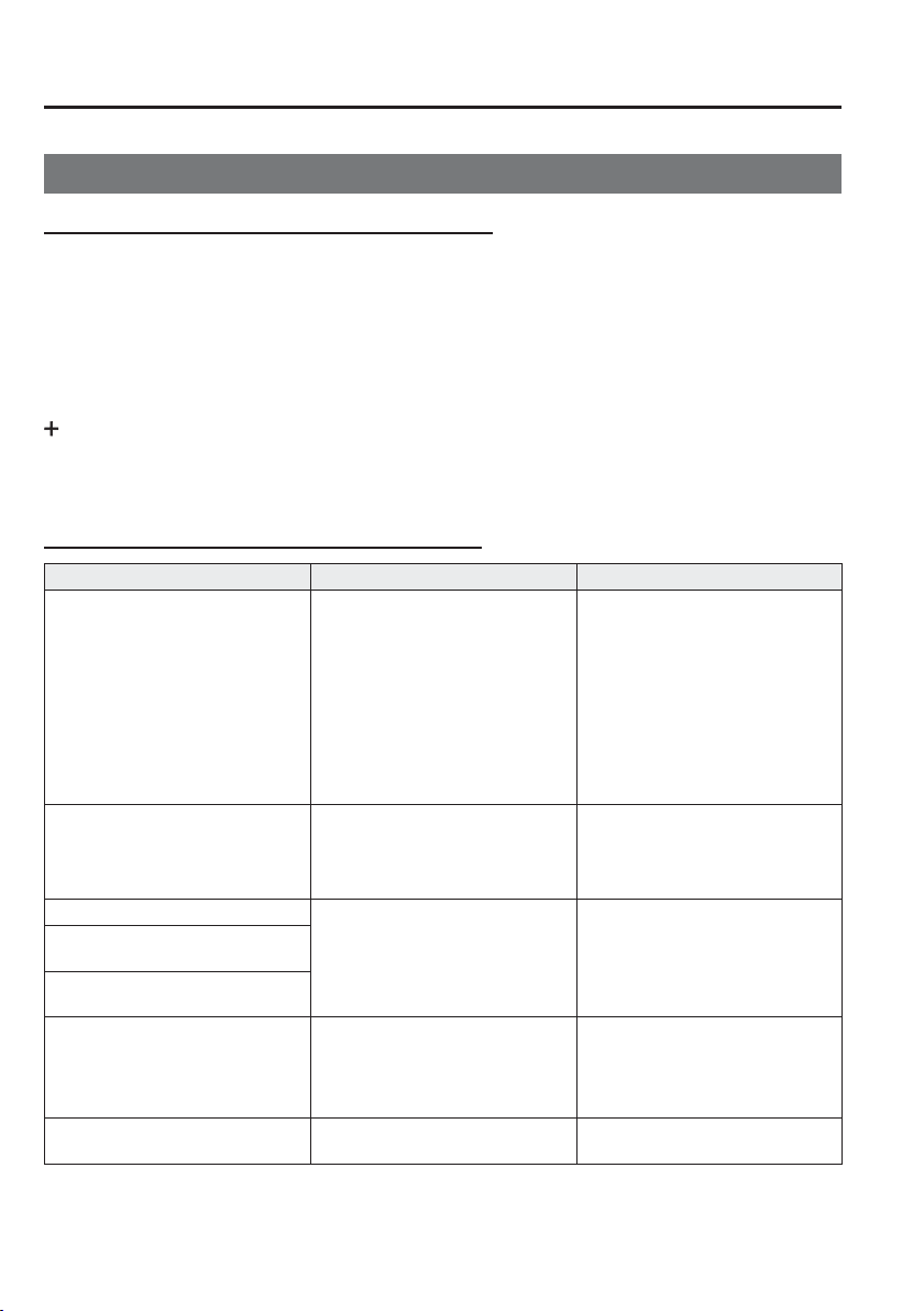
5
–
140
Interior Features
Audio Set [Type B (touchscreen)]
Troubleshooting
Mazda Bluetooth
®
Hands-Free Customer Service
If you have any problems with Bluetooth
®
, contact our toll-free customer service centre.
Phone:
(Germany)
0800 4263 738 (8:00—18:00 Central European Time)
(Except Germany)
00800 4263 7383 (8:00—18:00 Central European Time)
(Worldwide)
49 (0) 6838 907 287 (8:00—18:00 Central European Time)
We b :
http://www.mazdahandsfree.com
Bluetooth
®
Device pairing, connection problems
Symptom Cause Solution method
Unable to perform pairing —
First make sure the device is
compatible with the Bluetooth
®
unit, and then check whether the
Bluetooth
®
function and the Find
Mode/Visible setting
*1
on the
device are turned on. If pairing is
still not possible after this, contact
an expert repairer, we recommend
an Authorised Mazda Repairer or
Mazda Bluetooth
®
Hands-Free
Customer Service.
Pairing cannot be performed again
The pairing information paired to
the Bluetooth
®
unit or device is not
recognised correctly.
Perform pairing using the following
procedure.
Clear “Mazda” stored in the device.
Perform pairing again.
Unable to perform pairing
The Bluetooth
®
function and the
Find Mode/Visible setting
*1
on the
device may turn off automatically
after a period of time has elapsed
depending on the device.
Check whether the Bluetooth
®
function and the Find Mode/Visible
setting
*1
on the device are turned on
and pairing or reconnect.
Does not connect automatically
when starting the engine
Automatically connects, but then
disconnects suddenly
Disconnects intermittently
The device is in a location in which
radio wave interference can occur
easily, such as inside a bag in a rear
seat, in a rear pocket of a pair of
pants.
Move the device to a location in
which radio wave interference is less
likely to occur.
Does not connect automatically
when starting the engine
The pairing information is updated
when the device OS is updated.
Perform pairing again.
*1 Setting which detects the existence of a device external to the Bluetooth
®
unit

5
–
141
Interior Features
Audio Set [Type B (touchscreen)]
NOTE
When the OS of the device is updated, the pairing information may be deleted. If this
happens, reprogramme the pairing information to the Bluetooth
®
unit.
If you pair your phone which has already been paired to your vehicle more than once
in the past, you need to delete “Mazda” on your mobile device. Then, execute the
Bluetooth
®
search on your mobile device once again, and pair to a newly detected
“Mazda”.
Before you pair your device, make sure that Bluetooth
®
is “ON”, both on your phone
and on the vehicle.
If Bluetooth
®
-enabled devices are used in the following locations or conditions,
connection via Bluetooth
®
may not be possible.
The device is in a location hidden from the centre display such as behind or under a
seat, or inside the glove compartment.
The device contacts or is covered by a metal object or body.
The device is set to power-saving mode.
Different Bluetooth
®
-enabled devices can be used for Bluetooth
®
Hands-Free and
Bluetooth
®
audio. For example, device A can be connected as a Bluetooth
®
Hands-Free
device and device B can be connected as a Bluetooth
®
audio device. However, the
following may occur when they are used at the same time.
The Bluetooth
®
connection of the device is disconnected.
Noise occurs in the Hands-Free audio.
Hands-Free operates slowly.
5
–
142
Interior Features
Audio Set [Type B (touchscreen)]
Voice recognition related problems
Symptom Cause Solution method
Poor voice recognition
Excessive, slow speech.
Excessive, forceful speech
(shouting).
Speaking before the beep sound
has ended.
Loud noise (speaking or noise from
outside/inside vehicle).
A i r À ow from A/C is blowing
against the microphone.
Speaking in off-standard
expressions (dialect).
Regarding the causes indicated
on the left, be careful with how
you speak. In addition, when
numbers are spoken in a sequence,
recognition ability will improve
if no stop is placed between the
numbers.
False recognition of numbers
Poor voice recognition
There is a malfunction in the
microphone.
A poor connection or malfunction
with the microphone may have
occurred. Consult an expert repairer,
we recommend an Authorised
Mazda Repairer.
Phone-related voice recognition is
disabled
There is a problem with the
connection between the Bluetooth
®
unit and the device.
If there is any malfunction after
checking the pairing situation, check
for device pairing or connection
problems.
Names in the phonebook are not
easily recognised
The Bluetooth
®
system is under a
condition in which recognition is
dif¿ cult.
By carrying out the following
measures, the rate of recognition
will improve.
Clear memory from the phonebook
which is not used very often.
Avoid shortened names, use full
names. (Recognition improves the
longer the name is. By not using
names such as “Mum”, “Dad”,
recognition will improve.)
When operating the audio, a song
name is not recognised
Song names cannot be recognised
by voice.
—
You want to skip guidance —
Guidance can be skipped by quickly
pressing and releasing the talk
button.
Regarding problems with calls
Symptom Cause Solution method
When starting a call, vehicle noise
from the other party can be heard
For about three seconds after
starting a call, the Bluetooth
®
unit's Noise Suppression function
requires time to adapt to the call
environment.
This does not indicate a problem
with the device.
The other party cannot be heard or
the speaker's voice is quiet
The volume is set at zero or low. Increase the volume.

5
–
143
Interior Features
Audio Set [Type B (touchscreen)]
Other problems
Symptom Cause Solution method
The indication for the remaining
battery is different between the
vehicle and the device
The indication method is different
between the vehicle and the device.
—
When a call is made from the
vehicle, the telephone number is
updated in the incoming/outgoing
call record but the name does not
appear
The number has not been registered
into the phonebook.
If the number has been registered
into the phonebook, the incoming/
outgoing call record is updated by
the name in the phonebook when the
engine is restarted.
The cell phone does not synchronize
with the vehicle regarding the
incoming/outgoing call record
Some types of cell phones do not
synchronize automatically.
Operate the cell phone for
synchronization.
It takes a long time to complete the
function for changing the language
A maximum of 60 seconds is
required.
—
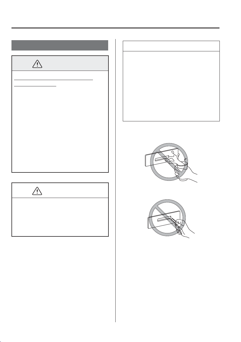
5
–
144
Interior Features
Appendix
T h i n g s Yo u N e e d t o K n o w
WARNING
Always adjust the audio while the
vehicle is stopped:
Do not adjust the audio control
switches while driving the vehicle.
Adjusting the audio while driving
the vehicle is dangerous as it could
distract your attention from the vehicle
operation which could lead to a serious
accident.
Even if the audio control switches are
equipped on the steering wheel, learn
to use the switches without looking
down at them so that you can keep your
maximum attention on the road while
driving the vehicle.
CAUTION
For the purposes of safe driving, adjust
the audio volume to a level that allows
you to hear sounds outside of the vehicle
including car horns and particularly
emergency vehicle sirens.
NOTE
To prevent the battery from being
discharged, do not leave the audio
system on for a long period of time
when the engine is not running.
If a cellular phone or CB radio is
used in or near the vehicle, it could
cause noise to occur from the audio
system, however, this does not
indicate that the system has been
damaged.
Do not spill any liquid on the audio
system.
Do not insert any objects, other than CDs,
into the slot.
5
–
145
Interior Features
Appendix
Radio Reception
AM characteristics
AM signals bend around such things as
buildings or mountains and bounce off the
ionosphere.
Therefore, they can reach longer distances
than FM signals.
Because of this, two stations may
sometimes be picked up on the same
frequency at the same time.
Station 2
Station 1
Ionosphere
FM characteristics
An FM broadcast range is usually about
40—50 km (25—30 miles) from the
source. Because of extra coding needed to
break the sound into two channels, stereo
FM has even less range than monaural
(non-stereo) FM.
FM Station
40—50km
(25—30 miles)
Signals from an FM transmitter are similar
to beams of light because they do not
bend around corners, but they do reÀ ect.
Unlike AM signals, FM signals cannot
travel beyond the horizon. Therefore, FM
stations cannot be received at the great
distances possible with AM reception.
AM wave
FM wave
FM wave
100—200 km (60—120 miles)
Ionosphere
Atmospheric conditions can also affect
FM reception. High humidity will cause
poor reception. However, cloudy days may
provide better reception than clear days.
Multipath noise
Since FM signals can be reÀ ected by
obstructions, it is possible to receive both
the direct signal and the reÀ ected signal
at the same time. This causes a slight
delay in reception and may be heard as a
broken sound or a distortion. This problem
may also be encountered when in close
proximity to the transmitter.
Reflected wave
Direct
5
–
146
Interior Features
Appendix
Flutter/Skip noise
Signals from an FM transmitter move in
straight lines and become weak in valleys
between tall buildings, mountains, and
other obstacles. When a vehicle passes
through such an area, the reception
conditions may change suddenly, resulting
in annoying noise.
Weak signal noise
In suburban areas, broadcast signals
become weak because of distance from the
transmitter. Reception in such fringe areas
is characterised by sound breakup.
Strong signal noise
This occurs very close to a transmitter
tower. The broadcast signals are extremely
strong, so the result is noise and sound
breakup at the radio receiver.
Station drift noise
When a vehicle reaches the area of two
strong stations broadcasting at similar
frequencies, the original station may be
temporarily lost and the second station
picked up. At this time there will be some
noise from this disturbance.
Station 2
88.3 MHz
Station 1
88.1 MHz
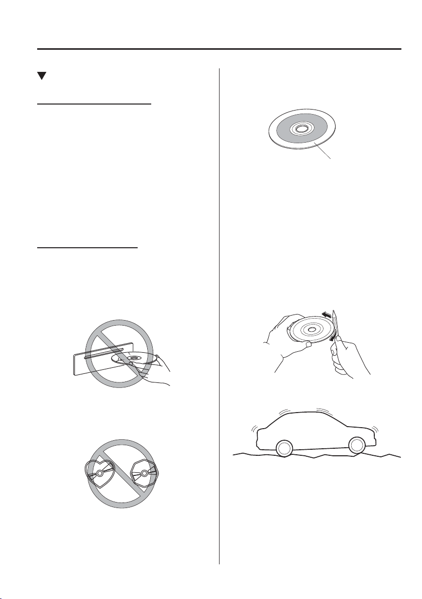
5
–
147
Interior Features
Appendix
Operating Tips for CD Player
Condensation phenomenon
Immediately after turning on the heater
when the vehicle is cold, the CD or
optical components (prism and lens) in
the CD player may become clouded with
condensation. At this time, the CD will
eject immediately when placed in the unit.
A clouded CD can be corrected simply by
wiping it with a soft cloth. Clouded optical
components will clear naturally in about
an hour. Wait for normal operation to
return before attempting to use the unit.
Handling the CD player
The following precautions should be
observed.
Do not use deformed or cracked CDs.
The disc may not eject resulting in a
malfunction.
Do not use non-conventional discs such
as heart-shaped, octagonal discs, etc.
The disc may not eject resulting in a
malfunction.
If the memory portion of the CD is
transparent or translucent, do not use the
disc.
Transparent
A new CD may have rough edges on its
inner and outer perimeters. If a disc with
rough edges is used, proper setting will
not be possible and the CD player will
not play the CD. In addition, the disc
may not eject resulting in a malfunction.
Remove the rough edges in advance
by using a ball-point pen or pencil
as shown in the following ¿ gure. To
remove the rough edges, rub the side of
the pen or pencil against the inner and
outer perimeter of the CD.
When driving over uneven surfaces, the
sound may jump.
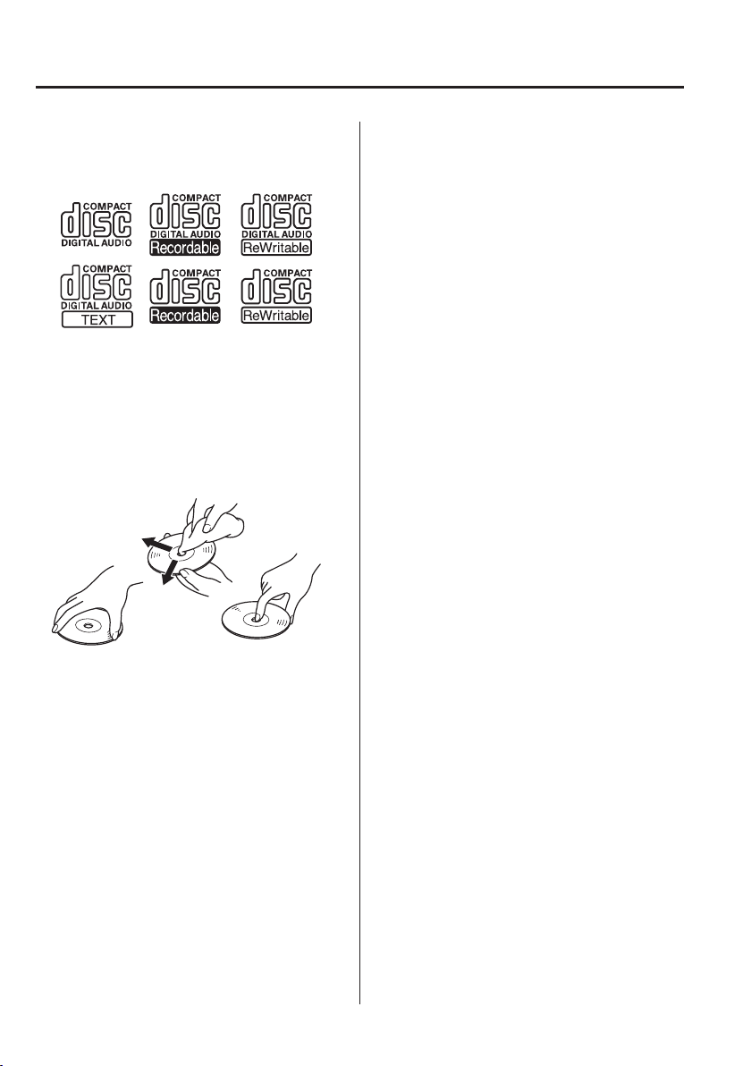
5
–
148
Interior Features
Appendix
CDs bearing the logo shown in the
illustration can be played. No other discs
can be played.
Use discs that have been legitimately
produced. If illegally-copied discs such
as pirated discs are used, the system may
not operate properly.
Be sure never to touch the signal surface
when handling the CDs. Pick up a CD
by grasping the outer edge or the edge of
the hole and the outer edge.
Do not stick paper or tape on the CD.
Avoid scratching the reverse side (the
side without a label). The disc may not
eject resulting in a malfunction.
Dust, ¿ nger smudges, and dirt can
decrease the amount of light reÀ ected
from the signal surface, thus affecting
sound quality. If the CD should become
soiled, gently wipe it with a soft cloth
from the centre of the CD to the edge.
Do not use record sprays, antistatic
agents, or household spray cleaners.
Volatile chemicals such as benzine and
thinner can also damage the surface of
the CD and must not be used. Anything
that can damage, warp, or fog plastic
should never be used to clean CDs.
The CD player ejects the CD if the CD
is inserted upside down. Also dirty and/
or defective CDs may be ejected.
Do not insert cleaning discs in the CD
player.
Do not insert any disc with a peel-off
seal af¿ xed to it.
This unit may not be able to play certain
CD-R/CD-RWs made using a computer
or music CD recorder due to disc
characteristics, scratches, smudges, dirt,
etc., or due to dust or condensation on
the lens inside the unit.
Storing CDs in the vehicle exposed to
direct sunlight or high temperature may
damage the CD-R/CD-RWs, and make
them unplayable.
CD-R/CD-RW exceeding 700 MB
cannot be played.
This unit may not be able to play certain
discs made using a computer due to the
application (writing software) setting
used. (For details, consult the store
where the application was purchased.)
It is possible that certain text data, such
as titles, recorded on a CD-R/CD-RW
may not be displayed when musical data
(CD-DA) is playing.
The period from when a CD-RW is
inserted to when it begins playing is
longer than a normal CD or CD-R.
Completely read the instruction manual
and cautions for CD-R/CD-RWs.
Do not use discs with cellophane tape
adhering, partially peeled off labels,
or adhesive material exuding from the
edges of the CD label. Also, do not use
discs with a commercially-available
CD-R label af¿ xed. The disc may not
eject resulting in a malfunction.
5
–
149
Interior Features
Appendix
Operating Tips for MP3
MP3 stands for MPEG Audio Layer 3,
which is standardised voice compression
established by the ISO
*1
working group
(MPEG).
Use of MP3 allows for audio data to be
compressed to approximately a tenth of
the source data size.
This unit plays ¿ les with the extension
(.mp3) as MP3 ¿ les.
*1 International Organisation for
Standardisation
CAUTION
Do not use an audio ¿ le extension on
¿ les other than audio ¿ les. In addition,
do not change the audio ¿ le extension.
Otherwise, the unit will not recognise
the ¿ le correctly resulting in noise or a
malfunction.
NOTE
Supply of this product only conveys a
license for private, non-commercial use
and does not convey a license nor imply
any right to use this product in any
commercial (i.e. revenue-generating)
real time broadcasting (terrestrial,
satellite, lead and/or any other media),
broadcasting/streaming via the Internet,
intranets and/or other networks or in
other electronic content distribution
systems, such as pay-audio or audio-on-
demand applications. An independent
license for such use is required.
For details, please visit http://www.
mp3licensing.com.
This audio system handles MP3 ¿ les
that have been recorded on CD-R/CD-
RW/CD-ROMs.
When naming an MP3 ¿ le, be sure to
add an MP3 ¿ le extension (.mp3) after
the ¿ le name.
The number of characters which can be
displayed is restricted.
Operating Tips for WMA
WMA is short for Windows Media
*1
Audio
and is the audio compression format used
by Microsoft
*1
.
Audio data can be created and stored at a
higher compression ratio than MP3.
This unit plays ¿ les with the extension
(.wma) as WMA ¿ les.
*1 Windows Media and Microsoft are
registered trademarks of Microsoft
Corporation U.S. in the United States
and other countries.
CAUTION
Do not use an audio ¿ le extension on
¿ les other than audio ¿ les. In addition,
do not change the audio ¿ le extension.
Otherwise, the unit will not recognise
the ¿ le correctly resulting in noise or a
malfunction.
5
–
150
Interior Features
Appendix
WMA ¿ les written under speci¿ cations
other than the indicated speci¿ cation
may not play normally or ¿ les or folder
names may not display correctly.
The ¿ le extension may not be provided
depending on the computer operating
system, version, software, or settings. In
this case, add the ¿ le extension “.wma”
to the end of the ¿ le name, and then
write it to the disc/memory.
Operating Tips for AAC
AAC stands for Advanced Audio Coding,
which is standardised voice compression
established by the ISO
*1
working group
(MPEG). Audio data can be created and
stored at a higher compression ratio than
MP3.
This unit plays ¿ les with the extensions
(.aac
*2
/.m4a/.wav
*2
) as the AAC ¿ les.
CAUTION
Do not use an audio ¿ le extension on
¿ les other than audio ¿ les. In addition,
do not change the audio ¿ le extension.
Otherwise, the unit will not recognise
the ¿ le correctly resulting in noise or a
malfunction.
AAC ¿ les written under speci¿ cations
other than the indicated speci¿ cation
may not play normally or ¿ les or folder
names may not display correctly.
The ¿ le extension may not be provided
depending on the computer operating
system, version, software, or settings. In
this case, add the ¿ le extension “.aac
*2
”,
“.m4a”, or “.wav
*2
” to the end of the ¿ le
name, and then write it to the memory.
*1 International Organisation for
Standardisation
*2 Type B
Operating Tips for OGG
OGG is the audio compression format for
Xiph. Org Foundation.
Audio data can be created and stored at a
higher compression ratio than MP3.
This unit plays ¿ les with the extension
(.ogg) as OGG ¿ les.
CAUTION
Do not use an audio ¿ le extension on
¿ les other than audio ¿ les. In addition,
do not change the audio ¿ le extension.
Otherwise, the unit will not recognise
the ¿ le correctly resulting in noise or a
malfunction.
OGG ¿ les written under speci¿ cations
other than the indicated speci¿ cation
may not play normally or ¿ les or folder
names may not display correctly.
The ¿ le extension may not be provided
depending on the computer operating
system, version, software, or settings. In
this case, add the ¿ le extension “.ogg” to
the end of the ¿ le name, and then write
it to the disc/memory.
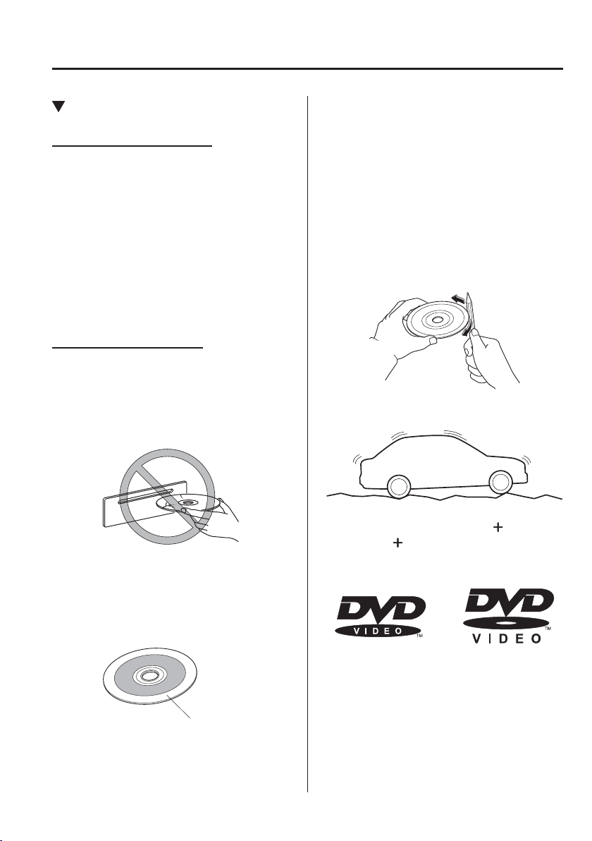
5
–
151
Interior Features
Appendix
Operating Tips for DVD Player
Condensation phenomenon
Immediately after turning on the heater
when the vehicle is cold, the DVD or
optical components (prism and lens) in the
DVD player may become clouded with
condensation. At this time, the DVD will
eject immediately when placed in the unit.
A clouded DVD can be corrected simply
by wiping it with a soft cloth. Clouded
optical components will clear naturally in
about an hour. Wait for normal operation
to return before attempting to use the unit.
Handling the DVD player
The following precautions should be
observed.
Do not use deformed or cracked DVDs.
The disc may not eject resulting in a
malfunction.
Do not use non-conventional discs such
as heart-shaped, etc. The disc may not
eject resulting in a malfunction.
If the memory portion of the DVD is
transparent or translucent, do not use the
disc.
Transparent
A new DVD may have rough edges on
its inner and outer perimeters. If a disc
with rough edges is used, proper setting
will not be possible and the DVD player
will not play the DVD. In addition,
the disc may not eject resulting in a
malfunction. Remove the rough edges
in advance by using a ball-point pen
or pencil as shown below. To remove
the rough edges, rub the side of the pen
or pencil against the inner and outer
perimeter of the DVD.
When driving over uneven surfaces, the
sound may jump.
DVDs bearing the logo shown in the
illustration or DVD-R/DVD
R/DVD-
RW/DVD
RW written with video data
(DVD-Video/DVD-VR ¿ le) can be
played.
Use discs that have been legitimately
produced. If illegally-copied discs such
as pirated discs are used, the system may
not operate properly.
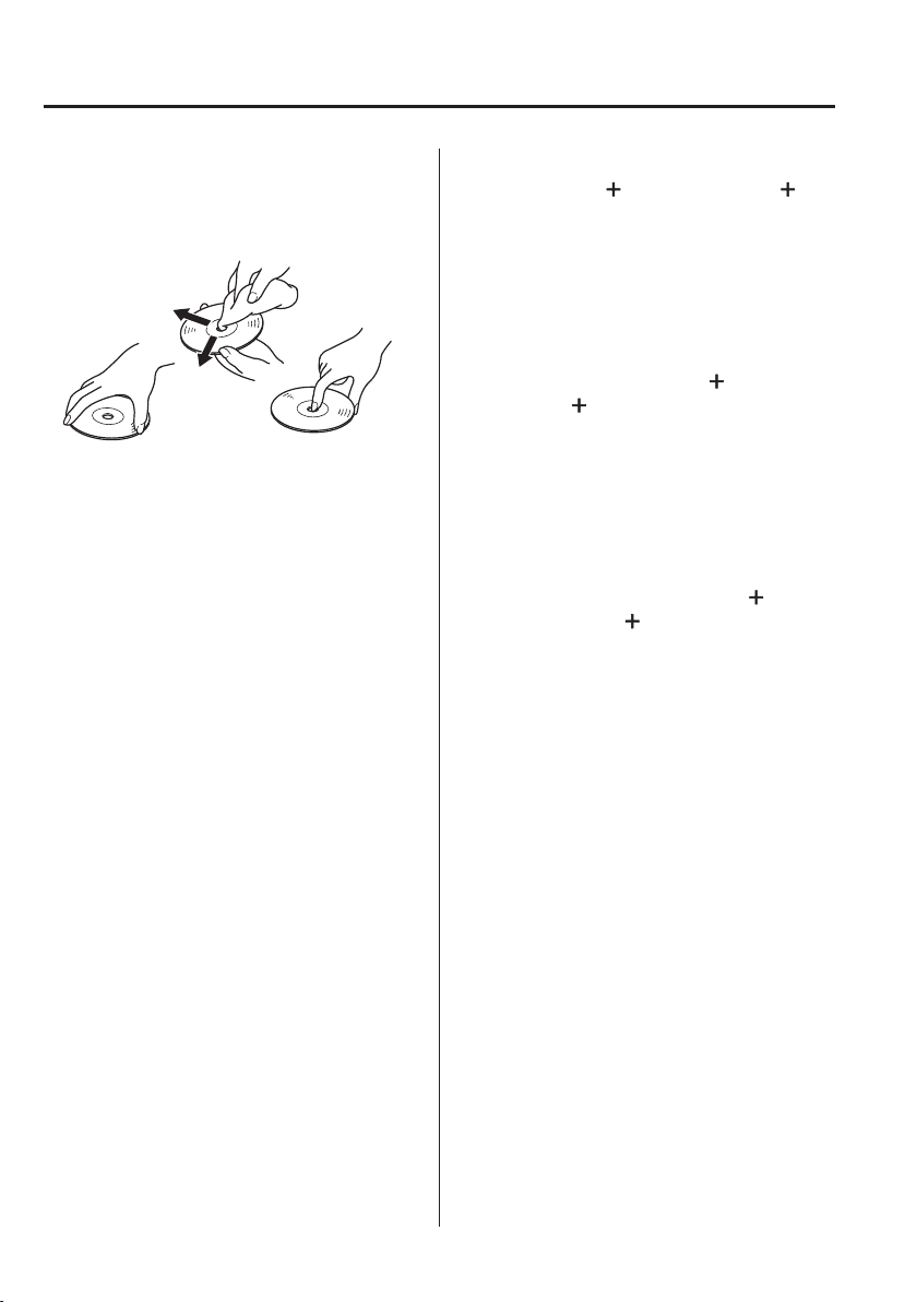
5
–
152
Interior Features
Appendix
Be sure never to touch the signal surface
when handling the DVDs. Pick up a
DVD by grasping the outer edge or the
edge of the hole and the outer edge.
Do not stick paper or tape on the DVD.
Avoid scratching the reverse side (the
side without a label). The disc may not
eject resulting in a malfunction.
Dust, ¿ nger smudges, and dirt can
decrease the amount of light reÀ ected
from the signal surface, thus affecting
sound quality. If the DVD should
become soiled, gently wipe it with a soft
cloth from the centre of the DVD to the
edge.
Do not use record sprays, antistatic
agents, or household spray cleaners.
Volatile chemicals such as benzine and
thinner can also damage the surface
of the DVD and must not be used.
Anything that can damage, warp, or fog
plastic should never be used to clean
DVDs.
The DVD player ejects the DVD if the
DVD is inserted upside down. Also dirty
and/or defective DVDs may be ejected.
Do not insert cleaning discs in the DVD
player.
Do not insert any disc with a peel-off
seal af¿ xed to it.
This unit may not be able to play certain
DVD-R/DVD
R/DVD-RW/DVD
RWs made using a computer or DVD
recorder due to disc characteristics,
scratches, smudges, dirt, etc., or due to
dust or condensation on the lens inside
the unit.
Storing DVDs in the vehicle exposed to
direct sunlight or high temperature may
damage the DVD-R/DVD
R/DVD-
RW/DVD
RWs, and make them
unplayable.
This unit may not be able to play certain
discs made using a computer due to the
application (writing software) setting
used. (For details, consult the store
where the application was purchased.)
Completely read the instruction manual
and cautions for DVD-R/DVD
R/
DVD-RW/DVD
RWs.
Do not use discs with cellophane tape
adhering, partially peeled off labels,
or adhesive material exuding from the
edges of the DVD label. Also, do not
use discs with a commercially-available
DVD-R label af¿ xed. The disc may not
eject resulting in a malfunction.
The conditions in which a DVD video
can be played may be pre-determined
depending on the intentions of the disc
software creator. Functions may not
operate as the user intends because
this DVD player operates according to
the design intentions of the software
creator. Always refer to the instructions
accompanying the disc to be played.
Manufactured under license by Dolby
Labouratories, Inc.. Dolby and the
double-D symbol are trademarks of
Dolby Labouratories.
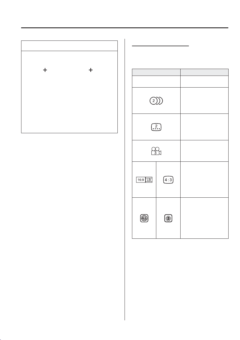
5
–
153
Interior Features
Appendix
NOTE
Video data (DVD-Video/DVD-VR
¿ les) written to DVD/DVD-R/
DVD
R/DVD-RW/DVD RW can
be played.
This unit is compatible for playback
of dual-layer DVD/DVD-R.
Regional number for this unit is [3].
DVD-Video/DVD-VR ¿ les written
under speci¿ cations other than the
indicated speci¿ cation may not play
normally or ¿ les or folder names
may not display correctly.
Mark indicating on disc
Marks indicated on discs or packages are
as follows:
Mark Meaning
PAL
Indicates a colour TV
system.
Indicates the number of
audio tracks.
The number indicates
the number of audio
recordings.
Indicates the number of
subtitled languages.
The number indicates
the number of recorded
languages.
Number of angles.
The number indicates
the number of recorded
angles.
Indicates the screen
modes which can be
selected.
“16:9” indicates a
wide screen and “4:3”
indicates a standard
screen.
Indicates the region code
for which a disc can be
played.
ALL indicates global
applicability, and
a number indicates
applicability based on
region.
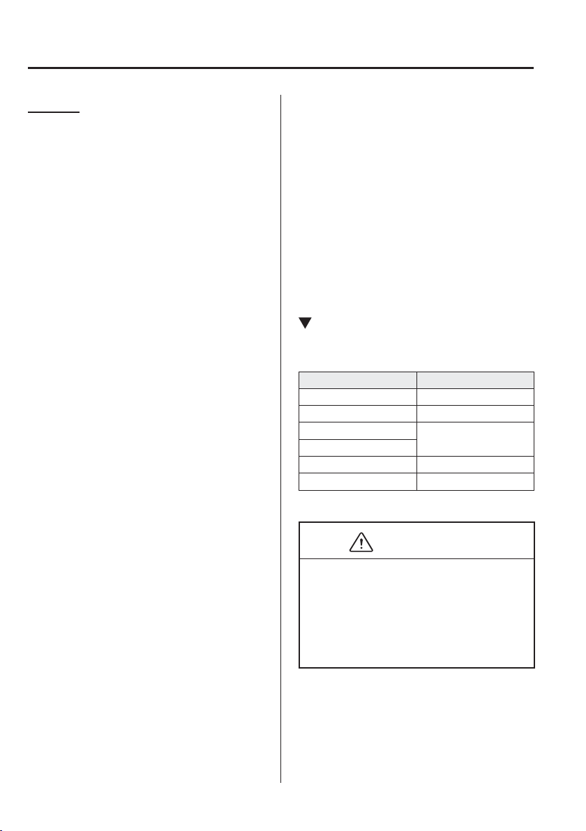
5
–
154
Interior Features
Appendix
Glossary
DVD-Video
DVD-Video is a video image storing
standard determined by the DVD forum.
“MPEG2”, a global standard in digital
compression technologies, has been
adopted which compresses on average
about 1/40th of the image data and stores
it. In addition, a variable-rate coding
technology, which changes the assigned
information amount according to the shape
of the screen image, has been adopted.
Audio information can be stored using
Dolby digital instead of PCM (Pulse Code
Modulation) and more realistic sounding
audio can be enjoyed.
In addition, various, supplementary
functions such as multi-language
availability are provided for enhanced
enjoyment.
DVD-VR
DVD-VR is short for DVD Video
Recording Format; video image storing
standard determined by the DVD forum.
Multi-angle
One of the DVD player's functions.
Because scenes can be recorded in
multiple angles (camera position), users
can choose a desired angle.
Multi-language
As a function of the DVD player, audio
or subtitles for the same video images can
be stored in multiple languages and the
language can be selected freely.
Region code
DVD players and discs are assigned codes
for each market region and only discs
manufactured for that speci¿ c region can
be played.
A disc cannot be played if the region code
assigned to the player is not indicated on
the disc.
In addition, even if a region code is not
indicated on the disc, disc playback may
be prohibited depending on the region. In
this case, a disc may not be playable in
this DVD player.
Operating Tips for USB device
This unit plays audio ¿ l e s a s f o l l o w s :
Extension Playback with this unit
.mp3 MP3
.wma WMA
.aac
*1
AAC
.m4a
.wav
*1
WAV
.ogg
*1
OGG
CAUTION
Do not use an audio ¿ le extension on
¿ les other than audio ¿ les. In addition,
do not change the audio ¿ le extension.
Otherwise, the unit will not recognise
the ¿ le correctly resulting in noise or a
malfunction.
5
–
155
Interior Features
Appendix
NOTE
Playback may not be possible
depending on the type and condition
of the USB À ash memory even if the
audio ¿ le complies with the standard.
A copyright protected WMA/AAC
¿ le cannot be played in this unit.
(Type B)
If a ¿ le name in the USB memory
is too long, it could cause operation
problems such as not being able to
playback the song.
(Recommended: Within 80
characters)
The order of the music data stored
in the device may differ from the
playback order.
To prevent loss or damage of stored
data, we recommend that you always
back up your data.
If a device exceeds the maximum
electric current value of 1,000 mA,
it may not operate or recharge when
connected.
Do not pull out the USB device while
in the USB mode (only pull it out
while in FM/AM radio or CD mode).
The device will not operate if the
data is password protected.
MP3/WMA/AAC/OGG
*1
¿ les written
under speci¿ cations other than the
indicated speci¿ cation may not play
normally or ¿ les/folder names may not
display correctly.
*1 Type B
Operating Tips for iPod
This unit supports playback of music ¿ les
recorded to an iPod.
* iPod is a trademark of Apple Inc.,
registered in the U.S. and other
countries.
The iPod may not be compatible
depending on the model or OS version. In
this case, an error message is displayed.
CAUTION
Remove the iPod when it is not in
use. Because the iPod is not designed
to withstand excessive changes
in temperature inside the cabin, it
could be damaged or the battery
may deteriorate due to the excessive
temperature or humidity inside the
cabin if it is left in the vehicle.
If data in the iPod is lost while it is
connected to the unit, Mazda cannot
guarantee recovery of any lost data.
If the iPod battery is deteriorated, the
iPod may not recharge and playback
may not be possible when it is
connected to the unit.
For details on using the iPod, refer to
the iPod instruction manual.
When connecting the iPod to a USB
port, all commands are made from
the audio unit. iPod control is not
possible.
NOTE
The audio unit cannot display images or
videos stored in an iPod.
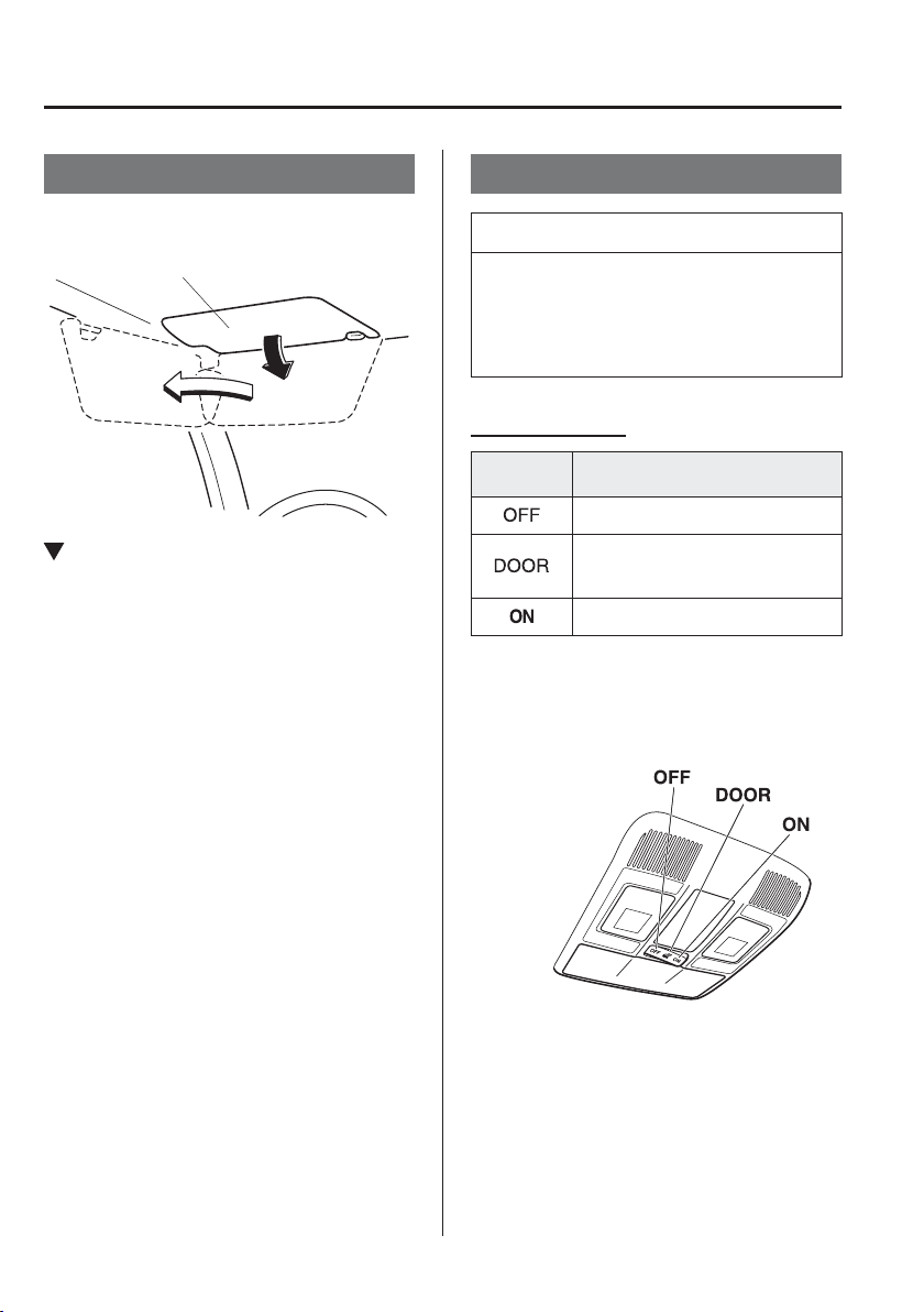
5
–
156
Interior Features
Interior Equipment
Sunvisors
When you need a sunvisor, lower it for use
in front or swing it to the side.
Sunvisor
Vanity Mirrors
To use the vanity mirror, lower the
sunvisor.
Interior Lights
NOTE
Do not leave the lights on for long
periods while the engine is turned off.
Otherwise the battery power could be
depleted.
Overhead Lights
Switch
Position
Overhead Lights
Light off
Light is on when any door is open
Light is on or off when the
illuminated entry system is on
Light on
Front
With Map Lights
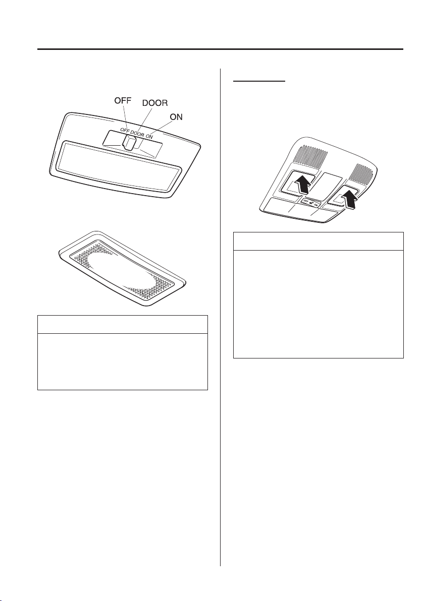
5
–
157
Interior Features
Interior Equipment
*Some models.
Without Map Lights
Rear
*
NOTE
(With map lights)
The rear overhead light also turn on and
off when the front overhead light switch
is operated.
Map Lights
*
When the overhead light switch is in the
door or off position, press the lens to
illuminate the map lights, and then press
the lens again to turn them off.
NOTE
The map lights will not turn off even
if the lens is pressed in the following
cases:
The overhead light switch is in the
ON position.
The overhead light switch is in the
door position with the door open.
The illuminated entry system is on.
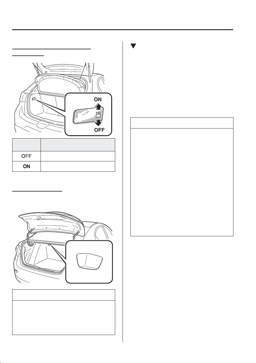
5
–
158
Interior Features
Interior Equipment
Luggage Compartment Lights
(Hatchback)
Switch
Position
Luggage Compartment Light
Light off
Light on when the liftgate is open
Boot Light (Saloon)
The boot light is on when the lid is open
and off when it's closed.
NOTE
To prevent the battery from being
discharged, do not leave the boot open
for a long period when the engine is not
running.
Illuminated Entry System
When the illuminated entry system
operates, the overhead lights and the
courtesy lights turn on in the following
conditions:
The driver's door is unlocked after the
ignition is switched OFF.
The ignition is switched OFF with all
doors closed.
NOTE
The illuminated entry system
operates when the overhead light
switch is in the DOOR position.
The illumination time differs
depending on the operation.
Battery saver
If an interior light is left on with
the ignition switched OFF, the light
is turned off automatically after
about 30 minutes to prevent battery
depletion.
The operation of the illuminated
entry system can be changed.
Refer to Personalisation Features on
page 9-13 .
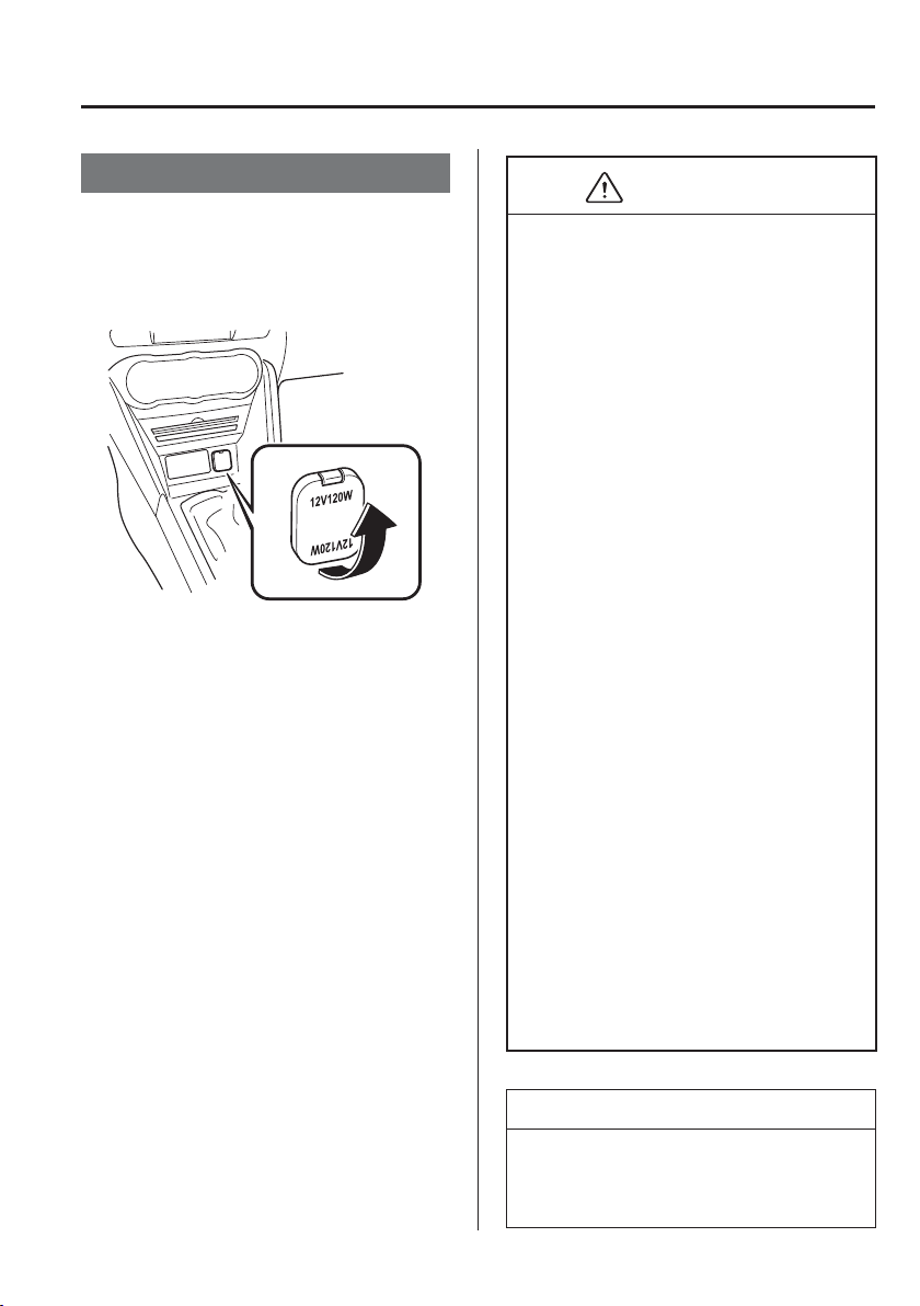
5
–
159
Interior Features
Interior Equipment
Accessory Sockets
Only use genuine Mazda accessories or
the equivalent requiring no greater than
120 W (DC 12 V, 10 A).
The ignition must be switched to ACC or
ON.
CAUTION
To prevent accessory socket damage
or electrical failure, pay attention to
the following:
Do not use accessories that require
more than 120 W (DC 12 V, 10 A).
Do not use accessories that are not
genuine Mazda accessories or the
equivalent.
Close the cover when the
accessory socket is not in use to
prevent foreign objects and liquids
from getting into the accessory
socket.
Correctly insert the plug into the
accessory socket.
Do not insert the cigarette lighter
into the accessory socket.
Noise may occur on the audio
playback depending on the device
connected to the accessory socket.
Depending on the device connected
to the accessory socket, the vehicle's
electrical system may be affected,
which could cause the warning
light to illuminate. Disconnect the
connected device and make sure
that the problem is resolved. If the
problem is resolved, disconnect the
device from the socket and switch
the ignition off. If the problem is not
resolved, consult an expert repairer,
we recommend an Authorised Mazda
Repairer.
NOTE
To prevent discharging of the battery, do
not use the socket for long periods with
the engine off or idling.
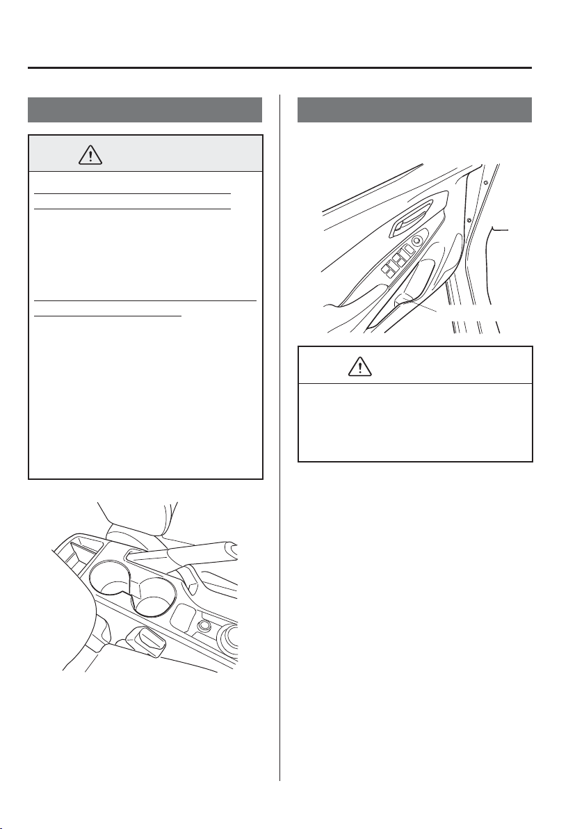
5
–
160
Interior Features
Interior Equipment
Cup Holder
WARNING
Never use a cup holder to hold hot
liquids while the vehicle is moving:
Using a cup holder to hold hot
liquids while the vehicle is moving is
dangerous. If the contents spill, you
could be scalded.
Do not put anything other than cups or
drink cans in cup holders:
Putting objects other than cups
or drink cans in a cup holder is
dangerous.
During sudden braking or
manoeuvring, occupants could be
hit and injured, or objects could be
thrown around the vehicle, causing
interference with the driver and the
possibility of an accident. Only use a
cup holder for cups or drink cans.
Bottle Holder
Bottle holders are on the inside of the front
doors.
Bottle holder
CAUTION
Do not use the bottle holders for
containers without caps. The contents
may spill when the door is opened or
closed.
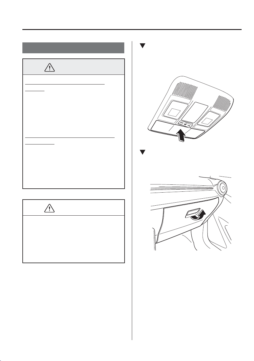
5
–
161
Interior Features
Interior Equipment
*Some models.
Storage Compartments
WARNING
Keep storage boxes closed when
driving:
Driving with the storage boxes open is
dangerous. To reduce the possibility of
injury in an accident or a sudden stop,
keep the storage boxes closed when
driving.
Do not put articles in storage spaces
with no lid:
Putting articles in storage spaces with
no lid is dangerous as they could be
thrown around the cabin if the vehicle
is suddenly accelerated and cause
injury depending on how the article is
stored.
CAUTION
Do not leave lighters or eyeglasses
in the storage boxes while parked
under the sun. A lighter could explode
or the plastic material in eyeglasses
could deform and crack from high
temperature.
Overhead Console
*
This console box is designed to store
eyeglasses or other accessories.
Push and release to open.
Glove Compartment
To open the glove compartment, pull the
latch toward you.
To close the glove compartment,
¿ rmly press in the centre of the glove
compartment lid.
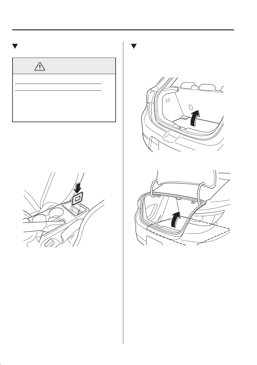
5
–
162
Interior Features
Interior Equipment
*Some models.
Centre Console Tray
WARNING
Never use a cup holder to hold hot
liquids while the vehicle is moving:
Using a cup holder to hold hot
liquids while the vehicle is moving is
dangerous. If the contents spill, you
could be scalded.
A cup or small items can be placed on
the centre console tray using the centre
console divider.
The centre console tray is large enough to
place a small item when the centre console
divider is not in use.
Cargo Sub-Compartment
*
Lift the boot mat.
(Hatchback)
(Saloon)
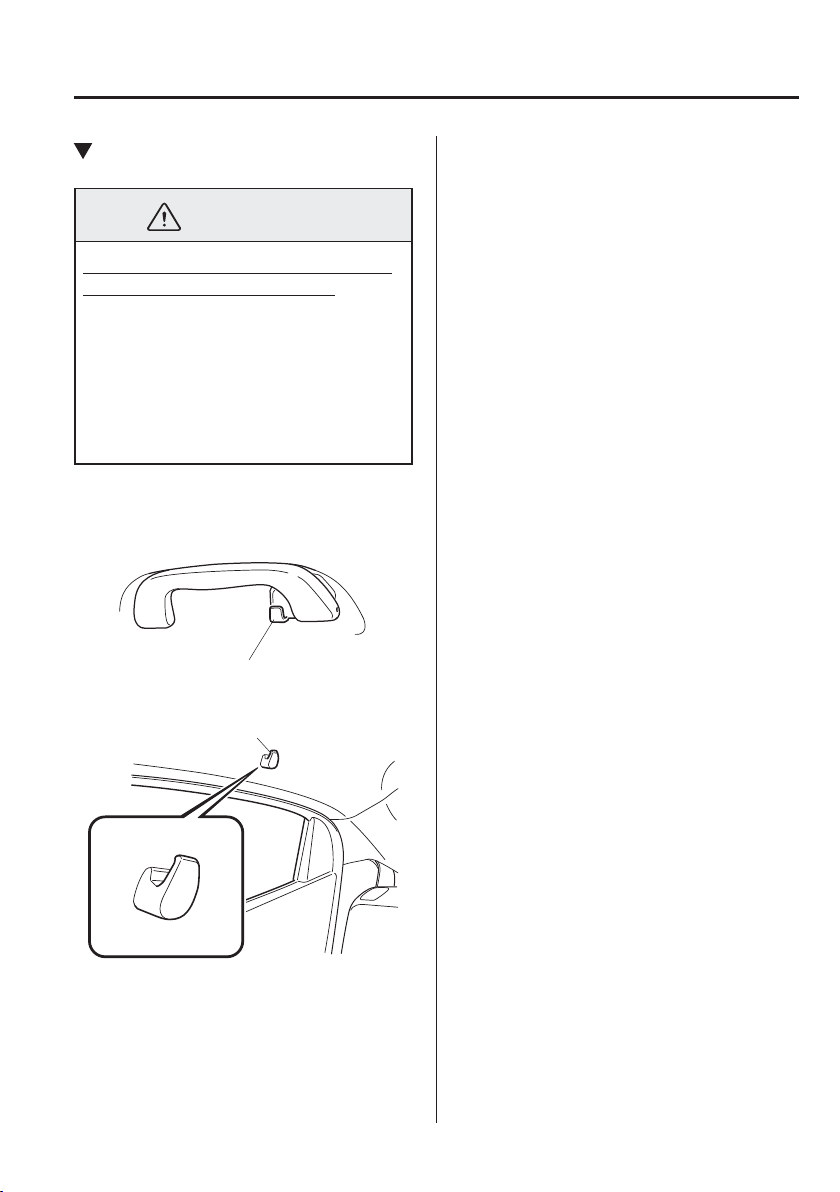
5
–
163
Interior Features
Interior Equipment
Rear Coat Hooks
WARNING
Never hang heavy or sharp objects on
the assist grips and coat hooks:
Hanging heavy or sharp-ended objects
such as a coat hanger from the assist
grips or coat hooks is dangerous as
they can À y off and hit an occupant in
the cabin if a curtain air bag was to
deploy, which could result in serious
injury or death.
Always hang clothes on the coat hooks
and the assist grips without hangers.
Type A
Coat hook
Type B
Coat hook

MEMO
5
–
164

6
–
16
–
1
6
Maintenance and Care
How to keep your Mazda in top condition.
Essential Information ........................................................................ 6-2
Introduction ................................................................................... 6-2
Scheduled Maintenance ..................................................................... 6-3
Scheduled Maintenance ................................................................ 6-3
Maintenance Monitor .................................................................. 6-15
Owner Maintenance ......................................................................... 6-17
Owner Maintenance Precautions ................................................ 6-17
Bonnet ......................................................................................... 6-19
Engine Compartment Overview ................................................. 6-21
Engine Oil ................................................................................... 6-23
Engine Coolant ............................................................................ 6-29
Brake/Clutch Fluid ...................................................................... 6-31
Window and Headlight Washer Fluid ......................................... 6-32
Body Lubrication ........................................................................ 6-33
Wiper Blades ............................................................................... 6-33
Battery ......................................................................................... 6-38
Key Battery Replacement ........................................................... 6-41
Tyres ............................................................................................ 6-44
Light Bulbs .................................................................................. 6-48
Fuses ........................................................................................... 6-61
Appearance Care.............................................................................. 6-66
Exterior Care ............................................................................... 6-66
Interior Care ................................................................................ 6-72
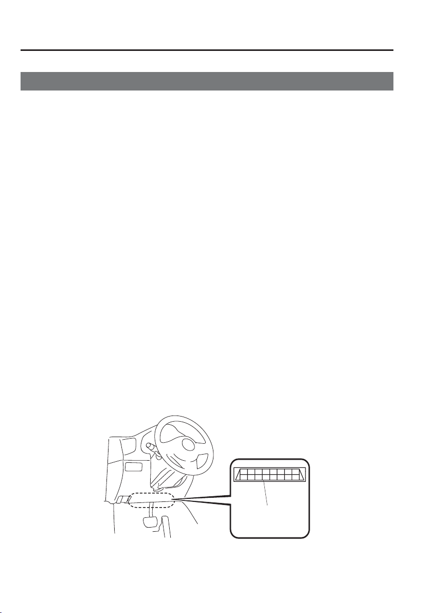
6
–
2
Maintenance and Care
Essential Information
I n t r o d u c t i o n
Be careful not to hurt yourself when inspecting your vehicle, replacing a tyre, or doing some
kind of maintenance such as car washing.
In particular, wear thick work gloves such as cotton gloves when touching areas that
are dif¿ cult to see while inspecting or working on your vehicle. Doing inspections or
procedures with your bare hands could cause injury.
If you are unsure about any procedure it describes, we strongly urge you to have a reliable
and quali¿ ed technician perform the work, we recommend an Authorised Mazda Repairer.
Authorised Mazda technicians and genuine Mazda parts are dedicated to your vehicle.
Without this expertise and the parts that have been designed and made especially for your
Mazda, inadequate, incomplete, and insuf¿ cient servicing may result in problems. This
could lead to vehicle damage or an accident and injuries.
For expert advice and quality service, consult an expert repairer, we recommend an
Authorised Mazda Repairer.
The owner should retain evidence that proper maintenance has been performed as
prescribed.
A claim against a warranty will not qualify if it results from lack of maintenance and not
from defective material or authorised workmanship.
The malfunction diagnosis connector is designed exclusively for connecting the specially
designed device to perform on-board diagnosis.
Do not connect any devices other than the specially designed malfunction diagnosis devices
for servicing. If any device other than the malfunction diagnosis device is connected, it may
affect the vehicle's electrical devices or lead to damage such as battery depletion.
Malfunction
diagnosis
connector

6
–
3
Maintenance and Care
Scheduled Maintenance
S c h e d u l e d M a i n t e n a n c e
NOTE
After the prescribed period, continue to follow the described maintenance at the
recommended intervals.
Emission control and related systems
The ignition and fuel systems are highly important to the emission control system and to
ef¿ cient engine operation. Do not tamper with them.
All inspections and adjustments must be made by an expert repairer, we recommend an
Authorised Mazda Repairer.
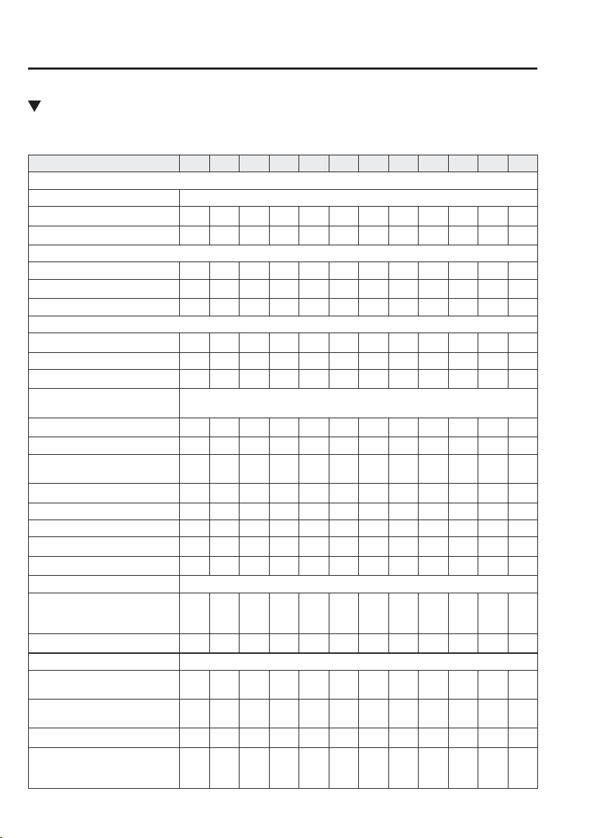
6
–
4
Maintenance and Care
Scheduled Maintenance
Europe
The maintenance monitor alerts regarding the next maintenance due. However, at least every
20,000 km or 12 months after the respective last maintenance the next maintenance is due.
Maintenance 1st 2nd 3rd 4th 5th 6th 7th 8th 9th 10th 11th 12th
SKYACTIV-G 1.5
Spark plugs
*1
Replace every 120,000 km (75,000 miles).
Air ¿ lter
*2
R R R R
Evaporative system (if installed) I I I I
SKYACTIV-D 1.5
Fuel ¿ lter D D R D D R D D R D D R
Fuel injection system
*3
I I I I
Air ¿ lter
*2
C C R C C R C C R C C R
SKYACTIV-G 1.5 AND SKYACTIV-D 1.5
Drive belts
*4
I I I I
Engine oil & ¿ lter
*5*6*7
R R R R R R R R R R R R
Cooling system I I I I I I
Engine coolant
*8
Replace at ¿ rst 200,000 km (125,000 miles) or 10 years;
after that, every 100,000 km (62,500 miles) or 5 years.
Fuel lines and hoses I I I I I I
Battery
*9
I I I I I I I I I I I I
Brake lines, hoses and
connections
I I I I I I I I I I I I
Brake À uid
*10
R R R R R R
Parking brake I I I I I I I I I I I I
Disc brakes I I I I I I I I I I I I
Drum brakes I I I I I I
Steering operation and linkages I I I I I I
Manual transaxle oil Replace every 180,000 km (112,500 miles).
Front and rear suspension, ball
joints and wheel bearing axial
play
I I I I I I
Driveshaft dust boots I I I I I I
Exhaust system and heat shields Inspect every 80,000 km (50,000 miles) or 5 years.
Bolts and nuts on chassis and
body
T T T T T T
Body condition (for rust,
corrosion and perforation)
I I I I I I I I I I I I
Cabin air ¿ lter (if installed) R R R R R R
Tyres (including spare tyre)
(with inÀ ation pressure
adjustment)
*11*12
I I I I I I I I I I I I

6
–
5
Maintenance and Care
Scheduled Maintenance
Maintenance 1st 2nd 3rd 4th 5th 6th 7th 8th 9th 10th 11th 12th
Emergency À at tyre repair kit (if
installed)
*13
I I I I I I I I I I I I
Chart symbols:
I : Inspect: Inspect and clean, repair, adjust, ¿ ll up, or replace if necessary.
R : Replace
C : Clean
T : Tighten
D : Drain
Remarks:
*1 In the countries below, inspect the spark plugs at every 10,000 km (6,250 miles) or 12 months before replacing
them at the said interval.
Albania, Bosnia and Herzegovina, Bulgaria, Croatia, Latvia, Macedonia, Moldova, Montenegro, Romania,
Serbia, Slovakia, Ukraine
*2 If the vehicle is operated in very dusty or sandy areas, clean and if necessary, replace the air ¿ lter more often
than the recommended intervals.
*3 Implement the fuel injection amount correction.
*4 Also inspect the air conditioner drive belts, if installed.
If the vehicle is operated primarily under any of the following conditions, inspect the drive belts at every
20,000 km (12,500 miles) or 12 months.
a) Driving in dusty conditions
b) Extended periods of idling or low speed operation
c) Driving for long period in cold temperatures or driving regularly at short distance only
d) Driving in extremely hot conditions
e) Driving in mountainous conditions continually
*5 Flexible setting is factory preset for some countries in Europe. Consult an Authorised Mazda Repairer for
details. Flexible setting can be set if the vehicle is operated mainly where none of the following conditions
apply.
a) Purpose of vehicle use is police car, taxi or driving school car.
b) Driving in dusty conditions
c) Extended periods of idling or low speed operation
Once the À exible maintenance is selected, the vehicle calculates the remaining oil life based on engine
operating conditions and lets you know when an oil change is due by illuminating the wrench indicator light in
the instrument cluster.
Reset the engine oil data whenever replacing the engine oil regardless of the message/wrench indicator light
display.
*6 If the vehicle is operated primarily under any of the following conditions, replace the engine oil and oil ¿ lter at
every 10,000 km (6,250 miles) or shorter.
a) Purpose of vehicle use is police car, taxi or driving school car.
b) Driving in dusty conditions
c) Extended periods of idling or low speed operation
d) Driving for long period in cold temperatures or driving regularly at short distance only
e) Driving in extremely hot conditions
f) Driving in mountainous conditions continually
*7 For SKYACTIV-D 1.5, reset the engine oil data whenever replacing the engine oil regardless of the message/
wrench indicator light display.
*8 Use of FL-22 is recommended when replacing engine coolant. Using engine coolant other than FL-22 may
cause serious damage to the engine and cooling system.

6
–
6
Maintenance and Care
Scheduled Maintenance
*9 Inspect the battery electrolyte level, speci¿ c gravity and outer appearance. The sealed battery only requires an
outer appearance inspection.
*10 If the brakes are used extensively (for example, continuous hard driving or mountain driving) or if the vehicle
is operated in extremely humid climates, replace the brake À uid annually.
*11 Tyre rotation is recommended every 10,000 km (6,250 miles).
*12 The Tyre Pressure Monitoring System (TPMS) initialization must be performed so that the system operates
normally (if equipped).
*13 Check the tyre repair À uid expiration date every year when performing the periodic maintenance. Replace the
tyre repair À uid bottle with new one before the expiration date.
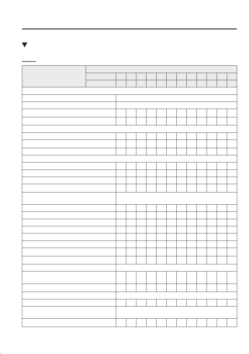
6
–
7
Maintenance and Care
Scheduled Maintenance
Except Europe
I s r a e l
Maintenance Interval
Number of months or kilometres, whichever comes ¿ rst
Months 12 24 36 48 60 72 84 96
108 120 132 144
×1000 km 15 30 45 60 75 90
105 120 135 150 165 180
SKYACTIV-G 1.5
Spark plugs Replace every 120,000 km or 6 years.
Fuel ¿ lter Replace every 135,000 km.
Evaporative system (if installed) I I I
Fuel lines and hoses I I I I I I
SKYACTIV-D 1.5
Fuel ¿ lter D D R D D R D D R D D R
Fuel injection system
*1
I I I I
Fuel lines and hoses I I I I I I I I I I I I
SKYACTIV-G 1.5 AND SKYACTIV-D 1.5
Drive belts
*2
I I I I I I I I I I I I
Engine oil & oil ¿ lter
*3*4
R R R R R R R R R R R R
Air ¿ lter
*5
C C C R C C C R C C C R
Cooling system I I I I I I
Engine coolant
*6
Replace at ¿ rst 195,000 km or 10 years; after that, every
90,000 km or 5 years.
Battery
*7
I I I I I I I I I I I I
Brake lines, hoses and connections I I I I I I I I I I I I
Brake À uid
*8
I R I R I R I R I R I R
Parking brake I I I I I I I I I I I I
Power brake unit (Brake booster) and hoses I I I I I I I I I I I I
Disc brakes I I I I I I I I I I I I
Drum brakes I I I I I I
Steering operation and linkages I I I I I I
Manual transaxle oil Replace every 100,000 km or 5 years.
Front and rear suspension, ball joints and wheel
bearing axial play
I I I I I I I I I I I I
Driveshaft dust boots I I I I
Exhaust system and heat shields Inspect every 75,000 km.
Bolts and nuts on chassis and body T T T T T T T T T T T T
Body condition (for rust, corrosion and
perforation)
Inspect annually.
Cabin air ¿ lter (if installed) R R R R R R

6
–
8
Maintenance and Care
Scheduled Maintenance
Maintenance Interval
Number of months or kilometres, whichever comes ¿ rst
Months 12 24 36 48 60 72 84 96
108 120 132 144
×1000 km 15 30 45 60 75 90
105 120 135 150 165 180
Tyres (including spare tyre) (with inÀ ation
pressure adjustment)
*9
I I I I I I I I I I I I
Emergency À at tyre repair kit (if installed)
*10
Inspect annually.
Chart symbols:
I : Inspect: Inspect and clean, repair, adjust, ¿ ll up, or replace if necessary.
R : Replace
C : Clean
T : Tighten
L : Lubricate
D : Drain
Remarks:
*1 Implement the fuel injection amount correction.
*2 Also inspect the air conditioner drive belts, if installed.
If the vehicle is operated primarily under any of the following conditions, inspect the drive belts at every
10,000 km or shorter.
a) Driving in dusty conditions
b) Extended periods of idling or low speed operation
c) Driving for long period in cold temperatures or driving regularly at short distance only
d) Driving in extremely hot conditions
e) Driving in mountainous conditions continually
*3 If the vehicle is operated primarily under any of the following conditions, replace the engine oil and oil ¿ lter at
every 10,000 km or shorter.
a) Purpose of vehicle use is police car, taxi or driving school car.
b) Driving in dusty conditions
c) Extended periods of idling or low speed operation
d) Driving for long period in cold temperatures or driving regularly at short distance only
e) Driving in extremely hot conditions
f) Driving in mountainous conditions continually
*4 For SKYACTIV-D 1.5, reset the engine oil data after replacing the engine oil.
*5 If the vehicle is operated in very dusty or sandy areas, clean and if necessary, replace the air ¿ lter more often
than the recommended intervals.
*6 Use of FL-22 is recommended when replacing engine coolant. Using engine coolant other than FL-22 may
cause serious damage to the engine and cooling system.
*7 Inspect the battery electrolyte level, speci¿ c gravity and outer appearance. The sealed battery only requires an
outer appearance inspection.
*8 If the brakes are used extensively (for example, continuous hard driving or mountain driving) or if the vehicle
is operated in extremely humid climates, replace the brake À uid annually.
*9 The Tyre Pressure Monitoring System (TPMS) initialization must be performed so that the system operates
normally (if equipped).
*10 Check the tyre repair À uid expiration date every year when performing the periodic maintenance. Replace the
tyre repair À uid bottle with new one before the expiration date.
6
–
9
Maintenance and Care
Scheduled Maintenance
Russia/Belarus/Azerbaijan/Kazakhstan
Maintenance Interval
Number of months or kilometres, whichever comes ¿ rst.
Months 12 24 36 48 60 72 84 96
108 120 132 144
×1000 km 15 30 45 60 75 90
105 120 135 150 165 180
Drive belts
*1
I I I I I I I I I I I I
Engine oil
Russia/
Belarus/
Kazakhstan
*2
R R R R R R R R R R R R
Azerbaijan
*3
Replace every 5,000 km or 6 months.
Engine oil ¿ lter
Russia/
Belarus/
Kazakhstan
*2
R R R R R R R R R R R R
Azerbaijan
*4
Replace every 10,000 km or 12 months.
Cooling system I I I I I I
Engine coolant
*5
Replace at ¿ rst 195,000 km or 10 years; after that, every
90,000 km or 5 years.
Air ¿ lter
*6
Russia/
Belarus/
Kazakhstan
C C R C C R C C R C C R
Azerbaijan C R C R C R C R C R C R
Fuel ¿ lter
Russia/
Belarus/
Kazakhstan
Replace every 120,000 km.
Azerbaijan Replace every 60,000 km.
Fuel lines and hoses I I I I I I
Spark plugs I I I I I I I R I I I I
Evaporative system (if installed) I I I
Battery
*7
I I I I I I I I I I I I
Brake lines, hoses and connections I I I I I I I I I I I I
Brake À uid
*8
R R R R R R
Parking brake I I I I I I I I I I I I
Disc brakes I I I I I I I I I I I I
Drum brakes I I I I I I I I I I I I
Steering operation and linkages I I I I I I I I I I I I
Manual transaxle oil R R
Front and rear suspension, ball joints and wheel
bearing axial play
I I I I I I I I I I I I
Driveshaft dust boots I I I I I I I I I I I I
Exhaust system and heat shields I I I I I I I I I I I I
Bolts and nuts on chassis and body T T T T T T T T T T T T
Hinges and catches L L L L L L L L L L L L
All electrical system I I I I I I I I I I I I

6
–
10
Maintenance and Care
Scheduled Maintenance
Maintenance Interval
Number of months or kilometres, whichever comes ¿ rst.
Months 12 24 36 48 60 72 84 96
108 120 132 144
×1000 km 15 30 45 60 75 90
105 120 135 150 165 180
Body condition (for rust, corrosion and
perforation)
Inspect annually.
Cabin air ¿ lter (if installed) R R R R R R
Tyres (including spare tyre) (with inÀ ation
pressure adjustment)
*9*10
I I I I I I I I I I I I
Emergency À at tyre repair kit (if installed)
*11
Inspect annually.
Chart symbols:
I : Inspect: Inspect and clean, repair, adjust, ¿ ll up, or replace if necessary.
R : Replace
C : Clean
T : Tighten
L : Lubricate
D : Drain
Remarks:
*1 Also inspect the air conditioner drive belts, if installed.
If the vehicle is operated primarily under any of the following conditions, inspect the drive belts at every
7,500 km or 6 months.
a) Driving in dusty conditions
b) Extended periods of idling or low speed operation
c) Driving for long period in cold temperatures or driving regularly at short distance only
d) Driving in extremely hot conditions
e) Driving in mountainous conditions continually
*2 If the vehicle is operated primarily under any of the following conditions, replace the engine oil and oil ¿ lter at
every 7,500 km or 6 months.
a) Purpose of vehicle use is police car, taxi or driving school car.
b) Driving in dusty conditions
c) Extended periods of idling or low speed operation
d) Driving for long period in cold temperatures or driving regularly at short distance only
e) Driving in extremely hot conditions
f) Driving in mountainous conditions continually
*3 If the vehicle is operated primarily under any of the following conditions, replace the engine oil at every
2,500 km or 3 months.
a) Purpose of vehicle use is police car, taxi or driving school car.
b) Driving in dusty conditions
c) Extended periods of idling or low speed operation
d) Driving for long period in cold temperatures or driving regularly at short distance only
e) Driving in extremely hot conditions
f) Driving in mountainous conditions continually

6
–
11
Maintenance and Care
Scheduled Maintenance
*4 If the vehicle is operated primarily under any of the following conditions, replace the engine oil ¿ lter at every
5,000 km or 6 months.
a) Purpose of vehicle use is police car, taxi or driving school car.
b) Driving in dusty conditions
c) Extended periods of idling or low speed operation
d) Driving for long period in cold temperatures or driving regularly at short distance only
e) Driving in extremely hot conditions
f) Driving in mountainous conditions continually
*5 Use of FL-22 is recommended when replacing engine coolant. Using engine coolant other than FL-22 may
cause serious damage to the engine and cooling system.
*6 If the vehicle is operated in very dusty or sandy areas, clean the air ¿ lter at every 7,500 km or 6 months.
*7 Inspect the battery electrolyte level, speci¿ c gravity and outer appearance. The sealed battery only requires an
outer appearance inspection.
*8 If the brakes are used extensively (for example, continuous hard driving or mountain driving) or if the vehicle
is operated in extremely humid climates, replace the brake À uid annually.
*9 Tyre rotation is recommended every 10,000 km.
*10 The Tyre Pressure Monitoring System (TPMS) initialization must be performed so that the system operates
normally (if equipped).
*11 Check the tyre repair À uid expiration date every year when performing the periodic maintenance. Replace the
tyre repair À uid bottle with new one before the expiration date.
6
–
12
Maintenance and Care
Scheduled Maintenance
Except Israel/Russia/Belarus/Azerbaijan/Kazakhstan
Maintenance
Interval
Number of months or kilometres (miles), whichever comes ¿ rst.
Months 6 12 18 24 30 36 42 48 54 60 66 72 78 84 90 96
×1000 km 10 20 30 40 50 60 70 80 90
100 110 120 130 140 150 160
×1000 miles
6.25 12.5
18.75
25
31.25
37.5
43.75
50
56.25
62.5
68.75
75
81.25
87.5
93.75
100
SKYACTIV-G 1.3 AND SKYACTIV-G 1.5
Fuel ¿ lter Replace every 60,000 km (37,500 miles).
Spark plugs
*1
Replace every 120,000 km (75,000 miles).
Evaporative system (if installed) I I I I I I I I
SKYACTIV-D 1.5
Fuel ¿ lter D R D R D R D R
Fuel injection system
*2
I I I
SKYACTIV-G 1.3, SKYACTIV-G 1.5, AND SKYACTIV-D 1.5
Drive belts
*3
I I I I I I I I I I I I I I I I
Engine oil
*4*5
Except
below
countries
R R R R R R R R R R R R R R R R
Georgia/
Armenia/
Cambodia/
Gabon/
Ghana/
Cameroon/
Burundi/
Mozambique
Replace every 5,000 km (3,125 miles) or 6 months.
Tanzania Replace every 3,000 km (1,875 miles) or 3 months.
Engine oil ¿ lter
*4
Except
below
countries
R R R R R R R R R R R R R R R R
Georgia/
Armenia/
Cambodia
Replace every 10,000 km (6,250 miles) or 1 year.
Gabon/
Ghana/
Cameroun/
Burundi/
Mozambique
Replace every 5,000 km (3,125 miles) or 6 months.
Tanzania Replace every 3,000 km (1,875 miles) or 3 months.
Cooling system I I I I I I I I
Engine coolant
*6
Replace at ¿ rst 200,000 km (125,000 miles) or 10 years; after that, every
100,000 km (62,500 miles) or 5 years.

6
–
13
Maintenance and Care
Scheduled Maintenance
Maintenance
Interval
Number of months or kilometres (miles), whichever comes ¿ rst.
Months 6 12 18 24 30 36 42 48 54 60 66 72 78 84 90 96
×1000 km 10 20 30 40 50 60 70 80 90
100 110 120 130 140 150 160
×1000 miles
6.25 12.5
18.75
25
31.25
37.5
43.75
50
56.25
62.5
68.75
75
81.25
87.5
93.75
100
Air ¿ lter
*7
Except
below
countries
C C R C C R C C
Georgia/
Armenia
C R C R C R C R
Fuel lines and hoses I I I I I I I I
Battery
*8
I I I I I I I I
Brake lines, hoses and connections I I I I I I I I
Brake À uid
*9
I I I R I I I R I I I R I I I R
Parking brake I I I I I I I I I I I I I I I I
Power brake unit (Brake booster)
and hoses
I I I I I I I I
Disc brakes I I I I I I I I I I I I I I I I
Drum brakes I I I I I I I I
Steering operation and linkages I I I I I I I I
Manual transaxle oil R
Front and rear suspension, ball
joints and wheel bearing axial play
I I I I I I I I
Driveshaft dust boots I I I I
Exhaust system and heat shields Inspect every 80,000 km (50,000 miles).
Bolts and nuts on chassis and body T T T T T T T T
Body condition (for rust, corrosion
and perforation)
Inspect annually.
Cabin air ¿ lter (if installed) R R R R R R R R
Tyres (including spare tyre) (with
inÀ ation pressure adjustment)
*10
I I I I I I I I I I I I I I I I
Tyre rotation
*10
Rotate every 10,000 km (6,250 miles).
Emergency À at tyre repair kit (if
installed)
*11
Inspect annually.
Chart symbols:
I : Inspect: Inspect and clean, repair, adjust, ¿ ll up, or replace if necessary.
R : Replace
C : Clean
T : Tighten
D : Drain

6
–
14
Maintenance and Care
Scheduled Maintenance
Remarks:
*1 In the countries below, inspect the spark plugs at every 10,000 km (6,250 miles) or 12 months before replacing
them at the said interval.
Algeria, Armenia, Angola, Bahrain, Bolivia, Burundi, B.Virgin, Cambodia, Cameroon, Chile, Costa Rica, Cote
d'Ivoire, Curacao, El Salvador, Gabon, Ghana, Georgia, Guatemala, Haiti, Honduras, Hong Kong, Iran, Jordan,
Kenya, Macau, Malaysia, Mongolia, Mozambique, Myanmar, Nigeria, Nicaragua, Oman, Panama, Papua
New Guinea, Peru, Philippines, Senegal, Seychelles, Syria, Tanzania, United Arab Emirates, Vietnam, Zaire,
Zimbabwe
*2 Implement the fuel injection amount correction.
*3 Also inspect the air conditioner drive belts, if installed.
If the vehicle is operated primarily under any of the following conditions, inspect the drive belts more often
than the recommended intervals.
a) Driving in dusty conditions
b) Extended periods of idling or low speed operation
c) Driving for long period in cold temperatures or driving regularly at short distance only
d) Driving in extremely hot conditions
e) Driving in mountainous conditions continually
*4 If the vehicle is operated primarily under any of the following conditions, replace the engine oil and oil ¿ lter
more often than the recommended intervals.
a) Purpose of vehicle use is police car, taxi or driving school car.
b) Driving in dusty conditions
c) Extended periods of idling or low speed operation
d) Driving for long period in cold temperatures or driving regularly at short distance only
e) Driving in extremely hot conditions
f) Driving in mountainous conditions continually
*5 For SKYACTIV-D 1.5, Reset the engine oil data whenever replacing the engine oil regardless of the message/
wrench indicator light display.
*6 Use of FL-22 is recommended when replacing engine coolant. Using engine coolant other than FL-22 may
cause serious damage to the engine and cooling system.
*7 If the vehicle is operated in very dusty or sandy areas, clean and if necessary, replace the air ¿ lter more often
than the recommended intervals.
*8 Inspect the battery electrolyte level, speci¿ c gravity and outer appearance. If the vehicle is operated in
extremely hot and cold areas, inspect the battery electrolyte level, speci¿ c gravity and appearance every
10,000 km (6,250 miles) or 6 months. The sealed battery only requires an outer appearance inspection.
*9 If the brakes are used extensively (for example, continuous hard driving or mountain driving) or if the vehicle
is operated in extremely humid climates, replace the brake À uid annually.
*10 The Tyre Pressure Monitoring System (TPMS) initialization must be performed so that the system operates
normally (if equipped).
*11 Check the tyre repair À uid expiration date every year when performing the periodic maintenance. Replace the
tyre repair À uid bottle with new one before the expiration date.
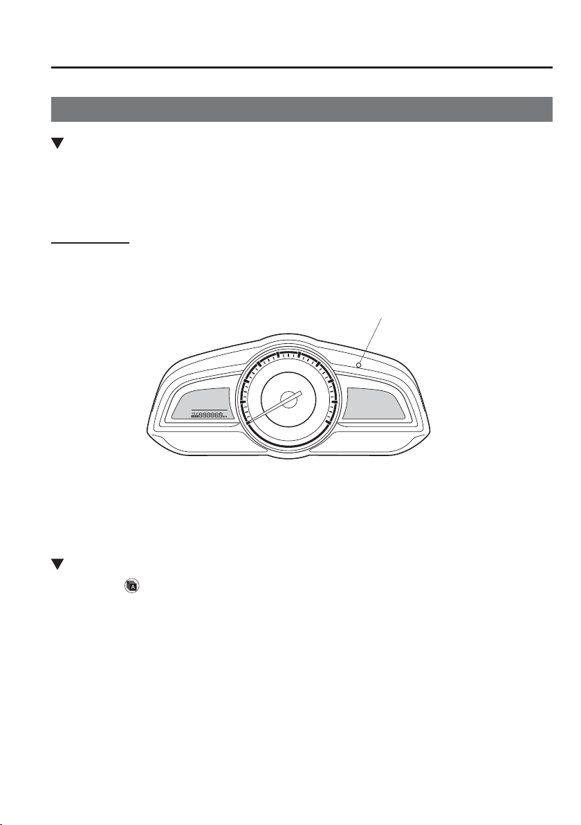
6
–
15
Maintenance and Care
Scheduled Maintenance
Maintenance Monitor
Maintenance Monitor (Type A audio)
“Oil Change” with À exible setting
*1
is available. Consult an Authorised Mazda Repairer for
details
*2
. When the engine oil À exible maintenance setting is selected, the wrench indicator
light in the instrument cluster will be illuminated when remaining oil life becomes less than
1,000 km (600 mile), or remaining days are less than 15 (Whichever comes ¿ rst).
Reset method
Press and hold the selector with the ignition switched off, then switch it on. Keep pressing
the selector for more than 5 seconds. The master warning light will À ash for a few seconds
when the reset is completed.
Selector
*1 The engine oil À exible maintenance setting is available (only some models). Based on
the engine operating conditions, the onboard computer in your vehicle calculates the
remaining oil life.
*2 When the engine oil À exible maintenance setting is selected, the system must be reset
whenever replacing the engine oil regardless of the wrench indicator light display.
Maintenance Monitor (Type B audio)
1. Select the icon on the home screen to display the “Applications” screen.
2. Select “Vehicle Status Monitor”.
3. Select “Maintenance” to display the maintenance list screen.
4. Switch the tab and select the setting item you want to change.
6
–
16
Maintenance and Care
Scheduled Maintenance
You can customize settings in the setup display as follows:
Tab Item Explanation
Scheduled
Setting Noti¿ cation can be switched on/off.
Time (months)
Displays the time or distance until maintenance is due.
Select this item to set the maintenance period.
The wrench indicator light in the instrument cluster will be
illuminated when the remaining distance is less than 1,000 km
or 600 mile, or the remaining number of days is less than 15
(whichever comes ¿ rst).
Distance (km or mile)
Reset
Resets the time and distance to the initial values.
Once the system turns on, it needs to be reset whenever carrying
out maintenance.
Tyre Rotation
Setting Noti¿ cation can be switched on/off.
Distance (km or mile)
Displays the distance until tyre rotation is due.
Select this item to set the tyre rotation distance.
The wrench indicator light in the instrument cluster will be
illuminated when the remaining distance is less than 1,000 km or
600 mile.
Reset
Resets the remaining distance to the initial value.
Once the system turns on, it needs to be reset whenever rotating
the tyres.
Oil Change
Setting
*1
N o t i ¿ cation can be switched on/off.
Distance (km or mile)
Displays the distance until the oil replacement is due.
Select this item to set the oil replacement distance.
The wrench indicator light in the instrument cluster will be
illuminated when the remaining distance is less than 1,000 km or
600 mile.
Reset
*2
Resets the remaining distance to the initial value.
Once the system turns on, it needs to be reset whenever replacing
the engine oil.
*1 The engine oil À exible maintenance setting is available (only some models). Consult an Authorised Mazda
Repairer for details.
When the engine oil À exible maintenance setting is selected, you will see the following items in the display. The
vehicle calculates the remaining oil life based on the engine operating conditions and lets you know when an oil
change is due by illuminating the wrench indicator light in the instrument cluster.
*2 Whenever the engine oil is replaced, the vehicle engine control unit reset is necessary for SKYACTIV-D 1.5.
Your Authorised Mazda Repairer will be able to reset the engine control unit or refer to the vehicle engine
control unit reset procedure on page 6-27 .
Tab Item Explanation
Oil Change
Oil life (%)
Displays the engine oil life until the oil replacement is due.
The wrench indicator light in the instrument cluster will be
illuminated when remaining oil life distance is less than 1,000
km (600 mile), or remaining days are less than 15 (whichever
comes ¿ rst).
Reset
Resets the remaining oil life to 100 %.
The system must be reset whenever replacing the engine oil.

6
–
17
Maintenance and Care
Owner Maintenance
Owner Maintenance Precautions
R o u t i n e S e r v i c e
We highly recommend that these items be inspected daily, or at least every week.
Engine Oil Level (page 6-28 )
Engine Coolant Level (page 6-29 )
Brake and clutch Fluid Level (page 6-31 )
Washer Fluid Level (page 6-32 )
Battery Maintenance (page 6-40 )
Tyre InÀ ation Pressure (page 6-44 )
Improper or incomplete service may result in problems. This section gives instructions only
for items that are easy to perform.
As explained in the Introduction (page 6-2 ), several procedures can be done only by a
quali¿ ed service technician with special tools.
Improper do-it yourself maintenance during the warranty period may affect warranty
coverage. For details, read the separate Mazda Warranty statement provided with the
vehicle. If you are unsure about any servicing or maintenance procedure, have it done by an
expert repairer, we recommend an Authorised Mazda Repairer.
There are strict environmental laws regarding the disposal of waste oil and À uids. Please
dispose of your waste properly and with due regard to the environment.
We recommend that you entrust the oil and À uid changes of your vehicle to an Authorised
Mazda Repairer.
6
–
18
Maintenance and Care
Owner Maintenance
WARNING
Do not perform maintenance work if you lack suf¿ cient knowledge and experience
or the proper tools and equipment to do the work. Have maintenance work done by a
quali¿ ed technician:
Performing maintenance work on a vehicle is dangerous if not done properly. You can
be seriously injured while performing some maintenance procedures.
If you must run the engine while working under the bonnet, make certain that you
remove all jewellery (especially rings, bracelets, watches, and necklaces) and all
neckties, scarves, and similar loose clothing before getting near the engine or cooling
fan which may turn on unexpectedly:
Working under the bonnet with the engine running is dangerous. It becomes even more
dangerous when you wear jewellery or loose clothing.
Either can become entangled in moving parts and result in injury.
Pull over to a safe location, then switch the ignition off and make sure the fan is
not running before attempting to work near the cooling fan:
Working near the cooling fan when it is running is dangerous. The fan could continue
running inde¿ nitely even if the engine has stopped and the engine compartment
temperature is high. You could be hit by the fan and seriously injured.
Do not leave items in the engine compartment:
After you have ¿ nished checking or doing servicing in the engine compartment, do not
forget and leave items such as tools or rags in the engine compartment.
Tools or other items left in the engine compartment could cause engine damage or a ¿ re
leading to an unexpected accident.
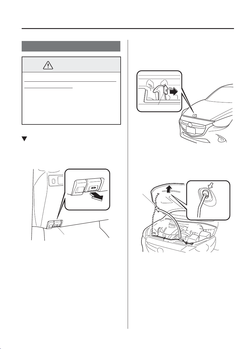
6
–
19
Maintenance and Care
Owner Maintenance
Bonnet
WARNING
Always check that the bonnet is closed
and securely locked:
A bonnet that is not closed and securely
locked is dangerous as it could À y open
while the vehicle is moving and block
the driver's vision which could result in
a serious accident.
Opening the Bonnet
1. With the vehicle parked, pull the
release handle to unlock the bonnet.
Release handle
2. Insert your hand into the bonnet
opening, slide the latch lever to the
right, and lift up the bonnet.
Lever
3. Grasp the support rod in the padded
area and secure it in the support rod
hole indicated by the arrow to hold the
bonnet open.
Pad
Clip
Clip
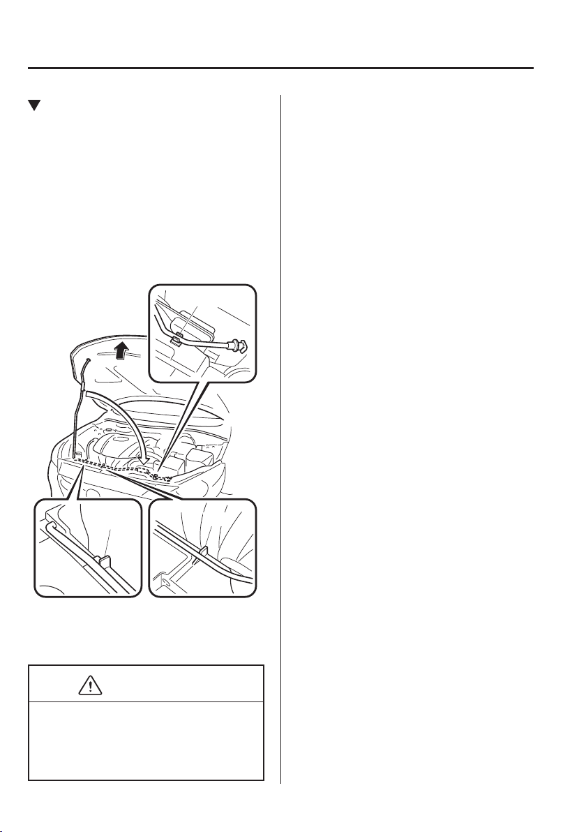
6
–
20
Maintenance and Care
Owner Maintenance
Closing the Bonnet
1. Check under the bonnet area to make
certain all ¿ ller caps are in place and all
loose items (e.g. tools, oil containers,
etc.) have been removed.
2. Lift the bonnet, grasp the padded area
on the support rod, and secure the
support rod in the clip. Verify that the
support rod is secured in the clip before
closing the bonnet.
Clip
Clip
Clip
3. Lower the bonnet slowly to a height of
about 20 cm (7.9 in) above its closed
position and then let it drop.
CAUTION
When closing the bonnet, do not push
it excessively such as by applying your
weight. Otherwise, the bonnet could be
deformed.
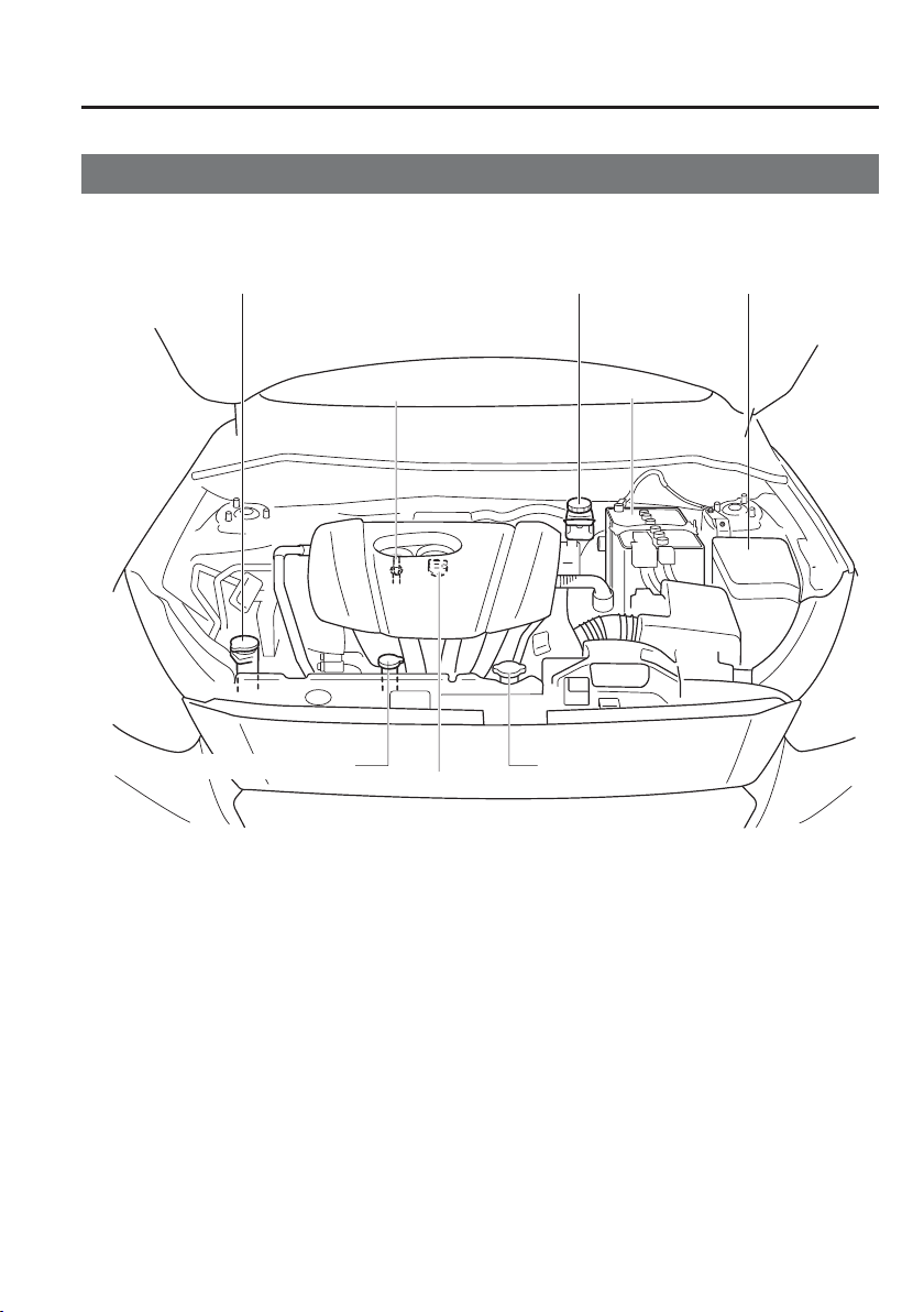
6
–
21
Maintenance and Care
Owner Maintenance
Engine Compartment Overview
Windscreen washer fluid reservoir Brake/Clutch fluid reservoir
Engine oil dipstick Battery
Fuse block
Cooling system cap
Engine coolant reservoir
Engine oil-filler cap
SKYACTIV-G 1.3 and SKYACTIV-G 1.5
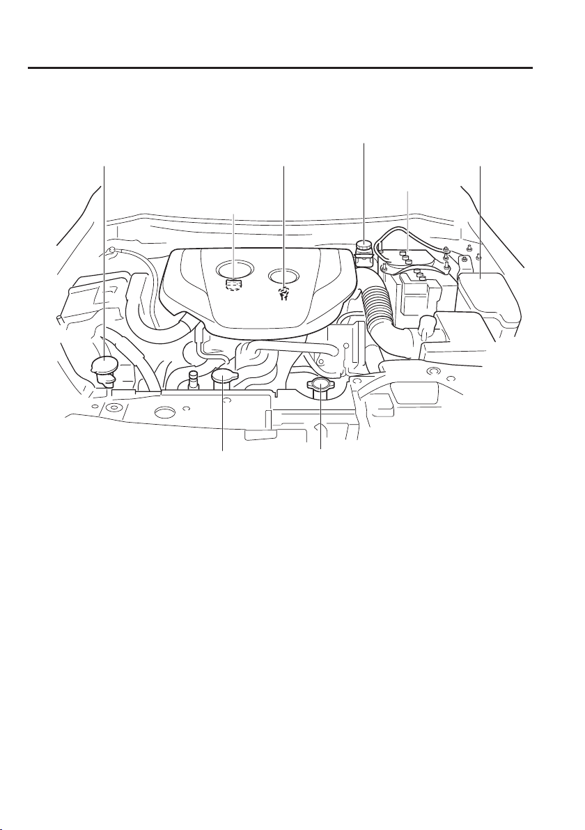
6
–
22
Maintenance and Care
Owner Maintenance
Windscreen washer fluid reservoir Engine oil dipstick
Battery
Fuse block
Coolin
g
s
y
stem capEn
g
ine coolant reservoir
Engine oil-filler cap
SKYACTIV-D 1.5
Brake/Clutch fluid reservoir
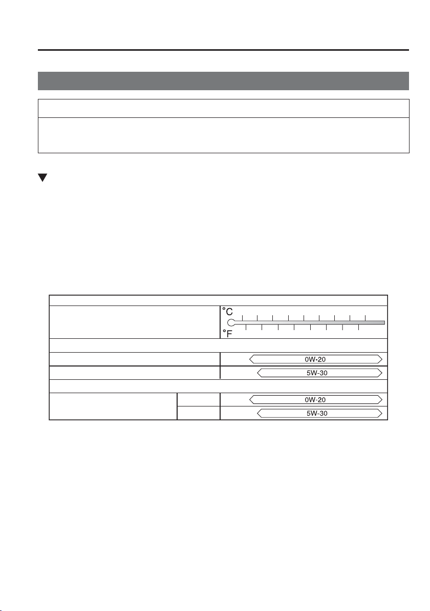
6
–
23
Maintenance and Care
Owner Maintenance
Engine Oil
NOTE
Changing the engine oil should be done by an expert repairer, we recommend an
Authorised Mazda Repairer.
Recommended Oil
In order to keep the maintenance interval (page 6-3 ) and to protect the engine from
damage caused by poor lubrication, it is vitally important to make use of engine oil with
the correct speci¿ cation. Do not use oils which do not meet the following speci¿ cations or
requirements. Use of unsuitable oil may lead to engine damage which is not covered by the
Mazda Warranty.
Temperature Range SAE Viscosity Numbers
Mazda Original Oil Ultra 5W-30
API SL/SM/SN or ACEA A3/A5
Mazda Original Oil Supra 0W-20
Alternative Oil Quality
Recommended oils
–30 –20 –10 0
10
20 30
40
–20
0
20
40
60
80
100
–40
–40
Grade
5W-30
0W-20
(SKYACTIV-G 1.5)
Europe
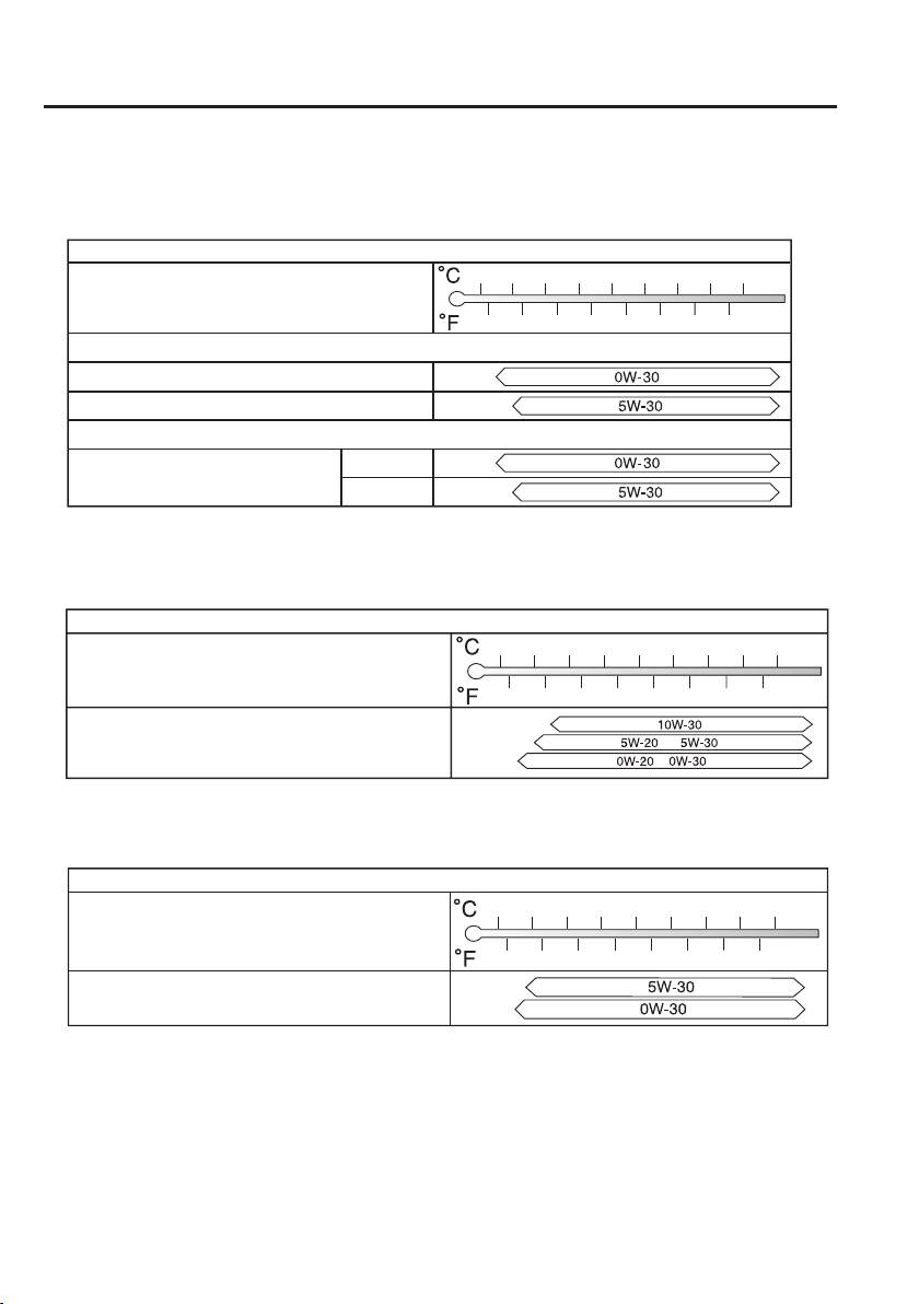
6
–
24
Maintenance and Care
Owner Maintenance
Temperature Range SAE Viscosity Numbers
Mazda Original Oil Ultra DPF 5W-30
ACEA C3
Mazda Original Oil Supra DPF 0W-30
Alternative Oil Quality
Recommended oils
–30 –20 –10 0
10
20 30
40
–20
0
20
40
60
80
100
–40
–40
Grade
5W-30
0W-30
(SKYACTIV-D 1.5)
Grade
API SG/SH/SJ/SL/SM/SN or
ILSAC GF-II/GF-III/GF-IV/GF-V
(SKYACTIV-G 1.3 and SKYACTIV-G 1.5)
Temperature Range SAE Viscosity Numbers
–30 –20 –10 0
10
20 30
40
–20
0
20
40
60
80
100
–40
–40
Except Europe
Grade
Temperature Range SAE Viscosity Numbers
ACEA C3
–30 –20 –10 0
10
20 30
40
–20
0
20
40
60
80
100
–40
–40
(SKYACTIV-D 1.5)
6
–
25
Maintenance and Care
Owner Maintenance
Engine oil viscosity, or thickness, has an effect on fuel economy and cold-weather operation
(starting and oil À ow).
Low-viscosity engine oils can provide improved fuel economy and cold-weather
performance.
When choosing an oil, consider the temperature range your vehicle will operate in before
the next oil change.
Then select the recommended viscosity from the chart.
CAUTION
Using oils of viscosity besides those recommended for speci¿ c temperature ranges
could result in engine damage.
(SKYACTIV-D 1.5)
SKYACTIV-D 1.5 uses speci¿ ed oil. Please con¿ rm the speci¿ cation in owner's
manual. If engine oil other than the speci¿ ed oil is used, the Diesel Particulate
Filter effective period of use will be shortened or the Diesel Particulate Filter may
be damaged.
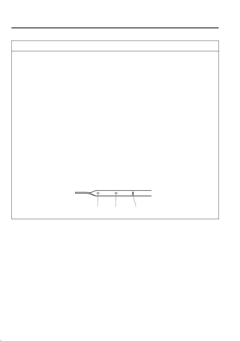
6
–
26
Maintenance and Care
Owner Maintenance
NOTE
(SKYACTIV-G 1.3 and SKYACTIV-G 1.5)
It is normal for all engines to consume engine oil under normal driving conditions.
Engine oil consumption may be as high as 0.8 L/1,000 km (1 L/800 miles). This may
be as a result of evaporation, internal ventilation or burning of the lubricating oil in
the working engine. Oil consumption may be higher when the engine is new due to
the running-in process. Oil consumption is also dependant on engine speed and engine
load. Under extreme driving conditions, oil consumption may be higher.
(SKYACTIV-D 1.5)
Whenever the engine oil is replaced, the vehicles engine control unit needs to be
reset as soon as possible. Otherwise the wrench indicator light or engine oil warning
light may turn on. To reset the engine control unit, consult an expert repairer, we
recommend an Authorised Mazda Repairer or refer to the vehicle engine control unit
reset procedure on page 6-27 .
Inspect the engine oil level periodically. When inspecting the engine oil, if the engine
oil level is exceeds the “X” mark on the dipstick, replace the engine oil. This should
be done by an expert repairer, we recommend an Authorised Mazda Repairer. When
replacing the engine oil, inspect the oil level using the oil dipstick and re¿ ll so that the
engine oil level is within the range between MIN and MAX as shown in the ¿ gure.
X MarkMAXMIN
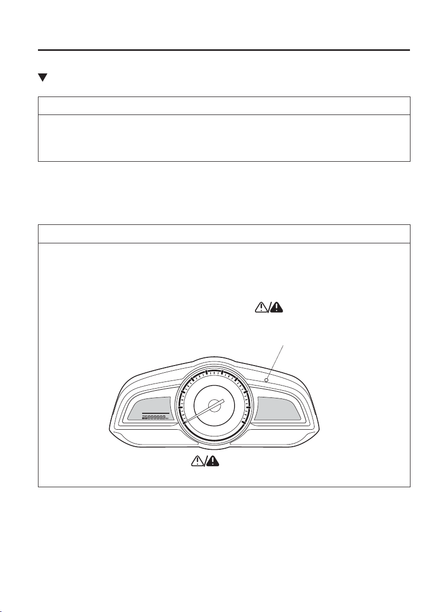
6
–
27
Maintenance and Care
Owner Maintenance
Vehicle Engine Control Unit Reset Procedure
NOTE
This procedure is intended for vehicles with SKYACTIV-D 1.5 and vehicles with
SKYACTIV-G 1.3 or SKYACTIV-G 1.5 which the engine oil À exible maintenance setting
is selected.
After replacing the engine oil, have a repair shop such as an Authorised Mazda Repairer
perform the initialization (engine oil data resetting) of the recorded value. If the value
recorded by the computer is not initialized, the wrench indicator light may not turn off or it
may turn on earlier than normal.
NOTE
The initialization (engine oil data resetting) of the recorded value can be performed using
the following procedure:
1. Switch the ignition OFF.
2. Switch the ignition ON with the selector pressed, and press and hold the selector for
about 5 seconds until the master warning light
À ashes.
Selector
3. After the master warning light
À ashes for several seconds, the initialization
is completed.
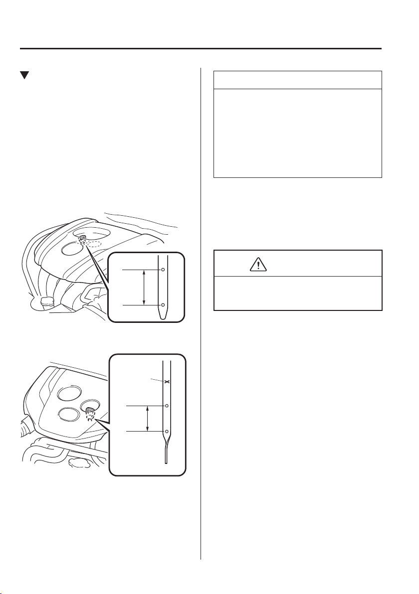
6
–
28
Maintenance and Care
Owner Maintenance
Inspecting Engine Oil Level
1. Be sure the vehicle is on a level
surface.
2. Warm up the engine to normal
operating temperature.
3. Turn it off and wait at least 5 minutes
for the oil to return to the sump.
4. Pull out the dipstick, wipe it clean, and
reinsert it fully.
SKYACTIV-G 1.3 and
SKYACTIV-G 1.5
MAX
MIN
OK
SKYACTIV-D 1.5
MAX
OK
MIN
X Mark
NOTE
(SKYACTIV-D 1.5)
When inspecting the engine oil level,
pull out the dipstick straight without
twisting. In addition, when inserting
the dipstick, always insert it without
twisting so that the “X” mark faces the
front of the vehicle.
5. Pull it out again and examine the level.
The level is normal if it is between the
MIN and MAX marks.
If it is near or below MIN, add enough
oil to bring the level to MAX.
CAUTION
Do not over¿ ll the engine oil. This may
cause engine damage.
6. Make sure the O-ring on the dipstick is
positioned properly before reinserting
the dipstick.
7. Reinsert the dipstick fully.
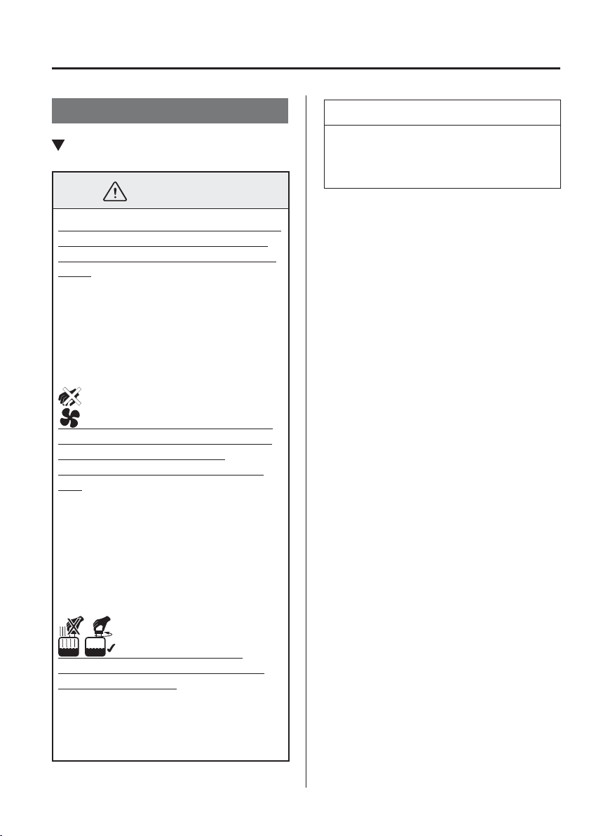
6
–
29
Maintenance and Care
Owner Maintenance
Engine Coolant
Inspecting Coolant Level
WARNING
Do not use a match or live À ame in the
engine compartment. DO NOT ADD
COOLANT WHEN THE ENGINE IS
HOT:
A hot engine is dangerous. If the
engine has been running, parts of the
engine compartment can become very
hot. You could be burned. Carefully
inspect the engine coolant in the
coolant reservoir, but do not open it.
Pull over to a safe location, then
switch the ignition off and make sure
the fan is not running before
attempting to work near the cooling
fan:
Working near the cooling fan when it
is running is dangerous. The fan could
continue running inde¿ nitely even if
the engine has stopped and the engine
compartment temperature is high. You
could be hit by the fan and seriously
injured.
Do not remove either
cooling system cap when the engine
and radiator are hot:
When the engine and radiator are hot,
scalding coolant and steam may shoot
out under pressure and cause serious
injury.
NOTE
Changing the coolant should be done
by an expert repairer, we recommend an
Authorised Mazda Repairer.
Inspect the antifreeze protection and
coolant level in the coolant reservoir at
least once a year—at the beginning of
the winter season—and before travelling
where temperatures may drop below
freezing.
Inspect the condition and connections of
all cooling system and heater hoses.
Replace any that are swollen or
deteriorated.
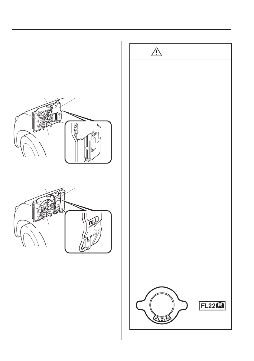
6
–
30
Maintenance and Care
Owner Maintenance
The coolant should be at full in the
radiator and between the F or FULL and
L marks on the coolant reservoir when the
engine is cool.
SKYACTIV-G 1.3 and SKYACTIV-G
1.5
Cooling system cap Coolant reservoir
Cooling fan
SKYACTIV-D 1.5
Cooling system cap Coolant reservoir
Cooling fan
If it is at or near L, add enough coolant to
the coolant reservoir to provide freezing
and corrosion protection and to bring the
level to F or FULL.
Securely tighten the coolant reservoir tank
cap after adding coolant.
CAUTION
Radiator coolant will damage paint.
Rinse it off quickly if spilled.
Use only soft (demineralised) water
in the coolant mixture. Water that
contains minerals will cut down on
the coolant's effectiveness.
Do not add only water. Always add a
proper coolant mixture.
The engine has aluminium parts and
must be protected by an ethylene-
glycol-based coolant to prevent
corrosion and freezing.
DO NOT USE coolants Containing
Alcohol, methanol, Borate or
Silicate.
These coolants could damage the
cooling system.
DO NOT MIX alcohol or methanol
with the coolant. This could damage
the cooling system.
Do not use a solution that contains
more than 60% antifreeze.
This would reduce effectiveness.
If the “FL22” mark is shown on or
near the cooling system cap, use
of FL-22 is recommended when
replacing engine coolant. Using
engine coolant other than FL-22 may
cause serious damage to the engine
and cooling system.
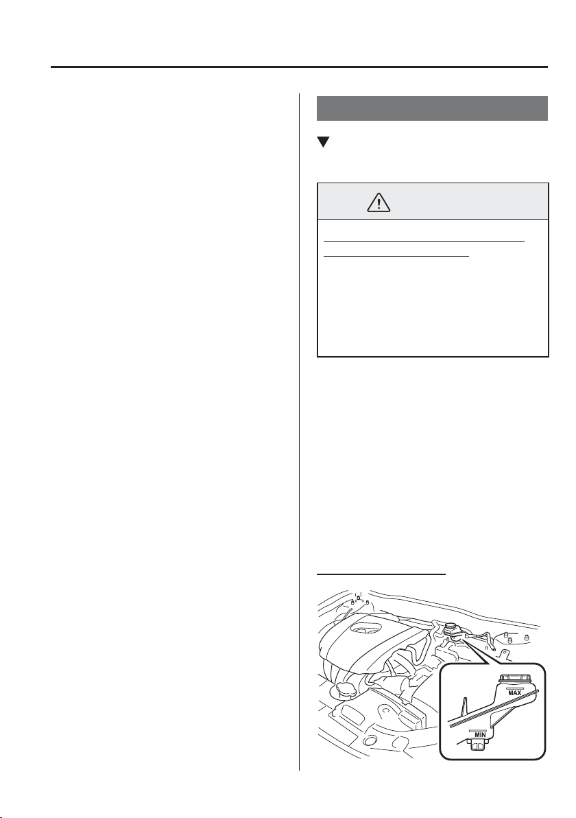
6
–
31
Maintenance and Care
Owner Maintenance
If the coolant reservoir is empty or new
coolant is required frequently, consult
an expert repairer, we recommend an
Authorised Mazda Repairer.
Brake/Clutch Fluid
Inspecting Brake/Clutch Fluid
Level
WARNING
If the brake/clutch À uid level is low,
have the brakes inspected:
A low brake/clutch À uid level is
dangerous.
A low level could indicate brake lining
wear or a brake system leak which
could cause the brakes to fail and lead
to an accident.
The brakes and clutch draw À uid from the
same reservoir.
Inspect the À uid level in the reservoir
regularly. It should be kept between the
MAX and MIN lines.
The level normally drops with
accumulated distance, a condition
associated with wear of brake and clutch
linings. If it is excessively low, have the
brake/clutch system inspected by an expert
repairer, we recommend an Authorised
Mazda Repairer.
Left-hand drive model
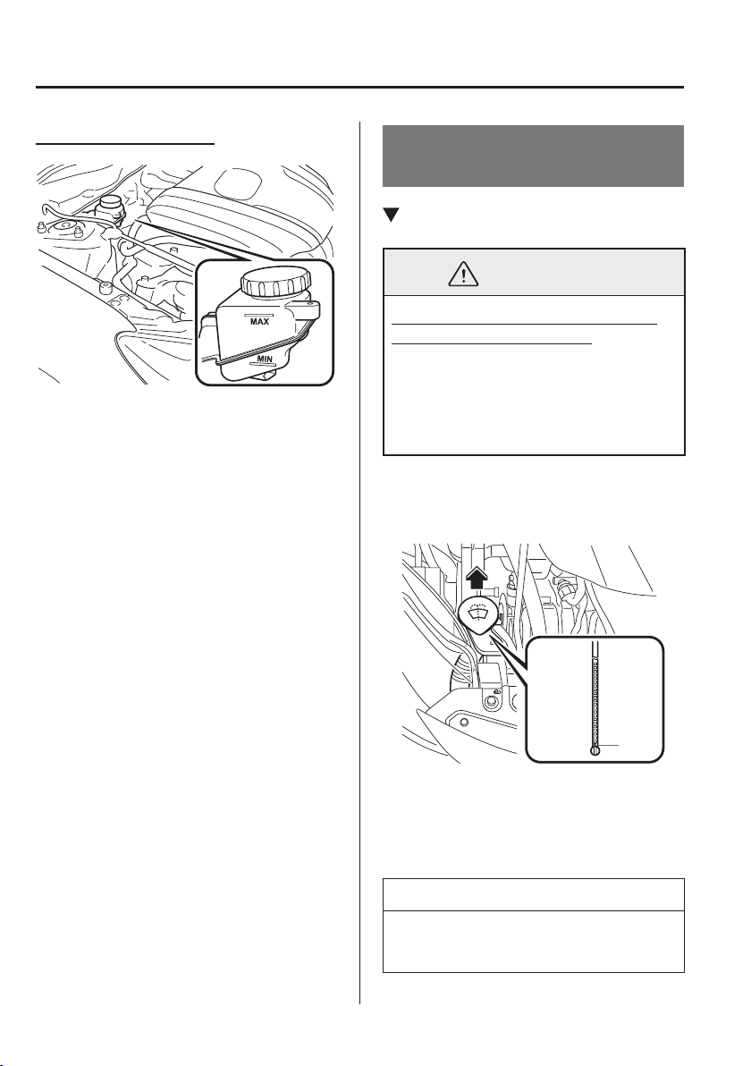
6
–
32
Maintenance and Care
Owner Maintenance
Right-hand drive model
Window and Headlight
Washer Fluid
Inspecting Washer Fluid Level
WARNING
Use only windscreen washer À uid or
plain water in the reservoir:
Using radiator antifreeze as washer
À uid is dangerous. If sprayed on the
windscreen, it will dirty the windscreen,
affect your visibility, and could result in
an accident.
Inspect À uid level in the washer À uid
reservoir; add À uid if necessary.
E
Use plain water if washer À uid is
unavailable.
But use only washer À uid in cold weather
to prevent it from freezing.
NOTE
Front and rear washer À uid is supplied
from the same reservoir.
6
–
33
Maintenance and Care
Owner Maintenance
Body Lubrication
All moving points of the body, such as
door and bonnet hinges and locks, should
be lubricated each time the engine oil is
changed. Use a nonfreezing lubricant on
locks during cold weather.
Make sure the bonnet's secondary latch
keeps the bonnet from opening when the
primary latch is released.
Wiper Blades
CAUTION
Hot waxes applied by automatic car
washers have been known to affect
the wiper's ability to clean windows.
To prevent damage to the wiper
blades, do not use petrol, paraf¿ n,
paint thinner, or other solvents on or
near them.
When the wiper lever is in the
AUTO position and the ignition is
switched ON, the wipers may move
automatically in the following cases:
If the windscreen above the rain
sensor is touched.
If the windscreen above the rain
sensor is wiped with a cloth.
If the windscreen is struck with a
hand or other object.
If the rain sensor is struck with a
hand or other object from inside
the vehicle.
Be careful not to pinch hands or
¿ ngers as it may cause injury, or
damage the wipers. When washing or
servicing the vehicle, make sure the
wiper lever is in the OFF position.
Contamination of either the windscreen or
the blades with foreign matter can reduce
wiper effectiveness. Common sources are
insects, tree sap, and hot wax treatments
used by some commercial car washes.
If the blades are not wiping properly,
clean the window and blades with a good
cleaner or mild detergent; then rinse
thoroughly with clean water. Repeat if
necessary.
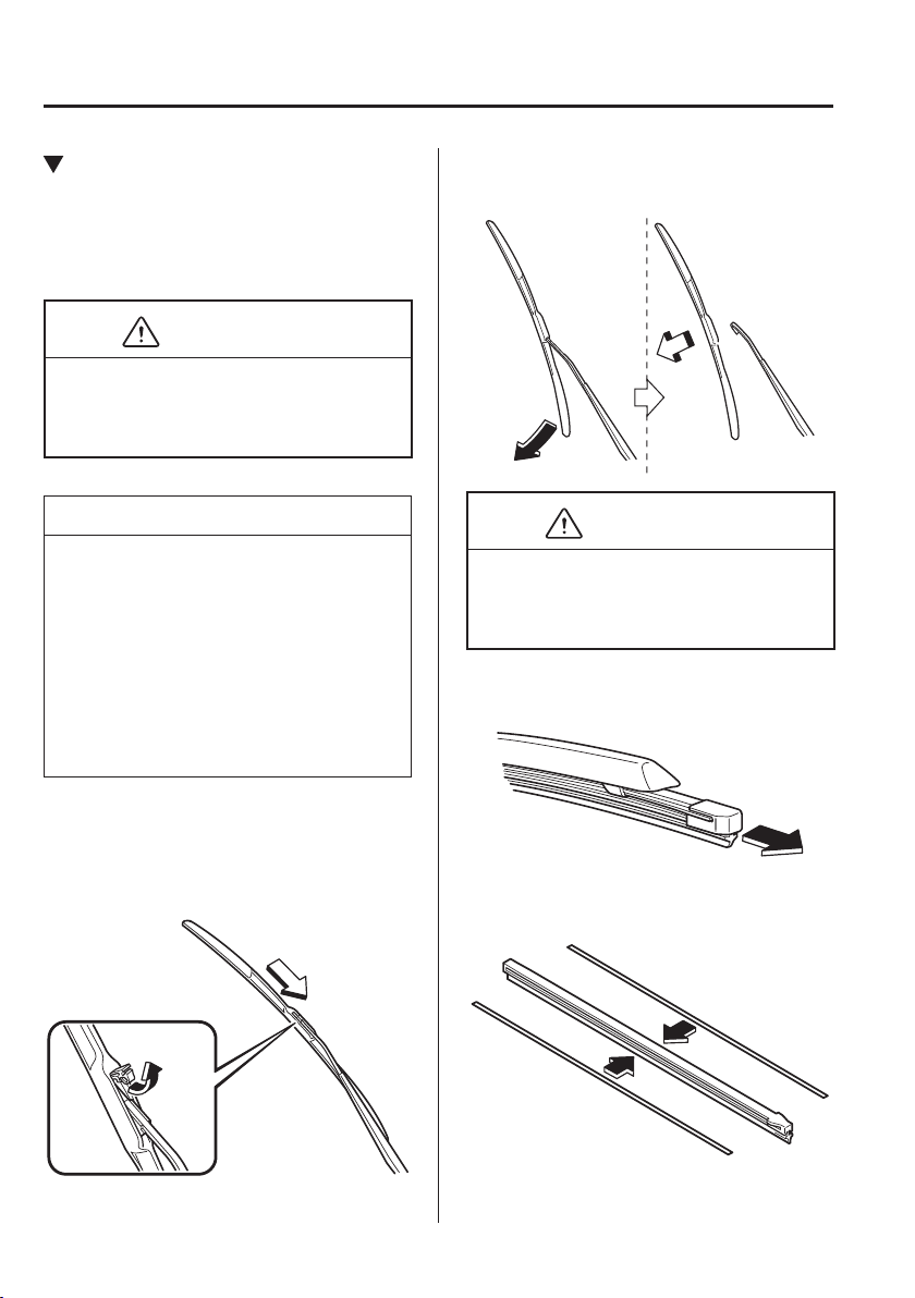
6
–
34
Maintenance and Care
Owner Maintenance
Replacing Windscreen Wiper
Blades
When the wipers no longer clean well, the
blades are probably worn or cracked.
Replace them.
CAUTION
To prevent damage to the wiper arms
and other components, do not try to
sweep the wiper arm by hand.
NOTE
When raising both windscreen wiper
arms, raise the driver's side wiper arm
¿ rst. When lowering the wiper arms,
slowly lower the wiper arm from the
passenger's side ¿ rst while supporting it
with your hand. Forcefully lowering the
wiper arms could damage the wiper arm
and blade, and may scratch or crack the
windscreen.
(Type A)
1. Raise the wiper arm.
2. Open the clip and slide the blade
assembly in the direction of the arrow.
3. Tilt the blade assembly and remove it
from the arm.
CAUTION
To prevent damage to the windscreen let
the wiper arm down easily, do not let it
slap down on the windscreen.
4. Pull down the blade rubber and slide it
out of blade holder.
5. Remove the metal stiffeners from each
blade rubber and install them in the
new blade.
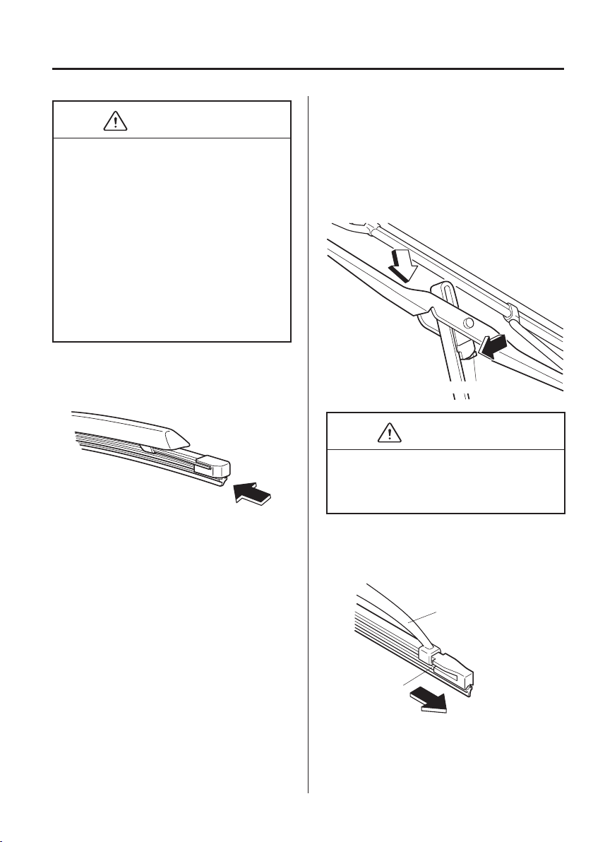
6
–
35
Maintenance and Care
Owner Maintenance
CAUTION
Do not bend or discard the stiffeners.
You need to use them again.
If the metal stiffeners are switched,
the blade's wiping ef¿ ciency could
be reduced.
So do not use the driver's side metal
stiffeners on the passenger's side, or
vice versa.
Be sure to reinstall the metal
stiffeners in the new blade rubber so
that the curve is the same as it was in
the old blade rubber.
6. Carefully insert the new blade rubber.
Then install the blade assembly in the
reverse order of removal.
(Type B)
1. Raise the wiper arm and turn the blade
assembly to expose the plastic locking
clip.
Compress the clip and slide the
assembly downward; then lift it off the
arm.
Plastic locking clip
CAUTION
To prevent damage to the windscreen let
the wiper arm down easily, do not let it
slap down on the windscreen.
2. Hold the end of the rubber and pull
until the tabs are free of the metal
support.
Metal support
Tab
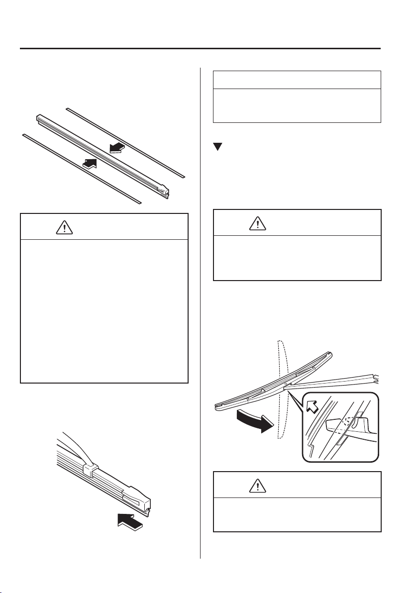
6
–
36
Maintenance and Care
Owner Maintenance
3. Remove the metal stiffeners from each
blade rubber and install them in the
new blade.
CAUTION
Do not bend or discard the stiffeners.
You need to use them again.
If the metal stiffeners are switched,
the blade's wiping ef¿ ciency could
be reduced.
So do not use the driver's side metal
stiffeners on the passenger's side, or
vice versa.
Be sure to reinstall the metal
stiffeners in the new blade rubber so
that the curve is the same as it was in
the old blade rubber.
4. Carefully insert the new blade rubber.
Then install the blade assembly in the
reverse order of removal.
NOTE
Install the blade so that the tabs are
toward the bottom of the wiper arm.
Replacing Rear Window Wiper
Blade (Hatchback)
When the wiper no longer cleans well, the
blade is probably worn or cracked.
Replace it.
CAUTION
To prevent damage to the wiper arm
and other components, do not move the
wiper by hand.
1. Raise the wiper arm and rotate the
wiper blade to the right until it unlocks,
then remove the blade.
CAUTION
To prevent damage to the rear window,
do not let the wiper arm fall on it.
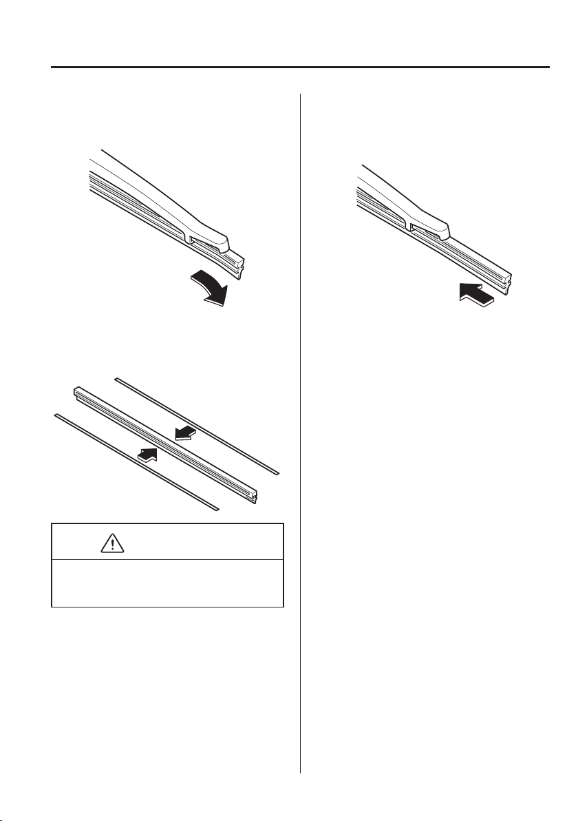
6
–
37
Maintenance and Care
Owner Maintenance
2. Pull down the blade rubber and slide it
out of the blade holder.
3. Remove the metal stiffeners from the
blade rubber and install them in the
new blade.
CAUTION
Do not bend or discard the stiffeners.
You need to use them again.
4. Carefully insert the new blade rubber.
Then install the blade assembly in the
reverse order of removal.
6
–
38
Maintenance and Care
Owner Maintenance
Battery
WARNING
Read the following precautions carefully before using the battery or inspecting to
ensure safe and correct handling:
Always wear eye protection when working near the battery:
Working without eye protection is dangerous. Battery À uid contains SULPHURIC
ACID which could cause blindness if splashed into your eyes. Also, hydrogen gas
produced during normal battery operation, could ignite and cause the battery to
explode.
Wear eye protection and protective gloves to prevent contact with battery À uid:
Spilled battery À uid is dangerous.
Battery À uid contains SULPHURIC ACID which could cause serious injuries if it gets
in eyes, or on the skin or clothing. If this happens, immediately À ush your eyes with
water for 15 minutes or wash your skin thoroughly and get medical attention.
Always keep batteries out of the reach of children:
Allowing children to play near batteries is dangerous. Battery À uid could cause serious
injuries if it gets in the eyes or on the skin.
Keep À ames and sparks away from open battery cells and do not allow metal
tools to contact the positive ( ) or negative ( ) terminal of the battery when working
near a battery. Do not allow the positive ( ) terminal to contact the vehicle body:
Flames and sparks near open battery cells are dangerous. Hydrogen gas, produced
during normal battery operation, could ignite and cause the battery to explode. An
exploding battery can cause serious burns and injuries. Keep all À ames including
cigarettes and sparks away from open battery cells.
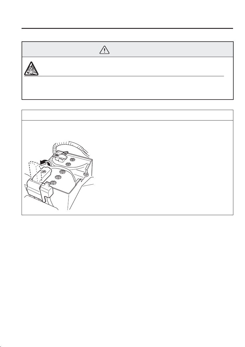
6
–
39
Maintenance and Care
Owner Maintenance
WARNING
Keep all À ames, including cigarettes, and sparks away from open battery cells:
Flames and sparks near open battery cells are dangerous. Hydrogen gas, produced
during normal battery operation, could ignite and cause the battery to explode. An
exploding battery can cause serious burns and injuries.
NOTE
Before performing battery maintenance, remove the battery cover.
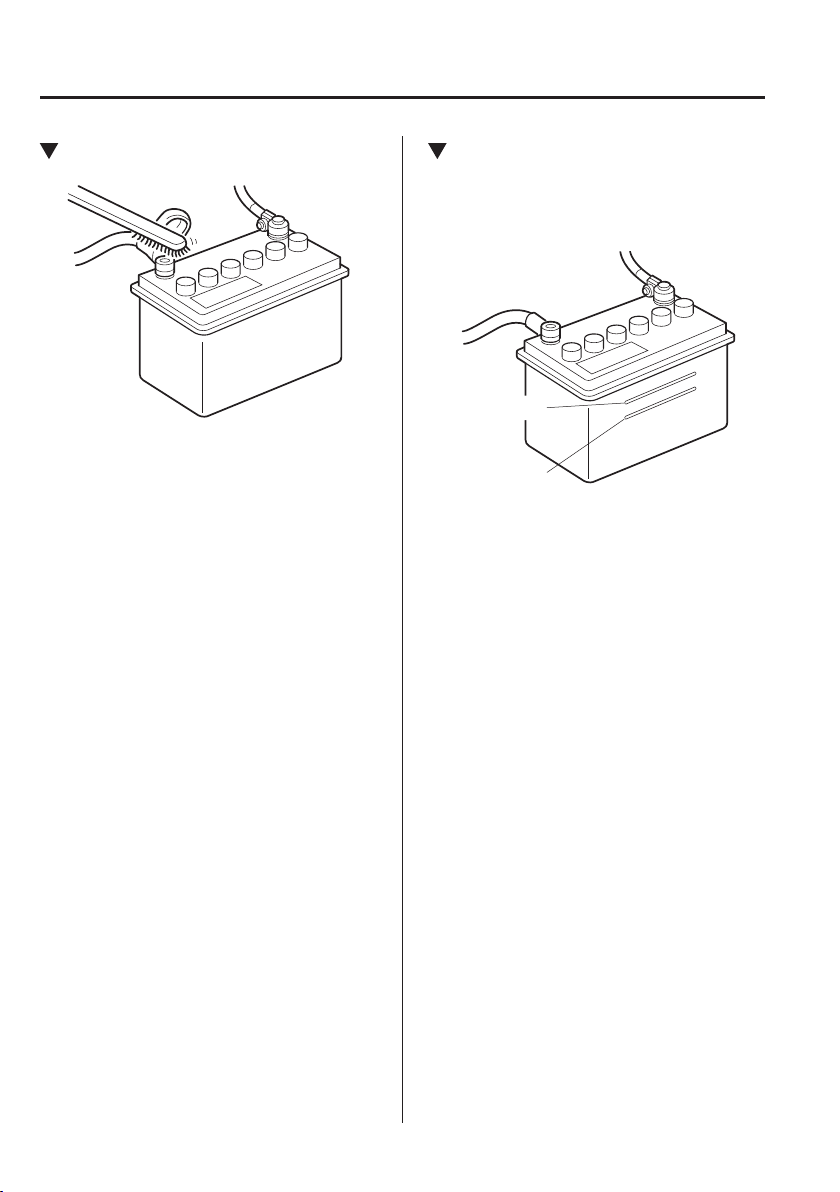
6
–
40
Maintenance and Care
Owner Maintenance
*Some models.
Battery Maintenance
To get the best service from a battery:
Keep it securely mounted.
Keep the top clean and dry.
Keep terminals and connections clean,
tight, and coated with petroleum jelly or
terminal grease.
Rinse off spilled electrolyte immediately
with a solution of water and baking
soda.
If the vehicle will not be used for an
extended time, disconnect the battery
leads and charge the battery every six
weeks.
Inspecting Electrolyte Level
*
A low level of electrolyte À uid will cause
the battery to discharge quickly.
Upper level
Lower level
Inspect the electrolyte level at least once
a week. If it is low, remove the caps and
add enough distilled water to bring the
level between the upper and lower level
(illustration).
Do not over¿ ll.
Examine the speci¿ c gravity of the
electrolyte with a hydrometer, especially
during cold weather. If it is low, recharge
the battery.
6
–
41
Maintenance and Care
Owner Maintenance
Battery Recharging
NOTE
Before performing maintenance or
recharging the battery, turn off all
accessories and stop the engine.
To disconnect the battery, remove the
negative lead ¿ rst. Install it last when
connecting the battery.
Be sure to remove the caps before
recharging the battery.
(With i-stop system)
Do not quick-charge the battery.
If the battery quickly discharges
because, for example, the lights were
left on too long with the engine off,
slow-charge it as required by battery
size and charger capacity.
If the battery gradually discharges
because of high electric load while the
vehicle is being used, recharge it as
required by battery size and charger
capacity.
Battery Replacement
Contact an Authorised Mazda Repairer for
a battery replacement purchase.
Key Battery Replacement
If the buttons on the transmitter are
inoperable and the operation indicator
light does not À ash, the battery may be
dead.
Replace with a new battery before the
transmitter becomes unusable.
CAUTION
Make sure the battery is installed
correctly. Battery leakage could
occur if it is not installed correctly.
When replacing the battery, be
careful not to touch any of the
internal circuitry and electrical
terminals, bend the electrical
terminals, or get dirt in the
transmitter as the transmitter could
be damaged.
There is the danger of explosion if
the battery is not correctly replaced.
Dispose of used batteries according
to the following instructions.
Insulate the plus and minus
terminals of the battery using
cellophane or equivalent tape.
Never disassemble.
Never throw the battery into ¿ re or
water.
Never deform or crush.
Replace only with the same type
battery (CR2025 or equivalent).
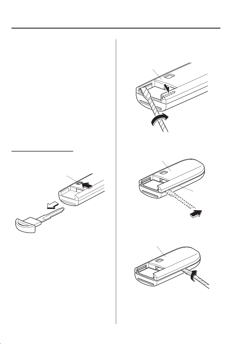
6
–
42
Maintenance and Care
Owner Maintenance
The following conditions indicate that the
battery power is low:
The KEY indicator light (green) À ashes
in the instrument cluster for about
30 seconds after the engine is turned off.
The system does not operate and
the operation indicator light on the
transmitter does not À ash when the
buttons are pressed.
The system's operational range is
reduced.
Replacing the battery at an Authorised
Mazda Repairer is recommended to
prevent damage to the key. If replacing the
battery by yourself, follow the instruction.
Replacing the key battery
1. Press the knob and pull out the
auxiliary key.
Knob
2. Twist a tape-wrapped À athead
screwdriver in the direction of the
arrow and open the cover slightly.
Cover
3. Insert the tape-wrapped À athead
screwdriver into the gap and slide it in
the direction of the arrow.
Cover
Gap
4. Twist the À athead screwdriver in the
direction of the arrow and remove the
cover.
Cover
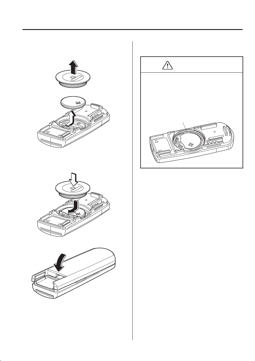
6
–
43
Maintenance and Care
Owner Maintenance
5. Remove the battery cap, then remove
the battery.
6. Insert a new battery with the positive
pole facing up, and then cover the
battery with the battery cap.
7. Close the cover.
8. Reinsert the auxiliary key.
CAUTION
Be careful not to allow the rubber
ring shown in the ¿ gure to be
scratched or damaged.
If the rubber ring detaches, reattach it
before inserting a new battery.
Rubber ring
6
–
44
Maintenance and Care
Owner Maintenance
*Some models.
Tyres
For reasons of proper performance, safety,
and better fuel economy, always maintain
recommended tyre inÀ ation pressures and
stay within the recommended load limits
and weight distribution.
WARNING
Using Different Tyre Types:
Driving your vehicle with different
types of tyres is dangerous. It could
cause poor handling and poor braking;
leading to loss of control.
Except for the limited use of the
temporary spare tyre, use only the same
type tyres (radial, bias-belted, bias-type)
on all four wheels.
Using Wrong-Sized Tyres:
Using any other tyre size than what is
speci¿ ed for the vehicle (page 9-10 )
is dangerous. It could seriously affect
ride, handling, ground clearance,
tyre clearance, and speedometer
calibration. This could cause you to
have an accident. Use only tyres that
are the correct size speci¿ ed for the
vehicle.
Tyre InÀ ation Pressure
WARNING
Always inÀ ate the tyres to the correct
pressure:
OverinÀ ation or underinÀ ation of tyres
is dangerous. Adverse handling or
unexpected tyre failure could result in
a serious accident.
Refer to Tyres on page 9-10 .
Use only a Mazda-genuine tyre valve
cap:
Use of a non-genuine part is dangerous
as the correct tyre air pressure cannot
be maintained if the tyre valve becomes
damaged. If the vehicle is driven under
this condition, the tyre air pressure
will decrease which could result in a
serious accident. Do not use any part
for the tyre valve cap that is not a
Mazda-genuine part.
Inspect all tyre pressures monthly
(including the spare
*
) when the tyres are
cold. Maintain recommended pressures for
the best ride, handling, and minimum tyre
wear.
Refer to the speci¿ cation charts (page
9-10 ).
(With tyre pressure monitoring system)
After adjusting the tyre pressure,
initialization of the tyre pressure
monitoring system is necessary to make
the system operate normally.
Refer to Tyre Pressure Monitoring System
Initialization on page 4-192 .
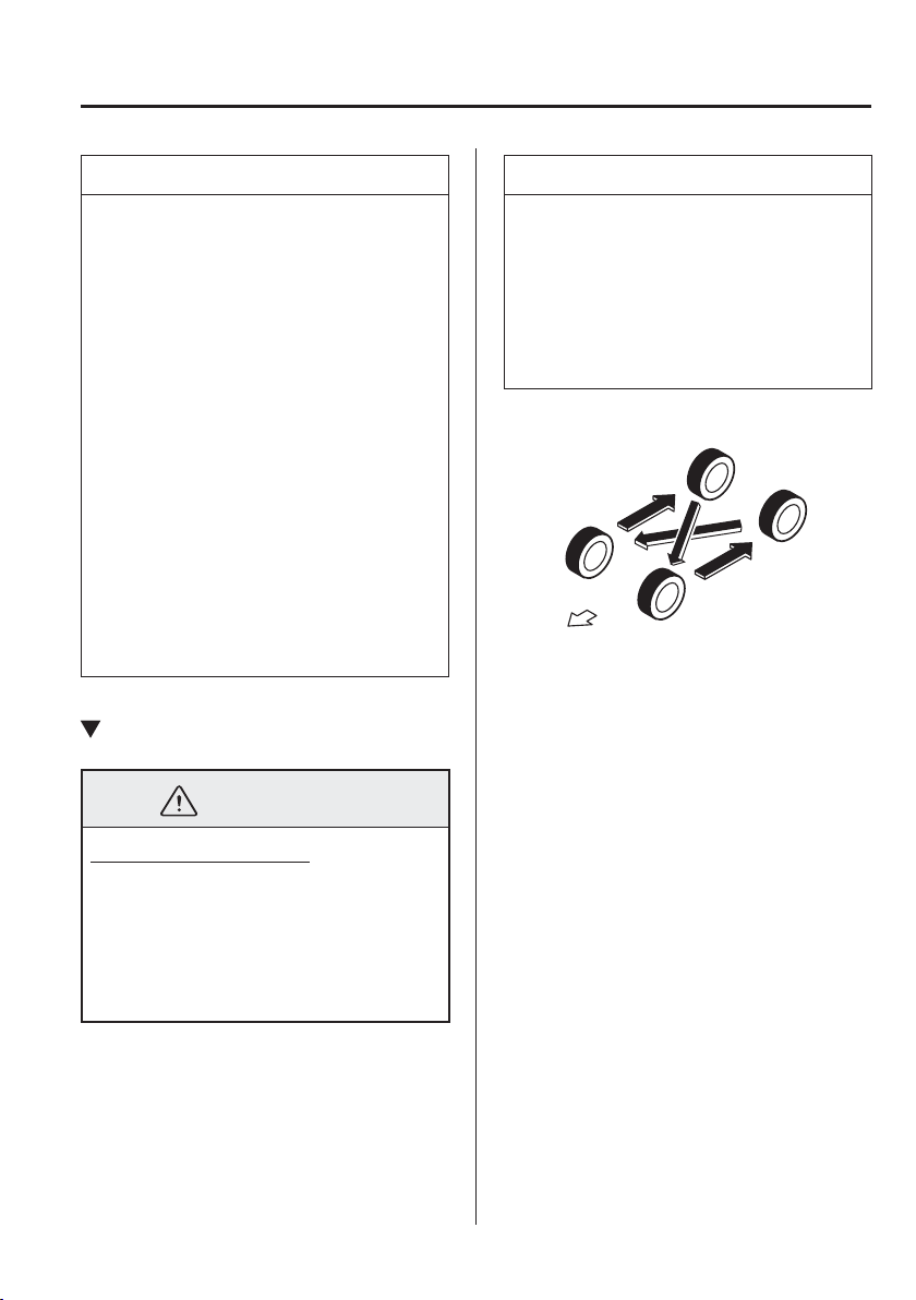
6
–
45
Maintenance and Care
Owner Maintenance
NOTE
Always check tyre pressure when
tyres are cold.
Warm tyres normally exceed
recommended pressures. Do not
release air from warm tyres to adjust
the pressure.
UnderinÀ ation can cause reduced
fuel economy, uneven and
accelerated tyre wear, and poor
sealing of the tyre bead, which
will deform the wheel and cause
separation of tyre from rim.
OverinÀ ation can produce a harsh
ride, uneven and accelerated tyre
wear, and a greater possibility of
damage from road hazards.
Keep your tyre pressure at the correct
levels. If one frequently needs
inÀ ating, have it inspected.
Tyre Rotation
WARNING
Rotate tyres periodically:
Irregular tyre wear is dangerous. To
equalize tread wear for maintaining
good performance in handling and
braking, rotate the tyres every
10,000 km (6,250 miles), or sooner if
irregular wear develops.
During rotation, inspect them for correct
balance.
NOTE
(Without temporary spare tyre)
Because your vehicle is not equipped
with a spare tyre, you cannot do a tyre
rotation safely with the jack that comes
with your vehicle. Have an expert
repairer, we recommend an Authorised
Mazda Repairer perform tyre rotation.
Do not include (TEMPORARY USE ONLY)
spare tyre in rotation.
Forward
Also, inspect them for uneven wear and
damage. Abnormal wear is usually caused
by one or a combination of the following:
Incorrect tyre pressure
Improper wheel alignment
Out-of-balance wheel
Severe braking
After rotation, inÀ ate all tyre pressures to
speci¿ cation (page 9-10 ) and inspect the
wheel nuts for tightness.
(With tyre pressure monitoring system)
After adjusting the tyre pressure,
initialization of the tyre pressure
monitoring system is necessary to make
the system operate normally.
Refer to Tyre Pressure Monitoring System
Initialization on page 4-192 .
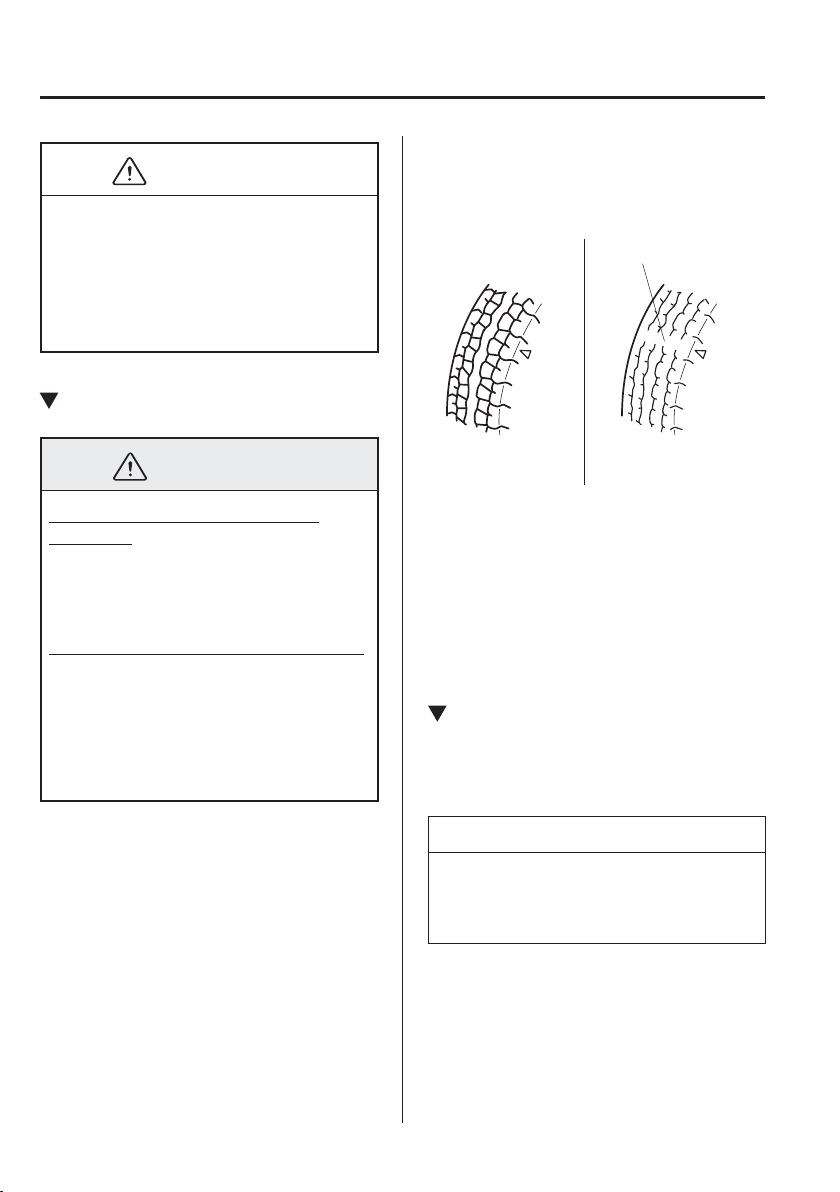
6
–
46
Maintenance and Care
Owner Maintenance
*Some models.
CAUTION
Rotate unidirectional tyres and radial
tyres that have an asymmetrical tread
pattern or studs only from front to rear,
not from side to side. Tyre performance
will be reduced if rotated from side to
side.
Replacing a Tyre
WARNING
Always use tyres that are in good
condition:
Driving with worn tyres is dangerous.
Reduced braking, steering, and traction
could result in an accident.
Replace all four tyres at the same time:
Replacing just one tyre is dangerous.
It could cause poor handling and poor
braking resulting in loss of vehicle
control. Mazda strongly recommends
that you replace all four tyres at the
same time.
If a tyre wears evenly, a wear indicator
will appear as a solid band across the
tread.
Replace the tyre when this happens.
New tread
Tread wear indicator
Worn tread
You should replace the tyre before the
band crosses the entire tread.
(With tyre pressure monitoring system)
After adjusting the tyre pressure,
initialization of the tyre pressure
monitoring system is necessary to make
the system operate normally.
Refer to Tyre Pressure Monitoring System
Initialization on page 4-192 .
Temporary Spare Tyre
*
Inspect the temporary spare tyre at least
monthly to make sure it is properly
inÀ ated and stored.
NOTE
The temporary spare tyre condition
gradually deteriorates even if it has not
been used.
The temporary spare tyre is easier to
handle because of its construction which
is lighter and smaller than a conventional
tyre. This tyre should be used only for an
emergency and only for a short distance.
6
–
47
Maintenance and Care
Owner Maintenance
*Some models.
Use the temporary spare tyre only until
the conventional tyre is repaired, which
should be as soon as possible.
Refer to Tyre on page 9-10 .
CAUTION
Do not use your temporary spare
tyre rim with a snow tyre or a
conventional tyre. Neither will
properly ¿ t and could damage both
tyre and rim.
The temporary spare tyre has a tread
life of less than 5,000 km (3,000
miles). The tread life may be shorter
depending on driving conditions.
The temporary spare tyre is for
limited use, however, if the tread
wear solid-band indicator appears,
replace the tyre with the same type of
temporary spare (page 6-46 ).
Replacing a Wheel
WARNING
Always use wheels of the correct size
on your vehicle:
Using a wrong-sized wheel is
dangerous. Braking and handling
could be affected, leading to loss of
control and an accident.
CAUTION
A wrong-sized wheel may adversely
affect:
Tyre ¿ t
Wheel and bearing life
Ground clearance
Snow-chain clearance
Speedometer calibration
Headlight aim
Bumper height
Tyre Pressure Monitoring System
*
NOTE
When replacing a wheel, make
sure the new one is the same as the
original factory wheel in diameter,
rim width, and offset (inset/outset).
For details, contact an expert
repairer, we recommend an
Authorised Mazda Repairer.
Proper tyre balancing provides the best
riding comfort and helps reduce tread
wear. Out-of-balance tyres can cause
vibration and uneven wear, such as
cupping and À at spots.
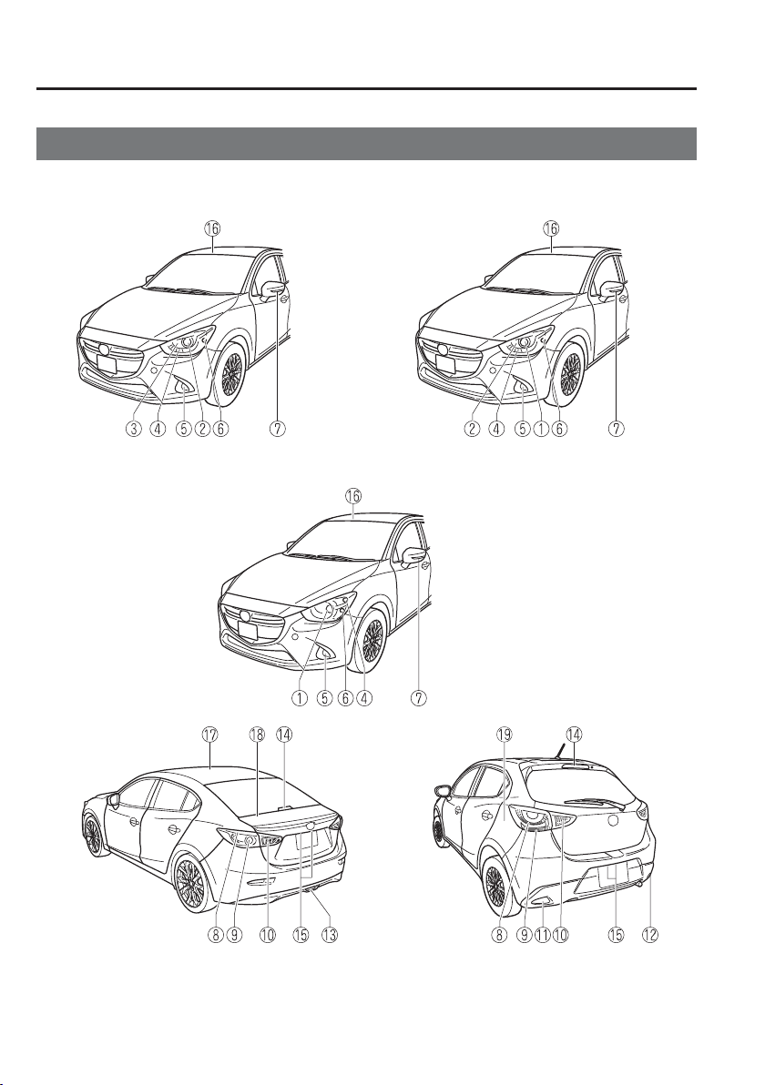
6
–
48
Maintenance and Care
Owner Maintenance
Light Bulbs
Saloon Hatchback
With LED Headlights
With Halogen Headlights
(Without Adaptive LED Headlights (ALH))
(With Adaptive LED Headlights (ALH))

6
–
49
Maintenance and Care
Owner Maintenance
*Some models.
Headlights (Low/High beam)
Headlights (Low beam)
Headlights (High beam)
Running lights
*
/Position lights
Front fog lights
*
Front direction indicator lights
Side direction indicator lights
Brake lights/Tail lights
Rear direction indicator lights
Reverse lights
Rear fog light (Left-hand drive model)
*
Rear fog light (Right-hand drive model)
*
Rear fog light
*
High-mount brake light
Number plate lights
Overhead lights (Front)/Map lights
*
Overhead lights (Rear)
*
Boot light (Saloon)
Luggage compartment light (Hatchback)
6
–
50
Maintenance and Care
Owner Maintenance
WARNING
Never touch the glass portion of a
halogen bulb with your bare hands
and always wear eye protection when
handling or working around the bulbs:
When a halogen bulb breaks, it is
dangerous. These bulbs contain
pressurised gas. If one is broken, it will
explode and serious injuries could be
caused by the À ying glass.
If the glass portion is touched with bare
hands, body oil could cause the bulb to
overheat and explode when lit.
Always keep halogen bulbs out of the
reach of children:
Playing with a halogen bulb is
dangerous. Serious injuries could be
caused by dropping a halogen bulb or
breaking it some other way.
CAUTION
When removing the lens or lamp unit
using a À athead screwdriver, make
sure that the À athead screwdriver does
not contact the interior terminal. If
the À athead screwdriver contacts the
terminal, a short circuit may occur.
NOTE
To replace the bulb, contact an
expert repairer, we recommend an
Authorised Mazda Repairer.
If the halogen bulb is accidentally
touched, it should be cleaned with
rubbing alcohol before being used.
Use the protective cover and carton
for the replacement bulb to dispose
of the old bulb promptly and out of
the reach of children.
Replacing Exterior Light Bulbs
Headlights (With LED headlights)
The LED bulb cannot be replaced as a
single unit because it is an integrated unit.
The LED bulb has to be replaced with
the unit. We recommend an Authorised
Mazda Repairer when the replacement is
necessary.
Headlights (With halogen headlights)
1. If you are changing the right bulb, start
the engine, turn the steering wheel all
the way to the left, and turn off engine.
If you are changing the left bulb, turn
the steering wheel to the right, and turn
off engine.
2. Make sure the headlight switch is off.
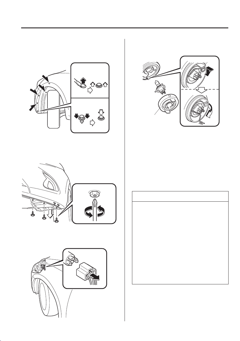
6
–
51
Maintenance and Care
Owner Maintenance
3. Pull the centre of each plastic retainer
and remove the retainers.
Removal
Installation
4. Turn the screw anticlockwise and
remove it, and then partially peel back
the mudguard.
5. Disconnect the connector from the
bulb.
6. Detach the sealing cover from the bulb.
Retaining spring
Sealing cover
7. Unhook the bulb retaining spring.
8. Swing the retaining spring out and
away to free the headlight bulb.
9. Carefully remove the headlight bulb
from the socket by pulling it straight
back.
10. Replace the bulb.
11. Install the new bulb in the reverse order
of the removal procedure.
NOTE
To replace the bulb, contact an
expert repairer, we recommend an
Authorised Mazda Repairer.
If the halogen bulb is accidentally
touched, it should be cleaned with
rubbing alcohol before being used.
Use the protective cover and carton
of the replacement bulb to dispose
of the old bulb promptly out of the
reach of children.
When reinstalling the sealing cover,
make sure it is ¿ tted correctly.
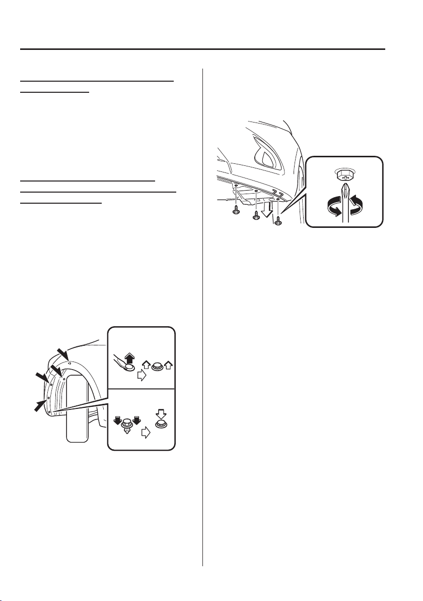
6
–
52
Maintenance and Care
Owner Maintenance
*Some models.
Running lights/Position lights (With
LED headlights)
The LED bulb cannot be replaced as a
single unit because it is an integrated unit.
The LED bulb has to be replaced with
the unit. We recommend an Authorised
Mazda Repairer when the replacement is
necessary.
Front direction indicator lights,
Running lights
*
/Position lights (With
halogen headlights)
1. If you are changing the right bulb, start
the engine, turn the steering wheel all
the way to the left, and turn off engine.
If you are changing the left bulb, turn
the steering wheel to the right, and turn
off engine.
2. Make sure the headlight switch is off.
3. Pull the centre of each plastic retainer
and remove the retainers.
Removal
Installation
4. Turn the screw anticlockwise and
remove it, and then partially peel back
the mudguard.
5. Turn the socket and bulb assembly
anticlockwise and remove it.
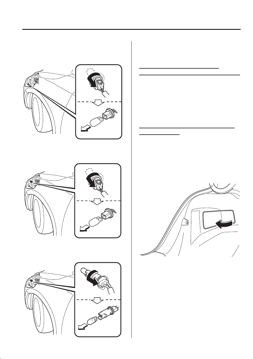
6
–
53
Maintenance and Care
Owner Maintenance
*Some models.
6. Disconnect the bulb from the socket.
Front direction indicator lights
Running lights/Position lights (With
halogen headlights)
*
Position lights (With halogen
headlights)
*
7. Install the new bulb in the reverse order
of the removal procedure.
Front fog lights
*
, Side direction
indicator lights, High-mount brake light
The LED bulb cannot be replaced as a
single unit because it is an integrated unit.
The LED bulb has to be replaced with
the unit. We recommend an Authorised
Mazda Repairer when the replacement is
necessary.
Rear direction indicator lights, Brake
lights/Tail lights
S a l o o n
1. Make sure the ignition is switched off,
and the headlight switch is off.
2. Remove the cover.
3. Turn the socket and bulb assembly
anticlockwise and remove it.
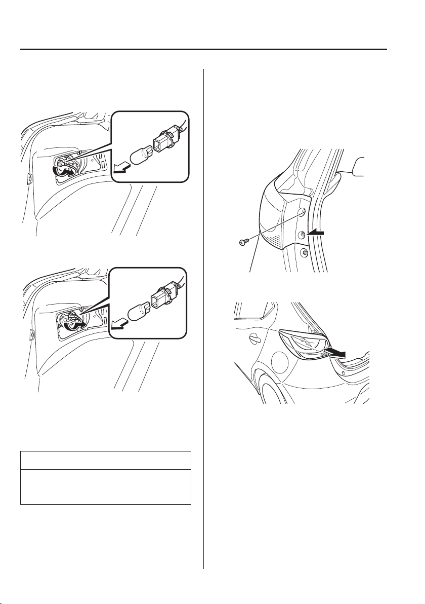
6
–
54
Maintenance and Care
Owner Maintenance
4. Disconnect the bulb from the socket.
Rear direction indicator lights
Brake lights/Tail lights
5. Install the new bulb in the reverse order
of the removal procedure.
6. Insert the cover tabs and install the
cover.
NOTE
Verify that the cover is securely
installed.
Hatchback
1. Make sure the ignition is switched off,
and the headlight switch is off.
2. Turn the bolts anticlockwise and
remove them.
3. Pull the unit rearward to remove it.
4. Turn the socket and bulb assembly
anticlockwise and remove it.
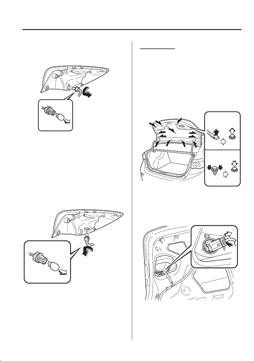
6
–
55
Maintenance and Care
Owner Maintenance
5. Disconnect the bulb from the socket.
Rear direction indicator lights
Brake lights/Tail lights
(LED type)
The LED bulb cannot be replaced as a
single unit because it is an integrated
unit.
The LED bulb has to be replaced with
the unit. We recommend an Authorised
Mazda Repairer when the replacement
is necessary.
(Bulb type)
6. Install the new bulb in the reverse order
of the removal procedure.
Reverse lights
S a l o o n
1. Make sure the ignition is switched off,
and the headlight switch is off.
2. Pull the centre of each plastic retainer
and remove the retainers.
3. Peel back the boot lid trim.
Removal
Installation
4. Disconnect the electrical connector
from the bulb by pressing the tab on the
connector with your ¿ nger and pulling
the connector.
5. Turn the socket and bulb assembly
anticlockwise and remove it.
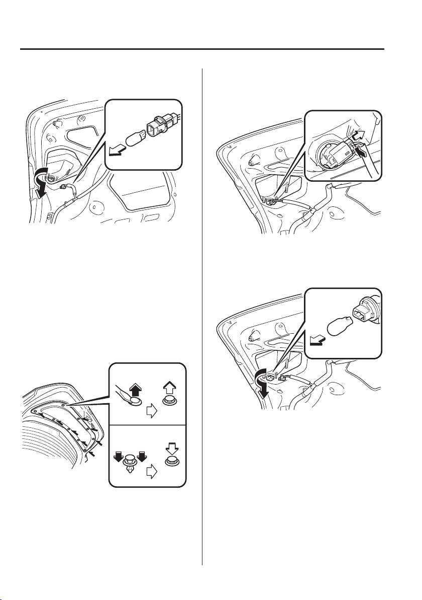
6
–
56
Maintenance and Care
Owner Maintenance
6. Disconnect the bulb from the socket.
7. Install the new bulb in the reverse order
of the removal procedure.
Hatchback
1. Make sure the ignition is switched off,
and the headlight switch is off.
2. Pull the centre of each plastic retainer
and remove the retainers.
3. Remove the cover on the interior
surface of the liftgate.
Removal
Installation
4. Disconnect the connector from the
socket.
5. Turn the socket and bulb assembly
anticlockwise and remove it.
6. Disconnect the bulb from the socket.
7. Install the new bulb in the reverse order
of the removal procedure.
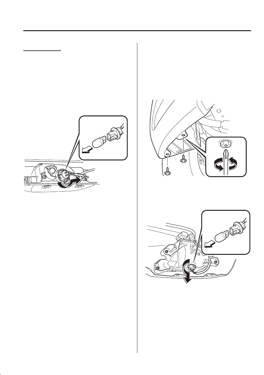
6
–
57
Maintenance and Care
Owner Maintenance
*Some models.
Rear fog light
*
S a l o o n
1. Make sure the ignition is switched off,
and the headlight switch is off.
2. Turn the socket and bulb assembly
anticlockwise and remove it.
3. Disconnect the bulb from the socket.
4. Install the new bulb in the reverse order
of the removal procedure.
Hatchback
1. Make sure the ignition is switched off
and the headlight switch is off.
2. Turn the screw anticlockwise and
remove it, and then partially peel back
the mudguard.
3. Turn the socket and bulb assembly
anticlockwise and remove it.
4. Disconnect the bulb from the socket.
5. Install the new bulb in the reverse order
of the removal procedure.
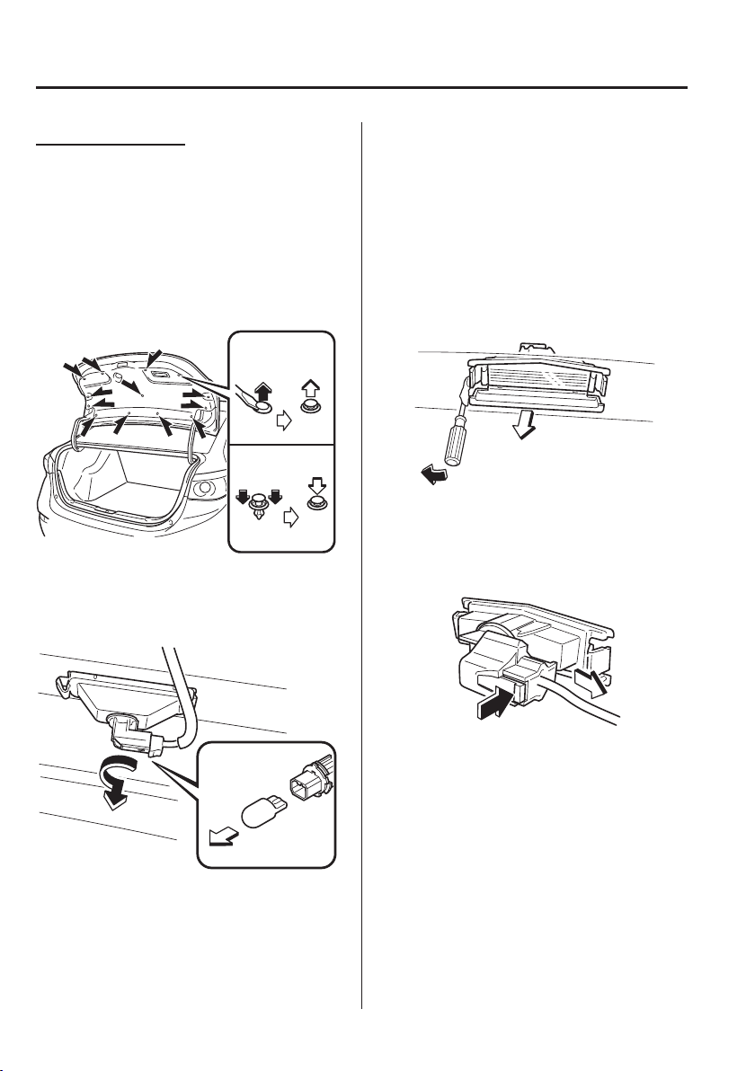
6
–
58
Maintenance and Care
Owner Maintenance
Number plate lights
S a l o o n
1. Make sure the ignition is switched off,
and the headlight switch is off.
2. Pull the centre of each plastic retainer
and remove the retainers.
3. Peel back the boot lid trim.
Removal
Installation
4. Turn the socket and bulb assembly
anticlockwise and remove it.
5. Disconnect the bulb from the socket.
6. Install the new bulb in the reverse order
of the removal procedure.
Hatchback
1. Make sure the ignition is switched off,
and the headlight switch is off.
2. Wrap a À athead screwdriver with a soft
cloth to prevent damage to the light
unit.
3. Insert a À athead screwdriver into the
position shown in the ¿ gure and pull
the light unit outward.
4. Disconnect the electrical connector
from the bulb by pressing the tab on the
connector with your ¿ nger and pulling
the connector.
5. Turn the socket and bulb assembly
anticlockwise and remove it.
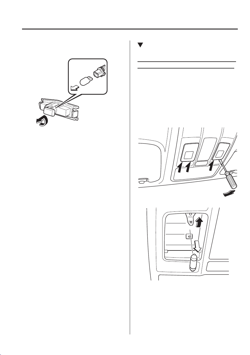
6
–
59
Maintenance and Care
Owner Maintenance
*Some models.
6. Disconnect the bulb from the socket.
7. Install the new bulb in the reverse order
of the removal procedure.
Replacing Interior Light Bulbs
Overhead lights/Map lights
*
, Overhead
lights (Front)
*
, Overhead lights (Rear)
*
1. Wrap a small À athead screwdriver
with a soft cloth to prevent damage to
the lens, and then remove the lens by
carefully prying on the edge of the lens
with the À athead screwdriver.
2. Disconnect the bulb by pulling it out.
Overhead lights/Map lights
*
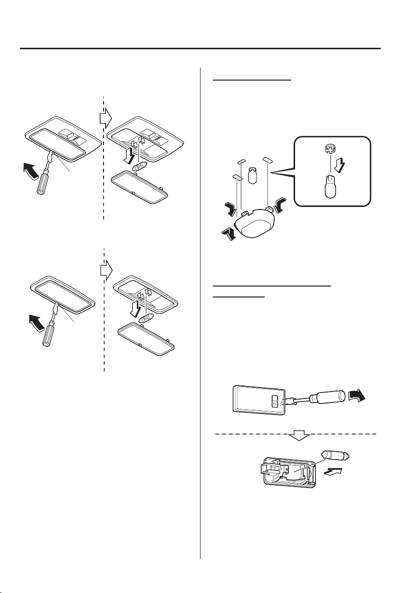
6
–
60
Maintenance and Care
Owner Maintenance
*Some models.
Overhead lights (Front)
*
Edge
Overhead lights (Rear)
*
Edge
3. Install the new bulb in the reverse order
of the removal procedure.
Boot light (Saloon)
1. Press both sides of the lens cap to
remove it.
2. Disconnect the bulb by pulling it out.
3. Install the new bulb in the reverse order
of the removal procedure.
Luggage compartment light
(Hatchback)
1. Wrap a small À athead screwdriver with
a soft cloth to prevent damage to the
lens and remove the lens by carefully
prying on the edge of the lens with the
À athead screwdriver.
2. Disconnect the bulb by pulling it out.
3. Install the new bulb in the reverse order
of the removal procedure.
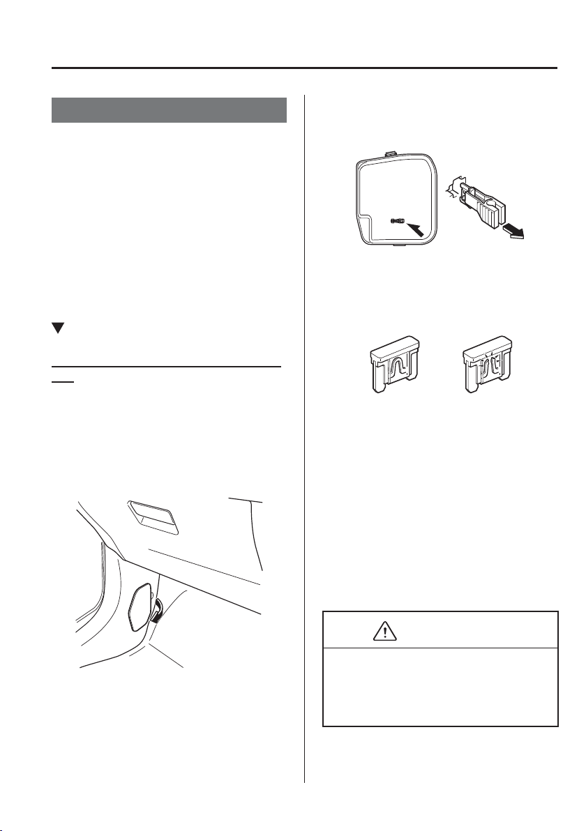
6
–
61
Maintenance and Care
Owner Maintenance
Fuses
Your vehicle's electrical system is
protected by fuses.
If any lights, accessories, or controls do
not work, inspect the appropriate circuit
protector. If a fuse has blown, the inside
element will be melted.
If the same fuse blows again, avoid using
that system and consult an expert repairer,
we recommend an Authorised Mazda
Repairer as soon as possible.
Fuse Replacement
Replacing the fuses on the vehicle's left
side
If the electrical system does not work, ¿ rst
inspect the fuses on the vehicle's left side.
1. Make sure the ignition is switched off,
and other switches are off.
2. Open the fuse panel cover.
3. Pull the fuse straight out with the
fuse puller provided on the fuse block
located in the engine compartment.
4. Inspect the fuse and replace it if it is
blown.
Normal
Blown
5. Insert a new fuse of the same amperage
rating, and make sure it ¿ ts tightly. If
it does not ¿ t tightly, have an expert
install it. We recommend an Authorised
Mazda Repairer.
If you have no spare fuses, borrow one
of the same rating from a circuit not
essential to vehicle operation, such as
the AUDIO or OUTLET circuit.
CAUTION
Always replace a fuse with a genuine
Mazda fuse or equivalent of the same
rating. Otherwise you may damage the
electric system.
6. Reinstall the cover and make sure that
it is securely installed.
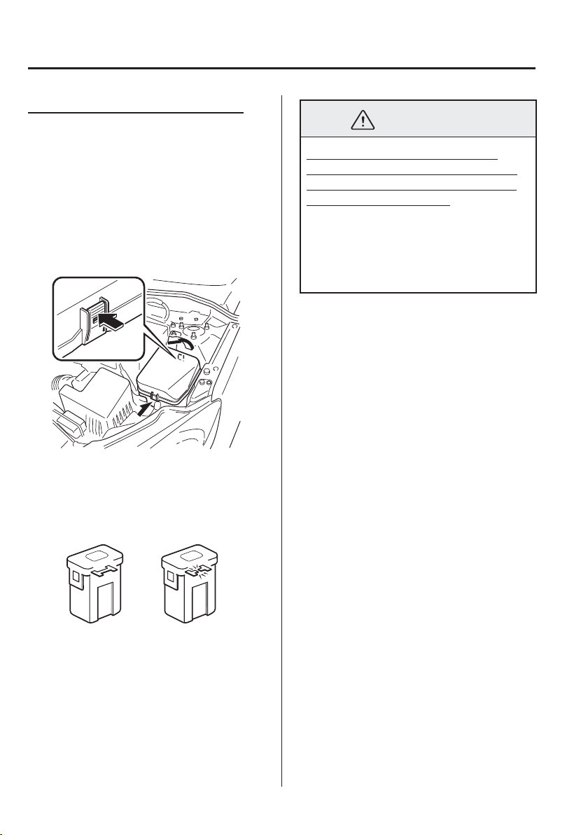
6
–
62
Maintenance and Care
Owner Maintenance
Replacing the fuses under the bonnet
If the headlights or other electrical
components do not work and the fuses
in the cabin are normal, inspect the fuse
block under the bonnet. If a fuse is blown,
it must be replaced. Follow these steps:
1. Make sure the ignition is switched off,
and other switches are off.
2. Remove the fuse block cover.
3. If any fuse but the MAIN fuse is
blown, replace it with a new one of the
same amperage rating .
Normal
Blown
WARNING
Do not replace the main fuse and
multiplex slow blow fuse by yourself.
Have an Authorised Mazda Repairer
perform the replacement:
Replacing these fuses by yourself
is dangerous because they are high
current fuses. Incorrect replacement
could cause an electrical shock or a
short circuit resulting in a ¿ re.
4. Reinstall the cover and make sure that
it is securely installed.
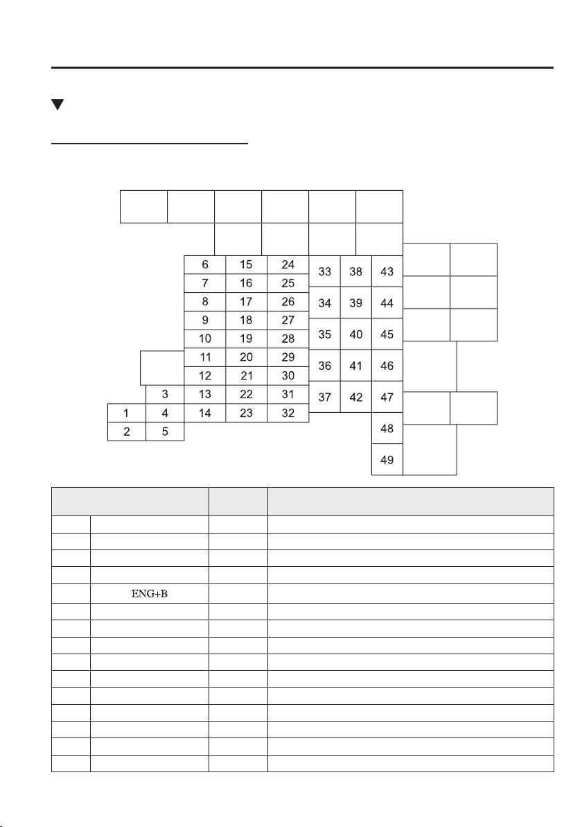
6
–
63
Maintenance and Care
Owner Maintenance
*Some models.
Fuse Panel Description
Fuse block (Engine compartment)
DESCRIPTION
FUSE
RATING
PROTECTED COMPONENT
1 C/U IG1 15 A For protection of various circuits
2 ENGINE IG1 7.5 A Engine control system
3 SUNROOF 10 A —
4 INTERIOR 15 A Overhead light
5
7.5 A Engine control system
6 AUDIO2 15 A Audio system
7 METER1 10 A Instrument cluster
8 SRS1 7.5 A Air bag
9 METER2 7.5 A Instrument cluster
*
10 RADIO 7.5 A Audio system
11 ENGINE3 15 A Engine control system
12 ENGINE1 15 A Engine control system
13 ENGINE2 15 A Engine control system
14 AUDIO1 25 A Audio system
15 A/C MAG 7.5 A Air conditioner
*
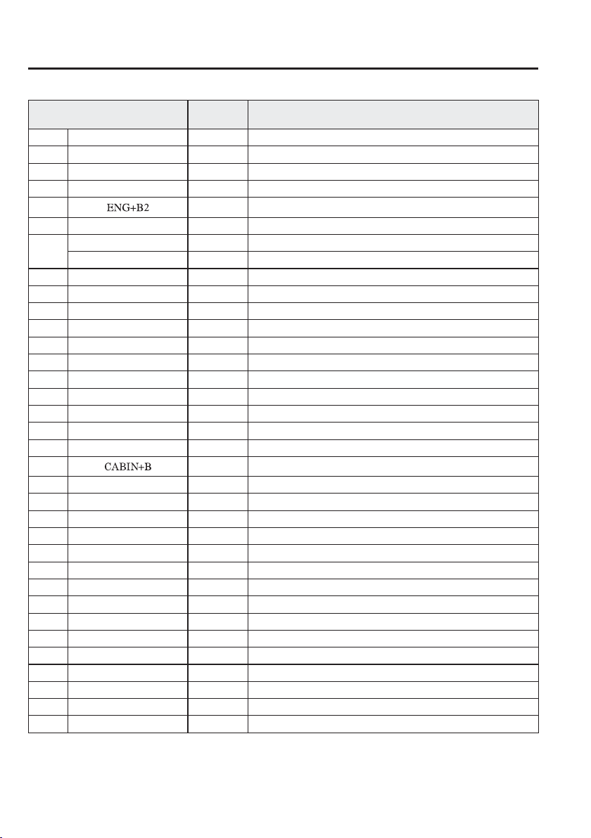
6
–
64
Maintenance and Care
Owner Maintenance
*Some models.
DESCRIPTION
FUSE
RATING
PROTECTED COMPONENT
16 AT PUMP 15 A Transaxle control system
*
17 AT 15 A Transaxle control system
*
18 D.LOCK 25 A Power door locks
19 H/L RH 20 A Headlight (RH)
20
7.5 A Engine control system
21 TAIL 20 A Tail lights, Number plate lights, Position lights
22
ST.HEATER 15 A —
— — —
23 ROOM 25 A Overhead light
24 FOG 15 A Front fog lights
*
25 H/CLEAN 20 A Headlight washer
*
26 STOP 10 A Brake lights, Rear fog light
*
27 HORN 15 A Horn
28 H/L LH 20 A Headlight (LH)
29 ABS/DSC S 30 A ABS, Dynamic stability control system
*
30 HAZARD 15 A Hazard warning À ashers, Direction indicator lights
31 FUEL PUMP 15 A Fuel system
*
32 FUEL WARM 25 A Fuel warmer
*
33 WIPER 20 A Front window wiper
34
50 A For protection of various circuits
35 FAN2 30 A Cooling fan
*
36 FUEL PUMP 30 A —
37 ABS/DSC M 50 A ABS, Dynamic stability control system
*
38 EVVT 20 A Engine control system
*
39 — — —
40 FAN1 30 A Cooling fan
*
41 FAN3 40 A Cooling fan
*
42 ENG.MAIN 40 A Engine control system
43 EPS 60 A Power steering system
*
44 DEFOG 40 A Rear window defogger
45 IG2 30 A For protection of various circuits
46 INJECTOR 30 A Engine control system
*
47 HEATER 40 A Air conditioner
48 P.WINDOW1 30 A Power windows
49 DCDC DE 40 A For protection of various circuits
*
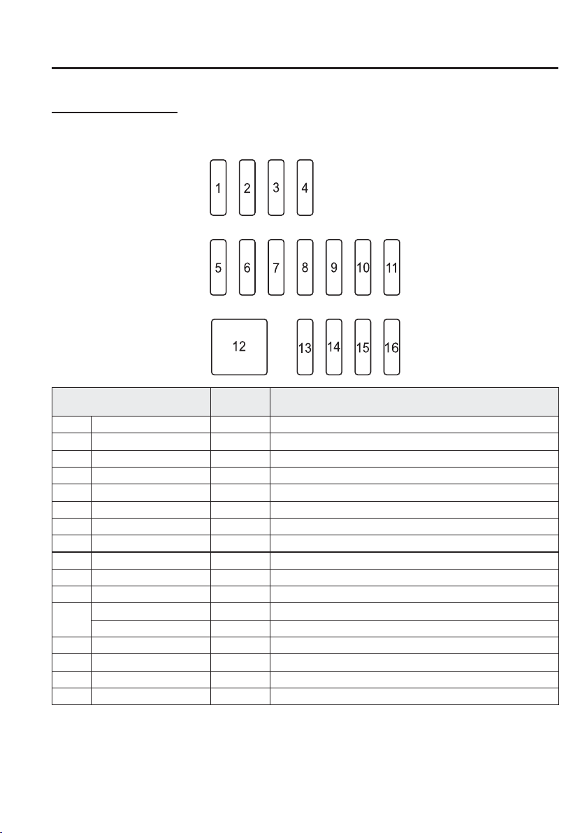
6
–
65
Maintenance and Care
Owner Maintenance
*Some models.
Fuse block (Left side)
DESCRIPTION
FUSE
RATING
PROTECTED COMPONENT
1 — — —
2 — — —
3 — — —
4 — — —
5 F.OUTLET 15 A Accessory sockets
6 — — —
7 AT IND 7.5 A AT shift indicator
*
8 MIRROR 7.5 A Power control mirror
9 — — —
10 P.WINDOW2 25 A Power windows
11 R.WIPER 15 A Rear window wiper and washer
12
P.SEAT D 30A —
— — —
13 — — —
14 SRS2/ESCL 15 A Electronic steering lock
15 SEAT WARM 20 A Seat warmer
*
16 M.DEF 7.5 A Mirror defogger
*

6
–
66
Maintenance and Care
Appearance Care
Exterior Care
The paintwork on your Mazda represents
the latest technical developments in
composition and methods of application.
Environmental hazards, however, can
harm the paint's protective properties, if
proper care is not taken.
Here are some examples of possible
damage, with tips on how to prevent them.
Etching Caused by Acid Rain or
Industrial Fallout
Occurrence
Industrial pollutants and vehicle emissions
drift into the air and mix with rain or dew
to form acids. These acids can settle on a
vehicle's ¿ nish. As the water evaporates,
the acid becomes concentrated and can
damage the ¿ nish.
And the longer the acid remains on the
surface, the greater the chance is for
damage.
Prevention
It is necessary to wash and wax your
vehicle to preserve its ¿ nish according to
the instructions in this section. These steps
should be taken immediately after you
suspect that acid rain has settled on your
vehicle's ¿ nish.
Damage Caused by Bird Dropping,
Insects, or Tree Sap
Occurrence
Bird droppings contain acids. If these
are not removed they can eat away the
clear and colour base coat of the vehicle's
paintwork.
When insects stick to the paint surface and
decompose, corrosive compounds form.
These can erode the clear and colour base
coat of the vehicle's paintwork if they are
not removed.
Tree sap will harden and adhere
permanently to the paint ¿ nish. If you
scratch the sap off while it is hard, some
vehicle paint could come off with it.
Prevention
It is necessary to have your Mazda washed
and waxed to preserve its ¿ nish according
to the instructions in this section. This
should be done as soon as possible.
Bird droppings can be removed with a soft
sponge and water. If you are travelling and
these are not available, a moistened tissue
may also take care of the problem. The
cleaned area should be waxed according to
the instructions in this section.
Insects and tree sap are best removed with
a soft sponge and water or a commercially
available chemical cleaner.
Another method is to cover the affected
area with dampened newspaper for one to
two hours. After removing the newspaper,
rinse off the loosened debris with water.

6
–
67
Maintenance and Care
Appearance Care
Water Marks
Occurrence
Rain, fog, dew, and even tap water can
contain harmful minerals such as salt and
lime. If moisture containing these minerals
settles on the vehicle and evaporates, the
minerals will concentrate and harden to
form white rings. The rings can damage
your vehicle's ¿ nish.
Prevention
It is necessary to wash and wax your
vehicle to preserve its ¿ nish according to
the instructions in this section. These steps
should be taken immediately after you ¿ nd
water marks on your vehicle's ¿ nish.
Paint Chipping
Occurrence
Paint chipping occurs when gravel thrown
in the air by another vehicle's tyres hits
your vehicle.
How to avoid paint chipping
Keeping a safe distance between you and
the vehicle ahead reduces the chances
of having your paint chipped by À ying
gravel.
NOTE
The paint chipping zone varies
with the speed of the vehicle. For
example, when travelling at 90 km/h
(56 mph), the paint chipping zone is
50 m (164 ft).
In low temperatures a vehicle's ¿ nish
hardens. This increases the chance of
paint chipping.
Chipped paint can lead to rust
forming on your Mazda. Before this
happens, repair the damage by using
Mazda touch-up paint according
to the instructions in this section.
Failure to repair the affected area
could lead to serious rusting and
expensive repairs.
Follow all label and container directions
when using a chemical cleaner or polish.
Read all warnings and cautions.
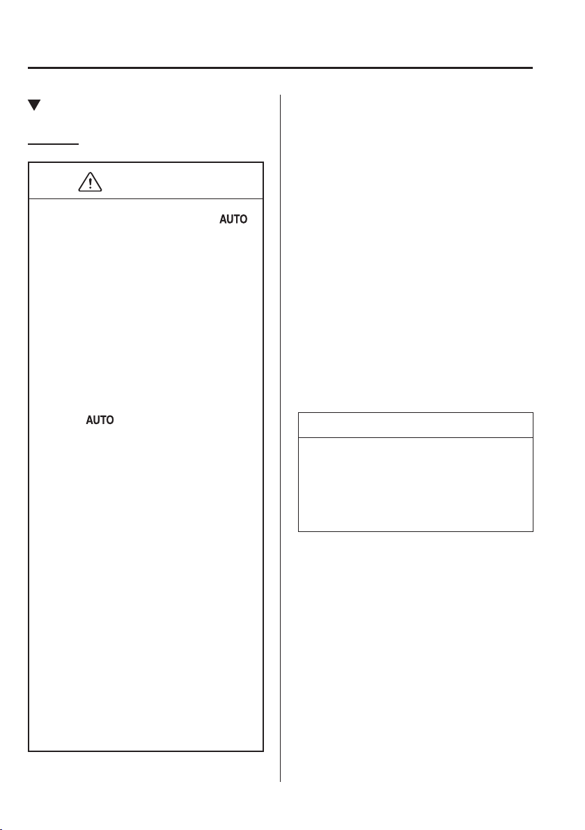
6
–
68
Maintenance and Care
Appearance Care
Maintaining the Finish
W a s h i n g
CAUTION
When the wiper lever is in the
position and the ignition is switched
ON, the wipers may move
automatically in the following cases:
If the windscreen above the rain
sensor is touched or wiped with a
cloth.
If the windscreen is struck with a
hand or other object from either
outside or inside the vehicle.
Keep hands and scrapers clear of the
windscreen when the wiper lever is
in the
position and the ignition
is switched ON as ¿ ngers could be
pinched or the wipers and wiper
blades damaged when the wipers
activate automatically.
If you are going to clean the
windscreen, be sure the wipers are
turned off completely (when it is
most likely that the engine is left
running) this is particularly important
when clearing ice and snow.
Do not spray water in the engine
compartment. Otherwise, it could
result in engine-starting problems or
damage to electrical parts.
When washing and waxing the
vehicle, be careful not to apply
excessive force to any single area
of the vehicle roof or the aerial.
Otherwise, you could dent the
vehicle or damage the aerial.
To help protect the ¿ nish from rust
and deterioration, wash your Mazda
thoroughly and frequently, at least once a
month, with lukewarm or cold water.
If the vehicle is washed improperly, the
paint surface could be scratched. Here are
some examples of how scratching could
occur.
Scratches occur on the paint surface when:
The vehicle is washed without ¿ rst
rinsing off dirt and other foreign matter.
The vehicle is washed with a rough, dry,
or dirty cloth.
The vehicle is washed at a car wash that
uses brushes that are dirty or too stiff.
Cleansers or wax containing abrasives
are used.
NOTE
Mazda is not responsible for
scratches caused by automatic car
washes or improper washing.
Scratches are more noticeable on
vehicles with darker paint ¿ nishes.
To minimize scratches on the vehicle's
paint ¿ nish:
Rinse off any dirt or other foreign matter
using lukewarm or cold water before
washing.
Use plenty of lukewarm or cold water
and a soft cloth when washing the
vehicle. Do not use a nylon cloth.
Rub gently when washing or drying the
vehicle.
Take your vehicle only to a car wash
that keeps its brushes well maintained.
Do not use abrasive cleansers or wax
that contain abrasives.
6
–
69
Maintenance and Care
Appearance Care
CAUTION
Do not use steel wool, abrasive
cleaners, or strong detergents
containing highly alkaline or caustic
agents on chrome-plated or anodised
aluminium parts. This may damage
the protective coating; also, cleaners
and detergents may discolour or
deteriorate the paint.
(With detachable aerial)
To prevent damaging the aerial,
remove it before entering a car wash
facility or passing beneath a low
overhead clearance.
Pay special attention to removing salt, dirt,
mud, and other foreign material from the
underside of the wings, and make sure the
drain holes in the lower edges of the doors
and rocker panels are clean.
Insects, tar, tree sap, bird droppings,
industrial fallout, and similar deposits
can damage the ¿ nish if not removed
immediately. When prompt washing with
plain water is ineffective, use a mild soap
made for use on vehicles.
Thoroughly rinse off all soap with
lukewarm or cold water. Do not allow
soap to dry on the ¿ nish.
After washing the vehicle, dry it with a
clean chamois to prevent water spots from
forming.
WARNING
Dry off brakes that have become
wet by driving slowly, releasing the
accelerator pedal and lightly applying
the brakes several times until the brake
performance returns to normal:
Driving with wet brakes is dangerous.
Increased stopping distance or the
vehicle pulling to one side when
braking could result in a serious
accident. Light braking will indicate
whether the brakes have been affected.
When using an automatic car wash
Retract the door mirrors.
The automatic car wash brushes could
reduce the paint lustre or hasten paint
deterioration.
When using a high water pressure car
wash
High water temperature and high water
pressure car washers are available
depending on the type of car wash
machine. If the car washer nozzle is
put too close to the vehicle, the force of
the spray could damage or deform the
molding, affect the sealability of parts,
and allow water to penetrate the interior.
Keep a suf¿ cient space (30 cm (12 in) or
more) between the nozzle and the vehicle.
In addition, do not spend too much time
spraying the same area of the vehicle, and
be very careful when spraying between
gaps in doors and around windows.
6
–
70
Maintenance and Care
Appearance Care
Waxing
Your vehicle needs to be waxed when
water no longer beads on the ¿ nish.
Always wash and dry the vehicle before
waxing it. In addition to the vehicle body,
wax the metal trim to maintain its lustre.
1. Use wax which contains no abrasives.
Waxes containing abrasive will remove
paint and could damage bright metal
parts.
2. Use a good grade of natural wax for
metallic, mica, and solid colours.
3. When waxing, coat evenly with the
sponge supplied or a soft cloth.
4. Wipe off the wax with a soft cloth.
NOTE
A spot remover to remove oil, tar, and
similar materials will usually also take
off the wax. Rewax these areas even if
the rest of the vehicle does not need it.
Paint Damage Touch-up
Repair damage to the ¿ nish caused by
stone chipping, damage during parking
etc., by using Mazda touch-up paint before
rust begins to form. First, remove the dirt
and grease with a clean soft cloth.
If rust has already begun to form:
1. Remove rust completely with
sandpaper.
2. Wipe with a clean soft cloth.
3. Apply rust preventive primer to the
area.
4. After drying it completely, apply a
suitable top coat material to the area.
Of course there will be no problem if
you assign the work to an expert repairer,
we recommend an Authorised Mazda
Repairer.
Cavity Protection
Cavities are treated for protection at the
factory, but additional protective treatment
after the vehicle has been put into use will
extend the life of the body.
We recommend that you consult an expert
repairer, we recommend an Authorised
Mazda Repairer concerning this additional
precaution.
Bright-Metal Maintenance
Use tar remover to remove road tar and
insects. Never do this with a knife or
similar tool.
To prevent corrosion on bright-
metal surfaces, apply wax or chrome
preservative and rub it to a high lustre.
During cold weather or in coastal areas,
cover bright-metal parts with a coating
of wax or preservative heavier than
usual. It would also help to coat them
with noncorrosive petroleum jelly or
some other protective compound.
CAUTION
Do not use steel wool, abrasive cleaners,
or strong detergents containing highly
alkaline or caustic agents on chrome-
plated or anodised aluminium parts. This
may result in damage to the protective
coating and cause discolouration or
paint deterioration.
6
–
71
Maintenance and Care
Appearance Care
*Some models.
Undercoating
This special coating is applied to the
critical parts of the underside to protect
vehicles from damage caused by
chemicals or stones. This coating is liable
to be damaged with time. Check this
coating periodically.
Should repairs be necessary, consult
an expert repairer, we recommend an
Authorised Mazda Repairer. They are well
informed on how repairs should be made.
Aluminium Wheel Maintenance
*
A protective coating is provided over the
aluminium wheels. Special care is needed
to protect this coating.
CAUTION
Do not use any detergent other than mild
detergent. Before using any detergent,
verify the ingredients. Otherwise, the
product could discolour or stain the
aluminium wheels.
NOTE
Do not use a wire brush or any
abrasive cleaner, polishing
compound, or solvent on aluminium
wheels. They may damage the
coating.
Always use a sponge or soft cloth to
clean the wheels.
Rinse the wheels thoroughly with
lukewarm or cold water. Also, be
sure to clean the wheels after driving
on dusty or salted roads to help
prevent corrosion.
Avoid washing your vehicle in an
automatic car wash that uses high-
speed or hard brushes.
(16-inch wheel vehicle)
If your aluminium wheels lose
lustre, apply wax which contains no
polishing powder.
6
–
72
Maintenance and Care
Appearance Care
Plastic Part Maintenance
When cleaning the plastic lenses of
the lights, do not use petrol, paraf¿ n,
recti¿ ed spirit, paint, thinner, highly
acidic detergents, or strongly alkaline
detergents. Otherwise, these chemical
agents can discolour or damage the
surfaces resulting in a signi¿ cant loss
in functionality. If plastic parts become
inadvertently exposed to any of these
chemical agents, À ush with water
immediately.
If plastic parts such as the bumpers
become inadvertently exposed to
chemical agents or À uids such as petrol,
oil, engine coolant, or battery À uid, it
could cause discolouration, staining,
or paint peeling. Wipe off any such
chemical agents or À uids using a soft
cloth immediately.
High water temperature and high water
pressure car washers are available
depending on the type of high pressure
car washer device. If the car washer
nozzle is put too close to the vehicle or
aimed at one area for an extended period
of time, it could deform plastic parts or
damage the paint.
Do not use wax containing compounds
(polish). Otherwise, it could result in
paint damage.
In addition, do not use an electrical or
air tool to apply wax. Otherwise, the
frictional heat generated could result
in deformation of plastic parts or paint
damage.
Interior Care
WARNING
Do not spray water into the vehicle
cabin:
Spraying water into the vehicle cabin
is dangerous as electrical devices such
as the audio and switches could get wet
resulting in a malfunction or vehicle
¿ re.
NOTE
Do not wipe the interior using
alcohol, chlorine bleach, or organic
solvents such as thinner, benzene,
and petrol. Otherwise, it may cause
discolouration or stains.
Rubbing hard with a stiff brush or
cloth may cause damage.
If the vehicle interior becomes soiled
by any of the following, wipe it off
immediately using a soft cloth.
Leaving it uncleaned could cause
discolouration, stains, cracks, or peeling
of the coating, and it will make it hard to
wipe off later.
Beverage or fragrance
Grease or oil
Soiling
6
–
73
Maintenance and Care
Appearance Care
*Some models.
Seat Belt Maintenance
1. Clean the soiled area by lightly dabbing
it with a soft cloth soaked in a mild
detergent (approx. 5%) diluted with
water.
2. Wipe off the remaining detergent using
a cloth soaked in clean water and
wrung out well.
3. Before retracting seat belts which have
been pulled out for cleaning, dry them
off thoroughly and make sure there is
no remaining moisture on them.
WARNING
If a seat belt appears frayed or has
abrasions, have it replaced by an
Authorised Mazda Repairer:
If a seat belts is used under such a
condition, it cannot function at its full
capacity which could result in serious
injury or death.
Use a mild detergent to remove soiling
from a seat belt:
If organic solvents are used for
cleaning the seat belts or they become
stained or bleached, there is the
possibility of them becoming weakened
and as a result, they may not function
at their full capacity which could cause
serious injury or death.
NOTE
Clean seat belts diligently if they get
dirty. Leaving them uncleaned will make
it dif¿ cult to clean them later, and it may
affect the smooth retracting of the seat
belt.
Vinyl Upholstery Maintenance
Remove dust and dirt from the vinyl
upholstery using a brush or vacuum.
Remove soiling from vinyl upholstery
using a leather and vinyl upholstery
cleaner.
Upholstery Maintenance
1. Clean the soiled area by lightly dabbing
it with a soft cloth soaked in a mild
detergent (approx. 5%) diluted with
water.
2. Wipe off the remaining detergent using
a cloth soaked in clean water and
wrung out well.
Leather Upholstery Maintenance
*
1. Remove dust and sand using a vacuum
cleaner.
2. Wipe off the soiled area with a soft
cloth and a suitable, special cleaner or
a soft cloth soaked in a mild detergent
(about 5%) diluted with water.
3. Wipe off the remaining detergent using
a cloth soaked in clean water and
wrung out well.
4. Remove moisture with a dry, soft cloth
and allow the leather to further dry in
a well-ventilated, shaded area. If the
leather gets wet such as from rain,
remove the moisture and dry it as soon
as possible.
6
–
74
Maintenance and Care
Appearance Care
*Some models.
NOTE
Because genuine leather is a natural
material, its surface is not uniform
and it may have natural scars,
scratches, and wrinkles.
To maintain the quality for as long
as possible, periodical maintenance,
about twice a year, is recommended.
If the leather upholstery comes into
contact with any of the following,
clean it immediately.
Leaving it uncleaned could cause
premature wear, mold, or stains.
Sand or dirt
Grease or oil, such as hand cream
Alcohol, such as in cosmetic or
hair dressing items
If the leather upholstery gets wet,
promptly remove moisture with a
dry cloth. Remaining moisture on the
surface may cause deterioration such
as hardening and shrinkage.
Exposure to direct sunlight for long
periods may cause deterioration
and shrinkage. When parking the
car under direct sunlight for long
periods, shade the interior using
sunshades.
Do not leave vinyl products on
the leather upholstery for long
periods. They may affect the leather
quality and colouring. If the cabin
temperature becomes hot, the vinyl
may deteriorate and adhere to the
genuine leather.
Plastic Part Maintenance
CAUTION
Do not use polishing agents.
Depending on the product ingredients,
they could cause discolouration, stains,
cracks or peeling of the coating.
Instrument Panel Top
Maintenance
1. Wipe the soiled area with a soft cloth
soaked in a mild detergent
(approx. 5%) diluted with water.
2. Wipe off the remaining detergent using
a cloth soaked in clean water and
wrung out well.
Active Driving Display
Maintenance
*
The combiner and mirror surface have
a special coating. When cleaning it, do
not use a hard cloth, a cloth with a rough
surface, or cleaning detergent. Use a ¿ ne-
textured, soft cloth.
If a chemical solvent gets on the combiner
or mirror surface, wipe it off immediately.
Otherwise, they could be damaged and the
surface coating could be scratched.
6
–
75
Maintenance and Care
Appearance Care
Panel Maintenance
If a panel becomes soiled, wipe it off with
a soft cloth soaked in clean water and
thoroughly wrung out.
If some areas require further cleaning, use
the following procedure:
1. Wipe the soiled area with a soft cloth
soaked in a mild detergent
(approx. 5 %) diluted with water.
2. Wipe off the remaining detergent using
a cloth soaked in clean water and
wrung out well.
NOTE
Be particularly careful when cleaning
shiny surface panels and metallic parts
such as plating as they can be scratched
easily.
Cleaning the Window Interiors
If the windows become covered with an
oily, greasy, or waxy ¿ lm, clean them with
glass cleaner. Follow the directions on the
container.
CAUTION
Do not scrape or scratch the inside of
the window glass. It could damage
the thermal ¿ laments and the aerial
lines.
When washing the inside of the
window glass, use a soft cloth
dampened in lukewarm water, gently
wiping the thermal ¿ laments and the
aerial lines.
Use of glass cleaning products could
damage the thermal ¿ laments and the
aerial lines.

MEMO
6
–
76

7
–
1
*Some models.
7
–
1
7
If Trouble Arises
Helpful information on what to do if a problem arises with the vehicle.
Parking in an Emergency ................... 7-2
Parking in an Emergency ............... 7-2
Roadside Emergency Triangle
Retaining Strap (Hatchback)
*
......... 7-2
Flat Tyre ............................................... 7-3
Spare Tyre and Tool Storage .......... 7-3
Emergency Flat Tyre Repair
Kit
*
................................................. 7-9
Changing a Flat Tyre
(With Spare Tyre) ......................... 7-16
Battery Runs Out .............................. 7-24
Jump-Starting ............................... 7-24
Emergency Starting .......................... 7-27
Starting a Flooded Engine
(SKYACTIV-G 1.3 and
SKYACTIV-G 1.5 ) ...................... 7-27
Push-Starting ................................ 7-27
Running Out of Fuel
(SKYACTIV-D 1.5) ..................... 7-28
Overheating ....................................... 7-29
Overheating .................................. 7-29
Emergency Towing ............................ 7-31
Towing Description ...................... 7-31
Towing/Tiedown Hooks ............... 7-32
Warning/Indicator Lights and Warning
Sounds ................................................ 7-35
If a Warning Light Turns On or
Flashes .......................................... 7-35
Message Indicated on Display
*
.... 7-48
Warning Sound is Activated ......... 7-50
When Liftgate/Boot Lid Cannot be
Opened ............................................... 7-55
When Liftgate/Boot Lid Cannot be
Opened ......................................... 7-55
Active Driving Display Does Not
Operate ............................................... 7-57
If the Active Driving Display does not
operate .......................................... 7-57
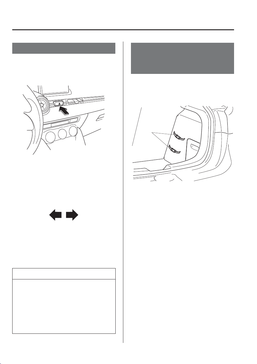
7
–
2
If Trouble Arises
Parking in an Emergency
*Some models.
Parking in an Emergency
The hazard warning lights should always
be used when you stop on or near a
roadway in an emergency.
The hazard warning lights warn other
drivers that your vehicle is a traf¿ c hazard
and that they must take extreme caution
when near it.
Depress the hazard warning À asher and
all the direction indicators will À ash. The
hazard warning indicator lights in the
instrument cluster À ash simultaneously.
NOTE
The direction indicators do not work
when the hazard warning lights are
on.
Check local regulations about the use
of hazard warning lights while the
vehicle is being towed to verify that
it is not in violation of the law.
Roadside Emergency
Triangle Retaining Strap
(Hatchback)
*
Keep the roadside emergency triangle in
the right side trim and secure it with the
strap.
Strap

7
–
3
If Trouble Arises
Flat Tyre
S p a r e Ty r e a n d To o l S t o r a g e
NOTE
Your vehicle may or may not be equipped with a spare tyre, jack, and wheel brace. For
details, consult an Authorised Mazda Repairer.
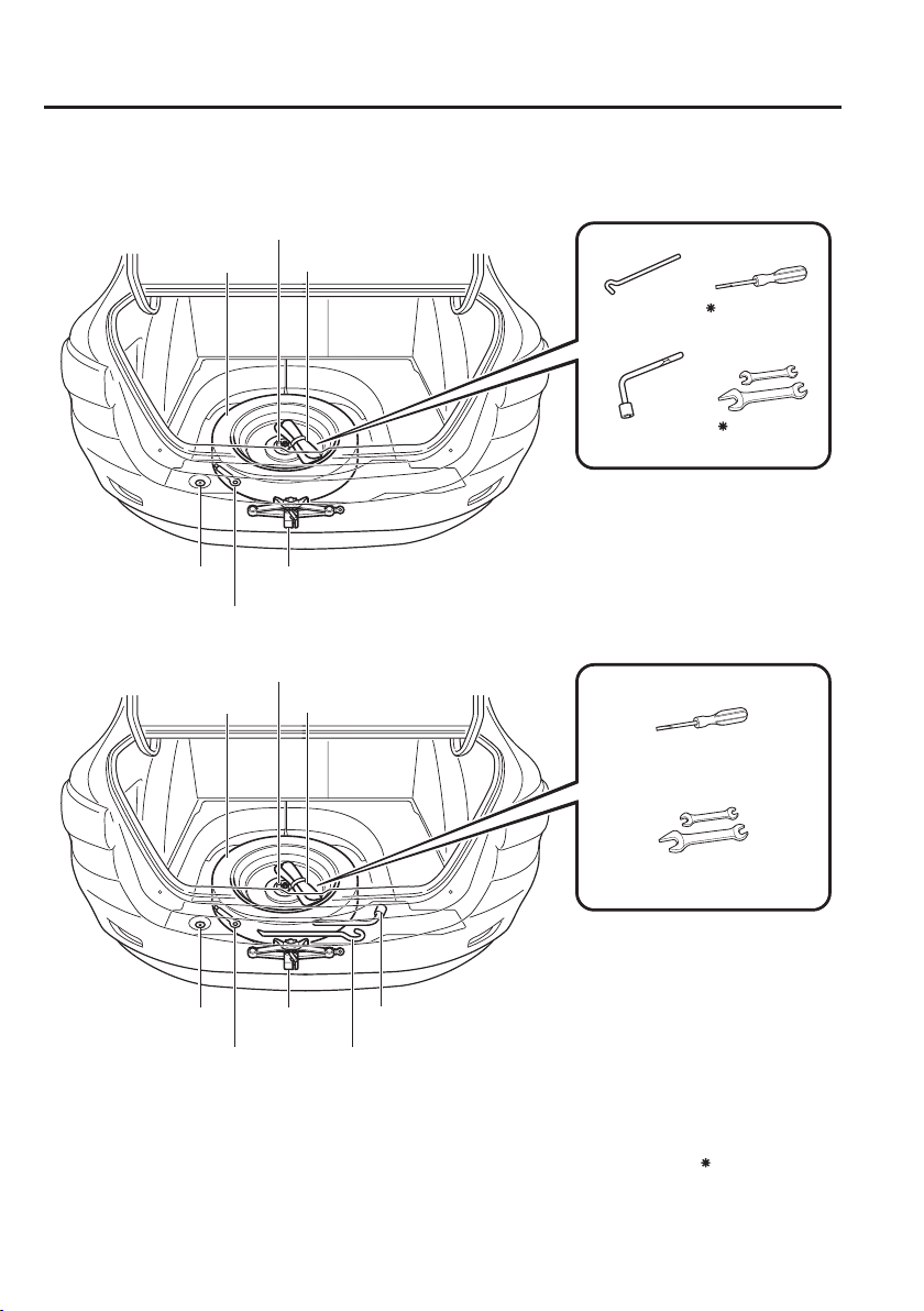
7
–
4
If Trouble Arises
Flat Tyre
Spare tyre and tools are stored in the locations illustrated in the diagram.
Jack
Tool bagSpare tyre
Towing eyelet
Jack point attachment
Spare tyre hold-down bolt
(Type B)
Saloon
(Type A)
Wheel brace
*
1
*
1
The jack point attachment can be used by vehicle repair shops and road assistance services.
Consult an Authorised Mazda Repairer for details.
Jack lever
Some models.
Screwdriver
Wrench
Jack
Tool bagSpare tyre
Towing eyelet
Jack point attachment
Spare tyre hold-down bolt
*
1
Wheel brace
Jack lever Screwdriver
Wrench
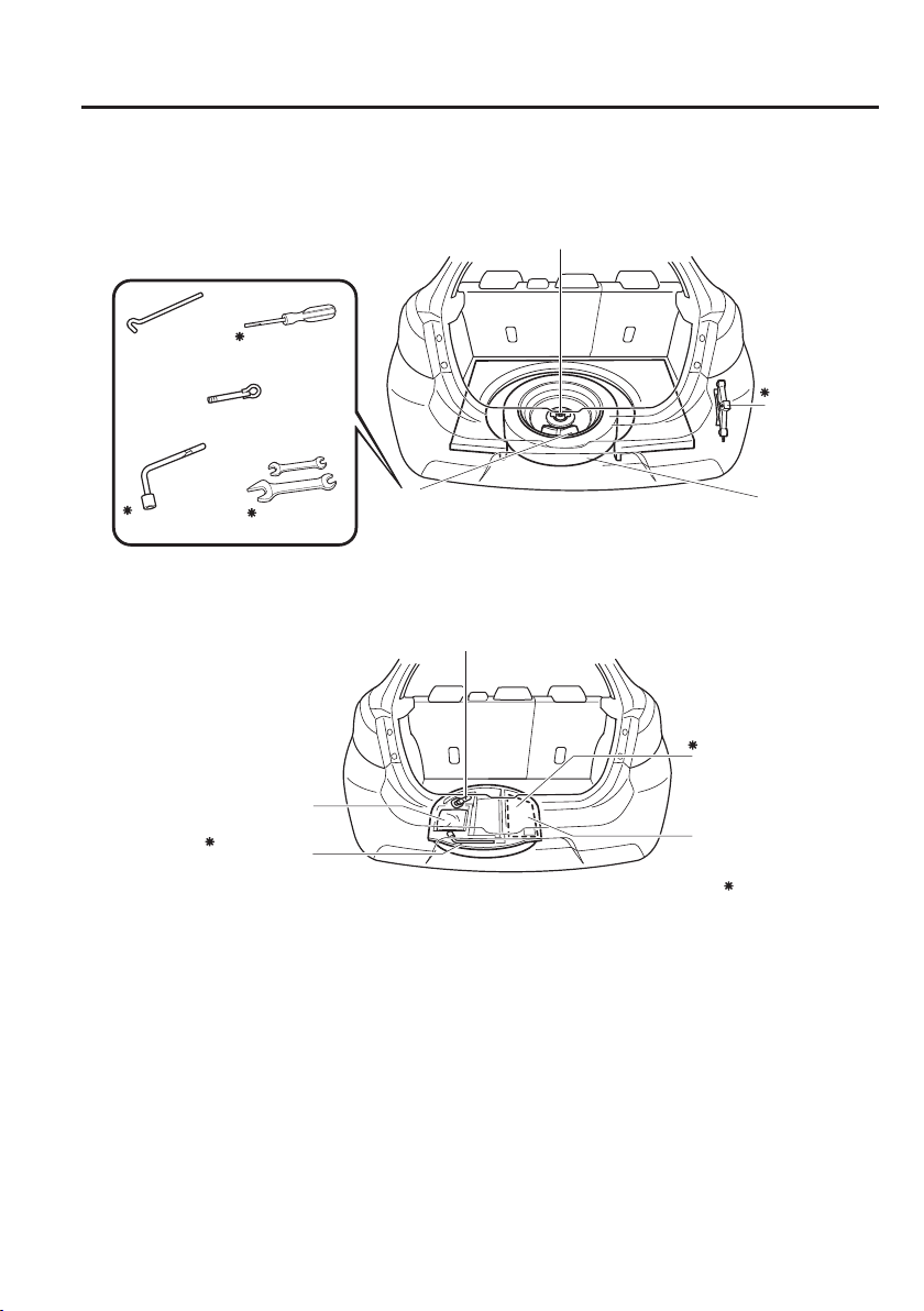
7
–
5
If Trouble Arises
Flat Tyre
Towing eyelet
Spare
tyre
Jack
Spare tyre hold-down bolt
Tool bag
With spare tyre
Towing eyelet
Jack lever
Jack
Without spare tyre
Hatchback
Emergency Flat Tyre
Repair Kit
Wheel brace
Some models.
Wheel brace
Jack lever
Screwdriver
Wrench
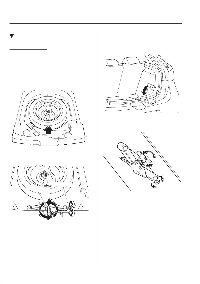
7
–
6
If Trouble Arises
Flat Tyre
*Some models.
Jack
*
To remove the jack
(With spare tyre)
Saloon
1. Lift the boot mat.
2. Remove the boot board.
3. Turn the wing bolt and jack screw
anticlockwise.
Wing bolt
Jack screw
Hatchback
1. Remove the cover.
Tabs
2. Turn the wing bolt and jack screw
anticlockwise.
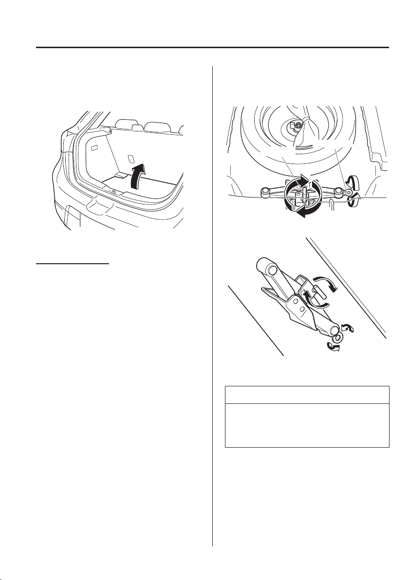
7
–
7
If Trouble Arises
Flat Tyre
(Without spare tyre)
1. Lift the luggage compartment mat.
2. Remove the jack.
To secure the jack
(With spare tyre)
1. Insert the wing bolt into the jack with
the jack screw pointing to the right
(Saloon) or down (Hatchback) and turn
the wing bolt clockwise to temporarily
tighten it.
2. Turn the jack screw in the direction
shown in the ¿ gure.
Saloon
Wing bolt
Jack screw
Hatchback
3. Turn the wing bolt completely to secure
the jack.
NOTE
If the jack is not completely secured, it
could rattle while driving. Make sure the
jack screw is suf¿ ciently tightened.
7
–
8
If Trouble Arises
Flat Tyre
*Some models.
4. Return the boot board to its original
position (Saloon), or insert the cover
tabs and install the cover (Hatchback).
NOTE
Verify that the cover is securely
installed.
(Without spare tyre)
Perform the removal procedure in reverse.
Maintenance
Always keep the jack clean.
Make sure the moving parts are kept
free from dirt or rust.
Make sure the screw thread is
adequately lubricated.
Spare Tyre
*
Your Mazda has a temporary spare tyre.
The temporary spare tyre is lighter and
smaller than a conventional tyre, and is
designed only for emergency use and
should be used only for VERY short
periods. Temporary spare tyres should
NEVER be used for long drives or
extended periods.
WARNING
Do not install the temporary spare tyre
on the front wheels (driving wheels):
Driving with the temporary spare tyre
on one of the front driving wheels is
dangerous. Handling will be affected.
You could lose control of the vehicle,
especially on ice or snow bound roads,
and have an accident. Move a regular
tyre to the front wheel and install the
temporary spare tyre to the rear.
CAUTION
When using the temporary spare
tyre, driving stability may decrease
compared to when using only the
conventional tyre. Drive carefully.
To avoid damage to the temporary
spare tyre or to the vehicle, observe
the following precautions:
Do not exceed 80 km/h (50 mph).
Avoid driving over obstacles. Also,
do not drive through an automatic
car wash. This tyre's diameter is
smaller than a conventional tyre,
so the ground clearance is reduced.
Do not use a tyre chain on this tyre
because it will not ¿ t properly.
Do not use your temporary spare
tyre on any other vehicle, it has
been designed only for your
Mazda.
Use only one temporary spare tyre
on your vehicle at the same time.
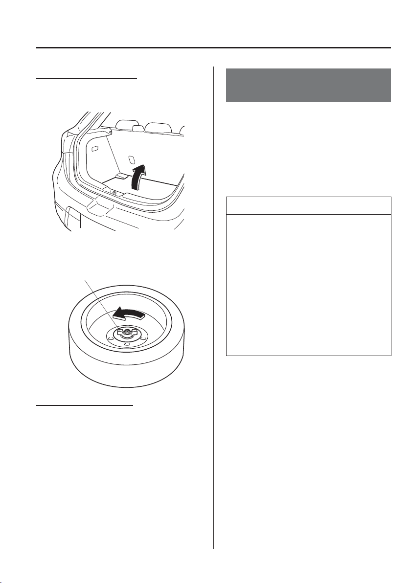
7
–
9
If Trouble Arises
Flat Tyre
*Some models.
To remove the spare tyre
1. Lift the boot/luggage compartment mat.
2. Turn the spare tyre hold-down bolt
anticlockwise.
Spare tyre hold-down bolt
To secure the spare tyre
Store the spare tyre in the reverse order
of removal. After storing, verify that the
spare tyre is stored securely.
Emergency Flat Tyre
Repair Kit
*
The emergency À at tyre repair kit included
with your Mazda is for a temporary repair
of a slightly damaged À at tyre resulting
from running over nails or similar sharp
objects on the road surface.
Perform the emergency À at tyre repair
without removing the nail or similar sharp
object which punctured the tyre.
NOTE
Your vehicle is not equipped with a
spare tyre. In the event of a À at tyre,
use the emergency À at tyre repair kit
to repair the tyre temporarily. When
doing the repair, refer to the instructions
included in the emergency À at tyre
repair kit. If an emergency repair was
performed on a À at tyre using the
emergency À at tyre repair kit, have
an expert repairer, we recommend an
Authorised Mazda Repairer, repair or
replace the tyre as soon as possible.

7
–
10
If Trouble Arises
Flat Tyre
About the Emergency Flat Tyre
Repair Kit
The emergency À at tyre repair kit includes
the following items.
Tyre sealant
Injection hose
Compressor
Valve core tool
Spare valve core
Speed restriction sticker Instructions
WARNING
Do not allow children to touch the tyre
sealant:
Ingestion of tyre sealant is
dangerous. In the event tyre sealant
is accidentally swallowed, drink
large amounts of water immediately
and seek medical assistance.
Tyre sealant that comes into contact
with the eyes and skin is dangerous.
If tyre sealant enters the eyes or
contacts the skin, À ush immediately
with large amounts of water and
seek medical assistance.
NOTE
The tyre sealant cannot be reused.
Purchase new tyre sealant at an
Authorised Mazda Repairer.
The emergency À at tyre repair kit
cannot be used in the following
cases.
Consult an expert repairer, we
recommend an Authorised Mazda
Repairer.
The period of effective use for
the tyre sealant has expired. (The
period of effectiveness is indicated
on the bottle label.)
The tear or puncture exceeds about
4 mm (0.16 in).
The damage has occurred to an
area of the tyre other than the
tread.
The vehicle has been driven with
nearly no air remaining in the tyre.
The tyre has come off the wheel
rim.
Damage to the wheel rim has
occurred.
The tyre has two or more
punctures.
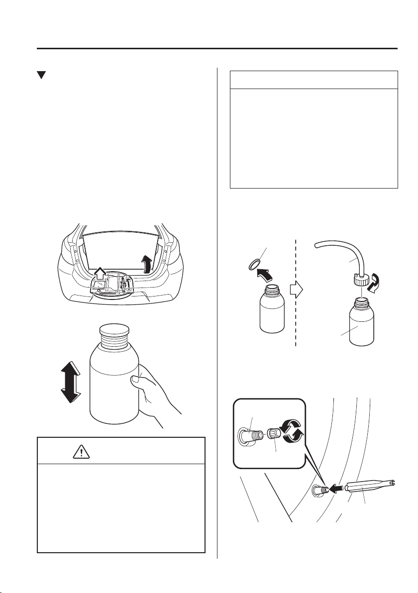
7
–
11
If Trouble Arises
Flat Tyre
Using the Emergency Flat Tyre
Repair Kit
1. Park on a level surface off the right-of-
way and set the parking brake.
2. Put a vehicle with an automatic
transaxle in Park (P), a manual
transaxle in Reverse (R) or 1, and turn
off the engine.
3. Turn on the hazard warning À asher.
4. Unload passengers and luggage, and
remove the emergency À at tyre repair
kit.
5. Shake the tyre sealant well.
CAUTION
If the bottle is shaken after the injection
hose is screwed on, tyre sealant could
spray out from the injection hose. Tyre
sealant contacting clothing or other
objects may be impossible to remove.
Shake the bottle before screwing on the
injection hose.
NOTE
The tyre sealant can be used at outside
temperatures down to -30 °C (-22 °F). In
extremely cold temperatures (0 °C
(32 °F) or below), the tyre sealant
hardens easily and injection of the
sealant will be dif¿ cult. Warm the
sealant inside the vehicle before doing
the injection work.
6. Remove the cap from the bottle. Screw
on the injection hose with the bottle's
inner cap left on to break the inner cap.
Cap
Injection hose
Tyre sealant
7. Remove the valve cap from the À at
tyre. Press the back of a valve core tool
to the core of the tyre valve and bleed
all the remaining air.
Valve core tool
Valve
Valve cap
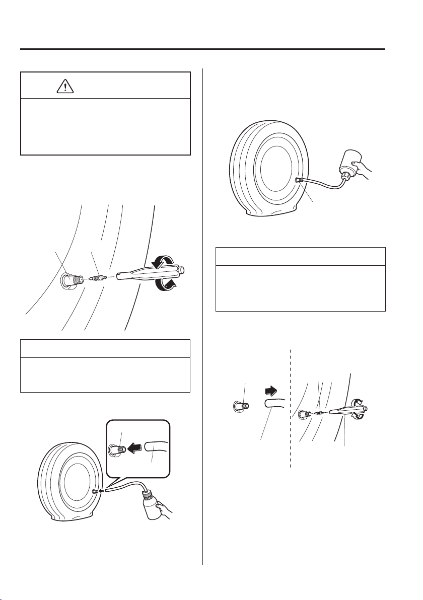
7
–
12
If Trouble Arises
Flat Tyre
CAUTION
If there is air remaining in the tyre when
the valve core is removed, the valve core
could À y out. Remove the valve core
carefully.
8. Turn the valve core anticlockwise with
the valve core tool and remove the
valve core.
Valve
Valve core
NOTE
Store the valve core in a place where it
will not get dirty.
9. Insert the injection hose into the valve.
Valve
Injection hose
10. Hold the bottom of the bottle upright,
squeeze the bottle with your hands, and
inject the entire amount of tyre sealant
into the tyre.
Valve
11. Pull out the injection hose from the
valve.
NOTE
The tyre sealant cannot be reused.
Purchase a new tyre sealant kit at an
Authorised Mazda Repairer.
12. Reinsert the valve core into the valve
and turn it clockwise to install it.
Injection hose
Valve core
tool
Valve
Valve core
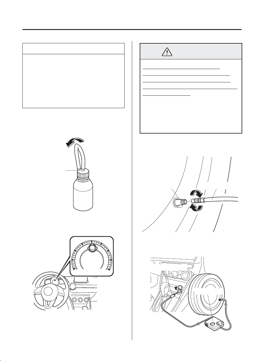
7
–
13
If Trouble Arises
Flat Tyre
NOTE
Do not throw away the empty tyre
sealant bottle after use. Return the empty
tyre sealant bottle to an Authorised
Mazda Repairer when replacing the tyre.
The empty tyre sealant bottle will need
to be used to extract and dispose of the
used sealant from the tyre.
13. After that, install the injection hose to
the tab of the bottle to prevent leakage
of any remaining sealant.
Tab
14. Attach the vehicle speed restriction
sticker in a place where the driver can
easily see it.
WARNING
Do not attach the vehicle speed
restriction sticker to the instrument
panel, as it would obstruct vision of
areas such as warning light indicators
or the speedometer:
Attaching the vehicle speed restriction
sticker to the steering wheel pad is
dangerous. The sticker could interfere
with air bag inÀ ation and cause serious
injury.
15. Install the compressor hose to the tyre
valve.
Valve
Compressor hose
16. Insert the compressor plug into the
interior accessory socket and switch the
ignition to ACC.
Compressor
Compressor plug
7
–
14
If Trouble Arises
Flat Tyre
CAUTION
Before pulling out the compressor
plug from the electrical socket, make
sure the compressor power switch is
off.
The compressor turns on and off with
the push-button switch.
17. Turn the compressor switch on and
inÀ ate the tyre carefully to the correct
inÀ ation pressure.
WARNING
Never operate the compressor above
300 kPa (3.1 kgf/cm
2
, 3 bar, 43.5 psi):
Operating the compressor above
300 kPa (3.1 kgf/cm
2
, 3 bar, 43.5 psi) is
dangerous. When the inÀ ation pressure
rises above 300 kPa (3.1 kgf/cm
2
, 3 bar,
43.5 psi), heated air will be exhausted
from the back of the compressor and
you could be burned.
NOTE
Check the tyre inÀ ation pressure
label (driver's door frame) for the
correct tyre inÀ ation pressure.
Do not use the compressor for longer
than 10 minutes because using the
compressor for long periods could
damage it.
If the tyre does not inÀ ate, repair
of the tyre may not be possible. If
the tyre does not reach the correct
inÀ ation pressure within a 10-minute
period, it probably has received more
extensive damage.
When this happens, the emergency
À at tyre repair kit cannot be used
to repair the tyre. Contact an
expert repairer, we recommend an
Authorised Mazda Repairer.
If the tyre has been over-inÀ ated,
loosen the screw cap on the
compressor and bleed some of the air
out.
18. When the tyre has been inÀ ated to
the proper inÀ ation pressure, turn the
compressor switch off and remove the
compressor hose from the tyre valve.
19. Install the tyre valve cap.
7
–
15
If Trouble Arises
Flat Tyre
20. Put the emergency À at tyre repair kit
in the luggage compartment/boot and
continue driving.
CAUTION
Drive carefully to an expert repairer,
we recommend an Authorised Mazda
Repairer and keep the vehicle speed
below 80 km/h (50 mph).
If the vehicle is driven 80 km/h
(50 mph) or higher, the vehicle might
begin to vibrate.
NOTE
(With tyre pressure monitoring
system)
If the tyre is not properly inÀ ated, the
tyre pressure monitoring system warning
light will illuminate.
21. After driving the vehicle for 10 minutes
or 5 km (3 miles), check the tyre
pressure with the tyre pressure gauge
equipped with the compressor. If the
tyre pressure has fallen below the
correct tyre pressure, inÀ ate the tyre to
the correct pressure again following the
steps from number 16.
CAUTION
If the tyre inÀ ation pressure falls
below 130 kPa (1.3 kgf/cm
2
or bar,
18.9 psi), repair cannot be done with
the repair kit. Park the vehicle on
a level surface off the right-of-way
and contact an expert repairer, we
recommend an Authorised Mazda
Repairer.
If the tyre inÀ ation pressure
continues to remain low after
repeating steps 15 to 21, park
the vehicle on a level surface off
the right-of-way and contact an
expert repairer, we recommend an
Authorised Mazda Repairer.
NOTE
When checking the tyre inÀ ation
pressure with the tyre pressure gauge
on the compressor unit, make sure the
compressor switch is turned off.
7
–
16
If Trouble Arises
Flat Tyre
22. If the tyre inÀ ation pressure remains
stable, the tyre repair is complete.
Drive the vehicle with care to an expert
repairer, we recommend an Authorised
Mazda Repairer to have the tyre
replaced.
CAUTION
A tyre that has been temporarily
repaired with the tyre sealant cannot
be reused. Mazda recommends
replacing the tyre with a new one.
The wheel can be reused after any
sealant adhering to it is wiped off and
carefully inspected. However, replace
the tyre valve with a new one.
Inspecting the Emergency Flat
Tyre Repair Kit
Inspect the emergency À at tyre repair kit at
regular intervals.
Check the tyre sealant period of
effective use.
Check the operation of the tyre
compressor.
NOTE
The tyre sealant has a period of effective
use. Check the period of effective use
indicated on the bottle label and do not
use it if it has expired. Have the tyre
sealant replaced at an Authorised Mazda
Repairer before the period of effective
use has expired.
Changing a Flat Tyre
(With Spare Tyre)
NOTE
If the following occurs while driving, it
could indicate a À at tyre.
Steering becomes dif¿ cult.
The vehicle begins to vibrate
excessively.
The vehicle pulls in one direction.
If you have a À at tyre, drive slowly to a
level spot that is well off the road and out
of the way of traf¿ c to change the tyre.
Stopping in traf¿ c or on the shoulder of a
busy road is dangerous.
WARNING
Be sure to follow the directions for
changing a tyre:
Changing a tyre is dangerous if not
done properly. The vehicle can slip off
the jack and seriously injure someone.
No person should place any portion
of their body under a vehicle that is
supported by a jack.
Never allow anyone inside a vehicle
supported by a jack:
Allowing someone to remain in
a vehicle supported by a jack is
dangerous. The occupant could cause
the vehicle to fall resulting in serious
injury.
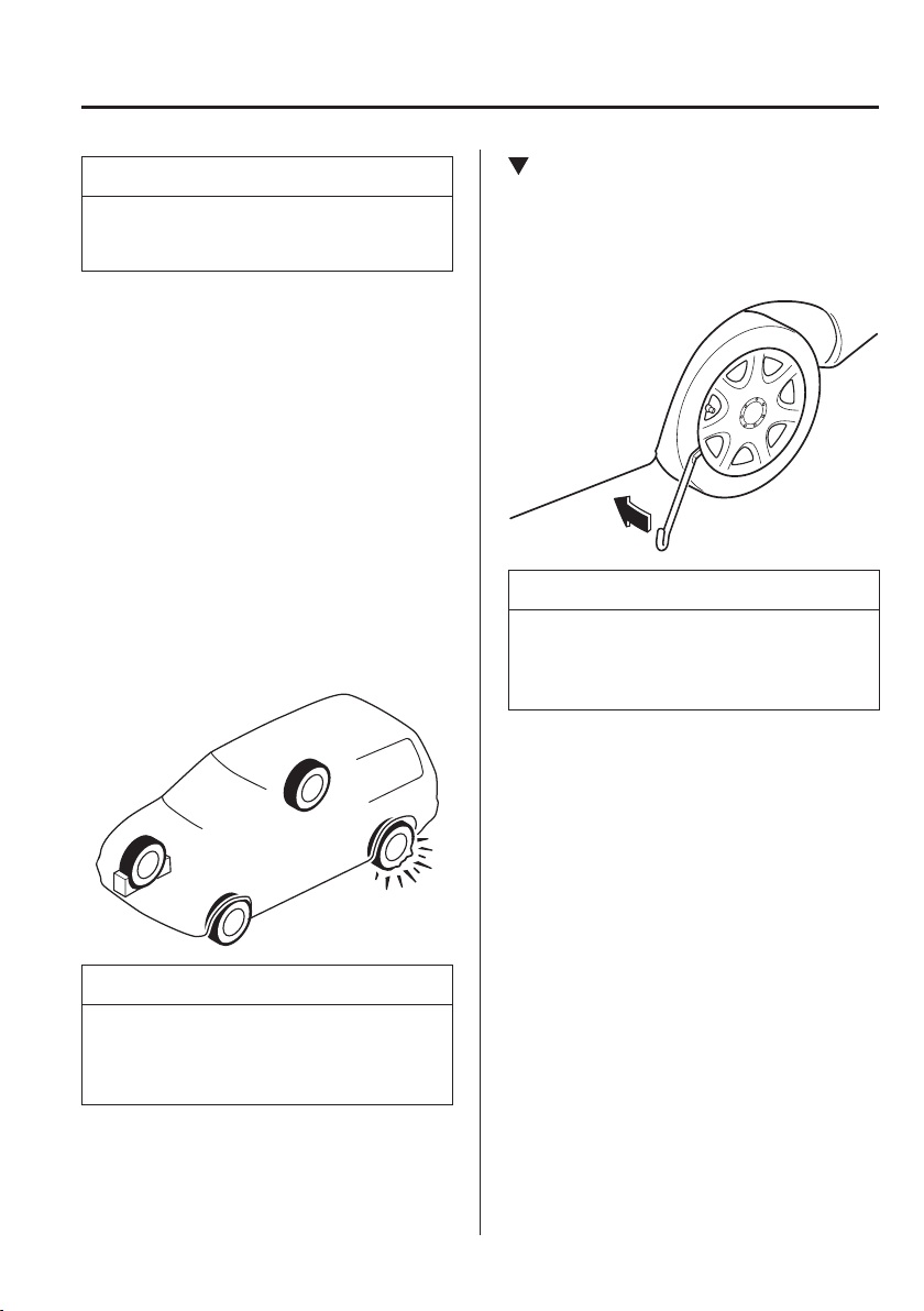
7
–
17
If Trouble Arises
Flat Tyre
NOTE
Make sure the jack is well lubricated
before using it.
1. Park on a hard, level surface off the
right-of-way and ¿ rmly set the parking
brake.
2. Put a vehicle with an automatic
transaxle in Park (P), a manual
transaxle in Reverse (R) or 1, and turn
off the engine.
3. Turn on the hazard warning À asher.
4. Have everyone get out of the vehicle
and away from the vehicle and traf¿ c.
5. Remove the jack, tool, and spare tyre
(page 7-3 ).
6. Block the wheel diagonally opposite
the À at tyre. When blocking a wheel,
place a tyre block both in front and
behind the tyre.
NOTE
When blocking a tyre, use rocks or
wood blocks of suf¿ cient size if possible
to hold the tyre in place.
Removing a Flat Tyre
1. If your vehicle is equipped with a
wheel cover, pry off the wheel cover
with the bevelled end of the jack lever.
NOTE
Force the end of the jack lever ¿ rmly
between wheel and cover, or removal
will be dif¿ cult.
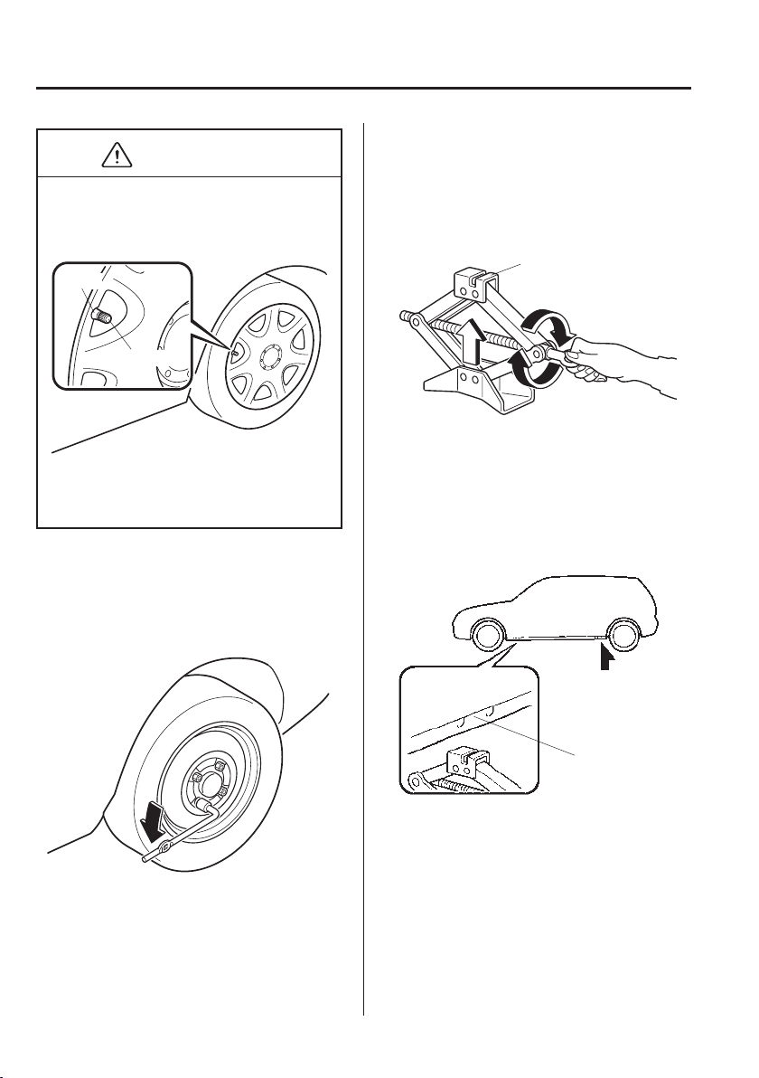
7
–
18
If Trouble Arises
Flat Tyre
CAUTION
Align the notch on the wheel cover with
the valve stem when installing it.
Tyre valve
Notch
Damage could occur during installation
if the wheel cover is not properly
aligned.
2. Loosen the wheel nuts by turning them
anticlockwise one turn each, but do not
remove any wheel nuts until the tyre
has been raised off the ground.
3. Place the jack on the ground.
4. Turn the jack screw in the direction
shown in the ¿ gure and adjust the jack
head so that it is close to the jack-up
position.
Jack head
5. Place the jack under the jack-up
position closest to the tyre being
changed with the jack head squarely
under the jack-up point.
Jacking position
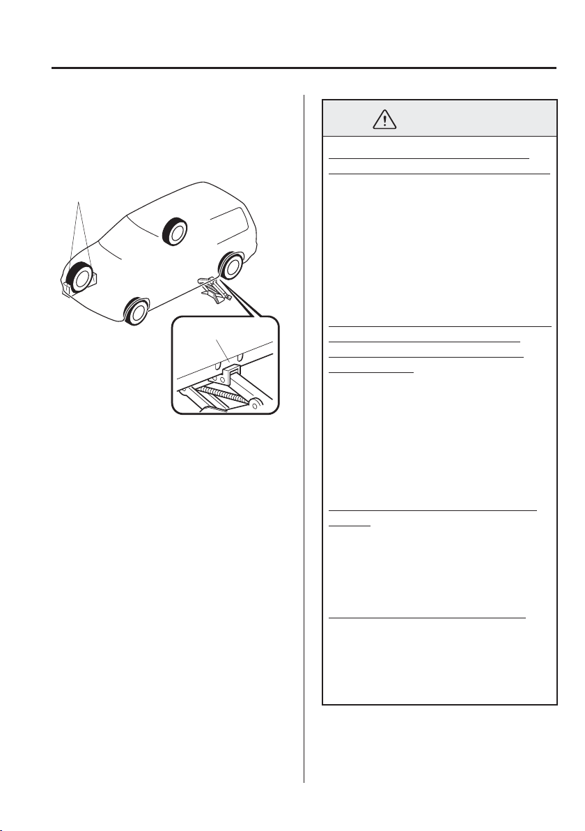
7
–
19
If Trouble Arises
Flat Tyre
6. Continue raising the jack head
gradually by rotating the screw with
your hand until the jack head is inserted
into the jack-up position.
Tyre blocks
Jacking position
WARNING
Use only the front and rear jacking
positions recommended in this manual:
Attempting to jack the vehicle
in positions other than those
recommended in this manual is
dangerous. The vehicle could slip off
the jack and seriously injure or even
kill someone. Use only the front and
rear jacking positions recommended in
this manual.
Do not jack up the vehicle in a position
other than the designated jack-up
position or place any objects on or
under the jack:
Jacking up the vehicle in a position
other than the designated jack-up
position or placing objects on or
under the jack is dangerous as it could
deform the vehicle body or the vehicle
could fall off the jack resulting in an
accident.
Use only the jack provided with your
Mazda:
Using a jack that is not designed for
your Mazda is dangerous. The vehicle
could slip off the jack and seriously
injure someone.
Never place objects under the jack:
Jacking the vehicle with an object
under the jack is dangerous. The
jack could slip and someone could be
seriously injured by the jack or the
falling vehicle.
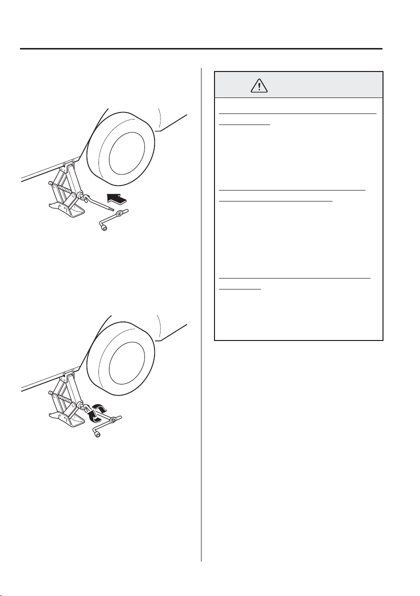
7
–
20
If Trouble Arises
Flat Tyre
7. Insert the jack lever and attach the
wheel brace to tyre jack.
8. Turn the jack handle clockwise and
raise the vehicle high enough so that
the spare tyre can be installed. Before
removing the wheel nuts, make sure
your Mazda is ¿ rmly in position and
that it cannot slip or move.
WARNING
Do not jack up the vehicle higher than
is necessary:
Jacking up the vehicle higher than
is necessary is dangerous as it could
destabilize the vehicle resulting in an
accident.
Do not start the engine or shake the
vehicle while it is jacked up:
Starting the engine or shaking
the vehicle while it is jacked up is
dangerous as it could cause the vehicle
to fall off the jack resulting in an
accident.
Never go under the vehicle while it is
jacked up:
Going under the vehicle while it is
jacked up is dangerous as it could
result in death or serious injury if the
vehicle were to fall off the jack.
9. Remove the wheel nuts by turning
them anticlockwise; then remove the
wheel and centre cap.
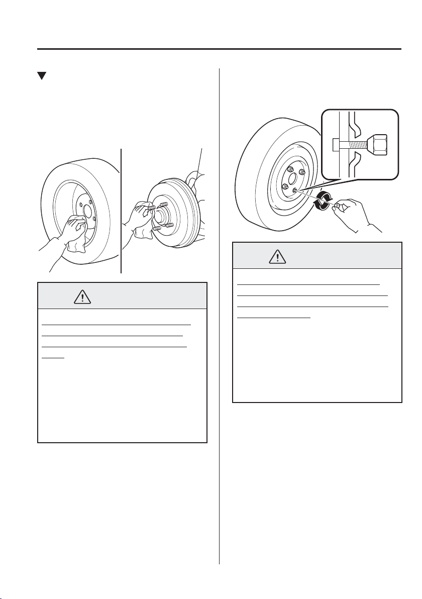
7
–
21
If Trouble Arises
Flat Tyre
Mounting the Spare Tyre
1. Remove dirt and grime from the
mounting surfaces of the wheel and
hub, including the hub bolts, with a
cloth.
WARNING
Make sure the mounting surfaces of
the wheel, hub and wheel nuts are
clean before changing or replacing
tyres:
When changing or replacing a tyre,
not removing dirt and grime from the
mounting surfaces of the wheel, hub
and hub bolts is dangerous. The wheel
nuts could loosen while driving and
cause the tyre to come off, resulting in
an accident.
2. Mount the spare tyre.
3. Install the wheel nuts with the bevelled
edge inward; tighten them by hand.
WARNING
Do not apply oil or grease to wheel
nuts and bolts and do not tighten the
wheel nuts beyond the recommended
tightening torque:
Applying oil or grease to wheel nuts
and bolts is dangerous. The wheel nuts
could loosen while driving and cause
the tyre to come off, resulting in an
accident. In addition, wheel nuts and
bolts could be damaged if tightened
more than necessary.
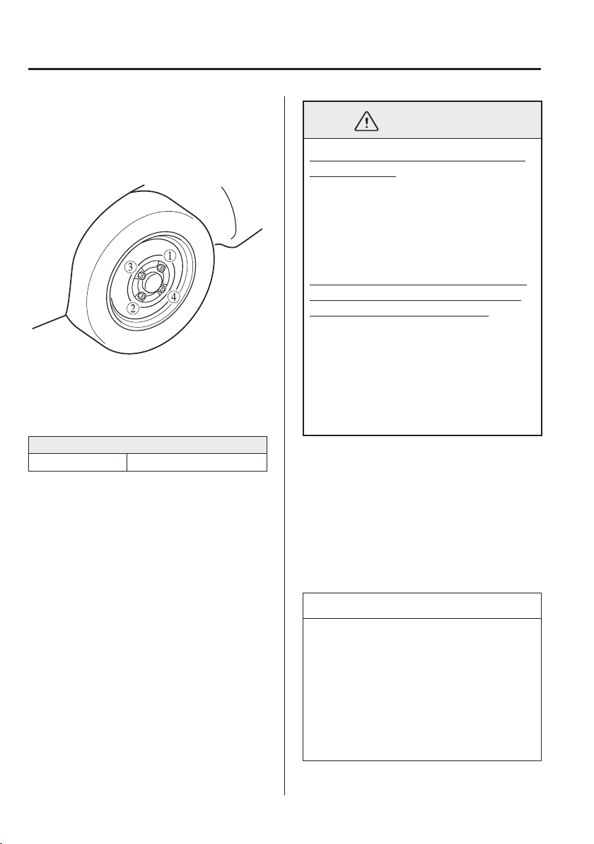
7
–
22
If Trouble Arises
Flat Tyre
4. Turn the wheel brace anticlockwise and
lower the vehicle.
5. Use the wheel brace to tighten the nuts
in the order shown.
If you are unsure of how tight the nuts
should be, have them inspected at an
expert repairer, we recommend an
Authorised Mazda Repairer.
Nut tightening torque
N·m (kgf·m, ft·lbf) 108—147 (12—14, 80—108)
WARNING
Always securely and correctly tighten
the wheel nuts:
Improperly or loosely tightened wheel
nuts are dangerous. The wheel could
wobble or come off. This could result
in loss of vehicle control and cause a
serious accident.
Be sure to reinstall the same nuts you
removed or replace them with metric
nuts of the same con¿ guration:
Because the wheel studs and wheel
nuts on your Mazda have metric
threads, using a non-metric nut is
dangerous. On a metric stud, it would
not secure the wheel and would
damage the stud, which could cause the
wheel to slip off and cause an accident.
6. Remove the tyre blocks and store the
tools and jack.
7. Store the damaged tyre in the luggage
compartment.
8. Check the inÀ ation pressure. Refer to
Tyres on page 9-10 .
9. Have the À at tyre repaired or replaced
as soon as possible.
NOTE
(With tyre pressure monitoring
system)
Do not press the tyre pressure
monitoring system set switch after
installing the spare tyre. The switch
is only to be pressed after installing
the repaired À at tyre or installing a
replacement tyre (page 4-38 ).
7
–
23
If Trouble Arises
Flat Tyre
WARNING
Do not drive with any tyres that have
incorrect air pressure:
Driving on tyres with incorrect air
pressure is dangerous. Tyres with
incorrect pressure could affect
handling and result in an accident.
When you check the regular tyres' air
pressure, check the spare tyre, too.
NOTE
To prevent the jack and tool from
rattling, store them properly.
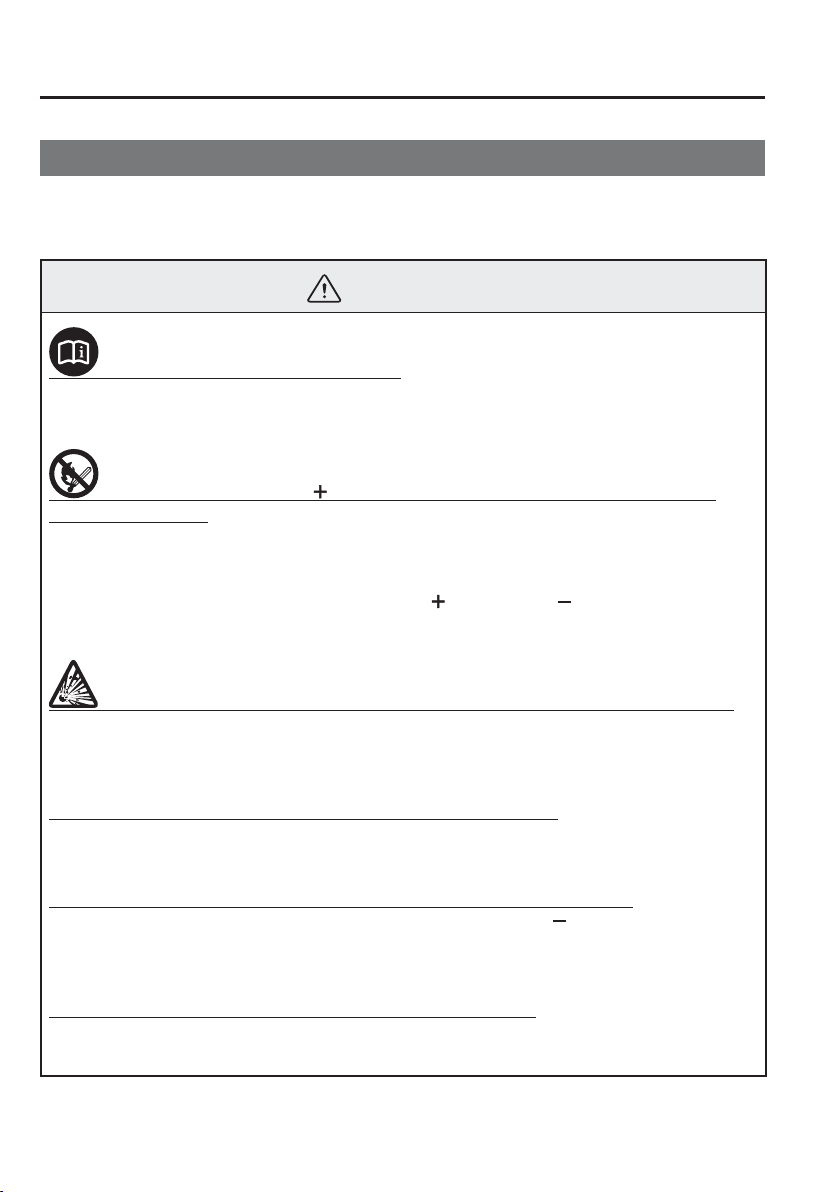
7
–
24
If Trouble Arises
Battery Runs Out
J u m p - S t a r t i n g
Jump-starting is dangerous if done incorrectly. So follow the procedure carefully. If you
feel unsure about jump-starting, we strongly recommend that you have a competent service
technician do the work.
WARNING
Follow These Precautions Carefully:
To ensure safe and correct handling of the battery, read the following precautions
carefully before using the battery or inspecting it.
Do not allow the positive ( ) terminal to contact any other metal object that
could cause sparks:
Flames and sparks near open battery cells are dangerous. Hydrogen gas, produced
during normal battery operation, could ignite and cause the battery to explode. An
exploding battery can cause serious burns and injuries. When working near a battery,
do not allow metal tools to contact the positive (
) or negative ( ) terminal of the
battery.
Keep all À ames, including cigarettes, and sparks away from open battery cells:
Flames and sparks near open battery cells are dangerous. Hydrogen gas, produced
during normal battery operation, could ignite and cause the battery to explode. An
exploding battery can cause serious burns and injuries.
Do not jump-start a frozen battery or one with a low À uid level:
Jump-starting a frozen battery or one with a low À uid level is dangerous. It may rupture
or explode, causing serious injury.
Connect the negative lead to a good ground point away from the battery:
Connecting the end of the second jumper lead to the negative (
) terminal of the
discharged battery is dangerous.
A spark could cause the gas around the battery to explode and injure someone.
Route the jumper leads away from parts that will be moving:
Connecting a jumper lead near or to moving parts (cooling fans, belts) is dangerous.
The lead could get caught when the engine starts and cause serious injury.
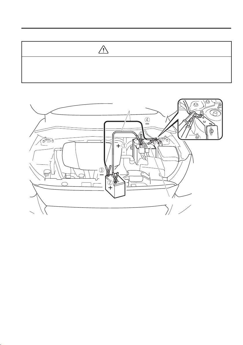
7
–
25
If Trouble Arises
Battery Runs Out
CAUTION
Use only a 12 V booster system. You can damage a 12 V starter, ignition system, and other
electrical parts beyond repair with a 24 V power supply (two 12 V batteries in series or a
24 V motor generator set).
Jumper leads
Discharged battery
Booster battery
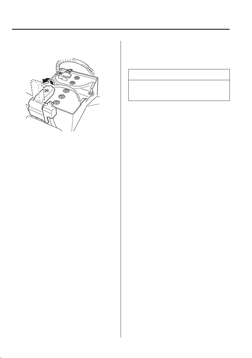
7
–
26
If Trouble Arises
Battery Runs Out
1. Remove the battery cover.
2. Make sure the booster battery is 12
V and that its negative terminal is
grounded.
3. If the booster battery is in another
vehicle, do not allow both vehicles
to touch. Turn off the engine of the
vehicle with the booster battery and
all unnecessary electrical loads in both
vehicles.
4. Connect the jumper leads in the exact
sequence as in the illustration.
Connect one end of a lead to the
positive terminal on the discharged
battery (1).
Attach the other end to the positive
terminal on the booster battery (2).
Connect one end of the other lead to
the negative terminal of the booster
battery (3).
Connect the other end to the ground
point indicated in the illustration
away from the discharged battery (4).
5. Start the engine of the booster vehicle
and run it a few minutes. Then start the
engine of the other vehicle.
6. When ¿ nished, carefully disconnect the
leads in the reverse order described in
the illustration.
7. If the battery cover has been removed,
install it in the reverse order of
removal.
NOTE
Verify that the covers are securely
installed.
7
–
27
If Trouble Arises
Emergency Starting
Starting a Flooded Engine
(SKYACTIV-G 1.3 and
SKYACTIV-G 1.5 )
If the engine fails to start, it may be
À ooded (excessive fuel in the engine).
Follow this procedure:
1. If the engine does not start within
¿ ve seconds on the ¿ rst try, wait ten
seconds and try again.
2. Make sure the parking brake is on.
3. Depress the accelerator all the way and
hold it there.
4. Depress the clutch pedal (Manual
transaxle) or the brake pedal
(Automatic transaxle), then press the
push button start. If the engine starts,
release the accelerator immediately
because the engine will suddenly rev
up.
5. If the engine fails to start, crank it
without depressing the accelerator.
If the engine still does not start using
the previous procedure, have your
vehicle inspected by an expert repairer,
we recommend an Authorised Mazda
Repairer.
Push-Starting
Do not push-start your Mazda.
WARNING
Never tow a vehicle to start it:
Towing a vehicle to start it is
dangerous. The vehicle being towed
could surge forward when its engine
starts, causing the two vehicles to
collide. The occupants could be
injured.
CAUTION
Do not push-start a vehicle that has a
manual transaxle. It can damage the
emission control system.
NOTE
You cannot start a vehicle with an
automatic transaxle by pushing it.
7
–
28
If Trouble Arises
Emergency Starting
Running Out of Fuel
(SKYACTIV-D 1.5)
CAUTION
Do not try starting the engine for more
than 10 seconds at a time. Doing so,
could damage the starter. If the engine
does not start on the ¿ rst try wait about
20 seconds before trying again.
If your vehicle runs out of fuel, add at least
10 L (2.6 US gal, 2.2 Imp gal) of fuel, and
try to restart the engine. Because air can
get into fuel lines when a vehicle runs out
of fuel, your engine may take longer to
start. If the engine does not start the ¿ rst
time, try starting it several more times.
If it still does not start, contact an expert
repairer, we recommend an Authorised
Mazda Repairer.
7
–
29
If Trouble Arises
Overheating
O v e r h e a t i n g
If the high engine coolant temperature
warning light turns on, the vehicle loses
power, or you hear a loud knocking or
pinging noise, the engine is probably too
hot.
WARNING
Pull over to a safe location, then
switch the ignition off and make sure
the fan is not running before
attempting to work near the cooling
fan:
Working near the cooling fan when it
is running is dangerous. The fan could
continue running inde¿ nitely even if
the engine has stopped and the engine
compartment temperature is high. You
could be hit by the fan and seriously
injured.
Do not remove either
cooling system cap when the engine
and radiator are hot:
When the engine and radiator are hot,
scalding coolant and steam may shoot
out under pressure and cause serious
injury.
Open the bonnet ONLY after steam is
no longer escaping from the engine:
Steam from an overheated engine is
dangerous. The escaping steam could
seriously burn you.
If the high engine coolant temperature
warning light turns on:
1. Drive safely to the side of the road and
park off the right-of-way.
2. Put a vehicle with an automatic
transaxle in park (P), a manual
transaxle in neutral.
3. Apply the parking brake.
4. Turn off the air conditioner.
5. Check whether coolant or steam is
escaping from the engine compartment.
If steam is coming from the engine
compartment:
Do not go near the front of the vehicle.
Stop the engine.
Wait until the steam dissipates, then
open the bonnet and start the engine.
If neither coolant nor steam is
escaping:
Open the bonnet and idle the engine
until it cools.
CAUTION
If the cooling fan does not operate
while the engine is running, the engine
temperature will increase. Stop the
engine and call an expert repairer,
we recommend an Authorised Mazda
Repairer.
6. Make sure the cooling fan is operating,
then turn off the engine after the
temperature has decreased.
7. When cool, check the coolant level.
If it is low, look for coolant leaks from
the radiator and hoses.
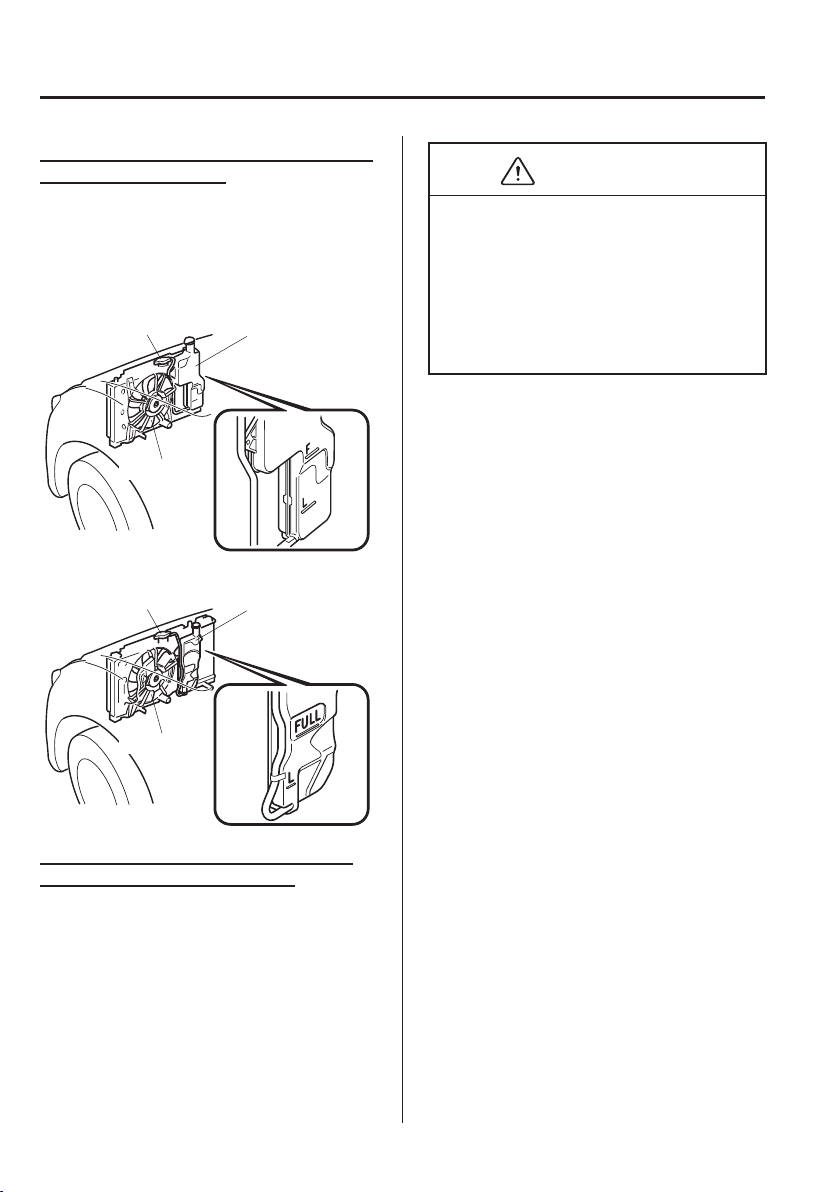
7
–
30
If Trouble Arises
Overheating
If you ¿ nd a leak or other damage, or if
coolant is still leaking:
Stop the engine and call an expert repairer,
we recommend an Authorised Mazda
Repairer.
SKYACTIV-G 1.3 and SKYACTIV-G
1.5
Cooling system cap Coolant reservoir
Cooling fan
SKYACTIV-D 1.5
Cooling system cap Coolant reservoir
Cooling fan
If you ¿ nd no problems, the engine is
cool, and no leaks are obvious:
Carefully add coolant as required (page
6-29 ).
CAUTION
If the engine continues to overheat or
frequently overheats, have the cooling
system inspected. The engine could
be seriously damaged unless repairs
are made. Consult an expert repairer,
we recommend an Authorised Mazda
Repairer.
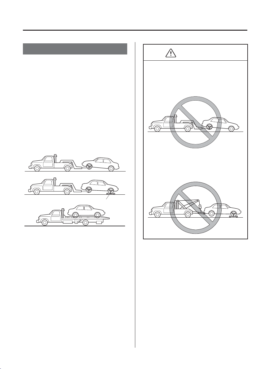
7
–
31
If Trouble Arises
Emergency Towing
Towing Description
We recommend that towing be done only
by an expert repairer, we recommend
an Authorised Mazda Repairer or a
commercial tow-truck service.
Proper lifting and towing are necessary
to prevent damage to the vehicle.
Government and local laws must be
followed.
A towed vehicle usually should have its
drive wheels (front wheels) off the ground.
If excessive damage or other conditions
prevent this, use wheel dollies.
Wheel dollies
When towing with the rear wheels on the
ground, release the parking brake.
CAUTION
Do not tow the vehicle pointed
backward with driving wheels on
the ground. This may cause internal
damage to the transaxle.
Do not tow with sling-type
equipment. This could damage your
vehicle. Use wheel-lift or À atbed
equipment.
If towing service is not available in an
emergency, the vehicle may be towed with
all four wheels on the ground using the
towing hook at the front of the vehicle.
Only tow the vehicle on paved surfaces for
short distances at low speeds.
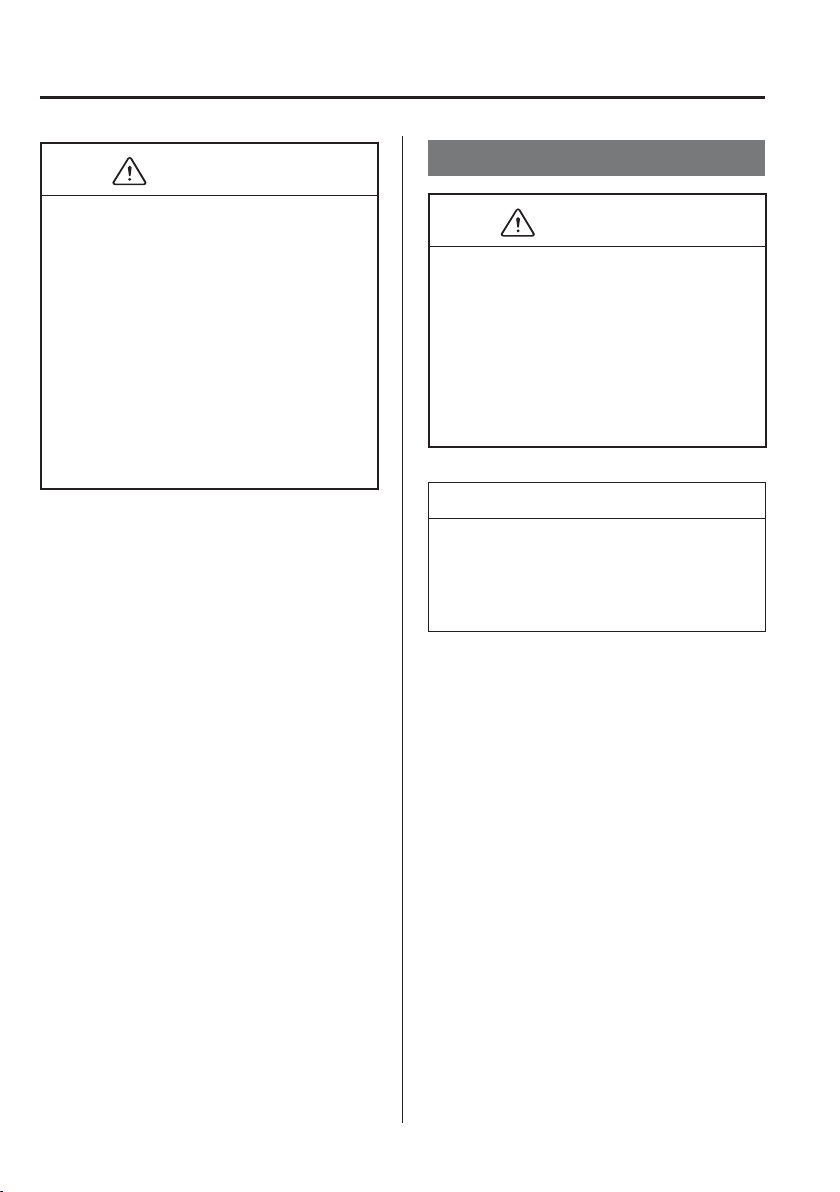
7
–
32
If Trouble Arises
Emergency Towing
CAUTION
Follow these instructions when towing
the vehicle with all wheels on the
ground.
Shift to neutral (Manual transaxle),
or the N position (Automatic
transaxle).
Switch the ignition to ACC.
Release the parking brake.
Remember that power assist for the
brakes and steering will not be available
when the engine is not running.
Towing/Tiedown Hooks
CAUTION
The towing eyelet should be used
in an emergency (to get the vehicle
out of a ditch or a snow bank, for
example).
When using the towing eyelets,
always pull the lead or chain in a
straight direction with respect to the
eyelet. Never apply a sideways force.
NOTE
When towing with chain or lead, wrap
the chain or lead with a soft cloth near
the bumper to prevent damage to the
bumper.
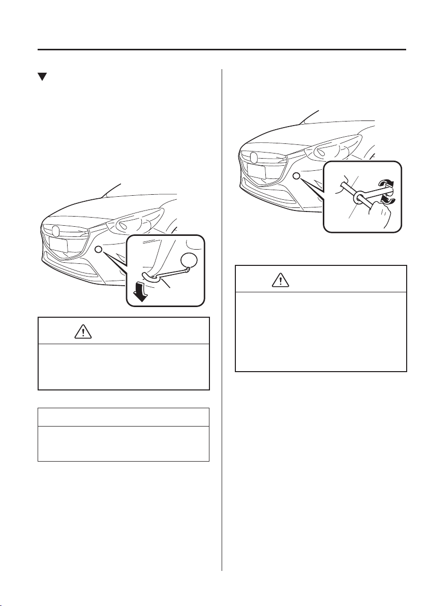
7
–
33
If Trouble Arises
Emergency Towing
Towing Hook-Front
1. Remove the towing eyelet and
the wheel brace from the luggage
compartment (page 7-3 ).
2. Wrap a jack lever or similar tool with
a soft cloth to prevent damage to a
painted bumper, and open the cap
located on the front bumper.
CAUTION
Do not use excessive force as it may
damage the cap or scratch the painted
bumper surface.
NOTE
Remove the cap completely and store it
so as not to lose it.
3. Securely install the towing eyelet using
the wheel brace.
Wheel brace
Towing eyelet
4. Hook the towing rope to the towing
eyelet.
CAUTION
If the towing eyelet is not securely
tightened, it may loosen or disengage
from the bumper when towing the
vehicle. Make sure that the towing
eyelet is securely tightened to the
bumper.
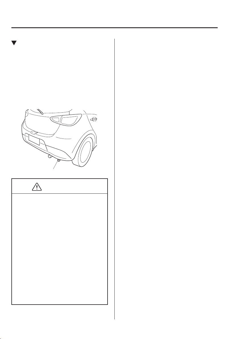
7
–
34
If Trouble Arises
Emergency Towing
Tiedown Hook-Rear
The hook positioned under the rear
bumper on the right side is for tying down
the vehicle during transport, and it cannot
be used for towing other vehicles.
It can be used as a towing hook only when
the vehicle must be towed by another
vehicle in an emergency case such as when
the vehicle is stuck in snow, however, it
may damage the bumper.
Tiedown hook
CAUTION
When using the hook in such emergency
cases, observe the following so as not to
damage the tiedown hook or the vehicle
body.
The vehicle must be pulled straight
to the rear so that no load is applied
to the vehicle in the lateral direction.
The bumper may be damaged if the
tie down hook is used as a towing
hook.
When using a metal chain or wire
lead, wrap a cloth around the
attachment area. If the metal chain
or wire lead contacts the bumper
directly, the bumper could be
scratched or damaged.
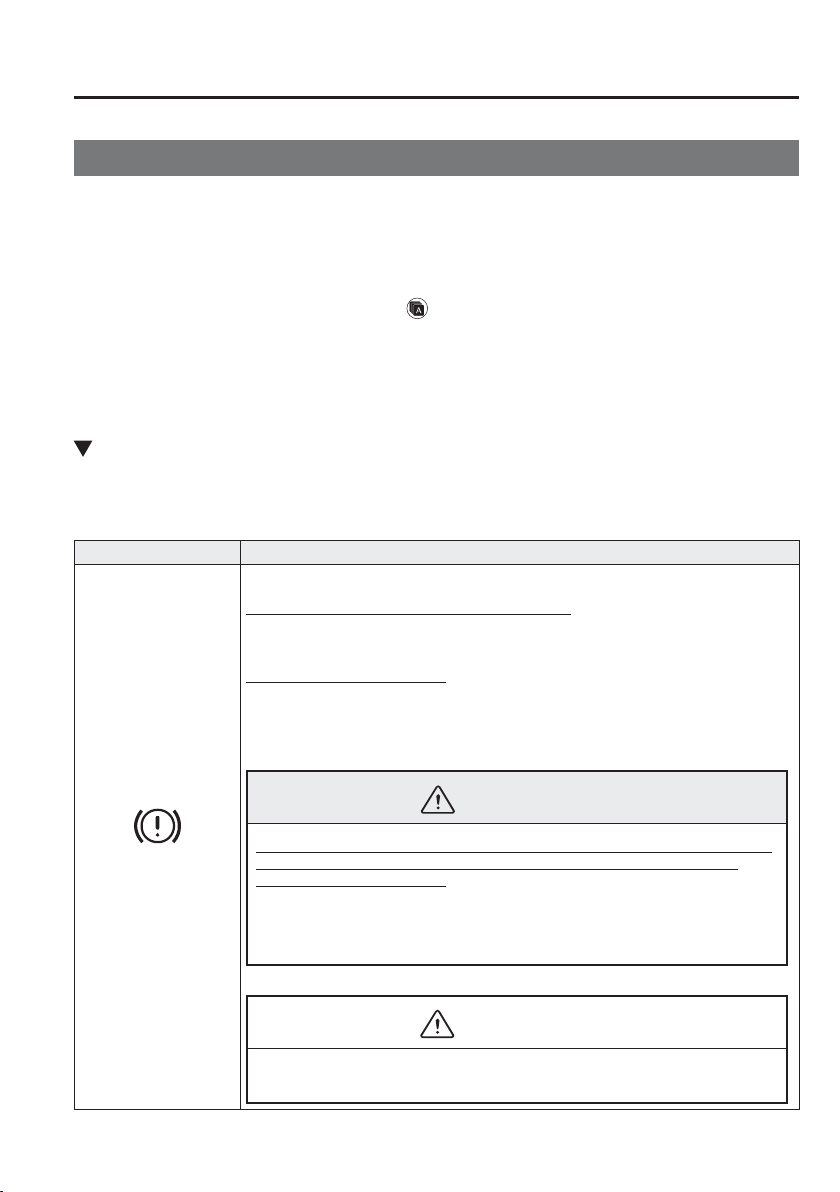
7
–
35
If Trouble Arises
Warning/Indicator Lights and Warning Sounds
If a Warning Light Turns On or Flashes
If any warning light turns on/À ashes, take appropriate action for each light. There is no
problem if the light turns off, however if the light does not turn off or turns on/À ashes again,
consult an Authorised Mazda Repairer.
(Vehicles with type B audio)
The warning contents can be veri¿ ed on the centre display.
1. If the warning light is turned on, select icon on the home screen to display the
application screen.
2. Select “Vehicle Status Monitor”.
3. Select “Warning Guidance” to display the current warnings.
4. Select the applicable warning to view the warning details.
Stop Vehicle in Safe Place Immediately
If any of the following warning lights turns on, the system may have a malfunction. Stop the
vehicle in a safe place immediately and contact an Authorised Mazda Repairer.
Signal Warning
Brake System Warning
Light
This warning has the following functions:
Parking brake warning/Warning light inspection
The light illuminates when the parking brake is applied with the ignition switched to
START or ON. It turns off when the parking brake is fully released.
Low brake À uid level warning
If the brake warning light remains illuminated even though the parking brake is
released, the brake À uid may be low or there could be a problem with the brake
system. Park the vehicle in a safe place immediately and contact an expert repairer, we
recommend an Authorised Mazda Repairer.
WARNING
Do not drive with the brake system warning light illuminated. Contact an expert
repairer, we recommend an Authorised Mazda Repairer to have the brakes
inspected as soon as possible:
Driving with the brake system warning light illuminated is dangerous. It
indicates that your brakes may not work at all or that they could completely fail
at any time. If this light remains illuminated, after checking that the parking
brake is fully released, have the brakes inspected immediately.
CAUTION
In addition, the effectiveness of the braking may diminish so you may need to
depress the brake pedal more strongly than normal to stop the vehicle.
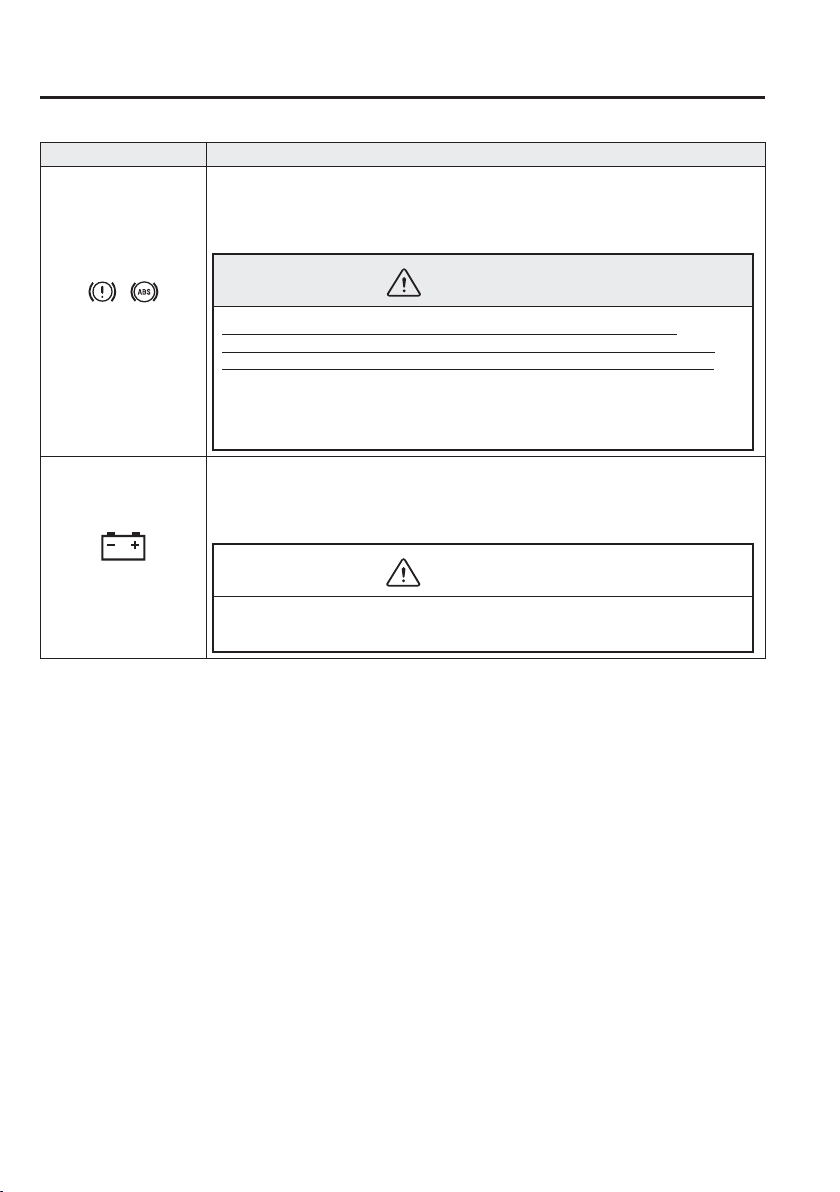
7
–
36
If Trouble Arises
Warning/Indicator Lights and Warning Sounds
Signal Warning
Electronic Brake Force
Distribution System
Warning
If the electronic brake force distribution control unit determines that some components
are operating incorrectly, the control unit may illuminate the brake system warning
light and the ABS warning light simultaneously. The problem is likely to be the
electronic brake force distribution system.
WARNING
Do not drive with both the ABS warning light and brake warning light
illuminated. Have the vehicle towed to an expert repairer, we recommend an
Authorised Mazda Repairer to have the brakes inspected as soon as possible:
Driving when the brake system warning light and ABS warning light are
illuminated simultaneously is dangerous.
When both lights are illuminated, the rear wheels could lock more quickly in an
emergency stop than under normal circumstances.
Charging System
Warning Light
If the warning light turns on while driving, it indicates a problem with the generator or
the charging system.
Drive to the side of the road and park off the right-of-way. Consult an expert repairer,
we recommend an Authorised Mazda Repairer.
CAUTION
Do not continue driving when the charging system warning light is illuminated
because the engine could stop unexpectedly.
7
–
37
If Trouble Arises
Warning/Indicator Lights and Warning Sounds
Signal Warning
Engine Oil Warning
Light
This warning light indicates low engine oil pressure.
CAUTION
Do not run the engine if the oil pressure is low. Otherwise, it could result in
extensive engine damage.
If the light illuminates or the warning indication is displayed while driving:
1. Drive to the side of the road and park off the right-of-way on level ground.
2. Turn off the engine and wait 5 minutes for the oil to drain back into the sump.
3. Inspect the engine oil level 6-28 . If it's low, add the appropriate amount of engine
oil while being careful not to over¿ ll.
CAUTION
Do not run the engine if the oil level is low. Otherwise, it could result in extensive
engine damage.
4. Start the engine and check the warning light.
If the light remains illuminated even though the oil level is normal or after adding oil,
stop the engine immediately and have your vehicle towed to an expert repairer, we
recommend an Authorised Mazda Repairer.
(Red)
High Engine Coolant
Temperature Warning
Light
The light À ashes when the engine coolant temperature is extremely high, and
illuminates when the engine coolant temperature increases further.
Handling Procedure
Flashing light
Drive slowly to reduce engine load until you can ¿ nd a safe place to stop the vehicle
and wait for the engine to cool down.
Illuminated light
This indicates the possibility of overheating. Park the vehicle in a safe place
immediately and stop the engine.
Refer to Overheating 7-29 .
CAUTION
Do not drive the vehicle with the high engine coolant temperature warning light
illuminated. Otherwise, it could result in damage to the engine.
7
–
38
If Trouble Arises
Warning/Indicator Lights and Warning Sounds
Signal Warning
Power Steering
Malfunction Indicator
Light
The light illuminates/À ashes if the electric power steering has a malfunction.
If the light illuminates/À ashes, stop the vehicle in a safe place and do not operate the
steering wheel. There is no problem if the light turns off after a while. Contact an
expert repairer, we recommend an Authorised Mazda Repairer if the light illuminates/
À ashes continuously.
NOTE
If the indicator light illuminates/À ashes, the power steering will not operate
normally. In this happens, the steering wheel can still be operated, however, the
operation may feel heavy compared to normal, or the steering wheel could vibrate
when turning.
Repeatedly jerking the steering wheel left and right while the vehicle is stopped
or moving extremely slowly will cause the power steering system to go into
protective mode which will make the steering feel heavy, but this does not indicate
a problem. If this occurs, park the vehicle safely and wait several minutes for the
system to return to normal.
Contact Authorised Mazda Repairer and Have Vehicle Inspected
If any of the following warning lights turns on/À ashes, the system may have a malfunction.
Contact an expert repairer, we recommend an Authorised Mazda Repairer to have your
vehicle inspected.
Signal Warning
ABS Warning Light
If the ABS warning light stays on while you're driving, the ABS control unit has detected a
system malfunction. If this occurs, your brakes will function normally as if the vehicle had
no ABS.
Should this happen, consult an expert repairer, we recommend an Authorised Mazda
Repairer as soon as possible.
NOTE
When the engine is jump-started to charge the battery, uneven rpm occurs and the ABS
warning light may illuminate. If this occurs, it is the result of the weak battery and
does not indicate an ABS malfunction.
(With DSC vehicles)
The brake assist system does not operate while the ABS warning light is illuminated.
7
–
39
If Trouble Arises
Warning/Indicator Lights and Warning Sounds
*Some models.
Signal Warning
Master Warning
Light
Vehicles with type B audio
The light turns on when the system has a malfunction.
Operate the centre display and verify the content.
Refer to If a Warning Light Turns On or Flashes on page 7-35 .
Vehicles with type A audio
The light illuminates continuously if any one of the following occurs. Consult an expert
repairer, we recommend an Authorised Mazda Repairer.
There is a malfunction in the battery management system.
There is a malfunction in the brake switch.
(SKYACTIV-D 1.5)
There is a malfunction in the engine's hydraulic control.
There is a malfunction in the engine's timing chain.
There is a malfunction in the blow-by heater.
There is a malfunction in the oil level sensor.
Check Engine Light
If this light illuminates while driving, the vehicle may have a problem. It is important to
note the driving conditions when the light illuminated and consult an expert repairer, we
recommend an Authorised Mazda Repairer.
The check engine light may illuminate in the following cases:
The engine's electrical system has a problem.
The emission control system has a problem.
(SKYACTIV-G 1.3, SKYACTIV-G 1.5)
The fuel tank level being very low or approaching empty.
The fuel-¿ ller cap is missing or not tightened securely.
If the check engine light remains on, or it À ashes continuously , do not drive at high speeds
and consult an expert repairer, we recommend an Authorised Mazda Repairer as soon as
possible.
(Amber)
i-stop warning light
*
When the light is turned on
A problem in the system may be indicated under the following conditions. Have your
vehicle inspected at an expert repairer, we recommend an Authorised Mazda Repairer.
The light does not turn on when the ignition is switched ON.
The light continues to remain on even though the i-stop OFF switch has been pressed
while the engine is running.
When the light is À ashing
The light continues to À ash if the system has a malfunction. Have your vehicle inspected at
an expert repairer, we recommend an Authorised Mazda Repairer.
(Amber)
i-ELOOP Warning
Light
*
The light turns on if there is any malfunction in the i-ELOOP system. Consult an expert
repairer, we recommend an Authorised Mazda Repairer.
7
–
40
If Trouble Arises
Warning/Indicator Lights and Warning Sounds
*Some models.
Signal Warning
Automatic
Transaxle Warning
Light
*
The light illuminates when the transaxle has a problem.
CAUTION
If the automatic transaxle warning light illuminates, the transaxle has an electrical
problem. Continuing to drive your Mazda in this condition could cause damage to your
transaxle. Consult an expert repairer, we recommend an Authorised Mazda Repairer as
soon as possible.
(Turns on)
TCS/DSC Indicator
Light
*
If the light stays on, the TCS, DSC or the brake assist system may have a malfunction and
they may not operate correctly. Take your vehicle to an expert repairer, we recommend an
Authorised Mazda Repairer.
Air Bag/Seat Belt
Pretensioner System
Warning Light
A system malfunction is indicated if the warning light constantly À ashes, constantly
illuminates or does not illuminate at all when the ignition is switched ON. If any of these
occur, consult an expert repairer, we recommend an Authorised Mazda Repairer as soon as
possible. The system may not operate in an accident.
WARNING
Never tamper with the air bag/pretensioner systems and always have an expert
repairer, we recommend an Authorised Mazda Repairer perform all servicing and
repairs:
Self-servicing or tampering with the systems is dangerous. An air bag/pretensioner
could accidentally activate or become disabled causing serious injury or death.
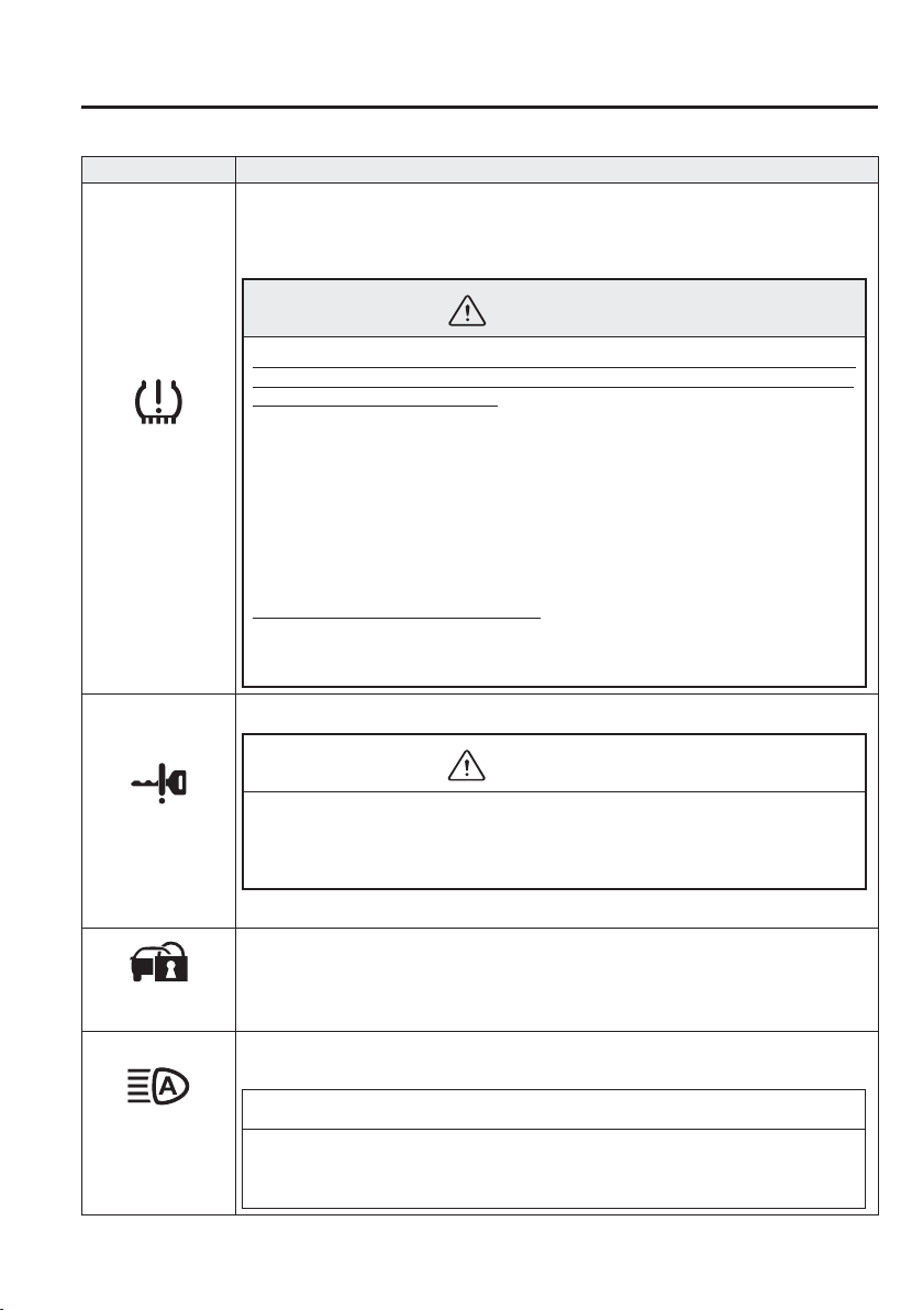
7
–
41
If Trouble Arises
Warning/Indicator Lights and Warning Sounds
*Some models.
Signal Warning
(Flashing)
Tyre Pressure
Monitoring System
Warning Light
*
If the tyre pressure monitoring system has a malfunction, the tyre pressure warning
light À ashes for about 1 minute when the ignition is switched ON and then continues
illuminating. Have your vehicle checked by an expert repairer, we recommend an
Authorised Mazda Repairer as soon as possible.
WARNING
If the tyre pressure monitoring system warning light illuminates or À ashes, or the tyre
pressure warning beep sound is heard, decrease vehicle speed immediately and avoid
sudden manoeuvring and braking:
If the tyre pressure monitoring system warning light illuminates or À ashes, or the
tyre pressure warning beep sound is heard, it is dangerous to drive the vehicle at high
speeds, or perform sudden manoeuvring or braking. Vehicle drivability could worsen
and result in an accident.
To determine if you have a slow leak or a À at, pull over to a safe position where you
can check the visual condition of the tyre and determine if you have enough air
to proceed to a place where air may be added and the system monitored again by
an expert repairer, we recommend an Authorised Mazda Repairer or a tyre repair
station.
Do not ignore the TPMS Warning Light:
Ignoring the TPMS warning light is dangerous, even if you know why it is
illuminated. Have the problem taken care of as soon as possible before it develops
into a more serious situation that could lead to tyre failure and a dangerous accident.
(Red)
(Turns on)
KEY Warning Light
If any malfunction occurs in the keyless entry system, it illuminates continuously.
CAUTION
If the key warning indicator light illuminates or the push button start indicator light
(amber) À ashes, the engine may not start. If the engine cannot be started, try starting it
using the emergency operation for starting the engine, and have the vehicle inspected at
an expert repairer, we recommend an Authorised Mazda Repairer as soon as possible.
Refer to Emergency Operation for Starting the Engine on page 4-11 .
Security Indicator
Light
If the engine does not start with the correct key, and the security indicator light remains
illuminated or À ashing, try the following:
Make sure the key is within the operational range for signal transmission. Switch the
ignition off, and then restart the engine. If the engine does not start after 3 or more tries,
contact an expert repairer, we recommend an Authorised Mazda Repairer.
(Amber)
High Beam Control
System (HBC)
Warning Light
*
The light remains turned on if there is a problem with the system. Have your vehicle
inspected at an expert repairer, we recommend an Authorised Mazda Repairer.
NOTE
If the windscreen area in front of the Forward Sensing Camera (FSC) is fogged or
obstructed, the light turns on temporarily. If the light remains turned on, there may be a
problem with the system.
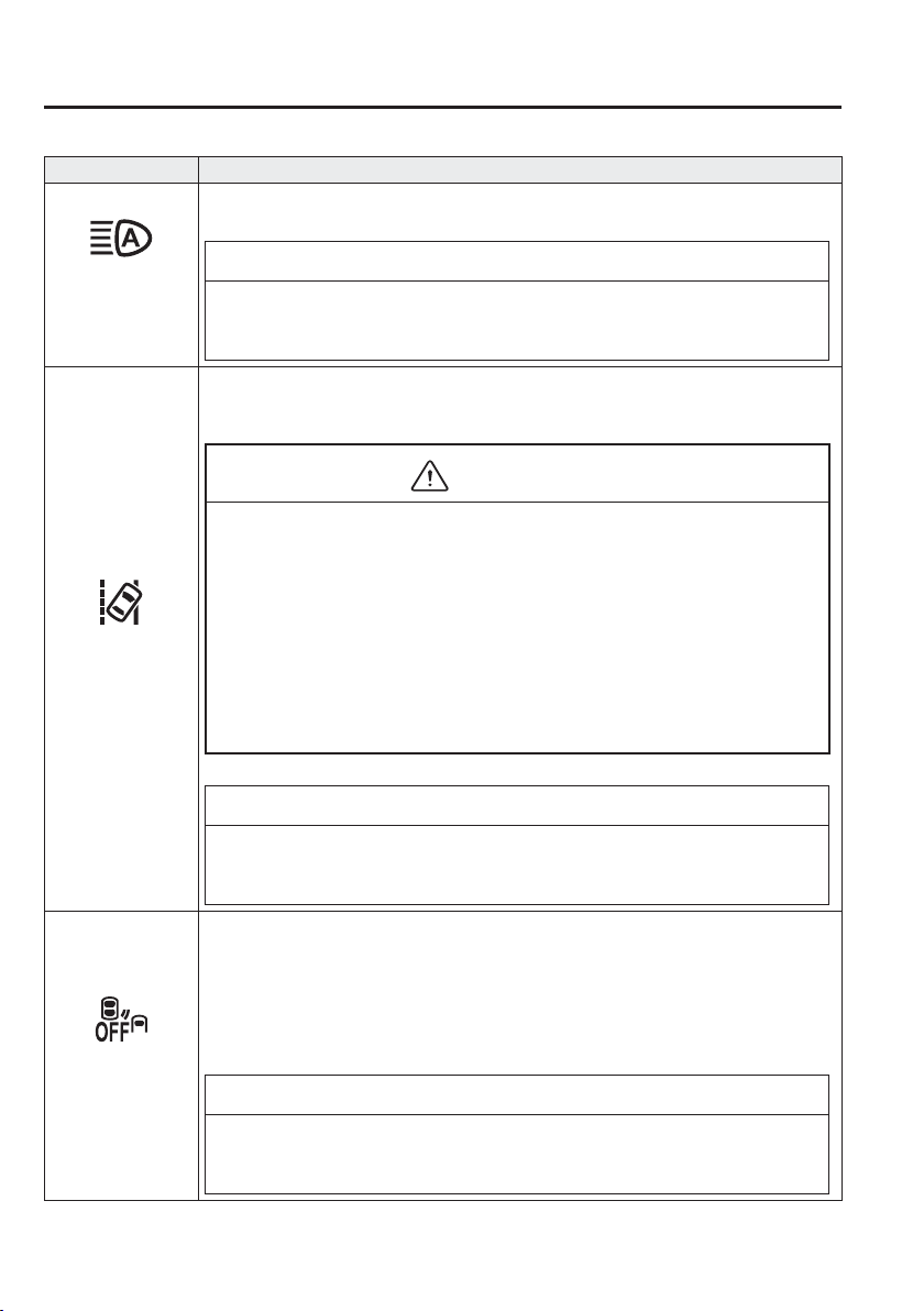
7
–
42
If Trouble Arises
Warning/Indicator Lights and Warning Sounds
*Some models.
Signal Warning
(Amber)
Adaptive LED
Headlights (ALH)
Warning Light
*
The light remains turned on if there is a problem with the system. Have your vehicle
inspected at an expert repairer, we recommend an Authorised Mazda Repairer.
NOTE
If the windscreen area in front of the Forward Sensing Camera (FSC) is fogged or
obstructed, the light turns on temporarily. If the light remains turned on, there may be a
problem with the system.
Lane Departure
Warning System
(LDWS) Warning
Light
*
The warning light remains turned on if there is a problem with the system. Have your
vehicle inspected at an expert repairer, we recommend an Authorised Mazda Repairer.
The LDWS does not operate when the warning light illuminates.
CAUTION
A problem in the system may be indicated under the following conditions. Have your
vehicle inspected at an expert repairer, we recommend an Authorised Mazda Repairer.
When the light remains turned on while driving the vehicle.
When the system is cancelled automatically, the light turns on. Normally, the system
restores automatically and the light turns off, however, if the light remains turned on,
there may be a problem with the system.
The light does not illuminate when the ignition is switched ON.
Always use tyres for all wheels that are of the speci¿ ed size, and the same
manufacture, brand, and tread pattern. In addition, do not use tyres with signi¿ cantly
different wear patterns on the same vehicle. If such improper tyres are used, the
LDWS may not operate normally.
When an emergency spare tyre is used, the system may not operate normally.
NOTE
If the windscreen area in front of the Forward Sensing Camera (FSC) is fogged or
obstructed, the light turns on temporarily. If the light remains turned on, there may be a
problem with the system.
Blind Spot
Monitoring (BSM)
OFF Indicator
Light
*
A problem in the system may be indicated under the following conditions.
Have your vehicle inspected at an expert repairer, we recommend an Authorised Mazda
Repairer.
The light does not turn on when the ignition is switched ON.
The light remains on even when the Blind Spot Monitoring (BSM) system can be
operated.
The light turns on while driving the vehicle.
NOTE
If the vehicle is driven on a road with less traf¿ c and few vehicles that the radar sensors
can detect, the system may pause (The Blind Spot Monitoring (BSM) OFF indicator
light in the instrument cluster illuminates). However, it does not indicate a malfunction.
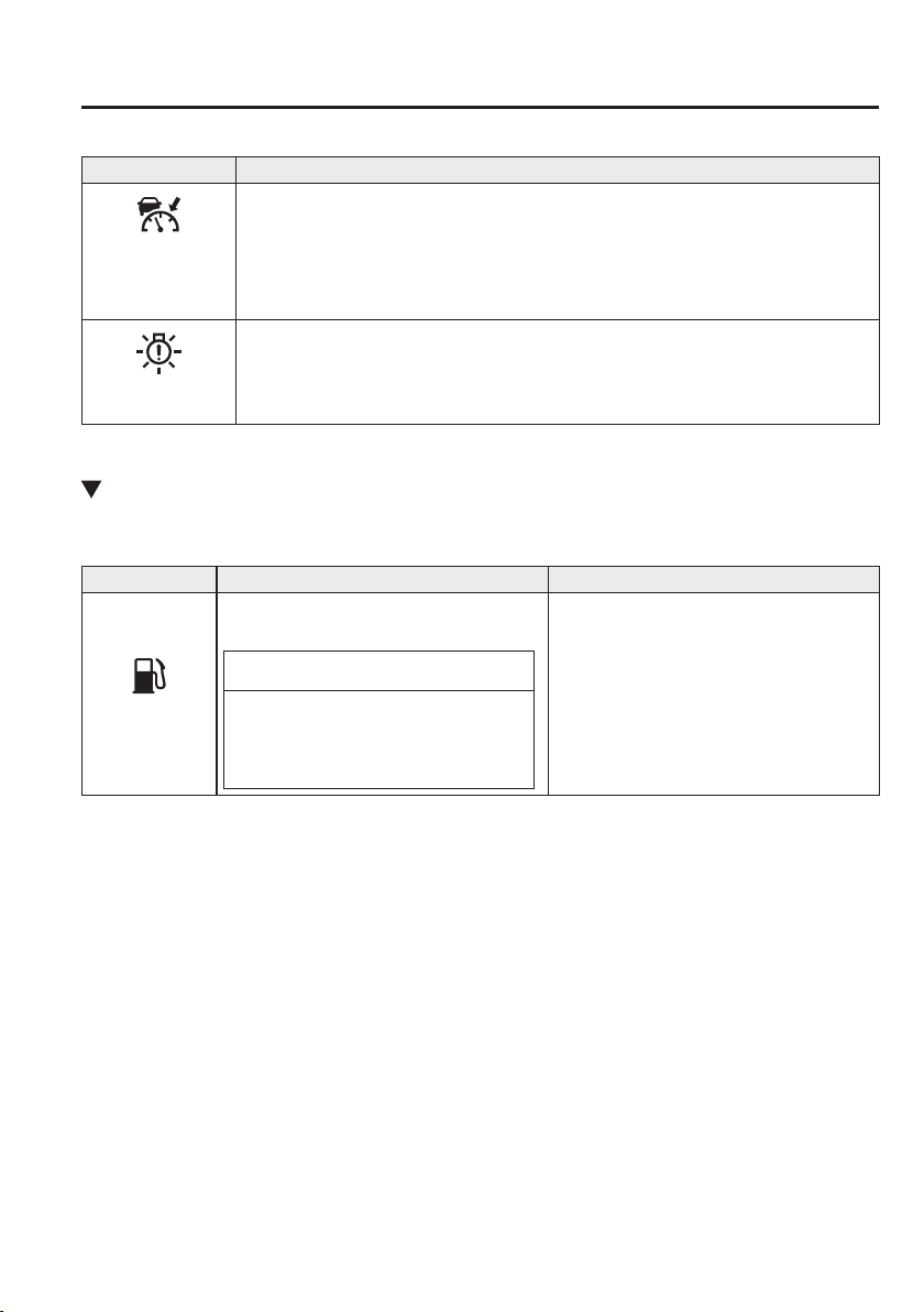
7
–
43
If Trouble Arises
Warning/Indicator Lights and Warning Sounds
*Some models.
Signal Warning
(Amber)
Mazda Radar Cruise
Control (MRCC)
Warning Light
*
The warning light turns on if there is a malfunction in the system while the Mazda Radar
Cruise Control (MRCC) system is on. Have your vehicle inspected at an expert repairer, we
recommend an Authorised Mazda Repairer.
LED Headlight
Warning Light
*
This light illuminates if there is a malfunction in the LED headlight. Have your vehicle
inspected by an expert repairer, we recommend an Authorised Mazda Repairer.
Taking Action
Take the appropriate action and verify that the warning light turns off.
Signal Warning Action to be taken
Low Fuel
Warning Light
The light turns on when the remaining fuel is
about 9.0 L (2.3 US gal, 1.9 Imp gal).
NOTE
The light illumination timing may vary
because fuel inside the fuel tank moves
around according to the driving conditions
and the vehicle posture.
Add fuel.
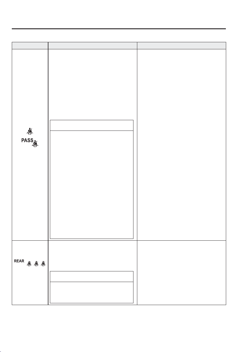
7
–
44
If Trouble Arises
Warning/Indicator Lights and Warning Sounds
*Some models.
Signal Warning Action to be taken
Seat Belt
Warning Light
(Front seat)
The seat belt warning light turns on if the
driver or front passenger's seat is occupied
and the seat belt is not fastened with the
ignition switched ON.
If the driver or front passenger's seat belt is
unfastened (only when the front passenger
seat is occupied) and the vehicle is driven at
a speed faster than about 20 km/h (12 mph),
the warning light À ashes. After a short time,
the warning light stops À ashing, but remains
illuminated. If a seat belt remains unfastened,
the warning light À ashes again for a given
period of time.
NOTE
If the driver or front passenger's seat
belt is unfastened after the warning light
turns on, and the vehicle speed exceeds
20 km/h (12 mph), the warning light
À ashes again.
Placing heavy items on the front
passenger's seat may cause the front
passenger's seat belt warning function
to operate depending on the weight of
the item.
To allow the front passenger's seat
weight sensor to function properly, do
not place and sit on an additional seat
cushion on the front passenger's seat.
The sensor may not function properly
because the additional seat cushion could
cause sensor interference.
If a small child is seated on the front
passenger's seat, the warning light may
not operate.
Fasten the seat belts.
(Red)
Seat Belt
Warning Light
(Rear seat)
*
If the rear seat belts are not fastened while the
ignition is switched ON , the driver and the
passenger are alerted by the warning light.
The warning light operates even if there is no
passenger on the rear seat.
NOTE
If a rear seat belt is not fastened by a
certain period of time after the engine has
been started, the warning light turns off.
Fasten the seat belts.
7
–
45
If Trouble Arises
Warning/Indicator Lights and Warning Sounds
*Some models.
Signal Warning Action to be taken
Door-Ajar
Warning Light
The light turns on if any door/liftgate/boot lid
is not closed securely.
Close the door/liftgate/boot lid securely.
Low Washer
Fluid Level
Warning Light
*
This warning light indicates that little washer
À uid remains.
Add washer À uid (page 6-32 ).
120km/h
Warning Light
*
The 120 km/h warning light illuminates when
the vehicle speed exceeds 120 km/h.
Lower the vehicle speed.
7
–
46
If Trouble Arises
Warning/Indicator Lights and Warning Sounds
*Some models.
Signal Warning Action to be taken
(Turns on)
Tyre Pressure
Monitoring
System Warning
Light
*
When the warning light illuminates, and
the warning beep sound is heard (about 3
seconds), tyre pressure is too low in one or
more tyres.
WARNING
If the tyre pressure monitoring system
warning light illuminates or À ashes,
or the tyre pressure warning beep
sound is heard, decrease vehicle
speed immediately and avoid sudden
manoeuvring and braking:
If the tyre pressure monitoring system
warning light illuminates or À ashes, or
the tyre pressure warning beep sound
is heard, it is dangerous to drive the
vehicle at high speeds, or perform
sudden manoeuvring or braking. Vehicle
drivability could worsen and result in an
accident.
To determine if you have a slow leak or
a À at, pull over to a safe position where
you can check the visual condition of the
tyre and determine if you have enough
air to proceed to a place where air may
be added and the system monitored again
by an expert repairer, we recommend
an Authorised Mazda Repairer or a tyre
repair station.
Do not ignore the TPMS Warning Light:
Ignoring the TPMS warning light is
dangerous, even if you know why it is
illuminated. Have the problem taken
care of as soon as possible before it
develops into a more serious situation
that could lead to tyre failure and a
dangerous accident.
Inspect the tyres and adjust to the speci¿ ed
inÀ ation pressure (page 6-44 ).
NOTE
Perform tyre pressure adjustment when
the tyres are cold. Tyre pressure will
vary according to the tyre temperature,
therefore let the vehicle stand for
1 hour or only drive it 1.6 km (1 mile) or
less before adjusting the tyre pressures.
When pressure is adjusted on hot tyres
to the cold inÀ ation pressure, the TPMS
warning light/beep may turn on after
the tyres cool and pressure drops below
speci¿ cation.
Also, an illuminated TPMS warning
light, resulting from the tyre air
pressure dropping due to cold ambient
temperature will remain illuminated
even if the ambient temperature rises.
In this case, it will also be necessary to
adjust the tyre air pressures. If the TPMS
warning light illuminates due to a drop in
tyre air pressure, make sure to check and
adjust the tyre air pressures.
Tyres lose air naturally over time and
the TPMS cannot tell if the tyres are
getting too soft over time or you have
a À at. However, when you ¿ nd one low
tyre in a set of four-that is an indication
of trouble; you should have someone
drive the vehicle slowly forward so you
can inspect any low tyre for cuts and any
metal objects sticking through tread or
sidewall. Put a few drops of water in the
valve stem to see if it bubbles indicating
a bad valve. Leaks need to be addressed
by more than simply reinÀ ating the
tyre as leaks are dangerous — take it to
an expert repairer, we recommend an
Authorised Mazda Repairer.
7
–
47
If Trouble Arises
Warning/Indicator Lights and Warning Sounds
*Some models.
Signal Warning Action to be taken
(Amber)
Smart Brake
Support/Smart
City Brake
Support (SBS/
SCBS) Warning
Light
*
The light turns on if the windscreen or
the radar sensor are dirty, or there is a
malfunction in the system.
Vehicles with type B audio
Verify the reason why the warning light
is illuminated on the centre display (page
7-35 ).
If the reason why the warning light is
illuminated is due to a dirty windscreen, clean
the windscreen.
If the warning light is illuminated because of
a dirty radar sensor, clean the front emblem.
For any other reasons, have the vehicle
inspected at an expert repairer, we recommend
an Authorised Mazda Repairer.
Vehicles with type A audio
If the reason why the warning light is
illuminated is due to a dirty windscreen, clean
the windscreen. For any other reasons, have
the vehicle inspected at an expert repairer, we
recommend an Authorised Mazda Repairer.
KEY Warning Light
Take the appropriate action and verify that the warning light turns off.
Signal Cause Action to be taken
(Red)
(Flashing)
The advanced key battery is dead. Replace the key battery (page 6-41 ).
The advanced key is not within the
operation range.
Bring the advanced key into the operation
range (page 3-7 ).
The advanced key is placed in areas inside
the cabin where it is dif¿ cult for the key to
be detected.
A key from another manufacturer similar to
the advanced key is in the operation range.
Take the key from another manufacturer
similar to the advanced key out of the
operation range.
Without the ignition switched off, the
advanced key is taken out of the cabin, and
then all the doors are closed.
Bring the advanced key back into the
cabin.
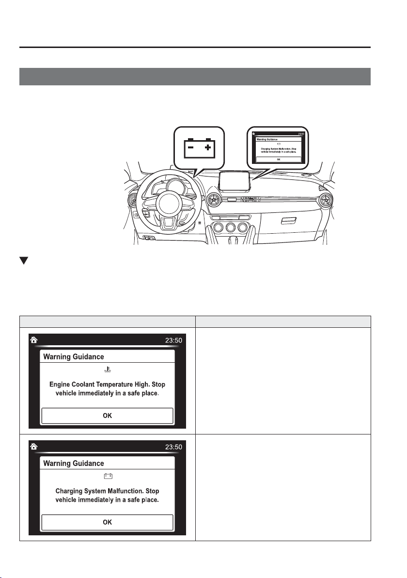
7
–
48
If Trouble Arises
Warning/Indicator Lights and Warning Sounds
*Some models.
Message Indicated on Display
*
If a message is displayed in the centre display (Type B audio), take appropriate action (in a
calm manner) according to the displayed message.
(Display example)
Stop Vehicle in Safe Place Immediately
If the following messages are displayed in the centre display (Type B audio), a vehicle
system may be malfunctioning. Stop the vehicle in a safe place and contact an Authorised
Mazda Repairer.
Display Indicated Condition
Displays if the engine coolant temperature has increased
excessively.
Displays if the charging system has a malfunction.
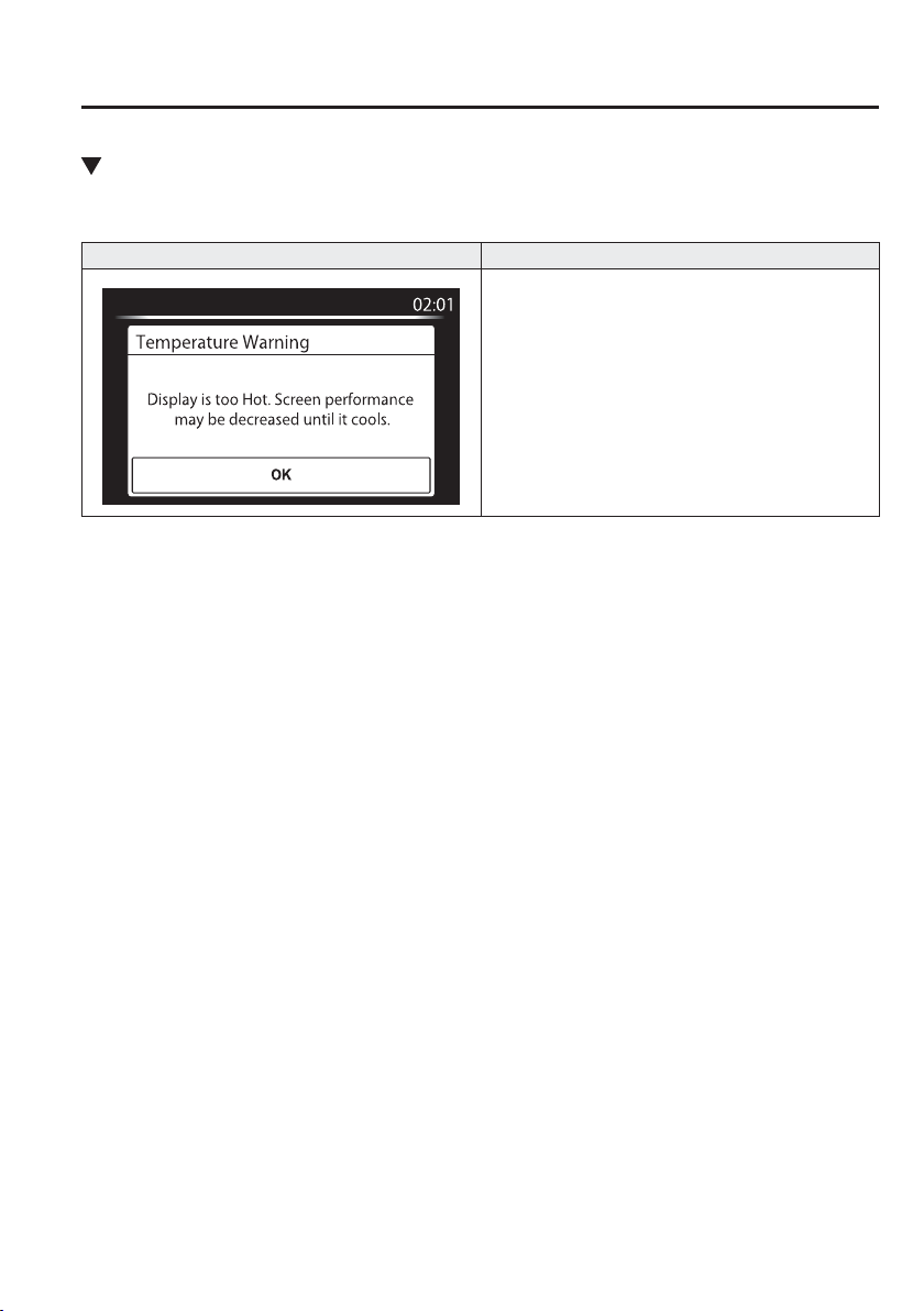
7
–
49
If Trouble Arises
Warning/Indicator Lights and Warning Sounds
Verify Display Content
Displays in the following cases:
Display Indicated Condition/Action to be taken
The following message is displayed when the
temperature around the centre display is high.
Lowering the temperature in the cabin or the
temperature around the centre display by avoiding
direct sunlight is recommended.
7
–
50
If Trouble Arises
Warning/Indicator Lights and Warning Sounds
Warning Sound is
Activated
Lights-On Reminder
If lights are on and the ignition is switched
to ACC or off, a continuous beep sound
will be heard when the driver's door is
opened.
NOTE
When the ignition is switched to
ACC, the “Ignition Not Switched
Off (STOP) Warning Beep” (page
7-51 ) overrides the lights-on
reminder.
A personalised function is available
to change the sound volume for the
lights-on reminder.
Refer to Personalisation Features on
page 9-13 .
Air Bag/Seat Belt Pretensioner
System Warning Beep
If there is a problem with the air bag/seat
belt pretensioner systems and the warning
light illumination, a warning beep sound
will be heard for about 5 seconds every
minute.
The air bag and seat belt pretensioner
system warning beep sound will continue
to be heard for approximately 35 minutes.
Have your vehicle inspected at an expert
repairer, we recommend an Authorised
Mazda Repairer as soon as possible.
WARNING
Do not drive the vehicle with the air
bag/seat belt pretensioner system
warning beep sounding:
Driving the vehicle with the air bag/
seat belt pretensioner system warning
beep sounding is dangerous. In a
collision, the air bags and the seat belt
pretensioner system will not deploy and
this could result in death or serious
injury. Contact an expert repairer,
we recommend an Authorised Mazda
Repairer to have the vehicle inspected
as soon as possible.
Seat Belt Warning Beep
F r o n t s e a t
If the vehicle speed exceeds about
20 km/h (12 mph) with the driver or front
passenger's seat belt unfastened, a warning
beep sounds continuously. If the seat belt
remains unfastened, the beep sound stops
once and then continues for about
90 seconds. The beep stops after the driver
or front passenger's seat belt is fastened.
7
–
51
If Trouble Arises
Warning/Indicator Lights and Warning Sounds
*Some models.
NOTE
Placing heavy items on the front
passenger seat may cause the front
passenger seat belt warning function
to operate depending on the weight
of the item.
To allow the front passenger seat
weight sensor to function properly,
do not place and sit on an additional
seat cushion on the front passenger
seat. The sensor may not function
properly because the additional
seat cushion could cause sensor
interference.
When a small child sits on the front
passenger seat, it is possible that the
warning beep will not operate.
Rear seat
*
The warning beep only sounds if a seat
belt is unfastened after being fastened.
Ignition Not Switched Off (STOP)
Warning Beep
If the driver's door is opened with the
ignition switched to ACC, a beep will
be heard continuously in the cabin to
notify the driver that the ignition has not
been switched OFF (STOP). Under this
condition, the keyless entry system will
not operate, the vehicle cannot be locked,
and the battery voltage will be depleted.
Key Removed from Vehicle
Warning Beep
Vehicles with advanced keyless function
If the key is taken out of the vehicle while
the ignition is not switched OFF and
all the doors are closed, the beep which
sounds outside of the vehicle will be heard
6 times, the beep which sounds inside
the vehicle will be heard 6 times, and the
KEY warning light (red) in the instrument
cluster À ashes continuously to notify
the driver that the ignition has not been
switched OFF.
Vehicles without advanced keyless
function
If the key is taken out of the vehicle while
the ignition is not switched OFF and all
the doors are closed, a beep will be heard
in the cabin 6 times and the KEY warning
light (red) in the instrument cluster turns
on continuously to notify the driver that
the ignition has not been switched OFF.
NOTE
Because the key utilizes low-intensity
radio waves, the Key Removed From
Vehicle Warning may activate if the key
is carried together with a metal object
or it is placed in a poor signal reception
area.
Request Switch Inoperable
Warning Beep (With the advanced
keyless function)
If the request switch is pressed with the
door open or ajar, or the ignition is not
switched OFF with a key being carried, a
beep will be heard outside for about
2 seconds to notify the driver that the door
or liftgate/boot lid cannot be locked.

7
–
52
If Trouble Arises
Warning/Indicator Lights and Warning Sounds
*Some models.
Key Left-in-luggage Compartment/
Boot Warning Beep (With the
advanced keyless function)
If the key is left in the luggage
compartment/boot with all the doors
locked and the liftgate/boot lid closed, a
beep will be heard outside for about
10 seconds to notify the driver that the
key is in the luggage compartment/boot.
In this case, take out the key by pressing
the electric liftgate/boot lid opener and
opening the liftgate/boot lid. The key
taken out of the luggage compartment/
boot may not operate because its functions
have been temporarily stopped. To restore
the key's functions, perform the applicable
procedure (page 3-8 ).
Key Left-in-vehicle Warning Beep
(With the advanced keyless
function)
If all the doors and luggage compartment/
boot are locked using another key while
the key is left in the cabin, the beep
which sounds outside of the vehicle will
be heard for about 10 seconds to notify
the driver that the key is in the cabin. In
this case, take out the key by opening the
door. A key taken out of the vehicle using
this method may not operate because its
functions have been temporarily stopped.
To restore the key's functions, perform the
applicable procedure (page 3-8 ).
Electronic Steering Lock Warning
Beep
The warning beep operates if the steering
wheel is not unlocked after the push button
start is pressed. (page 4-4 )
i-stop Warning Beep
*
If the driver's door is opened while
engine idling is stopped, the warning
sound operates to notify the driver that
engine idling is stopped. It stops when
the driver's door is closed.
The warning sound operates if the
following operations are performed
while the engine idling is stopped. In
such cases, the engine does not restart
automatically to ensure safety. Start the
engine using the normal method.
(European model)
The driver's seat belt is unfastened and
the driver's door is opened.
(Except European model)
(Manual transaxle)
With the shift lever in a position
other than neutral, the driver's seat
belt is unfastened and the driver's
door is opened.
(Automatic transaxle)
With the selector lever in the D or
M (not in second gear ¿ xed mode)
position, the driver's seat belt is
unfastened and the driver's door is
opened.
Vehicle Speed Alarm
*
The vehicle speed alarm function is
designed to alarm the driver via a single
beep sound and a warning indication in the
instrument cluster that the previously set
vehicle speed has been exceeded.
You can change the vehicle speed setting
at which the warning is triggered.
120 km/h Warning Beep
*
If the vehicle speed exceeds 120 km/h, a
chime sounds for 5 seconds.
7
–
53
If Trouble Arises
Warning/Indicator Lights and Warning Sounds
*Some models.
Outside Temperature Warning
Beep
Warns the driver of the possibility of icy
roads when the outside temperature is low.
If the outside temperature is lower than
about 4 °C (39 °F) , a beep sound is heard
once and the outside temperature display
À ashes for about ten seconds.
Refer to Outside Temperature Display on
page 4-31 .
Over Rev. Buzzer
*
The buzzer sounds to notify the driver if
the engine speed is about to exceed the
permissible engine speed.
CAUTION
Operate the accelerator and shift gears
according to the driving conditions so
that the buzzer does not sound. If the
engine speed exceeds the permissible
engine speed, the engine could be
damaged.
Tyre InÀ ation Pressure Warning
Beep
*
The warning beep sound will be heard
for about 3 seconds when there is any
abnormality in tyre inÀ ation pressures
(page 4-190 ).
Power Steering Warning Buzzer
If the power steering system has
a malfunction, the power steering
malfunction light turns on or À ashes and
the buzzer operates at the same time.
Refer to Warning Lights on page 4-38 .
Blind Spot Monitoring (BSM)
System Warning Beep
*
D r i v i n g f o r w a r d
The warning beep operates when the
direction indicator lever is operated to
the side where the Blind Spot Monitoring
(BSM) warning light is illuminated.
NOTE
A personalised function is available
to change the Blind Spot Monitoring
(BSM) warning beep sound volume.
Refer to Personalisation Features on
page 9-13 .
Reversing
If a moving object such as a vehicle or
two-wheeled vehicle approaches on the
left or right from behind your vehicle, the
Blind Spot Monitoring (BSM) warning
sound is activated.
Lane Departure Warning Sound
*
While the system is operating, if the
system determines that the vehicle may
depart from the lane, it sounds a warning
sound.
NOTE
The volume of the LDWS warning
sound can be changed.
Refer to Personalisation Features on
page 9-13 .
The type of the LDWS warning
sound can be changed.
Refer to Personalisation Features on
page 9-13 .
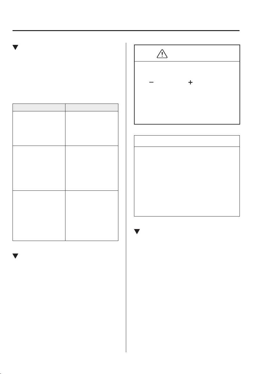
7
–
54
If Trouble Arises
Warning/Indicator Lights and Warning Sounds
*Some models.
Mazda Radar Cruise Control
(MRCC) System Warnings
*
The Mazda Radar Cruise Control (MRCC)
system warnings notify the driver of
system malfunctions and cautions on use
when required.
Check based on the beep sound.
Cautions What to check
The beep sounds 1 time
while the Mazda Radar
Cruise Control (MRCC)
is operating
The vehicle speed is
slower than 25 km/h
(16 mph) and the Mazda
Radar Cruise Control
(MRCC) system has
been cancelled.
(European models)
The beep sounds 5 times
while driving
(Except European
models)
The beep continues to
sound while the vehicle
is being driven.
The distance between
your vehicle and the
vehicle ahead is too
close. Verify the safety
of the surrounding area
and reduce vehicle
speed.
When the Mazda Radar
Cruise Control (MRCC)
is operating, the beep
sounds and the Mazda
Radar Cruise Control
(MRCC) warning
light (amber) in the
instrument cluster turns
on.
A malfunction in the
system may be indicated.
Have your vehicle
inspected at an expert
repairer, we recommend
an Authorised Mazda
Repairer.
Speed Limiter Warning Beep
*
If the vehicle speed exceeds the set speed
by about 3 km/h (2 mph) or more, a
warning beep operates continuously. The
warning beep operates until the vehicle
speed decreases to the set speed or less.
CAUTION
If the set speed is set lower than the
current vehicle speed by pressing the
SET
or RESUME/ switch, the
warning beep is not activated for about
30 seconds even if the vehicle speed is
faster than the newly set speed by
3 km/h (2 mph). Be careful not to drive
over the set speed.
NOTE
When the system is temporarily
cancelled by depressing the accelerator
pedal fully, the adjustable speed limiter
display shows the cancel display. If the
vehicle speed exceeds the set speed by
about 3 km/h (2 mph) or more while the
cancel display is displayed, the set speed
display À ashes but the warning sound is
not operated.
Collision Warning
*
If there is a possibility of a collision with
a vehicle ahead or an obstruction at the
rear of the vehicle, the warning light in the
instrument cluster À ashes at the same time
as the warning indication is displayed in
the active driving display, and a warning
sound is activated intermittently.
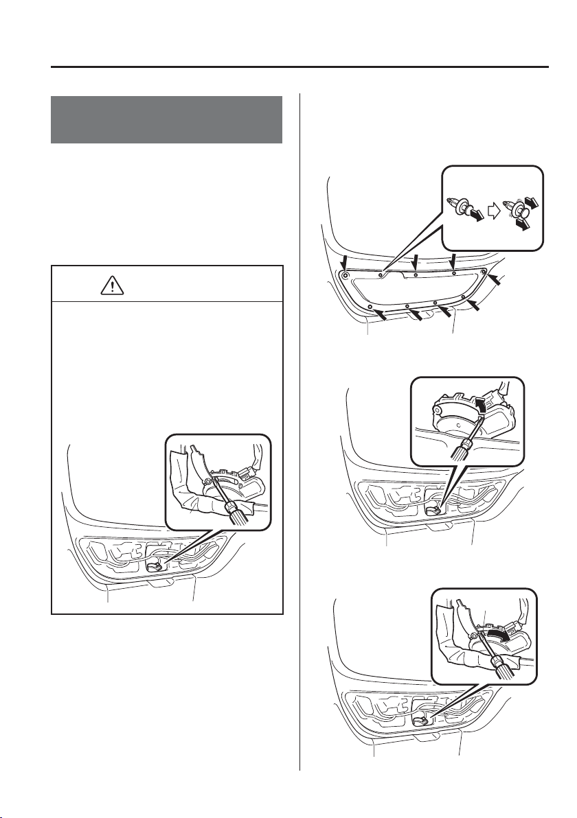
7
–
55
If Trouble Arises
When Liftgate/Boot Lid Cannot be Opened
When Liftgate/Boot Lid
Cannot be Opened
If the vehicle battery is dead or there is a
malfunction in the electrical system and
the liftgate/boot lid cannot be opened,
perform the following procedure as an
emergency measure to open it:
(Hatchback)
CAUTION
Perform the procedure using a cloth
to cover sharp edges which could
injure your hands.
Perform the procedure carefully
when using a À athead screwdriver
as it could cause damage to the
surrounding area or vehicle parts.
Cloth
1. Fold down the rear seatbacks.
Refer to Split/One-piece Folding the
Seatback on page 2-7 .
2. Pull the centre section of the plastic
fastener and remove the fasteners, then
remove cover on the interior surface of
the liftgate.
Removal
3. Using a À athead screwdriver, open the
inner cover.
4. Using a À athead screwdriver, turn the
lever to the right to unlock the liftgate.
Lever
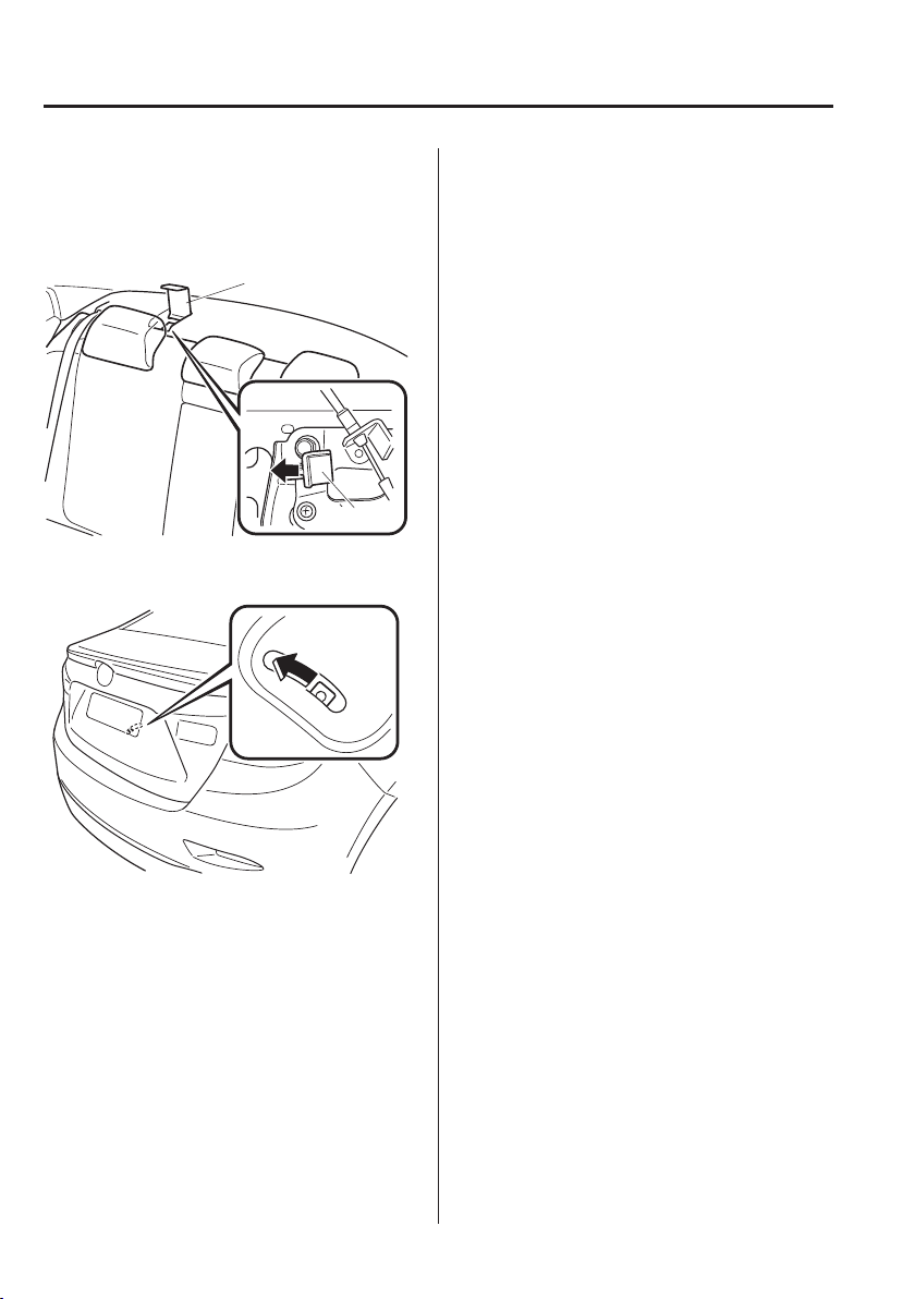
7
–
56
If Trouble Arises
When Liftgate/Boot Lid Cannot be Opened
(Saloon)
1. Open the cover.
2. Move the lever to the left to fold the
seatback.
Lever
Cover
3. Move the lever to the left to open the
boot lid.
After performing this emergency measure,
have the vehicle inspected at an expert
repairer, we recommend an Authorised
Mazda Repairer as soon as possible.

7
–
57
If Trouble Arises
Active Driving Display Does Not Operate
If the Active Driving Display does not operate
If the active driving display does not operate, switch the ignition off and then restart the
engine. If the active driving display does not operate even with the engine restarted, have
the vehicle inspected at an expert repairer, we recommend an Authorised Mazda Repairer.

MEMO
7
–
58

8
–
18
–
1
8
Customer Information
Important consumer information including warranties and add-on
equipment.
Warranty ............................................................................................. 8-2
Registering Your Vehicle in A Foreign Country ........................... 8-2
Add-On Non-Genuine Parts and Accessories ............................... 8-3
Cell Phones ......................................................................................... 8-4
Cell Phones Warning ..................................................................... 8-4
Recording of Vehicle Data ................................................................. 8-5
Recording of Vehicle Data ............................................................ 8-5
Declaration of Conformity ................................................................ 8-6
Declaration of Conformity ............................................................ 8-6
Electromagnetic Compatibility ....................................................... 8-26
Electromagnetic Compatibility ................................................... 8-26
Collection/Disposal of Old Equipment/Used Battery ................... 8-28
Information for Users on Collection and Disposal of Old
Equipment and Used Batteries .................................................... 8-28

8
–
2
Customer Information
Warranty
Registering Your Vehicle in A Foreign Country
Registering your vehicle in a foreign country may be problematic depending on whether it
meets the speci¿ c emission and safety standards of the country in which the vehicle will be
driven. Consequently, your vehicle may require modi¿ cations at personal expense in order
to meet the regulations.
In addition, you should be aware of the following issues:
Satisfactory vehicle servicing may be dif¿ cult or impossible in another country.
The fuel speci¿ ed for your vehicle may be unavailable.
Parts, servicing techniques, and tools necessary to maintain and repair your vehicle may be
unavailable.
There might not be an Authorised Mazda Dealer in the country you plan to take your
vehicle.
The Mazda warranty is valid only in certain countries.
8
–
3
Customer Information
Warranty
Add-On Non-Genuine Parts and Accessories
Please note that technical alterations to the original state of your Mazda vehicle can affect
the safety of the vehicle. Such technical alterations include not only the use of unsuitable
spare parts, but also accessories, ¿ ttings or attachments, including rims and tyres.
Genuine Mazda Parts and Genuine Mazda Accessories have been speci¿ cally designed for
Mazda vehicles.
Other parts and accessories than those mentioned above have not been examined and
approved by Mazda unless explicitly stated by Mazda. We cannot certify the suitability of
such products. Mazda is not liable for any damage caused by the use of such products.
WARNING
Be very careful in choosing and installing add-on electrical equipment, such as mobile
telephones, two-way radios, stereo systems, and car alarm systems:
Incorrectly choosing or installing improper add-on equipment or choosing an improper
installer is dangerous. Essential systems could be damaged, causing engine stalling,
air-bag (SRS) activation, ABS/TCS/DSC inactivation, or a ¿ re in the vehicle.
Mazda assumes no responsibility for death, injury, or expenses that may result from the
installation of add-on non-genuine parts or accessories.
8
–
4
Customer Information
Cell Phones
Cell Phones Warning
WARNING
Please comply with the legal regulations concerning the use of communication
equipment in vehicles in your country:
Use of any electrical devices such as cell phones, computers, portable radios, vehicle
navigation or other devices by the driver while the vehicle is moving is dangerous.
Dialing a number on a cell phone while driving also ties-up the driver's hands. Use of
these devices will cause the driver to be distracted and could lead to a serious accident.
If a passenger is unable to use the device, pull off the right-of-way to a safe area before
use. If use of a cell phone is necessary despite this warning, use a hands-free system
to at least leave the hands free to drive the vehicle. Never use a cell phone or other
electrical devices while the vehicle is moving and, instead, concentrate on the full-time
job of driving.
8
–
5
Customer Information
Recording of Vehicle Data
Recording of Vehicle Data
This vehicle is equipped with a computer which records the following main vehicle data
related to vehicle controls, operation, and other driving conditions.
Recorded data
Vehicle conditions such as engine speed and vehicle speed
Driving operation conditions such as accelerator and brake pedals, and information related
to the environmental circumstances while the vehicle is driven
Malfunction diagnosis information from each on-vehicle computer
Information related to controls of other on-vehicle computers
NOTE
The recorded data may vary depending on the vehicle grade and optional equipment.
Voice and images are not recorded.
Data handling
Mazda and its subcontracting parties may obtain and use the recorded data for vehicle
malfunction diagnosis, research and development, and quality improvement.
Mazda will not disclose or provide any of the obtained data to a third party unless:
An agreement from the vehicle owner (agreements from lessor and lessee for leased
vehicle) is obtained
Of¿ cially requested by the police or other law enforcement authorities
For statistical processing by a research institution after processing the data so that
identi¿ cation of the owner or the vehicle is impossible
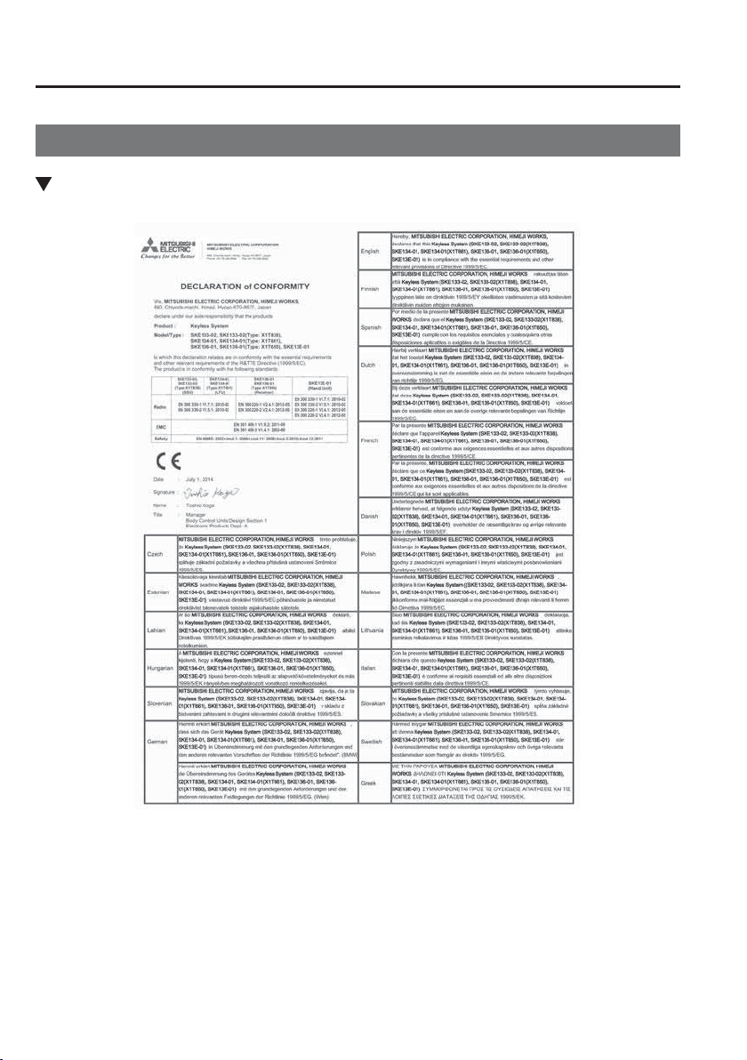
8
–
6
Customer Information
Declaration of Conformity
Declaration of Conformity
Keyless Entry System/Immobilizer System
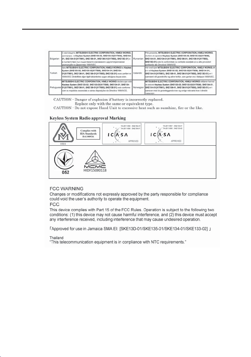
8
–
7
Customer Information
Declaration of Conformity
8
–
8
Customer Information
Declaration of Conformity
8
–
9
Customer Information
Declaration of Conformity
8
–
10
Customer Information
Declaration of Conformity
8
–
11
Customer Information
Declaration of Conformity
Blind Spot Monitoring (BSM) System
8
–
12
Customer Information
Declaration of Conformity
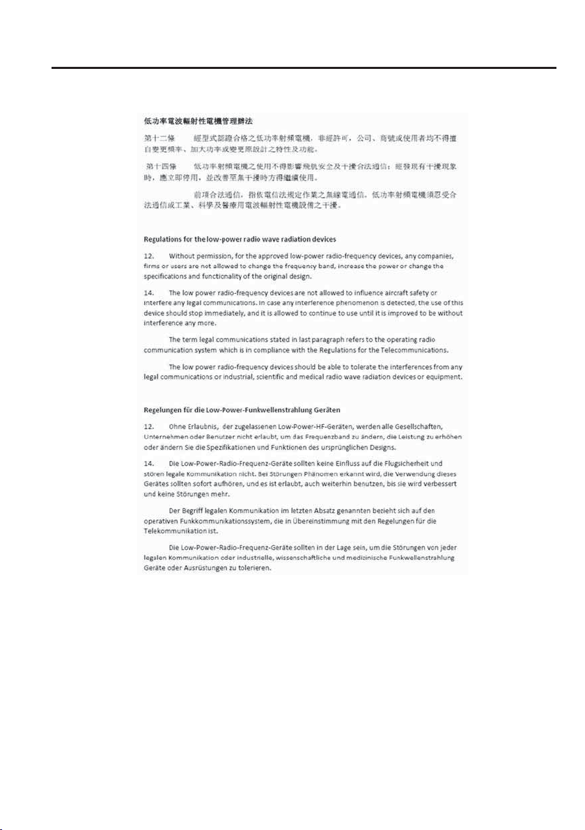
8
–
13
Customer Information
Declaration of Conformity
8
–
14
Customer Information
Declaration of Conformity
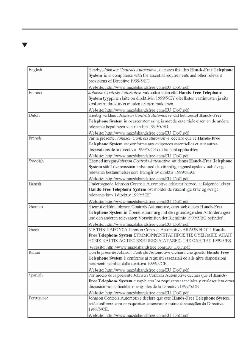
8
–
15
Customer Information
Declaration of Conformity
Bluetooth
®
Hands-Free
Type A
8
–
16
Customer Information
Declaration of Conformity
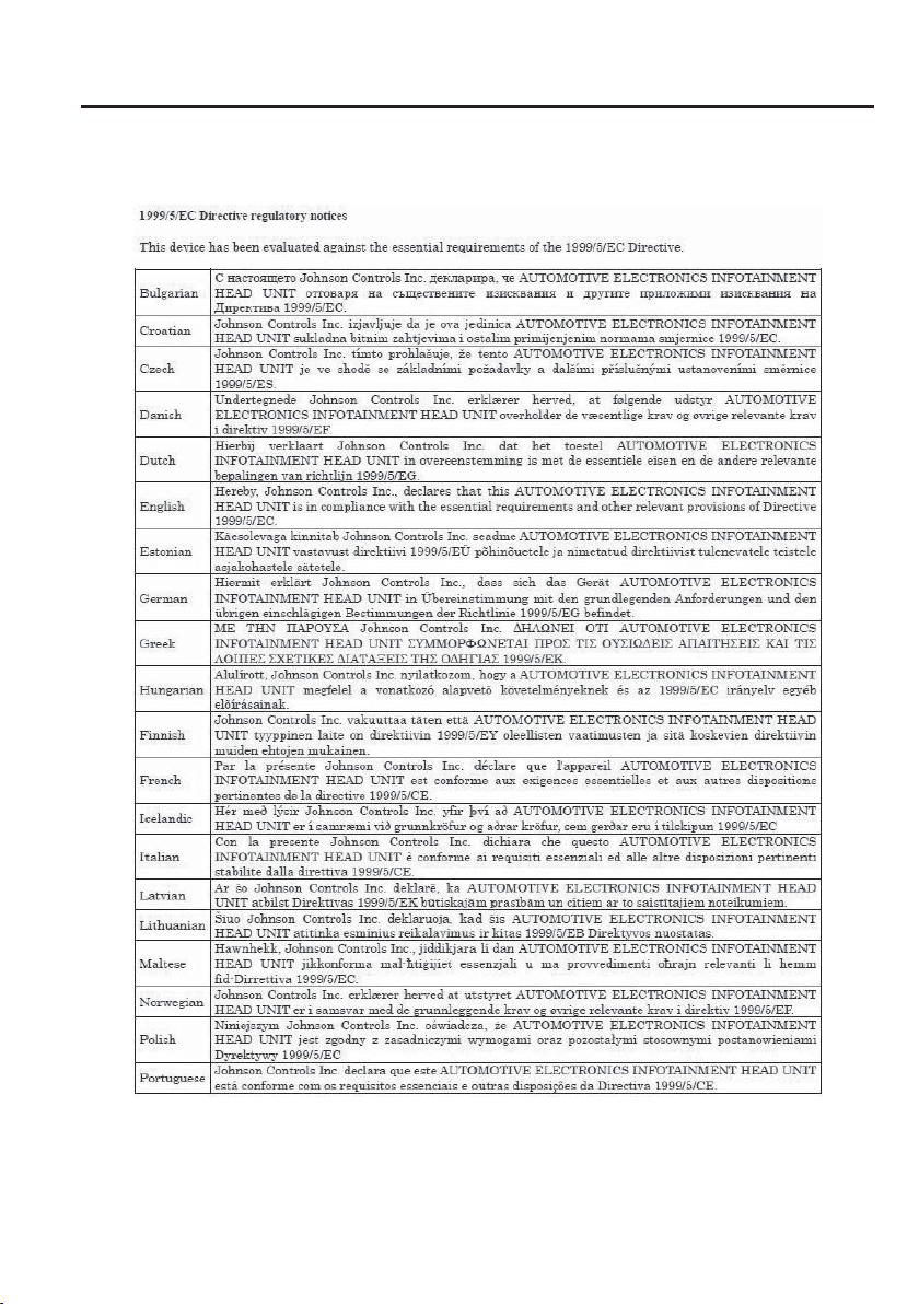
8
–
17
Customer Information
Declaration of Conformity
Type B
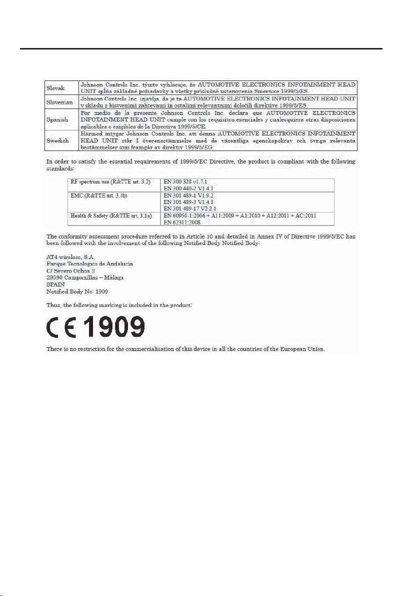
8
–
18
Customer Information
Declaration of Conformity
8
–
19
Customer Information
Declaration of Conformity
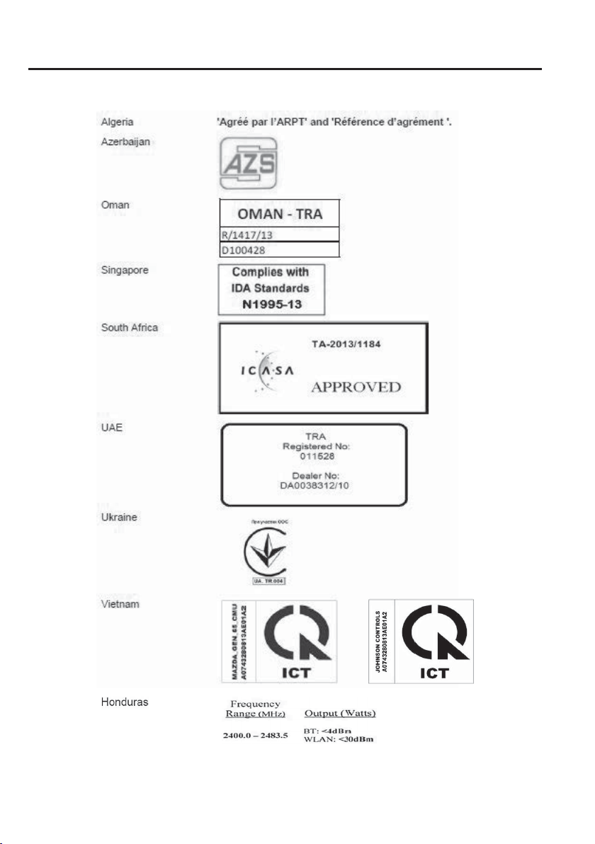
8
–
20
Customer Information
Declaration of Conformity
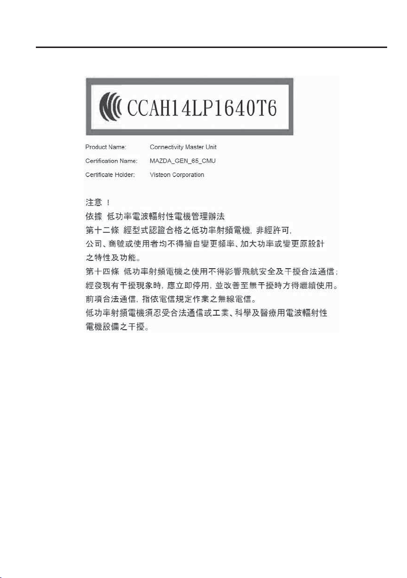
8
–
21
Customer Information
Declaration of Conformity
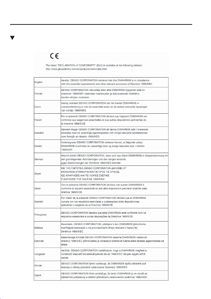
8
–
22
Customer Information
Declaration of Conformity
Distance Recognition Support System (DRSS)/Mazda Radar Cruise Control
(MRCC)/Smart Brake Support (SBS)
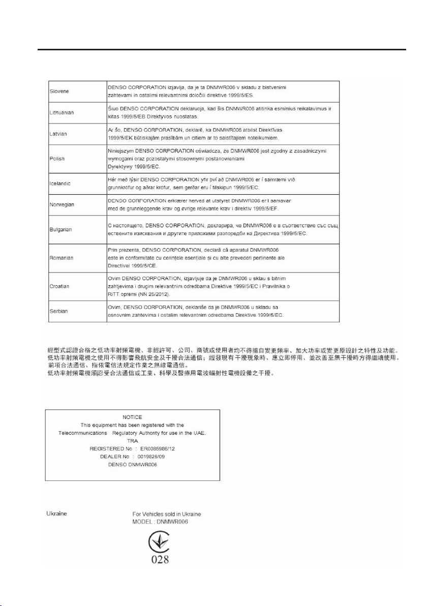
8
–
23
Customer Information
Declaration of Conformity
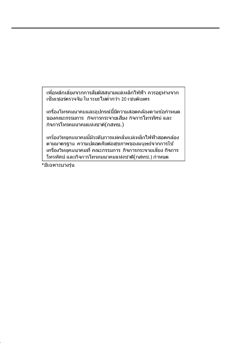
8
–
24
Customer Information
Declaration of Conformity

8
–
25
Customer Information
Declaration of Conformity
For Vehicles sold in Moldova
MODEL: DNMWR006
8
–
26
Customer Information
Electromagnetic Compatibility
Electromagnetic Compatibility
Your Mazda has been tested and certi¿ ed to the UNECE
*1
10 regulation as related to
electromagnetic compatibility. Radio Frequency (RF) transmitter equipment (e.g. cellular
telephones, amateur radio transmitters, etc.) may only be ¿ tted to your Mazda if they
comply with the parameters shown in the table below.
*1 UNECE stands for United Nations Economic Commission for Europe.
It is your responsibility to ensure that any equipment you have ¿ tted complies with
applicable local legislations. Have any equipment ¿ tted by properly trained technicians.
CAUTION
Do not mount any transceiver, microphones, speakers, or any other item in the
deployment path of the air bag system.
Do not fasten aerial lead to original vehicle wiring, fuel pipes or brake pipes. Avoid
running the aerial lead parallel with the wire harness to the best extent possible.
Keep the aerial and power leads at least 100 mm (3.9 in) from any electronic modules
and the air bags.
Avoid using the cigar lighter or accessory socket as a power source for the RF-
transmitting equipment.
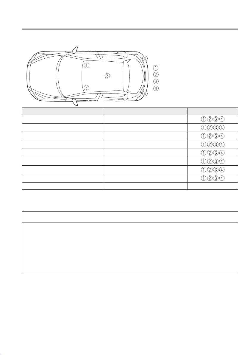
8
–
27
Customer Information
Electromagnetic Compatibility
Aerial positions:
: front right of roof
: front left of roof
: centre of roof
: both sides of liftgate (Hatchback)
Frequency Band (MHz) Maximum output power (Wattage) Aerial Positions
50 — 54 50
68 — 87.5 50
142 — 176 50
380 — 470 50
806 — 940 10
1200 — 1300 10
1710 — 1885 10
1885 — 2025 10
2400 — 2500 0.01
*1
In a cabin
*1
*1 Only for Bluetooth
®
NOTE
After the installation of RF transmitters, check for disturbances from and to all electrical
equipment in the vehicle, both in the standby and transmit modes.
Check all electrical equipment:
with the ignition ON
with the engine running
during a road test at various speeds.
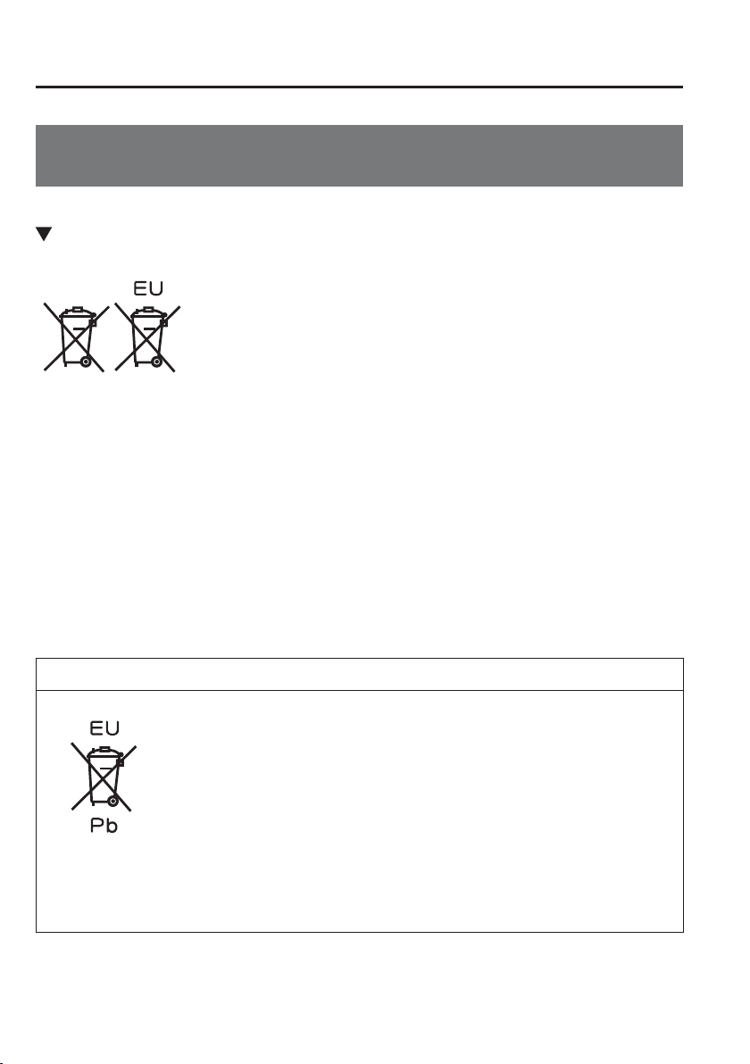
8
–
28
Customer Information
Collection/Disposal of Old Equipment/Used Battery
Information for Users on Collection and Disposal of Old
Equipment and Used Batteries
When disposing your old battery, please refer to the information as follows.
Information on Disposal in the European Union
These crossed-out wheeled bin symbols on the products, packaging, and/or accompanying
documents mean that used electronic products and batteries should not be mixed with
general household waste. For proper treatment, recovery and recycling of old products and
used batteries, please take them to applicable collection points, in accordance with your
national legislation and the Directives 2006/66/EC.
By disposing of these products and batteries correctly, you will help to save valuable
resources and prevent any potential negative effects on human health and the environment
which could otherwise arise from inappropriate waste handling.
For more information about collection and recycling of old products and batteries, please
contact your local municipality, your waste disposal service or the point of sales where you
purchased the items.
NOTE
The bottom two letters might be used in combination with the crossed-out wheeled bin
symbol. In this case it complies with the requirement established by the Directive for the
chemical involved.
“Pb” and “Cd” mean lead and cadmium respectively.

8
–
29
Customer Information
Collection/Disposal of Old Equipment/Used Battery
Information on Disposal in Other Countries Outside the European Union
The above symbols are only valid in the European Union. If you wish to discard old
products and used batteries, please contact your local authorities, your waste disposal
service or the point of sales where you purchased the items, and ask for the correct method
of disposal.

MEMO
8
–
30

9
–
19
–
1
9
Speci¿ cations
Technical information about your Mazda.
Identi¿ cation Numbers ...................................................................... 9-2
Vehicle Information Labels ........................................................... 9-2
Speci¿ cations ...................................................................................... 9-4
Speci¿ cations ................................................................................ 9-4
Personalisation Features.................................................................. 9-13
Personalisation Features .............................................................. 9-13
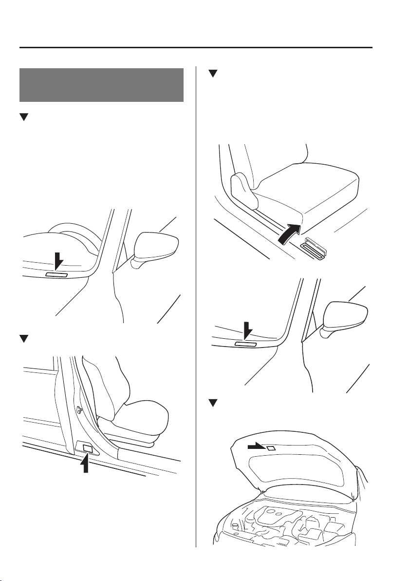
9
–
2
Speci¿ cations
Identi¿ cation Numbers
Vehicle Information
Labels
Vehicle Identi¿ cation Number
(South Africa)
The vehicle identi¿ cation number legally
identi¿ es your vehicle. The number is on
a plate attached to the cowl panel located
on the left corner of the instrument panel.
This plate can easily be seen through the
windscreen.
Model Plate
Chassis Number/Vehicle
Identi¿ cation Number
(Ireland, Russia, U.K.)
Chassis Number
Open the cover shown in the ¿ gure to
check the chassis number.
Vehicle Identi¿ cation Number
Vehicle Emission Control
Information Label (Thailand)
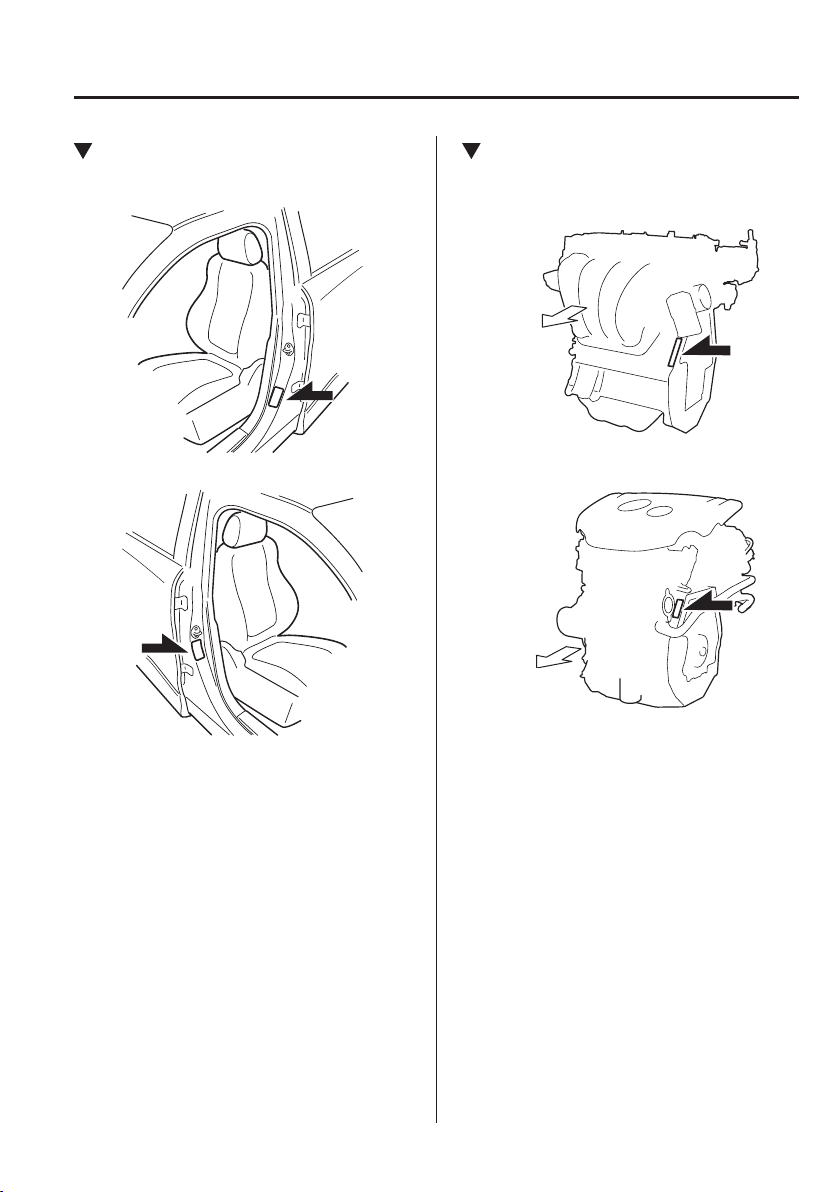
9
–
3
Speci¿ cations
Identi¿ cation Numbers
Tyre Pressure Label
Left-hand drive model
Right-hand drive model
Engine Number
SKYACTIV-G 1.3, SKYACTIV-G 1.5
Forward
SKYACTIV-D 1.5
Forward
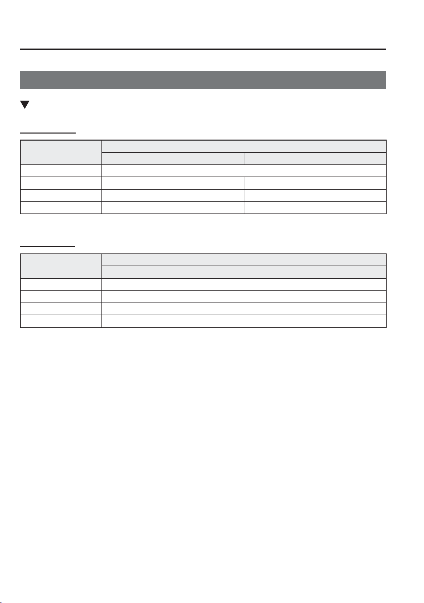
9
–
4
Speci¿ cations
Speci¿ cations
S p e c i ¿ cations
Engine
Petrol engine
Item
Speci¿ cation
SKYACTIV-G 1.3 SKYACTIV-G 1.5
Type DOHC-16V in-line, 4-cylinder
Bore × Stroke 71 × 82 mm (2.80 × 3.23 in) 74.5 × 85.8 mm (2.93 × 3.38 in)
Displacement 1,299 ml (1,299 cc) 1,496 ml (1,496 cc)
Compression ratio 12.0 12.0/13.0/14.0
Diesel engine
Item
Speci¿ cation
SKYACTIV-D 1.5
Type DOHC-16V in-line, 4-cylinder
Bore × Stroke 76 × 82.6 mm (2.99 × 3.25 in)
Displacement 1,499 ml (1,499 cc)
Compression ratio 14.8
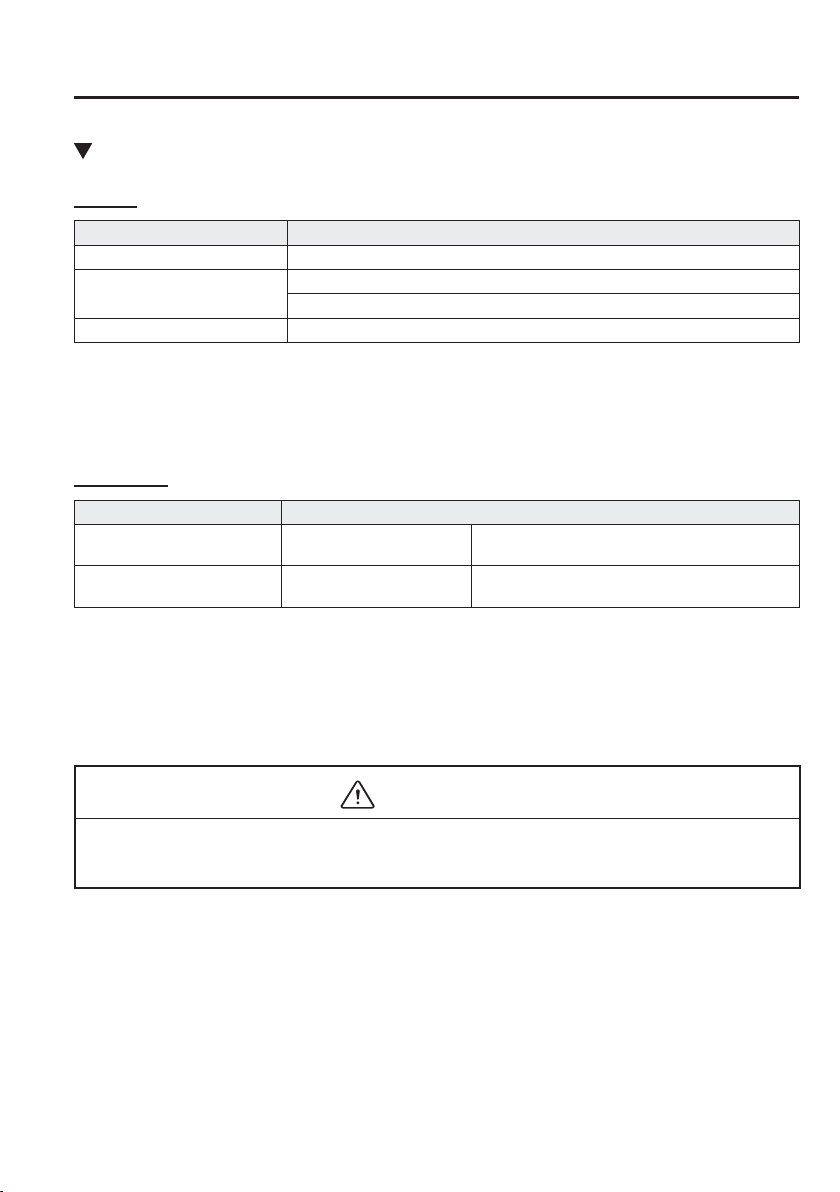
9
–
5
Speci¿ cations
Speci¿ cations
Electrical System
Battery
Classi¿ cation Speci¿ cation
SKYACTIV-G 1.3 Q-85
*1
SKYACTIV-G 1.5
N-55 (S)
*1
or Q-85
*1
12V-60Ah/20HR
*2
SKYACTIV-D 1.5 S-95
*1
or Q-85
*1
*1 N-55 (S), Q-85 or S-95 is designed for i-stop system (FOR STOP & START)/i-ELOOP system. Only N-55 (S),
Q-85 or S-95 should be used to ensure correct operation of i-stop system (FOR STOP & START)/i-ELOOP
system. Consult an expert repairer, we recommend an Authorised Mazda Repairer for details.
*2 Not for i-stop system/i-ELOOP system.
S p a r k - p l u g
Classi¿ cation Speci¿ cation
SKYACTIV-G 1.3,
SKYACTIV-G 1.5 LP
*1
Mazda Genuine spark plug
*2
P51R-18-110
SKYACTIV-G 1.5 MP
*1
,
SKYACTIV-G 1.5 HP
*1
Mazda Genuine spark plug
*2
PE5R-18-110 or PE5S-18-110
*1 The alphabetical letters at the end of the engine types are short for the following:
LP: Low-Power
MP: Medium-Power
HP: High-Power
*2 The spark plugs provide the SKYACTIV-G its optimum performance. Consult an expert repairer, we
recommend an Authorised Mazda Repairer for details.
CAUTION
When cleaning the iridium plugs, do not use a wire brush. The ¿ ne particulate coating on
the iridium alloy and platinum tips could be damaged.
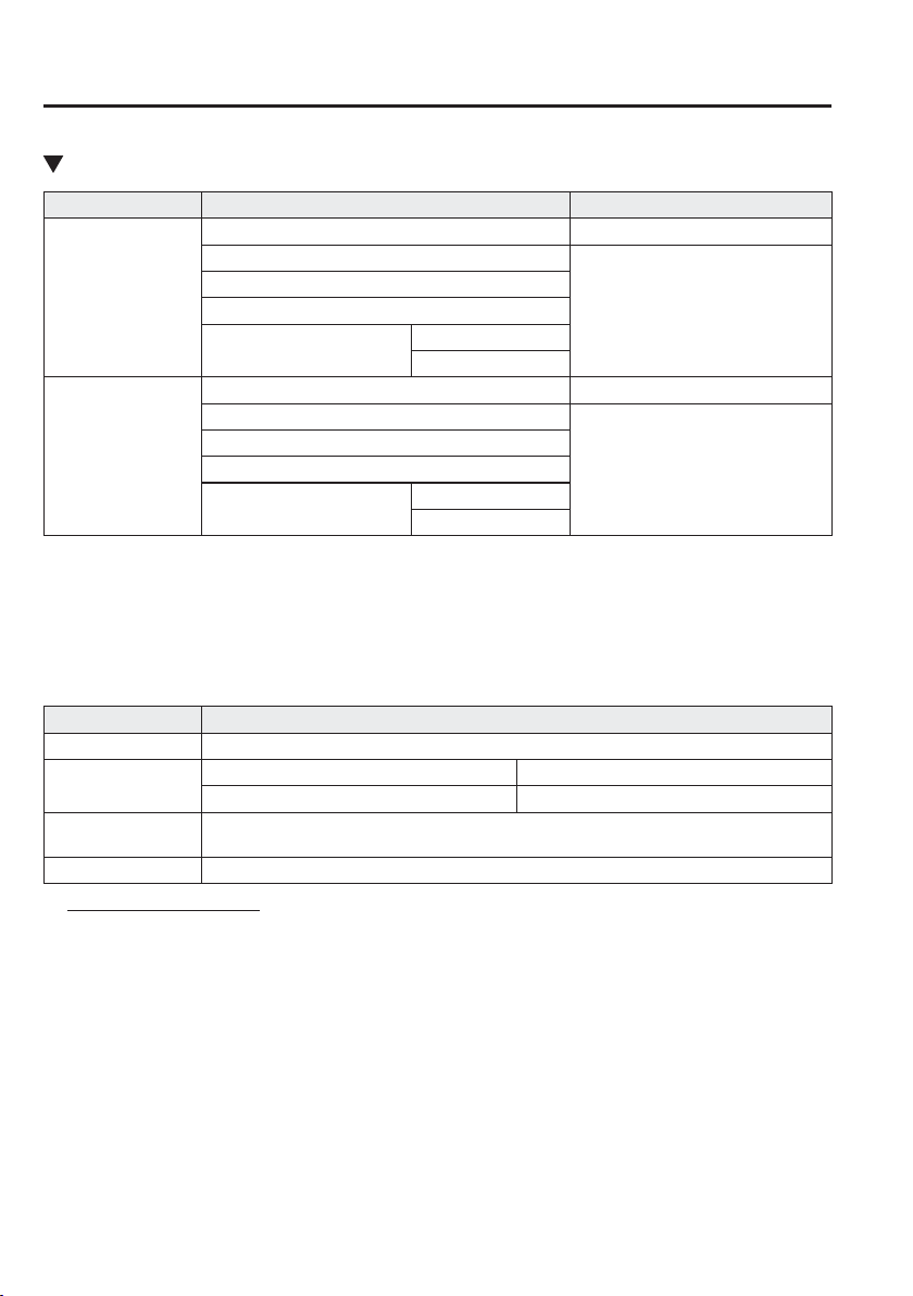
9
–
6
Speci¿ cations
Speci¿ cations
Lubricant Quality
Engine oil
*1
Europe Except Europe
SKYACTIV-G 1.3,
SKYACTIV-G 1.5
Recommended Oils
*2
Oil Quality
Mazda Original Oil Supra 0W-20
API SG/SH/SJ/SL/SM/SN or
ILSAC GF-II/GF-III/GF-IV/GF-V
Mazda Original Oil Ultra 5W-30
Alternative Oil Quality
*3
API SL/SM/SN or
ACEA A3/A5
0W-20
5W-30
SKYACTIV-D 1.5
Recommended Oils
*2
Oil Quality
Mazda Original Oil Supra DPF 0W-30
ACEA C3
0W-30 / 5W-30
Mazda Original Oil Ultra DPF 5W-30
Alternative Oil Quality
*3
ACEA C3
0W-30
5W-30
*1 Refer to the recommended SAE viscosity numbers on page 6-23 .
*2 Mazda Original Oils are specially designed/tested for the respective engine. For optimum performance we
recommend to use Mazda Original Oils at all times.
*3 If you are unable to ¿ nd a Mazda Original Oil, alternative oils meeting the listed speci¿ cation may also be used.
Do not use oils which do not meet the above speci¿ cation or requirements. Use of
unsuitable oil may lead to engine damage which is not covered by the Mazda Warranty.
Lubricant Classi¿ cation
Coolant FL-22 type
Manual transaxle oil
API Service GL-4
SAE 75W-80
Automatic transaxle
À uid
Mazda Original Oil ATF-FZ
Brake/Clutch À uid SAE J1703 or FMVSS116 DOT-3 or DOT-4
*1
* 1 (Except European models)
Use FMVSS116 DOT-4 brake À uid for vehicles equipped with the SKYACTIV-D 1.5 engine and drum type rear
brakes.
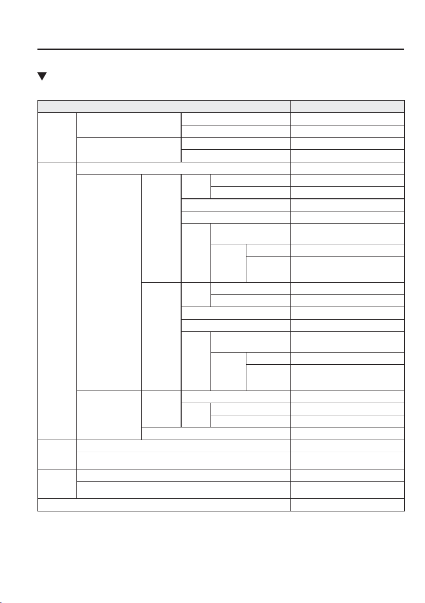
9
–
7
Speci¿ cations
Speci¿ cations
Capacities
(Approximate Quantities)
Item Capacity
Engine oil
SKYACTIV-G 1.3,
SKYACTIV-G 1.5
With oil ¿ lter replacement 4.2 L (4.4 US qt, 3.7 Imp qt)
Without oil ¿ lter replacement 3.9 L (4.1 US qt, 3.4 Imp qt)
SKYACTIV-D 1.5
With oil ¿ lter replacement 5.1 L (5.4 US qt, 4.5 Imp qt)
Without oil ¿ lter replacement 4.7 L (5.0 US qt, 4.1 Imp qt)
Coolant
SKYACTIV-G 1.3 5.2 L (5.5 US qt, 4.6 Imp qt)
SKYACTIV-G 1.5
Manual
transaxle
Europe
Left-hand drive model 5.4 L (5.7 US qt, 4.8 Imp qt)
Right-hand drive model
5.0 L (5.3 US qt, 4.4 Imp qt)
Russia 5.4 L (5.7 US qt, 4.8 Imp qt)
Israel 5.0 L (5.3 US qt, 4.4 Imp qt)
Except
above
Left-hand drive model
*1
5.0 L (5.3 US qt, 4.4 Imp qt)/
5.4 L (5.7 US qt, 4.8 Imp qt)
Right-
hand
drive
model
With heater 5.0 L (5.3 US qt, 4.4 Imp qt)
Without
heater
4.5 L (4.8 US qt, 4.0 Imp qt)
Automatic
transaxle
Europe
Left-hand drive model 5.6 L (5.9 US qt, 4.9 Imp qt)
Right-hand drive model
5.2 L (5.5 US qt, 4.6 Imp qt)
Russia 5.6 L (5.9 US qt, 4.9 Imp qt)
Israel, Saudi Arabia 5.2 L (5.5 US qt, 4.6 Imp qt)
Except
above
Left-hand drive model
*1
5.2 L (5.5 US qt, 4.6 Imp qt)/
5.6 L (5.9 US qt, 4.9 Imp qt)
Right-
hand
drive
model
With heater 5.2 L (5.5 US qt, 4.6 Imp qt)
Without
heater
4.7 L (5.0 US qt, 4.1 Imp qt)
SKYACTIV-D 1.5
For engine
Europe 6.6 L (7.0 US qt, 5.8 Imp qt)
Except
above
Left-hand drive model 6.7 L (7.1 US qt, 5.9 Imp qt)
Right-hand drive model
6.8 L (7.2 US qt, 6.0 Imp qt)
For water-cooled charge air cooler 2.0 L (2.1 US qt, 1.8 Imp qt)
Manual
transaxle
oil
SKYACTIV-G 1.5 1.59 L (1.68 US qt, 1.40 Imp qt)
SKYACTIV-D 1.5 1.64 L (1.73 US qt, 1.44 Imp qt)
Automatic
transaxle
À uid
SKYACTIV-G 1.3, SKYACTIV-G 1.5 7.2 L (7.6 US qt, 6.3 Imp qt)
SKYACTIV-D 1.5 7.8 L (8.2 US qt, 6.9 Imp qt)
Fuel tank 44.0 L (11.6 US gal, 9.68 Imp gal)
Check oil and À uid levels with dipsticks or reservoir gauges.
*1 The engine coolant amount varies depending on the speci¿ cation.
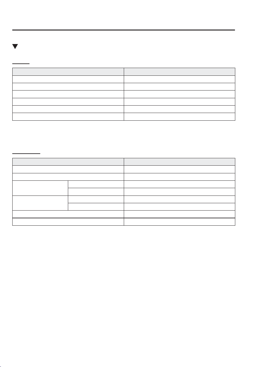
9
–
8
Speci¿ cations
Speci¿ cations
Dimensions
S a l o o n
Item Vehicle speci¿ cation
Overall length 4,320 mm (170.1 in)
Overall width 1,695 mm (66.7 in)
Overall height 1,470 mm (57.9 in)
Front tread 1,495 mm (58.9 in)
Rear tread 1,485 mm (58.5 in)
Wheelbase 2,570 mm (101.2 in)
H a t c h b a c k
Item Vehicle speci¿ cation
Overall length 4,060 mm (159.8 in)
Overall width 1,695 mm (66.7 in)
Overall height
Except Colombia 1,495 mm (58.9 in)
Colombia 1,505 mm (59.3 in)
Front tread
Except Colombia 1,495 mm (58.9 in)
Colombia 1,490 mm (58.7 in)
Rear tread 1,485 mm (58.5 in)
Wheelbase 2,570 mm (101.2 in)
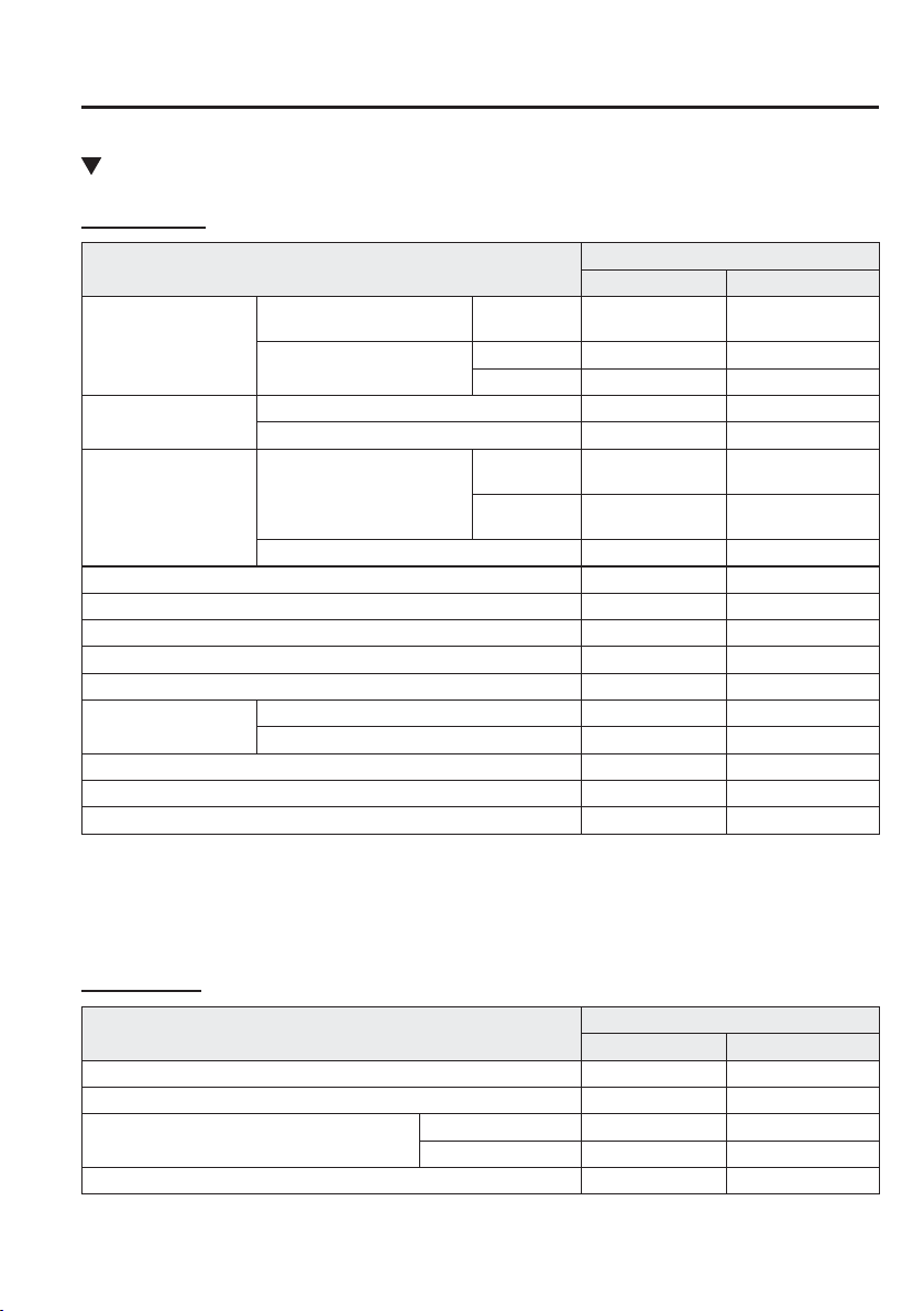
9
–
9
Speci¿ cations
Speci¿ cations
*Some models.
Light Bulbs
Exterior light
Light bulb
Category
Wattage UNECE
*1
(SAE)
Headlights
Halogen bulb headlights
High/Low
beam
60/55 H4 (H4)
LED headlights
High beam LED
*2
— (—)
Low beam LED
*2
— (—)
Running lights
*
With halogen bulb headlights 21/5
*3
W21/5W (7443)
With LED headlights LED
*2
— (—)
Position lights
With halogen bulb headlights
With running
lights
21/5
*4
W21/5W (7443)
Without
running lights
5 W5W (—)
With LED headlights LED
*2
— (—)
Front direction indicator lights 21 WY21W (7443NA)
Front fog lights
*
L E D
*2
— (—)
Side direction indicator lights LED
*2
— (—)
High-mount brake light LED
*2
— (—)
Rear direction indicator lights 21 WY21W (7443NA)
Brake lights/Tail lights
Bulb type 21/5 W21/5W (7443)
LED type LED
*2
— (—)
Reverse lights 16 W16W (921)
Rear fog light
*
21 W21W (7440)
Number plate lights 5 W5W (—)
*1 UNECE stands for United Nations Economic Commission for Europe.
*2 LED is the abbreviation for Light Emitting Diode.
*3 Double-¿ lament light bulb, however, only 21 W ¿ lament bulb is used in the running lights.
*4 Double-¿ lament light bulb, however, only 5 W ¿ lament bulb is used in the position lights.
Interior light
Light bulb
Category
Wattage UNECE
*1
Boot light (Saloon) 3 —
Luggage compartment light (Hatchback) 5 —
Overhead light (Front)
With map lights 8 —
Without map lights 10 —
Overhead light (Rear)
*
10 —
*1 UNECE stands for United Nations Economic Commission for Europe.
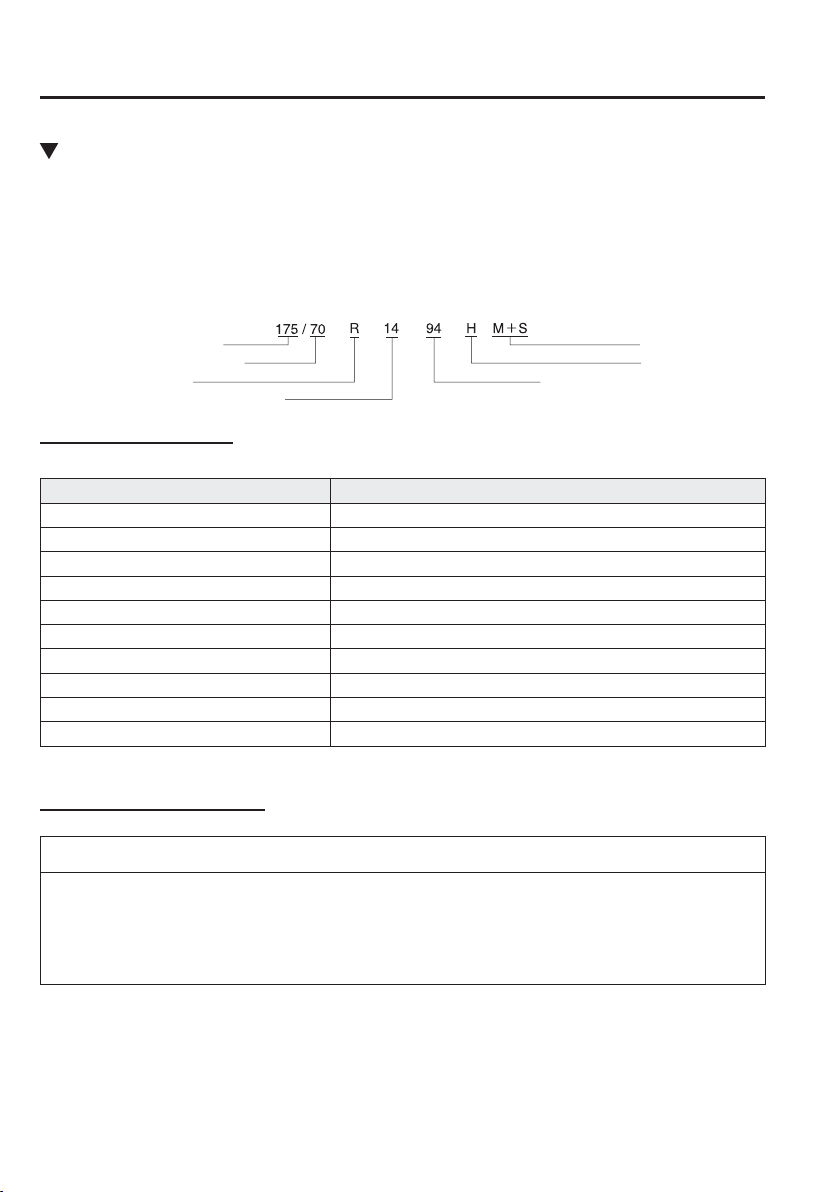
9
–
10
Speci¿ cations
Speci¿ cations
Tyres
Sample tyre mark and its meaning
Nominal section width
Nominal aspect ratio in %
Construction code
Mud and snow
Speed symbol
Load index (not on ZR tyres)
Nominal rim diameter in inches
Tyre mark information
Choose the proper tyres for your vehicle using the following tyre mark information.
Speed symbol Maximum permissible speed
Q Up to 160 km/h (99 mph)
R Up to 170 km/h (105 mph)
S Up to 180 km/h (111 mph)
T Up to 190 km/h (118 mph)
U Up to 200 km/h (124 mph)
H Up to 210 km/h (130 mph)
V Up to 240 km/h (149 mph)
W Up to 270 km/h (167 mph)
Y Up to 300 km/h (186 mph)
ZR Over 240 km/h (149 mph)
Tyre and inÀ ation pressure
NOTE
The tyres have been optimally matched with the chassis of your vehicle.
When replacing tyres, Mazda recommends that you replace tyres of the same type
originally ¿ tted to your vehicle. For details, contact an expert repairer, we recommend an
Authorised Mazda Repairer.
Check the tyre pressure label for tyre size and inÀ ation pressure (page 6-44 ).
After adjusting the tyre pressure, initialization of the tyre pressure monitoring system is
necessary to make the system operates normally.
Refer to Tyre Pressure Monitoring System Initialization on page 4-192 .
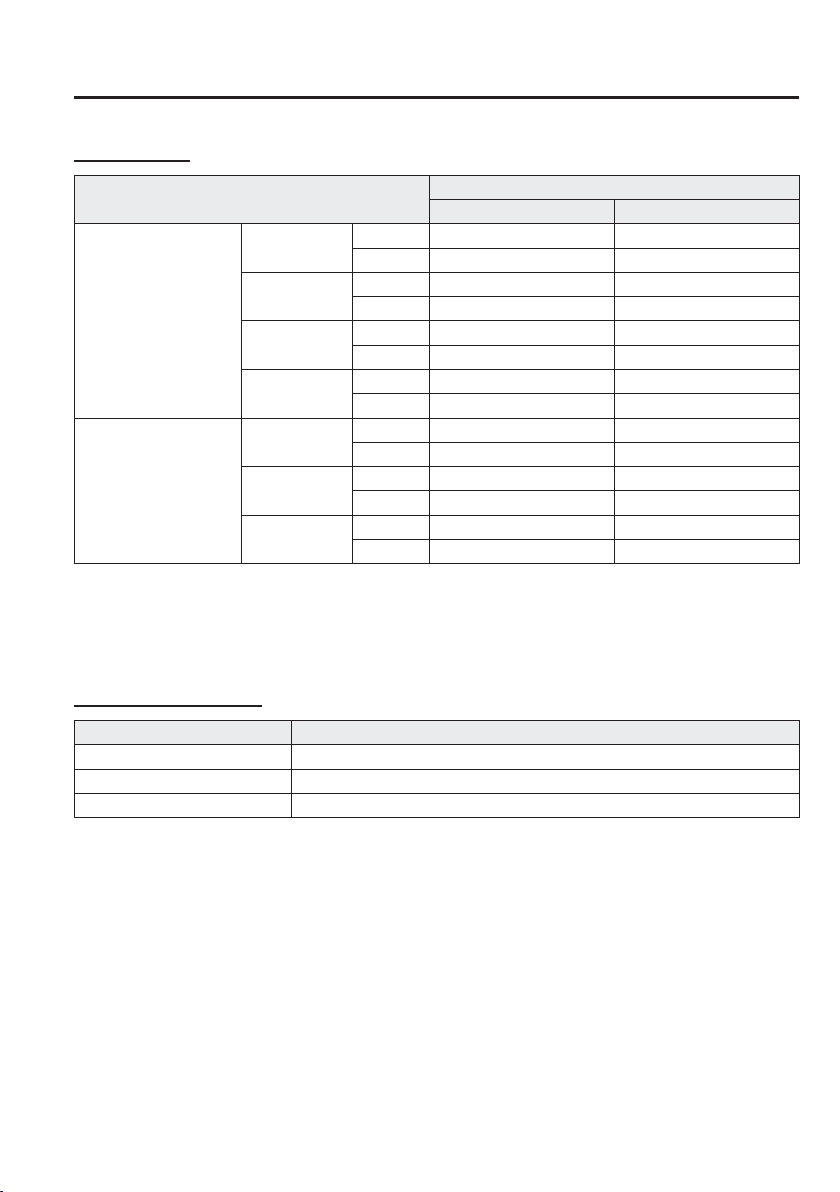
9
–
11
Speci¿ cations
Speci¿ cations
*Some models.
Standard tyre
Tyre size
InÀ ation pressure
Up to 3 persons —Full load
185/65R15 88T
Type A
*1
Front 230 kPa (2.3 bar, 33 psi) 260 kPa (2.6 bar, 38 psi)
Rear 210 kPa (2.1 bar, 30 psi) 320 kPa (3.2 bar, 46 psi)
Type B
*1
Front 250 kPa (2.5 bar, 36 psi) 270 kPa (2.7 bar, 39 psi)
Rear 230 kPa (2.3 bar, 33 psi) 320 kPa (3.2 bar, 46 psi)
Type C
*1
Front 260 kPa (2.6 bar, 38 psi) 270 kPa (2.7 bar, 39 psi)
Rear 230 kPa (2.3 bar, 33 psi) 320 kPa (3.2 bar, 46 psi)
Type D
*1
Front 240 kPa (2.4 bar, 35 psi) 260 kPa (2.6 bar, 38 psi)
Rear 210 kPa (2.1 bar, 30 psi) 320 kPa (3.2 bar, 46 psi)
185/60R16 86H
Type A
*1
Front 250 kPa (2.5 bar, 36 psi) 260 kPa (2.6 bar, 38 psi)
Rear 230 kPa (2.3 bar, 33 psi) 330 kPa (3.3 bar, 48 psi)
Type B
*1
Front 250 kPa (2.5 bar, 36 psi) 270 kPa (2.7 bar, 39 psi)
Rear 230 kPa (2.3 bar, 33 psi) 330 kPa (3.3 bar, 48 psi)
Type C
*1
Front 260 kPa (2.6 bar, 38 psi) 270 kPa (2.7 bar, 39 psi)
Rear 230 kPa (2.3 bar, 33 psi) 330 kPa (3.3 bar, 48 psi)
1 person's weight: About 75 kg
*1 Check the tyre inÀ ation pressure label (driver's door frame ) for the correct tyre inÀ ation pressure. Refer to Tyre
Pressure Label on page 9-3 .
Temporary spare tyre
*
Tyre size InÀ ation pressure
T125/90R15 96M 420 kPa (60 psi)
T125/70D15 95M 420 kPa (60 psi)
165/65R14 79M 250 kPa (2.5 bar, 36 psi)
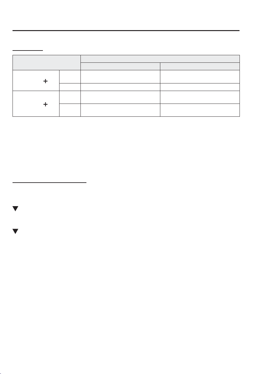
9
–
12
Speci¿ cations
Speci¿ cations
Winter tyre
Tyre size
InÀ ation pressure
Up to 3 persons —Full load
185/65R15
*1
M S
Front
230 kPa (2.3 bar, 33 psi)
*3
/
240 kPa (2.4 bar, 35 psi)
*4
260 kPa (2.6 bar, 38 psi)
Rear 230 kPa (2.3 bar, 33 psi) 320 kPa (3.2 bar, 46 psi)
185/60R16
*2
M S
Front
250 kPa (2.5 bar, 36 psi)
*3
/
260 kPa (2.6 bar, 38 psi)
*4
270 kPa (2.7 bar, 39 psi)
Rear 250 kPa (2.5 bar, 36 psi)
320 kPa (3.2 bar, 46 psi)
*5
/
350 kPa (3.5 bar, 50 psi)
*6
1 person's weight: About 75 kg
*1 Load index and Speed Symbol: 88Q/88S/88T
*2 Load index and Speed Symbol: 86Q/86S/86T/86H
*3 SKYACTIV-G 1.5
*4 SKYACTIV-D 1.5
*5 Load index and Speed Symbol: 86Q/86S/86T
*6 Load index and Speed Symbol: 86H
Wheel nut tightening torque
When installing a tyre, tighten the wheel nut to the following torque.
108—147 N·m (12—14 kgf·m, 80—108 ft·lbf)
Fuses
Refer to Fuses on page 6-61 .
Brakes
If you require information regarding the wear limit speci¿ cation for the brake disc plates
and drums, or the measurement method, please contact an expert repairer, we recommend an
Authorised Mazda Repairer. The information is made freely available.
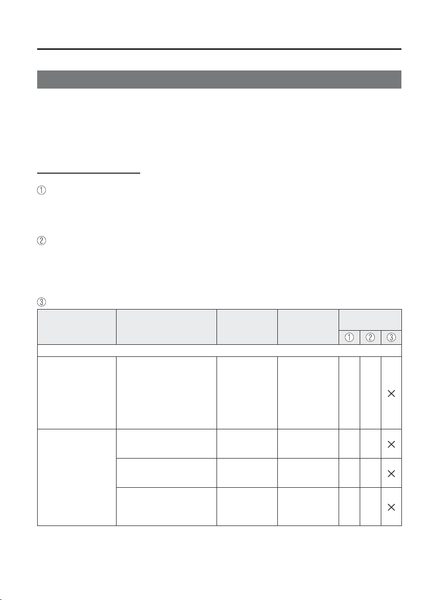
9
–
13
Speci¿ cations
Personalisation Features
Personalisation Features
The following personalisation features can be set or changed by the customer or an
Authorised Mazda Repairer. Consult an Authorised Mazda Repairer for details.
Additionally, some of the personalisation features can be changed by the customer
depending on the feature.
Personalisation features and settings which can be changed differ depending on the market
and speci¿ cation.
Settings Change Method
Settings can be changed by operating the centre display screen.
A: Refer to Settings on page 5-137 .
B: Refer to Fuel Economy Monitor on page 4-93 .
C: Refer to Active Driving Display on page 4-35 .
Settings can be changed by operating the vehicle switches.
D: Refer to Auto Lock/Unlock Function on page 3-17 .
E: Refer to Transmitter on page 3-4 .
F: Refer to Locking, Unlocking with Request Switch (With the advanced keyless function)
on page 3-14 .
Settings can be changed by an Authorised Mazda Repairer.
Item Feature Factory Setting
Available
Settings
Settings Change
Method
Safety
Smart City Brake
Support Forward
(SCBS F)
(page 4-155 )
Smart City Brake
Support Reverse
(SCBS R)
(page 4-161 )
Operational/non-operational
*1
O n O n / O f f A —
Smart Brake Support
(SBS)
(page 4-167 )
The system can be changed
so that Smart Brake Support
(SBS) does not operate.
*1
On On/Off A —
The distance at which the
collision warning activates
can be changed.
Near Near/Far A —
The volume of the collision
warning can be changed.
High High/Low/Off A —
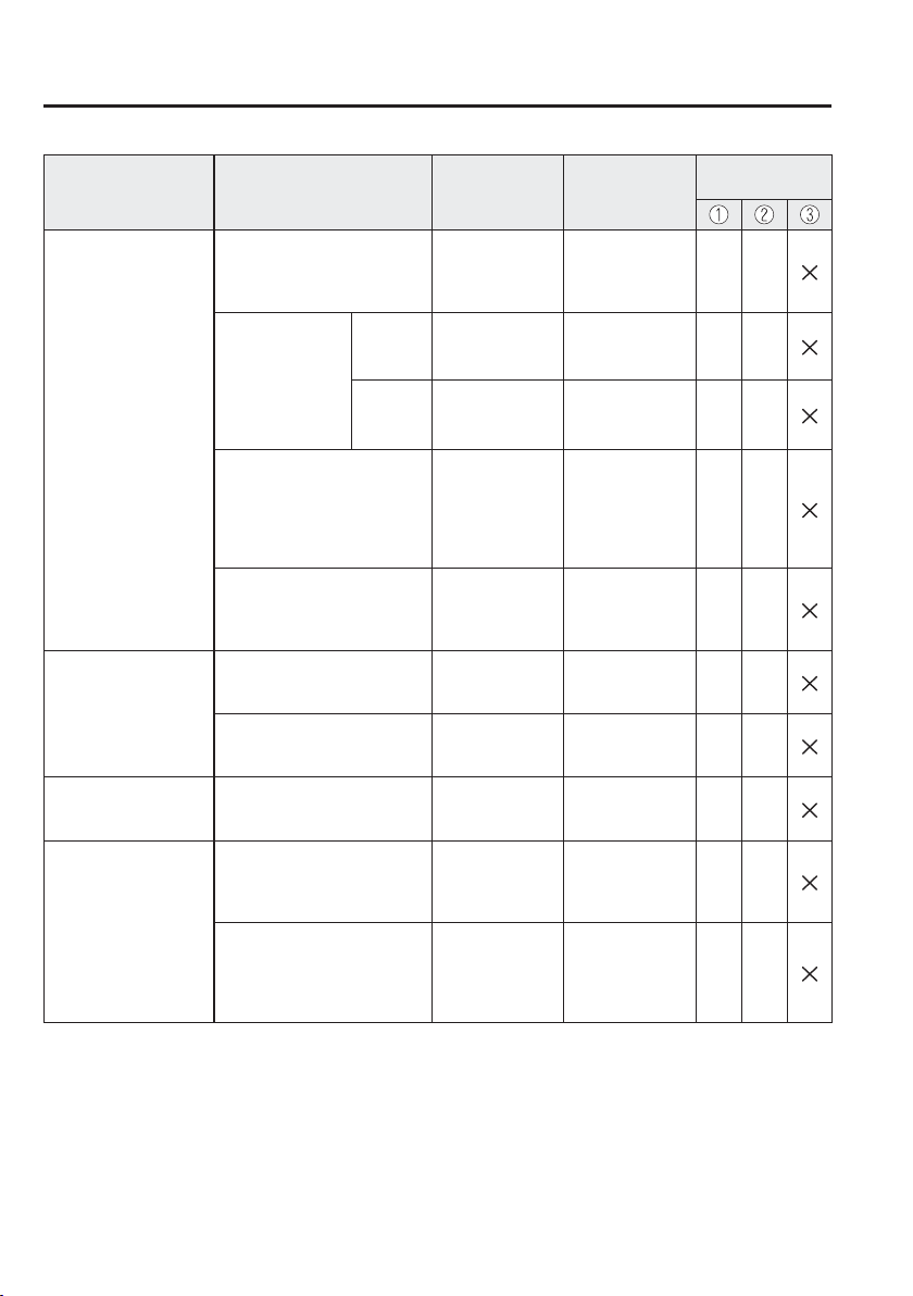
9
–
14
Speci¿ cations
Personalisation Features
Item Feature Factory Setting
Available
Settings
Settings Change
Method
Lane Departure
Warning System
(LDWS)
(page 4-111 )
The warning sound for the
Lane Departure Warning
System (LDWS) can be
changed.
*2
Rumble Strip
Beep/Rumble
Strip
A —
The volume
of the warning
sound for the
Lane Departure
Warning System
(LDWS) can be
changed.
Rumble Low High/Mid/Low A —
Beep Low High/Low A —
The warning timing in which
the Lane Departure Warning
System (LDWS) determines
that the vehicle may be
deviating from its lane can be
changed.
On_Line
Inside_Line/
On_Line/
Outside_Line
A —
The sensitivity of the warning
for the Lane Departure
Warning System (LDWS) can
be changed.
Mid_LO
High/Mid_LO/
LO
A —
Blind Spot Monitoring
(BSM)
(page 4-117 )
The system can be changed
so that Blind Spot Monitoring
(BSM) does not operate.
*1
On On/Off A —
Warning beep volume
*3
High
High/
L o w /
O f f
A —
Driver Attention Alert
(DAA)
(page 4-127 )
The system can be changed
so that Driver Attention Alert
(DAA) does not operate.
*1
On On/Off A —
Distance Recognition
Support System
(DRSS)
(page 4-124 )
The system can be changed
so that Distance Recognition
Support System (DRSS) does
not operate.
*1
On On/Off A —
The distance at which the
vehicle ahead and your
vehicle indicated in the
display À ashes in white can
be changed.
Near
Far/Medium/
Near
A —
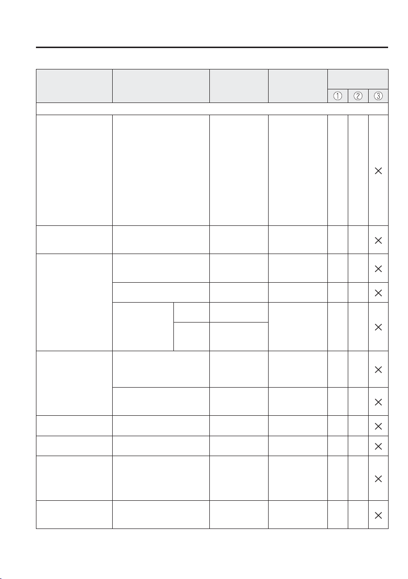
9
–
15
Speci¿ cations
Personalisation Features
Item Feature Factory Setting
Available
Settings
Settings Change
Method
Vehicle
Door locks
(page 3-17 )
Operation condition of auto
lock/unlock function
Lock: Driving,
Unlock: IGN Off
Off/
Lock When
Driving/
Lock: Driving,
Unlock: IGN
Off/
Lock When
Shifting Out
Of P/
Lock: Shift From
P, Unlock: In P/
Lock: Driving,
Unlock: In P
A D
Keyless entry system
(page 3-3 )
Time for locking door
automatically
30 seconds
90 seconds/
60 seconds/
30 seconds
A —
Advanced keyless
entry system
(page 3-9 )
Time for locking door
automatically
30 seconds
90 seconds/
60 seconds/
30 seconds
A —
Auto-lock function operation/
non-operational
Off On/Off A —
Beep volume
when locking/
unlocking
European
models
Off
High/
Medium/
L o w /
O f f
A
E,
F
Except
European
models
Medium
Illuminated entry
system
(page 5-158 )
Time until interior lights turn
off after closing door
15 seconds
60 seconds/
30 seconds/
15 seconds/
7.5 seconds
A —
Time until interior lights turn
off automatically when any
door is not closed completely
30 minutes
60 minutes/
30 minutes/
10 minutes
A —
Auto-wiper control
(page 4-72 )
Operational/non-operational On On/Off
*4
A —
Running lights
(page 4-68 )
Operational/non-operational On On/Off — —
Auto-light control
(page 4-61 )
Timing by which lights turn
on
Medium
Light/
Medium Light/
Medium/
Medium Dark/
Dark
A —
High Beam Control
System (HBC)
(page 4-105 )
Operational/non-operational
*1
O n O n / O f f A —
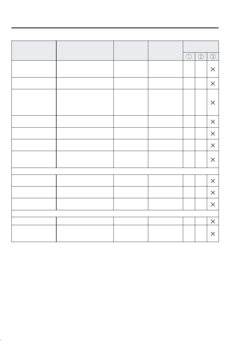
9
–
16
Speci¿ cations
Personalisation Features
Item Feature Factory Setting
Available
Settings
Settings Change
Method
Adaptive LED
Headlights (ALH)
(page 4-108 )
Operational/non-operational
*1
O n O n / O f f A —
Lights-on reminder
(page 7-50 )
Warning beep volume
High or Low
or Off
High/Low/Off A —
Coming home light
(page 4-67 )
Time until headlights turn off 30 seconds
120 seconds/
90 seconds/
60 seconds/
30 seconds/
O f f
A —
Leaving home light
(page 4-67 )
Operational/non-operational On or Off On/Off A —
Direction indicator
(page 4-71 )
Beep volume High High/Low A —
Three-À ash turn signal
(page 4-72 )
Operational/non-operational On or Off On/Off A —
Rear window defogger
(page 4-78 )
The operation time for the
rear window defogger can be
changed.
15 minutes
15 minutes/
Continuous
*5
— —
System
Language Language indicated in display English
Depends on
market
*6
A —
Temperature
Temperature unit indicated in
display
°C °F/°C A —
Distance
Distance unit indicated in
display
mi or km mi/km A —
Fuel Economy Monitor (page 4-93 )
Ending display Display/non-display Off On/Off B —
Fuel economy
resetting procedure
Linkage/non-linkage with
fuel economy reset and trip
meter reset
Off On/Off B —
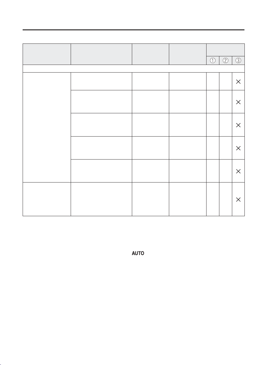
9
–
17
Speci¿ cations
Personalisation Features
Item Feature Factory Setting
Available
Settings
Settings Change
Method
Active Driving Display (page 4-35 )
Display
Setting can be changed so that
the Active Driving Display is
not displayed.
On On/Off C —
The display height (up/down
position) can be changed.
0
13 steps up/
down from initial
setting
(total: 27 steps)
C —
The method for adjusting
the display brightness
(automatically/manually) can
be changed.
AUTO
AUTO/
MANUAL
C —
The standard brightness
while automatic adjustment is
selected can be changed using
the brightness adjustment.
0
2 steps up/down
from initial
setting
(total: 5 steps)
C —
The standard brightness while
manual adjustment is selected
can be changed using the
brightness adjustment.
0
20 steps up/
down from initial
setting
(total: 41 steps)
C —
Navigation guidance
The display information can
be changed.
Adaptive Lane/
Street/Turn
At Manoeuvre/
Lane Guidance
& Turn by Turn/
Street Name &
Turn by Turn/
OFF
C —
*1 Though these systems can be turned Off, doing so will defeat the purpose of the system and Mazda recommends
that these systems remain On.
*2 For vehicles with an audio system other than the on-screen function type, the warning sound cannot be changed.
The warning sound is only a beep.
*3 Only the volume of the warning beep during Blind Spot Monitoring (BSM) operation can be changed. The
volume of the warning beep during Rear Cross Traf¿ c Alert (RCTA) operation cannot be changed.
*4 If the auto-wiper control is set to Off, the wiper lever
position is set to intermittent operation.
*5 The operation may stop in 15 minutes due to the effect of the outside temperature even if the operation time of
the rear window defogger has been changed to Continuous.
*6 Available only in display from the centre display.

9
–
18
MEMO

10
–
110
–
1
10
Index

10
–
2
Index
1
120 km/h warning beep .......................7-52
A
Accessory Socket ..............................5-159
Active Driving Display .......................4-35
Adaptive LED Headlights (ALH) .....4-108
Add-On Non-Genuine Parts and
Accessories ...........................................8-3
Adjustable Speed Limiter ........4-32, 4-148
Activation/deactivation ...............4-152
Adjustable speed limiter set indication
(green) ......................................... 4-150
Adjustable speed limiter set indication
(white)/indicator light (green) .....4-150
Adjustable Speed Limiter Display ......4-32
Advanced Key
Advanced keyless entry system ...... 3-9
Operational range ..........................3-10
Air Bag/Seat Belt Pretensioner System
Warning Beep ......................................7-50
Air Bag Systems ................................. 2-41
Air-Conditioning System ......................5-4
Fully Automatic Type ....................5-14
Manual Type ....................................5-7
Operating Tips .................................5-4
Vent Operation ................................ 5-5
Ambient Temperature Display ............4-31
Antilock Brake System (ABS) ............4-86
Audio Control Switch
Adjusting the Volume ....................5-18
Mute Switch ..................................5-18
Seek Switch ...................................5-19
Audio Set [Type A (non-touchscreen)]
AUX ..............................................5-37
Bluetooth
®
..................................... 5-46
CD Player ......................................5-34
Clock .............................................5-28
Error Indications............................5-45
iPod mode......................................5-42
Power/Volume/Sound Controls .....5-26
Radio .............................................5-30
Radio (RDS) .................................. 5-30
Troubleshooting ............................5-76
USB ...............................................5-38
Voice Recognition .........................5-72
Audio Set [Type B (touchscreen)]
Applications ................................5-139
AUX ............................................5-100
Bluetooth
®
................................... 5-107
CD Player ......................................5-94
DVD Player ...................................5-97
Digital Audio Broadcasting (DAB)
Radio ............................................. 5-91
Radio .............................................5-88
Radio (RDS) .................................. 5-88
Settings ........................................5-137
Troubleshooting ..........................5-140
USB .............................................5-101
Voice Recognition .......................5-134
Volume/Display/Sound Controls ...5-86
Audio System
Aerial ............................................. 5-23
Appendix .....................................5-144
Audio Control Switch ...................5-18
Audio Set
[Type A (non-touchscreen)] ........... 5-26
Audio Set
[Type B (touchscreen)] ..................5-80
AUX/USB mode ...........................5-20
Before Using the Audio System ....5-18

10
–
3
Index
Automatic Transaxle ...........................4-49
Active Adaptive Shift (AAS) ........4-52
Automatic transaxle controls.........4-49
Direct mode ...................................4-59
Driving tips....................................4-60
Manual shift mode.........................4-53
Shift-lock system ........................... 4-50
Transaxle ranges ............................ 4-51
B
Battery .................................................6-38
Inspecting Electrolyte Level ......... 6-40
Maintenance ..................................6-40
Recharging ....................................6-41
Replacement ..................................6-41
Speci¿ cations ..................................9-5
Battery runs out ...................................7-24
Jump-Starting ................................7-24
Blind Spot Monitoring (BSM) .......... 4-117
Cancelling operation of Blind Spot
Monitoring (BSM) ......................4-123
Blind Spot Monitoring (BSM) System
warning beep .......................................7-53
Bluetooth
®
[Type A (non-touchscreen)]
Bluetooth
®
Audio .......................... 5-62
Bluetooth
®
Hands-Free..................5-65
Bluetooth
®
Preparation ..................5-49
Bluetooth
®
[Type B (touchscreen)]
Bluetooth
®
Audio ........................ 5-114
Bluetooth
®
Hands-Free................5-124
Bluetooth
®
Preparation ................ 5-111
Body Lubrication ................................6-33
Bonnet Release ....................................6-19
Boot Lid ..............................................3-21
When liftgate/boot lid cannot be
opened ........................................... 7-55
Boot Light .........................................5-156
Bottle Holder .....................................5-160
Brakes
Brakes assist ..................................4-83
Foot brake......................................4-81
Pad wear indicator .........................4-83
Parking brake ................................ 4-82
Warning light ................................. 4-83
C
Capacities ..............................................9-7
Carbon Monoxide ...............................3-30
Cargo Sub-Compartment ..................5-162
Cell Phones ...........................................8-4
Child Restraint
Categories of child-restraint
systems ..........................................2-26
Child-restraint precautions ............2-21
Child-restraint system installation
...2-26
Child-restraint system suitability for
various seat positions table............2-32
Installing child-restraint systems...2-36
Child Safety Locks for Rear Doors .....3-20
Collision warning ................................7-54
Coming Home Light ...........................4-67
Control Status Display ........................4-95
Cruise Control ...................................4-184
Cruise Control Switch .................4-185
Cruise Main Indicator Light (Amber)/
Cruise Set Indicator Light
(Green) ........................................4-186
Cruise Control Set Vehicle Speed
Display ................................................ 4-32
Cup Holder ........................................5-160
D
Defogger
Mirror ............................................4-79
Rear window .................................4-78
Diesel Particulate Filter .....................4-194
Dimensions ........................................... 9-8
Direction Indicators ............................4-71

10
–
4
Index
Distance Recognition Support System
(DRSS) ..............................................4-124
Indication on display ...................4-125
Door Locks .......................................... 3-11
Driver Attention Alert (DAA) ........... 4-127
Drive selection ....................................4-99
Driving In Flooded Area .....................3-54
Driving Tips
Automatic transaxle ...................... 4-60
Driving in À ooded area..................3-54
Floor mat .......................................3-50
Hazardous driving .........................3-49
Rocking the vehicle .......................3-51
Running-in.....................................3-48
Saving fuel and protection of the
environment...................................3-48
Turbocharged vehicles
(SKYACTIV-D 1.5) ......................3-55
Winter driving ............................... 3-51
Dynamic Stability Control (DSC) .......4-88
DSC OFF Indicator Light..............4-89
DSC OFF Switch...........................4-89
TCS/DSC Indicator Light ............. 4-88
E
Effectiveness Display ..........................4-98
Electronic steering lock warning beep 7-52
Emergency Starting
Push-Starting .................................7-27
Running Out of Fuel
(SKYACTIV-D 1.5) ......................7-28
Starting a Flooded Engine
(SKYACTIV-G 1.3 and SKYACTIV-G
1.5) ................................................7-27
Emergency Stop Signal System ..........4-84
Emergency Towing
Towing Description .......................7-31
Towing/Tiedown Hooks ................7-32
Emission Control System
(SKYACTIV-D 1.5) ............................ 3-29
Emission Control System (SKYACTIV-G
1.3, SKYACTIV-G 1.5) .......................3-28
Ending Display ....................................4-98
Engine
Bonnet release ...............................6-19
Coolant ..........................................6-29
Engine Compartment Overview ....6-21
Exhaust gas....................................3-30
Oil .................................................. 6-23
Starting ............................................4-5
Essential information ............................6-2
Exhaust Gas ........................................ 3-30
Exterior Care .......................................6-66
Aluminium Wheel Maintenance ...6-71
Bright-Metal Maintenance ............6-70
Cavity Protection ........................... 6-70
Maintaining the Finish ..................6-68
Paint Damage Touch-up ................6-70
Plastic Part Maintenance ...............6-72
Undercoating .................................6-71
F
Flasher
Hazard warning .............................4-80
Headlights ..................................... 4-61
Flat Tyre ................................................7-3
Mounting the Spare Tyre ...............7-21
Removing a Flat Tyre ....................7-17
Floor Mat ............................................ 3-50
Fluid
Brake/Clutch ................................. 6-31
Washer ...........................................6-32
Fluids
Classi¿ cation ...................................9-6
Fog Lights ...........................................4-69
Front ..............................................4-69
Rear ...............................................4-70
Foot Brake ...........................................4-81
Forward Sensing Camera (FSC) .......4-170
Front Seat ..............................................2-5

10
–
5
Index
Fuel
Filler À ap and cap ..........................3-31
Gauge ............................................4-30
Requirements (SKYACTIV-D 1.5)
...3-27
Requirements (SKYACTIV-G 1.3,
SKYACTIV-G 1.5) ........................3-26
Tank capacity ..................................9-7
Fuel Consumption Display ................. 4-94
Fuel Economy Monitor .......................4-93
Control status display ....................4-95
Effectiveness display .....................4-98
Ending display ............................... 4-98
Fuel consumption display ............. 4-94
Fuses ................................................... 6-61
Panel description ...........................6-63
Replacement ..................................6-61
G
Gauges .................................................4-24
Glove Compartment ..........................5-161
H
Hazard Warning Flasher ......................4-80
Hazardous Driving ..............................3-49
Head Restraint ..................................... 2-11
Headlight Washer ................................4-77
Headlights
Coming home light ........................ 4-67
Control...........................................4-61
Flashing .........................................4-66
High-low beam .............................. 4-66
Leaving home light ....................... 4-67
Levelling ....................................... 4-68
Running lights ...............................4-68
Washer ...........................................4-77
High Beam Control System (HBC)
...4-105
Hill Launch Assist (HLA) ...................4-84
Horn ....................................................4-79
I
i-ACTIVSENSE ................................4-102
Active Safety Technology ...........4-102
Adaptive LED Headlights (ALH)
...4-108
Adjustable Speed Limiter ............ 4-148
Blind Spot Monitoring (BSM) .... 4-117
Detection Devices .......................4-103
Distance Recognition Support System
(DRSS) ........................................4-124
Driver Attention Alert (DAA) ..... 4-127
Forward Sensing Camera (FSC)
...4-170
High Beam Control System
(HBC) ..........................................4-105
Lane Departure Warning System
(LDWS) ....................................... 4-111
Laser Sensor ................................4-179
Mazda Radar Cruise Control
(MRCC).......................................4-135
Pre-Crash Safety Technology ......4-103
Radar Sensors (Rear)...................4-181
Radar sensor (front).....................4-176
Rear Cross Traf¿ c Alert (RCTA)
...4-130
Smart Brake Support (SBS) ........ 4-167
Smart City Brake Support [Reverse]
(SCBS R) ..................................... 4-161
Smart City Brake Support
(SCBS) ........................................ 4-155
Ultrasonic sensor (rear) ...............4-183
i-ELOOP ............................................. 4-90
Control status display ....................4-92
Display ..........................................4-90
i-ELOOP indicator light ................4-92
i-stop ................................................... 4-13
i-stop OFF switch ..........................4-21
Indicator light (Green)...................4-18
Vehicle roll prevention function ....4-22
Warning light (Amber) ..................4-18
i-stop warning beep .............................7-52
If a Warning Light Turns On or
Flashes.................................................7-35
If the Active Driving Display does not
operate .................................................7-57

10
–
6
Index
Ignition
Switch .............................................. 4-4
Ignition not switched off (STOP) warning
beep .....................................................7-51
Illuminated Entry System ................. 5-158
Immobilizer System ............................3-42
Indicator Lights ...................................4-41
Glow plug ...................................... 4-45
Low engine coolant temperature ...4-44
Wrench .......................................... 4-44
Inspecting Brake/Clutch Fluid Level
...6-31
Inspecting Coolant Level ....................6-29
Inspecting Engine Oil Level ...............6-28
Inspecting Washer Fluid Level............6-32
Instrument Cluster ...............................4-24
Instrument Panel Illumination .............4-30
Interior Care ........................................6-72
Active driving display
maintenance...................................6-74
Cleaning the window interiors ......6-75
Instrument panel top maintenance
...6-74
Leather upholstery maintenance ... 6-73
Panel maintenance .........................6-75
Plastic part maintenance ................6-74
Seat belt maintenance ....................6-73
Upholstery maintenance ................6-73
Vinyl upholstery maintenance .......6-73
Interior Lights ...................................5-156
Boot Light ...................................5-156
Luggage Compartment Light ......5-156
Map Lights ..................................5-156
Overhead Lights ..........................5-156
J
Jack ....................................................... 7-6
Jump-Starting ......................................7-24
K
Key Suspend Function ..........................3-8
Key left-in-luggage compartment warning
beep (With the advanced keyless
function) ..............................................7-52
Key left-in-vehicle warning beep (With the
advanced keyless function) .................7-52
Keyless Entry System ...........................3-3
Key removed from vehicle warning
beep .....................................................7-51
Keys ......................................................3-2
Key suspend function ......................3-8
Transmitter ...................................... 3-4
L
Label Information .................................9-2
Lane-Change Signals ..........................4-72
Lane Departure Warning System
(LDWS) ............................................. 4-111
LDWS OFF switch ...................... 4-114
Lane Departure Warning sound ..........7-53
Laser Sensor ......................................4-179
Leaving Home Light ...........................4-67
Liftgate ................................................3-21
When liftgate/boot lid cannot be
opened ........................................... 7-55
Liftgate/Boot Lid
Luggage compartment ...................3-24
Light Bulbs
Replacement ..................................6-48
Speci¿ cations ..................................9-9
Lighting Control..................................4-61
Lights-on reminder ..............................7-50
Lubricant Quality ..................................9-6
Luggage Compartment Light ............5-156

10
–
7
Index
M
Maintenance
Information ...................................... 6-2
Scheduled ........................................6-3
Maintenance Monitor ..........................6-15
Manual Windows ................................3-41
Map Lights ........................................5-156
Mazda Radar Cruise Control
(MRCC) ............................................4-135
Close proximity warning .............4-139
Cruise control function ................ 4-145
Display indication .......................4-138
Setting the system ....................... 4-139
Shift-up/shift-down request
display ......................................... 4-144
Mazda Radar Cruise Control (MRCC)
System warnings .................................7-54
Message Indicated on Display ............7-48
Meters and Gauges ..............................4-24
Mirror Defogger ..................................4-79
Mirrors
Outside mirrors..............................3-34
Rearview mirror ............................3-37
O
Odometer and Trip Meter ....................4-25
Outside Mirrors ...................................3-34
Outside Temperature Display ..............4-31
Outside temperature warning beep .....7-53
Over Rev. buzzer .................................7-53
Overhead Console .............................5-161
Overhead Lights ................................5-156
Overheating .........................................7-29
Owner Maintenance
Closing the Bonnet ........................6-20
Engine Compartment Overview ....6-21
Key battery replacement ............... 6-41
Opening the Bonnet.......................6-19
Owner Maintenance Precautions...6-17
P
Parking Brake ......................................4-82
Parking Sensor System ..................... 4-204
Park assist sensor system
operation ......................................4-207
Sensor detection range ................ 4-206
Personalisation Features ......................9-13
Power Steering ..................................4-101
Power Windows ..................................3-38
Power steering warning buzzer ...........7-53
R
Radar Sensor (Front) .........................4-176
Radar Sensors (Rear) ........................4-181
Rear Coat Hooks ...............................5-163
Rear Cross Traf¿ c Alert (RCTA) ...... 4-130
Rear Door Child Safety Locks ............3-20
Rear Seat ...............................................2-7
Rear View Monitor............................4-195
Displayable range on the screen
...4-197
Picture quality adjustment ...........4-203
Rear view monitor operation .......4-199
Rear view parking camera
location ........................................4-196
Switching to the rear view monitor
display ......................................... 4-196
Variance between actual road conditions
and displayed Image
....................4-201
Viewing the display ..................... 4-198
Rear Window Defogger ...................... 4-78
Rear Window Washer ..........................4-77
Rear Window Wiper ............................ 4-77
Rearview Mirror ..................................3-37
Recommended Oil .............................. 6-23
Recording of Vehicle Data ....................8-5
Registering Your Vehicle in A Foreign
Country .................................................8-2

10
–
8
Index
Replacement
Fuse ...............................................6-61
Key battery ....................................6-41
Light Bulbs .................................... 6-48
Tyres ..............................................6-46
Wheel ............................................6-47
Wiper .............................................6-33
Request switch inoperable warning beep
(With the advanced keyless function)
...7-51
Roadside Emergency Triangle Retaining
Strap ...................................................... 7-2
Rocking the Vehicle ............................3-51
Running-In ..........................................3-48
S
Saving Fuel and Protection of the
Environment ........................................3-48
Scheduled Maintenance ........................6-3
Seat Belt System
3-point type ...................................2-17
Emergency locking ........................2-16
Pregnant women ............................ 2-16
Seat belt precautions ..................... 2-14
Seat belt warning beep ........................7-50
Seats
Front seat .........................................2-5
Head restraint ................................ 2-11
Rear seat ..........................................2-7
Seat warmer ..................................... 2-6
Security System
Immobilizer system .......................3-42
Theft-deterrent system .................. 3-44
Smart Brake Support (SBS) ..............4-167
Collision warning ........................4-169
Smart Brake Support (SBS) indicator
light (red) ..................................... 4-169
Stopping the Smart Brake Support
(SBS) system operation ...............4-169
Smart City Brake Support [Reverse]
(SCBS R) .......................................... 4-161
Smart City Brake Support (SCBS)
Indicator Light (Red)...................4-165
Stopping the Smart City Brake Support
[Reverse] (SCBS R) system
operation ......................................4-166
Smart City Brake Support (SCBS) ... 4-155
Spare Tyre .............................................7-8
Speci¿ cations ........................................9-4
Speed Limiter Warning Beep ..............7-54
Speed Unit Selector .............................4-25
Speedometer ........................................4-25
SRS Air Bags
Front passenger air bag deactivation
switch ............................................2-47
How the SRS air bags work .......... 2-52
Limitations to SRS air bag ............2-58
SRS air bag deployment criteria ... 2-56
Supplementary restraint system
components ...................................2-51
Starting the Engine ................................4-5
Steering Wheel ....................................3-33
Horn...............................................4-79
Storage Compartments ......................5-161
Cargo sub-compartment ..............5-162
Glove compartment .....................5-161
Overhead console ........................5-161
Rear coat hooks ...........................5-163
Sunvisors ...........................................5-156
T
Tachometer ..........................................4-29
Theft-Deterrent System .......................3-44
Towing
Towing Caravans and Trailers
(Europe/Turkey/South Africa) .......3-56
Towing Description ............................. 7-31
Towing/Tiedown
Hook ..............................................7-32
Traction Control System (TCS) ..........4-87
TCS/DSC Indicator Light ............. 4-87

10
–
9
Index
Transmitter ............................................3-4
Trip Computer .....................................4-32
Trip Meter ...........................................4-25
Trouble
Battery runs out .............................7-24
Emergency Starting .......................7-27
Emergency Towing........................7-31
Flat Tyre .......................................... 7-3
Overheating ...................................7-29
Parking in an Emergency ................7-2
When liftgate/boot lid cannot be
opened ........................................... 7-55
Tyre Pressure Monitoring System .....4-190
Tyre inÀ ation pressure warning beep
...7-53
Tyres .................................................... 6-44
Flat Tyre .......................................... 7-3
Replacing a Tyre ............................ 6-46
Replacing a Wheel ........................6-47
Snow tyres .....................................3-52
Speci¿ cations ................................9-10
Temporary Spare Tyre ...................6-46
Tyre InÀ ation Pressure ..................6-44
Tyre Rotation ................................. 6-45
Tyre chains .................................... 3-53
U
Ultrasonic Sensor (Rear) ...................4-183
V
Vanity Mirrors ...................................5-156
Vehicle Information Labels ...................9-2
Vehicle speed alarm ............................7-52
W
Warning Lights .................................... 4-38
Warning Sound is Activated ................7-50
120 km/h warning beep .................7-52
Air Bag/Seat Belt Pretensioner System
Warning Beep ................................7-50
Blind Spot Monitoring (BSM) System
warning beep .................................7-53
Collision warning ..........................7-54
Electronic steering lock warning
beep ............................................... 7-52
i-stop warning beep .......................7-52
Ignition not switched off (STOP)
warning beep .................................7-51
Key left-in-luggage compartment
warning beep (With the advanced
keyless function) ........................... 7-52
Key left-in-vehicle warning beep (With
the advanced keyless function) ..... 7-52
Key removed from vehicle warning
beep ............................................... 7-51
Lane Departure Warning sound .....7-53
Lights-on reminder ........................ 7-50
Mazda Radar Cruise Control (MRCC)
System warnings ...........................7-54
Outside temperature warning beep
...7-53
Over Rev. buzzer ...........................7-53
Power steering warning buzzer .....7-53
Request switch inoperable warning
beep (With the advanced keyless
function) ........................................7-51
Seat belt warning beep ..................7-50
Speed Limiter Warning Beep ........7-54
Tyre inÀ ation pressure warning
beep ............................................... 7-53
Vehicle speed alarm.......................7-52
Warranty ................................................8-2
Windows
Manual windows ...........................3-41
Power windows .............................3-38
Windscreen Washer ............................. 4-76
Windscreen Wipers .............................4-73

10
–
10
Index
Winter Driving ....................................3-51
Wiper
Replacing Rear Window Wiper Blade
(Hatchback) ...................................6-36
Replacing Windscreen Wiper
Blades ............................................6-34

8FR3-EE-16J_2
Printed in Europe