User Manual GE PDS22MBRBBB Refrigerator
About the controls with numbered settings.

NOTE: The refrigerator is shipped with protective film covering the temperature controls. If this film was not removed during installation, remove it now.
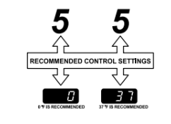
Initially, set the refrigerator control at 5 and the freezer control at 5 and allow 24 hours for the temperature to stabilize.
Several adjustments may be required. Adjust the controls one increment at a time, and allow 24 hours after each adjustment for the refrigerator to reach the temperature you have set.
Setting either or both controls to 0 stops cooling in both the refrigerator and freezer compartments, but does not shut off electrical power to the refrigerator.
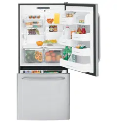
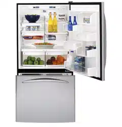
Performance Air Flow System
The Performance Air Flow System is designed to maximize temperature control in the refrigerator and freezer compartments. This unique special feature consists of the Air Tower along the back wall of the refrigerator and the Air Tunnel on the bottom portion of the freezer rear wall. Placing food in front of the louvers on these components will not affect performance.
About the water filter. (on some models)
Water Filter Cartridge
The water filter cartridge is located in the back upper right corner of the refrigerator compartment.
When to Replace the Filter
There is a replacement indicator light for the water filter cartridge on the temperature display. This light will turn orange to tell you that you need to replace the filter soon. The filter cartridge should be replaced when the replacement indicator light turns red or if the flow of water to the dispenser or icemaker decreases.
Installing the Filter Cartridge
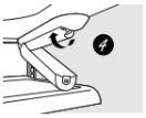
1. If you are replacing the cartridge, first remove the old one. Open the cartridge cover by pressing in on the tab at the front and pulling down.
2. Remove the cartridge by slowly rotating it counterclockwise. A small amount of water may drip down.
CAUTION: If air has been trapped in the system, the filter cartridge may be ejected as it is removed. Use caution when removing.
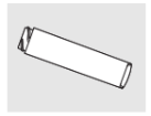
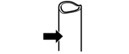
3. Remove the protective foil from the end of the cartridge.
4. Lining up the arrow on the cartridge and the cartridge holder, slowly rotate the cartridge clockwise until it stops. When the cartridge is properly installed, you will feel it “click” as it locks into place. The blade on the end of the cartridge should be positioned vertically. Do not overtighten.
5. Close the cartridge cover.
6. Run water from the dispenser for minutes (about 11⁄2 gallons) to clear the system and prevent sputtering. See To Use the Dispenser section.
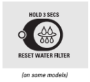
7. Press and hold the RESET WATER FILTER pad for 3 seconds.
NOTE: A newly-installed water filter cartridge may cause water to spurt from the dispenser.
Filter Bypass Plug
You must use the filter bypass plug when a replacement filter cartridge is not available. The icemaker will not operate without the filter or filter bypass plug.
Replacement Filters:
Filter Model GSWF
Customers in Canada should consult the yellow pages for the nearest Camco Service Center.
About the shelves and bins.
Not all features are on all models.
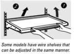
Rearranging the Shelves
Shelves in the refrigerator compartment are adjustable.
Refrigerator Compartment
To remove:
- Tilt the shelf up at the front.
- Lift the shelf up at the back and bring the shelf out.
To replace:
- While tilting the shelf up, insert the top hook at the back of the shelf in a slot on the track.
- Lower the front of the shelf until the bottom of the shelf locks into place.

Spillproof Shelves (on some models)
Spillproof shelves have special edges to help prevent spills from dripping to lower shelves. To remove or replace the shelves, see Rearranging the Shelves.

Slide-Out Spillproof Shelf (on some models)
The slide-out spillproof shelf allows you to reach items stored behind others. The special edges are designed to help prevent spills from dripping to lower shelves.
To remove:
- Remove all items from shelf.
- Slide the shelf out until it stops.
- Lift the front edge of the shelf until the central tabs are above the front bar.
- Continue pulling the shelf forward until it can be removed.
To replace:
- Place the rear shelf tabs just in front of the central notches on the shelf frame.
- Slide the shelf in until the central tabs are slightly behind the front bar.
- Lower the shelf into place until it is horizontal and slide the shelf in.
Make sure that the shelf sits flat after reinstallation and doesn’t move freely from side to side. Make sure you push the shelves all the way in before you close the door.

Adjustable Bins on the Door
Adjustable bins can easily be carried from refrigerator to work area.
To remove: Lift bin straight up, then pull out.
To replace or relocate: Engage the bin in the molded supports of the door, and push in. Bin will lock in place.
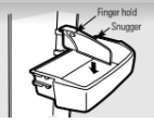
The snugger helps prevent tipping, spilling or sliding of small items stored on the door shelf. Grip the finger hold near the rear of the snugger and move it to fit your needs.
Non-Adjustable Shelves on the Door
To remove: Lift the shelf straight up, then pull out.
To replace: Engage the shelf in the molded supports on the door and push down. It will lock in place.

About the additional features.
Not all features are on all models.
Shelf Saver Rack (on some models)
Slide-out beverage rack holds twelve cans of soda or two wine/water bottles (lengthwise). It can be removed for cleaning.
To remove, slide the rack out to the stop position, lift the rack up and past the stop position and lift it out.
About the crispers and pans.
Not all features are on all models.
Fruit and Vegetable Crisper
Excess water that may accumulate in the bottom of the drawers or under the drawers should be wiped dry.
Adjustable Humidity Crisper (on some models)
Slide the control all the way to the HIGH setting to provide high humidity recommended for most vegetables.
Slide the control all the way to the LOW setting to provide lower humidity levels recommended for most fruits.
Snack Pan (on some models)
This pan can be moved to the most useful location for your family’s needs.
To remove, slide the pan out to the stop position, lift the pan up and past the stop position and lift it out.
Adjustable Temperature Deli Pan (on some models)
When the pan is placed in the 7th slot from the bottom of the track and the lever is set at COLDEST, air from the freezer is forced around the pan to keep it very cold.
You can move the pan to any location if you don’t want the extra cold storage. The settings can be adjusted anywhere between cold and coldest .
When set at cold, the pan will stay at the normal refrigerator temperature. The coldest setting provides the coldest storage area.
Crisper Removal
To Remove:
These drawers can be removed easily by lifting up slightly while pulling the drawer past the stop location.
When the door cannot be fully opened, remove the drawer farthest from the door first. Make sure the drawer closest to the door is fully closed. There is a latch at the front of the center slide rail. Push down on the latch and slide the center slide rail, to which the drawer is attached, away from the door. Remove the drawer.
About the freezer.
Not all features are on all models.
Basket/Shelf Removal
To remove the deep full-width basket on freezer drawer models:
- Open the freezer drawer until it stops.
- The freezer basket rests on a frame inside the freezer drawer. Lift the basket up at the back.
- Lift the front up and lift the entire basket up and out of the drawer.
To remove the half-width basket:
- Pull the basket out to the stop location.
- Lift the basket up at the front to release it from the slides.
- Lift the back up and out of the slide.
When replacing the basket, make sure that the wire tabs and wire hooks on the sides of the basket go into the slots in the top of the upper basket slides.
NOTE: Always be sure to fully close this basket. You will know it is fully closed when you feel it “click” into place.
To remove the deep full-width baskets on freezer door models, the shallow full-width basket and the full-width wire shelf:
- Pull the basket/shelf out to the stop location.
- Lift the front up and over the stop location.
- Lift the basket/shelf up and out.
To remove the shelf above the ice bin:
- Pull the shelf straight out.
About the automatic icemaker.
A newly installed refrigerator may take 12 to 24 hours to begin making ice.
Automatic Icemaker (on some models)
The icemaker will produce seven cubes per cycle—approximately 100–130 cubes in a 24-hour period, depending on freezer compartment temperature, room temperature, number of door openings and other use conditions. See below for how to access ice and reach the power switch.
If the refrigerator is operated before the water connection is made to the icemaker, set the power switch in the O (off) position. The icemaker power light will turn green when the freezer light switch is pressed in or when the freezer door is closed.
When the refrigerator has been connected to the water supply, set the power switch to the l (on) position. The icemaker will fill with water when it cools to 15°F (–10°C). A newly installed refrigerator may take 12 to 24 hours to begin making ice cubes.
You will hear a buzzing sound each time the icemaker fills with water. Throw away the first few batches of ice to allow the water line to clear. Be sure nothing interferes with the sweep of the feeler arm.
When the bin fills to the level of the feeler arm, the icemaker will stop producing ice. It is normal for several cubes to be joined together.
If ice is not used frequently, old ice cubes will become cloudy, taste stale and shrink.
NOTE: In homes with lower-than-average water pressure, you may hear the icemaker cycle multiple times when making one batch of ice.
Accessing Ice and Reaching the Power Switch
To reach the icemaker power switch, pull the shelf above the ice bin straight out. Always be sure to replace the shelf.
To access ice, simply pull the bin forward.
Icemaker Accessory Kit
If your refrigerator did not come already equipped with an automatic icemaker, an icemaker accessory kit is available at extra cost.
Check the back of the refrigerator for the specific icemaker kit needed for your model.
To Use the Dispenser (on some models)
The water dispenser is located on the left wall inside the refrigerator compartment.
To dispense water:
- Hold the glass against the recess.
- Push the water dispenser button.
- Hold the glass underneath the dispenser for 2–3 seconds after releasing the dispenser button. Water may continue to dispense after the button is released.
If no water is dispensed when the refrigerator is first installed, there may be air in the water line system. Press the dispenser button for at least 2 minutes to remove trapped air from the water line and to fill the water system. During this process, the dispenser noise may be loud as the air is purged from the water line system. To flush out impurities in the water line, throw away the first 6 glassfuls of water.
NOTE: To avoid water deposits, the dispenser should be cleaned periodically by wiping with a clean cloth or sponge.
Care and cleaning of the refrigerator.
Cleaning the Outside
The door handles and trim. Clean with a cloth dampened with soapy water. Dry with a soft cloth. Do not use wax on the door handles and trim.
Keep the outside clean. Wipe with a clean cloth lightly dampened with kitchen appliance wax or mild liquid dish detergent. Dry and polish with a clean, soft cloth.
Do not wipe the refrigerator with a soiled dish cloth or wet towel. These may leave a residue that can erode the paint. Do not use scouring pads, powdered cleaners, bleach or cleaners containing bleach because these products can scratch and weaken the paint finish.
The stainless steel panels and door handles. Stainless steel (on some models) can be cleaned with a commercially available stainless steel cleaner. A spray-on stainless steel cleaner works best. Do not use appliance wax or polish on the stainless steel.
Cleaning the Inside
To help prevent odors, leave an open box of baking soda in the refrigerator and freezer compartments.
Unplug the refrigerator before cleaning. If this is not practical, wring excess moisture out of sponge or cloth when cleaning around switches, lights or controls.
Use an appliance wax polish on the inside surface between the doors.
Use warm water and baking soda solution— about a tablespoon (15 ml) of baking soda to a quart (1 liter) of water. This both cleans and neutralizes odors. Rinse and wipe dry.
After cleaning the door gaskets, apply a thin layer of petroleum jelly to the door gaskets at the hinge side. This helps keep the gaskets from sticking and bending out of shape.
Avoid cleaning cold glass shelves with hot water because the extreme temperature difference may cause them to break. Handle glass shelves carefully. Bumping tempered glass can cause it to shatter.
Do not wash any plastic refrigerator parts in the dishwasher.
Behind the Refrigerator
Be careful when moving the refrigerator away from the wall. All types of floor coverings can be damaged, particularly cushioned coverings and those with embossed surfaces.
Pull the refrigerator straight out and return it to position by pushing it straight in. Moving the refrigerator in a side direction may result in damage to the floor covering or refrigerator.
When pushing the refrigerator back, make sure you don’t roll over the power cord or icemaker supply line (on some models).
Preparing for Vacation
For long vacations or absences, remove food and unplug the refrigerator. Move the freezer control to the 0 (off) position, and clean the interior with a baking soda solution of one tablespoon (15 ml) of baking soda to one quart (1 liter) of water. Leave the doors open.
Set the icemaker power switch to the O (off) position and shut off the water supply to the refrigerator.
If the temperature can drop below freezing, have a qualified servicer drain the water supply system (on some models) to prevent serious property damage due to flooding.
Preparing to Move
Secure all loose items such as base grille, shelves and drawers by taping them securely in place to prevent damage.
When using a hand truck to move the refrigerator, do not rest the front or back of the refrigerator against the hand truck. This could damage the refrigerator. Handle only from the sides of the refrigerator.
Be sure the refrigerator stays in an upright position during moving.
INSTALLING THE REFRIGERATOR
REFRIGERATOR LOCATION
- Do not install the refrigerator where the temperature will go below 60°F (16°C) because it will not run often enough to maintain proper temperatures.
- Do not install the refrigerator where the temperature will go above 100°F (37°C) because it will not perform properly.
- Install it on a floor strong enough to support it fully loaded.
REMOVE TOP CAP (on some models)
- IMPORTANT NOTE: This refrigerator is 34-1/2′′ deep. Doors and passageways leading to the installation location must be at least 36′′ wide in order to leave the doors and handles attached to the refrigerator while transporting it into the installation location. If passageways are less than 36′′, the refrigerator doors and handles can easily be scratched and damaged. The top cap and doors can be removed to allow the refrigerator to be safely moved indoors. Start with Step A.
- If it is not necessary to remove doors, skip Step A. Leave tape and all packaging on doors until the refrigerator is in the final location.
- SKID REMOVAL: Tilt refrigerator to each side to remove skid.
- NOTE: Use a padded hand truck to move this refrigerator. Place the refrigerator on the hand truck with a side against the truck. We strongly recommend that TWO PEOPLE move and complete this installation.
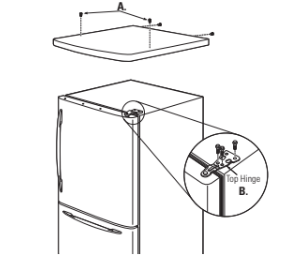
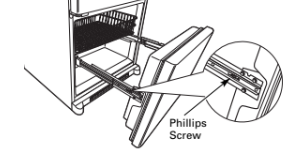
A. Locate and remove the two Phillips head screws on the top of the refrigerator. Remove the two screws on each side at the rear of the top cap. Lift off and remove top cap.
B. Remove the fresh-food door. Refer to Steps 1 through 3 of “Reversing the Door Swing” section.
C. Remove the bottom freezer drawer. Refer to "Removing Freezer Drawer” section.
D. Move refrigerator to the installation location.
REINSTALL DOORS, DRAWERS AND TOP CAP
E. Carefully lower the door onto the center hinge. Reinstall top hinge. NOTE: Ensure the door is properly aligned to the case top to avoid readjustment of the door during top cap reinstallation.
F. Place cap over the top of the refrigerator. Reinstall the original screws in the top and back of the cap.
G. Reinstall the bottom freezer drawer. Refer to "Replacing the Freezer Drawer” section.
1. CONNECTING THE REFRIGERATOR
TO THE HOUSE WATER LINE (icemaker and dispenser models)
A cold water supply is required for automatic icemaker operation. If there is not a cold water supply, you will need to provide one. See
Installing the Water Line section.
NOTES:
- Before making the connection to the refrigerator, be sure the refrigerator power cord is not plugged into the wall outlet.
- If your refrigerator does not have a water filter, we recommend installing one if your water supply has sand or particles that could clog the screen of the refrigerator’s water valve. Install it in the water line near the refrigerator. If using GE SmartConnectTM Refrigerator Tubing Kit, you will need an additional tube (WX08X10002) to connect the filter. Do not cut plastic tube to install filter.
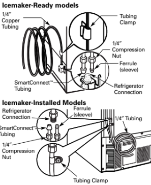
A. If you are using copper tubing, place a compression nut and ferrule (sleeve) onto the end of the tubing coming from the house cold water supply.
If you are using the GE SmartConnectTM tubing, the nuts are already assembled to the tubing.
B. If you are using copper tubing, insert the end of the tubing into the refrigerator connection, at the back of the refrigerator, as far as possible. While holding the tubing, tighten the fitting.
If you are using GE SmartConnectTM tubing, insert the molded end of the tubing into the refrigerator connection, at the back of the refrigerator, and tighten the compression nut until it is hand tight. Then tighten one additional turn with a wrench. Overtightening may cause leaks.
C. Fasten the tubing into the clamp provided to hold it in position. You may need to pry open the clamp.
2. TURN ON THE WATER SUPPLY (icemaker and dispenser models)
Turn the water on at the shutoff valve house water supply) and check for any leaks.
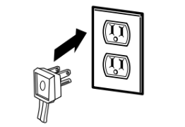
3. PLUG IN THE REFRIGERATOR
On models with an icemaker, before plugging in the refrigerator, make sure the icemaker power switch is set to the O (off) position. See the grounding information attached to the power cord.
4. PUT THE REFRIGERATOR IN PLACE
Move the refrigerator to its final location.
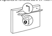
5. REMOVE THE FRESH FOOD DOOR HANDLE
(For placement in the installation location or reversal of the handles – on some models)
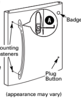
Stainless steel (on some models):
A. REMOVING THE DOOR HANDLE: Loosen the set screws with the 3/32′′Allen wrench and remove the handle. NOTE: For Double Door models follow the same procedure on the opposite door.

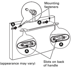
B. REVERSING THE DOOR HANDLE:
- Remove the handle mounting fasteners with a 1/4′′ Allen wrench and transfer the handle mounting fasteners to the right side.
- Remove and transfer the plug button and logo badge to the left side of the fresh food door. NOTE: Use a flat plastic edge to prevent damaging the door. Remove any adhesive on the door with a mild detergent. Remove the paper covering on the adhesive backing on the logo badge prior to carefully attaching the badge to the door.
Plastic handle (on some models):
A. REMOVING THE DOOR HANDLE: Slide the handle up on the handle mounting fasteners and remove the handle.
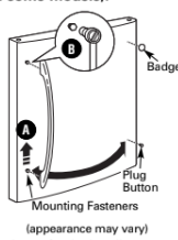
B. REVERSING THE DOOR HANDLE:
- Remove the handle mounting fasteners with a or 10 mm socket wrench and transfer the handle mounting fasteners to the right side.
- Remove and transfer the plug button and logo badge to the left side of the fresh food door. NOTE: Use a flat plastic edge to prevent damaging the door. Remove any adhesive on the door with a mild detergent. Remove the paper covering on the adhesive backing on the logo badge prior to carefully attaching the badge to the door.
After removing the handle: Move the small plug button from the top right side of the door top and insert it into the hole on the opposite side.
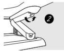
6. REMOVE THE FREEZER DOOR HANDLE
Stainless steel handle:
A. Loosen the set screws located on the underside of the handle with the 3/32′′ Allen wrench and remove the handle.
NOTE: If the handle mounting fasteners need to be tightened or removed use a 1/4′′ Allen wrench.
Plastic handle:
A. Slide the handle to the right on the handle mounting fasteners and remove the handle.
NOTE: If the handle mounting fasteners need to be tightened or removed use a 3/8′′ or 10 mm socket wrench.
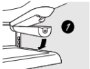
7. ATTACH THE FRESH FOOD DOOR HANDLE
Stainless steel handle:
A. Attach the handle to the handle mounting fasteners and tighten the set screws with a Allen wrench.
NOTE: For Double Door models follow the same procedure on the opposite door.
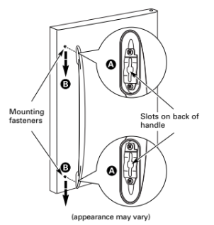
Plastic handle:
A. Attach the handle to the handle mounting fasteners by aligning the slots with the handle mounting fasteners.
B. Slide it down until it is firmly locked into position.
8. ATTACH THE FREEZER DOOR HANDLE
Stainless steel handle:
A. Attach the handle firmly to the mounting fasteners and tighten the set screws on the bottom of the handle with a 3/32′′ Allen wrench.

Plastic handle:
A. Attach the handle to the mounting fasteners by aligning the slots with the mounting fasteners.
B. Slide it to the left until it is firmly locked into position.

9. LEVEL THE REFRIGERATOR
The leveling legs have 3 purposes:
- Leveling legs adjust so the door closes easily when opened about halfway. (Front of the refrigerator should be [6mm] higher than the rear of the refrigerator).
- Leveling legs adjust so the refrigerator is firmly positioned on the floor and does not wobble.
- Leveling legs serve as a stabilizing brake to hold the refrigerator securely in position during operation and cleaning.
A. Turn the leveling legs clockwise to raise the refrigerator, counterclockwise to lower it.

CAUTION: To avoid possible personal injury or property damage, the leveling feet must be firmly touching the floor.
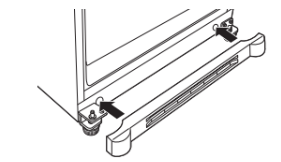
B. Install the base grille by aligning the prongs on the back of the grille with the holes in the cabinet. Push forward until the grille snaps into place.
10. SET THE CONTROLS
Set the controls to the recommended setting.
REMOVE PACKAGING START ICEMAKER ( icemaker models)
A) Remove all tape, foam and protective packing from shelves and drawers.
B) Remove the tie downs from the freezer baskets.
C) Place half width basket onto drawer slides. See About the freezer section for instructions.

Set the icemaker power switch to the I (on) position. The icemaker will not begin to operate until it reaches its operating temperature of 15°F (–9°C) or below. It will then begin operation automatically. It will take 2–3 days to fill the ice bin.
REPLACING THE FREEZER DRAWER (on some models)
1. ATTACH AND SECURE THE DRAWER FRONT TO THE SLIDES
A. Pull out the rail assemblies to the full length on each side of the cabinet.

B. Locate the slots on the inside of the rail assemblies near the back.
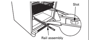
C. Insert the hooks at the back of the drawer railings into the slots on the rail assemblies.
D. Lower the front of the drawer, making sure the tabs on the sides of the railings fit into the front slots in the rail assemblies.

E. Replace the Phillips head screws on both rail assemblies.
2. REPLACE THE FREEZER BASKET
Replace the lower freezer basket by lowering it into the frame.

INSTALLING THE WATER LINE (ICEMAKER MODELS)
WHAT YOU WILL NEED
- Copper or GE SmartConnectTM Refrigerator Tubing kit, 1/4′′ outer diameter to connect the refrigerator to the water supply. If using copper, be sure both ends of the tubing are cut square.
To determine how much tubing you need: measure the distance from the water valve on the back of the refrigerator to the water supply pipe. Then add 8′ (2.4 m). Be sure there is sufficient extra tubing (about 8′ [2.4 m] coiled into 3 turns of about 10′′ [25 cm] diameter) to allow the refrigerator to move out from the wall after installation. Be sure that the kit you select allows at least m) as described above.
NOTE: The only GE approved plastic tubing is that supplied in GE SmartConnectTM Refrigerator Tubing kits. Do not use any other plastic water supply line because the line is under pressure at all times. Certain types of plastic will crack or rupture with age and cause water damage to your home.
- A GE water supply kit (containing tubing, shutoff valve and fittings listed below) is available at extra cost from your dealer or from Parts and Accessories, 800.626.2002 in Canada 1.888.261.3055).
- A cold water supply. The water pressure must be between 20 and 120 p.s.i. (1.4–8.1 bar).
- Power drill.
- 1/2′′ or adjustable wrench.
- Straight and Phillips blade screwdriver.
- Two 1/4′′ outer diameter compression nuts and 2 ferrules (sleeves)—to connect the copper tubing to the shutoff valve and the refrigerator water valve.
- If you are using a GE SmartConnectTM Refrigerator Tubing kit, the necessary fittings are preassembled to the tubing.
- If your existing copper water line has a flared fitting at the end, you will need an adapter (available at plumbing supply stores) to connect the water line to the refrigerator OR you can cut off the flared fitting with a tube cutter and then use a compression fitting. Do not cut formed end from GE SmartConnectTM Refrigerator tubing.
- Shutoff valve to connect to the cold water line. The shutoff valve should have a water inlet with a minimum inside diameter of at the point of connection to the COLD WATER LINE. Saddle-type shutoff valves are included in many water supply kits. Before purchasing, make sure a saddle-type valve complies with your local plumbing codes.
1. SHUT OFF THE MAIN WATER SUPPLY
Turn on the nearest faucet long enough to clear the line of water.
2. CHOOSE THE VALVE LOCATION
Choose a location for the valve that is easily accessible. It is best to connect into the side of a vertical water pipe. When it is necessary to connect into a horizontal water pipe, make the connection to the top or side, rather than at the bottom, to avoid drawing off any sediment from the water pipe.
3. DRILL THE HOLE FOR THE VALVE
Drill a 1/4′′ hole in the water pipe (even if using a self-piercing valve), using a sharp bit. Remove any burrs resulting from drilling the hole in the pipe.
Take care not to allow water to drain into the drill.
Failure to drill a 1/4′′ hole may result in reduced ice production or smaller cubes.

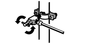
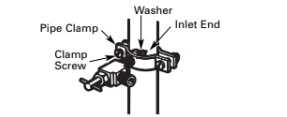
4. FASTEN THE SHUTOFF VALVE
Fasten the shutoff valve to the cold water pipe with the pipe clamp.

NOTE: Commonwealth of Massachusetts Plumbing Codes 248CMR shall be adhered to. Saddle valves are illegal and use is not permitted in Massachusetts. Consult with your licensed plumber.
5. TIGHTEN THE PIPE CLAMP
Tighten the clamp screws until the sealing washer begins to swell.
NOTE: Do not overtighten or you may crush the tubing.
6. ROUTE THE TUBING
Route the tubing between the cold water line and the refrigerator. Route the tubing through a hole drilled in the wall or floor (behind the refrigerator or adjacent base cabinet) as close to the wall as possible.
NOTE: Be sure there is sufficient extra tubing (about 8′ [2.4 m] coiled into 3 turns of about 10′′ [25 cm] diameter) to allow the refrigerator to move out from the wall after installation.
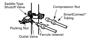
7. CONNECT THE TUBING TO THE VALVE
Place the compression nut and ferrule sleeve) for copper tubing onto the end of the tubing and connect it to the shutoff valve.
Make sure the tubing is fully inserted into the valve. Tighten the compression nut securely.
For plastic tubing from a GE SmartConnectTM Refrigerator Tubing kit, insert the molded end of the tubing into the shutoff valve and tighten compression nut until it is hand tight, then tighten one additional turn with a wrench. Overtightening may cause leaks.
NOTE: Commonwealth of Massachusetts Plumbing Codes 248CMR shall be adhered to. Saddle valves are illegal and use is not permitted in Massachusetts. Consult with your licensed plumber.
8. FLUSH OUT THE TUBING
Turn the main water supply on and flush out the tubing until the water is clear. Shut the water off at the water valve after about one quart (1 liter) of water has been flushed through the tubing.