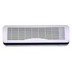
GE Appliances
Deluxe High Wall
Split System
Pub. No. 49-7373-1 CG 2-98
Cooling Only Models Heat Pump Models
AS0CD09 AS1CD09 AS0RD09 AS1RD09
AS0CD12 AS1CD12 AS0RD12 AS1RD12
AS0CD18 AS1CD18 AS0RD18 AS1RD18
Owner’s Manual &
Installation Instructions
Customer Service Troubleshooting Tips
Operating Instructions
Safety Instructions
Installation Instructions
Congratulations!
You Are Now Part of the GE Family
Welcome to the GE family. We’re proud of our quality products and we are committed
to providing dependable service. You’ll see it in this easy-to-use Owner’s Manual and
you’ll hear it in the friendly voices of our customer service department.
Best of all, you’ll experience these values each time you use your air conditioner.
That’s important, because your new air conditioner will be part of your family for
many years. And we hope you will be part of ours for a long time to come.
We thank you for buying GE. We appreciate your purchase, and hope you will
continue to rely on us whenever you need quality appliances for your home.
GE & You, A Service Partnership.
Safety Information
Safety Precautions . . . . . . . . . . . . .3
Operating Instructions
Remote Control
Features . . . . . . . . . . . . . . . . . . .4–6
Operation Mode Selection . . . . .7, 8
Additional Features . . . . . . . . .9–11
Care and Cleaning . . . . . . . . . . . .12
Installation Instructions
Electrical Requirements . . . . . . . .13
Location . . . . . . . . . . . . . . . . . . . .14
Indoor Unit Installation . . . . .15, 16
Connection of Pipes . . . . . . . .17–22
Check Connection . . . . . . . . .23–26
Test Run . . . . . . . . . . . . . . . . . . . .27
Installation Templates . . . . . .28, 29
Troubleshooting Tips
Before You
Call For Service . . . . . . . . . . . . . .30
Normal Operating Sounds . . . . . .30
Customer Service
Warranty . . . . . . . . . . . . . . . . . . .31
Service Telephone
Numbers . . . . . . . . . . . .Back Cover
FOR YOUR RECORDS
Write the model and serial numbers here for the indoor and
outdoor units:
Indoor model # Serial #
Outdoor model # Serial #
You can find them on a label on the side of each unit.
Staple sales slip or cancelled check here.
Proof of the original purchase date is needed to obtain service
under the warranty.
Inside you will find many helpful hints on how to use and maintain
your air conditioner properly. Just a little preventive care on your
part can save you a great deal of time and money over the life of
your air conditioner.
You’ll find many answers to common problems in the
Before You
Call For Service
section. If you review our chart of
Troubleshooting
Tips
first, you may not need to call for service at all.
READ THIS MANUAL
IF YOU NEED SERVICE
If you do need service, you can relax knowing help is only a phone
call away. A list of toll-free customer service numbers is included in
the back section. Or, you can always call the GE Answer Center® at
800.626.2000, 24 hours a day, 7 days a week.
For any service which requires entry into the
refrigerant sealed system, Federal regulations
require the work be performed by a technician
having a Class II or Universal certification.
2
IMPORTANT SAFETY INFORMATION.
READ ALL INSTRUCTIONS BEFORE USING.
WARNING!
For your safety, the information in this manual must be followed to minimize the risk of fire, electric shock
or personal injury.
■ This system must be properly installed in
accordance with the Installation Instructions
before it is used.
■ Be certain the power source is disconnected
before servicing the product.
NOTES:
■ We strongly recommend that any servicing
be performed by a qualified individual.
■ Since outdoor condensing unit has a sump
heater on the compressor for heat pump
models, the power should be turned on at
least 5 hours before unit operation. Leave
the power on unless you will not be using the
system for an extended period of time.
For any service which requires entry
into the refrigerant sealed system,
Federal regulations require the work
be performed by a technician having a
Class II or Universal certification.
SAFETY PRECAUTIONS
3
Read and follow this Safety Information carefully.
SAVE THESE INSTRUCTIONS
Customer ServiceTroubleshooting Tips
Operating Instructions
Safety Instructions
Installation Instructions
4
Customer Service Troubleshooting Tips
Operating Instructions
Safety Instructions
Installation Instructions
Customer Service Troubleshooting Tips
Installation Instructions
Safety Instructions
Operating Instructions
Customer Service Troubleshooting Tips
Installation Instructions
Safety Instructions
Operating Instructions
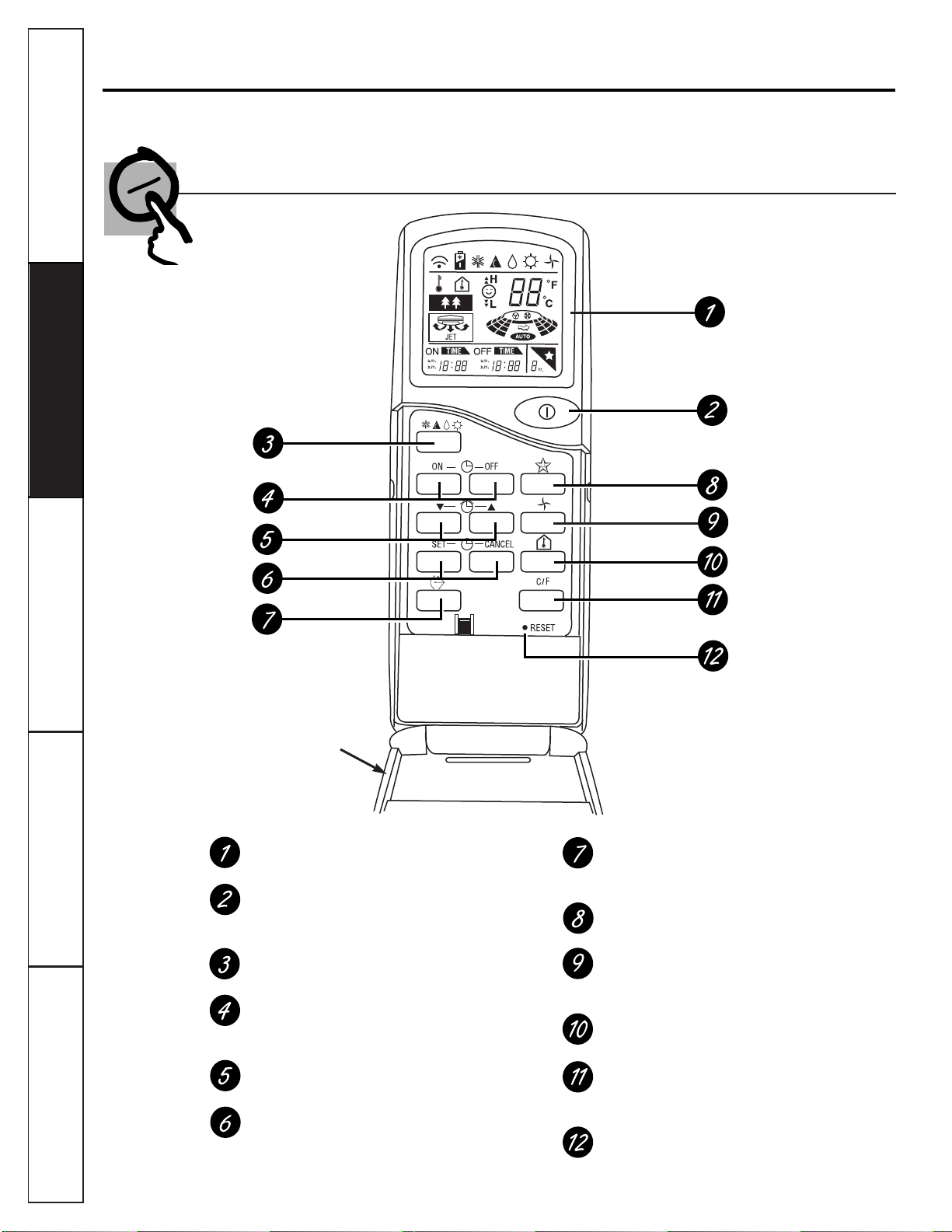
About the remote control on the system.
The remote control transmits the signals to the system.
Features of the Remote Control—Door Open
OPERATION DISPLAY
Displays the operation conditions.
START/STOP BUTTON
Operation starts when this button is pressed and
stops when the button is pressed again.
OPERATION MODE SELECTION BUTTON
Used to select the operation mode.
ON/OFF TIMER BUTTONS
Used to set the time of starting and stopping
operation.
TIME SETTING BUTTONS
Used to adjust the time.
TIMER SET/CANCEL BUTTONS
Used to set the timer when the desired time is
obtained and to cancel the Timer operation.
AIRFLOW DIRECTION START/STOP BUTTON
Used to stop or start louver movement and set
the desired up/down airflow direction.
SLEEP MODE AUTO BUTTON
Used to set Sleep Mode Auto operation.
AIR CIRCULATION BUTTON
Used to circulate the room air without cooling
or heating (turns indoor fan on/off).
ROOM TEMPERATURE CHECKING BUTTON
Used to check the room temperature.
0
C to
0
F SWITCHING BUTTON
Used to switch temperature reading from
Centigrade to Fahrenheit.
RESET BUTTON
Used prior to resetting time or after replacing
batteries.
Flip-up door (opened)
Customer ServiceTroubleshooting Tips
Operating Instructions
Safety Instructions
Installation Instructions
5
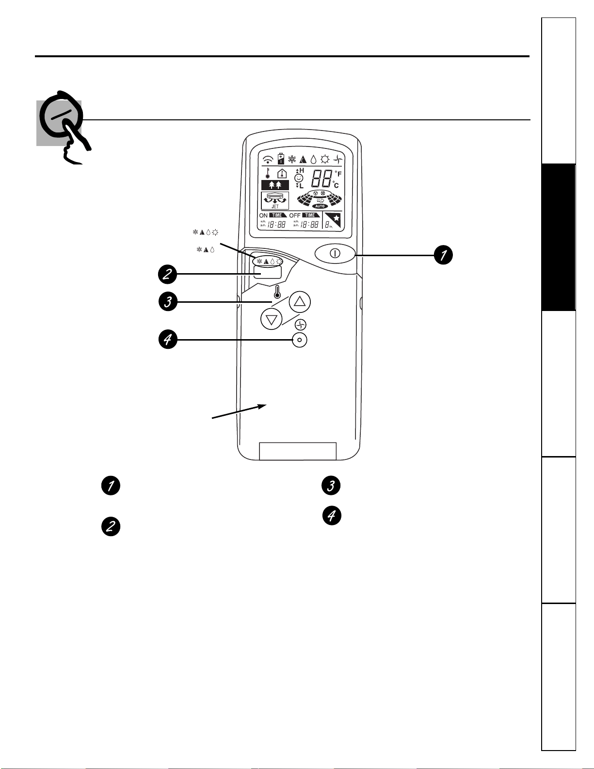
Features of the Remote Control—Door Closed
START/STOP BUTTON
Operation starts when this button is pressed and
stops when the button is pressed again.
OPERATION MODE SELECTION BUTTON
Used to select the operation mode.
ROOM TEMPERATURE SETTING BUTTONS
Used to select the room temperature.
INDOOR FAN SPEED SELECTOR
Used to select fan speed in four steps–low,
medium, high or AUTO.
Flip-up door (closed)
or
Heat pump model:
Cooling model:
6
Customer Service Troubleshooting Tips
Operating Instructions
Safety Instructions
Installation Instructions
Customer Service Troubleshooting Tips
Installation Instructions
Safety Instructions
Operating Instructions
Customer Service Troubleshooting Tips
Installation Instructions
Safety Instructions
Operating Instructions
About the remote control on the system.
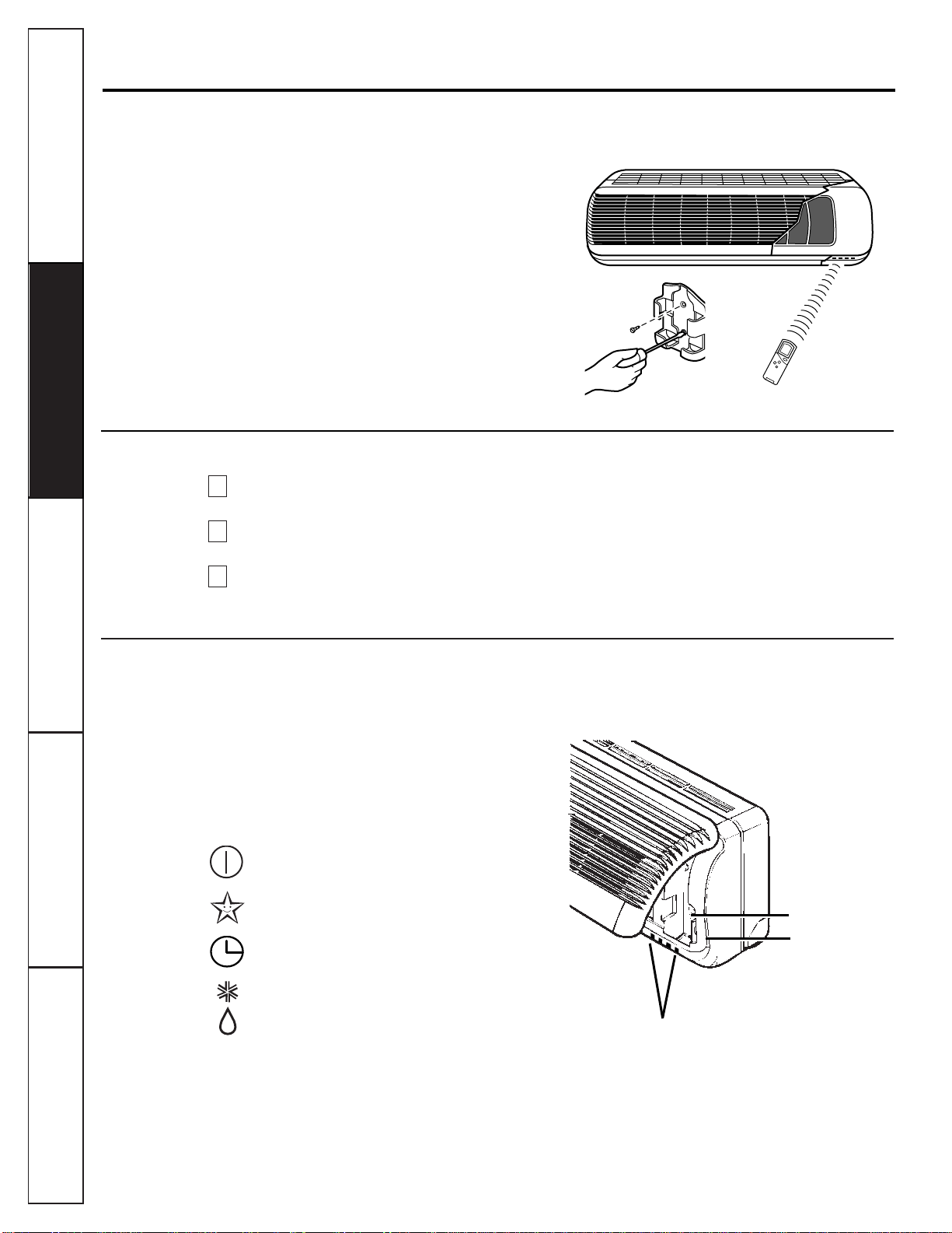
Storage and Tips For Using the Remote Control
■ The remote control may be stored inside the
system or mounted on a wall.
■ Aim at the signal receptor on the system so it will
operate properly.
■ The remote control signal can be received at a
distance of up to 23 ft.
How to Insert the Batteries
Remove the battery cover by sliding it according
to the arrow direction.
Insert new batteries making sure that the (+)
and (—) of battery are installed correctly.
Reattach the cover by sliding it back into
position.
NOTES:
■ Use 2 “AAA” (1.5 volt) batteries. Do not use
rechargeable batteries.
■ Remove the batteries from the remote control if
the system is not going to be used for a long time.
3
2
1
Inside the Indoor System
Some controls are located inside the indoor unit.
Open the front panel by lifting it up.
Manual Operation
—
Use when the remote
control cannot be used.
Signal Receptor
—
Receives the signals from the
remote control.
Operation Indication Lamps
ON/OFF
Lights up during the
system operation.
SLEEP MODE
Lights up during the Sleep
Mode operation.
TIMER
Lights up during the Timer
operation.
DEFROST
Lights up during the
MODE
Defrost Mode or Hot Start
operation (heat pump
model only).
OUT
OUTDOOR
Lights up during Outdoor
DOOR
UNIT
Unit operation (cooling
OPERATION
model only).
Mount on wall for
remote control storage.
Manual operation
Signal receptor
Operation indication lamps
Customer ServiceTroubleshooting Tips
Operating Instructions
Safety Instructions
Installation Instructions
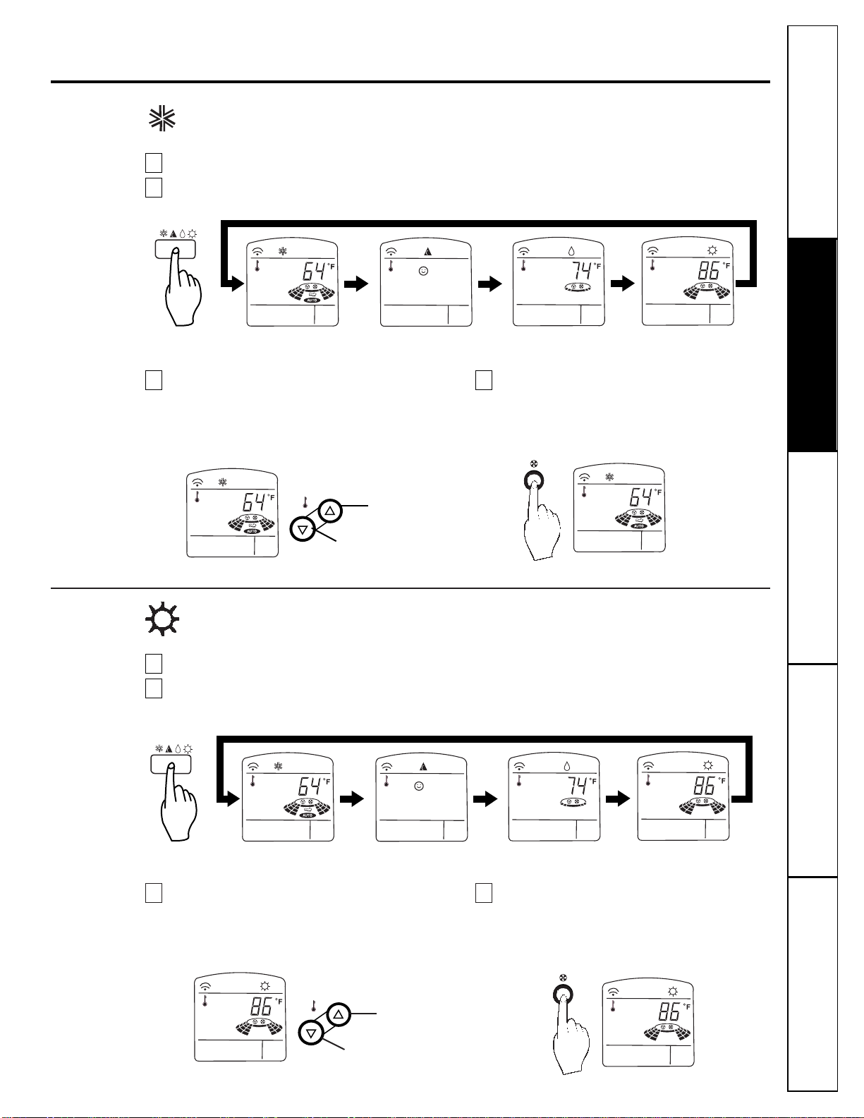
How to use the Operation Mode Selection button.
Cooling Operation
Press the Start/Stop button. The unit will respond with a beep.
Open the door on the remote control. To select cooling operation, press the Operation Mode Selection
button. Each time the button is pressed, the operation mode is shifted in the arrow direction.
2
1
Close the door on the remote control.
Set the temperature lower than the room
temperature. The temperature can be set
within a range of 64°F–86° F in 2° F
increments.
Set the fan speed again with the door of the
remote control still closed. You can select the
fan speed in four steps—low, medium, high or
AUTO
. Each time the button is pressed, the fan
speed mode is shifted.
43
To raise the
temperature
Cooling Auto
Dehumidify Heating
(Heat pump only)
To lower the
temperature
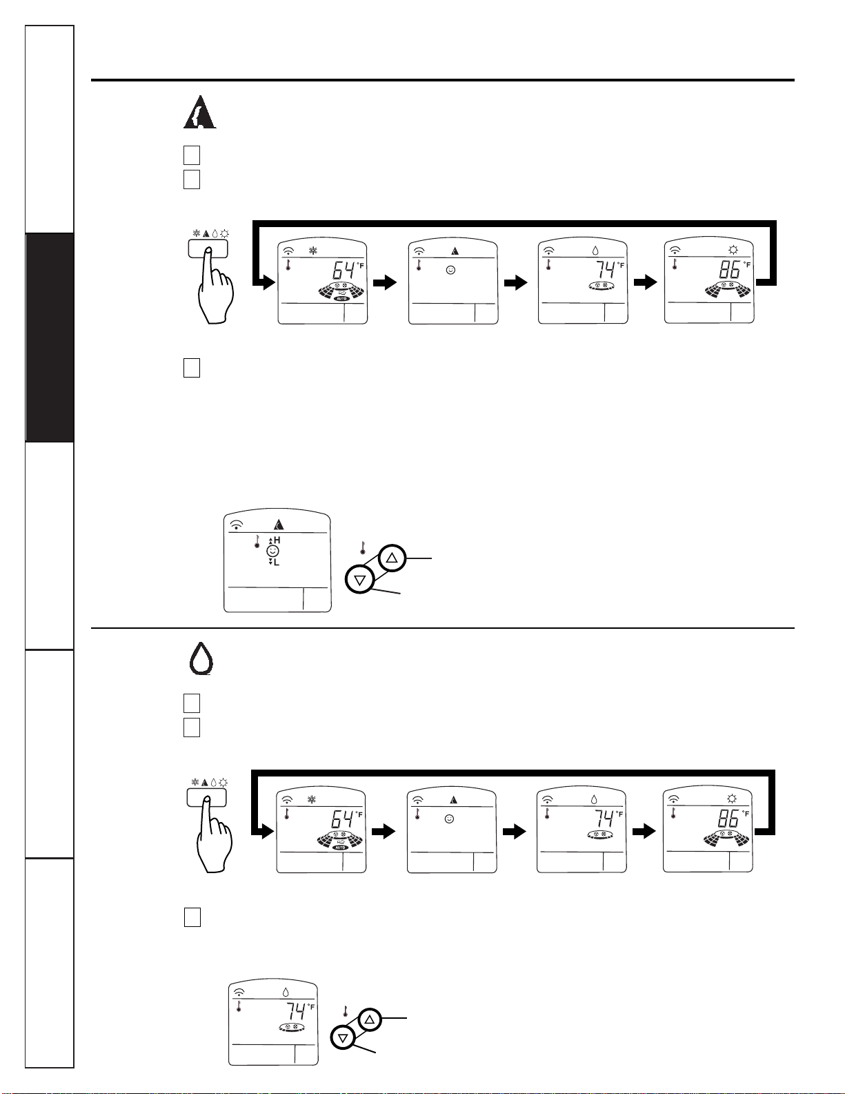
Press the Start/Stop button. The unit will respond with a beep.
Open the door on the remote control. To select heating operation, press the Operation Mode
Selection button. Each time the button is pressed, the operation mode is shifted in the arrow direction.
2
1
Close the door on the remote control.
Set the temperature higher than the room
temperature. The temperature can be set
within a range of 60° F–86° F in 2° F
increments.
Set the fan speed again with the door of the
remote control still closed. You can select the
fan speed in four steps—low, medium, high or
AUTO
. Each time the button is pressed, the fan
speed mode is shifted.
43
To raise the
temperature
To lower the
temperature
Cooling Auto
Dehumidify Heating
(Heat pump only)
Heating Operation (Heat pump model only)
7
8
Customer Service Troubleshooting Tips
Operating Instructions
Safety Instructions
Installation Instructions
Customer Service Troubleshooting Tips
Installation Instructions
Safety Instructions
Operating Instructions
Customer Service Troubleshooting Tips
Installation Instructions
Safety Instructions
Operating Instructions
How to use the Operation Mode Selection button.
Auto Operation
Press the Start/Stop button. The unit will respond with a beep.
Open the door on the remote control. To select auto operation, press the Operation Mode Selection
button. Each time the button is pressed, the operation mode is shifted in the arrow direction.
2
1
The temperature and fan speed are
automatically set by the electronic controls
based on the actual room temperature. If you
want to change the set temperature, close the
door on the remote control and press the Room
Temperature Setting buttons. The cooler or
warmer you feel, the more times (up to two
times) you should press the button. The set
temperature will then be changed automatically.
During Auto Operation:
■ You cannot switch the indoor fan speed. It has
already been set by the electronic control.
■ If the system is not operating as desired,
manually switch to another mode. The system
will not automatically switch from the cooling
mode to the heating mode, or from heating to
cooling, it must be done manually. Reset using
the Operation Mode Selection button.
■ During Auto Operation, pressing the Airflow
Direction Start/Stop button makes the horizontal
louvers swing up and down automatically. If you
want to stop auto-swing, press the Airflow
Direction Start/Stop button again.
3
To raise the
temperature
To lower the temperature
Cooling
Auto Dehumidify
Heating (Heat pump only)
Press the Start/Stop button. The unit will respond with a beep.
Open the door on the remote control. To select dehumidify operation, press the Operation Mode
Selection button. Each time the button is pressed, the operation mode is shifted in the arrow direction.
2
1
Cooling Auto
Dehumidify Heating (Heat pump only)
Close the door on the remote control. Set the
temperature higher than the room
temperature. The temperature can be set within
a range of 64° F–86° F in 2° F increments.
During Dehumidify Operation:
■ The indoor fan speed is automatically set to low
and cannot be adjusted.
■ The indoor fan may stop during this operation if
the electronic control detects over-cooling.
3
Dehumidify Operation
To raise the
temperature
To lower the temperature
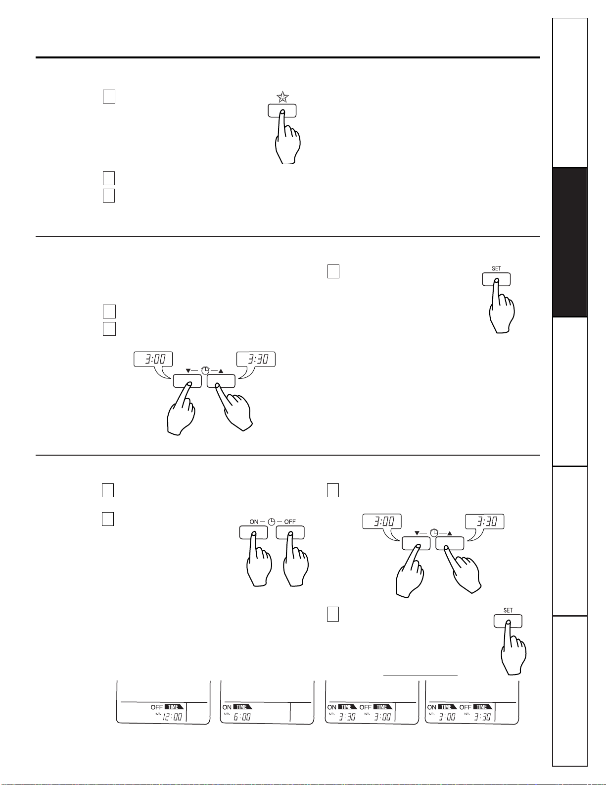
Sleep Mode
Press the Sleep Mode Auto button
to set the time you want the unit to
automatically turn off.
Make sure the Sleep Mode Auto LED lights up.
The Timer is programmed in one-hour
increments by pressing the Sleep Mode Auto
button 1 to 7 times.
To cancel the Sleep Mode, press the Sleep Mode
Auto button several times until the star (✩)
disappears from the operation display.
NOTE: The Sleep Mode will be operated at low fan
speed (cooling) or medium fan speed (heat pump only)
for quiet sleeping.
IN COOLING MODE: The temperature will
automatically rise by 2°F over the next 30 minutes
and by 4° F in 1 hour for comfortable sleeping.
3
2
1
Setting the Time
Time can be set only when you have pressed the
Reset button. If you have just replaced the batteries,
the Reset button should be pressed to reset the time.
Press the Start/Stop button.
Press the Time Setting buttons until the
desired time is set.
Press the Timer
SET
button.
NOTE: Check the indicator for
A.M. and P.M.
3
2
1
Customer ServiceTroubleshooting Tips
Operating Instructions
Safety Instructions
Installation Instructions
Additional features.
Delay Start/Pre-Set Stop
NOTE: Select one of the following four types of operation. With the unit running:
Delay OFF Timer Delay ON Timer Delay OFF and ON Timer Delay ON and OFF Timer
Make sure the time is set correctly on
the remote control display.
Press the ON/OFF Timer
buttons to turn Timer on
or off.
Press the Time Setting buttons until the desired
time is set.
Store the selected on/off setting
by pressing the Timer
SET
button.
4
3
2
1
9
10
Customer Service Troubleshooting Tips
Operating Instructions
Safety Instructions
Installation Instructions
Customer Service Troubleshooting Tips
Installation Instructions
Safety Instructions
Operating Instructions
Customer Service Troubleshooting Tips
Installation Instructions
Safety Instructions
Operating Instructions
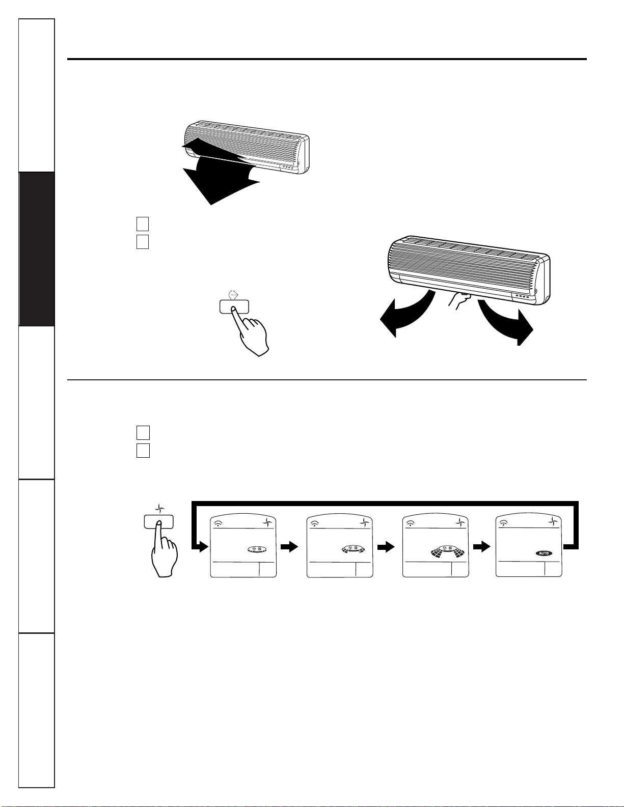
Additional features.
Airflow Direction (Indoor unit)
The up/down airflow can be adjusted by using the
remote control.
Press the Start/Stop button to start the unit.
Open the door on the remote control. Press the
Airflow Direction Start/Stop button and the
louvers will swing up and down. Press it again
and the louvers will stop at the desired setting.
NOTES:
■ Always use the remote control to adjust the
up/down airflow direction. Moving the louvers
by hand could cause operational errors or
damage the unit.
■ When the unit is shut off, the up/down airflow
direction louver will close the air outlet vent of
the system.
To adjust left/right direction:
Adjust the left/right airflow direction by hand.
2
1
Air Circulation Mode
Circulates the room air without cooling or heating.
Press the Start/Stop button. The unit will respond with a beep.
Open the door on the remote control. Press the Air Circulation button. Close the door on the remote
control. Now each time that you press the Indoor Fan Speed Selector, the fan speed is shifted from low
to medium to high to
AUTO
, and then back to low again.
NOTES:
■ The fan speed of the indoor unit will automatically cycle depending on the room temperature.
■
AUTO
economizes power consumption and prevents overcooling. The fan speed is automatically
changed from medium to low or vice versa, depending on the ambient temperature.
2
1
Fan speed is on low. Fan speed is on medium. Fan speed is on high.
AUTO Air
Customer ServiceTroubleshooting Tips
Operating Instructions
Safety Instructions
Installation Instructions
11
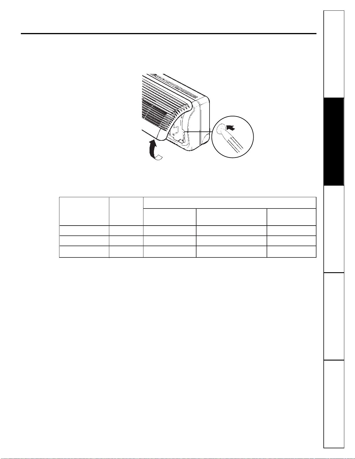
Manual Operation
If the remote control will not operate the unit, open the front panel upward and press the Manual
Operation button.
If you want to stop operation, raise the front panel and press the Manual Operation button again.
During Manual Operation, the operating conditions are automatically set as follows:
Use a pencil to press
the button.
Cooling Only Heat Pump Model
Model
Room Temp. Room Temp. Room Temp.
above 76° F 70° F thru 76° F below 70° F
Operating Mode Cooling Cooling Dehumidify Heating
Indoor Fan Speed High High Fan turns on/off automatically High
Setting Temperature 72° F 72° F Air intake temperature 76° F
12
Customer Service Troubleshooting Tips
Operating Instructions
Safety Instructions
Installation Instructions
Customer Service Troubleshooting Tips
Installation Instructions
Safety Instructions
Operating Instructions
Customer Service Troubleshooting Tips
Installation Instructions
Safety Instructions
Operating Instructions
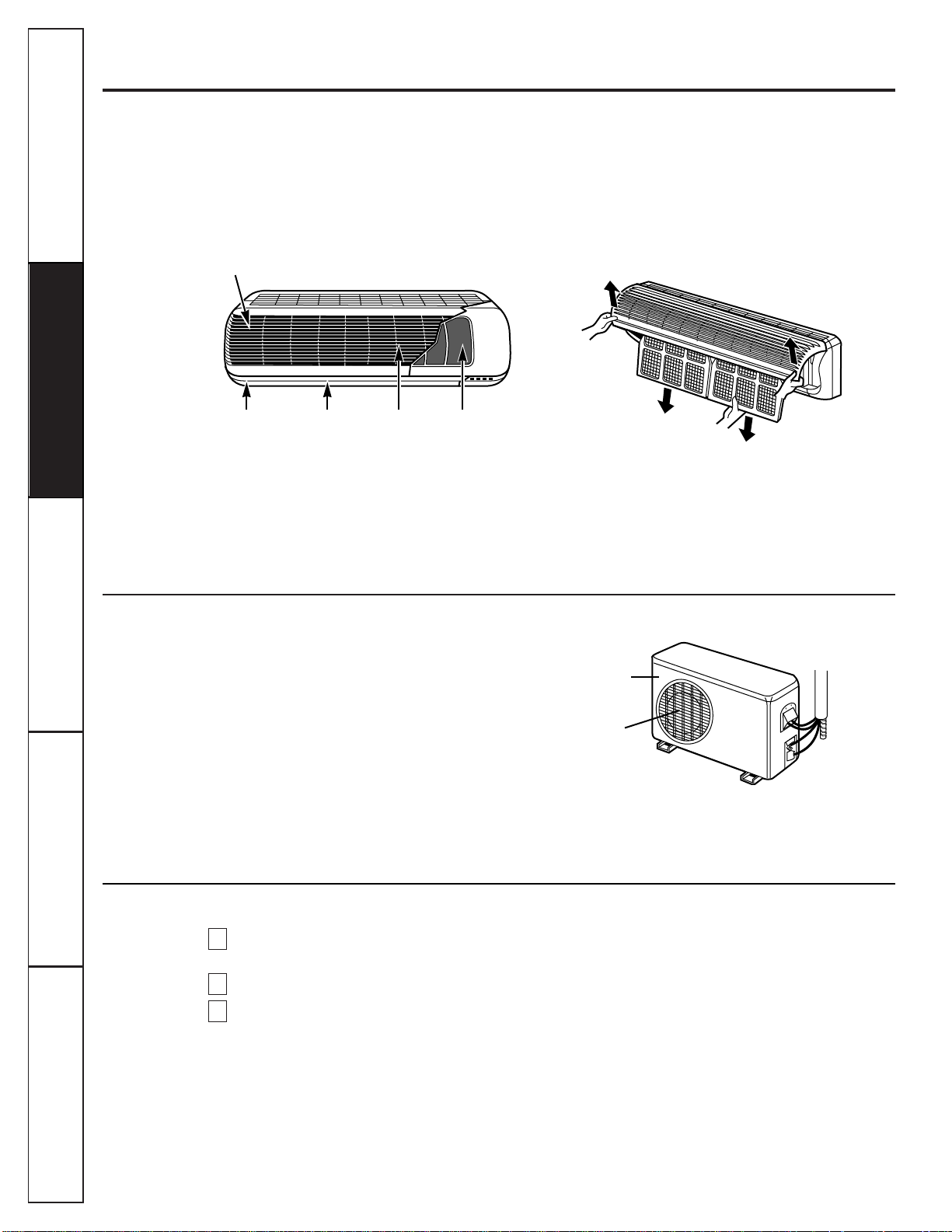
Indoor Unit
Grille, Case and Remote Control
Turn the system off before cleaning. To clean, wipe
with a soft, dry cloth. Do not use bleach or abrasives.
Air Filters
The two air filters behind the front grille should be
checked and cleaned at least every 30 days or more
often if necessary.
Lift the front access panel and pull the filter tab
slightly forward to remove the filter. Clean the filter
with a vacuum or warm, soapy water. Rinse and let
the filter dry before replacing it.
CAUTION: DO NOT operate the system without a filter
because dirt and lint will clog it and reduce performance.
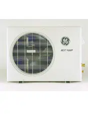
Outdoor Unit
The heat exchanger coils and panel vents of the
outdoor unit should be checked regularly. If
clogged with dirt or debris, the heat exchanger and
panel vents may be professionally steam cleaned, a
service available through your GE service outlet.
NOTE:
■
Supply power must be disconnected before cleaning the
outdoor unit.
■
Dirty or clogged coils will reduce the operating efficiency of
the system and cause higher operating costs.
Air intake vent
Air intake vents
Air outlet vent
Air outlet vent
Horizontal louver Vertical louver Air filters
If you’re closing up for the season…(cooling-only models)
Operate the system in the Air Circulation mode
for 2 hours. This will dry out the system.
Remove the batteries from the remote control.
Cover the outdoor unit with a protective cover.
3
2
1
Care and cleaning of the air conditioner.
CAUTION: Before performing any maintenance, turn off the main power to the system.
■
Do not use an extension cord with this system.
■
Aluminum building wiring may present special problems—consult a qualified electrician.
■
When the unit is in the STOP position, there is still voltage to the electrical controls.
■
Disconnect the power to the system before servicing by removing the branch circuit fuses
or turning the circuit breakers off at the panel.
CAUTION
■
Be certain all wiring complies with local building codes and NEC and that the supply voltage for this
system is correct. The system supply voltage is connected to the outdoor unit only.
■
Check the rating nameplate on side panel of outdoor unit for required circuit protection rating and
required supply voltage.
■
Use Underwriters-approved electrical branch circuit disconnect for providing supply voltage to split
system outdoor unit. Locate disconnect within sight and readily accessible from outdoor unit.
■
The split system indoor unit requires low voltage (D.C.) supplied from the outdoor unit via
interconnecting wiring. The interconnecting wiring between indoor and outdoor units of this
system must be 18–4 wiring, 18-gauge (minimum), 300-volt rating, type SJO–WA or STO–WA.
■
Be certain there is an uninterrupted, unbroken electrical ground connection.
Electrical Requirements
Customer ServiceTroubleshooting Tips
Operating Instructions
Safety Instructions
Installation Instructions
Installation instructions.
READ THE INSTALLATION INSTRUCTIONS CAREFULLY AND COMPLETELY BEFORE YOU BEGIN.
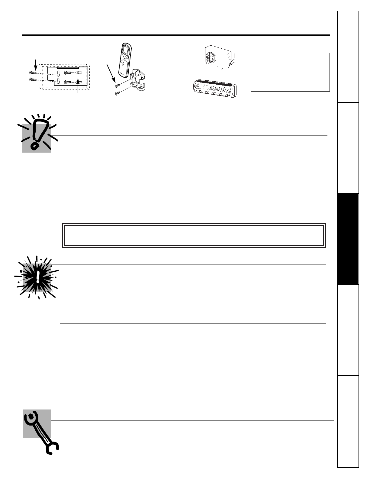
NOTE: Optional tube kits—which
contain pre-flared insulated tubing,
wiring, etc., to complete system
installation requirements—are
available from General Electric.
NOTE TO INSTALLER: Leave these instructions with the indoor unit after installation is completed.
NOTE TO CONSUMER: Keep these instructions for future use.
IMPORTANT NOTES:
■
Follow National Electric Codes (NEC) and/or local codes and ordinances.
■
For personal safety, this system must be properly grounded.
■
Protective devices (fuses or circuit breakers) acceptable for installation are specified on the
nameplate of each unit.
■
Servicing and installation of the refrigerant system must be performed only by a licensed, HVAC
certified technician.
■
Make sure to avoid wiring or plumbing inside the wall when installing.
For any service which requires entry into the refrigerant sealed system, Federal regulations require the
work be performed by a technician having a Class II or Universal certification.
Before You Begin
■
Electric drill
■
Carpenter’s stud finder (recommended)
■
2
3
⁄
4
”–3” diameter hole saw
■
Phillips-head screwdriver
■
Pencil
■
Crescent wrench
NOTE: A licensed, certified (to handle refrigerant-22,
recovery, etc.) technician is required for installation of
these split air conditioning or heating pump systems.
Tools You Will Need
Parts included
Type A screws
Type B
screws
Installation plate
Remote control
holder
Outdoor unit
Indoor unit
13
14
Customer Service Troubleshooting Tips
Operating Instructions
Safety Instructions
Installation Instructions
Customer Service Troubleshooting Tips
Installation Instructions
Safety Instructions
Operating Instructions
Customer Service Troubleshooting Tips
Installation Instructions
Safety Instructions
Operating Instructions
Installation instructions.
Read completely, then follow step by step.
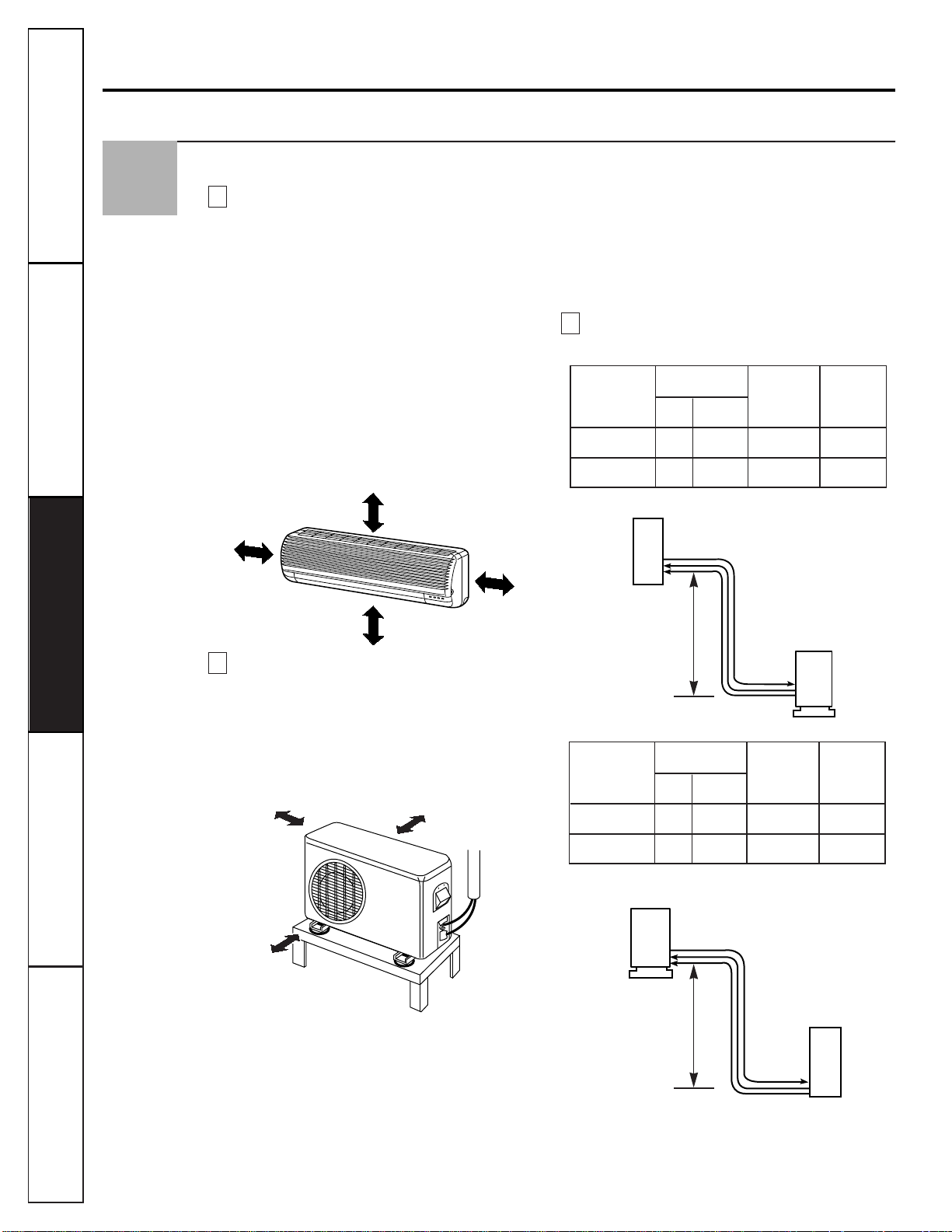
Select the Best Location
Indoor Unit.
■Do not have any heat or steam near the unit.
■Select a place where there are no obstacles in
front of the unit.
■Make sure that condensate drainage can be
conveniently routed away.
■Do not install near a doorway.
■Ensure that the space around the left and right
of the unit is more than 2². The unit should be
installed as high on the wall as possible, allowing a
minimum of 3² from ceiling.
■Use a stud finder to locate studs to prevent
unnecessary damage to the wall.
Outdoor Unit.
■If an awning is built over the unit to prevent direct
sunlight or rain exposure, make sure that heat
radiation from the condenser is not restricted.
■Ensure that the space around the back and sides
is more than 4². The front of the unit should have
more than 28² of space.
■Construct and anchor a strong and level
mounting base or pad for the outdoor unit.
■Use the provided rubber grommets between
the unit’s four mounts and the base or pad.
■Anchor the outdoor unit through its four
mounts using bolts.
■
Rooftop Installations:
If the outdoor unit is installed on a roof structure,
be sure to level the unit. Ensure the roof structure
and anchoring method are adequate for the unit
location. Consult local codes regarding rooftop
mounting.
Piping Length and Elevation.
C
B
A
1
Model Pipe Size* Max. Max.
(Cooling Length Elevation
Capacity) Gas Liquid A B
18K 5/8² 3/8² 40¢ 26¢
9K, 12K 1/2² 1/4² 40¢ 26¢
More than 2²
More than 2²
Install higher than eye level
More than 3²
More than 4²
More than 4²
More than 28²
Indoor
unit
Outdoor
unit
Indoor
unit
Outdoor
unit
A (Max. length)
B
Indoor unit mounted above outdoor unit
Model Pipe Size* Max. Max.
(Cooling Length Elevation
Capacity) Gas Liquid A B
18K 5/8² 3/8² 40¢ 26¢
9K, 12K 1/2² 1/4² 40¢ 26¢
Outdoor unit mounted above indoor unit
* Both gas and liquid interconnecting pipes must be insulated.
* Both gas and liquid interconnecting pipes must be insulated.
* Both gas and liquid interconnecting pipes must be insulated.
A (Max. length)
B
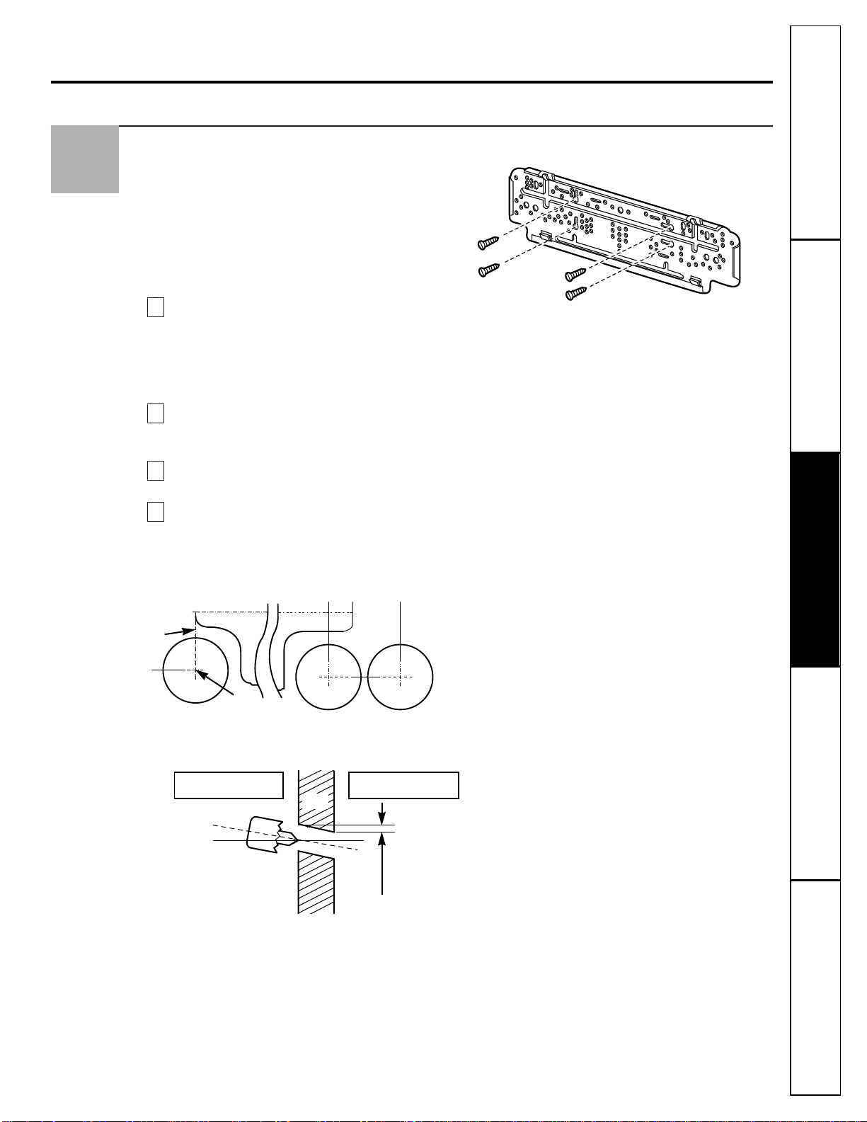
Indoor Unit Installation
The wall you select should be strong and solid
enough to protect it from vibration.
NOTE:
These instructions do not cover all
installations. However, the typical installation will be
to secure the installation plate to wall studs 16² apart.
It is recommended that a stud finder be used to
locate the wall studs.
Measure the wall and mark the centerline. It is
also important to use caution concerning the
location of the installation plate—routing of
the wiring to power outlets is through the walls
typically. Drilling the hole through the wall for
piping connections must be done safely.
Mount the installation plate on the wall with
four type A screws. If mounting the unit on a
concrete wall, use anchor bolts.
Mount the installation plate horizontally by
aligning the centerline using a level.
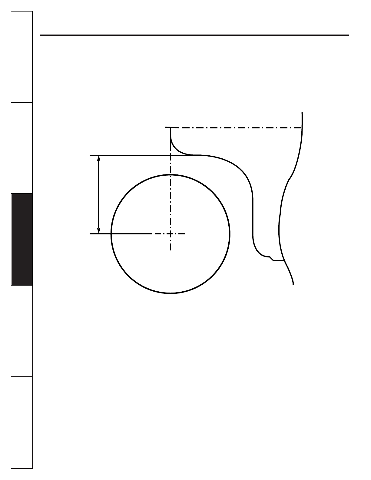
Drill the piping hole with a 2
3
⁄
4
–3² hole core
drill. Drill the piping hole at either the right or
the left with the hole slightly slanted to the
outdoor side (see illustration below).
(See templates in the back of this manual for hole location relative
to the installation plate.)
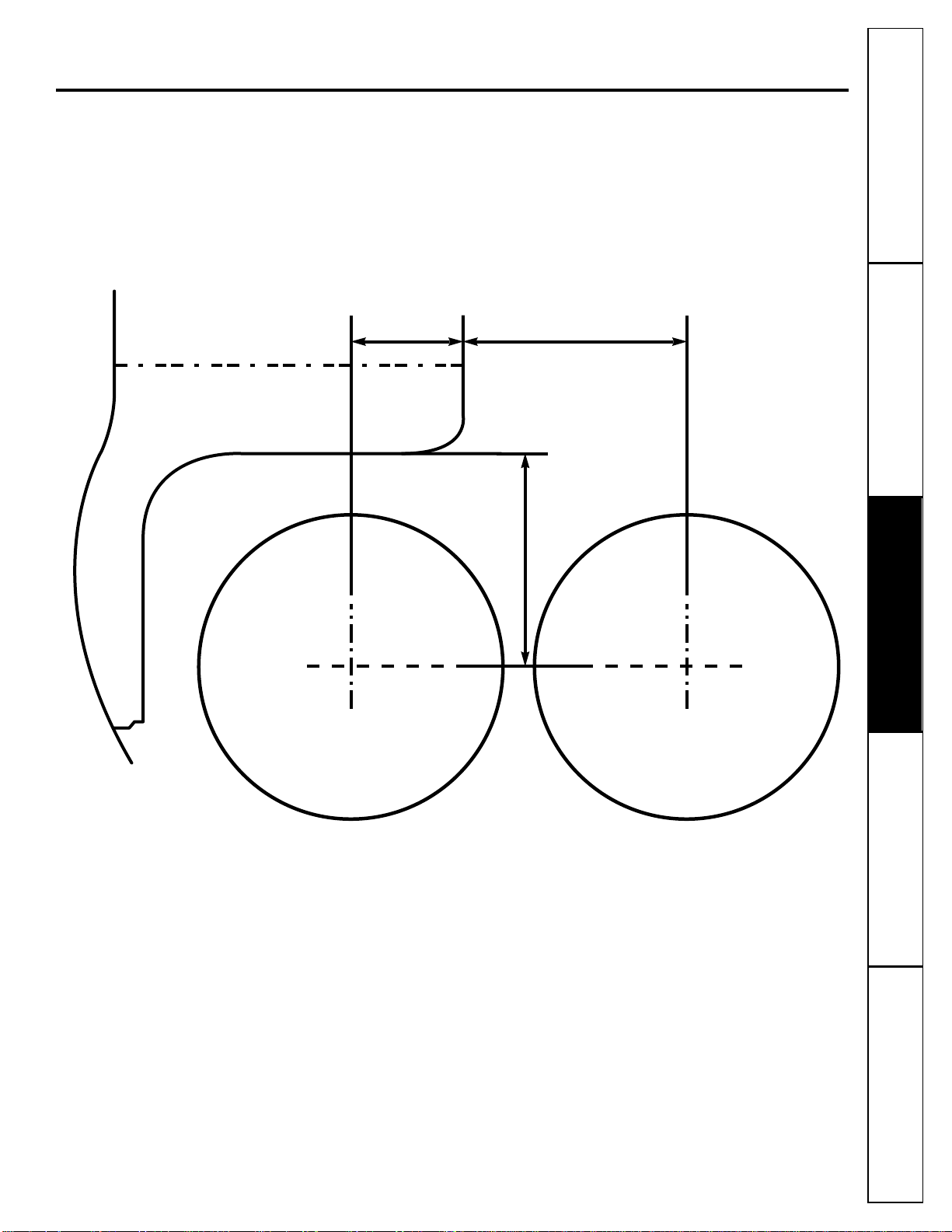
NOTES:
■For right rear piping, draw a line in the direction of
the arrow marked “A” and make another line
extending from the bottom line of the installation
plate. The meeting point of the two lines is the
center of the hole.
■For left rear piping, draw a line extending left
from the bottom line of the installation plate.
This is the center line of any hole for the left rear
installation.
Indoor Outdoor
D
C
B
A
2
Installation plate
Type A screw
Left rear piping
Center
line
Hole
center
Installation plate
“A”
2
3
⁄
4
–3² dia. piping hole
Customer ServiceTroubleshooting Tips
Operating Instructions
Safety Instructions
Installation Instructions
Wall
0.2~0.3²
Indoor Outdoor
15
16
Customer Service Troubleshooting Tips
Operating Instructions
Safety Instructions
Installation Instructions
Customer Service Troubleshooting Tips
Installation Instructions
Safety Instructions
Operating Instructions
Customer Service Troubleshooting Tips
Installation Instructions
Safety Instructions
Operating Instructions
Installation instructions.
Refrigerant Piping and Condensate Drain–Indoor Unit
Optional tubing kits are available which consist
of all interconnecting copper lines, wiring
needed to connect indoor to outdoor units,
and a plastic sleeve endcap to enhance the
installation wall hole sealing. You may also
purchase the tubing, insulation, wiring, etc.,
locally for the installation. See chart on page 14
for tubing diameter sizes required for the
different models.
NOTE:
Since the refrigerant metering device is
located in the outdoor unit, both the gas and the
liquid tubing line sets must be insulated. Armaflex
material is recommended.
*For heat pump models, heat-resistant insulation material
with minimum rating of 230° F is required.
See chart on page 14 for maximum lengths of
tubing for interconnecting units. The indoor
and outdoor units are provided with flare nuts.
See the brass fittings on the indoor/outdoor
sections.
NOTE:
The indoor unit is shipped from the factory
with a nitrogen holding charge to prevent moisture
contamination during shipment. Remove the flare
nuts on the indoor unit to vent the nitrogen
(environmentally friendly) into the atmosphere.
Measure distance between indoor and outdoor
units, considering the routing for the piping
and wiring. Cut tubing to lengths, insert the
tubing insulation. Flare the ends of tubes, after
inserting flare nuts that will connect to the
indoor and outdoor units.
C
B
A
3
Gas line insulation
Liquid line insulation
Minimum 5/16
² wall
insulation thickness*
Connection of the Pipes
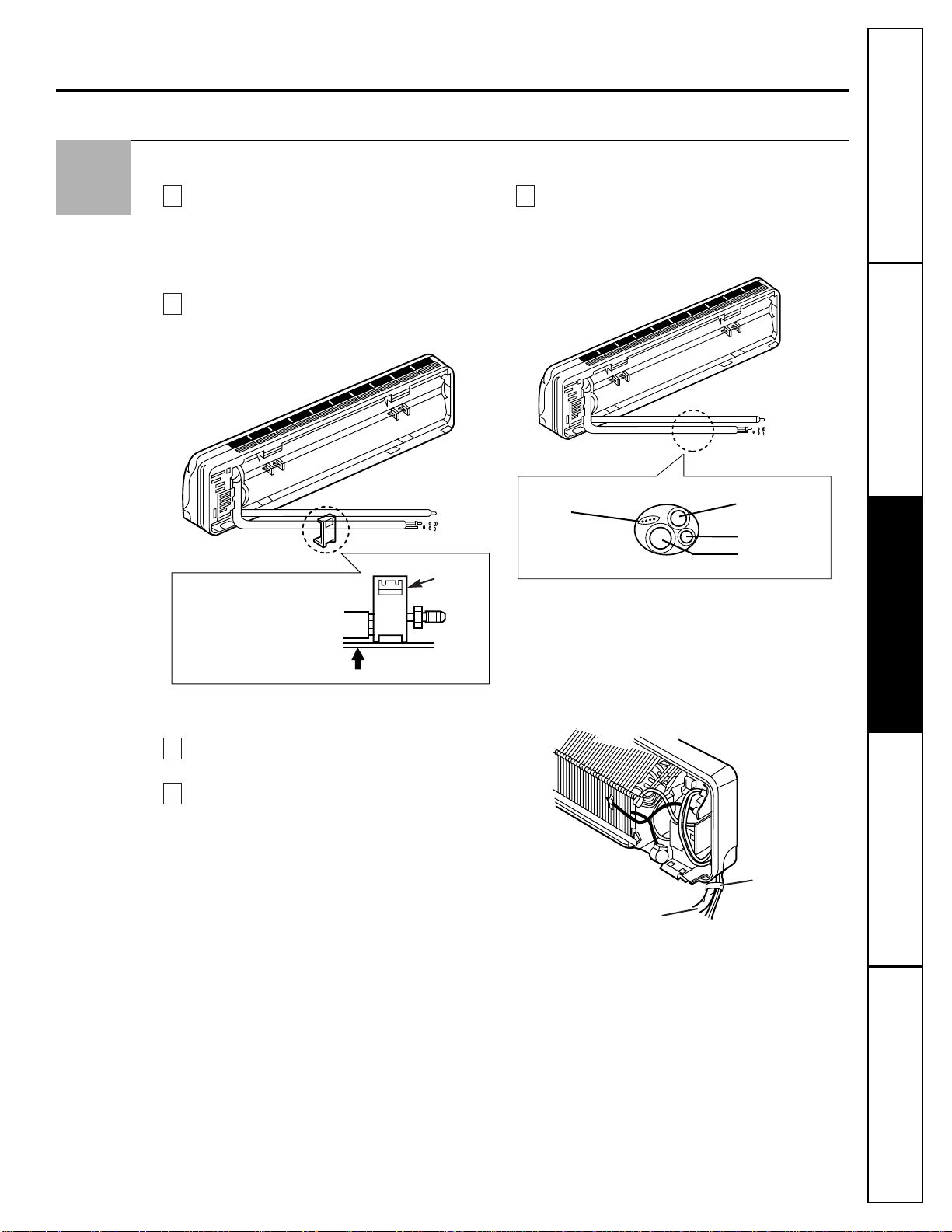
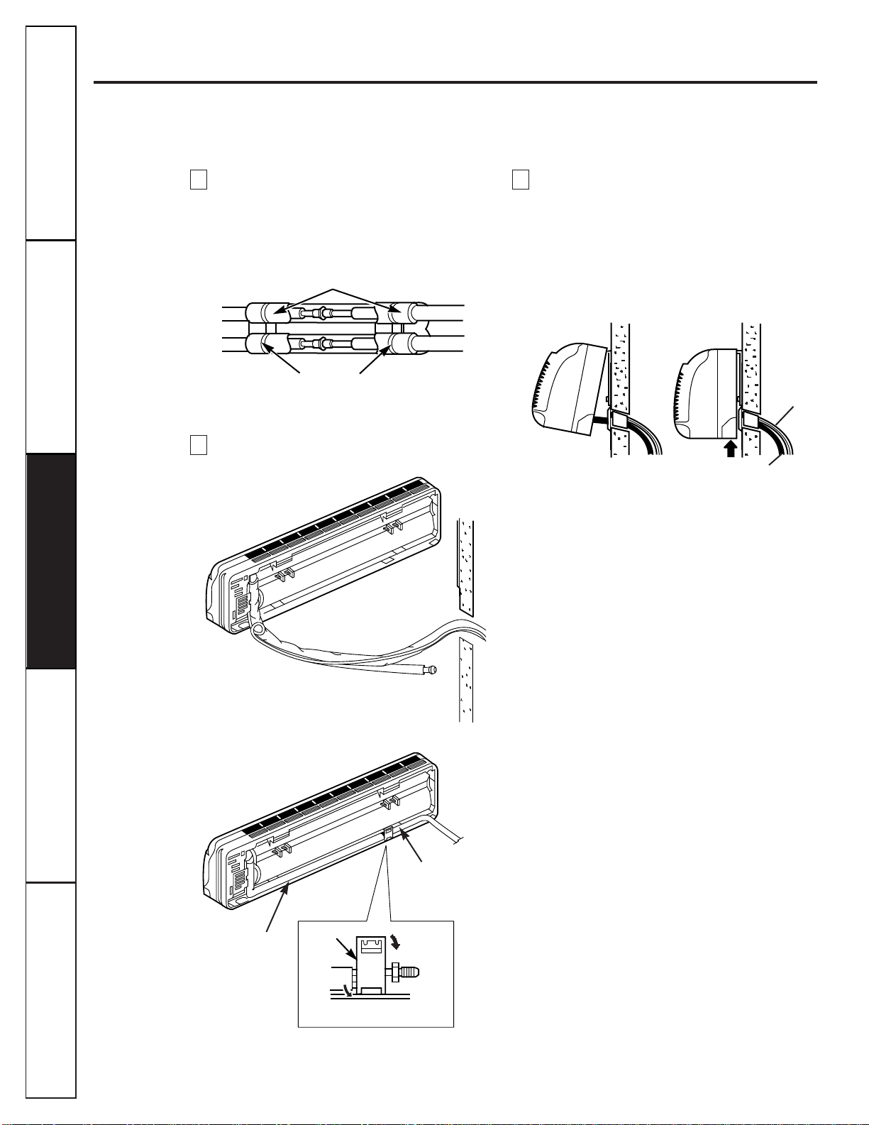
Preparing the indoor unit’s piping and drain
hose for installation through the wall.
Remove the plastic tubing retainer (see
illustration below) and pull the tubing
and drain line away from chassis.
Replace the plastic tubing holder in the original
position.
FOR RIGHT REARPIPING:
Route the tubing and the drain hose straight
backwards.
Insert the connecting wiring cable into the
indoor unit from the outdoor unit through
the piping hole.
1
Do not connect the cable to the indoor unit.
2
Make a small loop with the cable for easy
connection later.
NOTE:
Wiring must comply with local and NEC
codes. The interconnecting wiring between
indoor and outdoor units of this system must be
18–4 wiring, 18-gauge (minimum), 300-volt rating,
type SJO-WA or STO-WA.
Tape the tubing, drain hose and the connecting
cable. Be sure that the drain hose is located at
the lowest side of the bundle. Locating at the
upper side can cause drain pan to overflow
inside the unit.
NOTE:
If the drain hose will be routed in the room,
insulate the hose with an insulation material
*
so
that dripping from “sweating” (condensation) will
not damage furniture or floors.
*
Foamed polyethylene or equivalent is
recommended.
E
D
C
B
A
4
Taping
Gas side piping
Liquid side piping
Drain hose
Connecting cable
Indoor/outdoor
connecting cable
Customer ServiceTroubleshooting Tips
Operating Instructions
Safety Instructions
Installation Instructions
17
➀
Press
➁
Pull
To remove the retainer, press
the bottom of chassis near the
retainer upward and pull the
tab out of its hole.
Tubing
holding
retainer
18
Customer Service Troubleshooting Tips
Operating Instructions
Safety Instructions
Installation Instructions
Customer Service Troubleshooting Tips
Installation Instructions
Safety Instructions
Operating Instructions
Customer Service Troubleshooting Tips
Installation Instructions
Safety Instructions
Operating Instructions
Installation instructions.
Indoor unit installation.
Hook the indoor unit onto the upper
portion of the installation plate. (Engage
the two hooks of the rear top of the indoor
unit with the upper edge of the installation
plate.) Ensure that the hooks are properly
seated on the installation plate by moving it
left and right.
Connecting the pipings to the indoor unit.
1
Align the center of the pipings and
sufficiently tighten the flare nut by hand.
2
Tighten the flare nut with a wrench.
Wrap the insulation material around the
connecting portion.
CAUTION:Be careful to arrange the pipings, drain hose
and cables as shown on page 17 by connecting them to the
indoor unit.
H
G
F
Press the lower left and right sides of the unit against
the installation plate until the hooks engage with their
slots (clicking sound).
Drain hose
Connecting
cable
Plastic bands
Isulation material
Wrap insulation material around the connecting portion.
Indoor unit tubing
Flare nut
Piping
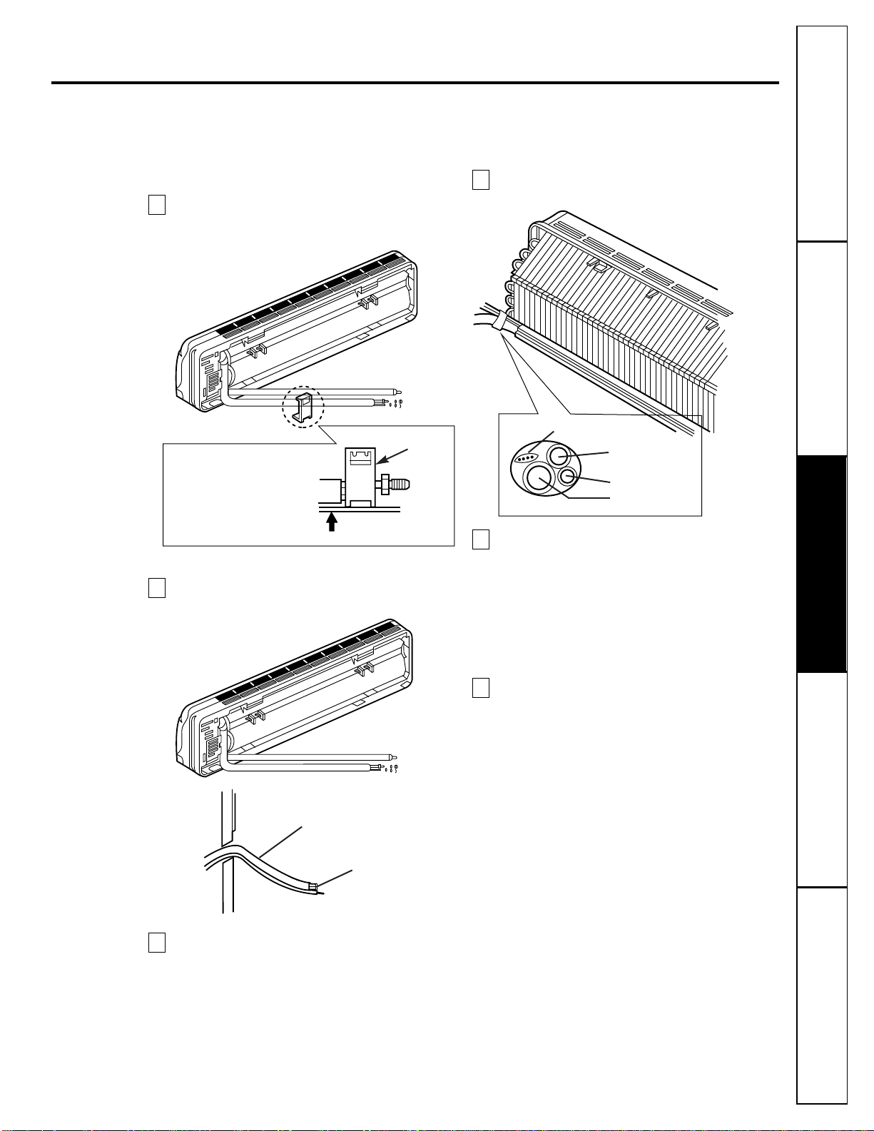
Connection of the Pipes
FOR LEFT REARPIPING:
Route the indoor tubing with the drain hose
through the piping hole in the desired position.
Insert the pipings, power supply cord and the
connecting cable into the piping hole.
Insert the connecting cable into the indoor unit.
1
Do not connect the cable to the indoor unit.
2
Make a small loop with the cable for easy
connection later.
NOTE:
Wiring must comply with local and NEC
codes. The interconnecting wiring between
indoor and outdoor units of this system must be
18–4 wiring, 18-gauge (minimum), 300-volt rating,
type SJO-WA or STO-WA.
Tape the tubing, drain hose and the connecting
cable.
Indoor unit installation.
Hook the indoor unit onto the upper
portion of the installation plate. (Engage
the two hooks of the rear top of the indoor
unit with the upper edge of the installation
plate.) Ensure that the hooks are properly
seated on the installation plate by moving it
left and right.
Connect the pipings to the indoor unit.
Align the center of the pipings and
sufficiently tighten the flare nut by hand.
F
E
D
C
B
A
Customer ServiceTroubleshooting Tips
Operating Instructions
Safety Instructions
Installation Instructions
19
➀
Press
Outside
Indoor
Piping
Connecting cable
➁
Pull
Tubing
holding
retainer
To remove the retainer, press
the bottom of chassis near the
retainer upward and pull the
tab out of its hole.
Gas side piping
Liquid side piping
Drain hose
Connecting cable
20
Customer Service Troubleshooting Tips
Operating Instructions
Safety Instructions
Installation Instructions
Customer Service Troubleshooting Tips
Installation Instructions
Safety Instructions
Operating Instructions
Customer Service Troubleshooting Tips
Installation Instructions
Safety Instructions
Operating Instructions
Installation instructions.
Piping and Condensate Drain Line—Indoor
Wrap the insulation material around the
connecting portion.
CAUTION:Be careful to arrange the pipings, drain hose and
cables as shown on page 17 by inserting them into the indoor
unit and reattaching the tubing retainer.
Reroute the pipings and the connecting cable
across the back of the chassis.
Indoor unit installation.
Hook the indoor unit onto the upper
portion of the installation plate. (Engage the
two hooks of the rear top of the indoor unit
with the upper edge of the installation
plate.) Ensure that the hooks are properly
seated on the installation plate by moving it
left and right.
I
H
G
Reinsert the tubing retainer
Press the lower left and right sides of the unit against
the installation plate until the hooks engage with their
slots (clicking sound).
Drain hose
Connecting
cable
➀
Hook
➁
Push
Piping
Drain hose
Plastic bands
Isulation material
Wrap insulation material around the connecting portion.
Tubing holding
retainer
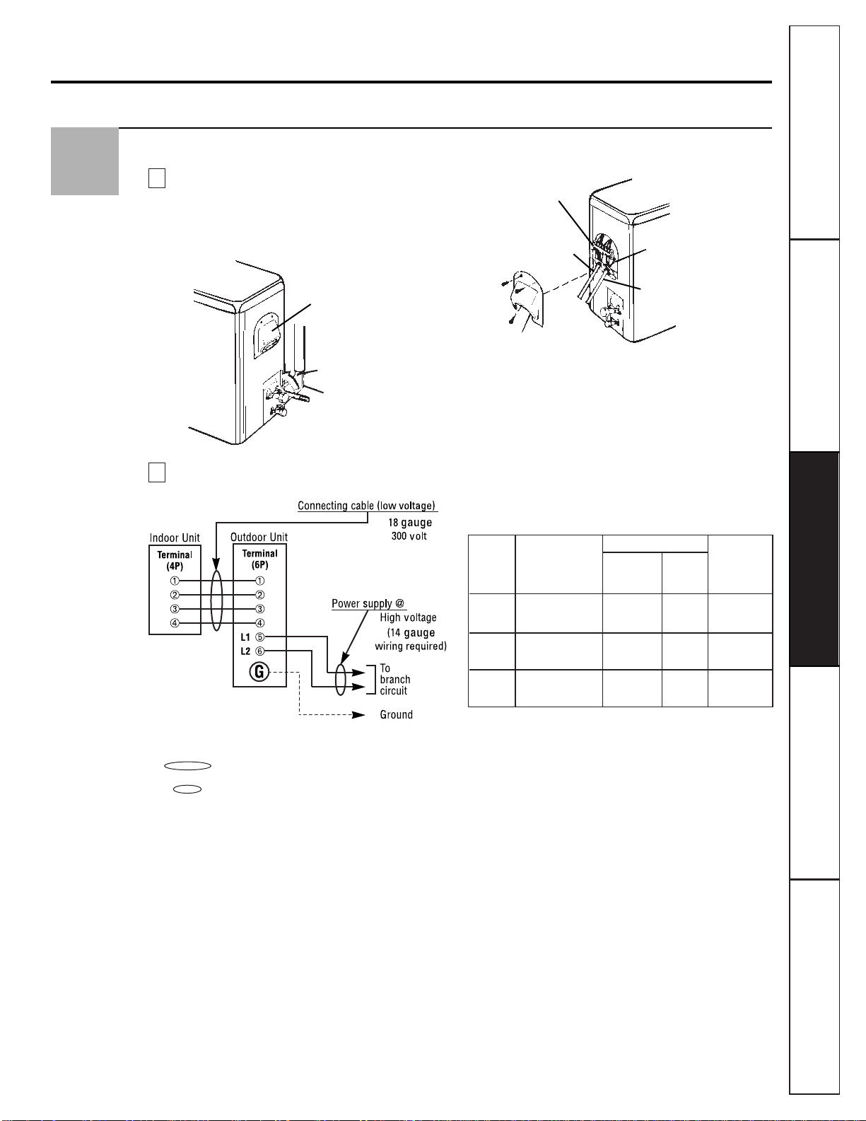
Connection of the Pipes and the Cable to the Outdoor Unit
Connecting the pipings to the outdoor unit.
1
Align the center of the pipings and
sufficiently tighten the flare nut by hand.
2
Tighten the flare nut with a wrench.
Wiring diagram:
NOTES:
■ shows field wiring (low voltage).
■ shows power source wiring.
■Separately wire the high and low voltage lines.
■Use heat-proof electrical wiring capable of
withstanding temperatures of up to 167° F.
■Use outdoor and waterproof connection cable
rated more than 300V for the connection
between indoor and outdoor units. (For
example, Type SJO-WA.)
WARNING
■Be sure to comply with local codes to route the
wire from the indoor unit to the outdoor unit
(size of wire and wiring method, etc.).
■Every wire must be connected securely.
■No wire should be allowed to touch refrigerant
tubing, the compressor or any moving parts.
Outdoor unit
Terminal block
Low voltage wiring
Cover control
Conduit panel
Supply voltage
connection
B
Gas side piping
(larger dia.)
Liquid side piping
(smaller dia.)
Outdoor unit
Wiring access cover
A
5
AWG(Min.)
Fuse or
Power Supply Low
Breaker
Model
Source voltage voltage
Capacity
connection wiring
9K 115V 14 18 15 amps
60Hz – 1Ph
12K 115V 14 18 20 amps
60Hz – 1Ph
18K 230/208V 14 18 15 amps
60Hz – 1Ph
Customer ServiceTroubleshooting Tips
Operating Instructions
Safety Instructions
Installation Instructions
21
22
Customer Service Troubleshooting Tips
Operating Instructions
Safety Instructions
Installation Instructions
Customer Service Troubleshooting Tips
Installation Instructions
Safety Instructions
Operating Instructions
Customer Service Troubleshooting Tips
Installation Instructions
Safety Instructions
Operating Instructions
Installation instructions.
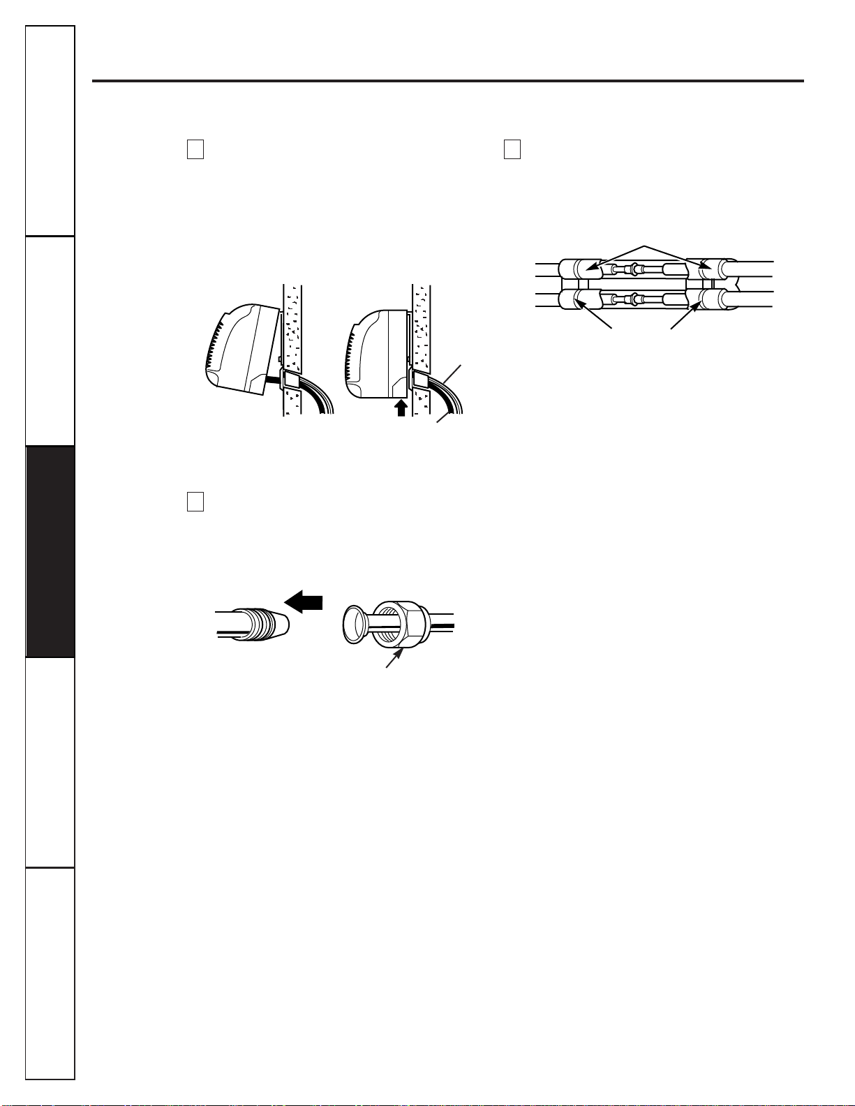
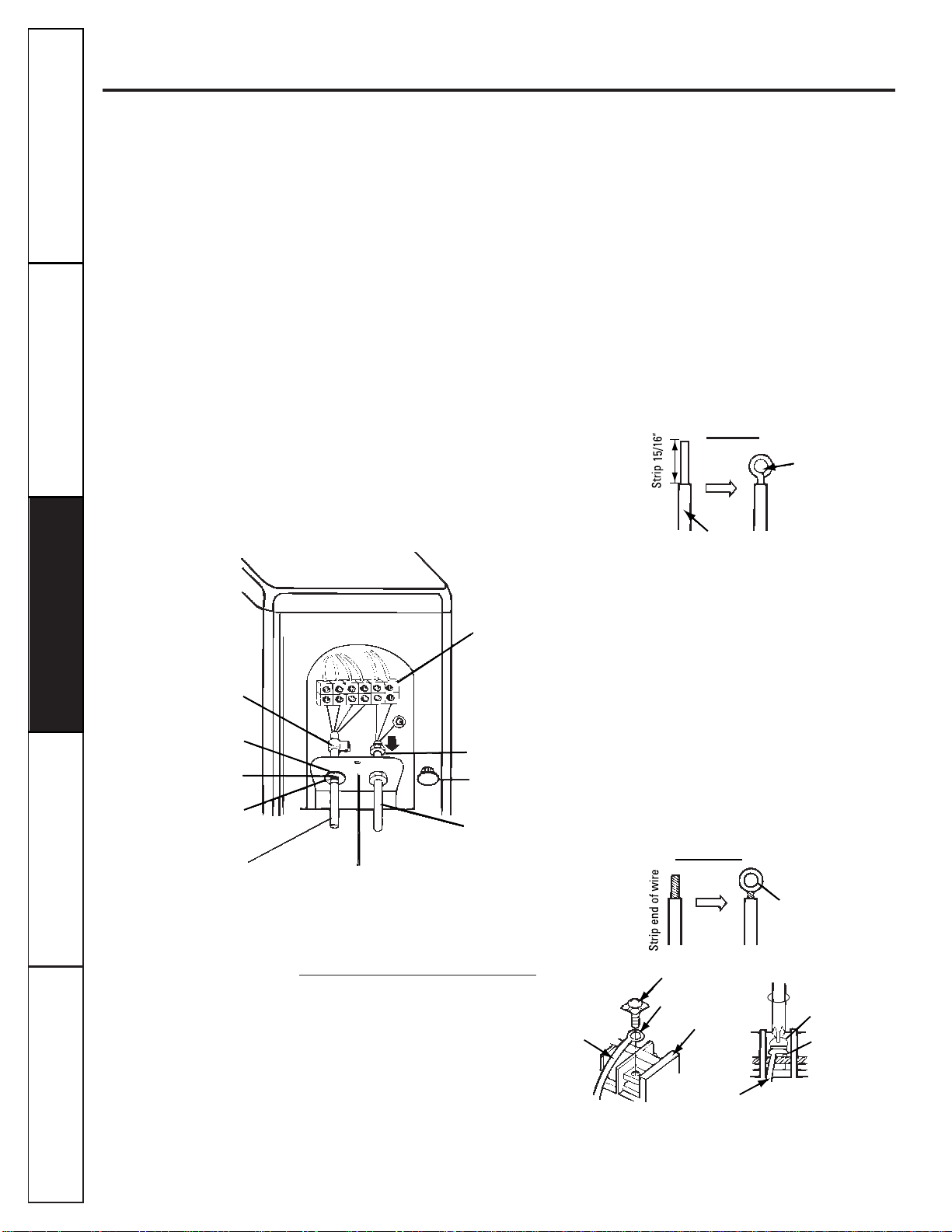
Connecting wiring to outdoor unit:
1
Remove the wiring access cover on the
outdoor unit.
2
Drill a hole through the plastic plug cap
appropriate for the passage of connecting cable
(for low voltage line).
3
Pass the connecting cable through hole.
4
Properly connect the wire onto the terminal
block.
5
Fix the connecting cable with the clamp cord
provided on the unit to avoid strain at the
terminal when the connecting cable is pulled
outside by up to a 35-pound weight.
6
Wind vinyl tape over the connecting cable for
sealing between the surface of the connecting
cable and cap.
7
Mount the taped part of the cable on the cap.
8
Mount the holed cap with the wound cable on the
conduit panel.
WARNING:
Loose wiring may cause the terminal to
overheat or result in unit malfunction. A fire hazard
may also exist. Be sure all wiring is tightly connected.
How to connect wiring to the terminals:
■For solid core wiring (or F-cable)
1
Cut the wire end with a wire cutter or wire-cutting
pliers, then strip the insulation to expose the solid
wire about 15/16².
2
Using a screwdriver, remove the terminal
screw(s) on the terminal plate.
3
Using pliers, bend the solid wire to form a loop
suitable for the terminal screw.
4
Shape the loop wire properly, place it on the
terminal plate and tighten securely using a
screwdriver.
■For strand wiring
1
Cut the wire end with a wire cutter or wire cutting
pliers, then strip the insulation to expose the
strand wiring about 3/8².
2
Using a screwdriver, remove the terminal
screw(s) on the terminal plate.
3
Using a round terminal fastener or pliers,
securely clamp each stripped wire end with a
round terminal.
4
Position the round terminal wire, and replace
and tighten the terminal screw using a
screwdriver.
Screw with
special washer
Round terminal
Terminal plate
Wire
Screw with
special washer
Round terminal
Stranded wire
Round
terminal
Solid wire
Loop
Insulation
Clamp cord
Hole
(for low
voltage line)
Taping
(for sealing)
Cap
(resuse)
Low voltage line
(connecting cable)
Conduit panel
Power supply line
(1ø, 230/208V or
115V, depending
on model)
Cap
(remove)
Lock nut
Terminal block
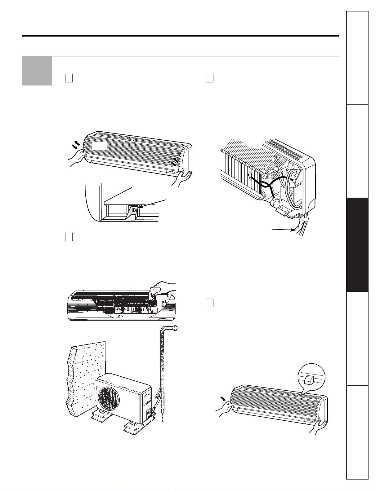
Check the Condensate Drain and Connect the Cable to the Indoor Unit
Remove the grille from the indoor unit.
1
Set the up and down air direction louvers to
the open position (horizontally) by hand.
2
Remove 3 screws that retain the front grille.
Pull the lower left and right sides of the grille
toward you and lift it off.
Check the drainage.
1
Pour a glass of water on the evaporator.
2
Ensure that water flows through the drain
hose of the indoor unit without any leakage
and goes out the drain exit.
Connect the cable to the indoor unit by
connecting the wires to the terminals on the
control board individually according to the
outdoor unit connection.
1
Ensure that the color of the wires of the
outdoor unit and the terminal No. are the
same as those of the indoor unit. (Refer to
the Wiring diagram on page 21.)
WARNING:
■Be sure to refer to the wiring diagram —see Mini
Manual. Improper wiring can cause the unit to
operate incorrectly and result in a fire hazard.
■Check local electrical codes and any specified
wiring instructions or limitations.
Attach the grille onto the cabinet.
1
Grasp the lower part of the left and right
sides of the grille and engage the four tabs
on the top inside edge of the chassis.
2
Press the grille toward the chassis until it
clicks back into place.
3
Reinstall the (3) retaining screws.
4
Close grille front.
D
C
B
A
6
Customer ServiceTroubleshooting Tips
Operating Instructions
Safety Instructions
Installation Instructions
23
Grille
Chassis
Connecting cable
Remove screws
(3 places)
24
Customer Service Troubleshooting Tips
Operating Instructions
Safety Instructions
Installation Instructions
Customer Service Troubleshooting Tips
Installation Instructions
Safety Instructions
Operating Instructions
Customer Service Troubleshooting Tips
Installation Instructions
Safety Instructions
Operating Instructions
Installation instructions.
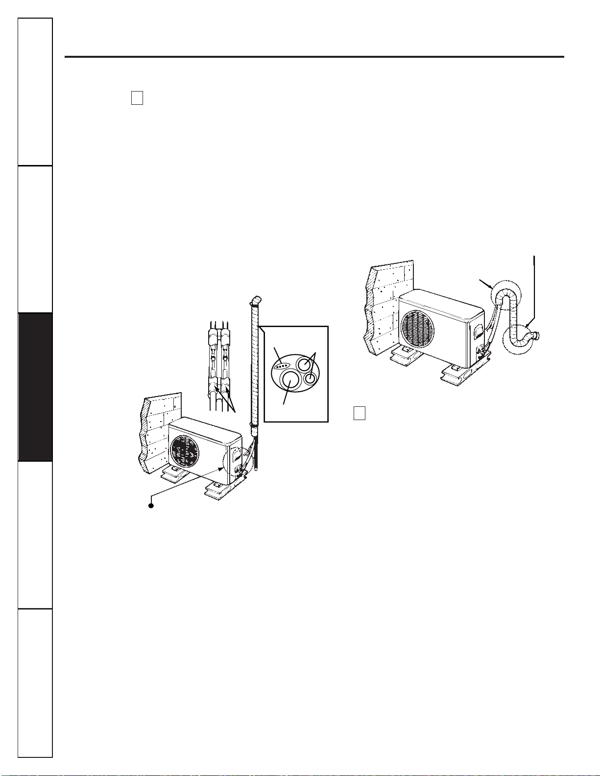
Form the pipings by wrapping the connecting
portion of the indoor unit with insulation
material and secure it with two plastic bands
(for the right pipings).
If you want to connect an additional drain
hose, the end of the drain outlet should be
routed above the ground. Secure the drain line
appropriately.
■If the outdoor unit is being installed below the
position of the indoor unit:
1
Tape the pipings, drain hose and connecting
cable from down to up.
2
Form the pipings gathered by taping along the
exterior wall and fix them onto the wall by
saddle or equivalent.
■If the outdoor unit is being installed above the
position of the indoor unit:
1
Tape the pipings and connecting cable from
down to up.
2
Form the pipings gathered by taping along the
exterior wall. The trap should be formed up to
prevent water from entering into the room.
3
Fix the pipings onto the wall by saddle or
equivalent.
A plastic drain elbow is provided with the
outdoor heat pump unit for routing any
condensation away from the outdoor unit
basepan. Attach the elbow to the basepan
near the compressor and then attach a hose
(that you provide) to the other end to route
the water away.
F
Seal small openings
around pipings with
a gum type sealer.
Trap
Seal small openings
around pipings with
a gum type sealer.
Plastic
band
Trap is required to prevent water from
entering into electrical parts.
Drain hose
Pipings
Connecting
cable
E
Air Purging
Any air or moisture remaining in the refrigerant
system has undesirable effects as indicated below.
■Pressure in the system rises.
■Operating current rises.
■Cooling (or heating) efficiency drops.
■Moisture in the refrigerant circuit may freeze and
block capillary tubing.
■Water may lead to corrosion of parts in the
refrigerant system.
The indoor unit and tubing between the indoor
and outdoor units must be leak-tested and the
system evacuated to remove any noncondensables
and moisture.
NOTE: The outdoor unit contains R22 charge for the
total system.
Air purging with a vacuum pump.
Preparation:
Check that each tube (both liquid and gas side
tubes) between the indoor and outdoor units has
been properly connected and all wiring for the test
run has been completed. Remove the valve caps
from both the gas and the liquid side service valves
on the outdoor unit. Note that both liquid and gas
side service valves on the outdoor unit are kept
closed at this stage.
NOTE: The outdoor unit contains R22 charge for the
total system.
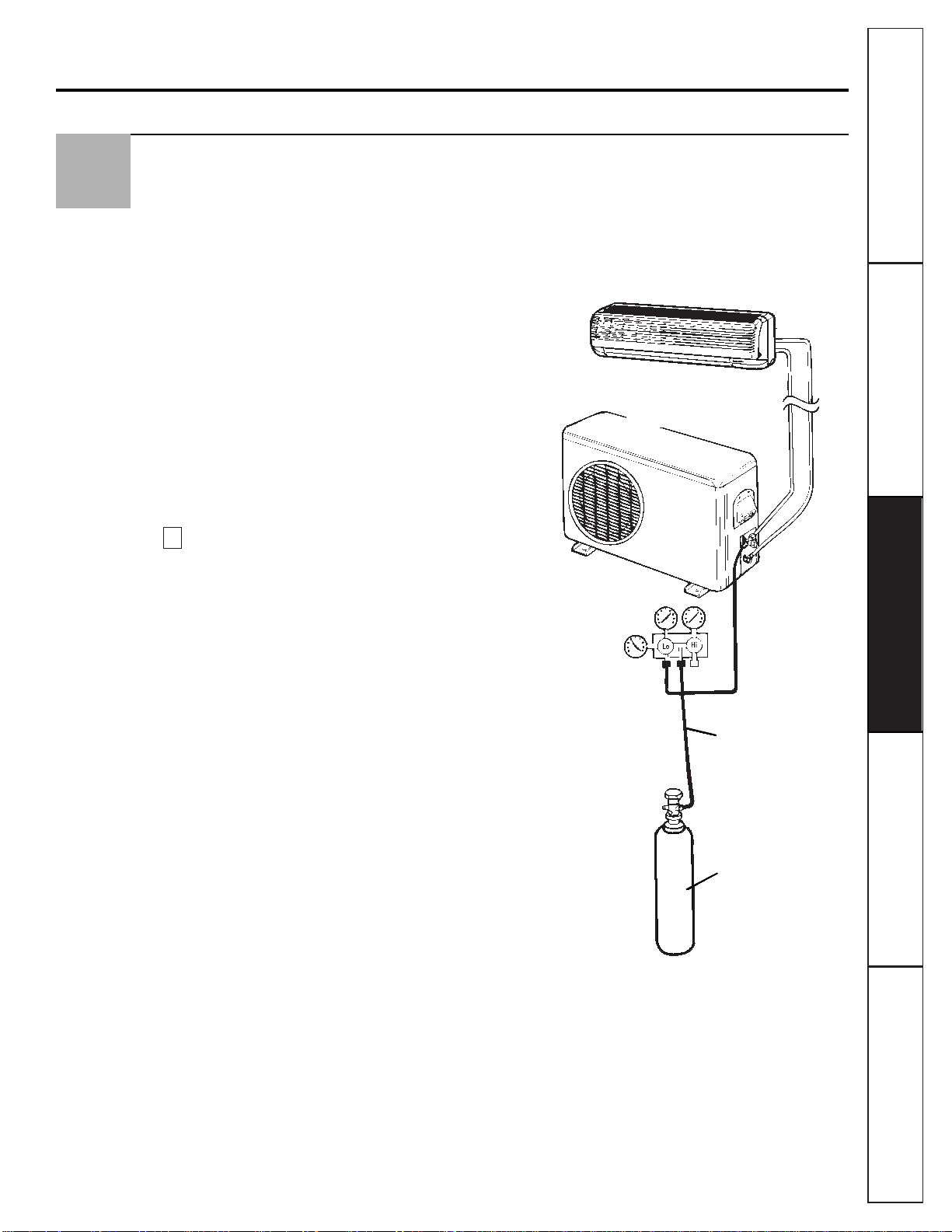
Leak Test:
1
Connect a manifold valve (with pressure gauges)
and dry nitrogen gas cylinder to the suction
service port.
2
Pressurize the system to no more than 150
P.S.I.G. with dry nitrogen gas and close the
cylinder valve when the gauge reading reaches
150 P.S.I.G. Next, test for leaks with liquid soap.
CAUTION: To avoid nitrogen entering the refrigerant system
in a liquid state, the top of the cylinder must be higher than its
bottom when you pressurize the system. Usually, the cylinder
is used in a vertical standing position.
3
Do a leak test of all joints of the tubing (both
indoor and outdoor) and both gas and liquid side
service valves. Bubbles indicate a leak. Be sure to
wipe off the soap with a clean cloth.
4
After the system is found to be free of leaks,
relieve the nitrogen pressure by loosening the
charge hose connector at the nitrogen cylinder.
When the system pressure is reduced to normal,
disconnect the hose from the cylinder.
Indoor unit
Outdoor unit
Manifold valve
Pressure gauge
Charge hose
Nitrogen gas cylinder
(in vertical standing
position).
A
7
Customer ServiceTroubleshooting Tips
Operating Instructions
Safety Instructions
Installation Instructions
25
26
Customer Service Troubleshooting Tips
Operating Instructions
Safety Instructions
Installation Instructions
Customer Service Troubleshooting Tips
Installation Instructions
Safety Instructions
Operating Instructions
Customer Service Troubleshooting Tips
Installation Instructions
Safety Instructions
Operating Instructions
Installation instructions.
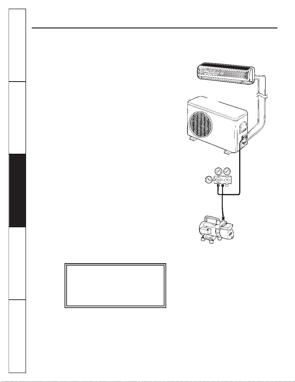
Evacuation:
Connect the charge hose end described in the
preceding steps to the vacuum pump to evacuate
the tubing and the indoor unit. Confirm that the
“Lo” knob of the manifold valve is open. Run the
vacuum pump. The operation time for evacuation
varies with the tubing length and capacity of the
pump.
Allow the pump to operate until the system has
been evacuated down to 300 microns. Allow the
pump to continue running for an additional 15
minutes. Turn off the pump and leave the
connections secured to the two service valves. After
5 minutes, if the system fails to hold 500 microns or
less, check all connections for tight fit and repeat
the evacuation procedure.
Finishing the Job:
1
With a service valve wrench, turn the valve stem of
the liquid side valve counter-clockwise to fully
open the valve.
2
Turn the valve stem of gas side valve counter-
clockwise to fully open the valve.
3
Loosen the charge hose connected to the gas side
service port slightly to release the pressure, then
remove the hose.
4
Replace the flare nut and its bonnet on the gas
side service port and fasten the flare nut securely
with an adjustable wrench. This process is very
important to prevent gas leaks in the system.
5
Replace the valve caps at both gas and liquid side
service valves and fasten them securely and
tightly.
This completes air purging with a vacuum pump.
The system is now ready to test run.
Manifold valve
Pressure
gauge
Vacuum pump
Outdoor unit
Indoor unit
For any service which requires entry
into the refrigerant sealed system,
Federal regulations require the work
be performed by a technician having a
Class II or Universal certification.
Test Running and Evaluation
1
Check that all tubing and wiring has been
properly connected.
2
Check that the gas and liquid side service valves
are fully open.
Operate the system for 15–20 minutes. Check the
system refrigerant charge:
1
Measure the pressure of the gas side service valve.
2
Measure the outside ambient air temperature.
NOTE: Refer to the Mini-Manual supplied with the unit for
the systems operating amperage and evaporator discharge air
temperature at the various ambient levels. At a typical outdoor
ambient temperature of 95° F, the gas (suction) pressure at the
outdoor unit should be 70–75 P.S.I.G. in cooling mode.
For any service which requires entry
into the refrigerant sealed system,
Federal regulations require the work
be performed by a technician having a
Class II or Universal certification.
8
Customer ServiceTroubleshooting Tips
Operating Instructions
Safety Instructions
Installation Instructions
27
Customer Service Troubleshooting Tips
Operating Instructions
Safety Instructions
Installation Instructions
Customer Service Troubleshooting Tips
Installation Instructions
Safety Instructions
Operating Instructions
Customer Service Troubleshooting Tips
Installation Instructions
Safety Instructions
Operating Instructions
Installation instruction templates.
28
LLeefftt SSiiddee IInnssttaallllaattiioonn
Installation plate
Piping hole
Ø 2-3/4²
1.8²
Customer ServiceTroubleshooting Tips
Operating Instructions
Safety Instructions
Installation Instructions
29
RRiigghhtt SSiiddee IInnssttaallllaattiioonn
Installation plate
Piping hole
Ø 2-3/4²
Piping hole
Ø 2-3/4²
1² 2²
1.9²
Models: AS1CD09 AS1CD18
AS1RD09 AS1RD18
AS1CD12
AS1RD12
30
Customer Service Troubleshooting Tips
Operating Instructions
Safety Instructions
Installation Instructions
Customer Service Troubleshooting Tips
Installation Instructions
Safety Instructions
Operating Instructions
Customer Service Troubleshooting Tips
Installation Instructions
Safety Instructions
Operating Instructions
Troubleshooting Tips
Save time and money! Review the chart below first and
you may not need to call for service.
Problem Possible Causes What To Do
The system
The fuse is blown/circuit •Check the house fuse/circuit breaker box and replace
does not start
breaker is tripped. the fuse or reset the breaker.
The Timer operation • Check the Timer functions and make sure they are
is not set correctly. set to the desired settings.
The unit does not •This is normal. Wait about 3 minutes and the unit
operate when restarted. will restart.
The system does
Airflow is restricted. • Make sure there are no curtains, blinds or furniture
not cool or heat as
blocking the front of the system.
it should
The temperature control may • Turn to a lower or higher setting. The lowest setting
not be set high or low enough. provides maximum cooling. The highest setting provides
maximum heating (heat pumps only).
The air filter is dirty. • Clean the filter at least every 30 days. See the
Operating
Instructions
section.
The room may have been hot • When the system is first turned on you need to allow
or cold. time for the room to cool down or warm up.
Cold or warm air is escaping. •Check for open furnace floor registers and cold
air returns.
The remote control
The batteries may be dead. •Replace the batteries.
display is faint or shows
no display at all
The batteries are inserted •Check the position of the batteries. They should be
incorrectly. inserted in the opposite (+) and (—) direction.
Normal Operating Sounds
■ You may hear a sound like water flowing. This is
the sound of refrigerant flowing inside the system.
■ A noise that sounds like air being released is a
design feature of dehumidifying water being
processed inside the system.
■ You may hear a clicking noise when you start or
stop the unit. This sound is the expansion or
contraction of the unit due to changes in the
temperature.
Before you call for service…
31
Customer ServiceTroubleshooting Tips
Operating Instructions
Safety Instructions
Installation Instructions
Split System Warranty
All warranty service provided by our Factory Service Centers,
or an authorized Customer Care
®
technician. For service,
call 800-GE-CARES.
For The Period Of: GE Will Replace, At No Charge To You:
One Year Any part
of the split system air conditioner which fails due to a defect in materials or workmanship.
From the date of the
During this
full one-year warranty,
GE will also provide,
free of charge,
all labor and in-home
original purchase
service to replace the defective part.
Five Years Any part of the sealed refrigerating system
(the compressor, condenser, evaporator and internal
From the date of the
connecting tubing) which fails due to a defect in materials or workmanship. During this
original purchase five-year warranty,
GE will also provide,
free of charge,
all labor and in-home service to replace
the defective part.
For each of the above warranties: Transportation expense to and from a service shop and shop service labor, if required,
will be free of charge.
■Service trips to your home to teach you how to use the
product.
■Improper installation. If you have an installation problem,
or if the split system air conditioner is of improper cooling
capacity for the intended use, contact your dealer or
installer. You are responsible for providing adequate
electrical connecting facilities.
■Failure of the product resulting from modifications to the
product or due to unreasonable use including failure to
provide reasonable and necessary maintenance.
■In commercial locations, labor necessary to move the
unit to a location where it is accessible for service by a
technician.
■Replacement of house fuses or resetting of circuit
breakers.
■Failure due to corrosion on models not corrosion-
protected.
■Damage to the product or system leaks caused by
improper field-installed interconnecting tubing between
indoor and outdoor units, improper power supply voltage,
accident, fire, floods or acts of God.
■Incidental or consequential damage to personal
property caused by possible defects with this split
system air conditioner.
What GE Will Not Cover:
This warranty is extended to the original purchaser and any succeeding owner for products purchased for home
use within the USA. In Alaska, the warranty excludes the cost of shipping or service calls to your home.
Some states do not allow the exclusion or limitation of incidental or consequential damages. This warranty gives
you specific legal rights, and you may also have other rights which vary from state to state. To know what your
legal rights are, consult your local or state consumer affairs office or your state’s Attorney General.
Warrantor: General Electric Company. Louisville, KY 40225

Operating Instructions
Safety Instructions
Installation Instructions
Troubleshooting TipsCustomer Service
Service Telephone Numbers.
GE Answer Center
®
800.626.2000
The GE Answer Center® is open 24 hours a day, 7 days a week.
In-Home Repair Service
800-GE-CARES (800-432-2737)
Expert GE repair service is only a phone call away.
Special Needs Service
800.626.2000
800-TDD-GEAC (800-833-4322)
GE offers, free of charge, a brochure to assist in planning a barrier-free kitchen for persons
with limited mobility.
Service Contracts
800-626-2224
Purchase a GE service contract while your warranty is still in effect and you’ll receive a
substantial discount. GE Consumer Service will still be there after your warranty expires.
Parts and Accessories
800-626-2002
Individuals qualified to service their own appliances can have parts or accessories sent directly
to their homes (VISA, MasterCard and Discover cards are accepted).
Servicing and installation of the refrigerant system must be performed only by a licensed,
HVAC certified technician.
Instructions contained in this manual cover procedures to be performed by any user. Other servicing
generally should be referred to qualified service personnel. Caution must be exercised, since
improper servicing may cause unsafe operation.
For any service which requires entry into the refrigerant sealed system, Federal regulations
require the work be performed by a technician having a Class II or Universal certification.
Service Satisfaction
If you are not satisfied with the service you receive from GE:
First,
contact the people who serviced your appliance.
Next,
if you are still not pleased, write all the details—including your phone number—to:
Manager, Consumer Relations
GE Appliances
Appliance Park
Louisville, KY 40225
Finally,
if your problem is still not resolved, write:
Major Appliance Consumer Action Program
20 North Wacker Drive
Chicago, IL 60606
Printed in Korea
32