Loading ...
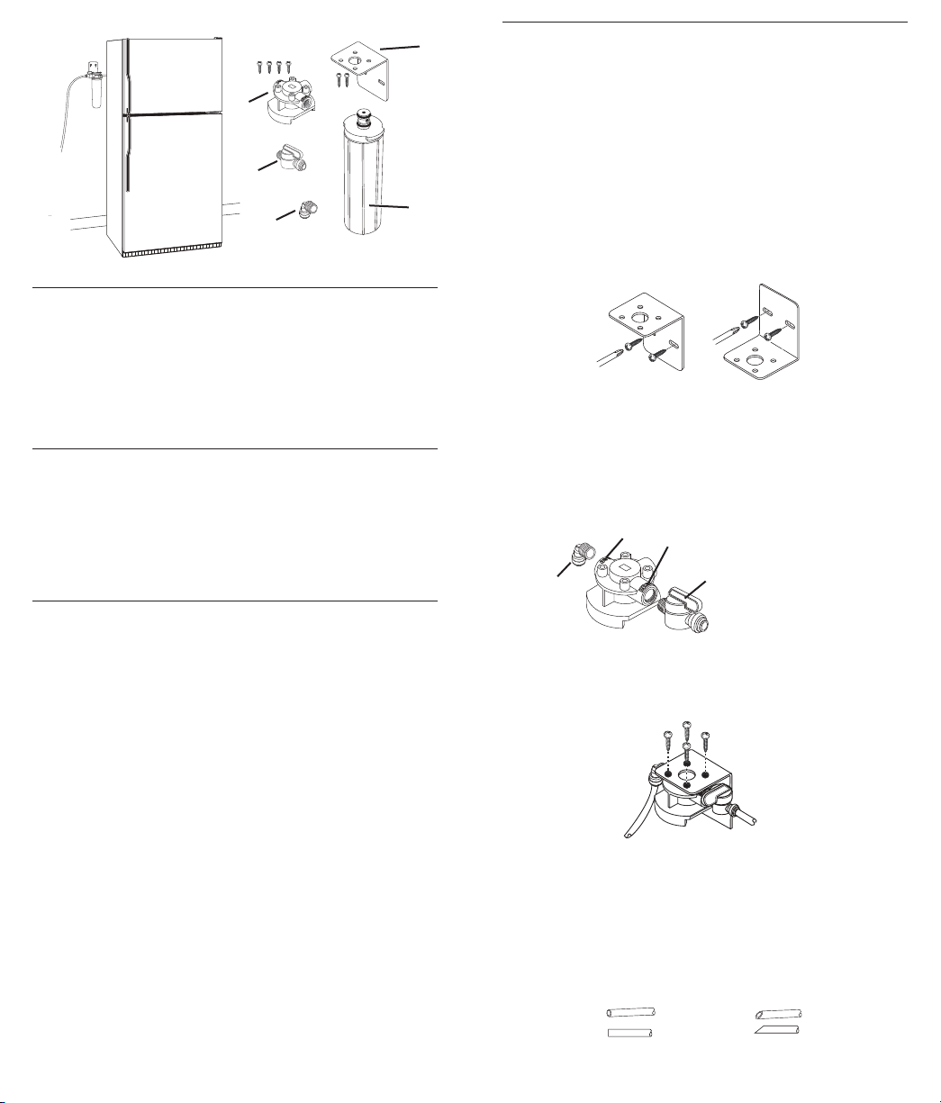
Parts and Material Included
A. Filter Head and four
Phillips head screws
B. Filter Bracket and two
Phillips mounting screws
D. 1/4" Male shutoff valve
with push-in fi ttings
E. 1/4" Male push-in fi tting
with fl ow control
C. Filter Cartridge
Tools and Parts Needed
Gather the required tools before starting installation. Read and
follow the instructions provided with any tools listed here.
■ Phillips Head Screwdriver
■ Adjustable Wrench
■ Tube Cutter (for use
with copper tubing) or
Utility Knife
Installation Requirements
■ Install the fi lter with the inlet and outlet ports as labeled.
Make sure not to reverse connections as fi lter life will not
operate properly.
■ Do not install near electric wires or water pipes that will
be in path of drill when selecting the position to mount the
bracket. Do not mount on refrigerator.
■ Mount fi lter in such a position as to prevent it from being
struck by other items, such as wastebaskets, etc.
■ Properly tighten all fi ttings to ensure a leak-free assembly.
■ Install in a location that is not susceptible to freezing
temperatures as damage to the housing could occur.
■ Install away from direct sunlight as prolonged exposure to
light can weaken plastic components.
■ Allow a minimum of 2 1/2" clear space below unit to
facilitate fi lter change.
■ A water supply line must be run to the refrigerator (icemaker)
according to the refrigerator manufacturer’s instructions
prior to installation of this fi lter.
■ Some local codes may require the use of a licensed
plumber or certifi ed installer when disrupting a potable
water line. Determine and follow any and all local codes and
requirements.
Installation Instructions
For Use With Cold Water Only
NOTE: This product features an attached shutoff valve to turn
water off/on during fi lter replacement. This will allow you to
install product in any convenient location along the water line.
1. Turn off water supply to refrigerator.
2. Select location for fi lter assembly and fasten bracket.
Bracket may be installed in the up or down position as
shown in Figure 1, using the two Phillips mounting screws
provided. See “Installation Requirements” for areas to
avoid. Be sure to allow 2 1/2" of clearance below fi lter
assembly to facilitate cartridge change. Filter location
should be adjacent to water supply line.
3. Screw the 1/4" Male shutoff valve into the INLET port of head
assembly (see Figure 2). Hand tighten. NOTE: Inlet port is
marked “3.”
Screw the 1/4" male
push-in fi tting with fl ow control to the outlet port
(see Figure 2). If necessary, use adjustable wrench to
assist in tightening fi tting. NOTE: Outlet port is marked “1.”
4. Attach fi lter head assembly to the mounting bracket with 4
Phillips screws provided (see Figure 3).
5. Place catch basin nearby to catch water from lines
when cut. Cut water supply line to refrigerator icemaker.
(See Figure 4).
NOTE: Make sure you can connect line to fi lter head fi ttings
without kinking line. Do not kink tubing as this will impede
water fl ow. Use a utility knife for plastic lines or a tube
cutter for copper lines. Cut tubing straight. Remove any
burrs from copper tubing.
A
B
C
D
E
Figure 3
Figure 1
Correct Incorrect
Figure 4
Figure 2
B
C
D
A
A. 1/4" Push-In Fitting with
Flow Control
B. Outlet
C. Inlet
D. Shutoff Valve Push-In
Fitting
Loading ...
Loading ...
Loading ...