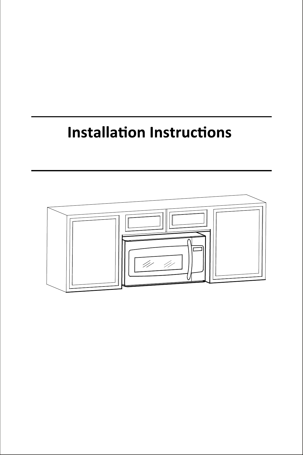
General information
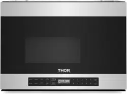
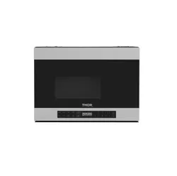
Over the Range Microwave Oven
READ CAREFULLY. KEEP THESE INSTRUCTIONS.
1

2
General informaon
IMPORTANT SAFETY INSTALLATIONS....................................................................................................................................3
ELECTRICAL REQQUIREMENTS ..............................................................................................................................................3
Introducon .........................................................................................................................................................................3
BEFORE YOU BEGIN ..............................................................................................................................................................3
HOOD EXHAUST..................................................................................................................................................................4
DAMAGE – SHIPMENT/INSTALLATION..................................................................................................................................6
PARTS INCLUDED..................................................................................................................................................................6
TOOLS YOU WILL NEED.........................................................................................................................................................7
MOUNTING SPACE...............................................................................................................................................................7
Step-by-step installaon guide
PLACEMENT OF THE MOUNTING PLATE......................................................................................................................... 8–12
INSTALLATION TYPES(ChooseA,BorC) ..........................................................................................................................13-24
A.
B.
C.
BEFORE YOU USE YOUR MICROWAVE ..............................................................................................................................26
CONTENTS
General information
3
Introducon
Ti on gi wi ow yo ow o yo new overernge mirowve
BEFORE YOU BEGIN
e e rn oy n ry
IMPOTANT – Sve ee in for or’ e
IMPOTANT – rve governing o n orine
Noe o er – Be re o eve e ro e onr
Noe Coer – Keep e n for re refere
Sk eve – Inon of pne rer b n rk
Proper r
ey of r
Pro re o improper overe y
IMPORTANT SAFETY INSTRUCTIONS
IMPOTANT–PEASE EAD CAEUY O PESONA SAETY, THIS MUST BE Y D
TO AVOID SEVEE ATA SHOCK
T pr rr reerong, proper gre for fe
n If no propery grne, or if e e box o no mee
eer rerem ne ner C ENTS
e
eer o be oye orre ny e
Te power r of ppi ppe w r
eerong (grng
w e w nr reerong (grng w reee
minimize y of ri r from pe
Yo o ve e w reee n r eke by e en o mke re e reepe
propey groe
ere nr worong re eere, very impor o ve rep w propery
gre reerong reep by r
DO NOT, UN ANY CITANCES, CUT, M, MOVE ANY THE NGS
OM THE COD
DO NOT USE AN EXTENSION COD
Caution
or peon fey, remove e oe fe or open e ir brker before beginning
o v vere or ry
or fey, n rfe be pbe of ppornge bin o,
in n o e we of po ( krm pr
oven o of o 0 pon ( kiogrm for o weig of 0 pon
kiogrm
or peron fey, pr n be in in e r
rngem n
or I be mon BOTH p bin AND w
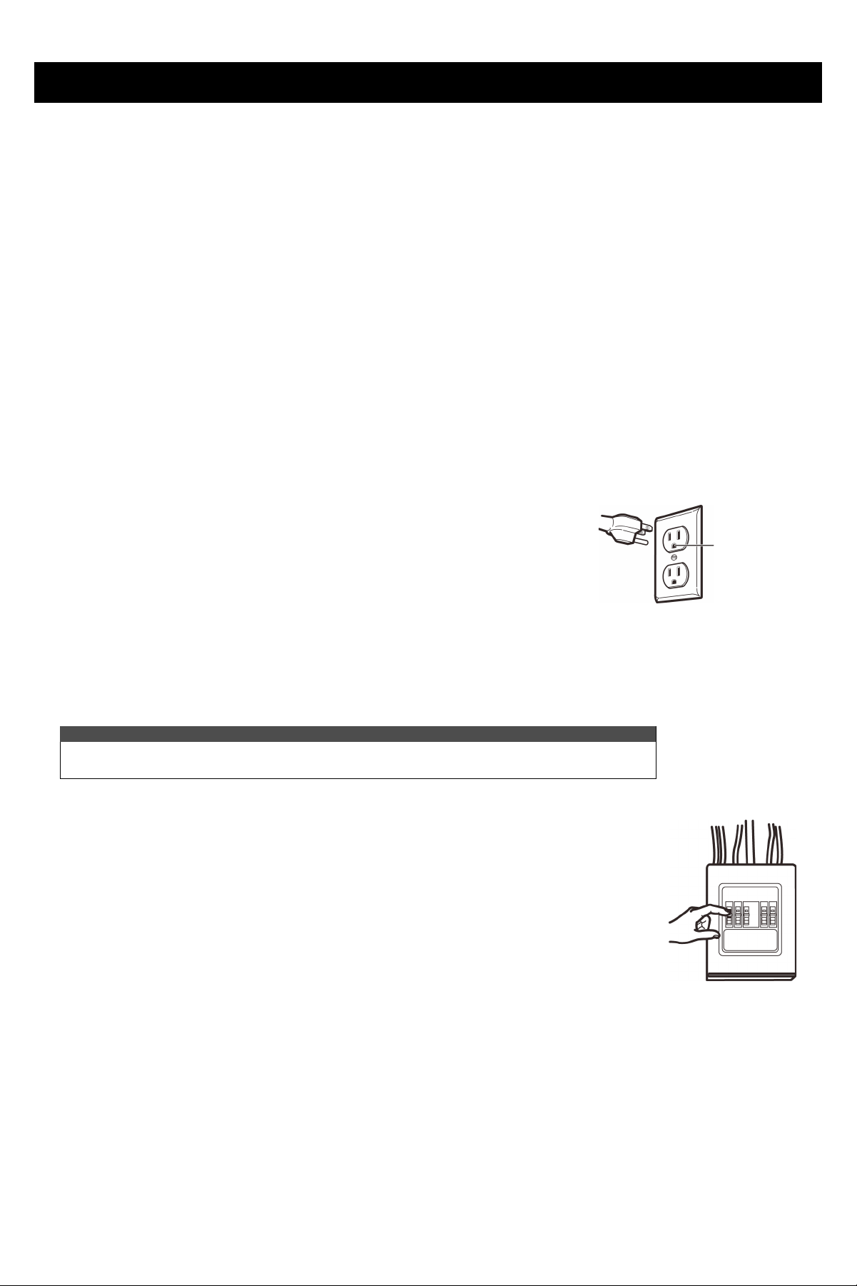
ELEC TRICAL REQUIREMENTS
Te pr r of yor rowve 20 vo AC, 0 Herz, , kiow T pr be
onnee o y ir of e proper voe freeny ire ze onform o e reremen of
Non Co or pr o for ko rg Te power pp r g
be br pre 20 re br r g gre o e o box be
in
e bine bove e mirowve oven Te o box n py r o be e by qi
eer onform e o erCo or e prevg o e
Note
or eer in n onfey, reommen wo pee pr
Enre proper
gr before
e
General information
4
HOOD EXHAUST
NOTE: Read these next two pages only if you plan to vent your exhaust to the outside. If you plan to recirculate
the air back into the room,proceed to page 6.
OUTSIDE TOP EXHAUST (EXAMPLE ONLY)
OUTSIDE BACK EXHAUST (EXAMPLE ONLY)
Tn e of o
Tn e of o
* IMPORTANT: If a rectangular-to -round transion adaptor is used, the boom corners of the damper will have to
be cut to fit, using the n snips, in order to allow free movement of the damper.
EQUIVALENT NUMBER
LENGTH
DUCT PIECES
DUCT PIECES
x USED
USED
=
EQUIVALENT
LENGTH
EQUIVALENT NUMBER
LENGTH*
EQUIVALENT
LENGTH
2 x =
S
S
(
x ( =
*
x =
E
Total Length
E
Total Length
= 41 Ft.
NOTE: For back exhaust, case should be taken to align exhaust with space between studs, or wall should be
prepared at the me it is constructed by leaving enough space between the wall studs to accommodate exhaust.
x =
x =
3
3 x =
0 x (2 = 20
= 63 F t.
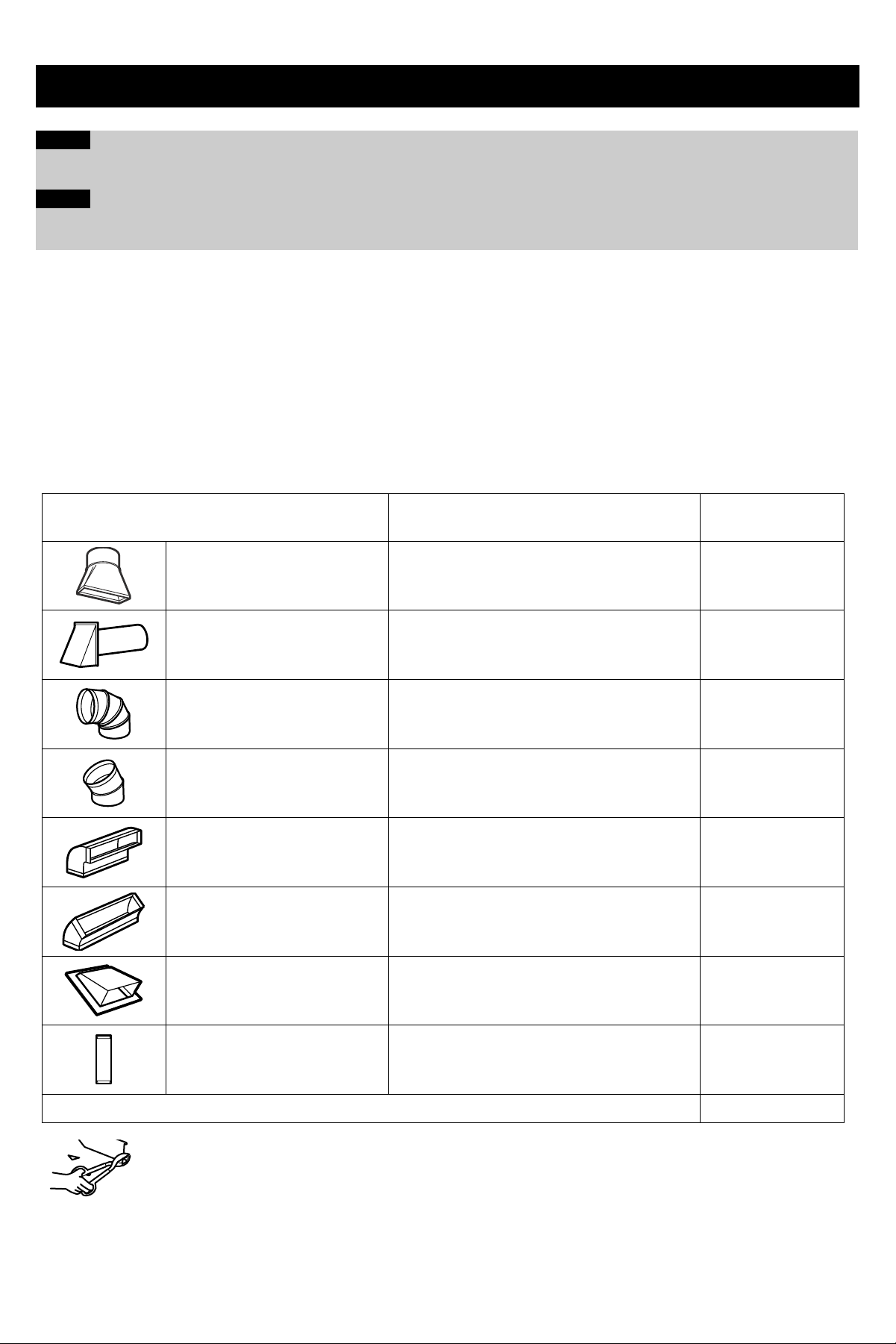
General information
EQUIVALENT NUMBER
LENGTH LENGTH
DUCT PIECES
USED
EQUIVALENT
r*
5
* IMPORTANT:
x =
x =
x =
x =
x =
x =
x =
x =
S
x =
Total Du ctw ork = F t.
Maximum duct length:
Elbows, transions, wall and roof caps, etc.,
NOTE:
should not exceed 140 equivalent feet.
NOTE:
Also, make sure dampers swing freely and nothing is
blocking the ducts.
Exhaust connecon:
Do not use less than a 6"diameter
duct.
6
General information
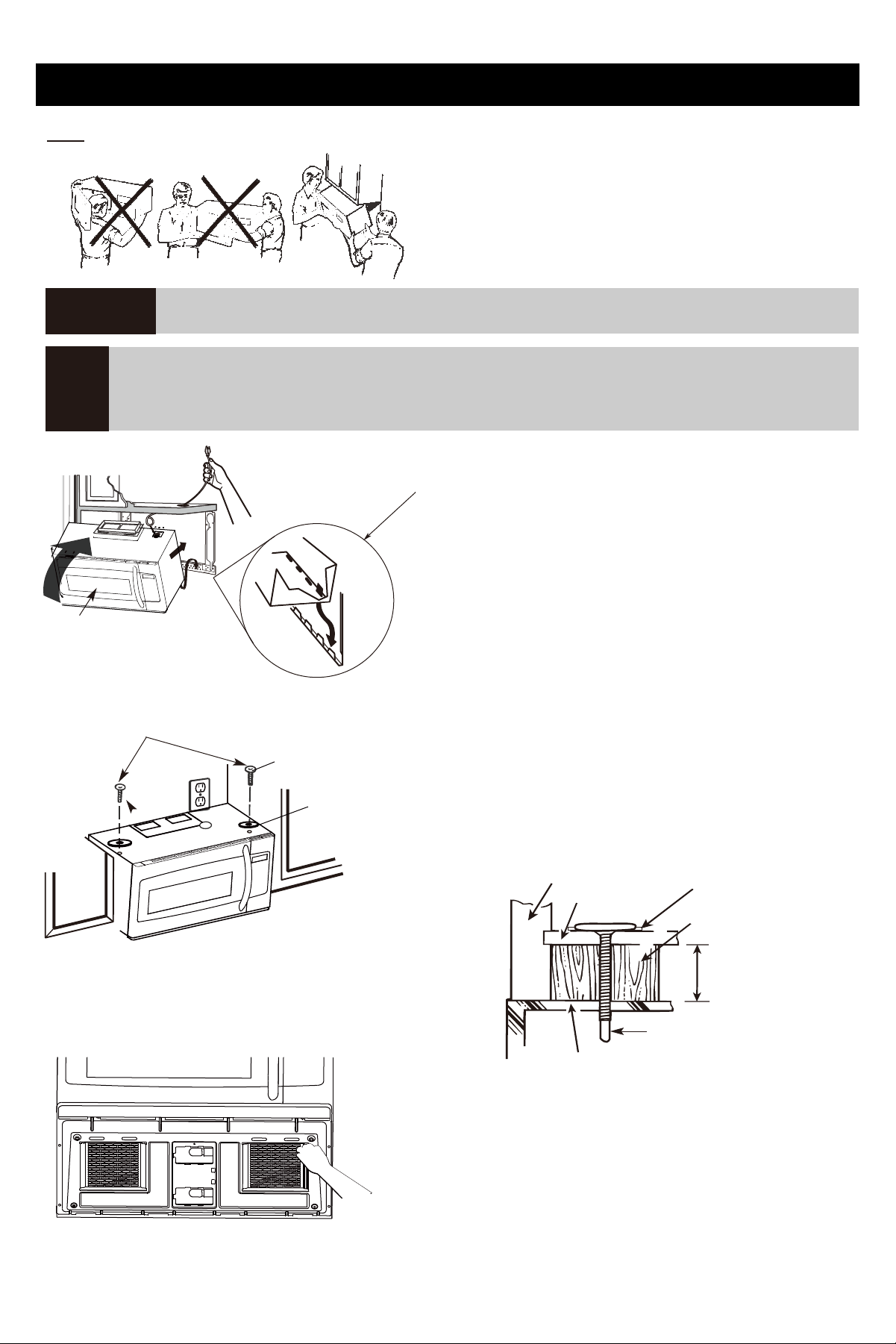
DAMAGE-SHIPMENT/INSTALLATION
• If the unit is damaged in shipment, return the unit to the store in which it was bought for repair or replacement.
• If the unit is damaged by the customer, repair or replacement is the responsibility of the customer.
• If the unit is damaged by the installer (if other than the customer), repair or replacement must be made by
arrangement between customer and installer.
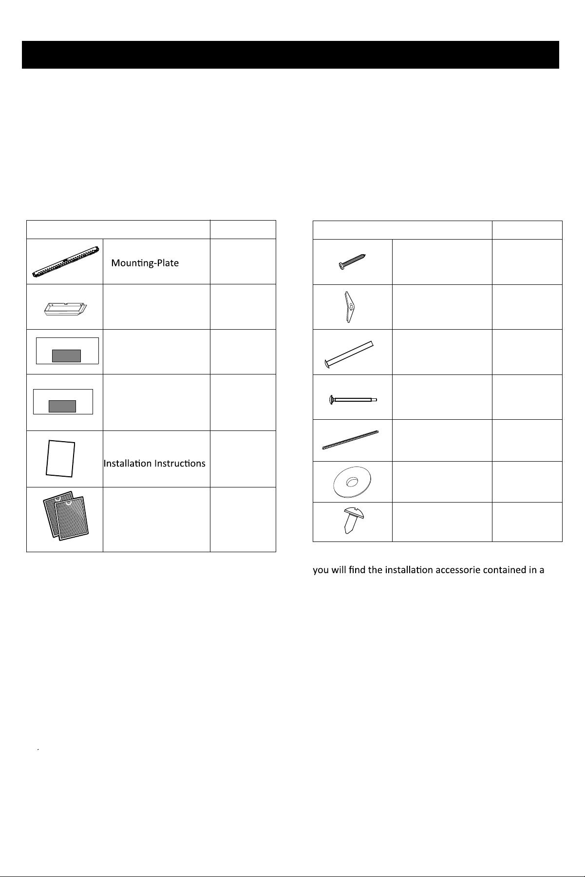
INSTALLATION ACCESSORIES
packet with the unit .Check to make sure you have all
these parts.
NOTE: Some extra parts are included.
PARTS INCLUDED
QUANTITY
PART
1
1
exhaust adaptor
Top Cabinet Template
1
Rear Wall Template
1
1
Separately Packed
Grease Filters
2
TOP CABINET TEMPLATE
REAR WALL TEMPLATE
In
st
a
l
l
a
t
i
o
n
I
n
st
r
u
ctio
n
s
PART
QUANTITY
Wood Screw
(¼" x 2")
2
Wing nut
(
3
/16" x 3")
Self-aligning
Machine Screw
Machine Screw
(¼"-20 x 3")
2
2
Nylon Grommet
(for metal cab inets)
1
2
2
Washer
Sheet Metal Screw
2
General information
7
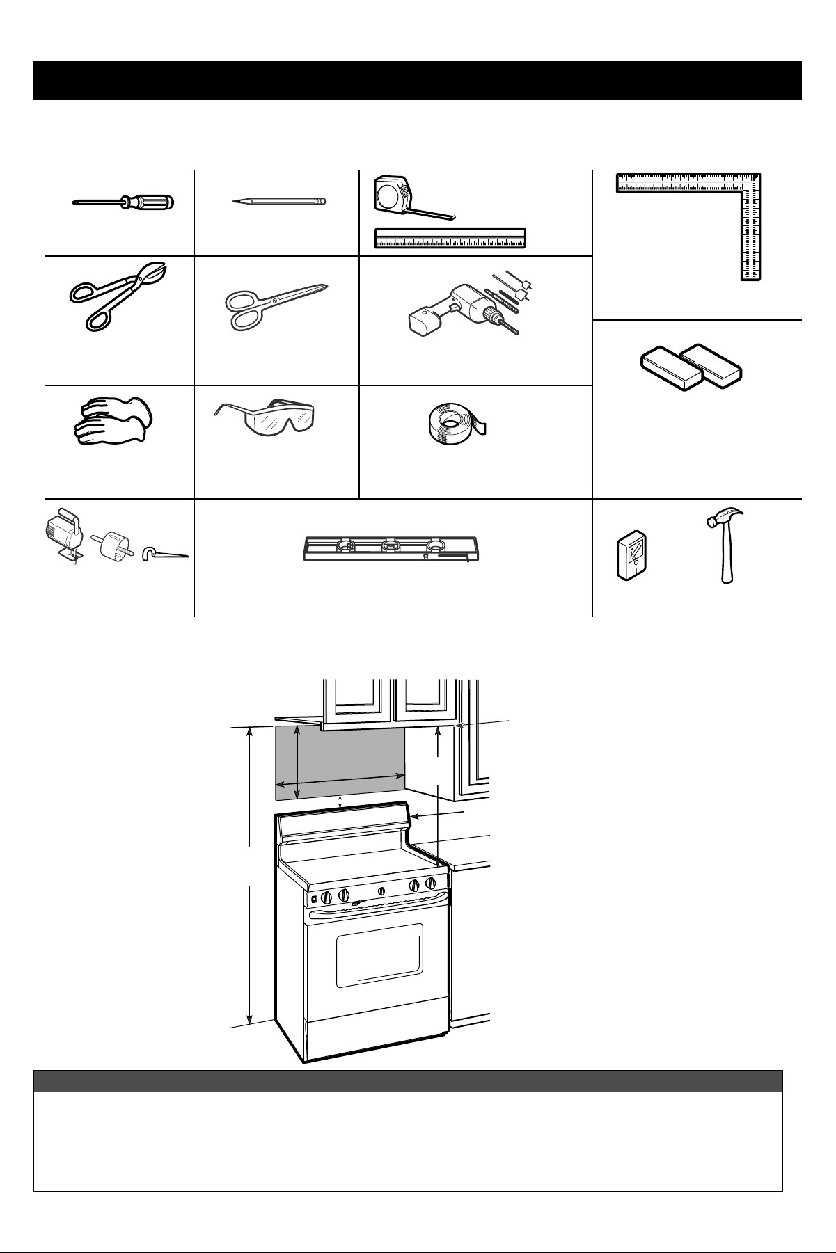
TOOLS YOU WILL NEED
i b or w
piee(for op
ing in ree
ne n, if
MOUNTING SPACE
NOTES :
•
½
30
2
3
0
#2 Pp
wriver
Pe
or re
Crpen re
(opn
r r wi ”, ”, ”
Egeo
ev
Sw
(r, e, or key
fey
Gove
S
e, if
Tin nip
per, if
Step-by-step installation guide
8
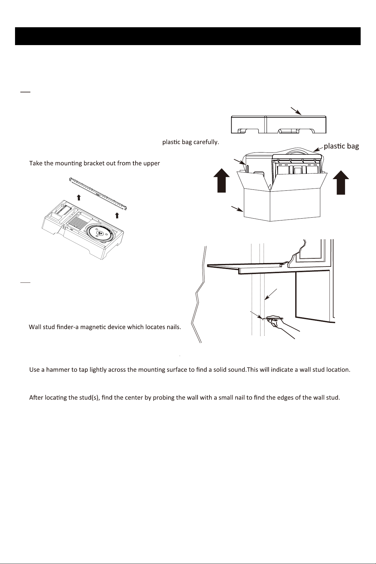
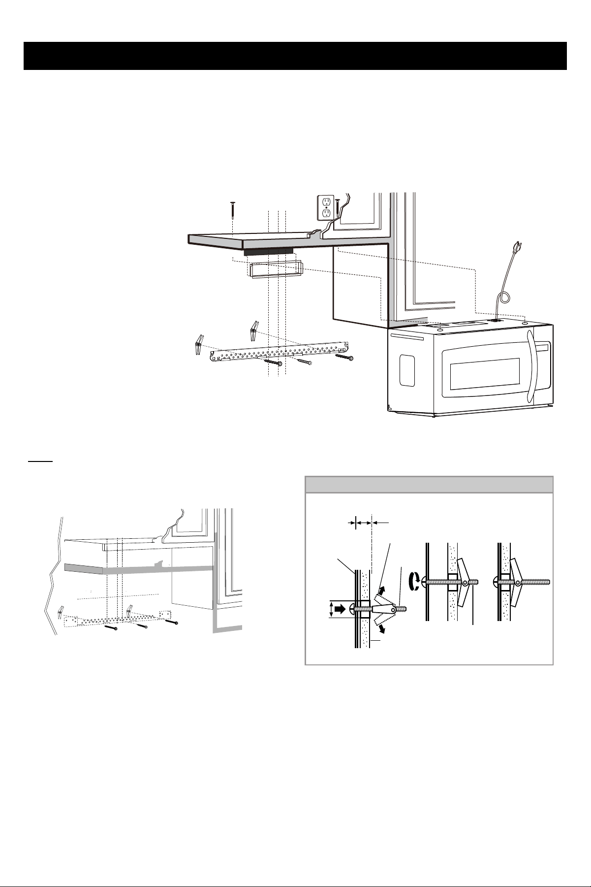
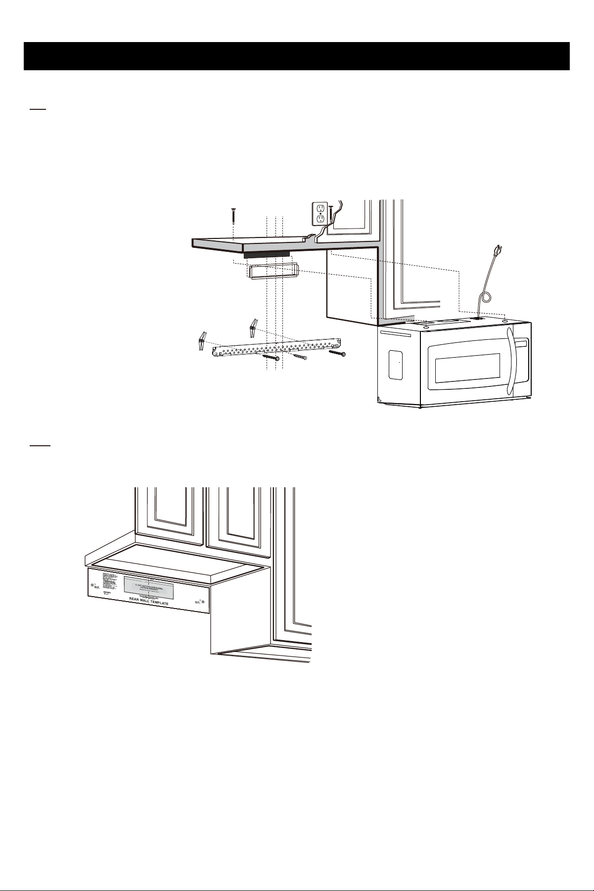
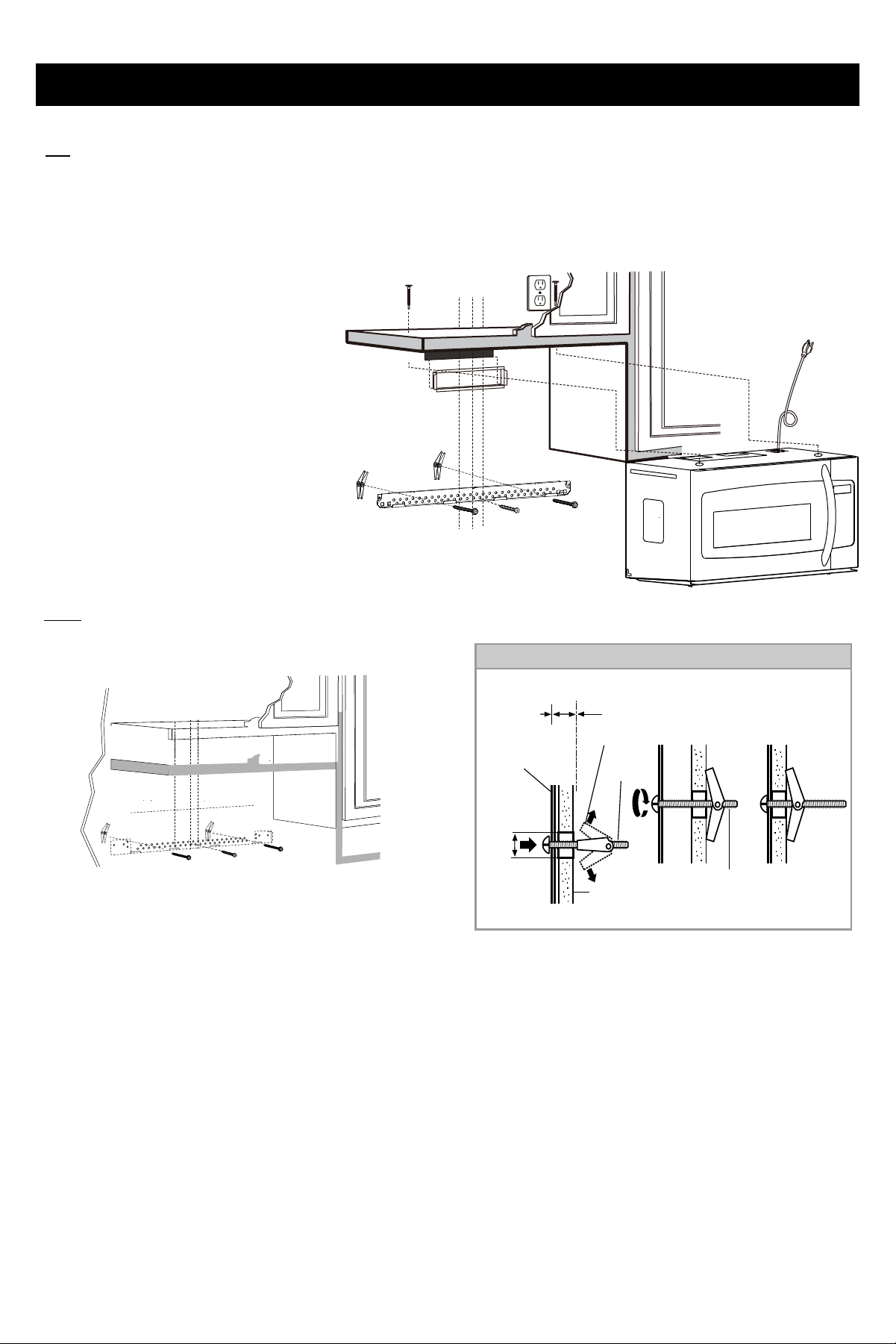
1. PLACEMENT OF THE MOUNTING PLATE
A .
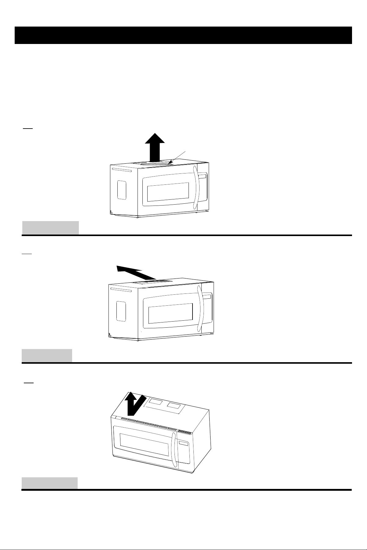
REMOVING THE MICROWAVE OVEN FROM THE CARTON/REMOVING THE
MOUNTING PLATE
1.Open the carton and remove the upper foam from the box ,
but remember to keep the accessories.
2.Pull the oven out of the carton and remove the
3. foam.
B .
FINGING THE WALL STUDS
1. Find the wall studs, using one of the following methods;
2.
Then place a mark halfway between the edges.The center of any adjacent wall studs should be 16” or 24” from this mark.
3. Draw a line down the center of the wall studs.
THE MICROWAVE MUST BE CONNECTED TO AT LEAST ONE WALL STUD.
Wall Studs
Wall Studs Center
OR
B.
A.
the upper foam
carton
oven
Step-by-step installation guide
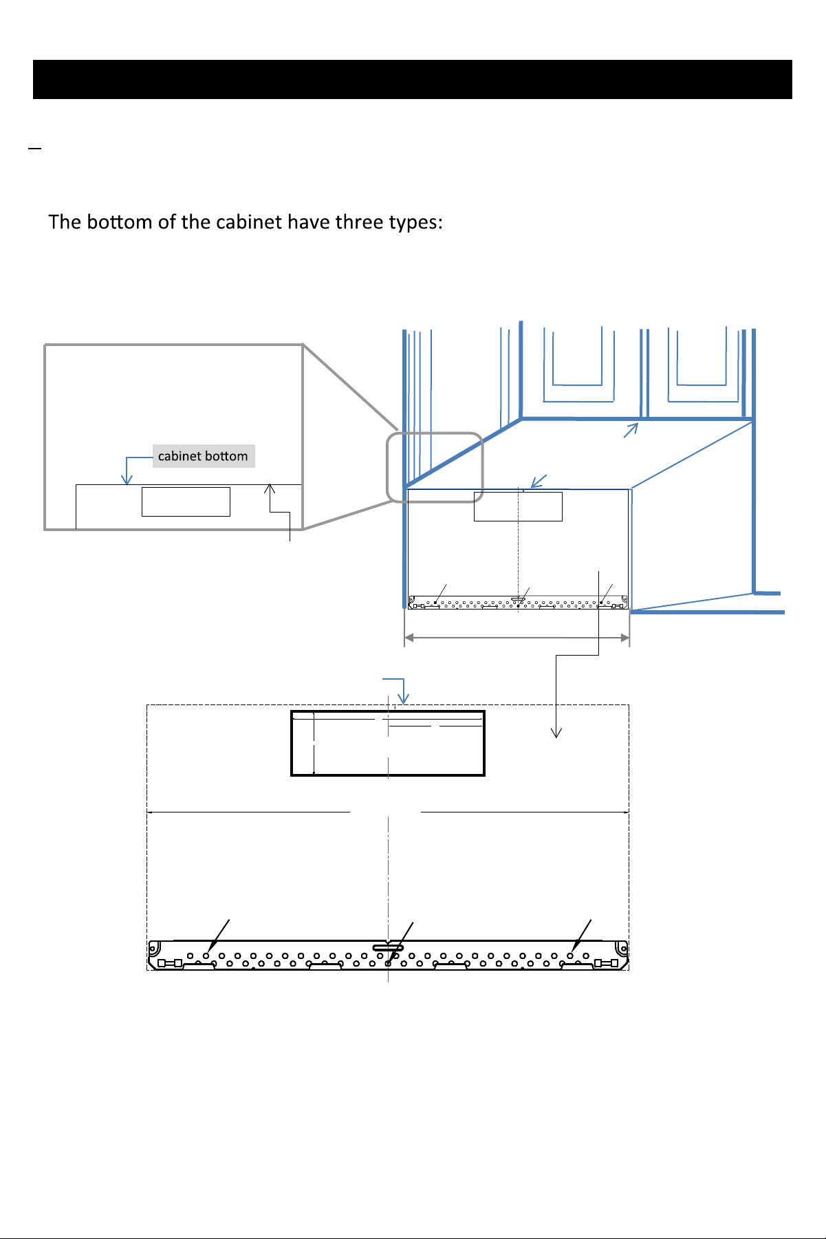
1.Beneath flat boom cabinet
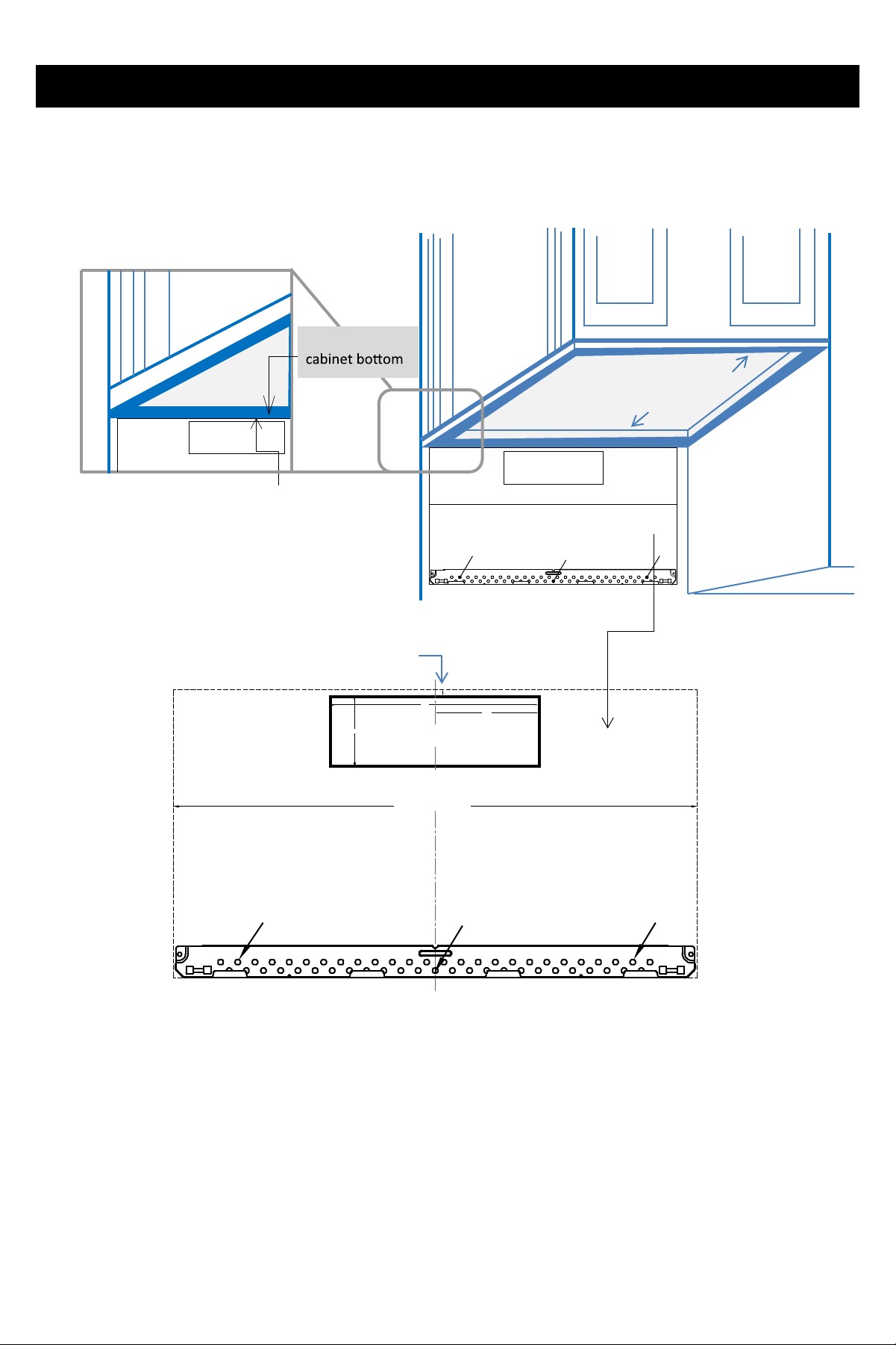
C. DETERMING TOP LINE OF REAR WALL TEMPLATE LOCATION UNDER YOUR
CABINET
Front
Re ar
TOP INE O EA A TEMPATE
TOP INE O EA A TEMPATE
F.CUT OUT FOR HORIZONTAL
OUTSIDE EXHAUST
3/8" TO EDGE
CAUTION -IF EXHAUST ADAPTOR IS POSITIONED OUTSIDE
RECOMMENDED DIMENSION, GREASE-ADEN AIR WILL
DISCHARGE INTO HOUSE STRUCTURE
CUT HOLE THROUGH REAR WALL FOR EXHAUST ADAPTOR
A
C
B
REAR WALL TEMPLATE
NOTE: IT IS VE Y IMPO T ANT TO
IN THE INST
THIS
TE
T
T O THE
INS T
TANT :
TE AT T
INE
Y
SP ACED T TS IN ATE
A
F.CUT OUT FOR HORIZONTAL
OUTSIDE EXHAUST
CAUTION -IF EXHAUST ADAPTOR IS POSITIONED OUTSIDE
RECOMMENDED DIMENSION, GREASE-ADEN AIR WILL
DISCHARGE INTO HOUSE STRUCTURE
CUT HOLE THROUGH REAR WALL FOR EXHAUST ADAPTOR
NOTE: IT IS VE Y IMPO T ANT TO
IN THE INST
THIS
TE
T
T O THE
INS T
9
12"
4"
F.CUT OUT FOR HORIZONTAL
OUTSIDE EXHAUST
3/8" TO EDGE
30" MINIMUM WIDTH REQUIRED
REAR WALL TEMPLATE
CAUTION -IF EXHAUST ADAPTOR IS P OS ITIONED OUTSIDE
RECOMMENDED DIMENSION,GREASE-L ADEN AIR WILL
DISCHARGE INTO HOUSE ST RUCTURE.
CUT HOLE THROUGH REAR WALL FOR E XHAUST ADAPTOR
NOTE :IT IS VEY IMPOTANT T O
EAD AND OO T HE DIECT IONS
IN THE INSTAATION INS TUCTIONS
BEOE POCEEDING ITH THIS
EA A TE MPAT E
T i empe ifor oing e orizon ex
o Do no i empe for veri or
rerion ex
T pe e empe o e rer w
2U ber or keyoe w o o e
e re rog e rer w
3emove e empe
from e rer w
ET UE TO AND POCEED ITH THE
INST AATION INS TUCTIONS
o e n mrk oeo ign wi oe in e
moning pe
IMPOTANT:
OCATE AT EAS T ONE STUD ON EITH E SIDE O
THE CENTEINE
MAK T HE OCATION O 2 ADDITION A, EVENY
SPACED TOGGE BOTS IN THE MOUNT ING PATE
AEA
A
C
B
6
"
Step-by-step installation guide
2. Beneath framed recessed cabinet
TOP INE O EA A TEMPATE
30" M I N I M U M W I D T H R E Q U I R E D
F.CUT OUT FOR HORIZONTAL
OUTSIDE EXHAUST
CAUTION -IF EXHAUST ADAPTOR IS POSITIONED OUTSIDE
RECOMMENDED DIMENSION, GREASE-ADEN AIR WILL
DISCHARGE INTO HOUSE STRUCTURE
CUT HOLE THROUGH REAR WALL FOR EXHAUST ADAPTOR
A
C
B
REAR WALL TEMPLATE
NOTE: I T IS VE Y TANT T O
IN THE INS T A
THIS
ATE
oer
e
r
Te r
er
TO THE
INST
r
TAN T:
ATE AT
THE CE
Y
SP ACED T TS IN TE
A
F.CUT OUT FOR HORIZONTAL
OUTSIDE EXHAUST
CAUTION -IF EXHAUST ADAPTOR IS POSITIONED OUTSIDE
RECOMMENDED DIMENSION, GREASE-ADEN AIR WILL
DISCHARGE INTO HOUSE STRUCTURE
CUT HOLE THROUGH REAR WALL FOR EXHAUST ADAPTOR
NOTE: IT IS VE Y IMPO TANT T O
IN THE INST
THIS
TE
T
T O THE
INS T
TEATE
Front
Rear
10
12"
4"
F.CUT OUT FOR HORIZONTAL
OUTSIDE EXHAUST
3/8" TO EDGE
30" MINIMUM WIDTH REQUIRED
REAR WALL TEMPLATE
CAUTION -IF EXHAUST ADAPTOR IS P OS ITIONED OUTSIDE
RECOMMENDED DIMENSION,GREASE-L ADEN AIR WILL
DISCHARGE INTO HOUSE ST RUCTURE.
CUT HOLE THROUGH REAR WALL FOR E XHAUST ADAPTOR
NOTE :IT IS VEY IMPOTANT T O
EAD AND OO T HE DIECT IONS
IN THE INSTAATION INS TUCTIONS
BEOE POCEEDING ITH THIS
EA A TE MPAT E
T i empe ifor oing e orizon ex
o Do no i empe for veri or
rerion ex
T pe e empe o e rer w
2U ber or keyoe w o o e
e re rog e rer w
3emove e empe
from e rer w
ET UE TO AND POCEED ITH THE
INST AATION INS TUCTIONS
o e n mrk oeo ign wi oe in e
moning pe
IMPOTANT:
OCATE AT EAS T ONE STUD ON EITH E SIDE O
THE CENTEINE
MAK T HE OCATION O 2 ADDITION A, EVENY
SPACED TOGGE BOTS IN THE MOUNT ING PATE
AEA
A
C
B
6
"
Step-by-step installation guide
TOP INE O EA A TEMPATE
F.CUT OUT FOR HORIZONTAL
OUTSIDE EXHAUST
CAUTION -IF EXHAUST ADAPTOR IS POSITIONED OUTSIDE
RECOMMENDED DIMENSION, GREASE-ADEN AIR WILL
DISCHARGE INTO HOUSE STRUCTURE
CUT HOLE THROUGH REAR WALL FOR EXHAUST ADAPTOR
NOTE: IT IS VE Y IMPO TANT T O
IN THE INS T
THIS
TE
T
T O THE
INS T
TEATE
Front
Rear
3. Beneath framed recesse boom cabinet with front overhang
12"
4"
F.CUT OUT FOR HORIZONTAL
OUTSIDE EXHAUST
3/8" TO EDGE
30" MINIMUM WIDTH REQUIRED
REAR WALL TEMPLATE
CAUTION -IF EXHAUST ADAPTOR IS P OSITIONED OUTSIDE
RECOMMENDED DIMENSION,GREASE-L ADEN AIR WILL
DISCHARGE INTO HOUSE ST RUCTURE.
CUT HOLE THROUGH REAR WALL FOR E XHAUST ADAPTOR
NOTE :IT IS VE Y IMPOTANT T O
E AD AND O O THE DI EC TIONS
IN THE INS TA AT ION INST UC TIONS
BE OE P OCEE DING IT H THIS
E A A T EMPAT E
Ti empe i for oing e orizon ex
o Do no e i empe for veri or
reirion ex
Tpe e empe o e rer w
2Ue ber or keyoe w o o e
e re rog e rer w
3emove e empe
from e r er w
E TUE T O AND P OCE ED IT H T HE
INST A AT ION INST UCT IONS
oe n mrk oe o ign w i oe in e
moning pe
IMPOT ANT :
OCAT E AT E AS T ONE ST UD ON E ITH E S IDE O
THE CE NTE INE
MAK THE OC ATION O 2 ADDIT ION A , E VE NY
SP ACE D T OGGE BOT S IN THE MOUNT ING PA TE
AE A
Trim e rer w empe on g e oe ine
A
C
B
11
12"12"
12"
4"
F.CUT OUT FOR HORIZONTAL
OUTSIDE EXHAUST
3/8" TO EDGE
30" MINIMUM WIDTH REQUIRED
REAR WALL TEMPLATE
CAUTION -IF EXHAUST ADAPTOR IS P OSITIONED OUTSIDE
RECOMMENDED DIMENSION,GREASE-L ADEN AIR WILL
DISCHARGE INTO HOUSE ST RUCTURE.
CUT HOLE THROUGH REAR WALL FOR E XHAUST ADAPTOR
NOT E:IT IS VE Y IMPOTANT T O
EAD AND OO THE DIECT IONS
IN THE INSTA ATION INST UCTIONS
BEOE POCEE DING IT H THIS
EA A TE MPAT E
T iempe i for oing e orizon ex
o Do no iempe for veri or
rerion ex
T pe e empe o e rer w
2U ber or keyoe w o o e
e re rog e rer w
3emove e empe
from e rer w
ETUE T O AND POCEE D ITH THE
INST AATION INSTUCTIONS
o e n mrk oeo ign wi oe in e
moning pe
IMPOTANT:
OCATE AT EAST ONE ST UD ON E ITH E SIDE O
THE CE NTE INE
MAK THE OC ATION O 2 ADDITION A, EVE NY
SP ACED TOGGE BOTS IN T HE MOUNT ING PATE
AEA
A
C
B
6
"
Step-by-step installation guide
12
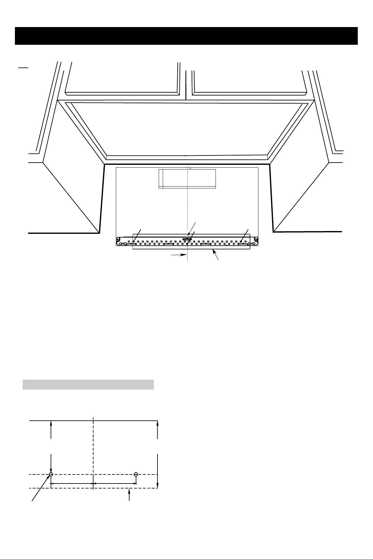
D.
ALIGNING TOP LINE OF REAR WALL TEMPLATE
、B、、
bottom edge line of upper cabinet
2
Are E
CAUTION:
30 " M I N I M U M W I D T H R E Q U I R E D
12
F.CUT OUT FOR HORIZONTAL
OUTSIDE EXHAUST
3/8" TO EDGE
CAUTION -IF EXHAUST ADAPTOR IS POSITIONED OUTSIDE
RECOMMENDED DIMENSION, GREASE-ADEN AIR WILL
DISCHARGE INTO HOUSE STRUCTURE
CUT HOLE THROUGH REAR WALL FOR EXHAUST ADAPTOR
A
C
B
REAR WALL TEMPLATE
4"
Cener ine noe
NOTE: IT IS VE Y TANT T O
IN THE INS T
THIS
TE
T
T O THE
INST
ANT :
TE AT
Y
SP ACED T TS IN TE
A
Step-by-step installation guide
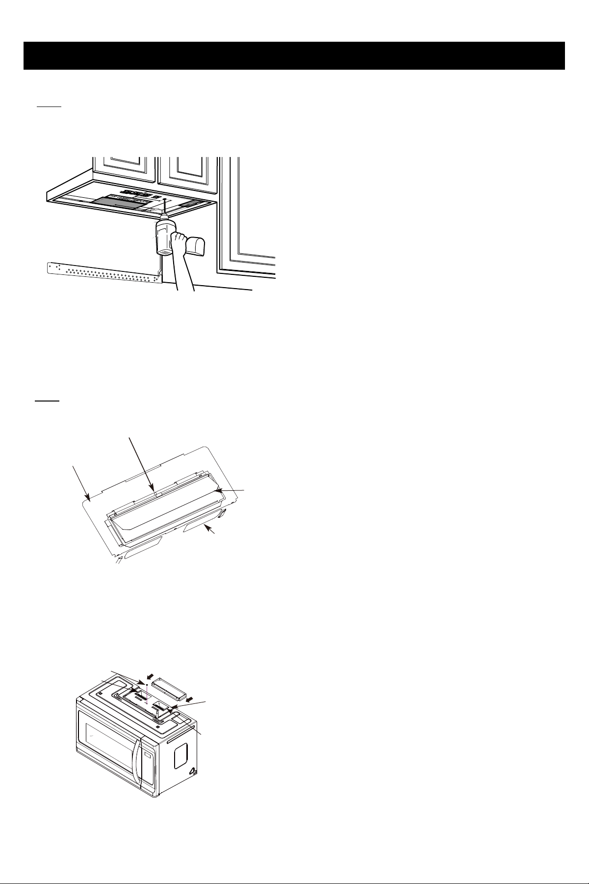
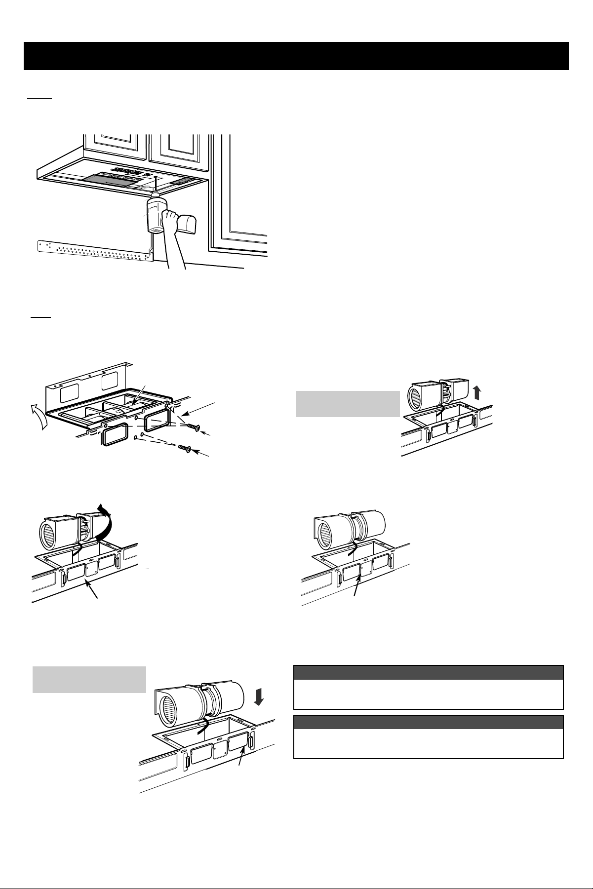
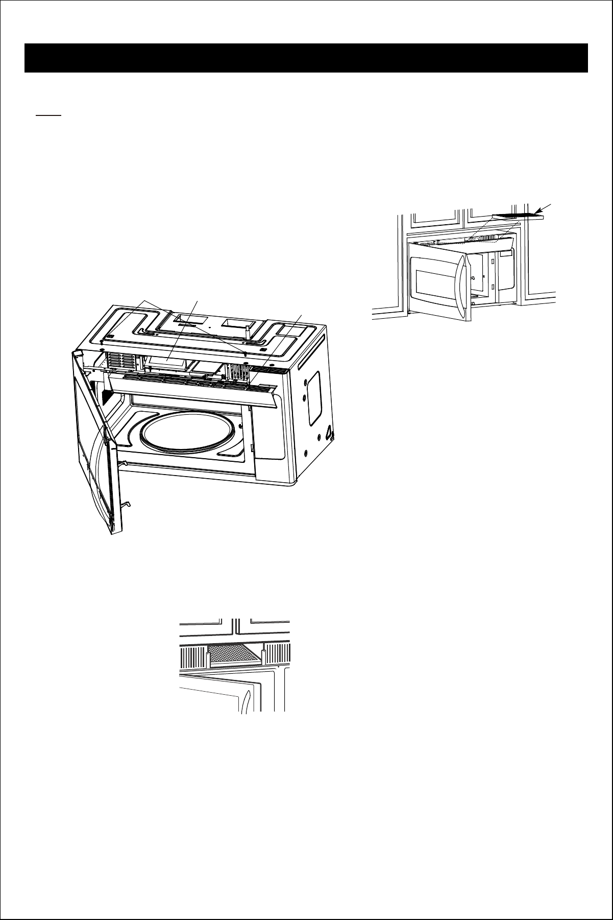
2. INSTALLATION TYPES (Choose A, B or C)
A:Outside Top Exhaust(Vercal Duct)
B:Outside Back Exhaust(Horizontal Duct)
C:Recirculang(Non-Vented Ductless)
A.
OUTSIDE TOP EXHAUST(Vercal Duct)
B .
OUTSIDE BACK EXHAUST(Horizontal Duct)
for
C .
RECIRCULATING(Non-vented Ductless)
Apor in P for
O T op
E
13
NOTE: This microwave is shipped assembled for Recirculang.
Step-by-step installation guide
14
INSTALLATION OVERVIEW
A1 .
A2 . TOP CABINET
A3.
A4.
A5 .
A6.
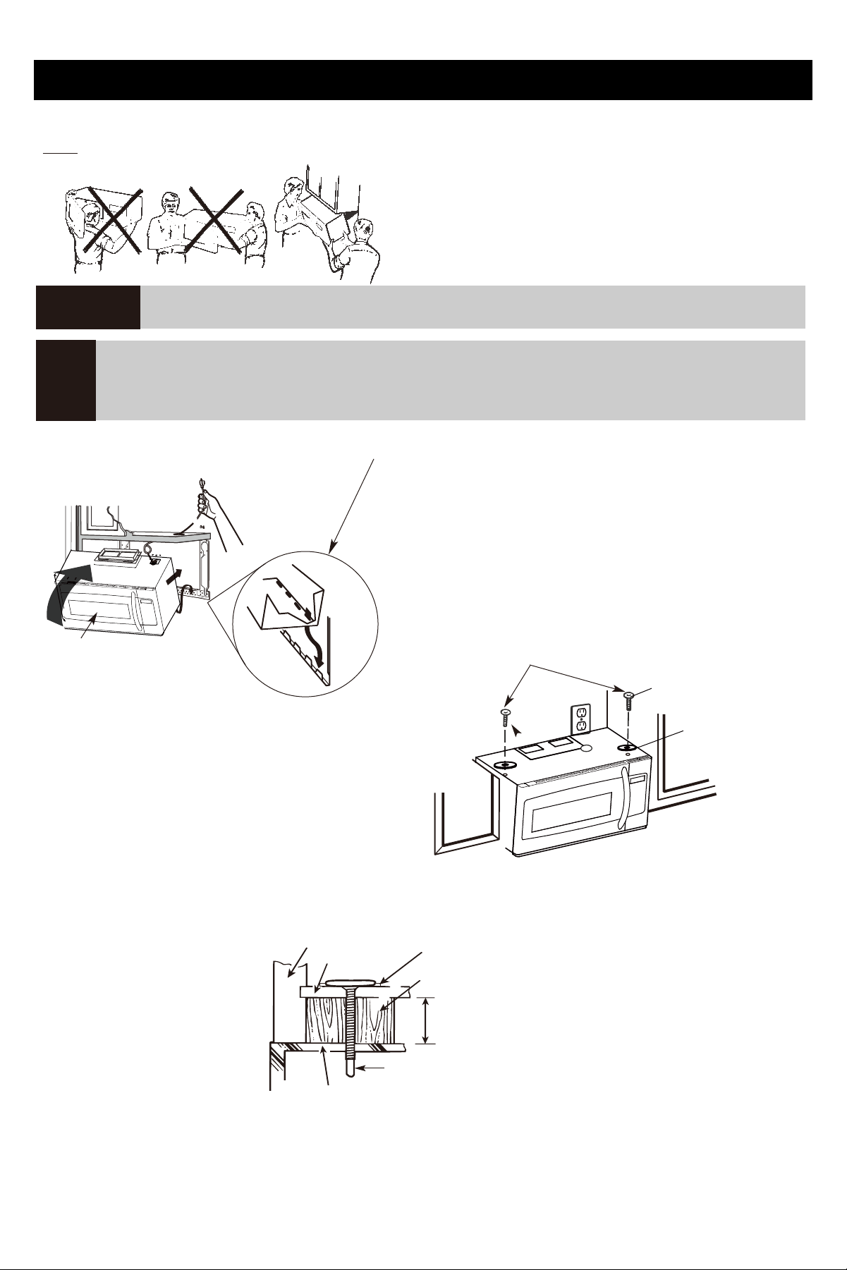
A.
OUTSIDE TOP EXHAUST (Vercal Duct ) DEFAULT
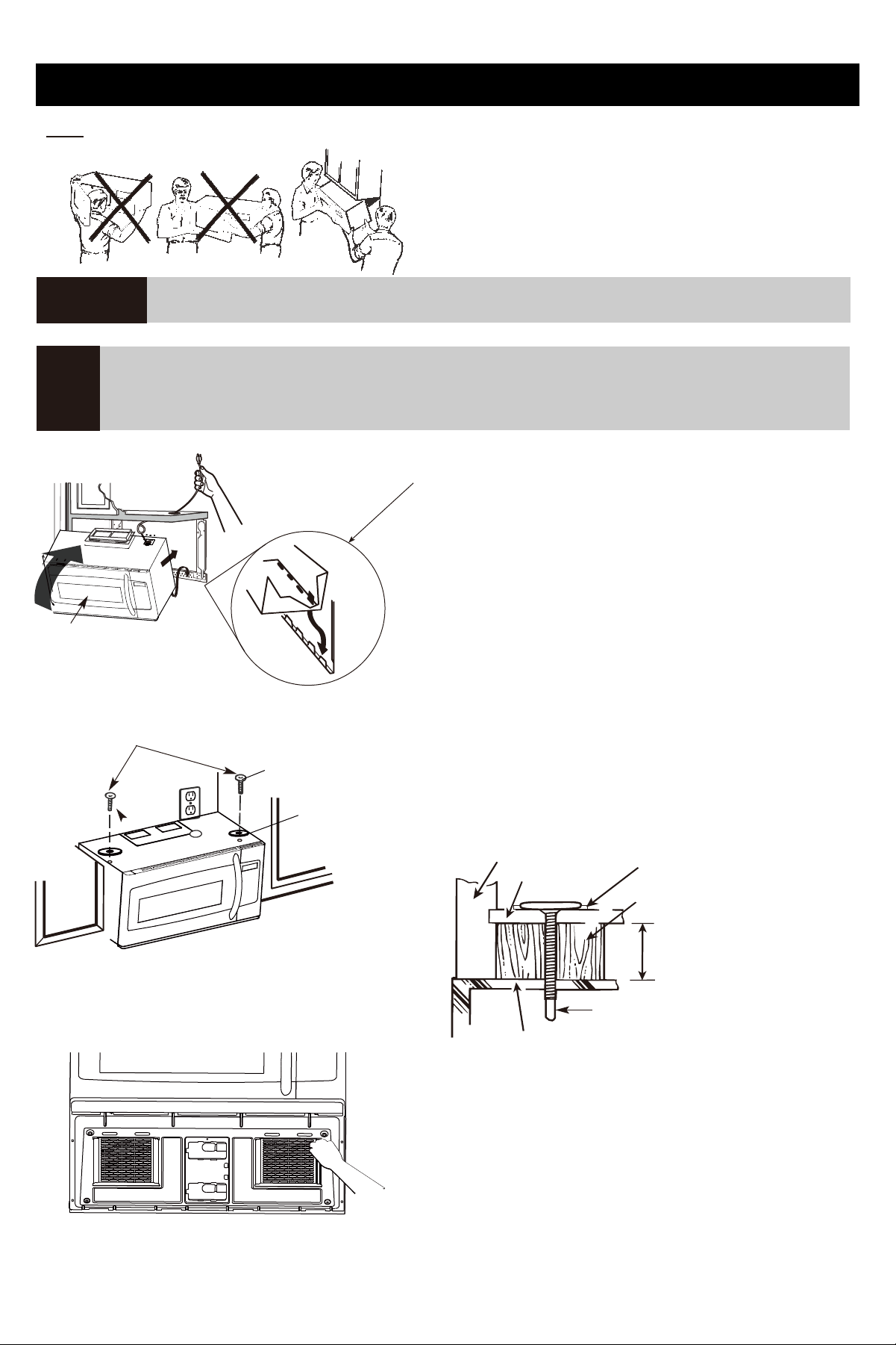
CAUTION: Be careful to avoid pinching fingers between the back of the mounng plate and the wall.
A1.
ATTACH MOUNTING PLATE TO THE WALL
(
To use toggle bolts
Step-by-step installation guide
15
A3.
CHECK FOR PROPER DAMPER OPERATION
• Make sure tape securing damper is removed and damper pivots easily before mounng microwave.
A2.
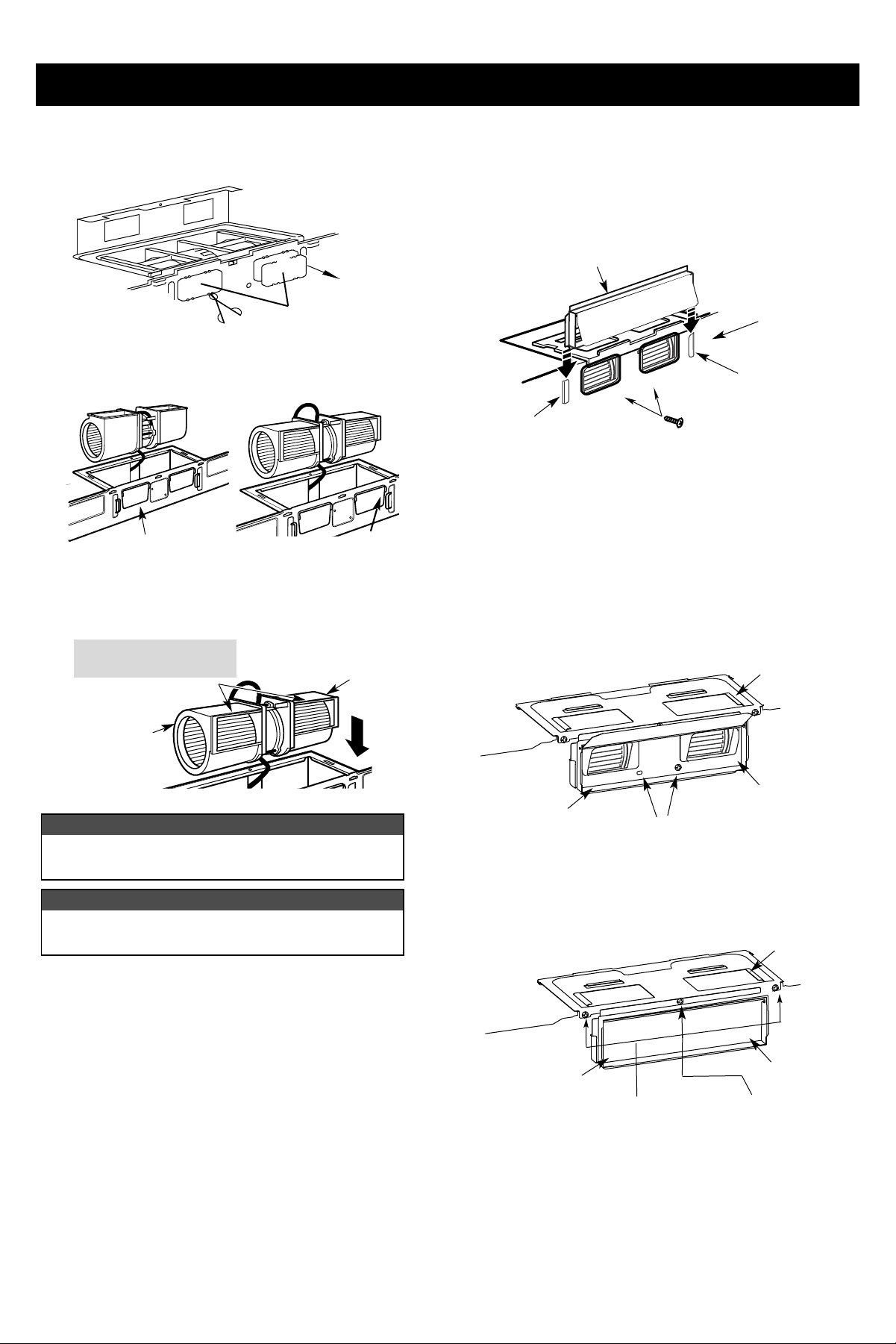
USE TOP CABINET TEMPLATE FOR PREPARATION OF TOP CABINET
CAUTION :Wear safety goggles when drilling holes in the cabinet boom.
Blower Plate
Screw
Guide
Guide
Step-by-step installation guide
A4.
MOUNT THE MICROWAVE OVEN
16
E
、
keep power
Do not grip or use handle during installaon.
If filler blocks are not used, case damage may occur from over ghtening screws.
If your cabinet is metal, use the nylon grommet around the power cord hole to prevent cung of the cord.
We recommend using filler blocks if the cabinet front hangs below the cabinet boom shelf.
When mounng the microwave oven, thread power cord through hole in boom of top cabinet. Keep it ght
throughout Step 1-3.Do not pinch cord or li oven by pulling cord.
NOTE:
IMPORTANT:
Step-by-step installation guide
17
A5.
ADJUST THE EXHAUST ADAPTOR
A6.
CONNECTING DUCTWORK
Step-by-step installation guide
18
B .
OUTSIDE BACK EXHAUST(Horizontal Duct)
B 1.
PREPARING THE REAR WALL TEMPLATE FOR OUTSIDE BACK EXHAUST
INSTALLATION OVERVIEW

Step-by-step installation guide
B 3.
USE TOP CABINET TEMPLATE FOR PREPARATION OF TOP CABINET
CAUTION : Wear safety goggles when drilling holes in the
cabinet boom.
19
BEFORE : Fan Blade
Openings Facing UP
B ower Moor
B 4.
ADAPTING MICROWAVE BLOWER FOR OUTSIDE BACK EXHAUST
CAUTION: Be careful to avoid pinching fingers between the back of the mounng plate and the wall.
B 2.
ATTACH MOUNTING PLATE TO THE WALL
(
To use toggle bolts
Step-by-step installation guide
20
Before
A
B
&
CAUTION:
NOTE:
Step-by-step installation guide
21
B 5.
MOUNT THE MICROWAVE OVEN
E
keep power
Do not grip or use handle during installaon.
If filler blocks are not used, case damage may occur from over ghtening screws.
If your cabinet is metal, use the nylon grommet around the power cord hole to prevent cung of the cord.
We recommend using filler blocks if the cabinet front hangs below the cabinet boom shelf.
When mounng the microwave oven, thread power cord through hole in boom of top cabinet. Keep it ght
throughout Step 1-3.Do not pinch cord or li oven by pulling cord.
NOTE:
IMPORTANT:
、,
Step-by-step installation guide
C .
RECIRCULATING(Non-vented Ductless)
INSTALLATION OVERVIEW
TOP CABINET
OVEN
22
CAUTION: Be careful to avoid pinching fingers between the back of the mounng plate and the wall.
C 1.
ATTACH THE MOUNTING PLATE TO THE WALL
(
To use toggle bolts
Step-by-step installation guide
23
C 2.
USE TOP CABINET TEMPLATE FOR PREPARATION OF TOP CABINET
CAUTION : Wear safety goggles when drilling holes in the
cabinet boom.
B ower Moor
C 3.
ADAPTING BLOWER FOR RECIRCULATION
Before
of
CAUTION:
NOTE:
Step-by-step installation guide
24
C4 .
MOUNT THE MICROWAVE OVEN
E
keep power
Do not grip or use handle during installaon.
If filler blocks are not used, case damage may occur from over ghtening screws.
If your cabinet is metal, use the nylon grommet around the power cord hole to prevent cung of the cord.
We recommend using filler blocks if the cabinet front hangs below the cabinet boom shelf.
When mounng the microwave oven, thread power cord through hole in boom of top cabinet. Keep it ght
throughout Step 1-3.Do not pinch cord or li oven by pulling cord.
NOTE:
IMPORTANT:
、,
C5 .
Step-by-step installation guide
25
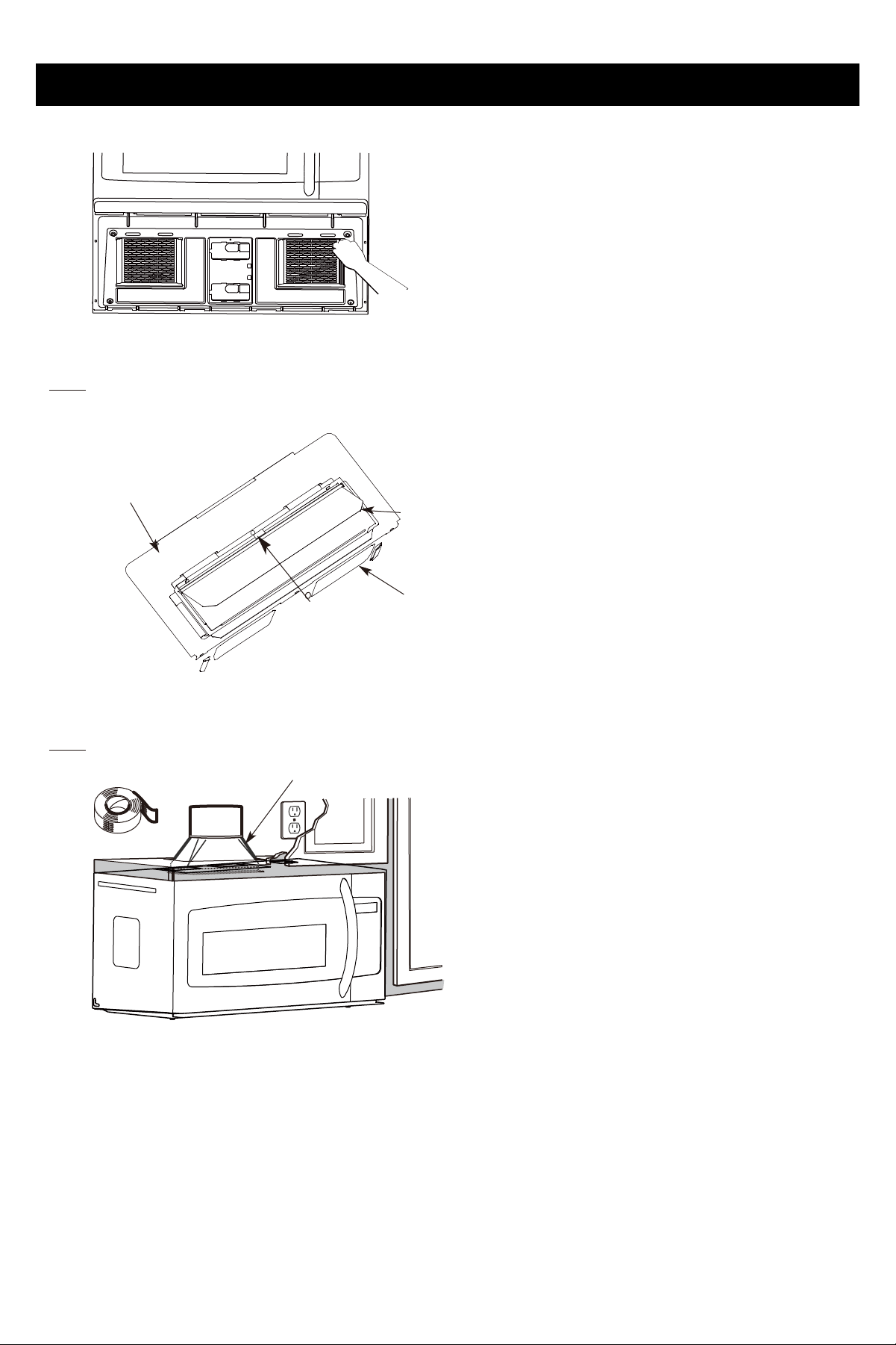
CHANGE THE CHARCOAL FILTER
1. Remove two screws of the louver which is on the top of the oven
by using a #1 Phillips screwdriver.
Charcoal filter is used for nonvented, recirculated installation. The filter should be changed every 6 to 12 months
depending on use.
2.
Open the door then Remove the louver and take the used
charcoal filter out .
3.
Install the new charcoal filter.When properly installed,the wire mesh of the filter should be visible from the
front.
4.
Charcoal
Filter
Charcoal Filter
Louver
Louver Screw
Repalce the louver and the screws.
Step-by-step installation guide
26
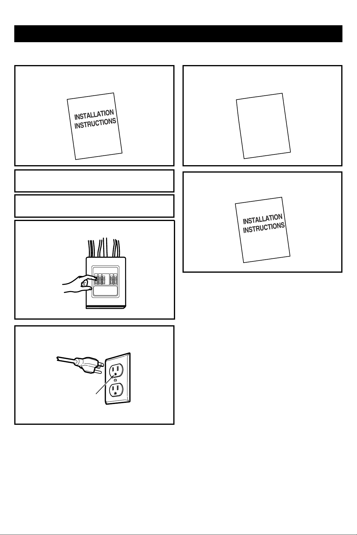
BEFORE YOU USE YOUR MICROWAVE
I proper
ex
before e
USER GUIDE