Loading ...
Loading ...
Loading ...
6
For Non-Vented (Recirculating) Installations
If it is not possible to vent cooking fumes and vapors to the
outside, the hood can be used in the non-vented (recirculating)
version, using a Recirculation Kit (which includes charcoal
filters and a deflector). To order, see the “Assistance or Service”
section.
The ducting from this fan to the outside of the building has a
strong effect on the air flow, noise and energy use of the fan.
Use the shortest, straightest duct routing possible for best
performance, and avoid installing the fan with smaller ducts
than recommended.
Insulation around the ducts can reduce energy loss and inhibit
mold growth. Fans installed with existing ducts may not
achieve their rated airflow.
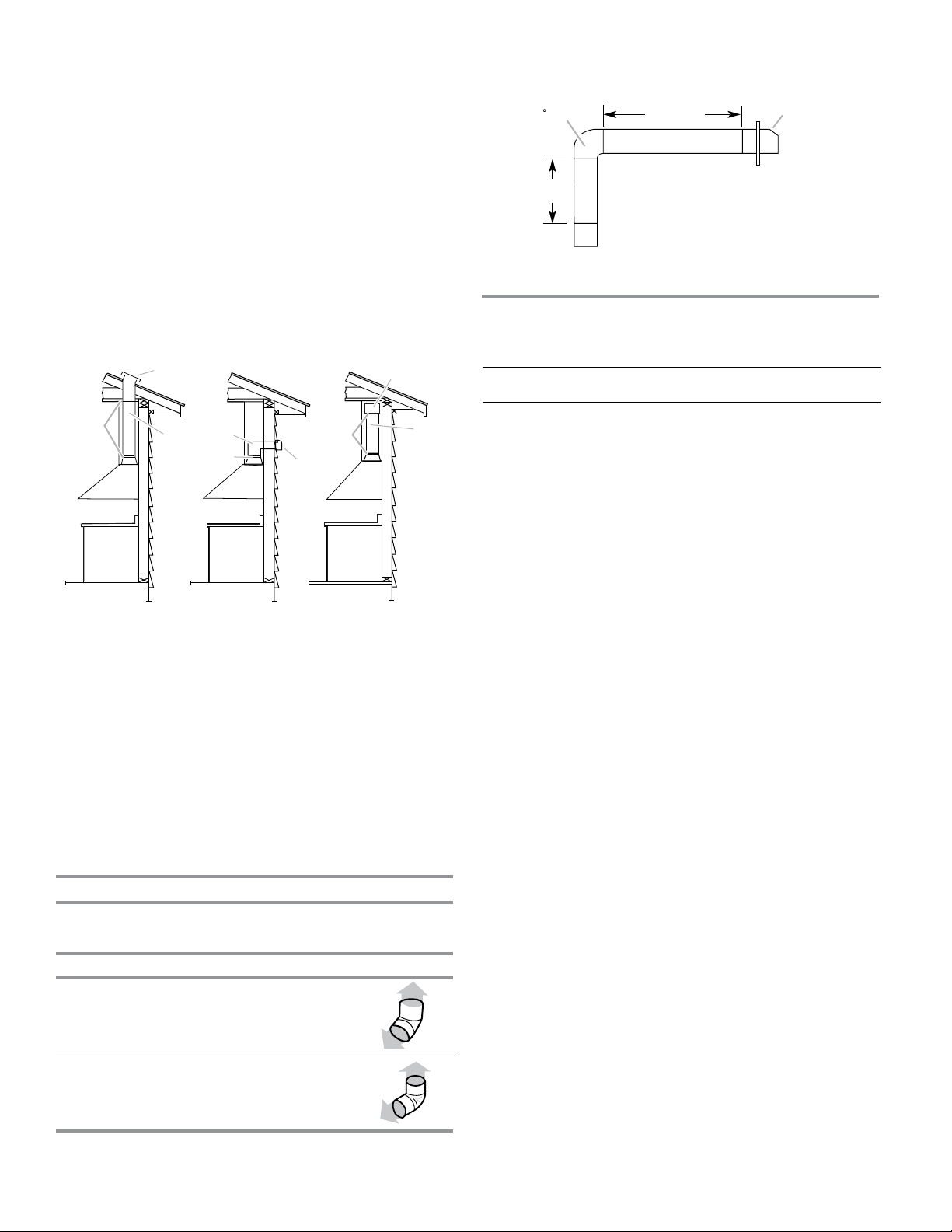
Vent Piece 6" (15.2 cm) Round
45° elbow 2.5 ft
(0.8 m)
90° elbow 5.0 ft
(1.5 m)
Example vent system
1 - 90° elbow = 5.0 ft (1.5 m)
1 - wall cap = 0.0 ft (0.0 m)
8 ft (2.4 m) straight = 8.0 ft (2.4 m)
Length of system = 13.0 ft (3.9 m)
Calculating Vent System Length
To calculate the length of the system you need, add the
equivalent feet (meters) for each vent piece used in the system.
Maximum equivalent vent length is 35 ft (10.7 m).
The following example falls within the maximum recommended
vent length of 35 ft (10.7 m).
Electrical Requirements
Observe all governing codes and ordinances.
Ensure that the electrical installation is adequate and in
conformance with National Electrical Code, ANSI/NFPA 70
(latest edition), or CSA Standards C22.1-94, Canadian Electrical
Code, Part 1 and C22.2 No. 0-M91 (latest edition) and all local
codes and ordinances.
If codes permit and a separate ground wire is used, it is
recommended that a qualified electrician determine that the
ground path is adequate.
A copy of the above code standards can be obtained from:
National Fire Protection Association
1 Batterymarch Park
Quincy, MA 02169-7471
CSA International
8501 East Pleasant Valley Road
Cleveland, OH 44131-5575
■ A 120 volt, 60 Hz., AC only, 15-amp, fused electrical circuit
is required.
■ If the house has aluminum wiring, follow the procedure
below:
1. Connect a section of solid copper wire to the pigtail
leads.
2. Connect the aluminum wiring to the added section of
copper wire using special connectors and/or tools
designed and UL listed for joining copper to aluminum.
Follow the electrical connector manufacturer's recommended
procedure. Aluminum/copper connection must conform with
local codes and industry accepted wiring practices.
■ Wire sizes and connections must conform with the rating of
the appliance as specified on the model/serial/rating plate.
The model/serial/rating plate is located behind the left filter
on the rear wall of the range hood.
■ Wire sizes must conform to the requirements of the
National Electrical Code, ANSI/NFPA 70 (latest edition), or
CSA Standards C22. 1-94, Canadian Electrical Code, Part
1 and C22.2 No. 0-M91 (latest edition) and all local codes
and ordinances.
90 elbow
6 ft (1.8 m)
2 ft
(0.6 m)
Wall cap
Ensure duct joints and exterior penetrations are sealed with
caulk or other similar material to create an air-tight path and to
minimize building heat loss and gain and reduce the potential
for condensation.
Place/wrap insulation around duct and/or fan in order to
minimize possible condensation buildup within the duct,
building heat loss and gain.
A. Roof cap
B. 6" (15.2 cm)
round vent
C. Seal duct joints
with duct
tape/caulk
A. Wall cap
B. 6" (15.2 cm)
round vent
C. Seal duct joints
with duct
tape/caulk
A. Deflector
B. 6" (15.2 cm)
round vent
C. Seal duct joints
with duct
tape/caulk
*The recirculating version are not neither Energy Star nor HVI certified.
Roof Venting Wall Venting Non-vented
(recirculating)
C
B
A
C
B
A
C
B
A
Loading ...
Loading ...
Loading ...