User Manual
Version 1.0 | 05/29/2013
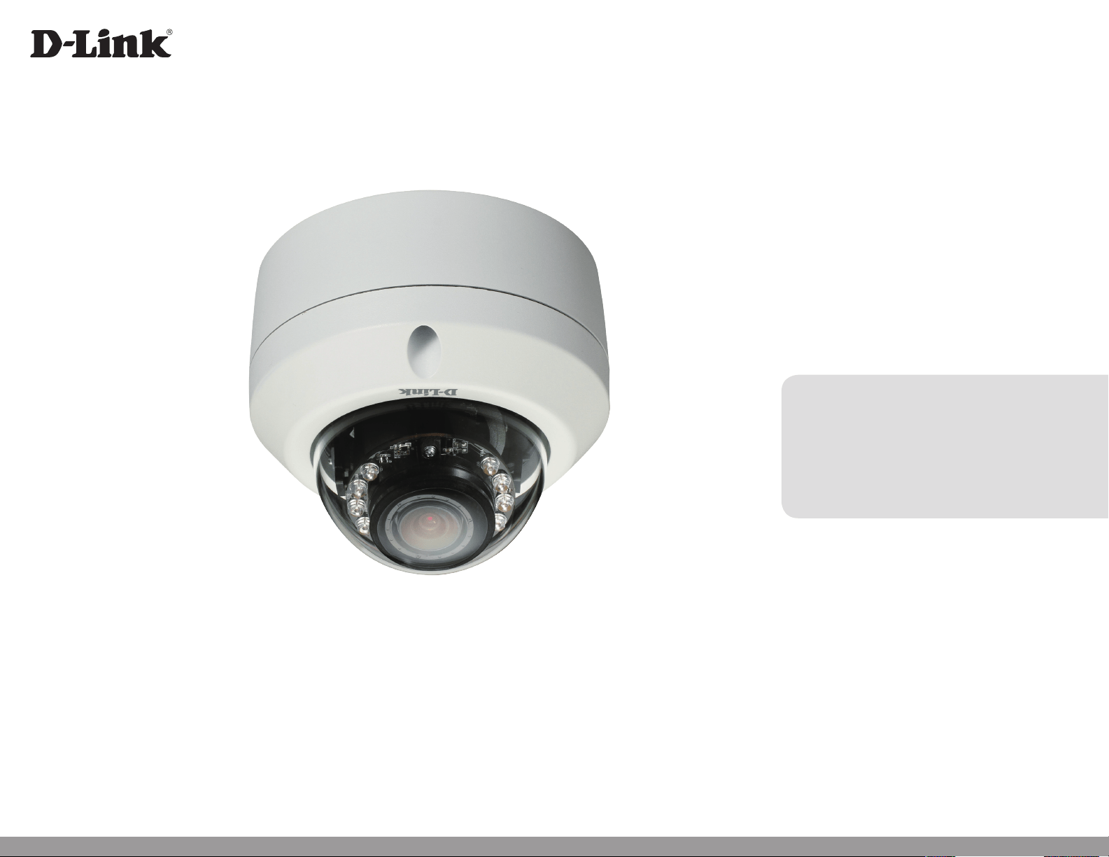
DCS-6314
Full HD Outdoor Fixed Dome Network Camera
2D-Link DCS-6314 User Manual
D-Link reserves the right to revise this publication and to make changes in the content hereof without obligation to notify any person or
organization of such revisions or changes. Information in this document may become obsolete as our services and websites develop and
change.
Manual Revisions
Revision Date Description
1.0 May 29, 2013 DCS-6314 Revision A1 with rmware version 1.00
Trademarks
D-Link and the D-Link logo are trademarks or registered trademarks of D-Link Corporation or its subsidiaries in the United States or other
countries. All other company or product names mentioned herein are trademarks or registered trademarks of their respective companies.
Copyright © 2013 D-Link Corporation.
All rights reserved. This publication may not be reproduced, in whole or in part, without prior expressed written permission from D-Link Corporation.
Preface

3D-Link DCS-6314 User Manual
Table of Contents
Product Overview ......................................................................... 4
Package Contents ................................................................. 4
Introduction ............................................................................5
System Requirements .........................................................5
Features .................................................................................... 6
Hardware Overview ............................................................. 7
Front ...................................................................................... 7
Top..........................................................................................8
Cable Harness..................................................................... 9
Internal ...............................................................................10
Assembly and Installation .......................................................11
Installing a Micro SD Card ................................................11
Deploying the Camera ..................................................13
Mounting the Camera .......................................................15
Attaching the Camera to the Pendant Mount ......18
Attaching the Camera to the Bent Mount .............20
Orienting the Camera ....................................................22
Camera Installation Wizard .............................................23
General Connection Using 12 V DC Power
Adapter ...............................................................................23
Connection Using Power over Ethernet .................24
Software Installation ......................................................25
D-ViewCam Setup Wizard ............................................28
Conguration ...............................................................................30
Using the Conguration Interface ................................30
Live Video ..............................................................................31
Setup .......................................................................................33
Setup Wizard ....................................................................33
Network Setup .................................................................39
Dynamic DNS ...................................................................42
Image Setup .....................................................................43
Audio and Video ..............................................................45
Preset ...................................................................................47
Motion Detection ...........................................................49
Time and Date ..................................................................50
Event Setup .......................................................................51
SD Card ...............................................................................59
Advanced ...............................................................................60
Digital Input/Output ......................................................60
ICR and IR ...........................................................................61
HTTPS ..................................................................................62
Access List ..........................................................................63
Maintenance .........................................................................64
Device Management .....................................................64
System ................................................................................65
Firmware Upgrade ..........................................................66
Status ......................................................................................67
Device Info ........................................................................67
Logs .....................................................................................68
Help......................................................................................69
DI/DO Specications .................................................................70
Technical Specications ...........................................................71

4D-Link DCS-6314 User Manual
Section 1: Product Overview
Product Overview
Package Contents
DCS-6314 Full HD Outdoor Fixed Dome Network Camera
Power adapter
CD-ROM with User Manual and software
Quick Installation Guide
Security Wrench
CAT5 Ethernet cable
Weather Shield
Screws and wall socket
4Pin Terminal Block
If any of the above items are missing, please contact your reseller.
Note: Using a power supply with a dierent voltage than the one included with your
product will cause damage and void the warranty for this product.

5D-Link DCS-6314 User Manual
Section 1: Product Overview
Introduction
The DCS-6314 Full HD Outdoor Fixed Dome Network Camera is a professional surveillance and security solution for small,
medium, and large enterprises alike. The DCS-6314 uses a 2 megapixel progressive scan CMOS sensor which produces high
quality images with low noise, making it ideal for surveillance applications. Together with the WDR enhancement, users can
identify image details in both extremely bright as well as dark environments.
The DCS-6314 has an IP68 certied weatherproof housing designed for both indoor and outdoor applications. The built-in
removable IR-cut lter and IR LEDs give the DCS-6314 the capability to view up to 15 meters at night. The ability to use Power
over Ethernet (PoE) also allows it to be easily installed in a variety of locations without the need for supplemental power cabling.
The combination of IP68 housing, IR-Cut Filter, IR LEDs and PoE make the DCS-6314 an ideal solution for a high performance,
reliable and cost-eective 24 hour megapixel surveillance solution with an easy clutter-free installation.
• Computer with Microsoft Windows® 8, 7, Vista®, or XP (for CD-ROM Setup Wizard), Mac OS or Linux
• PC with 1.3GHz or above; at least 128MB RAM
• Internet Explorer 7 or above , Firefox 3.5 or above, Safari 4 and Chrome 8.0 or above
• Existing 10/100 Ethernet-based network
• A Micro SD memory card (optional) is required for recording to onboard storage. SDHC Class 6 or above is recommended.
• Broadband Internet connection
System Requirements

6D-Link DCS-6314 User Manual
Section 1: Product Overview
Wide Dynamic Range
Wide Dynamic Range technology corrects imperfect lighting conditions, providing clear images with the right amount of contrast even when a
subject is backlit
Remote Monitoring Utility
The D-ViewCam application adds enhanced features and functionality for the Network Camera and allows administrators to congure and access
the Network Camera from a remote site via Intranet or Internet. Other features include image monitoring, recording images to a hard drive, viewing
up to 32 cameras on one screen, and taking snapshots.
IR LED for Day and Night Functionality
The built-in infrared LEDs enables night time viewing of up to 15 meters (49 feet).
IP68 Weatherproof Housing
The DCS-6314 uses an IP68 weatherproof housing, allowing you to rest assured that in the toughest of conditions, it will continue to provide round-
the-clock surveillance.
PoE (Power over Ethernet) for Flexible Installation
The DCS-6314 can get all the power it needs from a PoE switch or PoE injector for a simple and clutter-free installation.
Features

7D-Link DCS-6314 User Manual
Section 1: Product Overview
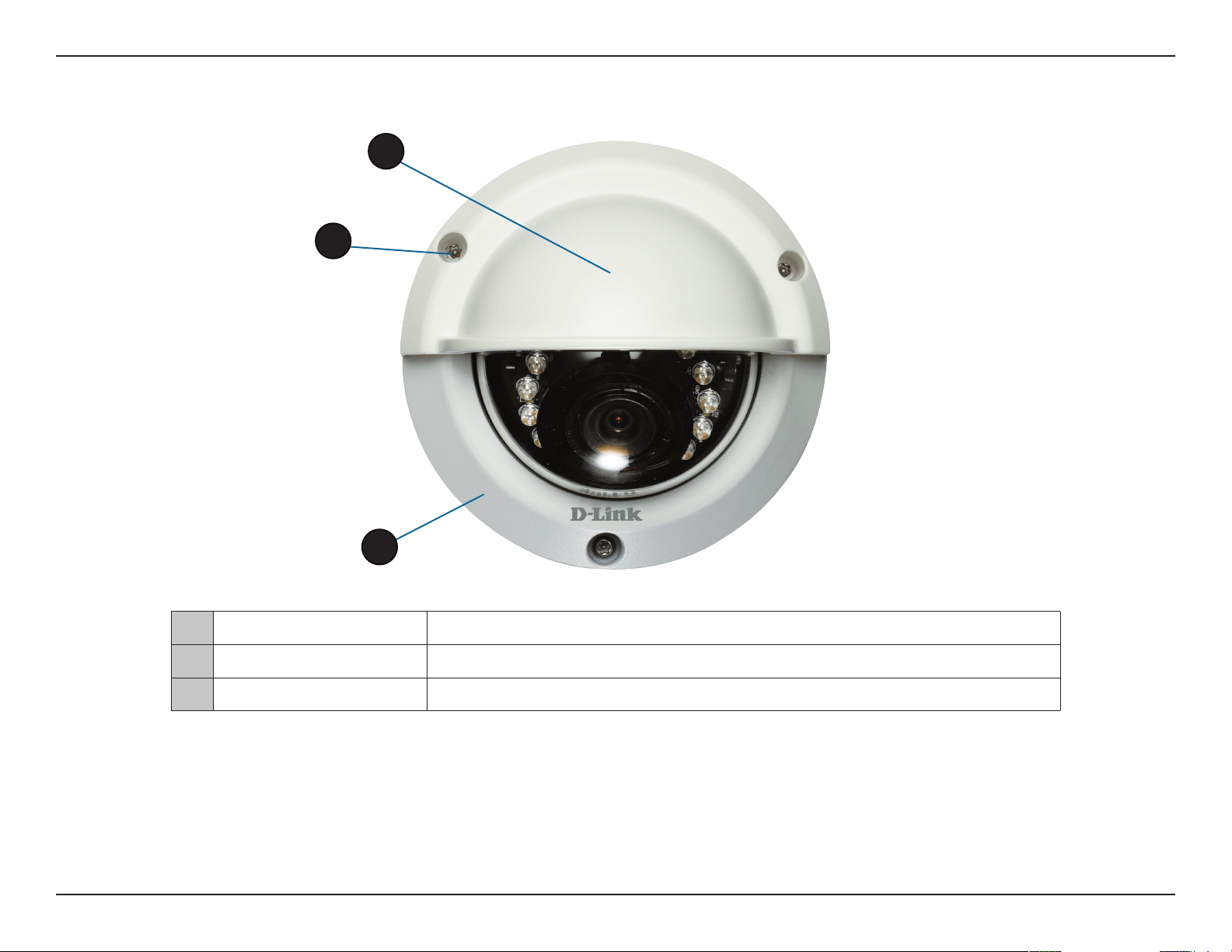
Front
Hardware Overview
1 Light Sensor
The light sensor measures the lighting conditions and switches between color
and infrared accordingly
2 Camera Lens
Vari-focal lens to record video of the surrounding area
3 IR LEDs
Infrared LEDs illuminate the camera's eld of view at night
4 Power/Status LED
Indicates the camera's current status
3
4
2
1
8D-Link DCS-6314 User Manual
Section 1: Product Overview
Top
1 Weather Shield Shields the camera sensor from direct sunlight.
2 Adjustment Screw
Used to secure the weather shield to the camera.
3 Bottom Camera Shoe Used to attach to the optional mounting accessories.
1
2
3
Note: When the weathershield is attached, the camera video may show reections when the IR LEDs
are on and the camera is at a high angle. If you experience this, it is recommended that you lower
the angle of the camera or turn o the IR LEDs. For details on how to adjust the camera angle, please
see "Orienting the Camera" on page 22. For details on how to turn the IR LEDs on/o, please see "ICR
and IR" on page 61.
9D-Link DCS-6314 User Manual
Section 1: Product Overview
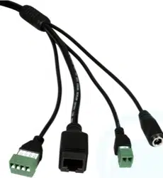
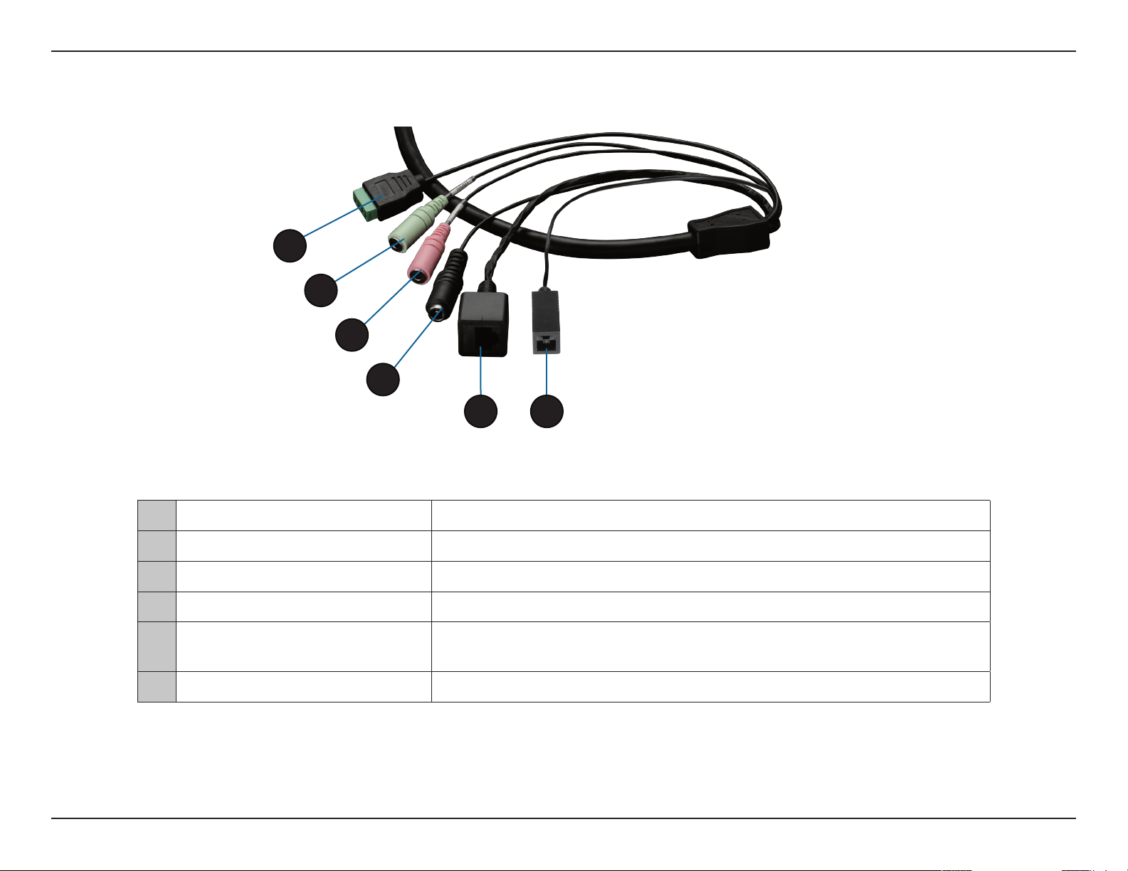
Cable Harness
1 DI/DO Connector
I/O connectors for external devices. 12V DC output.
2 Audio Out (Green)
Connects to a speaker.
3 Audio In (Red) Connects to a microphone.
4 Power Connector Power connector for the provided 12V DC power adapter.
5 Ethernet Jack
Connects to an RJ45 Ethernet port. Can be used with PoE to provide power to
the camera.
6 Reset Button
Press and hold the recessed button for 10 seconds to reset the camera.
1
4
5 6
3
2
11D-Link DCS-6314 User Manual
Section 2: Assembly and Installation
Assembly and Installation
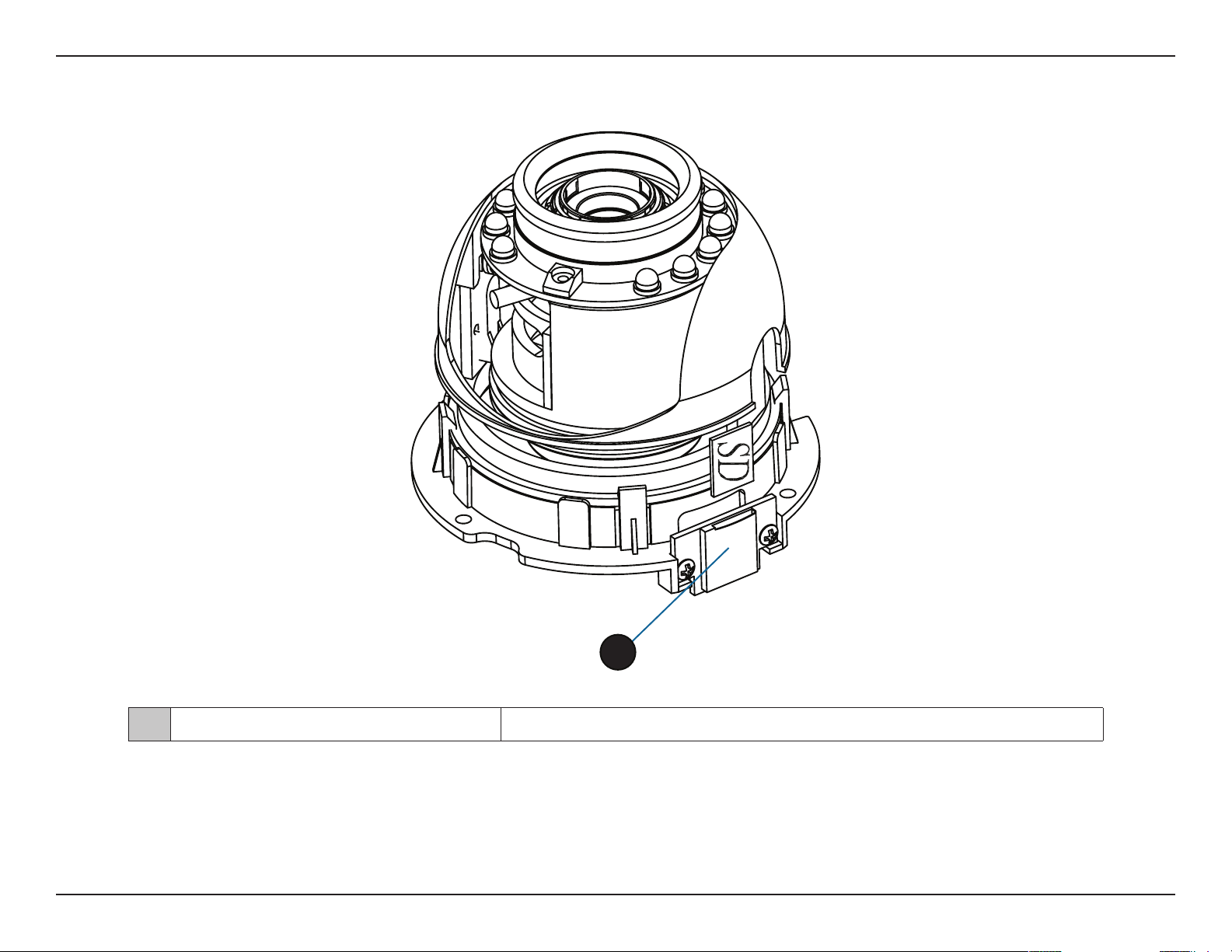
Installing a Micro SD Card
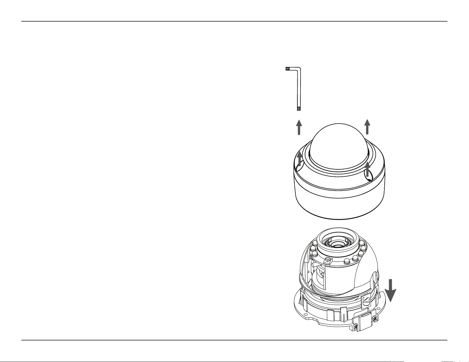
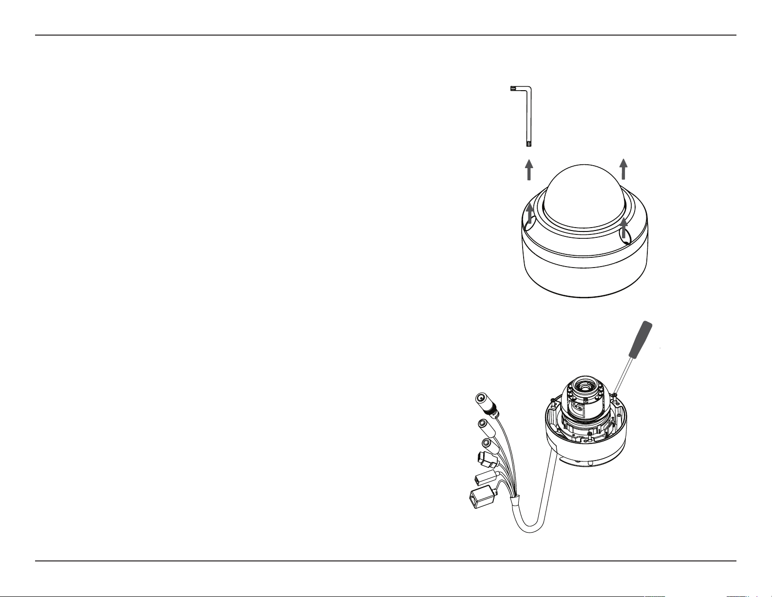
Step 1
Place the camera face down on a non-slip at surface.
Step 3
Remove the base of the camera by holding the camera rmly and
rotating the base in a counter clockwise direction.
Step 2
Remove the adjustable top part of the camera housing by removing
the three retaining screws.
12D-Link DCS-6314 User Manual
Section 2: Assembly and Installation
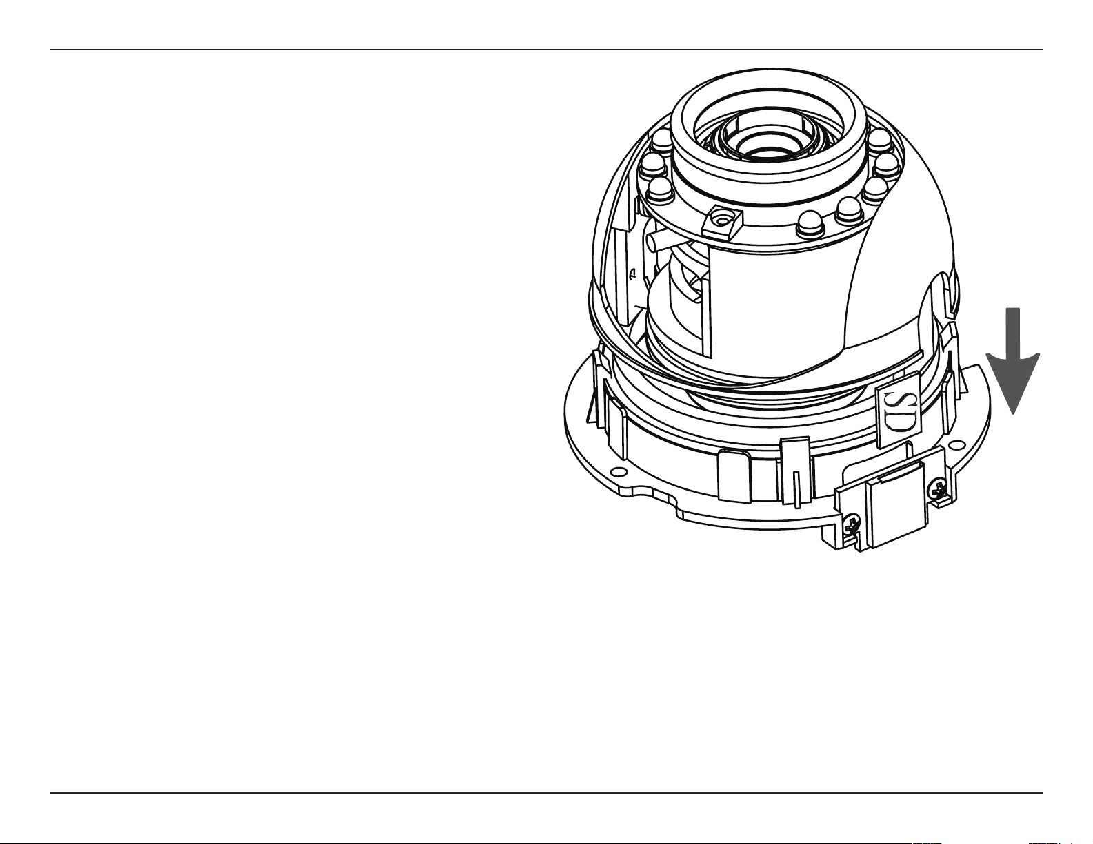
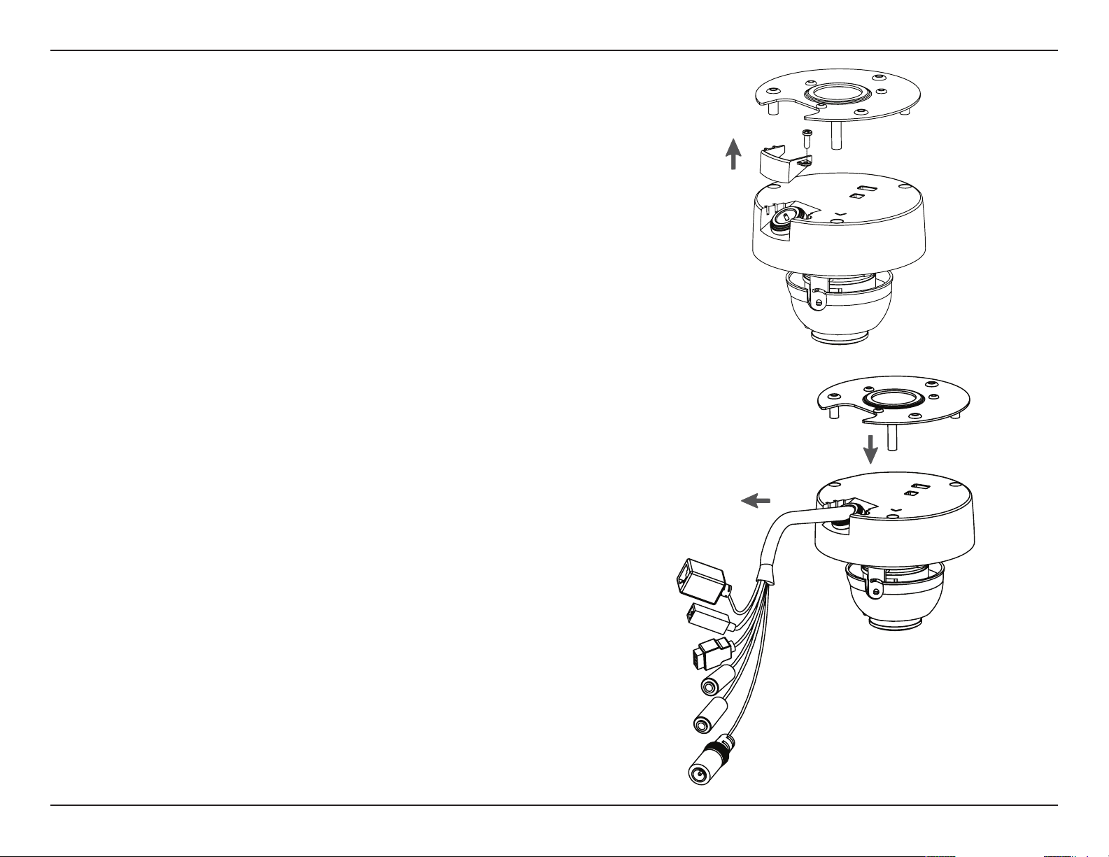
Step 5
Replace the base of the camera by holding the camera rmly and
rotating the base in a clockwise direction ensuring a tight t.
Note: Users are advised to ensure that the weatherproof seals are
secured rmly in place.
Step 4
Insert your Micro SD memory card into the slot with the notch oriented
to the front of the camera.
13D-Link DCS-6314 User Manual
Section 2: Assembly and Installation
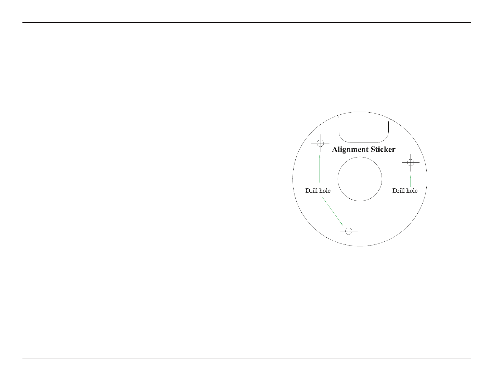
Step 1
Position the Alignment Sticker in the desired location making
sure the Camera and Wire-in-Bracket have sucient space.
Use the dimension diagrams in "Dimensions" on page 73 for
additional reference.
Step 2
Use a 6mm drill bit to make required holes approximately
30mm deep.
Step 3
Remove the Alignment Sticker.
Step 4
Insert wall anchors and ax the mounting plate using the
screws provided.
Deploying the Camera
Note: Before deploying the camera to a xed location, it is recommended that you take a photo from the desired location to
ensure an adequate eld-of-view.
14D-Link DCS-6314 User Manual
Section 2: Assembly and Installation
Step 5
Fasten the camera rmly to the mounting plate using the
screw provided ensuring clear passage for the cables through
the cable channel or via the mounting plate cut-out.
15D-Link DCS-6314 User Manual
Section 2: Assembly and Installation
Mounting the Camera
The DCS-6314 is suitable for mounting to a wall using the
camera shoe and wire-in bracket provided.
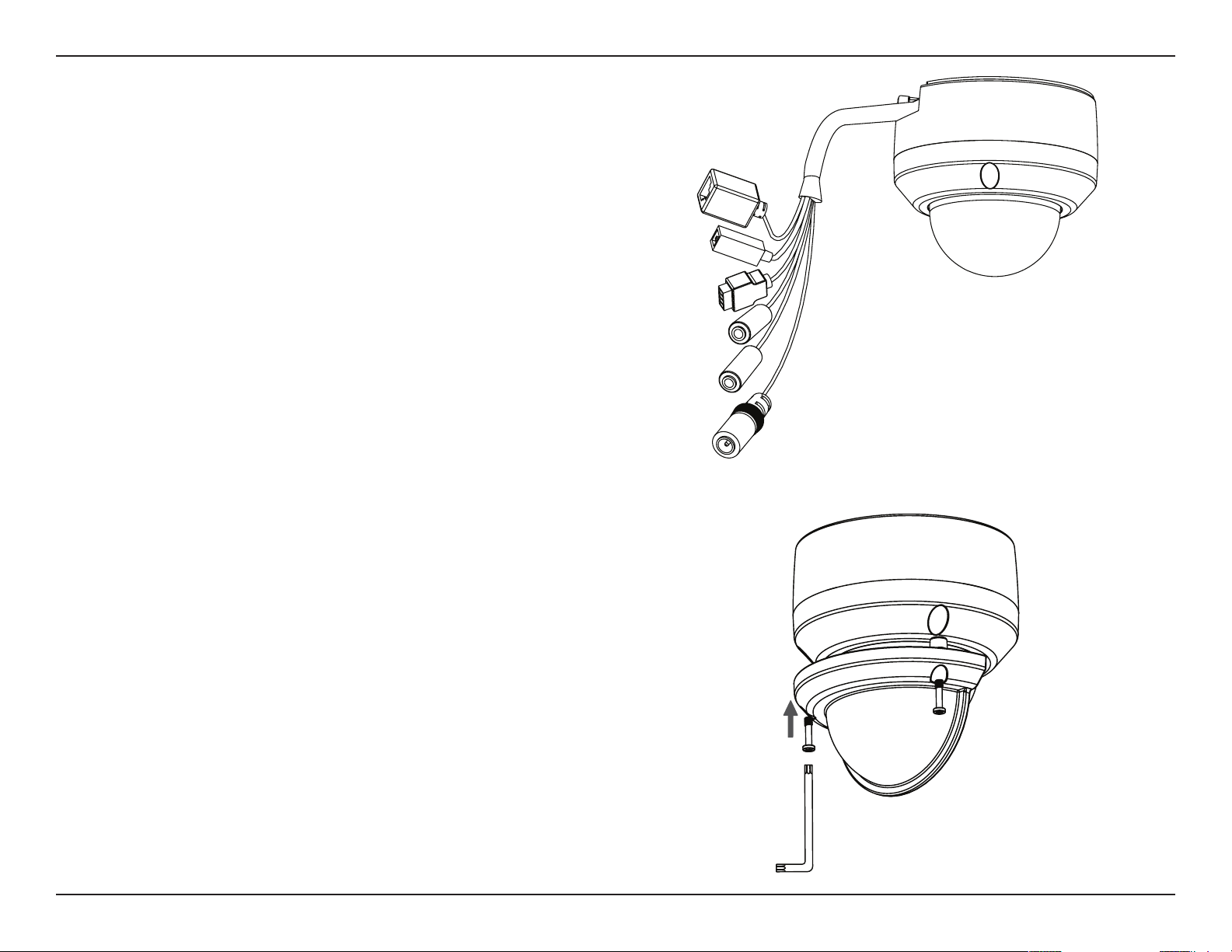
Step 1
Remove the top part of the camera housing by using the
included tool to unscrew the three retaining screws.
Step 2
Once the cover has been removed, use a screwdriver to
remove the bottom mounting plate from the lower half of
the camera housing. The mounting plate is secured with three
screws positioned around the outer edge of the lower part
of the camera housing.
If you will be mounting the camera directly to a wall or ceiling,
please continue to the next page.
If you will be mounting the camera using the pendant mount,
please refer to "Attaching the Camera to the Pendant Mount"
on page 18.
If you will be mounting the camera using the bent mount,
please refer to "Attaching the Camera to the Bent Mount" on
page 20.
16D-Link DCS-6314 User Manual
Section 2: Assembly and Installation
Step 3
Remove the mounting plate from the lower half of the camera
housing. It can now be attached to a wall or ceiling using the
mounting guide. Please see "Deploying the Camera" on page
13 for more instructions.
If you will be installing the camera onto a surface that cannot
house the cable, the cable access part can be removed so
that the cable can exit the camera housing easily. Once the
mounting plate has been removed, you will be able to remove
the cable access panel. If you will be routing the connection
cables through a wall or ceiling, it is recommended to leave
this part attached, as it will help protect the cable from
vandalism.
Step 4
Slide the lower half of the camera housing onto the mounting
plate and resecure it. Make sure that the cable sheath extends
out of the base in such a way that the cable is not kinked or
twisted.
17D-Link DCS-6314 User Manual
Section 2: Assembly and Installation
Step 5
Reattach the top part of the camera housing, and secure it by
tightening the three retaining screws.
Step 6
If necessary, the included weather shield can now be attached
to the camera.
18D-Link DCS-6314 User Manual
Section 2: Assembly and Installation
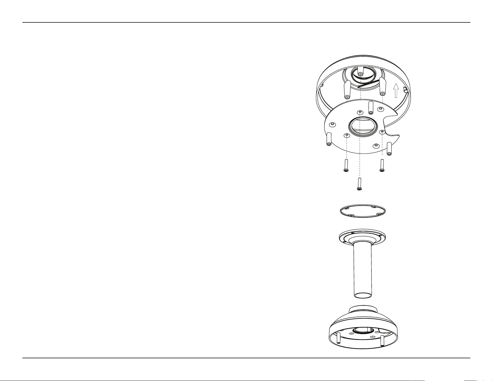
Pendant Bracket
Bracket Cap
Rubber Seal
Bracket Cap
Mounting Plate
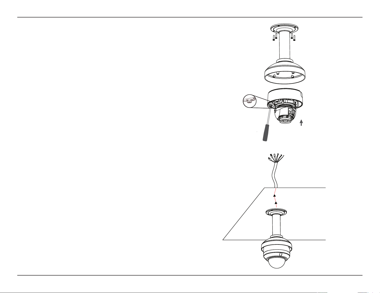
Attaching the Camera to the Pendant Mount
Step 1
Begin by attaching the mounting plate that was removed
from the lower part of the camera housing into the bracket
cap.
Step 2
Place the rubber seal onto the mounting part of the pendant
bracket. Use the included mounting guide to mark out on the
ceiling the proper placement of the mounting holes. Securely
mount the rubber seal and pendant bracket to the ceiling, if
you need more details please see "Deploying the Camera"
on page 13.
Step 3
Attach the bracket cap, by screwing it onto the pendant
bracket.
19D-Link DCS-6314 User Manual
Section 2: Assembly and Installation
Step 4
Begin the process of reattaching the bottom part of the
camera housing, by rst pushing the cable sheath up through
the pendant mount. Once the cable has been pushed through,
you can then rmly reattach the bottom part of the camera
housing, and secure it by tightening the three retaining
screws.
Step 5
Reattach the top part of the camera housing, and secure it by
tightening the three retaining screws.
If necessary, the included weather shield can now be attached
to the camera. Please see step 6 of "Mounting the Camera"
on page 15 for more details on how to do this.
Dome
Camera
20D-Link DCS-6314 User Manual
Section 2: Assembly and Installation
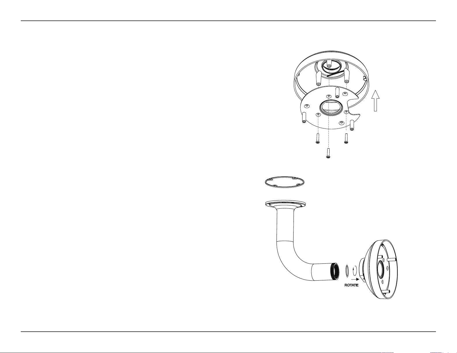
Attaching the Camera to the Bent Mount
Step 1
Begin by attaching the mounting plate that was removed
from the lower part of the camera housing into the bracket
cap.
Step 2
Place the rubber seal onto the mounting part of the bent
bracket. Use the included mounting guide to mark out on
the ceiling the proper placement of the mounting holes.
Securely mount the rubber seal and pendant bracket to the
ceiling, if you need more details please see "Deploying the
Camera" on page 13.
Step 3
Attach the bracket cap, by screwing it onto the pendant
bracket.
Bracket
Cap
Mounting
Plate
Bracket
Cap
Bent
Bracket

21D-Link DCS-6314 User Manual
Section 2: Assembly and Installation
Dome
Camera
Step 4
Begin the process of reattaching the bottom part of the
camera housing, by rst pushing the cable sheath up through
the bent mount. Once the cable has been pushed through,
you can then rmly reattach the bottom part of the camera
housing, and secure it by tightening the three retaining
screws.
Step 5
Reattach the top part of the camera housing, and secure it by
tightening the three retaining screws.
If necessary, the included weather shield can now be attached
to the camera. Please see step 6 of "Mounting the Camera"
on page 15 for more details on how to do this.
22D-Link DCS-6314 User Manual
Section 2: Assembly and Installation
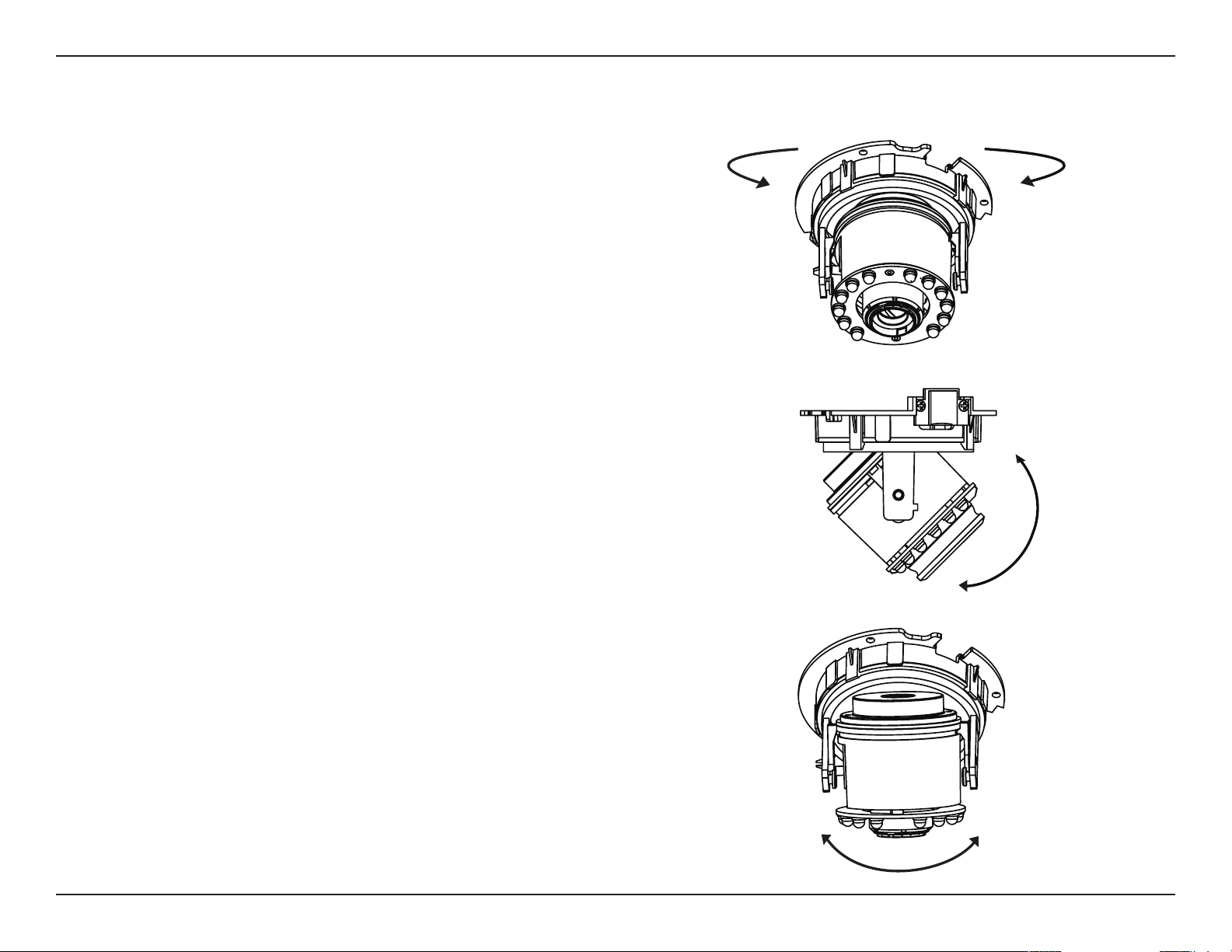
Orienting the Camera
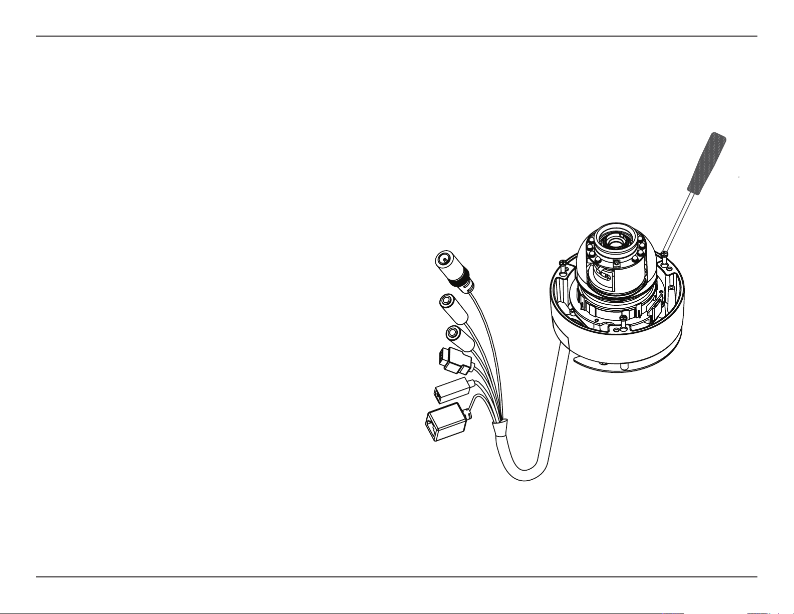
Step 1
Turn the lens module left and right until the desired position
is achieved.
Step 2
Loosen the tilt screws on both sides of the camera, and turn
the lens module up and down until the desired position is
achieved.
Step 3
Turn the lens to adjust the IP camera’s image until the desired
orientation is achieved.
The DCS-6314 can be adjusted to ensure an optimal viewing
position when mounted to a wall by following the steps
outlined.

23D-Link DCS-6314 User Manual
Section 2: Assembly and Installation
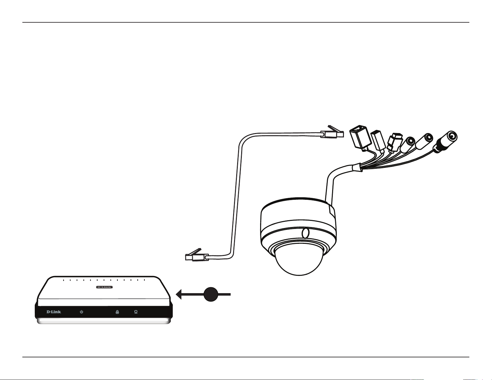
Camera Installation Wizard
Step 1
Connect the network camera to a hub via an Ethernet cable.
Step 2
Connect the supplied power cable from the camera to a power outlet.
General Connection Using 12 V DC Power Adapter
2
1
24D-Link DCS-6314 User Manual
Section 2: Assembly and Installation
Step 1
If you are using a PoE hub, connect the IP camera to the hub via an Ethernet cable, which will provide transmission of both
power and data over a single cable.
Connection Using Power over Ethernet
1
25D-Link DCS-6314 User Manual
Section 2: Assembly and Installation
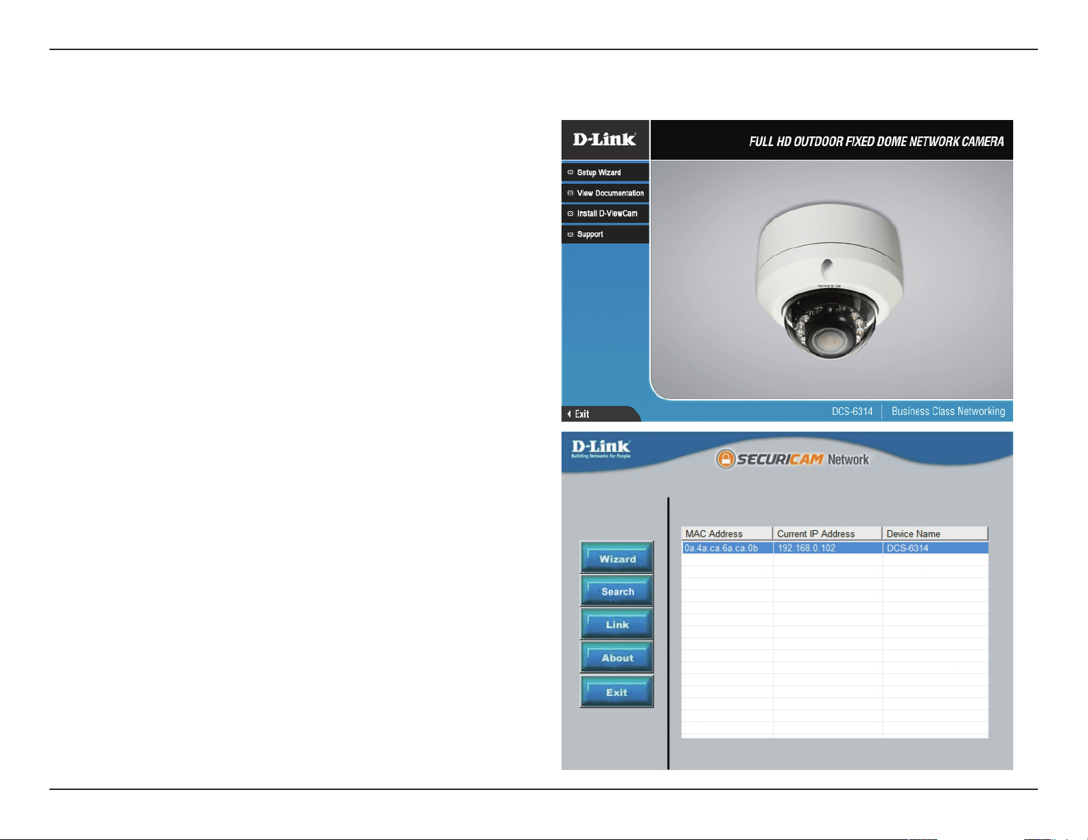
Step 1
Insert the Installation CD-ROM into your computer’s optical
drive to start the autorun program.
The CD-ROM will open the Camera Installation Wizard. The
Setup Wizard will guide you through the installation process
through to conguring your camera.
Note:
If the autorun program does not automatically start on your
computer, go to Windows, click Start > Run. In the Run
command box type D:\setup.exe, where D: represents your
CD-ROM drive.
Step 2
Accept the End User Licence Agreement and follow the on
screen prompts to install the Camera Installation Wizard.
Step 3
Select your camera from the list, then click Wizard. If you
have multiple cameras, you can identify them by the MAC ID
printed on the label on the back of your camera.
Software Installation
26D-Link DCS-6314 User Manual
Section 2: Assembly and Installation
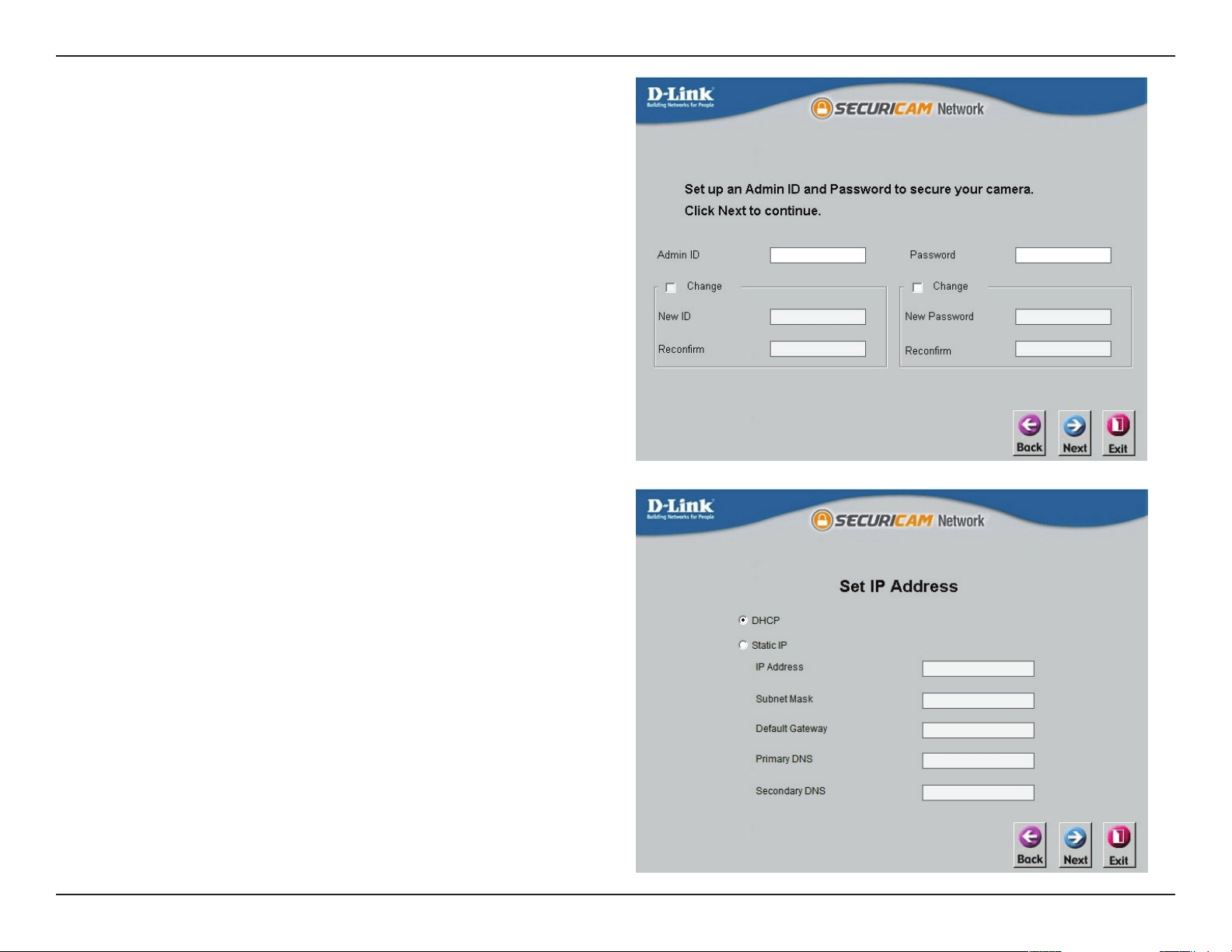
Step 4
By default the Admin ID is "admin" and the password is blank.
It is recommended that you create and conrm a password
for your device.
Click Next to continue.
Step 5
Select Static IP if your Internet Service Provider has provided
you with connection settings, or if you wish to set a static
address within your home network. Enter the correct
conguration information and click Next to continue.
Note: Select DHCP if you are unsure of which settings to
choose.
Click Next to continue.
27D-Link DCS-6314 User Manual
Section 2: Assembly and Installation
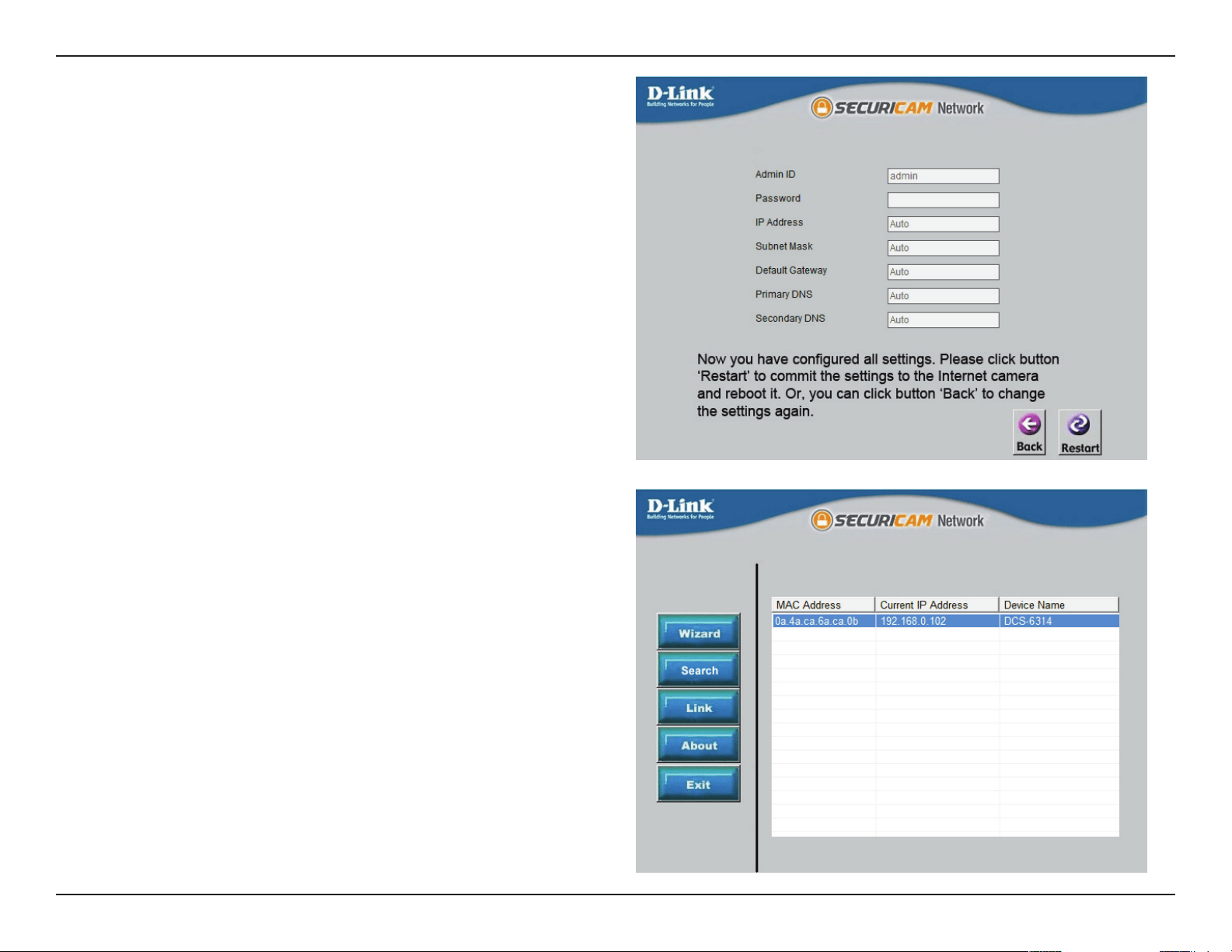
Step 6
Conrm your camera login details and IP address details and
click Restart.
The LED on the front of the DCS-6314 will blink, then turn
solid green once it successfully connects to your network..
Step 7
Your DCS-6314 camera is now set up, Click Exit to exit the
wizard and can skip to "Conguration" on page 30 for advanced
conguration of your camera.
28D-Link DCS-6314 User Manual
Section 2: Assembly and Installation
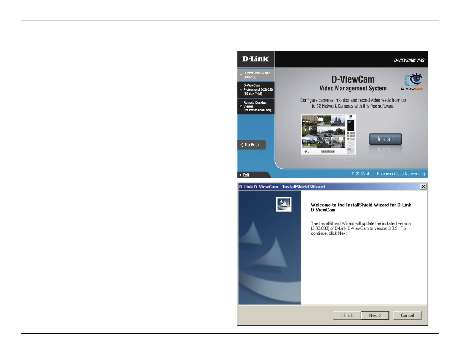
D-ViewCam software is included for the administrator to
manage multiple D-Link IP cameras remotely. You may use
the software to congure all the advanced settings for your
cameras. D-ViewCam is a comprehensive management tool
for IP surveillance.
Step 1
Insert the CD-ROM into the CD-ROM drive. Click "Install
D-ViewCam Software" from menu, and select "D-ViewCam"
to install the VMS software.
Step 2
Follow the Installation Wizard to install D-ViewCam.
D-ViewCam Setup Wizard
29D-Link DCS-6314 User Manual
Section 2: Assembly and Installation
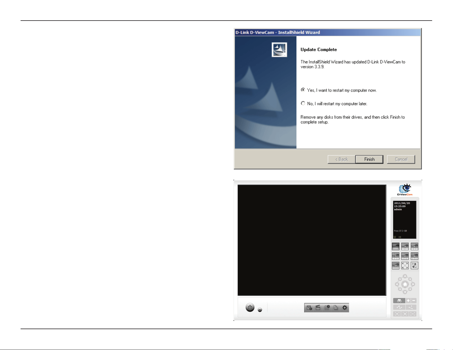
Step 3
Click Finish to complete the installation.
Step 5
For more detail operation of using the D-ViewCam
software, please refer to D-ViewCam Manual.
30D-Link DCS-6314 User Manual
Section 3: Conguration
Conguration
Using the Conguration Interface
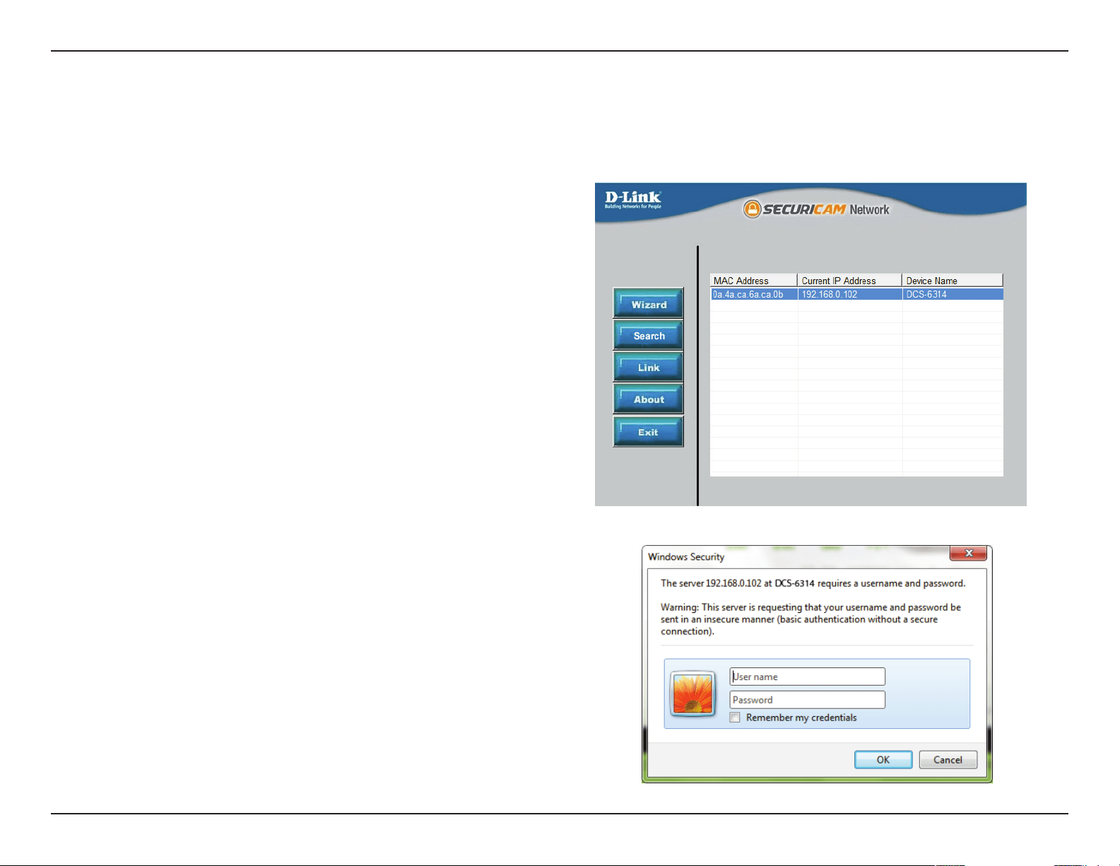
After completing the Camera Installation Wizard, you
are ready to use your camera. The camera’s built-in Web
conguration utility is designed to allow you to easily
access and congure your DCS-6314. At the end of the
wizard, click Link, or enter the IP address of your camera
into a web browser, such as Mozilla Firefox. To log in, use
the User name admin and the password you created in the
Installation Wizard. If you did not create a password, the
default password is blank. After entering your password,
click OK.
Step 1
Click the Link button on the Wizard. The Setup Wizard will
automatically open your web browser to the IP address
ofthe camera.
Step 2
Enter your credentials to access the conguration interface.
2
31D-Link DCS-6314 User Manual
Section 3: Conguration
Live Video
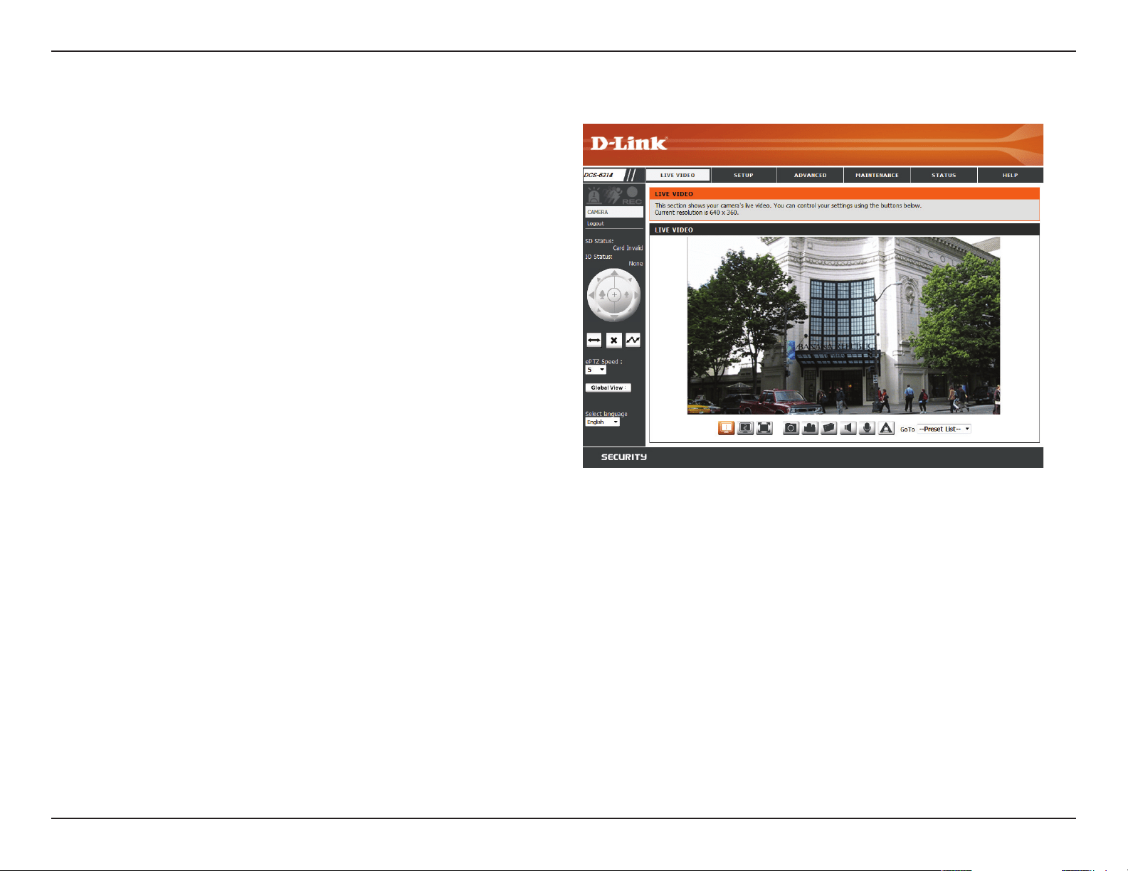
This section shows your camera’s live video. You may select any of
the available icons listed below to operate the camera. You may also
select your language using the drop-down menu on the left side of
the screen.
You can zoom in and out on the live video image using your mouse.
Right-click to zoom out or left-click to zoom in on the image.
This option displays the status of the SD card. If no
SD card has been inserted, this screen will display the
message "Card Invalid."
This option displays the status of your I/O device if a
device has been connected.
You may select a value between 0 and 10. 0 is the
slowest and 10 is the fastest.
This window indicates the total eld of view (FOV) of
the camera. The red box indicates the visible region
of interest (ROI). This option will only be present if the
view window size is set to be smaller than the current
frame size. You can nd more information on how to
set the frame size and view window area in "Audio
and Video" on page 45.
You may select the interface language using this
menu.
If any presets have been dened, selecting a preset
from this list will display it.
SD Status:
IO Status:
ePTZ Speed:
Global View:
Language:
Go To:
(Preset List)
32D-Link DCS-6314 User Manual
Section 3: Conguration
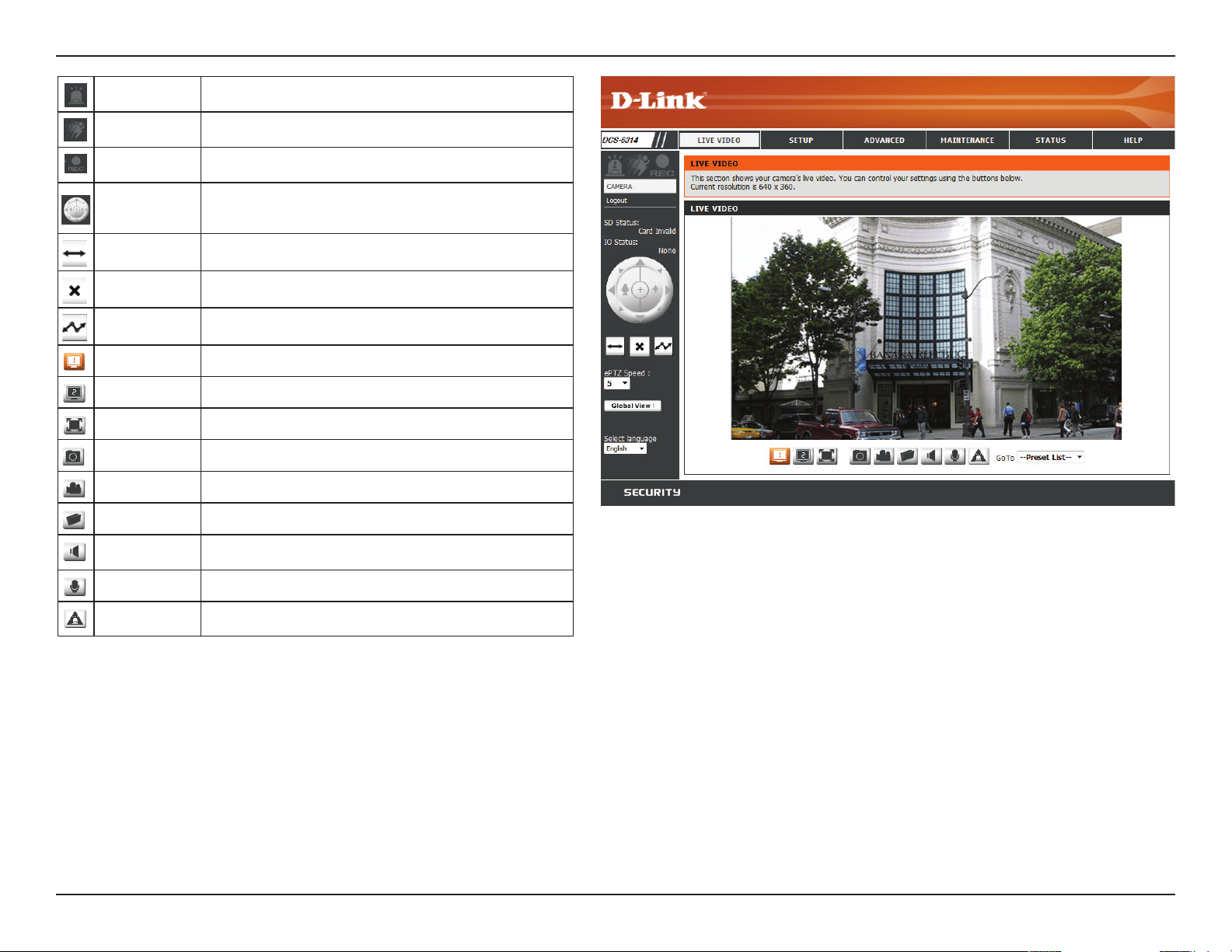
Digital Input
Indicator
This indicator will change color when a digital input signal is
detected.
Motion Trigger
Indicator
This indicator will change color when a trigger event occurs.
Note: The video motion feature must be enabled.
Recording
Indicator
When a recording is in progress, this indicator will change color.
Control Pad This control pad can be used to electronically pan, tilt, and zoom
(ePTZ) within the camera's predened view area, if one has been
dened.
Auto Pan Starts the automatic panning function. The ROI will pan from back
and forth within the FOV
Stop Stops the camera ePTZ motion
Preset Path Starts the camera's motion along the predened path
Video Prole 1 Select's predened settings congured on page 45
Video Prole 2 Select's alternate predened settings congured on page 45
Full Screen Mode
Will enlarge the video stream to use fullscreen
Take a Snapshot Will record the current image
Record Video Clip
Will record a video clip, using predened settings
Set up Storage
Will allow you to select a folder on your computer to save to.
Listen/Stop
Listening
Enable or disable the ability to listen through the built in
microphone.
Talk/Stop Talking
Enable or disable the ability to speak through the built in speaker.
Start/Stop Digital
Output
Enable or disable the ability to use the built in digital in/out port.
33D-Link DCS-6314 User Manual
Section 3: Conguration
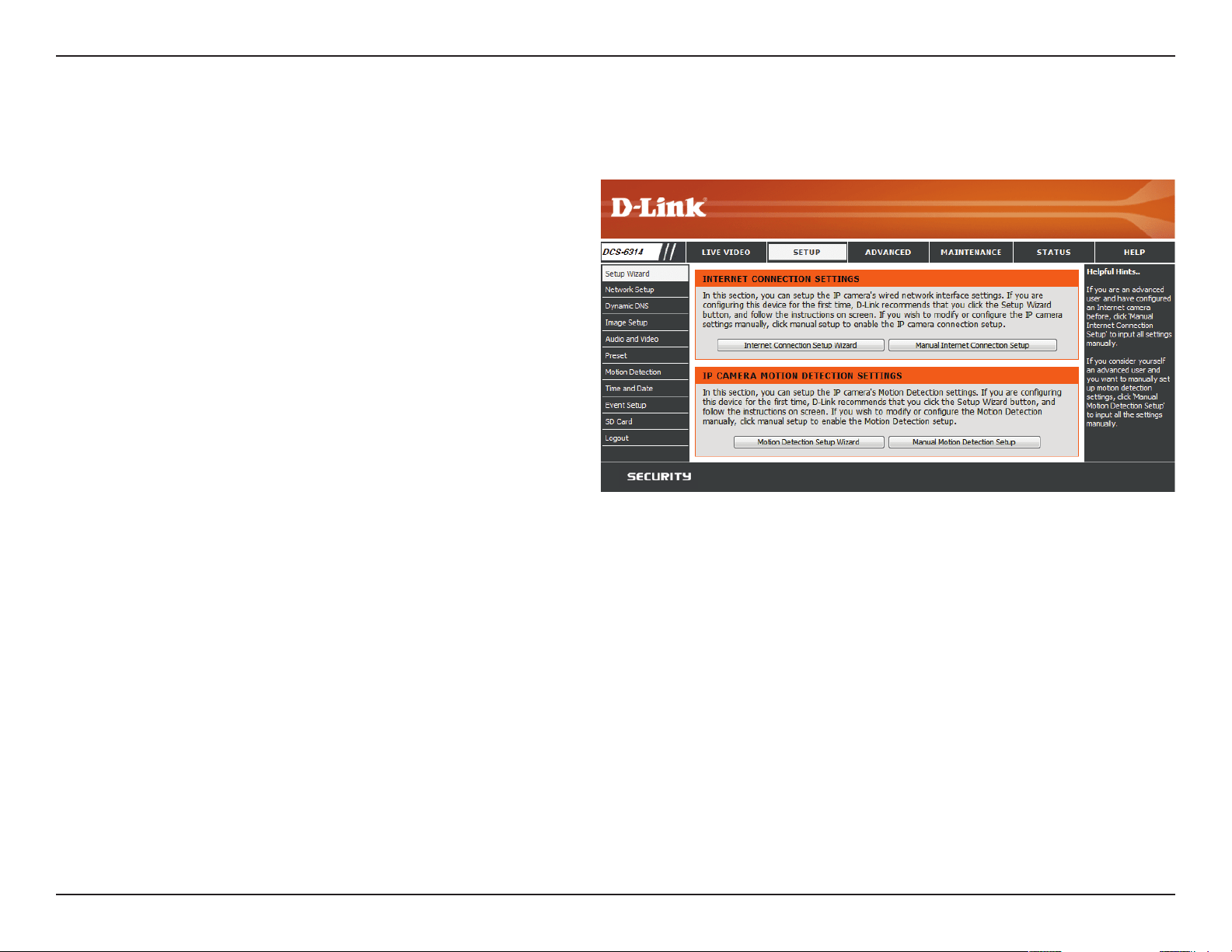
Setup
Setup Wizard
To congure your Network Camera, click Internet Connection Setup
Wizard. Alternatively, you may click Manual Internet Connection
Setup to manually congure your Network Camera and skip to
"Network Setup" on page 39.
To quickly congure your Network Camera’s motion detection
settings, click Motion Detection Setup Wizard. If you want to enter
your settings without running the wizard, click Manual Motion
Detection Setup and skip to"Motion Detection" on page 49.
34D-Link DCS-6314 User Manual
Section 3: Conguration
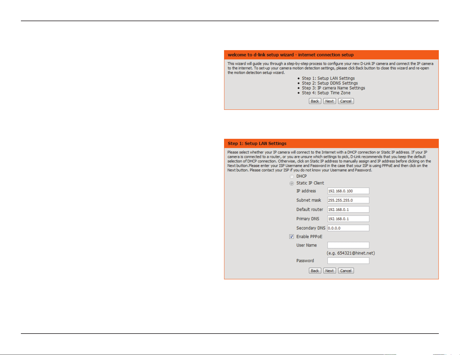
Internet Connection Setup Wizard
This wizard will guide you through a step-by-step process to
congure your new D-Link Camera and connect the camera to the
internet. Click Next to continue.
Note: Select DHCP if you are unsure of which settings to choose.
Select Static IP if your Internet Service Provider has provided you
with connection settings, or if you wish to set a static address within
your home network. Enter the correct conguration information
and click Next to continue.
If you are using PPPoE, select Enable PPPoE and enter your user
name and password, otherwise click Next to continue.

35D-Link DCS-6314 User Manual
Section 3: Conguration
If you have a Dynamic DNS account and would like the camera to
update your IP address automatically, Select Enable DDNS and
enter your host information. Click Next to continue.
Enter a name for your camera and click Next to continue.
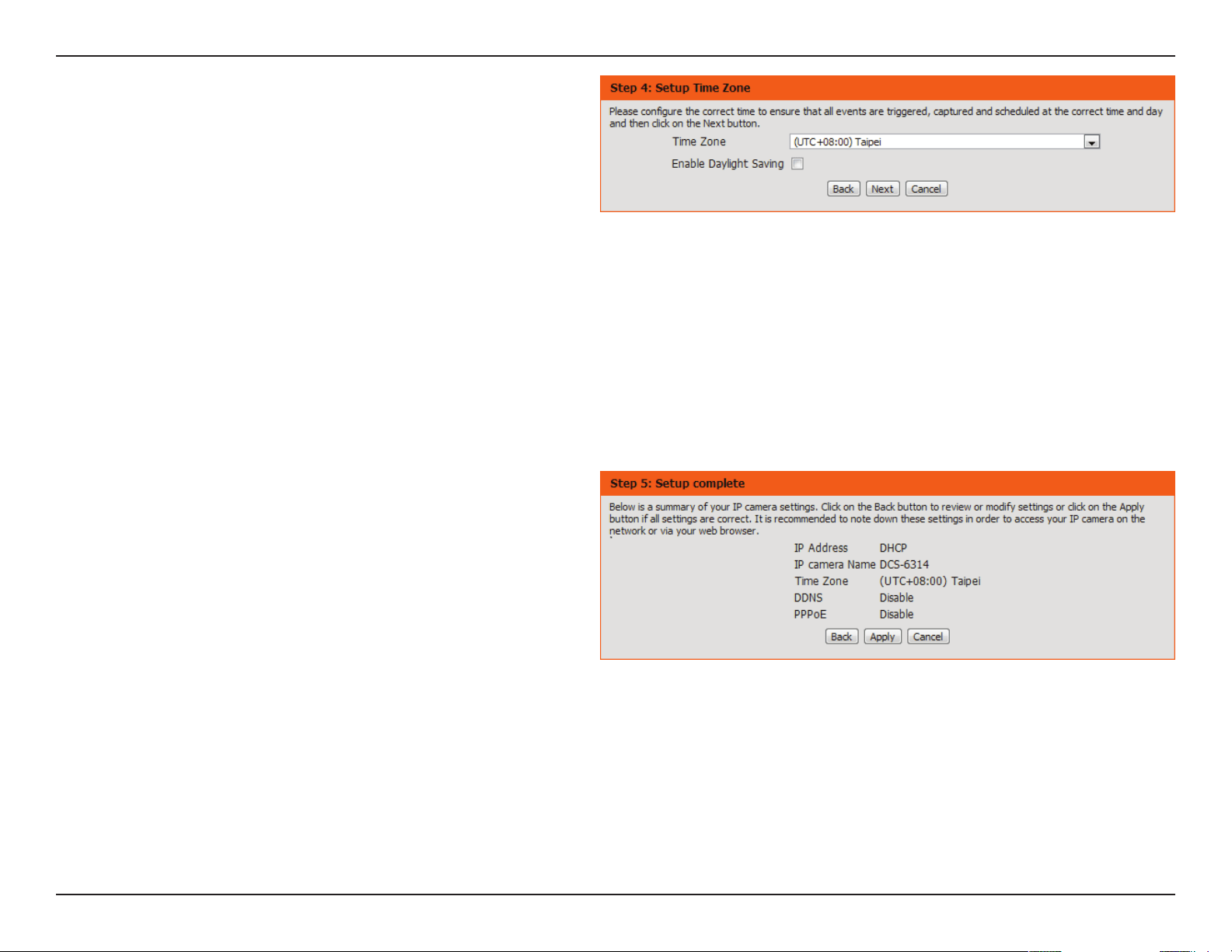
36D-Link DCS-6314 User Manual
Section 3: Conguration
Congure the correct time to ensure that all events will be triggered
as scheduled. Click Next to continue.
Conrm the settings are correct and click Apply to save them.
The settings will be saved to the DCS-6314 and the camera will
restart.

37D-Link DCS-6314 User Manual
Section 3: Conguration
This wizard will guide you through a step-by-step process to
congure your camera's motion detection functions.
Click Next to continue.
Motion Detection Setup Wizard
Step 1
This step will allow you to enable or disable motion detection,
specify the detection sensitivity, and adjust the camera’s ability to
detect movement.
You may specify whether the camera should capture a snapshot or
a video clip when motion is detected.
Please see the Motion Detection section on "Motion Detection" on
page 49 for information about how to congure motion detection.
Step 2
This step allows you to enable motion detection based on a
customized schedule. Specify the day and hours. You may also
choose to always record whenever motion is detected.
This UI element should be inside like the
other steps

38D-Link DCS-6314 User Manual
Section 3: Conguration
Step 3
This step allows you to specify how you will receive event
notications from your camera. You may choose not to receive
notications, or to receive notications via e-mail or FTP.
Please enter the relevant information for your e-mail or FTP
account.
Click Next to continue.
Step 4
You have completed the Motion Detection Wizard.
Please verify your settings and click Apply to save them.
Please wait a few moments while the camera saves your settings
and restarts.
39D-Link DCS-6314 User Manual
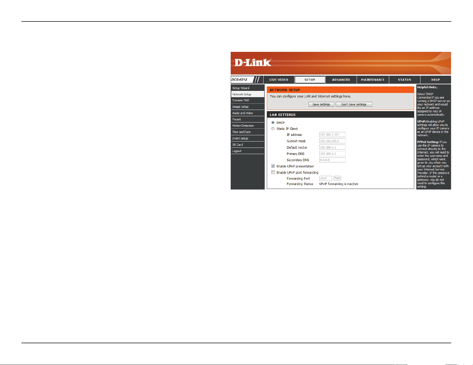
Section 3: Conguration
Network Setup
Use this section to congure the network connections for your
camera. All relevant information must be entered accurately. After
making any changes, click the Save Settings button to save your
changes.
LAN Settings:
DHCP:
Static IP Client:
IP Address:
Subnet Mask:
Default
Gateway:
Primary DNS:
Secondary
DNS:
Enable UPnP
Presentation:
Enable
UPnP Port
Forwarding:
This section lets you congure settings for your
local area network.
Select this connection if you have a DHCP server
running on your network and would like your
camera to obtain an IP address automatically.
You may obtain a static or xed IP address and
other network information from your network
administrator for your camera.
Enter the xed IP address in this eld.
This number is used to determine if the destination is
in the same subnet. The default value is 255.255.255.0.
The gateway used to forward frames to destinations
in a dierent subnet. Invalid gateway settings may
cause the failure of transmissions to a dierent
subnet.
The primary domain name server translates names
to IP addresses.
The secondary DNS acts as a backup to the primary.
Enabling this setting allows your camera to be
congured as a UPnP device on your network.
Enabling this setting allows the camera to add port
forwarding entries into the router automatically on
a UPnP capable network.
40D-Link DCS-6314 User Manual
Section 3: Conguration
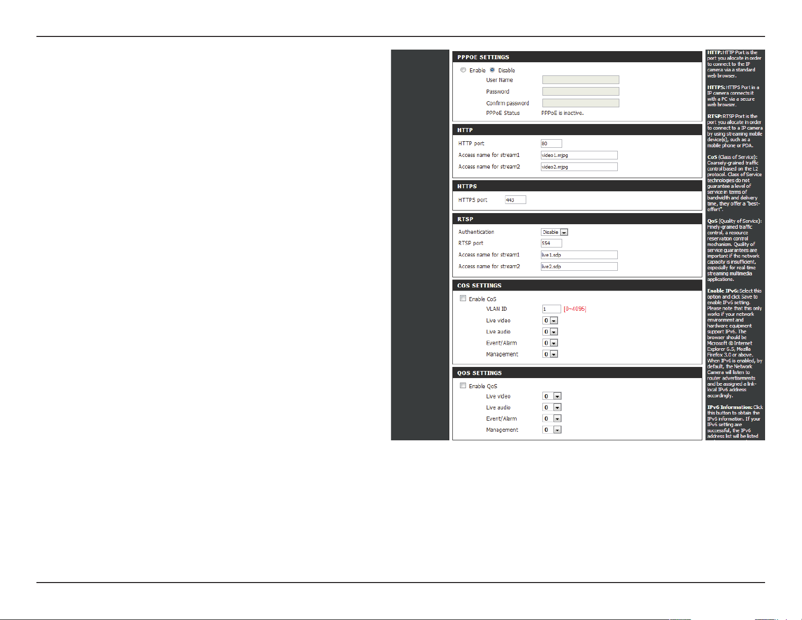
Enable PPPoE:
User Name /
Password:
HTTP Port:
Access Name
for Stream 1~3:
HTTPS Port:
Authentication:
RTSP Port:
Enable CoS:
Enable QoS:
Enable this setting if your network uses PPPoE.
Enter the username and password for your PPPoE
account. Re-enter your password in the Conrm
Password eld. You may obtain this information
from your ISP.
The default port number is 80.
The default name is video#.mjpg, where # is the
number of the stream.
You may use a PC with a secure browser to connect
to the HTTPS port of the camera. The default port
number is 443.
Choose to enable or disable RTSP digest encryption.
Digest encryption uses MD5 hashes.
The port number that you use for RTSP streaming
to mobile devices, such as mobile phones or PDAs.
The default port number is 554. You may specify
the address of a particular stream. For instance,
live1.sdp can be accessed at rtsp://x.x.x.x/video1.
sdp where the x.x.x.x represents the ip address of
your camera.
Enabling the Class of Service setting implements a
best-eort policy without making any bandwidth
reservations.
Enabling QoS allows you to specify a trac priority
policy to ensure a consistent Quality of Service
during busy periods. If the Network Camera is
connected to a router that itself implements QoS,
the router's settings will override the QoS settings
of the camera.
41D-Link DCS-6314 User Manual
Section 3: Conguration
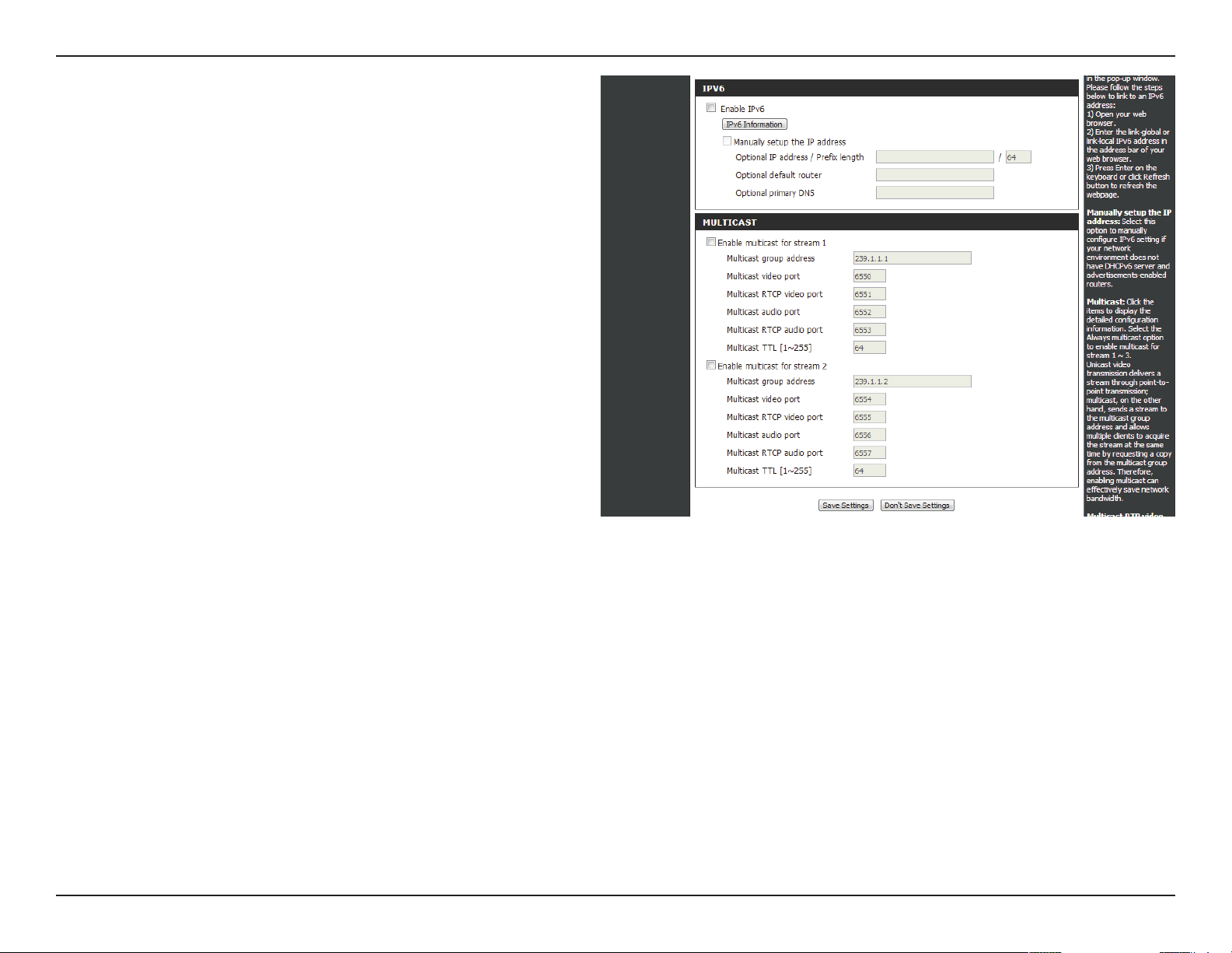
Enable IPv6:
Enable
Multicast for
stream:
Enable the IPv6 setting to use the IPv6 protocol.
Enabling the option allows you to manually set up
the address, specify an optional IP address, specify
an optional router and an optional primary DNS.
The DCS-6314 allows you to multicast each of the
available streams via group address and specify the
TTL value for each stream. Enter the port and TTL
settings you wish to use if you do not want to use
the defaults.
After making any changes, click the Save Settings
button to save your changes.
42D-Link DCS-6314 User Manual
Section 3: Conguration
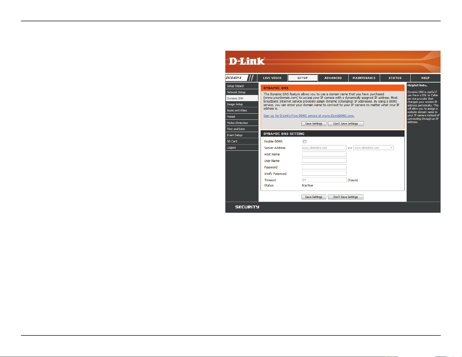
Dynamic DNS
DDNS (Dynamic Domain Name Server) will hold a DNS host name
and synchronize the public IP address of the modem when it has
been modied. A user name and password are required when using
the DDNS service. After making any changes, click the Save Settings
button to save your changes.
Enable DDNS:
Server Address:
Host Name:
User Name:
Password:
Timeout:
Status:
Select this checkbox to enable the DDNS
function.
Select your Dynamic DNS provider from the pull
down menu or enter the server address manually.
Enter the host name of the DDNS server.
Enter the user name or e-mail used to connect to
your DDNS account.
Enter the password used to connect to your
DDNS server account.
Enter the DNS timeout values you wish to use.
Indicates the connection status, which is
automatically determined by the system.
43D-Link DCS-6314 User Manual
Section 3: Conguration
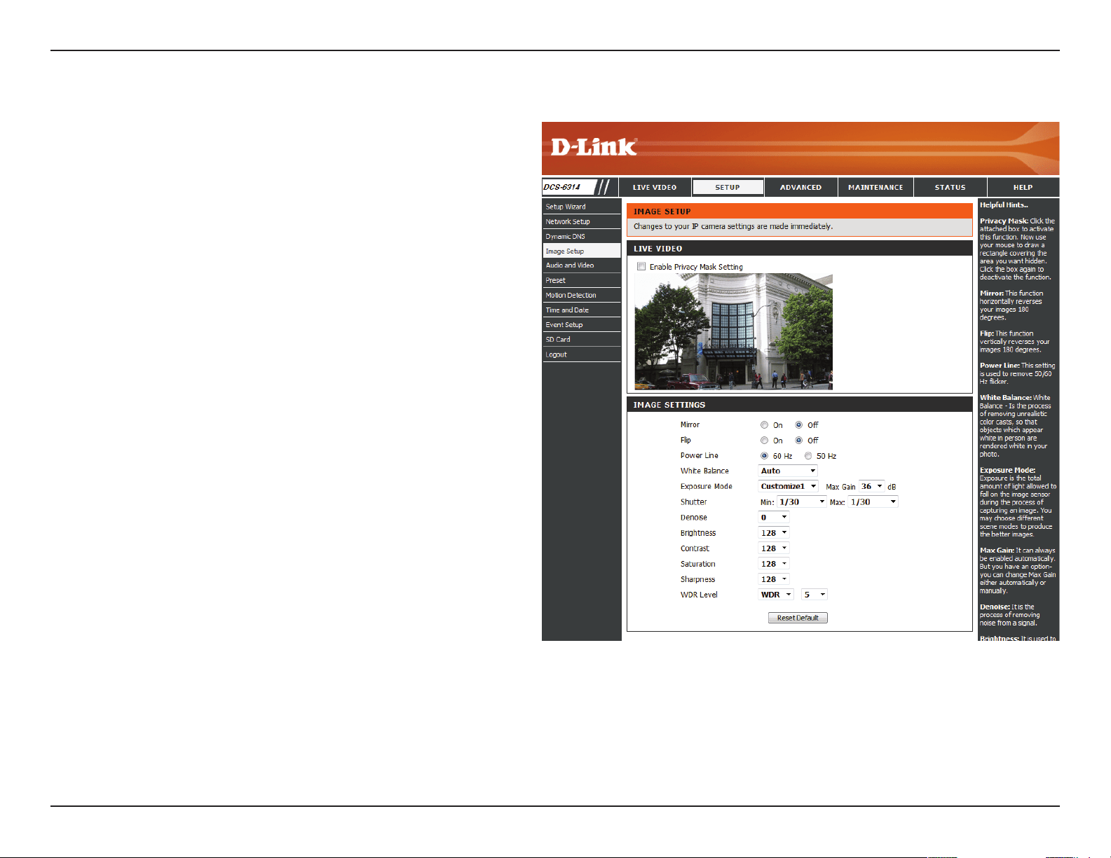
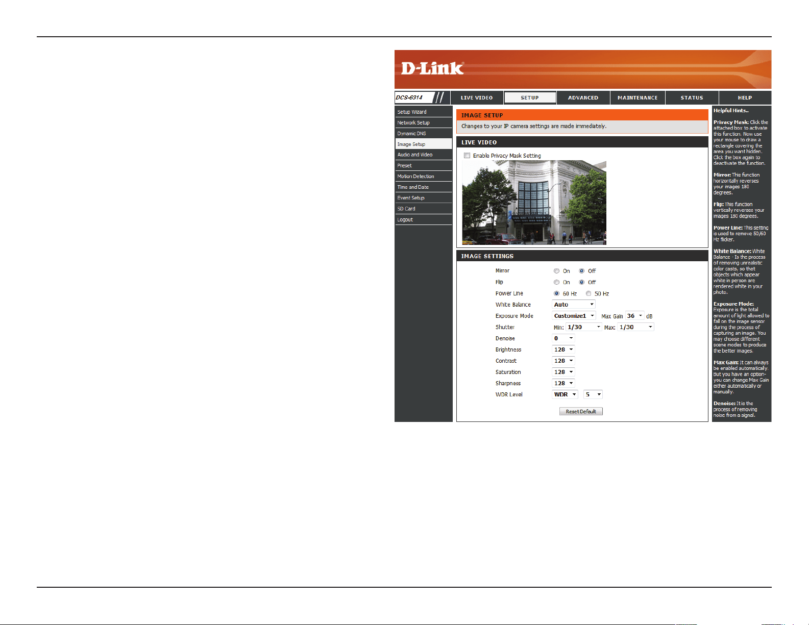
Image Setup
In this section, you may congure the video image settings for
your camera. A preview of the image will be shown in Live Video.
Enable Privacy
Mask:
Mirror:
Flip:
Power Line:
White Balance:
The Privacy Mask setting allows you to specify
up to 3 rectangular areas on the camera's image
to be blocked/excluded from recordings and
snapshots.
You may click and drag the mouse cursor over
the camera image to draw a mask area. Right
clicking on the camera image brings up the
following menu options:
Disable All: Disables all mask areas
Enable All: Enables all mask areas
Reset All: Clears all mask areas.
This will mirror the image horizontally.
This will ip the image vertically. When turning
Flip on, you may want to consider turning Mirror
on as well.
Select the frequency used by your power lines to
avoid interference or distortion.
Use the drop-down box to change white balance
settings to help balance colors for dierent
environments. You can choose from Auto,
Outdoor, Indoor, Fluorescent, and Push Hold.
Changes the exposure mode. Use the drop-down
44D-Link DCS-6314 User Manual
Section 3: Conguration
Exposure
Mode:
Denoise:
Brightness:
Contrast:
Saturation:
Sharpness:
WDR Level:
Reset Default:
box to set the camera for Indoor, Outdoor, or
Night environments, or to Moving to capture
moving objects. The Low Noise option will focus
on creating a high-quality picture without noise.
You can also create 3 dierent custom exposure
modes. The Max Gain setting will allow you to
control the maximum amount of gain to apply to
brighten the picture.
This setting controls the amount of noise
reduction that will be applied to the picture.
Adjust this setting to compensate for backlit
subjects.
Adjust this setting to alter the color intensity/
strength.
This setting controls the amount of coloration,
from grayscale to fully saturated.
Specify a value from 0 to 128 to specify how
much sharpening to apply to the image.
Specify a value from 0 to 10 to specify how much
WDR to apply to the image, or select None.
Click this button to reset the image to factory
default settings.
45D-Link DCS-6314 User Manual
Section 3: Conguration
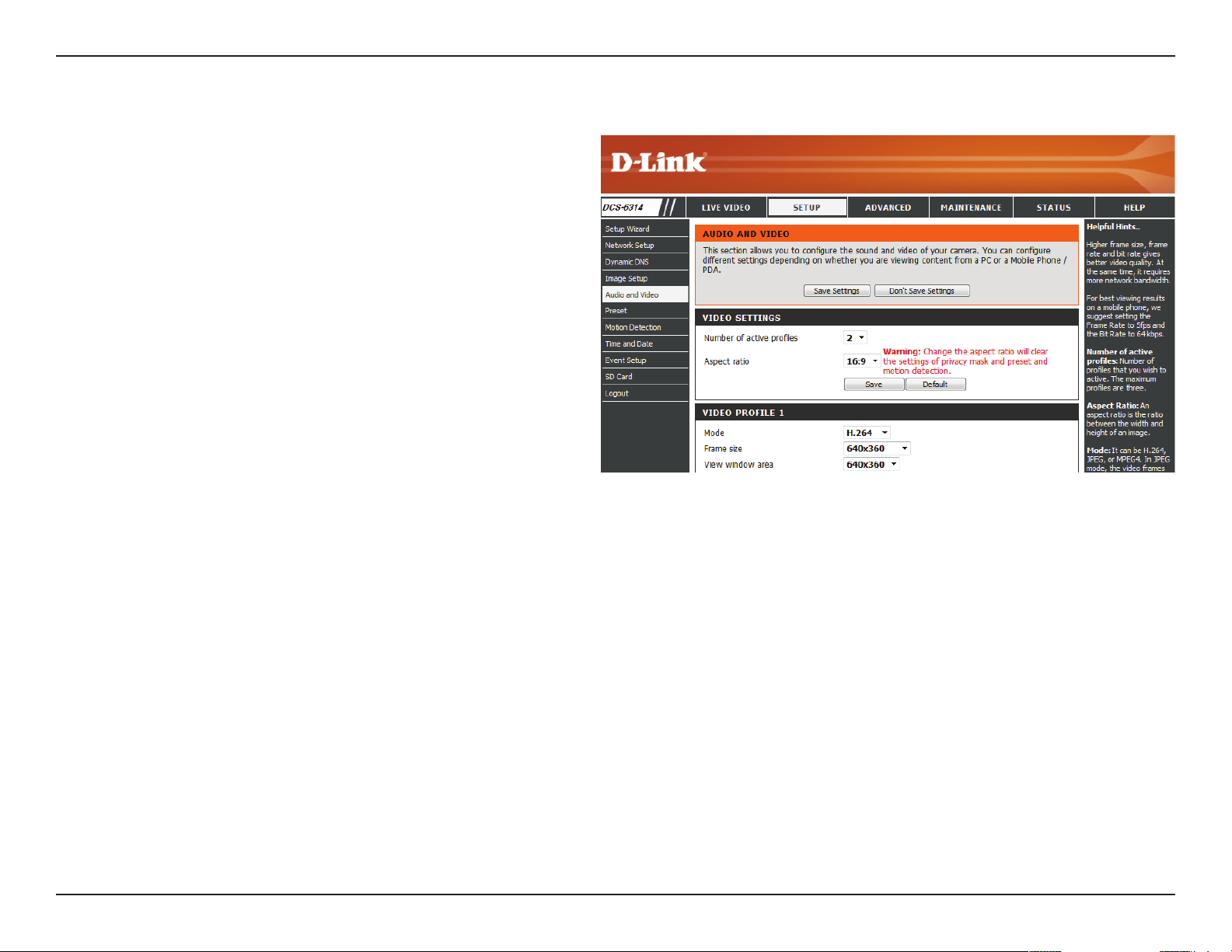
Audio and Video
You may congure up to 3 video proles with dierent settings
for your camera. Hence, you may set up dierent proles for your
computer and mobile display. In addition, you may also congure
the two-way audio settings for your camera. After making any
changes, click the Save Settings button to save your changes.
Aspect ratio:
Mode:
Frame size /
View window
area:
Set the aspect ratio of the video to 4:3 standard or
16:9 widescreen.
Set the video codec to be used to JPEG, MPEG-4, or
H.264.
The eld of view for the DCS-6314 is xed based on
its mounted orientation. The ePTZ function requires
that the frame size is larger than the view window
area in order to allow the user to pan, tilt, and zoom
within the image. The frame size determines the
actual image size that is captured by the DCS-6314.
The view window area can be set to a smaller area in
order to help focus in on certain parts of the larger
frame size that is captured. If you want to use the
ePTZ or Global View function on the Live View page,
the frame size should always be set larger than the
view window size when setting video proles.
16:9 1920 x 1080, 1280 x 720, 800 x 450,
640 x 360, 480 x 270, 320 x 176, 176 x
144 up to 30 fps
4:3 1440 x 1080, 1280 x 960, 1024 x 768,
800 x 600, 640 x 480, 320 x 240, 176 x
144 up to 30 fps
Note: If your View window area is the same as your
Frame size, you will not be able to use the ePTZ
function.
46D-Link DCS-6314 User Manual
Section 3: Conguration
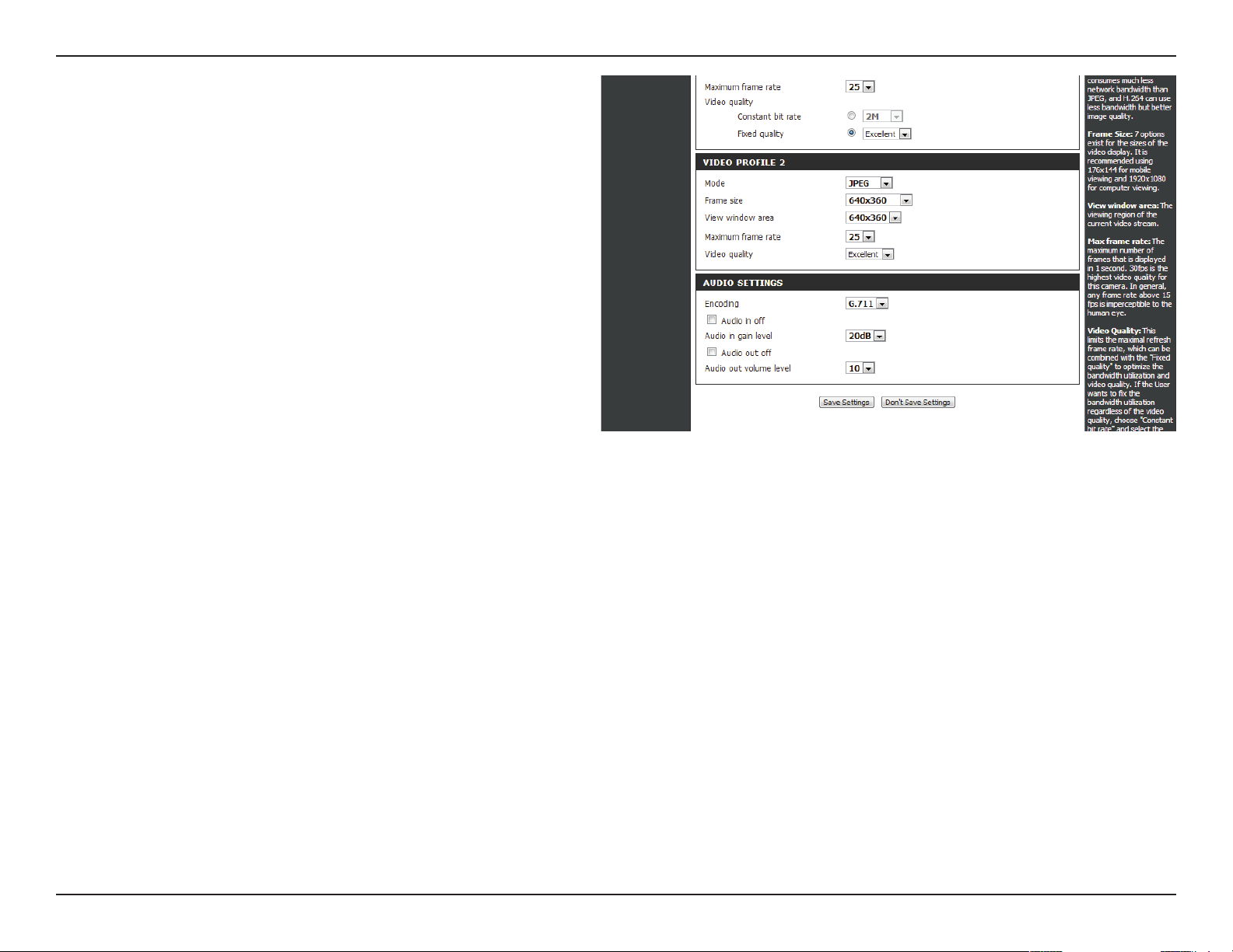
Maximum
frame rate:
Video Quality:
Constant bit
rate:
Fixed quality:
Audio in o:
Audio in gain
level:
Audio out o:
Audio out
volume level:
A higher frame rate provides smoother motion
for videos, and requires more bandwidth. Lower
frame rates will result in stuttering motion, and
requires less bandwidth.
This limits the maximum frame rate, which can
be combined with the "Fixed quality" option to
optimize the bandwidth utilization and video
quality. If xed bandwidth utilization is desired
regardless of the video quality, choose "Constant
bit rate" and select the desired bandwidth.
The bps will aect the bit rate of the video
recorded by the camera. Higher bit rates result in
higher video quality.
Select the image quality level for the camera to
try to maintain. High quality levels will result in
increased bit rates.
Selecting this checkbox will mute incoming audio.
This setting controls the amount of gain applied
to incoming audio to increase its volume.
Selecting this checkbox will mute outgoing audio.
This setting controls the amount of gain applied
to outgoing audio to increase its volume.
47D-Link DCS-6314 User Manual
Section 3: Conguration
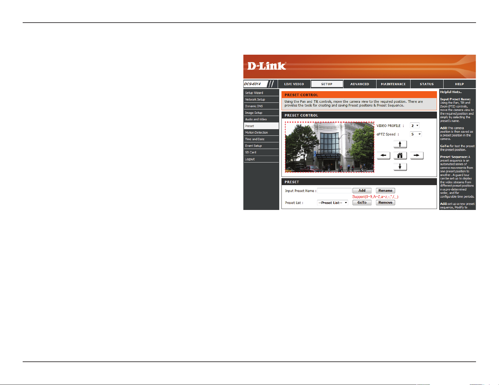
Preset
This screen allows you to set preset points for the ePTZ function of
the camera, which allows you to look around the camera's viewable
area by using a zoomed view. Presets allow you to quickly go to and
view a specic part of the area your camera is covering, and you
can create preset sequences, which will automatically change the
camera's view between the dierent presets according to a dened
order and timing you can set.
Note: If your View window area is the same as your Frame size, you
will not be able to use the ePTZ function.
Video Prole:
ePTZ Speed:
Arrow Buttons
and Home
Button:
Input Preset
Name:
Preset List:
This selects which video prole to use.
You may select a value between 0 and 10. 0 is the
slowest and 10 is the fastest.
Use these buttons to move to a specic part of the
viewing area, which you can then set as a preset.
Click the Home button to return to the center of
the viewing area.
Enter the name of the preset you want to create,
then click the Add button to make a new preset.
If an existing preset has been selected from the
Preset List, you can change its name by typing in a
new name, then clicking the Rename button.
Click this drop-down box to see a list of all the
presets that have been created. You can select
one, then click the GoTo button to change the
displayed camera view to the preset. Clicking the
Remove button will delete the currently selected
preset.
48D-Link DCS-6314 User Manual
Section 3: Conguration
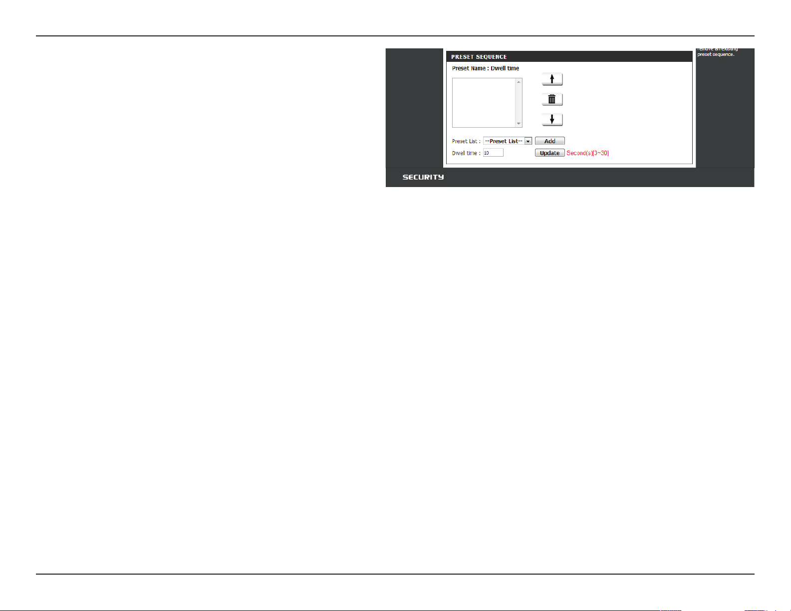
Preset
Sequence:
Preset List:
This section allows you to create a preset sequence,
which automatically moves the camera's view
between a set of preset views.
To add a preset to the sequence, select it from the
drop-down box at the bottom of this window, set
the Dwell time to determine how long the camera
view will stay at that preset, then click the Add
button. The preset name will appear in the list,
followed by the dwell time to view that preset for.
You can rearrange your presets in the sequence by
selecting a preset in the sequence, then clicking
the arrow buttons to move it higher or lower in
the current sequence.
Clicking the trash can button will remove the
currently selected preset from the sequence.
If you want to change the dwell time for a preset,
select it from the list, enter a new dwell time, then
click the Update button.
49D-Link DCS-6314 User Manual
Section 3: Conguration
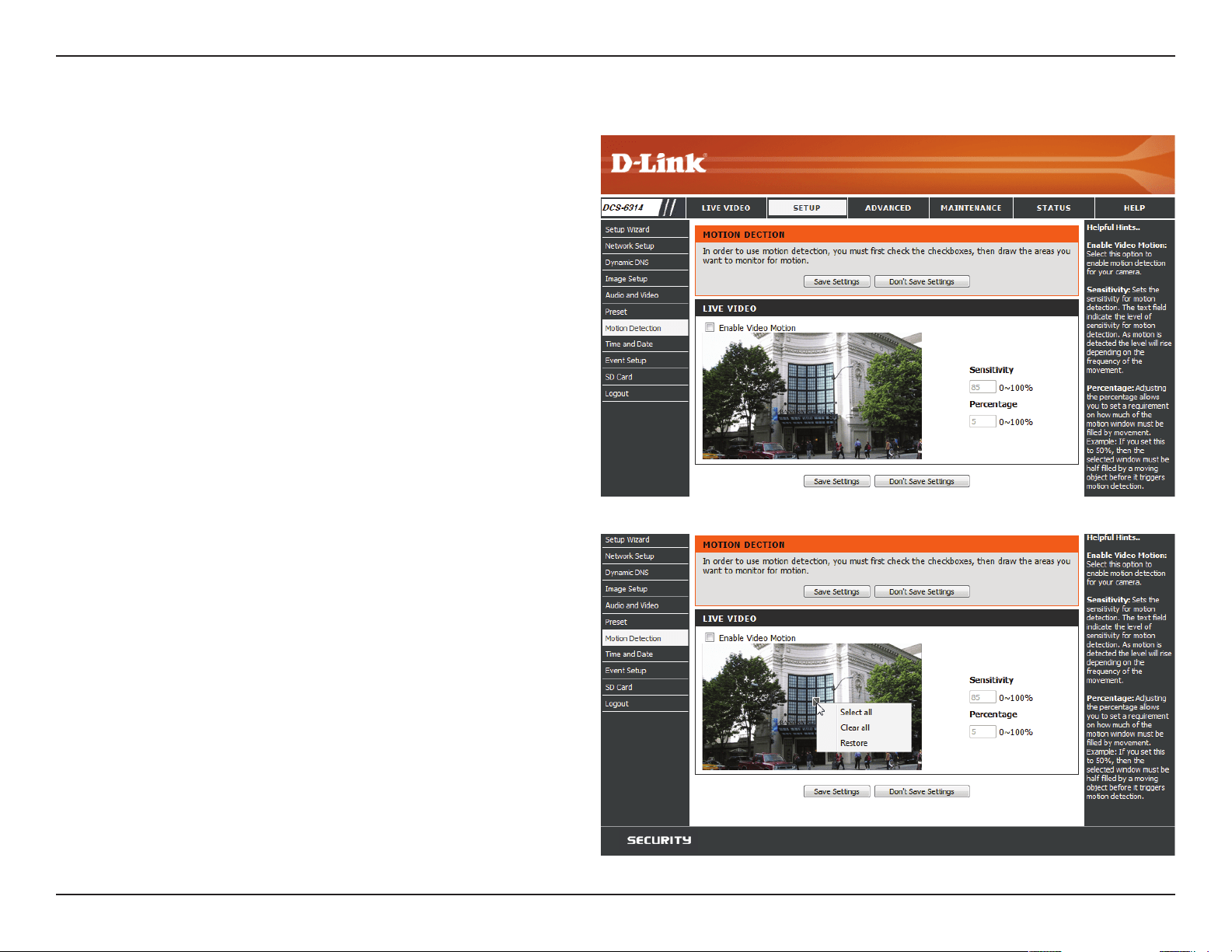
Motion Detection
Enabling Video Motion will allow your camera to use the motion
detection feature. You may draw a nite motion area that will be
used for monitoring. After making any changes, click the Save
Settings button to save your changes.
Enable Video
Motion:
Sensitivity:
Percentage:
Draw Motion
Area:
Erase Motion
Area:
Select this box to enable the motion detection
feature of your camera.
Species the measurable dierence between two
sequential images that would indicate motion.
Please enter a value between 0 and 100.
Species the amount of motion in the window
being monitored that is required to initiate an
alert. If this is set to 100%, motion is detected
within the whole window will trigger a snapshot.
Draw the motion detection area by dragging
your mouse in the window (indicated by the red
square).
To erase a motion detection area, simply click on
the red square that you wish to remove.
Right clicking on the camera image brings up the
following menu options:
Select All: Draws a motion detection area over
the entire screen.
Clear All: Clears any motion detection areas
that have been drawn.
Restore: Restores the previously specied
motion detection areas.
50D-Link DCS-6314 User Manual
Section 3: Conguration
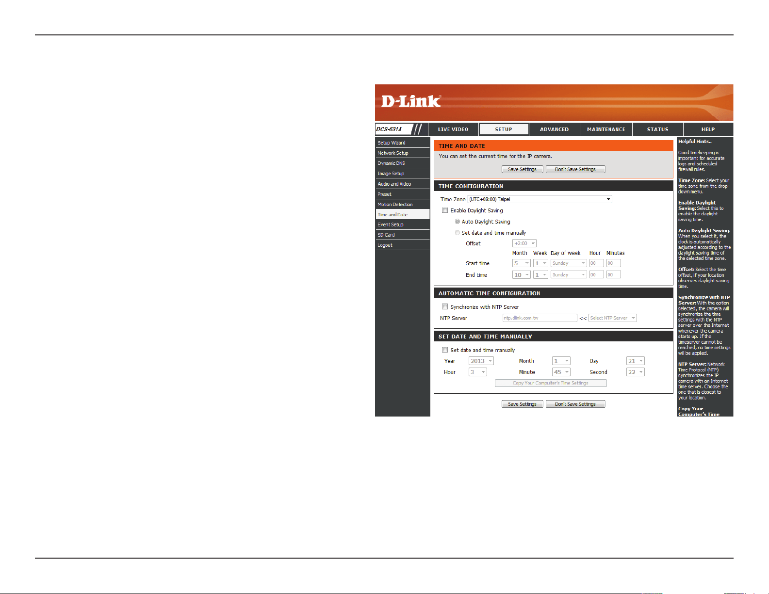
Time and Date
This section allows you to automatically or manually congure,
update, and maintain the internal system clock for your camera.
After making any changes, click the Save Settings button to save
your changes.
Time Zone:
Enable
Daylight
Saving:
Auto Daylight
Saving:
Set Date and
Time Manually:
Oset:
Synchronize
with NTP
Server:
NTP Server:
Set the Date
and Time
Manually:
Copy Your
Computer's
Time Settings:
Select your time zone from the drop-down menu.
Select this to enable Daylight Saving Time.
Select this option to allow your camera to congure
the Daylight Saving settings automatically.
Selecting this option allows you to congure the
Daylight Saving date and time manually.
Sets the amount of time to be added or removed
when Daylight Saving is enabled.
Enable this feature to obtain time automatically
from an NTP server.
Network Time Protocol (NTP) synchronizes the
DCS-6314 with an Internet time server.
Choose the one that is closest to your location.
This option allows you to set the time and date
manually.
This will synchronize the time information from
your PC.
51D-Link DCS-6314 User Manual
Section 3: Conguration
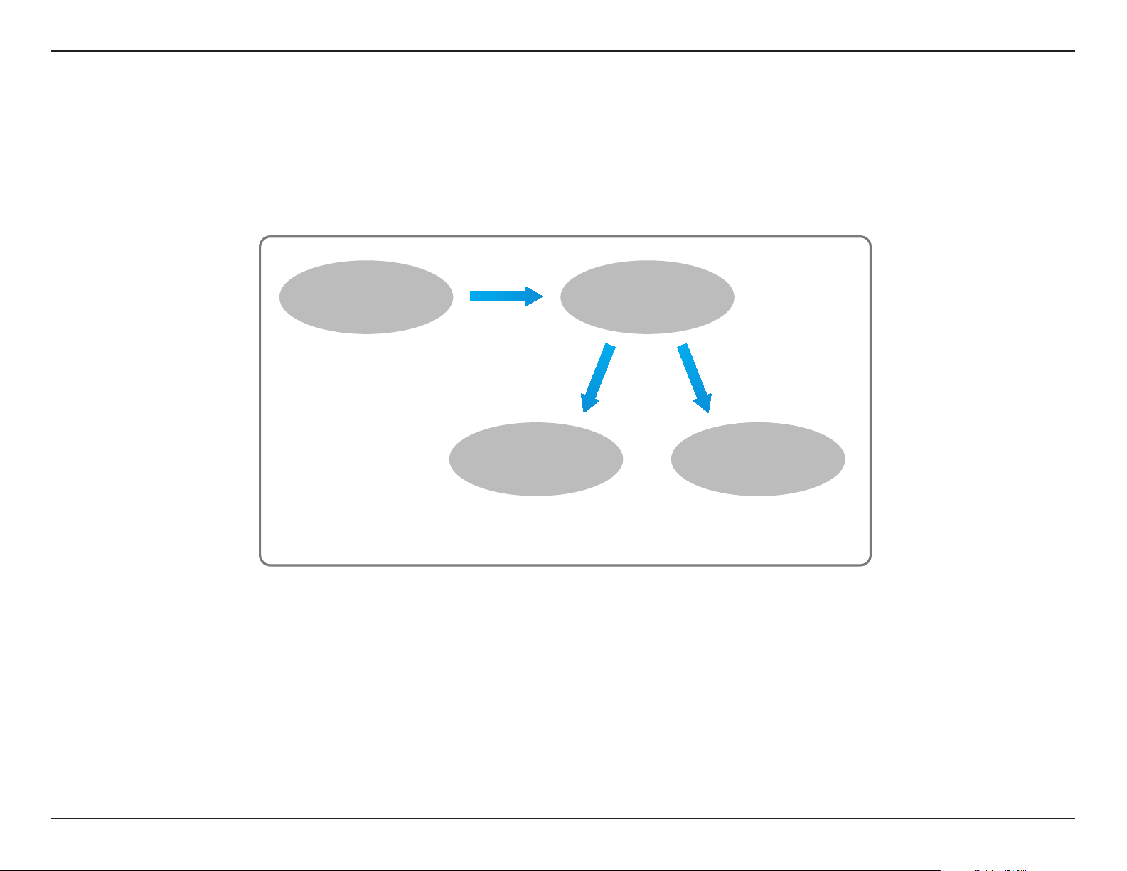
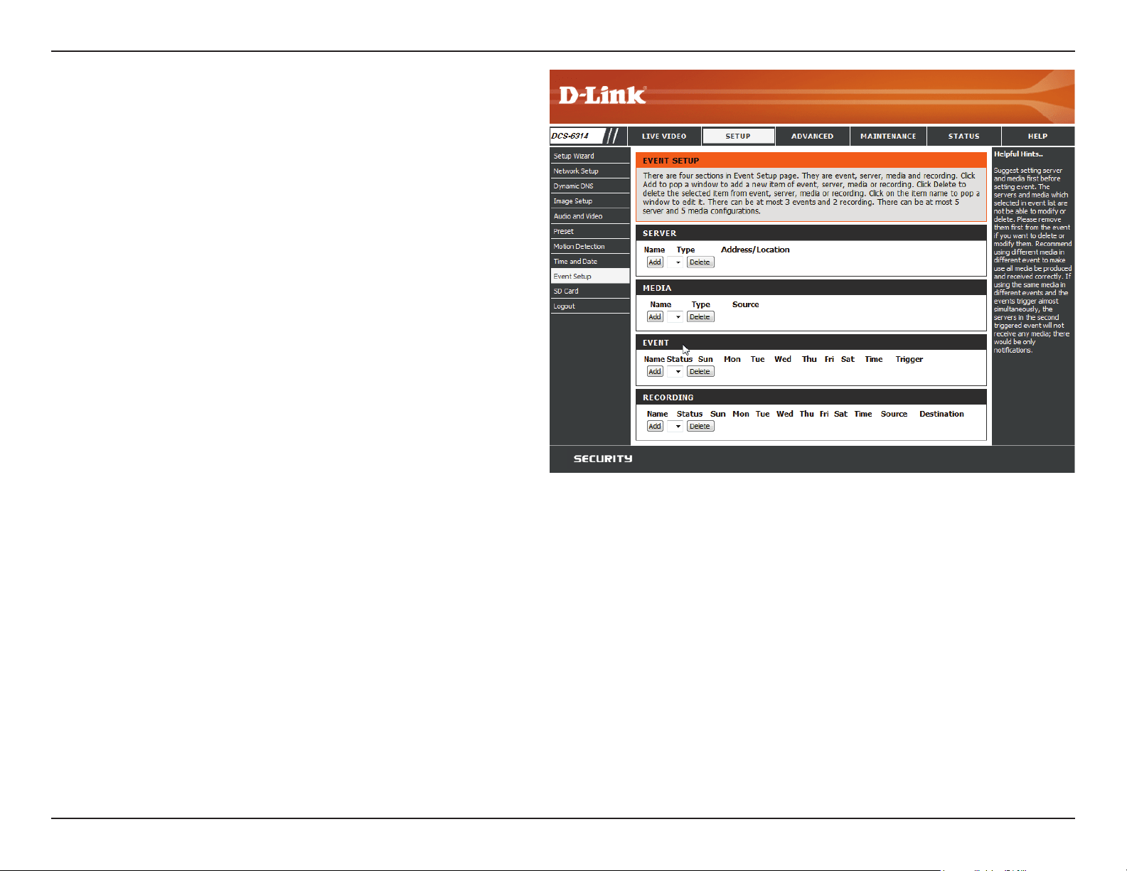
Event Setup
In a typical application, when motion is detected, the DCS-6314 sends images to a FTP server or via e-mail as notications. As shown in the
illustration below, an event can be triggered by many sources, such as motion detection. When an event is triggered, a specied action will be
performed. You can congure the Network Camera to send snapshots or videos to your e-mail address or FTP site.
To start plotting an event, it is suggested to congure server and media columns rst so that the Network Camera will know what action shall be
performed when a trigger is activated.
ex.
Motion detection,
Periodically, Digital input,
System reboot
Event Condition
ex.
Snapshot, Video Clips
ex.
Email, FTP
Media
(what to send)
Server
(where to send)
Action
52D-Link DCS-6314 User Manual
Section 3: Conguration
The Event Setup page includes 4 dierent sections.
• Server
• Media
• Event
• Recording
1. To add a new item - "event, server or media," click Add. A screen
will appear and allow you to update the elds accordingly.
2. To delete the selected item from the pull-down menu of event,
server or media, click Delete.
3. Click on the item name to pop up a window for modifying.
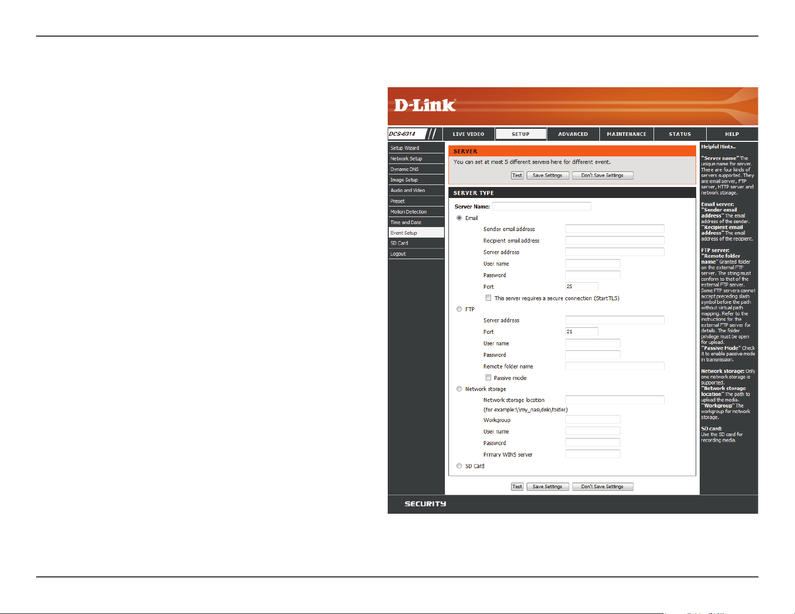
53D-Link DCS-6314 User Manual
Section 3: Conguration
Add Server
Server Name:
E-mail:
FTP:
Network
Storage:
SD Card:
Enter the unique name of your server.
Enter the conguration for the target e-mail server
account.
Enter the conguration for the target FTP server
account.
Specify a network storage device. Only one
network storage device is supported.
Use the camera's onboard SD card storage.
You can congure up to 5 servers to save snapshots and/or video
to. After making any changes, click the Save Settings button to save
your changes.
54D-Link DCS-6314 User Manual
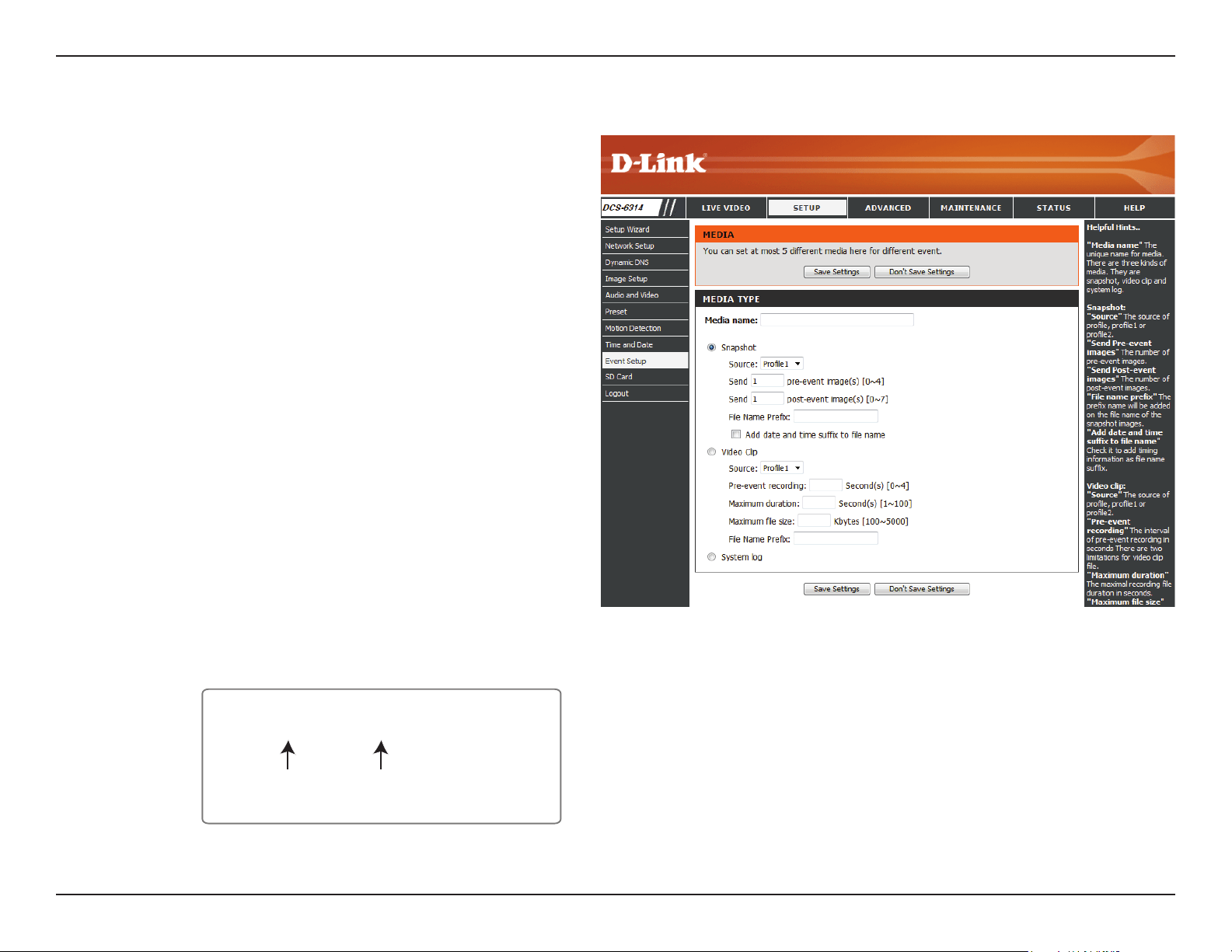
Section 3: Conguration
Add Media
Media Name:
Snapshot:
Source:
Send pre-
event image(s)
[0~4]:
Send post-
event image(s)
[0~7]:
File name
prex:
Enter a unique name for media type you want to
create.
Select this option to set the media type to
snapshots.
Set the video prole to use as the media source.
Refer to Audio and Video on "Audio and Video" on
page 45 for more information on video proles.
Set the number of pre-event images to take. Pre-
event images are images taken before the main
event snapshot is taken.
Set the number of post-event images to take.
Post-event images are images taken after the
main event snapshot is taken. You can set up to 7
post-event images to be taken.
The prex name will be added on the le name.
SNAPSHOTS20080104_100341
Date and time suffix
The format is: YYYYMMDD_HHMMSS
File name prefix
There are three types of media, Snapshot, Video Clip, and System
Log. After making any changes, click the Save Settings button to
save your changes.

55D-Link DCS-6314 User Manual
Section 3: Conguration
Add date and
time sux to
le name:
Video clip:
Source:
Pre-event
recording:
Maximum
duration:
Maximum le
size:
System log:
Check this to add timing information as le name sux. Please see the previous page for an example on how the le name will be
determined if this option is enabled.
Select this option to set the media type to video clips.
Set the video prole to use as the media source. Refer to "Audio and Video" on page 45 for more information on video proles.
This sets how many seconds to record before the main event video clip starts. You can record up to 4 seconds of pre-event video.
Set the maximum length of video to record for your video clips.
Set the maximum le size to record for your video clips.
Select this option to set the media type to system logs. This will save the event to the camera system log, but will not record any
snapshots or video.
56D-Link DCS-6314 User Manual
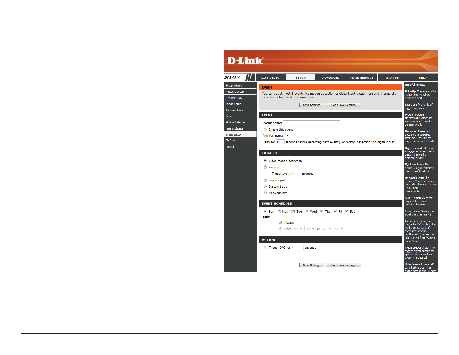
Section 3: Conguration
Add Event
Create and schedule up to 3 events with their own settings here.
After making any changes, click the Save Settings button to save
your changes.
Event name:
Enable this
event:
Priority:
Delay:
Video Motion
Detection:
Periodic:
Digital Input:
System Boot:
Network Lost:
Time:
Trigger D/O:
Enter a name for the event.
Select this box to activate this event.
Set the priority for this event. The event with
higher priority will be executed rst.
Select the delay time before checking the next
event. It is being used for both events of motion
detection and digital input trigger.
Motion is detected during live video monitoring.
Select the windows that need to be monitored.
The event is triggered in specied intervals. The
trigger interval unit is in minutes.
The external trigger input to the camera.
Triggers an event when the system boots up.
Triggers an event when the network connection
is lost.
Select Always or enter the time interval.
Specify the amount of time in seconds if an event
is triggered

57D-Link DCS-6314 User Manual
Section 3: Conguration
Add Recording
Recording
entry name:
Enable this
recording:
Priority:
Source:
Recording
schedule:
The unique name of the entry.
Select this to enable the recording function.
Set the priority for this entry. The entry with a
higher priority value will be executed rst.
The source of the stream.
Scheduling the recording entry.
Here you can congure and schedule the recording settings. After
making any changes, click the Save Settings button to save your
changes.
58D-Link DCS-6314 User Manual
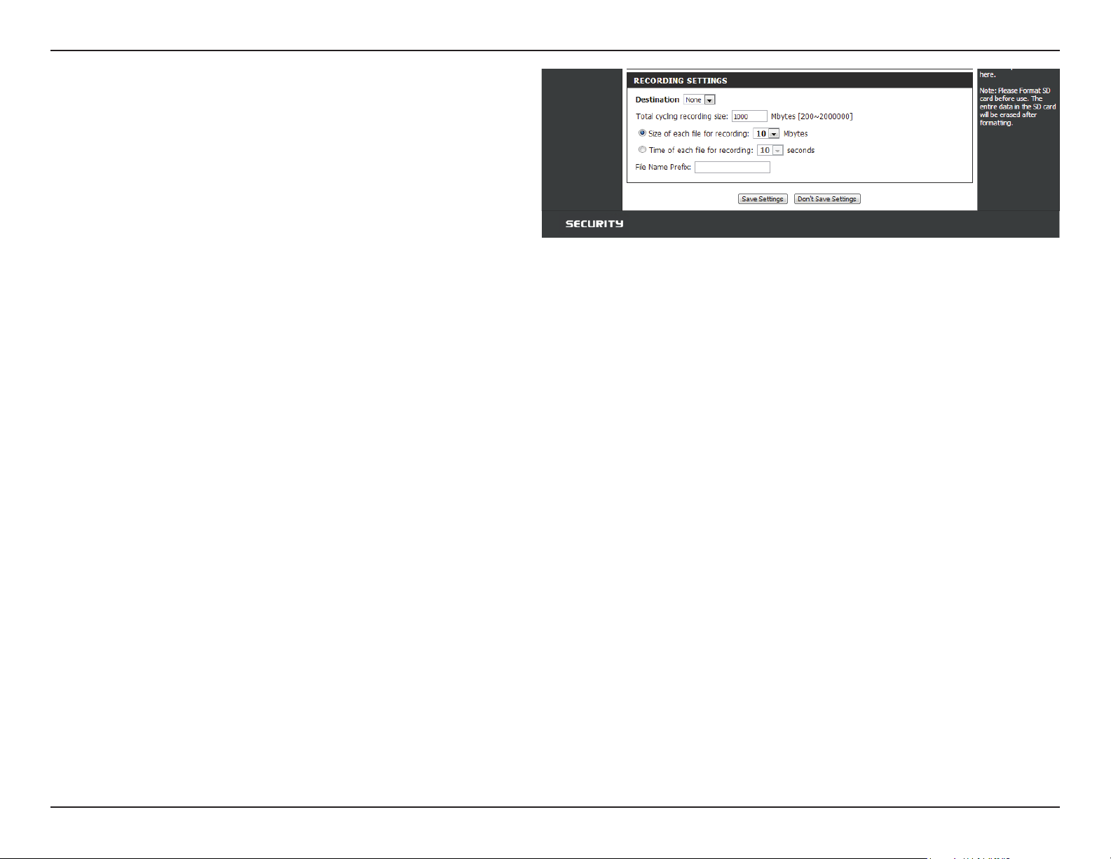
Section 3: Conguration
Recording
settings:
Destination:
Total cycling
recording size:
Size of each le
for recording:
Time of
each le for
recording:
File Name
Prex:
Conguring the setting for the recording.
Select the folder where the recording le will be
stored.
Please input a HDD volume between 1MB and 2TB
for recording space. The recording data will replace
the oldest record when the total recording size
exceeds this value. For example, if each recording
le is 6MB, and the total cyclical recording size is
600MB, then the camera will record 100 les in the
specied location (folder) and then will delete the
oldest le and create new le for cyclical recording.
If this is selected, les will be separated based on
the le size you specify.
If this is selected, les will be separated based on
the maximum length you specify.
The prex name will be added on the le name of
the recording le(s).
59D-Link DCS-6314 User Manual
Section 3: Conguration
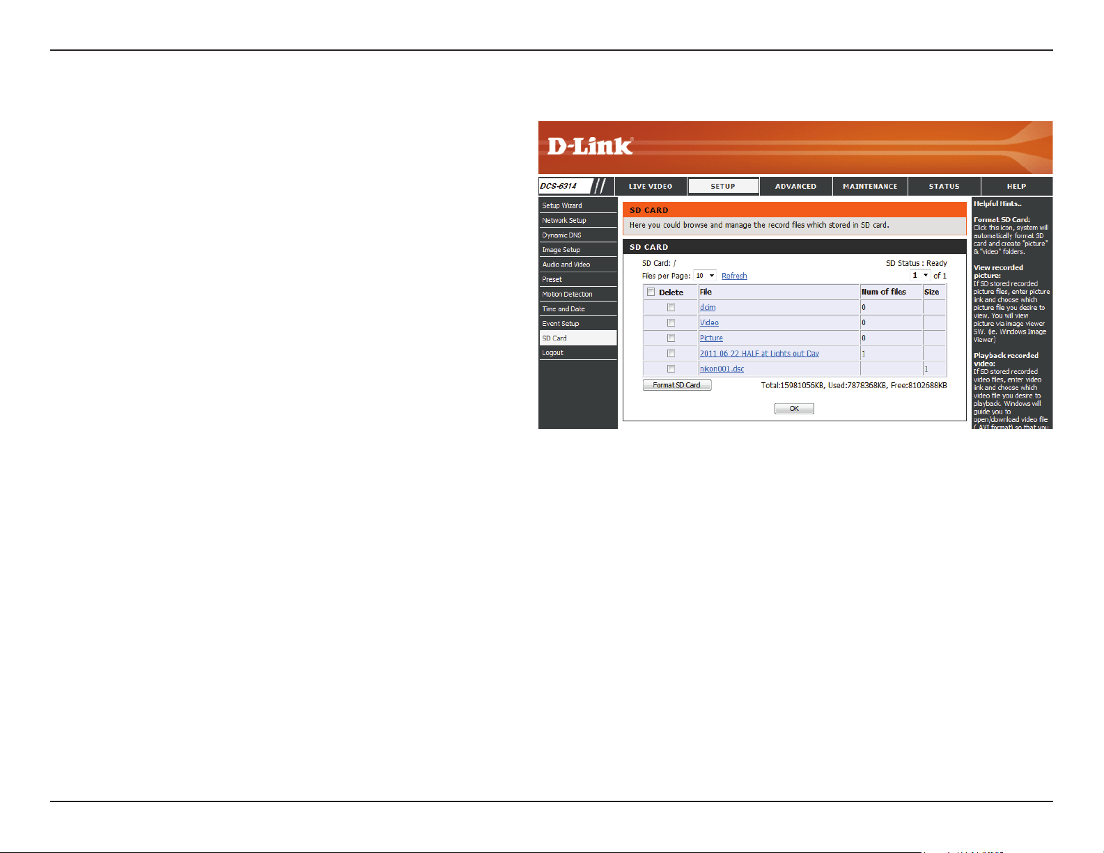
SD Card
Format SD
Card:
View Recorded
Picture:
Playback
Recorded
Video:
Refresh:
Click this icon to automatically format the SD card
and create "picture" & "video" folders.
If the picture les are stored on the SD card, click
on the picture folder and choose the picture le
you would like to view.
If video les are stored on the SD card, click on the
video folder and choose the video le you would
like to view.
Reloads the le and folder information from the
SD card.
Here you may browse and manage the recorded les which are
stored on the SD card.
60D-Link DCS-6314 User Manual
Section 3: Conguration
Advanced
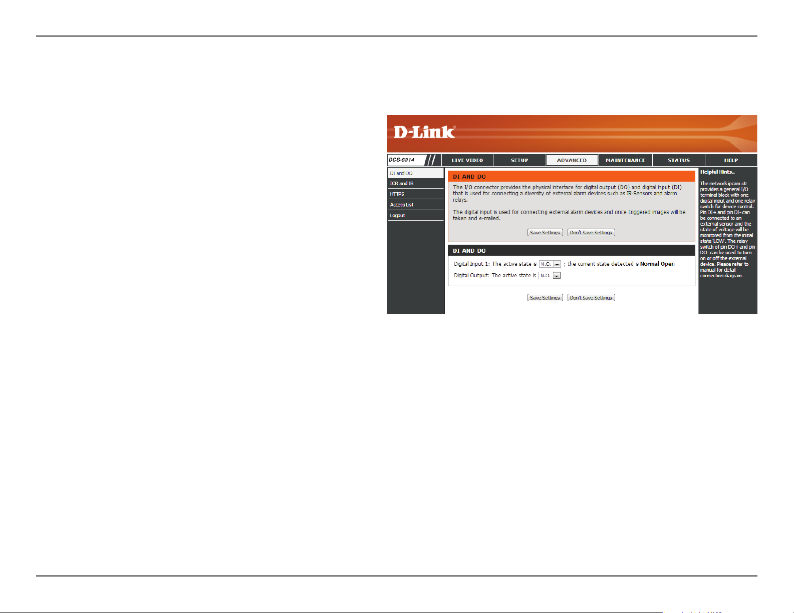
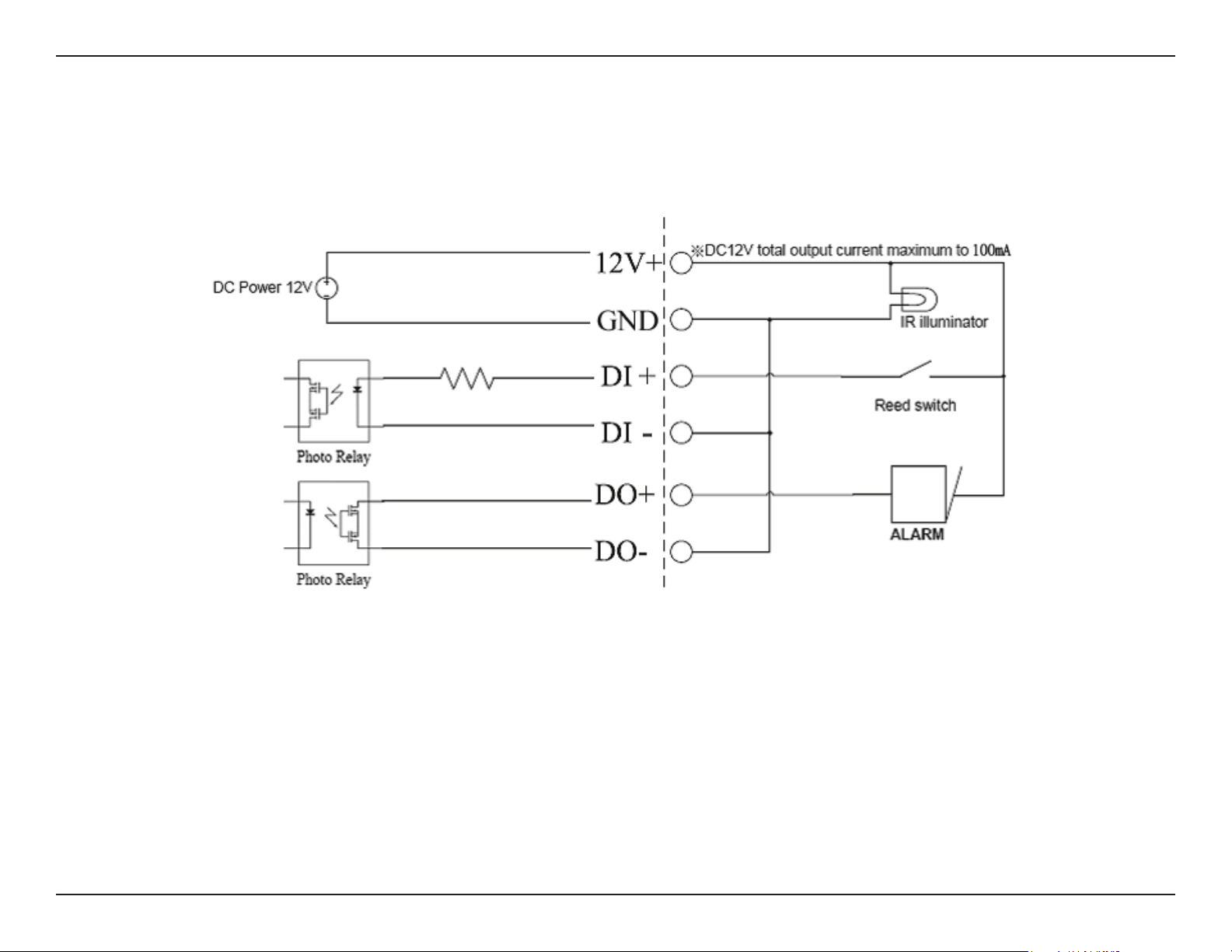
Digital Input/Output
This screen allows you to control the behavior of digital input and
digital output devices. The I/O connector provides the physical
interface for digital output (DO) and digital input (DI) that is used
for connecting a variety of external alarm devices such as IR-
Sensors and alarm relays. The digital input is used for connecting
external alarm devices and once triggered images will be taken and
e-mailed. After making any changes, click the Save Settings button
to save your changes.
Select D/I or
D/O Mode:
LED:
Video Output:
The camera will send a signal when an event
is triggered, depending upon the type of device
connected to the DI circuit.
N.C. stands for Normally Closed. This means that
the normal state of the circuit is closed. Therefore
events are triggered when the device status
changes to "Open."
N.O. stands for Normally Open. This means that
the normal state of the circuit is open. Therefore
events are triggered when the device status
changes to "Closed."
You may specify whether or not to illuminate the
status LED on the camera.
Enable/ disable the BNC terminal TV output signal.
61D-Link DCS-6314 User Manual
Section 3: Conguration
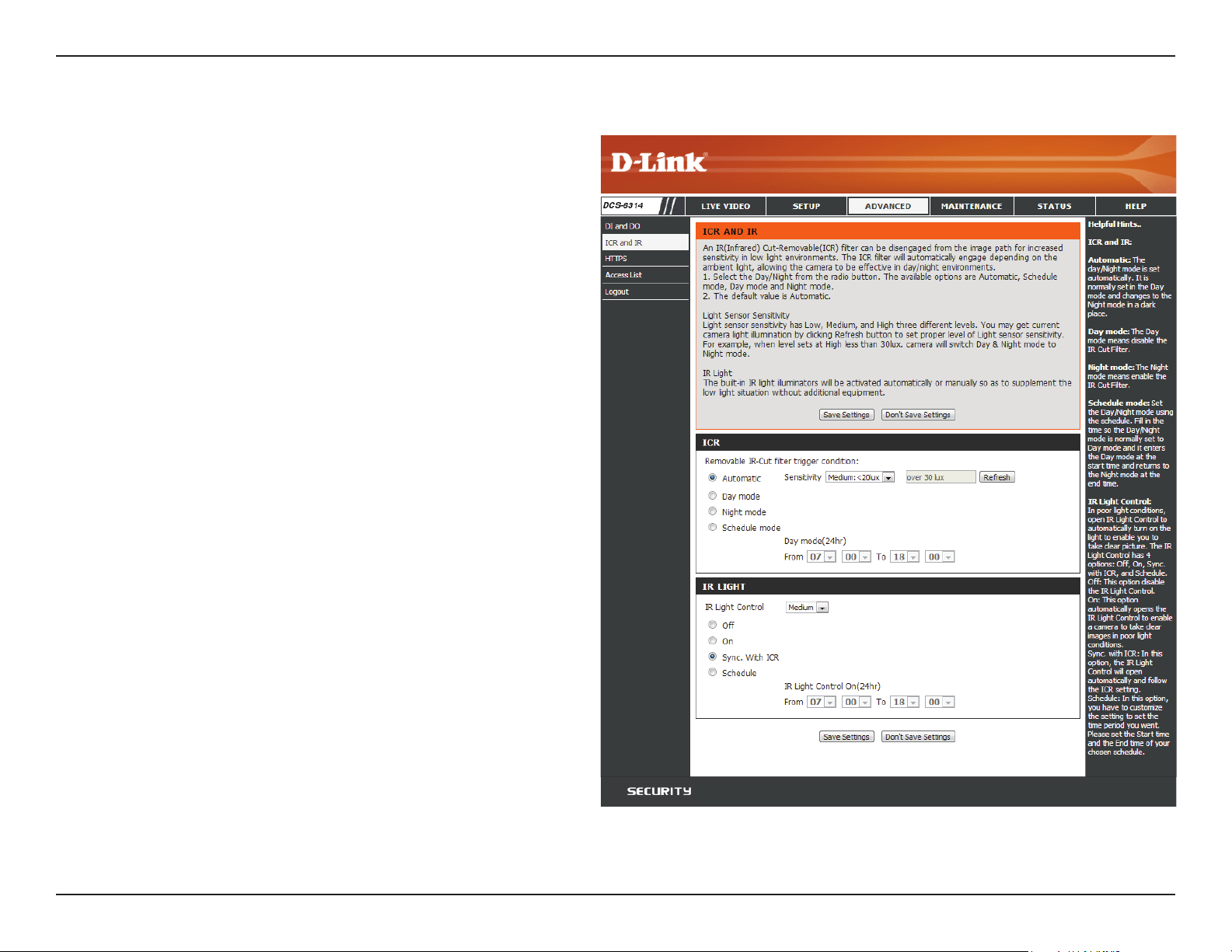
Here you can congure the ICR and IR settings. An IR(Infrared) Cut-
Removable(ICR) lter can be disengaged for increased sensitivity in
low light environments.
Automatic:
Day Mode:
Night Mode:
Schedule
Mode:
IR Light
Control:
O:
On:
Sync:
Schedule:
The Day/Night mode is set automatically. Generally,
the camera uses Day mode and switches to Night
mode when needed.
Day mode enables the IR Cut Filter.
Night mode disables the IR Cut Filter.
Set up the Day/Night mode using a schedule. The
camera will enter Day mode at the starting time
and return to Night mode at the ending time.
The camera can enable or disable the IR (infrared)
light according to your preferences. This setting
provides additional controls depending on your
specic application.
The IR light will always be o.
The IR light will always be on.
The IR light will turn on when the ICR sensor is on.
The IR light will turn on or o according to the
schedule that you specify below.
ICR and IR
62D-Link DCS-6314 User Manual
Section 3: Conguration
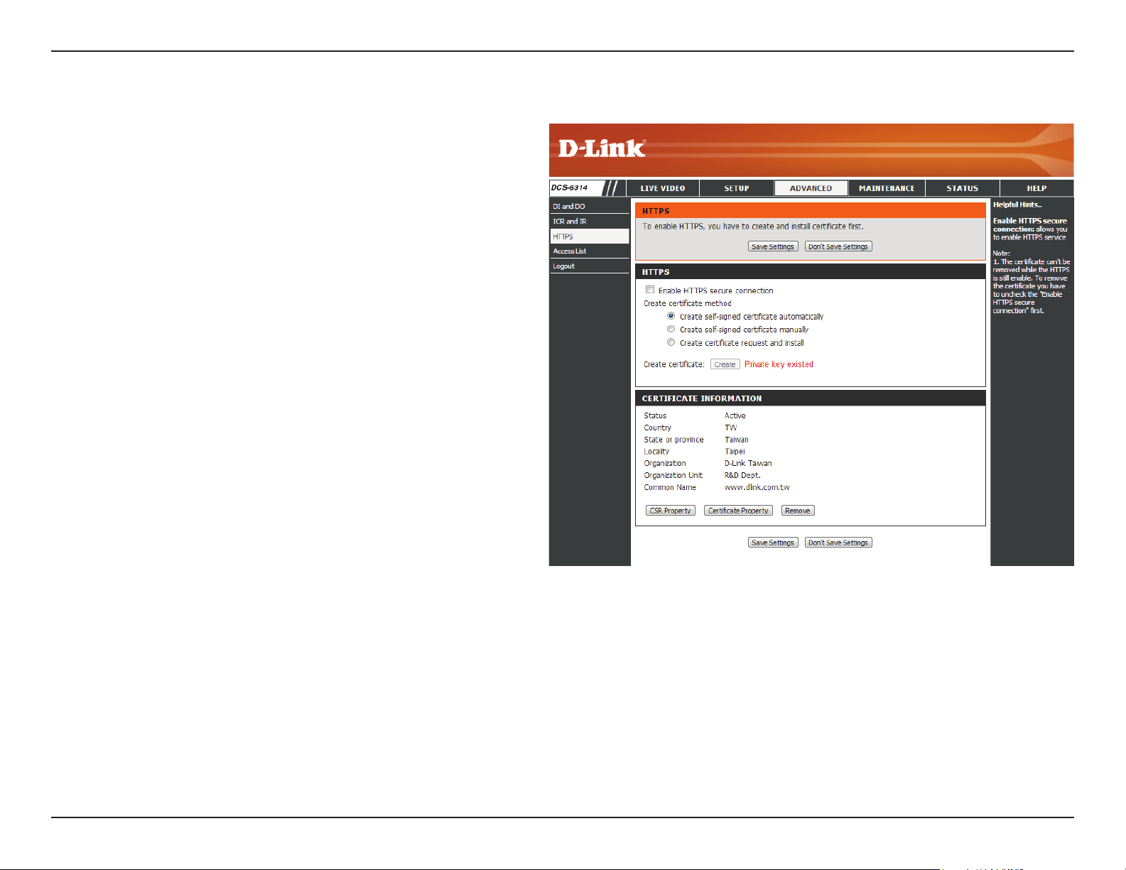
HTTPS
This page allows you to install and activate an HTTPS certicate for
secure access to your camera. After making any changes, click the
Save Settings button to save your changes.
Enable
HTTPS Secure
Connection:
Create
Certicate
Method:
Status:
Note:
Enable the HTTPS service.
Choose the way the certicate should be created.
Three options are available:
Create a self-signed certicate automatically
Create a self-signed certicate manually
Create a certicate request and install
Displays the status of the certicate.
The certicate cannot be removed while the
HTTPS is still enabled. To remove the certicate,
you must rst uncheck Enable HTTPS secure
connection.
63D-Link DCS-6314 User Manual
Section 3: Conguration
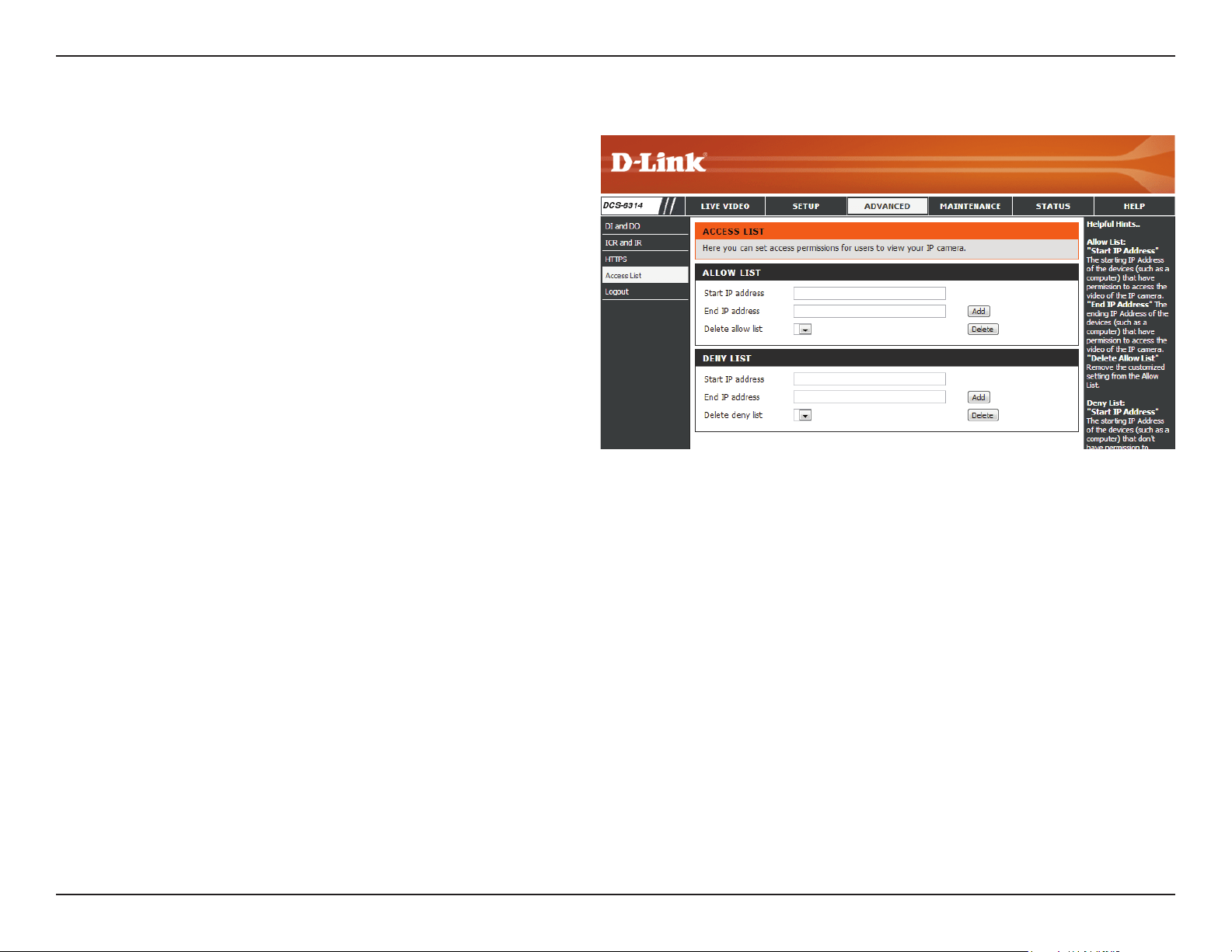
Access List
Here you can set access permissions for users to view your
DCS-6314.
Allow list:
Start IP
address:
End IP address:
Delete allow
list:
Deny list:
Delete deny
list:
The list of IP addresses that have the access right
to the camera.
The starting IP Address of the devices (such as
a computer) that have permission to access
the video of the camera. Click Add to save the
changes made.
Note: A total of seven lists can be congured for
both columns.
The ending IP Address of the devices (such as a
computer) that have permission to access the
video of the camera.
Remove the customized setting from the Allow
List.
The list of IP addresses that have no access rights
to the camera.
Remove the customized setting from the Delete
List.
For example:
When the range of the Allowed List is set from
1.1.1.0 to 192.255.255.255 and the range of the
Denied List is set from 1.1.1.0 to 170.255.255.255.
Only users with IPs located between 171.0.0.0 and
192.255.255.255 can access the Network Camera.
64D-Link DCS-6314 User Manual
Section 3: Conguration
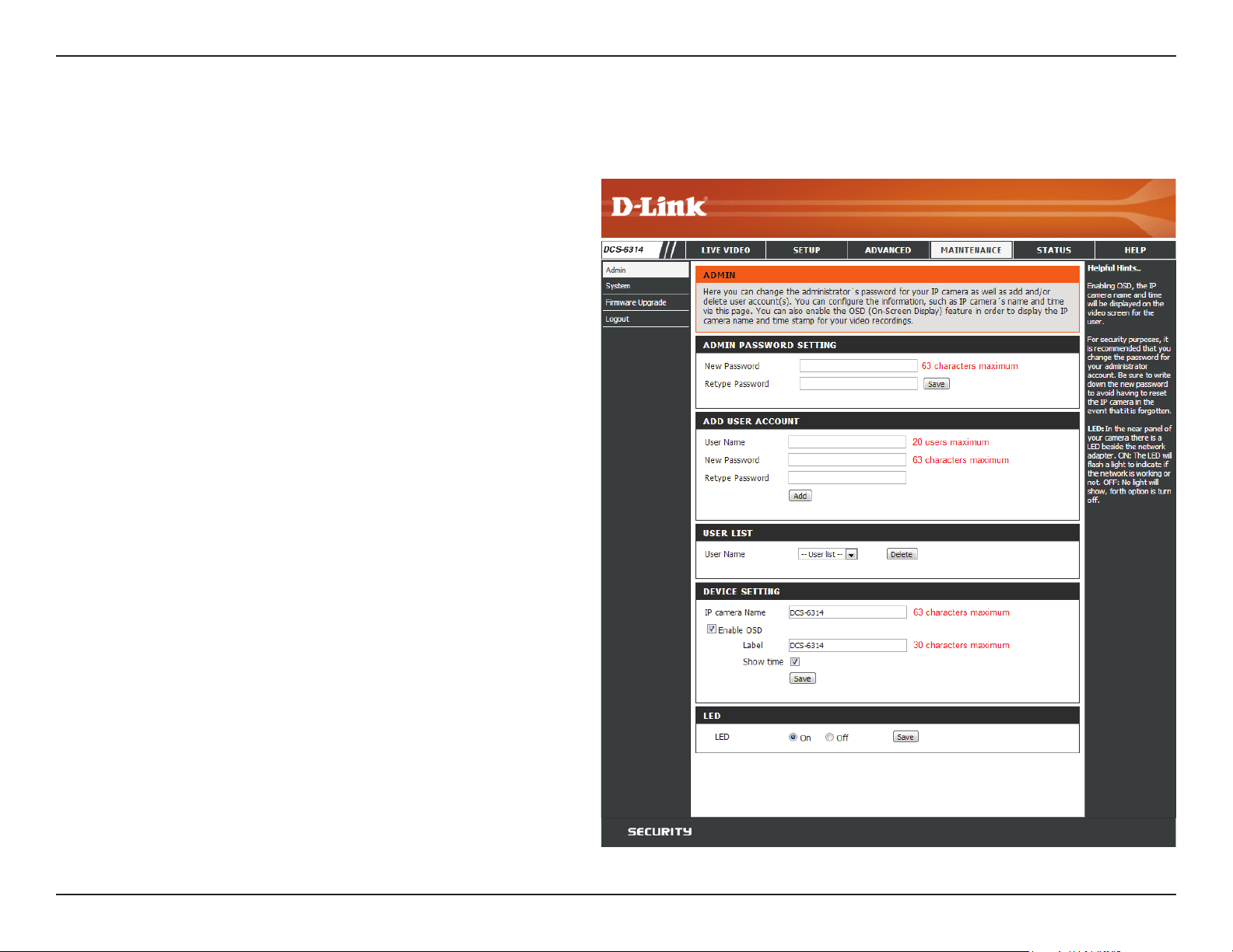
Maintenance
Device Management
In this section you may change settings for the administration of the
camera. You can also add or delete users, as well as enable or disable
certain functions such as the on screen display or camera LED's.
Admin
Password
Setting:
Add User
Account:
User Name:
Password:
User List:
Camera Name:
Enable OSD:
Label:
Show Time:
LED:
Set a new password for the administrator’s
account.
Add new user account.
The user name for the new account.
The password for the new account.
All the existing user accounts will be displayed
here. You may delete accounts included in the
list, but you may want to reserve at least one as a
guest account.
Create a unique name for your camera that will
be added to the le name prex when creating a
snapshot or a video clip.
Select this option to enable the On-Screen Display
feature for your camera.
Enter a label for the camera, which will be shown
on the OSD when it is enabled.
Select this option to enable the time-stamp
display on the video screen.
Select whether to turn the camera LED on or o.
65D-Link DCS-6314 User Manual
Section 3: Conguration
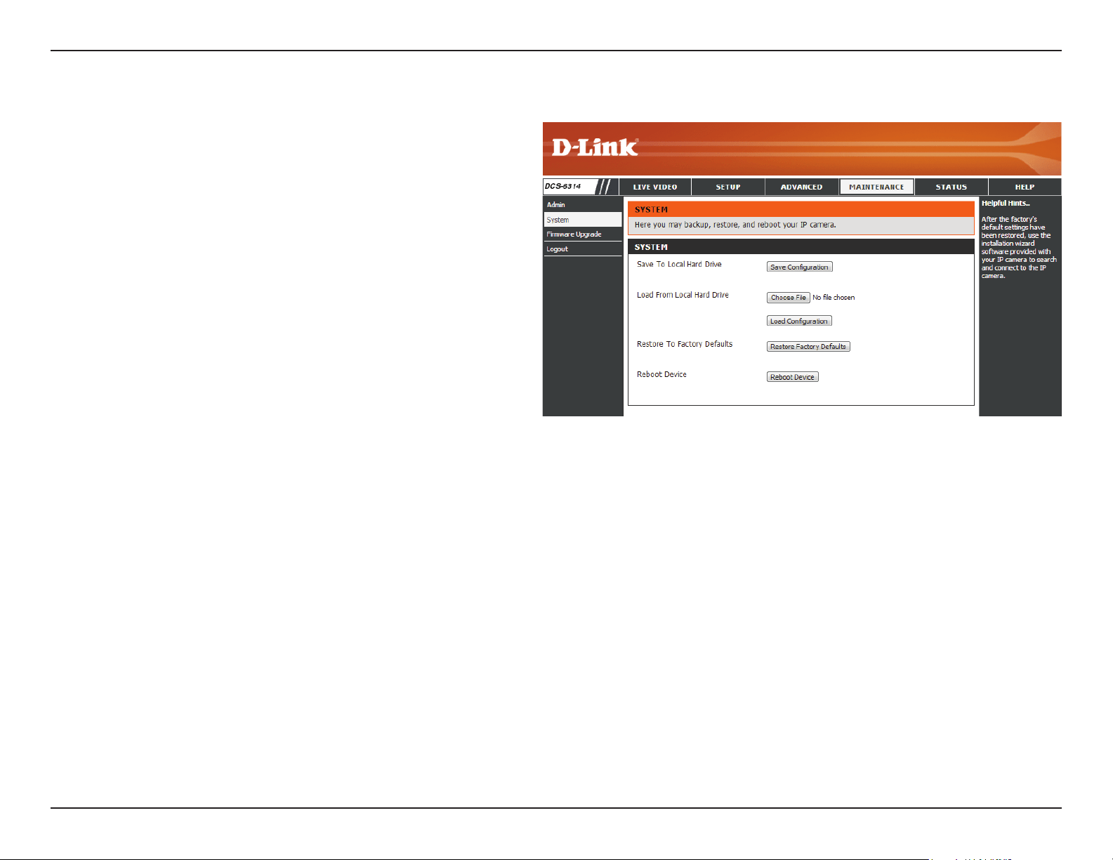
System
In this section, you may backup, restore and reset the camera
conguration, or reboot the camera.
Save To Local
Hard Drive:
Load From
Local Hard
Drive:
Restore
to Factory
Default:
Reboot Device:
You may save your current camera conguration
as a le on your computer.
Locate a pre-saved conguration by clicking
Browse and then restore the pre-dened settings
to your camera by clicking Load Conguration.
You may reset your camera and restore the factory
settings by clicking Restore Factory Defaults.
This will restart your camera.
66D-Link DCS-6314 User Manual
Section 3: Conguration
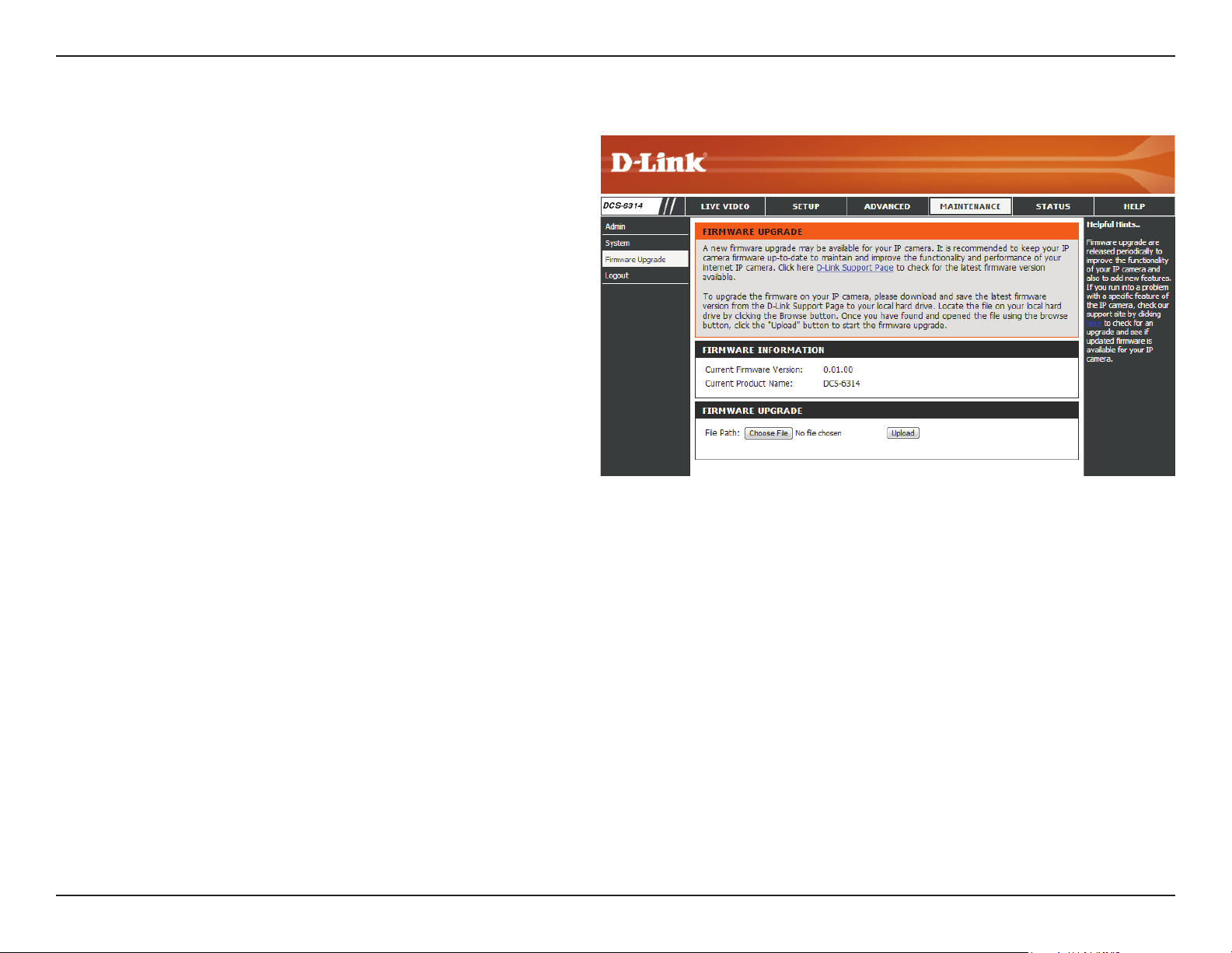
Firmware Upgrade
The camera's current rmware version will be displayed on this
screen. You may visit the D-Link Support Website to check for the
latest available rmware version.
To upgrade the rmware on your DCS-6314, please download and
save the latest rmware version from the D-Link Support Page to
your local hard drive. Locate the le on your local hard drive by
clicking the Browse button. Select the le and click the Upload
button to start upgrading the rmware.
Current
Firmware
Version:
Current
Product Name:
File Path:
Upload:
Displays the detected rmware version.
Displays the camera model name.
Locate the le (upgraded rmware) on your hard
drive by clicking Browse.
Uploads the new rmware to your camera.
67D-Link DCS-6314 User Manual
Section 3: Conguration
Status
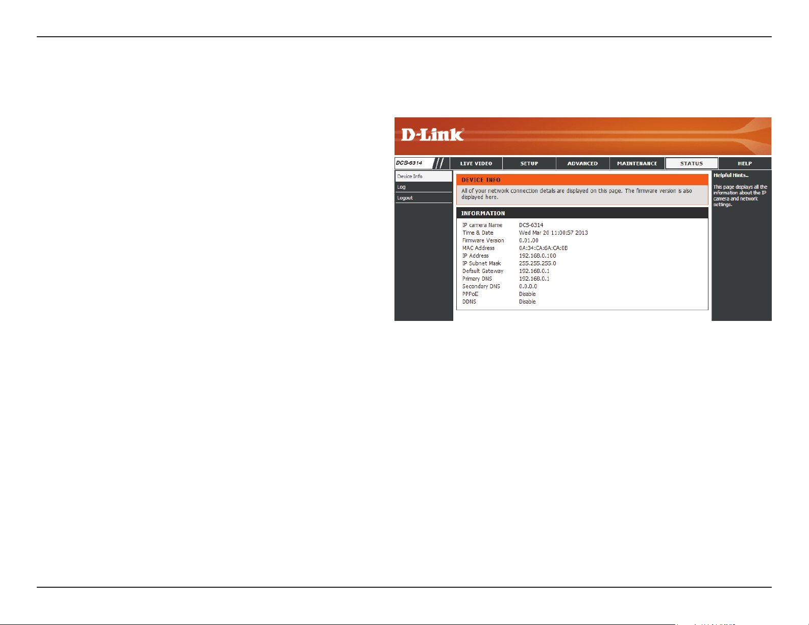
Device Info
This page displays detailed information about your device and
network connection.
68D-Link DCS-6314 User Manual
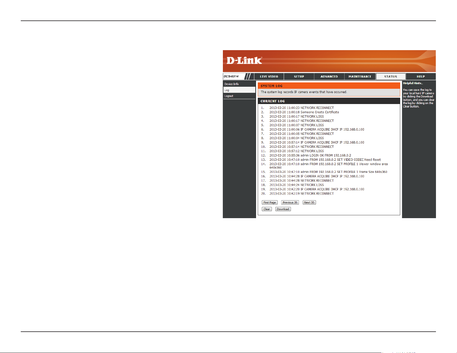
Section 3: Conguration
This page displays the log information of your camera. You may
download the information by clicking Download. You may also
click Clear to delete the saved log information.
Logs
69D-Link DCS-6314 User Manual
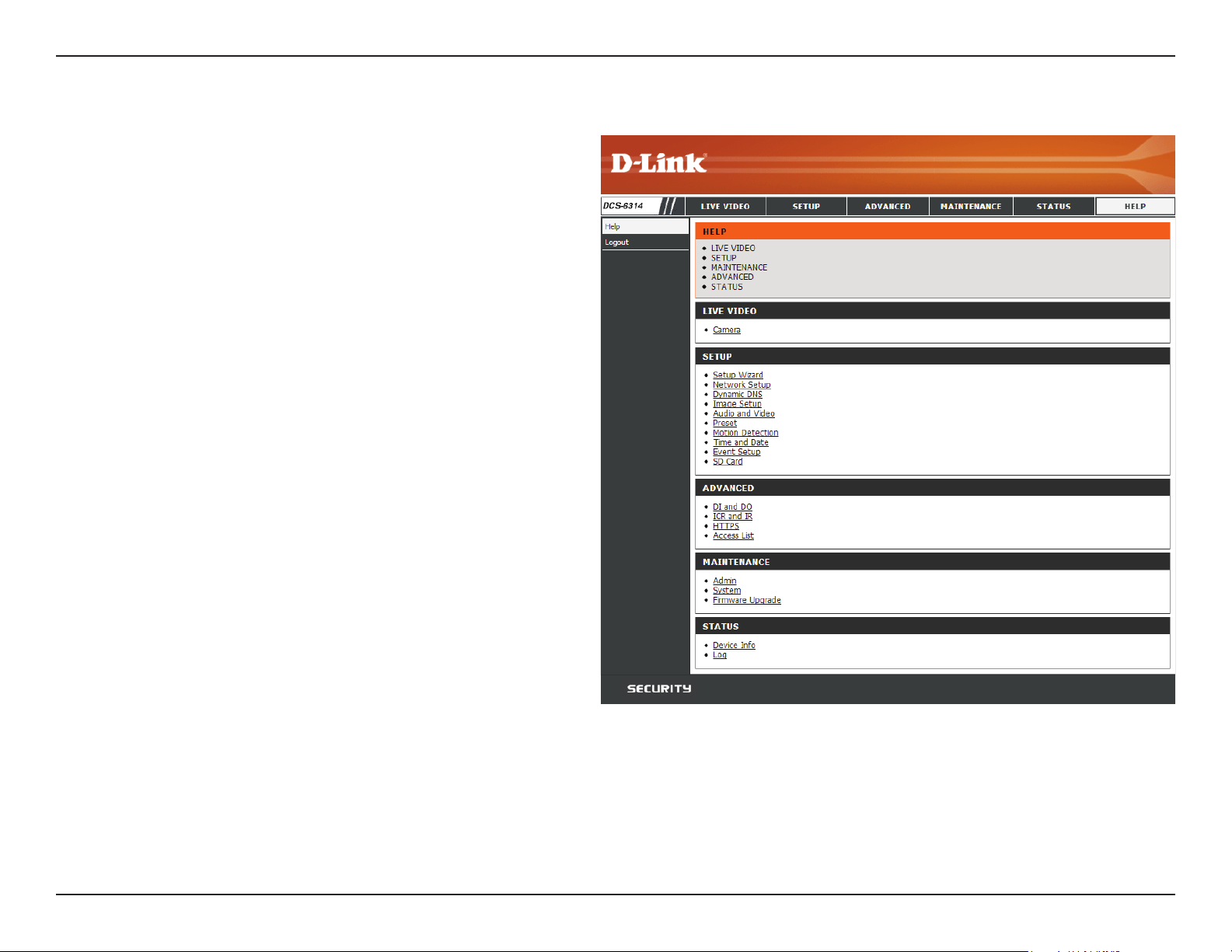
Section 3: Conguration
This page provides helpful information regarding camera
operation.
Help
70D-Link DCS-6314 User Manual
Appendix A: DI/DO Specications
DI/DO Specications

71D-Link DCS-6314 User Manual
Appendix A: Technical Specications
Technical Specications
Camera Camera Hardware
Prole
• 1/2.8” 2 Megapixel progressive CMOS sensor
• 15 meter IR illumination distance
• Minimum illumination 0.2 Lux / F1.4 Color mode
• Minimum illumination 0.05 Lux / F1.4 Black and White mode
• Minimum illumination 0 Lux Black and White mode with IR LED on
• Removable (ICR) Filter module
• 2.8 to 12mm variable focal lens
• Aperture F1.4
• Angle of view (16:9)
• (H) 96.5° ~ 31.2°
• (V) 64.5° ~ 17.8°
• (D) 117.5° ~ 36.8°
Camera Housing
• IP68 compliant weatherproof housing
• IK-10 compliant vandal-proof housing
• Included weather shield
Image Features
• Configurable image size, quality, frame rate, and bit rate
• Time stamp and text overlays
• Configurable motion detection windows
• Configurable privacy mask zones
• Configurable exposure time, brightness, saturation, contrast, contrast,
sharpness.
Video
Compression
• Simultaneous H.264/MPEG-4/MJPEG format compression
• H.264/MPEG-4 multicast streaming
• JPEG for still images
Video Resolution
• 16:9 - 1920 x 1080, 1280 x 720, 800 x 450, 640 x 360, 480 x 270, 320 x 176,
176 x 144 up to 30 fps
• 4:3 - 1440 x 1080, 1280 x 960, 1024 x 768, 800 x 600, 640 x 480, 320 x 240,
176 x 144 up to 30 fps
Audio Support
• G.726 • G.711
External Device
Interface
• 10/100 BASE-TX Ethernet port with PoE
• 1 DI / 1 DO
• DC12 V, 100 mA Output
• micro SD/SDHC card Slot
• Audio input / output
Network Network Protocols
• IPv6
• IPv4
• TCP/IP
• UDP
• ICMP
• DHCP client
• NTP client (D-Link)
• DNS client
• DDNS client (D-Link)
• SMTP client
• FTP client
• HTTP / HTTPS
• Samba client
• PPPoE
• UPnP port forwarding
• RTP / RTSP/ RTCP
• IP filtering
• QoS
• CoS
• Multicast
• ONVIF compliant
Security
• Administrator and user group protection
• Password authentication
• HTTP and RTSP digest encryption

72D-Link DCS-6314 User Manual
Appendix A: Technical Specications
System
Management
System
Requirements for
Web Interface
• Browser: Internet Explorer, Firefox, Chrome, Safari
Event
Management
• Motion detection
• Event notification and uploading of snapshots/video clips via e-mail or FTP
• Supports multiple SMTP and FTP servers
• Multiple event notifications
• Multiple recording methods for easy backup
Remote
Management
• Take snapshots/video clips and save to local hard drive or NAS via web browser • Configuration interface accessible via web browser
OS Support
• Windows 2000/XP/Vista/Windows 7/8
D-ViewCam™
System
Requirements
• Operating System: Microsoft Windows 7/Vista/XP
• Web Browser: Internet Explorer 7 or higher
• Protocol: Standard TCP/IP
D-ViewCam™
Software
Functions
• Remote management/control of up to 32 cameras
• Viewing of up to 32 cameras on one screen
• Supports all management functions provided in web interface
• Scheduled motion triggered, or manual recording options
General Weight
• 1112g (with weathershield)
External Power
Adapter
• Input: 100~240 V AC , 50/60 Hz • Output: 12 V DC 1.25 A
Power
Consumption
• 10 +-5% Watt
Temperature
• Operating: -30 to 50 °C (-22 to 122 °F) • Storage: -20° to 70° C (-4° to 158° F)
Humidity
• Operating: 20% to 80% non-condensing • Storage: 5% to 95% non-condensing
Certications
• CE
• CE LVD
• FCC
• C-Tick
73D-Link DCS-6314 User Manual
Appendix A: Technical Specications
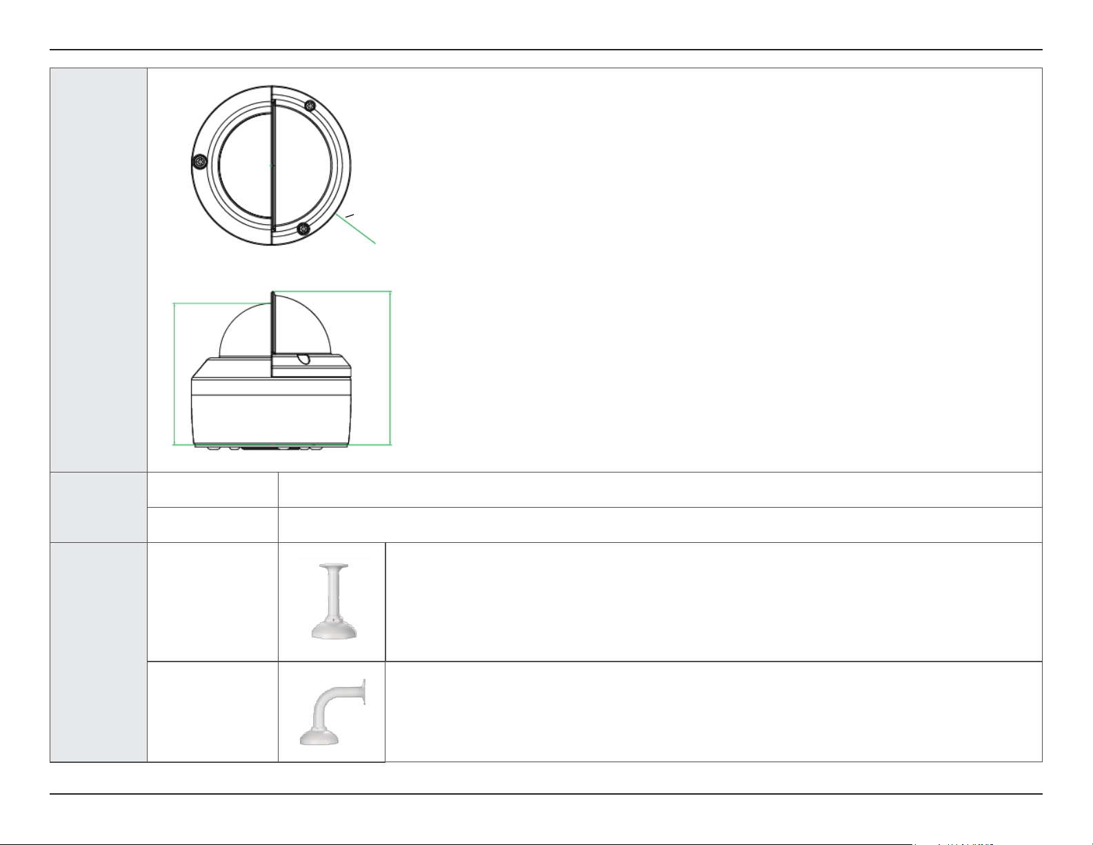
Dimensions
Order
Information
Part Number Description
DCS-6314 Full HD Outdoor Fixed Dome Network Camera
Optional
Accessories
DCS-34-2
Pendant Mount
201 x 150 mm (7.9 x 5.9 inches), 665 grams (1.45 lbs)
DCS-34-3
Bent Arm Mount
253 x 150 mm (9.96 x 5.9 inches), 770 grams (1.7 lbs)
123.2mm
113.7mm
O128mm