This document should only be removed by customer after installation.
P/N: A01265603
Not satised with the installation of your refrigerator? Please contact 1-800-4MY-HOME.
Installation Instructions for Top Mount Refrigerator
®
2
3
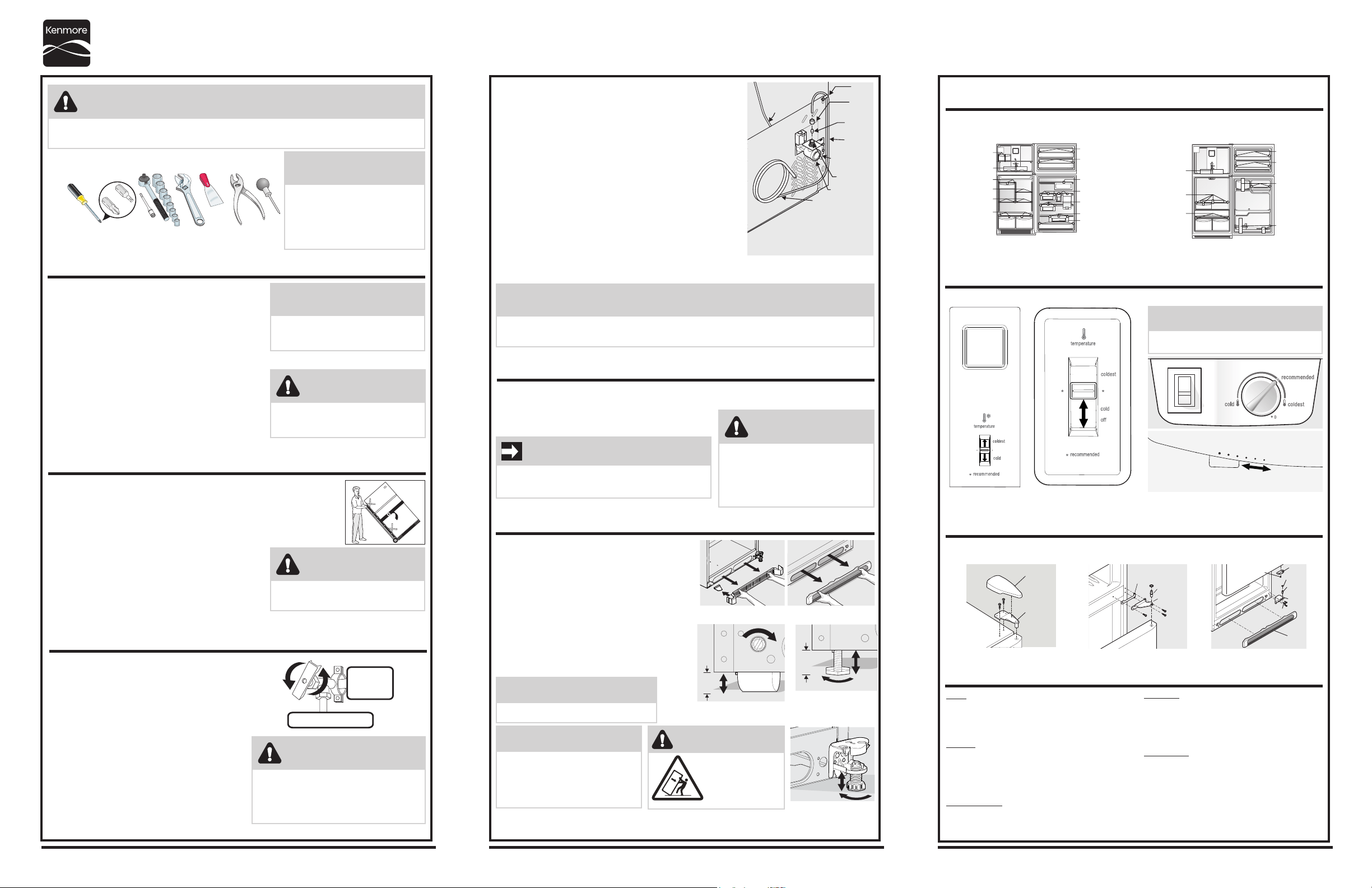
To connect the water supply to the rear of your refrigerator:
1. Ensure that the refrigerator is not plugged in.
2. Flush the supply line until water is clear by placing the end of the
copper tube in a sink or bucket and opening the shut-o valve.
3. Remove the plastic cap from the water valve inlet at the rear of your
refrigerator. Discard the cap.
4. Slide the brass compression nut, then the ferrule (sleeve) onto copper
tube.
5. Push the copper tube into water valve inlet as far as it will go (¼ inch).
6. Slide the ferrule (sleeve) into valve and nger-tighten the
compression nut onto valve. Tighten another half turn with a wrench.
Do not over-tighten.
7. Secure the copper tube to your refrigerator’s rear panel with a steel
clamp and screw (see illustration).
8. Coil the excess copper tubing (about 2½ turns) behind your
refrigerator as shown. Arrange coiled tubing to avoid vibration or
wear against other surfaces.
9. Open water supply shut-o valve and tighten any connections that leak.
5
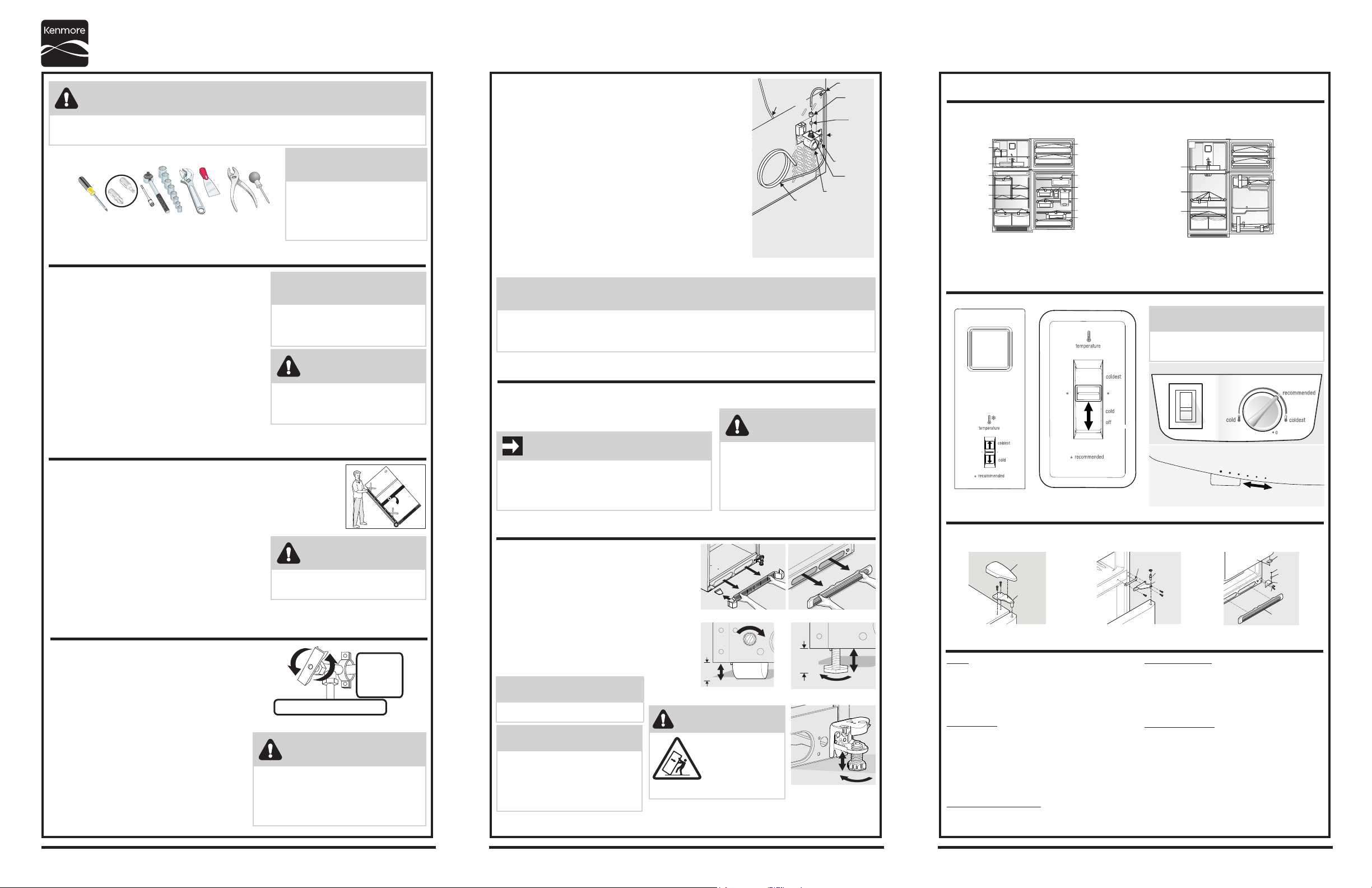
Remove Internal Shipping Materials
7
8
1
4
6
9
Doors
Handles are secure and tight
Door seals completely to cabinet on all sides
Freezer door is level across the top
Leveling
Refrigerator is level, side to side and tilted
¼” (6mm) front to back
Toe grille is properly attached to refrigerator
Cabinet is setting solid on all corners
Electrical Power
House power turned on
Refrigerator plugged in
Ice Maker
House water supply connected to refrigerator
No water leaks present at all connections
- recheck in 24 hours
Ice Maker is turned ON.
Final Checks
Shipping material removed
Fresh Food and Freezer controls set
Crisper Humidity controls set
Registration Card sent in
Installation Checkoff List
Prepare The Installation Site
Transport Unpackaged Refrigerator To Site
Location of these materials may vary depending on your model.
garage
temperature
coldest
cold
off
* recommended
2 pieces of tape
1 piece of tape
3 pieces of tape
2 pieces of tape
4 pieces of tape
4 pieces of tape
2 pieces of tape
2 pieces of tape
1 piece of tape
5 pieces of tape
3 pieces of tape
3 pieces of tape
2 pieces of tape
OR
Tools Necessary:
Phillips Head
or
Quadrex Head
Screwdriver
(OR)
Socket
Wrench Set
Plastic
Putty
Knife
Adjustable
Wrench
Pliers
Awl
Include these minimum guidelines in your site preparation:
• Choose a place near a grounded electrical outlet.
• Do not use an extension cord or an adapter plug.
• Avoid direct sunlight and close proximity to a range,
dishwasher or other heat source.
• Floor should be level and able to support a fully
loaded refrigerator.
Allow the following clearances for ease of installation,
proper air circulation, and plumbing and electrical
connections:
Sides & Top: ⅜ inch
Rear: 1 inch
By now, you have already removed your refrigerator’s shipping carton. You may still
need to use a hand truck to move it through close spaces or entrances.
If the refrigerator is larger than an entrance, consider two options:
• Remove the entrance door if one exists.
• Remove the refrigerator doors (see how in your Use & Care Guide).
When using a hand truck:
• Load refrigerator from side of cabinet only.
• Do not run retaining straps over handles.
• Do not over-tighten retaining straps.
• Never use refrigerator handles to move the refrigerator.
• Remove tape from doors only after unit is in place.
Connect Water Supply
What you will need:
• Access to a cold water line with pressure of
30-100 psi.
• Copper tubing with ¼-inch (6.4mm) OD.
Length for this tubing is the distance from the
rear of the refrigerator to your household water
supply line plus 7 feet (2.1 meters).
• A shut-o valve for the connection between your
household water line and the refrigerator supply
line. Do not use a self-piercing shut-o valve.
• A compression nut and ferrule (sleeve) for the
water supply connection at the rear of your
refrigerator.
House
plumbing
line
Waterline hookup
Plastic Water
Tubing to Ice
Maker Fill
Tube
Steel
Clamp
Brass
Compression
Nut
Ferrule
(Sleeve)
Copper
water line
Water Valve
Bracket
Valve Inlet
Water Valve
Copper water line
from household
water supply
(Include enough tubing in loop to allow
moving refrigerator out for cleaning.)
Place In Permanent Position
If possible, use a hand truck to position the refrigerator directly in front of its cabinet enclosure.
Be careful not to move the refrigerator beyond its water supply (copper tubing) connections.
Plug in the power cord, and push the refrigerator straight back
into place.
Level Refrigerator & Adjust Doors (if necessary)
Guidelines for nal positioning of your refrigerator:
• All four corners of the cabinet must rest rmly on the oor.
• The cabinet should be level at the front and rear.
• The sides should tilt ¼-inch (6 mm) from front-to-
back (to ensure that doors close and seal properly).
• Doors should align with each other and be level.
To level the cabinet using the front rollers:
1. Remove the toe grille (Figure 1).
2. Use a at-blade screwdriver or ⅜ inch socket wrench
to raise or lower the front rollers (Figure 2).
3. Use adjustable wrench to adjust leveling screws. Lower
the leveling screws on each side clockwise until they
contact the oor (Figure 3).
We use packing foam and tape to secure the internal parts of your refrigerator for shipping. Once the
refrigerator is in position, you can remove this material.
Controls
When changing controls, wait 24 hours before making additional adjustments.
Door Removal (if necessary)
If you need to remove the doors to get your refrigerator into the house, please see “Door Removal
Instructions” in your Use & Care Manual.
WARNING
To avoid electric shock, which can cause death or severe personal injury, do not connect your refrigerator to
an electrical power source until you have completed Step 3 of these instructions.
CAUTION
Room temperatures below 55°F (13°C) or
above 110°F (43°C) will impair cooling
ability of your refrigerator’s compressor.
IMPORTANT
If you are installing your refrigerator without connecting it
to a water supply, make sure the ice maker’s power switch
is turned O (see the Use & Care Guide for more details).
NOTE
These installation instructions
are provided only as a possible
customer option. We recommend
that you use a service or kitchen
contracting professional to install
your refrigerator.
NOTE
Information about cabinetry construction
for your new appliance is available for
contractors. Call 1-877-435-3287.
CAUTION
Shifting the refrigerator from side to side
may damage ooring.
CAUTION
To avoid property damage:
• Use copper tubing for the water supply line
(plastic tubing is more likely to leak).
• Ensure water supply complies with local
plumbing codes.
CAUTION
• Shifting the refrigerator from side to
side may damage ooring.
• Do not block the toe grille on the lower
front of your refrigerator. Sucient
air circulation is essential for proper
operation.
NOTE
• The ice maker’s ll valve may operate noisily if the household water supply is shut o.
• After ensuring no water leaks exist at any connection, be sure to check for leaks again in 24 hours.
NOTE
Raise the front of the refrigerator enough
so the doors close freely when opened
halfway. The refrigerator should slope ¼
inch to ½ inch from front-to-back. Then
level the refrigerator from side-to-side.
Vegetables Fruits
lo
hi
Humidity Control
Top
Hinge
Cover
Top Hinge
Central
Hinge
Shim
Pin
Washer
Hinge
Pin
Bottom
Hinge
Screws
Toe
Grille
Door Stop
Screw
Door
Stop
1 piece of tape
4 pieces of tape
2 pieces of tape
2 pieces of tape
3 pieces of tape
2 pieces of tape
2 pieces of tape
Figure 1
4. Some models are equipped with an anti-tip bracket (Figure 4). Lower it clockwise until it
contacts the oor.
Figure 4 (some models)
Anti-tip
Bracket
WARNING
The anti-tip device
must be installed
according to the
instructions in your
Use & Care Manual.
Failure to do so will result in injury.
Raise
9/16"
(14 mm)
Max
Figure 3
9/16"
(14 mm)
Max
Raise
Figure 2
or
NOTE
Allow 15 minutes for compressor to start after
initial start up or power interruption.
NOTE
See Use and Care Manual for door reversal.
Allow 24 hrs for adjustments
2
3
Raccordement de l’alimentation en eau à l’arrière de votre
réfrigérateur:
1 Assurez-vous que le réfrigérateur n’est pas branché.
2 Placez l’extrémité de la conduite en cuivre dans un évier ou un seau,
puis ouvrez le robinet d’arrêt pour laisser couler l’eau jusqu’à ce
qu’elle soit propre.
3 Enlevez le capuchon en plastique du robinet d'arrivée d’eau situé à
l’arrière du réfrigérateur. Jetez le capuchon.
4 Faites glisser l’écrou à compression en laiton sur la conduite en
cuivre, puis mettez la bague (le manchon).
5 Poussez la conduite en cuivre dans le robinet d'arrivée d’eau aussi
loin que possible (6,4mm [¼po]).
6 Faites glisser la bague (le manchon) dans le robinet et serrez l'écrou
à compression sur le robinet avec les doigts. Serrez d’un autre demi-
tour avec une clé. Ne serrez pas trop.
7 Fixez la conduite en cuivre au panneau arrière du réfrigérateur à
l'aide d'un collier en acier et d'une vis (reportez-vous à l’illustration).
8 Enroulez l'excédent de conduite en cuivre (deux tours et demi environ)
derrière votre réfrigérateur, comme illustré. Placez la conduite de façon
à éviter les vibrations ou le frottement contre d’autres surfaces.
9 Ouvrez le robinet d’alimentation en eau et serrez tous les raccordements qui fuient.
5
7
8
1
4
6
9
Portes
Les poignées sont bien xées
Les portes ferment hermétiquement sur tous les
côtés de la caisse
La porte du congélateur est de niveau tout le
long de la partie supérieure
Mise à niveau
Les côtés du réfrigérateur sont de niveau. Le
réfrigérateur est incliné vers l'arrière de 6mm
(¼po)
La grille de protection est correctement xée au
réfrigérateur
Les quatre coins de la caisse reposent fermement
sur le plancher
Alimentation en électricité
Le système électrique de la maison est sous tension
Le réfrigérateur est branché
Machine à glaçons
Le système d'alimentation en eau est raccordé
au réfrigérateur
Il n'y a aucune fuite au niveau des raccords -
seconde vérication 24 heures plus tard
La machine à glaçons est en marche
Vérications nales
Le matériel d'expédition est enlevé
Les commandes des compartiments
réfrigérateur et congélateur sont réglées
Les commandes du contrôle d'humidité sont
réglées
La carte d'enregistrement est envoyée
Préparation de l'emplacement
Transport du réfrigérateur déballé vers son emplacement d'installation
L'emplacement du matériel d'expédition peut varier selon le modèle.
Outils nécessaires:
Tournevis Phillips™
ou
Tournevis Quadrex™
Ensemble de
clés à douilles
(OU)
OU
Clé à ouverture
variable
Pinces
Le couteau
en plastique
de mastic
Poinçon
Tenez compte des éléments suivants dans la préparation
de l'emplacementd'installation :
• Placez l'appareil près d’une prise électrique mise à la
terre.
• N'utilisez pas de rallonge électrique ni de che
d'adaptation.
• Évitez d'exposer le réfrigérateur aux rayons directs
du soleil et ne l'installez pas près d'une cuisinière,
d'un lave-vaisselle ou de toute autre source de
chaleur.
• Le plancher doit être de niveau et doit pouvoir
supporter un réfrigérateur rempli à pleine capacité.
Prévoyez les dégagements suivants pour faciliter
l’installation, assurer une circulation d'air appropriée et
raccorder la plomberie et les branchements électriques:
Côtés et dessus: 1cm (⅜po)
Arrière: 2,5cm (1po)
À cette étape, vous avez déjà enlevé l'emballage d'expédition du réfrigérateur. Il se peut
que vous ayez encore besoin d'un chariot manuel pour le déplacer dans des passages ou
des espaces restreints.
Si le réfrigérateur est plus large qu'une entrée, vous avez deux options:
• Enlevez la porte d'entrée, s'il y en a une.
• Enlevez les portes du réfrigérateur (reportez-vous au guide d'utilisation et
d'entretien pour des instructions détaillées).
Lorsque vous utilisez un chariot manuel:
• Installez le réfrigérateur sur le chariot seulement du côté
de ses parois latérales.
• Ne faites pas passer de courroie de retenue par-dessus
les poignées.
• Ne serrez pas trop les courroies de retenue.
• Ne déplacez jamais le réfrigérateur par ses poignées.
• Enlevez le ruban des portes seulement après avoir mis
l'appareil en place.
Raccordement de l'alimentation en eau
Vous aurez besoin de ceci :
• Un accès à une canalisation d'eau froide dotée
d'une pression située entre
206,8 et 689,5kPa
(de 30 à 100lb/po²).
• Une conduite en cuivre de 6,4mm (¼po) de
diamètre extérieur. Pour connaître la longueur
de conduite dont vous avez besoin, ajoutez
2,1m (7pi) à la distance qui sépare l'arrière du
réfrigérateur à la canalisation du système d'arrivée
d'eau de la maison.
• Un robinet d'arrêt pour le raccord situé entre la
conduite d'eau du système de distribution domestique
et la conduite d'alimentation du réfrigérateur.
N'utilisez pas de robinets d'arrêt auto-perceur.
• Un écrou à compression et une bague (un
manchon) pour le raccord de l'alimentation en
eau situé à l'arrière du réfrigérateur.
Canalisation
d'eau
de la
maison
Conduite d'eau de raccordement
Collier en
acier
Écrou à
compression
en laiton
Bague
(manchon)
Conduite en
cuivre pour
l’alimentation
en eau
Support du
robinet d'eau
Robinet
d’arrivée d'eau
Robinet d'eau
Conduite en cuivre pour
l’alimentation en eau du
système de distribution
domestique
(La boucle comprend une longueur de
conduite suffisante pour pouvoir
déplacer le réfrigérateur lors
du nettoyage.)
Tube en plastique
relié au tube de
remplissage du
bac a glyçons
Installation à l'emplacement permanent
Si possible, utilisez un chariot manuel pour installer le réfrigérateur directement devant l'espace prévu
entre les armoires. Prenez soin de ne pas déplacer le réfrigérateur au-delà de la longueur des raccords
d'alimentation en eau (conduite en cuivre).
Branchez le cordon d'alimentation, puis poussez le
réfrigérateur tout droit en place.
Nous utilisons de la mousse et du ruban d'emballage pour protéger les pièces internes de votre
réfrigérateur durant l'expédition. Une fois que votre réfrigérateur est installé, vous pouvez enlever le
matériel d'expédition.
Lorsque vous modiez les réglages des commandes, attendez 24heures avant d'eectuer d'autres changements.
Si vous devez enlever les portes de votre réfrigérateur pour le faire entrer dans votre demeure, veuillez vous
reporter à la section «Instructions de dépose de la porte» qui se trouve dans le guide d'utilisation et d'entretien.
AVERTISSEMENT
Pour éviter des chocs électriques susceptibles de causer de graves blessures ou la mort, ne branchez pas votre
réfrigérateur à une source d'alimentation en électricité avant d'avoir terminé l'étape 3 de ces instructions.
ATTENTION
Des températures ambiantes inférieures à
13 °C (55 °F) ou supérieures à 43 °C (110 °F)
diminueront la capacité de refroidissement
du compresseur de votre réfrigérateur.
IMPORTANT
Si vous installez votre réfrigérateur sans le raccorder à
une conduite d'alimentation en eau, assurez-vous que
l'interrupteur de la machine à glaçons est en position
d'arrêt (O) (reportez-vous au guide d'utilisation et
d'entretien pour plus de détails).
REMARQUE
Ces instructions d'installation ne sont
fournies que pour vous donner la
possibilité d'installer l'appareil vous-
même. Toutefois, nous recommandons
de faire appel à un technicien qualié
pour installer votre réfrigérateur.
REMARQUE
De l'information sur la construction d'armoires
pouvant accueillir votre nouvel appareil
est disponible pour les entrepreneurs en
téléphonant au: 1877435-3287.
ATTENTION
Le déplacement latéral du réfrigérateur
peut endommager le revêtement de sol.
ATTENTION
Pour éviter les dommages matériels:
• Utilisez une conduite en cuivre pour
l’alimentation en eau (un tube en plastique
risque davantage de fuir).
• Assurez-vous que l’alimentation en eau est
conforme aux codes de plomberie locaux.
ATTENTION
• Le déplacement latéral du
réfrigérateur peut endommager le
revêtement de sol.
• N'obstruez pas la grille de protection
située à l’avant de votre réfrigérateur. Une
circulation d'air susante est essentielle au
bon fonctionnement de l'appareil.
REMARQUE
• Il se peut que la soupape de remplissage de la machine à glaçons fonctionne bruyamment si le
système de distribution d'eau domestique est fermé.
• Après vous être assuré qu'il n'y ait aucune fuite d'eau au niveau des raccords, vériez à nouveau
l'absence de fuite 24 heures plus tard.
Couvre-
charnière
supérieur
Charnière
supérieure
Charniere
Centrale
Cale
Tige
Butée
Axe de
charnière
Vis
Charnière
inférieure
Grille de
protection
Rondelle
Vis de butée
Mise à niveau du réfrigérateur et ajustement des portes (si nécessaire)
Enlèvement du matériel d’expédition intérieur
Commandes
Dépose de la porte (si nécessaire)
Liste de vérication de l’installation
Directives pour la mise en place nale de votre réfrigérateur:
• Les quatre coins de la caisse doivent reposer
fermement sur le plancher.
• Le cabinet devrait être égal au devant et à l’arrière.
• Les côtés doivent être inclinés de 6 mm (¼ po) de
l’avant vers l’arrière (pour s’assurer que les portes se
ferment hermétiquement et correctement).
• Les portes doivent être alignées et de niveau.
Pour mettre à niveau la carrosserie à l’aide des roulettes avant :
1 Retirez la grille de protection. (Figure 1).
2 Utilisez un tournevis à lame plate ou une clé à douille de
⅜ po pour lever ou abaisser les roulettes avant (Figure 2).
3 Utilisez une clé ajustable pour ajuster les vis calantes. Abaissez
les vis calantes de chaque côté dans le sens des aiguilles d’une
montre jusqu’à ce qu’elles touchent le sol (Figure 3).
REMARQUE
Élevez l’avant du réfrigérateur
susamment pour que les portes se
ferment d’elles-mêmes lorsqu’elles sont à
moitié ouvertes. Le réfrigérateur doit être
incliné vers l’arrière de ¼ à ½po (de 6,4
à 12,7mm). Ensuite, mettez les côtés du
réfrigérateur de niveau.
Figure 1
4 Certains modèles sont équipés d’un support antibasculement (Figure 4). Abaissez-le dans le sens des
aiguilles d’une montre.
Figure 4
(quelques modèles)
Abaisser
Le support anti-
basculement
WARNING
Le dispositif
antibasculement doit être
installé conformément
aux instructions
présentées dans votre
guide d’utilisation et
d’entretien. Tout manquement à cette
règle entraînera des blessures.
14 mm
Max
Relevez
Figure 3
Relevez
14 mm
Max
Figure 2
or
1 morceau
de ruban
2 morceaux
de ruban
2 morceaux
de ruban
3 morceaux
de ruban
2 morceaux
de ruban
2 morceaux
de ruban
4 morceaux
de ruban
garage
temperature
coldest
cold
off
* recommended
4 morceaux
de ruban
2 morceaux
de ruban
3 morceaux
de ruban
2 morceaux
de ruban
4 morceaux
de ruban
2 morceaux
de ruban
2 morceaux
de ruban
1 morceau
de ruban
5 morceaux
de ruban
3 morceaux
de ruban
3 morceaux
de ruban
2 morceaux
de ruban
1 morceau
de ruban
Vegetables
(Légumes)
Fruits
(Fruits)
lo
hi
Commande réfrigérateur/congélateur
®
Instructions d'installation pour réfrigérateurs à compartiments superposés Ce document ne devrait être enlevé par le client qu'après l'installation.
Vous n'êtes pas satisfait de l'installation de votre réfrigérateur? Veuillez communiquer avec le magasin où vous avez acheté votre appareil.
N° DE PIÈCE : A01265603
REMARQUE
Attendez 15 minutes pour que le compresseur
redémarre après un premier démarrage ou une
coupure de courant.
REMARQUE
Voir d’utilisation et d’entretien pour
l’inversion de la porte.
(température)
(plus fríod)
(fríod)
(* recommandé)
(* recommandé)
(froid)
(plus froid)
(température)
(hors tension)
Allow 24 hrs for adjustments
(Attendre 24 heures pour que les réglages se stabilisent)
(froid)
(plus froid)
(recommandé)