
SEDONA SIDE BURNER ACCESSORY
CARE & USE/INSTALLATION
™
MAKE THE MOST OF YOUR

2
|
SEDONA SIDE BURNER ACCESSORY CARE & USE/INSTALLATION
Part # 34172
Rev. A 2/13
WARNINGS
READ THIS MANUAL CAREFULLY and completely before using your grill to reduce the risk of:
1. Fire
2. Burn hazard, personal injury or property damage
3. Ruined steaks or other unpleasant cooking experiences
4. Unapproved installation or servicing.
THIS PRODUCT IS DESIGNED FOR OUTDOOR USE ONLY. Improper installation, adjustment, alteration, service
or maintenance can cause property damage, injury or death.
Read this manual thoroughly before installation, use, or servicing of this product.
1. The burning of gas cooking fuel generates some by-products which are on the list of substances which are
known by the State of California to cause cancer or reproductive harm.
2. California law requires businesses to warn customers of potential exposure to such substances. To minimize
exposure to the substances, always operate this unit according to the use and care instructions found in this
manual. Be certain to provide adequate ventilation when cooking.
3. California Proposition 65 lists “Silica, crystalline” which is used in one of the components of the IR burner, as
an agent known to the state of California to cause cancer.
If you smell gas:
1. Shut off all gas supply lines to the grill.
2. Extinguish any open flames.
3. Carefully open the lid. Remember, it may be
extremely hot!
If odor continues, keep everyone away from the
grill and immediately call your gas supplier or your
fire department.
1. DO NOT store or use gasoline or other flam-
mable vapors and liquids in the vicinity of this
or any other appliance.
2. An LP cylinder not connected for use shall
not be stored in the vicinity of this or any
other appliance.
s’Il y a une odeur de gaz:
1. Coupez l’admission de gaz de l’appariel.
2. Éteindre toute flamme nue.
3. Ouvrir le couvercle.
Si l’odeur persiste, éloignez-vous de l’appareil et
appelez immédiatement le fournisseur de gaz ou
le service d’incendie.
•Ne pas entreposer ni utiliser de l’essence ni
d’autres vapeurs ou liquides inflammables dans le
voisinage de l’appareil, ni de tout autre appareil.
•Une bouteille de propane qui n’est pas raccordée
en vue de son utilisation, ne doit pas être en-
treposée dans le voisinage de cet appareil ou de
tout autre appareil.
WarnIng
danger
WarnIng
danger
avertIssment
warning! calIfornIa proposItIon 65

SEDONA SIDE BURNER ACCESSORY CARE & USE/INSTALLATION
|
3
1. Before each use, complete the checklist below.
2. Make sure all burner control knobs are in the “OFF” position.
3. Push and hold the control knob for 2 - 5 seconds while listening for and visually
verifying the ignition spark is present.
4. Turn the knob to the “LITE” position.
5. After ignition set the knob to the desired setting.
•Do you smell gas? If yes, shut off everything and call the
gas company or a qualified plumber to check for leaks, if
not please continue
•Are you prepared to stay with the side burner during the
entire cooking process? If not, gather what you need be-
fore starting the lighting process. If yes, please continue.
•Is your cooking area free and clear of any combustibles,
besides your food, that might ignite? If no, clear the area
before starting the lighting process, If yes, please con-
tinue
•Do all control knobs turn freely? If not, call for service; if
yes, please continue.
•If you are using a portable propane cylinder, is it connect-
ed and leak tested? If not, check the connection before
continuing. If yes please continue.
•Do you know where your side burner’s main gas supply
shut-off valve is located? If not, locate it before continu-
ing. If yes, please continue.
•Are all burners properly seated in the side burner? If not,
seat the burners properly before continuing. If yes please
continue.
•Is the wind blowing just lightly and not blowing on the
side burner? If not, wait until the wind subsides or turn
your free-standing grill so the wind goes into the front of
the grill. If yes, please continue with the lighting process.
CHECKLIST BEFORE EACH USE (FOR YOUR SAFETY)
HOW TO LIGHT YOUR GRILL ACCESSORY

SEDONA SIDE BURNER ACCESSORY CARE & USE/INSTALLATION
|
9
This manual covers several accessory appliances and optional accessories for those appliances.
Accessories covered in this MAnuAl
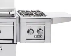
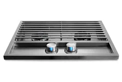
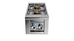
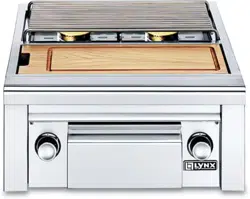
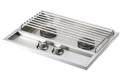
The LSB501 and LSB502 (Side Burner 1 & 2) feature either one or two 12,500 BTU/Hr burners for cooking smaller
food items. The LSB501 and LSB502 are designed for installation in a non-combustible, built-in enclosure.
DOUBLE SIDE BURNER
SINGLE SIDE BURNER
LSB502
LSB501
USING YOUR ACCESSORY
10
|
SEDONA SIDE BURNER ACCESSORY CARE & USE/INSTALLATION
SAFETY PRACTICES AND PRECAUTIONS
Ensure that burner ties and all packing materials are re-
moved before lighting any new accessory.
AT EACH NEW SEASON
At the start of each new grilling season you should remove
the cooking grates and check the burners, venturis, orifices
and valves for obstructions.
Spiders and insects often nest in these areas of the acces-
sory and can disrupt air flow, causing damage to the acces-
sory and personal injury.
Also, check all hoses and fittings for damage, abrasion,
wear and tear and repair, if necessary, before turning the
gas on.
The 4/11 gas pressure regulator, Lynx part number 30781
supplied with the unit must be used for natural gas, or
LP supplied from a bulk storage system. The regulator is
factory preset, and convertible for either natural or LP gas.
(See INDEX: “Converting for Fuel Type” for further details.)
If connection to a Type 1, 20 lb LP cylinder is required, a LP
gas pressure regulator and hose assembly is required and
it must be the type specified by Lynx. (See INDEX: “Con-
tacting Lynx”.) When a LP gas pressure regulator and hose
assembly is used, the 4/11 regulator must be removed to
prevent over-regulation.
Leak check all connections with a soap and water solution
before operating the burners. Turn all knobs to OFF and
SLOWLY turn on the gas supply valve. (See INDEX: “Leak
Testing” for further details.)
Do not use any grill or side burner if you smell gas.
LIGHTING INSTRUCTIONS
1. Remove burner cover completely. Do not attempt to
light any burner with the cover in place
2. Ensure all knobs are in the OFF position. Test the igni-
tion system by pressing in the burner control knob
and looking and listening for the clicking sound of
the igniter. If no spark is visible and no clicking sound
is heard, proceed with match-lighting or refer to the
trouble shooting section.
3. Turn on the main gas supply and purge if needed.
4. Push in and turn the burner control knob to the LITE
position and hold for 5 seconds.
5. If burner does not light, turn knob to OFF, wait 5 min-
utes to allow gas to dissipate and repeat step 4 above
PURGING THE GAS LINES
You should purge the gas line of air before attempting to
light the grill accessory.
1. Make sure all grill controls are in the “OFF” position.
2. Slowly turn on the main gas supply.
3. Push in the control knob for the burner furthest from
the fuel source. Using the burner furthest from the fuel
source will completely purge the lines. It will take sev-
eral seconds for the burner to light.
4. Hold the knob ON for about 20 seconds to allow the
air in the system to purge and the burner to light
5. Wait at least 5 minutes after shutting off the control
before attempting to light the burners.
Lighting instructions for ALL Accessories
1. DO NOT store or use gasoline or other flam-
mable vapors and liquids in the vicinity of this
or any other appliance.
2. An LP cylinder not connected for use shall
not be stored in the vicinity of this or any
other appliance.
WarnIng

14
|
SEDONA SIDE BURNER ACCESSORY CARE & USE/INSTALLATION
BUILT-IN INSTALLATIONS
Lynx built-in accessories are intended for installation in a
built-in enclosure constructed of non-combustible materials.
The accessory drops into the opening shown in the cutout
detail drawing and hangs from its counter-top trim. A deck
is not required to support it from the bottom.
Pay special attention to the provisions shown for gas line
hook-up. (See INDEX: “Cut-out Dimensions for Built-in
Grills & Accessories”.)
The enclosure should have ventilation holes to prevent gas
build-up in the event of a leak. The deck ledges and coun-
ter should be flat and level. (Refer to ANSI Z21.58 Standard
for Outdoor Cooking Gas Appliances, Section 1.7 Enclo-
sures For Self Contained LP-Gas Supply Systems or local
codes for additional information.)
The accessory may be powered directly from your Sedona
grill’s transformer’s power supply. (See INDEX: “Electrical
Connections”).
When a grill is not available or if the grill is not located
close enough to the accessory a LASK Switch Kit is avail-
able from the manufacturer as an optional purchase.
CLEARANCE TO COMBUSTIBLE MATERIALS
Minimum clearance from the sides and back of the acces-
sory to adjacent combustible construction below the top of
unit are 12” from the sides and back.
Dégagement minimal entre les parois latérales et l’arrière
de l’appariel et la construction combustible au-dessous du
panneau supérieur de l’appareil (30 cm à partir des parois
latérales et 30 cm à partir de l’arrière).
Minimum clearance from sides and back of unit to adjacent
combustible construction extending above the unit is 18”
from the sides and back.
Dégagement horizontal minimal entre les parois latérales et
l’arrière de l’appariel et la construction verticale combustible
au-dessus de l’appareil (45.7 cm à partir des parois latérales
et 45.7 cm à partir de l’arrière).
Do not use this appliance under overhead combustible
surfaces.
Ne pas utiliser cet appareil sous une surface combustible.
before you start...continued

SEDONA SIDE BURNER ACCESSORY CARE & USE/INSTALLATION
|
15
WARNING
Never connect a gas line directly to the side burner. A pressure regulator must be installed on all gas equipment.
All local codes require it and THE MANUFACTURER supplies the correct regulator with your accessory. Removing
or failing to install the pressure regulator can result in fire and serious personal injury and will void the warranty.
The accessory is factory set to use either propane (LP) or
natural gas (NAT). It is critical that the gas you use matches
that which the accessory was set up for. You can verify that
by checking the rating plate.
The rating plate is located on the sheet metal body of the
appliance.
Ensure that the gas supplied meets with the minimum pres-
sure requirements.
Do not operate the accessory on any gas other than that for
which the accessory has been set.
Fuel WC Max Inlet WC Min Under Full
Load
Nat Gas 7 in 4 in
LP 14 in 10 in
Water Column Requirements
Both the regulator and the burner orifices have been fac-
tory preset for the type of gas specified on the rating plate.
Converting to a different type of gas requires a conver-
sion kit which is available from the manufacturer, and
must be installed by a qualified technician. (See INDEX:
“Contacting Lynx”.)
All installation and all installation parts must conform to
local codes with the National Electrical Code, ANSI/NFPA
70-1990 and the National Fuel Gas Code, ANSI Z223.1/
NFPA 54 in the U.S. and CGA-B149.1/.2 in Canada.
Canadian installations must conform to CGA-B149.1/.2
natural gas/propane installation code. (Canada)
NATURAL GAS
The manufacturer recommends that only qualified profes-
sionals perform the required plumbing on this product.
The gas supply line must be sized to accommodate the
total BTU requirements of all the gas-fired equipment that
will be connected to that line.
In no case should pipe less than 3/4” inside diameter or 1”
outside diameter be used.
•Calculate the total BTU output of all equipment and
refer to “INDEX: Gas Supply Line Runs” for allowable run
distances. Failure to meet these minimum requirements
may reduce performance of the accessory and any other
appliances running on that supply line.
•Always keep supply line runs as short as possible. (See
INDEX: “Gas Supply line runs”.)
•A gas shut-off valve must be installed in an easily acces-
sible location by a qualified plumber.
•Keep any threading compound off of the first two pipe
threads to avoid having any small pieces of compound
break loose and clog a burner valve or orifice. Do not put
sealant on any male end of flare fittings.
It is recommended that any flexible pipe used be kept as
short as possible. (See INDEX: “Gas Connections” for typi-
cal permanent hook up.)
Gas PlumbinG
Gas & electric connections
Keep last two
threads clean

16
|
SEDONA SIDE BURNER ACCESSORY CARE & USE/INSTALLATION
LP Gas
The side burners that are factory preset for use with LP gas
come equipped with a 4/11 regulator, Lynx part number
30781. The regulator is used for permanently plumbed,
hard piped LP connections, such as those in line with a
bulk cylinder. If connection to a Type 1, 20 lb LP cylinder
is required a LP gas pressure regulator and hose assembly
is required and must be the type specified by Lynx. (See
INDEX: “Contacting Lynx”.)
When a LP gas pressure regulator and hose is used, the
4/11 regulator must be removed to prevent over-regulation.
ConvertinG for fueL tyPe
After changing the orifices the service technician must make
sure the correct regulator setting is used. If you are using the
4/11 convertible regulator, ensure that it is set for the correct
fuel. The correct fuel type will be abbreviated at the end of
the plunger. The service technician must remove the cap and
check the plunger. If needed, pull the plunger from the cap,
flip it over and re-attach it to the cap. Then re-attach the cap
into the regulator and tighten with a 7/8 inch wrench.
Never connect an unregulated gas line to the grill accessory.
When exchanging your cylinder for a refill, exchange only
for a Type 1 20 lb. cylinder with an over-fill protection de-
vice.
Never use a cylinder with a damaged valve.
A dented or rusty LP cylinder may be hazardous and should
be avoided. If in doubt, have it checked by your LP supplier.
Always check for leaks after every LP cylinder change. (See
INDEX: “Leak Testing” for further details.)
Always shut off the LP-gas supply at the cylinder when the
accessory is not in use.
Cylinders must be stored outdoors in a well-ventilated area
out of the reach of children. If your accessory is stored in-
doors, the LP cylinder must be stored outside.
Place a dust cap on the cylinder valve outlet whenever the
cylinder is not in use. Only install the type of dust cap on
the cylinder valve outlet that is provided with the cylinder
valve. Other types of caps or plugs may result in leakage of
propane.
Mettre un bouchon antipoussière sur la sortie du robinet
d’une bouteille qui n’est pas utilisée. Utiliser uniquement
le type de bouchon antipoussière fourni avec le robinet de
la bouteille. D’autres types de bouchons pourraient ne pas
être étanches et permettre des fuites de propane.
LP ConneCtions
Make sure the LP cylinder valve is fully closed. It is possible for
the valve to be open without releasing gas but, as soon as you
start connecting the regulator, gas will leak from the connec-
tion.
Insert the regulator inlet into the cylinder valve and turn the
black coupler clockwise until the coupler is hand tight. Do
not over-tighten this connection.
To disconnect the coupler, first make sure the main cylinder
valve is turned off. Grasp the coupler and turn counter clock-
wise. Always leak-test the connection after refilling or ex-
changing LP cylinders. (See INDEX: “Leak Testing” for further
details.)
LP cylinder with type 1 valve connection
Gas & electric connections ...continued
18
|
SEDONA SIDE BURNER ACCESSORY CARE & USE/INSTALLATION
Installation requires an outdoor 120VAC 15A GFI (Ground
Fault Interrupter) electrical outlet adjacent to the accessory.
The GFI outlet features an internal breaker that reduces
shock hazard. This type of outlet should be installed inside
the enclosure by a qualified electrician.
The built in side burners are designed for connection to an
adjacent Lynx grill, 12-volt transformer during installation to
provide power for lighting and ignition (See INDEX: “Side
Burner Schematics”.) A Lynx LASK switch kit may be used
if no grill is available for connection. The side burners use
a standard 9-Volt battery as a back- up for the electronic
ignition system only. To install or replace the battery, follow
this procedure:
1. Locate the battery compartment
2. Using a small screwdriver, or a coin or similar object,
pry open the battery compartment and pull out the
holder
3. Remove the battery, and replace it with a fresh 9-volt
battery being careful to install the battery with the ter-
minals facing inward.
4. Insert the battery holder back into the battery compart-
ment and snap it into place
If the electrical system fails to operate, a connection may
have come loose in shipping or the GFI may have tripped,
requiring a reset. See the Troubleshooting section for
more details.
CONNECTING THE WIRING
The accessory electrical harnesses are designed to provide
power for both ignition and lighting. While ignition is con-
trolled at the accessory, lighting is controlled at the grill.
You can control lighting at the accessory by installing the
Lynx Accessory Light Switch (LASK).
Disconnect the 4-pin connector on the grill and connect
those plugs to the mating plugs on your accessory. (See
INDEX: “Electrical Connections”.)
Important note: If using multiple Lynx accessories with the
Control Illumination/Blue LED’S, a connector for this pur-
pose is built into the accessory wiring. This will allow you to
use the light switch on your Lynx grill to actuate the power
on more than one accessory.
OPTIONAL ELECTRICAL KITS
In addition to the accessory burner kits, Lynx also manufactures 3 specialized electrical kits that you may purchase for your
accessory, depending upon how it will be installed. Each electrical kit ships with an instructional sheet for assembly. As-
sembly instructions and schematics/drawings can also be found on our website at www.lynxgrills.com
.
•LASK Lynx Accessory Switch Kit
•LPEK Lynx Power Extension Kit
This switch and transformer kit allows independent control of a Lynx accessory
burner without connection to a grill. The kit contains a transformer and mounting
bracket as well as a switch assembly with a mounting plate
The Lynx Power Extension Kit provides 12 feet of additional wire between your
Lynx Grill and accessory burner.
electric connections
SEDONA SIDE BURNER ACCESSORY CARE & USE/INSTALLATION
|
19
testing the installation
Before turning the gas supply on, check for proper installa-
tion using the following test:
1. Plug the transformer back into the receptacle.
2. Push in the gas control knob on your accessory and
watch the igniter spark.
3. Turn on the light switch on the grill. Both the grill and
the grill accessory lights should operate together. This
indicates a proper assembly.
4. Turn the gas on to all appliances.
5. Perform a leak test if you have not done so since
plumbing the unit.
6. Check all burners for proper ignition. Refer to the Light-
ing Instructions for Side Burners.
Leak TesTing
Leak Test Procedure:
1. Create a soapy solution of 1 part soap and 3 parts
water.
2. Confirm that all control knobs are in the off position.
3. Turn on the fuel supply. For natural gas, turn the valve
handle 1/4 turn to align with the gas flow.
4. For LP, turn the cylinder valve knob counter clockwise
one full rotation.
5. Apply the soap solution generously by paint brush or
squirt bottle on all connections and fittings.
6. If bubbles appear to “grow” on any of the connections,
you have a gas leak. IMMEDIATELY turn off the gas
supply.
Fixing a gas Leak
danger!
To prevent fire or explosion hazard, DO NOT smoke
or allow any potential source of ignition (sparks,
electrical arcing, etc) in the area while performing a
leak test. Leak tests should be conducted outdoors
only. Never conduct a leak test using fire or flame.
1. Shut off the gas supply
2. Turn all grill controls to the “ON” position to purge the
grill of any gas build-up, then turn the controls back
“OFF”.
3. Wash off the soapy solution with cold water and dry.
4. Tighten the loose joint, or replace the faulty part with
manufacturer-recommended replacement parts.
5. DO NOT attempt to repair the LP cylinder valve if it is
damaged. The only way to safely resolve a damaged
cylinder is to REPLACE IT.
6. Repeat the leak test to ensure that no leaks are present.
20
|
SEDONA SIDE BURNER ACCESSORY CARE & USE/INSTALLATION
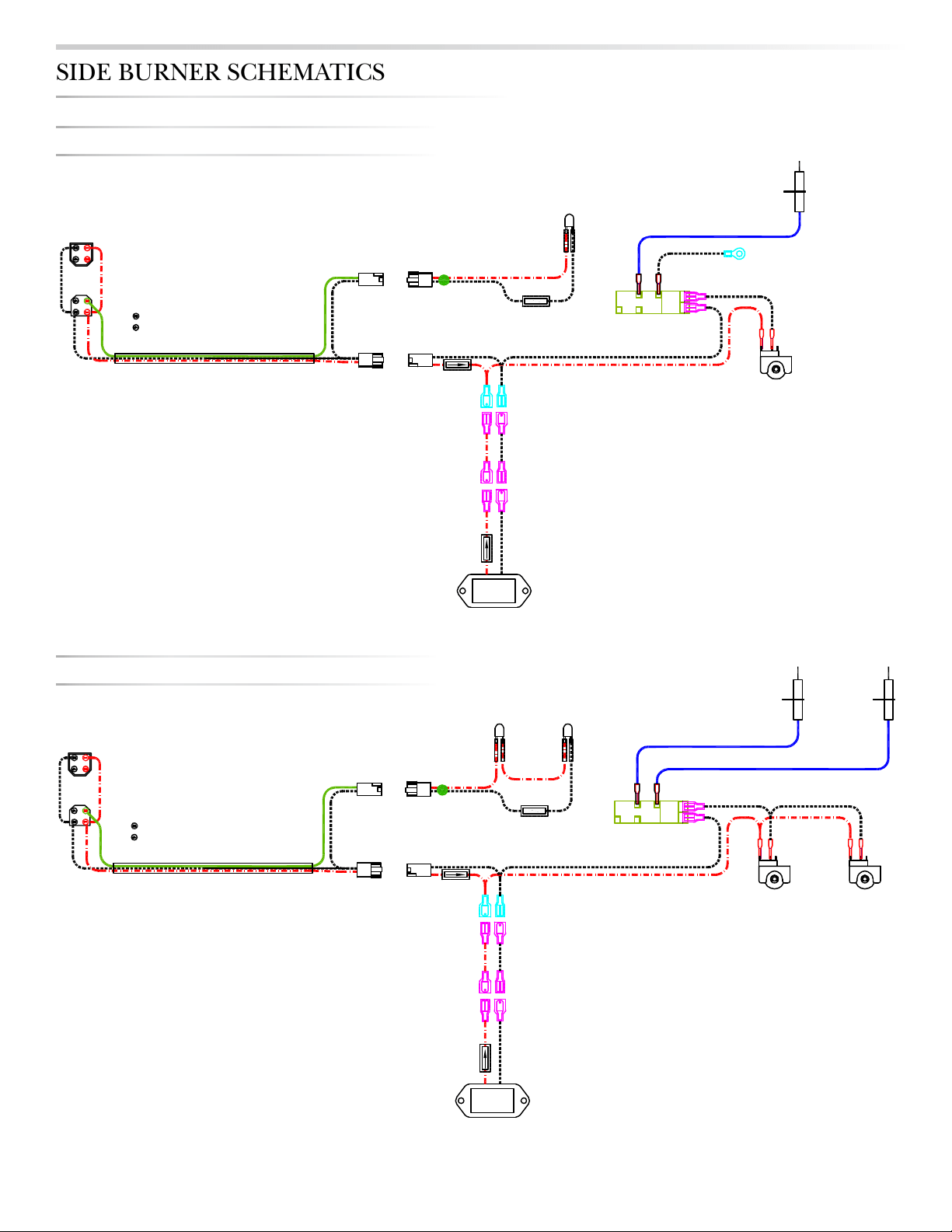
LEAD WITH PIN
DEAD LEAD (NO PIN)
LED
Light
MF
Mo lex
Female
Male pins
Green
Varistor
MM
Molex Male
Female Pins
MF
Mo lex
Female
Male pins
MM
BURNER
Molex Male
Female Pins
LEAD WITH PIN
DEAD LEAD (NO PIN)
LED
Light
LED
Light
MF
Mo lex
Female
Male pins
Green
Varistor
MM
Molex Male
Female Pins
MF
Mo lex
Female
Male pins
MM
RIGHT
BURNER
LEFT
BURNER
Molex Male
Female Pins
LSB502 Side Burner
LSB501 Side Burner
LEAD WITH PIN
DEAD LEAD (NO PIN)
LED
Light
MF
Mo lex
Female
Male pins
Green
Varistor
MM
Molex Male
Female Pins
MF
Mo lex
Female
Male pins
MM
BURNER
Molex Male
Female Pins
LEAD WITH PIN
DEAD LEAD (NO PIN)
LED
Light
LED
Light
MF
Mo lex
Female
Male pins
Green
Varistor
MM
Molex Male
Female Pins
MF
Mo lex
Female
Male pins
MM
RIGHT
BURNER
LEFT
BURNER
Molex Male
Female Pins
LSB502 Side Burner
LSB501 Side Burner
LSB501 SIDE BURNER
LSB502 SIDE BURNER
SIDE BURNER SCHEMATICS

SEDONA SIDE BURNER ACCESSORY CARE & USE/INSTALLATION
|
21
SIDE BURNER CONNECTOR
SIDE BURNER SCHEMATICS ...continued
22
|
SEDONA SIDE BURNER ACCESSORY CARE & USE/INSTALLATION
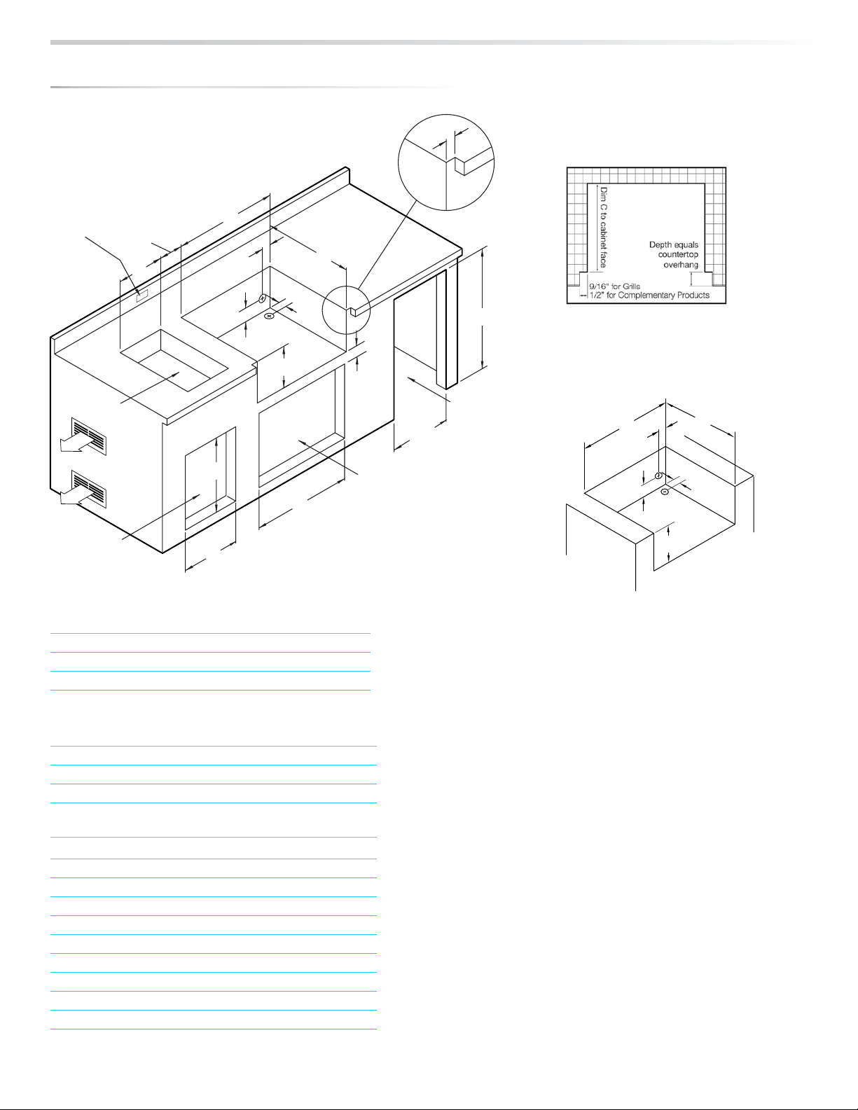
Measurements in inches.
CUT-OUT DIMENSIONS FOR SEDONA BUILT-IN GRILLS & ACCESSORIES
Note: For Natural Gas grills, the manufacturer
recommends using 3/4” gas supply lines.
COUNTERTOP NOTCH DETAIL
Only required if island countertop
overhangs the face of the island
NOTE: Insulating jacket required for all grills
installed into a combustible enclosure.
Note: Side burners may be rotated 90 degrees.
INSULATING JACKET
An enclosure for an LP-gas cylinder shall be ventilated by openings at
both the upper and lower levels of the enclosure. The effectiveness of the
opening(s) for purposes of ventilation shall be determined with the LP-gas
supply cylinder in place. This shall be accompanied by one of the follow-
ing:
a) One side of the enclosure shall be completely open; or
b) For an enclosure having four sides, a top and a bottom:
1. At least two ventilation openings shall be provided in the side walls of the
enclosure, located within 5 in (217 mm) of the top of the enclosure, equally
sized, spaced at a minimum of 90 degrees (1.57 rad), and unobstructed. The
opening(s) shall have a total free area of not less than 1 in 2/ lb (14.2 cm2/
kg) of stored fuel capacity.
2. Ventilation opening(s) shall be provided at floor level of the enclosure and
shall have a total free area of not less than 1/2 in2/lb (7.1 cm2/kg) of stored
fuel capacity. If ventilation openings at floor level are in a side wall, there
shall be at least two openings. The bottom of the openings shall be 1 in
(25.4 mm) or less from the floor level and the upper edge no more than 5 in
(127 mm) above the floor level. The openings shall be equally sized, spaced
at a minimum of 90 degrees (1.57 rad) and unobstructed.
3. Every opening shall have minimum dimensions so as to permit the entrance
of a 1/8 in (3.2 mm) diameter rod.
4. Ventilation openings in side walls shall not communicate directly with other
enclosures of the outdoor cooking gas appliance.
Keep the ventilation openings of the cylinder enclosure free and clear from
debris.
A
4.5”
5”
3”
C
B
BUiLT-in griLL
Model A B C
L400 23.00 10.00 21.25
L500 29.00 10.00 21.25
L600 35.00 10.00 21.25
COMPLEMEnTarY PrODUCTS
Model A B C
LSB501* 11.00 4.00 16.00
LSB502* 21.00 4.00 16.00
LDR424 22.00 19.00 –
LDR530 28.25 19.00 –
LDR636 33.75 19.00 –
LSA530 28.25 19.00 20.00
LSA636 33.75 19.00 20.00
LUD517 17.25 12.75 20.00
L500REF 21.50 34.00 24.50
BUiLT-in griLL w/ inSULaTing JaCKET
Model A B C
LIJ400 30.00 11.62 23.25
LIJ500 36.00 11.62 23.25
LIJ600 42.00 11.62 23.25
A
A
0.56”
Double
Drawers
(LUD)
Single &
Double Side
Burner (LSB)
Outdoor
Refrigerator
(L500REF)
Door & Drawer Options
(LDR, LSA or LTA)
CUTOUT NOT
REQUIRED
WITH LIJs
Locate a 110 V 15Amp
GFI outlet for rotisserie
models.
B
C
A
B
3.50”
3.50”
12.00”
2.00”
34.00”
2.25”
21.50”
A
* When installing the LSB side burners
over the refrigerator, the counter top
must be at least 37-1/2” above the floor.
*
SEDONA SIDE BURNER ACCESSORY CARE & USE/INSTALLATION
|
25
4
7
11
2
14
8
9
16
18
17
1
3
12
10
13
21
23
22
15
20
19
24
25
5 6
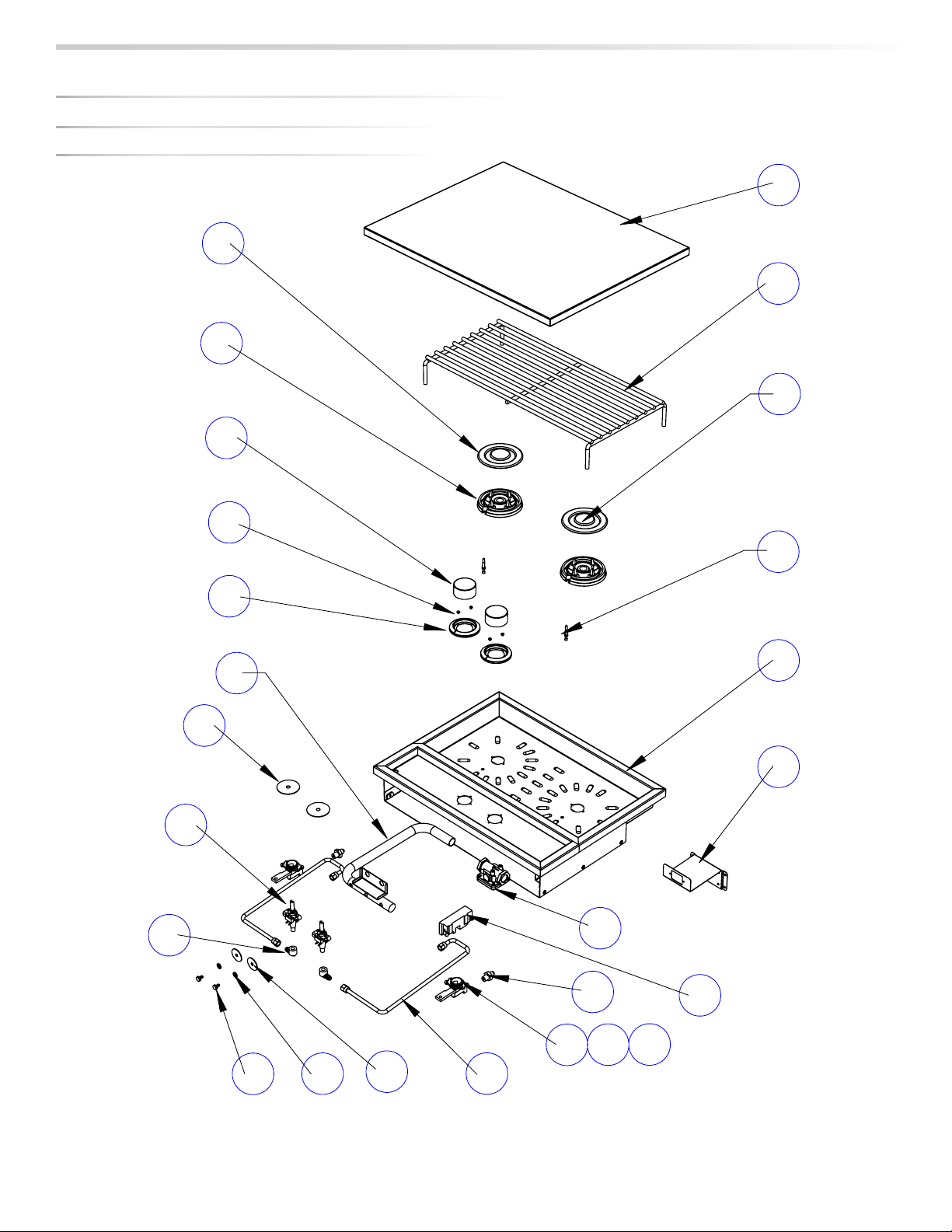
LSB502 SIDE BURNER
SIDE BURNER EXpLODED pARTS VIEW...continued
26
|
SEDONA SIDE BURNER ACCESSORY CARE & USE/INSTALLATION
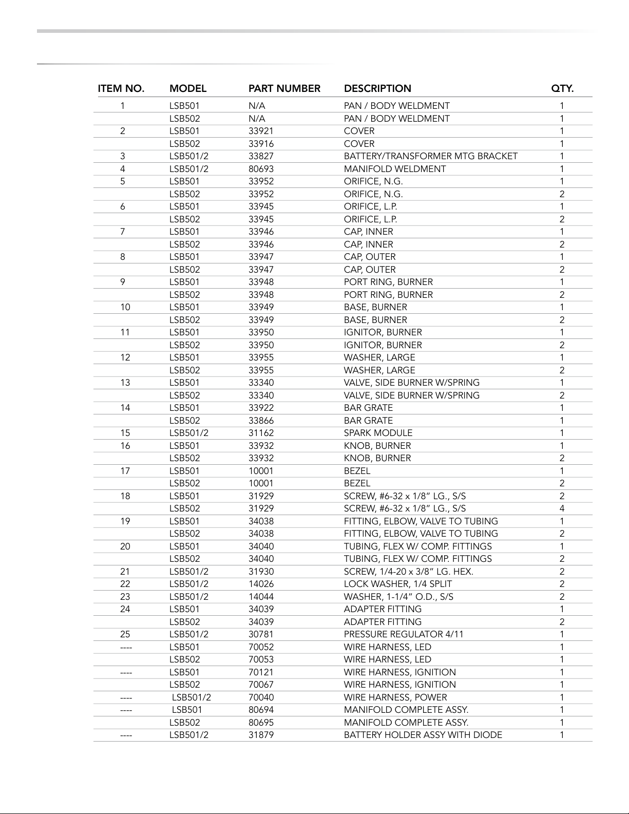
SIDE BURNER EXpLODED pARTS LIST
ITEM NO. MODEL PART NUMBER DESCRIPTION QTY.
1 LSB501 N/A PAN / BODY WELDMENT 1
LSB502 N/A PAN / BODY WELDMENT 1
2 LSB501 33921 COVER 1
LSB502 33916 COVER 1
3 LSB501/2 33827 BATTERY/TRANSFORMER MTG BRACKET 1
4 LSB501/2 80693 MANIFOLD WELDMENT 1
5 LSB501 33952 ORIFICE, N.G. 1
LSB502 33952 ORIFICE, N.G. 2
6 LSB501 33945 ORIFICE, L.P. 1
LSB502 33945 ORIFICE, L.P. 2
7 LSB501 33946 CAP, INNER 1
LSB502 33946 CAP, INNER 2
8 LSB501 33947 CAP, OUTER 1
LSB502 33947 CAP, OUTER 2
9 LSB501 33948 PORT RING, BURNER 1
LSB502 33948 PORT RING, BURNER 2
10 LSB501 33949 BASE, BURNER 1
LSB502 33949 BASE, BURNER 2
11 LSB501 33950 IGNITOR, BURNER 1
LSB502 33950 IGNITOR, BURNER 2
12 LSB501 33955 WASHER, LARGE 1
LSB502 33955 WASHER, LARGE 2
13 LSB501 33340 VALVE, SIDE BURNER W/SPRING 1
LSB502 33340 VALVE, SIDE BURNER W/SPRING 2
14 LSB501 33922 BAR GRATE 1
LSB502 33866 BAR GRATE 1
15 LSB501/2 31162 SPARK MODULE 1
16 LSB501 33932 KNOB, BURNER 1
LSB502 33932 KNOB, BURNER 2
17 LSB501 10001 BEZEL 1
LSB502 10001 BEZEL 2
18 LSB501 31929 SCREW, #6-32 x 1/8” LG., S/S 2
LSB502 31929 SCREW, #6-32 x 1/8” LG., S/S 4
19 LSB501 34038 FITTING, ELBOW, VALVE TO TUBING 1
LSB502 34038 FITTING, ELBOW, VALVE TO TUBING 2
20 LSB501 34040 TUBING, FLEX W/ COMP. FITTINGS 1
LSB502 34040 TUBING, FLEX W/ COMP. FITTINGS 2
21 LSB501/2 31930 SCREW, 1/4-20 x 3/8” LG. HEX. 2
22 LSB501/2 14026 LOCK WASHER, 1/4 SPLIT 2
23 LSB501/2 14044 WASHER, 1-1/4” O.D., S/S 2
24 LSB501 34039 ADAPTER FITTING 1
LSB502 34039 ADAPTER FITTING 2
25 LSB501/2 30781 PRESSURE REGULATOR 4/11 1
---- LSB501 70052 WIRE HARNESS, LED 1
LSB502 70053 WIRE HARNESS, LED 1
---- LSB501 70121 WIRE HARNESS, IGNITION 1
LSB502 70067 WIRE HARNESS, IGNITION 1
---- LSB501/2 70040 WIRE HARNESS, POWER 1
---- LSB501 80694 MANIFOLD COMPLETE ASSY. 1
LSB502 80695 MANIFOLD COMPLETE ASSY. 1
---- LSB501/2 31879 BATTERY HOLDER ASSY WITH DIODE 1