Loading ...
Loading ...
Loading ...
9
3-wire connection: Direct wire
Use this method only if local codes permit connecting ground
conductor to neutral supply wire.
1. Loosen (do not remove) the hex washer head screws and
insert the neutral (white) wire under the screw clamp at the
bottom of the center position terminal connector.
2. Insert the other 2 wires (lines 1 and 2) under the other 2 screw
clamps.
3. Securely tighten the hex washer head screws to
35 lbs-in. (4.0 N-m) minimum torque to make a proper
electrical connection.
4. Tighten the locking ring of the conduit connector.
5. Replace the terminal block cover.
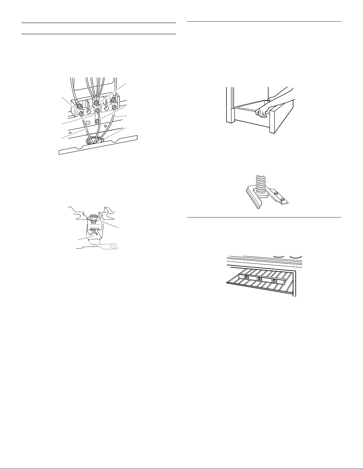
Verify Anti-Tip Bracket Location
1. On models with a storage drawer, pull drawer open to first
stop position. Lift front of drawer to clear white wheels in
drawer guides. Remove drawer and set it aside on a covered
surface.
On models with a warming drawer, the rear leg cannot be
seen by removing the warming drawer. It will be necessary to
view the rear foot from outside the range.
2. To check that the anti-tip bracket is installed, use a flashlight
and look underneath the bottom of the range.
■ Look for the anti-tip bracket securely attached to floor.
■ Slide range back so rear range foot is under anti-tip
bracket.
Level Range
1. Place rack in oven.
2. Place level on rack and check levelness of range, first side to
side; then front to back.
3. If range is not level, pull range forward until rear leveling leg is
removed from the anti-tip bracket.
On Ranges Equipped with Storage Drawers:
Use a ¼" drive ratchet, wrench or pliers to adjust leveling legs
up or down until the range is level. Push range back into
position. Check that rear leveling leg is engaged in anti-tip
bracket.
On Ranges Equipped with Warming Drawers:
Use a wrench or pliers to adjust leveling legs up or down until
the range is level. Push range back into position. Check that
rear leveling leg is engaged in anti-tip bracket.
NOTE: Range must be level for satisfactory baking
performance.
4. Replace the storage drawer (or warming drawer on some
models).
A. Line 1
B. Ground-link
C. Hex washer head screw
D. Silver-colored terminal
block screw
E. Neutral (white) wire
F. Line 2
G. UL listed strain relief
and power supply
cable
A. Insert wire under screw clamp.
B. Hex washer head screw
A
B
C
D
E
F
G
A
B
Loading ...
Loading ...
Loading ...