
© 2020 by Snow Joe
®
, LLC
All rights reserved. Original instructions.
SAVE THESE INSTRUCTIONS
A Division of Snow Joe
®
, LLC
OPERATOR’S MANUAL
Model GTS4002C Form No. SJ-GTS4002C-880E-MR6
CORDLESS LAWN + GARDEN
MULTI-TOOL SYSTEM
24-VOLT MAX* | POLE HEDGE TRIMMER | POLE CHAIN SAW | POLE GRASS TRIMMER
R
IMPORTANT!
Safety Instructions
All Operators Must Read These
Instructions Before Use
Always follow these safety guidelines. Failure to do so may
result in serious bodily injury or death.
General Safety
mWARNING! This appliance is not intended for use
by children or by unassisted, unsupervised persons whose
physical, sensory or mental capabilities prevent them from
using it safely. Children should be supervised to ensure that
they do not play with the appliance.
Before starting up your machine, please check it carefully for
any defects. If you nd any, do not start up your machine.
Contact your authorized Snow Joe
®
+ Sun Joe
®
dealer or
call the Snow Joe
®
+ Sun Joe
®
customer service center at
1-866-SNOWJOE (1-866-766-9563).
mWARNING! When using the power tool, basic safety
precautions should always be followed to reduce the risk of
re, electric shock, and personal injury. These include:
1. Keep work area clean and well-lit – Cluttered, dark
areas invite accidents.
2. Avoid dangerous environments – Do not use the power
tool in rain, in damp or wet locations, or in bad weather,
especially when there is a risk of lighting. This decreases
the risk of being struck by lighting. Do not operate the
power tool in gaseous or explosive atmospheres or use
the power tool near ammable or combustible liquids.
Motors in these tools normally spark, and the sparks
might ignite fumes.
3. Know your product – Know how to start and stop the
machine. Be thoroughly familiar with the controls.
4. Keep children, bystanders, and pets away –
All spectators, including pets, should be kept a safe
distance away from the work area.
5. Dress properly – Do not wear loose clothing or jewelry.
They can get caught in moving parts. Protective rubber
gloves and non-slip footwear are recommended when
working outdoors.
6.
mCAUTION! – Exercise caution to avoid slipping or
falling. Wear protective footwear that will protect your feet
and improve your footing on slippery surfaces.
7. Stay alert – Watch what you are doing. Use common
sense. Do not operate the power tool when you are tired,
or under the inuence of alcohol or drugs.
8. Do not overreach –
Keep proper footing and balance
at all times.
9. Avoid unintentional starting – Do not carry the power
tool with your nger on the trigger. Make sure the switch
is o before inserting the battery.
10. Use the right appliance – Do not use the power tool
for any applications other than those for which it was
intended.
11. Blades are sharp – Don't grasp the exposed cutting
blades or cutting edges when picking up or holding the
power tool.
12. Use two hands – Hold the telescoping pole and handle
with both hands to avoid loss of control.
13. Remove the battery – Remove the battery from the
power tool when it is not in use, before servicing it,
when changing accessories, and when performing any
other maintenance task.
14. Use safety glasses – Also use safety footwear,
snug-tting clothing, protective gloves, hearing and
head protection.
15. Use head protection – Always use head protection when
operating the power tool overhead. Falling debris can
result in serious personal injury.
16. Do not force the tool – It will perform better with less
likelihood of personal or mechanical injury if it is used at
the rate for which it was designed.
17. Store indoors – When not in use, the power tool should
be stored indoors in a dry and high or locked-up place out
of the reach of children.
18. Check for damaged parts – Before further use of the
appliance, all guards and parts should be carefully
checked to determine that it will operate properly and
perform its intended function. Check for alignment of
moving parts, binding of moving parts, breakage of parts,
mounting, and any other condition that may aect its
operation. A guard or other part that is damaged should
be properly repaired or replaced. Contact the Snow Joe
®
+ Sun Joe
®
customer service center at 1-866-SNOWJOE
(1-866-766-9563) for assistance.
1

2
19. Maintain the power tool with care – Keep the cutting
edges sharp and clean for optimal performance and to
reduce the risk of injury. Keep the handles dry, clean,
and free from oil and grease. Follow the additional
recommendations described in the maintenance section
of this manual.
20. Do not use the power tool if the switch does not turn it on
and o. Any power tool that cannot be controlled with the
switch is dangerous and must be repaired.
21. Keep all parts of the body away from the cutting blades/
chain. Do not remove cut material or hold material to be
cut when blades/chain are moving. Make sure the switch
is o when clearing jammed material. The blades/chain will
continue moving for a while after the tool is turned o.
A moment of inattention while operating the power tool
may result in serious personal injury.
22. Carry the power tool by the handle with the cutting blade/
chain stopped. When transporting or storing the power
tool, always keep the blades/chain covered.
Proper handling of the garden tool will reduce
possible personal injury from the cutting blades.
23. Hold the product by insulated gripping surfaces only,
because the cutting blades/chain may contact hidden
wiring. Cutting blades/chain contacting a “live” wire may
make exposed metal parts of the product “live”and could
give the operator an electric shock.
24. The unit has not been designed to provide protection
from electric shock in the event of contact with overhead
electric lines. Never use the power tool near any electrical
power lines. Contact with or use near power lines may
cause serious injury or electric shock resulting in death.
Maintain a minimum clearance of 50 ft (15 m) from all
power lines.
mWARNING! Before inspecting, cleaning, or servicing
the machine, remove the battery and wait for all moving parts
to stop. Failure to follow these instructions can result in serious
personal injury or property damage.
mWARNING! Do not use this appliance without reading
this instruction manual.
mWARNING! Do not use the appliance within range of
persons unless they are wearing protective clothing.
mWARNING! Do not operate the cordless power tool in
a tree, on a ladder, or on a scaold. Using the tool under such
circumstances is extremely dangerous.
mWARNING! Do not let familiarity with this type of tool
prevent you from taking all necessary precautions. Remember
that a careless fraction of a second is sucient to inict
serious injury.
mWARNING! The multi-tool system must be fully
assembled before operation! Do not use the tool that is only
partly assembled or assembled with damaged parts!
mWARNING! Starting, stopping, and restarting an
electric motor repeatedly within a few seconds can generate
a great deal of heat and damage the motor. To protect the life
of your cordless power tool, always wait at least ve seconds
after stopping before restarting the unit.
mWARNING! Electrical Shock Hazard – Before starting
up your machine, please check it carefully for any defects.
If you nd any, do not start up your machine and contact your
distributor.
NOTE: Take care of small parts that are removed during
assembly or when making adjustments. Keep them secure
to avoid loss.
Please contact an authorized Snow Joe
®
+ Sun Joe
®
dealer
or call the Snow Joe
®
+ Sun Joe
®
customer service center
at 1-866-SNOWJOE (1-866-766-9563) for all maintenance
or operations not foreseen in this manual. Any operation
performed in an unauthorized service center or by unqualied
personnel will completely invalidate the warranty.
mWARNING! For your safety and that of others:
• Correct maintenance is essential to maintain the original
eciency and safety of the machine over time.
• Keep all nuts, bolts, and screws tight to be sure the
equipment is in safe working condition.
• Never use the machine with worn or damaged parts.
Damaged parts are to be replaced and never repaired.
mWARNING! Always wear protective gloves during
maintenance operations.
mWARNING! Use only original manufacturer’s
replacement parts, accessories and attachments. Failure to
do so can cause possible injury and poor performance.
To order genuine replacement parts or accessories for the
Sun Joe
®
GTS4002C cordless lawn + garden multi-tool
system, please visit sunjoe.com or contact the Snow Joe
®
+
Sun Joe
®
customer service center at 1-866-SNOWJOE
(1-866-766-9563).
Cleaning the Tool
mWARNING! Never let any liquid get inside the motor
housing and NEVER immerse any part of the housing in liquid.
1. Stop the motor and remove the battery.
2. Clean dirt and debris from the body of the tool, using a
damp cloth with a mild detergent.
NOTE: Do not use any strong detergents on the plastic
housing or the handle, as they can be damaged by certain
aromatic oils such as pine and lemon, and by solvents
such as kerosene.

3
Storage
m
WARNING! Do not at any time let brake uids, gasoline,
petroleum-based products, penetrating oils, etc., come in
contact with plastic parts. Chemicals can damage, weaken, or
destroy plastic which may result in serious personal injury.
1. Stop the motor and remove the battery.
2. Clean the multi-tool system thoroughly before storing.
3. Always place the blade cover on the blade and bar sheath
on the chain bar before storing or transporting the multi-
tool system. Use caution to avoid the sharp teeth of the
blade and the chain.
4. Store the multi-tool system indoors, in a dry place that is
inaccessible to children. Keep away from corrosive agents
such as garden chemicals and de-icing salts.
5. We recommend using the original package for storage or
covering the product with a suitable cloth or enclosure to
protect it against dust.
Specic Safety Warnings
for Pole Chain Saw
1. Only the pole chain saw operator should be in the
work area.
2. Do not use the pole chain saw to cut down trees.
3. Always use two hands when operating the pole chain
saw. Grip the pole chain saw securely with one hand on
the trigger and the other hand on the pole or the auxiliary
handle.
4. Before starting the pole chain saw, make sure that the
saw chain is not in contact with any object.
5. Do not allow the pole chain saw to make contact with
grounded objects such as pipes, fences, and metal posts.
6. Do not force the pole chain saw while cutting. Apply light
pressure. It will perform more eectively and safely if it is
used at the rate for which it was designed.
7. Use extreme caution when cutting a limb that is under
tension. When wood tension is released, the limb could
spring back and strike the operator, causing severe injury
or death.
8. During transport, hold the pole at its balance point,
with the guide bar and chain facing to the rear.
9. Do not cut small brush and saplings with the pole chain
saw. Small branches may catch in the chain and be
whipped towards the operator, which could pull the
operator o balance.
10. Never stand directly under the limb you are trimming.
Always position yourself outside the path of falling debris.
11. Keep a rm, steady pressure on the pole chain saw while
cutting. Do not try to cut limbs larger in diameter than the
length of the guide bar.
12. Keep other people and pets away from the cutting end of
the pole chain saw and at a safe distance away from the
work area.
Kickback
mWARNING! Kickback may occur when the nose or tip
of the guide bar touches an object, or when the wood closes
in and pinches the saw chain in the cut.
AVOID CONTACTING THE GUIDE BAR TIP WITH ANY
OBJECT. In some cases, when the tip makes contact with an
object, it may cause a fast reverse reaction, kicking the guide
bar up and back towards the operator. Pinching the saw chain
along the top of the guide bar may also push the guide bar
rapidly back towards the operator. Either of these reactions
may cause you to lose control of the pole chain saw, which
could result in serious personal injury.
• Kickback safety devices on this pole chain saw include
a skip chain and a low kickback guide bar. These will
reduce, but not entirely prevent, kickbacks. Follow the
necessary precautions indicated in this operator's manual
to avoid kickbacks.
• Always use two hands when operating the pole chain saw,
one hand gripping the trigger and the other hand gripping
the pole or the auxiliary handle. Use a rm grip.
Thumbs and ngers must wrap around the trigger and
the pole/auxiliary handle.
• Keep all guards in place on the pole chain saw. Make sure
they are in proper working order.
• Do not overreach or extend arms above shoulder height.
• Keep solid footing and balance at all times.
• Never try cutting through two branches at the same time.
Only cut one at a time.
• Do not bury the guide bar nose or try to cut by boring the
guide bar nose into the wood.
• Watch for shifting of wood or other forces that may pinch
the chain.
• Use extreme caution when re-entering a previous cut.
• Use the low-kickback chain and guide bar supplied with
this pole chain saw. Only use genuine Snow Joe
®
+
Sun Joe
®
replacement parts designed specically for use
with this pole chain saw.
• Never use a dull or loose chain. Keep the chain sharp and
properly tensioned.
Specic Safety Warnings
for Pole Hedge Trimmer
1. Remove any adjusting key or wrench before turning
the power tool on. A wrench or key left attached to the
rotating part of the power tool may result in personal
injury.
2. Remove any blade that has been damaged. Always make
sure that the blade is installed correctly and securely
fastened before each use. Failure to do so can cause
serious injury.
3. Never cut any material over 0.6 in. (1.5 cm) in diameter.

4
4. Maintain a rm grip on the handle and the pole/auxiliary
handle while cutting with the blade. Keep the blade away
from body.
5. Use the pole hedge trimmer and accessories in
accordance with these instructions, taking into account
the working conditions the work to be performed. Use of
the power tool for operations dierent from intended use
could lead to a hazardous situation.
Specic Safety Warnings for
Grass Trimmer + Edger
mCAUTION! The safety guard is critical to the safety of
the operator and the safety of people standing within a safe
distance of the grass trimmer. The safety guard keeps the unit
in good working order and must always be in place during
operation. Failure to have the guard in place during operation
is dangerous and will void the warranty.
1. Keep away from the cutting line – It can seriously injure
the skin.
2. Do not try to stop the cutting device with your hands –
Always let it come to a stop by itself.
mCAUTION! The trimmer line spool will continue to rotate
after turning the trimmer OFF. Wait until the trimmer line spool
has completely stopped before making contact.
3. Only use the same type of line originally provided with
the tool.
4. Do not use the unit to cut grass that is not in contact with
the ground.
5. Keep guards in place and in working order.
6. Keep blades sharp.
7. Keep hands and feet away from cutting area.
8. Do not switch the grass trimmer + edger ON in enclosed
or poorly ventilated spaces or in the presence of
ammable and/or explosive substances such as liquids,
gases, and powders.
9. The user of the grass trimmer + edger is responsible for
any damage sustained by third parties that has been
caused by the grass trimmer + edger within the
working area.
10. Only cut during broad daylight or with adequate
articial light.
11. Do not cross roads or gravel paths while the unit is
still running.
12. When the grass trimmer + edger is not in use, store it in a
dry place and out of the reach of children.
13. The grass trimmer + edger must be operated in a vertical
position, perpendicular to the ground.
14. Check regularly that all screws are properly secured.
15. Never use the grass trimmer + edger when it is raining or
when excessively moist and humid conditions are present.
Do not cut damp grass or leave the tool outside overnight.
16. If the grass trimmer + edger strikes a foreign object or
becomes entangled with it, stop the tool immediately.
Remove the battery, check for damage, and have any
damage repaired before proceeding with operation.
Do not operate the tool with a broken hub or spool.
Battery & Charger
Safety Instructions
We pay a great deal of attention to the design of every battery
pack to ensure that we supply you with batteries that are safe,
durable and have a high energy density. The battery cells have
a wide range of safety devices. Each individual cell is initially
formatted and its electrical characteristic curves are recorded.
This data is then used exclusively to be able to assemble the
best possible battery packs.
Despite all the safety precautions, caution must always be
exercised when handling batteries. The following points must
be obeyed at all times to ensure safe use. Safe use can only
be guaranteed if undamaged cells are used. Incorrect handling
of the battery pack can cause cell damage.
IMPORTANT! Analyses conrm that incorrect use and poor
care of high-performance batteries are the main factors
responsible for personal and/or product damage.
mWARNING! Use only approved replacement batteries;
other batteries may damage the power tool and cause it to
malfunction, which can lead to serious personal injury.
mWARNING! Do not use a battery pack or appliance that
is damaged or modied. Damaged or modied batteries may
exhibit unpredictable behavior resulting in re, explosion or risk
of injury.
Do not modify or attempt to repair the appliance or the battery
pack except as indicated in the instructions for use and care.
Have your battery pack serviced by a qualied repair person
using only identical replacement parts. This will ensure that the
safety of the battery pack is maintained.
mCAUTION! To reduce the risk of injury, charge the
iON+ 24V lithium-ion battery pack only in its designated
iON+ 24V lithium-ion charger. Other types of chargers present
risk of re, personal injury and damage. Do not wire a battery
pack to a power supply plug or car cigarette lighter. Such
misuse will permanently disable or damage the battery pack.
• Avoid dangerous environments – Do not charge the
battery pack in rain, snow or in damp or wet locations.
Do not use the battery pack or charger in the presence of
explosive atmospheres (gaseous fumes, dust or ammable
materials) because sparks may be generated when inserting
or removing the battery pack, which could lead to a re.
• Charge in a well-ventilated area – Do not block the
charger vents. Keep them clear to allow for proper
ventilation. Do not allow smoking or open ames near a
charging battery pack. Vented gases may explode.

5
NOTE: The safe temperature range for the battery is 40°F
(4.5°C) to 105°F (40.5°C). Do not charge the battery outside
in freezing weather; charge it at room temperature.
• Maintain charger cord – When unplugging the charger, pull
the plug, not the cord, from the receptacle to reduce the
risk of damage to the electrical plug and cord. Never carry
the charger by its cord or yank it by the cord to disconnect
it from the receptacle. Keep the cord away from heat, oil
and sharp edges. Make sure the cord will not be stepped
on, tripped over or subjected to damage or stress when the
charger is in use. Do not use the charger with a damaged
cord or plug. Replace a damaged charger immediately.
• Do not use an extension cord unless it is absolutely
necessary – Using the wrong, damaged or improperly
wired extension cord poses a risk of re and electric shock.
If an extension cord must be used, plug the charger into a
properly wired 16 gauge or larger extension cord with the
female plug matching the male plug on the charger. Make
sure that the extension cord is in good electrical condition.
• Charger 24VCHRG-AC is rated for 100 – 240 volt
AC only – The charger must be plugged into an
appropriate receptacle.
• Use only recommended attachments – Use of an
attachment not recommended or sold by the battery
charger or battery pack manufacturer may result in risk
of re, electric shock or personal injury.
• Unplug charger when not in use – Make sure to remove
battery packs from unplugged chargers.
mWARNING! To reduce the risk of electric shock,
always unplug the charger before performing any cleaning
or maintenance. Do not allow water to ow into the charger.
Use a Ground Fault Circuit Interrupter (GFCI) to reduce shock
hazards.
• Do not burn or incinerate battery packs – Battery packs
may explode, causing personal injury or damage.
Toxic fumes and materials are created when battery
packs are burned.
• Do not crush, drop or damage battery packs – Do not
use the battery pack or charger if they have sustained a
sharp blow, been dropped, run over or have been damaged
in any way (i.e. pierced with a nail, hit with a hammer,
stepped on, etc.).
• Do not disassemble – Incorrect reassembly may pose
a serious risk of electric shock, re or exposure to toxic
battery chemicals. If the battery or charger are damaged,
contact an authorized Snow Joe
®
+ Sun Joe
®
dealer or
call the Snow Joe
®
+ Sun Joe
®
customer service center at
1-866-SNOWJOE (1-866-766-9563) for assistance.
• Battery chemicals cause serious burns – Never let a
damaged battery pack contact the skin, eyes or mouth. If a
damaged battery pack leaks battery chemicals, use rubber
or neoprene gloves to safely dispose of it. If skin is exposed
to battery uids, wash the aected area with soap and
water and rinse with vinegar. If eyes are exposed to battery
chemicals, immediately ush with water for
20 minutes and seek medical attention. Remove and
dispose of contaminated clothing.
• Do not short circuit – A battery pack will short circuit if
a metal object makes a connection between the positive
and negative contacts on the battery pack. Do not place a
battery pack near anything that may cause a short circuit,
such as paper clips, coins, keys, screws, nails and other
metallic objects. A short-circuited battery pack poses a risk
of re and severe personal injury.
• Store your battery pack and charger in a cool, dry
place – Do not store the battery pack or charger where
temperatures may exceed 105ºF (40.5ºC), such as in direct
sunlight or inside a vehicle or metal building during the
summer.
Information about the battery
1. The battery pack supplied with your cordless power tool is
only partially charged. The battery pack has to be charged
completely before you use the tool for the rst time.
2. For optimum battery performance, avoid low discharge
cycles by charging the battery pack frequently.
3. Store the battery pack in a cool place, ideally at
59°F (15°C) and charged to at least 40%.
4. Lithium-ion batteries are subject to a natural aging
process. The battery pack must be replaced at the latest
when its capacity falls to just 80% of its capacity when
new. Weakened cells in an aged battery pack are no
longer capable of meeting the high power requirements
needed for the proper operation of your multi-tool system,
and therefore pose a safety risk.
5. Do not throw battery packs into an open re as this poses
a risk of explosion.
6. Do not ignite the battery pack or expose it to re.
7. Do not exhaustively discharge batteries. Exhaustive
discharge will damage the battery cells. The most
common cause of exhaustive discharge is lengthy storage
or non-use of partially discharged batteries. Stop working
as soon as the performance of the battery falls noticeably
or the electronic protection system triggers.
Place the battery pack in storage only after it has
been fully charged.
8. Protect batteries and the tool from overloads. Overloads
will quickly result in overheating and cell damage inside
the battery housing even if this overheating is not
apparent externally.
9. Avoid damage and shocks. Immediately replace batteries
that have been dropped from a height of more than
3 feet (1 meter) or those that have been exposed to violent
shocks, even if the housing of the battery pack appears
to be undamaged. The battery cells inside the battery may
have suered serious damage. In such instances,
please read the waste disposal information for proper
battery disposal.

6
10. If the battery pack suers overloading and overheating,
the integrated protective cuto will switch o the
equipment for safety reasons.
IMPORTANT! Do not press the ON/OFF switch any more
if the protective cut-o has been activated. This may
damage the battery pack.
11. Use only original battery packs. The use of other batteries
poses a re risk and may result in injuries or an explosion.
Information about the charger and the
charging process
1. Please check the data marked on the rating plate of the
battery charger. Be sure to connect the battery charger
to a power supply with the voltage marked on the rating
plate. Never connect it to a dierent mains voltage.
2. Protect the battery charger and its cord from damage.
Keep the charger and its cord away from heat, oil and
sharp edges. Have damaged cords repaired without delay
by a qualied technician at an authorized Snow Joe
®
+
Sun Joe
®
dealer or call the Snow Joe
®
+ Sun Joe
®
customer service center at 1-866-SNOWJOE
(1-866-766-9563).
3. Electrical plugs must match the outlet. Never modify
the plug in any way. Do not use any adapter plugs with
grounded appliances. Unmodied plugs and matching
outlets will reduce the risk of electric shock.
4. Keep the battery charger, battery pack(s) and the cordless
tool out of the reach of children.
5. Do not use the supplied battery charger to charge other
cordless tools.
6. During periods of heavy use, the battery pack will become
warm. Allow the battery pack to cool to room temperature
before inserting it into the charger to recharge.
7. Do not overcharge batteries. Do not exceed the maximum
charging times. These charging times only apply to
discharged batteries. Frequent insertion of a charged or
partially charged battery pack will result in overcharging
and cell damage. Do not leave batteries in the charger for
days on end.
8. Never use or charge batteries if you suspect that it has
been more than 12 months since the last time they were
charged. There is a high probability that the battery pack
has already suered dangerous damage (exhaustive
discharge).
9. Charging batteries at a temperature below 50°F (10°C) will
cause chemical damage to the cells and may cause a re.
10. Do not use batteries that have been exposed to heat
during the charging process, as the battery cells may have
suered dangerous damage.
11. Do not use batteries that have suered curvature or
deformation during the charging process or those that
exhibit other atypical symptoms (gassing, hissing,
cracking, etc.).
12. Never fully discharge the battery pack
(maximum recommended depth of discharge is 80%).
A complete discharge of the battery pack will lead to
premature aging of the battery cells.
Protection from environmental inuences
1. Wear suitable work clothes. Wear safety goggles.
2. Protect your cordless tool and the battery charger from
moisture and rain. Moisture and rain can cause dangerous
cell damage.
3. Do not use the cordless tool or the battery charger near
vapors and ammable liquids.
4. Use the battery charger and cordless tools only in dry
conditions and at an ambient temperature of 40°F – 105°F
(4.5°C – 40.5°C).
5. Do not keep the battery charger in places where the
temperature is liable to reach over 104°F (40°C). In
particular, do not leave the battery charger in a car that is
parked in the sunshine.
6. Protect batteries from overheating. Overloads,
overcharging and exposure to direct sunlight will result
in overheating and cell damage. Never charge or work
with batteries that have been overheated – replace them
immediately, if possible.
7. Store the charger and your cordless tool only in dry
locations with an ambient temperature of 40°F – 105°F
(4.5°C – 40.5°C). Store your lithium-ion battery pack in a
cool, dry place at a temperature of 50°F – 68°F
(10°F – 20°C). Protect the battery pack, charger and
cordless tool from humidity and direct sunlight.
Only place fully charged batteries in storage (charged to
at least 40%).
8. Prevent the lithium-ion battery pack from freezing. Battery
packs that were stored below 32°F (0°C) for more than
60 minutes must be discarded.
9. When handling batteries, be wary of electrostatic charge.
Electrostatic discharges can damage the electronic
protection system and the battery cells. Avoid electrostatic
charging and never touch the battery poles.
7
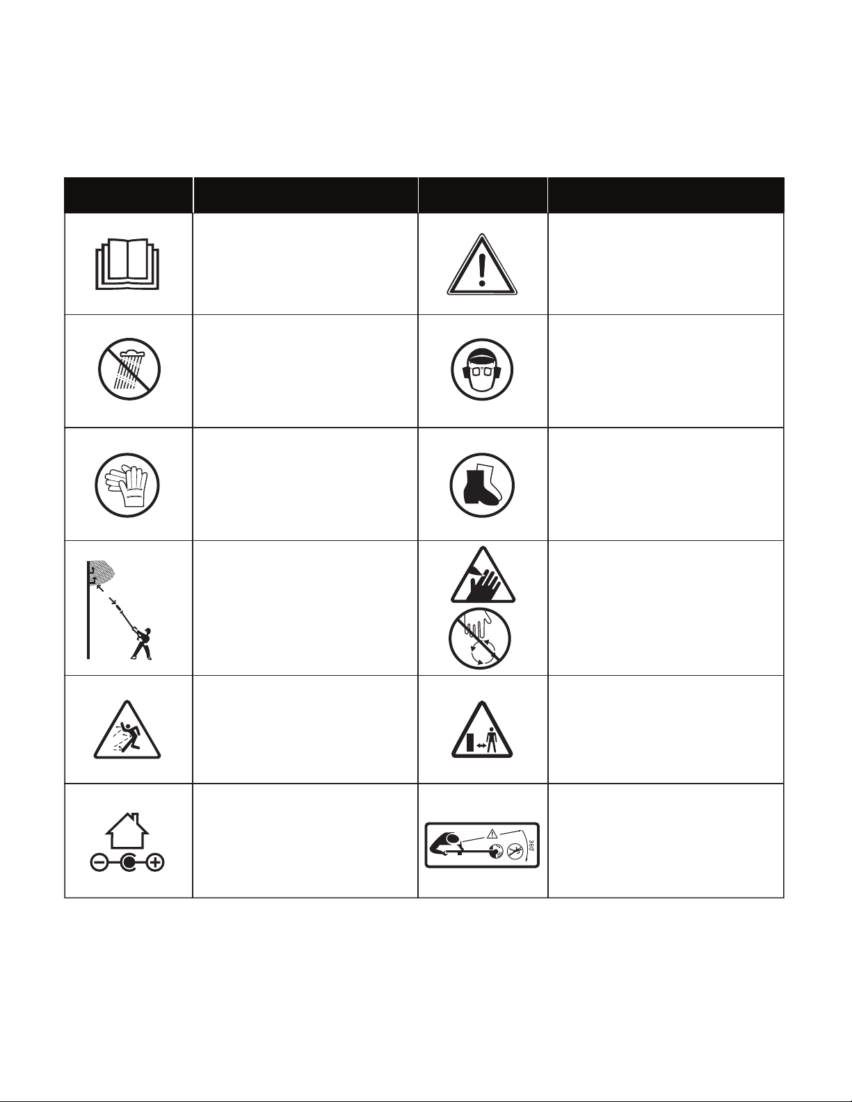
Safety Symbols
The following table depicts and describes safety symbols that may appear on this product. Read, understand, and follow all
instructions on the machine before attempting to assemble and operate.
READ THE OPERATOR'S
MANUAL(S) – Read, understand,
and follow all instructions in the
user manual(s) before attempting
to assemble and operate.
SAFETY ALERT – Indicates a
precaution, a warning, or a danger.
WEAR EYE AND HEARING
PROTECTION – For protection
against injury, wear ear defenders
and safety goggles.
WARNING! Do not expose the unit
to rain or wet conditions. Keep dry.
Symbols SymbolsDescriptions Descriptions
Indoor use only. Only use battery
charger indoors.
50 ft
(15 m)
WARNING! SHOCK HAZARD –
Keep at least 50 ft (15 m) away
from power lines. Do not overreach.
Keep proper footing and balance at
all times.
DANGER! ROTATING BLADES
– Keep hands and feet away from
openings while the saw is running.
Thrown objects and rotating blades
can cause severe injury.
Keep bystanders a minimum
distance of 50 ft (15 m) away from
the work area.
Wear protective gloves when using
the machine and handling debris.
DANGER! Beware of thrown
objects to bystanders. Keep
bystanders at least 15 m (50 ft)
away from the machine.
Wear foot protection when using
the machine and handling debris.
8
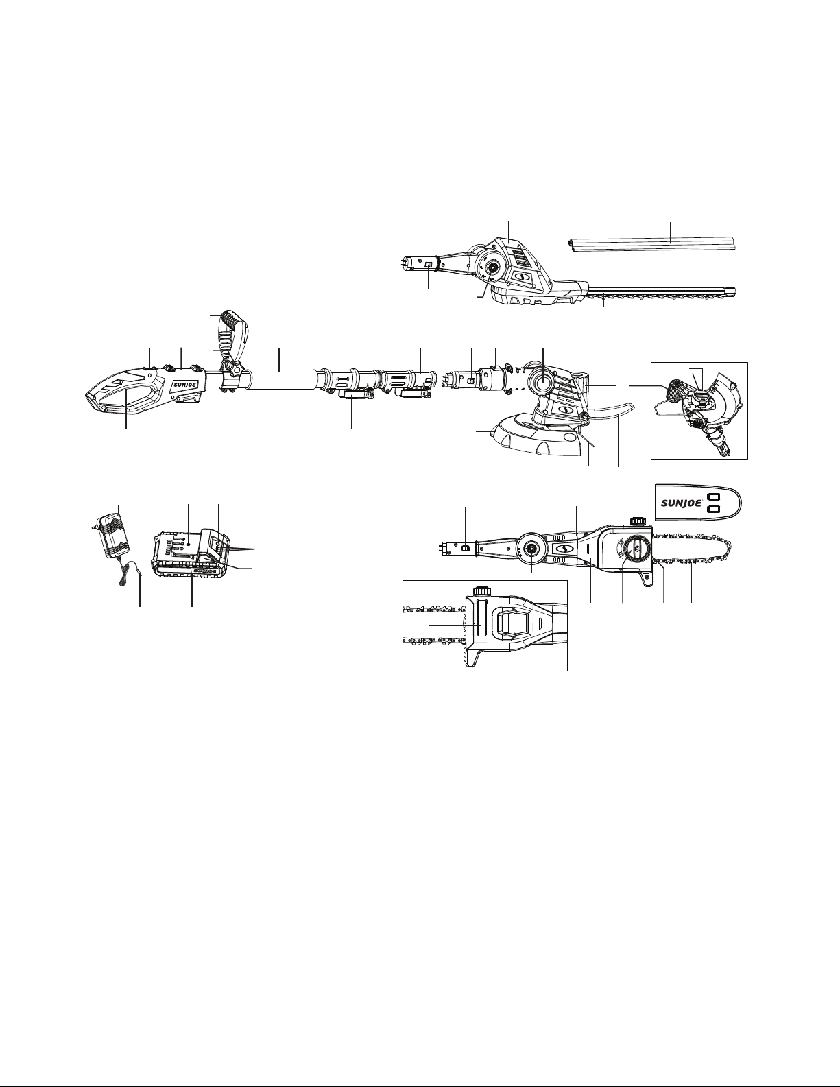
Know Your Cordless Lawn + Garden Multi-tool System
Read the owner’s manual and safety instructions carefully before operating the cordless multi-tool system. Compare the
illustration below to the cordless multi-tool system in order to familiarize yourself with the location of the various controls and
adjustments. Save this manual for future reference.
1. Hedge trimmer blade cover
2. Hedge trimmer head
3. Lock tab
4. Rotating button
5. Hedge trimmer blade
6. Edging wheel
7. Grass trimmer + edger head
8. Converting switch
9. Telescoping pole
10. Soft grip
11. Auxiliary handle
12. Auxiliary Handle lock knob
13. Handle
14. Safety lock switch
15. On/O [Trigger] switch
16. Battery compartment
17. Auxiliary handle loop
18. Telescoping lock
19. Assembly lock
20. Safety guard
21. Trimmer line
22. Flower guard
23. Spool
24. Chain bar cover
25. Oil tank cap
26. Chain saw head
27. Chain/sprocket end cover
28. Chain/sprocket end cover knob
29. Chain tensioner ring
30. 8-inch cutting chain
31. 8-inch guide bar
32. Oil level window
33. iON+ 24V lithium-ion battery
(24VBAT-LTE) featuring exclusive
EcoSharp
®
technology
34. Push lock button
35. Battery indicators
36. Push button for battery indicator
37. Charge socket
38. iON+ 24V lithium-ion charger
(24VCHRG-AC)
39. Charger plug
R
R
24
VOLT
1
2
3
4
5
6
79
10
14
15
13
16
18
19
Bottom of the grass
trimmer head
21
22
24
25
27
20
3 4
Back of the chain saw head
23
26
3
4
28 29 30 31
32
33
35
3637
38
39
8
11
12
34
17

9
Technical Data
Battery Voltage* ............................................................ 24V D.C.
Battery Capacity ............................................................... 2.0 Ah
Charging Time Max ...................................................1 hr 20 min
Telescoping Pole Length ....................................... 3.7 ft to 5.3 ft
........................................................................... (1.1 m to 1.6 m)
Auxiliary Handle Angles ........................................ -45° | 0° | 45°
Charger Input .......................................100 – 240 V 50 – 60 Hz
Charger Output .................................................. 25.2V DC 1.4A
Pole Hedge Trimmer
Motor ................................................................................ 250 W
Blade Length ...................................................17.7 inch (45 cm)
Cutting Diameter ..............................................0.6 inch (1.5 cm)
Head Angles ..............................................................-45° to 90°
Battery Run Time Max ...................................................50 mins
............................................... (cuts up to 4,000 sq ft of hedges)
Weight (with Battery Installed) ............................. 7.7 lbs (3.5 kg)
Grass Trimmer + Edger
Motor ................................................................................ 200 W
Cutting Diameter ................................................ 10 inch (25 cm)
Spool Length ............................................................16.5 ft (5 m)
Spool Advance ............................................................Auto-feed
Line diameter ...............................................0.055 inch (1.4 mm)
Head Angles ..................................................................0° to 60°
Battery Run Time Max ................................................... 45 mins
..................................................... (trims up to 2,045 lft of grass)
Weight (with Battery Installed) ............................ 6.2 lbs (2.8 kg)
Pole Chain Saw
Motor ................................................................................ 350 W
Bar/Chain Length .............................................. 8 inch (20.3 cm)
Cutting Thickness .................................... Max: 7.5 inch (19 cm)
......................................................
Recommended: 6.5 in. (16.5 cm)
Oil Tank Capacity ............................................... 2.7 oz (80 ml)
Overhead Reach Max .................................................13 ft (4 m)
Head Angles ..................................................................0° to 30°
Battery Run Time Max ..................Up to 32 cuts of 4" x 4" pine
Weight (with Battery Installed) ............................. 7.7 lbs (3.5 kg)
* Initial no-load voltage, when fully charged, peaks at 24 volts; nominal voltage
under typical load is 21.6 volts.
Unpacking
Carton Contents
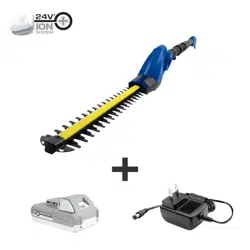
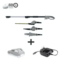
• Telescoping pole with auxiliary handle
• Chain saw head with chain and bar pre-mounted
• Chain saw bar sheath
• Hex key wrench
• Hedge trimmer head with blade
• Hedge trimmer blade sheath
• Grass trimmer + edger head
• Grass trimmer + edger safety guard
• Pre-wound spool (x2)
• iON+ 24V lithium-ion battery
• iON+ 24V lithium-ion charger
• Manuals with registration card
• 3.4 oz (100 ml) bar + chain lubricant oil
1. Carefully remove the multi-tool system and check to see
that all of the above items are supplied.
2. Inspect the product carefully to make sure no breakage or
damage occurred during shipping. If you nd damaged or
missing parts, DO NOT return the unit to the store. Please
call the Snow Joe
®
+ Sun Joe
®
customer service center at
1-866-SNOWJOE (1-866-766-9563).
NOTE: Do not discard the shipping carton and packaging
material until you are ready to use your new cordless
multi-tool system. The packaging is made of recyclable
materials. Properly dispose of these materials in
accordance with local regulations.
IMPORTANT! The equipment and packaging material are
not toys. Do not let children play with plastic bags, foils,
or small parts. These items can be swallowed and pose a
suocation risk!
Battery Pack Operation
The equipment is powered by a lithium-ion battery. The battery
pack is completely sealed and maintenance free.
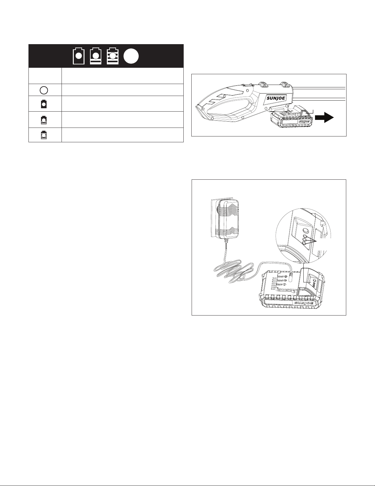
Battery Charge Level Indicator
The battery pack is equipped with a push button for checking
the charge level. Simply press the push button to read o the
battery charge level from the LEDs of the battery indicator:
• All 3 level monitoring LEDs are lit: Battery charge level
is high.
• 2 level monitoring LEDs are lit: Battery charge level is
decreasing. Stop work as soon as possible.
• 1 level monitoring LED is lit: Battery is at. Stop work
IMMEDIATELY and charge the battery. Otherwise the
battery’s service life will be greatly shortened.
Battery + Charger
10
Charge level button
The battery is at 30% capacity
and requires charging
The battery is at 60% capacity
and requires charging soon
The battery is at full capacity
Light IndicatorsLights
NOTE: If the charge level button does not appear to be
working, insert the charger and charge as needed.
NOTE: Immediately after using the battery pack, the charge
level button may display a lower charge than it will if checked
a few minutes later. The battery cells “recover” some of their
charge after resting.
Charger Operation
m
WARNING! Charge only iON+ 24V lithium-ion battery
packs with its compatible iON+ 24V lithium-ion charger. Other
types of batteries may cause personal injury and damage.
To reduce the risk of electric shock, do not allow water to ow
into the charger's AC/DC plug.
When to Charge the iON+ 24VBAT-LTE
Lithium-iON Battery
NOTE: The iON+ 24VBAT-LTE lithium-ion battery packs do
not develop a "memory" when charged after only a partial
discharge. Therefore, it is not necessary to run down the
battery pack before inserting the charger plug.
• Use the battery indicator lights to determine when to charge
your iON+ 24VBAT-LTE lithium-ion battery pack.
• You can "top-o" your battery pack's charge before starting
a big job or after a long day of use.
Charging the Battery
1. Push the push lock button on the battery to pull the
battery pack out from the battery compartment (Fig. 1).
2. Check that the mains voltage is the same as that marked
on the rating plate of the battery charger. Then, plug the
charger adaptor into an appropriate AC power outlet.
Connect the charger plug into the charge socket of the
battery to start charging (Fig. 2).
3. The battery will take approximately 80 minutes to charge.
The battery indicator LEDs will twinkle and illuminate one
by one during the charging process. Unplug the charger
immediately when the 3 LEDs are all illuminated.
mCAUTION! FIRE HAZARD. When disconnecting the
charger from the battery, be sure to unplug the charger from
the outlet rst, then disconnect the charger from the battery
mWARNING! This charger does not automatically
turn o when the battery is fully charged. Please take care
not to leave the battery plugged into the charger. Switch
o or unplug the charger at the mains when charging is
complete.
4. Timely recharging of the battery will help prolong the
battery's life. You must recharge the battery pack when
you notice a drop in the equipment's power.
R
Fig. 1
Push button
Fig. 2
Battery
indicators
11
IMPORTANT! Never allow the battery pack to become
fully discharged as this will cause irreversible damage to
the battery.
Assembly
m
DANGER! Never start the motor before installing the
guide bar, chain, and chain/sprocket end cover. Without all
these parts in place, the clutch can y o or explode, exposing
the user to potentially serious injuries.
Installing/Replacing Guide Bar And
Cutting Chain
Tools and supplies required:
• Hex key wrench (provided)
• Heavy-duty work gloves
NOTE: When replacing the guide bar and chain, use only
identical replacement parts. Make sure the pole chain saw
is disconnected with the battery before proceeding with
installation.
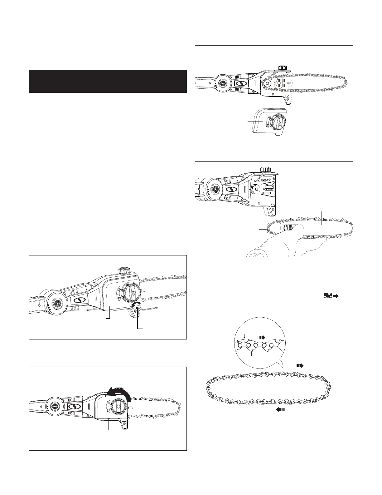
1. Remove the hex bolt by screwing it counterclockwise with
the hex key wrench (Fig. 3).
2. Screw the chain/sprocket end cover knob
counterclockwise to release chain/sprocket end cover
(Figs. 4 – 5).
3. Remove the bar and chain from the mounting surface
(Fig. 6).
4. Remove the old chain from the bar.
5. Lay out the new saw chain in a loop and straighten any
kinks. THE SHARP SIDE OF THE TEETH MUST FACE
AWAY FROM YOU IN THE DIRECTION OF THE CHAIN
ROTATION INDICATED ON THE GUIDE BAR
.
If the teeth face backwards, turn the loop over (Fig. 7).
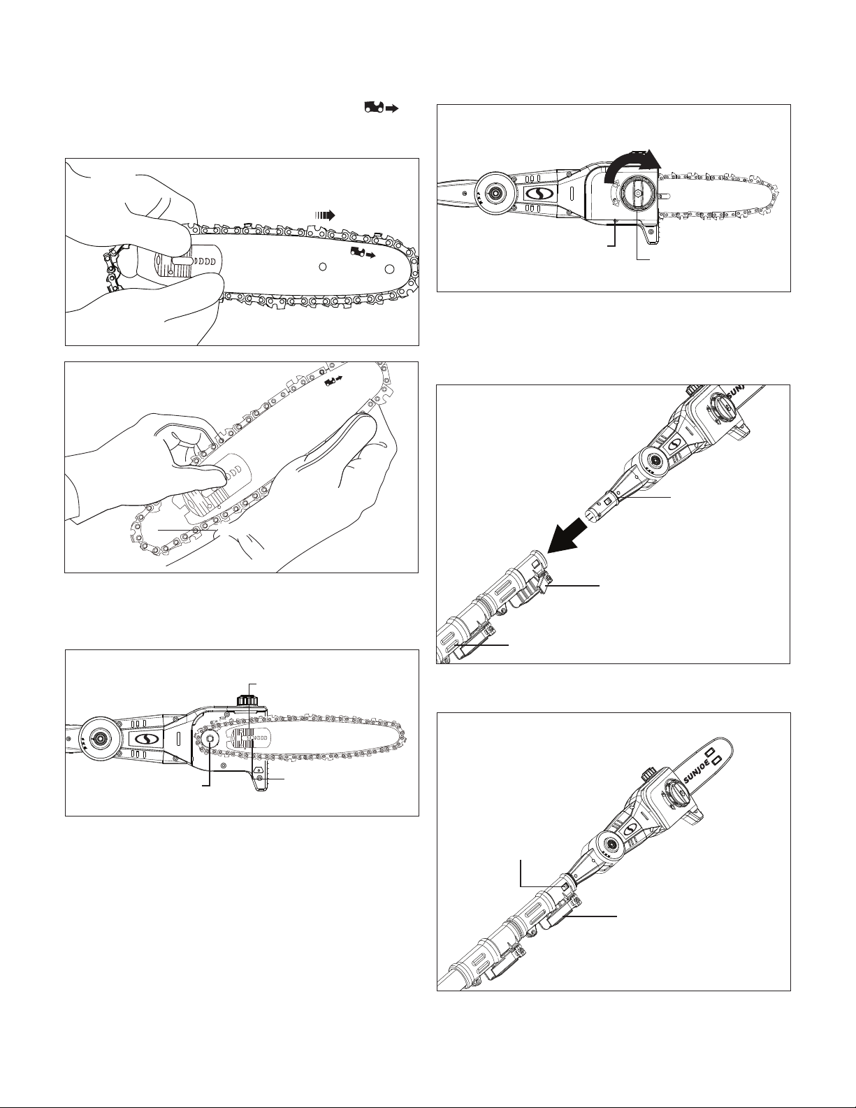
6. Starting at the tip, mount the chain drive links into the
bar groove, leaving a loop at the back of the bar. The
chain will loosely t until it is placed on the sprocket
(Figs. 8 – 9).
Pole Chain Saw
Fig. 3
Chain/sprocket
end cover
Hex bolt
Hex key wrench
Fig. 4
Chain/sprocket
end cover
Chain/sprocket
end cover knob
Fig. 5
Chain/sprocket
end cover
Fig. 6
Cutting chain
Guide bar
Fig. 7
Chain rotation
Sharp cutting edge
Chain drive link
12
NOTE: Make certain of the direction of the chain .
If the chain is mounted backwards, the saw will vibrate
abnormally and will not cut.
7.
Hold the chain in position on the bar and place the loop
around the sprocket. Fit the bar ush against the mounting
surface so that the bar studs are in the long slot of the bar
and the adjusting pin is in the chain tension pin hole (Fig. 10).
8. Replace the chain/sprocket end cover by positioning the
cover onto the saw head. Tighten the end cover knob,
but leave the bar free to move for tension adjustment.
Put back the hex bolt by screwing it clockwise with the
hex key wrench.
9.
Remove all slack from the chain by turning the chain
tensioner ring clockwise until the chain seats snugly against
the bar with the drive links in the bar groove (Fig. 11).
NOTE: The chain is correctly tensioned when there is no
sag on the underside of the guide bar; the chain is snug,
but can be rotated by hand without binding. For more
information on chain tensioning, see the Maintenance +
Care section beginning on pg. 17.
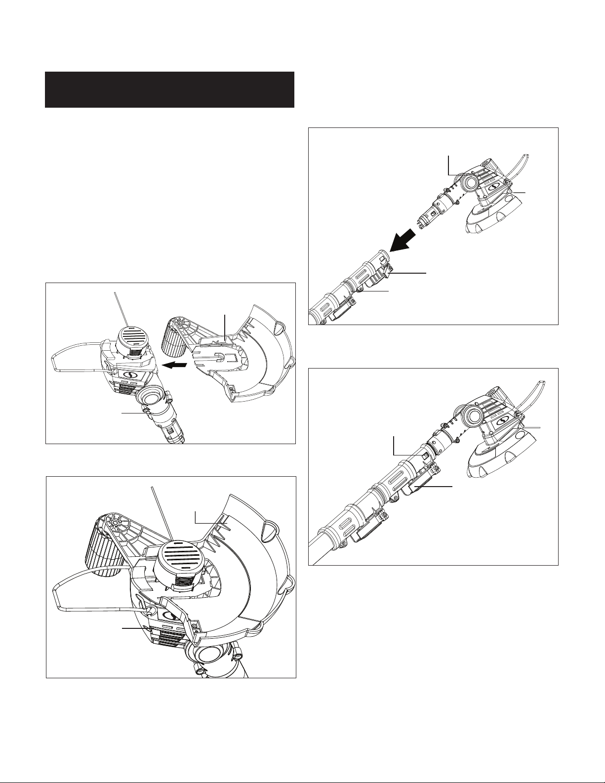
Connecting to the Telescoping Pole
1. Open the assembly lock on the telescoping pole, and
push the chain saw head into the opening on the end of
the pole (Fig. 12).
2. When the lock tabs snap in, lock back the assembly lock,
the pole chain saw will be ready to use (Fig. 13).
Fig. 8
Fig. 9
Loop
Fig. 10
Sprocket
Adjusting pin
Chain tension
pin hole
Fig. 11
Chain/sprocket
end cover
Chain tensioner
ring
R
Fig. 12
Telescoping pole
Assembly lock
Chain saw head
R
Fig. 13
Lock tab
Assembly lock
13
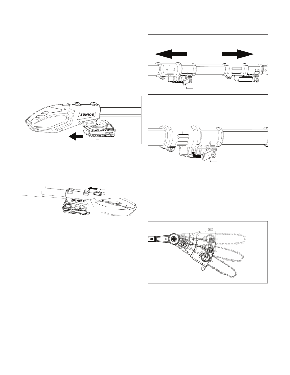
3. To remove the chain saw head, release the On/O switch
and remove the battery. Unlock the assembly lock.
Push the lock tabs on both sides, and pull the chain saw
head out (Fig. 13).
Operation
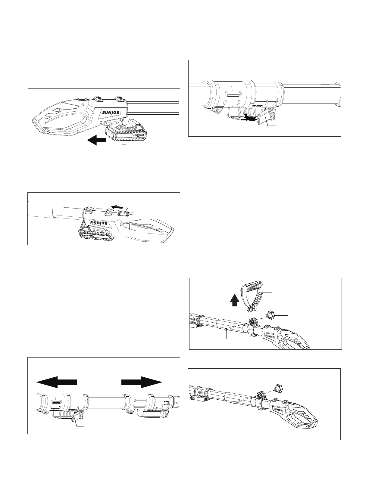
Starting and Stopping
1. Slide the battery into the battery compartment until it
clicks to lock into position (Fig. 14).
2. To turn the pole chain saw ON, push and hold the safety
lock switch (located on the handle) forward with your
thumb and then squeeze the On/O switch with your
ngers. Once the tool is running, you can release the
safety lock switch (Fig. 15).
3. To turn the tool OFF, release the On/O switch (Fig. 15).
Adjusting the Telescoping Pole
This machine is equipped with a telescoping pole which
provides up to 7.2 ft (2.2 m) of overhead reach. To adjust the
telescoping pole, follow the instructions below.
1. Disconnect the saw from the power supply by removing
the battery from the compartment.
2. Unclip the telescoping lock to release the pole. Extend the
pole to the desired length (Fig. 16).
NOTE: Push poles toward each other to shorten the pole
or pull them away from each other to lengthen the pole.
Only extend the pole to the minimum length required to
reach the limb.
3. Lock the pole in position by closing the telescoping lock
(Fig. 17), and ensure that the pole is secured.
mWARNING! Failure to lock the telescoping lock as
directed could result in personal injury or property damage.
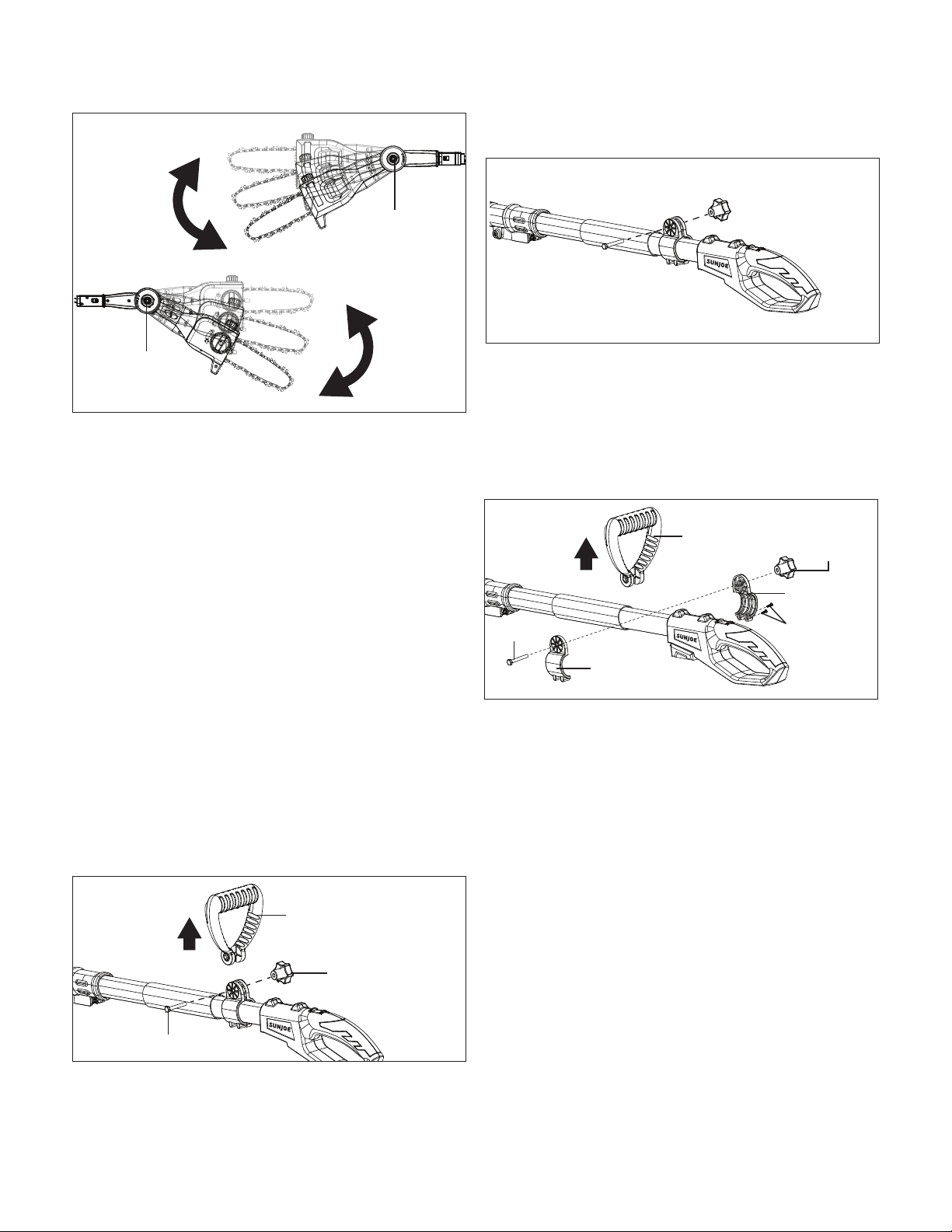
Adjusting the Multi-Angle Head
The pole chain saw head can be rotated for dierent cutting
angles for 0º, 15º, and 30º (Fig. 18). Follow the below
instructions to adjust angles.
1. Rotate the chain saw head to the desired cutting angle
while pressing the rotating buttons located on both sides
simultaneously (Fig. 19).
Fig. 14
Battery
Fig. 15
On/O switch
Safety lock
switch
Fig. 16
Pull Pull
Telescoping lock
Fig. 17
Telescoping lock
Fig. 18
0º
15º
30º
14
2. Release the buttons when the chain saw head is set to the
desired angle.
NOTE: Failure to properly secure the chain saw head may
result in personal injury and/or property damage.
mWARNING! Always ensure the chain saw head is
securely locked! Do not attempt to use the pole chain saw with
the head in any other position or unlocked!
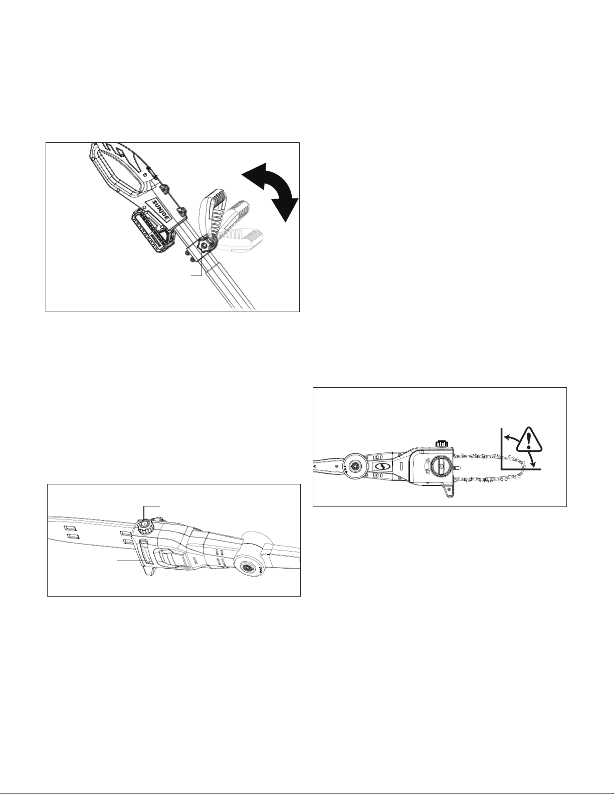
Adjusting the Auxiliary Handle
The chain saw is equipped with an auxiliary handle that can be
adjusted and removed. Follow the instruction below to operate
the auxiliary handle
mWARNING! Make sure the knob, bolt, and the screws
are xed into place. Failure to lock any of them as directed
could result in personal injury or property damage.
To Remove the Auxiliary Handle
1. Disconnect the saw from the power supply by removing
the battery from the compartment.
2. Unscrew the auxiliary handle lock knob and remove it and
the bolt, then the auxiliary handle can be pulled out
(Fig. 20).
3. Re-assemble the auxiliary handle lock knob and the bolt
on (Fig. 21).
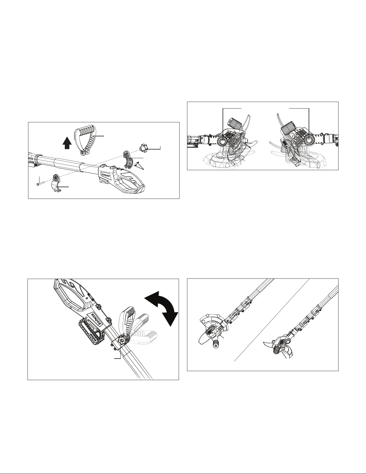
To Adjust the Position of the Auxiliary Handle
1. Disconnect the saw from the power supply by removing
the battery from the compartment.
2. Remove the auxiliary handle lock knob, the bolt, and the
auxiliary handle. Use a screw driver to remove the two
screws that used to x the auxiliary handle loops.
Remove the loops from the pole (Fig. 22).
3. Re-assemble the auxiliary handle loop on the desired spot
on the pole by using the two screws, and put back the
auxiliary handle, the auxiliary handle lock knob and the
bolt (Fig. 22).
Fig. 19
Rotating button
Front Side
Back Side
Rotating button
R
Fig. 20
Auxiliary handle
Auxiliary handle
lock knob
Bolt
R
Fig. 21
R
Fig. 22
Auxiliary handle
Auxiliary
handle
lock knob
Bolt
Auxiliary
handle loop
Screws
Auxiliary
handle loop
15
To Adjust the Angle of the Auxiliary Handle
1. Stop the saw by releasing the On/O switch.
2. The auxiliary handle can be adjusted in -45°, 0°, 45°.
Rotate the auxiliary handle lock knob to unlock the handle,
and then rotate the handle to the desired angle (Fig. 23).
3. Rotate the auxiliary handle lock knob back to lock the
handle in position.
Cutting Tips for Pole Chain Saw
mCAUTION!
• Before starting the saw, remove the oil tank cap and add
bar & chain oil to the top of the oil level window (Fig. 24).
One minute of use will consume approximately 0.15 oz
(4 ml) of oil. Rell when the oil level drops to 1/4 of a tank.
NOTE: Your pole chain saw head is equipped with an
automatic oil pump for bar and chain oiling. You must add
bar and chain oil or your pole chain saw will not function.
mWARNING! Be sure that the chain is not in contact with
any object when you start the motor.
mWARNING! Keep hands away from chain. Keep hands
on handles. Do not overreach.
A good, rm grip on the tool using both hands will help you
maintain control. Place one hand on the soft grip or the
auxiliary handle, and the other hand on the handle with your
thumbs and ngers encircling the pole and handle. A rm grip
combined with proper positioning of the handle against your
body will help you maintain control of the saw. Do not let go of
the saw while it is in operation.
mCAUTION! The chain will continue to run for several
seconds after turning o the tool.
Do not use the pole chain saw under wet conditions.
Use extreme caution when cutting small brush, saplings,
or limbs under tension because slender and tense material
may catch the saw and be whipped toward you, pull you o
balance, or spring back.
Do not use the pole chain saw to cut vines and/or small
underbrush.
Prior to each cutting session, run through the daily checklist
(see pg. 19).
mWARNING! Do not cut trees near electrical wires.
mWARNING! Failure to lubricate the chain will cause
damage to the bar and chain. Use only a good quality bar
and chain oil designed specically for use with chain saws.
One minute of use will consume approximately 0.15 oz.
(4 ml) of oil.
NOTE: It is normal for oil to seep from the saw when not in
use. To prevent seepage, empty the oil tank after each use.
When storing the unit for a long period of time (3 months or
longer), be sure the chain is lightly lubricated; this will prevent
rust on the chain and bar sprocket.
mWARNING! Kickback may occur when the moving
chain contacts an object at the upper portion of the tip of
the guide bar or when the wood closes in and pinches the
chain saw in the cut (Fig. 25). Contact at the upper portion
of the tip of the guide bar can cause the chain to dig into
the object and stop the chain for an instant. The result is a
lightning-fast reverse reaction, which kicks the guide bar up
and back toward the operator. If the chain saw is pinched
along the top of the guide bar, the guide bar can be driven
rapidly back toward the operator. Either of these reactions
can cause loss of saw control, which can throw the operator
o balance and result in serious injury. Do not rely exclusively
upon the safety devices built into the saw. As a user, you
should take several precautions to keep your cutting jobs free
from accident or injury.
Proper Cutting Stance
• Balance your weight with both feet on solid ground.
• Your body should always be to the left of the chain line.
R
Fig. 23
Auxiliary
handle lock
knob
Fig. 24
Oil tank cap
Oil level
window
KICKBACK DANGER ZONE
Fig. 25
16
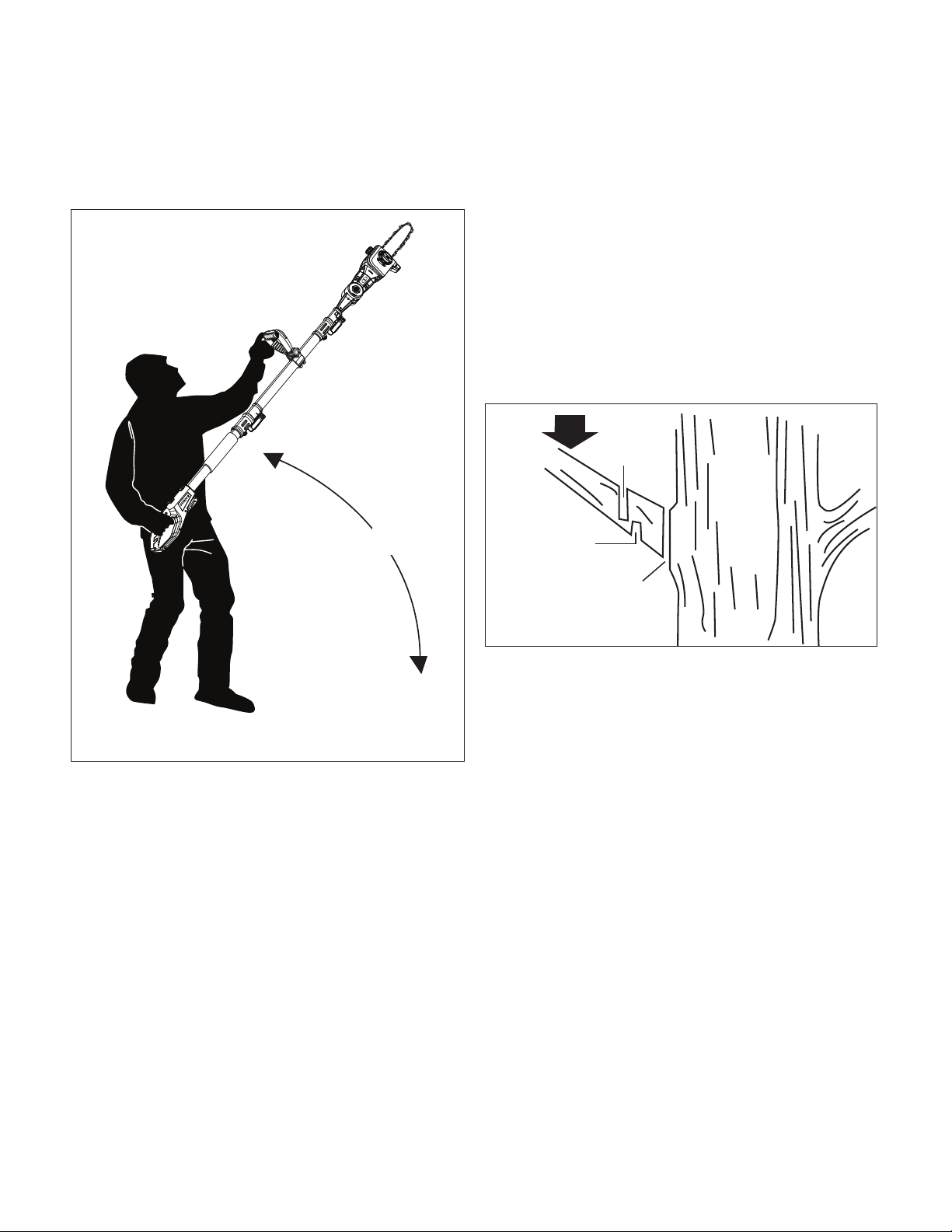
• The most typical cutting application is to position the
unit at an angle of 60° or less depending on the specic
situation (Fig. 26). As the angle of the pole chain saw shaft
to the ground increases, the diculty of making the rst
cut (from the underside of limb) increases.
Basic Cutting Procedure
This unit with the chain saw head is designed for trimming
small branches and limbs up to recommended 6.5 in.
(16.5 cm), not to exceed a Max. cut of 7.5 in. (19 cm) in
diameter depending on type of wood. Practice cutting a few
small limbs using the following technique to get the “feel” of
using the saw before you begin a major sawing operation.
• Take the proper stance in front of the tree with the
saw OFF (Fig. 26).
• Switch on the pole chain saw and let the chain accelerate
to full speed before entering the cut.
• Keep the saw running the entire time you are cutting;
maintain a steady speed.
• Allow the chain to cut for you; exert only light downward
pressure. If you force the cut, damage to the bar, chain, or
unit can result.
• PUSH and PULL – This reaction force is always opposite
to the direction the chain is moving when it is in contact
with the wood. Thus, the operator must be ready to
control the PULL when cutting on the bottom edge of the
bar, and PUSH when cutting along the top edge.
• Do not put pressure on the saw at the end of the cut.
Pruning
Pruning is the process of trimming limbs from a live tree.
• Remove long branches in several stages.
• Cut lower branches rst to allow the top branches more
room to fall.
• When pruning trees, it is important not to make the
nishing cut next to the main limb or trunk until you have
cut o the farthest lying limb. This will reduce the weight
and prevent stripping the bark from the main member.
• Under cut the branch 1/3 through for your rst cut.
Your second cut should over cut to drop the branch o
(Fig. 27). Be prepared to balance the weight of the pole
chain saw when the limb falls.
• Now make your nishing cut from the topside of the
branch smoothly and neatly against the main member so
the bark will grow back to seal the wound.
• Release the On/O switch as soon as the cut is
completed. Failure to follow proper cutting procedures will
result in the bar and chain binding and becoming pinched
or trapped in the limb.
Limbing
Limbing is the process of removing branches from a fallen tree.
• You should cut limbs one at a time. Remove the cut limbs
from the work area often to help keep the work area clean
and safe.
• Cut branches under tension from the bottom up to avoid
binding the bar and chain.
• Keep the tree between you and the pole chain saw while
limbing. Cut from the side of the tree opposite the branch
you are cutting.
If the Saw Becomes Pinched or Trapped
1. Wait for the blade to stop, wait ve minutes for the saw to
cool, remove the battery, and wear gloves to protect your
hands from the chain teeth.
2. If you can reach the limb from the ground, lift the limb
while holding the saw. This should release the “pinch” and
free the saw.
3. If the saw is still trapped, call a professional for
assistance.
R
Fig. 26
60º MAXIMUM
Fig. 27
Load
Second Cut
First Cut
1/3 Diameter
Finishing Cut
17
Maintenance + Care
m
WARNING! Always remove the battery before
performing any adjustments, maintenance, or repairs to your
cordless pole chain saw.
• Use protective gloves when handling the bar and chain.
• Keep the bar encased in its sheath, except when working
directly on the bar or the chain.
• Never dispose of oils or other polluting materials in
unauthorized places.
Chain Tension
Check the chain tension before using the saw when the chain
is cold. The correct tension of a cold chain is when there is no
slack on the underside of the guide bar; the chain is snug, but
you can rotate it by hand without binding.
During normal saw operation, the temperature of the chain
will increase. The drive links of a correctly tensioned warm
chain will hang approximately 0.050 in. (1.25 mm) out of the
bar groove (Fig. 28). Be aware that a chain tensioned while
warm, may be too tight upon cooling. Check the “cold tension”
before next use. The chain must be re-tensioned whenever the
ats on the drive links hang out of the bar groove (Fig. 28).
NOTE: A new chain tends to stretch. Check the chain tension
frequently and re-tension as needed.
Nuts and Screws
Periodically check that all the nuts and screws are tightened
securely. Check that the telescoping lock and assembly lock
are intact and in proper working order.
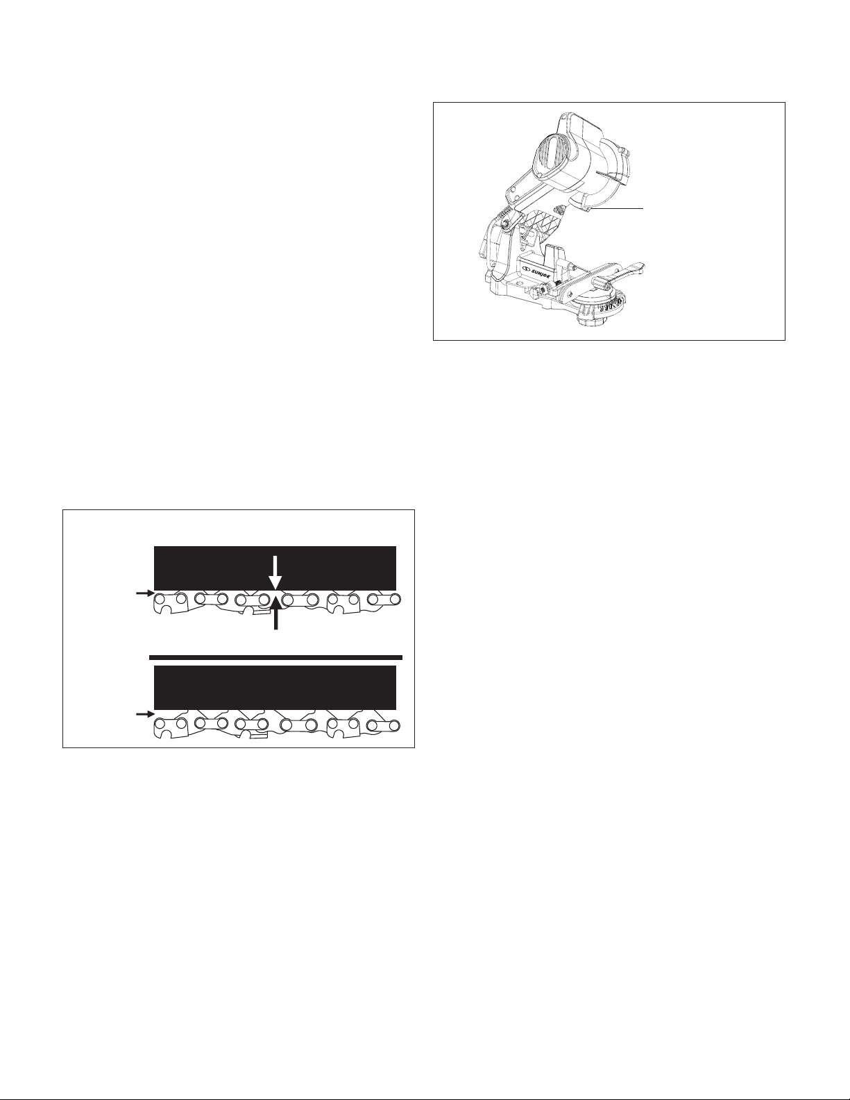
Chain Sharpening
To maintain optimal blade sharpness and peak performance,
Sun Joe recommends model 24V-CSSHRP-LTE Cordless
Chain Saw Sharpener, available on sunjoe.com, by phone at
1-866-SNOWJOE (1-866-766-9563) (Fig. 29).
mWARNING! To ensure that the saw works safely and
eciently, it is essential that the cutting components are
well-sharpened. It is highly recommended to replace the
chain once it loses its ability to cut cleanly and safely.
It is possible, however, to sharpen the existing chain if the
sharpening is carefully performed. Any work on the chain
and bar requires specic experience and special tools.
For safety purposes, we recommend you contact an
authorized Snow Joe
®
+ Sun Joe
®
dealer or call the Snow Joe
®
+ Sun Joe
®
customer service center at 1-866-SNOWJOE
(1-866-766-9563).
Sharpening is necessary when:
• The sawdust looks like dust;
• Cutting becomes more dicult;
• The cut is not straight;
• Vibrations increase.
An authorized service center will sharpen the chain using the
right tools to ensure minimum removal of material and even
sharpness on all the cutting edges.
If you sharpen the chain yourself, use special round-section
les with the right diameter depending on the type of chain
(see “Chain Maintenance Table” on pg. 19). You need a certain
amount of skill and experience to avoid damaging the cutting
edges.
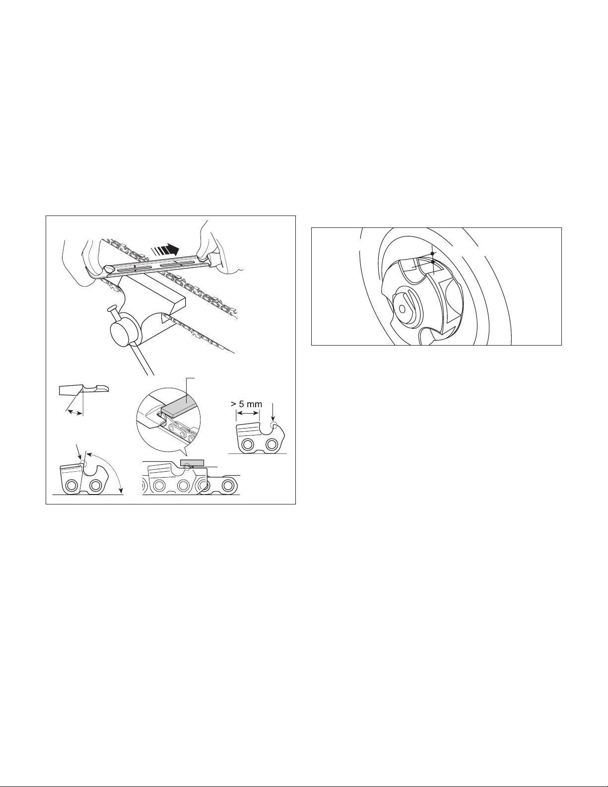
Sharpen the chain as follows (Fig. 30):
• Secure the bar rmly, with the chain mounted,
in a suitable vise.
• Tighten the chain if it is loose.
• Mount the le in the guide and then insert it in the tooth
at a constant angle from the cutting edge.
• Sharpen in a forward motion a few times and repeat this
on all the cutting edges facing the same way (right or left).
• To move the chain forward, use a screwdriver.
Fig. 28
Properly Adjusted Warm Chain
Approximately 0.050 in. (1.25 mm)
Flats are
visible here
Flats are not
visible here
Chain Needs Tensioning
Fig. 29
R
Cordless Chain
Saw Sharpener
24V-CSSHRP-LTE
• Turn the bar over in the vise and repeat on all the other
cutting edges.
• Check that the depth limiter tooth does not stick out
farther than the inspection tool and le any projecting
parts with a at le, rounding o the edges (Fig. 30).
• After sharpening, remove all traces of ling and dust
and lubricate the chain in an oil bath. Replace the chain
whenever:
– The length of the cutting edges decreases to
5 mm or less;
– There is too much play between the links and the rivets.
Guide Bar Maintenance
When the guide bar shows signs of wear, turn it over on the
saw to distribute the wear for maximum bar life. Feathering or
burring of the bar rails is a normal process of bar wear. You
should smooth such faults with a le as soon as they occur.
Replace a bar with any of the following faults:
• wear inside the bar rails permitting the chain to lay over
sideways
• bent guide bar
• cracked or broken rails
• spread rails
Turn the saw over, check the underside of the guide bar, and
make sure that the lubrication holes and chain groove are free
from impurities.
Chain Sprocket
Regularly check the condition of the sprocket and replace it
when wear exceeds 0.5 mm (Fig. 31).
Do not mount a new chain with a worn sprocket or vice-versa.
Fig. 30
Inspection tool
Depth limiter tooth
Cutting edge
Depth
limiter
tooth
< 0.5 mm
Fig. 31
18

Troubleshooting
Troubleshooting Tips
Most diculties are easy to x. Consult the troubleshooting
table for common problems and their solutions. If you continue
to experience problems or need repairs beyond these minor
adjustments, please call 1-866-SNOWJOE (1-866-766-9563)
for assistance.
mWARNING! Always remove the battery before
performing any adjustments, maintenance, or repairs to your
cordless chain saw.
Troubleshooting Table
Daily Checklist, Cleaning
and Storage
Daily Checklist
To help maintain your pole chain saw for optimum
performance, we recommend you complete this checklist prior
to each work session.
mWARNING! Do not insert the battery until you have
completed all of the daily checks.
• Inspect for any visible damage to the chain, guide bar, or
motor housing.
• Inspect the oil port and guide bar rails and clean them to
remove any debris.
• Check the chain tension.
• Check the chain teeth for sharpness.
• Check the bar and chain oil level; ll with only new chain
oil specically formulated for chain saws.
NOTE: If you notice anything unusual, such as a vibration or an
odd sound, shut the saw OFF immediately. Remove the battery
and check the saw for any damage.
If you cannot nd the cause of the problem or are uncertain
what to do, then have the saw inspected by an authorized
Snow Joe
®
+ Sun Joe
®
dealer or call the Snow Joe
®
+
Sun Joe
®
customer service center at 1-866-SNOWJOE
(1-866-766-9563) before using it.
mCAUTION!
• Remove the battery and wait at least ve minutes for the
saw to cool before servicing or storing your unit.
• If you drop the saw, carefully inspect it for damage. If the
guide bar is bent, the housing is cracked, the handle is
broken, or if you see any other condition that may aect
the saw’s operation, DO NOT USE the tool. Instead, have
it serviced at an authorized Snow Joe
®
+ Sun Joe
®
dealer or call the Snow Joe
®
+ Sun Joe
®
customer service
center at 1-866-SNOWJOE (1-866-766-9563).
Problems Corrective Action
The saw
motor fails
to start
• Check that you have inserted the battery properly
and the battery has enough power to work.
• Make sure that you fully depress, push forward
and hold the safety lock switch before squeezing
the ON/OFF trigger switch.
• The chain is too tight; re-tension.
• The chain tension is too tight; re-tension.
• The chain oil tank is empty; rell.
• The lubrication holes are plugged; clean them out.
• The chain tension is too tight; re-tension.
• The guide bar or chain is damaged; inspect
and replace the damaged part.
The saw
runs, but
the chain
speed is
low
Bar and
chain
running
hot and
smoking
The saw
motor
runs, but
the chain
is not
turning
19
Chain Maintenance Table
33
3/8
inches mm
Drive Links Chain Pitch Chain Gauge
File Diameter
inches
mm inches mm
9.5 0.050 1.3 45/32
Assembly
m
WARNING! Do not insert battery until assembly is
complete. Failure to comply could result in accidental starting
and possible serious personal injury.
Fitting the Safety Guard
mWARNING! The guard must be properly installed.
The guard provides the operator and other bystanders with
some protection from thrown objects.
1. Align the safety guard with the grass trimmer + edger
head as shown (Fig. 32).
2. Firmly press the safety guard into place until it clicks into
the position (Fig. 33).
Connecting to the Telescoping Pole
1. Open the assembly lock on the telescoping pole, and
push the grass trimmer + edger head into the opening on
the end of the pole (Fig. 34).
2. When the lock tabs snap in, lock back the assembly lock,
and the grass trimmer + edger will be ready to use
(Fig. 35).
3. To remove the grass trimmer + edger head, release
the On/O switch and remove the battery. Unlock the
assembly lock, push the lock tabs on both sides, and pull
the grass trimmer + edger head out (Fig. 35).
Grass Trimmer + Edger
Fig. 32
Safety Guard
Grass trimmer
+ edger head
Fig. 33
Safety Guard
Grass trimmer
+ edger head
Telescoping pole
Fig. 34
Grass trimmer
+ edger head
Assembly lock
Fig. 35
Lock tab
Assembly lock
20
Operation
Starting and Stopping
1. Slide the battery into the battery compartment until it
clicks to lock into position (Fig. 36).
2. To turn the grass trimmer + hedger ON, push and hold
the safety lock switch (located on the handle) forward
with your thumb and then squeeze the On/O switch with
your ngers. Once the tool is running, you can release the
safety lock switch (Fig. 37).
3. To turn the tool OFF, release the On/O switch (Fig. 37).
Adjusting the Telescoping Pole
This machine is equipped with a telescoping pole which can
telescope from 3.7 ft (1.1 m) to 5.3 ft (1.6 m). To adjust the
telescoping pole, follow the instructions below.
1. Disconnect the grass trimmer + edger from the power
supply by removing the battery from the compartment.
2. Unclip the telescoping lock to release the pole. Extend the
pole to the desired length (Fig. 38).
NOTE: Push poles toward each other to shorten the pole
or pull them away from each other to lengthen the pole.
Only extend the pole to the minimum length required to
reach the grass.
3. Lock the pole in position by closing the telescoping lock
(Fig. 39), and ensure that the pole is secured.
mWARNING! Failure to lock the telescoping lock as
directed could result in personal injury.
Adjusting the Auxiliary Handle
The grass trimmer + edger is equipped with an auxiliary handle
that can be adjusted and removed. Follow the instruction
below to operate the auxiliary handle.
mWARNING! Make sure the knob, bolt, and the screws
are xed into place after adjusting. Failure to lock any of them
as directed could result in personal injury or property damage.
To Remove the Auxiliary Handle
1. Disconnect the grass trimmer + edger from the power
supply by removing the battery from the compartment.
2. Screw the auxiliary handle lock knob and remove it with
the bolt, then the auxiliary handle can be pulled out
(Fig. 40).
3. Re-assemble the auxiliary handle lock knob and the bolt
on (Fig. 41).
Fig. 36
Battery
Fig. 37
On/O switch
Safety lock
switch
Fig. 38
Pull Pull
Telescoping lock
Fig. 39
Telescoping lock
R
Fig. 40
Auxiliary handle
Auxiliary handle
lock knob
Bolt
R
Fig. 41
21
NOTE: It's recommended to not remove the auxiliary
handle when operating the grass trimmer + edger for better
maneuverability and easier operation.
To Adjust the Position of the Auxiliary Handle
1. Disconnect the grass trimmer + edger from the power
supply by removing the battery from the compartment.
2. Remove the auxiliary handle lock knob, the bolt, and the
auxiliary handle. Use a screw driver to remove the two
screws used to x the auxiliary handle loop. Remove the
loop from the pole (Fig. 42).
3. Re-assemble the auxiliary handle loops on the desired
spot on the pole by using the two screws, and put back
the auxiliary handle, the auxiliary handle lock knob and the
bolt (Fig. 42).
To Adjust the Angle of the Auxiliary Handle
1. Stop the grass trimmer + edger by releasing the On/O
switch.
2. The auxiliary handle can be adjusted into -45°, 0°, 45°.
Rotate the handle lock knob to unlock the handle, and
then rotate the handle to the desired angle (Fig. 43).
3. Rotate the handle lock knob back to lock the handle
in position.
Adjusting the Multi-Angle Head
The grass trimmer + edger head can be rotated for 5 dierent
cutting angles for 0°, 15°, 30°, 45° and 60°. Follow the below
instructions to adjust angles.
1. Rotate the grass trimmer + edger head to desired angle
while pressing the rotating buttons located on both sides
of the unit simultaneously (Fig. 44).
2. Release the buttons when the grass trimmer + edger head
is xed into the desired angle.
NOTE: Failure to properly secure the grass trimmer +
edger head may result in personal injury and/or property
damage.
mWARNING! Always ensure the grass trimmer + edger
head is securely locked! Do not attempt to use the grass
trimmer + edger with the head in any other position
or unlocked!
Working Mode Converting
The unit can be converted between two mode: the grass
trimmer mode and the edger mode (Fig. 45).
R
Fig. 42
Auxiliary handle
Auxiliary
handle
lock knob
Bolt
Auxiliary
handle loop
Screws
Auxiliary
handle loop
R
Fig. 43
Removable
handle
R
Fig. 44
Left side
Right side
Rotating buttons
Fig. 45
Grass trimmer
Edger
22
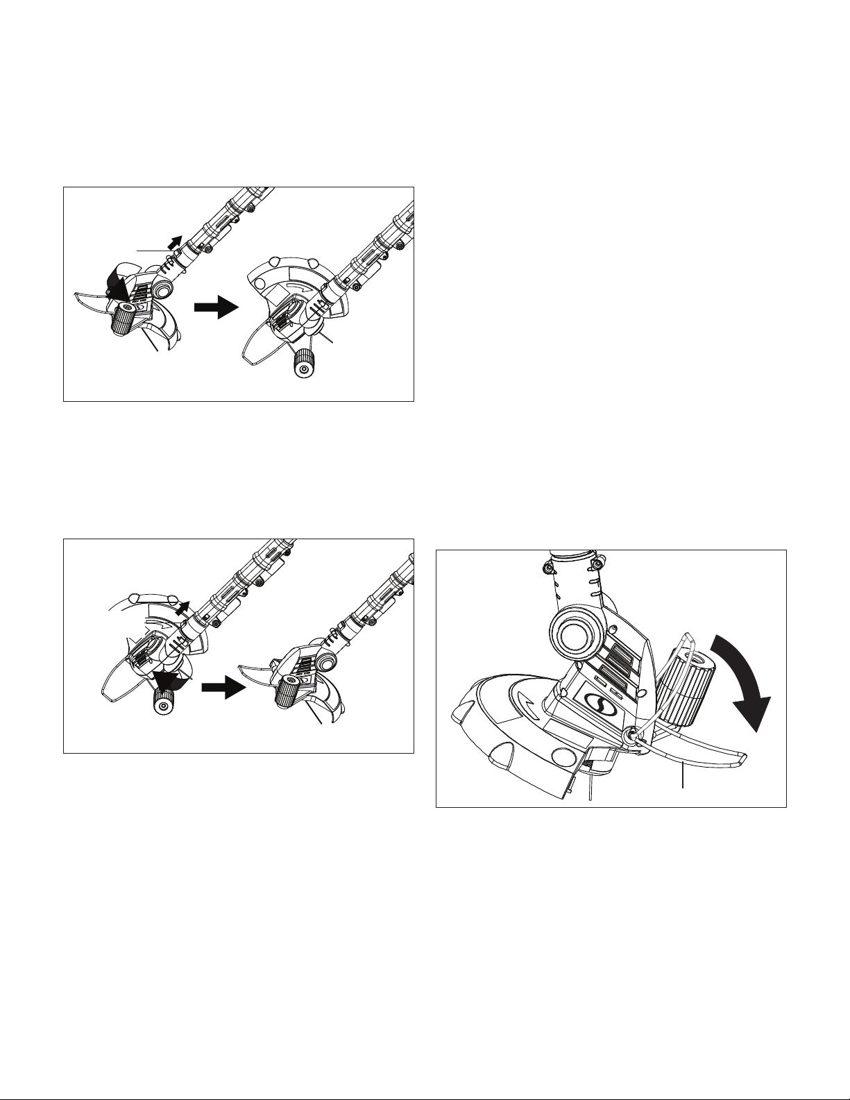
To convert the unit, follow the instruction below:
1. To convert the grass trimmer to an edger, slide the
converting switch on the trimmer head up, meanwhile turn
the lower part of the trimmer head to the side until the
trimmer head is locked into position (Fig. 46).
2. Release the converting switch to lock the edger in place.
Press the rotating buttons on both sides to adjust the
head angle if needed.
3. To convert the edger to a grass trimmer, slide the
converting switch on the edger head up, meanwhile turn
the lower part of the edger head to the side until the head
is locked into position (Fig. 47).
4. Release the converting switch to lock the grass trimmer in
place. Press the rotating buttons on both sides to adjust
the head angle if needed.
Operation Tips
• Wear non-slip gloves for maximum grip and protection.
• For the best cutting action against walls, fences, and in
high grass, move the grass trimmer slowly so grass is cut
with the tip of the high speed nylon line.
• Avoid dragging the grass trimmer and string spool hub in
contact with the ground.
• Trim only when grass and weeds are dry.
NOTE: As the weather becomes cooler, the tendency for the
nylon line to break becomes greater. DO NOT USE WHEN
TEMPERATURE IS BELOW 50ºF (10ºC).
• Cut tall grass from top down. This will prevent grass from
wrapping around the shaft housing and string head which
may cause damage from overheating.
• If grass becomes wrapped around the string head:
– Stop the grass trimmer.
– Remove the battery.
– Remove the grass.
• Hold the grass trimmer with your right hand on the rear
handle and your left hand on the auxiliary handle. The grass
trimmer should be held at a comfortable position with the
auxiliary handle about hip height.
• To use the edger guide/ower guard, ip it down from its
stored position (Fig. 48).
mWARNING! Always hold the trimmer away from
body. Any contact with the grass trimmer cutting head while
operating can result in serious personal injury.
• The life of your nylon line is dependent upon following
instructions for proper use, as well as what is being cut,
and where the cutting is being done.
mWARNING! Remove stones, loose pieces of wood, and
other objects from the cutting area. The string continues to
rotate for a few seconds after switching o the trimmer. Let the
motor come to a complete stop before resuming operation.
Do not rapidly switch the trimmer o and on.
Fig. 46
Grass trimmer Edger
Converting
switch
Fig. 47
Grass trimmerEdger
Converting
switch
Fig. 48
Edger guide/ower guide
23
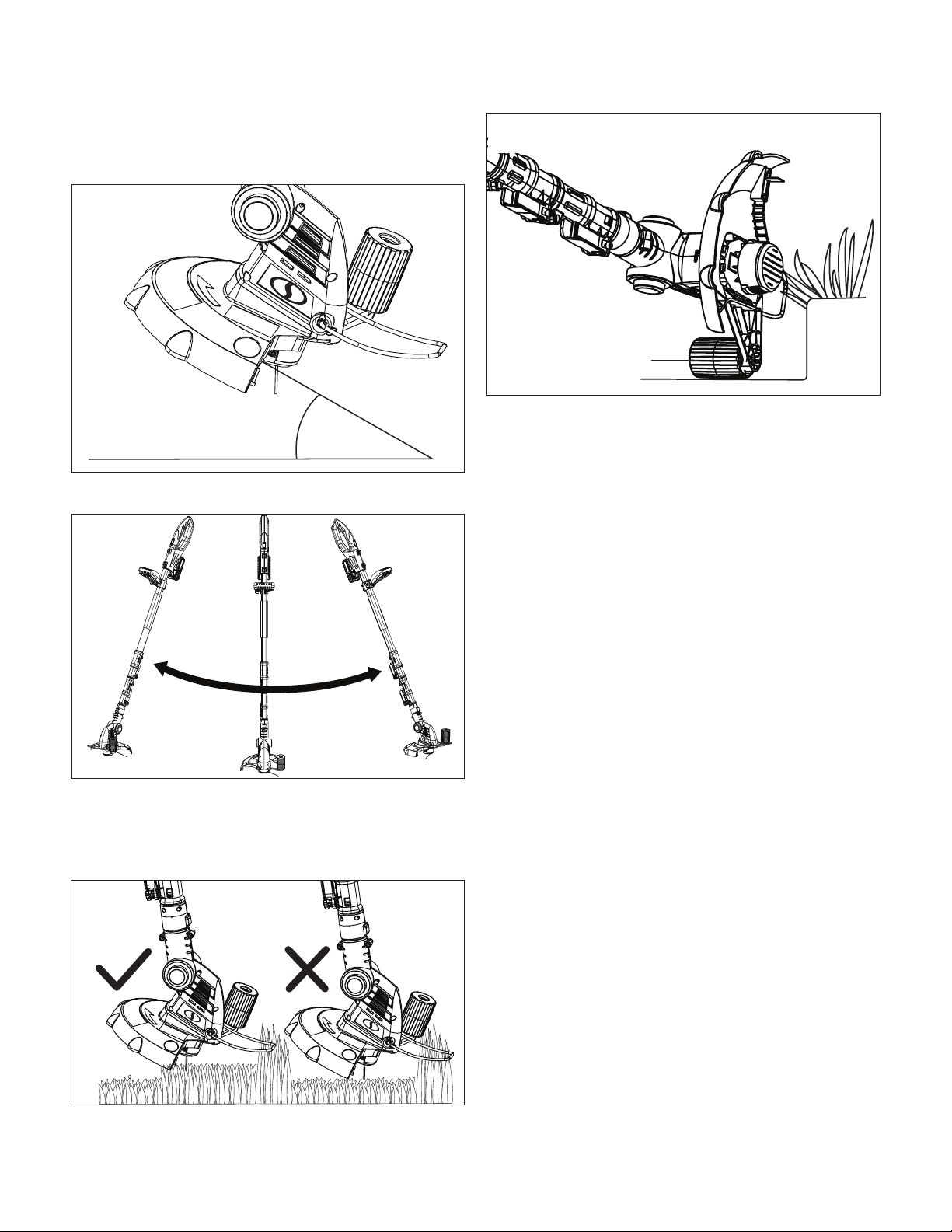
mCAUTION! Always wear eye protection.
1. Hold the trimmer at an angle of approximately
10 – 30 degrees to the work area (Fig. 49).
2. Slowly swing the trimmer from side to side (Fig. 50).
3. Do not overload your trimmer; instead, take small “bites”
of grass, working from the top to the bottom. This will
keep the machine operating at high speed and will greatly
improve its cutting eciency (Fig. 51).
4. When using as a edger, using the edging wheel for
supporting and guidance (Fig. 52).
Advancing Lines
NOTE: Your trimmer uses 0.055 in. (1.4 mm) diameter nylon
line to cut grass and weed quickly and easily. In time, the
tip of the nylon line will become worn and the auto-feed
mechanism will automatically feed and trim a fresh length of
line. The cutting line will wear faster if the cutting is done along
sidewalks or other abrasive surfaces, or heavier weeds are
being cut.
The grass trimmer + edger is equipped with an auto-feed
head. Bumping the head to try to advance the line will damage
trimmer.
1. With the unit running, release the ON/OFF switch trigger.
2. Wait two seconds, and press the ON/OFF switch trigger.
NOTE: The lines will extend approximately 1/4 in. with each
stop and start of the switch trigger until the lines reach the
length of the safety guard.
3. Resume the trimming + edging.
mWARNING! Do not operate the grass trimmer + edger
in a tree, on a ladder, or on a scaold; this is extremely
dangerous.
mWARNING! Do not bump the unit on ground in attempt
to feed line or for any other purpose.
Maintenance + Care
m
WARNING! Make sure to remove the battery before
inspecting its parts.
mWARNING! Always wear protective gloves during
maintenance tasks. Do not carry out maintenance when the
motor is running or hot.
• Never use water or chemical cleaners to clean your grass
trimmer + edger. Wipe it clean with a dry cloth.
• Plastic parts may be cleaned by using mild soap and a
damp rag.
Fig. 49
10º – 30º
Fig. 50
Fig. 51
Fig. 52
Edging wheel
24
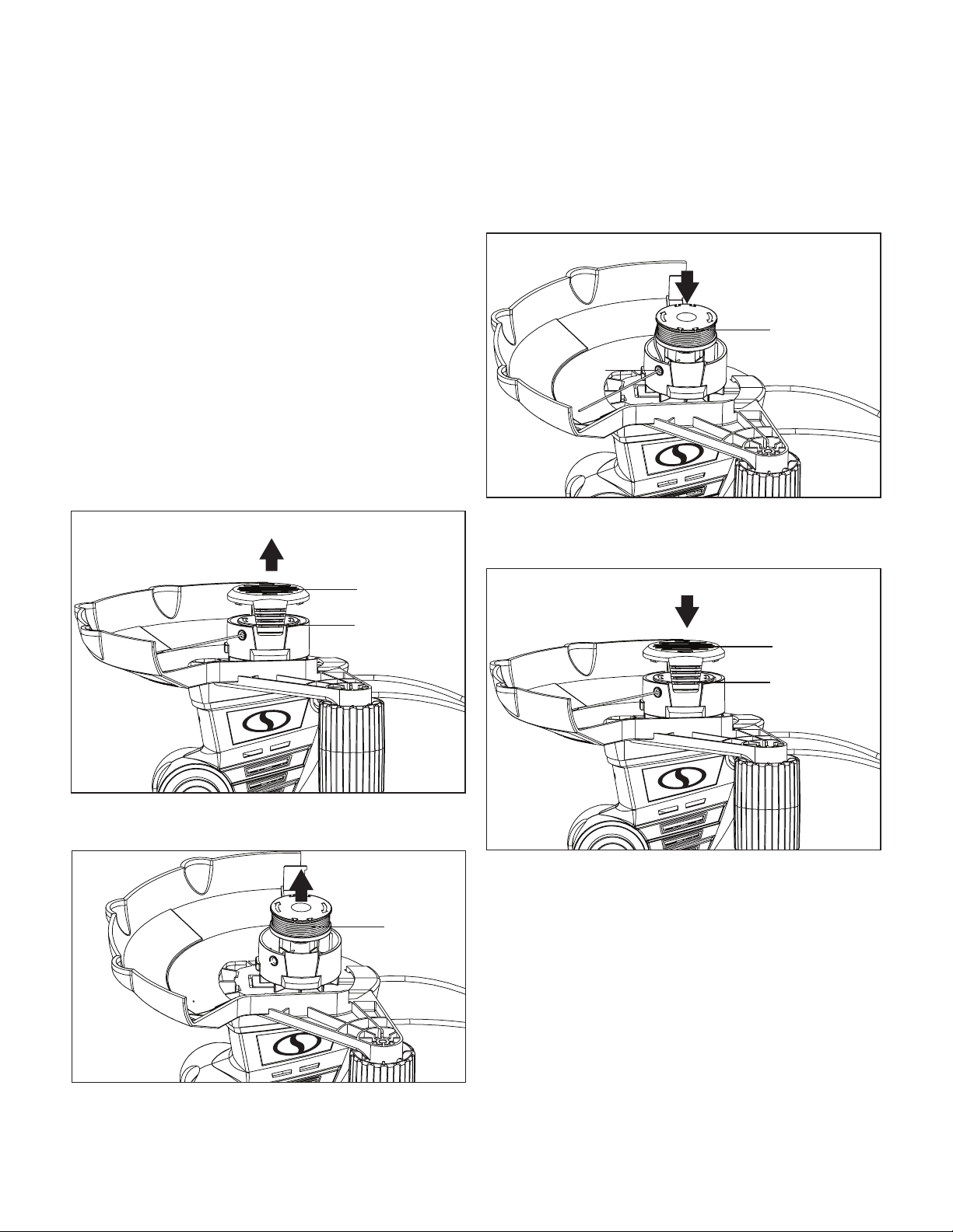
• Always store your grass trimmer + edger in a dry place.
Do not allow any liquid to get inside it.
• Keep the motor ventilation slots clean.
• If you see some sparks ashing in the ventilation slots, this
is normal and will not damage your power tool.
IMPORTANT! To ensure product safety and reliability, repairs,
maintenance, and adjustments to this power tool should be
performed only with identical replacement parts. Contact your
authorized Snow Joe
®
+ Sun Joe
®
dealer or call the Snow Joe
®
+ Sun Joe
®
customer service center at 1-866-SNOWJOE
(1-866-766-9563) for assistance.
Replacing the Spool + Clearing Jams
and Tangled Lines
mWARNING! Remove the battery from the unit before
changing the trimmer line.
1. Press together both release tabs on the line spool cover
and remove the cover by pulling it straight o (Fig. 53).
2. Lift and remove the spool out of the hub (Fig. 54) and
clean out any dirt or grass residue.
3. In case of jams or tangled line, unwrap about 6 inches
(15 cm) of line to ensure that it's not damaged.
4. If it appears undamaged, rewind it and hook the line
end through one set of the slots of the spool. This will
temporarily prevent the spool from unwinding.
5. Unhook the line from the slot and carefully reinsert
through its respective slot on the side of the hub and
gently press the spool down (Fig. 55).
6. Reinstall the spool cover by depressing the release tabs
into their slots in the hub, and push down until the spool
cover clicks into place (Fig. 56).
Winding the Line
NOTE: A factory wound spool (model GTS4002C-RS-6PK)
is available for easy spool replacement on the GTS4002C
cordless grass trimmer + edger. Visit sunjoe.com to purchase
this accessory online. Should you wish to wind the line
yourself, the instructions are provided below. Self-winding,
however, is NOT recommended because if the line is not
wound properly it can cause the trimmer’s auto feed system
to malfunction. For this reason, users are strongly urged to
purchase the pre-wound spool.
1. Stop the grass trimmer + edger, and remove the battery.
Fig. 53
Spool cover
Tab
Fig. 54
Spool
Fig. 55
Spool
Slot
Fig. 56
Spool cover
Tab
25
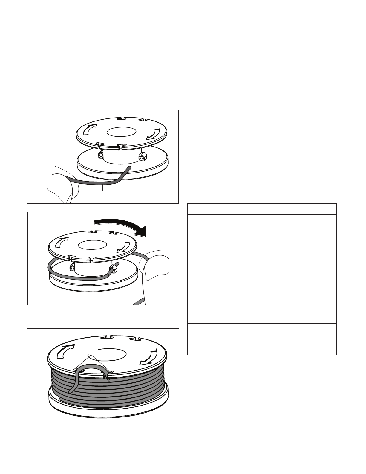
2. To remove the spool from the trimmer hub, follow steps
1 and 2 from the section "Replacing the Spool + Clearing
Jams and Tangled Lines" beginning on page 25.
3. Take one line with maximum length of 16.5 ft. (5 m)
and maximum diameter of 0.055 in. (1.4 mm). Insert the
end of the line in one of the eyes of the spool and wind on
the line according to the indicated direction of winding.
Please make certain that the line is wound on evenly and
tightly (Figs. 57 – 58).
4. Hook the end of the line in one of the slots on the spool
(Fig. 59).
5. Re-install the spool as instructed in steps 5 to 6 of
"Replacing the Spool + Clearing Jams and Tangled Lines".
mCAUTION! Catapulted pieces of nylon line may
cause injury.
NOTE: The maximum recommended length of line is
16.5 ft. (5 m).
mWARNING! Pay attention to the winding direction.
NOTE: Always replace the spool with a new pre-wound spool.
Visit sunjoe.com to purchase the pre-wound spool (model
GTS4002C-RS-6PK) for this cordless grass trimmer + edger.
IMPORTANT: Keep all areas of the cutting head and cutting
head cover clean. Place the cap back by pushing it rmly
onto the cutting head. To ensure that the cutting head cover
is correctly tted, try to remove it without depressing the two
tabs. If it is correctly tted, it should not move.
Troubleshooting
mWARNING! Always remove the battery before
performing any adjustments, maintenance, or repairs to your
cordless grass trimmer + edger.
Fig. 57
Eye of the spoolSpool line
Fig. 58
Fig. 59
Slots
Problems Corrective Action
The motor
does not
run or the
tool runs
slowly.
• Check that you have inserted the battery
properly and the battery has enough power to
work.
• Remove the spool and clean the slots; carefully
remove any grass and weeds or other debris.
• Cut the spool line o so that it just reaches the
line trimming blade.
• Take the trimmer to an authorized service center
if the trimmer does not start after completing
these checks.
Auto line
feed does
not work.
• Stop the machine and clean the trimming lines.
• Install a new spool of cutting line.
• Clean the auto feed.
• Remove the spool cover and pull the cutting line
until it reaches the trimming blade.
Line fails to
cut o.
• Rewind or trim line to line cutter.
• Take the trimmer to an authorized service
center if the trimmer does not start after
completing these checks.
26
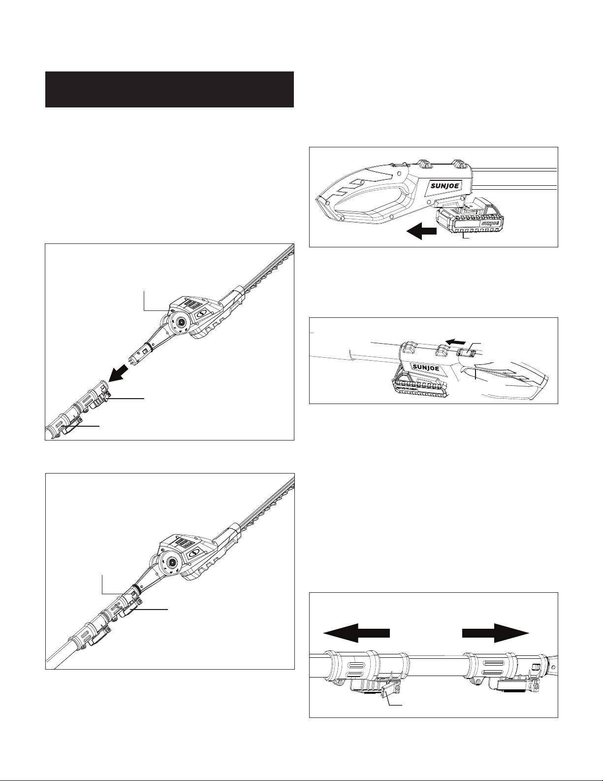
27
Assembly
Connecting to the Telescoping Pole
The hedge trimmer head comes fully assembled. To use the
machine as a pole hedge trimmer, connect the hedge trimmer
head with the telescoping pole as indicated below.
1. Open the assembly lock on the telescoping pole, and
push the hedge trimmer head into the opening on the end
of the pole (Fig. 60).
2. When the lock tabs snap in, lock back the assembly lock,
and the pole hedge trimmer will be ready to use (Fig. 61).
3. To remove the hedge trimmer head, release the On/O
switch and remove the battery. Unlock the assembly lock.
Push the lock tabs on both sides, and pull the hedge
trimmer head out (Fig. 61).
Operation
Starting and Stopping
1. Slide the battery into the battery compartment until it
clicks to lock into position (Fig. 62).
2. To turn the pole hedge trimmer ON, push and hold the
safety lock switch (located on the handle) forward with
your thumb and then squeeze the On/O switch with
your ngers. Once the tool is running, you can release the
safety lock switch (Fig. 63).
3. To turn the tool OFF, release the On/O switch (Fig. 63).
Adjusting the Telescoping Pole
This machine is equipped with a telescoping pole which can
telescope from 3.7 ft (1.1 m) to 5.3 ft (1.6 m). To adjust the
telescoping pole, follow the instructions below.
1. Disconnect the hedge trimmer from the power supply by
removing the battery from the compartment.
2. Unclip the telescoping lock to release the pole. Extend the
pole to the desired length (Fig. 64).
NOTE: Push poles toward each other to shorten the pole
or pull them away from each other to lengthen the pole.
Only extend the pole to the minimum length required to
reach the hedges.
Pole Hedge Trimmer
Fig. 60
Hedge trimmer head
Assembly lock
Telescoping pole
Fig. 61
Lock tab
Assembly lock
Fig. 62
Battery
Fig. 63
On/O switch
Safety lock
switch
Fig. 64
Pull Pull
Telescoping lock
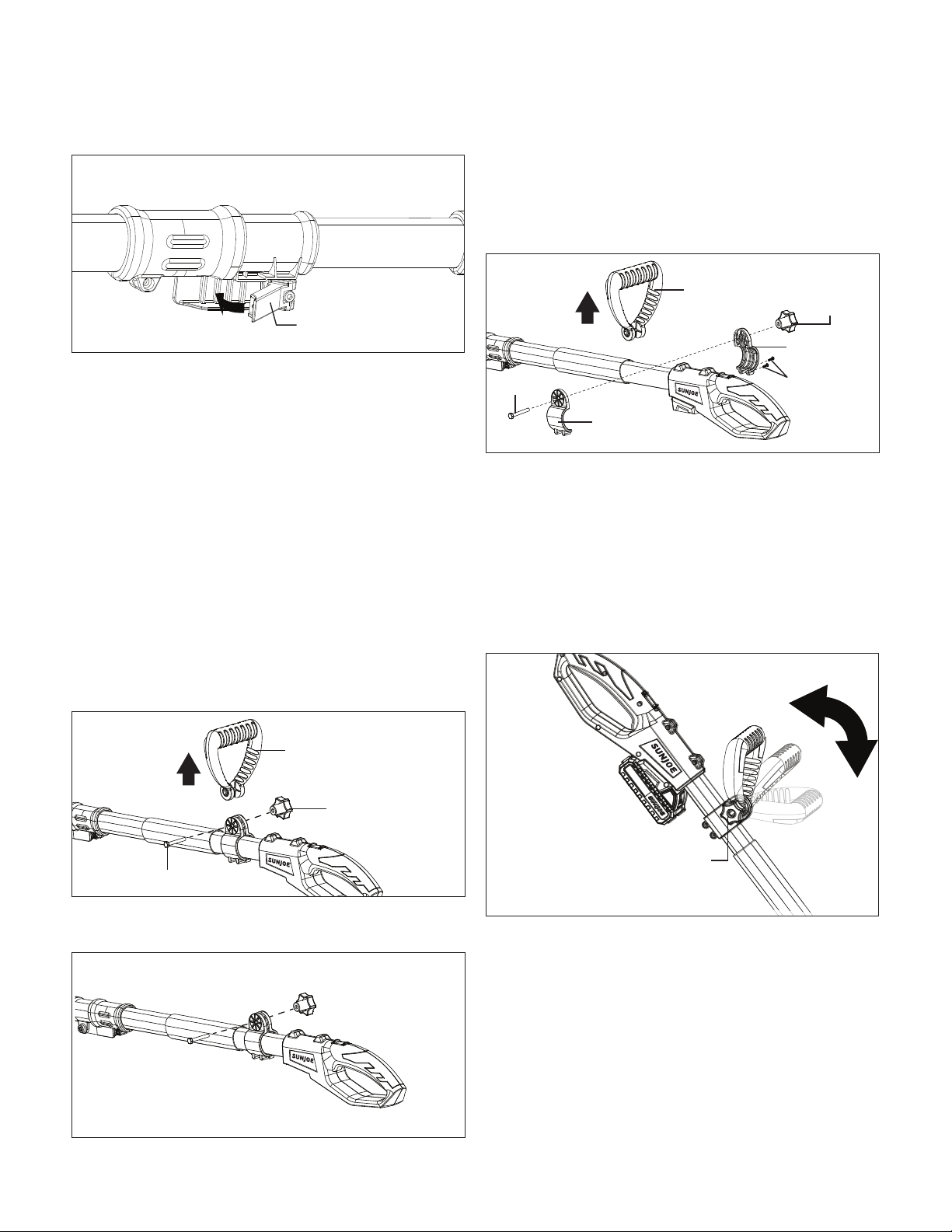
28
3. Lock the pole in position by closing the telescoping lock
(Fig. 65), and ensure that the pole is secured.
mWARNING! Failure to lock the telescoping lock as
directed could result in personal injury.
Adjusting the Auxiliary Handle
The hedge trimmer is equipped with an auxiliary handle that
can be adjusted and removed. Follow the instruction below to
operate the auxiliary handle
mWARNING! Make sure the knob, bolt, and the screws
are xed into place. Failure to lock any of them as directed
could result in personal injury or property damage.
To Remove the Auxiliary Handle
1. Disconnect the hedge trimmer from the power supply by
removing the battery from the compartment.
2. Screw the auxiliary handle lock knob and remove it and
the bolt, then the auxiliary handle can be pulled out
(Fig. 66).
3. Re-assemble the auxiliary handle lock knob and the bolt
on (Fig. 67).
To Adjust the Position of the Auxiliary Handle
1. Disconnect the hedge trimmer from the power supply by
removing the battery from the compartment.
2. Remove the auxiliary handle lock knob, the bolt, and the
auxiliary handle. Use a screw driver to remove the two
screws that used to x the auxiliary handle loops.
Remove the loops from the pole (Fig. 68).
3. Re-assemble the auxiliary handle loops on the desired
spot on the pole by using the two screws, and put back
the auxiliary handle, the auxiliary handle lock knob and the
bolt (Fig. 68).
To Adjust the Angle of the Auxiliary Handle
1. Stop the hedge trimmer by releasing the On/O switch,
2. The auxiliary handle can be adjusted in -45°, 0°, 45°.
Rotate the handle lock knob to unlock the handle, and
then rotate the handle to the desired angle (Fig. 69).
3. Rotate the handle lock knob back to lock the handle
in position.
Fig. 65
Telescoping lock
R
Fig. 66
Auxiliary handle
Auxiliary handle
lock knob
Bolt
R
Fig. 67
R
Fig. 68
Auxiliary handle
Auxiliary
handle
lock knob
Bolt
Auxiliary
handle loop
Screws
Auxiliary
handle loop
R
Fig. 69
Removable
auxiliary
handle
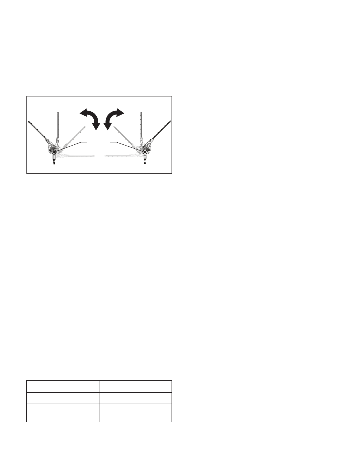
29
Adjusting the Multi-Angle Head
The hedge trimmer head can be rotated for 10 dierent cutting
angles for -45º, -30º, -15º, 0º, 15º, 30º, 45º, 60º, 75º, and 90º.
Follow the below instructions to adjust angles.
1. Rotate the trimmer head to the desired cutting angle while
pressing the rotating buttons located on both sides of the
unit simultaneously (Fig. 70).
2. Release the buttons when the trimmer head is xed into
the desired angle.
NOTE: Failure to properly secure the trimmer head may
result in personal injury or property damage.
mWARNING! Always ensure the hedge trimmer head is
securely locked! Do not attempt to use the pole hedge trimmer
with the head in any other position or unlocked!
Before Operation
1. Check the tool, the battery as well as accessories for
damage before each use. Do not use the tool if it is
damaged or shows wear.
2. Double check that the accessories and attachments are
properly xed.
3. Always hold the tool by its handle and soft grip/auxiliary
handle. Keep the handles dry to ensure safe support.
4. Ensure that the air vents are always unobstructed and
clear. Clean them if necessary with a soft brush. Blocked
air vents may lead to overheating and damage the tool.
5. Switch the tool o immediately if you are disturbed
while working by other people entering the working
area. Always let the tool come to a complete stop before
putting it down.
6. Do not overwork yourself. Take regular breaks to ensure
you can concentrate on the work and have full control
over the tool.
Trimming Times
Cutting Tips
mWARNING! Always hold the pole hedge trimmer with
both hands. Never hold shrubs with one hand and operate the
pole hedge trimmer with the other. Failure to heed this warning
can result in serious injury.
mWARNING! Clear the area to be cut before each use.
Remove all objects such as cords, lights, wire, or loose string
which can become entangled in the cutting blade and create a
risk of serious personal injury.
• Do not force the pole hedge trimmer through heavy
shrubbery. This can cause the blades to bind and slow
down. If the blades slow down, reduce the pace.
• Do not attempt to cut stems or twigs that are larger than
0.6 in. (1.5 cm) thick, or those obviously too large to feed
into the cutting blade. Use a non-powered hand saw or
pruning saw to trim large stems.
• If blades do become jammed, stop the motor, allow the
blades to stop, and remove the battery from the power tool
before attempting to remove the obstruction.
• If desired, you can use a string to help cut your hedge level.
Decide how high you want the hedge. Stretch a piece of
string along the hedge at the desired height. Trim the hedge
just above the guide line of string. Trim the side of a hedge
so that it will be slightly narrower at the top. More of the
hedge will be exposed when shaped this way, and it will be
more uniform.
• Wear gloves when trimming thorny or prickly growth.
When trimming new growth, use a wide sweeping action,
so that the stems are fed directly into the cutting blade.
Older growth will have thicker stems and will be trimmed
easiest by using a sawing movement.
• Hold unit rmly with both hands. Always keep your left hand
on the telescoping pole and your right hand on the rear
handle. The unit is used for cutting in either direction in a
slow, sweeping action from side to side.
• Stand so that you are stable and balanced on both feet.
• Inspect and clear the area of any hidden objects.
• To protect yourself from electrocution, do not operate within
33 feet (10 m) of overhead electrical lines.
• Never use the pole hedge trimmer near power lines,
fencing, posts, buildings, or other immovable objects.
• Never use a blade after hitting a hard object without rst
inspecting it for damage. Do not use if any damage is
detected.
1. To use the pole hedge trimmer for trimming tall, hard-to-
read hedges or shrubs, hold the trimmer at the position
shown below (Fig. 71). Pivot the power head to several
dierent positions to shape or sculpt shrubs or hedges.
Fig. 70
Rotating
buttons
Front side Back side
Green leaf hedges June to October
Evergreens April to August
Conifers and other fast
growing shrubs
Every 6 – 8 weeks

30
2. To use pole hedge trimmer for trimming the bottoms and
sides of hedges and shrubs, hold the pole trimmer at the
position shown below (Fig. 72).
3. To use pole hedge trimmer for trimming low-lying foliage
or ground cover, hold the pole hedge trimmer at the
position as shown below (Fig. 73).
mCAUTION! Do not use the pole hedge trimmer for
cutting stems greater than 0.6 inch (1.5 cm) thick.
Use the pole hedge trimmer only for cutting normal shrubbery
found around houses and buildings.
Do not force the pole hedge trimmer through dense growth.
A slight back and forth sawing action may ease the cutting of
larger, more dense growth. If the pole hedge trimmer begins to
slow down, reduce the rate of speed at which you are trying to
cut. If the pole hedge trimmer becomes jammed, immediately
turn the trimmer o. Remove the battery and clear the jammed
debris from the cutter blades.
Care + Maintenance
m
WARNING! Blades are sharp. When handling the blade
assembly, wear non-slip, heavy-duty protective gloves. Do not
place your hand or ngers between blades or in any position
where they could get pinched or cut. NEVER touch the blades
or service the unit with the battery inserted.
Lubricate the Blades
For easier operation and longer blade life, lubricate the pole
hedge trimmer blade before and after each use.
1. Stop the motor and remove the battery.
2. Lay the pole hedge trimmer on a at surface.
Apply lightweight machine oil along the edge of the
top blade (Fig. 74).
If you will be using the pole hedge trimmer for an extended
period, it is advisable to stop work intermittently in order to
re-oil the blade.
NOTE: Do not oil while the pole hedge trimmer is running.
R
Fig. 71
R
Fig. 72
Fig. 73
Fig. 74

31
Disposal
Recycling the tool
• Do not dispose of electrical appliances as unsorted
municipal waste. Use separate collection facilities.
• Contact your local government agency for information
regarding the collection systems available.
• If electrical appliances are disposed of in landlls
or dumps, hazardous substances can leak into the
groundwater and get into the food chain, damaging your
health and well-being.
• When replacing old appliances with new ones, the retailer
is legally obligated to take back your old appliance for
disposal at least free of charge.
Recycling + Disposal
The product comes in a package that protects it against
damage during shipping. Keep the package until you are
sure that all parts have been delivered and the product is
functioning properly. Recycle the package afterwards or keep
it for long-term storage.
WEEE symbol. Waste electrical products should not
be disposed of with household waste. Please recycle
where facilities exist. Check with your local authority
or local store for recycling regulations.
Battery Caution + Disposal
Always dispose of your battery pack according to federal,
state, and local regulations. Contact a recycling agency in your
area for recycling locations.
mCAUTION! Even discharged battery packs contain
some energy. Before disposing, use electrical tape to cover
the terminals to prevent the battery pack from shorting, which
could cause a re or explosion.
mWARNING! To reduce the risk of injury or explosion,
never burn or incinerate a battery pack even if it is damaged,
dead or completely discharged. When burned, toxic fumes and
materials are emitted into the surrounding atmosphere.
1. Batteries vary according to device. Consult your manual
for specic information.
2. Install only new batteries of the same type in your product
(where applicable).
3. Failure to insert batteries in the correct polarity,
as indicated in the battery compartment or manual, may
shorten the life of the batteries or cause batteries to leak.
4. Do not mix old and new batteries.
5. Do not mix Alkaline, Standard (Carbon-Zinc) or
Rechargeable (Nickel Cadmium, Nickel Metal Hydride,
or Lithium-Ion) batteries.
6. Do not dispose of batteries in re.
7. Batteries should be recycled or disposed of as per state
and local guidelines.
If your Sun Joe
®
iON GTS4002C cordless lawn + garden
multi-tool system requires service or maintenance, please call
1-866-SNOWJOE (1-866-766-9563) for assistance.
Model + Serial Number
When contacting the company, reordering parts, or arranging
service from an authorized dealer, you will need to provide the
model and serial numbers, which can be found on the decal
located on the housing of the unit. Copy these numbers into
the space provided below.
Support
Record the following numbers from the housing or handle of your
new product:
G T S 4 0 0 2 C
Model #:
Serial #:

32
Optional Accessories
mWARNING! ALWAYS use only authorized Snow Joe
®
+ Sun Joe
®
replacement parts and accessories. NEVER use
replacement parts or accessories that are not intended for use with this cordless garden tool system. Contact Snow Joe
®
+
Sun Joe
®
if you are unsure whether it is safe to use a particular replacement part or accessory with your cordless garden tool
system. The use of any other attachment or accessory can be dangerous and could cause injury or mechanical damage.
NOTE: Accessories are subject to change without any obligation on the part of Snow Joe
®
+ Sun Joe
®
to provide notice of such
changes. Accessories can be ordered online at sunjoe.com or via phone by contacting the Snow Joe
®
+ Sun Joe
®
customer
service center at 1-866-SNOWJOE (1-866-766-9563).
iON+ 24V 2.0 Ah Lithium-Ion Battery
Battery Charge Time Max:
Charge times vary by charger. See website for details.
Battery Run Time Max:
Pole hedge trimmer: 50 min (cuts up to 4,000 sq ft of hedges)
Pole grass trimmer: 45 min (trims up to 2,045 lft of grass)
Pole chain saw: Up to 32 cuts of 4" x 4" pine
iON+ 24V 2.5 Ah Lithium-Ion Battery
Battery Charge Time Max:
Charge times vary by charger. See website for details.
Battery Run Time Max:
Pole hedge trimmer: 60 min (cuts up to 4,840 sq ft of hedges)
Pole grass trimmer: 55 min (trims up to 2,425 lft of grass)
Pole chain saw: Up to 40 cuts of 4" x 4" pine
Pre-wound spool (6 Pack)
24VBAT-LTE
GTS4002C-RS-6PK
ModelAccessories Item
1
2
4
3
6
5
8-inch (20.3 cm) replacement chain
7
8
8-inch (20.3 cm) replacement bar
SWJ-8CHAIN
SWJ-8BAR
24VBAT-LT
iON+ 24V 5.0 Ah Lithium-Ion Battery
Battery Charge Time Max:
Charge times vary by charger. See website for details.
Battery Run Time Max:
Pole hedge trimmer: 2 hr 10 min (cuts up to 10,265 sq ft of hedges)
Pole grass trimmer: 1 hr 55 min (trims up to 5,000 lft of grass)
Pole chain saw: Up to 80 cuts of 4" x 4" pine
iON+ 24V 4.0 Ah Lithium-Ion Battery
Battery Charge Time Max:
Charge times vary by charger. See website for details.
Battery Run Time Max:
Pole hedge trimmer: 1 hr 40 min (cuts up to 8,180 sq ft of hedges)
Pole grass trimmer: 1 hr 30 min (trims up to 4,225 lft of grass)
Pole chain saw: Up to 64 cuts of 4" x 4" pine
24VBAT-XR
24VBAT
iON+ 24V Lithium-Ion Battery Quick Charger
24VCHRG-QC

33
NOTES

34
NOTES

35
R4_01282020
SNOW JOE
®
+ SUN JOE
®
CUSTOMER PROMISE
OUR WARRANTY:
Snow Joe
warrants new, genuine, powered and non-powered Products to be free from defects in material or workmanship when used
for ordinary household use for a period of two years from the date of purchase by the original, end-user purchaser when purchased
from Snow Joe or from one of Snow Joe’s authorized sellers with proof of purchase. Because Snow Joe is unable to control the quality
of its Products sold by unauthorized sellers, unless otherwise prohibited by law, this Warranty does not cover Products purchased from
unauthorized sellers. If your Product does not work or there’s an issue with a specic part that is covered by the terms of this Warranty,
Snow Joe will elect to either (1) send you a free replacement part, (2) replace the Product with a new or comparable product at no
charge, or (3) repair the Product. How cool is that!
This Warranty gives you specific legal rights, and you may also have other rights which vary from State to State.
PRODUCT REGISTRATION:
Snow Joe strongly encourages you to register your Product. You can register online at snowjoe.com/register, or by printing and
mailing in a registration card available online from our website, or calling our Customer Service Department at 1-866-SNOWJOE
(1-866-766-9563), or by e-mailing us at [email protected]. Failure to register your Product will not diminish your warranty
rights. However, registering your Product will allow Snow Joe to better serve you with any of your customer service needs.
WHO CAN SEEK LIMITED WARRANTY COVERAGE:
This Warranty is extended by Snow Joe to the original purchaser and original owner of the Product.
WHAT IS NOT COVERED?
This Warranty does not apply if the Product has been used commercially or for non-household or rental applications. This Warranty also
does not apply if the Product was purchased from an unauthorized seller. This Warranty also does not cover cosmetic changes that do
not aect performance. Wearing parts like belts, augers, chains and tines are not covered under this Warranty, and can be purchased
at snowjoe.com or by calling 1-866-SNOWJOE (1-866-766-9563).
ABOVE ALL ELSE, Snow Joe, LLC (“Snow Joe”) is dedicated to you, our customer. We strive to make your experience as pleasant as
possible. Unfortunately, there are times when a Snow Joe
®
, Sun Joe
®
, or Aqua Joe
®
product (“Product”) does not work or breaks under
normal operating conditions. We think it’s important that you know what you can expect from us. That’s why we have a Limited Warranty
(“Warranty”) for our Products.

sunjoe.com