Loading ...
Loading ...
Loading ...
17
perfectly preserved. The
MC312 Power Amplifier
with Power Guard is not
limited to just the rated
power output, but will
actually produce distor-
tion free output well
above its rated power due
to the McIntosh phi-
losophy of conservative
design.
Power Supply Circuits
To compliment the design of the MC312 Power Am-
plifier Circuitry, there is a high current high voltage
power supply for both channels. Refer to figures 24
and 27. The very large Power Transfomer can supply
over 13 amps of continuous current. Refer to figure 25
(golf ball is for size comparison).
It is enclosed in the legendary McIntosh Potted En-
closures and weighs 28 lbs. The two super size main
filter capacitors can store over 300 Joules of energy
When the A/V Control Center is switched On, a (+5V)
signal operates the power relay in the MC312. The
MC312 also has two remote Power Control Out Jacks.
The Power Control signal from these jacks is delayed
by a fraction of a second so that the turn on power
surge of the next power amplifier occurs at a later
time. This helps prevent power circuit overload that
could trip circuit breakers or blow fuses, a very impor-
tant feature in a high power Home Systems employing
multiple MC312 Power Amplifiers.
for both amplifier channels, necessary for the wide
dynamic range that “Digital Audio” demands. Refer to
figure 26.
The power
amplifier
draws high
current
from the
AC power
line. There-
fore, it is
important
that they
plug di-
rectly into
the wall
outlet.
Also, most
owners de-
sire one power switch for the whole audio system. The
MC312 is equipped with a circuit that provides remote
Power Control from a McIntosh A/V Control Center.
Refer to figure 27.
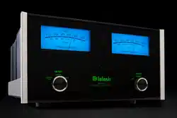
Figure 23
With Power Guard
Technical Description, con’t
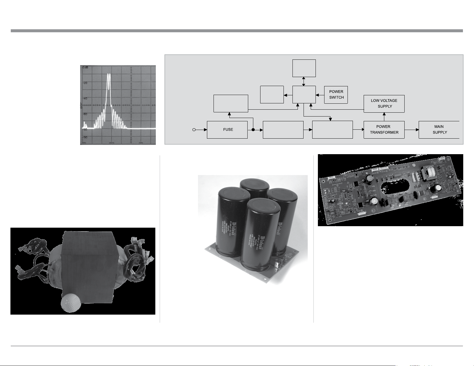
Figure 24
Block Diagram
of the
Power Supply
INRUSH
CURRENT
LIMITER
AC Power
MAIN RELAYS
BACKUP
POWER SUPPLY
CONTROL
LOGIC
LIGHTING
CONTROL
POWER
CONTROL
Figure 25
Figure 26
Figure 27
Loading ...
Loading ...
Loading ...