Loading ...
Loading ...
Loading ...

en Installation
18
Electrical connection
:Warning – Risk of electric shock!
Components inside the appliance may have sharp
edges. These may damage the connecting cable. Do
not kink or pinch the connecting cable during
installation.
The required connection data can be found on the
rating plate inside the appliance; to do this, remove the
metal mesh grease filter.
Length of the cable: approx. 1.30 m
This appliance complies with the EC interference
suppression regulations.
:Warning – Risk of electric shock!
It must always be possible to disconnect the appliance
from the electricity supply. The appliance must only be
connected to a protective contact socket that has been
correctly installed.
The mains plug of the mains power cable must be
easily accessible after installation of the appliance. If
this is not possible, an all-pole isolating switch must be
integrated into the permanent electrical installation
according to the conditions of overvoltage category III
and according to the installation regulations.
The permanent electrical installation must only be wired
by a professional electrician. We recommend installing
a residual-current circuit breaker (RCCB) in the
appliance's power supply circuit.
5Installation
I nst al l at i on
Fitting the upper support frame
1. Before fitting, determine the total height of the
support frame and mark the screw holes.
Note: The height of the support frame can be
adjusted in 20 mm intervals.
2. On the ceiling, mark the centre point of the
appliance.
3. Using the enclosed template, mark the positions for
the screws on the ceiling.
4. Drill four 8 mm diameter holes to a depth of 80 mm
for the fasteners and press in the wall plugs flush
with the ceiling.
5. Fasten the upper part of the support frame to the
ceiling with 4 screws.
Note: Ensure that the support frame is in the correct
position. The middle bracket defines the preferred
side and must be facing the hob control elements.
Fitting the lower support frame
Fasten the upper and lower part of the support frame at
the specified total height using 10 screws.
Notes
■ Ensure that the lower support frame is in the correct
position. The open side must be facing the hob
control elements.
■ The support frame can be subsequently re-
positioned by loosening the securing screws.
[
[
[
([KDXVWDLU
PP
&LUFXODWHGDLU
PP
[
Installation en
19
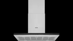
Fitting the appliance
1. Hook the appliance from below into the support
frame.
Note: Ensure that the mains cable is not trapped.
2. Fasten the appliance to the support frame using 2
securing screws.
3. Hook in the retaining clip and screw tight.
Connecting the pipes
Note: If using an aluminium pipe, smooth the
connection area beforehand.
Exhaust-air pipe Ø 150 mm (recommended size)
Attach the exhaust-air pipe directly to the air-pipe
connector and seal.
Exhaust-air pipe Ø 120 mm
1. Attach the reducing connector directly to the air-pipe
connector.
2. Attach the exhaust air pipe to the reducing
connector.
3. Seal both joints appropriately.
Attaching the flue duct
:Warning – Risk of injury!
Components inside the appliance may have sharp
edges. Wear protective gloves.
1. Separate the flue ducts.
To do this, remove the adhesive tape.
2. Remove the protective foil from both sides.
3. Place both parts of the upper flue on the appliance
and push together.
Note: The slots of the upper flue must point
downwards.
4. Push up the upper flue part and secure with 2
screws.
5. Insert both lower parts of the flue and push together.
[
[
Loading ...