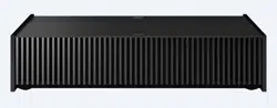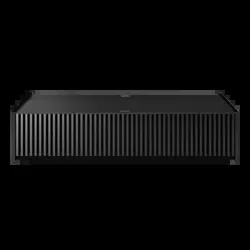
VPL-VZ1000
4-693-528-13 (1)
G:\Sagyou\11 Nov\1129\1129\4693528131\4693528131VPLVZ1000UC7\01GB-
VPLVZ1000UC\010COV.fm
masterpage:Cover
Video Projector
VPL-VZ1000
4-693-528-13 (1)
© 2017 Sony Corporation
Quick Reference Manual ___ US
Guide de reference rapide _ FR
Printed in Japan
G:\#sagyou\12 De\1203\4693528131\4693528131VPLVZ1000UC7\01GB-
VPLVZ1000UC\040BCO.fm
masterpage:Back Cover
VPL-VZ1000
4-693-528-13 (1)
About the Quick Reference Manual
US
2
This Quick Reference Manual explains the installation and basic operations for projecting pictures.
Before operating the unit, please read this manual thoroughly and retain it for future reference.
Refer to “About Indicators,” “Cleaning the Air Filter,” and “Cleaning,” as necessary.
For details on the operations, refer to the Operating Instructions contained in the supplied CD-ROM.
About the Quick Reference Manual
Installing the Unit................................................... Page 3
Adjusting .................................................................. Page 7
Connecting the Unit............................................ Page 10
Attaching the Covers.......................................... Page 11
Projecting............................................................... Page 13
Error Handling
About Indicators....................................................................... Page 14
Maintenance
Cleaning the Air Filter.............................................................. Page 15
Cleaning.................................................................................... Page 15
Step 1
Step 2
Step 3
Step 4
Step 5
Using the CD-ROM manual
The manual can be read on a computer with Adobe
Reader installed.
You can download Adobe Reader free from the Adobe
website.
1 Open the index.html file in the CD-ROM.
2 Select and click on the manual that you want to read.
If you have lost or damaged the CD-ROM, you can purchase a new
one from your Sony dealer or Sony service counter.
Adobe and Adobe Reader are trademarks of Adobe Systems
Incorporated in the United States and/or other countries.
Note

Installing the Unit
3
US
Check the carton to make sure it contains the following
items:
• Remote control RM-PJ28 (1)
• Size AA (R6) manganese batteries (2)
• AC power cord (1)
• Plug holder (1)
• Top cover (1)
• Side covers (2)
• Straps for side covers (2)
• Rivets for side covers (2)
• Cleaning cloth (1)
• Quick Reference Manual (this manual) (1)
• Safety Regulations (1)
• Operating Instructions (CD-ROM) (1)
Caution about handling the remote control
• Handle the remote control with care. Do not drop or step
on it, or spill liquid of any kind onto it.
• Do not place the remote control in a location near a heat
source, a place subject to direct sunlight, or a damp
room.
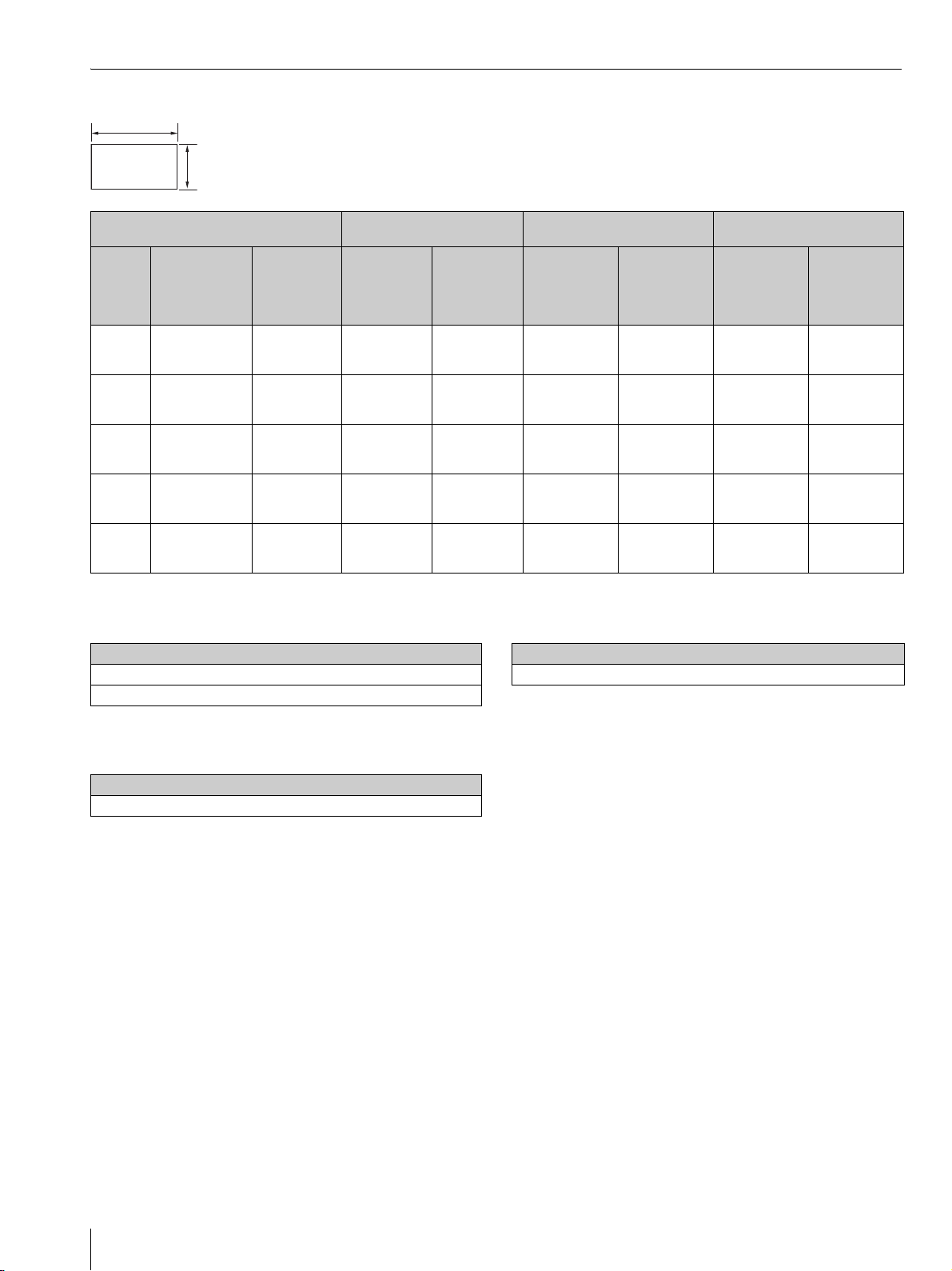
L1: Distance from a projection surface to the rear of the
unit
L2: Distance from a projection surface to the front of the
unit
H: Distance from the installation surface to the bottom of
the screen
W: Horizontal width of the screen
Installing the Unit
Step 1
Checking the Supplied Accessories
Inserting the Batteries into the
Remote Control
Push and slide to open.
Insert the batteries E side first.
Installation Distance and Projection
Image Size
L2
L1
W
H
US
Installing the Unit
US
4
When projecting in 1.90:1 (Native Full Display 17:9) format
Formula 1 (calculates an installation distance from a
projection image size)
Unit: cm (inches)
Formula 2 (calculates a projection image size from an
installation distance)
Unit: cm (inches)
Formula 3 (calculates a distance from the installation
surface to the bottom of a projection image)
Unit: cm (inches)
Projection image size Installation distance
Adjustment amount of picture
shift
Adjustment amount of picture
size
Diagonal
(D)
Width × Height
Bottom
height (H)
From a
projection
surface to the
rear of the unit
(L1)
From a
projection
surface to the
front of the
unit (L2)
Horizontal
direction
Vertical
direction
Horizontal
direction
Vertical
direction
84-inch
(2.14 m)
1.89 m × 1.00 m
(74 inches × 39
inches)
39.0 cm
(15.3 inches)
5.0 cm
(2.0 inches)
52.0 cm
(20.5 inches)
+/
_
5.3 cm
(+/
_
2.1 inches)
+/
_
6.0 cm
(+/
_
2.4 inches)
+/
_
1.9 cm
(+/
_
0.7 inches)
+/
_
1.0 cm
(+/
_
0.4 inches)
95-inch
(2.40 m)
2.13 m × 1.12 m
(84 inches × 44
inches)
41.8 cm
(16.5 inches)
10.2 cm
(4.0 inches)
57.2 cm
(22.5 inches)
+/
_
6.0 cm
(+/
_
2.4 inches)
+/
_
6.7 cm
(+/
_
2.6 inches)
+/
_
2.1 cm
(+/
_
0.8 inches)
+/
_
1.1 cm
(+/
_
0.4 inches)
105-inch
(2.67 m)
2.36 m × 1.24 m
(93 inches × 49
inches)
44.7 cm
(17.6 inches)
15.5 cm
(6.1 inches)
62.5 cm
(24.6 inches)
+/
_
6.6 cm
(+/
_
2.6 inches)
+/
_
7.5 cm
(+/
_
2.9 inches)
+/
_
2.4 cm
(+/
_
0.9 inches)
+/
_
1.2 cm
(+/
_
0.5 inches)
116-inch
(2.94 m)
2.60 m × 1.37 m
(102 inches × 54
inches)
47.6 cm
(18.7 inches)
20.7 cm
(8.2 inches)
67.7 cm
(26.7 inches)
+/
_
7.3 cm
(+/
_
2.9 inches)
+/
_
8.2 cm
(+/
_
3.2 inches)
+/
_
2.6 cm
(+/
_
0.9 inches)
+/
_
1.4 cm
(+/
_
0.6 inches)
126-inch
(3.21 m)
2.84 m × 1.49 m
(112 inches × 59
inches)
50.4 cm
(19.9 inches)
26.0 cm
(10.2 inches)
73.0 cm
(28.7 inches)
+/
_
8.0 cm
(+/
_
3.1 inches)
+/
_
9.0 cm
(+/
_
3.5 inches)
+/
_
2.8 cm
(+/
_
1.1 inches)
+/
_
1.5 cm
(+/
_
0.6 inches)
1.90
1
Projection image size
L1 = 0.2219 × W - 36.9398 (L1 = 0.2219 × W - 14.5432)
L2 = 0.2219 × W + 10.0602 (L2 = 0.2219 × W + 3.9607)
From a projection surface to the rear of the unit
W = 4.5069 × L1 + 166.4916 (W = 4.5069 × L1 + 65.5479)
Projection image size
H = 0.1213 × W + 16.0372 (H = 0.1213 × W + 6.3139)
Installing the Unit
5
US
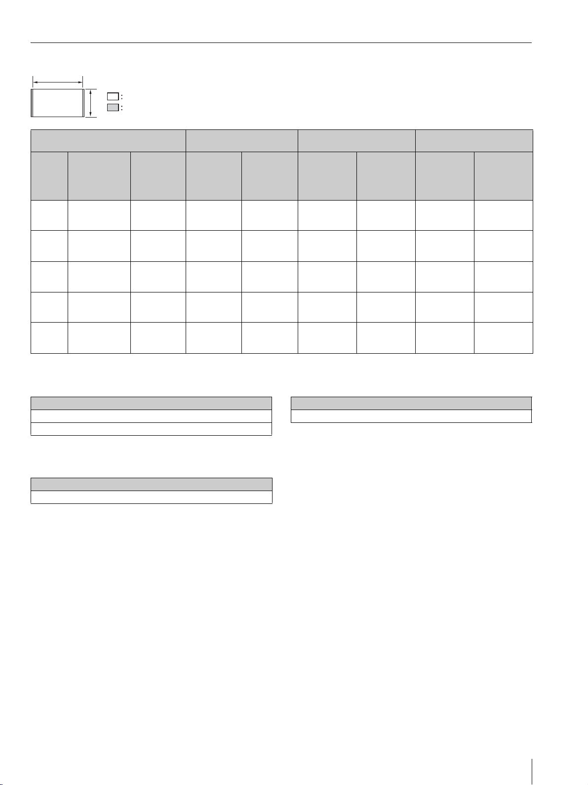
When projecting in 1.78:1 (16:9) format
Formula 1 (calculates an installation distance from a
projection image size)
Unit: cm (inches)
Formula 2 (calculates a projection image size from an
installation distance)
Unit: cm (inches)
Formula 3 (calculates a distance from the installation
surface to the bottom of a projection image)
Unit: cm (inches)
Projection image size Installation distance
Adjustment amount of picture
shift
Adjustment amount of picture
size
Diagonal
(D)
Width × Height
Bottom
height (H)
From a
projection
surface to the
rear of the unit
(L1)
From a
projection
surface to the
front of the
unit (L2)
Horizontal
direction
Vertical
direction
Horizontal
direction
Vertical
direction
80-inch
(2.03 m)
1.77 m × 1.00 m
(70 inches × 39
inches)
39.0 cm
(15.3 inches)
5.0 cm
(2.0 inches)
52.0 cm
(20.5 inches)
+/
_
5.3 cm
(+/
_
2.1 inches)
+/
_
6.0 cm
(+/
_
2.4 inches)
+/
_
1.8 cm
(+/
_
0.7 inches)
+/
_
1.0 cm
(+/
_
0.4 inches)
90-inch
(2.29 m)
1.99 m × 1.12 m
(78 inches × 44
inches)
41.8 cm
(16.5 inches)
10.2 cm
(4.0 inches)
57.2 cm
(22.5 inches)
+/
_
6.0 cm
(+/
_
2.4 inches)
+/
_
6.7 cm
(+/
_
2.6 inches)
+/
_
2.0 cm
(+/
_
0.8 inches)
+/
_
1.1 cm
(+/
_
0.4 inches)
100-inch
(2.54 m)
2.22 m × 1.24 m
(87 inches × 49
inches)
44.7 cm
(17.6 inches)
15.5 cm
(6.1 inches)
62.5 cm
(24.6 inches)
+/
_
6.6 cm
(+/
_
2.6 inches)
+/
_
7.5 cm
(+/
_
2.9 inches)
+/
_
2.2 cm
(+/
_
0.9 inches)
+/
_
1.2 cm
(+/
_
0.5 inches)
110-inch
(2.79 m)
2.44 m × 1.37 m
(96 inches × 54
inches)
47.6 cm
(18.7 inches)
20.7 cm
(8.2 inches)
67.7 cm
(26.7 inches)
+/
_
7.3 cm
(+/
_
2.9 inches)
+/
_
8.2 cm
(+/
_
3.2 inches)
+/
_
2.4 cm
(+/
_
0.9 inches)
+/
_
1.4 cm
(+/
_
0.6 inches)
120-inch
(3.05 m)
2.66 m × 1.49 m
(105 inches × 59
inches)
50.4 cm
(19.9 inches)
26.0 cm
(10.2 inches)
73.0 cm
(28.7 inches)
+/
_
8.0 cm
(+/
_
3.1 inches)
+/
_
9.0 cm
(+/
_
3.5 inches)
+/
_
2.7 cm
(+/
_
1.1 inches)
+/
_
1.5 cm
(+/
_
0.6 inches)
1.78
1
Video display area
Projection area
Projection image size
L1 = 0.2368 × W - 36.9638 (L1 = 0.2368 × W - 14.5527)
L2 = 0.2368 × W + 10.0362 (L2 = 0.2368 × W + 3.9512)
From a projection surface to the rear of the unit
W = 4.2226 × L1 + 156.0908 (W = 4.2226 × L1 + 61.4531)
Projection image size
H = 0.1295 × W + 16.0240 (H = 0.1295 × W + 6.3087)
Installing the Unit
US
6
The installation distance between the unit and a projection
surface varies depending on the projection size. Install this
unit so that it fits the desired projection size.
For customers
CAUTION
When mounting the projector to the ceiling or moving it to
a different location, do not do so by yourself.
For dealers
• When installing the unit on a ceiling, be sure to read
“Safety precautions for installing the unit on a ceiling” in
the Safety Regulations (supplied separately).
• When installing the unit on a ceiling, remove the feet
first, and follow the instructions below.
Screw diameter: M10
Fixing positions: 5 positions
Insertion length of screws: 10 mm - 50 mm (
13
/
32
-
2 inches)
Recommended tightening torque: 1.3 - 1.5 N•m
1 Position the unit so that the unit is parallel to the
projection surface.
Top view
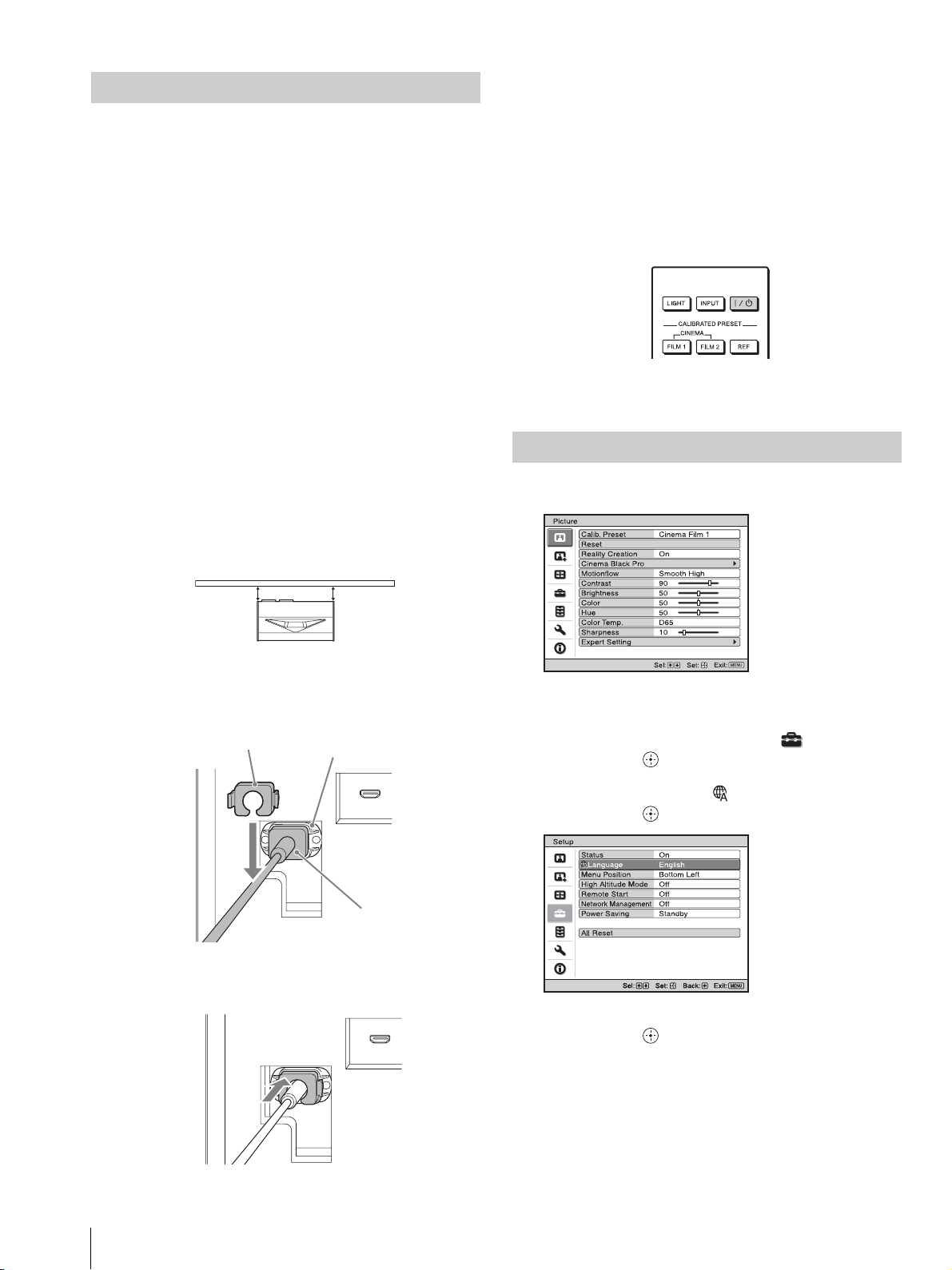
2 Plug the AC power cord into the AC IN socket, then
attach the plug holder to the AC power cord.
3 Slide the plug holder over the AC power cord to fix to
the unit.
4 Plug the AC power cord into a wall outlet.
The unit goes into standby mode.
Tip
After connecting the AC power cord to the unit, the LED
indicator may blink.
You may not be able to control the unit while the indicator is
blinking, but this is not a malfunction. Wait until it stops
blinking.
5 Press the ?/1 (On/Standby) button to turn on the unit.
The LED indicator lights in white.
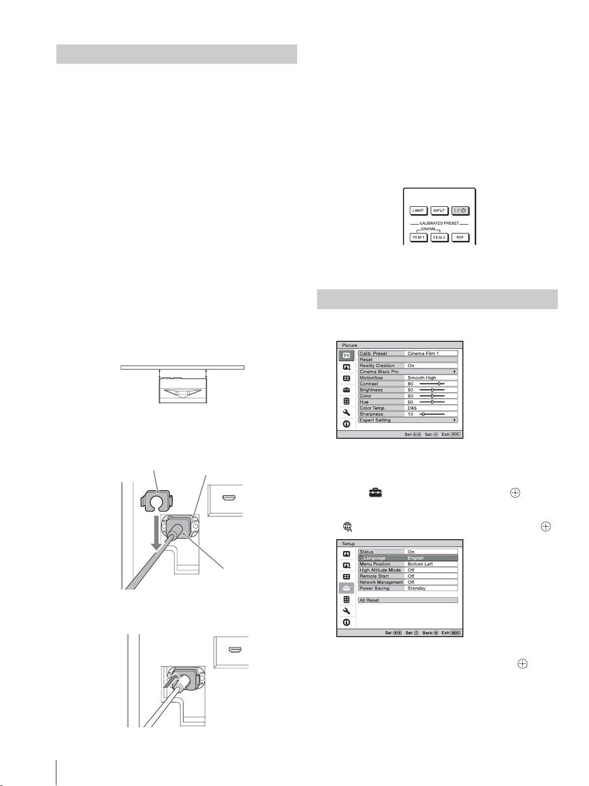
1 Press MENU to display the menu.
2 Select the menu language.
a Press M/m to select the Setup menu, then
press , or .
b Press M/m to select “ Language,” then
press , or .
c Press M/m/</, to select a language, then
press , or .
3 Press MENU to turn off the menu window.
Installing the Unit
ab
a = b
Projection surface
Plug holder (supplied)
AC IN socket
AC power cord
(supplied)
Selecting the Menu Language
Setup
Status
Language
Menu Position
High Altitude Mode
Remote Start
Network Management
Power Saving
All Reset
On
English
Bottom Left
Off
Off
Off
Standby
Adjusting
7
US
Tip
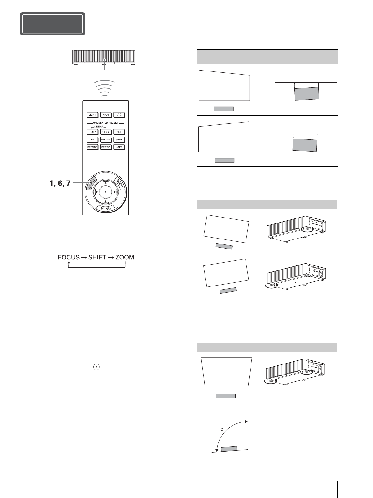
When adjusting the lens, each time you press the PATTERN button
of the remote control or the LENS button on the unit, the lens
adjustment function switches as follows.
1 Press the PATTERN button to display the Lens Focus
adjustment window, and adjust the focus of the picture
by pressing the M/m/</, buttons.
Tips
• The factory default for focus has been adjusted to the 100-
inch screen. Make fine adjustments according to the screen
size and installing position.
• Adjust by checking the entire test pattern. The amplitude of
the pattern focus on the top of the picture becomes large with
the ultra short focus projector.
• If you press the RESET button on the remote control while
the Lens Focus adjustment window is displayed, the focus
setting returns to the factory default.
• Whenever you press the button, the test pattern
disappears.
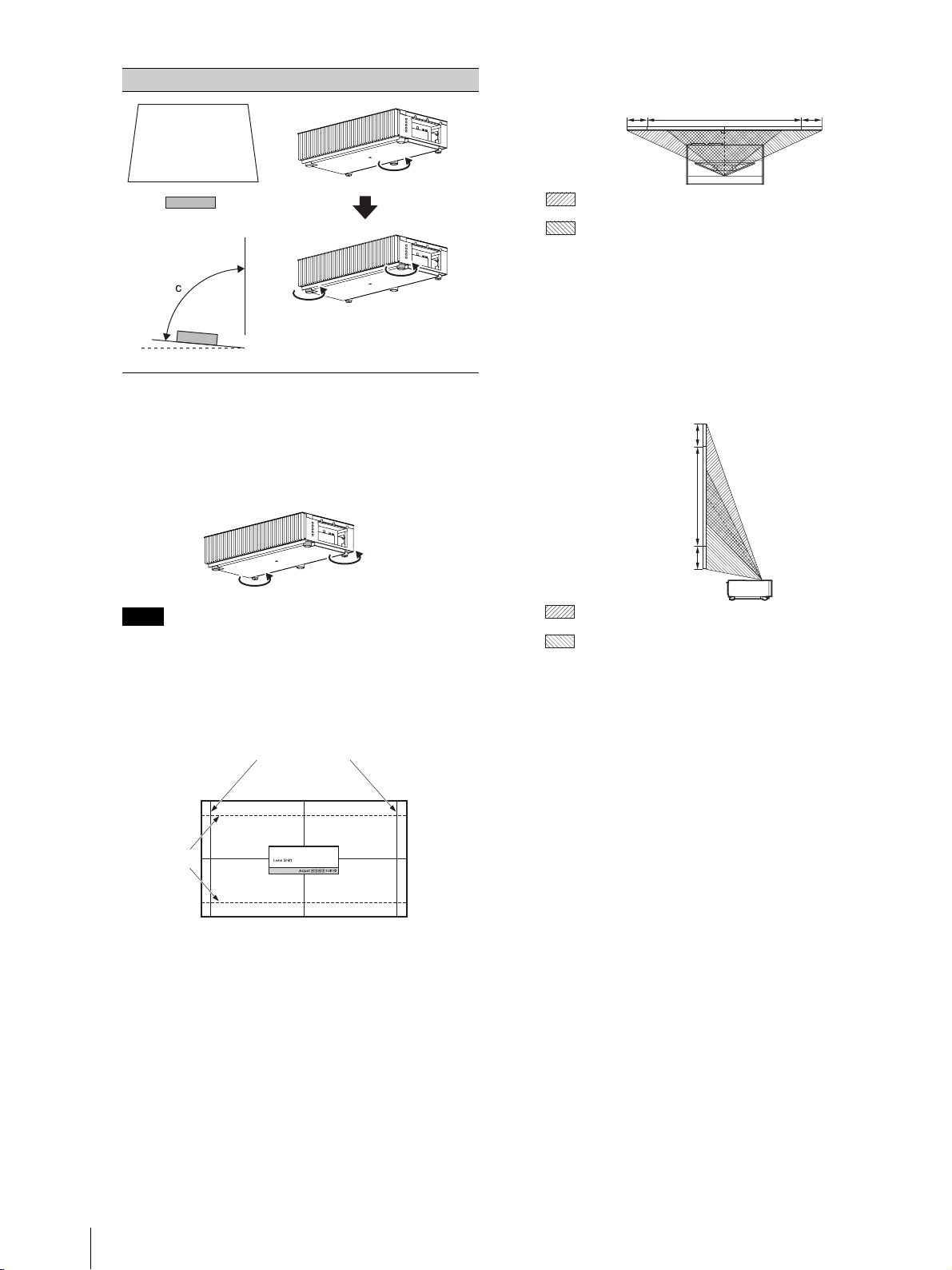
2 Check if the upper side and lower side of the picture
are parallel.
If not, install the unit in a position parallel to the
projection surface (a=b).
3 Check if the lower side of the picture is horizontal.
If not, use the left/right feet (adjustable) to keep the
unit level. For details on adjusting the feet, see page 9.
4 Check if the left side and right side of the picture are
vertical.
If not, use the feet (adjustable) to keep the unit vertical
to the projection surface. For details on adjusting the
feet, see page 9.
Adjusting
Step 2
Remote control detector
Image distortion Installation state to the projection surface
(Top view)
Image distortion Feet adjustment
Image distortion Feet adjustment
a
b
a > b
a
b
a < b
c > 90°
Side view
Adjusting
US
8
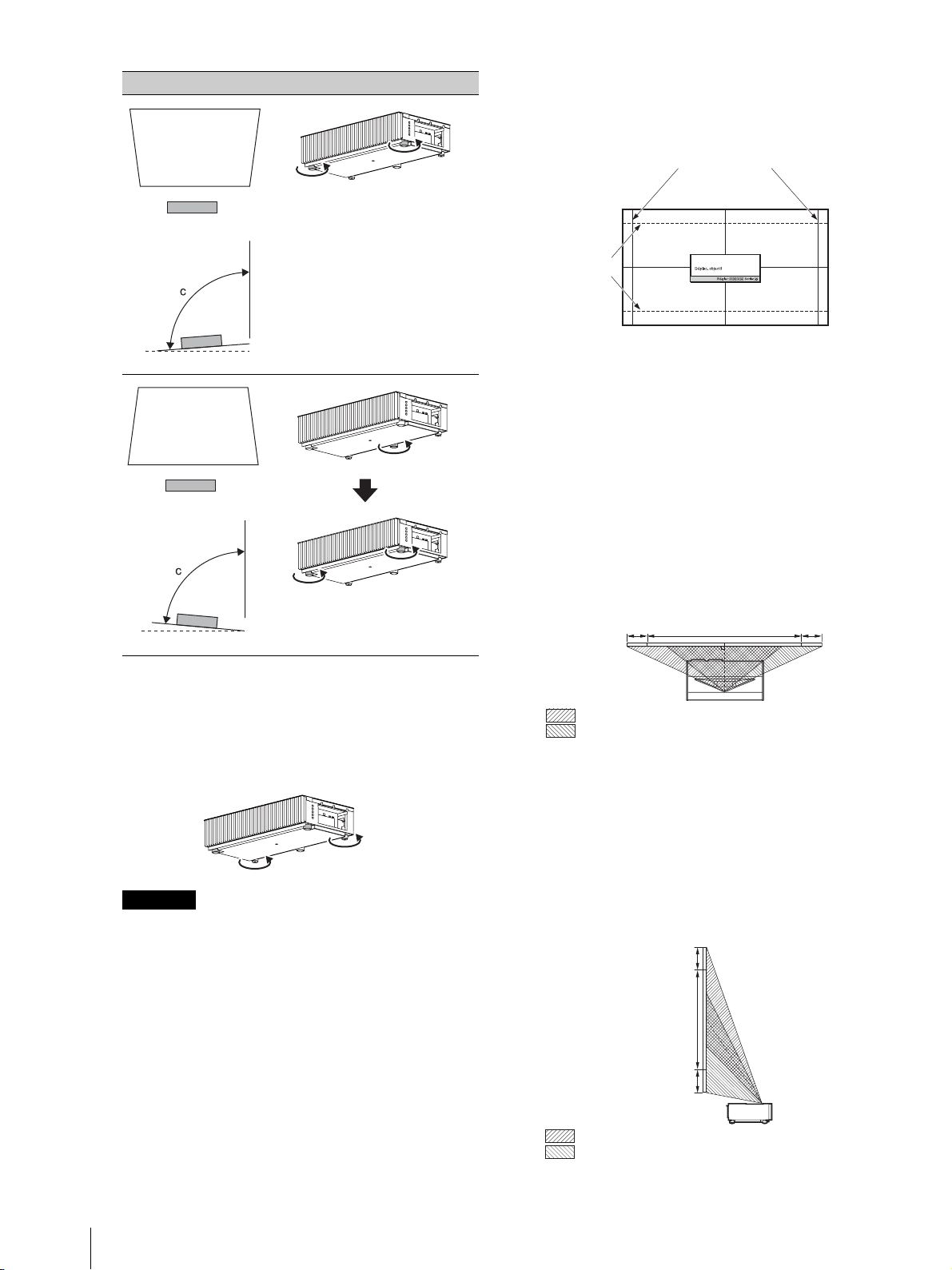
If the frame of the projection surface is rectangle and
parallel to the floor, adjustment is completed.
Tip
If the picture remains distorted, repeat step 2 and 3.
5 Adjust the feet for preventing backlash to the floor.
The picture may be distorted if you turn the feet for preventing
backlash too much.
6 Press the PATTERN button to display the Lens Shift
adjustment window, and adjust the picture position by
pressing the M/m/</, buttons.
Tip
If you press the RESET button on the remote control while the
Lens Shift adjustment window is displayed, the picture
position returns to the center of the lens (factory default
position).
To adjust the horizontal position
When pressing the </, button, the picture
projected on the screen moves right or left by a
maximum of 3% of the screen width from the center
of the lens.
Top view
* For 17:9 display, the range of movement will be +/
_
2.8%.
To adjust the vertical position
When pressing the M/m button, the picture projected
on the screen moves up or down by a maximum of 6%
of the screen height from the center of the lens.
Side view
7 Press the PATTERN button again to display the Lens
Zoom adjustment window. Then adjust the size of the
picture by pressing the M/m/</, buttons.
To make the picture larger, press M/,.
To make the picture smaller, press m/<.
Note
Image distortion Feet adjustment
c < 90°
Side view
Adjust the foot
near the rear
side so that it is
longer.
Adjust the
height with the
feet near the
front side.
1.78:1 (16:9)
2.35:1
The dashed lines show the screen sizes of
each aspect ratio.
3%* 3%*1 screen width
: Picture position when moving the picture to the left at
maximum
: Picture position when moving the picture to the right at
maximum
6%
6%
1 screen
height
: Picture position when moving the picture upward at
maximum
: Picture position when moving the picture downward at
maximum
Adjusting
9
US
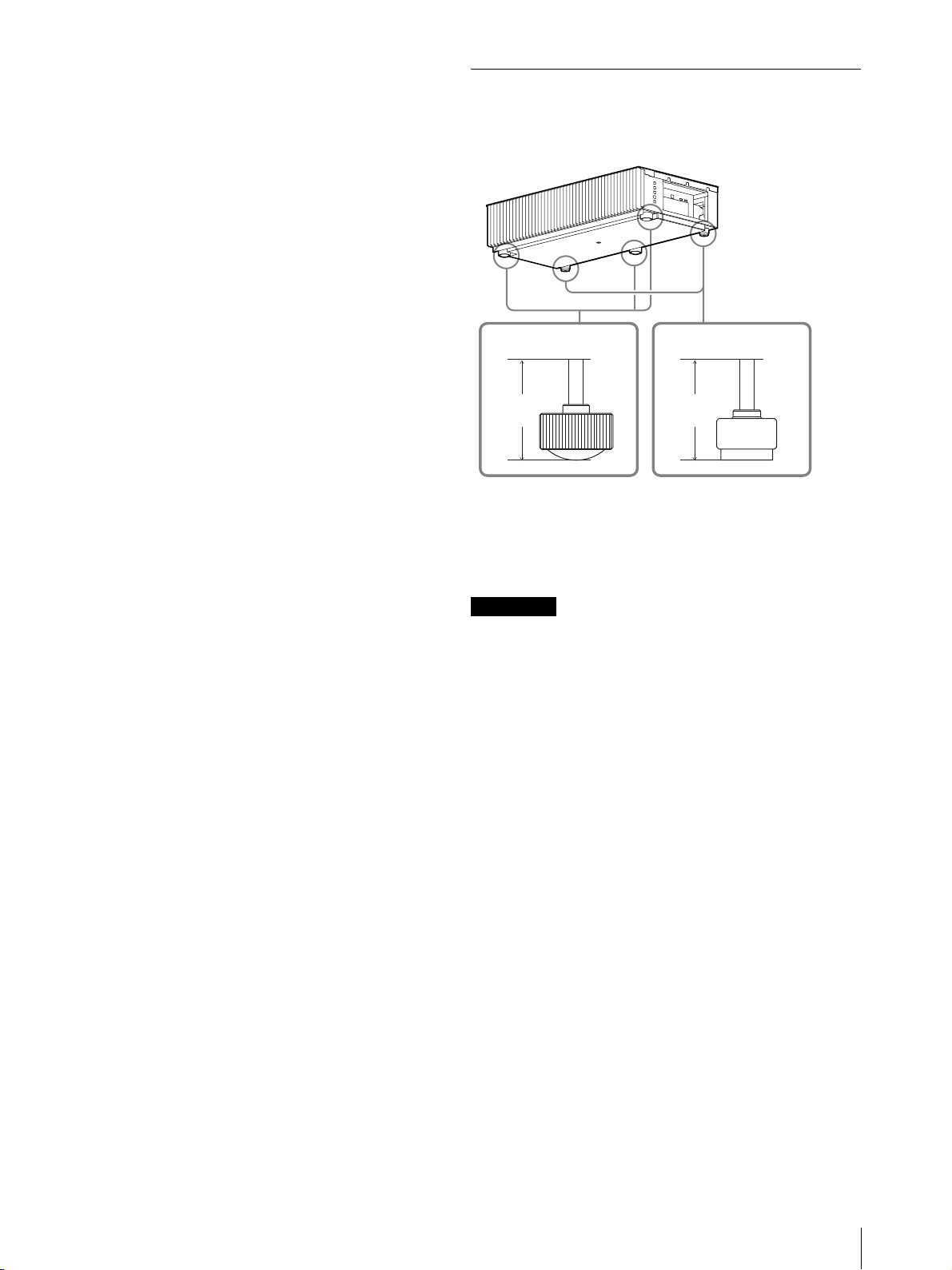
Adjusting the height of the feet
You can adjust the height and tilt of the unit using the three
feet at the bottom of the unit, and prevent backlash of the
unit using the two feet.
Tips
• The feet for adjusting the tilt can be adjusted by 1.5 mm with every
full turn.
• The left and right feet near the rear side can be used to prevent the
backlash. You can adjust these feet to the same height as the feet
for adjusting the tilt.
• Be careful not to get your finger caught when turning the feet for
adjusting the tilt or feet for preventing backlash.
• You can adjust the foot height up to 20 mm. If the foot height is
more than 30 mm, the foot may come off and the unit may drop
causing an injury.
Notes
Foot
height
Foot
height
Foot for adjusting
the tilt
Foot for preventing
backlash
Connecting the Unit
US
10
When making connections, be sure to do the following:
• Turn off all equipment before making any connections.
• Use the proper cables for each connection.
• Insert the cable plugs properly; poor connection at the plugs may cause a malfunction or poor picture quality. When
pulling out a cable, be sure to pull it out from the plug, not the cable itself.
• Refer to the operating instructions of the connected equipment.
Connecting the Unit
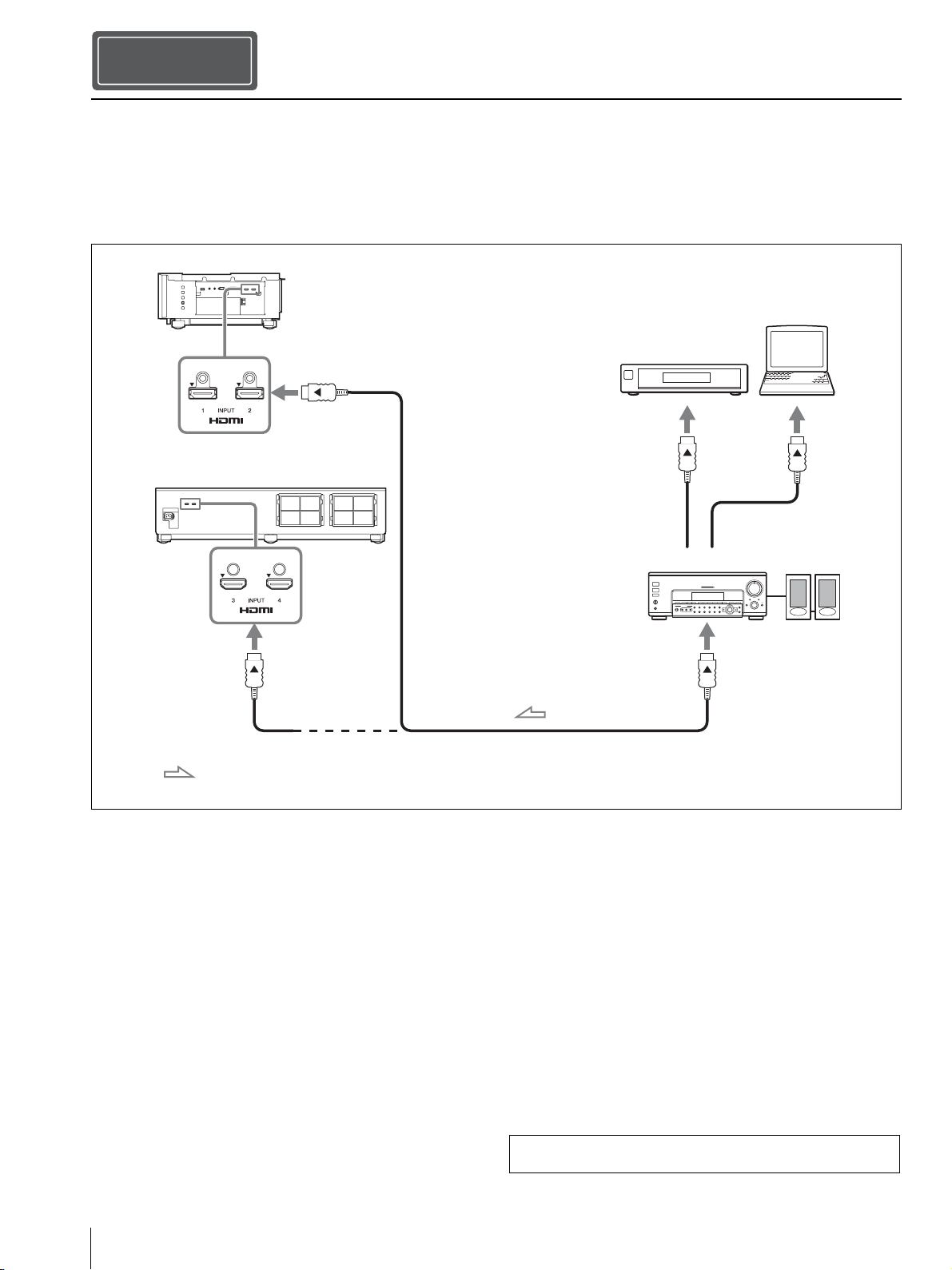
Step 3
Right side of the unit
Equipment with HDMI
output connectors
to HDMI
output
HDMI cable (not supplied)
Computer
Rear side of the unit
: Video signal flow
AV amplifier Speakers
to HDMI input
to HDMI input
Use a Premium High Speed HDMI cable on which
the cable type logo is specified.
For more information, refer to “Connections and Preparations” in
the Operating Instructions contained in the supplied CD-ROM.
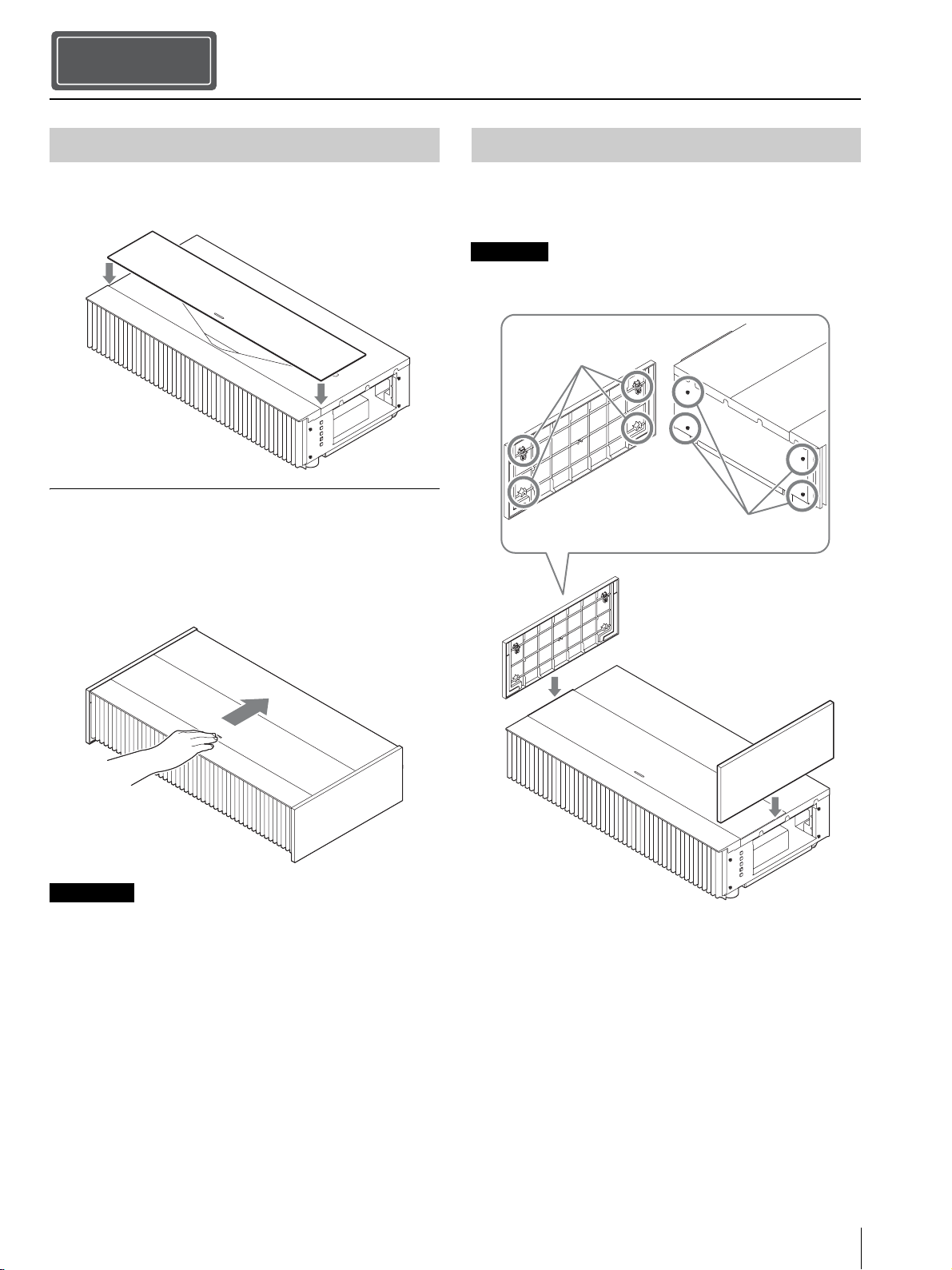
Attaching the Covers
11
US
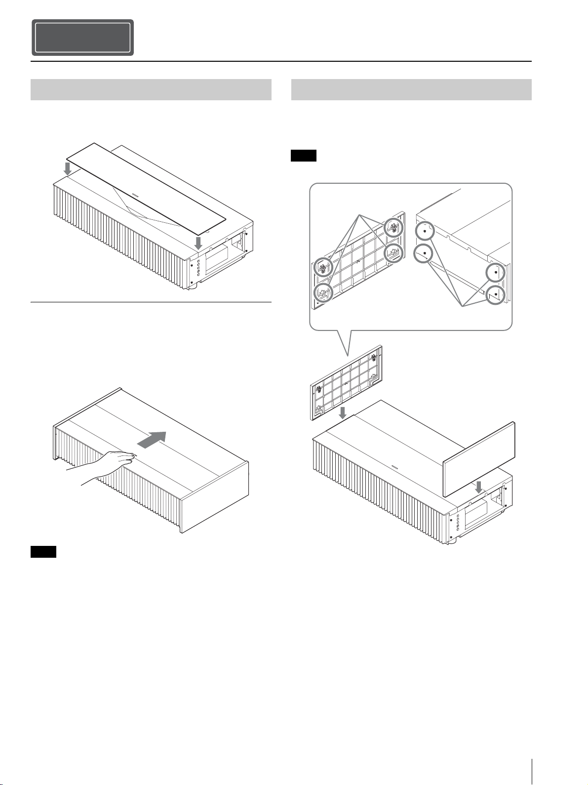
Place the top cover on the top of the unit, and align the left
and right position.
Using the top cover
Slide the top cover by the pull on the center of the top
cover.
You can prevent the accumulation of dust on the projection
window by closing the top cover when the unit is not in
use.
• Do not close the top cover when turning the power on.
• Use the top cover together with the side covers.
• If dust is in the sliding surface, it may scratch the unit.
• When removing the top cover, do not set the top cover upright.
After attaching the top cover, place the side covers by
hooking the holes of the side covers to the tabs on the side
of the unit.
Make sure that all 4 holes are hooked to the tabs.
Attaching the Covers
Step 4
Attaching the Top Cover
Notes
Attaching the Side Covers
Note
Hole
Tab
Attaching the Covers
US
12
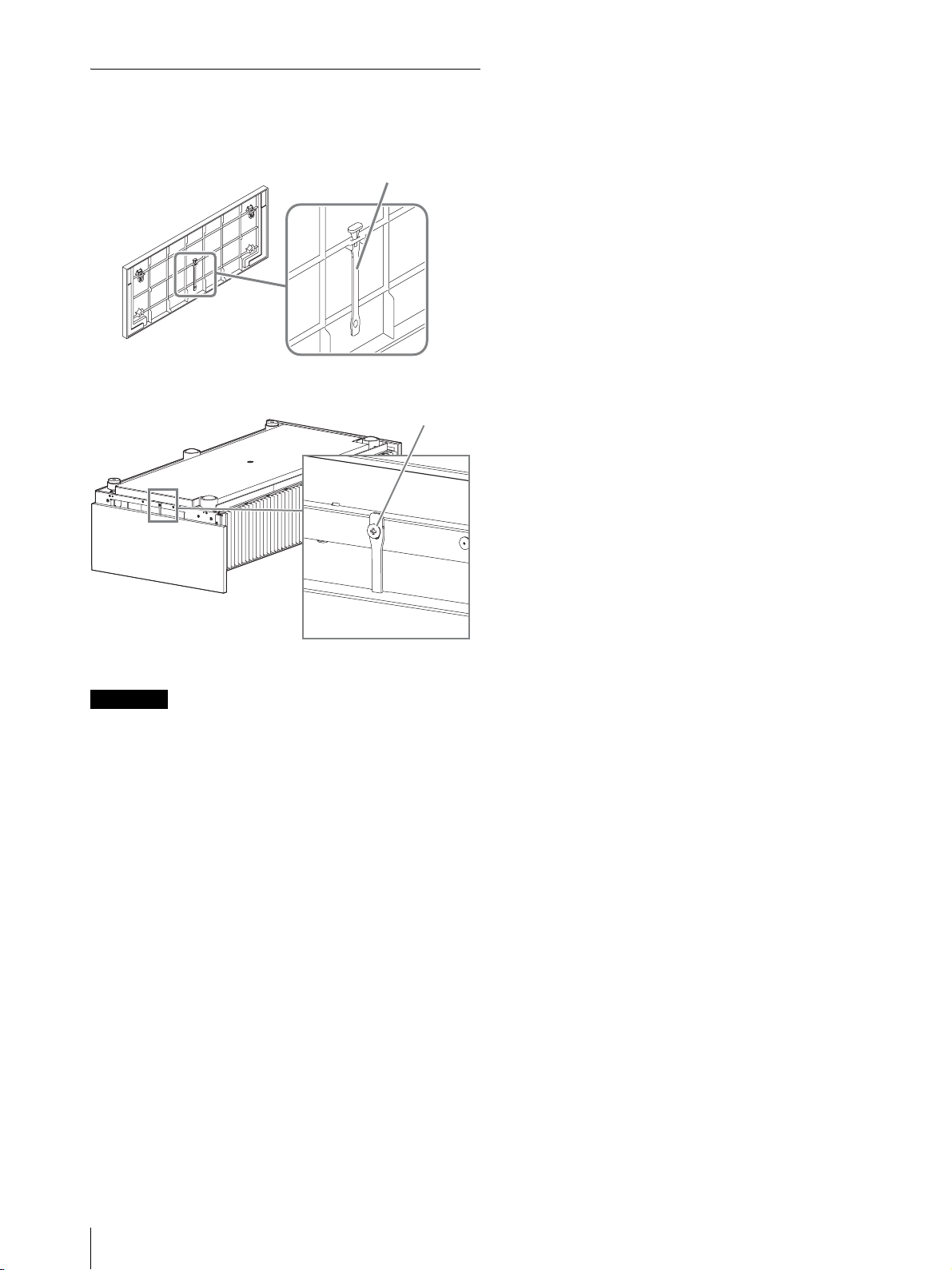
Attaching the side covers when installing
the unit on a ceiling
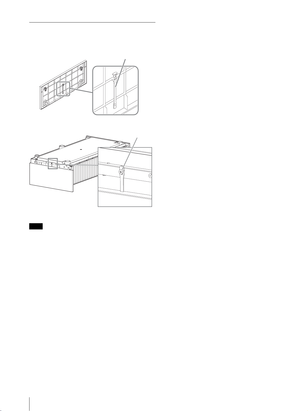
1 Attach the strap to the side covers.
2 Attach a safety rivet to the unit.
3 Attach the side covers.
When installing the unit on a ceiling, do not attach the top cover.
Note
Strap (supplied)
Rivet (supplied)
Projecting
13
US
1 Turn on both the unit and the equipment connected to
the unit.
2 Press INPUT to display the input palette on the
projection surface.
3 Select the equipment from which you want to display
images.
Press INPUT repeatedly or press M/m/ to select the
equipment.
Projects the picture from the selected equipment.
1 Press the ?/1 (On/Standby) button.
The message “POWER OFF?” appears.
2 Press the ?/1 button again before the message
disappears.
The LED indicator turns off.
You can disconnect the AC power cord after the LED
indicator turns off.
Never disconnect the AC power cord while the unit is turned on.
Tips
• You can turn off the unit by holding the ?/1 button for about 1
second, instead of performing the above steps.
• The LED indicator does not change when “Illumination” is set to
“Off” on the Installation menu.
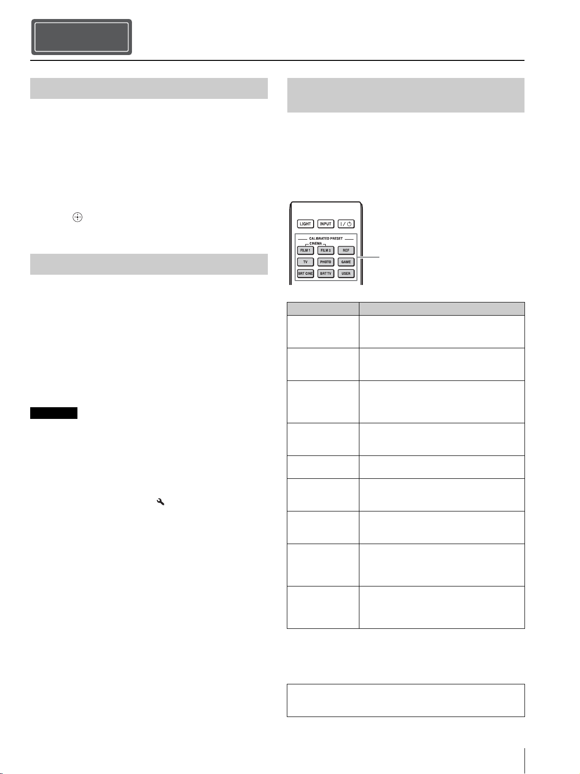
With the CALIBRATED PRESET buttons, you can select
the picture viewing mode that best suits the type of video
source or room conditions.
You can save and use different preset modes for 2D/3D
respectively.
Projecting
Step 5
Projecting the Picture
Turning Off the Power
Note
Selecting the Picture Viewing Mode
Setting items Description
CINEMA FILM 1 Picture quality suited to reproducing the
highly dynamic and clear images typical of
master positive film.
CINEMA FILM 2 Picture quality suited to reproducing the rich
tone and color typical of a movie theater,
based on the CINEMA FILM 1.
REF A picture quality setup suitable for when you
want to reproduce faithfully the original
image quality, or for enjoying image quality,
without any adjustment.
TV Picture quality suited for watching TV
programs, sports, concerts, and other video
images.
PHOTO Ideal for projecting still images taken with a
digital camera.
GAME Picture quality suited to gaming, with well-
modulated colors and fast response.
BRT CINE Picture quality suited for watching movies in
a bright environment, such as a living room.
BRT TV Picture quality suited for watching TV
programs, sports, concerts, and other video
images in a bright environment, such as a
living room.
USER Adjusts the picture quality to suit your taste
then saves the setting. The factory default
setting is the same as REF.
CALIBRATED PRESET buttons
For more information, refer to “Projecting the Picture and
Adjusting the Screen” in the Operating Instructions contained in
the supplied CD-ROM.
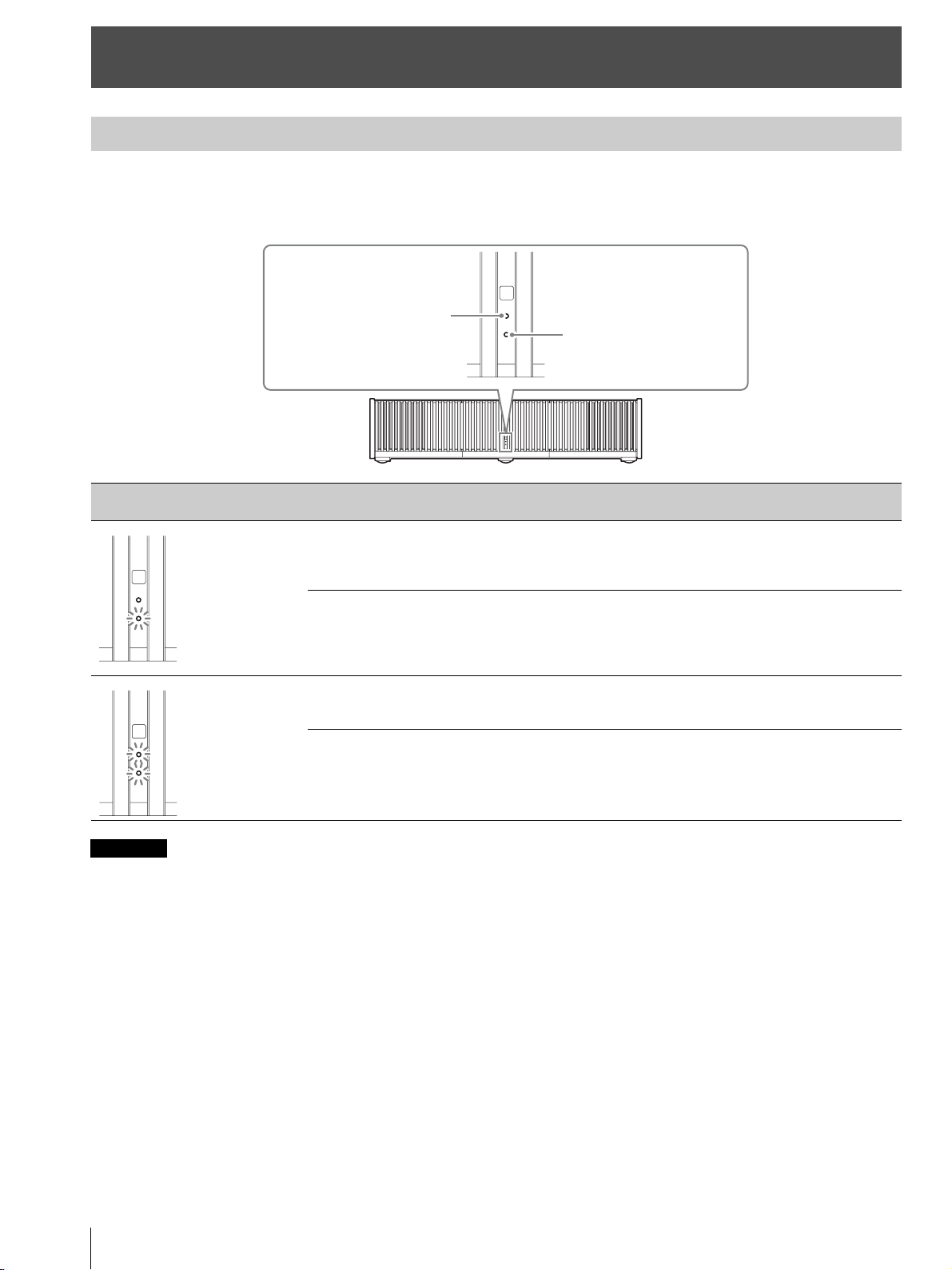
Error Handling
US
14
The WARNING1 or WARNING2 indicator lights up or flashes if there is any trouble with your projector.
If there is any problem or an error message appears on the screen, refer to “Error Handling” in the Operating Instructions
contained in the supplied CD-ROM.
If the indicator starts flashing in a way of other than the above, or the symptom persists even after carrying out the above methods, consult with
qualified Sony personnel.
Error Handling
About Indicators
Flashing/Lighting indicators The number of
flashes
Cause and Remedy
Three times The light source does not light properly due to an abnormality of the light source or
light source power. Turn off, then turn on the power after a while.
If the symptom persists, consult qualified Sony personnel.
Six times The unit detects a drop impact.
If there is abnormality on the unit, consult with qualified Sony personnel.
If there are no abnormalities on the unit, disconnect the AC power cord and check
that the LED indicator turns off, then connect the AC power cord and turn the unit
on.
Twice The internal temperature is unusually high. Check to ensure that nothing is blocking
the ventilation holes, the air filter is not clogged, and the unit is not being used at
high altitudes.
Three times The fan is broken. Consult with qualified Sony personnel.
Note
WARNING2
WARNING1
(Flashes in red)
(Flashes in red)
(Flashes in red)
Both indicators flash
Maintenance
15
US
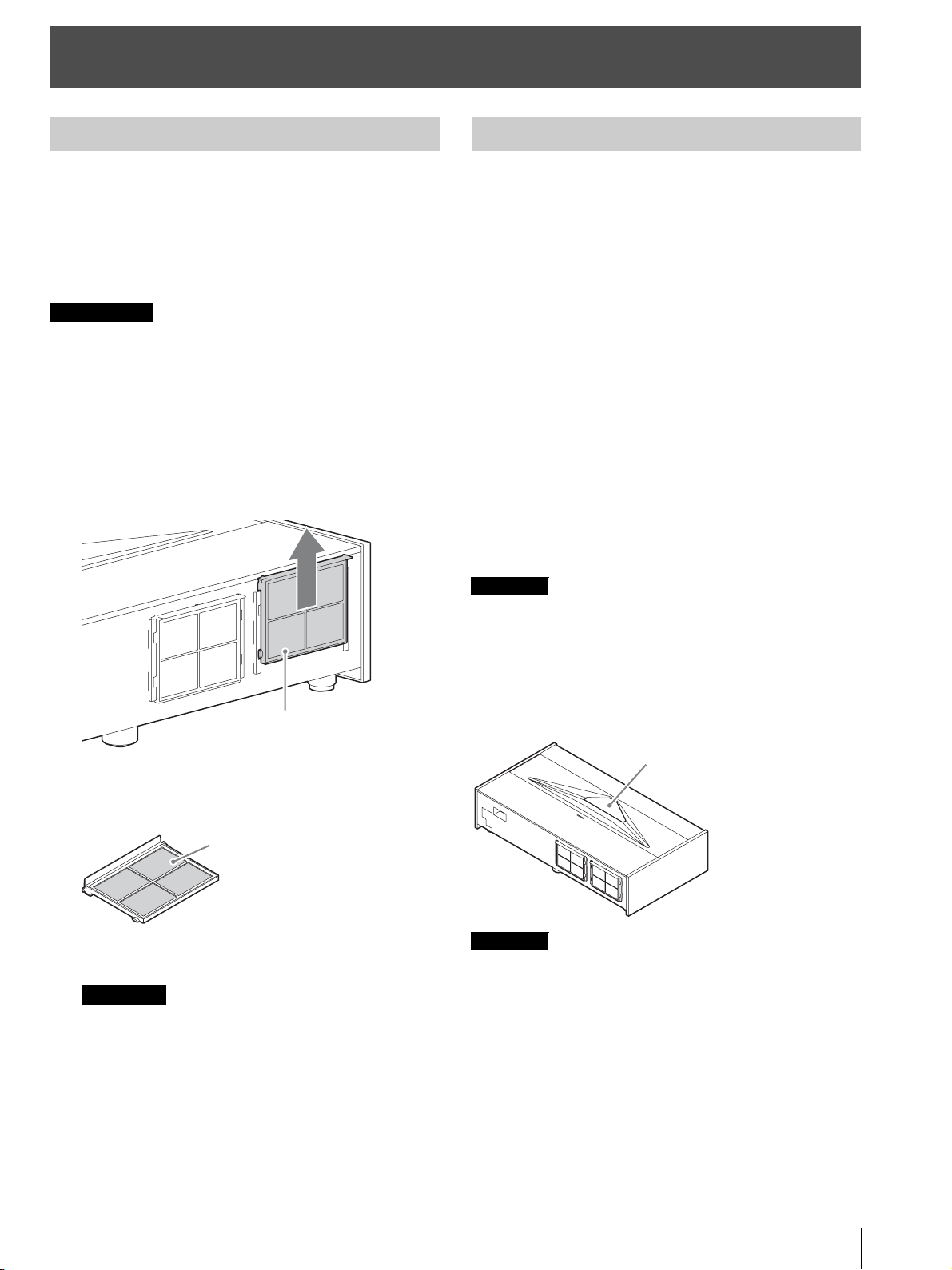
Clean the air filter regularly, preferably once a year.
If the dust cannot be removed from the air filter even after
cleaning, replace the air filter with a new one.
For details on a new air filter, consult with qualified Sony
personnel.
If you continue to use the air filter, dust may
accumulate, clogging it. As a result, the temperature
may rise inside the unit, leading to a possible
malfunction or fire.
1 Turn off the projector, and disconnect the AC power
cord from the AC outlet.
2 Pull out the air filter unit from the projector.
3 Clean the air filter with a vacuum cleaner.
Clean the front and back of the filter.
4 Attach the air filter unit.
• Securely attach the air filter unit. If not attached to the
specified position, the air filter may fall out.
• When washing with water, let the air filter dry completely.
Cleaning the cabinet
• To remove dust from the cabinet, wipe gently with the
supplied cleaning cloth or a dry soft cloth. If dust is
persistent, wipe with a soft cloth slightly moistened with
a diluted mild detergent solution, and then wipe with a
dry cloth.
• Never use any type of abrasive pad, alkaline/acid
cleaner, scouring powder, or volatile solvent, such as
alcohol, benzene, thinner or insecticide.
• Wiping with a dirty cloth may scratch the unit.
• Using a volatile substance such as insecticide or
maintaining prolonged contact with rubber or vinyl
materials may result in damage to the cabinet material.
Cleaning the side covers
When removing dust from the side covers, wipe gently
with the supplied cleaning cloth.
If you wipe the side covers forcibly, it may scratch them.
Cleaning the projection window
When removing dust from the projection window, wipe
gently with the supplied cleaning cloth.
The projection window is made of glass. If you forcibly push or hit
it, it may break and cause an injury.
Maintenance
Cleaning the Air Filter
Caution
Notes
Air filter unit
Air filter
Cleaning
Note
Note
Projection window
À propos du Guide de référence rapide
FR
2
Ce Guide de référence rapide décrit l’installation et les procédures de base de projection des images.
Avant d’utiliser l’appareil, veuillez lire attentivement ce manuel et le conserver pour future référence.
Reportez-vous à « À propos des indicateurs », à « Nettoyage du filtre à air » et à « Nettoyage », le cas échéant.
Pour plus d’informations sur l’utilisation, reportez-vous au Mode d’emploi que vous trouverez sur le CD-ROM fourni.
À propos du Guide de référence rapide
Installation de l’appareil ...................................... Page 3
Réglage ..................................................................... Page 7
Raccordement de l’appareil.............................. Page 10
Fixation des caches............................................ Page 11
Projection............................................................... Page 13
Gestion des
erreurs
À propos des indicateurs ........................................................ Page 14
Entretien
Nettoyage du filtre à air ........................................................... Page 15
Nettoyage.................................................................................. Page 15
Etape 1
Etape 2
Etape 3
Etape 4
Etape 5
Utilisation du manuel sur CD-ROM
Vous devez installer Adobe Reader sur votre ordinateur
pour pouvoir lire ce manuel.
Vous pouvez télécharger Adobe Reader gratuitement
depuis le site Web d’Adobe.
1 Ouvrez le fichier index.html situé sur le CD-ROM.
2 Sélectionnez le manuel que vous souhaitez lire, puis
cliquez sur ce dernier.
Si vous avez perdu ou endommagé le CD-ROM, vous pouvez
acheter un CD-ROM de remplacement auprès de votre représentant
Sony ou du service clientèle Sony.
Adobe et Adobe Reader sont des marques d’Adobe Systems
Incorporated aux États-Unis et/ou dans d’autres pays.
Remarque
Installation de l’appareil
3
FR
Vérifiez si le carton renferme bien tous les éléments
suivants :
• Télécommande RM-PJ28 (1)
• Piles au manganèse AA (R6) (2)
• Cordon d’alimentation secteur (1)
• Porte-fiche (1)
• Cache supérieur (1)
• Caches latéraux (2)
• Sangles des caches latéraux (2)
• Rivets des caches latéraux (2)
• Chiffon de nettoyage (1)
• Guide de référence rapide (ce manuel) (1)
• Règlements de sécurité (1)
• Mode d’emploi (CD-ROM) (1)
Précautions relatives à la manipulation de la
télécommande
• Manipulez la télécommande avec précaution. Ne
renversez aucun liquide sur la télécommande, ne la
laissez pas tomber et ne marchez pas dessus.
• Ne placez pas la télécommande à proximité d’une source
de chaleur, dans un endroit exposé aux rayons directs du
soleil ou dans une pièce humide.
L1 : Distance entre une surface de projection et l’arrière de
l’appareil
L2 : Distance entre une surface de projection et l’avant de
l’appareil
H : Distance entre une surface d’installation et le bas de
l’écran
W : Largeur horizontale de l’écran
Installation de l’appareil
Etape 1
Vérification des accessoires fournis
Insertion des piles dans la
télécommande
Appuyez et faites glisser pour ouvrir.
Insérez le côté E des piles en premier.
Distance d’installation et taille de
l’image de projection
L2
L1
W
H
FR
Installation de l’appareil
FR
4
Lors d’une projection au format 1,90:1 (Plein écran natif 17:9)
Formule 1 (calcule une distance d’installation à partir
d’une taille d’image de projection)
Unité : cm (pouces)
Formule 2 (calcule une taille d’image de projection à partir
d’une distance d’installation)
Unité : cm (pouces)
Formule 3 (calcule une distance entre une surface
d’installation et le bas d’une image de projection)
Unité : cm (pouces)
Taille de l’image de projection Distance d’installation
Valeur de réglage du décalage
d’image
Valeur de réglage de la taille
d’image
Diagonale
(D)
Largeur ×
Hauteur
Hauteur du
bas (H)
Entre une
surface de
projection et
l’arrière de
l’appareil (L1)
Entre une
surface de
projection et
l’avant de
l’appareil (L2)
Sens horizontal Sens vertical Sens horizontal Sens vertical
84 po
(2,14 m)
1,89 m × 1,00 m
(74 po × 39 po)
39,0 cm
(15,3 po)
5,0 cm
(2,0 po)
52,0 cm
(20,5 po)
+/–5,3 cm
(+/–2,1 po)
+/–6,0 cm
(+/–2,4 po)
+/–1,9 cm
(+/–0,7 po)
+/–1,0 cm
(+/–0,4 po)
95 po
(2,40 m)
2,13 m × 1,12 m
(84 po × 44 po)
41,8 cm
(16,5 po)
10,2 cm
(4,0 po)
57,2 cm
(22,5 po)
+/–6,0 cm
(+/–2,4 po)
+/–6,7 cm
(+/–2,6 po)
+/–2,1 cm
(+/–0,8 po)
+/–1,1 cm
(+/–0,4 po)
105 po
(2,67 m)
2,36 m × 1,24 m
(93 po × 49 po)
44,7 cm
(17,6 po)
15,5 cm
(6,1 po)
62,5 cm
(24,6 po)
+/–6,6 cm
(+/–2,6 po)
+/–7,5 cm
(+/–2,9 po)
+/–2,4 cm
(+/–0,9 po)
+/–1,2 cm
(+/–0,5 po)
116 po
(2,94 m)
2,60 m × 1,37 m
(102 po × 54 po)
47,6 cm
(18,7 po)
20,7 cm
(8,2 po)
67,7 cm
(26,7 po)
+/–7,3 cm
(+/–2,9 po)
+/–8,2 cm
(+/–3,2 po)
+/–2,6 cm
(+/–0,9 po)
+/–1,4 cm
(+/–0,6 po)
126 po
(3,21 m)
2,84 m × 1,49 m
(112 po × 59 po)
50,4 cm
(19,9 po)
26,0 cm
(10,2 po)
73,0 cm
(28,7 po)
+/–8,0 cm
(+/–3,1 po)
+/–9,0 cm
(+/–3,5 po)
+/–2,8 cm
(+/–1,1 po)
+/–1,5 cm
(+/–0,6 po)
1,90
1
Taille de l’image de projection
L1 = 0,2219 × W - 36,9398 (L1 = 0,2219 × W - 14,5432)
L2 = 0,2219 × W + 10,0602 (L2 = 0,2219 × W + 3,9607)
Entre une surface de projection et l’arrière de l’appareil
W = 4,5069 × L1 + 166,4916 (W = 4,5069 × L1 + 65,5479)
Taille de l’image de projection
H = 0,1213 × W + 16,0372 (H = 0,1213 × W + 6,3139)
Installation de l’appareil
5
FR
Lors d’une projection au format 1,78:1 (16:9)
Formule 1 (calcule une distance d’installation à partir
d’une taille d’image de projection)
Unité : cm (pouces)
Formule 2 (calcule une taille d’image de projection à partir
d’une distance d’installation)
Unité : cm (pouces)
Formule 3 (calcule une distance entre une surface
d’installation et le bas d’une image de projection)
Unité : cm (pouces)
Taille de l’image de projection Distance d’installation
Valeur de réglage du décalage
d’image
Valeur de réglage de la taille
d’image
Diagonale
(D)
Largeur ×
Hauteur
Hauteur du
bas (H)
Entre une
surface de
projection et
l’arrière de
l’appareil (L1)
Entre une
surface de
projection et
l’avant de
l’appareil (L2)
Sens horizontal Sens vertical Sens horizontal Sens vertical
80 po
(2,03 m)
1,77 m × 1,00 m
(70 po × 39 po)
39,0 cm
(15,3 po)
5,0 cm
(2,0 po)
52,0 cm
(20,5 po)
+/–5,3 cm
(+/–2,1 po)
+/–6,0 cm
(+/–2,4 po)
+/–1,8 cm
(+/–0,7 po)
+/–1,0 cm
(+/–0,4 po)
90 po
(2,29 m)
1,99 m × 1,12 m
(78 po × 44 po)
41,8 cm
(16,5 po)
10,2 cm
(4,0 po)
57,2 cm
(22,5 po)
+/–6,0 cm
(+/–2,4 po)
+/–6,7 cm
(+/–2,6 po)
+/–2,0 cm
(+/–0,8 po)
+/–1,1 cm
(+/–0,4 po)
100 po
(2,54 m)
2,22 m × 1,24 m
(87 po × 49 po)
44,7 cm
(17,6 po)
15,5 cm
(6,1 po)
62,5 cm
(24,6 po)
+/–6,6 cm
(+/–2,6 po)
+/–7,5 cm
(+/–2,9 po)
+/–2,2 cm
(+/–0,9 po)
+/–1,2 cm
(+/–0,5 po)
110 po
(2,79 m)
2,44 m × 1,37 m
(96 po × 54 po)
47,6 cm
(18,7 po)
20,7 cm
(8,2 po)
67,7 cm
(26,7 po)
+/–7,3 cm
(+/–2,9 po)
+/–8,2 cm
(+/–3,2 po)
+/–2,4 cm
(+/–0,9 po)
+/–1,4 cm
(+/–0,6 po)
120 po
(3,05 m)
2,66 m × 1,49 m
(105 po × 59 po)
50,4 cm
(19,9 po)
26,0 cm
(10,2 po)
73,0 cm
(28,7 po)
+/–8,0 cm
(+/–3,1 po)
+/–9,0 cm
(+/–3,5 po)
+/–2,7 cm
(+/–1,1 po)
+/–1,5 cm
(+/–0,6 po)
1,78
1
Zone d’affichage vidéo
Zone de projection
Taille de l’image de projection
L1 = 0,2368 × W - 36,9638 (L1 = 0,2368 × W - 14,5527)
L2 = 0,2368 × W + 10,0362 (L2 = 0,2368 × W + 3,9512)
Entre une surface de projection et l’arrière de l’appareil
W = 4,2226 × L1 + 156,0908 (W = 4,2226 × L1 + 61,4531)
Taille de l’image de projection
H = 0,1295 × W + 16,0240 (H = 0,1295 × W + 6,3087)
Installation de l’appareil
FR
6
La distance d’installation séparant l’appareil de la surface
de projection varie selon la taille de projection. Installez
cet appareil de façon à ce qu’il s’ajuste à la taille de
projection désirée.
À l’attention des clients
ATTENTION
Ne montez jamais le projecteur au plafond et ne le
déplacez jamais par vos propres moyens.
À l’attention des revendeurs
• Avant d’installer l’appareil au plafond, veillez à lire les
« Consignes de sécurité concernant l’installation de
l’appareil au plafond » des Règlements de sécurité
(fournis séparément).
• Avant d’installer l’appareil au plafond, retirez d’abord
les pieds avant de suivre les instructions ci-dessous.
Diamètre de vis : M10
Positions de fixation : 5 positions
Longueur d’insertion des vis : 10 mm - 50 mm (
13
/
32
- 2 po)
Couple de serrage recommandé : 1,3 - 1,5 N•m
1 Positionnez l’appareil de façon à ce que l’appareil soit
parallèle à la surface de projection.
Vue du haut
2 Branchez le cordon d’alimentation secteur à la prise
AC IN, puis fixez le porte-fiche au cordon.
3 Faites glisser le porte-fiche par-dessus le cordon
d’alimentation secteur afin de le fixer à l’appareil.
4 Branchez le cordon d’alimentation secteur à une prise
murale.
L’appareil se met en veille.
Conseil
Après avoir branché le cordon d’alimentation secteur à
l’appareil, il est possible que l’indicateur LED clignote.
Il est possible que vous ne puissiez pas commander l’appareil
lorsque l’indicateur clignote, mais il ne s’agit pas d’un
dysfonctionnement. Attendez qu’il cesse de clignoter.
5 Appuyez sur le bouton ?/1 (Marche/Veille) pour
mettre l’appareil sous tension.
L’indicateur LED s’allume en blanc.
1 Appuyez sur MENU pour afficher le menu.
2 Sélectionnez la langue du menu.
a Appuyez sur M/m pour sélectionner le menu
Setup , puis appuyez sur , ou .
b Appuyez sur M/m pour sélectionner le menu
« Language », puis appuyez sur , ou .
c Appuyez sur M/m/</, pour sélectionner
une langue, puis appuyez sur , ou .
3 Appuyez sur MENU pour désactiver la fenêtre du
menu.
Installation de l’appareil
ab
a = b
Surface de projection
Porte-fiche (fourni)
Prise AC IN
Cordon
d’alimentation
secteur (fourni)
Sélection de la langue du menu
Setup
Status
Language
Menu Position
High Altitude Mode
Remote Start
Network Management
Power Saving
All Reset
On
English
Bottom Left
Off
Off
Off
Standby
Réglage
7
FR
Conseil
Lors du réglage de l’objectif, à chaque appui du bouton PATTERN
de la télécommande ou du bouton LENS de l’appareil, la fonction de
réglage de l’objectif bascule comme suit.
1 Appuyez sur le bouton PATTERN pour afficher la
fenêtre de réglage Focus d’objectif, puis réglez la
mise au point de l’image en appuyant sur les boutons
M/m/</,.
Conseils
• Le réglage d’usine par défaut de la mise au point est destiné
à un écran de 100 pouces. Effectuez des réglages précis en
fonction de la taille de l’écran et de la position d’installation.
• Procédez au réglage en vérifiant la mire d’essai entière.
L’amplitude de la mise au point sur la mire en haut de
l’image s’élargit avec le projecteur à mise au point ultra
courte.
• Si vous appuyez sur le bouton RESET de la télécommande
pendant l’affichage de la fenêtre de réglage Focus d’objectif,
le réglage d’usine par défaut de la mise au point est rétabli.
• Dès que vous appuyez sur le bouton , la mire d’essai
disparaît.
2 Vérifiez si le côté supérieur et le côté inférieur de
l’image sont parallèles.
Si ce n’est pas le cas, installez l’appareil de façon à ce
qu’il soit parallèle à la surface de projection (a=b).
3 Vérifiez si le côté inférieur de l’image est horizontal.
Si ce n’est pas le cas, utilisez les pieds gauches/droits
pour maintenir l’appareil à l’horizontale. Pour plus
d’informations sur le réglage des pieds, voir page 9.
4 Vérifiez si le côté gauche et le côté droit de l’image
sont verticaux.
Si ce n’est pas le cas, utilisez les pieds (réglables)
pour maintenir l’appareil vertical par rapport à la
surface de projection. Pour plus d’informations sur le
réglage des pieds, voir page 9.
Réglage
Etape 2
Capteur de télécommande
Distorsion
d’image
État d’installation sur la surface de
projection
(vue du haut)
Distorsion d’image Réglage des pieds
a
b
a > b
a
b
a < b
Réglage
FR
8
Si le cadre de la surface de projection est rectangulaire
et parallèle au sol, le réglage est terminé.
Conseil
Si l’image reste déformée, répétez les étapes 2 et 3.
5 Réglez les pieds servant à éviter le jeu sur le sol.
Il est possible que l’image se déforme si vous faites trop pivoter
les pieds servant à éviter le jeu.
6 Appuyez sur le bouton PATTERN pour afficher la
fenêtre de réglage Déplac. objectif, puis réglez la
position de l’image en appuyant sur les boutons M/m/
</,.
Conseil
Si vous appuyez sur le bouton RESET de la télécommande
pendant l’affichage de la fenêtre de réglage Déplac. objectif, la
position de l’image revient au centre de l’objectif (position par
défaut).
Pour régler la position horizontale
Lorsque vous appuyez sur le bouton </,, l’image
projetée sur l’écran se décale vers la droite ou la
gauche sur 3 % maximum de la largeur d’écran en
partant du centre de l’objectif.
Vue du haut
* Pour l’affichage en 17:9, la plage de mouvement est de
+/–2,8 %.
Pour régler la position verticale
Lorsque vous appuyez sur le bouton M/m, l’image
projetée sur l’écran se décale vers le haut ou le bas sur
6 % maximum de la hauteur d’écran en partant du
centre de l’objectif.
Vue de côté
Distorsion d’image Réglage des pieds
Remarque
c > 90°
Vue de côté
c < 90°
Vue de côté
Réglez le pied
proche de
l’arrière afin de
l’allonger.
Réglez la
hauteur avec
le pied proche
de l’avant.
1,78:1 (16:9)
2,35:1
Les lignes pointillées indiquent les tailles
d’écran de chaque rapport de format.
3 %* 3 %*1 largeur d’écran
: position de l’image décalée au maximum vers la gauche
: position de l’image décalée au maximum vers la droite
6 %
6 %
1 hauteur
d’écran
: position de l’image décalée au maximum vers le haut
: position de l’image décalée au maximum vers le bas
Réglage
9
FR
7 Appuyez une nouvelle fois sur le bouton PATTERN
pour afficher la fenêtre de réglage Zoom d’objectif.
Réglez ensuite la taille de l’image en appuyant sur les
boutons M/m/</,.
Pour agrandir l’image, appuyez sur M/,.
Pour réduire l’image, appuyez sur m/<.
Réglage de la hauteur des pieds
Vous pouvez régler la hauteur et l’inclinaison de l’appareil
à l’aide des trois pieds du dessous de l’appareil, et éviter le
jeu de l’appareil à l’aide des deux pieds.
Conseils
• Les pieds servant à régler l’inclinaison peuvent être ajustés de
1,5 mm à chaque tour complet.
• Les pieds gauche et droit proches de l’arrière peuvent être utilisés
pour éviter le jeu. Vous pouvez régler ces pieds à la même hauteur
que les pieds servant à régler l’inclinaison.
• Veillez à ne pas vous coincer les doigts lorsque vous faites pivoter
les pieds servant à régler l’inclinaison ou les pieds servant à éviter
le jeu.
• Vous pouvez régler la hauteur de pied jusqu’à 20 mm. Si la
hauteur de pied dépasse 30 mm, il est possible que le pied se
détache et que l’appareil tombe, causant ainsi des blessures.
Remarques
Hauteur
de pied
Hauteur
de pied
Pied servant à
régler l’inclinaison
Pied servant à éviter
le jeu

Raccordement de l’appareil
FR
10
Lors de l’exécution des raccordements, vous devez procéder comme suit :
• Mettez tous les appareils hors tension avant tout raccordement.
• Utilisez les câbles appropriés pour chaque raccordement.
• Insérez correctement les fiches de câble ; le mauvais raccordement des fiches peut entraîner un dysfonctionnement ou
une piètre qualité d’image. Débranchez les câbles en les tenant par leur fiche. Ne tirez pas sur le câble proprement dit.
• Reportez-vous au mode d’emploi de l’appareil à raccorder.
Raccordement de l’appareil
Etape 3
Côté droit de l’appareil
Appareil avec des
connecteurs de sortie
HDMI
vers la sortie
HDMI
Câble HDMI (non fourni)
Ordinateur
Arrière de l’appareil
: flux du signal vidéo
Amplificateur AV Haut-parleurs
vers l’entrée HDMI
vers l’entrée HDMI
Utilisez un câble HDMI haut débit premium qui
porte le logo du type de câble.
Pour plus d’informations reportez-vous à « Raccordements et
préparatifs » dans le Mode d’emploi que vous trouverez sur le
CD-ROM fourni.
Fixation des caches
11
FR
Placez le cache supérieur sur le dessus de l’appareil, puis
alignez les positions gauche et droite.
Utilisation du cache supérieur
Faites glisser le cache supérieur avec la poignée située en
son centre.
Vous pouvez empêcher l’accumulation de poussière sur la
fenêtre de projection en fermant le cache supérieur lorsque
l’appareil n’est pas utilisé.
• Ne fermez pas le cache supérieur lors de la mise sous tension.
• Utilisez le cache supérieur en même temps que les caches latéraux.
• Si de la poussière se trouve sur la surface de glissement, elle risque
de rayer l’appareil.
• Lorsque vous retirez le cache supérieur, ne le placez pas à la
verticale.
Après avoir fixé le cache supérieur, placez les caches
latéraux en accrochant les orifices des caches latéraux aux
languettes du côté de l’appareil.
Assurez-vous que les 4 orifices sont accrochés aux
languettes.
Fixation des caches
Etape 4
Fixation du cache supérieur
Remarques
Fixation des caches latéraux
Remarque
Orifice
Languette
Fixation des caches
FR
12
Fixation des caches latéraux lors de
l’installation de l’appareil sur un plafond
1 Fixez la sangle aux caches latéraux.
2 Fixez un rivet de sécurité à l’appareil.
3 Fixez les caches latéraux.
Pour installer l’appareil sur un plafond, ne fixez pas le cache
supérieur.
Remarque
Sangle (fournie)
Rivet (fourni)
Projection
13
FR
1 Mettez sous tension cet appareil et l’appareil qui y est
raccordé.
2 Appuyez sur INPUT pour afficher la palette d’entrée
sur la surface de projection.
3 Sélectionnez le périphérique à partir duquel vous
voulez afficher les images.
Appuyez plusieurs fois sur INPUT ou appuyez sur
M/m/
pour sélectionner l’appareil.
Projette l’image à partir de l’appareil sélectionné.
1 Appuyez sur le bouton ?/1 (Marche/Veille).
Le message « METTRE HORS TENSION? »
apparaît sur l’écran.
2 Appuyez une nouvelle fois sur le bouton ?/1 avant
que le message disparaisse.
L’indicateur LED s’éteint.
Vous pouvez débrancher le cordon d’alimentation secteur
une fois l’indicateur LED éteint.
Ne débranchez jamais le cordon d’alimentation secteur pendant que
l’appareil est sous tension.
Conseils
• Vous pouvez mettre l’appareil hors tension en maintenant le
bouton ?/1 enfoncé pendant 1 seconde environ, plutôt qu’en
suivant les étapes ci-dessus.
• L’indicateur LED ne change pas lorsque « Éclairage » est réglé sur
« Off » dans le menu Installation .
Avec les boutons CALIBRATED PRESET, vous pouvez
sélectionner le mode d’affichage de l’image qui convient le
mieux au type de source vidéo ou aux conditions de la
pièce.
Vous pouvez enregistrer et utiliser différents modes de
préréglage respectivement pour la 2D/3D.
Projection
Etape 5
Projection de l’image
Mise hors tension
Remarque
Sélection du mode d’affichage de
l’image
Paramètres Description
CINEMA FILM 1 Qualité d’image adaptée à la reproduction
d’images hautement dynamiques et nettes,
typiques d’un chef-d’œuvre du cinéma.
CINEMA FILM 2 Qualité d’image adaptée à la reproduction de
tons riches et de couleurs dignes du cinéma,
en fonction de CINEMA FILM 1.
REF Configuration de qualité d’image appropriée
lorsque vous souhaitez reproduire fidèlement
la qualité d’image d’origine ou pour profiter
de la qualité d’image sans aucun réglage.
TV Qualité d’image adéquate pour regarder des
programmes TV, du sport, des concerts et
d’autres images vidéo.
PHOTO Idéal pour la projection d’images fixes
provenant d’un appareil photo numérique.
GAME Qualité d’image adaptée aux jeux, avec des
couleurs bien modulées et une réponse
rapide.
BRT CINE Qualité d’image adéquate pour regarder les
films dans un environnement lumineux,
comme un séjour.
BRT TV Qualité d’image adéquate pour regarder des
programmes TV, du sport, des concerts et
d’autres images vidéo dans un environnement
lumineux, comme un séjour.
USER Règle la qualité de l’image en fonction de
votre goût, puis enregistre le paramètre. Le
réglage en usine par défaut est identique à
REF.
Boutons CALIBRATED PRESET
Pour plus d’informations, reportez-vous à « Projection de l’image
et réglage de l’écran » dans le Mode d’emploi que vous trouverez
sur le CD-ROM fourni.
Gestion des erreurs
FR
14
L’indicateur WARNING1 ou WARNING2 s’allume ou clignote en cas de problème quelconque sur le projecteur.
En cas de problème ou si un message d’erreur apparaît à l’écran, reportez-vous à « Gestion des erreurs » dans le Mode
d’emploi que vous trouverez sur le CD-ROM fourni.
Si l’indicateur se met à clignoter d’une manière qui n’est pas décrite ci-dessus ou si le symptôme persiste même après avoir effectué les
opérations ci-dessus, consultez le service après-vente Sony.
Gestion des erreurs
À propos des indicateurs
Clignotement/Éclairage des
indicateurs
Nombre de
clignotements
Cause et remède
Trois fois La source lumineuse ne s’allume pas correctement en raison d’une anomalie de la
source lumineuse ou de l’alimentation de la source lumineuse. Mettez l’appareil
hors tension, puis sous tension après un certain temps.
Si le symptôme persiste, consultez le service après-vente Sony.
Six fois L’appareil détecte l’impact d’une chute.
En cas d’anomalie de l’appareil, consultez le service après-vente Sony.
En l’absence d’anomalie sur l’appareil, débranchez le cordon d’alimentation
secteur et assurez-vous que l’indicateur LED s’éteint, puis rebranchez le cordon
d’alimentation secteur et remettez l’appareil sous tension.
Deux fois La température à l’intérieur du projecteur est anormalement élevée. Assurez-vous
que rien ne colmate les orifices de ventilation, que le filtre à air n’est pas obstrué et
que l’appareil n’est pas utilisé à haute altitude.
Trois fois Le ventilateur est défectueux. Consultez le service après-vente Sony.
Remarque
WARNING2
WARNING1
(Clignote en rouge)
(Clignote en rouge)
(Clignote en rouge)
Les deux indicateurs
clignotent
Entretien
15
FR
Nettoyez régulièrement le filtre à air, de préférence une
fois par an.
S’il est impossible de retirer la poussière du filtre à air
même après le nettoyage, remplacez le filtre à air par un
neuf.
Pour plus d’informations sur les filtres à air neufs,
consultez un technicien Sony qualifié.
Si vous continuez à utiliser le filtre à air, de la poussière
peut s’accumuler et l’obstruer. En conséquence, la
température peut monter à l’intérieur de l’appareil, ce
qui peut entraîner un dysfonctionnement ou un
incendie.
1 Mettez le projecteur hors tension et débranchez le
cordon d’alimentation secteur de la prise secteur.
2 Retirez l’unité de filtre à air du projecteur.
3 Nettoyez le filtre à air avec un aspirateur.
Nettoyez l’avant et l’arrière du filtre.
4 Fixez l’unité de filtre à air.
• Fixez solidement l’unité de filtre à air. Si celle-ci n’est pas
fixée à la position indiquée, le filtre à air risque de tomber.
• Après l’avoir lavé à l’eau, laissez le filtre à air sécher
complètement.
Nettoyage du boîtier
• Pour retirer la poussière qui recouvre le boîtier, essuyez-
le délicatement avec le chiffon de nettoyage fourni ou un
chiffon doux sec. Pour les poussières tenaces, passez un
linge doux légèrement trempé dans une solution de
détergent doux dilué dans l’eau, puis essuyez avec un
chiffon sec.
• N’utilisez aucun type de tissu abrasif, de nettoyant
alcalin ou acide, de poudre à récurer ou de solvant
volatile tel que de l’alcool, du benzène, un diluant ou un
insecticide.
• N’utilisez pas un chiffon sale, car vous risquez de rayer
l’appareil.
• L’utilisation d’une substance volatile telle qu’un
insecticide ou le contact prolongé avec des objets en
caoutchouc ou en vinyle peut endommager le matériau
du boîtier.
Nettoyage des caches latéraux
Pour retirer la poussière qui recouvre les caches latéraux,
essuyez-les délicatement avec le chiffon de nettoyage
fourni.
Si vous essuyez les caches latéraux brutalement, vous risquez de les
rayer.
Nettoyage de la fenêtre de projection
Pour retirer la poussière qui recouvre la fenêtre de
projection, essuyez-la délicatement avec le chiffon de
nettoyage fourni.
La fenêtre de projection est en verre. Si vous appuyez brutalement
sur celle-ci ou la heurtez brutalement, vous risquez de la briser et de
causer des blessures.
Entretien
Nettoyage du filtre à air
Mise en garde
Remarques
Unité de filtre à air
Filtre à
air
Nettoyage
Remarque
Remarque
Fenêtre de projection