UNIQUE 20/24/30
9

UNIQUE 20/24/30
10
GAS CONNECTIONS (All Units)
NOTICE TO MASSACHUSETTS APPLIANCE DEALERS:
Be sure this document is included in all gas range appliances sold to consumers in
the State of Massachusetts.
NOTICE: Massachusetts law requires the following:
Appliances must be installed by a licensed plumber or gas fitter.
Appliances must be connected with three (3) foot (36” maximum length)
flexible gas connector and
A “T” handle type manual gas valve in the gas supply line to the appliance
.
Have the dealer where you purchase your new range install it or have him
recommend a qualified installer. Installation must conform with local codes. in the
absence of local codes, the installation must conform with the National Fuel Gas
Code, ANSI Z223.1-Latest Edition in the U.S.A. or the CAN/CGA B149.1 or .2
Installation Codes in Canada.
The range should be connected to the supply line with 1/2-inch black iron pipe or a
certified flexible type stove connector. To prevent gas leaks, put an approved sealing
compound, which is resistant to liquefied petroleum gases, on all threaded
connections.
Important: Do not apply pressure directly to the range manifold pipe when tightening
supply connections. The manifold pipe should be held securely at the pressure
regulator to prevent twisting. Hold the pressure regulator with a wrench during the
tightening of the connection, or the manifold pipe may be twisted and split, and
cause a dangerous leak.
The installation of ranges designed for manufactured (mobile) home installation
must conform with the Manufactured Construction and Safety, Title 24 CFR, Part
3280, [formerly the Federal standard for Mobile Home Construction and Safety,
Title 24, HUD (Part 280)] in the U.S.A. or C.S.A. Standard CAN/CGA Z240.4.2 in
Canada or, when such standards are not applicable with local codes.
The installation of ranges designed for recreational vehicle installation must conform
with state or other codes or, in the absence of such codes, with the standard for
recreational vehicles. ANSI A119.2.2–1982 in the U.S.A. or CAN/CGA Z240.4.2 in
Canada.
The installation of appliances designed for recreational park trailers must conform
with state or other codes or, in the absence of such codes, with the standard for
recreational park trailers, ANSI A119.5.
Note: Check all piping connections in the unit for leaks. Never use an open flame to
check for gas leaks. Use a soap solution. It is not impossible for connections made at
UNIQUE 20/24/30
11
the factory to leak, due to vibration encountered in transportation. Make certain you
have checked them all, and repair any connections that leak.
The appliance and its individual shut-off valve must be disconnected from the gas
supply piping system during any pressure testing of that system at test pressures in
excess of ½ psig.
The appliance must be isolated from the gas supply piping system by closing its
individual manual shut-off valve during any pressure testing of the gas supply piping
system at test pressures equal to or less than 1/2 psig.
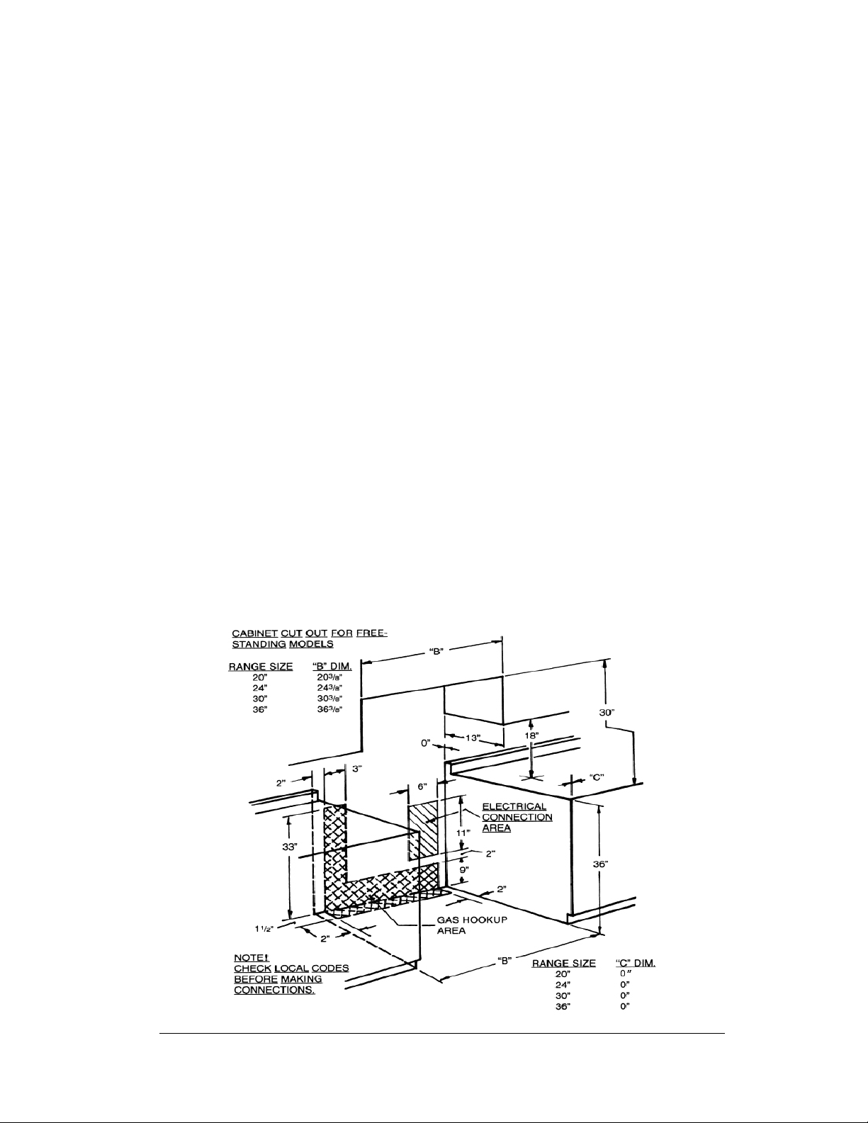
WALL CLEARANCES
All units must be installed in accordance to minimum rear and side wall clearance
and clearances extended vertically above cooking top which are stated on the serial
plate. (The serial plate is located below the cooktop.)
ANY OPENINGS IN THE WALL BEHIND THE UNIT AND IN THE FLOOR
UNDER THE UNIT MUST BE SEALED.
Note. Due to potential hazards it is recommended that storage cabinets not be
installed above the cooking surface.
IN THE EVENT OVERHEAD CABINETS ARE INSTALLED, THE
MAXIMUM DEPTH OF CABINETS INSTALLED ABOVE COOKING TOPS
SHOULD BE 13”.

UNIQUE 20/24/30
12
ALIGNMENTS AND ADJUSTMENTS
Installation
It is the responsibility of the installer to make certain that the range is properly
adjusted at the time of installation. Situations caused by improper adjustments or
improper installation are not covered under the warranty. Any expenses incurred due
to such situations will not be paid by the manufacturer of the appliance.
Gas Range Conversion and Adjustment Guide
The range will either be set for use with Liquefied Petroleum (LP) or Natural Gas.
The factory setting is indicated on the serial plate. When set for Natural Gas
operation, the pressure regulator will regulate the pressure to 4 inches water column.
When set for LP Gas operation, the pressure regulator will regulate the gas to 10
inches water column pressure.
On sealed burner models the main top must be removed to adjust
regulator, thermostat and to install the proper burner orifices