Loading ...
Loading ...
Loading ...
Electric wiring requirements
The cooker MUST be installed in compliance with:
• Wiring connections in AS/NZS3000 Wiring Rules.
• Local regulations, municipal building codes and other
statutory regulations.
• Data Plate – Gives information about the rating and
is located behind the bottom of the oven door.
• A functional switch MUST be provided near the appliance in
an accessible position (AS/NZS3000 – Clause 4.7.1).
• Wiring MUST be protected against mechanical failure (AS/
NZS3000 – Clause 3.9).
• Disconnection from the fixed wiring must occur as required by
AS3000 wiring rules.
• This range must be connected with cable of 75°C rating
minimum.
• This product has passed the insulation resistance test after
manufacture. If the resistance reading is low at installation,
it is probably caused by moisture from the atmosphere
being absorbed by the elements after the range has been
produced. (pass at 0.01MΩ AS/NZS 3000 Wiring Rules
Clause 8.3.6.2).
• The cooker MUST be properly earthed.
• When connections are made to a multiphase 230/240V
supply, the bridge piece MUST be removed from between
the active connections.
• If the supply cord is damaged, it must be replaced by
the manufacturer, its service agent or similarly qualified
persons in order to avoid a hazard.
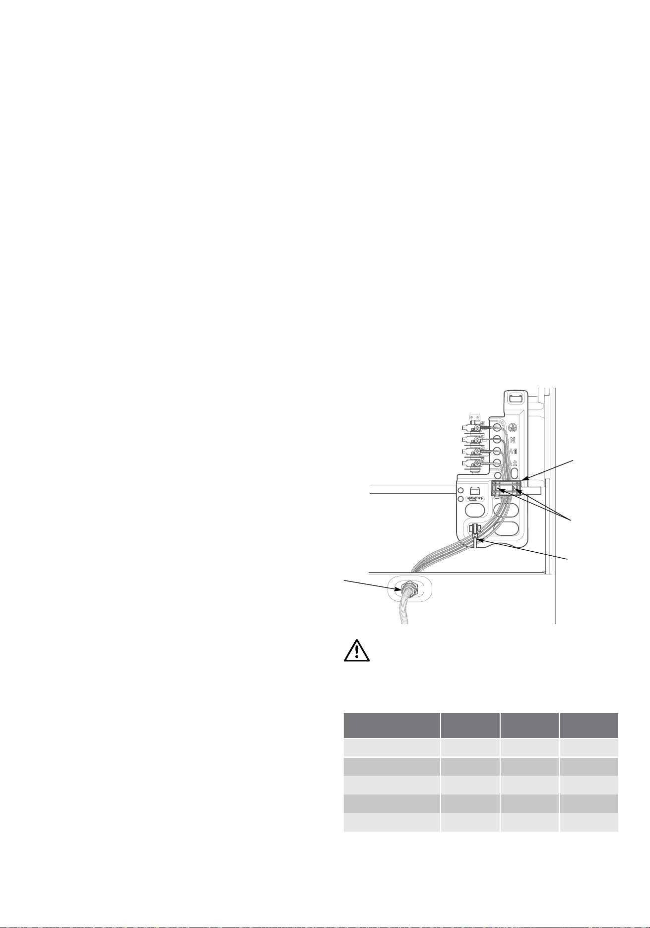
Hard wiring
1. Remove rear panel.
2. Fit wires through hole at bottom centre using the appropriate
gland to protect insulation of wires from the hole edge. Note
that the secondary insulation of the wires will probably need
to be removed to fit through gland. If the conduit to appliance
is required to bend due to rear wall an elbow may be
required to achieve this.
3. Set the length of wiring from the gland to terminal block,
ensuring length is sufficient but not excessive.
4. Make connections to terminals and engage wires into plastic
clip. Cable tie as per diagram and secure plastic clip with
two long screws supplied.
5. Replace rear cover.
WARNING
warning
Ensure wires cannot contact hot element ends or sharp edges.
Rated power input
Model Total kW A1 kW A2 kW
CFE532 8.2 2.2 6.0
CFE535 9.64 3.64 6.0
CFE536 8.2 2.24 6.0
CFE537 10.04 4.04 6.0
CFE547 9.64 4.04 5.6
installation
Restraining Device
Anchor Points
Connection
Gas
Point
150mm
650mm
Grill shutter
The following table shows the supply and operating pressures for various supplies.
Gas type Natural gas Universal LPG Propane
Supply pressure at inlet to appliance regulator
(if fitted)
1.13 (kPa)
Minimum
2.75* (kPa) 2.75* (kPa)
Operating pressure at
appliance test point
1.00 (kPa) 2.75 (kPa) 2.75 (kPa)
* If the regulator is placed upstream of the cooker inlet, as is normal for cookers operating on LPG, then the supply pressure
and operating pressure are the same. The following table shows the injector sizes for each burner.
The following table shows the injector sizes for each burner.
Injector Natural gas Universal LPG Propane
Low heat burner 1.00 mm 0.55 mm 0.62 mm
Medium heat burner 1.35 mm 0.70 mm 0.82 mm
High heat burner 1.60 mm 0.90 mm 0.95 mm
Intense heat wok burner 1.75 mm 1.00 mm 1.00 mm
Grill – main injector 1.50 mm 0.82 mm 0.82 mm
Oven – main injector 1.60 mm 0.82 mm 0.95 mm
Oven – bypass screw 0.73 mm 0.45 mm 0.45 mm
Checking pipe size
To work out a suitable pipe size for connection use the information in this table.
Gas Consumption (MJ/h)
Model Natural gas Universal LPG Propane
CFG503 58.1 45.7 56.5
CFG504 47 36.7 47.5
CFG513 60.2 48.2 58.3
CFG516 37.3 30.2 -
CFG517 49.1 39.2 49.3
Operation on NG
• The appliance regulator MUST be orientated so that the
pressure nipple is accessible
• The arrow showing the direction of flow MUST be
pointed correctly
• The regulator has a ½” BSP internal thread at the inlet and outlet.
Gas requirements
This appliance must be installed by an authorised person, according to all codes and regulations of:
• AS/NZS 5601.1 (particular attention to clause 6.10.1 and figure 6.3 on page 97, and clause 6.10.1.11)
• Local gas fitting regulations, municipal building codes and other statutory regulations.
The cookers come in three gas types:
Natural gas, Propane and Universal LPG. If the cooker is required to use ULPG, a conversion kit can be obtained by
contacting the Customer Care Centre for details. Before installation, check that the cooker is suitable for the gas supply by looking
at the data plate behind the bottom of the oven door.
installation
Chef 540 Upright Cooker INSTALLATION 2120 INSTALLATION Chef 540 Upright Cooker
Plastic
Clip
Plastic
clip screw
securing
points
Cable tie
Gland
1/2”B SP
Internal Thread
NG Regulator
Pressure test point
Also use information about the length
of the run, number of elbows, tees and
bends, the available service pressure
and the supply requirements. AS/NZS
5601.1 will help you with this matter.
Loading ...
Loading ...
Loading ...