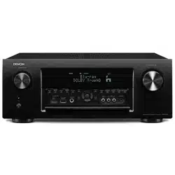
Used to turn the power of the MAIN ZONE (room where this unit is located) on/off (standby). (p. 91)
Power indicator
This is lit as follows according to the power status:
White: Power on
Off: Normal standby
Red:
When “HDMI Pass Through” is set to “On” (p. 200)
When “HDMI Control” is set to “On” (p. 202)
When “Network Control” is set to “Always On” (p. 256)
SOURCE SELECT knob
This selects the input source. (p. 91)
Remote control sensor
This receives signals from the remote control unit. (p. 9)
Display
This displays various pieces of information. (p. 22)
MASTER VOLUME knob
This adjusts the volume level. (p. 92)
Door
When you are using buttons and/or connectors behind the door, press the bottom of the door to open it. Be careful not to catch your fingers when closing the door.
With the door open
ZONE2 ON/OFF button
This turns the power of ZONE2 (another room) on/off. (p. 175)
ZONE2 SOURCE button
This selects the input source for ZONE2. (p. 175)
ZONE3 ON/OFF button
This turns the power of ZONE3 (another room) on/off. (p. 175)
ZONE3 SOURCE button
This selects the input source for ZONE3. (p. 175)
STATUS button
Each press of this switches the status information that is shown on the display.
Information button (INFO)
This displays the status information on the TV screen. (p. 272)
Cursor buttons ()
These select items.
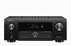
OPTION button
This displays the option menu on the TV screen.
DIMMER button
Each press of this switches the brightness of the display. (p. 267)
QUICK SELECT buttons
With a single press of any of these buttons, you can call up various settings you’ve registered to each button such as the input source, volume level and sound mode settings. (p. 161)
AUX-HDMI connector
This is used to connect HDMI output compatible devices such as video camcorders and game consoles. (p. 80)
USB port (T)
This is used to connect USB storages (such as USB memory devices). (p. 82)
BACK button
This returns to the previous screen.
ENTER button
This determines the selection.
SETUP button
This displays the menu on the TV screen. (p. 181)
SETUP MIC jack
This is used to connect the supplied Sound calibration microphone. (p. 222)
Headphones jack (PHONES)
This is used to connect headphones.
When the headphones are plugged into this jack, audio will no longer be output from the connected speakers or from the PRE OUT connectors.
NOTE To prevent hearing loss, do not raise the volume level excessively when using headphones.
Display
Input signal indicators
These light according to the audio input mode settings of each input source. (p. 216)
Decoder indicators
These light when Dolby or DTS signals are input or when the Dolby or DTS decoder is running.
Audyssey® indicator
This lights when “MultEQ® XT32”, “Dynamic EQ”, “Dynamic Volume” or “Audyssey LFCTM” has been set up. (p. 193)
Tuner reception mode indicators
These light up according to the reception conditions when the input source is set to “Tuner”.
TUNED: Lights up when the broadcast is properly tuned in.
STEREO: Lights up when receiving FM stereo broadcasts.
Monitor output indicator
These light according to the HDMI monitor output setting. When set to “Auto(Dual)”, the indicators light according to connection status.
MULTI ZONE indicator
This lights up when ZONE2 or ZONE3 (another room) power is turned on. (p. 175)
Sleep timer indicator
This lights when the sleep mode is selected. (p. 159)
MUTE indicator
This blinks while the sound is muted. (p. 92)
Volume indicator
Information display
The input source name, sound mode, setting values and other information are displayed here.
Front speaker indicator
This lights according to the setting of the front A and B speakers.
Input/output signal channel indicators
The channel for input/output signals is displayed according to the setting configured for “Channel Indicators”. (p. 268)
When “Channel Indicators” is set to “Output” (Default) These light when audio signals are being output from the speakers.
When “Channel Indicators” is set to “Input” These light corresponding to the channels that include the input signals.
When playing HD Audio sources, the indicator lights when a signal from an extension channel (a channel other than the front, center, surround, surround back, front height, front wide or LFE channel) is input.
Rear panel
For details, see the next page.
Bluetooth/wireless LAN antenna connectors
Used to connect the included external antennas for Bluetooth/wireless connectivity when connecting to a network via wireless LAN, or when connecting to a handheld device via Bluetooth. (v p. 86)
Place the external antennas for Bluetooth/wireless connectivity evenly over the screw terminal of rear.
Turn clockwise until the antennas is fully connected.
Rotate the antenna upwards for best reception.
TRIGGER OUT jacks
Used to connect devices equipped with the trigger function. (p. 88)
Digital audio connectors (DIGITAL AUDIO)
Used to connect devices equipped with digital audio connectors.
Connection 2: TV equipped with an HDMI connector and incompatible with the ARC (Audio Return Channel) / eARC (Enhanced Audio Return Channel)” (p. 74)
Connection 3: TV equipped without an HDMI connector” (p. 75)
Connecting a set-top box (Satellite tuner/cable TV)” (p. 77)
Connecting a DVD player or Blu-ray Disc player” (p. 78)
RS-232C connector
Used to connect home automation controller devices fitted with RS-232C connectors. Consult the owner’s manual of the home automation controller for more information about serial control of this unit.
Perform the operation below beforehand.
Turn on the power of this unit.
Turn off the power of this unit from the external controller.
Check that the unit is in the standby mode.
REMOTE CONTROL jacks
Used to connect infrared receivers/transmitters in order to operate this unit and external devices from a different room. (p. 87)
SIGNAL GND terminal
Used to connect a ground wire for the turntable. (p. 81)
NETWORK connector
Used to connect to a LAN cable when connecting to a wired LAN network. (p. 85)
Video connectors (VIDEO)
Used to connect devices equipped with video connectors.
Connection 3: TV equipped without an HDMI connector” (p. 75)
Connecting a set-top box (Satellite tuner/cable TV)” (p. 77)
Connecting a DVD player or Blu-ray Disc player” (p. 78)
HDMI connectors
Used to connect devices equipped with HDMI connectors.
"Connection 1: TV equipped with an HDMI connector and compatible with the ARC (Audio Return Channel) / eARC (Enhanced Audio Return Channel)” (p. 73)
"Connection 2: TV equipped with an HDMI connector and incompatible with the ARC (Audio Return Channel) / eARC
"Enhanced Audio Return Channel)” (p. 74)
"Connecting a set-top box (Satellite tuner/cable TV)” (p. 77)
"Connecting a DVD player or Blu-ray Disc player” (p. 78)
"Connecting a player device compatible with the 8K” (p. 79)
AC inlet (AC IN)
Used to connect the power cord. (p. 89)
FM/AM antenna terminals (ANTENNA)
Used to connect FM antennas and AM loop antennas. (p. 83)
Analog audio connectors (AUDIO)
Used to connect devices equipped with analog audio connectors.
“Connecting a set-top box (Satellite tuner/cable TV)” (p. 77)
“Connecting a DVD player or Blu-ray Disc player” (p. 78)
“Connecting a turntable” (p. 81)
Speaker terminals (SPEAKERS)
Used to connect speakers. (p. 40)
PRE OUT connectors
Used to connect a subwoofer with built-in amplifier or an external power amplifier.
"Connecting the subwoofer” (p. 41)
"Connecting 11.1-channel speakers” (p. 59)
"Connecting an external power amplifier” (p. 71)
"Connecting ZONE” (p. 169)
Component video connectors (COMPONENT VIDEO)
Used to connect devices equipped with component video connectors.
Connection 3: TV equipped without an HDMI connector” (p. 75)
Connecting a DVD player or Blu-ray Disc player” (p. 78)
NOTE Do not touch the inner pins of the connectors on the rear panel. Electrostatic discharge may cause permanent damage to the unit.
Connections
Connecting speakers
Here we connect the speakers in the room to this unit.
Before connecting speakers
NOTE
Disconnect this unit’s power plug from the power outlet before connecting the speakers. Also, turn off the subwoofer.
Connect so that the speaker cable core wires do not protrude from the speaker terminal. The protection circuit may be activated if the core wires touch the rear panel or if the + and - sides touch each other. (“Protection circuit” (p. 329))
Never touch the speaker terminals while the power cord is connected. Doing so could result in electric shock. When the “Setup Assistant” (page 9 in the separate “Quick Start Guide”) is running, follow the instructions in the “Setup Assistant” screen for making connections. (Power is not supplied to the speaker terminals while the “Setup Assistant” is running.)
Use speakers with an impedance of 4 – 16 Ω/ohms.
Connecting the speaker cables
Carefully check the left (L) and right (R) channels and + (red) and – (black) polarities on the speakers being connected to this unit, and be sure to connect the channels and polarities correctly.
1 Peel off about 3/8 inch (10 mm) of sheathing from the tip of the speaker cable, then either twist the core wire tightly or terminate it.
2 Turn the speaker terminal counterclockwise to loosen it.
3 Insert the speaker cable’s core wire to the hilt into the speaker terminal.
4 Turn the speaker terminal clockwise to tighten it.
Connecting a TV
Connect a TV to this unit so that the input video is output to the TV. You can also enjoy audio from the TV on this unit.
How to connect a TV depends on the connectors and functions equipped on the TV.
ARC (Audio Return Channel) / eARC (Enhanced Audio Return Channel) function plays TV audio on this unit by sending the TV audio signal to this unit via HDMI cable.
Connection 1 : TV equipped with an HDMI connector and compatible with the ARC (Audio Return Channel) / eARC (Enhanced Audio Return Channel)
Use an HDMI cable to connect a TV that is compatible with the ARC / eARC function to this unit.
Set “HDMI Control” to “On” or “ARC” to “On” when using a TV that supports the ARC function. (p. 202)
Using an eARC function-compatible television enables audio playback from the speaker connected to this unit, regardless of “HDMI Control” and “ARC” settings in the menu.
When using the ARC / eARC function, connect to the HDMI MONITOR 1 connector.
eARC function settings may be required depending on the eARC function-compatible television you are using. Make sure eARC is set to on if this setting exists on your television. For more information, check your television’s owner’s manual.
When an ARC and eARC function-compatible television is connected, the eARC function is prioritized.
Use a “High Speed HDMI Cable with Ethernet” when using an ARC / eARC function-compatible television.
Use an “Ultra High Speed 48 Gbps HDMI cable” to enjoy 8K video.
Set “4K/8K Signal Format” to “8K Enhanced” in the menu to enjoy 8K video. (p. 211)
Connection 2 : TV equipped with an HDMI connector and incompatible with the ARC (Audio Return Channel) / eARC (Enhanced Audio Return Channel)
Use an HDMI cable to connect the TV to this unit.
To listen to audio from TV on this unit, use an optical cable to connect the TV to this unit.
Connection 3: TV equipped without an HDMI connector
Use a component video or a video cable to connect the TV to this unit.
To listen to audio from TV on this unit, use an optical cable to connect the TV to this unit.
Connecting a USB memory device to the USB port
For operating instructions see “Playing a USB memory device” (p. 93).
Denon does not guarantee that all USB memory devices will operate or receive power. When using a portable USB hard disk drive (HDD) which came with an AC adapter, use that device’s supplied AC adapter.
NOTE
USB memory devices will not work via a USB hub.
It is not possible to use this unit by connecting the unit’s USB port to a PC via a USB cable.
Do not use an extension cable when connecting a USB memory device. This may cause radio interference with other devices.
Connecting FM/AM antennas
Connect the antenna, tune in to a broadcast and then move the antenna to the location where there is least noise. Then use tape, etc. to fix the antenna in this location. (“Listening to FM/AM broadcasts” (p. 105))
If you are unable to receive a good broadcast signal, we recommend installing an outdoor antenna. For details, inquire at the retail store where you purchased the unit.
NOTE Make sure the AM loop antenna lead terminals do not touch metal parts of the panel.
Using the AM loop antenna
Suspending on a wall
Suspend directly on a wall without assembling
Standing alone
Use the procedure shown above to assemble.
When assembling, refer to “AM loop antenna assembly”.
AM loop antenna assembly
1. Put the stand section through the bottom of the loop antenna from the rear and bend it forward.
2. Insert the projecting part into the square hole in the stand.
Connecting an external control device
REMOTE CONTROL jacks
When this unit is installed in a location where the remote control signals cannot reach (installation in a cabinet etc.), it can still be controlled by the remote control by connecting a remote control receiver unit (sold separately).
You can also use it to remotely control ZONE2 and ZONE3 (another rooms).
TRIGGER OUT jacks
When a device with TRIGGER IN jack is connected, the connected device’s power on/standby can be controlled through linked operation to this unit. The TRIGGER OUT jack outputs a maximum 12 V DC/150 mA electrical signal.
NOTE
Use a monaural mini-plug cable for connecting the TRIGGER OUT jacks. Do not use a stereo mini-plug cable.
If the permissible trigger input level for the connected device is larger than 12 V DC/150 mA, or has shorted, the TRIGGER OUT jack cannot be used. In this case, turn off the power to the unit, and disconnect it.
Connecting the power cord
After completing all the connections, insert the power plug into the power outlet.
Playback
Basic operation
Turning the power on
1. Press POWER to turn on power to the unit.
You can press the input source select button when the unit is in standby mode to turn on the power.
You can also switch the power to standby by pressing X on the main unit.
Selecting the input source
1. Press the input source select button to be played back.
The desired input source can be selected directly.
You can also select the input source by turning SOURCE SELECT on the main unit.
Adjusting the volume
Use VOLUME to adjust the volume.
The variable range differs according to the input signal and channel level setting.
You can also adjust the master volume by turning MASTER VOLUME on the main unit.
Turning off the sound temporarily (Muting)
Press MUTE .
MUTE indicator on the display flashes.
: appears on the TV screen.
The sound is reduced to the level set at “Mute Level” in the menu. (v p. 192)
To cancel mute, either adjust the sound volume or press MUTE: again.
If : is displayed on the TV screen for more than 5 minutes when the “Screen Saver” is set to “On”, the : symbol moves randomly over the TV screen. (v p. 210) (This feature will be supported via firmware update.)
The following describes the procedure for playing DVD player/Blu-ray Disc player.
1. Prepare for playback.
Turn on the power of the TV, subwoofer and player.
Change the TV input to the input of this unit.
2. Press POWER X to turn on power to the unit.
3. Press DVD or Blu-ray to switch an input source for a player used for playback.
4. Play the DVD player or Blu-ray Disc player.
Surround playback (p. 141)
Playing a USB memory device
Playing back music files stored on a USB memory device.
Only USB memory devices conforming to mass storage class standards can be played on this unit.
This unit is compatible with USB memory devices in “FAT32” or “NTFS” format.
The audio format types and specifications supported by this unit for playback are as follows.
See “Playing back a USB memory devices” (v p. 316) for details.
WMA
MP3
WAV
MPEG-4 AAC
FLAC
Apple Lossless
DSD
Playing files stored on USB memory devices
Insert a “FAT32” or “NTFS” formatted USB memory device into the USB port.
Press USB to switch the input source to “USB”.
Select the name of this unit.
Browse the music on your USB memory device and select something to play.
When you select something to play you will be asked how you want to queue up your music.
5. Use to select the “Play Now” or “Play Now & Replace Queue”, then press ENTER.
Playback starts.
When an MP3 music file includes album art data, the album art can be displayed while playing the file.
NOTE
Note that Denon will accept no responsibility whatsoever for any problems arising with the data on a USB memory device when using this unit in conjunction with the USB memory device.
When a USB memory device is connected to this unit, the unit loads all of the files on the USB memory device. Loading may take a while if the USB memory device contains a large number of folders and/or files.
Listening to music on a Bluetooth device
Music files stored on Bluetooth devices such as smartphones, digital music players, etc. can be enjoyed on this unit by pairing and connecting this unit with the Bluetooth device.
Communication is possible up to a range of about 98.4 ft/30 m.
NOTE To play back music from a Bluetooth device, the Bluetooth device needs to support the A2DP profile.
Tips
Tips
I want the volume not to become too loud by mistake
Set the volume upper limit for “Volume Limit” in the menu beforehand. This prevents children or others from increasing the volume too much by mistake. You can set this for each zone. (“Volume” (p. 192), “Volume Limit” (p. 265))
I want to keep the volume at the same level when I turn the power on
By default, the volume setting when power was previously set to standby on this unit is applied at next power on with no change. To use a fixed volume level, set the volume level at power on for “Power On Volume” in the menu. You can set this for each zone. (“Volume” (p. 192), “Power On Volume” (p. 265))
I want to have the subwoofer always output audio
Depending on the input signals and sound mode, the subwoofer may not output audio. When “Subwoofer Mode” in the menu is set to “LFE+Main”, you can have the subwoofer always output audio. (p. 246)
I want to make human voices in the movies clearer
Use “Center Level Adjust” in the menu to adjust the level. (p. 182)
I want to keep bass and clarity during playback at a lower volume level
Set “Dynamic EQ” in the menu to “On”. This setting corrects the frequency characteristics to allow you to enjoy clear sound without the bass being lost even during playback at a lower volume level. (p. 194)
I want to automatically adjust the volume level difference in content such as TV and movies
Set “Dynamic Volume” in the menu. Volume level changes (between quiet scenes and loud scenes) in TV shows or movies are automatically adjusted to your desired level. (p. 195)
I want to set the optimized listening environment after changing the configuration/position of the speakers or changing a speaker to a new one
Perform Audyssey® Setup. This automatically makes the optimized speaker settings for the new listening environment. (p. 219)
I want to combine a desired video with the current music
Set “Video Select” in the option menu to “On”. You can combine the current music with your desired video source from a Set-top Box or DVD, etc. while listening to music from the Tuner, CD, Phono, HEOS Music, USB or Bluetooth. (p. 137)
I want to skip unused input sources
Set unused input sources for “Hide Sources” in the menu. This allows you to skip unused input sources when turning the SOURCE SELECT knob on this unit. (p. 217)
I want to enjoy the same music in all zones at the home party, etc.
Set “All Zone Stereo” in the option menu to “Start”. You can simultaneously play back music in another room (ZONE2, ZONE3) that is played back in MAIN ZONE. (p. 139)
I want to minimize the delay in video signals when I’m playing a game on my game console
When the video is delayed against button operations with the controller on the game console, set “Video Mode” in the menu to “Game”. (p. 206)
I want to operate this unit using the TV remote control
Select “AV Receiver” in a TV menu such as “Input”z or “Operate Connected HDMI Device”z. The Smart Menu of this unit is displayed on the TV. This Smart Menu can be operated using the remote control of your TV.
* The selection method differs depending on your TV. See the owner's manual of your TV for details.
I want to use the external power amplifier to the Front channel for my 11.1-channel speaker system
Set “Pre-out” to “Front” to connect your external power amplifier for the front channels. (p. 237)
Troubleshooting
If a problem should arise, first check the following:
Are the connections correct?
Is the set being operated as described in the owner’s manual?
Are the other devices operating properly?
If steps 1 to 3 above do not improve the problem, restarting the device may improve the problem.
Continue pressing the button on the unit until “Restart” appears in the display, or remove and re-insert the power cord of the unit.
If this unit does not operate properly, check the corresponding symptoms in this section.
If the symptoms do not match any of those described here, consult your dealer as it could be due to a fault in this unit. In this case, disconnect the power immediately and contact the store where you purchased this unit.
Power does not turn on / Power is turned off
Power does not turn on.
Check whether the power plug is correctly inserted into the power outlet. (p. 89)
Power automatically turns off.
The sleep timer is set. Turn on the power again. (p. 159)
“Auto Standby” is set. “Auto Standby” is triggered when there is no operation for a set amount of time. To disable “Auto Standby”, set “Auto Standby” on the menu to “Off”. (p. 262)
Power turns off and the power indicator flashes in red approx. every 2 seconds.
The protection circuit has been activated due to a rise in temperature within this unit. Turn the power off, wait about an hour until this unit cools down sufficiently, and then turn the power on again. (p. 329)
Please re-install this unit in a place having good ventilation.
Power turns off and the power indicator flashes in red approx. every 0.5 seconds.
Check the speaker connections. The protection circuit may have been activated because speaker cable core wires came in contact with each other or a core wire was disconnected from the connector and came in contact with the rear panel of this unit. After unplugging the power cord, take corrective action such as firmly re-twisting the core wire or taking care of the connector, and then reconnect the wire. (p. 40)
Turn down the volume and turn on the power again. (p. 91)
This unit’s amplifier circuit has failed. Unplug the power cord and contact our customer service center.
The power to this unit does not turn off when you press the Power operation button. “ZONE2 On” or “ZONE3 On” appears on the display.
Power in either ZONE2 or ZONE3 is on. To turn off the power of the device (standby), press either the ZONE2 ON/OFF or ZONE3 ON/OFF button on the main unit or press the POWER button after pressing the Z2 or Z3 button on the remote control unit.
Operations cannot be performed through the remote control unit
Operations cannot be performed through the remote control unit.
Batteries are worn out. Replace with new batteries. (p. 9)
Operate the remote control unit within a distance of about 23 ft/7 m from this unit and at an angle of within 30°. (p. 9)
Remove any obstacle between this unit and the remote control unit.
Insert the batteries in the proper direction, checking the and marks. (p. 9)
The set’s remote control sensor is exposed to strong light (direct sunlight, inverter type fluorescent bulb light, etc.). Move the set to a place in which the remote control sensor will not be exposed to strong light.
The operation target zone does not correspond to the zone setting specified on the remote control unit. Press MAIN, Z2 or Z3 to select the zone to operate. (p. 181)
The remote control unit operating mode is used to operate other devices. Press MAIN to set the operating mode to AVR. (p. 279)
When using a 3D video device, the remote control unit of this unit may not function due to effects of infrared communications between units (such as TV and glasses for 3D viewing). In this case, adjust the direction of units with the 3D communications function and their distance to ensure they do not affect operations from the remote control unit of this unit.
Display on this unit shows nothing
Display is off.
Set “Dimmer” on the menu to something other than “Off”. (p. 267)
When the sound mode is set to “Pure Direct”, the display is off. (p. 144)
No sound comes out
No sound comes out of speakers.
Check the connections for all devices. (p. 40)
Insert connection cables all the way in.
Check that input connectors and output connectors are not reversely connected.
Check cables for damage.
Check that speaker cables are properly connected. Check that cable core wires come in contact with the metal part on speaker terminals. (p. 40)
Securely tighten the speaker terminals. Check speaker terminals for looseness. (p. 40)
Check that a proper input source is selected. (p. 91)
Adjust the volume. (p. 92)
Cancel the mute mode. (p. 92)
Check the digital audio input connector setting. (p. 214)
Check the digital audio output setting on the connected device. On some devices, the digital audio output is set to off by default.
When a headphone is plugged into the PHONES jack on the main unit, sound is not output from the speaker terminal and PRE OUT connector.
Audio is output to your Bluetooth headphones, but not to speakers or pre-outs when “Output Mode” set to “Bluetooth Only”. Change “Output Mode” to “Bluetooth + Speakers” to output audio from your Bluetooth headphones as well as your speakers or pre-outs. (p. 263)
No sound comes out when using the DVI-D connection.
When this unit is connected to a device equipped with a DVI-D connector, no sound is output. Make a separate audio connection.
Desired sound does not come out
The volume does not increase.
The maximum volume is set too low. Set the maximum volume using “Limit” on the menu. (p. 192)
Appropriate volume correction processing is performed according to the input audio format and settings, so the volume may not reach the upper limit.
The volume of Bluetooth headphones does not decrease.
Bluetooth headphones volume cannot be adjusted from this unit. Use a Bluetooth headphones with volume adjustment.
No sound comes out with the HDMI connection.
Check the connection of the HDMI connectors. (p. 73)
When outputting HDMI audio from the speakers, set “HDMI Audio Out” on the menu to “AVR”. To output from the TV, set “TV”. (p. 200)
When using the HDMI Control function, check that the audio output is set to the AV amplifier on the TV. (p. 156)
When an eARC function-compatible television is connected, television audio is not output from the speaker connected to this unit
eARC function settings may be required depending on the eARC function-compatible television you are using. Make sure eARC is set to on if this setting exists on your television. For more information, check your television’s owner’s manual.
Make sure the input source of this unit is “TV Audio”.
The eARC function does not operate when the HDMI input connector is set to the “TV Audio” input source. To enable eARC function operation, remove the HDMI input connector setting, then restart this unit and the television. (p. 215)
No sound comes out of a specific speaker.
Check that speaker cables are properly connected.
Check that a selection other than “None” is set for the “Speaker Config.” setting in menu. (p. 238)
Check the “Assign Mode” setting in the menu. (p. 230)
When the sound mode is “Stereo” and “Virtual”, audio is only output from the front speakers and subwoofer.
Audio is not output from the surround back speaker if “Speaker Virtualizer” is set to “On” when “Speaker Config.” - “Surr. Back” is set to “1 spkr” in the menu. (p. 185)
When “Speaker Config.” - “Surr. Back” is set to “2 spkrs”, “Speaker Config.” - “Center” is set to “Large” or “Small”, and sound mode is set to “IMAX DTS”, surround audio is output from the surround back speaker. Audio is not output from the surround speaker. (p. 239)
No sound is produced from subwoofer.
Check the subwoofer connections.
Turn on the subwoofer’s power.
Set “Speaker Config.” - “Subwoofer” in the menu to “1 spkr” or “2 spkrs”. (p. 238)
When “Speaker Config.” - “Front” in the menu is set to “Large”, depending on the input signal and the sound mode, no sound may be output from the subwoofer. (p. 238)
When no subwoofer audio signal (LFE) is included in the input signals, no sound may be output from the subwoofer. (p. 246)
You can make the subwoofer always output sound by setting the “Subwoofer Mode” to “LFE+Main”. (p. 246)
DTS sound is not output.
Check that the digital audio output setting on the connected device is set to “DTS”.
Dolby Atmos, Dolby TrueHD, DTS-HD, Dolby Digital Plus audio is not output.
Make HDMI connections. (p. 77)
Check the digital audio output setting on the connected device. On some devices, “PCM” is set by default.
DTS Neural:X mode cannot be selected.
DTS Neural:X cannot be selected when using the headphones.
Dolby Surround mode cannot be selected.
Dolby Surround cannot be selected when using the headphones.
IMAX DTS:X cannot be selected.
IMAX DTS:X and IMAX DTS cannot be selected but DTS:X and DTS can be selected, when the headphones are used.
Sound modes other than “Stereo” or “Direct” cannot be selected.
Only “Stereo” or “Direct” can be selected for the sound mode if Headphone:X signals are input.
Audyssey MultEQ® XT32, Audyssey Dynamic EQ®, Audyssey Dynamic Volume® and Audyssey LFC™ cannot be selected.
These cannot be selected when you have not performed Audyssey® Setup. (p. 219)
Switch to a sound mode other than “Direct” or “Pure Direct”. (p. 143)
Audyssey Dynamic EQ®, Audyssey Dynamic Volume® and Audyssey LFC™ cannot be selected when sound mode is “DTS Virtual:X” or sound mode that have “+ Virtual:X” in the sound mode name.
These cannot be selected when using the headphones.
"Restorer” cannot be selected.
Check that an analog signal or PCM signal (Sample Rate = 44.1/48 kHz) is input. For playback of multichannel signals such as Dolby Digital or DTS surround, “Restorer” cannot be used. (p. 190)
Switch to a sound mode other than “Direct” or “Pure Direct”. (p. 143)
No audio is output from PRE OUT or speakers for ZONE2/ZONE3.
In ZONE2/ZONE3, the audio can be played back when signals input from digital connectors (OPTICAL/COAXIAL) are in 2ch PCM format.
In ZONE2, the audio can be played back when signals input from the HDMI connector are in 2ch PCM format. To play back the audio in ZONE2 irrespective of the input signal format, set “HDMI Audio” in the menu to “PCM”. Depending on the played back device, the audio may not be played back even with this setting. In that case, set the audio format to “PCM (2ch)” on the played back device. (p. 265)
When listening to audio from a Bluetooth device in ZONE2/ZONE3, remove any obstructions between the Bluetooth device and this unit and use it within a range of about 98.4 ft/30 m.
Sound mode settings are not available when using Bluetooth headphones. Audio menu settings are also not available.
This unit cannot change sound mode or audio menu settings for audio output to Bluetooth headphones.
Sound is interrupted or noise occurs
During playback from the Internet radio or USB memory device, sound is occasionally interrupted.
When the transfer speed of the USB memory device is slow, sound may occasionally be interrupted.
The network communication speed is slow or the radio station is busy.
When making a call on iPhone, noise occurs in audio output on this unit.
When making a call, keep a distance of 0.7 ft/20 cm or longer between iPhone and this unit.
Noise often occurs in FM/AM broadcasting.
Change the antenna orientation or position. (p. 83)
Separate the AM loop antenna from the unit.
Use an outdoor antenna. (p. 83)
Separate the antenna from other connection cables. (p. 83)
The sounds appear to be distorted.
Lower the volume. (p. 92)
Set “Off” to the “ECO Mode”. When “On” or “Auto” is in the “ECO Mode”, the audio may by distorted when the playback volume is high. (p. 259)
Sound cuts out when using Wi-Fi connection.
The frequency band used by the wireless LAN is also used by microwave ovens, cordless telephones, wireless game controllers and other wireless LAN devices. Using such devices at the same time as this unit may cause sound to cut out due to electronic interference. Sound cut out can be improved using the following methods. (p. 85)
Install devices that cause interference away from this unit.
Turn off the power supply to devices that cause interference.
Change the settings of the router channel to which this unit is connected to. (See the instruction manual of the wireless router for details on how to change the channel.)
Switch to a wired LAN connection.
Particularly when you play back large music files, depending on your wireless LAN environment, the playback sound may be interrupted. In this case, make the wired LAN connection. (p. 252)
No video is shown on the TV
No picture appears.
Check the connections for all devices. (p. 73)
Insert connection cables all the way in.
Check that input connectors and output connectors are not reversely connected.
Check cables for damage.
Match the input settings to the input connector of the TV connected to this unit. (p. 214)
Check that the proper input source is selected. (p. 91)
Check the video input connector setting. (p. 214)
Check that the resolution of the player corresponds to that of the TV. (p. 271)
Check whether the TV is compatible with copyright protection (HDCP). If connected to a device not compatible with HDCP, video will not be output correctly. (p. 313)
To enjoy content that is copyright protected by HDCP 2.2 or HDCP 2.3, use a playback device and TV compatible with HDCP 2.2 or HDCP 2.3.
The HDMI signal cannot be converted to an analog signal. Use analog connections. (p. 314)
To play back a 4K video, use a “High Speed HDMI Cable” or an “High Speed HDMI Cable with Ethernet”. In order to achieve a higher fidelity for 4K videos, it is recommended to use a “Premium High Speed HDMI Cables” or an “Premium High Speed HDMI Cables with Ethernet” that has an HDMI Premium Certified Cable label on the product package.
Use an “Ultra High Speed 48 Gbps HDMI cable” to enjoy 8K or 4K 120Hz video.
No video is shown on the TV with the DVI-D connection.
With the DVI-D connection, on some device combinations, devices may not function properly due to the copy guard copyright protection (HDCP). (p. 313)
No video from an input source such as a game console is shown on the TV.
When special video signals are input from a game console, etc., the Video Conversion function may not function. Connect the input connector to the monitor output connector of the same type.
While the menu is being displayed, no video is shown on the TV.
The video being played will not appear in the background of the menu when the menu is operated during playback of the following video signals.
Some images of 3D video contents
Computer resolution images (example: VGA)
Video with an aspect ratio other than 16:9 or 4:3
4K or 8K video
Some kind of HDR signals
Some kind of game contents
Compressed video
When using HDMI ZONE2, the video output in MAIN ZONE is interrupted.
When ZONE2 is operated with the same input source selected for MAIN ZONE and ZONE2, video in MAIN ZONE may be interrupted.
The menu screen is not displayed on the TV
The menu screen or status information screen is not displayed on the TV.
The menu screen is only displayed on this unit and a TV connected with an HDMI cable. If this unit is connected to a TV using a different video output connector, operate while watching the display on this unit.
The status information will not appear on the TV when the following video signals are being played.
Some images of 3D video content
Computer resolution images (example: VGA)
Video with an aspect ratio other than 16:9 or 4:3
Some kind of HDR signals
Some kind of game contents
Compressed video
When a 2D video is converted to a 3D video on the TV, the menu screen or status information screen is not displayed properly. (p. 272)
In the pure direct playback mode, the menu screen or status information is not displayed. Switch to a sound mode other than the pure direct mode. (p. 142)
Set the “TV Format” setting in the menu to a selection that is appropriate for the TV. (p. 213)
The color of the menu screen and operations content displayed on the television is different from normal
The color of the menu screen and operations content displayed on the television is different.
Performing operations on this unit during playback of a Dolby Vision signal may cause variance in the color display of the menu screen and operations content. This is a characteristic of the Dolby Vision signal and is not a malfunction.
AirPlay cannot be played back
The AirPlay icon is not displayed on iTunes / iPhone / iPod touch / iPad.
This unit and PC / iPhone / iPod touch / iPad are not connected to the same network (LAN). Connect it to the same LAN as this unit. (p. 85)
The firmware on iTunes / iPhone / iPod touch / iPad is not compatible with AirPlay. Update the firmware to the latest version.
Audio is not output.
The volume on iTunes / iPhone / iPod touch / iPad is set to the minimum level. The volume on iTunes / iPhone / iPod touch / iPad is linked with the volume on this unit. Set a proper volume level.
The AirPlay playback is not performed, or this unit is not selected. Click the AirPlay icon on the iTunes / iPhone / iPod touch / iPad screen and select this unit. (p. 129)
Audio is interrupted during the AirPlay playback on iPhone / iPod touch / iPad.
Quit the application running in the background of the iPhone/iPod touch/iPad, and then play using AirPlay.
Some external factors may be affecting the wireless connection. Modify the network environment by taking measures such as shortening the distance from the wireless LAN access point.
iTunes cannot be played back through the remote control unit.
Enable the “Allow iTunes audio control from remote speakers” setting on iTunes. Then, you can perform playback, pause, and skip operations through the remote control unit.
USB memory devices cannot be played back
USB memory device is not recognized.
Disconnect and reconnect the USB memory device. (p. 82)
Mass storage class compatible USB memory devices are supported.
This unit does not support a connection through a USB hub. Connect the USB memory device directly to the USB port.
The USB memory device must be formatted to “FAT32” or “NTFS”.
Not all USB memory devices are guaranteed to work. Some USB memory devices are not recognized. When using a type of portable hard disc drive compatible with the USB connection that requires power from an AC adapter, use the AC adapter that came with the drive.
Files on the USB memory device are not displayed.
Files of a type not supported by this unit are not displayed. (p. 93)
This unit is able to display files in a maximum of eight folder layers. A maximum of 5000 files (folders) can also be displayed for each layer. Modify the folder structure of the USB memory device.
When multiple partitions exist on the USB memory device, only files on the first partition are displayed.
iOS and Android devices are not recognized.
The USB port of this unit does not support playback from iOS and Android devices.
Files on a USB memory device cannot be played.
Files are created in a format that is not supported by this unit. Check the formats supported by this unit. (p. 316)
You are attempting to play a file that is copyright protected. Files that are copyright protected cannot be played on this unit.
Playback may not be possible if the album art file size exceeds 2 MB.
Bluetooth cannot be played back
Bluetooth devices cannot be connected to this unit.
The Bluetooth function in the Bluetooth device has not been enabled. See the Owner’s Manual of the Bluetooth device to enable the Bluetooth function.
Bring the Bluetooth device near to this unit.
The Bluetooth device cannot connect with this unit if it is not compatible with the A2DP profile.
Turn the power of the Bluetooth device off and on again, and then try again.
Smartphones and other Bluetooth devices cannot be connected.
Smartphones and other Bluetooth devices cannot be connected when “Transmitter” is set to “On”. Press Bluetooth on the remote control to switch the input source to Bluetooth, then connect the device. (p. 263)
Cannot connect Bluetooth headphones.
Bring the Bluetooth headphones near to this unit.
Turn the power of the Bluetooth headphones off and on again, and then try again.
Go to “General” - “Bluetooth Transmitter”, and set “Transmitter” to “On” within the menu. (p. 263)
Make sure this unit is not already connected to another pair of Bluetooth headphones. Check the currently connected Bluetooth headphones by pressing INFO on the remote control or STATUS button on the unit. Disconnect the connected Bluetooth headphones before connecting the ones you want to use.
Bluetooth headphones cannot be connected if Bluetooth is being used as an input source in any zone.
Bluetooth headphones cannot be connected if this unit is grouped in the HEOS App. Remove this unit from the group to enable Bluetooth headphones connection.
The Bluetooth headphones cannot connect with this unit if it is not compatible with the A2DP profile.
Connection and operation are not guaranteed for all Bluetooth-enabled devices.
This unit can only connect to one Bluetooth headphone at a time. However, up to 8 Bluetooth headphones can be registered. You can switch between registered devices from “Device List” in the “Bluetooth Transmitter” menu. (p. 263)
The sound is cut off.
Bring the Bluetooth device near to this unit.
Remove obstructions between the Bluetooth device and this unit.
To prevent electromagnetic interference, locate this unit away from microwave ovens, wireless LAN devices and other Bluetooth devices.
Reconnect the Bluetooth device.
The sound is cut off or noise occurs when using Bluetooth headphones.
Move the Bluetooth headphones closer to this unit.
Remove obstructions between the Bluetooth headphones and this unit.
Reconnect the Bluetooth headphones.
To prevent electromagnetic interference, locate this unit away from microwave ovens, wireless LAN devices and other Bluetooth devices.
We recommend using wired LAN to connect this unit and other devices.
Bluetooth transmits on the 2.4 GHz band which may interfere with Wi-Fi transmitted on this band. Connect this unit and other devices to Wi-Fi network on a 5 GHz band if available on your Wi-Fi router.
Audio is delayed on my Bluetooth headphones.
This unit cannot adjust audio delay on Buetooth headphones.
The Internet radio cannot be played back
A list of broadcasting stations is not displayed.
The LAN cable is not properly connected, or the network is disconnected. Check the connection status. (p. 85)
Perform the network diagnostic mode.
Internet Radio cannot be played.
The selected radio station is broadcasting in a format that is not supported by this unit. Formats that can be played back in this unit are MP3, WMA and AAC. (p. 319)
The firewall function is enabled on the router. Check the firewall setting.
The IP address is not properly set. (p. 254)
Check the power of the router is on.
To obtain the IP address automatically, enable the DHCP server function on the router. Also, set the DHCP setting to “On” on this unit. (p. 254)
To obtain the IP address manually, set the IP address on this unit. (p. 254)
Some radio stations broadcast silently during some time period. In this case, no audio is output. Wait for a while and select the same radio station, or select another radio station. (p. 114)
The selected radio station is not in service. Select a radio station in service.
Cannot connect to favorite radio stations.
Radio station is not currently in service. Register radio stations in service.
Music files on PC or NAS cannot be played back
Files stored on a computer cannot be played.
Files are stored in a non-compatible format. Record in a compatible format. (p. 318)
Files that are copyright protected cannot be played on this unit.
The USB port of this unit cannot be used for connection to a computer.
Media sharing settings on the server or NAS do not allow this unit. Change the settings to allow this unit. For details, see the owner’s manual of the server or NAS.
Server is not found, or it is not possible to connect to the server.
The computer’s or router’s firewall is activated. Check the computer’s or router’s firewall settings.
Computer’s power is not turned on. Turn on the power.
Server is not running. Launch the server.
IP address of this unit is wrong. Check the IP address of this unit. (p. 251)
Music files on PC cannot be played back.
Even if PC is connected to the USB port on this unit, music files on it cannot be played back. Connect PC to this unit through the network. (p. 85)
Files on PC or NAS are not displayed.
Files of a type not supported by this unit are not displayed. (p. 318)
Music stored on a NAS cannot be played.
If you use a NAS in conformity with the DLNA standard, enable the DLNA server function in the NAS setting.
If you use a NAS that does not conform with the DLNA standard, play the music via a PC. Set Windows Media Player’s media sharing function and add NAS to the selected play folder.
If connection is restricted, set audio equipment as the connection target.
Various online services cannot be played
Various online services cannot be played.
The online service may have been discontinued.
The HDMI Control function does not work
The HDMI Control function does not work.
Check that “HDMI Control” in the menu is set to “On”. (p. 202)
You cannot operate devices that are not compatible with the HDMI Control function. In addition, depending on the connected device or the settings, the HDMI Control function may not work. In this case, operate the external device directly. (p. 156)
Check that the HDMI Control function setting is enabled on all devices connected to this unit. (p. 156)
When you make connection related changes such as connecting an additional HDMI device, the link operation settings may be initialized. Turn off this unit and devices connected via HDMI, and turn them on again. (p. 156)
The HDMI MONITOR 2 connector is not compatible with the HDMI Control function. Use the HDMI MONITOR 1 connector to connect to the TV. (p. 73)
Cannot connect to a wireless LAN network
Cannot connect to the network.
The network name (SSID), password and encryption setting have not been set up correctly. Configure the network settings according to the setting details of this unit. (p. 253)
Shorten the distance from the wireless LAN access point and remove any obstructions to improve access first before re-connecting again. Place the unit away from microwave ovens and other network access points.
Configure the access point channel settings away from channels that are being used by other networks.
This unit is not compatible with WEP (TSN).
Cannot connect to a WPS Router.
Check that the WPS mode of the router is operating.
Press the WPS button on the router and then press the “Connect” button displayed on the TV within 2 minutes.
A router/settings that are compatible with WPS 2.0 standards are required. Set the encryption time to “None”, “WPA-PSK (AES)” or WPA2-PSK (AES). p. 253)
If the router encryption method is WEP/WPA-TKIP/WPA2-TKIP, you cannot connect by using the WPS button on the router. In this case, use the “Scan Networks” or “Manual” method to connect.
Cannot connect to the network using iPhone/iPod touch/iPad.
Update the iPhone/iPod touch/iPad firmware to the latest version.
When configuring the settings via a wireless connection, iOS 7 or later needs to be supported.
When using HDMI ZONE2, the devices does not function properly
When using MAIN ZONE, video output is interrupted in HDMI ZONE2.
With the same input source selected for MAIN ZONE and ZONE2, when you operate MAIN ZONE, video may be interrupted in HDMI ZONE2.
When using HDMI ZONE2, no video or audio is output from the TV in ZONE2.
Check that the power is on for ZONE2. (p. 175)
Check the input source for ZONE2. (p. 175)
The AUX-HDMI and HDMI 7 connector does not support the HDMI ZONE2 function.
In ZONE2, playback is only possible when the input signals are HDMI signals.
When the TV does not support the input audio format, audio is not output. Set the audio format to “PCM” on the playback device. Alternatively, set “ZONE2 Setup” - “HDMI Audio” in the menu to “PCM”. (p. 265)
When the TV is not compatible with the resolution of the input video, no video is output. Set the output resolution on the playback device to a resolution that is compatible with the TV.
When using HDMI ZONE2, MAIN ZONE audio is played back as PCM.
When the same input source is selected for MAIN ZONE and ZONE2, the audio format is limited according to the specifications of the TV in ZONE2.
Update/upgrade error messages
If an update/upgrade is interrupted or fails, an error message appears.
Display
Description
Connection failed. Please check your network, then try again.
The network connection is unstable.
Connection to the server failed.
Check your network environment and try the update again.
Update failed. Please check your network, then try again.
The download of the firmware failed.
Check your network environment and try the update again.
Upgrade failed. Please check your network, then try again.
The download of the firmware failed.
Check your network environment and try the upgrade again.
Please check your network, unplug and reconnect the power cord, and try again.
The update failed.
Press and hold the on the main unit for more than 5 seconds, or remove and re-insert the power cord.


 Power operation button (
 )
) Power indicator
 SOURCE SELECT knob
 Remote control sensor
 Display
 MASTER VOLUME knob
 Door
Door

 )
) OPTION button
 DIMMER button
 QUICK SELECT buttons
 AUX-HDMI connector
 USB port (T)
 BACK button
 ENTER button
 SETUP button
 SETUP MIC jack
 Headphones jack (PHONES)

 indicator lights when a signal from an extension channel (a channel other than the front, center, surround, surround back, front height, front wide or LFE channel) is input.


 FM/AM antenna terminals (ANTENNA)
 Analog audio connectors (AUDIO)
 Speaker terminals (SPEAKERS)
 PRE OUT connectors
 Component video connectors (COMPONENT VIDEO)


 to turn on power to the unit.
 to adjust the volume.
 .
. : appears on the TV screen.


 to select the “Play Now” or “Play Now & Replace Queue”, then press ENTER.


 button on the unit until “Restart” appears in the display, or remove and re-insert the power cord of the unit.
 and
and  marks. (p. 9)
 on the main unit for more than 5 seconds, or remove and re-insert the power cord.