Loading ...
Loading ...
Loading ...
12
EEV KIT INSTALLATION
ENGLISH
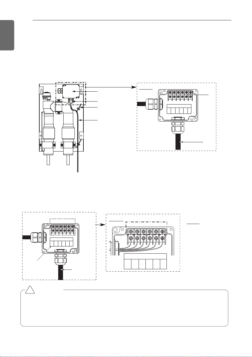
Electrical Work
1 Open the terminal box cover(A).
2 Pass EEV cable(Field supply, 6 wires) from the AHU Control Kit through cable gland and con-
nect the cable wires into the terminal connector(C) following instructions as describe in step
3 Route the cable out of the EEV Kit box according to figure below and fix with the support tie
wrap(D).
4
Use a screwdriver(+) and follow indicated instructions for connecting cable wires into the termi-
nal connector according to the circuit diagram of Comm. Kit(PRCKA0/PRDCA0).
5
Make sure that field wiring and insulation is not squeezed when closing the EEV Kit box cover.
6 Close the EEV Kit box cover(4 x M4).
A. Terminal box cover
B. Cable gland
C. Terminal connector
D. Support tie wrap
E. Electric wiring work(Field supply, 6 wires)
A
B
D
E
B
R
R
D
B
L
O
R
Y
L
W
H
EEV
C
Detail
E
NOTE
1. BR : BROWN
2. RD : RED
3. BL : BLUE
4. OR : ORANGE
5. YL : YELLOW
6. WH : WHITE
B
R
R
D
B
L
O
R
Y
L
W
H
EEV
Field work
Field connect wires
Connect
Label
B
R
R
D
B
L
O
R
Y
L
W
H
EEV
<Field wiring part>
123456
Detail
CAUTION
• Before connecting the wires(Field supply), make sure to compare with the Connect label
between EEV Kit and Comm. Kit(PRCKA0/PRDCA0).
•
Make sure to connect the wires according to the circuit diagram in Comm. Kit(PRCKA0/PRDCA0)
• Use the ring type to connect to the terminal block.
!
Loading ...
Loading ...
Loading ...