
www.lg.com
OWNER'S MANUAL
NETWORK MONITOR
N2210WZ
Please read the safety information carefully before using the product.
Network Monitor Model
English

2
ENG
English
Table of Contents
TABLE OF CONTENTS
3 ASSEMBLING AND
PREPARING
3 Unpacking
4 Partsandbuttons
6 SettingUptheMonitorset
6 - AttachingtheStandBase
6 - Detachingthestandbase
7 - Adjustingthestandheight
7 - Adjustingtheangle
8 - Mountingonatable
8 - UsingtheKensingtonlockingdevice
9 - Detachingthestandbody
9 - Swivelstand
9 - Installingthewallmountplate
10 - Mountingonawall
11 USING THE MONITOR SET
11 ConnectingInputSignalCable
11 - D-SUBINconnection-PC
11 - D-SUBOUTconnection-PCoIP
12 - DVIconnection-PCoIP
13 ConnectingLAN/Peripherals
13 - LANconnection-PCoIP
14 - Peripheraldeviceconnection
15 - SelfImageAdjustment
16 CUSTOMIZING SETTINGS
16 AccessingTheMainMenus
17 MENUSettings
17 - Picture
18 - Color
19 - Display
19 - Volume(OnlysupportedinPCoIP)
20 - Others
21 AUTOSettings:D-SUBInput
21 -//-Settings:PCoIPInput
22 TROUBLESHOOTING
24 PRODUCT SPECIFICATION
25 PresetMode
25 PowerIndicator
26 PROPER POSTURE
26 Properpostureforusingthemonitor
27 USING PCOIP SOLUTION
3
ENG
English
ASSEMBLING AND PREPARING
ASSEMBLING AND PREPARING
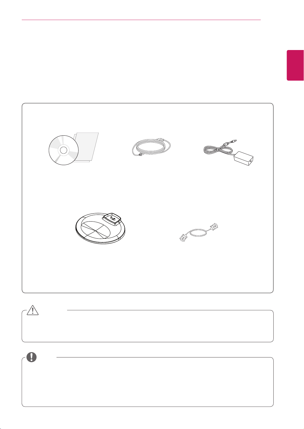
Unpacking
Pleasecheckwhetherallthecomponentsareincludedintheboxbeforeusingtheproduct.Ifthereare
missingcomponents,contacttheretailstorewhereyoupurchasedtheproduct.Notethattheproductand
componentsmaylookdifferentfromthoseshownhere.
OnlyuseanapprovedLGpoweradapter.
Damagecausedbyotherpoweradaptersisnotcoveredbywarranty.
Notethatthecomponentsmaylookdifferentfromthoseshownhere.
Withoutpriornotice,allinformationandspecificationsinthismanualaresubjecttochangetoimprove
theperformanceoftheproduct.
Topurchaseoptionalaccessories,visitanelectronicsstoreoronlineshoppingsiteorcontacttheretail
storewhereyoupurchasedtheproduct.
Power CordUser Manual/Card
Stand Base
Adaptor
CAUTION
NOTE
15-pin D-SUB Signal Cable

5
ENG
English
ASSEMBLING AND PREPARING
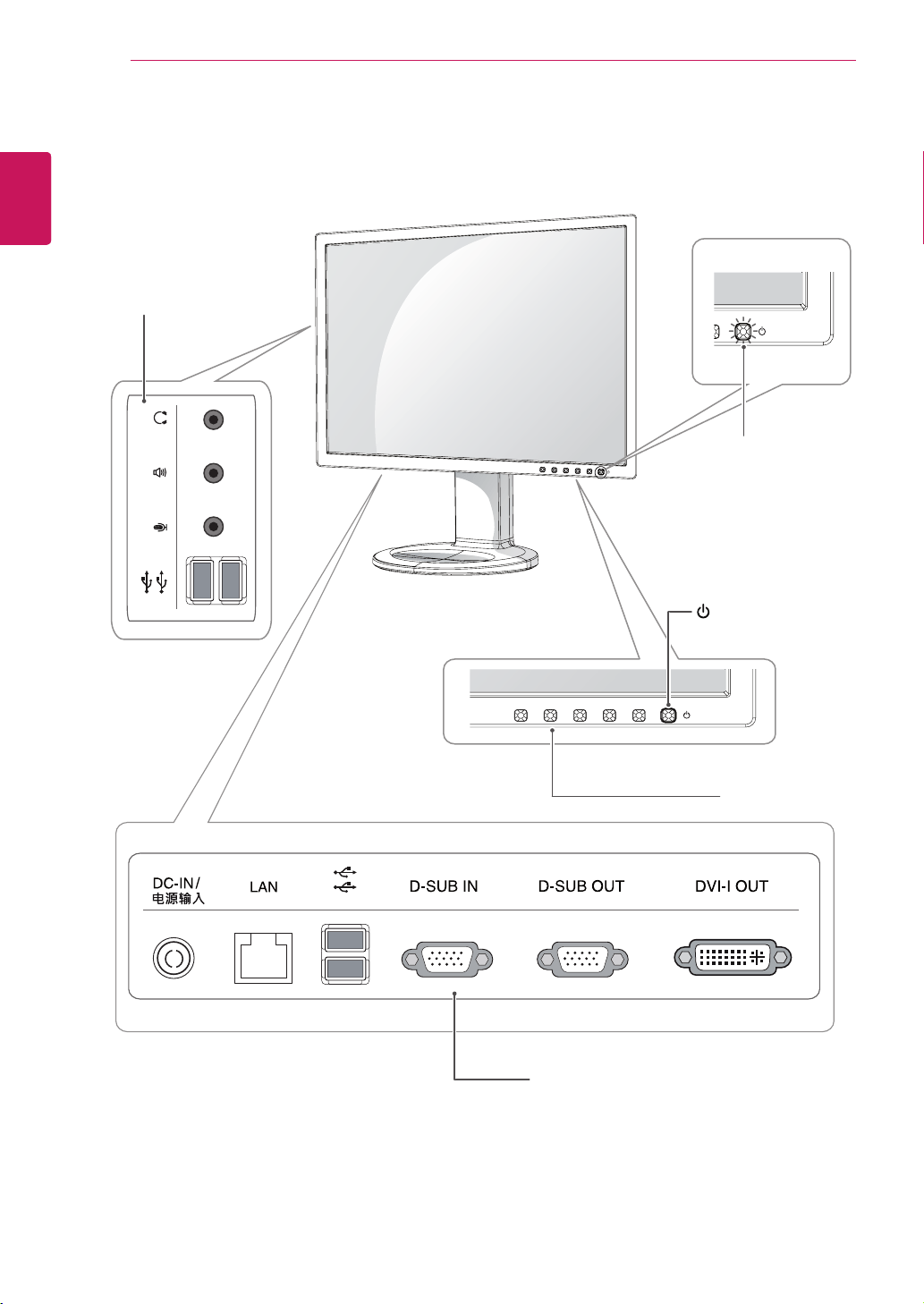
Button Description
MENU Activatesthemainmenu.
OSD Lock/Unlock
Functions
Locks/unlockstheOSDscreen.
TolocktheOSDscreen,pressandholdtheMENUbutton
forseveralseconds.The"OSDLOCKED"messagewillbe
displayedandthescreenwillbelocked.
TounlocktheOSDscreen,pressandholdtheMENU
buttonagainforseveralseconds.The"OSDUNLOCKED"
messagewillbedisplayedandthescreenwillbeunlocked.
VOLUME(OnlyPCoIPmode)
AdjustthevolumeoftheMonitorset.(Seep.19)
AUTO Toadjustthemonitorsettings,presstheAUTObuttonontheMONITORSETUPOSD
menu(onlysupportedforanalogsignal).
Foroptimalscreendisplay,usethefollowingresolution.
Optimal Resolution 1680x1050
INPUT Allowsselectionoftheinputsignal.
IfyouconnectthemonitortoacomputerusingaD-SUBcable,selecteitherthePCoIP
orD-SUBinputsignal.
Ifonlyonecomputerisconnectedtothemonitor,theinputsignalisdetectedautomati-
cally.TheinitialinputsignalisPCoIP.
EXIT ExitstheOSDmenu.
(PowerButton)
D-SUBInput:PowerOn/Off
PCoIPInput
MonitorOff:Pressthepowerbuttonandwaitfor5seconds.
PCoIPOff:Pressthepowerbuttontwice.
PCoIPOn:Pressthepowerbutton.
RemotePCPowerControl:Pressthepowerbuttonforatleastfivesecondstoturn
thePCon/off.
*TousetheRemotePCPowerControlfunction,separatesettingsarerequiredforthePC.
Power Indicator Whenthemonitorisinoperatingmode,thepowerindicator
willturnwhite(onmode).
Whenthemonitorisinpowersavingmode,thepowerindica-
torwillblinkwhite.
6
ENG
English
ASSEMBLING AND PREPARING
Thecomponentsappearingintheillustra-
tionsmaylookdifferentfromtheactualprod-
uct.
Donotcarrythemonitorupside-downasthis
maycauseittofalloffitsstand,resultingin
damageorinjury.
Toavoiddamagingthescreenwhenlifting
ormovingthemonitor,onlyholdthestandor
theplasticcover.Thisavoidsputtingunnec-
essarypressureonthescreen.
Onlyremovethetapeandthelockingpin
whenthemonitorismountedonthestand
baseandisinanuprightposition.Otherwise,
thestandbodymayprotrude,whichmay
leadtoinjury.
Detaching the stand base
1
Placethemonitor'sscreenfacedown.
Toprotectthescreenfromscratches,coverthe
surfacewithasoftcloth.
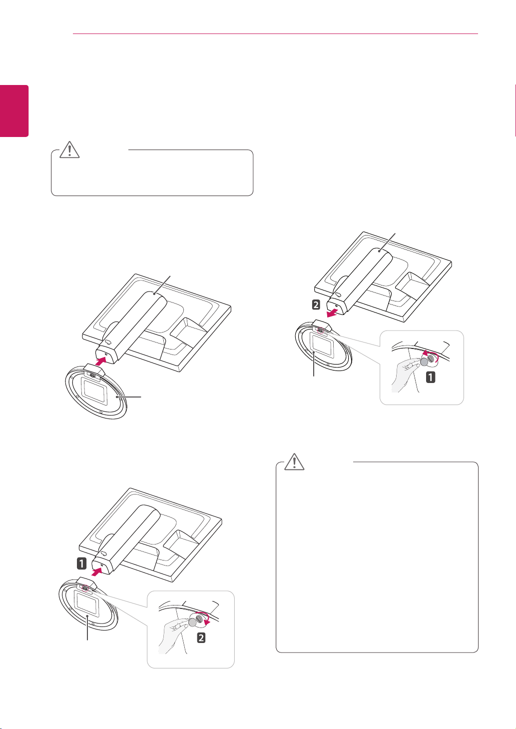
Setting Up the Monitor set
Attaching the Stand Base
1
Placethemonitor'sscreenfacedown.
Toprotectthescreenfromscratches,cover
thesurfacewithasoftcloth.
3
Usingacoin,turnthescrewclockwisetose-
cure the stand base.
2
Checktheposition (at the front and rear) of
thestandbody, then mountthestand baseon
thestand body asshowninthefigure.
Stand Body
Stand Base
Stand Base
2
Usingacoin,turnthescrewinthestandbase
counterclockwise.Detachthestand base from
thestand body.
Stand Body
Stand Base
CAUTION
CAUTION
7
ENG
English
ASSEMBLING AND PREPARING
Oncethepinisremoved,itisnotnecessary
tore-insertittoadjusttheheight.
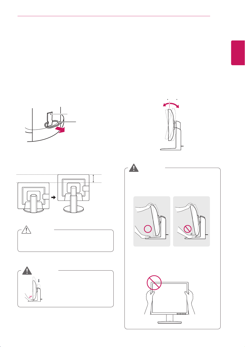
Adjusting the stand height
1
Placethemonitormountedonthestandbase
inanuprightposition.
Adjusting the angle
1
Placethemonitormountedonthestandbase
inanuprightposition.
2
Removethetapeattachedatthebottomrear
ofthe stand body, thenpulloutthelocking
pin.
3
Theheightcanbeadjustedupto110 mm.
2
Adjusttheangleofthescreen.Theangleofthe
screencanbeadjustedupto15°forwardsand
5°backwardsforacomfortableviewingexperi-
ence.
Toavoidinjurytothefingerswhenadjusting
thescreen,donotholdthelowerpartofthe
monitor'sframeasillustratedbelow.
Donotputyourfingerbe-
tweenthescreenandthe
base(chassis)whenadjust-
ingthescreen'sheight.
Becarefulnottotouchorpressthescreen
areawhenadjustingtheangleofthemonitor.
15- 5
Front Side Rear Side
15- 5
Tape
Locking Pin
Stand Body
110.0 mm
CAUTION
WARNING
WARNING
8
ENG
English
ASSEMBLING AND PREPARING
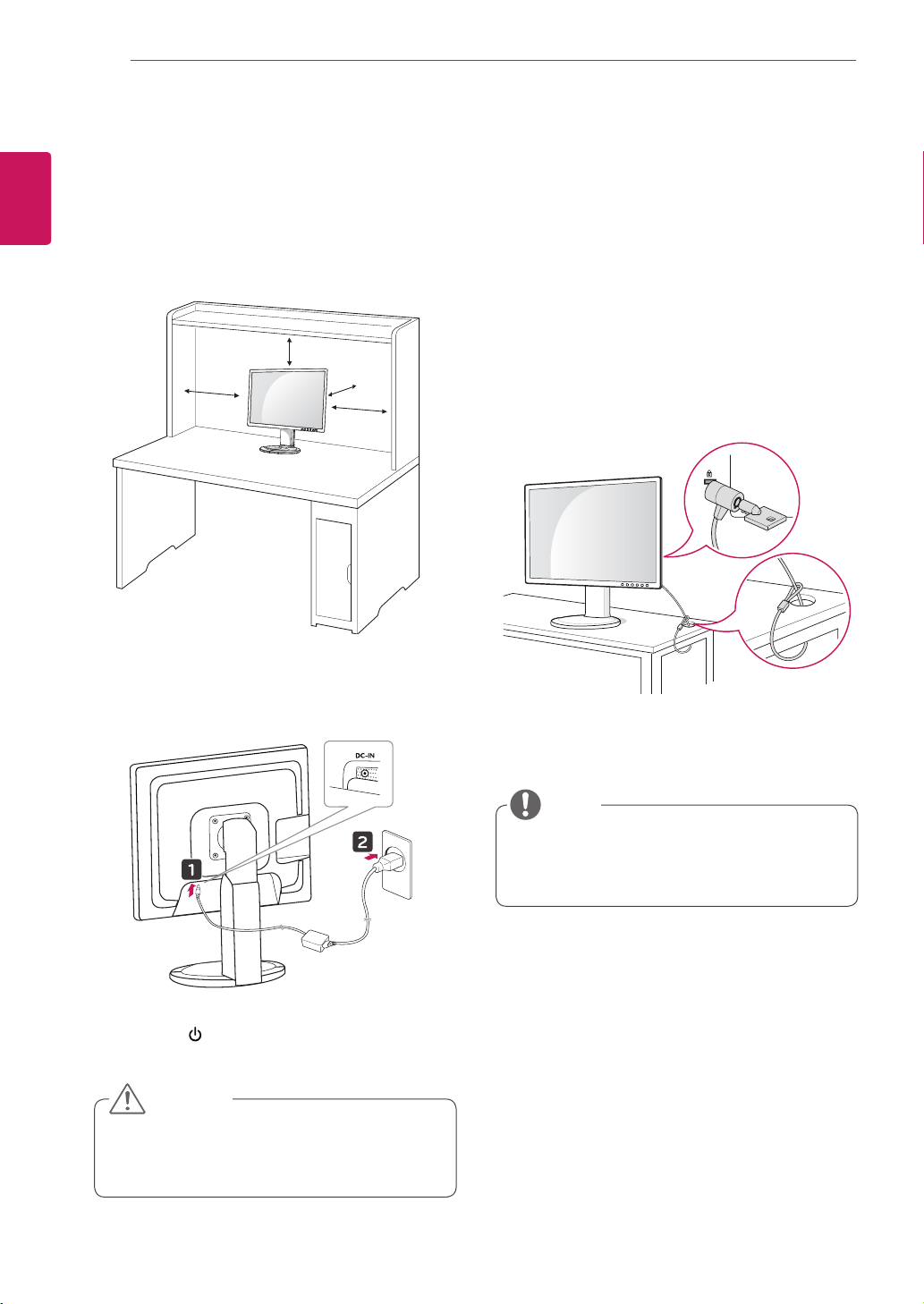
Mounting on a table
1
Liftthemonitorandplaceitonthetableinan
uprightposition.
Installatleast10 cm awayfromthewallto
ensuresufficientventilation.
2
Connecttheadaptortothemonitor,thenplug
thepowercordintothewalloutlet.
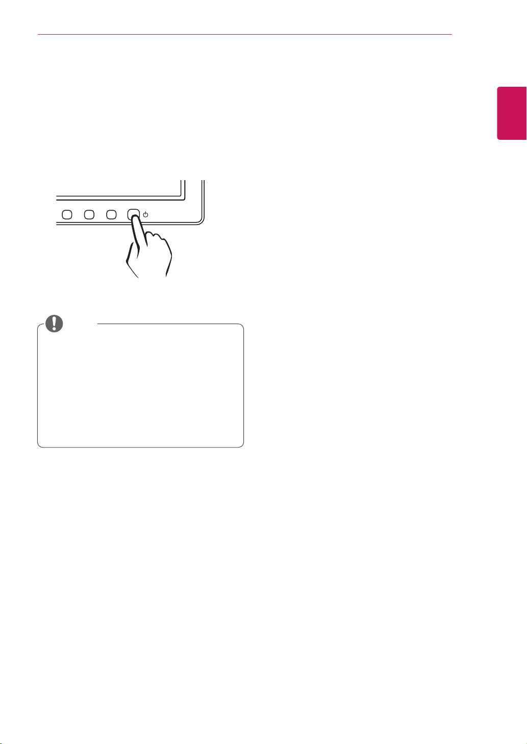
3
Pressthe (Power)buttononthefrontofthe
monitortoturnonthemonitor.
10 cm
10 cm
10 cm
10 cm
Unplugthepowercordpriortomovingor
installingthemonitor.Thereisriskofelectric
shock.
Using the Kensington locking
device
TheconnectorfortheKensingtonlockislocated
ontherearofthemonitor.
Formoreinformationoninstallationandusage,
refertotheKensingtonlockusermanualorvisit
thewebsiteathttp://www.kensington.com.
ConnectthemonitortothetablewiththeKensing-
tonlockcable.
UsingtheKensingtonlockisoptional.The
accessoriescanbepurchasedatyourlocal
electronicsstore.
CAUTION
NOTE
9
ENG
English
ASSEMBLING AND PREPARING
Installing the wall mount plate
ThismonitorhasaVESAcompatiblemountonthe
back.MostmountswillrequireanLGmounting
plate.
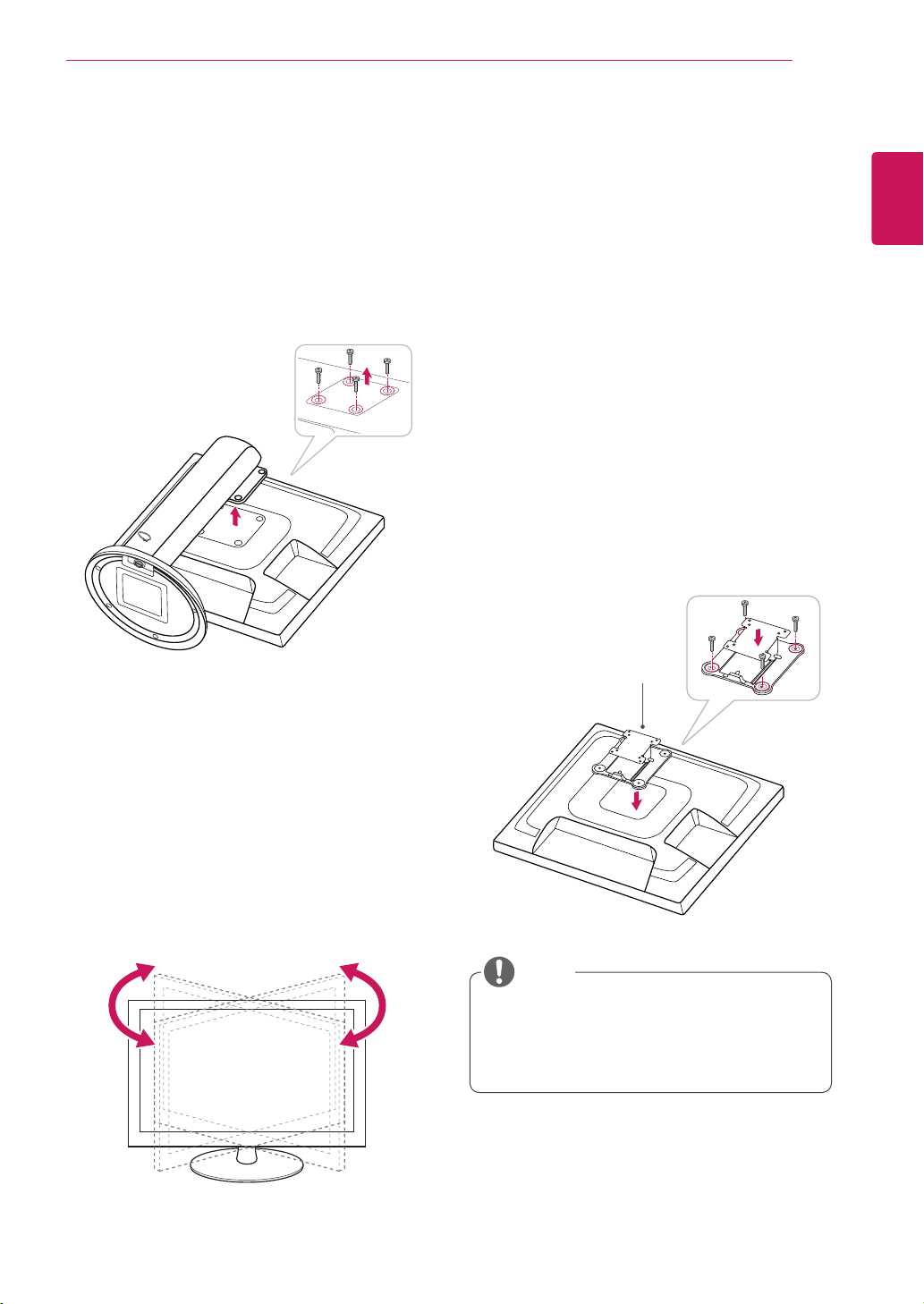
Detaching the stand body
1
Placethemonitor'sscreenfacedown.To
protectthescreenfromscratches,coverthe
surfacewithasoftcloth.
2
Usingascrewdriver,removethefourscrews
anddetachthestandfromthemonitor.
Swivel stand
ImageshownmaydifferfromyourMonitor
set.
1
Swivel356degreesandadjusttheangleofthe
Monitorsettosuityourview.
1
Placethemonitor'sscreenfacedown.To
protectthescreenfromscratches,coverthe
surfacewithasoftcloth.
2
Placethewallmountplateonthemonitorand
alignitwiththescrewholesonthemonitor.
3
Usingascrewdriver,tightenthefourscrewsto
fixtheplateontothemonitor.
Thewallmountplateissoldseparately.
Formoreinformationontheinstallation,refer
tothewallmountplate'sinstallationguide.
Wall Mount Plate
NOTE
10
ENG
English
ASSEMBLING AND PREPARING
10 cm
10 cm
10 cm
10 cm
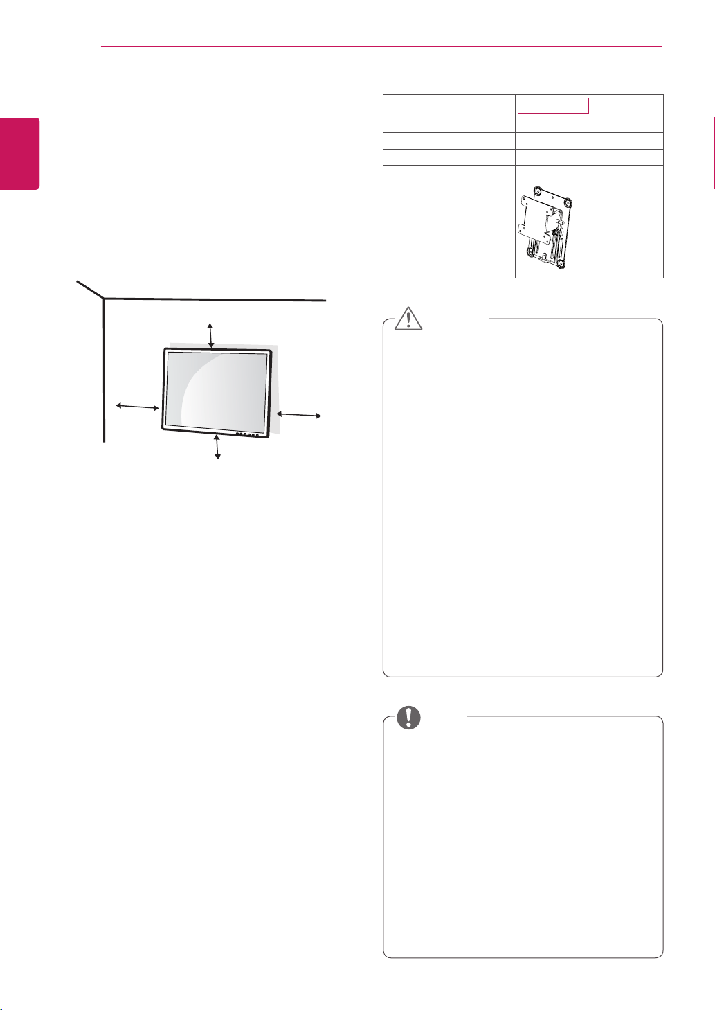
IfyouintendtomounttheMonitorsettoawall,
attachWallmountinginterface(optionalparts)to
thebackoftheset.
WhenyouinstalltheMonitorsetusingawall
mountinginterface(optionalparts),attachit
carefullysoitwillnotdrop.
1
Please,Usethescrewandwallmountinterface
inaccordancewithVESAStandards.
2
Ifyouusescrewlongerthanstandard,the
monitormightbedamagedinternally.
3
Ifyouuseimproperscrew,theproductmightbe
damagedanddropfrommountedposition.In
thiscase,LGElectronicsisnotresponsiblefor
it.
4
VESAcompatible.
5
PleaseuseVESAstandardasbelow.
784.8mm(30.9inch)andunder
*WallMountPadThickness:2.6mm
*Screw:Φ4.0mmxPitch0.7mmx
Length10mm
787.4mm(31.0inch)andabove
*PleaseuseVESAstandardwallmountpad
andscrews.
Unplugthepowercordbeforemovingorin-
stallingthemonitortoavoidelectricshocks.
Installingthemonitorontheceilingorona
slantedwallmayresultinthemonitorfalling
off,whichcouldleadtoinjury.Pleaseuse
aLGwallmountingbracketwhenusinga
VESAmount.Formoreinformation,contact
yourlocalretailstoreoraqualifiedinstaller.
Applyingexcessiveforcewhenfastening
screwsmaycausedamagetothemoni-
tor.Damagecausedinthiswaywillnotbe
coveredbytheproductwarranty.
Usethewallmountingbracketandscrews
thatconformtotheVESAstandard.Dam-
agecausedbytheuseormisuseofinap-
propriatecomponentswillnotbecovered
bytheproductwarranty.
UsethescrewsspecifiedintheVESAstan-
dard.
Thewallmountkitincludestheinstallation
guideandnecessaryparts.
Thewallmountingbracketisoptional.The
accessoriescanbepurchasedatyourlocal
retailstore.
Thelengthofthescrewmaydifferforeach
wallmountingbracket.Ensurethecorrect
lengthofthescrewisused.
Formoreinformation,pleaserefertotheuser
manualforthewallmountingbracket.
Model
N2210WZ
VESA (A x B)
75x75
Stand Screw
M4
Required Screw
4
Wall Mount Plate
(Optional)
RW120
Mounting on a wall
Installthemonitoratleast10cmawayfromthe
wallandleaveabout10cmofspaceateachside
ofthemonitortoensuresufficientventilation.De-
tailedinstallationinstructionscanbeobtainedfrom
yourlocalretailstore.Pleaserefertothemanual
toinstallandsetupatiltingwallmountingbracket.
CAUTION
NOTE
11
ENG
English
USING THE MONITOR SET
USING THE MONITOR SET
Connecting Input Signal Cable
Thismonitorsupportsthe*PlugandPlay
feature.
*PlugandPlay:Afeaturethatallowsyouto
addadevicetoyourcomputer,withouthaving
toreconfigureanythingorinstallanymanual
drivers.
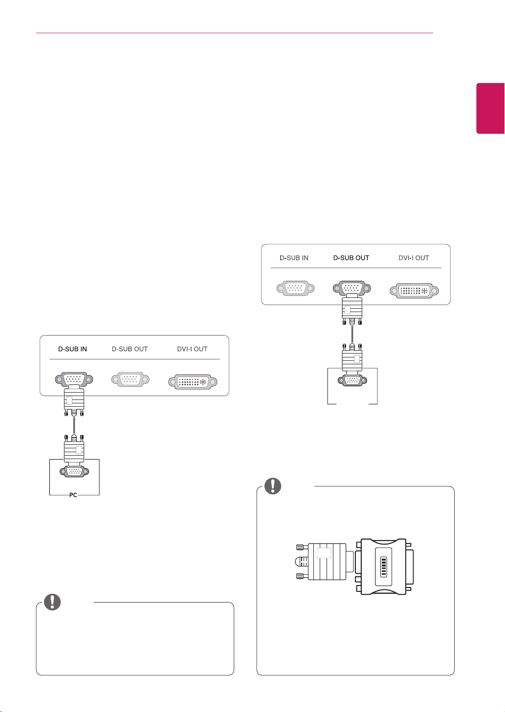
D-SUB IN connection - PC
D-SUBINtransfersanalogvideosignalsfromthe
PCtothemonitor.
ConnectthemonitortothePCusingtheprovided
15-pinD-SUBsignalcableasillustratedbelow.
MacintoshAdaptor:UsethestandardMa-
cintoshadaptor.Othercommercialadaptors
maynotbecompatible(duetothesignaling
difference).
WhenusingaMacintoshD-SUBinputcable
Whenusingthisdevicesimplyasaregu-
larmonitorthroughtheRGBINport,set
"PCoIP"toOFFinMENU>OTHERSto
reduceenergyconsumption.
NOTE
NOTE
RGB OUT
RGB IN
MONITOR
RGB OUT
RGB IN
MONITOR
D-SUB OUT connection - PCoIP
D-SUBOUTcanonlymirrortheimagedisplayed
onthemonitor.(itdoesnotsupportanextended
desktop).
ConnectthemonitortothePCusingtheprovided
15-pinD-SUBsignalcableasillustratedbelow.
12
ENG
English
USING THE MONITOR SET
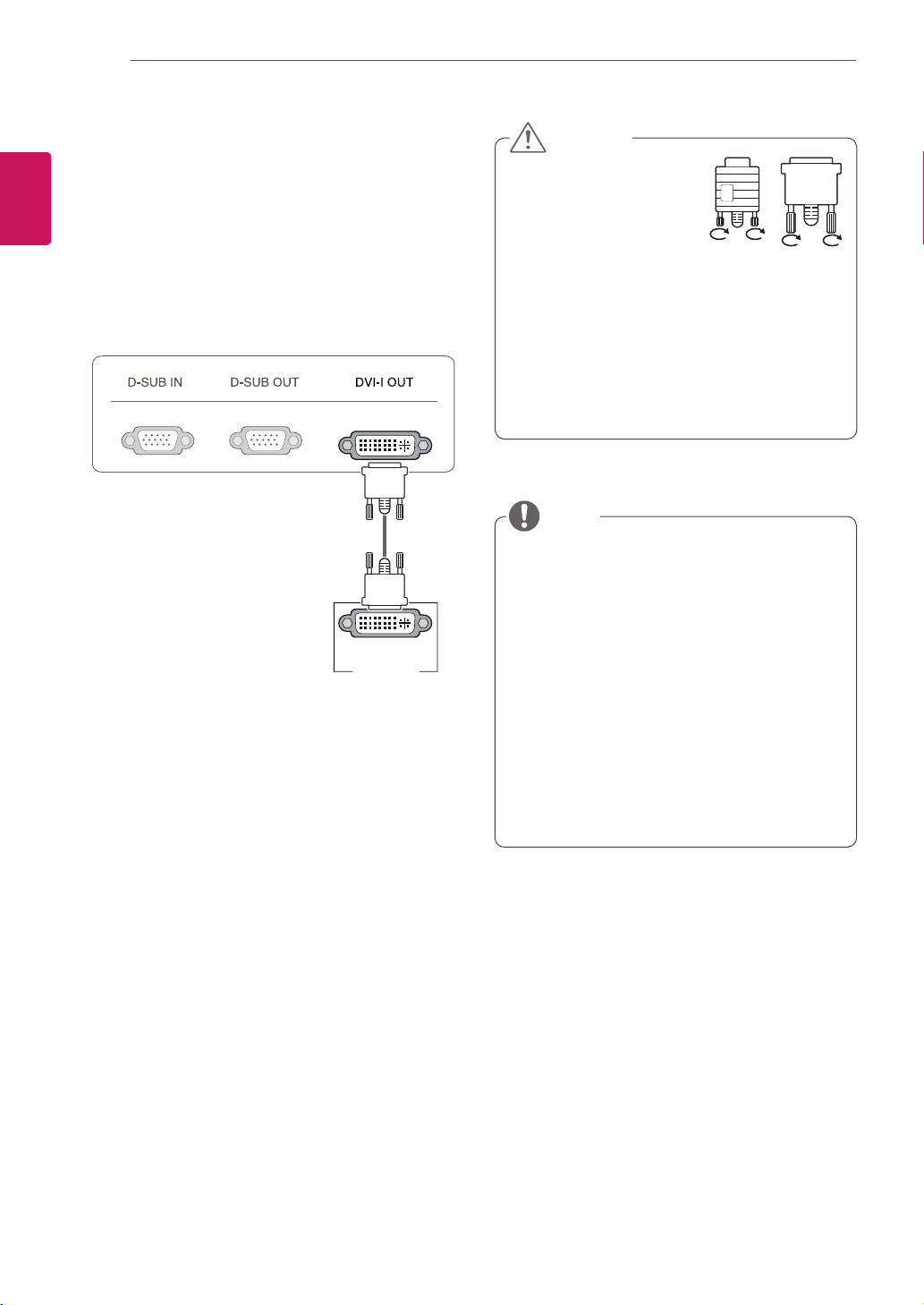
DVI connection - PCoIP
Transfersdigitalvideosignalstoanothermonitor.
ConnectthemonitorusingtheDVIcableasillus-
tratedbelow.
Thisconnectionisusedtosupportanextended
monitororreplicatetheimagedisplayedonthe
monitor.
Toconnectthemonitortoacomputer,use
theappropriatesignalcable(LANandD-
SUB).
AconvertercanbeusedtoconverttheDVI-I
inputsignaltoD-SUBinputsignal.
Whenconnectingthepowercordtotheout-
let,useagrounded(3-hole)multi-socketora
groundedwalloutlet.
Themonitormayflickerwhenturnedoninan
areaoflowtemperature.Thisisnormal.
Sometimesred,greenorbluespotsmayap-
pearonthescreen.Thisisnormal.
Connecttheinputsignal
cableandtighteninthe
directionofthearrow.To
preventdisconnection
securethecabletightly.
Donotpressonthescreenforaprolonged
time.Thismaycauseimagedistortion.
Donotdisplayastillimageonthescreen
foraprolongedtime.Thismaycauseimage
retention.Ifpossible,usethescreensaver.
DVI-I(D) IN
MONITOR
CAUTION
NOTE
13
ENG
English
USING THE MONITOR SET
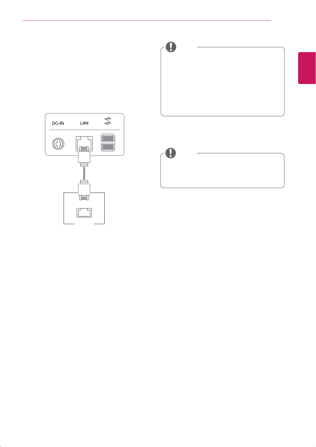
Connecting LAN/Peripherals
LAN connection - PCoIP
TheLANconnectiontransmitsPCoIPsignalsto
themonitor.Connecttherouterorswitchtothe
monitorusingaLANcableasillustratedbelow.
TheLANcableissoldseparately.
ThefollowingLANcabletypecanbeused:
Standard:IEEE802.3ETHERNET
WhenconnectingtheEarphoneOutorLine
OutthroughtheLAN,usethevolumeiconon
thetaskbarofyourPCtoadjustthevolume.
ConnecttheLANcableandtheperipheral
devicespriortobootingupthePC.
LAN
Hub/Router
NOTE
NOTE
14
ENG
English
USING THE MONITOR SET
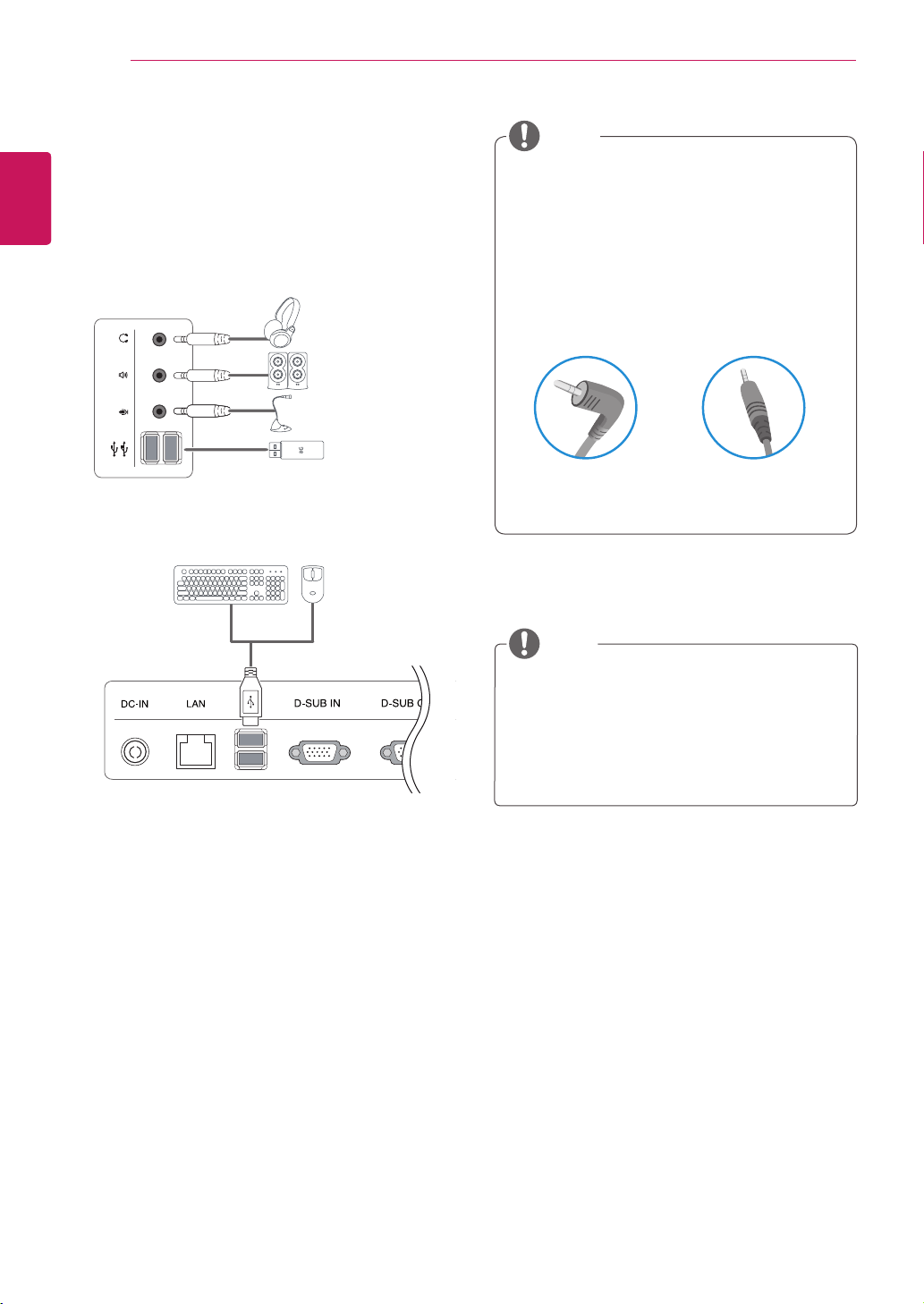
Peripheraldevicesaresoldseparately.
TheUSBportsontheleftandbottomofthe
monitorcanbeusedtoconnectthekey-
board,mouse,andotherUSBdevices.
Cableswithangledplugsmayhaveclear-
anceissues,usestraightplugswhenpos-
sible.
AngleType StraightType
Peripheral device connection
Connectperipheraldevicestothemonitorusing
USB,headphone,speaker,andmicrophoneports.
Left
Bottom
NOTE
NOTE
Headphones,speakersormicrophonemay
notworknormally,dependingontheserver
PCsettings.
Virtualsolutionsmayaffectthefunctionsor
speedofthespecificUSBstoragedevice.
15
ENG
English
USING THE MONITOR SET
Whatis"SelfImageAdjustment"?Thisfunc-
tionrunswhenthemonitorisconnectedfor
thefirsttimeandperformsautomaticimage
adjustmentforeachsignal(onlyavailablefor
analog[D-SUBinput]signals)toprovidean
optimalscreendisplay.
Self Image Adjustment
Pressthepowerbuttononthefronttoturnon
themonitor.Whenpoweredon,the"Self Image
Adjustment" functionwillrunautomatically(only
availableforanalog[D-SUBinput]signals).
NOTE
16
ENG
English
CUSTOMIZING SETTINGS
CUSTOMIZING SETTINGS
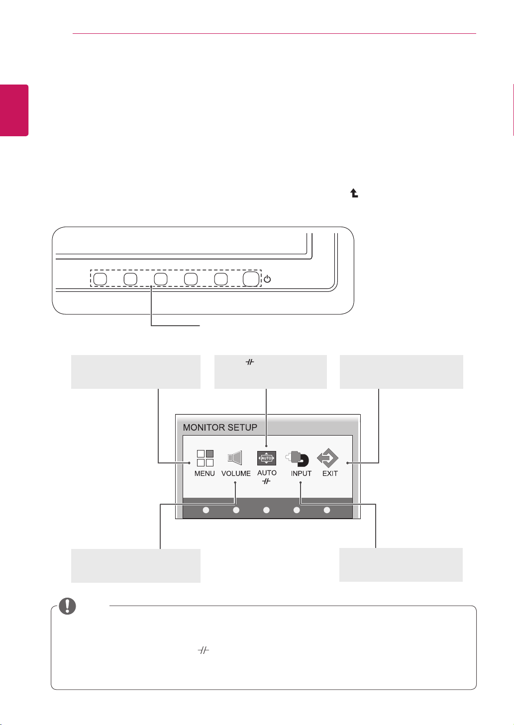
Accessing The Main Menus
1
PressanybuttononthefrontofthemonitortodisplaytheMONITORSETUPOSDmenu.
2
Presstoselectthedesiredmenuitem.
3
Tochangethesettingsoftheselecteditempressthebuttonsonthefrontofthemonitor.
Toreturntotheuppermenuorsetothermenuitems,usetheuparrow( )button.
4
SelectEXITtoleavetheOSDmenu.
MENU (See p.17)
Setsthescreenoptions.
EXIT(See p.5)
ExitstheOSDmenu.
AUTO
/
(Seep.21
)
Optimizestheresolution.
/Disconnectsfromtheserver.
Differentmenuitemsareenableddependingonthetypeofinputsignal.
D-SUB Input: MENU,AUTO,INPUT,EXIT
PCoIP Input: MENU,VOLUME, ,INPUT,EXIT
Thelanguageofthemonitor'sOSDmenuandthatoftheOSDmenuillustratedintheCD-ROM
manualmaybedifferent.
Front Side Buttons
VOLUME (See p.19)
Setsthevolume.
INPUT (See p.5)
Setstheexternalinput.
NOTE
17
ENG
English
CUSTOMIZING SETTINGS
MENU Settings
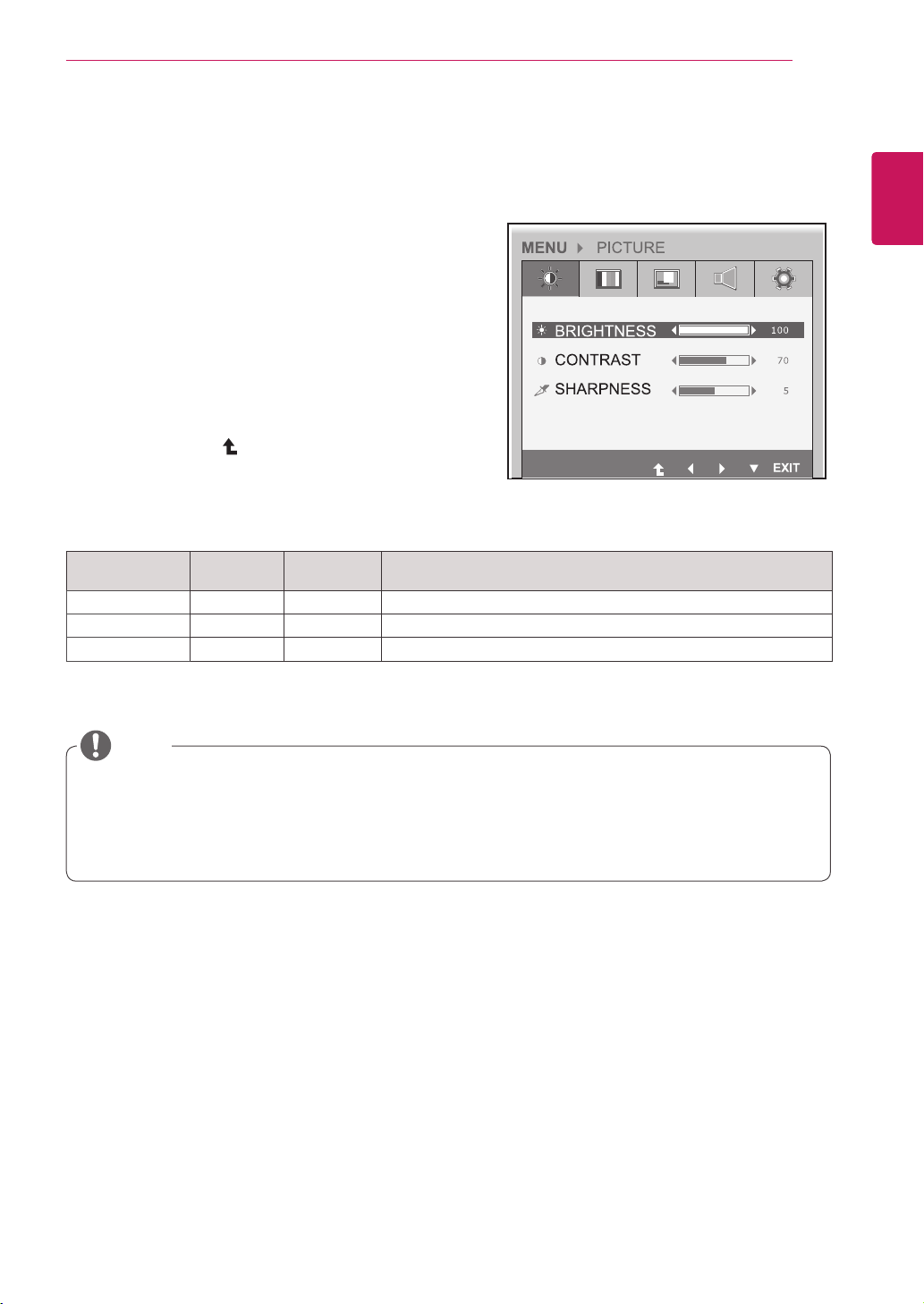
Picture
1
Pressanybuttononthefrontofthemonitortodis-
playtheMONITOR SETUP OSDmenu.
2
PresstheMENU buttontodisplaytheoptionsinthe
OSDmenu.
3
Settheoptionsbypressingthebuttonsonthefront
ofthemonitor.
4
SelectEXITtoleavetheOSDmenu.
Toreturntotheuppermenuorsetothermenuitems,
usetheuparrow( )button.
Eachoptionisexplainedbelow.
Menu Analog
(D-SUB)
PCoIP
Description
BRIGHTNESS
● ●
Setsthebrightnessofthescreen.
CONTRAST
● ●
Setsthecontrastofthescreen.
SHARPNESS
● ●
Setsthesharpnessofthescreen.
Ifthescreenisnotdisplayedproperlyafteradjustingthesettings,usethe"FACTORYRESET"
optiontorevertbacktothefactorydefaultsettings.Ifnecessary,enablethe"WHITEBALANCE"
optionagain.Thisoptionisenabledonlyforanalog(D-SUB)signals.
Analog: D-SUB (analog signal) input.
PCoIP
: Internal signal through the LAN.
NOTE
18
ENG
English
CUSTOMIZING SETTINGS
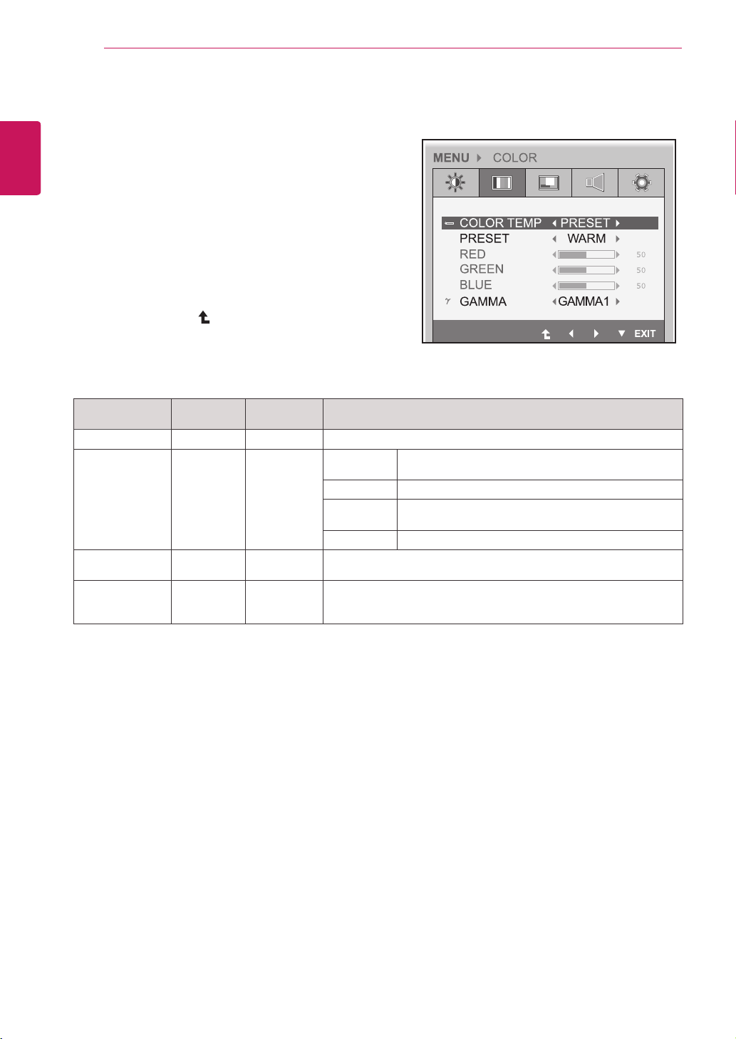
Menu Analog
(D-SUB)
PCoIP
Description
COLOR TEMP
● ●
AllowsPRESETorUSERtobeselected.
PRESET
● ●
sRGB SetsthescreencoloraccordingtothesRGBcolor
standard.
WARM Setsthescreencolortoareddishtone.
MEDIUM Setsthescreencolorbetweenthereddishandbluish
tone.
COOL Setsthescreencolortoabluishtone.
USER
● ●
YoucancustomizethepicturecolorusingRed,Green,andBlue
colors.
GAMMA
● ●
Setstheclarityofthescreen.
Thegammavaluecanbesetto0,1or2,fromdarkertobrighter
screencolorsrespectively.
Analog: D-SUB (analog signal) input. PCoIP: Internal signal through the LAN.
Color
1
Pressanybuttononthefrontofthemonitortodis-
playtheMONITOR SETUP OSDmenu.
2
PresstheMENU buttontodisplaytheoptionsinthe
OSDmenu.
3
Settheoptionsbypressingthebuttonsonthefront
ofthemonitor.
4
SelectEXIT toleavetheOSDmenu.
Toreturntotheuppermenuorsetothermenuitems,
usetheuparrow( )button.
Eachoptionisexplainedbelow.
19
ENG
English
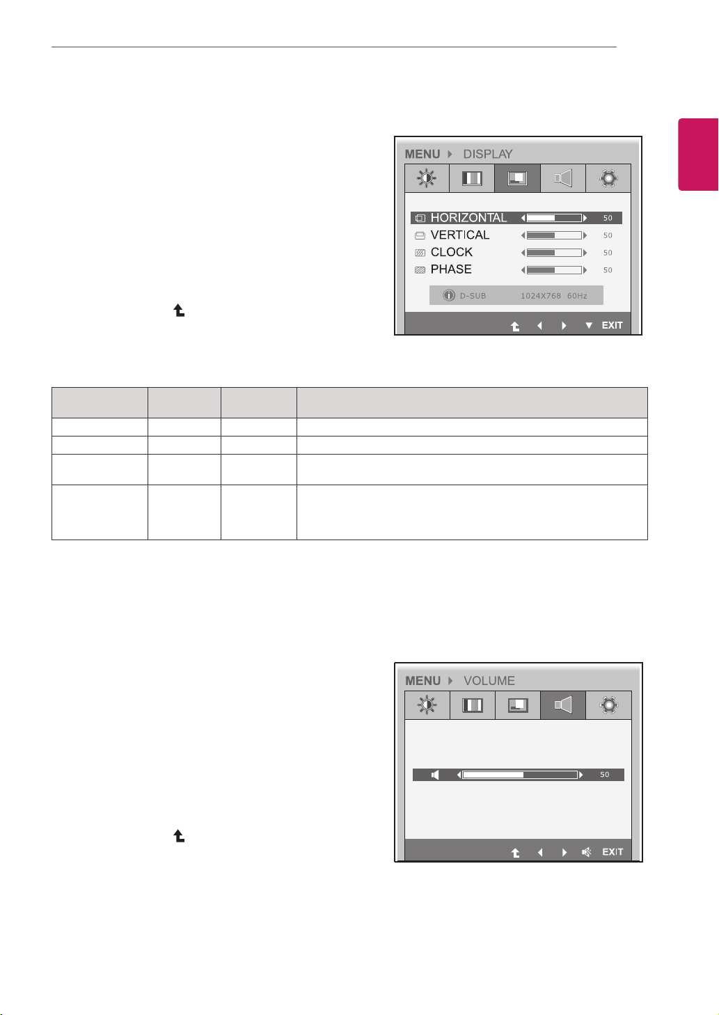
CUSTOMIZING SETTINGS
Menu Analog
(D-SUB)
PCoIP
Description
HORIZONTAL
● x
Movesthedisplayarealeftorright.
VERTICAL
● x
Movesthedisplayareaupordown.
CLOCK
● x
Ifverticallinesareshownonthescreen,adjustthefrequencytomini-
mizethelinesandadjustthescreen'shorizontalwidth.
PHASE
● x
Adjuststhefocusofthescreen'simage.
Usewhenfrequenciesareshownonthescreenorwhenthetextap-
pearsoverlapped.Foroptimalresults,usethisoptionafteradjusting
the"CLOCK"option.
Analog: D-SUB (analog signal) input. PCoIP: Internal signal through the LAN.
Display
1
Pressanybuttononthefrontofthemonitortodis-
playtheMONITOR SETUP OSDmenu.
2
PresstheMENU buttontodisplaytheoptionsinthe
OSDmenu.
3
Settheoptionsbypressingthebuttonsonthefront
ofthemonitor.
4
SelectEXITtoleavetheOSDmenu.
Toreturntotheuppermenuorsetothermenuitems,
usetheuparrow( )button.
Eachoptionisexplainedbelow.
Volume (Only supported in PCoIP)
1
Pressanybuttononthefrontofthemonitortodis-
playtheMONITOR SETUP OSDmenu.
2
PresstheMENU buttontodisplaytheoptionsinthe
OSDmenu.
3
Settheoptionsbypressingthebuttonsonthefront
ofthemonitor.
4
SelectEXITtoleavetheOSDmenu.
Toreturntotheuppermenuorsetothermenuitems,
usetheuparrow( )button.
20
ENG
English
CUSTOMIZING SETTINGS
Menu Analog
(D-SUB)
PCoIP
Description
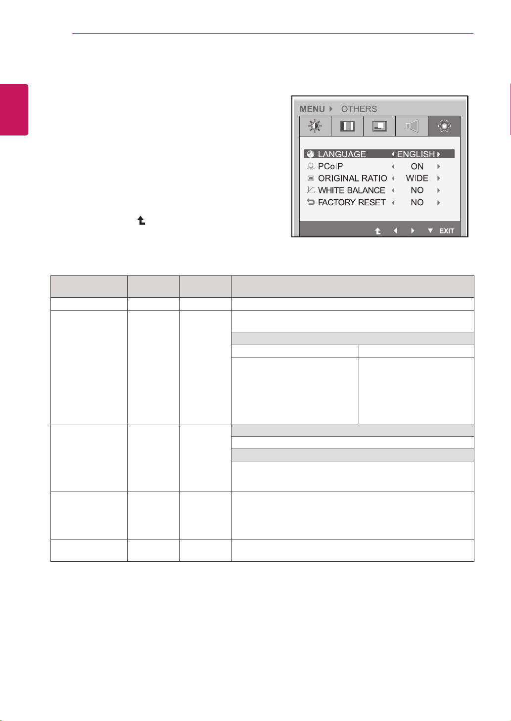
LANGUAGE
● ●
Setsthemenuscreentothedesiredlanguage.
PCoIP
● x
AllowsthePCoIPtobeturnedONorOFF.
IftheinputisPCoIP,the"PCoIP"optionisdisabled.
ThisoptionisenabledwhenanalogsignalsareinputviaD-SUB.
IfPCoIPisON IfPCoIPisOFF
-UsetheINPUTbuttontoswitch
betweenPCoIPandD-SUB.
-IftheD-SUBcableisremoved,
theinputwillautomaticallybe
switchedtoPCoIP.
-IftheD-SUBcableisre-
moved,"NoSignal"willbe
displayed.
-IfINPUTissettoD-SUB,
whenDCisswitchedfrom
ONtoOFF,PCoIPwillnotbe
enabled.
ORIGINAL RATIO
● ●
WIDE
Switchtofullscreenmodeaccordingtoinputimagesignal.
ORIGINAL
Changetheinputimagesignalratiotooriginal.
*ThisfunctionworksonlyifinputresolutionislowerthanMonitor
setratio(16:9).
WHITE BALANCE
● x
Ifthevideocardoutputisdifferentfromthespecifiedlevel,thecolor
mayappeartohavealteredduetothevideosignaldistortion.The
whitebalanceadjuststheoutputsignalleveltocorrespondtothatof
thestandardsignal,thusprovidingoptimaldisplay.Runthisoption
whenthescreendisplaysanimagewithbothwhiteandblack.
FACTORY RESET
● ●
Resetsthescreentothefactorydefaultsettings.Notethatthelan-
guageoptionwillnotbereset.
Analog: D-SUB (analog signal) input. PCoIP: Internal signal through the LAN.
Others
1
Pressanybuttononthefrontofthemonitortodis-
playtheMONITOR SETUPOSDmenu.
2
PresstheMENU buttontodisplaytheoptionsinthe
OSDmenu.
3
Settheoptionsbypressingthebuttonsonthefront
ofthemonitor.
4
SelectEXITtoleavetheOSDmenu.
Toreturntotheuppermenuorsetothermenuitems,
usetheuparrow( )button.
Eachoptionisexplainedbelow.

21
ENG
English
CUSTOMIZING SETTINGS
1
Pressanybuttononthefrontofthemonitortodis-
playtheMONITOR SETUP OSDmenu.
2
PresstheAUTO buttontoautomaticallyadjustthe
screen.
3
SelectEXIT toleavetheOSDmenu.
Toreturntotheuppermenuorsetothermenuitems,
usetheuparrow( )button.
-//-
Settings : PCoIP Input
1
PressanybuttononthefrontofthemonitortodisplaytheMONITOR SETUP OSDmenu.
2
Pressthebuttonforatleastthreesecondstodisconnectfromtheserver.
3
SelectEXIT toleavetheOSDmenu.
Toreturntotheuppermenuorsetothermenuitems,usetheuparrow( )button.
PressingtheAUTObuttonallowsthemonitortoautomaticallyoptimizethescreentothecurrentdisplay
mode.
Ifyouarenotsatisfiedwiththeoptimizedscreen,youcanmanuallyadjustthepositionofthedisplayarea,
frequency,phaseandsharpnessintheOSDmenu.
(OnlyavailableforD-SUB[analog]signals.Notethatthesharpnesssettingisonlyavailablefordigitalsig-
nals.)
InPCoIPmode,pressthebuttonforatleastthreesecondstodisconnectfromtheserver.
PROCESSING AUTO IMAGE ADJUSTMENT
FOR OPTIMAL DISPLAY
CHANGE RESOLUTION TO 1680 x 1050
Whatis"AutoImageAdjustment"?TheAutoImageAdjustmentoptionallowsyoutoimprovethe
picturequalityifthescreenisdimmed,ifthetextappearsblurredorspread,ifthescreenflickersor
ifthedisplayareaisnotcenteredafteradjustingtheresolution.(OnlyavailableforD-SUB[analog]
signals.)
NOTE
AUTO Settings : D-SUB Input

22
ENG
English
Troubleshooting
TROUBLESHOOTING
Nothing is displayed on the screen
Isthemonitor'spowercordpluggedin?
Checkifthepowercordiscorrectlypluggedintotheoutlet.
Isthepowerindicatoron?
Checkthepowerindicator.
Isthepowerindicatordisplayingas
white?
Adjustthebrightnessandthecontrast.
Isthepowerindicatorblinking?
Ifthemonitorisinpowersavingmode,movethemouseorpressany
keyonthekeyboardtoswitchthedisplayon.
Checkifthecomputeristurnedon.
Isthe"OUTOFRANGE"message
displayed?
ThisoccurswhensignalstransferredfromthePC(videocard)areout
ofthehorizontalorverticalfrequencyrangeofthemonitor.Pleasesee
the"ProductSpecification"sectionofthismanualtosettheappropri-
atefrequency.
Isthe"CHECKSIGNALCABLE"
messageisdisplayed?
ThisisdisplayedwhenthesignalcablebetweenthePCandthemoni-
torismissingordisconnected.Checkthecableandreconnect.
The "OSD LOCKED" message is displayed.
Isthe"OSDLOCKED"message
displayedwhentheMENUbuttonis
pressed?
TheOSDlockfeatureisenabledtopreventundesiredmodification
oftheOSDsettings.PressandholdtheMENUbuttonforacoupleof
secondstounlocktheOSD.(The"OSDUNLOCKED"messagewillbe
displayed.)
The screen retains an image.
Doesimagestickingoccureven
whenthemonitoristurnedoff?
Displayingastillimageforaprolongedtimemaycausedamagetothe
screen,resultingintheretentionoftheimage.
Useascreensavertoprotectthescreenwhenusingthemonitorfora
prolongedperiodoftime.
Vertical Frequency:Inordertodisplayanimage,thescreenmustberefresheddozensoftimesper
secondlikeafluorescentlamp.Thenumberoftimesthescreenisrefreshedpersecondiscalled
verticalfrequencyorrefreshrateandisrepresentedbyHz.
Horizontal Frequency: Thetimeittakestodisplayonehorizontallineiscalledthehorizontalcycle.
Thenumberofhorizontallinesdisplayedinonesecond
canbecalculatedbydividingonebythehorizontalcycle.Thisiscalledhorizontalfrequencyandis
representedbykHz.
NOTE

23
ENG
English
Troubleshooting
The image is displayed abnormally.
Doesthedisplayareaappearun-
centered?
PressingtheAUTObuttonwillautomaticallyoptimizethescreentothecurrent
displaymode.
Ifyouarenotsatisfiedwiththeoptimizedscreen,youcanmanuallyadjustthe
POSITIONoptionintheOSDmenu.
Doesthescreenexhibitvertical
lines?
PressingtheAUTObuttonwillautomaticallyoptimizethescreentothecurrent
displaymode.
Ifyouarenotsatisfiedwiththeoptimizedscreen,youcanmanuallyadjustthe
FREQUENCYoptionintheOSDmenu.
Doesthescreendisplayhorizontal
frequencies,ordoesthetextappear
blurred?
PressingtheAUTObuttonwillautomaticallyoptimizethescreentothecurrent
displaymode.
Ifyouarenotsatisfiedwiththeoptimizedscreen,youcanmanuallyadjustthe
PHASEoptionintheOSDmenu.
Checkifthevideocard'sresolutionorfrequencyiswithintherangeallowedbythemonitorandsetto
therecommended(optimal)resolutioninControl Panel >Display > Settings.
Failingtosetthevideocardtotherecommended(optimal)resolutionmayresultinblurredtext,a
dimmedscreen,atruncateddisplayareaormisalignmentofthedisplay.
Theconfigurationproceduremaydifferdependingonyourcomputerand/oroperatingsystem.Also,
somevideocardsmaynotsupportcertainresolutions.Ifthisisthecase,contactthecomputeror
videocardmanufacturerforassistance.
TheAUTOoptionisonlyavailableforD-SUB(analog)signals.
The display color is abnormal.
Doesthedisplaycolorappeardis-
colored(16color)?
Setthecolorto24bit(truecolor)orhigher.InWindows,gotoControl
Panel>Display>Settings>ColorQuality.
Doesthedisplaycolorappearun-
stableorinmonochrome?
Checkifthesignalcableisconnectedproperly.Re-connectthecable
orre-insertthePC'svideocard.
Aretherespotsonthescreen?
Whenusingthemonitor,pixilatedspots(red,green,blue,whiteor
black)mayappearonthescreen.ThisisnormalfortheLCDscreen.
Itisnotanerrornorisitrelatedtothemonitor'sperformance.
NOTE
24
ENG
English
Specications
PRODUCT SPECIFICATION
LCDScreen Type 558mm(22inch)TFT(ThinFilmTransistor)
LCD(LiquidCrystalDisplay)Screen
Diagonallengthofthescreen:558mm
PixelPitch 0.282mmx0.282mm
Resolution MaximumResolution 1680x1050@60Hz
RecommendedResolution 1680x1050@60Hz
VideoSignal HorizontalFrequency 30kHzto66kHz
VerticalFrequency 57Hzto63Hz
Synchronization SeparateSync/PCoIP
InputConnector 15-pinD-SUB(Analog),10/100/1000MbpsRJ45(PCoIP)
Power 19V 3.2A
PowerConsumption OnMode:42W(Typical)
PowerSavingMode≤16W
OffMode≤1W
AC/DCAdapter TypePA-1650-68,manufacturedbyLITE-ONTECHNOLOGYCORPORATION.
OUTPUT:19V 3.42A
Dimension/
Weight
MonitorSize(WidthxHeightxDepth)
WithStand 506.4mmx368.9mmx224.4mm
WithoutStand 506.4mmx333.2mmx59.1mm
Weight(Without
Packaging)
4.2kg
StandAngle
Adjustment
Forwards/Backwards:-5°to15°(Monitor)
Environment
Condition
OperatingCondition Temperature:10°Cto35°C;Humidity:10%to80%
StoringCondition Temperature:-20°Cto60°C;Humidity:5%to90%
Thespecificationsaresubjecttochangewithoutnotice.

25
ENG
English
Product Specication
Preset Mode
Display Modes
(Resolution)
Horizontal
Frequency (kHz)
Vertical
Frequency (Hz)
Polarity (H/V) Remark
720x400 31.468 70 -/+
640x480 31.469 60 -/-
800x600 37.879 60 +/+
1024x768 48.363 60 -/-
1280x1024 63.981 60 +/+
1680x1050 65.290 60 -/+ RecommendedMode
Power Indicator
Mode LED Color
OnMode White
PowerSaving FlashingWhite
OffMode Off

26
ENG
English
Proper Posture
PROPER POSTURE
Proper posture for using the monitor
Adjusttheanglesothatthescreenisslightlylowerthanyoureyes.
Usingthemonitorforaprolongedperiodoftimecancauseeyefatigue.Takea10-minutebreakevery
hour.
Thestandisdesignedtobestsupportthemonitorwhentheoptimalconditionsareselected.
Adjusttheangleofthemonitorfrom-5°to15°toobtainthebestviewofthescreen.
Youshouldbe
looking
slightlydownat
thescreen.
Placeyourhandsgently
onthekeyboard,
keepingyourarmsbentat
theelbows
andextendedhorizontally
infrontofyou.
Adjusttheangle
from-5°to15°
sothatthereisnore-
flection
orglarefromthe
screen.
27
ENG
English
Using PCoIP Solution
USING PCOIP SOLUTION
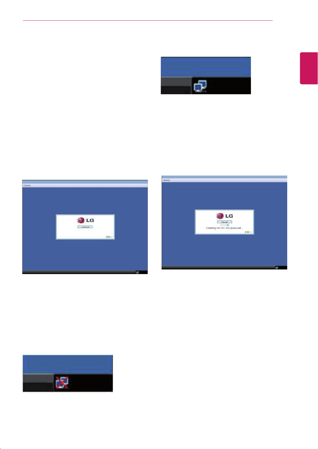
SelectingtheConnectbuttoninitiatesaPCoIPor
RDPsessiondependingonthesessionsettings.
WhilethePCoIPconnectionispending,theOSD
localGUIwilldisplaya"ConnectionPending"
message.Whentheconnectionisestablished,the
OSDlocalGUIwilldisappearandbereplacedby
thesessionimage.
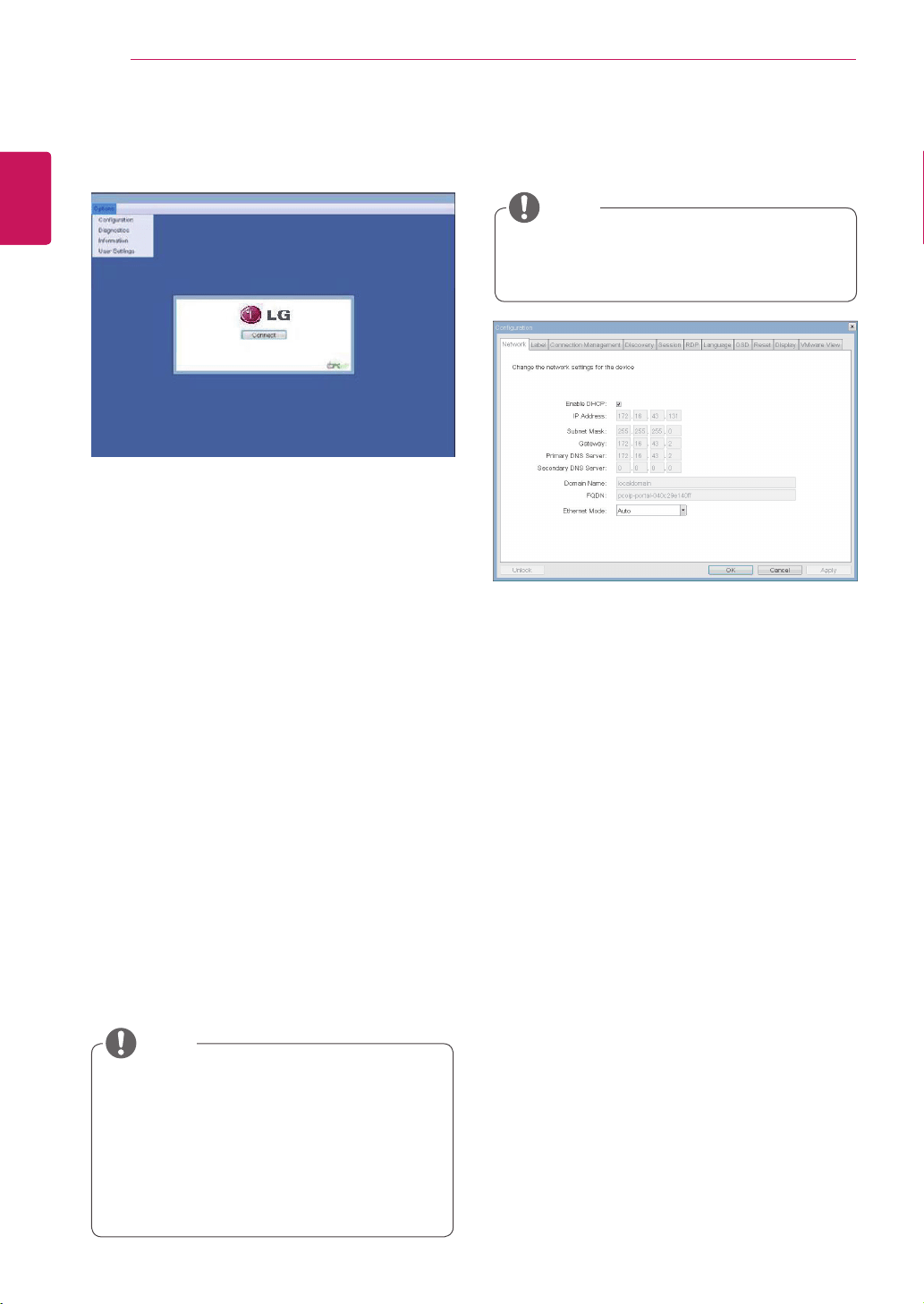
OSD Options Menu
SelectingtheOptionsmenuwillproducealistof
selections.TheOSDOptionsmenucontains:
Configuration
Diagnostics
Information
User Settings
Ared"X"overthenetworkiconindicatesthat
eitherthenetworkisnotproperlyconnectedorthat
theconnectionisstillbeinginitialized(i.e.during
portalbootup).Figure2-2showsthered"X"over
thenetworkiconindicatingthatthenetworkisnot
ready.
Figure2-3showsthenetworkiconwhenready.
Figure2-1.OSDConnectScreen
Figure2-4.OSDConnectScreen(Connecting)
Figure2-2.NetworkNotReady(Detail)
Figure2-3.NetworkReady(Detail)
Connect Screen
TheConnectscreenisshownduringstart-up,
exceptwhentheportalhasbeenconfiguredfora
managedstart-uporauto-reconnect.Thelogodis-
playedabovetheConnectbuttoncanbechanged
byuploadingareplacementimageviatheadmin
interface.Thenetworkicononthebottomrightof
theConnectscreenshowsthestatusofthenet-
workconnection.Youmustwaituntilthenetwork
iconisdisplayedasshowninFigure2-3.
Selectingoneoftheoptionswillproduceasettings
window.
28
ENG
English
Using PCoIP Solution
Figure2-5.OSDOptionsMenu
Configuration Window
IntheConfigurationwindow,theadministratorcan
accessthewindowtabsthatcontainthesettingsto
configureandmanagetheportalenvironment.
TheConfigurationwindowhasthefollowingtabs:
Network
Label
Connection Management
Discovery
Session
RDP
Language
OSD
Reset
Display
VMware View
Figure2-6.NetworkConfiguration
EachtabcontainsOK,CancelandApplybuttons
toallowtheadministratortoapplyorcancelthe
modifiedsettings.
Enable DHCP
IftheEnableDHCPoptionisselected,adevicewill
beconnectedtotheDHCPserver.thatallocates
theIPaddress,subnetmask,gatewayIPaddress,
andDNSserver.Ifthisoptionisdisabled,the
aboveparametersmustbeconfiguredmanually.
IP Address
TheIPAddressfieldcontainstheIPaddressofthe
device.IfDHCPisdisabled,thisfieldisrequired.
IfDHCPisenabled,thisfieldcannotbeedited.
ThisfieldmustcontainthecorrectIPaddress.Ifan
incorrectIPaddressisprovided,anOSDmessage
isdisplayedpromptingtheadministratortoprovide
thecorrecttheIPaddress.
Subnet Mask
TheSubnetMaskfieldcontainsthesubnetmask
ofthedevice.IfDHCPisdisabled,thisfieldis
required.IfDHCPisenabled,thisfieldcannotbe
edited.Thisfieldmusthavethecorrectsubnet
mask.Ifanincorrectsubnetmaskisprovided,an
OSDmessageisdisplayedpromptingtheadminis-
tratortoprovidethecorrectthesubnetmask.
Network Tab
TheNetworktaballowstheadministratortoconfig-
uretheportalnetworkparameters.
SomePCoIPdeviceshavetheirpassword
protectiondisabledandcanbeloggedinto
themanagementwebpageoraccessthe
OSDparameterswithoutapassword.The
loginpageandtheOSD'spasswordprotec-
tioncanbeenabledinthePCoIPmanage-
mentconsole.
Thenetworkparameterscanalsobecon-
figuredusingtheWebpageAdministration
Interface.
NOTE
Selectingoneoftheoptionswillproduceasettings
window.
NOTE
29
ENG
English
Using PCoIP Solution
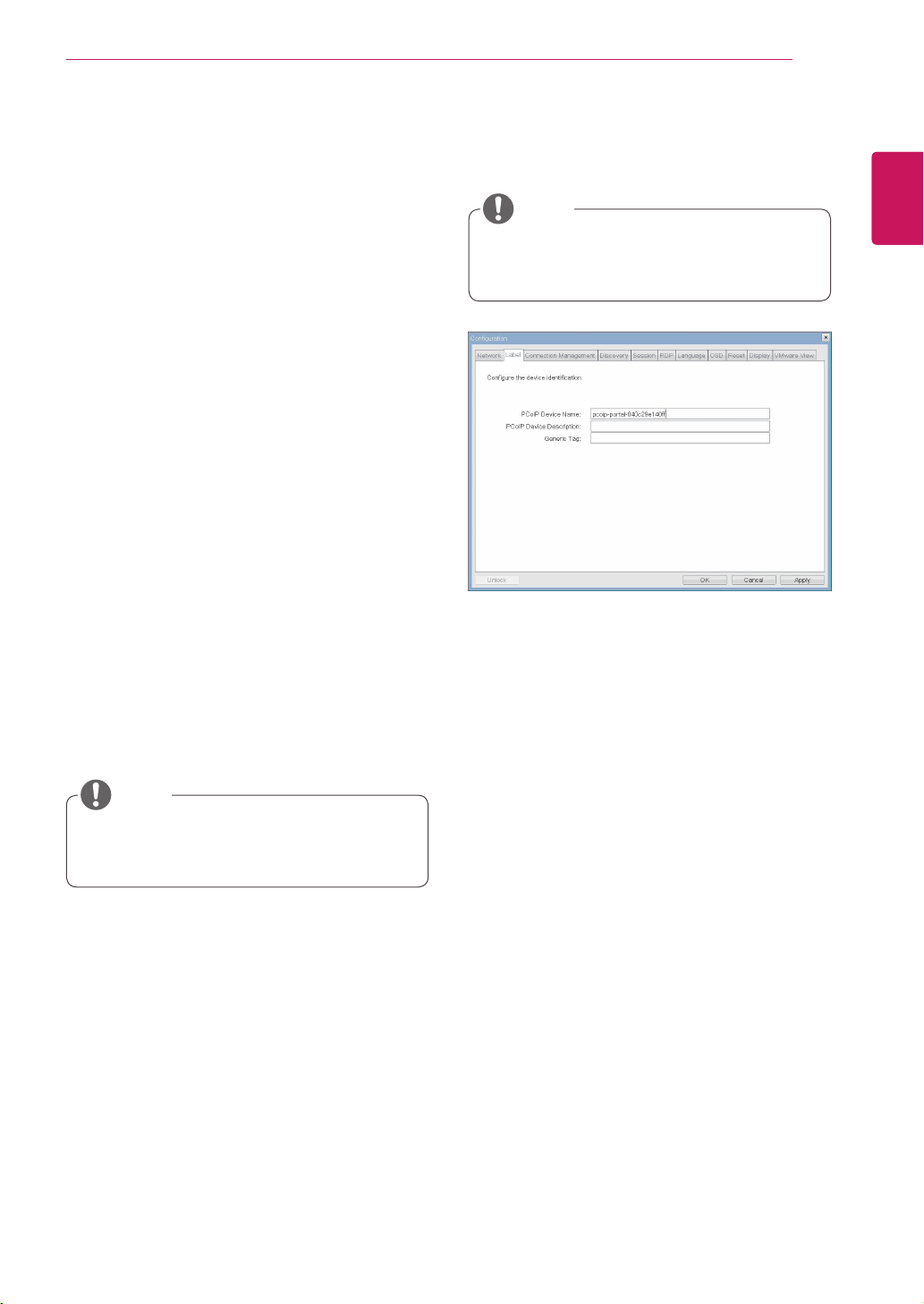
Figure2-7.LabelConfiguration
Label Tab
TheLabeltaballowstheadministratororhostto
addcustomizedinformationtotheportal.
Theportallabelparameterscanalsobecon-
figuredusingtheWebpageAdministration
Interface.
InordertoutilizetheFQDNfeature,aDNS
server,configuredproperlywithDHCPoption
81,mustbeused.
Gateway
TheGatewayfieldcontainsthegatewayIPad-
dressofthedevice.IfDHCPisdisabled,thisfield
isrequired.IfDHCPisenabled,thisfieldcannotbe
edited.
Primary DNS Server
ThePrimaryDNSServerfieldcontainstheprimary
DNSIPaddressofthedevice.Thisfieldisoption-
al.IfDHCPisenabled,thisfieldcannotbeedited.
Secondary DNS Server
TheSecondaryDNSServerfieldcontainsthesec-
ondaryDNSIPaddressofthedevice.Thisfieldis
optional.IftheDHCPisenabled,thisfieldcannot
beedited.
Domain Name
TheDomainNamefieldcontainsthedomainname
used,e.g."domainlocal".Thisfieldisoptional.Itspeci-
fiesonwhichdomainthehostorportaloperates.
FQDN
TheFQDNfieldrepresentstheFullyQualifiedDo-
mainNameofthehostorportal.Thedefaultvalueis
PCoIP-host-MACorPCoIP-portal-MAC,whereMAC
istheMACaddressofthehostorportal.Ifthereis
adomainname,itwillbeaddedtotheFQDNinthe
formatofPCoIP-host-MAC.domain.local
PCoIP Device Name
InthePCoIPDeviceNamefield,theadministrator
canspecifyalogicalnametothehostorportal.
ThedefaultvalueisPCoIP-host-MACorPCoIP-
portal-MAC,whereMACistheMACaddressofthe
hostorportal.
PCoIP Device Description
InthePCoIPDeviceDescriptionfield,theadministra-
torcanaddspecificinformation,suchastheendpoint
location,oraddadescriptiontothehostorportal.
ThisfieldcannotbeusedinthePCoIPfirmwareand
accessibilityisstrictlylimitedtotheadministrator.
Generic Tag
IntheGenericTagfield,theadministratorcanadda
generictagtothehostorportal.
ThisfieldcannotbeusedinthePCoIPfirmwareand
accessibilityisstrictlylimitedtotheadministrator.
Ethernet Mode
TheEthernetModefieldspecifiestheportal'sEth-
ernetmode.
Theavailableoptionsareasfollows.
Auto
100MbpsFull-Duplex
10MbpsFull-Duplex
Ifanothernetworkdeviceisconfiguredtooper-
ateunder10MbpsFull-Duplexor100MbpsFull-
Duplex,theadministratorshouldalwayssetthe
EthernetModefieldtoAutoandonlyuse10Mbps
Full-Duplexor100MbpsFull-Duplex.
NOTE
NOTE
30
ENG
English
Using PCoIP Solution
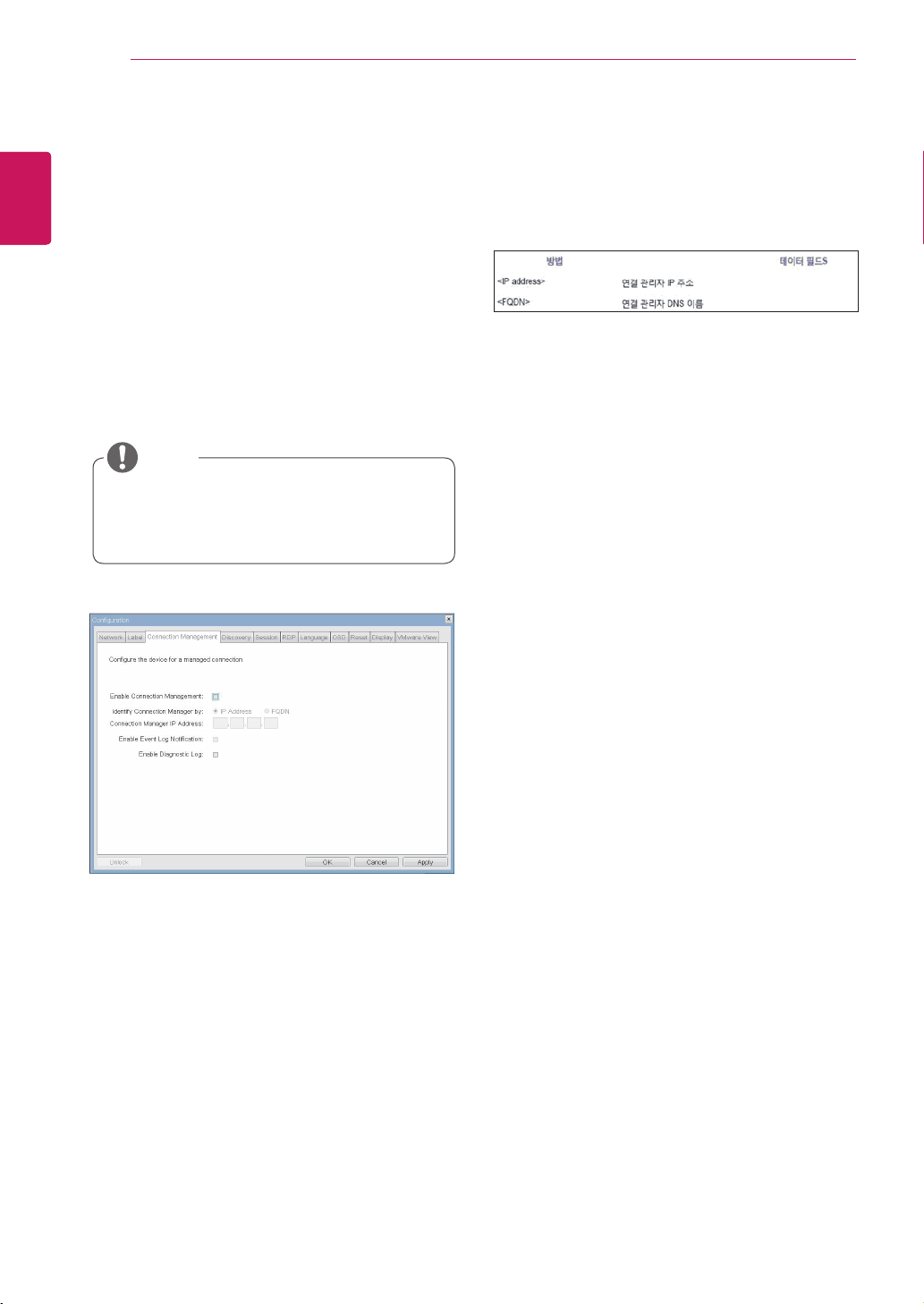
Figure2-8.ConnectionManagementConfiguration
Table2-1ConnectionManagerMethod
Connection Management Tab
The Connection Management tab allows the
user to enable or disable the connection man-
agement and specify the connection manager's
IP address.
Inamanagedconnection,anexternalConnection
ManagementServercancommunicatewithadevice
toremotelycontrolandconfigurethedevice.The
connectionmanagercanalsosearchforanap-
propriatepeertoconnecttothedevice.Connection
Managementsignificantlyreducesthetasksofthe
administratorinalargeandcomplicatedsystem.
Table2-1showstheconfigurationparametersthat
canbeusedwithoneofthetwomethods.Ifan
incorrectIPaddressorDNSnameisprovided,an
OSDmessageisdisplayedpromptingtheadminis-
tratortocorrecttheerror.
TheConnectionManagementparameters
canalsobeconfiguredusingtheWebpage
AdministrationInterface.
Enable Connection Management
IftheEnableConnectionManagementoptionis
enabled,thedevicecanbecontrolledandconfig-
uredfromanexternalconnectionmanager.
Identify Connection Manager By
TheIdentifyConnectionManagerByselectoral-
lowstheadministratortodecidewhethertoiden-
tifytheconnectionmanagerbyIPAddressorby
FQDN.IfConnectionManagementisdisabled,
thisfieldisnotrequiredandcanthereforenotbe
edited.
Enable Event Log Notification
TheEnableEventLogNotificationfieldcontrols
whetherthePCoIPhostandtheportaldeviceswill
sendtheireventlogtotheconnectionmanage-
mentserver.
Enable Diagnostic Log
TheEnableDiagnosticLogfieldspecifieswhether
tologtheconnectionmanagementspecificdebug
messagetothePCoIPhostandtotheportalde-
vices'eventlogs.
NOTE
31
ENG
English
Using PCoIP Solution
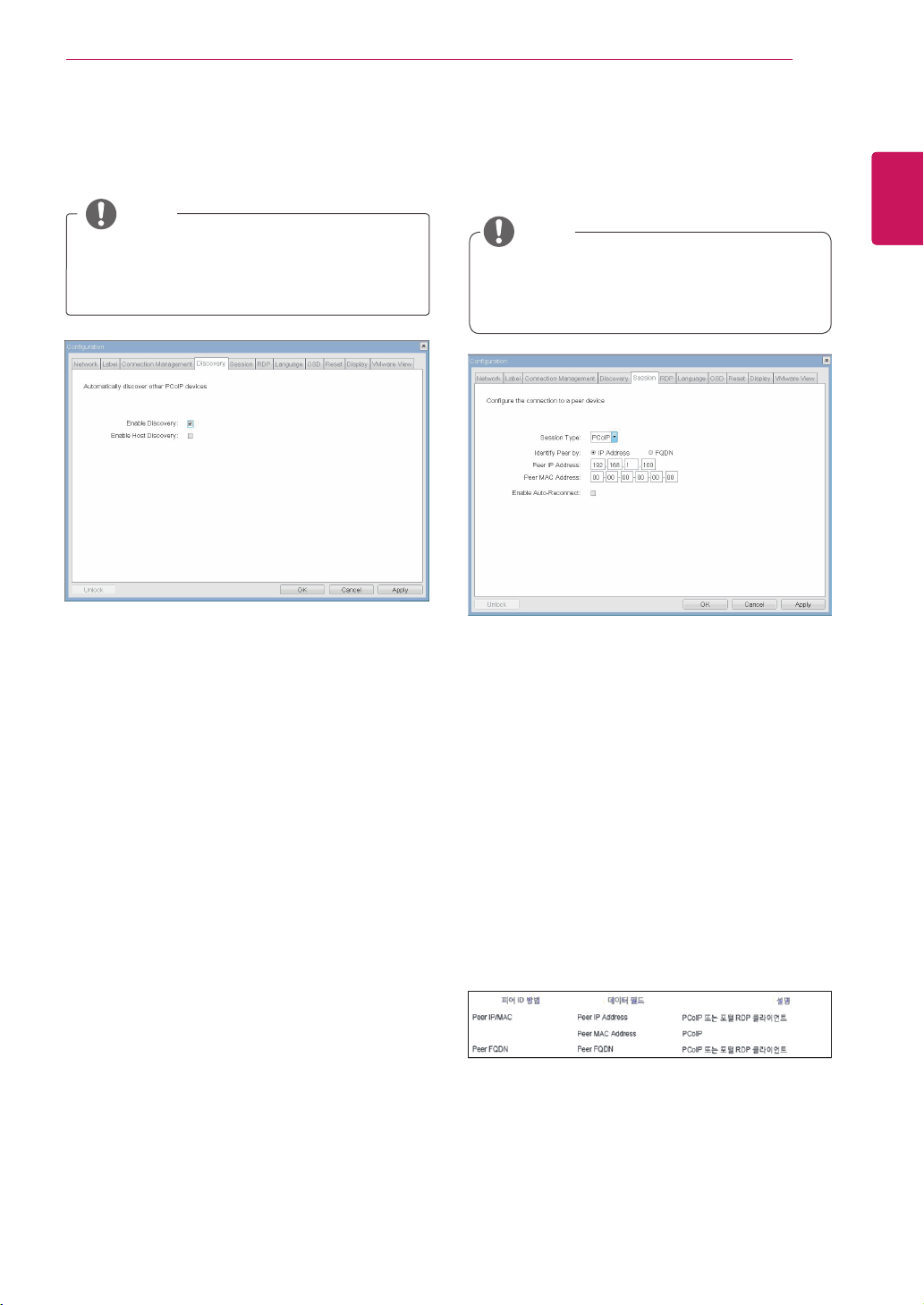
Table2-2.PeerIDMethod
Enable Discovery
IftheEnableDiscoveryoptionisselected,adevice
willuseSLPDiscoverytodynamicallylocatethe
peerdevicewithoutrequiringanyinformationabout
thelocationofthedeviceinthenetwork.This
meansthattheconfigurationandmaintenance
workinacomplicatedsystemcanbesignificantly
reduced.
AsSLPDiscoveryrequiresamulticast-enabled
router,therecommendedsearchstructureisDNS-
SRVDiscovery.
Enable Host Discovery
TheEnableHostDiscoveryoptionallowstheuser
tofindthehostnotlistedinthePCoIPsession
fromtheportal.Whenthisoptionisenabled,up
to10availablehostscanbelisted,intheorder
oftheirdetectionfromtheportal.UsetheEnable
HostDiscoveryoptionwhentherearearelatively
smallnumberofhosts.
Session Type
InSessionType,theadministratorcanconfigurea
portalforthePCoIPsessionortheRDPsession.
Identify Peer By
TheIdentifyPeerByselectorallowstheadminis-
tratortodecidewhethertoidentifythepeerdevice
byIP,byMACaddressorbyFQDN.
Table2-2showsthepeerIDparametersthatcan
beusedwithoneofthetwomethods.Ifanincor-
rectIPaddressorDNSnameisprovided,anOSD
messageisdisplayedpromptingtheadministrator
tocorrecttheerror.
Enable Auto-Reconnect
TheEnableAuto-Reconnectoptionallowsthepor-
taltoautomaticallyreconnecttothelastconnected
hostwhenthesessionisclosed.
Figure2-9.DiscoveryConfiguration
Figure2-10.SessionConfiguration
Discovery Tab
TheDiscoverytaballowstheadministratortoeas-
ilyfindaportalinthePCoIPsystem.
Session Tab
TheSessiontaballowstheadministratortosetthe
methodtoconnectthedevicetoapeerdevice.
TheDiscoveryparameterscanalsobecon-
figuredusingtheWebpageAdministration
Interface.
TheSessionparameterscanalsobecon-
figuredusingtheWebpageAdministration
Interface.
NOTE
NOTE
32
ENG
English
Using PCoIP Solution
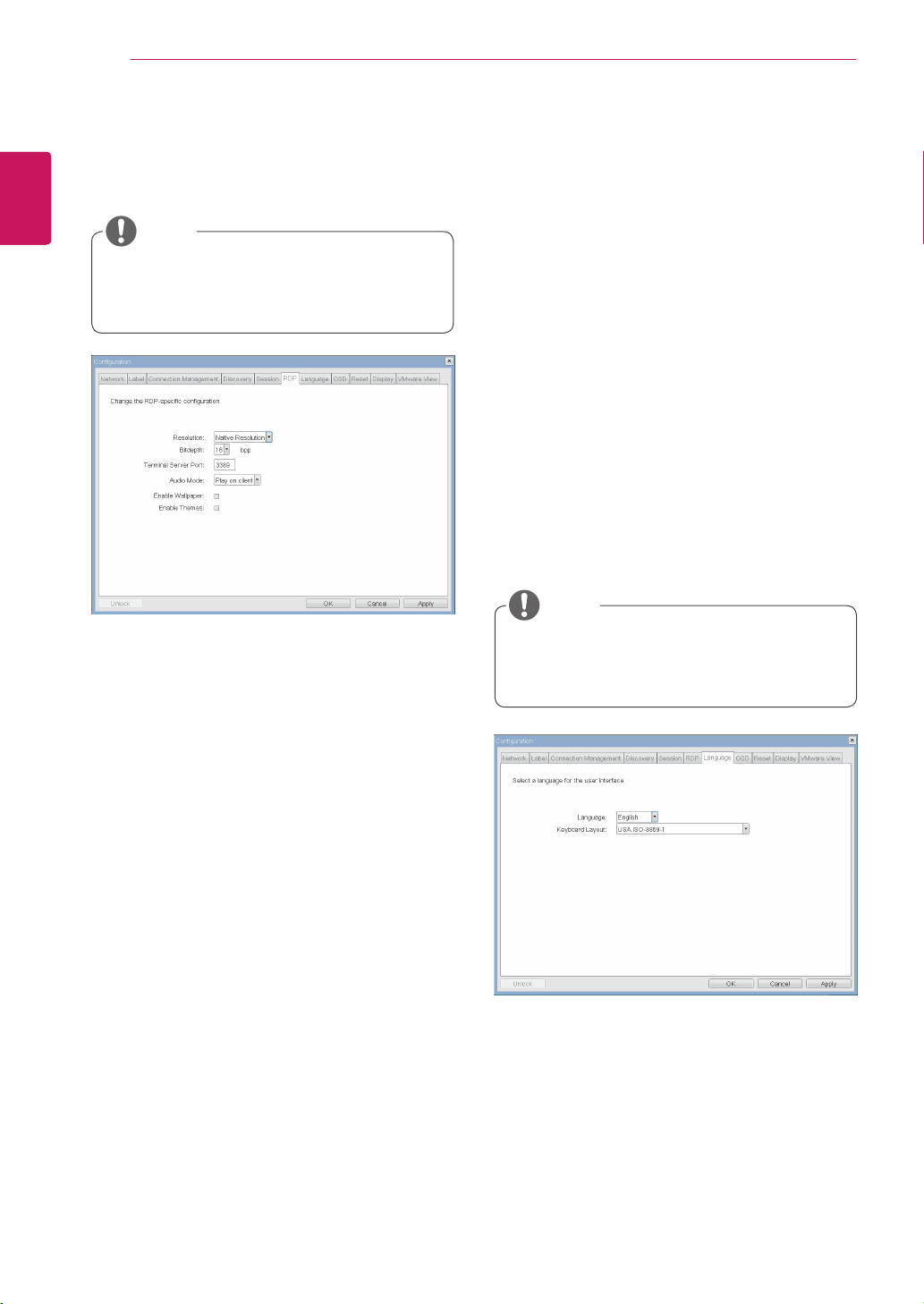
Resolution
TheResolutionfieldisusedtosettheRDPscreen
resolution.Theavailablevaluesareasfollows.
NativeResolution
800x600
1024x768
1280x768
1280x1024
1440x900
1600x1200
1680x1050
1920x1080
1920x1200
Bit Depth
TheBitDepthfieldisusedtosetthecolorbitdepth
fortheRDPsession.Theavailablevaluesareas
follows.
8bpp(bitsperpixel)
16bpp
24bpp
Terminal Server Port
TheTerminalServerPortfieldisusedtosetthe
portnumbertoconnecttheRDPclient.
Language
TheLanguagefieldisusedtosetthedisplay
languageoftheOSDandtheuserleveleventlog
messages.
Keyboard Layout
TheKeyboardLayoutfieldallowstheadministrator
tomodifythekeyboardlayout.
Figure2-11.RDPConfiguration
Figure2-12.LanguageConfiguration
RDP Tab
TheRDPtaballowstheadministratortoconfigure
theremotedesktopprotocol(RDP)specificset-
tings.
Language Tab
TheLanguagetaballowstheadministratortoset
theOSDlanguage.
TheRDPLabelparameterscanalsobecon-
figuredusingtheWebpageAdministration
Interface.
TheLanguageparameterscanalsobecon-
figuredusingtheWebpageAdministration
Interface.
Audio Mode
TheAudioModefieldisusedtosettheaudioplay-
backlocationoftheRDPsession.Theavailable
optionsareasfollows.
None
Playonclient
Playonhost
Enable Wallpaper
TheEnableWallpaperfieldisusedtoallowthe
usertousethewallpaperintheRDPsession.
Enable Themes
TheEnableThemesfieldisusedtoenabletheuser
tousethewallpaperthemeintheRDPsession.
NOTE
NOTE

33
ENG
English
Using PCoIP Solution
Screen-Saver Timeout
TheScreen-SaverTimeoutfieldallowsthead-
ministratortosetatimelimitforthescreensaver.
Thetimelimitisdefinedinseconds.Themaximum
timeis9999seconds.Ifitissetto0seconds,the
screensaverwillbeturnedoff.
Reset Parameters
PressingtheResetParametersbuttonwillresetall
settingsandoptionstothefactorydefaultsettings.
Whenthisbuttonispressed,anOSDmessageis
displayed.Thisistoprompttheadministratorand
preventaccidentalreset.
Figure2-13.OSDConfiguration
Figure2-14Reset
OSD Tab
TheOSDtaballowstheadministratortomodifythe
OnScreenDisplay(OSD)parameters.
Reset Tab
TheResettaballowstheadministratortoresetall
configurableparametersstoredinFlash.
TheOSDparameterscanalsobeconfigured
usingtheWebpageAdministrationInterface.
TheResetfunctioncanalsobeaccessed
throughtheWebpageAdministrationInter-
face.
NOTE
NOTE
34
ENG
English
Using PCoIP Solution
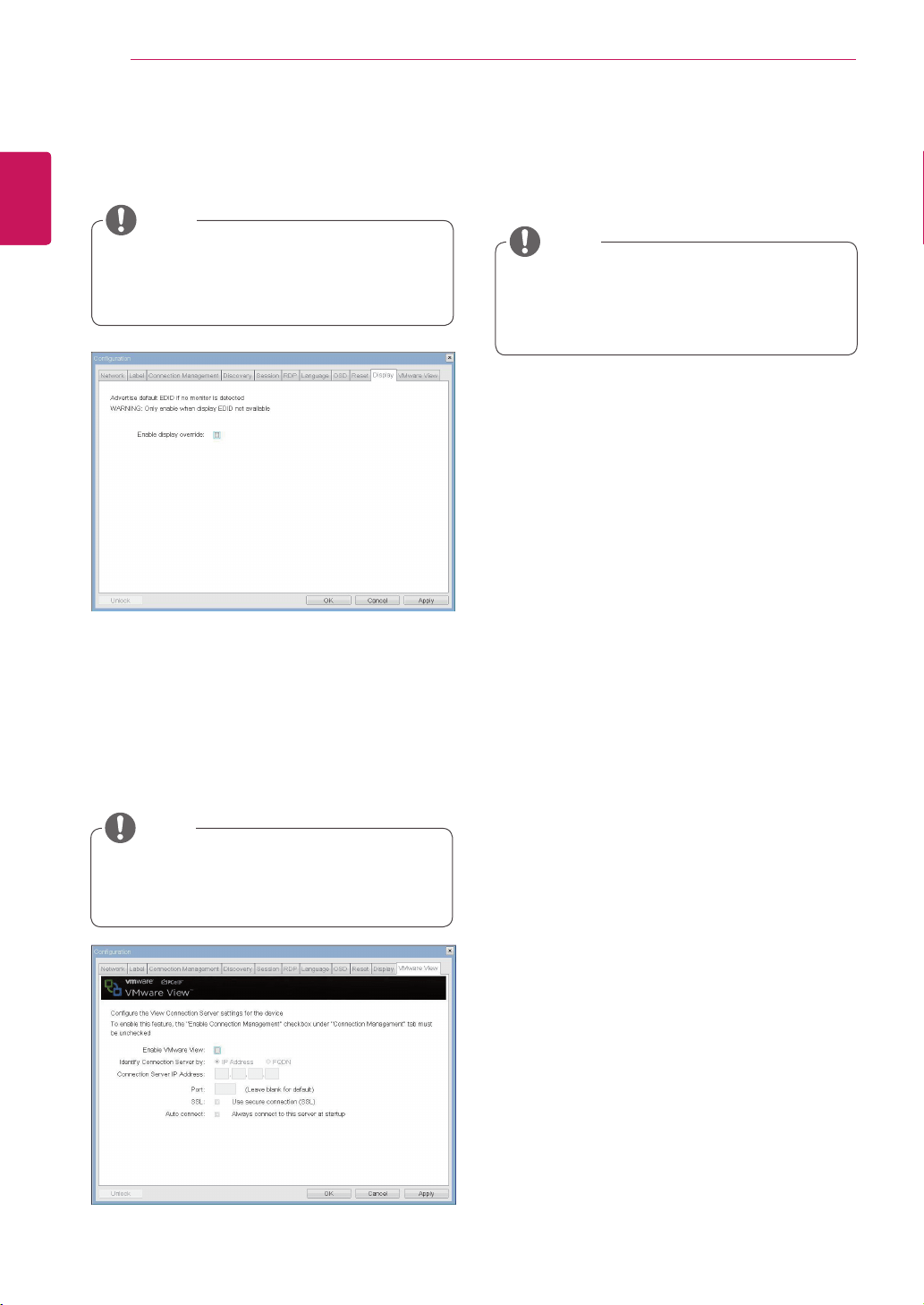
Enable VMware View
TheEnableVMwareViewoptionallowstheuserto
configuretheportaltousetheVMwareViewCon-
nectionServer.
Identify Connection Server by
TheIdentifyConnectionServerbyselectorallows
theadministratortodecidewhethertoidentifythe
connectionmanagerbyIPaddressorbyFQDN.If
VMwareViewisdisabled,thisfieldisnotrequired
cannotbeedited.
Port
ThePortparameterallowstheadministratorto
specifytheporttocommunicatewiththeVMware
ViewConnectionServer.
SSL
TheSSLparameterallowstheadministratorto
specifytheSSLtocommunicatewiththeVMware
ViewConnectionServer.
Auto Connect
TheAutoConnectparameterallowstheadminis-
tratortoensurethatthedevicealwaysautomati-
callyconnectstotheVMwareViewConnection
Serverwhenstartingtheportal.
Event Log
Session Statistics
PCoIP Processor
Ping
EachtabhastheClosebuttontoclosethewindow.
Figure2-15.DisplayConfiguration
Figure2-16.VMwareViewConfiguration
Display Tab
TheDisplaytaballowstheusertoconfigurethe
EDIDfunctionofthemonitor.
Diagnostics Window
IntheDiagnosticswindow,theadministratorcan
accessthewindowtabtodiagnosetheportal.The
Diagnosticswindowhasthefollowingtabs:
VMware View Tab
TheVMwareViewtaballowstheusertoselectthe
devicetousetheVMwareViewConnectionServer.
TheEnabledisplayoverridefunctioncanbe
usedwhentheEDIDfunctionofthemonitor
isnotrunning.
TheVMwareViewparameterscanalsobe
configuredusingtheWebpageAdministra-
tionInterface.
ToenabletheVMwareViewfunction,the
EnableConnectionManagementcheckbox
intheEnableConnectionManagementTab
mustbedeselected.
NOTE
NOTE
NOTE
35
ENG
English
Using PCoIP Solution
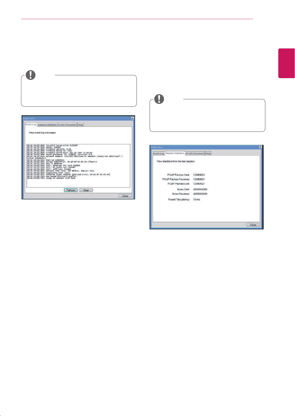
View Event Log Message
TheViewEventLogMessagefielddisplaysthelog
messagesaccompaniedbythetimestampinforma-
tion.Thefollowingtwobuttonsareavailable:
Refresh
TheRefreshbuttonrefreshesthedisplayedevent
logmessages.
Clear
TheClearbuttonclearsalleventlogmessages.
PCoIP Packets Statistics
PCoIPPacketsSent
ThePCoIPPacketsSentfieldshowsthetotal
numberofPCoIPpacketssentfromtheportal
tothehostinthelastactivesession.
PCoIPPacketsReceived
ThePCoIPPacketsReceivedfieldshowsthe
totalnumberofPCoIPpacketsreceivedfrom
thehosttotheportalinthelastactivesession.
PCoIPPacketsLost
ThePCoIPPacketsLostfieldshowsthetotal
numberofPCoIPpacketslostinthelastac-
tivesession.
Figure2-17.EventLogConfiguration
Figure2-18.SessionStatisticsConfiguration
Event Log Tab
TheEventLogtaballowstheadministratortoview
anddeletetheeventlogmessagesfromtheportal.
Session Statistics Tab
TheSessionStatisticstaballowstheadministrator
toviewthePCoIPspecificstatisticsofthelastac-
tivePCoIPsessionfromtheportal.
Theeventlog(regardlessofthequantity)
canalsoberesetusingtheWebpageAdmin-
istrationInterface.
Thesessionstatistics(regardlessofthe
quantity)canalsobeviewedusingtheWeb-
pageAdministrationInterface.
NOTE
NOTE
36
ENG
English
Using PCoIP Solution
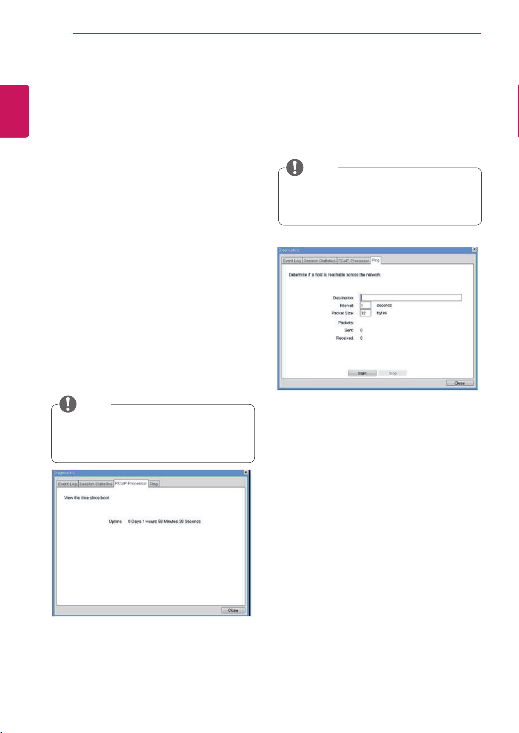
Ping Settings
Destination
TheIPaddressorFQDNtoperformtheping
test.
Interval
Theintervalbetweenthepingpackets.
PacketSize
Thesizeofthepingpacket.
Packets
Sent
Thenumberofpingpacketssent.
Received
Thenumberofpingpacketsreceived.
Figure2-19.PCoIPProcessorConfiguration
Figure2-20.PingConfiguration
PCoIP Processor Tab
ThePCoIPProcessortaballowstheadministrator
toviewtheportalPCoIPprocessor'suptimesince
itslastbooting.
Ping Tab
ThePingtaballowstheadministratortoperforma
pingtesttothedeviceandcheckifitcanreachthe
overallIPnetwork.Thisisusefultocheckwhether
thedevicecanreachthehost.
ThePCoIPProcessorUptimecanalsobe
viewedusingtheWebpageAdministration
Interface.
ThePingtabhasnocorrespondingmenuin
totheWebpageAdministrationInterfaceof
Section1.
NOTE
Bytes Statistics
BytesSent
TheBytesSentfieldshowsthetotalnumber
ofbytessentinthelastactivesession.
BytesReceived
TheBytesReceivedfieldshowsthetotal
numberofbytesreceivedinthelastactive
session.
Round Trip Latency
TheRoundTripLatencyfieldshowsthetotal
round-tripPCoIPsystem(e.g.fromtheportalto
thehost,thenbacktotheportal)andthenetwork
latencyinmilliseconds(+/-1ms).
NOTE
37
ENG
English
Using PCoIP Solution
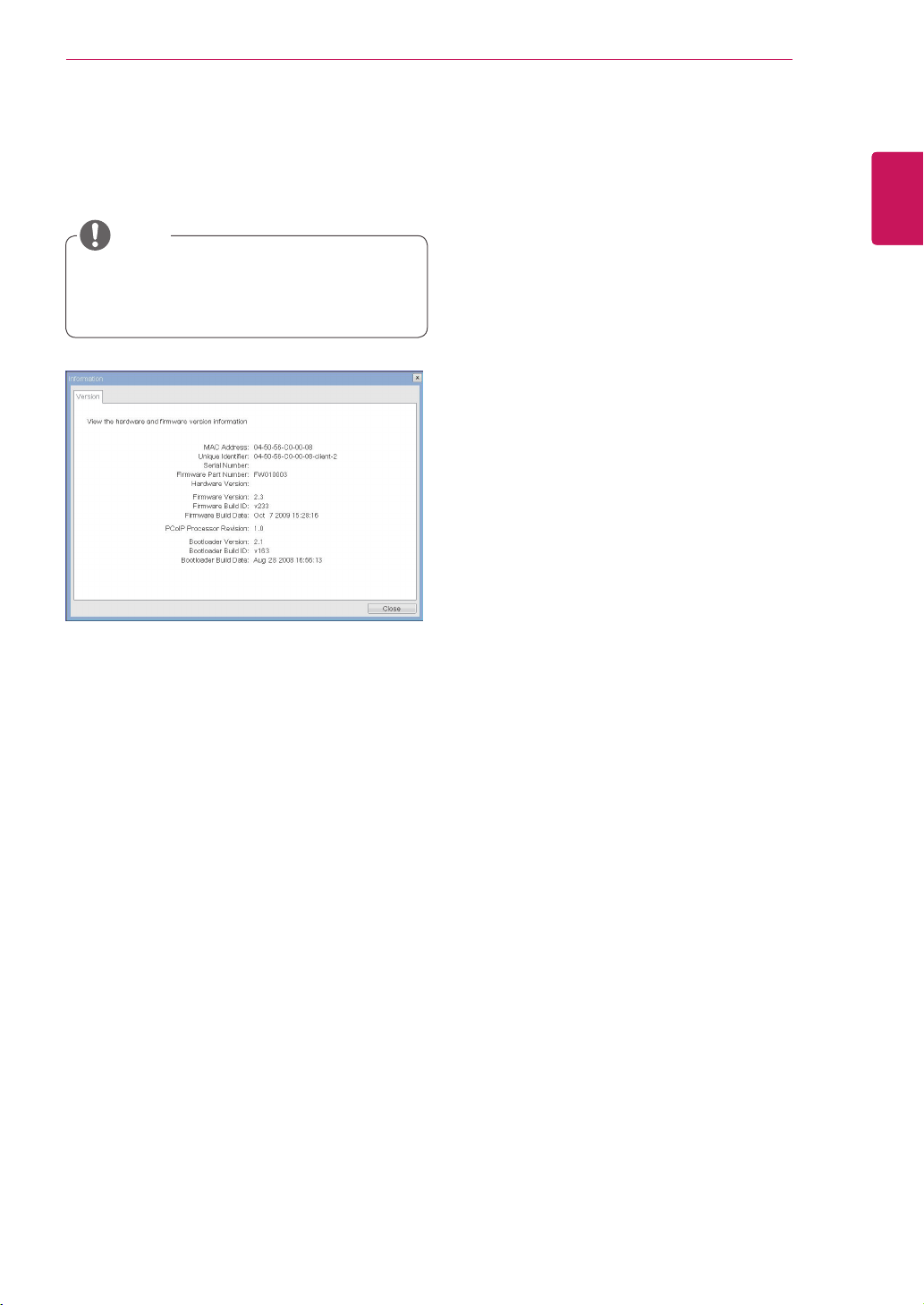
VPD Information
TheVitalProductData(VPD)isinformationthat
uniquelyidentifieseachportalorhost.
MACAddress
TheportalMACaddress
UniqueIdentifier
TheportalID
SerialNumber
Theportalserialnumber
FirmwarePartNumber
ThepartnumberofthePCoIPfirmware
HardwareVersion
Theportalhardwareversion
Firmware Information
TheFirmwareInformationshowsthedetailsofthe
currentPCoIPfirmware.
FirmwareVersion
ThecurrentPCoIPfirmwareversion
FirmwareBuildID
ThecurrentPCoIPfirmwarerevisioncode
FirmwareBuildDate
ThecurrentPCoIPfirmwarebuilddate
Boot Loader Information
TheBootLoaderInformationshowsthedetailsof
thecurrentPCoIPbootloader.
BootLoaderVersion
ThecurrentPCoIPbootloaderversion
BootLoaderBuildID
ThecurrentPCoIPbootloaderrevisioncode
BootLoaderBuildDate
ThecurrentPCoIPbootloaderbuilddate
Boot Loader Information
TheBootLoaderInformationshowsthedetailsof
thecurrentPCoIPbootloader.
Mouse
Keyboard
Image
DisplayTopology
Figure2-21.VersionConfiguration
Information Window
IntheInformationwindow,theadministratorcan
accesstheVersiontabthatcontainsthedevice
relatedinformation.
User Settings Window
IntheUserSettingswindow,theadministratorcan
accessthetabtoselectthemouseandkeyboard
anddefinethePCoIPimagequality.
TheUserSettingswindowhasthefollowingtabs:
PCoIP Processor Revision
ThisshowsthePCoIPprocessor'srevisioncode.
TERA1x00RevisionAsiliconeisdenotedby0.0
andTERA1x00RevisionBsiliconeisdenotedby
1.0.
Theversioninformationcanalsobeviewed
usingtheWebpageAdministrationInterface.
NOTE
38
ENG
English
Using PCoIP Solution
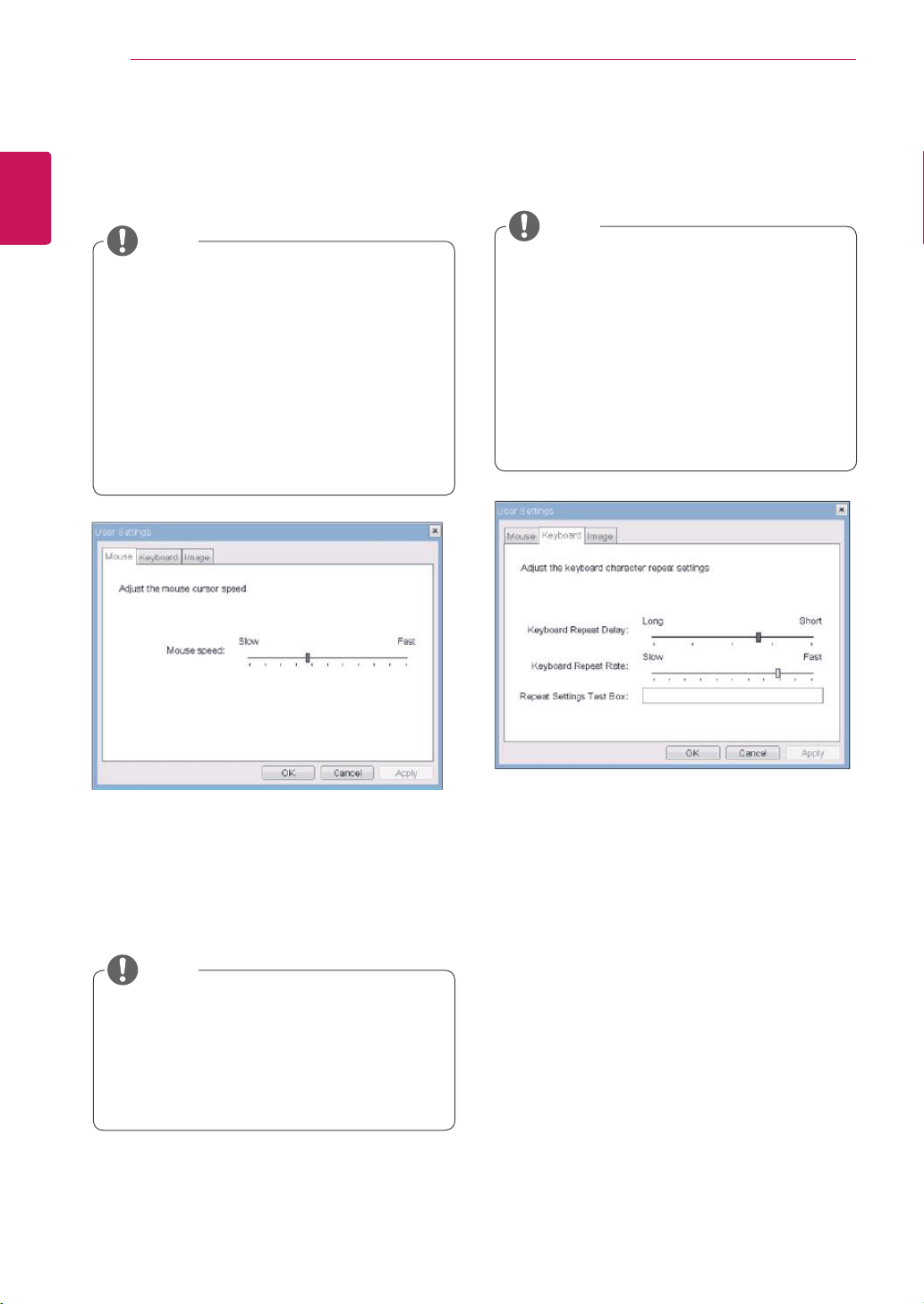
Mouse Speed
TheMouseSpeedfieldallowstheusertosetthe
portal'smousecursorspeed.
Keyboard Repeat Delay
TheKeyboardRepeatDelayfieldallowstheuser
tosettheportal'skeyboardrepeatdelay.
Keyboard Repeat Rate
TheKeyboardRepeatRatefieldallowstheuserto
settheportal'skeyboardrepeatrate.
Repeat Settings Test Box
TheRepeatSettingsTestBoxallowstheuserto
testtheselectedkeyboardsettings.
Figure2-22.Mouse
Figure2-23.Keyboard
Mouse Tab
TheMousetaballowstheusertomodifytheOSD
andRDPsession'smousecursorspeedsetting.
Keyboard Tab
TheKeyboardtaballowstheusertomodifythe
OSDandRDPsession'skeyboardrepeatsetting.
TheOSDmousecursorspeedsettingdoes
notaffectthemousecursorsettingswhen
aPColPsessionisactiveunlesstheLocal
KeyboardHostDriverfunctionisbeingused
(seePColPHostSoftwareUserGuidefor
moreinformation).
TheMousetabhasnocorrespondingmenu
intheWebpageAdministrationInterfaceof
Section1.
TheOSDkeyboardsettingdoesnotaffect
thekeyboardsettingswhenaPColPsession
isactiveunlesstheLocalKeyboardHost
Driverfunctionisbeingused(seePColP
HostSoftwareUserGuideformoreinforma-
tion).
TheKeyboardtabhasnocorresponding
menuintheWebpageAdministrationInter-
faceofSection1.
TheMouseSpeedcanalsobeconfiguredvia
thePCoIPHostSoftware.Formoreinforma-
tiononusingthePCoIPHostSoftware,refer
tothePCoIPHostSoftwareUserGuide.
NOTE
NOTE
NOTE
39
ENG
English
Using PCoIP Solution
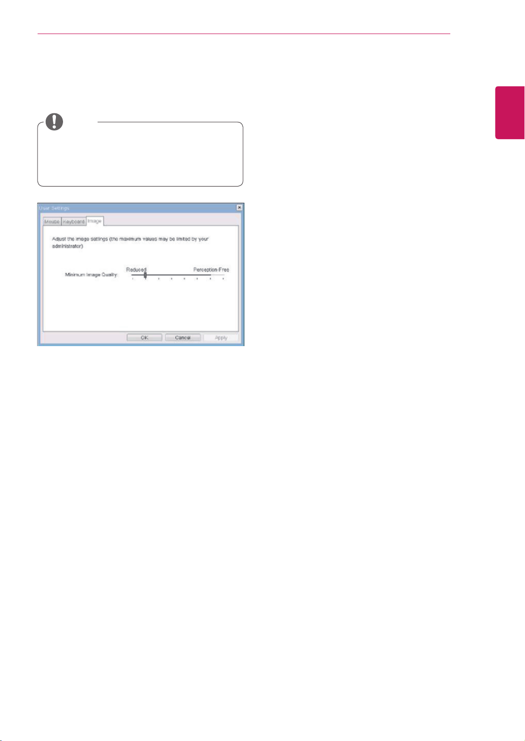
Minimum Image Quality
TheMinimumImageQualitysliderallowsthead-
ministratortomakecompromisesbetweenimage
qualityandframeratewhennetworkbandwidth
islimited.Sometimes,lower-qualityimagesata
higherframeratemayberequired,whileatother
times,higher-qualityimagesatalowerframerate
maybepreferred.
Inenvironmentswherethenetworkbandwidthis
limited,movingtheslidertowardsReduceden-
sureshigherframerates;
movingtheslidertowardsPerception-Freeensures
higherimagequality.Whennetworkbandwidthis
notlimited,thePCoIPsystemwillmaintainpercep-
tion-freequalityregardlessoftheMinimumImage
Qualitysetting.
Figure2-24.Image
Image
TheImagetaballowsausertochangetheimage
settingsonthePCoIPsystem.
TheImageparameterscanalsobecon-
figuredusingtheWebpageAdministration
Interface.
NOTE

MakesuretoreadtheSafetyPrecautions
beforeusingtheproduct.
KeeptheOwner'sManual(CD)inan
accessibleplaceforfuturereference.
ThemodelandserialnumberoftheSET
islocatedonthebackandonesideofthe
SET.Recorditbelowshouldyoueverneed
service.
MODEL
SERIAL


