© Panasonic Corporation 2018 Unauthorized copy-
ing and distribution is a violation of law.
Order Number MOD1806497CE
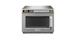
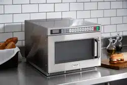
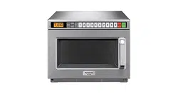
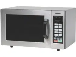
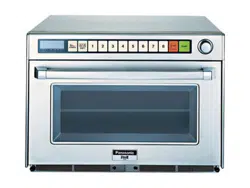
Microwave Oven
Model No. NE-1878BPQ
Destination : United Kingdom
TABLE OF CONTENTS
PAGE PAGE
1 Safety Precautions----------------------------------------------- 2
2 Specifications ----------------------------------------------------- 3
3 Location of Controls and Components ------------------- 4
4 Operating Instructions------------------------------------------ 5
5 Service Mode -----------------------------------------------------17
6 Troubleshooting Guide ----------------------------------------21
7 Disassembly and Assembly Instructions ---------------31
8 Measurements and Adjustments---------------------------37
9Dimensions--------------------------------------------------------38
10 Block Diagram----------------------------------------------------39
11 Wiring Connection Diagram ---------------------------------40
12 Exploded View and Replacement Parts List -----------42
2
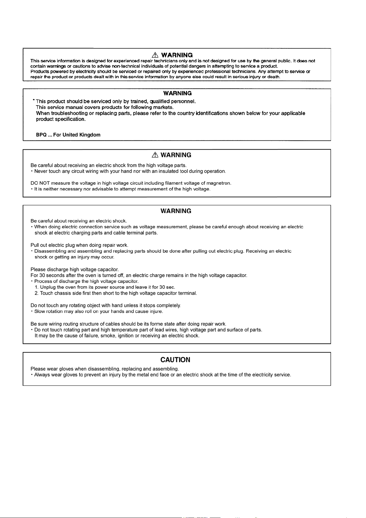
1 Safety Precautions
3
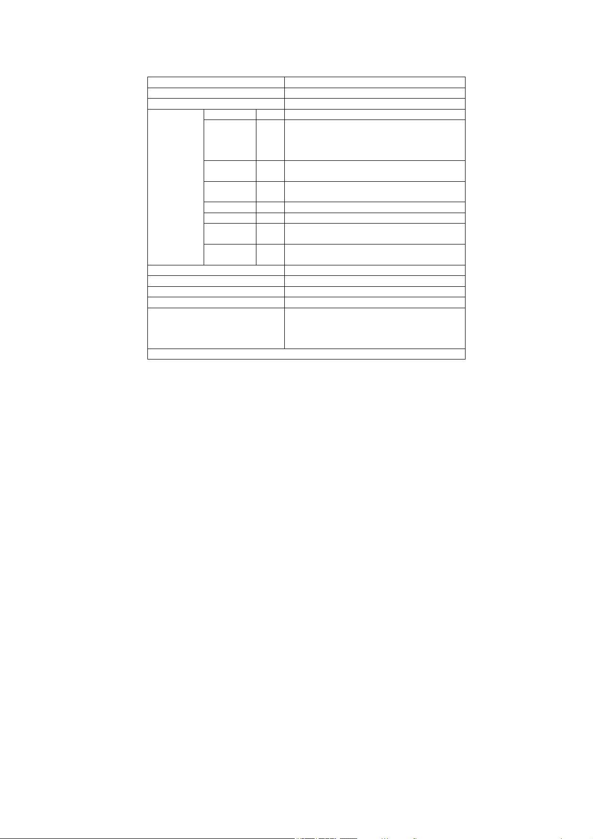
2 Specifications
Models: NE-1878
Power Source: 230-240V AC Single Phase 50 Hz
Power Requirement: 2650W, (11.6A)
*Output: HIGH (P10) 1800 W
MEDIUM
HIGH
(P9)
(P8)
(P7)
(P6)
90%
80%
70%
60%
MEDIUM (P5)
(P4)
50%
40%
LOW (P3)
(P2)
30%
25%
DEFROST (P1) 340 W
OFF (P0) 0%
HEAT FROM
TOP DOWN
(PU1)
(PU2)
50%
25%
HEAT FROM
BOTTOM
(PL1)
(PL2)
50%
25%
Frequency: 2,450 MHZ
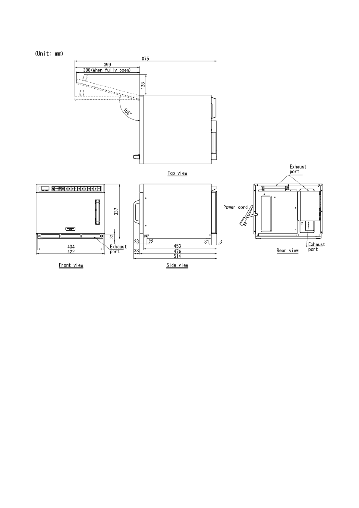
Outside Dimensions (WDH) 422 mm 476 mm 337 mm
Cavity Dimensions (WDH) 330 mm 310 mm 175 mm
Net Weight 17.5 kg
Timer: Maximum programmable time for single stage
heating
P1 and P0=30 minutes
P10-P2, PU1-PL2=15 minutes
Specifications subject to change without notice.
4
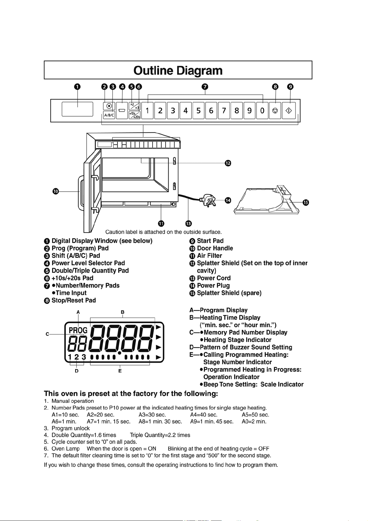
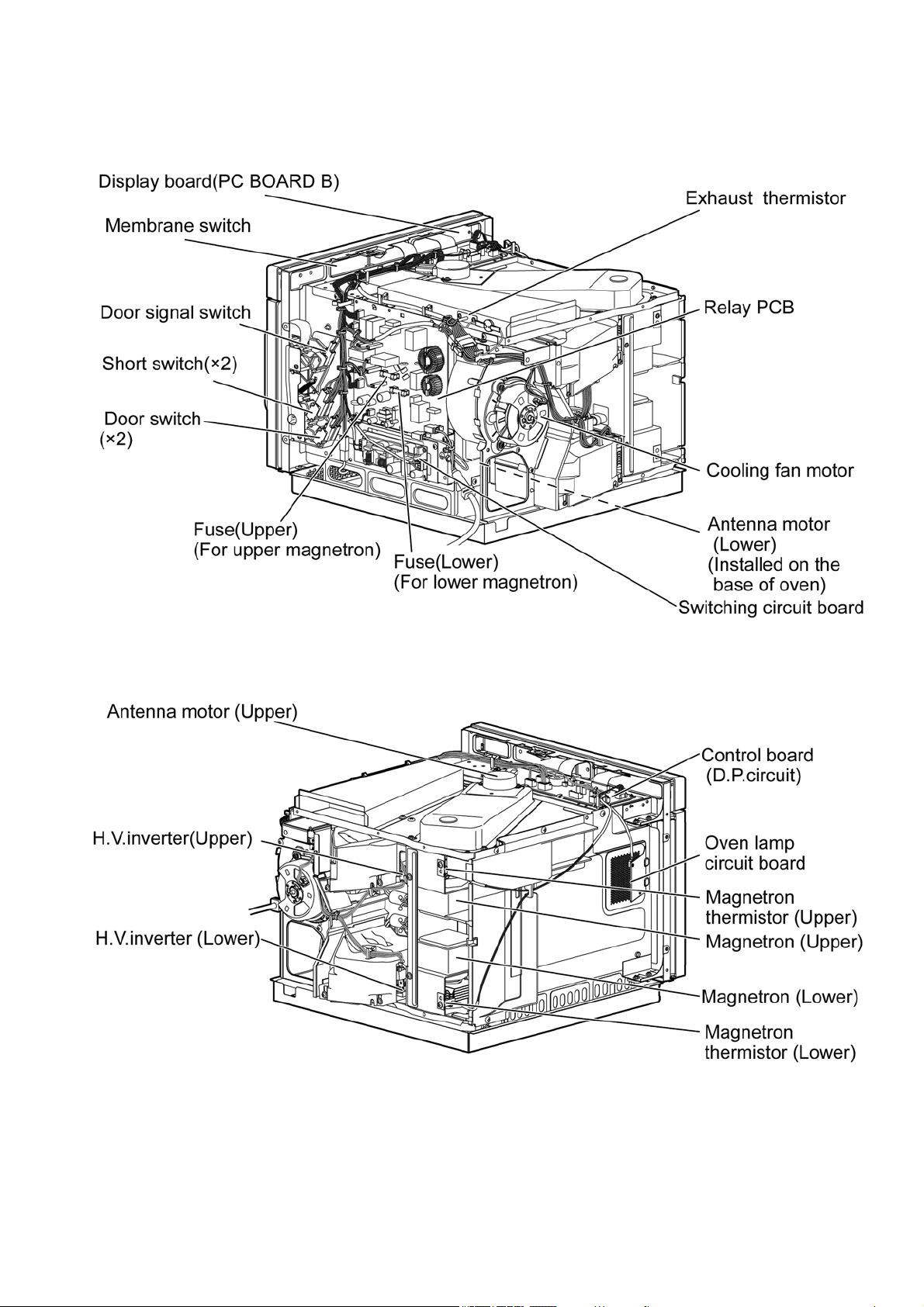
3 Location of Controls and Components
3.1. Outline diagram
5
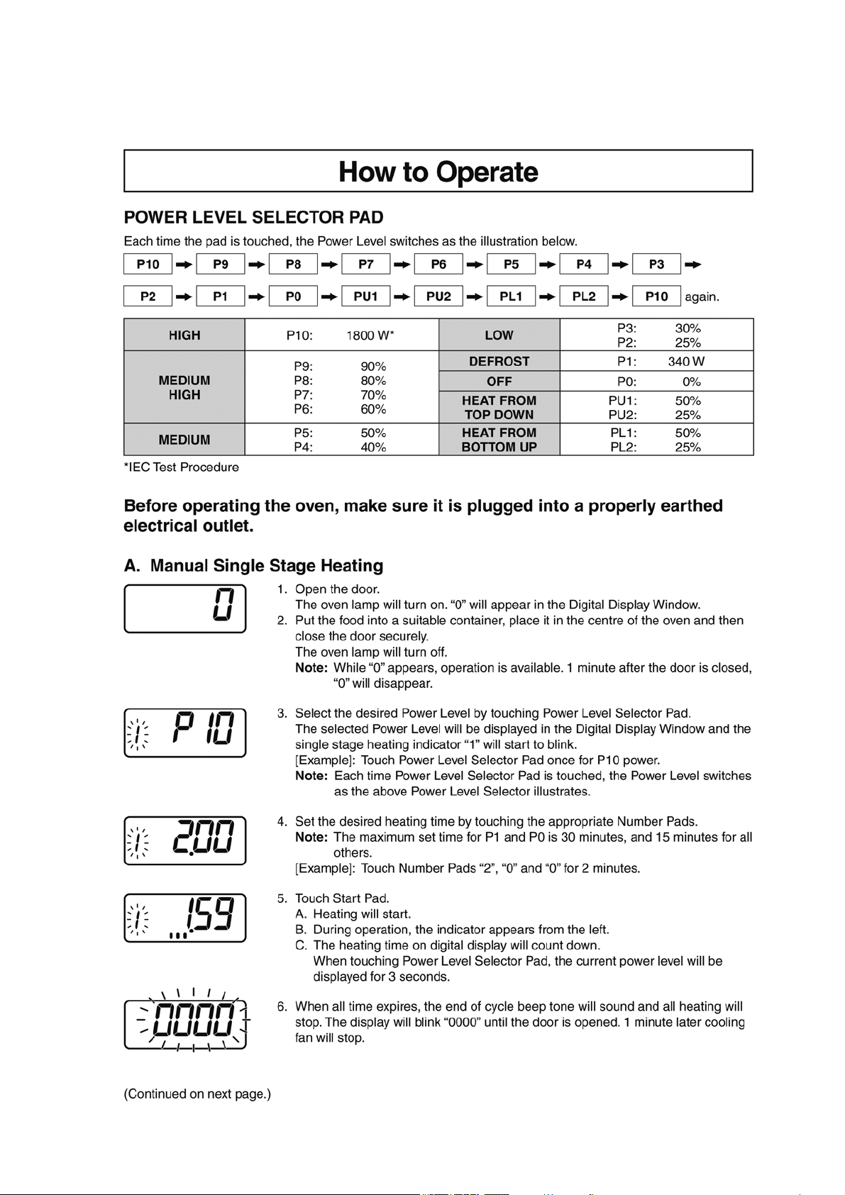
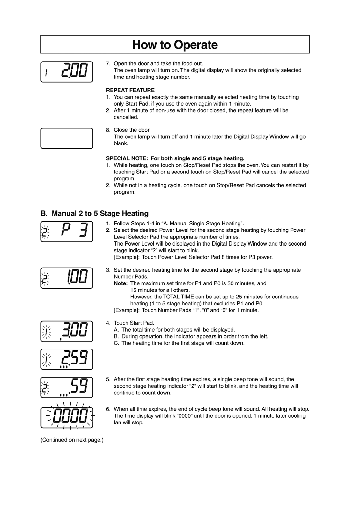
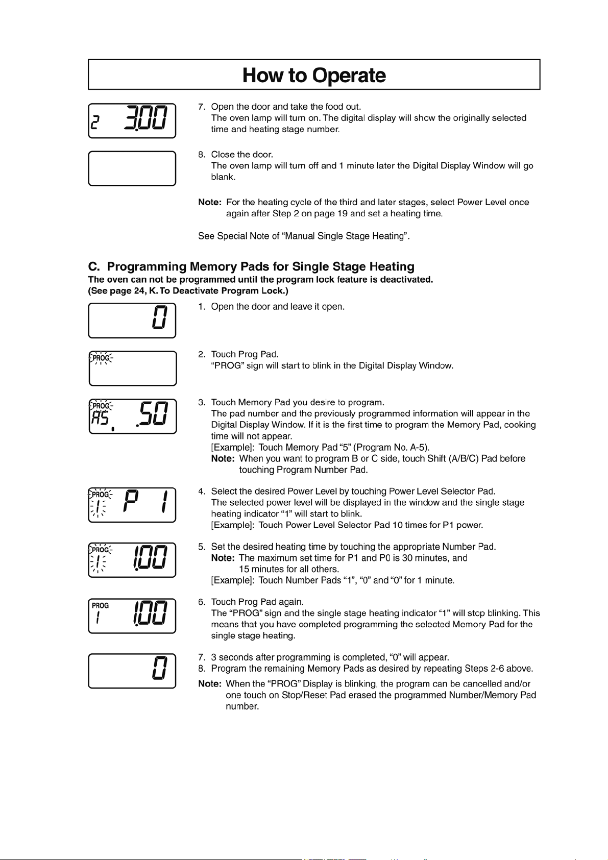
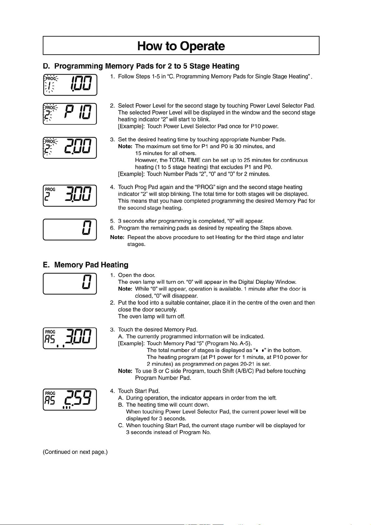
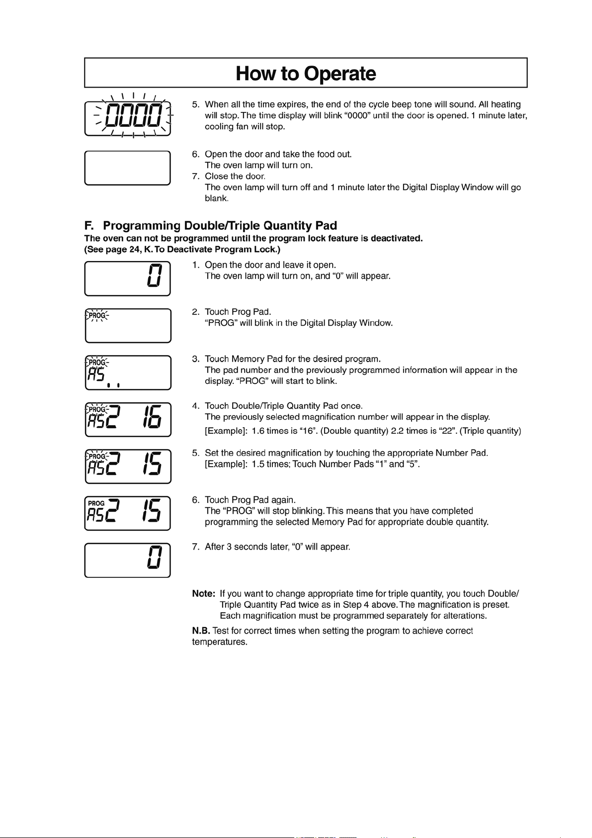
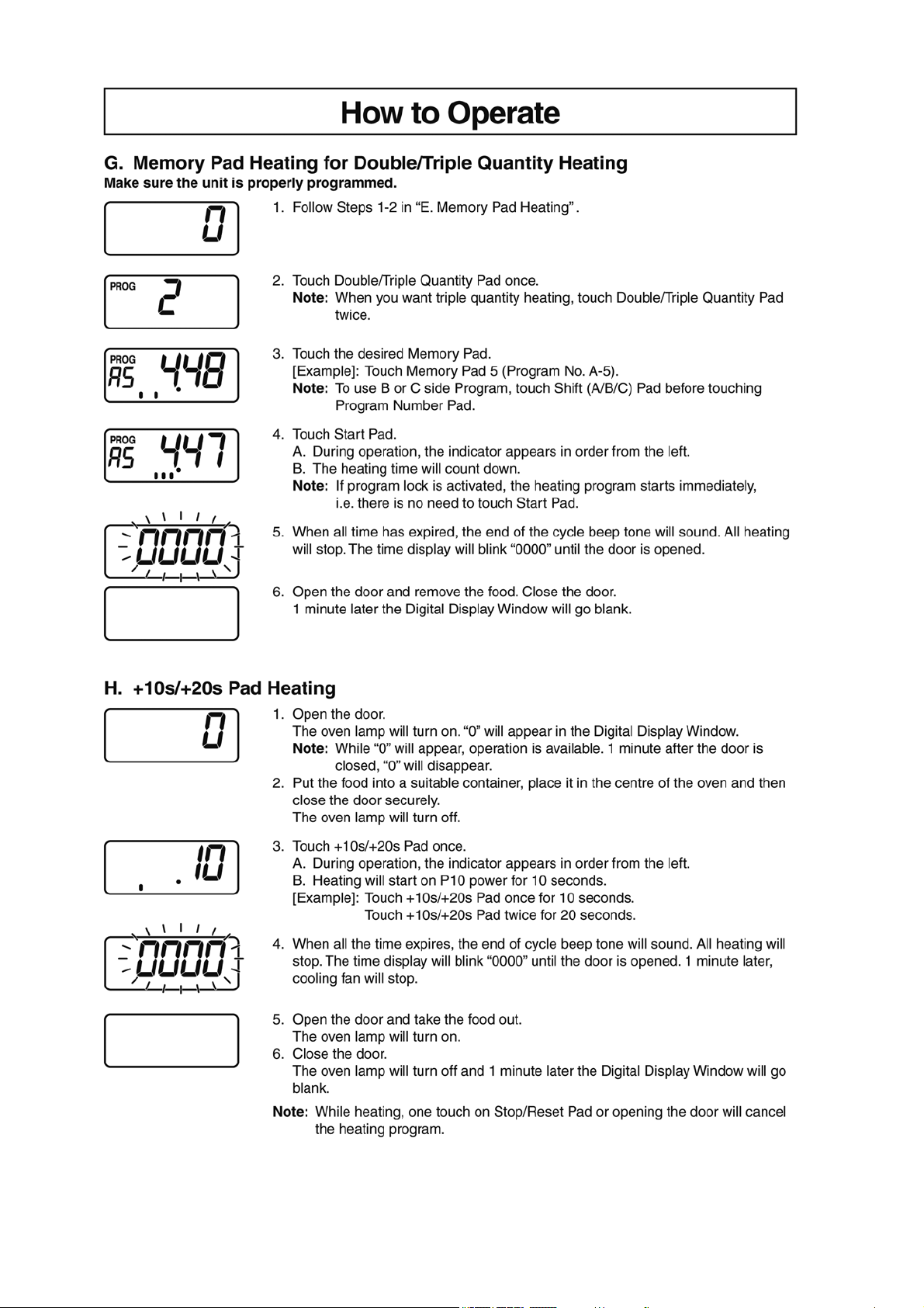
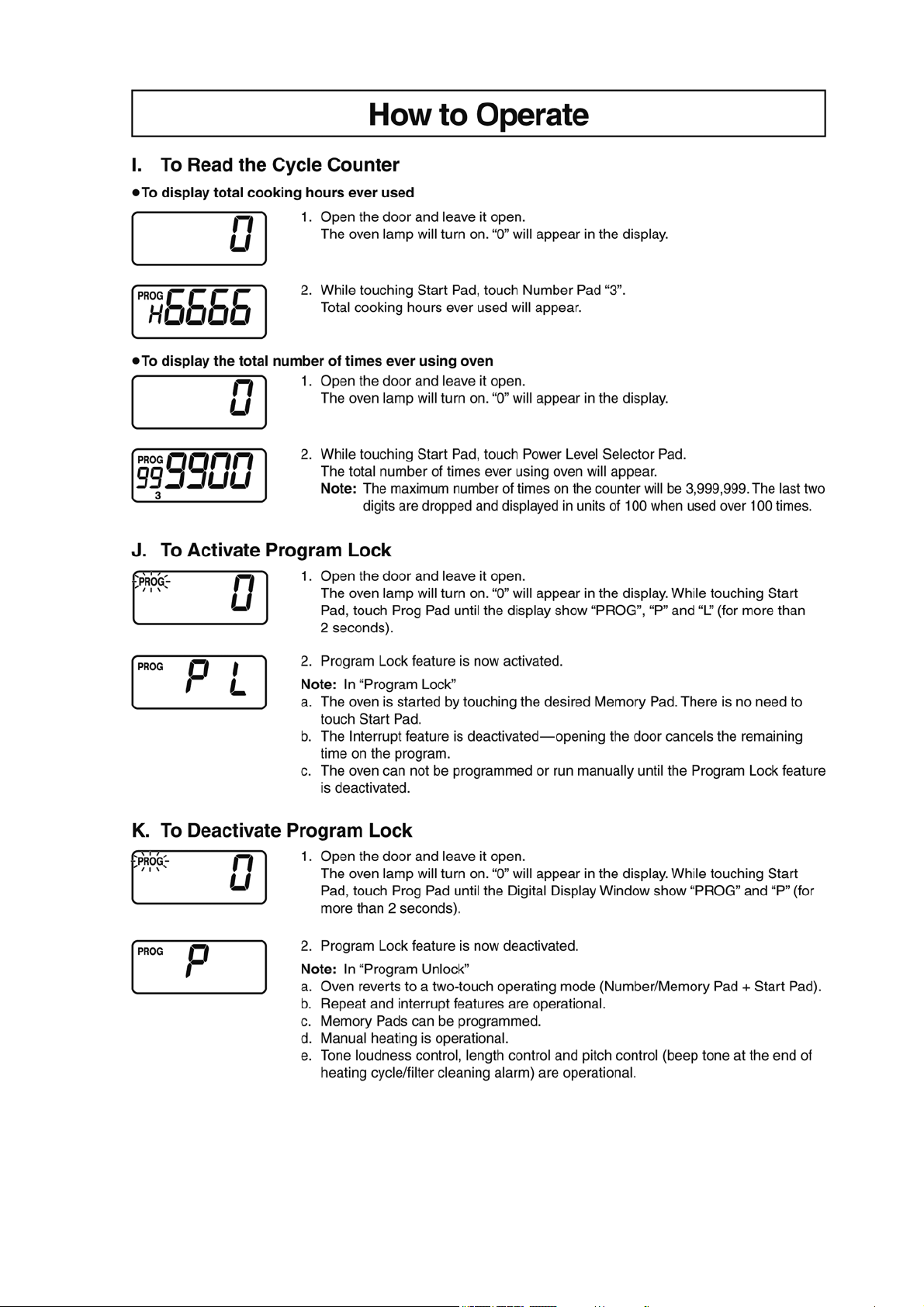
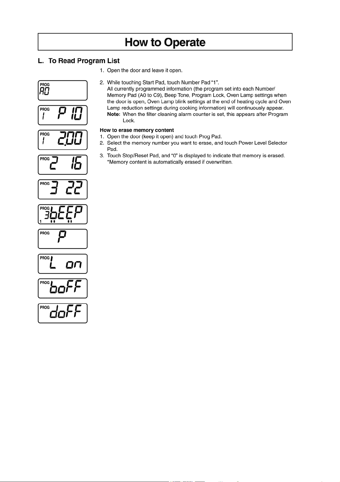
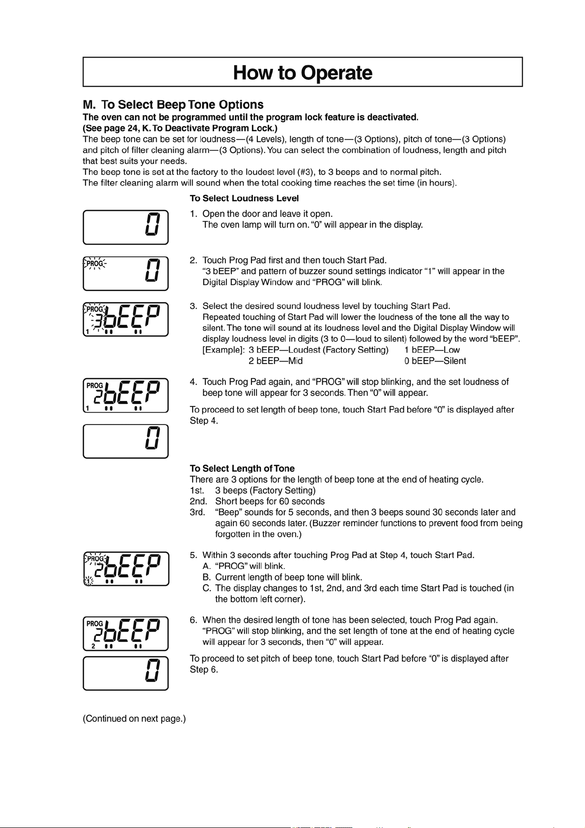
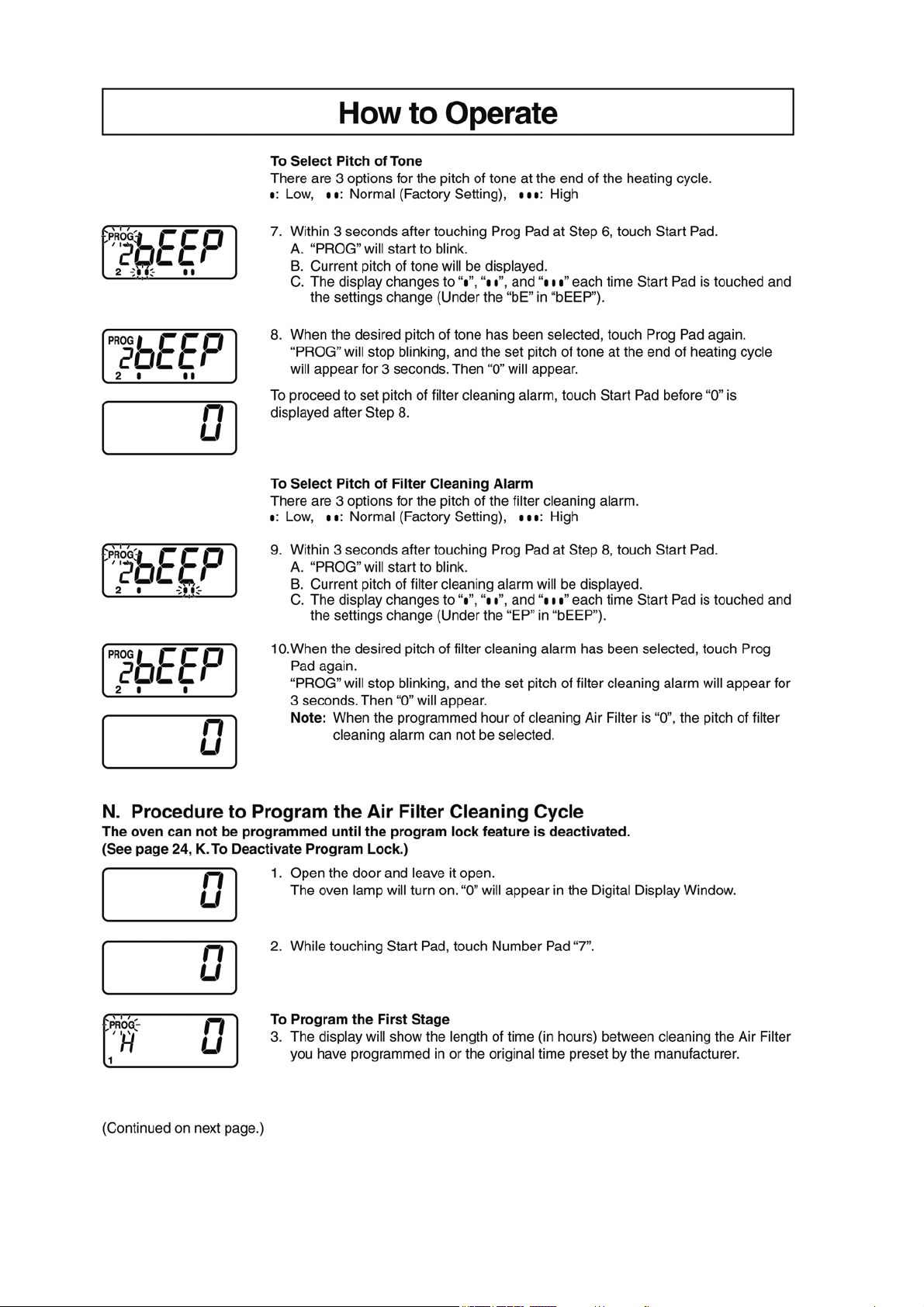
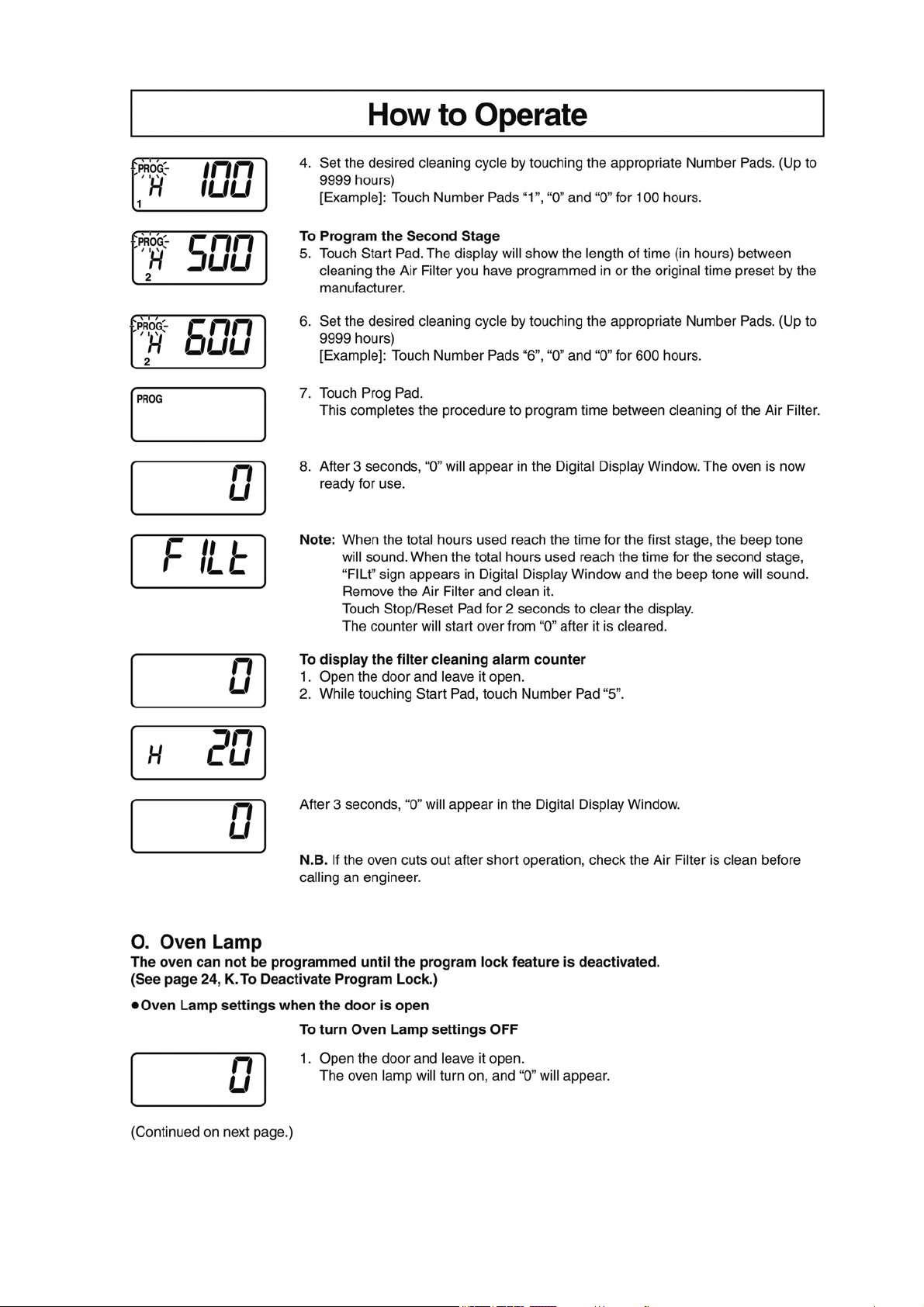
4 Operating Instructions
4.1. Operation procedure
6
7
8
9
10
11
12
13
14
15
16
17
5 Service Mode
To prevent accidents during repair and ensure your safety after the repair, be sure to read or refer to “Safety Precautions” describing
precautions that you must observe when repairing.
5.1. Failure code function
In the event of a failure, a failure code is displayed to stop the operation.
• Once displayed, the failure code “F 97,” “F 98,” “FE 7” or “FE 8 is stored in memory, which prevents the oven from operating even
if any part is replaced, and it remains displayed until the stored failure code is erased. Erase the code before conducting an oper-
ation test.
• If “F 97” or “FE 7” code failure occurs until a second time, you are taken back to the initial display screen.
If the failure occurs a third time, this failure code is displayed.
• If “F 98” or “FE 8” code failure occurs until a third time, you are taken back to the initial display screen.
If the failure occurs a fourth time, this failure code is displayed.
• The failure code “F 00” “U 40” “U 41”cannot be stored even if they are displayed,
18
5.1.1. Failure code list
F □□ : Device failure / U □□ : User error
DISPLAY CONDITIONS RESET CAUSES / REMEDIES
Upper circuit Lower circuit
F00 • Communication error between the micro-
computer and the memory IC.
• Press Stop/Reset button. • Control board (D.P.circuit)
F01 • Abnormal rise in the exhaust temperature
(120 °C or higher).
• Overheating and ignition of food in the oven.
• Reset when the tempera-
ture in the oven falls to 60
°C or less.
• Clean the inside of the oven and the
exhaust channel. Replace parts if
necessary.
• Exhaust thermistor (Insulation failure)
F03 • Upon detection of an abnormal voltage for
10 seconds.
• Displayed only when the failure code is
called up.
• Press Stop/Reset button. • Check the power-supply voltage.
• Control board (D.P.circuit)
F18 F19 • Error in detection of the secondary current. • Press Stop/Reset button. • Confirm the grounding state of
H.V.Inverter.
• Confirm the grounding state of control
board (D.P.circuit).
• H.V. Inverter (Insufficient cooling)
F32 F22 • Open or short-circuit in the MAG thermistor. - • MAG thermistor
F33 • Open or short-circuit in the exhaust thermis-
tor.
- • Exhaust thermistor
F44 • Shorted membrane switch.
• With a continued press of the same key for
2 minutes.
• Press Stop/Reset button. • Membrane switch
F77 • Lock detection of cooling fan motor (for con-
trol board (D.P.circuit)).
• Press Stop/Reset button. • DC fan motor
(Cooling fan for control board (D.P.cir-
cuit))
F90 FE0 • Abnormal temperature in IGBT of
H.V.Inverter.
• Press Stop/Reset button. • Insufficient cooling of H.V.Inverter
(Fan Motor / fan motor drive circuit)
F92 FE2 • Magnetron failure (Detection of A-K short
circuit.)
• Press Stop/Reset button. • Magnetron
F95 FE5 • Inverter actuation signal failure
(At startup of inverter, an actuation signal
has not been input.)
• Press Stop/Reset button. • Inverter connector disconnection
• Latch adjustment failure
F96 FE6 • Inverter actuation signal failure.
(During non-actuation of inverter, an actua-
tion signal is Lo.)
• Press Stop/Reset button. • H.V.Inverter
• Control board (D.P.circuit)
F97 FE7 • Inverter actuation signal failure.
(During actuation of inverter, an actuation
signal is Hi)
(At startup of inverter, an actuation signal is
Hi.)
• Press Stop/Reset button. • Absence of any inverter AC input
(Door switch / Relay circuit / Relay
connector / CN702 disconnection,
etc.)
• Magnetron
F98 FE8 • Inverter actuation signal failure.
(At startup of inverter, an actuation signal is
Lo)
• Press Stop/Reset button. • Magnetron (breaking of heater wire,
etc.)
• H.V.Inverter
• Disconnection of magnetron’s lead
wire
F99 FE9 • If actuation signal is input to the microcom-
puter when the inverter is not in actuation.
• Press Stop/Reset button. • Control board (D.P.circuit)
U30 • Memory cooking with double/triple quantity
has exceeded the maximum cooking time.
• Press Stop/Reset button. • Check and change the time.
U40 • Abnormal temperature detection of magne-
tron when the oven is operated without food
(Empty heating detection).
• Press Stop/Reset button. • Confirm the inside of the oven.
• Magnetron thermistor
U41 • Abnormal secondary current detection of
H.V.inverter when the oven is operated with-
out food (Empty heating detection).
• Press Stop/Reset button. • Confirm the inside of the oven.
• H.V. Inverter
19
5.2. How to erase self-diagnosis memory
• Memory of self-diagnosis cannot be erased by turning OFF the power.
• By "How to erase self-diagnosis memory (1)" , self-diagnosis memory of "F 97", "F 98", "FE 7" and "FE 8" cannot be erased.
In this case, erase the memory of self-diagnosis by "How to erase self-diagnosis memory (2)" .
lHow to erase self-diagnosis memory (1) (when error code other than "F 97", "F 98", "FE 7" or "FE 8" is displayed)
lHow to erase self-diagnosis memory (2) (when error code "F 97", "F 98", "FE 7" or "FE 8" is displayed)
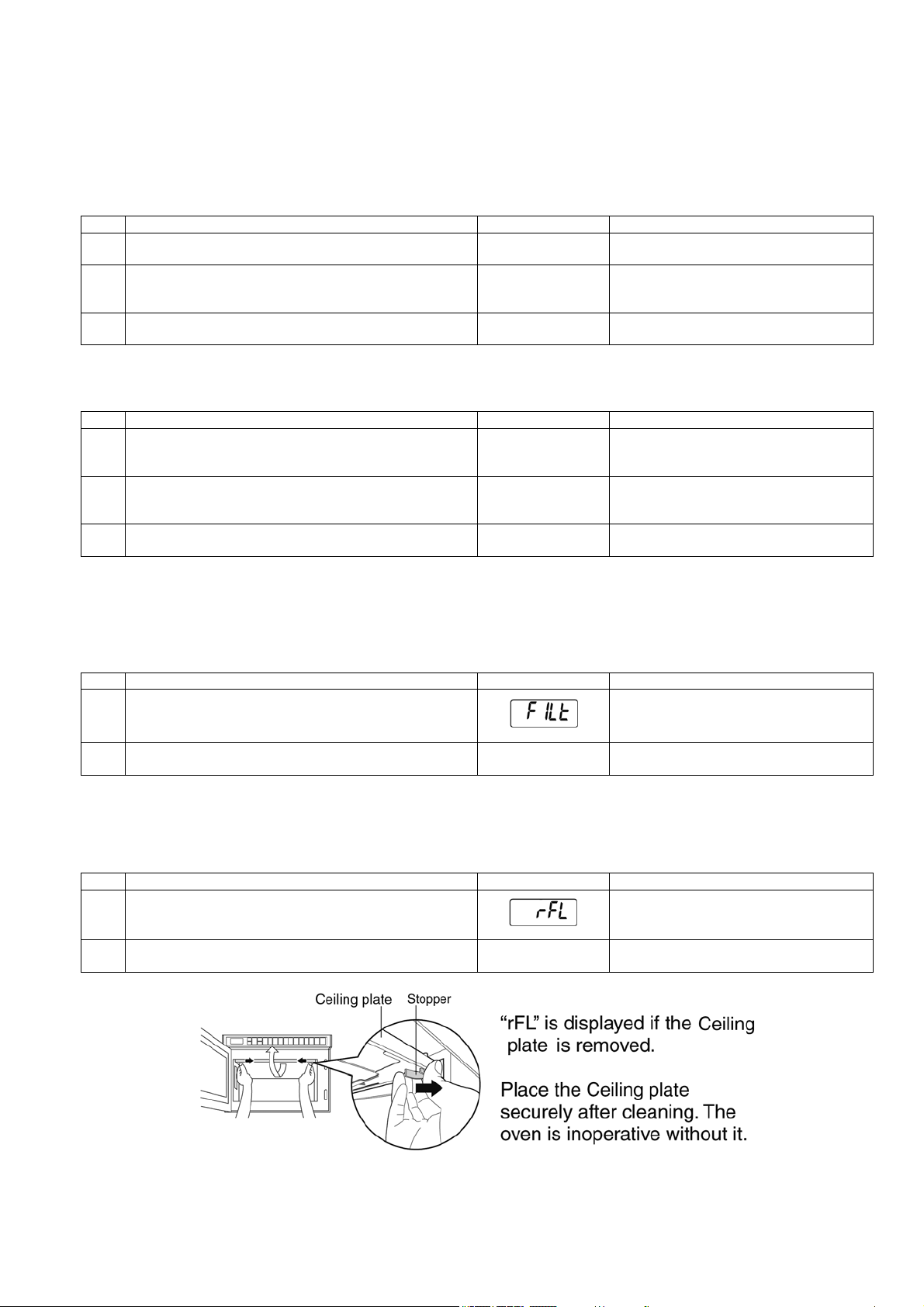
5.3. How to cancel ”FILt” sign in the display
• "FILt" sign in the display cannot be cancelled by turning OFF the power.
• Pressing "Pause/Cancel" key generates short beep tone and the "FILt" sign disappears but cannot be cancelled.
Use the following method to cancel the "FILt" sign.
5.4. How to cancel ”rFL” sign in the display
• "rFL" is displayed if the ceiling plate is removed.
• Place the ceiling plate securely. The oven is inoperative without it.
Procedure Display Remarks
1. Door open.
0
2. Press "Start" key and "8" at the same time to display self-diag-
nosis.
(Example)
F33 0000 is displayed if any error have not
been occurred yet.
3. While the display is shown, press "Pause/Cancel" to erase the
memory of self-diagnosis.
0
Procedure Display Remarks
1. Door open.
0
2. Press "Start" key and "8" at the same time to display self-diag-
nosis.
(Example)
F98 0000 is displayed if any error have not
been occurred yet.
3. While the display is shown, press "Pause/Cancel" to erase the
memory of self-diagnosis.
0
Procedure Display Remarks
1. Door is closed condition.
2. Keep pressing "Pause/Cancel" key for 2 seconds.
0
"FILt" sign is cancelled.
Procedure Display Remarks
1. Ceiling plate is removed.
2. Place the ceiling plate securely.
0
"rFL" sign is cancelled.
20
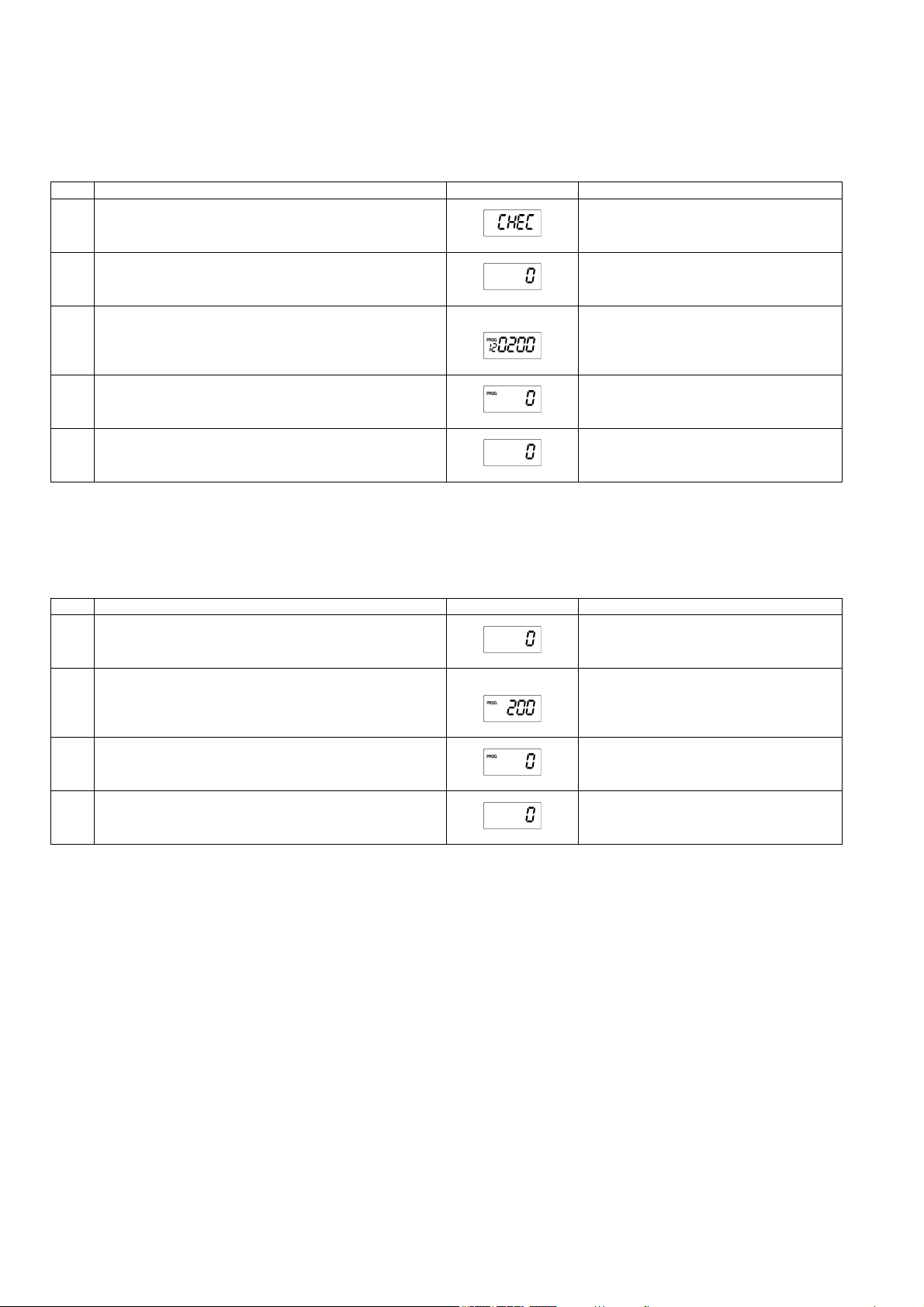
5.5. How to cancel ”CHEC” sign in the display
• When the number of times of using magnetron reaches 120,000 times, the display indicates CHEC after heating.
• Once CHEC is displayed, it is displayed every time when cooking is finished.
Follow the procedure as mentioned below to cancel the "CHEC" sign in the display.
5.6. How to reset the number of times of using magnetron
• When the magnetron is replaced after displaying error codes such as "F 92", "FE 2", "F 97", "FE 7", "F98", or "FE 8", the number
of times of using magnetron needs resetting.
Follow the procedure as mentioned below to reset the number of times of using magnetron.
Procedure Display Remarks
1. After finishing heating with the door closed, leave the condition
for 1 minute.
CHEC is displayed.
2. Door open. Initial display condition.
3. Press "Start" key and "4" at the same time. (Example) Number of times of using magnetron is dis-
played.
• When the number of times of use is 100 or
below, the display rounds down the number.
4. Press "Pause/Cancel" key within 3 seconds. CHEC display is canceled.
• Reset the number of times of use
5. Display returns to the initial screen in 3 seconds. Initial display condition.
Procedure Display Remarks
1. Door open. Initial display condition.
2. Press "Start" key and "4" at the same time. (Example) Number of times of using magnetron is dis-
played.
• When the number of times of use is 100 or
below, the display rounds down the number.
3. Press "Pause/Cancel" key within 3 seconds. Resetting the number of times of using magne-
tron is completed.
• Reset the number of times of use
4. Display returns to the initial screen in 3 seconds. Initial display condition.
21
6 Troubleshooting Guide
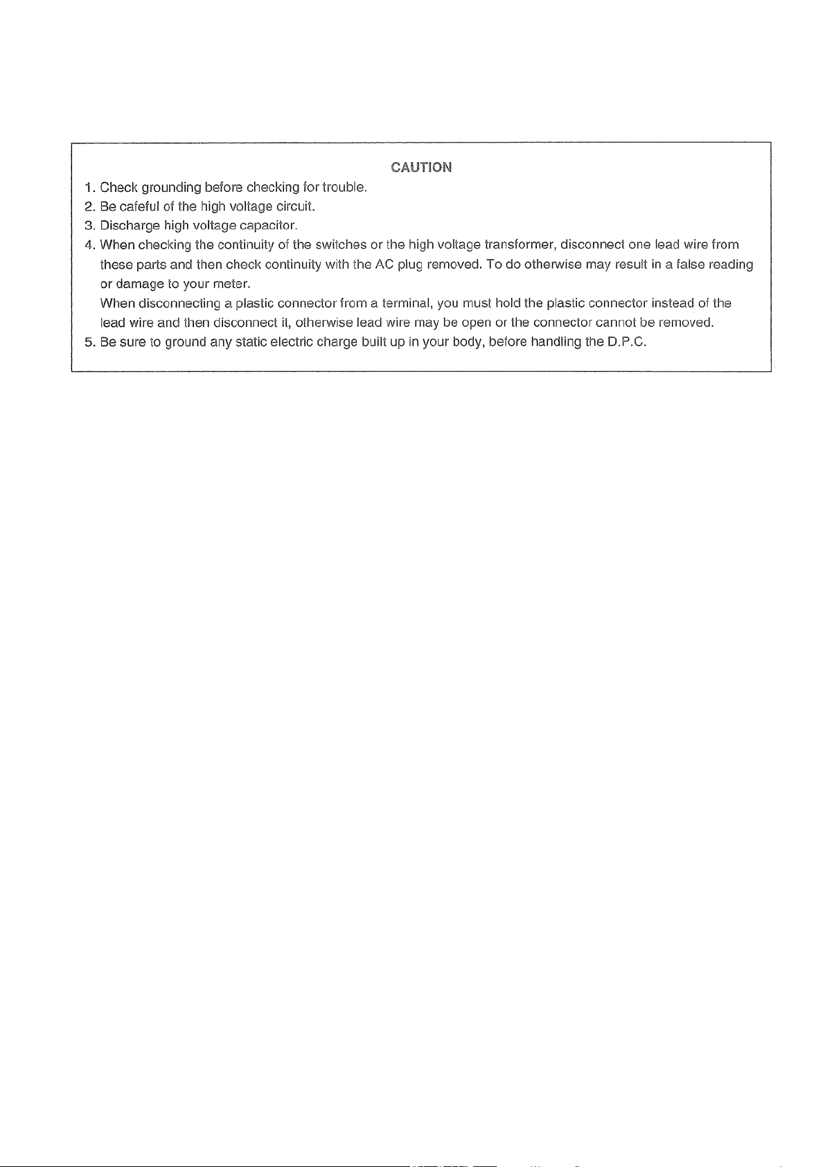
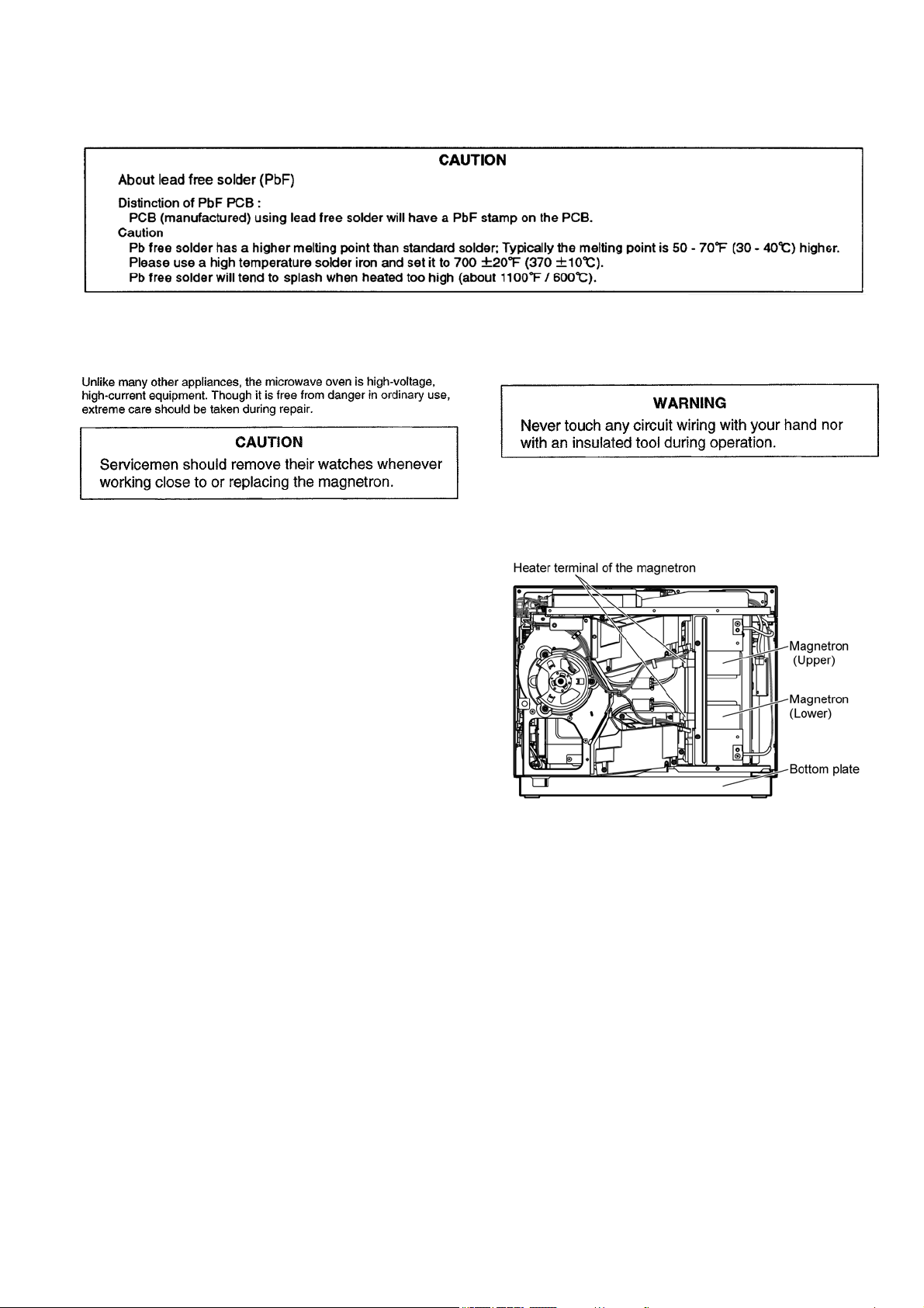
6.1. Precautions when repairing
To prevent accidents during repair and ensure your safety after the repair, be sure to read or refer to “Safety Precautions” describing
precautions that you must observe when repairing.
6.2. Before repair
6.3. Discharging high-voltage capacitor
When the confirmation of power-on is performed, always
discharge the capacitor as shown below.
6.3.1. Method of discharging the high-
voltage capacitor
• Be sure to unplug the AC cord, leave it for 30 sec. and then
unplug the connector of magnetron.
• Short circuit the chassis (lower plate, oven, etc.) and inverter
terminal of the high-voltage lead wire, then heater terminals
of the magnetron.
Touch the lead wire for shot-circuiting first on the chassis.
22
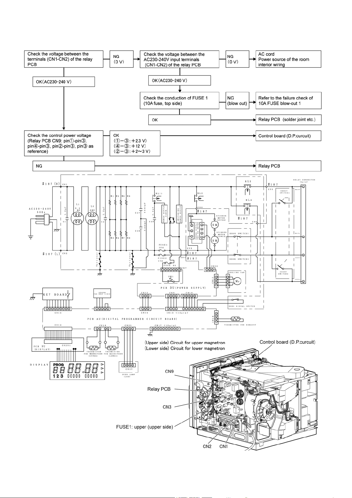
6.4. Power cannot be turned on
Power cannot be turned on (Opening the door does not indicate 0. Keys do not work.)
23
6.5. 10A FUSE blow-out 1
Power cannot be turned on (Opening the door does not indicate 0. Keys do not work.)
24
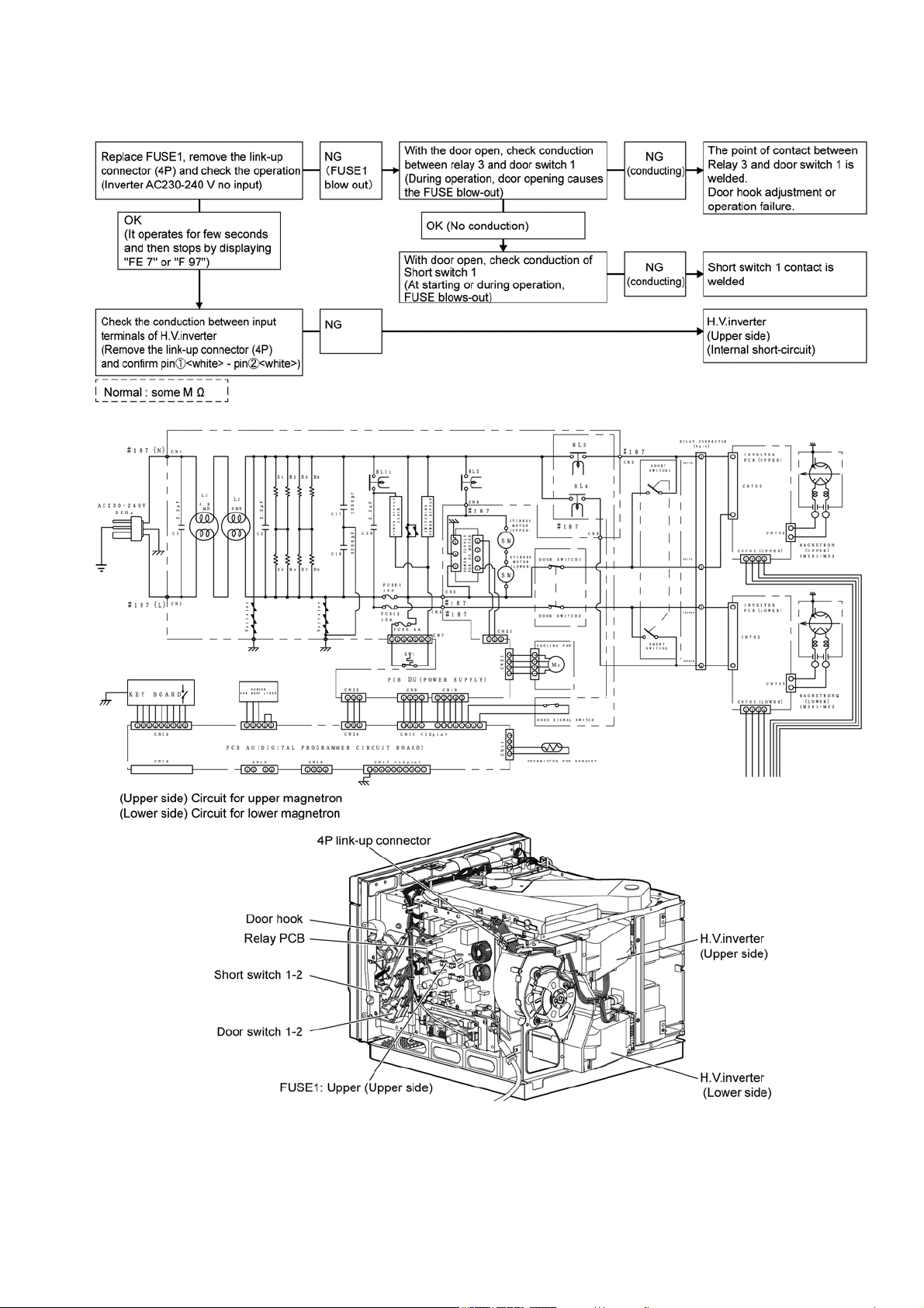
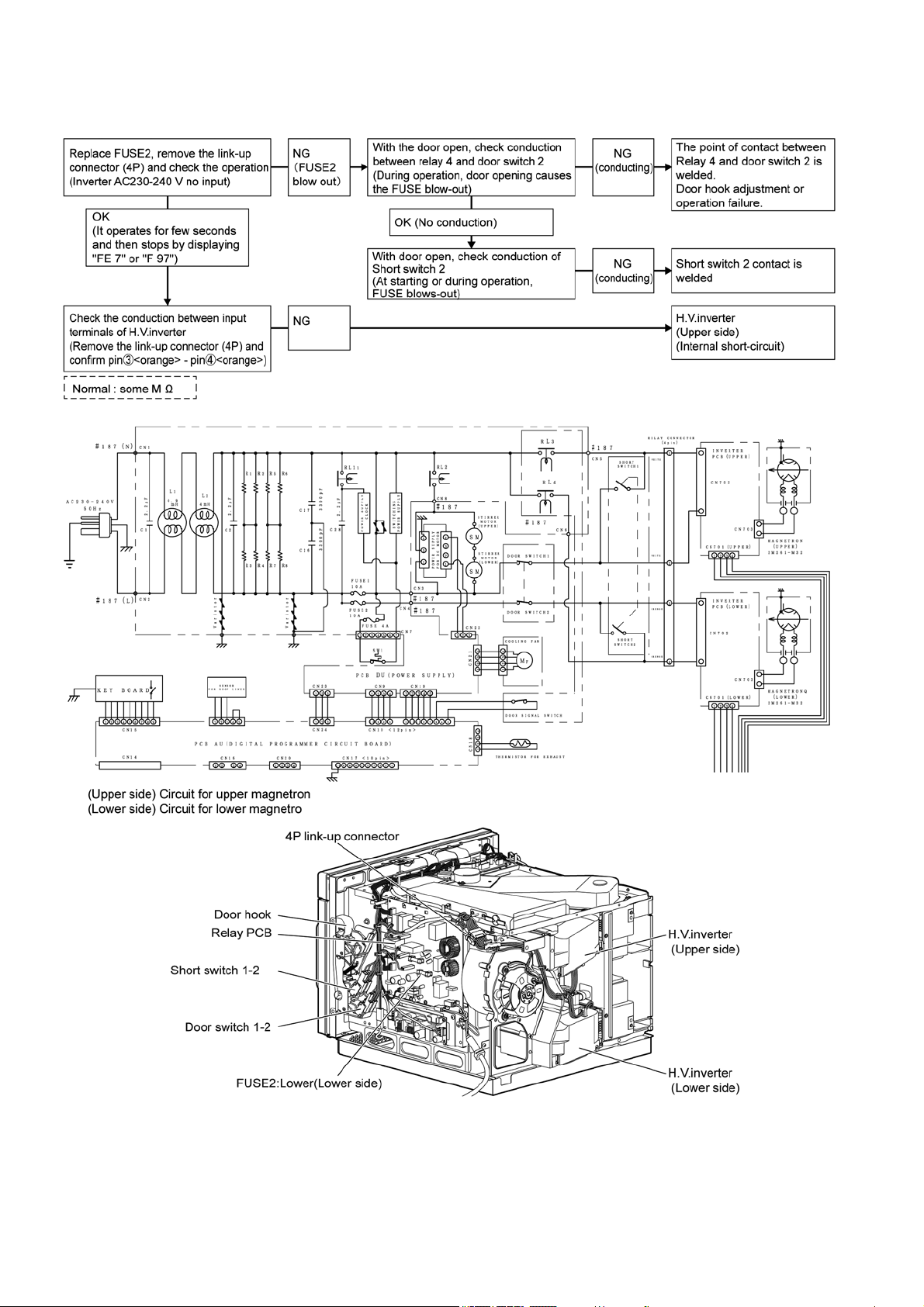
6.6. 10A FUSE blow-out 2
In several seconds after starting cooking, operation stops by displaying "FE 7"
25
6.7. Oven does not warm up
In several seconds or several 10s seconds after starting cooking, operation stops by displaying "FE 5", " F 95", "FE 7",
"FE 8", "F 98"
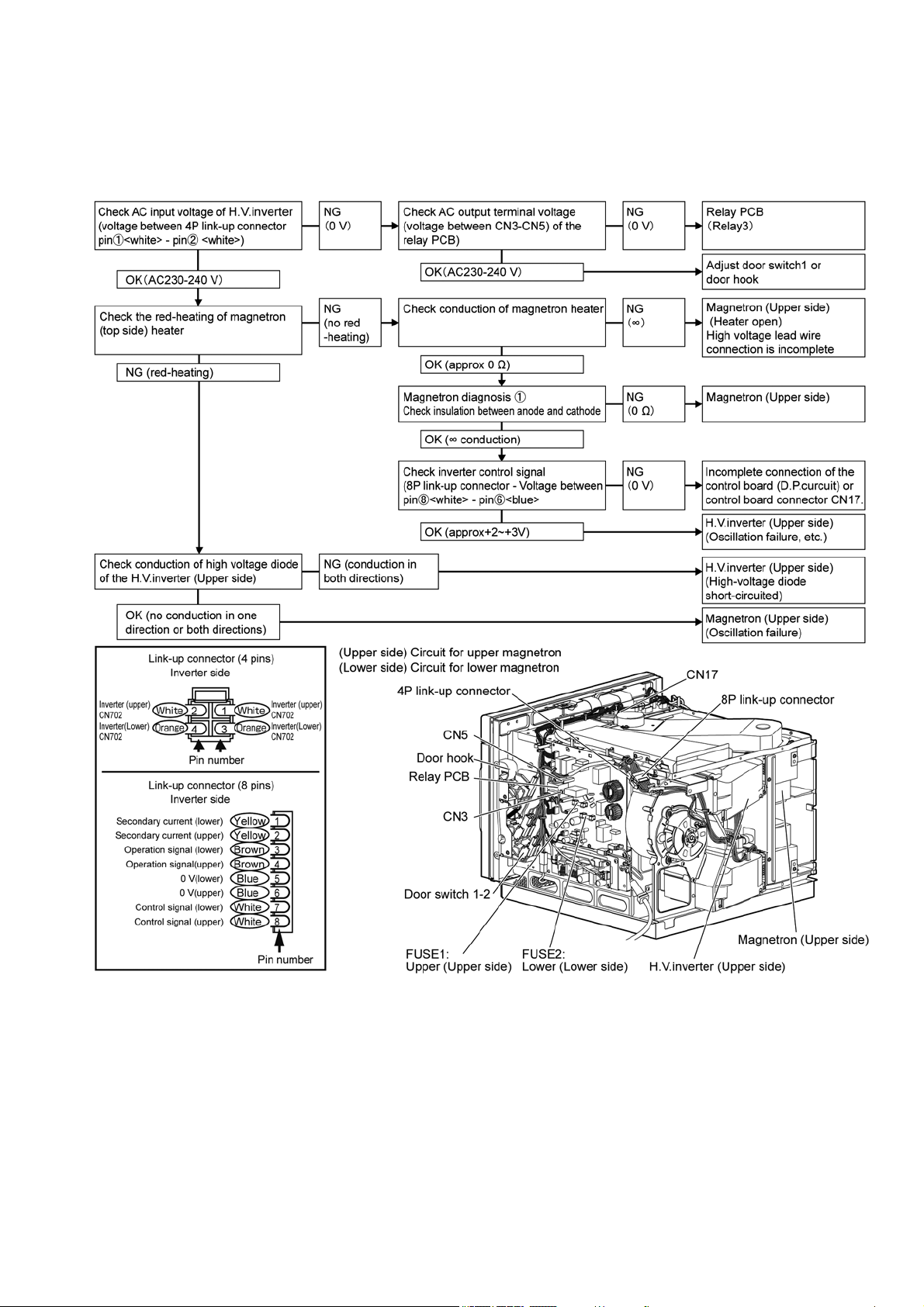
6.7.1. "F 95", "F 97", "F 98" are displayed (Check the circuit for upper magnetron. )
(In the case of FUSE 1 [10A FUSE upper side] blow-out defect, power cannot be supplied)
26
27
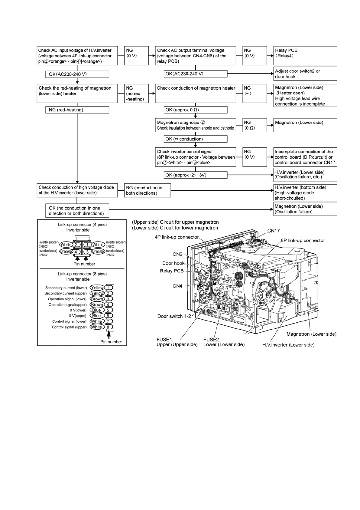
6.7.2. Displays "FE 5", "FE 7", "FE 8" (Check the circuit for lower magnetron)
28
29
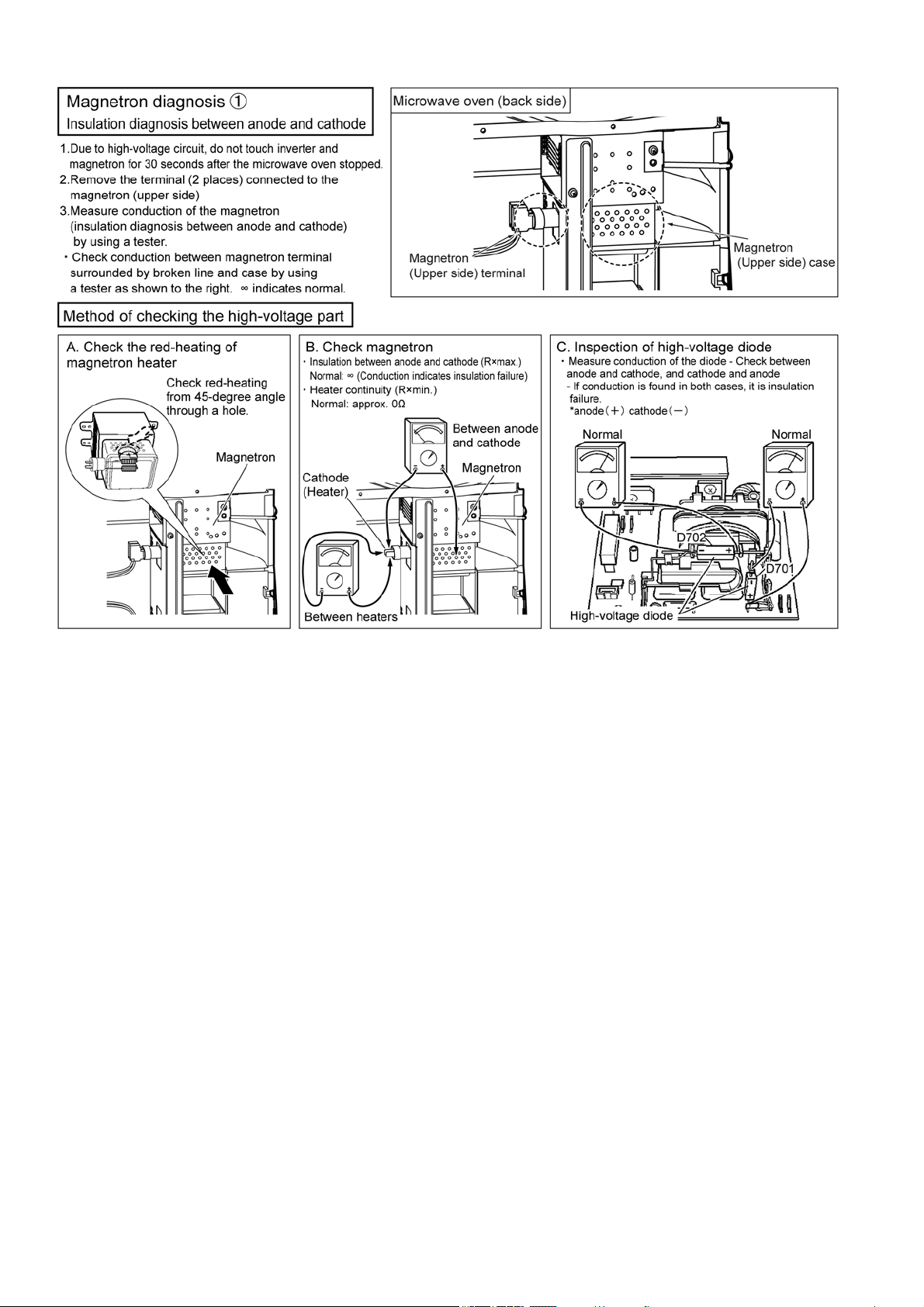
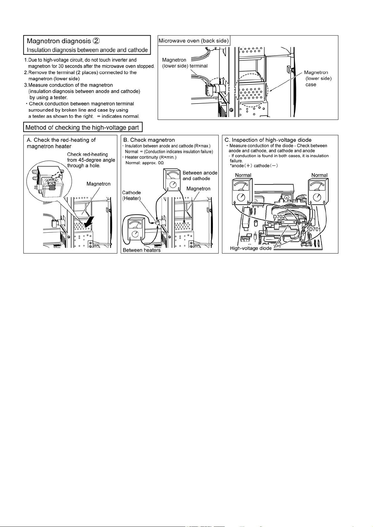
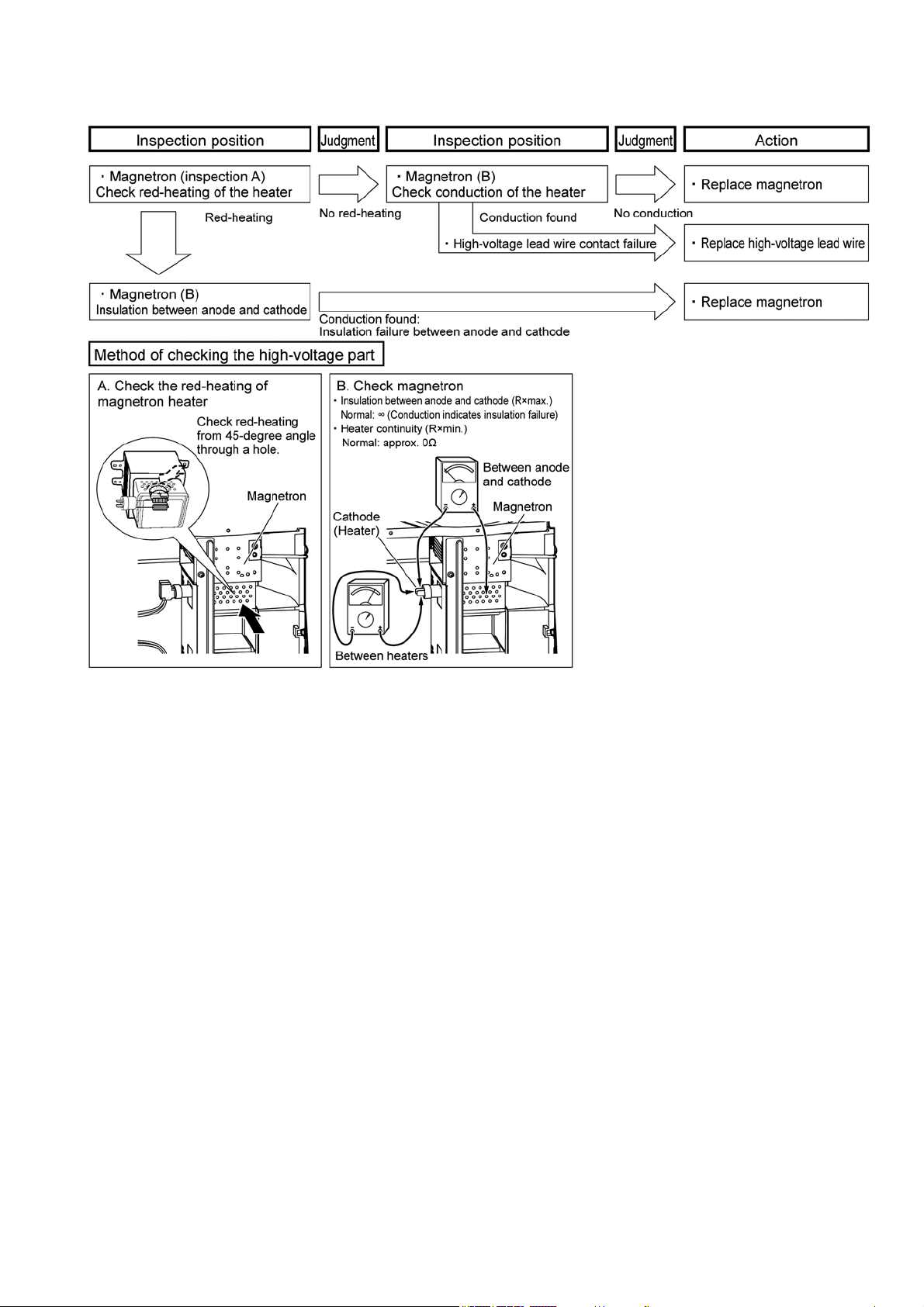
6.7.3. How to check the magnetron when indicating "F 92" or "FE 2"
When "F 92", "FE 2" is indicated, inspect by using the following procedure.
30
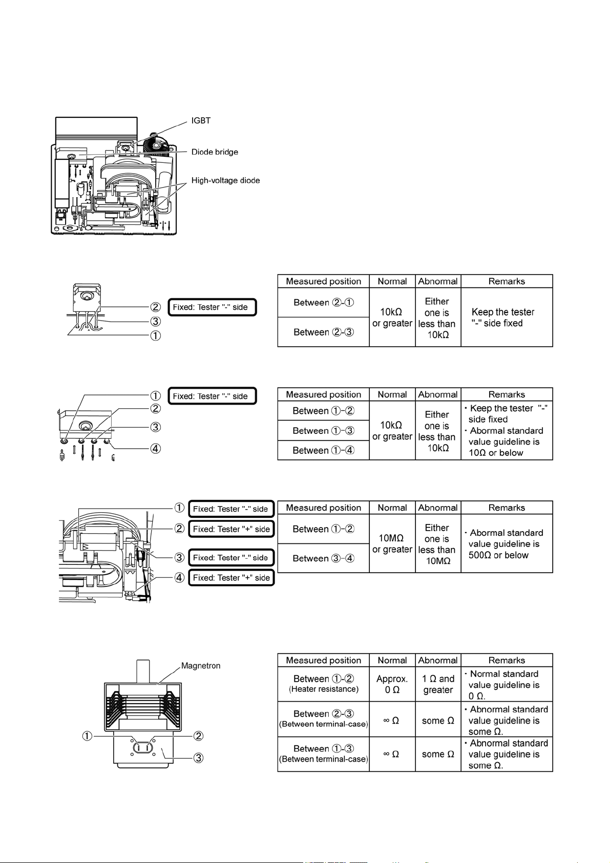
6.7.4. Component test procedure for magnetron and H.V.inverter
Caution: First, remove wiring of the component to be checked to make it a stand-alone condition.
6.7.4.1. How to check an H.V.inverter
Mainly use failure diagnosis of F97/FE7/F98/FE8 Caution:
Polarity of a tester is shown below.
Use the tester as shown for measurement.
Otherwise, misjudgment may occur.
6.7.4.2. How to check an IGBT
6.7.4.3. How to check a diode bridge
6.7.4.4. How to check a high-voltage diode
6.7.4.5. How to check a magnetron
Use failure diagnosis mainly by F97/FE7/F98/FE8, particularly by F92 and FE2.
31
7 Disassembly and Assembly Instructions
To prevent accidents during repair and ensure your safety after the repair, be sure to read or refer to “Safety Precautions” describing
precautions that you must observe when repairing.
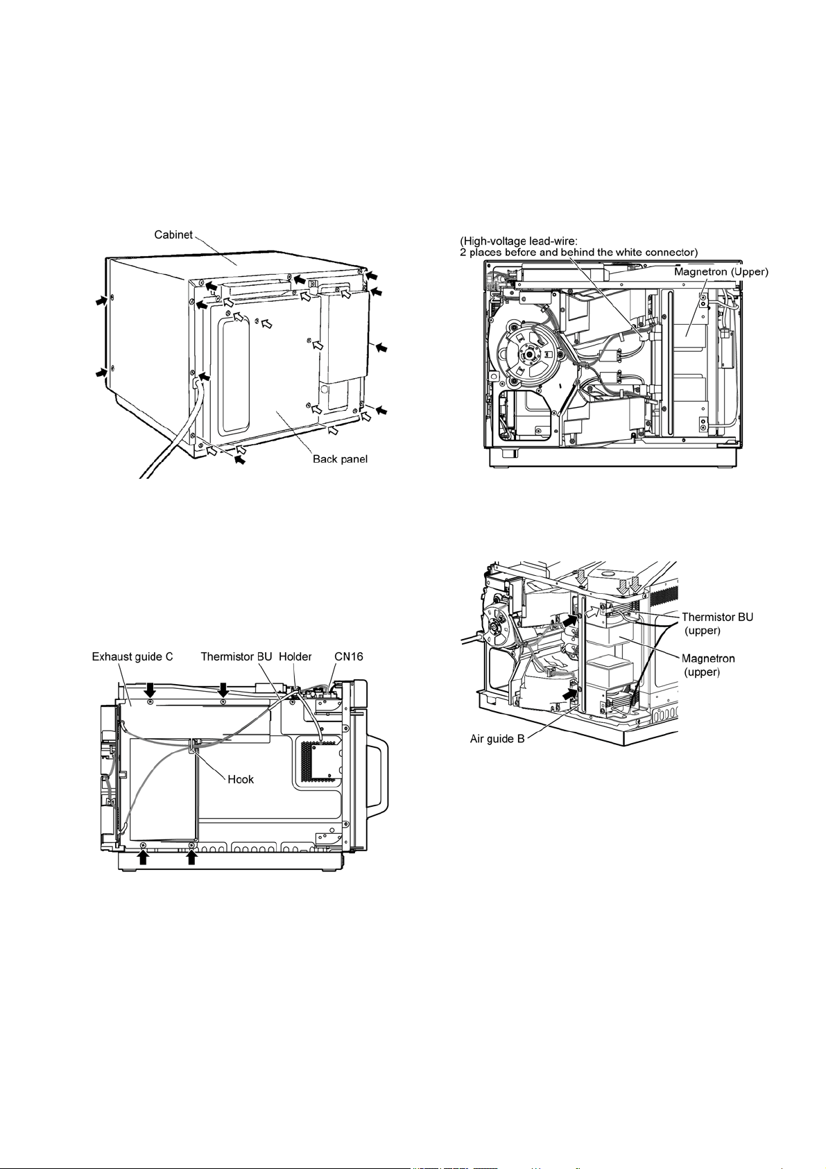
7.1. Cabinet, back panel
1. Remove the cabinet. (Black arrow: 2 screws each at the
left and right, and 9 screws on the back)
2. Remove the back panel. (White arrow: 11 screws)
7.2. Magnetron
1. Remove the cabinet and back panel.
(Refer to "7.1.Cabinet, back panel")
7.2.1. Exhaust guide
1. Remove the connector (CN16) of thermistor BU.
2. Unhook the lead wire from the hook and holder.
3. Remove the exhaust guide C. (Black arrow: 4 screws)
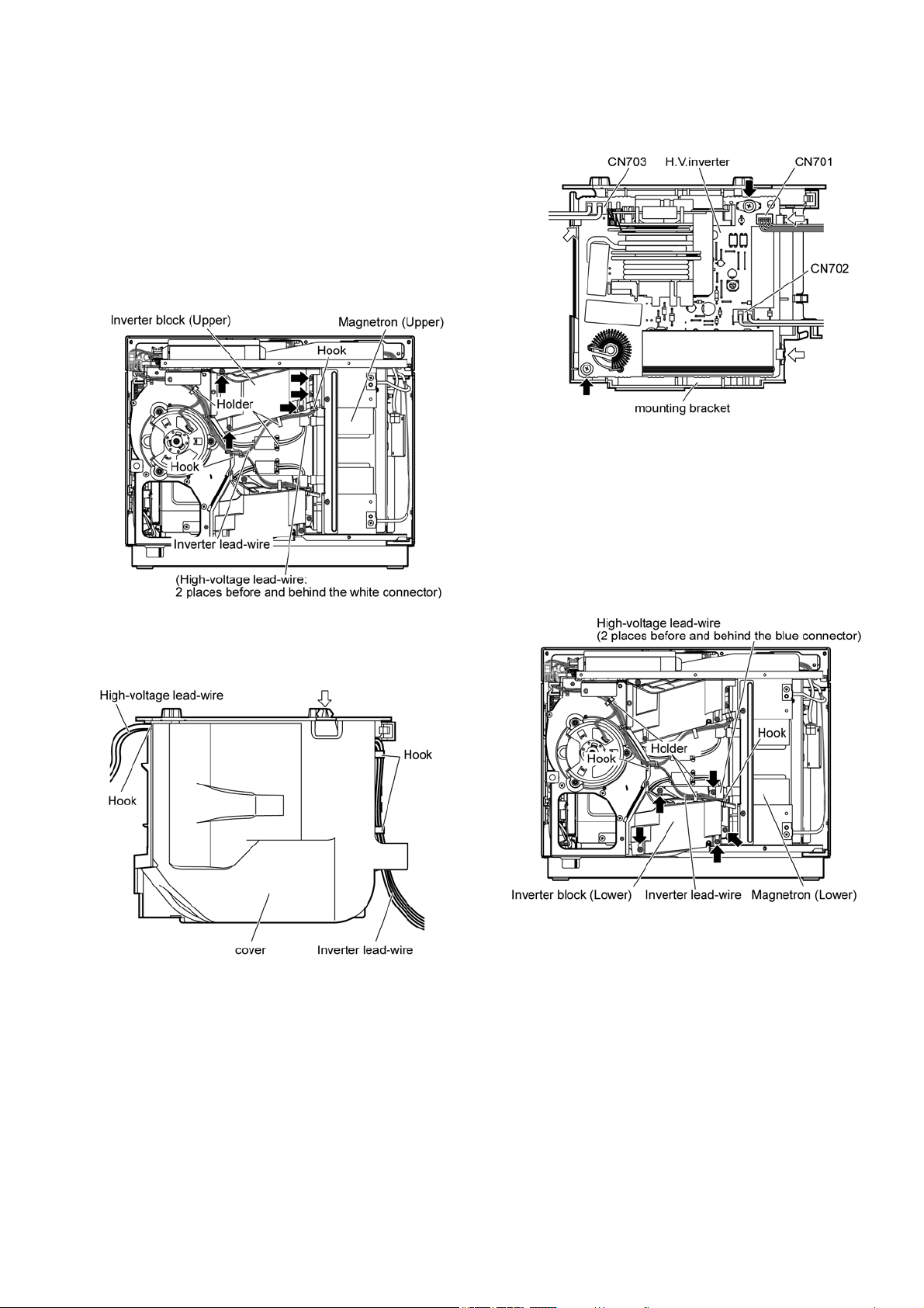
7.2.2. Magnetron (upper)
1. Remove the high-voltage lead-wire of the magnetron
(upper).
(High-voltage lead-wire: 2 places before and behind the
white connector)
2. Remove the air guide B. (Black arrow: 2 screws)
3. Remove the thermistor BU (upper). (White arrow: 1
screw)
4. Remove the magnetron. (Tilted arrow: 3 screws)
32
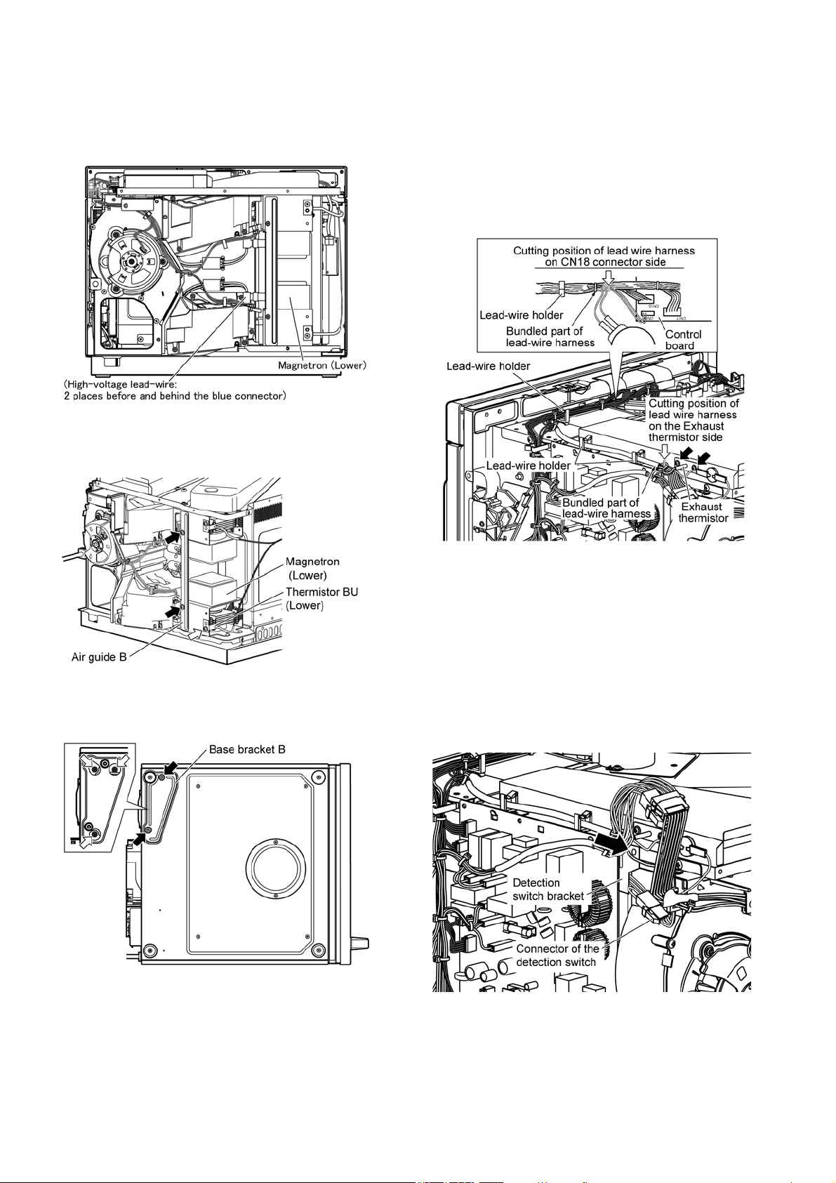
7.2.3. Magnetron (lower)
1. Remove the high-voltage lead-wire of the magnetron
(lower)
(High-voltage lead-wire: 2 places before and behind the
blue connector)
2. Remove the air guide B. (Black arrow: 2 screws)
3. Remove the thermistor BU (lower). (White arrow: 1
screw)
4. Lay the magnetron down sideways.
5. Remove the base bracket B. (Black arrow: 2 screws)
6. Remove the magnetron (lower). (White arrow: 3 screws)
7.3. Exhaust thermistor
1. Remove the cabinet. (Refer to 7.1.Cabinet, back panel)
2. In the lead-wire harness, cut the lead-wire of exhaust
thermistor at the thermistor side bundle.
3. In the lead-wire harness, cut the lead-wire of exhaust
thermistor at the connector side bundle.
4. Remove the exhaust thermistor. (Black arrow: 2 screws)
• Leave the remaining lead-wire of the exhaust thermistor in
the lead-wire harness as they are bundled.
• When installing, bundle the lead-wire of the exhaust thermis-
tor with the lead-wire holder.
7.4. Detection switch
1. Remove the cabinet and back panel.
(Refer to "7.1.Cabinet, back panel")
2. Remove the connector of the detection switch.
3. Remove the detection switch bracket.
(Black arrow: 1 screw)
4. Remove the detection switch from the detection switch
bracket.
33
7.5. H.V.inverter
1. Remove the cabinet and back panel.
( Refer to "7.1.Cabinet, back panel”)
7.5.1. H.V.inverter (upper)
1. Remove the inverter lead-wire and high-voltage lead-wire
from each hook and holder.
2. Remove the high-voltage lead-wire from the magnetron
(upper)
High-voltage lead-wire (2 places before and behind the
white connector)
3. Remove inverter block (upper). (Black arrow: 5 screws)
4. Remove the inverter lead-wire and high-voltage lead-wire
from each hook and holder.
5. Remove the cover (White arrow: 1 hook)
6. Remove connectors (CN701, CN702, CN703).
7. Remove the H.V.inverter. (Black arrow: 2 screws, white
arrow: 3 hooks)
7.5.2. H.V.inverter (lower)
1. Remove the inverter lead-wire and high-voltage lead-wire
from each hook and holder.
2. Remove the high-voltage lead-wire from the magnetron
(lower).
(High-voltage lead-wire: 2 places before and behind the
blue connector)
3. Remove inverter block (lower). (Black arrow: 5 screws)
34
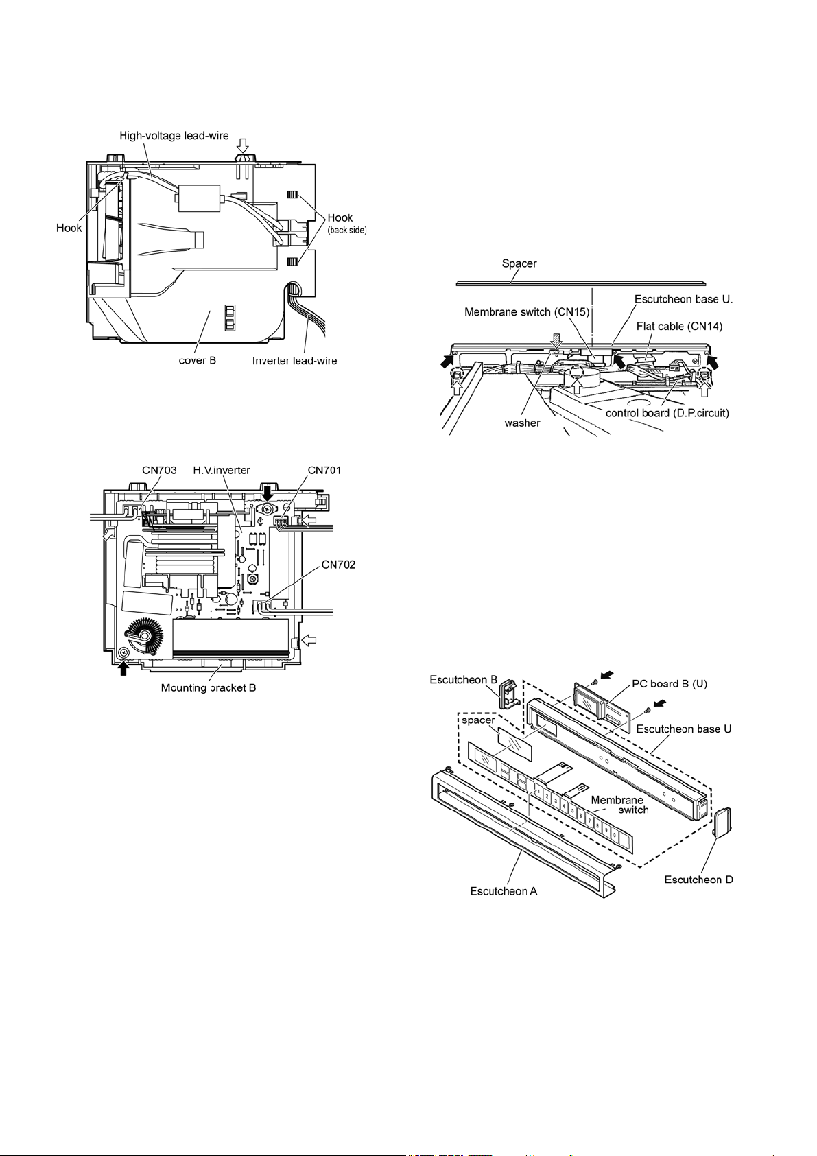
4. Remove the inverter lead-wire and high-voltage lead-wire
from each hook.
5. Remove cover B. (White arrow: 1 hook)
6. Remove connectors (CN701, CN702, CN703).
7. Remove the H.V.inverter. (Black arrow: 2 screws, white
arrow: 3 hooks)
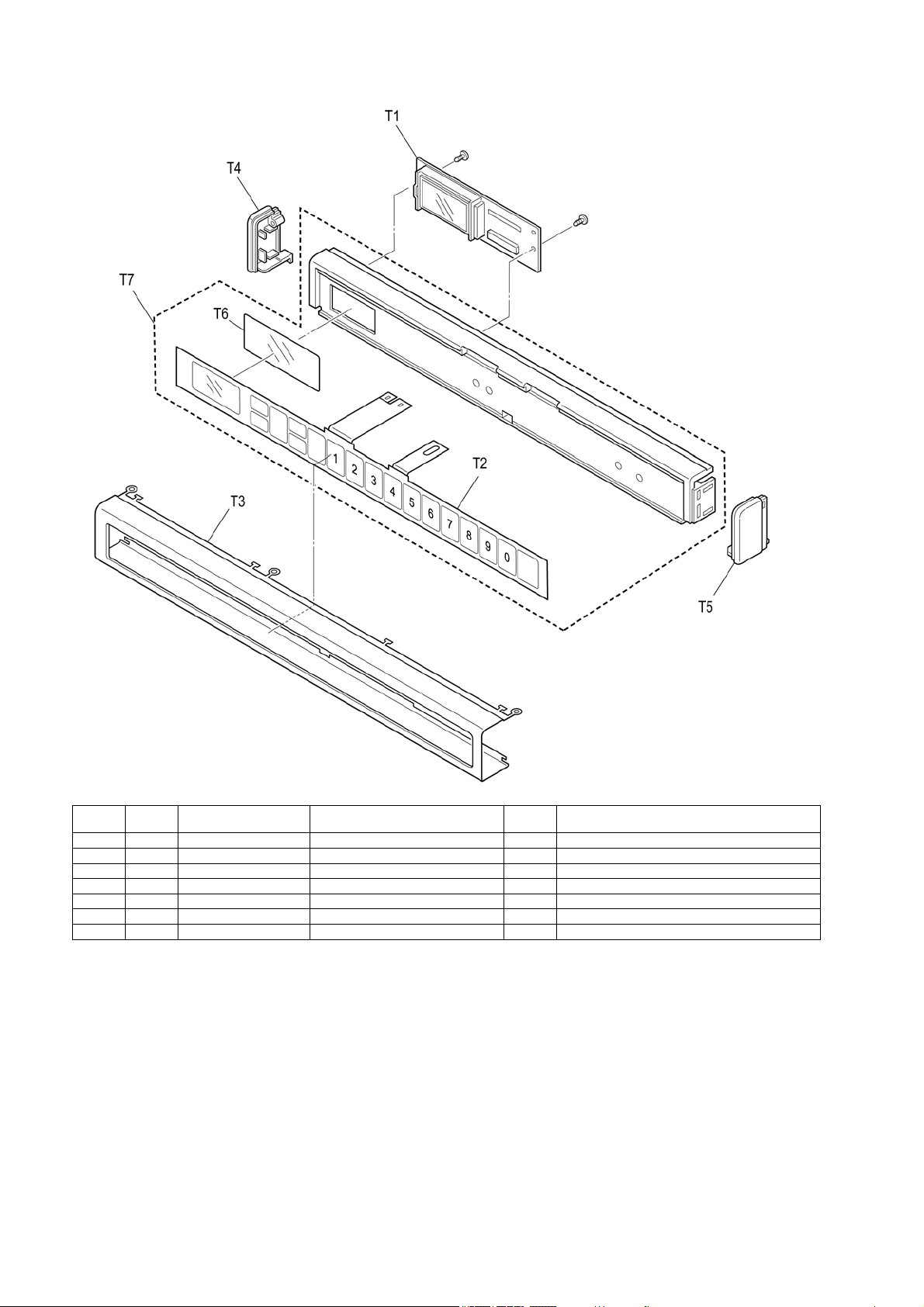
7.6. Operation unit (Escutcheon
base U)
1. Remove the cabinet.
2. Remove the flat cable (CN14) and keyboard (CN15) on
PC board.
3. Remove the spacer.
• It will be used for attachment.
4. Remove the washer. (Tilted arrow: 1 screw)
5. Remove the escutcheon base U. (Black arrow: 3 screws,
bottom side circle: 3 hooks)
7.6.1. Membrane switch
1. Remove the escutcheon base U.
(Refer to "7.6.Operation unit (Escutcheon base U)"
2. Remove escutcheon A, B, and D.
• Flatten the securing hook of escutcheon A and remove it
from the escutcheon base U.
3. Separate the membrane switch from escutcheon base U.
7.6.2. PC board B (U)
1. Remove the escutcheon base U.
(Refer to "7.6.Operation unit (Escutcheon base U)"
2. Remove PC board B (U) (Black arrow: 2 screws)
35
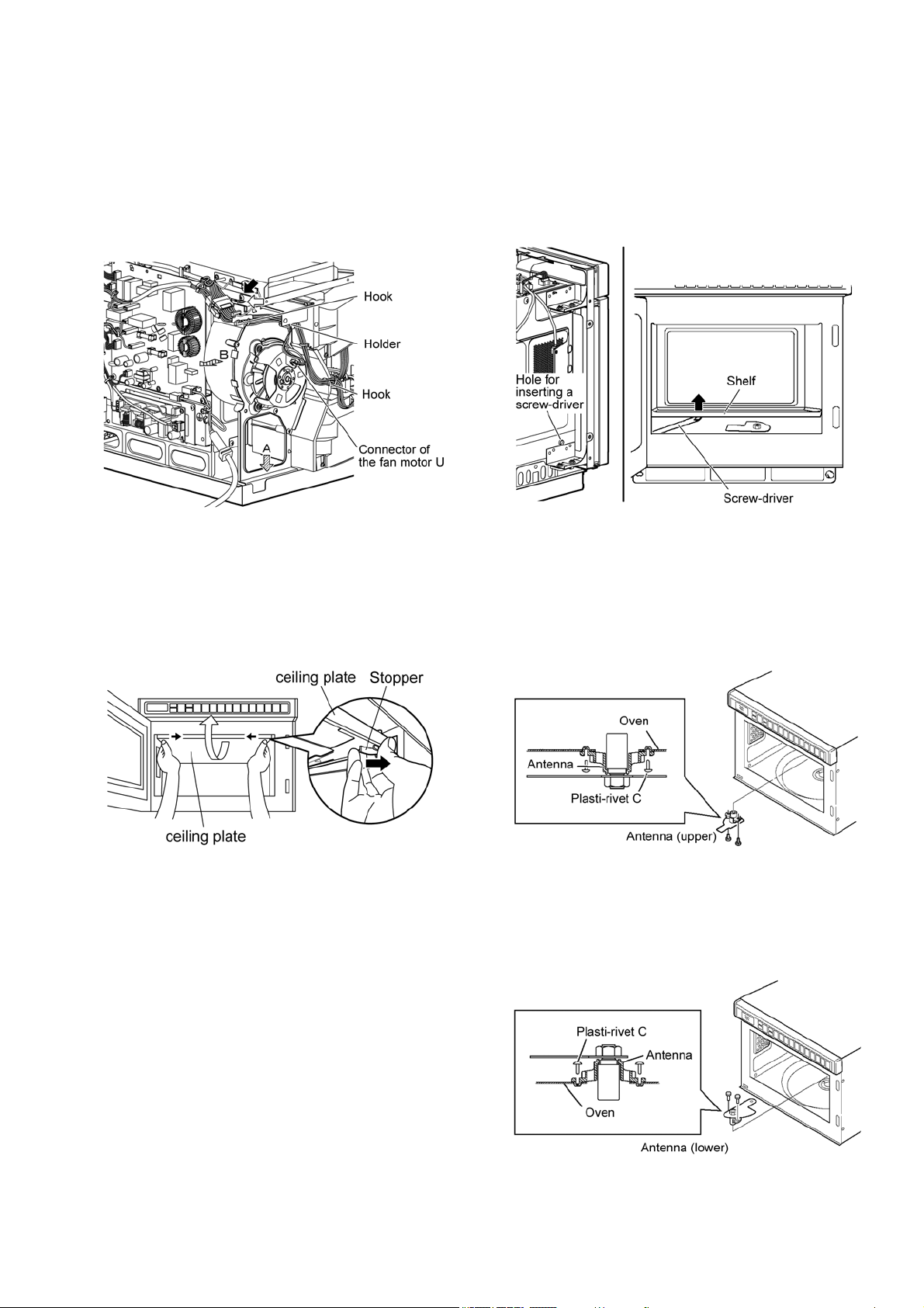
7.7. Fan motor U
1. Remove the cabinet and back panel.
(Refer to "7.1.Cabinet, back panel")
2. Remove the connector of the fan motor U.
3. Unhook the lead wire from the hook and holder.
4. Remove fan motor U.
(White arrow: 1 screw, black arrow: 1 screw)
• Push the fan motor U toward the bottom (tilted arrow A)
and tilt it to the side (tilted arrow B) to remove it.
7.8. Ceiling plate
1. Remove the ceiling plate.
• Pull the ceiling plate stopper located on the left and right
sides of the ceiling plate toward inside until disengaged.
• When installing, align the 3 protrusions on the back, and
then engage the hooks on both sides.
7.9. Shelf
1. Remove the cabinet.
(Refer to "7.1.Cabinet, back panel")
2. Remove the shelf.
• In the screw-driver insertion hole located at the left of the
oven, insert a screw-driver and press-down the handle to
lift up the
shelf.
(Hole diameter approx. 8mm)
7.10. Antenna
7.10.1. Antenna (Upper)
1. Remove the ceiling plate.
(Refer to "7.8.Ceiling plate")
2. Remove the antenna. (Plasti-rivet C: 2 pieces)
7.10.2. Antenna (Lower)
1. Remove the shelf.
(Refer to "7.9.Shelf")
2. Remove the antenna (lower). (Plasti-rivet C: 2 pieces)
36
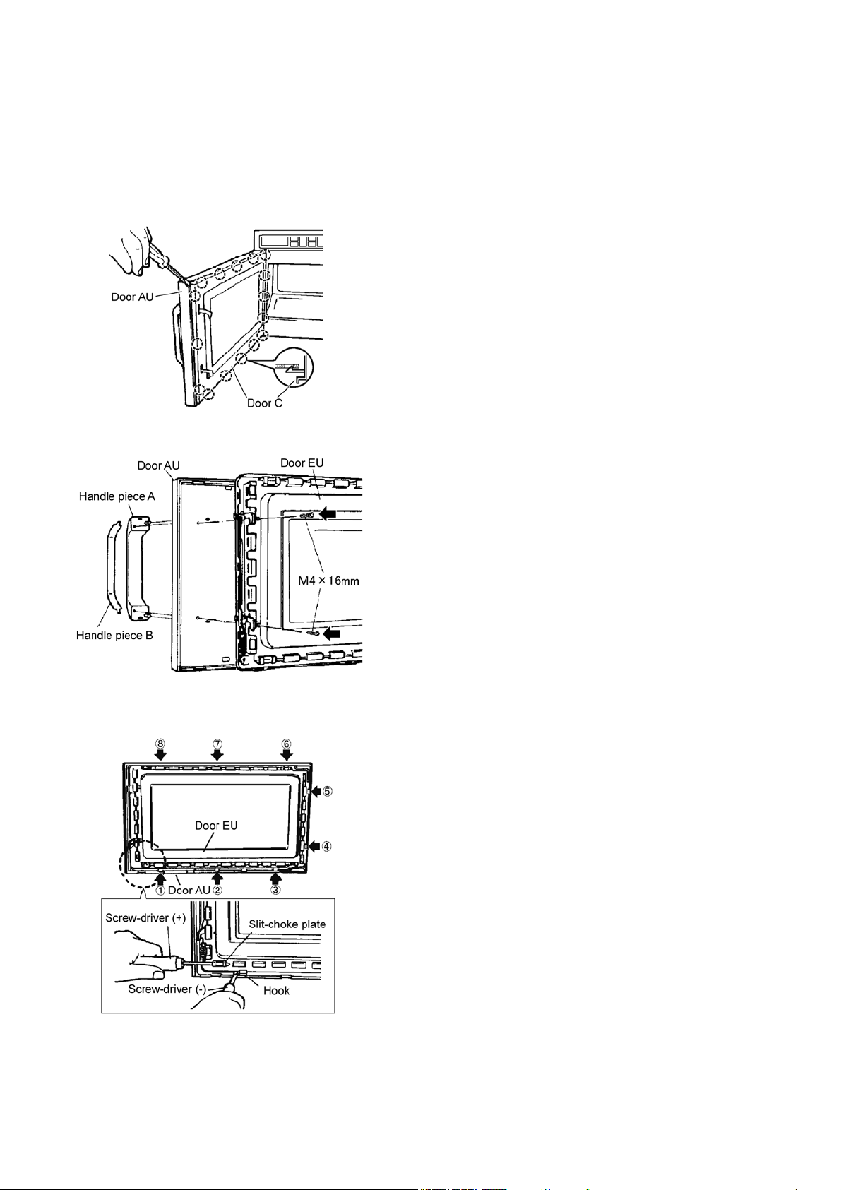
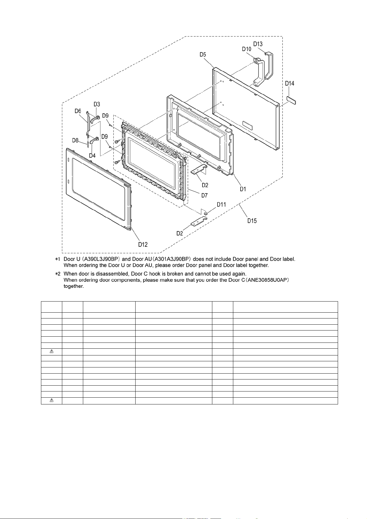
7.11. Door disassembly
1. Remove the door C.
• While inserting a screw-driver between door AU and
door C, and remove door C by disengaging the hook of
door C.
(Note)
Door C is held on door EU by using hooks. When the
hook is broken, replace the door C.
2. Remove the handle. (Black arrow: 2 screws)
3. Remove the door AU. (Black arrow: 8 hooks)
• Disengage the hooks of door AU engaged with door EU.
37
8 Measurements and Adjustments
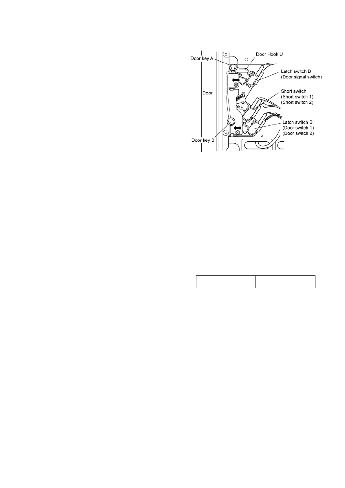
8.1. Adjustment of hinge and hook
When the components related to Door and door hook U are dis-
assembled/assembled or replaced, check the operation of each
switch.
Please confirm that the gap between the switch housing
and switch actuator levers is no more than 1.0 mm when
the door is closed.
• When operation failure occurs in door switch, door signal
switch, or short switch, perform adjustment as shown below.
1. Hinge adjustment
Close the door to tightly attach to the oven front surface,
and fasten the hinge attachment screws.
2.
Door hook U adjustment
a. Close the door and loosen the attachment screws of
door hook U and move the door hook U backward
until it stops and then fasten the screws
b. Check the door open/close and the operation of each
switch.
8.2. Measurement of microwave
output
The output power of magnetron can be determined by perform-
ing IEC standard test procedures. However, due to the com-
plexity of IEC test procedures, it is recommended to test the
magnetron using the simple method outlined below.
Necessary Equipmet:
* 1 liter beaker
* Glass thermometer
* Wrist watch or stopwatch
NOTE:
Check the line voltage under load. Low voltage will lower
the magnetron output. Take the temperature readings and
heating time as accurate as possible.
(A) Fill the beaker with exactly one liter of tap water. Stir the
water using the thermometer and record the beaker's tem-
perature (recorded as T1).
(B) Place the beaker on the center of glass cook plate. Set
the oven for High power and heat it for exactly one minute.
(C) Stir the water again and read the temperature of the
beaker (recorded as T2).
(D) The normal temperature rise (T2-T1) at High power
position for each model is as shown in table.
TABLE(1 ℓ - 1min.test)
RATED OUTPUT TEMPERATURE RISE
1800W (IEC-705) Min. 16.0 °C
38
9 Dimensions
39
10 Block Diagram
• (Upper) (Lower) correspond to the upper and lower magnetron.
40
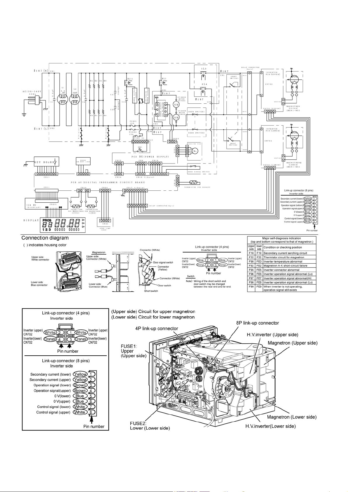
11 Wiring Connection Diagram
11.1. Wiring Connection Diagram
41
11.2. Switch Operation
11.3. Relay operation
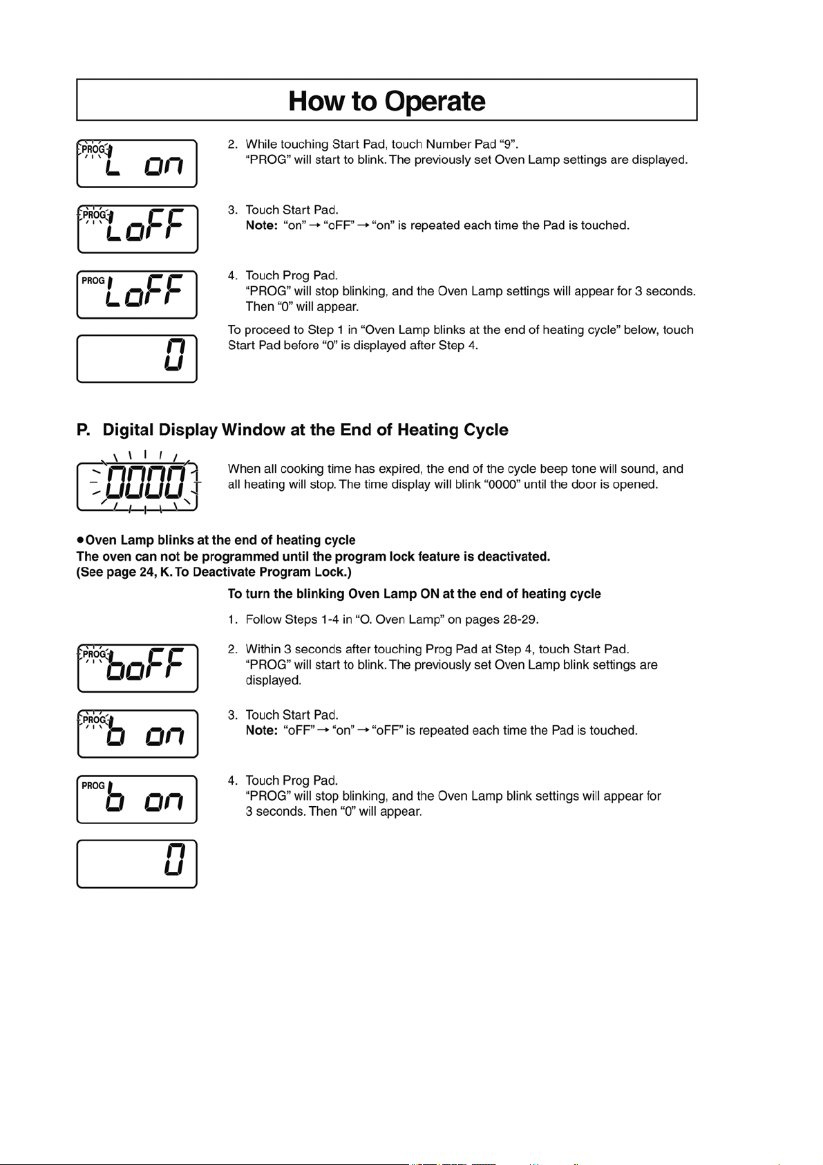
11.4. Oven lamp operation
• Setting the oven lamp ON causes the following operation.
11.5. Cooling fan operation
Door condition Door Switch 1
Door Switch 2
Short switch 1
Short switch 2
Door Signal Switch
Open OFF ON OFF
Close ON OFF ON
Relay Operation
Relay 2 RL2 Fan motor, stirer motor ON-OFF
Relay 3 RL3 Inverter (upper) input (230-240V) ON-OFF (ON when cooking is set).
Relay 4 RL4 Inverter (upper) input (230-240V) ON-OFF (ON when cooking is set).
Door condition Oven lamp
Open ON
Close OFF
Condition Rotation on or off
During cooking Rotation
After cooking 20 sec (when use frequency was low) to 1 min (when use frequency was high)
42
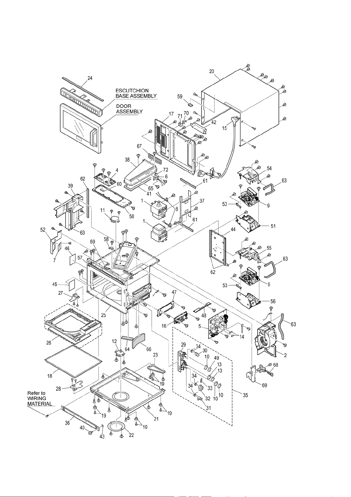
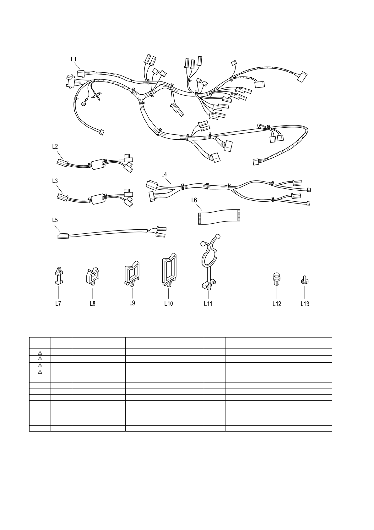
12 Exploded View and Replacement Parts List
12.1. Exploded view and parts list
43
Safety Ref.
No.
Part No. Part Name & Description Pcs/set Remarks
1 2M261-M32U3Y6 MAGNETRON 2
2 A490W3J90BP FAN MOTOR, DC, 40.8W 1 40.8W
4 A603L3J90BP D.P.CIRCUIT (U) 1
5 A603Y3J90BP RELAY PCB 1
6 A605A-3E10S EXHAUST THERMISTOR 1 124°C
7 A605S-3J00 PCB, OVEN LAMP 1
8 A605Y-3J00 THERMISTOR BU 1 FOR MAGNETRON
9 A606Y3G70BPC H.V.INVERTER 2
10 A61424T00AP MICRO SWITCH 1 (V-16G-3C25-M)
11 A6144-3E10 ANTENNA MOTOR, AC, Single phase, 3W 1 UPPER, 3W
12 A6144-3E20 ANTENNA MOTOR, AC, Single phase, 3W 1 LOWER, 3W
13 ANE61784L0AG MICRO SWITCH 2 (V-16G-2C25)
14 A62304210BP FUSE, 10A 2 10A/250V
15 A910A3J90BP AC CORO W/PLUG 1 WITH CORD BUSHING, CORD BRACKET
16 N0AC1GF00002 PCB, POWER SUPPLY 1
17 A100Q3J90BP BACK PANEL 1
18 ANE010T8U0AP SHELF 1
19 A1008-3B10 RUBBER FOOT 4
20 A1009-3E10 CABINET BODY 1
21 A100A3J90BP BASE 1
22 ANE10288U0AP ANTENNA MOTOR COVER 1
23 A1166-3B10 BASE BRACKET B 1
24 ANE11748U0AP SPACER 1
25 A200A-3J00 OVEN U 1
26 A2011-3E10S CEILING PLATE 1
27 A202K3E20P6 ANTENNA (U) 1 UPPER
28 A202V-3B10 ANTENNA BU 1 LOWER
29 A3020-3853 DOOR HOOK A 1
30 A3136-3470 HOOK SPACER A 1
31 A31373F90BP HOOK SPACER B 1
32 A3138-3470 HOOK SPACER C 1
33 ANE32398U0AP SPRING 1
34 ANE32628U1AP SPRING B 3
35 A393C-3B10 DOOR HOOK U 1
36 A400B-3280 AIR FILTER FRAME 1
37 A4026-3B10 AIR GUIDE B 1
38 A402N3J90BP EXHAUST GUIDE (AU) 1
39 A4114-3J00 EXHAUST GUIDE (C) 1
40 A4091-3290 SCREW 1
41 A4115-3B10 EXHAUST GUIDE CUSHION (A) 1
42 A4122-3B10 EXHAUST GUIDE (F) 1
43 A6408-3280 WASHER 1
44 A6029-3J00 MOUNTING BRACKET 1
45 ANE60408U0AP OVEN LAMP SHEET 1
46 A6040-3E10 OVEN LAMP SHEET 1
47 A6068-3J00 MOUNTING BRACKET 1 FOR POWER SUPPLY
48 A6229-3J00 MOUNTING BRACKET 1 FOR RELAY PCB
49 A62383230GP SPACER 1
50 A6585-3B10 MOUNTING BRACKET 1 FOR D.P.CIRCUIT (U)
51 A6585-3J00 MOUNTING BRACKET 1 FOR H.V.INVERTER (UPPER)
52 A6603-3E10 LAMP BRACKET 1 FOR LAMP
53 A6662-3J00 BRACKET, EARTH 2 FOR H.V.INVERTER
54 A6720-3J00 COVER 1 FOR H.V.INVERTER (UPPER)
55 A6721-3J00 COVER B 1 FOR H.V.INVERTER (LOWER)
56 A6763-3J00 MOUNTING BRACKET 1 FOR H.V.INVERTER (LOWER)
57 A8251-3180 SPACER 1
58 A6408-3280 WASHER 1 FOR EARTH
59 ANE0902000CD CUSHION RUBBER A 2
44
60 ANE0922000AD CUSHION RUBBER C 1
61 ANE0922000AL CUSHION RUBBER C 2
62 ANE0922000AP CUSHION RUBBER C 3
63 ANE0922000AQ CUSHION RUBBER C 4
64 ANE0922000CH CUSHION RUBBER C 1
65 ANE0924000AQ CUSHION RUBBER C 1
66 ANE092B000BK CUSHION RUBBER C 1
67 ANE0962000AT CUSHION RUBBER D 1
68 A611K3J90BP DETECTION SWITCH 1
69 A22133J90BP DETECTION SWITCH BRACKET 1
70 A66623170GP BRACKET, EARTH 1
71 XWNANE65GV BRACKET 1
72 A61454050AP THERMAL CUTOUT, 105°C 15A 1
A05243J90BP NAME PLATE 1
A01703J90BP DOOR LABEL 1
A00064080BP CAUTION LABEL 1
A01723F90EU CAUTION LABEL S 1
XTW3+6BJ SCREW 4 3x6 (FOR ANTENNA MOTOR)
XTWANE3+8EX SCREW 4 3x8 (FOR EXHAUST THERMISTOR, THERMAL
CUTOUT)
XTW3+10BJ SCREW 1 3x10 (FOR DETECTION SWITCH)
-- -
XTT4+8RDN SCREW 2 4x8 (FOR EXHAUST GUIDE (F), WASHER)
XTWANE4+8BN SCREW 7 4x8 (FOR EXHAUST GUIDE (AU), FAN MOTOR,
PCB (OVEN LAMP), DETECTION SWITCH
BRACKET, DETECTION SWITCH)
XTW4+8QJ SCREW 2 4x8 (FOR H.V.INVERTER)
XTWA4+8SJ SCREW 9 4x8 (FOR AIR GUIDE B, THERMISTOR BU,
BRACKET(EARTH), LEAD WIRE HAR-
NESS(EARTH))
XTC4+10BC SCREW 7 4x10 (FOR CABINET BODY, BASE)
XTN4+F10BJ SCREW 1 4x10 (FOR RELAY PCB)
XTW4+10TJ SCREW 8 4x10 (FOR MOUNTING BRACKETx2, COVER,
COVER B FOR H.V.INVERTER)
XTN4+12QJ SCREW (BLACK) 5 4x12 (FOR PC BOARD B (U), ESCUTCHEON
BASE U)
XTTANE4+12BN SCREW 38 4x12 (FOR BASE, BACK PANEL, EXHAUST
GUIDE (C), MOUNTING BRACKET, LAMP
BRACKET, FAN MOTOR, AC CORO W/PLUG)
XTW4+12TJ SCREW 2 4x12 (FOR DOOR HOOK U)
XYEA4+C16TSJ SCREW 2 4x16 (FOR HANDLE PIECE A)
XSWA5+10UJ SCREW 4 5x10 (FOR HINGE)
XYF5+AF10J SCREW 6 5x10 (FOR MAGNETRON)
XYE6+F20FJ SCREW 1 6x20 (FOR BACK PANEL)
Safety Ref.
No.
Part No. Part Name & Description Pcs/set Remarks
45
Safety Ref.
No.
Part No. Part Name & Description Pcs/set Remarks
D1 ANE30038U0AP DOOR FRAME (U) 1
D2 A3007-3J00 HINGE 1
D3 A3018-3B10 DOOR KEY A 1 UPPER
D4 A01065202AP DOOR KEY B 1 LOWER
D5 A301A3J90BP DOOR AU 1
D6 A301H-3850 DOOR KEY LEVER BU 1
D7 A301Q3J90BP DOOR EU 1
D8 A2011-3E10S DOOR KEY SPRING 1
D9 ANE30562Q0AP HANDLE PIN A 2
D10 A30703170GP HANDLE PIECE A 1
D11 ANE3081P60AP DOOR HINGE SPACER 1
D12 ANE30858U0AP DOOR C 1
D13 ANE31348U0AP HANDLE PIECE B 1
D14 A31863J90BP DOOR PANEL 1
D15 A390L3J90BP DOOR U 1
46
Safety Ref.
No.
Part No. Part Name & Description Pcs/set Remarks
T1 A603M-3J00 PC BOARD B (U) 1
T2 A630Y3J90BP MEMBRANE SWITCH 1
T3 ANE80018U0AP ESCUTCHEON A 1
T4 A80023E20P6 ESCUTCHEON B 1
T5 A80063E20P6 ESCUTCHEON D 1
T6 A8016-3B10 SPACER 1
T7 A800L3J90BP ESCUTCHEON BASE U 1
47
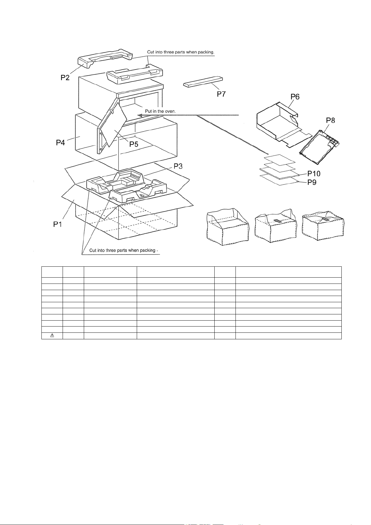
Safety Ref.
No.
Part No. Part Name & Description Pcs/set Remarks
P1 A01023J90BP PACKING CASE,PAPER 1
P2 A0104-3J00 UPPER FILLER 1
P3 A0105-3J00 LOWER FILLER 1
P4 A01065202AP VINYL COVER 1
P5 ANE01072Q0AP DOOR SHEET 1
P6 A01083J90BP TRAY PACKING 1
P7 A01453E20P6 DOOR SHEET B 1
P8 A2011-3E10S CEILING PLATE 1
P9 A04203J90BP OPERATING GUIDE 1
P10 A00033J90BP INSTRUCTION BOOK 1
48
Safety Ref.
No.
Part No. Part Name & Description Pcs/set Remarks
L1 A030A3J90BP LEAD WIRE HARNESS 1
L2 A030E-3J00 LEAD WIRE 1 FOR H.V.INVERTER AND MAGNETRON (LOWER)
L3 A030E-3J10 LEAD WIRE 1 FOR H.V.INVERTER AND MAGNETRON (UPPER)
L4 A030F-3J00 LEAD WIRE HARNESS B 1 FOR H.V.INVERTER
L5 A0352-3E10 LEAD WIRE 1 FOR ANTENNA MOTOR (LOWER)
L6 A6590-3E20 FLAT CABLE 1 FOR PC BOARD B (U) AND D.P.CIRCUIT (U)
L7 A8311-3B10 SPACER B 2
L8 ANE9071-3M0 LEAD WIRE HOLDER B 1
L9 ANE9071-730 LEAD WIRE HOLDER B 5
L10 ANE9071-740 LEAD WIRE HOLDER B 1
L11 ANE9072-400 LEAD WIRE HOLDER C 2
L12 ANE90828U0AP CLIP (BLACK) 1
L13 ANE91658V0AP CLIP C 4