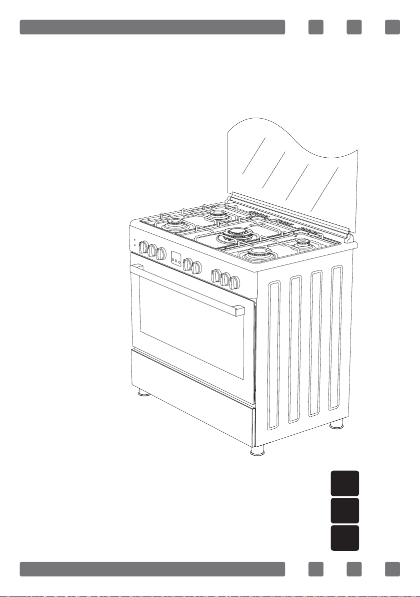
FREE STANDING OVEN
90x60 Gas & Electrical Oven
H10-20-180-158 Rev 006
USER MANUAL
GB
MANUEL D’INSTRUCTIONS
FR
SA

2
Dear User,
Our objective is to make this product provide you with the best
output which is manufactured in our modern facilities in a careful
working environment, in compliance with total quality concept.
Therefore, we suggest you to read the user manual carefully before
using the product and, keep it permanently at your disposal.
Note: This user manual is prepared for more than one model. Some
of the features specied in the Manual may not be available in your
appliance.
All our appliances are only for domestic use, not for commercial use.
* Mark the products as option.
“THIS APPLIANCE SHALL BE INSTALLED IN ACCORDANCE WITH THE
REGULA TIONS FORCE AND ONLY USED IN A WELL VENTILATED SPACE. READ
THE INSTRUCTIONS BEFORE INSTALLING OR USING THIS APPLIANCE”
“Conforms with the WEEE Regulations."
GB
3
CONTENTS
Important Warnings
4
Introduction Of The Appliance 7
Important Warnings 8
Electrical Wiring Scheme 9
Gas Hose Passage Way 10
Chain Lashing Illustration 11
Installation Of Your Oven 11
Technical Features Of Your Oven 12
Reduced Gas Flow Rate Setting For Hob Taps 12
Reduced Flame Gas Cock Adjustment 13
Description Of Oven 13
Description Of The Control Panels 14
Using The Burner Groups 15
Using Hot Plates 16
Installation Of The Oven Feet 16
Using Oven Section 17
Cooking Time Table 18
Using The Grill Deector Sheet 19
Catalytic Walls 20
Chicken Roasting 20
Cleaning And Maintenance Of The
Oven’s Front Door Glass 21
Changing The Oven Lamp 21
Maintenance And Cleaning 22
Installation Of The Oven Door 23
Accesories 24
Removal Of The Lower And Upper Burner And
Installation Of The Injector To The Gas Oven 25
Injector, Gas Flow And Power Table 26
If Your Oven Does Not Operate 28
Environmentally-Friendly Disposal and
Package Information 28
GB

4
IMPORTANT WARNINGS
1.WARNING: To avoid electrocution, ensure that the
electrical circuit of the product is open before replacing
the lamp.
2.WARNING:Before touching the connection terminals,
all supply circuit should be disconnected.
3.WARNING:While operating the grill, the reachable
sections can be hot. Keep the children away.
4.WARNING:Any inadvertent cooking made with fats and
oils can be dangerous and cause re.
5.WARNING:Risk of re; do not store the food materials
on the cooking surface.
6.WARNING:If the surface is cracked, unplug the device
to prevent any risk of electric shock.
7.WARNING:During usage the reachable sections can be
hot. Keep the small children away.
8.WARNING:The appliance and its reachable sections
become hot during usage.
9.The setting conditions of this appliance is indicated
on the label. (Or data tag)
10.This appliance is not connected to a combustion
product discharge system.This appliance shall be
connected and installed as per the applicable
installation legislation. Consider the requirements
related with ventilation.
GB

5
11.Using a gas hob will release humidity and combus-
tion products in the room where it resides. Especially
during when the appliance in use, ensure that the kitch-
en is well ventilated and retain the natural ventilation
holes or install a mechanical ventilation system. (Hood
on top of the oven) Sustained usage of the appliance
may require additional ventilation. For example open-
ing a window or if available, increasing the ventilation
level of a mechanical ventilation system.
12.The reachable sections can become hot when the
grill is used. Keep the small children away.
13.WARNING:The appliance is intended for cooking only.
It must not be used for other purposes like room heating.
14.There are additional protective equipment to
prevent inadvertent touching to the oven doors. This
equipment should be installed if there are children.
15.“This appliance should be installed as per
regulations and in well-ventilated location only. Read
the instructions before installing or operating the
appliance.”
16.“Before placing the appliance check the local
conditions (gas type and gas pressure) and ensure
that the settings of the appliance is appropriate.”
17.“These instructions are applicable for countries of
which symbols are indicated on the appliance. If the
country symbol is not available on the appliance,in
order to adapt the appliance to the conditions of such
country, the technical instructions should be read.”
GB

6
18.“Do not operate the system for more that 15
seconds. If the burner does not ignite at the end of
15 seconds stop the operation of the system and open
the section door and/or wait for at least 1 minute
before igniting the burner.
19.Do not use steam cleaners to clean the appliance.
20.Before opening the oven door clean the remnants
on it. Before closing the oven door, let it cool.
21.NEVER try to extinguish a re with water, rst
disconnect the mains supply and then using, for
example a lid or blanket, cover the re.
22.Do not use hard and abrasive cleaning agents or
hard metal scrapers to clean the oven door glass as
they may scratch and shatter the surface.
23.After placing a dish, ensure that the door is rmly
closed.
24.Unless continuous supervision is provided, the
children of age 8 or below should be kept away.
25.Pay attention for not to touch the heating elements.
26.This appliance can be used by children aged from
8 years and above and persons with reduced physical,
sensory or mental capabilities or lack of experience
and knowledge if they have been given supervision or
instruction concerning use of the appliance in a safe
way and understand the hazards involved.
GB
7
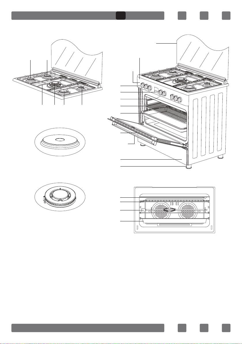
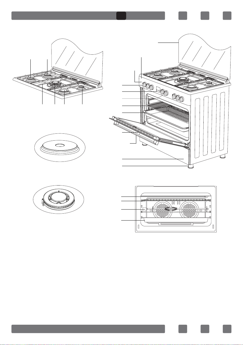
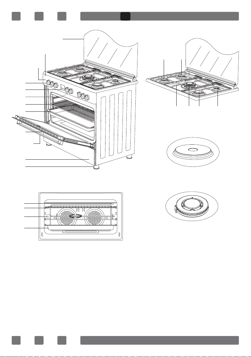
INTRODUCTION OF THE APPLIANCE
21
22
23
24
1
3 4 5 6
2
7*
8*
10
9
11
18
12
13
14
15
16
19
20
17
1. Middle Burner
2. Middle Burner
3. Trivet
4. WOK Burner
5. Large Burner
6. Auxiliary Burner
7. Hot Plate
8. WOK Burner
17. Door
18. Handle
19. Lower Cabinet Door
20. Plastic Leg
21. Lamp
22. Grill
23. Chicken Roasting
24. Deep Tray
9. Glass Door
10. Control Panel
11. Led Lamp
12. Oven Control Knobs
13. Digital Timer
14. Hob Control Knobs
15. Wire Grill
16. Deep Tray
GB

8
IMPORTANT WARNINGS
Electrical Connection and Security
1. Your oven requires 16 or 32 Ampere fuse according to the appliance’s
power. If necessary, installation by a qualied electrician is recommended.
2.Your oven is adjusted in compliance with 220-240V AC/380-415V
AC 50/60Hz.electric supply. If the mains are different from this specied
value, contact your authorized service.
3. Electrical connection of the oven should only be made by the sockets
with earth system installed in compliance with the regulations. If there
is no proper socket with earth system in the place where the oven will be
installed, immediately contact a qualied electrician. Manufacturer shall
never be responsible from the damages that will arise because of the
sockets connected to the appliance with no earth system.
4. Electrical cable should not touch the hot parts of the appliance.
5. For disconnection from the supply mains having a contact separation
in all poles that provide full disconnection, must be incorporated in xed
wiring in according with the wiring rules.
Gas Connection and Security
1. Before your appliance is connected to the gas supply, ensure that
the gas category and pressure specications shown in the data plate cor-
responds with your gas supply. If necessary call authorized service for
adjusting to gas category.
2. This appliance shall be installed in accordance with the regulations
in force and only used in a well ventilated space. Read the instructions
before installing or using this appliance. In the interest of safety this
appliances must be installed and / or serviced by a competent person as
stated in the gas safety regulations current editions.
3. The appliance must not be installed in a room without a window or
other controllable opening. If is installed in a room without a door which
opens directly to the outside, a permanent opening is required. The air
circulation should be 2 m3/h per kW of burners.
4. The gas connection should be performed from the right or left. For
this reason, change the hose nozzle, plug and the seals.
5. Please use exible hose for gas connection.
GB
9
6. If you make a connection with a exible metal hose, locate a seal
between the main gas pipes.
7. The inner diameter of the exible hose, which the butane hose
nozzle is connected, should be 6mm for the house-type gas tubes. The
inner diameter of the exible hose, which the natural hose nozzle is
connected, should be 15mm.The hose should tightly be tted to the
hose nozzle by squeezing with a clamp. The hose should be replaced
before its last expiry date.
8. Caution! Make the oven connection to the gas inlet valve, the hose
length must be short and be sure that there is no leakage. The exible
hose used should not be longer than 125 cm for safety.
9. Re-inspect the gas connection.
10. When placing your oven to its location, ensure that it is at the
counter level. Bring it to the counter level by adjusting the feet if
necessary.
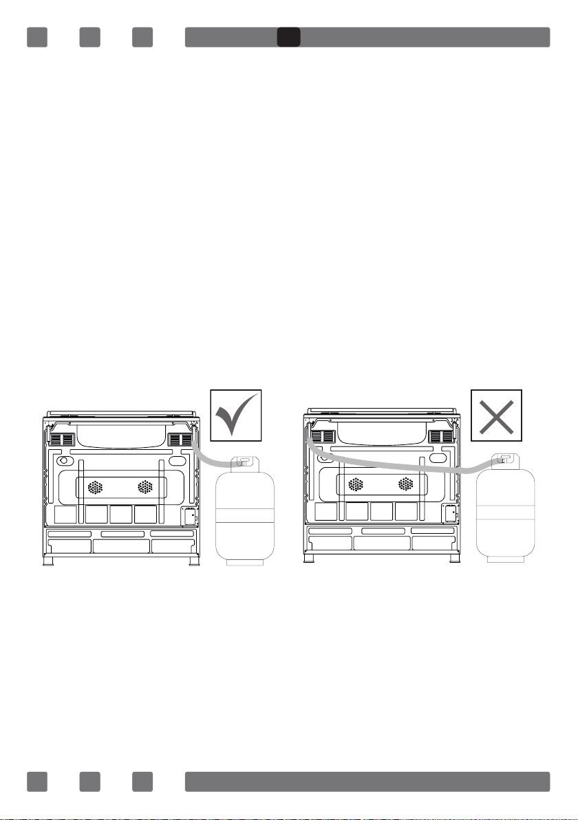
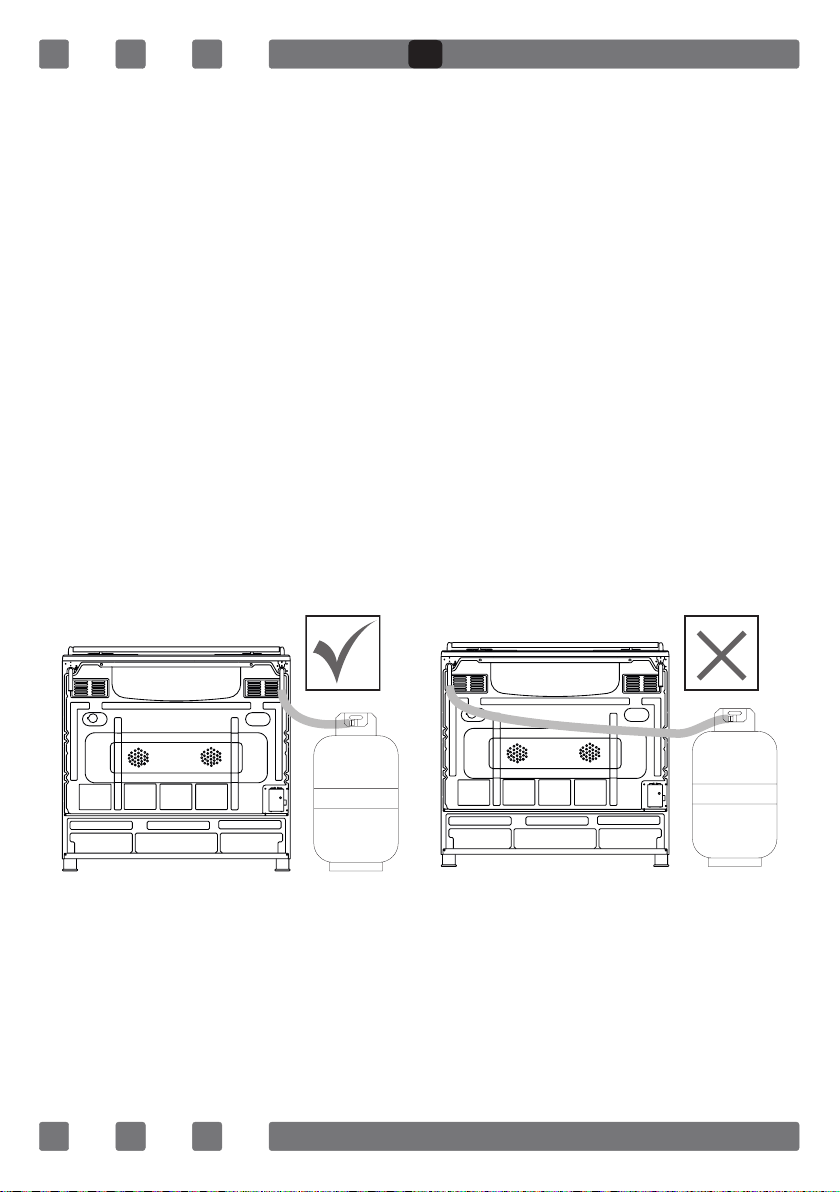
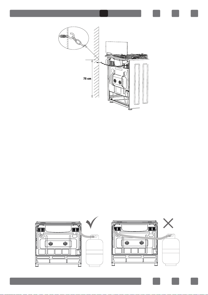
DO NOT MAKE GAS HOSE and ELECTRICAL CABLE OF YOUR OVEN GO
THROUGH THE HEATED AREAS, ESPECIALLY THROUGH THE REAR SIDE OF
THE OVEN. DO NOT MOVE GAS CONNECTED OVEN. SINCE THE FORCING
SHALL LOOSEN THE HOSE, GAS LEAKAGE MAY OCCUR.
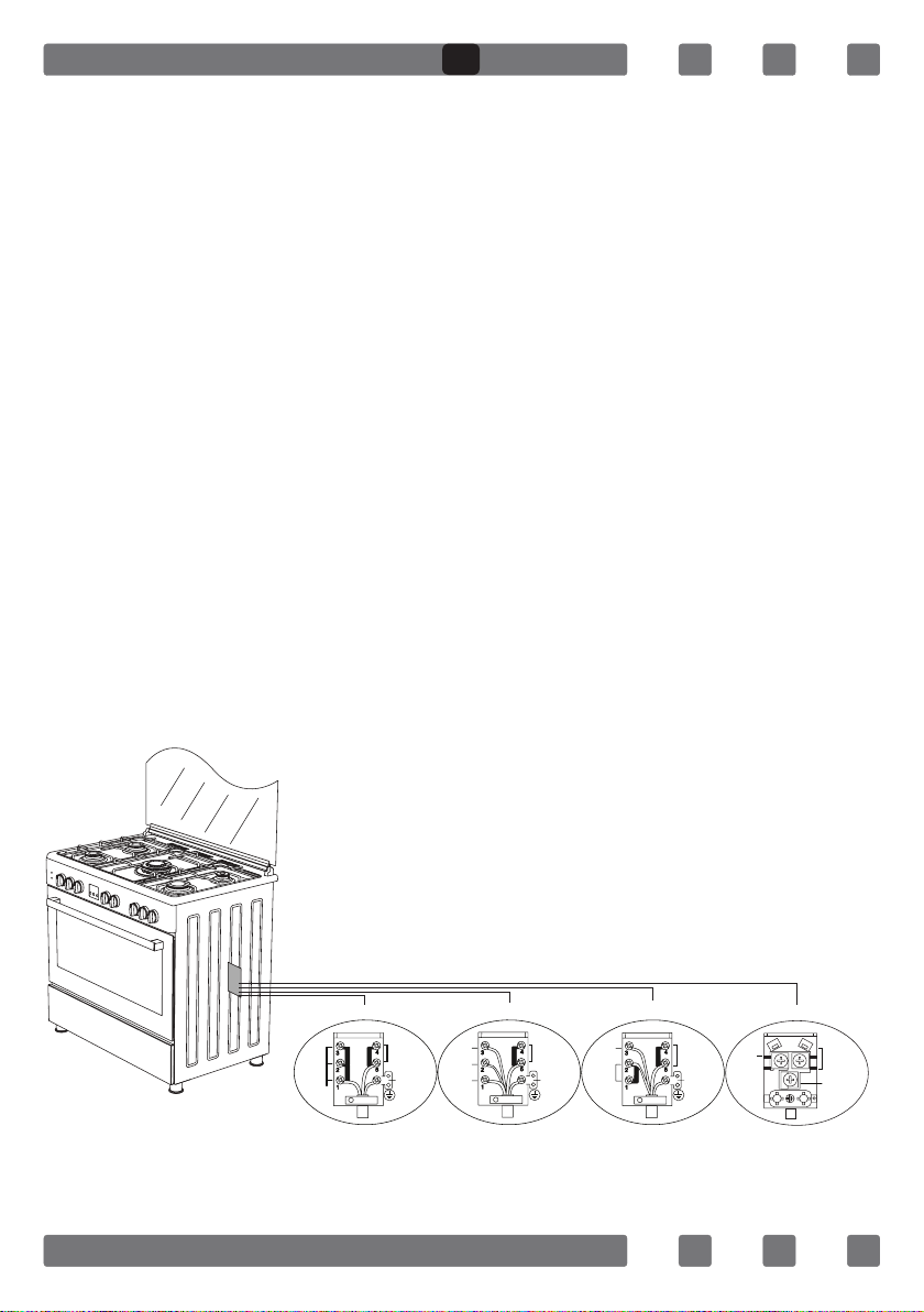
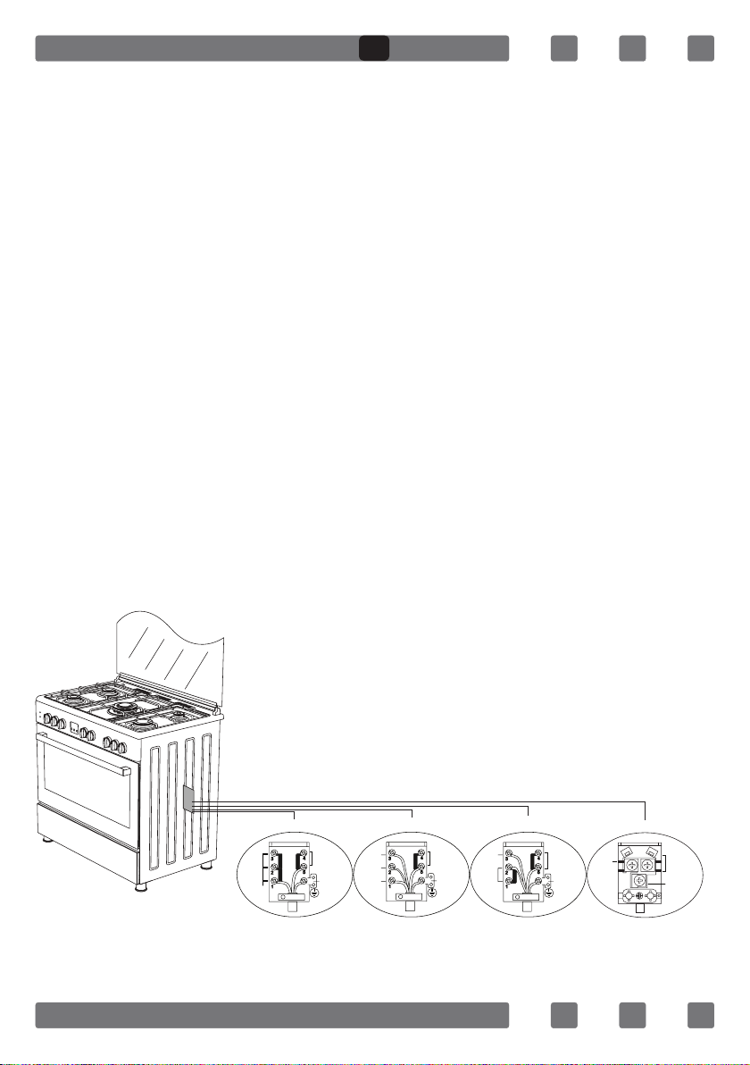
ELECTRICAL WIRING SCHEME
220-240V~50/60Hz 220-240V~50/60Hz
400V 3N~50/60Hz 400V 2N~50/60Hz
Earth
Terre
Erdung
Earth
Terre
Erdung
Earth
Terre
Erdung
Earth
Terre
Erdung
L3
L2
L1
L2
L1
L1
Live
Phase
Neutral
Neutre
Neutral
Neutre
Neutral
Neutre
H05 VV-F 3G 4mm² H05 VV-F 5G 1.5mm² H05 VV-F 4G 1.5mm² H05 VV-F 3G 1.5mm²
Neutral
Neutre
380-415V 3N~50/60Hz 380-415V 2N~50/60Hz
220-240V~50/60Hz 220-240V~50/60Hz
GB
10
GAS HOSE PASSAGE WAY
1. Connect the appliance to the gas piping tap in shortest possible route
and in a way that ensure no gas leakage will occur.
2. In order to carry on a tightness and sealing safety check ensure that
the knobs on the control panel are closed and the gas cylindir is open.
3. While performing a gas leakage check, never use any kind of lighter,
match, cigarette or similar burning substance.
4. Apply soap bubble on the connection points. If there is any kind of
leakage then it will cause bubbling.
5. While inserting the appliance in place ensure that it is on the same
level with the worktop. If required adjust the legs inorder the make level
with the worktop.
6. Use the appliance on a level surface and in a well ventilated
environment.
Figure 1 Figure 2
GB
11
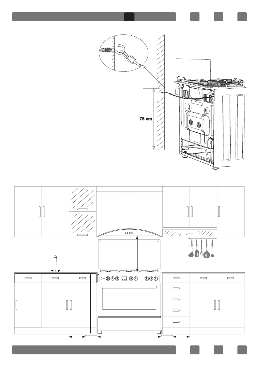
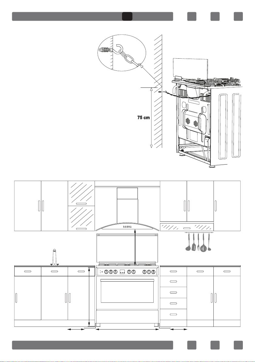
CHAIN LASHING ILLUSTRATION
Before using the appliance, in
order to ensure safe use, be sure
to x the appliance to the wall
using thechain and hooked screw
supplied. Ensure that the hook is
screwed into the wall securely.
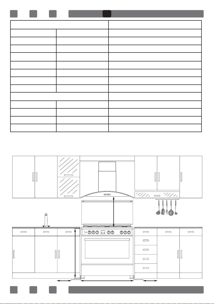
INSTALLATION OF YOUR OVEN
650mm min.
850 mm min.
900 mm min.20 mm 20 mm
GB
12
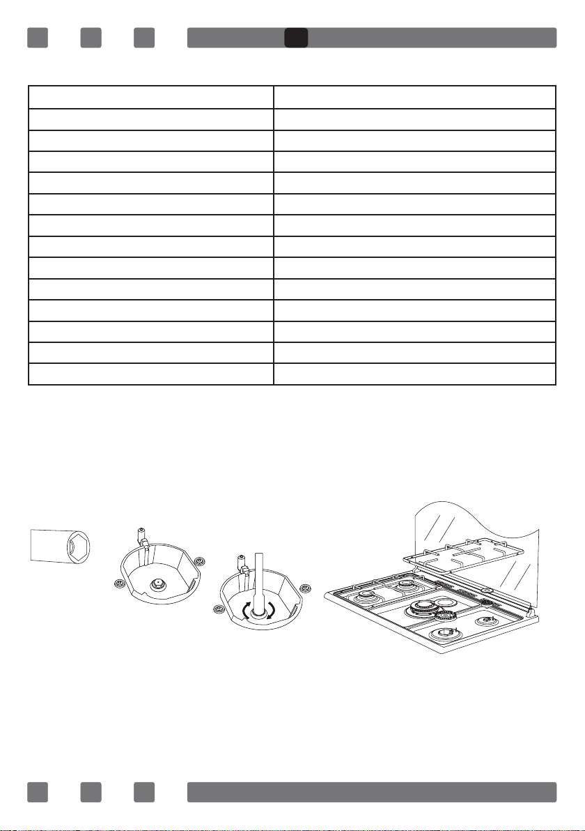
TECHNICAL FEATURES OF YOUR OVEN
SPECIFICATIONS 90x60
Outer Width 900mm
Outer Depth 610mm
Outer Height 925mm
Lamp Power 15W
Bottom Heating Element 2000W
Top Heating Element 1500W
Grill Heating Element **2500W / 3250W
Turbo Heating Element 1250W x 2
Supply Voltage 220-240V AC/380-415V AC 50/60Hz
Hotplate 145mm* 1000W
Hotplate 180mm* 1500W
Hotplate Rapid 145mm* 1500W
Hotplate Rapid 180mm* 2000W
** only for mix product.
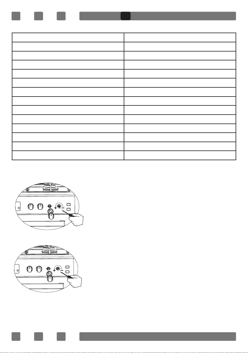
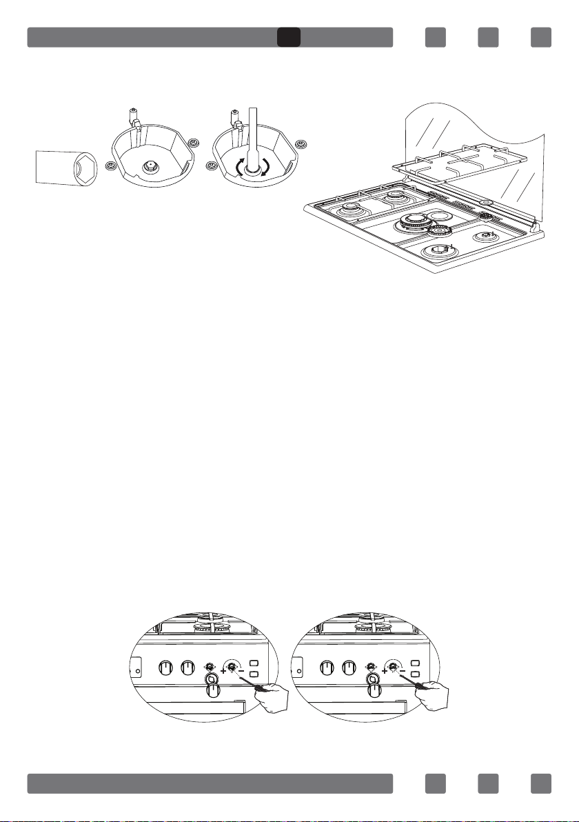
REDUCED GAS FLOW RATE SETTING FOR HOB TAPS
1. Ignite the burner that is to be adjustment and
turn the knob to the reduced position.
2. Remove the knob from the gas tap.
3. Use an appropriately sized screwdriver to adjust
the ow rate adjustment screw. For LPG (Butane-Pro
pane) turn the screw clockwise. For the naturel gas,
you should turn the screw counter- clockwise once.
“The normal length of a straight ame in the
reduced position should be 6-7 mm.“
4. If the ame is higher then the desired
position, turn the screw clockwise. If it is smaller
turn anticolockwise.
5. For the last control, bring the burner both
to higt-ame and reduced positions and check
whether the ame is on or off.
Depending on the type of gas tap used in your
appliance the adjustment screw position may vary.
To adjust your oven acc. to the gas type, make
the adjustment for reduced ame carefully by turning with a small screwdriver
as shown below on the screw in the middle of the gas cocks as well as nozzle
changes. (Figure 3 and 4)
Figure 3
Figure 4
GB
13
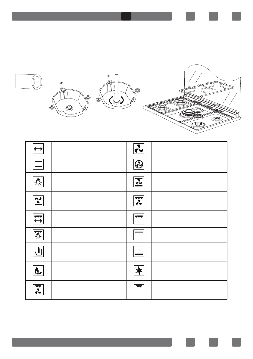
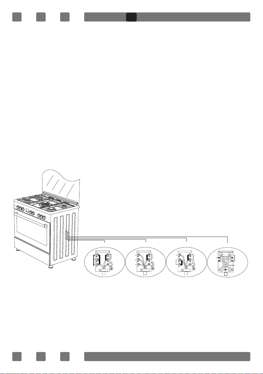
REDUCED FLAME GAS COCK ADJUSTMENT
1. Please use driver with special head for removed and install nozzle
as (Figure 5).
2. Please remove nozzle (Figure 6) from burner with special nozzle
driver and install new nozzle. (Figure 7)
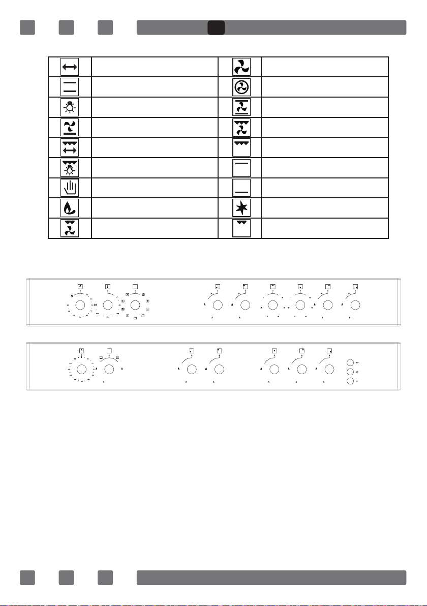
DESCRIPTION OF OVEN
Figure 5
Figure 6
Figure 7
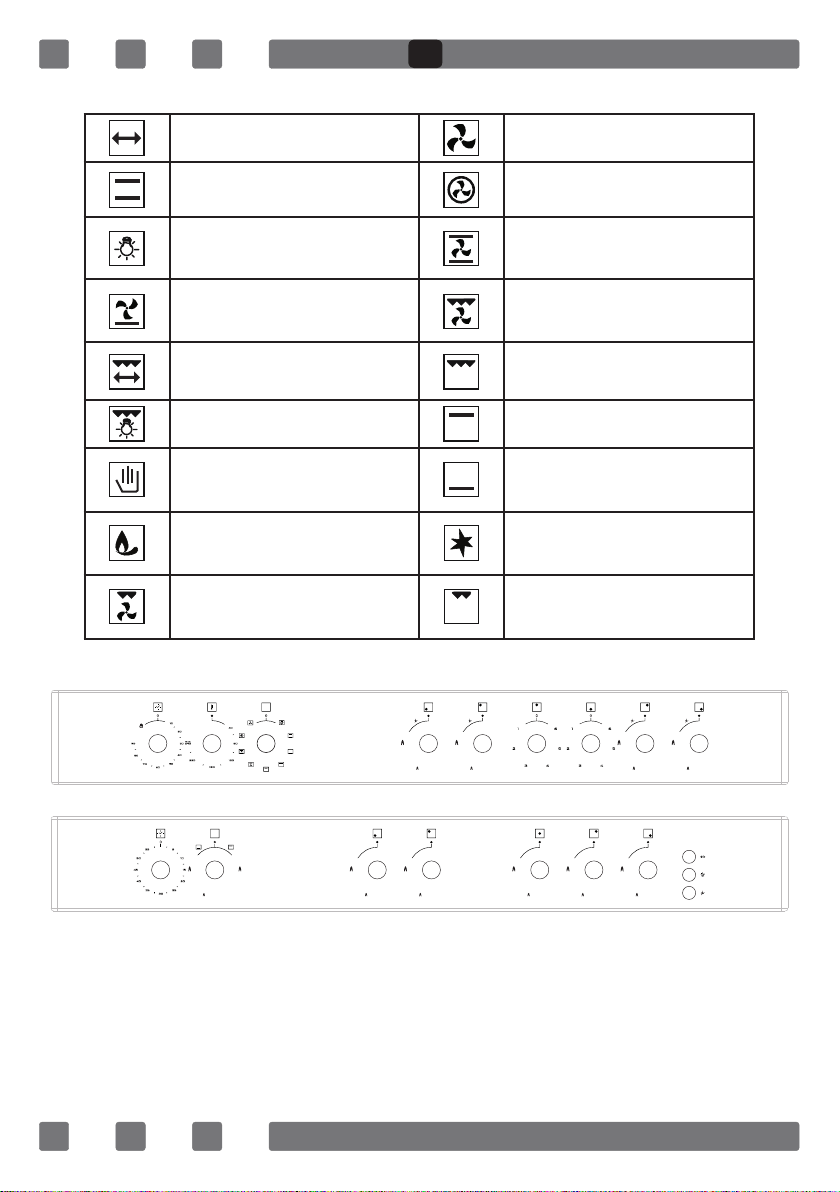
Turnspit Fan
Top + Bottom Heating
Element
Turbo Heating + Fan
Lamp
Bottom + Top Heating
Elements + Fan
Bottom Heating Element
+ Fan
Grill Heating Element+Fan
Grill Heating Element
Grill Burner / Grill Heating
Element
Grill Heating Element+Lamp Top Heating Element
Electrical Timer
Oven Burner / Bottom
Heating Element
Flame Ignition Lighter
Small Grill and Fan Small Grill
GB
14
THERMOSTAT KNOB; In order to operate the oven, thermostat must
be adjusted to desired temperature. Your thermostat has a feature of
adjustment to 40 - 240 degree.
MECHANIC TIMER KNOB*; In order to operate the oven,timerswitch should
be adjusted to desired time from 0-90 minute. You can use cooking time
table.
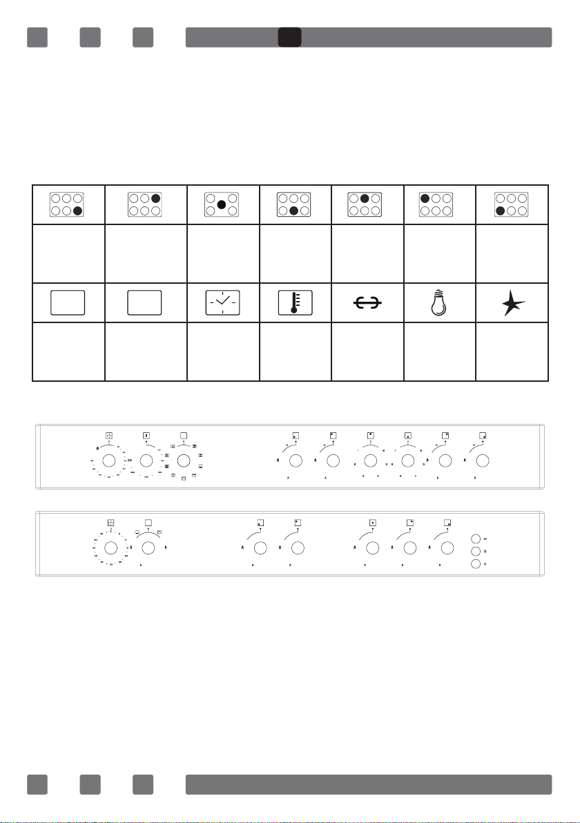
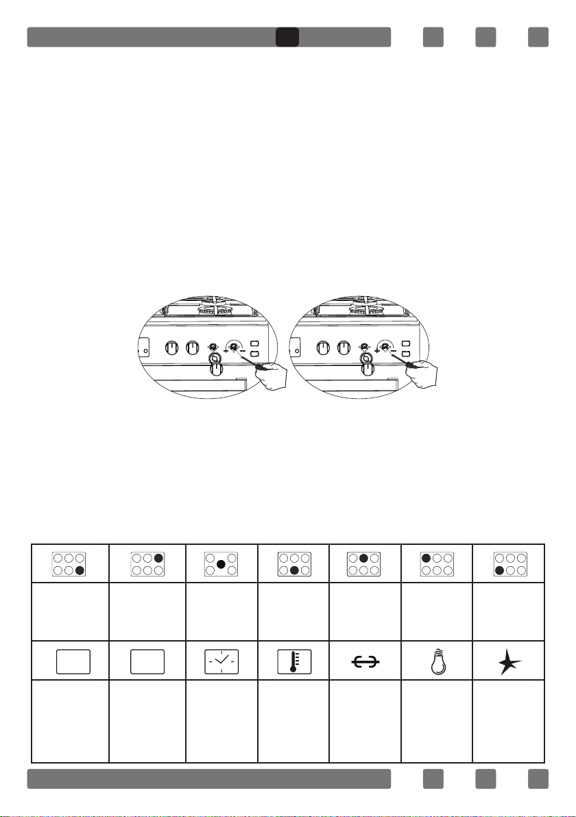
DESCRIPTION OF THE CONTROL PANELS
Note: The meaning of the symbols on the control panel of device is
provided below. Not every symbol is on every model; only take notice
of the symbols on your device.
Front Right
Burner
(Small
Burner)
Rear Right
Burner
(Middle
Burner)
Wok
Burner
Or
Hotplate
Front
Electric
Hot Plate
Rear
Electric
Hot Plate
Rear Left
Burner
(Middle
Burner)
Front Left
Burner
(Big
Burner)
Grill
Burner
Or Heating
Element
Oven Burner
(Optional) Or
Heating
Element
Timer
(Optional)
Thermostat
(Optional)
Turnspit Lamp
Ignition
Lighter
GB
15
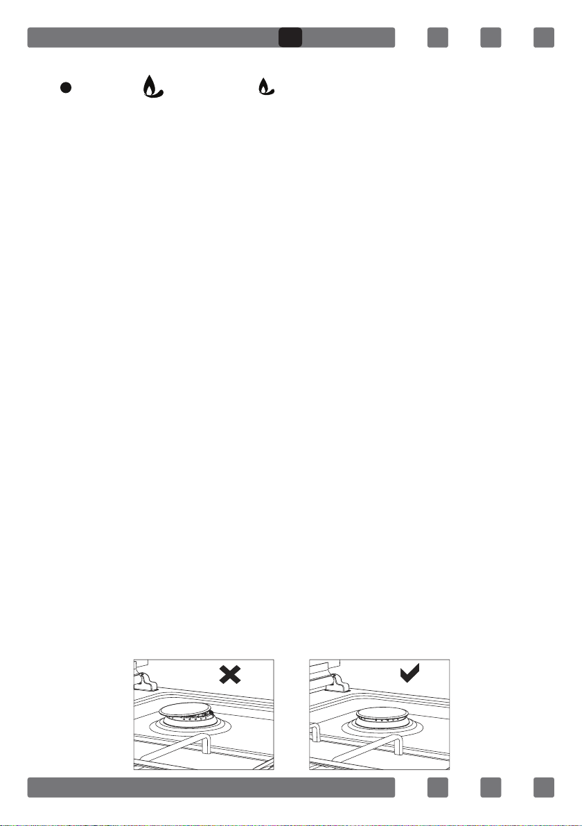
USING THE BURNER GROUPS
1. Closed Fully open Half open
2. Our gas ovens top and bottom burner working system is one by one.
When you want use your preference burner, before you must make press
the tap knob and wait nearly 5-10 second. Then you can to iname through
with automatic ignition system (optional) or match. You must wait 10-15
second after iname to have press by tap knob and after you can make
allow the knob. If you can not made this operation you must try again.
3. The cocks controlling the gas cookers have special mechanism.
In order to light the cooker;
4. Always press on the switch forward and bring it to ame symbol
by turning anticlockwise (left). All of the lighters shall operate and the
cooker you controlled shall light only. Keep the switch pressed until
ignition is performed.
5. If your oven has ignition system from push button switch please press
and turn gas valve open position and same time press ignition button.
6. In models with security system, when ame of the cooker is extin-
guished, control valve cuts off the gas automatically. For operate the burners
with gas security system you must make press the knob and turn antilock
wise. After the ignition (with optional automatic ignition system or match)
you must wait nearly 5-10 second for gas security systems activation.
7. Do not continuously operate the igniter for more than 15 seconds.
After 15 seconds, if the burner does not ignite, then stop and if you are
trying to ignite the oven then open the door and wait a minimum of one
minute before trying again. If the burner is extinguished for of the any
reason, close the gas control valve and wait a minimum of one minute
before trying again.
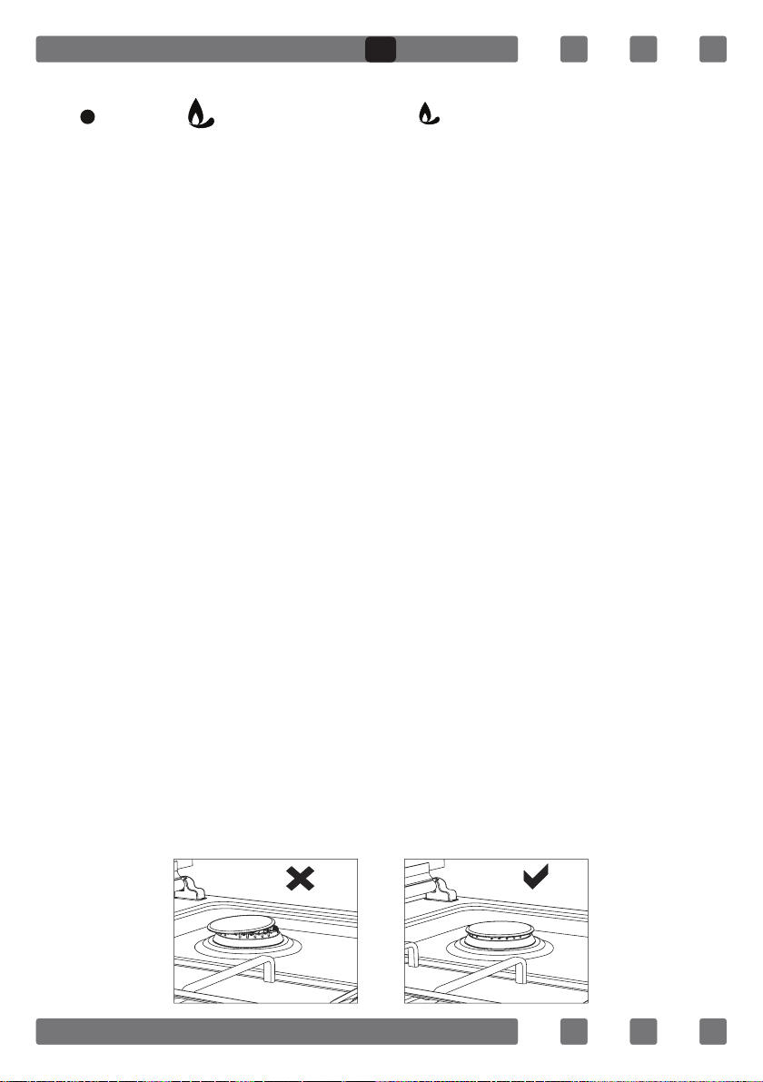
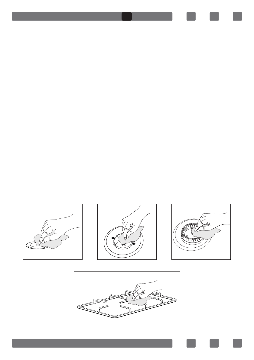
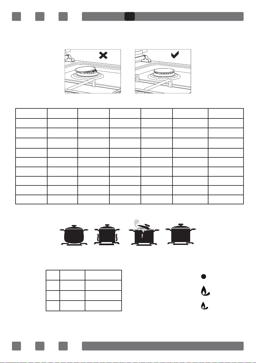
8. Before operating your hob please make sure that the burner caps
are well positioned. The right placement of the burner caps are shown
as below.
Figure 8 Figure 9
GB
16
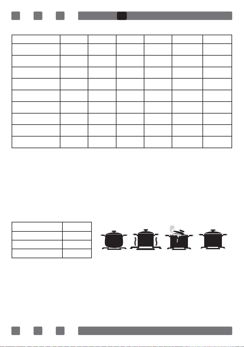
USING HOT PLATES*
LEVEL 1 LEVEL 2 LEVEL 3 LEVEL 4 LEVEL 5 LEVEL 6
Ø80mm 200W 250W 450W --- --- ---
Ø145mm 250W 750W 1000W --- --- ---
Ø180mm 500W 750W 1500W --- --- ---
Ø145mm Rapid 500W 1000W 1500W --- --- ---
Ø180mm Rapid 850W 1150W 2000W --- --- ---
Ø145mm 95W 155W 250W 400W 750W 1000W
Ø180mm 115W 175W 250W 600W 850W 1500W
Ø145mm Rapid 135W 165W 250W 500W 750W 1500W
Ø180mm Rapid 175W 220W 300W 850W 1150W 2000W
1.Electric Hotplates have standard of 6 temperature levels.
(as described herein above)
2. When using rst time, operate your electric hotplate in position
6 for 5 minutes. This will make the agent on your hotplate which is
sensitive to heat get hardened by burning. Use at bottomed saucepans
which fully contact with the heat as much as you can, so that you can
use the energy more productively.
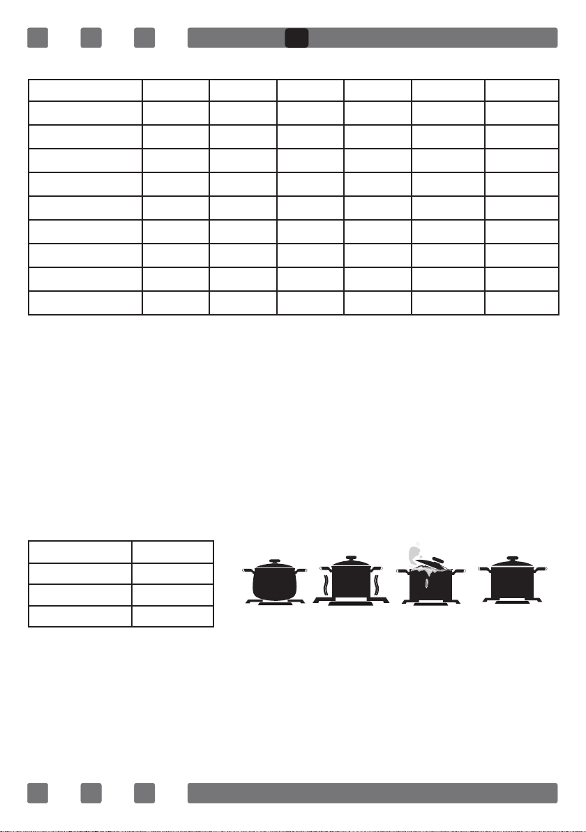
3. In order to obtain maximum output, be careful that the saucepan
which will be used should be at bottomed, and use the saucepans with
dimensions given below.
WOK Burner 26-32cm
Big Burner 22-26cm
Normal Burner 18-22cm
Small Burner 12-18cm
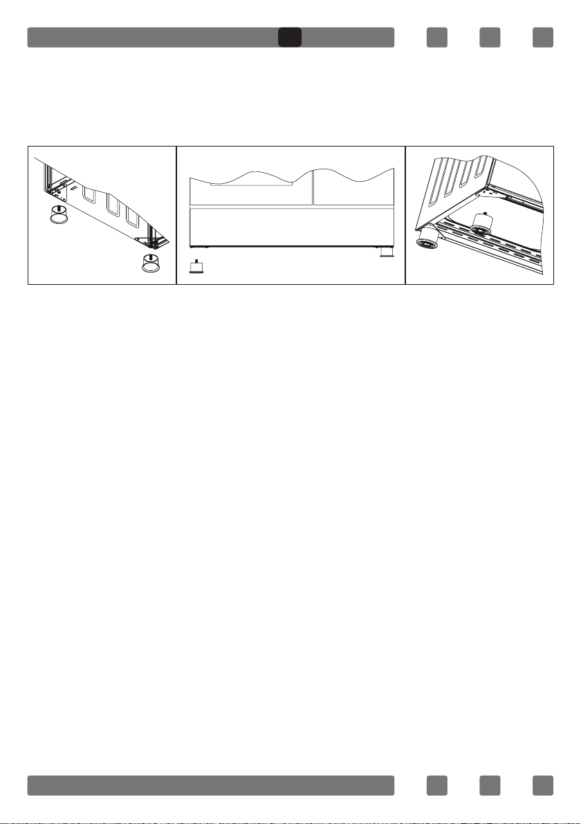
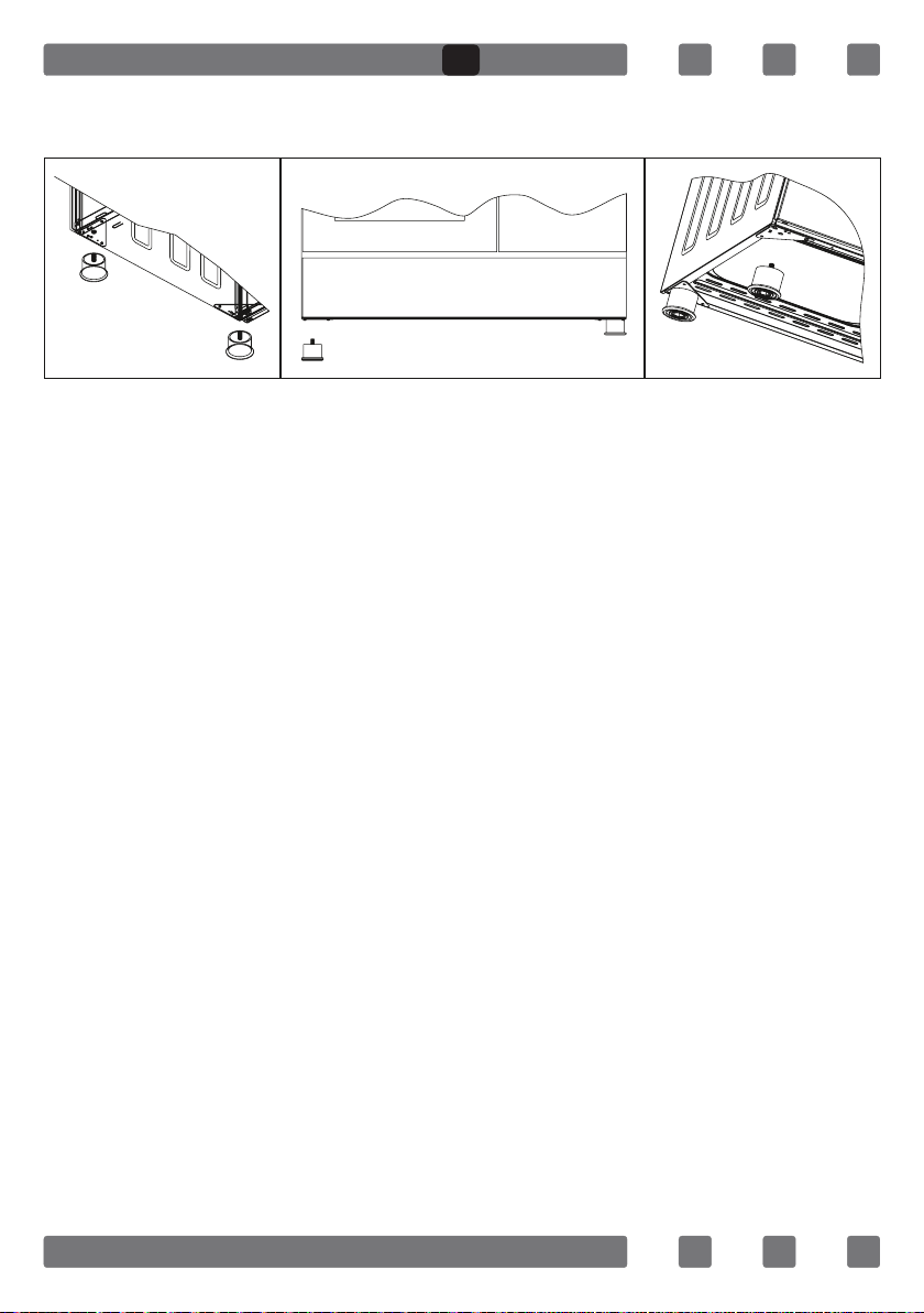
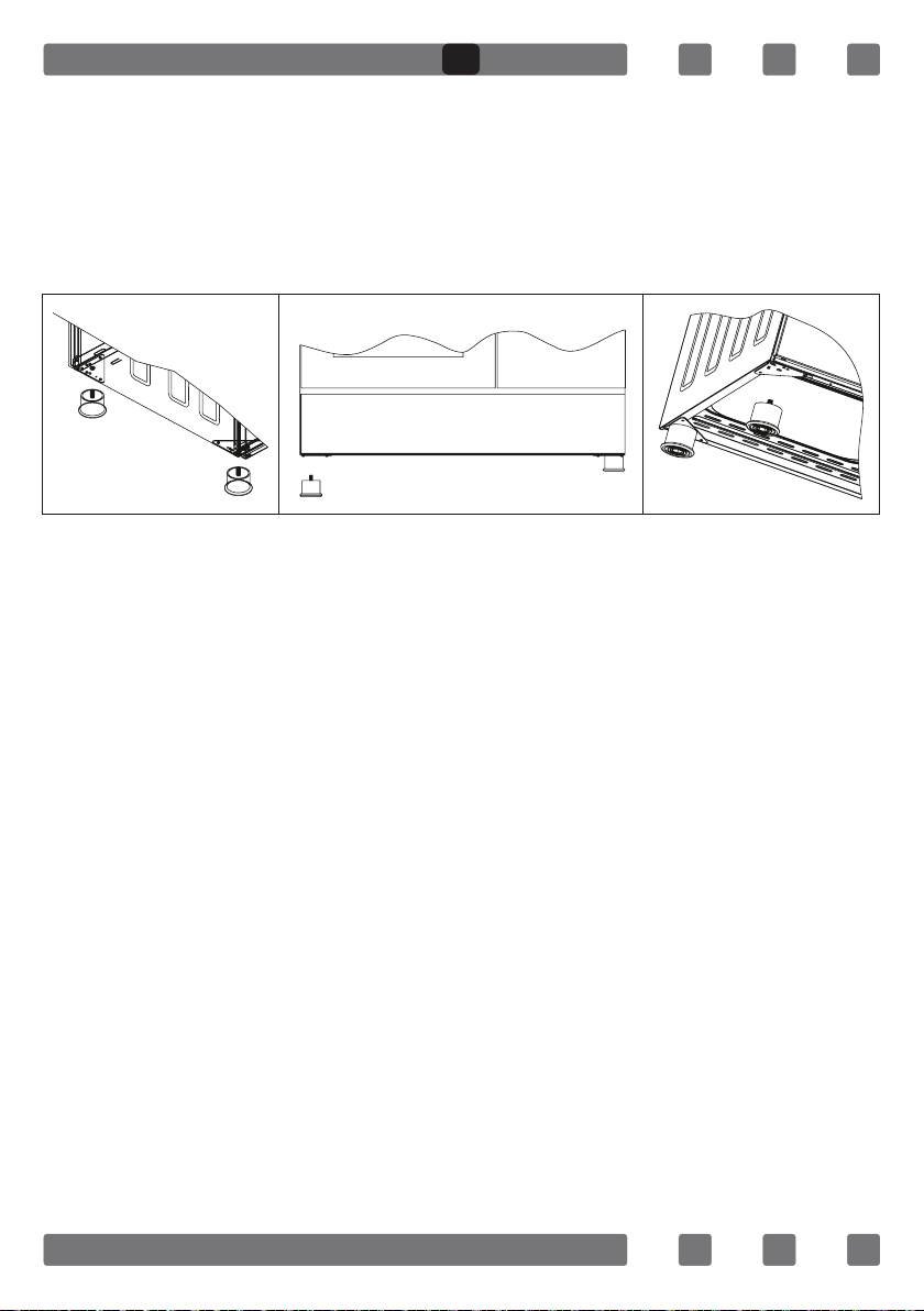
INSTALLATION OF THE OVEN FEET
In order to install the oven feet;
1.Foot attachment lath is installed on the oven from the bottom of the
oven as shown in (Figure 10).Nuts are centered on these lathes in order
to screw feet. Complete the feet installation process by screwing the feet
to the nuts (Figure 11).
False False False True
GB
17
2.You can balance your oven by turning the screwed feet according to
the surface type you are using.
3.If your oven has plastic food as in (Figure 12) you can adjust your
ovens height from these feet as turned clockwise or anticlockwise.
USING OVEN SECTION
1. When your oven is operated rst time, an odor will be spread out
which will be sourced from using the heating elements. In order to get
rid of this, operate it for 45 minutes while it is empty. In order to make
cooking in your oven; oven switch must have been rotated and ignition
must have been made. Otherwise, your oven will not run.
2. Kinds of meals you will cook, cooking times and Thermostat positions
(Optional) were given in cooking table. The values given in the cooking
table are characteristic values and were obtained as a result of the tests
performed in our laboratory. You can nd different avors suitable for your
taste depending on your cooking and using habits.
3. Open the oven cover at level 1 and use the safety panel when
grilling on your oven.
4. Cooking times: The results may change according to the local
voltage and material having different quality, amount, and temperatures.
5. During the time when cooking is being performed in the oven, the lid
of the oven shouldn’t be opened frequently. Otherwise circulation of the
heat may be imbalanced and the results may change.
6. Cake forms while cooking cake gives better result.
7. MECHANIC TIMER KNOB; In order to operate the oven, timer switch
should be adjusted to desired time.
Figure 10
Figure 12Figure 11
GB
18
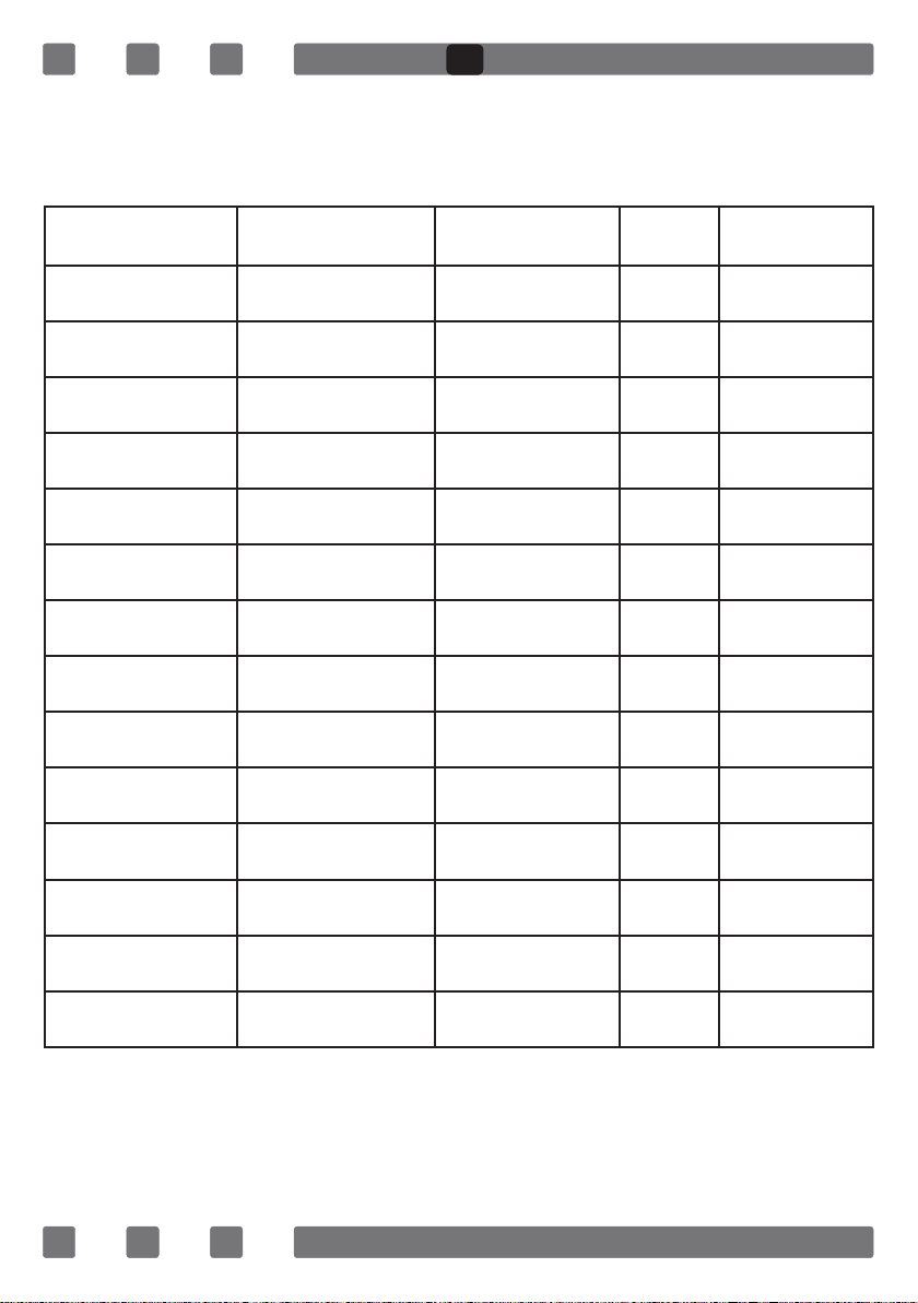
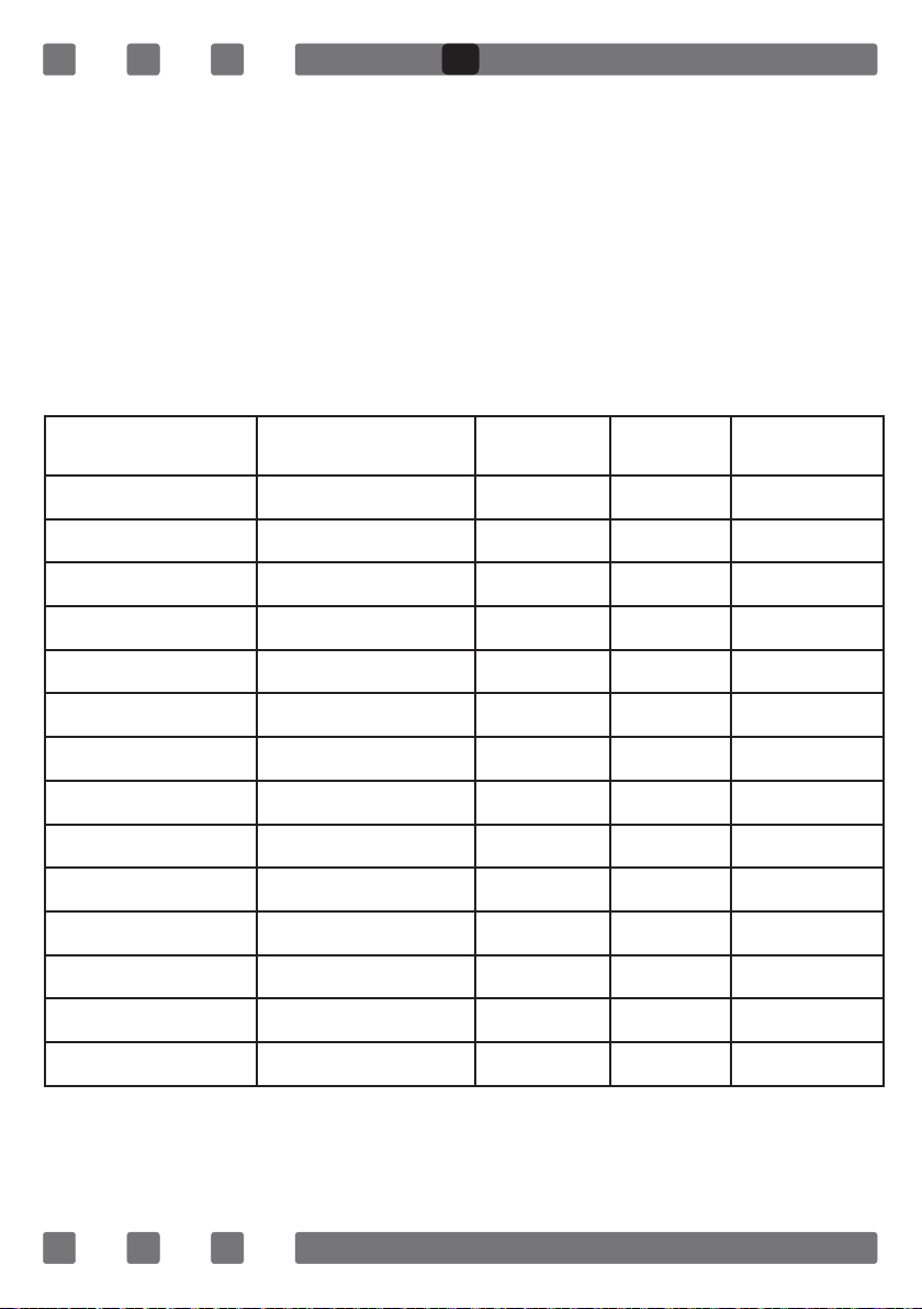
COOKING TIME TABLE
WARNING: Oven must be preheated for 7-10 minutes before placing
the food in it.
Food
Cooking
Function
Cooking
Temperature (°C)
Cooking
Rack
Cooking
Time (min.)
Cake Static 180 2 70
Small Cake Static 180 2 40
Pie Static 200 2 70
Pastry Static+Fan 180-200 2 20-25
Cookie Static 175 2 20
Apple Pie Static 180-190 1 150
Sponge cake Static 175 2 45-50
Pizza Static 190 2 25
Lasagne Static 180-200 2 50-60
Meringue Static 100 2 60
Grilled Chicken* Grill+Fan 220 4 25-35
Grilled Fish* Grill+Fan 220 4 35-40
Calf Steak* Grill Max. 4 30
Grilled Meatball* Grill Max. 4 40
* Food must be turned after half of the cooking time.
GB
19
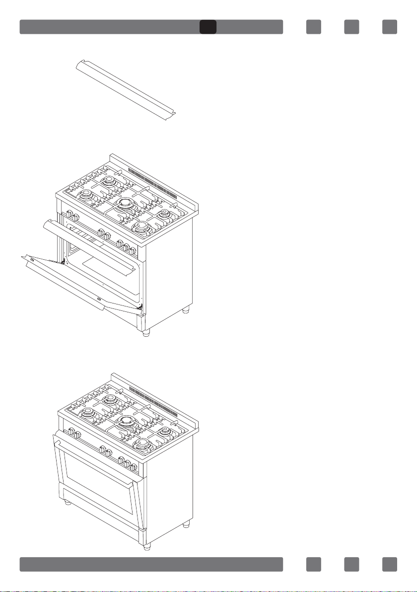
USING THE GRILL DEFLECTOR SHEET*
1. A safety panel is designed to
protect control panel and the
buttons when the oven is in grill
mode. (Figure 13)
2. Please use this safety panel in
order to avoid the heat to damage
control panel and the buttons when
the oven is grill mode.
WARNING: Accessible parts may be
hot when the grill in use. Young
children should be kept away.
3. Place the safety panel under
control panel by opening the oven
front cover glass. (Figure 14)
4. And then secure the safety
panel in between oven and front
cover by gently closing the cover.
(Figure 15)
5. It is important for cooking to
keep the cover open in specied
distance when cooking in grill
mode.
6. Safety panel will provide an
ideal cooking circumstance while
protecting control panel and
buttons.
If the cooker has the “CLOSED GRILL
FUNCTIONED” option with thermostat,
you can keep the oven door closed
during operation; in this case the grill
deector sheet will be unnecessary.
Figure 15
Figure 14
Figure 13
GB
20
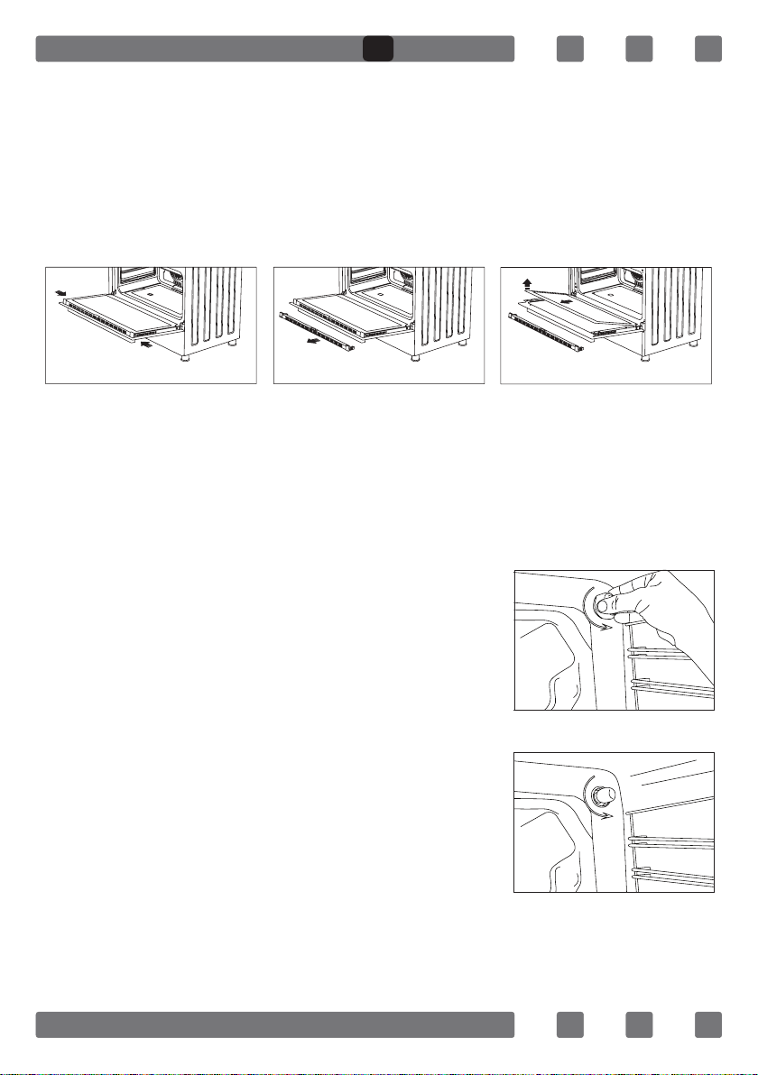
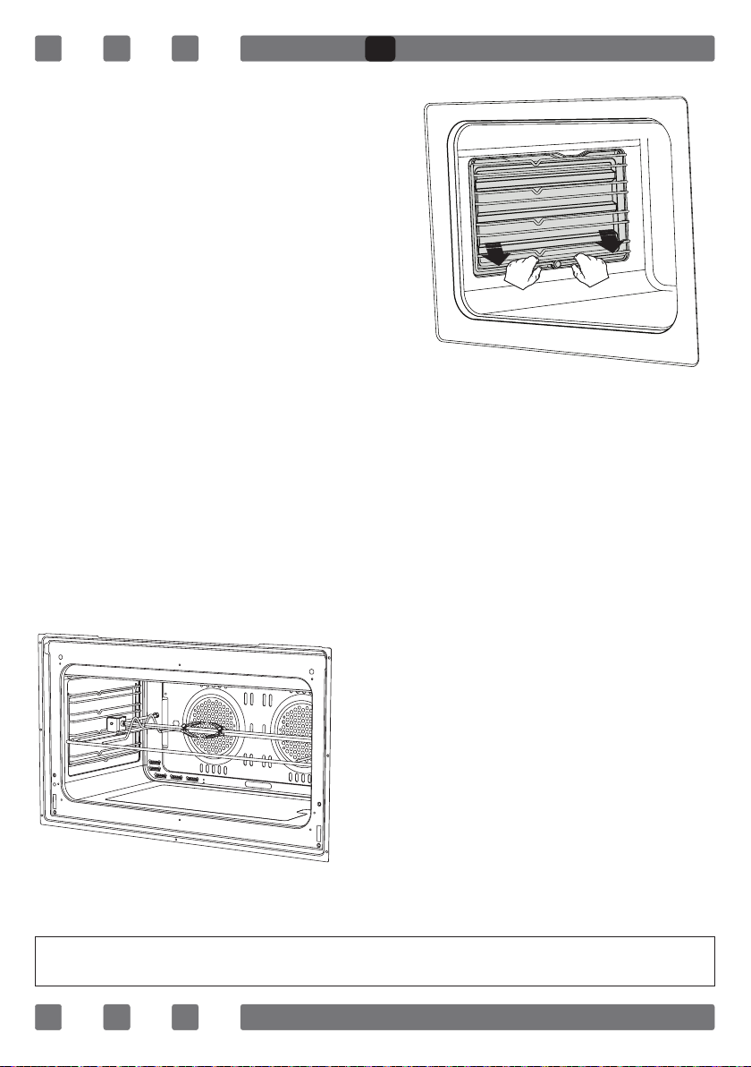
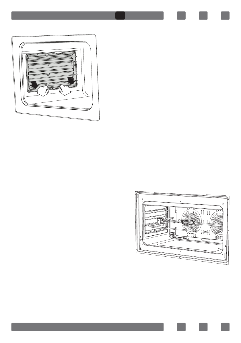
CATALYTIC WALLS*
Catalytic walls are located on
the left and the right side of cavity
under the guides. Catalytic walls
banish the bad smell and obtain the
best performance from the cooker.
Catalytic walls also absorb oil
residue and clean your oven
while it’s operating.
Removing the catalytic walls
In order to remove the catalytic walls; the guides must be pulled out.
As soon as the guides are pulled out, the catalytic walls will be released
automatically. The catalytic walls must be changed after 2-3 years.
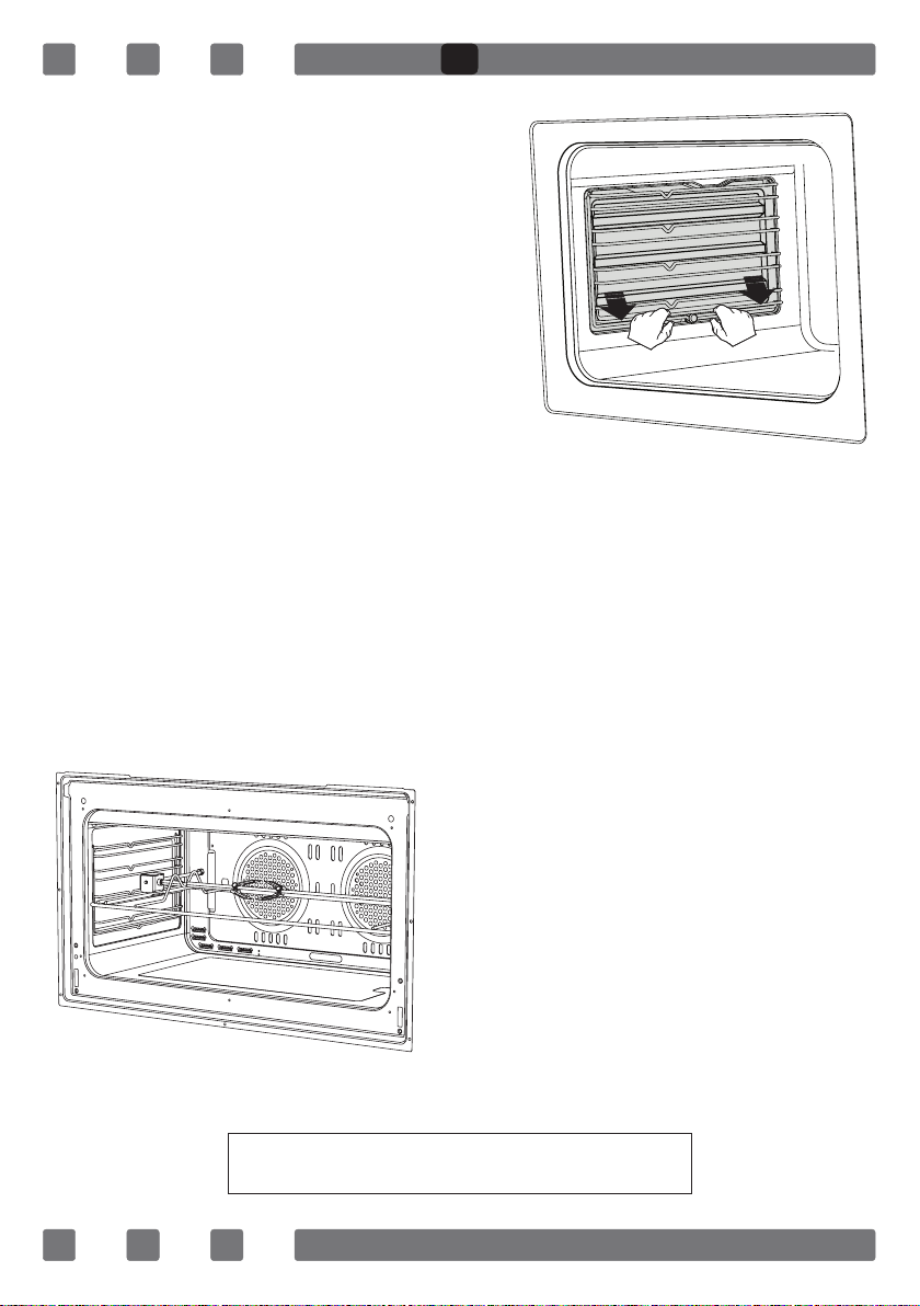
CHICKEN ROASTING*
Place the spit on the frame. Slide
turn spit frame into the oven at the
desired level.Locate a dripping pan
through the bottom in order to collect
the fast. Add some water in dripping
pan for easy cleaning.Do not forget
to remove plastic part from spit.After
grilling, screw the plastik handle to
the skewer and take out the food from
oven.
Figure 16
Figure 17
“Always grill with the oven door closed”
GB
21
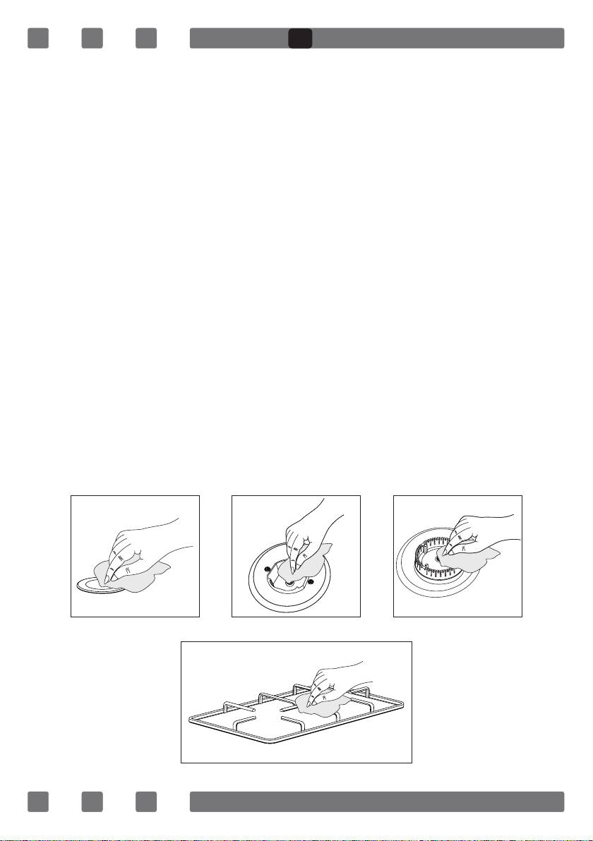
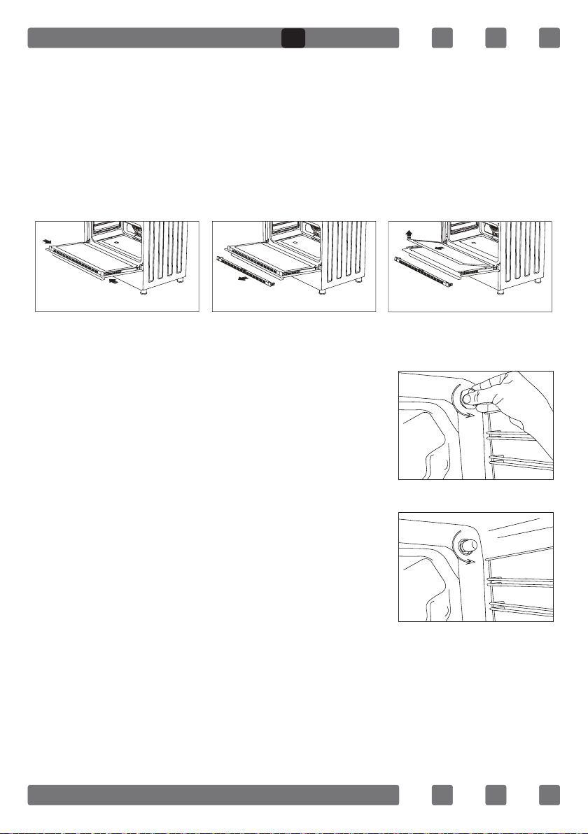
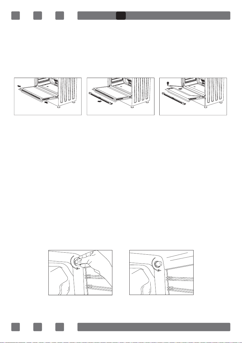
CLEANING AND MAINTENANCE OF THE OVEN’S FRONT DOOR GLASS
Remove the prole by pressing the plastic latches on both left and right
sides as shown in Figure 18 and pulling the prole towards yourself as
shown in Figure 19 Then remove the inner-glass as shown in Figure 20
If required, middle glass can be removed in the same way. After cleaning
and maintenance are done, remount the glasses and the prole in reverse
order.Make sure the prole is properly seated in its place.
CHANGING THE OVEN LAMP
In order to avoid the possibility of an electric shock, ensure that the
circuit of the appliance is open before changing the lamp.
(The open-circuit is an electrical circuit that does not conduct current)
1. First of all, cut the electrical connection of the appliance and ensure
that the appliance is cooled down.
2. Remove the glass protection by turning as
shown in the gure. If you have difculty in
turning it, the use of plastic gloves will help you.
3. Afterwards, remove the lamp by
turning and install the new lamp with the same
specications. The specications of the lamp
should be as follows:
- 230 V, AC
- 15 W
- Type E14
4. Place the glass protection and complete
the replacing process by plugging in the electric
cable of the appliance. Now, you can use your
oven.
Figure 18 Figure 19 Figure 20
Figure 21
Figure 22
GB
22
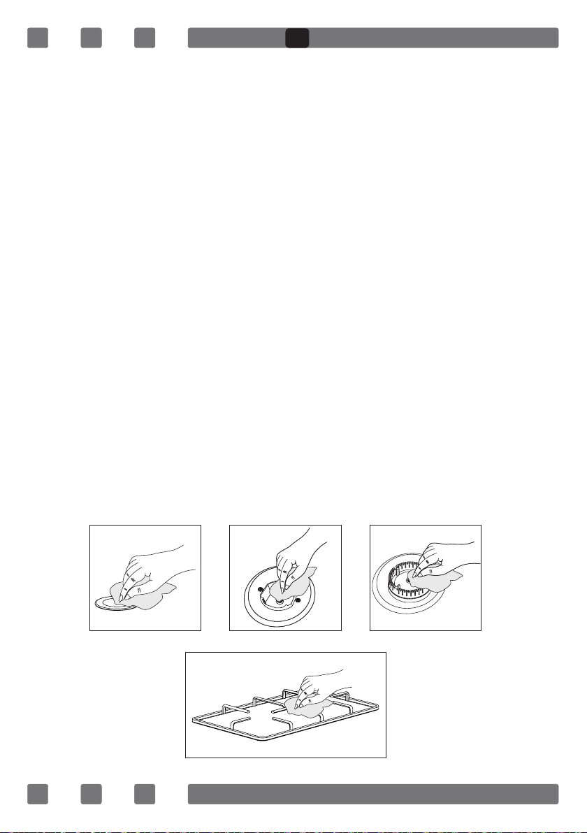
MAINTENANCE and CLEANING
1. Disconnect the plug supplying electricity for the oven from the socket.
2. While oven is operating or shortly after it starts operating, it is
extremely hot. You must avoid touching from heating elements.
3. Never clean the interior part, panel, lid, trays and all other parts of
the oven by the tools like hard brush, cleaning mesh or knife. Do not
use abrasive, scratching agents and detergents.
4. After cleaning the interior parts of the oven with a soapy cloth, rinse
it and then dry thoroughly with a soft cloth.
5. Clean the glass surfaces with special glass cleaning agents.
6. Do not clean your oven with steam cleaners.
7. Before opening the upper lid of the oven, clean spilled liquid off the
lid. Also, before closing the lid, ensure that the cooker table is cooled
enough.
8. Never use inammable agents like acid, thinner and gasoline when
cleaning your oven.
9. Do not wash any part of your oven in dishwasher.
10. In order to clean the front glass lid of the oven; remove the xing
screws xing the handle by means of a screwdriver and remove the oven
door. Than clean and rinse it thoroughly. After drying, place the oven
glass properly and re-install the handle.
Figure 24
Figure 25
Figure 23
Figure 26
GB

23
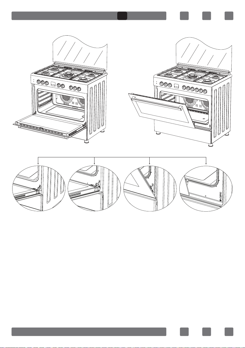
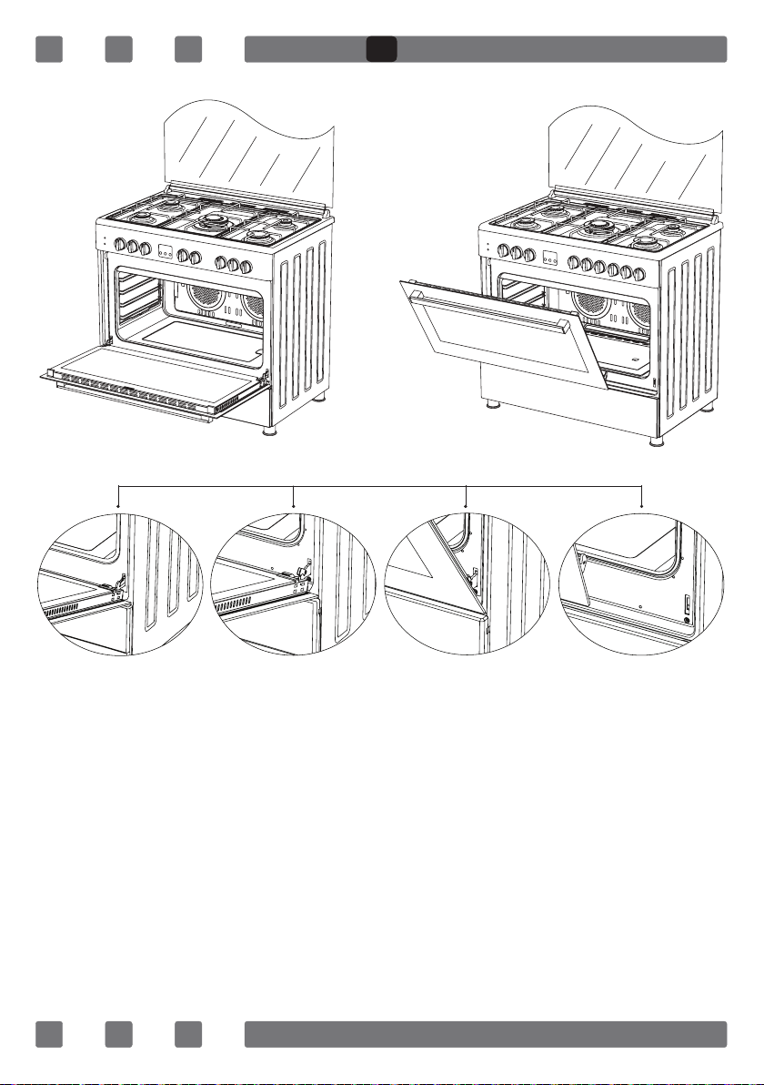
INSTALLATION OF THE OVEN DOOR
Figure 27 Figure 28
Completely open
the oven door by
pulling it to your-
self. Afterwards,
perform the un-
locking process by
pulling the hinge
lock upwards with
the help of a screw
driver as shown in
Figure 27.1.
Bring the hinge
lock to the widest
angle as shown in
Figure 27.2. Bring
both hinges con-
necting the oven
door to the oven to
the same position.
Afterwards, close
the oven door as to
lean on the hinge
lock as shown in
Figure 28.1.
In order to re-place the oven door, perform the abovementioned steps in reverse.
To remove the
oven door, pull it
upwards by holding
it with both hands
when close to the
closed position as
shown in
Figure 28.2.
Figure 27.1 Figure 27.2 Figure 28.1 Figure 28.2
GB
24
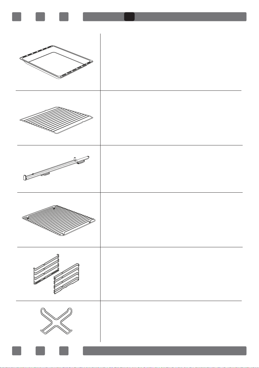
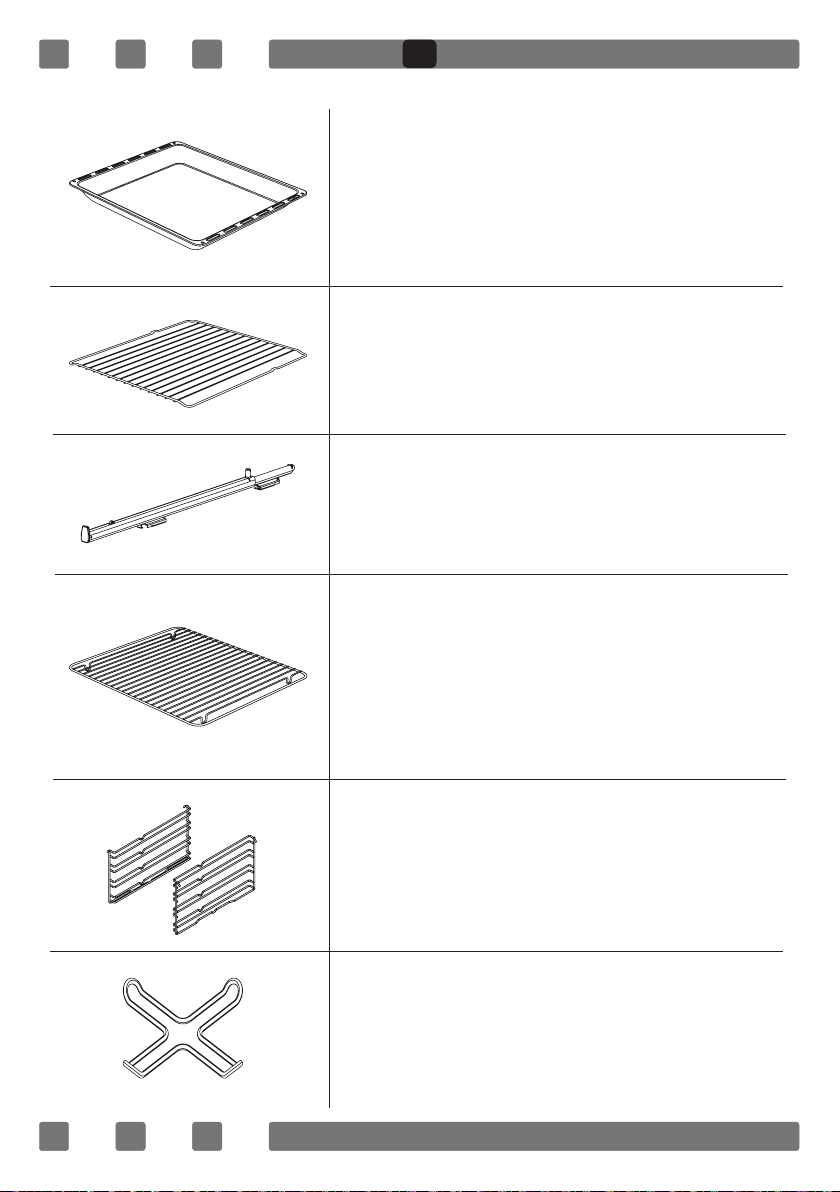
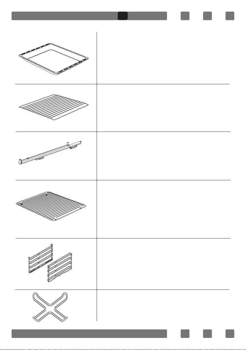
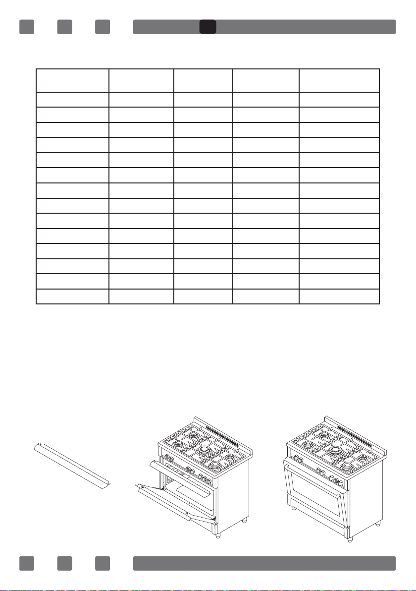
ACCESORIES
Deep Tray
Used for pastries, deep fried foods and
stew recipes. In case of frying directly on
the grill for cakes, frozen foods and meat
dishes, it can be used of oil pick-up tray.
Wire Grill
Used for frying and/or placing the foods
to be baked, fried and frozen foods on the
desired rack.
Telescopic Rail*
With the help of telescopic rails, the trays
and/or wire racks can be easily placed and
removed.
Coffee Pot Support Unit*
Can be used for coffee pot.
Lower and Upper Wire Racks
While cooking, you can place the deep
tray and tray on the lower and upper wire
racks.
In Tray Wire Grill*
Foods that can stick while cooking such
as beef are placed on in tray grill. Thus,
the contact and sticking of the food is
prevented.
GB
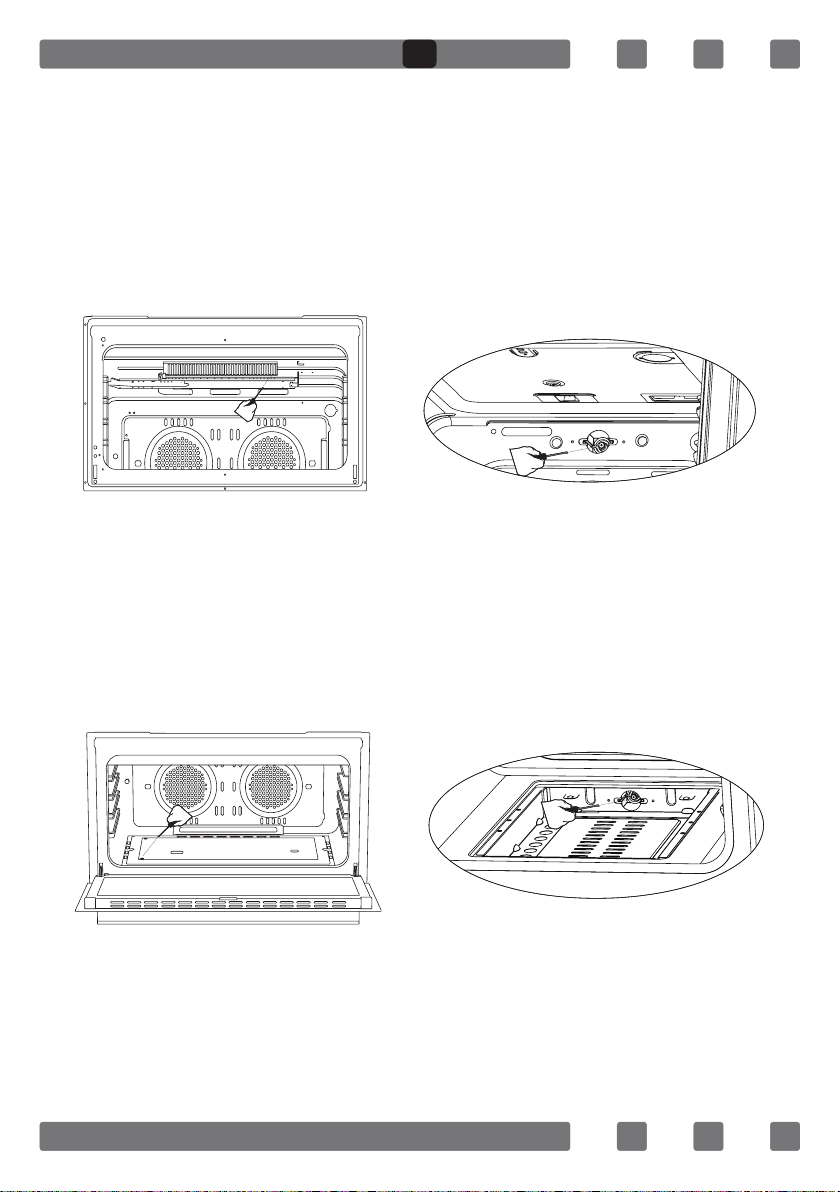
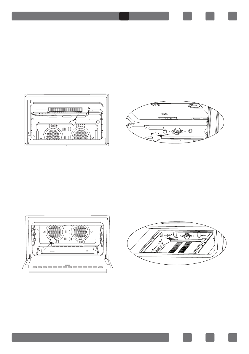
25
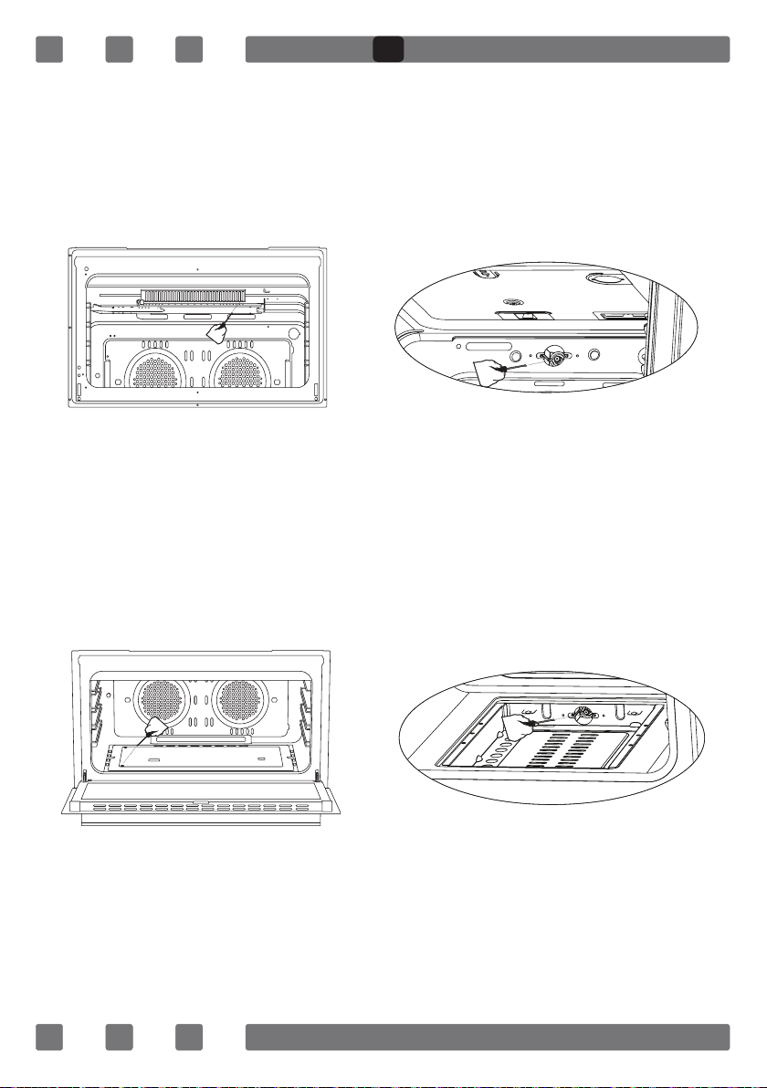
REMOVAL OF THE LOWER AND UPPER BURNER AND INSTALLATION OF THE
INJECTOR TO THE GAS OVEN
Removal of the Upper Burner:
With the help of a screw driver, remove the screw as shown in Figure
29. As shown in Figure 29.1, remove the injector in the bearing with a
socket wrench. In order to re-place the burner, apply the removal process
reversely.
Removal of the Lower Burner:
The lower burner door has been xed with two screws. As shown in
Figure 30, remove it with the help of a screw driver. As shown in Figure
30.1, remove the injector in the bearing with a socket wrench. In order to
re-place the burner, apply the removal process reversely.
Figure 29 Figure 29.1
Figure 30 Figure 30.1
GB

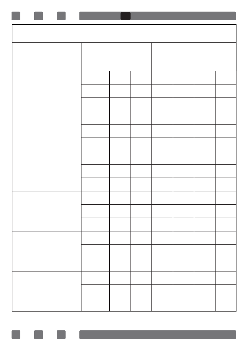
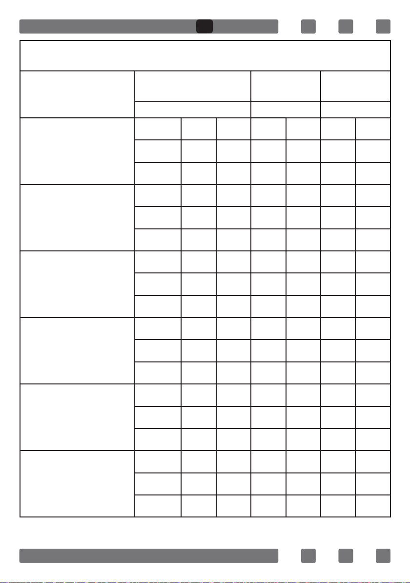
26
90*60
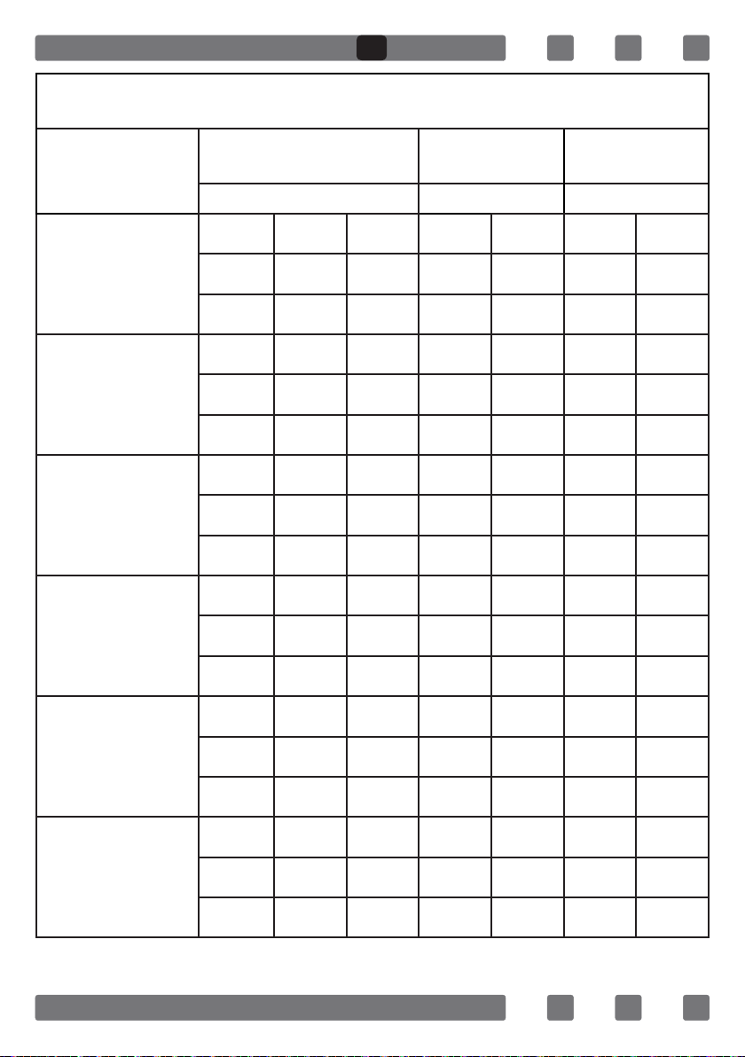
INJECTOR, GAS FLOW And POWER TABLE
BURNER
SPECIFICATIONS
G20,20 mbar
G25,25 mbar
G20,25 mbar G20,13 mbar
Gas Natural Gas Natural Gas Natural
Wok
Burner
Injector 1,40 mm 1,28 mm 1,60 mm
Gas Flow 0,333 m³/h 0,333 m³/h 0,333 m³/h
Power 3,50 kW 3,50 kW 3,50 kW
Rapid
Burner
Injector 1,15 mm 1,10 mm 1,45 mm
Gas Flow 0,276 m³/h 0,276 m³/h 0,276 m³/h
Power 2,90 kW 2,90 kW 2,90 kW
Semi-Rapid
Burner
Injector 0,97 mm 0,92 mm 1,10 mm
Gas Flow 0,162 m³/h 0,162 m³/h 0,162 m³/h
Power 1,70 kW 1,70 kW 1,70 kW
Auxiliary
Burner
Injector 0,72 mm 0,70 mm 0,85 mm
Gas Flow 0,96 m³/h 0,96 m³/h 0,96 m³/h
Power 0,95 kW 0,95 kW 0,95 kW
Grill
Burner
Injector 1,20 mm 1,20 mm 1,50 mm
Gas Flow 0,257 m³/h 0,257 m³/h 0,257 m³/h
Power 2,70 kW 2,70 kW 2,70 kW
Oven
Burner
Injector 1,45 mm 1,45 mm 1,70 mm
Gas Flow 0,38 m³/h 0,38 m³/h 0,38 m³/h
Power 4,00 kW 4,00 kW 4,00 kW
GB

27
90*60
INJECTOR, GAS FLOW And POWER TABLE
BURNER
SPECIFICATIONS
G30,28-30 mbar
G31,37 mbar
G30,50 mbar G30,37 mbar
LPG LPG LPG
Wok
Burner
Injector 0,96 mm 0,76 mm 0,96 mm
Gas Flow 254 g/h 254 g/h 254 g/h
Power 3,50 kW 3,5 kW 3,5 kW
Rapid
Burner
Injector 0,85 mm 0,75 mm 0,85 mm
Gas Flow 211 g/h 211 g/h 211 g/h
Power 2,90 kW 2,90 kW 2,90 kW
Semi-Rapid
Burner
Injector 0,65 mm 0,60 mm 0,65 mm
Gas Flow 124 g/h 124 g/h 124 g/h
Power 1,70 kW 1,70 kW 1,70 kW
Auxiliary
Burner
Injector 0,50 mm 0,43 mm 0,50 mm
Gas Flow 69 g/h 69,1 g/h 69,1 g/h
Power 0,95 kW 0,95 kW 0,95 kW
Grill
Burner
Injector 0,85 mm 0,85 mm 0,85 mm
Gas Flow 196 g/h 196 g/h 196 g/h
Power 2,70 kW 2,70 kW 2,70 kW
Oven
Burner
Injector 1,00 mm 1,00 mm 1,00 mm
Gas Flow 291 g/h 291 g/h 291 g/h
Power 4,00 kW 4,00 kW 4,00 kW
GB
28
IF YOUR OVEN DOES NOT OPERATE
1. Please check main gas valve.
2. Gas hose is can be broken or bend.
3. Please check the connection of gas hose with oven.
4. Please check noise of gas rate.
5. Please check the gas valve, suitable or unsuitable for your oven.
6. If you can not to solve the problem, to apply manufacturer-supplier
services agent or similar qualied persons.
7. We are recommended per 2 year chance your ovens gas valve.
8. Please check the plug of power supply cord has a well connection
with wall socket or not.
9. Please check the electric network.
10. Please check the fuse.
11. Please check power supply cord for any damage problems.
ENVIRONMENTALLY-FRIENDLY DISPOSAL
Dispose of packaging in an environmentally-friendly
manner.
This appliance is labelled in accordance with European
Directive 2012/19/EU concerning used electrical and
electronic appliances (waste electrical and electronic
equipment - WEEE). The guideline determines the
frame work for the return and recycling of used
appliances as applicable throughout to the EU.
PACKAGE INFORMATION
Packaging materials of the product are manufactured from recyclable
materials in accordance with our National Environment Regulations.
Do not dispose of the packaging materials together with the domestic
or other wastes. Take them to the packaging material collection points
designated by the local authorities.
GB

29
FR
Cher utilisateur,
Notre objectif est que ce produit fabriqué dans nos installations
modernes dans un excellent environnement de travail, en conformité
avec le concept de qualité totale, vous donne totale satisfaction.
Par conséquent, nous vous suggérons de lire attentivement le manuel
de l’utilisateur avant d’utiliser le produit et de le garder en permanence
à votre disposition.
Note: Ce manuel de l’utilisateur est préparé pour plus d’un modèle. Il
se peut que certaines des caractéristiques spéciées dans ce manuel ne
soient pas disponibles dans votre appareil.
*Marquez les produits en option.
"CET APPAREIL DOIT ETRE INSTALLE SELON LES REGLEMENTS EN VIGUEUR
ET UTILISE DANS UN ESPACE BIEN AERE. LIRE LES INSTRUCTIONS AVANT
D'INSTALLER OU D'UTILISER CET APPAREIL."
“Conforme au Standart DEEE”
30
TABLE DES MATIERES
Avertissements Importants
31
Presentation De L’appareil 35
Avertissements Importants 36
Connexion Électrique Schéma 37
Passage Pour Le Tuyau De Gaz 38
Schéma De Connexion De La Chaine 39
Installation De Votre Four 39
Caracteristiques Techniques De Votre Four 40
Instructions Pour Le Changement De Gicleur 40
Réglage De La Réduction Du Débit De Gaz Pour Les
Robinets De La Cuisinière 40
Description Du Four Et Des Panneaux De Commande 41
Tableaux De Bord 42
Utilisation De La Table De Cuisson 43
Utilisation Des Plaques Chauffantes 44
Installation Des Pieds Du Four 44
Uitilisation Du Four 45
Tableau De Cuisson 46
Utilisation De L’ecran De Protection 47
Parois Catalytiques 48
Rôtissage Du Poulet 48
Nettoyage Et Entretien De La Vitre
De La Porte Avant Du Four 49
Changement De La Lampe Du Four 49
Maintenance Et Nettoyage 50
Assemblage de la porte du four 51
Les Accessoires 52
Desassemblage Des Bruleurs Du Haut Et
Du Bas Du Four A Gaz Et Fixation Des Injecteurs 53
Injecteur, Consuption Et Puissance Tableau 54
Si Votre Four Ne Fonctionne Pas 56
Mise Au Rebut Respectueuse De L’environnement Et
Informations Relatives À L’emballage 56
FR

31
AVERTISSEMENTS IMPORTANTS
1. AVERTISSEMENT: Pour éviter tout risque d’électrocution,
assurez-vous que le circuit électrique du produit est
ouvert avant de remplacer la lampe.
2. AVERTISSEMENT: Avant de toucher les bornes de
connexion, il est indispensable de couper tous les
circuits d’alimentation.
3. AVERTISSEMENT: Les parties accessibles du gril
peuvent devenir chaudes lorsqu’il est en marche. Ne
laissez pas les enfants s’approcher de l’appareil.
4. AVERTISSEMENT: Des précautions doivent être prises
lors de la cuisson avec des graisses et des huiles, car
elles peuvent être dangereuses et provoquer un incendie.
5. AVERTISSEMENT: Risque d’incendie ! Évitez de ranger
les produits alimentaires sur la surface de cuisson.
6. AVERTISSEMENT: Si la surface est ssurée, débranchez
l’appareil pour éviter tout risque d’électrocution.
7. AVERTISSEMENT: Les parties accessibles de l’appareil
peuvent devenir chaudes lorsqu’il est en marche. Ne lais-
sez pas les enfants s’en approcher.
8. AVERTISSEMENT: L’appareil et ses parties accessibles
deviennent chauds pendant l’utilisation.
9. Les conditions de réglage de l’appareil sont
indiquées sur l’étiquette. (ou les étiquettes de
données)
FR

32
10. Cet appareil n’est pas raccordé à un système
d’évacuation des produits de combustion. Par ailleurs,
ledit appareil doit être raccordé et installé selon la
législation applicable. Considérez les exigences
relatives à la ventilation.
11. L’utilisation d’une cuisinière à gaz libère l’humidité
et les produits de combustion dans la pièce où elle
est installée. En particulier lorsque l’appareil en cours
d’utilisation, assurez-vous que la cuisine est bien
ventilée et que les trous de ventilation naturelle ne
sont pas obstrués. Vous pouvez également installer un
système de ventilation mécanique. (Hotte au-dessus
du four) L’utilisation prolongée de l’appareil peut né-
cessiter une ventilation supplémentaire. On peut par
exemple ouvrir une fenêtre ou, si possible, augmenter
le niveau de ventilation d’un système de ventilation
mécanique.
12. Les parties accessibles du gril peuvent devenir.
chaudes lorsqu’il est en marche. Ne laissez pas les
enfants s’en approcher.
13. AVERTISSEMENT: L’appareil est destiné à la cuisson.
Par conséquent, il ne doit pas être utilisé à d’autres ns
telles que le chauffage d’une pièce.
14. Un équipement de protection supplémentaire
est fourni pour éviter que l’utilisateur ne touche par
inadvertance aux portes du four. Cet équipement doit
installer s’il y a des enfants.
FR

33
15. Cet appareil doit être installé selon les règlements
et seulement dans un endroit bien aéré. Lisez les
instructions avant d’installer ou d’utiliser l’appareil.
16. Avant d’installer l’appareil, vériez les conditions
locales (type de gaz et pression du gaz) et assurez-vous
que les réglages de l’appareil sont appropriés.
17. Ces instructions sont applicables pour les pays
dont les symboles sont indiqués sur l’appareil. Si le
symbole du pays n’est pas disponible sur l’appareil,
il convient de lire les instructions techniques pour
adapter l’appareil aux conditions dudit pays.
18. N’exécutez pas le système pendant plus de 15
secondes. Si le brûleur ne s’allume pas au bout de
15 secondes, arrêtez le système et ouvrez la porte de
la section et/ou attendez au moins 1 minute avant
d’allumer le brûleur.
19. N’utilisez pas d’appareils de nettoyage à la vapeur
pour nettoyer l’appareil.
20. Avant d’ouvrir la porte du four, nettoyer les
résidus qui s’y trouvent. Laisser d’abord le four
refroidir avant de refermer la porte.
21. N’essayez jamais d’éteindre une amme avec de
l’eau; coupez d’abord l’alimentation et, à l’aide d’un
couvercle ou d’une couverture, couvrez la amme.
22. N’utilisez pas de produits de nettoyage durs et
abrasifs ou des couteaux racleurs pour nettoyer la
vitre de la porte du four, car ils peuvent enrayer ou
éraer la surface.
FR

34
23. Après avoir introduit un plat, assurez-vous que le
porte est bien fermée.
24. Ne laissez pas les enfants de moins de 8 ans
sans supervision s’approcher de l’appareil.
25. Évitez de toucher les éléments chauffants, au
risque de vous brûler.
26. Cet appareil peut être utilisé par des enfants
de 8 ans et plus et des personnes dont les capacités
physiques, sensorielles ou mentales sont réduites
ou n’ayant pas sufsamment d’expérience ou de
connaissances si une personne chargée de la sécurité
les surveille ou leur apprend à utiliser le produit en
toute sécurité et en étant conscients des dangers y
afférents.
FR
35
PRESENTATION DE L’APPAREIL
21
22
23
24
1
3 4 5 6
2
7*
8*
10
9
11
18
12
13
14
15
16
19
20
17
1. Brûleur Central
2. Brûleur Central
3. Grille
4. WOK Brûleur
5. Grand Brûleur
6. Auxiliaire Brûleur
7. Plaque Chauffante
8. WOK Brûleur
17. Porte du Four
18. Poignée du Four
19. Porte de l’armoire
du bas
20. Pied en Plastique
21. Lampe
22. Grille
23. Poulet à Rôtir
24. Plaque Profonde
9. Porte en Verre
10. Panneau de Commande
11. Lampe Led
12. Boutons de commande du four
13. Minuteur Digital
14. Boutons Plaques de Cuisson
15. Grille
16. Plaque Profonde
FR

36
AVERTISSEMENTS IMPORTANTS
Connections Electrique Et Sécurité
1.Votre four est réglé en conformité avec une alimentation électrique de
220-240V / 380-415V AC, 50/60 Hz. Si le courant est différent de cette
valeur spéciée, contactez votre centre de service autorisé.
2.L’installation électrique du four doit être uniquement effectuée par
le réseau avec liaison de terre, installé selon les lois en vigueur. Si le ré-
seau où se situe le four n’est pas conforme, veuillez alors immédiatement
contacter un électricien qualié. Le fabricant décline toute responsabilité
en cas de dommages causés par l’installation d’un four sur un réseau
non-conforme au système terre.
3.Le câble électrique ne doit pas être en contact avec la table de travail.
4.Quelques modèles sont fournis sans la prise. Dans ce cas, veuillez
utiliser un câble agréer pour une connexion mono phase.
Branchement Du Gaz Et Sécurité
1.Avant de brancher votre appareil à l’arrivée de gaz, vériez que
les catégories de gaz et les spécications concernant la pression
correspondent à celles de l’arrivée de gaz. Si nécessaire, contactez le
service autorisé pour l’adaptation de la catégorie de gaz.
2.L’appareil doit être installé conformément aux lois en vigueur et doit
être utilisé uniquement dans un endroit aéré. Bien lire les instructions
avant l’installation et l’utilisation du matériel. Dans un souci de sécu-
rité, l’appareil doit être installé et/ou mis en service par une personne
compétente, comme le mentionnent les manuels de recommandations
de sécurité du gaz.
3.L’appareil ne doir pas être installé dans une pièce sans fenêtre ou
sans ouverture. S’il est installé dans une pièce sans porte donnant
directement sur l’extérieur, une ouverture permanente est exigée. La
circulation de l’air doit être de 2 m³/h par brûleur.
4.Le branchement du gaz peut être effectué par la droite ou par la
gauche. N’oubliez pas de changer le robinet de la tuyère, la prise et le
dispositif d’étanchéité.
5.Si vous effectuez le raccordement avec un tuyau en métal exible,
placez un joint d’étanchéité entre les deux.
FR
37
6.Le diamètre interne du tuyau exible, avec lequel le tuyau du butane
est relié, doit être de 6mm pour les tuyaux à gaz de maison. Le diamètre
interne du tuyau exible, avec lequel le robinet du exible est relié, doit
être de 15 mm. Le tuyau doit être fermement xé avec le robinet du
exible en serrant avec une pince. Le tuyau doit être remplacé avant sa
date d’expiration.
7.Attention! Pour le branchement du four avec la valve d’arrivée de
gaz, le tuyau doit être court et assurez vous qu’il n’y ait aucun défaut
d’étanchéité. Pour votre sécurité, le tuyau utilisé ne doit pas dépasser
125 cm.
8.Veriez une fois de plus le branchement du gaz.
9.Lorsque vous installez votre four, assurez-vous qu’il soit bien à niveau.
En cas contraire, ajustez les pieds du four.
EN AUCUN CAS LE TUYAU DE GAZ ET LE CABLE ELECTRIQUE NE DOIVENT
ENTRER EN CONTACT AVEC LES PARTIES CHAUFFANTES DU FOUR, TOUT
PARTICULIEREMENT AVEC LA PARTI E ARRIERE DE L’APPAREIL. NE PAS
BOUGER LE FOUR UNE FOIS CONNECTE. LE DEBRANCHEMENT DU TUYAU
POURRAIT CREER UNE FUITE DE GAZ.
CONNEXION ÉLECTRIQUE SCHÉMA
220-240V~50/60Hz 220-240V~50/60Hz
400V 3N~50/60Hz 400V 2N~50/60Hz
Earth
Terre
Erdung
Earth
Terre
Erdung
Earth
Terre
Erdung
Earth
Terre
Erdung
L3
L2
L1
L2
L1
L1
Live
Phase
Neutral
Neutre
Neutral
Neutre
Neutral
Neutre
H05 VV-F 3G 4mm² H05 VV-F 5G 1.5mm² H05 VV-F 4G 1.5mm² H05 VV-F 3G 1.5mm²
Neutral
Neutre
380-415V 3N~50/60Hz 380-415V 2N~50/60Hz
220-240V~50/60Hz 220-240V~50/60Hz
FR
38
PASSAGE POUR LE TUYAU DE GAZ
1. Branchez l’appareil sur le robinet de la tuyauterie de gaz suivant
l’itinéraire le plus court possible et de telle sorte qu’aucune fuite de gaz
ne puisse être enregistrée.
2. Pour effectuer le contrôle d’étanchéité, assurez-vous que les
poignées du panneau de commande sont fermées et que la bouteille de
gaz est ouverte.
3. Lors d’une vérication de fuite de gaz, évitez d’utiliser tout type de
briquet, allumette, cigarette ou substance similaire.
4. Appliquez une solution savonneuse aux points de raccordement. En
cas de fuite, des bulles vont apparaître.
5. Lors de la mise en place de l’appareil, assurez-vous qu’il est au
même niveau que le plan de travail. Au besoin, réglez ses pieds au
niveau du plan de travail.
6. Placez l’appareil sur une surface plane et utilisez-le dans un endroit
bien aéré.
Dessin 1
Dessin 2
FR
39
SCHÉMA DE CONNEXION DE LA CHAINE
Pour être sûr d’utiliser le produit
en toute sécurité, assurez-vous
que le produit est xé sur le mur
avec une chaine et un vis crochet
avant d’utiliser l’appareil.
Assurez-vous que le crochet est
vissé de façon sécurisée sur le
mur.
INSTALLATION DE VOTRE FOUR
650mm min.
850 mm min.
900 mm min.20 mm 20 mm
FR
40
CARACTERISTIQUES TECHNIQUES DE VOTRE FOUR
CARACTÉRISTIQUES 90x60
Largeur Extérieure 900mm
Profondeur Extérieure 610mm
Hauteur Extérieure 925mm
Puissance Ampoule 15W
Elément Chauffant Du Bas 2000W
Elément Chauffant Du Haut 1500W
Elément Chauffant Du Grill **2500W / 3250W
Elément Chauffant Turbo 1250W x 2
Tension D’alimentation 220-240V AC/380-415V AC 50/60Hz.
Plat Chaud Ø145mm* 1000W
Plat Chaud Ø180mm* 1500W
Plat Chaud Rapide 145mm* 1500W
Plat Chaud Rapide 180mm* 2000W
** seulement pour le produit mixte.
INSTRUCTIONS POUR LE CHANGEMENT DE GICLEUR
1. Veuillez utiliser un tournevis spécial pour enlever et installer le
gicleur. (Dessin 3)
2. Retirez le gicleur (Dessin 4) du brûleur avec le tournevis spécial et
installez le nouveau gicleur. (Dessin 5).
RÉGLAGE DE LA RÉDUCTION DU DÉBIT DE GAZ POUR LES ROBINETS DE LA
CUISINIÈRE
1. Allumez le brûleur à ajuster et tournez le bouton en direction de la
position réduite.
2. Retirez le bouton du robinet à gaz.
Dessin 3
Dessin 4
Dessin 5
FR
41
3. Utilisez un tournevis de taille appropriée pour régler la vis de réglage
du débit. Pour le GPL (Butane - Propane), tournez la vis dans le sens ho-
raire. Pour le gaz naturel, tournez la vis une fois dans le sens antihoraire.
« La longueur normale d’une amme droite en position réduite doit être
de 6 à 7 mm.
4. Si la amme est plus élevée que la position souhaitée, tournez la vis dans
le sens horaire. Dans le cas contraire, tournez-la dans le sens antihoraire.
5. En guise de dernier contrôle, mettez le brûleur à la fois dans les
positions Flamme haute et amme réduite et vériez si la amme est
allumée ou éteinte.
La position de la vis peut varier selon le type de robinet à gaz utilisé
pour votre appareil. (Dessin 6 et 7)
BOUTON DU THERMOSTAT: Pour faire marcher votre four, le thermostat
doit être réglé à la température désirée. Vous pouvez régler le
thermostat entre 40 et 240 degrés.
BOUTON MINUTERIE MECANIQUE*: Pour faire marcher votre four, la
minuterie doit être réglée sur le temps désiré.
Dessin 6
Dessin 7
Bruleur
Arrière
Gauche
Bruleur
Avant Droit
Wok
Bruleur
Plaque
Chauffante
Avant
Plaque
Chauffante
Arrière
Bruleur
Arrière
Gauche
Bruleur
Avant
Gauche
Grill Brûleur
Ou Un
Élément De
Chauffage
Brûleur Du
Four* Ou
Élément De
Chauffage
Minuteur* Thermostat
Tourne-
broche
Ampoule
Du Four
Lumière
D’allumage
FR
42
DESCRIPTION DU FOUR et des PANNEAUX DE COMMANDE
TABLEAUX DE BORD
Remarque :
La signication des symboles gurant sur le panneau de
commande de l’appareil est donnée ci-dessous. Tous les symboles ne
gurent pas sur tous les modèles, par conséquent, ne vous attardez
que sur les symboles qui gurent sur votre appareil.
Tourne Broche
(Grıll Poulet)
Seulement Ventilateur Se
Fonctionne
Chauffant Supérieure Et
Inferieure & Se Fonctionnent
Instrument Chauffant Turbo +
Ventilateur
Lampe
Chauffant Supérieure Et
Inferieure & Sefonctionnent +
Seulement Ventilateur
Instrument Chauffant
Inferieure + Seulement
Ventilateur Se Fonctionne
Grille Chauffant Et Ventilateur
Se Fonctionnent
Grill Heating Element +
Tournebroche
Grille Chauffant Se Fonctionnent
Grille Chauffant Se
Fonctionnent+Lampe
Instrument Chauffant Supérieure
Minuterie Électrique Instrument Chauffant Inferieure
Flamme Allumage
Petit Gril Et Ventilateur Petit Gril
FR
43
UTILISATION DE LA TABLE DE CUISSON
1. Ferme Entièrement ouvert A moitié ouvert
2. An d’assurer une utilisation optimale, assurez vous que la
casserole utilisée ait un fond plat, et utilisez des casseroles aux
dimensions indiquées ci-dessous Le robinet de contrôle de la cuisinière
à gaz ont un mécanisme spécial. An d’allumer la cuisinière;
3.Toujours presser la commande en avant et faire apparaître le
symbole de la amme en tournant dans le sens inverse des aiguilles
d’une montre (gauche) Tous les voyants fonctionnent et seul le bec
que vous contrôlez doit être allumé. Maintenez la commande appuyée
jusqu’à ce que le voyant soit en marche.
4.Pour les modèles munis d’un système de sécurité, quand la
amme de la cuisinière est éteinte, la valve de contrôle coupe le gaz
automatiquement. N’utilisez pas pendant plus que 15 secs l’allumage.
Si après ces 15 secondes le brûleur ne s’allume pas, arrêter pendant
quelques instants et si vous essayiez d’allumer le four, ouvrer la porte et
attendez au moins 1 minute avent de réessayer.
5.Si le bruleur s’est éteint pour l’une ou l’autre raison, éteignez
celui-ci et attendez minimum une minute avant de le rallumer.
6.Pour faire marcher les brûleurs avec un système de sécurité pour le
gaz, il faut appuyer sur le bouton et tourner dans le sens contraire des
aiguilles d’une montre.
7.Après l’allumage (avec le système d’allumage automatique en option
ou une allumette), il vous faut attendre environ 5-10 secondes pour que
le système de sécurité soit activé.
8.Avant d’allumer votre plaque, veuillez vous assurer que les chapeaux
de brûleur sont placés comme il convient. La position appropriée des
chapeaux de brûleur est illustrée ci-dessous.
Dessin 8 Dessin 9
FR
44
UTILISATION DES PLAQUES CHAUFFANTES*
NIVEAU 1 NIVEAU 2 NIVEAU 3 NIVEAU 4 NIVEAU 5 NIVEAU 6
Ø80mm 200W 250W 450W --- --- ---
Ø145mm 250W 750W 1000W --- --- ---
Ø180mm 500W 750W 1500W --- --- ---
Ø145mm Rapide 500W 1000W 1500W --- --- ---
Ø180mm Rapide 850W 1150W 2000W --- --- ---
Ø145mm 95W 155W 250W 400W 750W 1000W
Ø180mm 115W 175W 250W 600W 850W 1500W
Ø145mm Rapide 135W 165W 250W 500W 750W 1500W
Ø180mm Rapide 175W 220W 300W 850W 1150W 2000W
1. Les plaques chauffantes électriques ont normalement 6 niveaux de
température.
2. Lorsque vous l’utilisez pour la première fois, faites marcher la
plaque électrique en position 6 pendant 5 minutes. De cette façon, le
produit de stockage (huile) sur votre plaque qui est sensible à la chaleur
brûlera par combustion (risque de légère fumée dans votre pièce).
Utilisez des casseroles à fond plat qui sont bien en contact avec la
plaque pour utiliser l’énergie de façon optimale.
WOK Brûleur 26-32cm
Grand Brûleur 22-26cm
Brûleur Moyen 18-22cm
Brûleur Auxiliaire 12-18cm
INSTALLATION DES PIEDS DU FOUR
An d’installer les pieds du four;
1.Les vis d’installation des pieds sont positionnées en dessous du four
(Dessin 10) Des écrous de xation sont situés sur ces vis dans le but de
xer les pieds (Dessin 11).
2. Complétez l’installation des pieds en vissant les pieds à l’écrou
(Dessin 12).
Faux Faux Faux Droit
FR
45
3. Vous pouvez stabiliser votre four en serrant ou desserrant les vis
selon le type de surface.
UITILISATION DU FOUR
1.Les brûleurs à gaz du four en haut et en bas fonctionnent
indépendamment l’un de l’autre. Lorsque vous voulez utiliser votre
brûleur préféré, il vous faut d’abord appuyer sur le bouton et attendre
environ 5-10 secondes. Vous pouvez alors allumer les brûleurs avec le
système d’allumage automatique (en option) ou une allumette. Il vous
faut maintenir la pression sur le bouton pendant 10-15 secondes après
l’allumage.
2.Vous pouvez ensuite relâcher le bouton. Si ça ne reste pas allumé, il
vous faut recommencer. Une fois le four allumé, vous pouvez fermer la
porte du four 3-4 minutes après.
3.Lors de la première utilisation de votre four, une odeur due à l’uti-
lisation des éléments chauffants se dégagera. An de faire disparaître
cette odeur, laissez le four rempli en marche pendant 45 minutes. An
d’utiliser votre four; la commande du four doit être tournée et le contact
doit être mis.
4.Les différents types de repas possibles, les temps de cuisson, et
le réglage du Thermostat (en option) sont mentionnés dans la table
de cuisson. Les données présentées dans la table de cuisson sont des
données typiques obtenues lors de tests réalisés dans notre laboratoire.
Vous pouvez trouver plusieurs saveurs adaptées à votre goût selon vos
habitudes de cuisine et d’utilisation.
5.Ouvrez votre four en position 1 et utilisez le panneau de sécurité
quand vous utilisez le grill.
Dessin 10
Dessin12Dessin 11
FR
46
6.Temps de cuisson: les résultats peuvent varier selon: le voltage, local
la qualité, la quantité ou la température du matériel Pendant le temps
de cuisson au four, la vitre du four doit être ouverte fréquemment.
7.Sinon, la circulation de la chaleur peut être perturbée et les
résultats peuvent alors changer; Utiliser des moules à gâteau lors de la
cuisson permette l’obtention d’un meilleur résultat.
AVERTISSEMENT: Le four doit être préchauffé pendant 7 à 10 minutes
avant d’y placer des aliments.
TABLEAU DE CUISSON
Plats
Fonction de
Cuisson
Temperature
(°C)
Position de
La Grille
Temps de
Cuisson (min.)
Gâteau Statique 180 2 70
Petits Gâteaux Statique 180 2 40
Tarte Statique 200 2 70
Pâtisserie Statique+Ventilateur 180-200 2 20-25
Cookie Statique 175 2 20
Tarte Aux Pommes Statique 180-190 1 150
Gateau Éponge Statique 175 2 45-50
Pizza Statique 190 2 25
Lasagne Statique 180-200 2 50-60
Meringue Statique 100 2 60
Poulet Grillé* Gril+Ventilateur 220 4 25-35
Poisson Grillé* Gril+Ventilateur 220 4 35-40
Steak de veau* Gril Max. 4 30
Boulette De Viande* Gril Max. 4 40
* Les aliments doivent être retournés à la fin de la première moitié du
temps de cuisson.
FR

47
UTILISATION DE L’ECRAN DE PROTECTION*
1. Un panneau de sécurité a été
conçu pour la protection du
panneau de commande et ses
boutons lorsque le four est en
mode gril. (Dessin 13)
2. Placez le panneau de sécurité
sous le panneau de commande
en prenant le soin d’ouvrir la
vitre du couvercle avant du four
(Dessin 14)
3. Ensuite, xez le panneau de
sécurité entre le four et le couvercle
avant en fermant doucement ce
dernier. (Dessin 15)
4. Veuillez utiliser ce panneau de
sécurité pour éviter que la chaleur
endommage le panneau de
commande et ses boutons lorsque
le four est en mode gril.
5. En ce qui concerne la cuisson, il
est important de garder le couvercle
à une distance spécique lors de la
cuisson au mode gril.
6. Le panneau de sécurité offre
des conditions idéales de cuisson
tout en protégeant le panneau de
commande et ses boutons.
Dessin 15
Dessin 14
Dessin 13
FR
48
PAROIS CATALYTIQUES*
Les parois catalytiques se trouvent
à gauche et à droite de la cavité
située sous les guides. Les parois
catalytiques expulsent la mauvaise
odeur et permettent d’obtenir une
meilleure performance de la cuisin-
ière. Elles absorbent également les
résidus d’huile et nettoient votre
four lorsqu’il est en marche.
Retrait des parois catalytiques
Pour retirer les parois catalytiques, vous devez retirer les guides.
Une fois les guides démontés, les parois catalytiques seront dégagées
automatiquement. Vous devez changer les parois catalytiques après 2
ou 3 ans.
RÔTISSAGE DU POULET*
Placez la broche à rôtir sur le cadre.
Faites glisser le cadre de la broche à
rôtir dans le four au niveau souhaité.
Installez le récipient de récupération à
travers la partie inférieure pour la
récupération des aliments. Ajoutez de
l’eau dans le récipient de récupération
pour un nettoyage facile. N’oubliez
pas de retirer le plastique de la broche
à rôtir. Après la cuisson, vissez la
poignée plastique sur la brochette et
retirez les aliments du four.
Dessin 16
Dessin 17
“ Pour les grillades, laisser en permanence la porte du four ouverte ”
FR
49
NETTOYAGE ET ENTRETIEN DE LA VITRE DE LA PORTE AVANT DU FOUR
Retirez le prolé en appuyant sur les loquets en plastique des côtés
gauche et droit, comme illustré à la Dessin 18, et tirez-le vers vous,
comme illustré à la Dessin 19. Puis, retirez la vitre intérieure, comme
illustré à la Dessin 20. Au besoin, procédez de la même manière pour le
retrait de la vitre du milieu. Une fois le nettoyage et l’entretien achevés,
replacez les vitres et le prolé dans l’ordre inverse.Assurez-vous que le
prolé est placé comme il convient.
CHANGEMENT DE LA LAMPE DU FOUR
Pour éviter le risque d’électrocution,
assurez-vous que le circuit de l’appareil est
ouvert avant le changement de la lampe.
(Le fait que le circuit soit ouvert signie que
l’électricité est coupée)
1. Couper d’abord la connexion électrique de
l’appareil et assurez-vous que l’appareil a refroidi.
2. Retirer la protection en verre en tournant
comme indiqué dans le dessin ci-contre. Si
vous avez du mal à tourner, l’utilisation de gant
en plastique va vous faciliter la tâche.
3. Puis retirer la lampe en la tournant et insérer
la nouvelle lampe qui a les mêmes propriétés.
Les propriétés de la lampe doivent être ainsi:
- 230 V, AC - 15 W - Type E14
4. Remettre la protection en verre, brancher le câble électrique de
l’appareil et terminer l’opération de changement de lampe. Vous pouvez
utiliser votre four maintenant.
Dessin18 Dessin 19 Dessin 20
Dessin 21
Dessin 22
FR
50
MAINTENANCE et NETTOYAGE
1. Déconnectez la prise male, alimentant le four en électricité, de la
prise murale.
2. Pendant que le four marche ou peu après, il est extrêmement
chaud. Il vous faut éviter de toucher les éléments chauffants.
3. Ne nettoyez jamais la partie intérieure, le panneau, le couvercle,
les tiroirs et toutes les autres pièces du four avec des outils comme une
brosse dure, une éponge métallique ou un couteau. N’utilisez pas de
produits abrasifs, qui rayent et des détergents.
4. Nettoyez les surfaces en verre avec des nettoyants spéciaux pour verre.
5. Ne nettoyez pas votre four avec des nettoyeurs à vapeur.
6. Lavez les têtes de brûleur de temps en temps avec de l’eau
savonneuse et nettoyez les conduites de gaz avec une brosse.
7. Avant d’ouvrir le couvercle supérieur du four, nettoyez le liquide se
trouvant sur le couvercle. De plus, avant de le fermer, assurez-vous que
la plaque de cuisson est sufsamment refroidie.
8. N’utilisez jamais de produits inammables comme un acide, un
solvant et de l’essence lorsque vous nettoyez votre four.
9. Ne lavez pas d’élément de votre four dans votre lave-vaisselle.
10. Pour nettoyer la porte frontale en verre du four, enlevez les vis de
xation de la poignée avec un tournevis et enlevez la porte du four. Puis
nettoyez et rincez complètement. Après séchage, replacez la porte
correctement et réinstallez la poignée.
Dessin 24
Dessin 25
Dessin 23
Dessin 26
FR
51
ASSEMBLAGE DE LA PORTE DU FOUR
Dessin 27 Dessin 28
Ouvrir complètement
la porte du four en
la tirant vers vous.
Puis, comme indiqué
sur le Dessin 27.1,
réalisé l’opération
de déverrouillage en
tirant vers le haut le
verrou de la char-
nière à l’aide d’un
tournevis.
Positionnez le verrou
de la charnière au
degré d’angle le plus
grand comme sur le
Dessin 27.2. Position-
ner de la même façon
les deux charnières
qui attachent la porte
du four au four.
Puis fermer la porte
du four que vous avez
ouvert en le posant
sur le verrou de la
charnière jusqu’à
qu’elle soit en posi-
tion, comme sur le
Dessin 28.1.
Pour remettre la porte du four à sa place, effectuer les mêmes opérations dans le sens
inverse.
Pour retirer la porte
du four, lorsque vous
êtes au niveau proche
de la position fermée,
tenir la porte avec les
deux mains et tirer
vers le haut comme
indiqué sur le
Dessin 28.2 .
Dessin 27.1 Dessin 27.2
Dessin 28.1
Dessin 28.2
FR
52
LES ACCESSOIRES
Réducteur de Brûleur*
Utilisé pour les saucières.
Plaque Profonde
Utilisée pour les farinages, grandes fritures
et plats avec sauces.Pour les cakes, plats
congelés et plats avec viande, il peut aussi
être utilisé comme récupérateur de gras en
cas de grillade sur la grille.
Grille
Utilisée pour les plats à rôtir, frire ou pour
installer les produits congelés sur l'étagère
souhaitée.
Rails Télescopique*
Grâce aux rails télescopiques, les plaques
et étagères peuvent être facilement
retirées et insérées.
Etagères en Grille İnférieure et Supérieure
Vous pouvez installer les plaques et plaques
profondes sur les étagères inférieures et
supérieures pendant la cuisson.
Grille à Placer Dans le Plateau*
Les aliments tels que beefsteak qui peuvent
coller pendant la cuisson sont posés sur
des grille à installer sur le plateau. De
cette façon on empêche à l'aliment de
toucher et de coller sur le plateau.
FR
53
DESASSEMBLAGE DES BRULEURS DU HAUT ET DU BAS DU FOUR A GAZ ET
FIXATION DES INJECTEURS
Désassembler le brûleur du haut:
With the help of a screw driver, remove the screw as shown in Dessin
29. As shown in Dessin 29.1, remove the injector in the bearing with
a socket wrench. In order to re-place the burner, apply the removal
process reversely.
Désassembler le brûleur du bas:
The lower burner door has been xed with two screws. As shown in
Dessin 30, remove it with the help of a screw driver. As shown in Dessin
30.1, remove the injector in the bearing with a socket wrench. In order to
re-place the burner, apply the removal process reversely.
Dessin 29 Dessin 29.1
Dessin 30 Dessin 30.1
FR
54
90*60
INJECTEUR, CONSUPTION et PUISSANCE TABLEAU
VALEURS DES INJECTEURS
DE BRULEUR
SELON LE TYPE DE GAZ
G20,20 mbar
G25,25 mbar
G20,25 mbar G20,13 mbar
Gaz Naturel Gaz Naturel Gaz Naturel
Wok
Brûleur
Injecteur 1,40 mm 1,28 mm 1,60 mm
Consuption 0,333 m³/h 0,333 m³/h 0,333 m³/h
Puissance 3,50 kW 3,50 kW 3,50 kW
Grand
Brûleur
Injecteur 1,15 mm 1,10 mm 1,45 mm
Consuption 0,276 m³/h 0,276 m³/h 0,276 m³/h
Puissance 2,90 kW 2,90 kW 2,90 kW
Brûleur
Moyen
Injecteur 0,97 mm 0,92 mm 1,10 mm
Consuption 0,162 m³/h 0,162 m³/h 0,162 m³/h
Puissance 1,70 kW 1,70 kW 1,70 kW
Petit
Brûleur
Injecteur 0,72 mm 0,70 mm 0,85 mm
Consuption 0,96 m³/h 0,96 m³/h 0,96 m³/h
Puissance 0,95 kW 0,95 kW 0,95 kW
Brûleur du
Haut Grill
Injecteur 1,20 mm 1,20 mm 1,50 mm
Consuption 0,257 m³/h 0,257 m³/h 0,257 m³/h
Puissance 2,70 kW 2,70 kW 2,70 kW
Brûleur du
Bas Four
Injecteur 1,45 mm 1,45 mm 1,70 mm
Consuption 0,38 m³/h 0,38 m³/h 0,38 m³/h
Puissance 4,00 kW 4,00 kW 4,00 kW
FR
55
90*60
INJECTEUR, CONSUPTION et PUISSANCE TABLEAU
VALEURS DES INJECTEURS
DE BRULEUR
SELON LE TYPE DE GAZ
G30,28-30 mbar
G31,37 mbar
G30,50 mbar G30,37 mbar
LPG LPG LPG
Wok
Brûleur
Injecteur 0,96 mm 0,76 mm 0,96 mm
Consuption 254 g/h 254 g/h 254 g/h
Puissance 3,50 kW 3,5 kW 3,5 kW
Grand
Brûleur
Injecteur 0,85 mm 0,75 mm 0,85 mm
Consuption 211 g/h 211 g/h 211 g/h
Puissance 2,90 kW 2,90 kW 2,90 kW
Brûleur
Moyen
Injecteur 0,65 mm 0,60 mm 0,65 mm
Consuption 124 g/h 124 g/h 124 g/h
Puissance 1,70 kW 1,70 kW 1,70 kW
Petit
Brûleur
Injecteur 0,50 mm 0,43 mm 0,50 mm
Consuption 69 g/h 69,1 g/h 69,1 g/h
Puissance 0,95 kW 0,95 kW 0,95 kW
Brûleur du
Haut Grill
Injecteur 0,85 mm 0,85 mm 0,85 mm
Consuption 196 g/h 196 g/h 196 g/h
Puissance 2,70 kW 2,70 kW 2,70 kW
Brûleur du
Bas Four
Injecteur 1,00 mm 1,00 mm 1,00 mm
Consuption 291 g/h 291 g/h 291 g/h
Puissance 4,00 kW 4,00 kW 4,00 kW
FR
56
SI VOTRE FOUR NE FONCTIONNE PAS
1.Merci de vérier la valve principale du gaz
2.Le tuyau à gaz peut être cassé ou noué.
3.Merci de vérier le branchement du tuyau à gaz avec votre four.
4.Merci de vérier le bruit du niveau du gaz
5.Merci de vérier le tuyau du gaz, compatible ou non avec votre four.
6.Si vous ne parvenez pas à résoudre le problème contacter le
fournisseur-constructeur ou une personne compétente.
7.Nous vous recommandons de changer la valve à gaz tout les deux ans.
8.Merci de vérier si le câble d’alimentation à une bonne connexion
avec les prises des murs ou non.
9.Merci de vérier le réseau électrique
10.Vérier les fusibles
11.Merci de vérier le câble d’alimentation pour tous dommages.
MISE AU REBUT RESPECTUEUSE DE L’ENVIRONNEMENT
Procédez à la mise au rebut de l’emballage de manière
écologique.
Le présent appareil est étiqueté conformément à la
Directive 2012/19/UE du parlement européen rela-
tive aux appareils électriques et électroniques usagés
(déchets d’équipements électriques et électroniques -
DEEE). La directive ci-dessus détermine le cadre de
retour et de recyclage des appareils usagés tels
qu’appliqué au sein de l’UE
INFORMATIONS RELATIVES À L’EMBALLAGE
Les matériaux d’emballage de cet appareil sont fabriqués à partir de
matériaux recyclables, conformément à nos réglementations nationales
en matière d’environnement. Ne jetez pas les matériaux d’emballage
avec les ordures ménagères habituelles ou autres déchets. Transportez-les
plutôt vers les points de collecte de matériaux d’emballage désignés par
les autorités locales.
FR
57
WEEE
SA
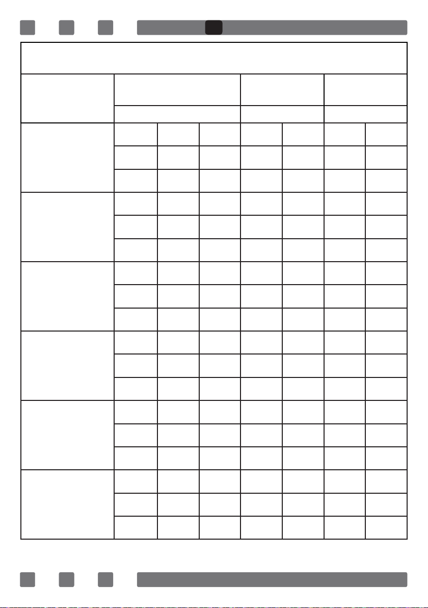
58
G20,20 mbar
G25,25 mbar
G20,25 mbar G20,13 mbar
mm
mm
mm
m³/h
m³/h
m³/h
kW
kW
kW
mm
mm
mm
m³/h
m³/h
m³/h
kW
kW
kW
mm
mm
mm
m³/h
m³/h
m³/h
kW
kW
kW
mm
mm
mm
m³/h
m³/h
m³/h
kW
kW
kW
mm
mm
mm
m³/h
m³/h
m³/h
kW
kW
kW
mm
mm
mm
m³/h
m³/h
m³/h
kW
kW
kW
SA
59
G30,28-30 mbar
G31,37 mbar
G30,50 mbar G30,37 mbar
LPG LPG LPG
mm
mm
mm
g/h
g/h
g/h
kW
kW
kW
mm
mm
mm
g/h
g/h
g/h
kW
kW
kW
mm
mm
mm
g/h
g/h
g/h
kW
kW
kW
mm
mm
mm
g/h
g/h
g/h
kW
kW
kW
mm
mm
mm
g/h
g/h
g/h
kW
kW
kW
mm
mm
mm
g/h
g/h
g/h
kW
kW
kW
SA
60
SA
61
SA
62
SA
63
SA
64
- AC -E
SA
65
-
""
SA
66
(
.7-10
.*
SA
67
:
SA
68
--- --- ---
--- --- ---
--- --- ---
--- --- ---
--- --- ---
SA

69
–
-
SA
70
SA
71
.
“
SA
72
*
*
*
*
**
650mm min.
850 mm min.
900 mm min.20 mm 20 mm
SA
73
.
.
.
.
SA
74
220-240V~50/60Hz 220-240V~50/60Hz
400V 3N~50/60Hz 400V 2N~50/60Hz
Earth
Terre
Erdung
Earth
Terre
Erdung
Earth
Terre
Erdung
Earth
Terre
Erdung
L3
L2
L1
L2
L1
L1
Live
Phase
Neutral
Neutre
Neutral
Neutre
Neutral
Neutre
H05 VV-F 3G 4mm² H05 VV-F 5G 1.5mm² H05 VV-F 4G 1.5mm² H05 VV-F 3G 1.5mm²
Neutral
Neutre
380-415V 3N~50/60Hz 380-415V 2N~50/60Hz
220-240V~50/60Hz 220-240V~50/60Hz
SA

75
²
3
2
SA
76
*
*
.
SA

77
“
.”
“
.”
“
.”
“
SA

78
SA

79
SA
USER MANUAL
GB
MANUEL D’INSTRUCTIONS
FR
SA