Loading ...
Loading ...
Loading ...
A-19
PREPARATION
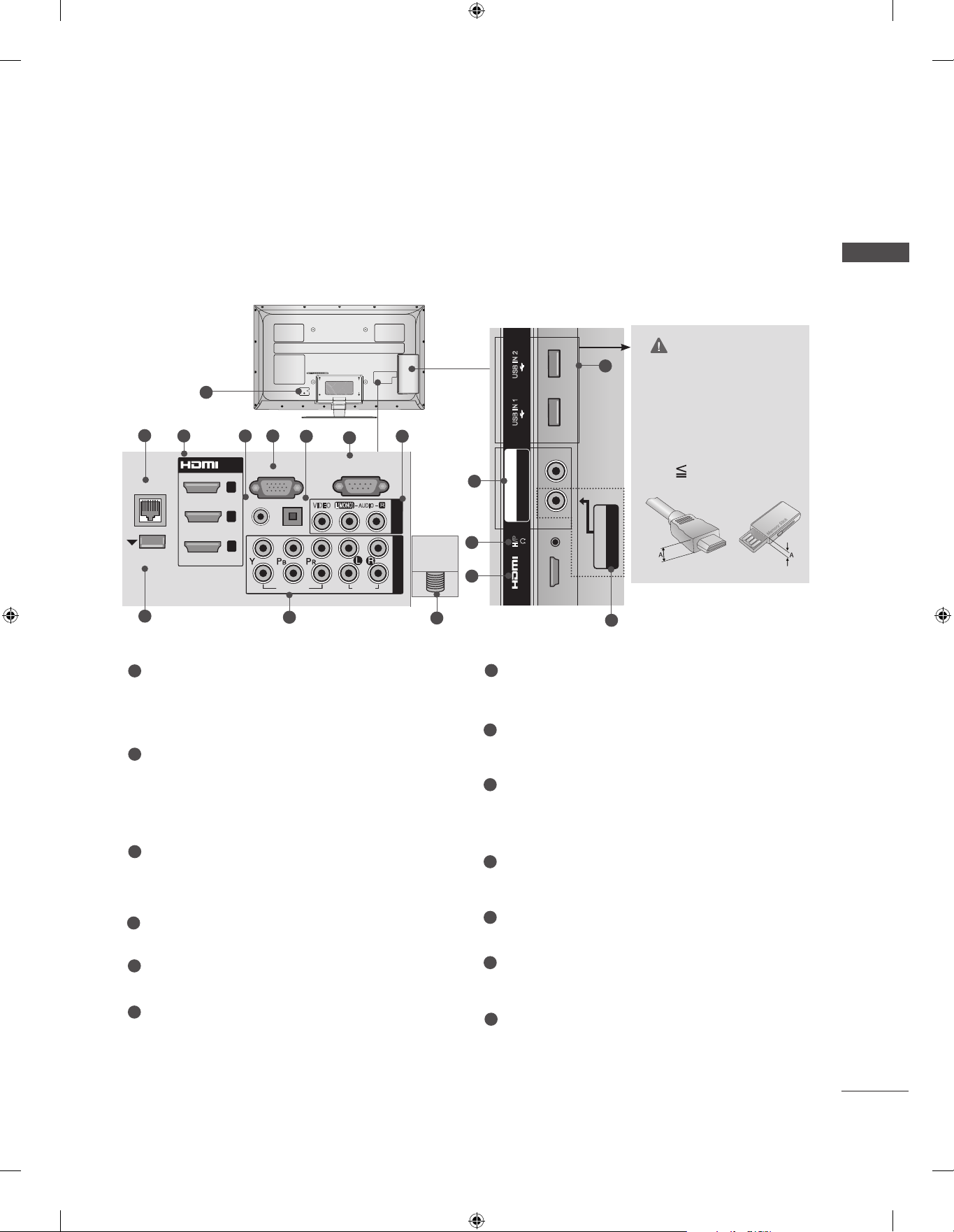
CAUTION
► Use a product with the
following thickness for
optimal connection to
HDMI cable(only HDMI
IN 4) / USB device.
*A 10 mm
Only 32/37/42/47/55LE55**, 32/37/42/47/55LE7***, 42/47/55LE8***,
42/47/55LX6***, 47/55LX9***
1(DVI)
2
3
HDMI/DVI IN
(RGB)
WIRELESS
CONTROL
L/MONO
R
AUDIO
VIDEO
AV IN 2
LAN
USB IN 2
H/P
USB IN 1
HDMI
IN 4
ANTENNA
IN
AV IN3
VIDEO / AUDIO
COMPONENT IN2
AUDIO / Y P
B
P
R
1
RGB IN
(PC)
RS-232C IN
(CONTROL & SERVICE)
(RGB/DVI)
WIRELESS
CONTROL
OPTICAL DIGITAL
1
2
COMPONENT IN
AUDIO
VIDEO
LAN
/DVI IN
1
2
3
AUDIO IN
AUDIO OUT
R
L(MONO)
AUDIO
VIDEO
AV IN 1
USB IN 2
H/P
USB IN 1
AV IN2
VIDEO / AUDIO
COMPONENT IN3
AUDIO / Y P
B
P
R
IN 4
ANTENNA/
CABLE IN
12
11
3
10
■ Image shown may differ from your TV.
Power Cord Socket
This TV operates on an AC power. The volt-
age is indicated on the Specifications page.
(► p.163 to 175) Never attempt to operate
the TV on DC power.
LAN
Network connection for Weather info, Photo
Album, Movie Online, etc.
Also used for video, photo and music files on
a local network.
HDMI/DVI IN Input
Connect an HDMI signal to HDMI IN. Or DVI
(VIDEO) signal to HDMI/DVI port with DVI to
HDMI cable.
RGB/DVI Audio Input
Connect the audio from a PC or DTV.
RGB IN Input
Connect the output from a PC.
OPTICAL DIGITAL AUDIO OUT
Connect digital audio to various types of
equipment.
Connect to a Digital Audio Component.
Use an Optical audio cable.
RS-232C IN (CONTROL & SERVICE) PORT
Connect to the RS-232C port on a PC.
This port is used for Service or Hotel mode.
Audio/Video Input
Connect audio/video output from an external
device to these jacks.
WIRELESS Control
Connect the Wireless Dongle to the TV to
control the external input devices connected
to Media Box wirelessly.
Component Input
Connect a component video/audio device to
these jacks.
USB Input
Connect USB storage device to this jack.
Headphone Socket
Plug the headphone into the headphone
socket.
Antenna / Cable Input
Connect antenna or cable to this jack.
1
2
3
4
5
6
7
8
9
10
11
12
13
RGB IN
(PC)
RS-232C IN
(CONTROL & SERVICE)
(RGB/DVI)
WIRELESS
CONTROL
OPTICAL DIGITAL
1
2
COMPONENT IN
AUDIO
VIDEO
LAN
/DVI IN
1
2
3
AUDIO IN
AUDIO OUT
R
L(MONO)
AUDIO
VIDEO
AV IN 1
USB IN 2
H/P
USB IN 1
AV IN2
VIDEO / AUDIO
COMPONENT IN3
AUDIO / Y P
B
P
R
IN 4
ANTENNA/
CABLE IN
2
3 54
6
10
8
7
9
13
8
Loading ...
Loading ...
Loading ...