Loading ...
Loading ...
Loading ...
12
INSTALLATION
Fan Rocker
Switch
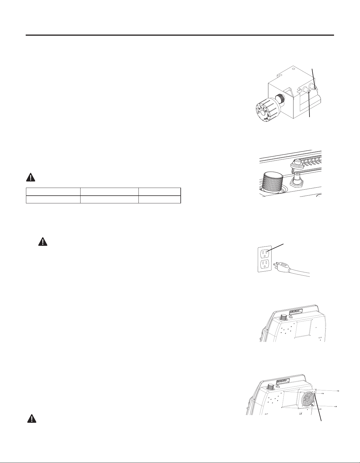
INSTALLING IGNITOR BATTERY
• Battery is included.
• Unscrew ignitor cap and insert included battery negative (at)
side down (See Fig. 7). Replace Ignitor cap.
• Be sure to observe proper polarity (+/-) when installing or re-
placing the battery. Damage due to improper battery installa-
tion may void the warranty on the product.
• Install/replace the battery according to the type and quantity
stated in table below.
• Remove battery when depleted.
• For long periods of non-operation, remove the battery from all
components for safety.
WARNING: Do not use rechargable silver oxide cell batteries.
Do NOT dispose of batteries in re. Improper disposal may
cause batteries to leak or explode.
INSTALLATION
Component Type of Battery Battery Qty.
Ignitor AAA 1
Fig. 7 - Installing Ignitor Battery
Fig. 8 - Fan Electric Supply
Grounded Three-Prong
Receptacle
GAS SELECTION
IMPORTANT: Before proceeding with the installation, the qualied ser-
vice technician converting the heater between gas supplies must verify
correct manifold pressure. A reading can be taken using a pressure
gauge and the appropriate pressure tap (See Fig. 6).
Fig. 6 - Checking Manifold
Pressure
OUTLET
INLET
Fig. 9 - Knock-out Panel
Fig. 10 - Attaching Fan
Rocker Switch
INSTALLING FAN (OPTIONAL)
WARNING: Electrical Grounding Instructions
This appliance is equipped with a three-prong (grounding) plug
for your protection against shock hazard and should be plugged
directly into a properly grounded three-prong receptacle (See Fig. 8).
1. Wall mounted heater must be disconnected from gas supply and
removed from wall before installing fan accessory. Contact a
qualied service person to do this.
2. Remove fan knock-out panel using a screwdriver (See Fig. 9).
Attach Fan to the rear panel of the heater using the four
screws provided.
NOTE: Be sure the rocker switch is positioned in the upper right
corner. (See Fig. 10).
3. This fan is equipped with manual “MAN” and automatic “AUTO”
settings (See Fig. 11 on page 13). Set the rocker switch to “MAN”
for manual mode, allowing the fan to continuously run until the
rocker switch is returned to the OFF “O” position. Set the rocker
switch to “AUTO” for the automatic mode, which will turn the fan on
and off based on ambient room temperature. It may take 5 to 10
minutes for the fan to come on when the unit is cold.
NOTE: If any of the original wire as supplied with the appliance must
be replaced, it must be replaced with a wire of at least an equal tem-
perature rating. Refer to Fig. 12 on page 13 for wiring diagram.
CAUTION: Label all wires prior to disconnection when servicing
controls. Wiring errors can cause improper and dangerous opera-
tion. Verify proper operation after servicing.
Loading ...
Loading ...
Loading ...