Loading ...
Loading ...
Loading ...
4
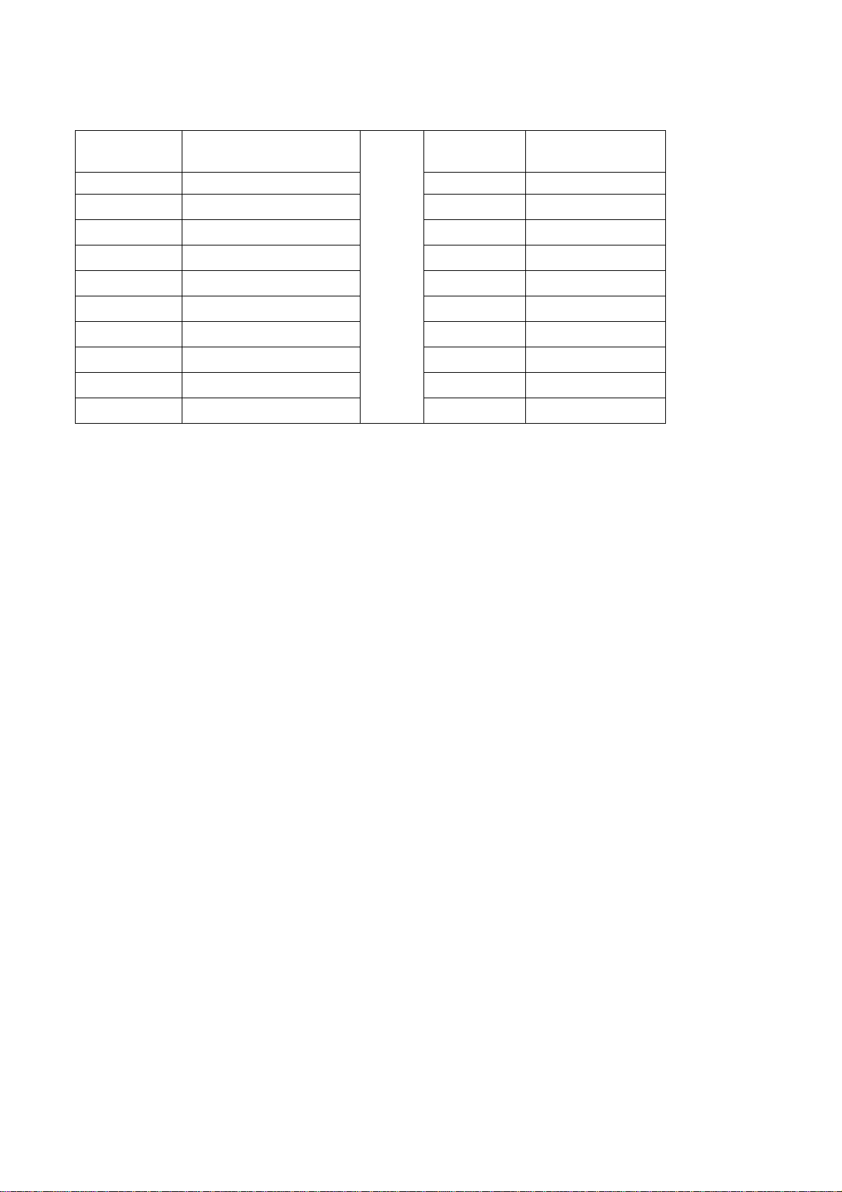
Table n.1
Hobs models
Type A
Type B
Hobs
models
Type A
Type B
Min. Clearances (mm) Min. Clearances (mm)
L1
500
L10
860
L2
40
L11
915
L3
50
W
890
L4
457
D
520
L5
600
B1 (*)
40
L6
330
B2 (*)
152
L7
925
B3 (*)
40
L8
40
B4 (*)
152
L9
172
(*) Note:
-B1 is the min. clearance between the front edge of the appliance and the front edge of the cabinet.
-B2 and B4 are the min. clearance between the left/right side edge of the appliance and the side wall (if
present).
-B3 is the min. clearance between the back edge of the appliance and the back wall.
Attaching the hotplate
To prevent liquids from leaking accidentally into the underlying storage space, the appliance is equipped with
a special gasket. To apply this gasket, carefully follow the instructions in Fig. 3. Lay out the protective sealing
strips along the edges of the opening in the bench top and carefully overlap the strip end. (See Fig. 3). insert
the hotplate into the bench top opening. With a screwdriver assemble the brackets to the hotplate bottom by
means of the screws . (See Fig. 3A-3B). Slide the hooks into position and secure them with the screws.
Trim the part of the sealing strips which extend beyond the hotplate base
IMPORTANT INFORMATION CONCERNING THE INSTALLATION OF THE APPLIANCE
The hob can be installed by itself, in an isolated position or inserted between two kitchen units or
between one kitchen unit and a wall. Furthermore the back wall and surrounding surfaces must
resist a temperature of 65 K.
To prevent the plastic layer which covers the kitchen unit from ungluing, the glue used to join the
two surfaces together must resist temperatures of up to 150 °C
The installation of the appliance must be carried out according to the norms in force of the country
concerned and the appliance must be installed in a well ventilated place.
This appliance is not equipped with devices to remove the products of combustion. The appliance
must therefore be connected following the norms for installation mentioned above. Special attention
must be paid to the information below regarding aeration and ventilation of the premises.
Data Label - The Data Label is located on the bottom of the appliance. A duplicate Data Label is supplied to
adhere in an accessible area next to the appliance. This appliance is suitable for Natural Gas and Propane
Gas; ensure that the available gas supply matches the Data Label and the gas type label.
VENTILATION OF THE PREMISES
To guarantee that the appliance works correctly it is necessary that the place where the appliance is installed
is continuously ventilated. The volume of the premises must not be less than 25 m³ and the quantity of air
needed must be based on the regular combustion of gas and on the ventilation of the premises. The natural
flow of air will take place through permanent openings made in the wall of the premises to be ventilated:
these openings will be connected to the outside and must have a minimum section of 100 cm² ( see Fig. 4 ).
These openings must be made in such a way that they cannot be obstructed.
Loading ...
Loading ...
Loading ...