Loading ...
Loading ...
Loading ...
17
!
CAUTION
Weight of overlay door panel must not exceed 15
pounds (6.8 kg) for a solid door model or 10 pounds
(4.5 kg) for a glass door model.
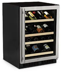
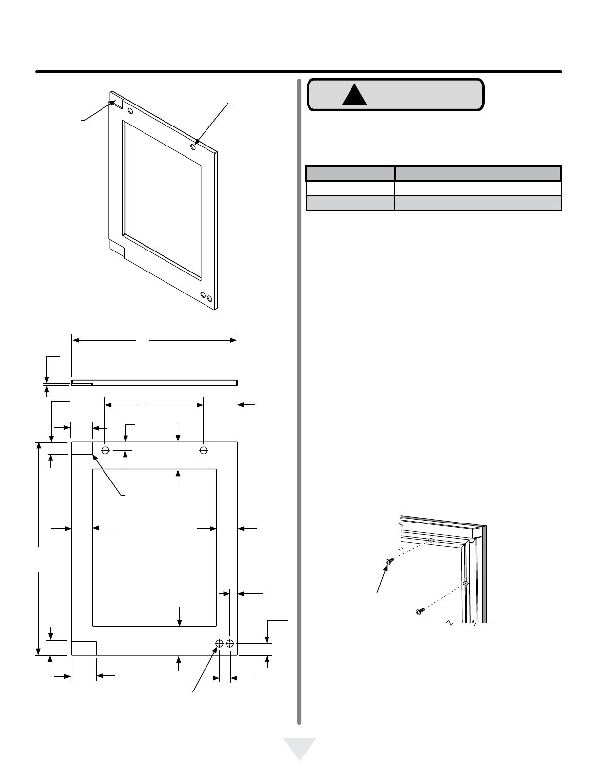
OVERLAY DOOR PANEL INSTALLATION
Clearance
for hinge
at top and
bottom
Top of door
Clearance for
screw head,
4 places
Figure 22
Right Hand Hinged Door
24" (61 cm) wide appliance
Hinge side of door
23
3
⁄4"
(60.3 cm)
Figure 23
Right Hand Hinged Door
24" (61 cm) wide appliance
3
1
⁄8"
(7.9 cm)
3
1
⁄8"
(7.9 cm)
1
3
⁄4"
(4.4 cm)
2"
(5.1 cm)
3
11
⁄16"
(9.4 cm)
1
⁄4"
(6 mm)
Deep
30
11
⁄32"
(77.1 cm)
1" (2.5 cm) diameter
x
1
⁄4" (6 mm) deep
4 places
3
1
⁄8"
(7.9 cm)
1
1
⁄2"
(3.8 cm)
typical
1
11
⁄16"
(4.3 cm)
4
7
⁄8"
(12.4 cm)
14"
(35.6 cm)
1
3
⁄16"
(3 cm)
3
27
⁄32"
(9.8 cm)
1
⁄4" (6 mm)
radius is
permissible
This side
facing
interior
4
1
⁄8"
(10.5 cm)
Material Type #10 Wood Screw
Hardwood
1
⁄8" (3.2 mm) Diameter. Pilot Hole
Softwood
7
⁄64 (2.8 mm) Diameter. Pilot Hole
Table B
Figure 24
#10 x 1/2"
screw
Step 4: Assemble the panel to the door
The preferred method of attaching the panel to the door
is to clamp the panel to the door so it cannot move while
drilling the screw pilot holes. Use bar clamps or "C" clamps
with pads on the clamping surfaces that will not mar the
panel or the door. The custom overlay panel should be
ush with the top of the door and centered along the width
of the door. See Figure 15a. Drill holes through the gasket
extrusion using the 10 holes as pilot holes. Use the drill
size from the chart in Table "B", being careful not to drill
through the front surface of the panel. If the overlay panel is
thinner than
5
⁄8" (16 mm) thick shorter screws will have to be
obtained. Fasten the panel to the door with the 10 screws
provided in the literature pack. (See Figure 24). Remove
the clamps and replace the gasket in the gasket extrusion
channels of the door. Some force may be required to seat
the gasket into the channels. Be sure the gasket corners
are seated properly.
1
5
⁄32"
(2.9 cm)
Loading ...
Loading ...
Loading ...