Loading ...
Loading ...
Loading ...
4 | JL Audio - C3-525 Owner’s Manual
5
Amplifier
Output
Red
Black
Amplifier
Output
Red Black
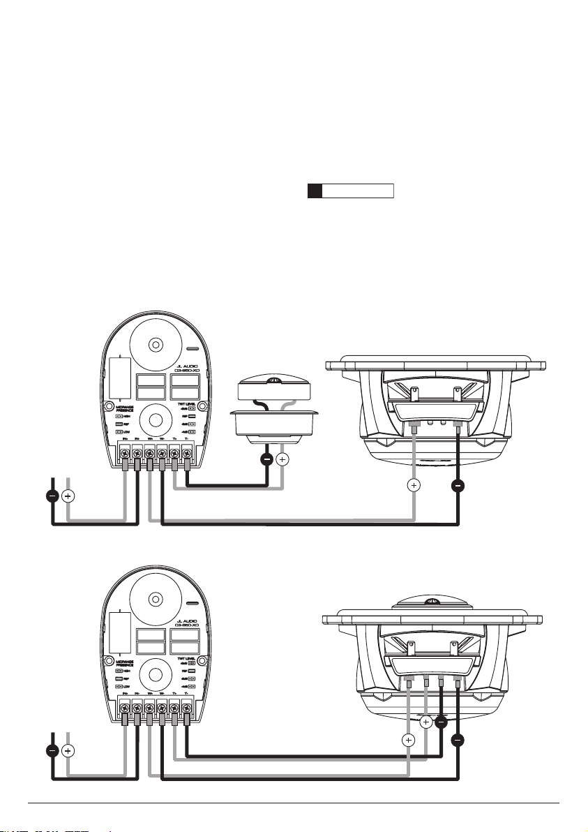
WIRING YOUR SPEAKER SYSTEM
C3ConvertibleComponentsgiveyoutheoption
ofinstallingthespeakersasseparatecomponent
speakersystemsorascoaxialsystems(tweeters
mountedontothecenterofeachwoofer).
Positive(+)andnegative(–)connectionstothe
crossoverfromtheamplifieroutputsaremadewith
theterminalslabeled“IN+”and“IN–”.ThePositive
andNegativeoutputstothewooferconnectionsare
labeled“W+”and“W–”ontheCrossoverandshould
beconnectedtocorresponding“WFR+”and
“WFR–”terminalsonthewoofer(asillustrated
below).Thetweeterconnectionsvarybysystem
configurationandmaybemadeinoneoftwoways.
Incomponentconfiguration,thetweeteroutputs,
labeled“T+”and“T–”ontheCrossovershouldbewired
directlytothecorrespondingleadonthetweeter(See
DiagramA).Incoaxialconfiguration,thetweeteris
connectedviaaninternaljumper(Seepage6formore
information)andtheCrossovertweeteroutputsshould
bewiredtothecorresponding“T WT+”and“T WT–”
terminalsonthewoofer(SeeDiagramB).
WARNING
!!
It is absolutely vital that your component system
is connected as shown in this manual. Failure to
connect the system as shown may result in damage to
your speakers which is NOT covered under warranty.
Do not substitute different crossover networks into
your C3 System. Do not use crossover networks
intended for different C3 models.
DIAGRAM B: Coaxial System Wiring
DIAGRAM A: Component System Wiring
Loading ...
Loading ...
Loading ...