
Loading ...
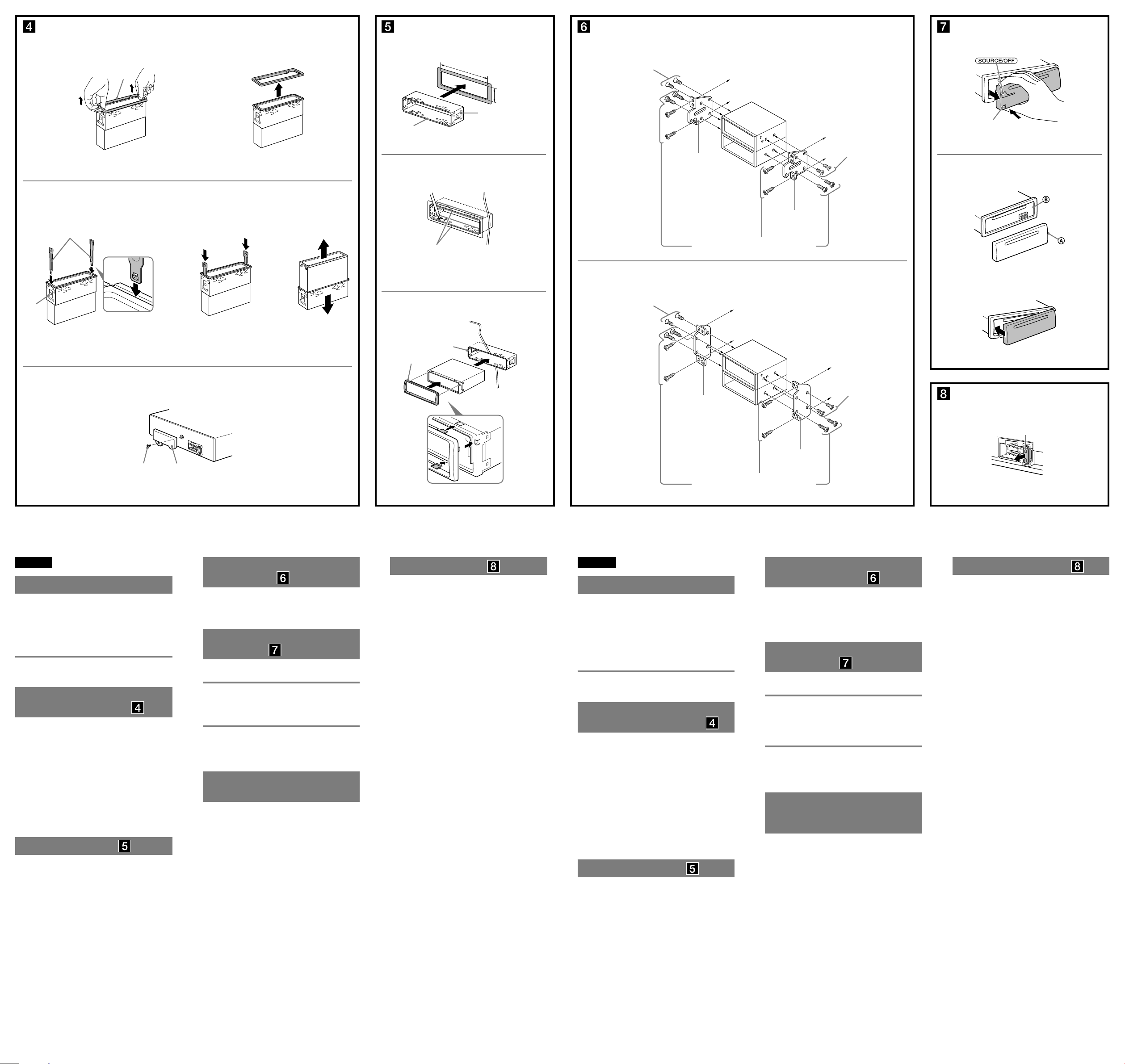
Fuse replacement ( )
When replacing the fuse, be sure to use one matching the
amperage rating stated on the original fuse. If the fuse
blows, check the power connection and replace the fuse. If
the fuse blows again after replacement, there may be an
internal malfunction. In such a case, consult your nearest
Sony dealer.
Sustitución del fusible ( )
Al sustituir el fusible, asegúrese de utilizar uno cuyo
amperaje coincida con el especificado en el original. Si el
fusible se funde, verifique la conexión de alimentación y
sustitúyalo. Si el fusible vuelve a fundirse después de
sustituirlo, es posible que exista alguna falla de
funcionamiento interno. En tal caso, consulte con el
distribuidor Sony más cercano.
Mounting the unit in a
Japanese car (
)
You may not be able to install this unit in some makes of
Japanese cars. In such a case, consult your Sony dealer.
Note
To prevent malfunction, install only with the supplied screws .
How to detach and attach the
front panel (
)
Before installing the unit, detach the front panel.
-A To detach
Before detaching the front panel, be sure to press and hold
. Press the front panel release button, and
pull it off towards you.
-B To attach
Engage part of the front panel with part of the unit,
as illustrated, and push the left side into position until it
clicks.
Warning if your car’s ignition
has no ACC position
Be sure to set the Auto Off function. For details, see the
supplied Operating Instructions.
The unit will shut off completely and automatically in the
set time after the unit is turned off, which prevents battery
drain.
If you do not set the Auto Off function, press and hold
until the display disappears each time
you turn the ignition off.
Montaje de la unidad en un
automóvil japonés (
)
Es posible que no pueda instalar esta unidad en algunos
automóviles japoneses. En tal caso, consulte a su
distribuidor Sony.
Nota
Para evitar que se produzcan fallas de funcionamiento, realice la
instalación solamente con los tornillos suministrados .
Forma de extraer e instalar el
panel frontal (
)
Antes de instalar la unidad, extraiga el panel frontal.
-A Para extraerlo
Antes de extraer el panel frontal, asegúrese de mantener
presionado . Presione el botón de
liberación del panel frontal y extraiga el panel frontal hacia
usted.
-B Para instalarlo
Coloque la parte del panel frontal en la parte de la
unidad, como se muestra en la ilustración, y después
presione la parte izquierda hasta que encaje.
Advertencia: si el encendido
del automóvil no dispone de
una posición ACC
Asegúrese de ajustar la función de desconexión
automática. Para obtener más información, consulte el
manual de instrucciones suministrado.
La unidad se apagará completa y automáticamente en el
tiempo establecido después de que se desconecte la
unidad, lo que evita que se desgaste la batería.
Si no ha ajustado la función de desconexión automática,
mantenga presionado cada vez que
apague el interruptor de encendido, hasta que la pantalla
desaparezca.
Español
Precauciones
Elija cuidadosamente el lugar de montaje de forma que
la unidad no interfiera con las funciones normales de
conducción.
Evite instalar la unidad donde pueda quedar expuesta a
polvo, suciedad, vibraciones excesivas o altas
temperaturas, por ejemplo, a la luz solar directa o cerca
de conductos de calefacción.
Para realizar una instalación segura y firme, utilice
solamente elementos de instalación suministrados.
Ajuste del ángulo de montaje
Ajuste el ángulo de montaje a menos de 45°.
Extracción del marco de
protección y del soporte (
)
Antes de instalar la unidad, retire el marco de
protección y el soporte de la misma.
1 Retire el marco de protección .
Apriete ambos bordes del marco de protección
y, a continuación, tire de él hacia fuera.
2 Retire el soporte .
Inserte ambas llaves de liberación entre la
unidad y el soporte hasta que encajen.
Presione el soporte y, a continuación,
levante la unidad para separar ambos
elementos.
Nota
Antes de instalar esta unidad, extraiga el tornillo y el compartimento que
se encuentran en la parte posterior de la unidad. No utilice las piezas
anteriores que extrajo al instalar la unidad (-3).
Ejemplo de montaje ( )
Instalación en el tablero
Notas
Antes de instalar la unidad, compruebe que los enganches de ambos
lados del soporte estén doblados hacia adentro 2 mm. Si no lo están
o están doblados hacia afuera, la unidad no se instalará correctamente
y puede saltar (-1).
Si es necesario, doble las uñas hacia fuera para que encaje firmemente
(-2).
Compruebe que los 4 enganches del marco de protección estén bien
fijados en las ranuras de la unidad (-3).
English
Precautions
Choose the installation location carefully so that the unit
will not interfere with normal driving operations.
Avoid installing the unit in areas subject to dust, dirt,
excessive vibration, or high temperatures, such as in
direct sunlight or near heater ducts.
Use only the supplied mounting hardware for a safe and
secure installation.
Mounting angle adjustment
Adjust the mounting angle to less than 45°.
Removing the protection
collar and the bracket (
)
Before installing the unit, remove the protection
collar and the bracket from the unit.
1 Remove the protection collar .
Pinch both edges of the protection collar , then
pull it out.
2 Remove the bracket .
Insert both release keys together between
the unit and the bracket until they click.
Pull down the bracket , then pull up the unit
to separate.
Note
Before installing this unit, remove the screw and box on the back of the
unit. Do not use the previous parts you removed when installing the unit
(-3).
Mounting example ( )
Installation in the dashboard
Notes
Before installing, make sure that the catches on both sides of the
bracket are bent inwards 2 mm (
3
/32 in). If the catches are straight or
bent outwards, the unit will not be installed securely and may spring
out (-1).
Bend these claws outward for a tight fit, if necessary (-2).
Make sure that the 4 catches on the protection collar are properly
engaged in the slots of the unit (-3).
Bracket
Soporte
Bracket
Soporte
Bracket
Soporte
Bracket
Soporte
A TOYOTA
B NISSAN
to dashboard/center console
al tablero o consola central
to dashboard/center console
al tablero o consola central
Existing parts supplied with your car
Piezas existentes suministradas con su automóvil
Existing parts supplied with your car
Piezas existentes suministradas con su automóvil
size
5 × max. 8 mm
(
7
/32 × max.
5
/16 in)
Tamaño
5 × 8 mm máx.
size
5 × max. 8 mm
(
7
/32 × max.
5
/16 in)
Tamaño
5 × 8 mm máx.
size
5 × max. 8 mm
(
7
/32 × max.
5
/16 in)
Tamaño
5 × 8 mm máx.
size
5 × max. 8 mm
(
7
/32 × max.
5
/16 in)
Tamaño
5 × 8 mm máx.
1
2
3
Face the hook inwards.
El gancho debe encontrarse
en la parte interior.
A
B
Fuse (10 A)
Fusible (10 A)
Front panel release button
Botón de liberación del panel
frontal
Dashboard
Tablero
Claws
Uñas
2
3
1
Catch
Enganche
Screw
Tornillo
Box
Compartimento
182 mm (7
1
/4 in)
53 mm
(2
1
/8 in)