4-427-433-21(1)
MEX-BT31PW
Bluetooth
®
Audio System
Owner’s Record
The model and serial numbers are located on the bottom of the unit.
Record the serial number in the space provided below.
Refer to these numbers whenever you call upon your Sony dealer
regarding this product.
Model No. MEX-BT31PW Serial No.
To cancel the demonstration (DEMO) display, see page 7.
Para cancelar la pantalla de demostración (DEMO), consulte la
página 6.
Operating Instructions GB
Manual de
instrucciones
ES

2
Warning
This device complies with Part 15 of the
FCC Rules. Operation is subject to the
following two conditions: (1) this device
may not cause harmful interference, and (2)
this device must accept any interference
received, including interference that may
cause undesired operation.
This transmitter must not be co-located or
operated in conjunction with any other
antenna or transmitter.
This equipment complies with FCC
radiation exposure limits set forth for an
uncontrolled environment and meets the
FCC radio frequency (RF) Exposure
Guidelines in Supplement C to OET65. This
equipment has very low levels of RF energy
that it deemed to comply without maximum
permissive exposure evaluation (MPE). But
it is desirable that it should be installed and
operated keeping the radiator at least 20 cm
or more away from person's body
(excluding extremities: hands, wrists, feet
and ankles).
The Bluetooth word mark and logos are
owned by the Bluetooth SIG, Inc. and any
use of such marks by Sony Corporation is
under license. Other trademarks and trade
names are those of their respective owners.
This product is protected by certain
intellectual property rights of Microsoft
Corporation. Use or distribution of such
technology outside of this product is
prohibited without a license from Microsoft
or an authorized Microsoft subsidiary.
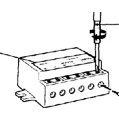
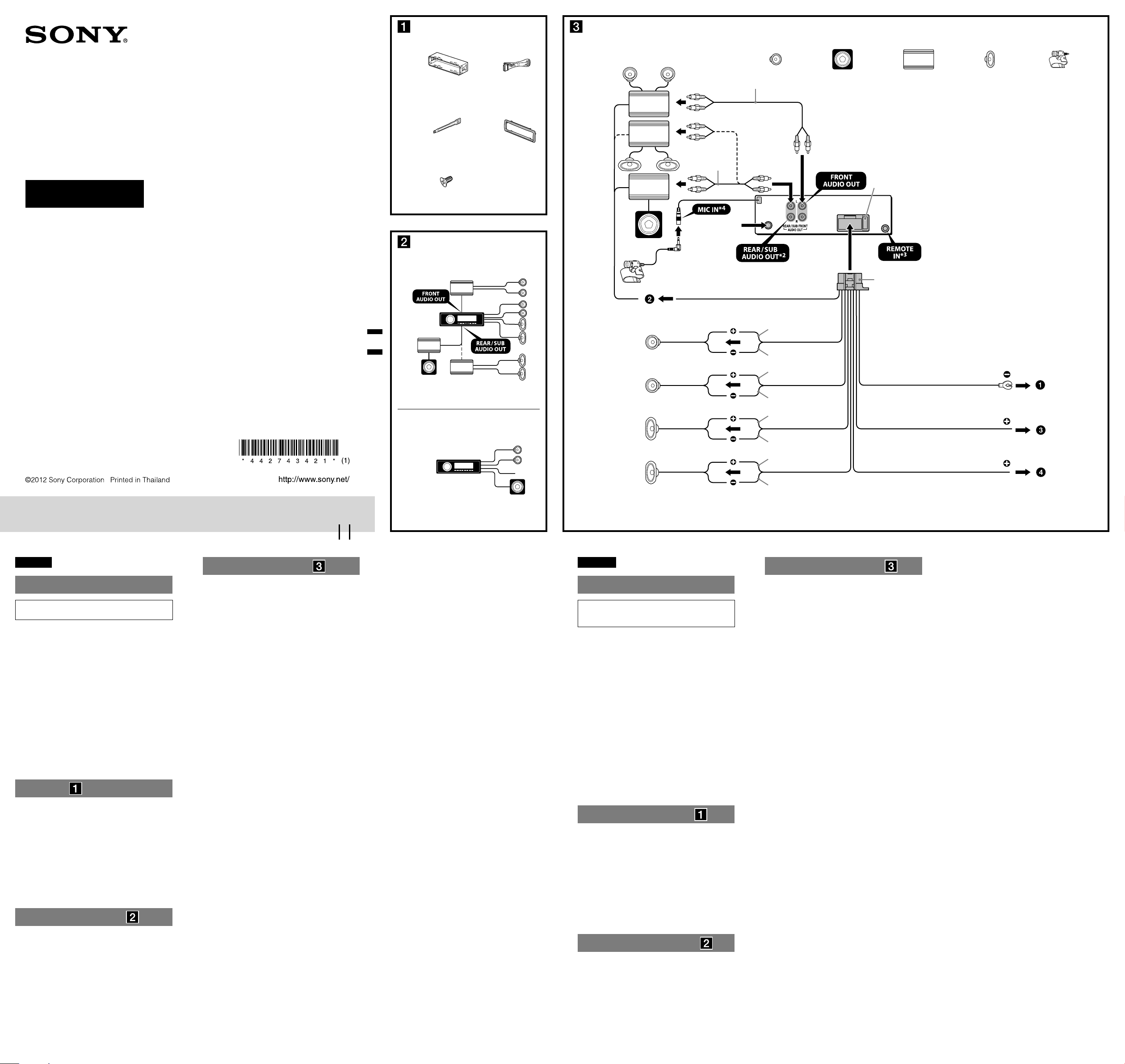
Be sure to install this unit in the
dashboard of the car for safety.
For installation and connections,
see the supplied installation/connections
manual.
This equipment has been tested and found
to comply with the limits for a Class B
digital device, pursuant to Part 15 of the
FCC Rules.
These limits are designed to provide
reasonable protection against harmful
interference in a residential installation.
This equipment generates, uses, and can
radiate radio frequency energy and, if not
installed and used in accordance with the
instructions, may cause harmful
interference to radio communications.
However, there is no guarantee that
interference will not occur in a particular
installation. If this equipment does cause
harmful interference to radio or television
reception, which can be determined by
turning the equipment off and on, the user
is encouraged to try to correct the
interference by one or more of the
following measures:
– Reorient or relocate the receiving
antenna.
– Increase the separation between the
equipment and receiver.
– Connect the equipment into an outlet on
a circuit different from that to which the
receiver is connected.
– Consult the dealer or an experienced
radio/TV technician for help.
You are cautioned that any changes or
modifications not expressly approved in
this manual could void your authority to
operate this equipment.
CAUTION
The use of optical instruments with this
product will increase eye hazard.
For the State of California, USA only
Perchlorate Material – special handling
may apply, See
www.dtsc.ca.gov/hazardouswaste/perchlorate
Perchlorate Material: Lithium battery
contains perchlorate
ZAPPIN and Quick-BrowZer are
trademarks of Sony Corporation.
Windows Media is either a registered
trademark or trademark of Microsoft
Corporation in the United States and/or
other countries.

3
Android is a trademark of Google Inc. Use
of this trademark is subject to Google
Permissions.
BlackBerry® is the property of Research In
Motion Limited and is registered and/or
used in the U.S. and countries around the
world. Used under license from Research In
Motion Limited.
Warning if your car’s ignition has no
ACC position
Be sure to set the Auto Off function
(page 32). The unit will shut off
completely and automatically in the set
time after the unit is turned off, which
prevents battery drain. If you do not set
the Auto Off function, press and hold
until the display
disappears each time you turn the
ignition off.
MPEG Layer-3 audio coding technology
and patents licensed from Fraunhofer IIS
and Thomson.
Pandora, the Pandora logo, and the
Pandora trade dress are trademarks or
registered trademarks of Pandora Media,
Inc., used with permission.
Note on the lithium battery
Do not expose the battery to excessive heat
such as direct sunlight, fire or the like.

4
Table of contents
Getting Started . . . . . . . . . . . . . . . . . . . . . . . . . . . . . . . . . . . . . . . . . . . . . . . . . . . . . 6
Notes on Bluetooth function . . . . . . . . . . . . . . . . . . . . . . . . . . . . . . . . . . . . . . . . . . . . . . . 6
Canceling the DEMO mode . . . . . . . . . . . . . . . . . . . . . . . . . . . . . . . . . . . . . . . . . . . . . . . . 7
Setting the clock . . . . . . . . . . . . . . . . . . . . . . . . . . . . . . . . . . . . . . . . . . . . . . . . . . . . . . . . . . 7
Detaching the front panel . . . . . . . . . . . . . . . . . . . . . . . . . . . . . . . . . . . . . . . . . . . . . . . . . . 7
Location of controls. . . . . . . . . . . . . . . . . . . . . . . . . . . . . . . . . . . . . . . . . . . . . . . . . 8
Main unit. . . . . . . . . . . . . . . . . . . . . . . . . . . . . . . . . . . . . . . . . . . . . . . . . . . . . . . . . . . . . . . . 8
RM-X231 Remote commander . . . . . . . . . . . . . . . . . . . . . . . . . . . . . . . . . . . . . . . . . . . . 10
Radio . . . . . . . . . . . . . . . . . . . . . . . . . . . . . . . . . . . . . . . . . . . . . . . . . . . . . . . . . . . . 11
Storing and receiving stations . . . . . . . . . . . . . . . . . . . . . . . . . . . . . . . . . . . . . . . . . . . . . 11
RDS. . . . . . . . . . . . . . . . . . . . . . . . . . . . . . . . . . . . . . . . . . . . . . . . . . . . . . . . . . . . . . . . . . . . 11
CD . . . . . . . . . . . . . . . . . . . . . . . . . . . . . . . . . . . . . . . . . . . . . . . . . . . . . . . . . . . . . . 12
Playing a disc. . . . . . . . . . . . . . . . . . . . . . . . . . . . . . . . . . . . . . . . . . . . . . . . . . . . . . . . . . . . 12
USB devices. . . . . . . . . . . . . . . . . . . . . . . . . . . . . . . . . . . . . . . . . . . . . . . . . . . . . . . 13
Playing back a USB device . . . . . . . . . . . . . . . . . . . . . . . . . . . . . . . . . . . . . . . . . . . . . . . . 13
iPod . . . . . . . . . . . . . . . . . . . . . . . . . . . . . . . . . . . . . . . . . . . . . . . . . . . . . . . . . . . . . 14
Playing back iPod. . . . . . . . . . . . . . . . . . . . . . . . . . . . . . . . . . . . . . . . . . . . . . . . . . . . . . . .14
Operating an iPod directly — Passenger control . . . . . . . . . . . . . . . . . . . . . . . . . . . . . 15
Pandora® via USB (iPhone) . . . . . . . . . . . . . . . . . . . . . . . . . . . . . . . . . . . . . . . . . 15
Streaming Pandora® . . . . . . . . . . . . . . . . . . . . . . . . . . . . . . . . . . . . . . . . . . . . . . . . . . . . . . 15
Searching and playing tracks . . . . . . . . . . . . . . . . . . . . . . . . . . . . . . . . . . . . . . . . 17
Playing tracks in various modes. . . . . . . . . . . . . . . . . . . . . . . . . . . . . . . . . . . . . . . . . . . . 17
Searching a track by name — Quick-BrowZer™ . . . . . . . . . . . . . . . . . . . . . . . . . . . . . . 18
Searching a track by listening to track passages — ZAPPIN™ . . . . . . . . . . . . . . . . . . 19
Connecting Bluetooth devices . . . . . . . . . . . . . . . . . . . . . . . . . . . . . . . . . . . . . . . 19
Bluetooth operations . . . . . . . . . . . . . . . . . . . . . . . . . . . . . . . . . . . . . . . . . . . . . . . . . . . . . 19
Pairing . . . . . . . . . . . . . . . . . . . . . . . . . . . . . . . . . . . . . . . . . . . . . . . . . . . . . . . . . . . . . . . . . 20
Connection . . . . . . . . . . . . . . . . . . . . . . . . . . . . . . . . . . . . . . . . . . . . . . . . . . . . . . . . . . . . . 21
Handsfree calling . . . . . . . . . . . . . . . . . . . . . . . . . . . . . . . . . . . . . . . . . . . . . . . . . . . . . . . .23
Music streaming . . . . . . . . . . . . . . . . . . . . . . . . . . . . . . . . . . . . . . . . . . . . . . . . . . . . . . . . .26
Initializing Bluetooth Settings . . . . . . . . . . . . . . . . . . . . . . . . . . . . . . . . . . . . . . . . . . . . . 27
Pandora® via Bluetooth wireless technology (Android™ & BlackBerry®
phones) . . . . . . . . . . . . . . . . . . . . . . . . . . . . . . . . . . . . . . . . . . . . . . . . . . . . . . . . . . 27
Streaming Pandora®. . . . . . . . . . . . . . . . . . . . . . . . . . . . . . . . . . . . . . . . . . . . . . . . . . . . . . 27

5
Sound Settings and Setup Menu. . . . . . . . . . . . . . . . . . . . . . . . . . . . . . . . . . . . . .29
Enjoying sophisticated sound functions — Advanced Sound Engine . . . . . . . . . . . .29
Adjusting setup items . . . . . . . . . . . . . . . . . . . . . . . . . . . . . . . . . . . . . . . . . . . . . . . . . . . .31
Using optional equipment. . . . . . . . . . . . . . . . . . . . . . . . . . . . . . . . . . . . . . . . . . .34
Auxiliary audio equipment . . . . . . . . . . . . . . . . . . . . . . . . . . . . . . . . . . . . . . . . . . . . . . . .34
Additional Information. . . . . . . . . . . . . . . . . . . . . . . . . . . . . . . . . . . . . . . . . . . . .34
Precautions . . . . . . . . . . . . . . . . . . . . . . . . . . . . . . . . . . . . . . . . . . . . . . . . . . . . . . . . . . . . .34
Maintenance . . . . . . . . . . . . . . . . . . . . . . . . . . . . . . . . . . . . . . . . . . . . . . . . . . . . . . . . . . . .37
Specifications. . . . . . . . . . . . . . . . . . . . . . . . . . . . . . . . . . . . . . . . . . . . . . . . . . . . . . . . . . . .37
Troubleshooting . . . . . . . . . . . . . . . . . . . . . . . . . . . . . . . . . . . . . . . . . . . . . . . . . . . . . . . . .38

6
Getting Started
Notes on Bluetooth
function
Caution
IN NO EVENT SHALL SONY BE LIABLE
FOR ANY INCIDENTAL, INDIRECT OR
CONSEQUENTIAL DAMAGES OR OTHER
DAMAGES INCLUDING, WITHOUT
LIMITATION, LOSS OF PROFITS, LOSS OF
REVENUE, LOSS OF DATA, LOSS OF USE
OF THE PRODUCT OR ANY ASSOCIATED
EQUIPMENT, DOWNTIME, AND
PURCHASER’S TIME RELATED TO OR
ARISING OUT OF THE USE OF THIS
PRODUCT, ITS HARDWARE AND/OR ITS
SOFTWARE.
IMPORTANT NOTICE!
Safe and efficient use
Changes or modifications to this unit not
expressly approved by Sony may void the
user’s authority to operate the equipment.
Please check for exceptions, due to national
requirement or limitations, in usage of
Bluetooth equipment before using this
product.
Driving
Check the laws and regulations on the use of
cellular phones and handsfree equipment in
the areas where you drive.
Always give full attention to driving and pull
off the road and park before making or
answering a call if driving conditions so
require.
Connecting to other devices
When connecting to any other device, please
read its user guide for detailed safety
instructions.
Radio frequency exposure
RF signals may affect improperly installed or
inadequately shielded electronic systems in
cars, such as electronic fuel injection systems,
electronic antiskid (antilock) braking systems,
electronic speed control systems or air bag
systems. For installation or service of this
device, please consult with the manufacturer
or its representative of your car. Faulty
installation or service may be dangerous and
may invalidate any warranty that may apply to
this device.
Consult with the manufacturer of your car to
ensure that the use of your cellular phone in
the car will not affect its electronic system.
Check regularly that all wireless device
equipment in your car is mounted and
operating properly.
Emergency calls
This Bluetooth car handsfree and the
electronic device connected to the handsfree
operate using radio signals, cellular, and
landline networks as well as user-programmed
function, which cannot guarantee connection
under all conditions.
Therefore do not rely solely upon any
electronic device for essential communications
(such as medical emergencies).
Remember, in order to make or receive calls,
the handsfree and the electronic device
connected to the handsfree must be switched
on in a service area with adequate cellular
signal strength.
Emergency calls may not be possible on all
cellular phone networks or when certain
network services and/or phone features are in
use.
Check with your local service provider.
7
Canceling the DEMO
mode
You can cancel the demonstration display
which appears while this unit is turned off.
1 Press , rotate the control dial
until “DISPLAY” appears, then press
it.
2 Rotate the control dial until “DEMO”
appears, then press it.
3 Rotate the control dial to select
“DEMO-OFF,” then press it.
The setting is complete.
4 Press (BACK) to return to the
previous display.
The display returns to normal reception/
play mode.
Setting the clock
The clock uses a 12-hour digital indication.
1 Press , rotate the control dial
until “GENERAL” appears, then press
it.
2 Rotate the control dial until “CLOCK-
ADJ” appears, then press it.
The hour indication flashes.
3 Rotate the control dial to set the hour
and minute.
To move the digital indication, press
+/–.
4 After setting the minute, press
.
The setup is complete and the clock
starts.
To display the clock, press .
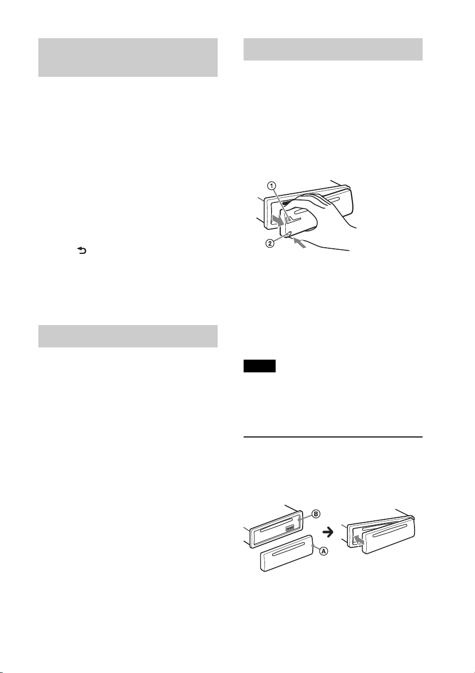
Detaching the front panel
You can detach the front panel of this unit
to prevent theft.
1 Press and hold .
The unit is turned off.
2 Press the front panel release button ,
then remove the panel by pulling it
towards you.
Caution alarm
If you turn the ignition switch to the OFF
position without detaching the front panel,
the caution alarm will sound for a few
seconds. The alarm will only sound if the
built-in amplifier is used.
Note
Do not subject the front panel to heat/high
temperature or moisture. Avoid leaving it in a
parked car or on a dashboard/rear tray.
Attaching the front panel
Engage part of the front panel with part
of the unit, as illustrated, and push the
left side into position until it clicks.
8
Location of controls
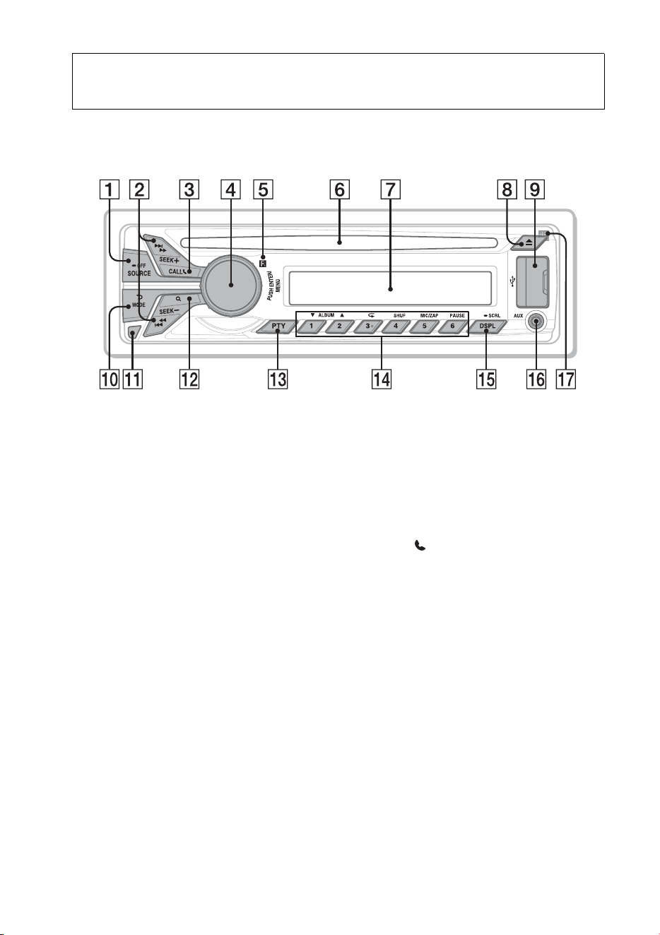
Main unit
This section contains instructions on the
location of controls and basic operations.
SOURCE/OFF button*
1
Press to turn on the power; select the
source (Radio/CD/USB/Pandora® via
USB/AUX/Bluetooth audio/Bluetooth
Pandora®/Bluetooth phone).
Press repeatedly to change to another
source.
Press and hold for 1 second to turn off
the power.
Press and hold for more than 2 seconds
to turn off the power and the display
disappears.
SEEK +/– buttons
Radio:
To tune in stations automatically
(press); find a station manually (press
and hold).
CD/USB:
To skip a track (press); skip tracks
continuously (press, then press again
within about 2 seconds and hold);
reverse/fast-forward a track (press and
hold).
Pandora® via USB/Bluetooth
Pandora®:
To skip a track (press +).
Bluetooth Audio*
2
:
To skip a track (press); reverse/fast-
forward a track (press and hold).
CALL button page 20
To enter the call menu (press); switch
the Bluetooth signal (press and hold
more than 2 seconds); receive/end a call
(press).
Control dial/ENTER/MENU button
page 31
Rotate to adjust volume.
Press to enter setup mode.
Press to receive/end a call.
Receptor for the remote
commander
Disc slot
Insert the disc (label side up), playback
starts.
Display window
(Eject) button
To eject the disc.

9
USB port page 13, 14, 15
(BACK)/MODE button page 11,
15, 16, 24, 28
Press to return to the previous display;
select the radio band (FM/AM).
Press and hold to enter/cancel the
passenger control (iPod); enter the
bookmark mode (Pandora® via USB/
Bluetooth Pandora®).
Press to activate/deactivate the
appropriate device (this unit/cellular
phone) (Bluetooth phone).
Front panel release button page 7
(BROWSE) button page 16, 18, 28
To enter the Quick-BrowZer™ mode
(CD/USB); list the station (Pandora® via
USB/Bluetooth Pandora®).
PTY (Program Type) button page 11
To select PTY in RDS.
Number buttons
Radio:
To receive stored stations (press); store
stations (press and hold).
CD/USB:
/: ALBUM / (during MP3/
WMA/AAC playback)
To skip an album (press); skip
albums continuously (press and
hold).
: (Repeat)*
3
page 17
: SHUF page 17
: ZAP page 19
: PAUSE
To pause playback. Press again to
resume playback.
Pandora® via USB/Bluetooth
Pandora®:
/: Thumbs down ()/up ()
(press and hold for 1 second) page 16,
28
: PAUSE
To pause playback. Press again to
resume playback.
Bluetooth Audio*
2
:
/: ALBUM /
: (Repeat)*
3
page 26
: SHUF page 26
: PAUSE
To pause playback. Press again to
resume playback.
Bluetooth phone: page 24, 25
To call a stored phone number (press);
to store a phone number as a preset
(press and hold) (in the call menu).
: MIC (during a call) page 24
To set the MIC gain (press); to
select Echo Canceler/Noise
Canceler mode (press and hold).
DSPL (Display)/SCRL (Scroll) button
page 11, 12, 13, 14, 16, 22, 26, 28
To change display items (press); scroll a
display item (press and hold).
AUX input jack page 34
Microphone (on the inner panel)
To make the handsfree function work
properly, do not cover the microphone
with tape, etc.
*1 Depending on the device connected to the
USB port, Bluetooth Pandora® may not be
available.
*2 When a Bluetooth audio device (supports
AVRCP of Bluetooth technology) is
connected. Depending on the device, certain
operations may not be available.
*3 This button has a tactile dot.
Note
If the unit is turned off and the display
disappears, the unit cannot be operated with the
remote commander unless on
the unit is pressed, or a disc is inserted to activate
the unit first.
10
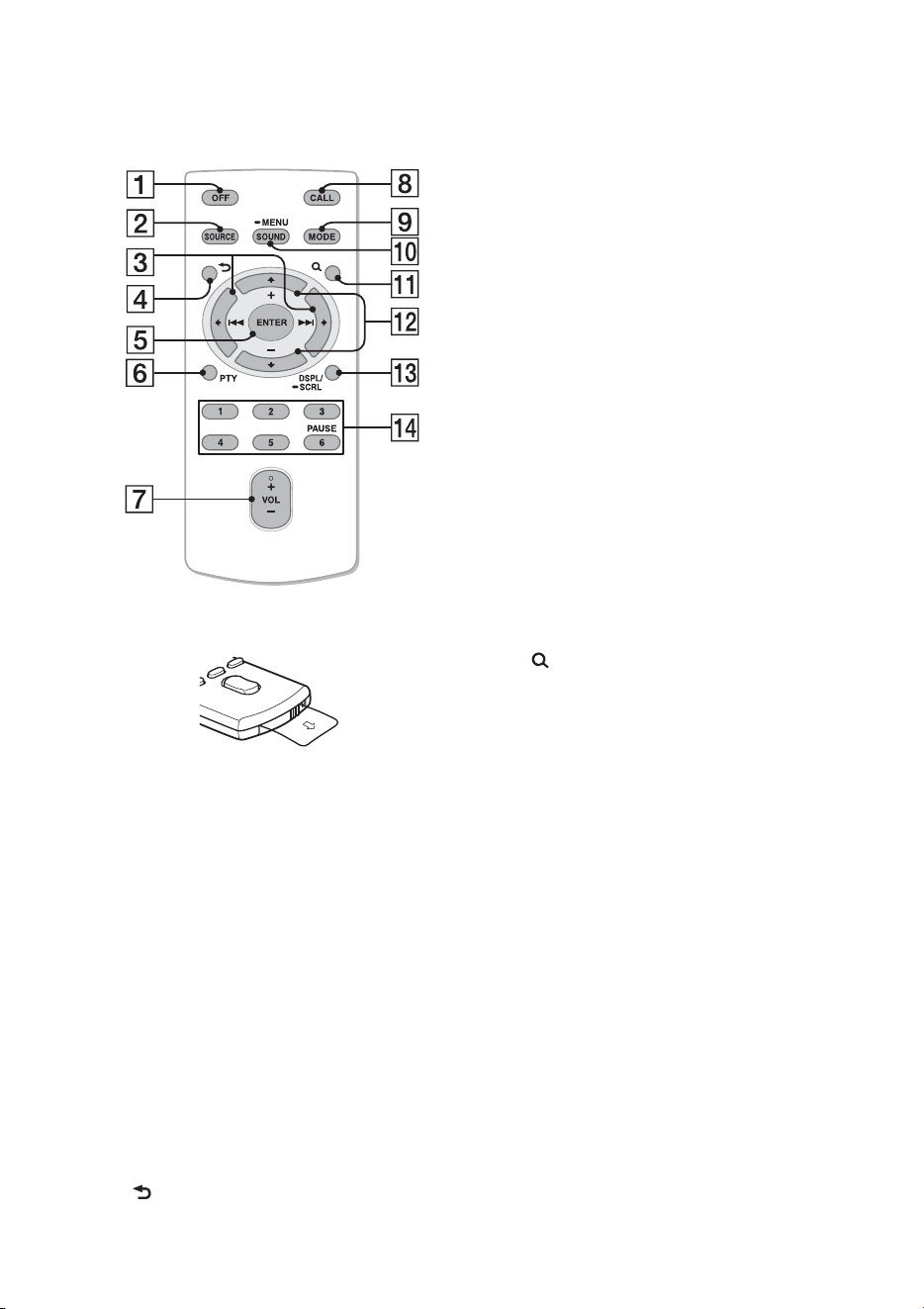
RM-X231 Remote
commander
Remove the insulation film before use.
OFF button
To turn off the power; stop the source;
reject a call.
SOURCE button*
1
Press to turn on the power.
Press repeatedly to change to another
source (Radio/CD/USB/Pandora® via
USB/AUX/Bluetooth audio/Bluetooth
Pandora®/Bluetooth phone).
()/ () buttons
To control Radio/CD/USB/Pandora®
via USB/Bluetooth audio/Bluetooth
Pandora®, the same as +/– on
the unit.
Setup items can be operated by .
(BACK) button
To return to the previous display.
ENTER button
To apply a setting; receive a call; end a
call.
PTY (Program Type) button
VOL (Volume) +*
2
/– button
CALL button
To enter the call menu.
To receive/end a call.
MODE button
Press to select the radio band (FM/AM).
Press and hold to enter/cancel the
passenger control (iPod); enter the
bookmark mode (Pandora® via USB/
Bluetooth Pandora®).
Press to activate/deactivate the
appropriate device (this unit/cellular
phone) (Bluetooth phone).
SOUND/MENU button
To enter the SOUND menu directly
(press); to enter setup mode (press and
hold).
(BROWSE) button
(+)/ (–) buttons
To control CD/USB/Pandora® via USB/
Bluetooth audio device/Bluetooth
Pandora®, the same as /
(ALBUM /) on the unit.
Setup items can be operated by .
DSPL (Display)/SCRL (Scroll) button
Number buttons
To receive stored stations (press); store
stations (press and hold).
To call a stored phone number (press);
to store a phone number as a preset
(press and hold) (in the call menu)
(Bluetooth phone).
To pause playback (press ).
*1 Depending on the device connected to the
USB port, Bluetooth Pandora® may not be
available.
*2 This button has a tactile dot.

11
Radio
Storing and receiving
stations
Caution
When tuning in stations while driving, use
Best Tuning Memory (BTM) to prevent an
accident.
Storing automatically — BTM
1 Press repeatedly until
“TUNER” appears.
To change the band, press
repeatedly. You can select from FM1,
FM2, FM3, AM1 or AM2.
2 Press , rotate the control dial
until “GENERAL” appears, then press
it.
3 Rotate the control dial until “BTM”
appears, then press it.
The unit stores stations in order of
frequency on the number buttons.
Storing manually
1 While receiving the station that you
want to store, press and hold a number
button ( to ) until “MEM”
appears.
Receiving the stored stations
1 Select the band, then press a number
button ( to ).
Tuning automatically
1
Select the band, then press +/–
to search for the station.
Scanning stops when the unit receives a
station. Repeat this procedure until the
desired station is received.
Tip
If you know the frequency of the station you want
to listen to, press and hold +/– to locate
the approximate frequency, then press
+/– repeatedly to fine adjust to the
desired frequency (manual tuning).
RDS
FM stations with Radio Data System (RDS)
service send inaudible digital information
along with the regular radio program signal.
Notes
• Depending on the country/region, not all RDS
functions may be available.
• RDS will not work if the signal strength is too
weak, or if the station you are tuned to is not
transmitting RDS data.
Changing display items
Press .
Selecting PTY (Program Types)
Use PTY to display or search for a desired
program type.
1 Press during FM reception.
The current program type name appears
if the station is transmitting PTY data.
2 Rotate the control dial until the desired
program type appears, then press it.
The unit starts to search for a station
broadcasting the selected program type.

12
Type of programs
Note
You may receive a different radio program from
the one you select.
Setting CT (Clock Time)
The CT data from the RDS transmission
sets the clock.
1 Set “CT-ON” in setup (page 32).
Note
The CT function may not work properly even
though an RDS station is being received.
CD
Playing a disc
This unit can play CD-DA (also containing
CD TEXT) and CD-R/CD-RW (MP3/
WMA/AAC files (page 35)).
1 Insert the disc (label side up).
Playback starts automatically.
To eject the disc, press .
Notes
• When ejecting/inserting a disc, keep any USB
devices disconnected to avoid damage to the
disc.
• Corresponding codec is MP3 (.mp3), WMA
(.wma) and AAC (.m4a).
Changing display items
Press .
Displayed items may differ depending on
the disc type, recording format and settings.
NEWS (News), INFORM (Information),
SPORTS (Sports), TALK (Talk), ROCK
(Rock), CLS ROCK (Classic Rock), ADLT
HIT (Adult Hits), SOFT RCK (Soft Rock),
TOP 40 (Top 40), COUNTRY (Country),
OLDIES (Oldies), SOFT (Soft), NOSTALGA
(Nostalgia), JAZZ (Jazz), CLASSICL
(Classical), R AND B (Rhythm and Blues),
SOFT R B (Soft Rhythm and Blues),
LANGUAGE (Foreign Language), REL
MUSC (Religious Music), REL TALK
(Religious Talk), PERSNLTY (Personality),
PUBLIC (Public), COLLEGE (College),
WEATHER (Weather)
13
USB devices
• MSC (Mass Storage Class)-type USB
devices (such as a USB flash drive, digital
media player, Android phone) compliant
with the USB standard can be used.
Depending on the digital media player or
Android phone, setting the USB
connection mode to MSC is required.
• Backup of data to a USB device is
recommended.
Notes
• Connect the USB device after starting the
engine.
Depending on the USB device, malfunction or
damage may occur if it is connected before
starting the engine.
• Corresponding codec is MP3 (.mp3), WMA
(.wma), AAC (.m4a) and AAC (.mp4).
• For details on the compatibility of your USB
device, visit the support site on the back cover.
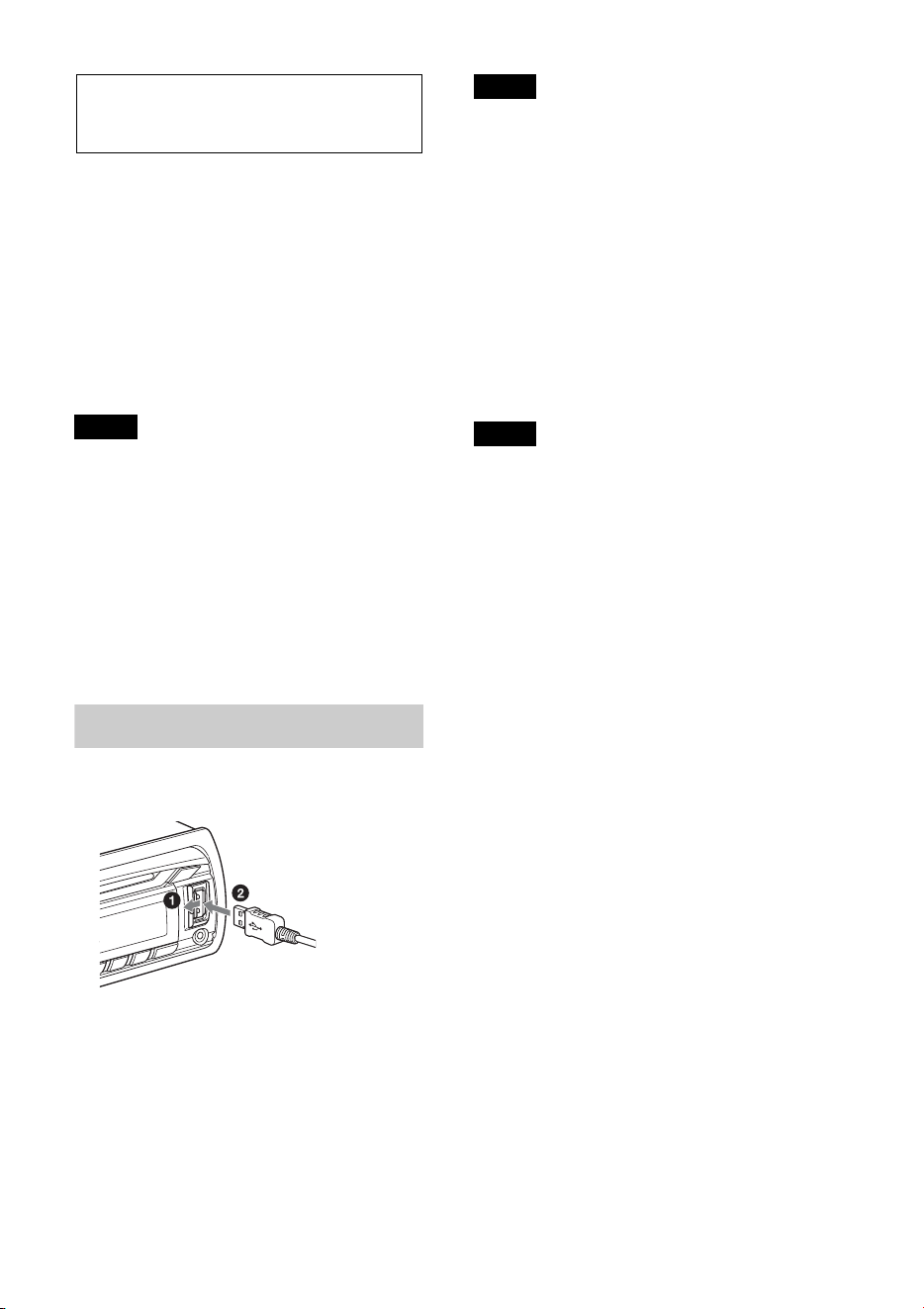
Playing back a USB device
1 Open the USB cover, then connect the
USB device to the USB port.
Playback starts.
If a USB device is already connected, to start
playback, press repeatedly
until “USB” appears.
To stop playback, press and hold
for 1 second.
To remove the USB device, stop the USB
playback, then remove the USB device.
Notes
• Do not use USB devices so large or heavy that
they may fall down due to vibration, or cause a
loose connection.
• Do not detach the front panel during playback
of the USB device, otherwise USB data may be
damaged.
Changing display items
Press .
Displayed items may differ depending on
the USB device, recording format and
settings.
Notes
• The maximum number of tracks is 10,000.
• It may take time for playback to begin,
depending on the amount of recorded data.
• During playback or fast-forward/reverse of a
VBR (Variable Bit Rate) MP3/WMA/AAC file,
elapsed playing time may not display
accurately.
• Playback of the following MP3/WMA/AAC
files is not supported.
– lossless compression files
–copyright-protected files
– DRM (Digital Rights Management) files
–Multi-channel audio files
14
iPod
In these Operating Instructions, “iPod” is
used as a general reference for the iPod
functions on the iPod and iPhone, unless
otherwise specified by the text or
illustrations.
For details on the compatibility of your
iPod, see “About iPod” (page 35) or visit the
support site on the back cover.
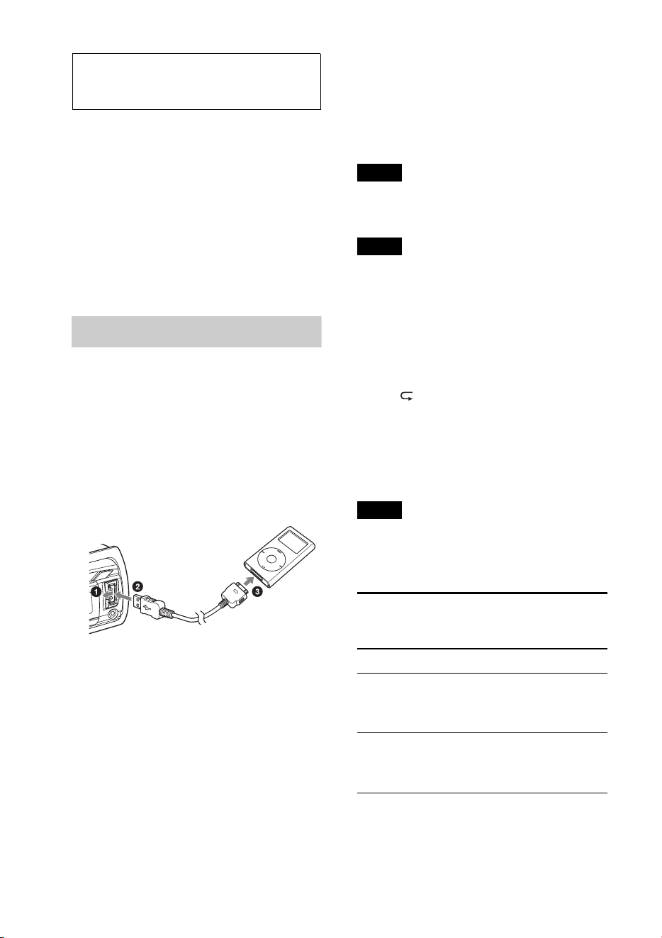
Playing back iPod
Before connecting the iPod, turn down the
volume of the unit.
1 Open the USB cover, then connect the
iPod to the USB port with a USB
connection cable for iPod (not
supplied)*.
* RC-100IP USB connection cable for iPod is
recommended.
The tracks on the iPod start playing
automatically from the point last played.
If an iPod is already connected, to start
playback, press
repeatedly until “USB” appears. (“IPD”
appears in the display when iPod is
recognized.)
To stop playback, press and hold
for 1 second.
To remove the iPod, stop the iPod playback,
then remove the iPod.
Caution for iPhone
When you connect iPhone via USB, phone call
volume is controlled by iPhone, not the unit. Do
not inadvertently increase the volume on the unit
during a call, as sudden loud sound may result
when the call ends.
Note
Do not detach the front panel during playback of
the iPod, otherwise data may be damaged.
Tip
The iPod is recharged while the unit is turned on.
Resuming mode
When the iPod is connected to the unit,
playback starts in the mode set by the iPod.
In this mode, the following buttons do not
function.
– ()
– (SHUF)
Changing display items
Press .
Note
Some letters stored in iPod may not be displayed
correctly.
Skipping albums, podcasts,
genres, playlists and artists
To Do this
Skip Press / (ALBUM /
) [press once for each
skip]
Skip
continuously
Press and hold /
(ALBUM /)
[hold to desired point]
15
Operating an iPod directly
— Passenger control
You can operate an iPod directly even when
it is connected to the unit.
1 During playback, press and hold
.
“MODE IPOD” appears and you will be
able to operate the iPod directly.
To exit the passenger control, press and
hold .
“MODE AUDIO” will appear and direct
operation of the iPod will not be possible.
Note
The volume can be adjusted only by the unit.
Pandora® via USB
(iPhone)
Pandora® is available to stream music
through your iPhone. You can control
Pandora® on a USB-connected iPhone from
this unit.
Download the latest version of the Pandora®
application and obtain more information
from www.pandora.com
For details on usable devices, visit the
support site on the back cover.
Notes
• Certain Pandora® service functions may not be
available.
• The Pandora® service is only available in the
U.S.
Streaming Pandora®
Before connecting the iPhone, turn down
the volume of the unit.
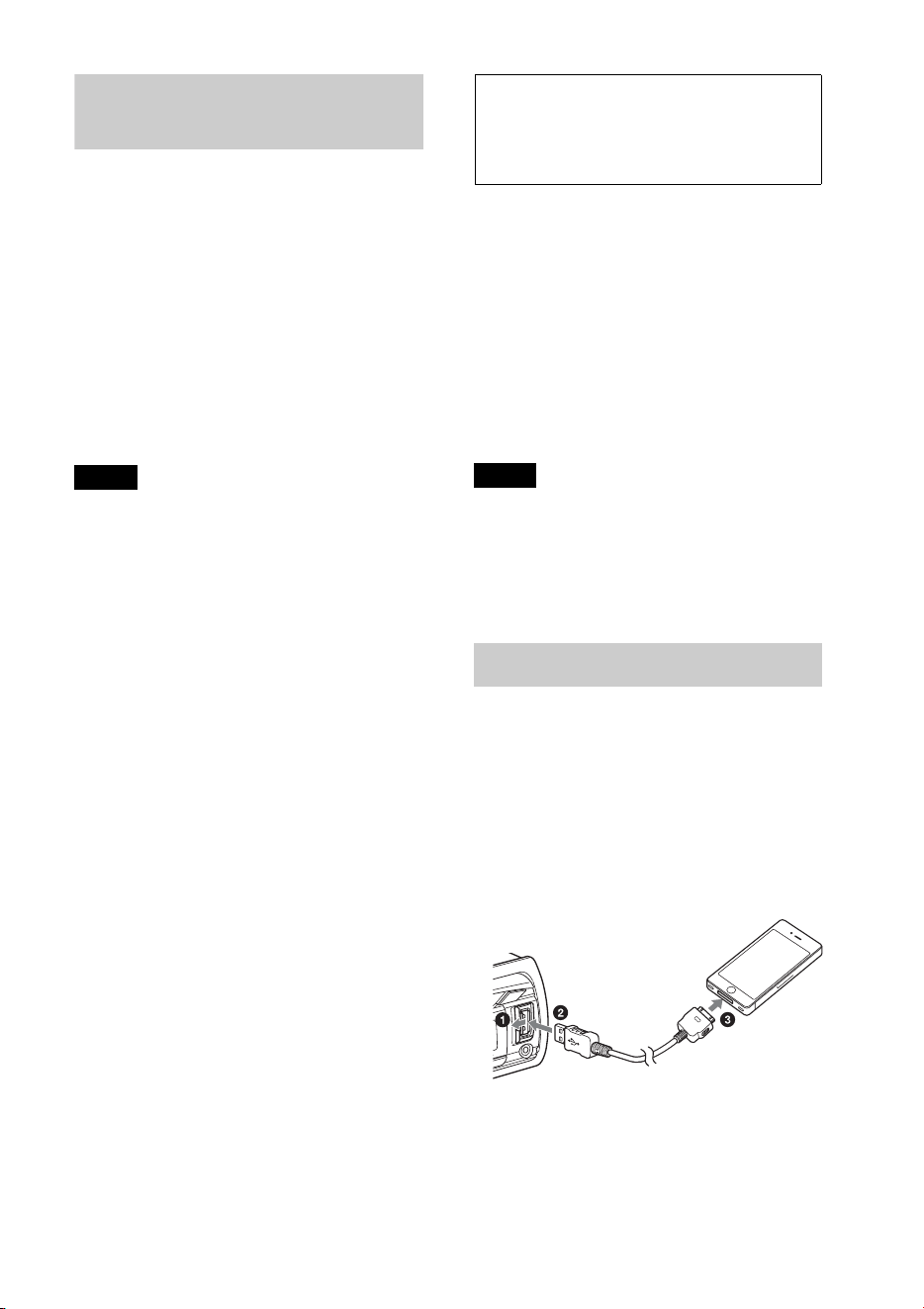
1 Open the USB cover, then connect the
iPhone to the USB port with a USB
connection cable for iPhone (not
supplied)*.
* RC-100IP USB connection cable for iPhone
is recommended.
2 Press repeatedly until
“PANDORA USB” appears.
3 Launch Pandora® application on the
iPhone.

16
4 Adjust the volume on this unit.
To pause playback, press (PAUSE). To
resume playback, press again.
To skip a track, press +.
Notes
• You cannot skip back to the previous track.
• Pandora® limits the number of skips allowed.
Changing display items
Press .
“Thumbs” feedback
“Thumbs Up” or “Thumbs Down” feedback
allows you to personalize stations to suit
your preference.
Thumbs Up
During playback, press and hold ()
for 1 second.
Thumbs Down
During playback, press and hold ()
for 1 second.
Station list
The station list allows you to easily select a
desired station.
1 During playback, press (BROWSE).
2 Press + to select the sorting
order “BY DATE” or “A TO Z.”
3 Rotate the control dial to select the
desired station, then press it.
Playback starts.
Shuffle
Shuffle allows you to listen to tracks played
on one or more Pandora® stations in your
station list randomly.
Edit your Shuffle station selections on the
device before connection.
Bookmarking
The track or artist currently being played
can be bookmarked and stored in your
Pandora® account.
1 During playback, press and hold
until “BOOKMARK”
appears.
2 Rotate the control dial to select “TRK”
(Track) or “ART” (Artist), then press
it.
17
Searching and
playing tracks
Playing tracks in various
modes
You can listen to tracks repeatedly (repeat
play) or in random order (shuffle play).
Available play modes differ depending on
the selected sound source.
1 During playback, press () or
(SHUF) repeatedly until the
desired play mode appears.
Playback in selected play mode may take
time to start.
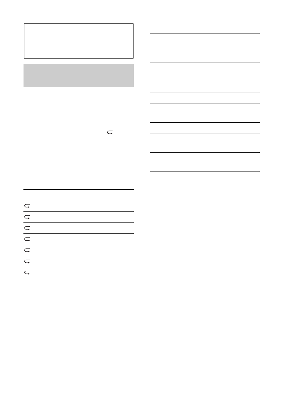
Repeat play
Shuffle play
*1 iPod only
*2 CD only
*3 USB and iPod only
Select To play
TRACK track repeatedly.
ALBUM album repeatedly.
PODCAST*
1
podcast repeatedly.
ARTIST*
1
artist repeatedly.
PLAYLIST*
1
playlist repeatedly.
GENRE*
1
genre repeatedly.
OFF track in normal order
(Normal play).
Select To play
SHUF ALBUM album in random
order.
SHUF DISC*
2
disc in random order.
SHUF PODCAST*
1
podcast in random
order.
SHUF ARTIST*
1
artist in random order.
SHUF PLAYLIST*
1
playlist in random
order.
SHUF GENRE*
1
genre in random order.
SHUF DEVICE*
3
device in random
order.
SHUF OFF track in normal order
(Normal play).
18
Searching a track by
name — Quick-BrowZer™
You can search for a track in a CD or USB
device easily by category.
1 Press (BROWSE)*.
The unit enters the Quick-BrowZer
mode, and the list of search categories
appears.
When the track list appears, press
(BACK) repeatedly until the desired
search category appears.
* During USB playback, press (BROWSE)
for more than 2 seconds to directly return to
the beginning of the category list.
2 Rotate the control dial to select the
desired search category, then press it to
confirm.
3 Repeat step 2 until the desired track is
selected.
Playback starts.
To exit the Quick-BrowZer mode, press
(BROWSE).
Notes
• When entering the Quick-BrowZer mode, the
repeat/shuffle setting is canceled.
• “ ” lights up when there is an upper layer,
and “ ” lights up when there is a lower layer.
Searching by skip items
— Jump mode
When many items are in a category, you can
search for a desired item quickly.
1 Press + in Quick-BrowZer
mode.
The item name will appear.
2 Rotate the control dial to select the
item near the one desired.
The list is skipped in steps of 10% of the
total number of items in the list.
3 Press (ENTER).
The display returns to the Quick-
BrowZer mode and the selected item
appears.
4 Rotate the control dial to select the
desired item and press it.
Playback starts if the selected item is a
track.
To cancel Jump mode, press (BACK) or
–.
Searching by alphabetical
order — Alphabet search
When an iPod is connected to the unit, you
can search for a desired item alphabetically.
1 Press + in Quick-BrowZer
mode.
2 Rotate the control dial to select the first
letter of the desired item, then press it.
A list of items beginning with the
selected letter appears in alphabetical
order.
3 Rotate the control dial to select the
desired item, then press it.
Playback starts if the selected item is a
track.
To cancel Alphabet search, press
(BACK) or –.
Notes
• In Alphabet search, a symbol or article (a/an/
the) before the selected letter of the item is
excluded.
• Depending on the search item you select, only
Jump mode may be available.
• Alphabet search may take some time,
depending on the number of tracks.
19
Searching a track by
listening to track
passages — ZAPPIN™
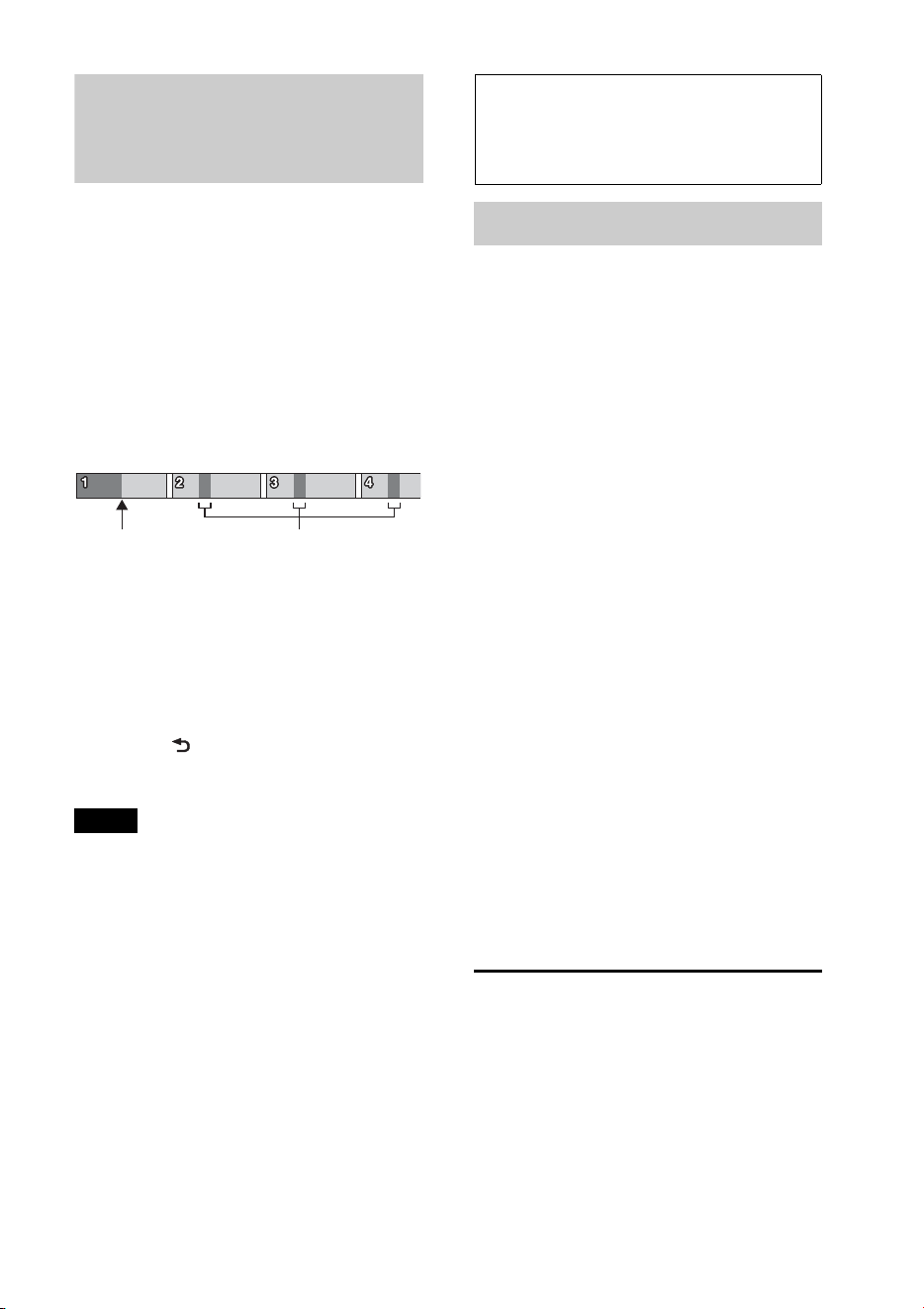
By playing back short track passages in a
CD or USB device in sequence, you can
search for a track you want to listen to.
ZAPPIN mode is suitable for searching for a
track in shuffle or shuffle repeat mode.
1 Press (ZAP) during playback.
Playback starts from a passage of the
next track. You can select the playback
time (page 32).
2 Press (ENTER) or (ZAP)
when a track you want to listen is
played back.
The track that you select returns to
normal play mode from the beginning.
Pressing (BACK) will also play back
the chosen track.
Tips
•Press +/– in ZAPPIN mode to skip a
track.
•Press / (ALBUM /) in ZAPPIN
mode to skip an album.
Connecting
Bluetooth devices
Bluetooth operations
The Bluetooth function allows for handsfree
calling and music streaming via this unit.
To use the Bluetooth function, the following
procedure is necessary.
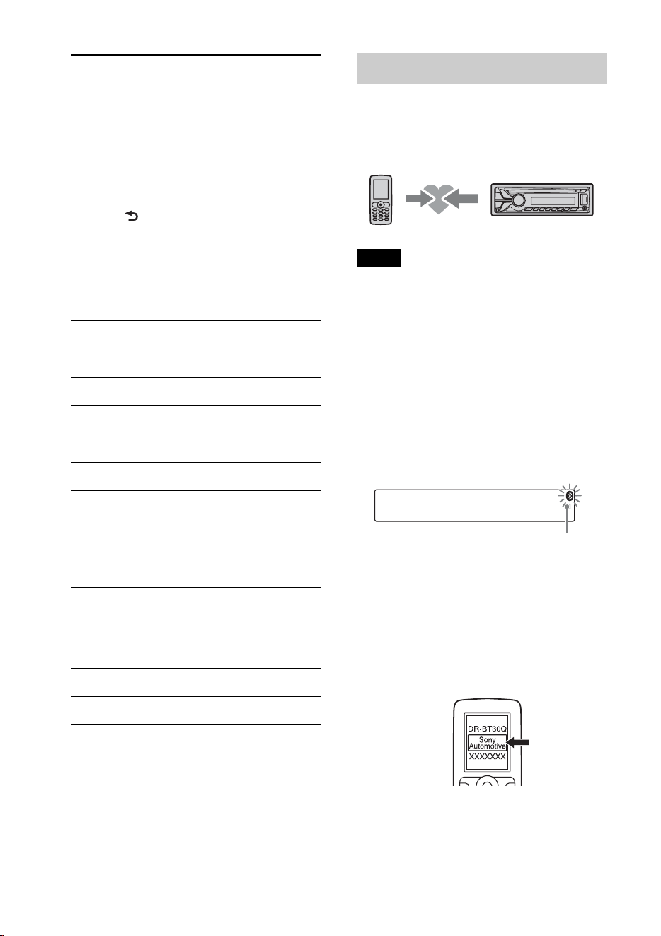
Pairing
When connecting Bluetooth devices for
the first time, mutual registration is
required. This is called “pairing.”
Registration is required only for the first
time, as this unit and the other devices
will recognize each other automatically
thereafter.
Connection
To use the device after pairing is made,
start the connection. Sometimes pairing
allows for connection automatically.
Handsfree calling/Music streaming
You can make/receive handsfree calls
and listen to music when the connection
is made.
If pairing is not possible, your device may
not be compatible with this unit. For details
on compatible devices, visit the support site
on the back cover.
Installing the microphone
To improve audio quality while talking
through this unit, you need to install the
microphone (not supplied).
For details on how to connect the
microphone, refer to the supplied
“Installation/Connections” guide.
The part of each track to play
back in ZAPPIN mode.
Track
pressed.
20
Operating the Bluetooth
functions
1 Press .
The call menu appears.
2 Rotate the control dial until the desired
item appears, then press it.
3 Press (BACK)*.
The source returns to the Bluetooth
phone.
* For PAIRING, REDIAL, VOICE DIAL and BT
SIGNL settings, step 3 is not necessary.
The following items can be set:
*1 You can also select these items by pressing
and rotating the control dial to
select “BT.”
*2 Depending on the cellular phone, this unit’s
ringtone may be output even if set to “2
(cellular phone).”
*3 Appears on the setup menu when the unit is
turned off.
Pairing
The Bluetooth device (cellular phone, audio
device, etc.) and this unit need to be
“paired” before use between each other via
the Bluetooth function.
Tips
• For details on pairing for a Bluetooth device,
refer to the operating instructions supplied with
the device.
• You can pair up to 9 Bluetooth devices with this
unit.
1 Place the Bluetooth device within 1 m
(3 ft) of this unit.
2 Press and rotate the control
dial until “PAIRING” appears, then
press it.
The unit enters pairing standby mode.
3 Set the Bluetooth device to search for
this unit.
A list of detected devices appears in the
display of the device to be connected.
This unit is displayed as “Sony
Automotive” on the device to be
connected.
PAIRING*
1
(page 20)
PHONEBOOK (page 23)
REDIAL (page 24)
RECENT CALL (page 23)
VOICE DIAL (page 25)
DIAL NUMBER (page 24)
RINGTONE*
1
*
2
Selects whether this unit or the
connected cellular phone outputs the
ringtone: “1 (this unit)”- “2 (cellular
phone).”
AUTO ANS*
1
(Auto Answer)
Sets this unit to answer an incoming call
automatically: “OFF”-“1 (about 3
seconds)”-“2 (about 10 seconds).”
BT SIGNL*
1
(Bluetooth Signal) (page 21, 22)
BT INIT*
3
(Bluetooth Initialize) (page 27)
Flashing
21
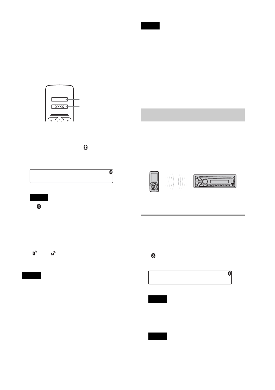
4 If passkey* input is required in the
display of the device to be connected,
input “0000.”
If the device supports Bluetooth version
2.1, passkey input is not required.
* Passkey may be called “passcode,” “PIN
code,” “PIN number” or “Password,” etc.,
depending on the device.
This unit and the Bluetooth device
memorize each other’s information, and
when pairing is made, stays lit.
The unit is ready for connection to the
device.
Note
If “ ” continues to flash, the Bluetooth
device may not be compatible with this unit.
For details on compatible devices, visit the
support site on the back cover.
5 Select this unit on the Bluetooth device
to be connected.
“ ” or “ ” appears when the
connection is made.
Notes
• While connecting to a Bluetooth device, this
unit cannot be detected from another device.
To enable detection, enter the pairing mode and
search for this unit from another device.
• It may take time to search or connect.
• Depending on the device, the confirmation
display of the connection appears before
inputting the passkey.
• The time limit for inputting the passkey differs
depending on the device. If the time expires,
perform the pairing procedure from the
beginning again.
• This unit cannot be connected to a device that
supports only HSP (Head Set Profile).
Tip
Connection between this unit and the Bluetooth
device may be automatic, depending on the
device.
Canceling pairing
Perform step 2 to cancel the pairing mode
after this unit and the Bluetooth device are
paired.
Connection
To use the device after pairing is made, start
the connection. Sometimes pairing allows
for connection automatically.
If pairing has already been achieved, start
operation from here.
Connecting a cellular phone
1 Press and rotate the control
dial until “BT SIGNL” appears, then
press it.
“ ” lights up when Bluetooth signal is
activated.
Note
When the Bluetooth signal for this unit is
already ON, selecting “BT SIGNL” deactivates
the Bluetooth signal.
Tip
You can also output the Bluetooth signal from
this unit by pressing and holding on
this unit more than 2 seconds.
Input passkey
“0000”
22
2 Turn on the cellular phone and activate
the Bluetooth signal.
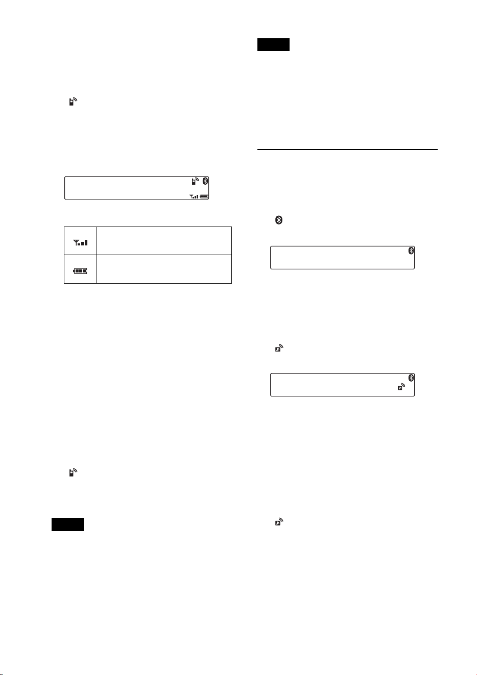
3 Connect to this unit using the cellular
phone.
“ ” appears when the connection is
made. If you select the Bluetooth phone
source after the connection is made, the
network name and the connected
cellular phone name appear in the
display.
Icons in the display:
* Turns off without handsfree connection.
Differs depending on the cellular phone.
Changing display items
Press .
Connecting the last-connected cellular
phone from this unit
1 Make sure the Bluetooth signal of the
cellular phone is activated.
2 Press repeatedly until “BT
PHONE” appears.
3 Press (ENTER).
“ ” flashes while the connection is
being made, then stays lit while
connected.
Notes
• Some cellular phones require permission to
access their phonebook data during handsfree
connection to this unit. Obtain permission via
the cellular phone.
• While streaming Bluetooth audio, you cannot
connect from this unit to the cellular phone.
Connect from the cellular phone to this unit
instead. A connecting noise may be heard over
playback sound.
Tip
With Bluetooth signal on: when the ignition is
turned to on, this unit reconnects automatically
to the last-connected cellular phone. But
automatic connection also depends on the
cellular phone’s specification. If automatic
connection is not made, connect manually.
Connecting an audio device
1 Press and rotate the control
dial until “BT SIGNL” appears, then
press it.
“ ” lights up when Bluetooth signal is
activated.
2 Turn on the audio device and activate
the Bluetooth signal.
3 Connect to this unit using the audio
device.
“ ” appears when the connection is
made.
Connecting the last-connected audio
device from this unit
1 Make sure the Bluetooth signal of the audio
device is activated.
2 Press repeatedly until “BT
AUDIO” appears.
3 Press (PAUSE).
“ ” flashes while the connection is
being made, then stays lit while
connected.
Signal strength status of
connected cellular phone.*
Remaining battery status of
connected cellular phone.*
23
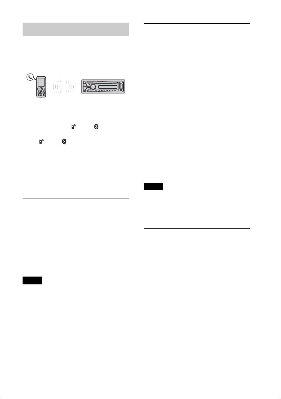
Handsfree calling
Once the unit is connected to the cellular
phone, you can make/receive handsfree
calls by operating this unit.
Before handsfree calling, check the
following:
Make sure that “ ” and “ ” appear in
the display.
If “ ” and “ ” do not appear, perform
the connection procedure (page 21).
If you cannot connect this unit and the
cellular phone via the Bluetooth
function, perform the pairing procedure
(page 20).
Receiving calls
When receiving a call, a ringtone is output
from your car speakers or the connected
cellular phone. The caller’s name or phone
number appears in the display.
1 Press when a call is received
with a ringtone.
The phone call starts.
Notes
• Depending on the cellular phone, the caller’s
name may appear.
• The ringtone and talker’s voice are output only
from the front speakers.
Rejecting a call
Press and hold for 1
second.
Ending a call
Press again.
Calling from the phonebook
When connecting to a cellular phone
supporting PBAP (Phone Book Access
Profile), you can access the phonebook, and
make a call.
1 Press and rotate the control
dial until “PHONEBOOK” appears,
then press it.
2 Rotate the control dial to select an
initial from the initial list, and then
press it.
3 Rotate the control dial to select a name
from the name list, and then press it.
4 Rotate the control dial to select a
number from the number list, and then
press it.
The phone call starts.
Note
Depending on the cellular phone, contacts
displayed on the unit may differ from the
phonebook of the cellular phone.
Calling from the call history
When connecting to a cellular phone
supporting PBAP (Phone Book Access
Profile), you can access to the call history
stored in the cellular phone, and make a
call.
1 Press and rotate the control
dial until “RECENT CALL” appears,
then press it.
A list of the call history appears.
2 Rotate the control dial to select a name
or phone number from the call history,
then press it.
The phone call starts.

24
Calling by phone number
input
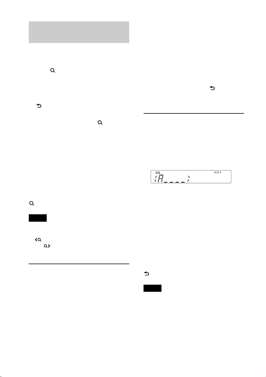
1 Press and rotate the control
dial until “DIAL NUMBER” appears,
then press it.
2 Rotate the control dial to enter the
phone number, and lastly select “ ”
(space), then press (ENTER)*.
The phone call starts.
* To move the digital indication, press
–/+.
Note
“_” appears instead of “#” on the display.
Calling by preset number
You can store up to 6 contacts in the preset
dial. For details on how to store, see “Preset
dial” (page 25).
1 Press , rotate the
control dial until “BT PHONE”
appears, then press it.
2 Press a number button ( to ) to
select the contact you want to call.
3 Press (ENTER).
The phone call starts.
Calling by redial
1 Press and rotate the control
dial until “REDIAL” appears, then
press it.
The phone call starts.
Operations during a call
Presetting the volume of the ringtone
and talker’s voice
You can preset the volume level of the
ringtone and talker’s voice.
To adjust the ringtone volume:
Rotate the control dial while receiving a call.
Ringtone volume can be adjusted.
To adjust the talker’s voice volume:
Rotate the control dial during a call. The
talker’s voice volume can be adjusted.
Note
If the Bluetooth phone source is selected, rotating
the control dial will only adjust the talker’s
volume.
Mic gain adjustment
You can adjust the volume for the other
party. Press (MIC) to adjust the volume
levels (“MIC-LOW,” “MIC-MID,” “MIC-
HI”).
EC/NC Mode (Echo Canceler/Noise
Canceler Mode)
You can reduce echo and noise.
Press and hold (MIC) to set to “EC/
NC-1” or “EC/NC-2.”
Call transfer
In order to activate/deactivate the
appropriate device (this unit/cellular
phone), press or use your cellular
phone.
Notes
• For details on cellular phone operation, refer to
your cellular phone manual.
• Depending on the cellular phone, handsfree
connection may be cut off when call transfer is
attempted.
25
Preset dial
You can store up to 6 contacts in the preset
dial.
Notes
• If your cellular phone supports PBAP (Phone
Book Access Profile), you can select a phone
number from the phonebook or call history.
• Disconnecting the power supply lead will erase
all the contacts in the preset dial.
1 Select a phone number that you want to
store in the preset dial, from the
phonebook, call history* or by
inputting the phone number directly.
The phone number appears in the
display of this unit.
* For the call history, you can also select from
the caller name. In this case, the caller name
appears in the display of this unit.
2 Press and hold a number button (
to ) to select the preset number to
store until “MEM” appears.
The contact is stored in the selected
preset number.
Voice dial activation
You can activate voice dialing with a cellular
phone connected to this unit by saying the
voice tag stored on the cellular phone, then
make a call.
1 Press and rotate the control
dial until “VOICE DIAL” appears, then
press it.
2 Say the voice tag stored on the cellular
phone.
Your voice is recognized, and the call is
made.
Notes
• Check that the unit and cellular phone are
connected beforehand.
• Store a voice tag on your cellular phone
beforehand.
• If you activate voice dialing with a cellular
phone connected to this unit, this function may
not always work in some cases.
• Voice dialing may not work in some situations,
depending on the effectiveness of the cellular
phone’s recognition function. For details, see
the support site on the back cover.
Tip
Store voice tags while seated in the car, via this
unit with “BT PHONE” source selected.
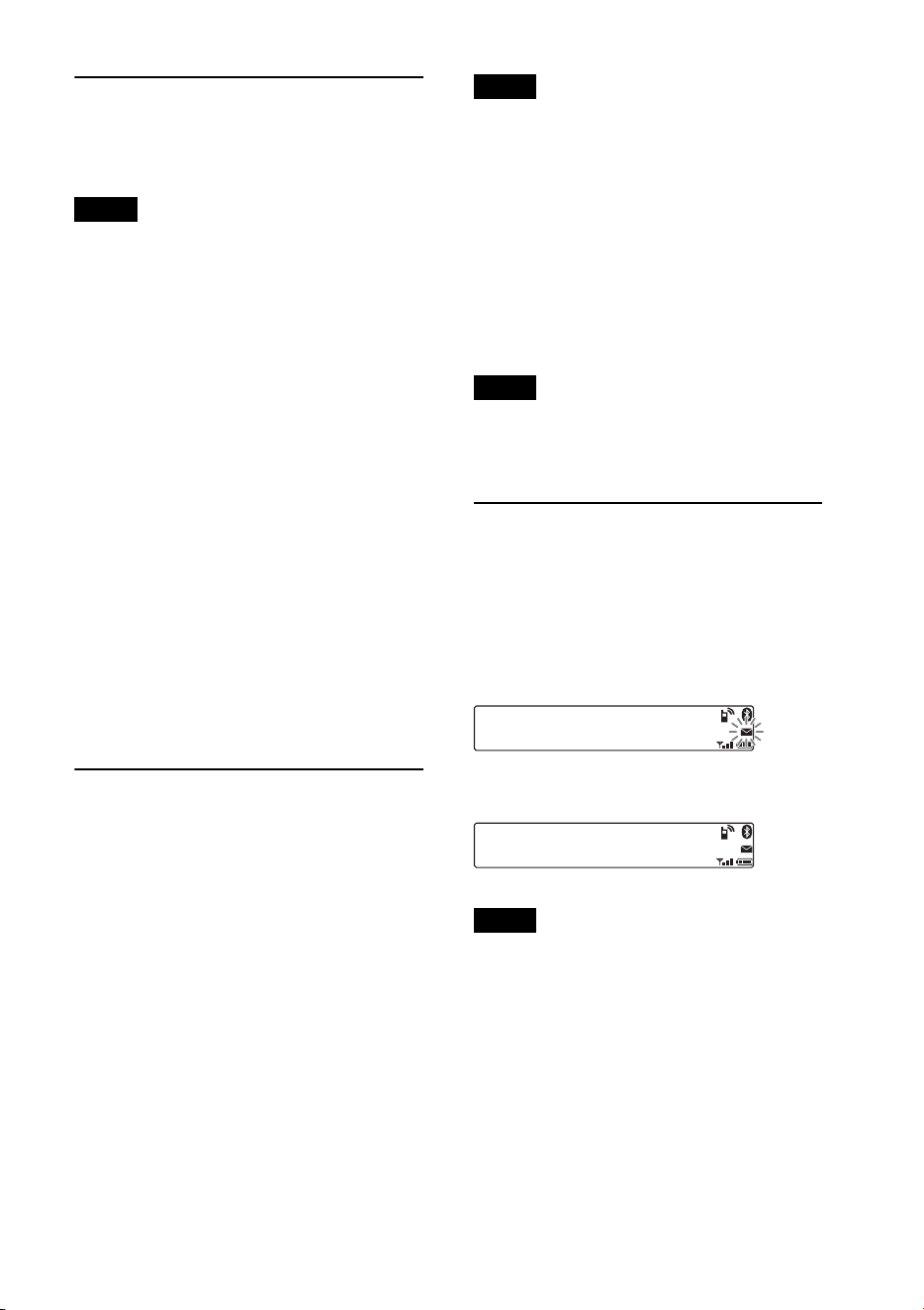
SMS indicator
While connecting a cellular phone to this
unit, the SMS indicator informs you of any
incoming or unread SMS messages.
If you receive a new SMS message, the SMS
indicator flashes.
If there are any unread SMS messages, the
SMS indicator stays lit.
Note
Function of the SMS indicator may depend on
the cellular phone.
26
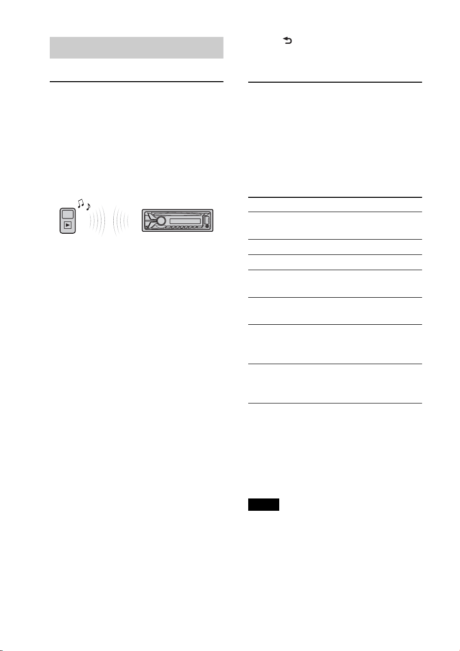
Music streaming
Listening to music from an
audio device
You can listen to music from an audio
device on this unit if the audio device
supports A2DP (Advanced Audio
Distribution Profile) of Bluetooth
technology.
1 Turn down the volume on this unit.
2 Press repeatedly until
“BT AUDIO” appears.
3 Operate the audio device to start
playback.
4 Adjust the volume on this unit.
Changing display items
Press .
Adjusting the volume level
The volume level is adjustable for any
difference between the unit and the
Bluetooth audio device.
1 Start playback of the Bluetooth audio device
at a moderate volume.
2 Set your usual listening volume on the unit.
3 Press , rotate the control dial until
“SOUND” appears, then press it.
4 Rotate the control dial until “BTA VOL”
appears, then press it.
5 Rotate the control dial to adjust the input
level (“+18dB” – “0dB” – “– 8dB”), then
press it.
6 Press (BACK) to return to the previous
display.
Operating an audio device
with this unit
You can perform the following operations
on this unit if the audio device supports
AVRCP (Audio Video Remote Control
Profile) of Bluetooth technology. (The
operation differs depending on the audio
device.)
*1 Press repeatedly until the desired setting
appears.
*2 Depending on the device, it may be necessary
to press twice.
Operations other than the above should be
performed on the audio device.
Notes
• Depending on the audio device, information,
such as title, track number/time, playback
status, etc., may not be displayed on this unit.
The information is displayed during Bluetooth
audio playback only.
• Even if the source is changed on this unit,
playback of the audio device does not stop.
To Do this
Skip albums
Press
/
(ALBUM
/
)
[press once for each album]
Repeat play Press (REP)*
1
Shuffle play Press (SHUF)*
1
Play Press (PAUSE)*
2
on
this unit.
Pause Press (PAUSE)*
2
on
this unit.
Skip tracks Press –/+ (/
) [press once for each
track]
Reverse/
Fast-forward
Press and hold –/+
(/) [hold to
desired point]

27
Initializing Bluetooth
Settings
You can initialize all the Bluetooth related
settings (pairing information, preset
number, device information, etc.) from this
unit.
1 Press and hold for 1
second to turn off the power.
2 Press , rotate the control dial
until “BT” appears, then press it.
The menu list appears.
3 Rotate the control dial to select “BT
INIT,” then press it.
The confirmation appears.
4 Rotate the control dial to select “INIT-
YES,” then press it.
“INITIAL” flashes while initializing the
Bluetooth settings; “COMPLETE”
appears when initializing has finished.
5 Press (BACK) to return to the
previous display.
Note
When disposing of this unit, preset numbers
should be deleted with “BT INIT.”
Pandora
®
via
Bluetooth wireless
technology (Android
™
& BlackBerry
®
phones)
Pandora® is available to stream music
through your Android™ and BlackBerry®
phones.
You can control Pandora® on Bluetooth
connected Android and BlackBerry phone
from this unit.
Download the latest version of the Pandora®
application and obtain more information
from
www.pandora.com
For details on usable devices, visit the
support site on the back cover.
Notes
• Certain Pandora® service functions may not be
available.
• You can control Pandora® via the Bluetooth
function on Android and BlackBerry phones
only.
• The Pandora® service is only available in the
U.S.
Streaming Pandora®
Before connecting the mobile device, turn
down the volume of the unit.
1 Connect this unit and the mobile
device via the Bluetooth function
(page 19).
2 Press repeatedly until
“BT PANDORA”*
1
appears.
3 Launch Pandora® application on the
mobile device.

28
4 Press *
2
(PAUSE) to start playback.
*1 Does not appear, depending on the device
connected to the USB port.
*2 When the mobile device is connected, the
device number may appear. Make sure that
the same numbers are displayed (e.g., 123456)
in this unit and the mobile device, then press
on this unit and select “Yes” on the
mobile device.
To pause playback, press (PAUSE). To
resume playback, press again.
To skip a track, press +.
Notes
• You cannot skip back to the previous track.
• Pandora® limits the number of skips allowed.
Changing display items
Press .
Adjusting the volume level
The volume level of Pandora® is adjusted in
the same way as a Bluetooth audio device.
For details, see page 26.
“Thumbs” feedback
“Thumbs Up” or “Thumbs Down” feedback
allows you to personalize stations to suit
your preference.
Thumbs Up
During playback, press and hold ()
for 1 second.
Thumbs Down
During playback, press and hold ()
for 1 second.
Station list
The station list allows you to easily select a
desired station.
1 During playback, press (BROWSE).
2 Press + to select the sorting
order “BY DATE” or “A TO Z.”
3 Rotate the control dial to select the
desired station, then press it.
Playback starts.
Shuffle
Shuffle allows you to listen to tracks played
on one or more Pandora® stations in your
station list randomly.
Edit your Shuffle station selections on the
device before connection.
Bookmarking
The track or artist currently being played
can be bookmarked and stored in your
Pandora® account.
1 During playback, press and hold
until “BOOKMARK”
appears.
2 Rotate the control dial to select “TRK”
(Track) or “ART” (Artist), then press
it.
29
Sound Settings and
Setup Menu
Enjoying sophisticated
sound functions —
Advanced Sound Engine
Advanced Sound Engine creates an ideal in-
car sound field with digital signal
processing.
Selecting the sound quality
— EQ7 Preset
You can select an equalizer curve from 7
equalizer curves (XPLOD, VOCAL, EDGE,
CRUISE, SPACE, GRAVITY, CUSTOM or
OFF).
1 During reception/playback, press
, rotate the control dial until
“SOUND” appears, then press it.
2 Rotate the control dial until “EQ7
PRESET” appears, then press it.
3 Rotate the control dial until the desired
equalizer curve appears, then press it.
4 Press (BACK) to return to the
previous display.
To cancel the equalizer curve, select “OFF”
in step 3.
Tip
The equalizer curve setting can be memorized for
each source.
Customizing the equalizer
curve — EQ7 Setting
“CUSTOM” of EQ7 allows you to make
your own equalizer settings.
1 After selecting a source, press ,
rotate the control dial until “SOUND”
appears, then press it.
2 Rotate the control dial until “EQ7
SETTING” appears, then press it.
3 Rotate the control dial until “BASE”
appears, then press it.
You can select an equalizer curve as a
basis for further customizing.
4 Rotate the control dial to select the
equalizer curve, then press it.
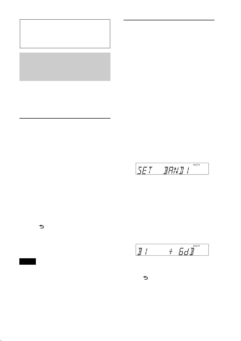
5 Setting the equalizer curve.
Rotate the control dial to select the
frequency range, then press it.
BAND1: 63 Hz
BAND2: 160 Hz
BAND3: 400 Hz
BAND4: 1 kHz
BAND5: 2.5 kHz
BAND6: 6.3 kHz
BAND7: 16.0 kHz
Rotate the control dial to adjust the
volume level, then press it.
The volume level is adjustable in 1 dB
steps, from -6 dB to +6 dB.
Repeat steps and to adjust other
frequency ranges.
6 Press (BACK) to return to the
previous display.
The equalizer curve is stored in
“CUSTOM.”
30
Optimizing sound by Time
Alignment — Listening
Position
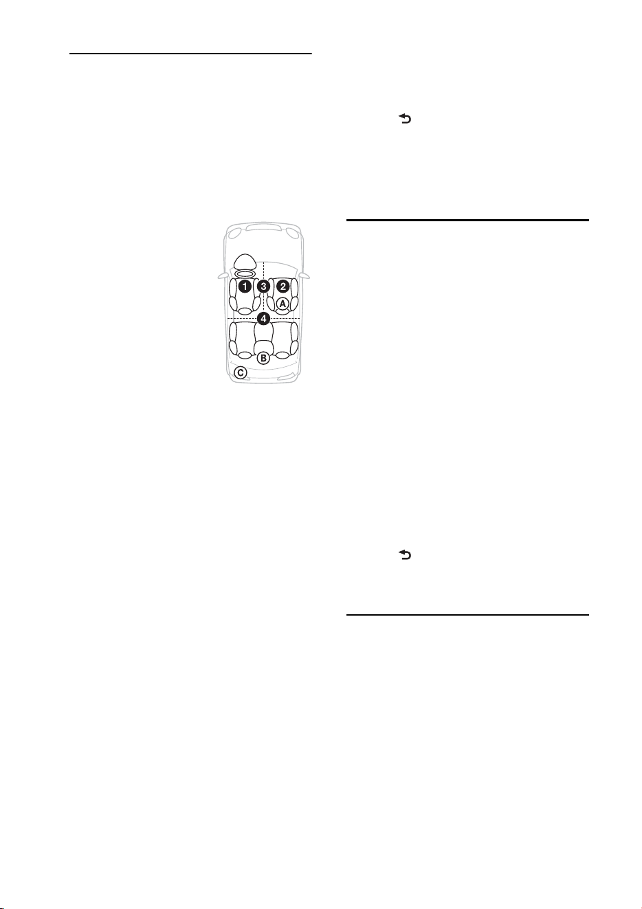
The unit can simulate a natural sound field
by delaying the sound output from each
speaker to suit your position.
The options for “POSITION” are indicated
below.
You can also set the approximate subwoofer
position from your listening position if:
–the audio output is set to “SUB-OUT”
(page 32).
–the listening position is set to other than
“OFF.”
The options for “SET SW POS” are
indicated below.
NEAR (): Near
NORMAL (): Normal
FAR (): Far
1 During reception/playback, press
, rotate the control dial until
“SOUND” appears, then press it.
2 Rotate the control dial until
“POSITION” appears, then press it.
3 Rotate the control dial until “SET F/R
POS” appears, then press it.
4 Rotate the control dial to select from
“FRONT L,” “FRONT R,” “FRONT” or
“ALL,” then press it.
5 Rotate the control dial until “SET SW
POS” appears, then press it.
6 Rotate the control dial to select the
subwoofer position from “NEAR,”
“NORMAL” or “FAR,” then press it.
7 Press (BACK) to return to the
previous display.
To cancel listening position, select “OFF” in
step 4.
Adjusting the listening
position
You can fine-tune the listening position
setting.
1 During reception/playback, press
, rotate the control dial until
“SOUND” appears, then press it.
2 Rotate the control dial until
“POSITION” appears, then press it.
3 Rotate the control dial until “ADJ
POSITION” appears, then press it.
4 Rotate the control dial to adjust the
listening position, then press it.
Adjustable range: “+3” – “CENTER” –
“–3.”
5 Press (BACK) to return to the
previous display.
DM+ Advanced
DM+ Advanced improves digitally
compressed sound by restoring high
frequencies lost in the compression process.
1 During playback, press , rotate
the control dial until “SOUND”
appears, then press it.
2 Rotate the control dial until “DM+”
appears, then press it.
3 Rotate the control dial to select “ON,”
then press it.
FRONT L (): Front left
FRONT R (): Front right
FRONT (): Center front
ALL (): In the center of
your car
OFF: No position set

31
4 Press (BACK) to return to the
previous display.
Tip
The DM+ setting can be memorized for each
source other than the tuner.
Using rear speakers as
subwoofer — Rear Bass
Enhancer
Rear Bass Enhancer enhances the bass
sound by applying a low pass filter setting
(page 32) to the rear speakers. This function
allows the rear speakers to work as a
subwoofer if one is not connected.
1 During reception/playback, press
, rotate the control dial until
“SOUND” appears, then press it.
2 Rotate the control dial until “RB ENH”
appears, then press it.
3 Rotate the control dial until “RBE
MODE” appears, then press it.
4 Rotate the control dial to select from
“1,” “2” or “3,” then press it.
5 Press (BACK) to return to the
previous display.
Using a subwoofer without a
power amplifier —
Subwoofer Direct Connection
You can use the subwoofer without a power
amplifier when it is connected to the rear
speaker cord.
Note
Be sure to connect a 4 - 8 ohm subwoofer to
either of the rear speaker cords. Do not connect a
speaker to the other rear speaker cord.
1 During reception/playback, press
, rotate the control dial until
“SOUND” appears, then press it.
2 Rotate the control dial until “SW
DIREC” appears, then press it.
3 Rotate the control dial until “SW
MODE” appears, then press it.
4 Rotate the control dial to select “1,” “2”
or “3,” then press it.
5 Press (BACK) to return to the
previous display.
For details on the settings for the subwoofer
phase, position, low pass filter frequency
and the low pass filter slope, see page 33.
Adjusting setup items
1 Press , rotate the control dial
until the desired category appears, then
press it.
2 Rotate the control dial until the desired
item appears, then press it.
3 Rotate the control dial to select the
setting, then press it.*
The setting is complete.
4 Press (BACK) to return to the
previous display.
* For CLOCK-ADJ and BTM settings, step 4 is
not necessary.
The following items can be set depending
on the source and setting:
GENERAL:
CLOCK-ADJ (Clock Adjust) (page 7)
CAUT ALM*
1
(Caution Alarm)
Activates the caution alarm: “ON,”
“OFF” (page 7).

32
*1 When the unit is turned off.
*2 When the tuner is selected.
*3 When the CD or USB is selected.
SOUND:
BEEP
Activates the beep sound: “ON,” “OFF.”
AUTO OFF
Shuts off automatically after a desired
time when the unit is turned off: “NO,”
“30S (Seconds),” “30M (Minutes),” “60M
(Minutes).”
AUX-A*
1
(AUX Audio)
Activates the AUX source display: “ON,”
“OFF” (page 34).
REAR/SUB*
1
Switches the audio output: “SUB-OUT”
(subwoofer), “REAR-OUT” (power
amplifier).
CT (Clock Time)
Activates the CT function: “ON,” “OFF”
(page 12).
BTM*
2
(page 11)
ZAPPIN*
3
ZAP TIME (Zappin Time)
Selects the playback time for the
ZAPPIN function.
– “Z.TIME-1 (about 6 seconds),”
“Z.TIME-2 (about 15 seconds),”
“Z.TIME-3 (about 30 seconds).”
ZAP BEEP (Zappin Beep)
Applies a beep sound between track
passages: “ON,” “OFF.”
EQ7 PRESET (page 29)
EQ7 SETTING (page 29)
POSITION
SET F/R POS (Set Front/Rear Position)
(page 30)
ADJ POSITION*
1
(Adjust Position)
(page 30)
SET SW POS*
1
*
2
(Set Subwoofer
Position) (page 30)
BALANCE
Adjusts the sound balance: “RIGHT-15”
– “CENTER” – “LEFT-15.”
FADER
Adjusts the relative level: “FRONT-15” –
“CENTER” – “REAR-15.”
DM+*
3
(page 30)
LOUDNESS (Dynamic Loudness)
Reinforces bass and treble for clear
sound at low volume levels: “ON,”
“OFF.”
ALO (Automatic Level Optimizer)
Adjust the playback volume level of all
playback sources to the optimum level:
“ON,” “OFF.”
RB ENH*
4
(Rear Bass Enhancer)
RBE MODE (Rear Bass Enhancer
Mode)
Selects the rear bass enhancer mode: “1,”
“2,” “3,” “OFF.”
LPF FREQ (Low Pass Filter Frequency)
Selects the subwoofer cut-off frequency:
“50Hz,” “60Hz,” “80Hz,” “100Hz,”
“120Hz.”
LPF SLOP (Low Pass Filter Slope)
Selects the LPF slope: “1,” “2,” “3.”

33
*1 Does not appear when “SET F/R POS” is set to
“OFF.”
*2 When the audio output is set to “SUB-OUT”
(page 32).
*3 Does not appear when the tuner is selected.
*4 When the audio output is set to “REAR-
OUT” and “SW DIREC” is set to “OFF.”
*5 When the audio output is set to “REAR-
OUT” and “RBE MODE” is set to “OFF.”
*6 When the AUX is selected.
*7 When Bluetooth audio source is activated.
DISPLAY:
* When the CD, USB, Pandora® via USB,
Bluetooth audio or Bluetooth Pandora® is
selected.
BT (Bluetooth):
For details on setup items for the Bluetooth
settings, see page 20.
SW DIREC*
5
(Subwoofer Direct
Connection)
SW MODE (Subwoofer Mode)
Selects the subwoofer mode: “1,” “2,” “3,”
“OFF.”
SW PHASE (Subwoofer Phase)
Selects the subwoofer phase: “NORM,”
“REV.”
SW POS*
1
(Subwoofer Position)
(page 30)
Selects the subwoofer position: “NEAR,”
“NORMAL,” “FAR. ”
LPF FREQ (Low Pass Filter Frequency)
Selects the subwoofer cut-off frequency:
“50Hz,” “60Hz,” “80Hz,” “100Hz,”
“120Hz.”
LPF SLOP (Low Pass Filter Slope)
Selects the LPF slope: “1,” “2,” “3.”
S.WOOFER*
2
(Subwoofer)
SW LEVEL (Subwoofer Level)
Adjusts the subwoofer volume level:
“+10 dB” – “0 dB” – “–10 dB.”
(“ATT” is displayed at the lowest
setting.)
SW PHASE (Subwoofer Phase)
Selects the subwoofer phase: “NORM,”
“REV.”
SW POS*
1
(Subwoofer Position)
Selects the subwoofer position: “NEAR,”
“NORMAL,” “FAR. ”
LPF FREQ (Low Pass Filter Frequency)
Selects the subwoofer cut-off frequency:
“50Hz,” “60Hz,” “80Hz,” “100Hz,”
“120Hz.”
LPF SLOP (Low Pass Filter Slope)
Selects the LPF slope: “1,” “2,” “3.”
HPF (High Pass Filter)
HPF FREQ (High Pass Filter Frequency)
Selects the front/rear speaker cut-off
frequency: “OFF,” “50Hz,” “60Hz,”
“80Hz,” “100Hz,” “120Hz.”
HPF SLOP (High Pass Filter Slope)
Selects the HPF slope (effective only
when HPF FREQ is set to other than
“OFF”): “1,” “2,” “3.”
AUX VOL*
6
(AUX Volume level)
Adjusts the volume level for each
connected auxiliary equipment:
“+18 dB” – “0 dB” – “–8 dB.”
This setting negates the need to adjust
the volume level between sources.
BTA VOL*
7
(Bluetooth Audio Volume
Level) (page 26)
DEMO
(Demonstration)
Activates the demonstration: “ON,”
“OFF.”
DIMMER
Changes the display brightness: “ON,”
“OFF.”
AUTO SCR* (Auto Scroll)
Scrolls long items automatically: “ON,”
“OFF.”
34
Using optional
equipment
Auxiliary audio
equipment
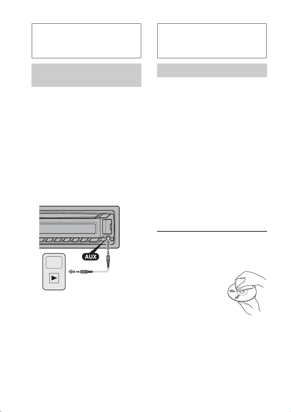
By connecting an optional portable audio
device to the AUX input jack (stereo mini
jack) on the unit and then simply selecting
the source, you can listen on your car
speakers.
Connecting the portable audio device
1 Turn off the portable audio device.
2 Turn down the volume on the unit.
3 Connect the portable audio device to the
unit with a connecting cord (not supplied)*.
* Be sure to use a straight type plug.
Adjusting the volume level
Be sure to adjust the volume for each
connected audio device before playback.
1 Turn down the volume on the unit.
2 Press repeatedly until
“AUX” appears.
3 Start playback of the portable audio device
at a moderate volume.
4 Set your usual listening volume on the unit.
5 Adjust the input level (page 33).
Additional
Information
Precautions
• Cool off the unit beforehand if your car has
been parked in direct sunlight.
• Do not leave the front panel or audio devices
brought in inside the car, or it may cause
malfunction due to high temperature in
direct sunlight.
• Power antenna (aerial) extends
automatically.
Moisture condensation
Should moisture condensation occur inside
the unit, remove the disc and wait for about an
hour for it to dry out; otherwise the unit will
not operate properly.
To maintain high sound quality
Do not splash liquid onto the unit or discs.
Notes on discs
• Do not expose discs to direct sunlight or heat
sources such as hot air ducts, nor leave it in a
car parked in direct sunlight.
• Before playing, wipe the
discs with a cleaning cloth
from the center out. Do not
use solvents such as
benzine, thinner,
commercially available
cleaners.
• This unit is designed to play back discs that
conform to the Compact Disc (CD)
standard. DualDiscs and some of the music
discs encoded with copyright protection
technologies do not conform to the Compact
Disc (CD) standard, therefore, these discs
may not be playable by this unit.
35
• Discs that this unit CANNOT play
– Discs with labels, stickers, or sticky tape or
paper attached. Doing so may cause a
malfunction, or may ruin the disc.
– Discs with non-standard shapes (e.g., heart,
square, star). Attempting to do so may
damage the unit.
–8 cm (3
1
/4 in) discs.
Notes on CD-R/CD-RW discs
• The maximum number of: (CD-R/CD-RW
only)
– folders (albums): 150 (including root folder)
– files (tracks) and folders: 300 (may less than
300 if folder/file names contain many
characters)
– displayable characters for a folder/file name:
32 (Joliet)/64 (Romeo)
• If the multi-session disc begins with a CD-
DA session, it is recognized as a CD-DA disc,
and other sessions are not played back.
• Discs that this unit CANNOT play
– CD-R/CD-RW of poor recording quality.
– CD-R/CD-RW recorded with an
incompatible recording device.
– CD-R/CD-RW which is finalized incorrectly.
– CD-R/CD-RW other than those recorded in
music CD format or MP3 format conforming
to ISO9660 Level 1/Level 2, Joliet/Romeo or
multi-session.
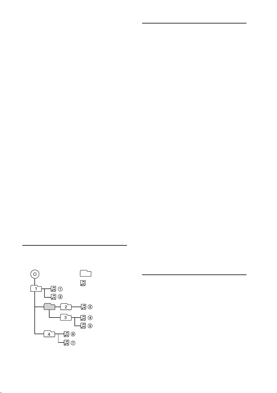
Playback order of MP3/WMA/
AAC files
About iPod
* Passenger control is not available for iPod nano
(1st generation).
About Bluetooth function
What is Bluetooth technology?
• Bluetooth wireless technology is a short-
range wireless technology that enables
wireless data communication between digital
devices, such as a cellular phone and a
headset. Bluetooth wireless technology
operates within a range of about 10 m (about
33 feet). Connecting two devices is common,
but some devices can be connected to
multiple devices at the same time.
Folder
(album)
MP3/WMA/
AAC file (track)
MP3/WMA/AAC
• You can connect to the following iPod
models. Update your iPod devices to the
latest software before use.
Made for
– iPod touch (4th generation)
– iPod touch (3rd generation)
– iPod touch (2nd generation)
– iPod classic
– iPod nano (6th generation)
– iPod nano (5th generation)
– iPod nano (4th generation)
– iPod nano (3rd generation)
– iPod nano (2nd generation)
– iPod nano (1st generation)*
– iPhone 4S
– iPhone 4
– iPhone 3GS
– iPhone 3G
• “Made for iPod” and “Made for iPhone”
mean that an electronic accessory has
been designed to connect specically to
iPod or iPhone respectively and has been
certied by the developer to meet Apple
performance standards. Apple is not
responsible for the operation of this device
or its compliance with safety and
regulatory standards. Please note that the
use of this accessory with iPod or iPhone
may aect wireless performance.

36
• You do not need to use a cable for
connection since Bluetooth technology is a
wireless technology, neither is it necessary
for the devices to face one another, such is
the case with infrared technology. For
example, you can use such a device in a bag
or pocket.
• Bluetooth technology is an international
standard supported by millions of
companies all over the world, and employed
by various companies worldwide.
On Bluetooth communication
• Bluetooth wireless technology operates
within a range of about 10 m.
Maximum communication range may vary
depending on obstacles (person, metal, wall,
etc.) or electromagnetic environment.
• The following conditions may affect the
sensitivity of Bluetooth communication.
– There is an obstacle such as a person, metal,
or wall between this unit and Bluetooth
device.
– A device using 2.4 GHz frequency, such as a
wireless LAN device, cordless telephone, or
microwave oven, is in use near this unit.
• Because Bluetooth devices and wireless LAN
(IEEE802.11b/g) use the same frequency,
microwave interference may occur and result
in communication speed deterioration,
noise, or invalid connection if this unit is
used near a wireless LAN device. In such as
case, perform the following.
– Use this unit at least 10 m away from the
wireless LAN device.
– If this unit is used within 10 m of a wireless
LAN device, turn off the wireless LAN device.
– Install this unit and Bluetooth device as near
to each other as possible.
• Microwaves emitting from a Bluetooth
device may affect the operation of electronic
medical devices. Turn off this unit and other
Bluetooth devices in the following locations,
as it may cause an accident.
– where inflammable gas is present, in a
hospital, train, airplane, or petrol station
– near automatic doors or a fire alarm
• This unit supports security capabilities that
comply with the Bluetooth standard to
provide a secure connection when the
Bluetooth wireless technology is used, but
security may not be enough depending on
the setting. Be careful when communicating
using Bluetooth wireless technology.
• We do not take any responsibility for the
leakage of information during Bluetooth
communication.
• Connection with all Bluetooth devices
cannot be guaranteed.
– A device featuring Bluetooth function is
required to conform to the Bluetooth
standard specified by Bluetooth SIG, and be
authenticated.
– Even if the connected device conforms to the
above mentioned Bluetooth standard, some
devices may not be connected or work
correctly, depending on the features or
specifications of the device.
– While talking on the phone hands free, noise
may occur, depending on the device or
communication environment.
• Depending on the device to be connected, it
may require some time to start
communication.
Others
• Using the Bluetooth device may not function
on cellular phones, depending on radio wave
conditions and location where the
equipment is being used.
• If you experience discomfort after using the
Bluetooth device, stop using the Bluetooth
device immediately. Should any problem
persist, consult your nearest Sony dealer.
If you have any questions or problems
concerning your unit that are not covered in
this manual, consult your nearest Sony dealer.
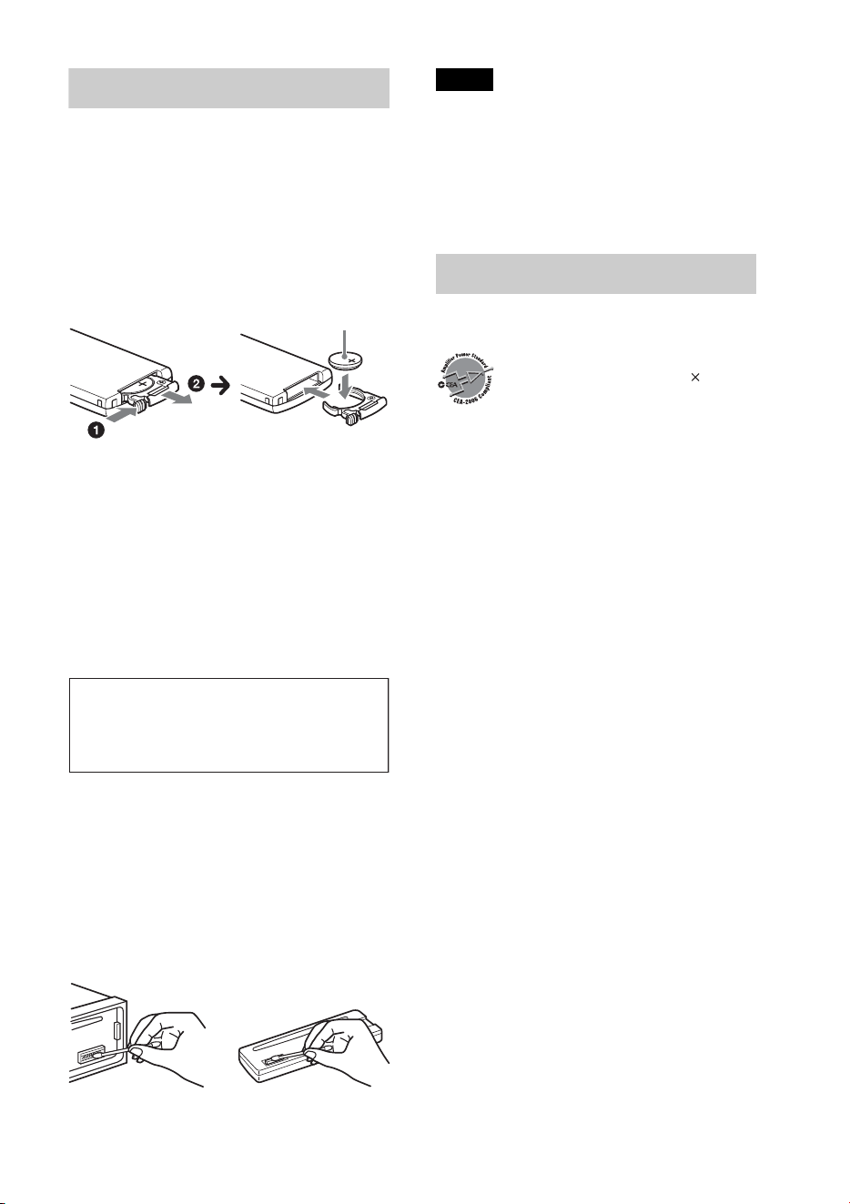
37
Maintenance
Replacing the lithium battery of the
remote commander
When the battery becomes weak, the range
of the remote commander becomes shorter.
Replace the battery with a new CR2025
lithium battery. Use of any other battery
may present a risk of fire or explosion.
Notes on the lithium battery
• Keep the lithium battery out of the reach of
children. Should the battery be swallowed,
immediately consult a doctor.
• Wipe the battery with a dry cloth to assure a
good contact.
• Be sure to observe the correct polarity when
installing the battery.
• Do not hold the battery with metallic tweezers,
otherwise a short-circuit may occur.
Cleaning the connectors
The unit may not function properly if the
connectors between the unit and the front
panel are not clean. In order to prevent this,
detach the front panel (page 7) and clean the
connectors with a cotton swab. Do not apply
too much force. Otherwise, the connectors
may be damaged.
Notes
• For safety, turn off the ignition before cleaning
the connectors, and remove the key from the
ignition switch.
• Never touch the connectors directly with your
fingers or with any metal device.
Specifications
Tuner section
FM
Tuning range: 87.5 – 107.9 MHz
Antenna (aerial) terminal:
External antenna (aerial) connector
Intermediate frequency: 25 kHz
Usable sensitivity: 8 dBf
Selectivity: 75 dB at 400 kHz
Signal-to-noise ratio: 80 dB (stereo)
Separation: 50 dB at 1 kHz
Frequency response: 20 – 15,000 Hz
AM
Tuning range: 530 – 1,710 kHz
Antenna (aerial) terminal:
External antenna (aerial) connector
Intermediate frequency:
9,115 kHz or 9,125 kHz/5 kHz
Sensitivity: 26 μV
CD Player section
Signal-to-noise ratio: 120 dB
Frequency response: 10 – 20,000 Hz
Wow and flutter: Below measurable limit
USB Player section
Interface: USB (Full-speed)
Maximum current: 1 A
Wireless Communication
Communication System:
Bluetooth Standard version 2.1 + EDR
Output:
Bluetooth Standard Power Class 2 (Max. +4
dBm)
+ side up
WARNING
Battery may explode if mistreated.
Do not recharge, disassemble, or dispose
of in fire.
CEA2006 Standard
Power Output: 17 Watts RMS 4 at
4 Ohms < 1% THD+N
SN Ratio: 80 dBA
(reference: 1 Watt into 4 Ohms)
AUDIO POWER SPECIFICATIONS

38
Maximum communication range:
Line of sight approx. 10 m (33 ft)*
1
Frequency band:
2.4 GHz band (2.4000 – 2.4835 GHz)
Modulation method: FHSS
Compatible Bluetooth Profiles*
2
:
A2DP (Advanced Audio Distribution Profile)
1.2
AVRCP (Audio Video Remote Control Profile)
1.3
HFP (Handsfree Profile) 1.5
PBAP (Phone Book Access Profile)
SPP (Serial Port Profile)
*1 The actual range will vary depending on
factors such as obstacles between devices,
magnetic fields around a microwave oven,
static electricity, reception sensitivity, antenna
(aerial)’s performance, operating system,
software application, etc.
*2 Bluetooth standard profiles indicate the
purpose of Bluetooth communication
between devices.
Power amplifier section
Output: Speaker outputs
Speaker impedance: 4 – 8 ohms
Maximum power output: 52 W × 4 (at 4 ohms)
General
Outputs:
Audio outputs terminal (front, rear/sub
switchable)
Power antenna (aerial)/Power amplifier control
terminal (REM OUT)
Inputs:
Remote controller input terminal
Antenna (aerial) input terminal
MIC input terminal
AUX input jack (stereo mini jack)
USB port
Power requirements: 12 V DC car battery
(negative ground (earth))
Dimensions: Approx. 178 × 50 × 177 mm
(7
1
/8 × 2 × 7 in) (w/h/d)
Mounting dimensions: Approx. 182 × 53 × 160 mm
(7
1
/4 × 2
1
/8 × 6
5
/16 in) (w/h/d)
Mass: Approx. 1.2 kg (2 lb 11 oz)
Supplied accessories:
Remote commander: RM-X231
Parts for installation and connections (1 set)
Optional accessories/equipment:
Microphone: XA-MC10
USB connection cable for iPod: RC-100IP
Your dealer may not handle some of the above
listed accessories. Please ask the dealer for
detailed information.
Design and specifications are subject to change
without notice.
Troubleshooting
The following checklist will help you remedy
problems you may encounter with your unit.
Before going through the checklist below,
check the connection and operating
procedures.
For details on using the fuse and removing the
unit from the dashboard, refer to the
installation/connections manual supplied with
this unit.
If the problem is not solved, visit the support
site on the back cover.
39
General
No power is being supplied to the unit.
Check the connection or fuse.
If the unit is turned off and the display
disappears, the unit cannot be operated with
the remote commander.
–Turn on the unit.
The power antenna (aerial) does not extend.
The power antenna (aerial) does not have a
relay box.
No sound.
The ATT function is activated.
The position of the fader control “FADER” is
not set for a 2-speaker system.
No beep sound.
The beep sound is canceled (page 32).
An optional power amplifier is connected and
you are not using the built-in amplifier.
The contents of the memory have been
erased.
The power supply lead or battery has been
disconnected or not connected properly.
The unit is reset.
– Store again in the memory.
Stored stations and correct time are erased.
The fuse has blown.
Makes noise when the position of the
ignition is switched.
The leads are not matched correctly with the
car’s accessory power connector.
During playback or reception,
demonstration mode starts.
If no operation is performed for 5 minutes
with “DEMO-ON” set, demonstration mode
starts.
– Set “DEMO-OFF” (page 33).
The display disappears from/does not
appear in the display window.
The dimmer is set to “DIM-ON” (page 33).
The display disappears if you press and hold
.
–Press on the unit until the
display appears.
The connectors are dirty (page 37).
The Auto Off function does not operate.
The unit is turned on. The Auto Off function
activates after turning off the unit.
–Turn off the unit.
The operation buttons do not function.
The disc will not eject.
Press and (BACK)/ for
more than 2 seconds.
The contents stored in memory are erased.
For your safety, do not perform the reset
operation while you are driving.
Radio reception
The stations cannot be received.
The sound is hampered by noises.
The connection is not correct.
– Connect an REM OUT lead (blue/white
striped) or accessory power supply lead (red)
to the power supply lead of a car’s antenna
(aerial) booster (only when your car has
built-in radio antenna (aerial) in the rear/
side glass).
– Check the connection of the car antenna
(aerial).
– If the auto antenna (aerial) will not go up,
check the connection of the power antenna
(aerial) control lead.
Preset tuning is not possible.
Store the correct frequency in the memory.
The broadcast signal is too weak.
Automatic tuning is not possible.
The broadcast signal is too weak.
– Perform manual tuning.
RDS
PTY displays “- - - - - - - -.”
The current station is not an RDS station.
RDS data has not been received.
The station does not specify the program type.
CD playback
The disc cannot be loaded.
Another disc is already loaded.
The disc has been forcibly inserted upside
down or in the wrong way.

40
The disc does not play back.
Defective or dirty disc.
The CD-Rs/CD-RWs are not for audio use
(page 35).
MP3/WMA/AAC files cannot be played back.
The disc is incompatible with the MP3/WMA/
AAC format and version. For details on
playable discs and formats, visit the support
site.
MP3/WMA/AAC files take longer to play back
than others.
The following discs take a longer time to start
playback.
– A disc recorded with a complicated tree
structure.
– A disc recorded in Multi Session.
– A disc to which data can be added.
The display items do not scroll.
For discs with very many characters, those may
not scroll.
“AUTO SCR” is set to “OFF.”
– Set “A.SCRL-ON” (page 33).
–Press and hold (SCRL).
The sound skips.
Installation is not correct.
– Install the unit at an angle of less than 45° in
a sturdy part of the car.
Defective or dirty disc.
USB playback
You cannot play back items via a USB hub.
This unit cannot recognize USB devices via a
USB hub.
Cannot play back items.
A USB device does not work.
– Connect it again.
A USB device takes longer to play back.
The USB device contains files with a
complicated tree structure.
The sound is intermittent.
The sound may be intermittent at a high-bit-
rate of more than 320 kbps.
Pandora® connection is not possible.
Shut down Pandora® application on the mobile
device, and then launch again.
Bluetooth function
The connecting device cannot detect this
unit.
Before the pairing is made, set this unit to
pairing standby mode.
While connected to a Bluetooth device, this
unit cannot be detected from another device.
– Disconnect the current connection and
search for this unit from another device.
When the device pairing is made, set the
Bluetooth signal output to on (page 20, 21, 22).
Connection is not possible.
The connection is controlled from one side
(this unit or Bluetooth device), but not both.
– Connect to this unit from a Bluetooth device
or vice versa.
Check the pairing and connection procedures
in the manual of the other device, etc., and
perform the operation again.
The name of the detected device does not
appear.
Depending on the status of the other device, it
may not be possible to obtain the name.
No ringtone.
Adjust the volume by rotating the control dial
while receiving a call.
Depending on the connecting device, the
ringtone may not be sent properly.
– Set “RINGTONE” to “1” (page 20).
The front speakers are not connected to the
unit.
– Connect the front speakers to the unit. The
ringtone is output only from the front
speakers.
The talker’s voice volume is low.
Adjust the volume level.
The talker’s voice cannot be heard.
The front speakers are not connected to the
unit.
– Connect the front speakers to the unit. The
talker’s voice is output only from the front
speakers.

41
A call partner says that the volume is too low
or high.
Adjust the volume accordingly using mic gain
adjustment (page 24).
Echo or noise occurs in phone call
conversations.
Lower the volume.
Set EC/NC Mode to “EC/NC-1” or “EC/NC-2”
(page 24).
If the ambient noise other than the phone call
sound is loud, try reducing this noise.
E.g.: If a window is open and road noise, etc., is
loud, shut the window. If an air conditioner is
loud, lower the air conditioner.
The phone is not connected.
When Bluetooth audio is played, the phone is
not connected even if you press .
– Connect from the phone.
The phone sound quality is poor.
Phone sound quality depends on reception
conditions of cellular phone.
– Move your car to a place where you can
enhance the cellular phone’s signal if the
reception is poor.
The volume of the connected audio device is
low (high).
Volume level will differ depending on the
audio device.
– Adjust the volume of the connected audio
device or this unit.
No sound is heard from the Bluetooth audio
device.
The audio device is paused.
– Cancel pause of the audio device.
The sound skips during playback of a
Bluetooth audio device.
Reduce the distance between the unit and the
Bluetooth audio device.
If the Bluetooth audio device is stored in a case
which interrupts the signal, remove the audio
device from the case during use.
Several Bluetooth devices or other devices
which emit radio waves are in use nearby.
– Turn off the other devices.
– Increase the distance from the other devices.
The playback sound stops momentarily when
the connection between this unit and the
cellular phone is being made. This is not a
malfunction.
The connected Bluetooth audio device
cannot be controlled.
Check that the connected Bluetooth audio
device supports AVRCP.
Some functions do not work.
Check if the connecting device supports the
functions in question.
The name of the other party does not appear
when a call is received.
The calling phone is not set to send the phone
number.
A call is answered unintentionally.
The connecting phone is set to answer a call
automatically.
“AUTO ANS” of this unit is set to “ANS-1” or
“ANS-2” (page 20).
Pairing failed due to time out.
Depending on the connecting device, the time
limit for pairing may be short.
– Try completing the pairing within the time.
Bluetooth function cannot operate.
Turn off the unit by pressing
for more than 2 seconds, then turn the unit on
again.
No sound is output from the car speakers
during handsfree call.
If the sound is output from the cellular phone,
set the cellular phone to output the sound from
the car speakers.
Pandora® connection is not possible.
Shut down the Pandora® application on the
mobile device, and then launch again.
Error displays/Messages
CHECKING
The unit is confirming the connection of a
USB device.
42
– Wait until confirming the connection is
finished.
ERROR
The disc is dirty or inserted upside down.
– Clean or insert the disc correctly.
A blank disc has been inserted.
The disc cannot play due to a problem.
–Insert another disc.
USB device was not automatically recognized.
– Connect it again.
Press to remove the disc.
FAILURE
The connection of speakers/amplifiers is
incorrect.
– See the installation/connections manual of
this model to check the connection.
HUB NO SUPRT (Hubs Not Supported)
USB hub is not supported on this unit.
NO DEV (No Device)
“USB” is selected as source without a USB
device connected. A USB device or a USB cable
has been disconnected during playback.
– Be sure to connect a USB device and USB
cable.
NO DISC
The disc is ejected, or “CD” is selected as the
source without inserting the disc.
NO MUSIC
The disc or USB device does not contain a
music file.
– Insert a music CD in this unit.
– Connect a USB device with a music file in it.
NO NAME
A disc/album/artist/track name is not written
in the track.
NOT FOUND
There is no item beginning with the selected
letter in Alphabet search.
OFFSET
There may be an internal malfunction.
– Check the connection. If the error indication
remains on in the display, consult your
nearest Sony dealer.
OVERLOAD
USB device is overloaded.
– Disconnect the USB device, then change the
source by pressing .
– Indicates that the USB device is out of order,
or an unsupported device is connected.
PUSH EJT (Push Eject)
The disc cannot be ejected.
–Press (eject).
READ
The unit is reading all track and album
information on the disc.
– Wait until reading is complete and playback
starts automatically. Depending on the disc
structure, it may take more than a minute.
USB NO SUPRT (USB Not Supported)
The connected USB device is not supported.
– For details on the compatibility of your USB
device, visit the support site.
“” or “”
During reverse or fast-forward, you have
reached the beginning or the end of the disc
and you cannot go any further.
“”
The character cannot be displayed with the
unit.
For Bluetooth function:
BT BUSY (Bluetooth Busy)
The phonebook and the call history of the
cellular phone are not accessible from this unit.
– Wait for a while, and then try again.
EMPTY
The call history is empty.
ERROR
BT Initialize failed.
Phonebook access failed.
Phonebook content was changed while
accessing the cellular phone.
– Access the phonebook in the cellular phone
again.

43
MEM FAILURE (Memory Failure)
This unit failed to store the contact in the
preset dial.
– Make sure that the number you intend to
store is correct (page 25).
MEMORY BUSY
This unit is storing data.
– Wait until storing has finished.
NO DEV (No Device)
Bluetooth audio source is selected without a
Bluetooth audio device connected. A
Bluetooth audio device has been disconnected
during a call.
– Be sure to connect a Bluetooth audio device.
Bluetooth phone source is selected without a
cellular phone connected. A cellular phone has
been disconnected during a call.
– Be sure to connect a cellular phone.
NO INFO (No Information)
Network name and cellular phone name are
not received with cellular phone connected.
P (preset number) EMPTY
The preset dial is empty.
UNKNOWN
Name or phone number cannot be displayed
when browsing phonebook or call history.
WITHHELD
Phone number is hidden by caller.
For Pandora® operation:
CANNOT SKIP
Skipping tracks on Pandora® is not allowed.
– Wait until the commercial ends.
– Pandora® limits the number of skips allowed
on their service. Wait until the next track
begins, or select another station on the list.
CHK DEV (Check Device)
Pandora® does not start up.
– Start up the Pandora® application and log
into your account.
ERROR
“Thumbs” feedback failed.
– Try “Thumbs Up/Down” again.
Bookmarking failed.
– Try bookmarking again.
NO STATION
There is no station on your Pandora® account.
– Create the station on the mobile device.
NOT ALLOWED
“Thumbs” feedback is not allowed.
– Wait until the commercial ends.
– Some functions, such as Shared Station, do
not permit feedback. Wait until the next
track begins, or select another station on the
list.
Bookmark is not allowed.
– Wait until the commercial ends.
– Select another track or station, then try it
again.
OPEN APP (Open Application)
When connecting via the USB port.
Pandora® does not start up.
– Start up the Pandora® application on iPhone.
OPEN APP (Open Application), PRESS PAUSE
When connecting via the Bluetooth function.
Pandora® does not start up.
– Start up the Pandora® application on the
mobile device, then press (PAUSE).
PAN NO SUPRT (Pandora® Not Supported)
The connected device is not supported.
– For details on the compatibility of the
device, visit the support site.
If these solutions do not help improve the
situation, consult your nearest Sony dealer.
If you take the unit to be repaired because of
CD playback trouble, bring the disc that was
used at the time the problem began.
2
La marca de la palabra y logotipos de
Bluetooth son propiedad de Bluetooth SIG,
Inc. y Sony Corporation posee licencia para
utilizar cualquiera de dichas marcas. Otras
marcas registradas y nombres comerciales
pertenecen a sus respectivos propietarios.
Este producto está protegido por los
derechos de propiedad intelectual de
Microsoft Corporation. Queda prohibido el
uso o la distribución de esta tecnología fuera
de este producto si no se dispone de una
licencia de Microsoft o una división
autorizada de Microsoft.
Android es una marca comercial de Google
Inc. El uso de esta marca comercial está
sujeto a Google Permissions.
BlackBerry® es propiedad de Research In
Motion Limited y está registrada y/o se
utiliza en los EE.UU. y en países de todo el
mundo. Se utiliza bajo licencia de Research
In Motion Limited.
Pandora, el logotipo de Pandora y la imagen
de la marca Pandora son marcas
comerciales o marcas comerciales
registradas de Pandora Media, Inc.,
utilizadas con autorización.
Advertencia: si el encendido del
automóvil no dispone de una
posición ACC
Asegúrese de ajustar la función de
desconexión automática (página 35). La
unidad se apagará completa y
automáticamente en el tiempo establecido
después de apagarla, lo cual evita que se
agote la batería. Si no ajusta la función de
desconexión automática, mantenga
presionado hasta que se
apague la pantalla cada vez que apague el
motor.

3
Tabla de contenidos
Procedimientos iniciales . . . . . . . . . . . . . . . . . . . . . . . . . . . . . . . . . . . . . . . . . . . . .5
Notas sobre la función Bluetooth. . . . . . . . . . . . . . . . . . . . . . . . . . . . . . . . . . . . . . . . . . . . 5
Cancelación del modo DEMO . . . . . . . . . . . . . . . . . . . . . . . . . . . . . . . . . . . . . . . . . . . . . .6
Ajuste del reloj . . . . . . . . . . . . . . . . . . . . . . . . . . . . . . . . . . . . . . . . . . . . . . . . . . . . . . . . . . . 6
Extracción del panel frontal . . . . . . . . . . . . . . . . . . . . . . . . . . . . . . . . . . . . . . . . . . . . . . . . 6
Ubicación de los controles . . . . . . . . . . . . . . . . . . . . . . . . . . . . . . . . . . . . . . . . . . .8
Unidad principal. . . . . . . . . . . . . . . . . . . . . . . . . . . . . . . . . . . . . . . . . . . . . . . . . . . . . . . . . . 8
Control remoto RM-X231. . . . . . . . . . . . . . . . . . . . . . . . . . . . . . . . . . . . . . . . . . . . . . . . .10
Radio . . . . . . . . . . . . . . . . . . . . . . . . . . . . . . . . . . . . . . . . . . . . . . . . . . . . . . . . . . . .12
Almacenamiento y recepción de emisoras . . . . . . . . . . . . . . . . . . . . . . . . . . . . . . . . . . .12
RDS. . . . . . . . . . . . . . . . . . . . . . . . . . . . . . . . . . . . . . . . . . . . . . . . . . . . . . . . . . . . . . . . . . . .12
CD. . . . . . . . . . . . . . . . . . . . . . . . . . . . . . . . . . . . . . . . . . . . . . . . . . . . . . . . . . . . . . .14
Reproducción de un disco. . . . . . . . . . . . . . . . . . . . . . . . . . . . . . . . . . . . . . . . . . . . . . . . .14
Dispositivos USB . . . . . . . . . . . . . . . . . . . . . . . . . . . . . . . . . . . . . . . . . . . . . . . . . .14
Reproducción de un dispositivo USB . . . . . . . . . . . . . . . . . . . . . . . . . . . . . . . . . . . . . . .14
iPod. . . . . . . . . . . . . . . . . . . . . . . . . . . . . . . . . . . . . . . . . . . . . . . . . . . . . . . . . . . . . .15
Reproducción de un iPod . . . . . . . . . . . . . . . . . . . . . . . . . . . . . . . . . . . . . . . . . . . . . . . . .15
Utilización directa del iPod — Control de pasajero . . . . . . . . . . . . . . . . . . . . . . . . . . . 16
Pandora® via USB (iPhone). . . . . . . . . . . . . . . . . . . . . . . . . . . . . . . . . . . . . . . . . .17
Transmisión de Pandora® . . . . . . . . . . . . . . . . . . . . . . . . . . . . . . . . . . . . . . . . . . . . . . . . .17
Búsqueda y reproducción de pistas . . . . . . . . . . . . . . . . . . . . . . . . . . . . . . . . . . .18
Reproducción de pistas en varios modos . . . . . . . . . . . . . . . . . . . . . . . . . . . . . . . . . . . .18
Búsqueda de una pista por nombre — Quick-BrowZer™ . . . . . . . . . . . . . . . . . . . . . .19
Búsqueda de una pista mediante la escucha de fragmentos de pista
— ZAPPIN™ . . . . . . . . . . . . . . . . . . . . . . . . . . . . . . . . . . . . . . . . . . . . . . . . . . . . . . . . . . . . 20
Conexión de dispositivos Bluetooth . . . . . . . . . . . . . . . . . . . . . . . . . . . . . . . . . .21
Operaciones Bluetooth . . . . . . . . . . . . . . . . . . . . . . . . . . . . . . . . . . . . . . . . . . . . . . . . . . .21
Emparejamiento . . . . . . . . . . . . . . . . . . . . . . . . . . . . . . . . . . . . . . . . . . . . . . . . . . . . . . . . .22
Conexión . . . . . . . . . . . . . . . . . . . . . . . . . . . . . . . . . . . . . . . . . . . . . . . . . . . . . . . . . . . . . . . 23
Realización de llamadas con manos libres . . . . . . . . . . . . . . . . . . . . . . . . . . . . . . . . . . .25
Transmisión de música . . . . . . . . . . . . . . . . . . . . . . . . . . . . . . . . . . . . . . . . . . . . . . . . . . .28
Inicialización de los ajustes Bluetooth. . . . . . . . . . . . . . . . . . . . . . . . . . . . . . . . . . . . . . .29
La tecnología inalámbrica de Pandora® via Bluetooth
(teléfonos Android™ y BlackBerry®) . . . . . . . . . . . . . . . . . . . . . . . . . . . . . . . . . .30
Transmisión de Pandora® . . . . . . . . . . . . . . . . . . . . . . . . . . . . . . . . . . . . . . . . . . . . . . . . .30

4
Ajustes de sonido y menú de configuración . . . . . . . . . . . . . . . . . . . . . . . . . . . 31
Uso de funciones de sonido sofisticadas — Sistema de sonido avanzado . . . . . . . . . 31
Ajuste de los elementos de configuración . . . . . . . . . . . . . . . . . . . . . . . . . . . . . . . . . . . 34
Uso de equipo opcional. . . . . . . . . . . . . . . . . . . . . . . . . . . . . . . . . . . . . . . . . . . . . 37
Equipo de audio auxiliar . . . . . . . . . . . . . . . . . . . . . . . . . . . . . . . . . . . . . . . . . . . . . . . . . . 37
Información complementaria . . . . . . . . . . . . . . . . . . . . . . . . . . . . . . . . . . . . . . . 38
Precauciones . . . . . . . . . . . . . . . . . . . . . . . . . . . . . . . . . . . . . . . . . . . . . . . . . . . . . . . . . . . . 38
Mantenimiento. . . . . . . . . . . . . . . . . . . . . . . . . . . . . . . . . . . . . . . . . . . . . . . . . . . . . . . . . .41
Especificaciones . . . . . . . . . . . . . . . . . . . . . . . . . . . . . . . . . . . . . . . . . . . . . . . . . . . . . . . . . 41
Solución de problemas . . . . . . . . . . . . . . . . . . . . . . . . . . . . . . . . . . . . . . . . . . . . . . . . . . . 42

5
Procedimientos
iniciales
Notas sobre la función
Bluetooth
Precaución
SONY NO SERÁ RESPONSABLE DE
NINGÚN DAÑO INCIDENTAL,
INDIRECTO O DERIVADO NI DE OTROS
DAÑOS INCLUYENDO, SIN LÍMITES,
PÉRDIDA DE GANANCIAS, PÉRDIDA DE
INGRESOS, PÉRDIDA DE DATOS,
PÉRDIDA DE LA UTILIDAD DEL
PRODUCTO O DE CUALQUIER EQUIPO
RELACIONADO, TIEMPO DE
INACTIVIDAD Y TIEMPO DEL
COMPRADOR RELACIONADO CON LA
UTILIZACIÓN DE ESTE PRODUCTO, SU
HARDWARE Y SU SOFTWARE, O QUE
RESULTE DE DICHA UTILIZACIÓN.
AVISO IMPORTANTE
Utilización segura y eficaz
Los cambios o las modificaciones que se
realicen en esta unidad sin la aprobación de
Sony pueden anular la autorización del
usuario para utilizar el equipo.
Revise las excepciones, debido a requisitos
nacionales o limitaciones, en cuanto a la
utilización de los equipos Bluetooth antes de
utilizar el producto.
Manejo
Consulte las leyes y las normas acerca de la
utilización de teléfonos celulares y equipos de
manos libres en las áreas en las que maneja.
Preste siempre atención a la carretera y
estacione el automóvil antes de realizar o
contestar una llamada si las condiciones lo
requieren.
Conexión a otros dispositivos
Al conectar el equipo a cualquier otro
dispositivo, lea el manual de instrucciones
correspondiente para obtener las instrucciones
de seguridad.
Exposición a radiofrecuencia
Las señales de radiofrecuencia pueden afectar
los sistemas electrónicos que no hayan sido
instalados o protegidos correctamente en
automóviles, como los sistemas electrónicos de
inyección de combustible, sistemas
electrónicos de frenado antideslizante
(antibloqueo), sistemas electrónicos de control
de velocidad o sistemas de airbag. Para la
instalación o el mantenimiento de este
dispositivo, consulte al fabricante de su
automóvil o su representante. La instalación o
el mantenimiento incorrectos podrían ser
peligrosos e invalidar cualquier garantía
aplicada a este dispositivo.
Consulte con el fabricante de su automóvil
para asegurarse de que el uso del teléfono
celular en el automóvil no afectará el sistema
electrónico.
Controle regularmente que todos los equipos
del dispositivo inalámbrico de su automóvil
estén instalados y funcionen correctamente.
Llamadas de emergencia
El dispositivo de manos libres Bluetooth para
automóviles y el dispositivo electrónico
conectados al manos libres funcionan
utilizando redes de señales de radio, celulares y
terrestres así como también la función
programada por el usuario, que no pueden
garantizar la conexión en todas las
condiciones.
Por lo tanto, no dependa únicamente de un
dispositivo electrónico para las
comunicaciones esenciales (como las
emergencias médicas).
Recuerde que, para realizar o recibir llamadas,
el dispositivo de manos libres y el dispositivo
electrónico conectado al manos libres deben
operar en una zona de servicio que tenga una
intensidad de señal para celulares adecuada.
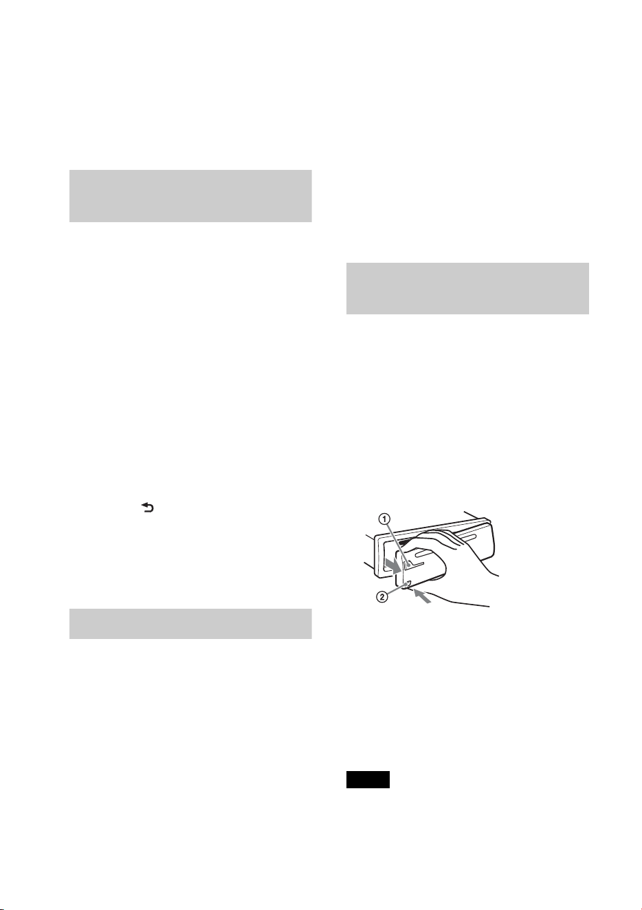
6
Es posible que no se puedan realizar llamadas
de emergencia en todas las redes de teléfonos
celulares o cuando se estén utilizando ciertos
servicios de la red y características del teléfono.
Verifíquelo con su proveedor de servicio local.
Cancelación del modo
DEMO
Puede cancelar la pantalla de demostración
que aparece mientras la unidad está
apagada.
1 Presione y gire el selector de
control hasta que aparezca
“DISPLAY”; luego, presiónelo.
2 Gire el selector de control hasta que
aparezca “DEMO” y, a continuación,
presiónelo.
3 Gire el selector de control para
seleccionar “DEMO-OFF” y, a
continuación, presiónelo.
El ajuste finalizó.
4 Presione (BACK) para volver a la
pantalla anterior.
La pantalla vuelve al modo de recepción/
reproducción normal.
Ajuste del reloj
El reloj emplea una indicación digital de 12
horas.
1 Presione y gire el selector de
control hasta que aparezca
“GENERAL”; luego, presiónelo.
2 Gire el selector de control hasta que
aparezca “CLOCK-ADJ” y, a
continuación, presiónelo.
La indicación de la hora parpadea.
3 Gire el selector de control para ajustar
la hora y los minutos.
Para mover la indicación digital,
presione +/–.
4 Una vez ajustados los minutos,
presione .
El ajuste se completa y el reloj se pone en
funcionamiento.
Presione para que aparezca el reloj.
Extracción del panel
frontal
Es posible extraer el panel frontal de la
unidad para evitar que lo roben.
1 Mantenga presionado
.
La unidad se apagará.
2 Presione el botón de liberación del
panel frontal y, a continuación,
extraiga el panel tirando de él hacia
usted.
Alarma de precaución
Si gira el interruptor de la llave de
encendido hasta la posición OFF sin haber
extraído el panel frontal, la alarma de
precaución sonará durante unos segundos.
La alarma sonará solamente si se utiliza el
amplificador incorporado.
Nota
No someta el panel frontal al calor ni a
temperaturas altas o excesiva humedad. Evite
dejarlo en un automóvil estacionado o sobre el
tablero o la bandeja trasera.
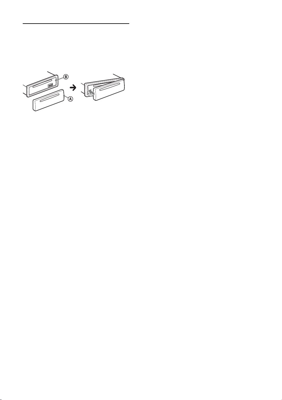
7
Colocación del panel frontal
Fije la parte del panel frontal en la parte
de la unidad, tal como muestra la
ilustración, y presione el lado izquierdo
hasta que encaje.
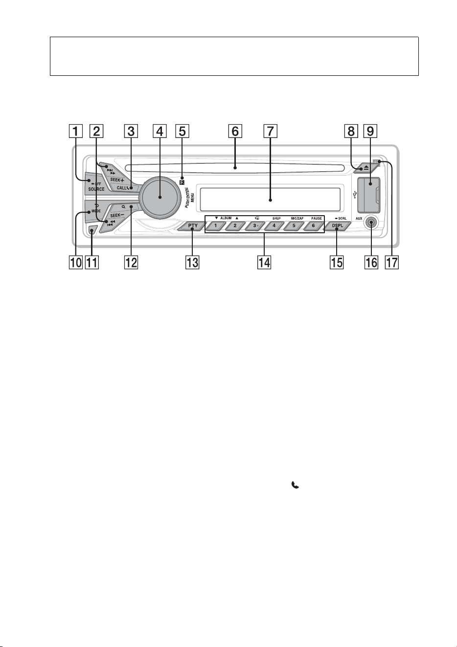
8
Ubicación de los controles
Unidad principal
Este apartado contiene instrucciones acerca
de la ubicación de los controles y las
operaciones básicas.
Botón SOURCE/OFF*
1
Presione para encender la unidad;
seleccione la fuente (Radio/CD/USB/
Pandora® via USB/AUX/audio
Bluetooth/Pandora® Bluetooth/teléfono
Bluetooth).
Presione repetidamente para cambiar a
otra fuente.
Manténgalo presionado durante 1
segundo para apagar la unidad.
Manténgalo presionado durante más de
2 segundos para apagar la unidad y la
pantalla desaparece.
Botones SEEK +/–
Radio:
Para sintonizar emisoras en forma
automática (presionar); para localizar
una emisora en forma manual
(mantener presionado).
CD/USB:
Para saltear una pista (presionar); para
saltear pistas en forma continua
(presionar y volver a presionar al cabo
de 2 segundos y mantener presionado);
para avanzar rápidamente o retroceder
una pista (mantener presionado).
Pandora® via USB/Pandora®
Bluetooth:
Para saltear una pista (presionar
+).
Audio Bluetooth*
2
:
Para saltear una pista (presionar); para
retroceder o avanzar rápidamente una
pista (mantener presionado).
Botón CALL página 21
Para ingresar en el menú de llamada
(presionar); cambiar la señal Bluetooth
(mantener presionado más de 2
segundos); recibir o finalizar una
llamada (presionar).

9
Selector de control/botón ENTER/
MENU página 34
Gire para ajustar el volumen.
Presione para entrar en el modo de
configuración.
Presiónelo para recibir o finalizar una
llamada.
Receptor del control remoto
Ranura del disco
Inserte el disco (con la etiqueta mirando
hacia arriba) y se iniciará la
reproducción.
Visualizador
Botón (Expulsar)
Para expulsar el disco.
Puerto USB página 14, 15, 17
Botón (BACK)/MODE página 12,
16, 18, 27, 31
Presione este botón para volver a la
pantalla anterior o para seleccionar la
banda de radio (FM/AM).
Mantenga presionado para acceder o
cancelar el control de pasajero (iPod);
ingresar en el modo favoritos (Pandora®
via USB/Pandora® Bluetooth).
Presione para activar/desactivar el
dispositivo adecuado (esta unidad/
teléfono celular) (teléfono Bluetooth).
Botón de liberación del panel
frontal página 6
Botón (BROWSE) página 17, 19, 31
Para acceder al modo Quick-BrowZer™
(CD/USB); visualizar la emisora
(Pandora® via USB/Pandora®
Bluetooth).
Botón PTY (tipos de programa)
página 13
Para seleccionar PTY en RDS.
Botones numéricos
Radio:
Para recibir las emisoras almacenadas
(presionar); para almacenar emisoras
(mantener presionado).
CD/USB:
/: ALBUM / (durante la
reproducción de MP3/WMA/AAC)
Para saltear un álbum (presionar);
saltear álbumes continuamente
(mantener presionado).
: (Repetir)*
3
página 18
: SHUF página 18
: ZAP página 20
: PAUSE
Para pausar la reproducción.
Presiónelo nuevamente para
reanudar la reproducción.
Pandora® via USB/Pandora®
Bluetooth:
/: Pulgares abajo ()/arriba
() (mantenga presionado durante 1
segundo) página 17, 30
: PAUSE
Para pausar la reproducción.
Presiónelo nuevamente para
reanudar la reproducción.
Audio Bluetooth*
2
:
/: ALBUM /
: (Repetir)*
3
página 29
: SHUF página 29
: PAUSE
Para pausar la reproducción.
Presiónelo nuevamente para
reanudar la reproducción.
Teléfono Bluetooth: página 26, 27
Para llamar a un número de teléfono
almacenado (presionar); para
almacenar un número de teléfono como
valor predefinido (mantener
presionado) (en el menú de llamada).
: MIC (durante una llamada)
página 27
Para ajustar la ganancia de MIC
(presionar); para seleccionar el
modo de cancelacion de eco/ruido
(mantener presionado).
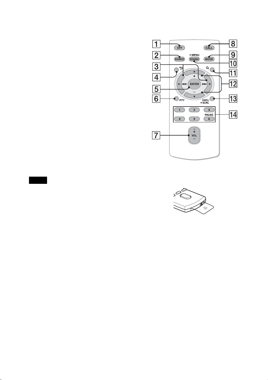
10
Botón DSPL (Pantalla)/SCRL
(Desplazamiento) página 12, 14, 15,
16, 17, 24, 28, 30
Para cambiar los elementos de pantalla
(presionar); para desplazar un elemento
de la pantalla (mantener presionado).
Toma de entrada AUX página 37
Micrófono (en el panel interior)
Para hacer que la función manos libres
funcione correctamente, no debe cubrir
el micrófono con cinta, etc.
*1 Dependiendo del dispositivo conectado al
puerto USB, es posible que Bluetooth
Pandora® no esté disponible.
*2 Cuando se conecta un dispositivo de audio
Bluetooth (compatible con AVRCP de la
tecnología Bluetooth). Según el dispositivo, es
posible que algunas funciones no estén
disponibles.
*3 Este botón tiene un punto sensible al tacto.
Nota
Si la unidad está apagada y desaparece la
indicación de pantalla, no se podrá utilizar con el
control remoto salvo que se presione
en la unidad o se inserte
primero un disco para activarla.
Control remoto RM-X231
Retire la película de aislamiento antes de
usar la unidad.
Botón OFF
Para apagar la alimentación; para
detener la fuente y para rechazar una
llamada.
Botón SOURCE*
1
Presione para encender la unidad.
Presione repetidamente para cambiar a
otra fuente (Radio/CD/USB/Pandora®
via USB/AUX/audio Bluetooth/
Pandora® Bluetooth/teléfono
Bluetooth).
Botones ()/ ()
Para controlar la Radio/CD/USB/
Pandora® via USB/audio Bluetooth/
Pandora® Bluetooth, de la misma
manera que con +/– en la
unidad.
Es posible ajustar los elementos
mediante .

11
Botón (BACK)
Para volver a la pantalla anterior.
Botón ENTER
Para aplicar un ajuste; para recibir una
llamada y para finalizar una llamada.
Botón PTY (tipos de programa)
Botón VOL (volumen) +*
2
/–
Botón CALL
Para acceder al menú de llamada.
Para recibir o finalizar una llamada.
Botón MODE
Presione este botón para seleccionar la
banda de radio (FM/AM).
Mantenga presionado para acceder o
cancelar el control de pasajero (iPod);
ingresar en el modo favoritos (Pandora®
via USB/Pandora® Bluetooth).
Presione para activar/desactivar el
dispositivo adecuado (esta unidad/
teléfono celular) (teléfono Bluetooth).
Botón SOUND/MENU
Para acceder al menú SOUND
directamente (presionar); para acceder
al menú de configuración (mantener
presionado).
Botón (BROWSE)
Botones (+)/ (–)
Para controlar el dispositivo de CD/
USB/Pandora® via USB/audio
Bluetooth/Pandora® Bluetooth, de la
misma manera que con /
(ALBUM /) en la unidad.
Es posible ajustar los elementos
mediante .
Botón DSPL (Pantalla)/SCRL
(Desplazamiento)
Botones numéricos
Para recibir las emisoras almacenadas
(presionar); para almacenar emisoras
(mantener presionado).
Para llamar a un número de teléfono
almacenado (presionar); para
almacenar un número de teléfono como
valor predefinido (mantener
presionado) (en el menú de llamada)
(teléfono Bluetooth).
Para pausar la reproducción (presionar
).
*1 Dependiendo del dispositivo conectado al
puerto USB, es posible que Bluetooth
Pandora® no esté disponible.
*2 Este botón tiene un punto sensible al tacto.

12
Radio
Almacenamiento y
recepción de emisoras
Precaución
Para sintonizar emisoras mientras maneja,
utilice la función BTM (Memoria de la
mejor sintonía) para evitar accidentes.
Almacenamiento automático
— BTM
1 Presione varias veces
hasta que aparezca “TUNER”.
Para cambiar de banda, presione
varias veces. Puede seleccionar
entre FM1, FM2, FM3, AM1 y AM2.
2 Presione y gire el selector de
control hasta que aparezca
“GENERAL”; luego, presiónelo.
3 Gire el selector de control hasta que
aparezca “BTM” y, a continuación,
presiónelo.
La unidad almacena las emisoras en el
orden de frecuencia en los botones
numéricos.
Almacenamiento manual
1 Mientras recibe la emisora que desea
almacenar, mantenga presionado un
botón numérico (de a ) hasta
que aparezca “MEM”.
Recepción de las emisoras
almacenadas
1 Seleccione la banda y, a continuación,
presione un botón numérico (de a
).
Sintonización automática
1 Seleccione la banda y, a continuación,
presione +/– para buscar la
emisora.
La búsqueda se detiene cuando la unidad
recibe una emisora. Repita este
procedimiento hasta recibir la emisora
deseada.
Sugerencia
Si conoce la frecuencia de la emisora que desea
escuchar, mantenga presionado +/–
para localizar la frecuencia aproximada y, a
continuación, presione +/– varias veces
para ajustar la frecuencia deseada con mayor
precisión (sintonización manual).
RDS
Las emisoras de radio FM que tienen el
servicio de Sistema de datos de radio (RDS)
envían información digital inaudible junto a
la señal habitual del programa de radio.
Notas
• Dependiendo del país o la región, puede que no
estén disponibles todas las funciones RDS.
• RDS no funcionará si la intensidad de la señal es
muy débil o si la emisora que sintonizó no
transmite datos RDS.
Cambio de elementos de pantalla
Presione .

13
Selección de PTY (Tipos de
programa)
Usar PTY para mostrar o buscar el tipo de
programa deseado.
1 Presione durante la recepción
de FM.
Si la estación está transmitiendo datos
PTY, aparece el nombre del tipo de
programa actual.
2 Gire el selector de control hasta que
aparezca el tipo de programa deseado
y, a continuación, presiónelo.
La unidad comienza a buscar una
estación que emita el tipo de programa
seleccionado.
Tipos de programas
Nota
Puede recibir un programa de radio distinto del
que seleccionó.
Ajuste de CT (Hora del reloj)
Los datos CT de la transmisión RDS ajustan
el reloj.
1 Ajuste “CT-ON” en la configuración
(página 35).
Nota
Puede que la función CT no funcione
adecuadamente a pesar de que se reciba una
emisora RDS.
NEWS (Noticias), INFORM (Información),
SPORTS (Deportes), TALK (Conversación),
ROCK (Rock), CLS ROCK (Rock clásico),
ADLT HIT (Éxitos para el adulto), SOFT
RCK (Rock suave), TOP 40 (Top 40),
COUNTRY (Country), OLDIES (Oldies),
SOFT (Lentos), NOSTALGA (Nostalgia),
JAZZ (Jazz), CLASSICL (Clásico), R AND B
(R&B), SOFT R B (R&B suave),
LANGUAGE (Idiomas extranjeros), REL
MUSC (Música religiosa), REL TALK
(Conversación religiosa), PERSNLTY
(Personalidad), PUBLIC (Público),
COLLEGE (Universidad), WEATHER
(Tiempo)
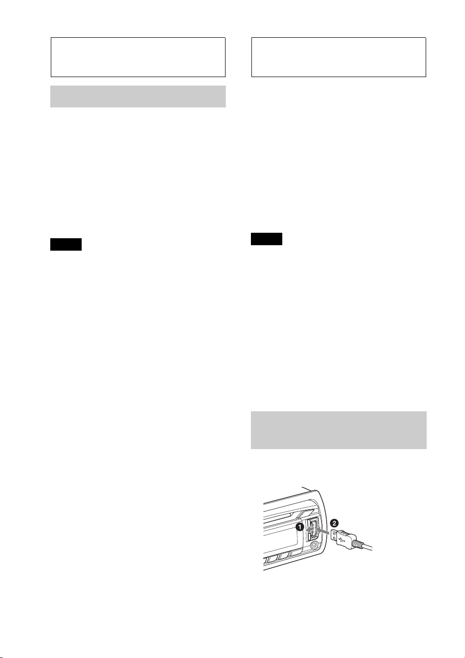
14
CD
Reproducción de un disco
Esta unidad permite reproducir discos CD-
DA (incluidos CD TEXT) y CD-R/CD-RW
(archivos MP3/WMA/AAC (página 38)).
1 Inserte el disco (con la etiqueta
orientada hacia arriba).
La reproducción se inicia
automáticamente.
Para expulsar el disco, presione .
Notas
• Al expulsar o insertar un disco, mantenga
desconectado cualquier dispositivo USB para
evitar dañar el disco.
• Los códecs correspondientes son MP3 (.mp3),
WMA (.wma) y AAC (.m4a).
Cambio de elementos de pantalla
Presione .
Es posible que los elementos que se
muestren varíen en función del tipo de
disco, el formato de grabación y los ajustes.
Dispositivos USB
• Es posible utilizar dispositivos USB de
almacenamiento masivo (MSC) (como
una unidad flash USB, un reproductor
multimedia digital, un teléfono Android)
que cumplan con el estándar de USB.
Según el reproductor multimedia digital o
el teléfono Android, se requiere que se le
ajuste el modo de conexión USB a MSC.
• Se recomienda realizar una copia de
seguridad de los datos almacenados en los
dispositivos USB.
Notas
• Conecte el dispositivo USB después de arrancar
el motor.
En función del tipo de dispositivo USB, si lo
conecta antes de arrancar el motor, es posible
que este no funcione correctamente o que se
dañe.
• Los códecs correspondientes son MP3 (.mp3),
WMA (.wma), AAC (.m4a) y AAC (.mp4).
• Para obtener más información acerca de la
compatibilidad del dispositivo USB, visite el
sitio web de soporte técnico que figura en la
cubierta posterior.
Reproducción de un
dispositivo USB
1 Abra la cubierta USB y conecte el
dispositivo USB al puerto USB.
Se inicia la reproducción.
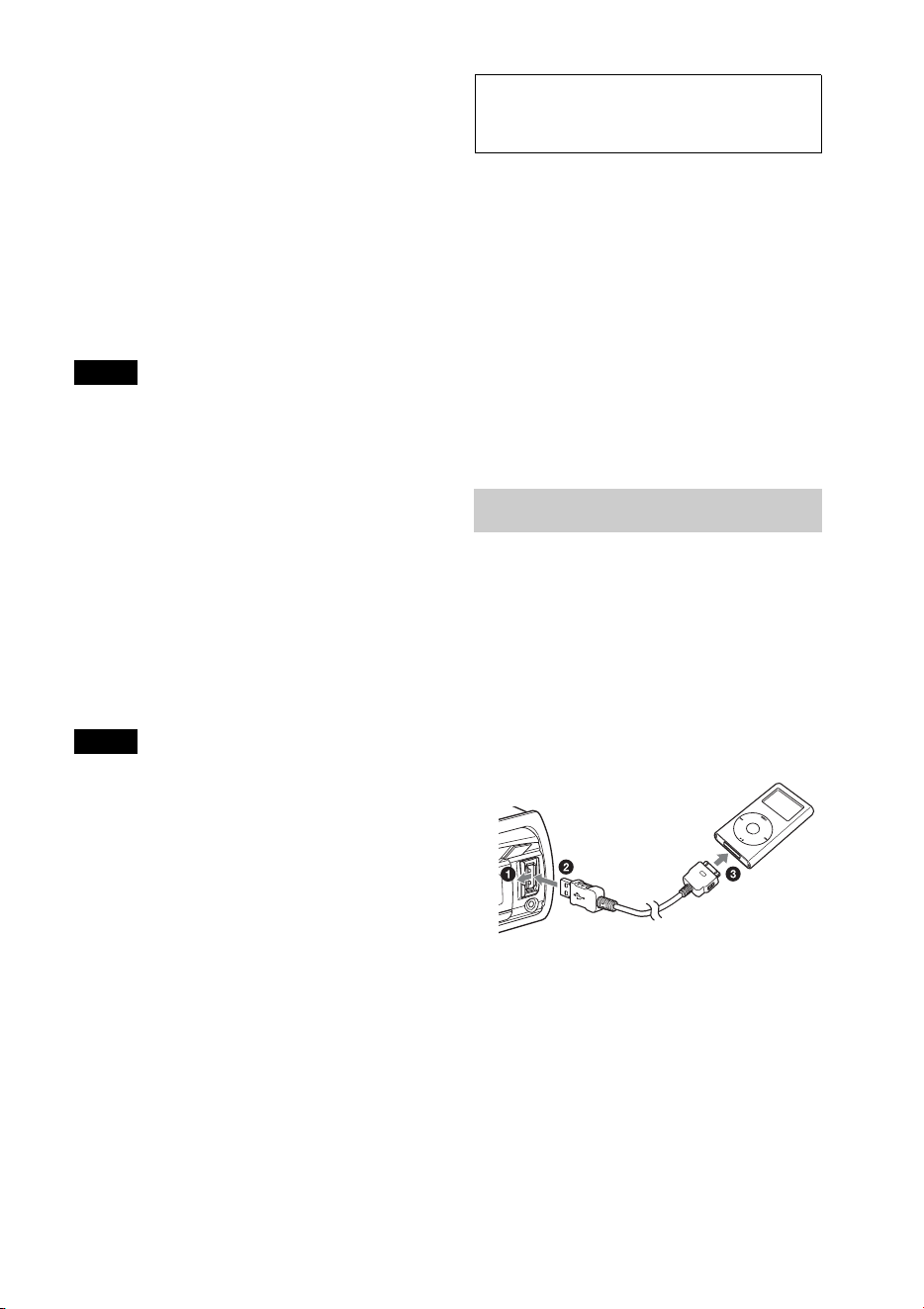
15
Si ya hay un dispositivo USB conectado,
presione varias veces hasta
que aparezca “USB” para empezar la
reproducción.
Para detener la reproducción, mantenga
presionado durante 1
segundo.
Para retirar el dispositivo USB, detenga la
reproducción USB y, a continuación, retire
el dispositivo USB.
Notas
• No utilice dispositivos USB demasiado grandes
o pesados, ya que se podrían caer debido a la
vibración, o bien, provocar una conexión
deficiente.
• No extraiga el panel frontal durante la
reproducción del dispositivo USB, ya que podrá
dañar los datos del USB.
Cambio de elementos de pantalla
Presione .
Los elementos que se muestran podrían
variar en función del tipo de dispositivo
USB, el formato de grabación y los ajustes.
Notas
• La cantidad máxima de pistas es 10 000.
• Es posible que el inicio de la reproducción
demore un poco, en función de la cantidad de
datos grabados.
• Durante la reproducción de un archivo MP3/
WMA/AAC de VBR (Velocidad de bits
variable) o al avanzar o retroceder rápidamente,
es posible que el tiempo de reproducción
transcurrido no se muestre con precisión.
• No es posible reproducir los archivos MP3/
WMA/AAC que se indican a continuación.
– archivos con formato de compresión sin
pérdida
– archivos protegidos por derechos de autor
– archivos DRM (Gestión de derechos
digitales)
– archivos de audio de canales múltiples
iPod
En este Manual de instrucciones, “iPod” se
utiliza como referencia general para las
funciones del iPod en el iPod y el iPhone, a
menos que se especifique lo contrario en el
texto o en las ilustraciones.
Para obtener más información acerca de la
compatibilidad de su iPod, consulte “Acerca
de iPod” (página 39) o visite el sitio web de
soporte técnico que figura en la cubierta
posterior.
Reproducción de un iPod
Antes de conectar el iPod, baje el volumen
de la unidad.
1 Abra la cubierta USB y, a continuación,
conecte el iPod al puerto USB con el
cable de conexión USB para el iPod (no
suministrado)*.
* Se recomienda el uso del cable de conexión
USB RC-100IP para iPod.
Las pistas del iPod empiezan a
reproducirse automáticamente a partir
del punto en el que se detuvo la última
reproducción.
Si ya hay un iPod conectado, presione
varias veces hasta que
aparezca “USB” para empezar la
reproducción. (“IPD” aparecerá en la
pantalla cuando se reconozca el iPod).
16
Para detener la reproducción, mantenga
presionado durante 1
segundo.
Para retirar el iPod, detenga la reproducción
del iPod y, a continuación, retire el iPod.
Precaución para iPhone
Al conectar el iPhone mediante USB, el volumen
de las llamadas telefónicas es controlado por el
iPhone, y no por la unidad. Trate de no subir el
volumen de la unidad durante una llamada sin
darse cuenta, ya que puede producirse un sonido
fuerte y repentino al terminar la llamada.
Nota
No extraiga el panel frontal durante la
reproducción del iPod, ya que podrá dañar los
datos.
Sugerencia
El iPod se recarga mientras la unidad está
encendida.
Modo de reanudación
Cuando el iPod está conectado a la unidad,
se inicia la reproducción en el modo
definido por el iPod. En este modo, no es
posible utilizar los botones siguientes.
– ()
– (SHUF)
Cambio de elementos de pantalla
Presione .
Nota
Es posible que algunos caracteres almacenados en
el iPod no se visualicen correctamente.
Saltear álbumes, podcasts,
géneros, listas de
reproducción y artistas
Utilización directa del
iPod — Control de
pasajero
Puede utilizar directamente un iPod incluso
si está conectado a la unidad.
1 Durante la reproducción, mantenga
presionado .
Aparece “MODE IPOD” y se puede
utilizar el iPod directamente.
Para salir del control de pasajero, mantenga
presionado .
Aparecerá “MODE AUDIO” y no será
posible operar directamente el iPod.
Nota
Sólo es posible ajustar el volumen en la unidad.
Para Realice esta acción
Saltear Presione / (ALBUM
/) [presionar una vez
para saltear cada elemento]
Saltear en
forma continua
Mantenga presionado /
(ALBUM /)
[mantener presionado hasta
llegar al punto deseado]
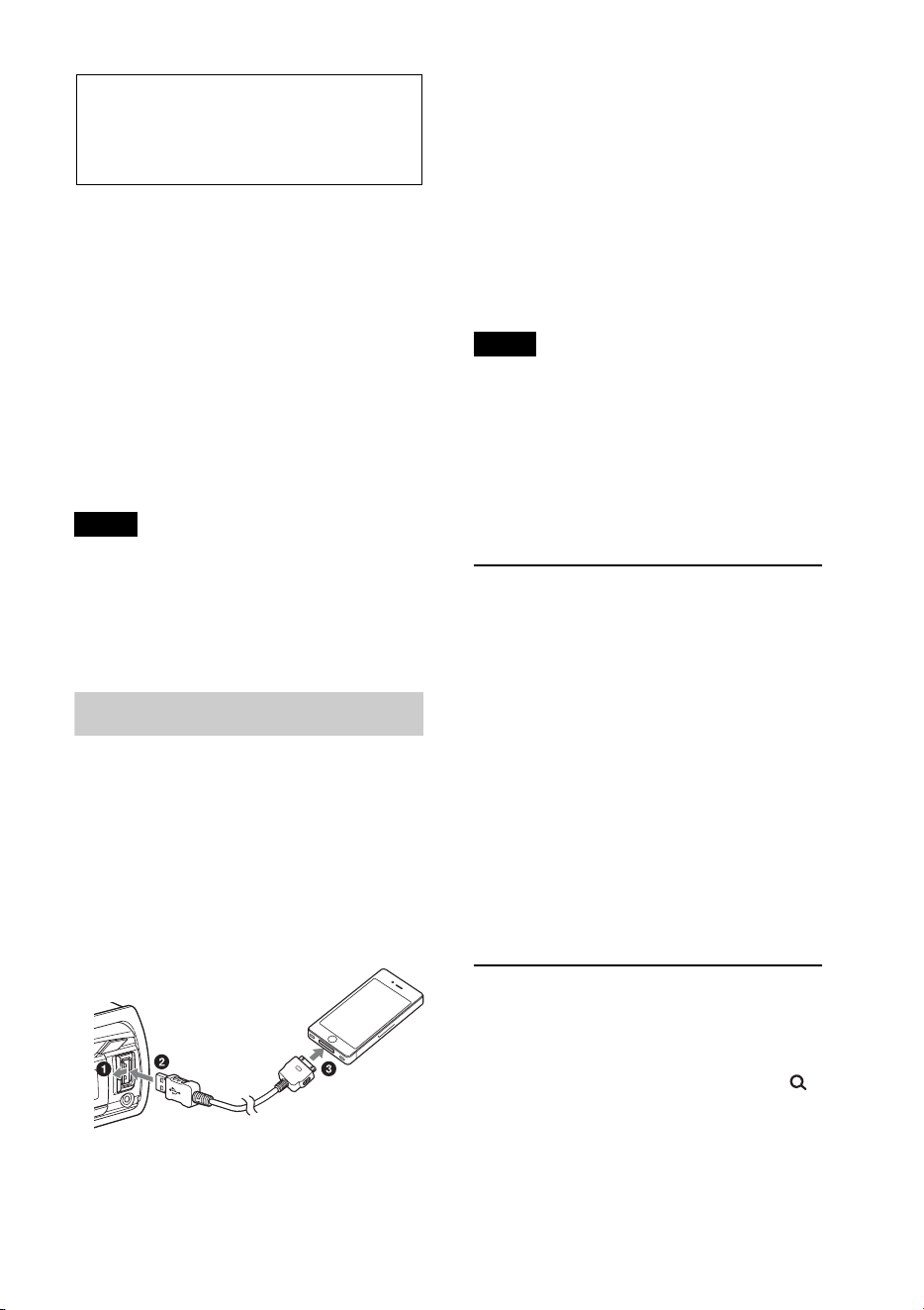
17
Pandora® via USB
(iPhone)
Pandora® está disponible para transmitir
música a través de su iPhone. Puede
controlar Pandora® en un iPhone conectado
a USB desde esta unidad.
Descargue la última versión de la aplicación
Pandora® y obtenga más información en la
página www.pandora.com
Para obtener más información sobre los
dispositivos utilizables, visite el sitio web de
servicio técnico que se indica en la cubierta
posterior.
Notas
• Es posible que ciertas funciones del servicio de
Pandora® no estén disponibles.
• El servicio de Pandora® está disponible
solamente en los Estados Unidos.
Transmisión de Pandora®
Antes de conectar el iPhone, baje el
volumen de la unidad.
1 Abra la cubierta USB y, a continuación,
conecte el iPhone al puerto USB con el
cable de conexión USB para el iPhone
(no suministrado)*.
* Se recomienda el uso del cable de conexión
USB RC-100IP para iPhone.
2 Presione varias veces
hasta que aparezca “PANDORA USB”.
3 Inicie la aplicación Pandora® en el
iPhone.
4 Ajuste el volumen de esta unidad.
Para pausar la reproducción, presione
(PAUSE). Para volver a activar la
reproducción, vuelva a presionarlo.
Para saltear una pista, presione +.
Notas
• No puede volver a la pista anterior.
• Pandora® limita la cantidad de salteos
permitidos.
Cambio de elementos de pantalla
Presione .
Comentarios de “Pulgares”
Los comentarios de “Pulgares arriba” o
“Pulgares abajo” le permiten personalizar
las emisoras para que se ajusten a sus
preferencias.
Pulgares arriba
Durante la reproducción, mantenga
presionado () durante 1 segundo.
Pulgares abajo
Durante la reproducción, mantenga
presionado () durante 1 segundo.
Lista de emisoras
La lista de emisoras le permite seleccionar
con facilidad la emisora deseada.
1 Durante la reproducción, presione
(BROWSE).
2 Presione + para seleccionar el
orden de clasificación “BY DATE” o “A
TO Z”.
18
3 Gire el selector de control para
seleccionar la emisora deseada y, a
continuación, presiónelo.
Se inicia la reproducción.
Shuffle
La opción Shuffle le permite escuchar las
pistas reproducidas en una o más emisoras
Pandora® de su lista de emisoras de forma
aleatoria.
Edite sus selecciones de estaciones Shuffle
en el dispositivo antes de la conexión.
Marcar como favorito
La pista o el artista que está siendo
reproducido puede ser marcado como
favorito y almacenado en su cuenta de
Pandora®.
1 Durante la reproducción, mantenga
presionado hasta que
aparezca “BOOKMARK”.
2 Gire el selector de control para
seleccionar “TRK” (pista) o “ART”
(artista) y, a continuación, presiónelo.
Búsqueda y
reproducción de pistas
Reproducción de pistas
en varios modos
Puede escuchar las pistas repetidamente
(reproducción repetida) o en orden
aleatorio (reproducción aleatoria).
Los modos de reproducción disponibles
varían en función de la fuente de sonido
seleccionada.
1 Durante la reproducción, presione
() o (SHUF) varias veces
hasta que aparezca el modo de
reproducción deseado.
Es posible que la reproducción en el
modo de reproducción seleccionado se
demore en iniciar.
Reproducción repetida
Seleccione Para reproducir
TRACK pistas en forma
repetida.
ALBUM álbumes en forma
repetida.
PODCAST*
1
podcast en forma
repetida.
ARTIST*
1
artistas en forma
repetida.
PLAYLIST*
1
listas de reproducción
en forma repetida.
GENRE*
1
géneros en forma
repetida.
OFF pistas en orden normal
(Reproducción
normal).
19
Reproducción aleatoria
*1 solamente iPod
*2 solamente CD
*3 solamente USB y iPod
Búsqueda de una pista
por nombre — Quick-
BrowZer™
Puede buscar una pista fácilmente en un CD
o dispositivo USB por categoría.
1 Presione (BROWSE)*.
La unidad accede al modo Quick-
BrowZer y aparece la lista de categorías
de búsqueda.
Cuando aparece la lista de pistas,
presione (BACK) repetidamente
hasta que aparezca la categoría de
búsqueda deseada.
* Durante la reproducción USB, presione
(BROWSE) durante más de 2 segundos
para volver directamente al inicio de la lista
de categorías.
2 Gire el selector de control para
seleccionar la categoría de búsqueda
deseada y, a continuación, presiónelo
para confirmarla.
3 Repita el paso 2 hasta que se seleccione
la pista deseada.
Se inicia la reproducción.
Para salir del modo Quick-BrowZer,
presione (BROWSE).
Notas
• Al acceder al modo Quick-BrowZer, se cancela
el ajuste de reproducción repetida/aleatoria.
• “ ” se enciende cuando hay una capa
superior y “ ” se enciende cuando hay una
capa inferior.
Búsqueda por salteo de
elementos — modo de
omisión
Cuando varios elementos se encuentran
dentro de una misma categoría, es posible
encontrar el elemento que desee
rápidamente.
1 Presione + en el modo Quick-
BrowZer.
Aparecerá el nombre del elemento.
2 Gire el selector de control para
seleccionar el elemento que se
encuentra cerca del elemento deseado.
Se realizan saltos en pasos del 10 % de la
cantidad total de elementos presentes en
la lista.
Seleccione Para reproducir
SHUF ALBUM álbumes en orden
aleatorio.
SHUF DISC*
2
discos en orden
aleatorio.
SHUF PODCAST*
1
podcast en orden
aleatorio.
SHUF ARTIST*
1
artistas en orden
aleatorio.
SHUF PLAYLIST*
1
listas de reproducción
en orden aleatorio.
SHUF GENRE*
1
géneros en orden
aleatorio.
SHUF DEVICE*
3
dispositivos en orden
aleatorio.
SHUF OFF pistas en orden normal
(Reproducción
normal).
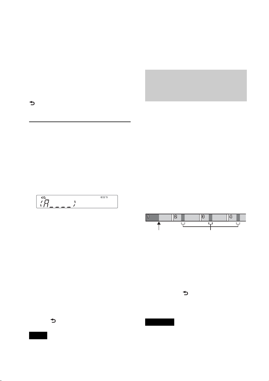
20
3 Presione (ENTER).
Vuelve a la pantalla del modo Quick-
BrowZer y aparece el elemento
seleccionado.
4 Gire el selector de control para
seleccionar el elemento deseado y
presiónelo.
Si el elemento seleccionado es una pista,
empieza la reproducción.
Para cancelar el modo de omisión, presione
(BACK) o –.
Búsqueda por orden
alfabético — Búsqueda
alfabética
Cuando se conecta un iPod a la unidad, es
posible buscar un elemento deseado de
manera alfabética.
1 Presione + en el modo Quick-
BrowZer.
2 Gire el selector de control para
seleccionar la primera letra del
elemento deseado y, a continuación,
presiónelo.
Aparecerá una lista ordenada
alfabéticamente con los elementos que
comienzan con la letra seleccionada.
3 Gire el selector de control para
seleccionar el elemento deseado y, a
continuación, presiónelo.
Si el elemento seleccionado es una pista,
empieza la reproducción.
Para cancelar la Búsqueda alfabética,
presione (BACK) o –.
Notas
• En la Búsqueda alfabética se excluyen los
símbolos y artículos (a/an/the) situados delante
de la letra seleccionada del elemento.
• En función del elemento de búsqueda que
seleccione, es posible que solamente esté
disponible el modo de omisión.
• La Búsqueda alfabética puede tardar un tiempo,
según la cantidad de pistas.
Búsqueda de una pista mediante
la escucha de fragmentos de
pista — ZAPPIN
™
Es posible buscar una pista que desee
escuchar mediante la reproducción de
pequeños fragmentos de pistas de un CD o
dispositivo USB de forma secuencial.
El modo ZAPPIN es adecuado para buscar
pistas en el modo de reproducción aleatoria
o de repetición aleatoria.
1 Presione (ZAP) durante la
reproducción.
La reproducción se iniciará a partir del
fragmento de la pista siguiente. Puede
seleccionar el tiempo de reproducción
(página 35).
2 Presione (ENTER) o
(ZAP) cuando se reproduzca una pista
que desea escuchar.
La pista seleccionada se reproduce
normalmente desde el principio.
Al presionar (BACK) también se
reproducirá nuevamente la pista
seleccionada.
Sugerencias
•Presione +/– en el modo ZAPPIN para
omitir una pista.
•Presione / (ALBUM /) en el modo
ZAPPIN para omitir un álbum.
Partes de cada pista que se
reproducen en el modo
ZAPPIN.
Pista
presionado.

21
Conexión de
dispositivos Bluetooth
Operaciones Bluetooth
La función Bluetooth permite realizar
llamadas con manos libres y la transmisión
continua de música a través de esta unidad.
Para utilizar la función Bluetooth, es
necesario realizar el procedimiento
siguiente.
Emparejamiento
Cuando se conectan dispositivos
Bluetooth por primera vez, se requiere
un registro mutuo. Este proceso se
denomina “emparejamiento”. Es
necesario realizar el registro
(emparejamiento) la primera vez ya que,
una vez emparejados, los dispositivos se
reconocerán entre sí automáticamente.
Conexión
Para utilizar el dispositivo después de
llevar a cabo el emparejamiento, inicie la
conexión. En ocasiones, el
emparejamiento permite establecer la
conexión automáticamente.
Llamadas con manos libres y
transmisión continua de música
Puede realizar o recibir llamadas de
manos libres y escuchar música después
de establecer la conexión.
Si el emparejamiento no es posible, quizá el
dispositivo no sea compatible con esta
unidad. Para obtener más información
sobre los dispositivos compatibles, visite el
sitio web de servicio técnico que se indica en
la cubierta posterior.
Instalación del micrófono
Para mejorar la calidad de audio que se
obtiene al hablar a través de la unidad es
necesario instalar el micrófono (no
suministrado).
Para obtener detalles sobre cómo conectar
el micrófono, consulte el manual
suministrado de “Instalación/Conexiones”.
Operación de las funciones
Bluetooth
1 Presione .
Aparecerá el menú de llamada.
2 Gire el selector de control hasta que
aparezca el elemento deseado y, a
continuación, presiónelo.
3 Presione (BACK)*.
La fuente regresa al teléfono Bluetooth.
* Para el ajuste de PAIRING, REDIAL, VOICE
DIAL y BT SIGNL, el paso 3 no es necesario.
Puede ajustar los elementos siguientes:
PAIRING*
1
(página 22)
PHONEBOOK (página 25)
REDIAL (página 26)
RECENT CALL (página 26)
VOICE DIAL (página 27)
DIAL NUMBER (página 26)
RINGTONE*
1
*
2
Selecciona si esta unidad o el teléfono
celular conectado emite el tono de
llamadas: “1 (esta unidad)”- “2 (teléfono
celular)”.
AUTO ANS*
1
(Respuesta automática)
Ajusta la unidad para que responda
automáticamente una llamada entrante:
“OFF”-“1 (aproximadamente 3
segundos)”-“2 (aproximadamente 10
segundos)”.
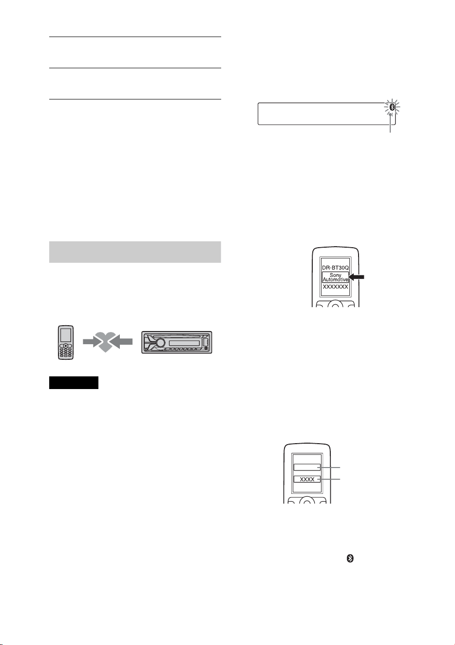
22
*1 También puede seleccionar estos elementos al
presionar y girar el selector de
control para seleccionar “BT”.
*2 En función del teléfono celular, es posible que
el tono de llamada de esta unidad se emita
incluso si se configura en “2 (teléfono
celular)”.
*3 Aparece en el menú de configuración cuando
la unidad está apagada.
Emparejamiento
El dispositivo Bluetooth (teléfono celular,
dispositivo de audio, etc.) y esta unidad
deben “emparejarse” antes de utilizarse
entre sí mediante la función Bluetooth.
Sugerencias
• Para obtener más información acerca de cómo
emparejar un dispositivo Bluetooth, consultar
las instrucciones de funcionamiento que se
suministran con el dispositivo.
• Puede emparejar hasta 9 dispositivos Bluetooth
con esta unidad.
1 Coloque el dispositivo Bluetooth a una
distancia máxima de 1 metro respecto
de la unidad.
2 Presione y gire el selector de
control hasta que aparezca
“PAIRING”; luego, presione sobre él.
La unidad entrará en modo de espera de
emparejamiento.
3 Configure el dispositivo Bluetooth
para buscar esta unidad.
Aparece una lista de los dispositivos
detectados en la pantalla del dispositivo
que desea conectar. La unidad se
muestra como “Sony Automotive” en el
dispositivo que se va a conectar.
4 Si se requiere una clave* en la pantalla
del dispositivo que se desea conectar,
introduzca “0000”.
Si el dispositivo admite la versión
Bluetooth 2.1, no se requiere la
introducción de una clave.
* La clave de paso puede denominarse “clave
de acceso”, “código PIN”, “número PIN” o
“contraseña”, etc. en función del dispositivo.
Esta unidad y el dispositivo Bluetooth
memorizan mutuamente la información
y, cuando se realiza el emparejamiento,
permanece encendido .
BT SIGNL*
1
(Señal Bluetooth) (página 23,
24)
BT INIT*
3
(Inicialización de Bluetooth)
(página 29)
Parpadea
Introduzca la clave
“0000”
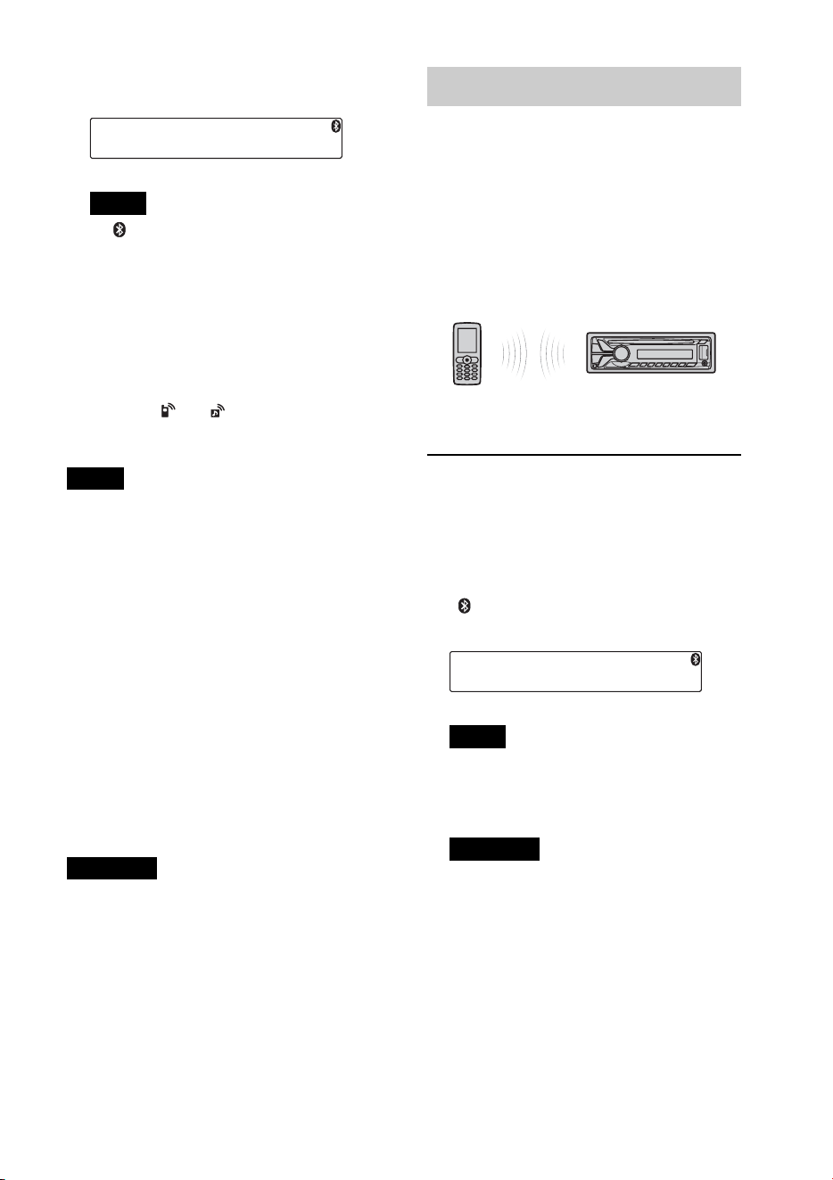
23
La unidad está lista para ser conectada al
dispositivo.
Nota
Si “ ” continúa parpadeando, es posible que
el dispositivo Bluetooth no sea compatible
con esta unidad. Para obtener más
información sobre los dispositivos
compatibles, visite el sitio web de servicio
técnico que se indica en la cubierta posterior.
5 Seleccione esta unidad en el dispositivo
Bluetooth que desea conectar.
Aparece “ ” o “ ” cuando la conexión
está establecida.
Notas
• Mientras se conecta a un dispositivo Bluetooth,
esta unidad no puede detectarse desde otro
dispositivo. Para habilitar la detección, acceda
al modo de emparejamiento y busque esta
unidad desde otro dispositivo.
• Es posible que la búsqueda o la conexión
demore un poco.
• Según el dispositivo, la pantalla de
confirmación de la conexión aparece antes de
introducir la clave.
• El plazo para introducir la clave varía según el
dispositivo. Si el tiempo se agota, realice
nuevamente el procedimiento de
emparejamiento, desde el principio.
• Esta unidad no puede conectarse a un
dispositivo compatible solamente con HSP
(Head Set Profile).
Sugerencia
La conexión entre esta unidad y el dispositivo
Bluetooth podría ser automática, según el
dispositivo.
Cancelación del emparejamiento
Realizar el paso 2 para cancelar el modo de
emparejamiento luego de que esta unidad y
el dispositivo Bluetooth estén emparejados.
Conexión
Para utilizar el dispositivo después de llevar
a cabo el emparejamiento, inicie la
conexión. En ocasiones, el emparejamiento
permite establecer la conexión
automáticamente.
Si ha conseguido realizar el
emparejamiento, inicie la operación a partir
de este punto.
Conexión de un teléfono
celular
1 Presione y gire el selector de
control hasta que aparezca “BT
SIGNL”; luego, presiónelo.
“ ” se enciende cuando se activa la
señal Bluetooth.
Nota
Cuando la señal Bluetooth de esta unidad ya
está encendida (ON), seleccionar “BT SIGNL”
desactiva la señal Bluetooth.
Sugerencia
También puede extraer la señal Bluetooth de
esta unidad manteniendo presionado
en esta unidad durante más de 2 segundos.
2 Encienda el teléfono celular y active la
señal Bluetooth.
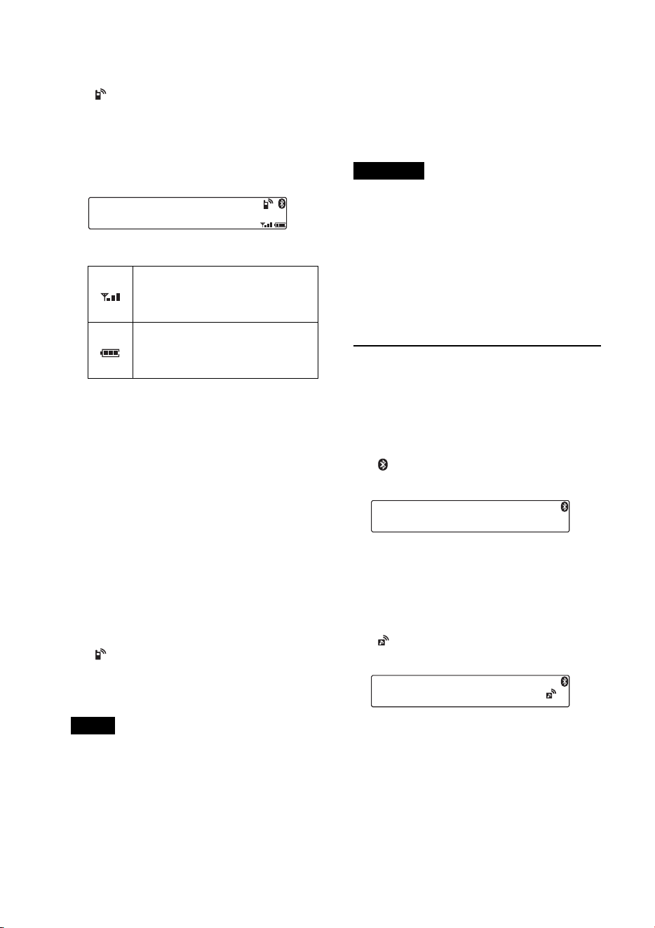
24
3 Realice la conexión a esta unidad
mediante el teléfono celular.
“ ” aparece cuando la conexión está
establecida. Si selecciona una fuente de
teléfono Bluetooth una vez que se
estableció la conexión, los nombres de la
red y del teléfono celular conectado
también aparecen en la pantalla.
Íconos en la pantalla:
* Se apaga si no existe conexión con manos
libres. Difiere en función del teléfono
celular.
Cambio de elementos de pantalla
Presione .
Conexión del último teléfono celular
conectado desde esta unidad
1 Asegúrese de que la señal Bluetooth del
teléfono celular esté activada.
2 Presione varias veces hasta
que aparezca “BT PHONE”.
3 Presione (ENTER).
“ ” parpadea mientras se establece la
conexión. Luego se queda encendido
mientras la conexión esté habilitada.
Notas
• Algunos teléfonos celulares requieren
autorización para acceder a los datos de su
agenda telefónica durante la conexión del
manos libres con esta unidad. La autorización
se obtiene mediante el teléfono celular.
• Mientras trasmite audio Bluetooth, no puede
realizar la conexión de esta unidad al teléfono
celular. Realice en cambio la conexión desde el
teléfono celular a la unidad. Es posible que se
escuche un ruido de conexión durante el sonido
de reproducción.
Sugerencia
Con la señal Bluetooth activada: si el encendido
se ajusta en la posición ON, la unidad vuelve a
conectarse automáticamente al último teléfono
celular conectado. No obstante, la conexión
automática también depende de la especificación
del teléfono celular. Si no conecta
automáticamente, realice la conexión de forma
manual.
Conexión de un dispositivo
de audio
1 Presione y gire el selector de
control hasta que aparezca “BT
SIGNL”; luego, presiónelo.
“ ” se enciende cuando se activa la
señal Bluetooth.
2 Encienda el dispositivo de audio y
active la señal Bluetooth.
3 Realice la conexión a esta unidad
mediante el dispositivo de audio.
“ ” aparece cuando la conexión está
establecida.
Conexión del último dispositivo de
audio conectado desde esta unidad
1 Asegúrese de que la señal Bluetooth del
dispositivo de audio esté activada.
2 Presione varias veces hasta
que aparezca “BT AUDIO”.
Estado de la potencia de señal
del teléfono celular al que se
conecta.*
Estado de la batería restante del
teléfono celular al que se
conecta.*
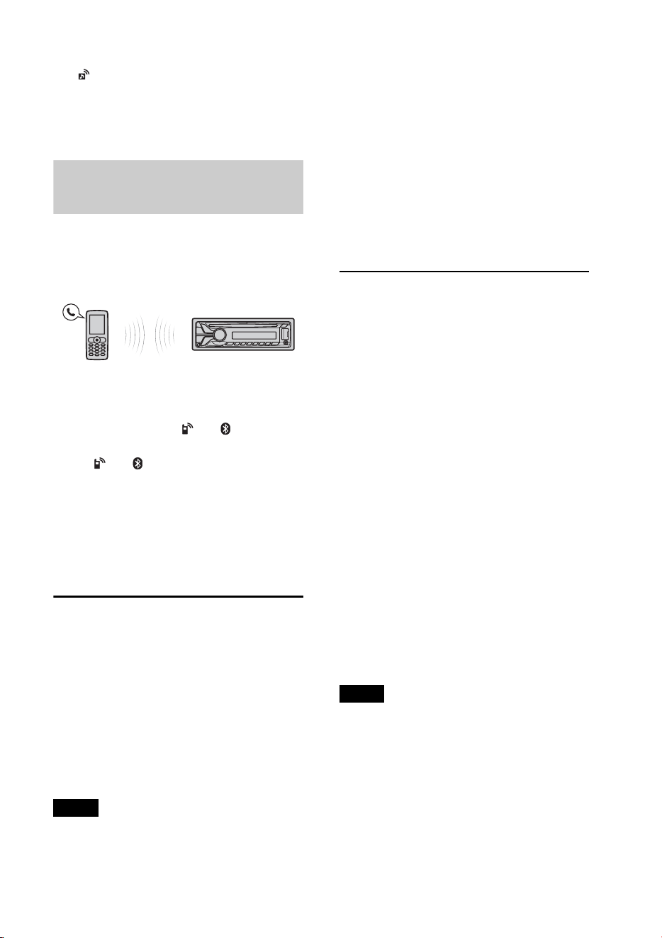
25
3 Presione (PAUSE).
“ ” parpadea mientras se establece la
conexión. Luego se queda encendido
mientras la conexión esté habilitada.
Realización de llamadas
con manos libres
Una vez que la unidad está conectada al
teléfono celular, puede realizar o contestar
llamadas con manos libres con esta unidad.
Antes de realizar una llamada con manos
libres, verifique lo siguiente:
Asegúrese de que “ ” y “ ” aparezcan
en la pantalla.
Si “ ” y “ ” no aparecen, realice el
procedimiento de conexión (página 23).
Si no puede conectar la unidad con el
teléfono celular mediante la función
Bluetooth, realice el procedimiento de
emparejamiento (página 22).
Recepción de llamadas
Cuando se recibe una llamada, se emite un
tono de llamada a través de los altavoces del
automóvil o del teléfono celular conectado.
El nombre o el número de teléfono de la
persona que llama aparecen en la pantalla.
1 Presione cuando reciba una
llamada con un tono de llamada.
Comienza la llamada telefónica.
Notas
• En función del teléfono celular, es posible que
aparezca solamente el nombre de la persona
que llama.
• El tono de llamada y la voz de la persona que
habla son emitidos solamente desde los
altavoces frontales.
Rechazar una llamada
Mantenga presionado
durante 1 segundo.
Finalizar una llamada
Presione nuevamente.
Realización de llamadas
desde la agenda telefónica
Cuando se conecta a un teléfono celular
compatible con PBAP (Phone Book Access
Profile), puede acceder a la agenda
telefónica y realizar una llamada.
1 Presione y gire el selector de
control hasta que aparezca
“PHONEBOOK”; luego, presiónelo.
2 Gire el selector de control para
seleccionar una inicial de la lista de
iniciales y, a continuación, presiónela.
3 Gire el selector de control para
seleccionar un nombre de la lista de
nombres y, a continuación, presiónelo.
4 Gire el selector de control para
seleccionar un número de la lista de
números y, a continuación, presiónelo.
Comienza la llamada telefónica.
Nota
En función del teléfono celular, es posible que los
contactos visualizados en la unidad sean
diferentes de la agenda telefónica del teléfono
celular.

26
Realización de llamadas
desde el historial de llamadas
Cuando se conecta a un teléfono celular
compatible con PBAP (Phone Book Access
Profile), puede acceder al historial de
llamadas almacenado en el teléfono celular y
realizar una llamada.
1 Presione y gire el selector de
control hasta que aparezca “RECENT
CALL”; luego, presione sobre él.
Aparece una lista del historial de
llamadas.
2 Gire el selector de control para
seleccionar un nombre o un número
telefónico del historial de llamadas y, a
continuación, presiónelo.
Comienza la llamada telefónica.
Realización de llamadas
mediante la introducción de
un número de teléfono
1 Presione y gire el selector de
control hasta que aparezca “DIAL
NUMBER”; luego, presione sobre él.
2 Gire el selector de control para ingresar
el número de teléfono y finalmente
seleccione “ ” (espacio), luego presione
(ENTER)*.
Comienza la llamada telefónica.
* Para mover la indicación digital, presione
–/+.
Nota
En la pantalla aparecerá “_” en lugar de “#”.
Realización de llamadas
mediante números
predefinidos
Es posible almacenar hasta 6 contactos en la
marcación predefinida. Para obtener más
información acerca de cómo almacenarlos,
consulte “Marcación predefinida”
(página 27).
1 Presione y gire el
selector de control hasta que aparezca
“BT PHONE”; luego, presiónelo.
2 Presione un botón numérico ( a
) para seleccionar el contacto que
desea llamar.
3 Presione (ENTER).
Comienza la llamada telefónica.
Realización de llamadas
mediante repetición de
marcado
1 Presione y gire el selector de
control hasta que aparezca “REDIAL”;
luego, presiónelo.
Comienza la llamada telefónica.
Operaciones durante una
llamada
Configuración del volumen del tono de
llamada y del auricular
Puede configurar el volumen del tono de
llamada y del auricular.
Para ajustar el volumen del tono de
llamada:
Gire el selector de control mientras recibe la
llamada. Se puede ajustar el volumen del
tono de llamada.

27
Para ajustar el volumen del auricular:
Gire el selector de control durante una
llamada. Se puede ajustar el volumen de la
voz de la persona que habla.
Nota
Si seleccionó la fuente de teléfono Bluetooth, al
girar el selector de control solamente se ajustará
el volumen del auricular.
Ajuste de ganancia de micrófono
Puede ajustar el volumen de la otra parte.
Presione (MIC) para ajustar los niveles
de volumen (“MIC-LOW”, “MIC-MID”,
“MIC-HI”).
Modo EC/NC (modo de cancelación de
eco/ruido)
Puede reducir el eco y el ruido.
Mantenga presionado (MIC) para
configurar “EC/NC-1” o “EC/NC-2”.
Transferencia de llamadas
Para poder activar o desactivar el
dispositivo apropiado (esta unidad/teléfono
celular), presione o utilice su
teléfono celular.
Notas
• Para obtener más información acerca del
funcionamiento del teléfono celular, consulte el
manual de dicho dispositivo.
• En función del teléfono celular, es posible que la
conexión de manos libres se interrumpa al
intentar transferir una llamada.
Marcación predefinida
Es posible almacenar hasta 6 contactos en la
marcación predefinida.
Notas
• Si su teléfono celular es compatible con PBAP
(Phone Book Access Profile), puede seleccionar
un número telefónico desde la agenda del
teléfono o desde el historial de llamadas.
• Si desconecta el cable de fuente de alimentación
se borrarán todos los contactos de la marcación
predefinida.
1 Seleccione un número de teléfono que
desee almacenar en la marcación
predefinida de la agenda telefónica, el
historial de llamadas* o bien
ingresando directamente el número.
El número de teléfono aparecerá en la
pantalla de esta unidad.
* En el historial de llamadas también puede
seleccionar por el nombre de la persona que
llama. En este caso, el nombre de la persona
que llama aparecerá en la pantalla de esta
unidad.
2 Mantenga presionado un botón
numérico ( a ) para seleccionar
el número predefinido en el que desea
almacenar, hasta que aparezca “MEM”.
El contacto se almacena en el número
predefinido que seleccione.
Activación de la marcación
por voz
Para activar la marcación por voz con un
teléfono celular conectado a esta unidad,
mencione la etiqueta de voz almacenada en
el teléfono celular y, a continuación, realice
la llamada.
1 Presione y gire el selector de
control hasta que aparezca “VOICE
DIAL”; luego, presione sobre él.
2 Mencione la etiqueta de voz
almacenada en el teléfono celular.
Se reconocerá su voz y se realizará la
llamada.
Notas
• Antes de comenzar, compruebe que la unidad y
el teléfono celular estén conectados.
• Almacene una etiqueta de voz en el teléfono
celular de antemano.
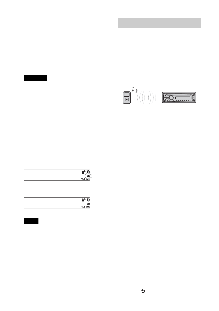
28
• Si activa la marcación por voz con un teléfono
celular conectado a la unidad, es posible que
esta función no esté siempre disponible en
algunos casos.
• Es posible que la marcación por voz no
funcione en algunas situaciones, según la
eficacia de la función de reconocimiento de voz
del teléfono celular. Para obtener más
información, consulte el sitio de soporte técnico
que se indica en la cubierta posterior.
Sugerencia
Almacene una etiqueta de voz mientras se
encuentra sentado en el automóvil, a través de
esta unidad y con la fuente “BT PHONE”
seleccionada.
Indicador de SMS
Cuando conecta un teléfono celular a esta
unidad, el indicador de SMS le informa si
existen mensajes SMS en la bandeja de
entrada o sin leer.
Si recibe un nuevo mensaje SMS, el
indicador de SMS parpadea.
Si existen mensajes SMS sin leer, el
indicador de SMS permanece encendido.
Nota
Es posible que el funcionamiento del indicador de
SMS dependa del teléfono celular.
Transmisión de música
Reproducción de música
desde un dispositivo de audio
Esta unidad permite escuchar música de un
dispositivo de audio si es compatible con
A2DP (Advanced Audio Distribution
Profile) de la tecnología Bluetooth.
1 Baje el volumen de esta unidad.
2 Presione varias veces
hasta que aparezca “BT AUDIO”.
3 Para comenzar la reproducción, utilice
las funciones del dispositivo de audio.
4 Ajuste el volumen de esta unidad.
Cambio de elementos de pantalla
Presione .
Ajuste del nivel de volumen
Puede ajustar cualquier diferencia en el
nivel de volumen entre la unidad y el
dispositivo de audio Bluetooth.
1 Inicie la reproducción en el dispositivo de
audio Bluetooth con un volumen moderado.
2 Seleccione el volumen habitual en la unidad.
3 Presione y gire el selector de
control hasta que aparezca “SOUND”;
luego, presiónelo.
4 Gire el selector de control hasta que
aparezca “BTA VOL” y, a continuación,
presiónelo.
5 Gire el selector de control para ajustar el
nivel de entrada (“+18dB” - “0dB” -
“- 8dB”), y, a continuación, presiónelo.
6 Presione (BACK) para volver a la
pantalla anterior.

29
Operación de un dispositivo
de audio con esta unidad
Puede realizar las siguientes operaciones en
esta unidad si el dispositivo de audio es
compatible con AVRCP (Audio Video
Remote Control Profile) de la tecnología
Bluetooth. (La operación puede variar en
función del tipo de dispositivo de audio.)
*1 Presione varias veces hasta que aparezca el
ajuste deseado.
*2 Según el tipo de dispositivo, es posible que sea
necesario presionar dos veces.
Cualquier otra operación se debe realizar
directamente en el dispositivo de audio.
Notas
• En función del dispositivo de audio, es posible
que no se muestre en esta unidad cierta
información como, por ejemplo, el título, el
número de pista y la duración, el estado de la
reproducción, etc. La información se muestra
solamente durante la reproducción de audio
Bluetooth.
• Incluso si se cambia la fuente en la unidad, la
reproducción de la señal del dispositivo de
audio no se interrumpe.
Inicialización de los
ajustes Bluetooth
Puede inicializar todos los ajustes
relacionados con la tecnología Bluetooth
(información de emparejamiento, números
predefinidos, información del dispositivo,
etc.) de esta unidad.
1 Mantenga presionado
durante 1 segundo para apagar la
unidad.
2 Presione y gire el selector de
control hasta que aparezca “BT”; luego,
presiónelo.
Aparecerá la lista de menús.
3 Gire el selector de control para
seleccionar “BT INIT” y, a
continuación, presiónelo.
Aparece la pantalla de confirmación.
4 Gire el selector de control para
seleccionar “INIT-YES” y, a
continuación, presiónelo.
Parpadeará la leyenda “INITIAL”
mientras se inicializan los ajustes
Bluetooth; aparecerá “COMPLETE”
cuando haya terminado la inicialización.
5 Presione (BACK) para volver a la
pantalla anterior.
Nota
Al desechar esta unidad, se deben eliminar los
números predefinidos mediante la función “BT
INIT”.
Para Realice esta acción
Saltear
álbumes
Presione
/
(ALBUM
/
)
[presionar una vez para
cada álbum]
Reproducción
repetida
Presione (REP)*
1
Reproducción
aleatoria
Presione (SHUF)*
1
Reproducir Presione (PAUSE)*
2
en
esta unidad.
Pausar Presione (PAUSE)*
2
en
esta unidad.
Saltear pistas Presione –/+
(/) [presione una
vez por cada pista]
Retroceder/
Avanzar
Mantenga presionado
–/+ (/)
[mantener presionado
hasta llegar al punto
deseado]

30
La tecnología
inalámbrica de Pandora
®
via Bluetooth (teléfonos
Android
™
y BlackBerry
®
)
Pandora® está disponible para transmitir
música a través de sus teléfonos Android™ y
BlackBerry®.
Puede controlar Pandora® en teléfonos
Android y BlackBerry conectados a
Bluetooth desde esta unidad.
Descargue la última versión de la aplicación
Pandora® y obtenga más información desde
www.pandora.com
Para obtener más información sobre los
dispositivos utilizables, visite el sitio web de
servicio técnico que se indica en la cubierta
posterior.
Notas
• Es posible que ciertas funciones del servicio de
Pandora® no estén disponibles.
• Puede controlar Pandora® a través de la función
Bluetooth en teléfonos Android y BlackBerry
solamente.
• El servicio de Pandora® está disponible
solamente en los Estados Unidos.
Transmisión de Pandora®
Antes de conectar el dispositivo móvil, baje
el volumen de la unidad.
1 Conecte esta unidad y el dispositivo
móvil a través de la función Bluetooth
(página 21).
2 Presione varias veces
hasta que aparezca “BT PANDORA”*
1
.
3 Inicie la aplicación Pandora® en el
dispositivo móvil.
4 Presione *
2
(PAUSE) para iniciar la
reproducción.
*1 No aparece, dependiendo del dispositivo
conectado al puerto USB.
*2 Cuando el dispositivo móvil está conectado,
puede que aparezca el número del dispositivo.
Asegúrese de que se visualicen los mismos
números (por ej., 123456) en esta unidad y en
el dispositivo móvil, luego presione
en esta unidad y seleccione “Yes” en el
dispositivo móvil.
Para pausar la reproducción, presione
(PAUSE). Para volver a activar la
reproducción, vuelva a presionarlo.
Para saltear una pista, presione +.
Notas
• No puede volver a la pista anterior.
• Pandora® limita la cantidad de salteos
permitidos.
Cambio de elementos de pantalla
Presione .
Ajuste del nivel de volumen
El nivel de volumen de Pandora® se ajusta
de la misma forma que un dispositivo de
audio Bluetooth. Para obtener detalles,
consulte la página 28.
Comentarios de “Pulgares”
Los comentarios de “Pulgares arriba” o
“Pulgares abajo” le permiten personalizar
las emisoras para que se ajusten a sus
preferencias.
Pulgares arriba
Durante la reproducción, mantenga
presionado () durante 1 segundo.
Pulgares abajo
Durante la reproducción, mantenga
presionado () durante 1 segundo.

31
Lista de emisoras
La lista de emisoras le permite seleccionar
con facilidad la emisora deseada.
1 Durante la reproducción, presione
(BROWSE).
2 Presione + para seleccionar el
orden de clasificación “BY DATE” o “A
TO Z”.
3 Gire el selector de control para
seleccionar la emisora deseada y, a
continuación, presiónelo.
Se inicia la reproducción.
Shuffle
La opción Shuffle le permite escuchar las
pistas reproducidas en una o más emisoras
Pandora® de su lista de emisoras de forma
aleatoria.
Edite sus selecciones de estaciones Shuffle
en el dispositivo antes de la conexión.
Marcar como favorito
La pista o el artista que está siendo
reproducido puede ser marcado como
favorito y almacenado en su cuenta de
Pandora®.
1 Durante la reproducción, mantenga
presionado hasta que
aparezca “BOOKMARK”.
2 Gire el selector de control para
seleccionar “TRK” (pista) o “ART”
(artista) y, a continuación, presiónelo.
Ajustes de sonido y
menú de configuración
Uso de funciones de sonido
sofisticadas — Sistema de
sonido avanzado
El Sistema de sonido avanzado crea un
campo de sonido ideal en el interior del
vehículo gracias a un procesamiento de
señales digitales.
Selección de la calidad de
sonido — Preajuste de EQ7
Puede seleccionar una curva de ecualizador
entre 7 curvas de ecualizador (XPLOD,
VOCAL, EDGE, CRUISE, SPACE,
GRAVITY, CUSTOM u OFF).
1 Durante la recepción/reproducción,
presione , gire el selector de
control hasta que aparezca “SOUND” y
luego presiónelo.
2 Gire el selector de control hasta que
aparezca “EQ7 PRESET” y, a
continuación, presiónelo.
3 Gire el selector de control hasta que
aparezca la curva de ecualizador
deseada y, a continuación, presiónelo.
4 Presione (BACK) para volver a la
pantalla anterior.
Para cancelar la curva de ecualizador,
seleccione “OFF” en el paso 3.
Sugerencia
El ajuste de la curva de ecualizador se puede
memorizar para cada fuente.
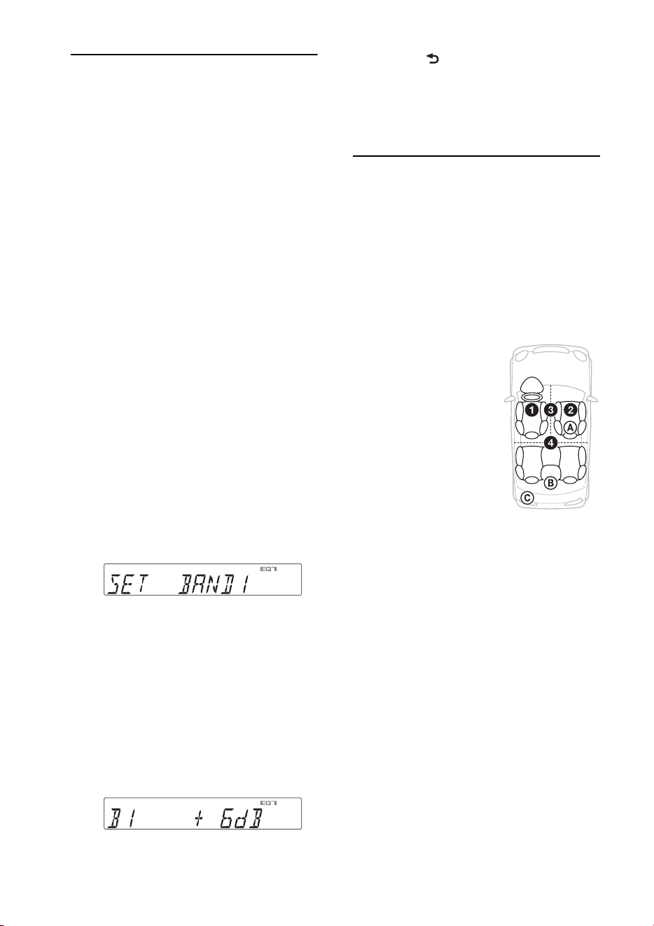
32
Personalización de la curva
de ecualizador — Ajuste de
EQ7
“CUSTOM” de EQ7 le permite realizar sus
propios ajustes en el ecualizador.
1 Después de seleccionar una fuente,
presione , gire el selector de
control hasta que aparezca “SOUND” y
luego presiónelo.
2 Gire el selector de control hasta que
aparezca “EQ7 SETTING” y, a
continuación, presiónelo.
3 Gire el selector de control hasta que
aparezca “BASE” y, a continuación,
presiónelo.
Es posible seleccionar una curva de
ecualizador como base para una
personalización más precisa.
4 Gire el selector de control para
seleccionar la curva de ecualizador y, a
continuación, presiónelo.
5 Ajuste de la curva de ecualizador.
Gire el selector de control para
seleccionar el rango de frecuencia y, a
continuación, presiónelo.
BAND1: 63 Hz
BAND2: 160 Hz
BAND3: 400 Hz
BAND4: 1 kHz
BAND5: 2,5 kHz
BAND6: 6,3 kHz
BAND7: 16,0 kHz
Gire el selector de control para ajustar
el nivel de volumen y, a continuación,
presiónelo.
El nivel de volumen puede ajustarse en
intervalos de 1 dB entre -6 dB y +6 dB.
Repita los pasos y para ajustar
otros rangos de frecuencia.
6 Presione (BACK) para volver a la
pantalla anterior.
La curva de ecualizador se almacena en
“CUSTOM”.
Optimización de sonido por
Alineación de tiempo —
Posición de escucha
La unidad permite simular un campo de
sonido natural mediante el retardo de la
salida de sonido desde cada uno de los
altavoces para adecuarse a su posición.
A continuación, se enumeran las opciones
de “POSITION”.
Asimismo, puede configurar la posición
aproximada del altavoz potenciador de
graves desde su posición de escucha si:
–la salida de audio se ajusta en “SUB-OUT”
(página 35).
–la posición de escucha se ajusta en una
opción distinta de “OFF”.
A continuación, se indican las opciones
para “SET SW POS”.
NEAR (): cerca
NORMAL (): normal
FAR (): lejos
1 Durante la recepción/reproducción,
presione , gire el selector de
control hasta que aparezca “SOUND” y
luego presiónelo.
FRONT L (): izquierda
delantera
FRONT R (): derecha
delantera
FRONT (): delantera
central
ALL (): en el centro del
automóvil
OFF: sin configuración de
posición

33
2 Gire el selector de control hasta que
aparezca “POSITION” y, a
continuación, presiónelo.
3 Gire el selector de control hasta que
aparezca “SET F/R POS” y, a
continuación, presiónelo.
4 Gire el selector de control para
seleccionar entre “FRONT L”,
“FRONT R”, “FRONT” o “ALL” y, a
continuación, presiónelo.
5 Gire el selector de control hasta que
aparezca “SET SW POS” y, a
continuación, presiónelo.
6 Gire el selector de control para
seleccionar la posición del altavoz
potenciador de graves entre “NEAR”,
“NORMAL” o “FAR” y, a
continuación, presiónelo.
7 Presione (BACK) para volver a la
pantalla anterior.
Para cancelar la posición de escucha,
seleccione “OFF” en el paso 4.
Ajuste de la posición de
escucha
Es posible sintonizar con mayor precisión el
ajuste de la posición de escucha.
1 Durante la recepción/reproducción,
presione , gire el selector de
control hasta que aparezca “SOUND” y
luego presiónelo.
2 Gire el selector de control hasta que
aparezca “POSITION” y, a
continuación, presiónelo.
3 Gire el selector de control hasta que
aparezca “ADJ POSITION” y, a
continuación, presiónelo.
4 Gire el selector de control para ajustar
la posición de escucha y, a
continuación, presiónelo.
Rango ajustable: “+3” – “CENTER” –
“–3”.
5 Presione (BACK) para volver a la
pantalla anterior.
DM+ Avanzado
DM+ Avanzado mejora el sonido
comprimido digitalmente, ya que restaura
las altas frecuencias que se pierden en el
proceso de compresión.
1 Durante la reproducción, presione
, gire el selector de control
hasta que aparezca “SOUND” y luego
presiónelo.
2 Gire el selector de control hasta que
aparezca “DM+” y, a continuación,
presiónelo.
3 Gire el selector de control para
seleccionar “ON” y, a continuación,
presiónelo.
4 Presione (BACK) para volver a la
pantalla anterior.
Sugerencia
El ajuste de DM+ se puede memorizar para cada
fuente diferente al sintonizador.

34
Uso de los altavoces
posteriores como altavoz
potenciador de graves —
Potenciador de sonidos
graves posteriores
El Potenciador de sonidos graves
posteriores mejora los sonidos graves, ya
que aplica el ajuste del filtro de paso bajo
(página 36) a los altavoces posteriores. Esta
función permite que los altavoces
posteriores funcionen como altavoces
potenciadores de graves si uno de ellos no
está conectado.
1 Durante la recepción/reproducción,
presione , gire el selector de
control hasta que aparezca “SOUND” y
luego presiónelo.
2 Gire el selector de control hasta que
aparezca “RB ENH” y, a continuación,
presiónelo.
3 Gire el selector de control hasta que
aparezca “RBE MODE” y, a
continuación, presiónelo.
4 Gire el selector de control para
seleccionar entre “1”, “2” o “3” y, a
continuación, presiónelo.
5 Presione (BACK) para volver a la
pantalla anterior.
Utilizar un altavoz
potenciador de graves sin un
amplificador de potencia —
Conexión directa al altavoz
potenciador de graves
Puede utilizar el altavoz potenciador de
graves sin un amplificador de potencia
cuando está conectado al cable del altavoz
posterior.
Nota
Asegúrese de conectar un altavoz potenciador de
graves de 4 a 8 Ω a cualquiera de los cables del
altavoz posterior. No conecte un altavoz al otro
cable de altavoz posterior.
1 Durante la recepción/reproducción,
presione , gire el selector de
control hasta que aparezca “SOUND” y
luego presiónelo.
2 Gire el selector de control hasta que
aparezca “SW DIREC” y, a
continuación, presiónelo.
3 Gire el selector de control hasta que
aparezca “SW MODE” y, a
continuación, presiónelo.
4 Gire el selector de control para
seleccionar entre “1”, “2” o “3” y, a
continuación, presiónelo.
5 Presione (BACK) para volver a la
pantalla anterior.
Para obtener más información acerca de la
fase del altavoz potenciador de graves,
posición, frecuencia de filtro de paso bajo y
la pendiente del filtro de paso bajo, consulte
la página 36.
Ajuste de los elementos
de configuración
1 Presione , gire el selector de
control hasta que aparezca la categoría
deseada y, a continuación, presiónelo.
2 Gire el selector de control hasta que
aparezca el elemento deseado y, a
continuación, presiónelo.
3 Gire el selector de control para
seleccionar el ajuste y, a continuación,
presiónelo.*
El ajuste finalizó.
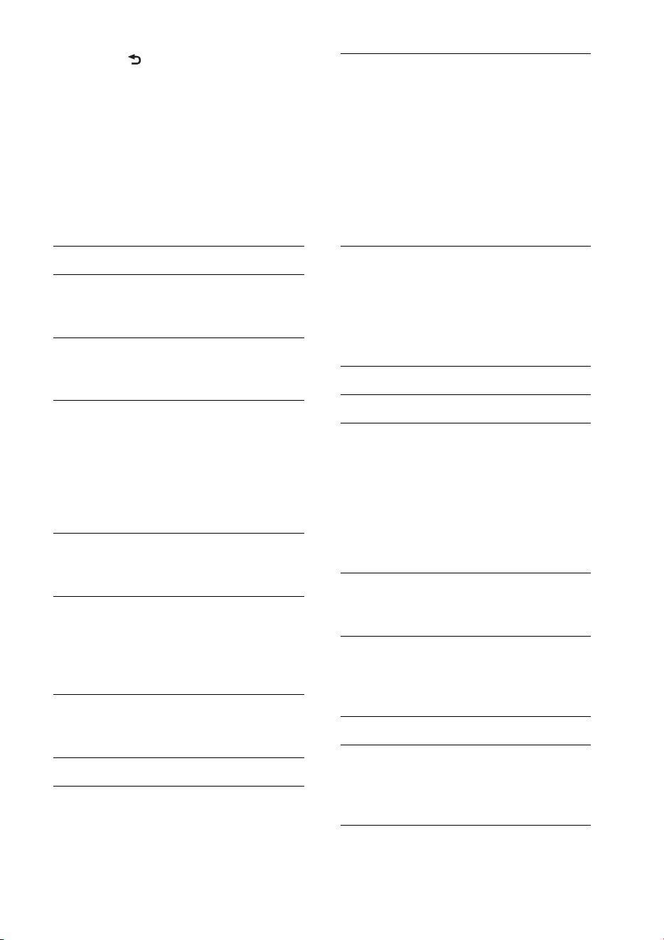
35
4 Presione (BACK) para volver a la
pantalla anterior.
* No es necesario realizar el paso 4 para los
ajustes de CLOCK-ADJ y BTM.
Los siguientes elementos pueden ajustarse
en función de la fuente y de la
configuración:
GENERAL:
*1 Cuando la unidad está apagada.
*2 Cuando se selecciona el sintonizador.
*3 Cuando se selecciona el CD o USB.
SOUND:
CLOCK-ADJ (Ajuste del reloj) (página 6)
CAUT ALM*
1
(Alarma de precaución)
Activa la alarma de precaución: “ON”,
“OFF” (página 6).
BEEP
Activa el sonido de los pitidos: “ON”,
“OFF”.
AUTO OFF
Desconecta la alimentación
automáticamente una vez transcurrido
un período de tiempo deseado cuando la
unidad está apagada: “NO”, “30S
(segundos)”, “30M (minutos)”, “60M
(minutos)”.
AUX-A*
1
(Audio AUX)
Activa la visualización de la fuente AUX:
“ON”, “OFF” (página 37).
REAR/SUB*
1
Permite cambiar la salida de audio:
“SUB-OUT” (altavoz potenciador de
graves), “REAR-OUT” (amplificador de
potencia).
CT (Hora del reloj)
Activa la función CT: “ON”, “OFF”
(página 13).
BTM*
2
(página 12)
ZAPPIN*
3
ZAP TIME (Tiempo de reproducción
del modo Zappin)
Permite seleccionar el tiempo de
reproducción de la función ZAPPIN.
– “Z.TIME-1 (6 segundos aprox.)”,
“Z.TIME-2 (15 segundos aprox.)”,
“Z.TIME-3 (30 segundos aprox.)”.
ZAP BEEP (Pitidos del modo Zappin)
Aplica un sonido de pitido entre
fragmentos de pistas: “ON”, “OFF”.
EQ7 PRESET (página 31)
EQ7 SETTING (página 32)
POSITION
SET F/R POS (Configurar la posición
frontal/posterior) (página 32)
ADJ POSITION*
1
(Ajuste de la
posición) (página 33)
SET SW POS*
1
*
2
(Configurar la
posición del altavoz potenciador de
graves) (página 32)
BALANCE
Permite ajustar el balance de sonido:
“RIGHT-15” – “CENTER” – “LEFT-15”.
FADER
Permite ajustar el nivel relativo:
“FRONT-15” – “CENTER” – “REAR-
15”.
DM+*
3
(página 33)
LOUDNESS (Sonoridad dinámica)
Refuerza los graves y agudos para
obtener un sonido claro a niveles de
volumen bajos: “ON”, “OFF”.

36
ALO (Optimizador de nivel automático)
Ajuste el nivel de volumen de
reproducción de todas las fuentes de
reproducción al nivel óptimo: “ON”,
“OFF”.
RB ENH*
4
(Potenciador de sonidos graves)
RBE MODE (Potenciador posterior de
sonidos graves)
Selecciona el potenciador posterior de
sonidos graves: “1”, “2”, “3”, “OFF”.
LPF FREQ (Frecuencia de filtro de paso
bajo)
Selecciona la frecuencia de corte del
altavoz potenciador de graves: “50Hz”,
“60Hz”, “80Hz”, “100Hz”, “120Hz”.
LPF SLOP (Pendiente de filtro de paso
bajo)
Selecciona la pendiente LPF: “1”, “2”,
“3”.
SW DIREC*
5
(Conexión directa al altavoz
potenciador de graves)
SW MODE (Modo del altavoz
potenciador de graves)
Selecciona el modo del altavoz
potenciador de graves: “1”, “2”, “3”,
“OFF”.
SW PHASE (Fase del altavoz
potenciador de graves)
Selecciona la fase del altavoz potenciador
de graves: “NORM”, “REV”.
SW POS*
1
(Posición del altavoz
potenciador de graves) (página 32)
Selecciona la posición del altavoz
potenciador de graves: “NEAR”,
“NORMAL”, “FAR”.
LPF FREQ (Frecuencia de filtro de paso
bajo)
Selecciona la frecuencia de corte del
altavoz potenciador de graves: “50Hz”,
“60Hz”, “80Hz”, “100Hz”, “120Hz”.
LPF SLOP (Pendiente de filtro de paso
bajo)
Selecciona la pendiente LPF: “1”, “2”,
“3”.
S.WOOFER*
2
(Altavoz potenciador de
graves)
SW LEVEL (Nivel del altavoz
potenciador de graves)
Permite ajustar el nivel de volumen del
altavoz potenciador de graves: “+10 dB”
– “0 dB” – “–10 dB”.
(“ATT” aparece en pantalla con el ajuste
más bajo).
SW PHASE (Fase de altavoz potenciador
de graves)
Selecciona la fase del altavoz potenciador
de graves: “NORM”, “REV”.
SW POS*
1
(Posición del altavoz
potenciador de graves)
Selecciona la posición del altavoz
potenciador de graves: “NEAR”,
“NORMAL”, “FAR”.
LPF FREQ (Frecuencia de filtro de paso
bajo)
Selecciona la frecuencia de corte del
altavoz potenciador de graves: “50Hz”,
“60Hz”, “80Hz”, “100Hz”, “120Hz”.
LPF SLOP (Pendiente de filtro de paso
bajo)
Selecciona la pendiente LPF: “1”, “2”,
“3”.
HPF (Filtro de paso alto)
HPF FREQ (Frecuencia de filtro de paso
alto)
Selecciona la frecuencia de corte del
altavoz frontal/posterior: “OFF”, “50Hz”,
“60Hz”, “80Hz”, “100Hz”, “120Hz”.
HPF SLOP (Pendiente de filtro de paso
alto)
Selecciona la pendiente HPF (efectivo
solamente cuando HPF FREQ se ajusta
en un valor diferente a “OFF”): “1”, “2”,
“3”.
AUX VOL*
6
(Nivel de volumen AUX)
Ajusta el nivel de volumen de cada
equipo auxiliar conectado:
“+18 dB” – “0 dB” – “–8 dB”.
Este ajuste elimina la necesidad de
ajustar el nivel de volumen entre fuentes.
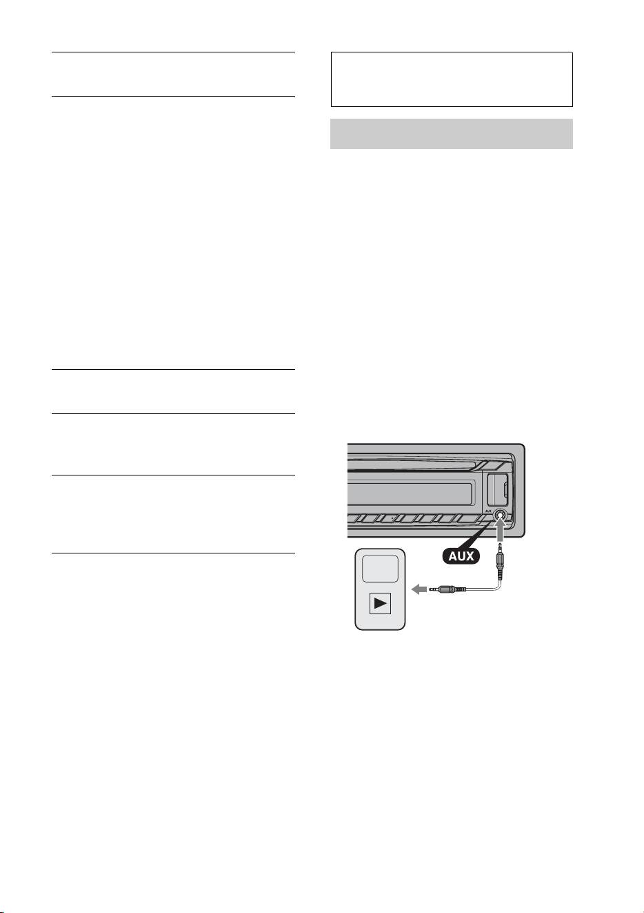
37
*1 No aparece cuando “SET F/R POS” se ajusta
en “OFF”.
*2 Cuando la salida de audio se ajusta en “SUB-
OUT” (página 35).
*3 No aparece cuando está seleccionado el
sintonizador.
*4 Cuando la salida de audio se ajusta en “REAR-
OUT” y “SW DIREC” se ajusta en “OFF”.
*5 Cuando la salida de audio se ajusta en “REAR-
OUT” y “RBE MODE” se ajusta en “OFF”.
*6 Cuando se selecciona el AUX.
*7 Cuando se activa la fuente de audio Bluetooth.
DISPLAY:
* Cuando se selecciona CD, USB, Pandora® via
USB, audio Bluetooth o Pandora® Bluetooth.
BT (Bluetooth):
Para obtener detalles acerca de los
elementos de configuración para la
configuración de Bluetooth, consulte la
página 21.
Uso de equipo opcional
Equipo de audio auxiliar
Si conecta un dispositivo de audio portátil
opcional a la toma de entrada AUX
(minitoma estéreo) de la unidad y
simplemente selecciona la fuente, podrá
escuchar por los altavoces del automóvil.
Conexión del dispositivo de audio
portátil
1 Apague el dispositivo de audio portátil.
2 Baje el volumen de la unidad.
3 Conecte el dispositivo de audio portátil a la
unidad con un cable de conexión (no
suministrado)*.
* Asegúrese de utilizar una clavija recta.
Ajuste del nivel de volumen
Asegúrese de ajustar el volumen de cada
equipo de audio conectado antes de la
reproducción.
1 Baje el volumen de la unidad.
2 Presione varias veces hasta
que aparezca “AUX”.
3 Inicie la reproducción en el dispositivo de
audio portátil con un volumen moderado.
4 Seleccione el volumen habitual en la unidad.
5 Ajuste el nivel de entrada (página 36).
BTA VOL*
7
(Nivel de volumen de audio
Bluetooth) (página 28)
DEMO
(Demostración)
Activa la demostración: “ON”, “OFF”.
DIMMER
Permite cambiar el brillo de la pantalla:
“ON”, “OFF”.
AUTO SCR* (Desplazamiento automático)
Desplaza de manera automática aquellos
elementos demasiado extensos: “ON”,
“OFF”.

38
Información
complementaria
Precauciones
• Deje que la unidad se enfríe antes de usarla si
el automóvil ha estado estacionado bajo la
luz directa del sol.
• No deje el panel frontal o los dispositivos de
audio dentro del vehículo o podría causar
fallas en el funcionamiento debido a las altas
temperaturas bajo la luz directa del sol.
• La antena de alimentación se extiende
automáticamente.
Condensación de humedad
Si se produce condensación de humedad en el
interior de la unidad, extraiga el disco y espere
una hora aproximadamente hasta que se haya
secado por completo la unidad. De lo
contrario, la unidad no funcionará
correctamente.
Para mantener una alta calidad de
sonido
No derrame ningún tipo de líquido sobre la
unidad o los discos.
Notas sobre los discos
• No exponga los discos a la luz solar directa ni
a fuentes de calor como, por ejemplo,
conductos de aire caliente, ni los deje en el
automóvil estacionado bajo la luz solar
directa.
• Antes de reproducir los
discos, límpielos con un
paño de limpieza. Hágalo
desde el centro hacia los
bordes. No utilice
disolventes como bencina,
diluyentes ni productos de
limpieza disponibles en el mercado.
• Esta unidad se diseñó para reproducir discos
que cumplen con el estándar Compact disc
(CD). Los DualDisc y otros discos de música
codificados con tecnologías de protección de
derechos de autor no cumplen el estándar
Compact disc (CD), por lo que no podrán
reproducirse con esta unidad.
• Discos que NO se pueden reproducir en
esta unidad
– Discos con etiquetas, autoadhesivos o cinta
adhesiva o papeles adheridos. Si utiliza este
tipo de discos, puede provocar una falla de
funcionamiento o dañar el disco.
– Discos con formas no estandarizadas (por
ejemplo, formas de corazón, cuadrado o
estrella). Si lo intenta, puede dañar la unidad.
– Discos de 8 cm.
Notas sobre los discos CD-R/CD-RW
• Número máximo de: (sólo CD-R/CD-RW)
– carpetas (álbumes): 150 (incluida la carpeta
raíz)
– archivos (pistas) y carpetas: 300 (si los
nombres de carpeta o archivo contienen
muchos caracteres, este número puede ser
inferior a 300)
– caracteres que se pueden visualizar en el
nombre de una carpeta o archivo: 32 (Joliet)/
64 (Romeo)
• Si un disco multisesión empieza con una
sesión CD-DA, se reconoce como un disco
CD-DA y las otras sesiones no se
reproducen.
• Discos que NO se pueden reproducir en
esta unidad
– CD-R/CD-RW de calidad de grabación
deficiente.
– CD-R/CD-RW grabados con un dispositivo
de grabación no compatible.
– CD-R/CD-RW no finalizados correctamente.
– CD-R/CD-RW que no se hayan grabado en
formato CD de música o en formato MP3 que
cumpla la norma ISO9660 Level 1/Level 2,
Joliet/Romeo o multisesión.
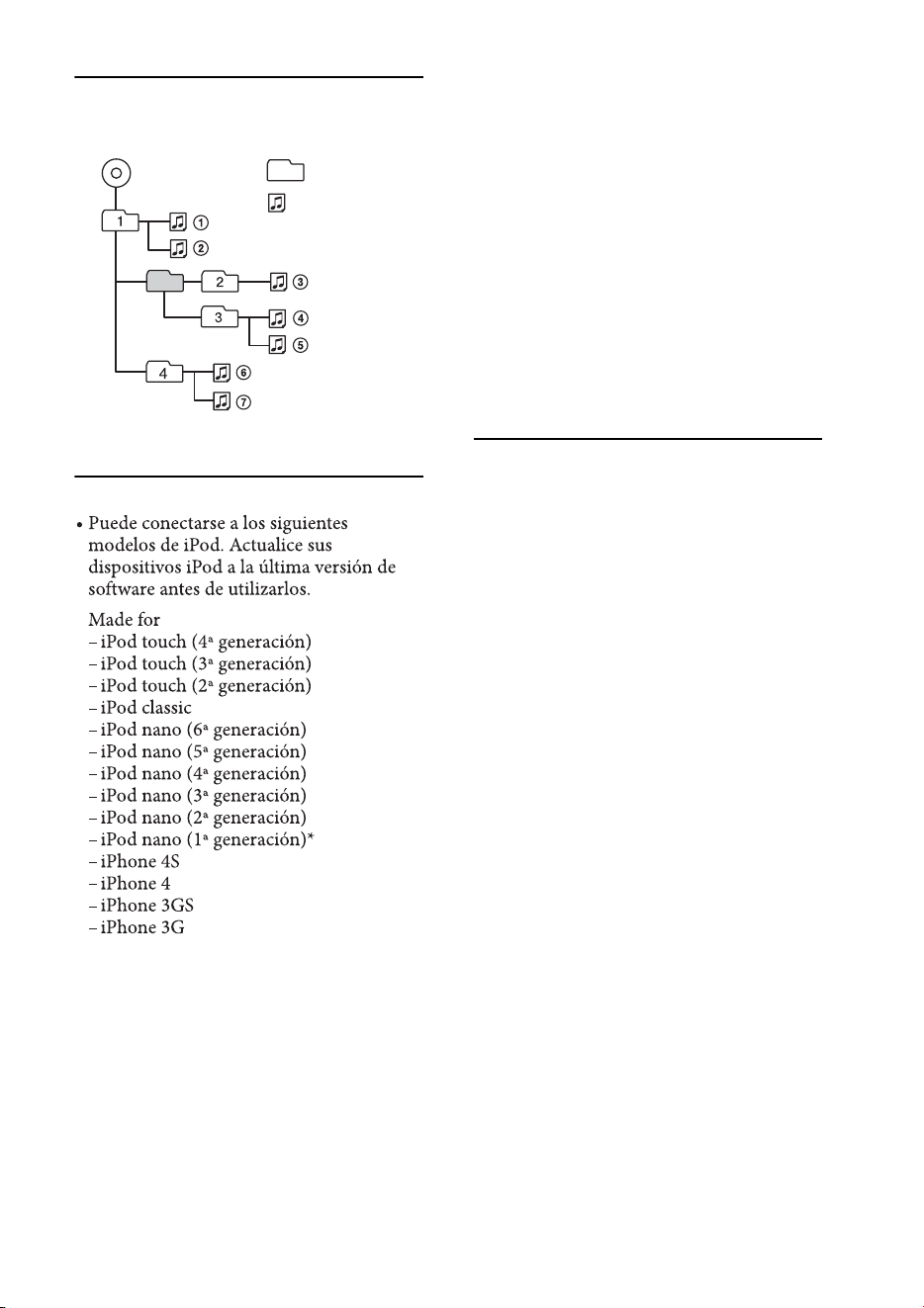
39
Orden de reproducción de los
archivos MP3/WMA/AAC
Acerca de iPod
* El control de pasajero no se encuentra
disponible para iPod nano (primera
generación).
Acerca de la función
Bluetooth
¿Qué es la tecnología Bluetooth?
• La tecnología inalámbrica Bluetooth es una
tecnología de corto alcance que permite la
comunicación inalámbrica de datos entre
dispositivos digitales, como un teléfono
celular y un auricular. La tecnología
inalámbrica Bluetooth tiene una cobertura
de aproximadamente 10 metros. Lo habitual
es conectar dos dispositivos, aunque algunos
dispositivos pueden conectarse a varios
dispositivos al mismo tiempo.
• No es necesario utilizar un cable para realizar
la conexión ya que la tecnología Bluetooth es
inalámbrica. Tampoco es necesario que los
dispositivos estén orientados entre sí, como
sucede con la tecnología infrarroja. Por
ejemplo, puede utilizar este tipo de
dispositivos dentro de una bolsa o un
bolsillo.
• La tecnología Bluetooth es un estándar
internacional admitido por millones de
empresas en todo el mundo y que utilizan
varias compañías a escala internacional.
Acerca de la comunicación Bluetooth
• La tecnología inalámbrica Bluetooth tiene
una cobertura de aproximadamente 10 m.
El área de cobertura puede variar en función
de los obstáculos (personas, objetos
metálicos, paredes, etc.) o del entorno
electromagnético.
Carpeta
(álbum)
Archivo MP3/
WMA/AAC
(pista)
MP3/WMA/AAC
• “Made for iPod” y “Made for iPhone”
indican que un accesorio electrónico se
diseñó para conectarse especícamente a
los dispositivos iPod o iPhone
respectivamente, y que el fabricante
obtuvo la certicación necesaria para que
cumpla con los estándares de rendimiento
de Apple. Apple no se hace responsable
del funcionamiento de este dispositivo en
cumplimiento de los estándares de
seguridad y normativa. Tenga en cuenta
que el uso de este accesorio con el iPod o
el iPhone puede afectar al rendimiento
inalámbrico.

40
• Las siguientes condiciones pueden afectar la
sensibilidad de la comunicación Bluetooth.
– La existencia de obstáculos como, una
persona, un objeto metálico o una pared,
entre esta unidad y el dispositivo Bluetooth.
– El uso de dispositivos que utilicen una
frecuencia de 2,4 GHz, como un dispositivo
LAN inalámbrico, un teléfono inalámbrico o
un microondas cerca de la unidad.
• Como los dispositivos Bluetooth y las redes
LAN inalámbricas (IEEE802.11b/g) utilizan
la misma frecuencia, pueden producirse
interferencias de microondas que provoquen
el deterioro de la velocidad de comunicación,
la aparición de ruido o una conexión no
válida si la unidad se utiliza cerca de un
dispositivo LAN inalámbrico. En este caso,
realice el procedimiento siguiente.
– Utilice esta unidad a una distancia mínima de
10 m del dispositivo LAN inalámbrico.
– Si utiliza esta unidad a menos de 10 m de un
dispositivo LAN inalámbrico, apague el
dispositivo LAN inalámbrico.
– Instale esta unidad y el dispositivo Bluetooth
a la distancia más corta posible entre sí.
• Las microondas que emite un dispositivo
Bluetooth pueden afectar el funcionamiento
de dispositivos médicos electrónicos. Apague
esta unidad y los demás dispositivos
Bluetooth en los lugares siguientes ya que
podrían provocar un accidente.
– Lugares con presencia de gas inflamable,
hospitales, trenes, aviones o gasolineras
– Lugares cerca de puertas automáticas o
alarmas de incendios
• Esta unidad admite recursos de seguridad
que cumplen con el estándar Bluetooth para
proporcionar una conexión segura al utilizar
la tecnología inalámbrica Bluetooth, pero es
posible que la seguridad sea insuficiente
según el ajuste. Tenga cuidado al realizar una
comunicación con la tecnología inalámbrica
Bluetooth.
• No se aceptan responsabilidades por la
pérdida de información que pudiera
producirse durante una comunicación
Bluetooth.
• No se garantiza la comunicación con todos
los dispositivos Bluetooth.
– Un dispositivo que disponga de la función
Bluetooth debe cumplir el estándar Bluetooth
SIG y estar autenticado.
– Incluso en el caso de que el dispositivo
conectado cumpla el estándar Bluetooth
mencionado anteriormente, es posible que
algunos dispositivos no puedan conectarse o
funcionar correctamente, según las
características o las especificaciones del
dispositivo.
– Mientras esté hablando con el manos libres
del teléfono, puede producirse ruido, según el
dispositivo o el entorno de comunicación.
• En función del dispositivo que vaya a
conectarse, es posible que transcurra cierto
tiempo antes de que se inicie la
comunicación.
Otros
• Es posible que el dispositivo Bluetooth no
funcione en teléfonos celulares según las
condiciones de las ondas de radio y la
ubicación en la que se utilice el equipo.
• Si no se siente cómodo después de utilizar el
dispositivo Bluetooth, deje de utilizarlo
inmediatamente. Si el problema persiste,
consulte con el distribuidor Sony más
cercano.
Si desea realizar alguna consulta o solucionar
algún problema relativo a la unidad que no se
trate en este manual, póngase en contacto con
el distribuidor Sony más cercano.
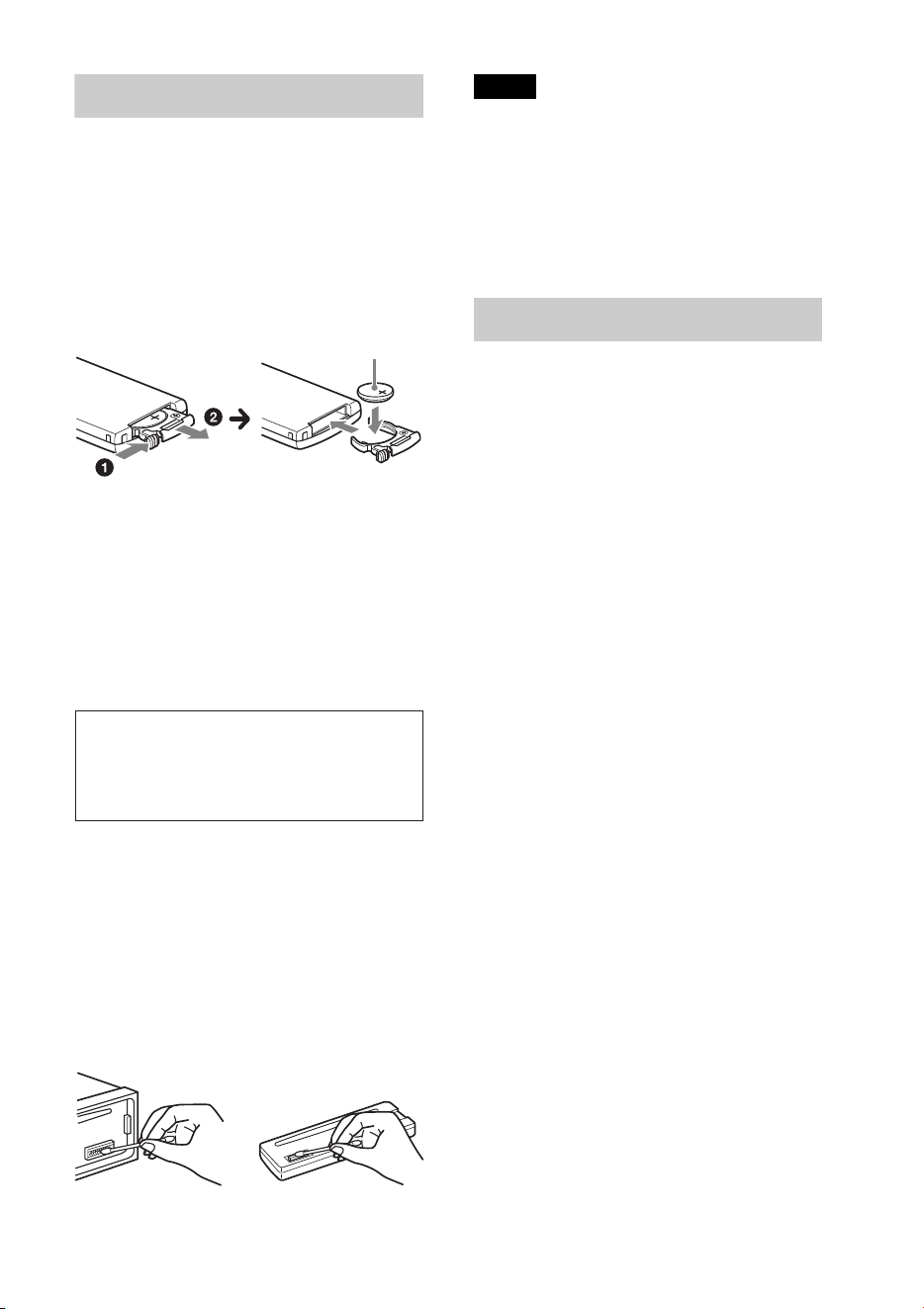
41
Mantenimiento
Sustitución de la pila de litio del control
remoto
El alcance del control remoto disminuye a
medida que se agota la pila. Sustitúyala por
una pila de litio CR2025 nueva. El uso de
cualquier otra pila podría provocar un
incendio o una explosión.
Notas sobre la pila de litio
• Mantenga la pila de litio fuera del alcance de los
niños. Si se ingiriese, póngase en contacto
inmediatamente con un médico.
• Limpie la pila con un paño seco para garantizar
un contacto óptimo.
• Asegúrese de respetar la polaridad al instalarla.
• No sujete la pila con pinzas metálicas, ya que
podría producirse un cortocircuito.
Limpieza de los conectores
Es posible que la unidad no funcione
correctamente si los conectores entre ésta y el
panel frontal están sucios. Para evitar esta
situación, extraiga el panel frontal (página 6) y
limpie los conectores con un hisopo de
algodón. Realice esta operación con suavidad.
De lo contrario, los conectores podrían
resultar dañados.
Notas
• Por razones de seguridad, apague el motor
antes de limpiar los conectores y extraiga la
llave del interruptor de encendido.
• No toque nunca los conectores directamente
con los dedos ni con ningún dispositivo
metálico.
Especificaciones
Sección del sintonizador
FM
Rango de sintonización: de 87,5 a 107,9 MHz
Terminal de antena:
conector de antena externa
Frecuencia intermedia: 25 kHz
Sensibilidad útil: 8 dBf
Selectividad: 75 dB a 400 kHz
Relación señal-ruido: 80 dB (estéreo)
Separación: 50 dB a 1 kHz
Respuesta de frecuencia: 20 – 15 000 Hz
AM
Rango de sintonización: de 530 a 1 710 kHz
Terminal de antena:
conector de antena externa
Frecuencia intermedia:
9 115 kHz o 9 125 kHz/5 kHz
Sensibilidad: 26 μV
Sección del reproductor de CD
Relación señal-ruido: 120 dB
Respuesta de frecuencia: 10 – 20 000 Hz
Fluctuación y trémolo: inferior al límite medible
Sección del reproductor USB
Interfaz: USB (velocidad máxima)
Corriente máxima: 1 A
Comunicación inalámbrica
Sistema de comunicación:
versión Bluetooth estándar 2.1 + EDR
Salida:
Energía estándar Bluetooth Clase 2
(Máx. +4 dBm)
Área de cobertura:
línea de visión aprox. 10 m*
1
Banda de frecuencias:
banda 2,4 GHz (2,4000 – 2,4835 GHz)
Método de modulación: FHSS
Lado + hacia arriba
ADVERTENCIA
La pila puede explotar si no se emplea
adecuadamente. No recargue la pila;
tampoco la desmonte ni la arroje al fuego.

42
Perfiles compatibles con la tecnología Bluetooth*
2
:
A2DP (Advanced Audio Distribution Profile)
1.2
AVRCP (Audio Video Remote Control Profile)
1.3
HFP (Handsfree Profile) 1.5
PBAP (Phone Book Access Profile)
SPP (Serial Port Profile)
*1 El alcance real variará según factores, como
los obstáculos entre los dispositivos, los
campos magnéticos alrededor de un horno de
microondas, la electricidad estática, la
sensibilidad de recepción, el funcionamiento
de la antena, el sistema operativo, la
aplicación del software, etc.
*2 Los perfiles estándar Bluetooth indican el
propósito de la comunicación Bluetooth entre
dispositivos.
Sección del amplificador de
potencia
Salida: salidas de altavoz
Impedancia de altavoz: 4 – 8 Ω
Salida de potencia máxima: 52 W × 4 (a 4 Ω)
Generales
Salidas:
Terminal de salidas de audio (frontal,
intercambiable entre altavoz potenciador de
graves y posterior)
Antena de alimentación/Terminal de control
del amplificador de potencia (REM OUT)
Entradas:
Terminal de entrada del control remoto
Terminal de entrada de la antena
Terminal de entrada MIC
Toma de entrada AUX (minitoma estéreo)
Puerto USB
Requisitos de alimentación: batería de automóvil de
cc 12 V (masa negativa (tierra))
Dimensiones:
aprox. 178 × 50 × 177 mm (an/al/prf)
Dimensiones de montaje:
aprox. 182 × 53 × 160 mm (an/al/prf)
Peso: aprox. 1,2 kg
Accesorios suministrados:
Control remoto: RM-X231
Componentes de instalación y conexiones
(1 juego)
Equipo y accesorios opcionales:
Micrófono: XA-MC10
Cable de conexión USB para iPod: RC-100IP
Es posible que su distribuidor no comercialice
algunos de los accesorios que figuran en la lista
anterior. Solicite información detallada.
El diseño y las especificaciones están sujetos a
cambios sin previo aviso.
Solución de problemas
La siguiente lista de comprobación le ayudará
a solucionar los problemas que puedan
producirse con la unidad.
Antes de consultarla, revise los
procedimientos de conexión y de
funcionamiento.
Para obtener más detalles acerca de cómo
utilizar el fusible y cómo retirar la unidad del
tablero, consulte el manual de instalación y de
conexiones suministrado con esta unidad.
Si el problema no se resuelve, visite el sitio web
de soporte técnico que figura en la cubierta
posterior.
Generales
La unidad no recibe alimentación.
Revise la conexión o el fusible.
Si la unidad está apagada y la pantalla
desaparece, no se puede operar con el control
remoto.
– Encienda la unidad.
La antena de alimentación no se extiende.
La antena de alimentación no dispone de una
caja de relé.
No se emite el sonido.
La función ATT está activada.
La posición del control de equilibrio “FADER”
no está ajustada para un sistema de 2 altavoces.
No se escuchan pitidos.
El sonido de los pitidos está cancelado
(página 35).
Se encuentra conectado un amplificador de
potencia opcional y no está usando el
amplificador integrado.

43
El contenido de la memoria se borró.
Se desconectó el cable o la batería de fuente de
alimentación, o no están conectados
correctamente.
La unidad se reinicia.
– Vuelva a almacenar los datos en la memoria.
Las emisoras almacenadas y la hora correcta
se borraron.
El fusible se fundió.
Se escucha ruido cuando se cambia la
posición de la llave de encendido.
Los cables no se conectaron de forma correcta
al conector de alimentación auxiliar del
automóvil.
Durante la reproducción o la recepción, el
modo demostración se inicia.
Si no se realiza ninguna operación durante 5
minutos y la opción “DEMO-ON” está
ajustada, se iniciará el modo de demostración.
– Ajuste “DEMO-OFF” (página 37).
Las indicaciones desaparecen de la pantalla
o no aparecen en ella.
El atenuador está ajustado en “DIM-ON”
(página 37).
La pantalla se apaga si mantiene presionado
.
–Presione en la unidad hasta
que se ilumine la pantalla.
Los conectores están sucios (página 41).
La función Auto Off no funciona.
La unidad está encendida. La función Auto Off
se activa después de apagar la unidad.
–Apague la unidad.
Los botones de operación no funcionan.
El disco no se expulsa.
Presione y (BACK)/
durante más de 2 segundos.
Los contenidos almacenados en la memoria
son eliminados.
Por su seguridad, no realice la operación de
reinicio mientras maneja.
Recepción de radio
No es posible recibir las emisoras.
Hay ruidos que obstaculizan el sonido.
La conexión no es correcta.
– Conecte un cable de REM OUT (rayas
azules/blancas) o un cable de fuente de
alimentación auxiliar (rojo) al cable de
fuente de alimentación del amplificador de
señal de la antena del automóvil (solamente
cuando el automóvil tenga una antena de
radio integrada en el cristal posterior o
lateral).
– Compruebe la conexión de la antena del
automóvil.
– Si la antena del automóvil no se extiende,
compruebe la conexión del cable de control
de la antena del automóvil.
No es posible utilizar la sintonización
programada.
Almacene la frecuencia correcta en la
memoria.
La señal de emisión es demasiado débil.
No es posible utilizar la sintonización
automática.
La señal de emisión es demasiado débil.
– Use la sintonización manual.
RDS
PTY muestra “- - - - - - - -”.
La emisora actual no es una emisora RDS.
No se recibieron datos RDS.
La emisora no especifica el tipo de programa.
Reproducción de CD
No es posible insertar el disco.
Ya hay un disco insertado.
El disco se insertó a la fuerza al revés o de
forma incorrecta.
No se inicia la reproducción.
Disco defectuoso o sucio.
Los discos CD-R/CD-RW no son para audio
(página 38).

44
No es posible reproducir archivos MP3/
WMA/AAC.
El disco no es compatible con el formato y la
versión de MP3/WMA/AAC. Para obtener
más información acerca de los discos y
formatos que se pueden reproducir, visite el
sitio web de soporte técnico en línea.
Los archivos MP3/WMA/AAC tardan más
tiempo en reproducirse que otros.
El inicio de la reproducción de los siguientes
discos tarda algo más de tiempo.
– Disco grabado con una estructura de árbol
complicada.
– Disco grabado en Multi Session.
– Disco al que es posible añadir datos.
Los elementos de pantalla no se desplazan.
En el caso de discos con muchos caracteres, es
posible que éstos no se desplacen.
La opción “AUTO SCR” está ajustada en
“OFF”.
–Ajuste “A.SCRL-ON” (página37).
– Mantenga presionado (SCRL).
Se producen saltos de sonido.
La instalación no es correcta.
– Instale la unidad en un ángulo inferior a 45°
en una parte firme del automóvil.
Disco defectuoso o sucio.
Reproducción USB
No es posible reproducir elementos a través
de un concentrador USB.
Esta unidad no puede reconocer dispositivos
USB a través de un concentrador USB.
No se pueden reproducir elementos.
Un dispositivo USB no funciona.
– Conéctelo nuevamente.
El dispositivo USB tarda en reproducirse.
El dispositivo USB contiene archivos con una
estructura de árbol compleja.
El sonido es discontinuo.
Es posible que la discontinuidad del sonido se
deba a una tasa alta de bits de más de 320 kbps.
No es posible realizar la conexión con
Pandora®.
Apague la aplicación Pandora® en el
dispositivo móvil y, a continuación, vuelva a
iniciarla.
Función Bluetooth
El dispositivo de conexión no puede detectar
esta unidad.
Antes de realizar el emparejamiento, configure
esta unidad en el modo de espera del
emparejamiento.
Mientras se conecta al otro dispositivo
Bluetooth, esta unidad no puede detectarse
desde otro dispositivo.
– Desconecte la conexión actual y busque esta
unidad desde otro dispositivo.
Una vez realizado el emparejamiento del
dispositivo, active la salida de señal Bluetooth
(página 22, 23, 24).
No es posible realizar la conexión.
La conexión se controla de un solo lado (esta
unidad o dispositivo Bluetooth) pero no de
ambos lados.
– Conecte esta unidad a un dispositivo
Bluetooth o viceversa.
Compruebe los procesos de emparejamiento y
conexión en el manual del otro dispositivo, etc.
y repítalos.
No aparece el nombre del dispositivo
detectado.
Según el estado del otro dispositivo, es posible
que no se pueda obtener el nombre.
No se emite ningún tono de llamada.
Ajuste el volumen girando el selector de
control mientras recibe una llamada.
Según el dispositivo de conexión, es posible
que el tono de llamada no se emita
correctamente.
– Ajuste “RINGTONE” en “1” (página 21).
Los altavoces frontales no están conectados a la
unidad.
– Conecte los altavoces frontales a la unidad.
El tono de llamada se emite solamente desde
los altavoces frontales.

45
El volumen de la voz de la persona que habla
es bajo.
Ajuste el nivel de volumen.
No se escucha la voz de la persona que habla.
Los altavoces frontales no están conectados a la
unidad.
– Conecte los altavoces frontales a la unidad.
La voz de la persona que habla es emitida
solamente desde los altavoces frontales.
El interlocutor de una llamada le notifica que
el volumen es demasiado bajo o demasiado
alto.
Ajuste el volumen según corresponda
mediante la ganancia de micrófono
(página 27).
Se producen ecos o ruidos durante las
conversaciones telefónicas.
Baje el volumen.
Ajuste el modo EC/NC en “EC/NC-1” o “EC/
NC-2” (página 27).
Si el ruido ambiental ajeno al sonido de la
llamada telefónica es alto, intente reducirlo.
Por ejemplo: si hay una ventana abierta e
ingresa ruido de la calle a un alto volumen,
ciérrela. Si el aire acondicionado está alto,
bájelo.
El teléfono no está conectado.
Durante la reproducción de audio Bluetooth,
el teléfono no está conectado aunque presione
.
– Realice la conexión desde el teléfono.
La calidad de sonido del teléfono es baja.
La calidad del sonido del teléfono depende de
las condiciones de recepción del teléfono
celular.
– Mueva el automóvil a un lugar en el que
pueda mejorar la señal del teléfono celular si
la recepción es de mala calidad.
El volumen del dispositivo de audio
conectado es bajo (alto).
El nivel de volumen cambiará dependiendo del
dispositivo de audio.
– Ajuste el volumen del dispositivo de audio
conectado o de esta unidad.
No se oye ningún sonido proveniente del
dispositivo de audio Bluetooth.
El dispositivo de audio se encuentra en pausa.
– Cancele la pausa del dispositivo de audio.
El sonido salta durante la reproducción de
un dispositivo de audio Bluetooth.
Reduzca la distancia entre la unidad y el
dispositivo de audio Bluetooth.
Si el dispositivo de audio Bluetooth está
guardado en un estuche que interrumpe la
señal, retírelo mientras lo utilice.
En los alrededores se están utilizando varios
dispositivos Bluetooth u otros dispositivos que
emiten ondas de radio.
– Apague los otros dispositivos.
– Aumente la distancia entre la unidad y los
otros dispositivos.
El sonido de reproducción se detiene
momentáneamente mientras se establece la
conexión entre esta unidad y el teléfono
celular. No se trata de una falla de
funcionamiento.
No es posible controlar el dispositivo de
audio Bluetooth conectado.
Compruebe que el dispositivo de audio
Bluetooth conectado sea compatible con
AVRCP.
Algunas funciones no están disponibles.
Compruebe que el dispositivo de conexión sea
compatible con las funciones en cuestión.
El nombre del otro interlocutor no aparece al
recibir una llamada.
El teléfono desde el que se llama está ajustado
para no mostrar el número de teléfono.
Se contesta una llamada accidentalmente.
El teléfono conectado está configurado para
responder una llamada automáticamente.
La función “AUTO ANS” de esta unidad está
ajustada en “ANS-1” o “ANS-2” (página 21).
El emparejamiento ha fallado porque se ha
superado el tiempo establecido.
Según el dispositivo de conexión, es posible
que el tiempo para el emparejamiento sea
escaso.
– Intente completar el emparejamiento en el
tiempo establecido.

46
No es posible utilizar la función Bluetooth.
Apague la unidad presionando
durante más de 2 segundos,
luego vuelva a encender la unidad.
Durante la llamada con manos libres, los
altavoces del automóvil no emiten ningún
sonido.
Si el sonido de salida viene del teléfono celular,
ajuste el teléfono para que el sonido se emita
por los altavoces del automóvil.
No es posible realizar la conexión con
Pandora®.
Apague la aplicación Pandora® en el
dispositivo móvil y, a continuación, vuelva a
iniciarla.
Mensajes/indicaciones de
error
CHECKING
La unidad está confirmando la conexión de un
dispositivo USB.
– Espere mientras finaliza el proceso de
confirmación de la conexión.
ERROR
El disco está sucio o se insertó al revés.
– Límpielo o insértelo de forma correcta.
Se insertó un disco vacío.
No es posible reproducir el disco debido a un
problema.
– Inserte otro disco.
El dispositivo USB no ha sido reconocido
automáticamente.
– Conéctelo nuevamente.
Presione para extraer el disco.
FAILURE
La conexión de los altavoces y amplificadores
es incorrecta.
– Consulte el manual de instalación y de
conexiones de este modelo para revisar la
conexión.
HUB NO SUPRT (No admite concentradores)
El concentrador USB no es compatible con esta
unidad.
NO DEV (No hay dispositivo)
“USB” se selecciona como fuente sin que esté
conectado un dispositivo USB. Se ha
desconectado un dispositivo USB o un cable
USB durante la reproducción.
– Asegúrese de conectar un dispositivo USB y
un cable USB.
NO DISC
El disco es expulsado o el “CD” se selecciona
como fuente sin insertar el disco.
NO MUSIC
El disco o dispositivo USB no contiene ningún
archivo de música.
– Inserte un CD de música en esta unidad.
– Conecte un dispositivo USB que contenga
algún archivo de música.
NO NAME
No se grabó un nombre de disco/álbum/
artista/pista en la pista.
NOT FOUND
No hay ningún elemento que comience por la
letra seleccionada en la Búsqueda alfabética.
OFFSET
Es posible que se haya producido una falla
interna.
– Revise la conexión. Si el indicador de error
permanece en pantalla, póngase en contacto
con el distribuidor Sony más cercano.
OVERLOAD
El dispositivo USB está sobrecargado.
– Desconecte el dispositivo USB y, a
continuación, presione
para cambiar la fuente.
– Indica que el dispositivo USB está fuera de
servicio, o que hay un dispositivo
incompatible conectado.
PUSH EJT (Presione expulsar)
No es posible expulsar el disco.
–Presione (expulsar).
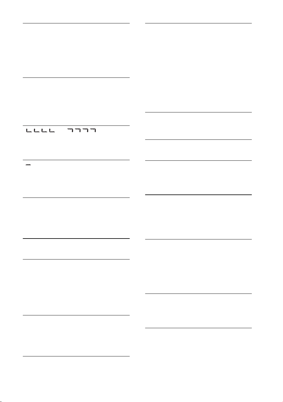
47
READ
La unidad está leyendo toda la información de
pistas y de álbumes del disco.
– Espere hasta que finalice la lectura y se inicie
la reproducción automáticamente. Es
posible que demore más de un minuto en
función de la estructura del disco.
USB NO SUPRT (USB no compatible)
El dispositivo USB conectado no es
compatible.
– Para obtener más información acerca de la
compatibilidad del dispositivo USB, visite el
sitio web de soporte técnico.
“” o “”
Durante la operación de avance o retroceso
rápido, llegó al principio o al final del disco,
por lo que no es posible continuar.
“”
No se puede mostrar el carácter con la unidad.
Para la función Bluetooth:
BT BUSY (Bluetooth no disponible)
La agenda telefónica y el historial de llamadas
del teléfono celular no son accesibles mediante
esta unidad.
– Espere un momento e inténtelo nuevamente.
EMPTY
El historial de llamadas está vacío.
ERROR
Falló BT Initialize.
Falló el acceso a la agenda telefónica.
El contenido de la agenda telefónica ha sido
modificado durante el acceso al teléfono
celular.
– Acceda a la agenda telefónica nuevamente.
MEM FAILURE (Error de memoria)
La unidad no pudo almacenar el contacto en la
marcación predefinida.
– Asegúrese de que el número que desea
almacenar sea correcto (página 27).
MEMORY BUSY
Esta unidad está almacenando datos.
– Espere a que termine el almacenamiento.
NO DEV (No hay dispositivo)
La fuente de audio Bluetooth se selecciona sin
que esté conectado un dispositivo Bluetooth.
El dispositivo de audio Bluetooth se ha
desconectado durante una llamada.
– Asegúrese de conectar un dispositivo de
audio Bluetooth.
La fuente del teléfono Bluetooth se selecciona
sin un teléfono celular conectado. El teléfono
celular se ha desconectado durante una
llamada.
– Asegúrese de conectar un teléfono celular.
NO INFO (Sin información)
El nombre de la red y del teléfono celular no se
reciben con el teléfono celular conectado.
P (número predefinido) EMPTY
La marcación predefinida está vacía.
UNKNOWN
El nombre o el número de teléfono no se
pueden visualizar al explorar una agenda
telefónica o un historial de llamadas.
WITHHELD
La persona que llama oculta el número de
teléfono.
Para la utilización de Pandora®:
CANNOT SKIP
No se permite saltear pistas en Pandora®.
– Espere hasta que finalice el comercial.
– Pandora® limita la cantidad de salteos
permitidos en su servicio. Espere a que
comience la siguiente pista o seleccione otra
emisora de la lista.
CHK DEV (Compruebe dispositivo)
Pandora® no se inicia.
– Inicie la aplicación Pandora® e inicie sesión
en su cuenta.
ERROR
Fallaron los comentarios de “Pulgares”.
– Intente “Pulgares arriba/abajo” nuevamente.
Falló la marcación como favorito.
– Intente marcar como favorito nuevamente.

48
NO STATION
No hay emisoras en su cuenta de Pandora®.
– Cree una emisora en el dispositivo móvil.
NOT ALLOWED
No se permiten los comentarios de “Pulgares”.
– Espere hasta que finalice el comercial.
– Algunas funciones, tales como Emisora
compartida, no permiten comentarios.
Espere a que comience la siguiente pista o
seleccione otra emisora de la lista.
No se permite marcar como favorito.
– Espere hasta que finalice el comercial.
– Seleccione otra pista o emisora y vuelva a
intentarlo.
OPEN APP (Abrir aplicación)
Cuando se conecta a través del puerto USB.
Pandora® no se inicia.
– Inicie la aplicación Pandora® en iPhone.
OPEN APP (Abrir aplicación), PRESS PAUSE
Cuando se conecta a través de la función
Bluetooth.
Pandora® no se inicia.
– Inicie la aplicación Pandora® en el
dispositivo móvil y luego presione
(PAUSE).
PAN NO SUPRT (Pandora® no compatible)
El dispositivo conectado no es compatible.
– Para obtener más información acerca de la
compatibilidad del dispositivo, visite el sitio
web de soporte técnico.
Si estas soluciones no ayudan a solucionar el
problema, póngase en contacto con el
distribuidor Sony más cercano.
Si entrega la unidad para su reparación a causa
de problemas en la reproducción de CD, lleve
el disco que se utilizó cuando se produjo el
problema.

©2012 Sony Corporation Printed in Thailand
http://www.sony.net/
http://esupport.sony.com
http://www.sony.com/caraudio
http://www.SONY.com