Models/Modelos: 796.6155*, 796.7155*
Kenmore Elite®
Dryer
Secadora
P/N MFL67652511
Sears Brands Management Corporation
Hoff man Estates, IL 60179 U.S.A.
www.kenmore.com
Sears Canada Inc.
Toronto, Ontario, Canada M5B 2C3
www.sears.ca
Use & Care Guide
Manual de Uso y Cuidado
English / Español
* = color number, número de color
®

2
TABLE OF CONTENTS
PRODUCT RECORD
Master Protection Agreements
Congratulations on making a smart purchase. Your new
Kenmore
®
product is designed and manufactured for
years of dependable operation. But like all products,
it may require preventive maintenance or repair from
time to time. That’s when having a Master Protection
Agreement can save you money and aggravation.
The Master Protection Agreement also helps extend the life
of your new product. Here’s what the Agreement* includes:
• Parts and labor not just for repairing defects, but to
help keep products operating properly
under normal
use. Our coverage goes well beyond the product
warranty. No deductibles, no functional failure
excluded from coverage – real protection.
• Expert service by experienced service technicians
trusted in millions of homes every year
.
• Unlimited service calls and nationwide service, as often
as you want us, whenever you want us.
• “No-lemon” guarantee – replacement of your
covered product after three separate product failures
occur within twelve months and a fourth repair is
required. Includes free delivery and installation, if
necessary, of replacement product.
• Product replacement if your covered product can't be fi xed.
• Annual Preventive Maintenance Check at your request—
no extra charge.
• Fast help by phone—phone support from a service
agent on on all products to help troubleshoot problems.
Think of us as a “talking owner’s manual.”
•
Power surge protection against electrical damage due
to
power fl uctuations.
• $300 food loss protection for any food spoilage that
is the result of mechanical failure of any covered
refrigerator or freezer.
• Service Promise: $50 if fi rst attempt repair of your
covered product can't be accomplished and product is
not usable while awaiting further repair service.
• Rental reimbursement if repair of your covered
product takes longer than promised.
• 25% discount off the regular price of any non-covered
repair service and related installed parts.
Once you purchase the Agreement, a simple phone call
is all that it takes for you to schedule service. You can
call anytime day or night.
The Master Protection Agreement is a risk-free purchase.
If you cancel for any reason during the product warranty
period, we will provide a full refund, or a prorated refund
anytime after the product warranty period expires.
Purchase your Master Protection Agreement today!
Some limitations and exclusions apply. For prices and
additional information in the U.S.A. call 1-800-827-6655.
*Coverage in Canada varies on some items. For full
details call Sears Canada at 1-800-361-6665.
Sears Installation Service
For Sears professional installation of home appliances,
garage door openers, water heaters, and other major
home items, in the U.S.A. call 1-844-553-6667 and in
Canada call 1-800-469-4663.
In the space below, record the date of purchase, model,
and serial number of your product. You will fi nd the
model and serial number printed on an identifi cation
plate located inside the dryer door. Have these items of
information available whenever you contact Sears
concerning your product.
Model No.
Date of Purchase
Serial No.
Save these instructions and your sales receipt for future
reference.
PROTECTION AGREEMENTS
IMPORTANT SAFETY INSTRUCTIONS ....................3-6
GROUNDING REQUIREMENTS ................................... 4
FEATURES AND BENEFITS
Key Parts and Components ........................................7
Accessories ................................................................... 7
INSTALLATION INSTRUCTIONS
Key Dimensions and Specifi cations ..........................8
Location Requirements ................................................8
Choose the Proper Location .......................................8
Clearances ....................................................................8
Gas Dryers .....................................................................9
Gas Requirements .................................................9
Electrical Requirements .........................................9
Connecting the Gas Supply ...............................10
Electric Dryers .............................................................11
Electrical Requirements ........................................11
Connecting Electric Dryers ................................ 12
Venting the Dryer .................................................13-14
Connecting the Inlet Hose ......................................... 15
Leveling the Dryer ..................................................... 16
Reversing the Two-Way Door .............................17-22
Final Installation Check ............................................23
HOW TO USE
Control Panel Features ............................................ 24
Time and Status Display ..........................................25
Operating the Dryer ................................................ 26
Sorting Loads ............................................................ 27
Loading the Dryer .................................................... 27
Cycle Guide ........................................................ 28-29
Using the Two-Way Door ........................................ 30
Cycle Modifi er Buttons .............................................32
Cycle Options and Special Features ......................33
Steam Features .......................................................... 34
Steam Cycle Guide ....................................................35
USER MAINTENANCE INSTRUCTIONS
Regular Cleaning ......................................................36
Cleaning the Exterior ......................................... 36
Cleaning the Interior .......................................... 36
Cleaning Around and Under the Dryer ...........36
Cleaning the Lint Filter .......................................36
Maintaining the Exhaust System ....................... 37
Kenmore Connect
™
System ......................................... 38
TROUBLESHOOTING GUIDE
FAQs ............................................................................39
Before Calling for Service ................................ 39-42
WARRANTY ...................................................................43
SERVICE ..........................................................Back Cover
3
IMPORTANT SAFETY INSTRUCTIONS
READ ALL INSTRUCTIONS BEFORE USE
DANGER:
WARNING:
Your safety and the safety of others is very important.
We have provided many important safety messages in this manual and on your appliance. Always read and
obey all safety messages.
This is the safety alert symbol.
This symbol alerts you to potential hazards that can kill or hurt you and others.
All safety messages will follow the safety alert symbol and either the word DANGER or WARNING.
These words mean:
• Do not install a clothes dryer with fl exible plastic venting materials. If a fl exible metal (foil type) duct is installed,
it must be of a specifi c type identifi ed by the appliance manufacturer as suitable for use with clothes dryers.
Flexible venting materials are known to collapse, be easily crushed, and trap lint. These conditions will obstruct
clothes dryer airfl ow and increase the risk of fi re.
WARNING:
For your safety, the information in this manual must be followed to
minimize the risk of fi re, explosion, or electric shock, or to prevent property damage, personal injury,
or loss of life.
Indicates a hazardous situation which, if not avoided, could result in death or serious injury.
Indicates a hazardous situation which, if not avoided, will result in death or serious injury.
All safety messages will tell you what the potential hazard is, tell you how to reduce the chance of injury, and
tell you what can happen if the instructions are not followed.
CAUTION:
Indicates a hazardous situation which, if not avoided, could result in minor or
moderate injury.
SAVE THESE INSTRUCTIONS
FIRE HAZARD
Failure to follow safety warnings exactly could result in serious injury, death or property damage.
• Do not install a booster fan in the exhaust duct.
• Install all clothes dryers in accordance with the installation instructions of the manufacturer of the dryer.
WARNING
FIRE OR EXPLOSION HAZARD
Failure to follow safety warnings exactly could result in serious injury, death or property damage.
• Do not store or use gasoline or other fl ammable vapors and liquids in the vicinity of this or any other
appliance.
• Installation and service must be performed by a qualifi ed installer, service agency or the gas supplier.
WHAT TO DO IF YOU SMELL GAS:
1. Do not try to light a match or cigarette, or turn on any gas or electrical appliance.
2. Do not touch any electrical switches. Do not use any phones in your building.
3. Clear the room, building, or area of all occupants.
4. Immediately call your gas supplier from a neighbor’s phone. Carefully follow the gas supplier’s
instructions
.
5. If you cannot reach your gas supplier, call the fi re department.
WARNING
4
IMPORTANT SAFETY INSTRUCTIONS
• Read all instructions before using the dryer.
• Before use, the dryer must be properly installed, as
described in this manual.
• Do not place items exposed to cooking oils in your
dryer. Items contaminated with cooking oils may
contribute to a chemical reaction that could cause a
load to catch fi re.
• Do not dry articles that have been previously cleaned
in, washed in, soaked in, or spotted with gasoline,
dry-cleaning solvents, or other fl ammable or explosive
substances, as they give off vapors that could ignite
or explode.
• Do not reach into the dryer if the drum or any other
part is moving.
• Do not repair or replace any part of the dryer or
attempt any servicing unless specifi cally recommended
in this Use and Care Guide or in published user-repair
instructions that you understand and have the skills to
carry out.
• Do not tamper with controls.
• Before the dryer is removed from service or discarded,
remove the door to the drying compartment.
CALIFORNIA SAFE DRINKING WATER AND TOXIC ENFORCEMENT ACT
This act requires the Governor of California to publish a list of substances known to the state to cause cancer,
birth defects, or other reproductive harm and requires businesses to warn customers of potential exposure to
such substances. Gas appliances can cause minor exposure to four of these substances, namely benzene, carbon
monoxide, formaldehyde, and soot, caused primarily by the incomplete combustion of natural gas or LP fuels.
Properly adjusted dryers will minimize incomplete combustion. Exposure to these substances can be minimized
further by properly venting the dryer to the outdoors.
GROUNDING REQUIREMENTS
This appliance must be grounded. In the event of malfunction or breakdown, grounding will reduce the risk of
electric shock by providing a path of least resistance for electric current. This appliance must be equipped with
a cord having an equipment-grounding conductor and a grounding plug. The plug must be plugged into an
appropriate outlet that is properly installed and grounded in accordance with all local codes and ordinances.
Improper connection of the equipment-grounding conductor can result in a risk of
electric shock. Check with a qualifi ed electrician or service person if you are in doubt as to whether the appliance
is properly grounded. Do not modify the plug provided with the appliance. If it will not fi t the outlet, have a proper
outlet installed by a qualifi ed electrician. This appliance must be connected to a grounded metal, permanent
wiring system or an equipment grounding conductor must be run with the circuit conductors and connected to the
equipment grounding terminal or lead on the appliance. Electrical shock can result if the dryer is not properly
grounded.
• Do not allow children to play on or in the dryer. Close
supervision of children is necessary when the dryer is
used near children.
• Do not use fabric softeners or products to eliminate
static unless recommended by the manufacturer of the
fabric softener or product.
• Do not use heat to dry articles containing foam rubber
or similarly textured rubber-like materials.
• Keep area around the exhaust opening and adjacent
surrounding areas free from the accumulation of lint,
dust, and dirt.
• The interior of the dryer and exhaust vent should be
cleaned periodically by qualifi ed service personnel.
• Do not install or store the dryer where it will be
exposed to the weather.
• Always check the inside of the dryer for
foreign objects.
• Clean the lint fi lter before or after each load.
• This product contains chemicals known to the State of
California to cause cancer and birth defects or other
reproductive harm. Wash hands after handling.
BASIC SAFETY PRECAUTIONS
WARNING:
WARNING:
To reduce the risk of fi re, electric shock, or injury to persons when using this appliance,
follow basic precautions, including the following:

5
• Properly ground dryer to conform with all governing
codes and ordinances. Follow details in the installation
instructions. Electrical shock can result if the dryer is not
properly grounded.
• Before use, the dryer must be properly installed as
described in this manual. Electrical shock can result if
the dryer is not properly grounded.
• Install and store the dryer where it will not be exposed
to temperatures below freezing or exposed to
the weather.
• All repairs and servicing must be performed by an
authorized service technician unless specifi cally
recommended in this Owner’s Guide. Use only
authorized factory parts. Failure to follow this warning
can cause serious injury, fi re, electrical shock, or death.
• To reduce the risk of electrical shock, do not install the
dryer in humid spaces. Failure to follow this warning
can cause serious injury, fi re, electrical shock, or death.
• Connect to a properly rated, protected, and sized
power circuit to avoid electrical overload. Improper
power circuits can melt, creating risk of electrical shock
and/or fi re hazard.
• Gas dryers MUST be exhausted to the outside. Failure
to follow these instructions can result in fi re or death.
• The dryer exhaust system must be exhausted to the
outside of the dwelling. If the dryer is not exhausted
outdoors, some fi ne lint and large amounts of
moisture will be expelled into the laundry area. An
accumulation of lint in any area of the home can
create a health and fi re hazard.
• Use only rigid metal or fl exible metal 4 inch diameter
duct inside the dryer cabinet or for exhausting to the
outside. Use of plastic or other combustible ductwork
can cause a fi re. Punctured ductwork can cause a fi re
if it collapses or becomes otherwise restricted in use or
during installation.
• Ductwork is not provided with the dryer, and you
should obtain the necessary ductwork locally. The end
cap should have hinged dampers to prevent backdraft
when the dryer is not in use. Failure to follow these
instructions can result in fi re or death.
• Remove all packing items and dispose of all shipping
materials properly. Failure to do so can result in death,
fi re, explosion, burns, or death.
• Place dryer at least 18 inches above the fl oor for a
garage installation. Failure to do so can result in fi re,
explosion, burns, or death.
• Keep all packaging from children. Packaging material
can be dangerous for children. There is a risk of
suff ocation.
• Do not install near items that produce heat or open
fl ame such as stoves or cooking ovens. Failure to follow
this warning can cause product deformation, smoke and
fi re.
• Do not place candles or cigarettes on top of the
product. Failure to follow this warning can cause
product deformation, smoke and fi re.
• Remove all protective vinyl fi lm from the product.
Failure to do so can cause product deformation, smoke
and fi re.
• The exhaust duct must be 4 inches (10.2 cm) in
diameter with no obstructions. The exhaust duct
should be kept as short as possible. Make sure to
clean any old ducts before installing your new dryer.
Failure to follow these instructions can result in fi
re or
death.
• Rigid or semi rigid metal ducting is recommended
for use between the dryer and the wall. In special
installations when it is impossible to make a
connection with the above recommendations, a UL
listed fl exible metal transition duct may be used
between the dryer and wall connection only. The
use of this ducting will aff ect drying time. Failure to
follow these instructions can result in fi re or death.
• DO NOT use sheet metal screws or other fasteners
which extend into the duct that could catch lint and
reduce the effi ciency of the exhaust system. Secure
all joints with duct tape. For complete details, follow
the Installation Instructions. Failure to follow these
instructions can result in fi re or death.
IMPORTANT SAFETY INSTRUCTIONS
SAFETY INSTRUCTIONS FOR INSTALLATION
Exhaust/Ducting:
WARNING:
To reduce the risk of fi re, electric shock, or injury to persons when using this appliance,
follow basic precautions, including the following:
6
SAFETY INSTRUCTIONS FOR CONNECTING ELECTRICITY
WARNING:
To reduce the risk of fi re, electric shock, or injury to persons when using this appliance,
follow basic precautions, including the following:
• Do not, under any circumstances, cut or remove
the ground prong from the power cord. To prevent
personal injury or damage to the dryer, the electrical
power cord must be plugged in to a properly
grounded outlet.
• For personal safety, this dryer must be properly
grounded. Failure to do so can result in electrical
shock or injury.
• Refer to the installation instructions in this manual
for specifi c electrical requirements for your model.
Failure to follow these instructions can create an
electrical shock hazard and/or a fi re hazard.
• This dryer must be plugged in to a properly grounded
outlet. Electrical shock can result if the dryer is not
properly grounded. Have the wall outlet and circuit
checked by a qualifi ed electrician to make sure the
outlet is properly grounded. Failure to follow these
instructions can create an electrical shock hazard
and/or a fi re hazard.
• The dryer should always be plugged in to its own
individual electrical outlet which has a voltage rating
that matches the rating plate. This provides the best
performance and also prevents overloading house
wiring circuits which could cause a fi re hazard from
overheated wires.
• Never unplug your dryer by pulling on the power
cord. Always grip the plug fi rmly and pull straight
out from the outlet. The power cord can be damaged,
resulting in a risk of fi re and electrical shock.
• Repair or replace immediately all power cords that
have become frayed or otherwise damaged. Do not
use a cord that shows cracks or abrasion damage
along its length or at either end. The power cord can
melt, creating electrical shock and/or fi re hazard.
• When installing or moving the dryer, be careful not
to pinch, crush, or damage the power cord. This will
prevent injury and prevent damage to the dryer from
fi re and electrical shock.
IMPORTANT SAFETY INSTRUCTIONS
SAFETY INSTRUCTIONS FOR STEAM FUNCTIONS
WARNING:
To reduce the risk of fi re, electric shock, or injury to persons when using this appliance,
follow basic precautions, including the following:
• Do not open the dryer door during steam cycles.
Failure to follow these instructions can result in a burn
hazard.
• Do not dry articles that have been previously
cleaned in, washed in, soaked in, or spotted with
gasoline, dry-cleaning solvents, or other fl ammable
or explosive substances as they give off vapors
that could ignite or explode. Failure to follow these
instructions can result in fi re or death.
• Do not fi ll the steam feeder with gasoline, dry-
cleaning solvents, or other fl ammable or explosive
substances. Failure to follow these instructions can
result in fi re or death.
• Do not touch the steam nozzle in the drum during
or after the steam cycle. Failure to follow these
instructions can result in a burn hazard.
• Do not fi ll the steam feeder with hot water (over
86°F/30°C). Failure to follow these instructions can
result in a burn hazard.
7
FEATURES AND BENEFITS
KEY PARTS AND COMPONENTS
EASY-TO-USE CONTROL PANEL
Rotate the cycle selector knob to select the desired
dry cycle. Add cycle options or adjust settings with the
touch of a button.
TIME AND STATUS DISPLAY
The easy-to-read LED display shows cycle status and
estimated time remaining.
CYCLE MODIFIERS
Adjust the cycle defaults such as temperature and dry
level with the touch of a button.
NOTE: Not all settings are available for all cycles.
CHECK VENT
(Duct Blockage Sensing System)
The CHECK VENT (Duct blockage sensing system)
detects and alerts you to blockages in the exhaust
system that reduce airfl ow from the dryer.
Maintaining clean exhaust system ducts improves
operating effi ciency and helps minimize service calls,
saving you money.
LARGE CAPACITY STEEL DRUM WITH DRUM LIGHT
The ultra-large stainless steel drum off ers superior
durability. The drum light can be turned on during a
cycle by using the DRUM LIGHT button on the control
panel. The light also comes on when the door is
opened, if the control is ON.
EASY-ACCESS REVERSIBLE DOOR
The wide-opening, see-through glass door provides
easy access for loading and unloading. Door swing
can be reversed to adjust for installation location.
FRONT-MOUNT LINT FILTER
The front-mount lint fi lter allows for easy access and
cleaning between loads.
LEVELING FEET
Four leveling feet (two in front, and two in back)
adjust to improve dryer stability on uneven fl oors.
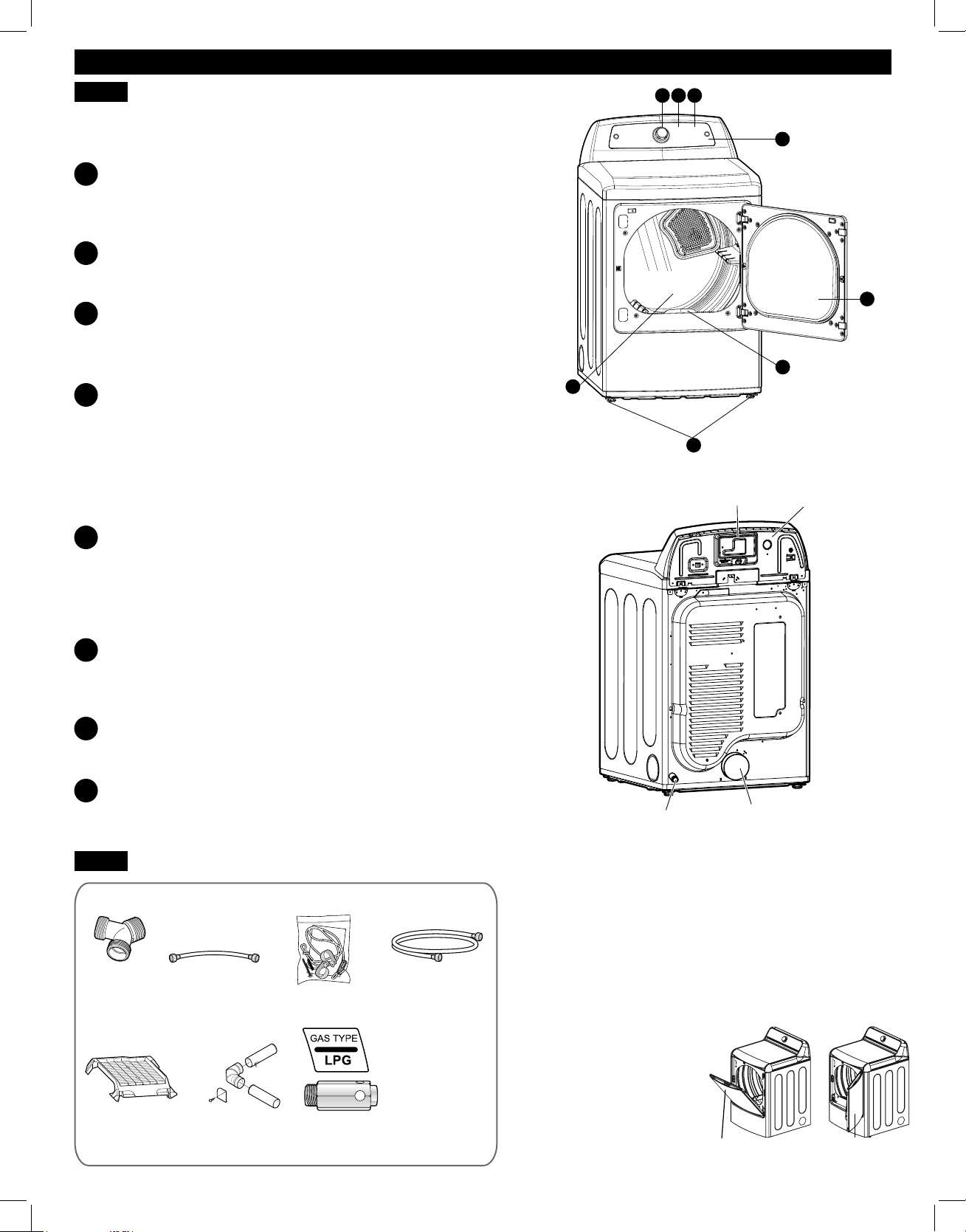
There are several important components that are
referenced in this manual.
A
B
C
D
E
F
G
H
Rear of Dryer
Terminal Block
Access Panel
(Electric Models)
Power Cord
Location
(Gas Models)
Exhaust Duct
Outlet
Gas Connection
Location
(Gas Models)
ACCESSORIES
H
G
AD B
E
F
C
Front of Dryer
Two-Way Reversible Door (on some models)
Optional Accessories
(steam models)
Y connector short hose
(steam models)
side vent kit
(sold separately)
Kit No. D26-49670
safety tether kit
(on some models)
drying rack
(sold separately)
No. 3750EL0001C
Included Accessories
LP conversion kit
No. 383EEL3002D
Required Accessories
long hose
(sold separately)
(steam models)
Safety Tether Kit
This optional kit helps prevent the dryer tipping if
children climb on the door or if someone should fall
onto the door. It is recommended that you install this
kit, depending on your situation, but it is not required.
Follow the customer installation instructions included
with the kit to properly install the kit. If you do not
install the kit, store it out of reach of children.
hamper door swing door
Open the dryer door from
the top, hamper-style,
when loading the dryer to
help guide clothes into the
drum and prevent them from
falling onto the fl oor.
When unloading the
dryer or loading bulkier
items, use the swing door for
easy access to the drum.

8
INSTALLATION INSTRUCTIONS
KEY DIMENSIONS AND SPECIFICATIONS
LOCATION REQUIREMENTS
IMPORTANT: Read all installation instructions
completely before installing and operating your dryer.
It is important that you review this entire manual before
installing and using your dryer. It contains detailed
instructions concerning electrical connections, gas
connections and exhaust requirements.
CHOOSE THE PROPER LOCATION
• Store and install the dryer where it will not be exposed
to temperatures below freezing or exposed to outdoor
weather conditions.
• Choose a location with a solid, level fl oor.
• If the dryer is being installed in a garage, place the
dryer at least 18 inches (45.7cm) above the fl oor.
• Properly ground the dryer to conform with all
governing codes and ordinances.
• To reduce the risk of electric shock, do not install the
dryer in damp or wet locations.
NOTE: Installing the dryer in a humid space, or
installing or storing the dryer where it will be exposed
to the weather or freezing temperatures, may result in
rust or other damage that is not covered by the product
warranty.
IMPORTANT: If you are installing the dryer in a
manufactured or mobile home, refer to the
Special Electrical Requirements for Mobile or
Manufactured Homes section.
CLEARANCES
• Most installations require a minimum 5 ½ inch (14 cm)
clearance behind the dryer for the exhaust ducting.
• Allow minimum clearances of at least 1 inch (2.5 cm)
on the sides and back to minimize vibration and noise.
• Allowing additional clearance for installation and
servicing is recommended.
• Be sure to allow for wall, door, or fl oor moldings that
may increase the required clearances.
• Allow at least 21 inches (53.3 cm) in front of the dryer
to open the door.
Additional Instructions for Closet Installations
The closet door must allow for suffi cient airfl ow. Refer to the
diagram above for minimum vent opening requirements. A
louvered door is also acceptable.
Description Dryer Dryer (Gas and Electric)
Electrical Requirements Refer to the rating label
Gas Requirements* NG: 4–10.5 inches WC
Gas Requirements* LP: 8–13 inches WC
Dimensions 27 in. (W) X 28.9 in. (D) X 45 in. (H), 50
¼
in. (D with door open)
68.6 cm (W) X 73.4 cm (D) X 114.1 cm (H), 127.5 cm (D with door open)
Net Weight Electric : 127.9 lb. (58 kg) Gas : 130.5 lb. (59.2 kg)
Drying Capacity IEC 7.3 cu. ft.
*Gas Models Only
21 ¼"
(54 cm)
4"
(10 cm)
4"
(10 cm)
1"
(2.5 cm)
1"
(2.5 cm)
28
15
e
16
"
(73.4 cm)
27"
(68.6 cm)
50 ¼"
(127.5 cm)
3"
(7.6 cm)
3"
(7.6 cm)
48 in.
2
(310 cm)
34 in.
2
(155 cm)
Closet Door Clearance Requirements
9
INSTALLATION INSTRUCTIONS
GAS DRYERS
GAS REQUIREMENTS (GAS MODELS ONLY)
To reduce the risk of fi re,
electric shock, or injury to persons when using this
appliance, follow basic precautions, including
the following:
WARNING:
• Gas supply requirements: As shipped from the
factory, this dryer is confi gured for use with natural
gas (NG). It can be converted for use with propane
(LP) gas. Gas pressure must not exceed 8 inches
water column for (NG), or 13 inches water column for
(LP).
• A qualifi ed service or gas company technician must
connect the dryer to the gas service. Failure to follow
these instructions can result in fi re, explosion, or death.
• Isolate the dryer from the gas supply system by
closing its individual manual shutoff valve during any
pressure testing of the gas supply. Failure to do so can
result in fi re, explosion, or death.
• Supply line requirements: Your laundry room must
have a rigid gas supply line to your dryer. In the
United States, an individual manual shutoff valve
MUST be installed within at least 6 ft. (1.8 m) of the
dryer, in accordance with the National Fuel Gas Code
ANSI Z223.1 or Canadian gas installation code CSA
B149.1. A ⅛ inch NPT pipe plug must be installed.
Failure to do so can result in fi re, explosion, or death.
• If using a rigid pipe, the rigid pipe should be ½ inch
IPS. If acceptable under local codes and ordinances
and when acceptable to your gas supplier, ⅜ inch
approved tubing may be used where lengths are less
than 20 ft. (6.1 m). Larger tubing should be used for
lengths in excess of 20 ft. (6.1 m). Failure to do so can
result in fi re, explosion, or death.
ELECTRICAL REQUIREMENTS FOR
GAS MODELS ONLY
Failure to follow safety warnings could result in serious
injury or death.
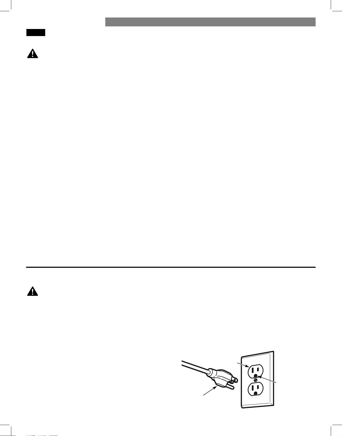
• The power cord of this dryer is equipped with a
3-prong (grounding) plug for protection against
shock hazard and should be plugged directly into
a properly grounded 3-prong receptacle. Failure to
follow this warning can result in fi re, explosion, or death.
• Do not, under any circumstances, cut or remove the
third (ground) prong from the power cord. Failure
to follow this warning can result in fi re, explosion, or
death.
• For personal safety, this dryer must be properly
grounded. Failure to follow this warning can result in
fi re, explosion, or death.
• This dryer must be plugged into a 120-VAC, 60-Hz.
grounded outlet protected by a 15-ampere fuse or
circuit breaker. Failure to follow this warning can result
in fi re, explosion, or death.
• Where a standard 2-prong wall outlet is encountered,
it is your personal responsibility and obligation to
have it replaced with a properly grounded 3-prong
wall outlet. Failure to follow this warning can result in
fi re, explosion, or death.
• Connect the dryer to the type of gas shown on
the nameplate. Failure to do so can result in fi re,
explosion, or death.
• To prevent contamination of the gas valve, purge the
gas supply of air and sediment before connecting
the gas supply to the dryer. Before tightening the
connection between the gas supply and the dryer,
purge remaining air until the odor of gas is detected.
Failure to do so can result in fi re, explosion, or death.
• DO NOT use an open fl ame to inspect for gas leaks.
Use a noncorrosive leak detection fl uid. Failure to do
so can result in fi re, explosion, or death.
• Use only a new AGA- or CSA-certifi ed gas supply
line with fl exible stainless steel connectors. Failure to
do so can result in fi re, explosion, or death.
• Securely tighten all gas connections. Failure to do so
can result in fi re, explosion, or death.
• Use Tefl on tape or a pipe-joint compound that is
insoluble in propane (LP) gas on all pipe threads.
Failure to do so can result in fi re, explosion,
or death.
• DO NOT attempt any disassembly of the dryer;
disassembly requires the attention and tools of
an authorized and qualifi ed service technician or
company. Failure to follow this warning can result in fi re,
explosion, or death.
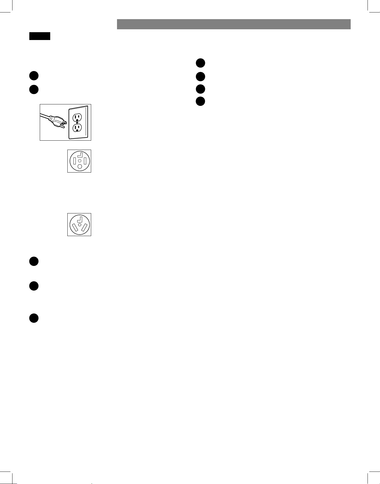
3-prong
grounding
plug
3-prong
grounding
type wall
receptacle
Ensure proper
ground exists
before use.
WARNING: ELECTRIC SHOCK HAZARD
10
To reduce the risk of fi re,
electric shock, or injury to persons when using this
appliance, follow basic precautions, including
the following:
• Installation and service must be performed by a
qualifi ed installer, service agency, or the gas supplier.
Failure to do so can result in fi re, explosion, or death.
• Use only a new stainless steel fl exible connector and
a new AGA-certifi ed connector. Failure to do so can
result in fi re, explosion, or death.
• A gas shutoff valve must be installed within 6 ft.
(1.8 m) of the dryer. Failure to do so can result in fi re,
explosion, or death.
• The dryer is confi gured for natural gas when
shipped from the factory. Make sure that the dryer
is equipped with the correct burner nozzle for the
type of gas being used (natural gas or propane gas).
Failure to do so can result in fi re, explosion, or death.
CONNECTING THE GAS SUPPLY
NOTE: This dryer is confi gured from the factory set for
natural gas (NG). If the dryer is to be used with
propane (LP) gas, it must be converted by a qualifi ed
service technician.
Make sure that the gas supply to the laundry room is
turned OFF and the dryer is unplugged. Confi rm that
the type of gas available in the laundry room is
appropriate for the dryer.
Remove the shipping cap from the gas fi tting at the
back of the dryer. Be careful not to damage the
threads of the gas connector when removing the
shipping cap.
Connect the dryer to the laundry room’s gas supply
using a new fl exible stainless steel connector with a ⅜
inches NPT fi tting.
NOTE: DO NOT use old connectors.
Securely tighten all connections between the dryer
and the laundry room’s gas supply.
Turn on the laundry room’s gas supply.
Check all pipe connections (both internal and external)
for gas leaks with a noncorrosive leak-detection fl uid.
Proceed to Venting the Dryer (refer to pages 13-14).
High-Altitude Installations
The BTU rating of this dryer is AGA-certifi ed for
elevations below 10,000 feet.
If your gas dryer is being installed at an elevation
above 10,000 feet, it must be derated by a qualifi ed
technician or gas supplier.
• If necessary, the correct nozzle (for the LP nozzle kit,
order part number 383EEL3002D) should be installed
by a qualifi ed technician and the change should be
noted on the dryer. Failure to do so can result in fi re,
explosion, or death.
• All connections must be in accordance with local
codes and regulations. Failure to do so can result in
fi re, explosion, or death.
• Gas dryers MUST exhaust to the outdoors. Failure to do
so can result in fi re, explosion, or death.
WARNING:
1
2
3
4
5
6
7
INSTALLATION INSTRUCTIONS
⅜ in. NPT Gas
Connection
⅛ in. NPT Pipe Plug
AGA/CSA-Certified
Stainless Steel Flexible
Connector
Gas Supply
Shutoff Valve
GAS DRYERS (continued)
11
ELECTRIC DRYERS
ELECTRICAL REQUIREMENTS
To help prevent fi re,
electrical shock, serious injury, or death, the wiring
and grounding must conform to the latest edition of
the National Electrical Code, ANSI/NFPA 70 and
all applicable local regulations. Contact a qualifi ed
electrician to check the home’s wiring and fuses to ensure
that the home has adequate electrical power to operate
the dryer.
To reduce the risk of
fi re, electric shock, or injury to persons when using this
appliance, follow basic precautions, including
the following:
• Any installation in a manufactured or mobile
home must comply with the Manufactured Home
Construction and Safety Standards Title 24 CFR, Part
32-80 or Standard CAN/CSA0Z240 MH and local
codes and ordinances.
• A 4-wire connection is required for all mobile and
manufactured home installations, as well as all new
construction after January 1, 1996. Failure to follow
this requirement can result in fi re, explosion, or death.
• This dryer must be connected to a grounded metal,
permanent wiring system, or an equipment grounding
conductor must be run with the circuit conductors and
connected to the equipment grounding terminal or
lead on the dryer. Failure to do so can result in fi re,
explosion, or death.
• The dryer has its own terminal block that must be
connected to a separate 240 VAC, 60-Hertz, single
phase circuit, fused at 30 amperes (the circuit must be
fused on both sides of the line). ELECTRICAL SERVICE
FOR THE DRYER SHOULD BE OF THE MAXIMUM
RATE VOLTAGE LISTED ON THE NAMEPLATE. DO
NOT CONNECT THE DRYER TO A 110-, 115-, OR 120-
VOLT CIRCUIT. Failure to follow these instructions can
result in fi re, explosion, or death.
• If the branch circuit to the dryer is 15 ft. (4.5 m) or
less in length, use UL (Underwriters Laboratories)
listed No.-10 AWG wire (copper wire only), or as
required by local codes. If over 15 ft. (4.50 m), use
UL-listed No.-8 AWG wire (copper wire only), or as
required by local codes. Allow suffi cient slack in the
wiring so the dryer can be moved from its normal
location when necessary. Failure to do so can result in
fi re, explosion, or death.
• The power cord (pigtail) connection between the
wall receptacle and the dryer terminal block IS NOT
supplied with the dryer. The type of pigtail and
gauge of wire must conform to local codes and with
instructions on the following pages. Failure to follow
these instructions can result in fi re, explosion, or death
• A 4-wire connection is required for all new
construction after January 1, 1996. A 4-wire
connection must be used where local codes do not
permit grounding through the neutral wire. Failure to
do so can result in fi re, explosion, or death.
To reduce the risk of fi re,
electric shock, or injury to persons when using this
appliance, follow basic precautions, including the
following:
WARNING:
WARNING:
WARNING:
Special Electrical Requirements for Mobile
or Manufactured Homes
Electrical Requirements for Electric Models Only
INSTALLATION INSTRUCTIONS
12
ELECTRIC DRYERS (continued)
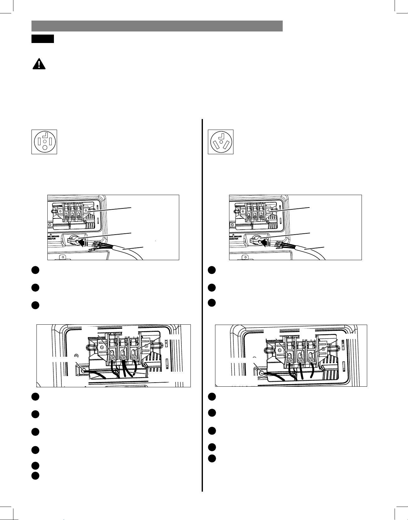
CONNECTING ELECTRIC DRYERS
Connect the power cord to the terminal block. Each
colored wire should be connected to the same color
screw. Wire color indicated on manual is connected to
the same color screw in block. Failure to follow these
instructions may result in a short or overload.
Four-Wire Power Cord
• A 4-wire connection is required for all
mobile and manufactured home installations,
as well as all new construction after
January 1, 1996.
• A UL-listed strain relief is required.
• Use a 30-amp, 240-volt, 4-wire, UL-listed power cord
with #10 AWG-minimum copper conductor and closed
loop or forked terminals with upturned ends.
Remove the terminal block access cover on the upper
back of the dryer.
Install a UL-listed strain relief into the power cord
through-hole.
Thread a 30-amp, 240-volt, 4-wire, UL-listed power
cord with #10 AWG-minimum copper conductor
through the strain relief.
Transfer the dryer’s ground wire from behind the green
ground screw to the center screw of the terminal block.
Attach the two hot leads of the power cord to the outer
terminal block screws.
Attach the white neutral wire to the center screw of
the terminal block.
Attach the power cord ground wire to the green
ground screw.
TIGHTEN ALL SCREWS SECURELY.
Reinstall the terminal block access cover.
Attach the two hot leads (black and red) of the
power cord to the outer terminal block screws.
Attach the neutral (white) wire to the center terminal
block screw.
Connect the external ground (if required by local
codes) to the green ground screw.
TIGHTEN ALL SCREWS SECURELY.
Reinstall the terminal block access cover.
Grounding through the neutral conductor is prohibited
for: (1) new branch-circuit installations, (2) mobile
homes, (3) recreational vehicles, and (4) areas where
local codes prohibit grounding through the
neutral conductor.
Three-Wire Power Cord
• A 3-wire connection is NOT permitted on
new construction after January 1, 1996.
• A UL-listed strain relief is required.
• Use a 30-amp, 240-volt, 3-wire, UL-listed power cord
with #10 AWG-minimum copper conductor and closed
loop or forked terminals with upturned ends.
Remove the terminal block access cover on the upper
back of the dryer.
Install a UL-listed strain relief into the power cord
through-hole.
Thread a 30-amp, 240-volt, 3-wire, UL-listed power
cord with #10 AWG-minimum copper conductor
through the strain relief.
WARNING:
1
44
2
5
5
3
6
7
8
9
6
7
8
3
2
1
INSTALLATION INSTRUCTIONS
UL-Listed
Strain Relief
UL-Listed 4-Wire
Power Cord
Te r minal
Block
UL-Listed
Strain Relief
UL-Listed 3-Wire
Power Cord
Te r minal
Block
Power Cord
Ground Wire
White wire moved
from ground screw
Ground Screw
Hot (Red)
Neutral
(White)
Hot
(Black)
White wire from
dryer harness
Ground Screw
Hot (Red)
Neutral
(White)
Hot
(Black)
13
VENTING THE DRYER
CHECK THE EXHAUST SYSTEM FOR PROBLEMS
IMPORTANT!
The most common cause of dryer problems is poor exhaust venting. Before installing the new dryer, check the items
listed below to make sure to get the best possible performance. This can save time and money by reducing cycle
times and increasing energy effi ciency.
• DIRTY OR DAMAGED EXHAUST DUCTS. Lint builds up in exhaust ducts over time. This decreases the airfl ow and
makes the dryer work harder. Visually inspect the ducts from both ends and have them cleaned if they have not
been cleaned recently.
• WRONG VENT MATERIAL. Check the vent to make sure it is rigid or semi-rigid metal ducting. If the venting is
plastic or fl exible foil, have it replaced before using the dryer.
• RESTRICTED OR DAMAGED VENT HOOD. Check the vent hood outside. It must be clean and free of lint buildup.
Check the damper and make sure it opens fully and easily.
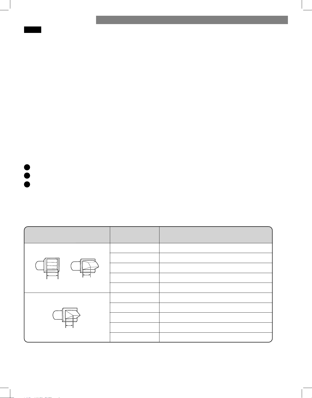
• EXCESSIVELY LONG VENT. Measure the length of the exhaust system and count the elbows. Use the chart below to
see if the duct is too long. If it is too long, have the duct routed to another location that is within the
venting guidelines.
• DO NOT USE PLASTIC OR FOIL VENTING. The transition duct from the dryer to the wall must be rigid or
semi-rigid metal ducting. If the old transition duct is plastic or foil, REPLACE IT with semi-rigid metal ducting.
Using the DUCT LENGTH CHART (below)
Find the existing vent hood type in the chart below.
Select the row that matches the number of elbows in the dryer duct run.
Look to the right of the elbow number for the maximum duct length for the installation. Longer duct length will result
in reduced drying performance, longer dry times and increased energy consumption. Extremely long ducts can even
shorten the life of the dryer.
DO NOT exceed the maximum length for the vent hood type and number of elbows used.
DUCT LENGTH CHART
NOTE: Deduct 6 ft. (1.8 m) for each additional elbow. Using more than four 90° elbows is not recommended.
1
2
3
INSTALLATION INSTRUCTIONS
Recommended
Only for Short-Run Installations
4"
(10.2 cm )
4"
(10.2 cm )
(6.35 cm )
Number of 90°
Elbows
Vent Hood Type
Maximum length of 4" (10.2 cm )
diameter rigid metal duct
65 feet (19.8 m)
55 feet (16.8 m)
47 feet (13.7 m)
36 feet (11.0 m)
28 feet (8.5 m)
55 feet (16.8 m)
47 feet (13.7 m)
41 feet (12.5 m)
30 feet (9.1 m)
22 feet (6.7 m)
0
1
2
3
4
0
1
2
3
4
2 ½"
14
VENTING THE DRYER (continued)
Routing and Connecting Ductwork
Follow the guidelines below to maximize dryer
performance and reduce lint buildup and condensation
in the ductwork.
NOTE: Transition duct and fi ttings are NOT included
and must be purchased separately.
• Use 4 inch (102mm) diameter rigid or semi-rigid
metal duct.
• The exhaust duct run should be as short as possible.
• Use as few elbow joints as possible.
• The male end of each section of exhaust duct must
point away from the dryer.
• Use duct tape on all joints. Never use screws.
• Insulate ducts that run through unheated areas in
order to reduce condensation and lint buildup on
duct surfaces.
• The total length of semi-rigid metal transition duct
should not exceed 8 ft. (2.4 m).
IMPORTANT: Failure to exhaust the dryer, per the
guidelines included within these instructions, may
result in unsatisfactory dryer performance. All venting
and ductwork beyond the exterior of the dryer is the
responsibility of the consumer. Product failure, as
a result of improper venting, is not covered by the
manufacturer’s warranty.
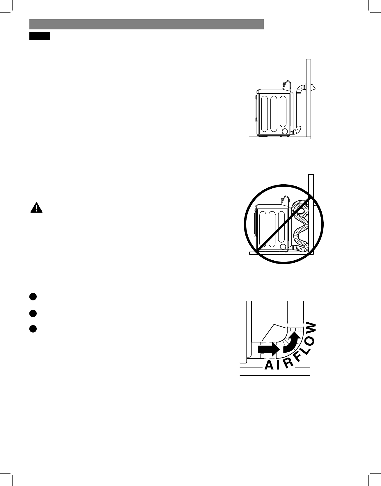
Connecting the Dryer Vent
Verify all ducts and elbows are clean and free
from any blockages.
Measure duct length. DO NOT exceed the
maximum length listed in the Duct Length Chart.
Connect dryer exhaust to existing duct.
Failure to follow these
guidelines will result in poor performance, product
failure, and/or result in fi re or death.
WARNING:
1
2
3
• Only use duct tape or clamps.
• DO NOT use screws to secure ductwork.
• Use rigid or semi-rigid metal ducts.
• DO NOT use plastic or thin metal foil tubing
for ductwork.
• The male end of each elbow must always point in
the direction of the airfl ow.
Male
Ends
Correct Venting
Incorrect Venting
NOTE: Be careful when moving the dryer into its
fi nal location. Do NOT crush the duct. Make sure the
connections do not come loose.
INSTALLATION INSTRUCTIONSINSTALLATION INSTRUCTIONS
15
CONNECTING THE INLET HOSE
The dryer must be connected to the cold water tap
using the new water supply hose. Do not use old hoses.
NOTE:
• Water supply pressure must be between 20 psi and
120 psi (138–827 kPa).
• Do not strip or cross-thread when connecting inlet hose
to the valve.
• If the water supply pressure is more than 120 psi
(827kPa), a pressure reducing valve should be
installed.
• Periodically check the condition of the hose and
replace the hose if necessary.
• Replace inlet hoses after 5 years of use to reduce the
risk of hose failure.
• Record hose installation or replacement dates on the
hoses for future reference.
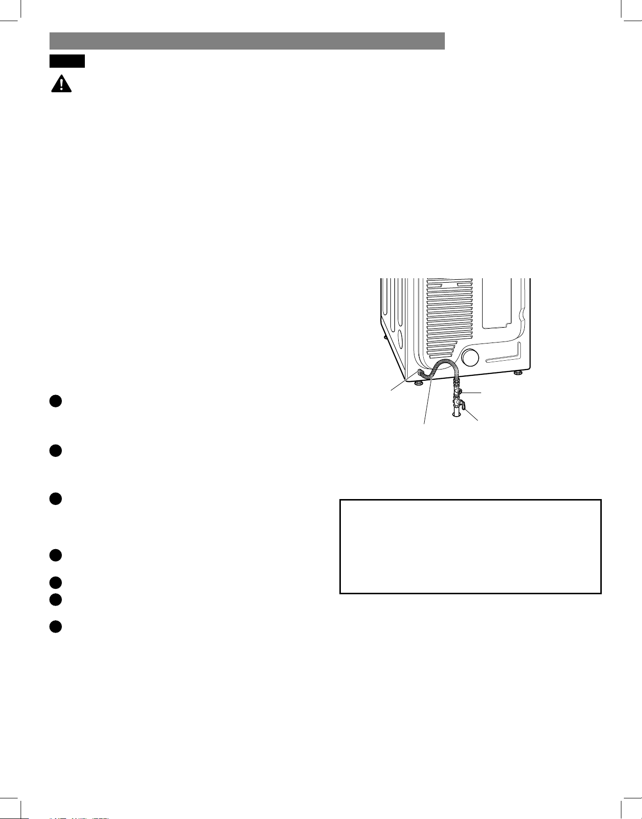
1
Check the rubber seal at each end of the inlet hoses.
Two rubber seals are supplied with each inlet hose.
They are used for preventing water leaks. Make sure
the connection to the cold water tap is tight.
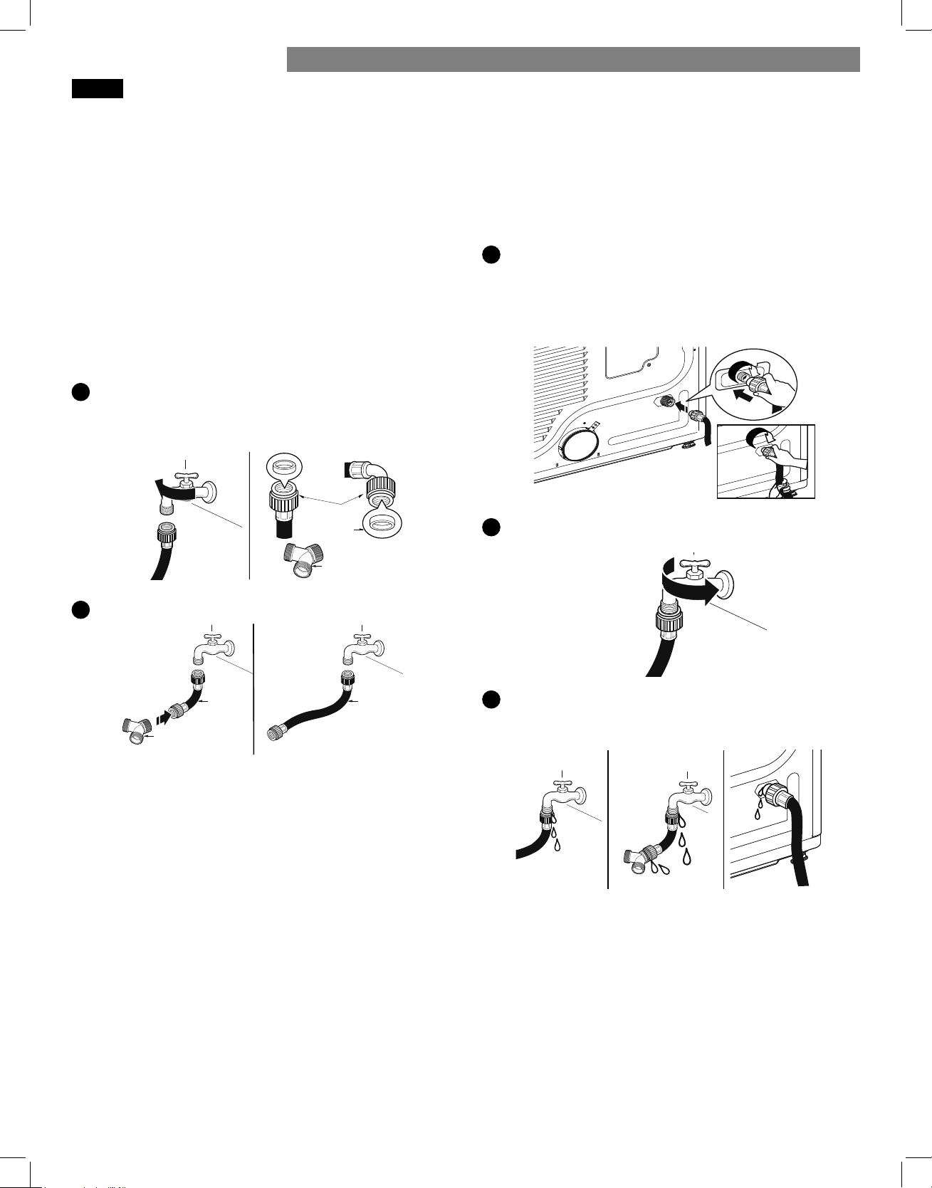
2
Check the installation type.
Connect all water supply hoses tightly by hand and
then tighten another 2/3 turn with pliers.
WITH WASHER: When connecting the dryer to the same
faucet as a washer.
a. Shut off the cold water tap and remove the washer
hose.
b. Connect the short hose to the Y-connector.
c. Connect the other end of the short hose to the cold
water faucet.
d. Connect the long dryer hose to one side of the Y-connector
and connect the washer hose to the other side.
WITHOUT WASHER: If the dryer does not share the
cold water tap with a washer.
a. Connect the straight end of the long hose to the cold
water faucet.
NOTE:
• Before connecting the water line to the dryer, fl ush
several gallons of water into a drain or bucket. This
will help prevent foreign particles such as sand and
scale from clogging the dryer inlet valve.
• Do not overtighten. Damage to the coupling can
result.
3
Connect the hose to the dryer.
• Connect the water supply hose to the dryer inlet
valve tightly by hand and then tighten another 2/3
turn with pliers. Make sure that there are no kinks in
the hoses and that they are not crushed.
4
Turn on the cold water faucet.
5
Check for leaks at the Y-connector (if used) and all
hoses.
NOTE:
• If any leaks are found, shut off the water faucet,
remove the hose and check the condition of the hose
washer.
Hose
connector
Y connector
Rubber
seal
Long
hose
WITH WASHER WITHOUT WASHER
Short
hose
Y connector
INSTALLATION INSTRUCTIONS
16
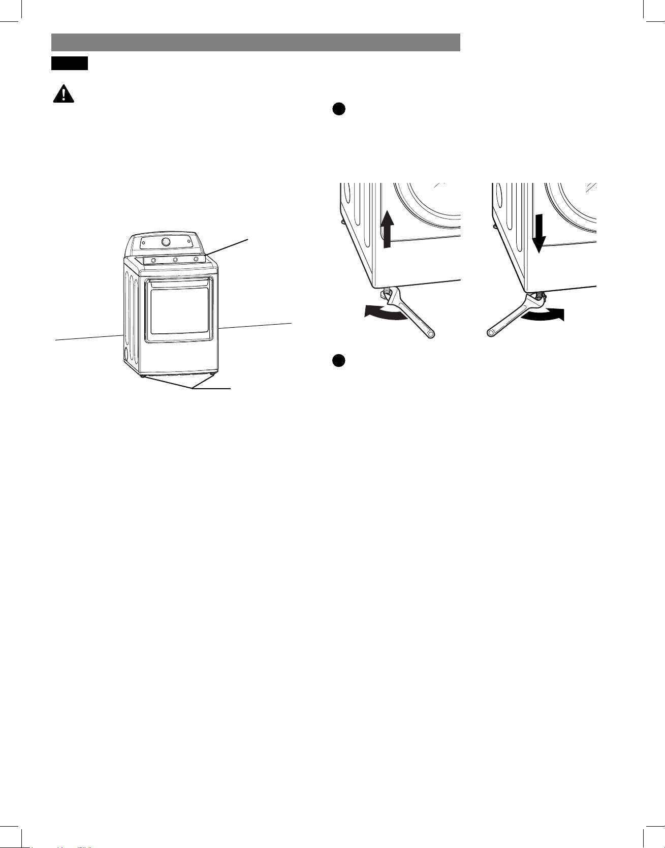
LEVELING THE DRYER
• Wear gloves during installation.
• Failure to follow these instructions can result in injury.
To ensure that the dryer provides optimal drying
performance, it must be level. To minimize vibration,
noise, and unwanted movement, the fl oor must be a
level, solid surface.
NOTE: Adjust the leveling feet only as far as necessary
to level the dryer. Extending the leveling feet more than
necessary can cause the dryer to vibrate.
Position the dryer in the fi nal location. Place a level
across the top of the dryer.
All four leveling feet must rest solidly on the fl oor.
Gently push on the top corners of the dryer to make
sure that the dryer does not rock from corner to corner.
WARNING:
1
Level
Leveling Feet
Use a wrench to turn the leveling feet. Turn the
leveling foot clockwise to raise the dryer; turn the
foot counterclockwise to lower the dryer. Using a
level to check, adjust the feet until the dryer is level
from side to side and front to back. Make sure all
four feet are in fi rm contact with the fl oor.
NOTE: If you are installing the dryer on the optional
pedestal, the dryer leveling feet should be fully retracted.
Use the leveling feet on the pedestal to level the dryer.
2
INSTALLATION INSTRUCTIONSINSTALLATION INSTRUCTIONS
17
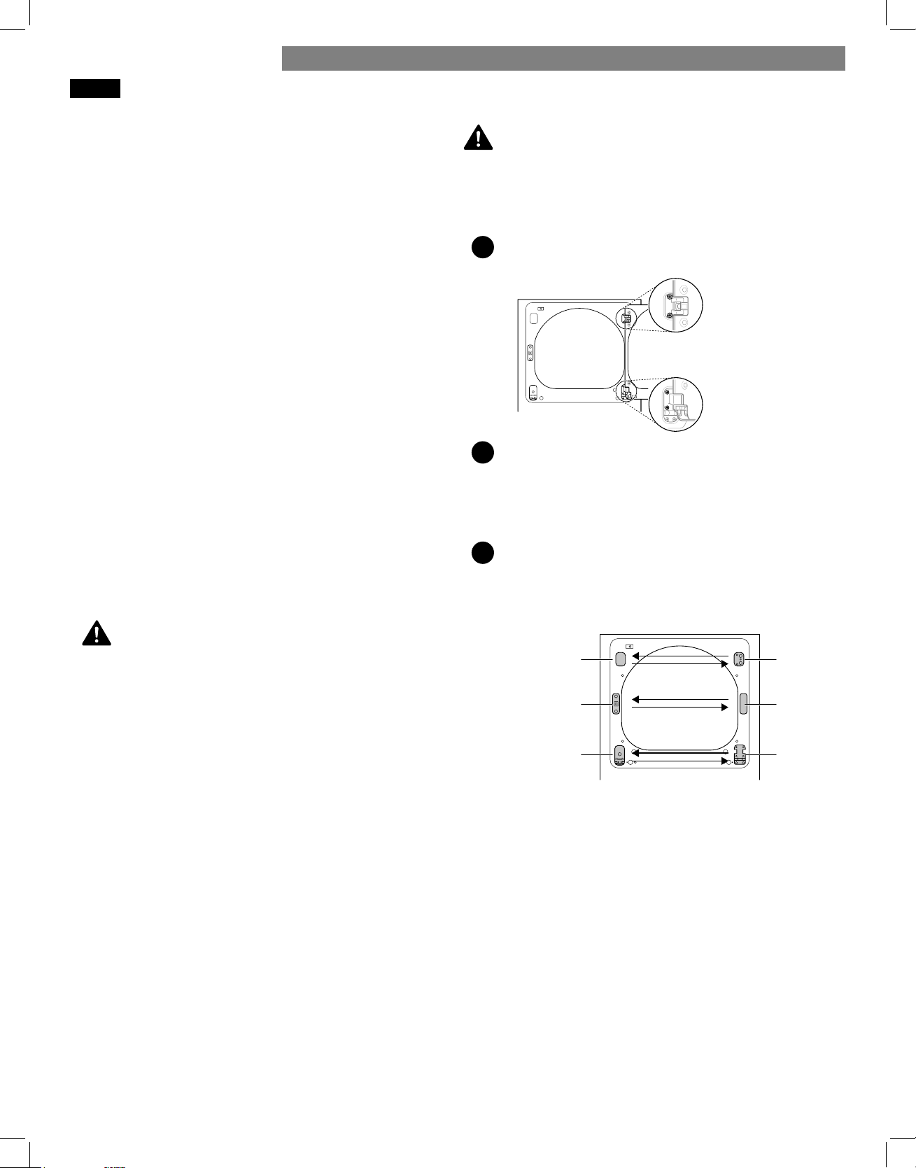
REVERSING THE TWO-WAY DOOR
WARNING:
Be sure to support the weight of the door before
removing the hinge screws.
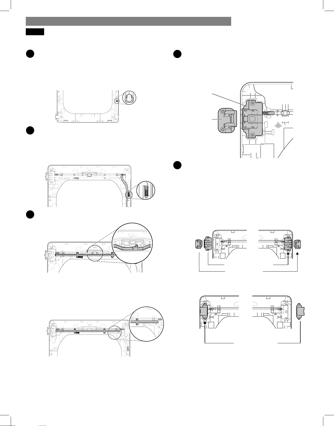
On the Cabinet:
1
Open the door from the side so that the hinge
screws are accessible.
2
Remove the four hinge screws.
While supporting the door, remove the four hinge
screws, two from each hinge. Set the door aside face
down on a protected surface to prevent damage to
the door or the work surface.
3
Reverse the components on the cabinet.
a. Use a Phillips screwdriver to remove the two screws
and the latch mechanism on the front panel of the
cabinet.
b. Remove the latch hole cover by gently prying it up
with a flat-blade screwdriver, being careful not to
scratch the paint. Install the latch hole cover on
the opposite side, where the latch mechanism was
removed. Install the latch mechanism in the position
from which you removed the latch hole cover, using
the two screws removed in step a.
c. Remove the hinge cover by gently prying it up
with a flat-blade screwdriver, being careful not
to scratch the paint. Rotate the hinge cover 180
degrees and install it on the opposite side, where
the upper hinge was attached.
Before You Begin
NOTE:
The door reversal procedure for the two-way door is
far more complex than for a conventional dryer door.
Read through these instructions in their entirety before
beginning the process, in order to gauge whether to
have the procedure done by a professional installer or
service person.
Service calls to reverse the door are not covered under
the product warranty.
The door reversal procedure consists of four main parts:
• Removing and reinstalling the door and hinges (steps 1,
2 and 18)
• Removing and reversing components on the dryer
cabinet (step 3)
• Removing and reversing components on the door cover
(steps 4 and 5)
• Removing and reversing components inside the door
(steps 6 through 17).
Tools Required
Phillips screwdriver
Large flat-blade screwdriver
(recommended
for hinge screws if they are tight or your Phillips
screwdriver is worn)
Small flat blade screwdriver
(for lifting out parts)
THE DRYER DOOR IS VERY LARGE AND HEAVY.
Failure to follow the instructions below can result in
damage to the dryer, property damage or personal
injury.
• To avoid damage to the dryer or the door, support the
door with a stool or box that fits under the door, or
have an assistant support the weight of the door.
• Avoid dropping the door to prevent damage to the
door or the floor.
• Unplug the dryer or turn off power at the main circuit
breaker before beginning door reversal.
Instructions
NOTE:
The instructions here are for changing the door swing
from a right to a left side hinge. If the door has
been reversed, and it is necessary to change it back,
use care when following these instructions. Some of
the illustrations and the left/right references will be
reversed, and you will need to read the instructions
carefully.
screws
Two large
screws
Two small
upper
hinge
hinge
cover
hinge
latch
mechanism
latch
hole
cover
hinge
bracket
WARNING:
INSTALLATION INSTRUCTIONS
18
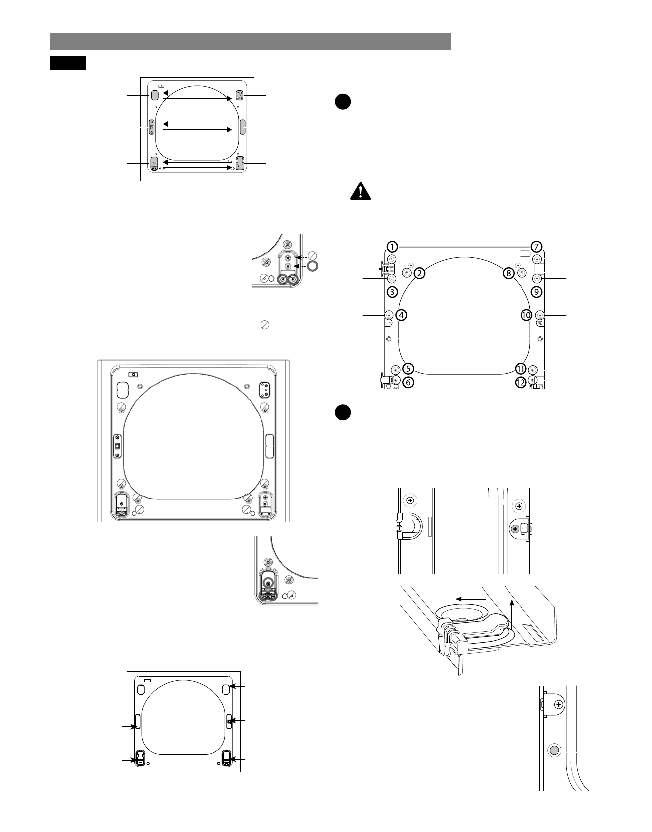
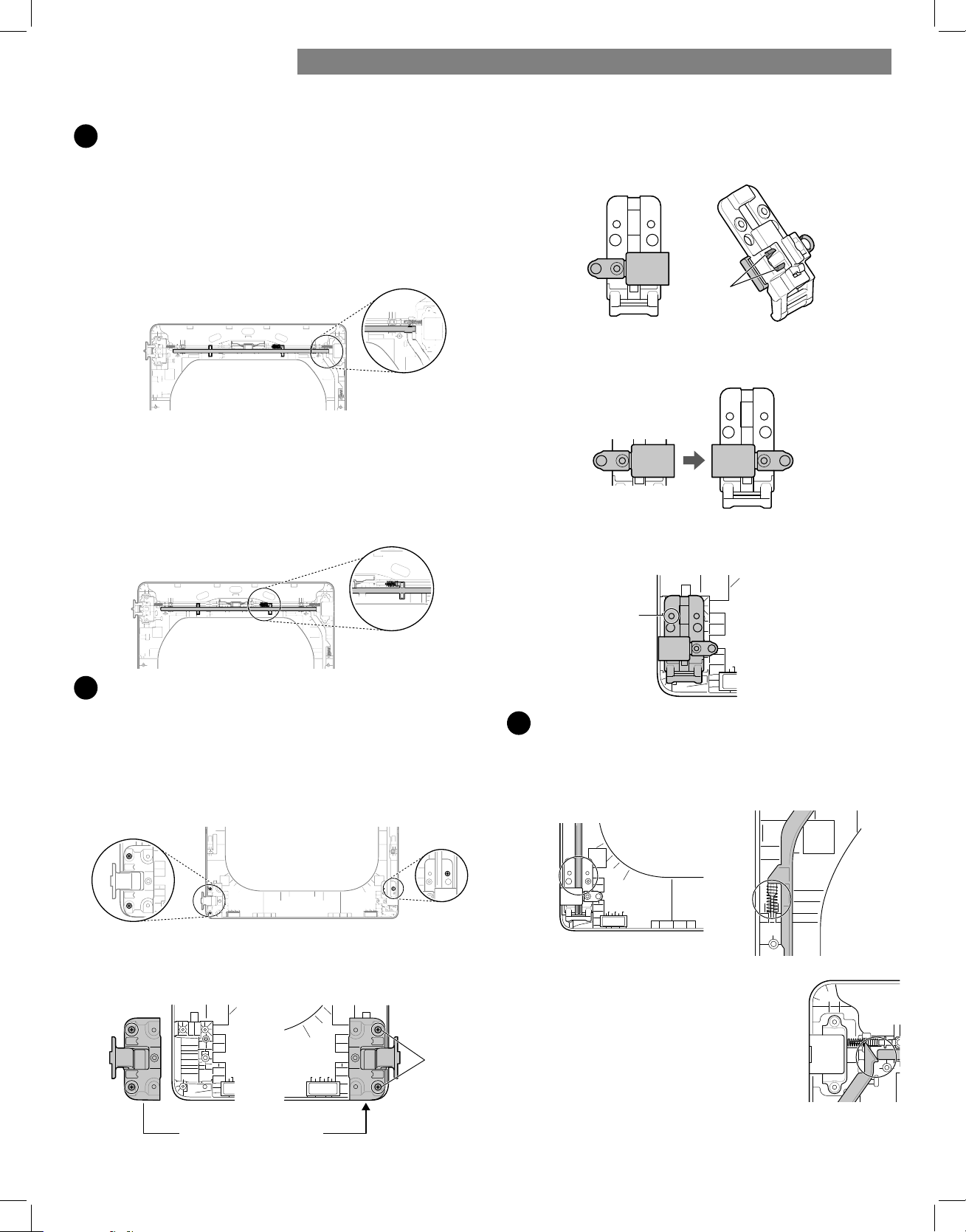
CAUTION:
d. Reverse the hinge and the hinge bracket at the
bottom of the cabinet. Remove the two screws
from the hinge bracket at bottom right and remove
the hinge bracket.
Remove the lower of the two screws
behind the hinge bracket. Do NOT
remove the upper screw behind the
hinge bracket. Set the parts aside.
e. Remove the three screws on the
hinge at bottom left. Remove the
hinge and reinstall it on the right
side. The top screw occupies the
hole where you removed the screw
behind the hinge bracket in step d.
f. Install the hinge bracket removed in
step d on the bottom left side, fi rst installing one
screw behind the hinge bracket.
On the Door:
4
Lift off the door cover.
With the door laid inside facing up on a protected
surface, remove the 12 screws on the inside of the
door. Carefully lift off the door cover with the help
of a small flat-blade screwdriver inserted in the
upper corner (circled below).
The edges of the door cover may be sharp. Take care
when handling, or wear gloves to avoid injury.
5
Switch the door strike and the blank cover.
Remove the four screws on the door cover that secure
the door strike and the blank cover.
Switch the door strike and the blank cover, installing
them on the opposite sides from which they were
removed.
Gently pry out the hole plug on the
side of the door cover and install it
in the hole on the opposite side.
Set the door cover aside.
NOTE:
Do NOT remove any of the eight screws on the
face of the cabinet (marked with below).
Doing so could result in damage to the dryer and
the need for a service call to repair the dryer.
Hole
p l u g
Twelve screws
Side
Interlock
button
screw
Long
screws
Short
Blank cover Door strike
Pull
Raise
Remove blank cover
Hole
plug
upper
hinge
hinge
cover
hinge
latch
mechanism
latch
hole
cover
hinge
bracket
hinge
cover
hinge
bracket
latch hole
cover
latch
mechanism
hinge
cabinet reversal complete
REVERSING THE TWO-WAY DOOR (continued)
INSTALLATION INSTRUCTIONSINSTALLATION INSTRUCTIONS
19
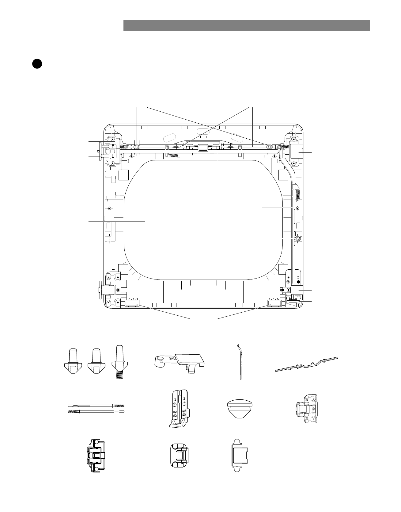
6
Reverse the components inside the door.
You will now be removing and reversing various components inside the door. See below for a detailed diagram
and identification of the inner structure and parts of the door. (The diagram shows the "before view" of the
door, with the default setup for a right side hinge swing. After following these instructions, your door should be a
mirror image of the illustration.)
upper
KLQJHoOOHU
VLGHORFNURG
side intHUORFNbuttRn
ORZHU
KLQJHoOOHU
ORZHU
EUDFNHW
hinge
bumpers
LQQHUORFNURGVtRSLQWHUORFNEXWWRQV
tRSORFNURG
upper
DVVHPEO\
hinge
upper
SLYRW
hinge
JODVV
ORZHU
hinge
DVVHPEO\
LQWHUORFNEXWWRQV
XSSHUKLQJHDVVHPEO\ XSSHUKLQJHSLYRW
LQQHUORFNURGV
ORZHUKLQJHEUDFNHW
tRSORFNURG
ORZHUKLQJHDVVHPEO\
VLGHORFNURG
KROHSOXJ
ORZHUKLQJHoOOHU
XSSHUKLQJHoOOHU
INSTALLATION INSTRUCTIONS
20
7
Lift out the grey interlock button in the side of the
door.
Make sure to remove the spring with the interlock
button and to keep the two together. Set the
interlock button aside. Do not confuse it with the
interlock buttons from the top of the outer door.
8
Remove the side lock rod.
Remove the side lock rod from the lower hinge
bracket by lifting the top end of the rod and sliding
it toward the top of the door. The spring should
remain attached to the lock rod. Set the lock rod
aside.
9
Remove the top lock rod.
a. Slide the lock rod to the right to remove it from the
hinge assembly on the left side.
b. While sliding the lock rod right, lift the right end
up and out of the guides. Set the lock rod aside.
NOTE:
Do not remove the two inner lock rods and two
interlock buttons (see page 20) located underneath
the top lock rod. They do NOT need to be reversed.
10
Remove the upper hinge pivot.
Once the top lock rod has been removed, the
hinge pivot can easily be removed from the hinge
assembly on the upper left and set aside.
11
Reverse the upper hinge assembly and hinge filler.
Lift out the upper hinge filler (on the right) and set it
aside.
Carefully lift the upper hinge assembly (on the left)
out of the outer door frame, using a small flat-blade
screwdriver if necessary. Rotate the hinge assembly
180 degrees and install it on the upper right side of
the outer door. You will need to press firmly to install
the hinge assembly.
The hinge pivot removed in step 10 will be installed
later.
Now rotate the hinge filler 180 degrees and install it
on the upper left side of the door.
spring
upper
hinge
pivot
upper
hinge
assembly
upper hinge assembly
upper hinge pivot
XSSHUKLQJHoOOHU
REVERSING THE TWO-WAY DOOR (continued)
INSTALLATION INSTRUCTIONSINSTALLATION INSTRUCTIONS
21
12
Reinstall the top lock rod.
Rotate the top lock rod (removed in step 9) 180 degrees
end for end from its original position and reinstall it.
The spring should now be to the right of center, with
the spring on the side of the rod facing the top of
the door.
a. Insert the right end of the lock rod into the right hinge
assembly. Make sure the rod is aligned with the
guides in the door panel.
b. Lower the rod into position, sliding it to bypass
the center handle, making sure to align the lock
rod with the guides all the way across the door
panel. When released, the lock rod should slide
completely into the hinge asembly on the right.
Slide the lock rod back and forth to make sure it is
correctly positioned in the guides and slides easily.
13
Reverse the lower hinge bracket and hinge
assembly.
a. Remove the screw from the lower hinge bracket
(on the right) and lift the hinge bracket out. Set it
aside.
Remove the two screws from the lower hinge
assembly on the bottom left and lift the hinge
assembly out.
b. Rotate the lower hinge assembly 180 degrees and
install it on the right side using the two screws
removed in step a.
c. Flip over the lower hinge bracket and release the
tabs on the back locking the hinge filler to the hinge
bracket.
d. Rotate the hinge filler 180 degrees and snap it
back onto the front of the hinge bracket facing in
the opposite direction.
e. Mount the lower hinge bracket and the filler on the
left side of the door with the screw removed in step a.
14
Install the side lock rod.
Flip the side lock rod over and install it on the
opposite side. Insert the lower end into the left hinge
and lower the rod into the guides on the door while
compressing the spring inside the recess.
M
ake sure the top of the side lock
rod is beside the top lock rod and
the two do not overlap each other, so
the two rods can interact correctly.
If they are not aligned properly, the
door will not operate properly.
Lower hinge assembly
Screws
tab s
screw
INSTALLATION INSTRUCTIONS
22
15
Reinstall the side interlock button.
Reinstall the side interlock button removed in step 7.
Center the spring in the compartment and insert the
interlock button on top of it.
16
Reinstall the door cover.
Clean the glass on the door and door cover, if
necessary.
Make sure the two gray interlock buttons are
properly installed and that the top and side lock rods
are properly aligned where they meet. Carefully
lower the door cover into place, aligning the holes in
the cover with the interlock buttons on the top and
side and the bumpers on the bottom. Take care not
to dislodge the lock rods while mounting the door
cover. Once the door cover is in place, secure it with
the 12 screws removed in step 4.
The ten similar screws go around the top and sides
of the door cover. Make sure to install the two
different screws on the bottom edge, in the locations
marked below.
17
Install the top right hinge pivot.
Pick up the upper hinge pivot removed earlier and
rotate it 180 degrees. Press in the side interlock
button on the left side and hold it down while
pressing the hinge pivot into the hinge assembly on
the top right side. If the door has been reassembled
correctly, the lock rod slides back easily and locks
the pivot in place. The door is now ready to remount
on the opposite side of the dryer.
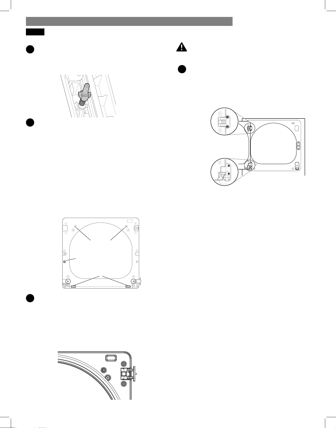
Be sure to support the weight of the door before
installing the hinge screws.
18
Reinstall the door.
While supporting the door, install the four hinge
screws removed in step 2. Test the swing of the door
to make sure the hinges and latch are properly
aligned and that the door opens, closes, and latches
properly in both directions.
If the door doesn’t operate smoothly, remove the
door and then the door cover to check that the lock
rods and interlock buttons are properly mounted and
aligned. The interlock buttons should be oriented
correctly and operating smoothly. The interlock rods
should be in the proper position and should not
overlap at the contact point. (See steps 12-14.)
If the door is damaged, or if the door does not work after
reassembly, contact the call center at 1-800-469-4663.
interlock
buttons
side
interlock
button
bumpers
WARNING:
Two
large
screws
Two
small
screws
INSTALLATION INSTRUCTIONSINSTALLATION INSTRUCTIONS
REVERSING THE TWO-WAY DOOR (continued)
23
FINAL INSTALLATION CHECK
Once you have completed the installation of the dryer
and it is in its fi nal location, confi rm proper operation
with the following steps and tests.
Is gas turned on? (Gas models only)
Is dryer plugged in? Dryer should always be
plugged into the proper outlet.
Gas dryer should use a
120-VAC, 60-Hz. grounded
3-prong outlet.
Electric dryer should use a
4-wire connection which is
required for all mobile
and manufactured home
installations, as well as all new
construction after
January 1, 1996.
-- OR --
A 3-wire connection.
NOTE: A 3-wire connection
is NOT permitted on new
construction after
January 1, 1996.
Is the dryer transition duct connected? Make sure
the transition duct behind the dryer is properly
connected and is not crushed or damaged.
Is dryer level? Once the dryer is in its fi nal location,
recheck the dryer to be sure it is level. Make sure it is
level front to back and side to side, and that all four
leveling feet rest fi rmly on the fl oor.
Is the dryer heating normally? Perform the following
dryer heating test.
Testing Dryer Heating
Close the dryer door.
Press the POWER button to turn the dryer on.
Turn the cycle selector knob to Normal drying cycle.
Press the START/PAUSE to start the dryer. Open the
dryer door and check that the air inside is warm
after three minutes.
NOTE: If all air is not purged from the gas line, the gas
igniter may turn off before the main burner ignites. If
this happens, the igniter will reattempt gas ignition until
all the air is purged from the gas line.
GAS MODELS
Close the dryer door, press the POWER button to turn
the dryer on, and start the dryer on a heat setting.
When the dryer starts, the igniter should ignite the main
burner.
ELECTRIC MODELS
Close the dryer door, press the POWER button to turn
the dryer on, and start the dryer on a heat setting. The
exhaust air should be warm after the dryer has been
operating for 3 minutes.
Checking Airfl ow
Eff ective dryer operation requires proper airfl ow. The
adequacy of the airfl ow can be measured by evaluating
the static pressure. Static pressure in the exhaust duct
can be measured with a manometer, placed on the ex-
haust duct approximately 2 ft. (60.9 cm) from the dryer.
Static pressure in the exhaust duct should not exceed
0.6 inches (1.5 cm). The dryer should be checked while
the dryer is running with no load.
Checking Levelness
Once the dryer is in its fi nal location, recheck the dryer
to be sure it is level. Make sure it is level front to back
and side to side, and that all four leveling feet are
fi rmly on the fl oor.
Checking Venting
The vent duct should be checked for lint buildup and
cleaned at least once per year. If any noticeable
reduction in drying performance occurs, check the duct
for obstructions and blockages.
1
1
2
3
4
2
3
4
5
INSTALLATION INSTRUCTIONS
24
INSTALLATION INSTRUCTIONSINSTALLATION INSTRUCTIONS
INSTALLATION TEST (DUCT CHECK)
Once you have completed the installation of the dryer,
use this test to make sure the condition of the exhaust
system is adequate for proper operation of the dryer.
This test should be performed to alert you to any serious
problems in the exhaust system of your home.
The dryer features Check Vent, an innovative sensing system
that automatically detects blockages and restrictions in dryer
ductwork. Keeping ductwork clean of lint buildup and free of
restrictions allows clothes to dry faster and reduces energy
use.
NOTE: The dryer should be cool before starting this test. If the
dryer was warmed up during installation, run the Air Dry cycle
for a few minutes to reduce the interior temperature.
To activate the installation test:
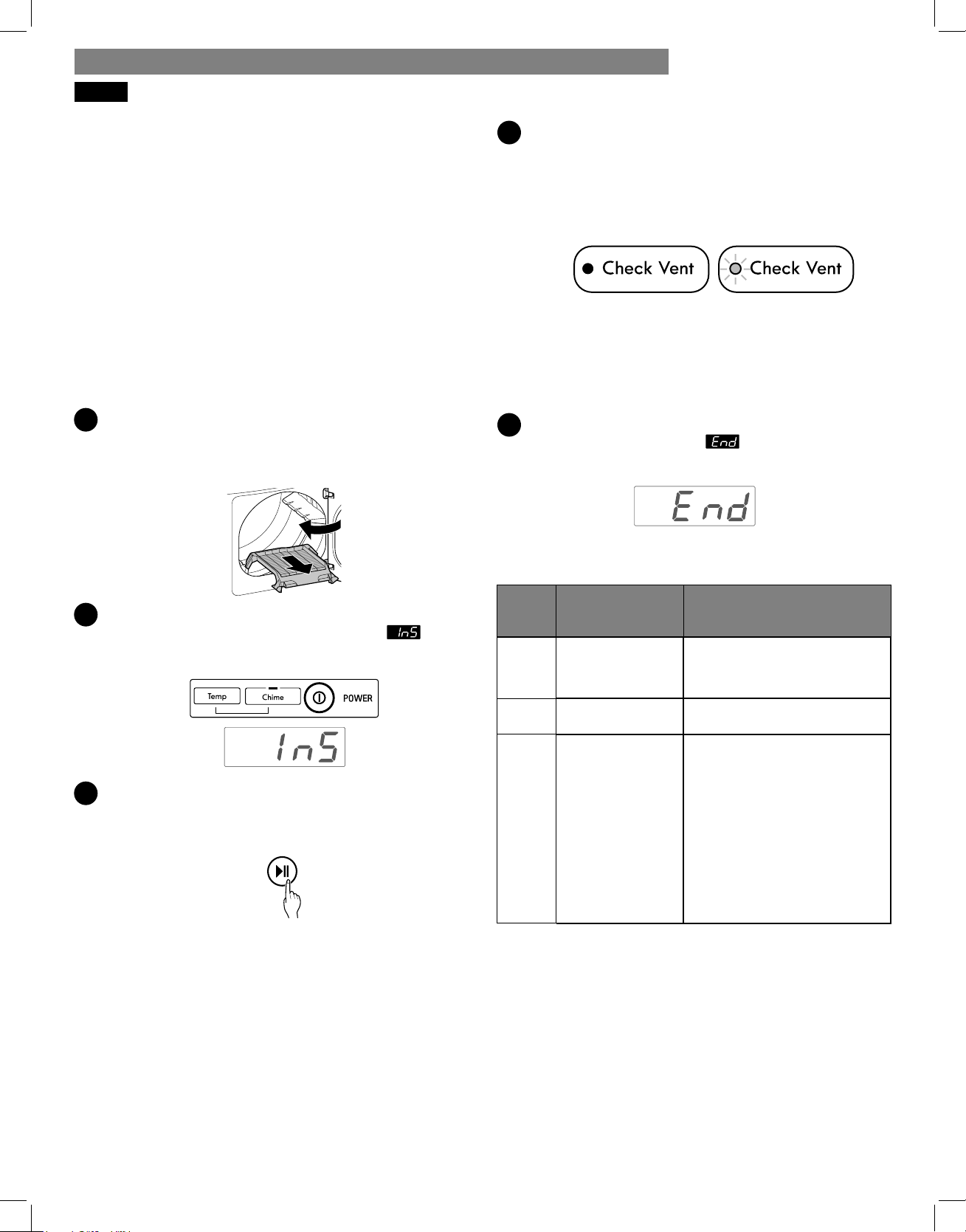
1
Remove the drying rack and literature, then close the
dryer door.
Do not load anything in the drum for this test, as it may
aff ect the accuracy of the results.
2
Press the Power button, then immediately press and
hold both the Temp and Chime buttons until
appears in the display.
3
Press the START/PAUSE button.
The dryer will start the test, which lasts about 2 minutes.
The heat is turned on and the temperatures in the drum
are measured.
4
Check the display for results.
During the test cycle, monitor the CHECK VENT LED on
the control panel. If the LED does not blink by the time the
cycle ends, the exhaust system is adequate. If the exhaust
system is severely restricted, the CHECK VENT LED blinks.
Have the exhaust system checked immediately, as dryer
performance will be poor.
Not blinking:
OK
Blinking:
RESTRICTED
Other problems may also be shown with error codes.
Refer to the table below for error code details and
solutions.
5
End of cycle.
At the end of the test cycle, appears in the display.
The test cycle ends and the dryer shuts off automatically
after a short delay.
Check any error codes in the chart below before
calling for service.
Error
Code
Possible Causes Solutions
tE1
or
tE2
Temperature
sensor failure
Turn off dryer and call for
service.
HS
Humidity sensor
failure
Turn off dryer and call for
service.
PS
or PF
or nP
• Electric dryer
power cord is
not connected
correctly, or
house power
supply is
incorrect.
• House fuse is
blown, circuit
breaker has
tripped, or
power outage
has occurred.
• Check power supply or
connection of power cord to
terminal block. Refer to the
Connecting Electric Dryers
section of this guide for
complete instructions.
• Reset circuit breaker
or replace fuse. Do not
increase fuse capacity.
If problem is a circuit
overload, have it corrected
by a qualifi ed electrician.
25
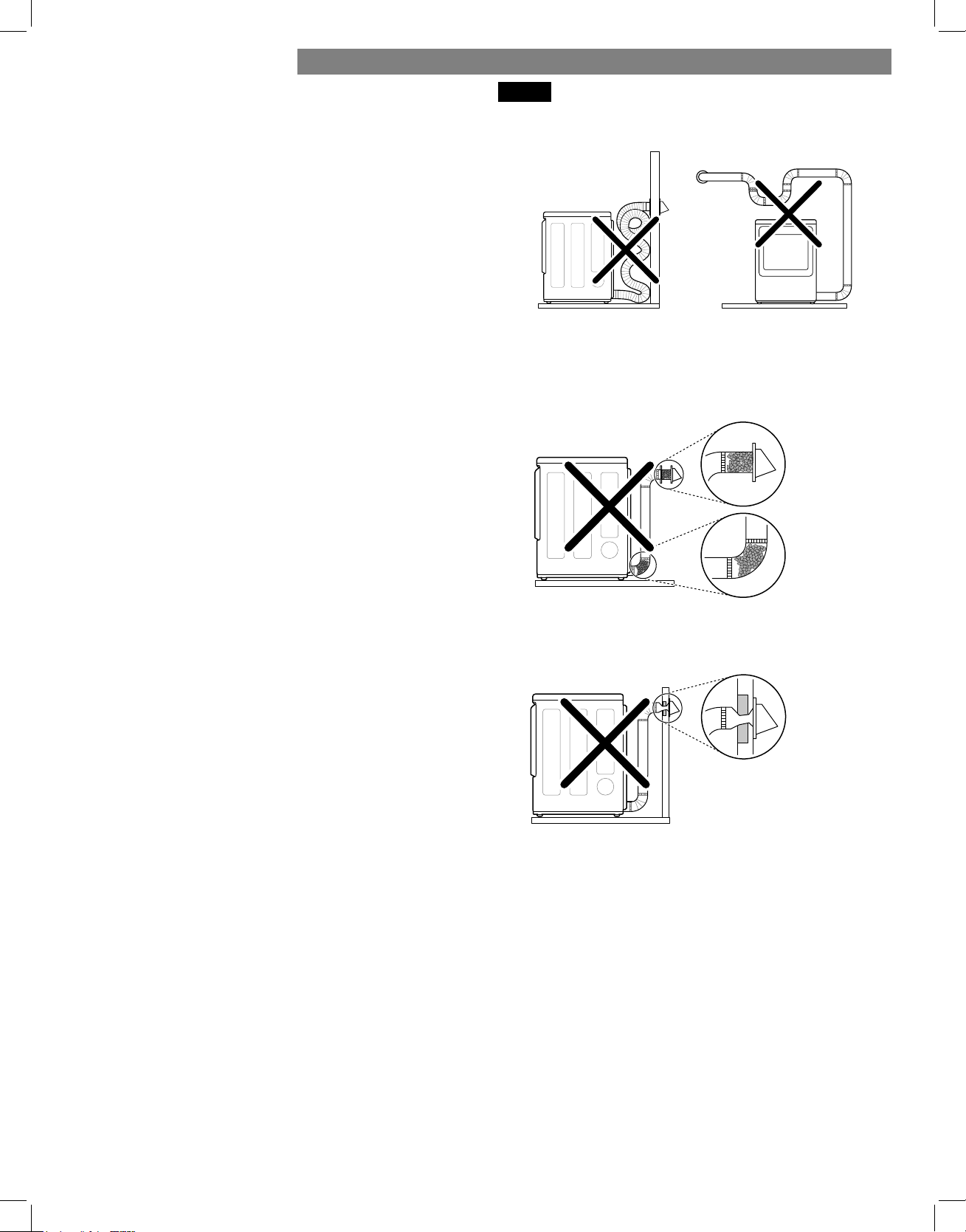
RESTRICTED OR BLOCKED AIRFLOW
INSTALLATION INSTRUCTIONS
Check the duct condition.
If the CHECK VENT LED is blinking, check the exhaust
system for restrictions and damage. Repair or replace
the exhaust system as needed.
NOTE: When the dryer is fi rst installed, this test should
be performed to alert you to any existing problems
with the exhaust ducts in your home. However, since the
test performed during normal operation provides more
accurate information on the condition of the exhaust
duct than does the installation test, the results of the two
tests may not be the same.
Do not interrupt the test cycle, as this could result in
inaccurate results.
Even if the LED is not blinking during the test cycle,
some restrictions may still be present in the exhaust
system. Refer to the Venting the Dryer section of
this guide for complete exhaust system and venting
requirements.
Avoid long runs or runs with multiple elbows or bends.
Excess or crushed
transition duct
Check for blockages and lint buildup.
Too many elbows or
exhaust too long
Lint
blockage
buildup or
Make sure the ductwork is not crushed or restricted.
Crushed
or
damaged
exhaust
26
HOW TO USE
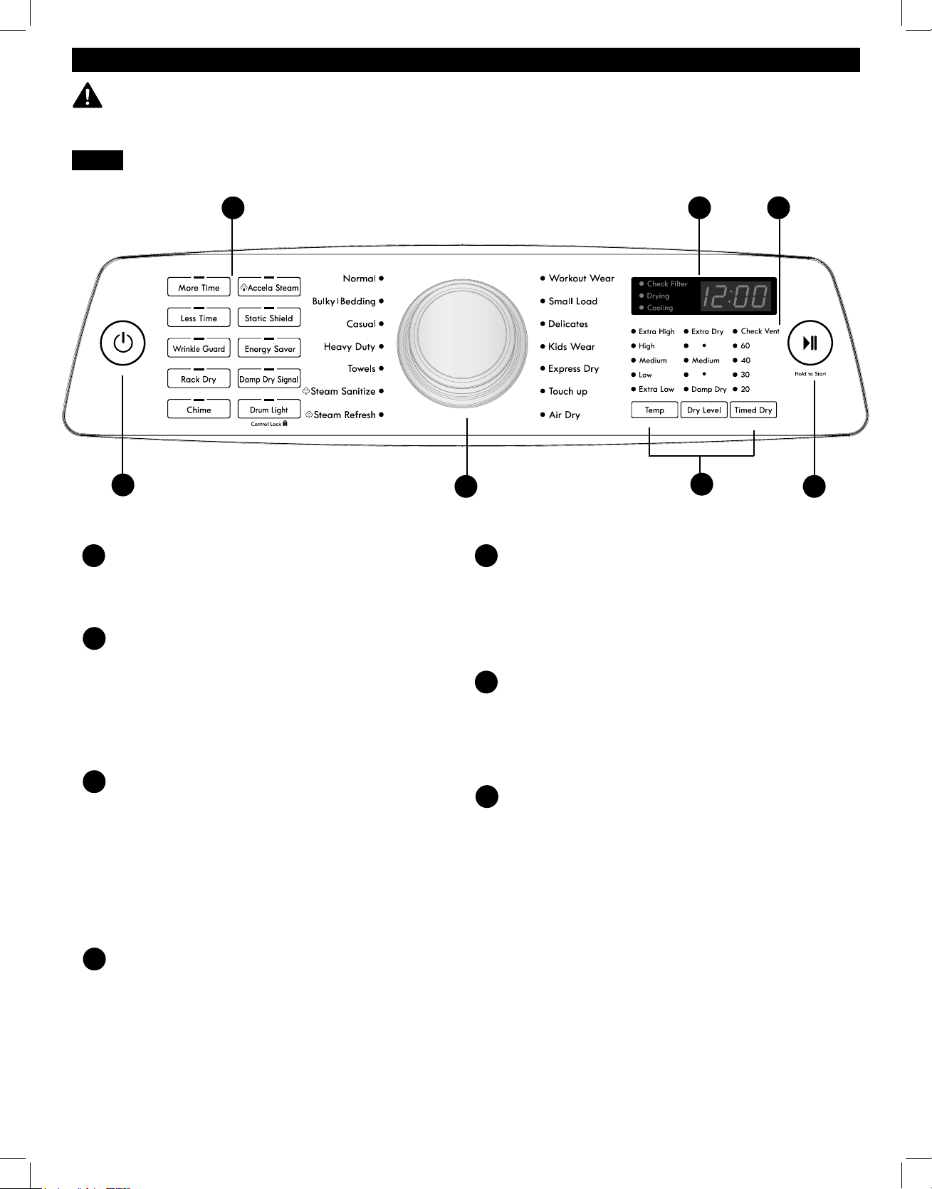
CONTROL PANEL FEATURES
POWER (ON/OFF) BUTTON
Press to turn the dryer ON. Press again to turn the
dryer OFF. Pressing the POWER button during a cycle
will cancel that cycle and any settings will be lost.
CYCLE SELECTOR KNOB
The cycle selector knob is used to select the desired
dry cycle by rotating the knob in either direction until
the desired cycle LED is illuminated. Once the desired
cycle has been selected, the standard presets for that
cycle will show in the display. These settings can be
adjusted using the cycle modifi er or option buttons
any time before starting the cycle.
START/PAUSE BUTTON
Press this button to start the selected cycle. The
dryer will display the estimated time (AUTO DRY) or
set time (TIMED DRY) remaining and start tumbling.
To pause the cycle at any time, open the dryer door
or press START/PAUSE. To resume the cycle where it
was stopped, press START/PAUSE again.
NOTE: If the dryer has been stopped for more than
four minutes, the dryer will turn off automatically
and all settings will be lost.
OPTION BUTTONS
These buttons allow you to select cycle options.
Some of the option buttons have secondary
functions. The controls can be locked or unlocked by
pressing and holding the DRUM LIGHT button for
fi ve seconds.
CYCLE MODIFIER BUTTONS
Use these buttons to adjust the settings for the
selected cycle. The settings light up above the
buttons to show the current selection. The default
temperature setting cannot be changed in AUTO
DRY cycles. AUTO DRY cycles are modifi ed using
the Dry Level button.
TIME AND STATUS DISPLAY
The display shows the estimated time remaining for
auto cycles and actual time for timed cycles. The
status of the cycle is also displayed. The CHECK
VENT indicator will illuminate if there is a serious
restriction in the exhaust system.
CHECK VENT INDICATOR
(DUCT BLOCKAGE SENSING SYSTEM)
The CHECK VENT duct blockage sensing system
detects and alerts you to blockages in the ductwork
that reduce exhaust fl ow from the dryer. This light
does not indicate any problems with your dryer. If
this light blinks, it indicates that your home’s exhaust
system has a serious restriction, which is not covered
by your dryer’s warranty.
E
F
B
C
WARNING:
To reduce the risk of fi re, electric shock, or injury to persons, read this entire
manual, including the Important Safety Instructions, before operating this dryer.
NOTE: To protect your fabrics, not all settings are allowed in all cycles.
D
A
A
B
D
F
C
E
G
G
27
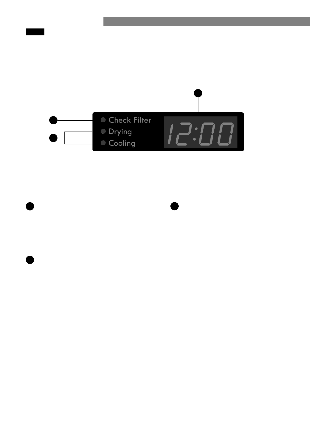
TIME AND STATUS DISPLAY
The Time and Status Display shows the cycle time, cycle
progress, and vent status. When the dryer is turned on, the
display will illuminate.
TIME DISPLAY
When a cycle is selected, the display will indicate
the default time for that cycle including selected
options or adjustments. In AUTO DRY cycles,
the time remaining will be estimated and may
change during the cycle, depending on the
condition of the load. In TIMED DRY, the time
displayed will be the actual time remaining.
CHECK FILTER LIGHT
The CHECK FILTER light will blink before each
load, as a reminder to check the lint fi lter. Always
clean the lint fi lter before every cycle.
A
B
CYCLE STATUS INDICATORS
This portion of the display shows which stage of the
drying cycle is currently under way (DRYING
or COOLING).
C
A
B
C
HOW TO USE
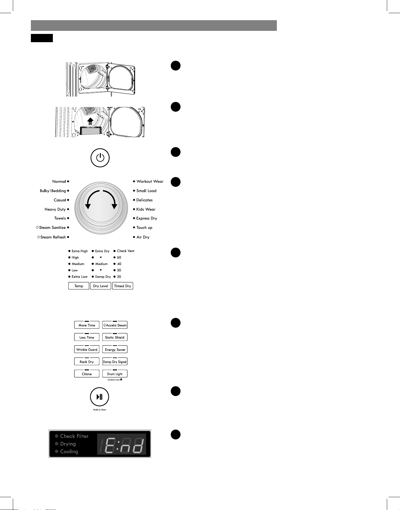
28
OPERATING THE DRYER
1
LOAD THE DRYER
Load the dryer with the wet laundry from the washer. If the
load is extra large, you may need to divide it into smaller
loads for proper performance and fabric care.
2
CLEAN THE LINT FILTER
If the lint fi lter has not already been cleaned, lift out the fi lter
and remove the lint from the last load. This will help ensure the
fastest and most effi cient drying performance.
3
TURN ON THE DRYER
Press the POWER button to turn ON the dryer. The cycle LEDs
will illuminate and a chime will sound.
4
SELECT A CYCLE
Turn the cycle selector knob in either direction until the LED for
the desired cycle is illuminated. The preset temperature, dry
level, and option settings for that cycle will display.
5
SELECT CYCLE MODIFIERS
Default settings for the selected cycle can now be changed, if
desired, using the Temp and Dry Level buttons.
NOTE: Not all options or modifi ers are available on all cycles.
Temperature can only be adjusted on Timed Dry cycles; Dry
Level is only available on Auto Dry cycles. A diff erent chime
will sound and the LED will not illuminate if the selection is not
allowed.
6
SELECT CYCLE OPTIONS
Cycle options can be added using the option buttons.
NOTE: Not all options or modifi ers are available on all cycles.
A diff erent chime will sound and the LED will not come on if
the selection is not allowed.
7
BEGIN CYCLE
Press the START/PAUSE button to begin the cycle. The cycle
can be paused at any time by opening the door or by pressing
the START/PAUSE button. If the cycle is not restarted within four
minutes of being paused, the dryer will shut off and the settings
will be lost.
8
END OF CYCLE
When the cycle is fi nished, the chime will sound. Immediately
remove your clothing from the dryer to reduce wrinkling. If
WRINKLE GUARD is selected, the dryer will tumble briefl y
every few minutes to help prevent wrinkles from setting in the
clothes.
INSTALLATION INSTRUCTIONSHOW TO USE
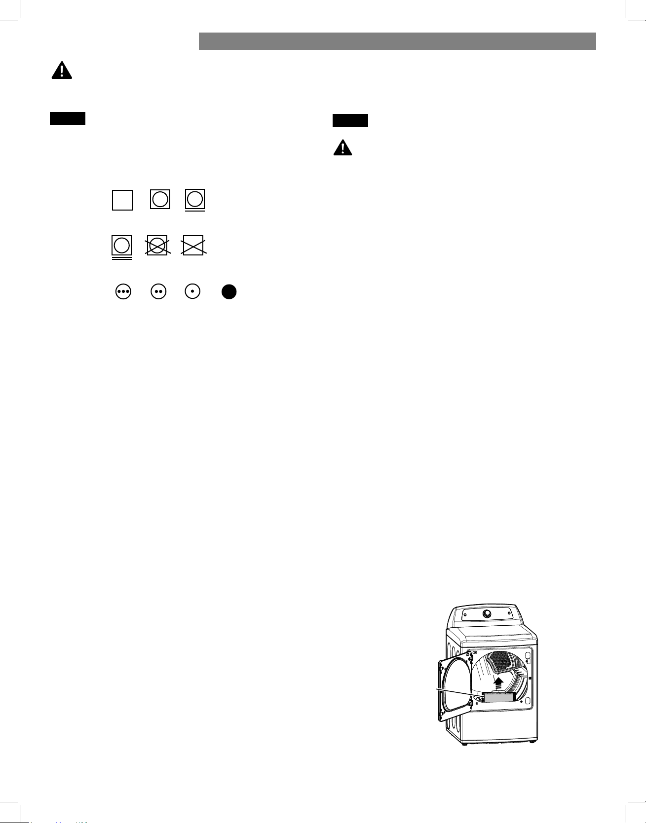
29
Fabric Care Labels
Most articles of clothing feature fabric care labels that
include instructions for proper care.
Group Similar Items
For best results, sort clothes into loads that can be dried
with the same drying cycle.
Diff erent fabrics have diff erent care requirements, and
some fabrics will dry more quickly than others. For best
fabric care results, always dry fabrics with similar care
requirements together.
SORTING LOADS
LOADING THE DRYER
WARNING:
To reduce the risk of fi re, electric shock, or injury to persons, read this entire manual,
including the Important Safety Instructions, before operating this dryer.
To reduce the risk of fi re,
electric shock, or injury to persons when using this
appliance, follow basic precautions, including the
following:
• Check all pockets to make sure that they are empty.
Items such as clips, pens, coins, and keys can damage
both your dryer and your clothes. Flammable objects
such as lighters or matches could ignite, causing a fi re.
Failure to do so can result in fi re, explosion, or death.
• Never dry clothes that have been exposed to oil,
gasoline, or other fl ammable substances. Washing
clothes will not completely remove oil residues. Failure
to obey this warning can result in fi re, explosion,
or death.
Loading Tips
• Combine large and small items in the same load.
• Damp clothes will expand as they dry. Do not overload
the dryer; clothes require room to tumble and
dry properly.
• Close zippers, hooks, and drawstrings to prevent these
items from snagging or tangling on other clothes.
CHECK THE LINT FILTER BEFORE EVERY LOAD
Every time the dryer is turned on, the CHECK FILTER
light will blink as a reminder to make sure the fi lter is
clean. Always make sure the lint fi lter is clean before
starting a new load; a clogged lint fi lter will increase
drying times. To clean, pull the lint fi lter straight up and
roll any lint off the fi lter with your fi ngers. Do not rinse
or wash the fi lter to remove lint. Push the lint fi lter fi rmly
back into place.
Always ensure the lint fi lter is properly installed before
running the dryer. Running the dryer with a loose or
missing lint fi lter may damage the dryer and articles in
the dryer.
WARNING:
Tumble
dry
Heat
setting
Dry
Normal
Permanent Press/
wrinkle resistant
Gentle/
delicate
Do not
tumble dry
Do not dry
(used with do
not wash)
High
Medium Low
No heat/air
Lint Filter
HOW TO USE
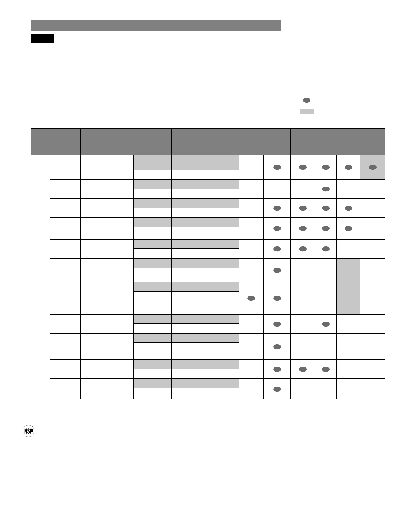
30
The cycle guide below shows the available options and recommended fabric types for AUTO DRY cycles.
*NOTE: The default time and actual time will vary depending on the size of the load and moisture content.
NOTE: To protect garments, not every dry level or option is available with every cycle. Temperature settings cannot
be changed. A diff erent chime sounds and the LED does not illuminate or the selection does not change if the
selection is not allowed.
CYCLE GUIDE
Modifi ers Options
Type Cycle Fabric Type Temperature Dry Level
Time in
Min.*
More
Time/
Less
Time
Wrinkle
Guard
Damp
Dry
Signal
Static
Shield
Accela
Steam
Energy
Saver
AUTO DRY
Normal
Work clothes,
etc.
Medium Medium
Elec: 67
Gas: 63
Adjustable
Bulky/
Bedding
Comforter,
pillows, shirts
Medium Medium 55
Adjustable
Casual
Permanent press,
synthetic items
Low Medium 32
Adjustable
Heavy
Duty
Jeans,
heavyweight
items
Extra High Medium 54
Adjustable
Towels
Towels, heavy
cottons, denims
High Medium 55
Adjustable
Steam
Sanitize
Comforter,
bedding, children’s
clothing, etc.
Extra High Auto 31
Steam
Refresh
1-5 garments.
Comforters, shirts,
trousers, etc. Do
not use cycle for
delicate fabrics.
High Auto 10
Adjustable Adjustable
Workout
Wear
†
Workout wear
Auto Auto 27
Small
Load
Small cotton,
normal, or towel
loads
(Max 3 lb)
Extra High Medium 30
Adjustable
Delicates
Lingerie, sheets,
blouses
Low Medium 28
Adjustable
Kids
Wear
Children's clothes
Extra High Medium 35
= available option
= default setting
Auto Dry Cycles
AUTO DRY cycles utilize a sensor that detects moisture levels in the clothes and adjusts the drying time as needed to
ensure superior results. The dryer automatically sets the dry level and temperature at the recommended setting for each
cycle. The estimated time remaining will be shown in the display.
CERTIFIED BY NSF
NSF International (formerly the National Sanitation Foundation), certifi es that the STEAM SANITIZE cycle reduces
99.9% of bacteria on laundry, and none of the bacteria will carry over onto the next laundry load.
• The default settings for the STEAM SANITIZE cycle are HIGH temperature and EXTRA DRY. These default
settings cannot be changed.
• Do NOT use this cycle with delicate items or fabrics.
† The Workout Wear cycle helps to maintain the performance and extend the life of garments created with special
high-performance properties. The temperature and dry level are set automatically and are not adjustable.
INSTALLATION INSTRUCTIONSHOW TO USE
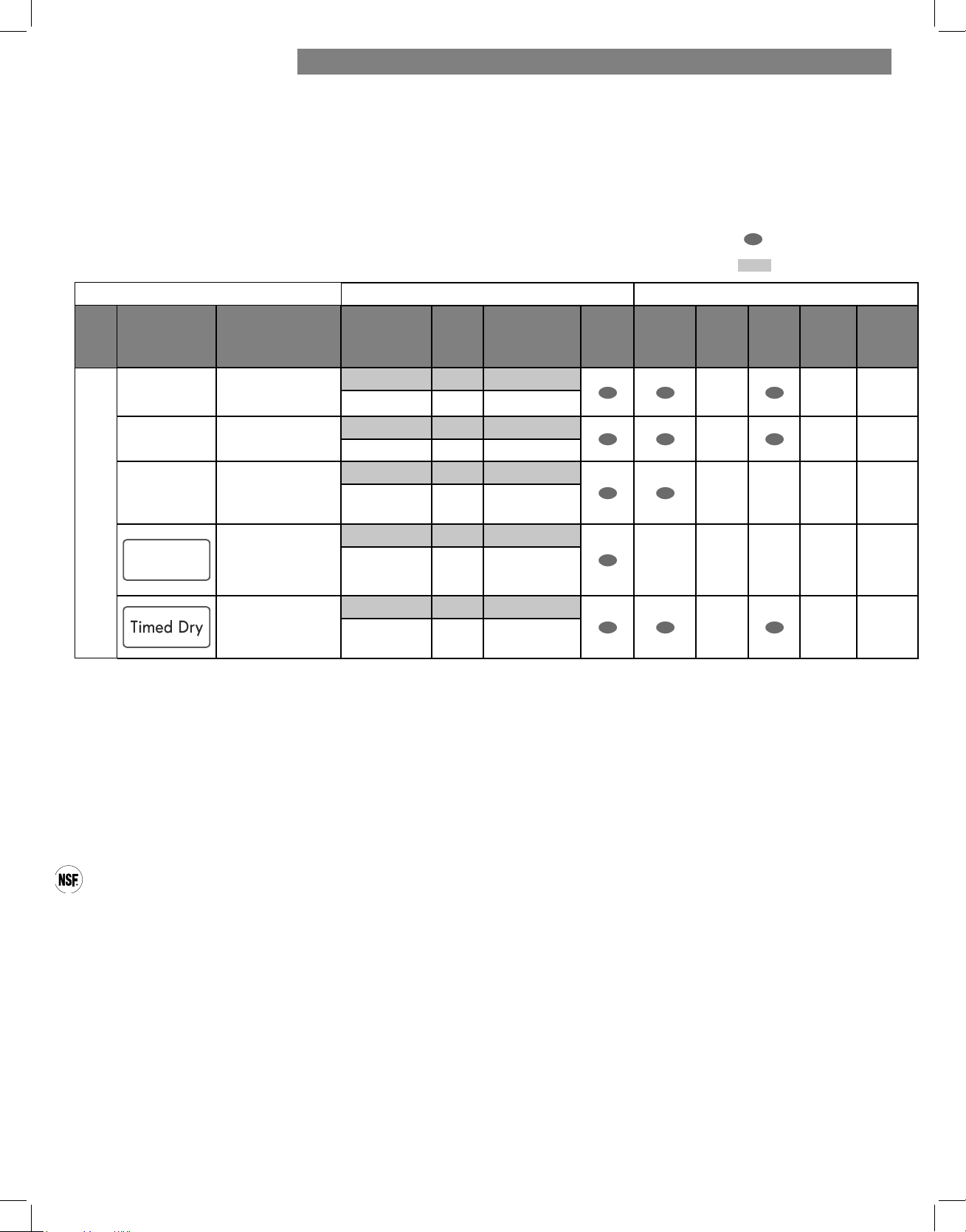
31
Timed Dry Cycles
Use Timed Dry cycles to select a specifi c amount of drying time and the drying temperature. When a TIMED DRY
cycle is selected, the display shows the actual time remaining in the cycle.
Change the actual time for the cycle by pressing MORE TIME or LESS TIME. Press and hold the MORE TIME or
LESS TIME buttons to rapidly change the time.
Modifi ers Options
Type Cycle Fabric Type Temperature
Dry
Level
Time in Min.
More
Time/
Less
Time
Wrinkle
Guard
Damp
Dry
Signal
Static
Shield
Accela
Steam
Energy
Saver
TIMED DRY
Express Dry
For small loads
with short drying
times
Extra High Off 25
Adjustable Max. 100
Touch Up
For removing
light wrinkles
High Off 20
Adjustable Max. 100
Air Dry
For items that
require heat-free
drying such as
plastics or rubber
Air Only Off 30
Max. 100
Rack Dry
Wool sweaters,
silk, lingerie
Off Off 50
Low
Extra Low
Air Only
Max 100
For loads that
require a specifi c
dry time.
Extra High Off 20/30/40/60
Adjustable Max 100
The cycle guide below shows the available options and recommended fabric types for TIMED DRY cycles.
= available option
= default setting
STEAM SANITIZE CYCLE
The STEAM SANITIZE cycle is designed to reduce the amount of certain types of bacteria in clothing. When this
cycle is selected, the temperature is set to HIGH and the dry level is set to EXTRA DRY. These default settings cannot
be changed.
NOTE: Do NOT use this cycle with delicate items or fabrics.
CERTIFIED BY NSF
NSF International (formerly the National Sanitation Foundation), certifi es that the STEAM SANITIZE cycle reduces
99.9% of bacteria on laundry, and none of the bacteria will carry over onto the next laundry load.
• The default settings for the STEAM SANITIZE cycle are HIGH temperature and EXTRA DRY. These default
settings cannot be changed.
• Do NOT use this cycle with delicate items or fabrics.
† The Workout Wear cycle helps to maintain the performance and extend the life of garments created with special
high-performance properties. The temperature and dry level are set automatically and are not adjustable.
HOW TO USE
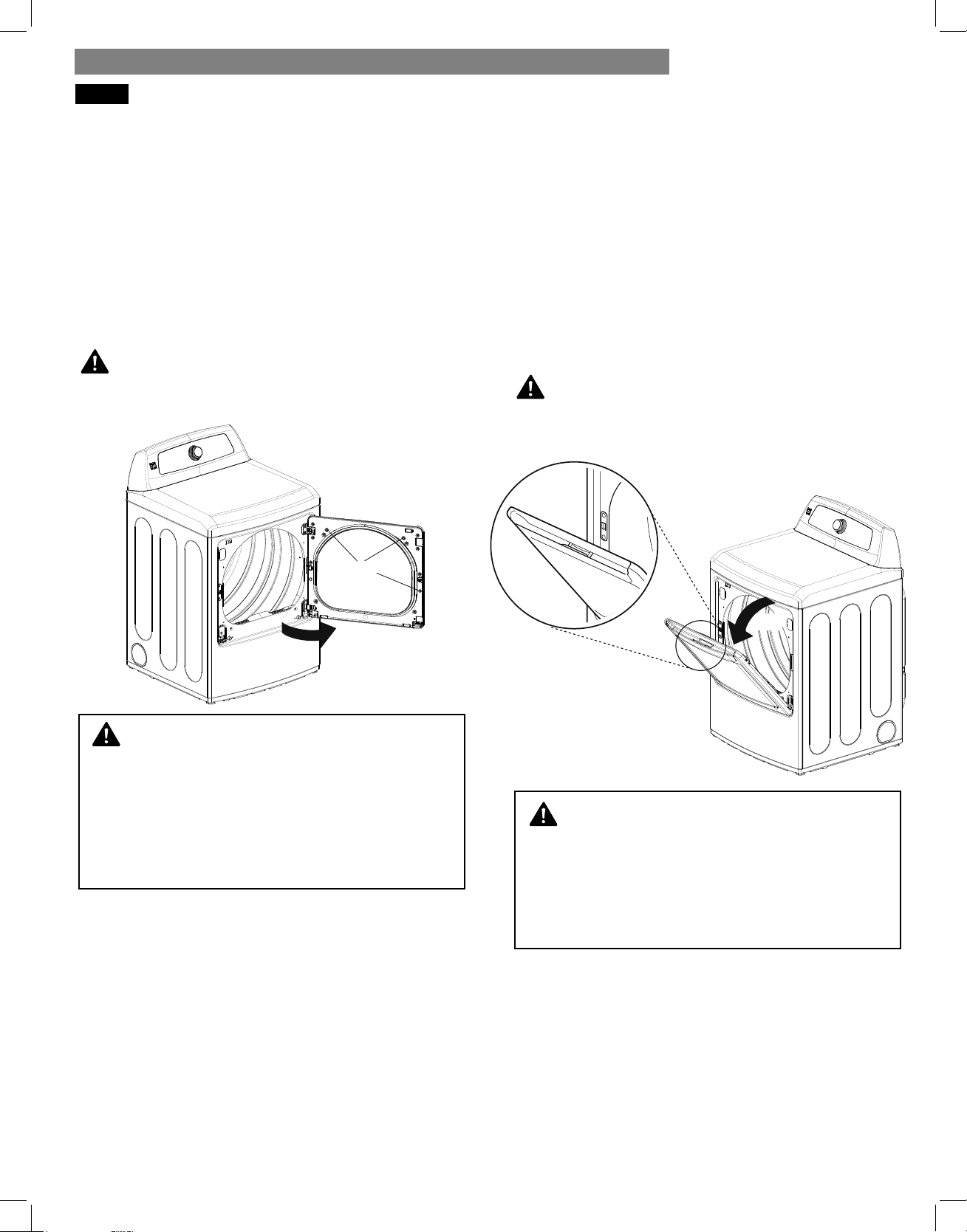
32
The dryer is equipped with a two-way door which
opens in two directions, from the side as a swing door
and from the top as a hamper door.
Swing Door
Use the two-way door as a swing door when
unloading, or when loading bulkier items, for easy
access to the drum.
To open the swing door, insert your fingers into the
handle recess on the top of the door on the side
opposite the hinge and pull the door open.
CAUTION:
Make sure the hamper door release is completely
closed before using the swing door.
Hamper Door
Use the two-way door as a hamper door when
loading. The hamper door opens about 40 degrees,
acting as a chute, to help guide items into the drum
and help prevent items from falling onto the floor.
It also comes in handy when unloading a few small
items, helping prevent the rest of the laundry from
being pulled onto the floor.
To open the hamper door, press the release on the top
of the door and pull the door forward.
Make sure the laundry is fully inserted in the drum
before closing the door.
CAUTION:
Make sure the swing door latch is completely closed
before pressing the hamper door release.
USING THE TWO-WAY DOOR
WARNING:
Do not press the three interlock buttons when
Do not press the three interlock buttons when
the door is open. The door may fall off and
the door is open. The door may fall off and
cause serious injury.
cause serious injury.
Do not place heavy items on or lean against the
Do not place heavy items on or lean against the
top of the door when it is open.
top of the door when it is open.
The dryer could tip forward, causing injury or
The dryer could tip forward, causing injury or
damage.
damage.
WARNING:
Do not attempt to pull the hamper door open
Do not attempt to pull the hamper door open
more than 40 degrees.
more than 40 degrees.
Take care when opening and closing the door.
Take care when opening and closing the door.
If the door drops forward unexpectedly, fingers
If the door drops forward unexpectedly, fingers
and hands can get caught in the door handle
and hands can get caught in the door handle
and injured.
and injured.
hamper door
hamper door release
40°
swing door
interlock
buttons
INSTALLATION INSTRUCTIONSHOW TO USE
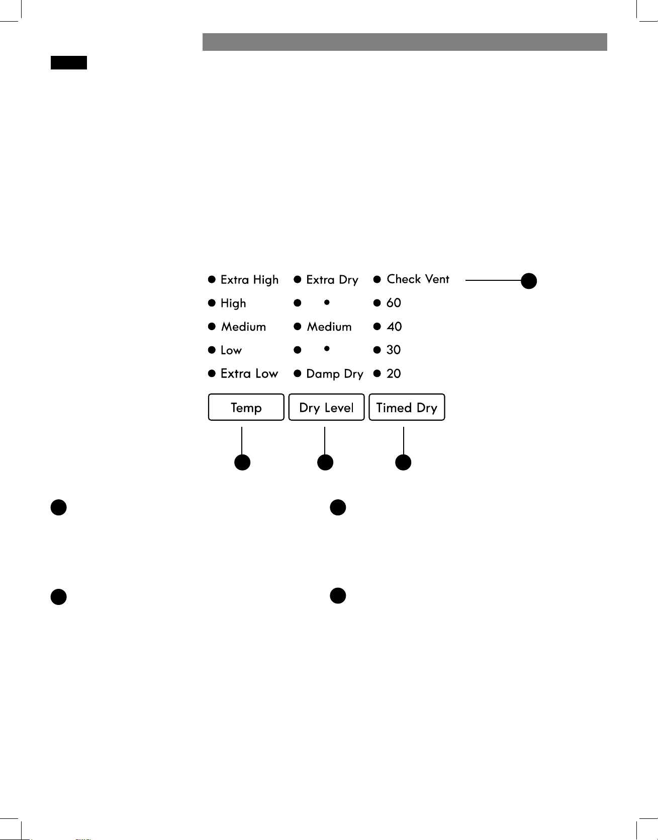
33
Each cycle has default settings that are selected
automatically. You may also customize these settings
using the cycle modifi er buttons.
AUTO DRY cycles are designed to properly care for
specifi c fabrics and loads. As a result, not all settings are
available for each cycle selection.
TIMED DRY cycles have default settings, but you may
also customize the temperature setting and add options.
Settings are not limited in most timed dry cycles. Use
care when setting options and modifi ers for these cycles
to prevent damage to your clothing.
NOTE: To protect garments, not every dry level,
temperature, or option is available with every cycle.
CYCLE MODIFIER BUTTONS
AC
B
TEMP
Adjusts the temperature setting from EXTRA LOW
to EXTRA HIGH. This allows precise care of your
fabrics and garments. Press the TEMP button
repeatedly to scroll through available settings.
Temperature settings are not adjustable in AUTO
DRY cycles.
DRY LEVEL
Sets the level of dryness for the selected AUTO DRY
cycle. Press the DRY LEVEL button repeatedly to
scroll through available settings. Use this button to
adjust the dryness of the articles in the load to your
preference.
• This option is not available with TIMED DRY cycles.
• The dryer will automatically adjust the cycle time.
• Selecting EXTRA DRY will increase the cycle time
and dry level, while DAMP DRY will decrease the
cycle time and dry level.
• Use the DAMP DRY setting for items that you wish
to iron or hang for fi nal drying.
TIMED DRY
Allows you to manually select 20, 30, 40, or 60
minutes of dry time. Use the MORE TIME/LESS TIME
buttons to increase or decrease the selected drying
time in 1-minute increments. Press and hold the
MORE TIME or LESS TIME buttons to rapidly change
the time.
CHECK VENT
(Duct Blockage Sensing System)
The CHECK VENT (Duct blockage sensing system)
detects and alerts you to blockages in the exhaust
system that reduce airfl ow from the dryer.
Maintaining clean exhaust system ducts improves
operating effi ciency and helps minimize service
calls, saving you money.
D
A B C
D
HOW TO USE
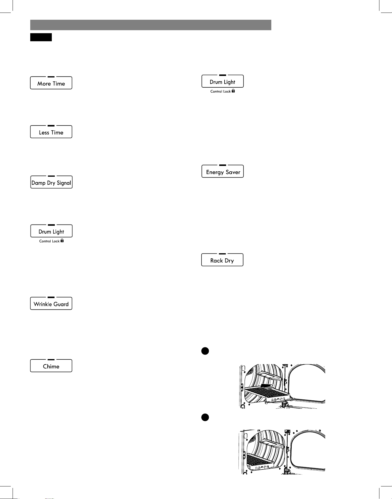
34
CYCLE OPTIONS AND SPECIAL FEATURES
The dryer features several additional cycle options and special features to meet your individual needs.
MORE TIME
Use the MORE TIME/LESS TIME buttons
to increase or decrease the selected
drying time in 1-minute increments.
Press and hold the MORE TIME or LESS TIME buttons to
rapidly change the time.
LESS TIME
Use the MORE TIME/LESS TIME buttons
to increase or decrease the selected
drying time in 1-minute increments. Press
and hold the MORE TIME or LESS TIME buttons to
rapidly change the time.
DAMP DRY SIGNAL
If you press the DAMP DRY SIGNAL
button, the dryer will emit a chime when
the clothes are just short of completely
dry, in case you want to remove them for ironing or
hang drying.
DRUM LIGHT
Use the DRUM LIGHT button to turn on
the light inside the drum during
cycle operation.
NOTE: The drum light will also come on if the dryer
door is opened; however, after the dryer has been
off for more than four minutes, the drum light will be
disabled until the POWER button is pressed to turn on
the dryer.
WRINKLE GUARD
Selecting this option will tumble the
clothes after the cycle ends for a few
seconds every few minutes without heat.
This option is active for 150 minutes after the end of the
cycle, or until the door is opened. This helps prevent
wrinkles if the clothes are not removed immediately
after the cycle has fi nished.
CHIME
The CHIME button adjusts the volume of
the chime or turns it off . Press the button
repeatedly until the desired sound level
is reached.
CONTROL LOCK
Use this option to disable the controls.
All controls will be disabled except for
the POWER button. Once set, the
CONTROL LOCK must be turned off before the controls
can be used. After the dryer has shut off , the POWER
button will allow the dryer to be turned on, but the
controls will remain locked. When the CONTROL LOCK
is set, the LED will illuminate and “CL” will display
alternately with the cycle time.
Press and hold the DRUM LIGHT button for fi ve seconds
to activate or deactivate the CONTROL LOCK.
ENERGY SAVER (on some models)
This option helps to reduce the energy
consumption of the Normal cycle,
depending on the size of the load.
When the Energy Saver option is selected, the cycle
begins with an air dry section and the drying time is
increased.
NOTE: The SAVE ENERGY option is turned on by
default on the Normal cycle. If you want a faster drying
time which begins with heated drying, turn off the SAVE
ENERGY option on the Normal cycle.
RACK DRY
Use Rack Dry with items, such as wool
sweaters, silk, and lingerie, that should
dry fl at. Rack Dry can also be used with
items that should not be tumbled dry, such as gym shoes
or stuff ed toys.
NOTE: Never tumble dry a load of clothing with the
rack installed. When Rack Dry is used, the drum rotates
as usual, but the rack does not move. Make sure all
items remain completely on the rack and cannot fall off
or be pulled off by the turning drum. Remove the rack
after use.
Installing the Dryer Rack
1
With the dryer door open, slide the rack into the
dryer drum.
2
Seat the rack evenly on the edge of the inner door
rim and resting fl at on the inside of the dryer.
INSTALLATION INSTRUCTIONSHOW TO USE
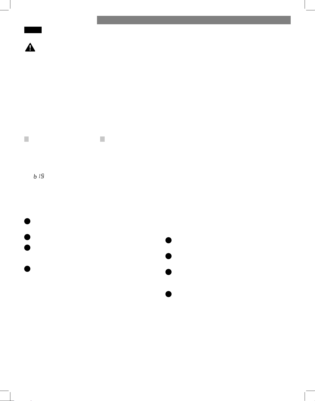
35
IMPORTANT NOTES ABOUT STEAM FUNCTIONS:
• Steam may not be clearly visible during the steam
functions. This is normal.
• Do not use Steam Refresh with items such as wool,
wool blankets, leather jackets, silk, wet clothes, lingerie,
foam products, or electric blankets.
• For best results, load articles of similar size and fabric
type. Do not overload.
• If the home’s exhaust system is restricted, the
performance of the steam functions will be reduced.
• During steam operation, the clothes will tumble for
only a few seconds, once a minute.
STATIC SHIELD
This option uses steam late in the drying cycle to reduce
the static electricity caused by dry fabrics rubbing
together. Change the steam time by pressing the MORE
TIME and LESS TIME buttons to display the approximate
number of articles in the load: 7, 9, 11, 14, 16 or 18.
Steam time is approximately 1-6 minutes, depending on
the number of garments selected.
NOTE: When STATIC SHIELD is added to auto dry
cycles, the LESS and DAMP dry levels cannot
be selected.
ACCELA STEAM
ACCELA STEAM helps prevent the overdrying of clothes
by injecting steam during the drying process.
USING THE STEAM OPTIONS
Adding Steam to a Standard Cycle
1
Turn the dryer ON and turn the cycle selector knob
to select the desired cycle.
2
Use the cycle modifi er buttons to adjust the settings
for that cycle.
3
Press the button for the steam option desired. Adjust
for the load size using the MORE TIME or LESS TIME
button.
4
Press the START/PAUSE button to start the cycle.
• Do not open the dryer door during Steam Cycles.
Steam can cause severe burns.
• Do not touch the steam nozzle in the drum during or
after the steam cycle.
Using the STEAM REFRESH cycle
The STEAM REFRESH cycle uses the power of steam to
quickly reduce wrinkles and odor in fabrics. It brings
new life to wrinkled clothes that have been stored for
an extended period of time, and it can make heavily
wrinkled clothes easier to iron. STEAM REFRESH can
also be used to help reduce odors in clothes, such as
clothes that were worn in a room where people had
been smoking. This cycle can refresh from one to fi ve
garments, or one bulky item such as a comforter. Use
3
for one to three garments and
5
for four or fi ve
garments. For these settings, the dryer tumbles without
heat while the water in the steam generator is heated.
Once steam begins to fl ow, the dryer will only tumble
for about three seconds every minute. Best results are
achieved with 70/30 cotton/polyblend fabrics.
The
(big) setting should be used for bulky items,
such as comforters. For this setting, the cycle begins
with a heated dry segment followed by a shorter steam
segment, as above.
NOTE: The STATIC SHIELD option can be used together
with the STEAM REFRESH cycle to help prevent
static electricity after the cycle.
1
Turn the dryer ON and select the STEAM REFRESH
cycle.
2
Select the STATIC SHIELD option, if desired.
3
The default number of garments is three. Press the
MORE TIME or LESS TIME button to adjust the load
size, as described above.
4
Press the START/PAUSE button to start the cycle.
Using the STEAM SANITIZE cycle
The STEAM SANITIZE cycle is ideal for sanitizing non-
washable items quickly and easily using the power of
steam. This cycle is recommended for use with cotton
and polyester materials. (Do NOT use for urethane
foam, down feathers, or delicate items.)
STEAM FEATURES
WARNING:
HOW TO USE
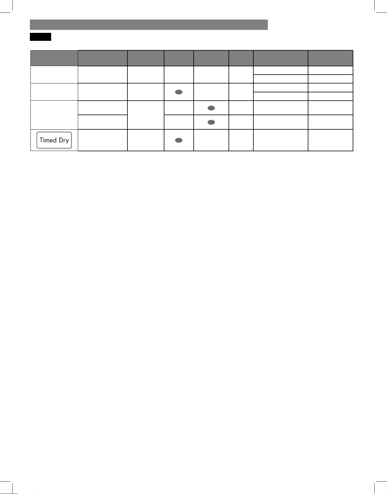
36
STEAM CYCLE GUIDE
Cycle Steam
Default
Time
Temp.
Control
Dry Level
Fabric
State
Fabric Type
Maximum
Amount
Steam Sanitize 31 minutes
dry
comforter, bedding single (1 each)
children's clothing 3 lb
Steam Refresh 10 minutes
dry
comforter single (1 each)
shirts* 5 each
Sensor Cycle
+
Steam Option
+
Static Shield
follows
selected
cycle
wet
varies by
selected cycle
8 lb (18 items)
+
Accela Steam
wet
varies by
selected cycle
8 lb (18 items)
+
Static Shield
38 minutes
wet
varies by
selected cycle
8 lb (18 items)
* Shirt: 70% cotton / 30% poly blend. Except especially delicate fabrics.
• When the lint fi lter or exhaust duct is clogged, steam options will not give
proper results.
• For best results, load articles of similar size and fabric type. Do not
overload.
NOTE:
• When sensor dry is selected with the STATIC SHIELD or ACCELA STEAM
option, a dry level of Less or Damp cannot be selected.
• The STATIC SHIELD option may also be selected during Timed Dry cycles.
• After the steam option is selected in Timed Dry, the MORE TIME or LESS
TIME buttons will change the steam time only.
• After pressing Start/Pause, the MORE TIME or LESS TIME buttons will be
disabled.
INSTALLATION INSTRUCTIONSHOW TO USE
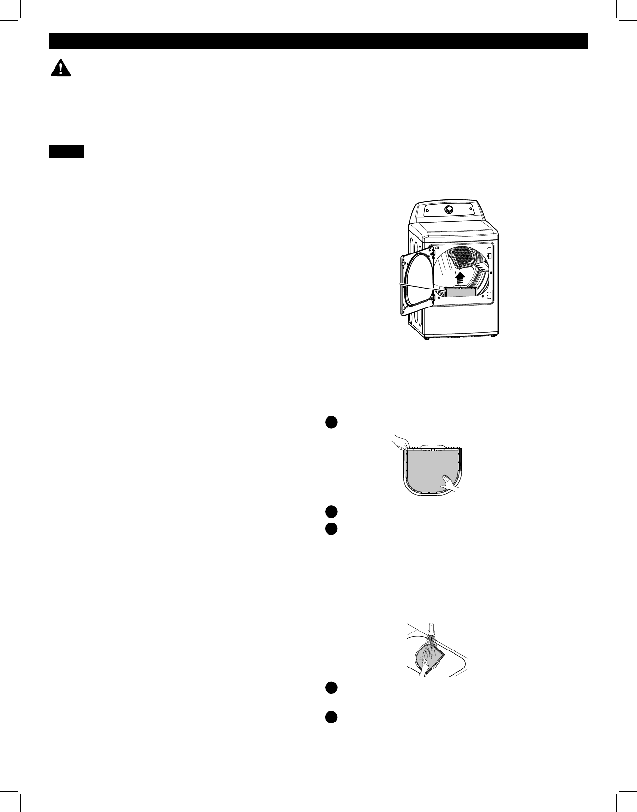
37
USER MAINTENANCE INSTRUCTIONS
REGULAR CLEANING
WARNING:
To reduce the risk of fi re, electric shock, or injury to persons, read this entire manual,
including the Important Safety Instructions, before operating this dryer.
• Unplug the dryer or turn the power off before cleaning to avoid the risk of electric shock. Failure to follow this
warning can cause serious injury, fi re, electrical shock, or death.
• Never use harsh chemicals, abrasive cleaners, or solvents to clean the dryer. They will damage the fi nish.
Cleaning the Exterior
Proper care of your dryer can extend its life. The outside
of the machine can be cleaned with warm water and
a mild, nonabrasive household detergent. Immediately
wipe off any spills with a soft, damp cloth.
IMPORTANT: Do not use cleaning alcohols, solvents, or
similar products.
NEVER use steel wool or abrasive cleansers because
they can damage the surface.
Cleaning the Interior
Wipe around the door opening and seal with a soft,
damp cloth to prevent lint and dust buildup that could
damage the door seal.
Clean the window with a soft cloth dampened with
warm water and a mild, nonabrasive household
detergent, then wipe dry.
NEVER use steel wool or abrasive cleansers; they can
scratch or damage the surface.
Cleaning Around and Under the Dryer
Vacuum lint and dust from around the dryer and
underneath it regularly.
Cleaning the Lint Filter
ALWAYS make sure the lint fi lter is clean before every
cycle. The CHECK FILTER light on the control panel will
blink before every cycle to remind you.
NOTE: NEVER operate the dryer without the lint fi lter.
To remove lint between cycles:
Open the dryer door.
Pull the lint fi lter straight up.
Roll any lint off the fi lter with your fi ngers.
Periodic thorough cleaning:
Some fabric softeners can build up on the lint fi lter over
time. This buildup can restrict the airfl ow through the
fi lter reducing dryer effi ciency and lengthening drying
times. After removing lint, if the fi lter looks dark or dirty
when held up to the light, follow these steps to clean:
Use hot soapy water and a stiff brush to clean
the fi lter.
Make sure the fi lter is completely dry before
reinstalling it and using the dryer.
NOTE: NEVER operate the dryer with a wet lint fi lter.
1
2
3
1
2
Lint Filter

38
• DIRTY OR DAMAGED EXHAUST DUCTS
• WRONG VENT MATERIAL
• RESTRICTED OR DAMAGED VENT HOOD
• EXCESSIVELY LONG VENT
• THE USE OF PLASTIC OR FOIL VENTING
Maintaining the Exhaust System
Vent ducts should be checked for lint buildup and
cleaned at least once per year. If any noticeable
reduction in drying performance occurs, check the ducts
for obstructions and blockages.
If the CHECK VENT indicator illuminates, the exhaust
system should be checked immediately for damage
or obstructions. The CHECK VENT indicator signals a
serious reduction in exhaust airfl ow which will greatly
reduce energy effi ciency and increase drying times.
Damaged or restricted exhaust systems are not covered
by the dryer warranty. Damage to the dryer that is
caused by damaged, restricted, or otherwise inadequate
exhaust systems is not covered by the dryer warranty.
CHECK VENT Indicator
The CHECK VENT warning system is designed to
help you avoid the reduced performance caused by
restrictions in the household exhaust system. The CHECK
VENT indicator illuminates to alert you when problems
in the system occur, so you can have them repaired.
While you should always check and maintain your
exhaust system regularly, the CHECK VENT warning
system will detect and alert you if serious problems
develop in your home’s exhaust system. This includes
exhaust systems that are unsatisfactory for any reason
including a blockage in the venting, crushed/kinked
venting, or venting which exceeds the maximum
recommended length requirement as described in the
installation section.
NOTE: The total length includes the length from the
back of the dryer to the outside vent hood, PLUS a
factor for every 90° elbow in the exhaust system. For
example, if the distance from the back of the dryer to
the vent hood is 30 feet, and there are four elbows in
the system, then it exceeds the 28 foot maximum length
allowed for those conditions.
The CHECK VENT indicator on the control panel will
alert you that the exhaust system is not moving enough
air from the dryer to the outside. This lack of airfl ow will
lead to long dry times, poor drying and possibly dryer
failure.
As a reminder, external dryer venting is considered
part of your home and is not covered by the product
warranty or protection agreements. There are services
available for cleaning/maintaining the external venting.
Sears provides this service via Sears Carpet, Upholstery,
and Duct Cleaning. Call 1-800-661-6594 to schedule
duct cleaning service from Sears (if it is available in
your area).
MAINTAINING THE EXHAUST SYSTEM
CHECK VENT Operation
The CHECK VENT system uses components already
in the dryer. By monitoring these components over the
course of several cycles, the control is able to determine
how much restriction there is in the exhaust system. If
it detects a high level of restriction, it will turn on the
CHECK VENT light to alert you to the condition. The
dryer will continue to operate after the light comes
on, but you should have the exhaust system cleaned or
repaired immediately to avoid longer dry times and
higher energy consumption.
IMPORTANT: In order for a dryer to properly and
effi ciently dry your clothes, it is extremely important
that the exhaust system is as short and clean as
possible. It MUST be less than the maximum installation
requirements as outlined in the installation section. It is
also very important that you make sure that when the
dryer is installed, the exhaust system is clean and clear
of any restrictions and is not kinked or crushed.
Failure to meet these guidelines will result in long dry
times, increased energy consumption and possibly even
clothing damage or dryer failure. When exhaust system
restrictions become extreme, the CHECK VENT light will
blink to alert you to the condition so you can have the
exhaust system cleaned or repaired.
To prevent false alarms and for increased reliability,
the dryer will monitor the exhaust condition for
several loads. If multiple, consecutive cycles exceed
the restriction limits, the control will blink the CHECK
VENT indicator.
A blinking CHECK VENT indicator means the external
venting should be checked for potential restrictions as
soon as possible.
The CHECK VENT indicator will remain active
(blinking) until the restriction is resolved AND the
control has verifi ed the improved airfl ow for
several cycles.
After the exhaust is cleaned or repaired, it will take
several cycles for the CHECK VENT indicator to reset
and turn off the light.
NOTE: The CHECK VENT indicator is designed to
measure performance over several consecutive cycles
before activating or deactivating, to avoid false alarms.
A very large load, such as a large comforter, could
cause the CHECK VENT system to sense that the exhaust
system is restricted, but this would not cause the light to
blink. However, if several large loads were to run back
to back, the CHECK VENT indicator could be activated.
1
2
3
4
The most common cause of dryer problems is poor exhaust venting. Poor exhaust venting may result from the
following conditions:
USER MAINTENANCE INSTRUCTIONS
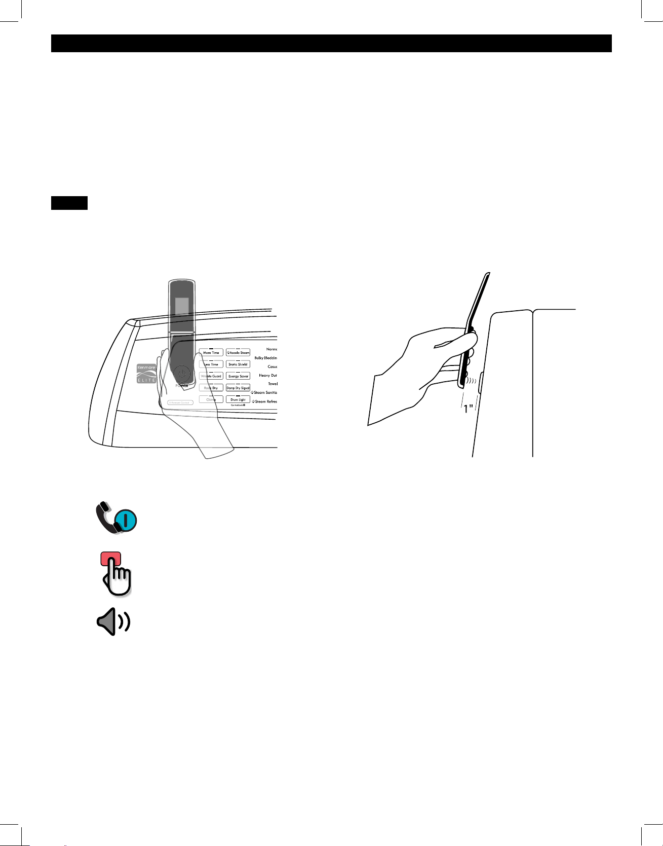
39
Kenmore Connect™ System
HOLD the mouthpiece of your phone over the POWER button, when instructed to do so by
the call center, no more than one inch from (but not touching) the machine.
NOTE: Do not press any other buttons or turn the cycle selector knob.
PUSH and hold the TEMP button while continuing to hold your phone to the
POWER button.
LISTEN for two beeps. After you hear the two beeps, release the TEMP button. Keep the
phone in place until the tone transmission has fi nished. The display will count down the time.
Once the countdown is over and the tones have stopped, resume your conversation with
the technician, who will then be able to assist you in using the information transmitted for
analysis.
Should you experience any problems with your
dryer, it has the capability of transmitting data via
your telephone to the Kenmore Connect Team. This
gives you the capability of speaking directly to our
specially trained technicians. The technician records
the data transmitted from your machine and uses it
to analyze the issue, providing a fast and eff ective
diagnosis.
If you experience problems with your dryer, in the
U.S.A. call 1-844-553-6667 and in Canada call
1-800-469-4663
. Only use the Kenmore Connect
System feature when instructed to do so by the
Kenmore Connect Team. The transmission sounds that
you will hear are normal and sound similar to a fax
machine.
Kenmore Connect cannot be activated unless your
dryer is turned on by pressing the POWER button. If
your dryer is unable to turn on, then troubleshooting
must be done without using Kenmore Connect.
NOTE:
• For best results, do not move the phone while the tones are being transmitted.
• If the call center agent is not able to get an accurate recording of the data, you may be
asked to try again.
• Pressing the POWER button during the transmission will shut off Kenmore Connect.
Using the Kenmore Connect™ System
First, call 1-844-553-6667 (U.S.A.) or 1-800-469-4663 (Canada). If the number of the phone you are using is on
fi le and is associated with your dryer, you will be quickly relayed to a Kenmore Connect team agent. Follow the
technician’s instructions and perform the following steps only when requested to by the Kenmore Connect Team
agent.
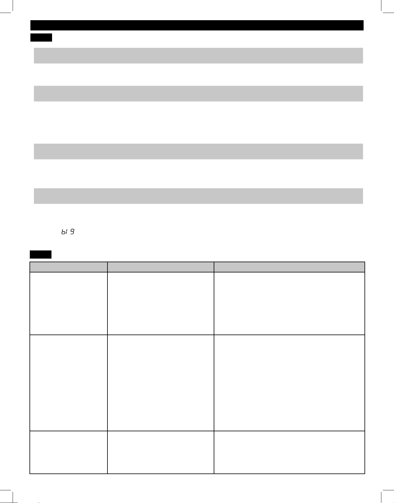
40
TROUBLESHOOTING GUIDE
FAQs
Q: When I press a button, why does my dryer beep and then nothing happens?
A: The Control Lock feature is turned on. To turn off Control Lock, turn the dryer on, then press and hold the
button that has *Control Lock on or under it for 5 seconds.
Q: Why does my dryer take so long to dry clothes?
A: Proper airfl ow is critical to the effi cient operation of clothes dryers. A lint fi lter which is full of lint or
clogged with fabric softener sheet residue can reduce the airfl ow to the point that the time required to
dry clothing will be greatly increased. Another factor aff ecting dry time is your home exhaust system.
An exhaust system which is dirty and clogged with lint, or is excessively long, needs to be professionally
cleaned or repaired.
Q: Why does my dryer start by itself every few minutes?
A: This is how the Wrinkle Guard feature works. The dryer runs briefl y every few minutes for up to 3 hours
after the cycle fi nishes. This feature is designed to help prevent wrinkles from setting in when the dryer is
not unloaded immediately after the cycle is fi nished.
Q: Why does my dryer show 3 minutes when I select the Steam Refresh cycle?
A: When the Steam Refresh cycle is selected, the dryer displays the number of garments rather than the
estimated cycle time, until the cycle is started. Use the MORE TIME or LESS TIME buttons to adjust the
load size setting for the number of garments you desire. For a large load or single bulky item use the
(big) setting.
BEFORE CALLING FOR SERVICE
Problem Possible Cause Solutions
*CHECK VENT indicator
is blinking
* This warning light is
not a dryer failure and
is not covered by the
dryer warranty. Contact
a duct cleaning service to
have your exhaust system
cleaned and inspected.
Exhaust system is too long or has
too many turns/restrictions.
Partial blockage of the ductwork due
to lint buildup or other foreign object.
The appliance has detected a
restriction in the external dryer
venting.
Install a shorter or straighter duct run. See the
Installation Instructions for details.
Ductwork should be checked/cleaned immediately.
Dryer can be used in this condition, but drying times
will be longer and energy consumption will increase.
See the CHECK VENT INDICATOR and CHECK
VENT OPERATION sections for details regarding
this function.
The display shows d80,
d90, or d95
The ductwork is about 80%-95%
blocked. These error codes are only
displayed for 2 hours.
Do not use the dryer until the exhaust system has
been cleaned and/or repaired. Using the dryer
with a severely restricted exhaust is dangerous and
could result in a fi re or other property damage.
Check the outside dryer vent while the dryer is
operating to make sure there is strong airfl ow.
If the exhaust system is extremely long, have it
repaired or rerouted.
Keep the area around the dryer clean and free of
clutter.
Check vent hood for damage or lint clogging.
Make sure the area around the vent hood is clear.
The CHECK VENT
indicator remains active
(blinking) after clearing the
restriction in the venting.
After clearing the restriction, the
CHECK VENT system requires
multiple, consecutive cycles to
determine that the performance
value has improved before the
CHECK VENT indicator is reset.
If the CHECK VENT indicator remains active for
more than fi ve cycles after the restriction has been
cleared, call for service.
41
BEFORE CALLING FOR SERVICE (continued)
Problem Possible Cause Solutions
Dryer will not turn on Power cord is not properly
plugged in.
House fuse is blown, circuit
breaker has tripped, or power
outage has occurred.
Make sure that the plug is securely plugged into a
grounded outlet matching the dryer’s rating plate.
Reset circuit breaker or replace fuse. Do not increase
fuse capacity. If the problem is a circuit overload,
have it corrected by a qualifi ed electrician.
Buttons are disabled or
CL shows in display
CONTROL LOCK function is
engaged.
Press and hold the DRUM LIGHT button for three seconds
to activate or deactivate the function.
Error code: tE1 through tE7 Temperature sensor failure. Turn off the dryer and call for service.
Display shows error
code PS (electric dryers
only)
Power cord is connected
incorrectly.
White (N) and red (L2) wires on power cord. Check
power cord connections for neutral connection on the
center terminal. 240 volts applied to the control, so it
will protect itself.
Display shows error
code nP or gAS
Power cord connection is incorrect.
Gas supply or service turned off
(gas models only).
Check the connection of power cord to terminal block.
Confi rm that house gas shutoff and dryer gas shutoff
are both fully open.
Light does not turn on
when door is opened
Dryer has been off for more than
four minutes and light is disabled.
Press the POWER button to turn on the dryer, which will
enable the drum light.
Dryer does not heat House fuse is blown, circuit
breaker has tripped, or power
outage has occurred.
Gas supply or service is turned off
(gas models only).
Reset circuit breaker or replace fuse. Do not increase
fuse capacity. If the problem is a circuit overload,
have it corrected by a qualifi ed electrician.
NOTE: Due to the design of electric dryers, it is possible
for a circuit problem to allow an electric dryer to run
without heat.
Confi rm that the house gas shutoff and the dryer gas
shutoff valves are both fully open. Even if gas is not
supplied to the dryer, it will run and no error codes
will display. Verify that other gas appliances in the
home are working normally.
Greasy or dirty spots on
clothes
Clean and dirty clothes are being
dried together.
Clothes were not properly cleaned
or rinsed before being placed in
the dryer.
Only use your dryer to dry clean items. Soil from dirty
clothes can transfer to the clean clothes in the same or
later loads.
Stains on dried clothes could be stains that weren’t
removed during the washing process. Make sure
that clothes are being completely cleaned or rinsed
according to the instructions for your washer and
detergent. Some diffi cult soils may require pre-
treating prior to washing.
Lint on clothes Lint fi lter not cleaned properly.
Laundry not sorted properly.
Excess static in clothes.
Dryer is overloaded.
Tissue, paper, etc., left in pockets.
Remove the lint from the fi lter before every load.
With the lint removed, hold the fi lter up to a light to
see if it is dirty or clogged. If it looks dirty, follow the
cleaning instructions. With some loads that produce
high amounts of lint, it may be necessary to clean the
fi lter during the cycle.
Some fabrics are lint producers (i.e., a fuzzy white cotton
towel) and should be dried separately from clothes that
are lint trappers (i.e., a pair of black linen pants).
Use a fabric softener to reduce static electricity. Be
sure to follow the manufacturer’s instructions. Over
drying a load of laundry can cause a buildup of
static electricity. Adjust settings and use a shorter
drying time, or use AUTO DRY cycles.
Divide extra large loads into smaller loads for drying.
Check pockets thoroughly before washing and drying
clothes.
TROUBLESHOOTING GUIDE
42
Problem Possible Cause Solutions
Drying time is not
consistent
Heat settings, load size, or dampness
of clothing is not consistent.
The drying time for a load will vary
depending on the type of heat used (electric,
natural gas, or LP gas), the size of the load,
the type of fabrics, the wetness of the clothes,
and the condition of the exhaust duct and lint
fi lter. Even an unbalanced load in the washer
can cause poor spinning, resulting in wetter
clothes which will take longer to dry.
Clothes take too long to dry Exhaust ducts are blocked, dirty, or
duct run is too long.
Load is not properly sorted.
Large load of heavy fabrics.
Dryer controls are not set properly.
Lint fi lter needs to be cleaned.
House fuse is blown, circuit breaker
has tripped, or power outage has
occurred.
Dryer is overloaded.
Dryer is under loaded.
Confi rm that the exhaust duct is properly
confi gured and free of debris, lint, and
obstructions. Make sure that outside wall
dampers can open properly and are not
blocked, jammed, or damaged.
Separate heavy items from lightweight items.
Larger and heavier items take longer to dry.
Light items in a load with heavy items can fool
the sensor because the light items dry faster.
Heavy fabrics take longer to dry because they
tend to retain more moisture. To help reduce
and maintain more consistent drying times for
large and heavy fabrics, separate these items
into smaller loads of a consistent size.
Use the appropriate control settings for the
type of load you are drying. Some loads
may require an adjustment of the DRY LEVEL
setting for proper drying.
Remove the lint from the fi lter before every
load. With the lint removed, hold the fi lter up
to a light to see if it is dirty or clogged. If it
looks dirty, follow the cleaning instructions on.
With some loads that produce high amounts
of lint, such as new bath towels, it may be
necessary to pause the cycle and clean the
fi lter during the cycle.
Reset circuit breaker or replace fuse. Do
not increase fuse capacity. If the problem
is a circuit overload, have it corrected by a
qualifi ed electrician.
NOTE: Due to the design of electric dryers, it
is possible for a circuit problem to allow an
electric dryer to run without heat.
Divide extra large loads into smaller loads for
better drying performance and effi ciency.
If you are drying a very small load, add a
few extra items to ensure proper tumbling
action. If the load is very small and you are
using AUTO DRY cycles, the electronic control
cannot properly sense the dryness of the load
and may shut off too soon. Use TIMED DRY or
add some extra wet clothes to the load.
BEFORE CALLING FOR SERVICE (continued)
INSTALLATION INSTRUCTIONSTROUBLESHOOTING GUIDE
43
Problem Possible Cause Solutions
Clothes are
wrinkled
Clothes dried too long (over
dried).
Clothes left in dryer too long
after cycle ends.
Over drying a load of laundry can lead to wrinkled clothes. Try
a shorter drying time or LESS DRY setting and remove items while
they still retain a slight amount of moisture.
Use the WRINKLE GUARD option. This feature will tumble the
clothes briefl y every few minutes for up to 150 minutes to help
prevent wrinkling.
Clothes are
shrinking
Garment care instructions are
not being followed.
To avoid shrinking your clothes, always consult and follow fabric
care instructions. Some fabrics will naturally shrink when washed.
Other fabrics can be washed but will shrink when dried in a dryer.
Use a low or no heat setting.
Excess static in
clothes after
drying
Fabric softener is not used or
used incorrectly.
Clothes dried too long (over
dried).
Drying synthetics, permanent
press, or synthetic blends.
Use a fabric softener or the STATIC SHIELD option, if equipped,
to reduce static electricity. Be sure to follow the manufacturer’s
instructions.
Over drying a load of laundry can cause a buildup of static
electricity. Adjust settings and use a shorter drying time, or use
AUTO DRY cycles. Select a LESS DRY setting on AUTO DRY
cycles, if necessary.
These fabrics are naturally more prone to static buildup. Try using fabric
softener, or use LESS DRY and/or shorter TIMED DRY time settings.
Steam Features
Not Working
Water drips from nozzle
when steam cycle starts.
Steam is not visible during
steam cycle.
Steam is not generated and
no error code is displayed.
Garments are still wrinkled
at the end of the STEAM
REFRESH cycle.
Creases or pleats are gone
from garments after Steam
Refresh.
Garments have static after
using the Static Shield option.
Garments are too damp or
too dry after using Static
Shield option.
Water drips down the door
during steam cycles.
Drum does not turn during
steam cycles.
Cannot see steam vapor at
the beginning of the cycle.
Odors are not completely
removed at the end of the
STEAM REFRESH cycle.
This is normal steam condensation. The dripping water will stop after
a short time.
This is normal. Check for condensation on the inside of the door
during the steam portion of the cycle. Steam is not directly visible.
Water level error. Unplug the dryer and call for service.
Load only one to fi ve garments (or a single bulky item). Do not
mix fabric types. STEAM REFRESH is most eff ective on 70/30
cotton/polyblends. Do not use on 100% cotton items.
This cycle removes wrinkles from fabric. Use an iron to replace
creases and pleats in garments.
The amount of static that builds up when wearing garments
depends on the individual moisture level in the skin.
Select the load weight manually before starting the Static Shield
option.
Steam is invisible. However, under some conditions, the condensed
fog may be seen, or condensation will form on the inside of the
door glass and may be seen dripping down the glass.
The drum is turned off so that the steam vapor remains in the
drum. The drum will turn for only a few seconds, once a minute.
Steam is released at diff erent stages of the cycle for each
option. Steam cannot be seen, but condensation may form on the
inside of the door when steam is being generated.
Some odors are diffi cult to remove. Fabrics containing certain
diffi cult odors or very strong odors may not refresh well and
should be washed or dry cleaned instead.
TROUBLESHOOTING GUIDE
44
Kenmore Elite Limited Warranty
FOR ONE YEAR from the date of sale this appliance is warranted against defects in material or
workmanship when it is correctly installed, operated and maintained according to all supplied instructions.
WITH PROOF OF SALE, a defective appliance will receive free repair or replacement at option of seller.
For warranty coverage details to obtain free repair or replacement, visit the web page:
www.kenmore.com/warranty
This warranty applies for only 90 DAYS from the sale date in the United States, and is void in Canada, if this
appliance is ever used for other than private household purposes.
This warranty covers ONLY defects in material and workmanship, and will NOT pay for:
1. Expendable items that can wear out from normal use, including but not limited to fi lters, belts, bags or
screw-in base light bulbs.
2. A service technician to clean or maintain this appliance, or to instruct the user in correct appliance
installation, operation and maintenance.
3. Service calls to correct appliance installation not performed by Sears authorized service agents, or to
repair problems with house fuses, circuit breakers, house wiring, and plumbing or gas supply systems
resulting from such installation.
4. Damage to or failure of this appliance resulting from installation not performed by Sears authorized
service agents, including installation that was not in accord with electrical, gas or plumbing codes.
5. Damage to or failure of this appliance, including discoloration or surface rust, if it is not correctly
operated and maintained according to all supplied instructions.
6. Damage to or failure of this appliance, including discoloration or surface rust, resulting from accident,
alteration, abuse, misuse or use for other than its intended purpose.
7. Damage to or failure of this appliance, including discoloration or surface rust, caused by the use of
detergents, cleaners, chemicals or utensils other than those recommended in all instructions supplied with
the product.
8. Damage to or failure of parts or systems resulting from unauthorized modifi cations made to this
appliance.
9. Service to an appliance if the model and serial plate is missing, altered, or cannot easily be determined
to have the appropriate certifi cation logo.
Disclaimer of implied warranties; limitation of remedies
Customer’s sole and exclusive remedy under this limited warranty shall be product repair or replacement
as provided herein. Implied warranties, including warranties of merchantability or fi tness for a particular
purpose, are limited to one year or the shortest period allowed by law. Seller shall not be liable for incidental
or consequential damages. Some states and provinces do not allow the exclusion or limitation of incidental
or consequential damages, or limitation on the duration of implied warranties of merchantability or fi tness, so
these exclusions or limitations may not apply to you.
This warranty applies only while this appliance is used in the United States or Canada*.
This warranty gives you specifi c legal rights, and you may also have other rights which vary from state to state.
* In-home repair service is not available in all Canadian geographical areas, nor will this warranty cover user
or servicer travel and transportation expenses if this product is located in a remote area (as defi ned by Sears
Canada Inc.) where an authorized servicer is not available.
Sears Brands Management Corporation, Hoff man Estates, IL 60179
Sears Canada Inc., Toronto, Ontario, Canada M5B 2C3
WARRANTY

45
NOTES

46
NOTES

47
NOTES

48
ÍNDICE
REGISTRO DEL PRODUCTO
Contratos maestros de protección
Felicidades por haber realizado una compra inteligente. Su
nuevo producto Kenmore
®
ha sido diseñado y fabricado para
proporcionarle años de funcionamiento fi able. No obstante,
al igual que cualquier otro producto, es posible que requiera
un mantenimiento preventivo o alguna reparación cada cierto
tiempo. Por este motivo, disponer de un contrato maestro de
protección puede ahorrarle dinero y molestias.
El contrato maestro de protección también le ayuda a
prolongar de este producto. A continuación, se indica lo que
incluye este contrato*:
• Material y mano de obra necesario para mantener los
productos en funcionamiento bajo uso normal, no únicamente
los defectos de fabricación. Nuestra cobertura es muy superior
a la garantía del producto. No hay ninguna avería funcional
deducible que se excluya de la cobertura: se trata deuna
protección real.
• Servicio experto de técnicos de servicio experimentados
confi aba en millones de hogares todos los años.
• Sin límite de solicitudes de reparación y servicio en el país, con
tanta frecuencia como des
ee y en cualquier momento.
• Funcionamiento garantizado: sustitución del producto cubierto
después de tres fracasos de productos separados se producen
dentro de los doce meses y se requiere una cuarta reparación.
Incluye la entrega gratuita y la instalación, si es necesario, del
producto de reemplazo.
• Sustitución del producto: si el producto cubierto por el servicio
no se puede
averiar.
• Comprobación anual de mantenimiento preventivo si lo
solicita, sin ningún gasto adicional.
• Ayuda rápida por teléfono: asistencia por teléfono de un
agente de servicio para cualquier producto para ayudar a
solucionar problemas. Puede pensar en nosotros como un
“manual del usuario parlante”.
• Protección de sobretensiones contra daños eléctricos debidos a
fl uctuaciones de energía.
• $300 protección contra pérdida de alimentos para cualquier
deterioro de los alimentos que es el resultado de una falla
mecánica de cualquier refrigerador o congelador cubierto.
• Servicio promesa: $50 si la primera tentativa de reparación
de su producto garantizado no puede llevarse a cabo y el
producto no es utilizable en espera de mayor servicio de
reparación.
• 25% de descuento del precio habitual de cualquier servicio de
reparación y componente instalado relacionado no cubierto
por el servicio.
Una vez adquirido el contrato, sólo tendrá que realizar una
llamada de teléfono para programar el servicio. Puede llamarnos
en cualquier momento del día o de la noche.
El contrato maestro de protección es una compra sin riesgos. Si por
cualquier motivo cancela el contrato durante el plazo de garantía
del producto, le devolveremos todo el importe o bien una cantidad
prorrateada una vez que haya fi nalizado el plazo de garantía del
producto. Adquiera hoy mismo su contrato maestro de protección.
Se aplican ciertas limitaciones y exclusiones. Para consultar
las tarifas y obtener más información en EE.UU. llame al
1-800-827-6655.
* La cobertura en Canadá varía en algunos aspectos.
Para obtener más información, llame a Sears Canada al
1-800-361-6665.
Servicio de instalación de Sears
Para solicitar la instalación profesional de Sears de
electrodomésticos, mecanismos de apertura de puertas
degaraje, calentadores de agua y otros electrodomésticos
degran tamaño, llame en EE. UU.
1-844-553-6667 y llame
en Canadá 1-800-469-4663
.
En el espacio siguiente, anote la fecha de la compra, el modelo y el
número de serie del producto. Encontrará el modelo y el número de
serie impreso en la placa de identificación situada en el interior de
la puerta de la secadora. Tenga esta información a mano siempre
que se ponga en contacto con Sears en relación con su producto.
N.º de modelo.
Fecha de compra
N.º de serie
Guarde estas instrucciones y su ticket de compra para
futuras consultas.
CONTRATOS DE PROTECCIÓN
INSTRUCCIONES IMPORTANTES
SOBRE SEGURIDAD ....................................................................47-50
REQUISITOS DE CONEXIÓN A TIERRA
.....................................48
FUNCIONES Y VENTAJAS
Piezas y componentes clave ................................................... 51
Accesorios..................................................................................51
INSTRUCCIONES DE INSTALACIÓN
Dimensiones y especificaciones clave..................................52
Requisitos de ubicación ..........................................................52
Cómo elegir la ubicación más adecuada ........................... 52
Distancias de separación ......................................................52
Secadoras a gas ..................................................................... 53
Requisitos de gas ...........................................................53
Requisitos eléctricos ........................................................53
Conexión al suministro de gas ......................................54
Secadoras eléctricas .............................................................. 55
Requisitos eléctricos ........................................................55
Conexión de las secadoras eléctricas..........................56
Ventilación de la secadora .............................................57-58
Conexión de la manguera de entrada ................................59
Nivelación de la secadora ....................................................60
Inversión de la puerta bidireccional ...............................61-66
Comprobación final de instalación .....................................67
INSTRUCCIONES DE USO
Funciones del panel de control ............................................68
Pantalla de tiempo y estado ................................................69
Funcionamiento de la secadora .......................................... 70
Clasificación de cargas ......................................................... 71
Carga de la secadora ........................................................... 71
Guía de ciclos ...................................................................72-73
Utilizando el bidireccional puerta reversible ..................... 74
Botones modificadores del ciclo ..........................................75
Opciones de ciclos y funciones especiales ......................... 76
Funciones de vapor .............................................................. 77
Guía de ciclos de vapor ........................................................78
INSTRUCCIONES DE MANTENIMIENTO DEL USUARIO
Limpieza habitual ...................................................................79
Limpieza del exterior .......................................................79
Limpieza del interior ........................................................79
Limpieza alrededor de la secadora y debajo de ella ......79
Limpieza del filtro de pelusas .......................................79
Mantenimiento del sistema de ventilacion ..................80
Sistema Kenmore Connect
™
...............................................81
GUÍA DE SOLUCIÓN DE PROBLEMAS
Preguntas frecuentes ..............................................................82
Antes de solicitar asistencia técnica ..............................82-86
GARANTÍA ...................................................................................87
SERVICIO ..........................................................Cubierta posterior

49
INSTRUCCIONES IMPORTANTES SOBRE SEGURIDAD
LEA TODAS LAS INSTRUCCIONES ANTES DE UTILIZAR ESTE PRODUCTO
PELIGRO:
ADVERTENCIA:
• No instale la secadora de ropa con materiales de ventilación de plástico fl exible. Si se instala un conducto metálico fl exible
(detipo lámina de metal), debe ser del tipo concreto especifi cado por el fabricante del aparato como adecuado para usarlo con
secadoras. Se sabe que los materiales de ventilación fl exibles se colapsan, se pueden aplastar con facilidad y atrapan pelusas.
Estas circunstancias puede obstaculizar el fl ujo de aire de la secadora y aumentar el riesgo de incendio.
Su seguridad y la de los demás es muy importante.
Hemos incluido numerosos mensajes de seguridad en este manual sobre su electrodoméstico. Lea y cumpla siempre todos los
mensajes de seguridad.
Éste es el símbolo de alerta de seguridad.
Este símbolo le avisa de posibles peligros de muerte o lesiones para usted o los demás.
Todos los mensajes de seguridad incluirá el símbolo de alerta y la palabra PELIGRO o ADVERTENCIA.
Estas palabras signifi can:
Indica una situación peligrosa que, si no se evita, podría provocar lesiones graves
olamuerte.
Indica una situación peligrosa que, si no se evita, puede producir lesiones graves o la muerte.
Todos los mensajes de seguridad le indicarán cuál es el posible peligro, lo que debe hacer para reducir la probabilidad
delesiones y lo que puede ocurrirle si no se siguen las instrucciones.
PRECAUCIÓN:
Indica una situación peligrosa que, si no se evita, puede producir una lesión menor
omoderada.
GUARDE ESTAS INSTRUCCIONES
ADVERTENCIA:
Por su seguridad, debe seguir la información de este manual para reducir
al mínimo el riesgo de incendio, explosión o descarga eléctrica, así como prevenir adecuadamente daños
materiales, lesiones personales o muerte.
RIESGO DE INCENDIO
Si no se observan estrictamente las advertencias de seguridad, pueden producirse daños materiales,
lesiones graves o la muerte.
• No instale un ventilador auxiliar en el tubo de salida.
• Instale todas las secadoras de ropa conforme a las instrucciones de instalación del fabricante de la secadora.
ADVERTENCIA
RIESGO DE INCENDIO O EXPLOSIÓN
Si no se observan estrictamente las advertencias de seguridad, pueden producirse daños materiales,
lesiones graves o la muerte.
• No almacene ni use gasolina u otros líquidos o vapores infl amables cerca de este aparato ni de ningún otro.
• La instalación y el mantenimiento deben ser realizados por un instalador, una agencia de servicio o una
compañia de gas califi cados.
QUÉ HACER SI HUELE A GAS:
1. No intente encender una cerilla o un cigarrillo, ni tampoco ningún aparato que funcione con gas o
electricidad.
2. No toque ningún interruptor eléctrico. No utilice ningún teléfono en su edificio.
3. Despeje de personas la habitación, edificio o zona.
4. Llame inmediatamente a la compañía de gas utilizando el teléfono de un vecino. Siga atentamente
las instrucciones delacompañía de gas.
5. Si no puede ponerse en contacto con la compañía de gas, llame a los bomberos.
ADVERTENCIA

50
INSTRUCCIONES IMPORTANTES SOBRE SEGURIDAD
• Lea todas las instrucciones antes de utilizar la secadora.
• Antes de utilizar la secadora, es necesario instalarla
correctamente, según se describe en este manual.
• No introduzca en la secadora artículos que hayan estado
expuestos a aceites de cocina. Los artículos impregnados de
aceites de cocina pueden contribuir a una reacción química
que podría hacer que una carga se incendiase.
• No seque artículos que previamente hayan sido limpiados,
lavados, sumergidos o salpicados con gasolina, disolventes
de limpieza en seco o cualquier otra sustancia infl amable o
explosiva, ya que pueden desprender vapores que podrían
incendiarse o explotar.
• No introduzca las manos en la secadora mientras el tambor o
cualquier otro elemento esté en movimiento.
• No repare ni sustituya ninguna pieza de la secadora ni intente
repararla a menos que se recomiende específi camente en
esta guía de uso y cuidado, o en instrucciones publicadas de
reparaciones que comprenda y sepa aplicar.
• No altere los controles.
• Antes de poner la secadora fuera de servicio o desecharla,
retire la puerta del compartimento de secado.
LEY EJECUTIVA SOBRE LA SEGURIDAD DEL AGUA POTABLE Y LOS AGENTES TÓXICOS
DE CALIFORNIA
Esta ley requiere que el gobernador de California publique una lista de sustancias que se sabe que producen cáncer, defectos
congénitos o cualquier otra lesión reproductiva, y obliga a las empresas a advertir a los clientes sobre la posible exposición a tales
sustancias. Los electrodomésticos de gas pueden ocasionar una exposición leve a cuatro de estas sustancias, en concreto benceno,
monóxido de carbón, formaldehído y hollín, generados principalmente por la combustión incompleta del gas natural o el propano.
Una secadora correctamente ajustada minimizará la combustión incompleta. La exposición a estas sustancias se puede minimizar
aún más dotando a la secadora de una ventilación adecuada al exterior.
REQUISITOS DE CONEXIÓN A TIERRA
Este electrodoméstico debe estar conectado a tierra. En caso de avería o fallo de funcionamiento, la conexión a tierra reducirá el
riesgo de descarga eléctrica, al proporcionar a la corriente eléctrica una trayectoria de una menor resistencia. Este electrodoméstico
debe estar equipado con un cable que disponga de un conductor de conexión a tierra del equipo y un enchufe con conexión a
tierra. El enchufe debe conectarse a una toma de corriente adecuada que esté correctamente instalada y con conexión a tierra
según las normativas y las ordenanzas locales.
ADVERTENCIA: Una conexión inadecuada del conductor de conexión a tierra del equipo puede ocasionar
un riesgo de descarga eléctrica. Consulte a un eléctrico o técnico cualifi cado si tiene dudas sobre si el electrodoméstico está
correctamente conectado a tierra. No modifi que el enchufe que se entrega con el electrodoméstico. Si no encaja en la toma de
corriente, solicite a un electricista adecuadamente formado que le instale una toma de corriente apropiada. Este electrodoméstico
debe conectarse a un sistema de cableado permanente metálico con conexión a tierra o se debe tender un conductor para la
conexión a tierra del equipo con los conductores del circuito y conectado al terminal de conexión a tierra del equipo o al conductor
de suministro del electrodoméstico. Si la secadora no se encuentra adecuadamente conectada a tierra, se pueden producir
descargas eléctricas.
• No permita que los niños jueguen encima de la secadora o en
su interior. Si se usa la secadora cerca de niños, será necesario
vigilarlos atentamente.
• No utilice suavizantes ni productos para eliminar la estática
a menos que lo recomiende el fabricante del suavizante o
producto.
• No utilice el calor para secar artículos que contengan
gomaespuma o materiales con una textura similar.
• Evite la acumulación de pelusa, polvo o tierra alrededor del
área de la apertura de ventilación y áreas adyacentes.
• La parte interior de la secadora y el conducto de ventilación
se deberán limpiar periódicamente, y la misma deberá ser
realizada por técnicos cualifi cados.
• No instale ni coloque esta secadora en lugares donde pueda
estar expuesta a las inclemencias meteorológicas.
• Antes de cargar la secadora, revise siempre que no haya
objetos extraños en su interior.
• Retire la pelusa del fi ltro antes de cada carga.
• ADVERTENCIA: Este producto contiene químicos conocidos
por el Estado de California como causantes de cáncer y
defectos de nacimiento u otros daños reproductivos. Lávese
las manos después de usarlo.
PRECAUCIONES BÁSICAS DE SEGURIDAD
ADVERTENCIA: Para reducir el riesgo de incendio, descarga eléctrica o lesiones físicas al utilizar este
electrodoméstico, siga estas precauciones básicas, entre las que se incluyen las siguientes:

51
• Conecte la secadora adecuadamente a tierra según las
normativas y las ordenanzas vigentes. Siga los detalles en
las instrucciones de instalación. Si la secadora no se encuentra
adecuadamente conectada a tierra, se pueden producir
descargas eléctricas.
• Antes de utilizar la secadora, es necesario instalarla
correctamente, según se describe en este manual. Si la
secadora no se encuentra adecuadamente conectada a tierra,
se pueden producir descargas eléctricas.
• Instale y almacene la secadora en un lugar no expuesto a
temperaturas inferiores al punto de congelación ni expuesto
ala intemperie.
• Todas las reparaciones y el mantenimiento deberán ser
realizados por un técnico autorizado a menos que se den
otras recomendaciones específicas en el manual del usuario.
Utilice sólo piezas de fábrica autorizadas. Si no se cumple con
esta advertencia se podrán producir lesiones graves, incendios,
descargas eléctricas o muerte.
• Con el fin de reducir el riesgo de descargas eléctricas no
instale la secadora en espacios húmedos. Si no se cumple con
esta advertencia se podrán producir lesiones graves, incendios,
descargas eléctricas o muerte.
• Conecte un circuito eléctrico clasificado, protegido y adecuado
para evitar sobrecargas eléctricas. Un circuito eléctrico
inadecuado se puede fundir, creando descargas eléctricas y/o
riesgo de incendio.
• Las secadoras de gas DEBEN tener un conducto de
ventilación al exterior. Si no se siguen estas instrucciones se
podrá producir incendio o muerte.
• El sistema de ventilación de la secadora debe dirigirse
al exterior de la vivienda. Si la secadora no se ventila
al exterior, se expulsará pelusa y grandes cantidades de
humedad a la zona de lavandería. Una acumulación de
pelusa en cualquier zona de la vivienda puede crear un
peligro de incendio y para la salud.
• Use únicamente sistemas de ventilación de metal rígido o
flexible de 10,2 cm (4 pulgadas) de diámetro dentro del
gabinete de la secadora o para ventilación al exterior. Los
sistemas de ventilación de plástico u otro material pueden
causar incendios. Los sistemas de ventilación agujereados
pueden causar incendios si se colapsan o bloquean durante
eluso o la instalación.
• El sistema de ventilación no se incluye con la secadora, por
lo que deberá obtenerlo localmente. La tapa terminal deberá
tener reguladores de tiro con bisagras para prevenir el retorno
de descarga cuando no se usa la secadora. Si no se siguen
estas instrucciones se podrá producir incendio o muerte.
• Quite todos los elementos de embalaje y deseche
adecuadamente todos los materiales de envío. Si no se cumple
con esto se podrá producir una explosión, incendio, quemaduras
o muerte.
• Coloque la secadora a una altura mínima de 46 cm
(18pulgadas) sobre el suelo para una instalación en el garaje.
Si no se cumple con esto se podrá producir una explosión,
incendio, quemaduras o muerte.
• Mantenga todos los envoltorios alejados de los niños.
Losmateriales de los envoltorios pueden resultar peligrosos
paralos niños. Existe riesgo de asfixia.
• No lo instale cerca de un elemento que genera calor, como
una cocina o un horno de cocción. Si no se cumple con esta
advertencia se puede provocar una deformación, humo
ounincendio.
• No coloque velas ni cigarrillos sobre el producto. Si no
se cumple con esta advertencia se puede provocar una
deformación, humo o un incendio.
• Quite la película de vinilo protectora del producto. Si no
se cumple con esta advertencia se puede provocar una
deformación, humo o un incendio.
• El conducto de escape deberá tener 10,2 cm (4 pulgadas)
dediámetro sin obstrucciones. El conducto de escape deberá
mantenerse lo más corto posible. Asegúrese de limpiar
cualquier tipo de conducto antiguo antes de instalar su
secadora nueva. Si no se siguen estas instrucciones se podrá
producir incendio o muerte.
• Se recomienda usar conductos rígidos o semirrígidos entre
la secadora y la pared. En instalaciones particulares,
cuando es imposible realizar una conexión siguiendo las
recomendaciones antes indicadas, únicamente se puede
utilizar un conducto metálico de transición aprobado por UL
entre la secadora y la conexión de pared. Usar este tipo de
conducto afectará al tiempo de secado. Si no se siguen estas
instrucciones se podrá producir incendio o muerte.
• NO utilice tornillos de lámina de metal ni otro tipo de
sujeciones que se extiendan dentro del conducto y puedan
atrapar pelusa y reducir la eficiencia del sistema de
ventilación. Asegure todas las uniones con cinta aislante
impermeable. Para más detalles, siga las instrucciones de
instalación. Si no se siguen estas instrucciones se podrá producir
incendio o muerte.
INSTRUCCIONES DE SEGURIDAD PARA LA INSTALACIÓN
Ventilación/conductos:
ADVERTENCIA: Para reducir el riesgo de incendio, descarga eléctrica o lesiones físicas al utilizar este
electrodoméstico, siga estas precauciones básicas, entre las que se incluyen las siguientes:
INSTRUCCIONES IMPORTANTES SOBRE SEGURIDAD
52
INSTRUCCIONES DE SEGURIDAD PARA LAS CONEXIONES ELÉCTRICAS
ADVERTENCIA: Para reducir el riesgo de incendio, descarga eléctrica o lesiones físicas al utilizar este
electrodoméstico, siga estas precauciones básicas, entre las que se incluyen las siguientes:
• Bajo ninguna circunstancia, corte o quite la clavija de
conexión a tierra del cable eléctrico. Para evitar lesiones
personales o daños a la secadora, el cable eléctrico debe
estar conectado a una toma de corriente con la conexión
atierra adecuada.
• Por motivos de seguridad personal, este electrodoméstico
debe estar conectado a tierra adecuadamente. Si no se
cumple esta advertencia, se podrán producir descargas
eléctricas o lesiones.
• Consulte las instrucciones de instalación de este manual para
obtener los requisitos eléctricos específicos de su modelo.
Si no se siguen estas instrucciones, se podrán producir
descargas eléctricas y/o riesgo de incendio.
• Esta secadora debe enchufarse a una toma de corriente
conectada a tierra adecuadamente. Si la secadora no se
encuentra adecuadamente conectada a tierra, se pueden
producir descargas eléctricas. Solicite a un electricista
cualificado que controle la toma de corriente y el circuito
eléctrico para asegurarse de que la toma de corriente está
correctamente conectada a tierra. Si no se siguen estas
instrucciones, se podrán producir descargas eléctricas y/o
riesgo de incendio.
• La secadora debe estar siempre enchufada a su toma
de corriente individual, con la clasificación de tensión
correspondiente a la placa de datos de servicio. De esta
manera, además de conseguir un funcionamiento óptimo,
también evitará la sobrecarga de los circuitos del cableado
doméstico, lo que podría producir un incendio debido a los
cables sobrecalentados.
• No desenchufe nunca la secadora tirando del cable de
corriente. Agarre siempre el enchufe firmemente y tire del
mismo para retirarlo de la toma de corriente. El cable de
corriente podría resultar dañado, lo que ocasionaría un riesgo
de incendio o descarga eléctrica.
• Repare o reemplace de inmediato todos los cables de corriente
pelados o con cualquier tipo de daño. No use un cable con
grietas o abrasiones sobre su extensión o en los extremos.
Estecable de corriente se puede fundir, ocasionando un riesgo
de descargas eléctricas y/o incendio.
• Al instalar o cambiar de lugar la secadora, tenga cuidado
de no forzar, aplastar o dañar el cable de alimentación.
Deesta manera, evitará heridas o daños debido a incendios
odescargas eléctricas sobre la secadora.
INSTRUCCIONES DE SEGURIDAD PARA LAS FUNCIONES CON VAPOR
ADVERTENCIA: Para reducir el riesgo de incendio, descarga eléctrica o lesiones físicas al utilizar este
electrodoméstico, siga estas precauciones básicas, entre las que se incluyen las siguientes:
• No abra la puerta de la secadora durante los ciclos de vapor.
Si no se siguen estas instrucciones podría existir un riesgo de
quemadura.
• No seque prendas que previamente se hayan limpiado, lavado,
sumergido o salpicado con gasolina, solventes de lavado en
seco o cualquier otra sustancia infl amable o explosiva, ya
que se pueden desprender vapores que podrían incendiarse o
explotar. Si no se siguen estas instrucciones se podrá producir
incendio o muerte.
• No llene el alimentador de vapor con gasolina, solvente
de lavado en seco o cualquier otra sustancia infl amable o
explosiva. Si no se siguen estas instrucciones se podrá producir
incendio o muerte.
• No toque la boquilla de vapor en el tambor durante el ciclo
de vapor o después de fi nalizado el mismo. Si no se siguen
estas instrucciones podría existir un riesgo de quemadura.
INSTRUCCIONES IMPORTANTES SOBRE SEGURIDAD
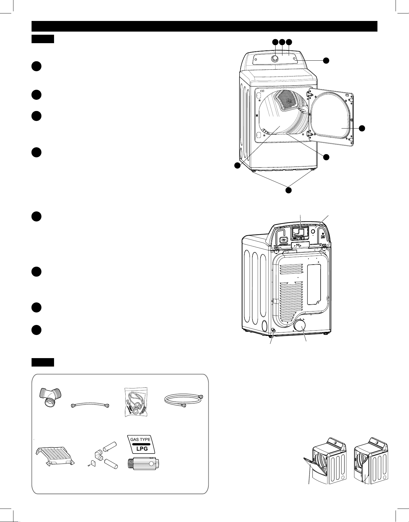
53
FUNCIONES Y VENTAJAS
PIEZAS Y COMPONENTES CLAVE
PANEL DE CONTROL DE FÁCIL USO
Gire el mando selector de ciclo para seleccionar el ciclo
de secado que desee. Añada opciones de ciclo oajuste
los valores tocando un botón.
PANTALLA DE TIEMPO Y ESTADO
La pantalla LED de fácil lectura muestra el estado
delciclo y el tiempo restante estimado.
MODIFICADORES DE CICLO
Ajuste los valores predeterminados del ciclo como
latemperatura y nivel de secado tocando un botón.
NOTA: No todos los ajustes están disponibles para todos
los ciclos.
COMPROBAR VENTILACIÓN
(Sistema de detección de bloqueo del conducto)
La COMPROBACIÓN DE VENTILACIÓN (sistema de
detección de bloqueo del conducto) detecta y alerta
sobre la existencia de bloqueos en el sistema de
ventilación que reducen el flujo de aire de la secadora.
Al mantener limpios los conductos del sistema de
ventilación, mejora el rendimiento y necesitará una
menor asistencia técnica, ahorrándole dinero.
TAMBOR DE ACERO DE CAPACIDAD GRANDE
CON ILUMINACIÓN
El tambor de acero inoxidable de capacidad ultra
grande proporciona una durabilidad superior. La
iluminación del tambor se puede encender durante un
ciclo pulsando el botón DRUM LIGHT situado en elpanel
de control. La luz también se enciende al abrir la puerta,
si el control está activado.
PUERTA REVERSIBLE DE FÁCIL ACCESO
La puerta de cristal transparente de amplia apertura
facilita el acceso para realizar la carga y descarga.
El giro de apertura de la puerta puede cambiarse
desentido para ajustarse al lugar de instalación.
FILTRO DE PELUSAS DE MONTAJE FRONTAL
El filtro de pelusas de montaje frontal permite un acceso
y limpieza más sencillos entre cargas.
PIES DE NIVELACIÓN
Los cuatro pies de nivelación (dos frontales y dos
posteriores) se pueden ajustar para mejorar la
estabilidad de la secadora sobre suelos irregulares.
Existen varios componentes importantes a los que se hace
referencia en este manual.
A
B
C
D
E
F
G
H
ACCESORIOS
Parte posterior de
la secadora
Ubicación del cable
de alimentación
(modelos de gas)
Panel de acceso al
bloque de terminales
(modelos eléctricos)
Ubicación de la
toma de gas
(modelos de gas)
Salida del conducto
de evacuación
H
G
AD B
E
F
C
Puerta reversible de doble sentido (en algunos modelos)
Kit de fi jación de seguridad
Este kit opcional ayuda a evitar que la secadora vuelque si los
niños se suben a la puerta o si alguien cae sobre la puerta. Se
recomienda la instalación de este kit dependiendo de su situación
particular, pero no es obligatoria. Siga las instrucciones de
instalación incluidas con el kit para instalarlo correctamente. Si
no instala el kit, guárdelo fuera del alcance de los niños.
Abra la puerta de la secadora desde
la parte superior (como la puerta de
un canasto de ropa) cuando carga
la secadora, lo que le permite
guiar la ropa hacia el tambor y
evitar que se caiga al suelo. Para
descargar la secadora o cargar
prendas más voluminosas, utilice la
puerta abatible para un fácil
acceso al tambor.
hamper door swing door
puerta de apertura
superior
puerta abatible
Optional Accessories
(steam models)
Y connector short hose
(steam models)
side vent kit
(sold separately)
Kit No. D26-49670
safety tether kit
(on some models)
drying rack
(sold separately)
No. 3750EL0001C
Included Accessories
LP conversion kit
No. 383EEL3002D
Required Accessories
long hose
(sold separately)
(steam models)
conector en "Y"
(modelos de vapor)
manguera corta
(modelos de vapor)
kit de fi jación de
seguridad
(en algunos modelos)
rejilla de secado
(se vende por separado)
N.
o
de kit: 3750EL0001C
kit de ventilación lateral
(se vende por separado)
N.
o
de kit: D26-49670
kit de conversión de LP
N.
o
de kit: 383EEL3002D
Accesorios incluidos
Accesorios opcionales
Accesorios necesarios
manguera larga
(se vende por separado)
(modelos de vapor)
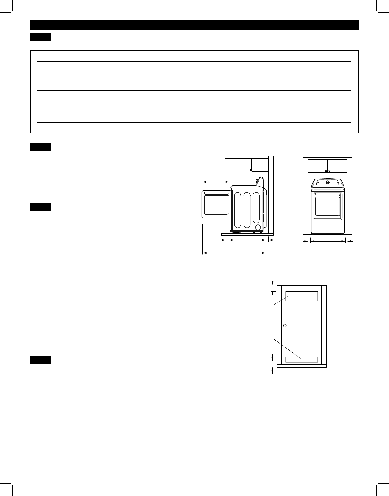
54
INSTRUCCIONES DE INSTALACIÓN
DIMENSIONES Y ESPECIFICACIONES CLAVE
REQUISITOS DE UBICACIÓN
IMPORTANTE: Lea completamente todas las instrucciones
de instalación antes de instalar y poner en funcionamiento su
secadora. Es importante que revise por completo este manual
antes de instalar y utilizar su secadora. En las siguientes páginas
se proporcionan instrucciones pormenorizadas acerca de las
conexiones eléctricas, las conexiones de gas y los requisitos de
ventilación.
CÓMO ELEGIR LA UBICACIÓN MÁS
ADECUADA
• No almacene ni instale la secadora en lugares expuestos a
temperaturas de congelación ni a inclemencias meteorológicas.
• Escoja una ubicación que disponga de un suelo firme y
nivelado.
• Si va a instalar la secadora en un garaje, coloque la unidad al
menos a 45,7 cm (18 pulgadas) sobre el nivel del suelo.
• Conecte correctamente a tierra la secadora cumpliendo todas
las normativas y ordenanzas.
• Para reducir el riesgo de descarga eléctrica, no instale la
secadora en espacios húmedos ni mojados.
NOTE: La instalación de la secadora en un lugar húmedo,
ni instalar o almacenar la secadora donde esté expuesta a
la intemperie o a temperaturas bajo cero, puede dar lugar
a oxidaciones y otros daños que no están cubiertos por la
garantía del producto.
IMPORTANTE: Si va a instalar su secadora en una vivienda
prefabricada o móvil, consulte la sección Requisitos eléctricos
especiales para viviendas móviles o prefabricadas.
DISTANCIAS DE SEPARACIÓN
• La mayoría de las instalaciones requieren una distancia de
separación mínima de 14 cm (5 ½ pulgadas) en la parte
trasera de la secadora para el conducto de ventilación.
• Deje una distancia de separación mínima en los laterales
y parte posterior de 2,5 cm (1 pulgada) para minimizar la
vibración y el ruido.
• Se recomienda dejar una distancia de separación adicional
para llevar a cabo la instalación y el mantenimiento.
• No olvide tener en cuenta las molduras de paredes, puertas
o suelo, que podrían aumentar la distancia de separación
necesaria.
• Deje al menos 53,3 cm (21 pulgadas) en la parte frontal dela
secadora para abrir la puerta.
Instrucciones adicionales para instalaciones en armario:
La puerta del armario debe permitir la entrada del flujo de aire
suficiente. Consulte el esquema superior para consultar los requisitos
mínimos de las aperturas de ventilación. También es aceptable la
utilización de puertas de celosía.
Descripción Secadora Secadora (gas y eléctrica)
Requisitos eléctricos Consulte la etiqueta de especificaciones.
Requerimientos de gas* NG: 4–10,5 pulgadas de columna de agua
Requerimientos de gas* LP: 8–13 pulgadas de columna de agua
Dimensiones 68,6 cm (ancho) X 73,4 cm (largo) X 114,1 cm (alto), 127,5 cm (S. con la puerta abierta)
27 pulgadas (ancho) X 28,9 pulgadas (largo) X 45 pulgadas (alto), 50 ¼ pulgadas
(S. con la puerta abierta)
Peso neto Eléctricia: 58 kg (127,9 libras) Gas: 59.2 kg (130,5 libras)
Capacidad de secado IEC 7,3 pies cúbicos
* Sólo modelos de gas
54 cm
eSXOJDGDV
4"
(10 FP
4"
(10 FP
2,5 cm
SXOJDGD
1"
(2.5 FP
28 e
(73.4 FP
27"
FP
50 e
(127.5 FP
Requisitos de ventilación de la puerta del armaio
3"
(7.6 cm)
3"
(7.6 cm)
48 pulgadas
2
(310 cm)
34 pulgadas
2
(155 cm)
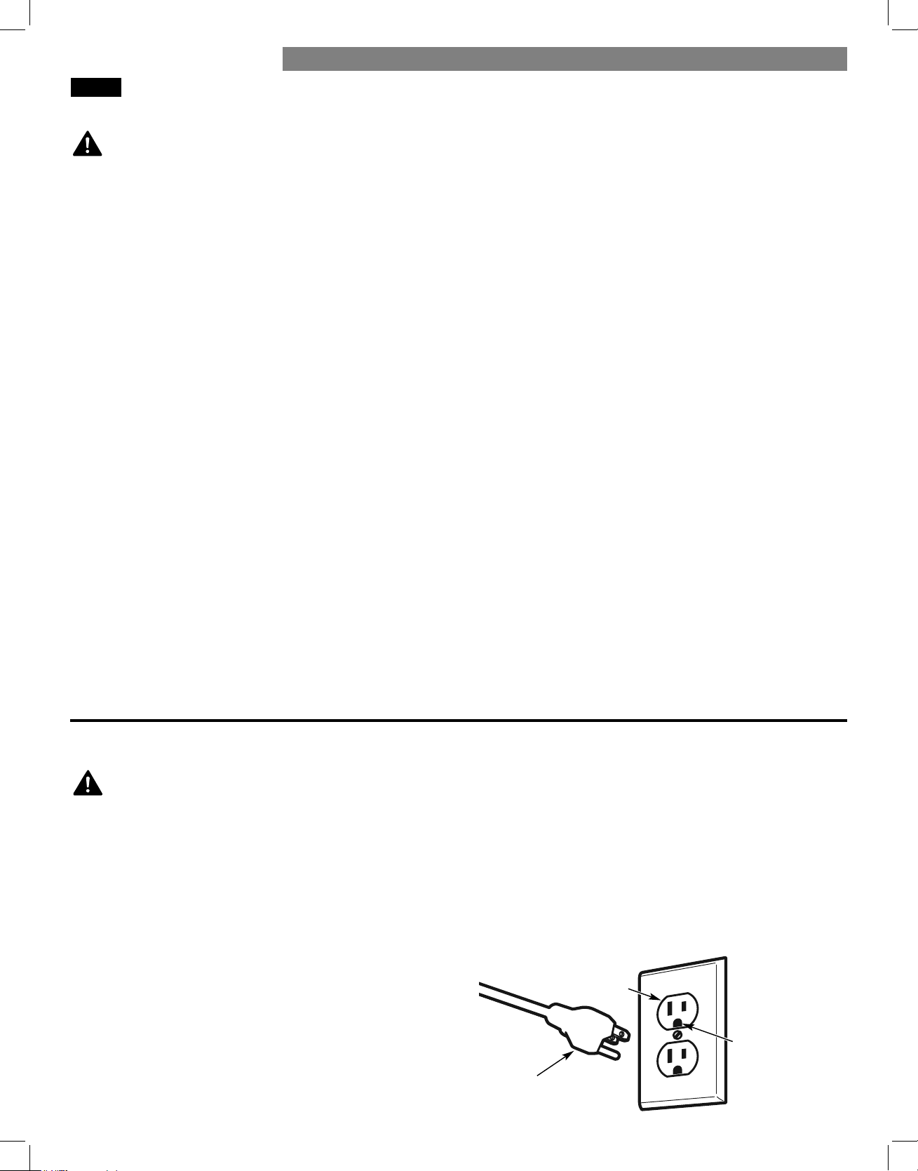
55
SECADORAS A GAS
REQUISITOS DE GAS (SÓLO MODELOS DE GAS)
Para reducir el riesgo
de incendio, descarga eléctrica o lesiones físicas al utilizar este
electrodoméstico, siga estas precauciones básicas,
entre las que
se incluyen las siguientes:
ADVERTENCIA:
• Requisitos del suministro de gas: Esta secadora viene
configurada de fábrica para utilizar gas natural (NG).
Esposible adaptarla para utilizarla con propano licuado (LP).
La presión del gas no debe sobrepasar las 8pulgadas de
columna de agua para (NG) ni 13 pulgadas de columna de
agua para (LP).
• La conexión de la secadora al suministro de gas
debe realizarla un técnico de servicio cualificado de
mantenimiento o de la compañía. Si no se siguen estas
instrucciones, podrían ocasionarse riesgos de explosión,
incendio o, incluso, muerte.
• Aísle la secadora del sistema de suministro de gas cerrando
su válvula manual de cierre individual durante cualquier
prueba de presión del suministro de gas. Si no se cumple con
esto se podrá producir una explosión, incendio o muerte.
• Requisitos de la línea de suministro: Su lavadero debe
disponer de una toma de suministro de gas rígida para su
secadora. En Estados Unidos, debe instalarse una válvula
manual de corte individual en un radio de al menos 1,8m
(6pies) de la secadora, según el National Fuel Gas Code
ANSI Z223.1 o el reglamento de instalaciones de gas
canadiense CSA B149.1. Debe instalarse un tapón de tubería
NPT de ⅛pulgadas. Si no se cumple con esto se podrá
producir una explosión, incendio o muerte.
• Si se utiliza una tubería rígida, debe ser IPS de ½ pulgadas
(1,25 cm). Si lo aceptan los códigos y ordenanzas locales y
su proveedor de gas, puede utilizarse tubería autorizada de
⅜pulgadas cuando la longitud sea inferior a 6,1 m (20 pies).
Deberá utilizarse tubería de mayor sección para longitudes
que excedan los 6,1 m (20 pies). Si no se cumple con esto se
podrá producir una explosión, incendio o muerte.
REQUISITOS ELÉCTRICOS SÓLO PARA
MODELOS DE GAS
Si no observan las advertencias de suguridad, pueden
producirce lesiones graves o la muerte.
• El cable de alimentación de esta secadora está equipado con
un enchufe de tres clavijas (de puesta a tierra) a fin de brindar
protección contra descargas eléctricas y debe conectarse
directamente a un receptáculo de tres clavijas (de puesta a
tierra). Si no se sigue esta advertencia, podrían ocasionarse riesgos
de explosión, incendio o, incluso, muerte.
• Bajo ninguna circunstancia, corte o quite la tercera clavija
(de puesta a tierra) del cable eléctrico. Si no se sigue esta
advertencia, podrían ocasionarse riesgos de explosión,
incendio o, incluso, muerte.
• Por motivos de seguridad personal, este electrodoméstico
debe estar conectado a tierra adecuadamente. Si no se sigue
esta advertencia, podrían ocasionarse riesgos de explosión,
incendio o, incluso, muerte.
• Esta secadora debe enchufarse a una toma de pared
con puesta a tierra de 120 V de CA, 60 Hz, protegida
mediante un fusible o un disyuntor de 15 A. Si no se sigue
esta advertencia, podrían ocasionarse riesgos de explosión,
incendio o, incluso, muerte.
• Si únicamente se dispone de una toma de corriente de
2clavijas, será responsabilidad y obligación suya sustituirlo
por otra de 3 clavijas, de puesta a tierra, y adecuada para
este uso. Si no se sigue esta advertencia, podrían ocasionarse
riesgos de explosión, incendio o, incluso, muerte.
• Conecte la secadora al tipo de gas que se indique en la placa
de identificación. Si no se cumple con esto se podrá producir
una explosión, incendio o muerte.
• Para evitar contaminación procedente de la válvula de gas,
purgue el aire y los sedimentos del suministro de gas antes
de conectarlo a la secadora. Antes de apretar la conexión
entre el suministro de gas y la secadora, purgue el aire
residual hasta que perciba olor a gas. Si no se cumple con
esto se podrá producir una explosión, incendio o muerte.
• NO utilice una llama abierta para buscar fugas de gas.
Utilice un líquido de detección de fugas no corrosivo. Si no
secumple con esto se podrá producir una explosión, incendio
o muerte.
• Utilice únicamente una toma de suministro de gas certificada
AGA o CSA con conectores de acero inoxidable flexible. Si no
se cumple con esto se podrá producir una explosión, incendio
o muerte.
• Apriete firmemente todas las conexiones de gas. Si no se
cumple con esto se podrá producir una explosión, incendio
omuerte.
• Utilice cinta de teflón o un sellador de tubos que sea
insoluble en gas propano licuado (LP) en todas las tuberías.
Si no se cumple con esto se podrá producir una explosión,
incendio o muerte.
• NO intente desmontar la secadora; cualquier desmontaje
requiere la atención y las herramientas de un técnico o
compañía de servicio autorizada y cualificada. Si no se sigue
esta advertencia, podrían ocasionarse riesgos de explosión,
incendio o, incluso, muerte.
Enchufe de conexión
a tierra de 3 clavijas
Toma de pared
de tipo de
conexión a tierra
de 3 clavijas
Asegúrese de que
dispone de una
conexión a tierra
adecuada antes
de ponerla en
funcionamiento.
INSTRUCCIONES DE INSTALACIÓN
ADVERTENCIA: PELIGRO DE
DESCARGA ELÉCTRICA
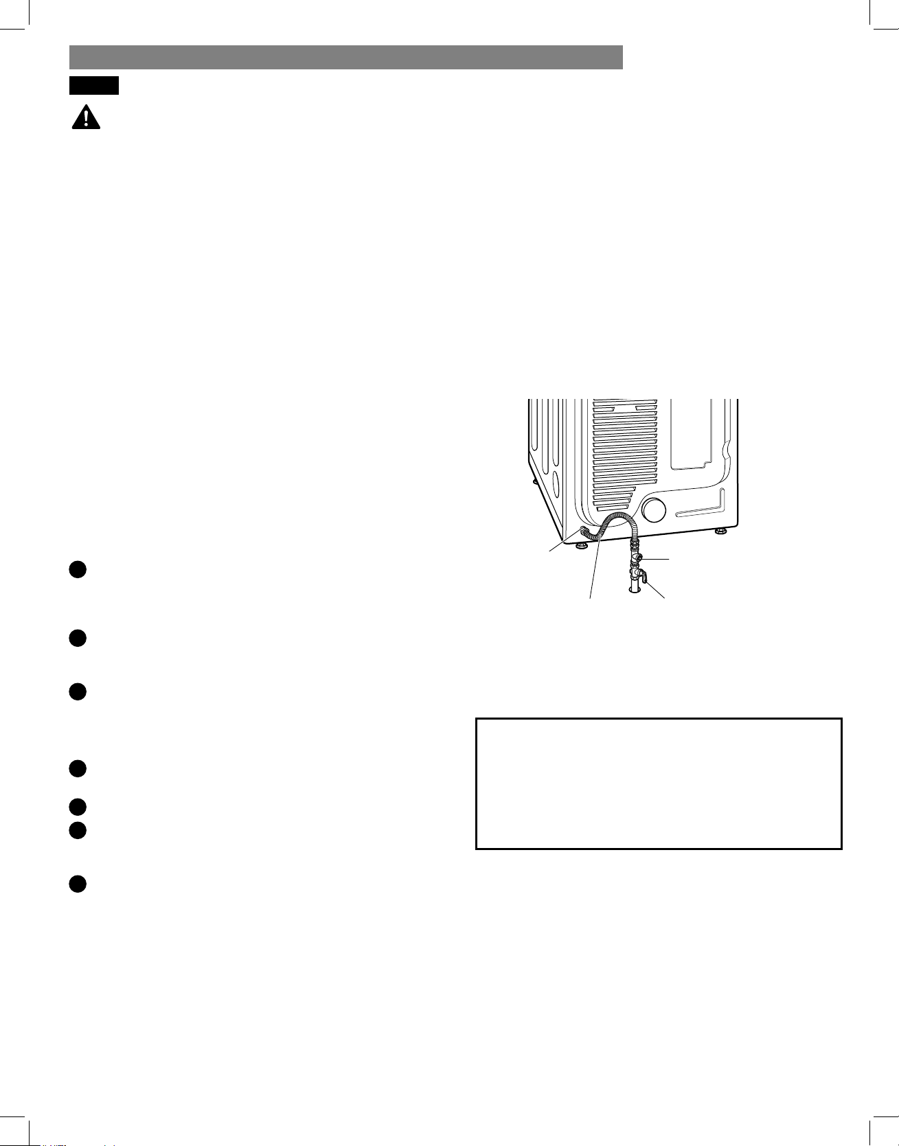
56
INSTRUCCIONES DE INSTALACIÓN
Para reducir el riesgo
de incendio, descarga eléctrica o lesiones físicas al utilizar este
electrodoméstico, siga estas precauciones básicas, entre las que
se incluyen las siguientes:
• La instalación y el servicio deben ser realizados por un
técnico cualificado, una agencia de mantenimiento o la
compañía de gas. Si no se cumple con esto se podrá producir
una explosión, incendio o muerte.
• Utilice únicamente un conector flexible de acero inoxidable
yun conector certificado AGA nuevos. Si no se cumple con
esto se podrá producir una explosión, incendio o muerte.
• Debe instalarse una válvula de corte de gas en un radio de
1,8 m (6 pies) de la secadora. Si no se cumple con esto se
podrá producir una explosión, incendio o muerte.
• La secadora viene configurada de fábrica para utilizar gas
natural. Asegúrese de que la secadora está equipada con
la boquilla de quemador adecuada al tipo de gas que está
utilizando (gas natural o gas propano). Si no se cumple con
esto se podrá producir una explosión, incendio o muerte.
CONEXIÓN AL SUMINISTRO DE GAS
NOTA: Esta secadora viene configurada de fábrica para usar
gas natural (NG). Si la secadora va a utilizarse con gas
propano (LP), deberá adaptarla un técnico de servicio
cualificado.
1
Asegúrese de que el suministro de gas que da servicio
al lavadero esté CORTADO y que la secadora esté
desenchufada. Confirme que el tipo de gas disponible en su
lavadero es el adecuado para la secadora.
2
Retire el tapón de transporte del adaptador de gas situado en
la parte posterior de la secadora. Asegúrese de no dañar las
roscas del conector de gas al retirar el tapón de transporte.
3
Conecte la secadora al suministro de gas del lavadero
utilizando un conector de acero inoxidable flexible con un
adaptador NPT de ⅜ pulgadas.
NOTA: NO utilice conectores viejos.
4
Apriete firmemente todas las conexiones entre la secadora
yel suministro de gas de su lavadero.
5
Abra el suministro de gas del lavadero.
6
Compruebe todas las conexiones de los conductos (tanto
internas o externas) en busca de posibles fugas de gas
utilizando un líquido de detección de fugas no corrosivo.
7
Continúe con los requisitos de ventilación.
Instalaciones en altitudes elevadas
La clasificación BTU de esta secadora tiene certificación
AGA para cotas inferiores a 10.000 pies.
Si va a instalar su secadora en una cota superior a
10.000pies, un técnico cualificado o proveedor de gas
deberá reducir su capacidad eléctrica.
• Si fuese necesario, la boquilla adecuada (para el kit de
boquilla de LP, solicite el número de referencia 383EEL3002D)
debe instalarla un técnico cualificado, indicando el cambio en
la secadora. Si no se cumple con esto se podrá producir una
explosión, incendio o muerte.
• Todas las conexiones deben realizarse conforme a los
códigos y normativas locales. Si no se cumple con esto se
podrá producir una explosión, incendio o muerte.
• Las secadoras de gas DEBEN evacuar al exterior. Si no se
cumple con esto se podrá producir una explosión, incendio
omuerte.
ADVERTENCIA:
⅜ pulgadas (0,95cm)
Gas NPTConexión
⅛ pulgadas (0,30 cm)
Enchufe de tubo NPT
Conector flexible de
acero inoxidable con
certificación AGA/CSA
Válvula de corte de
suministro de gas
SECADORAS A GAS (continuación)
57
SECADORAS ELÉCTRICAS
REQUISITOS ELÉCTRICOS
Para ayudar a prevenir
incendios, descargas eléctricas, lesiones graves o incluso la
muerte, el cableado y la puesta a tierra deben cumplir la edición
más reciente del National Electrical Code, ANSI/NFPA 70 y
todas las normativas locales de aplicación. Póngase en contacto
con un electricista cualificado para comprobar el cableado y
los fusibles de su vivienda para asegurarse de que dispone de la
potencia eléctrica adecuada para utilizar la secadora.
Para reducir el riesgo
de incendio, descarga eléctrica o lesiones físicas al utilizar este
electrodoméstico, siga estas precauciones básicas, entre las que
se incluyen las siguientes:
• Cualquier instalación en una vivienda prefabricada o móvil
debe cumplir con las directrices del Manufactured Home
Construction and Safety Standards, título 24 CFR, sección
32-80 ó con el estándar CAN/CSA0Z240 MH y los códigos
yordenanzas locales.
• Es necesaria una conexión tetrafilar para las instalaciones
realizadas en todas las viviendas móviles y prefabricadas,
así como toda nueva construcción a partir del 1 de enero
de 1996. Si no se cumple con esto se podrá producir una
explosión, incendio o muerte.
• Esta secadora debe conectarse a un sistema de cableado
permanente metálico con conexión a tierra o se debe
tender un conductor para la conexión a tierra del equipo
con los conductores del circuito y conectado al terminal de
conexión a tierra del equipo o al conductor de suministro de
la secadora. Si no se cumple con esto se podrá producir una
explosión, incendio o muerte.
• La secadora dispone de un bloque de terminales propio que
debe conectarse a un circuito monofásico independiente
de 240 V de CA y 60 Hz, con fusible de 30 A. El circuito
debe disponer de fusibles en ambos extremos de la línea.
ELSERVICIO ELÉCTRICO PARA LA SECADORA DEBE SER
DEL MÁXIMO VOLTAJE NOMINAL INDICADO EN LA PLACA
DE ESPECIFICACIONES. NO CONECTE LA SECADORA A
UN CIRCUITO DE 110, 115 Ó 120 VOLTIOS. Si no se siguen
estas instrucciones, podrían ocasionarse riesgos de explosión,
incendio o, incluso, muerte.
• Si el ramal del circuito a la secadora tiene una longitud
igual o inferior a 4,5 m (15 pies), utilice el cable AWGn.º10
con clasificación UL (Underwriters Laboratories) (sólo cable
de cobre) o el que requieran las normativas locales. Si
supera los 4,50 m (15 pies), utilice el cable AWG n.º 8 con
clasificación UL (sólo cable de cobre) o el que requieran
las normativas locales. Permita la suficiente holgura en el
cableado para que la secadora pueda ser desplazada de
suubicación habitual cuando sea necesario. Si no se cumple
con esto se podrá producir una explosión, incendio o muerte.
• La conexión del cable de alimentación (cable flexible de
conexión) entre la toma de pared y el bloque de terminales de
la secadora NO SE INCLUYE con la unidad. El tipo de cable
flexible de conexión y su calibre deben cumplir las normativas
locales y las instrucciones que se proporcionan en las
páginas siguientes. Si no se siguen estas instrucciones, podrían
ocasionarse riesgos de explosión, incendio o, incluso, muerte.
• Es necesario disponer de una conexión tetrafilar en toda
nueva construcción a partir del 1 de enero de 1996. Debe
utilizarse una conexión tetrafilar allí donde las normativas
locales no permitan la puesta a tierra a través del cable
neutro. Si no se cumple esta advertencia, se podrá producir
una explosión, incendio o muerte.
Para reducir el riesgo
de incendio, descarga eléctrica o lesiones físicas al utilizar este
electrodoméstico, siga estas precauciones básicas, entre las que
se incluyen las siguientes:
ADVERTENCIA:
ADVERTENCIA:
ADVERTENCIA:
Requisitos eléctricos especiales para
viviendas móviles o prefabricadas
Requisitos eléctricos sólo para modelos eléctricos
INSTRUCCIONES DE INSTALACIÓN

58
INSTRUCCIONES DE INSTALACIÓN
SECADORAS ELÉCTRICAS (continuación)
CONEXIÓN DE LAS SECADORAS ELÉCTRICAS
Conecte el cable de alimentación al bloque de terminales.
Cada cable de un color en concreto debe conectarse al tornillo
del mismo color. El cable del color indicado en el manual
se conecta al tornillo del mismo color en el bloque. Si no se
siguen estas instrucciones, se pueden provocar cortocircuitos
osobrecarga.
Cable de alimentación tetrafi lar
• Es obligatorio disponer de una conexión tetrafilar
para las instalaciones realizadas en todas las
viviendas móviles y prefabricadas, así como toda
nueva construcción a partir del 1 de enero de 1996.
• Es preciso disponer de un sujetacables con clasificación UL.
• Instale un cable eléctrico tetrafilar de 30 amperios, 240 V y
con clasificación UL con un conductor de cobre n.º 10 AWG
como mínimo y terminales de bucle cerrado o de horquilla con
extremos doblados hacia arriba.
1
Retire la tapa de acceso al bloque de terminales situado
enla sección superior de la parte posterior de la secadora.
2
Instale un sujetacables con clasificación UL dentro del
orificio de paso del cable de alimentación.
3
Introduzca un cable de alimentación tetrafilar de 30 A,
240V y con clasificación UL con conductor de cobre
mínimo AWG n.º 10 a través del sujetacables.
4
Cambie el cable de tierra de la secadora de la parte posterior
del tornillo verde de conexión a tierra al tornillo central del
bloque de terminales.
5
Fije los dos cables activos del cable de alimentación a los
tornillos del bloque de terminales exteriores.
6
Fije el cable neutro blanco al tornillo central del bloque
determinales.
7
Fije el hilo de conexión a tierra del cable de alimentación
altornillo de tierra verde.
8
APRIETE FIRMEMENTE TODOS LOS TORNILLOS.
9
Vuelva a colocar la tapa de acceso al bloque de terminales.
4
Fije los dos cables activos (negro y rojo) del cable de
alimentación a los tornillos del bloque de terminales
exteriores.
5
Fije el cable neutro (blanco) al tornillo central del bloque de
terminales.
6
Conecte la puesta a tierra externa (si lo exigen las
normativas locales) al tornillo verde de conexión a tierra.
7
APRIETE FIRMEMENTE TODOS LOS TORNILLOS.
8
Vuelva a colocar la tapa de acceso al bloque de terminales.
La puesta a tierra a través del conductor neutro está prohibida
para: (1) nuevas instalaciones de circuitos derivados,
(2)viviendas móviles, (3) vehículos recreativos y (4) zonas
enlas que los códigos locales prohíban la puesta a tierra
através del conductor neutro.
Cable de alimentación trifi lar
• NO están permitidas las conexiones trifilares en
nuevas construcciones a partir del 1 de enero de 1996.
• Es preciso disponer de un sujetacables con
clasificación UL.
• Instale un cable eléctrico trifilar de 30 amperios, 240 V, con
clasificación UL y con un conductor de cobre n.º 10 AWG
como mínimo y terminales de bucle cerrado o de horquilla con
extremos doblados hacia arriba.
1
Retire la tapa de acceso al bloque de terminales situado en
la sección superior de la parte posterior de la secadora.
2
Instale un sujetacables con clasificación UL dentro del
orificio de paso del cable de alimentación.
3
Introduzca un cable de alimentación trifilar de 30 A, 240 V
y con clasificación UL con conductor de cobre mínimo AWG
n.º 10 a través del sujetacables.
ADVERTENCIA:
6XMHWDFDEOHVFRQ
FODVLILFDFLyQ8/
&DEOHGH
DOLPHQWDFLyQ
WHWUDILODUFRQ
FODVLILFDFLyQ8/
%ORTXHGH
WHUPLQDOHV
6XMHWDFDEOHV
FRQFODVLILFDFLyQ8/
&DEOHGH
DOLPHQWDFLyQ
WULILODUFRQ
FODVLILFDFLyQ8/
%ORTXHGH
WHUPLQDOHV
+LORGHFRQH[LyQDWLHUUD
GHFDEOHGHDOLPHQWDFLyQ
&DEOHEODQFRPRYLGR
GHWRUQLOORGHFRQH[LyQ
DWLHUUD
7RUQLOORGHFRQH[LyQDWLHUUD
$FWLYRURMR
1HXWUR
EODQFR
$FWLYR
QHJUR
+LOREODQFRGH
HVWUXFWXUDGHVHFDGRUD
7RUQLOORGHFRQH[LyQDWLHUUD
$FWLYRURMR
1HXWUR
EODQFR
$FWLYR
QHJUR
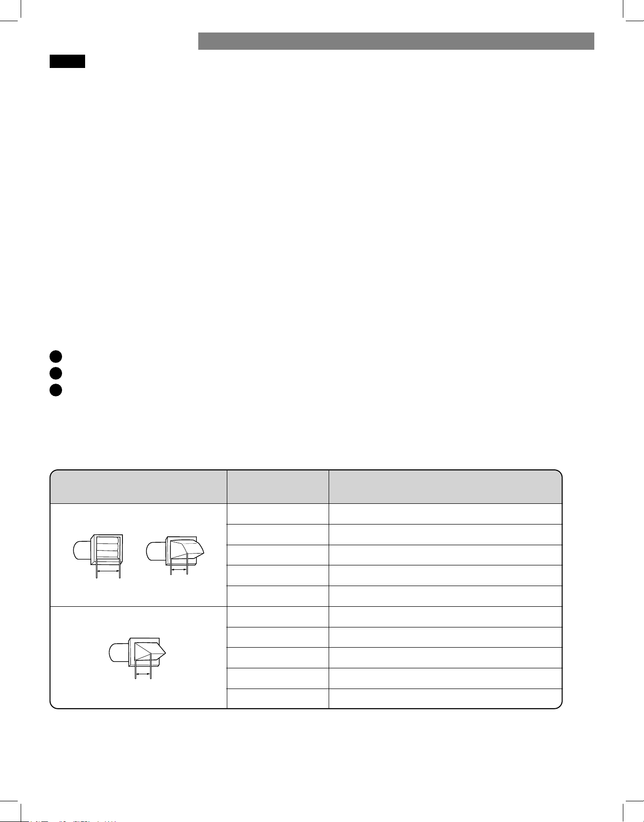
59
VENTILACIÓN DE LA SECADORA
COMPRUEBE LA EXISTENCIA DE PROBLEMAS EN SU SISTEMA DE EVACUACIÓN
¡IMPORTANTE!
La causa más habitual de problemas en la secadora es una ventilación deficiente. Antes de instalar su nueva secadora, compruebe
los elementos enumerados a continuación para garantizar el mejor rendimiento posible. De esta manera, podrá ahorrar tiempo y
dinero al reducir los tiempos de los ciclos y aumentar la eficiencia energética.
• CONDUCTOS DE VENTILACIÓN SUCIOS O DAÑADOS. Se produce una acumulación de pelusas con el paso del tiempo en los
conductos de ventilación, lo que reduce el flujo de aire y aumenta el trabajo de la secadora. Inspeccione visualmente los conductos
desde ambos extremos y límpielos si no lo ha hecho recientemente.
• MATERIAL INADECUADO DE LOS CONDUCTOS DE VENTILACIÓN. Compruebe que los conductos de ventilación son de metal rígido
o semirrígido. Si los conductos de ventilación son de plástico o lámina metálica flexible, sustitúyalos antes de utilizar la secadora.
• EXTRACTOR OBSTRUIDO O DAÑADO. Compruebe su extractor exterior. Debe estar limpio y libre de acumulaciones de pelusas.
Compruebe el regulador de tiro y asegúrese de que se abre fácilmente y por completo.
• CONDUCTO DE VENTILACIÓN DE LONGITUD EXCESIVA. Mida la longitud de su sistema de ventilación y cuente los codos. Utilice
el cuadro que aparece a continuación para comprobar si su conducto es demasiado largo. Si lo es, rediríjalo de forma que cumpla
las directrices de ventilación.
• NO UTILICE CONDUCTOS DE VENTILACIÓN DE PLÁSTICO O LÁMINA METÁLICA. El conducto de paso desde su secadora a
la pared debe ser rígido o semirrígido. Si su viejo conducto de paso es de plástico o de lámina metálica, SUSTITÚYALO por un
conducto metálico semirrígido.
Uso del CUADRO DE LONGITUDES DEL CONDUCTO (a continuación)
1
Busque el tipo de extractor de pared en el cuadro siguiente.
2
Seleccione la fila que coincida con el número de codos requeridos en el recorrido del conducto de la secadora.
3
Lea a la derecha del número de codos la longitud máxima del conducto para la instalación. Una mayor longitud de conducto
ocasionará una menor eficacia de secado, tiempos de secado más prolongados y un mayor consumo de energía. Si el recorrido
delconducto es extremadamente largo, es posible que se reduzca la vida útil de la secadora.
NO supere la longitud máxima para el tipo de extractor y número de codos del conducto utilizado.
CUADRO DE LONGITUDES DEL CONDUCTO
NOTA: Reste 1,8 m (6 pies) por cada codo adicional. No se recomienda utilizar más de cuatro codos de 90°.
Recomendado
Sólo para instalaciones de recorrido corto
10,2 cm
(4 pulgadas)
(2
1/2
pulg.)
6,35 cm
Número
codos de 90°
Tipo de extractor
Longitud máxima de conducto metálico rígido
de 10,2 cm (4 pulgadas) de diámetro
19,8 m (65 pies)
0
1
2
3
4
0
1
2
3
4
10,2 cm
(4 pulgadas)
16,8 m (55 pies)
13,7 m (47 pies)
11,0 m (36 pies)
8,5 m (28 pies)
16,8 m (55 pies)
13,7 m (47 pies)
12,5 m (41 pies)
9,1 m (30 pies)
6,7 m (22 pies)
INSTRUCCIONES DE INSTALACIÓN
INSTRUCCIONES DE INSTALACIÓN
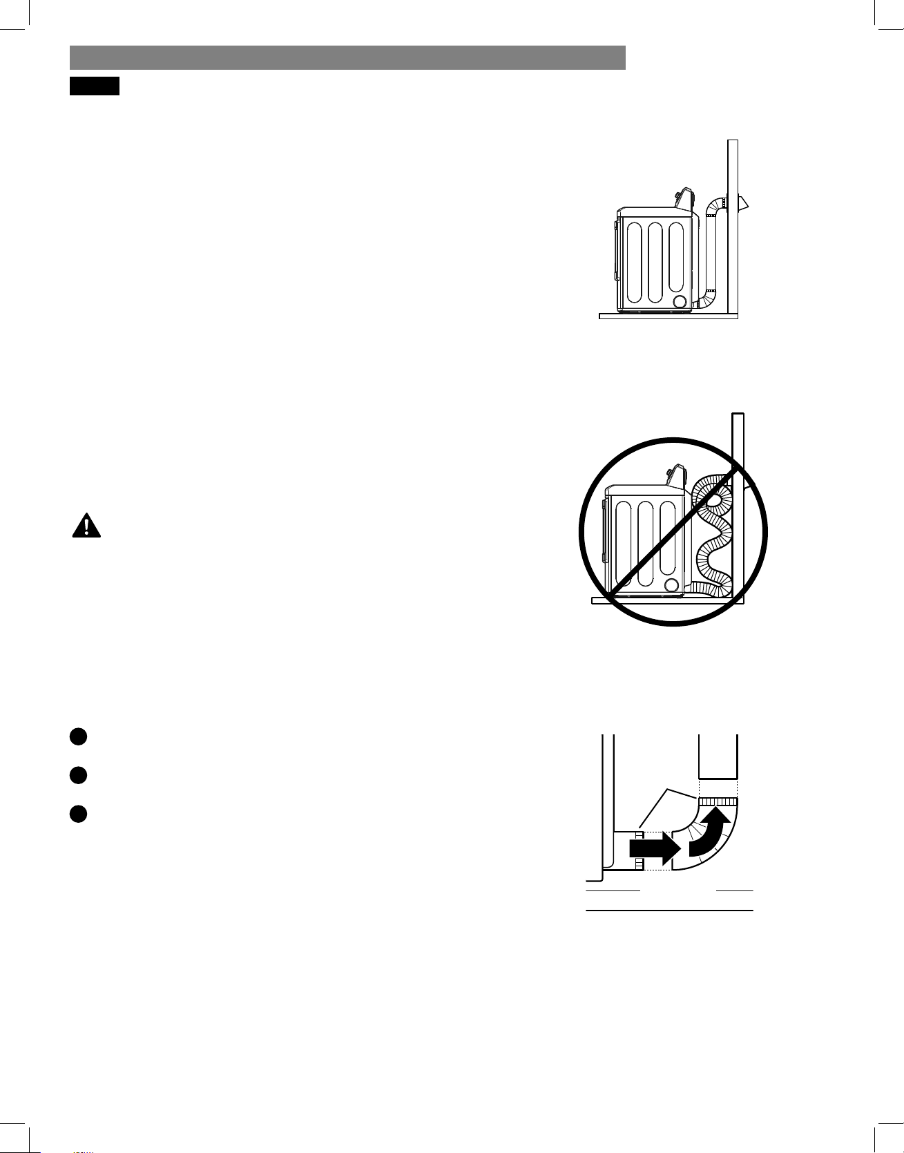
60
INSTRUCCIONES DE INSTALACIÓN
VENTILACIÓN DE LA SECADORA (continuación)
Colocación y conexión de los conductos
Siga las directrices expuestas a continuación para lograr un
funcionamiento óptimo de la secadora y reducir la acumulación
de pelusa y la condensación en los conductos.
NOTA: Los conductos y las uniones NO se incluyen, por lo que
deberán adquirirse por separado.
• Utilice un conducto metálico rígido o semirrígido de 102 mm
(4 pulgadas) de diámetro.
• El recorrido del conducto de ventilación debe ser lo más corto
posible.
• Utilice la mínima cantidad posible de uniones en codo.
• El extremo macho de cada sección del conducto de
ventilación debe apuntar hacia fuera de la secadora.
• Utilice cinta para conductos en todas las uniones. No utilice
nunca tornillos.
• Aísle los conductos que pasen a través de áreas no
calefactadas con el fin de reducir la condensación y la
acumulación de pelusa sobre la superficie del conducto.
• La longitud total de un conducto metálico de transición
semirrígido no deberá exceder los 2,4 m (8 pies).
IMPORTANTE: Si no se ventila la secadora según las directrices
incluidas en estas instrucciones, el rendimiento de la unidad podría
no ser satisfactorio. Toda la ventilación y conductos externos a la
propia secadora son responsabilidad del consumidor. Los fallos en
el producto como consecuencia de una ventilación inadecuada no
quedan cubiertos por la garantía del fabricante.
Conexión del conducto de ventilación de la
secadora
1
Compruebe que todos los conductos y codos estén limpios y
libres de obstrucciones.
2
Mida la longitud del conducto. NO sobrepase la longitud
máxima que se indica en el cuadro.
3
Conecte la ventilación de la secadora a los conductos
existentes.
Si no se siguen estas
directrices ocasionará un rendimiento deficiente, fallos del
producto y/o podría producir incendios o riesgo de muerte.
ADVERTENCIA:
• Utilice únicamente cinta o abrazaderas para conductos.
• NO utilice tornillos para sujetar los conductos.
• Utilice conductos metálicos rígidos o semirrígidos.
• NO utilice tubos de plástico ni de lámina metálica para
los conductos.
• El extremo macho de cada codo debe apuntar siempre en
el sentido del flujo de aire.
Ventilación correcta
Ventilación incorrecta
NOTA: Tenga cuidado al trasladar la secadora hasta su
ubicación final. NO aplaste el conducto. Asegúrese de que las
conexiones no quedan sueltas.
Extremos
macho
F
L
U
J
O
D
E
A
I
R
E
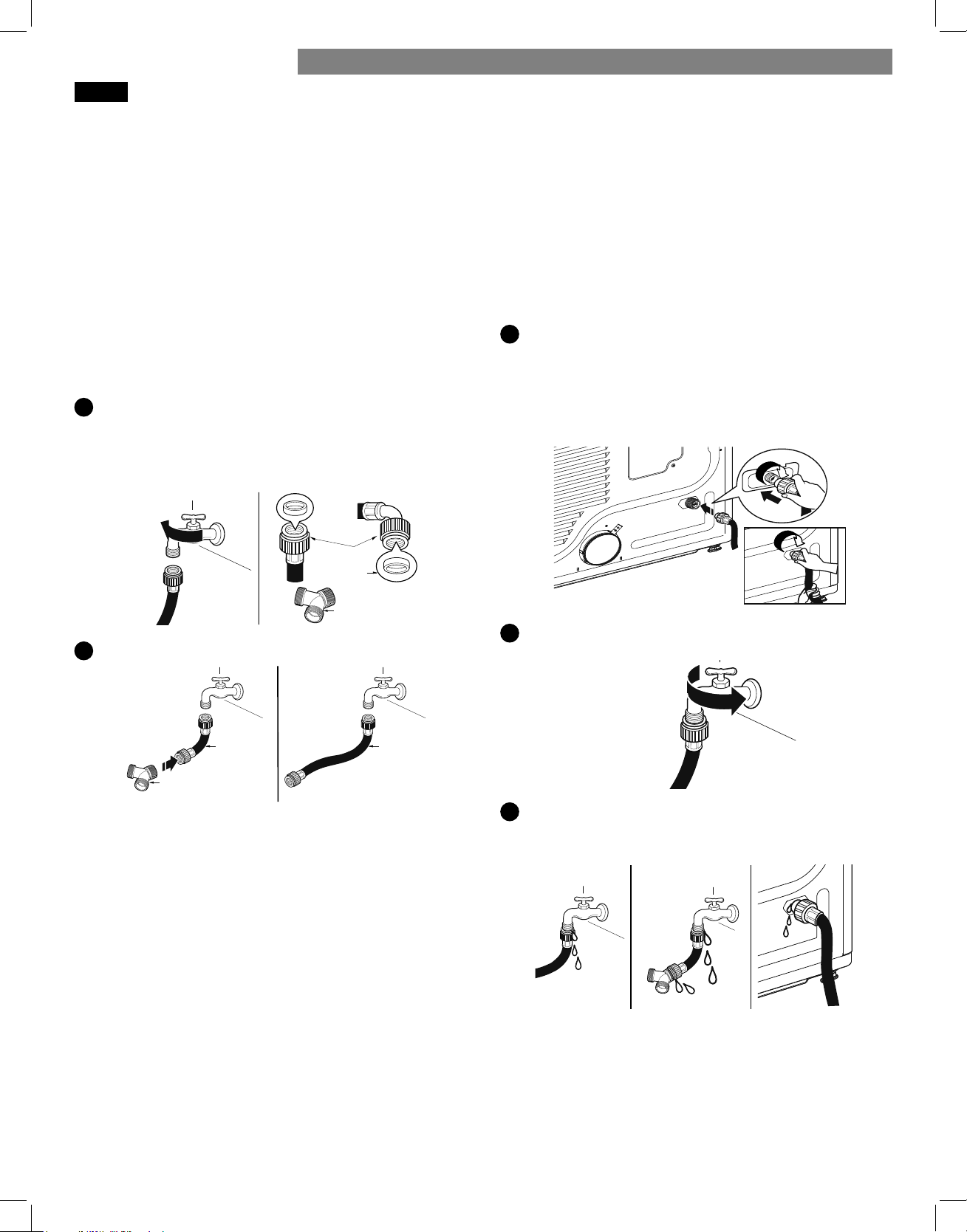
61
CONEXIÓN DE LA MANGUERA DE ENTRADA (modelos de vapor)
La secadora debe conectarse al grifo de agua fría mediante
una manguera de suministro de agua nueva. No utilice
mangueras viejas.
NOTA:
• La presión del suministro de agua debe ser de entre
20 y 120 psi (138 a 827 kPa).
• No dañe ni fuerce la rosca cuando conecte la manguera de
entrada a la válvula.
• Si la presión de agua es superior a 827 kPa, debe instalarse
una válvula reductora de presión.
• Revise las condiciones de la manguera de manera periódica y
reemplácela si fuera necesario.
• Reemplace las mangueras de entrada después de 5 años de
uso para reducir el riesgo de falla en la manguera..
• Anote las fechas de instalación o de reemplazo en las
mangueras para futuras consultas.
1
Revise el sello de goma de la manguera de entrada. Se
proporcionan dos sellos de goma con cada manguera
de entrada. Se utilizan para evitar las pérdidas de agua.
Asegúrese de que la conexión con el grifo de agua fría sea
hermética.
2
Verifi que el tipo de instalación.
Apriete bien todas las conexiones de las mangueras de
suministro de agua a mano y luego ajuste otros 2/3 de
vuelta con pinzas.
CON LAVADORA: En el caso de conectar la secadora en el
mismo grifo que la lavadora.
a. Cierre el grifo de agua fría y quite la manguera de la lava-
dora.
b. Conecte la manguera corta al conector en "Y" usando uno de
los sellos de goma.
c. Conecte el otro extremo de la manguera corta al grifo de
agua fría.
d. Conecte la manguera larga de la secadora en un extremo del
conector en "Y" y conecte la manguera de la lavadora en el otro
extremo.
SIN LAVADORA: Si la secadora no comparte el grifo de agua
fría con una lavadora.
a. Conecte el extremo recto de la manguera larga al grifo de
agua fría.
NOTA:
• Antes de conectar la línea de agua a la secadora, evacue
varios galones de agua en un desagüe o en un cubo. Esto
evitará que algunas partículas extrañas como arena y sarro
tapen la válvula de entrada de la secadora.
• No ajuste de más. Podría dañar los acoplamientos.
3
Connect the hose to the dryer.
• Conecte la manguera a la secadora. Conecte la manguera
de suministro de agua a la válvula de entrada de la seca-
dora a mano y luego ajuste otros 2/3 de vuelta con pin-
zas. Asegúrese de que las mangueras no estén plegadas ni
aplastadas.
4
Abra el grifo de agua fría.
5
Verifi que que no haya fugas en el conector en "Y" (si se
utiliza) ni en ninguna otra manguera.
NOTA:
• Si hubiera fugas, cierre el grifo de agua, quite la manguera y
revise el estado del sello de goma.
conector
de la
manguera
conector en “Y”
sello de
goma
manguera
larga
CON LAVADORA SIN LAVADORA
conector en “Y”
manguera
corta
INSTRUCCIONES DE INSTALACIÓN
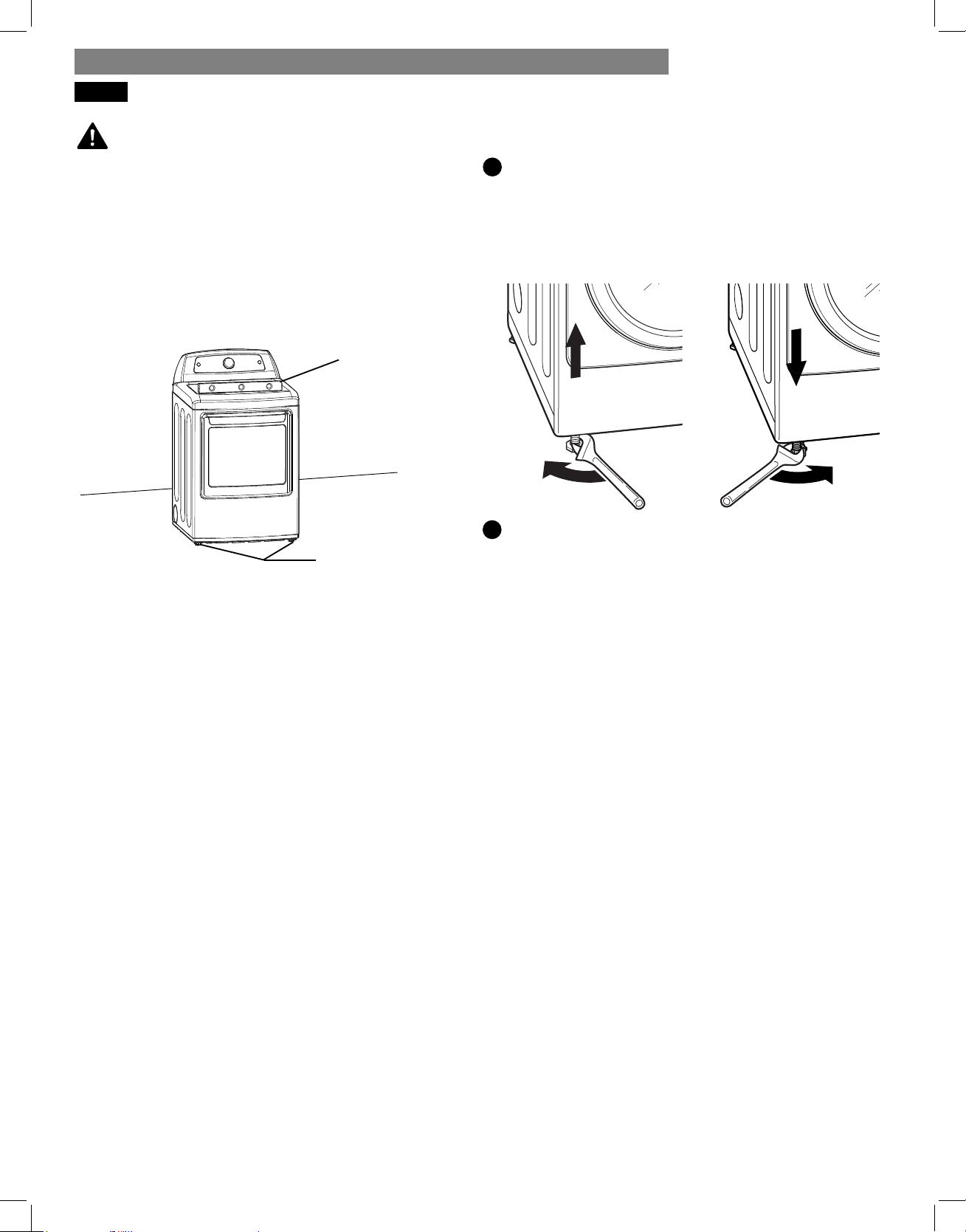
62
NIVELACIÓN DE LA SECADORA
• Utilice guantes durante la instalación.
• Si no se siguen estas instrucciones puede provocar lesiones
físicas.
Para asegurarse de obtener un secado óptimo, la secadora
debe estar nivelada. Para minimizar la vibración, los ruidos y los
movimientos no deseados, la superficie del suelo debe ser firme
y estar nivelada.
NOTA: Ajuste los pies de nivelación sólo lo necesario para
nivelar la secadora. Si se extienden los pies de nivelación más
de lo necesario, se pueden provocar vibraciones en la secadora.
1
Coloque la secadora en su ubicación final. Coloque un nivel
sobre la parte superior de la secadora.
Los cuatro pies de nivelación deben apoyarse firmemente
sobre el suelo. Presione ligeramente las esquinas superiores
de la secadora para asegurarse de que no existe desequilibrio
entre ellas.
ADVERTENCIA:
nivel
pies de nivelación
2
Use una llave inglesa para girar los pies de nivelación.
Gire el pie de nivelación en sentido horario para elevar
la secadora y gírelo en sentido antihorario para bajarla.
Con un nivel, ajuste los pies hasta que la secadora quede
nivelada de lado a lado y de adelante hacia atrás.
Asegúrese de que los cuatro pies están en contacto directo
con el suelo.
NOTA: Si desea instalar la secadora sobre el pedestal opcional,
deberá retraer completamente los pies de nivelación. Utilice los
pies de nivelación del pedestal para nivelar la secadora.
INSTRUCCIONES DE INSTALACIÓN
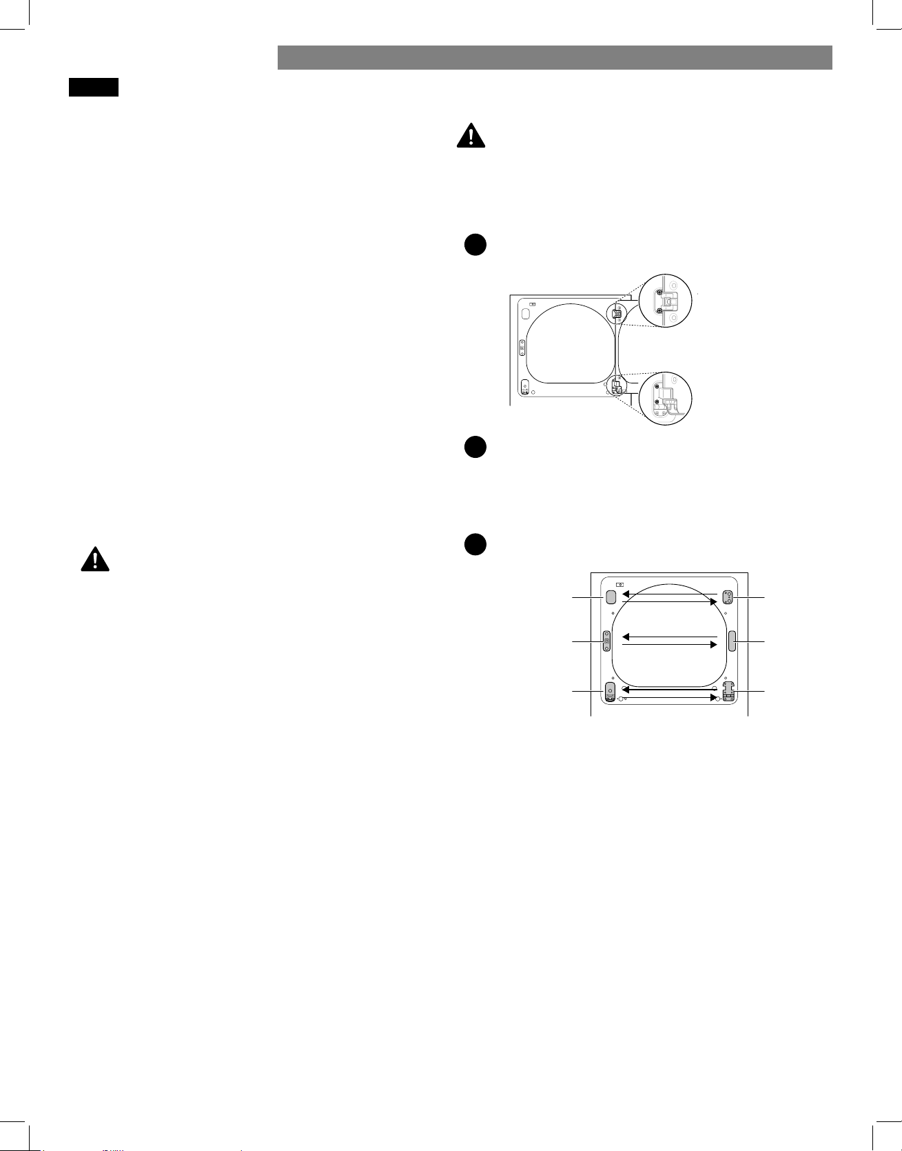
63
INVERSIÓN DE LA PUERTA BIDIRECCIONAL
ADVERTENCIA:
Asegúrese de soportar el peso de la puerta antes de extraer los
tornillos de las bisagras.
DEL GABINETE :
1
Abra la puerta de costado de manera de poder acceder
a los tornillos de las bisagras.
2
Extraiga los cuatro tornillos de las bisagras.
Mientras sostiene a la puerta, extraiga los cuatro tornillos
de las bisagras, dos de cada bisagra. Aparte la puerta:
colóquela de cara al suelo sobre una superficie protegida
para evitar que se dañe la puerta o la superficie de trabajo.
3
Invierta los componentes del gabinete.
a. Utilice un destornillador Phillips para extraer los dos tornillos
y el mecanismo de cierre del panel frontal del gabinete.
b. Extraiga la cubierta del agujero del cierre mediante un
suave movimiento de palanca con un destornillador de
punta plana, cuidando de no rayar la pintura. Instale la
cubierta del agujero del cierre en el lado opuesto, de
donde se ha extraído el mecanismo de cierre. Instale el
mecanismo de cierre en la posición de donde extrajo la
cubierta del agujero del pestillo utilizando los dos tornillos
extraídos en el paso a.
c. Retire la cubierta de la bisagra mediante un suave
movimiento de palanca con un destornillador de punta
plana, cuidando de no rayar la pintura. Gire la cubierta
de la bisagra 180 grados e instálela en el lado opuesto,
donde estaba sujeta la bisagra superior.
Antes de comenzar
NOTA:
Las llamadas al servicio técnico para invertir la mano de la
puerta no están cubiertas bajo la garantía del producto.
El proceso de inversión de puerta para la puerta de dos
direcciones es más complejo que para una puerta convencional
de secadora. Lea atentamente estas instrucciones antes de
comenzar el proceso, para que usted pueda decidir si debería
encargar el trabajo a un instalador profesional o un técnico.
El procedimiento consiste en cuatro partes principales:
• Retirada y nueva instalación de la puerta y las bisagras (pasos
1, 2 y 18)
• Retirada e inversión de los componentes del mueble de la
secadora (paso 3)
• Retirada e inversión de los componentes de la cubierta de la
puerta (pasos 4 y 5)
• Retirada e inversión de los componentes del interior de la
puerta (pasos 6 a 17).
Herramientas necesarias
Destornillador Phillips
Destornillador de punta plana grande
(recomendado
para los tornillos de las bisagras si están apretados o si su
destornillador Phillips está desgastado)
Destornillador de punta plana pequeño
(para levantar piezas)
LA PUERTA DE LA SECADORA ES MUY GRANDE Y
PESADA. Si no se siguen las instrucciones a continuación, se
podrían producir daños en la secadora o en la propiedad o
lesiones personales.
• Para evitar daños en la secadora o en la puerta, sostenga la
puerta con un taburete o una caja que quepa debajo de la
puerta o pida a una persona que lo asista a soportar el peso
de la puerta.
• Evite que la puerta se caiga para que no se produzcan
daños en la puerta o en el piso.
• Desenchufe la secadora o corte la energía desde el disyuntor
principal antes de comenzar el procedimiento de inversión
de la puerta.
Instrucciones
NOTA:
Las instrucciones que aquí se ofrecen son para modificar la
abertura de la puerta de una posición con las bisagras a la
derecha a una posición con las bisagras a la izquierda. Si
la puerta se invirtió y debe hacerlo nuevamente, siga estas
instrucciones con cuidado. Algunas de las ilustraciones y las
referencias de derecha/izquierda estarán al revés, por lo que
debe leer las instrucciones con sumo cuidado.
ADVERTENCIA:
screws
Two large
screws
Two small
dos tornillos
grandes
dos tornillos
pequeños
upper
hinge
hinge
cover
hinge
latch
mechanism
latch
hole
cover
hinge
bracket
cubierta de
la bisagra
mecanismo
de cierre
bisagra
bisagra
superior
cubierta del
agujero del
pestillo
soporte de
la bisagra
INSTRUCCIONES DE INSTALACIÓN
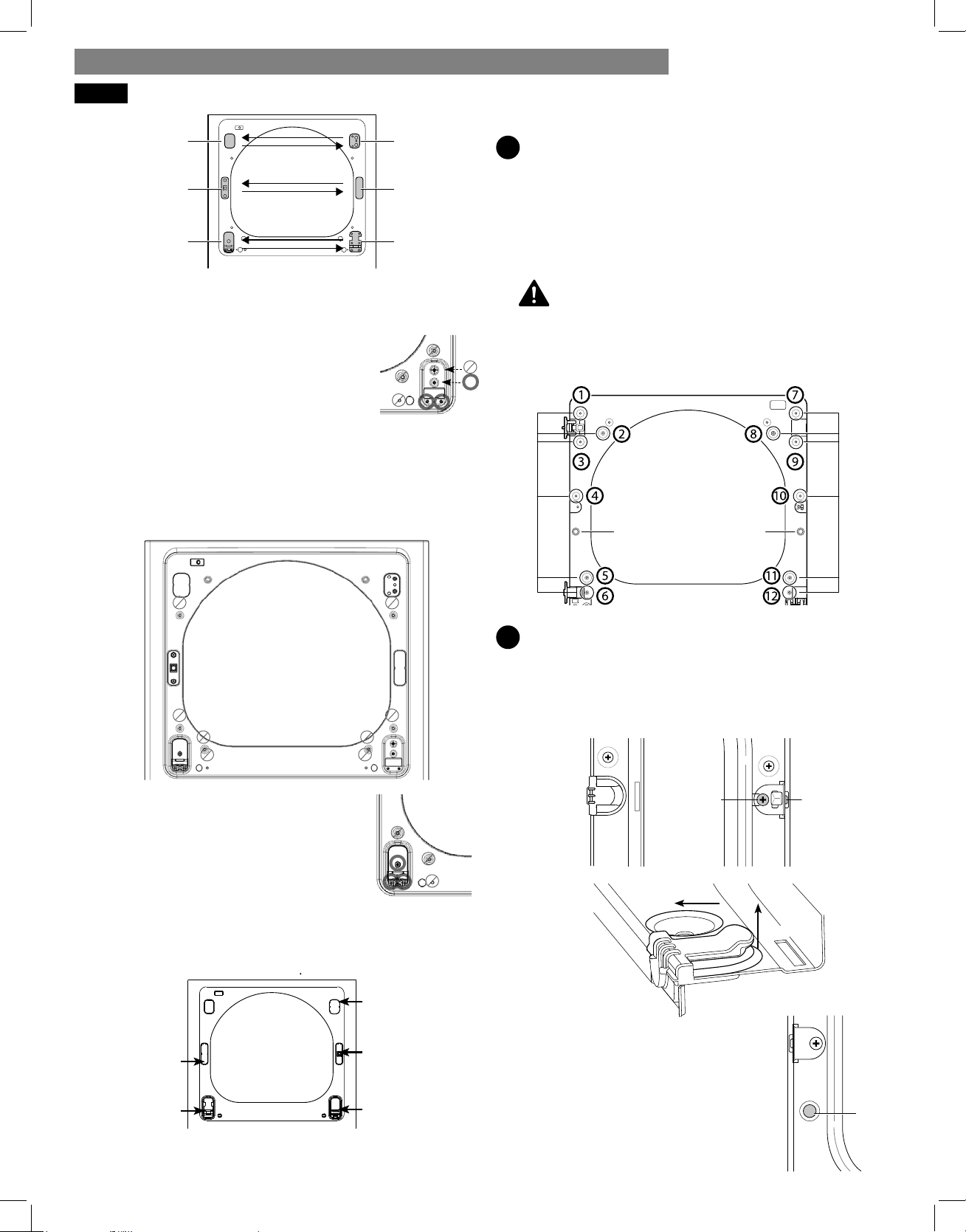
64
PRECAUCIÓN:
d. Invierta la bisagra y el soporte de la bisagra de la
parte inferior del gabinete. Extraiga los dos tornillos
del soporte de la bisagra en la parte inferior derecha y
retire el soporte de la bisagra. Extraiga
el tornillo inferior de los dos tornillos que
se encuentran detrás del soporte de la
bisagra. NO extraiga el tornillo superior
detrás del soporte de la bisagra. Aparte
las piezas.
e. Extraiga los tres tornillos de la bisagra
inferior izquierda. Extraiga la bisagra y
vuelva a instalarla en el lado derecho.
El tornillo superior ocupará el agujero
de donde extrajo el tornillo detrás del
soporte de la bisagra en el paso d.
f. Instale el soporte de la bisagra que extrajo en el paso d
en el lado inferior izquierdo colocando primero un tornillo
detrás del soporte de la bisagra.
EN LA PUERTA :
4
Levante la cubierta de la puerta.
Con la puerta apoyada sobre una superficie protegida y
con su parte interior mirando hacia arriba, extraiga los
doce tornillos de la parte interior de la puerta. Levante
con cuidado la cubierta de la puerta con la ayuda de un
destornillador de punta plana pequeño insertado en la
esquina superior (con un círculo aquí abajo).
Los bordes de la cubierta de la puerta pueden ser fi losos.
Tenga cuidado al manipularla o use guantes para evitar
lesiones.
5
Intercambie la cerradura de la puerta y la cubierta
ciega.
Extraiga los dos tornillos de la cubierta de la puerta que
sujetan la cerradura de la puerta.
Intercambie la cerradura de la puerta y la cubierta ciega
e
instálelas en el lado opuesto del lado de donde las
extrajo.
Retire con un suave movimiento de
palanca la tapa del agujero que se
encuentra en el costado de la cubierta
de la puerta e instálela en el agujero del
lado opuesto.
Aparte la cubierta de la puerta.
NOTA:
NO extraiga ninguno de los ocho tornillos del frente
del gabinete (se indican aquí abajo). Si esto se hiciere,
se podrían producir daños en la secadora y podría
tener que llamar al servicio técnico para que repare la
secadora.
hinge
cover
hinge
bracket
latch hole
cover
latch
mechanism
hinge
p
upper
hinge
hinge
cover
hinge
latch
mechanism
latch
hole
cover
hinge
bracket
cubierta de
la bisagra
mecanismo
de cierre
bisagra
bisagra
superior
cubierta del
agujero del
pestillo
soporte de
la bisagra
cubierta del
agujero del
pestillo
soporte de
la bisagra
cubierta de
la bisagra
mecanismo
de cierre
bisagra
Hole
p l u g
Twelve screws
Side
Interlock
button
doce tornillos
tapa del
agujero
botón de
bloqueo
lateral
screw
Long
screws
Short
Blank cover Door strike
Pull
Raise
Remove blank cover
tornillo
largo
tornillos
cortos
cubierta ciega cerradura de la puerta
tirar
elevar
quitar cubierta blanca
Hole
plug
tapa del
agujero
INVERSIÓN DE LA PUERTA BIDIRECCIONAL (continuación)
INSTRUCCIONES DE INSTALACIÓN
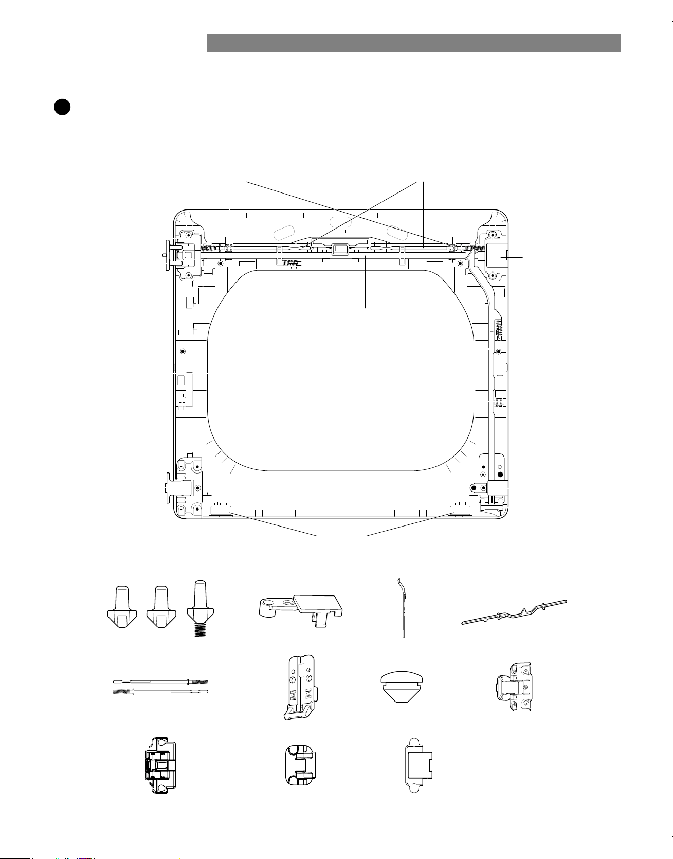
65
6
Invierta los componentes de la parte interior de la puerta.
Ahora retirará e invertirá varios componentes de la parte interior de la puerta. Aquí abajo encontrará un diagrama detallado
con la identificación de la estructura interna y las partes de la puerta. (El diagrama muestra la “vista anterior” de la puerta,
con la distribución predeterminada para una apertura con la bisagra del lado derecho. Luego de seguir estas instrucciones, la
puerta será una imagen en espejo de la ilustración).
Pieza de
relleno de
la bisagra
superior
Barra de bloqueo lateral
Botón de bloqueo lateral
Pieza de
relleno de
la bisagra
inferior
Soporte de
la bisagra
inferior
Topes
Barras de bloqueo interioresBotones de bloqueo superiores
Barra de bloqueo superior
Ensamblaje
de la bisagra
superior
Pivote de
la bisagra
superior
Cristal
Ensamblaje
de la bisagra
inferior
Botones de bloqueo
Ensamblaje de la bisagra superior Pivote de la bisagra superior Pieza de relleno de la bisagra superior
Barras de bloqueo interiores
Pieza de relleno de la bisagra inferior
Soporte de la bisagra inferior
Barra de bloqueo superior
Ensamblaje de la bisagra inferior
Barra de bloqueo
lateral
Tapa del agujero
INSTRUCCIONES DE INSTALACIÓN

66
7
Retire el botón de bloqueo de color gris del costado de
la puerta.
Asegúrese de extraer el resorte con el botón de bloqueo y de
conservar las dos piezas juntas. Aparte el botón de
bloqueo.
No lo mezcle con los botones de bloqueo de la
parte superior
de la puerta exterior.
8
Extraiga la barra de bloqueo lateral.
Extraiga la barra de bloqueo lateral del soporte de la
bisagra inferior levantando el extremo superior de la
barra y deslizándola hacia la parte superior de la puerta.
El resorte debe mantenerse sujeto a la barra de bloqueo.
Aparte la barra de bloqueo.
9
Extraiga la barra de bloqueo superior.
a. Deslice la barra de bloqueo hacia la derecha para
extraerla del ensamblaje de la bisagra que se encuentra
en el costado izquierdo.
b. Mientras desliza la barra hacia la derecha, levante el
extremo derecho y retírelo de las guías.
NOTA:
No retire las dos barras de bloqueo interiores y los dos
botones de bloqueo (ver página 65) ubicadas debajo de la
barra de boqueo superior. NO deben invertirse.
10
E
xtraiga el pivote de la bisagra superior.
Una vez que haya extraído la barra de bloqueo superior, el
pivote de la bisagra puede extraerse
fácilmente del ensamblaje
de la bisagra en la parte
superior izquierda. Apártelo.
11
I
nvierta el ensamblaje de la bisagra y la pieza de
r
elleno de la bisagra superiores.
Retire la pieza de relleno de la bisagra superior (a la
derecha) y apártela.
Con cuidado, levante el ensamblaje de la bisagra superior
(a la izquierda) y sáquelo del marco de la puerta exterior;
use un destornillador de punta plana pequeño si fuera
necesario. Gire el ensamblaje de la bisagra 180 grados e
instálelo en la parte superior derecha de la puerta exterior.
Deberá presionar firmemente para instalar el ensamblaje
de la bisagra. El pivote de la bisagra extraído en el paso 10
se instalará más adelante.
Ahora, gire la pieza de relleno de la bisagra 180 grados e
instálela en la parte superior izquierda de la puerta.
upper
hinge
pivot
upper
hinge
assembly
ensamblaje
de la bisagra
superior
pivote de
la bisagra
superior
upper hinge assembly
upper hinge pivot
ensamblaje de la bisagra superior
pivote de la bisagra superior
XSSHUKLQJHoOOHU
pieza de relleno de la bisagra superior
spring
resorte
INVERSIÓN DE LA PUERTA BIDIRECCIONAL (continuación)
INSTRUCCIONES DE INSTALACIÓN
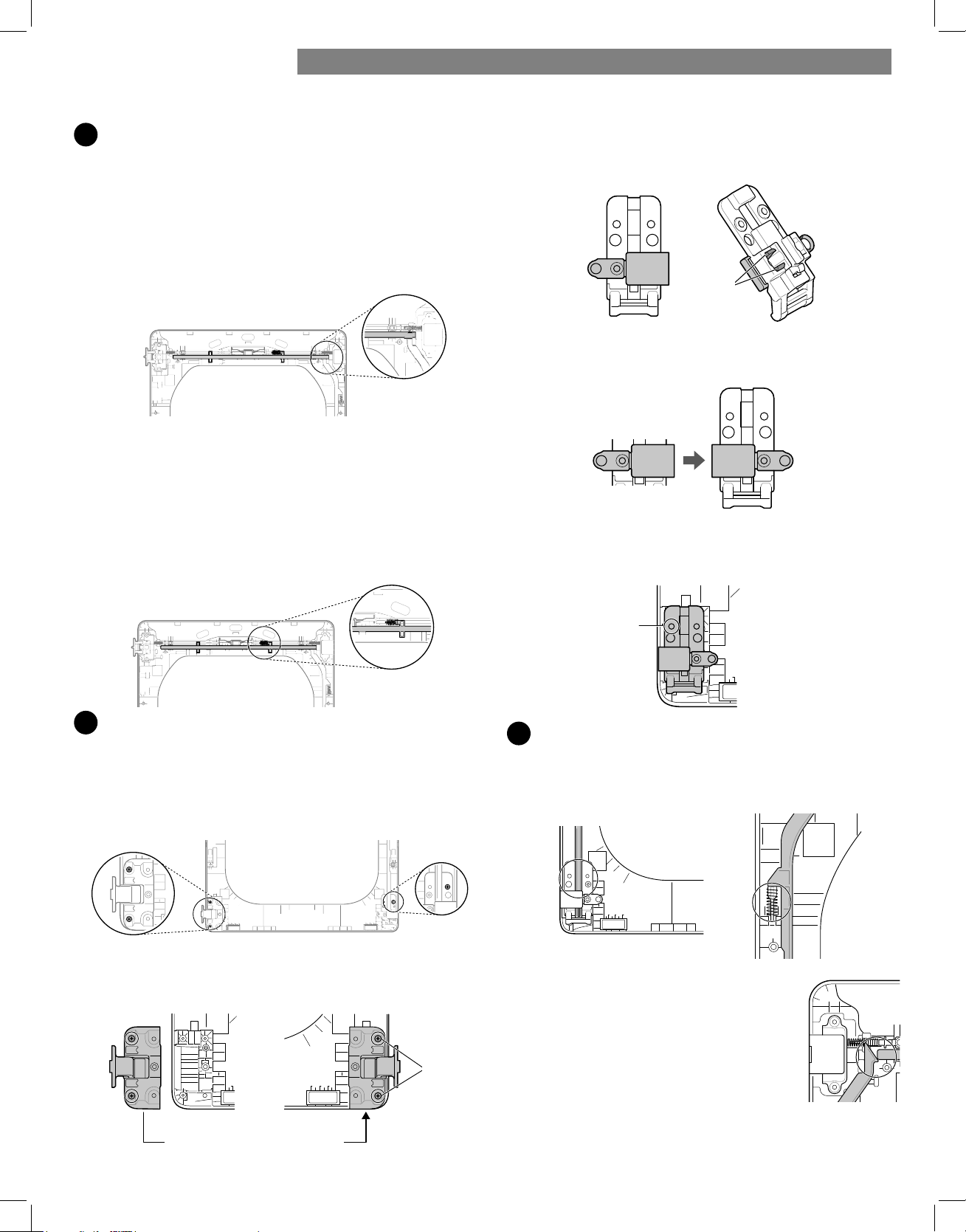
67
12
V
uelva a instalar la barra de bloqueo superior.
Gire la barra de bloqueo superior (extraída en el paso 9)
180 grados en la posición contraria a su posición original y
vuelva a instalarla. El resorte ahora debe encontrarse hacia
la derecha del centro, con el resorte del costado de la barra
orientado hacia la parte superior de la puerta.
a. Inserte el extremo derecho de la barra de bloqueo en el
ensamblaje de la bisagra derecha. Asegúrese de que la
barra esté alineada con las guías del panel de la puerta.
b. Baje la barra y colóquela en su posición, deslizándola y
rodeando la manija central, y asegurándose de alinear
la barra de bloqueo con las guías a lo largo del panel
de la puerta. Cuando la suelte, la barra de bloqueo debe
deslizarse completamente e insertarse en el ensamblaje
de la bisagra de la derecha. Deslice la barra de bloqueo
hacia adelante y hacia atrás para asegurarse de que
esté correctamente colocada en las guías y que corra
con facilidad.
13
I
nvierta el soporte de la bisagra y el ensamblaje de
l
a
bisagra inferiores.
a. Extraiga el tornillo del soporte de la bisagra inferior (a
la derecha) y retire el soporte de la bisagra. Apártela.
Extraiga los dos tornillos del ensamblaje de la bisagra
inferior de la parte inferior izquierda y retire el
ensamblaje de la bisagra.
b. Gire el ensamblaje de la bisagra inferior 180 grados e
instálelo en el lado derecho utilizando los dos tornillos
extraídos en el paso a.
c. Voltee el soporte de la bisagra inferior y suelte las lengüetas
que se encuentran en la parte posterior y que sujetan la pieza
de relleno de la bisagra con el soporte de la bisagra.
d. Gire la bisagra 180 grados y vuelva a colocarla en la
parte delantera del soporte de la bisagra orientada
hacia la dirección contraria.
e. Instale el soporte de la bisagra inferior y la pieza de relleno
en el costado izquierdo de la puerta con el tornillo extraído
en el paso a.
14
I
nstale la barra de bloqueo lateral.
Voltee la barra de bloqueo lateral e instálela en el lado
opuesto. Inserte el extremo inferior en la bisagra
izquierda;
baje la barra sobre las guías de la puerta al
tiempo que
comprime el resorte dentro de la cavidad.
Asegúrese de que la parte superior de la
barra de
bloqueo lateral se encuentre al
costado de la barra de
boqueo superior
y que no se superpongan, de manera
que
las dos barras puedan interactuar de la
manera
correcta. Si no están alineadas
correctamente, la
puerta no funcionará
bien.
Lower hinge assembly
Screws
ensamblaje de la bisagra superior
tornillos
tab s
lengüeta
screw
tornillo
INSTRUCCIONES DE INSTALACIÓN
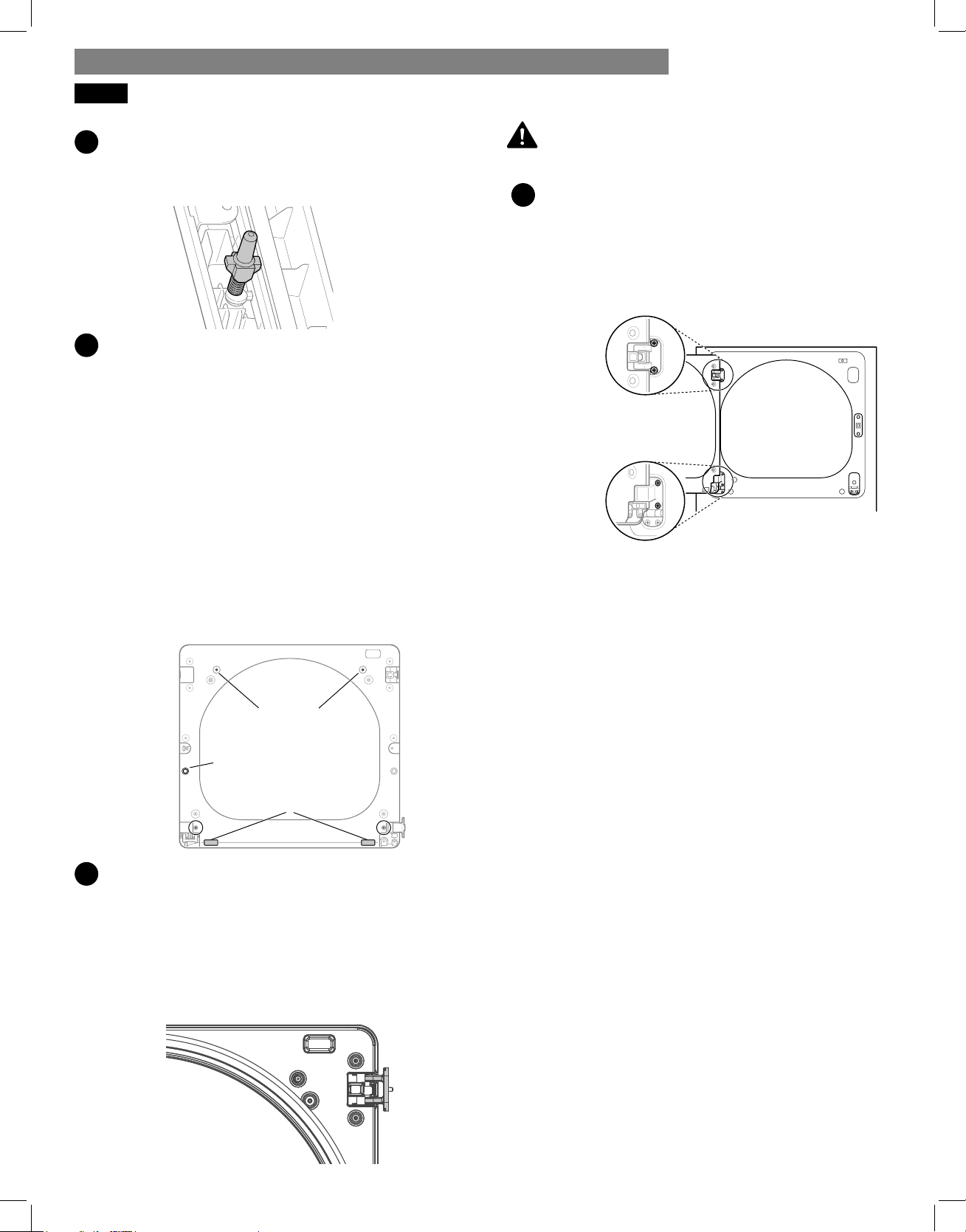
68
15
V
uelva a instalar el botón de bloqueo lateral.
Vuelva a instalar el botón de bloqueo lateral extraído en el
paso 7. Coloque el resorte en el centro del
compartimiento
e inserte el botón de bloqueo arriba
del resorte.
16
V
uelva a instalar la cubierta de la puerta.
Limpie el cristal de la puerta y de la cubierta de la cubierta
si fuera necesario.
Asegúrese de que los tres botones de bloqueo de color
gris estén colocados correctamente y que las barras de
bloqueo superior y lateral estén bien alineadas en
el lugar
donde se encuentran una con la otra. Con
cuidado, baje
la cubierta de la puerta y colóquela en
su lugar, alineando
los orificios de la cubierta con los
botones de bloqueo de
la parte superior y del costado,
y con los topes en la parte
inferior. Tenga cuidado de
no desencajar las barras de
bloqueo cuando instale
la cubierta de la puerta. Una vez
que la cubierta de
la puerta está colocada, fíjela con los 12
tornillos
extraídos en el paso 4. Los diez tornillos similares se
colocan alrededor de la parte superior y los costados de la
cubierta de la puerta. Asegúrese de instalar los
dos tornillos
diferentes en el borde inferior, en los
lugares que se indican
aquí abajo.
17
Ahora, tome el pivote de la bisagra superior que extrajo
anteriormente y gírelo 180 grados.
Presione el botón de interbloqueo lateral ubicado en el lado
izquierdo y sosténgalo hacia abajo mientras presiona el
pivote de la bisagra dentro del ensamble de la bisagra en
el lado superior derecho. Si la puerta fue bien puesta en su
lugar, la varilla de bloqueo se deslizará a su lugar fácilmente
y trabará el pivote en su lugar. La puerta está ahora lista
para remontarse en el lado opuesto de la secadora.
Asegúrese de soportar el peso de la puerta antes de
i
nstalar los tornillos de las bisagras.
18
V
uelva a instalar la puerta.
Mientras sostiene la puerta, instale los cuatro tornillos de
las bisagras extraídos en el paso 2. Pruebe el
movimiento
giratorio de la puerta para asegurarse
de que las bisagras
y el pestillo estén correctamente
alineados y que la puerta
se abra, se cierre y se trabe
adecuadamente en ambas
direcciones.
Si la puerta no funciona correctamente, retírela y
abra la
tapa para comprobar el correcto montaje y
alineación de
las barras de bloqueo y los botones de
enclavamiento.
Los botones de enclavamiento deben orientarse
correctamente y funcionar con suavidad. Las barras
de bloqueo deben estar en la posición adecuada y no
superponerse en el punto de contacto. (Consulte los pasos
12-14.)
Si está dañado, o si la puerta no funciona tras el montaje,
póngase en contacto con el centro de
asistencia telefónica al
1-800-469-4663.
ADVERTENCIA:
interlock
buttons
side
interlock
button
bumpers
botones de
bloqueo
botón de
bloqueo
lateral
topes
Two
large
screws
Two
small
screws
dos
tornillos
grandes
dos
tornillos
pequeños
INVERSIÓN DE LA PUERTA BIDIRECCIONAL (continuación)
INSTRUCCIONES DE INSTALACIÓN
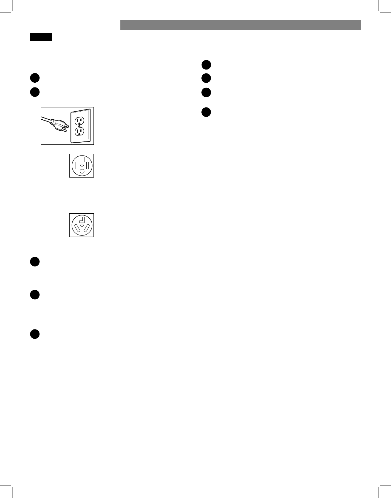
69
COMPROBACIÓN FINAL DE LA INSTALACIÓN
Una vez finalizada la instalación y colocada la secadora
en su posición final, compruebe que la secadora funciona
correctamente realizando los siguientes pasos y pruebas.
¿Está ABIERTO el gas? (Sólo modelos de gas)
¿Está enchufada la secadora? La secadora debe estar
siempre enchufada a una toma de corriente adecuada.
Las secadoras de gas requieren
una toma de corriente de 120 V de
CA, 60 Hz y tres clavijas con toma
de tierra.
Las secadoras requieren una
conexión tetrafilar para las todas
instalaciones realizadas en viviendas
móviles o prefabricadas, así como
en todas las nuevas construcciones a
partir del 1deenero de 1996.
-- O --
Conexión trifilar.
NOTA: NO se permiten las
conexiones trifilares en nuevas
construcciones a partir del
1 de enero de 1996.
¿Están conectados los conductos de ventilación de la
secadora? Asegúrese de que el conducto de transición
situado detrás de la secadora esté correctamente
conectado y no esté aplastado ni dañado.
4
¿Está nivelada la secadora? Una vez situada la secadora
en su posición final, vuelva a comprobar que la secadora
esté nivelada. Asegúrese de que está nivelada de lado a
lado y de adelante hacia atrás, y de que los cuatro pies de
nivelación se apoyan firmemente sobre el suelo.
5
¿Se calienta normalmente la secadora? Realice la siguiente
prueba de calentamiento de la secadora.
Prueba de calentamiento de la secadora
Cierre la puerta de la secadora.
2
Presione el botón POWER para encender la secadora.
3
Gire el mando del selector de ciclo hasta el ciclo de secado
normal.
4
Presione START/PAUSE para poner en funcionamiento la
secadora. Abra la puerta de la secadora y compruebe que
el aire del interior está templado después de tres minutos.
NOTA: Si no se purga todo el aire procedente de la toma de
gas, el generador de chispas de gas podría apagarse antes de
encender el quemador principal. Si esto ocurre, el generador de
chispas volverá a intentar encender el gas hasta que se purgue
todo el aire procedente de la toma de gas.
MODELOS DE GAS
Cierre la puerta de la secadora, presione el botón POWER para
encenderla e inicie el equipo en un ajuste de calor. Cuando la
secadora inicie, el dispositivo de ignición deberá encender el
quemador principal.
MODELOS ELÉCTRICOS
Cierre la puerta de la secadora, presione el botón POWER para
encenderla e inicie el equipo en un ajuste de calor. El aire de
escape deberá estar tibio después de que la secadora haya
funcionado durante 3 minutos.
Revisión del flujo de aire
El funcionamiento efectivo de la secadora requiere de un
flujo de aire adecuado. La adecuación del flujo de aire puede
medirse evaluando la presión estática. La presión estática
del conducto de escape se puede medir con un manómetro,
colocado en el conducto de escape a aproximadamente 2 pies
(60.9 cm) de distancia de la secadora. La presión estática del
conducto de escape no debe superar las 0.6 pulgadas (1.5 cm).
Se debe revisar la secadora mientras está funcionando sin
carga.
Revisión de nivelado
Una vez que la secadora se encuentre en su ubicación
definitiva, vuelva a revisar que esté nivelada. Asegúrese de que
está nivelada de adelante hacia atrás y de lado a lado, y de
que las cuatro patas niveladoras estén firmemente asentadas en
el piso.
Comprobación de la ventilación
Debe comprobarse si hay acumulaciones de pelusa en el
conducto de ventilación y limpiarlo al menos una vez al año.
Sise produce cualquier reducción apreciable en el rendimiento
del secado, compruebe los conductos en busca de obstrucciones
y bloqueos.
1
1
2
3
INSTRUCCIONES DE INSTALACIÓN
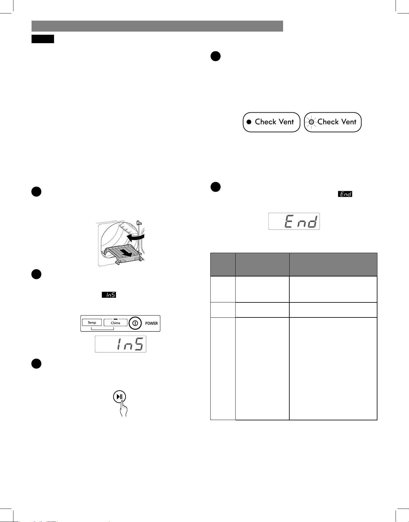
70
PRUEBA DE INSTALACIÓN (REVISIÓN DE CONDUCTOS)
Después de completar la instalación de la secadora,
haga esta prueba para asegurarse de que las
condiciones del sistema de escape sean las adecuadas
para el funcionamiento correcto de la secadora. Esta
prueba debe realizarse para indicarle si existe algún
problema grave en el sistema de escape de su casa.
Su secadora cuenta con CHECK VENT, un sistema innovador
que detecta automáticamente los bloqueos y las restricciones
en los conductos de la secadora. Mantener los conductos sin
acumulación de pelusa y sin restricciones le permitirá secar la
ropa más rápido y reducir el uso de energía.
NOTA: La secadora debe estar fría antes de comenzar esta
prueba. Si la secadora se calentó durante la instalación,
ejecute el ciclo AIR DRY durante unos minutos para reducir la
temperatura interna.
Para activar la prueba de instalación:
1
Retire la rejilla de secado y la documentación, y cierre
la puerta.
No cargue nada en el tambor para hacer esta prueba, ya
que podría infl uir en la precisión de los resultados.
2
Pulse el botón Encendido (Power), y luego pulse y
mantenga pulsado Temp y Spitido (Chime) más de 0,5
segundos. Esta secuencia de botones activa el test de
instalación. El codigo aparecerá en la pantalla de
visualizacion si la activacion se ha realizado con exito.
3
Presione el botón START/PAUSE.
La secadora iniciará la prueba, que durará cerca de
2 minutos. Se encenderá el calor y se medirán las
temperaturas en el tambor.
4
Verifi que la pantalla para ver los resultados.
Durante el ciclo de prueba, observe la pantalla de
CHECK VENT en el panel de control. Si el LED no
parpadea al fi nal del ciclo,, el sistema de escape está
en condiciones adecuadas. Si el sistema de escape está
notoriamente restringido, el CHECK VENT LED parpadea.
Haga revisar el sistema de inmediato, ya que el
funcionamiento será defi ciente.
Not blinking:
OK
Blinking:
RESTRICTED
Si existen otros problemas, estos se indicarán con códigos
de error. Consulte el cuadro para ver más detalles sobre
los códigos de error y sus soluciones
5
Fin del ciclo.
Al fi nal del ciclo de prueba, se visualizará . El
ciclo de prueba terminará y la secadora se apagará de
forma automática después de una breve pausa.
Verifi que el código de error antes de llamar al servicio
técnico.
Código
de
error
Causas posibles Soluciones
tE1
o
tE2
Falla del sensor
de temperatura
Apague la secadora y llame
al servicio técnico.
HS
Falla del sensor
de humedad
Apague la secadora y llame
al servicio técnico.
PS
o PF
o nP
• El cable de
alimentación
de la secadora
eléctrica no
está conectado
correctamente
o el suministro
eléctrico de la
casa no es el
correcto.
• Se ha quemado
el fusible de
la casa, se ha
disparado el
disyuntor o ha
habido un corte
de energía.
• Verifi que el suministro de
energía o la conexión del
cable de alimentación
con el bloque de bornes.
Consulte la sección
Conexión de secadoras
eléctricas de este manual
para obtener instrucciones
detalladas.
• Restablezca el disyuntor o
reemplace el fusible. No
aumente la capacidad del
fusible. Si el problema es
una sobrecarga del circuito,
solicite los servicios de un
electricista califi cado.
INSTRUCCIONES DE INSTALACIÓN
No parpadea:
Adecuado
Parpadea:
Restringido

71
FLUJO DE AIRE RESTRINGIDO O
BLOQUEADO
Verifi que las condiciones del conducto.
Si el LED de CHECK VENT está encendido, revise
el sistema de escape para verifi car que no haya
restricciones ni daños. Repare o reemplace el sistema de
escape según sea necesario.
NOTA: Cuando recién se instale la secadora, debe
realizarse esta prueba para que esté informado acerca
de la presencia de cualquier problema relacionado con
el conducto de escape de su casa. Sin embargo, puesto
que la prueba realizada durante un funcionamiento
normal ofrece información más precisa sobre el estado
del conducto de escape que la prueba de instalación,
la cantidad de barras visualizadas durante las dos
pruebas puede no ser la misma.
No interrumpa el ciclo de prueba, ya que si lo hace, la
prueba puede arrojar resultados inexactos.
Aunque no se haya visualizado ninguna barra durante
el ciclo de prueba, aún puede haber restricciones en el
sistema de escape. Consulte la sección Ventilación de la
secadora de este manual para obtener detalles sobre el
sistema de escape y los requisitos de ventilación.
INSTRUCCIONES DE INSTALACIÓN
Evite tendidos largos o con muchos codos o curvas.
Excess or crushed
transition duct
Check for blockages and lint buildup.
Too many elbows or
exhaust too long
Lint
blockage
buildup or
Make sure the ductwork is not crushed or restricted.
Crushed
or
damaged
exhaust
Conducto de transición
muy largo o apretado
Demasiado largo o
con demasiados codos
Compruebe la presencia de bloqueos y acumulación de
pelusa.
Asegúrese de que los conductos no estén aplastados ni
restringidos.
Acumulación
de pelusa o
bloqueo
Conducto
de escape
aplastado o
dañado
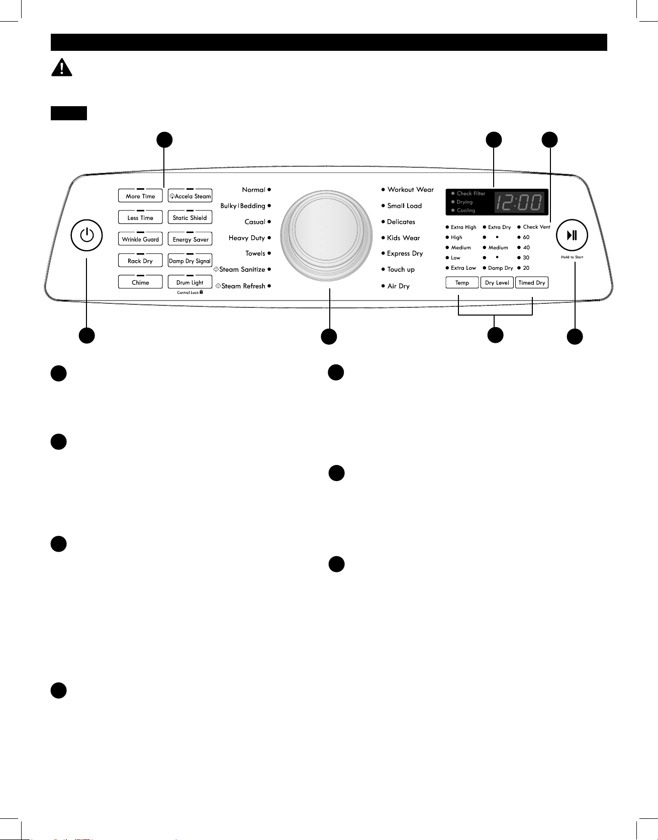
72
INSTRUCCIONES DE USO
FUNCIONES DEL PANEL DE CONTROL
ADVERTENCIA:
Para reducir el riesgo de incendio, descarga eléctrica o lesiones personales, lea
completamente este manual, incluyendo las instrucciones importantes sobre seguridad, antes de poner en funcionamiento la
secadora.
NOTA: Para proteger sus tejidos, no todos los ajustes se admiten en todos los ciclos.
BOTÓN POWER (ENCENDER/APAGAR)
Presione este botón para ENCENDER la secadora.
Presiónelode nuevo para APAGAR la secadora. Al presionar
el botón POWER durante un ciclo, se cancelará dicho ciclo
ycualquier ajuste de carga se perderá.
MANDO DEL SELECTOR DE CICLO Y CICLOS
El mando del selector de ciclo se utiliza para seleccionar
el ciclo de secado deseado girándolo en cualquier sentido
hasta que el LED ilumine dicho ciclo. Una vez seleccionado
elciclo deseado, se mostrarán en pantalla los ajustes
estándar para dicho ciclo. Estos ajustes pueden cambiarse
utilizando los botones modificadores de ciclo o de opción
encualquier momento antes de que el ciclo comience.
BOTÓN START/PAUSE
Presione este botón para iniciar el ciclo seleccionado.
La pantalla cambiará y la secadora mostrará el tiempo
restante estimado (SECADO AUTOMÁTICO) o ajustado
(SECADO MANUAL) y comenzará a girar. Para detener
temporalmente el ciclo en cualquier momento, abra la
puerta de la secadora o presione el botón START/PAUSE.
Para reanudar el ciclo desde el punto en que se detuvo,
presione de nuevo el botón START/PAUSE.
NOTA: Si la secadora permanece detenida durante más de
cuatro minutos, se apagará automáticamente y se perderán
todos los ajustes realizados.
BOTONES DE OPCIÓN
Los botones de opción le permitirán seleccionar las
opciones utilizadas para el ciclo. Algunos botones de
opción tienen funciones secundarias. Los controles se
pueden bloquear o desbloquear manteniendo presionado el
botón DRUM LIGHT durante cinco segundos.
BOTONES MODIFICADORES DEL CICLO
Utilice estos botones para definir los ajustes del ciclo
seleccionado. Los indicadores luminosos ubicados sobre
los botones muestran la selección actual. El ajuste
predeterminado de temperatura no se puede cambiar en
los ciclos de SECADO POR SENSOR. Los ciclos de SECADO
AUTOMÁTICO se pueden modificar utilizando el botón Dry
Level.
PANTALLA DE TIEMPO Y ESTADO
La pantalla muestra el tiempo restante estimado para los
ciclos automáticos y el tiempo que ha transcurrido para
los ciclos manuales. También se indica el estado del ciclo.
El indicador de COMPROBACIÓN DE VENTILACIÓN se
encenderá si hay una obstrucción grave en el sistema de
ventilación.
COMPROBAR VENTILACIÓN
(Sistema de detección de bloqueo del conducto)
La COMPROBACIÓN DE VENTILACIÓN (sistema de
detección de bloqueo del conducto) detecta y alerta sobre
la existencia de bloqueos en el sistema de ventilación
que reducen el flujo de aire de la secadora. Al mantener
limpios los conductos del sistema de ventilación, mejora
el rendimiento y necesitará una menor asistencia técnica,
ahorrándole dinero.
A
E
F
G
B
C
D
A
B
D
F
C
E
G
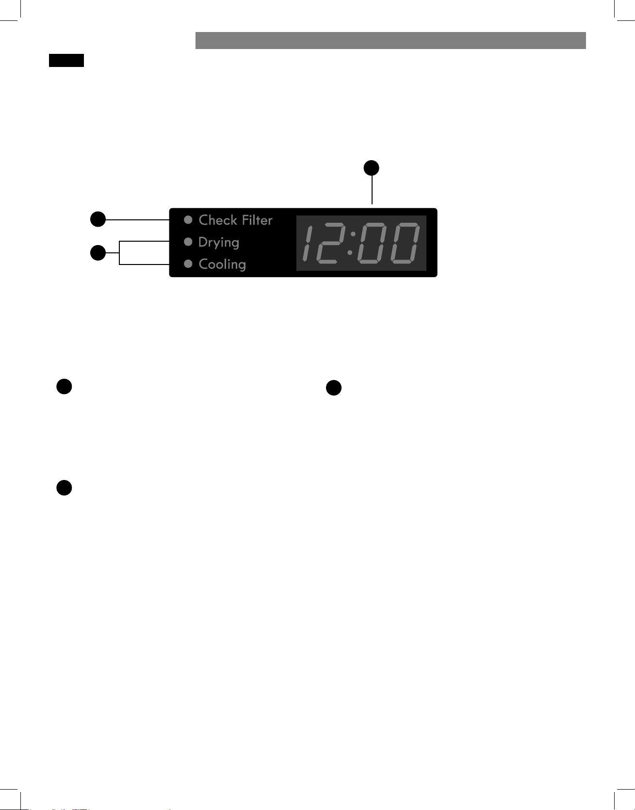
73
PANTALLA DE TIEMPO Y ESTADO
La pantalla de tiempo y estado muestra el tiempo restante estimado,
el proceso del ciclo y el estado de ventilación. Al encender la
secadora, la pantalla se iluminará.
PANTALLA DE TIEMPO
Al seleccionar un ciclo, la pantalla indicará el tiempo
predeterminado para dicho ciclo incluidos los ajustes o las
opciones seleccionadas. En los ciclos de secado automático,
se estimará el tiempo restante y es posible que cambie
durante el ciclo, en función de las condiciones de la carga.
En el secado manual, se mostrará exactamente el tiempo
que falta para que finalice el ciclo.
INDICADOR DEL FILTRO DE PELUSAS
El indicador CHECK FILTER parpadeará antes de cada
carga, para recordarle que compruebe el filtro de pelusas.
Limpie siempre el filtro de pelusas antes de cada ciclo.
INDICADORES DE ESTADO DEL CICLO
Esta sección de la pantalla muestra la fase del ciclo en
curso (DRYING o COOLING) (Secado o enfriamiento).
A
B
C
A
B
C
INSTRUCCIONES DE USO
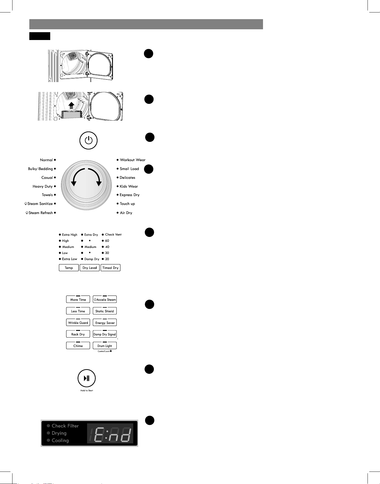
74
CARGAR LA SECADORA
Cargue en la secadora la colada húmeda procedente de la lavadora. Si la
carga es muy grande, deberá dividirla en cargas más pequeñas para obtener un
buen rendimiento y proteger los tejidos.
LIMPIAR EL FILTRO DE PELUSAS
Si aún no ha limpiado el filtro de pelusas, extráigalo y elimine las pelusas
procedentes de la última carga. De esta manera, se asegurará la máxima
eficacia y rapidez del secado.
ENCENDER LA SECADORA
Presione el botón POWER para ENCENDER la secadora. Los LED de ciclo se
iluminarán y se emitirá un aviso sonoro.
SELECCIONAR UN CICLO
Gire el mando del selector de ciclo en cualquier sentido hasta que se ilumine el
LED del ciclo que desee. Se mostrarán los ajustes predefinidos de temperatura,
nivel de secado y opción para este ciclo.
SELECCIONAR LOS MODIFICADORES DE CICLO
Los ajustes predeterminados para el ciclo seleccionado se pueden cambiar
ahora si lodesea, utilizando la temperatura y el nivel de secado.
NOTA: No todas las opciones y modificadores están disponibles para todos
los ciclos. La temperatura sólo se puede ajustar para los ciclos de secado por
tiempo; el nivel de secado sólo está disponible para los ciclos de SECADO
AUTOMÁTICO. Sonará un aviso sonoro diferente y el LED no se iluminará si no
se permite una determinada selección.
SELECCIONAR LAS OPCIONES DE CICLO
Las opciones de ciclo pueden añadirse utilizando los botones de opción tal y
como semuestra en (antiarrugas, antiestática y bloqueo de los controles).
NOTA: No todas las opciones y modificadores están disponibles para todos
los ciclos. Sonará un aviso sonoro diferente y el LED no se encenderá si no se
permite una determinada selección.
INICIAR EL CICLO
Presione el botón START/PAUSE para que comience el ciclo. Se puede detener
temporalmente el ciclo en cualquier momento abriendo la puerta o presionando
el botón START/PAUSE. Si no se reanuda el ciclo en un intervalo de cuatro minutos,
lasecadora se apagará y se perderán los ajustes del ciclo.
FIN DEL CICLO
Al finalizar el ciclo, sonará un aviso sonoro. Retire inmediatamente la ropa de la
secadora para reducir las arrugas. Si tiene seleccionada la función antiarrugas,
lasecadora girará brevemente la carga cada pocos minutos para ayudar a
prevenir laaparición de arrugas en la ropa.
1
2
3
4
5
6
7
8
FUNCIONAMIENTO DE LA SECADORA
INSTRUCCIONES DE USO
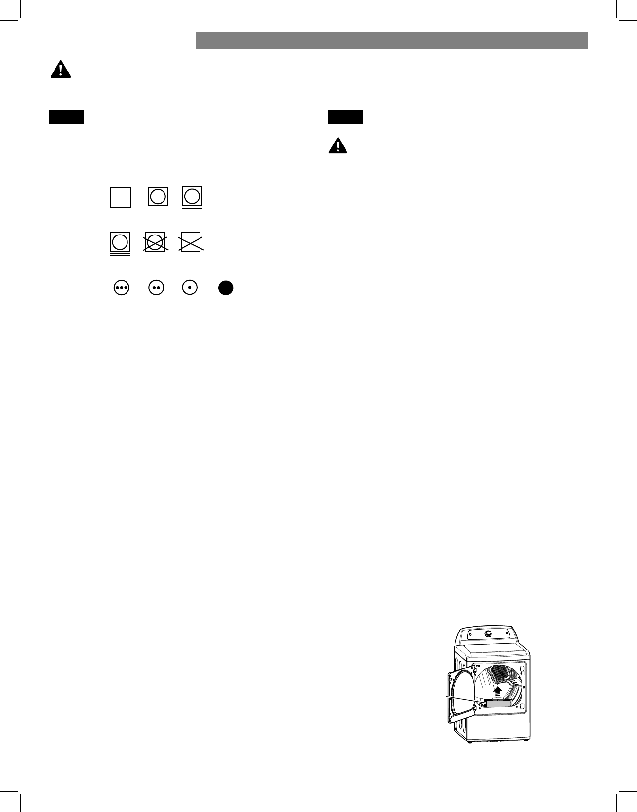
75
Etiquetas de cuidado de las prendas
La mayoría de las etiquetas de las prendas incluyen etiquetas
con instrucciones sobre sus cuidados específicos.
Agrupación de prendas similares
Para obtener resultados óptimos, clasifique las prendas en
cargas que puedan secarse mediante el mismo ciclo de secado.
Los distintos tejidos precisan diferentes cuidados y algunos se
secarán más rápidamente que otros. Para obtener resultados
óptimos, seque siempre juntos los tejidos que requieran cuidados
similares.
CLASIFICACIÓN DE CARGAS
CARGA DE LA SECADORA
ADVERTENCIA:
A fin de reducir el riesgo de incendio, descargas eléctricas o lesiones personales, antes de
poner en funcionamiento este electrodoméstico, lea completamente este manual, incluidas las instrucciones importantes sobre seguridad.
Para reducir el riesgo
de incendio, descarga eléctrica o lesiones físicas al utilizar este
electrodoméstico, siga estas precauciones básicas, entre las que
se incluyen las siguientes:
• Compruebe que todos los bolsillos están vacíos. Objetos como
clips, bolígrafos, monedas y llaves pueden dañar tanto la
secadora como las prendas. Los objetos inflamables, como
mecheros o cerillas, pueden prenderse y provocar un incendio.
Si no se cumple con esto se podrá producir una explosión,
incendio o muerte.
• No seque nunca prendas que hayan estado expuestas
aaceite, gasolina o cualquier otra sustancia inflamable.
Ellavado de las prendas no eliminará completamente la
presencia de residuos de aceite. Si no sigue esta advertencia,
pueden ocasionarse incendios, explosiones o, incluso, peligro
de muerte.
Consejos útiles para cargar la secadora
• Mezcle prendas grandes y pequeñas en la misma carga.
• Las prendas húmedas aumentarán de volumen al secarse.
Nocargue en exceso la secadora: las prendas requieren
espacio para girar y secarse adecuadamente.
• Cierre cremalleras, broches y cordones para evitar enganches
o enredos en otras prendas.
COMPROBAR EL FILTRO DE PELUSAS ANTES DE
CADA CARGA
Cada vez que se enciende la secadora, la luz del indicador
CHECK FILTER parpadeará para recordarle que debe asegurarse
de que el filtro está limpio. Asegúrese siempre de que el filtro
de pelusas está limpio antes de secar una nueva carga; un filtro
de pelusas obstruido incrementará los tiempos de secado. Para
limpiarlo, tire del filtro hacia arriba y elimine cualquier pelusa
adherida al filtro con los dedos. No enjuague ni lave el filtro para
eliminar la pelusa. Presione firmemente el filtro de pelusas para
devolverlo a su lugar.
Asegúrese siempre de que el filtro de pelusas está instalado
correctamente antes de poner la secadora en funcionamiento.
Si se pone en funcionamiento la secadora sin el filtro de pelusas
o sin encajarlo correctamente, la secadora o las prendas que
contiene podrían resultar dañadas.
ADVERTENCIA:
Secado a
máquina
Ajuste de
calor
Seco
Normal
Prendas de planchado
permanente/antiarrugas
Suave/
delicado
No secar a
máquina
No secar
(utilizado junto
a "no lavar")
Alto
Medio Bajo
Sin calor/aire
Filtro de pelusas
INSTRUCCIONES DE USO
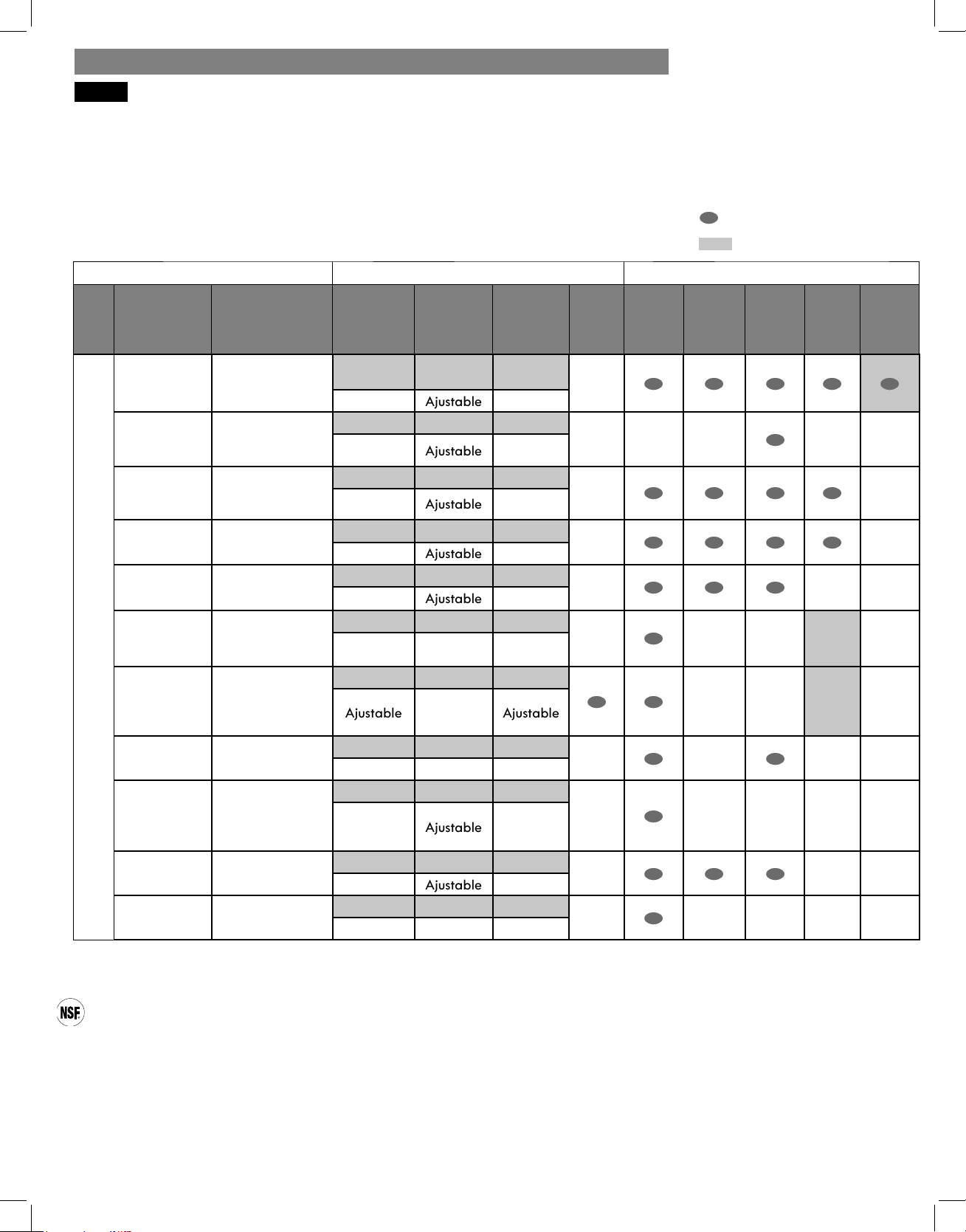
76
La siguiente guía de ciclos muestra las opciones disponibles y los tipos de tejidos recomendados para los ciclos de SECADO AUTOMÁTICO.
*NOTA: El tiempo predeterminado y real variarán dependiendo del tamaño de la carga y su contenido de humedad.
NOTA: Para proteger sus prendas, no todos los niveles de secado, temperatura y opciones están disponibles para todos los ciclos. Los
ajustes de temperatura no se pueden modificar. Sonará un aviso sonoro diferente y el LED no se iluminará o la selección no cambiará si
no se permite la selección.
GUÍA DE CICLOS
= opción disponible
= ajuste predeterminado
CERTIFICADO POR NSF
NSF International (anteriormente, National Sanitation Foundation, Fundación Nacional de Saneamiento), certifica que el ciclo de
desinfección con vapor STEAM SANITIZE reduce el 99,9% de las bacterias presentes en la colada y que no se transmitirá ninguna
bacteria a la siguiente carga.
• Los ajustes predeterminados para el ciclo STEAM SANITIZE son temperatura ALTA y secado MUY SECO. Estos ajustes
predeterminados no se pueden cambiar.
• NO utilice este ciclo para prendas o tejidos delicados.
† El ciclo para Ropa Deportiva está diseñado para ayudar a mantener el rendimiento y extender la durabilidad de las prendas
confeccionadas con propiedades especiales de alto rendimiento. Los niveles de temperatura y de secado son configurados
automáticamente y no son ajustables.
Ciclos de secado automático
Los ciclos de SECADO AUTOMÁTICO utilizan un sensor que detecta los niveles de humedad en las prendas y ajusta el tiempo de secado
necesario para obtener resultados óptimos. La secadora ajusta automáticamente el nivel de secado y la temperatura en los valores
recomendados para cada ciclo. El tiempo estimado restante aparecerá en la pantalla.
Modificadores Opciones
Tipo Ciclo Tipo de tejido
Tempera-
tura
Nivel de
secado
Tiempo en
min.*
Más/
menos
tiempo
Anti-
arrugas
Señal
seco
húmedo
Antiest-
atica
Accela
Steam
Energy
Saver
SECADO AUTOMÁTICO
Normal
Ropa de trabajo,
etc.
Media Media
Elec: 67
Gas: 63
Ajustable
Prendas
voluminosas/
ropa de capa
Colchas,
almohadas,
camisas
Media Media 55
Ajustable
Ropa
informal
Prendas de
planchado
permanente y
sintéticas
Baja Media 32
Ajustable
Carga
pesada
Vaqueros,
prendas pesadas
Extra Alta Media 54
Ajustable
Toallas
Toallas, camisas,
sábanas, tejanos,
coladas mixtas
Alta Media 55
Ajustable
Desinfección
con vapor
Colchas, ropa de
cama, ropa de
niños, etc.
Extra alta Auto 31
Refrescado
con vapor
Colchas, camisas,
pan ta lones,
1-5prendas (NO
utilice para tejidos
delicados).
Alta Desac 10
Ajustable Ajustable
Ropa de
ejercicio
†
Ropa de ejercicio
Auto Auto 27
Carga
pequeña
Sólo tejidos
normales y de
algodón/toallas
(3 libras máximo)
Extra alta Media 30
Ajustable
Prendas
delicadas
Ropa interior,
sábanas, blusas
Baja Media 28
Ajustable
Ropa de niños Ropa de niños
Extra alta Media 35
INSTRUCCIONES DE USO
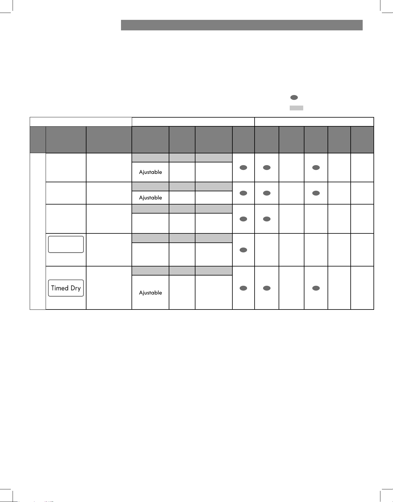
77
Ciclos de secado manual
Utilice los ciclos de secado manual para seleccionar un tiempo y temperatura de secado específicos. Al seleccionar el ciclo de SECADO
MANUAL, la pantalla muestra el tiempo que queda para que termine el ciclo.
Puede cambiar el tiempo del ciclo presionando los botones MORE TIME o LESS TIME para aumentar o reducir el tiempo,
respectivamente. Mantenga presionado cualquiera de estos botones para que el tiempo cambie a mayor velocidad.
La siguiente guía de ciclos muestra las opciones disponibles y los tipos de tejidos recomendados para los ciclos de secado manual.
NOTA: Para proteger sus prendas, no todos los niveles de temperatura y opciones están disponibles para todos los ciclos. Los ajustes de
temperatura no se pueden modificar. Sonará un aviso sonoro diferente y el LED no se iluminará si no se permite una determinada selección.
= opción disponible
= ajuste predeterminado
Modificadores Opciones
Tipo Ciclo Tipo de tejido Temperatura
Nivel de
secado
Tiempo en
min.
Más/
menos
tiempo
Anti-
arrugas
Señal
seco
húmedo
Antiest-
atica
Accela
Steam
Energy
Saver
SECADO MANUAL
Secado
rápido
Para cargas
pequeñas con
tiempos de
secado breves
Extra alta Desac 25
Ajustable Máx. 100
Mucha
suciedad
Para eliminar
pequeñas
arrugas
Alta Desac 20
Ajustable Máx. 100
Secado con
aire
Para prendas
que deben
secarse sin
calor, como
plásticos o
goma
Sólo aire Desac 30
Máx. 100
Rack Dry
Secado en
rejilla
Suéteres de
lana, la seda, la
ropa interior
Desac Desac 50
Baja
Extra baja
Sólo aire
Máx 100
Para secado
general. El
tiempo, la
temperatura
y las opciones
se pueden fijar
manualmente.
Alta Desac 20/30/40/60
Ajustable Max 100
INSTRUCCIONES DE USO
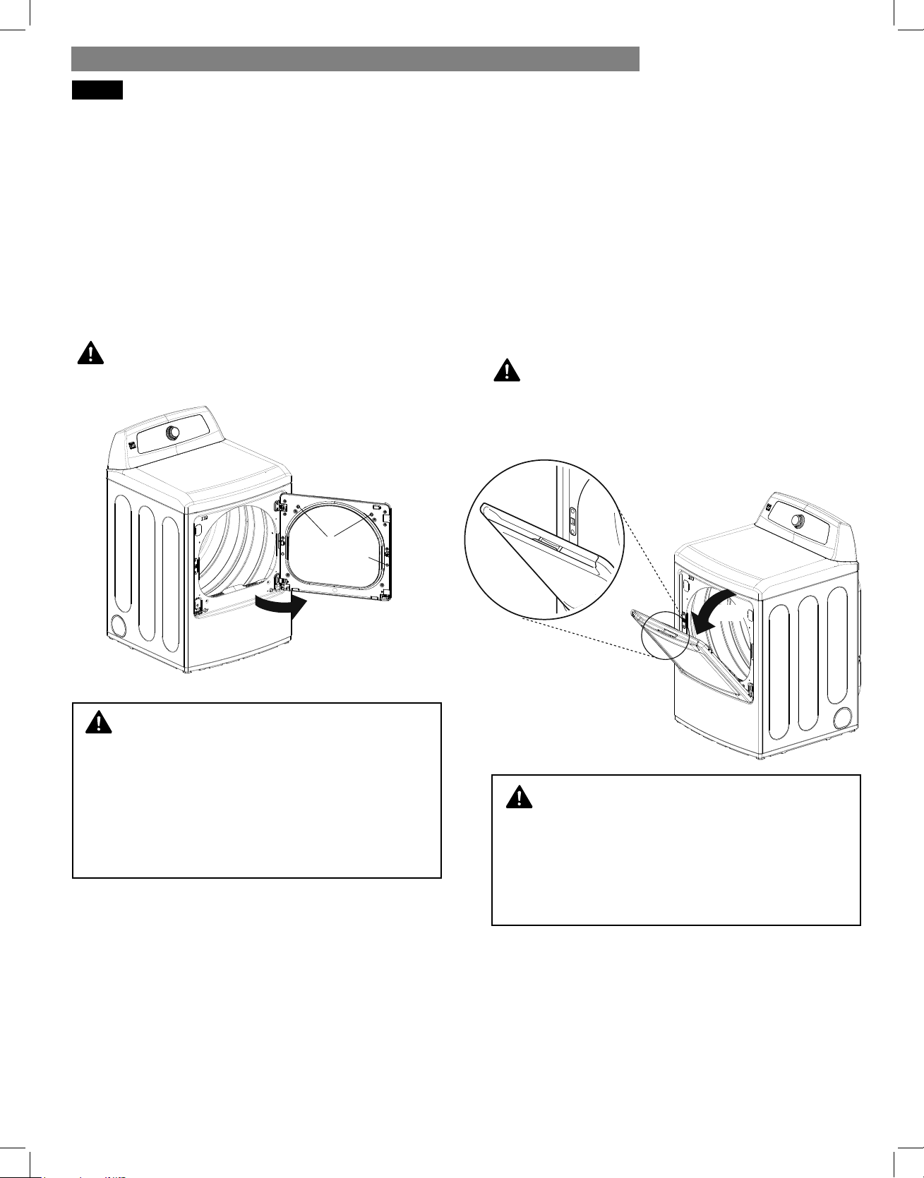
78
El secador está equipado con una puerta bidireccional
que se abre en dos direcciones, desde el lado como
una puerta batiente y desde la parte superior como
una puerta cesto.
Puerta batiente
Utilice la puerta bidireccional como una puerta batiente para
la descarga o carga de ropa voluminosa, ya que permite un
fácil acceso al tambor.
Para abrir la puerta batiente, inserte los dedos en el hueco
de la manivela en la parte superior de la puerta, en el lado
opuesto a las bisagras, y tire de la puerta para abrirla.
PRECAUCIÓN:
Asegúrese de que la puerta de tipo cesto esté completamente
cerrada antes de utilizar la puerta batiente.
Puerta de tipo cesto
Utilice la puerta bidireccional como una puerta de tipo cesto
al cargar la secadora. Ésta actúa como un conducto para
ayudarle a colocar la ropa en el tambor y evitar que las
prendas caigan al suelo. También resulta de utilidad para la
descarga de algunas prendas pequeñas, y evita que el resto
de la colada caiga al suelo.
Para abrir la puerta de tipo cesto, presione y suelte en el
centro del hueco de la manivela ubicada en la parte superior
de la puerta y tire de la puerta hacia delante.
Asegúrese de introducir la ropa correctamente en el tambor
antes de cerrar la puerta.
PRECAUCIÓN:
Asegúrese de que el pestillo de la puerta batiente esté
completamente cerrado antes de presionar para la apertura
de la puerta de tipo cesto.
UTILIZANDO EL BIDIRECCIONAL PUERTA
ADVERTENCIA:
Con la puerta abierta, si presiona los tres botones
Con la puerta abierta, si presiona los tres botones
de enclavamiento, podría caerse la puerta. Si no
de enclavamiento, podría caerse la puerta. Si no
se cumple con esta advertencia se podran producir
se cumple con esta advertencia se podran producir
heridas graves.
heridas graves.
No coloque objetos pesados ni se apoye sobre la
No coloque objetos pesados ni se apoye sobre la
parte superior de la puerta abierta.
parte superior de la puerta abierta.
La secadora podría volcarse hacia delante y causarle
La secadora podría volcarse hacia delante y causarle
lesiones personales o daños materiales.
lesiones personales o daños materiales.
ADVERTENCIA:
No intente abrir la puerta de tipo cesto más de 40
No intente abrir la puerta de tipo cesto más de 40
grados.
grados.
Tenga cuidado al abrir y cerrar la puerta. Los dedos
Tenga cuidado al abrir y cerrar la puerta. Los dedos
y las manos podrían quedar enganchados en la
y las manos podrían quedar enganchados en la
puerta y causar daños si ésta cae hacia delante de
puerta y causar daños si ésta cae hacia delante de
forma inadvertida.
forma inadvertida.
hamper door
hamper door release
40°
pestillo de la puerta de tipo cesto
puerta de tipo cesto
swing door
interlock
buttons
puerta batiente
botones de
enclavamiento
INSTRUCCIONES DE USO
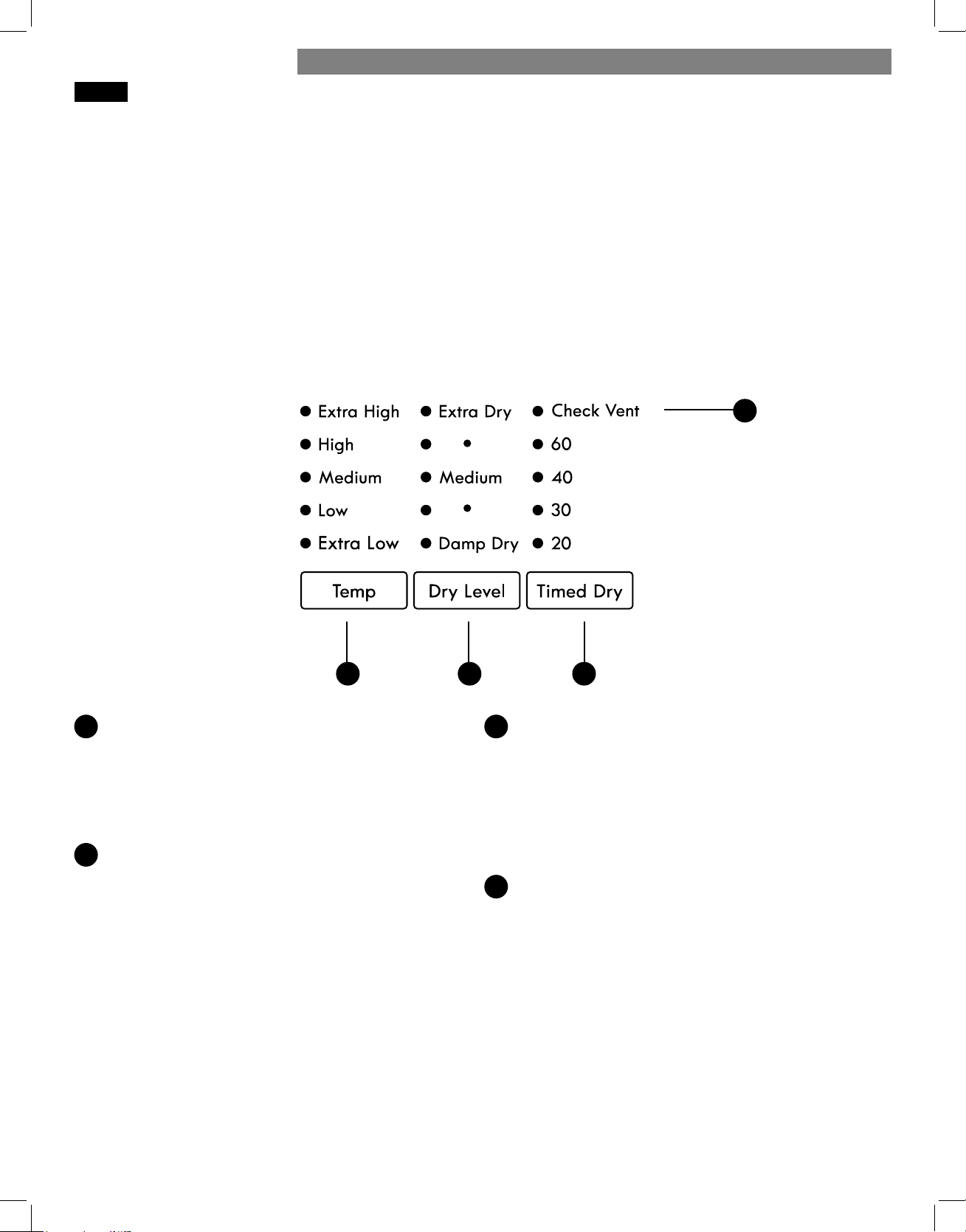
79
Cada ciclo dispone de ajustes predeterminados que se
seleccionan automáticamente. También puede personalizar estos
ajustes utilizando los botones modificadores de ciclo.
Los ciclos de SECADO AUTOMÁTICO están diseñados para el
cuidado específico de ciertos tejidos y cargas. Por lo tanto, no
todos los ajustes están disponibles para todos los ciclos.
Los ciclos de SECADO MANUAL disponen de ajustes
predeterminados, pero también puede cambiar el ajuste de
temperatura y añadir opciones.
Los ajustes no tienen limitaciones en la mayoría de los ciclos de
secado manual. Para evitar posibles daños a las prendas, tenga
cuidado al ajustar las opciones y los modificadores de estos ciclos.
NOTA: Para proteger sus prendas, no todos los niveles de
secado, temperatura y opciones están disponibles para todos
losciclos.
BOTONES MODIFICADORES DEL CICLO
CONTROL DE TEMPERATURA
Ajusta la temperatura entre EXTRA LOW (Muy baja) y
EXTRAHIGH (Muy alta). De esta manera, puede cuidar con
precisión sus prendas y tejidos. Presione repetidamente el
botón TEMP CONTROL para desplazarse entre los ajustes
disponibles. El ajuste de temperatura no puede modificarse
en los ciclos de secado automático.
NIVEL DE SECADO
Selecciona el nivel de secado para el ciclo de
SECADOAUTOMÁTICO seleccionado. Presione repetida-
mente el botón DRY LEVEL para desplazarse entre los
ajustes disponibles. Utilice este botón para ajustar el tipo
desecado que prefiera para las prendas de la carga.
• Esta opción no está disponible para los ciclos de secado
manual.
• La secadora ajustará automáticamente el tiempo de
duración del ciclo. Seleccionar EXTRA DRY o MOREDRY
(muy seco o más seco) incrementará el tiempo de
duración del ciclo, mientras LESS DRY o DAMP DRY
(menos seco o seco húmedo) reducirá el tiempo y el nivel
de secado.
• Utilice los ajustes LESS DRY o DAMP DRY (menos seco
oseco húmedo) para prendas que desee planchar o
colgar para acabar de secar.
SECADO MANUAL
Le permite seleccionar manualmente una duración del
secado de 20, 30, 40 o 60 minutos. Utilice los botones
MORETIME/LESS TIME (más tiempo/menos tiempo) para
aumentar o reducir el tiempo de secado seleccionado en
incrementos de 1 minuto. Mantenga presionado cualquiera
de estos botones para que el tiempo cambie a mayor
velocidad. Utilice este ciclo para cargas pequeñas o para
eliminar arrugas.
COMPROBAR VENTILACIÓN
(Sistema de detección de bloqueo del conducto)
La COMPROBACIÓN DE VENTILACIÓN (sistema de
detección de bloqueo del conducto) detecta y alerta sobre
la existencia de bloqueos en el sistema de ventilación
que reducen el flujo de aire de la secadora. Al mantener
limpios los conductos del sistema de ventilación, mejora
el rendimiento y necesitará una menor asistencia técnica,
ahorrándole dinero.
AC
B
D
A B C
D
INSTRUCCIONES DE USO
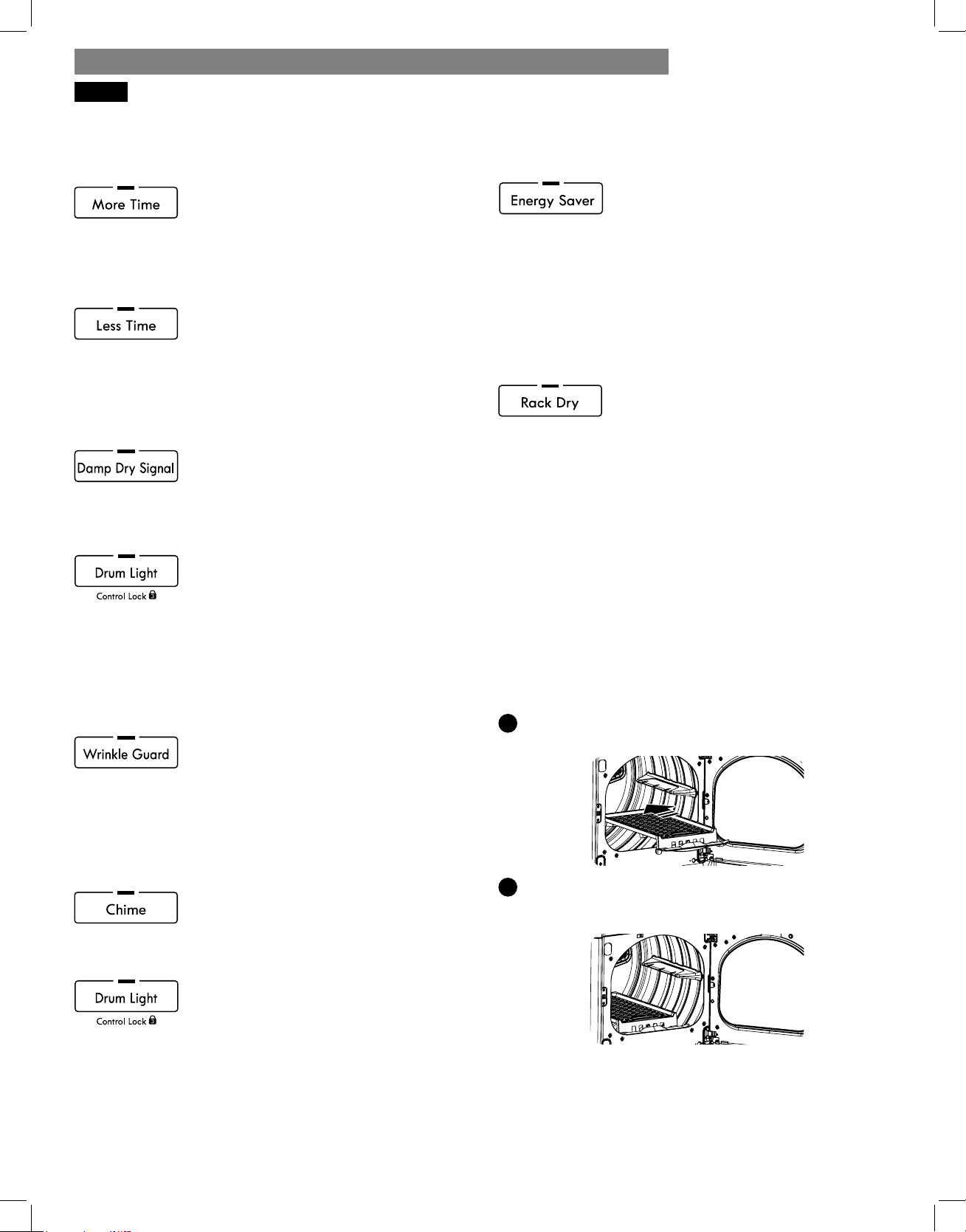
80
OPCIONES DE CICLOS Y FUNCIONES ESPECIALES
La secadora incluye varias funciones especiales y opciones adicionales para los ciclos para adaptarse a sus necesidades particulares.
MORE TIME (MÁS TIEMPO)
Utilice el tiempo de MORE TIME / LESS TIME
botones de tiempo para aumentar o disminuir
el tiempo de secado seleccionado en
incrementos de 1 minuto. Mantenga pulsado el tiempo más o
menos botones TIME para cambiar rápidamente el tiempo.
LESS TIME (MENOS TIEMPO)
Utilice el tiempo de MORE TIME / LESS TIME
botones de tiempo para aumentar o disminuir
el tiempo de secado seleccionado en
incrementos de 1 minuto. Mantenga pulsado el tiempo más o
menos botones TIME para cambiar rápidamente el tiempo.
DAMP DRY SIGNAL (AMORTIGUAR LA SEÑAL
SECA)
Si se pulsa el botón DAMP DRY señal seca, la
secadora se emitirá un timbre cuando la ropa
está justo antes de completamente seco, en
caso de que quitárselas para planchar o colgar el secado.
DRUM LIGHT (ILUMINACIÓN DEL TAMBOR)
Utilice el botón DRUM LIGHT para
encender la iluminación del interior del
tambor durante un ciclo.
NOTA: La iluminación del tambor también se encenderá si
se abre la puerta de la secadora; no obstante, si la secadora
ha permanecido apagada durante más de cuatro minutos, se
apagará la iluminación del tambor hasta que se presione el
botón POWER para encender la secadora.
WRINKLE GUARD (ANTIARRUGAS)
Si selecciona esta opción, la secadora
continuará girando con las prendas en su interior
durante unos segundos cada pocos minutos sin
calentarlas. Esta opción permanecerá activa durante 150 minutos
una vez finalizado el ciclo o hasta que se abra la puerta. Esta
opción ayuda a evitar las arrugas que se producen en las prendas si
no se retiran inmediatamente una vez terminado el ciclo.
CHIME (AVISO SONORO)
El botón CHIME ajusta el volumen del aviso
sonoro o lo desactiva. Presione repetidamente
el botón hasta llegar al volumen deseado.
CONTROL LOCK (BLOQUEO DE LOS CONTROLES)
Utilice esta opción para deshabilitar los
controles. Mantenga presionado el botón
DRUM LIGHT durante cinco segundos para
activar o desactivar el BLOQUEO DE LOS CONTROLES.
Se desactivarán todos los controles excepto el botón POWER.
Una vez activado, es necesario desactivar el bloqueo de los
controles antes de poder utilizar los controles. Una vez apagada
la secadora, el botón POWER permitirá encender la máquina,
pero los controles continuarán bloqueados. Si se activa el
BLOQUEO DE LOS CONTROLES, se iluminará el LED y en la
pantalla se alternará el texto “CL” con el tiempo del ciclo.
ENERGY SAVER (en algunos modelos)
Esta opción ayuda a reducir el consumo de
energía en el ciclo Normal según el tamaño de
la carga. Cuando se seleccione el ahorro de
energia, el ciclo comienza con una seccion de secado por aire y
se aumenta el tiempo de secado.
NOTA: TLa opción Energy Saver se activa de forma
predeterminada en el ciclo Normal. Puede desactivar la
opcion de ahorro de energia para un ciclo Normal mas
rapido que comienza con secado caliente.
RACK DRY (SECADO EN REJILLA)
Use el ciclo RACK DRY con artículos tales
como suéteres de lana, sedas, y lencería, que
se deberían secar en posición horizontal.
También se puede usar RACK DRY con artículos que no deben
secarse girando, tales como calzado deportivo o animales de
peluche. Cuando se utiliza el ciclo de RACK DRY, pulse el botón
de control de temperatura (TEMP. CONTROL) para seleccionar
entre las opciones Ultra Low o Low (Muy baja o Baja)
termperatura. Si no se selecciona la temperatura, incumplimientos
que el ciclo sin calor.
NOTA: NUNCA seque a máquina una carga de ropa con la
bandeja instalada. Cuando la bandeja está instalada, el tambor
girará de manera habitual, pero la bandeja no se moverá.
Asegúrese de que todas las prendas a secar permanezcan
por completo sobre la bandeja y no se caigan o no sean
arrastradas fuera por el tambor en funcionamiento. Asegúrese
de extraer la bandeja luego de su uso.
Para instalar el estante de secado
1
Manteniendo abierta la puerta de la secadora, deslice el
estante en el tambor de la secadora.
2
Asegúrese de que esté asentado uniformemente sobre el
borde interior de la puerta y descanse horizontalmente
sobre el interior de la secadora.
INSTRUCCIONES DE USO
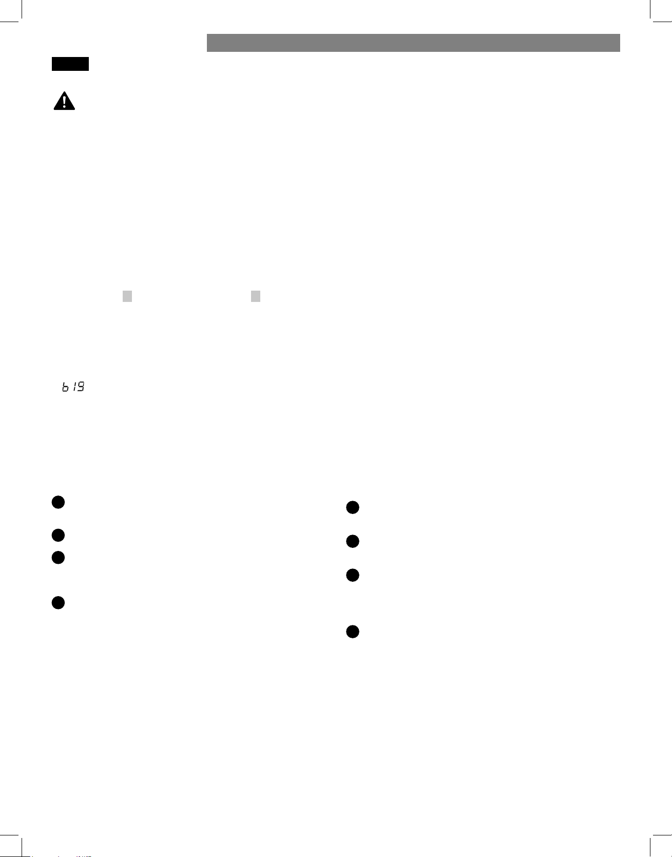
81
NOTAS IMPORTANTES SOBRE LAS FUNCIONES DE VAPOR:
• Es posible que el vapor sea claramente visible durante las
funciones de vapor. Esto es normal.
• No use la función REFRESCADO CON VAPOR con prendas
de lana, cobijas de lana, chaquetas de cuero, seda, ropa
húmeda, lencería, productos de goma espuma o mantas
eléctricas.
• Para mejores resultados, coloque prendas con un tamaño y
tipo de tejido similares. No coloque ropa en exceso.
• Si el sistema de ventilación de la vivienda está obstruido,
disminuirá el rendimiento de las funciones de vapor.
• Durante la operación con vapor, la ropa girará solo unos
pocos segundos cada minuto.
STATIC SHIELD (ANTIESTÁTICA)
Esta opción utiliza el vapor más tarde en el ciclo de secado
para reducir la electricidad estática producida por la
fricción entre los tejidos secos. Cambie el tiempo de vapor
presionando los botones MORE TIME y LESS TIME (más
tiempo y menos tiempo) hasta presentar en pantalla el número
aproximado de prendas en la carga: 7, 9, 11, 14, 16 ó 18. El
tiempo de vapor es de aproximadamente 1-6 minutos, lo que
depende del número de prendas seleccionadas.
NOTA: Cuando se añade ANTIESTÁTICA a los ciclos de
secado automático, el nivel de menos seco y seco húmedo no
se puede seleccionar.
ACCELA STEAM
ACCELA STEAM ayuda a prevenir el sobresecado de la ropa
inyectando vapor durante el proceso de secado.
USANDO LAS OPCIÓNES DE VAPÓR
Agregando vapor a un ciclo estándar
1
Encienda la secadora y gire la perilla selectora al ciclo
deseado.
2
Utilice los botones de confi guración de ciclo para ajustar
las confi guraciones para ese ciclo.
3
Presione el botón vapor para la opción que le gustaria
agregar. Luego ajuste el tamaño de carga utilizando los
botones Más Tiempo (More Time) o Menos Tiempo (Less
Time).
4
Presione el botón de Inicio/Pausa (Start/Pause) para
iniciar el ciclo.
• No abra la secadora durante los ciclos de vapor. El vapor
puede provocar quemaduras graves.
• No toque la boquilla de vapor en el tambor durante el ciclo
de vapor o después de finalizado el mismo.
Uso del Ciclo REFRESCADO CON VAPOR
El ciclo refrescado con vapor usa la fuerza del vapor para
reducir rápidamente las arrugas y olores en los tejidos.
Revive la ropa arrugada que ha estado guardada por largo
tiempo y facilite el planchado de prendas muy arrugadas.
REFRESCADO CON VAPOR también se puede usar para
reducir los olores de la ropa, por ejemplo cuando se usaron las
prendas en una sala donde las personas estuvieron fumando.
Este ciclo puede refrescar de una a cinco prendas o una
prenda voluminosa, por ejemplo una colcha. Están disponibles
tres niveles. Use
3
para una a tres prendas y
5
para cuatro
a cinco prendas. Con estos niveles, la secadora seca sin calor
mientras se calienta el agua presente en el generador de
vapor. Una vez que empieza a fluir el vapor, la secadora
secará sólo durante tres segundos de cada minuto. Se obtienen
mejores resultados con tejidos de mezcla 70/30 de algodón/
poliéster.
El nivel grande (big) se debe usar para prendas
voluminosas, como almohadas o animales de peluche. Con
este nivel, la secadora inicia con un segmento de calor seco
seguido de un segmento de vapor más breve, como se indica
arriba.
NOTA: La opción ANTIESTÁTICA se puede usar junto con el
ciclo REFRESCADO CON VAPOR para evitar la electricidad
estática después del ciclo.
ENCIENDA la secadora y seleccione el ciclo
REFRESCADO CON VAPOR.
Seleccione la opción ANTIESTÁTICA si lo desea.
El número predeterminado de prendas es tres. Presione el
botón MORE TIME o LESS TIME para ajustar el tamaño
de la carga como ya se describió.
Presione el botón START/PAUSE para que comience el
ciclo.
Cómo usar el ciclo STEAM SANITIZE
El ciclo STEAM SANITIZE es idóneo para la higienización
rápida y sencilla de elementos que no pueden lavarse,
utilizando sólo el poder del vapor.
Recomendamos utilizar este ciclo para tejidos de algodón
y poliéster. (NO use para espuma de uretano, plumas o
prendas delicadas).
FUNCIONES DE VAPOR
1
2
3
4
ADVERTENCIA:
INSTRUCCIONES DE USO
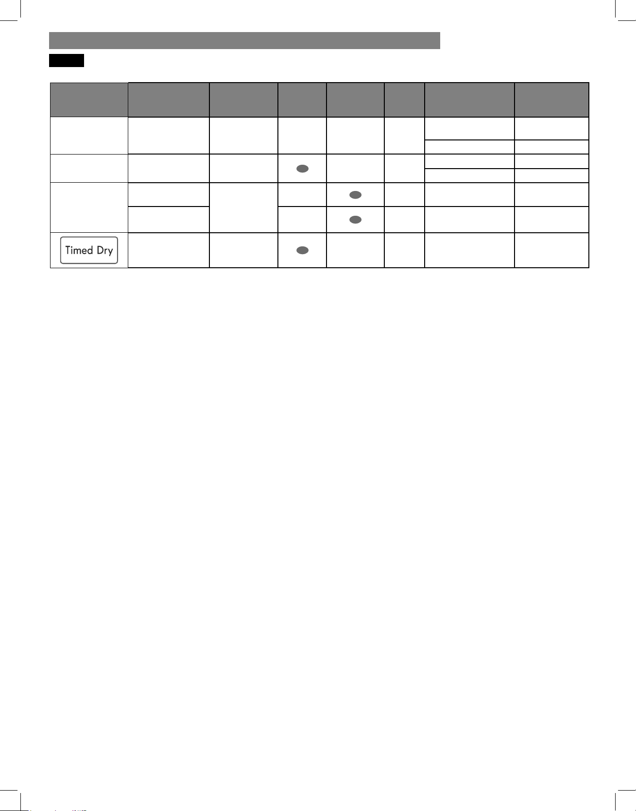
82
GUÍA DE CICLOS DE VAPOR
Ciclo Vapor
Tiempo
programado
Control
temp.
Nivel de
secado
Estado
de tela
Tipo de tela Cantidad máx.
Steam Sanitize 31 minutos
seca
camisas, ropa de
cama
camisa (1 cada)
ropa de niños 3 lb
Steam Refresh 10 minutos
seca
edredón camisa (1 cada)
camisas* 5 cada
Secado con
sensor
+
Opción de
vapor
+
Static Shield
siga el ciclo
seleccionado
mojada
varía según el ciclo
seleccionado
8 lb (18 artículos)
+
Accela Steam
mojada
varía según el ciclo
seleccionado
8 lb (18 artículos)
+
Static Shield
38 minutos
mojada
varía según el ciclo
seleccionado
8 lb (18 artículos)
* Camisa: mezcla de 70% algodón / 30% poliéster. Excepto telas especialmente
delicadas.
• Cuando se tapan el fi ltro de pelusas o el conducto de salida, las opciones de
vapor no darán los resultados adecuados.
• Para mejores resultados, las prendas deben ser de tamaños y de tipos de tela
similares. No sobrecargue la secadora.
NOTA:
• Cuando se selecciona Secado Con Sensor (Sensor Dry) con la opcíon Reducción
Estática (Static Shield) no puede seleccionarse Nivel De Secado (Dry Level) de
Menos (Less) o Humedo (Damp).
• La opcion Reducción Estática (Static Shield) también pueden seleccionarse
durante los ciclos Tiempo De Secado (Time Dry).
• Después de seleccionar la opción Vapor en Timed Dry, los botones Más Tiempo
(More Time) o Menos Tiempo (Less Time) cambiarán el tiempo de vapor
ÚNICAMENTE.
• Despues de presionar Inicio/Pausa (Start/Pause), los botones Más Tiempo (More
Time) o Menos Tiempo (Less Time) no funcionarán.
INSTRUCCIONES DE USO
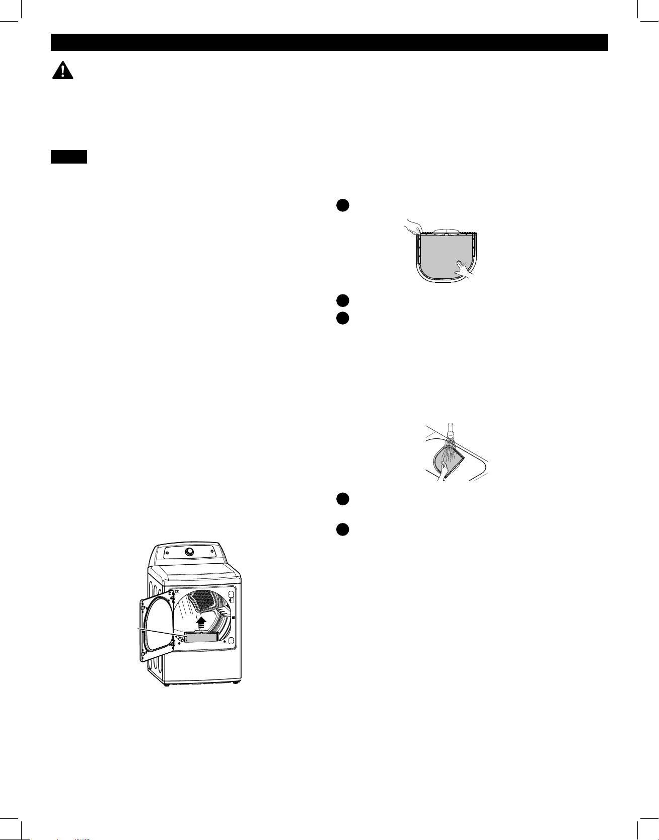
83
INSTRUCCIONES DE MANTENIMIENTO DEL USUARIO
LIMPIEZA HABITUAL
ADVERTENCIA:
A fin de reducir el riesgo de incendio, descargas eléctricas o lesiones personales, antes de
poner en funcionamiento este electrodoméstico, lea completamente este manual, incluidas las instrucciones importantes sobre seguridad.
• Desenchufe la secadora antes de proceder a su limpieza para evitar posibles descargas eléctricas. Si no se cumple con esta
advertencia se podrán producir lesiones graves, incendios, descargas eléctricas o muerte.
• No utilice nunca productos químicos fuertes, limpiadores abrasivos o disolventes para limpiar la secadora. Dañarán el acabado.
Limpieza del exterior
Unos cuidados adecuados prolongarán la vida útil de la
secadora. Puede limpiar el exterior de la máquina con agua
caliente y un detergente doméstico suave y no abrasivo. Limpie
inmediatamente cualquier derrame con un paño suave y húmedo.
IMPORTANTE: No utilice alcoholes de limpieza, disolventes ni
productos similares.
No utilice NUNCA estropajos metálicos ni limpiadores
abrasivos; pueden dañar la superficie.
Limpieza del interior
Seque el contorno del hueco y la junta de la puerta con un
paño suave y húmedo para eliminar las acumulaciones de
pelusas y polvo que podrían dañar la junta de la puerta.
Limpie el cristal de la puerta con un paño suave humedecido en
agua caliente y un detergente doméstico suave y no abrasivo; a
continuación séquelo.
No utilice NUNCA estropajos metálicos ni limpiadores
abrasivos; pueden arañar o dañar la superficie.
Limpieza alrededor de la secadora y debajo
de ella
Aspire regularmente las pelusas y el polvo de los alrededores
ydebajo de la secadora.
Asegúrese SIEMPRE de que el filtro de pelusas esté limpio antes
de cada ciclo. El indicador CHECK FILTER del panel de control
parpadeará antes de cada ciclo para recordárselo.
NOTA: No utilice NUNCA la secadora sin el filtro de pelusas
instalado.
Limpieza del fi ltro de pelusas
Para eliminar las pelusas entre ciclos:
Abra la puerta de la secadora.
Tire hacia arriba del filtro de pelusas.
Elimine los restos de pelusa del filtro con los dedos.
Limpieza exhaustiva periódica:
Con el paso del tiempo, cierto tipo de suavizantes pueden
acumularse en el filtro de pelusas. Estas acumulaciones pueden
restringir el flujo de aire a través del filtro, reduciendo la
eficiencia de la secadora y alargando los tiempos de secado.
Si tras retirar la pelusa, el filtro presenta un aspecto oscuro o
sucio al trasluz, siga estos pasos para limpiarlo:
Utilice agua caliente jabonosa y un cepillo duro para limpiar
el filtro.
Asegúrese de que el filtro está completamente seco antes
de volver a instalarlo y utilizar la secadora.
NOTA: No ponga NUNCA en funcionamiento la secadora con
un filtro de pelusas húmedo.
1
2
3
1
2
Filtro de pelusas

84
• CONDUCTOS DE VENTILACIÓN SUCIOS O DAÑADOS
• MATERIAL INADECUADO DE LOS CONDUCTOS DE VENTILACIÓN
• EXTRACTOR OBSTRUIDO O DAÑADO
• CONDUCTO DE VENTILACIÓN DE LONGITUD EXCESIVA
• USO DE CONDUCTOS DE VENTILACIÓN DE PLÁSTICO O LÁMINA METÁLICA.
Mantenimiento del sistema de ventilación
Deben comprobarse los conductos de ventilación en busca de
acumulaciones de pelusa y limpiarlos al menos una vez al año. Si se
produce cualquier reducción apreciable en el rendimiento del secado,
compruebe los conductos en busca de obstrucciones y bloqueos.
Si se ilumina el indicador CHECK VENT, debe comprobarse
inmediatamente la existencia de obstrucciones o daños en
el sistema de ventilación. El indicador CHECK VENT indica
una reducción grave en la ventilación del flujo de aire que
reducirá drásticamente el rendimiento energético y aumentará
los tiempos de secado. Los sistemas de ventilación dañados o
restringidos no están cubiertos por la garantía de la secadora.
Los daños ocasionados en la secadora derivados de sistemas
de ventilación dañados, obstruidos o inadecuados por cualquier
otro motivo, no están cubiertos por la garantía de la unidad.
Indicador CHECK VENT
El sistema de advertencia CHECK VENT ha sido diseñado para
ayudarle a evitar la reducción del rendimiento que pueden ocasionar
las obstrucciones en el sistema de ventilación de la vivienda. El
indicador CHECK VENT se ilumina para avisarle cuando se produce
un problema en el sistema, de manera que pueda repararlo.
Aunque debe comprobar y realizar el mantenimiento del
sistema de ventilación regularmente, el sistema de advertencia
CHECK VENT detectará y le avisará de cualquier problema
grave que se desarrolle en el sistema de ventilación de la
vivienda. Entre estos, se incluyen sistemas de ventilación que no
sean adecuados por cualquier motivo, incluido una obstrucción
en la ventilación, conductos aplastados o retorcidos, o una
ventilación que supere la longitud máxima recomendada tal
como se describe en la sección de instalación.
NOTA: La longitud total incluye la longitud desde la parte
posterior de la secadora hasta el extractor exterior, MÁS un
factor por cada codo de 90° en el sistema de ventilación. Por
ejemplo, si la distancia desde la parte posterior de la secadora
hasta el extractor es de 9 m (30 pies), y hay cuatro codos en el
sistema, superará la longitud máxima de 8,5 m (28 pies) que se
permite en estas condiciones.
El indicador CHECK VENT del panel de control le avisará de
que el sistema de ventilación no está desplazando suficiente
aire de la secadora al exterior. Esta reducción del flujo de aire
ocasionará tiempos de secado más largos, un secado deficiente
y, probablemente, averías en la secadora.
Le recordamos que el sistema de ventilación externa de la
secadora se considera parte de su vivienda y no está cubierta
por la garantía del producto ni por los contratos de protección.
Hayservicios disponibles para realizar la limpieza o el
mantenimiento de la ventilación externa. Sears ofrece este
servicio mediante Sears Carpet, Upholstery, and DuctCleaning.
Llame al 1-800-661-6594 para solicitar el servicio de manteni-
miento de conductos de Sears (si está disponible en su zona).
MANTENIMIENTO DEL SISTEMA DE VENTILACIÓN
Funcionamiento de CHECK VENT
El sistema CHECK VENT utiliza componentes que ya se
encuentran en la secadora. Mediante la supervisión de estos
componentes durante varios ciclos, el control puede determinar
el nivel de obstrucción que presenta el sistema de ventilación.
Si detecta un alto nivel de obstrucción, encenderá el indicador
CHECK VENT para avisarle del problema. La secadora
seguirá funcionando después de que se ilumine el indicador,
pero deberá limpiar o reparar inmediatamente el sistema de
ventilación para evitar que se prolonguen los tiempos de secado
y un mayor consumo de energía.
IMPORTANTE: Para que la secadora pueda secar las prendas
de manera adecuada y eficiente, es extremadamente
importante que el sistema de ventilación sea lo más corto y
esté lo más limpio posible. Su longitud DEBE ser inferior a
los requisitos de instalación máxima que se detallaban en la
sección de instalación. También es muy importante que se
asegure de que cuando se instale la secadora, el sistema de
ventilación esté limpio, no presente obstrucciones y no esté
aplastado ni retorcido.
Si no se cumplen estas directrices se alargarán los tiempos
de secado, se consumirá más energía y es posible que incluso
las prendas resulten dañadas o se produzca una avería en la
secadora. Cuando la obstrucción del sistema de ventilación sea
crítica, el indicador CHECK VENT parpadeará para avisarle de
este problema, de manera que pueda limpiarlo o repararlo.
Para evitar falsas alarmas y ofrecer una mayor confiabilidad,
la secadora examinará el estado de ventilación durante
varias cargas. Si durante varias cargas consecutivas se
superan los límites de obstrucción, el control hará parpadear
el indicador CHECK VENT.
Cuando parpadea el indicador CHECK VENT, indica que es
necesario comprobar lo antes posible la ventilación externa
en busca de posibles obstrucciones.
El indicador CHECK VENT permanecerá encendido
(parpadeando) hasta que se haya resuelto la obstrucción Y
ADEMÁS el control haya comprobado que el flujo de aire ha
mejorado durante varios ciclos.
Una vez limpiado o reparado el sistema de ventilación, el
indicador CHECK VENT tarda varios ciclos en restablecerse
y apagar el indicador.
NOTA: El indicador CHECK VENT ha sido diseñado para medir
el rendimiento durante varios ciclos consecutivos antes de
activarse o desactivarse, con objeto de evitar falsas alarmas.
Una carga muy grande, como un edredón muy voluminoso,
puede hacer que el sistema de comprobación de la ventilación
detecte que el sistema de ventilación está obstruido, pero en
este caso no haría que el indicador parpadease. No obstante,
sise ejecutarán consecutivamente varias cargas muy grandes,
esposible que se encendiese el indicador CHECK VENT.
1
2
3
4
La causa más habitual de problemas en la secadora es una ventilación deficiente. Una ventilación deficiente puede producirse por
los siguientes motivos:
INSTRUCCIONES DE MANTENIMIENTO DEL USUARIO
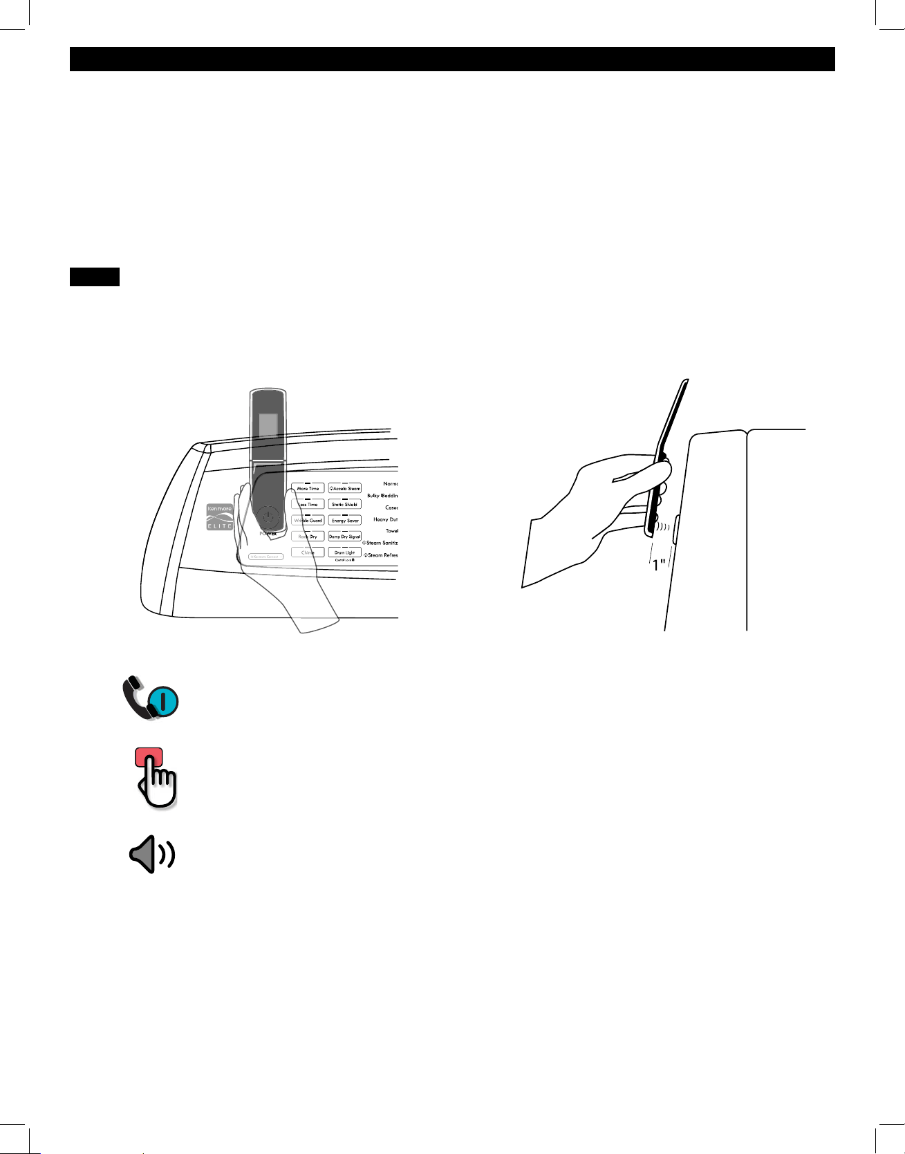
85
Sistema Kenmore Connect™
MANTENGA el micrófono del teléfono sobre el botón de ENCENDIDO, cuando el centro
de llamadas se lo solicite, a no más de 2,5 cm (pero sin tocar) la máquina.
NOTA: No pulse ningún otro botón ni gire el mando del selector de ciclo.
MANTENGA PULSADO el botón de TEMP mientras sigue sujetando el teléfono sobre el
botón POWER.
ESPERE A ESCUCHAR dos pitidos. Tras escuchar los dos pitidos, suelte el botón de
TEMP. Mantenga el teléfono en su sitio hasta que haya terminado la transmisión de tonos.
En la pantalla aparecerá el recuento de tiempo. Una vez fi nalizada la cuenta atrás y
cuando los tonos se hayan detenido, reanude su conversación con el técnico que le podrá
ayudar a utilizar la información transmitida para el análisis.
Si experimenta algún problema con la secadora,
podrá transmitir datos a través del teléfono con
el equipo Kenmore Connect. Así podrá hablar
directamente con nuestros técnicos especializados.
El técnico graba los datos transmitidos desde la
máquina y los utiliza para analizar el problema,
ofreciendo un diagnóstico rápido y efi caz.
Si experimenta problemas con la secadora, en los
EE.UU. llame al 1-844-553-6667 y en Canadá llame
1-800-469-4663.
Sólo utilice el sistema Kenmore
Connect cuando se lo pida el equipo de Kenmore
Connect. Los sonidos de transmisión que oirá son
normales y suenan de forma parecida a un equipo de
fax.
Kenmore Connect no se puede activar a menos que
la secadora se encienda pulsado el botón POWER.
Si la secadora no se puede encender, la solución de
problemas deberá llevarse a cabo sin utilizar Kenmore
Connect.
NOTA:
• Para obtener mejores resultados, no mueva el teléfono mientras se estén trasmitiendo los
tonos.
• Si el agente del centro de llamadas no puede grabar con precisión los datos, quizá le pida
que lo intente de nuevo.
• Si pulsa el botón POWER durante la transmisión se apagará el sistema Kenmore Connect.
Uso del sistema Kenmore Connect™
Primero, comuniquese al 1-844-553-6667 (EE.UU.) o 1-800-469-4663 (Canadá). Si el número del teléfono que está
utilizando está en el archivo, y se asocia con la secadora, usted será retransmitido rápidamente a un agente del
equipo Kenmore Connect. Siga las instrucciones del técnico y siga estos pasos cuando se le solicite.

86
GUÍA DE SOLUCIÓN DE PROBLEMAS
PREGUNTAS FRECUENTES
P: ¿Cuando presiono un botón, ¿por qué la secadora emite un pitido y luego no sucede nada?
R: La función Child Lock está activada. Para desactivar Control Lock, encienda la secadora y, luego,
mantenga presionado el botón con la indicación *Control Lock en él o debajo de él durante 5 segundos.
P: ¿Por qué la secadora tarda tanto tiempo en secar la ropa?
R: Un adecuado fl ujo de aire es esencial para la efi cacia del funcionamiento de las secadoras de ropa.
Un fi ltro de pelusa lleno de pelusa o tapado con una capa de residuos de suavizante para ropa puede
reducir el fl ujo de aire a tal punto que el tiempo de secado puede incrementarse en gran medida. Otro
factor que afecta el tiempo de secado es el sistema de escape de su casa. Un sistema de escape sucio
y repleto de pelusa o demasiado extenso debe ser limpiado o reparado por un profesional.
P: ¿Por qué la secadora se inicia sola cada pocos minutos?
R: Así es como funciona la función Wrinkle Guard. La secadora funciona por poco tiempo cada pocos
minutos durante un período de hasta 3 horas después de que fi naliza el ciclo. Esta función está
diseñada para ayudar a prevenir la formación de arrugas cuando la secadora no se descarga de
inmediato luego de que el ciclo fi naliza.
P: ¿Por qué la secadora indica 3 minutos cuando selecciono el ciclo Steam Refresh?
R: Cuando se selecciona el ciclo Steam Refresh, la secadora muestra la cantidad de prendas, en lugar del
tiempo estimado del ciclo, hasta que inicia el ciclo. Use los botones More Time o Less Time para ajustar
el tamaño de la carga según la cantidad de prendas que desea. Para una carga grande o una sola
prenda voluminosa, use el ajuste
(grande).
ANTES DE SOLICITAR ASISTENCIA TÉCNICA
Problema Causa posible Soluciones
* La luz CHECK VENT
parpadea.
* Este indicador de
advertencia no señala una
avería de la secadora y no
está cubierto por la garantía
de la máquina. Póngase en
contacto con el servicio de
limpieza de conductos para
concertar una cita y limpiar
e inspeccionar su sistema de
ventilación.
El sistema de ventilación es demasiado
largo o tiene demasiados cambios de
dirección/obstrucciones.
Existen bloqueos parciales en los
conductos por acumulaciones de pelusas u
otros objetos extraños.
El electrodoméstico ha detectado una
obstrucción en la ventilación externa de
la secadora.
Instale un conducto con un recorrido más corto o recto.
Consulte las instrucciones de instalación para obtener
más detalles.
El conducto debe comprobarse/limpiarse
inmediatamente. La secadora puede utilizarse en estas
condiciones, pero los tiempos de secado serán mayores y
aumentará el consumo eléctrico.
Consulte las secciones sobre el INDICADOR CHECK
VENT y el funcionamiento de la COMPROBACIÓN DE
LA VENTILACIÓN para obtener más información acerca
de esta función.
La pantalla indica d80, d90,
d95.
Los conductos están bloqueados en
un 80%-95%. (Los códigos de error se
muestra solo durante 2 horas.)
El sistema de escape de la casa está
bloqueado.
No utilice la secadora hasta que el sistema
de escape haya sido limpiado y/o reparado.
Utilizar la secadora con un escape notoriamente
restringido es peligroso y podría ocasionar un
incendio u otros daños a la propiedad.
Revise la ventilación exterior cuando la secadora
está funcionando para asegurarse de que el fl ujo
de aire sea potente.
Si el sistema de escape es extremadamente
largo, hágalo reparar o desviar.
Mantenga la zona alrededor de la secadora
limpia y libre de residuos.
Revise la campana de ventilación para
comprobar si está dañada o tapada con pelusas.
Asegúrese de que la zona alrededor de la
campana de ventilación esté despejada.
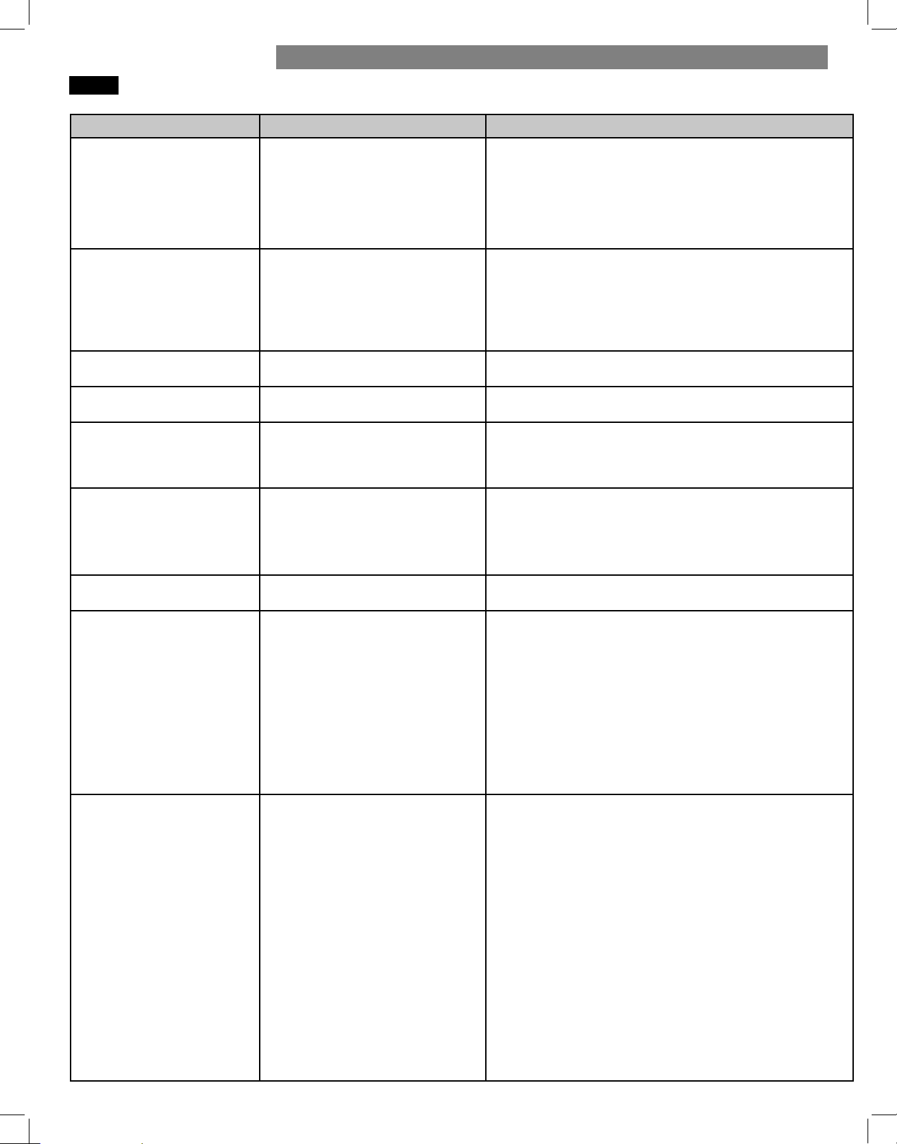
87
ANTES DE SOLICITAR ASISTENCIA TÉCNICA (continuación)
Problema Causa posible Soluciones
El indicador CHECK VENT
permanecerá activo
(parpadeando) después de
eliminar la obstrucción de la
ventilación.
Después de eliminar la obstrucción,
el sistema de comprobación de la
ventilación requiere varios ciclos
consecutivos para determinar
que el rendimiento ha mejorado
antes de restablecer el indicador
CHECKVENT.
Si el indicador CHECK VENT sigue encendido durante más
de cinco ciclos después de eliminar la obstrucción, llame al
servicio técnico.
La secadora no se enciende. El cable de alimentación no se ha
enchufado de forma adecuada.
Se ha fundido el fusible, ha saltado el
disyuntor o se ha producido un corte
de suministro eléctrico en la vivienda.
Compruebe que el enchufe esté conectado firmemente a una
toma de pared con conexión de conexión a tierra que coincida con
la placa de especificaciones de la secadora.
Reinicie el disyuntor o sustituya el fusible. No aumente la
capacidad del fusible. Si el problema es una sobrecarga
delcircuito, haga que lo solucione un electricista cualificado.
Los botones están desactivados
o aparece CL en la pantalla
La función CONTROL LOCK (bloqueo
de los controles) está activada.
Mantenga presionado el botón DRUM LIGHT durante tres
segundos para activar o desactivar la función.
La pantalla muestra los códigos de
error: tE1 través tE7.
Error del sensor de temperatura. Apague la secadora y llame al servicio técnico.
La pantalla muestra los
códigos de error: PS (sólo
secadoras eléctricas).
No se conectó correctamente el
cable de alimentación
Hilos blanco (N) y rojo (L2) del cable de alimentación.
Compruebe las conexiones del cable de alimentación para ver
la conexión del neutro en la terminal central. Seaplicaron 240
voltios al control, por lo que se protegió automáticamente.
La pantalla muestra los
códigos de error: nP o gAS
El cable de alimentación está mal
conectado.
Se ha apagado el suministro o
servicio de gas (solo modelos a gas).
Compruebe la conexión del cable de alimentación al bloque
de terminales.
Confi rme que la válvula de corte de gas de la vivienda
y la válvula de corte de gas de la secadora estén
completamente abiertas.
La luz no enciende cuando la
puerta está abierta
La secadora ha estado apagada por más
de cuatro minutos y la luz se ha apagado.
Presione el botón POWER (encendido) para encender la secadora;
se encenderá la luz del tambor.
La secadora no calienta. Se ha fundido el fusible, ha saltado el
disyuntor o se ha producido un corte
de suministro eléctrico en la vivienda.
Suministro o servicio de gas cortado
(sólomodelos de gas).
Reinicie el disyuntor o sustituya el fusible. No aumente la
capacidad del fusible. Si el problema es una sobrecarga
delcircuito, haga que lo solucione un electricista cualificado.
NOTA: Debido al diseño de las secadoras eléctricas, es posible
que un problema del circuito permita que una secadora eléctrica
funcione sin calor.
Compruebe que las válvulas de corte de gas de la vivienda y
la secadora están abiertas por completo. Aunque la secadora
no disponga de suministro de gas, funcionará y no mostrará
códigos de error. Compruebe que funcionen con normalidad otros
electrodomésticos dela vivienda que utilicen gas.
Hay pelusa en las prendas. No se ha limpiado adecuadamente el
filtro de pelusas.
No se ordenó correctamente la
colada.
Electricidad estática excesiva en las
prendas.
La secadora está sobrecargada.
Se han dejado pañuelos, papeles, etc.
en los bolsillos.
Elimine las pelusas del filtro antes de cada carga. Tras eliminar
la pelusa, sujete el filtro al trasluz para comprobar si está sucio
u obstruido. Si parece sucio, siga las instrucciones de limpieza
proporcionadas. Con ciertas cargas que generan grandes cantidades
de pelusa, podría ser necesario limpiar el filtro durante el ciclo.
Algunos tejidos producen mucha pelusa (por ejemplo, una toalla
de algodón blanco muy gruesa) y deben secarse aparte de
las prendas a las que se adhiere con facilidad la pelusa (por
ejemplo, un par de pantalones negros de hilo).
Utilice un suavizante para reducir la electricidad estática.
Asegúrese de seguir las instrucciones del fabricante. Si se
seca excesivamente una carga, es posible que se acumule
electricidad estática en las prendas. Ajuste los valores y utilice
tiempos de secado más cortos o ciclos de secado automático.
Divida las cargas muy grandes en otras más pequeñas para secarlas.
Examine cuidadosamente los bolsillos antes de lavar y secar las
prendas.
GUÍA DE SOLUCIÓN DE PROBLEMAS
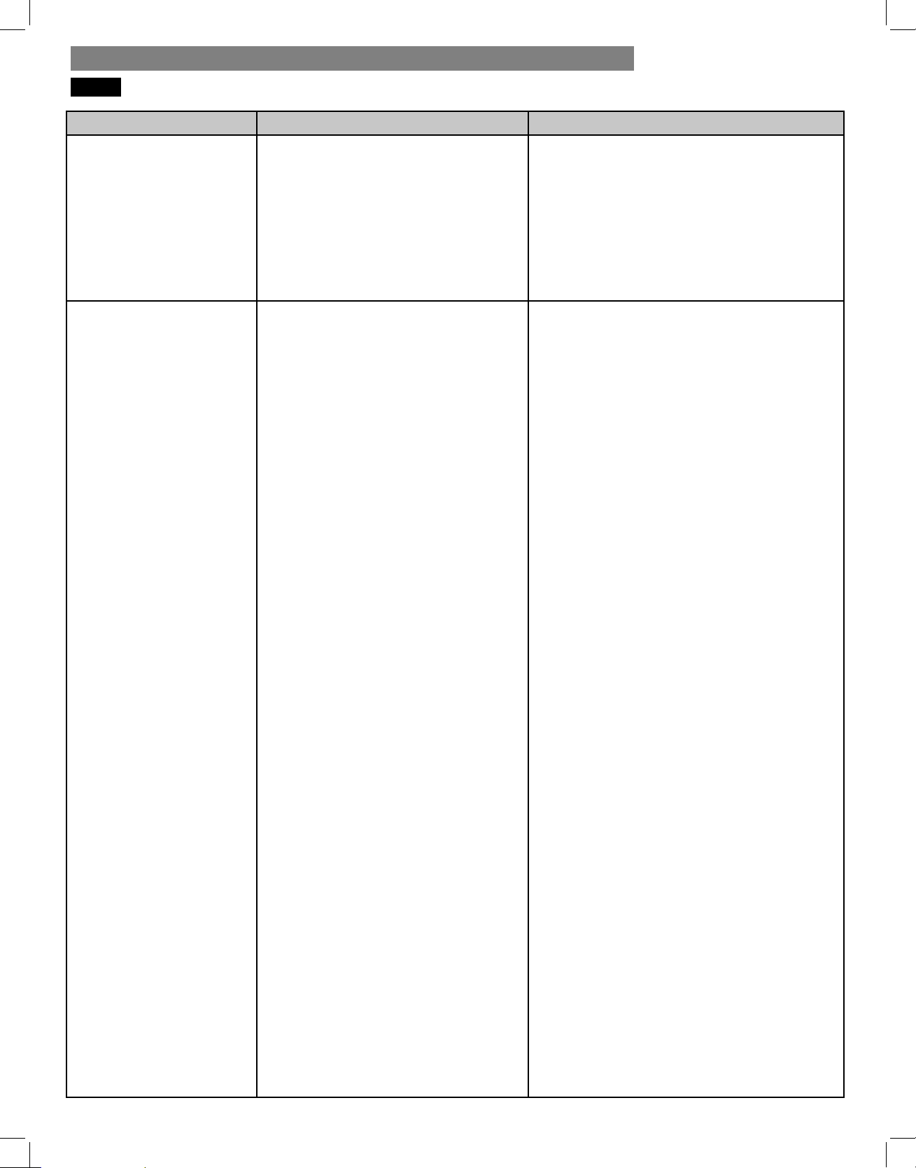
88
ANTES DE SOLICITAR ASISTENCIA TÉCNICA (continuación)
Problema Causa posible Soluciones
Manchas de grasa o suciedad
en las prendas
Se han secado juntas prendas limpias y
sucias.
Las prendas no se limpiaron o enjuagaron
adecuadamente antes de introducirlas en la
secadora.
Utilice su secadora sólo para secar prendas limpias;
la ropa sucia puede contaminar prendas limpias
introducidas en la misma carga o en cargas posteriores.
Las manchas en prendas secas podrían no haber
sido eliminadas durante el proceso de lavado.
Asegúrese de que las prendas han sido limpiadas o
enjuagadas por completo según las instrucciones de
su lavadora y del fabricante del detergente. Ciertas
manchas difíciles podrían requerir un tratamiento
previo al lavado.
Las prendas tardan mucho en
secarse.
Los conductos de ventilación están
obstruidos, sucios o son demasiado largos.
La carga no se ha agrupado correctamente.
Se trata de una carga grande de tejidos
pesados.
Los controles de la secadora no están
ajustados correctamente.
El filtro de pelusas necesita limpieza.
Se ha fundido el fusible, ha saltado el
disyuntor o se ha producido un corte de
suministro eléctrico en la vivienda.
La secadora está sobrecargada.
La secadora está cargada de forma
insuficiente.
Asegúrese de que los conductos de ventilación están
instalados correctamente y libres de residuos, pelusas
y obstrucciones. Asegúrese de que los amortiguadores
de la pared exterior pueden abrirse correctamente y
no están obstruidos, atascados ni dañados.
Separe las prendas pesadas de las ligeras. Las
prendas más grandes y pesadas tardan más en
secarse. Las prendas ligeras en una carga de
prendas pesadas pueden falsear los resultados del
sensor, ya que se secan antes.
Los tejidos pesados tardan más en secarse debido
a que tienden a retener más humedad. Para
ayudar a reducir y mantener tiempos de secado
más consistentes para tejidos grandes y pesados,
divida estas prendas en cargas más pequeñas de un
tamaño coherente.
Utilice los ajustes de control adecuados al tipo de
carga que está secando. Algunas cargas pueden
requerir un ajuste del NIVEL DE SECADO para
secarse correctamente.
Elimine las pelusas del filtro antes de cada carga.
Tras eliminar la pelusa, sujete el filtro al trasluz para
comprobar si está sucio u obstruido. Si parece sucio,
siga las instrucciones de limpieza proporcionadas.
Con ciertas cargas que generan grandes cantidades
de pelusa, como unas toallas de baño nuevas, podría
ser necesario detener el ciclo y limpiar el filtro
durante el transcurso del mismo.
Reinicie el disyuntor o sustituya el fusible. No
aumente la capacidad del fusible. Si el problema es
una sobrecarga del circuito, haga que lo solucione
un electricista cualificado.
NOTA: Debido al diseño de las secadoras eléctricas,
es posible que un problema del circuito permita que
una secadora eléctrica funcione sin calor.
Divida las cargas muy grandes en otras más
pequeñas para conseguir un mejor funcionamiento y
una mayor eficiencia de secado.
Si está secando una carga muy pequeña, añada
algunas prendas más para asegurarse de que las
prendas giran adecuadamente. Si la carga es muy
pequeña y está utilizando ciclos de secado automático,
el control electrónico no podrá detectar correctamente
la humedad de la carga y podría finalizar el ciclo
demasiado pronto. Utilice la función de secado manual
o añada algunas prendas húmedas más a la carga.
GUÍA DE SOLUCIÓN DE PROBLEMAS
89
ANTES DE SOLICITAR ASISTENCIA TÉCNICA (continuación)
Problema Causa posible Soluciones
El tiempo de secado no es
consistente.
Los ajustes de calor, tamaño de la
carga o humedad en las prendas no son
consistentes.
El tiempo de secado de una carga variará dependiendo
del tipo de calor utilizado (eléctrico, gas natural o
gas LP), el tamaño de la carga, los tipos de tejidos, la
humedad de las prendas y el estado de los conductos
de ventilación y del filtro de pelusas. Incluso una carga
desequilibrada en la lavadora puede ocasionar un
centrifugado deficiente, que hará que las prendas estén
más húmedas y tarden más tiempo en secarse.
Las prendas están
arrugadas.
Las prendas se han secado durante
demasiado tiempo (secado excesivo).
Se han dejado demasiado tiempo las
prendas en la secadora una vez finalizado
el ciclo.
Si se seca excesivamente una carga de ropa, es posible
que las prendas queden arrugadas. Pruebe a utilizar un
tiempo de secado más corto o el ajuste LESS DRY y retire
los elementos mientras todavía les quede un poco de
humedad.
Utilice la opción WRINKLE GUARD. Esta función hará
que las prendas giren durante unos segundos cada pocos
minutos durante un máximo de 150 minutos para evitar
las arrugas.
Las prendas han
encogido.
No se siguieron las instrucciones de cuidado
de las prendas.
Para evitar que las prendas encojan, consulte siempre las
instrucciones de cuidado de la prenda y sígalas. Algunos
tejidos encogerán de manera natural al lavarlos. Otros
tejidos se pueden lavar en lavadora pero encogen si se
secan a máquina. Utilice un secado a baja temperatura
o sin calor.
Electricidad estática
excesiva en las prendas
tras el secado
No se ha utilizado suavizante o se ha usado
de forma incorrecta.
Las prendas se han secado durante
demasiado tiempo (secado excesivo).
Se están secando prendas sintéticas,
de planchado permanente o de mezcla
sintética.
Utilice un suavizante o la opción STATIC SHIELD, si
dispone de ella, para reducir la electricidad estática.
Asegúrese de seguir las instrucciones del fabricante.
Si se seca excesivamente una carga, es posible que se
acumule electricidad estática en las prendas. Ajuste los
valores y utilice tiempos de secado más cortos o ciclos de
secado automático. Seleccione un ajuste LESS DRY en los
ciclos de secado automático, si es necesario.
Estos tejidos son, por naturaleza, más propensos a
acumular electricidad estática. Intente utilizar suavizante
o utilice la opción LESS DRY y/o un ajuste de tiempo más
corto para la función de secado manual.
GUÍA DE SOLUCIÓN DE PROBLEMAS
90
ANTES DE SOLICITAR ASISTENCIA TÉCNICA (continuación)
Problema Causa posible Soluciones
Las funciones de vapor no
están operativas
Gotea agua de la boquilla cuando
comienza el ciclo STEAM CYCLE.
El vapor no es visible durante el ciclo
STEAM CYCLE.
No se genera vapor y la pantalla no
muestra códigos de error.
Las prendas siguen estando arrugadas al
terminar el ciclo STEAM REFRESH (refresco
por vapor).
No existen arrugas en las prendas tras
utilizar el ciclo STEAM REFRESH.
Las prendas tienen estática después de que
se usa la opción de reducción de estática
STATIC SHIELD.
Las prendas están demasiado húmedas
o secas después de usar la opción de
reducción de estática Static Shield.
Existen gotas de agua en la puerta durante
los ciclos de vapor.
El tambor no gira durante los ciclos de
vapor.
No puede verse el vapor al comienzo del
ciclo.
La ropa sigue teniendo olor después del
ciclo STEAM REFRESH.
Se trata de condensación de vapor. El agua dejará de
gotear después de unos momentos.
El vapor es difícil de ver cuando la puerta está cerrada.
Sin embargo, por lo general, se formará condensación
en el interior de la puerta de la secadora si el sistema de
vapor está funcionando correctamente.
Error de nivel de agua. Desenchufe la secadora y llame
al servicio técnico.
Cargue únicamente entre 1 y 5 prendas (excepto prendas
voluminosas individuales). No mezcle distintos de tejidos.
El ciclo STEAM REFRESH es más efi caz en tejidos con
mezcla 70/30 de algodón/poliéster. No utilice prendas
de algodón 100%.
Este ciclo está diseñado para eliminar las arrugas.
Si, tras el ciclo STEAM REFRESH, desea crear rayas o
marcas en sus prendas, deberá plancharlas para que así
sea.
La cantidad de estática experimentada dependerá del
nivel de humedad específi co de la piel.
Seleccione el peso de la carga de forma manual antes
de iniciar la opción de reducción de estática.
El vapor en invisible. Sin embargo, bajo ciertas
condiciones, la nube condensada puede verse o puede
formarse condensación en el interior del cristal de la
puerta.
El tambor se detiene para que el vapor permanezca en
el mismo. El tambor girará sólo durante unos segundos
cada minuto.
El vapor se libera en distintos períodos del ciclo para
cada opción. El vapor no puede verse, pero podría
formarse condensación en el interior de la puerta al
generarse vapor.
Algunos olores son difíciles de eliminar. Los tejidos que
contengan ciertos olores difíciles de eliminar o muy
fuertes, podrían no refrescarse correctamente y requerir
ser lavadas o limpiadas en seco.
GUÍA DE SOLUCIÓN DE PROBLEMAS
91
Garantía limitada de Kenmore Elite
POR UN AÑO a partir de la fecha de venta, este electrodoméstico está cubierto por la garantía
contra defectos de material o mano de obra cuando la instalación, operación y mantenimiento del
electrodoméstico son correctos y siguen todas las instrucciones suministradas.
JUNTO CON LA PRUEBA DE VENTA, el electrodoméstico defectuoso recibirá sin cargo su reparación o
reemplazo, a opción del vendedor.
Para conocer los detalles de la cobertura de garantía para obtener la reparación o el reemplazo gratis del
producto, visite la página Web: www.kenmore.com/warranty
Esta cobertura de garantía aplica sólo por 90 DÍAS a partir de la fecha de venta en los Estados Unidos, y
no será válida en Canadá, si el electrodoméstico es utilizado para otro fi n que no sea de uso doméstico.
Esta garantía cubre ÚNICAMENTE los defectos de material y mano de obra, y NO pagará:
1. Elementos consumibles que puedan desgastarse debido al uso normal, incluyendo entre otros, los fi ltros,
correas, bolsas o bombillas extraíbles.
2. Un técnico de servicio para realizar labores de limpieza o mantenimiento del electrodoméstico, o para
enseñar al usuario la instalación, funcionamiento o mantenimiento correctos del producto.
3. Llamadas al servicio técnico para corregir la instalación del electrodoméstico no realizada por
agentes de servicio autorizados de Sears, o bien para solucionar problemas relacionados con fusibles
domésticos, disyuntores, cableado, sistemas de plomería o de suministro de gas, que resulten de tal
instalación.
4. Daños o averías resultantes de la instalación no realizada por agentes de servicio autorizados de
Sears, incluida la instalación que no fue realizada de acuerdo con los códigos eléctricos, de gas o de
fontanería.
5. Daños o averías, incluyendo la decoloración u óxido de la superfi cie, si el funcionamiento y
mantenimiento del electrodoméstico no son correctos de acuerdo a las instrucciones suministradas.
6. Daños o averías, incluyendo la decoloración u óxido de la superfi cie, que resulten de cualquier
accidente, alteración, abuso, uso incorrecto o uso con propósitos distintos a los fi nes para los que el
producto fue diseñado.
7. Daños o averías, incluyendo la decoloración u óxido de la superfi cie, causados por el uso de
detergentes, limpiadores, sustancias químicas o utensilios distintos a los recomendados en todas las
instrucciones suministradas con el producto.
8. Daños o fallas de los componentes o sistemas como resultado de modifi caciones hechas sin
autorización a este producto.
9. Servicio técnico al electrodoméstico si el modelo y placa de serie han sido removidos, alterados, o
cuando no pueda determinarse fácilmente que tenga el logo de certifi cación apropiado.
Descargo de responsabilidad de garantías implícitas; limitación de acciones legales
El único y exclusivo recurso del cliente bajo esta garantía limitada será la reparación del producto como se
indica en la presente. Las garantías implícitas, incluyendo garantías de comerciabilidad y aptitud para un
objetivo particular, se encuentran limitadas a un año o al período más corto permitido por la ley. Sears no
será responsable de los daños incidentales o derivados. Algunos estados y provincias no permiten la exclusión
o limitación de daños o limitaciones incidentales o resultantes, o limitaciones sobre la duración de garantías
implícitas o de comerciabilidad o aptitud, por lo tanto las limitaciones o exclusiones anteriores pueden no
aplicarse en su caso.
Esta garantía podrá aplicarse sólo si este electrodoméstico se utiliza en los Estados Unidos o Canadá*.
Esta garantía le otorga derechos legales específi cos, y usted también puede contar con otros derechos, que
pueden variar de estado a estado.
*El servicio de reparación a domicilio no está disponible en todas las áreas geográfi cas de Canadá. Tampoco
esta garantía cubrirá los gastos de traslado o transporte del usuario o del técnico de reparación si el producto
está ubicado en un área remota (tal como la defi ne Sears Canada Inc.) donde no haya ningún técnico de
servicio disponible.
Sears Brands Management Corporation, Hoff man Estates, IL 60179
Sears Canada Inc., Toronto, Ontario, Canada M5B 2C3
GARANTÍA

92
NOTAS

93
NOTAS

94
NOTAS

95
NOTAS
.HQPRUH
§
)RU6HDUV+RPH6HUYLFHVLQKRPHUHSDLU
RIDOO.HQPRUHPDMRUDSSOLDQFHV
)RUWKHUHSODFHPHQWSDUWVDFFHVVRULHVDQG
8VH&DUH*XLGHVWKDW\RXQHHGWRGRLW\RXUVHOI
)RUSURIHVVLRQDOLQVWDOODWLRQRIPDMRUKRPHDSSOLDQFHV
DQGLWHPVOLNHDLUFRQGLWLRQHUVDQGZDWHUKHDWHUV
ZZZNHQPRUHFRP
,Q&DQDGD
,Q&DQDGD,Q&DQDGD
,Q&DQDGD
ZZZVHDUVFD
&DOODQ\WLPHIRUWKHORFDWLRQRI\RXUQHDUHVW
6HDUV
6HDUV6HDUV
6HDUV
3DUWV5HSDLU6HUYLFH&HQWHU
3DUWV5HSDLU6HUYLFH&HQWHU3DUWV5HSDLU6HUYLFH&HQWHU
3DUWV5HSDLU6HUYLFH&HQWHU
86$
&DQDGD
7RSXUFKDVHDSURWHFWLRQDJUHHPHQWRQDVHUYLFHDEOHSURGXFW
86$
&DQDGD
3DUDSHGLUVHUYLFLRGHUHSDUDFLÚQ
DGRPLFLOLR\RUGHQDUSLH]DV
68
6868
68
+2*$5
+2*$5+2*$5
+2*$5
§
ZZZNHQPRUHFRP
$X&DQDGDSRXUVHUYLFHHQIUDQÐDLV
/(
/(/(
/(
)2<(5
)2<(5)2<(5
)2<(5
0&
ZZZVHDUVFD
§


