
Please read this manual carefully before operating
your set.
Retain it for future reference.
Record model number and serial number of the set.
See the label attached on the back cover and quote
this information to your dealer when you require
service.
Installation and
Operating Guide
26LH1DC3
26LH1DC4
26LH1DC5
www.lgcommercial.com
2
WARNING / CAUTION
REGULATORY INFORMATION
This equipment has been tested and found to comply
with the limits for a Class B digital device, pursuant to
Part 15 of the FCC Rules.
These limits are designed to provide reasonable
protection against harmful interference when the
equipment is operated in a residential installation. This
equipment generates, uses and can radiate radio
frequency energy and, if not installed and used in
accordance with the instruction manual, may cause
harmful interference to radio communications. However,
there is no guarantee that interference will not occur in a
particular installation. If this equipment does cause
harmful interference to radio or television reception,
which can be determined by turning the equipment off
and on, the user is encouraged to try to correct the
interference by one or more of the following measures:
•Reorient or relocate the receiving antenna.
•Increase the separation between the equipment and
receiver.
• Connect the equipment into an outlet on a circuit
different from that to which the receiver is
connected.
• Consult the dealer or an experienced radio/TV
technician for help.
IT IS FORBIDDEN TO CONNECT THIS TV
TO ANY TELECOMMUNICATION
NETWORK / TELEPHONE.
The exclamation point within an
equilateral triangle is intended to alert
the user to the presence of important
operating and maintenance (servicing) instructions
in the literature accompanying the appliance.
The lightning flash with arrowhead
symbol, within an equilateral triangle, is
intended to alert the user to the
presence of uninsulated “dangerous voltage”
within the product’s enclosure that may be of
sufficient magnitude to constitute a risk of
electric shock to persons.
CAUTION:
TO REDUCE THE RISK OF ELECTRIC SHOCK
DO NOT REMOVE COVER (OR BACK). NO
USER SERVICEABLE PARTS INSIDE. REFER TO
QUALIFIED SERVICE PERSONNEL.
WARNING
TO PREVENT FIRE OR SHOCK HAZARDS, DO NOT
EXPOSE THIS PRODUCT TO RAIN OR MOISTURE.
THIS PRODUCT MUST BE USED WITH UL LISTED
MOUNTING BRACKET.
This reminder is provided to call the CATV system installer’s
attention to Article 820-40 of the National Electric Code
(U.S.A.). The code provides guidelines for proper
grounding and, in particular, specifies that the cable ground
shall be connected to the grounding system of the building,
as close to the point of the cable entry as practical.
NOTE TO CABLE TV INSTALLER
Changes or modifications not expressly approved by the
party responsible for compliance could void the user’s
authority to operate the equipment.
CAUTION
THE PARTY RESPONSIBLE FOR PRODUCT
COMPLIANCE
(LG Electronics U.S.A., Inc.,)
(2000 Millbrook Drive)
(TELEPHONE NO:1-847-941-8000)

3
Do not attempt to modify this product in any way
without written authorization from LG Electronics
Corporation.
Unauthorized modification could void the user’s
authority to operate this product.
CAUTION
Apparatus shall not be exposed to dripping or
splashing and no objects filled with liquids, such as
vases, shall not be placed on the apparatus.
WARNING
THESE SERVICING INSTRUCTIONS ARE FOR USE BY
QUALIFIED SERVICE PERSONNEL ONLY. TO REDUCE
THE RISK OF ELECTRIC SHOCK, DO NOT PERFORM
ANY SERVICING OTHER THAN THAT CONTAINED
IN THE OPERATING INSTRUCTIONS UNLESS YOU
ARE QUALIFIED TO DO SO.
CAUTION
When used outside of the U.S., it may be used HAR
cord with fitting of an approved agency is employed.
(When used outside of U.S., other power supply cords
may be used if the cord is approved by the local
regulating agency.)
CAUTION
YOUR PRODUCT HAS BEEN MANUFACTURED AND TESTED WITH YOUR SAFETY IN MIND. HOWEVER,
IMPROPER USE CAN RESULT IN POTENTIAL ELECTRICAL SHOCK OR FIRE HAZARDS. TO AVOID DEFEATING
THE SAFEGUARDS THAT HAVE BEEN BUILT INTO YOUR NEW PRODUCT, PLEASE READ AND OBSERVE THE
FOLLOWING SAFETY POINTS WHEN INSTALLING AND USING YOUR NEW PRODUCT, AND SAVE THEM FOR
FUTURE REFERENCE. OBSERVING THE SIMPLE PRECAUTIONS DISCUSSED IN THIS MANUAL CAN HELP YOU
GET MANY YEARS OF ENJOYMENT AND SAFE OPERATION THAT ARE BUILT INTO YOUR NEW PRODUCT.
IMPORTANT SAFEGUARDS FOR YOU AND YOUR NEW PRODUCT
Clean the exterior of this television by removing dust
with a lint-free cloth.
CAUTION: To avoid damage to the surface of the
television, do not use abrasive or chemical cleaning
agents.
CLEANING AND DISINFECTION
G
If the TV feels cold to the touch, there may be a small “flicker” when it is turned on. This is normal, there is
nothing wrong with the TV.
G
Some minute dot defects may be visible on the screen, appearing as tiny red, green, or blue spots.
However, they have no adverse effect on the TVs performance.
G
Avoid touching the LCD screen or holding your finger(s) against it for long periods of time. Doing so may
produce some temporary distortion effects on the screen.
NOTE

4
SAFETY INSTRUCTIONS
IMPORTANT SAFETY INSTRUCTIONS
1. Read these instructions.
2. Keep these instructions.
3. Heed all warnings.
4. Follow all instructions.
5. Do not use this apparatus near water.
6. Clean only with dry cloth.
7. Do not block any ventilation openings. Install in accordance with the manufacturer’s instructions.
8. Do not install near any heat sources such as radiators, heat registers, stoves, or other apparatus (including
amplifiers) that produce heat.
9. Do not defeat the safety purpose of the polarized or grounding-type plug. A polarized plug has two blades with
one wider than the other. A grounding type plug has two blades and a third grounding prong. The wide blade or
the third prong is provided for your safety. If the provided plug does not fit into your outlet, consult an
electrician for replacement of the obsolete outlet.
10 .Protect the power cord from being walked on or pinched particularly at plugs, convenience receptacles, and the
point where they exit from the apparatus.
11 . Only use attachments/accessories specified by the manufacturer.
12 .Use only with the cart, stand, tripod, bracket, or table specified by the manufacturer, or sold with the apparatus.
When a cart is used, use caution when moving the cart/apparatus combination to avoid injury from tip-over.
13 . Unplug this apparatus during lightning storms or when unused for long periods of time.
14 .Refer all servicing to qualified service personnel. Servicing is required when the apparatus has been damaged in
any way, such as power-supply cord or plug is damaged, liquid has been spilled or object have fallen into the
apparatus, the apparatus has been exposed to rain or moisture, does not operate normally, or has been dropped.
Outdoor Antenna Grounding
If an outside antenna or cable system is connected to the product, be sure the antenna or cable system is grounded
so as to provide some protection against voltage surges and built-up static charges. Article 810 of the National
Electrical Code (U.S.A.), ANSI/NFPA 70 provides information with regard to proper grounding of the mast and
supporting structure, grounding of the lead-in wire to an antenna discharge unit, size of grounding conductors,
location of antenna-discharge unit, connection to grounding electrodes, and requirements for the grounding
electrode.
Example of Grounding According to National Electrical Code Instructions
Antenna Lead in Wire
Antenna Discharge Unit
(NEC Section 810-20)
Grounding Conductor
(NEC Section 810-21)
Ground Clamps
Power Service Grounding
Electrode System (NEC
Art 250, Part H)
Ground Clamp
Electric Service
Equipment
NEC - National Electrical Code
PORTABLE CART WARNING

5
CONTENTS
Antenna or Cable Connection . . . . . . . . . . . . . . . . . . . . . . 10
HD Receiver Setup
. . . . . . . . . . . . . . . . . . . . . . . . . . . . . . . . . . . . . . 11
DVD Setup
. . . . . . . . . . . . . . . . . . . . . . . . . . . . . . . . . . . . . . . . . . . . . . . 14
VCR Setup
. . . . . . . . . . . . . . . . . . . . . . . . . . . . . . . . . . . . . . . . . . . . . . . . 16
Other A/V Source Setup
. . . . . . . . . . . . . . . . . . . . . . . . . . . . . .
18
Digital Audio Output
. . . . . . . . . . . . . . . . . . . . . . . . . . . . . . . . . 18
PC Setup
. . . . . . . . . . . . . . . . . . . . . . . . . . . . . . . . . . . . . . . . . . . . . . . . . 19
Screen Setup for PC mode
. . . . . . . . . . . . . . . . . . . . . . . . . . 21
DV I Hookup To RJP or DVD Player . . . . . . . . . . . . . . . 22
Computer PC Hookup
. . . . . . . . . . . . . . . . . . . . . . . . . . . . . . . 22
EXTERNAL EQUIPMENT SETUP
User Remote Control Button Functions . . . . . . . . . 23
Installer Remote Control Button Functions . . . . 24
On-Screen Menus Selection
. . . . . . . . . . . . . . . . . . . . . . . . . . 25
Channel Search
. . . . . . . . . . . . . . . . . . . . . . . . . . . . . . . . . . . . . . . . . . 26
WATCHING TV /CHANNEL CONTROL
Clock Setting . . . . . . . . . . . . . . . . . . . . . . . . . . . . . . . . . . . . . . . . . . . . 30
Daylight Saving . . . . . . . . . . . . . . . . . . . . . . . . . . . . . . . . . . . 32
Time Zone Settings . . . . . . . . . . . . . . . . . . . . . . . . . . . . . . 32
TV Activation Time Settings
. . . . . . . . . . . . . . . . . . . 33
TV Deactivation Time Settings
. . . . . . . . . . . . . . . 33
Auto Off . . . . . . . . . . . . . . . . . . . . . . . . . . . . . . . . . . . . . . . . . . . 34
TIME SETTING
WARNING / CAUTION
. . . . . . . . . . . . . . . . . . . . . . . . . . . 2
SAFETY INSTRUCTIONS . . . . . . . . . . . . . . . . . . . . . . . . 4
CONTENTS
. . . . . . . . . . . . . . . . . . . . . . . . . . . . . . . . . . . . . . . . . . . . 5
Accessories
. . . . . . . . . . . . . . . . . . . . . . . . . . . . . . . . . . . . . . . . . . . . . . . . . 6
Front Panel Information . . . . . . . . . . . . . . . . . . . . . . . . . . . . . . . 7
Back Panel Information . . . . . . . . . . . . . . . . . . . . . . . . . . . . . . . . 8
VESA Wall Mounting
. . . . . . . . . . . . . . . . . . . . . . . . . . . . . . . . . . . . 9
PREPARATION
Set Password & Lock System
. . . . . . . . . . . . . . . . . . . . . . . . . . .
35
Movie & TV Ratings
. . . . . . . . . . . . . . . . . . . . . . . . . . . . . . . . . . . . . .
37
PARENTAL CONTROL/RATINGS
Caption / Text
. . . . . . . . . . . . . . . . . . . . . . . . . . . . . . . . . . . . . . . . . . 41
Preset Sound Settings . . . . . . . . . . . . . . . . . . . . . . . . . . 43
Sound Setting Adjustment-user Mode . . . . . 43
Sound Balance Setup
. . . . . . . . . . . . . . . . . . . . . . . . . . . 44
Digital Audio Output Settings . . . . . . . . . . . . . 44
Aautomatic Volume Control Settings . . . . 45
Analog Audio Settings . . . . . . . . . . . . . . . . . . . . . . . . . 45
Digital Audio Language Settings . . . . . . . . . . . . 46
Using External Speakers . . . . . . . . . . . . . . . . . . . . . . 46
Menu Language . . . . . . . . . . . . . . . . . . . . . . . . . . . . . . . . . . 47
Menu Transparency Settings . . . . . . . . . . . . . . . . . . 48
Set ID
. . . . . . . . . . . . . . . . . . . . . . . . . . . . . . . . . . . . . . . . . . . . . . 48
SOUND & LANGUAGE CONTROL
Preset Picture Settings . . . . . . . . . . . . . . . . . . . . . . . . . . . . . . 49
Screen Format Adjustments . . . . . . . . . . . . . . . . . 50
Noise Reduction
. . . . . . . . . . . . . . . . . . . . . . . . . . . . . . . . . 51
Film Mode Options . . . . . . . . . . . . . . . . . . . . . . . . . . . .51
PICTURE CONTROL
Tr oubleshooting . . . . . . . . . . . . . . . . . . . . . . . . . . . . . . . . . . . . . . . .69
Cloning Procedure Troubleshooting
. . . . . . . . . . . . . . .71
Clone Troubleshooting Flow Chart . . . . . . . . . . . . . . . .73
TV Operating Check
. . . . . . . . . . . . . . . . . . . . . . . . . . . . . . . . . .74
Glossary of Terms . . . . . . . . . . . . . . . . . . . . . . . . . . . . . . . . . . . . . .75
Installer Quick Setup Guide . . . . . . . . . . . . . . . . . . . . . . . . . 76
APPENDIX
Installer Overview . . . . . . . . . . . . . . . . . . . . . . . . . . . . . . . . . . . . . . .52
Commercial Mode Setup . . . . . . . . . . . . . . . . . . . . . . . . . . . . .53
Cloning Connections/Learning Setup . . . . . . . . . . . . .54
Clone Programmer/Learning Setup
. . . . . . . . . . . . . . .55
Cloning Connections/Teaching Setup
. . . . . . . . . . . . .56
Installer Menu . . . . . . . . . . . . . . . . . . . . . . . . . . . . . . . . . . . . . . . . . . .58
Peference . . . . . . . . . . . . . . . . . . . . . . . . . . . . . . . . . . . . . . . . . . . . . . . . . .63
COMMERCIAL MODE
6
PREPARATION
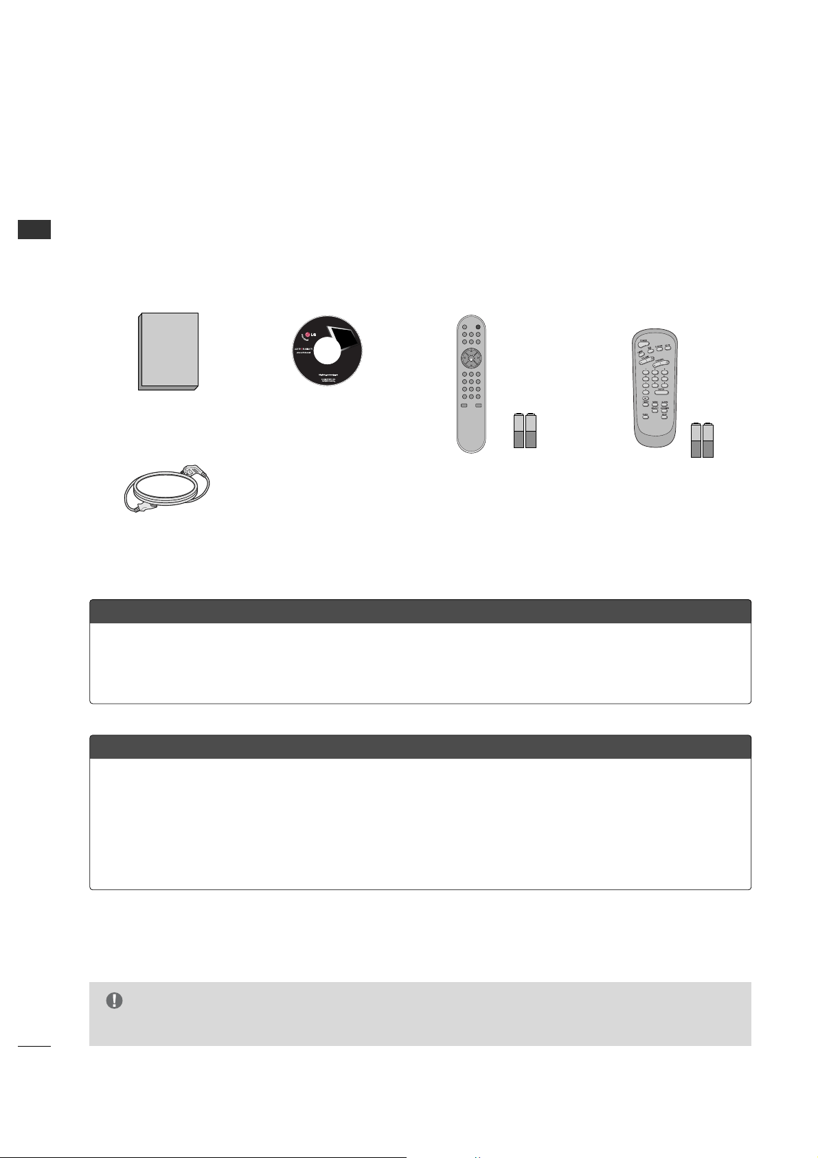
ACCESSORIES
Ensure that the following accessories are included with your product. If an accessory is missing, please contact the
dealer where you purchased the product.
User must use shielded signal interface cables with ferrite cores to maintain standard compliance for the product.
Owner’s Manual CD Manual
Power Co rd
Shown herein is an optional Installer remote control available for the 26LH1DC3/4/5 models only. The
installer remote control is NOT included with the TV.
•However, the user's remote is included with the TV.
To perform a normal installation set up, you need an installer's remote and the LT2002 Quickset II Clone
Programmer – both are shown and described in later sections. See your LG dealer if you wish to purchase
the Installer remote and LT2002. The installer remote allows access to the Installer menus, User menus in
the Manual Channel Set options on the Setup menu. The installer remote has Menu, Select, and Adjust
Keys. The LT2002 Quickset II Clone Programmer is used to duplicate a TV's setup and install it on another
identical TV.
Optional Installer Remote Control for Model No. Series 26LH1DC3/4/5
Purchase the Optional Installer's Remote and Clone Programmer
User Remote Control.
Batteries
Installer Remote Control.
Batteries (Optional )
POWERMUTE
TV/AV
CH
PREVIEW
GUIDE
SAP INFO
123
456
7
-
89
0
CC
TIMER
FLASHBK
CH
CH
VOL
OK
VOL
ALARM
G
Design and specifications are subject to change without prior notice.
NOTE
PREPARATION
7
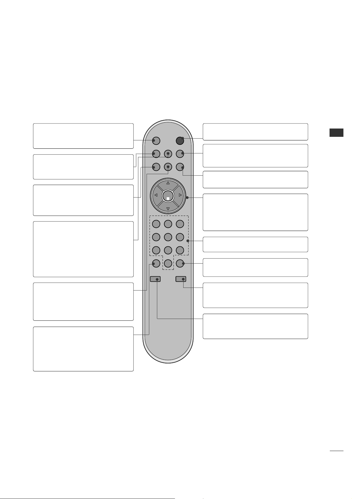
PREPARATION
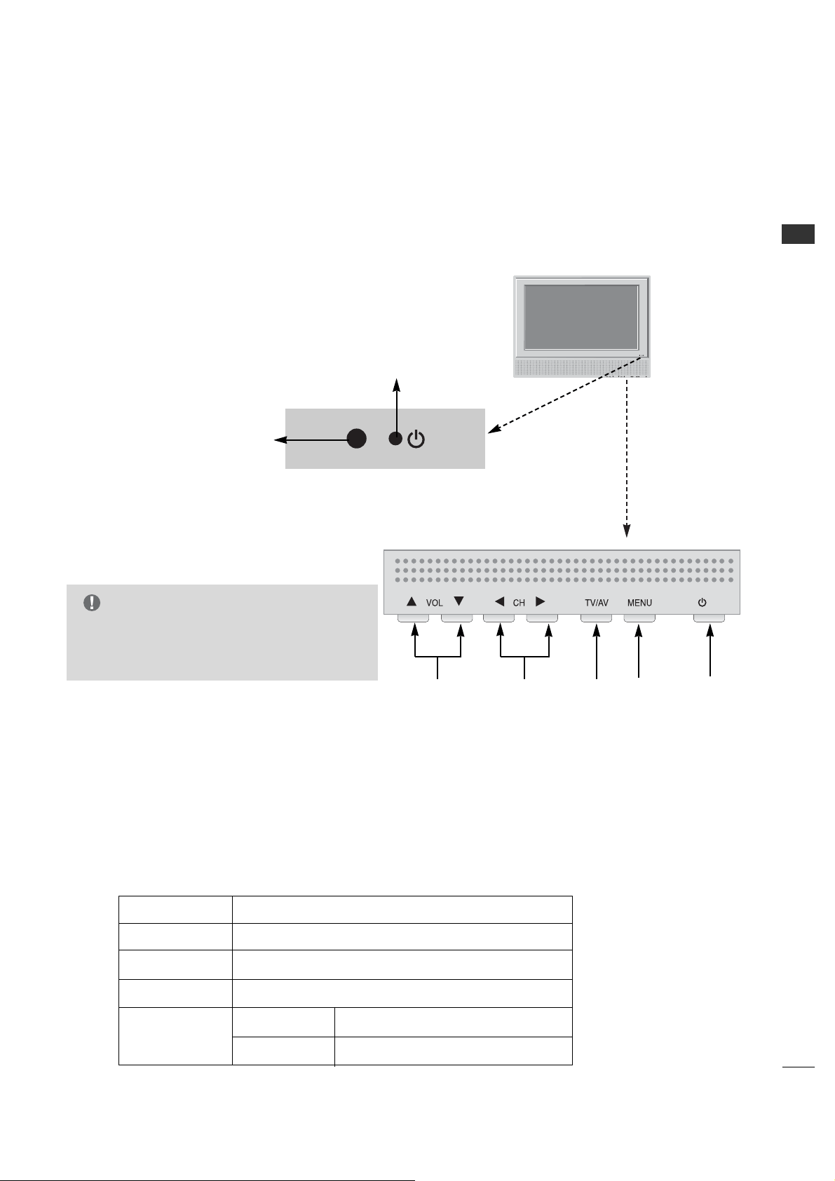
FRONT PANEL INFORMATION
On-Screen Displays
See descriptions on page 25. On-screen displays will appear when the feature
is active or the function is being used.
Use the VV OOLL (Volume) Up/Down button to
adjust the sound level to your preference.
Use the CC HH (Channel) Up/Down button to
cycle through the available channels.
Displays the current channel bank. Press
again to change banks.
Press MMEENNUU repeatedly to scroll through
menus.
TV Operation
Press the PPOOWWEERR button to turn the TV
on from standby mode.
Power / Standby Indicator
Glows red in Standby mode.
Glows green when the TV is
turned on.
Glows orange in Sleep Timer
and/or Alarm mode.
A
B
C
D
E
/ I
LED Color Action/Status
RED Power is Off (Standby)
GREEN is flashing Power On sequence is processing
GREEN Power is On
ORANGE If Power is Off On Timer is set or Alarm is set
If Power is On Off Timer is set or Sleep Timer is set
/ I
A
B
CDE
■
Here shown may be somewhat different from your TV.
■
Using the front control panel to operate the TV.
Front Panel Controls
Remote Control Sensor
G
With Installer menu item 11 buttons Defeat
set to 000 (the default setting), Menu and
TTVV //AAVV buttons are disabled.
NOTE

8
PREPARATION
Back Connection Panel
M.P.I. INTERFACE
Use with clone programmer.
FUTURE USE
DVI/PC AUDIO IN
PC IN
HDMI/DVI IN
DIGITAL AUDIO OUT
(Optical)
RS-232C PORT
RS-232C SELECT
SWITCH
UPDATE SWITCH
ANTENNA CABLE
Connect to an antenna or
cable system.
S-VIDEO IN
AUDIO / VIDEO 1, 3 IN
Connect Audio / Video
equipment to these jacks.
COMPONENT 1, 2 IN
AC IN
RJP INTERFACE
VIDEO2(SIDE AUTO-CAMPORT)
VIDEO IN AUDIO IN
LR
AUDIO/
VIDEO 2
(SIDE
AUTO-
CAMPORT)
PREPARATION
BACK PANEL INFORMATION
■
Here shown may be somewhat different from your TV.
G
RS-232C, Update Switch and RS-232C Select Switch are reserved for qualified and authorized service and
technical support personal only.
NOTE
PREPARATION
9
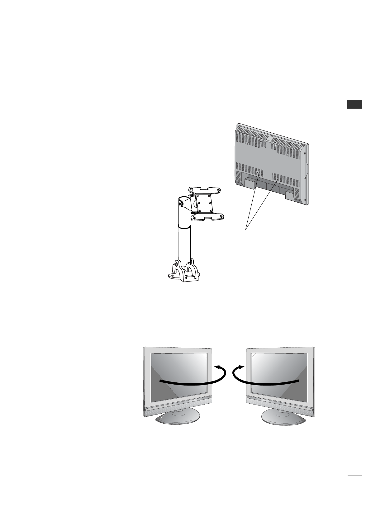
VESA WALL MAUNTING
There are several Vesa standard
mounts available that can be used
with this TV. The mount shown to the
right would be installed on the TV
back using required bolts in the four
pre-threaded holes provided.
Follow any instructions supplied with
the Vesa mount if one is to be used
for the TV installation.
Swivel Stand
- The TV can be conveniently
swiveled on its stand 30° to
the left or right to provide
optimum viewing angles.
■
Here shown may be somewhat different from your TV.
TV Swivel Stand
Vesa Standard
Mounting Holes
Typical
Vesa
Mount
EXTERNAL EQUIPMENT SETUP
10
EXTERNAL EQUIPMENT SETUP
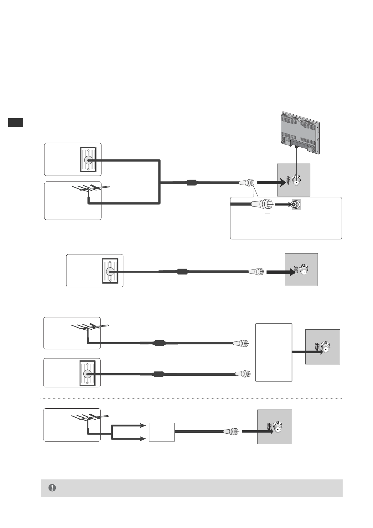
ANTENNA OR CABLE CONNECTION
1. Antenna (Analog or Digital)
Wall Antenna Socket or Outdoor Antenna without a Cable Box Connections.
For optimum picture quality, adjust antenna direction if needed.
Wall
Antenna
Socket
Outdoor
Antenna
(VHF, UHF)
Multi-family Dwellings/Apartments
(Connect to wall antenna socket)
RF Coaxial Wire (75 ohm)
Single-family Dwellings /Houses
(Connect to wall jack for outdoor antenna)
Be careful not to bend the bronze wire
when connecting the antenna.
Copper Wire
2. Cable
Cable TV
Wall Jack
RF Coaxial Wire (75 ohm)
■
To improve the picture quality in a poor signal area, please purchase a signal amplifier and install properly.
■
If the antenna needs to be split for two TV’s, install a 2-Way Signal Splitter.
■
If the antenna is not installed properly, contact your dealer for assistance.
Antenna
UHF
Signal
Amplifier
VHF
3. Using both cable and antenna
Cable TV
Wall Jack
Antenna
RF Coaxial Wire (75 ohm)
RF Coaxial Wire (75 ohm)
Diplexer
(Signal
Combiner)
G
The TV will let you know when the analog, cable, and digital channel scans are complete.
NOTE
EXTERNAL EQUIPMENT SETUP
11
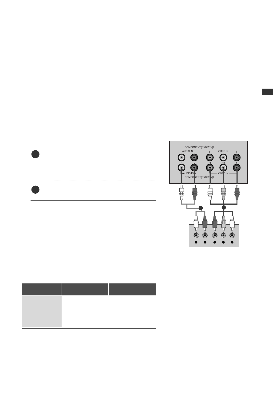
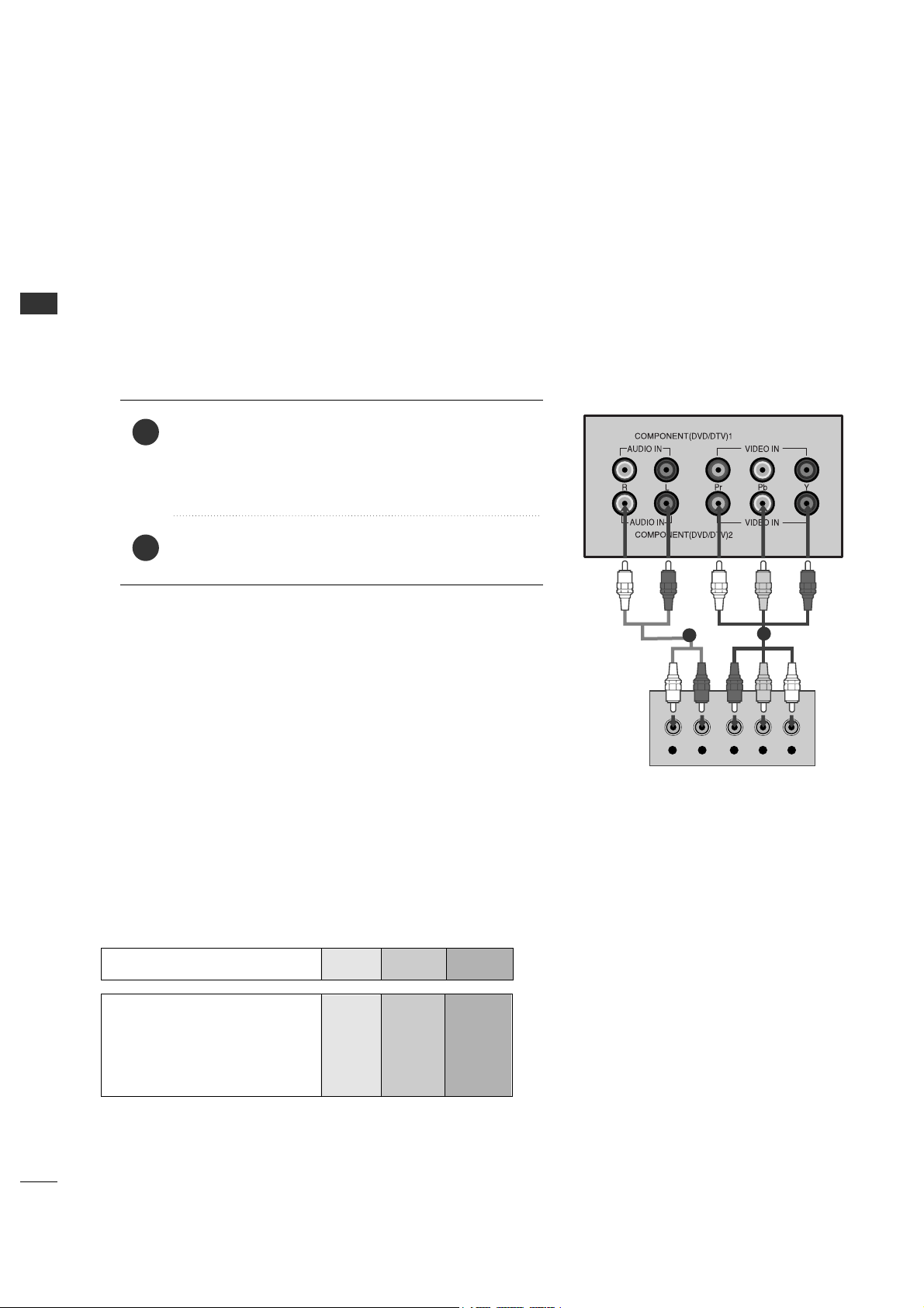
HD RECEIVER SETUP
This TV can receive Digital Over-the-air/Cable signals without an external digital set-top box. However, if you do
receive digital signals from a digital set-top box or other digital external device, refer to the figure as shown below.
L R Y PB PR
When connecting Component cable
2
1
1. How to connect
Connect the audio output of the digital set-top box to
the CCOOMMPPOONN EENNTT((DDVVDD//DDTTVV))11 jacks on the set.
Connect the video outputs (Y, PB, PR) of the digital set
top box to the CCOOMM PPOONNEENNTT((DDVVDD//DDTTVV))11 jacks on
the set. Match the jack colors
(Y = green, PB = blue, and PR = red).
2
1
2. How to use
■
Turn on the digital set-top box.
(Refer to the owner’s manual for the digital set-top box.
operation)
■
Select CCoommppoonneenntt11 input source by using the TTVV//AAVV
button on the remote control.
■
If connected to CCOOMMPPOONN EENNTT((DDVV DD//DDTTVV))22 input,
select CCoommppoonneenntt22 input source.
■
To prevent the equipment damage, never plug in any power cords until you have finished connecting all
equipment.
Signal
480i
480p
720p
1080i
Component 1/2
Yes
Yes
Yes
Yes
HDMI1/DVI,
HDMI2
No
Yes
Yes
Yes
EXTERNAL EQUIPMENT SETUP
12
EXTERNAL EQUIPMENT SETUP
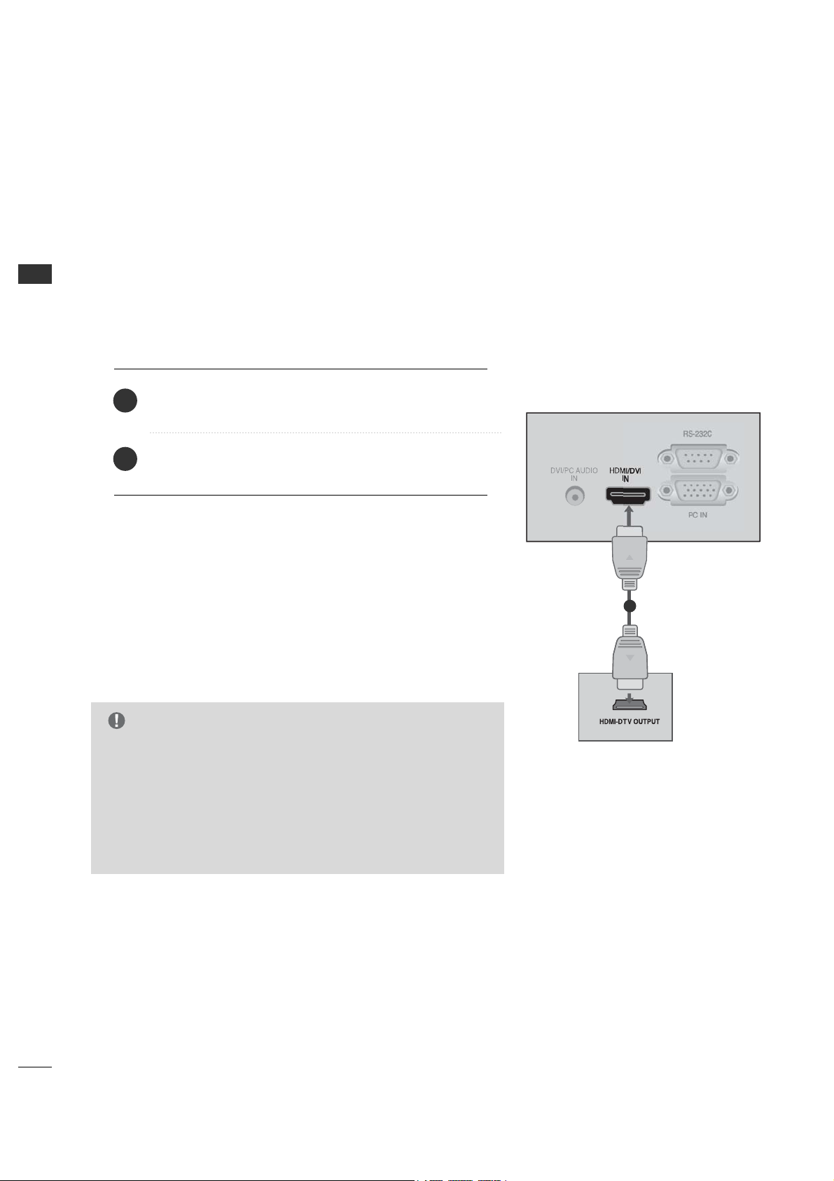
When connecting HDMI cable
No separated audio connection is necessary.
HDMI supports both audio and video.
Connect the digital set-top box to HHDDMMII//DDVVII IINN jack on
the set.
1. How to connect
2. How to use
■
Turn on the digital set-top box.
(Refer to the owner’s manual for the digital set-top box.)
■
Select HHDDMMII input source by using the TT VV //AA VV button
on the remote control.
1
2
1
G
When connected, the TV will tell a connected device what
resolution it supports and the resolution it prefers. If the device
supports this Auto HDMI function, the player output resolution
will be automatically set to 720p.
G
If the device does not support Auto HDMI, you need to set the
output resolution appropriately.
NOTE
EXTERNAL EQUIPMENT SETUP
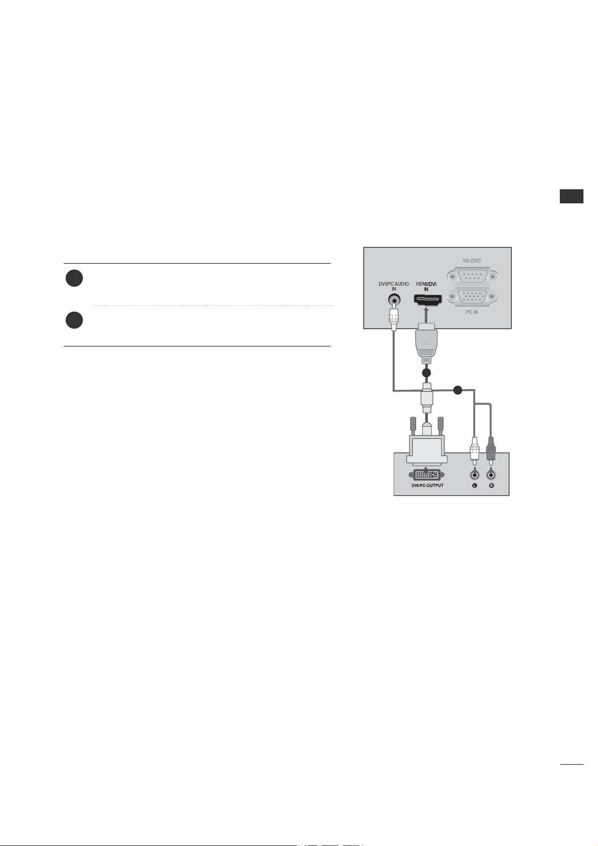
13
Connect the audio output of the digital set-top box to
the DDVVII//PPCC AAUUDDIIOO IINN jack on the set.
Connect the DVI output of the digital set-top box to the
HHDDMMII//DDVVII IINN jack on the set.
1. How to connect
■
Turn on the digital set-top box. (Refer to the owner’s
manual for the digital set-top box.)
■
Select HHDDMMII input source by using the TT VV //AA VV button
on the remote control.
2. How to use
2
1
1
2
When connecting HDMI to DVI cableWhen connecting HDMI to DVI cable
EXTERNAL EQUIPMENT SETUP
14
EXTERNAL EQUIPMENT SETUP
DVD SETUP
When connecting Component cable
To get better picture quality, connect a DVD player to the component input ports as shown below.
Component Input ports
Component ports on the TV
YPB PR
Video output ports
on DVD player
Y
Y
Y
Y
P
B
B-Y
Cb
Pb
P
R
R-Y
Cr
Pr
Connect the audio outputs of the DVD to the
CC OOMMPPOONNEENNTT((DDVVDD//DDTTVV ))11 jacks on the set.
Connect the video outputs (Y, PB, PR) of the DVD to
the CCOOMMPPOONNEE NNTT ((DDVVDD//DDTTVV ))11 jacks on the set.
Match the jack colors
(Y = green, PB = blue, and PR = red).
1. How to connect
2. How to use
■
Turn on the DVD player, insert a DVD.
■
Select CCoommppoonneenntt11 input source by using the TT VV //AAVV
button on the remote control.
■
If connected to CCOOMMPPOONNEENNTT((DDVVDD//DDTT VV))22 input,
select CCoommppoonneenntt22 input source.
■
Refer to the DVD player's manual for operating instructions.
2
1
L R Y PB PR
2
1
EXTERNAL EQUIPMENT SETUP
15
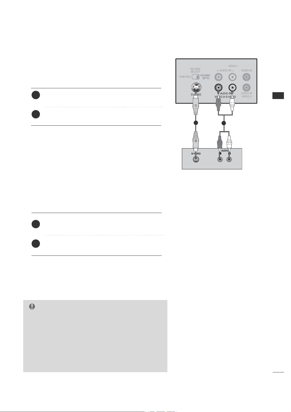
When connecting with an S-Video cable
2
3
When connecting HDMI cable
No separated audio connection is necessary.
HDMI supports both audio and video.
Connect the HDMI output of the DVD to the
HHDDMMII//DDVVII IINN jack on the set.
1. How to connect
2. How to use
■
Select HHDDMMII input source by using the TTVV// AAVV button on
the remote control.
■
Refer to the DVD player's manual for operating instructions.
G
When connected, the TV will tell a connected device what
resolution it supports and the resolution it prefers. If the device
supports this Auto HDMI function, the player output resolution
will be automatically set to 720p.
G
If the device does not support Auto HDMI, you need to set the
output resolution appropriately.
To get the best picture quality, adjust the output resolution of
the DVD to 720p.
NOTE
Connect the audio outputs of the VCR to the AA UU DD II OO
input jacks on the set.
Connect the S-VIDEO output of the VCR to the
SS--VV IIDD EEOO input on the set.
1. How to connect
2
1
1
2
EXTERNAL EQUIPMENT SETUP
16
EXTERNAL EQUIPMENT SETUP
VCR SETUP
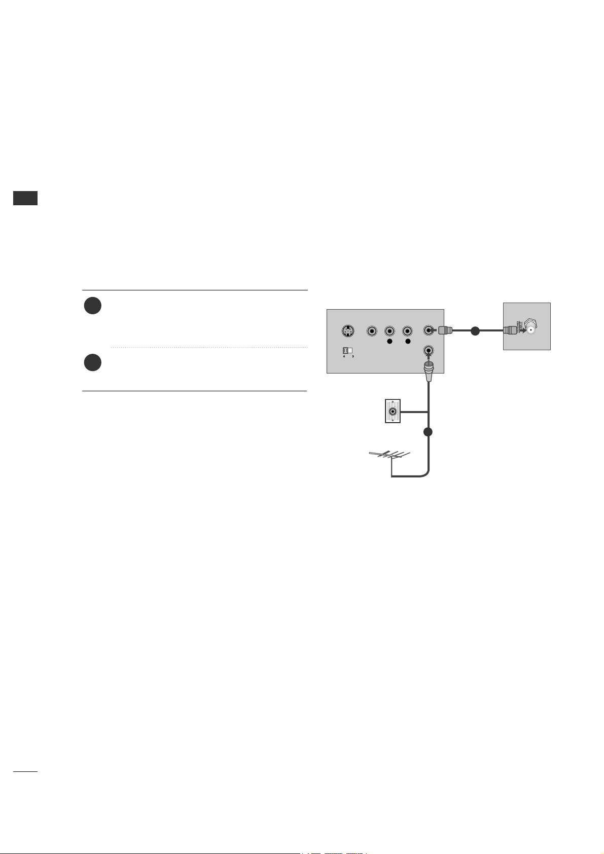
When connecting with an antenna
■
To avoid picture noise (interference), leave an adequate distance between the VCR and TV.
■
If the 4:3 picture format is used; the fixed images on the sides of the screen may remain visible on the screen.
This phenomenon is common to all manufactures and in consequence the manufactures warranty does not cover
the product bearing this phenomenon.
L R
S-VIDEO VIDEO
OUTPUT
SWITCH
ANT IN
ANT OUT
Wall Jack
Antenna
1
2
Connect the antenna cable to the RF antenna
in socket of the VCR.
Connect the RF antenna out socket of the
VCR to the AANNTTEENNNNAA//CCAABBLLEE socket on
the set.
1. How to connect
■
Set VCR output switch to 3 or 4 and then tune
TV to the same channel number.
■
Insert a video tape into the VCR and press PLAY
on the VCR. (Refer to the VCR owner’s manual.)
2. How to use
2
1
EXTERNAL EQUIPMENT SETUP
17
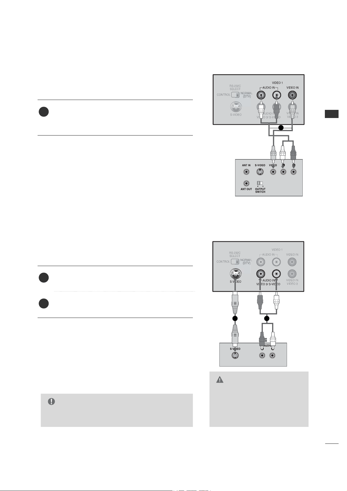
When connecting with a RCA cable
Connect the VVIIDDEEOO11 jacks between TV and VCR. Match
the jack colors (Video = yellow, Audio Left = white, and
Audio Right = red)
1. How to connect
2. How to use
■
Insert a video tape into the VCR and press PLAY on the
VCR. (Refer to the VCR owner’s manual.)
■
Select AA VV 11 input source by using the TT VV // AAVV button on
the remote control.
■
If connected to VVIIDDEEOO33, select AA VV 33 input source.
When connecting with an S-Video cable
Connect the audio outputs of the VCR to the AA UU DD IIOO
IINN jacks on the set.
Connect the S-VIDEO output of the VCR to the
SS--VV IIDD EEOO input on the set.
1. How to connect
2. How to use
■
Insert a video tape into the VCR and press PLAY on the
VCR. (Refer to the VCR owner’s manual.)
■
Select SS-- VV II DD EEOO input source by using the TT VV //AAVV but-
ton on the remote control.
1
2
1
1
1 2
G
The picture quality is improved: compared to normal
composite (RCA cable) input.
NOTE
G
Do not connect to both Video and
S-Video at the same time. In the
event that you connect both
Video and the S-Video cables, only
the S-Video will work.
CAUTION
EXTERNAL EQUIPMENT SETUP
18
EXTERNAL EQUIPMENT SETUP
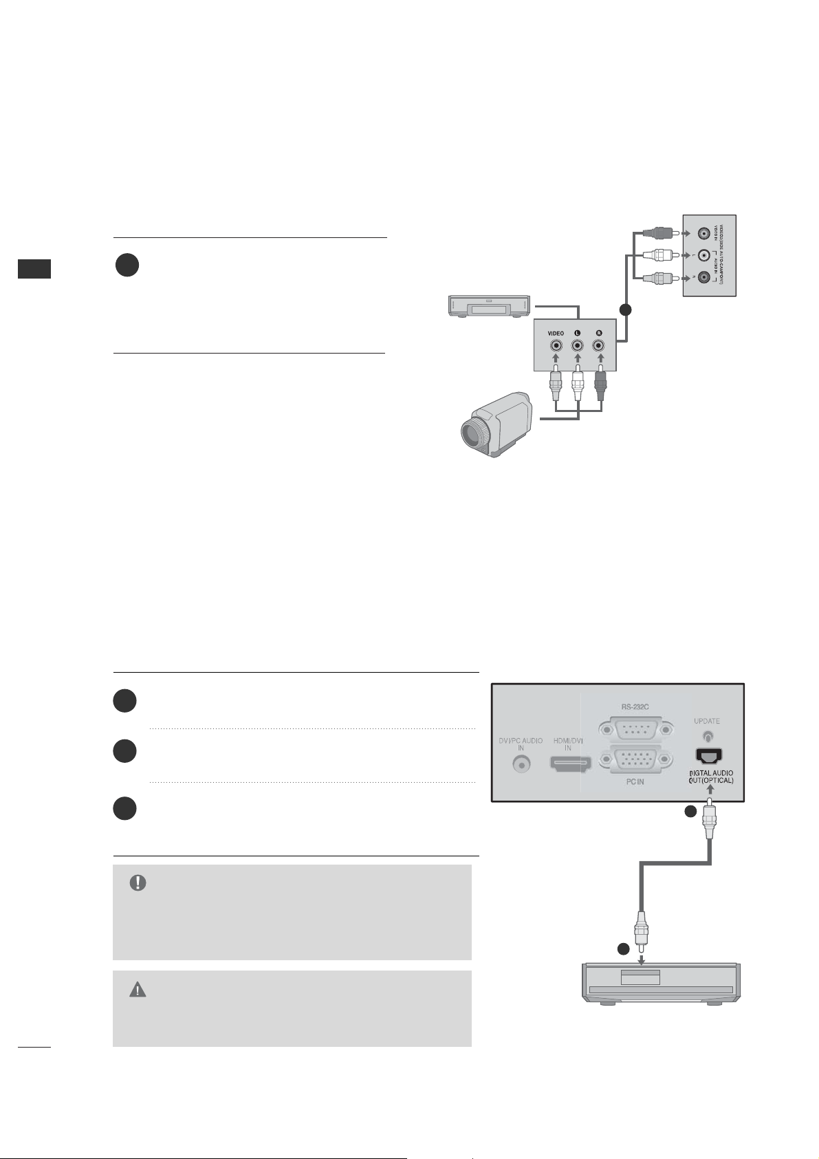
OTHER A/V SOURCE SETUP
Connect the VVIIDDEEOO22 jacks between
TV and external equipment. Match the
jack colors.
(Video = yellow, Audio Left = white, and
Audio Right = red)
1. How to connect
2. How to use
■
Select AA VV 22 input source by using the TT VV //AAVV
button on the remote control.
■
Operate the corresponding external equipment.
1
■
Send the TV’s audio to external audio equipment via the Digital Audio Output (Optical) port.
Connect the other end of the optical cable to the
digital audio (optical) input on the audio equipment.
Set the “Digital Output - Dolby Digital” in the Sound
menu. (G p.44). See the external audio equipment
instruction manual for operation.
Connect one end of an optical cable to the TV Digital
Audio (Optical) Output port.
1. How to connect
2
3
1
1
2
DIGITAL AUDIO OUTPUT
G
When connecting with external audio equipments, such
as amplifiers or speakers, please turn the TV speakers
off. (G p.46)
NOTE
G
Do not look into the optical output port. Looking at the
laser beam may damage your vision.
CAUTION
Camcorder
Video Game Set
1
ex) TV Model
EXTERNAL EQUIPMENT SETUP
19
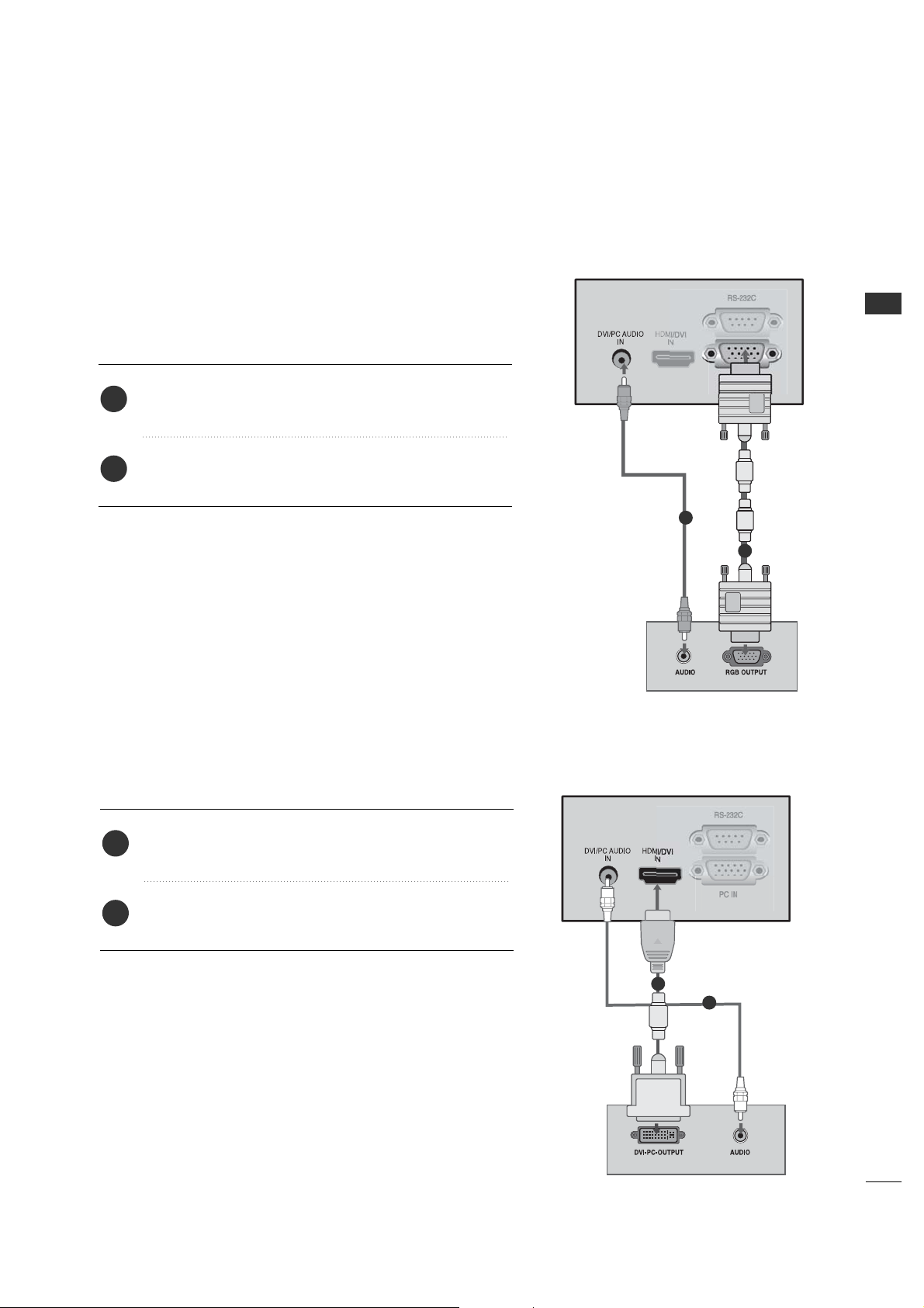
When connecting HDMI to DVI cable
Connect the PC audio output to the DDVVII//PPCC AAUUDDIIOO
IINN jack on the set.
Connect the DVI output of the PC to the HHDDMMII//DDVVII
IINN jack on the set.
1. How to connect
2. How to use
■
Turn on the PC and the TV.
■
Select HHDDMMII input source by using the TTVV// AAVV button on
the remote control.
2
1
When connecting D-sub 15pin cable
Connect the PC audio output to the DDVVII//PPCC AAUUDDIIOO
IINN jack on the set.
Connect the RGB output of the PC to the PPCC IINN jack
on the set.
1. How to connect
2. How to use
■
Turn on the PC and the TV.
■
Select PPCC input source by using the TT VV // AAVV button on the
remote control.
2
1
1
2
This TV provides Plug and Play capability, meaning that the PC adjusts automatically to the TV's settings.
PC SETUP
1
2

EXTERNAL EQUIPMENT SETUP
20
EXTERNAL EQUIPMENT SETUP
G
To get the the best picture quality, adjust the PC
graphics card to 1024x768, 60Hz.
G
Depending on the graphics card, DOS mode may
not work if a HDMI to DVI Cable is in use.
G
Check the image on your TV. There may be noise
associated with the resolution, vertical pattern,
contrast or brightness in PC mode. If noise is
present, change the PC output to another
resolution, change the refresh rate to another rate
or adjust the brightness and contrast on the
VIDEO menu until the picture is clear. If the
refresh rate of the PC graphic card can not be
changed, change the PC graphic card or consult
the manufacturer of the PC graphic card.
G
Avoid keeping a fixed image on the screen for a
long period of time. The fixed image may become
permanently imprinted on the screen.
G
The synchronization input form for Horizontal and
Vertical frequencies is separate.
RGB-PC, HDMI1/DVI-PC mode
Horizontal Vertical
Frequency
(
KHz
)
Frequency
(
Hz
)
31.469 70.08
31.469 70.08
31.469 59.94
37.879 60.31
48.363 60.00
47.776 59.87
47.720 59.799
47.130 59.65
Resolution
720x400
136 0x768
640x350
* RGB-PC mode only: 640x350, 720X400
640x480
800x600
102 4x768
HDMI1/DVI-DTV,
HDMI2-DTV mode
Horizontal Vertical
Frequency
(
KHz
)
Frequency
(
Hz
)
31.469 59.94
31.500 60.00
44.960 59.94
45.000 60.00
33.720 59.94
33.750 60.00
Resolution
720x480
128 0x720
19 20x1080i
128 0x768
136 6x768
Supported Display Specifications
NOTE
EXTERNAL EQUIPMENT SETUP
21
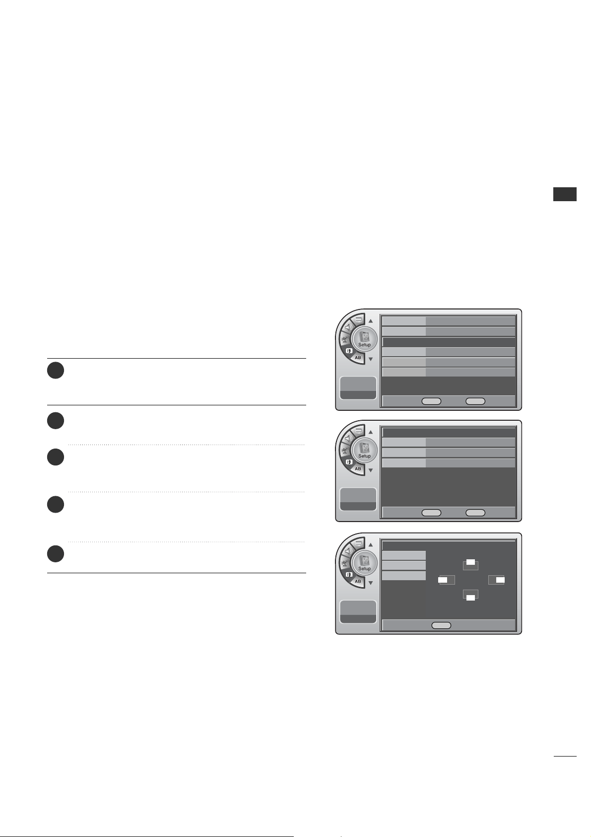
SCREEN SETUP FOR PC MODE
When the RGB input of the set is connected to a PC output,
select the RGB-PC as the main input mode.
When HDMI/DVI connect to PC output and select HDMI/DVI
input, this function is used.
After connecting RGB-PC or HDMI/DVI to PC input and
checking the screen quality.
When you change the resolution, select the proper resolution
in pre-sent input to see the best picture appearance.
Overview
Position
G
Frequency 50
Phase 98
Auto
--:-- --
--. -- ----
F G Move OK Select Menu Back
Position
Frequency
Phase
Auto
--:-- --
--. -- ----
DEF G Move Menu Back
Time
V-Chip
PC
G
Menu Language English
Menu Transparency
Semi Opaque
Set ID 1
11:20 PM
Sep.11, 2006
DE
Move OK Select Menu Back
D
FG
E
Adjustment for screen Position,
Frequency, Phase and Auto
Press the MM EE NN UU button and then use the AADD JJ D or E
button to highlight the SSeett uupp menu and press the OO KK
((EE nnttee rr)) button.
1
Use the AADDJJ D or E button to highlight PPCC and press
the OOKK ((EEnn tteerr )) button.
2
Use the AADDJJ D or E button to highlight PPoossiittiioonn,
FFrreeqquueennccyy,PPhhaassee,AAuuttoo and press the OOKK (( EEnntteerr ))
button.
3
Use the AADDJJ DEF G button to make appropriate
adjustment. When finished, press OOKK ((EEnnttee rr)) button.
■
The FFrreeqquueennccyy, PPhhaa ssee adjustment range is 00~110000.
4
When finished, press MM EENN UU repeatedly to remove the
menus.
5
EXTERNAL EQUIPMENT SETUP
22
EXTERNAL EQUIPMENT SETUP
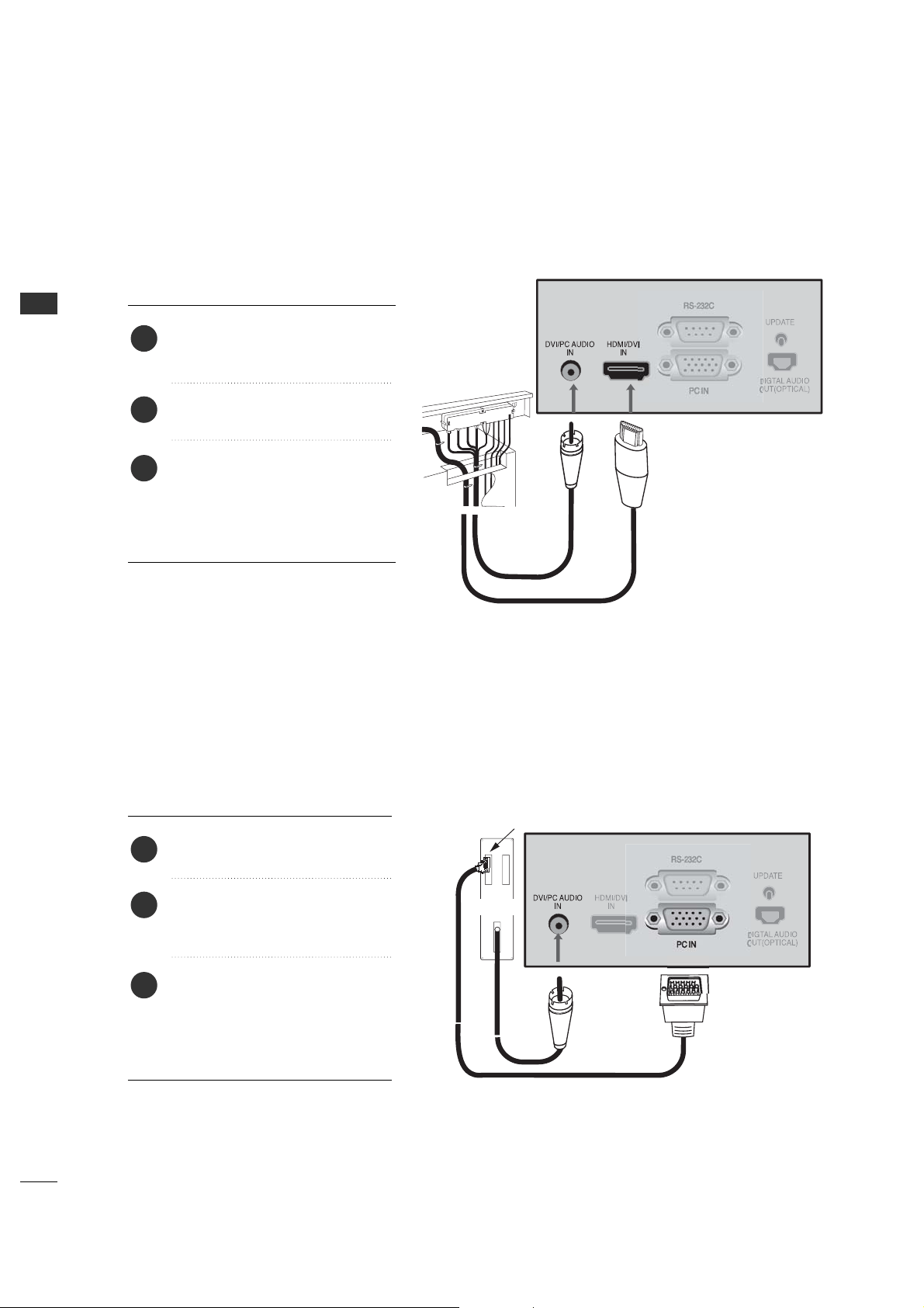
DVI HOOKUP TO RJP OR DVD PLAYER
Connect a DVI cable between the
RJP and DVI in port on the TV.
Locate the DVI out port on the
RJP (Remote Jack Pack) or DVI
device.
1. How to connect
2
If required, make Audio connections
as indicated to the right.
After all connections have been
made, select the DVI source to
display the DVI image on the TV.
3
1
COMPUTER PC HOOKUPCOMPUTER PC HOOKUP
Locate the computer out port on
the computer.
1. How to connect
2
Make PC Audio connections as
indicated to the right.
After all connections have been
made, select the PC source to
display the PC image on the TV.
3
1
Connect a computer cable
between the computer and PC
In on the TV.
Computer Output
Back of
Computer
Audio Out
WATCHING TV / CHANNEL CONTROL
23
WATCHING TV / CHANNEL CONTROL
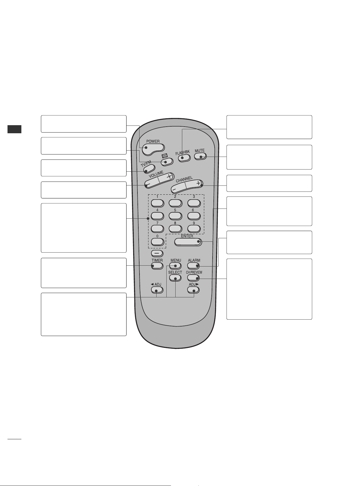
USER REMOTE CONTROL BUTTON FUNCTIONS
POWERMUTE
TV/AV
CH
PREVIEW
GUIDE
SAP INFO
123
456
7
-
89
0
CC
TIMER
FLASHBK
CH
CH
VOL
OK
VOL
ALARM
User
Remote Control
MUTE
Turns sound Off and On, while the picture
remains.
CHANNEL PREVIEW
Displays available TV channels, and (if
active) the Guest Parental Control menu:
set V-Chip blocks to restrict both analog
and digital programming.
• Aux Channel allows the guest to select
the Audio / Video inputs. (Use the A/V
jacks on the back of the TV as a source).
[-] BUTTON
When selecting a digital broadcast
channel, key in the Main channel number
followed by the -> [-] -> then the sub
channel number. Analog channels do not
contain a sub channel number.
INFO
Check the current program information,
screen status, multi-sound status and time.
Press with Guide onscreen for more
Program information.
CC
Press to activate English subtitles.
POWER
Turns TV On or Off.
FLASHBK (FLASHBACK)
Use to return to the last channel viewed.
NUMBER BUTTONS
Use for direct channel entry.
GUIDE
Use to view DTV program information.
Press INFO for additional information.
ALARM
Use to go to the Alarm menu. Set a time for
the TV to turn itself on.
TIMER
Press repeatedly to select a preset time to
automatically shut the TV off.
VOLUME / CHANNEL / OK (Enter)
Increase or decrease the volume / Change
channels.
Select on-screen menu items and change
menu values.
SAP
Selects MTS sound: Mono, Stereo, and
SAP in analog mode. Change the audio
language in DTV mode.
TV/AV
Displays a menu of all available input
sources.
A brief list of the buttons on the optional user’s remote and what they do.
WATCHING TV / CHANNEL CONTROL
24
WATCHING TV / CHANNEL CONTROL
INSTALLER REMOTE CONTROL BUTTON FUNCTIONS
A brief list of the buttons on the optional installer’s remote and what they do.
Installer
Remote Control
POWER
Turns TV On or Off.
TV/FM
Not application
VOLUME (-/+)
Decreases/increases sound level.
CC (Closed Captioning)
Press to access closed captions.
TIMER
Press repeatedly to select a preset
time to automatically shut the TV
off.
NUMBER KEYPAD
When selecting a digital broadcast
channel, key in the Main channel
number followed by the -> [-] ->
then the sub channel number.
Analog channels do not contain a
sub channel number.
MENU/SELECT/ADJ (Adjust)
Press to display the main on-screen
menu.
Use SELECT to choose an option
and ADJ (adjust) Left/Right to
change the selected option.
FLASHBK (Flashback)
Returns to the previous channel
viewed.
CHANNEL (-/+)
Tunes to next available channel.
MUTE
Turns sound Off and On, while the
picture remains.
CHANNEL PREVIEW
Displays available TV channels, and
(if active) the Guest Parental Control
menu: set V-Chip blocks to restrict
both analog and digital programming.
• Aux Channel allows the guest to
select the Audio / Video inputs.
(Use the A/V jacks on the back of
the TV as a source).
ALARM
Use to go to the Alarm menu. Set a
time for the TV to turn itself on.
ENTER (OK)
Press to view the Channel/Time
display or to remove any on-screen
display or menu.
WATCHING TV / CHANNEL CONTROL
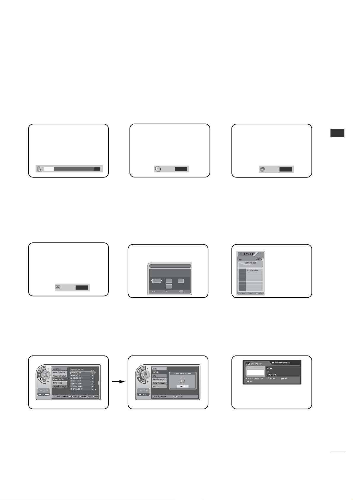
25
Use the remote keys indicated below to access these menus and displays.
In this manual, the OSD (On Screen Displays shown) may be different. The following are just generic examples
to familiarize you with the TVs options.
ON-SCREEN MENUS SELECTION
Volume Display
Press VOLUME.
Shows currently selected sound
setting.
Sleep Timer Menu
Press TIMER.
Sets a time to automatically turn the
TV off and shows remaining time
before TV shutoff.
SAP Display
Selects MTS sound: Mono, Stereo,
and SAP in analog mode. Change
the audio language in DTV mode.
Caption Display
Press the CC.
Turns selected option on or off. See
Closed Captions page to select
options.
Alarm Timer
Current Time 11:17 AM
Exit
AdjustMove
OK
Hr.
Off
Min.
Alarm Display
Press the ALARM.
Set a time for the TV to turn itself
on.
Guide Display
Press the GUIDE to view DTV
program information.
Channel Preview
Press the CH PREVIEW.
Displays available TV channels.
V-Chip
Press the CC.
Move to the V-Chip menu.
INFO
Press the INFO.
Check the current program
information.
21
SAP
Stereo
1
2
6
9
3
TIMER
Off
CAPTION
OFF
GF
GF
WATCHING TV / CHANNEL CONTROL
26
WATCHING TV /CHANNEL CONTROL
G
Auto Program finds channels being received by the TV’s
analog and digital tuners.
G
Cable will not work unless you subscribe to a cable
service.
NOTE
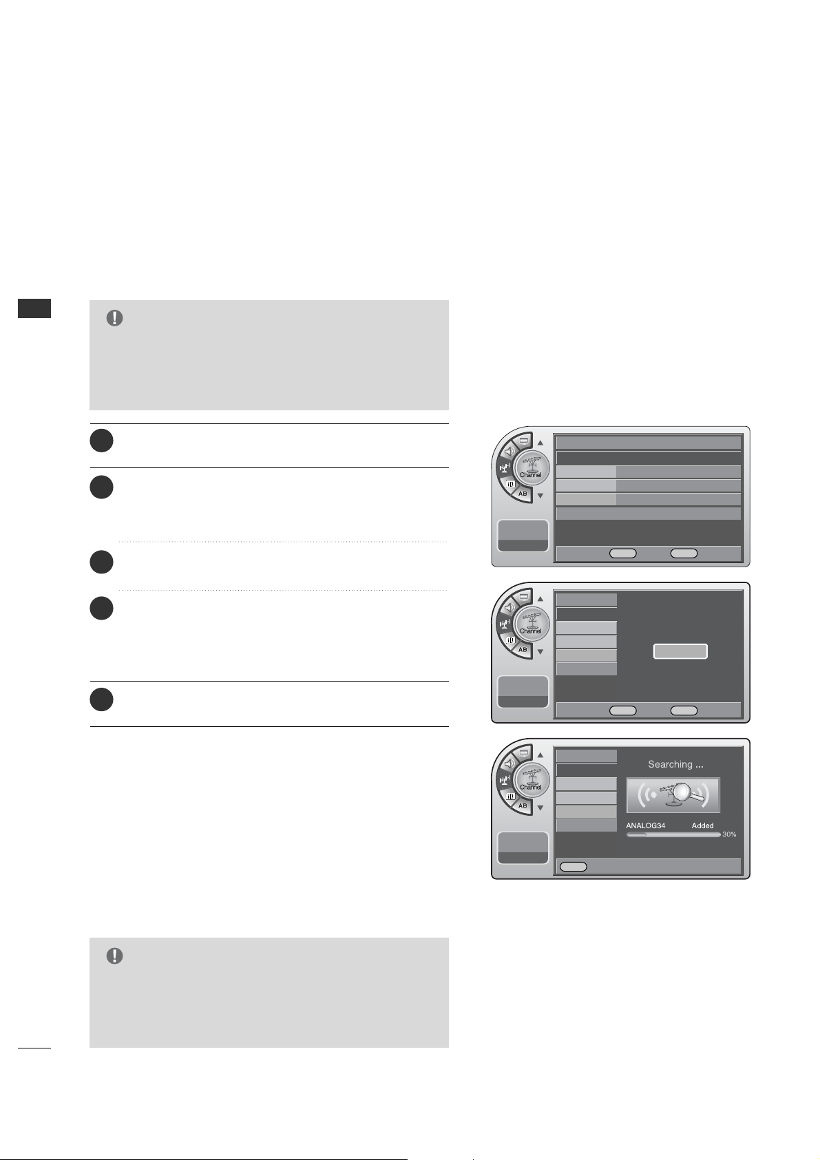
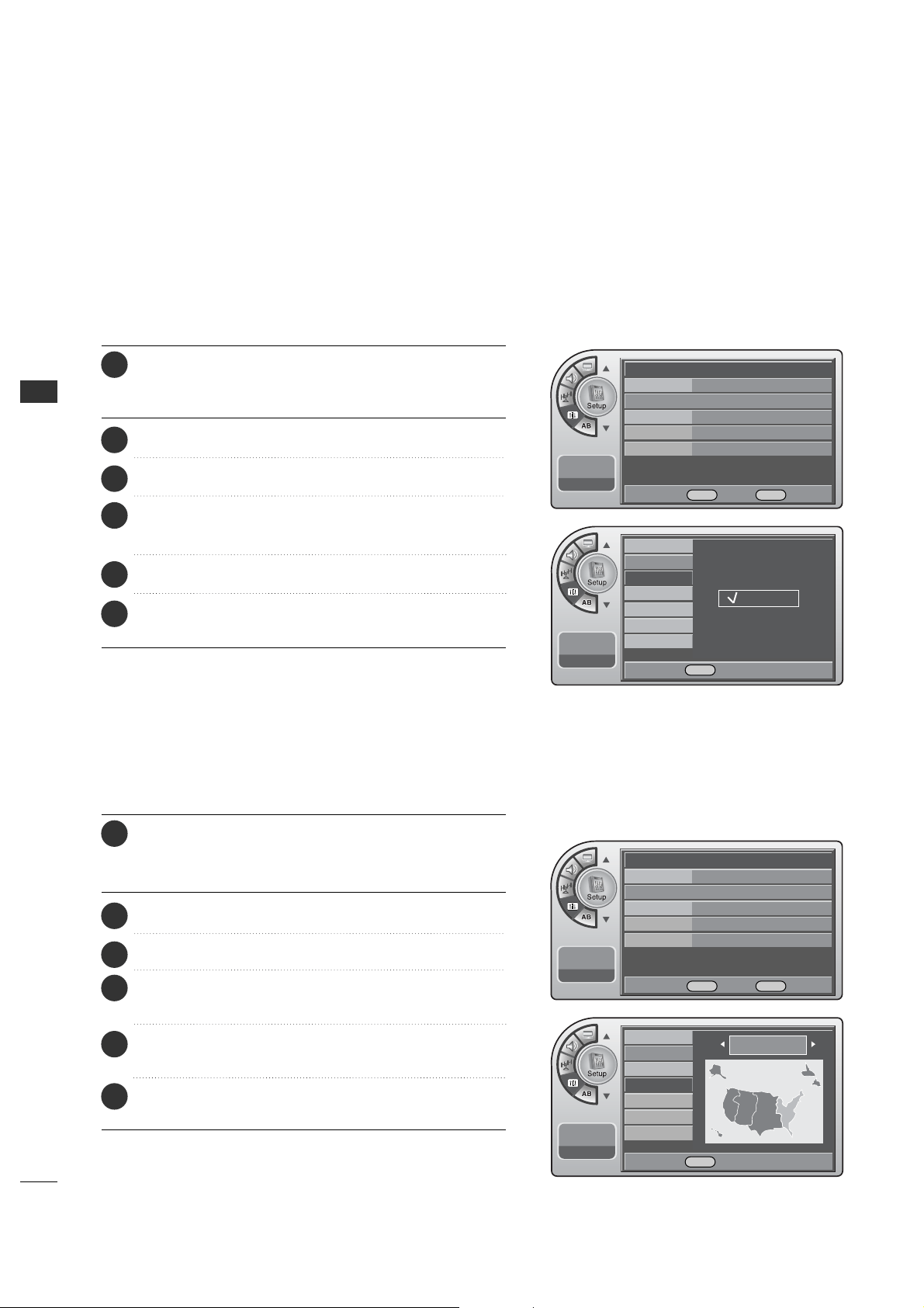
CHANNEL SEARCH
With the optional Installer remote control in hand and
press the PPOOWWEERR button to turn the TV on.
Use Auto Program to automatically find and store all of the
channels available in the selected Tuning Band.
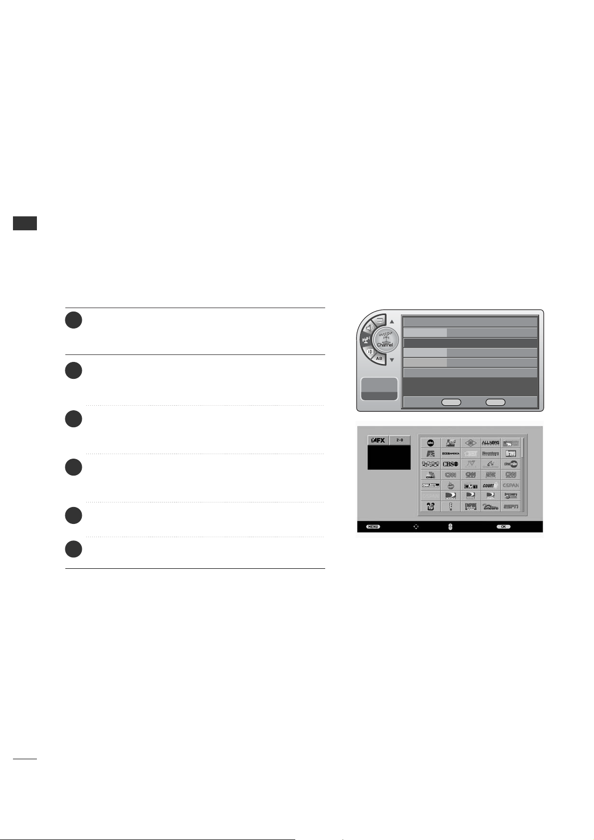
1
When finished, press MM EENN UU repeatedly to remove the
menus.
5
Press the MM EE NN UU button and then use the AADD JJ D or E
button to highlight the CChhaannnneell menu and press the
OOKK ((EEnnttee rr)) button.
2
Press the OOKK ((EE nn tteerr )) button to highlight
AAuuttoo pprrooggrraamm.
3
Press the OOKK (( EEnntteerr )) button to start the channel
search.
After finding all available channels, a display appears briefly
showing the number of analog and digital channels found.
4
Auto Program (Channel Search)
G
Tuning Band must be set before doing the channel
search. See Installer menu item 003 Band/AFC. Default
setting is 1, for CATV. When Auto Program is run, any
assigned channel labels are automatically removed.
NOTE
Antenna
Auto Program G
Channel Label
Channel List
Fine Tune Auto
Signal Strength
--:-- --
--. -- ----
Antenna
Auto Program
Channel Label
Channel List
Fine Tune
Signal Strength
--:-- --
--. -- ----
Antenna
Auto Program
Channel Label
Channel List
Fine Tune
Signal Strength
--:-- --
--. -- ----
Press OK to Search
Yes
DE
Move OK Select Menu Back
F G Move OK Select Menu Back
Menu Back

WATCHING TV / CHANNEL CONTROL
27
G
If you delete a found channel, it isn’t gone forever.
Simply re-enter the Channel List menu and re-add the channel
to show the check mark.
NOTE
After the channel search, remove unwanted channels.
Channel List
Press the MM EE NN UU button and then use the AADD JJ D or E
button to highlight the CChhaannnneell menu and press the
OOKK ((EEnnttee rr)) button.
1
Use the AADDJJ D or E button to highlight CChhaannnneell LLiisstt
and press the OOKK ((EEnntteerr )) button.
2
Use the AADDJJ D or E button to highlight the channel
you wish to delete and press the AA DD JJ G button.
The AADDJJ G button toggles the check mark on and off.
If the check mark appears next to the channel number,
the channel appears in the channel scan.
3
When finished, press MM EENN UU repeatedly to remove the
menus.
4
Antenna
Auto Program
Channel Label
Channel List
Fine Tune
Signal Strength
--:-- --
--. -- ----
Antenna
Auto Program
Channel Label
Channel List
G
Fine Tune Auto
Signal Strength
--:-- --
--. -- ----
DE
Move OK Select Menu Back
DEMove G Add/Del OK View Menu Back
WATCHING TV / CHANNEL CONTROL
28
WATCHING TV /CHANNEL CONTROL
Channel Labels help the user identify the channel or network
being viewed.
In the Setup menu with the Channel Labels option highlighted,
use the AA DDJJ
DD EE FF GG
buttons to scroll through the
available channel labels, such as, A&E, AMC, ESPN, HBO, etc.
These are a series of preset labels from which you can choose
the more common networks. Use any of these to label the
channels in the TV’s memory.
Channel Labels Setup
Press the MM EE NN UU button and then use the AADD JJ D or E
button to highlight the CChhaannnneell menu and press the
OOKK ((EEnnttee rr)) button.
1
Use the AADDJJ D or E button to highlight CChhaannnneell
LLaabbeell and press the OOKK ((EEnntteerr )) button.
This action displays the CChhaannnneell LLaabbeell menu.
2
Use CChhaannnneell D or E (+ / -) button to select channels
and the AADDJJ DEF Gbuttons to navigate the labels
menu.
3
When the label is highlighted you want for the channel
shown in the screen and press OOKK ((EEnntteerr )) button to
add the label to the channel.
4
Select the next channel to label with CChhaannnneell D or E
(+ / -) button to or if finished channel labeling.
5
Antenna
Auto Program
Channel Label
G
Channel List
Fine Tune Auto
Signal Strength
--:-- --
--. -- ----
DE
Move OK Select Menu Back
Previous
Move
Change Ch. Add/DeleteCH
When finished, press MM EENN UU repeatedly to remove the
menus.
6
WATCHING TV / CHANNEL CONTROL
29
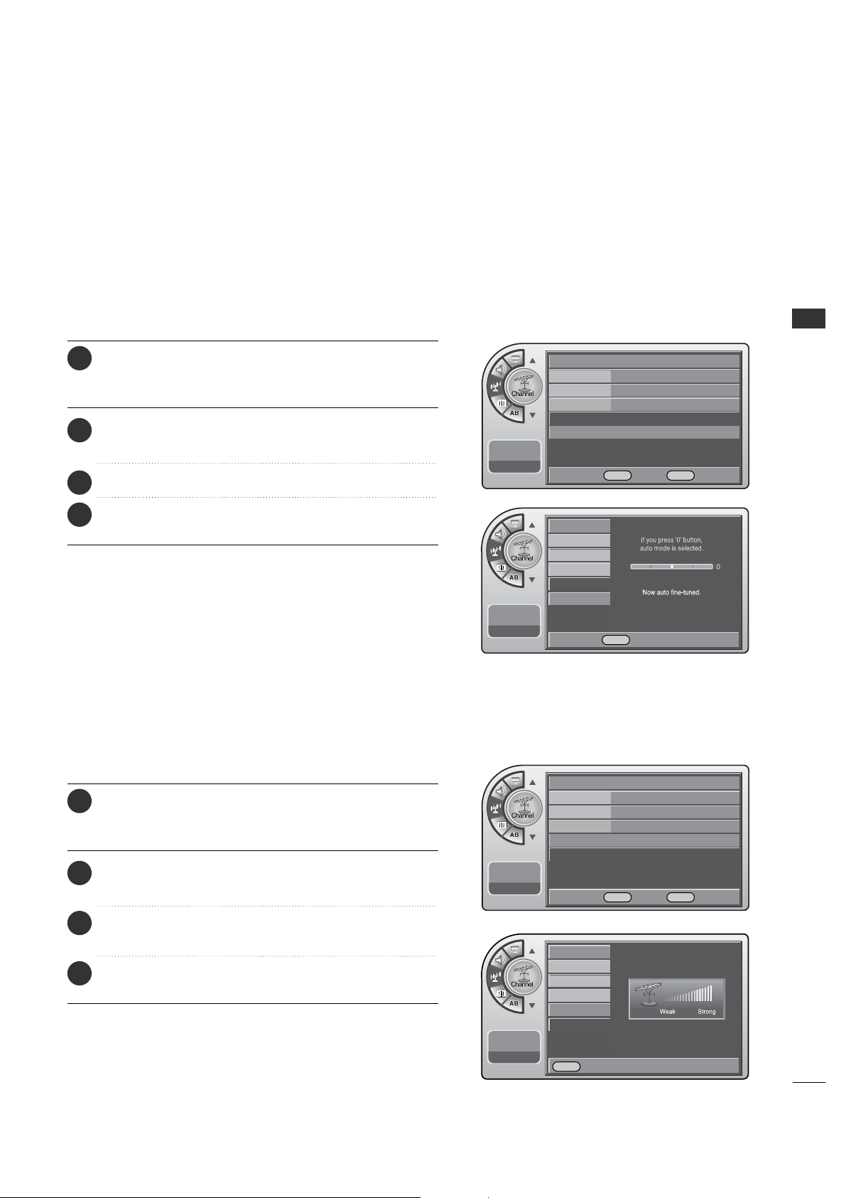
If a dashed line or no color appears, the screen is unstable,
therefore try channel adjustments.
(This is only available for analog broadcasting.)
Unstable Screen
Press the MM EE NN UU button and then use the AADD JJ D or E
button to highlight the CChhaannnneell menu and press the
OOKK ((EEnnttee rr)) button.
1
Use the AADDJJ D or E button to highlight FFiinnee TTuunnee and
press the OOKK ((EEnn tteerr )) button.
2
Press the AA DDJJ F or G button to adjust.
3
When finished, press MM EENN UU repeatedly to remove the
menus.
4
This shows the current digital signal strength as a picture.
(This is only available for digital broadcasting.)
Checking the Strength of the Digital Signal
Press the MM EE NN UU button and then use the AADD JJ D or E
button to highlight the CChhaannnneell menu and press the
OOKK ((EEnnttee rr)) button.
1
Use the AADDJJ D or E button to highlight SSiiggnnaall SSttrreennggtthh
and press the OOKK ((EEnntteerr )) button.
2
View the on-screen signal strength monitor to see the
quality of the signal being received.
3
When finished, press MM EENN UU repeatedly to remove the
menus.
4
Antenna
Auto Program
Channel Label
Channel List
Fine Tune Auto
G
Signal Strength
--:-- --
--. -- ----
DE
Move OK Select Menu Back
Antenna
Auto Program
Channel Label
Channel List
Fine Tune
Signal Strength G
--:-- --
--. -- ----
DE
Move OK Select Menu Back
Antenna
Auto Program
Channel Label
Channel List
Fine Tune
Signal Strength
--:-- --
--. -- ----
F G Adjust Menu Back
Antenna
Auto Program
Channel Label
Channel List
Fine Tune
Signal Strength
--:-- --
--. -- ----
Menu Back
TIME SETTING
30
TIME SETTING
CLOCK SETTING
Use the AADDJJ DEF Gbuttons to set the year, month, day,
hours and minutes.
Manual Time Settings
OOnn--OOffff TTiimmeerrss SSeettuupp
Set the On-Off Timers using the procedures described above.
--:-- --
--. -- ----
Clock Manual G
Manual Clock
Daylight Saving
Time Zone
On Timer
Off Timer
Auto Off Off
--:-- --
--. -- ----
Clock
Manual Clock
Daylight Saving
Time Zone
On Timer
Off Timer
Auto Off
Time
G
V-Chip
PC
Menu Language English
Menu Transparency
Semi Opaque
Set ID 1
--:-- --
--. -- ----
G
If you intend to use the On-Off Timers, it is best to set
the clock manually.
NOTE
DE
Move OK Select Menu Back
DE
Move OK Select Menu Back
--:-- --
--. -- ----
Clock Manual
Manual Clock
G
Daylight Saving
Time Zone
On Timer
Off Timer
Auto Off Off
DE
Move OK Select Menu Back
--:-- --
--. -- ----
Clock
Manual Clock
Daylight Saving
Time Zone
On Timer
Off Timer
Auto Off
Auto
Manual
DE Select Menu Back
DEAdjust F G Move Menu Back
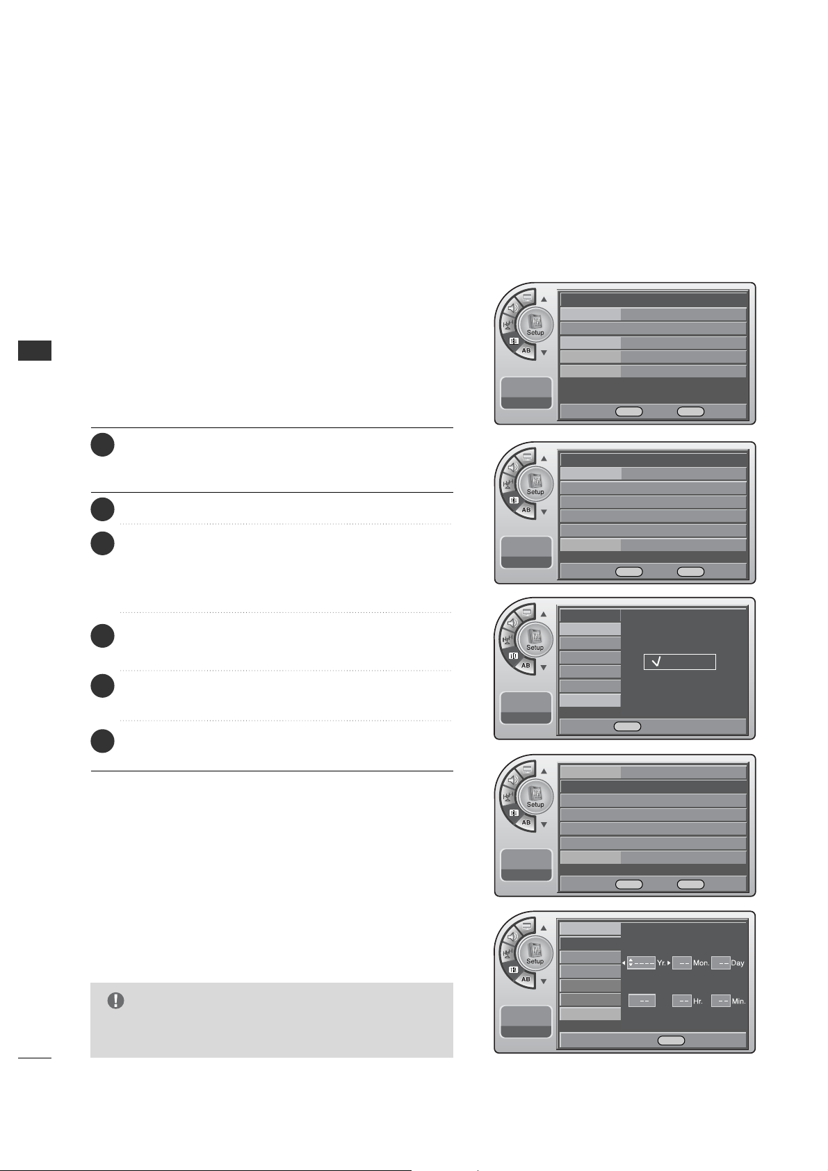
Press the MM EE NN UU button and then use the AADD JJ D or E
button to highlight the SS ee tt uupp menu and press the OO KK
((EE nnttee rr)) button.
1
Use the AADDJJ D or E button to the TTiimm ee.
2
Press the OOKK (( EEnntteerr )) button to highlight CClloocckk.
Manual or Auto will appear on the menu next to clock. If
manual is selected, on the menu use the AADD JJ D or E button
to highlight MMaannuu aa ll and press the OO KK (( EEnntteerr )) button.
3
Use the AADDJJ DEF Gbuttons to set the year, month,
day, hours and minutes.
5
Use the AADDJJ D or E button to highlight MMaannuuaall CClloocckk
and press the OOKK ((EEnntteerr ))button.
4
When finished, press MM EENN UU repeatedly to remove the
menus.
6
31
TIME SETTING
Mini glossary
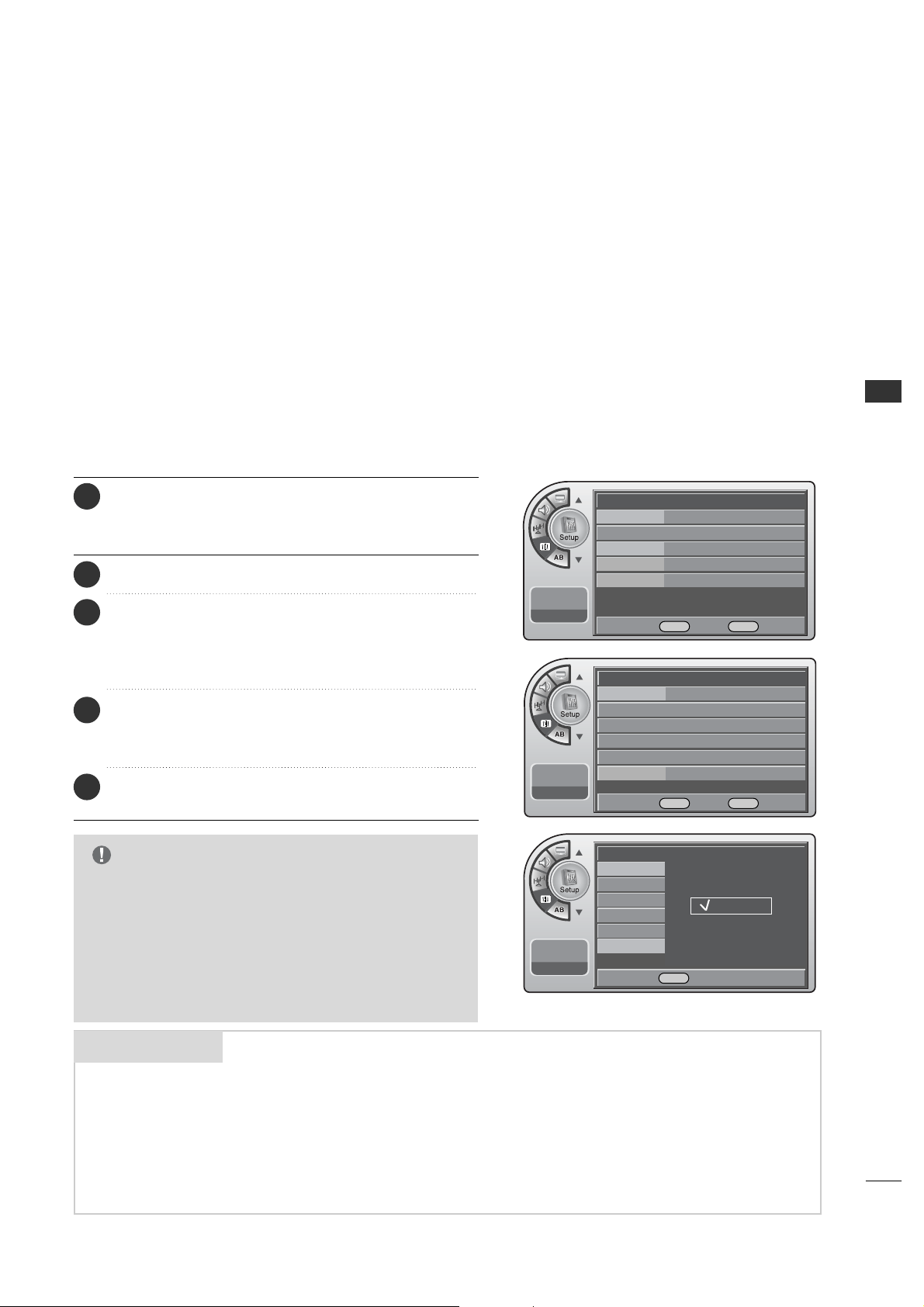
If you select auto time setting, time will be set from the
digital broadcast information.
Automatic Time Settings
G
Caution: Some digital channels may change the time
incorrectly using the Automatic Clock Set feature.
G
In this event, the Alarm may not function as intended
and the TV may not turn on at the expected time.
G
If the end user will have access to the Alarm, it may be
best to use the Manual Clock Set mode and set the
clock to local time manually.
NOTE
A four-digit figure broken down into hours and minutes, used to enter the current
time when setting the clock or wake-up alarm.
First two digits that are entered when setting the clock or the wake-up alarm.
TIME
HOURS
The last two digits that are entered when setting the clock, or the wake-up alarm.
MINUTES
Time
G
V-Chip
PC
Menu Language English
Menu Transparency
Semi Opaque
Set ID 1
--:-- --
--. -- ----
DE
Move OK Select Menu Back
--:-- --
--. -- ----
Clock Manual G
Manual Clock
Daylight Saving
Time Zone
On Timer
Off Timer
Auto Off Off
DE
Move OK Select Menu Back
--:-- --
--. -- ----
Auto Off
Clock
Manual Clock
Daylight Saving
Time Zone
On Timer
Off Timer
Auto
Manual
DE Select Menu Back
Press the MM EE NN UU button and then use the AADD JJ D or E
button to highlight the SSeett uupp menu and press the OO KK
((EE nnttee rr)) button.
1
Use the AADDJJ D or E button to the TTiimm ee.
2
Press the OOKK (( EEnntteerr )) button to highlight CClloocckk.
Manual or Auto will appear on the menu next to clock.
Select Auto on the sub-menu with the AADDJJ D or E
button and press the OO KK ((EEnntteerr )) button.
3
Use the AADDJJ DEF Gbuttons to set the Daylight
Savings and Time Zone options for your local area.
See the next page.
4
When finished, press MM EENN UU repeatedly to remove the
menus.
5
TIME SETTING
32
TIME SETTING
Time
G
V-Chip
PC
Menu Language English
Menu Transparency
Semi Opaque
Set ID 1
11:20 PM
Sep.11, 2006
DE
Move OK Select Menu Back
Time
G
V-Chip
PC
Menu Language English
Menu Transparency
Semi Opaque
Set ID 1
11:20 PM
Sep.11, 2006
DE
Move OK Select Menu Back
11:20 PM
Sep.11, 2006
Clock
Manual Clock
Daylight Saving
Time Zone
On Timer
Off Timer
Auto Off
No
Yes
DE Select Menu Back
11:20 PM
Sep.11, 2006
Clock
Manual Clock
Daylight Saving
Time Zone
On Timer
Off Timer
Auto Off
Easten
F G Select Menu Back
Daylight Saving
Installer can select to use Daylight Savings to adjust the clock time.
This is operated from the Automatic Time Settings.
Press the MM EE NN UU button and then use the AADD JJ D or E
button to highlight the SS ee tt uupp menu and press the OO KK
((EE nnttee rr)) button.
1
Use the AADDJJ D or E button to the TTiimm ee.
2
Press the OOKK (( EEnntteerr )) button to highlight CClloocckk.
3
Use the AADDJJ D or E button to highlight the DDaayylliigghhtt
SSaavviinngg and press the OOKK ((EEnn tteerr )) button.
4
When finished, press MM EENN UU repeatedly to remove the
menus.
6
Use the AADDJJ D or E button to choose YY ee ss or NN oo.
5
Installer can set the Time Zone.
This is operated from the Automatic Time Settings.
Time Zone Settings
Press the MM EE NN UU button and then use the AADD JJ D or E
button to highlight the SS ee tt uupp menu and press the OO KK
(( EEnn tt ee rr )) button.
1
Use the AADDJJ D or E button to the TTiimm ee.
2
Press the OOKK (( EEnntteerr )) button to highlight CClloocckk.
3
Use the AADDJJ D or E button to highlight TTiimmee ZZoonnee
and press the OOKK (( EE nn tteerr )) button.
4
Use the AADDJJ F or G button to select the TTiimmee ZZoonnee
and press the OOKK (( EE nn tteerr )) button.
5
When finished, press MM EENN UU repeatedly to remove the
menus.
6
33
TIME SETTING
11:20 PM
Sep.11, 2006
Clock
Manual Clock
Daylight Saving
Time Zone
On Timer
Off Timer
Auto Off
Time
G
V-Chip
PC
Menu Language English
Menu Transparency
Semi Opaque
Set ID 1
11:20 PM
Sep.11, 2006
DE
Move OK Select Menu Back
11:20 PM
Sep.11, 2006
Clock
Manual Clock
Daylight Saving
Time Zone
On Timer
Off Timer
Auto Off
Time
G
V-Chip
PC
Menu Language English
Menu Transparency
Semi Opaque
Set ID 1
11:20 PM
Sep.11, 2006
DE
Move OK Select Menu Back
DE Adjust F G Move Menu Back
DE Adjust F G Move Menu Back
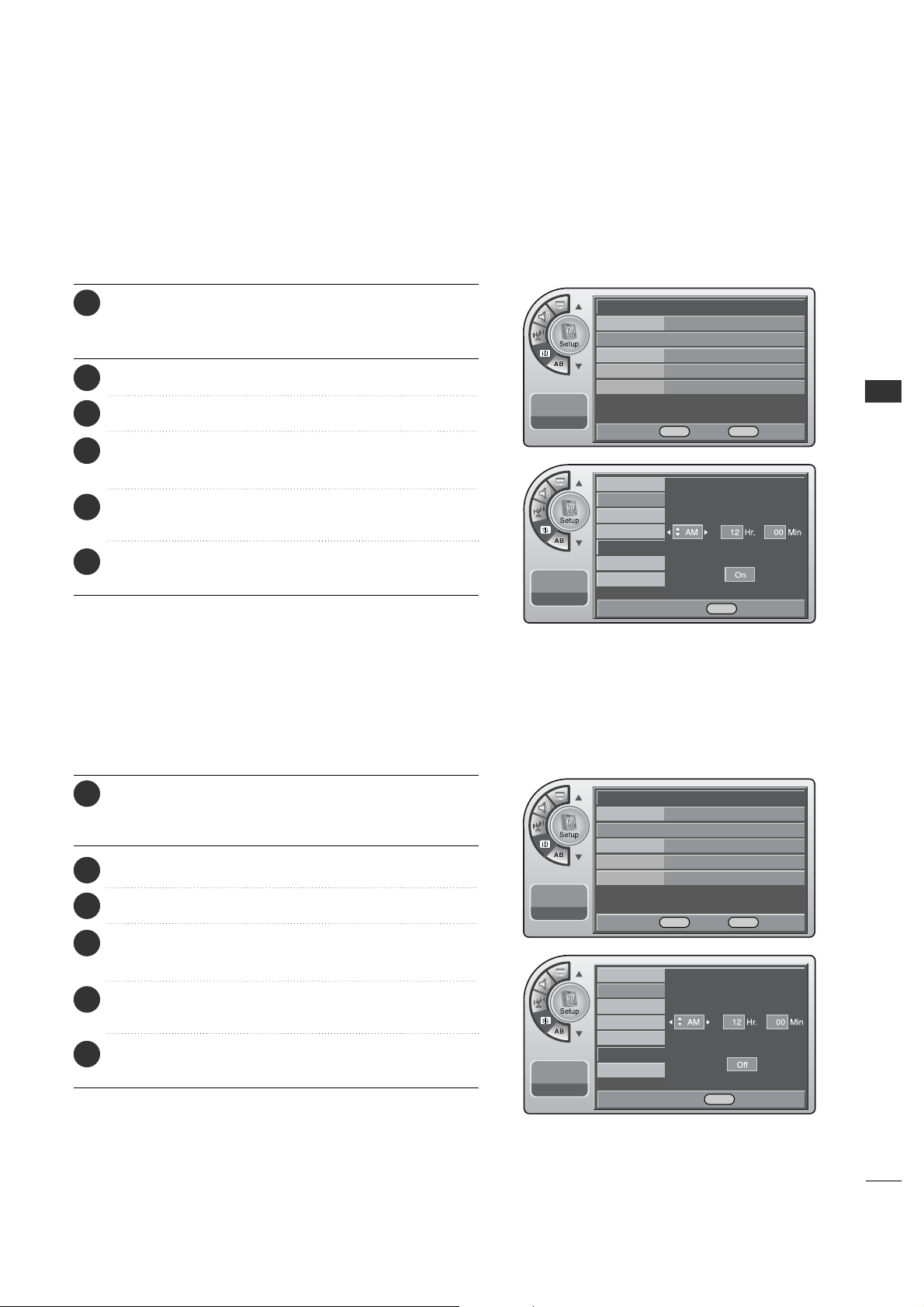
TV Activation Time Settings
You can set a time for the TV to automatically turn-on.
Press the MM EE NN UU button and then use the AADD JJ D or E
button to highlight the SSeett uupp menu and press the OO KK
(( EEnn tt ee rr )) button.
1
Use the AADDJJ D or E button to the TTiimm ee.
2
Press the OOKK (( EEnntteerr )) button to highlight CClloocckk.
3
Use the AADDJJ D or E button to highlight OOnn TTiimmeerr and
press the OOKK (( EE nntt eerr)) button.
4
Use the AADDJJ DEF Gbuttons to choose AAMM // PPMM,
HHoouurrss,MMiinn uutteess and time period to turn-on.
5
When finished, press MM EENN UU repeatedly to remove the
menus.
6
Press the MM EE NN UU button and then use the AADD JJ D or E
button to highlight the SSeett uupp menu and press the OO KK
(( EEnn tt ee rr )) button.
1
Use the AADDJJ D or E button to the TTiimm ee.
2
Press the OOKK (( EEnntteerr )) button to highlight CClloocckk.
3
Use the AADDJJ D or E button to highlight OOffff TT iimmeerr and
press the OOKK (( EE nntt eerr)) button.
4
Use the AADDJJ DEF Gbuttons to choose AAMM // PPMM,
HHoouurrss,MMiinn uutteess and time period to turn-off.
5
When finished, press MM EENN UU repeatedly to remove the
menus.
6
TV Deactivation Time Settings
You can set a time for the TV to automatically turn-off.
34
TIME SETTING
TIME SETTING
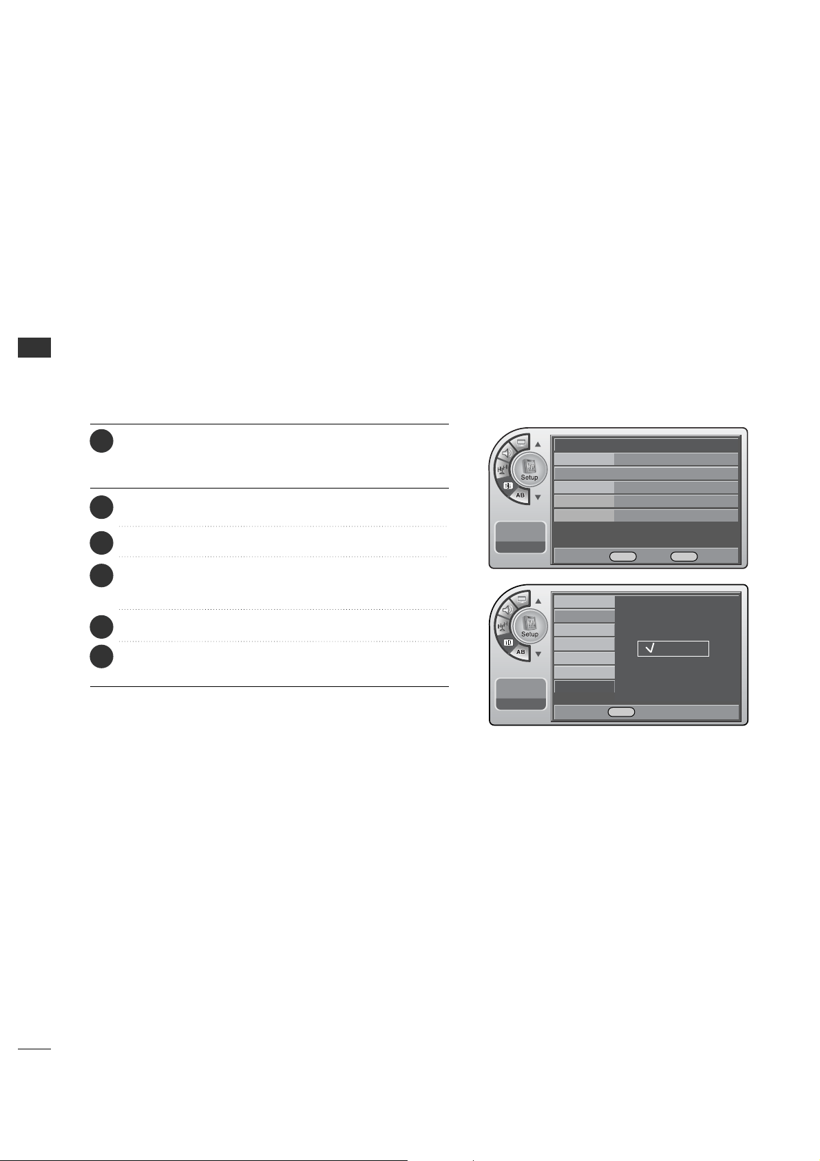
Auto Off
If there is no signal on the TV for 15 minutes or more, or if no
button is pressed for more than 3 hours, this function turns
off the TV automatically.
Time
G
V-Chip
PC
Menu Language English
Menu Transparency
Semi Opaque
Set ID 1
11:20 PM
Sep.11, 2006
DE
Move OK Select Menu Back
11:20 PM
Sep.11, 2006
Clock
Manual Clock
Daylight Saving
Time Zone
On Timer
Off Timer
Auto Off
Off
On
DE Select Menu Back
Press the MM EE NN UU button and then use the AADD JJ D or E
button to highlight the SS ee tt uupp menu and press the OO KK
(( EEnn tt ee rr )) button.
1
Use the AADDJJ D or E button to the TTiimm ee.
2
Use the AADDJJ D or E button to highlight AAuuttoo OOffff and
press the OOKK (( EE nntt eerr)) button.
4
Use the AADDJJ D or E button to choose OO nn or OO ff ff.
5
When finished, press MM EENN UU repeatedly to remove the
menus.
6
Press the OOKK (( EEnntteerr )) button to highlight CClloocckk.
3
PARENTAL CONTROL/RATINGS
35
PARENTAL CONTROL/RATINGS
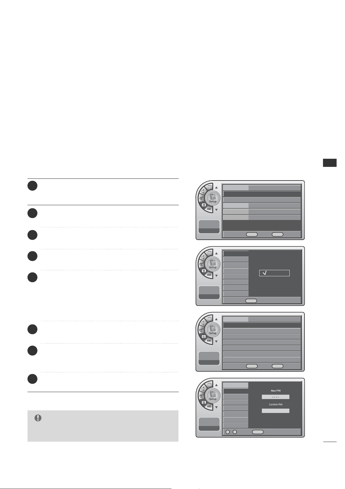
SET PASSWORD & LOCK SYSTEM
This option sets up or changes the password for blocking
program ratings.
Entering a PIN (Password)
G
If you ever forget your password, key in ‘7’, ‘7’, ‘7’, ‘7’ on
the remote control.
NOTE
Press the MM EE NN UU button and then use the AADD JJ D or E
button to highlight the SSeett uupp menu and press the OO KK
(( EEnn tt ee rr )) button.
1
Use the AADDJJ D or E button to highlight VV--CChhiipp and
press the OOKK (( EE nntt eerr)) button.
2
Use the AADDJJ D or E button to highlight OO nn/OO ff ff and
press the OOKK (( EE nntt eerr)) button.
3
Use the AADDJJ D or E button to highlight OO nn and press
the OOKK ((EEnn tteerr )) button.
4
Use the AADDJJ D or E button to highlight CChhaannggiinngg PPIINN
and press the OOKK (( EEnntteerr )) button.
6
Enter the digits password.
As soon as the 4 digits are entered, re-enter the same
4 digits on the CCoonnffiirrmm PPIINN.
7
If a password has been entered, key it in using the
number keypad. If no password has been set, enter the
4 digits password (0-9) using the remote control. This
is the PIN. Each time the menu is entered, the
password will be required until the block time expires.
The TV is set up with the default password “0-0-0-0”.
5
When finished, press MM EENN UU repeatedly to remove the
menus.
8
Time
V-Chip
G
PC
Menu Language English
Menu Transparency
Semi Opaque
Set ID 1
11:20 PM
Sep.11, 2006
DE
Move OK Select Menu Back
On/Off
Changing PIN
Set Block Hour
TVPG Rating
D/L Rating
MPAA Rating
Can. English Rating
Can. French Rating
11:20 PM
Sep.11, 2006
Off
On
On/Off
Changing PIN
Set Block Hour
TVPG Rating
MPAA Rating
D/L Rating
Can. English Rating
Can. French Rating
11:20 PM
Sep.11, 2006
On/Off On
Changing PIN
G
Set Block Hour 12
TVPG Rating
D/L Rating
MPAA Rating
Can. English Rating
Can. French Rating
11:20 PM
Sep.11, 2006
DE Select Menu Back
DE
Move OK Select Menu Back
0 ~ 9 Number Menu Back

PARENTAL CONTROL/RATINGS
36
PARENTAL CONTROL/RATINGS
Set Block Hour.
Press the MM EE NN UU button and then use the AADD JJ D or E
button to highlight the SS ee tt uupp menu and press the OO KK
(( EEnn tt ee rr )) button.
1
Use the AADDJJ D or E button to highlight VV--CChhiipp and
press the OOKK (( EE nntt eerr)) button.
2
Use the AADDJJ D or E button to highlight SSeett BBlloocckk
HHoouurr and press the OOKK (( EEnntt eerr)) button.
4
Use the AADDJJ D or E button to choose 11~1122 hours and
press the OOKK (( EE nntt eerr)) button.
5
Enter the 4 digits password.
3
When finished, press MM EENN UU repeatedly to remove the
menus.
6
Time
V-Chip
G
PC
Menu Language English
Menu Transparency
Semi Opaque
Set ID 1
11:20 PM
Sep.11, 2006
DE
Move OK Select Menu Back
On/Off On
Changing PIN
Set Block Hour 12
G
TVPG Rating
MPAA Rating
D/L Rating
Can. English Rating
Can. French Rating
11:20 PM
Sep.11, 2006
DE
Move OK Select Menu Back
On/Off
Changing PIN
Set Block Hour
TVPG Rating
MPAA Rating
D/L Rating
Can. English Rating
Can. French Rating
11:20 PM
Sep.11, 2006
DE Select Menu Back
37
MOVIE & TV RATINGS
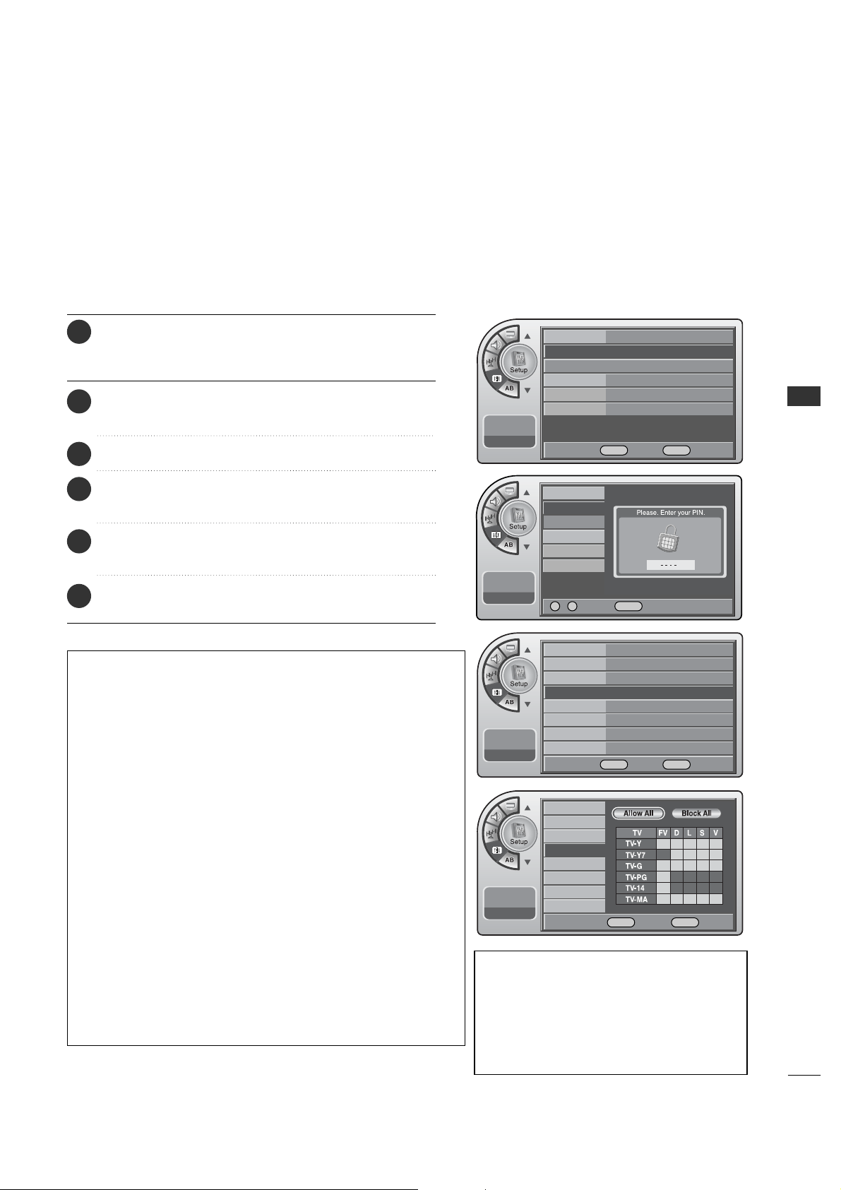
You can block programs based on the TV program rating.
TVPG Ratings
Description of the TV (FCC) Rating Codes:
TV (FCC) Age Categories
TV-MA
Mature audiences only. This program may contain mature themes,
profane language, graphic violence and explicit sexual content.
TV-14
Parents strongly cautioned. This program may contain
sophisticated themes, sexual content, strong language and more
intense violence.
TV-PG
Parental guidance suggested. The program may contain infrequent
coarse language, limited violence, some suggestive sexual dialog
and situations.
TV-G
General audience. This contains little or no violence, no strong
language, and little or no sexual dialog or situations.
TV-Y7
Directed for older children. Themes and elements in this program
may include mild physical or comedic violence, or may frighten
children under the age of seven.
TV-Y
All children. The themes and elements in this program are
specifically designed for a very young audience, including children
from ages two – six.
TV (FCC) Content Sub-Categories:
V Violence.
S Violence.
L Offensive language.
V Violence.
D Dialog...sexual innuendo.
FV Fantasy or cartoon violence.
Enter the 4 digits password.
3
Press the MM EE NN UU button and then use the AADD JJ D or E
button to highlight the SSeett uupp menu and press the OO KK
(( EEnn tt ee rr )) button.
1
Use the AADDJJ D or E button to highlight VV--CChhiipp and
press the OOKK (( EE nntt eerr)) button.
2
Use the AADDJJ D or E button to highlight the
TTVVPPGG RRaatt ii nn gg and press the OOKK ((EEnn tt eerr )) button.
4
When finished, press MM EENN UU repeatedly to remove the
menus.
6
Use the AADDJJ DEF G buttons to choose and set up
the menu options for TT VVPP GG RRaatt iinngg.
5
PARENTAL CONTROL/RATINGS
Time
V-Chip
PC
Menu Language
Menu Transparency
Set ID
11:20 PM
Sep.11, 2006
On/Off
Changing PIN
Set Block Hour
TVPG Rating
MPAA Rating
D/L Rating
Can. English Rating
Can. French Rating
11:20 PM
Sep.11, 2006
Time
V-Chip
G
PC
Menu Language English
Menu Transparency
Semi Opaque
Set ID 1
11:20 PM
Sep.11, 2006
DE
Move OK Select Menu Back
On/Off On
Changing PIN
Set Block Hour 12
TVPG Rating
G
MPAA Rating
D/L Rating
Can. English Rating
Can. French Rating
11:20 PM
Sep.11, 2006
DE
Move OK Select Menu Back
0 ~ 9 Number Menu Back
DE F G Move OK Select Menu Back
PARENTAL CONTROL/RATINGS
PARENTAL CONTROL/RATINGS
38
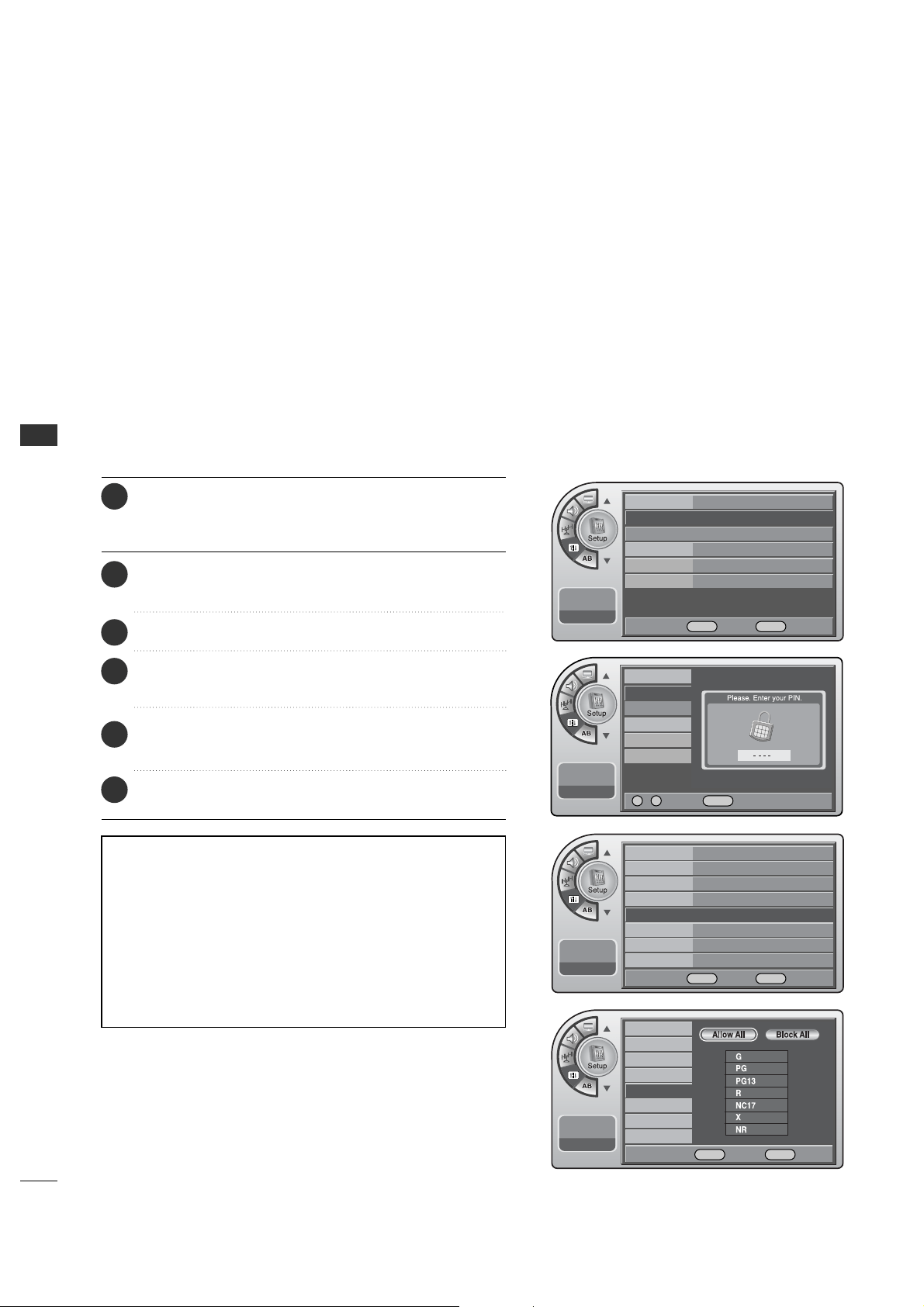
Restricting movies by their rating.
MPAA Ratings
Description of the MPAA and TV (FCC) Rating Codes:
The MPAA Rating System (Movies)
G General Audience. No restrictions.
PG Children under 13 should be accompanied by an adult.
PG-13 Parental guidance suggested. Children under 13 should
be accompanied by an adult.
NC-17 Not classified. Viewers should be 17 or older.
X Adults only.
• MPAA ratings: The selected rating will be locked. In addition,
any ratings that are more restrictive will also be blocked.
Press the MM EE NN UU button and then use the AADD JJ D or E
button to highlight the SS ee tt uupp menu and press the OO KK
(( EEnn tt ee rr )) button.
1
Use the AADDJJ D or E button to highlight VV--CChhiipp and
press the OOKK (( EE nntt eerr)) button.
2
Use the AADDJJ DEFGbuttons to choose and set up
the menu options for MMPP AA AA RR aatt ii nngg.
5
When finished, press MM EENN UU repeatedly to remove the
menus.
6
Use the AADDJJ D or E button to highlight the
MM PPAAAA RR aatt ii nngg and press the OOKK (( EEnntteerr )) button.
4
Enter the 4 digits password.
3
Time
V-Chip
PC
Menu Language
Menu Transparency
Set ID
11:20 PM
Sep.11, 2006
On/Off
Changing PIN
Set Block Hour
TVPG Rating
MPAA Rating
D/L Rating
Can. English Rating
Can. French Rating
11:20 PM
Sep.11, 2006
Time
V-Chip
G
PC
Menu Language English
Menu Transparency
Semi Opaque
Set ID 1
11:20 PM
Sep.11, 2006
DE
Move OK Select Menu Back
On/Off On
Changing PIN
Set Block Hour 12
TVPG Rating
D/L Rating
MPAA Rating
G
Can. English Rating
Can. French Rating
11:20 PM
Sep.11, 2006
DE
Move OK Select Menu Back
0 ~ 9 Number Menu Back
DE F G Move OK Select Menu Back
PARENTAL CONTROL/RATINGS
39
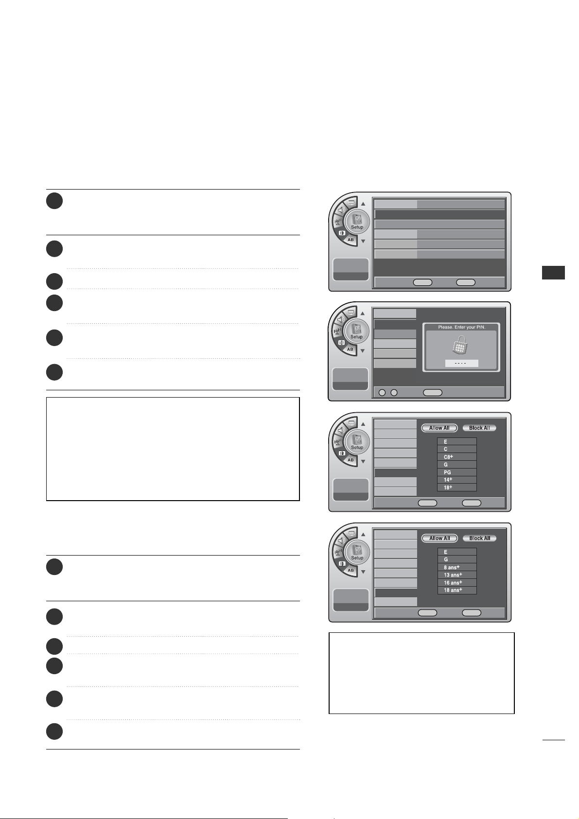
Canadian English Ratings
Canadian English Ratings
E Expect No restriction.
C Children
C8+ Viewers should be 8 or older.
G General Audience.
PG Parental guidance suggested. Children under 14 should be
accompanied by an adult.
14+ Restricted. Viewers should be 14 or older.
18+ Restricted. Viewers should be 18 or older.
Canadian French Ratings
E Expect No restriction.
G For a ll
8+ Restricted. Viewers should be 8 or older.
13+ Restricted. Viewers should be 13 or older.
16+ Restricted. Viewers should be 16 or older.
18+ Restricted. Viewers should be 18 or older.
Press the MM EE NN UU button and then use the AADD JJ D or E
button to highlight the SSeett uupp menu and press the OO KK
(( EEnn tt ee rr )) button.
1
Use the AADDJJ D or E button to highlight VV--CChhiipp and
press the OOKK (( EE nntt eerr)) button.
2
Enter the 4digits password.
3
Use the AADDJJ D or E button to highlight the
CCaann.. EEnngglliisshh RRaattiinngg and press the OOKK ((EEnn tt eerr )) button.
4
Use the AADDJJ DEF Gbuttons to choose and set up
the menu options for CCaann.. EEnngglliisshh RRaattiinngg.
5
When finished, press MM EENN UU repeatedly to remove the
menus.
6
Canadian French Ratings
Press the MM EE NN UU button and then use the AADD JJ D or E
button to highlight the SSeett uupp menu and press the OO KK
(( EEnn tt ee rr )) button.
1
Use the AADDJJ D or E button to highlight VV--CChhiipp and
press the OOKK (( EE nntt eerr)) button.
2
Enter the 4digits password.
3
Use the AADDJJ D or E button to highlight the
CCaann.. FFrreenncchh RRaattiinngg and press the OOKK (( EEnntt eerr)) button.
4
Use the AADDJJ DEF Gbuttons to choose and set up
the menu options for CCaann.. FFrreenncchh RRaattiinngg.
5
When finished, press MM EENN UU repeatedly to remove the
menus.
6
Time
V-Chip
PC
Menu Language
Menu Transparency
Set ID
11:20 PM
Sep.11, 2006
Time
V-Chip
G
PC
Menu Language English
Menu Transparency
Semi Opaque
Set ID 1
11:20 PM
Sep.11, 2006
DE
Move OK Select Menu Back
0 ~ 9 Number Menu Back
On/Off
Changing PIN
Set Block Hour
TVPG Rating
MPAA Rating
D/L Rating
Can. English Rating
Can. French Rating
11:20 PM
Sep.11, 2006
On/Off
Changing PIN
Set Block Hour
TVPG Rating
MPAA Rating
D/L Rating
Can. English Rating
Can. French Rating
11:20 PM
Sep.11, 2006
DE F G Move OK Select Menu Back
DE F G Move OK Select Menu Back
40
PARENTAL CONTROL/RATINGS
PARENTAL CONTROL/RATINGS
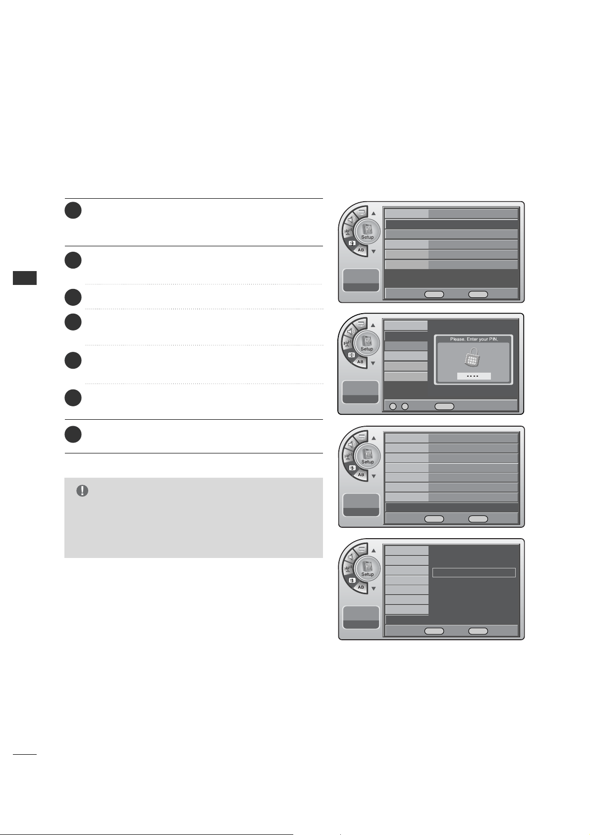
Downloadable Rating
Press the MM EE NN UU button and then use the AADD JJ D or E
button to highlight the SS ee tt uupp menu and press the OO KK
(( EEnn tt ee rr )) button.
1
Use the AADDJJ D or E button to highlight VV--CChhiipp and
press the OOKK (( EE nntt eerr)) button.
2
Use the AADDJJ D or E buttons to choose DDiimm00, DDiimm11,
DD ii mm22 or DDii mm33 and press the OOKK (( EEnntteerr )) button.
5
Use the AADDJJ D or E buttons to choose DD11LL11, DD11LL22
or DD11LL33.
6
Use the AADDJJ D or E button to highlight the
DD// LL RRaattiinngg and press the OO KK (( EEnntteerr )) button.
4
When finished, press MM EENN UU repeatedly to remove the
menus.
7
Enter the 4 digits password.
3
■
LLoocckk mmeennuu--DDoowwnnllooaaddaabbllee RRaattiinngg in the CD manual is added by the information presented here.
Your TV’s OSD (On Screen Display) may differ slightly from what is shown in this manual.
Time
V-Chip
Menu Language
Menu Transparency
Set ID
11:20 PM
Sep.11, 2006
On/Off On
Changing PIN
Set Block Hour 12
TVPG Rating
MPAA Rating
D/L Rating
G
Can. English Rating
Can. French Rating
11:20 PM
Sep.11, 2006
On/Off
Changing PIN
Set Block Hour
TVPG Rating
MPAA Rating
D/L Rating
Can. English Rating
Can. French Rating
11:20 PM
Sep.11, 2006
0 ~ 9 Number MENU Back
DE Move OK Select MENU Back
Time
V-Chip
G
Menu Language English
Menu Transparency
Semi Opaque
Set ID 1
11:20 PM
Sep.11, 2006
DE Move OK Select MENU Back
D/L Rating (1/1)
Dim0
Dim1
G
Dim2
Dim3
G
This function may become available in the future and
will be available only for digital channel signal.
G
This function operates only when TV has received
Region5 Rating data.
NOTE
DE Move OK Select MENU Back
SOUND & LANGUAGE CONTROL
41
SOUND & LANGUAGE CONTROL
CAPTION / TEXT
Turn Captions On/Off
Analog Mode
The term for the words that scroll across the bottom of the TV screen; usually the
audio portion of the program provided for the hearing impaired.
The term for the words that appear in a large black frame and almost cover the
entire screen; usually messages provided by the broadcaster.
CAPTIONS
TEXT
Mini glossary
On/Off
Off
G
Analog Mode
Digital Mode
Digital Font Option
11:20 PM
Sep.11, 2006
On/Off
On
Analog Mode CC1
G
Digital Mode
Digital Font Option
11:20 PM
Sep.11, 2006
11:20 PM
Sep.11, 2006
On/Off
Analog Mode
Digital Mode
Digital Font Option
Off
On
11:20 PM
Sep.11, 2006
On/Off
Analog Mode
Digital Mode
Digital Font Option
CC1
CC2
CC3
CC4
TEXT1
TEXT2
TEXT3
TEXT4
DE
Move OK Select Menu Back
DE
Move OK Select Menu Back
DE Select Menu Back
DESelect Menu Back
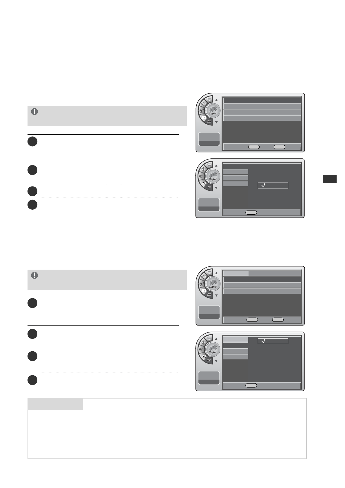
Press the MM EE NN UU button and then use the AADD JJ D or E
button to highlight the CCaappttiioonn menu and press the
OOKK (( EE nntt eerr)) button.
1
Use the AADDJJ D or E button to highlight OO nn/OO ff ff and
press the OOKK (( EE nntt eerr)) button.
2
When finished, press MM EENN UU repeatedly to remove the
menus.
4
Use the AADDJJ D or E button to choose OO nn or OO ff ff.
3
G
Pressing CC on the remote to select a captions
option will also turn closed captions on.
NOTE
Analog Captions will display on the screen whether the signal
is from an RF channel or external equipment input.
Press the MM EE NN UU button and then use the AADD JJ D or E
button to highlight the CCaappttiioonn menu and press the
OOKK (( EE nntt eerr)) button.
1
Use the AADDJJ D or E button to highlight AAnnaalloogg MMooddee
and press OOKK ((EEnntt eerr)) button.
2
Use the AADDJJ D or E button to choose CCCC11--TTEEXXTT44
and
press the OOKK (( EE nntt eerr)) button.
3
When finished, press MM EENN UU repeatedly to remove the
menus.
4
G
Pressing CC on the remote selects a captions
option.
NOTE
SOUND & LANGUAGE CONTROL
42
SOUND & LANGUAGE CONTROL
Digital Captions Mode
Digital Font Options
G
If the digital options custom settings are to be cloned,
all menu options should be set to any option other than
Default. If Default is left set for any one option, then
all the options will be reset to default after cloning.
NOTE
On/Off
On
Analog Mode
CC1
Digital Mode
Service1 G
Digital Font Option
11:20 PM
Sep.11, 2006
On/Off
On
Analog Mode
CC1
Digital Mode
Service1
Digital Font Option
G
11:20 PM
Sep.11, 2006
Font Size Default
G
Font Style Default
Foreground Color
Default
Background Color
Default
Edge Color
Default
Foreground Opacity
Default
Background Opacity
Default
Edge Style
Default
11:20 PM
Sep.11, 2006
Caption
11:20 PM
Sep.11, 2006
On/Off
Analog Mode
Digital Mode
Digital Font Option
Service1
Service2
Service3
Service4
Service5
Service6
DE
Move OK Select Menu Back
DE
Move OK Select Menu Back
DE
Move OK Select Menu Back
DE Select Menu Back
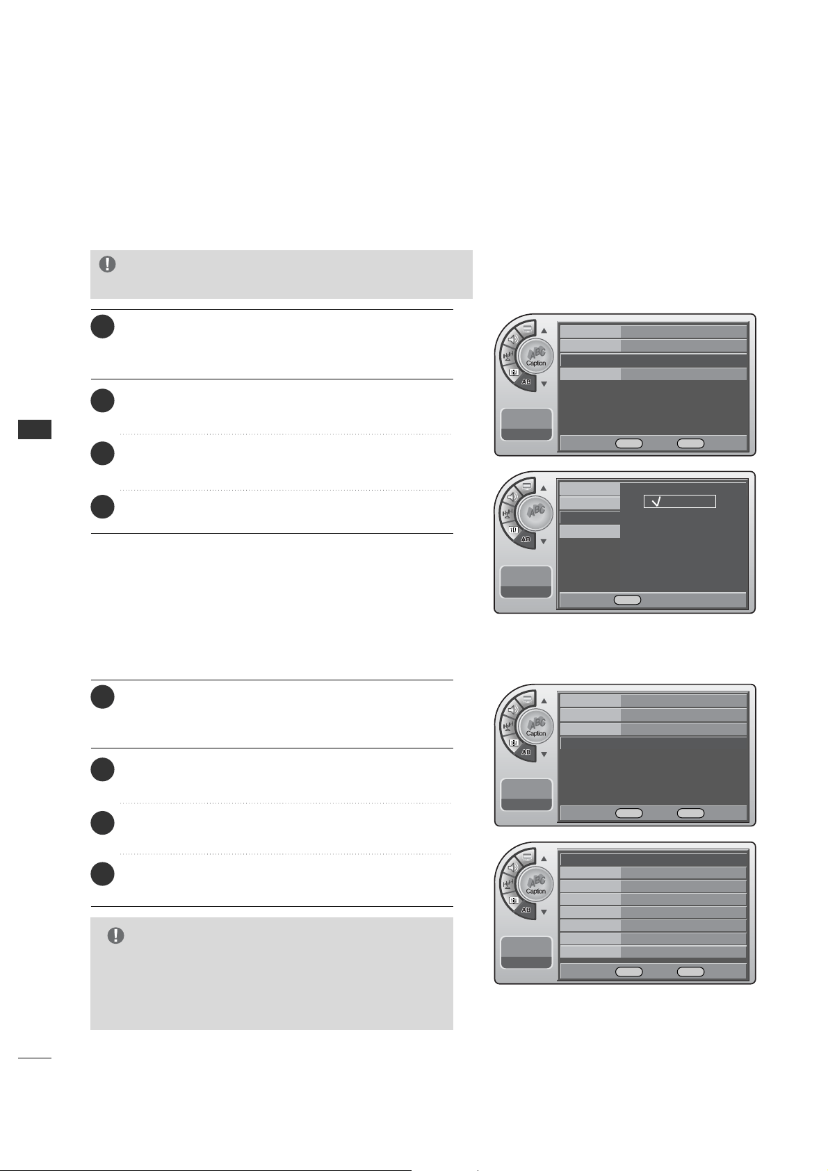
Press the MM EE NN UU button and then use the AADD JJ D or E
button to highlight the CCaappttiioonn menu and press the
OOKK (( EE nntt eerr)) button.
1
Use the AADDJJ D or E button to highlight DDiiggiittaall MMooddee
and press the OOKK (( EEnntteerr )) button.
2
Use the AADDJJ D or E button to choose SSeerrvviiccee 11--SSeerrvviiccee 66
and
press the OOKK (( EE nntt eerr)) button.
3
When finished, press MM EENN UU repeatedly to remove the
menus.
4
G
Pressing CC on the remote selects a captions
option.
NOTE
Digital Captions only appear on digital channels, tune in a
digi-tal channel that is actually broadcasting digital captions.
Press the MM EE NN UU button and then use the AADD JJ D or E
button to highlight the CCaappttiioonn menu and press the
OOKK (( EE nntt eerr)) button.
1
Use the AADDJJ D or E button to highlight DDiiggiittaall FFoonntt
OOppttiioonnss and press the OO KK ((EEnn tteerr )) button.
2
Use the AADDJJ DEF Gbuttons to customize each
option: Font Size, Font Style, Foreground Color etc.
3
When finished, press MM EENN UU repeatedly to remove the
menus.
4
SOUND & LANGUAGE CONTROL
43
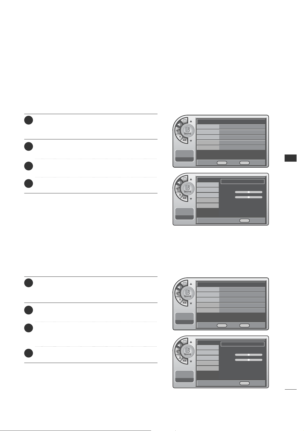
Preset Sound Settings
Match the sound mode to the program’s character, Music,
Movie, Sports, or News.
(This is Feature operates only in DTV mode.)
Mode Standard G
Balance
Digital Output Dolby Digital
Auto Volume On
Multi-Track Stereo
Internal Speaker
On
11:20 PM
Sep.11, 2006
Mode
Balance
Digital Output
Auto Volume
Multi-Track
Internal Speaker
11:20 PM
Sep.11, 2006
Adjust the sound to suit your taste and room situations.
Sound Setting Adjustment-User Mode
Manual G
Treble
-+
Bass
F G Move G Select Menu Back
Mode
Balance
Digital Output
Auto Volume
Multi-Track
Internal Speaker
11:20 PM
Sep.11, 2006
Standard G
Treble
-+
Bass
F G Move G Select Menu Back
DE
Move OK Select Menu Back
Mode Manual G
Balance
Digital Output Dolby Digital
Auto Volume On
Multi-Track Stereo
Internal Speaker
On
11:20 PM
Sep.11, 2006
DE
Move OK Select Menu Back
Press the MM EE NN UU button and then use the AADD JJ D or E
button to highlight the SSoouunndd menu and press the OO KK
(( EEnn tt ee rr )) button.
1
Use the AADDJJ D or E button to highlight MMooddee and
press the OOKK (( EE nntt eerr)) button.
2
Use the AADDJJ G button to customize each option: or
choose a preset mode like Music, Movie, etc.
3
When finished, press MM EENN UU repeatedly to remove the
menus.
4
Press the MM EE NN UU button and then use the AADD JJ D or E
button to highlight the SSoouunndd menu and press the OO KK
(( EEnn tt ee rr )) button.
1
Use the AADDJJ D or E button to highlight MMooddee and
press the OOKK (( EE nntt eerr)) button.
2
Use the AADDJJ G button to choose MMaann uu aa ll and use
AADDJJ DEF Gbuttons to set your own settings for the
options. When finished, press the OO KK ((EEnntt ee rr)) button.
3
When finished, press MM EENN UU repeatedly to remove the
menus.
4
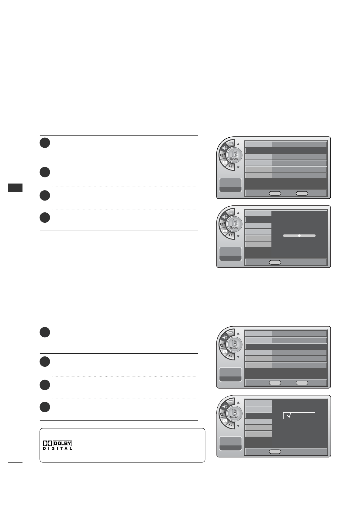
SOUND & LANGUAGE CONTROL
44
SOUND & LANGUAGE CONTROL
Adjust the speaker balance for optimum sound quality.
Sound Balance Setup
Mode
Balance
Digital Output
Auto Volume
Multi-Track
Internal Speaker
11:20 PM
Sep.11, 2006
Adjust left/Light balance.
0
0
Set the digital audio output as Dolby Digital or PCM.
Digital Audio Output Settings
<Dolby Digital>
This product is under license of Dolby Laboratories.
The “Dolby” or D symbol is a trademark of Dolby
Laboratories.
Mode
Balance
Digital Output
Auto Volume
Multi-Track
Internal Speaker
11:20 PM
Sep.11, 2006
Dolby Digital
PCM
Mode Standard
Balance G
Digital Output Dolby Digital
Auto Volume On
Multi-Track Stereo
Internal Speaker
On
11:20 PM
Sep.11, 2006
DE
Move OK Select Menu Back
Mode Standard
Balance
Digital Output Dolby Digital G
Auto Volume On
Multi-Track English
Internal Speaker
On
11:20 PM
Sep.11, 2006
DE
Move OK Select Menu Back
F G Adjust Menu Back
DESelect Menu Back
Press the MM EE NN UU button and then use the AADD JJ D or E
button to highlight the SSoouunndd menu and press the OO KK
(( EEnn tt ee rr )) button.
1
Use the AADDJJ D or E button to highlight BBaallaannccee and
press the OOKK (( EE nntt eerr)) button.
2
Use the AADDJJ F or G button to move the sound more to
the Left or Right.
3
When finished, press MM EENN UU repeatedly to remove the
menus.
4
Press the MM EE NN UU button and then use the AADD JJ D or E
button to highlight the SSoouunndd menu and press the OO KK
(( EEnn tt ee rr )) button.
1
Use the AADDJJ D or E button to highlight DDiiggiittaall OOuu tt ppuutt
and press the OOKK (( EEnntteerr )) button.
2
Use the AADDJJ
D
or
E
buttons to choose DDoollbbyy DDiiggiittaall
or PPCCMM.
3
When finished, press MM EENN UU repeatedly to remove the
menus.
4
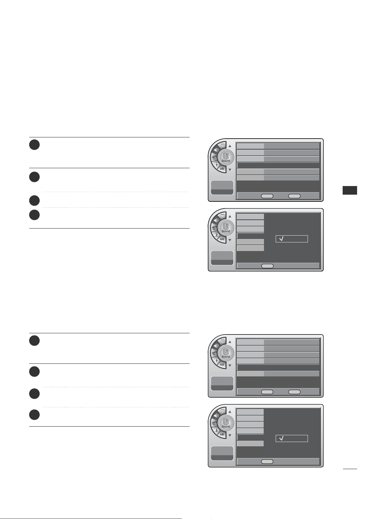
SOUND & LANGUAGE CONTROL
45
Mode
Balance
Digital Output
Auto Volume
Multi-Track
Internal Speaker
11:20 PM
Sep.11, 2006
Have the TV automatically maintain the sound level between
different channels.
Automatic Volume Control Settings
Mode
Balance
Digital Output
Auto Volume
Multi-Track
Internal Speaker
11:20 PM
Sep.11, 2006
Off
On
Mono
Stereo
SAP
Mode Standard
Balance
Digital Output Dolby Digital
Auto Volume On
G
Multi-Track Stereo
Internal Speaker
On
11:20 PM
Sep.11, 2006
DE
Move OK Select Menu Back
Mode Standard
Balance
Digital Output Dolby Digital
Auto Volume On
Multi-Track Stereo
G
Internal Speaker
On
11:20 PM
Sep.11, 2006
DE Move OK Select Menu Back
DE Select Menu Back
DE Select Menu Back
You can set analog audio settings.
Analog Audio Settings
Press the MM EE NN UU button and then use the AADD JJ D or E
button to highlight the SSoouunndd menu and press the OO KK
(( EEnn tt ee rr )) button.
1
Use the AADDJJ D or E button to highlight AAuuttoo VVoolluummee
and press the OOKK (( EEnntteerr )) button.
2
Use the AA DD JJ
D
or
E
button to choose OO nn or OO ff ff.
3
When finished, press MM EENN UU repeatedly to remove the
menus.
4
Press the MM EE NN UU button and then use the AADD JJ D or E
button to highlight the SSoouunndd menu and press the OO KK
(( EEnn tt ee rr )) button.
1
Use the AADDJJ D or E button to highlight MMuullttii--TTrraacckk
and press the OOKK (( EEnntteerr )) button.
2
Use the AADDJJ
D
or
E
button to choose Mono, Stereo or
SAP and press the OOKK ((EEnn tteerr )) button.
3
When finished, press MM EENN UU repeatedly to remove the
menus.
4
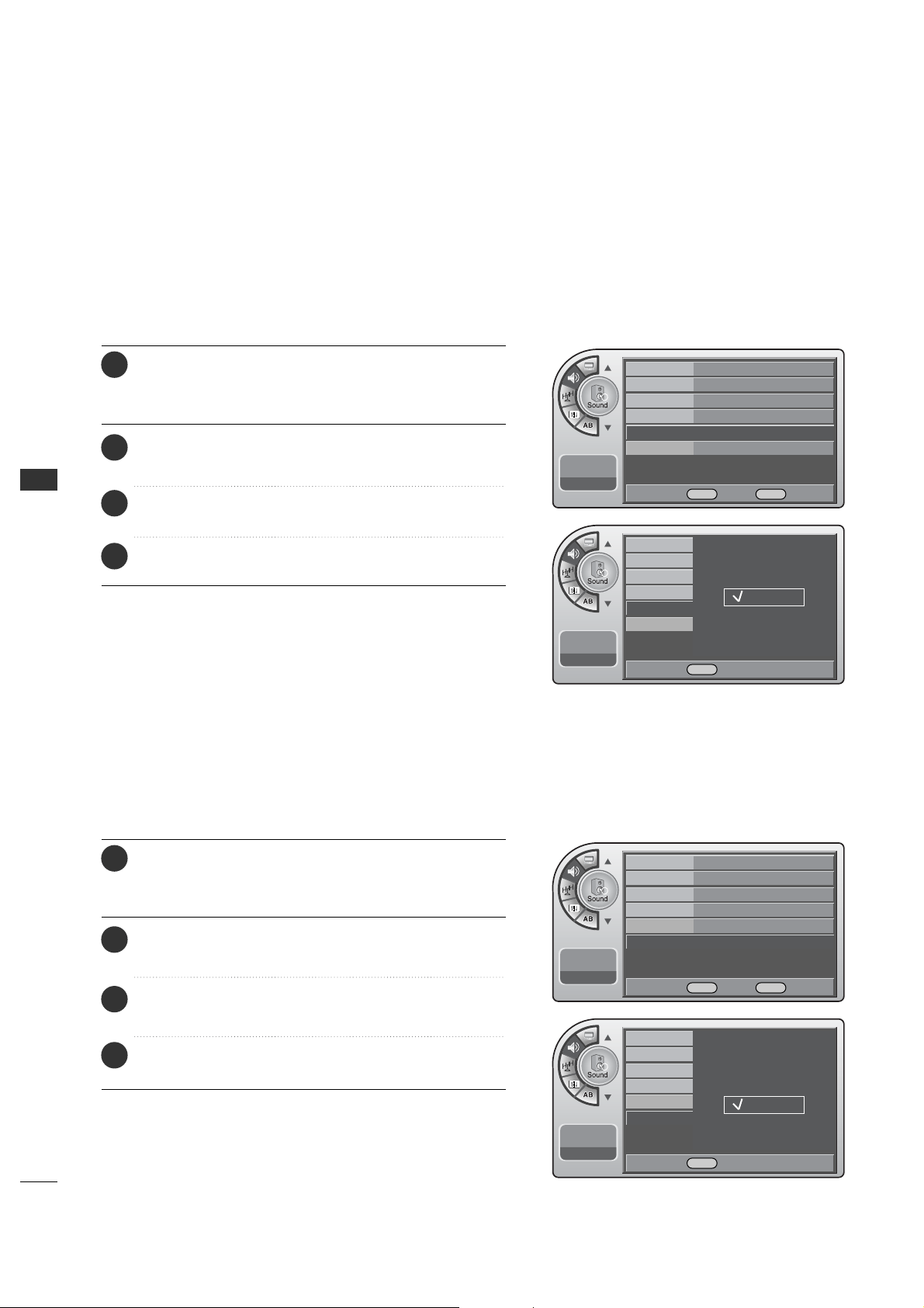
SOUND & LANGUAGE CONTROL
46
SOUND & LANGUAGE CONTROL
Set the internal speaker to Off to listen to the TV through an
external audio system, the TV sound will not be heard.
Using External Speakers
You can set digital audio language.
Digital Audio Language Settings
Mode
Balance
Digital Output
Auto Volume
Multi-Track
Internal Speaker
11:20 PM
Sep.11, 2006
English
Spanish
French
Mode Standard
Balance
Digital Output Dolby Digital
Auto Volume On
Multi-Track English
G
Internal Speaker
On
11:20 PM
Sep.11, 2006
DE
Move OK Select Menu Back
Mode Standard
Balance
Digital Output Dolby Digital
Auto Volume On
Multi-Track English
Internal Speaker
On G
11:20 PM
Sep.11, 2006
DE
Move OK Select Menu Back
DESelect Menu Back
Mode
Balance
Digital Output
Auto Volume
Multi-Track
Internal Speaker
11:20 PM
Sep.11, 2006
Off
On
DE Select Menu Back
Press the MM EE NN UU button and then use the AADD JJ D or E
button to highlight the SSoouunndd menu and press the OO KK
(( EEnn tt ee rr )) button.
1
Use the AADDJJ D or E button to highlight MMuullttii--TTrraacckk
and press the OOKK (( EEnntteerr )) button.
2
Use the AADDJJ
D
or
E
button to choose English, Spanish
or French and press the OO KK (( EEnntteerr )) button.
3
When finished, press MM EENN UU repeatedly to remove the
menus.
4
Press the MM EE NN UU button and then use the AADD JJ D or E
button to highlight the SSoouunndd menu and press the OO KK
(( EEnn tt ee rr )) button.
1
Use the AADDJJ D or E button to highlight IInntteerrnnaall SSppeeaakkeerr
and press the OOKK (( EEnntteerr )) button.
2
Use the AADDJJ D or E button to choose OO nn or OO ff ff and
press the OOKK (( EE nntt eerr)) button.
3
When finished, press MM EENN UU repeatedly to remove the
menus.
4
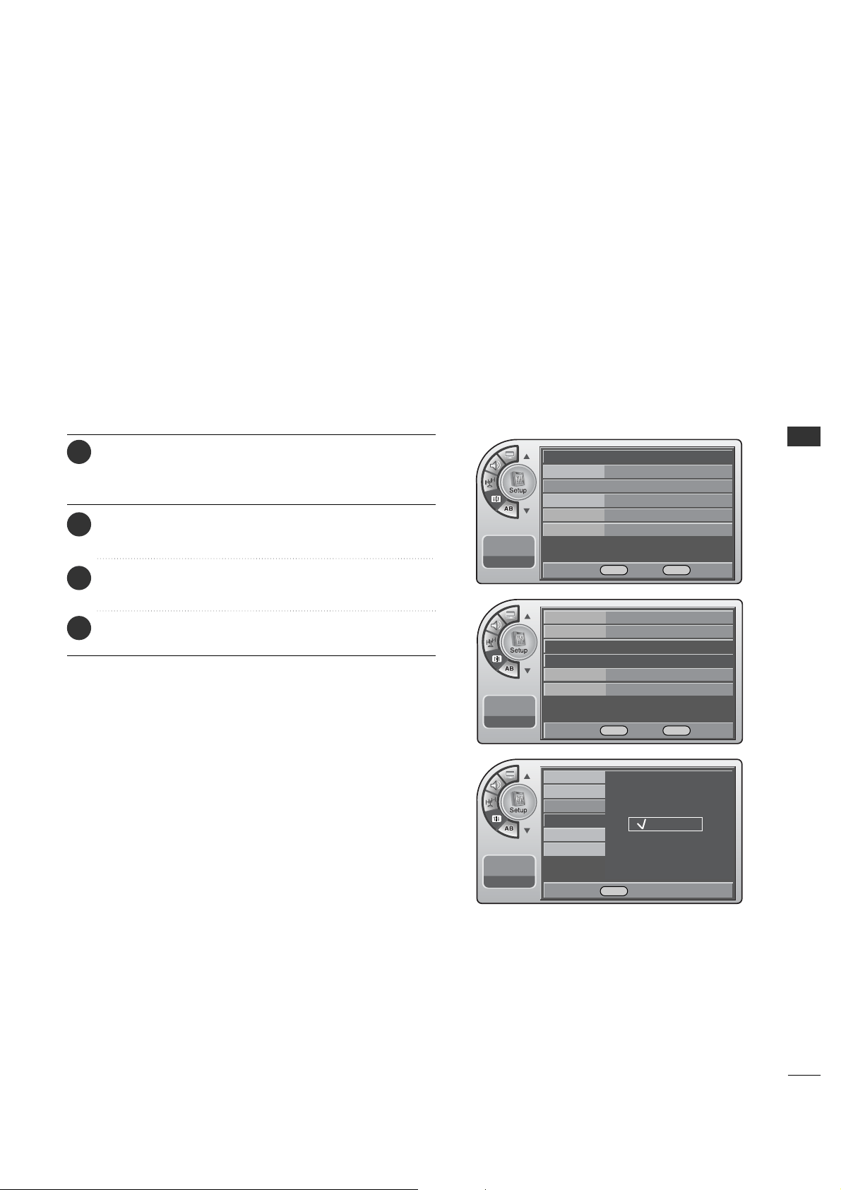
SOUND & LANGUAGE CONTROL
47
Menu Language
The menus can be shown on the screen inter selected language.
First select your language.
11:20 PM
Sep.11, 2006
Time
V-Chip
PC
Menu Language
Menu Transparency
Set ID
English
Español
Français
Time
V-Chip
PC
Menu Language English
G
Menu Transparency
Semi Opaque
Set ID 1
11:20 PM
Sep.11, 2006
DE
Move OK Select Menu Back
DE Select Menu Back
Time
G
V-Chip
PC
Menu Language English
Menu Transparency
Semi Opaque
Set ID 1
11:20 PM
Sep.11, 2006
DE
Move OK Select Menu Back
Press the MM EE NN UU button and then use the AADD JJ D or E
button to highlight the SSeett uupp menu and press the OO KK
(( EEnn tt ee rr )) button.
1
Use the AADDJJ D or E button to highlight MMeenn uu LLaa nngguuaaggee
and press the OOKK (( EEnntteerr )) button.
2
Use the AADDJJ D or E button to highlight and set the
Menu Language: English, Español or Français.
3
When finished, press MM EENN UU repeatedly to remove the
menus.
4
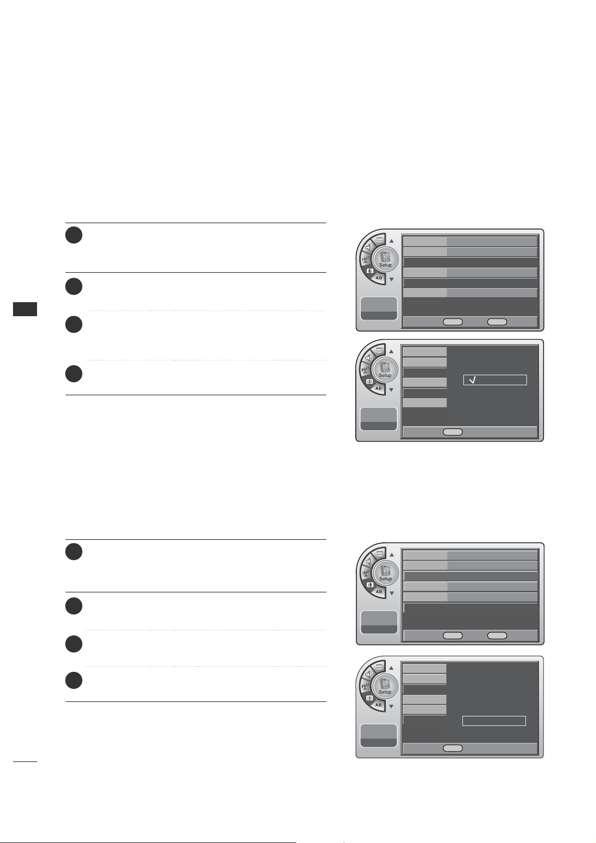
SOUND & LANGUAGE CONTROL
48
SOUND & LANGUAGE CONTROL
Menu Transparency Settings
Menu Transparency sets the background transparency of the menu.
11:20 PM
Sep.11, 2006
Time
V-Chip
PC
Menu Language
Menu Transparency
Set ID
Opaque
Semi Opaque
Semi Trans
Transparent
Set ID
Use this function to specify a set ID number.
11:20 PM
Sep.11, 2006
Time
V-Chip
PC
Menu Language
Menu Transparency
Set ID
Time
V-Chip
PC
Menu Language English
Menu Transparency
Semi Opaque
G
Set ID 1
11:20 PM
Sep.11, 2006
DE
Move OK Select Menu Back
Time
V-Chip
PC
Menu Language English
Menu Transparency
Semi Opaque
Set ID 1
G
11:20 PM
Sep.11, 2006
DE
Move OK Select Menu Back
DE Select Menu Back
D
1
E
DE Adjust Menu Back
Press the MM EE NN UU button and then use the AADD JJ D or E
button to highlight the SS ee tt uupp menu and press the OO KK
(( EEnn tt ee rr )) button.
1
Use the AADDJJ D or E button to highlight
MMeennuu TTrraannssppaarreennccyy and press the OOKK (( EEnntteerr )) button.
2
Use the AADDJJ D or E button to highlight and set the
Menu Transparency: Opaque, Semi Opaque, Semi Trans,
Transparent.
3
When finished, press MM EENN UU repeatedly to remove the
menus.
4
Press the MM EE NN UU button and then use the AADD JJ D or E
button to highlight the SS ee tt uupp menu and press the OO KK
(( EEnn tt ee rr )) button.
1
Use the AADDJJ D or E button to highlight SS eett IIDD and
press the OOKK (( EE nntt eerr)) button.
2
Use the AADDJJ D or E button to adjust SSeett II DD to choose
the desired monitor ID number.
3
When finished, press MM EENN UU repeatedly to remove the
menus.
4
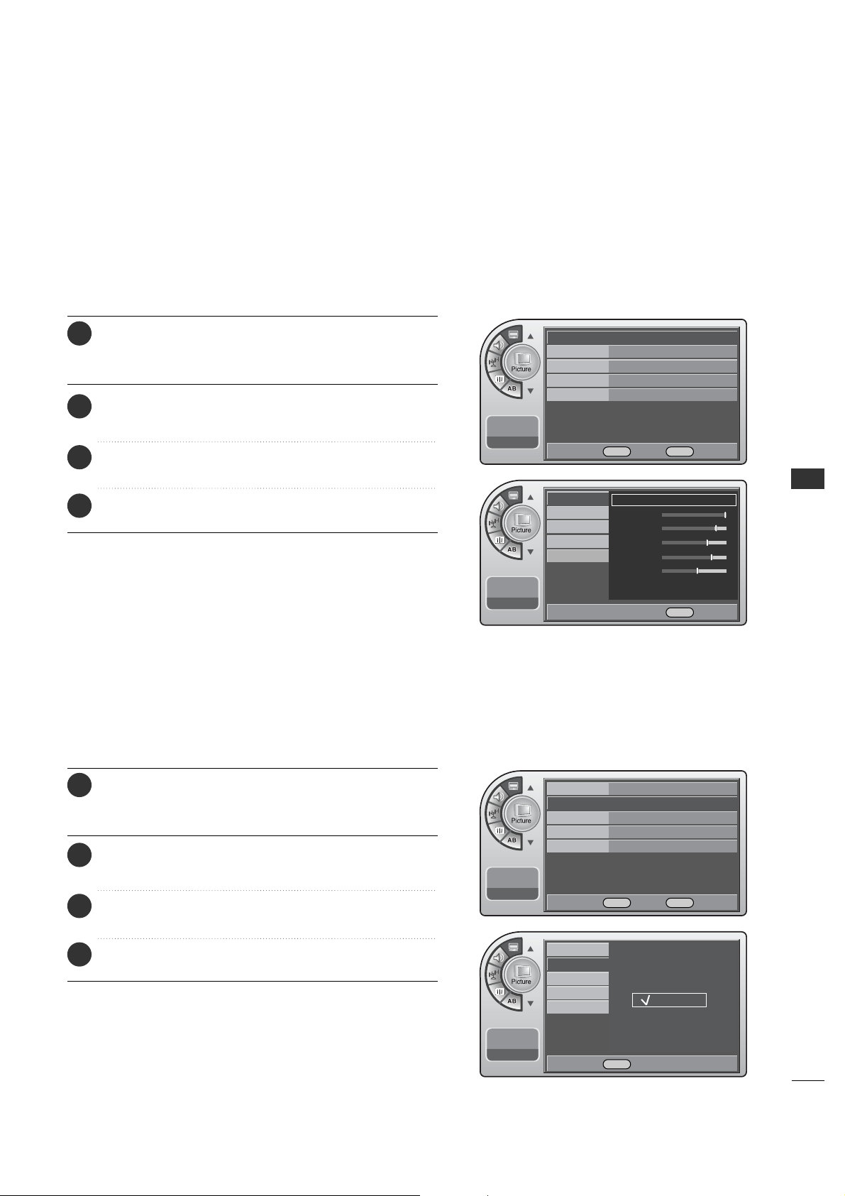
PICTURE CONTROL
49
PICTURE CONTROL
PRESET PICTURE SETTINGS
Set the picture mode to the program content, e.g. Dynamic or
Mild etc.
Picture - Preset
Choose one of three automatic color adjust ment.
Color Temperature Settings
Mode Standard G
Color Temperature
Cool
Screen Format
16:9
Noise Reduction Off
Film Mode
Off
11:20 PM
Sep.11, 2006
DE
Move OK Select Menu Back
Mode Standard
Color Temperature
Cool
G
Screen Format
16:9
Noise Reduction
Off
Film Mode Off
11:20 PM
Sep.11, 2006
Mode
Color Temperature
Screen Format
Noise Reduction
Film Mode
11:20 PM
Sep.11, 2006
Norma
Cool
Warm
Mode
Color Temperature
Standard
G
Contrast
Brightness
Sharpness
Color
Tint
Screen Format
Noise Reduction
Film Mode
11:20 PM
Sep.11, 2006
F G Move G Select Menu Back
DE
Move OK Select Menu Back
DE Select Menu Back
Press the MM EE NN UU button and then use the AADD JJ D or E
button to highlight the PPiiccttuurree menu and press the OO KK
(( EEnn tt ee rr )) button.
1
Use the AADDJJ D or E button to highlight MMooddee and
press the OOKK (( EE nntt eerr)) button.
2
Use the AADDJJ G button to choose a preset picture setup.
When finished, press the OOKK (( EEnntteerr )) button.
3
When finished, press MM EE NNUU repeatedly to remove the
menus.
4
Press the MM EE NN UU button and then use the AADD JJ D or E
button to highlight the PPiiccttuurree menu and press the OO KK
(( EEnn tt ee rr )) button.
1
Use the AADDJJ D or E button to choose
CCoolloorr TTeemmppeerraattuurree and press the OOKK (( EEnntteerr )) button.
2
Use the AADDJJ D or E button to choose Normal, Cool or
Warm. When finished, press the OO KK ((EEnn tteerr )) button.
3
When finished, press MM EENN UU repeatedly to remove the
menus.
4
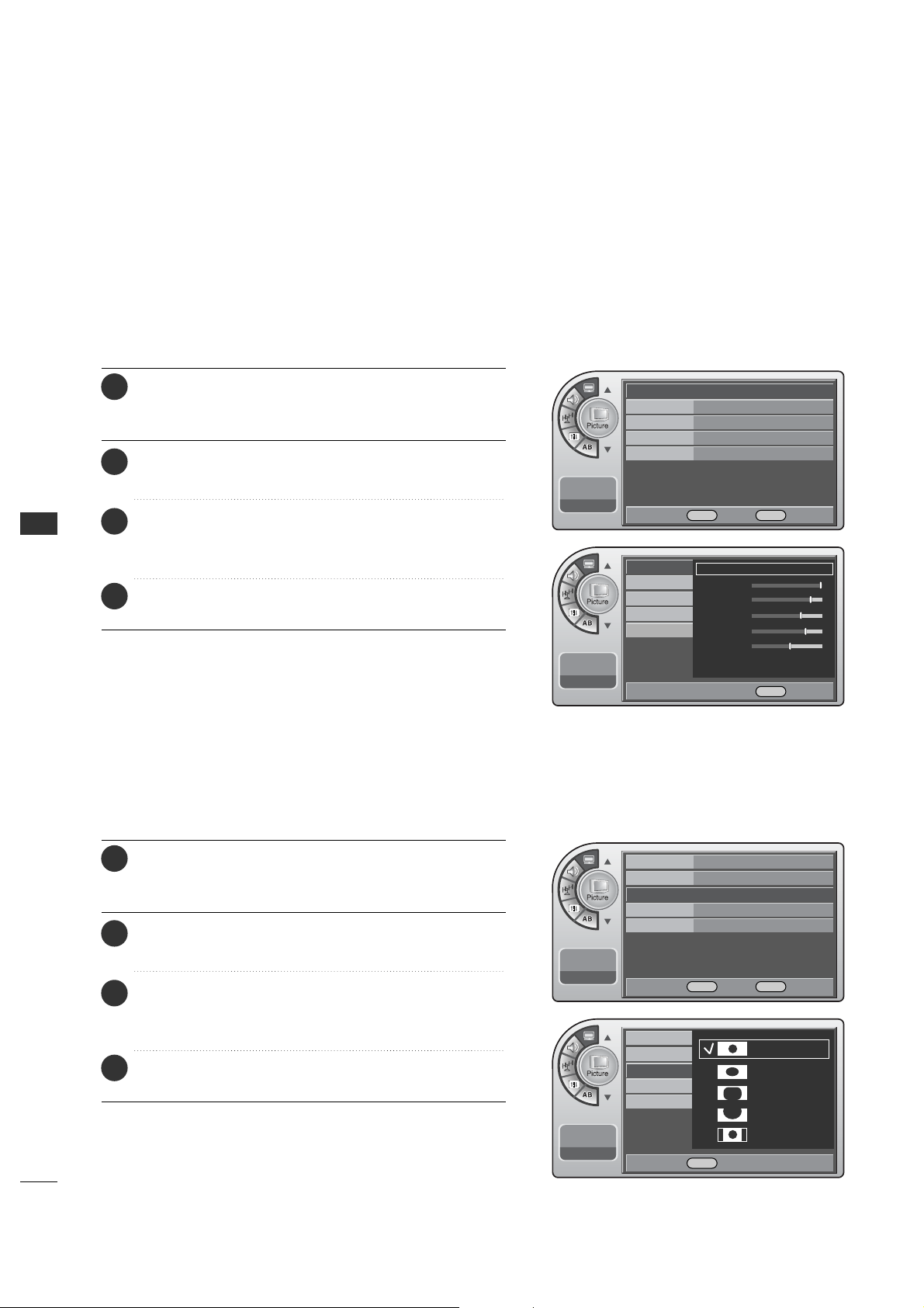
PICTURE CONTROL
50
PICTURE CONTROL
The user can choose preset formats for the picture on analog channels.
Screen Format Adjustments
To make custom picture settings, set the Mode to Manual on the menu.
Use the Manual settings for the best presentation of movies.
The patient will then be able to view movies with more realism.
Manual Picture Adjustment
Mode Standard G
Color Temperature
Cool
Screen Format
16:9
Noise Reduction
Off
Film Mode Off
11:20 PM
Sep.11, 2006
Mode Standard
Color Temperature
Cool
Screen Format
16:9
G
Noise Reduction
Off
Film Mode Off
11:20 PM
Sep.11, 2006
Mode
Color Temperature
Manual
G
Contrast
Brightness
Sharpness
Color
Tint
Screen Format
Noise Reduction
Film Mode
11:20 PM
Sep.11, 2006
DE
Move OK Select Menu Back
DE
Move OK Select Menu Back
Mode
Color Temperature
Screen Format
Noise Reduction
Film Mode
11:20 PM
Sep.11, 2006
Set By Program
16:9
Zoom1
Zoom2
4:3
DE Select Menu Back
F G Move G Select Menu Back
Press the MM EE NN UU button and then use the AADD JJ D or E
button to highlight the PPiiccttuurree menu and press the OO KK
(( EEnn tt ee rr )) button.
1
Use the AADDJJ D or E button to highlight MMooddee
and press the OOKK (( EEnntteerr )) button.
2
Use the AADDJJ G button to choose MMaann uu aa ll and use
AADDJJ DEF Gbuttons to set your own settings for the
options. When finished, press the MMEENNUU button.
3
When finished, press MM EENN UU repeatedly to remove the
menus.
4
Press the MM EE NN UU button and then use the AADD JJ D or E
button to highlight the PPiiccttuurree menu and press the OO KK
(( EEnn tt ee rr )) button.
1
Use the AADDJJ D or E button to highlight SSccrreeeenn FFoorrmmaatt
and press the OOKK (( EEnntteerr )) button.
2
Use the AADDJJ
D
or
E
buttons to choose a preset screen
format: Set By Program, 16:9, Zoom1, Zoom2 or 4:3.
When finished, press the OOKK (( EEnntteerr )) button.
3
When finished, press MM EENN UU repeatedly to remove the
menus.
4
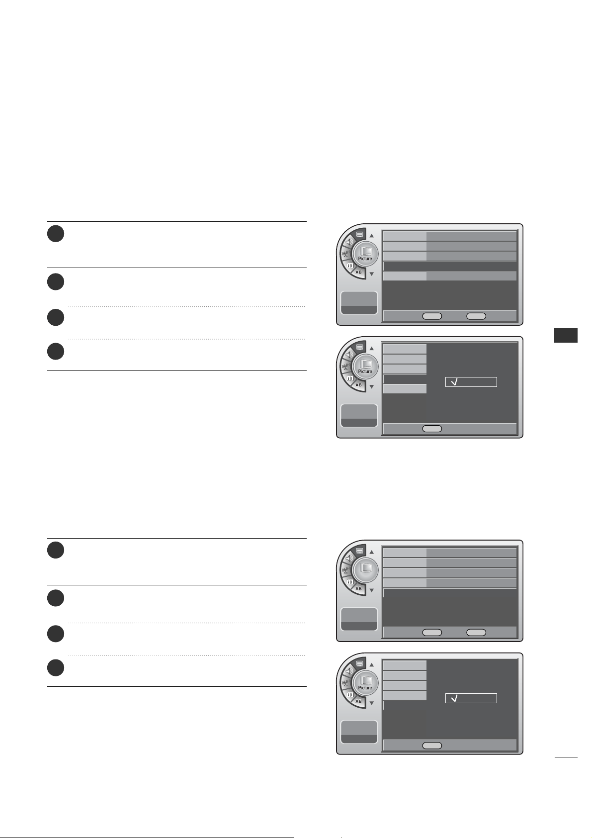
51
PICTURE CONTROL
The user can watch movies with a more realistic picture on analog channels.
Turn Film Mode On to view movies with optimum preset picture settings.
Film Mode Options
Noise Reduction
The user can watch movies with a more realistic picture on analog
channels.
Mode Standard
Color Temperature
Cool
Screen Format
16:9
Noise Reduction
Off
G
Film Mode Off
11:20 PM
Sep.11, 2006
DE
Move OK Select Menu Back
Picture
Mode Standard
Color Temperature
Cool
Screen Format
16:9
Noise Reduction
Off
Film Mode Off G
11:20 PM
Sep.11, 2006
DE
Move OK Select Menu Back
Mode
Color Temperature
Screen Format
Noise Reduction
Film Mode
11:20 PM
Sep.11, 2006
Off
On
Mode
Color Temperature
Screen Format
Noise Reduction
Film Mode
11:20 PM
Sep.11, 2006
Off
On
DESelect Menu Back
DESelect Menu Back
Press the MM EE NN UU button and then use the AADD JJ D or E
button to highlight the PPiiccttuurree menu and press the OO KK
(( EEnn tt ee rr )) button.
1
Use the AADDJJ D or E button to choose NNooiissee RReedduuccttiioonn
and press the OOKK (( EEnntteerr )) button.
2
Use the AADDJJ
D
or
E
button to choose OO nn or OO ff ff.
When finished, press the OOKK (( EEnntteerr )) button.
3
When finished, press MM EENN UU repeatedly to remove the
menus.
4
Press the MM EE NN UU button and then use the AADD JJ D or E
button to highlight the PPiiccttuurree menu and press the OO KK
(( EEnn tt ee rr )) button.
1
Use the AADDJJ D or E button to choose FFiillmm MMooddee and
press the OOKK (( EE nntt eerr)) button.
2
Use the AADDJJ D or E button to choose OO nn or OO ff ff.
When finished, press the OOKK (( EEnntteerr )) button.
3
When finished, press MM EENN UU repeatedly to remove the
menus.
4
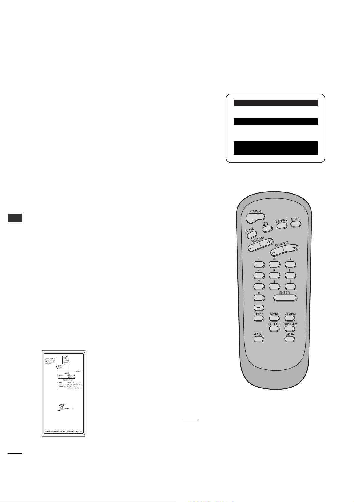
COMMERCIAL MODE
52
COMMERCIAL MODE
INSTALLER OVERVIEW
Operating Installer Menu
To set up the controls for the TV you will need to know how to enter
the 26LH1DC3/4/5 Installer menu and make changes to the default
values as required. If necessary, familiarize yourself with the 26LH1DC3/4/5
Installer menu and how to make and save changes in the menu.
Optional Installer Remote
You will need an Installer remote control similar to the one shown to the
right.
The TV’s clonable features need to be set up before 2-5-5 + Menu is
done.
This is a critical step.
If the Master TV display panel’s clonable features like: Clock Set, adding
channel icons and channel labels, etc. are not done properly, then the
cloned 26LH1DC3/4/5 TVs will all have problems. For example, do not do
2-5-5 + Menu more than once or the TV setup will become corrupted. If
you need to start the procedure over, then begin by setting installer item
117 to 001, and pressing Enter to reset the TV to default values in the
installer menu. You can do 2-5-4 + Menu mode more than once but this
mode is limited to only editing channel icons and channel labels.
Refer to the appropriate section in the Manual for other TV features:
Picture, Sound etc.
*Note: Digital Font options are available only after a channel search has
been run and when the TV is tuned to an active digital channel with digital
captions.
LT 2002 Clone Programmer
As the cloning procedure is being performed, specific steps need to
be done at the indicated times to achieve the
desired result. Be sure to do each cloning task as
indicated. If a procedure or step is left out or not
performed correctly, then the TV setup will be wrong
and cloning may not work. At each step, pay
attention to assure the TV screen shows the proper
message(s) when cloning. If the message indicated
does not appear, there is a problem with that step
and cloning may not be successful. Cloning is only
possible when the signal source is an Analog
channel,
not a digital channel.
Following is the Commercial Mode Operation Setup.
QuickSet II Programmer
LT2002
¤
LODGING PTC INSTALLER MENU
000 INSTALLER SEQ 000
UPN 000-000-000-000 FPGA 09F1
PTC V1.00.000 CPU V1.01.00
Typical Installer Menu
53
COMMERCIAL MODE
COMMERCIAL MODE SETUP
*Note1: Disconnect all Aux inputs. Under certain conditions, Auto Program (Channel
search) is disabled if there is an Aux input active.
*Note2: Under certain conditions, changes to the input mode of the RGB
inputs will not take effect until the power is cycled (TV is turned Off and On). To avoid
confusion, disconnect all RGB inputs before entering the Installer menu.
Overview: Commercial Mode Setup Procedure
1. Set Installer Menu Items
(Enter Installer Menu, see page 42 for detailed instructions.)
a. Set Installer menu item 117 F A CT DEFAULT, to 001 and press ENTER.
(This clears all installer menu items, custom settings, channel labels/icons
and reloads the factory default settings.)
b. Set Item 003 BAND/AFC.
- Broadcast: set to 000.- HRC: set to 002
- CATV: set to 001.- IRC: set to 003
c. Set item 028 CH OVERIDE to 001. This allows access to Auto Program,
Channel Labels and Channel List options in the Channel Menu.
d. Set other particular installer items that affect your TV programming
network. See pages 57 - 62.
e. After all required installer menu item settings have been adjusted, press
ENTER on the remote to remove Installer Menu.
2. Set Up TV Features
(See Picture, Sound, Setup menus etc. See TV Clonable options list on
page 62.)
*Note: Digital Font options are only available after a channel search has been run
and when the TV is tuned to an active digital channel with digital captions.
3. Run Auto Program
(Search for all available channels.) Go to the Channel menu and access
the Auto Program option, follow on-screen instructions.
a. Edit Channel Scan. In the Channel Menu, access the Channel List menu.
• Delete channels per your system requirements: do you want to delete any
free channels so the guest cannot access them?
•Add familiar Channel Icons like ABC, CBS, NBC etc. to the channel
onscreen display. Add identifiable labels for the end user to readily know
what common networks are available. In the Channel menu, select the
Channel Label option, follow instructions on the bottom of the screen.
4. Transfer TV Setup to Controller Box: 2-5-5 + Menu
After the TV channel scan has been edited and channel label icons added,
enter the Installer menu. Once in the Installer menu, press 2-5-5 and
MENU on the remote. This transfers the TV setup to the internal controller
box.
*Note: Only do 2-5-5 + MENU once or TV setup may be corrupted.
TV scans available channels and exits menu when transfer to controller is complete.
5. Perform Adding Custom Channel Labels: 2-5-4 + Menu Mode
Enter Installer menu, press 2-5-4 and Menu. Add your own custom labels to
the channel on-screen displays. (See page 62.) To remove menu press
MENU.
*Note: 2-5-4 + MENU can be performed more than once.
Verify TV Setup
At this point, verify that the channel lineup, channel icons and custom
labels are correct. Make sure the TV features are set per your requirements.
Set item 028 CH OVERIDE to 000 to lock the channel scan. After the
preceding has been completed, the Master TV setup is ready to be copied to
the LT2002 Clone Programmer, see next page.
This page provides an overview of the TV configuration. See the pages listed below for more specific, detailed
instructions at each step; how to access and use the Installer menu etc.
L26W56XA Installer Menu
L26W56XA Installer Menu Items
RJP (Remote Jack Pack) TV Setup
Custom Channel Label ‘WXYZ’ created in 2-5-4 +
Menu Add Channel Label Mode
After TV setup has been verified,
set item 028 Ch Overide back to 000.
LODGING PTC INSTALLER MENU
117FACT DEFAULT 00X
003 BAND/AFC 00X
028 CH.OVERIDE 001
073 CH. NOT AVBLE 001
• RJP Available? If you will use an RJP in
your system, review installer items:
-004 Start Channel cannot be set to
000.
-Set 040 Auto Camport to 000.
-Set 093 RJP Available to 001.
004 STRT CHANNEL XXX
040 AUTO CAMPORT 000
093 RJP AVAILABLE 001
028 CH. OVERIDE 000
000 INSTALLER SEQ 000
UPN 000-000-000-000 FPGA 09F1
PTC V1.00.000 CPU V1.01.00
WXYZ
DIGITAL 19-3
MONO SAPSTEREO
WXYZ
ANALOG 2
MONO
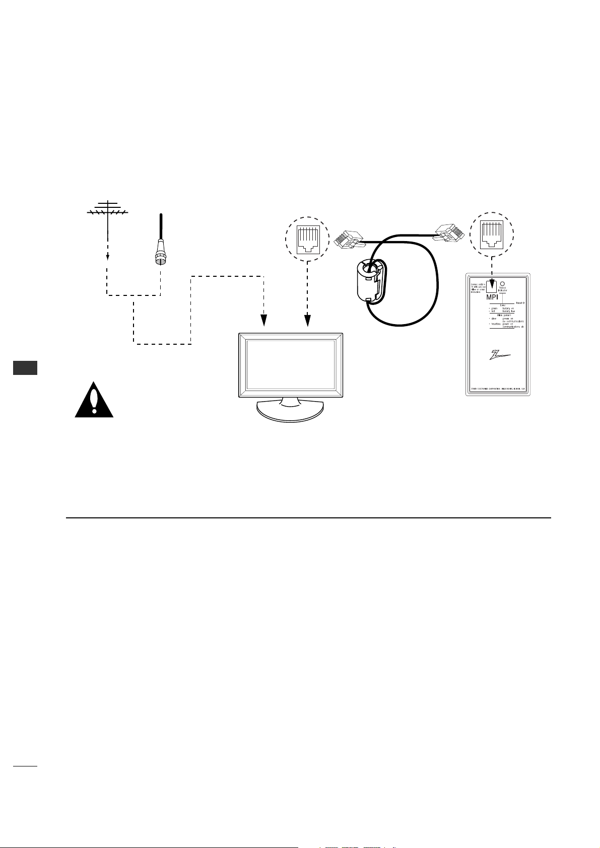
54
COMMERCIAL MODE
COMMERCIAL MODE
CLONING CONNECTIONS/LEARNING SETUP
*Note1: It is assumed that the 26LH1DC3/4/5 is connected to a signal source, the source selected is Antenna (RF) In, the signal is from
an Analog channel, not a digital channel, all equipment is connected to power and turned on and the LT2002 Clone Programmer main menu
(THE CLONE HAS CONTROL OF THE TV) menu is displayed on the TV screen, the clone programmer LED is blinking the required heart
beat pattern, see above and next page.
*Note2: Once the clone is connected, do not touch the unit or otherwise disturb it or the MPI connections. Any disturbance while the
clone is operating may disrupt the master setup transfer or copying etc.
- Connections for the LT2002 Clone Programmer to Learn the 26LH1DC3/4/5 Master TV Setup
Clone Programmer
Master 26LH1DC3/4/5
THE CLONE HAS CONTROL OF THE TV
THE CLONE IS VERSION XX
THE TV IS VERSION XX
THE SW IS REVISION XX
CLONE CLOCK = XX:XX
TV CLOCK = XX:XX
-PRESS ANY KEY TO CONTINUE.
-DISCONNECT CLONE WHEN DONE.
QuickSet II Programmer
LT2002
¤
Ferrite Core
(TDK, ZCAT
2035-0930)
Antenna
or CATV
Warning: Do not use LT2002
if a Lodge Net PPV card is
installed in TV or clone
programmer device will be
damaged.
Before you begin cloning...
• The Master 26LH1DC3/4/5 should be connected to
a good, stable signal from an over-the-air antenna or
cable service Analog channel and connected to power.
(See above.)
•Teaching and Learning is only possible between
identical model devices. (However, the LT2002 Clone
programmer can store up to 3 different ‘master’
setups.)
WARNING: Copying a blank or incorrect memory into a
TV, STB or other device will cause the TV, STB or
other device to operate erratically or become
inoperable.
• Use an Installer’s remote to operate Learning and
Teaching menus.
• Make sure that the batteries in the Clone programmer
are fresh.
• If batteries are removed, the Clone Clock time will be
lost.
•Decide if you want to set the time from the Clone
programmer TV which has the clock set to the current
time.
•Setting the time and transferring it to the Clone or
other device is a separate procedure.
•Follow the connection diagram above to connect the
Clone to a Master 26LH1DC3/4/5 TV display panel.
After learning is complete, to another identical
26LH1DC3/4/5 TV display panel to “teach” it the
master setup.
•After the 26LH1DC3/4/5s setup has been copied to
another identical 26LH1DC3/4/5, that identical unit
with the copied setup, needs to be disconnected from
power for about 15 seconds to activate the
newly-copied setup.
•See the Clone Tr oubleshooting section to resolve
problems.
Turn to the next page to continue Cloning Setup.
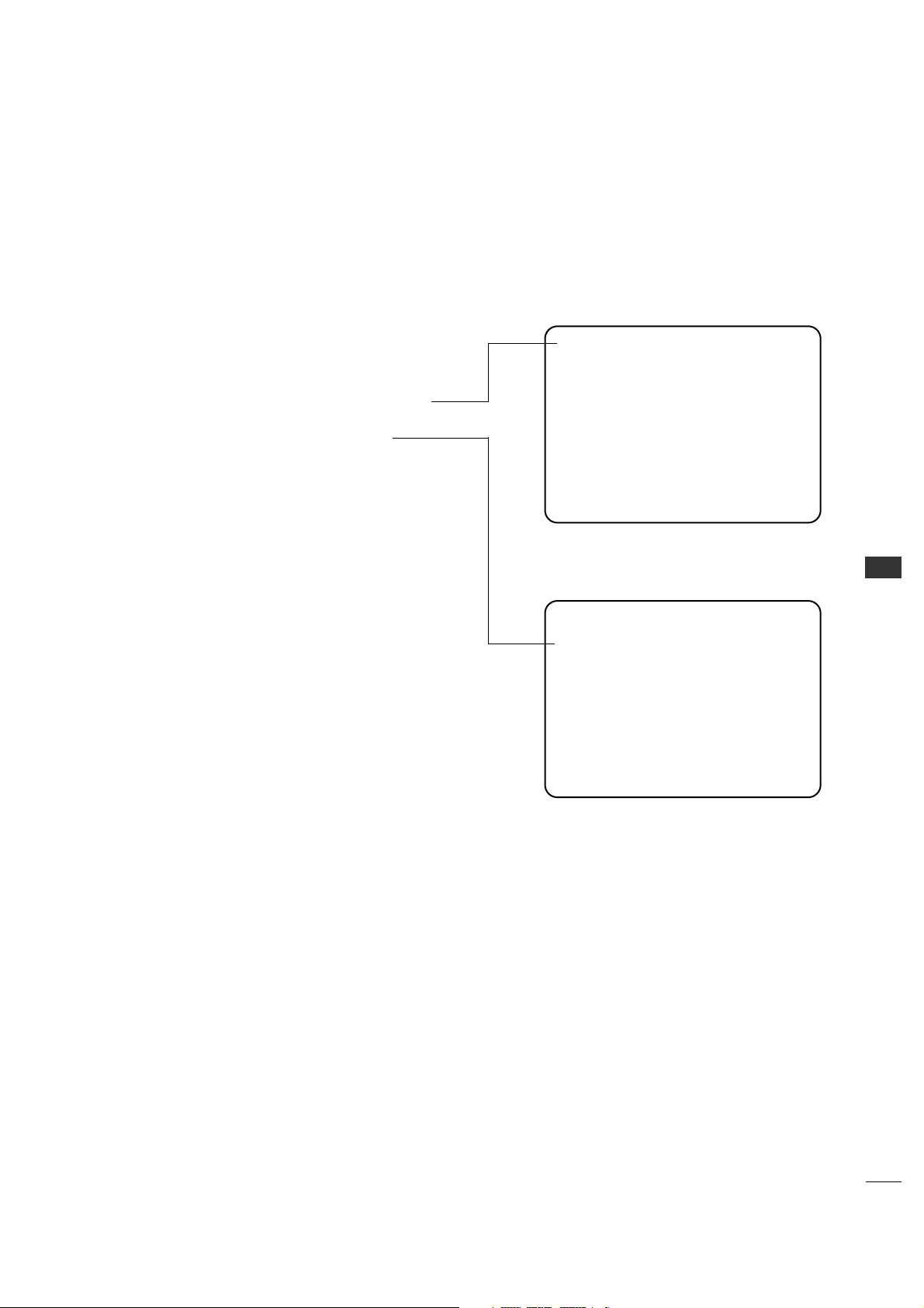
55
COMMERCIAL MODE
Learn Setup from Master 26LH1DC3/4/5
Press 1 to select the “LEARN FROM TV” option, then press
ON/OFF, POWER, or ENTER to go to the Memory Bank
Selection Menu. Pick the Memory ”Bank” you want to store
the master 26LH1DC3/4/5’s setup in by pressing either
Channel button repeatedly to choose Memory 1, 2 or 3. (If
you choose a Memory “Bank” that has a master device’s
setup programmed into it, that setup will be overwritten by
the new master 26LH1DC3/4/5’s setup.) Once the Clone
memory bank is selected, press ON/OFF, POWER, or ENTER.
The Clone memory bank you have selected will be shown.
Press ON/OFF or POWER to begin copying the master
26LH1DC3/4/5’s setup.
CLONE PROGRAMMER LEARNING SETUP
Instructions for the Clone Programmer to Learn the Master 26LH1DC3/4/5 Setup.
Learning the Master TV Setup
Use MPI Cable to Connect LT2002 Clone Programmer to
Master 26LH1DC3/4/5 MPI Port
If there is a good connection, “THE CLONE HAS CONTROL
OF TV” message will appear. Press any button on the Installer
remote.
Set the Clock (Optional)
Set the time on a Master TV’s Clock. (If the time has
already been copied from a TV into the Clone programmer,
you can set a master TV’s clock by copying the time from
the Clone programmer.) The Clone Programmer can copy the
current time to both a master TV and to the Clone’s internal
clock; accurate to within one minute. (Another reason that
the Clone programmer should be equipped with fresh,
high-quality alkaline batteries, is for it to keep the time as
accurately as possible.)
Since the Clone Programmer’s time cannot be set directly,
the current time needs to be copied from a LG TV equipped
with M.P.I. input capability.
After the time is copied to the Clone programmer, the
current time can then be transferred to another TV. (This
can be a master TV, or another TV which has already had
the features set up.)
*Note: When using the clone programmer for teaching or learning,
be sure that the heartbeat pattern is shown on the LEDs. Both learning
and teaching should take about 45 or more seconds depending on the
complexity of the master setup. While the clone is functioning, do not
move it or otherwise disturb the clone or wiring connections. If the clone
finishes the function in less than 45 seconds, redo the function again.
Press the reset button if the clone does not act normally.
LT 2002 Clone Programmer Communication
Problems
•A slow flashing green light indicates there are
communication problems between the
26LH1DC3/4/5 and the LT2002 clone pro-
grammer. If this is the case, check for a dam-
aged cable, poor contacts, or other connection
troubles.
• If the status indicator is red, the programmer
batteries are low and should be replaced. Install
4 high-quality alkaline AA batteries.
THE CLONE HAS CONTROL OF THE TV
THE CLONE IS VERSION XX
THE TV IS VERSION XX
THE SW IS REVISION XX
CLONE CLOCK= XX:XX
TV CLOCK= XX:XX
-PRESS ANY KEY TO CONTINUE.
-DISCONNECT CLONE WHEN DONE.
This menu should appear by itself after the
LT 2002 is connected to the 26LH1DC3/4/5 MPI
port.
CLONE SELECTION MENU
(1) LEARN FROM TV
(2) TEACH TO TV
(3) SET CLONE CLOCK FROM TV
(4) SET TV CLOCK FROM CLONE
(5) DISPLAY TV SETUP
(6) DISPLAY CLONE SETUP
-TO CHANGE MENU ITEMS, PRESS
CHANNEL KEYS OR DIGITS.
-TO EXECUTE ITEM, PRESS ON/OFF,
POWER, OR ENTER
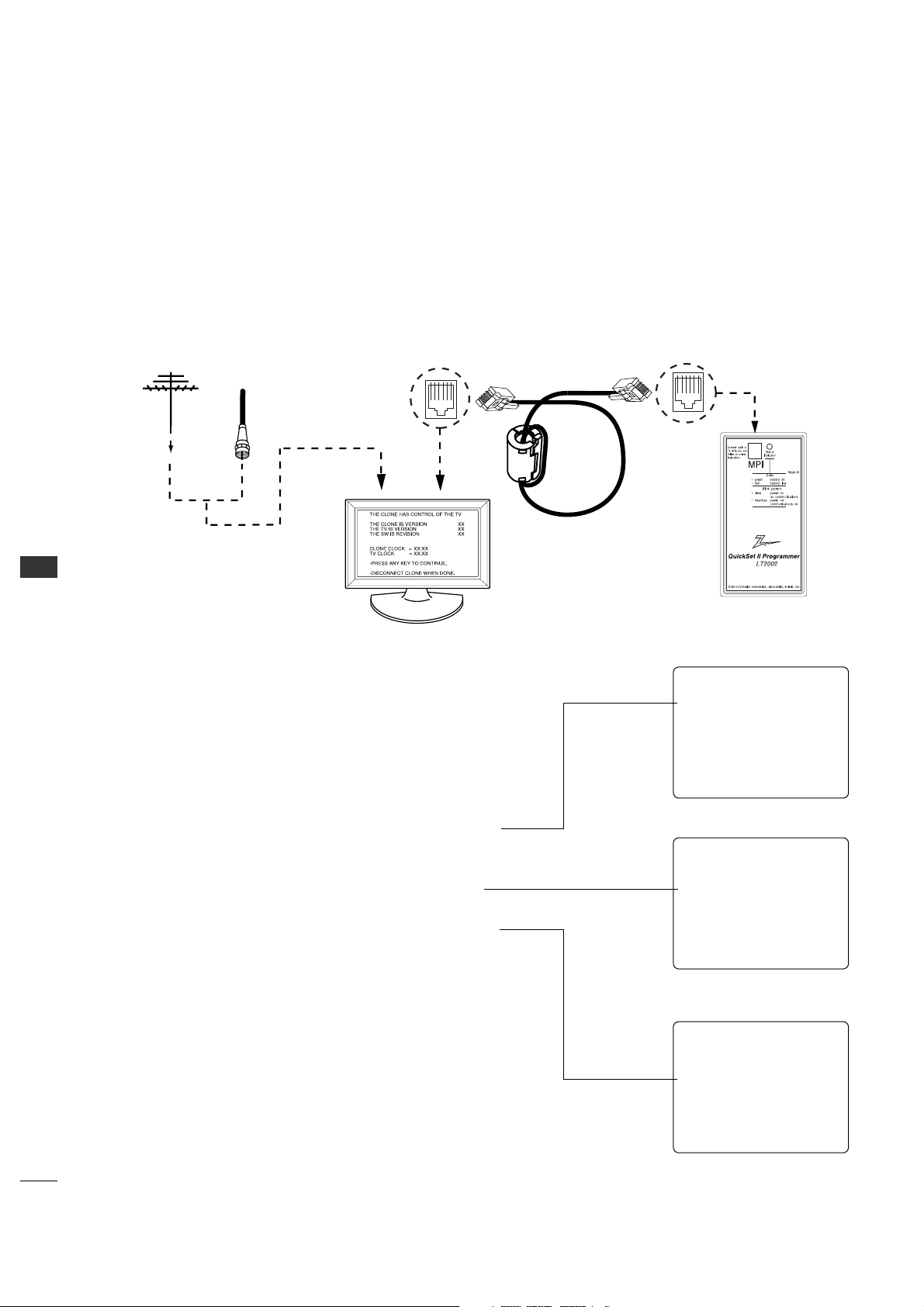
COMMERCIAL MODE
56
COMMERCIAL MODE
CLONING CONNECTIONS/TEACHING SETUP
- Connections for the LT2002 to Teach another 26LH1DC3/4/5 the Master Setup
Teaching the Master Setup to Another 26LH1DC3/4/5
Teach Master 26LH1DC3/4/5’s Setup to the target
26LH1DC3/4/5
After learning is complete, remove the M.P.I. cable from the
master 26LH1DC3/4/5 and connect it to the target
26LH1DC3/4/5 that you want to copy the master
26LH1DC3/4/5’s setup into. With “THE CLONE HAS
CONTROL OF TV” message displayed, press 2 to go to the
“TEACH TO TV” option, press ON/OFF, POWER, or ENTER.
Select the LT2002 memory that the new setup is in. Press
On/Off to transfer the new setup and other information to
the new 26LH1DC3/4/5. Teaching usually takes 2-3
minutes.
After the “TEACHING COMPLETE” message is displayed,
press any button to return to the Clone menu, then press
ON/OFF, POWER, or ENTER. If finished, detach M.P.I. cable
from the target, newly cloned 26LH1DC3/4/5.
Disconnect 26LH1DC3/4/5 Power for 15 Seconds
Unplug the AC power cord of the newly cloned
26LH1DC3/4/5 from the power outlet for about 15 seconds
to activate the newlycopied setup.
Clone Programmer
Master 26LH1DC3/4/5
Ferrite Core
(TDK, ZCAT
2035-0930)
Antenna
or CATV
CLONE SELECTION MENU
(1) LEARN FROM TV
(2) TEACH TO TV
(3) SET CLONE CLOCK FROM TV
(4) SET TV CLOCK FROM CLONE
(5) DISPLAY TV SETUP
(6) DISPLAY CLONE SETUP
-TO CHANGE MENU ITEMS, PRESS
CHANNEL KEYS OR DIGITS.
-TO EXECUTE ITEM, PRESS ON/OFF,
POWER, OR ENTER
TEACHING IN PROGRESS,
PLEASE WAIT
TEACHING COMPLETE
This menu should appear after any key is
pressed on the Installer remote.
This display will appear during Teaching
function.
This display will appear after Teaching is
complete.
COMMERCIAL MODE
57
Accessing the Installer’s Menu
Make sure TV is on. Installer’s menu items can be accessed by using
an installer’s remote control. Just press MENU repeatedly (at least 10
times) until the TV seems to stop responding, then press 9, 8, 7, 6,
then ENTER to access the Installer’s menu. To remove the Installer’s
menu, press ENTER again. Any changes you make will be stored in
nonvolatile memory. (The menu also disappears automatically.)
The Installer’s menu opens with item 000 INSTALLER SEQ 000. Use
the Up/Down arrow buttons to sequence through the available menu
items. Or, access an item directly by keying in the line number, then
pressing MENU. For example, to access the Sleep Timer option
which is item 015, press 0-1-5, then MENU. To change a setting, use
the Left/Right arrow buttons. Or, enter a value directly.
Using the Installer’s Menu
Items 000 ~ 117 are immediately accessible only upon entering the
Installer’s Menu. Their numbers, descriptions, ranges, factory default
settings, and a place for listing any changes made on-site are given
below and on the following pages.
- Use the Installer’s Menu to set up or change operational settings.
See more detailed descriptions of the Installer menu items on the following pages...
Installer Menu Items 000 through 117
Typical Installer Menu
LODGING PTC INSTALLER MENU
000 INSTALLER SEQ 000
UPN 000-000-000-000 FPGA 09F1
PTC V1.00.000 CPU V1.01.00
Menu Item Function Value Range Default Value Brief Description of Function and Comments
000 INSTALLER SEQ 0 ~ 30 Leave default set to 0.
001 POWER MANAGE 0 ~ 70 Sets number of hours of no activity before auto shut Off.
002 AC ON 0 / 1 0 Set to 1 to enable auto turn On at power up.
003 BAND/AFC 0 ~ 31Selects Tuning Band: 0=Broadcast, 1=CATV, 2=HRC, 3=IRC
004 STRT CHANNEL 0-125, 126, 127, 255 255 Channel at turn-on (Set 255 to return to last channel before power Off).
005 CHAN LOCK 0 / 1 0 If set to 1, cannot tune from current channel.
007 STRT VOLUME 0 ~ 63, 255 255 Sets Volume level at TV turn-on (Set 255 to retain last volume level).
008 MIN VOLUME 0 ~ 63 0Sets minimum allowable volume setting.
009 MAX VOLUME 0 ~ 63 63 Sets maximum allowable volume setting.
010MUTE DISABLE 0 / 1 0 Set to 1to disable mute function.
011 KEY DEFEAT 0 / 1 1 Set to 1 to disable menu navigation keys on display panel.
015 SLEEP TIMER 0 / 1 1 Set to 1 to enable Sleep Timer.
016 EN TIMER 0 / 1 0 Set to 1 to enable On/Off Timers.
017 ALARM 0 / 1 1 Set to 1 to enable Alarm.
021V-CHIP 0 / 1 1 Set to 1 to enable V-Chip functions.
022 MAX BLK HRS 0 ~ 99 12 Sets number of V-Chip (Parental Control) blocking hours.
023 CAPTION LOCK 0 / 1 0 Set to 1 to retain caption setting at power Off.
028 CH. OVERIDE 0 / 1 1 If set to 0, limits direct access to favorite channels.
029 OLD OCV 0 / 1 0 Set to 1 to change M.P.I. operation to OCV.
030 ACK MASK 0 / 1 0 If set to 1, changes M.P.I. for some OCV boxes.
031 POLL RATE 20 ~ 16994 Selects poll rate for M.P.I.
03 TIMING PULSE 186 ~ 227 207 Sets baud rate for M.P.I.
034 CAMPORT EN 0 / 1 1 Set to 1 to enable Video 2 input.

COMMERCIAL MODE
58
COMMERCIAL MODE
INSTALLER MENU
- Installer Menu Items 035 through 117
Menu Item Function
Value Range
Default Value Brief Description of Function and Comments
035 COMPPORT EN. 0 / 1 1 Set to 1 to enable HDMI. Set to 0 to disable.
038 YPrPb EN. 0 / 1 1 Set to 1 to enable display panel Component 1 input jacks.
039 REAR AUX EN 0 / 1 1 Set to 1 to enable display panel Video 1 input jack.
040AUTO CAMPORT 0 / 1 1 Set to 1 to automatically switch to Camport.
046 STRT AUX SRCE 1 ~ 7, 255255 Sets the starting AUX source.
047AUX STATUS 0 / 1 0 Set to 1 for M.P.I. AUX source to be reported as a channel number instead of Channel 0.
053 DIS. CH-TIME 0 / 1 0 Set to 1 to disable Channel-Time display.
069 EN. CH-T COL. 0 / 1 1 Set to 1 to enable custom color for the Channel-Time display.
070FOR. CH-TIME 0 ~ 72 Chooses custom foreground color for the Channel-Time display.
071 BCK. CH-TIME 0 ~ 72 Chooses custom background color for the Channel-Time display.
073 CH NOT AVBLE 0 / 1 0 If set to 1 and channel override is 0, “NOT AVAILABLE” message is displayed
when directly accessing a channel not in the favorite channel list.
075 REVERT CH 0 / 1 0 If set to 1 and loss of M.P.I. communication occurs, TV tunes to Start Channel.
078 UPN MSB 0 ~ 2550 User programmable number, most significant byte.
079 UPN MSB-1 0 ~ 2550 User programmable number, most significant byte - 1.
080 UPN MSB-2 0 ~ 2550 User programmable number, most significant byte - 2.
081 UPN LSB 0 ~ 2550 User programmable number, least significant byte.
082 CHKSM ERROR 0 / 1 1 Enforces rigid M.P.I. checksum.
083 HANDSHK TIME 0 ~ 55Relaxes M.P.I. timing to be compatible with PC based Windows-controlled systems.
084 PERMANENT BLK 0 / 1 0 Removes block hours setting for Parental Control and makes block permanent.
087 REAR RGB EN. 0 / 1 1 Enables RGB1 input. Set to 1 to enable, set to 0 to disable.
088 EN NOISE MUTE 0 / 1 1 If set to 1, mutes audio if no signal is present.
090 KEY LOCK 0 / 1 0 If set to 1, keyboard is locked out, IR is still functional.
091 YPrPb2 EN. 0 / 1 1 Set to 1 to enable Component 2 input jacks.
092RGB2 ENABLE 0 ~ 22
Enables Video 3 input. Set to 1 for Composite Video or 2 for S-Video. Set to 0 to disable.
093 RJP AVAILABLE 0 / 1 0 Set to 1 to enable.
094 SAP MENU EN 0 / 1 1
Set to 0 to disable feature on Function menu. Set to 1 to enable feature on Function menu.
096 DEF. ASP. RATIO 0, 1, 2, 4, 5 2 Sets default aspect ratio at power up. See detailed descriptions and item 106.
10 2ATSC BAND 0 ~ 44 Selects ATSC band.
10 3ATSC TUNE MODE 0 / 1 1 Sets ATSC tuning mode. Set to 0 for virtual channels, set to 1 for physical channels.
10 4STA RT MINOR CH 0 ~ 2550 Selects Minor start channel. Set 0 for NTSC. Not 0, sets Minor channel number.
10 6ASP RATIO LOCK 0 / 1 0
To retain set aspect ratio on power cycle, set to 1. Set to 0 for default ratio on power cycle.
10 7BANNER SELECT N/A N/A Not applicable.
116 VIDEO MUTE EN 0 / 1 0 Set to 0 for normal, set to 1 for Blank.
117FACT DEFAULT 0 / 1 0 0=Normal. 1=Loads factory default presets of all above settings.

59
COMMERCIAL MODE
005 - CHAN LOCK (Channel Lock)
CHAN LOCK is ideal if the system must always be on
the same channel. Changing channels with Channel
Up/Down or keypad numbers is impossible. Channel Lock
is inactive if set to 0 (default).
Generally, this feature is used in connection with START
CHANNEL (Installer item 004) where the start channel
may, for example, be set to 3 or 4. If the start channel is 3,
then the 26LH1DC3/4/5 will remain locked on Channel 3.
007 - STRT VOLUME (Start Volume)
This function allows the Installer to determine the initial
volume level setting when the 26LH1DC3/4/5 is turned
On. This feature is useful for an in-house information
channel, since the 26LH1DC3/4/5 would always select
that volume level when it is turned On. The range of
values are 0 - 63, 255. If 255 is selected, the current
volume level will be retained in memory when the
26LH1DC3/4/5 is turned Off; at turn On, the volume
level will be
automatically set at the previous or last level.
008 - MIN VOLUME (Minimum Volume)
This function determines the minimum volume level
allowable with the VOLUME (VOL) Up/Down control. In
this way, for example, someone cannot set the volume
too low to hear. The value range is from 0 to 63 —
change values with ADJ Left/Right arrow. The factory
default is 0, which provides the full range of volume
control, if item 009 MAX VOLUME is also set to 63. It
may be best to set the
same value on every 26LH1DC3/4/5.
*Note: The minimum volume level cannot have a value setting higher
than the MAX VOLUME level (described below).
009 - MAX VOLUME (Maximum Volume)
This function determines the maximum volume level
allowable with the VOLUME (VOL) Up/Down controls. In
this way, for example, someone can not set the volume
level high enough to disturb others.
(Continued on next page)
*Note: For Items 007, 008 and 009
For legacy reasons, the scale used is 0 - 63. The PTC software
will translate this to the 0 - 100 scale used by the TV.
To translate a TV volume level to the installer menu value, use
the following formula:
Installer Value = TV V
alue x 63
10 0
Enter only the whole number (disregard fractions).
Detailed Descriptions of Installer Menu Items
000 - INSTALLER SEQUENCE
Specifies entry sequence to the Installer Menu.
0 = 9876 1 = 4321
2 = 1478 3 = 3698
001 - POWER MANAGE (Power Management)
Determines hours of no activity before automatic
shutoff. The POWER MANAGE function is for saving
energy. If set to 0, Power Manage is Off. Settings range
from 0 - 7, with 1 - 7 representing the hours that the
TV will remain On, unless there has been activity from
either the control panel or remote control.
002 - AC ON (AC Power Switchable)
If set to 1, allows the 26LH1DC3/4/5 to turn On just
by applying AC power. Pressing the On button is not
necessary. This is desirable if the 26LH1DC3/4/5 is
plugged into a cable box or a power outlet controlled by
a wall switch. Use ADJ Left/Right arrow to choose 0 or
1 where 0 is the default is Off, and 1 is On.
*Note: f set to 1 (On), the 26LH1DC3/4/5 does not respond to
On/Off commands from either the remote or the display control
panel, and the SLEEP TIMER is also nonfunctional.
003 - BAND/AFC (Band/Automatic Frequency
Control)
Selects the tuning band. There are 4 possible settings
for this option:
0 = Broadcast 1 = CATV
2 = HRC 3 = IRC
If some channels were not found by Auto Program, select
the appropriate Band setting here and add the channels
using the Channel List option in the Channel Menu.
004 - STRT CHANNEL (Start Channel)
If active, this function allows you to determine the initial
channel number when the 26LH1DC3/4/5 is turned
On. This feature is useful for an in-house information
channel, since the 26LH1DC3/4/5 would always select
that channel when it is turned On. Setting this to 255
causes the last channel viewed when the
26LH1DC3/4/5 was turned Off, to be the tuned to
channel when the 26LH1DC3/4/5 is turned On again.
255 = Last channel 1-125 = Ch X 0 = Aux
126 = Map to Channel3. 127 = Map to Channel 4.
*Note: Item 004 STRT CHANNEL cannot be set to 0 if item 093
RJP AVAILABLE is set to “1”.
INSTALLER MENU

COMMERCIAL MODE
COMMERCIAL MODE
60
029 - OLD OCV (On Command Video
TM
)
Set to 1 for operation with systems from On Command
Corporation.
030 - ACK MASK
M.P.I. Communication Parameter. Leave at default setting
unless changed by Pay-Per-View provider. When set to 1,
changes M.P.I. for some OCV boxes.
031 - POLL RATE
M.P.I. Communication Parameter. Selects Poll Rate for
M.P.I. Leave at default setting unless changed by
Pay-Per- View provider. Step size of 16 ms.
032 - TIMING PULSE
M.P.I. Communication Parameter. Leave at default setting
unless changed by Pay-Per-View provider. Sets baud rate.
Step size of 4.3 uS.
034 - CAMPORT EN. (Camera Port Enable)
Set to 1 to enable Video 2 input on display panel. If set
to 0, Video 2 input on display panel is not functional.
035 - COMPPORT EN. (Computer Po rt Enable)
Enable/disables display panel HDMI input jack. Set to 0
to disable, set to 1 to enable.
*Note: The setting above is ignored if Installer item 093 RJP AVAIL
ABLE, is set to 1.
038 - YPrPb EN. (Rear Component Video Enable)
Set to 1 to enable display panel rear Component Video
1 input.
Set to 0 to disable display panel rear Component Video
1 input.
039 - REAR AUX EN. (Rear Aux Enable)
Set to 1 to enable display panel rear AUX (Video 1)
input.
Set to 0 to disable display panel rear AUX (Video 1)
input.
040 - AUTO CAMPORT
Set to 1 to automatically switch to Camport when
equipment is connected to front Video input.
Set to 0 to disable front Video automatic source
selection.
*Note: This item must be set to 0 in order to enable item 093 RJP
AVAILABLE to be set to 1.
046 - STRT AUX SRCE (Start Aux Source)
Sets the starting AUX source.
Start source if start channel =0
1 = Video1 4 = RGB1 7 = Video 3 / S-Video
2 = Video2 5 = Component 2 255 = Last Aux
3 = HDMI 1 6 = Component 1
047 - AUX STATUS
Set to 1 for M.P.I. AUX source to be reported as a
channel number instead of channel 0. Set to 0 to
disable AUX identification change.
Controls M.P.I. status channel response for AUX inputs.
(Continued on next page)
(Continued from previous page)
The value range is 0 to 63, with 63 as the default,
which gives the user the full range of volume control, if
item 008 MIN VOLUME is also set at 0. Change values
with ADJ Left/Right arrow keys. It may be best to set
the same value on every 26LH1DC3/4/5.
*Note: The maximum volume level cannot have a value setting lower
than the MIN VOLUME level (described previously).
010 - MUTE DISABLE
Enables or disables sound mute function. If set to 1,
sound cannot be muted, mute is disabled. If set to 0,
sound can be muted.
011 - KEY DEFEAT (Keyboard Defeat)
If set to 1, key defeat prevents the end user from
accessing the onscreen menus with the display front
panel—MENU, SELECT, and Left / Right arrow keys and
TV/AV do not function. If set to 0, those keys do func-
tion.
*Note: The menus can always be accessed by pressing MENU on the
Installer remote.
015 - SLEEP TIMER
If set to 1, the SLEEP TIMER feature may be used. If
set to 0, the Sleep Timer is not available.
016 - EN TIMER (Enable On/Off Timers)
If set to 1, Timer function is available to user. Set to 0
to disable On/Off Timer functions. (Clock must be set in
order to use Timers.)
017 - ALARM
Gives the installer the option of making the Alarm
function available to the end user. If set to 1, Alarm
function is available to end user.
Set to 0 to disable the Alarm function.
*Note: Clock must be set before the Alarm function will work.
021 - V-CHIP (Parental Control)
Set to 1 to activate V-Chip (Parental Control); have it
available to end user to filter and control or otherwise
restrict programming content that can appear. Set to 0
to turn V-Chip feature Off, not available to user; no
programming restrictions can be set.
022 - MAX BLK HRS (Maximum Block Hours)
Sets hours from 0 to 99 for the maximum V-Chip
(Parental Control) block hours. Default setting is for 12
blocking hours.
023 - CAPTION LOCK
Set to 1 to restore previous caption On/Off state after
turn Off. If set to 0, captions are always Off at turn
On.
(Continued from previous page)
028 - CH. OVERIDE (Channel Override)
If set to 1, the user can select channels with either
Channel up/down or by direct keypad entry. If set to 0,
only those channels that are added on the channel list
can be selected.

COMMERCIAL MODE
61
053 - DIS. CH-TIME (Disable Channel-Time)
Set to 1 to disable the Channel-Time display,
Channel-Time display will not appear.
Set to 0 to enable the Channel-Time display.
069 - EN. CH-T COL. (Enable Channel-Time Custom Color)
Set to 1 to enable custom color for the Channel-Time
display.
Set to 0 to disable custom color for the Channel-Time
display.
070 - FOR. CH-TIME (Channel-Time Display Foreground Color)
Set according to Color Chart.
0 = Black 3 = Yellow 6 = Cyan
1 = Red4 = Blue 7 = White
2 = Green 5 = Violet
*Note: If foreground and background colors are the same, menu
background is transparent.
071 - BCK. CH-TIME (Channel-Time Display Background Color)
Set according to Color Chart.
0 = Black 3 = Yellow 6 = Cyan
1 = Red4 = Blue 7 = White
2 = Green 5 = Violet
*Note: If foreground and background colors are the same, menu
background is transparent.
073 - CH NOT AVBLE (Channel Not Available)
If set to 1 and item 028 CHANNEL OVERRIDE is set to
0, “NOT AVAILABLE” message is displayed when directly
accessing a channel not in the channel scan list available
in memory.
075 - REVERT CH (Revert to Start Channel)
If set to 1 and loss of M.P.I. communication occurs, TV
automatically tunes to the specified Start Channel.
077 - QUICK SHUTOFF
Allows TV power off to be controlled by the pillow speaker
channel selection button. User would press and hold
button down for time required to have TV turn off. Value
Range 0 - 17, each number represents 1/2 second. For
example, if set to 4, TV would turn off if user held
speaker channel button down for 2 seconds.
078 - UPN MSB (UPN Most Significant Byte)
User programmable number, most significant byte
readable by M.P.I. command.
*Note: Not linked to serial number.
079 - UPN MSB-1 (UPN Most Significant Byte-1)
User programmable number, most significant byte-1
readable by M.P.I. command. Not linked to serial number.
080 - UPN MSB-2 (UPN Most Significant Byte-2)
User programmable number, most significant byte-2
readable by M.P.I. command. Not linked to serial number.
081 - UPN LSB (UPN Least Significant Byte)
User programmable number, least significant byte
readable by M.P.I. command. Not linked to serial
number.
082 - CHKSM ERROR (Checksum Error)
Enforces rigid M.P.I. checksum validation.
Set to 1 for validation.
Set to 0 to disable (does not check checksum on M.P.I.
async port).
SPI is always checked.
083 - HANDSHK TIME (Handshake Time)
Adds an additional delay to the handshake time which is
64 msec, thus relaxing M.P.I. timing requirements to be
compatible with PC based Windows controlled systems,
range is 0 - 5.
(Timeout = 25.5MS + [25.5 MS* Handshake time]).
084 - PERMANENT BLK (Permanent Block)
Allows Lock (Parental Control) blocking schemes to be
permanent by disabling the blocking hours function.
Set to 1 to install Parental Control restrictions permanently.
Set to 0 for user-specified hours control of blocking schemes.
087 - REAR RGB EN. (Rear RGB1 Enable)
Controls access to rear RGB1 input on display panel.
Set to 1 to enable RGB1 input for DTV. Set to 0 to
disable RGB1 input.
*Note: The setting above is ignored if Installer item 093 RJP
AVAILABLE, is set to 1. Then 087 - REAR RGB EN. above, always
resets itself to PC (1) -- regardless of what value appears for item
087 on the Installer menu.
088 - EN NOISE MUTE (Enable Noise Mute)
If set to 1, audio mutes if no signal is present.
090 - KEY LOCK
If set to 1, display panel keyboard is locked out, not
available to end user. IR receiver remains functional.
091 - YPrPb2 EN. (Rear Component Video 2 Enable)
Set to 1 to enable display panel Component 2 input.
Set to 0 to disable display panel Component 2 input.
092 - RGB2 ENABLE (Red-Green-Blue 2 Enable)
Set to 1 to enable display panel Video 3 input for
Composite Video, set to 2 to enable for S-Video. Set to 0
to disable display panel Video 3 input.
093 - RJP AVAILABLE
Set to 1, remote jack pack is available.
Set to 0, remote jack pack is not available.
*Note: This item can not be set to 1 if item 040 AUTO CAMPORT is
set to 1.
(Continued on next page)
INSTALLER MENU

COMMERCIAL MODE
62
COMMERCIAL MODE
(Continued from previous page)
094 - SAP MENU EN (2nd Audio Program)
Set to 1 to enable SAP feature, if available.
Set to 0 to disable SAP feature.
096 - DEF. ASP. RATIO (Default Aspect Ratio)
Selects default aspect ratio at power up, see settings
below.
10 2 - ATSC BAND
Sets up TV to receive different types of incoming signals:
0=Broadcast, 1=CATV, 2=HRC, 3=IRC, 4=Same as
NTSC.
10 3 - ATSC TUNE MODE
Selects ATSC tuning mode: 0=Virtual, 1=Physical.
Note: The setting above is ignored if Installer item 102
ATSC BAND, is set to 1=CATV, 2=HRC, or 3=IRC. Then
10 3 - ATSC TUNE MODE above always resets itself to
Physical (1), regardless of what value appears for item
10 3 on the Installer menu.
10 4 - START MINOR CHANNEL
Sets XX-XX minor starting channel at power up:
0=NTSC. If not 0, number selected is the Minor start
channel number.
10 6 - ASP RATIO LOCK (Aspect Ratio Lock)
Set to 1 to retain previous aspect ratio with power Off.
Set to 0 to retain default aspect ratio with power Off.
See item 96 Default Aspect Ratio above.
107 - BANNER SELECT
Not applicable.
116 - VIDEO MUTE EN (Video Mute Enable)
Set to 0 for normal.
Set to 1 for blank.
117 - FACT DEFAULT (Factory Default)
Set to 0 for normal.
Set to 1 to load default settings for all installer menu
items.
WARNING: Setting this to 1 will reload the
factory defaults and clear the channel list
including erasing any assigned Channel Icons
and Labels.
Set to 0 for set by program.
Set to 1 for 4:3.
Set to 2 for 16:9 (Factory Default).
Set to 4 for Zoom 1
Set to 5 for Zoom 2

COMMERCIAL MODE
63
Closable Menu Features
Channel
Auto Program
(Active channels
found with the
channel search)
Channel Labels
Channel List
Fine Tune
Picture
Mode
Contrast
Brightness
Color
Sharpness
Tint
Color Temperature
Screen Format
Film Mode
Sound
Mode
Tr eble
Bass
Balance
Auto Volume
Multi-Track
Internal Speaker
Setup
Time
Clock
Auto Off
V-Chip
TVPG Rating
MPAA Rating
Menu Language
SET ID
Caption
On/Off
Analog Mode
Digital Mode
Digital Font Option
*Note: For Digital Font Options, if any default setting is left unchanged prior to cloning, then all the digital font options wil be set to default
settings. If you want custom digital font options to be clonable, set all digital font options to settings other than Default.
PEFERENCE
TV Features / Menus that can be Cloned
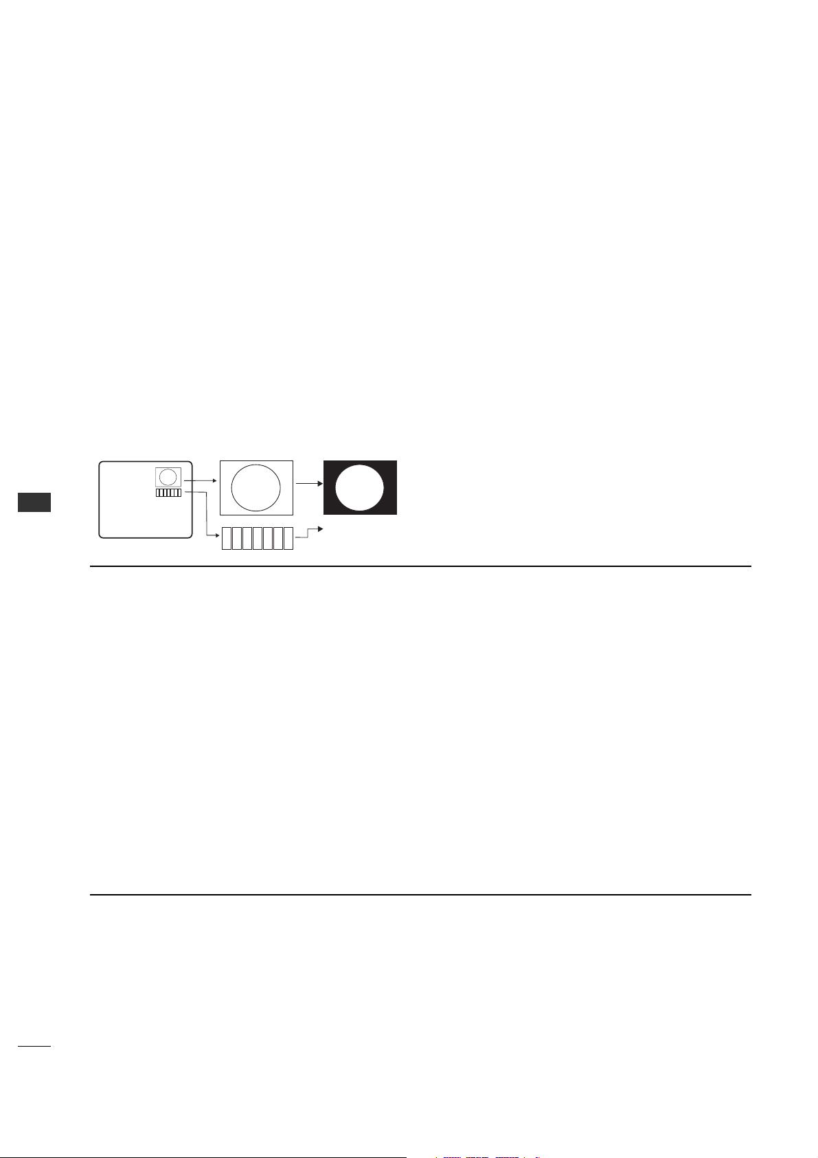
64
COMMERCIAL MODE
COMMERCIAL MODE
Editing/Adding Channel ICONs and/or Labels
If there is no pre-assigned ICON, you can make a
channel label of up to 7 characters to help in identifying
the channel or network.
At your option, channel labels can also be added in
addition to a pre-assigned ICON. You may also add
labels for the Aux input sources to clearly identify the
devices that are connected to the Aux inputs.
Editing and adding the labels can only be done if there
are channels entered into the 26LH1DC3/4/5’s channel
map either by using the method described in item 6
(page 64), by cloning or by the use of the master
remote control from the PPV provider.
To Do Channel Editing/Labeling, proceed as follows
1. Enter 26LH1DC3/4/5 Installer menu.
2. After the installer menu appears, press ‘2’, ‘5’, ‘4’,
‘MENU’.
This enters the channel label edit mode.
Add your channel icons and channel labels in this
menu, see below. (You can do this more than once.)
3. To exit the menu when done press “MENU”.
Adding Channel Icons and Labels in the 2-5-4 + Menu Mode
1
2
3
4
5
6
7
XYZ
XYZ
XYZ
NETWORK
(Label)
(Icon)
Changing a Channel’s ICON on
Master TV
1. With Channel Up/Down, select
the channel you want to change
the Icon for.
2. With the Right or Left ADJ
button, select the letter ‘I’ on the
channel ID display.
3. With the Up or Down ADJ button,
select the desired ICON you
want to appear to identify the
channel. (If you know the ICON
number, enter the number
followed by Enter / Select.)
*Note: If no Icon is available, leave at or
select the default blank icon display.
4. Proceed with Changing/Adding
Labels orgo to the next channel.
Changing/Adding Channel Labels on
Master TV
1. Channel Up/Down to select the
desired channel.
2. Press the Right or Left ADJ arrow
repeatedly until the numbers 1 to
7 show up. The number shows
the position of the character that
can be changed. Number 1 is the
first character, number 2 the
second character and so on.
3. With the Up or Down ADJ arrow,
select the desired character.
4. Proceed to the next number
position or use Channel Up/Down
to go to the next channel.
Changing Source Labels on Master
TV
1. Press “TV/AV” to select the
desired Aux input source; Video 1,
Component, S-Video etc.
2. Press the Right or Left ADJ arrow
repeat-edly until the numbers 0
to 9 show up.
The number shows the position of
the character that can be
changed.
3. Use the Up or Down ADJ arrow
to select the desired character.
4. Press “TV/AV” for the next Aux
source or proceed with Changing
Icon or Changing/Adding Labels.
• CHANNEL Up/Down - Tunes in the next channel in
scan.
• Left/Right Arrows - Select the item to change. If “I”
is shown, the ICON can be changed. If a number is
shown, it indicates the position of the character that
can be changed.
•Up/Down Arrows - Select the ICON or the character
to be displayed.
•0 – 9 - Use to enter the index number of the ICON,
if known.
• OK (Enter/Select) - Changes the ICON after the
number has been entered.
• TV/AV - Changes the Aux input source for labeling.
This key is located on the side of the TV front and
on Installer remote control.
•MENU - Exits the labeling/editing menu.
Installer Remote Control Key Functions for Master TV Channel Editing/Labeling Menu
PEFERENCE
Procedures for adding Channel Label Icons/Custom Channel Labels
(2-5-4 + MENU Mode)

COMMERCIAL MODE
65
To set up a master TV you will need to know
how to enter the 26LH1DC3/4/5 Installer
menu and make changes to the default values
as required. If necessary, familiarize yourself
with the 26LH1DC3/4/5 Installer menu and how to
make and save changes in the menu, befor
e attempting
to clone the 26LH1DC3/4/5 Master TV setup.
You will also need an Installer remote control similar to
the one shown in the front of this manual.
Finally, the TV’s clonable features need to be set up.
This is a critical step. If the Master TV display panel’s
clonable features like adding channel icons or channel
labels are not correctly added, then the cloned
26LH1DC3/4/5s TVs will all have problems.
As the cloning procedure is being performed, specific
steps need to be done at the indicated times to achieve
the desired result. Be sure to do each task as indicated.
If a procedure or step is left out or not performed
completely, cloning may not work. At each step, pay
attention to assure the TV screen shows the proper
message when
cloning. If the message indicated does not appear, there
is a problem with that step and cloning may not be
successful. Cloning is only possible when the signal
source is an Analog channel, not a digital channel.
IMPORTANT INSTALLER SETUP INFORMATION! PLEASE READ THE FOLLOWING...
Making a Master TV
Detailed Instructions
The following describes the procedure for preparing a
Master 26LH1DC3/4/5 for cloning and the procedure
for adding Channel Icons and/or Labels.
Note 1: Disconnect all Aux inputs. Under certain
conditions, Auto Program Scan is disabled if there is an
Aux input active.
Note 2: Under certain conditions, changes to the input
mode of the RGB inputs will not take effect until the
power is cycled (TV is turned Off and On). To avoid
confusion, disconnect all RGB inputs before entering the
Installer menu.
1. Enter the 26LH1DC3/4/5 installer menu.
a. Reset the internal controller to factory default by
accessing installer menu item 117 FACT DEFAULT, set
it to 1 and press “ENTER”. The value will change
back to 0 after the TV’s internal controller has been
restored to factory default condition.
b. Within the Installer menu, set the Installer menu
items to the configuration required of your
institution.
c. It is important to set the tuning band at this time,
see
Installer menu item 03 BAND/AFC.
d. Set Installer menu item 28 – CH OVERIDE to 001
to allow access to the Auto Program and Channel
List/Channel Label features in the Channel Menu.
Exit the Installer menu.
2. Access the Master TV menus and set the clonable
options on the menus to the desired configuration.
Refer to the Clonable Menu Features Chart on the
see page 63.
3. Run Auto Program.
4. Enter the Channel List/Channel Label menu and edit
the channel line-up to include the Free-To-Guest
Channels only.
5. Assign ICONs to the channels using the Channel
Label Menu.
Note: You can add Channel ICONS typically network
logos like ABC, NBC, PBS etc. in this step. Or, in Step 7,
add Channel ICONS or labels for channels without
Icons.
6. Transfer the TV setup: Enter the 26LH1DC3/4/5
installer menu.
Press ‘2’, ‘5’, ‘5’, ‘MENU’ to start the transfer of the
TV’s setup to the 26LH1DC3/4/5. Once the
transfer is complete, the system will exit the Installer
menu.
Note: Only do 2-5-5 + MENU once. The TV setup
may be corrupted if 255 + Menu is done more than
one time.
7. Edit/Add Channel ICONs and Channel Labels as needed.
Enter Installer menu. With menu displayed, press 2-
5-4 + MENU.
See page 62 for detailed instructions:
-
Editing/Adding Channel ICON and Labels on
Master TV
-
Changing a Channel’s ICON on Master TV
-
Changing/Adding Channel Labels on Master TV
-
Changing Source Labels on Master TV
8. Verify Master TV setup and feature configuration:
• Did you add Channel ICONS?
• Did you add Channel Labels?
• Did you add Aux Source Labels?
• Did you adjust all TV menu options as required?
The TV master setup is now ready to be cloned.
Go to the master TV cloning section or continue on
to page 52.
After verifying master setup, enter the 26LH1DC3/4/5
Installer menu and set Installer menu item 028 Ch
Overide to 000.
PEFERENCE
Detailed Information For Making A Master TV

COMMERCIAL MODE
66
COMMERCIAL MODE
The software version of the 26LH1DC3/4/5 may be checked by accessing the INSTALLER MENU. To do this, press
the MENU button at least 10 times until the menu display ceases to respond to MENU key presses.
Then, press "9", "8", "7", "6", "OK (Enter/Select)".
Procedure to Check Software Version
Typical Installer Menu
LODGING PTC INSTALLER MENU
000 INSTALLER SEQ 000
UPN 000-000-000-000 FPGA 09F1
PTC V1.00.000 CPU V1.01.00
PEFERENCE
Software Version Check
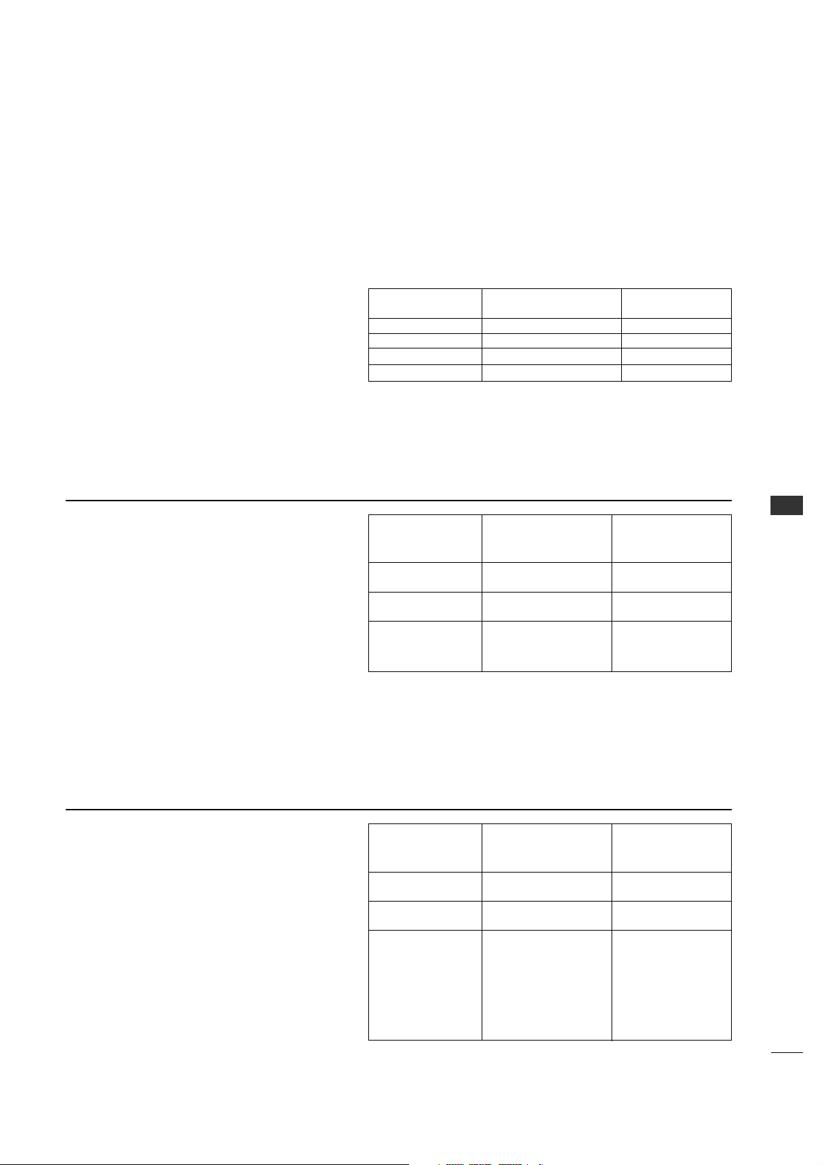
67
COMMERCIAL MODE
The CAMPORT Auto Sense function is enabled
when:
1. Installer Menu Item 34, CAMPORT EN is set to
1 AND
2. Installer Menu Item 40, AUTO CAMPORT is
enabled (1).
Selectable= Can be accessed with TV/AV key,
direct access, etc.
Auto Sense= Switches to this input when
connector is inserted.
The camport (Front Video) has the highest priority
and will override any commands including tuning to
the Start Channel.
Item 34
CAMPORT EN
0
0
1
1
Item 40
AUTO CAMPORT
0
1
0
1
Front Video
Operation
Disabled
Disabled
Selectable
Auto Sense
CAMPORT (Front Video) Functionality Control
CAMPORT Operation (Stand-Alone)
When Camport Auto Sense is enabled as above,
the TV’s source will switch to the front video
whenever a plug is inserted into any of the front
panel video inputs (either composite Video or
S-Video).
When the plug is removed, the TV will switch back
to the Previous channel or input source that the
TV was using before the Plug was inserted.
However, if any direct access to an RF channel or
Aux channel is requested while the camport is
active, then, when the camport plug is removed,
the TV will switch to the last requested channel.
Source changes using any Source Keys (TV/AV)
are ignored. Channel Up/Channel Down and
Flashback Commands are not direct access tuning
commands and they are also ignored.
CAMPORT Operation (PPV)
The operation will be similar to that of the
Stand-Alone mode.
However, the PPV providers may send different
commands to the TV for the same user commands.
For instance, some providers will always send a
direct tune command when it receives a channel
up/down or a flashback command while other PPV
providers will just send a key command.
Previous State
Before Inserting
CAMPORT
Aux or RF Channel
Aux or RF Channel
Aux or RF Channel
Operation State
While CAMPORT
Is Active
None
Direct Access
Ch Up/Down,
Flashback
and TV/AV Keys
State
Upon Removal
Of CAMPORT
Previous Aux
or RF Channel
Last Requested
RF or Aux Channel
Previous Aux
or RF Channel
Previous State
Before Inserting
CAMPORT
Aux or RF Channel
Aux or RF Channel
Aux or RF Channel
Operation
While CAMPORT
Is Active
None
Direct Access
Ch Up/Down,
Flashback
and TV/AV Keys
State
Upon Removal
Of CAMPORT
Previous Aux
or RF Channel
Last Requested
RF or Aux Channel
Last Requested
Channel if PPV
translates it to direct
access tuning
command. Otherwise,
goes to Previous Aux
or RF Channel
PEFERENCE
26LH1DC3/4/5 Camport Auto Sense Operation

COMMERCIAL MODE
COMMERCIAL MODE
68
26LH1DC3/4/5 Aux Input Configuration
DIRECT
ACCESS
Tuning
OLD_OCV
=0
130 90
Video2
(Front)
CV ONLY
34
CAMPORT_EN
0x01 0
Video Front
(Camport)
0(VIDEO) 2
Video Front
(Camport)
131 91
Video1(Rear)
CV ONLY
DTV/PC
Auto
39
REAR_AUX_EN
0x02 1
Rear Video
(Aux)
0(VIDEO) 1
Rear Video
(Aux)
132 92
Component 2
91
YPrPb2 EN
0x04 2
S-Video
Rear
0(VIDEO) 5
S-Video
Rear
133 93
DVI/HDMI1
35
COMPORT EN
0x08 3
Front
Computer
0(VIDEO) 3
Front
Computer
DTV/PC
Auto
134 94
RGB1
87
REAR RGB EN
0x10 4
Computer 0(VIDEO) 4SVGA Rear
CV
S-Video
135 95
Video 3
92
RGB2 ENABLE
0x20 5
NTSC Rear
Computer
0(VIDEO)
1(S-VIDEO)
7
NTSC Rear
Computer
136 96
Component1
38
YPrPb EN
0x40 6
Rear
YPrPb
component
video
0(VIDEO)
6
YUV
Component
OLD_OCV
=1
Source Input Source Mode
Number
Value Value
Labeling LabelingLabeling
26LH1DC3/4/5
ENABLE
Installer Menu
MPI DATA
STATUS TYPE
0x41 SOURCES
ENABLED (R/W)
DATA STATUS
TYPE 0xD2
CURRENT AV
SOURCE (R)
DATA
STATUS
TYPE 0X0D
AUX
SOURCE
(R)
MPI DATA
STATUS
AUX
SOURCE
ASSIGNMENT
PEFERENCE
26LH1DC3/4/5 Aux Input Configuration

69
APPENDIX
APPENDIX
TROUBLESHOOTING
Some quick and easy tips to resolving problems
Display Panel Picture
8 See troubleshooting flow chart.
No Power.
Power
Display panel is turned off.
Wrong tuning band.
Antenna/Cable not
connected.
Connections incorrect.
M.P.I. not connected.
Encrypted program.
8 Turn TV on.
8 Power failure?
8 Adjust Installer menu settings.
8 Connect Antenna/Cable signal source to 26LH1DC3/4/5.
8 Check connections on 26LH1DC3/4/5.
8 If applicable, connect M.P.I. cable to M.P.I. device.
8 Tr y a n o t h er channel.
No picture
Software Problems
8 Remove power cord for 5 minuts.
Software lockup.
TV not functions properly.
8 Start all over with item 117, set to 001, press Enter then redo Auto Program, Channel List, Clock, etc.
*Note: 2-5-4 + MENU can be done more than once.
2-5-5 + MENU performed
more than once.
Software Corrupted.
8 After 2-5-5 + MENU, only channels included in TV controller will appear.
If channel is available, redo channel scan. If it is not available it will not appear on the TV screen.
Channel not included
in channel scan in TV
controller.
Can not direct enter channel number
8 After Auto Program and Channel List, etc. press 2-5-5 + MENU to transfer channels and TV setup to
internal TV controller. Afterward, only Physical or only Virtual channels will appear in digital channel scan,
analog channel scan will be normal.
*Note: Be sure to set item 028 Ch Overide to 000.
2-5-5 + MENU not per-
formed.
Virtual and Physical channels appear in channel scan w/Channel Up/Down.
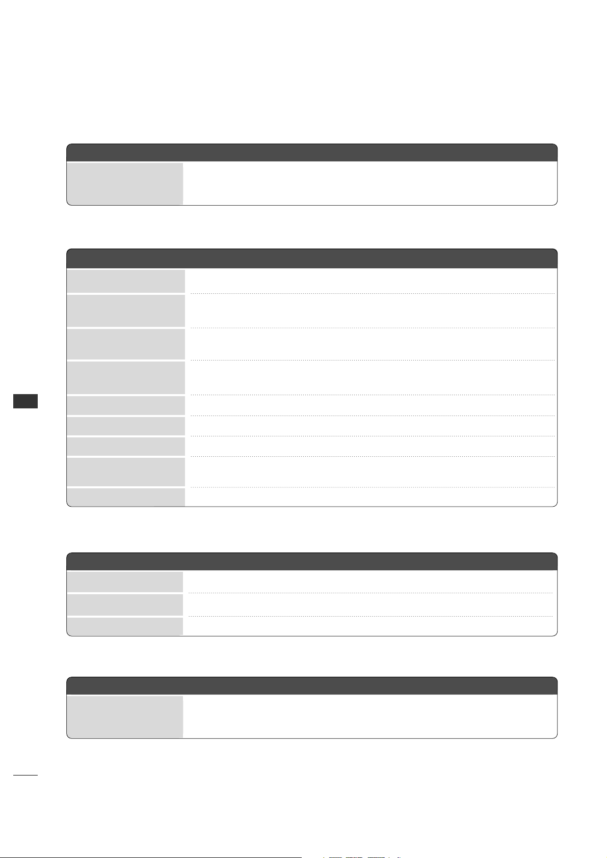
70
APPENDIX
APPENDIX
Remote Control
Picture Reception
Broadcast Tuning Mode Digital Channel OSD
*Note: For other problems not caused by the 26LH1DC3/4/5, refer to other devices’ operating guide.
Remote not in TV mode.
Not aimed at IR remote
sensor.
8 Use Mode key to select TV; puts remote into 26LH1DC3/4/5 mode.
Weak batteries.
8 Replace batteries.
Wrong battery polarity.
8 Check that “+” and “-” match in battery compartment.
Too much light in room.
8 Dim room light.
Incorrect Bed 1-2 setting.
8 Set correct Bed 1-2 setting.
8 Point remote at TV’s IR receiver on TV.
Remote too far from IR
sensor.
Remote too far from IR
sensor.
8 Move remote closer to TV’s IR receiver or darken room.
IR path to TV’s receiver
obstructed.
8 Remove obstructions.
Wrong Installer remote
control.
8 Requires compatible Installer remote, contact your LG dealer.
Remote doesn’t work.
8 Press MUTE or use Volume Up key to increase sound level.
Audio muted.
8 Tr y a different channel.
Broadcast problem.
8 Turn TV speakers on.
TV Speakers Off.
Normal picture, poor or no sound.
8 Set Item 103 to 0 for information to be added to virtual channel tuning digital OSD.
Item 103 set to 1 physical
channels tuning.
No Information available display.
Erratic Operation
8 Adjust Installer menu settings as required.
8 Remove TV power cord for 15 seconds.
Wrong Installer menu
settings.
Software problem.
Installer menu setup.
APPENDIX
71
CLONING PROCEDURE TROUBLESHOOTING
Warning: Do not use LT2002 while a
LodgeNet PPV card is installed in TV or clone
programmer will be damaged.
Reset Clone After Static Shock
After replacing exhausted batteries, or if the programmer
behaves strangely after a static shock, activate the
internal reset switch and restore normal operation.
After a reset, check the real-time clock setting. It may
be necessary to reset the Clone Programmer clock from
a TV containing the correct time.
*Note: The LT2002 programmer is designed to be used with TVs
containing the 221-01006 and later processors. Use with earlier TV
sets may give unpredictable results. Processors used before the
221-01006-04 have a limited screen display capability. They
cannot display entire screens as shown in the quick setup
instructions accompanying the LT2002 clone programmer. Use
the printed menu illustrations on the quick setup sheet supplied
with the Clone as an aid to making your programming choices.
(Although the menus are not all displayed, the clone functions
all operate normally.)
IMPORTANT INSTALLER SETUP INFORMATION! PLEASE READ THE FOLLOWING...
8 Only use an appropriate Installer remote to operate clone programmer with 26LH1DC3/4/5.
Wrong Installer remote.
Remote does not operate clone.
8 Connect 26LH1DC3/4/5 to a reliable Analog channel signal source.
Weak signal.
Clone menu hard to read.
8 Set time on a TV, copy time to Clone Programmer.
Time not available.
No time set.
8 Connect M.P.I. cord.
M.P.I. cord not connected.
8 26LH1DC3/4/5 must be powered On for clone to work.
26LH1DC3/4/5 not
turned on.
8 Install 4 fresh AA high-quality alkaline batteries.
Weak batteries.
LED does not blink
APPENDIX
72
APPENDIX
CLONING PROCEDURE TROUBLESHOOTING
• After cloning operations are complete, just unplug the LT2002 from the 26LH1DC3/4/5.
• If the 26LH1DC3/4/5 does not display a picture on the TV (blank screen) after a few seconds, just change channels.
Master and Other 26LH1DC3/4/5
8 Wait until procedure complete message is displayed.
Procedure interrupted.
8 Cloning is only possible with identical model TVs.
Different TV models.
8 Reread 54 - 55 - 56 pages to be sure all tasks were performed.
Step(s) omitted or not
performed.
8 Redo cloning and be sure learning/teaching time is about 1 min. and 5 to15 seconds (75 seconds).
Insufficient cloning time.
8 Reset Clone Programmer.
Cloning erratic.
Cloning did not work.
8 Batteries must remain installed to retain time settings.
Batteries were removed.
Clone time disappeared.
8 Disconnect newly cloned unit from power for 5 seconds.
26LH1DC3/4/5 not reset.
New Setup not present
8 Tr y a different LT2002 Clone programmer.
8 Reset Clone Programmer.
Clone programmer problem.
Clone not working
8 Retry cloning again.
Clone should only scan
channels once.
Clone Scans Channels more than once.
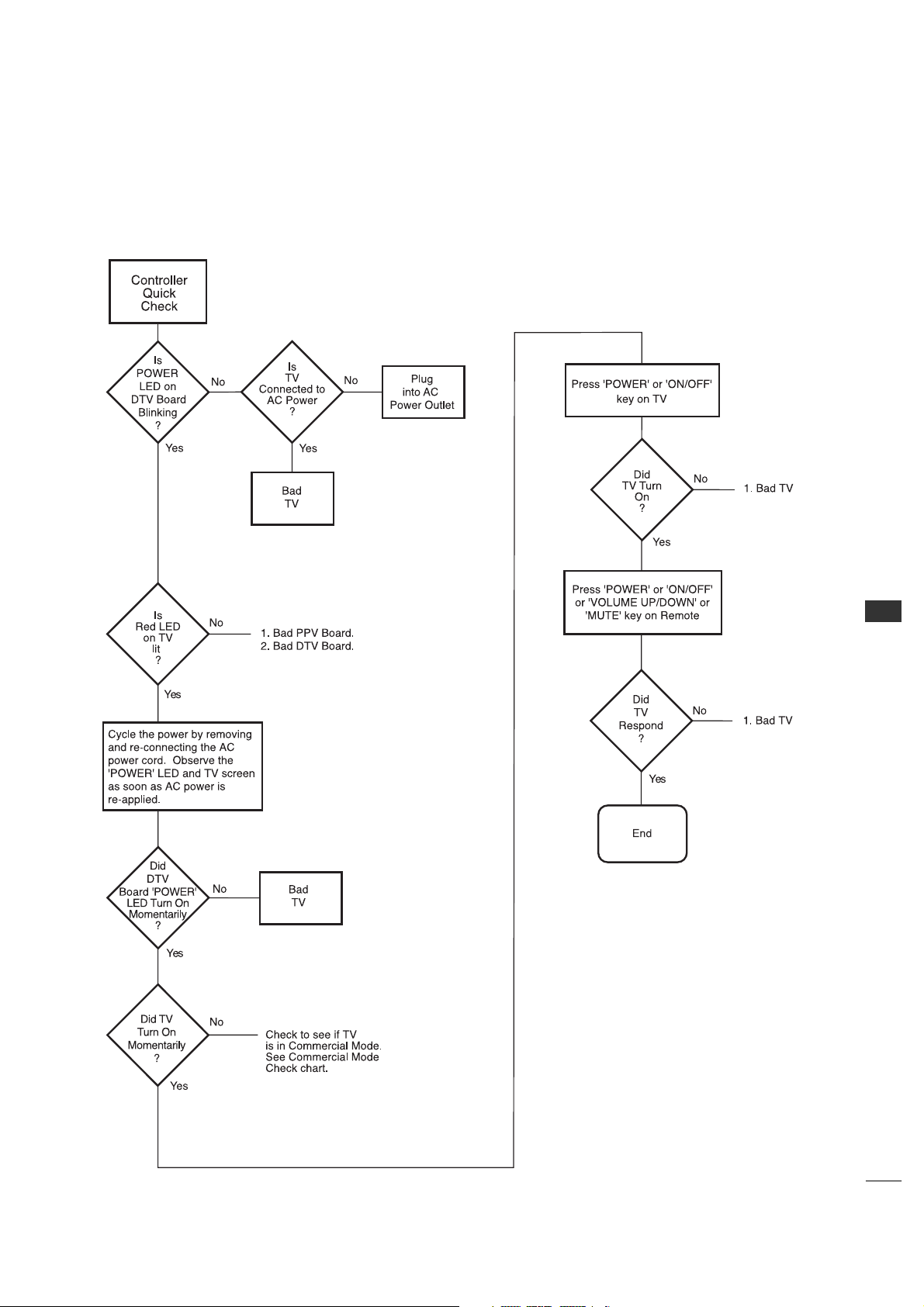
APPENDIX
73
CLONE TROUBLESHOOTING FLOW CHART
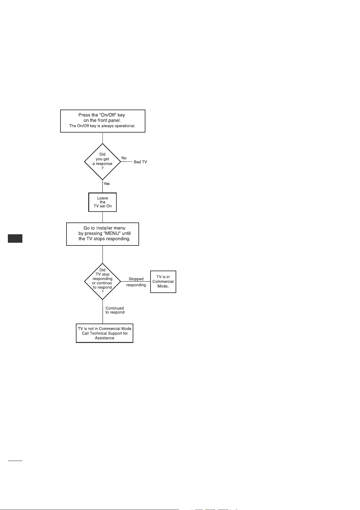
APPENDIX
74
APPENDIX
TV OPERATING CHECK

75
GLOSSARY OF TERMS
75 OHM RF CABLE
The wire that comes from an off-air
antenna or cable service provider.
The end looks like a hex-shaped nut
with a wire sticking through the
middle. It screws onto the
Antenna/Cable threaded jack on the
back of the 26LH1DC3/4/5.
300 TO 75 OHM ADAPTER
A small device that connects a
two-wire 300ohm antenna to a 75
ohm RF jack.
They are usually about an inch long
with two screws on one end and a
round opening with a wire sticking
out on the other end.
ANALOG TELEVISION
Standard television broadcasting
format in 4:3 picture aspect ratio.
A/V CABLES
Audio/Video cables. Three cables
bunched together—right audio
(red), left audio (white), and video
(yellow). A/V cables are used for
stereo playback of videocassettes
and for higher quality picture and
sound from other A/V devices.
A/V DEVICE
Any device that produces video or
sound (VCR, DVD, cable box, or
television).
AMPLIFIER
An electronic device that amplifies
sound from a television, CD player,
VCR, DVD, or other Audio/Video
device.
ANTENNA
The physical receiver of television
signals sent over the air. A large
metal piece of equipment does not
always have to be visible to be using
an antenna.
CABLE
Cable service box. Refers to the
descrambler box cable subscribers use
to receive cable programming signals.
DVD, cable box, or television).
CATV
Programming provided by a cable
service.
DIGITAL TELEVISION
High-resolution, cinema-quality
television signals transmitted digitally.
DVI
Digital Video Interface
Accommodates analog and digital
interfaces with a single connector.
COMPOSITE VIDEO
Typical video jack, uses one wire for
transporting three-color video signals.
COMPONENT VIDEO
Uses three wires for transporting
three-color video signals. The end
result is usually better video quality.
DELETED
Lets you remove channels from the
list that the end user can scroll
through using CH (Channel)
Up/Down.
HDMI
High-definition multimedia interface.
HDTV
High-definition television. Refers to
television signals that have higher
resolution than ordinary analog TV
signals.
HDSTB
High-definition set top box. Refers
to a tuner device that receives
high-definition television signals
which have higher resolution than
ordinary analog TV signals.
INPUT
Refers to the input jack that
receives a signal from a TV, VCR,
DVD Player or other Audio/Video
device.
JACK
An input or output connector on the
back of a TV, VCR, DVD Player or
other Audio/Video device.
MONO SOUND
Mono (monaural) sound is one
channel of sound. On more than one
speaker, all the speakers play the
same audio.
OUTPUT
Refers to the output jack that sends
a signal out of a VCR, DVD, or
other A/V device.
PHYSICAL CHANNEL NUMBER
Actual digital major, dashed minor
channel number that a station is
broadcasting on.
RGB (Red, Green, Blue)
Connection input or output port
available for producing a video image
using three separate colors: Red,
Green, and Blue.
2ND AUDIO PROGRAMMING/SAP
Second Audio Programming (SAP) is
another, separate audio channel
available with some programming.
Choosing SAP often refers to
listening to audio in another
language, such as Spanish or French.
SIGNAL
Picture and sound traveling through
a cable, or over the air, to the TV.
STEREO SOUND
Stereo (Stereophonic) sound refers
to audio that’s divided into right and
left sides.
TUNER
Device that picks up the broadcast
signal and turns it into picture and
sound.
VIRTUAL CHANNEL NUMBER
The arbitrarily assigned digital
dashed minor channel number that a
station is broadcasting on.
A list of definitions for some of the words found in this guide
APPENDIX
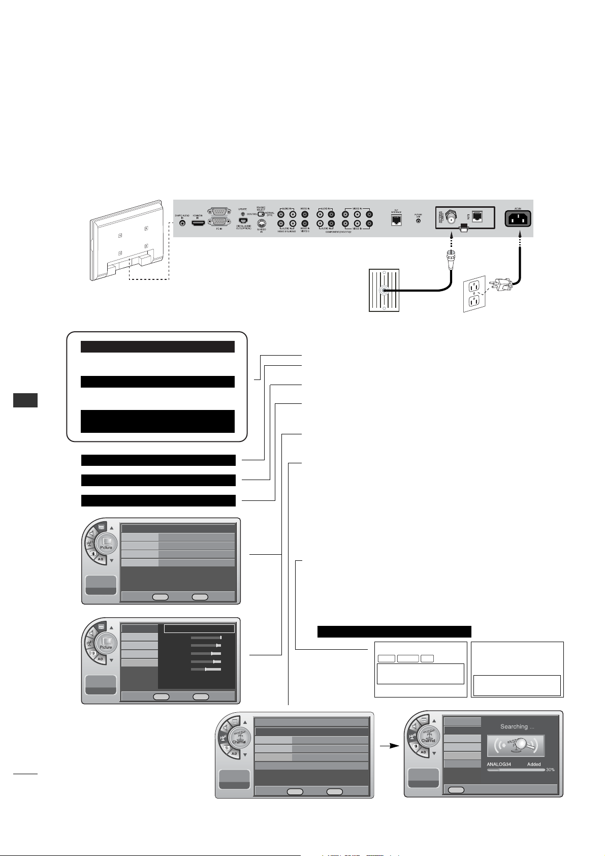
APPENDIX
76
APPENDIX
INSTALLER QUICK SETUP GUIDE
Quick Setup Guide for Integrated Master TVs
See table of contents for more information.
Setup Instructions for Making a Master TV
1. Connect TV to signal source, connect power cord and turn TV power on.
2. Enter the TV installer menu.
*Note: If this is not a new setup, set Installer item 117 to 001 and press
Enter to reset TV to default condition.
• Set Tuning Band.
Set Installer menu item 003 BAND/AFC to CATV: 001, Broadcast: 000 etc.
• If necessary, set Installer menu item 028 CH OVERIDE to 001.
In addition, set any other installer items as required of your system.
Exit Installer menu.
3. Access the Master TV menus and set the closable options on the menus to
the desired configurations. Refer to the Closable Menu Features Chart for
the TV. (Picture, Sound, Time etc.)
4. Do a Channel Search; run Auto Program. (aka EZ Scan.)
5. Enter the Channel Edit menu and delete channels per your requirements.
6. Enter the Channel Label menu and assign ICONs to the channels.
*Note: You can add Channel ICONS typically network logos like ABC, NBC,
PBS etc. in this step. Or, in Step 8, add Channel ICONS or custom text
labels for channels which no Icons are available for.
7. Tr ansfer the TV setup. After all menu options and features are set to your
requirements, enter the installer menu. Press ‘2’, ‘5’, ‘5’, ‘MENU’ to start
the transfer of the TV’s setup to the PTC.
After the transfer is complete, the system will exit the Installer menu.
8. Set any Channel Labels as needed.
a. Enter Installer menu.
b. Press ‘2’, ‘5’, ‘4’, ‘MENU’ to enter the menu. In this menu edit the
assigned
channel Icons, assign custom text labels for channels and assign labels for
active Aux sources. Press ‘Menu’ to exit.
9. Enter the Installer menu. Set item 028 Ch Overide to 000 and exit menu.
LODGING PTC INSTALLER MENU
117FACT DEFAULT 00X
003 BAND/AFC 00X
028 CH.OVERIDE 001
028 CH.OVERIDE 000
000 INSTALLER SEQ 000
UPN 000-000-000-000 FPGA 09F1
PTC V1.00.000 CPU V1.01.00
WXYZ
DIGITAL 19-3
MONO SAPSTEREO
WXYZ
ANALOG 2
MONO
Antenna
Wall Jack
AC Power Cord
RF Coaxial Wire
(75ohm)
Mode Standard G
Color Temperature
Cool
Noise Reduction Off
Screen Format
16:9
Film Mode
Off
11:20 PM
Sep.11, 2006
Antenna
Auto Program
G
Channel Label
Channel List
Fine Tune Auto
Signal Strength
--:-- --
--.-- ----
Antenna
Auto Program
Channel Label
Channel List
Fine Tune
Signal Strength
--:-- --
--.-- ----
11:20 PM
Sep.11, 2006
Mode
Color Temperature
Standard
G
Contrast 100
Brightness 79
Sharpness 65
Color 70
Tint 0
Screen Format
Noise Reduction
Film Mode
DE
Move OK Select Menu Back
DE
Move OK Select Menu Back
DE
Move OK Select Menu Back
Menu Back

77
NOTE

78
NOTE

PRODUCT SPECIFICATIONS
26LH1DC3/4/5
MODELS
27.01 x 22.0 x 9.97 inches / 686.0 x 558.7 x 253.2 mm
AC100-240V ~ 50/60Hz
NTSC-M, ATSC, 64 & 256 QAM
VHF 2-13, UHF 14-69, CATV 1-135, DTV 2-69, CADTV 1-135
75 ohm
32 ~ 10 4°F (0 ~ 40°C)
Less than 80%
-4 ~ 14 0°F (-20 ~ 60°C)
Less than 85%
Dimensions
(Width x Height x Depth)
Weight
Power requirement
Television System
Program Coverage
External Antenna Impedance
Environment condition
33.95 pounds / 15.4 kg
Operating Temperature
Operating Humidity
Storage Temperature
Storage Humidity
The specifications shown above may be changed without prior notice for quality improvement.
79