JG79Y335H01
Required Tools for Installation
Phillips screwdriver
Level
Scale
Utility knife or scissors
65 mm hole saw
Torque wrench
Wrench (or spanner)
4 mm hexagonal wrench
Flare tool for R32, R410A
Gauge manifold for R32, R410A
Vacuum pump for R32, R410A
Charge hose for R32, R410A
Pipe cutter with reamer
ENGLISH
REFRIGERANT
SPLIT-TYPE AIR CONDITIONERS
INSTALLATION MANUAL
Model names are indicated in 1-3.
When installing multi units, refer to the
installation manual of the multi unit for
outdoor unit installation.
Appropriate personal protective equipment
The installer should ensure they check the respective Work Health
and Safety (WHS) Act within their jurisdiction as the requirements and
obligations may differ.
1. BEFORE INSTALLATION
MEANINGS OF SYMBOLS DISPLAYED ON INDOOR UNIT AND/OR OUTDOOR UNIT
WARNING
5LVNRI¿UH
7KLVXQLWXVHVDÀDPPDEOHUHIULJHUDQW
,IUHIULJHUDQWOHDNVDQGFRPHVLQFRQWDFWZLWK¿UHRUKHDWLQJSDUWLWZLOOFUHDWHKDUPIXOJDVDQGWKHUHLVULVNRI¿UH
Read the OPERATING INSTRUCTIONS carefully before operation.
Service personnel are required to carefully read the OPERATING INSTRUCTIONS and INSTALLATION MANUAL before operation.
Further information is available in the OPERATING INSTRUCTIONS, INSTALLATION MANUAL, and the like.
1-1. THE FOLLOWING SHOULD ALWAYS BE OBSERVED FOR SAFETY
%HVXUHWRUHDG³7+()2//2:,1*6+28/'$/:$<6%(2%6(59(')256$)(7<´EHIRUHLQVWDOOLQJWKHDLUFRQGLWLRQHU
%HVXUHWRREVHUYHWKHZDUQLQJVDQGFDXWLRQVVSHFL¿HGKHUHDVWKH\LQFOXGHLPSRUWDQWLWHPVUHODWHGWRVDIHW\
$IWHUUHDGLQJWKLVPDQXDOEHVXUHWRNHHSLWWRJHWKHUZLWKWKH23(5$7,1*,16758&7,216IRUIXWXUHUHIHUHQFH
:KHQXVLQJWKLVSURGXFWLQ$XVWUDOLDFDUHIXOO\UHDGWKH$XVWUDOLDQ,QVWLWXWHRI5HIULJHUDWLRQDQG)ODPPDEOHUHIULJHUDQWV6DIHW\*XLGHLQ$LUFRQGLWLRQLQJDQG+HDWLQJ$,5$+DVZHOO
WARNING
(Could lead to death, serious injury, etc.)
■ Do not install the unit by yourself (user).
,QFRPSOHWH LQVWDOODWLRQ FRXOG FDXVH ¿UH HOHFWULF VKRFN
injury due to the unit falling, or leakage of water. Consult
WKHGHDOHUIURPZKRP\RXSXUFKDVHGWKHXQLWRUDTXDOL¿HG
installer.
■ Perform the installation securely referring to the
installation manual.
,QFRPSOHWH LQVWDOODWLRQ FRXOG FDXVH ¿UH HOHFWULF VKRFN
injury due to the unit falling, or leakage of water.
■ When installing the unit, use appropriate protective
equipment and tools for safety.
Failure to do so could cause injury.
■ Install the unit securely in a place which can bear the
weight of the unit.
If the installation location cannot bear the weight of the
unit, the unit could fall causing injury.
■ (OHFWULFDOZRUNVKRXOGEHSHUIRUPHGE\DTXDOL¿HG
experienced electrician, according to the installation
manual. Be sure to use an exclusive circuit. Do not
connect other electrical appliances to the circuit.
,IWKHFDSDFLW\RIWKHSRZHUFLUFXLWLVLQVXI¿FLHQWRUWKHUH
LVLQFRPSOHWHHOHFWULFDOZRUNLWFRXOGUHVXOWLQD¿UHRUDQ
electric shock.
■ Earth the unit correctly.
'RQRWFRQQHFWWKHHDUWKWRDJDVSLSHZDWHUSLSHOLJKW-
QLQJ URG RU WHOHSKRQH HDUWK 'HIHFWLYH HDUWKLQJ FRXOG
cause electric shock.
■ Do not damage the wires by applying excessive pres-
sure with parts or screws.
'DPDJHGZLUHVFRXOGFDXVH¿UHRUHOHFWULFVKRFN
■ Be sure to cut off the main power in case of setting
up the indoor P.C. board or wiring works.
Failure to do so could cause electric shock.
■ 8VH WKH VSHFL¿HG ZLUHV WR FRQQHFW WKH LQGRRU DQG
RXWGRRUXQLWVVHFXUHO\DQGDWWDFKWKHZLUHV¿UPO\WR
the terminal block connecting sections so the stress
of the wires is not applied to the sections. Do not
extend the wires, or use intermediate connection.
,QFRPSOHWHFRQQHFWLQJDQGVHFXULQJFRXOGFDXVH¿UH
■ 'RQRWLQVWDOOWKHXQLWLQDSODFHZKHUHLQÀDPPDEOH
gas may leak.
If gas leaks and accumulates in the area around the unit,
it could cause an explosion.
■ Do not use intermediate connection of the power
cord or the extension cord and do not connect many
devices to one AC outlet.
,WFRXOGFDXVHD¿UHRUDQHOHFWULFVKRFNGXHWRGHIHFWLYH
contact, defective insulation, exceeding the permissible
current, etc.
■ %HVXUHWRXVHWKHSDUWVSURYLGHGRUVSHFL¿HGSDUWV
for the installation work.
The use of defective parts could cause an injury or leakage
RIZDWHUGXHWRD¿UHDQHOHFWULFVKRFNWKHXQLWIDOOLQJ
etc.
■ When plugging the power supply plug into the outlet,
make sure that there is no dust, clogging, or loose
parts in both the outlet and the plug. Make sure that
the power supply plug is pushed completely into the
outlet.
If there is dust, clogging, or loose parts on the power sup-
SO\SOXJRUWKHRXWOHWLWFRXOGFDXVHHOHFWULFVKRFNRU¿UH
If loose parts are found on the power supply plug, replace
it.
■ Attach the electrical cover to the indoor unit and the
service panel to the outdoor unit securely.
If the electrical cover of the indoor unit and/or the service
panel of the outdoor unit are not attached securely, it could
UHVXOWLQD¿UHRUDQHOHFWULFVKRFNGXHWRGXVWZDWHUHWF
■ When installing, relocating, or servicing the unit,
PDNHVXUHWKDWQRVXEVWDQFHRWKHUWKDQWKHVSHFL¿HG
refrigerant (R32) enters the refrigerant circuit.
Any presence of foreign substance such as air can cause
abnormal pressure rise and may result in explosion or
injury. The use of any refrigerant other than that speci-
¿HGIRUWKHV\VWHPZLOOFDXVHPHFKDQLFDOIDLOXUHV\VWHP
malfunction, or unit breakdown. In the worst case, this
could lead to a serious impediment to securing product
safety.
■ Do not discharge the refrigerant into the atmosphere.
If refrigerant leaks during installation, ventilate the
room. Check that the refrigerant does not leak after
installation has been completed.
,IUHIULJHUDQWOHDNVDQGFRPHVLQFRQWDFWZLWK¿UHRUKHDW-
ing part of such a fan heater, kerosene heater, or cooking
stove, it will create harmful gas. Provide ventilation in
accordance with EN378-1.
■ Use appropriate tools and piping materials for instal-
lation.
The pressure of R32 is 1.6 times more than R22. Not using
appropriate tools or materials and incomplete installation
could cause the pipes to burst or injury.
■ When pumping down the refrigerant, stop the com-
pressor before disconnecting the refrigerant pipes.
If the refrigerant pipes are disconnected while the com-
pressor is running and the stop valve is open, air could be
drawn in and the pressure in the refrigeration cycle could
become abnormally high. This could cause the pipes to
burst or injury.
■ When installing the unit, securely connect the refriger-
ant pipes before starting the compressor.
If the compressor is started before the refrigerant pipes are
connected and when the stop valve is open, air could be
drawn in and the pressure in the refrigeration cycle could
become abnormally high. This could cause the pipes to
burst or injury.
■ )DVWHQDÀDUHQXWZLWKDWRUTXHZUHQFKDVVSHFL¿HG
in this manual.
,IIDVWHQHGWRR WLJKWD ÀDUHQXWPD\ EUHDNDIWHUD ORQJ
period and cause refrigerant leakage.
■ The unit shall be installed in accordance with national
wiring regulations.
■ :KHQXVLQJD JDVEXUQHU RURWKHUÀDPHSURGXFLQJ
equipment, completely remove all of the refrigerant
from the air conditioner and ensure that the area is
well-ventilated.
,I WKH UHIULJHUDQW OHDNV DQG FRPHV LQ FRQWDFW LQ ¿UH RU
heating part, it will create harmful gas and there is risk of
¿UH
■ Do not use means to accelerate the defrosting process
or to clean, other than those recommended by the
manufacturer.
■ The appliance shall be stored in a room without
continuously operating ignition sources (for exam-
SOHRSHQÀDPHVDQ RSHUDWLQJJDVDSSOLDQFHRU DQ
operating electric heater).
■ Do not pierce or burn.
■ Be aware that refrigerants may not contain an odour.
■ Pipe-work shall be protected from physical damage.
■ The installation of pipe-work shall be kept to a mini-
mum.
■ Compliance with national gas regulations shall be
observed.
■ Keep any required ventilation openings clear of ob-
struction.
■ Do not install the indoor unit equipped with the Wi-Fi
interface nearby the automatic control devices such
DVDXWRPDWLFGRRUVRU¿UHDODUPV
It can cause accidents due to malfunctions.
■ Do not use the indoor unit equipped with the Wi-Fi
interface nearby the medical electrical equipment or
people who have a medical device such as a cardiac
SDFHPDNHURUDQLPSODQWDEOHFDUGLRYHUWHUGH¿EULOOD-
tor.
It can cause an accident due to malfunctions of the medical
equipment or device.
■ This indoor unit equipped with the Wi-Fi interface
should be installed and operated with a minimum
distance of 20 cm between the device and the user
or bystanders.
■ In Australia, only technicians that possess the appro-
priate license issued by the Australian Refrigeration
Council (ARC) should install this product.
1-2. SELECTING THE INSTALLATION LOCATION
1-3. SPECIFICATIONS
Model Power supply *1 :LUHVSHFL¿FDWLRQV
Pipe size
(thickness *4, *5)
Maximum amount
of refrigerant
charge *8
Indoor unit Outdoor unit
Rated
Voltage
Frequency
%UHDNHU
capacity
Power supply *2
Indoor/outdoor
connecting wire *2
'HPDQGFRQWUROVLJQDO
transmission cable *3
Gas / Liquid
06=$39*.' í
230 V 50/60 Hz
10 A
3-core
1.0 mm²
4-core
1.0 mm²
0.5 - 1.5 mm
2
ø9.52 / 6.35 mm
(0.8 mm)
í
06=$39*.' 08=$39*'
900 g06=$39*.' 08=$39*'
06=$39*.' 08=$39*'
06=$39*.' 08=$39*' 16 A
3-core
2.0 mm²
ø12.7 / 6.35 mm
(0.8 mm)
1100 g
Note:
When operating the air conditioner in low outside temperature, be sure to follow the
instructions described below.
1HYHULQVWDOOWKHRXWGRRUXQLWLQDSODFHZKHUHLWVDLULQOHWRXWOHWVLGHPD\EHH[SRVHG
directly to wind.
7RSUHYHQWH[SRVXUHWRZLQGLQVWDOOWKHRXWGRRUXQLWZLWKLWVDLULQOHWVLGHIDFLQJWKH
wall.
7RSUHYHQWH[SRVXUHWRZLQGLWLVUHFRPPHQGHGWRLQVWDOODEDIÀHERDUGRQWKHDLURXWOHW
side of the outdoor unit.
Avoid the following places for installation where air conditioner trouble is liable to occur.
:KHUHÀDPPDEOHJDVFRXOGOHDN
:KHUHWKHUHLVPXFKPDFKLQHRLO
:KHUHRLOLVVSODVKHGRUZKHUHWKHDUHDLV¿OOHGZLWKRLO\VPRNHVXFKDVFRRNLQJDUHDV
and factories, in which the properties of plastic could be changed and damaged).
6DOW\SODFHVVXFKDVWKHVHDVLGH
:KHUHVXO¿GHJDVLVJHQHUDWHGVXFKDVKRWVSULQJVHZDJHZDVWHZDWHU
:KHUHWKHUHLVKLJKIUHTXHQF\RUZLUHOHVVHTXLSPHQW
:KHUH WKHUH LV HPLVVLRQ RI KLJK OHYHOV RI 92&V LQFOXGLQJ SKWKDODWH FRPSRXQGV
formaldehyde, etc., which may cause chemical cracking.
7KHDSSOLDQFHVKDOOEHVWRUHGVRDVWRSUHYHQWPHFKDQLFDOGDPDJHIURPRFFXUULQJ
:KHUHDLUÀRZLVQRWEORFNHG
:KHUHFRRORUZDUPDLUVSUHDGVRYHUWKHHQWLUHURRP
5LJLGZDOOZLWKRXWYLEUDWLRQ
:KHUHLWLVQRWH[SRVHGWRGLUHFWVXQVKLQH'RQRWH[SRVHWRGLUHFWVXQVKLQHDOVRGXULQJ
the period following unpacking to before use.
:KHUHHDVLO\GUDLQHG
$WDGLVWDQFHPRUPRUHDZD\IURP\RXU79DQGUDGLR2SHUDWLRQRIWKHDLUFRQGLWLRQHU
PD\LQWHUIHUHZLWKUDGLRRU79UHFHSWLRQ$QDPSOL¿HUPD\EHUHTXLUHGIRUWKHDIIHFWHG
device.
,QDSODFHDVIDUDZD\DVSRVVLEOHIURPÀXRUHVFHQWDQGLQFDQGHVFHQWOLJKWV,QRUGHUWR
make the infrared remote control operate the air conditioner normally. The heat from the
lights may cause deformation or the ultraviolet may cause deterioration.
:KHUHWKHDLU¿OWHUFDQEHUHPRYHGDQGUHSODFHGHDVLO\
:KHUHLWLVDZD\IURPWKHRWKHUKHDWRUVWHDPVRXUFH
REMOTE CONTROLLER
:KHUHLWLVHDV\WRRSHUDWHDQGHDVLO\YLVLEOH
:KHUHFKLOGUHQFDQQRWWRXFKLW
6HOHFWDSRVLWLRQDERXWPDERYHWKHÀRRUDQGFKHFNWKDWVLJQDOVIURPWKHUHPRWH
controller are surely received by the indoor unit from that position (‘beep’ or ‘beep beep’
receiving tone sounds). After that, attach remote controller holder to a pillar or wall and
install wireless remote controller.
Note:
,QURRPVZKHUHLQYHUWHUW\SHÀXRUHVFHQWODPSVDUHXVHGWKHVLJQDOIURPWKHZLUHOHVV
remote controller may not be received.
OUTDOOR UNIT
:KHUHLWLVQRWH[SRVHGWRVWURQJZLQG,IWKHRXWGRRUXQLWLVH[SRVHGWRDZLQGGXULQJ
defrosting, the defrosting time will be longer.
:KHUHDLUÀRZLVJRRGDQGGXVWOHVV
:KHUHUDLQRUGLUHFWVXQOLJKWFDQEHDYRLGHGDVPXFKDVSRVVLEOH
:KHUHQHLJKERXUVDUHQRWDQQR\HGE\RSHUDWLRQVRXQGRUKRWRUFRRODLU
:KHUHULJLGZDOORUVXSSRUWLVDYDLODEOHWRSUHYHQWWKHLQFUHDVHRIRSHUDWLRQVRXQGRU
vibration.
:KHUHWKHUHLVQRULVNRIFRPEXVWLEOHJDVOHDNDJH
:KHQLQVWDOOLQJWKHXQLWDWDKLJKOHYHOEHVXUHWRVHFXUHWKHXQLWOHJV
:KHUHLWLVDWOHDVWPDZD\IURPWKHDQWHQQDRI79VHWRUUDGLR2SHUDWLRQRIWKHDLU
conditioner may interfere with radio or TV reception in areas where reception is weak.
$QDPSOL¿HUPD\EHUHTXLUHGIRUWKHDIIHFWHGGHYLFH
,QVWDOOWKHXQLWKRUL]RQWDOO\
3OHDVHLQVWDOOLWLQDQDUHDQRWDIIHFWHGE\VQRZIDOORUEORZLQJVQRZ,QDUHDVZLWKKHDY\
VQRZSOHDVHLQVWDOODFDQRS\DSHGHVWDODQGRUVRPHEDIÀHERDUGV
Note:
It is advisable to make a piping loop near outdoor unit so as to reduce vibration transmit-
ted from there.
Pipe length and height difference
Model AP25/35/42 AP50
Max. pipe length 20 m
Max. height difference 12 m
Max. number of bends *6, *7 10
Refrigerant adjustment A *8 20 g/m
Insulation thickness *9, *10 8 mm
&KDUJHOHVVSLSLQJOHQJWK% 10 m 15 m
INDOOR UNIT
CAUTION
(Could lead to serious injury in particular environments when operated incorrectly.)
■ Install an earth leakage breaker depending on the
installation place.
If an earth leakage breaker is not installed, it could cause
electric shock.
■ Perform the drainage/piping work securely accord-
ing to the installation manual.
If there is defect in the drainage/piping work, water could
drop from the unit, soaking and damaging household
goods.
■ 'RQRWWRXFKWKHDLULQOHWRUWKHDOXPLQXP¿QVRI
the outdoor unit.
This could cause injury.
■ Do not install the outdoor unit where small animals
may live.
If small animals enter and touch the electric parts inside
the unit, it could cause a malfunction, smoke emission,
RU¿UH$OVRDGYLVHXVHUWRNHHSWKHDUHDDURXQGWKHXQLW
clean.
■ Do not operate the air conditioner during interior
FRQVWUXFWLRQDQG¿QLVKLQJZRUNRUZKLOHZD[LQJ
WKHÀRRU
%HIRUHRSHUDWLQJWKH DLUFRQGLWLRQHUYHQWLODWH WKHURRP
well after such work is performed. Otherwise, it may cause
volatile elements to adhere inside the air conditioner,
resulting in water leakage or scattering of dew.
■ To prevent damage from static electricity, touch
a nearby metal body to discharge static electric-
ity from yourself before touching the indoor unit
equipped with the Wi-Fi interface.
Static electricity from the human body may damage the
Wi-Fi interface unit.
■ Do not use the indoor unit equipped with the Wi-Fi
interface nearby other wireless devices, micro-
waves, cordless phones, or facsimiles.
It can cause malfunctions.
*1 Connect to the power switch which has a gap of 3 mm or more when open to interrupt the source power phase.
(When the power switch is shut off, it must interrupt all phases.)
*2 Use wires in conformity with design 60245 IEC 57.
*3 Use wires in conformity with design AS/NZS 5000.2.
1HYHUXVHSLSHVZLWKWKLFNQHVVOHVVWKDQVSHFL¿HG7KHSUHVVXUHUHVLVWDQFHZLOOEHLQVXI¿FLHQW
*5 Use a copper pipe or a copper-alloy seamless pipe.
%HFDUHIXOQRWWRFUXVKRUEHQGWKHSLSHGXULQJSLSHEHQGLQJ
*7 Refrigerant pipe bending radius must be 100 mm or more.
,ISLSHOHQJWKH[FHHGV%PDGGLWLRQDOUHIULJHUDQW5FKDUJHLVUHTXLUHG1RDGGLWLRQDOFKDUJHLVUHTXLUHGIRU
SLSHOHQJWKDQGOHVV%P
$GGLWLRQDOUHIULJHUDQW $îSLSHOHQJWKP±%
,QVXODWLRQPDWHULDO+HDWUHVLVWLQJIRDPSODVWLFVSHFL¿FJUDYLW\
%HVXUHWRXVHWKHLQVXODWLRQRIVSHFL¿HGWKLFNQHVV([FHVVLYHWKLFNQHVVPD\FDXVHLQFRUUHFWLQVWDOODWLRQRI
WKHLQGRRUXQLWDQGLQVXI¿FLHQWWKLFNQHVVPD\FDXVHGHZGULSSDJH
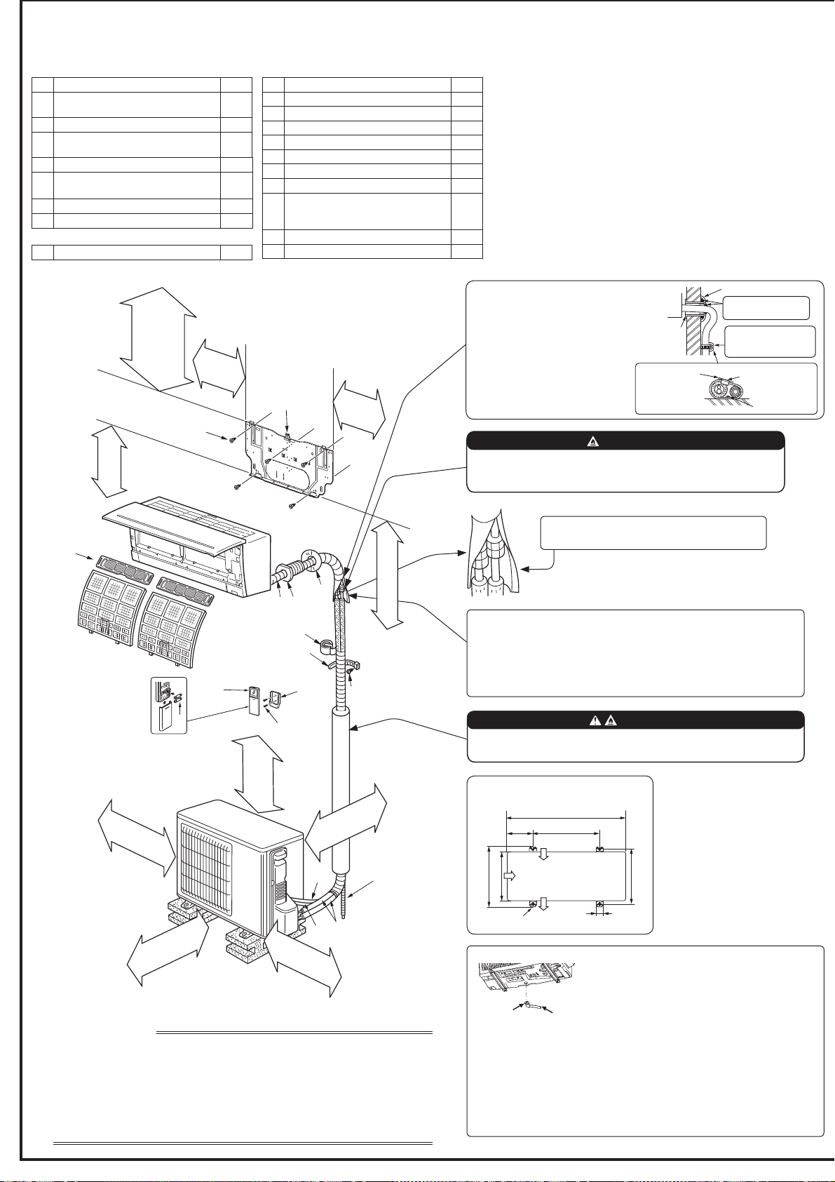
Outdoor unit installation
Air inlet
Air outlet
40 mm
2-10 mm × 21 mm slot
800 mm
150 mm
500 mm
344.5 mm
285 mm
304-325 mm
(G)
(E)
(C)
(4)
(D)
(F)
(B)
(K)
(A)
(I)
(7)
(3)
(8)
(6)
(5)
(2)
(1)
1-4. INSTALLATION DIAGRAM
When the piping is to be attached to a wall containing metals (tin plated) or metal
netting, use a chemically treated wooden piece 20 mm or thicker between the
wall and the piping or wrap 7 to 8 turns of insulation vinyl tape around the piping.
To use existing piping, perform COOL operation for 30 minutes and pump
GRZQEHIRUHUHPRYLQJWKHROGDLUFRQGLWLRQHU5HPDNHÀDUHDFFRUGLQJWRWKH
dimension for new refrigerant.
Appearance of the outdoor unit may differ from some models.
60 mm
or more
1.8 m to 2.3 m from the
ÀRRULVUHFRPPHQGHG
clear *2
100 mm
or more
100 mm
or more
200 mm *3
or more
*2 100 mm or more when front and sides
of unit are clear
Note:
*1 Place indoor/outdoor unit connecting wire (A) and
power supply cord (K) at least 1 m away from the TV
antenna wire.
After the leak test, apply insulating material tightly
so that there is no gap.
7RDYRLGULVNRI¿UHHPEHGRUSURWHFWWKHUHIULJHUDQWSLSLQJ
([WHUQDOGDPDJHRQWKHUHIULJHUDQWSLSLQJFDQEHFDXVHRI¿UH
(9)
(I)
PARTS TO BE PROVIDED AT YOUR SITE
(A) Indoor/outdoor unit connecting wire*1
1
% Extension pipe
1
(C) Wall hole sleeve
1
' Wall hole cover
1
(E) 3LSH¿[LQJEDQG
2 to 5
(F) Fixing screw for (E) 4 × 20 mm
2 to 5
(G) Piping tape
1
(H) Putty
1
(I)
'UDLQKRVH
(or soft PVC hose, 15 mm inner
diameter or hard PVC pipe VP16)
1 or 2
(J) Refrigeration oil
1
(K) Power supply cord*1
1
ACCESSORIES
Check the following parts before installation.
<Indoor unit>
(1) Installation plate
1
(2)
,QVWDOODWLRQSODWH¿[LQJVFUHZ
4 × 25 mm
5
(3) Wireless remote controller
1
(4)
Felt tape
(For left or left-rear piping)
1
(5) Remote controller holder
1
(6)
Fixing screw for (5) 3.5 × 16 mm
%ODFN
2
(7) %DWWHU\$$$IRU
2
(8) $LUFOHDQLQJ¿OWHU
2
<Outdoor unit>
(9) 'UDLQVRFNHW
1
Air inlet
*3 When any 2 sides of left, right and rear of unit are clear.
IMPORTANT NOTES
Units should be installed by licensed contractor according to local code requirements.
To comply with the requirements of Australian standard AS/NZS 3000 electrical
installations (wiring rules), the electrical wiring required between the indoor and
outdoor units must be installed by a licenced electrical contractor.
Check that cabling will not be subject to wear, corrosion, excessive pressure,
vibration, sharp edges or any other adverse environmental effects. The check shall
also take into account the effects of aging or continual vibration from sources such as
compressors or fans.
61
mm or more/
138
mm or more for
left and left back piping
(using spacer)
106 mm
or more
126
mm
or more
350 mm
or more
Note:
Install the unit horizontally.
'RQRWXVHGUDLQVRFNHWLQFROGUHJLRQV'UDLQPD\IUHH]HDQGPDNHWKH
fan stop.
The outdoor unit produces condensate during the heating operation. Select
the installation place to ensure to prevent the outdoor unit and/or the grounds
from being wet by drain water or damaged by frozen drain water.
Drain piping for outdoor unit
3URYLGHGUDLQSLSLQJEHIRUHLQGRRUDQGRXWGRRUSLS-
ing connection.
&RQQHFWGUDLQKRVH,,'PPDV VKRZQLQWKH
illustration.
0DNH VXUH WR SURYLGH GUDLQ SLSLQJ ZLWK D GRZQKLOO
JUDGHIRUHDV\GUDLQÀRZ
%HVXUHWRXVHZDOOKROHVOHHYH&
to prevent indoor/outdoor connect-
ing wire (A) from contacting metal
parts in the wall and to prevent
damage by rodents in case the
wall is hollow.
Indoor unit
Wall hole
sleeve (C)
Cut off the
extra length.
3LSH¿[LQJEDQG(
:DOOKROHFRYHU'
Fixing screw (F)
Seal the wall hole
gap with putty (H).
Fix the pipe to wall
ZLWKSLSH¿[LQJEDQG
(E).
WARNING
7RDYRLGULVNRI¿UHÀDUHFRQQHFWLRQVKRXOGEHLQVWDOOHGRXWGRRUV
5HXVDEOHPHFKDQLFDOFRQQHFWRUVDQGÀDUHGMRLQWVDUHQRWDOORZHG
indoors.
WARNING
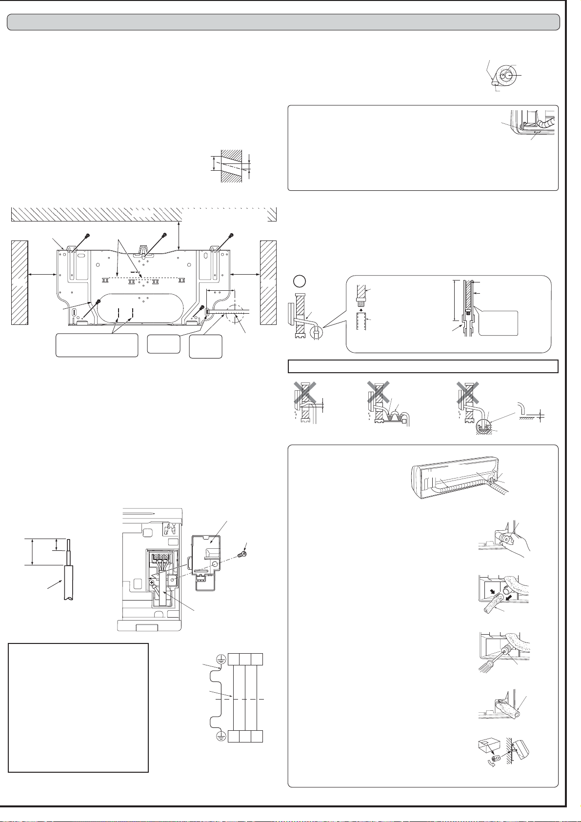
2-1. FIXING OF INSTALLATION PLATE
)LQGDVWUXFWXUDOPDWHULDOVXFKDVDVWXGLQWKHZDOODQG¿[LQVWDOODWLRQSODWHKRUL]RQ-
WDOO\E\WLJKWHQLQJWKH¿[LQJVFUHZV¿UPO\
7RSUHYHQWLQVWDOODWLRQSODWHIURPYLEUDWLQJEHVXUHWRLQVWDOOWKH¿[LQJVFUHZVLQWKH
KROHVLQGLFDWHGLQWKHLOOXVWUDWLRQ)RUDGGHGVXSSRUW¿[LQJVFUHZVPD\DOVREHLQVWDOOHG
in other holes.
:KHQWKHNQRFNRXWLVUHPRYHGDSSO\YLQ\OWDSHWRWKHNQRFNRXWHGJHVWRSUHYHQWGDPDJ-
ing the wires.
:KHQEROWVUHFHVVHGLQWKHFRQFUHWHZDOODUHWREHXWLOL]HGVHFXUHLQVWDOODWLRQSODWH
using 11 × 20 · 11 × 26 oval hole (450 mm pitch).
,IWKHUHFHVVHGEROWLVWRRORQJFKDQJHLWIRUDVKRUWHURQHDYDLODEOHLQWKHPDUNHW
2-2. WALL HOLE DRILLING
'HWHUPLQHWKHZDOOKROHSRVLWLRQ
'ULOO D¡ PP KROH 7KH RXWGRRUVLGH VKRXOG EH WR
7 mm lower than the indoor side.
3) Insert wall hole sleeve (C).
2-3. CONNECTING WIRES FOR INDOOR UNIT
You can connect indoor/outdoor lead wire without removing the front panel.
1) Open the front panel.
2) Remove VA clamp.
3) Pass indoor/outdoor unit connecting wire (A) from the back of the indoor unit and process
the end of the wire.
/RRVHQWHUPLQDOVFUHZDQGFRQQHFW¿UVWWKHHDUWKZLUHWKHQLQGRRURXWGRRUXQLWFRQ-
QHFWLQJZLUH$WRWKHWHUPLQDOEORFN%HFDUHIXOQRWWRPDNHPLVZLULQJ)L[WKHZLUHWR
the terminal block securely so that no part of its core is appeared, and no external force
is conveyed to the connecting section of the terminal block.
5) Firmly tighten the terminal screws to prevent them from loosening. After tightening, pull
WKHZLUHVOLJKWO\WRFRQ¿UPWKDWWKH\GRQRWPRYH
6) Secure indoor/outdoor unit connecting wire (A) and the earth wire with the VA clamp.
Never fail to hook the left claw of the VA clamp. Attach the VA clamp securely.
2-4. PIPE FORMING AND DRAIN PIPING
Pipe Forming
3ODFHWKHGUDLQKRVHEHORZWKHUHIULJHUDQWSLSLQJ
0DNHVXUHWKDWWKHGUDLQKRVHLVQRWKHDYHGRUVQDNHG
'RQRWSXOOWKHKRVHZKHQDSSO\LQJWKHWDSH
:KHQWKHGUDLQKRVHSDVVHVWKHURRPEHVXUHWRZUDSLQVXOD-
tion material (obtainable at a store) around it.
2. INDOOR UNIT INSTALLATION
Rear, right, or downward piping
1) Put the refrigerant piping and the drain hose togeth-
HUWKHQ¿UPO\DSSO\SLSLQJWDSH*IURPWKHHQG
2) Insert the piping and the drain hose into the wall
hole sleeve (C), and hook the upper part of the
indoor unit on the installation plate (1).
3) Check if the indoor unit is hooked securely on the installation plate (1) by moving the
unit to left and right.
4) Thrust the lower part of the indoor unit into the installation plate (1).
Drain Piping
,IWKHH[WHQVLRQGUDLQKRVHKDVWRSDVVWKURXJKDURRPEHVXUHWRZUDSLWZLWKFRPPHU-
cially sold insulation.
7KHGUDLQKRVHVKRXOGSRLQWGRZQZDUGIRUHDV\GUDLQÀRZ)LJ
,IWKHGUDLQKRVHSURYLGHGZLWKWKHLQGRRUXQLWLVWRRVKRUWFRQQHFWLWZLWKGUDLQKRVH,
that should be provided at your site. (Fig. 2)
:KHQFRQQHFWLQJWKHGUDLQKRVHWRWKHKDUGYLQ\OFKORULGHSLSHEHVXUHWRLQVHUWLWVHFXUHO\
into the pipe. (Fig. 3)
'RQRWPDNHGUDLQSLSLQJDVVKRZQEHORZ
'RQRWUDLVH
Accumulated
drain water
Air
Waving
Water
leakage
Water
leakage
Water
leakage
Tip of drain
hose dipped
in water
'LWFK
At least
50 mm
gap
'RZQZDUG
slope
'UDLQ
hose
Soft hose
,'PP
'UDLQKRVH
Hard vinyl chloride
SLSH,'PP
Insert
securely
'LIIHUHQW
diameter joint
70 cm
or more
Fig. 1 Fig. 2 Fig. 3
)RU IXWXUH VHUYLFLQJ JLYH H[WUDOHQJWK WR
the connecting wires.
0DNHHDUWKZLUHDOLWWOHORQJHUWKDQRWKHUV
(More than 60 mm)
'RQRWIROGWKHH[FHVVZLUHRUFUDPLWLQWR
small space. Take caution not to damage
the wires.
%HVXUHWRDWWDFKHDFKVFUHZWRLWVFRUUH-
spondent terminal when securing the cord
and/or the wire to the terminal block.
Note:'RQRWSODFHWKHZLUHVEHWZHHQWKH
indoor unit and the installation plate (1).
'DPDJHGZLUHFRXOGFDXVHKHDWJHQHUD-
WLRQRU¿UH
Wall
Outdoor
side
ø65 mm
5-7 mm
Installation plate (1)
Center of
ø65 mm hole
126 mm
or more
106 mm
or more
61 mm or more
138 mm or more for left and left
back piping (using spacer)
Ceiling
Wall
Wall
Fixing
screw (2)
100 mm
Level
* Same for left hole.
Fixing screw
VA clamp
Indoor/outdoor unit
connecting wire (A)
Lead wire
15 mm
35 mm
Indoor terminal block
Indoor/outdoor
unit connecting
wire (A)
Outdoor terminal block
Earth wire
(green/yellow)
S1 S2 S3
S1 S2 S3
Felt tape (4)
Piping tape (G)
Cut off in case of
left piping.
'UDLQFDS
'UDLQFDS
'UDLQKRVH
'UDLQFDS
'UDLQKRVH
Fig. 1
Fig. 2
Fig. 3
Fig. 4
Fig. 5
1) Put the refrigerant piping and the drain hose together,
WKHQ¿UPO\DSSO\IHOWWDSHIURPWKHHQG
Felt tape (4) overlap width should be 1/3 the tape width.
Use a bandage stopper at the end of felt tape (4).
2) Pull out the drain cap at the rear right of the indoor unit.
(Fig. 1)
+ROGWKHFRQYH[VHFWLRQDWWKHHQGDQGSXOOWKHGUDLQ
cap.
3) Pull out the drain hose at the rear left of the indoor unit.
(Fig. 2)
+ROGWKHFODZPDUNHGE\WKHDUURZVDQGSXOORXWWKH
drain hose forward.
4) Put the drain cap into the section to which the drain hose
is to be attached at the rear of the indoor unit. (Fig. 3)
,QVHUWQRWVKDUSHGJHGWRROVVXFKDVVFUHZGULYHUVLQWR
the hole at the end of the cap and insert the cap fully
into the drain pan.
5) Insert the drain hose fully into the drain pan at the rear
right of the indoor unit. (Fig. 4)
&KHFNLIWKHKRVHLVKRRNHGVHFXUHO\WRWKHSURMHFWLRQ
of its inserting part at the drain pan.
6) Insert the drain hose into wall hole sleeve (C), and hook
the upper part of indoor unit on installation plate (1).
Then, move the indoor unit completely to the left in order
to make placing the piping in the back space of the unit
easier.
7) Cut out a piece of cardboard from the shipping box, roll
it up, hook it onto the back rib, and use it as a spacer to
lift the indoor unit. (Fig. 5)
8) Connect the refrigerant piping with the extension pipe
%
9) Thrust the lower part of the indoor unit into the installation
plate (1).
Left or left-rear piping
Note:
%H VXUH WR UHDWWDFK WKH GUDLQ KRVH
and the drain cap in case of left or
left-rear piping.
Otherwise, it could cause drops of
water to drip down from the drain
hose.
Liquid pipe
Gas pipe
Felt tape (4)
Indoor/outdoor unit
connecting wire (A)
Piping tape (G)
Insert the
scale. *
The union joints of the indoor
unit are 110 mm to the left of
these punch marks.
Align the
scale with
the line. *
Cut off in case of
right piping.
Cut off in case of
downward piping.
%XUU
Copper pipe
Spare reamer
Pipe cutter
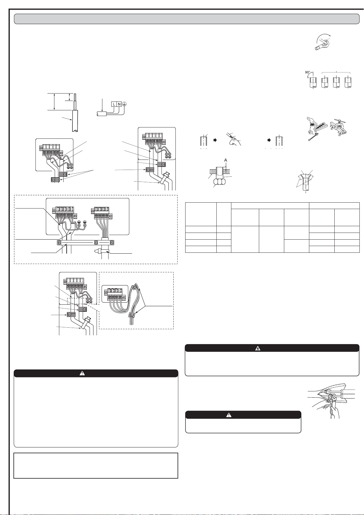
3-2. FLARING WORK
1) Cut the copper pipe correctly with pipe cutter. (Fig. 1, 2)
2) Completely remove all burrs from the cut cross section
of pipe. (Fig. 3)
3XWWKHHQGRIWKHFRSSHUSLSHWRGRZQZDUGGLUHFWLRQ
as you remove burrs in order to avoid to let burrs drop
in the piping.
5HPRYHÀDUHQXWVDWWDFKHGWRLQGRRUDQGRXWGRRUXQLWV
then put them on pipe having completed burr removal.
1RWSRVVLEOHWRSXWWKHPRQDIWHUÀDULQJZRUN
4) Flaring work (Fig. 4, 5). Firmly hold copper pipe in the
dimension shown in the table. Select A mm from the table
according to the tool you use.
5) Check
&RPSDUHWKHÀDUHGZRUNZLWK)LJ
,IÀDUHLVQRWHGWREHGHIHFWLYHFXWRIIWKHÀDUHGVHF-
WLRQDQGGRÀDULQJZRUNDJDLQ
3-3. PIPE CONNECTION
)DVWHQÀDUHQXWZLWKDWRUTXHZUHQFKDVVSHFL¿HGLQWKHWDEOH
:KHQIDVWHQHGWRRWLJKWÀDUHQXWPD\EUHDNDIWHUDORQJSHULRGDQGFDXVHUHIULJHUDQWOHDN-
age.
%HVXUHWRZUDSLQVXODWLRQDURXQGWKHSLSLQJ'LUHFWFRQWDFWZLWKWKHEDUHSLSLQJPD\UHVXOW
in burns or frostbite.
Indoor unit connection
Connect both liquid and gas pipings to indoor unit.
$SSO\DWKLQFRDWRIUHIULJHUDWLRQRLO-RQWKHÀDUHGHQGVRIWKHSLSHV'RQRWDSSO\UHIULJHUD-
tion oil on screw threads. Excessive tightening torque will result in damage on the screw.
)RUFRQQHFWLRQ¿UVWDOLJQWKHFHQWHUWKHQWLJKWHQWKH¿UVWWRWXUQVRIÀDUHQXW
8VHWLJKWHQLQJWRUTXHWDEOHDERYHDVDJXLGHOLQHIRULQGRRUXQLWVLGHXQLRQMRLQWVHFWLRQDQG
WLJKWHQXVLQJWZRZUHQFKHV([FHVVLYHWLJKWHQLQJGDPDJHVWKHÀDUHVHFWLRQ
Pipe diameter
(mm)
Nut
(mm)
A (mm) Tightening torque
Clutch type
tool for R32,
R410A
Clutch type
tool for
R22
Wing nut
type tool
for R22
1P NJIFP
¡´ 17
0 to 0.5 1.0 to 1.5
1.5 to 2.0
13.7 to 17.7 140 to 180
¡´ 22 34.3 to 41.2 350 to 420
¡´ 26
2.0 to 2.5
49.0 to 56.4 500 to 575
¡´ 29 73.5 to 78.4 750 to 800
Copper
pipe
Good
7LOWHG8QHYHQ%XUUHG
No good
Fig. 1
Fig. 2
Clutch type
Flaring tool
Fig. 4
Fig. 3
Smooth all
around
Even length
all around
Inside is shin-
ing without any
scratches.
Flare nut
'LH
Fig. 5 Fig. 6
3. OUTDOOR UNIT INSTALLATION
Copper pipe
Wing nut type
WARNING
When installing the unit, securely connect the refrigerant
pipes before starting the compressor.
3-1. CONNECTING WIRES FOR OUTDOOR UNIT
1) Open the service panel.
2) Loosen terminal screw, and connect indoor/outdoor unit connecting wire (A) from
WKHLQGRRUXQLWFRUUHFWO\RQWKHWHUPLQDOEORFN%HFDUHIXOQRWWRPDNHPLVZLULQJ)L[
the wire to the terminal block securely so that no part of its core is appeared, and no
external force is conveyed to the connecting section of the terminal block.
3) Firmly tighten the terminal screws to prevent them from loosening. After tightening,
SXOOWKHZLUHVOLJKWO\WRFRQ¿UPWKDWWKH\GRQRWPRYH
4) Connect power supply cord (K).
5)
Fix indoor/outdoor unit connecting wire (A) and power supply cord (K) with the cord clamp.
6) Close the service panel securely.
0DNHHDUWKZLUHDOLWWOHORQJHUWKDQRWKHUV0RUHWKDQPP
)RUIXWXUHVHUYLFLQJJLYHH[WUDOHQJWKWRWKHFRQQHFWLQJZLUHV
%HVXUHWRDWWDFKHDFKVFUHZWRLWVFRUUHVSRQGHQWWHUPLQDOZKHQVHFXULQJWKHFRUG
and/or the wire to the terminal block.
35 mm
15 mm
Lead wire
Power supply cord (K)
Outdoor unit connection
Connect pipes to stop valve pipe joint of the outdoor unit in
the same manner applied for indoor unit.
)RUWLJKWHQLQJXVHDWRUTXHZUHQFKRUVSDQQHUDQGXVHWKH
same tightening torque applied for indoor unit.
3-4. INSULATION AND TAPING
1) Cover piping joints with pipe cover.
2) For outdoor unit side, surely insulate every piping including valves.
3) Using piping tape (G), apply taping starting from the entry of outdoor unit.
6WRSWKHHQGRISLSLQJWDSH*ZLWKWDSHZLWKDGKHVLYHDJHQWDWWDFKHG
:KHQSLSLQJKDYHWREHDUUDQJHGWKURXJKDERYHFHLOLQJFORVHWRUZKHUHWKHWHPSHUDWXUH
and humidity are high, wind additional commercially sold insulation to prevent condensa-
tion.
Terminal block
Terminal block
Cord clamp
Power supply cord (K)
Indoor/outdoor unit
connecting wire (A)
$OZD\V¿[WKHSRZHU
supply cord on this side.
Insert the end of the cable
tie in the rectangle hole.
<AP25, 35, 42>
$39*'!
<AP50>
$39*'!
This unit has demand response capability which is compliant with AS/NZS 4755.3.1.
To activate this function, you need to make a contract with remote agents such as elec-
WULFVXSSO\FRPSDQ\WKHQWKLVXQLWVKRXOGEHFRQQHFWHGWR'HPDQGUHVSRQVHHQDEOLQJ
GHYLVH'5(')RUIXUWKHULQIRUPDWLRQFRQVXOW\RXUGHDOHU7KLVXQLWVXSSRUWV'HPDQG
5HVSRQVH0RGHV'50V'50'50DQG'50
CAUTION
7RSUHYHQWPDOIXQFWLRQFDXVHGE\QRLVHURXWHWKHFRUGFRQQHFWLQJWKLVXQLW
to DRED and the power supply cord as parallel as possible.
'RQRWFRQQHFWWKHGHPDQGFRQWUROWUDQVPLVVLRQFDEOHWRWKHWHUPLQDOEORFN
for power supply.
'RQRWSXOOH[WUHPHO\EHQGRUDSSO\VWURQJSUHVVXUHRQWKHZLUHWRSUHYHQW
failure.
'RQRWVFUHZ'5('WRRXWGRRUXQLW
'RQRWSXW'5('LQRXWGRRUXQLW
6HFXUHHOHFWULFDOZLULQJDERYHFODPS
'RQRWJHW'5('ZLUHFDXJKWLQWKHVHUYLFHSDQHO
6HFXUHWKHSRZHUVXSSO\FRUGLQGRRURXWGRRUXQLWFRQQHFWLQJZLUHDQG'5('
wire with the Cable clamp and Cable strap.
WARNING
7RDYRLGULVNRI¿UHÀDUHFRQQHFWLRQVKRXOGEHLQVWDOOHGRXWGRRUV
5HXVDEOHPHFKDQLFDOFRQQHFWRUVDQGÀDUHGMRLQWVDUHQRWDOORZHGLQGRRUV
:KHQFRQQHFWLQJWKHUHIULJHUDQWSLSLQJE\EUD]LQJUDWKHUWKDQXVLQJÀDUHFRQQHFWLRQV
complete all brazing prior to connecting indoor unit to outdoor unit.
1 2 3 C
Terminal block
Cable clamp
Cable strap
The tip should be
pointed to the left side.
'50
'50
'50
C : COMMON
Power supply
cord (K)
Indoor/outdoor
unit connecting
wire (A)
AS/NZS4755 terminal block
1 2 3 C
Terminal block
Cord clamp
Power supply cord (K)
Indoor/outdoor unit
connecting wire (A)
$OZD\V¿[WKHSRZHU
supply cord on this side.
Insert the end of
the cable tie in the
rectangle hole.
Wire saddle
'50
'50
'50
C : COMMON
AS/NZS4755
terminal block
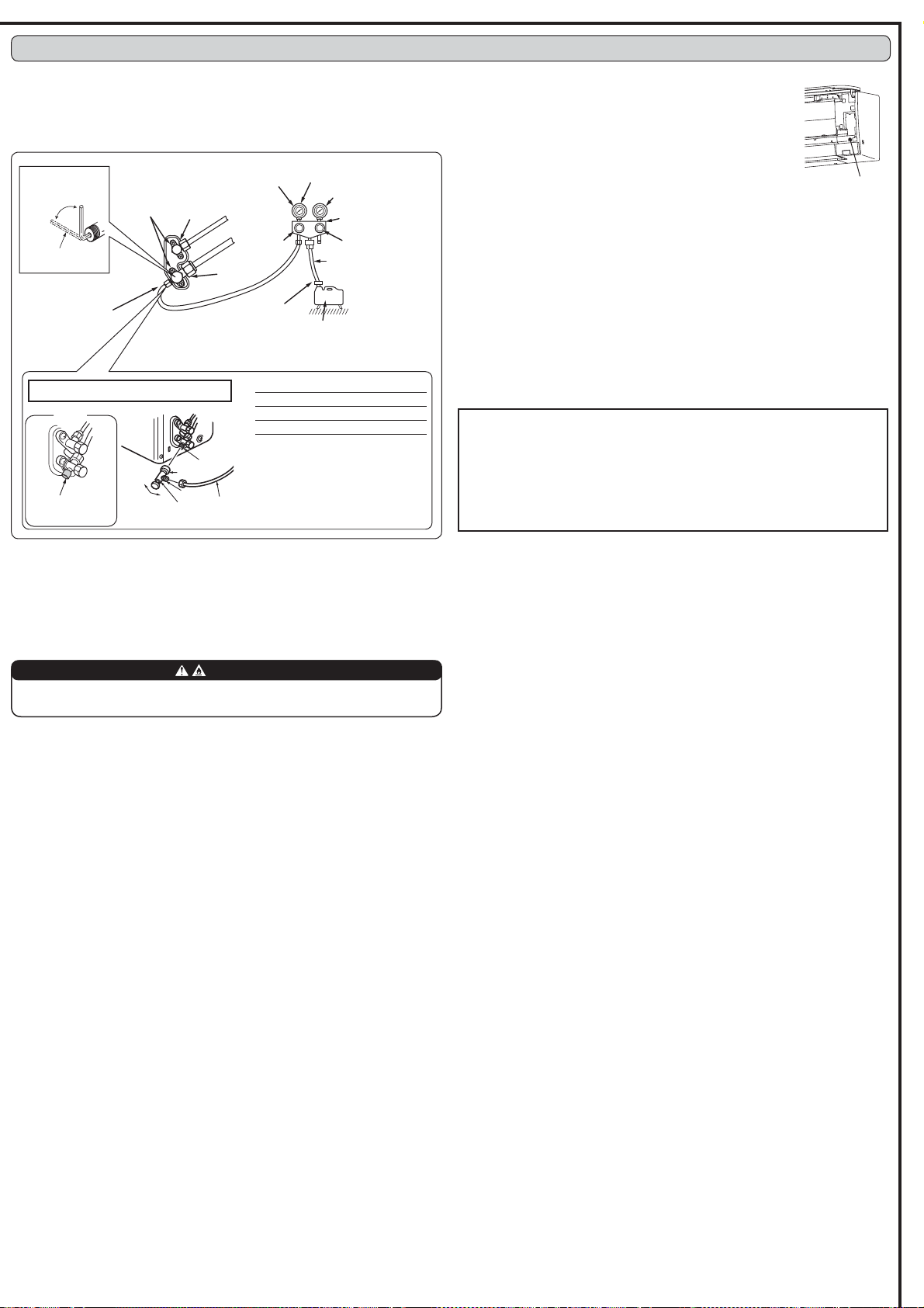
4-1. PURGING PROCEDURES AND LEAK TEST
1) Remove service port cap of stop valve on the side of the outdoor unit gas pipe. (The stop
valves are fully closed and covered in caps in initial state.)
2) Connect gauge manifold valve and vacuum pump to service port of stop valve on the gas
pipe side of the outdoor unit.
4-2. TEST RUN
1) Insert power supply plug into the power outlet and/or turn on the
breaker.
2) Press the E.O. SW once for COOL, and twice for HEAT operation.
Test run will be performed for 30 minutes. If the upper lamp of the
operation indicator blinks every 0.5 seconds, inspect the indoor/
outdoor unit connecting wire (A) for mis-wiring. After the test run,
emergency mode (set temperature 24ºC) will start.
7RVWRSRSHUDWLRQSUHVVWKH(26:VHYHUDOWLPHVXQWLODOO/('
lamps turn off. Refer to operating instructions for details.
4) Checking the remote (infrared) signal reception
3UHVV WKH 2))21 EXWWRQ RQ WKH UHPRWH FRQWUROOHU DQG
check that an electronic sound is heard from the indoor unit.
Press the OFF/ON button again to turn the air conditioner off.
2QFHWKH FRPSUHVVRU VWRSV WKH UHVWDUW SUHYHQWLYH GHYLFH
operates so the compressor will not operate for 3 minutes to
protect the air conditioner.
Stop valve for
GAS
Stop valve cap
(Torque 19.6 to
1P
WRNJIFP
Vacuum pump (or the vacuum
pump with the function to
SUHYHQWWKHEDFNÀRZ
Gauge manifold valve
(for R32, R410A)
Compound pressure gauge
(for R32, R410A)
–0.101 MPa
(
–760 mmHg)
Handle
Low
Handle High
Adapter for
preventing the
EDFNÀRZ
Charge hose
(for R32, R410A)
*Close
*Open
Hexagonal wrench
Precautions when using the control valve
When attaching the control valve
to the service port, valve core may
deform or loosen if excess pressure
is applied. This may cause gas leak.
Service port
%RG\
Close
<R32>
Open
Control
valve
A
When attaching the control valve to
the service port, make sure that the
valve core is in closed position, and
WKHQ WLJKWHQ SDUW $ 'R QRW WLJKWHQ
part A or turn the body when valve
core is in open position.
Service port cap
(Torque 13.7 to
1P140 to
180 kgfcm)
*4 to 5 turns
3) Run the vacuum pump. (Vacuumize until 500 microns is achieved.)
4) Check the vacuum with gauge manifold valve, then close gauge manifold valve, and stop
the vacuum pump.
5) Leave as it is for one or two minutes. Make sure pointer gauge manifold valve remains
LQWKHVDPHSRVLWLRQ&RQ¿UPWKDWSUHVVXUHJDXJHVKRZV±03D>*DXJH@±
mmHg).
6) Remove gauge manifold valve quickly from service port of stop valve.
Stop valve
IRU/,48,'
Caution:
$IWHUWHVWUXQRUUHPRWHVLJQDOUHFHSWLRQFKHFNWXUQRIIWKHXQLWZLWKWKH(26:RU
the remote controller before turning off the power supply. Not doing so will cause the
unit to start operation automatically when power supply is resumed.
To the user
$IWHULQVWDOOLQJWKHXQLWPDNHVXUHWRH[SODLQWKHXVHUDERXWDXWRUHVWDUWIXQFWLRQ
,I DXWR UHVWDUW IXQFWLRQ LV XQQHFHVVDU\ LW FDQ EH GHDFWLYDWHG &RQVXOW WKH VHUYLFH
representative to deactivate the function. Refer to the service manual for details.
4. PURGING PROCEDURES, LEAK TEST, AND TEST RUN
Pressure gauge
(for R32, R410A)
Emergency operation
switch (E.O. SW)
Charge
hose
Make sure to re-
place the cap after
the operation.
4-4. EXPLANATION TO THE USER
8VLQJWKH23(5$7,1*,16758&7,216H[SODLQWRWKHXVHUKRZWRXVHWKHDLUFRQGLWLRQHU
KRZWRXVHWKHUHPRWHFRQWUROOHUKRZWRUHPRYHWKHDLU¿OWHUVKRZWRFOHDQSUHFDXWLRQV
for operation, etc.).
5HFRPPHQGWKHXVHUWRUHDGWKH23(5$7,1*,16758&7,216FDUHIXOO\
7RDYRLGULVNRI¿UHPDNHVXUHWKDWWKHUHDUHQRÀDPPDEOHKD]DUGVRULJQLWLRQ
risks before opening the stop valves.
7) After refrigerant pipes are connected and evacuated, fully open all stop valves on both
sides of gas pipe and liquid pipe. Operating without fully opening lowers the performance
and this causes trouble.
5HIHUWRDQGFKDUJHWKHSUHVFULEHGDPRXQWRIUHIULJHUDQWLIQHHGHG%HVXUHWRFKDUJH
slowly with liquid refrigerant. Otherwise, composition of the refrigerant in the system may
be changed and affect performance of the air conditioner.
9) Tighten cap of service port to obtain the initial status.
10) Leak test
4-3. AUTO RESTART FUNCTION
This product is equipped with an auto restart function. When the power supply is stopped
during operation, such as during blackouts, the function automatically starts operation in
the previous setting once the power supply is resumed. (Refer to the operating instructions
for details.)
WARNING
6-3. PUMPING DOWN
When relocating or disposing of the air conditioner, pump down the system following the
procedure below so that no refrigerant is released into the atmosphere.
1) Connect the gauge manifold valve to the service port of the stop valve on the gas pipe side
of the outdoor unit.
2) Fully close the stop valve on the liquid pipe side of the outdoor unit.
3) Close the stop valve on the gas pipe side of the outdoor unit almost completely so that it
FDQEHHDVLO\FORVHGIXOO\ZKHQWKHSUHVVXUHJDXJHVKRZV03D>*DXJH@NJIFPð
4) Start the emergency COOL operation.
To start the emergency operation in COOL mode, disconnect the power supply plug and/
or turn off the breaker. After 15 seconds, connect the power supply plug and/or turn on
the breaker, and then press the E.O. SW once. (The emergency COOL operation can be
performed continuously for up to 30 minutes.)
5) Fully close the stop valve on the gas pipe side of the outdoor unit when the pressure gauge
VKRZVWR03D>*DXJH@DSSUR[WRNJIFPð
6) Stop the emergency COOL operation.
3UHVVWKH(26:VHYHUDOWLPHVXQWLODOO/('ODPSVWXUQRII5HIHUWRRSHUDWLQJLQVWUXFWLRQV
for details.
When pumping down the refrigerant, stop the compressor before disconnecting the
refrigerant pipes. The compressor may burst if air etc. get into it.
WARNING
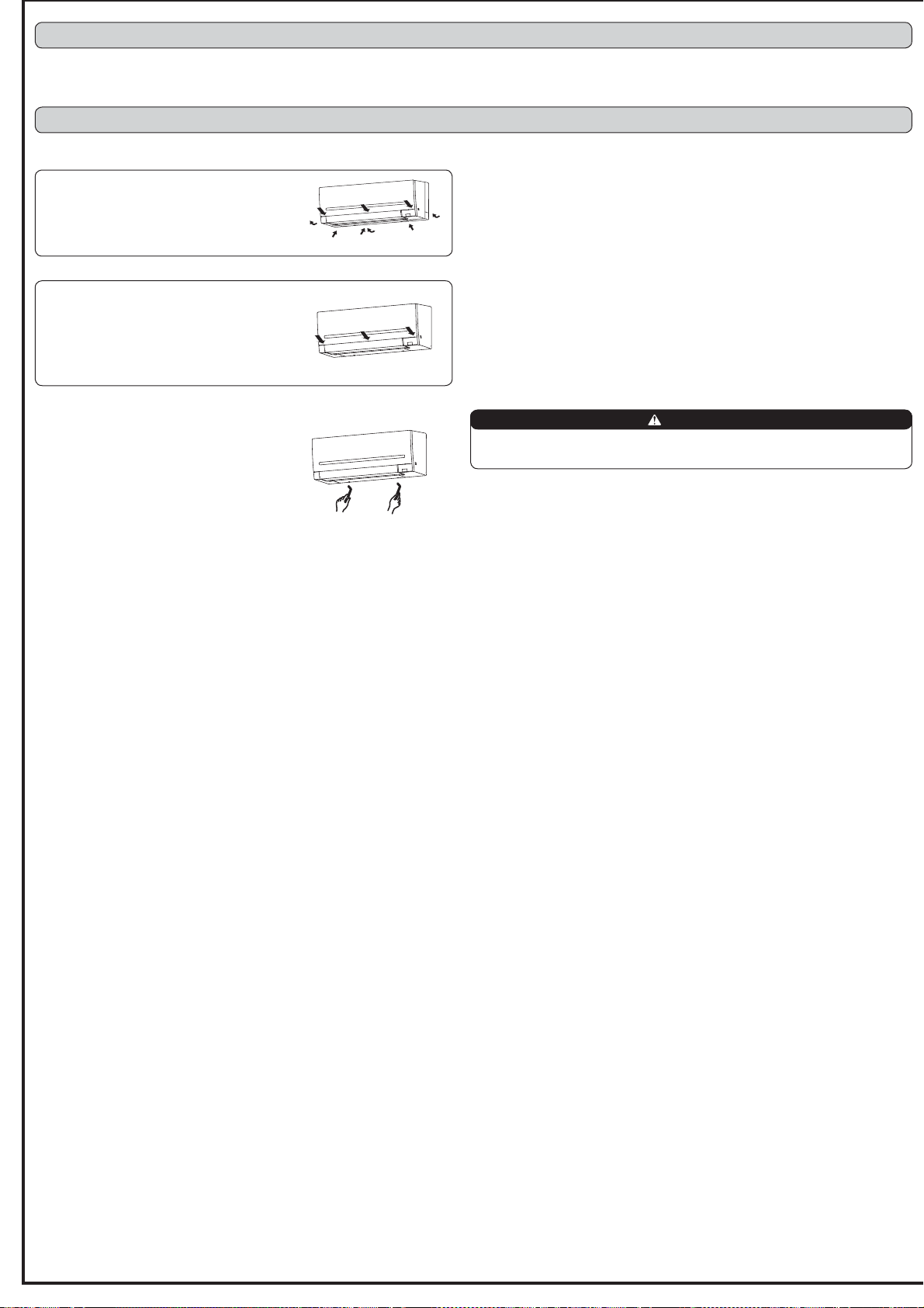
6-2. REMOVING THE INDOOR UNIT
Remove the bottom of the indoor unit from the
installation plate.
Release both left and right bottom part of indoor unit
and pull it downward and forward as shown in the
¿JXUHRQWKHULJKW
Installation procedure
1) Install the panel assembly following the removal
procedure in reverse.
%HVXUHWRSUHVVWKHSRVLWLRQVDVLQGLFDWHGE\WKH
arrows in order to attach the assembly completely
to the unit.
6. RELOCATION AND MAINTENANCE
5. CONNECTION SETUP OF THE Wi-Fi INTERFACE ( VGK TYPE ONLY)
This product is equipped with the Wi-Fi Interface as standard.
Refer to the OPERATING INSTRUCTIONS provided with the indoor unit for connection with the router.
6-1. REMOVING AND INSTALLING THE PANEL ASSEM
BLY
Removal procedure
5HPRYHWKHVFUHZVZKLFK¿[WKHSDQHODVVHPEO\
5HPRYHWKHSDQHODVVHPEO\%HVXUHWRUHPRYHLWV
ERWWRPHQG¿UVW
1
1
2
2
1
2
This product is designed and intended for use in the residential, commercial
and light-industrial environment.
+($'2)),&(72.<2%8,/',1*0$58128&+,&+,<2'$.8
TOKYO 100-8310, JAPAN